Embed Size (px)
Citation preview
INTRODUCTIONMAAT Project is an EU 7FP project related to the design
of a cruiser/feeder airship system [1, 2]. This project derivesfrom a preceding project called PSICHE regarding theanalysis of the hypothesis of energy production instratosphere by photovoltaic energy caption and conversionin hydrogen and oxygen. It requires a binary systemcomposed by a high altitude airship platform and a feederairship connecting it to the ground with capability of liftingup the necessary water for hydrolysis bringing downhydrogen and oxygen [3, 4, 5].
These projects have lead to a deep study about solarphotovoltaic productivity at high altitude [6], which isnecessary to ensure an adequate level of success to bothprojects. In particular, it has been demonstrated thatphotovoltaic energy caption at high altitude is about two
times the one on the ground, that photovoltaic productivity isfurther increased because of the lower temperature ofequilibrium of PV modules. In addition, hydrogen andoxygen storage as both compressed gas and liquefied gas ishigher than the production on the ground.
MAAT project allows defining a novel airshiparchitecture, which can change its own volume during serviceto regulate the buoyant force and ensure an increased level ofsafety using hydrogen. This novel airship architecture doesnot include the presence of internal air ballonets, reducing therisks connected with hydrogen use as buoyant gas. Airballonets do not ensure an adequate level of safety, especiallyduring long airborne time missions [7]. The permeability ofthe envelope of the ballonets to hydrogen makes presentsserious problems related to the possibility of reachinghydrogen auto-ignition conditions.
2013-01-2303Published 09/17/2013
Copyright © 2013 SAE Internationaldoi:10.4271/2013-01-2303
saeaero.saejournals.org
Propulsion of Photovoltaic Cruiser-Feeder AirshipsDimensioning by Constructal Design for Efficiency Method
Antonio Dumas, Mauro Madonia, and Michele TrancossiUniversità di Modena e Reggio Emilia
Dean VucinicVrije Universiteit Brussel
ABSTRACTThe European project MAAT (Multi-body Advanced Airship for Transport) is producing the design of a transportation
system for transport of people and goods, based on the cruiser feeder concept. This project defined novel airship conceptscapable of handling safer than in the past hydrogen as a buoyant gas. In particular, it has explored novel variable shapeairship concepts, which presents also intrinsic energetic advantages. It has recently conduced to the definition of aninnovative design method based on the constructal principle, which applies to large transport vehicles and allowsperforming an effective energetic optimization and an effective optimization for the specific mission. While the traditionalconstructal method performs an optimization with a down-to-top approach, it produces an optimization process in twostages: the first one defines the optimal characteristics of the system understood as a unitary system to achieve the desiredperformances; the second analyzes the subsystems, examining those most disadvantaged, in order to optimize itsperformance for the desired goal. It has been deeply tested on a traditional shaped airship allowing verifying that achanging volume airship has globally better energetic performances than a fixed volume one. This paper performs apreliminary analysis of the method for the design of a cruiser/feeder multibody airship such as the one, which is going tobe designed inside the MAAT project. The model presented defines the guidelines for the optimization of the systemconsidering the magnitudes involved in flight physics to achieve the goal of energetic self-sufficiency.
CITATION: Dumas, A., Madonia, M., Trancossi, M., and Vucinic, D., "Propulsion of Photovoltaic Cruiser-Feeder AirshipsDimensioning by Constructal Design for Efficiency Method," SAE Int. J. Aerosp. 6(1):2013, doi:10.4271/2013-01-2303.
____________________________________
273
THIS DOCUMENT IS PROTECTED BY U.S. AND INTERNATIONAL COPYRIGHT.It may not be reproduced, stored in a retrieval system, distributed or transmitted, in whole or in part, in any form or by any means.
Downloaded from SAE International by Antonio Dumas, Monday, September 30, 2013 09:57:18 AM
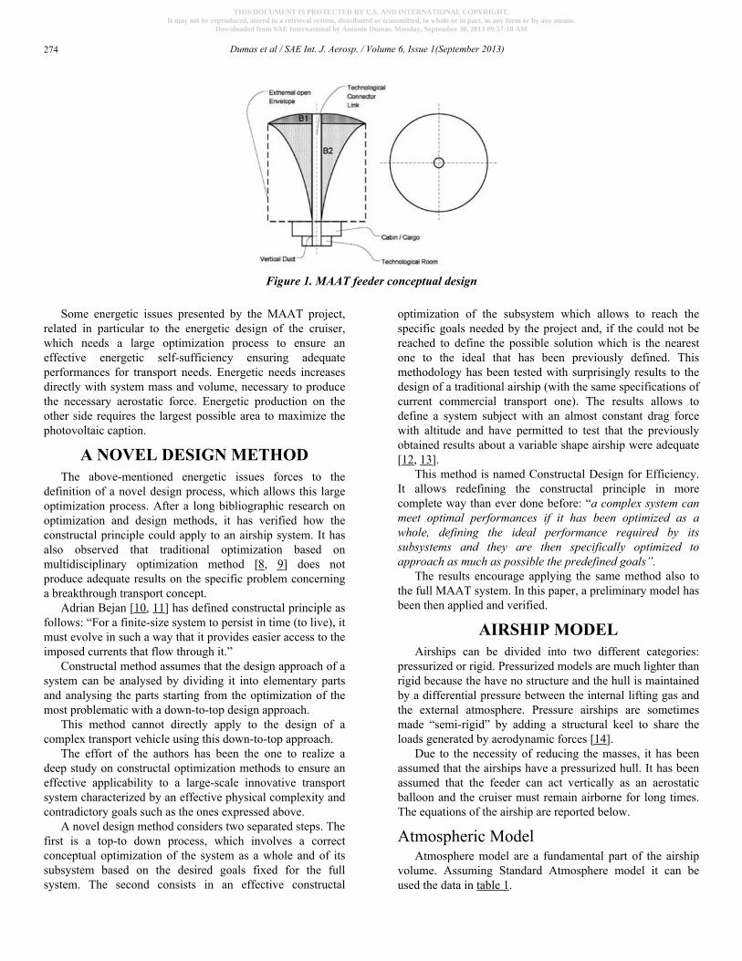
Some energetic issues presented by the MAAT project,related in particular to the energetic design of the cruiser,which needs a large optimization process to ensure aneffective energetic self-sufficiency ensuring adequateperformances for transport needs. Energetic needs increasesdirectly with system mass and volume, necessary to producethe necessary aerostatic force. Energetic production on theother side requires the largest possible area to maximize thephotovoltaic caption.
A NOVEL DESIGN METHODThe above-mentioned energetic issues forces to the
definition of a novel design process, which allows this largeoptimization process. After a long bibliographic research onoptimization and design methods, it has verified how theconstructal principle could apply to an airship system. It hasalso observed that traditional optimization based onmultidisciplinary optimization method [8, 9] does notproduce adequate results on the specific problem concerninga breakthrough transport concept.
Adrian Bejan [10, 11] has defined constructal principle asfollows: “For a finite-size system to persist in time (to live), itmust evolve in such a way that it provides easier access to theimposed currents that flow through it.”
Constructal method assumes that the design approach of asystem can be analysed by dividing it into elementary partsand analysing the parts starting from the optimization of themost problematic with a down-to-top design approach.
This method cannot directly apply to the design of acomplex transport vehicle using this down-to-top approach.
The effort of the authors has been the one to realize adeep study on constructal optimization methods to ensure aneffective applicability to a large-scale innovative transportsystem characterized by an effective physical complexity andcontradictory goals such as the ones expressed above.
A novel design method considers two separated steps. Thefirst is a top-to down process, which involves a correctconceptual optimization of the system as a whole and of itssubsystem based on the desired goals fixed for the fullsystem. The second consists in an effective constructal
optimization of the subsystem which allows to reach thespecific goals needed by the project and, if the could not bereached to define the possible solution which is the nearestone to the ideal that has been previously defined. Thismethodology has been tested with surprisingly results to thedesign of a traditional airship (with the same specifications ofcurrent commercial transport one). The results allows todefine a system subject with an almost constant drag forcewith altitude and have permitted to test that the previouslyobtained results about a variable shape airship were adequate[12, 13].
This method is named Constructal Design for Efficiency.It allows redefining the constructal principle in morecomplete way than ever done before: “a complex system canmeet optimal performances if it has been optimized as awhole, defining the ideal performance required by itssubsystems and they are then specifically optimized toapproach as much as possible the predefined goals”.
The results encourage applying the same method also tothe full MAAT system. In this paper, a preliminary model hasbeen then applied and verified.
AIRSHIP MODELAirships can be divided into two different categories:
pressurized or rigid. Pressurized models are much lighter thanrigid because the have no structure and the hull is maintainedby a differential pressure between the internal lifting gas andthe external atmosphere. Pressure airships are sometimesmade “semi-rigid” by adding a structural keel to share theloads generated by aerodynamic forces [14].
Due to the necessity of reducing the masses, it has beenassumed that the airships have a pressurized hull. It has beenassumed that the feeder can act vertically as an aerostaticballoon and the cruiser must remain airborne for long times.The equations of the airship are reported below.
Atmospheric ModelAtmosphere model are a fundamental part of the airship
volume. Assuming Standard Atmosphere model it can beused the data in table 1.
Figure 1. MAAT feeder conceptual design
Dumas et al / SAE Int. J. Aerosp. / Volume 6, Issue 1(September 2013)274
THIS DOCUMENT IS PROTECTED BY U.S. AND INTERNATIONAL COPYRIGHT.It may not be reproduced, stored in a retrieval system, distributed or transmitted, in whole or in part, in any form or by any means.
Downloaded from SAE International by Antonio Dumas, Monday, September 30, 2013 09:57:18 AM
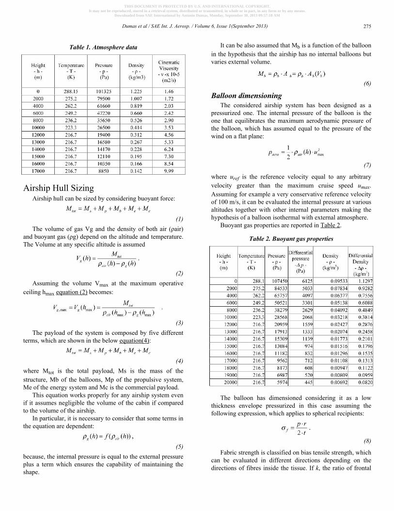
Table 1. Atmosphere data
Airship Hull SizingAirship hull can be sized by considering buoyant force:
(1)The volume of gas Vg and the density of both air (ρair)
and buoyant gas (ρg) depend on the altitude and temperature.The Volume at any specific altitude is assumed
(2)Assuming the volume Vmax at the maximum operative
ceiling hmax equation (2) becomes:
(3)The payload of the system is composed by five different
terms, which are shown in the below equation(4):
(4)where Mtot is the total payload, Ms is the mass of thestructure, Mb of the balloons, Mp of the propulsive system,Me of the energy system and Mc is the commercial payload.
This equation works properly for any airship system evenif it assumes negligible the volume of the cabin if comparedto the volume of the airship.
In particular, it is necessary to consider that some terms inthe equation are dependent:
(5)because, the internal pressure is equal to the external pressureplus a term which ensures the capability of maintaining theshape.
It can be also assumed that Mb is a function of the balloonin the hypothesis that the airship has no internal balloons butvaries external volume.
(6)
Balloon dimensioningThe considered airship system has been designed as a
pressurized one. The internal pressure of the balloon is theone that equilibrates the maximum aerodynamic pressure ofthe balloon, which has assumed equal to the pressure of thewind on a flat plane:
(7)
where uref is the reference velocity equal to any arbitraryvelocity greater than the maximum cruise speed umax.Assuming for example a very conservative reference velocityof 100 m/s, it can be evaluated the internal pressure at variousaltitudes together with other internal parameters making thehypothesis of a balloon isothermal with external atmosphere.
Buoyant gas properties are reported in Table 2.
Table 2. Buoyant gas properties
The balloon has dimensioned considering it as a lowthickness envelope pressurized in this case assuming thefollowing expression, which applies to spherical recipients:
(8)
Fabric strength is classified on bias tensile strength, whichcan be evaluated in different directions depending on thedirections of fibres inside the tissue. If k, the ratio of frontal
Dumas et al / SAE Int. J. Aerosp. / Volume 6, Issue 1(September 2013) 275
THIS DOCUMENT IS PROTECTED BY U.S. AND INTERNATIONAL COPYRIGHT.It may not be reproduced, stored in a retrieval system, distributed or transmitted, in whole or in part, in any form or by any means.
Downloaded from SAE International by Antonio Dumas, Monday, September 30, 2013 09:57:18 AM
area and volume elevated at 2/3, is the coefficient of theballoon, for a variable volume airship
(9)the mass of fabric for balloon realization balloon is
(10)Equation (10) is the mass for the balloon. This represents
the mass available for the internal structure and all systems. Itvaries with the fabric density and k. The required mass ofbuoyant gas becomes:
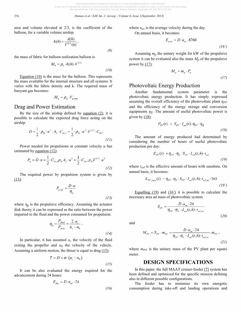
Drag and Power EstimationBy the size of the airship defined by equation (2), it is
possible to calculate the expected drag force acting on theairship:
(11)Power needed for propulsions at constant velocity u has
estimated by equation (12):
(12)The required power by propulsion system is given by
(13):
(13)where ηp is the propulsive efficiency. Assuming the actuatordisk theory it can be expressed as the ratio between the powerimparted to the fluid and the power consumed for propulsion:
(14)In particular, it has assumed uc the velocity of the fluid
exiting the propeller and u0 the velocity of the vehicle.Assuming a uniform motion, the thrust is equal to drag (15):
(15)It can be also evaluated the energy required for the
advancement during 24 hours:
(16)
where uav is the average velocity during the day.On annual basis, it becomes:
(16’)
Assuming mp the unitary weight for kW of the propulsivesystem it can be evaluated also the mass Mp of the propulsivepower by (17):
(17)
Photovoltaic Energy ProductionAnother fundamental system parameter is the
photovoltaic energy production. It has simply expressedassuming the overall efficiency of the photovoltaic plant ηPVand the efficiency of the energy storage and conversionequipments ηE. The amount of useful photovoltaic power isgiven by (18):
(18)
The amount of energy produced had determined byconsidering the number of hours of useful photovoltaicproduction per day:
(19)
where tsol is the effective amount of hours with sunshine. Onannual basis, it becomes:
(19’)
Equalling (19) and (16’) it is possible to calculate thenecessary area ad mass of photovoltaic system.
(20)
and
(21)
where mPV is the unitary mass of the PV plant per squaremeter.
DESIGN SPECIFICATIONSIn this paper, the full MAAT cruiser-feeder [7] system has
been defined and optimized for the specific mission definingalso in different possible configurations.
The feeder has to minimize its own energeticconsumption during take-off and landing operations and
Dumas et al / SAE Int. J. Aerosp. / Volume 6, Issue 1(September 2013)276
THIS DOCUMENT IS PROTECTED BY U.S. AND INTERNATIONAL COPYRIGHT.It may not be reproduced, stored in a retrieval system, distributed or transmitted, in whole or in part, in any form or by any means.
Downloaded from SAE International by Antonio Dumas, Monday, September 30, 2013 09:57:18 AM
during the full system motion. This system needs to bespecifically defined for the necessary operative conditions.The preliminary data for system design have reported inTable 3.
The cruiser specification can be defined in the same wayas done for the feeder. In particular, it can be assumed thatthe system payload capacity is equivalent to four feeders andthe area for passenger is considerably increased to at least3m2 for passenger. Design data are specified in Table 4.
Table 3. Specifications for the design of the feeder
Table 4. Specifications for the design of the cruiser
Design of the CabinsConsidering the data in Table 3 and 4, it is possible to
proceed to the design of the cabins of cruiser and feeder. Inparticular it is possible to evaluate cabin dimensions andweights. The material has been assumed carbon fibre withinternal thermal insulation in polyurethane and windowingsystem in reinforced PVC.
The system design requires considering atmospheric data,reported in Table 1. Internal cabin pressure can be evaluatedat 2600 m as the reference pressure for internalpressurization, even if in conservative calculations it has beenconsidered the atmospheric pressure at ground level. Materialproperties have been assumed from [17] and [18].
The cabins has assumed as a circular cylinder with twohemispheric ends. Dimensioning formulas are derived fromthe traditional calculation formulas used for an initialqualitative design [19].
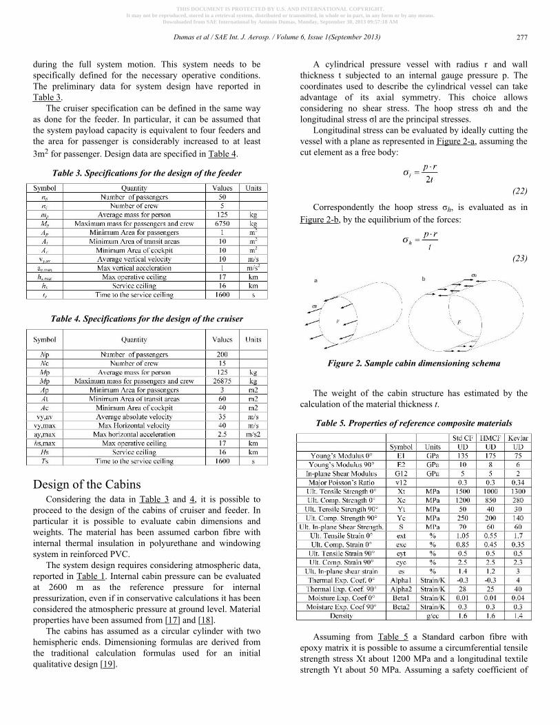
A cylindrical pressure vessel with radius r and wallthickness t subjected to an internal gauge pressure p. Thecoordinates used to describe the cylindrical vessel can takeadvantage of its axial symmetry. This choice allowsconsidering no shear stress. The hoop stress σh and thelongitudinal stress σl are the principal stresses.
Longitudinal stress can be evaluated by ideally cutting thevessel with a plane as represented in Figure 2-a, assuming thecut element as a free body:
(22)
Correspondently the hoop stress σh, is evaluated as inFigure 2-b, by the equilibrium of the forces:
(23)
Figure 2. Sample cabin dimensioning schema
The weight of the cabin structure has estimated by thecalculation of the material thickness t.
Table 5. Properties of reference composite materials
Assuming from Table 5 a Standard carbon fibre withepoxy matrix it is possible to assume a circumferential tensilestrength stress Xt about 1200 MPa and a longitudinal textilestrength Yt about 50 MPa. Assuming a safety coefficient of
Dumas et al / SAE Int. J. Aerosp. / Volume 6, Issue 1(September 2013) 277
THIS DOCUMENT IS PROTECTED BY U.S. AND INTERNATIONAL COPYRIGHT.It may not be reproduced, stored in a retrieval system, distributed or transmitted, in whole or in part, in any form or by any means.
Downloaded from SAE International by Antonio Dumas, Monday, September 30, 2013 09:57:18 AM
2.5 it can be verified that a cylinder with a radius of 2.5 mand thickness 0.003 m satisfies perfectly the requirements. Italso resists perfectly to the wind pressure at ground levelassuming a reference wind for structural calculations of 100m/s.
The thickness of internal insulation assuming that it isconstituted by polyurethane 40 kg/m3 foam with the propertyreported in table 1 [11] and [12]. It can be evaluatedassuming that a polyurethane foamed in place wall (40 kg/m3
and thickness of about 0.125 m is sufficient to ensure anoverall heat transfer coefficient U about 0.26 W/(m2K).
Table 6. Polyurethane properties
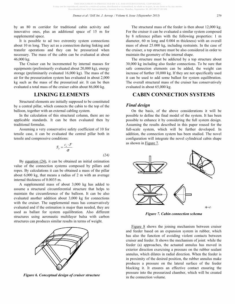
Feeder CabinThe section design shows clearly that it can be assumed
an internal radius about 2.375 m and a cord section of basisabout 2.05 m. Assuming the cabin section described in Figure2 it is possible to evaluate the dimensions of the cabin in alength of about 17 m plus spherical terminations. To ensurean adequate surplus in term of plant area, it can be assumed20m.
Figure 3. Section of the cabin
The final cabin design will be the one presented in Figure3. The total weight of cabin structure can be then estimatedassuming 0.002 m external carbon fibre, 0.125 mpolyurethane insulation and 0.001 m internal carbon fibrereinforcement.
The general mass of the structure is then about 3,520 kg.It needs to add the internal structure, which has beenevaluated in about 1,400 kg. The total structural weight it can
be then evaluated in about 5,000 kg. Considering the systemequipments including controls, chairs and controls,pressurization and acclimatization systems, avionics,hydrogen cylinders, etc., the global mass has conservativelyincremented of 5,000 kg. The total weight of the cabin atmaximum payload is then about 11,000 kg.
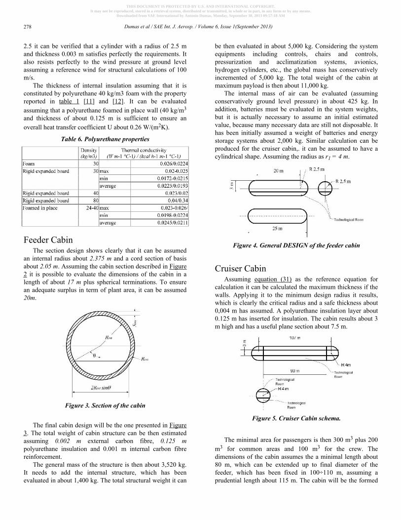
The internal mass of air can be evaluated (assumingconservatively ground level pressure) in about 425 kg. Inaddition, batteries must be evaluated in the system weights,but it is actually necessary to assume an initial estimatedvalue, because many necessary data are still not disposable. Ithas been initially assumed a weight of batteries and energystorage systems about 2,000 kg. Similar calculation can beproduced for the cruiser cabin,. it can be assumed to have acylindrical shape. Assuming the radius as r1 = 4 m.
Figure 4. General DESIGN of the feeder cabin
Cruiser CabinAssuming equation (31) as the reference equation for
calculation it can be calculated the maximum thickness if thewalls. Applying it to the minimum design radius it results,which is clearly the critical radius and a safe thickness about0,004 m has assumed. A polyurethane insulation layer about0.125 m has inserted for insulation. The cabin results about 3m high and has a useful plane section about 7.5 m.
Figure 5. Cruiser Cabin schema.
The minimal area for passengers is then 300 m3 plus 200m3 for common areas and 100 m3 for the crew. Thedimensions of the cabin assumes the a minimal length about80 m, which can be extended up to final diameter of thefeeder, which has been fixed in 100÷110 m, assuming aprudential length about 115 m. The cabin will be the formed
Dumas et al / SAE Int. J. Aerosp. / Volume 6, Issue 1(September 2013)278
THIS DOCUMENT IS PROTECTED BY U.S. AND INTERNATIONAL COPYRIGHT.It may not be reproduced, stored in a retrieval system, distributed or transmitted, in whole or in part, in any form or by any means.
Downloaded from SAE International by Antonio Dumas, Monday, September 30, 2013 09:57:18 AM
by an 80 m corridor for traditional cabin activity andinnovative ones, plus an additional space of 15 m forsupplemental space.
It is possible to ad two extremity system connectionsabout 10 m long. They act as a connection during linking andtransfer operations and they can be pressurized whennecessary. The mass of the cabin can be evaluated at about46,000 kg.
The Cruiser can be incremented by internal masses forequipments (preliminarily evaluated about 20,000 kg), energystorage (preliminarily evaluated 16,000 kg). The mass of theair for the pressurization system has evaluated in about 2,000kg such as the mass of the pressurized air. It can be thenevaluated a total mass of the cruiser cabin about 86,000 kg.
LINKING ELEMENTSStructural elements are initially supposed to be constituted
by a central pillar, which connects the cabin to the top of theballoon, together with an external cabling system.
In the calculation of this structural column, there are noapplicable standards. It can be then evaluated then bytraditional formulas.
Assuming a very conservative safety coefficient of 10 fortensile case, it can be evaluated the central pillar both intensile and compressive conditions:
(24)By equation (24), it can be obtained an initial estimation
value of the connection systems composed by pillars andropes. By calculations it can be obtained a mass of the pillarabout 6,000 kg, that means a radius of 2 m with an averageinternal thickness of 0.0035 m.
A supplemental mass of about 3,000 kg has added toassume a structural circumferential structure that helps tomaintain the circumference of the balloon. It can be alsoevaluated another addition about 3,000 kg for connectionswith the cruiser. The supplemental mass has conservativelyevaluated and if the estimation is major than needed, they areused as ballast for system equilibration. Also differentstructures using aeronautic multilayer balsa with carbonstructures can produces similar results in terms of weight.
Figure 6. Conceptual design of cruiser structure
The structural mass of the feeder is then about 12,000 kg.For the cruiser it can be evaluated a similar system composedby 8 reference pillars with the following properties: 1 mdiameter, 60 m long and 0.004 m thickness) with an overallmass of about 25.000 kg, including restraints. In the case ofthe cruiser, a top structure must be also considered in order tomaintain the geometry of the internal shape.
The structure must be addicted by a top structure about30,000 kg including also feeder connections. To be sure thatsafe connection elements can be added, the weight canincrease of further 10,000 kg. If they are not specifically usedit can be used to add some ballast for system equilibration.The overall structural mass of the cruiser has conservativelyevaluated in about 65,000 kg.
CABIN CONNECTION SYSTEMS
Final designOn the basis, of the above considerations it will be
possible to define the final model of the system. It has beenpossible to enhance it by considering the full system design.Assuming the results described in this paper reused for thefull-scale system, which will be further developed. Inaddition, the connection system has been studied. The novelconfiguration will integrate the novel cylindrical cabin shapeas shown in Figure 7.
Figure 7. Cabin connection schema
Figure 8 shows the joining mechanism between cruiserand feeder based on an expansion system in rubber, whichhas also the function of avoiding violent contacts betweencruiser and feeder. It shows the mechanism of joint: while thefeeder (a) approaches, the actuated annulus has moved inexterior direction exercising a pressure on the rubber sealantannulus, which dilates in radial direction. When the feeder isin proximity of the desired position, the rubber annulus makeproduces a pressure on the lateral surface of the feederblocking it. It ensures an effective contact ensuring thepressure into the pressurized chamber, which will be createdin the connection volume.
Dumas et al / SAE Int. J. Aerosp. / Volume 6, Issue 1(September 2013) 279
THIS DOCUMENT IS PROTECTED BY U.S. AND INTERNATIONAL COPYRIGHT.It may not be reproduced, stored in a retrieval system, distributed or transmitted, in whole or in part, in any form or by any means.
Downloaded from SAE International by Antonio Dumas, Monday, September 30, 2013 09:57:18 AM
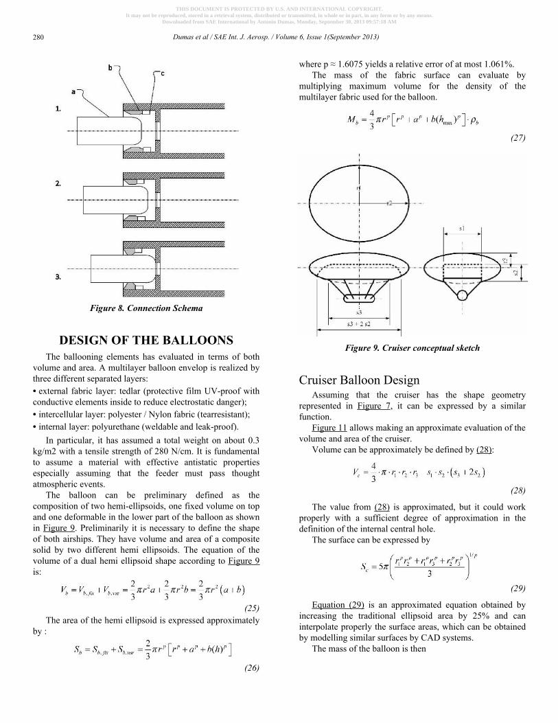
Figure 8. Connection Schema
DESIGN OF THE BALLOONSThe ballooning elements has evaluated in terms of both
volume and area. A multilayer balloon envelop is realized bythree different separated layers:• external fabric layer: tedlar (protective film UV-proof withconductive elements inside to reduce electrostatic danger);• intercellular layer: polyester / Nylon fabric (tearresistant);• internal layer: polyurethane (weldable and leak-proof).
In particular, it has assumed a total weight on about 0.3kg/m2 with a tensile strength of 280 N/cm. It is fundamentalto assume a material with effective antistatic propertiesespecially assuming that the feeder must pass thoughtatmospheric events.
The balloon can be preliminary defined as thecomposition of two hemi-ellipsoids, one fixed volume on topand one deformable in the lower part of the balloon as shownin Figure 9. Preliminarily it is necessary to define the shapeof both airships. They have volume and area of a compositesolid by two different hemi ellipsoids. The equation of thevolume of a dual hemi ellipsoid shape according to Figure 9is:
(25)The area of the hemi ellipsoid is expressed approximately
by :
(26)
where p ≈ 1.6075 yields a relative error of at most 1.061%.The mass of the fabric surface can evaluate by
multiplying maximum volume for the density of themultilayer fabric used for the balloon.
(27)
Figure 9. Cruiser conceptual sketch
Cruiser Balloon DesignAssuming that the cruiser has the shape geometry
represented in Figure 7, it can be expressed by a similarfunction.
Figure 11 allows making an approximate evaluation of thevolume and area of the cruiser.
Volume can be approximately be defined by (28):
(28)
The value from (28) is approximated, but it could workproperly with a sufficient degree of approximation in thedefinition of the internal central hole.
The surface can be expressed by
(29)
Equation (29) is an approximated equation obtained byincreasing the traditional ellipsoid area by 25% and caninterpolate properly the surface areas, which can be obtainedby modelling similar surfaces by CAD systems.
The mass of the balloon is then
Dumas et al / SAE Int. J. Aerosp. / Volume 6, Issue 1(September 2013)280
THIS DOCUMENT IS PROTECTED BY U.S. AND INTERNATIONAL COPYRIGHT.It may not be reproduced, stored in a retrieval system, distributed or transmitted, in whole or in part, in any form or by any means.
Downloaded from SAE International by Antonio Dumas, Monday, September 30, 2013 09:57:18 AM
(30)
Table 7. Feeder Volume in different conditions
Photovoltaic PlantPhotovoltaic plant has evaluated by assuming an area of
the plant about 90% of top surface of the cruiser and 20% ofthe feeder. In terms of productivity, it has estimated by theconclusions of a preceding paper of the authors [6]. It hasevaluated for a module with an average power of 200 W and13.5% efficiency.
Table 8. Forces and powers required by the feederduring vertical movements
Due to the increase of PV modules properties, it hasassumed that the efficiency has increased to about 18%. Theinstallation of the photovoltaic cells has been defined as athin laminate such as the one mounted on SolarWorld e-oneexperimental plane [23] with about 200W/m2 power installed.The nominal efficiency is 20% but it has reducedconservatively up to 18% to consider that some void spaces
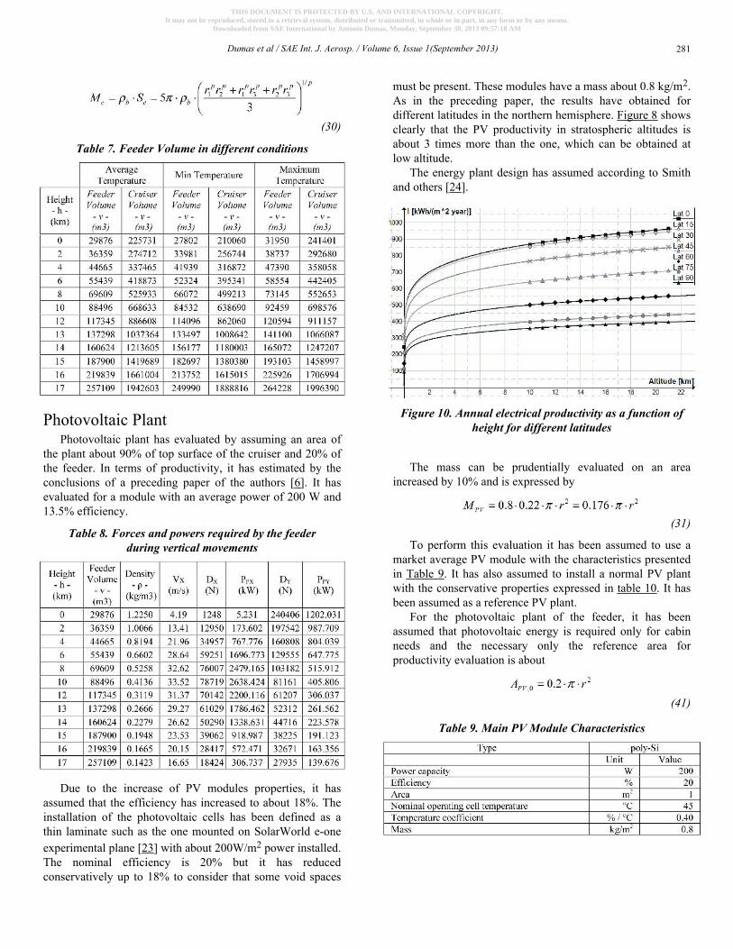
must be present. These modules have a mass about 0.8 kg/m2.As in the preceding paper, the results have obtained fordifferent latitudes in the northern hemisphere. Figure 8 showsclearly that the PV productivity in stratospheric altitudes isabout 3 times more than the one, which can be obtained atlow altitude.
The energy plant design has assumed according to Smithand others [24].
Figure 10. Annual electrical productivity as a function ofheight for different latitudes
The mass can be prudentially evaluated on an areaincreased by 10% and is expressed by
(31)
To perform this evaluation it has been assumed to use amarket average PV module with the characteristics presentedin Table 9. It has also assumed to install a normal PV plantwith the conservative properties expressed in table 10. It hasbeen assumed as a reference PV plant.
For the photovoltaic plant of the feeder, it has beenassumed that photovoltaic energy is required only for cabinneeds and the necessary only the reference area forproductivity evaluation is about
(41)
Table 9. Main PV Module Characteristics
Dumas et al / SAE Int. J. Aerosp. / Volume 6, Issue 1(September 2013) 281
THIS DOCUMENT IS PROTECTED BY U.S. AND INTERNATIONAL COPYRIGHT.It may not be reproduced, stored in a retrieval system, distributed or transmitted, in whole or in part, in any form or by any means.
Downloaded from SAE International by Antonio Dumas, Monday, September 30, 2013 09:57:18 AM
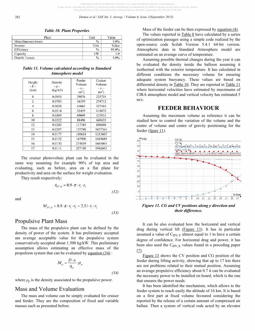
Table 10. Plant Properties
Table 11. Volume calculated according to StandardAtmosphere model
The cruiser photovoltaic plant can be evaluated in thesame way assuming for example 90% of top area andevaluating, such as before, area on a flat plane forproductivity and area on the surface for weight evaluation.
They result respectively:
(32)
and
(33)
Propulsive Plant MassThe mass of the propulsive plant can be defined by the
density of power of the system. It has preliminary acceptedam average acceptable value for the propulsive systemconservatively accepted about 1.500 kg/kW. This preliminaryassumption allows estimating an effective mass of thepropulsion system that can be evaluated by equation (34) :
(34)
where ρp is the density associated to the propulsive power.
Mass and Volume EvaluationThe mass and volume can be simply evaluated for cruiser
and feeder. They are the composition of fixed and variablemasses such as presented before.
Mass of the feeder can be then expressed by equation (4).The values reported in Table 8 have calculated by a series
of optimization passages using a simple code realized by theopen-source code Scilab Version 5.4.1 64-bit version.Atmospheric data in Standard Atmosphere model areestimated on an average curve of temperature.
Assuming possible thermal changes during the year it canbe evaluated the density inside the balloon assuming itisothermal with the exterior temperature. It has calculated indifferent conditions the necessary volume for ensuringadequate system buoyancy. These values are based ondifferential density in Table 10. They are reported in Table 11where horizontal velocities have estimated by maximums ofCIRA atmosphere model and vertical velocity has estimated 5m/s.
FEEDER BEHAVIOURAssuming the maximum volume as reference it can be
studied how to control the variation of the volume and thecentre of volume and centre of gravity positioning for thefeeder (fgure 11).
Figure 11. CG and CV positions along y direction andtheir difference.
It can be also evaluated how the horizontal and verticaldrag during vertical lift (Figure 13). It has in particularassumed a value of CDV,Y almost equal to 1 to have a certaindegree of confidence. For horizontal drag and power, it hasbeen also used the CDV,X values found in a preceding paper[7].
Figure 13 shows the CV position and CG position of thefeeder during lifting activity, showing that up to 17 km thereare not problems related to their mutual position. Assumingan average propulsive efficiency about 0.7 it can be evaluatedthe necessary power to be installed on board, which is the onethat ensures the power needs.
It has been identified the mechanism, which allows to thefeeder system to reach easily the altitude of 16 km. It is basedon a first part at fixed volume favoured considering thereported by the release of a certain amount of compressed airballast. Then a system of vertical rods acted by an elevator
Dumas et al / SAE Int. J. Aerosp. / Volume 6, Issue 1(September 2013)282
THIS DOCUMENT IS PROTECTED BY U.S. AND INTERNATIONAL COPYRIGHT.It may not be reproduced, stored in a retrieval system, distributed or transmitted, in whole or in part, in any form or by any means.
Downloaded from SAE International by Antonio Dumas, Monday, September 30, 2013 09:57:18 AM
moving on the central column varies the volume up to 14 km.After 14 km, the volume can be expanded by elasticity of theropes and of the tissue.
CRUISER BEHAVIOURThe cruiser is designed to remain airborne for long times
(months) and can be conceived in a much-simplified way. Inparticular, it can be conceived to lift as a heavyweightaerostatic balloon, which stabilizes its own shapeapproaching the operative ceiling. It can be then analyzed itsbehaviour only in proximity of the operative altitude.
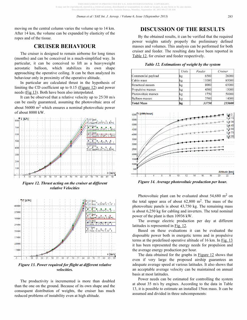
In particular are calculated thrust in the hypothesis oflimiting the CD coefficient up to 0.15 (Figure 12) and powerneeds (Fig 13). Both have been also interpolated.
It can be observed that a relative velocity up to 25/30 m/scan be easily guaranteed, assuming the photovoltaic area ofabout 56000 m2 which ensures a nominal photovoltaic powerof about 8000 kW.
Figure 12. Thrust acting on the cruiser at differentrelative Velocities
Figure 13. Power required for flight at different relativevelocities.
The productivity is incremented is more than doubledthan the one on the ground. Because of its own shape and theconsequent distribution of weights, the cruiser has muchreduced problems of instability even at high altitude.
DISCUSSION OF THE RESULTSBy the obtained results, it can be verified that the required
power weights satisfy properly the preliminary definedmasses and volumes. This analysis can be performed for bothcruiser and feeder. The resulting data have been reported inTable 12, for cruiser and feeder respectively.
Table 12. Estimations of weight by the system
Figure 14. Average photovoltaic production per hour.
Photovoltaic plant can be evaluated about 54,680 m2 onthe total upper area of about 62,800 m2. The mass of thephotovoltaic panels is about 43,750 kg. The remaining massis about 6,250 kg for cabling and inverters. The total nominalpower of the plant is then 10936 kW.
The average electric production per day at differentlatitudes is represented in Fig. 12.
Based on these evaluations it can be evaluated thedisposable power both in energetic terms and in propulsiveterms at the predefined operative altitude of 16 km. In Fig. 13it has been represented the energy needs for propulsion andthe average energy production per hour.
The data obtained for the graphs in Figure 12 shows thateven if very large the proposed airship guarantees anadequate average speed at various latitudes. It also shows thatan acceptable average velocity can be maintained on annualbasis at most latitudes.
Power needs can be estimated for controlling the systemat about 35 m/s by engines. According to the data in Table13, it is possible to estimate an installed 15ton mass. It can beassumed and divided in three subcomponents:
Dumas et al / SAE Int. J. Aerosp. / Volume 6, Issue 1(September 2013) 283
THIS DOCUMENT IS PROTECTED BY U.S. AND INTERNATIONAL COPYRIGHT.It may not be reproduced, stored in a retrieval system, distributed or transmitted, in whole or in part, in any form or by any means.
Downloaded from SAE International by Antonio Dumas, Monday, September 30, 2013 09:57:18 AM
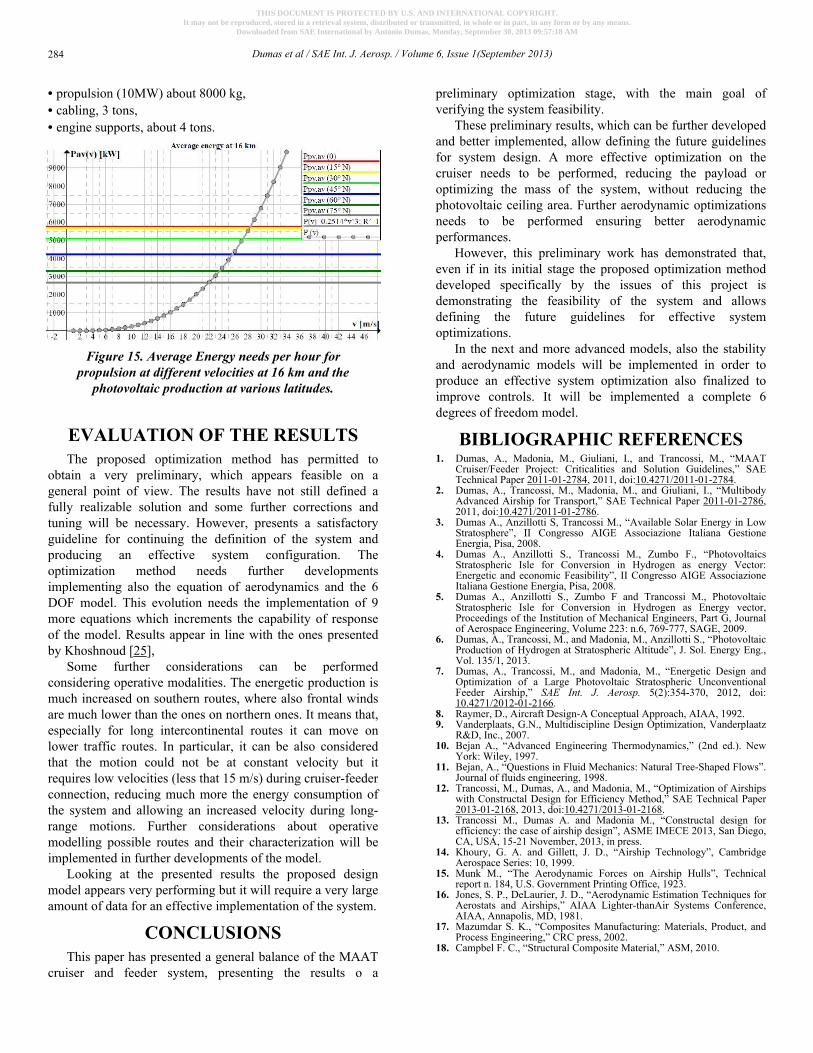
• propulsion (10MW) about 8000 kg,• cabling, 3 tons,• engine supports, about 4 tons.
Figure 15. Average Energy needs per hour forpropulsion at different velocities at 16 km and the
photovoltaic production at various latitudes.
EVALUATION OF THE RESULTSThe proposed optimization method has permitted to
obtain a very preliminary, which appears feasible on ageneral point of view. The results have not still defined afully realizable solution and some further corrections andtuning will be necessary. However, presents a satisfactoryguideline for continuing the definition of the system andproducing an effective system configuration. Theoptimization method needs further developmentsimplementing also the equation of aerodynamics and the 6DOF model. This evolution needs the implementation of 9more equations which increments the capability of responseof the model. Results appear in line with the ones presentedby Khoshnoud [25],
Some further considerations can be performedconsidering operative modalities. The energetic production ismuch increased on southern routes, where also frontal windsare much lower than the ones on northern ones. It means that,especially for long intercontinental routes it can move onlower traffic routes. In particular, it can be also consideredthat the motion could not be at constant velocity but itrequires low velocities (less that 15 m/s) during cruiser-feederconnection, reducing much more the energy consumption ofthe system and allowing an increased velocity during long-range motions. Further considerations about operativemodelling possible routes and their characterization will beimplemented in further developments of the model.
Looking at the presented results the proposed designmodel appears very performing but it will require a very largeamount of data for an effective implementation of the system.
CONCLUSIONSThis paper has presented a general balance of the MAAT
cruiser and feeder system, presenting the results o a
preliminary optimization stage, with the main goal ofverifying the system feasibility.
These preliminary results, which can be further developedand better implemented, allow defining the future guidelinesfor system design. A more effective optimization on thecruiser needs to be performed, reducing the payload oroptimizing the mass of the system, without reducing thephotovoltaic ceiling area. Further aerodynamic optimizationsneeds to be performed ensuring better aerodynamicperformances.
However, this preliminary work has demonstrated that,even if in its initial stage the proposed optimization methoddeveloped specifically by the issues of this project isdemonstrating the feasibility of the system and allowsdefining the future guidelines for effective systemoptimizations.
In the next and more advanced models, also the stabilityand aerodynamic models will be implemented in order toproduce an effective system optimization also finalized toimprove controls. It will be implemented a complete 6degrees of freedom model.
BIBLIOGRAPHIC REFERENCES1. Dumas, A., Madonia, M., Giuliani, I., and Trancossi, M., “MAAT
Cruiser/Feeder Project: Criticalities and Solution Guidelines,” SAETechnical Paper 2011-01-2784, 2011, doi:10.4271/2011-01-2784.
2. Dumas, A., Trancossi, M., Madonia, M., and Giuliani, I., “MultibodyAdvanced Airship for Transport,” SAE Technical Paper 2011-01-2786,2011, doi:10.4271/2011-01-2786.
3. Dumas A., Anzillotti S, Trancossi M., “Available Solar Energy in LowStratosphere”, II Congresso AIGE Associazione Italiana GestioneEnergia, Pisa, 2008.
4. Dumas A., Anzillotti S., Trancossi M., Zumbo F., “PhotovoltaicsStratospheric Isle for Conversion in Hydrogen as energy Vector:Energetic and economic Feasibility”, II Congresso AIGE AssociazioneItaliana Gestione Energia, Pisa, 2008.
5. Dumas A., Anzillotti S., Zumbo F and Trancossi M., PhotovoltaicStratospheric Isle for Conversion in Hydrogen as Energy vector,Proceedings of the Institution of Mechanical Engineers, Part G, Journalof Aerospace Engineering, Volume 223: n.6, 769-777, SAGE, 2009.
6. Dumas, A., Trancossi, M., and Madonia, M., Anzillotti S., “PhotovoltaicProduction of Hydrogen at Stratospheric Altitude”, J. Sol. Energy Eng.,Vol. 135/1, 2013.
7. Dumas, A., Trancossi, M., and Madonia, M., “Energetic Design andOptimization of a Large Photovoltaic Stratospheric UnconventionalFeeder Airship,” SAE Int. J. Aerosp. 5(2):354-370, 2012, doi:10.4271/2012-01-2166.
8. Raymer, D., Aircraft Design-A Conceptual Approach, AIAA, 1992.9. Vanderplaats, G.N., Multidiscipline Design Optimization, Vanderplaatz
R&D, Inc., 2007.10. Bejan A., “Advanced Engineering Thermodynamics,” (2nd ed.). New
York: Wiley, 1997.11. Bejan, A., “Questions in Fluid Mechanics: Natural Tree-Shaped Flows”.
Journal of fluids engineering, 1998.12. Trancossi, M., Dumas, A., and Madonia, M., “Optimization of Airships
with Constructal Design for Efficiency Method,” SAE Technical Paper2013-01-2168, 2013, doi:10.4271/2013-01-2168.
13. Trancossi M., Dumas A. and Madonia M., “Constructal design forefficiency: the case of airship design”, ASME IMECE 2013, San Diego,CA, USA, 15-21 November, 2013, in press.
14. Khoury, G. A. and Gillett, J. D., “Airship Technology”, CambridgeAerospace Series: 10, 1999.
15. Munk M., “The Aerodynamic Forces on Airship Hulls”, Technicalreport n. 184, U.S. Government Printing Office, 1923.
16. Jones, S. P., DeLaurier, J. D., “Aerodynamic Estimation Techniques forAerostats and Airships,” AIAA Lighter-thanAir Systems Conference,AIAA, Annapolis, MD, 1981.
17. Mazumdar S. K., “Composites Manufacturing: Materials, Product, andProcess Engineering,” CRC press, 2002.
18. Campbel F. C., “Structural Composite Material,” ASM, 2010.
Dumas et al / SAE Int. J. Aerosp. / Volume 6, Issue 1(September 2013)284
THIS DOCUMENT IS PROTECTED BY U.S. AND INTERNATIONAL COPYRIGHT.It may not be reproduced, stored in a retrieval system, distributed or transmitted, in whole or in part, in any form or by any means.
Downloaded from SAE International by Antonio Dumas, Monday, September 30, 2013 09:57:18 AM
19. VV. AA., “ANSI/AIAA S-080-1998, “Space Systems - MetallicPressure Vessels”, Pressurized Structures, and Pressure Components,”ANSI, 1998.
20. VV-AA., “Polyurethane Handbook”, Hanser Fachbuchverlag; Hanser /Gardner Publications. ed. 2009.
21. Shawyer, M.; Medina Pizzali, A.F., “The use of ice on small fishingvessels”. FAO Fisheries Technical Paper. No. 436, Rome, FAO, 2003.
22. Marckwardt K., “Unterlagen zur Vorlesung”, FlugzeugentwurfFachhochschule Hamburg, Fachbereich Fahrzeugtechnik, 1998.
23. SolarWorld e-One, Technical data and specifications, http://www.solarworld.de/en/group/sustainablemanagement/commitment/solarworld-e-one/
24. Smith T., Bingham C., Stewart P., Allarton R., and Steward J., “Energyharvesting and power network architectures for the multibody advancedairship for transport high altitude cruiser-feeder airship concept”,Proceedings of the Institution of Mechanical Engineers, Part G: Journalof Aerospace Engineering, April 2013 227: 586-598, 2013 doi:10.1177/0954410012469319
25. Khoshnoud F., Chen Y. K., Calay R. K., “On power and control systemsof the multibody advanced airship for transport”, International Journalof Modelling, Identification and Control, V. 18-4:313-322, 2013
CONTACT [email protected];
ACKNOWLEDGMENTSThe present work was performed as part of Project
MAAT | Multibody Advanced Airship for Transport | withref. 285602, supported by European Union through the 7thFramework Programme.
DEFINITIONS/ABBREVIATIONSh - Altitude [m]p - pressure [Pa]r - radius [m]t - fabbric thickness [m]u - velocity [m/s]
ρ - Density [kg/m3]
σ - Admissible stenght [N/mm2]CD,A - Drag coefficient expressed on the basis of frontal area
CD,V - Drag coefficient expressed on the basis of V2/3
D - Drag [N]Isol - Solar irradiance
M - Mass [kg]P - Power [kW]
S, A - Area [m2]T - Thrust [N]
U - W/(m2K).
V - Volume [m3]
Dumas et al / SAE Int. J. Aerosp. / Volume 6, Issue 1(September 2013) 285
THIS DOCUMENT IS PROTECTED BY U.S. AND INTERNATIONAL COPYRIGHT.It may not be reproduced, stored in a retrieval system, distributed or transmitted, in whole or in part, in any form or by any means.
Downloaded from SAE International by Antonio Dumas, Monday, September 30, 2013 09:57:18 AM


