Embed Size (px)
Citation preview

Volume 24 (2005), number 1 pp. 27–39 COMPUTER GRAPHICS forum
A Bidirectional Deposition Model of Wax Crayons
Dave Rudolf, David Mould and Eric Neufeld
Department of Computer Science, University of [email protected]
{mould,eric}@cs.usask.ca
AbstractWe present a physically inspired model of wax crayons, which synthesizes drawings from collections of user-specified strokes. Paper is represented by a height-field texture, and a crayon is modeled with a 2D mask thatevolves as it interacts with the paper. The amount of wax deposition is computed based on the crayon contactprofile, contact force and friction. Previously deposited wax is smeared by crayon action, based on wax softnessand contact information. Deposited wax can also be carved from the paper by the crayon and redeposited atanother location. The distributed wax is rendered using a simplified Kubelka–Monk model, which approximateslight transmission and scattering effects.
Keywords: nonphotorealistic rendering, procedural textures, interactive techniques.
ACM CCS: I.3.3 Computer Graphics: Line and curve generation, I.3.7 Computer Graphics: 3D Graphics andRealism: Color, Shading, Shadowing, Texture.
1. Introduction
Recent years have seen a proliferation of nonphotorealisticrendering (NPR) styles, such as oil painting, pen-and-inkillustration and copperplate engraving, among others. Onethread of research has involved simulating specific traditionalmedia, such as watercolors or pencils. In this paper, we de-scribe a drawing primitive designed to mimic wax crayons.
Wax crayons possess certain characteristics that make themchallenging to model. The crayon contact area is large enoughthat the paper cannot be treated as flat over the region of con-tact. The softness of wax is such that a substantial quantity ofwax adheres to the page, and that previously deposited waxcan be smeared and carved away by the action of later crayonstrokes. However, wax is much more viscous than paints andinks, and so its interactions are different than these other me-dia. Also, the crayon footprint can change shape over a shortperiod of time, changing substantially even within a singlestroke. Many different colors of wax crayon are commonlyin use, and the interaction between multiple translucent ma-terials offers a rendering challenge.
We present a method for simulating wax crayons basedon a physically inspired model of wax deposition, smear-
ing, and redeposition. Drawings are based on a collectionof user-specified strokes; the effect at each point along acrayon’s stroke is treated by first computing the crayon’s con-tact profile, then depositing wax from the crayon to the paper,updating the crayon shape, smearing and possibly carvingpreviously deposited wax. The final distribution of wax is ren-dered with a simplified Kubelka–Monk (KM) model, whichaccounts for light transmission and scattering through multi-ple layers of wax.
Wax crayons are archetypally associated with a certainhighly simplified drawing style. Despite the occasionallyonerous physical simulation we describe, we have endeav-ored to retain a sense of fun in the project, and we hope thatthis carries through in the childish artistic style of the imageswe present.
2. Previous Work
Originally, NPR branched from work in image processingand pattern recognition circles. The earliest work in NPRconsisted of specialized dithering techniques [1,2]. Edge de-tection and region extraction algorithms have been employedto decompose existing images or 3D models into their view-space elements: lines, curves, polygons, and the like [3,4].
c© The Eurographics Association and Blackwell Publishing Ltd2005. Published by Blackwell Publishing, 9600 GarsingtonRoad, Oxford OX4 2DQ, UK and 350 Main Street, Malden,MA 02148, USA. 27
Submitted December 2003Revised September 2004
Accepted December 2004

28 D. Rudolf et al./Bidirectional Deposition Model
The purpose of such work was to emphasize the importantfeatures of an object, and remove distracting details and im-perfections. From these basic building blocks, another area ofNPR research emerged: that which aims to simulate a partic-ular artistic style or medium, as we do in this paper. Graphicalprimitives are interpreted as artistic strokes or patches madeby the simulated artistic medium. Previous work simulatedmedia such as pencil sketches [3,4] and drawings [5,6,7],charcoal drawings [8], watercolor [9] and stained glass [10].Also, some work tries to simulate particular artistic styles,such as those of Dr. Seuss and Geoffrey Hayes [11].
Existing NPR methods follow distinct branches. One suchbranch makes use of the aforementioned image processingtechniques to extract primitives from 2D images and relateddata, such as depth buffers and stencil masks [3,12]. Alterna-tively, 3D geometry can be used directly [6,4,8,11]. Lastly,interactive systems have been developed that depend on user-defined input [13,9]. Our work falls into this last category,although we have designed our model to be independent ofthe source of input.
Techniques to represent artistic media vary widely, de-pending on the media being represented. A physically basedrepresentation of paper has been developed [7], but 2D heightmaps are widely used to represent the high-level texture ofpaper. Since a crayon’s contact surface is relatively large, wealso represent paper with height maps. With this approach,numerous texture synthesis methods have been employedto create visually appealing height maps [9,14,15]. We alsomake use of these methods.
In modeling actual artistic implements such as brushes andpencils, it is common practice to use a static 1D height maskto represent a cross-section of the implement perpendicularto the stroke path [3,4]. This simple representation limits thetypes of interaction that can be modeled. Some work uses tex-ture mapping to simulate artistic media in an abstract sense[5,8]. These methods assume that paper is relatively pre-dictable in structure. Other research makes use of 2D masksto represent an implement [9,13,16]. These models typicallyassume that the mask, once initialized, is static throughout itslifetime. Sousa and Buchanan [17] modeled graphite pencilsusing a polygon to represent the pencil tip. In their system,each vertex of the polygon is modified throughout the lengthof each stroke. Their method was used to represent a pencilthat could rotate and pivot, and also have nonuniform pressuredistributions. Points within the polygon must be interpolatedfrom the surrounding vertices, so there is a limit to the kindsof profiles that can be represented. The most dynamic modelof an artistic tool thus far was developed by Baxter et al. [18].Baxter’s work makes use of polygon meshes to represent dif-ferent styles of artistic brushes. These meshes deform as thebrush comes into contact with paper, accounting for springtension in the bristles.
Finally, some methods require an explicit rendering stepto generate the final image. A great deal of research has been
dedicated to volumetric rendering techniques [19] and lightscattering [20]. Takagi et al. [7] used such methods to ren-der their model of colored pencils. A volumetric approachis the most flexible, allowing arbitrary views of the modeledmedium. However, such an approach is also very costly, es-pecially for large number of pigment layers. A convenientcompromise is the KM color model, which has been used toapproximate the optical properties of translucent pigments[21]. This color model assumes that the viewing angle is nor-mal to the paper.
A deficiency of many current NPR techniques is that theymodel some amount of simple pigment deposition, apply theresults to an incrementally developed image, and then startthe next phase of deposition with an empty pigment model[13,9,3,4]. This eliminates the possibility of interaction be-tween deposition phases. Sousa and Buchanan [17] have suc-cessfully modeled smudging of graphite pencil, but consideronly a single pigment color. Baxter et al. [18] also allowedfor some level of smearing. Existing pigment is either con-sidered to be “wet” and will interact with the brush, or thepigment is “dry” and will not be considered for interaction.
Previous attempts have been made to generated crayon-likeimages. Adobe Systems® has included a conte crayon filterwith their distributions of Photoshop® for some time [16].This filter is simply a textured dither, and does not capture thetrue nature of wax. Kalnins et al. [13] have used brush masksin a stroke-based system to deposit wax onto a paper model,but they do not account for interaction between layers ofwax. Thus far, Corel Corporation’s PainterTM 8 [22] packagehas the most rigorous model of crayons. This system doesmodel wax interaction, similar to the work of Baxter et al.[18]. Corel’s model has two noticeable deficiencies. First,the color model used is a purely subtractive model. That is,it does not consider the light-scattering effect that is seenin real wax. When different colors of wax are blended, theydo not appear as real wax does. Second, the wax depositedby each stroke is immediately mixed with any previouslydeposited stroke, and the brush absorbs the resulting color.This would never occur with real crayons because of the highviscosity of wax. Typically, only the top layer of depositedwax will interact with the crayon. In this paper, we striveto eliminate the aforementioned discrepancies between realcrayon drawings and simulated ones.
3. Modeling Wax
We are concerned with how a crayon leaves its trail of waxas it passes across the surface of paper. Many physical pro-cesses affect the crayon. We forego a rigid physical model,and concentrate on the more prominent natural effects; ourrepresentation of wax is based on observation. To understandthe medium, we studied wax deposition using microscopyat different levels of magnification. Since wax has a highviscosity, our observations were done at relatively low mag-nification levels: between 6× and 75× zoom.
c© The Eurographics Association and Blackwell Publishing Ltd 2005

D. Rudolf et al./Bidirectional Deposition Model 29
In this section, we present the basic components of ourwax model. In particular, we discuss our representations ofwax crayons and paper, as well as our process for generat-ing paper texture. We then introduce the algorithm that de-scribes the interaction between a crayon and a paper texture.This algorithm first determines the crayon’s vertical positionwith respect to the underlying paper and a scalar force. Thecrayon’s location is then used to smear and carve wax thatwas previously deposited onto the paper, and also to depositnew wax. Lastly, we render the model using the KM method.
3.1. Representation of Media
We follow traditional methods of representing paper as a 2Dheight map [3,9]. Like recent work in NPR [17,18,7], oursystem must retain a record of deposited material throughoutthe evolution of the image. Because wax is easily smeared andcarved, we must keep a dynamic model of wax as it adheresto a static paper texture.
To do so, we maintain a column of wax layers at each cellof the paper texture. The columns are normal to the grossplane of the paper. Each layer has its own height, color, lighttransmittance and scattering properties, which are used in ourrendering algorithm (see Section 4). For efficiency, adjacentwax layers with the same properties are merged together.Also, sufficiently thin layers are blended with adjacent layers.Layer blending helps prevent the proliferation of extremelythin layers, mostly caused by wax smearing and redeposition(see Sections 3.6 and 3.7).
The actual crayon is modeled in a similar fashion. The pro-file of the crayon is also modeled as a 2D height map, whereheight values represent the crayon’s distance from the grossplane of the paper. Each cell in the crayon’s mask initiallycontains wax with the same color, transmittance, and scatter-ing properties. The height values in the 2D mask are modifiedas the crayon is worn down by friction.
Our dynamic mask allows us to model a variety of profilesthat real crayons would have. Using this method, we can rep-resent a variety of crayon tips. As seen in Figure 1, the maskcan represent a tip that is initially sharpened into a cone shape.Throughout a drawing stroke, the mask can be modified tosimulate the crayon tip as it is progressively abraded intoa blunt shape. Sharp features of the paper texture may evencarve minor ridges and hollows into the tip of the crayon. Thecrayon’s profile can also be tailored to represent the sharp-ened back-end rim, or even the long side of the crayon itself.Although the height map representation does prevent us frommodeling some possible wax configurations (mainly, verticalconcavities caused by extreme abrasion and adhesion), it issufficient for modeling interactions with widely used media,such as paper, which are relatively flat.
Each cell in the crayon mask also has an area property asso-ciated with it. This is done to counteract aliasing artifacts that
Figure 1: Example height profiles of crayons. Each of thefour images has a longitudinal view of a hypothetical crayonshape at the top, and the crayon mask that represents theshape at the bottom. The height of the masks’s cells is depictedby their intensity. The top-left image is a sharpened coniccrayon, the top right is the same crayon after abrasion, thebottom left is the flat back end of a crayon and the bottomright is the long side of a crayon.
were observed in our initial crayon renditions. Specifically,spurious stepping effects appeared when a stroke’s directionwas at a small angle (less than 20◦) from the Cartesian axes.Figure 2 shows examples of area profiles for round crayons.
As with the height field used to represent paper texture,the cells in the crayon mask can have layers of wax added tothem. This is done to mimic the way that loose flakes of waxare pressed against real crayons and carried to other locationsof the paper.
3.2. Generation of Paper Texture
When generating final images of crayon drawings, papertexture is an important consideration. Although our deposi-tion, smearing, and redeposition methods do not require any
c© The Eurographics Association and Blackwell Publishing Ltd 2005

30 D. Rudolf et al./Bidirectional Deposition Model
Figure 2: Example area profiles of crayons. The intensityof each crayon cell is inversely proportional to that cell’sassigned area. On the left is an aliased crayon mask, and onthe right is an anti-aliased mask. The true area of the crayonis shown in dark black on top of each mask.
Figure 3: Convolution mask used to generate van Wijk’slunar texture.
particular texture, they do depend on the texture. Real pa-per textures vary widely. Ideally, we should choose a texturethat approximates a kind of paper that is typically associatedwith wax crayons. In consequence, we have striven to find aheight field texture that is quite rough, akin to an inexpensiveconstruction paper that is commonly used by children.
We used the lunar texture postulated by van Wijk [15],which has a suitable combination of roughness and coher-ence. Our version of this texture was generated by convolvinga quarter-circle arc with a lattice populated by uniform noise.The convolution mask is shown in Figure 3 and an exampleof the texture thus derived is shown in Figure 4.
Our deposition and smearing algorithms (see Section 3.3)require that some texture be provided, but make no assump-tions about the nature of that texture. To test this aspect ofour model, we have also generated textures that are funda-mentally different than the aforementioned lunar texture. Forexample, we created a stippled texture by using a 2D maskto scale the amplitude of uniform noise. This mask is tiledacross the noise lattice to impose a repetitive structure uponthe generated texture. An example of one such texture is seenin Figure 4. Also shown in Figure 4 is a texture that was pho-tographically acquired from real construction paper. For thistexture, intensity values of the acquired image were used as
Figure 4: Wax deposition with different paper textures: lu-nar convolution (top), stipple restriction (center) and realconstruction paper acquired at 800 dpi (bottom).
the height values of the texture. Of course, the intensities ofconstruction paper may not be accurate measures of the con-struction paper’s height profile. The acquired texture is shownmerely as another example of our model’s robustness.
3.3. High-Level Interaction Algorithm
Our model of crayons mimics the dominant interactions thatare observed between real crayons and paper. First, we note
c© The Eurographics Association and Blackwell Publishing Ltd 2005

D. Rudolf et al./Bidirectional Deposition Model 31
Figure 5: Hypothetical interaction between crayon and pa-per: wax deposition (left) and smearing (right).
that wax is deposited by the crayon. The volume of depositedwax depends on the size of the contact area between thecrayon and paper, the slope of the paper over that area, andthe force that is exerted by the crayon onto the paper. Second,wax that has been deposited onto the paper can be smearedaround when the crayon passes over it. The smearing processpushes wax from the peaks of the paper texture, and downinto adjacent lower regions. Smearing also has a directionalcomponent, in that the crayon will push wax in its directionalheading. In this manner, wax can be pushed over ridges in thepaper. Figure 5 illustrates the interactions of a crayon withthe paper texture.
The flow of wax between a crayon and paper is bidirec-tional. A crayon deposits wax onto the paper, but it can alsolift deposited wax from the paper. The crayon may then trans-port the annexed wax and redeposit it at a different location.This process of redeposition is described in Section 3.7.
When creating wax renditions, we use lines and curvesas our drawing primitive. Although artists who work withacrylic crayons have other techniques at their disposal suchas dabbing, children typically use crayons for line drawings.Our method only requires that the directional heading of thecrayon be known at each step in the simulation. As such, ourmodel can support curved arcs such as splines.
To simulate a crayon stroke, we consider the endpointsP1 and P2, the crayon’s height mask M, the scalar force fapplied by the crayon to the paper, and the set C of colorproperties of the wax. For any given crayon position, wemust prepare the crayon, and modify the wax model. First,we adjust the crayon height values with respect to the appliedforce, the crayon’s height profile, and the profile of the paper(and the wax deposited on it) at the current location. Wethen use the new height values to modify the set of waxlayers L that lie on the paper. In modifying these layers, wefirst determine the amount of previously deposited wax thatcan be annexed by the crayon from the paper. The wax thatremains on the paper is then considered for smearing. Lastly,the crayon deposits new wax onto the paper, some of whichis wax that was carved off of the paper in an earlier time step.This process is summarized in Figure 6.
Of course, to draw a line, we only choose points Pi thatare appropriate for the resolution of our paper texture. In thefollowing sections, we give detailed algorithms for each ofprocedures in Figure 6.
Figure 6: Summary of the actions taken when a line is drawn.
3.4. Crayon Compression Due To Force
When drawing a line with a crayon, we must remove somevolume of wax from the crayon and deposit it onto the paperunderneath. The volume of deposited wax depends on thevalues of the crayon’s height mask, relative to the local heightof the paper. The simulation of all interactions between acrayon and paper are dependent on the vertical position ofthe crayon.
Since the crayon’s cells will potentially be worn away witheach movement, we must adjust the crayon’s overall heightat each step so that, at the next step, the crayon is exerting thesame amount of force upon the paper. To do so, we assumethat the wax compresses linearly, and use Hooke’s Law ofCompression to numerically determine the appropriate ver-tical displacement.
Hooke’s Law [23] can be written as
F = Y�L
L0A (1)
where Y is Young’s modulus constant, �L is the amount ofcompression, L0 is the unstressed length, and A is the cross-sectional area. If we assume that the length of the crayon L0 isapproximately constant, being much greater than the changein length �L, then we can reduce the above equation to:
F = λA�L. (2)
For the constant λ, we simply choose a value that producesaesthetically pleasing results.
We can sum up the force contributed by each crayon cellonto its corresponding paper cell, setting the contributionto zero if the crayon cell is above its paper cell. This latterstep prevents us from calculating the crayon’s displacementdirectly. We no longer have a continuous function to eval-uate, as the force is described by a piece-wise linear func-tion. Instead, we use Newton’s method to find a displacementthat gives us the desired amount of force, within some toler-ance ε. This tolerance can be chosen to suit the precision ofthe implementation, so that refinement stops when round-off
c© The Eurographics Association and Blackwell Publishing Ltd 2005

32 D. Rudolf et al./Bidirectional Deposition Model
Figure 7: Calculation of the crayon height values.
error is greater than the range of possible values. However,the cost of simulation is dramatically reduced when a suitabletolerance is imposed, with negligible visual difference in theresulting image. The error threshold that we have chosen touse is given in Table 1, along with other parameters of ourmodel.
To determine the vertical displacement of the crayon, weconsider the height of the crayon hmij at each mask cell mij,and the height of the paper hPij and also of all the waxlayers h L Pi j
at the corresponding location Pij. The crayonheight calculation is summarized in Figure 7. As seen inFigure 8, the amount of deposited wax varies with the appliedforce.
3.5. Frictional Deposition
Friction is the process by which wax is broken from thecrayon and deposited onto the paper. We model friction ontwo levels, macroscopic and microscopic. On a macroscopiclevel, we are concerned with the force of the crayon normalto the surface of the paper. As the crayon encounters convexfeatures in the paper’s texture, it leaves behind some quantityof wax. On a microscopic level, we use a coefficient of fric-tion to approximate the roughness of the paper on a smallerscale. The amount of deposited wax should be proportional
Figure 8: Wax deposition with different amounts of force.
to the frictional force, which is defined as
�FF = µ �FN = µ �N�N · �FC
‖ �N‖‖ �FC‖ (3)
where �FC is the force of the crayon on the feature’s surface;�FF, the force of friction; �FN, the crayon force normal to the
feature’s surface; �N , the surface normal of the feature and µ
is the coefficient of friction for the paper.
With our height-mapped paper texture, we interpolate ad-jacent height values to define a plane against which the crayonis moving, and calculate friction. This friction is determinedwith respect to that plane, the given scalar force being appliedto the paper by the crayon, and the directional heading of thecrayon itself (i.e., the direction of the stroke being drawn).
The value of µ depends on whether the crayon is inter-acting with clean paper or with paper that already has somewax. To add to the complications, a region of paper withan extremely thin layer of wax will have different frictionalproperties than a region with a thicker layer of wax. Cur-rent literature on the production of pulp and paper has littleto suggest an appropriate coefficient for paper alone. Whiletribology does offer insight into the wear properties of poly-mers and resins [24,25], it is difficult to determine the ratiosof esters, fatty acids, alcohols and hydrocarbons present inwax crayons. Since our model is not rigorously analytical, weartistically choose the two friction coefficients, and smooththe transition between them for thin layers of wax.
To deposit wax, we consider the point P at which the crayonis located, the crayon’s directional heading �V , the crayon’sheight mask M, the set of color properties C of the crayon, and
c© The Eurographics Association and Blackwell Publishing Ltd 2005

D. Rudolf et al./Bidirectional Deposition Model 33
Figure 9: The method for moving wax from the crayon tothe paper.
scalar force f which is normal to the gross plane of the paper.The wax deposited at each point Pij is added to the set oflayers LPij at that point. An example of wax deposition usingour model is shown in Figure 12. The method for computingdeposition appears in Figure 9.
In our algorithm, we compute several intermediate results.First, we find the point P ′
i j that is along the crayon’s headingand is closest to one of the eight neighbors. We use P ′
i j to
find the upcoming slope vector �Si j of the paper along the pathof the crayon. We also determine the force vector �Fi j and acoefficient of friction µi j given the amount of previouslydeposited wax.
3.6. Smearing
Smearing is a characteristic of the medium of wax, in thesame way that bleeding is a characteristic of watercolors. Asa crayon moves across paper, it smears the wax into adja-cent regions. Both newly and previously deposited wax aresmeared. To simulate smearing, we employ a smearing maskthat encompasses the current paper cell and its eight neigh-bors. Each value in the mask determines the proportion ofwax that is to be moved from the center cell to the cell un-derneath the given mask location. This smearing mechanismonly considers the effects of a single grid cell and its eightneighbors. Because of the viscosity of wax, we assume thatthe vast majority of the involved pressure is absorbed by theimmediate neighbors. Such an assumption would not holdfor pastels or softer media. With real pastels, pressure wouldbe propagated a greater distance.
To generate the smearing mask, we consider the relativelocation of each value (x , y), the height of the paper (and its
Figure 10: Pseudocode for the smearing algorithm.
wax) �z at that location, and the directional heading �V of thecrayon. Mask elements are given by the following equation:
Sxy = 1
‖−→
(x, y) ‖(α�z + β (x, y) · V
). (4)
We set the center mask value S0,0 to zero, so that we avoid“smearing” wax back onto itself.
In the above algorithm, we determine smearing factors torepresent the relative portions of deposited wax that smearedas a result of fluidic flow (s f) and directional pulling (s d).The values of α and β can be chosen to match a particularsmear pattern, or can be proportional to the crayon’s scalarvelocity. Once the mask is constructed, it is normalized to awax viscosity factor ν. The wax layers are then removed fromthe current paper cell, and distributed to the eight neighborsaccording to their mask values. Smearing is summarized inFigure 10. Some results from our smearing algorithm areshown in Figure 12.
3.7. Redeposition
One of the properties of wax is that it is self-adhesive. Asa crayon moves across the paper, it will carve out wax thathas already been deposited on the paper. The resulting loosevolume of wax may then be pressed against the crayon, whereit will be carried along to be deposited again to a differentregion of the paper. The effect of this redeposition process isquite evident in real crayons. Strokes that move over existingwax tend to show light streaks of the original wax pigments.We account for wax redeposition in a manner similar to thebidirectional deposition used by Baxter et al. [18] for paint
c© The Eurographics Association and Blackwell Publishing Ltd 2005

34 D. Rudolf et al./Bidirectional Deposition Model
pigments. In the Baxter model, a brush’s pigment color isblended with pigments that are on the canvas. This blendingoccurs for each time step of the simulation. As the brushmoves across the canvas, the presence of the brush’s originalcolor will decay exponentially until the brush contains onlypigments that it has absorbed from the canvas.
Because of the high viscosity of wax, the pigments in oursystem do not mix in the same manner as paints. Instead, lay-ers of wax are removed from the paper and placed back ontothe crayon. In this way, the reclaimed wax will be redepositedin a linear fashion, rather than exponential. Also, paint on acanvas will begin mixing with a brush’s pigment as soon asthe brush comes into contact with the canvas. However, nosignificant volume of deposited crayon wax will stick to thecrayon on mere contact. The crayon must carve the wax offof the paper. Thus, the reclaimed wax accumulates in frontof convex features of the crayon, relative to the stroke direc-tion. To simulate the directional nature of wax reclamation,we first determine the amount of wax to be reclaimed by thecrayon from the paper. We then use a mask S that encompassesthe current crayon cell and its eight neighbors, similar to thesmearing mask described in Section 3.6. This mask storesthe cosine of the angle between each of its cell positions andthe directional heading of the crayon. Figure 11 shows thedetails of our wax reclaiming method. Note that the distribu-tion mask S depends only on the heading of the crayon �V , thescalar force f , and an artistically chosen reclamation factor γ .Thus, S can be precomputed at the start of each linear crayonstroke. The effects of our redeposition method can be seen inFigure 12.
3.8. Parameters of the Model
Although we have not attempted to construct a thorough phys-ical simulation of wax, our model is quite flexible. Variousparameters in our system can be adjusted to represent otherartistic media. Table 1 summarizes these parameters and givesthe values we used.
4. Rendering
We next turn our attention to generating images from the waxmodel. Wax is best treated as a translucent pigment, so simpleadditive and subtractive color models such as RGB and CMYare inadequate. Instead, we employ a simplified KM model[21]. The KM model approximates spectral transmittance,scattering and interference. The value of these properties canbe inferred by two specified colors [9]. Each of these colors isthe observed result of a layer of pigment overtop of uniformbackground: one is the result with a black background, andthe other with a white background. From these two resultingcolors, KM theory provides a means of interpolating the colorthat results from an arbitrarily thick layer of pigment withany given background. The KM model does so by inferring
Figure 11: Algorithm for reclaiming deposited wax.
Table 1: Parameters of our model
Symbol Description Value
µwax Frictional coefficient of wax 0.5µpaper Frictional coefficient of paper 2ν Viscosity of wax 0.5α Flow smear factor 0.2β Directional smear factor 1 − α
γ Wax Reclamation factor 0.35λ Wax compression resistance factor 0.0005ε Force accuracy factor λ/4
how much light is scattered by the pigment medium, and howmuch is transmitted through the medium. The KM model alsoapproximates changes in hue due to thin-film interference.
In our model, we ignore interference effects, as we did notobserve them to contribute significantly to real crayon draw-ings. Consequently, each crayon is associated with a singleRGB color property, as well as transmittance and scatter-ing factors. These factors apply equally to all three colorchannels.
As mentioned previously, extremely thin layers of waxare merged together. The optical properties of the resultinglayer are set to weighted averages of the two layers that weremerged. Each layer’s contribution to the resulting blendedlayer is proportional to its height. This is a gross simplifi-cation of the KM model, but still produces acceptable re-sults and significantly decreases the computational cost ofthe smearing algorithm.
To render the wax model, we consider the color of thepaper texture CPij at each point Pij on the paper. To calculate
c© The Eurographics Association and Blackwell Publishing Ltd 2005

D. Rudolf et al./Bidirectional Deposition Model 35
Figure 12: Modeled interaction between crayon and paper:wax deposition (top), smearing (center) and redeposition(bottom). All images consist of a stroke of a dark coloredwax, followed by a stroke of a light colored.
the color that results from a layer of wax l k ∈ L Pi j , we makeuse of the layer’s colour C lk , its transmittance tlk , and itsreflectance rlk . Details of the calculation are given in Figure13.
We have endeavored to duplicate the optical properties ofcommon children’s crayons. Figure 14 illustrates the opticalproperties of our generated crayons, as compared to real waxcrayons. Table 2 lists the crayons we simulated and theirempirically determined properties.
5. Results
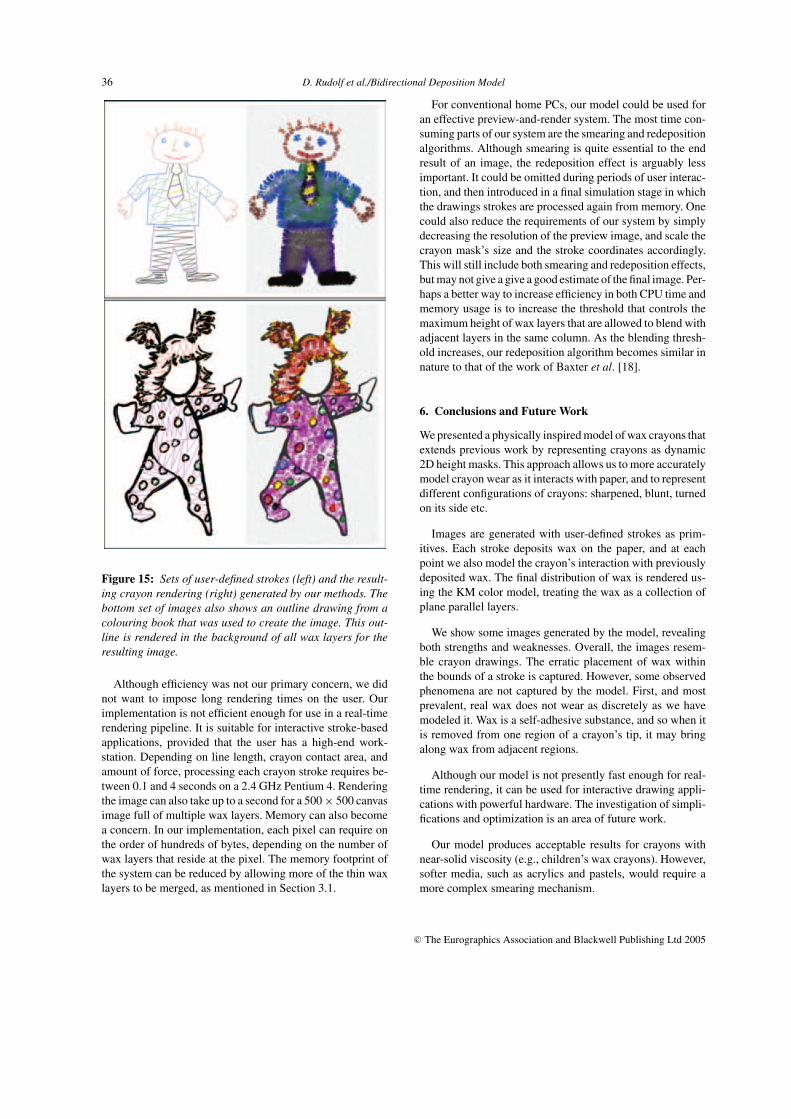
Figure 15 shows examples of final images. In the first im-age, interaction between colors is visible, particularly at the
Figure 13: Our simplified KM rendering algorithm.
Figure 14: Appearance of real wax crayons (top) and ourgenerated crayons (bottom).
Table 2: Optical properties of simulated crayons
Crayon Colour R G B t s
Red 0.95 0.45 0.45 0.605 0.0425
Orange 0.999 0.55 0.3 0.77 0.03
Yellow 0.95 0.9 0.2 0.869 0.0425
Green 0.35 0.8 0.35 0.55 0.06
Blue 0.3 0.5 0.9 0.77 0.045
Purple 0.65 0.45 0.75 0.715 0.05
Brown 0.8 0.6 0.55 0.495 0.075
Black 0.26 0.25 0.245 0.935 0.05
Grey 0.42 0.4 0.39 0.594 0.275
White 0.8 0.8 0.78 0.88 0.175
Periwinkle 0.7 0.7 0.9 0.605 0.125
Sea-green 0.6 0.9 0.65 0.55 0.1
Orchid 0.85 0.4 0.84 0.88 0.075
edges of the man’s tie. We can also see the effects of dif-fering friction on the man’s shirt: the periwinkle crayon wasapplied first, and when the sea-green crayon was used it pref-erentially deposited wax in regions that had been bare. Inter-action between colors is also apparent in the second image,particularly in the red and yellow portions of the character’shair, and on the polkadots of the pajamas. This image alsodemonstrates the scattering component of our KM model:the crayons’ colours are visible even when the backgroundis black. Figure 16 has more examples of drawings that weregenerated by our methods.
c© The Eurographics Association and Blackwell Publishing Ltd 2005
36 D. Rudolf et al./Bidirectional Deposition Model
Figure 15: Sets of user-defined strokes (left) and the result-ing crayon rendering (right) generated by our methods. Thebottom set of images also shows an outline drawing from acolouring book that was used to create the image. This out-line is rendered in the background of all wax layers for theresulting image.
Although efficiency was not our primary concern, we didnot want to impose long rendering times on the user. Ourimplementation is not efficient enough for use in a real-timerendering pipeline. It is suitable for interactive stroke-basedapplications, provided that the user has a high-end work-station. Depending on line length, crayon contact area, andamount of force, processing each crayon stroke requires be-tween 0.1 and 4 seconds on a 2.4 GHz Pentium 4. Renderingthe image can also take up to a second for a 500 × 500 canvasimage full of multiple wax layers. Memory can also becomea concern. In our implementation, each pixel can require onthe order of hundreds of bytes, depending on the number ofwax layers that reside at the pixel. The memory footprint ofthe system can be reduced by allowing more of the thin waxlayers to be merged, as mentioned in Section 3.1.
For conventional home PCs, our model could be used foran effective preview-and-render system. The most time con-suming parts of our system are the smearing and redepositionalgorithms. Although smearing is quite essential to the endresult of an image, the redeposition effect is arguably lessimportant. It could be omitted during periods of user interac-tion, and then introduced in a final simulation stage in whichthe drawings strokes are processed again from memory. Onecould also reduce the requirements of our system by simplydecreasing the resolution of the preview image, and scale thecrayon mask’s size and the stroke coordinates accordingly.This will still include both smearing and redeposition effects,but may not give a give a good estimate of the final image. Per-haps a better way to increase efficiency in both CPU time andmemory usage is to increase the threshold that controls themaximum height of wax layers that are allowed to blend withadjacent layers in the same column. As the blending thresh-old increases, our redeposition algorithm becomes similar innature to that of the work of Baxter et al. [18].
6. Conclusions and Future Work
We presented a physically inspired model of wax crayons thatextends previous work by representing crayons as dynamic2D height masks. This approach allows us to more accuratelymodel crayon wear as it interacts with paper, and to representdifferent configurations of crayons: sharpened, blunt, turnedon its side etc.
Images are generated with user-defined strokes as prim-itives. Each stroke deposits wax on the paper, and at eachpoint we also model the crayon’s interaction with previouslydeposited wax. The final distribution of wax is rendered us-ing the KM color model, treating the wax as a collection ofplane parallel layers.
We show some images generated by the model, revealingboth strengths and weaknesses. Overall, the images resem-ble crayon drawings. The erratic placement of wax withinthe bounds of a stroke is captured. However, some observedphenomena are not captured by the model. First, and mostprevalent, real wax does not wear as discretely as we havemodeled it. Wax is a self-adhesive substance, and so when itis removed from one region of a crayon’s tip, it may bringalong wax from adjacent regions.
Although our model is not presently fast enough for real-time rendering, it can be used for interactive drawing appli-cations with powerful hardware. The investigation of simpli-fications and optimization is an area of future work.
Our model produces acceptable results for crayons withnear-solid viscosity (e.g., children’s wax crayons). However,softer media, such as acrylics and pastels, would require amore complex smearing mechanism.
c© The Eurographics Association and Blackwell Publishing Ltd 2005

D. Rudolf et al./Bidirectional Deposition Model 37
Figure 16: Sample images generated with our wax deposition model.
c© The Eurographics Association and Blackwell Publishing Ltd 2005

38 D. Rudolf et al./Bidirectional Deposition Model
Refinements to our model would make it more generallyapplicable, both to modeling wax crayons and to related me-dia such as acrylics. We have only marginally accounted forthe orientation of the crayon itself. We could incorporate morecomplicated mechanics by using methods such as those ofSousa and Buchanan [17].
Much work still remains in simulating the predominantdrawing style associated with wax crayons. Some existingwork tries to model the imperfect stroke patterns that hu-mans produce [3,4,6], but we are not aware of any work onmodeling the drawing styles of children.
Future work also lies in connecting our stroke primitivewith a system that automatically deploys strokes. The com-bined system would provide a wax crayon filter, turning outcrayon renditions of arbitrary 2D images, or drawings madefrom 3D geometry.
Acknowledgements
Thank you to Mario Sousa for his questions and commentsabout our work. Special thanks to Nicole Haddock, DenyseKlette, and the rest of the Belly Button BuddiesTM, as wellas Cory Palmer, all for allowing us to scribble on theirillustrations.
References
1. L. Velho and J. de Miranda Gomes. Digital halftoningwith space filling curves. In Proceedings of the 18th An-nual Conference on Computer Graphics and InteractiveTechniques, pp. 81–90. ACM Press, 1991.
2. O. Veryovka and J. Buchanan. Halftoning with image-based dither screens. Graphics Interface, pp. 167–174,June 1999.
3. T. Strothotte and S. Schlechtweg. Non-PhotorealisticComputer Graphics: Modeling, Rendering, and Anima-tion. Morgan Kaufmann, Natick, MA, USA, 2002.
4. B. Gooch and A. Gooch. Non-Photorealistic Rendering.A.K. Peters, Ltd., New York, 2001.
5. A. Lake, C. Marshall, M. Harris, and M. Blackstein. Styl-ized rendering techniques for scalable real-time 3D ani-mation. In Proceedings of the First International Sympo-sium on Non-Photorealistic Animation and Rendering,pp. 13–20. ACM Press, 2000.
6. A. Mohr and M. Gleicher. HijackGL: reconstruct-ing from streams for stylized rendering. In Proceed-ings of the Second International Symposium on Non-Photorealistic Animation and Rendering, pp. 13–ff.ACM Press, 2002.
7. S. Takagi, M. Nakajima, and I. Fujishiro. Volumetricmodeling of colored pencil drawings. Proceedings of theSeventh Pacific Conference on Computer Graphics andApplications (Pacific Graphics), p. 250, October 5–7,1999, Seoul, Korea.
8. A. Majumder and M. Gopi. Hardware accelerated realtime charcoal rendering. In Proceedings of the SecondInternational Symposium on Non-Photorealistic Anima-tion and Rendering, pp. 59–66. ACM Press, 2002.
9. C. J. Curtis, S. E. Anderson, J. E. Seims, K. W. Fleis-cher and D. H. Salesin. Computer-generated watercolor.In Proceedings of the 24th Annual Conference on Com-puter Graphics and Interactive Techniques, pp. 421–430.ACM Press/Addison-Wesley Publishing Co., 1997.
10. D. Mould. A stained glass image filter. Proceedings of theEurographics Symposium on Rendering 2003, 16(1):20–25, June 2003.
11. M. A. Kowalski, L. Markosian, J. D. Northrup, L. Bour-dev, R. Barzel, L. S. Holden and J. F. Hughes. Art-based rendering of fur, grass, and trees. In Proceedingsof the 26th Annual Conference on Computer Graph-ics and Interactive Techniques, pp. 433–438. ACMPress/Addison-Wesley Publishing Co., 1999.
12. S. M. F. Treavett and M. Chen. Pen-and-ink renderingin volume visualisation. In Proceedings of the Confer-ence on Visualization ’00, pp. 203–210. IEEE ComputerSociety Press, 2000.
13. R. D. Kalnins, L. Markosian, B. J. Meier, M. A. Kowal-ski, J. C. Lee, P. L. Davidson, M. Webb, J. F. Hughesand A. Finkelstein. WYSIWYG NPR: drawing strokesdirectly on 3d models. In Proceedings of the 29th An-nual Conference on Computer Graphics and InteractiveTechniques, pp. 755–762. ACM Press, 2002.
14. K. Perlin. An image synthesizer. In Proceedings of the12th Annual Conference on Computer Graphics and In-teractive Techniques, pp. 287–296. ACM Press, 1985.
15. J. J. van Wijk. Spot noise: Texture synthesis for datavisualization. Computer Graphics (Proceedings of SIG-GRAPH 91, Las Vegas, Nevada), 25(4):309–318, July1991. ISBN 0-201-56291-X.
16. Adobe Systems Inc. Adobe Photoshop 5.5 Classroom ina Book, August 1999.
17. M. C. Sousa and J. W. Buchanan. Computer-generatedgraphite pencil rendering of 3D polygonal models. Com-puter Graphics Forum, 18(3), 1999.
18. B. Baxter, V. Scheib, M. C. Lin and D. Manocha. Dab:interactive haptic painting with 3d virtual brushes. In
c© The Eurographics Association and Blackwell Publishing Ltd 2005

D. Rudolf et al./Bidirectional Deposition Model 39
Proceedings of the 28th Annual Conference on Com-puter Graphics and Interactive Techniques, pp. 461–468.ACM Press, 2001.
19. P. Lacroute and M. Levoy. Fast volume rendering using ashear-warp factorization of the viewing transformation.In Proceedings of the 21st Annual Conference on Com-puter Graphics and Interactive Techniques, pp. 451–458.ACM Press, 1994.
20. H. W. Jensen, S. R. Marschner, M. Levoy, and P. Han-rahan. A practical model for subsurface light transport.In Proceedings of the 28th Annual Conference on Com-puter Graphics and Interactive Techniques, pp. 511–518.ACM Press, 2001.
21. C. S. Haase and G. W. Meyer. Modeling pigmented ma-terials for realistic image synthesis. ACM Transactionson Graphics (TOG), 11(4):305–335, 1992.
22. Corel Corp. Corel Painter 8 User’s Guide, 2003.
23. J. D. Cutnel and K. W. Johnson. Physics, 3rd ed. JohnWiley and Sons, Inc., New York, 1995.
24. B. Bhushan and B. K. Gupta. Handbook of Tribology:Materials, Coatings, and Surface Treatments. McGraw-Hill, New York, 1991.
25. Plastics Design Library. Fatigue and Tribological Prop-erties of Plastics and Elastomers, 1995.
c© The Eurographics Association and Blackwell Publishing Ltd 2005


