Embed Size (px)
Citation preview

INSTITUTE OF PHYSICS PUBLISHING SMART MATERIALS AND STRUCTURES
Smart Mater. Struct. 14 (2005) 1–7 doi:10.1088/0964-1726/14/0/000
A biomimetic undulatory tadpole robotusing ionic polymer–metal compositeactuatorsByungkyu Kim1,4, Deok-Ho Kim2,5, Jaehoon Jung2 andJong-Oh Park3
1 School of Aerospace and Mechanical Engineering, Hankuk Aviation University,Kyonggi-Do, 412-791, Korea2 Microsystem Research Center, Korea Institute of Science and Technology, PO Box 131,Cheongryang, Seoul, 130-650, Korea3 School of Mechanical Systems Engineering, Chonnam National University, Gwangju,500-757, Korea
E-mail: [email protected]
Received 26 October 2004PublishedOnline at stacks.iop.org/SMS/14/1
Ascii/Word/SMS/
sms210355/PAP
Printed 31/10/2005
Issue noTotal pagesFirst pageLast pageFile nameDate reqArtnum
Cover date
AbstractThe development of a wireless undulatory tadpole robot using ionicpolymer–metal composite (IPMC) actuators is presented. In order toimprove the thrust of the tadpole robot, a biomimetic undulatory motion ofthe fin tail is implemented. The overall size of the underwater microrobotprototype, shaped as a tadpole, is 96 mm in length, 24 mm in width, and25 mm in thickness. It has one polymer fin tail driven by the cast IPMCactuator, an internal (wireless) power source, and an embedded controller.The motion of the tadpole microrobot is controlled by changing thefrequency and duty ratio of the input voltage. Experimental results showthat this technique can accurately control the steering and swimming speedof the proposed underwater tadpole robot.
(Some figures in this article are in colour only in the electronic version)
1. Introduction
Biomimetic underwater microrobots are of great interestfor exploring unstructured underwater environments and forQ.1
Q.2 microsurgery within blood vessels for minimally invasivemedicine [1–9]. The design of highly maneuverableunderwater microrobots is often based on the swimmingmechanism and anatomic structure of fish primarily usingundulatory body motion, highly controllable fins and optimalthrust. Furthermore, the requirement of a wireless energysupply for underwater microrobots has been addressed forpractical applications [1, 8].
Underwater microrobots using giant magnetostrictiveactuators (GMA) [1], piezoelectric (PZT) actuators [3, 9],shape memory alloy (SMA) actuators [2, 6], and polymer
4 Author to whom any correspondence should be addressed.5 Current address: Department of Biomedical Engineering, School ofMedicine, Johns Hopkins University, Baltimore, MD 21218, USA.
actuators [4, 5] have been reported. Many of these previousprototypes have suffered from electrical leakage, lack of safetyin water, insufficient compactness, and stiff actuators. Q.3
Biomimetic fish-like propulsion using an ionic polymer–metal composite (IPMC) as a propulsion tail fin in water or anaqueous medium has been proposed [7, 8]. Compared with theavailable actuation methods mentioned above, IPMC actuationdemonstrates significant potential in providing a propulsiontail fin for underwater microrobots. IPMC is physically lightand flexible in nature. It has a suitable response time andhigh bending motion for an underwater microrobot swimmingstructure. It also uses low driving voltages (<3 V) and operateswell in an aqueous environment [10, 11]. For example,the stress generated by an IPMC is small compared to thatgenerated by shape memory alloys (SMAs) and lead zirconiumtitanate (PZT), while the strain is much higher. The efficiencyof IPMC is higher than that of SMA and almost the same asthat of PZT [12]. More information on IPMC actuators can befound in [13, 14].
0964-1726/05/000001+07$30.00 © 2005 IOP Publishing Ltd Printed in the UK 1

B Kim et al
Figure 1. Bending motion of IPMC actuator upon applying anelectric field.
This paper focuses on the development of a wirelesstadpole robot capable of high thrust, based on biomimeticundulatory motion, using cast IPMC actuators. Our previousstudies [15–17] reported on the casting process for commercialNafionTM films, which enabled us to make thick films forimproving the force generation of IPMC actuators. Forunderwater microrobots with improved thrust, we investigatedthe undulatory motion of the tadpole in Nature and employeda cast IPMC actuator as a propulsion tail fin for mimicking theundulatory tadpole robot in water. The design and evaluationof the tadpole microrobot is the subject of this paper.
The paper is structured as follows. In section 2, thepreparation of cast IPMC actuators is described. In section 3,the design of the biomimetic tadpole robot integrated with castIPMC actuators is described. In section 4, the motion andsteering capability of the underwater tadpole-like robot arediscussed, with experimental results. Finally, conclusions aregiven in section 5.
2. Preparation of cast IPMC actuators
IPMC is an electroactive polymer that bends in response tothe electrical potential. The mechanism of the bending motionof an IPMC actuator is illustrated in figure 1. As the voltageis applied, the hydrated cations in the NafionTM film move tothe negatively charged electrode. As a result of the volumechange inside the NafionTM film, the IPMC actuator bends tothe negatively charged side.
IPMC presents significant advantages as a propulsion tailfin for underwater microrobots; it is lightweight and flexible,exhibits a high displacement when actuated, requires onlya low driving voltage (<3 V), and operates well in a wetenvironment. For these reasons, we employed the IPMCactuator as a propulsion tail fin for mimicking undulatorytadpole-like propulsive motion in water.
Commercially available ion-exchange polymer films havea limitation in thickness. To control the thickness ofion-exchange polymer films, the casting method developedpreviously [15, 16] was used in this study. During thecasting procedure, liquid NafionTM is transformed into asolid film and the thickness of the film is controlled. Ourprevious study [15, 16] showed that the use of the casting
(A)
(B)
(C)
(D)
(E)
NafionTM solution into casting mold and dried
Strip off cast Nafion-film
Cast Nafion TM film
Thermal treatment
IPMC electrodes depositedby electro-less plating
Figure 2. Fabrication procedure for cast IPMC actuators.
Figure 3. 3D rapid prototyping of a tadpole-like robot.
method to fabricate an IPMC actuator with lower thicknessis advantageous for achieving larger displacement and lowerpower consumption than for the commercially available ion-exchange polymer films. For our tadpole robot design, a castIPMC actuator with dimensions 0.15 mm in thickness, 4 mmin width, and 30 mm in length was selected.
The fabrication process for cast IPMC actuators isillustrated in figure 2. The overall process consists of castingliquid NafionTM followed by an electroless chemical platingprocess. In step (A), liquid NafionTM (EW 1000, Dupont)is poured into the casting mold carefully so as not to createbubbles. After pouring the NafionTM solution into the castingmold, the solution is solidified. Solidification is performedunder atmospheric conditions at approximately 25 ◦C forseveral days. In steps (B) and (C), the cast NafionTM filmis stripped from the casting mold. The next step (D) illustratescuring of the cast NafionTM film. After stripping the cast filmfrom the casting mold, the film is placed in a vacuum oven at1 bar and 100 ◦C for an hour for thermal treatment. This curing
2

A biomimetic undulatory tadpole robot using IPMC actuators
IPMC actuator
Body Electrode
BatteryController24
42 54
Dimensions are in milimeters. (not to scale)
30Polymer fin
Figure 4. Overall design of the tadpole microrobot.
(a)
(b)
Figure 5. Photograph of the tadpole robot: (a) external view of themicrorobot; (b) view of the battery, electrode and embeddedcontroller located inside the body.
process increases the mechanical stiffness of the cast film byimproving the strength of the molecular bonds. Then, the castNafionTM film is immersed in a hydrogen peroxide solution ata temperature between 75 and 100 ◦C for 1 h, and then boiledin de-ionized water for 1 h. The final step (E) in preparingIPMC actuators is plating electrodes on both sides of the film.An electroless chemical plating process [15] is used to produceplatinum electrodes on the IPMC actuator.
3. Tadpole robot design
3.1. Description of overall design
Tadpoles are unusual among vertebrates in having a globosebody with a laterally compressed tail [20]. Tadpoles have asimple body structure, an easily controllable center of mass,and swim with large lateral deflections. The swimmingperformance of tadpoles is affected by body shape and stiffnessand the configuration of the tail fins. In order to performa biomimetic geometrical design of a tadpole-like robot,
tTotal
tON Time
Vol
tage
[V
]
V0
Duty Ratio = tON/ tTotal
Figure 6. Driving electric voltage.
Table 1. Specifications of the prototype microrobot.
Size 96 mm × 24 mm × 25 mmWeight 16.2 gBody Silicone (42 mm × 24 mm × 24 mm, 15.6 g)Fins PDMS film (54 mm × 20 mm × 0.3 mm, 0.55 g)Actuators IPMC (30 mm × 4 mm × 10.15 mm, 0.05 g)Power supply 2.5 V, adjustable frequency, embedded
a CAD model was taken from a bullfrog tadpole, Ranacatesbeiana. The 3D geometrical data for the tadpole shapewas reconstructed by combining 2D images, as illustrated infigure 3. The casting mold of the body shape was producedby 3D rapid prototyping. Figure 4 shows the overall designof the tadpole microrobot. The overall size of the underwatermicrorobot prototype shaped as a tadpole is 96 mm in length,24 mm in width, and 25 mm in thickness. The IPMC actuator(30 mm × 4 mm × 0.15 mm) was cut into a strip to drive a tailfin for propulsion.
Figure 5 shows a photograph of the prototype tadpolerobot. The microrobot consists of the body,one polymer fin taildriven by the cast IPMC actuator, and the controller module.The controller module is located inside the body and includes awireless power source, electrodes, and a frequency modulator.Power is supplied by a commercially available battery(model: SANYO CR-1/3N). PDMS (polydimethylsiloxane),a hydrophobic polymer material, is employed to fabricate thefin of the tadpole robot because of its low cost,ease of handling,and flexible material characteristics. PDMS plays an importantrole in providing the undulatory motion of the fin of the tadpolerobot. Detailed material and parametric information for thetadpole robot components are given in table 1.
3.2. Swimming mechanism
Compared with most fishes, tadpoles swim awkwardly,with waves of relatively high amplitude at both the snoutand tail tip. According to biomechanics theory on
3
B Kim et al
Z
X0h(x,t)
b(x)0 b(x)
Y
X
U
Z
X
n
t
dxx
α
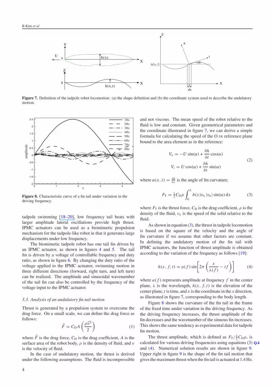
Figure 7. Definition of the tadpole robot locomotion: (a) the shape definition and (b) the coordinate system used to describe the undulatorymotion.
x
ampl
itude
0 1 2 3 4-2
- 1.5
-1
- 0.5
0
0.5
1
1.5
2
2.5 1Hz2Hz3Hz4Hz5Hz6Hz7Hz
8Hz
Figure 8. Characteristic curve of a fin tail under variation in thedriving frequency.
tadpole swimming [18–20], low frequency tail beats withlarger amplitude lateral oscillations provide high thrust.IPMC actuators can be used as a biomimetic propulsionmechanism for the tadpole-like robot in that it generates largedisplacements under low frequency.
The biomimetic tadpole robot has one tail fin driven byan IPMC actuator, as shown in figures 4 and 5. The tailfin is driven by a voltage of controllable frequency and dutyratio, as shown in figure 6. By changing the duty ratio of thevoltage applied to the IPMC actuator, swimming motion inthree different directions (forward, right turn, and left turn)can be realized. The amplitude and sinusoidal wavenumberof the tail fin can also be controlled by the frequency of thevoltage input to the IPMC actuator.
3.3. Analysis of an undulatory fin tail motion
Thrust is generated by a propulsion system to overcome thedrag force. On a small scale, we can define the drag force asfollows:
�F = CD A
(ρ�v2
2
)(1)
where �F is the drag force, CD is the drag coefficient, A is thesurface area of the robot body, ρ is the density of fluid, and v
is the velocity of fluid.In the case of undulatory motion, the thrust is derived
under the following assumptions. The fluid is incompressible
and not viscous. The mean speed of the robot relative to thefluid is low and constant. Given geometrical parameters andthe coordinate illustrated in figure 7, we can derive a simpleformula for calculating the speed of the O tn reference planebound to the area element as in the reference:
Vn = −U sin(α) +∂h
∂ tcos(α)
Vt = U cos(α) +∂h
∂ tsin(α)
(2)
where α(x, t) = ∂h∂x is the angle of fin curvature;
FT = 12 CDρ
∫ L
0b(x)vn |vn| sin(α) dx (3)
where FT is the thrust force, CD is the drag coefficient, ρ is thedensity of the fluid, νn is the speed of the solid relative to thefluid.
As shown in equation (3), the thrust in tadpole locomotionis based on the square of the velocity and the angle offin curvature if we assume that other factors are constant.In defining the undulatory motion of the fin tail withIPMC actuators, the function of thrust amplitude is obtainedaccording to the variation of the frequency as follows [19]:
h(x, f, t) = a( f ) sin
[2π
(x
λ( f )− t f
)](4)
where a( f ) represents amplitude at frequency f in the centerplane, λ is the wavelength, h(x, f, t) is the elevation of thecenter plane, t is time, and x is the coordinate in the x direction,as illustrated in figure 7, corresponding to the body length.
Figure 8 shows the curvature of the fin tail in the frameof the fixed time under variation in the driving frequency. Asthe driving frequency increases, the thrust amplitude of thefin decreases and the wavenumber of the sinuous fin increases.This shows the same tendency as experimental data for tadpolefin motion.
The thrust amplitude, which is defined as FT/ 12 CDρ, is
calculated for various driving frequencies using equations (3) Q.4
and (4). Numerical solution results are shown in figure 9.Upper right in figure 9 is the shape of the fin tail motion thatgives the maximum thrust when the fin tail is actuated at 1.4 Hz.
4

A biomimetic undulatory tadpole robot using IPMC actuators
X
Z
0 1 2 3 4
-1
-0.5
0
0.5
1
Thr
ust a
mpl
itude
2 4 6 8 10
0.5
1
1.5
2
2.5
3
3.5
4Fin Shape(1.4Hz)
Frequency
Figure 9. Thrust amplitude for variation in the driving frequency and the fin shape at 1.4 Hz driving frequency.
Figure 10. Maximum displacement of the tail fin (in air and water).
4. Experimental evaluation
We measured the swimming performance of the tadpole robotin a water tank by videotaping at 30 frames s−1. SamplingQ.5
at 30 Hz is insufficient for high speed kinematic analysis, butis well suited for measuring the direction and speed of travel,which are the focus of our interest.
4.1. Characteristics of the propulsion tail fin
First, we investigate the relationship between the drivingfrequency and displacement of the IPMC actuator. Asinusoidal AC voltage (±2.5 V) was applied to the actuator.In our previous study [15, 16], this voltage obtained maximumdisplacement and force of the IPMC actuator with dimensionsof 30 mm in length, 4 mm in width and 0.15 mm in thickness.
The bending displacement of cast IPMC actuators inwater and air is measured with a laser displacement sensor(model: LB-70, Keyence; accuracy: 10 µm). The maximum
D
D
(a) Undulatory Motion
(b) Oscillatory Motion
Figure 11. Features of undulatory and oscillatory motion.
bending displacement of the actuator at the free end is recordedusing a DAQ board and LabVIEW (National Instrument) whenbending motion is no longer observed. Figure 10 shows acomparison of the measured maximum bending displacementin air and water. Experimental results show that the measuredmaximum bending displacement in water is lower, particularlyat low frequencies (<3 Hz), than in air because of thehydrodynamic drag in water. In addition, the amplitude of theIPMC actuator decreases with increasing driving frequency, asshown in figure 10. On the basis of this experimental result, wecan determine the frequency of the voltage input to the IPMCactuators and use this to adjust the amplitude and sinusoidalwavenumber of the tail fin.
4.2. Undulatory motion versus oscillatory motion
The definitions of undulatory motion and oscillatory motionof the tadpole robot are illustrated in figure 11. Thepropulsive speed of the tadpole robot, for both motion types,was measured. A comparison of experimental results isshown in table 2. We employ PDMS polymer thin filmsto obtain undulatory motion of the fin and stiffer PETfilms for oscillatory motion. Experimental results confirmthat undulatory motion is more efficient than oscillatorymotion, which was also predicted by the previous theoreticalanalysis [7].
5
B Kim et al
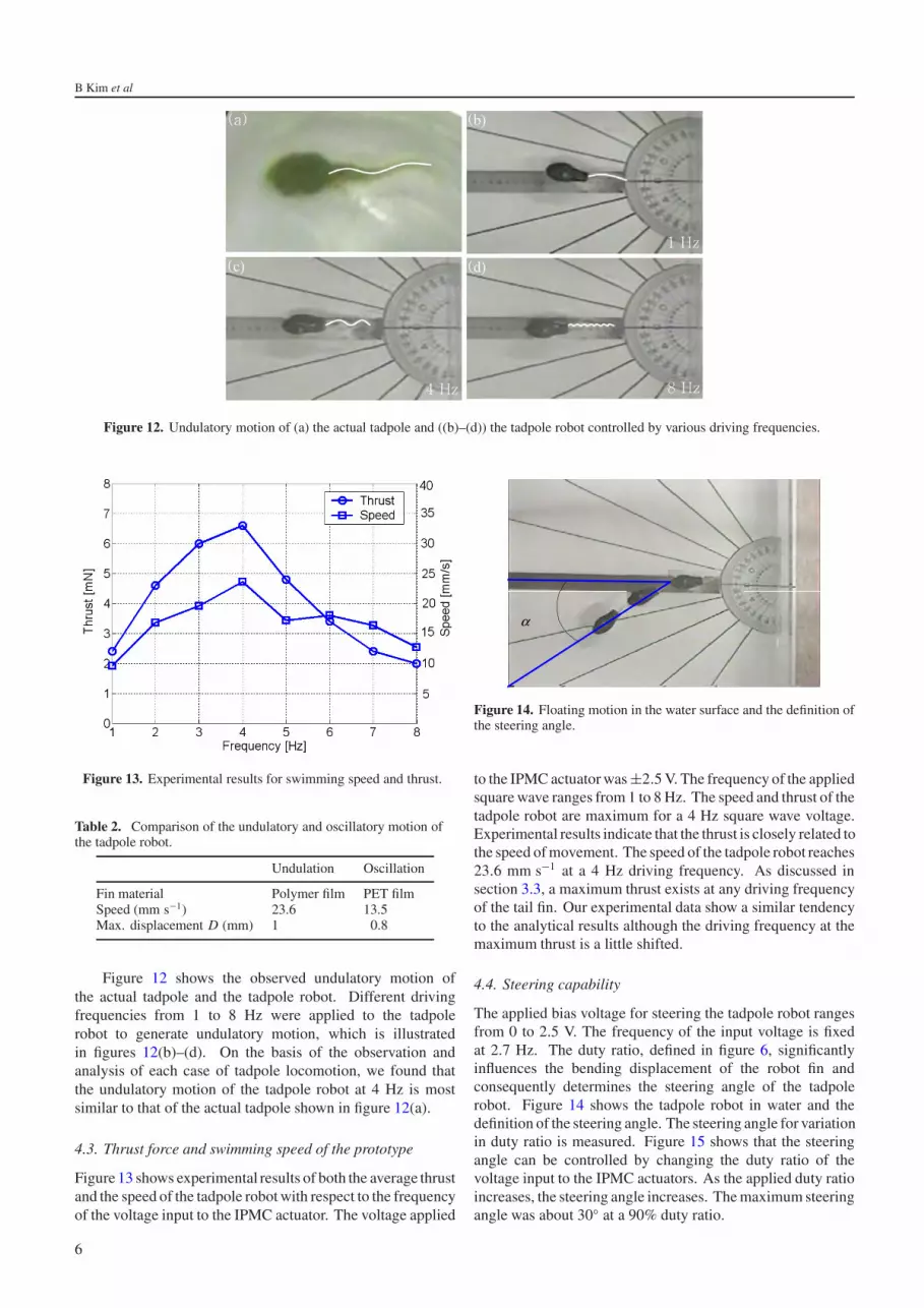
Figure 12. Undulatory motion of (a) the actual tadpole and ((b)–(d)) the tadpole robot controlled by various driving frequencies.
Figure 13. Experimental results for swimming speed and thrust.
Table 2. Comparison of the undulatory and oscillatory motion ofthe tadpole robot.
Undulation Oscillation
Fin material Polymer film PET filmSpeed (mm s−1) 23.6 13.5Max. displacement D (mm) 1 0.8
Figure 12 shows the observed undulatory motion ofthe actual tadpole and the tadpole robot. Different drivingfrequencies from 1 to 8 Hz were applied to the tadpolerobot to generate undulatory motion, which is illustratedin figures 12(b)–(d). On the basis of the observation andanalysis of each case of tadpole locomotion, we found thatthe undulatory motion of the tadpole robot at 4 Hz is mostsimilar to that of the actual tadpole shown in figure 12(a).
4.3. Thrust force and swimming speed of the prototype
Figure 13 shows experimental results of both the average thrustand the speed of the tadpole robot with respect to the frequencyof the voltage input to the IPMC actuator. The voltage applied
αα
Figure 14. Floating motion in the water surface and the definition ofthe steering angle.
to the IPMC actuator was ±2.5 V. The frequency of the appliedsquare wave ranges from 1 to 8 Hz. The speed and thrust of thetadpole robot are maximum for a 4 Hz square wave voltage.Experimental results indicate that the thrust is closely related tothe speed of movement. The speed of the tadpole robot reaches23.6 mm s−1 at a 4 Hz driving frequency. As discussed insection 3.3, a maximum thrust exists at any driving frequencyof the tail fin. Our experimental data show a similar tendencyto the analytical results although the driving frequency at themaximum thrust is a little shifted.
4.4. Steering capability
The applied bias voltage for steering the tadpole robot rangesfrom 0 to 2.5 V. The frequency of the input voltage is fixedat 2.7 Hz. The duty ratio, defined in figure 6, significantlyinfluences the bending displacement of the robot fin andconsequently determines the steering angle of the tadpolerobot. Figure 14 shows the tadpole robot in water and thedefinition of the steering angle. The steering angle for variationin duty ratio is measured. Figure 15 shows that the steeringangle can be controlled by changing the duty ratio of thevoltage input to the IPMC actuators. As the applied duty ratioincreases, the steering angle increases. The maximum steeringangle was about 30◦ at a 90% duty ratio.
6

A biomimetic undulatory tadpole robot using IPMC actuators
Figure 15. Steering test with various duty ratios.
5. Conclusions
This paper presents a wireless tadpole robot with biomimeticpropulsion, using a cast IPMC actuator. For the purposeof improving the thrust of the tadpole robot developed, thebiomimetic undulatory tadpole locomotion is investigated.The microrobot prototype consists of one polymer fin taildriven by a cast IPMC actuator, a wireless power source, andan embedded controller. The overall size of the underwatertadpole shaped microrobot is 96 mm in length,24 mm in width,and 25 mm in thickness.
Motion of the tadpole microrobot is measured by changingthe frequency of the input voltage from 1 to 8 Hz in water andthe duty ratio of the input voltage. Experiments investigatingfeatures such as the bending displacement of the IPMC actuatorin the water, the velocity change with respect to fin motion, thevelocity change for variations in actuator driving frequency,and the steering capability in relation to duty ratio variationsare conducted to investigate the motion and efficiency of thetadpole microrobot. Undulatory motion of the fin supplieshighly efficient propulsion. Experimental results also showthat the speed and steering angle of the underwater tadpolerobot can be controlled by changing the duty ratio and thefrequency of the input voltage. With an optimized inputwaveform, the speed of the tadpole robot reached 23.6 mm s−1
at a 4 Hz driving frequency.
Acknowledgments
This work was supported by the 21st Century’s Frontier R&DProjects under contract number MS-02-142-01 sponsored bythe Ministry of Science and Technology, Korea.
References
[1] Fukuda T, Hosokai H and Arai F 1990 Giant magnetostrictivealloy (GMA) applications to micro mobile robot as a microactuator without power supply cables Proc. IEEE Int. Conf.on Robotics and Automation (Piscataway, NJ: IEEE)pp 210–5
[2] Fukuda T, Hosokai H and Kikuchi I 1990 Distributed type ofactuator by shape memory alloy and its application tounderwater mobile robotic mechanism Proc. IEEE Int.Conf. on Robotics and Automation (Piscataway, NJ: IEEE)pp 1316–32
[3] Fukuda T, Kawamoto A, Arai F and Matsuura H 1995Steering mechanism of underwater micro mobile robotProc. IEEE Conf. on Robotics and Automation pp 363–8
[4] Mojarrad M and Shahinpoor M 1997 Biomimetic robotpropulsion using polymeric artificial muscles IEEE Conf.on Robotics and Automation (Piscataway, NJ: IEEE)pp 2152–7
[5] Shahinpoor M 1992 Conceptual design, kinematics anddynamics of swimming robotic structures using ionicpolymeric gel muscles Smart Mater. Struct. 1 91–4
[6] Garner L J, Wilson L N, Lagoudas D C andRediniotis O K 2000 Development of a shape memory alloyactuated biomimetic vehicle Smart Mater. Struct. 9 673–83
[7] Laurent G and Piat E 2001 Efficiency of swimmingmicrorobots using IPMC actuators Proc. IEEE Int. Conf. onRobotics and Automation (Piscataway, NJ: IEEE)pp 3914–9
[8] Guo S, Fukuda T and Asaka K 2003 A new type of fish-likeunderwater microrobot IEEE/ASME Trans. Mechatron. 8/1136–41 Q.6
[9] Edd J, Payen S, Rubinsky B, Stoller M L and Sitti M 2003Biomimetic propulsion for a swimming surgical microrobotProc. IEEE Int. Conf. on Robotics and Automationpp 2583–8
[10] Oguru K, Kawami Y and Takenaka H 1992 Bending of anion-conducting polymer film–electrode composite by anelectric stimulus at low voltage Trans. J. Micromach. Soc. 527–30
[11] Shahinpoor M 1995 Micro-electro-mechanics of ionicpolymeric gels as electrically controllable artificial musclesJ. Intell. Mater. Syst. Struct. 6 307–14
[12] Hunter I and Lafontaine S 1992 A comparison of muscle withartificial actuators Technical Digest of the IEEE Solid StateSensor and Actuator Workshop (Piscataway, NJ: IEEE)pp 178–85
[13] Shahinpoor M, Bar-Cohen Y, Simpson J O and Smith J 1998Ionic polymer–metal composites (IPMCs) as biomimeticsensors, actuators and artificial muscles—a review SmartMater. Struct. 7 15–30
[14] Shahinpoor M and Kim K J 2001 Ionic polymer–metalcomposites: I. Fundamentals Smart Mater. Struct.10 819–33
[15] Cha S E, Pak J J and Lee S K 2002 Fabrication process andcharacterization of ionic polymer–metal compositeactuators by electroless plating of platinum Trans. KIEE51/9 455–63
[16] Kim B, Kim B M, Ryu J, Oh I H, Lee S K, Cha S E andPak J 2003 Analysis of mechanical characteristics of theionic polymer metal composite (IPMC) actuator using castion-exchange film Proc. SPIE 10th Int. Symp. on SmartStructures and Materials vol 5051, (Bellingham, WA: SPIEOptical Engineering Press) pp 486–96
[17] Kim B, Ryu J, Jeong Y K, Tak Y H, Kim B M andPark J O 2003 A ciliary based 8-legged walking micro robotusing cast IPMC actuators Proc. IEEE Int. Conf. onRobotics and Automation (Piscataway, NJ: IEEE)pp 2940–5
[18] Hoff K 1987 Morphological determinants of fast-startperformance in anuran tadpoles Thesis DalhousieUniversity
[19] Liu H, Wassersug R and Kawachi K 1997 Thethree-dimensional hydrodynamics of tadpole locomotionJ. Exp. Biol. 200 2807–19
[20] Triantafyllou G S, Triantafyllou M S andGrosenbaugh M A 1993 Optimal thrust development inoscillating foils with applications to fish propulsion J.Fluids Struct. 7 205–14 Q.7
7

Queries for IOP paper 210355
Journal: SMSAuthor: B Kim et alShort title: A biomimetic undulatory tadpole robot usingIPMC actuators
Page 1
Query 1:Author: In several places I have standardized the English
somewhat. Please check that I have not inadvertently alteredthe meaning (and please accept my apologies if I have).
Query 2:-Author: Please be aware that the colour figures in this
proof will normally only appear in colour in the online Webversion. If you require colour in the printed journal andhave not previously arranged it, please contact the PublishingAdministrator now.
Query 3:Author: Amended wording ‘lack of safety in’ OK?
Page 4
Query 4:Author: Amended wording ‘is calculated for various
driving frequencies’ OK?
Page 5
Query 5:Author: Amended wording of figure 9 caption OK?
Page 7
Query 6:-Author: [8]: Please check the volume number.
Query 7:-Author: [20]: Please check the page range.
Reference linking to the original articles
References with a volume and page number in blue have a clickable linkto the original article created from data deposited by its publisher atCrossRef. Any anomalously unlinked references should be checked foraccuracy. Pale purple is used for links to e-prints at ArXiv.


