Embed Size (px)
Citation preview

Sensors 2010, 10, 6081-6091; doi:10.3390/s100606081
sensors ISSN 1424-8220
www.mdpi.com/journal/sensors Article
A Compact Tunable Diode Laser Absorption Spectrometer to
Monitor CO2 at 2.7 µm Wavelength in Hypersonic Flows
Raphäel Vallon 1, Jacques Soutadé
1, Jean-Luc Vérant
1, Jason Meyers
2, Sébastien Paris
2 and
Ajmal Mohamed 1,
*
1 The French Aerospace Lab, ONERA, BP72-29 avenue de la Division Leclerc, FR-92322 Chatillon
cedex, France; E-Mails: [email protected] (R.V.); [email protected] (J.S.);
[email protected] (J.-L.V.) 2 Von Karman Institute, 1640 Rhode-St-Génèse, Belgium; E-Mails: [email protected] (J.M.);
[email protected] (S.P.)
* Author to whom correspondence should be addressed; E-Mail: [email protected];
Tel.: +33-1-69936188; Fax: +33-1-69936188.
Received: 21 May 2010; in revised form: 4 June 2010 / Accepted: 8 June 2010/
Published: 17 June 2010
Abstract: Since the beginning of the Mars planet exploration, the characterization of
carbon dioxide hypersonic flows to simulate a spaceship’s Mars atmosphere entry
conditions has been an important issue. We have developed a Tunable Diode Laser
Absorption Spectrometer with a new room-temperature operating antimony-based
distributed feedback laser (DFB) diode laser to characterize the velocity, the temperature
and the density of such flows. This instrument has been tested during two measurement
campaigns in a free piston tunnel cold hypersonic facility and in a high enthalpy arc jet
wind tunnel. These tests also demonstrate the feasibility of mid-infrared fiber optics
coupling of the spectrometer to a wind tunnel for integrated or local flow characterization
with an optical probe placed in the flow.
Keywords: gas sensor; tunable diode laser absorption spectroscopy; distributed feedback
(DFB); laser velocimetry; CO2 monitoring; hypersonic flow; Mars atmosphere
PACS: 07.07.Df; 42.55.Px ; 07.57.Ty; 42.62.Fi; 42.79.Qx; 47.40.Ki; 96.30.Gc
OPEN ACCESS

Sensors 2010, 10
6082
1. Introduction
Mars, with its carbon dioxide atmosphere, will probably be the next planet visited by the human
species. But before sending a man to Mars, we must master the entry phase of a space vehicle into that
planet’s atmosphere. A high enthalpy hypersonic wind tunnel is one of the technical ways to reproduce
on Earth physical conditions similar to those of a potential Martian atmospheric entry. However, such
wind tunnels have been developed with air or nitrogen gas for modeling Earth reentry and now these
facilities must be extended to run with carbon dioxide, which is a much more complex molecule. For
more than a decade now, Tunable Diode Laser Absorption Spectroscopy (TDLAS) has been one of the
most used optical tools to characterize the free stream parameters of hypersonic flows through
measurements of probe species like NO, H2O, CO and CO2 [1,2]. However the setups are usually quite
cumbersome because of the use of cryogenic lead salt diode lasers necessary to detect these molecules in
the mid-infrared spectrum. We are developing a new absorption spectrometer based on a recently
available antimony diode laser [3] for CO and CO2 probing. These diodes emit in the 2 to 3 µm spectral
range where there are quite intense CO/CO2 lines for comfortable signal to noise ratio measurements
under rarefied gas flow conditions. Such diodes have already been successfully used in combustion and
shock tube studies [4-6]. Compared to the PbSe diodes used in our proceeding studies [2], they are non
cryogenic as well as less complex (compared, for example, to a difference frequency generation
scheme) allowing design of a quite miniature setup. To locally monitor carbon dioxide, the laser beam
can be sent to a probe in the flow through infrared fibers. The concept of such a probe, comprising two
arms equipped with mirrors and optical couplers and allowing only a small absorption path length in
the flow, has already been laid down by Wehe et al. using near infrared laser diodes and fiber optics to
probe H2O lines in high speed flows [7,8]. This configuration offers many advantages like avoiding
unnecessary absorption outside the flow, making optical coupling with the wind tunnel’s test chamber
easier and the probe could be positioned in the flow in the same manner as a classical Pitot probe.
The actual absorption spectrometer is equipped with a diode laser from Nanoplus emitting at 2.7 µm
for CO2 probing and has been tested at the Von Karman Institute (VKI) LONGSHOT cold hypersonic
wind tunnel and at the ONERA F4 high enthalpy wind tunnel. The diode emission window covers CO2
(ν1 + ν3) absorption lines of low and sufficiently high J, thus enabling the probing of a large range of
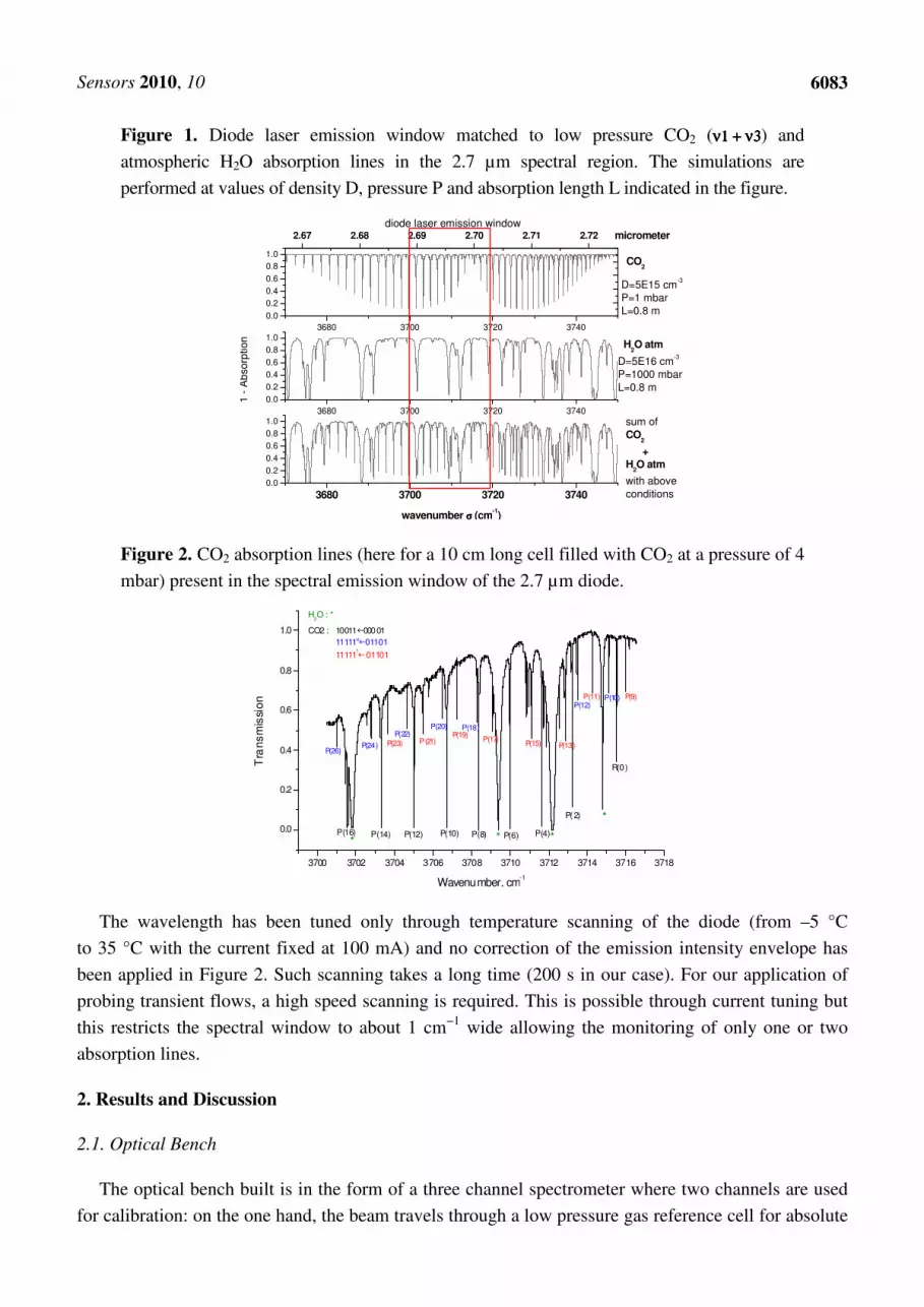
temperatures and is therefore compatible with both wind tunnels. This is illustrated in
Figure 1 where the diode emission window is matched to absorption line simulations under physical
conditions typically encountered in these facilities using the HITRAN database [9]. The simulated gas
has two components: CO2 at low pressure (about 100 Pa) mixed with some atmospheric pressure H2O
usually absorbed outside the test section in the region of the spectrometer (but this is sometimes
avoided through N2 purging). The simulations are performed for room temperature and for temperature
of 800 K, which is typical for the F4 wind tunnel case.
Figure 2 presents the experimental total spectral emission spectrum (about 16 cm−1 wide) of the
laser diode in our setup exhibiting the absorption lines of CO2 obtained when the laser beam crosses at
room temperature a 10 cm long cell filled with CO2 at a pressure of 4 mbar. These lines are overlapped
with atmospheric H2O lines absorbed outside the cell on a distance of about 1 meter.
Sensors 2010, 10
6083
Figure 1. Diode laser emission window matched to low pressure CO2 (ν1 + ν3ν1 + ν3ν1 + ν3ν1 + ν3) and
atmospheric H2O absorption lines in the 2.7 µm spectral region. The simulations are
performed at values of density D, pressure P and absorption length L indicated in the figure.
3680 3700 3720 37400.0
0.2
0.4
0.6
0.8
1.0
2.67 2.68 2.69 2.70 2.71 2.72
wavenumber σσσσ (cm-1)
3680 3700 3720 3740
0.0
0.2
0.4
0.6
0.8
1.0
1 -
Ab
so
rption
3680 3700 3720 3740
0.0
0.2
0.4
0.6
0.8
1.0
D=5E16 cm-3
P=1000 mbar
L=0.8 m
H2O atm
sum of
CO2
+
H2O atm
with above
conditions
CO2
D=5E15 cm-3
P=1 mbar
L=0.8 m
diode laser emission windowmicrometer
Figure 2. CO2 absorption lines (here for a 10 cm long cell filled with CO2 at a pressure of 4
mbar) present in the spectral emission window of the 2.7 µm diode.
3700 3702 3704 3706 3708 3710 3712 3714 3716 3718
0.0
0.2
0.4
0.6
0.8
1.0
Tra
nsm
issi
on
Wavenumber, cm-1
P(16) P(14) P(12) P(10) P(8) P(6) P(4)
P(2)
R(0)
* * *
*
H2O : *
P(26)P(24)
P(22)P(20) P(18)
P(12)P(10)
P(23) P(21)P(19)
P(17)P(15) P(13)
P(9)P(11)
CO2 : 10011�00001
11111e�01101
11111f� 01101
The wavelength has been tuned only through temperature scanning of the diode (from –5 °C
to 35 °C with the current fixed at 100 mA) and no correction of the emission intensity envelope has
been applied in Figure 2. Such scanning takes a long time (200 s in our case). For our application of
probing transient flows, a high speed scanning is required. This is possible through current tuning but
this restricts the spectral window to about 1 cm−1 wide allowing the monitoring of only one or two
absorption lines.
2. Results and Discussion
2.1. Optical Bench
The optical bench built is in the form of a three channel spectrometer where two channels are used
for calibration: on the one hand, the beam travels through a low pressure gas reference cell for absolute

Sensors 2010, 10
6084
wavelength calibration, and on the other hand, the beam travels through a Fabry-Perot interferometer
having 4.9 × 10⁻² cm−1 free spectral range (FSR) for relative wavelength calibration. These permanent
and simultaneous calibration channels are necessary because one cannot rely on a beforehand
calibration of the wavelength as there are many factors (harsh electromagnetic environment and long
time delays before an effective flow run) which can cause wavelength drift in the diode set initially at
certain desired conditions. The main part of the beam is coupled into an infrared fluorozirconate fiber
(from IR photonics and having a core diameter of 85 µm) to bring the laser beam close to the flow. We
can use either an optical probe for local measurement as tried by Wehe et al. [7] or two input/output
fiber couplers for integrated path characterization as shown in Figure 3. The optical probe we designed
allows obtaining an absorption path length of 4.24 cm in between its two arms (separated by a distance
of 3 cm) with an angle of 45° with the respect to the flow axis. For one of the runs at the Longshot
windtunnel, the use of short portion tubes allowed to reduce this path length to 3 cm.
Figure 3. Optical bench setup and two methods of coupling to the flow.
All laser beams are detected by high sensitivity Peltier cooled photodetectors. The InAs type has
been used for the calibration channels and the HgCdTe type, which has a better sensitivity and
bandwidth, has been used for the channel dedicated to measure flow absorption. The three channel
signals are simultaneously recorded by a 60 MHz bandwidth and 12-bits acquisition card. During a run,
the laser wavelength is scanned on an interval of about 0.5 cm−1 containing the absorption lines to be
monitored at a repetition rate ranging between 1 kHz and 10 KHz for a total duration of a few hundred
of milliseconds.
2.2. Measurement Campaign at the Von Karman Institute (VKI) Longshot Wind Tunnel
The VKI Longshot free piston wind tunnel has been chosen for the first feasibility tests because of its
non-chemically reacting nature of the flow where CO2 does not dissociate and is present at relatively high
densities for a good signal to noise ratio. VKI has also a TDLAS system [10] running with a diode
around 1.55 µm, but unfortunately it could not be operated simultaneously for comparison with our

Sensors 2010, 10
6085
measurements. The VKI Longshot free piston tunnel is a short duration facility operating with nitrogen or
carbon dioxide. It has been designed to generate very high Reynolds number hypersonic flows. Typical
Reynolds numbers at Mach 15 range are from 5 × 10⁶ m−1 to 15 × 106 m−1. It has a Mach 14 contoured
nozzle of 0.43 m exit diameter and a 6 degree conical nozzle of 0.6 m exit diameter which can be used
throughout the Mach number range from 15 to 20 using nitrogen and 10 to 15 using carbon dioxide.
A high precision incidence mechanism for pitch, roll, and yaw is mounted in the open-jet 4 m3 test
section. This mechanism is used to maintain our optical probe in the correct position so that the laser
beam has a 45 degree angle with the flow direction.
During this measurement campaign, three runs at typical conditions of the wind tunnel were tested,
two with CO2 flows and one with nitrogen seeded with 5% CO2, the latter aiming at probing Earth
reentry flows. Figure 4 shows a simulated spectrum for typical hypersonic flow conditions at the
Longshot facility (temperature of 150 K, velocity of 2,000 m·s−1, density of 1017 molecules·cm−3 and
pressure of 100 Pa) for an absorption path length of 3 centimeters. In these conditions, the main
absorption lines (of low quantum number J) to be used to characterize the cold free stream are nearly
saturated whereas the “hot” (or high J) CO2 lines are hardly noticeable. One could think of increasing
the absorption path length to bring a more comfortable signal to the hot lines but these lines cannot be
exploited to characterize the free stream flow core as they will be disturbed by important absorption
contributions from regions at higher temperatures than the core flow at 150 K.
Figure 4. Simulated CO2 absorption spectrums for VKI run conditions.
(a)
(b)
For the Longshot experiments, the spectral window is chosen to monitor the P(8)e CO2 line for
velocity measurements (Figure 4b) as the primary objective. It includes a hot line (P(18)f) which
should not be visible in the experimental spectra for the low temperature section of the flow but can
help to monitor hot portions of the flow. The experimental conditions for the three runs we tested are
summarized in Table 1.
Figure 5 presents typical spectra obtained during these runs. For all runs, the unshifted component
of the P(8)e becomes more and more intense (Figure 5a) and this is interpreted as low velocity gas
filling the probe, which is not vacuum tight. This gas component is at higher temperatures than in the
free stream and explains also the appearance of the ‘hot’ P(18) line in the spectra of Figure 5. The

Sensors 2010, 10
6086
spectra which are numerically fitted using a non-linear Levenberg -Marquart least-squares procedure
are presented in Figure 5b. The data reduction uses the standard two-layer gas model described and
justified in reference [2] where one layer corresponds to the free stream at high velocity and low
temperature and the other layer accounts for all static gas at higher temperatures.
Table 1. VKI wind tunnel flow conditions and parameters used for TDLAS.
Run
number Gas Pressure, temperature
Absorption lines
probes Comment
1633 CO2 230 Pa, 95 K at run time t = 10 ms
P(8)e and P(18)f for CO2
Schlieren not available, probe without protection tube
1634 CO2 230 Pa, 95 K at t = 10 ms P(8)e and P(18)f for CO2
Probe with protection tube to reduce the absorption path length to 3 cm
1635 N2 with 5% CO2
130 Pa, 40 K at 10 ms P(8)e and P(18)f for CO2
Probe without protection tube
Figure 5. Wavelength and intensity calibrated spectra at different instances of the flow (a)
and spectrum inversion (b).
(a)
(b)
The high speed Schlieren video acquired during the run shows a small angle for shock layers at the
beginning of the flow (Figure 6a). Unfortunately, after two milliseconds, these angles increase to bring
the shock interactions on the path of the laser beam (Figure 6b). The large fluctuations of the
shock-shock interaction zone induce disturbances of the laser beam and oscillations on the baseline of
acquired spectra.
Even after these two milliseconds, the spectrum inversion on the CO2 P(8)e line yields free stream
gas velocity, temperature and density with a relatively good agreement with results from free stream
flow rebuilding based on measurements of plenum pressure and stagnation conditions in the free
stream via a hemispheric probe [10,11].
Figure 7 shows a graphical presentation of this comparison. This close matching can be interpreted
as that most of the shock layer region being probed has properties close to the free-stream. The
interaction zone crossed is relatively small and its impact is more on bringing oscillations to the
absorption spectrum baseline. This in turn impacts on the derived parameters like temperature and

Sensors 2010, 10
6087
density whereas velocity is less affected as it depends less on line intensity profile. It is therefore
difficult to infer accuracies to these parameters except for velocity for which the precision is estimated
to be less than 10%.
Figure 6. Schlieren images of the probe during VKI Run 1635 with optical beam path shown in red.
30mm
DLAS mini-probe testing
in VKI Longshot windtunnel
Run 1635
Fiber optic
Fiber optic2.7µm laser beam
(a) Run time t < 2 ms.
(b) Run time t = 2 to 20 ms.
Figure 7. Compiled results for VKI LONGSHOT Run 1633.
0 2 4 6 8 10 12 14 16 18 20400800
120016002000
Velo
cit
y
(m/s
)
VKI LONSHOT Run 1633 /CO2
TDLAS
Flow rebuilding
0 2 4 6 8 10 12 14 16 18 200
100200300400
Tem
pera
ture
(K)
0 2 4 6 8 10 12 14 16 18 200
10203040
CO
2 d
en
sit
y
(10
16 c
m-3)
Flow time (ms)
Anyway, all derived values for velocity, temperature and CO2 density must be interpreted with care
because of the laser beam crossing the shock interactions region in between the fingers of the optical
probe. However, if we retain only the measurements for the first two milliseconds, this measurement
campaign allows us to validate the feasibility of TDLAS probing at 2.7 µm in this wind tunnel as well
as the use of infrared fluorine fiber optics coupled to a miniature probe with short absorption path in
the flow.
2.3. Measurement Campaign at the ONERA F4 High Enthalpy Arc Jet Wind Tunnel
The ONERA F4 facility [12] is an arc jet wind tunnel that has been widely used for performing test
campaigns for ESA Mars exploration projects such as Mars Sample Return Orbiter and Exomars. Such
Sensors 2010, 10
6088
CO2 tests achieved high enthalpy level thanks to a 60 MW electrical rotating arc in a 10 L plenum
chamber initially filled with gas at 10 to 40 bar at ambient temperature. The exact initial pressure, arc
duration and power are the driving parameters to tune for the aimed flow conditions. During the arc
generation, usually lasting from 40 to 120 milliseconds, the temperature and pressure will increase, up
to 4,000 K and 400 bar, until a pyrotechnic valve is opened in the plenum chamber to release the test
gas in a contoured nozzle generating a high enthalpy (up to 8 MJ/kg) hypersonic flow at velocities up
to 3.5 km/s. Four contoured nozzles are available for F4, but only the nozzle#2 (4,490 expansion ratio)
was used to perform CO2 test campaigns for flows at Mach numbers from 7 to 8 and unit Reynolds
numbers close to 105. The typical useful time for the flow is 200 milliseconds using carbon dioxide gas
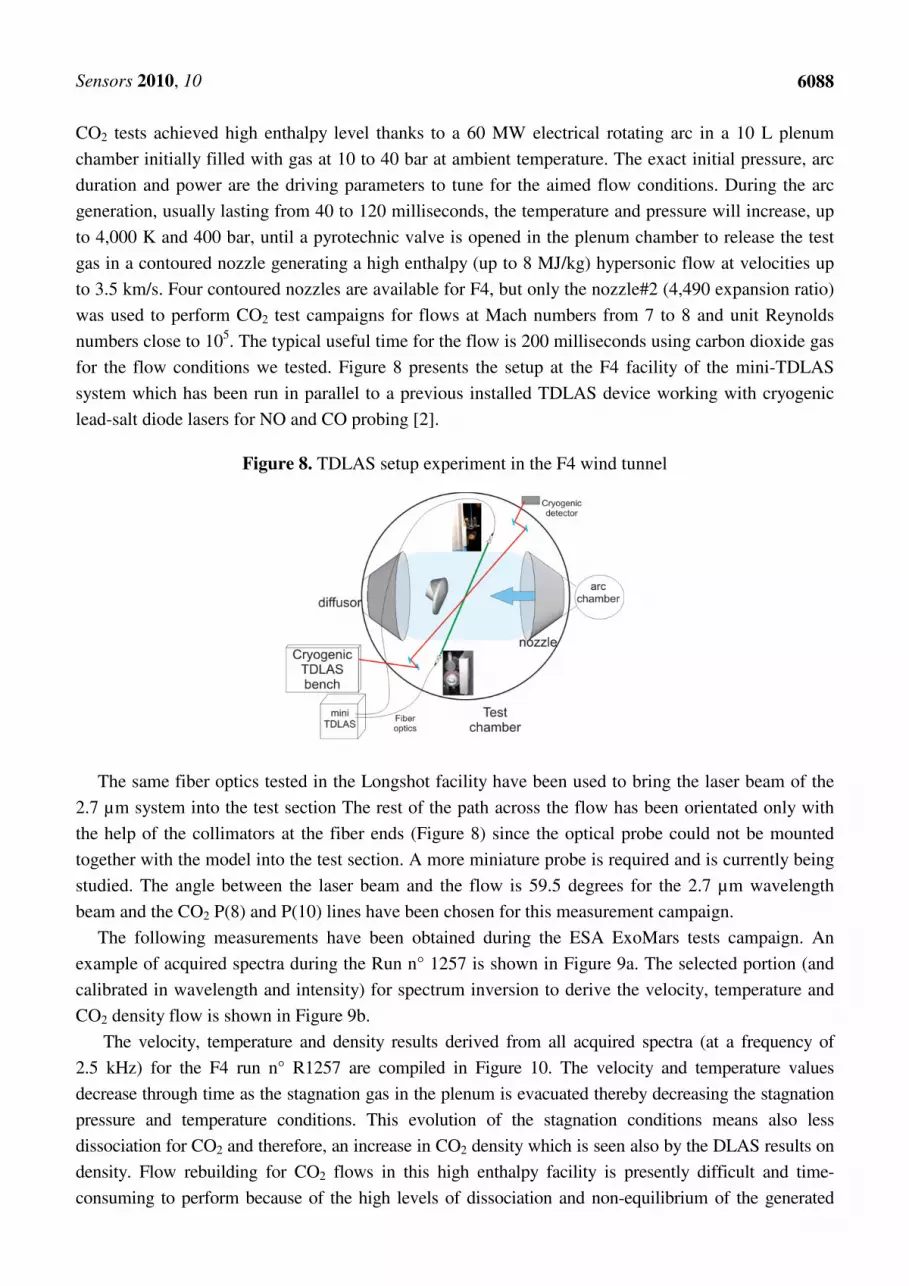
for the flow conditions we tested. Figure 8 presents the setup at the F4 facility of the mini-TDLAS
system which has been run in parallel to a previous installed TDLAS device working with cryogenic
lead-salt diode lasers for NO and CO probing [2].
Figure 8. TDLAS setup experiment in the F4 wind tunnel
The same fiber optics tested in the Longshot facility have been used to bring the laser beam of the
2.7 µm system into the test section The rest of the path across the flow has been orientated only with
the help of the collimators at the fiber ends (Figure 8) since the optical probe could not be mounted
together with the model into the test section. A more miniature probe is required and is currently being
studied. The angle between the laser beam and the flow is 59.5 degrees for the 2.7 µm wavelength
beam and the CO2 P(8) and P(10) lines have been chosen for this measurement campaign.
The following measurements have been obtained during the ESA ExoMars tests campaign. An
example of acquired spectra during the Run n° 1257 is shown in Figure 9a. The selected portion (and
calibrated in wavelength and intensity) for spectrum inversion to derive the velocity, temperature and
CO2 density flow is shown in Figure 9b.
The velocity, temperature and density results derived from all acquired spectra (at a frequency of
2.5 kHz) for the F4 run n° R1257 are compiled in Figure 10. The velocity and temperature values
decrease through time as the stagnation gas in the plenum is evacuated thereby decreasing the stagnation
pressure and temperature conditions. This evolution of the stagnation conditions means also less
dissociation for CO2 and therefore, an increase in CO2 density which is seen also by the DLAS results on
density. Flow rebuilding for CO2 flows in this high enthalpy facility is presently difficult and time-
consuming to perform because of the high levels of dissociation and non-equilibrium of the generated

Sensors 2010, 10
6089
flows. However, the TDLAS results can be compared to a few results obtained with a parabolised Navier
Stokes (PNS) code developed for air flows and presently being adapted to the CO2 case [13].
Figure 9. Example of absorption spectrum and derived measurements for the free stream of
F4 run R1257 at flow time t = 43 ms.
0.0 0.5 1.0 1.5 2.0 2.50.0
0.2
0.4
0.6
0.8
1.0
1.2
1.4
La
ser
sig
nal
inte
ns
ity (
V)
Wavelength scanning time (ms)
Fabry-Perot
F4- run 1257
Reference cell
filled with CO2 at 4 mbar, 300K
Flow spectrum
CO
2 P
(10
)
a) Raw spectra acquired at flow time t = 43 ms.
3706.65 3706.70 3706.75 3706.800.60
0.65
0.70
0.75
0.80
0.85
0.90
0.95
1.00
Exp
Best Fit
Tra
nsm
issio
n
Wavenumber σσσσ (cm-1)
Doppler Shifted CO2 P(10) line
Flow time = 43ms
T = 1014 K
V = 3142 m/s
[CO2] = 1.1 1016 cm-3
F4 Run 1257/CO2
'Hot' CO2 line
b) Spectrum inversion results for free stream.
Figure 10. CO2 compiled results for F4 run 1257.
0 20 40 60 80 100 120 140 160 180 2001000
2000
3000
4000
F4 Run 1257/CO2
TDLAS
Flow rebuilding (PNS)
Velo
cit
y
(m/s
)
0 20 40 60 80 100 120 140 160 180 200
500
1000
1500
2000
Te
mp
era
ture
(K)
0 20 40 60 80 100 120 140 160 180 2000.1
1
CO
2 D
en
sit
y
(10
16 c
m-3
)
Flow time (ms)
The CO2 flow is assumed to be in chemical non-equilibrium for the gas mixture created after arc
heating process. The results for four flow rebuilding instants of run 1257 are tabulated in Table 2 and
the velocity, temperature and CO2 density values are graphically reported in Figure 10: the TDLAS
results match well with these points for velocity and CO2 density but present quite higher values for the
flow temperature. The analysis of this discrepancy is still underway. On the measurement side, the
possible causes are that the absorption line profile (for the CO2 P(8) case) is not well measured because
of the low signal to noise ratio and also because of the disturbance caused by an overlapping weak line
present at high temperatures. On the theoretical side, the PNS code still needs validation for CO2 flows
and the TDLAS technique with an improved signal to noise ratio can be quite useful for
this purpose.

Sensors 2010, 10
6090
Table 2. Numerical flow rebuilding values for four instants of F4 run 1257.
Flow
time
(ms)
Stagnation conditions Free stream conditions
Pressur
e
Pi (bar)
Enthalpy
Hi (MJ/kg)
Velocity
(m/s)
Pressur
e
(Pa)
Temperature
(K)
MACH
number
Density in cm-3
CO2 O2 CO C O
60 180 6.5 3056 113 599 7.71 1.1E+16 1.1E+15 2.0E+15 1.4E+02 1.8E+13
86 149 5.5 2870 94 550 7.67 1.0E+16 7.5E+14 1.3E+15 1.2E+02 6.0E+12
139 110 4.5 2670 70 493 7.63 9.2E+15 4.2E+14 7.3E+14 1.0E+02 1.5E+12
176 93 3.5 2463 60 435 7.60 9.5E+15 1.8E+14 3.1E+14 1.0E+02 2.6E+11
3. Summary and Conclusions
We have developed a new transportable tunable diode laser spectrometer at 2.7 µm wavelength for
hypersonic carbon dioxide flow characterization. This spectrometer has been tested during two
measurements campaigns in two types of hypersonic wind tunnel: a free piston tunnel presenting
reference cold conditions and an arc jet wind tunnel presenting dissociation-recombination chemistry.
Both wind tunnels present harsh environments and low repetition occurrences for runs with short flow
durations (200 ms at most). Nevertheless, we demonstrated on the few allocated runs the feasibility of
this new compact TDLAS setup. We also demonstrated the feasibility of using a short absorption
length optical probe coupled by infrared fiber optics for more local monitoring of a flow. We are
presently improving this instrument through a new design for the probe so as to avoid having the laser
beam crossing shock-shock interaction regions and through addition of another antimonide diode
at 2.3 µm wavelength for simultaneous CO monitoring. The compact and portable instrument
developed is also quite practical in other fields like environmental monitoring. We will publish soon
the results of its application to monitor online trace gas species in the exhaust of airplane and
automobile
combustor engines.
Acknowledgements
This work has been sponsored by ESA (European Space Agency) through the HYFIE project
contract 20719/07/NL/IA and CNES (French Space Agency) through the EXOMARS project.
References
1. Arroyo, M.P.; Langlois, S.; Hanson, R.K. Diode-laser absorption technique for simultaneous
measurements of multiple gasdynamic parameters in high-speed flows containing water vapor.
Appl. Opt. 1994, 33, 3296-3307.
2. Mohamed, A.; Henry, D.; Louvet, Y.; Rosier, B.; Varghese, P.L. Tunable diode laser
measurements on nitric oxide in a hypersonic wind tunnel. AIAA J. 1996, 34, 494-499.
3. Salhi, A.; Barat, D.; Romanini, D.; Rouillard, Y.; Ouvrard, A.; Werner, R.; Seufert, J.; Koeth, J.;
Vicet, A.; Garnache, A. Single-frequency Sb-based distributed-feedback lasers emitting at 2.3 µm
above room temperature for application in tunable diode laser absorption spectroscopy. Appl. Opt.

Sensors 2010, 10
6091
2006, 45, 4957-4965.
4. Farooq, A.; Jeffries, J.B.; Hanson, R.K. CO2 concentration and temperature sensor for combustion
gases using diode-laser absorption near 2.7 µm. Appl. Phys. B 2008, 90, 619-628.
5. Farooq, A.; Jeffries, J.B.; Hanson, R.K. Measurements of CO2 concentration and temperature at
high pressures using 1f-normalized wavelength modulation spectroscopy with second harmonic
detection near 2.7 µm. Appl. Opt. 2009, 48, 6740-6753.
6. Chao, X.; Jeffries, J.B.; Hanson, R.K. Absorption sensor for CO in combustion gases using 2.3 µm
tunable diode lasers. Meas. Sci. Tech. 2009, 20, 115201.
7. Wehe, S.D.; Baer, D.S.; Hanson, R.K. Tunable diode-laser absorption measurements of
temperature, velocity, and H2O in hypervelocity flows. In Proceedings of the 33rd
AIAA/ASME/SAE/ASEE Joint Propulsion Conference & Exhibit, Seattle, WA, USA, 6-9 July
1997; AIAA: Reston, VA, USA, 1997; pp. 97-3267.
8. Wehe, S.D.; Baer, D.S.; Hanson, R.K. Measurements of gas temperature and velocity in
hypervelocity flows using diode-laser sensors. In Proceedings of the 20th AIAA Advanced
Measurement and Ground Testing Technology Conference, Albuquerque, NM, USA, 15-18 June
1998; AIAA: Reston, VA, USA, 1998; pp. 98-2699.
9. Rothman, L.S.; Gordon, I.E.; Barbe, A.; Benner, D.C.; Bernath, P.F.; Birk, M.; Boudon, V.;
Brown, L.R.; Campargue, A.; Champion, J.P.; Chance, K.; Coudert, L.H.; Dana, V.; Devi, V.M.;
Fally, S.; Flaud, J.M.; Gamache, R.R.; Goldman, A.; Jacquemart, D.; Kleiner, I.; Lacome, N.;
Lafferty, W.J.; Mandin, J.Y.; Massie, S.T.; Mikhailenko, S.N.; Miller, C.E.; Moazzen-Ahmadi,
N.; Naumenko, O.V.; Nikitin, A.V.; Orphal, J.; Perevalov, V.I.; Perrin, A.; Predoi-Cross, A.;
Rinsland, C.P.; Rotger, M.; Šimečková, M.; Smith, M.A.H.; Sung, K.; Tashkun, S.A.; Tennyson,
J.; Toth, R.A.; Vandaele, A.C.; Vander Auwera, J. The HITRAN 2008 molecular spectroscopic
database. J. Quant. Spectrosc. Radiat. Transf. 2009, 110, 533-572.
10. Meyers, J. Tunable diode laser absorption spectroscopy characterisation of impulse hypervelocity
CO2 flows. Ph.D. Thesis, Universite libre de Bruxelles, Bruxelles, Belgium, 2009.
11. Charbonnier, J.M.; Paris, S.; Dieudonné, W. Extensions of the operating domain of the VKI
longshot tunnel to the use of testing gases with various γ values. In Proceedings of the 87th
supersonic Tunnel Association, Modane, France, 4-6 May 1997.
12. François, G.; Ledy, J.P.; Masson, A. ONERA high enthalpy wind-tunnel F4. In Proceedings of the
82nd Meeting of the Supersonic Tunnel Association, Wright Patterson AFB, OH, USA, 16-18
October 1994.
13. Lefrançois, E.; VérantJ.-L.; Pélissier, C. CO2 high enthalpy flows rebuilding methodology
application to the ONERA F4 MSRO experimental campaigns. In Proceedings of the
Aerodynamics and thermochemistry of high speed flows, Marseille, France, 16-19 September
2002; pp. 57-58.
© 2010 by the authors; licensee MDPI, Basel, Switzerland. This article is an Open Access article
distributed under the terms and conditions of the Creative Commons Attribution license
(http://creativecommons.org/licenses/by/3.0/).


