Embed Size (px)
Citation preview

A Comparative Study of Fingerprint ThinningAlgorithms
N.P. KhanyileUniversity of KwaZulu-Natal
Faculty of Engineering;Council for Scientific and Industrial Research
Telephone: (012) 841–3372Email: [email protected]
J.R. TapamoUniversity of KwaZulu-Natal
Faculty of EngineeringEmail: [email protected]
E. DubeCouncil for Scientific and Industrial Research
Email: [email protected]
Abstract—Thinning plays a very important role in the prepro-cessing phase of automatic fingerprint recognition/identificationsystems. The performance of minutiae extraction relies heavilyon the quality of skeletons used. A good fingerprint thinningalgorithm can depress image noise and promote the robustnessof the minutiae extraction algorithm which helps improve theoverall performance of the system. Many thinning algorithmshave been devised and applied to a wide range of applicationsincluding, Optical Character Recognition (OCR), biological cellstructures and fingerprint patterns. With so many thinningalgorithms available, deciding which one is appropriate for aparticular application has become very difficult. In an effort toassist fingerprint biometrics developers choose an appropriatethinning algorithm, a study was taken to compare performanceof four different thinning algorithms. These four algorithms areimplemented and their performance evaluated and compared.The algorithms are compared in terms of the quality of theskeletons they produce (i.e. connectivity and spurious branches)as well as the time complexity associated with each algorithm.Results show that faster algorithms have difficulty preservingconnectivity. Zhang and Suen’s algorithm gives the least pro-cessing time, while Guo and Hall’s algorithm produces the bestskeleton quality.
I. INTRODUCTION
Thinning is a process of extracting a skeleton from an objectin a digital image. A skeleton of an image can be thoughtof as a one-pixel thick line through the middle of an objectwhich preserves the topology of that object. Thinning is afundamental preprocessing step in many image processing andpattern recognition algorithms [1]. Thinned images (skeletons)are easier to process and they reduce processing time forthe subsequent operations. Many thinning algorithms havebeen developed in the past three decades [1]-[10]. Two majorapproaches of thinning digital patterns can be categorizedinto iterative boundary removal algorithms and non-iterativedistance transformation algorithms (Fig. 1).
Iterative boundary removal algorithms delete pixels on theboundary of a pattern repeatedly until only unit pixel-widththinned image remains. Non-iterative distance transformationalgorithms are not appropriate for general applications sincethey are not robust, especially for patterns with highly variablestroke directions and thicknesses. Thinning based on iterativeboundary removal can be divided into sequential and parallelalgorithms [2].
Fig. 1. Classification of thinning algorithms
In sequential algorithms, the pixels are examined fordeletion in a fixed sequence in each iteration, and the deletionof pixel p in the nth iteration depends on all operationsperformed so far, i.e. on the results of (n − 1)th iteration;as well as on the current pixel in the nth iteration. In aparallel algorithm,the deletion of pixels in the nth iterationdepends only in the results of the nth iteration; therefore, allpixels are examined independently in the parallel manner ineach iteration [3]. The behavior of a thinning algorithm isdetermined by its structuring element. Structuring elementsare policies which define the situations at which foregroundpixels will be set to background and hence deleted. Thinningis used in but not limited to applications that processhandwritten and printed characters, fingerprints and palmprints, chromosomes and biological cell structures, and circuitdiagrams.Generally, fingerprint recognition systems work by matchingminutiae extracted from probe data, to reference minutiaeand it consists of the following stages: fingerprint acquisition,image pre-processing (fingerprint segmentation, enhancement,and orientation field estimation), fingerprint classification,minutiae detection and matching [4]. Fingerprint thinningis an important image enhancement processing step in anAutomatic Fingerprint Identification System (AFIS). It playsan equally significant role with fingerprint classification andenhancement in practical AFIS. It can significantly improvethe recognition performance of an AFIS [5].
Binary image thinning has been studied extensively inliterature. While some researchers have developed sequential

algorithms [6]–[9], the main focus is in parallel thinningalgorithms [2], [10]–[13], which are efficient and fast. Rajuand Xu [14] in their study of parallel thinning algorithmscompared Zhang-Suen, Guo-Hall and One Pass ThinningAlgorithm (OPTA) for character recognition. They found thatGuo-Hall outperformed the two other algorithms in terms ofskeleton quality. While OPTA is faster than the other twoalgorithms, its skeleton quality is not as good comparedto those of the other two algorithms. Gupta and Kaur [3]compared Zhang-Suen, Abdulla et al and a multipass iterativeboundary removal algorithm based on [15], [16]. They foundthat the mutlipass algorithm produced better results thanZhang-Suen and Adbulla et al with regards to connectivityand spurious branches of numerical patterns.This paper compares the application of four fingerprintthinning algorithms (Zhang-Suen’s [17], Guo-Hall’s [1],Abdulla et al’s [10] and Hall’s [18] algorithm) on fingerprintsbased on iterative boundary removal. These algorithms wereimplemented, their performance was evaluated and comparedbased on skeleton quality.
The rest of the paper is organized as follows: section 2presents some preliminary concepts that will be used through-out the paper. Section 3 is devoted to the evaluation andcomparison of results obtained and section 4 evaluates andcompares their performance. Section 5 concludes the paper,and Section 6 discusses future works.
II. PRELIMINARY CONCEPTS
Given N,M and g three positive integers, a gray scaleimage could be defined as
I = {(i, j, xij)|0 ≤ i ≤ N−1∧0 ≤ j ≤M−1∧0 ≤ xij ≤ g−1}(1)
where i, j, xij is a pixel of the image I , with (i, j) being theposition of the pixel and xij being its gray value. More oftenthe pixel (i, j, xij) is represented by (i, j), which we willadopt in this paper. A special case where g = 2 defines abinary image. An image is physically represented by a matrix,where entries are gray levels of the image. A binary imageconsists of only black and white pixel values. It typicallyrepresents an image in a more compact way, with obviously alost of information. In this paper, a black pixel is representedby a pixel value of 1, and a white pixel is represented by apixel value of 0.
A neighbor of a pixel is any pixel that is at a distance1 in any direction from the pixel in question. Assume thatthe neighbors of the pixel (i, j) are (i − 1, j), (i − 1, j + 1),(i − 1, j − 1), (i, j + 1), (i, j − 1), (i + 1, j), (i + 1, j + 1),and (i + 1, j − 1), as shown in Fig. 2.
Connectivity is determined by the number of pixels con-nected to other pixels. By connected pixels we mean pixels thatare neighbors. The algorithms discussed in this paper make useof 4-connectivity and 8-connectivity.
Fig. 2. 3x3 window showing the 8-neighborhood of a pixel (i, j)
Pixels are 4-connected if they are connected to every horizon-tal and vertical neighbor. This relationship is better illustratedby a diagram, view Fig 3.
Fig. 3. 4-connectivity
Pixels are 8-connected if they are connected to every hori-zontal, vertical and diagonal neighbor. For a better illustrationof 8-connectivity, view Fig 4.
Fig. 4. 8-connectivity
For an input binary image, let the object to be thinned berepresented by a set S, and the background and holes in theimage be represented by a set S.
III. THINNING ALGORITHMS
A. Zhang-Suen
In Zhang-Suen’s algorithm, a binary image is representedas a matrix IT where each pixel value IT(i,j) is either 1 or0. The object/pattern to be thinned consists of those pixelsvalued 1. Each stroke in the pattern is more than one pixelthick. Iterative transformations are applied to the matrixpixel by pixel, based on values of a small set of neighboringpixels shown in Fig. 2. This method removes all the contourpoints of the picture except those that belong to the skeleton[17]. Fully parallel thinning algorithms which are restrictedto operators with 3x3 support have difficulty preserving theconnectivity of an image [1]. To preserve connectivity mostparallel algorithms divide each iteration two subiterations [1],[10], [17], [18].
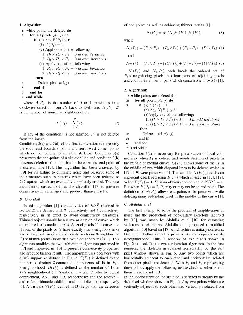
1. Algorithm:1: while points are deleted do2: for all pixels p(i, j) do3: if (a) 2 ≤ B(P1) ≤ 6
(b) A(P1) = 1(c) Apply one of the following
1. P2 × P4 × P6 = 0 in odd iterations2. P2 × P4 × P8 = 0 in even iterations
(d) Apply one of the following1. P4 × P6 × P8 = 0 in odd iterations2. P2 × P6 × P8 = 0 in even iterations
then4: Delete pixel p(i, j)5: end if6: end for7: end whilewhere A(P1) is the number of 0 to 1 transitions in a
clockwise direction from P9 back to itself, and B(P1) (2)is the number of non-zero neighbors of P1
B(P1) =
9∑i=2
Pi (2)
If any of the conditions is not satisfied, P1 is not deletedfrom the image.Conditions 3(c) and 3(d) of the first subiteration remove onlythe south-east boundary points and north-west corner pointswhich do not belong to an ideal skeleton. Condition 3(a)preservers the end-points of a skeleton line and condition 3(b)prevents deletion of points that lie between the end-point ofa skeleton line [17]. This algorithm has been criticized by[19] for its failure to eliminate noise and preserve some ofthe structures such as patterns which have been reduced to2x2 squares which are eventually completely eroded. The nextalgorithm discussed modifies this algorithm [17] to preserveconnectivity in all images and produce thinner results.
B. Guo-Hall
In this algorithm [1] conductivities of S&S (defined insection 2) are defined with 8- connectivity and 4-connectivityrespectively in an effort to avoid connectivity paradoxes.Thinned objects should be a curve or a union of curves whichare referred to as medial curves. A set of pixels G, is curve-likeif most of the pixels of G have exactly two 8-neighbors in Gand a few pixels in G are end-points (with one 8-neighbors inG) or branch points (more than two 8-neighbors in G) [1]. Thisalgorithm modifies the two-subiteration algorithm presented in[17] and improved in [19] to preserve connectivity propertiesand produce thinner results. The algorithm uses operators witha 3x3 support as defined in Fig. 2. C(P1) is defined as thenumber of distinct 8-connected components of 1s in P1’s8-neighborhood. B(P1) is defined as the number of 1s inP1’s neighborhood (1). Symbols ¯ , ∧ and ∨ refer to logicalcomplement, AND and OR, respectively; and the reserve +and • for arithmetic addition and multiplication respectively[1]. A variable N(P1), defined in (3) helps with the detection
of end-points as well as achieving thinner results [1].
N(P1) = MIN [N1(P1), N2(P1)] (3)
where
N1(P1) = (P9∨P2)+(P3∨P4)+(P5∨P6)+(P7∨P8) (4)
and
N2(P1) = (P2∨P3)+(P4∨P5)+(P6∨P7)+(P8∨P9) (5)
N1(P1) and N2(P1) each break the ordered set ofP1’s neighboring pixels into four pairs of adjoining pixelsand count the number of pairs which contain one or two 1s [1].
2. Algorithm:1: while points are deleted do2: for all pixels p(i, j) do3: if (a) C(P1) = 1;
(b) 2 ≤ N(P1) ≤ 3;(c)Apply one of the following:1. (P2 ∨ P3 ∨ P5) ∨ P4 = 0 in odd iterations2. (P6 ∨ P7 ∨ P9) ∧ P8 = 0 in even iterations
then4: Delete pixel p(i, j)5: end if6: end for7: end whileCondition 3(a) is necessary for preservation of local con-
nectivity when P1 is deleted and avoids deletion of pixels inthe middle of medial curves. C(P1) allows some of the 1s inthe middle of two-width diagonal lines to be deleted which in[17], [19] were preserved [1]. The variable N(P1) provides anend-point check replacing B(P1) which is used in [17], [19].When B(P1) = 1, P1 is an obvious end-point and N(P1) = 1.But when B(P1) = 2, P1 may or may not be an end-point. Thedefinition of N(P1) allows end-points to be preserved whiledeleting many redundant pixel in the middle of the curve [1].
C. Abdulla et al
The first attempt to solve the problem of amplification ofnoise and the production of non-unitary skeletons incurredby [17], was made by Abdulla et al [10] for extractingskeletons of characters. Abdulla et al proposed a modifiedalgorithm [10] based on [17] which achieves unitary skeletons.Deciding whether or not a pixel is skeletal depends on its8-neighborhood. Thus, a window of 3x3 pixels shown inFig. 2 is used. It is a two-subiteration algorithm. In the firstiteration, the skeleton in scanned horizontally by the 3x4pixel window shown in Fig. 5. Any two points which arehorizontally adjacent to each other and horizontally isolatedfrom other pixels are detected. With P1 and P4 representingthese points, apply the following test to check whether one ofthem is redundant [10].In the second iteration the skeleton is scanned vertically by the4x3 pixel window shown in Fig. 6. Any two points which arevertically adjacent to each other and vertically isolated from

other points are deleted. With P1 and P6 representing thesepoints, apply the following tests to check whether one of themis redundant [10].
Fig. 5. 3x4 pixel window
3. Algorithm:1: while points are deleted do2: for all pixels p(i, j) do3: Iteration 1 :4: if (a) SP 1.1 ∧ P6 = 1OR
(b) SP 1.2 ∧ P2 = 1OR(c) [(P2∧ P3)∨ (P3)∧ P2∨ P9]∧ [(P5)∧P6)∨
(P5 ∧ P6 ∧ P7]then
5: Delete pixel P1
6: where SP1.1 = P3∨P2∨P9, SP1.2 = P6∨P5∨P7
and ( ¯ ), ∨, ∧ are complement, logical OR andlogical AND respectively.
7: end if8: if P1 is not redundant
then9: if (P3 ∧ P10) ∨ (P5 ∧ P12)
then10: Delete P4
11: end if12: end if13: Iteration 2 :14: if (a) SP 2.1 ∧ P4 = 1OR
(b) SP 2.2 ∧ P8 = 1OR(c) [(P8 ∧ P7) ∨ (P7) ∧ P8 ∨ P9] ∧ [(P4) ∧ P5) ∨
(P5 ∧ P4 ∧ P3]then
15: Delete pixel P1
16: where SP2.1 = P9∨P8∨P7, SP2.2 = P3∨P4∨P5
and ( ¯ ), ∨, ∧ are complement, logical OR andlogical AND respectively.
17: end if18: if P1 is not redundant
then19: if (P7 ∧ P12) ∨ (P5 ∧ P10)
then20: Delete P6
21: end if22: end if23: end for24: end while
Fig. 6. 4x3 pixel window
D. Hall
Fully parallel thinning algorithms can have difficultypreserving connectivity of an image and researchers have

attempted to overcome this problem by partially serializingtheir algorithms by breaking a given iteration of theiralgorithm into distinct subiterations, or by partitioning theimage space into distinct subfields [18]. The algorithmproposed in [18] functions by first identifying in parallelall deletable pixels and then in parallel deleting all ofthose deletable pixels except certain pixels which mustbe maintained to preserve connectivity in an image. Thealgorithm works as follows:
4. Algorithm:1: while points are deleted do2: for all pixels p(i, j) do3: Determine the deletability of pixel p(i, j)4: if (a) 1 < B(P1) < 7;
(b) P1’s 8-neighborhood contains exactly one 4-connected component (connected set) of 1s.then
5: p(i, j) is deletable6: end if7: end for8: for all pixels p(i, j) do9: if (a) P2 = P6 = 1 and P4 is deletable
(b) P4 = P8 = 1 and P6 is deletable(c) P4, P5, P6 are deletable
then10: Do not delete pixel p(i, j)11: end if12: end for13: end while
Condition 4(b) guarantees that local connectivity is notdisrupted by removal of P1 alone. Conditions 4(a) and 4(b)together guarantee that P1 is 4-connected to S (defined insection 2) and condition 4(a) alone attempts to preserve end-points of thin lines. Condition 8(a) preserves pixels in avertical two-width rectangle, condition 8(b) preserves pixels ina horizontal two-width rectangle , and 8(c) preserves a pixelin a 2x2 square [18].
IV. PERFORMANCE EVALUATION AND COMPARISON
The four thinning algorithms were applied to thin fivefingerprint images shown in Fig. 7. Input images are filteredbinary images with the following sizes:
1) input image 1: 276x408 pixels2) input image 2: 408x480 pixels3) input image 3: 264x264 pixels4) input image 4: 336x336 pixels5) input image 5: 420x600 pixelsPerformance is evaluated in terms of connectivity, spurious
branches, convergence to unit width and data reduction effi-ciency/computational cost.
A. Connectivity
Connectivity preservation of a fingerprint pattern is crucialin AFISs, as disconnected patterns produce false minutiae.
Fig. 7. Input images
Patterns often loose their topology features if they becomedisconnected.
B. Spurious Branches
Like disconnectivity, spurious branches lead to false minu-tiae. Although post processing operations for spurious branchremoval exist, it is usually not the preferred approach sincethe extra post processing operations add extra complexity.
C. Convergence to unit width
A perfect skeleton must be unitary. If a skeleton Sm doesnot contain any one of the patterns Qk ( for k = 1 to 4 ) givenin Fig 8 , it is unitary [20].To measure width of the resulting skeleton, Jang and Chin[20] introduced a measure mt to compute the width of theextracted skeleton. mt is defined as:
mt = 1− Area[∪1≤k≤4SmQk]
Area[Sm](6)
where Area[•] is the operation that counts the number of 1-pixels. This measures a non-negative value less than or equalto 1, with mt = 1 if Sm is a perfect unit-width skeleton [20].
Fig. 8. Templates used to examine the width of the converged skeleton
D. Computational Cost
A fingerprint recognition system can only be realized whenit is fast and efficient. Thorough and efficient preprocessingtechniques lead to more efficient and accurate systems be-cause they improve the minutiae extraction algorithm which

minimizes the number of false minutiae points, thus improvingquality and speed of matching.A measure to evaluate both the data reduction efficiency andthe computational cost was defined by Jang and Chin as
md = min[1,Area[S]−Area[Sm]
n×Area[S]] (7)
where n is the number of parallel operations required toconverge and S is the original input image. This measure hasa value between 0 and 1; a large value indicates high efficiency.
E. Experimental Results and Comparison
Fig 10-14 show skeletons of the 5 test images resulting fromthe 4 thinning algorithms and Table 1 shows the results of thetwo measures mt & md (Eq 6 & Eq 7 respectively) for eachskeleton.
TABLE IEXPERIMENTAL RESULTS: mt & md READINGS
Quality MeasureImage Algorithm mt md
1 (a) Abdulla et.al 0.996 0.117(b) Guo-Hall 0.998 0.062(c) Hall 0.991 0.083(d) Zhang-Suen 0.698 0.129
2 (a) Abdulla et.al 0.974 0.120(b) Guo-Hall 0.997 0.065(c) Hall 0.988 0.085(d) Zhang-Suen 0.790 0.137
3 (a) Abdulla et.al 0.997 0.122(b) Guo-Hall 0.998 0.061(c) Hall 0.999 0.084(d) Zhang-Suen 0.864 0.130
4 (a) Abdulla et.al 0.978 0.105(b) Guo-Hall 0.993 0.056(c) Hall 0.993 0.079(d) Zhang-Suen 0.747 0.115
5 (a) Abdulla et.al 0.985 0.118(b) Guo-Hall 0.997 0.064(c) Hall 0.993 0.085(d) Zhang-Suen 0.695 0.134
The table has been graphed below (Fig 9) for a betterillustration.
Fig. 9. mt and md readings
Experimental results show that Zhang-Sue’s algorithmeffectively thins the image, but creates undesirable artifacts.The resulting skeletons (Figures 11(d), 12(d), 13(d), 14(d)and 15(d)) are non-unitary, giving an average value ofmt = 0.698 (lowest amongst the four algorithms and someimages have gaps between edges, in particular there is anentire ridge missing from the skeleton in Fig. 11 (d). This isdue to the fact that end-points are detected by A(P1) = 1.This condition works in many cases, but not for 2-pixelthick diagonal lines because in such cases A(P1) = 2. Inthis case end-points are deleted as they satisfy all the thedeletion conditions in the algorithm. One way around thiswas discussed by Raju and Xu [14] on their study of parallelthinning algorithms. In order to obtain 1-pixel thick skeletonand avoid deleting diagonal lines, some additional conditionsare added to the Zhang-Suen algorithm.In odd iterations, when A(P1) = 2, the following conditionsare checked:1) P4× P6 = 1 and P9 = 0 or2) P4× P2 = 1 and P3× P7× P8 = 1
In even iterations, when A(P1) = 2, the followingconditions are checked:1’) P2× P8 = 1 and P5 = 0 or2’) P6× P8 = 1 and P3× P4× P7 = 1
The resulting skeleton is not perfect, but it is significantlybetter than the skeleton produced by the original algorithm.This is shown by the minutiae points detected (Fig. 10)after introducing the conditions mentioned above. It can beobserved from Fig. 10 that after adding the extra conditions,the quality of the skeleton improves. Zhang-Suen’s algorithmis the most efficient of the four algorithms, giving an averageof md = 0.235. The algorithm fairly maintains connectivityand does not produce spurious branches.
Fig. 10. Skeleton produce by Zhand-Suen’s algorithm compared to modifiedversion
In [10] Abdulla et al stated that their algorithm producesunitary skeletons and in that manner it is not affected bynoise, nor does it amplify it. Although the algorithm workson characters [10], it does not work so well for fingerprintpatterns.

Fig. 11. (a) Skeleton produced by Adbulla et al’s algorithm from image 1;(b) Skeleton produced by Guo-Hall’s algorithm from image 1; (c) Skeletonproduced by Hall’s algorithm from image 1 ; (d) Skeleton produced by Zhang-Suen’s algorithm from image 1
Figures 11(a), 12(a), 13(a), 14(a) and 15(a) show that extranoise has been added to the skeleton. Even with its high valueof mt = 0.986 on average and a data reduction efficiencyvalue of md = 0.116 , Abdulla’s algorithm fails to maintainconnectivity and produces clusters of spurious branches.
Like Zhang-Sue’s, Hall’s algorithm [18] effectively thins thefingerprint pattern and unlike [17] it preservers all connectivityand does not leave gaps. Figures 11(c), 12(c), 13(c), 14(c)and 15(c) show the skeletons produced by this algorithm. Theaverage one-pixel width measure is mt = 0.993, which meansthe algorithm produces fairly unitary skeletons. The majorconcern with this algorithm [18] for fingerprint patterns isthe amount of spurious branches in the resulting skeletons.Fingerprint recognition relies heavily on minutiae extractionand spurious skeletons often lead to false minutiae detectionand hence depress the performance of the system.
Fig. 12. (a) Skeleton produced by Adbulla et al’s algorithm from image 2; (b) Skeleton produced by Guo-Hall’s algorithm from image 2; (c) Skeletonproduced by Hall’s algorithm from image 2 ; (d) Skeleton produced by Zhang-Suen’s algorithm from image 2
However, post processing algorithms can be applied toeliminate spurious branches and smooth skeletons [21]–[23].This approach is not recommended because Hall’s algorithmis not efficient, giving an average of md = 0.083, adding extraoperations required for removing spurious branches wouldworsen the efficiency of this algorithm which might not beideal for real time applications.
Lastly [1] gives the best results. The skeletons are non-spurious and preserve connectivity (see Figures 11(b), 12(b),13(b), 14(b) and 15(b)), thin and no ridges are missing. Minu-tiae features are clear and there is no apparent noise. Guo-Hallis better than Zhang-Suen at detecting end-points. N(P1) is
Fig. 13. (a) Skeleton produced by Adbulla et al’s algorithm from image 3;(b) Skeleton produced by Guo-Hall’s algorithm from image 3; (c) Skeletonproduced by Hall’s algorithm from image 3 ; (d) Skeleton produced by Zhang-Suen’s algorithm from image 3
able to detect end-points whether or not they have one or two8-neighbors. 2-pixel thick diagonal lines are not deleted. Itproduces fairly unitary skeletons, with mt = 0.997 on average.The only concern with this algorithm is its data reductionefficiency. The algorithm gave a value of md = 0.062, thelowest amongst the four algorithms.
Fig. 14. (a) Skeleton produced by Adbulla et al’s algorithm from image 4;(b) Skeleton produced by Guo-Hall’s algorithm from image 4 ; (c) Skeletonproduced by Hall’s algorithm from image 4 ; (d) Skeleton produced by Zhang-Suen’s algorithm from image 4
Fig. 15. (a) Skeleton produced by Adbulla et al’s algorithm from image 5 ;(b) Skeleton produced by Guo-Hall’s algorithm from image 5 ; (c) Skeletonproduced by Hall’s algorithm from image 5 ; (d) Skeleton produced by Zhang-Suen’s algorithm from image 5

V. CONCLUSION
There are many thinning algorithms available, and all havetheir own advantages and disadvantages. The choice of thethinning algorithm should depend on the application, as not allthinning algorithms will be suitable for a certain application.As with most computing systems, a trade off usually has tobe made between accuracy and execution time. Fast parallelthinning algorithms often suffer from loss of connectivity,as shown earlier with Zhang-Suen’s algorithm. The choiceshould depend on the nature of the application at hand. Forexample an application for an airport boarding gate, wouldhave to trade accuracy for execution time, whereas a highsecurity location or a transaction between business needs toensure high accuracy, and can trade the execution time. Thispaper has shown Guo-Hall’s thinning algorithm works best forfingerprint pattern. Even with the short-comings Zhang-Suen’salgorithm is still the most used thinning algorithm in literaturefor pattern recognition applications. Most algorithms modifyZhang-Suen’s algorithm either to address the connectivityissue or to adapt it for specific application.
VI. FUTURE WORK
Zhang-Suen, Gua-Hall and Hall algorithms are promisingand we will investigate them further. To improve efficiency,new distributed algorithms based on these three will bedeveloped. For Zhang-Suen’s algorithm, the most importantstep will be to try and eliminate the artifacts, and for Hall’salgorithm, the last step will be to apply post-processingtechniques to remove spurious branches after distributing theprocessing.
REFERENCES
[1] Z. Guo and R. Hall, “Parallel thinning with two-subiteration algorithms,”Communications of the ACM, vol. 32, pp. 359–373, Mar 1989.
[2] N. Han, C. La, and P. Rhee, “An effecient fully parallel thinningalgorithm,” Proceedings of the Fourth International IEEE Conferenceon Document Analysis and Recognition, vol. 01, pp. 137–141, 1997.
[3] R. Gupta and R. Kaur, “Skeletonization algorithm for numerical pat-terns,” International Jornal of Signal Processing, Image Processing andPattern Recognition, vol. 01, pp. 63–72, Dec 2008.
[4] A. Saleh, A. Eldin, and A. Wahdan, “A modified thinning algorithm forfingerprint identification systems,” International Conference on Com-puter Engineering & Systems, pp. 371–376, Dec 2009.
[5] L. Ji, Z. Yi, L. Shang, and X. Pu, “Binary fingerprint image thinningusing template-based pcnns,” IEEE transactions on systems, man, andcybernetics -part B: Cybernetics, vol. 37, pp. 1407–1413, Oct 2007.
[6] C. Arcelli and G. Baja, “A thinning algorithm based on prominencedetection,” Pattern Recognition, pp. 225–235, 1981.
[7] P. Kardos, G. Nemeth, and K. Palagyi, “An order-indepandent sequentialthinning algrithm,” pp. 162–175, 2009.
[8] H. Pu, J. Chen, and Y. Zhang, “Fingerprint thinning algorithm basedonn mathematical morphology,” The Eighth International Journal onEletriconic Measurements and Instruments, vol. 01, pp. 618–621, 2007.
[9] R. Zhou, C. Quek, and G. Ng, “A novel single-pass thinning algorithmand an effective set of performance criteria,” Pattern Recogntion Letters16, pp. 1267–1275, 1995.
[10] W. Abdulla, A. Saleh, and A. Morad, “A preprocessing algorithm forhand-written character recognition,” Pattern Recognition Letters 7, pp.13–18, 1988.
[11] L. Haung, G. Wan, and C. Liu, “An improved parallel thinningalgorithm,” Proceedings of the Seventh International Conference onDocument Analysis and Recognition, vol. 01, pp. 780–783, Dec 2003.
[12] H. Lingga, S. Sudiro, and E. Wibowo, “Hardware implementation offingerprint image thinning algorithm in fpga device,” IEEE InternationalConference on Networking and Information Technology, pp. 187–191,2010.
[13] H. Xu, Y. Qu, and F. Zhao, “Fpga based parallel thinning for binaryfingerprint image,” IEEE Chinese Conference on Pattern Recognition,pp. 1–4, Nov 2009.
[14] G. Raju and Y. Xu, “Study of parallel thinning algorithms,” IEEEInternational Conference on Systems, Man, and Cybernetics, vol. 01,pp. 661–666, Dec 1991.
[15] M. Ahmed and R. Ward, “A rotational invariant rule-based skeletoniza-tion algorithm for character recognition,” IEEE Transactions on PatternAnalysis and Machine Intelligence, vol. 24, pp. 1672–1678, Jan 2003.
[16] M. Girgis, A. Sewisy, and R. Mansour, “Employing generic algorithmsfor precise fingerprint matching based on line extraction,” GVIP Journal,vol. 07, pp. 51–59, 2007.
[17] T. Zhang and C. Suen, “A fast parallel algorithm for thinning digitalpatterns,” Communications of the ACM, vol. 27, pp. 236–239, Mar 1984.
[18] R. Hall, “Fast parallel thinning algorithms: Parallel speed and connec-tivity preservation,” Communications of the ACM, vol. 32, pp. 124–129,Jan 1989.
[19] H. Lu and P. Wang, “A comment on ’a fast parallel algorithm forthinning digital patterns’,” Communications of the ACM, vol. 29, pp.239–242, Mar 1986.
[20] B. Jang and T. Chin, “One-pass parallel thinning: Analysis, properties,and quantitative evaluation,” IEEE Transactions On Pattern Analysis AndMechine Intelligence, pp. 1129–1140, 1992.
[21] E. Virginia, “Fingerprint thinning algorithm,” IEEE AES Systems Mag-azine, pp. 28–30, Sep 2003.
[22] E. Nel, J. Preez, and B. Herbst, A Pseudo-Skeletonization Algorithm forStatic Handwritten Scripts. Springer-Verlag, 2009, vol. 01.
[23] D. Goldman and N. Bourbakis, “Well-shaped skeletons and fast com-putation of the (3,4) distance transform,” Journal of Electric Imaging,vol. 11, pp. 404–413, Jul 2002.


