Embed Size (px)
Citation preview
Distrib Parallel Databases (2007) 22: 55–83DOI 10.1007/s10619-007-7012-1
A decentralized execution modelfor inter-organizational workflows
Vijayalakshmi Atluri · Soon Ae Chun ·Ravi Mukkamala · Pietro Mazzoleni
Published online: 11 May 2007© Springer Science+Business Media, LLC 2007
Abstract Workflow Management Systems (WFMS) are often used to support the au-tomated execution of business processes. In today’s networked environment, it is notuncommon for organizations representing different business partners to collaboratefor providing value-added services and products. As such, workflows representing thebusiness processes in this loosely-coupled, dynamic and ad hoc coalition environmenttend to span across the organizational boundaries. As a result, it is not viable to em-ploy a single centralized WFMS to control the execution of the inter-organizationalworkflow due to limited scalability, availability and performance. To this end, in thispaper, we present a decentralized workflow model, where inter-task dependencies areenforced without requiring to have a centralized WFMS. In our model, a workflow isdivided into partitions called self-describing workflows, and handled by a light weightworkflow management component, called the workflow stub, located at each organi-zation. We present a performance study by considering different types of workflowswith varying degrees of parallelism. Our performance results indicate that decentral-
The work of V. Atluri is supported in part by the National Science Foundation under grantIIS-0306838.
V. Atluri (�)MS/IS Department, Rutgers University, Newark, NJ 07102, USAe-mail: [email protected]
S.A. ChunInformation Systems, City University of New York, Staten Island, NY 10314, USAe-mail: [email protected]
R. MukkamalaComputer Science Department, Old Dominion University, Norfolk, VA 23529, USAe-mail: [email protected]
P. MazzoleniDipartimento di Scienze dell’Informazione, University of Milan, via Comelico 39/41,20135 Milano, Italye-mail: [email protected]
56 Distrib Parallel Databases (2007) 22: 55–83
ized workflow management indeed enjoys significant gain in performance over itscentralized counterpart in cases where there is less parallelism.
Keywords Decentralized workflow execution · Self-describing workflow ·Workflow partition · Dependency split · Workflow stub · Evaluation of workflowexecution
1 Introduction
Workflow Management Systems (WFMS) are often used to support the automatedexecution of business processes. The proliferation of the Internet and the World WideWeb provides new opportunities for conducting business today. In this networkedeconomy, different organizations often collaborate, connecting suppliers and busi-ness partners to deliver more value-added services and products. Business processesin this loosely-coupled, dynamic and ad hoc coalitions among autonomous and inde-pendent organizations tend to span across the organizational boundaries. As a result,the tasks that make up the inter-organizational workflow are executed by differentorganizations. In such an environment it is not viable to employ a single central-ized workflow management system (WFMS) to control the execution of the workflowbecause of a number of reasons including limited scalability, availability and perfor-mance [22]. As such, it is desirable to be able to execute the workflow without havingto use a centralized WFMS, in other words, by employing a decentralized WFMS.
Specifically, the decentralized WFMS should mimic the responsibilities of its cen-tralized counterpart, namely, (1) distributing the tasks to the appropriate agents, and(2) ensuring the specified task dependencies by sending the tasks to their respectiveagents only when all requisite conditions are satisfied. However, executing a work-flow in a decentralized fashion is not trivial. This is primarily because, an inter-organizational workflow may comprise of task dependencies that span organizationalboundaries, called inter-site dependencies. The challenge therefore is to enforce inter-site dependencies by keeping the communication cost among sites to a minimum.A large number of inter-site dependencies may have serious consequences on theperformance and the degree of concurrency.
In this paper, we present a decentralized workflow model, where inter-task de-pendencies are enforced without requiring to have a centralized WFMS. It employsthe notion of self-describing workflows and WFMS stubs. Self-describing workflowsare partitions of a workflow that carry sufficient information such that they can bemanaged by a local task execution agent rather than the central WFMS. We formallyprove that our partitioning of workflows into self-describing workflows is such thatthe generation results in an equivalent workflow. A WFMS stub is a light-weightcomponent that can be attached to a task execution agent, which is responsible forreceiving the self-describing workflow, modifying it and re-sending it to the next taskexecution agent.
We present the results of our performance study by considering different work-flow types with varying degrees of parallelism. The two extreme types of workflowsare that all the tasks in the workflow must be executed in parallel and all tasks mustbe executed in a serial fashion. The remaining types of the workflows are a mix of
Distrib Parallel Databases (2007) 22: 55–83 57
both. In particular, we consider workflows comprising of at least 10 tasks, and in-volving AND-join and OR-split. Our performance results indicate that decentralizedworkflow management indeed enjoys significant gain in performance over centralizedworkflow management in cases where there is less parallelism.
This paper is organized as follows. We first present an example of inter-organizational workflow in Sect. 1.1, followed by the workflow model describedin Sect. 2. In Sect. 3, we present the decentralized control model and introduce theconcepts self-describing workflow, pre-condition splitting and a workflow partitionalgorithm. In Sect. 4, the performance study on the decentralized versus centralizedcontrol is presented. It includes descriptions on the experimental setup and experi-mental results followed by discussions. In Sect. 5, we present the system architectureand the implementation. In Sect. 6, we present the related work followed by conclud-ing remarks in Sect. 7.
1.1 Example
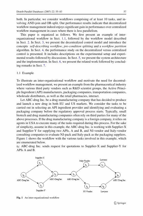
To illustrate an inter-organizational workflow and motivate the need for decentral-ized workflow management, we present an example from the pharmaceutical industrywhere various third party vendors such as R&D scientist groups, the Active Princi-ple Ingredient (API) manufacturers, packaging companies, transportation companies,wholesale distributors, as well as the retail pharmacies, interact.
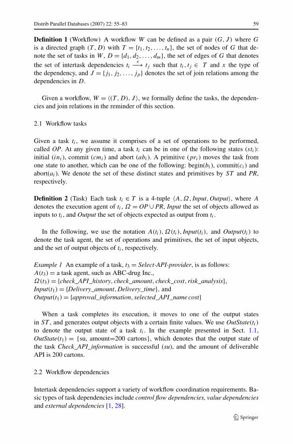
Let ABC-drug Inc. be a drug manufacturing company that has decided to produceand launch a new drug in both EU and US markets. We consider the tasks to becarried out in selecting an API ingredient provider and identifying and evaluating apackaging company before the regulatory approval process starts. Typically, smallbiotech and drug manufacturing companies often rely on third parties for many of theabove processes. If the drug manufacturing company is a foreign company, it relies onagents in USA to execute many of the tasks required during this process. For the sakeof simplicity, assume in this example, the ABC-drug Inc. is working with Supplier-Xand Supplier-Y for supplying two APIs, A and B, and NJ-vendor and Italy-vendorconsulting companies to evaluate NJ-pack and Italy-pack as the packaging suppliers.Figure 1 shows the workflow with the various tasks involved in this example, whichare enumerated below.t0: ABC-drug Inc. sends request for quotations to Supplier-X and Supplier-Y forAPIs A and B.
Fig. 1 An inter-organizational workflow
58 Distrib Parallel Databases (2007) 22: 55–83
Fig. 2 Centralized (traditional)workflow management
t1: Supplier-X sends available amount and price for APIs A and B.t2: Supplier-Y sends available amount and price for APIs A and B.t3: ABC-drug Inc. decides an API provider for drug manufacturing. If the two ingre-dients over 500 units each can be obtained, the manufacturing can proceed.t4: ABC-drug Inc. evaluates manufacturing requirements application for US and EU.t5: Italy-vendor evaluates whether the packaging company Italy-pack can meet thepackaging requirements for EU market.t6: NJ-vendor evaluates whether NJ-pack can satisfy packaging requirements for USmarket.t7: The lawyers of ABC-drug Inc. prepare EMEA (European Agency for Evaluationof Medical Products) application for the new drug, if t5 is satisfactory.t8: The lawyers of ABC-drug Inc. prepare FDA (US Food and Drug Administration)application for the new drug, if the outcome of t6 is satisfactory.t9: ABC-drug Inc. submits FDA and EMEA applications for approval.
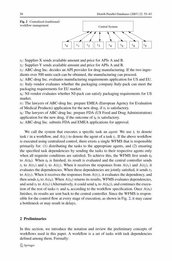
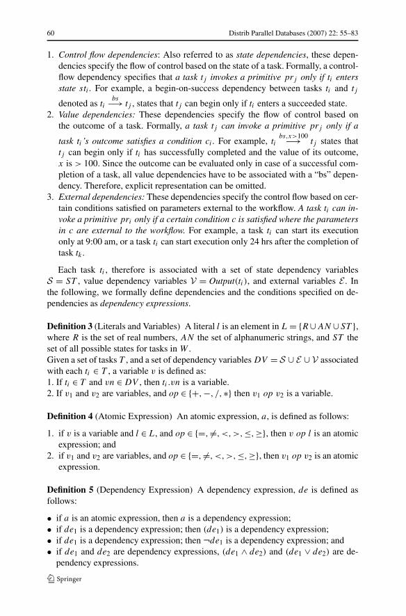
We call the system that executes a specific task an agent. We use ti to denotetask i in a workflow, and A(ti) to denote the agent of a task ti . If the above workflowis executed using centralized control, there exists a single WFMS that is responsibleprimarily for: (1) distributing the tasks to the appropriate agents, and (2) ensuringthe specified task dependencies by sending the tasks to their respective agents onlywhen all requisite conditions are satisfied. To achieve this, the WFMS first sends t0to A(t0). When t0 is finished, its result is evaluated and the central controller sendst1 to A(t1) and t2 to A(t2). When it receives the responses from A(t1) and A(t2), itevaluates the dependencies. When these dependencies are jointly satisfied, it sends t3to A(t3). When it receives the responses from A(t3), it evaluates the dependency, andthen sends t4 to A(t4). When A(t4) returns its results, WFMS evaluates dependencies,and send t5 to A(t5) (Alternatively, it could send t6 to A(t6)), and continues the execu-tion of the rest of tasks t7 and t9 according to the workflow specification. Once A(t9)
finishes, its results are sent back to the central controller. Since the WFMS is respon-sible for the control flow at every stage of execution, as shown in Fig. 2, it may causea bottleneck or may result in delays.
2 Preliminaries
In this section, we introduce the notation and review the preliminary concepts ofworkflows used in this paper. A workflow is a set of tasks with task dependenciesdefined among them. Formally:
Distrib Parallel Databases (2007) 22: 55–83 59
Definition 1 (Workflow) A workflow W can be defined as a pair (G,J ) where G
is a directed graph (T ,D) with T = {t1, t2, . . . , tn}, the set of nodes of G that de-note the set of tasks in W , D = {d1, d2, . . . , dm}, the set of edges of G that denotesthe set of intertask dependencies ti
x−→ tj such that ti , tj ∈ T and x the type ofthe dependency, and J = {j1, j2, . . . , jp} denotes the set of join relations among thedependencies in D.
Given a workflow, W = 〈(T ,D),J 〉, we formally define the tasks, the dependen-cies and join relations in the reminder of this section.
2.1 Workflow tasks
Given a task ti , we assume it comprises of a set of operations to be performed,called OP. At any given time, a task ti can be in one of the following states (sti ):initial (ini ), commit (cmi ) and abort (abi ). A primitive (pri ) moves the task fromone state to another, which can be one of the following: begin(bi ), commit(ci ) andabort(ai ). We denote the set of these distinct states and primitives by ST and PR,respectively.
Definition 2 (Task) Each task ti ∈ T is a 4-tuple 〈A,Ω, Input,Output〉, where A
denotes the execution agent of ti , Ω = OP ∪ PR, Input the set of objects allowed asinputs to ti , and Output the set of objects expected as output from ti .
In the following, we use the notation A(ti),Ω(ti), Input(ti), and Output(ti) todenote the task agent, the set of operations and primitives, the set of input objects,and the set of output objects of ti , respectively.
Example 1 An example of a task, t3 = Select-API-provider, is as follows:A(t3) = a task agent, such as ABC-drug Inc.,Ω(t3) = {check_API_history, check_amount, check_cost, risk_analysis},Input(t1) = {Delivery_amount,Delivery_time}, andOutput(t1) = {approval_information, selected_API_name cost}
When a task completes its execution, it moves to one of the output statesin ST , and generates output objects with a certain finite values. We use OutState(ti)to denote the output state of a task ti . In the example presented in Sect. 1.1,OutState(t1) = {su, amount=200 cartons}, which denotes that the output state ofthe task Check_API_information is successful (su), and the amount of deliverableAPI is 200 cartons.
2.2 Workflow dependencies
Intertask dependencies support a variety of workflow coordination requirements. Ba-sic types of task dependencies include control flow dependencies, value dependenciesand external dependencies [1, 28].
60 Distrib Parallel Databases (2007) 22: 55–83
1. Control flow dependencies: Also referred to as state dependencies, these depen-dencies specify the flow of control based on the state of a task. Formally, a control-flow dependency specifies that a task tj invokes a primitive prj only if ti entersstate sti . For example, a begin-on-success dependency between tasks ti and tj
denoted as tibs−→ tj , states that tj can begin only if ti enters a succeeded state.
2. Value dependencies: These dependencies specify the flow of control based onthe outcome of a task. Formally, a task tj can invoke a primitive prj only if a
task ti ’s outcome satisfies a condition ci . For example, tibs,x>100−→ tj states that
tj can begin only if ti has successfully completed and the value of its outcome,x is > 100. Since the outcome can be evaluated only in case of a successful com-pletion of a task, all value dependencies have to be associated with a “bs” depen-dency. Therefore, explicit representation can be omitted.
3. External dependencies: These dependencies specify the control flow based on cer-tain conditions satisfied on parameters external to the workflow. A task ti can in-voke a primitive pri only if a certain condition c is satisfied where the parametersin c are external to the workflow. For example, a task ti can start its executiononly at 9:00 am, or a task ti can start execution only 24 hrs after the completion oftask tk .
Each task ti , therefore is associated with a set of state dependency variablesS = ST , value dependency variables V = Output(ti), and external variables E . Inthe following, we formally define dependencies and the conditions specified on de-pendencies as dependency expressions.
Definition 3 (Literals and Variables) A literal l is an element in L = {R∪AN ∪ST },where R is the set of real numbers, AN the set of alphanumeric strings, and ST theset of all possible states for tasks in W .Given a set of tasks T , and a set of dependency variables DV = S ∪ E ∪ V associatedwith each ti ∈ T , a variable v is defined as:1. If ti ∈ T and vn ∈ DV , then ti .vn is a variable.2. If v1 and v2 are variables, and op ∈ {+,−, /,∗} then v1 op v2 is a variable.
Definition 4 (Atomic Expression) An atomic expression, a, is defined as follows:
1. if v is a variable and l ∈ L, and op ∈ {=, �=,<,>,≤,≥}, then v op l is an atomicexpression; and
2. if v1 and v2 are variables, and op ∈ {=, �=,<,>,≤,≥}, then v1 op v2 is an atomicexpression.
Definition 5 (Dependency Expression) A dependency expression, de is defined asfollows:
• if a is an atomic expression, then a is a dependency expression;• if de1 is a dependency expression; then (de1) is a dependency expression;• if de1 is a dependency expression; then ¬de1 is a dependency expression; and• if de1 and de2 are dependency expressions, (de1 ∧ de2) and (de1 ∨ de2) are de-
pendency expressions.
Distrib Parallel Databases (2007) 22: 55–83 61
Example 2 Following are examples of dependency expressions.
1. t1.state = su is a dependency expression2. (t1.amount > 400 ∧ t1.delivery − days ≥ 2) is a dependency expression
Definition 6 (Dependency) Each dependency tix−→ tj in D, is a 4-tuple 〈hd,de, tl,
pr〉, where hd and t l denote the head (ti ) and tail (tj ) tasks, de the dependencyexpression, and pr ∈ PR the primitive of tj to be invoked when de is True.
Example 3 Following is a list of examples of the three types of dependencies:
1. t1bc−→ t2: 〈t1, t1.state = commit, t2,begin〉
2. t1bc,amount>200−→ t2: 〈t1, (t1.state = commit ∧ t1.amount > 200), t2,begin〉
3. t1time=10am,abort−→ t2: 〈t1, (t1.time = 10am), t2,abort〉
2.3 Join relations
Traditionally, WFMS makes use of explicit synchronizing constructs to avoid ambi-guity. Join relations represent the logical relationships among the dependencies whena task is involved in multiple task dependencies such as AND-join or OR-join. TheAND-join, or synchronization, is when two or more parallel executing activities con-verge into a single common thread of control and all the information coming from theprevious tasks are needed to perform the task. The OR-join, or merging, is definedas a point within the workflow where two or more alternative activity(s) (workflowbranches) re-converge to a single common activity as the next step within the work-flow. Here, since not all parallel execution results are needed at the join point, theexecution can continue as soon as at least one of the previous tasks reaches the join.
For example, assume d1 = tix1−→ tj and d2 = tk
x2−→ tj , where d1 = 〈ti , de1, tj ,
prj 〉, and d2 = 〈tk, de2, tj ,prj 〉. An AND-join states that de1 ∧ de2 must be true toinitiate tj or rather to invoke the primitive of tj , prj . Similarly, an OR-joins statesthat de1 ∨ de2 must be true to initiate tj or rather to invoke the primitive of tj , prj .
Definition 7 (Join Expression) A join expression je is defined as follows:
• If d1 is a dependency, then d1 is a join expression.• If d1 and d2 are two dependencies, then (d1 ∧d2) and (d1 ∨d2) are join expressions.• If d1 is a dependency and je1 is a join expression, then d1 ∧ je1, d1 ∨ je1 are join
expressions.• If je1 and je2 are dependency expressions, then je1 ∧ je2, je1 ∨ je2 are join
expressions
Example 4 Following shows examples of join expressions:
1. (t2d2−→ t4, t3
d3−→ t4, t4d4−→ t4) can have a join relation among t2, t3 and t4, j4
whose join expression is ((d2 ∧ d3) ∨ d4), where d2 = (t2.state = success), d3 =(t3.state = success) and d4 = (t3.price + t2.price ≤ $200).
62 Distrib Parallel Databases (2007) 22: 55–83
Therefore, instead of explicitly representing a join condition as an AND or ORjoin, we represent that as a join relation whose join expression is composed of depen-dency expressions.
Now we can define join relations as follows:
Definition 8 (Join Relation) A join relation ji is a tuple 〈ti , jei〉, where ti is the taskat which the join relation is specified and jei is a join expression.
Example 5
1. t1d1−→ t3 = 〈t1, d1 = NULL, t3,begin〉
2. t2d2−→ t3 = 〈t1, d2 = NULL, t3,begin〉
3. t3d3−→ t3 = 〈t3, (t1.amount(A) ≥ 500 ∨ t2.amount(A) ≥ 500) ∧ (t1.amount(B ) ≥
500 ∨ t2.amount(B) ≥ 500), t3, begin 〉4. j3 = 〈t3, ((d1 ∧ d2) ∧ d3)〉
The join relation has a join expression d3 that states only when (t1.amount(A) ≥500 ∨ t2.amount(A) ≥ 500) ∧ (t1.amount(B ) ≥ 500 ∨ t2.amount(B) ≥ 500) is true,t3 could begin. Notice that d1 and d2 do not have any dependency expressions thatparticipate in the join relation.
2.4 Split relations
Consider a split relation as in d1 = tix1−→ tj and d2 = ti
x2−→ tk . Unlike join rela-tions, split relations do not necessarily have to be explicitly specified. An OR-splitcan be realized by appropriately choosing the conditions in the dependencies, as
in t4bf ∨cost>$4million−→ t5 and t4
cost≤$4million−→ t6 in example in Sect. 1.1. In this case,even if one does not explicitly specify that the split at t4 is an OR-split, based on thepreconditions of the dependencies t4 → t5 and t4 → t6, it is obvious that only oneamong t5 and t6 will be executed, but not both.
If there is only one dependency is evaluated true, then it is considered as an ex-clusive OR split while multiple but not all dependencies are evaluated true then it isconsidered as an inclusive OR-split. If all the outgoing dependencies are satisfied,then it is considered as AND-split. Thus, the explicit OR-split or AND-split is notnecessary. Any path that satisfies the dependency expression will be taken.
3 Decentralized control to preserve autonomy
In this section, we will first propose a methodology and architecture to enforce theinter-organizational task dependencies without the need for a centralized WFMS. Inregard to this, we propose (1) self-describing workflows and (2) WFMS stubs. Self-describing workflow carries workflow information, and WFMS stubs are lightweightsoftware component that can be installed at each agency to process a self-describingworkflow. We will first define the precondition set for each task, which is essential fordescribing the self-describing workflow. In the following, we discuss them in detail.
Distrib Parallel Databases (2007) 22: 55–83 63
3.1 Precondition set
The precondition set of ti , denoted as PreSet(ti) is a set of conditional expressionsthat have to be met in order to invoke a primitive in ti so that ti moves from one state tothe other based on the workflow specification. Preset(ti) can thus be derived from thetask dependencies and join relations. Since the dependencies may specify invocationof one of primitive operations (i.e. begin, commit, abort), we need to distinguish the
preconditions for each primitive. For example, tibc−→ tj invokes begin operation for
tj on ti ’s commit, while tic−→ tj invokes commit operation for tj on ti ’s commit.
For each task ti , we thus have three preconditions: Prebi , Prec
i and Preai , precondi-
tions to trigger begin, commit, and abort primitive operations respectively. (Note herethat based on the nature of the dependencies, some of the preconditions may alwaysbe True.) We have not included the preconditions for the evaluate primitive because,typically there will not be any dependency specification that requires to invoke it.PreSet(ti) thus includes the preconditions for only the three primitive operations forti , namely, begin, commit and abort. That is, PreSet(ti) = {Preb
i ,Preci ,Prea
i }.In the following, we derive the preconditions of a task ti for each primitive op-
eration pri from the join expression. Due to definitions 7 and 8, a task dependencyis a special case of a join relation. Given a join expression, the following definitionhelps to extract the part of the join expression relevant to a task primitive.
Definition 9 (Precondition) Let jei be the join expression of ti . We define the pre-condition for prj primitive of task ti as follows: Pre
prji = {jei | for each dk in jei ,
substitute dk with dek}.
Example 6 Some examples of preconditions for a primitive is illustrated with for t3 inexample in Sect. 1.1. Consider two different cases of Precondition Set for the task t3:
1. Precondition Set, Preb3 = (t2.state = f l), Prec
3 = ∅ and Prea3 = ∅, denotes that the
task t3 can start begin operation when t2 generates failed state f l.2. Precondition Set, Preb
3 = (t1.amount(A) ≥ 500 ∨ t2.amount(A) ≥ 500) ∧(t1.amount(B) ≥ 500 ∨ t2.amount(B) ≥ 500) Prec
3 = ∅ and Prea3 = ∅, denotes
that t3 can begin when the amount of A is greater than equal to 500 from ethertask t1 or t2, and the amount of B is greater than 500 from either t1 or t2.
As described in Sect. 2.3, the second example above illustrates the AND-join ex-pression as the precondition. Thus the explicit join operators, such as AND-join andOR-join, are not needed. Similarly, the OR-join can be expressed in the preconditionsas a join expression that is logical relations among dependencies. The advantage ofthis approach is discussed in [3]. With explicit AND-join or OR-join operator, thecomplex join relations shown above is not possible. In addition, the execution ofa task, such as t3, has to wait for the execution results from all the preceding tasks,e.g. t1 and t2 before the AND-join or OR-join can be evaluated. With our representa-tion where AND or OR-join is expressed as a precondition set, the execution of a taskcan start as soon as the precondition is satisfied. For instance, in the above example,the execution of the t3 can start as soon as t1 generates results of amount A and Bgreater than equal to 500, without waiting for the results from t2, since regardless ofwhatever results t2 generates, the precondition of t3 is satisfied to begin its execution.
64 Distrib Parallel Databases (2007) 22: 55–83
3.2 Self-describing workflows
Intuitively, a self-describing workflow comprises of (1) a task t , (2) all the tasks thatfollow t and the dependencies among them, (3) the input objects required to execute t ,(4) the task agent A(t) that executes t , (5) the precondition to execute t and (6) theoutput state of the task prior to t . This information is piggy-backed along with t whensending it to its execution agent. That is, as the workflow execution progresses, theworkflow gets divided into partitions and forwarded to the next task execution agent.We assume that the initial partition is the entire workflow, which is denoted as P1.Let Pi be the ith partition.
Following is a formal definition of the self-describing workflow:
Definition 10 (Self Describing Workflow) We define a self-describing workflow,Self (Pi), as a tuple 〈ti ,A(ti),PreSet(ti),OutState(ti),Pi〉, where ti is the first taskin Pi , A(ti) the agent that executes ti , PreSet(ti) the set of preconditions to be satis-fied for ti to enter a state sti , OutState(ti) the output state of ti , and Pi the workflowpartition.
OutState(ti) can be a control state, value state of a variable, and/or an externalstate. For instance, OutState(t6) in example in Sect. 1.1 can be {cm, test-result =“pass”}, and OutState(t7) can be {cm, test-result = “fail”}. Note that OutState(ti)is used for evaluating dependency expressions, while Output(ti) is forwarded to thefollowing agents to be used as input to their tasks.
3.3 WFMS stub
A WFMS stub is a small component that can be attached to a task execution agent.This module is responsible for: (1) evaluating the preconditions and sending the tasksto be executed at that site to its execution agent, (2) partitioning the remaining work-flow to construct self-describing workflows, (3) evaluating control information in thedependency expression to decide where to send the self-describing workflows, and(4) forwarding each self-describing workflow to the relevant subsequent agents.
Since dependency conditions are stored as preconditions, the WFMS stub needsto identify the part of the precondition that can be evaluated at the current executionagent, say A(ti) and the part that can be evaluated at the following agent, say A(tj ).Thus the stub at A(ti) needs to split the precondition of Pre(tj ) of tj . These two partsof the precondition are referred to as immediate and deferred, respectively.
Example 7 In the following, we show the immediate and deferred parts of the pre-condition for two cases—a single dependency and a join relation.
1. Consider a dependency t1x1−→ t2, where Preb
2 = (t1.status = su ∧ t2. tempera-ture_machine> 400F). This is a typical example of workflow used in the heavyindustry where a process can be done properly only under certain physical condi-tions. Here A(t1) is able to evaluate just part of Pre(t2), i.e., only (t1.status = su).But it cannot evaluate the remaining part, (t2.temperature_machine > 400F)
since it has no information about the temperature reached by the machine at t2
Distrib Parallel Databases (2007) 22: 55–83 65
at a given time. Therefore, this part of the precondition has to be deferred toA(t2) for its evaluation. Thus, immediate(t1) = (t1.status = su) and deferred(t1) =(t2.temperature_machine > 400F).
2. Consider a join relation j1 = 〈t3, d1 ∧d2 ∧d3〉 where de1 = (t1.status = su), de2 =(t2.status = su) and de3 = (t1.price + t2.price ≥ $200). It is obvious that whileimmediate(t1) = t1.status = su and deferred(t1) = (t2.status = su) ∧ (t1.price +t2.price ≥ $200), immediate(t2) = t2.status = su and deferred(t2) = (t1.status =su) ∧ (t1.price + t2.price ≥ $200).
The WFMS stub at A(ti) prepares self-describing workflows for the following taskagents A(tj ) by first partitioning the remaining workflow. Following is an algorithmfor generating a self-describing workflow.
Algorithm 1 (Workflow Partition Algorithm)
Partitioning(Pi ):Given Pi at A(ti ),For each tj where ti
x−→ tj exists in Pi ,Pj = {(T ,D) | T = a set of tasks such that each tk ∈ T is reachable from tj
D = a set of dependencies among tasks in T }Generate a Self-describing Workflow:Self (Pj ) = 〈tj ,A(tj ),PreSet(tj ),OutState(ti),Pj 〉
The self-describing workflow Self (Pj ) at A(ti) generated from the above algo-rithm consists of: the next task to be executed in the workflow (tj ), the agent thatexecutes tj (A(tj )), the precondition for tj (PreSet(tj )), ti ’s output state after its ex-ecution (OutState(ti)), and the workflow partition (Pj ).
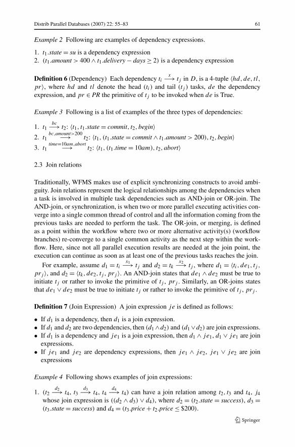
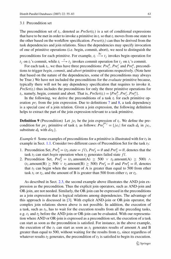
We illustrate the working of the partitioning and decentralized control with thehelp of the example in Sect. 1.1, as various steps shown in Fig. 3. The centralizedagent receives the workflow as a whole and forwards the whole partition to the firsttask agent A(t0). After task agent A(t0) finishes the execution of t0, it partitions the re-maining workflow in two: partition P 1.1 and P 1.2 as shown in Fig. 3. The task agentA(t1) finishes its own task t1 and partitions the workflow P 1.1 into partition P 2.1,and at the same time the task agent A(t2) finishes its task t2 and partition the workflowinto P 2.2. In this case, partitions P 2.1 and P 2.2 have the same structure. Each taskagent A(t1) and A(t2) sends the partitions P 2.1 and P 2.2 to the next agent A(t3).A(t3) discards one of the forwarded workflow partitions since these are the same,and execute its task t3. It prepares its partition P 3 and forwards it to task agent A(t4).Afer t4 is finished, A(t4) partitions the workflow into P 4.1 and P 4.2 each of which isforwarded to task agent A(t5) and A(t6), respectively. The task agent A(t5) executesits task and forwards the remaining partition P 5.1 to the next task agent A(t7), whilethe task agent A(t6) executes its task t6 and forwards its workflow partition P 5.2to task agent A(t8). Task agent A(t7) executes its tasks and forwards the remainingworkflow partition P 6 to task agent A(t9). Similarly, in parallel, task agent A(t8)
executes its task and forwards the remaining workflow partition P 6. Lastly, A(t9)
finishes its task and report back the result to the central controller.
66 Distrib Parallel Databases (2007) 22: 55–83
Fig. 3 Example of workflow partitioning process
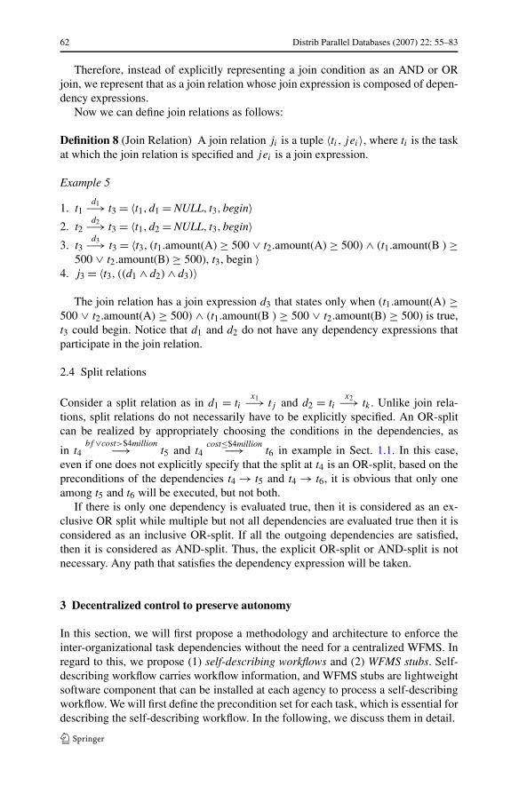
Fig. 4 Decentralized workflow management
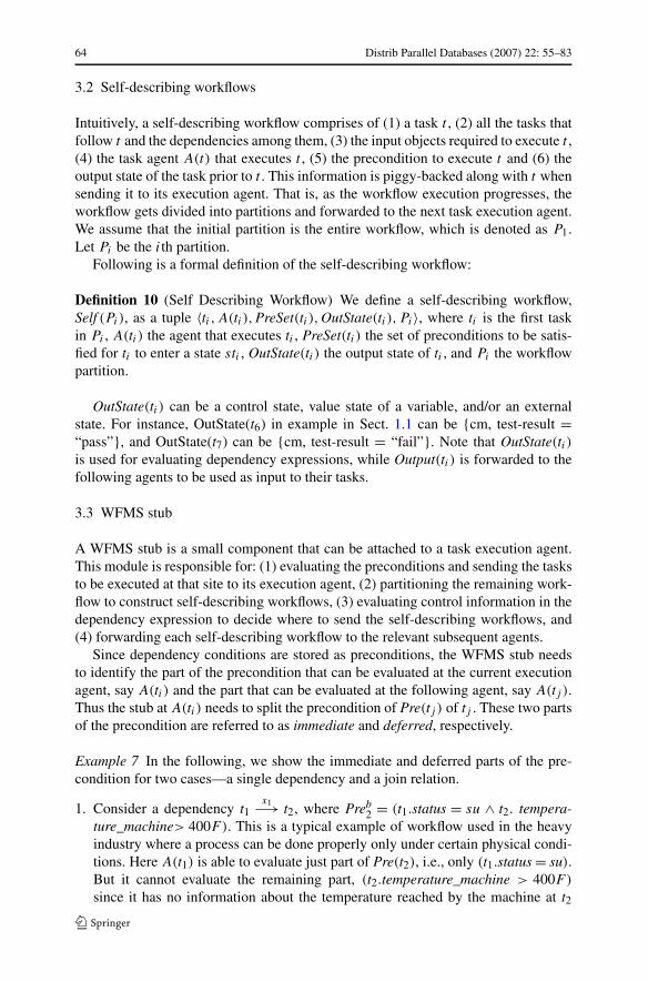
In other words, the execution of a workflow is managed by each task agent throughpeer-to-peer interaction as shown in Fig. 4. Each task agent knows which task toexecute, evaluates the dependencies and forwards the remaining workflow to the nexttask agent, until all the tasks in the workflow are executed. At the end, the last taskexecution agent(s) needs to report the results back to the central WFMS. Note thatthis way of execution results in fewer message exchanges between the central WFMS
Distrib Parallel Databases (2007) 22: 55–83 67
and the task execution agents, and also minimizes the control by one single centralcontrolling authority, which is desirable in autonomous environments.
The self describing workflow SELF(Pj ) at A(ti) generated from the algorithmcontains the following information:
1. tj = the next task of the workflow2. Pre(tj ) = precondition for tj3. OutState(ti) = ti ’s execution state information4. Pj = partition of workflow control
The self-describing workflows thus generated, when composed together, must beequivalent to the original workflow. The definition 11 defines the equivalence of aSelf (P ) and the composition of its partitioned workflows, and the theorem 1 provesthe union of self-describing workflow partitions is equivalent to the original work-flow.
Definition 11 (Equivalence) Given two self-describing workflows Self (P ) andSelf (P ′), we say that Self (P ) is equivalent to Self (P ′), denoted as Self (P ) ≡Self (P ′) if,
(1) the set of all operations in Self (P ) is same as that of Self (P ′), and(2) for each ti , the PreSet(ti) in Self (P ) = PreSet(ti) in Self (P ′).
Theorem 1 Let Self (Pi) be a self-describing workflow. Assume Self (Pi) is decom-posed into Self (Pi1), Self (Pi2), . . . ,Self (Pin) using algorithm 1. Then Self (Pi) ≡⋃n
j=1 Self (Pij ).
Proof To prove this theorem, from definition 11 we need to prove the following twoparts:(1) The union of the set of all operations in Self (Pi1), Self (Pi2), . . . ,Self (Pin) is sameas that of Self (Pi), and(2) for each ti , the PreSet(ti) in Self (P ) = PreSet(ti) in
⋃nj=1 Self (Pij ).
Part (1): Let us consider the WFMS stub at A(ti) and assume partition Pi is theinput to algorithm 1. Pi is partitioned according to this algorithm 1. Without loss ofgenerality, assume there exist one task ti1 such that ti
x−→ ti1 exists in Pi . Let tij bea task following ti1 in Pi . We encounter two cases now.
Case (i): There exists a single path from ti1 to tij . In this case, tij is includedonly once when Pi1 is partitioned later. And therefore, in the
⋃nj=1 Self (Pij ), every
task appears only once. As a result, the tasks in Self (Pi) are equivalent to thetasks in
⋃nj=1 Self (Pij ). Hence the union of the set of all operations in Self (Pi1),
Self (Pi2), . . . ,Self (Pin) is same as that of Self (Pi).
Case (ii): There exist multiple paths from ti1 to tij . In this case, tij may appear morethan once when Pi1 is partitioned later. And therefore, in the
⋃nj=1 Self (Pij ), every
task tik may appear more than once. As a result, the tasks in Self (Pi) are morethan the tasks in
⋃nj=1 Self (Pij ). Therefore, the set of all operations in Self (Pi1),
Self (Pi2), . . . ,Self (Pin) is same as that of Self (Pi).
68 Distrib Parallel Databases (2007) 22: 55–83
Part (2): This can be trivially proved as follows. The first step is to execute the par-titioning algorithm (algorithm 1). The PreSet(ti) for each ti , is not modified in thisalgorithm. Therefore, PreSet(ti) in Self (Pi) = PreSet(ti) in
⋃nj=1 Self (Pij ).
�
4 Performance evaluation
In most of the workflow systems, the duration of the workflow execution may spanover long periods of time, but there are also high volume workflows that requirequick response time, as in the travel arrangement servers such as Travelocity.com.For these time-sensitive workflows, the response time for executing workflows is animportant factor. In order to compare the performance of a centralized control withthat of a decentralized workflow management for these time-sensitive workflows, weconducted simulation studies to measure the average response (overhead) time forexecuting different numbers of workflows at a node.
There are several costs involved in executing a workflow at each task executionagent according to our decentralized workflow model. These include: task process-ing time, precondition evaluation time and workflow partitioning time. Since we areprimarily interested in the effect of decentralized processing over the centralizedprocessing, we do not consider the task processing in the response time. Accordingly,in centralized execution, the response time is measured by considering the time spentin the precondition evaluation only. Of course, this includes both the actual evaluationtime as well as queuing time. In decentralized execution, the response time includesnot only the precondition evaluation time, but also the workflow partitioning time. Forsimplicity, we assumed constant times for workflow partitioning at each task agent.
4.1 Workflow types
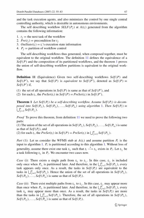
We considered AND-join cases and OR-split cases separately. The number of tasks ineach case w, denoted by |w|, is taken to be 10. Each case in AND-join workflows var-ied in the degree of parallelism, denoted by d(w) for each workflow w. Here, d(w)
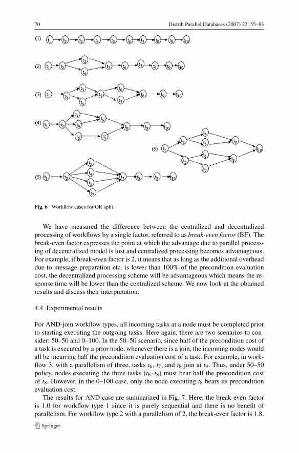
ranges from strictly sequential execution (i.e., no parallel task execution) to interme-diate parallel execution to maximum parallelism. Figure 5 shows the workflow caseswe considered. For example, workflow type 1 is a pure sequential workflow startingfrom task t1 to task t10. Workflow type 6 starts with t1, forks of t2–t8, and joins themat t9. So the degree of parallelism is six. Similarly, each case in OR-split workflowsvaried in the number of tasks to be executed in a chosen path (i.e., the length of thepath from the start task to the end task is varied). Figure 6 shows the different caseswe considered.
For centralized processing, we assumed a single central node to coordinate work-flow processing. In the case of decentralized processing, we assumed that there arefive task agents available to execute the 10 tasks of each workflow. For the sake ofsimplicity, we have assigned tasks t1 to t10 in a cyclic order among the 5 task agents.For example, tasks 1 and 6 were assigned to task agent 1, tasks 2 and 7 to task agent 2,and so on. In addition, we assumed that tasks 2–10 have a constant precondition eval-uation cost. Obviously, task 1 has no precondition.
Distrib Parallel Databases (2007) 22: 55–83 69
Fig. 5 Workflow cases for AND join
4.2 Precondition evaluation
The precondition of a task tj , resulting due to the dependency (ti → tj ), can be eval-uated either at the agent executing this task (A(tj )) or at the agent executing theprior task(s) (A(ti)). We considered three cases of the precondition evaluation: 0–100,50–50 and 100–0, indicating the percentage of precondition being evaluated at A(ti)
and A(tj ), respectively. For the experiment, we expressed each workflow in XML.The XML specification describes the control flows with splits and joins, and the as-sociated precondition evaluation times.
4.3 Experimental methodology
We varied the number of simultaneous workflow instances (100, 250, 500, 1000, . . . )for each type of workflow in order to see the variations in response time for differ-ent types of workflows for centralized and decentralized executions. In centralizedprocessing, the central coordinating node needs to send minimal information to thetask execution nodes. This is a benefit. However, all the precondition checking is tobe done at the centralized node itself. This is the cost. On the other hand, in the caseof decentralized processing of workflows, there is an additional cost for each node toprepare a message (including the workflow partition and other details of tasks in therest of the workflow) to be sent to the following nodes in the workflow. The benefitis the additional processing power and ability to process in parallel.
70 Distrib Parallel Databases (2007) 22: 55–83
Fig. 6 Workflow cases for OR split
We have measured the difference between the centralized and decentralizedprocessing of workflows by a single factor, referred to as break-even factor (BF). Thebreak-even factor expresses the point at which the advantage due to parallel process-ing of decentralized model is lost and centralized processing becomes advantageous.For example, if break-even factor is 2, it means that as long as the additional overheaddue to message preparation etc. is lower than 100% of the precondition evaluationcost, the decentralized processing scheme will be advantageous which means the re-sponse time will be lower than the centralized scheme. We now look at the obtainedresults and discuss their interpretation.
4.4 Experimental results
For AND-join workflow types, all incoming tasks at a node must be completed priorto starting executing the outgoing tasks. Here again, there are two scenarios to con-sider: 50–50 and 0–100. In the 50–50 scenario, since half of the precondition cost ofa task is executed by a prior node, whenever there is a join, the incoming nodes wouldall be incurring half the precondition evaluation cost of a task. For example, in work-flow 3, with a parallelism of three, tasks t6, t7, and t8 join at t9. Thus, under 50–50policy, nodes executing the three tasks (t6–t8) must bear half the precondition costof t8. However, in the 0–100 case, only the node executing t8 bears its preconditionevaluation cost.
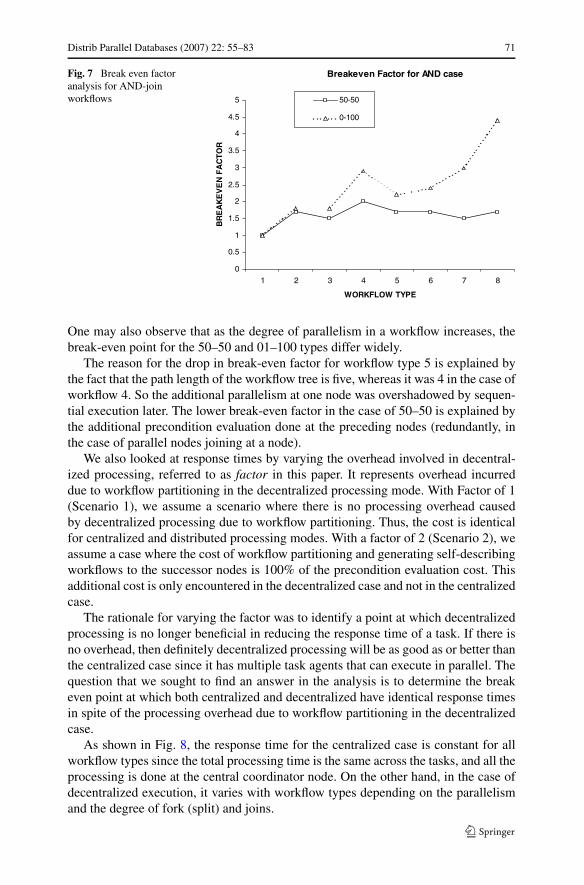
The results for AND case are summarized in Fig. 7. Here, the break-even factoris 1.0 for workflow type 1 since it is purely sequential and there is no benefit ofparallelism. For workflow type 2 with a parallelism of 2, the break-even factor is 1.8.
Distrib Parallel Databases (2007) 22: 55–83 71
Fig. 7 Break even factoranalysis for AND-joinworkflows
One may also observe that as the degree of parallelism in a workflow increases, thebreak-even point for the 50–50 and 01–100 types differ widely.
The reason for the drop in break-even factor for workflow type 5 is explained bythe fact that the path length of the workflow tree is five, whereas it was 4 in the case ofworkflow 4. So the additional parallelism at one node was overshadowed by sequen-tial execution later. The lower break-even factor in the case of 50–50 is explained bythe additional precondition evaluation done at the preceding nodes (redundantly, inthe case of parallel nodes joining at a node).
We also looked at response times by varying the overhead involved in decentral-ized processing, referred to as factor in this paper. It represents overhead incurreddue to workflow partitioning in the decentralized processing mode. With Factor of 1(Scenario 1), we assume a scenario where there is no processing overhead causedby decentralized processing due to workflow partitioning. Thus, the cost is identicalfor centralized and distributed processing modes. With a factor of 2 (Scenario 2), weassume a case where the cost of workflow partitioning and generating self-describingworkflows to the successor nodes is 100% of the precondition evaluation cost. Thisadditional cost is only encountered in the decentralized case and not in the centralizedcase.
The rationale for varying the factor was to identify a point at which decentralizedprocessing is no longer beneficial in reducing the response time of a task. If there isno overhead, then definitely decentralized processing will be as good as or better thanthe centralized case since it has multiple task agents that can execute in parallel. Thequestion that we sought to find an answer in the analysis is to determine the breakeven point at which both centralized and decentralized have identical response timesin spite of the processing overhead due to workflow partitioning in the decentralizedcase.
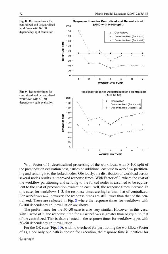
As shown in Fig. 8, the response time for the centralized case is constant for allworkflow types since the total processing time is the same across the tasks, and all theprocessing is done at the central coordinator node. On the other hand, in the case ofdecentralized execution, it varies with workflow types depending on the parallelismand the degree of fork (split) and joins.
72 Distrib Parallel Databases (2007) 22: 55–83
Fig. 8 Response times forcentralized and decentralizedworkflows with 0–100dependency split evaluation
Fig. 9 Response times forcentralized and decentralizedworkflows with 50–50dependency split evaluation
With Factor of 1, decentralized processing of the workflows, with 0–100 split ofthe precondition evaluation cost, causes no additional cost due to workflow partition-ing and sending it to the forked nodes. Obviously, the distribution of workload acrossseveral nodes results in improved response times. With Factor of 2, where the cost ofthe workflow partitioning and sending to the forked nodes is assumed to be equiva-lent to the cost of precondition evaluation cost itself, the response times increase. Inthis case, for workflows 1–3, the response times are higher than that of centralized.For workflows 4–7, however, the response times are still lower than that of the cen-tralized. These are reflected in Fig. 8 where the response times for workflows with0–100 dependency split evaluation are shown.
The performance for the 50–50 case is also very similar. However, in this case,with Factor of 2, the response time for all workflows is greater than or equal to thatof the centralized. This is also reflected in the response times for workflow types with50–50 dependency split evaluation.
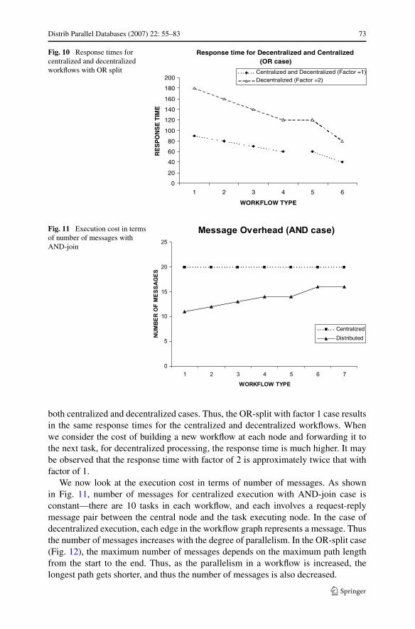
For the OR case (Fig. 10), with no overhead for partitioning the workflow (Factorof 1), since only one path is chosen for execution, the response time is identical for
Distrib Parallel Databases (2007) 22: 55–83 73
Fig. 10 Response times forcentralized and decentralizedworkflows with OR split
Fig. 11 Execution cost in termsof number of messages withAND-join
both centralized and decentralized cases. Thus, the OR-split with factor 1 case resultsin the same response times for the centralized and decentralized workflows. Whenwe consider the cost of building a new workflow at each node and forwarding it tothe next task, for decentralized processing, the response time is much higher. It maybe observed that the response time with factor of 2 is approximately twice that withfactor of 1.
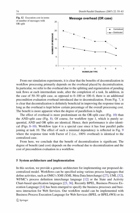
We now look at the execution cost in terms of number of messages. As shownin Fig. 11, number of messages for centralized execution with AND-join case isconstant—there are 10 tasks in each workflow, and each involves a request-replymessage pair between the central node and the task executing node. In the case ofdecentralized execution, each edge in the workflow graph represents a message. Thusthe number of messages increases with the degree of parallelism. In the OR-split case(Fig. 12), the maximum number of messages depends on the maximum path lengthfrom the start to the end. Thus, as the parallelism in a workflow is increased, thelongest path gets shorter, and thus the number of messages is also decreased.
74 Distrib Parallel Databases (2007) 22: 55–83
Fig. 12 Execution cost in termsof number of messages withOR-split
From our simulation experiments, it is clear that the benefits of decentralization inworkflow processing primarily depends on the overhead placed by decentralization.In particular, we refer to the overhead due to the splitting and regeneration of pendingtask flows at each intermediate node, after the completion of a task. In addition, inthe case of 50–50 split case, as opposed to 0–100 or 100–0, there is an additionalprecondition evaluation overhead introduced due to decentralization. From Fig. 7, itis clear that decentralization is definitely beneficial in improving the response time aslong as the overhead is kept below certain percentage of the overall processing cost.The benefit is more apparent when the degree of parallelism is high.
The effect of overhead is more predominant on the OR-split case (Fig. 10) thanthe AND-split case (Fig. 8). Of course, for workflow type 1, which is purely se-quential, AND and OR splits are identical. Hence, their performance is also identi-cal (Figs. 8–10). Workflow type 4 is a special case since it has four parallel pathsjoining at task 10. The effect of such a minimal dependency is reflected in Fig. 9where the response time with Factor of 2 (i.e., 100% overhead) is identical to thecentralized case.
From here, we conclude that the benefit of decentralization is significant. Thedegree of benefit (and cost) depends on the overhead due to decentralization and thecost of precondition evaluation in a workflow.
5 System architecture and implementation
In this section, we provide a generic architecture for implementing our proposed de-centralized model. Workflows can be specified using various process languages thatdefine activities, such as OMG’s XMI (XML Meta Data Interchange) [27], UML [32],WFMC’s process definition interchange language [12] or the State and ActivityChart-based specification languages [23, 36]. Recently BPEL, Business Process Ex-ecution Language [14] has been emerged to specify the business processes and busi-ness interaction for Web Services. Our workflow model can be implemented withBusiness Process Execution Language for Web Services (BPEL or BPEL4WS) or its
Distrib Parallel Databases (2007) 22: 55–83 75
latest version called WS-BPEL (also called BPEL 2.0) [19]. We refer to these dif-ferent versions of BPEL specifications as BPEL. BPEL is an XML-based standardlanguage for defining Web services business processes and business interaction pro-tocols. BPEL differs from other business process languages by providing both anabstract level and a low level. At the abstract level, it is used to define broader pa-rameters and constraints while keeping details hidden. At the low level, it definesexecutable processes.
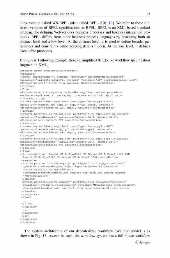
Example 8 Following example shows a simplified BPEL-like workflow specificationfragment in XML.
<process name="drugApprovalProcess"><sequence><invoke partnerLink="D-company" portType="lns:DrugApproveOrderPT"operation="initiate Approval process" variable="AP" createInstance="yes"><documentation>Initiate Drug approval Order</documentation></invoke><flow><documentation> A sequence to handle supplies, select providers,evaluate requirements, packaging, prepare and submit application</documentation><invoke partnerLink="supplierA" portType="lns:supplierAPT"operation="request-API-supply" input="API-types, amounts"><documentation>Decide On API supply amounts</documentation></invoke><receive partnerLink="supplierA" portType="lns:supplierA-CallbackPT"operation="sendAmounts" variables="Amount-SA-A, Amount-SA-B"><documentation>sendback API amounts</documentation></receive><invoke partnerLink="supplierB" portType="lns:supplierBPT"operation="request-API-supply"input="API-types, amounts"><documentation>Decide On API supply amounts</documentation></invoke><receive partnerLink="supplierB" portType="lns:supplierB-CallbackPT"operation="sendAmounts" variables="Amount-SB-A, Amount-SB-B"><documentation>sendback API amounts</documentation></receive></flow><if> <condition> (Amount-SA-A $\ge$500 OR Amount-SB-A $\ge$ 500) AND(Amount-SA-B $\ge$500 OR Amount-SB-B $\ge$ 500) </condition><sequence><invoke partnerLink="D-company" portType="lns:DrugApproveOrderPT"operation="selectAPI-provision" inputVariable="API-amounts"outputVariable="API-providers"><documentation>determine API vendors for each API amount needed</documentation>
</invoke><invoke partnerLink="D-company" portType="lns:DrugApproveOrderPT"operation="evaluate-requirements" variable="Manufacture-requirements"><documentation>Evaluate manufacturing requirements</documentation>
</invoke></sequence><flow>...
</flow><sequence>...
</sequence></if></sequence></process>
The system architecture of our decentralized workflow execution model is asshown in Fig. 13. As can be seen, the workflow system has a full-blown workflow
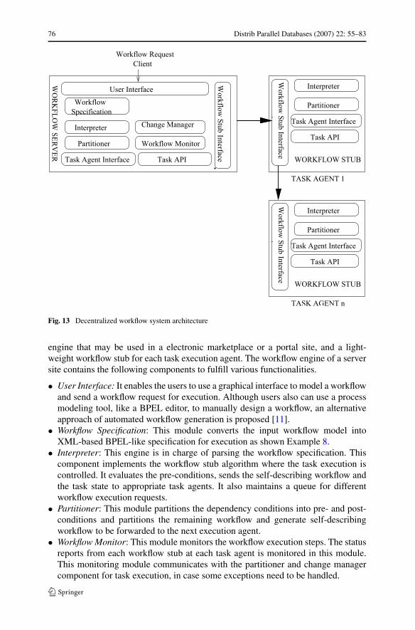
76 Distrib Parallel Databases (2007) 22: 55–83
Fig. 13 Decentralized workflow system architecture
engine that may be used in a electronic marketplace or a portal site, and a light-weight workflow stub for each task execution agent. The workflow engine of a serversite contains the following components to fulfill various functionalities.
• User Interface: It enables the users to use a graphical interface to model a workflowand send a workflow request for execution. Although users also can use a processmodeling tool, like a BPEL editor, to manually design a workflow, an alternativeapproach of automated workflow generation is proposed [11].
• Workflow Specification: This module converts the input workflow model intoXML-based BPEL-like specification for execution as shown Example 8.
• Interpreter: This engine is in charge of parsing the workflow specification. Thiscomponent implements the workflow stub algorithm where the task execution iscontrolled. It evaluates the pre-conditions, sends the self-describing workflow andthe task state to appropriate task agents. It also maintains a queue for differentworkflow execution requests.
• Partitioner: This module partitions the dependency conditions into pre- and post-conditions and partitions the remaining workflow and generate self-describingworkflow to be forwarded to the next execution agent.
• Workflow Monitor: This module monitors the workflow execution steps. The statusreports from each workflow stub at each task agent is monitored in this module.This monitoring module communicates with the partitioner and change managercomponent for task execution, in case some exceptions need to be handled.
Distrib Parallel Databases (2007) 22: 55–83 77
In the workflow stub that can be installed in any task execution agent (i.e. a node),there are workflow stub interface for communicating and exchanging messages withother workflow stubs, interpreter and partitioner to evaluate the workflow dependen-cies and partition the pre-condition and remaining workflow. The task agent interfaceand task API provide the interface for the task execution agents and systems.
• Workflow Stub Interface: Each workflow stub communicates with other workflowstubs and with the server through this stub interface.
• Workflow Interpreter: The workflow interpreter in the workflow stub, as in theserver side, parse the incoming workflow, make task lists and manages the taskexecution status information and queue.
• Workflow Partitioner: The workflow partitioner evaluates the pre-conditions andpartitions workflow using the execution status and pre-conditions.
• Task Agent Interface: It provides the task execution agent with a task list and taskstatus information.
• Task API: In case the task requires an application or database system interface,rather than a human task agent, the API interface provides the communicationwith an application system agent.
The workflow specification like Example 8 is partitioned to self-describing work-flow at different task agent as the workflow task is executed, and depending on thedependency evaluation, the self describing workflow partitions are forwarded to thenext appropriate task agents. The state and results of a task execution is part of theworkflow partition that is forwarded to the next agent. The HTTP protocol or JMSprotocol can be used for message communication. As a proof-of-concept prototype,HTTP protocol and Java Beans are used for implementing the communication be-tween task agents and for implementing partition and workflow stub algorithms.
6 Related work
Traditional workflow systems have been using the centralized architecture withclient/server components, where the process instances are created, managed and con-trolled by one centralized workflow engine [12]. The data and control are centrallymanaged while the computation of the tasks, either manual or automated system,are completed by clients. The clients connect to the server for receiving the worklistand interchange messages to the central workflow engine. Examples of these cen-tral workflow engine include Action Workflows [21], Regatta [33] and Spade [4].With the Internet and peer-to-peer computing environment, as well as with the real-time business processes with dynamic partner collaborations, the distributed work-flow management and decentralized control is needed to address the limitations ofthe centralized architecture [2, 15, 17, 22, 24, 31, 36, 37].
EXOTICA/Flowmark on Message Queue Manager [2] describes and implementsa distributed and decentralized execution architecture consisting of a process defi-nition node and runtime nodes. Once a process has been defined, this definition iscompiled at the definition node. After compilation, the process is divided into sev-eral parts and each part is distributed to a runtime node where process instances are
78 Distrib Parallel Databases (2007) 22: 55–83
executed. The division of the process is based on the users associated with the dif-ferent nodes and the roles associated with the different activities in the process. Eachruntime node has a node manager in charge of communicating with the process de-finition node. Each definition node sends to each involved node’s manager only theinformation pertaining to the activities that will execute at that node. This static infor-mation is stored in a process table. The manager then starts a process thread that is incharge of coordinating the execution of instances using a queue for communicatingwith other nodes and deciding when an activity is ready for execution.
In METEOR2 [15], the scheduling information is distributed among different taskmanagers. Each task manager is aware of its immediate successors and hence is ca-pable of activating the follow-up task managers once the task it controls terminates.The task manager is designed as CORBA objects with task activation, task invoca-tion, error handling and recovery components. In these approaches, a workflow ispre-partitioned in a central server, thus the partitions are made statically in the cen-tral server and distributed to each execution agent, whereas our approach partitionsdynamically as the workflow progresses with its execution. As a result, we send thepartitions to an agent only when needed, whereas other approaches send the partitionsto the execution agents even if they are not executed at all.
Mentor, Mentor-Lite prototype [24, 25, 36] has an execution environment that isbased on a distributed client-server architecture. Each workflow instance is executedby a number of MENTOR workflow servers. On each server, there is a MENTORworkflow engine which is responsible for interpreting and executing the control flowspecification of the workflow loaded into the engine. The invoked applications ofworkflow tasks are run at the client sites. All communication between servers is per-formed via a TP Monitor Tuxedo. A partitioning algorithm in Mentor system trans-forms the original state chart into orthogonal components for distributed executionof workflows. The orthogonal components are assigned to a number of workflowservers, such that each server executes a partition of the original workflow contain-ing at least one orthogonal component. The algorithm expands each state into three(state, instate, outstate), and each dependency (represented as ECA rules) into a num-ber of arcs reflecting all possible paths that are required to express the condition, thussimply exploding the number of states and dependencies. They also show the correct-ness of the partitioning by showing its equivalence to the original workflow. Whilethis study is more detailed on how the execution is actually achieved, it only dealswith the static decomposition of the workflows, but not the dynamic one. Moreover,it does not adequately deal with the issues that arise due to the concurrent executionof workflows.
While EXOTICA and METEOR2 illustrate decentralized and distributed architec-tures, the details of partitioning are not spelled out. Their distribution algorithm seemsto be static, the sites are all determined statically. Our approach to decentralized con-trol differs from these in the following aspects. In these approaches, a workflow ispre-partitioned in a central server, and the partitions are made statically in the cen-tral server and distributed to each execution agent, whereas our approach partitionsas the workflow progresses with its execution. As a result, we send the partitionsto an agent only when needed, whereas other approaches send the partitions to theexecution agents even if they are not executed at all.
Distrib Parallel Databases (2007) 22: 55–83 79
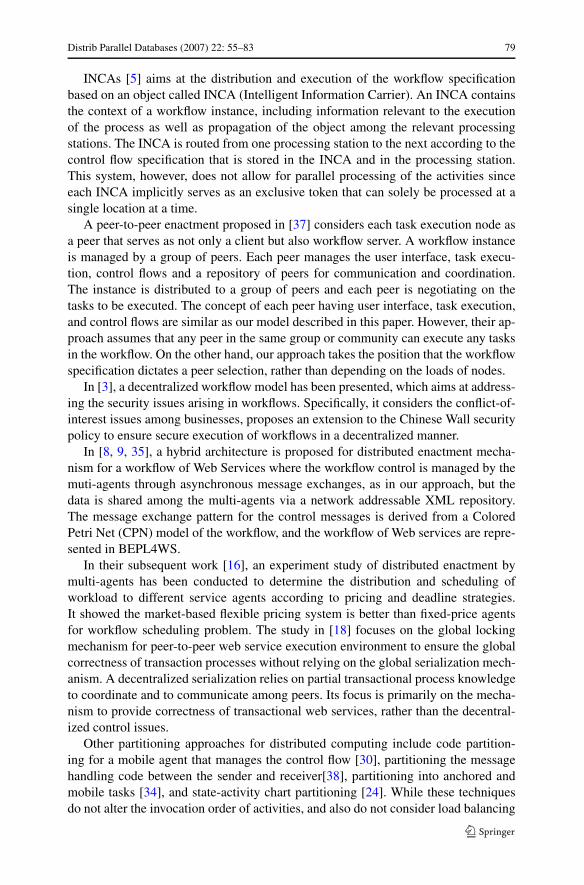
INCAs [5] aims at the distribution and execution of the workflow specificationbased on an object called INCA (Intelligent Information Carrier). An INCA containsthe context of a workflow instance, including information relevant to the executionof the process as well as propagation of the object among the relevant processingstations. The INCA is routed from one processing station to the next according to thecontrol flow specification that is stored in the INCA and in the processing station.This system, however, does not allow for parallel processing of the activities sinceeach INCA implicitly serves as an exclusive token that can solely be processed at asingle location at a time.
A peer-to-peer enactment proposed in [37] considers each task execution node asa peer that serves as not only a client but also workflow server. A workflow instanceis managed by a group of peers. Each peer manages the user interface, task execu-tion, control flows and a repository of peers for communication and coordination.The instance is distributed to a group of peers and each peer is negotiating on thetasks to be executed. The concept of each peer having user interface, task execution,and control flows are similar as our model described in this paper. However, their ap-proach assumes that any peer in the same group or community can execute any tasksin the workflow. On the other hand, our approach takes the position that the workflowspecification dictates a peer selection, rather than depending on the loads of nodes.
In [3], a decentralized workflow model has been presented, which aims at address-ing the security issues arising in workflows. Specifically, it considers the conflict-of-interest issues among businesses, proposes an extension to the Chinese Wall securitypolicy to ensure secure execution of workflows in a decentralized manner.
In [8, 9, 35], a hybrid architecture is proposed for distributed enactment mecha-nism for a workflow of Web Services where the workflow control is managed by themuti-agents through asynchronous message exchanges, as in our approach, but thedata is shared among the multi-agents via a network addressable XML repository.The message exchange pattern for the control messages is derived from a ColoredPetri Net (CPN) model of the workflow, and the workflow of Web services are repre-sented in BEPL4WS.
In their subsequent work [16], an experiment study of distributed enactment bymulti-agents has been conducted to determine the distribution and scheduling ofworkload to different service agents according to pricing and deadline strategies.It showed the market-based flexible pricing system is better than fixed-price agentsfor workflow scheduling problem. The study in [18] focuses on the global lockingmechanism for peer-to-peer web service execution environment to ensure the globalcorrectness of transaction processes without relying on the global serialization mech-anism. A decentralized serialization relies on partial transactional process knowledgeto coordinate and to communicate among peers. Its focus is primarily on the mecha-nism to provide correctness of transactional web services, rather than the decentral-ized control issues.
Other partitioning approaches for distributed computing include code partition-ing for a mobile agent that manages the control flow [30], partitioning the messagehandling code between the sender and receiver[38], partitioning into anchored andmobile tasks [34], and state-activity chart partitioning [24]. While these techniquesdo not alter the invocation order of activities, and also do not consider load balancing
80 Distrib Parallel Databases (2007) 22: 55–83
issues in mapping activities to workflow servers, in [26], a BPEL code partition-ing algorithm that is applicable to decentralization of composite web includes taskre-ordering but assumes the partitioning and re-ordering tasks are done in advance.In [6, 20], the BPEL4WS schema is UML activity diagram which is converted to an-other activity diagrams with control delegation rules to coordinate different processcontrollers. The resulting diagram with control synchronization is divided into sub-diagrams that are distributed to mobile devices for execution. The partitioning of theworkflows is done pre-execution stage.
The trend for executing interorganizational business processes is towards the Ser-vice Oriented Architecture (SOA). SELF-SERV [7, 29] presents a peer-to-peer Webservice orchestration of a composite service that consists of components services.The composite service is represented as a state diagram with transitions and ECArules. Each component service is managed by lightweight coordinators that managethe state transition, i.e. when to enter a state and when to finish the state. The compos-ite service state diagram is translated into XML document, and control informationof each state of the composite state chart is extracted into a routing table and up-loaded to hosts of component services. The routing table is used as knowledge baseat runtime by each of the coordinators involved in a composite service, and containsinformation of the location, peers and control flow routing policies. Notice that thecomposite service is not partitioned but rather the routing information is extracted fororchestrating the execution of each service.
In [10, 13], the business and government processes are represented as compos-ite services and are executed using the Web service orchestration. The experimentalwork in [10] shows the decentralized orchestration of composite Web services takesless response time to message size and the number of requests, and higher through-put than those of centralized execution. However, this study does not include thebuild time for partitioning BPEL4WS specification of composite Web services in theperformance analyses, while our study includes the dynamic partitioning in the per-formance analysis.
The focus of this paper has been to present a decentralized workflow executionmodel for inter-organizational workflow that does not resort to pre-partitioning andpre-distributions of tasks, or routing tables for coordination and that allows dynamicpartitions, and to present a performance study of the proposed decentralized modelto compare with the centralized control model, to demonstrate that it can indeed per-form better than centralized execution of workflows to a certain degree, dependingon overhead of dynamic partition and split dependency evaluation at each task agent.
Figure 14 shows the comparison chart of different approaches.
7 Conclusions and future research
The workflows representing today’s business processes are often operate in a dy-namic and ad-hoc coalition environment, and tend to span across the organizationalboundaries. As a result, it is not viable to employ a single centralized WFMS to con-trol the execution of the such inter-organizational workflow due to limited scalability,availability and performance. In this paper, we have presented a decentralized work-flow model, where inter-task dependencies are enforced without requiring to have
Distrib Parallel Databases (2007) 22: 55–83 81
Fig. 14 Example of workflow partitioning process
a centralized WFMS. We presented a workflow partition algorithm that creates aself-describing workflow and a light-weight workflow stub to control and manage theexecution of self-describing workflow and to coordinate with other workflow agent’sworkflow stubs.
We have conducted a performance evaluation study by considering different typesof workflows with varying degrees of parallelism and varying degree of dependencysplit evaluation. Our performance results indicate that decentralized workflow man-agement indeed enjoys significant gain in reduction of response time over centralizedworkflow management. We presented break-even analyses for AND-join and OR-split relations in various workflow types of different parallelism.
Our future work is to apply our decentralized control model for Web Servicesenvironment, where the same task can be executed in multiple task agents. The re-search issues include the selection strategies of different service providers and negoti-ation strategies. We will conduct the performance evaluations of the capability-based,quality of service (QoS), and policy-driven strategies for decentralized Web serviceexecutions, that can be compared with the centralized execution of these strategies.
References
1. Adam, N.R., Atluri, V., Huang, W.-K.: Modeling and analysis of workflows using petri nets. J. Intell.Inf. Syst. Special Issue on Workflow and Process Management 10(2) (1998)
2. Alonso, G., Agrawal, D., Abbadi, A.E., Mohan, C., Gunthor, R., Kamath, M.: EXotica/FMQM: a per-sistent message-based architecture for distributed workflow management. In: Proceedings of the IFIPWG8.1 Working Conference on Information Systems for Decentralized Organizations, Trondheim,August 1995
82 Distrib Parallel Databases (2007) 22: 55–83
3. Atluri, V., Chun, S.A., Mazzoleni, P.: Chinese wall security for decentralized workflow managementsystems. J. Comput. Secur. 12(6), 799–840 (2004)
4. Bandinelli, S., DiNitto, E., Fuggetta, A.: Supporting cooperation in the SPADE-1 environment. IEEETrans. Softw. Eng. 22(12), 841–865 (1996)
5. Barbara, D., Mehrotra, S., Rusinkiewicz, M.: INCAs: Managing Dynamic Workflows in DistributedEnvironments. J. Database Manag. Special Issue on Multidatabases 7(1) (1996)
6. Baresi, L., Maurino, A., Modafferi, S.: Workflow partitioning in mobile information systems. In:MOBIS, pp. 93–106 (2004)
7. Benatallah, B., Dumas, M., Sheng, Q.Z.: Facilitating the rapid development and scalable orchestrationof composite web services. Distrib. Parallel Databases 17(1), 5–37 (2005)
8. Buhler, P.A., Vidal, J.M.: Enacting bpel4ws specified workflows with multiagent systems. In: Pro-ceedings of the Workshop on Web Services and Agent-Based Engineering (2004)
9. Buhler, P.A., Vidal, J.M.: Integrating agent services into bpel4ws defined workflows. Technical report,USC CSE TR-2004-003 (2004)
10. Chafle, G., Chandra, S., Mann, V., Nanda, M.G.: Decentralized orchestration of composite web ser-vices. In WWW (Alternate Track Papers & Posters), pp. 134–143 (2004)
11. Chun, S.A., Atluri, V., Adam, N.R.: Domain knowledge-based automatic workflow generation. In:DEXA, pp. 81–92 (2002)
12. Workflow Management Coalition: Interface 1—process definition interchange v 1.0 final. http://www.wfmc.org (1998)
13. Contenti, M., Mecella, M., Termini, A., Baldoni, R.: A distributed architecture for supportinge-government cooperative processes. In: TCGOV 2005. Lecture Notes in Artificial Intelligence,vol. 3416, pp. 181–192 (2005)
14. Curbera, F., Goland, Y., Klein, J., Leymann, F., Roller, D., Thatte, S., Weerawarana, S.: Businessprocess execution language for web services, version 1.0, July 2002
15. Das, S., Kochut, K., Miller, J., Sheth, A., Worah, D.: ORBWork: A reliable distributed CORBA-basedworkflow enactment system for METEOR2. Technical Report UGA-CS-TR-97-001, University ofGeorgia, February 1997
16. Goradia, H., Vidal, J.M.: Multiagent workflow enactment using adaptive pricing mechanisms. In:AAAI Planning and Scheduling for Web Services Workshop (2005)
17. Grundy, J., Apperley, M., Hosking, J., Mugridge, W.: A decentralised architecture for software processmodeling and enactment. IEEE Internet Comput. 2(5), 53–62 (1998)
18. Haller, K., Schuldt, H., Turker, C.: Decentralized coordination of transactional processes in peer-to-peer environments. In: CIKM ’05: Proceedings of the 14th ACM International Conference on Infor-mation and Knowledge Management, pp. 28–35. ACM, New York (2005)
19. Jordan, D., Evdemon, J.: Web services business process execution language version 2.0. Technicalreport, OASIS Public Review Draft, August 2006
20. Maurino, A., Modafferi, S.: Partitioning rules for orchestrating mobile information systems. Pers.Ubiquitous Comput. 9(5), 291–300 (2005)
21. Medina-Mora, R., Winograd, T., Flores, R., Flores, F.: The action workflow approach to workflowmanagement technology. In: Proc. CSCW 92, pp. 281–288. ACM, New York (1992)
22. Mohan, C.: Workflow management in the Internet age, advances in databases and information sys-tems. In: LNCS, pp. 26–34. Springer, Berlin (1998)
23. Muth, P., Wodtke, D., Weikum, G., Dittrich, A.: Enterprise-wide workflow management based on stateand activity charts. In: Dogac, A., Kalinichenko, L., Sheth, A. (eds.) Workflow Management Systemsand Interoperability (1998)
24. Muth, P., Wodtke, D., Weissenfels, J.: From centralized workflow specification to distributed workflowexecution. J. Intell. Inf. Syst. 10(2) (1998)
25. Muth, P., Wodtke, D., Weissenfels, J., Weikum, G., Kotz Dittrich, A.: Enterprise-wide workflow man-agement based on state and activity charts (1998)
26. Nanda, M.G., Chandra, S., Sarkar, V.: Decentralizing execution of composite web services. In: OOP-SLA ’04: Proceedings of the 19th Annual ACM SIGPLAN Conference on Object-Oriented Program-ming, Systems, Languages, and Applications, pp. 170–187. ACM, New York (2004)
27. OMG: XML meta data interchange. http://www.omg.org28. Rusinkiewicz, M., Sheth, A.: Specification and execution of transactional workflows. In: Kim, W.
(ed.) Modern Database Systems: The Object Model, Interoperability, and Beyond, Addison–Wesley,Reading (1994)
29. Sheng, Q.Z., Benatallah, B., Dumas, M., Mak, E.O.-Y.: Self-serv: a platform for rapid composition ofweb services in a peer-to-peer environment. In: VLDB, pp. 1051–1054 (2002)

Distrib Parallel Databases (2007) 22: 55–83 83
30. Singh, A., Pande, S.: Compiler optimizations for java aglets in distributed data intensive applications.In: Proceedings of the ACM Symposium on Applied Computing (2002)
31. Singh, M.P., Huhns, M.N.: In: Multiagent Systems for Workflow, pp. 105–117 (1999)32. Relational Software: UML Documentation. http://www.rational.com/uml/resources33. Swenson, K., Maxwell, R., Matsumoto, T., Saghari, B., Irwin, K.: A business process environment
supporting collaborative planning. J. Collab. Comput. 1(1), 15–34 (1994)34. Tilevich, E., Smaragdakis, Y.: J-orchestra: Automatic java application partitioning. In: Proceedings of
European Conference on Object Oriented Programming (ECOOP 02) (2002)35. Vidal, J.M., Buhler, P., Stahl, C.: Multiagent systems with workflows. IEEE Internet Comput. 1, 76–82
(2004)36. Wodtke, D., Weikum, G.: A formal foundation for distributed workflow execution based on state
charts. In: Proceedings of the International Conference on Database Theory, Delphi, Greece, January1997
37. Yan, J., Yang, Y., Raikundalia, G.: Enacting business processes in a decentralised environment withp2p-based workflow support. In: Proc. of 4th International Conference on Web-Age Information Man-agement (WAIM’03). Lecture Notes in Computer Science. Springer, Berlin (2003)
38. Zhou, D., Pande, S., Schwan, K.: Method partitioning—runtime customization of pervasive programswithout design-time application knowledge. In: Proceedings of the 23rd International Conference onDistributed Computing Systems (ICDCS 03) (2003)


