Embed Size (px)
Citation preview

A Dependable Software Platform for Automotive Integrated Safety Systems
Xi Chen Martin Hiller
Klaus D. Müller-Glaser Vera Lauer
Keywords ISS, Integrated Safety Systems, dependable software platform, fault-tolerance, Agreement Protocol, Signed Message Protocol, Software Watchdog, E/E system architecture Abstract Integrated Safety Systems (ISS), making use of synergy effects from safety-relevant applications distributed across different domains, are currently one of the developing trends in the automotive industry. Such systems require a dependable fault tolerant in-vehicle electronic architecture. The EASIS consortium, composed of OEMs, sup-pliers and tool producers, is pursuing this goal. In order to meet the high dependability requirements of modern Integrated Safety Systems, the conventional approach is to make use of redundancy in hardware and software. However, to manage redundancy, basic fault tolerance software services are required. With the increasing integration density of functionalities on one ECU, basic software services to monitor and maintain separation of application compo-nents running in parallel as well as to ensure fault containment of corrupted applica-tion components are also required. This paper, as a result of collaboration within the EASIS consortium, describes a lay-ered software platform using the middleware concept, where fault tolerance services are mapped onto dependability software modules. In order to reach agreement among distributed safety-relevant applications with redundant hardware despite Byz-antine faults, an agreement protocol was designed based on the Signed Message Protocol. This dependability software service was prototyped and validated by means of a Lane-Keeping application. A software watchdog service, which can be used for monitoring time constraints and control flow of application components was also de-signed. The prototyping of the validator follows the model based approach combined with the principle of virtual integration.

Zusammenfassung Integrierte Sicherheitssysteme (ISS), welche die Synergieeffekte der sicherheitsrele-vanten Applikationen über die Fahrzeugdomänengrenze hinaus nutzen, sind heutzu-tage einer der Entwicklungstrends in der Automobilindustrie. Voraussetzung für ISS ist eine fehlertolerante und zuverlässige Elektronikarchitektur im Fahrzeug. Das aus Automobilherstellern, Zulieferern und Softwareherstellern bestehende EASIS-Konsortium hat sich zum Ziel gesetzt, eine solche integrierte Sicherheits-Elektronikarchitektur zu erarbeiten. Der konventionelle Ansatz, um die hohen Anforderungen an die Zuverlässigkeit des Elektroniksystems zu erfüllen, ist Redundanzen in Hard- und Software einzuführen. Um dies softwareseitig auch auf Applikationsebene nutzen zu können, werden feh-lertolerante Standarddienste benötigt. Aufgrund der ständig steigenden Funktions-dichte in Steuergeräten sollen diese Dienste zusätzlich das Überwachen und die Kapselung der parallel laufenden Applikationen sicherstellen. Auch sollen Seitenef-fekte im Fehlerfall vermindert werden. Dieser Beitrag beschreibt als Ergebnisse der Zusammenarbeit im EASIS Konsortium eine geschichtete Softwarearchitektur, in der die fehlertoleranten Standarddienste auf Zuverlässigkeits-Softwaremodule aufsetzen. Um eine Übereinstimmung der redundanten Einheiten bei byzantinischen Fehlern und Nichtdeterminismen zu erreichen, wurde ein auf dem Signed Message Protocol basiertes Übereinstimmungsprotokoll entworfen, implementiert und anschließend mit einer Fahrspurassistenz Anwendung validiert. Um die Zeitbedingungen und den Kon-trollfluss der Applikationskomponenten zu überwachen wurde auch ein softwareba-sierter Watchdog realisiert. Der Validator wird mit Hilfe des modell-basierten Entwick-lungsansatzes „Virtual Integration“ prototypisch aufgebaut.

1 Introduction and EASIS Approach
Trends in Automotive Safety Systems – ISS
The on-board electrics and electronics (E/E) in vehicles have become subject to ever demanding requirements in recent years, triggered by an ever-increasing demand for safety and comfort. On one side the complexity and the number of applications im-plemented with electronics and software are increasing exponentially, on the other side the E/E systems should exhibit at least the same dependability as the current mechanical system. Traditionally automotive safety systems can be divided into two main categories: passive safety systems and active safety systems. While passive safety systems, such as the crash zone, seat belts, airbag systems and rollover protection aim at re-ducing the negative impact of an accident (e.g. personal injury) by absorbing the re-sulting crash energy, active safety systems such as ABS, ESP (Electronic Stability Program from DaimlerChrysler), lane keeping/change assistance, etc. help to pre-vent accidents by assisting the driver in critical situations. Milestones in the evolution of automotive safety electronics include the introduction of electronics in the tradi-tional hydraulic system in 1978 and networked brake system with CAN (brake of each wheel individually) in 2001. Current passive or standalone safety systems have already reached a relatively mature standard, while future safety enhancements will mainly have to rely on active safety systems to avoid accidents before they occur. The so-called Integrated Safety System (ISS) as a combined network of both active and passive safety systems, as well as other automotive domains with integration of environment sensors such as video- and radar-sensing and enhanced telematics services. As shown in Figure 1, ISS is a composition of functions that enhance the level of safety not only for the passengers but also for the environment and other people, with the following special aspects: An ISS-application can spread across domain boarders in vehicle e.g. chas-
sis, cabin, powertrain, telematics, etc. An ISS-application can consist of functions from different domains with differ-
ent safety integrity levels. An ISS-application can potentially make use of components which themselves
are not necessarily safety relevant (e.g. Sliding Roof / Sunroof). Thus, comfort components may inherit a high safety level.

Active Safety
Telematics
EnvironmentDetection
Vehicle to VehicleVehicle to Road Infra-structure Communication
Passive Safety
PassivSafety
Function x
Safety-Function y
Gateways
OEMSupplier 1 Supplier 2
.c .c .c
OEMSupplier 1 Supplier 2
.c .c .c
Redundancies
Figure 1 Components of future integrated safety systems A good example of an ISS combining passive and active safety electronics is the Advanced Pre-Safe system from Mercedes-Benz [2], which detects an unavoidable crash and makes preparations to reduce the severity of the accident. The activation triggers are the plausibility check of information from on-board electronics ESP and BAS (Brake Assistance). Measures taken by the Advanced Pre-Safe system include activation of a reversible belt restraining system, adjustment of seat position and closing of side windows and sunroof.
High
Low
Safety potential
ESP
ABC
Environment recognitionTelematics, cabin and otherNon-safety applications
Safety cell
Seat belt
Air bag
ABS
Passive rollover protection
Passive safetyActive safetyIntegrated safety
Enabling technologies for IS
1960 1970 1980 1990 2000 2010 2020 2030
ETC
ACC
Road recognition
Collision avoidance
Injure avoiding
Pre-Safe
Figure 2 Safety potential of passive, active and integrated safety electronics [1]

As depicted in Figure 2, the y-axis of the graph represents the safety potential of the applications and x-axis represents the time. Passive safety systems have reached now a relatively high potential and improvement can be only reached with significant efforts. Active safety systems and Integrated Safety Systems exhibited less safety potential at the very beginning, but it can be foreseen that a lot of innovations will be achieved in the coming years. The European Commission’s transport policy has set new targets for a reduction of 50% in road fatalities by 2010. Concept of Integrated Safety Systems, as a very promising technology, is one of the most realistic approaches to the ambitious aims set by EU Commission. EASIS Approach
In addition to the trend of integrating safety functions to form larger systems to in-crease overall safety, another trend for automotive embedded software is standardi-zation of the ECU software architecture and platform strategy. In order to improve the software quality while reducing the development cycle and cost, different auto-motive OEMs and suppliers are working together to standardize the software module and software architecture. The EU project EASIS (Electronic Architecture and System Engineering for Inte-grated Safety Systems) was initiated in the year 2004. In the form of a consortium, EASIS is composed of 7 European OEMs, 8 system suppliers, 4 tool producers and other research institutes. EASIS is pursuing the goal of providing enabling technolo-gies for the introduction of integrated safety systems, by developing a standardized dependable in-vehicle fault tolerant electronic architecture (both dependable soft-ware and hardware platforms) and a standardized systems engineering approach for integrated safety systems with a dependable E/E-platform. This remainder of the paper is organized as follows: After a brief introduction in Chapter 1 to the EASIS roadmap and approach, the EASIS dependable software platform will be described in Chapter 2. Dependability software services with a focus on the Agreement Protocol and software watchdog will be specified in Chapter 3 and 4. The subsequent Chapter 5 gives an overview of the ongoing EASIS validator and first achieved results. The last section Chapter 6 concludes the paper with experi-ences gained in the EASIS project and draws an outlook on the future work. 2 EASIS Dependable Software Platform
State of the art of mechatronic systems, such as ABS and ESP are provided as a complete package of mechanic, electronics, sensor and software from system sup-pliers. Through the development of a tire pressure loss warning system, people real-ized the problems of migration of this application to different OEMs, with more and more resources being spent on adapting existing solutions to different environments. At the same time, the traditional approach can no longer handle the complexity of

ECU software. Software platform and standardization are two key approaches for facing this challenge. One central standardization initiative is the AUTOSAR Consortium [10], which aims to provide standardized software architecture for each in-vehicle ECU. The EASIS dependable software platform, however, focuses on the ECUs for the ISS-applications cross domain borders, taking the current trends of automotive software such as AUTOSAR into consideration and separating the safety relevant application software and underlying ECU hardware by providing a software platform. Future in-tegrated safety systems will mainly demonstrate fail-safe and fail-operational behav-ior, and are distributed over several physical nodes across several domains and/or networks. These new requirements will be supported by the dependability software services integrated in the EASIS software platform.
L1Microcontroller hardware
L2Microcontroller abstractionand device drivers
L4Application interfaceL4Application interface
L5Application software(including ISS components)
L3Common servicesand abstractionsL3Common servicesand abstractionsBasic services
ISSgeneralservices
ISSdependability
services
ISSgatewayservices
Basic drivers
Basic microcontroller interface
ISS drivers
ISS microcontroller interface
Application 1
MicrocontrollerMicrocontroller
ISS InterfaceBasic interface ISS InterfaceBasic interface
OSOS
Application 2 Application 3 …
Figure 3 EASIS software topology As shown in Figure 3, the EASIS software topology is structured in 5 layers. While safety relevant applications and their interfaces reside on the upper layer 5 and layer 4, layer 3 integrates besides the basic services such as communication, diagnosis and network management and additional ISS software services. The ISS software services include ISS general services, gateway services and the ISS dependability services. ISS dependability services include Agreement Protocol, software watchdog, protected application services, fault-tolerant intra-ECU and inter-ECU communication services and fault management framework. These ISS dependability software ser-vices aim to enhance the safety, reliability, availability and security of new safety functions. While the basic software services provide the communication, calibration, network management services, etc, ISS gateway services in layer3 provide secured inter-domain communication services. An OSEK-conform operating system [8] with safety relevant extensions is integrated across to layer 2 and layer 3. Device drivers, microcontroller abstraction layer and microcontroller hardware reside on layer 2 and layer 1 respectively.

3 Dependability Service - Agreement Protocol
The standard approach to realize fault-tolerance in technical systems is the use of structural redundancies, defined in [5] as the expansion of the system by additional components (software or hardware) to realize the same function redundantly. The structural redundancies within an electronic system however, introduce some prob-lems themselves. For example, while measuring the same dimension using redun-dant sensors, the measured values, which theoretically should be identical, may ex-hibit slight deviations due to the physical nature of the sensors and are therefore non-deterministic. The use of these values leads to the computation of non-deterministic results, which is not acceptable for safety-related applications. As discussed in [5], different sources of undesirable non-determinism can be identi-fied. One form of non-determinism affects the time-domain and arises in the pres-ence of a high latency jitter in the communication system, so that neither the arrival time of redundant messages nor their sequence in time can be predicted accurately. Worst of all, asymmetric faults (also known as the Byzantine faults, as discussed in [13]) can also occur due to software and hardware problems, i.e., arbitrary behavior in both the value and the time domain meaning that inconsistent redundant values could be forwarded to different nodes. Inconsistency in the value domain for structural redundancy can be solved by fault masking, which assumes the presence of a k-out-of-n system (see Figure 4). This consists of n redundant components, at least k of which must be non-faulty to ensure fault-tolerance.
Processor1
Processor2
Processor3
Structural Redundancy
Input
MaskerInputRepli-cation
Figure 4 Fault masking 2-out-of-3 system [5] Given the high requirements for reliability in some applications, the masker, which constitutes a single point of failure, might also be replicated. Since additional com-munication is required to reach a consistent decision among maskers, the overall messages overhead is increased. Non-determinism in the time domain can be solved by the synchronization of data transmission and simultaneous data processing on redundant nodes. The introduc-tion of a time-triggered in-vehicle communication system such as FlexRay [14] and a

predicable ECU operating system to guarantee the time constraints, simplifies the synchronization effort significantly. To ensure fault-tolerant communication even with Byzantine Faults, Lamport et al. provide different algorithms to solve the problem in [12], so that non-faulty compo-nents can reach agreement on a value regardless of faults. These algorithms allow the non-faulty nodes to compute the same interactive consistency vector (ICV) con-taining the private value of each non-faulty node. Once interactive consistency is achieved, each non-faulty node can apply an averaging or filtering function to the interactive consistency vector, according to the needs of the application. After investigation and assessment of different algorithms according to the various requirement of automotive safety applications, such as predictability, fault detection, number of redundancies, min. and max. communication overhead, the Signed Mes-sage Protocol as described in the following was chosen for the prototyping of Agreement Protocol in EASIS (Agreement Protocol mentioned in this paper refers to the Signed Message Protocol). Here we will explain some terms to specify the com-munication scenario for the Signed Message Protocol as defined in [4]: P is the set of all nodes, V is the set of all values, A k-phase scenario is a mapping from a non-empty string of length 1 k
over P to V, thus summarizing the outcome of a k-phase exchange of mes-sages. For example, let kpppw ...21 ., vw )( is then interpreted as the value p2 tells p1 that p4 told p3… that pr told pr-1 is pr’s private value. )( p sim-ply designates the private value of node p and p is the restriction of to the messages received by p in a scenario.
Let )( pv for a node p, which communicates this value to another node r by send-ing the message consisting of the triple ),,( vap , where a = Ap[v], Ap[v] here denotes a signed message from a node p including a data item v cannot be forged, as this mes-sage holds an authenticator from p. After receiving the message, r checks whether a = Ap[v]. If the test is successful, r takes v as the value of )( p (i.e. vrp )( ) and forwards the message )),,(,),,(,( vapvapAr r to all other nodes except p; otherwise
)(rp = nil. More generally, if r receives a message in the form )...)),,(,...,,(,( 2211 vapapap kk , where vAa
kpk and for 11 ki , )),,(,...,,( 11 vapapAa kkiipi i , then vprp k )...( 1 and r forwards the message after signing it to every other node differ-
ent to p1, p2… and pk; otherwise, )...( 1 kprp nil.
In the following, the signed messages algorithm SM(m, n, ) is described in terms of the value a non-faulty node p records for a given node q and a scenario . m desig-nates the number of faulty nodes ( 0m ) and n the total number of nodes ( mn ). Let Spq be the set of all non-nil values )( pwqp , where w ranges over strings of dis-

tinct elements with length m over },{ qpP . If Spq has exactly one element v, p re-cords v for q in its ICV; otherwise, q must be faulty and p records nil.
As proved in [12] this algorithm allows the non-faulty nodes to compute the same ICV containing the private value of each non-faulty node and nil for each faulty node. Although mn nodes are sufficient to allow non-faulty nodes to reach agreement in the presence of m faulty ones, 12 mn nodes will be required to enable for exam-ple a downstream masker using a majority decision to vote for the correct result. In Figure 5 this algorithm is slightly modified and presented. In contrast to the original signed message protocol, the ICV of each node is computed during the communica-tion phases (see Figure 5). Before the first phase, each node initializes its ICV to nil values except for its corresponding element where the node’s private value is re-corded. The vector is then updated upon each communication phase as follows. When a message )...)),,...(,(,( vapapap kkjjii is received by a node p and turns out to be valid, then If ICVp[k] = nil, then the value v is recorded for the k-th node, so that ICVp[k] =
v.
If ICVp[k] ≠ nil and ICVp[k] ≠ v, then a replication fault obviously occurred in the node pk and ICVp[k] is set to faulty, so that any further values for pk are ignored. Nevertheless, valid messages are always forwarded independently of the value of ICVp[k].
1. Phase
3:A
2. Phase
8:A
1 nil nil1 nil nil
2:B
4:C
4:Cnil nil 4nil nil 4
2:Bnil 2 nilnil 2 nil
1 2 41 2 4
8:A:C8 2 48 2 4
2:B:C
3:A:B
4:C:B
2:B:A 4:C:A
1 2 41 2 4
faulty 2 4faulty 2 4
faulty 2 4faulty 2 4
VA = 1
VB = 2
VC = 4
X:P Data item Xsigned by P
A A A
B B B
3 2 43 2 4
C C C
P
P
Non-faulty node
Faulty node
Correct replication
Faulty replication
Figure 5: Time diagram of the Agreement Protocol with 3 nodes [4]
Based on the automotive requirements, the Agreement Protocol service is embed-ded in the EASIS software architecture depicted in Figure 6, where data exchanges are executed using a fault-tolerant communication service via FlexRay.

FT-Communication Service
Common/Domain-specific and ISS interface
Agreement Protocol Service
Agreed Value +State Vector
Initial Value +# of phases + Tolerance value + Key Information
Communication(send/recceive)
Figure 6 Interface to fault-tolerant communication and application
As illustrated in Figure 6, the application using the AP service must provide an input value as the private value of the node, the number of phases (depending on the number of faults to be tolerated), the tolerance band and additional node information required for the signature mechanism. 4 Dependability Service - Software Watchdog
The ECU watchdog [7] is the last line of defense when the code collapses, in which, state of the art is a hardware watchdog timer. The hardware watchdog timer should be prompted periodically by the monitored object to prevent a hardware restart. It is usually a co-processor or external parallel running chip to the main processor. How-ever, with the increasing density of applications on one ECU and the complexity of the applications [9], the traditional approach of a hardware watchdog should be ex-tended with a software watchdog. Compared with the hardware watchdog, the software watchdog can be configured to monitor individual timing parameters of more than one application and internal con-trol flow of the applications on one ECU. Software based solutions, compared to hardware based ones can be more intelligent, flexible and cost-effective. A software watchdog can be designed to inform other dependability [11] software services in EASIS, such as the Fault Management Framework (FMF) to undertake different fault treatment depending on the source, type and severity of the faults. Fault Manage-ment Framework is another dependability software module in EASIS software topol-ogy to provide fault gathering, filtering, reporting and initiates coordinated fault toler-ant measures like reconfiguration services.

While there is no 100% fault-free embedded software and the software watchdog can be also affected by other software modules as well, the software watchdog is only an extension of the hardware watchdog but not a substitution. Future automotive embedded software can be developed independently from ECU hardware details. As depicted in Figure 7, application software components can be mapped onto different ECUs, where the application can be divided into atomic code sequence components called runnables [10]. The runnables can be glued to each other with the some automatic generated glue codes in the task as shown with the gray blocks between the runnables. In the implementation phase, the atomic runnables can be mapped onto tasks trig-gered by pre-defined cyclical times or events. Runnables from different applications can be mapped onto the same task, and tasks from different applications can be mapped onto the same ECU. One application can be mapped onto a different set of ECUs as well. Taking this method of software mapping into consideration, we need more flexible services to detect timing faults in runtime since runnables will be the most basic objects by the software development.
...
Task A (cyclic) Task B (cyclic)
Execution Scheduling on ECU1
...
App. SWC 1 App. SWC 2 App. SWC 3
... ... ...
Task C (event)
Execution Scheduling on ECU2
Figure 7 Mapping of application to ECUs and runnables to tasks By using the interfaces to runnables and the Fault Management Framework, as de-picted in Figure 8, the software watchdog is able to get the execution information of

runnables for its supervision functionalities and inform the FMF about task error indi-cation states. The EASIS software watchdog has three basic blocks: the heartbeat monitoring unit, the control flow checking unit and the task state indication unit. Heartbeat monitoring unit: With the help of the heartbeat indication routine,
runnables send their heartbeats to the software watchdog. Software watchdog supervises those heartbeats and checks if runnables are executed frequently enough (aliveness monitoring) or if they are executed too frequently (arrival rate monitoring).
Control flow checking (CFC) unit: The control flow checking service monitors the execution sequence of runnables by comparing real executed successors with the possible successor set of the predecessors.
Task state indication (TSI) unit: Errors of monitored runnables detected in the upper two blocks will be reported to TSI unit. TSI then compares the number of the detected errors to the threshold and generates individual supervision reports of runnables. These reports can be used to derive error indication states of the tasks, which can be used as the basis of information to deter-mine the status of the applications.
Heartbeat Monitoring Control Flow Checking
SWWatchdog
Aliveness Monitoring
Arrival Rate Monitoring
...
Fault Management Framework
Task State Indication
Figure 8 Functional architecture of software watchdog

Heartbeat Monitoring
Heartbeat monitoring offers a mechanism for periodically monitoring the aliveness and arrival rate of independent runnables. The following fault hypothesis/types [3] should be handled, with the heartbeat monitoring and its corresponding fault treat-ment:
1. Fault type for aliveness monitoring: There are less than an expected number of aliveness indications of the monitored runnable in one period. The moni-tored runnable is not running frequently enough, that is to say, the runnable is blocked or preempted for some reason and its aliveness indication routine is not executed frequently enough.
2. Fault type for arrival rate monitoring: Within one period, there are more alive-ness indications of the monitored runnable than expected. This fault could cause a starvation of other runnables because one runnable is executed too frequently.
For each runnable, the expected number of aliveness indications must be defined by the system designers and developers during the configuration phase. Depending on the individual features of the runnables, different runnables could have different pa-rameters (i.e. the lengths of time used in their fault type and frequency of aliveness indication, which should occur in the corresponding time period). In EASIS we chose a passive approach to record and monitor the runnable updates by saving the heart-beats of runnables in the Aliveness Counter (AC) and Arrival Rate Counter (ARC). These two kinds of counters are assigned to each runnable to record its heartbeats during the defined monitoring period according to the fault hypothesis and checked shortly before the next period begins. The monitoring periods are recorded in Cycle Counter for Aliveness (CCA) and Cycle Counter for Arrival Rate (CCAR). All of those counters should be reset to zero, if the periods defined in the fault hypothesis expire. A very simple example of heartbeat monitoring is shown in the Figure 9, with the fault hypothesis as follows: There are less than 2 heartbeats from the monitored runnable in 3 monitoring
cycles, m=2, n=3. There are more than 3 heartbeats from the monitored runnable within 2 moni-
toring cycles, p=3, q=2.
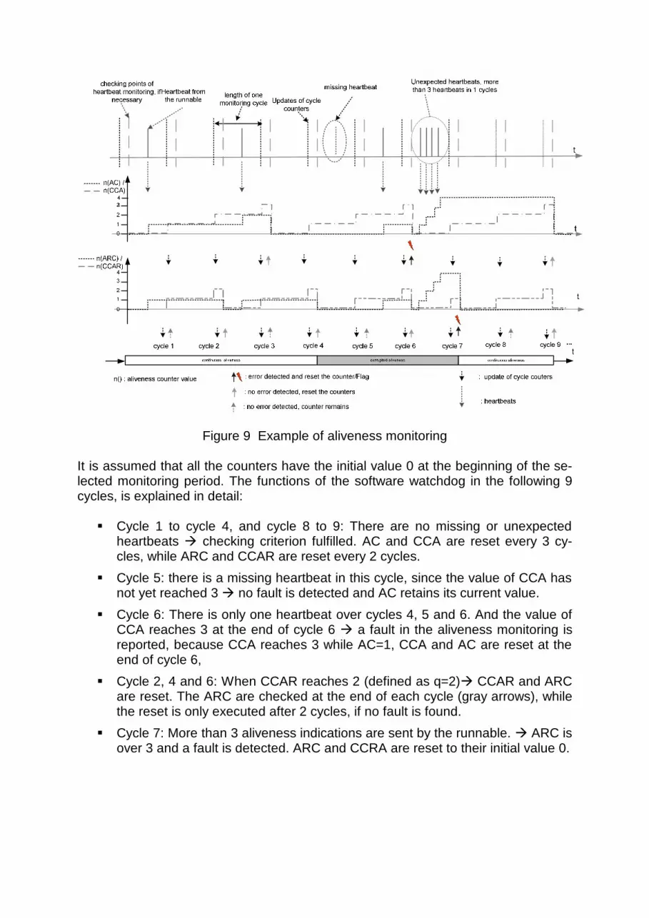
Figure 9 Example of aliveness monitoring It is assumed that all the counters have the initial value 0 at the beginning of the se-lected monitoring period. The functions of the software watchdog in the following 9 cycles, is explained in detail: Cycle 1 to cycle 4, and cycle 8 to 9: There are no missing or unexpected
heartbeats checking criterion fulfilled. AC and CCA are reset every 3 cy-cles, while ARC and CCAR are reset every 2 cycles.
Cycle 5: there is a missing heartbeat in this cycle, since the value of CCA has not yet reached 3 no fault is detected and AC retains its current value.
Cycle 6: There is only one heartbeat over cycles 4, 5 and 6. And the value of CCA reaches 3 at the end of cycle 6 a fault in the aliveness monitoring is reported, because CCA reaches 3 while AC=1, CCA and AC are reset at the end of cycle 6,
Cycle 2, 4 and 6: When CCAR reaches 2 (defined as q=2) CCAR and ARC are reset. The ARC are checked at the end of each cycle (gray arrows), while the reset is only executed after 2 cycles, if no fault is found.
Cycle 7: More than 3 aliveness indications are sent by the runnable. ARC is over 3 and a fault is detected. ARC and CCRA are reset to their initial value 0.

Control Flow Checking
Correct control flow is a fundamental part of the correct execution of computer pro-grams. In the embedded system, the following faults could be causes of control flow errors: Faults in the software design specification, implementation and integration. Coincidence faults in the system, e.g. memory errors. Corruption of program counter
To reduce the overhead involved during control flow checks, only the sequence of the runnables in safety-critical tasks will be monitored. With the help of aliveness in-dication routines, which are integrated into the runnables as automatically generated glue code in Figure 7, runnables currently being executed can be reported. In a look-up table, all the possible predecessor/successor relationships of the monitored run-nables are saved and compared to the actual execution sequence. In order to save system resources and reduce the system complexity, only the safety relevant run-nables are set under control flow monitoring. A simple example of control flow checking is demonstrated in Figure 10. Because the branch from runnable 1-1 to runnable 1-4 is an illegal branch and runnable 1-4 is not defined in the table as a possible successor, an error will be reported by the control flow checking block.
runnable 12
runnable 11
...
Task A (cyclic)
Execution of task A on ECU
glue code
runnable 14
illegal branch
current runnable 31,2141 error!
successorspredecessor
……1-41-2
1-2, 1-31-1
successorspredecessor
……1-41-2
1-2, 1-31-1
runnable 13
Figure 10 Example of control flow checking In order to achieve global monitoring by integration of the results from runnable-level monitoring, the error messages of runnables are recorded by the Task State Indica-tion Unit in an error indication vector and mapped onto the tasks. If one of the di-

mensions in the error indication vector reaches the threshold, the whole task will be considered as faulty. Based on the information of application/task mapping, corre-sponding fault treatment with a global view of the ECU is taken: If the global ECU state is “faulty”, the ECU might be reset by ECU software
reset depending on the requirements from applications. If the global ECU state is “OK”, the “faulty” application software components
might be restarted or terminated. If there are other tasks, which do not belong to any of the terminated/restarted
applications, those tasks might be terminated/restarted with the services pro-vided by the operating system.
5 EASIS Validator of Dependability Software Services
EASIS Validator and Validation Process
The objective of the EASIS validator is to prototype and validate some of the most relevant properties of the EASIS architecture both in hardware and software, includ-ing fault tolerant hardware, dependability software services and telematics services etc. The main part of the EASIS HIL (Hardware in the Loop) validator hosts a number of ISS-applications, such as SafeLane and SafeSpeed with Steer-by-Wire technol-ogy. SafeLane is a lane keeping support system increasing the active vehicle safety by warning the driver or actively intervening in critical situations concerning inappro-priate lateral guidance by the driver. SafeSpeed is a system to limit the vehicle speed to an externally commanded maximum value automatically. Figure 11 shows the structure of the EASIS-validator. The eight main nodes including driving dynamics control, environment simulation, fault-tolerant actuator and sensor and gateway nodes are connected using dual-channel FlexRay and active stars. In the following sections we will focus on the central node, the dual-duplex sensor nodes and the spy node. The central node is an AutoBox, a rapid prototyping plat-form from dSpace, where the safety applications of SafeLane and SafeSpeed with control algorithms and a dependability software service, are integrated. The spy node is an ECU, where safety relevant applications using the software watchdog and the Fault Management Framework, are integrated. A fault-tolerant sensor application with Agreement Protocol and other dependability services, such as dual-duplex sen-sors and signal selection are demonstrated on the Steering Wheel Sensors.

Steering Column
M1
M1
M2
M2
ETHERNET
CAN-Bus
FSUnit
FSUnit “Spy” Node
Steering wheel feedback actuator
Simplified vehicle dynamic simulator
Central Node
Steering wheel sensors
Telematics Gateway
Virtual Dashboard
SAFESPEEDRemote Monitoring
S1 S4S3S2
FSUnit
FSUnit
MechanicalInterface
Figure 11 Hardware Architecture of EASIS Validator [11]
Before we can explore the validation of the dependability software services in detail, a brief introduction to the development process, methodology and prototyping tool chain will be given. State of the art in the development of in-vehicle electronics is the model and simula-tion based development process, in which a sub-system will be developed and tested in a pure software environment with the help of simulation tools (Software in the Loop). The implementation of software on a particular hardware platform will only be initiated after a successful test of the functionalities with the help of simulation models. In the EASIS validator, however, we are facing more new challenges. Firstly, with the introduction of distributed integrated safety applications on one or several networks, the system complexity and requirements of dependability are increasing dramatically. Secondly, with the introduction of FlexRay as time-triggered communication, a global schedule with frames and signals should be defined by the system designer in the early phase, which makes the final integration easier, but involves more risk in the design. As a time-triggered communication system, FlexRay requires more effort for defining the scheduling table and synchronization of local tasks with global commu-nication. Thirdly, the development is carried out in EASIS, distributed between differ-ent companies, and it is not strongly characterized by the classical work distribution between OEM and supplier. The relationship of tool chains in the virtual integration and global development proc-ess is depicted in Figure 12, with Matlab/Simulink, DECOMSYS and dSpace soft-ware tools, so that dependability software services defined in EASIS can be vali-dated on the rapid prototyping platform MicroAutoBox.

After requirement analysis of the ISS-applications, we initiate the system functional design by building and modeling the whole system with Matlab/Simulink. In the sec-ond step, functional models will be mapped into the system architecture (ECUs and in-vehicle networks), FlexRay communication scheduling including task scheduling will be defined in an iterative process. In the third step, the whole system can be simulated on a PC as a virtual prototype. After the simulation phase by validating the virtual prototype against system requirements, in particular the safety requirements and timing constraints, the C-code of FlexRay communication and task scheduling will be generated. Based on the knowledge gained from the virtual prototype and other automotive con-straints such as resource and timing requirements, a rapid prototyping platform is chosen for the validation and evaluation of the concepts. Individual hardware specific code can be generated, compiled and loaded onto the rapid prototyping platform. The prototype in EASIS will be used to validate key concepts in the real hardware environment and tested against the requirement speciation, using appropriate tools for fault injection.
Functional model
FlexRay schedule
Prototypinghardware
MonitoringCalibration
Separated model for prototyping
platform
Archi.-allocfunctional
model
Code generation forcommunication and
task scheduling
Virtual prototype
Figure 12 Tool-chain and development process for the EASIS validator Validation of Agreement Protocol
As mentioned, the validation of the Agreement Protocol is carried out on the follow-ing three nodes: the Central Node and the two fault tolerant dual-duplex sensor nodes. Usually fault tolerant applications have backup system states, which are used when faulty components or other abnormal states are detected. In this case, all the distributed safety components must be informed of this situation and take synchro-nized and consistent fault treatment measures. In the EASIS validator, the Agree-ment Protocol will be applied to reach a reliable and deterministic transition of state information of distributed nodes, so an agreed state transition with fault tolerance for the global safety relevant application can be reached. As shown in Figure 13, the Agreement Protocol is embedded in the Central Node and the Sensor Nodes with the application software. Based on the state information of the sensor nodes, the

applications on the Central Node, for example SafeLane, can switch to different states, such as “operational”, “faulty sensor mode” or “failure” modes, while the fault-tolerant communication against Byzantine Faults is guaranteed by means of the Agreement Protocol.
Figure 13 Outline of system architecture for the validation of AP

Validation of Software Watchdog
The validation of the software watchdog, as well as fault-injection, is designed based on the fault hypothesis, which was built at the beginning of the design phase for the dependability software service. Generally speaking, there are two main categories of faults in ECU software: timing faults and value faults. While the aliveness monitoring and arrival rate checking are designed to detect timing faults of runnables, control flow checking is mainly de-signed to prevent runnable execution sequence faults resulting from memory prob-lems. Following the development process of virtual integration, we start with the modeling of runnables under Matlab/Simulink. On the spy-node, safety relevant applications such as front lighting and rear lighting control, as well as luminosity and rain sensors, will be designed using runnables and mapped to different tasks. Applications, as well as the software watchdog, will be prototyped and simulated using the model-based approach. Since the software watchdog is only designed for fault detection on the runnable layers, the fault handling mechanisms should be implemented in the Fault Management Framework to treat the application faults according to their severity. The Fault Management Framework can take fail-safe (e.g. deactivation of faulty task or faulty applications, etc.) or fail-operational measures (restart of faulty tasks or faulty applications, or other reconfiguration mechanisms). Thus, the complete fault tolerance process from fault detection to fault handling, concerning the timing and control flow error, can be validated in the EASIS validator. 6 Conclusion
Experience
The concepts and design of the dependable software platform for automotive inte-grated safety systems in EASIS reflects the current trends in automotive software development. The dependable software platform demonstrates the potential of func-tional alternatives for improving dependability in distributed embedded systems, while managing the complexity of Integrated Safety Systems as well as with modu-larization and platform strategy. With the help of Agreement Protocol as a configurable dependability software ser-vice, consistence among redundant nodes even in presence of to Byzantine faults can be provided. Structural redundancies with possible inconsistencies in the timing and value domains can be managed and configured by the system designer. The software watchdog, as another dependability software service, monitors the indi-vidual timing constraints of application runnables and their control flow. The interface to the software watchdog provides information for further appropriate fault treatment and variants for fault containment and tolerance.

The development and prototyping follows a model based process with the virtual in-tegration tool chain on a rapid prototyping platform. The approach in this paper pro-vides some of the most necessary services for developing safety relevant applica-tions distributed on several ECUs. Many valuable experiences were gained during the set up of FlexRay for the integrated safety relevant applications, such as FlexRay communication scheduling design, synchronization of local tasks with time-triggered communication task. Outlook for Future Works
The concepts of a dependable software platform for automotive integrated safety systems presented in this paper are heading towards an open and standardized automotive safety architecture. The dependability software services should be cate-gorized to a standard library, with configurable features for the integration with safety application from different safety integrity levels according to safety norms in automo-tive industry. In the development of ISS-applications, the strategies for the mapping of compo-nents of ISS-applications onto the physical ECUs and network topology are still un-der investigation. Here, many different aspects and constraints should be consid-ered, such as dependability, complexity, communication overhead and ECU-resources. A consolidated development process and appropriate tools, supporting safety rele-vant steps, FlexRay scheduling design, interchange format in the tool chains and between OEMs and suppliers, etc. are still being studied. In the EASIS validator, the functionalities and performances of the dependability soft-ware services have still to be evaluated. Experiences from the integration of EASIS dependability software services with an integrated safety application on an in-vehicle platform still have to be gathered. The hope is that the integration of these depend-ability software services into the platform will also lead to a significant improvement of system dependability of the in-vehicle safety electronics.

Literature
[1] G. Leen; D. Heffernan, "Expanding Automotive Electronic Sys-tems," IEEE Computer, pp. 5-6, Jan-2002.
[2] ATZ/MTZ, "Aktive und passive Sicherheit," ATZ/MTZ extra S-Klasse BR221, pp. 118-125, 2005.
[3] M. Krug, "Concept and Implementation of a Dependable Auto-motive Operating System," in Computer of Science: University of Tübingen, 1998, pp. p. 57, Chapter 5: Defining a Fault Hypothe-sis.
[4] M. Limam, "Conception and Implementation of an Agreement Protocol for Fault-Tolerant Automotive Embedded Systems (ba-sis document)," 2005.
[5] K. Echtle, Fehlertoleranzverfahren. Heidelberg: Springer-Verlag, 1990.
[6] D. Lantrip, "General Purpose Watchdog Timer Component for a Multitasking System," embedded world, 1997.
[7] J. Ganssle, "Watching the Watchdog," embedded world, 2003. [8] OSEK, "OSEK/VDX Operating System Specification 2.2.3,"
2005. [9] Bernhardt, "Markt- und Technologiestudie der Leistungselek-
tronik 2015," Arthur D Little GmbH - Consulting Sep-2005. [10] Th. Scharnhorst, "AUTOSAR – Challenges and Achievements
2005," presented at Electronic Systems for Vehicles 2005 from VDI-Society for Automotive and Traffic Systems Technology, Baden-Baden, 2005.
[11] EASIS, "Specification of EASIS Validator with Telematics Gate-way, WT5.1 Deliverable," EASIS Consortium 2006.
[12] L. Lamport; R.Shostak; M.Pease, "Reaching Agreement in the Presence of Faults," Journal of the ACM, vol. 27, no. 2, pp. 228..234, Apr-1980.
[13] L. Lamport; M. Pease; R. Shostak, "The Byzantine Generals Problem," ACM Transactions on Programming Languages and Systems, vol. 4, pp. 382-401, 1982.
[14] H. Heinecke, A. Schedl, B.Hedenetz, "FlexRay – ein Kommuni-kationssystem für dasAutomobil der Zukunft," in Elektronik Automotive, Sep-2002, pp. 36-45.
Authors
Dipl.-Ing. Xi Chen, M. Sc. DaimlerChrysler AG – Stuttgart (Germany)
Dr. Martin Hiller
Volvo Technology Corporation – Gothenburg (Sweden)
Prof. Dr.-Ing. Klaus D. Müller-Glaser University of Karlsruhe (TH) / Institute for Information Processing Technology –
Karlsruhe (Germany)
Dr.-Ing. Vera Lauer DaimlerChrysler AG – Stuttgart (Germany)


