Embed Size (px)
Citation preview

A Modal-Logic Based Graph Abstraction
Jorg Bauer2 Iovka Boneva1 Marcos E. Kurban3 Arend Rensink1
1 Institut fur Informatik, Technical University of Munich,85748 Garching bei Munchen, Germany
Email: [email protected] Formal Methods and Tools Group, EWI-INF, University of Twente
PO Box 217, 7500 AE, Enschede, The Netherlands{bonevai,rensink}@cs.utwente.nl
3 Former member of Formal Methods and Tools Group, EWI-INF, University ofTwente
Abstract. Infinite or very large state spaces often prohibit the success-ful verification of graph transformation systems. Abstract graph trans-formation is an approach that tackles this problem by abstracting graphsto abstract graphs of bounded size and by lifting application of produc-tions to abstract graphs. In this work, we present a new framework ofabstractions unifying and generalising existing takes on abstract graphtransformation. The precision of the abstraction can be adjusted accord-ing to the properties to be verified facilitating abstraction refinement.We present a modal logic defined on graphs, which is preserved and re-flected by our abstractions. Finally, we demonstrate the usability of theframework by verifying a graph transformation model of a firewall.
1 Introduction
Formal verification of graph transformation systems aims at statically provingor inferring properties of a graph transformation system, where such propertiesare typically given in some form of temporal logic. It is crucial to distinguish ver-ification and simulation, the latter being very useful only for debugging, whereasverification establishes a property for all computations of a graph transformationsystem. Problems do arise when approaching this task. One such problem is thepossibly infinite behaviour of a system which in most cases makes it impossibleto study the whole behaviour of the system. Another problem is space: even fora finite state space, each state can be quite big to represent.
Some approaches to formal verification of graph transformation systems in-clude [1,2,3,4,5,6,7,8].They can be characterised as to which approach to graphtransformation is used for modelling, which verification technique is applied, andwhich applications are tackled. The technique presented in [1] feeds finite-stategraph transformation systems, given as a double pushout system, to an off-the-shelf model checker to verify reactive systems. However, we face the moregeneral problem of unbounded systems. The approaches presented in [2,3] bothuse backwards reachability analysis for hyperedge replacement grammars trying
to reach an initial graph by backwards search from a forbidden configuration.The technique is applied to mechatronic systems and ad-hoc network routing,respectively, but, unfortunately, is not guaranteed to terminate. An approxima-tion of the behaviour of a graph transformation system in terms of Petri netunfoldings was used in [4] to verify properties of data structures residing in therun-time heap of programs with dynamically allocated heap memory.
In this work, we present a new take on abstract graph transformation asintroduced independently by [6] and [7]. Abstract graph transformation relies onabstract interpretation [9] of graph transformation systems, that is, given someequivalence relation, graphs are quotiented into abstract graphs of bounded,finite size. Application of productions is then lifted to work on abstract graphs.The abstraction first introduced in [10] summarises nodes with similar kind andnumber of incident edges, while the abstraction of [7] considers similar adjacentnodes. These two abstractions are generalised in this work and put into a unifyingframework. To this end, we introduce the notion of neighbourhood abstractionas a part of a general abstraction framework. For this abstraction, nodes aresummarised if they have similar neighbourhood up to some radius i, parameter ofthe abstraction. This enables abstractions with different precisions. Additionally,the number of possible abstract graphs obtained by neighbourhood abstractionis bounded. We introduce a logic accompanying our abstractions: given a formulaour abstraction guarantees that a) if the formula holds for the original graph,then it holds for the abstracted graph (preservation); and b) if the formula holdsfor the abstracted graph, then it holds for the original one too (reflection).
Contributions.
– Our abstraction framework unifies and generalises previous approaches onabstract graph transformation. For this particular technique, it supposedlyestablishes the most general treatment of local abstractions, that is, abstrac-tions based on equivalence relations, where equivalence is determined bylocal information on nodes. In contrast, equivalences used in shape analysis[11] of heap programs often consider global properties like reachability.
– Technically, the most surprising result comprises the definition of a modallogic, properties of which are preserved and reflected by our abstraction.While preservation is necessary for the soundness of analyses based on ourabstraction, reflection is a rather unusual and strong result.
– Our framework allows for automated abstraction refinement. If a propertycannot be established given a certain neighbourhood size, one may auto-matically increase this size to obtain more precise results. The only otherapproach allowing for automated refinement is [5].
– A canonical representation of abstract graphs reduces otherwise costly iso-morphism checks to simple equality tests.
– While, certainly, our method has its limitations, it works well for an im-portant class of systems, dynamic communication systems. They are char-acterised by a dynamically changing number of communicating objects anda dynamically changing communication topology. Important examples in-clude ad-hoc network protocols, traffic control- or mechatronic systems. Our
2
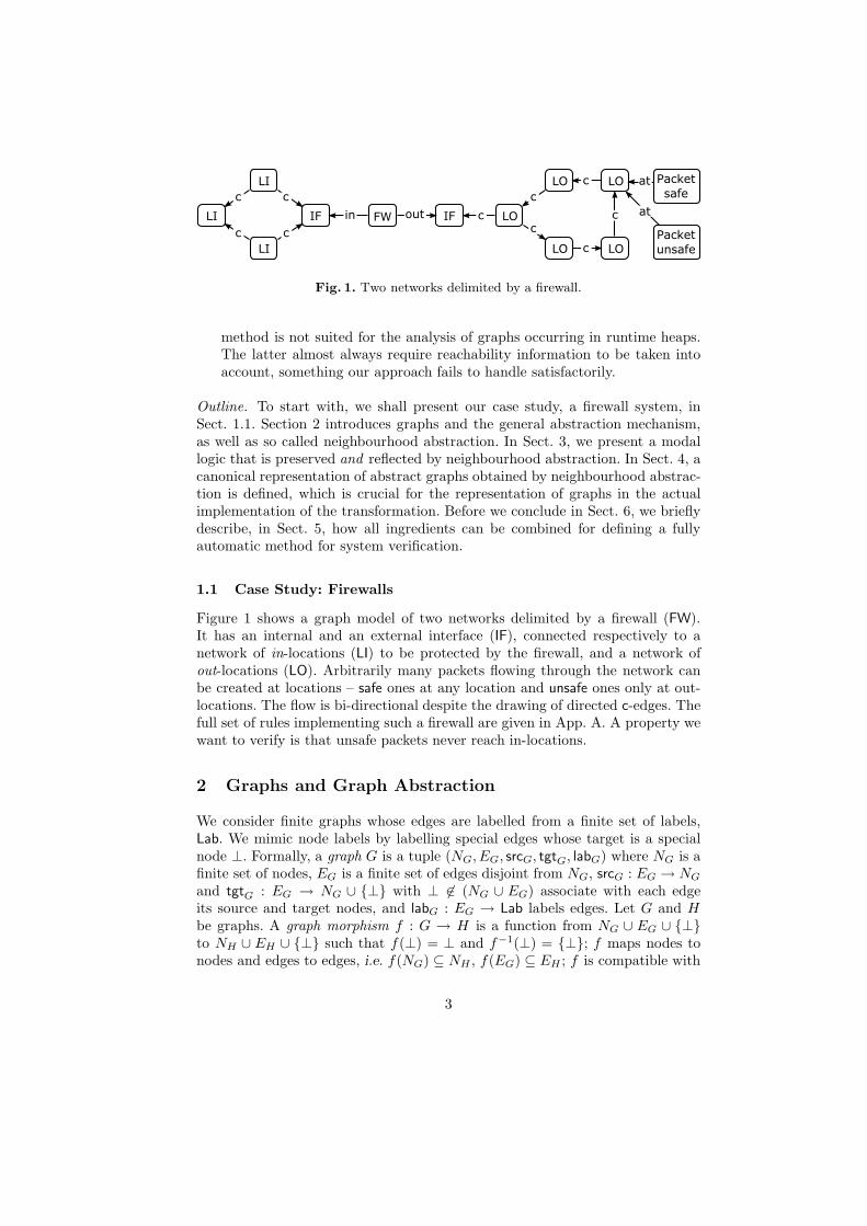
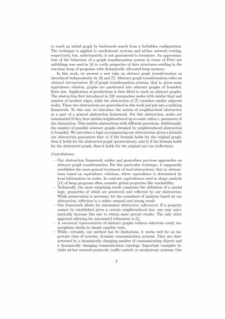
Fig. 1. Two networks delimited by a firewall.
method is not suited for the analysis of graphs occurring in runtime heaps.The latter almost always require reachability information to be taken intoaccount, something our approach fails to handle satisfactorily.
Outline. To start with, we shall present our case study, a firewall system, inSect. 1.1. Section 2 introduces graphs and the general abstraction mechanism,as well as so called neighbourhood abstraction. In Sect. 3, we present a modallogic that is preserved and reflected by neighbourhood abstraction. In Sect. 4, acanonical representation of abstract graphs obtained by neighbourhood abstrac-tion is defined, which is crucial for the representation of graphs in the actualimplementation of the transformation. Before we conclude in Sect. 6, we brieflydescribe, in Sect. 5, how all ingredients can be combined for defining a fullyautomatic method for system verification.
1.1 Case Study: Firewalls
Figure 1 shows a graph model of two networks delimited by a firewall (FW).It has an internal and an external interface (IF), connected respectively to anetwork of in-locations (LI) to be protected by the firewall, and a network ofout-locations (LO). Arbitrarily many packets flowing through the network canbe created at locations – safe ones at any location and unsafe ones only at out-locations. The flow is bi-directional despite the drawing of directed c-edges. Thefull set of rules implementing such a firewall are given in App. A. A property wewant to verify is that unsafe packets never reach in-locations.
2 Graphs and Graph Abstraction
We consider finite graphs whose edges are labelled from a finite set of labels,Lab. We mimic node labels by labelling special edges whose target is a specialnode ⊥. Formally, a graph G is a tuple (NG, EG, srcG, tgtG, labG) where NG is afinite set of nodes, EG is a finite set of edges disjoint from NG, srcG : EG → NG
and tgtG : EG → NG ∪ {⊥} with ⊥ 6∈ (NG ∪ EG) associate with each edgeits source and target nodes, and labG : EG → Lab labels edges. Let G and Hbe graphs. A graph morphism f : G → H is a function from NG ∪ EG ∪ {⊥}to NH ∪ EH ∪ {⊥} such that f(⊥) = ⊥ and f−1(⊥) = {⊥}; f maps nodes tonodes and edges to edges, i.e. f(NG) ⊆ NH , f(EG) ⊆ EH ; f is compatible with
3
(a) µ = 1, ν = 1 (b) µ = 1, ν = 3
Fig. 2. Examples of abstract graphs.
source and target mappings, i.e. srcH ◦ f = f ◦ srcG, and tgtH ◦ f = f ◦ tgtG,and f preserves labels, f ◦ labG = labH . A morphism f is called injective (resp.surjective, resp. bijective) if it defines an injective (resp. surjective, resp. bijective)map. A bijective morphism is also called an isomorphism. We extend labG toa node to determine its set of labels, i.e. labG(v) = {a ∈ Lab | ∃e ∈ EG :srcG(e) = v, tgtG(e) = ⊥, labG(e) = a}. We write v�a
G and v�a
G for the set ofa-outgoing edges and a-incoming edges of node v, respectively, i.e. v�a
G = {e ∈EG | srcG(e) = v, labG(e) = a} and symmetrically for v�a
G. For a set of nodes V ,V�
a
G (resp. V�a
G) is the extension of �a
G (resp. �a
G) on sets. Finally, for X,Ynodes or sets of nodes, we denote X ��
a
GY the set of a-labelled edges betweenX and Y , i.e. X ��
a
GY = X �a
G ∩Y�a
G. When the graph G is clear from thecontext, we may omit the subscript G. For brevity, in the sequel of the paper weignore the node ⊥ and simply talk about node labels.
A multiplicity approximates the cardinality of a finite set. For any naturalµ > 0, let Mµ be the set {0, 1, 2, . . . , µ, ω} where ω 6∈ N. The µ-multiplicity ofa set U is denoted |U |µ and defined by: |U |µ = Card(U) if Card(U) ≤ µ, and
|U |µ = ω otherwise. We write M+µ for the set Mµ r{0}. The usual ordering ≥ is
extended to elements of Mµ by ω ≥ λ for all λ in Mµ. Sums over multiplicitiesare defined as expected writing
∑µfor µ-bounded sums. For the sequel, we fix
two naturals, ν, µ > 0, to denote multiplicities of sets of nodes (ν) and sets ofedges (µ), i.e. ν and µ are parameters of graph abstractions.
2.1 Abstract Graphs and Abstraction
In this section, we discuss the notion of abstract graphs. Abstract graphs, suchas the ones of Fig. 2, represent sets of (concrete) graphs called their concreti-sations. Every node of an abstract graph is associated with a node multiplicityindicating the number of concrete graph nodes it represents. The dotted rect-angles are delimiting groups of nodes induced by an equivalence relation, thegrouping relation, on them. All edges have associated multiplicity information(from Mµ) in their end points: outgoing edges multiplicity, when associated tothe source of the edge, and incoming edges multiplicity when associated to thetarget. Sometimes, this multiplicity is shared by several edges, indicated by thegrey arc relating them. Edge multiplicities indicate how many of the depictededges should be there in a concretisation. Note that edges related in one of theirend points all have their other end point in the same group of nodes, and all havethe same label. Actually, this is the condition for relating edges. More precisely,
4
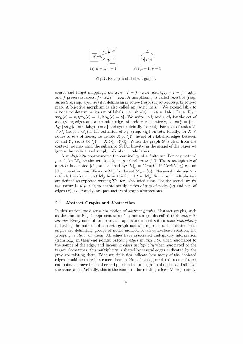
(a) (b)
Fig. 3. Example concretisations of the abstract graphs on Fig. 2.
edge multiplicities are associated with a triple composed of a node, a label anda group of nodes.
Consider the abstract graph of Fig. 2(a). It represents a set of bipartiteconcrete graphs, such as the ones of Fig. 3(a), where a-nodes are connected tob-nodes by c-edges. Each of these graphs has at least two (as ν = 1, ω standsfor “two or more”) a-nodes and at least three (ω plus one) b-nodes. Moreover,every a-node has at least two (i.e. ω) outgoing c-edges going to b-nodes. Allb-nodes except one have only one incoming edge; the remaining b-node has atleast two incoming edges. The abstract graph of Fig. 2(b) represents a set ofconcrete graphs having three a-nodes connected to each other forming b cycles,such as in Fig. 3(b).
Let us fix some notations. Let A be a set and ∼ ⊆ A× A be an equivalencerelation over A. For x ∈ A, [x]
∼denotes the equivalence class of x induced by ∼,
and A/∼ is the set of ∼-equivalence classes in A. If ∼ and ∼′ are two equivalencerelations over A such that ∼ ⊆ ∼′, then ∼ is called a refinement of ∼′.
Definition 1 (abstract graph). An abstract graph S is a structure (GS ,∼S
,multn,S ,multout,S ,multin,S) where
– GS = (NS , ES , srcS , tgtS , labS) is a graph;– ∼S ⊆ NS ×NS is an equivalence relation on NS called the grouping relation;– multn,S : NS → M+
ν is a node multiplicity function;– multout,S : NS×Lab×NS/∼S→ Mµ is an outgoing edges multiplicity function;– multin,S : NS×Lab×NS/∼S→ Mµ is an incoming edges multiplicity function.
Moreover, for any v ∈ NS, a ∈ Lab and C ∈ NS/∼S, we require multout,S(v, a, C)= 0 iff v ��
a
GSC = ∅, and multin,S(v, a, C) = 0 iff C ��
a
GSv = ∅.
Formally, the relation between concretisations of an abstract graph S and S iscaptured by abstraction morphisms respecting multiplicity.
Definition 2 (abstraction morphism, concretisation). Let G be a graphand S be an abstract graph. An abstraction morphism of G into S is a surjectivegraph morphism s : G→ GS such that the following conditions are met:
5
1. for all w ∈ NS: multn,S(w) =∣
∣s−1(w)∣
∣
ν;
2. for all w ∈ NS, for all a ∈ Lab, for all C ∈ NS /∼S, and for all v ∈ s−1(w):
multout,S(w, a, C) =∣
∣v ��a
G(s−1(C))∣
∣
µand multin,S(w, a, C) =
∣
∣(s−1(C)) ��a
Gv∣
∣
µ.
If s : G → S is an abstraction morphism, then G is a concretisation of S. Theset of all concretisations of S is written Concr(S).
As another example, Fig. 4, page 9 shows an abstract graph for the firewallexample from Fig. 1, with ν = µ = 1. The corresponding abstraction morphismsummarises the two LI-neighbours of the internal interface to the unique LI-neighbour of the internal interface in the abstract graph. The three LO nodesthat have only LO neighbours are summarised to a unique node. All other nodesin the abstract graph have multiplicity one and correspond to a unique node inthe concrete graph.
Note that the requirements on outgoing (resp. incoming) edge multiplicitiesguarantee in particular that two different nodes v, v′ of graph G can only besummarised by an abstraction morphism, if they have the same outgoing andincoming edges multiplicities with respect to a label and a group of nodes.
Construction of an Abstract Graph. Definitions 1 and 2 are declarative and donot give a hint on the effective construction of an abstract graph. This can bedone as follows: Let G be a graph and ∼, ≡ ⊆ NG × NG be two equivalencerelations such that ≡ refines ∼. Furthermore, assume that for any v, v′ ∈ NG,for any C ∈ NG/∼, and for any label a: v ≡ v′ implies
|v ��a
GC|µ = |v′ ��a
GC|µ and |C ��a
Gv|µ = |C ��a
Gv′|µ
Then ≡ and ∼ induce an abstract graph, S=(GS ,∼S,multn,multout,multin), andan abstraction morphism, s : G→ S as follows:
– Extend the equivalence relation ≡ to edges as follows: e ≡ e′ if srcG(e) ≡srcG(e′), tgtG(e) ≡ tgtG(e′) and labG(e) = labG(e′). Then SG = (NS , ES ,srcS , tgtS , labS) is the graph quotient of G w.r.t. ≡, i.e. NS = NG /≡; ES =EG /≡; and for any edge [e]
≡in ES , srcS([e]
≡) = [srcG(e)]
≡, tgtS([e]
≡) =
[tgtG(e)]≡
and labS([e]≡
) = labG(e). Note that, because of the definition of≡ on edges [e]
≡is well-defined.
– Mapping s : NG ∪ EG → NS ∪ ES is defined by s(v) = [v]≡
and s(e) = [e]≡
for any v ∈ NG and any e ∈ EG and extended to preserve ⊥.– ∼S ⊆ NS × NS is the equivalence relation given by [v]
≡∼S [v′]
≡if v ∼ v′
for all v, v′ ∈ NG.– multn : NS → M+
ν is defined by multn(w)=∣
∣s−1(w)∣
∣
νfor all w in NS .
– multout,multin : NS × Lab ×NS /∼S→ Mµ are mappings defined bymultout([v]≡ , a, C) = |v ��
a
GC|µ multin([v]≡, a, C) = |C ��
a
Gv|µfor all v ∈ NG, a ∈ Lab, and C ∈ NS /∼S .
It is obvious that S and s are indeed a well-defined abstract graph and abstrac-tion morphism for two such equivalence relations. The complete formalisation
6
and proof of this construction is in [12]. Note that not all abstract graphs canbe thus defined. Such abstract graphs necessarily have concretisations and can-not have parallel edges, which is not the case for general abstract graphs. Still,any abstract graph admitting concretisations and without parallel edges can bedefined this way. For a graph G and equivalence relations ∼ and ≡ as abovewe write abstr graph(G,∼,≡) and abstr morph(G,∼,≡) for the abstract graphand the corresponding abstraction morphism constructed as shown above.
2.2 Isomorphism of Abstract Graphs
Abstract graphs can be abstracted just like graphs, yielding “more abstract”graphs. In this section we describe this abstraction relation, which is com-poseable. We then use it to define the notion of isomorphism between abstractgraphs having the interesting property that isomorphic abstract graphs have thesame concretisations.
Definition 3 (abstraction morphism between abstract graphs). An ab-straction morphism from an abstract graph S to an abstract graph T is a graphmorphism f : GS → GT that complies to the following axioms:
1. ∀v, v′ ∈ NS: v ∼S v′ implies f(v) ∼T f(v′);
2. ∀w ∈ NT : multn,T (w) =(
∑νv∈f−1(w) multn,S(v)
)
;
3. ∀w ∈ NT , ∀a ∈ Lab, ∀C ∈ NT /∼T , ∀v ∈ f−1(w), it holds
multout,T (w, a, C) =
µ∑
D ∈ (f−1(C))/∼S
multout,S(v, a, D)
and similarly for the incoming edges multiplicity.
The axioms in the previous definition are well-defined. In the third axiom wesum up multout,S(v, a, D) and multin,S(v, a, D) for all D ∈ (f−1(C)) /∼S . It isthen necessary that all the triples (v, a, D) belong to the domain of multin,S , thatis, it is necessary that any such D belongs to NS /∼S. This is indeed the casethanks to the first axiom.
There is an analogy between an abstraction morphism between abstractgraphs (Def. 3) and an abstraction morphism from a graph into an abstractgraph (Def. 2). Namely, the second axiom in Def. 3 corresponds to the firstaxiom in Def. 2, but we sum up node multiplicities instead of simply countingnodes. Also the third axiom in Def. 3 and the second axiom in Def. 2 are anal-ogous. Note that the composition of two abstraction morphisms yields anotherabstraction morphism [12].
We can now define two abstract graphs S and T to be isomorphic if thereexists an isomorphism f : GS → GT such that both f and f−1 are abstractionmorphisms. This leads us to the following interesting statement proven in [12].
Lemma 1. If two abstract graphs S and T are isomorphic, then they have thesame concretisations.
7
Note that the inverse is not true. To this end, consider two abstract graphsS and T , where S has a single node of multiplicity two and no edges. T hastwo nodes, each of multiplicity one, and no edges. S and T both have a uniqueconcretisation (up to graph isomorphism) which is the graph with two nodesand no edges, but S and T are clearly not isomorphic.
2.3 Neighbourhood Abstraction
So far, we have defined the notion of abstract graphs, concretisations, and ab-straction morphisms. In our construction of abstract graphs, we assumed theexistence of equivalence relations ≡ and ∼ having particular properties. Weshall now define an interesting choice of such relations inducing the notion ofneighbourhood abstractions. This conveys the central idea of our work. In suchan abstract graph, each node represents concrete graph nodes that have similarneighbourhood, up to some “radius” i. This i is a parameter of the precision ofthe neighbourhood abstraction. By gradually increasing i, we can obtain moreprecise abstractions, if the current one is too imprecise to verify the desired prop-erties (abstraction refinement). We shall now define equivalence between nodesaccording to their neighbourhoods and, subsequently, neighbourhood abstrac-tion.
Definition 4 (neighbourhood abstraction). Let G be a graph. For each nat-ural i > 0, we define the i-neighbourhood equivalence relation ≡i over NG re-cursively by:
– v ≡0 v′ if labG(v) = labG(v′);
– v ≡i+1 v′ if v ≡i v
′, and |v ��aC|µ = |v′ ��
aC|µ, and |C ��av|µ = |C ��
av′|µfor all label a in Lab and for all C ∈ N / ≡i.
The level i neighbourhood abstraction of G is abstr graph(G,≡i−1,≡i) and thecorresponding abstraction morphism is abstr morph(G,≡i−1,≡i).
Two nodes are mapped to the same node of the abstract graph if they areneighbourhood equivalent up to some radius. The grouping relation is also givenby neighbourhood equivalence, but using a smaller radius. Figure 4 shows thelevel 1 neighbourhood abstraction of the firewall configuration from Fig. 1 forµ = 1 and ν = 1.
It is obvious from the definition that the level i+ 1 neighbourhood abstrac-tion of a graph refines the level i neighbourhood abstraction. This is the basisof our abstraction refinement mechanism. The neighbourhood abstraction of agraph is defined syntactically, which ties it to its representation. To avoid thisinconvenient situation, in the sequel by neighbourhood abstraction of a graphwe mean the isomorphism class of the actual abstract graph.
Neighbourhood abstraction behaves well w.r.t. isomorphism (Lemma 2 be-low). In combination with Lemma 1 this shows that two graphs obtained byneighbourhood abstraction are isomorphic iff they have the same concretisa-tions.
8
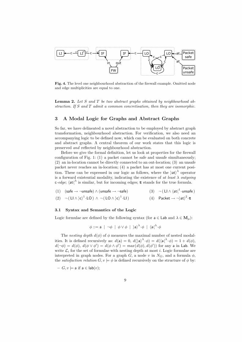
Fig. 4. The level one neighbourhood abstraction of the firewall example. Omitted nodeand edge multiplicities are equal to one.
Lemma 2. Let S and T be two abstract graphs obtained by neighbourhood ab-straction. If S and T admit a common concretisation, then they are isomorphic.
3 A Modal Logic for Graphs and Abstract Graphs
So far, we have delineated a novel abstraction to be employed by abstract graphtransformation, neighbourhood abstraction. For verification, we also need anaccompanying logic to be defined now, which can be evaluated on both concreteand abstract graphs. A central theorem of our work states that this logic ispreserved and reflected by neighbourhood abstraction.
Before we give the formal definition, let us look at properties for the firewallconfiguration of Fig. 1: (1) a packet cannot be safe and unsafe simultaneously;(2) an in-location cannot be directly connected to an out-location; (3) an unsafepacket never reaches an in-location; (4) a packet has at most one current posi-
tion. These can be expressed in our logic as follows, where the 〉at〉λ operatoris a forward existential modality, indicating the existence of at least λ outgoingc-edge; 〈at〈
λis similar, but for incoming edges; tt stands for the true formula.
(1) (safe → ¬unsafe) ∧ (unsafe → ¬safe) (3) ¬ ( LI ∧ 〈at〈1 ·unsafe )
(2) ¬ ( LI ∧ 〉c〉1·LO ) ∧ ¬ ( LO ∧ 〉c〉
1·LI ) (4) Packet → ¬〉at〉
2·tt
3.1 Syntax and Semantics of the Logic
Logic formulae are defined by the following syntax (for a ∈ Lab and λ ∈ Mµ):
φ ::= a | ¬φ | φ ∨ φ | 〉a〉λ ·φ | 〈a〈λ ·φ
The nesting depth d(φ) of φ measures the maximal number of nested modal-
ities. It is defined recursively as: d(a) = 0, d(〉a〉λ ·φ) = d(〈a〈λ ·φ) = 1 + d(φ),d(¬φ) = d(φ), d(φ ∨ φ′) = d(φ ∧ φ′) = max (d(φ), d(φ′)) for any a in Lab. Wewrite Li for the set of formulae with nesting depth at most i. Logic formulae areinterpreted in graph nodes. For a graph G, a node v in NG, and a formula φ,the satisfaction relation G, v |= φ is defined recursively on the structure of φ by:
– G, v |= a if a ∈ lab(v);
9
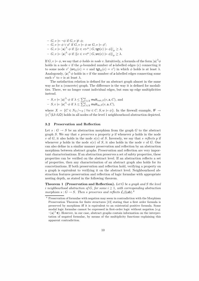
– G, v |= ¬φ if G, v 6|= φ;– G, v |= φ ∨ φ′ if G, v |= φ or G, v |= φ′;
– G, v |= 〉a〉λ·φ if |{e ∈ v�a | G, tgt(e) |= φ}|µ ≥ λ;
– G, v |= 〈a〈λ·φ if |{e ∈ v�a | G, src(e) |= φ}|µ ≥ λ.
If G, v |= φ, we say that φ holds in node v. Intuitively, a formula of the form 〉a〉λ·φ
holds in a node v if the µ-bounded number of a-labelled edges (e) connecting itto some node v′ (srcG(e) = v and tgtG(e) = v′) in which φ holds is at least λ.
Analogously, 〈a〈λ·φ holds in v if the number of a-labelled edges connecting some
such v′ to v is at least λ.The satisfaction relation is defined for an abstract graph almost in the same
way as for a (concrete) graph. The difference is the way it is defined for modali-ties. There, we no longer count individual edges, but sum up edge multiplicitiesinstead.
– S, v |= 〉a〉λ ·φ if λ ≤∑µ
C∈X multout,S(v, a, C), and
– S, v |= 〈a〈λ·φ if λ ≤
∑µC∈X multin,S(v, a, C),
where X = {C ∈ NS /∼S | ∀w ∈ C. S,w |= φ}. In the firewall example, IF →
〈c〈1·(LI∨LO) holds in all nodes of the level 1 neighbourhood abstraction depicted.
3.2 Preservation and Reflection
Let s : G → S be an abstraction morphism from the graph G to the abstractgraph S. We say that s preserves a property p if whenever p holds in the nodev of G, it also holds in the node s(v) of S. Inversely, we say that s reflects p ifwhenever p holds in the node s(v) of S, it also holds in the node v of G. Onecan also define in a similar manner preservation and reflection by an abstractionmorphism between abstract graphs. Preservation and reflection are very impor-tant characterisations. If an abstraction preserves a set of safety properties, theseproperties can be verified on the abstract level. If an abstraction reflects a setof properties, then any characterisation of an abstract graph also holds for itsconcretisations. If both preservation and reflection hold, verifying a property ona graph is equivalent to verifying it on the abstract level. Neighbourhood ab-straction features preservation and reflection of logic formulae with appropriatenesting depth, as stated in the following theorem.
Theorem 1 (Preservation and Reflection). Let G be a graph and S the leveli neighbourhood abstraction of G, for some i ≥ 1, with corresponding abstractionmorphism s : G→ S. Then s preserves and reflects Li(Lab).4
4 Preservation of formulae with negation may seem in contradiction with the MorphismPreservation Theorem for finite structures [13] stating that a first order formula ispreserved by morphism iff it is equivalent to an existential positive formula. Somemodal logic formulae cannot be expressed in first-order logic without negation (e.g.¬〉a〉λ·tt). However, in our case, abstract graphs contain information on the interpre-tation of negated formulae, by means of the multiplicity functions explaining thisapparent contradiction.
10
An important consequence of it is that neighbourhood abstraction can be para-metrised by the properties we want to verify by choosing the level of abstractionthat preserves the properties one is interested in. The following lemma formalisesthe relation between the logic and neighbourhood equivalence:
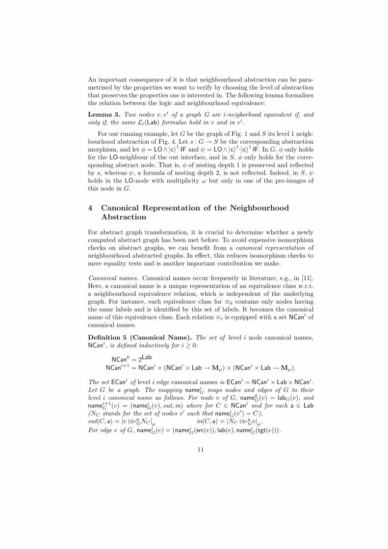
Lemma 3. Two nodes v, v′ of a graph G are i-neigborhood equivalent if, andonly if, the same Li(Lab) formulae hold in v and in v′.
For our running example, let G be the graph of Fig. 1 and S its level 1 neigh-bourhood abstraction of Fig. 4. Let s : G→ S be the corresponding abstractionmorphism, and let φ = LO∧〉c〉1·IF and ψ = LO∧〉c〉1·〉c〉1·IF. In G, φ only holdsfor the LO-neighbour of the out interface, and in S, φ only holds for the corre-sponding abstract node. That is, φ of nesting depth 1 is preserved and reflectedby s, whereas ψ, a formula of nesting depth 2, is not reflected. Indeed, in S, ψholds in the LO-node with multiplicity ω but only in one of the pre-images ofthis node in G.
4 Canonical Representation of the Neighbourhood
Abstraction
For abstract graph transformation, it is crucial to determine whether a newlycomputed abstract graph has been met before. To avoid expensive isomorphismchecks on abstract graphs, we can benefit from a canonical representation ofneighbourhood abstracted graphs. In effect, this reduces isomorphism checks tomere equality tests and is another important contribution we make.
Canonical names. Canonical names occur frequently in literature, e.g., in [11].Here, a canonical name is a unique representation of an equivalence class w.r.t.a neighbourhood equivalence relation, which is independent of the underlyinggraph. For instance, each equivalence class for ≡0 contains only nodes havingthe same labels and is identified by this set of labels. It becomes the canonicalname of this equivalence class. Each relation ≡i is equipped with a set NCani ofcanonical names.
Definition 5 (Canonical Name). The set of level i node canonical names,NCani, is defined inductively for i ≥ 0:
NCan0 = 2Lab
NCani+1 = NCani × (NCani × Lab → Mµ) × (NCani × Lab → Mµ).
The set ECani of level i edge canonical names is ECani = NCani × Lab×NCani.Let G be a graph. The mapping namei
G maps nodes and edges of G to theirlevel i canonical name as follows. For node v of G, name0
G(v) = labG(v), andnamei+1
G (v) = (nameiG(v), out, in) where for C ∈ NCani and for each a ∈ Lab
(NC stands for the set of nodes v′ such that nameiG(v′) = C),
out(C, a) = |v ��a
GNC |µ in(C, a) = |NC ��a
Gv|µ.
For edge e of G, nameiG(e) = (namei
G(src(e)), lab(e), nameiG(tgt(e))).
11
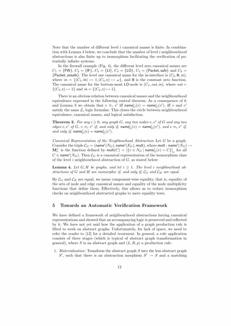
Note that the number of different level i canonical names is finite. In combina-tion with Lemma 4 below, we conclude that the number of level i neighbourhoodabstractions is also finite up to isomorphism facilitating the verification of po-tentially infinite systems.
In the firewall example (Fig. 4), the different level zero canonical names areC1 = {FW}, C2 = {IF}, C3 = {LI}, C4 = {LO}, C5 = {Packet, safe} and C6 ={Packet, unsafe}. The level one canonical name for the in-interface is (C2,0, in),where in = {(C1, in) 7→ 1, (C3, c) 7→ ω}, and 0 is the constant zero function.The canonical name for the bottom-most LO-node is (C4, out, in), where out ={(C4, c) 7→ 1} and in = {(C4, c) 7→ 1}.
There is an obvious relation between canonical names and the neighbourhoodequivalence expressed in the following central theorem. As a consequence of itand Lemma 3 we obtain that v ≡i v
′ iff nameiG(v) = namei
G(v′), iff v and v′
satisfy the same Li logic formulae. This closes the circle between neighbourhoodequivalence, canonical names, and logical satisfaction.
Theorem 2. For any i ≥ 0, any graph G, any two nodes v, v′ of G and any twoedges e, e′ of G, v ≡i v
′ if, and only if, nameiG(v) = namei
G(v′), and e ≡i e′ if,
and only if, nameiG(e) = namei
G(e′).
Canonical Representation of the Neighbourhood Abstraction Let G be a graph.Consider the triple CG = (namei(NG), namei(EG),mult), where mult : namei(NG) →M+
ν is the function defined by mult(C) =∣
∣{v ∈ NG | nameiG(v) = C}
∣
∣
νfor all
C ∈ namei(NG). Then CG is a canonical representation of the isomorphism classof the level i neighbourhood abstraction of G, as stated below:
Lemma 4. Let G,H be graphs, and let i ≥ 1. The level i neighbourhood ab-stractions of G and H are isomorphic if, and only if, CG and CH are equal.
By CG and CH are equal, we mean component-wise equality, that is, equality ofthe sets of node and edge canonical names and equality of the node multiplicityfunctions that define them. Effectively, this allows us to reduce isomorphismchecks on neighbourhood abstracted graphs to mere equality tests.
5 Towards an Automatic Verification Framework
We have defined a framework of neighbourhood abstractions having canonicalrepresentations and showed that an accompanying logic is preserved and reflectedby it. We have not yet said how the application of a graph production rule islifted to work on abstract graphs. Unfortunately, for lack of space, we need torefer the reader to [12] for a detailed treatment. In general, a rule applicationconsists of three stages (which is typical of abstract graph transformation ingeneral), where S is an abstract graph and (L,R, p) a production rule.
1. Materialisation: Transform the abstract graph S into the less abstract graphS′, such that there is an abstraction morphism S′ → S and a matching
12
m : L→ S′, the image of which is a concrete sub-graph of S′; i.e. a sub-graphin which all node and edge multiplicities are equal to one. S′ is not unique,and the aim of materialisation is to construct the set of abstract graphs Ssuch that for all concretisations G of S, for all matchings m : G→ S, thereexists T ∈ S and abstraction morphisms s : G→ T , t : T → S such that theimage of s ◦m is concrete in T .
2. Update: As we are dealing with concrete (sub-)graphs now, rule applicationis just as usual and applied to each element of materialisation.
3. Normalisation: The graphs obtained after updates need not necessarily be incanonical form. Therefore, we need to neighbourhood abstract them again.
We show in [12] that this abstract transformation mechanism is sound, in thesense that it over-approximates the concrete graph abstraction. If a graph G canbe transformed by rule (L,R, p) yielding a graph H , then G’s abstraction S canbe abstractly transformed by the same rule yielding H ’s abstraction T .
The overall verification of a system works as follows. Start with the neigh-bourhood abstraction of the initial graph of the system to be verified. Giventhe abstract transformation defined above, successively apply it to construct anabstract version of the graph transformation system which has neighbourhoodabstractions as states and which is guaranteed to be finite regardless the originalsystem. The canonical representation of the neighbourhood abstraction makesit easy to check whether a newly derived state has already been met before,which is a very costly operation in normal graph transformations. Moreover, theabstraction can be parametrised by the property one wants to verify, expressedin the modal logic. As the modal logic is preserved by the abstraction, one maynow evaluate formulas on finite, abstract graphs to obtain information about thepossibly infinite-state original system. Finally, note that our framework naturallygives rise to abstraction refinement: If the level i neighbourhood abstraction isnot conclusive, then one can try level i+ 1.
Running Example. In the abstract graph transformation system (GTS) inducedby the level 1 abstraction of the firewall example, all reachable abstract graphshave one FW-node and two IF-nodes, to which the different possible configu-rations of the internal and external networks are connected. The number ofabstract configurations is bounded, whereas the number of concrete configura-tions is infinite, because of the possibility of creating packets and connectingnew locations. Consider now the four properties listed above. They are all safetyproperties, defining invariants that should hold in all state of the GTS. Theseproperties indeed hold in all states of the abstract GTS. As the four formulae areof nesting depth one, by reflection of the logic we can deduce that they also holdin all states of the concrete GTS. For this particular example, the abstractionmechanism allows to verify the four properties using the level 1 neighbourhoodabstraction.
Usability and Limitations. Our verification framework is fully automatic andparametrised by the properties of interest. Due to the local nature of neigh-bourhood abstractions, it works well on systems where updates are determined
13
locally and where reachability is not important. Typical use cases include thefirewall example as given here or wireless traffic control systems as, e.g. the onesinvestigated in [7]. Also an application to ad-hoc network routing is promisingbut has not yet been explored.
However, our technique is not so suited for systems, where reachability is ofimportance, which is often the case for verification of software with dynamicallyallocated data structures. For instance, in the case of linked lists, our abstraction(regardless of radius) cannot distinguish between circular and non circular lists,which in practice results in lots of spurious states and transitions in the abstracttransition system (i.e. states and transitions that do not exist in the concretesystem). Also, the rather high complexity of our approach might be prohibitivefor really large examples. This is yet to be explored by careful experimentation.
6 Conclusion
We presented a framework of graph abstractions, called neighbourhood abstrac-tion, which generalises previous approaches to abstract graph transformation, amethod for formal verification of graph transformation systems. The abstractionis based on regrouping nodes with similar neighbourhood, and can be paramet-rised by the radius of the neighbourhood to be considered. It is guaranteed toyield systems of finite, bounded size facilitating their exploration. We also pre-sented a modal logic that can be interpreted both on graphs and on abstractgraphs. The logic and the abstraction are closely related, which makes it possi-ble to parametrise the abstraction so that it preserves and reflects the valuationof formulas. We delineated the implementation of a fully automated verificationframework based on our novel abstractions and facilitated by a canonical form ofabstract graphs. Interestingly, this framework also allows for automated abstrac-tion refinement. Our proposal is illustrated by an interesting and relevant graphtransformation based model of a firewall system. Usability and limitations of ourapproach were clearly identified. Note that related work was already discussedin the Introduction and that proofs and some other tedious formalities were leftout but can be found in [12].
Future Work. We plan to implement our technique within the Groove [14]framework, a standard tool for graph transformations. This will allow for a morethorough exploration of more examples and for a qualified judgement on prac-tical scalability. We believe that our framework caters for all possible local ab-stractions, where locality refers to the portion of the graph used to determinethe equivalence of nodes. On the other hand, this complicates the verificationof heap-manipulating programs, where reachability, a more global property, iscrucial. Therefore, we are working on abstractions taking reachability into ac-count. This is similar to abstractions used in the work of Sagiv et al. on shapeanalysis (see [11] for an overview) of heap-manipulating programs. In this work,the authors use logical structures to represent memory states of programs; ab-stract structures are 3-valued logical structures. Properties on these structures
14
are defined using first-order logic with transitive closure (FO+TC) enabling thedefinition of reachability. It seems promising to explore the opportunities offeredby FO+TC for abstract graph transformation too.
References
1. Heckel, R.: Compositional verification of reactive systems specified by graph trans-formation. In: FASE. (1998) 138–153
2. Becker, B., Beyer, D., Giese, H., Klein, F., Schilling, D.: Symbolic invariant veri-fication for systems with dynamic structural adaptation. In: ICSE, ACM (2006)
3. Saksena, M., Wibling, O., Jonsson, B.: Graph grammar modeling and verificationof ad hoc routing protocols. In: TACAS. Volume 4963 of LNCS., Springer (2008)
4. Baldan, P., Corradini, A., Konig, B.: Verifying finite-state graph grammars: Anunfolding-based approach. In: CONCUR. Volume 3170 of LNCS., Springer (2004)
5. Konig, B., Kozioura, V.: Counterexample-guided abstraction refinement for theanalysis of graph transformation systems. In: TACAS. Volume 3920 of LNCS.,Springer (2006)
6. Rensink, A., Distefano, D.: Abstract Graph Transformation. In: InternationalWorkshop on Software Verification and Validation (SVV). ENTCS (2005)
7. Bauer, J.: Analysis of Communication Topologies by Partner Abstraction. PhDthesis, Universitat des Saarlandes (2006)
8. Bauer, J., Wilhelm, R.: Static analysis of dynamic communication systems bypartner abstraction. In: SAS. Volume 4634 of LNCS., Springer (2007)
9. Cousot, P., Cousot, R.: Abstract interpretation: A unified lattice model for staticanalysis of programs by construction or approximation of fixpoints. In: POPL.(1977) 238–252
10. Rensink, A.: Canonical Graph Shapes. In: European Symposium on Programming(ESOP). Volume 2986 of LNCS., Springer-Verlag (2004) 401–415
11. Sagiv, M., Reps, T., Wilhelm, R.: Parametric Shape Analysis via 3-valued Logic.ACM Transactions on Programming Languages and Systems 24(3) (May 2002)
12. Boneva, I., Rensink, A., Kurban, M.E., Bauer, J.: Graph Abstraction and AbstractGraph Transformation. Technical report, University of Twente (2007)
13. Rossman, B.: Existential Positive Types and Preservation under Homomorphisms.In: 20th IEEE Symposium on Logic in Computer Science, CSP (2005) 467–476
14. Rensink, A.: The GROOVE Simulator: A Tool for State Space Generation. In:Applications of Graph Transformations with Industrial Relevance (AGTIVE’03).(2004) 479–485
15
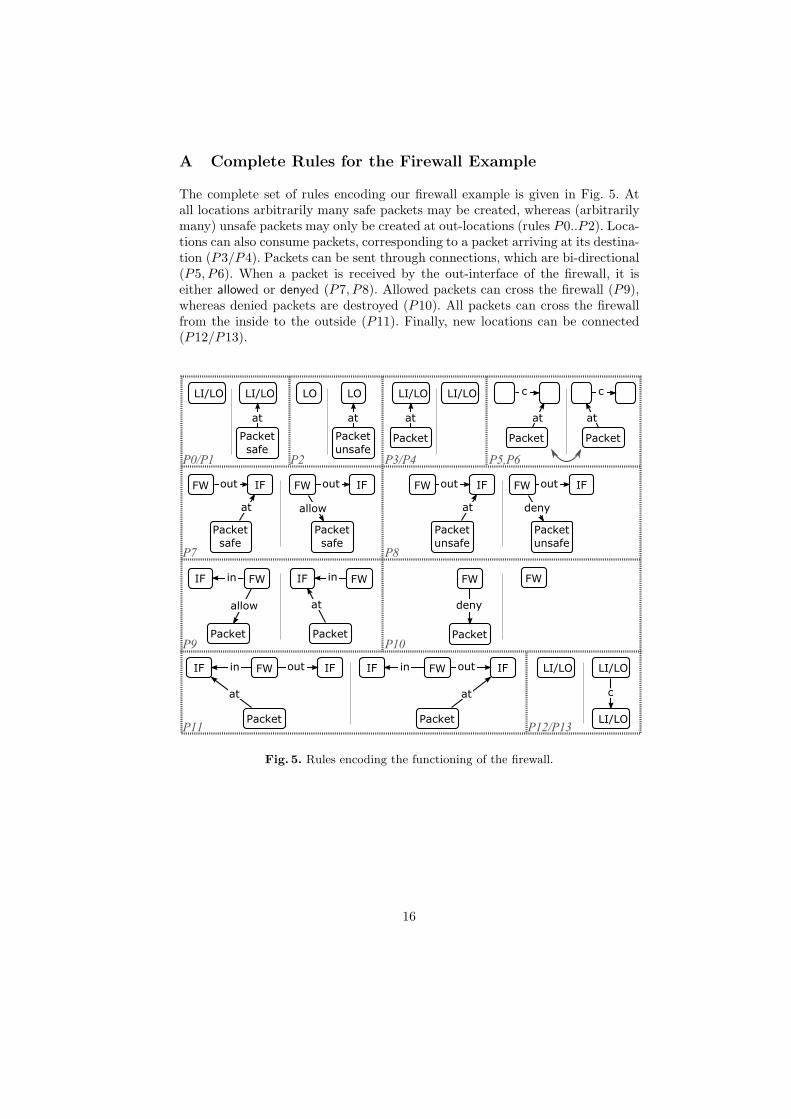
A Complete Rules for the Firewall Example
The complete set of rules encoding our firewall example is given in Fig. 5. Atall locations arbitrarily many safe packets may be created, whereas (arbitrarilymany) unsafe packets may only be created at out-locations (rules P0..P2). Loca-tions can also consume packets, corresponding to a packet arriving at its destina-tion (P3/P4). Packets can be sent through connections, which are bi-directional(P5, P6). When a packet is received by the out-interface of the firewall, it iseither allowed or denyed (P7, P8). Allowed packets can cross the firewall (P9),whereas denied packets are destroyed (P10). All packets can cross the firewallfrom the inside to the outside (P11). Finally, new locations can be connected(P12/P13).
Fig. 5. Rules encoding the functioning of the firewall.
16


![The Modal Ontological Argument meets Modal Fictionalism [Analytic Philosophy]](https://img.pdfslide.net/doc/110x75/635e13de88f33c6f82010207/the-modal-ontological-argument-meets-modal-fictionalism-analytic-philosophy.jpg)


