Embed Size (px)
Citation preview
www.iejrd.com SJIF: 7.169 1
International Engineering Journal For Research & Development Vol.6
Issue 4
A NEW DIRECTIONAL ELEMENT BASED DISTRIBUTION FEEDER
PROTECTION 1Mangesh R.Pande,
2Prof. Harshal V. Takpire
PG Student M.Tech 4th Semester, Department of Electrical Engineering, G. H. Raisoni University Amravati,
Maharashtra, INDIA1, Assistant Professor, Department of Electrical Engineering, G.H.Raisoni University
Amravati, Maharashtra, INDIA2.
[email protected], [email protected]
2
----------------------------------------------------------------------------------------------------------------------------- ----------
ABSTRACT
Over current relays are widely used for protection of power systems, directional ones for transmission
side, and non-directional ones for distribution side. The fault direction may be forward (between relay and grid),
or reverse (between relay and source), the normal power flow being from source to the grid. Known directional
overcurrent relays rely on a reference voltage phasor for estimating the direction of the fault, requiring both
current and voltage sensors. This increases the cost of the relays, prohibiting the utilization of such relays in the
distribution side protection and automation, which is going to be a key part in the smart grid initiative. In this
paper a novel current-only directional detection possibility is highlighted. Breaker is developed in 13 bus bar
system.
Index terms—definite minimum time (dmt), distribution automation (da), fault detection, fault Direction,
forward current Reverse current, overcurrent, protection, smart grid, feeder protection.
INTRODUCTION
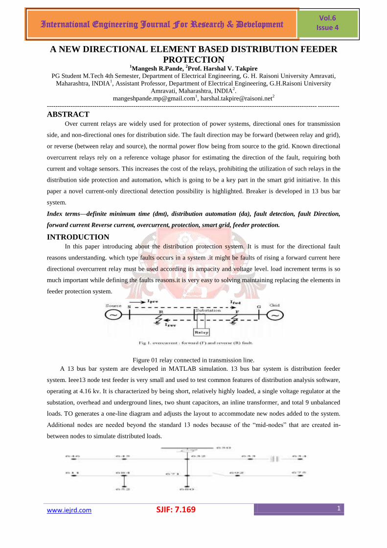
In this paper introducing about the distribution protection system. It is must for the directional fault
reasons understanding. which type faults occurs in a system .it might be faults of rising a forward current here
directional overcurrent relay must be used according its ampacity and voltage level. load increment terms is so
much important while defining the faults reasons.it is very easy to solving maintaining replacing the elements in
feeder protection system.
Figure 01 relay connected in transmission line.
A 13 bus bar system are developed in MATLAB simulation. 13 bus bar system is distribution feeder
system. Ieee13 node test feeder is very small and used to test common features of distribution analysis software,
operating at 4.16 kv. It is characterized by being short, relatively highly loaded, a single voltage regulator at the
substation, overhead and underground lines, two shunt capacitors, an inline transformer, and total 9 unbalanced
loads. TO generates a one-line diagram and adjusts the layout to accommodate new nodes added to the system.
Additional nodes are needed beyond the standard 13 nodes because of the ―mid-nodes‖ that are created in-
between nodes to simulate distributed loads.
www.iejrd.com SJIF: 7.169 2
International Engineering Journal For Research & Development Vol.6
Issue 4
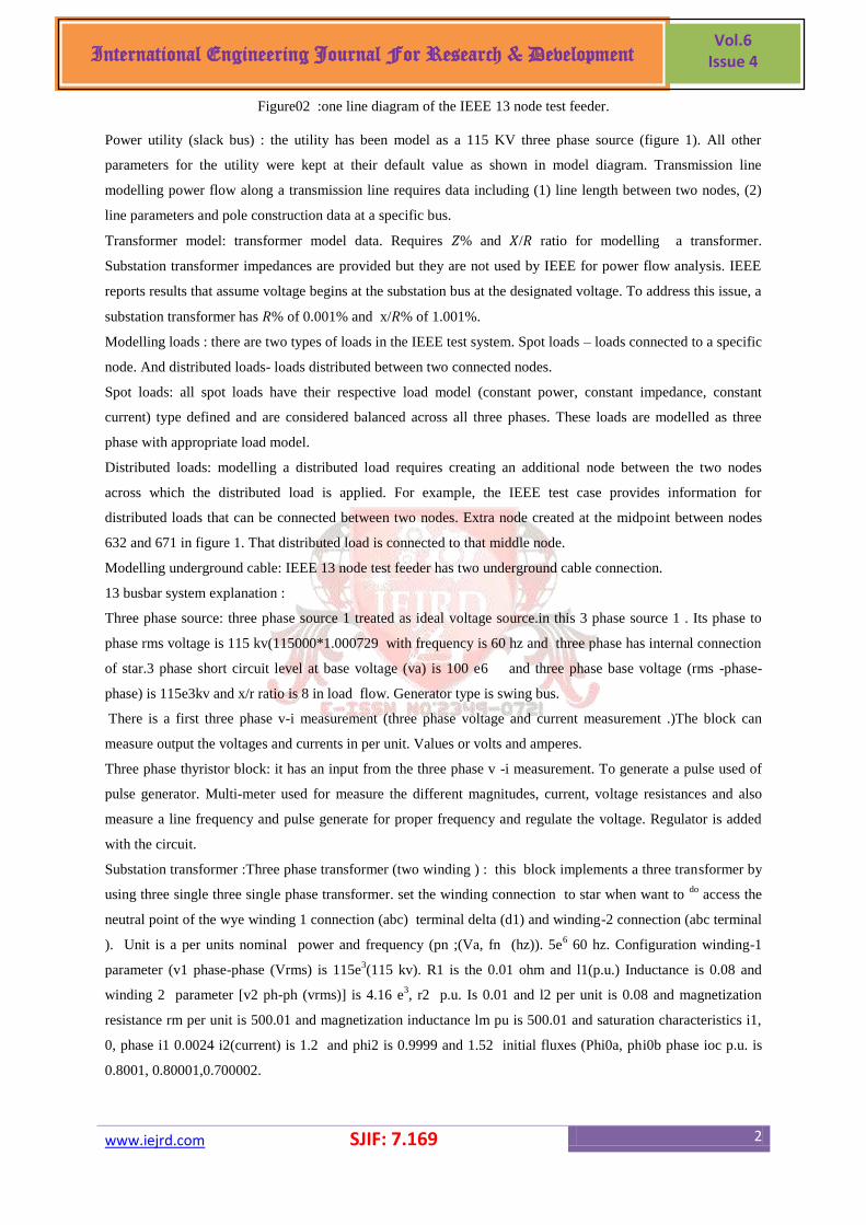
Figure02 :one line diagram of the IEEE 13 node test feeder.
Power utility (slack bus) : the utility has been model as a 115 KV three phase source (figure 1). All other
parameters for the utility were kept at their default value as shown in model diagram. Transmission line
modelling power flow along a transmission line requires data including (1) line length between two nodes, (2)
line parameters and pole construction data at a specific bus.
Transformer model: transformer model data. Requires 𝑍% and 𝑋/𝑅 ratio for modelling a transformer.
Substation transformer impedances are provided but they are not used by IEEE for power flow analysis. IEEE
reports results that assume voltage begins at the substation bus at the designated voltage. To address this issue, a
substation transformer has 𝑅% of 0.001% and x/𝑅% of 1.001%.
Modelling loads : there are two types of loads in the IEEE test system. Spot loads – loads connected to a specific
node. And distributed loads- loads distributed between two connected nodes.
Spot loads: all spot loads have their respective load model (constant power, constant impedance, constant
current) type defined and are considered balanced across all three phases. These loads are modelled as three
phase with appropriate load model.
Distributed loads: modelling a distributed load requires creating an additional node between the two nodes
across which the distributed load is applied. For example, the IEEE test case provides information for
distributed loads that can be connected between two nodes. Extra node created at the midpoint between nodes
632 and 671 in figure 1. That distributed load is connected to that middle node.
Modelling underground cable: IEEE 13 node test feeder has two underground cable connection.
13 busbar system explanation :
Three phase source: three phase source 1 treated as ideal voltage source.in this 3 phase source 1 . Its phase to
phase rms voltage is 115 kv(115000*1.000729 with frequency is 60 hz and three phase has internal connection
of star.3 phase short circuit level at base voltage (va) is 100 e6 and three phase base voltage (rms -phase-
phase) is 115e3kv and x/r ratio is 8 in load flow. Generator type is swing bus.
There is a first three phase v-i measurement (three phase voltage and current measurement .)The block can
measure output the voltages and currents in per unit. Values or volts and amperes.
Three phase thyristor block: it has an input from the three phase v -i measurement. To generate a pulse used of
pulse generator. Multi-meter used for measure the different magnitudes, current, voltage resistances and also
measure a line frequency and pulse generate for proper frequency and regulate the voltage. Regulator is added
with the circuit.
Substation transformer :Three phase transformer (two winding ) : this block implements a three transformer by
using three single three single phase transformer. set the winding connection to star when want to do
access the
neutral point of the wye winding 1 connection (abc) terminal delta (d1) and winding-2 connection (abc terminal
). Unit is a per units nominal power and frequency (pn ;(Va, fn (hz)). 5e6 60 hz. Configuration winding-1
parameter (v1 phase-phase (Vrms) is 115e3(115 kv). R1 is the 0.01 ohm and l1(p.u.) Inductance is 0.08 and
winding 2 parameter [v2 ph-ph (vrms)] is 4.16 e3, r2 p.u. Is 0.01 and l2 per unit is 0.08 and magnetization
resistance rm per unit is 500.01 and magnetization inductance lm pu is 500.01 and saturation characteristics i1,
0, phase i1 0.0024 i2(current) is 1.2 and phi2 is 0.9999 and 1.52 initial fluxes (Phi0a, phi0b phase ioc p.u. is
0.8001, 0.80001,0.700002.
www.iejrd.com SJIF: 7.169 3
International Engineering Journal For Research & Development Vol.6
Issue 4
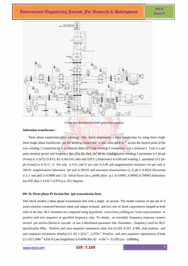
13 bus bar distribution feedr protection system.
Substation transformer :
Three phase transformer (two winding) : this block implements a three transformer by using three single
three single phase transformer. set the winding connection to star when want to do
access the neutral point of the
wye winding 1 connection (a b c) terminal delta (d1) and winding-2 connection (a b c terminal ). Unit is a per
units nominal power and frequency (pn ;(Va, fn (hz). 5e6 60 hz. Configuration winding-1 parameter (v1 ph-ph
(Vrms) is 115e3(115 KV). R1 is the 0.01 ohm and l1(P.U.) Inductance is 0.08 and winding 2 parameter [V2 ph-
ph (vrms)] is 4.16 e3, r2 Per unit is 0.01 and l2 per unit is 0.08 and magnetization resistance rm per unit is
500.01 .magnetization inductance per unit is 500.01 and saturation characteristics i1, 0, ph i1 0.0024 i2(current)
is 1.2 and phi2 is 0.9999 and 1.52 initial fluxes (io a, phi0b phioc p.u. Is 0.8001, 0.80001,0.700002.Substation
bus 650, Bus-1 4.16e3 v 0.979 p.u. 26.2 degrees.
601 2k Three phase PI Section line (pie transmission line):
This block models a three phase transmission line with a single pi section. The model consists of one set of rl
series element connected between input and output terminal and two sets of shunt capacitances lumped at both
ends of the line. RLC elements are computed using hyperbolic corrections yielding an ―exact representation in
positive and zero sequence at specified frequency only. To obtain , an extended, frequency response connect
several pie section blocks.in cascade or use a distributed parameter line. Parameter : frequency used for RLC
specification 60hz. Positive and zero sequence resistances ohm/ km [r1,r0]: 0.247, 0.309. And positive and
zero sequence resistances ohm/km [r1 r0] 1.321e-3
, 2.473e-3
. Positive and zero sequence capacitances (f/km)
[c1 c0] 5.398e-9
4.65e-9.Line length(km) is 0.6096.Bus 02 4.16e3 v 0.2285 p.u. -3.888deg.
www.iejrd.com SJIF: 7.169 4
International Engineering Journal For Research & Development Vol.6
Issue 4
602 block Three phase pie section line. This block models a three phase transmission line with a single pie
section. The model consist of one set of r-l series element connected between input and output terminal and two
sets of shunt capacitances lumped at both ends of the line .Rl element are computed using hyperbolic corrections
yielding an excel represent in positive and zero sequence at specified frequency only .To obtained an
extended frequency response connect several pie section block.in cascade or used a distributed parameter line .
Parameter :Frequency used for RLC specification 60 hz. Positive resistances (ohm/km )[r1,r0] :0.471 0.561
positive inductances (h/km) [i1 i0 ] 1.538e-3
2.692e-3
and positive capacitances (f/km) is 9.882e-9
and zero
sequence capacitances is 7.106e-9
. And line length in km is 0.1524.Bus 03 4.16 e3 0.9567 p.u. 144. Deg. 603
is the bus bar.
Block parameter transformer :Three phase transformer two winding mask link : this block implements a
three phase transformer by using three single phase transformer . Set the winding connection to yn. When y
want to access the neutral point of the wye (star). Configuration of this transformer winding1 connection (a-b-c
terminals):yg and winding 2 connection (a b c )terminals yg.
Parameters :Units is per unit .nominal power frequency pn (va) fn (hz),5 e5 60 hz..Winding parameters [v1 ph-
ph (vrms)= 4.16e3 r1 per unit is 0.011 . L1 per unit is 0.02Magnetization resistance rm is per unit is 500.01, and
magnetization inductance l.m. Per unit is 500. And saturation characteristics i1 is zero. Phi1=0.002 .I2 is 1.2 and
phi2=1.52 Initial fluxes (phi0a phi0b phioc) per unit. 0.80001 -0.8001 0.70002 break algebraic loop in
dissertation model bus 4 0.48e3 v 0.95Bus 634
Resistive load : this block connected with parallel RLC load 1 , parallel RLC load 2 . There took out 1 out 2 out
3 scope 2 (discrete waveforms phase a phase b phase c .
603 0.3 km: This block models a three phase transmission line with a single Pi Section the model consists of
one set r-l series element connected between input and output terminal ad two sets of shunt capacitances
lumped at both ends of the line .
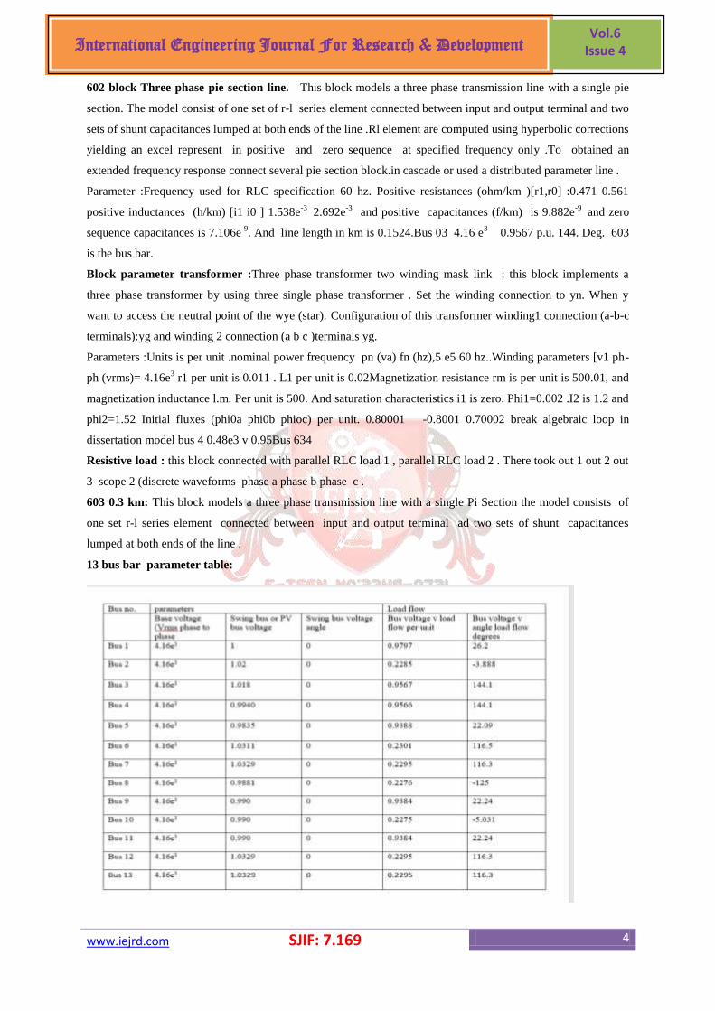
13 bus bar parameter table:
www.iejrd.com SJIF: 7.169 5
International Engineering Journal For Research & Development Vol.6
Issue 4
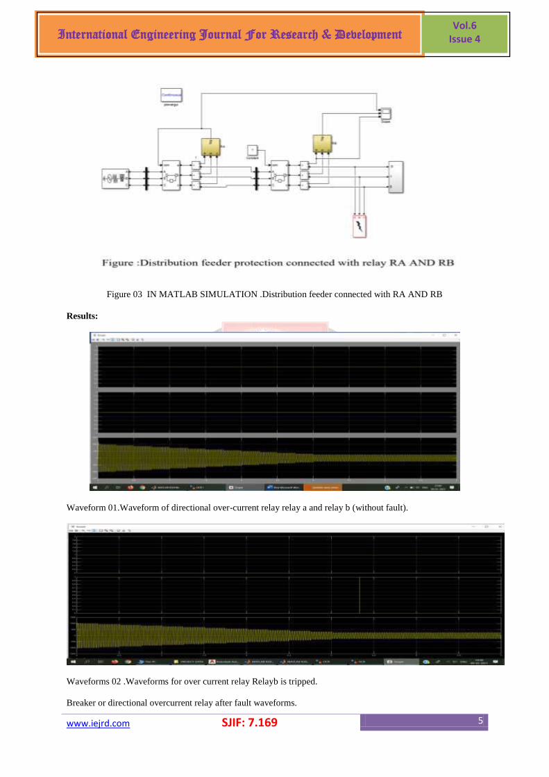
Figure 03 IN MATLAB SIMULATION .Distribution feeder connected with RA AND RB
Results:
Waveform 01.Waveform of directional over-current relay relay a and relay b (without fault).
Waveforms 02 .Waveforms for over current relay Relayb is tripped.
Breaker or directional overcurrent relay after fault waveforms.
www.iejrd.com SJIF: 7.169 6
International Engineering Journal For Research & Development Vol.6
Issue 4
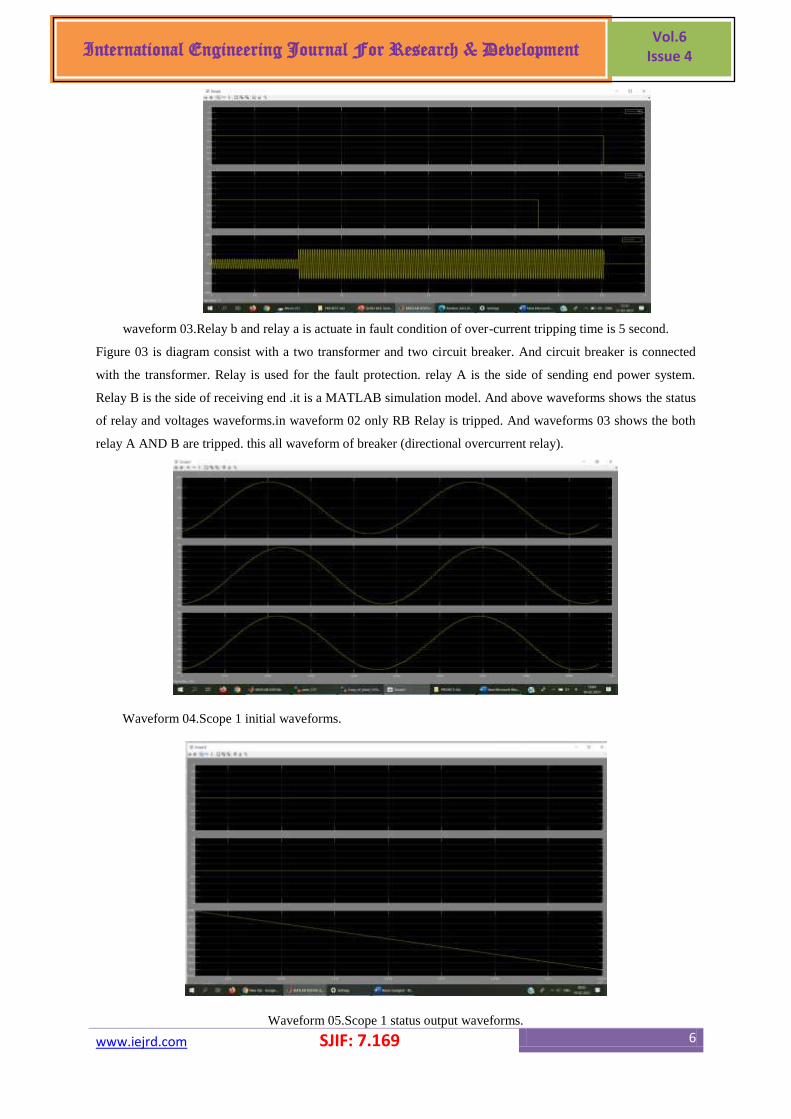
waveform 03.Relay b and relay a is actuate in fault condition of over-current tripping time is 5 second.
Figure 03 is diagram consist with a two transformer and two circuit breaker. And circuit breaker is connected
with the transformer. Relay is used for the fault protection. relay A is the side of sending end power system.
Relay B is the side of receiving end .it is a MATLAB simulation model. And above waveforms shows the status
of relay and voltages waveforms.in waveform 02 only RB Relay is tripped. And waveforms 03 shows the both
relay A AND B are tripped. this all waveform of breaker (directional overcurrent relay).
Waveform 04.Scope 1 initial waveforms.
Waveform 05.Scope 1 status output waveforms.
www.iejrd.com SJIF: 7.169 7
International Engineering Journal For Research & Development Vol.6
Issue 4
www.iejrd.com SJIF: 7.169 8
International Engineering Journal For Research & Development Vol.6
Issue 4
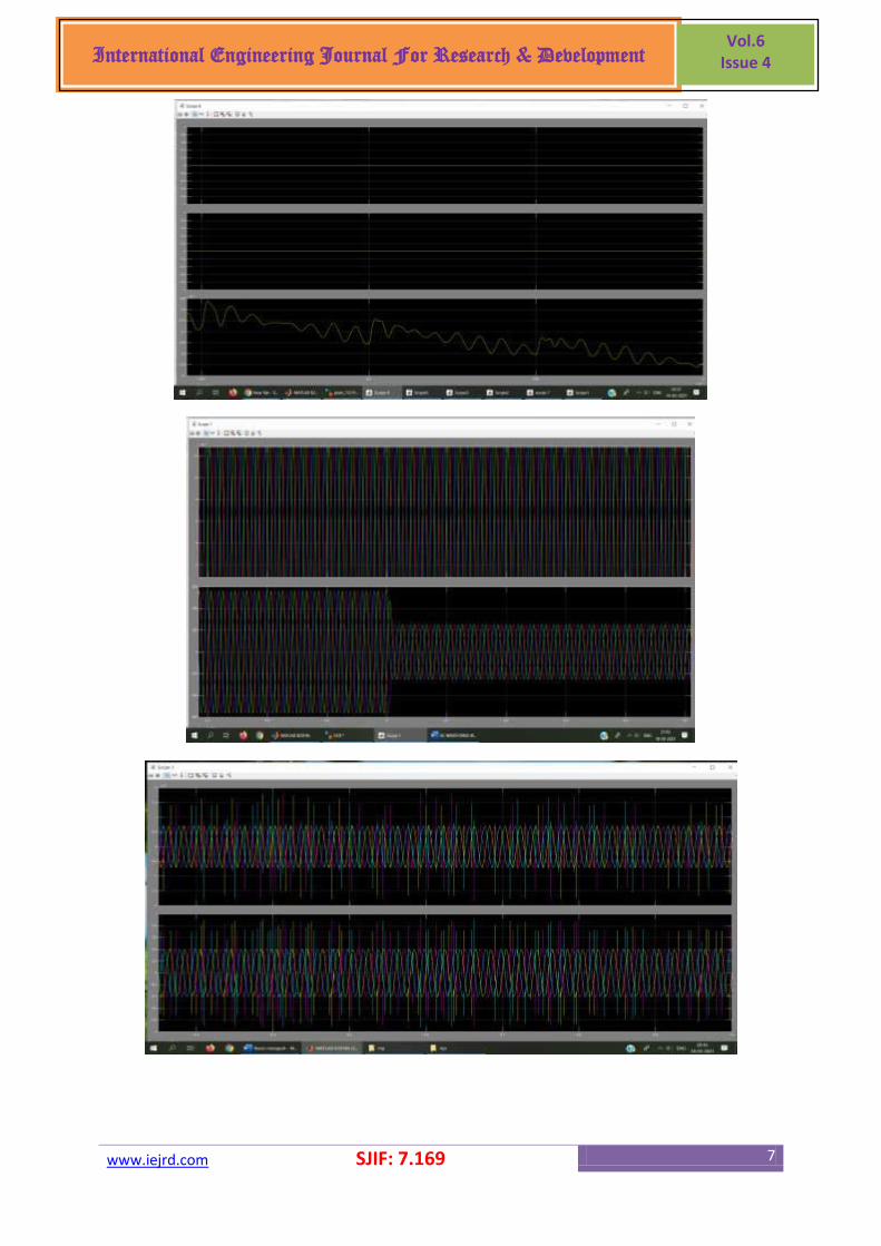
waveform 06.normal waveform of scope 2.
Above waveform shows the resistive current waveform. waveform 04 is the resistive current load waveform is
shown in scope 1. And waveforms 05 is a shows the status waveform of discrete signal of three phase
waveform. And waveform 06 shows the normal waveform of three phase.
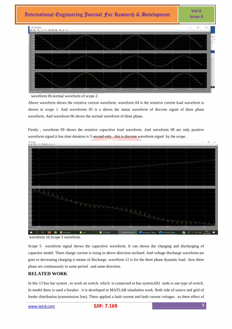
Firstly , waveform 09 shows the resistive capacitive load waveform. And waveform 08 are only positive
waveform signal.it has time duration is 5 second only . this is discrete waveform signal by the scope .
waveform 10.Scope 5 waveform.
Scope 5 waveform signal shows the capacitive waveform. It can shows the charging and discharging of
capacitor model. There charge current is rising in above direction inclined. And voltage discharge waveform are
goes to decreasing charging it means of discharge. waveform 12 is for the three phase dynamic load . how three
phase are continuously in same period . and same direction.
RELATED WORK
In this 13 bus bar system , to work on switch. which is connected in bus system.692 node is one type of switch.
In model there is used a breaker . it is developed in MATLAB simulation work. Both side of source and grid of
feeder distribution (transmission line). There applied a fault current and fault current voltages . so there effect of
www.iejrd.com SJIF: 7.169 9
International Engineering Journal For Research & Development Vol.6
Issue 4
directional over current relays actuation of relay RA and RB . there is main purpose of operation of directional
overcurrent relay. There shows in first relay A status and second relay B status and beneath that is current
waveform of three phase waveform.
CONCLUSION
A directional overcurrent relay is a susceptible element in a distribution feeder protection system in a load
increased condition can be secured from the higher forward current as well as reverse forward current. A
directional element can be sense a current of bi directional in power system. It will be effectively work in feeder
protection also with secured sensitivity and properly region wise operate a directional overcurrent relay. Future
distribution feeders will be connected with the number of electrical appliances that’s why there will be a
creating region wise fault (forward reverse), fwd<- fault, rev <-rev+-), Directional overcurrent relay save the
feeders fault from this situation. To studying for the distribution feeder protection and secured power
distribution system can be developed with directional overcurrent relay. While duration of fault relay will
tripped the duration of the faults relay will tripped the power distribution system. So there is 692 node is
developed in MATLAB simulation to tripped the relay when fault is occurred. both relay are operated while
the fault occurred.
REFERENCES
1. iman kiaei and mohammad ghanaatian ―current-only directional overcurrent protection Using postfault
current‖, ieee trans. 2019
2. i. Kiaei, s. Lotfifard and a. Bose, ―secure loss of excitation detection method for
synchronousGenerators during power swing conditions,‖ ieee trans. Energy conv., vol. 33, no. 4, pp.
1907-, dec. 2018.
3. h. Gharibpour, h. Monsef, m. Ghanaatian, ―the comparison of two control methods of power Swing
reduction in power system with upfc compensator,‖ 20th iranian conference electricalEngineering
(icee), pp. 386-391, 2012.
4. p.m. Anderson, ―power system protection,‖ new york: mcgraw-hill, 1999.
5. i. Kiaei and s. Lotfifard, ―a two-stage fault location identification method in multi-area power Grids
using heterogeneous types of data," ieee trans. Ind. Informatics, pp. 1-9, dec. 2018.
6. a. G. Phadke and j. S. Thorp, ―synchronized phasor measurements and their applications,‖New york:
springer, 2008.
7. a. K. Pradhan, a. Routray, and g. S. Madhan, ―fault direction estimation in radial distributionSystem
using phase change in sequence current,‖ ieee trans. Power del., vol. 22, no. 4, pp. 2065–2071, oct.
2007.
8. s. M. Hashemi, m. T. Hagh, and h. Seyedi, ―transmission-line protection: a directionalComparison
scheme using the average of Superimposed components,‖ IEEE trans. Power del.,Vol. 28, no. 2, pp.
955–964, April. 2013.
9. w. Chen, o. P. Malik, x. Yin, d. Chen, and z. Zhang, ―study of wavelet-based ultra high Speed
directional transmission line protection,‖ IEEE trans. Power del., vol. 18, no. 4, pp. 1134–1139, oct.
2003.
10. c. Aguilera, e. Orduña, and g. Rattá, ―directional traveling—wave protection based on slope Change
analysis,‖ ieee trans. Power del., vol. 22, no. 4, pp. 2025–2033, oct. 2007.
www.iejrd.com SJIF: 7.169 10
International Engineering Journal For Research & Development Vol.6
Issue 4
11. g. Benmouyal and j. Mahseredjian, ―a combined directional and faulted phase selector Element based
on incremental quantities,‖IEEE trans. Power del., vol. 16, no. 4, pp. 478–484,Oct. 2001.
12. 2w. A. Elmore, protective relaying theory and applications, 2nd ed. New york: marcel Dekker, 2003.
13. p. M. Anderson, power system protection. New york: mcgraw-hill, 1999.
14. j. Horak, ―directional overcurrent relaying (67) concepts,‖ in proc. 59th ieee conf.protective relay
engineers, 2006, pp. 164–176.
15. standard for measuring relays and protection equipment, no. 60255, int. Eletro-technical Commission
(iec), 2008.
16. a. G. Phadke and j. S. Thorp, synchronized phasor measurements and their applications. New york,
springer: , 2008.
17. i. Daubechies, ten lectures on wavelets. Philadelphia, pa: society for industrial and applied
mathematics, 1992. [7] a. Ukil, intelligent systems and signal processing in power engineering. New-
york: sp.
18. s. M. Brahma and a. A. Girgis, ―microprocessor-based reclosing to coordinate fuse and recloser in a
system with high penetration of distributed generation,‖ in proc.IEEE power eng. Soc. Winter meeting,
vol. 1, pp. 453–458, (2002).
19. n.hadjsaid, j.canard, and f.dumas, ―disperse degeneration impact on distribution networks‖, IEEE
compute. Appl. Power, vol. 12, pp. 22–28, (1999).
20. a. A. Girgis and s. M. Brahma, ―effect of distributed generation on protective device coordination in
distribution system,‖ in proc. Large eng. Syst. Conf halifax, ns, canada, pp. 115–119,( 2001).
21. s. M. Brahma and a. A. Girgis, ―impact of distributed generation on fuse and relay coordination
analysis and remedies‖ in proc int.assoc. Sci. Technol. Develop. clearwater, fl, pp. 384–389,( 2001).
22. e. Sortomme, g. J. Mapes, foster, s. S. Venkata. ―faultAnalysis and protection of a microgrid‖. Ieee
transaction on power delivery. Vol. 24, 3, pp. 1045-1053,( 2009).
23. s. Conti, l. Raffa, and u. Vagliasindi. ―innovative solutions for protection schemes in autonomous mv
micro-grids‖. Ieee int. Conf. On clean electrical power- renewable energy resources impact
(iccep’09),capri – Italy june 9-11,( 2009).
24. h. H. Zeineldin, e. F. El-saadany, and m. M. A. Salama. ―protective relay coordination for micro-grid
operation using particle swarm optimization‖. Ieee large engineering systems conference on power
engineering. Pp 152-157,( 2006).
25. h. Nikkhajoei, r. H. Lasseter. ―microgrid protection‖. Inproc. Ieee power eng. Soc. General meeting, pp
1-6,(2007).
26. su qianli, dong xinzhou, shi shenxing, su bin, and hejiali," a new principle of fault line selection for
distribution," in proc. 2001 iee the sevent international conference on developments in power system
protection conf., pp. 379-382, (2001).
27. dong xingzhou, bi jianguan, and bo zhiqian,"technique of fault line selection for non-directed ground
neutral system," in proc. 2002 upec conf., pp.193-196,(2002).
28. M.H.Haque, ―Efficient Load-flow Method for Distribution Systems with Radial orMesh
Configuration‖, IEE Proceedings on Generation, Transmission, Distribution,Vol.143, no.1, pp.33-39,
January 1996.
www.iejrd.com SJIF: 7.169 11
International Engineering Journal For Research & Development Vol.6
Issue 4
29. U.Eminoglu and M.H.Hocaoglu, ―A New Power Flow Method For Radial Distribution Systems
Including Voltage Dependent Load Models‖, Electric Power Systems Research Vol.76 pp.106-114,
2005.
30. Prasad K., Sahoo N. C., Chaturvedi A. and Ranjan R, ―A Simple Approach In Branch Current
Computation In Load Flow Analysis Of Radial Distribution Systems‖,International Journal for
Electrical Engineering Education, Vol.44/1, pp.1,2007.[100] Ghosh S. and Sherpa K., ―An Efficient
Method for Load−Flow Solution of RadialDistribution Networks,’’ Proceedings International Journal
of Electrical Power andEnergy Systems Engineering, 2008.
31. S. Sivanagaraju, J. Viswanatha Raoand M. Giridhar,―A loop based loop flow method for weakly
meshed distribution network‖, ARPN Journal of Engineering and Applied Sciences ISSN 1819-6608,
Vol.3,no.4,August 2008.
32. Kumar A. and Aravindhababu, ―An Improved Power Flow Technique for Distribution Systems‖,
Journal of Computer Science, Informatics and Electrical Engineering ,Vol.3, Issue 1, 2009.
33. Augugliaro A, Dusonchet L, Favuzza S, Ippolito MG, Riva Sanseverino E,―A Backward sweep method
for power flow solution in distribution networks‖, Electrical Power and Energy Systems 32 ,271-280
,2010.
34. ME thesis by Gurpreet Kaur ,―Load-flow analysis of Radial Distribution Networks ‖, from Thapar
University under the supervision of Dr. Smarajit Ghosh (Head & Professor, EIED) in June 2012.
35. D.P.Sharma , A.chaturvedi, G.Purohit & G.Prasad, ―An Improved Mechanism of a Leaf Node
Identification for Radial Distribution Network‖, IEEE Power and Energy Conference organized by
university of Illinois, U.S.A, 25-26 February, 2011.


