Embed Size (px)
Citation preview

374 IEEE SENSORS JOURNAL, VOL. 15, NO. 1, JANUARY 2015
Directional Sensor Control: Heuristic ApproachesShankarachary Ragi, Student Member, IEEE, Hans D. Mittelmann, and Edwin K. P. Chong, Fellow, IEEE
Abstract— We study the problem of controlling multiple2-D directional sensors while maximizing an objective functionbased on the information gain corresponding to multiple targetlocations. We assume a joint prior Gaussian distribution forthe target locations. A sensor generates a (noisy) measurementof a target only if the target lies within the field-of-view ofthe sensor, where the statistical properties of the measurementerror depend on the location of the target with respect to thesensor and direction of the sensor. The measurements from thesensors are fused to form global estimates of target locations.This problem is combinatorial in nature—the computation timeincreases exponentially with the number of sensors. We developheuristic methods to solve the problem approximately, andprovide analytical results on performance guarantees. We thenimprove the performance of our heuristic approaches by applyingan approximate dynamic programming approach called rollout.In addition, we address a variant of the above problem, wherethe goal is to map the sensors to the targets while maximizing theabovementioned objective function. This mapping problem alsoturns out to be combinatorial in nature, so we extend one of theabove heuristics to solve this mapping problem approximately.We compare the performance of these heuristic approachesanalytically and empirically.
Index Terms— Directional sensor control, maximizing informa-tion gain, rollout on heuristics, mapping sensors to targets.
I. INTRODUCTION
D IRECTIONAL sensors constitute a class of sensors thathave a limited field-of-view, e.g., surveillance cameras,
phased-array antennas, infrared sensors, and ultrasound sen-sors. The methods to control the directions of these sensorsare gaining importance owing to a wide range of applications,including surveillance, detection, and tracking. In this study,we develop tractable solutions to the problem of assigningdirections to multiple 2-D directional sensors to maximize theinformation gain corresponding to multiple target locations.Directional sensor control has been studied before in variouscontexts [2]–[5]; a general survey of this topic can be
Manuscript received May 3, 2014; accepted July 8, 2014. Date of publica-tion July 25, 2014; date of current version November 7, 2014. This work wassupported by the Naval Post-Graduate School Assistance, Grant/AgreementN00244-14-1-0038 through the NAVSUP Fleet Logistics Center San Diego(NAVSUP FLC San Diego). The work of S. Ragi and E. K. P. Chongwas supported by the Colorado State University’s Information Science andTechnology Center. The work of H. D. Mittelmann was supported by theAir Force Office of Scientific Research under Grant FA9550-12-1-0153. Theassociate editor coordinating the review of this paper and approving it forpublication was Prof. Okyay Kaynak.
S. Ragi and E. K. P. Chong are with the Department of Electrical andComputer Engineering, Colorado State University, Fort Collins, CO 80523USA (e-mail: [email protected]; [email protected]).
H. D. Mittelmann is with the School of Mathematical and Statisti-cal Sciences, Arizona State University, Tempe, AZ 85287 USA (e-mail:[email protected]).
Color versions of one or more of the figures in this paper are availableonline at http://ieeexplore.ieee.org.
Digital Object Identifier 10.1109/JSEN.2014.2343019
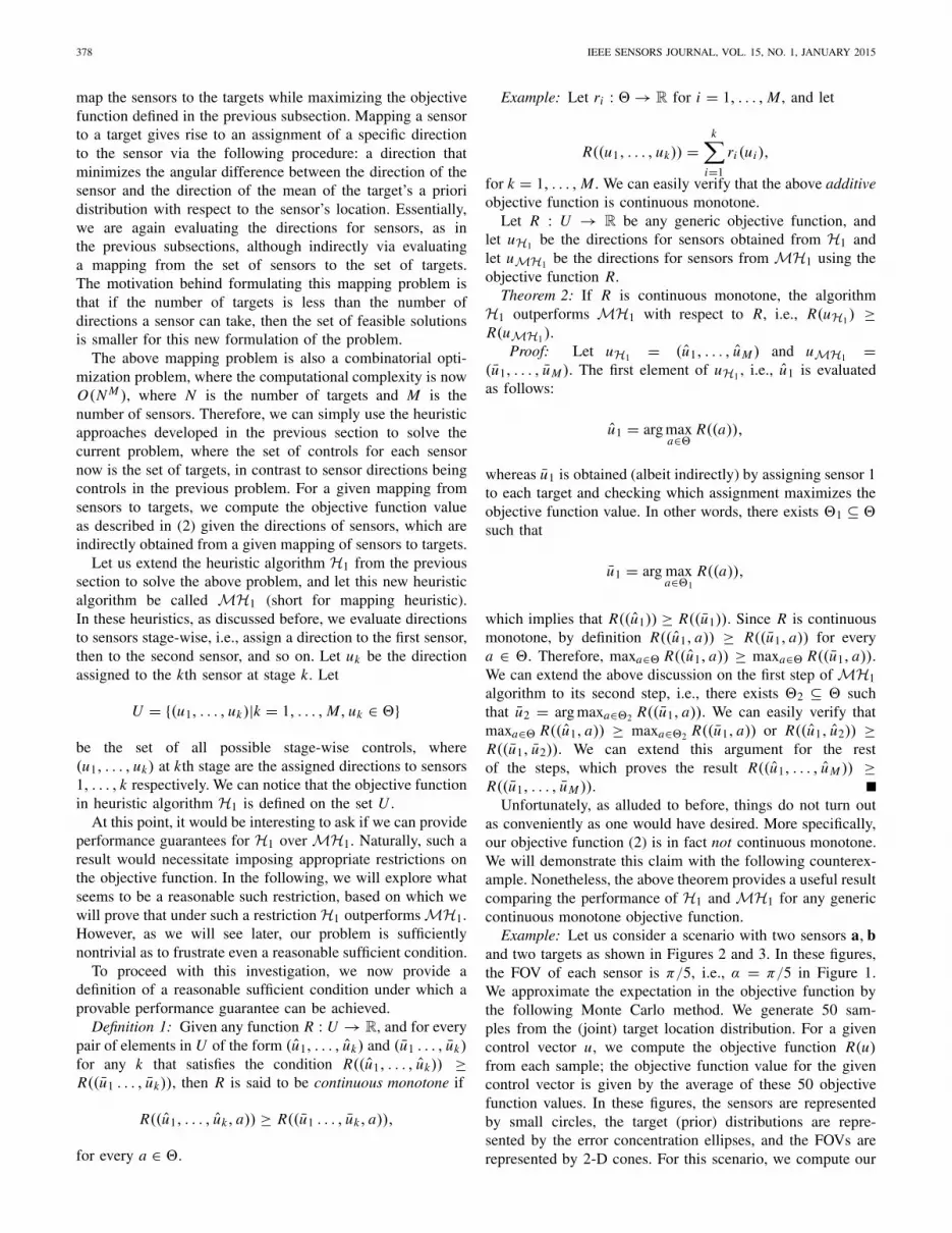
Fig. 1. Field-of-view of a sensor.
found in [6], where the focus is on coverage issues indirectional sensor networks.
In this study, we assume a joint prior Gaussian distributionfor the target locations, and we assume that the sensor loca-tions are known exactly. A directional sensor has a limitedfield-of-view (FOV), where the area sensed by the sensor isgiven by a sector in a circular region around the sensor asdepicted in Figure 1. The direction of the FOV of a sensorcan be changed by appropriately changing the direction ofthe sensor. The direction of a sensor can take several discretevalues in the interval [0, 2π). A directional sensor generates ameasurement of a target if and only if the target lies within theFOV of the sensor. We assume that there is a notional fusioncenter, which collects the measurements from each sensor, andfuses them to form global estimates of target locations.
The objective is to assign a direction to each sensor whilemaximizing an objective function based on the informationgain corresponding to target locations. This problem is hardto solve exactly because of its combinatorial nature—thecomputation time increases exponentially with the numberof sensors. In this study, we develop heuristic approachesthat are tractable, and provide bounds on the optimal infor-mation gain. We apply rollout on these heuristic approaches(as in [7]) via a dynamic programming formulation [8] toimprove the performance of our heuristics with respect to theabove objective function.
We then address the above problem using a different for-mulation, where the objective is to find a mapping of sensorsto targets while maximizing the above-mentioned objectivefunction. This problem is also combinatorial in nature, sowe extend one of the heuristic approaches, developed forthe previous formulation, to solve the mapping problemapproximately.
Section II provides a detailed description of the problem.In Section III, we discuss various heuristic approaches to
1530-437X © 2014 IEEE. Personal use is permitted, but republication/redistribution requires IEEE permission.See http://www.ieee.org/publications_standards/publications/rights/index.html for more information.

RAGI et al.: DIRECTIONAL SENSOR CONTROL: HEURISTIC APPROACHES 375
solve the above problem approximately, and we discuss naturalsufficient conditions on objective functions that lead to prov-able guaranteed performance for our heuristics. However, weshow via counterexamples that our objective function does notsatisfy these sufficient conditions, suggesting that the natureof the problem is highly nontrivial. Sections IV and V providesimulation results and concluding remarks respectively.
Parts of a preliminary version of this paper were publishedin the proceedings of 2013 SPIE Optics + Photonics Sym-posium [1]. This paper differs from the conference versionin the following ways: 1) we address our directional sensorcontrol problem via a new formulation, where we map sen-sors to targets while maximizing an objective function, andidentify that this mapping problem is combinatorial in nature,2) we extend a heuristic approach, published in the confer-ence version, to solve our mapping problem approximately,3) we provide analytical results comparing the performanceof our heuristics under certain sufficient conditions on theobjective function, and 4) we show via counterexamplesthat our objective function does not satisfy these sufficientconditions, which proves that our objective function possesseshighly nontrivial features that elude currently known analyticalmachinery.
II. PROBLEM SPECIFICATION
Targets: There are N targets in 2-D, where (χ1, χ2, . . . , χN )represent the locations of the targets. The target locations arenot known exactly. However, we assume a joint prior Gaussiandistribution for the target locations.
Directional Sensors: There are M directional sensors in2-D, where (s1, s2, . . . , sM ) represent the locations of thesensors. The sensor locations are known exactly. Let � ={1, . . . , K } be the set of directions each sensor can take,where each direction is a value in the interval [0, 2π). Letu = (u1, . . . , uM ) be the control vector, where ui ∈ �,i = 1, . . . , M , is the direction of the i th sensor. The field-of-view of a sensor, pointed at a particular direction θ ∈ �,is shown in Figure 1, where r and α are the radial andangular sensing ranges of the sensor respectively. Because ourfocus is on solution methods for the problem of controllingdirectional sensors, rather than on detailed sensor modeling,we adopt a simple 2-D sensing model as shown in Figure 1.The 2-D conical field-of-view model in Figure 1 is anappropriate approximation to the sensing behavior of manydirectional sensors, including surveillance cameras [9] andphased arrays [10]. In the case of surveillance cameras, thelimited radial range in our sensing model is well justified bythe constraint that the camera cannot detect the presence oftargets up to a given maximum size located outside a certainrange from the camera, when the size of the target image issmaller than a single pixel.
Measurement Errors: Each sensor generates a 2-D positionmeasurement of a target only if the target lies within theFOV of the sensor. These measurements are corrupted byrandom errors that depend on the relative location of the targetwith respect to the sensor and the direction of the sensor.
Algorithm 1 Approximate Posterior Distribution
A =[Pprior
j
]−1
y = Aξpriorj
for i = 0 to M do � Information filtering equationsif Sensor i generates observation then
A← A +HT[Z
(si , ui , ξ
priorj
)]−1H
y ← y +HT[Z
(si , ui , ξ
priorj
)]−1zi j
end ifend forP j = A−1
ξ j = A−1y
The measurement of the j th target at the i th sensor is given by
zi j =⎧⎨⎩
Hχ j + ni j if target lies withinFOV of sensor,
no measurement otherwise,
where ni j ∼ N (0, Z(si , ui , χ j )), H is an observation model,and Z(·) is the measurement error-covariance matrix, whichdepends on the direction of the sensor and the locations of thetarget and the sensor.
Fusion: The observations obtained from the sensors arefused to form a global estimate for each target. LetN (ξ
priorj , Pprior
j ), j = 1, . . . , N , be the prior distributions(Gaussian) of the target-locations. Given the observations andthe prior distributions, we evaluate the posterior distributionof the target-locations by fusing the observations. The targetobservations are not Gaussian; the evaluation of the trueBayesian posterior distribution is not tractable. Therefore,we approximate the posterior distribution of j th target asN (ξ j , P j ), j = 1, . . . , N , where ξ j and P j are evaluatedaccording to Algorithm 1, where zi j is the observation gener-ated at sensor i .
Objective: The objective is to compute u, i.e., the directionsfor the sensors, such that the following objective function(based on information gain) is maximized:
−E
⎡⎣
N∑j=1
log det(P j )
⎤⎦,
where the expectation is over the prior joint-distribution oftarget locations, and P j is the posterior distribution of thej th target, which is evaluated using Algorithm 1 given thelocations of the targets—these target locations are used onlyto check if the targets fall within the FOV of the sensors.
Information theory provides a way of quantifying theamount of signal-related information that can be extractedfrom a measurement. This theory also provides tools forassessing the fundamental limitations of different measurementsystems in achieving objectives such as detection and tracking,and these fundamental limits can be related to the amountof information gain associated with a specific measurementmethod. This motivated us to choose an information-theoreticobjective function (see [11] for more arguments on behalf ofusing an information-theoretic objective function).

376 IEEE SENSORS JOURNAL, VOL. 15, NO. 1, JANUARY 2015
Optimal Solution: The optimal directions for the sensorsare given by
u∗ = arg maxu∈�M
R(u), (1)
where
R(u) = −E
⎡⎣
N∑j=1
log det(P j (u))
⎤⎦ (2)
and P j (u), j = 1, . . . , N , are evaluated according toAlgorithm 1 given the control vector u. We approximatethe expectation by a Monte Carlo method. Specifically,we generate several samples from the joint prior distribu-tion of the target locations, and we compute the average(over the samples) objective function value for a given controlaction. The above problem is a combinatorial optimizationproblem, where the computational time required to find theoptimal solution is O(K M ). Since the computational timeincreases exponentially with the number of sensors M , weare interested in deriving tractable heuristic methods that arepolynomial with respect to the number of sensors.
III. APPROXIMATE SOLUTIONS
A. Continuous Optimization
We obtain an upper bound on the optimal objective functionvalue by “relaxing” the discrete property of our problem andsolving its continuous version. The continuous version of ourcombinatorial optimization problem is stated as follows:
maximize(u1,...,uM )
R(u1, . . . , uM )
subject to 0 ≤ ui < 2π, i = 1, . . . , M.
The optimal objective function value stands as an upperbound to the optimal objective function value of our originalproblem. The solution to the above problem can be obtainedvia a nonlinear programming (NLP) solver. Specifically, weadopt the simulated annealing algorithm to solve the aboveproblem.
In the following subsection, we present several heuristicapproaches to solve our problem approximately. The solutionsof these heuristics provide a lower bound on the optimalobjective function value (discussed later). Because it is hardto compute the optimal objective function value, we use theupper bound above on the optimal objective function value,i.e., the solution from the above-mentioned continuous opti-mization approach, to see how close the heuristics are to theoptimal.
B. Heuristic Approaches
Let u = (u1, u2, . . . , uM ) represent a solution to ourproblem. The optimal solution is given by
u∗ = arg maxui∈�,i=1...,M
R(u1, . . . , uM ),
where � = {1, . . . , K }. As we discussed earlier, the com-putation complexity to obtain the optimal solution through(1) is O(K M ), which is exponential in the number ofsensors M . So, we are interested in developing heuristicapproaches that are polynomial in the number of sensors.
The following algorithm, called H1, generates the solutionuH1 = (u1, . . . , uM ), where
u1 = arg maxu∈� R(u, Ø, . . . , Ø),
...
uk = arg maxu∈� R(u1, . . . , uk−1, u, Ø, . . . , Ø),
...
uM = arg maxu∈� R(u1, . . . , uM−1, u),
where Ø at any j th location in the solution u = (u1, . . . , uM ),i.e., u j replaced by Ø, means that the senor j is ignoredwhile computing the objective function (as if the sensor jdoes not generate any observations and does not influence theobjective function). Therefore, the algorithm H1 generates anapproximate solution uH1 = (u1, . . . , uM ), and the objectivefunction value from H1 is R(u1, u2, . . . , uM ). The computa-tional complexity of H1 is O(K M), which is now linear withrespect to the number of sensors.
We now present a second heuristic approach H2, where H2generates the solution uH2 = (u1, . . . , uM ). In contrast to theprevious heuristic approach, this approach may not generatethe elements of the solution vector in the order u1, . . . , uM .Let (p1, . . . , pM ) be the order in which the elements of thesolution vector are generated, where (p1, . . . , pM ) is a per-mutation of (1, . . . , M). This algorithm is evaluated stepwise,with a total of M steps. At each step, a sensor is assigned adirection, and this assignment is fixed for the rest of the steps,as described below.
1) In the first step, for each sensor i , we associate a direc-tion that maximizes the objective function that dependsonly on the direction of sensor i , i.e., we ignore therest of the sensors when we are associating a directionto the sensor i . Let p1 and u p1 be the sensor and itsassociated direction respectively that gives the maximumobjective function value among all the associations.Now, we assign direction u p1 to sensor p1, and thisassignment is fixed for the rest of the steps in thealgorithm.
2) In the kth step, we associate a direction to each sensorj ∈ {1, . . . , M} \ {p1, . . . , pk−1}, while maximizing theobjective function, which now depends on the directionsof the sensors p1, . . . , pk−1 (computed in the previousk− 1 steps) and the direction of sensor j . Let (pk, u pk )be the sensor-direction pair that has the maximum objec-tive function value from the above computation. At kthstep, we assign direction u pk to the sensor pk .
3) We repeat the above step until the last sensor pM isassigned a direction.
4) At the end of the algorithm, we are left with the solution(u1, . . . , uM ).
The computational complexity of this approach is O(K M2).In both the heuristics H1 and H2, since we do not search allpossible directions exhaustively, the objective function valuesfrom these approaches stand as lower bounds on the optimalvalue.

RAGI et al.: DIRECTIONAL SENSOR CONTROL: HEURISTIC APPROACHES 377
Note that the algorithm H1 requires an ordering among thesensors, and the objective function value from H1 dependson this order. But the objective function value from H2 isindependent of the ordering of sensors as H2 does not requireany ordering among the sensors.
C. Rollout on a Heuristic Approach
Given a heuristic approach that solves a combinatorialoptimization problem step-wise like our H1, theauthors of [7] have utilized dynamic programmingformulation [8] to improve the performance of the heuristic.Specifically, they use an approximate dynamic programmingapproach called rollout to improve the performance of thegiven heuristic. We adopt a similar technique, and applyrollout on our heuristics to improve their performance(with respect to the objective function value).
We can obtain the exact optimal solution (step-wise) usingthe dynamic programming [8] approach as follows. We startat a dummy (artificial) initial state; the state of the algorithmat the 1st stage is (u1). The state (of the algorithm) at thekth stage is of the form (u1, . . . , uk), also called k-solution.The terminal state is (u1, . . . , uM ). The control variable atstate (u1, . . . , uk−1) is uk ∈ �. We get a reward at the endof the Mth step called terminal reward, which is given by ouroriginal objective function R(u1, . . . , uM ). Let J ∗(u1, . . . , uk)be the optimal value-to-go (see [7] for details) starting fromthe k-solution, which is the optimal terminal reward giventhat (u1, . . . , uk) are already assigned to the sensors 1, . . . , k.The optimal solution to our problem (u∗1, u∗2, . . . , u∗M ) can beobtained from the following equations:
u∗k = arg maxu∈� J ∗(u∗1, . . . , u∗k−1, u), k = 1, . . . , M. (3)
In general, the optimal value-to-go J ∗(·) is hard to obtain,which is in fact true for our problem. For practical purposes,J ∗(·) is replaced with a heuristic value-to-go J(·), which isusually easy to obtain.
Let H be any heuristic algorithm, which generates thepath of states (i1, i2, . . . , iM ), where ik = (u1, . . . , uk).Let J (ik) represent the heuristic value-to-go startingfrom the k-solution ik = (u1, . . . , uk), from the algo-rithm H, i.e., we use H to evaluate the value-to-go. The value-to-go from the algorithm H is equalto the terminal reward obtained from the algorithm H,i.e., J(ik) = R(u1, u2, . . . , uM ). Therefore, the followingis true: J(i1) = J(i2) = · · · = J(iM ). We use thisheuristic value-to-go in (3) to find an approximate solution toour problem. We call this approximation algorithm “Rollouton H” (RH in short; the same notation was used in [7])due to its structure, which is similar to an approximatedynamic programming approach called rollout. The RH algo-rithm starts with the original dummy state, and generates thepath (i1, i2, . . . , iM ) according to the following equation:
ik = arg maxj∈N(ik−1)
J( j), k = 1, . . . , M
where, ik−1 = (u1, . . . , uk−1), and
N(ik−1) = {(u1, . . . , uk−1, u)|u ∈ �}, k = 1, . . . , M.
The following lemma is adapted from [7]. For completeness,we provide its proof.
Lemma 1: The algorithm RH is sequentially improvingwith respect to H, i.e., J(i1) ≤ J (i2) ≤ · · · ≤ J (iM ), where(i1, i2, . . . , iM ) is the path generated by the RH algorithm.
Proof: Let (i1, i i12 , . . . , i i1
M ) be the complete solution fromH given i1, which is obtained from the first step of RH.We can easily verify that J (i1) = J(i i1
2 ). Let i2 be the solutionobtained from the second step of RH, i.e.,
J(i2) = maxj∈N(i1)
J( j).
Butmax
j∈N(i1)J( j) ≥ J(i i1
2 ) = J (i1).
Therefore, J(i2) ≥ J (i1). We can extend this argument forthe rest of the steps in RH, which proves the result J (i1) ≤J(i2) ≤ · · · ≤ J (iM ).
The authors of [7] have argued that rollout on a heuristicperforms no worse than the heuristic in a different context.We will now extend this argument to our problem and provethat RH outperforms H.
Theorem 1: The algorithm RH outperforms H, i.e.,R(iM ) ≤ R(iM ), where iM and iM are the final paths generatedby the algorithms H and RH respectively.
Proof: We can easily verify that J (i1) = J(i2) = · · · =J(iM ) = R(iM ). Since (i1, . . . , iM ) is the path generated byRH, and since
i1 = arg maxj∈� J ( j),
the following is true: J (i1) ≥ J ( j) for all j ∈ �. Sincei1 ∈ �, therefore J (i1) ≥ J(i1). Therefore, from the aboveresult and Lemma 1, we can obtain the following result:
R(iM ) = J(iM ) ≥ · · · ≥ J(i1) ≥ J (i1) = R(iM ).
The above result proves that applying rollout on a heuris-tic approach guarantees to improve the performance of theheuristic with respect to any objective function. The aboverollout approach can be viewed as a one-step lookaheadapproach (or simply one-step rollout), as we optimize, atevery stage, the control for the current step by maximizingthe value-to-go given the control for the current step. At theexpense of increased computational burden, we can furtherimprove the solution from the above rollout by the followingapproach: optimize the controls for the current and the nextsteps combined (i.e., for two steps) by maximizing the value-to-go given the controls for the current and the next steps.This can be viewed as a two-step rollout. Similarly, we cangeneralize this to an m-step rollout; however as m increases,the computational requirement also increases. When m = M ,the rollout approach finds the exact optimal solution byexhaustively searching through all possible directions, withcomputational complexity O(K M ) as in the case of (1).
D. Mapping of Sensors to Targets
In this subsection, our problem formulation differs fromthe formulation in the previous section. Here, our goal is to
378 IEEE SENSORS JOURNAL, VOL. 15, NO. 1, JANUARY 2015
map the sensors to the targets while maximizing the objectivefunction defined in the previous subsection. Mapping a sensorto a target gives rise to an assignment of a specific directionto the sensor via the following procedure: a direction thatminimizes the angular difference between the direction of thesensor and the direction of the mean of the target’s a prioridistribution with respect to the sensor’s location. Essentially,we are again evaluating the directions for sensors, as inthe previous subsections, although indirectly via evaluatinga mapping from the set of sensors to the set of targets.The motivation behind formulating this mapping problem isthat if the number of targets is less than the number ofdirections a sensor can take, then the set of feasible solutionsis smaller for this new formulation of the problem.
The above mapping problem is also a combinatorial opti-mization problem, where the computational complexity is nowO(N M ), where N is the number of targets and M is thenumber of sensors. Therefore, we can simply use the heuristicapproaches developed in the previous section to solve thecurrent problem, where the set of controls for each sensornow is the set of targets, in contrast to sensor directions beingcontrols in the previous problem. For a given mapping fromsensors to targets, we compute the objective function valueas described in (2) given the directions of sensors, which areindirectly obtained from a given mapping of sensors to targets.
Let us extend the heuristic algorithm H1 from the previoussection to solve the above problem, and let this new heuristicalgorithm be called MH1 (short for mapping heuristic).In these heuristics, as discussed before, we evaluate directionsto sensors stage-wise, i.e., assign a direction to the first sensor,then to the second sensor, and so on. Let uk be the directionassigned to the kth sensor at stage k. Let
U = {(u1, . . . , uk)|k = 1, . . . , M, uk ∈ �}
be the set of all possible stage-wise controls, where(u1, . . . , uk) at kth stage are the assigned directions to sensors1, . . . , k respectively. We can notice that the objective functionin heuristic algorithm H1 is defined on the set U .
At this point, it would be interesting to ask if we can provideperformance guarantees for H1 over MH1. Naturally, such aresult would necessitate imposing appropriate restrictions onthe objective function. In the following, we will explore whatseems to be a reasonable such restriction, based on which wewill prove that under such a restriction H1 outperforms MH1.However, as we will see later, our problem is sufficientlynontrivial as to frustrate even a reasonable sufficient condition.
To proceed with this investigation, we now provide adefinition of a reasonable sufficient condition under which aprovable performance guarantee can be achieved.
Definition 1: Given any function R : U → R, and for everypair of elements in U of the form (u1, . . . , uk) and (u1 . . . , uk)for any k that satisfies the condition R((u1, . . . , uk)) ≥R((u1 . . . , uk)), then R is said to be continuous monotone if
R((u1, . . . , uk, a)) ≥ R((u1 . . . , uk, a)),
for every a ∈ �.
Example: Let ri : �→ R for i = 1, . . . , M , and let
R((u1, . . . , uk)) =k∑
i=1
ri (ui ),
for k = 1, . . . , M . We can easily verify that the above additiveobjective function is continuous monotone.
Let R : U → R be any generic objective function, andlet uH1 be the directions for sensors obtained from H1 andlet uMH1 be the directions for sensors from MH1 using theobjective function R.
Theorem 2: If R is continuous monotone, the algorithmH1 outperforms MH1 with respect to R, i.e., R(uH1) ≥R(uMH1).
Proof: Let uH1 = (u1, . . . , uM ) and uMH1 =(u1, . . . , uM ). The first element of uH1 , i.e., u1 is evaluatedas follows:
u1 = arg maxa∈� R((a)),
whereas u1 is obtained (albeit indirectly) by assigning sensor 1to each target and checking which assignment maximizes theobjective function value. In other words, there exists �1 ⊆ �such that
u1 = arg maxa∈�1
R((a)),
which implies that R((u1)) ≥ R((u1)). Since R is continuousmonotone, by definition R((u1, a)) ≥ R((u1, a)) for everya ∈ �. Therefore, maxa∈� R((u1, a)) ≥ maxa∈� R((u1, a)).We can extend the above discussion on the first step of MH1algorithm to its second step, i.e., there exists �2 ⊆ � suchthat u2 = arg maxa∈�2 R((u1, a)). We can easily verify thatmaxa∈� R((u1, a)) ≥ maxa∈�2 R((u1, a)) or R((u1, u2)) ≥R((u1, u2)). We can extend this argument for the restof the steps, which proves the result R((u1, . . . , uM )) ≥R((u1, . . . , uM )).
Unfortunately, as alluded to before, things do not turn outas conveniently as one would have desired. More specifically,our objective function (2) is in fact not continuous monotone.We will demonstrate this claim with the following counterex-ample. Nonetheless, the above theorem provides a useful resultcomparing the performance of H1 and MH1 for any genericcontinuous monotone objective function.
Example: Let us consider a scenario with two sensors a, band two targets as shown in Figures 2 and 3. In these figures,the FOV of each sensor is π/5, i.e., α = π/5 in Figure 1.We approximate the expectation in the objective function bythe following Monte Carlo method. We generate 50 sam-ples from the (joint) target location distribution. For a givencontrol vector u, we compute the objective function R(u)from each sample; the objective function value for the givencontrol vector is given by the average of these 50 objectivefunction values. In these figures, the sensors are representedby small circles, the target (prior) distributions are repre-sented by the error concentration ellipses, and the FOVs arerepresented by 2-D cones. For this scenario, we compute our

RAGI et al.: DIRECTIONAL SENSOR CONTROL: HEURISTIC APPROACHES 379
Fig. 2. Counterexample to show that our objective function is not continuousmonotone (Case 1).
Fig. 3. Counterexample to show that our objective function is not continuousmonotone (Case 2).
objective function values for the following two cases:1) sensors a and b are assigned directions 0 and π/2
respectively as shown in Figure 2, and2) sensors a and b are assigned directions −π/2 and π/2
respectively as shown in Figure 3.The following are the objective function values for the abovecases: R((0)) = 8.05, R((−π/2)) = 7.36, R((0, π/2)) =9.65, R((−π/2, π/2)) = 10.37. Therefore, R((0)) >R((−π/2)), but R((0, π/2)) < R((−π/2, π/2)), whichproves that our objective function (2) is not continuousmonotone.
IV. SIMULATION RESULTS AND FURTHER DISCUSSION
We implement the heuristic approaches presented in theprevious section in MATLAB for a scenario with six sensorsand nine targets, where each sensor can take 10 possibledirections {0, 2π/10, 2(2π/10), . . . , 9(2π/10)}. Figures 4, 5,and 6 depict the locations of targets, sensors, and the solutionfrom the approaches H1, RH1, and MH1 respectively. Thesolution from each of these approaches are the directionscomputed for the sensors (can be interpreted from the FOVs
Fig. 4. Solution from H1.
Fig. 5. Solution from RH1.
TABLE I
OBJECTIVE FUNCTION VALUES FROM VARIOUS APPROACHES
of sensors shown in these figures while using Figure 1 asreference). Table I compares the objective function values ofthe solutions obtained from each of the heuristic approachesdiscussed in this study along with the objective function valuefrom continuous (relaxed) optimization. This table corrobo-rates the result in Theorem 1 that the rollout on a heuristicapproach outperforms the heuristic approach.

380 IEEE SENSORS JOURNAL, VOL. 15, NO. 1, JANUARY 2015
Fig. 6. Solution from MH1.
TABLE II
COMPARISON OF OBJECTIVE FUNCTION VALUES
FROM H1 AND THE RELAXED APPROACH
Table I demonstrates that the objective function values fromthe heuristics are relatively close to that of the relaxed problem(upper bound), which implies that the solutions from ourheuristics are close to optimal. This prompts us to questionif in fact we could have known beforehand that our heuristicsare provably close to optimal because our problem exhibitsproperties that are known to result in provable suboptimalitybounds. We will now investigate this question.
In a recent study [12], [13], it was shown that if anobjective function is string-submodular,1 then the “greedystrategy” performs at least as good as (1− 1/e) ≈ 0.63 of theoptimal. The definition of the above-mentioned greedy strategyin [12] is exactly the same as our heuristic algorithm H1.The following is an interesting observation from the results inour study. The objective function value from H1 is
R(uH1) = 0.91Rrelaxed ≥ 0.91Roptimal ≥ (1− 1/e)Roptimal,
i.e., the objective function value from algorithm H1 is atleast as good as (1 − 1/e)Roptimal. We further compare theobjective function values from H1 and the relaxed approach(which provides an upper bound on the optimal objectivefunction value) for various scenarios with varying numbersof sensors and targets; Table II summarizes the results.
Table II demonstrates that our heuristic algorithm H1 is atleast as good as (1−1/e)Roptimal for every scenario considered.
1An objective function is said to be string-submodular if it has the followingproperties: forward-monotone and diminishing returns. See [12] or [13] forthe definition of these properties.
Fig. 7. Counterexample to show that our objective function is not string-submodular.
This observation suggests that our objective function may havea string-submodular type property. Unfortunately, things areonce again not quite as straightforward as one would haveexpected. Alas, our objective function turns out not to bestring-submodular, as we show in the following counterexam-ple. This suggests that our problem possesses highly nontrivialfeatures that elude currently known analytical machinery.
Example: Let us consider a scenario with three sensors andone target as shown in Figure 7. Let the sensors be a, b, and c.Without loss of generality, let a→ b→ c be the sequence inwhich directions are computed. Let us assign π/3, 3π/4, 3π/4to the sensors a, b, and c respectively. We can easily verifythe following:
R((π/3, 3π/4))− R((π/3))
≤ R((π/3, 3π/4, 3π/4))− R((π/3, 3π/4)),
where R is our objective function. The above inequality showsthat our objective function does not have the diminishingreturns property (again, see [12] or [13] for details), thusproving that our objective function is not string-submodular.
V. CONCLUDING REMARKS
We investigated the problem of controlling the directionalsensors for maximizing an information-gain-based objectivefunction. We identified that this problem is a combinatorialoptimization problem, and developed heuristic approaches(H1 and H2) to solve the problem approximately. We furtherimproved the performance of our heuristics by applying anapproximate dynamic programming approach called rollout.The rollout on our heuristic approach outperforms the heuristicapproach, and our empirical results are in agreement with this.
We then addressed this problem via a different formula-tion, where the goal was to find an optimal mapping fromthe set of sensors to the set of targets that maximizes ourinformation-gain-based objective function. This problem isalso combinatorial in nature, so we extended the heuristicapproach H1, developed for the previous formulation, to solvethis mapping problem approximately, and we called this newheuristic algorithm MH1. We investigated natural sufficient

RAGI et al.: DIRECTIONAL SENSOR CONTROL: HEURISTIC APPROACHES 381
conditions on objective functions that lead to provable guar-anteed performance for our heuristics. Specifically, we provedthat if an objective function is continuous monotone, thenMH1 outperforms H1 with respect to the objective functionvalue. However, we showed via a counterexample that ourobjective function does not satisfy this sufficient condition,suggesting that the nature of the problem is highly nontrivial.Nonetheless, the above result provides an analytical com-parison of performances of H1 and MH1 for any genericcontinuous monotone objective function.
Our empirical results show that our heuristic algorithm H1performed very close to the upper bound on the optimal, i.e.,close to optimal, leading us to wonder whether our objectivefunction possesses a property that would guarantee H1 toperform close to optimal. So, we investigated this question,and found a recent study in the literature that showed thatif an objective function is string-submodular, then the greedystrategy (H1 in our study) performs at least as good as (1−1/e)of the optimal. So, we further compared the performance ofH1 for several scenarios with varying numbers of sensors andtargets, and the results demonstrate that for each scenario theobjective function value from H1 is at least as good as (1−1/e)of the optimal. However, we found a counterexample provingour objective function is in fact not string-submodular. Thisagain suggests that our problem possesses highly nontrivialfeatures that elude currently known analytical machinery.It remains an interesting future study to understand why theperformance of our heuristic algorithm is so close to optimal.
ACKNOWLEDGMENT
The views expressed in written materials or publications,and/or made by speakers, moderators, and presenters, do notnecessarily reflect the official policies of the Naval Postgrad-uate School nor does mention of trade names, commercialpractices, or organizations imply endorsement by the U.S.Government.
REFERENCES
[1] S. Ragi, H. D. Mittelmann, and E. K. P. Chong, “Directional sensorcontrol for maximizing information gain,” in Proc. SPIE, Signal DataProcess. Small Targets, San Diego, CA, USA, vol. 8857, p. 88570J,Sep. 2013.
[2] Y. Wang and G. Cao, “Minimizing service delay in directional sensornetworks,” in Proc. IEEE INFOCOM, Shanghai, China, Apr. 2011,pp. 1790–1798.
[3] H. Ma and Y. Liu, “Some problems of directional sensor networks,” Int.J. Sensor Netw., vol. 2, nos. 1–2, pp. 44–52, 2007.
[4] J. Ai and A. A. Abouzeid, “Coverage by directional sensors in randomlydeployed wireless sensor networks,” J. Combinat. Optim., vol. 11, no. 1,pp. 21–41, 2006.
[5] G. Fusco and H. Gupta, “Placement and orientation of rotating direc-tional sensors,” in Proc. 7th Annu. IEEE Commun. Soc. Conf. SECON,Boston, MA, USA, Jun. 2010, pp. 1–9.
[6] M. A. Guvensan and A. G. Yavuz, “On coverage issues in directionalsensor networks: A survey,” Ad Hoc Netw., vol. 9, no. 7, pp. 1238–1255,2011.
[7] D. P. Bertsekas, J. N. Tsitsiklis, and C. Wu, “Rollout algorithms forcombinatorial optimization,” J. Heurist., vol. 3, no. 3, pp. 245–262,1997.
[8] R. Bellman, Dynamic Programming. Princeton, NJ, USA: PrincetonUniv. Press, 1957.
[9] C. J. Costello and I.-J. Wang, “Surveillance camera coordination throughdistributed scheduling,” in Proc. 44th IEEE Conf. Decision Control,Seville, Spain, Dec. 2005, pp. 1485–1490.
[10] G. P. Kefalas, “A phased-array ground terminal for satellite communi-cations,” IEEE Trans. Commun. Technol., vol. 13, no. 4, pp. 512–525,Dec. 1965.
[11] A. O. Hero, C. M. Kreucher, and D. Blatt, “Information theoreticapproaches to sensor management,” in Foundations and Applicationsof Sensor Management, A. O. Hero, D. Castanon, D. Cochran, andK. Kastella, Eds. New York, NY, USA: Springer-Verlag, 2008.
[12] Z. Zhang, E. K. P. Chong, A. Pezeshki, W. Moran, and S. D. Howard,“Submodularity and optimality of fusion rules in balanced binary relaytrees,” in Proc. IEEE 51st Annu. Conf. Decision Control, Maui, HI,USA, Dec. 2012, pp. 3802–3807.
[13] Z. Zhang, Z. Wang, E. K. P. Chong, A. Pezeshki, and W. Moran, “Nearoptimality of greedy strategies for string submodular functions withforward and backward curvature constraints,” in Proc. IEEE 52nd Conf.Decision Control, Florence, Italy, Dec. 2013, pp. 5156–5161.
Shankarachary Ragi received the Ph.D. degreefrom the Department of Electrical and ComputerEngineering, Colorado State University, Fort Collins,CO, USA, in 2014, and the B.Tech. and M.Tech.degrees (under the dual degree program) with aspecialization in communication systems from theDepartment of Electrical Engineering, Indian Insti-tute of Technology Madras, Chennai, India, in2009. His research interests include applicationsof POMDP and Dec-POMDP, multiagent decisionmaking under uncertainty, and path planning for
autonomous vehicles.
Hans D. Mittelmann received the M.S. degree inmathematics from the University of Mainz, Mainz,Germany, in 1971, and the Ph.D. degree and theHabilitation degree in mathematics from TechnicalUniversity in Darmstadt, Darmstadt, Germany, in1973 and 1976, respectively. He was an Asso-ciate Professor with the University of Dortmund,Dortmund, Germany, in 1977. His research was inthe numerical solution of partial differential equa-tions and the finite element method. In 1981, hespent a Sabbatical with the Department of Computer
Science, Stanford University, Stanford, CA, USA, and became a Full Pro-fessor with Arizona State University, Phoenix, AZ, USA, in 1982. He heldvisiting positions at several universities, including the University of Erlangen,Erlangen, Germany, Heidelberg University, Heidelberg, Germany, LeipzigUniversity, Leipzig, Germany, the University of Jyvaeskylae, Jyvaeskylae,Finland, the King Fahd University of Petroleum and Minerals, Dhahran, SaudiArabia, and the Tokyo Institute of Technology, Tokyo, Japan. His currentresearch is in computational optimization and its applications.
Edwin K. P. Chong (F’04) received the M.A. andPh.D. degrees from Princeton University, Princeton,NJ, USA, in 1989 and 1991, respectively, where heheld an IBM Fellowship. He then joined the Schoolof Electrical and Computer Engineering at PurdueUniversity, West Lafayette, IN, USA, in 1991. Since2001, he has been a Professor of Electrical andComputer Engineering and a Professor of Mathe-matics with Colorado State University, Fort Collins,CO, USA. His current interests are in networksand optimization methods. He co-authored the best
selling book An Introduction to Optimization–4th Edition (Wiley-Interscience,2013). He is currently a Senior Editor of the IEEE TRANSACTIONS ONAUTOMATIC CONTROL. He has served as the IEEE Control Systems SocietyDistinguished Lecturer. He was a recipient of the National Science Foundation(NSF) CAREER Award in 1995 and the American Society for EngineeringEducation Frederick Emmons Terman Award in 1998. He was also a co-recipient of the Best Paper Award for a paper in the journal ComputerNetworks in 2004 and the IEEE Control Systems Society DistinguishedMember Award in 2010. He is currently the Vice President of FinancialActivities of the IEEE Control Systems Society. He has served as a PrincipalInvestigator for numerous funded projects from NSF, the Defense AdvancedResearch Projects Agency, and other federal funding agencies, and fromindustrial sources.


