Embed Size (px)
Citation preview
IEEE TRANSACTIONS ON POWER DELIVERY, VOL. 36, NO. 5, OCTOBER 2021 2585
A New Transient-Based Earth Fault ProtectionSystem for Unearthed Meshed Distribution Networks
Juan Diego Rios Penaloza , Student Member, IEEE, Alberto Borghetti , Fellow, IEEE,Fabio Napolitano , Senior Member, IEEE, Fabio Tossani , Member, IEEE,
and Carlo Alberto Nucci , Fellow, IEEE
Abstract—This paper deals with the protection against earthfaults in medium voltage meshed networks with unearthed neutral.A communication-supported protection system is proposed andassessed through numerical simulations. The protection systemis based on the use of directional relays installed at both ends ofeach line of the network. Each relay communicates by sendingpermissive signals following the so-called directional comparisonoverreaching transfer trip scheme. Each directional relay imple-ments a new transient fault detection algorithm based on theangle between the zero-sequence voltage and current phasors. Thephasors are estimated at the dominant frequency of the networktransient-response within the first milliseconds after the fault,which range can be evaluated by means of a simplified circuit equiv-alent representation. The performances of the protection systemand the detection algorithm are evaluated for different networkconfigurations. By using a specifically developed co-simulationtool that interfaces EMTP-RV with Matlab, the influence of thecommunication latency is also analyzed. A Monte Carlo method isapplied to analyze the effects of fault resistance, incidence angle andfault location variations. Results of a real-time simulation obtainedin the Opal-RT environment further support the applicability of thealgorithm.
Index Terms—Communication latency, Distribution network,Dominant transient frequency, Earth fault protection, Earth modecurrent, Earth mode voltage, EMTP, Operation zone, Powersystem faults.
I. INTRODUCTION
M EDIUM Voltage (MV) networks are typically operatedin radial configuration due to straightforward control,
planning, and design of the protection schemes. However, dueto the growing installation of Distributed Generation (DG), openring configurations, typically used in urban power distributionsystems, are being replaced in some cases by loop and meshednetwork configurations. As most power outages in distributionsystems are due to faults, the meshed network configuration may
Manuscript received March 24, 2020; revised July 27, 2020; accepted Septem-ber 3, 2020. Date of publication September 9, 2020; date of current versionSeptember 23, 2021. This work was supported in part by the RdS projectPODCAST-CSEA and in part by the MISE (Italian Ministry for EconomicDevelopment). Paper no. TPWRD-00441-2020. (Corresponding author: JuanDiego Rios Penaloza.)
The authors are with the Department of Electrical, Electronic and InformationEngineering (DEI), University of Bologna, 40136 Bologna, Italy (e-mail: [email protected]; [email protected]; [email protected]; [email protected]; [email protected]).
Color versions of one or more figures in this article are available at https://doi.org/10.1109/TPWRD.2020.3022977.
Digital Object Identifier 10.1109/TPWRD.2020.3022977
improve the power quality with respect to the radial one [1]–[4]by reducing the duration and number of interruptions. Meshedconfigurations may also help to increase DG hosting capacity,operation flexibility, and voltage control, as well as to decreasepower losses and maintenance efforts [5]–[7]. However, the pro-tection scheme design is more complex than in radial networks,particularly for the case of compensated or unearthed neutral, inwhich the small values of the single-phase-to-ground fault cur-rents reduce the sensitivity of directional earth fault protectionsbased on the use of zero-sequence voltage and current phasorsat the utility frequency.
This paper deals with the protection for these types of net-works, namely MV meshed networks with unearthed neutral: thedevelopment of a communication-supported protection schemebased on the analysis of the fault-originated voltage and currenttransients is proposed to accomplish that.
Transient-based protective methods are considered a promis-ing and efficient solution in unearthed and compensated net-works, since they are not significantly affected either by thelevel of compensation of the neutral or by the fault character-istics [8], [9]. Furthermore, transient-based algorithms allow,in general, for a prompt operation. This is an important aspectespecially in unearthed MV networks as an earth fault may leadto considerable overvoltages in the sound phase conductors. Theovervoltages may cause a subsequent line-to-line fault or anearth fault in a different phase within a delay of, e.g., 160 ms[10]. Another requirement for a prompt relay operation is dueto the presence of DG, since connection rules may require thatgenerating units stop feeding the faulty area within a limited timeinterval (again, for instance, 160 ms, as in [11]). The presence ofDG is deliberately disregarded in this paper, since its inclusionwould require an extended and more specific analysis of theeffects of harmonics and disconnection of some units, amongother issues.
Different transient-based methods to detect the faulty sec-tion in MV unearthed and compensated neutral networks aredocumented in the literature. The algorithm presented in [12]evaluates the relation between the zero sequence voltage andthe zero sequence charge, estimated as the integral of the zerosequence current. The fault detection techniques presented in[13]–[15] are instead based on the estimation of the earth-modeimpedance that depends on the measure of the early time volt-age and current earth modes and on the dominant transientfrequency. The algorithm presented in [16] computes the zero
0885-8977 © 2020 IEEE. Personal use is permitted, but republication/redistribution requires IEEE permission.See https://www.ieee.org/publications/rights/index.html for more information.
Authorized licensed use limited to: Universita degli Studi di Bologna. Downloaded on January 24,2022 at 15:05:40 UTC from IEEE Xplore. Restrictions apply.
2586 IEEE TRANSACTIONS ON POWER DELIVERY, VOL. 36, NO. 5, OCTOBER 2021
sequence power factor estimated from active and reactive powerscalculations. Most of these algorithms are assessed in radialMV networks, and their application in a meshed network is notconsidered.
The typical aspects that might affect the performance of suchtransient methods are described in [9]:
- the line unbalance can reduce the performances of zero-sequence angle-based and zero-sequence energy-based in-dicators;
- faults at the zero-crossing voltage hamper the methodsbased on power, energy, and impedance calculations;
- the presence of underground cables negatively affectsthe current polarity-based and zero-sequence admittance-based indicators.
The transient-based protection algorithm presented in thispaper implements some specific countermeasures to deal withthe above-mentioned negative aspects. The directionality of thefault is determined by the phase angle displacement between theearth-mode voltage and the earth-mode current at the dominanttransient frequency. The implementation of a Butterworth digitalfilter and a zero-padding process to the input signals enhancesthe accuracy of the estimation of the dominant frequency andthe angle, even at low values of sampling frequency, attainableby modern relays. Relays are installed at both ends of eachline. Each relay communicates to the relay at the opposite lineend by exchanging permissive signals following the so-calleddirectional comparison permissive overreaching transfer trip(POTT) scheme [17]. In this scheme, when the relay senses thefault within its protection zone it sends a permissive signal tothe relay at the opposite end. Moreover, the relay outputs a tripsignal when two conditions are met: i) it senses the fault withinits protection zone and; ii) a signal is received from the relay atthe opposite line end.
The protection performances are assessed for the case ofdifferent unbalanced MV meshed networks. One case studyconsiders the presence of both overhead and underground lines.The Monte Carlo method is applied to analyze the influenceof fault resistance, with typical values in unearthed distributionnetworks as reported in [10], incidence angle, and fault locationvariations.
The analysis of the adopted POTT scheme performance is ac-complished taking into account a probability distribution of thedelays of the spread spectrum radio communications betweenthe relays in simulations performed by using the specificallydeveloped interface between the ElectroMagnetic Transient Pro-gram (EMTP-RV) environment and Matlab [18]. A further testof the applicability of the approach has been carried out by usingthe Opal-RT real-time environment.
The paper is structured as follows. Section II presents theprotection algorithm, the communication system, and the simu-lation tool used for the performance analysis. Section III presentsthe simulation cases and the results. Section IV discusses theresults and concludes the paper.
II. THE TRANSIENT-BASED PROTECTION SYSTEM
The following subsections provide a theoretical backgroundand describe the algorithm, the communication infrastructure
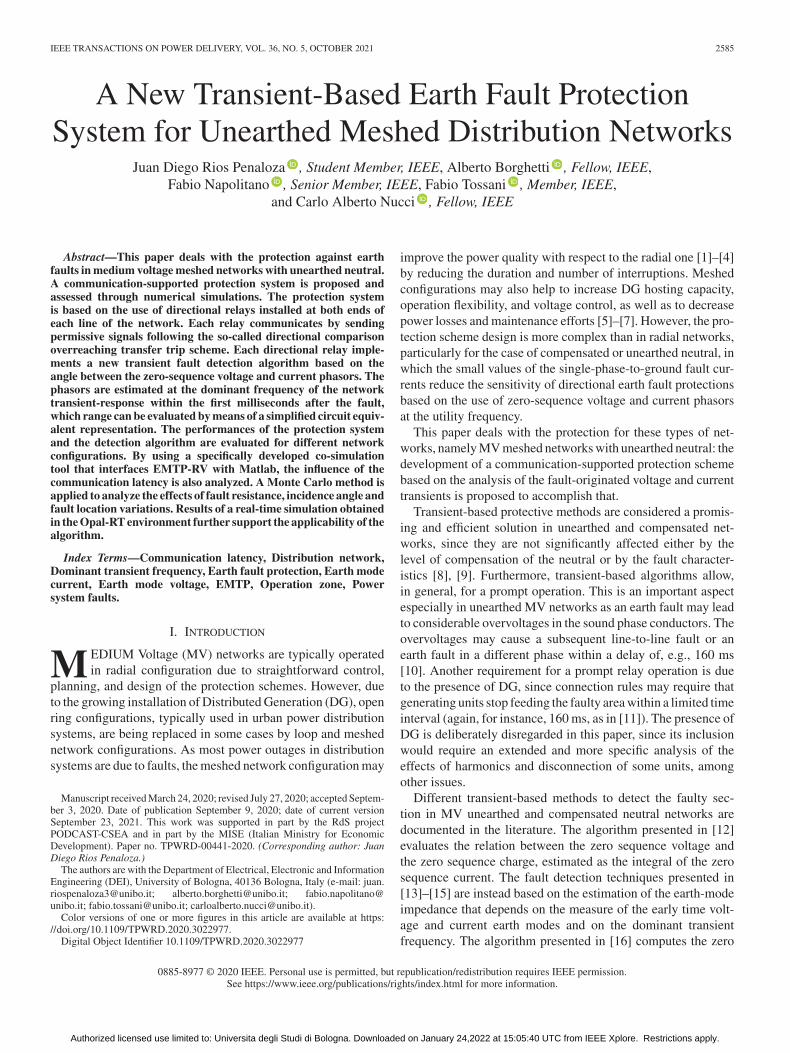
Fig. 1. Representation of the polarity of the phase displacement of zerosequence current respect to zero sequence voltage during an earth fault in ameshed network.
needed by the protection system, and the simulation tool adoptedfor the analysis of the performances.
A. Theoretical Background
When a single-phase-to-earth fault occurs in an unearthedneutral network, a transient phenomenon arises. Basically, thetransient can be interpreted as composed by a component dueto the lowering of the faulty phase conductor voltage and bya component due to the rising of the voltages in the soundphase conductors [13]. The frequencies of these two transientcomponents vary in different ranges and have different ampli-tudes. Following [13]–[15], the latter component is adopted inthe proposed fault detection algorithm, corresponding to thehigher amplitude and the lower frequency with respect to thedischarging one.
The analysis presented in [13], [14] for radial networks is ex-tended for meshed ones. Directional relays detect zero-sequencecurrent phasor at the dominant transient frequency i0 and thecorresponding voltage phasor v0. In radial networks, relays offaulty feeders detect i0 lagging v0 while those of healthy feedersdetect i0 leading v0, considering the positive direction of thecurrent from the bus to the line. As illustrated in Fig. 1, in meshednetworks, relays at both ends of faulty lines detect i0 lagging v0likewise radial networks, but in healthy lines one of the relays cansee i0 lagging v0 (see relay 1A in Fig. 1). The condition in whichi0 is leading v0 can be seen by both relays at both ends of healthylines or by only one of the two. The latter case may happen inlines of limited length where the leakage current through the linecapacitance is small, therefore the currents at both ends of theline have similar magnitude and opposite direction.
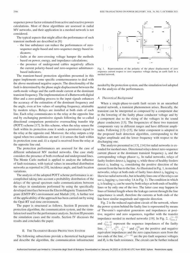
Fig. 2 is the reduced equivalent circuit of the network, wherethe power system behind the faulty line is represented by meansof Thevenin’s equivalent generators and impedances at posi-tive, negative and zero sequences, together with the transferimpedance needed in meshed networks [19]. In Fig. 2, z(+−0)
line,1
and z(+−0)line,2 represent the sequence impedances of the faulty
line, z(+−)1 , c(0)1 , z(+−)
2 and c(0)2 are the positive and negative
equivalent impedances and the zero capacitances seen from thetwo ends of the line, v(+−0) are the pre-fault sequence voltagesand Rf is the fault resistance. The circuit can be further reduced
Authorized licensed use limited to: Universita degli Studi di Bologna. Downloaded on January 24,2022 at 15:05:40 UTC from IEEE Xplore. Restrictions apply.
RIOS PENALOZA et al.: NEW TRANSIENT-BASED EARTH FAULT PROTECTION SYSTEM 2587
Fig. 2. Reduced equivalent circuit of the system in single-phase-to-groundfault condition.
into an RLC circuit which inductance and capacitance Leq andCeq provide the dominant frequency of the voltages and currentsv0,1, v0,2, i0,1 and i0,2 measured by the relays at the ends of thefaulted branch
fdom =1
2π√LeqCeq
(1)
The application of the equivalent circuit for the evaluation ofthe transient frequency is illustrated in the next Sections.
B. The Algorithm
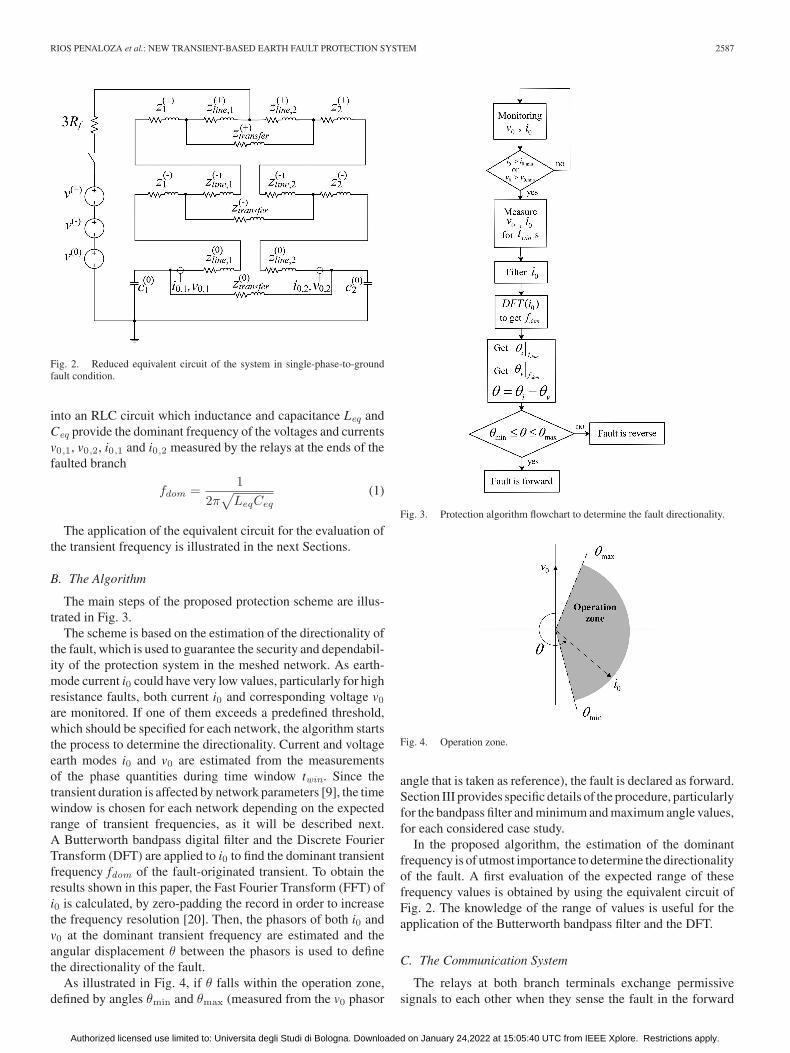
The main steps of the proposed protection scheme are illus-trated in Fig. 3.
The scheme is based on the estimation of the directionality ofthe fault, which is used to guarantee the security and dependabil-ity of the protection system in the meshed network. As earth-mode current i0 could have very low values, particularly for highresistance faults, both current i0 and corresponding voltage v0are monitored. If one of them exceeds a predefined threshold,which should be specified for each network, the algorithm startsthe process to determine the directionality. Current and voltageearth modes i0 and v0 are estimated from the measurementsof the phase quantities during time window twin. Since thetransient duration is affected by network parameters [9], the timewindow is chosen for each network depending on the expectedrange of transient frequencies, as it will be described next.A Butterworth bandpass digital filter and the Discrete FourierTransform (DFT) are applied to i0 to find the dominant transientfrequency fdom of the fault-originated transient. To obtain theresults shown in this paper, the Fast Fourier Transform (FFT) ofi0 is calculated, by zero-padding the record in order to increasethe frequency resolution [20]. Then, the phasors of both i0 andv0 at the dominant transient frequency are estimated and theangular displacement θ between the phasors is used to definethe directionality of the fault.
As illustrated in Fig. 4, if θ falls within the operation zone,defined by angles θmin and θmax (measured from the v0 phasor
Fig. 3. Protection algorithm flowchart to determine the fault directionality.
Fig. 4. Operation zone.
angle that is taken as reference), the fault is declared as forward.Section III provides specific details of the procedure, particularlyfor the bandpass filter and minimum and maximum angle values,for each considered case study.
In the proposed algorithm, the estimation of the dominantfrequency is of utmost importance to determine the directionalityof the fault. A first evaluation of the expected range of thesefrequency values is obtained by using the equivalent circuit ofFig. 2. The knowledge of the range of values is useful for theapplication of the Butterworth bandpass filter and the DFT.
C. The Communication System
The relays at both branch terminals exchange permissivesignals to each other when they sense the fault in the forward
Authorized licensed use limited to: Universita degli Studi di Bologna. Downloaded on January 24,2022 at 15:05:40 UTC from IEEE Xplore. Restrictions apply.
2588 IEEE TRANSACTIONS ON POWER DELIVERY, VOL. 36, NO. 5, OCTOBER 2021
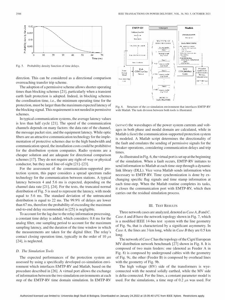
Fig. 5. Probability density function of time delays.
direction. This can be considered as a directional comparisonoverreaching transfer trip scheme.
The adoption of a permissive scheme allows shorter operatingtimes than blocking schemes [21], particularly when a transientearth fault protection is adopted. Indeed, in blocking schemesthe coordination time, i.e., the minimum operating time for theprotection, must be larger than the maximum expected latency ofthe blocking signal. This requirement is not needed in permissiveschemes.
In typical communication systems, the average latency valuesis less than half cycle [21]. The speed of the communicationchannels depends on many factors: the data rate of the channel,the message packet size, and the equipment latency. While opticfibers are an attractive communication technology for the imple-mentation of protective schemes due to the high bandwidth andcommunication speed, the installation costs could be prohibitivefor the distribution system companies. Radio systems are acheaper solution and are adequate for directional comparisonschemes [17]. They do not require any right-of-way or physicalconductor, but they need line-of-sight [21]–[23].
For the assessment of the communication-supported pro-tection system, this paper considers a spread spectrum radiotechnology for the communication between stations. A typicallatency between 4 and 5.6 ms is expected, depending on thechannel data rate [21], [24]. For the tests, the truncated normaldistribution of Fig. 5 is used to represent the latency, with modeequal to 5.6 ms. The standard deviation of the untruncateddistribution is equal to 22 ms. The 99.9% of delays are lowerthan 67 ms, therefore the probability of exceeding the maximumend-to-end delay recommended in [25] is negligible.
To account for the lag due to the relay information processing,a constant time delay is added, which considers: 0.8 ms for theanalog filter, one sampling period to account for the maximumsampling latency, and the duration of the time window in whichthe measurements are taken for the digital filter. The relay’scontact closing operation time, typically in the order of 10 μs[24], is neglected.
D. The Simulation Tools
The expected performances of the protection system areassessed by using a specifically developed co-simulation envi-ronment which interfaces EMTP-RV and Matlab, based on theprocedure described in [26]. A virtual port allows the exchangeof information between the two simulation environments at eachstep of the EMTP-RV time domain simulation. In EMTP-RV
Fig. 6. Structure of the co-simulation environment that interfaces EMTP-RVwith Matlab. The task division between both tools is illustrated.
(server) the waveshapes of the power system currents and volt-ages in both phase and modal domain are calculated, while inMatlab (client) the communication-supported protection systemis modeled. A Matlab script determines the directionality ofthe fault and emulates the sending of permissive signals for thebreaker operations, considering communication delays and triptimes.
As illustrated in Fig. 6, the virtual port is set up at the beginningof the simulation. When a fault occurs, EMTP-RV initiates tosend information to Matlab at each time-step through a dynamiclink library (DLL). Vice versa Matlab sends information whennecessary to EMTP-RV. Time synchronization is done by ex-changing specific flag signals and time stamp information ateach time-step. When the Matlab routine completes its tasks,it closes the communication port with EMTP-RV, which thencarries out the residual simulation process.
III. TEST RESULTS
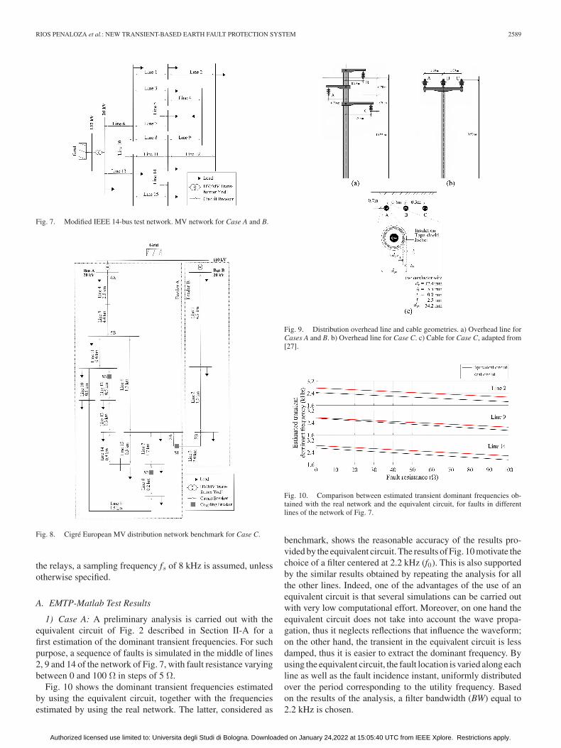
Three network cases are analyzed, denoted as Case A, B and C.Case A and B have the network topology shown in Fig. 7, whichis a modified IEEE 14-bus test system with the line geometryof Fig. 9a, that is characterized by a significant asymmetry. InCase A, the lines are 3 km long, while in Case B they are 0.5 kmlong.
The network of Case C has the topology of the Cigré EuropeanMV distribution network benchmark [27] shown in Fig. 8. It iscomposed of two main feeders: one (denoted as Feeder A inFig. 8) is composed by underground cables with the geometryof Fig. 9c, the other (Feeder B) is composed by overhead lineswith the geometry of Fig. 9b.
The high voltage (HV) side of the transformers is wye-connected with the neutral solidly earthed, while the MV sideis delta-connected. For the lines, a constant parameter model isused. For the simulations, a time step of 0.2 μs was used. For
Authorized licensed use limited to: Universita degli Studi di Bologna. Downloaded on January 24,2022 at 15:05:40 UTC from IEEE Xplore. Restrictions apply.
RIOS PENALOZA et al.: NEW TRANSIENT-BASED EARTH FAULT PROTECTION SYSTEM 2589
Fig. 7. Modified IEEE 14-bus test network. MV network for Case A and B.
Fig. 8. Cigré European MV distribution network benchmark for Case C.
the relays, a sampling frequency fs of 8 kHz is assumed, unlessotherwise specified.
A. EMTP-Matlab Test Results
1) Case A: A preliminary analysis is carried out with theequivalent circuit of Fig. 2 described in Section II-A for afirst estimation of the dominant transient frequencies. For suchpurpose, a sequence of faults is simulated in the middle of lines2, 9 and 14 of the network of Fig. 7, with fault resistance varyingbetween 0 and 100 Ω in steps of 5 Ω.
Fig. 10 shows the dominant transient frequencies estimatedby using the equivalent circuit, together with the frequenciesestimated by using the real network. The latter, considered as
Fig. 9. Distribution overhead line and cable geometries. a) Overhead line forCases A and B. b) Overhead line for Case C. c) Cable for Case C, adapted from[27].
Fig. 10. Comparison between estimated transient dominant frequencies ob-tained with the real network and the equivalent circuit, for faults in differentlines of the network of Fig. 7.
benchmark, shows the reasonable accuracy of the results pro-vided by the equivalent circuit. The results of Fig. 10 motivate thechoice of a filter centered at 2.2 kHz (f0). This is also supportedby the similar results obtained by repeating the analysis for allthe other lines. Indeed, one of the advantages of the use of anequivalent circuit is that several simulations can be carried outwith very low computational effort. Moreover, on one hand theequivalent circuit does not take into account the wave propa-gation, thus it neglects reflections that influence the waveform;on the other hand, the transient in the equivalent circuit is lessdamped, thus it is easier to extract the dominant frequency. Byusing the equivalent circuit, the fault location is varied along eachline as well as the fault incidence instant, uniformly distributedover the period corresponding to the utility frequency. Basedon the results of the analysis, a filter bandwidth (BW) equal to2.2 kHz is chosen.
Authorized licensed use limited to: Universita degli Studi di Bologna. Downloaded on January 24,2022 at 15:05:40 UTC from IEEE Xplore. Restrictions apply.
2590 IEEE TRANSACTIONS ON POWER DELIVERY, VOL. 36, NO. 5, OCTOBER 2021
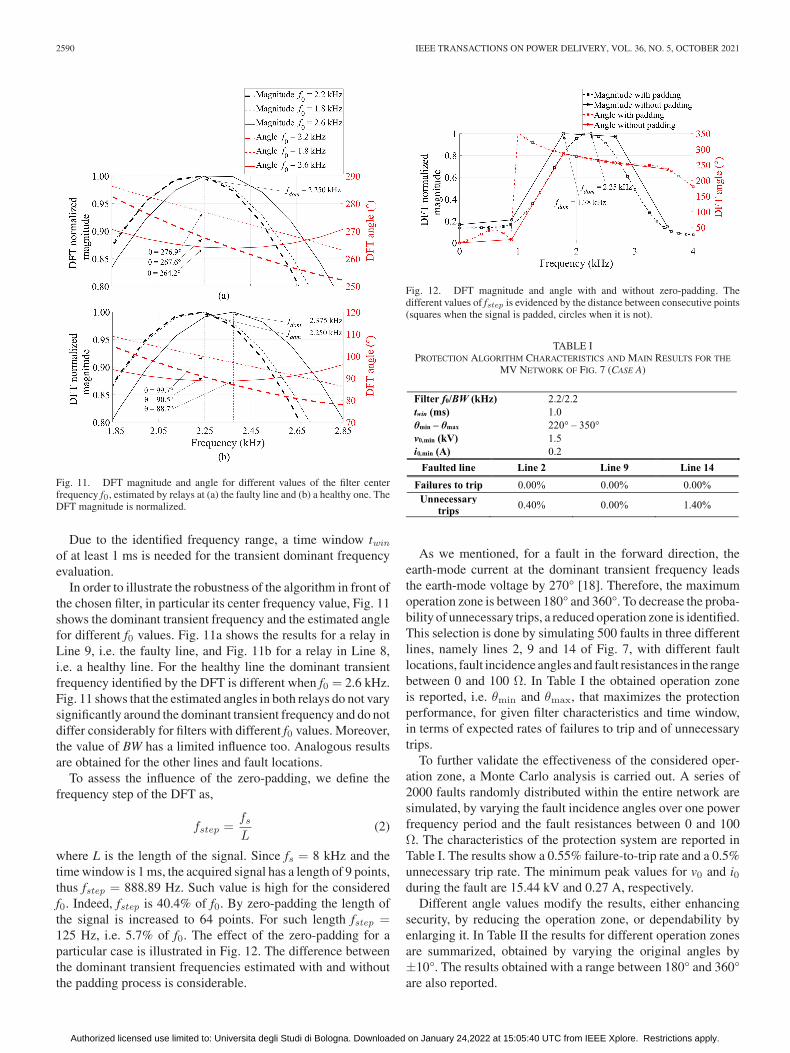
Fig. 11. DFT magnitude and angle for different values of the filter centerfrequency f0, estimated by relays at (a) the faulty line and (b) a healthy one. TheDFT magnitude is normalized.
Due to the identified frequency range, a time window twin
of at least 1 ms is needed for the transient dominant frequencyevaluation.
In order to illustrate the robustness of the algorithm in front ofthe chosen filter, in particular its center frequency value, Fig. 11shows the dominant transient frequency and the estimated anglefor different f0 values. Fig. 11a shows the results for a relay inLine 9, i.e. the faulty line, and Fig. 11b for a relay in Line 8,i.e. a healthy line. For the healthy line the dominant transientfrequency identified by the DFT is different when f0 = 2.6 kHz.Fig. 11 shows that the estimated angles in both relays do not varysignificantly around the dominant transient frequency and do notdiffer considerably for filters with different f0 values. Moreover,the value of BW has a limited influence too. Analogous resultsare obtained for the other lines and fault locations.
To assess the influence of the zero-padding, we define thefrequency step of the DFT as,
fstep =fsL
(2)
where L is the length of the signal. Since fs = 8 kHz and thetime window is 1 ms, the acquired signal has a length of 9 points,thus fstep = 888.89 Hz. Such value is high for the consideredf0. Indeed, fstep is 40.4% of f0. By zero-padding the length ofthe signal is increased to 64 points. For such length fstep =125 Hz, i.e. 5.7% of f0. The effect of the zero-padding for aparticular case is illustrated in Fig. 12. The difference betweenthe dominant transient frequencies estimated with and withoutthe padding process is considerable.
Fig. 12. DFT magnitude and angle with and without zero-padding. Thedifferent values of fstep is evidenced by the distance between consecutive points(squares when the signal is padded, circles when it is not).
TABLE IPROTECTION ALGORITHM CHARACTERISTICS AND MAIN RESULTS FOR THE
MV NETWORK OF FIG. 7 (CASE A)
As we mentioned, for a fault in the forward direction, theearth-mode current at the dominant transient frequency leadsthe earth-mode voltage by 270° [18]. Therefore, the maximumoperation zone is between 180° and 360°. To decrease the proba-bility of unnecessary trips, a reduced operation zone is identified.This selection is done by simulating 500 faults in three differentlines, namely lines 2, 9 and 14 of Fig. 7, with different faultlocations, fault incidence angles and fault resistances in the rangebetween 0 and 100 Ω. In Table I the obtained operation zoneis reported, i.e. θmin and θmax, that maximizes the protectionperformance, for given filter characteristics and time window,in terms of expected rates of failures to trip and of unnecessarytrips.
To further validate the effectiveness of the considered oper-ation zone, a Monte Carlo analysis is carried out. A series of2000 faults randomly distributed within the entire network aresimulated, by varying the fault incidence angles over one powerfrequency period and the fault resistances between 0 and 100Ω. The characteristics of the protection system are reported inTable I. The results show a 0.55% failure-to-trip rate and a 0.5%unnecessary trip rate. The minimum peak values for v0 and i0during the fault are 15.44 kV and 0.27 A, respectively.
Different angle values modify the results, either enhancingsecurity, by reducing the operation zone, or dependability byenlarging it. In Table II the results for different operation zonesare summarized, obtained by varying the original angles by±10°. The results obtained with a range between 180° and 360°are also reported.
Authorized licensed use limited to: Universita degli Studi di Bologna. Downloaded on January 24,2022 at 15:05:40 UTC from IEEE Xplore. Restrictions apply.
RIOS PENALOZA et al.: NEW TRANSIENT-BASED EARTH FAULT PROTECTION SYSTEM 2591
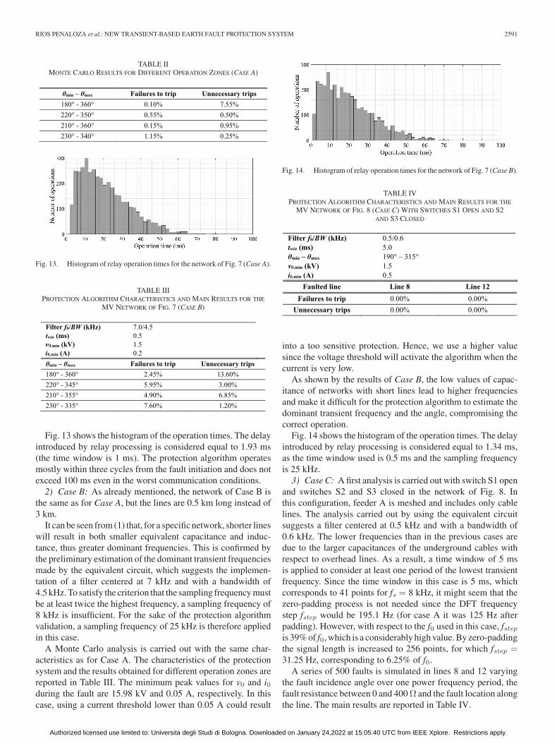
TABLE IIMONTE CARLO RESULTS FOR DIFFERENT OPERATION ZONES (CASE A)
Fig. 13. Histogram of relay operation times for the network of Fig. 7 (Case A).
TABLE IIIPROTECTION ALGORITHM CHARACTERISTICS AND MAIN RESULTS FOR THE
MV NETWORK OF FIG. 7 (CASE B)
Fig. 13 shows the histogram of the operation times. The delayintroduced by relay processing is considered equal to 1.93 ms(the time window is 1 ms). The protection algorithm operatesmostly within three cycles from the fault initiation and does notexceed 100 ms even in the worst communication conditions.
2) Case B: As already mentioned, the network of Case B isthe same as for Case A, but the lines are 0.5 km long instead of3 km.
It can be seen from (1) that, for a specific network, shorter lineswill result in both smaller equivalent capacitance and induc-tance, thus greater dominant frequencies. This is confirmed bythe preliminary estimation of the dominant transient frequenciesmade by the equivalent circuit, which suggests the implemen-tation of a filter centered at 7 kHz and with a bandwidth of4.5 kHz. To satisfy the criterion that the sampling frequency mustbe at least twice the highest frequency, a sampling frequency of8 kHz is insufficient. For the sake of the protection algorithmvalidation, a sampling frequency of 25 kHz is therefore appliedin this case.
A Monte Carlo analysis is carried out with the same char-acteristics as for Case A. The characteristics of the protectionsystem and the results obtained for different operation zones arereported in Table III. The minimum peak values for v0 and i0during the fault are 15.98 kV and 0.05 A, respectively. In thiscase, using a current threshold lower than 0.05 A could result
Fig. 14. Histogram of relay operation times for the network of Fig. 7 (Case B).
TABLE IVPROTECTION ALGORITHM CHARACTERISTICS AND MAIN RESULTS FOR THE
MV NETWORK OF FIG. 8 (CASE C) WITH SWITCHES S1 OPEN AND S2AND S3 CLOSED
into a too sensitive protection. Hence, we use a higher valuesince the voltage threshold will activate the algorithm when thecurrent is very low.
As shown by the results of Case B, the low values of capac-itance of networks with short lines lead to higher frequenciesand make it difficult for the protection algorithm to estimate thedominant transient frequency and the angle, compromising thecorrect operation.
Fig. 14 shows the histogram of the operation times. The delayintroduced by relay processing is considered equal to 1.34 ms,as the time window used is 0.5 ms and the sampling frequencyis 25 kHz.
3) Case C: A first analysis is carried out with switch S1 openand switches S2 and S3 closed in the network of Fig. 8. Inthis configuration, feeder A is meshed and includes only cablelines. The analysis carried out by using the equivalent circuitsuggests a filter centered at 0.5 kHz and with a bandwidth of0.6 kHz. The lower frequencies than in the previous cases aredue to the larger capacitances of the underground cables withrespect to overhead lines. As a result, a time window of 5 msis applied to consider at least one period of the lowest transientfrequency. Since the time window in this case is 5 ms, whichcorresponds to 41 points for fs = 8 kHz, it might seem that thezero-padding process is not needed since the DFT frequencystep fstep would be 195.1 Hz (for case A it was 125 Hz afterpadding). However, with respect to the f0 used in this case, fstepis 39% of f0, which is a considerably high value. By zero-paddingthe signal length is increased to 256 points, for which fstep =31.25 Hz, corresponding to 6.25% of f0.
A series of 500 faults is simulated in lines 8 and 12 varyingthe fault incidence angle over one power frequency period, thefault resistance between 0 and 400Ω and the fault location alongthe line. The main results are reported in Table IV.
Authorized licensed use limited to: Universita degli Studi di Bologna. Downloaded on January 24,2022 at 15:05:40 UTC from IEEE Xplore. Restrictions apply.
2592 IEEE TRANSACTIONS ON POWER DELIVERY, VOL. 36, NO. 5, OCTOBER 2021
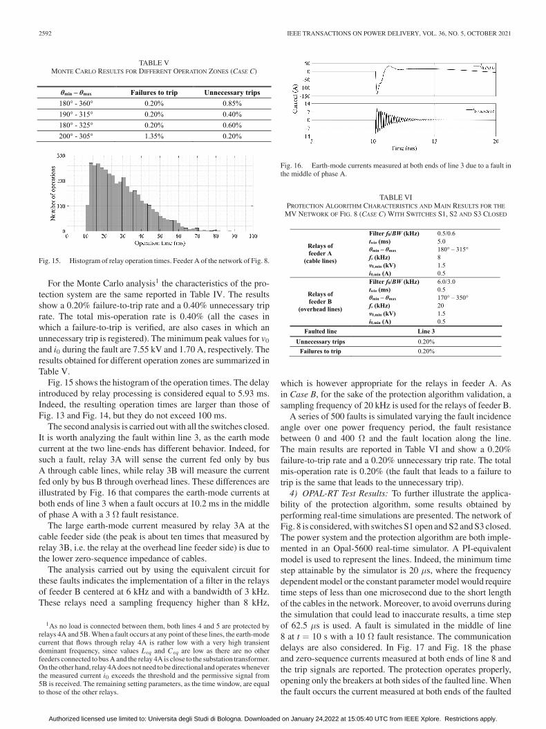
TABLE VMONTE CARLO RESULTS FOR DIFFERENT OPERATION ZONES (CASE C)
Fig. 15. Histogram of relay operation times. Feeder A of the network of Fig. 8.
For the Monte Carlo analysis1 the characteristics of the pro-tection system are the same reported in Table IV. The resultsshow a 0.20% failure-to-trip rate and a 0.40% unnecessary triprate. The total mis-operation rate is 0.40% (all the cases inwhich a failure-to-trip is verified, are also cases in which anunnecessary trip is registered). The minimum peak values for v0and i0 during the fault are 7.55 kV and 1.70 A, respectively. Theresults obtained for different operation zones are summarized inTable V.
Fig. 15 shows the histogram of the operation times. The delayintroduced by relay processing is considered equal to 5.93 ms.Indeed, the resulting operation times are larger than those ofFig. 13 and Fig. 14, but they do not exceed 100 ms.
The second analysis is carried out with all the switches closed.It is worth analyzing the fault within line 3, as the earth modecurrent at the two line-ends has different behavior. Indeed, forsuch a fault, relay 3A will sense the current fed only by busA through cable lines, while relay 3B will measure the currentfed only by bus B through overhead lines. These differences areillustrated by Fig. 16 that compares the earth-mode currents atboth ends of line 3 when a fault occurs at 10.2 ms in the middleof phase A with a 3 Ω fault resistance.
The large earth-mode current measured by relay 3A at thecable feeder side (the peak is about ten times that measured byrelay 3B, i.e. the relay at the overhead line feeder side) is due tothe lower zero-sequence impedance of cables.
The analysis carried out by using the equivalent circuit forthese faults indicates the implementation of a filter in the relaysof feeder B centered at 6 kHz and with a bandwidth of 3 kHz.These relays need a sampling frequency higher than 8 kHz,
1As no load is connected between them, both lines 4 and 5 are protected byrelays 4A and 5B. When a fault occurs at any point of these lines, the earth-modecurrent that flows through relay 4A is rather low with a very high transientdominant frequency, since values Leq and Ceq are low as there are no otherfeeders connected to bus A and the relay 4A is close to the substation transformer.On the other hand, relay 4A does not need to be directional and operates wheneverthe measured current i0 exceeds the threshold and the permissive signal from5B is received. The remaining setting parameters, as the time window, are equalto those of the other relays.
Fig. 16. Earth-mode currents measured at both ends of line 3 due to a fault inthe middle of phase A.
TABLE VIPROTECTION ALGORITHM CHARACTERISTICS AND MAIN RESULTS FOR THE
MV NETWORK OF FIG. 8 (CASE C) WITH SWITCHES S1, S2 AND S3 CLOSED
which is however appropriate for the relays in feeder A. Asin Case B, for the sake of the protection algorithm validation, asampling frequency of 20 kHz is used for the relays of feeder B.
A series of 500 faults is simulated varying the fault incidenceangle over one power frequency period, the fault resistancebetween 0 and 400 Ω and the fault location along the line.The main results are reported in Table VI and show a 0.20%failure-to-trip rate and a 0.20% unnecessary trip rate. The totalmis-operation rate is 0.20% (the fault that leads to a failure totrip is the same that leads to the unnecessary trip).
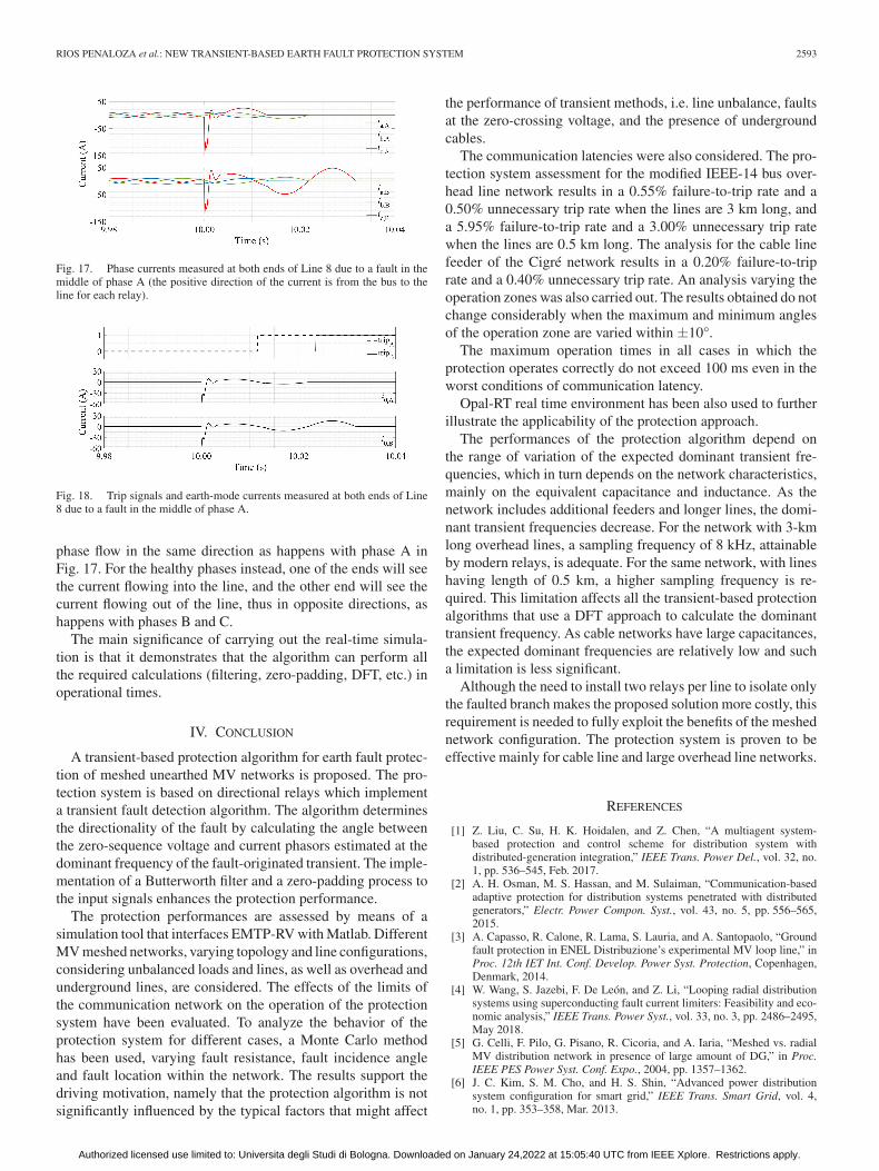
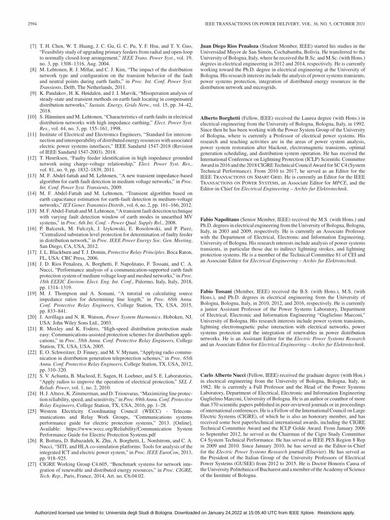
4) OPAL-RT Test Results: To further illustrate the applica-bility of the protection algorithm, some results obtained byperforming real-time simulations are presented. The network ofFig. 8 is considered, with switches S1 open and S2 and S3 closed.The power system and the protection algorithm are both imple-mented in an Opal-5600 real-time simulator. A PI-equivalentmodel is used to represent the lines. Indeed, the minimum timestep attainable by the simulator is 20 μs, where the frequencydependent model or the constant parameter model would requiretime steps of less than one microsecond due to the short lengthof the cables in the network. Moreover, to avoid overruns duringthe simulation that could lead to inaccurate results, a time stepof 62.5 μs is used. A fault is simulated in the middle of line8 at t = 10 s with a 10 Ω fault resistance. The communicationdelays are also considered. In Fig. 17 and Fig. 18 the phaseand zero-sequence currents measured at both ends of line 8 andthe trip signals are reported. The protection operates properly,opening only the breakers at both sides of the faulted line. Whenthe fault occurs the current measured at both ends of the faulted
Authorized licensed use limited to: Universita degli Studi di Bologna. Downloaded on January 24,2022 at 15:05:40 UTC from IEEE Xplore. Restrictions apply.
RIOS PENALOZA et al.: NEW TRANSIENT-BASED EARTH FAULT PROTECTION SYSTEM 2593
Fig. 17. Phase currents measured at both ends of Line 8 due to a fault in themiddle of phase A (the positive direction of the current is from the bus to theline for each relay).
Fig. 18. Trip signals and earth-mode currents measured at both ends of Line8 due to a fault in the middle of phase A.
phase flow in the same direction as happens with phase A inFig. 17. For the healthy phases instead, one of the ends will seethe current flowing into the line, and the other end will see thecurrent flowing out of the line, thus in opposite directions, ashappens with phases B and C.
The main significance of carrying out the real-time simula-tion is that it demonstrates that the algorithm can perform allthe required calculations (filtering, zero-padding, DFT, etc.) inoperational times.
IV. CONCLUSION
A transient-based protection algorithm for earth fault protec-tion of meshed unearthed MV networks is proposed. The pro-tection system is based on directional relays which implementa transient fault detection algorithm. The algorithm determinesthe directionality of the fault by calculating the angle betweenthe zero-sequence voltage and current phasors estimated at thedominant frequency of the fault-originated transient. The imple-mentation of a Butterworth filter and a zero-padding process tothe input signals enhances the protection performance.
The protection performances are assessed by means of asimulation tool that interfaces EMTP-RV with Matlab. DifferentMV meshed networks, varying topology and line configurations,considering unbalanced loads and lines, as well as overhead andunderground lines, are considered. The effects of the limits ofthe communication network on the operation of the protectionsystem have been evaluated. To analyze the behavior of theprotection system for different cases, a Monte Carlo methodhas been used, varying fault resistance, fault incidence angleand fault location within the network. The results support thedriving motivation, namely that the protection algorithm is notsignificantly influenced by the typical factors that might affect
the performance of transient methods, i.e. line unbalance, faultsat the zero-crossing voltage, and the presence of undergroundcables.
The communication latencies were also considered. The pro-tection system assessment for the modified IEEE-14 bus over-head line network results in a 0.55% failure-to-trip rate and a0.50% unnecessary trip rate when the lines are 3 km long, anda 5.95% failure-to-trip rate and a 3.00% unnecessary trip ratewhen the lines are 0.5 km long. The analysis for the cable linefeeder of the Cigré network results in a 0.20% failure-to-triprate and a 0.40% unnecessary trip rate. An analysis varying theoperation zones was also carried out. The results obtained do notchange considerably when the maximum and minimum anglesof the operation zone are varied within ±10°.
The maximum operation times in all cases in which theprotection operates correctly do not exceed 100 ms even in theworst conditions of communication latency.
Opal-RT real time environment has been also used to furtherillustrate the applicability of the protection approach.
The performances of the protection algorithm depend onthe range of variation of the expected dominant transient fre-quencies, which in turn depends on the network characteristics,mainly on the equivalent capacitance and inductance. As thenetwork includes additional feeders and longer lines, the domi-nant transient frequencies decrease. For the network with 3-kmlong overhead lines, a sampling frequency of 8 kHz, attainableby modern relays, is adequate. For the same network, with lineshaving length of 0.5 km, a higher sampling frequency is re-quired. This limitation affects all the transient-based protectionalgorithms that use a DFT approach to calculate the dominanttransient frequency. As cable networks have large capacitances,the expected dominant frequencies are relatively low and sucha limitation is less significant.
Although the need to install two relays per line to isolate onlythe faulted branch makes the proposed solution more costly, thisrequirement is needed to fully exploit the benefits of the meshednetwork configuration. The protection system is proven to beeffective mainly for cable line and large overhead line networks.
REFERENCES
[1] Z. Liu, C. Su, H. K. Hoidalen, and Z. Chen, “A multiagent system-based protection and control scheme for distribution system withdistributed-generation integration,” IEEE Trans. Power Del., vol. 32, no.1, pp. 536–545, Feb. 2017.
[2] A. H. Osman, M. S. Hassan, and M. Sulaiman, “Communication-basedadaptive protection for distribution systems penetrated with distributedgenerators,” Electr. Power Compon. Syst., vol. 43, no. 5, pp. 556–565,2015.
[3] A. Capasso, R. Calone, R. Lama, S. Lauria, and A. Santopaolo, “Groundfault protection in ENEL Distribuzione’s experimental MV loop line,” inProc. 12th IET Int. Conf. Develop. Power Syst. Protection, Copenhagen,Denmark, 2014.
[4] W. Wang, S. Jazebi, F. De León, and Z. Li, “Looping radial distributionsystems using superconducting fault current limiters: Feasibility and eco-nomic analysis,” IEEE Trans. Power Syst., vol. 33, no. 3, pp. 2486–2495,May 2018.
[5] G. Celli, F. Pilo, G. Pisano, R. Cicoria, and A. Iaria, “Meshed vs. radialMV distribution network in presence of large amount of DG,” in Proc.IEEE PES Power Syst. Conf. Expo., 2004, pp. 1357–1362.
[6] J. C. Kim, S. M. Cho, and H. S. Shin, “Advanced power distributionsystem configuration for smart grid,” IEEE Trans. Smart Grid, vol. 4,no. 1, pp. 353–358, Mar. 2013.
Authorized licensed use limited to: Universita degli Studi di Bologna. Downloaded on January 24,2022 at 15:05:40 UTC from IEEE Xplore. Restrictions apply.
2594 IEEE TRANSACTIONS ON POWER DELIVERY, VOL. 36, NO. 5, OCTOBER 2021
[7] T. H. Chen, W. T. Huang, J. C. Gu, G. C. Pu, Y. F. Hsu, and T. Y. Guo,“Feasibility study of upgrading primary feeders from radial and open-loopto normally closed-loop arrangement,” IEEE Trans. Power Syst., vol. 19,no. 3, pp. 1308–1316, Aug. 2004.
[8] M. Lehtonen, R. J. Millar, and C. J. Kim, “The impact of the distributionnetwork type and configuration on the transient behavior of the faultand neutral points during earth faults,” in Proc. Int. Conf. Power Syst.Transients, Delft, The Netherlands, 2011.
[9] K. Pandakov, H. K. Høidalen, and J. I. Marvik, “Misoperation analysis ofsteady-state and transient methods on earth fault locating in compensateddistribution networks,” Sustain. Energy, Grids Netw., vol. 15, pp. 34–42,2018.
[10] S. Hänninen and M. Lehtonen, “Characteristics of earth faults in electricaldistribution networks with high impedance earthing,” Elect. Power Syst.Res., vol. 44, no. 3, pp. 155–161, 1998.
[11] Institute of Electrical and Electronics Engineers, “Standard for intercon-nection and interoperability of distributed energy resources with associatedelectric power systems interfaces,” IEEE Sandartd 1547-2018 (Revisionof IEEE Sandartd 1547-2003). 2018.
[12] T. Henriksen, “Faulty feeder identification in high impedance groundednetwork using charge-voltage relationship,” Elect. Power Syst. Res.,vol. 81, no. 9, pp. 1832–1839, 2011.
[13] M. F. Abdel-fattah and M. Lehtonen, “A new transient impedance-basedalgorithm for earth fault detection in medium voltage networks,” in Proc.Int. Conf. Power Syst. Transients, 2009.
[14] M. F. Abdel-Fattah and M. Lehtonen, “Transient algorithm based onearth capacitance estimation for earth-fault detection in medium-voltagenetworks,” IET Gener. Transmiss Distrib., vol. 6, no. 2, pp. 161–166, 2012.
[15] M. F. Abdel-Fattah and M. Lehtonen, “A transient fault detection techniquewith varying fault detection window of earth modes in unearthed MVsystems,” in Proc. 6th Int. Conf. - Power Qual. Supply Rel., 2008.
[16] P. Balcerek, M. Fulczyk, J. Izykowski, E. Rosolowski, and P. Pierz,“Centralized substation level protection for determination of faulty feederin distribution network,” in Proc. IEEE Power Energy Soc. Gen. Meeting,San Diego, CA, USA, 2012.
[17] J. L. Blackburn and T. J. Domin, Protective Relay Principles. Boca Raton,FL, USA: CRC Press, 2006.
[18] J. D. Rios Penaloza, A. Borghetti, F. Napolitano, F. Tossani, and C. A.Nucci, “Performance analysis of a communication-supported earth faultprotection system of medium voltage loop and meshed networks,” in Proc.18th EEEIC Environ. Elect. Eng. Int. Conf., Palermo, Italy, Italy, 2018,pp. 1314–1319.
[19] M. J. Thompson and A. Somani, “A tutorial on calculating sourceimpedance ratios for determining line length,” in Proc. 68th Annu.Conf. Protective Relay Engineers, College Station, TX, USA, 2015,pp. 833–841.
[20] J. Arrillaga and N. R. Watson, Power System Harmonics. Hoboken, NJ,USA: John Wiley Sons Ltd., 2003.
[21] R. Moxley and K. Fodero, “High-speed distribution protection madeeasy: Communications-assisted protection schemes for distribution appli-cations,” in Proc. 58th Annu. Conf. Protective Relay Engineers, CollegeStation, TX, USA, USA, 2005.
[22] E. O. Schweitzer, D. Finney, and M. V. Mynam, “Applying radio commu-nication in distribution generation teleprotection schemes,” in Proc. 65thAnnu. Conf. Protective Relay Engineers, College Station, TX, USA, 2012,pp. 310–320.
[23] S. V. Achanta, B. Macleod, E. Sagen, H. Loehner, and S. E. Laboratories,“Apply radios to improve the operation of electrical protection,” SEL J.Reliab. Power, vol. 1, no. 2, 2010.
[24] H. J. Altuve, K. Zimmerman, and D. Tziouvaras, “Maximizing line protec-tion reliability, speed, and sensitivity,” in Proc. 69th Annu. Conf. ProtectiveRelay Engineers, College Station, TX, USA, 2016, pp. 1–28.
[25] Western Electricity Coordinating Council (WECC) - Telecom-munications and Relay Work Groups, “Communications systemsperformance guide for electric protection systems,” 2013. [Online].Available: https://www.wecc.org/Reliability/Communication SystemPerformance Guide for Electric Protection Systems.pdf
[26] R. Bottura, D. Babazadeh, K. Zhu, A. Borghetti, L. Nordstrom, and C. A.Nucci, “SITL and HLA co-simulation platforms: Tools for analysis of theintegrated ICT and electric power system,” in Proc. IEEE EuroCon, 2013,pp. 918–925.
[27] CIGRE Working Group C4.605, “Benchmark systems for network inte-gration of renewable and distributed energy resources,” in Proc. CIGRE,Tech. Rep., Paris, France, 2014, Art. no. C6.04.02.
Juan Diego Rios Penaloza (Student Member, IEEE) started his studies in theUniversidad Mayor de San Simón, Cochabamba, Bolivia. He transferred to theUniversity of Bologna, Italy, where he received the B.Sc. and M.Sc. (with Hons.)degrees in electrical engineering in 2012 and 2014, respectively. He is currentlyworking toward the Ph.D. degree in electrical engineering at the University ofBologna. His research interests include the analysis of power systems transients,power systems protection, integration of distributed energy resources in thedistribution network and microgrids.
Alberto Borghetti (Fellow, IEEE) received the Laurea degree (with Hons.) inelectrical engineering from the University of Bologna, Bologna, Italy, in 1992.Since then he has been working with the Power System Group of the Universityof Bologna, where is currently a Professor of electrical power systems. Hisresearch and teaching activities are in the areas of power system analysis,power system restoration after blackout, electromagnetic transients, optimalgeneration scheduling, and distribution system operation. He has received theInternational Conference on Lightning Protection (ICLP) Scientific CommitteeAward in 2016 and the 2018 CIGRE Technical Council Award for SC C4 (SystemTechnical Performance). From 2010 to 2017, he served as an Editor for theIEEE TRANSACTIONS ON SMART GRID. He is currently an Editor for the IEEETRANSACTIONS ON POWER SYSTEMS, an Associate Editor for MPCE, and theEditor-in-Chief for Electrical Engineering – Archiv fur Elektrotechnik.
Fabio Napolitano (Senior Member, IEEE) received the M.S. (with Hons.) andPh.D. degrees in electrical engineering from the University of Bologna, Bologna,Italy, in 2003 and 2009, respectively. He is currently an Associate Professorwith the Department of Electrical, Electronic and Information Engineering,University of Bologna. His research interests include analysis of power systemstransients, in particular those due to indirect lightning strokes, and lightningprotection systems. He is a member of the Technical Committee 81 of CEI andan Associate Editor for Electrical Engineering – Archiv fur Elektrotechnik.
Fabio Tossani (Member, IEEE) received the B.S. (with Hons.), M.S. (withHons.), and Ph.D. degrees in electrical engineering from the University ofBologna, Bologna, Italy, in 2010, 2012, and 2016, respectively. He is currentlya junior Assistant Professor of the Power Systems Laboratory, Departmentof Electrical, Electronic and Information Engineering “Guglielmo Marconi,”University of Bologna. His research interests include power system transients,lightning electromagnetic pulse interaction with electrical networks, powersystems protection and the integration of renewables in power distributionnetworks. He is an Assistant Editor for the Electric Power Systems Researchand an Associate Editor for Electrical Engineering – Archiv fur Elektrotechnik.
Carlo Alberto Nucci (Fellow, IEEE) received the graduate degree (with Hon.)in electrical engineering from the University of Bologna, Bologna, Italy, in1982. He is currently a Full Professor and the Head of the Power SystemsLaboratory, Department of Electrical, Electronic and Information EngineeringGuglielmo Marconi, University of Bologna. He is an author or coauthor of morethan 370 scientific papers published in peer-reviewed journals or in proceedingsof international conferences. He is a Fellow of the International Council on LargeElectric Systems (CIGRE), of which he is also an honorary member, and hasreceived some best paper/technical international awards, including the CIGRETechnical Committee Award and the ICLP Golde Award. From January 2006to September 2012, he served as the Chairman of the Cigre Study CommitteeC4 System Technical Performance. He has served as IEEE PES Region 8 Repin 2009 and 2010. Since January 2010, he has served as the Editor-in-Chieffor the Electric Power Systems Research journal (Elsevier). He has served asthe President of the Italian Group of the University Professors of ElectricalPower Systems (GUSEE) from 2012 to 2015. He is Doctor Honoris Causa ofthe University Politehnica of Bucharest and a member of the Academy of Scienceof the Institute of Bologna.
Authorized licensed use limited to: Universita degli Studi di Bologna. Downloaded on January 24,2022 at 15:05:40 UTC from IEEE Xplore. Restrictions apply.


