Embed Size (px)
Citation preview
?raitc hto$\ Pn*
A Novel Sensorless MPPT for Wind Turbine Generators Using
International Review of Eleetrical Engineering (I.R.E.E.), Yol. 10, N. 2ISSN 1827- 6660 March-April 2015
Small Wind Turbine Generators Otrfcs) ?re greatchoice for this country that has a low wind speed. SmallWTGs widely developed by using Permanent MagnetSynchronous Generator (PMSG), becaus€ it has a highefficiency with the absence of rotor losses and betterdynamic performance draa induction machines I I ] - [3].
Basically, the WTGs can be operated in two ways,namely canstant spoed and variable speed. The variablespeed more attractive than cslstant spoed, because cannraximize &e output power [4]-[5J. The variable speedcontrol is applied through a power converter. Someconverter models has been applied to PMSG-windturbine, such as a diode rectifier-inverter [5], back toback and matrix converters [6]. Mafrix converter isconsid€red a good altornative for grid-connedod WTGs,because it does not require energy storage and highpower densities pl-[9]. To reduce the matrix convertercosts, VSMC has been developed in [8]- This conv€rteruses only 12 active switch, so it is more efficient than theconventional matrix converter. and this converter isproposed for driyer the PMSG-wind turbine.
Variable sped eontrol of a PMSG-wind turbinerequires MPPT algorithms to obtain reference speed atmaximum po,wer point. Several MPPT algorithm lunbeen applied to a PMSG-wind turbine. The P0 algorithmbecame popular because it is simple. The PO determinesthe refereirce speed based on tlrc power variatiorn withconstant step. Determining the ideal step size is aproblem, becatrse a large step size gives a fast responsebut cause the oscillations at marimum poinl while asmall step size will slow dirwn the response.
.W
Very Sparse Matfix ConV€rter Basdd on Hybrid Intelligent Control
Muldi Yuhendri i" 2, Mochamad Ashari 1, Mauridhi Hery Purnomo i
Abstract - The maxirmrm power af Wind Turbine Generators (rWG{ ean be abtained byadjusting the rotor speed at the optimum Tip Speed Ratio (tSR), so that the MqxirTum PowerPoint Traeking (MPPD algorithms is needed to obtain the referenee speed. Tlw corwentionalMPPT such as Pertubartisn qnd Observation (PO), a rcference speed is determined by q conslantstep. Choosing appropriate the step size is a problem, because it mry cause problems in thef,esponse ond the oscillstions st the mmimum point. To solve this problem, the flexible step size isproposed by using Least Squares-Support Yector Mochfue (LS-SVM). Then, the Adaptive Type-2
Fuzzy Sliding Mode Control (AFSMOC) is applied to control a rotor speed at a reference speedthrough Very Sparse Matrix Converter (VSMC). To replace a rotor speed sewors, the ModelReference Adoptive System (MRAS) observers is proposed. The simulotion results shows that theMPPT based LS-SYM is remarkably faster and msre efficient than the PO algoritfun. LS-SYM cangenerate the Jlexible steps with the accuracy of classification 94.29 %. Tlte AFSMOC canregatating the rotor speed at reference poittt, so thst the mpcimum p{rwer can be achieved at allwind speeds. Copyrighl @ 2015 Ptoise Worthy kire S.nL - AII righs resewed
Keywords: lYind Turbine Generator, MPPT LS-SYM Type-2 Fuzry Sliding Mode Control YerySparse Matr* Corwerter
Nomenclature
p Pitch anglep Air density7 Tip speed ratio of wind turbine0o Aagle of the output voltage
Vi Permanenl fluxn)il Rotor speed(De Electrical speedCp Power cosfEcient of wind turbineia io dq-wo" ofstator currentsJ The rotor inertiaK" Gain of the speed errorKt The luq*d dirtt rbim€€s of systern
La, Ln dq-wris of stator inductancesmo Modulation indexnp Number of pole pairs of PMSGP* The mechanical power of wind turbinePo The output power of PMSGR Radius ofwindfirbine& slator resistanceT" Electromagnetic iorqu€T. Mechanical torquevo 'ttl a$-axis of stator voltagesvd, vq d4-axis of stator voltagesvw Wind speed
L IntroductionThe utilization of wind energy fur electric power
generation began to attract attention in Indonesia.
Copyright@ 2Al5 Praise Worthy Prize S.r.l. - All rights resemed

Muldi Yuhendri, MochamcdAshori, Mauridhi Hery Purnomo
To resolve this problem, a modified PO with flexiblestep has been proposed in [10]-[11]. The flexible stepbased on intelligent approach has also been applid suchas an ANFIS [4], and several a Neural Netwo* methods
U?J-U4I.In this paper, the flexible step is designed byusing LS-SVM based on multi-classification methods.LS-SVM is a machine leaming that developed brised onthe structural risk minimizations. LS-SVM proposed bySrrykens and Vandewalle [15] by using a set of linearequations to solve the quadratic prograrnming problemin SVM. It is more efficient than SVM- Rotor speed isregulated at reference point by using a Sliding ModeControl (SMC). This method has advantages such as fastdynamic respons€ and robust to pararnder variations116l-[18]. To improve the robushess, the SMC isdeveloped with adapfive gain using Type-2 FtuzySyslem (T2FS). It is more robustness thzn type-l finzrysystem {TIFS) to handle th€ uncertainty of parameters
t19l-t201. To reduce the driver costs, MRAS observer isproposed to replace the rotor sperd sensors.
il. Modeling of WTGs
Variable speed eonhol of IVTGs with employ aVSMC is proposedn as shown in Fig. l. The proposedscheme consists cf a PMSG, horizontal wind turbine andthe variable speed eontroller to sbtain rnaximum pow€rat all wind velocities.
The speed control is developed by usrng sensorlessField Oriented Control (FOC) m€fhods based on aconEtant torque angle control. In this metho4 the r-otorspeed is controlled by adjust the reference of4-axis stator€urr€nt d" while the referencc of d-axis stdor *ment ia"is kept zero. io" is regulated by AFSMOC based on thespeed error. Based on Fig. 1, the speed error is obtainedby compare thc estimated speed from MRAS otserverwith the reference speed from LS-SVM.
Both la. and iu* are regulated by using SMC to obtainthe refercnce voltage (va* and un). Then, both y,/* and vu*
are used to control the PMSG speed through a VSMC.
11.1. lYirdTurbirte
The amount of power captured by the wind turbine is^detennined by the radius of the fiubine R and the powercoefficient Cp which is written as:
P. =o.s co(A,B) p E Rz S* (l)
Co is function of thc tip Epped ratio GSR) ,1 and thepitch angle fl that witten as :
1=r. R (z)
l.
where ro, is rotor speed of wind Aribine. The maximnmpower is achieved whendre turbine op€ratss at maximumpower coefficier.$ Co, .It can be obtained by adjrst therotor speed at an oflimum value of the TSR i*. Basedon (1), thc maximum power of wid turbine can bewritten as ;
P* * =0.5 zr p cp-*(l*,p) F tl" (3)
The refer€,rre speod for maxinarm power is grven by:
* 1^^,
'. =tn, (4)
In this paper, the reference speeds is searched basedon the change ofpower using LS-SYM 1311,[32].
.roNAFSMOC
Fig l. The proposed schemes
Copyright @ 2015 Praise Worthy Pize S.r.l. - AII rights resemed Internatiotnl Review of Electrieal Etgircering, Yol. 10, N. 2

.:;5r
Muldi Yuhendri, MochamadAshtri, Mauridhi Hery Pumomo
11.2. Permanent Magnet SJsnchornow Generator
Viuiabte spe€d corlfol of PMSG bxed on sensoilessFOC is applied with decoupled conhol of the stalorcurrent n d-q axis.
The stator current in a rotating refersrce frame can bewritten as:
o ? =-*u+ot" i"+! (5)dt Lo" ( 't Ld
!"=-\, -@" id-*"T-+ (6)dt Lo'
Thc ouput power and the mechaaical dynamics ofPMSG are given by:
po =va io +vo io (7)
d T*-T"-Ba*i'*=T (8)
Bascd on (8), the PMSG speed control conducted byregulating the T"tlwougfi lo that written as:
= -1.5 n, V^ iq (9)
11.3. Yery Sparse Matrix Corwerter
Very Sparse Matrix Converter (VSMC) is ac-acconverters with direct voltage and frequency corversion,so capable for three-phase ac drives. Th€ VSMC consistsof the current source corn/crters (CSC) md the voltagesource converters (VSC) without Dc-link energi storage,as shown in Fig. 1. Small LC filtei is employed to reduoethe input harmonics. VSMC can be modulatcd by usingSpace vector modulation t7l-191.
The CSC modulation is designed to generate themaximum dc-link voltago arrd keep unity input power
&Stor. The swirching states of CSC are determined basedffi the space vector of the input voltage that is dividedinto 6 sectors, as shown in Fig. 2. The duty cycle for eachsectror can be calculated as tabulated in Table I.
The VSC is modulated based on space vectsr of {heou$ut voltage, which is separated by 6 sectors as shownin Fig. 3. Duty cycle of VSC is given by:
doo = no'*(%*r"), d Fo = *"'n(/r) Oo">
doo =l- doo - d po (l0b)
where moand 0oare the modulation index and the outputvoltage angle, that are given by:
oo =tan-t (rt,1.d'\ arrd mo =V,lV, (11)
Copyright @ 2015 Proise W*tby Prize S.r.l. -All *glas reserved
wlwre Yn and Y i are the output voltage anrplitude andthe inpuf voltage amplialde, resprcfively- The v*- andv*gnuathe refErensc of an oufput voltage.
To balance the input currents and the output voltages,the CSC modulations must be soordinsled with the SVCmodulationg and it is design€d bsed on the rnefhod in18].
IfI. MPPT Algorithms
The mechanical power of wind turbins depends on therotor s@ ot-antd wind speed v., as shswn in Fig. 4.
The ma:rimum power point is located at different rotor
ryd ir sach wind spsEd t?S]-{301. Ths r$axililrrrpower point is achiwed w*ren the Anbine operates atmaximum pfutt of pourcr coefficient Cp_*.
MPPT algorithms ir us€dto s€areh fhe referencrc speedtmtil the system setttres down at rnaximwn power point.For exanple, at a wind sp€ed vy2 in Fig. 4, the otrtputpower of PMSG P" \ryill bc at A if the rotor speed is co-.MFPT algeritlrms will alter the roeor spd in positif step+Aal, until it reaches the rcferenoe of a rotor speed ar.1,so that the power is maxirnum at B. If &e wind speedinereas€s to %4, tl.€ power will jrunp to C, so the MPPTalgorithms again alter the rotor speed until the power isrn*ximum at D, If the wind specd deereases to v.r, thgpower will ftlling dov*n to E.
llrl6 O E/6 n/2 51il6 7nl6 3EI2 lbtl6
Sector 2 J 4 5 6
d','d* Ja, Jo s*, sto s* ,9^ sw.s* S*.Sa' S*.{"d-,+d., sq s* sqe ,L sq Sa'
Fig. 2- The switchrng states of CSC stage
TABLEIDT]TY CYCLE G TgE RECI]}ER STAGE
See{orl Saefsr2 Scefor3 S€€totr4 Setor5 Sector6Er7-v/vo00O-ilwSh0-vrlv"l-velt"00S"p00O-v/v"l-v"lvtS*00-vJvtl-sdlv"OSr",-vt/t"00O-vit.l{",, ,,
110:\I"t.
01 l.\ d..l/"" r
l01
Fig. 3. The switching state of VSC stage
Inrenutiod Reyiew $Electica) Eagiw*ing, ys|. 10, N. 2

Muldi Yulrcndri, MoehamadAshari, Mauridhi Hery Purnomo
'
To obtain the maximurn power at F, the MPPTalgorithms will alter the rotor speed in negative step -Aar., and so on.
{n a coaventional MPff, such as a PO algorithms, thereference speed at maximum power point is searched byconstant step size, as showa in Fig. 5. FO algorithms *illalter the reference speed based on the sigrr of themeasured power variations- If the change of power ispositive Mo, then the step Ao* alss positive, vice versa,Determining the step sizs is the problem of a POalgodthms. The large stcp can irnprove a responsc but itcause a speed ripple problem at maximum power pointwhile the small steps will slow down a response I I 0].
To solve tlre problern a PO algorithms, the adaFnive
step size is proposed in this paper. The step sizc isdetermined based on the fact the mechanical power of thewind turbine is a cubic function of the rotor speed. LS-SVM is proposed to obtain the adaptive step size forMPPT.
III.I. MPPTAlgorithm Using LS-SIrM
'l'tre scherne of a MPPI algorithms using LS-SYM isshown in Fig. 6.
amr a-2 o.(rpn)
Fig, 4. The mechanical power as a firnction ofthe rotor speed
Fig. 5. Flowchart of FO algorithms
Copyright @ 2015 Praise Worlhy Prize S,r.l. - All rights resened
Fig: 6. &PPT alg@itluns usingLS-SVM
The input ofa LS-SVM are the power change AP, andthe previous value of a step size Lro*,4*r1, while the LS-SMvt output is a step size 4rcr'^, where, APu= Po- P4*.r1.
The variable stry size Aro*- is determined based on APo.
If AP" is large, thar the Lilo*- too largE ariii vice versa.So that the flexible b&)'- eatt be cbtained at all windveloeities. The Aar-4"-1; is added as input of a LS-SVMto minimize the wrong dirrotion of a tracking.
III.2. LSSVM Algorithns
Support vector machine (SVN{) is a kind oimachinelearnfug hsed on stafistical learning theory and has beenwidely used for classification or regression due to itsexcellat leaming perforruurce {211-851.
The SVM is proposed by Vapuik [21], while the LS-SYM is proposed by Suykens and Vandevralle p5J. Themain difference between SVM and LS-SVM is that SVMuse a quadratic programming for f:tining rvhile LS-SVMuse a set of linear equations, where the linear equationsin LS-SVM can reduce the complexity of a quadraticprogramming in SVM l23l-t24].
LS-SVM is developed based on the structural riskminimizations. The aim of the LS-SVM classifier is tofind the optimal separating hyperplane with maximummargin. In this paper, LS-SVI{ with multiclass methodsis proposed to obtain the flexible st6p in MPPTalgorithms. In multiclass methods, a LS-SVM producesestimates with multiple hyperplarn sryrafions,
Consider the training data {4, y;r), where x; : [AP-Lers*^@rl denotes the i-th I, S'SVM input attd yu = 61n'*is the i-th LS-SVM otrtput for pattem j, (j : 1,2, .., m)and (i : l, 2, .., n). The decision fimction of a binaryclassifier is given by;
(12)
where 6 is a real ccnstant a, are support values andK{A:r) is a kemel funrtions. The Rdial Basis Fuactiori(RBF) kemal is consider€d, K {x,x) = exd-llr - x,yztol'1.where o is constant. The optimal sepuating hyperplane isobtained from the optimization problem [22]:
minwr,br,e, ,
-v(r) = risr,lfr,y, K(",r ) "ul
4P {*,. t,, u o\ = l?*t - ZEZr' (13)
where w, e are the support vector snd the error variables,respectively.
InitializationPi<"-tl = P"1;aO
@m(n-l) = 6n(inil)
L%= Kt
236
Intematiorul Review of Electrical Erzgirzeeri*g, Vol. 10, N. 2

Muldi Yuhendri, MochamadAshari, Mauridhi Hery Purnomo
C is a parameter that determines the tradeoffbetweenthe maximum marginandthe minimum error.
The minimization in (13) includes the constraints:
{14)
h.*l#* g * (x,) + b.]= | - € i,^
where gl.) is a function which mapr the input space intta higher a dimensional space. The optimization problernin (13) and (14) are solved by using Lagrangemultipliers, such as discussed irt!221.
Generally, LS-SVM classifier is dosigned to solve abinary classification. To solve a multiclms problenq theencoding algorithms are needed to reformulate themulticla3s problem inio a binary class- Several m€ftcdshas becn applied, such as one vc$us one, on€ versus all,minimal ouput coding and error corecting output code
[23]-[25], while for dmoding can be used a hammingdistance or a Bayesian distance masurs rcfhods. Theorle ver$$ one rnethods is considered.
This methods requires sre classifier for each peir ofclasses (r,l. Based on (lZ), the deision fiinction for thepair ofclasses i andT is givsn by:
yu {*) = witg{x)+ b, (15)
for each xi:
@*(o1= a-{o-\* li
where yi = L(o*- is thc flexible step from the LS-SVMorl$ut.
ry. P'MSG Spoed ControlTo obtain maximum power, tlre mtor speed of PMSG
is controlled at reGrence point ar.*. fni PIASC speeaeontrol is developed based an sensorless FOC withconstan torque angle metlrsds.
In this method, tlre rotor speed is confolld t}roughthe q-axis of stator crrrcnt i, while thc daxis of thestator curr€nt la is set tn zoto. In this paper, tha lo iscontrolled using AFSMOC. Type-2 Fuzzy System(T2FS) is applied to obbia fhe adaptive gain of SlidingMode Control (SMC)-
SM{ is drc vmiable stnrclrre syst€rns drat consists ofa sliding nrrfree and the eslrol law [lE]: Tk€ sp€€dcotrol using SMC is develcped bared on the meclranicaldynamic in (8)-
The SMC inpn* is a Ssed tlrrot e@= (i.-* - &r- and theSM{ ou$rd is a referenc€ of 4-axis currenl iu*. Based on{8} ard (9} tl€ {$€chsnical of PMSG withparameter veriations dtre sySern disft$bances can berrritten as:
a, =(r.s np v^ i r L)+ x, (1e)
(20)
The sliding surface.gof SMC is given by:
s=ea+Ax"'!"rd,0
A - 1.5 npv,,$. The SMC otr@td in* is ohaiired frorncontrol law as follow:
(21)
the
where .K". is the gain of, a sliding srftce. The slidingsurhce is presented by satrrration finction as fsllsw:
r,.tlwi c' (',)*4] *r-ei,r
N,.rl*', g, (x,) + brf = | : € i.z
x(')= f, "c{ro{4)i+i'i:l(16)
K, =(r, -t.5 no v,(ii - ir)- n a,\t t
fi = r. e^ + K,"'(f).("; ,-') (n)
where:
"irr,(r)l t : !ii(t)to
_-_._.__/
[_l : yr(x)<0,
The class ofx; is given by:
ffi==-iu,(.lr -'
.xe{[r-
"rt rff,,(*) (18)
The overall accuracy and producer's accuracy basedon the confusion matrix are used to evalua{e the
of the LS-SVM: The overall accuracy isthe sum of the data samples correctly classified that canbe obtained by dividing the sum of the main diagonal ofthe confirsion matrix by total number of samples [26].
The producer's accuracy represent the proportion ofpixels in the &ta set that *re corectly rccognizrd by dreclassifier, which is obtained by dividing the diagonalelement(1, l) by the sum ofeolumn i.
The refercnce speed fiom a LS-SYM is given by:
Copyright @ 2015 Praise Wo'thy Prize Sr.l. - All rights reserted
Ferformsnse of SMC is d&rnrird by I{" atfr 4. Toimprove the robustress of a SMC, tlre adaptive gain ofsliding surlbce is prcposod by using TZFS.
"",(;)={t,
s>d
-d<s<d
s<+(23)
231
k tenwtiotwl Reriew $Elecetcd Etgircering, YaL I$, N. 2

Muldi Yahendri, Maehamad Ashari, Mauridhi Hery Purnomo
Y.1. Adaptive Fuzzy Type-2 Sliding Mofu Con*ol
The scheme of Adaptive F*4 Typ*2 Sliding ModeControl (AFSMOC) is shown in Fig. 7. In this method,TZFS is applied to obtain the adaptive gain of slidingsurface G", so the law control tn (22\ can b€ rewriten as:
(24)
G" is an adaptive gain of the T2FS output. The inputsof T2FS are fhe sliding surface s and t}re derivative of &esliding surface do where s : S K, and d, = SK,, with K,
is the gain of a T2FS input.
Fig. 7. The scheme ofAISMOC
The struchrre of T2FS consists of a fizzifier, rulebase, tuzzy inference mging type.reducer anddefilazlifrer [l6]-t14. The mayor difference between aT1FS with a T2FS is that the defuzzifier in TIFS is isadded with a type-reduction block in T2FS.
In a firzifier, the real values of the input aro mappinghto the membership function of fuzzy using tiangularmernbership function with uncertain width which ispresenled by upper mernbership function / and lower
mernbership funetion p. Then, the rule base will
detsrninethe csns€quent of T2FS. The i-th rule is givenby:
R' : F s is Xj and ds is xl TTIEN Gs is ri (25)
where X- Xa" e [NB, NM, NS, Z, PS, PM PB] are the
antecedents ofT2FS and G, is the consequent ofTZFS (i: 1,2, .., n\. N and P denote the negative and positive ofthe T2FS membership functisns. The rule bsse oJTZFSis listed in Table II.
The firing strength of the r'-th rule is given by:
,,:lt 7') (26)
where:
{t)" y.r,"(ds) and(27)
7' = F*:(s)xP"r{ds\
By u3ing the center of set (COS) type-redudion, theoutput can be written as:
Copyriglrt@ 2015 Praise Wortlry Prize S.r.l. - All righa resened
=Iv,,v,7 (2s)
wherc Ygss is an interval type-l set. yy is the left endpoint or the minirnum value of y"and y" is the right endpoint or the maximum value of;r
Both y7 and y, are computed by usrng &e Kamik-Mendel algorithms tl9]-t201. Tlre output T?FS can bewritten as:
G, = ! =Yt !!, (29)"2
By usrng (2a) and (29), the AFSMOC produce thereference ofq-axis current lu"to control the rotor speed.
The perfonnance of AFSMOC is deGrmined by K.and G. It is verified using Lyaprnov function The speedcontrol is carried out through VSMC by regulating the lo.usingAFSMOC.
VSMC is modulated based on dre reference of dg-axisvoltages ("i,"i).
To convert the current into the voltage, the cur,rentregulator is Feosed by using SMC.
f";l=l &u-a.4io 1*lr, "o!t ]l,r0.,Lr;l LR"iq+a"Ldid +ot"V- ) LKq
sE(Sq)J'
where Sa -- ii - io and Su : io* - io are the sliding surfaeeof d4-axis crrrents.
V. Model Reference Adaptive System
The iensodess schenp is pr6posod by using MRASobsenrers to replaee the spd sencor, MRAS sliserverconsists of tle ref€rence rnodcl, adjustable model ard theadapation mechanism Vn, as shswn in Fig. 8-
In this rncfhod, tlre rotor speed is estimated &ern thcdq -axis stator current.
i = x" e.+G,""'[;J.{r; ,-')
TABLEIIRUI-SBASEOFT2FS
PBZPSPSPMPMPBPBPM NT,S Z PS PS PM PM PBPS IfS NS Z PS PS PM PMZNM16}X'ZPSPSPMAIS NM NM A6 AIS Z PS PSNMNBNMNMXSMSZPSNB NB NB NM NM NS A/S Z
-f'=p-
Fig. 8. MR4.S o,bearzers
b relrwtiorel Fcview of Electieal Engfueerirg, YoL 10, N. 2
l- slidi's s-tfr-
K"AIe.

Maldi Yuhendri, MochamadAshari, Mauridhi Hery Parnamo
The reference model of stator current is {5) and (6).Based on (5) and (6), the adjustable model can be writtenAS:
The next step, a LS-SVM model is tested with 2541data samples. The testing results gives the overalaccuacy 94.29 o/s with the producer's acguttlqy as shownin Fig- 9(b). Fig. 9(b) ebo$/s thsfi tho produeer'$ rlecurffiyof several class€s. cafi achiwe lW Vs"
Th€ rtrinimitm piiritrctr's acruracy is &3-87 91" intraining and 86 7o in testing It sltows thd the LS.SVMperforrnance is great to classift the step size andconsidered valid for MPPT algorifims. Then, LS-SYMmsdel is applied inse MPPT as shown in Fig. 5." Thisrndet coorpred srirh PC d€o{ithrn to iav€stigsa ttneff,wtivenws of the proposed mdetr" FO algoridrm isd€aiged as sho*tm iil Fig. 5 with a odn*farit step si-e 0.4rpcr. This *ep size is chosen with the esnsidtration that ahig step sire will increase ttre sp€ed oscillation atmaximum point while a smile step size will down thespeed responses. Both MPPT are simulatedwith vaiarbte wind sped c strmn in Fig- 10- Figs" 1lshawthe ofboth MPFT alga-rithas:
-1 t,gsvlil\
di, R- v\=-;|+rit" |+! (31)ut L4 L4
dio- &i-^ 1-;.V-*vq Gz),=-rto-a"td-r" 4, "
\JL,
^" =(* o-*J(u iu : in fn -?(+ -L\)* a", pz1
n"L"
where ia and io are the e$imated value of @-axis ststorcurrent. The estimated angular speed r5. is obtained fromthe adaptafion mwhanism using PI eontroller:
where Ko and li, are dre gain of PI eontroller.The estimated rotor speed (b- and the estimated rotor
position d" are computed from 16,, as shown in Fig. 8.
W. Simulation Results
The proposed system in Fig. I is verified by a
simulation using matlab Simulirik. The parameterS ofsimulation are listed in Table III.
TABLEIIITHF. SrMrrLA'r'roN PA.RAMETERS
Comnonents Unit Parameters
150 160 170 t80 199tlata sar$€s
(a)
,15 -t -05 0 05 t t5&cb6s(b)
Figs. 9. P€rformaff€s of L$SV}I (a) dda samples
{b) the pro-duecr's aecuraey ofLS-SVM
0.5 1 1.5 2 2.5 3 3,5 4 1.5 5ttF(s)
Fig. l0.Wirds@s
Inenmtiatnl R'eview of Elee*ical b6imeriry, Vol. 10, N. 2
I
Wind TurbineR 2mp 1.22kglm]
n-.* t/1.2
Es-!
t
Gd
s
E
c?€a
PMSG
VSMC7-6 pF
A-42tnll
The first simulation is carried out to obtain the LS-SVM model for MPPT. The MPPT output is a re:brencespeed. The change ofa reference speed due wind speedvariations are determined by a step size. LS-SVM isdesigrred to produee the fexible step size Acr*- basd onmulticlass method. The class of a step size is determinedby the change of power AP" and the previous value of thestep size Aar."t*rl.
The step size is classified into 37 class with minimumvalge is -1.8 rpm and miximrrm valtre is 1.8 ryrn- LS-SVM is trained wift 2058 data samples to ohain a LS-SVM rnodel for MPPT- Fig- 9(a) shcws an example ofdata samples, where the step size are classified frorn -1.8rpmto l:8rpm.
The results of a LS-SVM faining gives the overalaccnracy of classification 94-56 Vo, while the producer'sac€uracy is shown in Fig.9(b).
Copyrigfu @ 2AI 5 Praise l$irthy Prize S.r.l. - AIt rights resemed
np
V^JB
o.2n8.5rnH
40-175 Wb
0-089kgm20.005N.n-Vrd
sgo
6
80
75
I
Ees6o
E5
4
crLt
239
:'
Muldi Yuhendri, MochamadAshari, Mauridhi Hery Purnomo
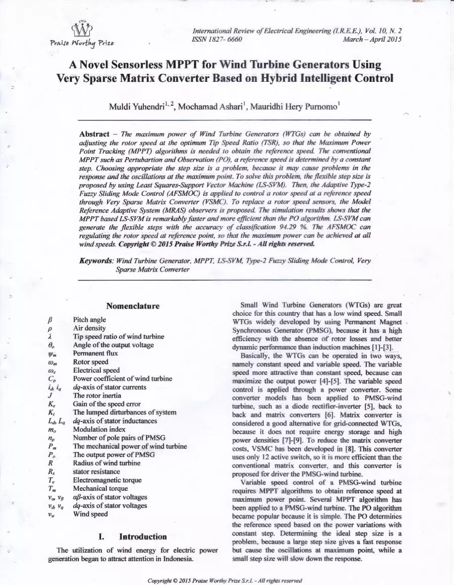
Fig. ll(a) shows that a LS-SVM can generate aflexible step size at all wind speed variations, while a P0algorifhm gen€rate a constant step. The flexible step sizein LS-SVM gives a fbst response, as sholrn in Fig. 11(b).
The reference speed of MPPT based IS-SVM can
following the reference values at all wind speed, whilethe PO algorithm consumes too much time to reach thereference point especially at the extreme change of windspeed. This can be seen in Fig. 1 1(b) at 3 seconds to 3.5
seconds. For starting conditions, the reference speed ofMPPT based LS-SVM can achieve the maximum point in0.22 seconds, while refe,rgnce speed of MPPT based POalgorithrn achieve the mxinum point in 0.76 seconds
Fig. 1 1(c) shows that MPPT bas€d LS-SYM also givesbest performace to regulate the reference speed at theoptimum TSR The optimum value of TSR is 8.05. Forsteady stale condition, the maximum error of MPFIbased LS-SVM to achieve the optimum TSR is 0.66,while in PO algorithm is 2.91. It shows that the MPPTbased LS-SVM is more efficient than the MPPT based
PO algorithm. The same condition is shown by the powercoefficient, as shown in Fig. 11(d). The power coefficientof MPPT based LS-SVM more stabil at the maximumpoint than the power coefficient qf MPPT based POalgorithm.
The maximum point of power coefficient is 0-53. Theminimum power coeffrcient for steady state condition inMPPT based LS-SVM is 0.51, while in MPPT based POis 0.341. This can be seen at 3 seconds - 3.5 seconds inFig. ll(d). This condition is caused by the extremechange of wind speed from 7.5 meter/seconds to 4.2meter/seconds. The excellent performance of MPPTbased LS-SVM confirm that a LS-SVM is capable toclassifu the step size based on the change ofpower.
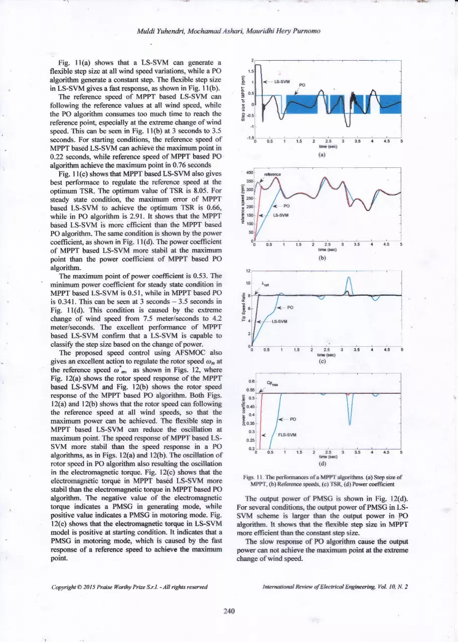
The proposed speed control using AFSMOC alsogives an excellent action to regulate the rotor speed a6 atthe reference spccd 6)*-, as shown in Figs. 12, whereFig. l2(a\ shows the rotor speed response of the ltrPTbased LS-SVM and Fig. 12ft) shows fhe rotor speedresponse of the MPPT based PO algorithm. Both Figs.12(a) and 12(b) shows that the rotor speed can followingthe reference speed at all q'ind speed& so that themaximum power can be achieved. The flexible step inMPPT based LS-SYM can reduce the oscillation atmaximum point. The speed respome of MPPT bassd LS-SVM more stabil than the speed response in a POalgorithms, as in Figs. 12(a) and l2(b). The oscillation ofrotor speed in PO algorithm also resulting the o'soillatio*in the electromagnetic torque. Fig. 12(c) shows that theeleckomagn€tic torque in MPPT based LS-SVM morestabil than the eleckomagnetie torque in MPPT based POalgorithrn. The negative value of the electromagnetictorque indicates a PMSG in generating mode, whilepositive value indicates a PMSG in motoring mode. Fig.lZ(c) shows that the elecbonragnetic torque in LS-SVMmodel is positive at starting conditian. It indicates that aPMSG in motoring modq which is criused by the ftstresponse of a reference speed to achicve the manimumpoint.
Copyright @ 2AI5 Praise Woihy PrEe S.r.l. - All rights resened
2 2.5tiftG {$e}(a)
o_6
0.55
b 0.5.o
* o.+s
, 04;R 0.36
0.25
o2
ffi'*'Figs. 1 I - The pcrformances of a MPFT algorittms. (a) Step size cf
MPPT, @) Refererrce speeds, (c) TS& (d) Porercoeffeicnt
The output power of PMSG is shown in Fig. 12(d).For several conditions, the ouQut power of FMSG in tS-SYM sclrenre is larger than tt€ output power in P0algorithm. trt shorvs that ttle flexit*e silep size in MFPTmore efficient than the constant step size.
The slow resporse of PO algmithrn cause tlre outputpower can not achievethe maximurn point atthc el@mechange ofwind speed.
E
Foc=
i!
EeE
"9&€
aF
240
Intenwrienal Review of Eleelricsl E4gineeriw, YaL 10, N.2

Muldi Yuhercdri, MochamadAshari, Mauridhi Hery Pumomo
E
P
E
s
Ez
s.!2
Eeg
2 2.5time {s€)(c)
€ -smB
= -lcin
E -1500
0.5 11.522533.544_55time (ss)(d)
Figs. 12. ThE performanc-es of an AFSMOC. (a) Tlrii rotor speed inMPPT based LS-SYM, (b) The rotor spd in MPPT based PO
algorithm, (c) The electromagnetie torque, (d) The PMSG oulput power
This can be seen at tirnes 3 seconds to 3.5 seconds. Itshows that the step size in PO algorithrn is small.
To solve this problem, the step size mrrst be increased,but it will increasing the oscillation of a speed. Theproposed speed observers by using MRAS observers has
Copyright @ 201 5 Praise l$artiry Prize S-r.1. - All rights resemed
been success to replac€ the functisn of rotor speedssnsorsi. I\,{RAS observer can estirnate the rotor speed, as
shown in Fig- l3{a)-The same condition is ot*rined for a rotor positio,n,
where the estimated rotor position can following themeasured rotor position, as shcwft in Fig. l3(b). VSMChas also been success employed for variable speed€ontrol of PMSG.
The main idea of a VSMC design is to produces avariable frequency at VSC stage, while the frequency ofCSC maintain constant at grid fiequency.
It is canied otrt by convert the gdd ac volt?gg_ tq a dsvoltage through the CSC stagq then the VSC stageconvert the DCJink voltage to the variable ac voltagewith variable frequency deperding on the referencespeed of PMSG.
Figs. 14 show the performances of a VSMC. Figs.l4{a) and 14{b} show that the frequency ofboth the gridside voltage and the grid side current are constant.Similar to the stand-alone rwtifier, the gdd current hassignificant distortion. By using srnall LC filter, thedi*ortion of the grid side current can be reduced as
shown in Fig. la@).The variable frequency at the VSC output is shown by
the stator current in Fig. l4(c).VSMC is modulated with zero dc-link curent
commutation, so that the DC-link voltage g€n€rat€d by{he CSC stage does not consist ofthe zero voltage levelsso *rc average value of ttle Dc-link voltage is nbtconstant as shown in Fig. l4(d)- It can be seen that thedc-link voltage is switching between line-to-line voltages
2 2.5lire$E)(a)
tire(€)o)
Fies. 13. The perfa@a&e$ ofMRAS observer(a) estimated rotor speed ft) rotor position
500
o
-zmL
l
-zsmL
Ee
o
o!t
€
o
o
-
o*st
-om
241
Intertptitrcl Review $Elee*icd Engineering, YoI. IA, N. 2

Muldi Yuhendri, Moehamad Ashari, Mauridhi Hery Purnomo
30
o-6zwEsroP3oEo -10Eo
-20
-30
tire(ss){a)
4.24 4.23 4.b 4.27 4.2A 4A 4.3 4-31 4.9 4.33 4.3ittime (s*)(b)
o_45 0,9 0_s5 't_05 't.1 1.15 't.2 1.25 1.3time (ss)
(c)
Figs. 14- The performanees of a VSMC- (a) grid side voltage,(b) grid side curren! (c) stator curren! (d) DC-link voltage
YIL Conelusion
Seirsorless MPFT cdntrol to obtain a maxifium powerofthe \MTGs is prop'osed by employing a VSMC.
Copyriglt @ 20 I 5 Praise Wortfu Prize S.r.l. - All rigfus resemed
Tlie maximum power of WTGs can be obtained byregulating thp rotor speed at the optimum TSR. It needs aMPPT algorithm to obtain the reference speed and thespeed controller to adjust the rotor speed at referencepoint. MPPT algorithm is developed with a flexible stepsize by using LS-SVM. Flexible step size is designed tominimize the speed oscillation at mexirnum point and so
to improve the speed r€spon. LS-SYM is desigred basedon multiclass method. The stry size is classified by I-S-SVM based on the change of power.
The rotor speed is adjusted at the reference speed byusing an AFSMOC. T2FS is applied in AF$MOe toobtain the adaptive gain of SMC, ttat can the robustressof AFSMOC against uncertainties dua parurrctervariation. Sensorless scherne is applied by using MRASobserver to replace the speed sensor.
The simulation results shows that a LS-SV|V! cangenerate the flexible step size in MPPT algorithm withthe overall accuracy of classificdion94.2f/o-
The performance of MPPT based LS-SYM is betterthan a P0 algori*m. LS-SVM can gives a fast responseand a low ryeed oseillation at maxirnurn paint. themaximurn error of MPPT based LS-SVM to achieve theoptimum TSR is 0.66, while in PO algorithm is 2.91. TheAFSMOC also gives an excellent action to regiulate therotor speed at the reference speed so tlrat the maximumpow€r can be achieved at all wind speeds.
Acknowledgements
The first aufhor acknowledges with gratitude thefinancial support of the Minisby of Research,TechnologSl and higher education oflndonesia through adoctoral research grant.
Refere*cesY. Chea P. Pillay, A. Khan, PM Wfud Generatu Topologres,IEEE Trans. Industry Applications, vol. 41, n. 6, November/December 2005, pp.1619 - 1626.Singb" N,, Agra$rdl, V., A review on power qulity erhanc€dconverter of permanent magret qFachrolous wkd generator,(2O13) Internatiowl Review € Elec:trieal Eagi*eering (IILEQ, g
(6! pp. 1681-1693.Uygun, D., Ocak" C., BuFkbicakci, 8." Desigr" andysis adexperimental verificatisri of an dici€N$ 2 kW paman*t;*agnetsynchronous generato for WP-As, (2Ol3) I*lenWioml Review ofElectrical Engtuteeing QREE),8 (2), pp. 603-607.A. lvtetnrrar- M. Tioursi, M. II#i, A. B- Stamb$tli, A YariableSptrsd Wind Gserator Marimrrn Pover Tmckiag Basd onAdaptative Neuro Fuzzy Inference Sysre;m, Expert Systems withApplicatiotn. vol. 38- 201 l. pp. 7659 -164.M, E, Ilaqre, M- Negnevitsky, K. M- Muttaqi, A Novel ControlStrategy for a YariableSped S/ihd Turbine With a PMSC,IEEE'Trans. bdwtry Aplicotiw rwl. 46, n /, JqqwylFebnnry2510, pp, 331 - 339.R. Melicio, V.M.F. Mendes, J.P,S. CdaEo, Comparative study ofpower @nvgrter tspolosies and coiltrol strategies for theharrpnic performaw of vanable-speed ra'ind turbin€ ggrratorsys$ems, Enzrgr, rol- 36, 2Q11, pg. 5ZO - 529.J. W. Kolar, T. Friedli, J, Rodriguea ard Patrick W, Review ofThrpE-Plqss PWM AC-AC CsrverEr Topologicq IWE Trms.Ittdustrial Electronics, vol. 58. n I 1.2009. pp. ,{988 - 5006.I. W. Kolar, F. Schafrneister S. D. Roud, ll Ertf Novel Three=
Iwflwttorel Review of Electrkal Engirwering, Vol. lA, N. 2
tll
rzl
t3l
t4l
4to
€-e 300go6 zooo
'ts
16l
m
o-t)4 o.tF o(b o07 0.08 0.09 o.1hm6(s)
*w *w ur tfl(d)
242
t8l

Muldi Yuhendri, MochamadAshari, Mauridhi Hery Purnomo
PiEs€ AC-AC Spane Matrix Converters, IEEE Ttons- PouterElectronics, vol. 22, n 5, September 2007,p. 1649 - 1661-
t9l M. Aner, E. Nowicki, D. Wood Employilg aVery Spa*e MatixConverter for Improved Dynamics of Grid-Connectd VariableSpeeil Small Wind Turbines, IEEE Power *rd EnergtCorferenee at Elinois (PECI), F ebruary 24-25, 2A12, Champign.Illionis USA.
[0] L- G. Gorudez; E. Figueres, G. Garcera O, Can-anza MaximumPower Point Tracking with Reduced MechaDi€l Stress Appliedto Wind Energy Conversion Systems, Applied Energt, vol. 87,
. . 2010,pp.2304=2312-tlll S. M. R Kaani, H. Goto, H. J. Guo, O. Ichinokura, A Novel
Algorifrm for Fast and Efficient Speed Sensorless MaximunoPorxer Point Tracking in Wind Energy Conversion Systems, ItE'tr'Trans. Indastrial Electranics, vol. 58, n. 1, January 201 I, pp- 29'36.
[12] W. M. Lin, C. M. Hong Intelligent Approach to Maximlm PowerPoint T:acking Control Strategy fcr Variable Sped Wind TutinsGeneration Sysflem,Energ4 rol. 35, 20l0,pp.24rr0 -2447.
[13] C- Y. Lee, P. Il Cheq Y. X. Sheq Mrudmum Power PointTrackiag (MPPT) System of Small Wind Power Generator UsingRBFNN fupmach" F,xpert Systems with Applieatiuts, wL 38,20ll,pp.12058 - 12065.
[14] H. Li, K. L. Shr, P- G- Mclarerg Nerx'al-Ndwork-BasedSensorless Maximum Wind Energy Captre With CompensatedPower Coeffrcien! IEEE Trots. Itdustry Applicatio*s, val- 41, n6, November/Decernber 2005, pp. f548 - 1556.
[15] J- A. K. Suykens, J. Yandewatle, I-east squres support vectormachine classifiery Newal Processing Leaers, val. 9, ra. 3,1999. pp. 293-3N.
[6] F. F. M. El-Sousy, Robls Wavelet Neural Ne{work Sliding ModeControl System for Permanent Magnet Synchronous Motor Drive,I ET Elect Pa oer Applicatiotts, wl. 5. n. 1, 201 I, pp. I 1 3 - I 32.
[17] Golshmi, A., Alizadeh Bidgoli, M.. Bathaee, S.M.T., Design ofopfimized slidiog mode mntrol to improve &e frrmic beluviorof PMSG wind turbfure with NFC track-to-back converter, (2O13)
Interndiotnl Review of Elec'trical Engtuceing (IREE), 8 (+\, pp.117G.1180.
[18] X. Yq O, Kaynak, Sliding-Mode Control Wrdr Soft Cmputing:A Snrvey, IEEE Trans, Irdustrial Eleclronies, tol. 56, n. 9,September 2009, pp. 3275 - 3285.
[19] Q- Liang, J. M. I\{,endel, Interval Typ€-z Fuzzy Logic Systerns:Theory and Desigp, IEEE Trans. Ftpzy Sysfors, wl. 8, n 5,Oe*ober 2000, pp. 535 - 550.
[20I J, M Mendel, R. I- John, F- Liu, Interval Typ-2 Furcy Lo$eSystems Made Simple IEEE Trans. Ftwy Systems, vol. 14, n. 6,December 2006, pp. 808 - 821.
[21] V- N. Vapnik, An overriew of statistical teaning ttwry, IEEETrahs. Neural Net*orks,tol. 10, no. 5,1999, pp. 988-999.
[24 J . A- K. Suykens, J. Vandewalle, Multiclass kast squar€s supportvector machine classifiers, Inteftwtiornl Joint Cot{erence oaNeural Networks, July lG16, 1999, Washingio* DC, USA.
[23] f. V. Crestel, J. A. I( Suykens, B. Baesens, Benchmarking LS-SVM Classifiers, Mrchilie Leiwiing. YoI. 54,2ffy- W. 132.
[24] Z. Noumu, P- Honeine, C- Riehard Multi{lass Iest fuuaresClassification d Binary-Classification Complexity, StatisticelSigrul ProcessingVarfuhop, June 28-3O 2011, Nice, Frurce
[25] T. Van Gestel, J. A. K. Suykens,G . Lanckriet, Multiclass LS-SVMs: Moderated Outputs and Coding-DecodfuE Sctremes,Newal Processtrg lettefs, l/ol. 15, 2ffiz,pp.45-58.
1261 H. Ztrang, W. Shi, K Liq Fuzzy-Topolory-Integrded SupportV*tor Machine for Remotely Sensd Image Clas*ification,,IEEETrans. Georcience atd Remote Sewing, ltol- 50, No. -3, March2012, pp.85&.852.
[24 J. Brahmi, L. Kric]en, A. Ouali, A comparative study betweertlnee sensorless control stsategies for PMSG in WECS, AryliedEnergt Yol. 86, zffi9,pp. 1ffi5 - 1573.
l28l I{andi, N., Bouzi4 A., New cootrol of a doublyJd induaiongensrator of a variable speed wind turbine wilh Kutransfonnatioq (2013) hrteryational Review of Arnomalic Control(IREACO}6 {2), pp. 183-188.
[29] Sundeep, S., Madhusudhana Rao, G., Sa*ar Rarn" 8.V., A,nANN control of maxfunum power point tracking for gridconnwted wind machi*es, (2il14) Interwtiorwl Review of
Copyrisrt @ 2015 Praise Worthy Prize S-r-1. - All righx resened
Automatic Control 6nnico),7 (ll pp. 52-59.
t30l charedaghi, F., Jamali, H., Derysi, M., Khalili, A., Maximumpower pornt Facking of variable speed wind gcneration systemconnected to Permanent Magnet Synchronous generator, (2011)Iftlenwtiotd Revtew on Mdetrling and Silmlations (IREI.fOS), 4(3) pp. 1044-1049.
[31] Karein. A-,A., Mansor, MB., Support vector machfure for MPPTefrciency improvement in photovoltaic syst6r, (2013)Inenatiarcl Rcview qf,4utonattc Carrrral (IREACA), 5 {2), pp.177-182-
[34 Li, Y-, M4 P.. Yr4 L-, LS-SVM soft sensrng based on hybridpmticle swum optimizatiorq (m1\ Inenaiorul Review onCompuen md $twoe (IRECOS} 7 (l\, pp. 2$489.
Authols' inform*tionrDepartment of Etetrical EngftE€ring; Institut Telnologi Sepuluh
Nopember GfS), Surabaya- Indonesia
zDepartrnen of Electrical Engineering. Universitas Negeri PadangPadang- Indonesia.
Mddi Ych€dri rwsiv€d bachelor degree fromUniversitas f.Ieg€ri Padarg GJNP), Padane;ldonesia in 2ff)5. He received M.T, dere€fiom k*6trd T&rologi Sepuhft Nope*ber
$iB (lTS). Surabaya l-n&nesia in 2009, and he isfj currentlV worklr€ towards the Dr. degree in
el*trical e,*rgireerirg &rfii Institr$ Telkrologi
renewable energy and inte[igeil system.
Moclemed Aslrri received hchelor degreq&om Irstiht T€knologi Sepuluh ){opernber
{n$, Suabaya Indonesia ia 1990. He rwivedfdEng. atd Ph.D. degres froen CurtinUniversity of Teclnrologr, Fertb, Arsalia in,2001 and 20Oa, rcspective$- He has joined ITSin t99O ard has b€eri a kofecldr sini:e 2009.His pimry 'r€sffirch inte&sts are pow€r
el*tronic, renewable energy, power quality and clrives.
Meuridhi fftry Pnraomo recsivcd bachelor&gr€€ from bstih* T€larologi SepuluhNopember GfS} Surahaya Indonesia in 1985.
IJe received M,Frg,, and Ph.D- degrees fromOsaka Crty tlniversity, Osaka Japan in 1995,6d 19y7, rcspetively. He hes joined ITS in1985 snd hs be& a Pra&ssor since 2004- Hiscun€r* int€r* fuclude irtelligent system
cpcration, control ardapplications. eleolric poyrer sysemsmBrsgement. He is aIEEE lvbrnbcr.
243
Inerm$omlReview of Electieal YoL 10, N. 2


