Embed Size (px)
Citation preview

Universal Model
THIS MICRO CHLORINE GENERATOR CREATES A TOTALLY REJUVENATING SPA AND PLUNGE POOL EXPERIENCE.
INSTRUCTION MANUAL
This manual is for:
PIXIE RP10 MODELSERP10H (Euro model)
RP10TH (Universal model
with timer)
RP10QTH (With battery
backup)
2
DISCLAIMER
• While every eff ort has been made to ensure that the information contained in this guide is accurate and
complete, no liability can be accepted for any errors or omissions.
• Australian Innovative Systems Pty Ltd (AIS Water) reserves the right to change the specifi cations of the
hardware and software described herein at any time without prior notice.
• No part of this guide may be reproduced, transmitted, transcribed, stored in a retrieval system, or
translated into any language in any form, by any means, without the prior written permission of Australian
Innovative Systems Pty Ltd.
• Australian Innovative Systems makes no warranties for damages resulting from lack of supply of chlorine
due to a mistaken operation or malfunction of the chlorine generator or use of non-genuine replacement
parts.
TRADEMARK ACKNOWLEDGEMENTS
Pixie™ is a trademark of Australian Innovative Systems Pty Ltd.
USE OF GENUINE AUSTRALIAN INNOVATIVE SYSTEMS REPLACEMENT PARTS IS RECOMMENDED.
This product is designed to perform optimally when used with genuine Australian Innovative Systems
replacement parts. Australian Innovative Systems Pty Ltd shall not be liable for any damages to this product
caused by the use of non-genuine replacement parts (e.g. electrode). Please note that this warranty does
not apply to repairs arising out of the malfunction of non-genuine replacement parts, although you may
request such repairs on a chargeable basis.
PURCHASED FROM:
PURCHASED DATE:
NOTE: Proof of purchase / installation is required for warranty claims. Please keep your records in a safe place.
3
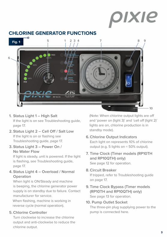
CHLORINE GENERATOR FUNCTIONS
6
5 1 2 3 4 7 8 9
10
1. Status Light 1 – High SaltIf the light is on see Troubleshooting guide,
page 17.
2. Status Light 2 – Cell Off / Salt LowIf the light is on or fl ashing see
Troubleshooting guide, page 17.
3. Status Light 3 – Power On / No Water Flow
If light is steady, unit is powered. If the light
is fl ashing, see Troubleshooting guide,
page 17.
4. Status Light 4 – Overload / Normal Operation
When light is ON/Steady and machine
is beeping, the chlorine generator power
supply is on standby due to failure. Contact
manufacturer for service.
When fl ashing, machine is working in
reverse cycle (normal operation).
5. Chlorine Controller Turn clockwise to increase the chlorine
output and anti-clockwise to reduce the
chlorine output.
(Note: When chlorine output lights are off
and ‘power on (light 3)’ and ‘cell off (light 2)’
lights are on, chlorine production is in
standby mode).
6. Chlorine Output Indicators Each light on represents 10% of chlorine
output (e.g. 5 lights on = 50% output).
7. Time Clock (Timer models (RP10TH and RP10QTH) only) See page 12 for operation.
8. Circuit Breaker If tripped, refer to Troubleshooting guide
on page 17.
9. Time Clock Bypass (Timer models (RP10TH and RP10QTH) only) See page 13 for operation.
10. Pump Outlet Socket The three-pin plug supplying power to the
pump is connected here.
Fig. 1
4
THE PIXIE™ SALTWATER CHLORINATION SYSTEM
Congratulations on your choice of a Pixie™ saltwater chlorinator system for your swimming
pool. The Pixie™ saltwater chlorinator you have purchased is designed for easy and simplistic
operation and maintenance. By following these instructions, you are assured years of trouble-
free operation.
These instructions have been compiled and produced to help you get the maximum results
from your unit and to assist you to fully understand and correctly operate your Pixie™ saltwater
chlorinator.
Please take the time to read these instructions thoroughly before attempting to operate your
unit. Should you require additional information or further assistance, please do not hesitate to
contact your local Pixie™ representative or visit our website www.aiswater.com.au.
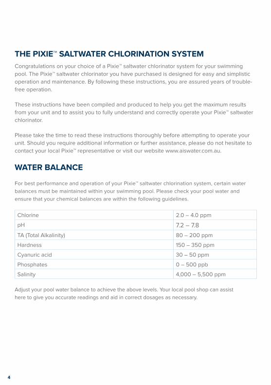
WATER BALANCE
For best performance and operation of your Pixie™ saltwater chlorination system, certain water
balances must be maintained within your swimming pool. Please check your pool water and
ensure that your chemical balances are within the following guidelines.
Adjust your pool water balance to achieve the above levels. Your local pool shop can assist
here to give you accurate readings and aid in correct dosages as necessary.
Chlorine 2.0 – 4.0 ppm
pH 7.2 – 7.8
TA (Total Alkalinity) 80 – 200 ppm
Hardness 150 – 350 ppm
Cyanuric acid 30 – 50 ppm
Phosphates 0 – 500 ppb
Salinity 4,000 – 5,500 ppm
5
CHLORINE GENERATOR INSTALLATION
FITTING THE CHLORINATOR CELL HOUSING
The Pixie™ cell housing must be plumbed into the return line of the pool fi lter system after the
fi lter and any diversion valves. Please refer to the installation diagram for the correct method of
installation (Fig. 3) and note installation of a gas trap below (Fig. 2).
In situations where a heater is incorporated, the Pixie™ housing must be installed after or in
parallel to the heater. Should a solar heating system be installed, the housing must be plumbed
after the solar diverters and before the heated water rejoins the main pool return line.
Please note that your cell housing has been manufactured so that 40 mm PVC pipe will fi t both
inlet and outlet ports internally, and 50 mm couplings will fi t externally. This allows the use of
either 40 mm or 50 mm PVC pipes in the pool return line.
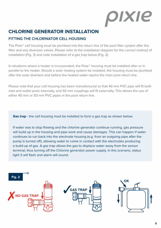
GAS TRAPNO GAS TRAP
OK
Gas trap - the cell housing must be installed to form a gas trap as shown below.
If water was to stop fl owing and the chlorine generator continue running, gas pressure
will build up in the housing and pipe work and cause damages. This can happen if water
continues to run back into the electrode housing (e.g. from an outgoing pipe after the
pump is turned off ), allowing water to come in contact with the electrodes producing
a build-up of gas. A gas trap allows the gas to displace water away from the sensor
terminal, thus turning off the Chlorine generator power supply. In this scenario, status
light 3 will fl ash and alarm will sound.
Fig. 2
6
4
5
3
1
2
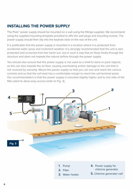
INSTALLING THE POWER SUPPLY
The Pixie™ power supply should be mounted on a wall using the fi ttings supplied. We recommend
using the supplied mounting template provided to affi x the wall plugs and mounting screws. The
power supply should then slip into the keyhole slots on the rear of the unit.
It is preferable that the power supply is mounted in a location where it is protected from
accidental water spray and inclement weather. It is strongly recommended that the unit is also
protected and screened from the harsh sun, but in such a way that air fl ows freely through the
structure and does not impede the natural airfl ow through the power supply.
You should also ensure that the power supply is not used as a shelf to store or pack objects,
as this can also impede the air fl ow, causing overheating and/or damage to the unit that is
not covered by warranty. Mount the power supply so that you can see and reach the various
controls and so that the cell lead has a comfortable margin to reach the cell terminal posts.
Our recommendation is that the power supply is mounted slightly higher and to one side of the
fi lter plant to allow easy access (refer to Fig. 3).
1. Pump
2. Filter
3. Water heater
4. Power supply for chlorine generator
5. Chlorine generator cell
Fig. 3
7
RAISING THE SALINITY OF A NEW POOL
For best results the salt concentration in the pool water is required to be within an average
range of approximately 4,000 to 5,500 parts per million (ppm). These fi gures are temperature
dependant. In summertime, as water temperatures rise, salt levels may require slight reduction
while in wintertime the reverse may be true to allow optimum performance of your unit.
Calculate the water volume of your pool as follows: average length x average width x average
depth in metres. Multiply this answer by 4. The answer is the amount of salt in kilograms you
need to add to increase the salinity of your pool from fresh water to above 4,000 ppm (the
recommended minimum salinity level for this chlorine generator).
Using only refi ned swimming pool salt add the desired quantity to the swimming pool water.
To assist in the rapid dissolving and mixing, sweep or brush the solids until they are fully
dissolved. Undissolved salt may result in staining your pool fi nish.
As salt is heavier than water it will continue to lie at the deepest point of your pool, even
though the salt granules themselves have fully dissolved. In order to ensure adequate and
permanent distribution of salt throughout the pool water, we recommend additional sweeping
and fi lter operation over a 12 – 24 hour period. Ensure that salt is totally dissolved before
commencing chlorinator operation.
How to raise salinity from existing levels
To raise salinity, take the diff erence between the desired level and current level of
salinity, divide by 1000 and multiply by known pool volume. The fi gure is the amount of
salt in kg needed to raise to the desired level.
For example:
Current level: 3200 ppm
Desired: 5000 ppm
Pool volume: 50 m3
5000 – 3200 = 1800,
1800/1000 x 50 = 90kg of salt
8
GENERAL CHLORINATOR OPERATION
Before switching on your Pixie™ saltwater chlorination system please ensure that you have
added the correct amount of pool salt, it has fully dissolved and is distributed throughout the
pool water. Ensure that the base pool chemistry is at the recommended levels and the pool
water is clean and crystal clear (see Water Balance Section).
With the main circulation pump plugged into the pump outlet (Fig 1, item 10), switch on Pixie
and set switch to bypass (Fig 1, item 9) . At this point the Pixie™ electronic display may register
a water flow fault as the cell housing fills with water and an alarm (beeping) may activate. This
is normal start up procedure and will cease as soon as the unit registers full and correct water
flow throughout the electrodes.
With the chlorine controller knob (Fig. 1, item 5) now turned fully clockwise to the maximum
position the green chlorine output indicator lights will illuminate one after the other. With the
correct amount of salt added to the pool water you should achieve a 100% (ten lights) reading.
In this position the Pixie™ chlorinator is producing maximum chlorine output.
Chlorine demand will differ from pool to pool due to bather load, water temperature or weather
conditions and this must be taken into consideration. By testing for chlorine residuals on a
regular basis you will quickly determine the chlorine state of your pool and what action you
need to take to adjust it if required.
After determining your pool’s chlorine needs, you can set the controller to the desired setting
to achieve your chlorine requirements and/or adjust your daily running times. Normally once
set, these controls do not require further adjustment except perhaps for the seasonal ones
suggested earlier.
Set your chlorine controller to achieve maximum and optimum results for your pool situation.
Please remember that an over chlorinated pool is not a healthy pool, so it may not be
necessary for you to run your chlorinator at maximum output to maintain recommended
chlorine levels.
Your Pixie™ saltwater chlorinator is fitted with a sophisticated electronic circuit board which
is designed to minimise the need for manual operations and maximise cell life by constantly
managing the correct operation of the power supply and electrolytic cell. In addition to the four
warning lights, a warning alarm (beeper) has been installed to alert you of any problems that
the electronic monitoring system has interpreted. The alarm will activate to alert you to any
problems that have been detected, and once rectified the unit will resume normal operations.
9
CHLORINATOR RUNNING TIMES
Chlorinator running times will vary from pool to pool and are dependent upon the situation
they are installed into, pool size and the overall usage of the pool in general. We recommend 2
hours break for every 4 hours of operation to prolong life of the power supply. The chlorinator
should not be run for more than 10 hours continuously. It is recommended not to operate unit
during the hottest part of the day and is preferable to run in early morning or late afternoon to
evening.
Several factors will determine the operational time of the chlorinator to be able to produce
sufficient chlorine for your pool’s requirements:
TIME: The longer you run your filter plant and chlorinator, the more chlorine you will produce.
RATE: The higher the chlorine output indicator lights up; the more chlorine is being produced.
CELL CLEANLINESS: The cleaner the cell, the better the chlorine production rate.
BASIC POOL CHEMISTRY: The more correctly maintained, the less chlorine waste.
SUNLIGHT: UV exposure reduces chlorine levels.
POWER SUPPLY CONTROL FUNCTIONS
Your Pixie™ saltwater chlorination system has been designed for simplistic operation and
control. The functions and controls (both standard and optional) and their various operations
will give you a greater understanding and knowledge of the control and maintenance of both
your Pixie™ unit and your pool (refer to Fig. 1 for controls).
CHLORINE CONTROLLER
(FIG. 1, ITEM 5)
The chlorine controller regulates the amount of chlorine production relevant to the position
it has been set to. By adjusting the chlorine controller clockwise, you increase chlorine
manufacture and by turning anti clockwise, you reduce production. Do not attempt to turn
the controller beyond its stops as this could cause damage to your unit that is not covered by
warranty.

10
CHLORINE OUTPUT INDICATOR(FIG. 1, ITEM 6)
Your power supply is fi tted with ten green indicator lights set in an arc shaped formation.
During operation of your chlorinator these lights will illuminate relevant to the degree at which
the chlorine controls have been adjusted. Working in conjunction with the chlorine controller
you can increase or decrease chlorine output to suit your pool’s requirements. As you increase
the output (by turning the control knob clockwise) the corresponding lights will illuminate
progressively to 100% (ten lights).
You have full control of chlorine production by adjusting the chlorine controller and illuminating
the number of lights to satisfy your chlorine demand. Each light represents 10% of capable
chlorine production up to its maximum output of 100% (ten lights).
STATUS INDICATOR LIGHTS(FIG. 1, ITEMS 1, 2, 3, 4)
There are four (4) status indicator lights located on the front of your chlorinator. These advise
at a glance the status of the chlorinator power supply and, when illuminated they indicate and
advise about the situation that the chlorinator’s electronic monitoring system has detected. The
lights and their functions are listed below.
When illuminated this indicates that you have exceeded recommended salt levels. As long
as this is not causing your chlorinator to overload no further action or reduction of salt
concentration is required at this point. No further salt should be added if this light is illuminated.
STEADY – When illuminated in a STEADY continuous light your chlorine production has been
switched off by turning the chlorine controller anti clockwise and your chlorinator power supply
is now in a standby mode. Turn the chlorine controller clockwise to resume normal operation.
FLASHING – If the light is illuminated and FLASHING the monitoring system has detected low
salt levels and this will need to be adjusted for the chlorinator to operate at maximum capacity.
This light will also fl ash if the cell has reached a point where its output is below the normal
operating output. Please refer to the section detailing the addition of salt to your pool.
STEADY Power onFLASHING No Water Flow
STEADYCell o�FLASHING Salt low
SALT HIGHERTHAN NECESSARYNo action required
STEADYOverloadFLASHING Normal operation
RP10QTHRP10TH
STEADY Power onFLASHING No Water Flow
STEADYCell o�FLASHING Salt low
SALT HIGHERTHAN NECESSARYNo action required
STEADYOverloadFLASHING Normal operation
STEADY Power onFLASHING No Water Flow
STEADYCell o�FLASHING Salt low
SALT HIGHERTHAN NECESSARYNo action required
STEADYOverloadFLASHING Normal operation
RP10QTHRP10TH
STEADY Power onFLASHING No Water Flow
STEADYCell o�FLASHING Salt low
SALT HIGHERTHAN NECESSARYNo action required
STEADYOverloadFLASHING Normal operation
11
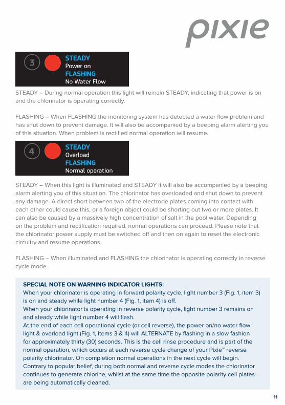
STEADY – During normal operation this light will remain STEADY, indicating that power is on
and the chlorinator is operating correctly.
FLASHING – When FLASHING the monitoring system has detected a water fl ow problem and
has shut down to prevent damage. It will also be accompanied by a beeping alarm alerting you
of this situation. When problem is rectifi ed normal operation will resume.
STEADY – When this light is illuminated and STEADY it will also be accompanied by a beeping
alarm alerting you of this situation. The chlorinator has overloaded and shut down to prevent
any damage. A direct short between two of the electrode plates coming into contact with
each other could cause this, or a foreign object could be shorting out two or more plates. It
can also be caused by a massively high concentration of salt in the pool water. Depending
on the problem and rectifi cation required, normal operations can proceed. Please note that
the chlorinator power supply must be switched off and then on again to reset the electronic
circuitry and resume operations.
FLASHING – When illuminated and FLASHING the chlorinator is operating correctly in reverse
cycle mode.
SPECIAL NOTE ON WARNING INDICATOR LIGHTS:
When your chlorinator is operating in forward polarity cycle, light number 3 (Fig. 1, item 3)
is on and steady while light number 4 (Fig. 1, item 4) is off .
When your chlorinator is operating in reverse polarity cycle, light number 3 remains on
and steady while light number 4 will fl ash.
At the end of each cell operational cycle (or cell reverse), the power on/no water fl ow
light & overload light (Fig. 1, Items 3 & 4) will ALTERNATE by fl ashing in a slow fashion
for approximately thirty (30) seconds. This is the cell rinse procedure and is part of the
normal operation, which occurs at each reverse cycle change of your Pixie™ reverse
polarity chlorinator. On completion normal operations in the next cycle will begin.
Contrary to popular belief, during both normal and reverse cycle modes the chlorinator
continues to generate chlorine, whilst at the same time the opposite polarity cell plates
are being automatically cleaned.
STEADY Power onFLASHING No Water Flow
STEADYCell o�FLASHING Salt low
SALT HIGHERTHAN NECESSARYNo action required
STEADYOverloadFLASHING Normal operation
RP10QTHRP10TH
STEADY Power onFLASHING No Water Flow
STEADYCell o�FLASHING Salt low
SALT HIGHERTHAN NECESSARYNo action required
STEADYOverloadFLASHING Normal operation
STEADY Power onFLASHING No Water Flow
STEADYCell o�FLASHING Salt low
SALT HIGHERTHAN NECESSARYNo action required
STEADYOverloadFLASHING Normal operation
RP10QTHRP10TH
STEADY Power onFLASHING No Water Flow
STEADYCell o�FLASHING Salt low
SALT HIGHERTHAN NECESSARYNo action required
STEADYOverloadFLASHING Normal operation
12
CIRCUIT BREAKER
The circuit breaker is designed to trip out in the event of a power surge or power overload.
When tripped the centre button will pop out shutting down the unit to prevent damage. To
reset, depress circuit breaker until a click is heard.
ON/OFF SWITCH – ERP10H MODEL ONLY
The on/off switch is located on the front panel and has been incorporated to allow you to
switch off the chlorinator function should you so desire. Please note that this switch will only
shut down the chlorinator operation. It will not aff ect the normal fi lter functions.
PUMP OUTPUT SOCKET – RP10TH and RP10QTH MODELS ONLY
A 240-volt pump output power socket is supplied and located on the right-hand underside of
the power supply. Your pool pump power supply lead should be plugged into this socket so
that when the time clock switches at your designated times both the saltwater chlorinator and
pool pump will activate in unison.
Do not attempt to operate the chlorinator power supply with the pool pump lead disconnected
as this will lead to a gas build-up inside the cell housing causing it to overheat resulting in
damage to your chlorinator equipment that is not covered by warranty. In extreme cases gas
build-up may also cause the cell housing to rupture and explode, as it is not built to withstand
this type of pressure, possibly resulting in personal injury.
The pump socket is designed to operate a single pool pump of maximum 8A only. Do not
attempt to operate any equipment other than your pool pump from this socket as damage
might occur to the power supply unit that is not covered under warranty.
TIME CLOCK OPERATIONS (RP10TH AND RP10QTH MODELS ONLY)(FIG. 1, ITEM 7)
The standard timer (Grässlin model FM/1 Stuz) is designed to switch your equipment on and off
at the nominated times.
Your timer has a standard clock face and hands set in the centre section, whilst the outer grey
bezel shows the hours in military style (24 hour) time. To set the clock to present time, place
your fi nger on the outer grey bezel and slowly turn it clockwise to the desired time.
SPECIAL NOTE ON TIMERS – RP10QTH Quartz Battery Backup model
If you require your Pixie™ saltwater chlorinator to be connected to a cheaper off -peak
tariff , we recommend the use of an appropriate quartz time clock for that purpose.
The unit may also be hard wired in, however, in case of incorrect wiring or damage
caused by modifi cations warranty will be void.
The Pixie™ RP10QTH (with battery backup) is available lieu of the standard model to allow
time of day to be maintained when power supply is interrupted.
13
Start and stop times are set by pushing the black pins out for on and inward for off. For
example, to turn the chlorinator on between 6 pm and 10 pm, push all the pins outwards
between 18 and 22. The remainder of the pins should be pushed inwards. With the elements
pushed outwards the timer will turn your equipment on when they reach the black indicators.
With the elements pushed in the timer will turn your equipment off during those times.
If you switch off the unit and pump during its timer cycle by interrupting the supply of power via
the power point or isolation switch, please remember to reset the time clock to present time
when you reconnect unit to power (RP10TH – without quartz battery backup only).
TIMER BYPASS SWITCH (RP10TH AND RP10QTH MODELS ONLY) (FIG. 1, ITEM 9)
On Pixie™ models fitted with a timer, a timer bypass switch will be found on the right-hand side
of the time clock. This switch allows you to bypass timer functions.
Three functions are available:
TIMER:
The time clock will automatically switch your pool equipment on or off at your designated
times.
OFF:
The time clock will not switch, but normal time will be maintained.
BYPASS:
The clock has bypassed all designated functions and will operate pool equipment indefinitely.
PLEASE NOTE: Return switch to ‘timer’ position after using the ‘off’ or ‘by-pass’ functions.
14
Step 3Step 1 Step 2
MAINTENANCE
ELECTRODE INSPECTION:
Pixie™ has a reverse polarity feature which reduces electrode cleaning. Regular inspection of
the electrode is recommended.
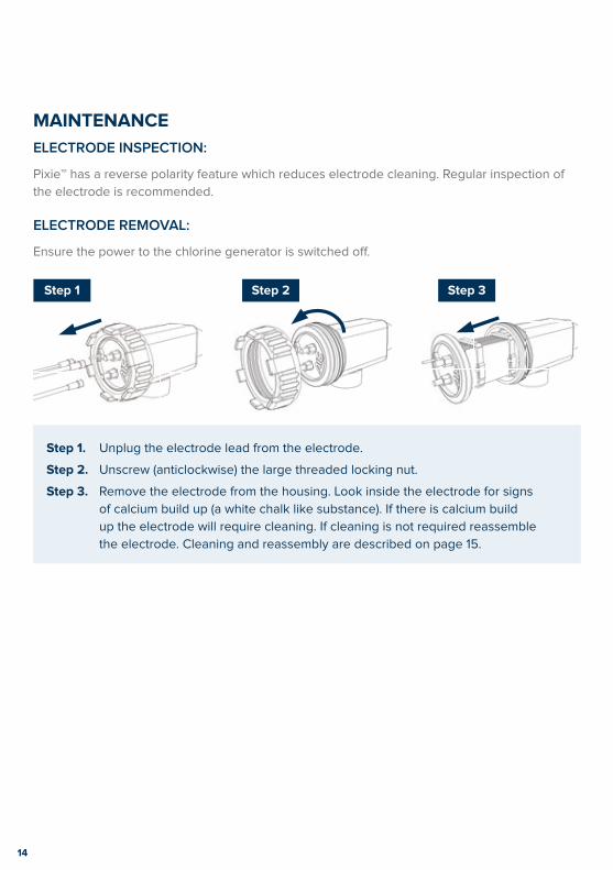
ELECTRODE REMOVAL:
Ensure the power to the chlorine generator is switched off .
Step 1. Unplug the electrode lead from the electrode.
Step 2. Unscrew (anticlockwise) the large threaded locking nut.
Step 3. Remove the electrode from the housing. Look inside the electrode for signs
of calcium build up (a white chalk like substance). If there is calcium build
up the electrode will require cleaning. If cleaning is not required reassemble
the electrode. Cleaning and reassembly are described on page 15.
15
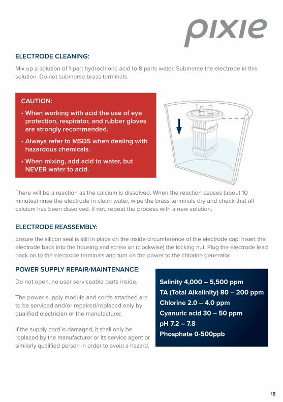
ELECTRODE CLEANING:
Mix up a solution of 1-part hydrochloric acid to 8 parts water. Submerse the electrode in this
solution. Do not submerse brass terminals.
There will be a reaction as the calcium is dissolved. When the reaction ceases (about 10
minutes) rinse the electrode in clean water, wipe the brass terminals dry and check that all
calcium has been dissolved. If not, repeat the process with a new solution.
ELECTRODE REASSEMBLY:
Ensure the silicon seal is still in place on the inside circumference of the electrode cap. Insert the
electrode back into the housing and screw on (clockwise) the locking nut. Plug the electrode lead
back on to the electrode terminals and turn on the power to the chlorine generator.
POWER SUPPLY REPAIR/MAINTENANCE:
Do not open, no user serviceable parts inside.
The power supply module and cords attached are
to be serviced and/or repaired/replaced only by
qualifi ed electrician or the manufacturer.
If the supply cord is damaged, it shall only be
replaced by the manufacturer or its service agent or
similarly qualifi ed person in order to avoid a hazard.
Salinity 4,000 – 5,500 ppm
TA (Total Alkalinity) 80 – 200 ppm
Chlorine 2.0 – 4.0 ppm
Cyanuric acid 30 – 50 ppm
pH 7.2 – 7.8
Phosphate 0-500ppb
CAUTION:
• When working with acid the use of eye protection, respirator, and rubber gloves are strongly recommended.
• Always refer to MSDS when dealing with hazardous chemicals.
• When mixing, add acid to water, but NEVER water to acid.
16
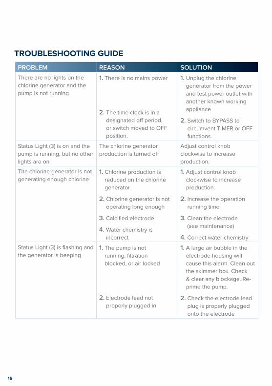
TROUBLESHOOTING GUIDE
PROBLEM REASON SOLUTION
There are no lights on the
chlorine generator and the
pump is not running
1. There is no mains power
2. The time clock is in a
designated off period,
or switch moved to OFF
position.
1. Unplug the chlorine
generator from the power
and test power outlet with
another known working
appliance
2. Switch to BYPASS to
circumvent TIMER or OFF
functions.
Status Light (3) is on and the
pump is running, but no other
lights are on
The chlorine generator
production is turned off
Adjust control knob
clockwise to increase
production.
The chlorine generator is not
generating enough chlorine1. Chlorine production is
reduced on the chlorine
generator.
2. Chlorine generator is not
operating long enough
3. Calcified electrode
4. Water chemistry is
incorrect
1. Adjust control knob
clockwise to increase
production.
2. Increase the operation
running time
3. Clean the electrode
(see maintenance)
4. Correct water chemistry
Status Light (3) is flashing and
the generator is beeping1. The pump is not
running, filtration
blocked, or air locked
2. Electrode lead not
properly plugged in
1. A large air bubble in the
electrode housing will
cause this alarm. Clean out
the skimmer box. Check
& clear any blockage. Re-
prime the pump.
2. Check the electrode lead
plug is properly plugged
onto the electrode
17
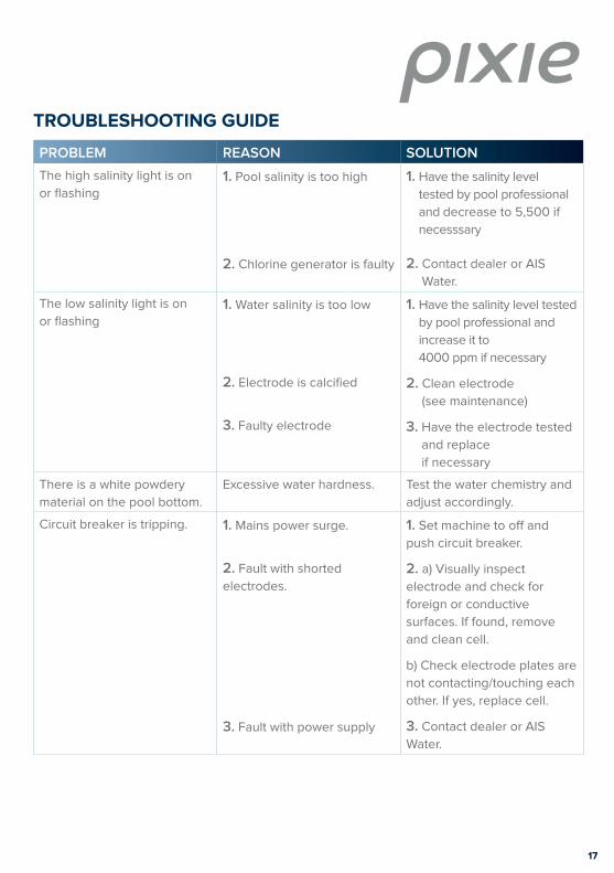
PROBLEM REASON SOLUTION
The high salinity light is on
or flashing1. Pool salinity is too high
2. Chlorine generator is faulty
1. Have the salinity level
tested by pool professional
and decrease to 5,500 if
necesssary
2. Contact dealer or AIS
Water.
The low salinity light is on
or flashing1. Water salinity is too low
2. Electrode is calcified
3. Faulty electrode
1. Have the salinity level tested
by pool professional and
increase it to
4000 ppm if necessary
2. Clean electrode
(see maintenance)
3. Have the electrode tested
and replace
if necessary
There is a white powdery
material on the pool bottom.
Excessive water hardness. Test the water chemistry and
adjust accordingly.
Circuit breaker is tripping. 1. Mains power surge.
2. Fault with shorted
electrodes.
3. Fault with power supply
1. Set machine to off and
push circuit breaker.
2. a) Visually inspect
electrode and check for
foreign or conductive
surfaces. If found, remove
and clean cell.
b) Check electrode plates are
not contacting/touching each
other. If yes, replace cell.
3. Contact dealer or AIS
Water.
TROUBLESHOOTING GUIDE
18
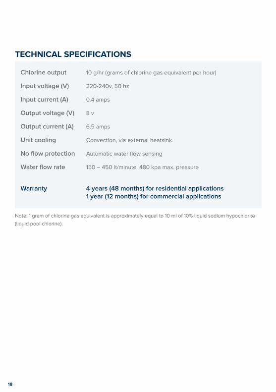
TECHNICAL SPECIFICATIONS
Chlorine output 10 g/hr (grams of chlorine gas equivalent per hour)
Input voltage (V) 220-240v, 50 hz
Input current (A) 0.4 amps
Output voltage (V) 8 v
Output current (A) 6.5 amps
Unit cooling Convection, via external heatsink
No fl ow protection Automatic water fl ow sensing
Water fl ow rate 150 – 450 lt/minute. 480 kpa max. pressure
Warranty 4 years (48 months) for residential applications 1 year (12 months) for commercial applications
Note: 1 gram of chlorine gas equivalent is approximately equal to 10 ml of 10% liquid sodium hypochlorite
(liquid pool chlorine).
19
WARRANTYYour Pixie™ chlorine generator is covered by a forty-eight (48) month in-factory repair warranty,
on all parts and labour, from the date of purchase. This warranty applies to the original
purchaser and is not transferable.
All chlorine generators are fully tested prior to being packed. If within 48 months of purchase
a problem occurs due to faulty workmanship or components, AIS Water will (at their discretion)
repair or replace the chlorine generator.
The manufacturer will not be liable for any consequential loss or damage caused by operation
outside the prescribed limits as outlined in the instruction manual, incorrect installation,
connection to an incorrect mains power supply, changes to internal wiring, misuse, abuse,
negligence, accidental damage, normal wear and tear, or damage caused by water entry.
Note: This warranty is strictly in-factory repair. In the case of failure, the complete unit
must be returned to the manufacturer or their designated agent. All forward and return costs
are the responsibility of the owner.
CONTACT DETAILS
In the unlikely event of a problem with your chlorine generator, please contact:
Warranty Hotline: 1800 676 076
Online warranty aiswater.com.au and go to: Support – Warranty Requests.
For assistance outside of the warranty period: call +61 7 3396 5222
Your local dealer:
For international warranty claims: Please contact your local dealer.

aiswater.com.au Enhancing life
AIS ContactsHead Office +61 7 3396 5222
51 Millennium Place, Tingalpa, Queensland 4173 Australia
Email: [email protected]
Facsimile +61 7 3393 3441
WARRANTY HOTLINE 1800 676 076 (Australia wide)
Scan any AIS Water logo to learn “Why choose AIS?” AR


