Embed Size (px)
Citation preview
A Portable Analyzer for Pouch-Actuated, ImmunoassayCassettes
Xianbo Qiu, Changchun Liu, Michael G. Mauk, Robert W. Hart, Dafeng Chen, Jing Qiu,Terry Kientz, Jonathan Fiene, and Haim H. Bau1
Department of Mechanical Engineering and Applied Mechanics, University of Pennsylvania, 220S. 33rd St., Philadelphia, PA 19104
AbstractA portable, small footprint, light, general purpose analyzer (processor) to control the flow inimmunoassay cassettes and to facilitate the detection of test results is described. The durableanalyzer accepts disposable cassettes that contain pouches and reaction chambers for various unitoperations such as hydration of dry reagents, stirring, and incubation. The analyzer includesindividually controlled, linear actuators to compress the pouches in the cassette, which facilitatesthe pumping and mixing of sample and reagents, and to close diaphragm-based valves for flowcontrol. The same types of actuators are used to compress pouches and actuate valves. Theanalyzer also houses a compact OEM scanner/reader to excite fluorescence and detect emissionfrom labels. The analyzer is hydraulically isolated from the cassette, reducing the possibility ofcross-contamination. The analyzer facilitates programmable, automated execution of a sequence ofoperations such as pumping and valving in a timely fashion, reducing the level of expertiserequired from the operator and the possibility for errors. The analyzer’s design is modular andexpandable to accommodate cassettes of various complexities and additional functionalities. Inthis paper, the utility of the analyzer has been demonstrated with the execution of a simple,consecutive, lateral flow assay of a model biological system and the test results were detected withup converting phosphor labels that are excited at infrared frequencies and emit in the visiblespectrum.
KeywordsPoint of Care Test; Immunoassay; Lateral Flow (LF); Microfluidic Cassette; Pouch; PortableAnalyzer; Processor; Linear Actuator
1. IntroductionIn recent years, there has been a growing interest in carrying out various diagnosticprocedures outside the lab at the point of testing. This trend has been motivated by, amongother things, the desire (i) to bring sophisticated diagnostic capabilities to remote areas,where both clinical laboratories and trained personnel are in short supply or non-existent; (ii)to reduce the time delay from test to answer to enable health care providers and other
© 2011 Elsevier B.V. All rights reserved.1Corresponding author: [email protected]'s Disclaimer: This is a PDF file of an unedited manuscript that has been accepted for publication. As a service to ourcustomers we are providing this early version of the manuscript. The manuscript will undergo copyediting, typesetting, and review ofthe resulting proof before it is published in its final citable form. Please note that during the production process errors may bediscovered which could affect the content, and all legal disclaimers that apply to the journal pertain.
NIH Public AccessAuthor ManuscriptSens Actuators B Chem. Author manuscript; available in PMC 2012 December 15.
Published in final edited form as:Sens Actuators B Chem. 2011 December 15; 160(1): 1529–1535. doi:10.1016/j.snb.2011.08.012.
NIH
-PA Author Manuscript
NIH
-PA Author Manuscript
NIH
-PA Author Manuscript

authorities to make informed and timely decisions; (iii) to reduce cost; (iv) to facilitatepersonalized medicine and administer care based on individual needs rather than accordingto rigid protocols; (v) to enhance privacy; and (vi) to improve public health and safety. As aresult, various “kits” for field tests have evolved, ranging from pregnancy tests to HIVantibody detection.
Lateral flow strips (dipsticks) are often used to detect the presence of antigens andantibodies to various pathogens [1, 2]. The popularity of lateral flow assays stems from theirsimplicity, reliability, low cost, and ability to operate without any instrumentation. Briefly,the lateral flow strip (made of a porous substrate) is functionalized with one or more capturelines of immobilized proteins (ligands) designed to bind with target molecules in the sampleand a control line used to assure that the sample has, indeed, migrated up the strip and thatthe labels (reporters) have not degraded. The user brings the lateral flow strip in contact withthe raw sample or a mixture of sample and buffer (diluent). The sample or mixture then iswicked along the lateral flow strip by capillary forces. Along its path, the sample hydrateslabels (i.e., reporter particles such as gold) that are dry-stored on the lateral flow strip, and itinteracts with the immobilized ligands at the test line(s) and the control line. The lateral flowtest can operate either as a sandwich assay [3] or a competitive assay [4]. In some cases,gold conjugate labels are used, and the test results can be read by eye without any instrument[5]. In other cases, labels such as fluorophores, quantum dots, and phosphor particles, whichrequire optical excitation at specific wavelengths and whose signal is detected with either aphotomultiplier or with a camera, are used [6]. Instrument-based detection often provideshigher sensitivity and consistency of the signal, facilitates quantification, and enables one tomaintain permanent records [7].
The main advantage of the lateral flow assay is that it can operate without any externalpumps and/or flow control. Lateral flow assays suffer, however, from certain disadvantages[2, 8–10], such as non-specific binding, high background signal, inability to undergostringent washes to remove unbound material, lack of control of the sample’s volume, andlow binding capacity at the test line(s). As a result, the performance of lateral flowimmunoassays falls short of that of centralized laboratory equipment, and lateral flow stripimmunoassays are generally limited to screening applications [8, 9].
In an effort to improve the performance of point of care immunoassays, a few researchersmodified the classical lateral flow protocol and employed a consecutive flow format [11].To improve sensitivity, the consecutive flow format employs a wash step. Additionally, tofacilitate multiplexing and reduce cost, non-specific reporter particles are occasionally used.As a result, the sample cannot be premixed with reporter particles as is done in the standardlateral flow assay. Instead, the sample must migrate up the strip without interacting with thereporter particles. The target analytes are captured at the test line(s). The strip is then loadedwith wash buffer to remove any non-specific bound proteins, and then it is finally loadedwith the labeling reagents [12]. These operations either must be carried out manually, whichmakes them prone to operator error, or executed with an instrument capable of judiciouslyflowing the reagents needed for the consecutive flow format at the appropriate sequence andtimes.
As an alternative to lateral flow assays, several groups have opted to use microbeads as theimmobilization medium. Bead - based assays are attractive due to the availability of a richlibrary of beads with various functionalizations. In one embodiment, many differentlyfunctionalized, bar-coded beads were distributed randomly in an array and used toconcurrently detect multiple analytes [13, 14]. In another embodiment, beads with variousfunctionalizations were placed at predetermined positions to allow for multiplexing [15, 16].Porous beads, such as agarose beads, are particularly attractive since they have a large
Qiu et al. Page 2
Sens Actuators B Chem. Author manuscript; available in PMC 2012 December 15.
NIH
-PA Author Manuscript
NIH
-PA Author Manuscript
NIH
-PA Author Manuscript

surface area to volume ratio and provide a high density of binding sites, which improvesassay sensitivity [15, 16]. In contrast to the lateral flow assays, most, if not all, of the bead-based assays require means to induce fluid flow and effectuate flow control.
One commonly used technique to facilitate flow control in immunoassay cassettes is throughthe use of pouches (blisters) and diaphragm-based valves [14, 17]. The pouches can be filledeither with the buffers needed for the process at hand or with air. In the latter case, inoperation, the air-filled pouches are connected to liquid storage chambers. Whencompressed, the pouches displace buffer from a storage compartment. A pouch-based fluidpropulsion strategy is attractive for point of care devices since it allows one to store all thereagents in the disposable cassette and avoids any liquid contact between the cassette andthe analyzer. In practice, this means that a generic analyzer can drive multiple types ofcassettes, and there is no possibility of cross-contamination. Moreover, a single analyzer canoperate with different types of cassettes designed to detect different targets.
In simple cases, the pouches can be actuated manually. Qiu et al [14] describe a manually-controlled immunoassay cassette in which the pouches are compressed by finger. To preventan operator’s error and improve test consistency, however, it may be desirable to automatethe process. To this end, Liu et al. [18] describe a spring-loaded, mechanically-driven, timeractuator capable of actuating pouches sequentially. The timer actuator does not require anyelectrical power. Unfortunately, the timer-actuator can actuate only a relatively smallnumber of pouches, and the sequence of operations is implemented in hardware and cannotbe readily changed. To reduce the limitation on the number of actuators and to increasedevice flexibility (by allowing software-control of the sequence of operations), we describehere a portable, fully automated analyzer (processor) comprised of an array of linearactuators that serve to compress pouches and diaphragm valves. The sequence and timing ofthe various operations are controlled with software and can be altered from one type ofcassette to another. Thus, the same analyzer can serve to process various types of cassettesand diagnose a variety of target molecules.
To make the ideas involved more concrete, we demonstrate the use of the analyzer in onerelatively simple, specific application of a consecutive flow assay. The consecutive flowprotocol requires sample premixing with lateral flow buffer, wash, and reporter loadingsteps. The wash step removes non-specific bound substances from the detection zone of thelateral flow strip. The reporter particles are loaded only in the last step. In our assay, weutilize upconverting phosphor conjugates (UCP) [19–22] as reporter particles. UCPs areexcited by long wavelength radiation and emit at shorter wavelengths. In contrast, almost allnatural phosphorescence phenomena emit at a wavelength larger than the excitationwavelength. As a result, UCPs are free of background emission. The UCP labels do notbleach, and they provide a permanent record. Since the UCP labels are excited in the infrared (IR), we equipped our analyzer with a reader that can excite the labels at the appropriatewavelengths and detect the resulting emission. The reader transverses along the lateral flowstrip to obtain a scan of the emitted signal as a function of position.
2. Analyzer DesignTo better understand the tasks required of the analyzer, we briefly introduce the variousoperations carried out by the immunoassay cassette. In the interest of space, we describe arelatively simple immunoassay cassette with lateral flow detection operating in aconsecutive flow format. For additional details on various pouch actuated devices, see Liu etal [18], Qiu et al [14], and Chen et al. [17]. We then provide a brief description of theanalyzer.
Qiu et al. Page 3
Sens Actuators B Chem. Author manuscript; available in PMC 2012 December 15.
NIH
-PA Author Manuscript
NIH
-PA Author Manuscript
NIH
-PA Author Manuscript

2.1 The Microfluidic Cassette and ImmunoassayThe immunoassay cassettes (94 mm × 59 mm × 6 mm) are prototyped in a polycarbonate(PC) sheet with a computer-numerical controlled (CNC) milling machine (Haas MillingOM-2A, Haas Automation Inc., Oxnard, CA). The assembled cassette is featured in Fig. 1[18]. The cassette incorporates air pouches that when depressed provide a pneumatic forceto drive the pre-stored liquid reagents through the microfluidic circuit. A pouch is depressedby applying force through a ball actuator to a flexible film that covers the pouch, such thatair inside the pouch is expelled into the channels of the microfluidic circuit to propel a liquidcharge (Fig. 1, (b)). The air pouch wells are formed by machining hemispherical cavities(using a ball-end mill) into the topside of the polycarbonate substrate that hosts themicrofluidic circuit. A 100 μm thick, flexible, natural latex rubber film (McMaster-Carr,New Brunswick, NJ) cap layer is then attached to the cassette body with double-sidedadhesive tape (McMaster-Carr, New Brunswick, NJ) to seal the well [18]. Alternatively,pouches can be capped by thermally bonding a thin (~100 μm), flexible film (TPS-4049B,Tolas Inc., Feasterville, PA) to the surface of the polyethylene [14].
The force needed to compress the pouches was measured by placing weights on the pouches.We estimate that a force of about 3 N is needed to completely compress each latex rubberfilm pouch. The flow rate of the fluids in the cassette was adjusted by controlling the speedof the actuator (which, in turn, controlled the speed of the pouch’s compression). As a result,the flow rates of the reagents were independent of their rheological properties.
The timed sequence of operations in the cassette consists of:
1. Sample loading
2. Mixing of the sample with a lateral flow buffer and ejection of the mixture onto thelateral flow strip
3. After a two minute wait (to avoid flooding the lateral flow strip), ejection of washsolution onto the lateral flow strip
4. After another two minute wait, ejection of solution, laden with UCP labels, onto thestrip
5. After about a 10–30 minute wait, reading of the signal emitted by the labels
Fig. 2 is a schematic of the consecutive flow, lateral flow assay. The lateral flow strip ismade with nitrocellulose. The strip is mated with a sample loading pad at its upstream endand an absorbent pad on the downstream end. Ligands are immobilized along linestransverse to the strip to form a “test line” and a “control line.” The test line containsimmobilized ligands (avidin in our case) specific to the target analyte. The control line ismade with ligands that bind to the reporter particles.
The operation and sensitivity of the analyzer were assessed using a dilution series of 305-bphaptenized PCR amplicon from B. Cereus that served as the test target. As is evident, inaddition to assaying antigens and antibodies, the lateral flow assay can also be used to detectconjugated PCR amplicons. The PCR products that serve as the target analyte werefunctionalized, via the primers, at one end with biotin and at the opposite end withDigoxigenin (DIG) hapten. The nitrocellulose lateral flow strip is striped with a test line ofimmobilized avidin to capture biotin-labeled target analyte and with a control line ofimmobilized goat anti-mouse IgG antibody to capture any unbound, anti-DIG coated, UCPreporter particles.
The sequence of operations of the consecutive flow strip assay is as follows (see Fig. 2). Thediluted sample with the labeled amplicon is loaded on the strip, where it is captured at the
Qiu et al. Page 4
Sens Actuators B Chem. Author manuscript; available in PMC 2012 December 15.
NIH
-PA Author Manuscript
NIH
-PA Author Manuscript
NIH
-PA Author Manuscript

test line. The strip is then washed by loading it with buffer. Next the strip is loaded with asuspension of anti-DIG-coated, UCP particles. The UCP particles migrate up the strip andbind to the DNA target molecules functionalized with DIG and captured at the test line.UCP particles which were not captured by the target molecules at the test line continue tothe control line, where they are immobilized through the anti-DIG binding with the stripedanti-mouse IgG antibody.
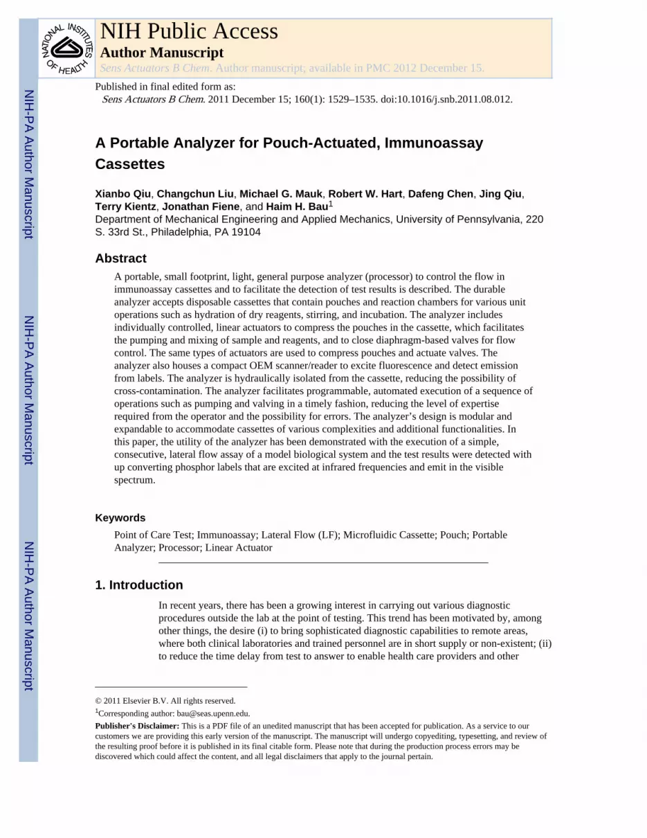
2.2 Instrument Design and OperationFig. 3 shows the portable, custom-made analyzer (190 mm × 100 mm × 80 mm) with itscover removed and an immunoassay cassette inserted in the analyzer’s drawer. The portableanalyzer is controlled with a PIC microcontroller (PIC18F45K20-I/PT, MicrochipTechnology Inc, Chandler, Arizona). The analyzer houses four low-voltage, stepper motordrivers (A3906, Allegro MicroSystems Inc., Massachusetts), which power three linearactuators (15000 series linear stepper motors, Haydon Kerk, CT) that perform the operationsrequired for the lateral flow assay. Each actuator is capable of providing up to 7 N of force,which far exceeds the 3 N of force that is needed to compress the pouch.
A compact, OEM type, UCP reader (72 mm × 47 mm × 18 mm, FLUO SENS integrated,ESE GmbH, Germany), driven by a linear actuator (15000 series linear stepper motors,Haydon Kerk, CT), is used to scan the strip. A USB to serial UART interfacing component(FT232R, Future Technology Devices International Limited, Glasgow, United Kingdom)enables the analyzer to communicate with a computer via a USB port.
The analyzer contains a pull-out drawer that houses the cassette (Fig. 3). The drawer isshaped to position and self-align the cassette to assure that, when closed, the actuators willbe positioned directly over their corresponding pouches and the lateral flow strip is alignedwith the reader’s path. Once the analyzer is powered on and the “start button” pressed, asmall LCD module lights up and displays instructions for the user.
Figure 4 depicts schematically the linear actuator with an affixed actuation ball used todepress the pouch membranes of the chip. Once the actuation ball moves down, it isprogrammed to stay down during the entire duration of the assay to prevent any reagentsfrom being sucked back into the channel and pouch. At the conclusion of the test, all theactuators return to their home positions. The linear actuator consists of a miniature, 15mmdiameter stepper motor with a linear step increment of 0.00079″ (0.02 mm) per step. Thecompact size of the actuators (installed in an upright position in the instrument) allowsconsiderable latitude in positioning the pouches on the cassette. When needed, an array ofmany actuators can be accommodated with a relatively small footprint. The flow rate isregulated by the speed of movement of the actuator.
Each actuator is controlled in an open-loop mode. A custom “home position” sensor,consisting of an electric switch, was constructed to identify the position of the motor. SeeFig. 5. The switch is triggered by the linear motor itself. Once the linear motor returns to itshome position, the switch closes and grounds the resistor (R). The resulting signal is sent tothe microcontroller as an interruption signal. This interruption signal clues themicrocontroller to turn off the power to the linear actuator.
To facilitate mixing, the analyzer compresses two pouches simultaneously. One pouchcontrols the sample flow and the other pouch controls the lateral buffer flow. The two fluidsflow concurrently through the zigzag path machined in the cassette (Fig. 1a). The bends inthe zigzag conduit induce secondary flows that enhance mixing. The performance of themixer was evaluated in Li et al [18]. The principles of operation of mixers that utilize bendsto induce secondary flows are described in Yi et al [23].
Qiu et al. Page 5
Sens Actuators B Chem. Author manuscript; available in PMC 2012 December 15.
NIH
-PA Author Manuscript
NIH
-PA Author Manuscript
NIH
-PA Author Manuscript

After the various reagents have been discharged onto the lateral flow strip, the system waitsabout thirty minutes to allow for the liquids and reagents to wick up the strip and interactwith the test and control lines and for the UCP labels to dry. Then, the optical reader scansthe strip. A linear actuator drives the reader at a constant speed along the lateral flow strip ata velocity of 0.67 mm/s. To minimize the scanning time, only the part of the strip’s length(~7 mm) that includes both the test line and the control line is scanned. The optical reader(FLUO SENS) uses the Modbus ASCII communication protocol. During the scan, thedetection data (1500 data points) is stored in the reader’s flash memory.
Custom software was written with Visual C++ 6.0 (Microsoft) to retrieve and process thecollected data from the reader. A Butterworth low-pass filter was used to eliminate highfrequency noise and to smooth the signal. The cut-off frequency of the low-pass filter wasdetermined based on a Fast Fourier Transform of the unprocessed data. The correlationbetween the signal and the reader’s position along the strip was determined based on thescanning range and the sequential position of the data points in the data stream. The signalintensity data is displayed on the computer screen as a function of position along the strip.The areas (Fig. 6) under the test peak and the control peak are calculated and their ratio isdisplayed.
The analyzer’s power consumption is less than 1W. This power is needed only for relativelyshort amounts of time. We estimate that the analyzer’s energy consumption is about 0.01 W-h per assay. If desired, the analyzer can be operated with a standard 9 V battery, whichtypically stores over 5 W-h of energy.
3. Procedure and MaterialsExperiments were carried out in parallel with our instrument and manually (for comparison)on a bench top. The bench top, LF-immunoassay protocol consisted of three steps: (i) 10 μLof sample was mixed with 40 μL of LF buffer, and then blotted onto the LF strip; (ii) aftertwo minutes, 20 μL of LF buffer was blotted onto the strip to carry away any unboundanalyte; and (iii) two minutes later, 60 μL of LF buffer laden with 60 ng of UCP conjugate[18] were added to the LF strip to label the immunoassay. After thirty minutes of incubation,the lateral flow strip was scanned with an UCP optical reader (OraSure UPLink, OraSureTechnologies, Bethlehem, PA). The same protocol was implemented in the automatedmicrofluidic assay. In the latter case, all the reagents were pre-stored in the cassette in liquidform.
The nitrocellulose LF strips were supplied by OraSure Technologies, Inc., (Bethlehem, PA).The LF buffer consisted of 100 mM HEPES (pH 7.2), 270 mM NaCl, 0.5% (v/v) Tween-20,and 1% (w/v) BSA. The immunolabeling buffer was a mixture of LF buffer with mouseanti-dig antibodies-conjugated UCP reporter particles for haptenized DNA.
The DNA samples were produced by lysing B. cereus cells (ATTC, Culture Type 6464,designation NRS 210), isolating the (genomic) DNA with a QIAGEN DNeasy™ Tissue Kit(QIAGEN Inc., Valencia, CA 91355), and using the eluted genomic DNA as the PCRtemplate. The PCR reagents were 50 mM Tris-HCl (pH 9.0), 1.5–3.5 mM MgCl2, 200 μMdNTP, and 0.1 μg/μL BSA. The forward and reverse primers used at 0.3 μM were,respectively, (5′-TCT CGC TTC ACT ATT CCC AAG T-3′) and (5′-AAG GTT CAA AAGATG GTA TTC AGG-3′). At the 5′-end, the forward and reverse primers were, respectively,provided with a Biotin (Bio) and a Digoxinenin (DIG) hapten. The primers targeted a 305 bpDNA fragment with 5′-digoxigenin (DIG) hapten on one strand and a 5′-biotin (Bio) haptenon the opposite strand [22]. The haptenized DNA concentration of the initial PCR productswas determined using an Infinite® 200 PRO series plate reader (Tecan Group Ltd.,
Qiu et al. Page 6
Sens Actuators B Chem. Author manuscript; available in PMC 2012 December 15.
NIH
-PA Author Manuscript
NIH
-PA Author Manuscript
NIH
-PA Author Manuscript

Switzerland) with a Quant-iT™ PicoGreen assay (Invitrogen Corporation, Carlsbad,California). The test samples contained 0 ng, 0.03 ng, 0.3 ng, 3 ng, and 30 ng of B. cereusDNA amplicon in 10 μl of water.
4. ResultsFirst, to evaluate the sensitivity of the detector and to compare the performances of thedetector with that of a commercially available machine, the lateral flow assay was carriedout manually on a benchtop and the lateral flow strip was scanned both with our portableanalyzer and a commercial Uplink IR (OraSure) laser reader.
Fig. 6 shows representative chromatograms of the detection results as obtained with ourdetector (top) and the UPLink analyzer (bottom). Fig. 6a depicts the signal intensities (inarbitrary units) as functions of position along the strip. The words “Test” and “Control” inFig. 6a denote, respectively, the test and control peaks. The area under the test peak isproportional to the amount of captured target analyte. The presence of a control peakindicates that the labels have migrated up the lateral flow strip. The sample in Fig. 6acontains 0.3 ng of DNA. In both cases, the test peak is clearly visible above the backgroundlevel. In the case of our analyzer, the test peak is about 2.5 times the background level.
The tests were repeated with various analyte concentrations. Fig. 6b depicts the ratio of theareas under the test and the control peaks as a function of target concentration. The darkblack and gray bars correspond, respectively, to results obtained with the UpLink (OraSure)scanner and with our analyzer. The error bars indicate the scatter of the data (n=3). In thecase of our analyzer, all the operations were carried out by the analyzer. As the mass of theDNA in the sample increases, the area of the test peak increased and the area of the controlpeak decreased. As the DNA mass increase, more labels are consumed to form the sandwichat the test line and fewer labels are available to bind at the control line. When the sample’smass was smaller than 0.3 ng, our analyzer did not detect any test peak. Although theUpLink detected a test peak even when the mass of the target molecules was smaller than0.3 ng, the area of the peak was insensitive to the target analyte concentration. In fact, theUpLink provided similar ratios of test to control peaks in the presence of 0.03 ng DNA andin the absence of DNA. Thus, one may conclude that the limits of detection of our analyzerand that of the OraSure scanner are approximately 0.3 ng of target DNA.
When the mass of the DNA in the sample was greater than 0.3 ng, the ratios of the test peakarea and the control peak area detected with our anaylyzer were comparable to thoseobtained with the UpLink device. When the DNA mass is between 0.3 and 30 ng, the ratioof the test and control peak areas is nearly proportional to the analyte concentration.
Next, the lateral flow assay was carried out in the microfluidic cassettes with our portableanalyzer. Fig. 7 depicts representative chromatograms of negative (no target), low positive(0.3 ng) and high positive (30 ng) samples. The negative signal yielded no test peak and alarge control peak. The low positive sample yielded moderately high test and control peaks.The high positive sample yielded a high test peak and a low control peak. The tests wererepeated several times (n=3) with similar results. The results indicate that target analyte assmall as 0.3 ng can be detected with our microfluidic diagnostics system and that the ratio ofthe areas of the test and control peaks can provide a rough estimate of target analyteconcentration.
In our previous work, we used a timer actuator to control the processes in the cassette [18].The timer actuator has the advantage that it does not require any electric power and is lessexpensive than the electronic processor. However, in the timer actuator, the sequence andtiming of operations are implemented in hardware during the manufacturing process and
Qiu et al. Page 7
Sens Actuators B Chem. Author manuscript; available in PMC 2012 December 15.
NIH
-PA Author Manuscript
NIH
-PA Author Manuscript
NIH
-PA Author Manuscript

cannot be changed. In contrast, the electronic actuator/processor described in this paper canbe reprogrammed at any time. Thus, the electronic device has much greater flexibilitycompared to the mechanical device described in Liu et al. [18].
6. Conclusions and OutlookA new integrated, portable analyzer/processor for operating microfluidic immunoassaycassettes utilizing up-converting phosphor reporters has been developed. The portableanalyzer was realized by combining miniature, independently-controlled actuators with acompact optical reader. The actuators’ sequence and timing of operations are controlled bysoftware. Thus, the actuators’ array can be configured to accommodate different types ofmicrofluidic chips. This ability to conveniently alter the sequence and timing of operationswas not available in our earlier mechanical processor, in which the “program” was cast inhardware [18].
The pouch-based cassette design (with pre-loaded reagents) and the portable analyzerdescribed here facilitate fully automated operation. To demonstrate the analyzer’s operation,we augmented the performance of the lateral flow immunoassay by adding the capability ofa consecutive flow format. The architecture of the analyzer is flexible and can be expandedto include additional functions. Similar analyzers can be used to carry out immunoassayswith bead-based cassettes of the types described in Qiu et al [14] and Thompson et al [16].Similar design rules can be applied to construct significantly more complex processor. Infact, in subsequent work, using similar design concepts as the ones described in this paper,we developed a device for nucleic acid processing capable, among other things, of isolatingand purifying nucleic acids from samples laden with bacteria and viruses and carrying outthermal cycling – based enzymatic amplification (PCR) [24].
The compact actuator/analyzer unit is portable and can be powered, if desired, by a standard9 V battery. The analyzer can be interfaced with a laptop computer, cell phone, GPS unit,and a barcode reader to identify the cassette and customize operations as appropriate for thetarget(s) coded in the barcode. By this means, test data can be automatically matched withtime and date of test, geographic location of the test, patient identification, and demographicdata. Test results and other data can be analyzed in situ as well as communicated over anetwork or wirelessly.
The analyzer provided performance comparable to that of benchtop procedures. The abilityto carry out relatively sophisticated diagnostics with devices that can be operated byunskilled personnel in the field as part of an interconnected healthcare network may assist intracking and stemming epidemics, especially in resource-poor areas lacking laboratoryfacilities. Similar devices can also be used in the clinic to facilitate individualized medicineand at home to enable one to adjust medication regimens according to individual needsrather than follow rigid protocols.
AcknowledgmentsThe work was supported by NIH/NIDCR Grant U01DE017855.
References1. Liu L, Peng C, Jin Z, Xu C. Development and evaluation of a rapid lateral flow
immunochromatographic strip assay for screening 19-nortestosterone. Biomed Chromatogr. 2007;21:861–866. [PubMed: 17428018]
Qiu et al. Page 8
Sens Actuators B Chem. Author manuscript; available in PMC 2012 December 15.
NIH
-PA Author Manuscript
NIH
-PA Author Manuscript
NIH
-PA Author Manuscript

2. Posthuma-Trumpie GA, Korf J, Amerongen Av. Lateral flow (immuno) assay: its strengths,weaknesses, opportunities and threats. A literature survey. Anal Bioanal Chem. 2009; 393:569–582.[PubMed: 18696055]
3. Qian S, Bau HH. A mathematical model of lateral flow bio-reactions applied to sandwich assays.Anal Biochem. 2003; 322:89–98. [PubMed: 14705784]
4. Qian S, Bau HH. Analysis of lateral flow bio-detectors: competitive format. Anal Biochem. 2004;326:211–224. [PubMed: 15003562]
5. Wang S, Zhang C, Wang J, Zhang Y. Development of colloidal gold-based flow-through andlateral-flow immunoassays for the rapid detection of the insecticide carbaryl. Anal Chim Acta.2005; 546:161–166.
6. Li Z, Wang Y, Wang J, Tang Z, Pounds JG, Lin Y. Rapid and sensitive detection of proteinbiomarker using a portable fluorescence biosensor based on quantum dots and a lateral flow teststrip. Anal Chem. 2010; 82:7008–7014. [PubMed: 20704391]
7. Kim S, Park JK. Development of a test strip reader for a lateral flow membrane-basedimmunochromatographic assay. Biotech and Biopro Eng. 2004; 9:127–131.
8. Bonenberger J, Doumanas M. Overcoming sensitivity limitations of lateral-flow immunoassays witha novel labeling technique. IVD Tech. May.2006
9. O’Farrell B, Bauer J. Developing highly sensitive, more reproducible lateral-flow assays, part 2:new challenges with new approaches. IVD Tech. July.2006
10. Peruski AH, Peruski LF Jr. Immunological methods for detection and identification of infectiousagents and biological warfare agents. Clin and Diag Lab Immunol. 2003; 10:506–513.
11. Corstjens PLAM, Chen Z, Zuiderwijk M, Bau HH, Abrams WR, Malamud D, Niedbala RS, TankeHJ. Rapid assay format for multiplex detection of humoral immune responses to infectious diseasepathogens (HIV, HCV, and TB). Ann N Y Acad Sci. 2007; 1098:437–445. [PubMed: 17435148]
12. Schubert-Ullrich P, Rudolf J, Ansari P, Galler B, Führer M, Molinelli A, Baumgartner S.Commercialized rapid immunoanalytical tests for determination of allergenic food proteins: anoverview. Anal Bioanal Chem. 2009; 395:69–81. [PubMed: 19308361]
13. Walt DR. Chemistry miniature analytical methods for medical diagnostics. Sci. 2005; 308:217–219.
14. Qiu X, Thompson JA, Chen Z, Liu C, Chen D, Ramprasad S, Mauk MG, Ongagna S, Barber C,Abrams WR, Malamud D, Corstjens PLAM, Bau HH. Finger-actuated, self-containedimmunoassay cassettes. Biomed Microdevices. 2009; 11:1175–1186. [PubMed: 19597994]
15. Kirby R, Cho EJ, Gehrke B, Bayer T, Park YS, Neikirk DP, McDevitt JT, Ellington AD. Aptamer-based sensor arrays for the detection and quantitation of proteins. Anal Chem. 2004; 76:4066–4075. [PubMed: 15253644]
16. Thompson JA, Bau HH. Microfluidic, bead-based assay: theory and experiments. J of ChromatogrB. 2010; 878:228–236.
17. Chen D, Mauk MG, Qiu X, Liu C, Kim J, Ramprasad S, Ongagna S, Abrams WR, Malamud D,Corstjens PLAM, Bau HH. An integrated microfluidic cassette for isolation, amplification, anddetection of nucleic acids. Biomed Microdevices. 2010; 12:705–19. [PubMed: 20401537]
18. Liu C, Qiu X, Ongagna S, Chen D, Chen Z, Abrams WR, Corstjens PL, Bau HH. A timer-actuatedimmunoassay cassette for detecting molecular markers in oral fluids. Lab Chip. 2009; 9:768–776.[PubMed: 19255658]
19. Corstjens PLAM, Zuiderwijk M, Tanke HJ, van der Ploeg-Schip J, Ottenhoff THM, Geluk A. Auser-friendly, highly sensitive assay to detect the IFN-γ secretion by T cells. Clin Biochem. 2008;6:440–444. [PubMed: 18201564]
20. Rijke, Fvd; Zijlmans, H.; Li, S.; Vail, T.; Raap, AK.; Niedbala, RS.; Tanke, HJ. Up-convertingphosphor reporters for nucleic acid microarrays. Nat Biotech. 2001; 19:273–276.
21. Li JJ, Ouellette AL, Giovangrandi L, Cooper DE, Ricco AJ, Kovacs GTA. Optical scanner forimmunoassays with up-converting phosphorescent labels. IEEE Trans on Biomed Eng. 2008;55:1560–1571.
22. Wang J, Chen Z, Corstjens PLAM, Mauk MG, Bau HH. A disposable microfluidic cassette forDNA amplification and detection. Lab Chip. 2006; 6:46–53. [PubMed: 16372068]
Qiu et al. Page 9
Sens Actuators B Chem. Author manuscript; available in PMC 2012 December 15.
NIH
-PA Author Manuscript
NIH
-PA Author Manuscript
NIH
-PA Author Manuscript

23. Yi M, Bau HH. The Kinematics of Bend-Induced Mixing in Micro-Conduits. International Journalof Heat and Fluid Flow. 2003; 24:645–656.
24. Qiu X, Chen D, Liu C, Mauk MG, Kientz T, Bau HH. A Portable, Integrated Analyzer forMicrofluidic - Based Molecular Analysis. accepted for publication in Biomedical Microdevices.201110.1007/s10544-011-9551–5
BiographiesXianbo Qiu received his PhD degree in Electrical Engineering from the Department ofAutomation, Shanghai Jiao Tong University, Shanghai, China in 2006. He was a ResearchFellow at the University of Pennsylvania from 2006 to 2011. He is currently an AssociateProfessor at the National Institute of Diagnostics and Vaccine Development in InfectiousDiseases, School of Public Health, Xiamen University. His main research interests includebiomedical instrumentation and microfluidic chips for point-of-care diagnostics.
Changchun Liu received his PhD degree in Electrical Engineering from the Institute ofElectronics, Chinese Academy of Sciences (IECAS), Beijing, China in 2005. Currently, heis a Research Associate at the Department of Mechanical Engineering and AppliedMechanics, University of Pennsylvania. His research interest focuses on the microfluidicchips, biosensors and BioMEMS devices for point-of-care diagnostics.
Michael G. Mauk has a PhD in Electrical Engineering from the University of Delaware(USA). He is a Researcher at the Univ. of Pennsylvania with an interest in developingmicrofluidic point of care diagnostics devices for infectious diseases.
Robert W. Hart studied biomedical engineering at Drexel University, USA, and receivedhis PhD in 2010. At the time of publication, he was carrying out postdoctoral training at theUniversity of Pennsylvania. He is currently a principal scientist at Optofluidics, Inc.,(Philadelphia PA) where he develops microfluidic and photonic devices.
Dafeng Chen received his PhD in Mechanical Engineering from Nanyang TechnologicalUniversity, Singapore in 2007. He was a Research Fellow at the University of Pennsylvaniafrom 2007 to 2010. His main research interests include microfluidics devices, BioMEMS,and Point of Care diagnostics.
Jing Qiu studied biology at New York University and received her M.S. degree in 2010.She is currently a researcher at the Cold Spring Harbor Laboratory studying breast cancerfocusing on the influence of chemotherapy on tumor-associated myeloid cells in the tumormicroenvironment.
Terry Kientz received his B.S. in Electrical Engineering from the University of Connecticutin 1989. He is currently a Control Systems Engineer that specializes in the development ofautomation systems for the water filtration industry.
Jonathan Fiene received his B.S. in Mechanical Engineering from the University ofNevada, Las Vegas in 2001 and his Master and Ph.D. in Mechanical Engineering fromStanford University in 2003 and 2007, respectively. He is currently a Senior Lecturer in theMechanical Engineering and Applied Mechanics Department at the University ofPennsylvania where he focuses on mechanical design, fabrication, robotics, andmechatronics.
Haim H. Bau received his PhD in Mechanical Engineering from Cornell University, Ithaca,NY, in 1980. He is currently a Professor of Mechanical Engineering and Applied Mechanics
Qiu et al. Page 10
Sens Actuators B Chem. Author manuscript; available in PMC 2012 December 15.
NIH
-PA Author Manuscript
NIH
-PA Author Manuscript
NIH
-PA Author Manuscript

at the University of Pennsylvania. His research interests are micro and nanofluidics andpoint of care diagnostics.
Qiu et al. Page 11
Sens Actuators B Chem. Author manuscript; available in PMC 2012 December 15.
NIH
-PA Author Manuscript
NIH
-PA Author Manuscript
NIH
-PA Author Manuscript

Fig. 1.(a) Microfluidic immunoassay cassette loaded with colored dyes representing the variousreagents. (b) Depressible air pouches actuate the on-board fluid as indicated in the cross-section schematics of a pouch compartment (top: pre-actuation and bottom: post-actuation).
Qiu et al. Page 12
Sens Actuators B Chem. Author manuscript; available in PMC 2012 December 15.
NIH
-PA Author Manuscript
NIH
-PA Author Manuscript
NIH
-PA Author Manuscript

Fig. 2.A schematic depiction of the sequence of operations carried out in the lateral flow (LF)assay
Qiu et al. Page 13
Sens Actuators B Chem. Author manuscript; available in PMC 2012 December 15.
NIH
-PA Author Manuscript
NIH
-PA Author Manuscript
NIH
-PA Author Manuscript
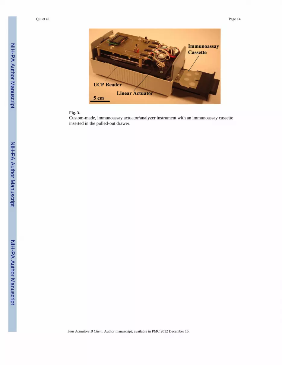
Fig. 3.Custom-made, immunoassay actuator/analyzer instrument with an immunoassay cassetteinserted in the pulled-out drawer.
Qiu et al. Page 14
Sens Actuators B Chem. Author manuscript; available in PMC 2012 December 15.
NIH
-PA Author Manuscript
NIH
-PA Author Manuscript
NIH
-PA Author Manuscript

Fig. 4.Linear actuator for depression pouch membranes
Qiu et al. Page 15
Sens Actuators B Chem. Author manuscript; available in PMC 2012 December 15.
NIH
-PA Author Manuscript
NIH
-PA Author Manuscript
NIH
-PA Author Manuscript

Fig. 5.Home position reset sensor
Qiu et al. Page 16
Sens Actuators B Chem. Author manuscript; available in PMC 2012 December 15.
NIH
-PA Author Manuscript
NIH
-PA Author Manuscript
NIH
-PA Author Manuscript
Qiu et al. Page 17
Sens Actuators B Chem. Author manuscript; available in PMC 2012 December 15.
NIH
-PA Author Manuscript
NIH
-PA Author Manuscript
NIH
-PA Author Manuscript

Fig. 6.(a) Emission intensity, as a function of position along the strip (scan result), of a 0.3 nghaptenized DNA sample obtained with the portable analyzer (top) and with the benchtopUPLink reader (bottom). (b) The ratio between the area of the test peak and the area of thecontrol peak as a function of the target analyte’s mass. The dark black and gray barscorrespond, respectively, to results obtained with the benchtop UPLink instrument and withthe portable analyzer. The error bars indicate the scatter of the data (n=3).
Qiu et al. Page 18
Sens Actuators B Chem. Author manuscript; available in PMC 2012 December 15.
NIH
-PA Author Manuscript
NIH
-PA Author Manuscript
NIH
-PA Author Manuscript

Fig. 7.Scan result for the negative (0 ng), low positive (0.3 ng), and high positive (30 ng) samplescarried out with our portable analyzer
Qiu et al. Page 19
Sens Actuators B Chem. Author manuscript; available in PMC 2012 December 15.
NIH
-PA Author Manuscript
NIH
-PA Author Manuscript
NIH
-PA Author Manuscript