Embed Size (px)
Citation preview

A RECONFIGURABLE ELECTROMAGNETIC BANDGAP STRUCTURE
FOR A BEAM STEERING BASE STATION ANTENNA
H. Boutayeb (3), T. Brillat (2), J.P. Daniel (5), F. Gadot (1), P.Y. Garel (4), A. de Lustrac (1),
K. Mahdjoubi (3), P. Ratajczak (4), A.C. Tarot (3)
(1) IEF, Université Paris XI,UMR 22 du CNRS, Bât. 22091415 ORSAY, FRANCE
[email protected], [email protected]
(2) GEA, IUT de Ville d’Avray, Université de Paris X92410 VILLE D’AVRAY, FRANCE
(3) IETR, Université de Rennes 1, Bât 11C, Campus de Beaulieu35042 RENNES, FRANCE
[email protected], [email protected], [email protected]
(4) France Telecom R&D, Antenna Department, Fort de tete de chien06320 LA TURBIE, FRANCE
[email protected], [email protected]
(5) ADVANTEN, Germanuim, 80 avenue des Buttes de Coësmes35700 RENNES, FRANCE
INTRODUCTION
The purpose of this communication is to present the works of a French Industry and Research sponsorized project
(RNRT Project) named "BIP" [1]. The goal of this project was to design a beam steering multi-band (GSM/DCS/UMTS)
base station antenna. After a presentation of the different partners, we will show how we would solved the problem of the
beam steering antenna with a controllable Electromagnetic BandGap (EBG) structure and we will present the results of
simulations and experiments in order to validate the concept.
1. "BIP" PROJECT PRESENTATION
The RNRT project was started in 2001 with 5 partners:
• 3 french universties laboratories:
• IEF (Institut d’Electronique Fondamentale),University of PARIS XI
• GEA (Groupe d’Electronique Appliquée), University of PARIS X,
• IETR (Institut d’Electronique et de Telecommunication de Rennes), University of RENNES 1,
• Antenna Department of France Telecom R&D,
• Advanten: an antennas & radio applications compagny.
In this project, we purposed to manage the coverage (single beam or multi-beam) of a base station for mobile
communications with a reconfigurable EBG material. The use of this kind of structure for this application must solved
different problems like:
• the design of a wide or multi-band controllable EBG material
• the capabilities to control the radiation over 360° in the azimuth plane (the maximum of radiation in the
elevation plane stay in the 90° direction),
• the matching of the antenna
HomeHome
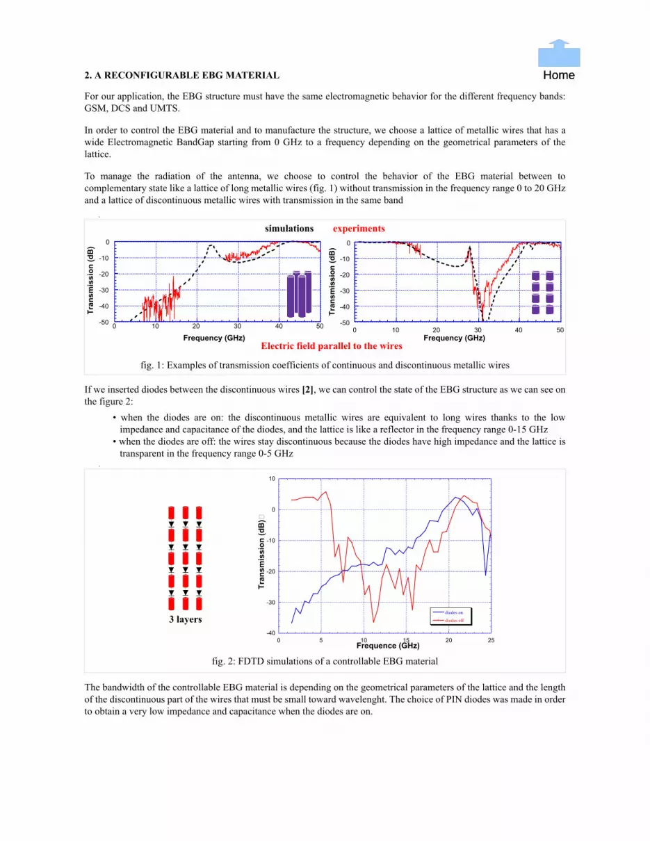
2. A RECONFIGURABLE EBG MATERIAL
For our application, the EBG structure must have the same electromagnetic behavior for the different frequency bands:
GSM, DCS and UMTS.
In order to control the EBG material and to manufacture the structure, we choose a lattice of metallic wires that has a
wide Electromagnetic BandGap starting from 0 GHz to a frequency depending on the geometrical parameters of the
lattice.
To manage the radiation of the antenna, we choose to control the behavior of the EBG material between to
complementary state like a lattice of long metallic wires (fig. 1) without transmission in the frequency range 0 to 20 GHz
and a lattice of discontinuous metallic wires with transmission in the same band
.
If we inserted diodes between the discontinuous wires [2], we can control the state of the EBG structure as we can see on
the figure 2:
• when the diodes are on: the discontinuous metallic wires are equivalent to long wires thanks to the low
impedance and capacitance of the diodes, and the lattice is like a reflector in the frequency range 0-15 GHz
• when the diodes are off: the wires stay discontinuous because the diodes have high impedance and the lattice is
transparent in the frequency range 0-5 GHz.
The bandwidth of the controllable EBG material is depending on the geometrical parameters of the lattice and the length
of the discontinuous part of the wires that must be small toward wavelenght. The choice of PIN diodes was made in order
to obtain a very low impedance and capacitance when the diodes are on.
-50
-40
-30
-20
-10
0
0 10 20 30 40 50
Tra
ns
mis
sio
n (
dB
)
Frequency (GHz)
-50
-40
-30
-20
-10
0
0 10 20 30 40 50T
ran
sm
iss
ion
(d
B)
Frequency (GHz)
fig. 1: Examples of transmission coefficients of continuous and discontinuous metallic wires
simulations experiments
Electric field parallel to the wires
-40
-30
-20
-10
0
10
0 5 10 15 20 25
diodes on
diodes off
Tra
ns
mis
sio
n (
dB
)�
Frequence (GHz)
fig. 2: FDTD simulations of a controllable EBG material
3 layers
HomeHome

3. THE BEAM STEERING
The square lattice of the controllable EBG material is transform to a cylindrical one in the center of it we have placed a
omni-directional probe [3]. The control of the coverage is made through the bias of the diodes. The figure 3 shows the
electric field in different cases of angular sector of diodes off. We can see that:
• when the diodes are on: the angular sectors are like reflectors,
• for the other sectors where the diodes are off, the EBG material is transparent,
• we can choose the azimuth angle, the beamwidth and manage single or multi-beam coverage.
The matching of this structure: cylindrical EBG material associated to a omni-directional probe in the center is difficult
because the reflector behavior of the EBG structure, when the diodes are on, reflects the radiation of the probe. So the
radiation go back through the probe and dismatches the input impedance of the antenna.
Different distributions of the cylindrical lattice are possible (fig. 4) like:
• a azimuthally distribution with a constant angle that allows to design a simple control system of the beam
steering because a constant number of wire on each cylindrical layer
• a distribution with a constant azimuth step where the beam control system is more complex because each must
be controlled independently but allows to match the antenna more easily.
The distribution of the cylindrical lattice has been optimized [3] taking into account that the number of cylindrical layers
is fixed by the beam shape, the level of back radiation and the input impedance of the antenna.
fig. 3: Electric field maps
diodes off: discontinuous wires diodes on: long wires
fig. 4: azimuthal distributions of the EBG material
HomeHome

4. EVALUATION OF THE PERFORMANCES
In order to estimate the electromagnetic characteristics of the EBG structure to control the coverage of the base station
antenna, we develop two breadboards:
• the first one to evaluate the control principle with the EBG material by the design of a single layer of
discontinuous metallic wires with diodes
• the second without electronically control but with a four layers of EBG structure of continuous metallic wires to
evaluate the EM performances: input impedance, capabilities of the single or multi-beam coverage.
4.1. Performances of the control principle
The breadboard has been realized in Advanten’s metallized
foam technology.
The probe is a monopole on a ground plane (fig. 5) inserted in a
foam cylinder of 100 mm radius and a r = 1.2 with a metallic
plate on the top. The discontinuous wires with 6 diodes are
placed on the exterior face of the cylinder and spaced by 15°,
this number and this spacing have been optimized in order to
keep the control and minimize the cost. So there are 144 diodes
on this breadboard.
The design of the antenna has been made with a FDTD software
and Ansoft HFSS code. A single layer of metallic wires don’t
allow to match the antenna in the all frequency band (fig. 6) when 6 contiguous wires are open (diodes off) equivalent to
a 90° aperture in the EBG structure. The measured reflection coefficient is presented fig. 6. We can see some differences
due to feeding kind: lumped feed for the simulations and a waveguide feeding for the experiment.
The simulated radiation patterns for different frequencies are presented fig. 7. We can see that the maximum of radiation
is not in the = 90° direction because a reduced ground plane.
The radiation patterns at 1.7 GHz are presented fig. 8 for different configurations of the diodes: 6 wires open in the
azimuth direction +90°, -90° and ±90°. The radiation patterns in E and E polarization are plotted in a 2D polar
representation where the axis agrees to = 0° and the exterior circle = 180°. We can see a small dissymmetry on the
back radiation between the +90° and -90° configuration certainly due to the manufacturing (soldering, ...).
The experiments show the capabilities of the beam steering with a cylindrical EBG material associated to a omni-
directional probe in the center.
Metallic plate
Foam : =1.2
Ground plane
fig. 5: Technologic breadboard
0.8 1 1.2 1.4 1.6 1.8 2 2.2-15
-10
-5
0
FDTD
HFSS
Frequency (GHz)
fig. 6: reflection coefficient
experiments
dB
discontinuous wireslong wires
HomeHome

fig. 7: Simulated radiation patterns of the technologic breadboard
30
210
60
240
90
270
120
300
150
330
180 0
-30
-20
-10
0
1.28GHz
0.94GHzE plane
-30
-20
-10
0
30
210
60
240
90
270
120
300
150
330
180 0
0.94GHz
1.28GHz
H plane
dB
dB
linear scale
linear scale
fig. 8: Measured radiation patterns of the technologic breadboard- F = 1.7 GHz
discontinuous wires long wires
HomeHome

4.2. Performances of the beam steering base station
The base station antenna was design with SR3D [4]. The cylindrical EBG material is composed by 4 layers with a
constant azimuthally step distribution. For this antenna, we didn’t take into account diodes in the EBG material. the
structure is modelized with only continuous and discontinuous wires.
On the fig. 9, we can the simulated radiation patterns for different configuration of the EBG material in order to obtain a
single or multi-beam coverage. The maximum of radiation in the main polarization (E ) is in the = 90° direction and
the level of cross-polarization is below -15 dB for the upper bands and below -10 dB for the GSM band (not presented).
For the experiment, we put and remove the long metallic wires depending the configuration of the EBG material, the
discontinuous wires didn’t have been manufacturing. So in order to compare experiments and simulations, we have
realized new simulation in the same geometrical configurations without discontinuous wires.
When the EBG material is open in a aperture of 60°,
we can see that the input impedance (fig. 10) is well
predicted with SR3D. the simulated S.W.R. (red
symbols) is comparable to the measured one (blue
line). there is a frequency shift of 20 MHz on the
resonance position. A optimization of the imput
impedance is possible and is shown with the green
line.
For the same aperture (60°) of the EBG material, the
radiation patterns in the E polarization are presented
fig. 11 at 0.9, 1.75 and 2 GHz. The comparizon
between experiment and simulation is excellent. the
difference for the 2 GHz pattern is due to the
frequency shift.
fig. 9: Simulated radiation patterns of the base station antenna - F = 1.8 GHz
E
E
E
E
E
E
fig. 10: Input impedance
S.W
.R.
SR3Dexperimentsoptimization
HomeHome

CONCLUSION
The simulations and experiments show the capabilities of a azimuthally beam steering by a cylindrical EBG material
controlled with PIN diodes associated to a omni-directional probe in the center.
The manufacturing of the complete structure with 4 layers of controllable EBG material will allow to validate the
concept of this antenna and the use of this technology in term of electromagnetic performances (input impedance,
radiation pattern, losses, ...) for the application of base station antenna.
REFERENCES
[1] http://www.telecom.gouv.fr/rnrt
[2] A. De Lustrac, T. Brillat, F. Gadot, E. Akmansoy
"Numerical and experimental demonstration of an electronically controllable PBG in the frequency range 0 to 20
GHz"
Proceeding AP2000, Davos, April 2000.
[3] H. Boutayeb
"Etude des structures périodiques planaires et conformes associées aux antennes. Application aux
communications mobiles"
PhD of Rennes 1 University, December 2003.
[4] R. Bills, P. Brachat, C. Dedeban, P. Ratajczak,
"SR3D: Recent Developments for Large EM problems"
Proceeding JINA 2002, Nice, November 2002.
fig. 11: E radiation patterns comparizon of the base station antenna
Experiments
Simulations
F = 0.9 GHz F = 1.75 GHz F = 2.0 GHz
HomeHome


