Embed Size (px)
Citation preview
Citation: Khalilidermani, M.; Knez,
D. A Survey of Application of
Mechanical Specific Energy in
Petroleum and Space Drilling.
Energies 2022, 15, 3162. https://
doi.org/10.3390/en15093162
Academic Editors: Reza Rezaee and
Hossein Hamidi
Received: 25 February 2022
Accepted: 24 April 2022
Published: 26 April 2022
Publisher’s Note: MDPI stays neutral
with regard to jurisdictional claims in
published maps and institutional affil-
iations.
Copyright: © 2022 by the authors.
Licensee MDPI, Basel, Switzerland.
This article is an open access article
distributed under the terms and
conditions of the Creative Commons
Attribution (CC BY) license (https://
creativecommons.org/licenses/by/
4.0/).
energies
Review
A Survey of Application of Mechanical Specific Energy inPetroleum and Space DrillingMitra Khalilidermani and Dariusz Knez *
Department of Drilling and Geoengineering, Faculty of Drilling, Oil, and Gas, AGH University of Scienceand Technology, 30-059 Krakow, Poland; [email protected]* Correspondence: [email protected]; Tel./Fax: +48-12-617-3784
Abstract: The optimization of drilling operations is an ongoing necessity since the major proportion ofthe terrestrial hydrocarbon reservoirs has been exhausted. Furthermore, there is a growing tendencyamong the space exploration agencies to drill the subsurface formations of the remote planets, suchas the Moon and Mars. To optimize the drilling efficiency in such complicated conditions, themechanical specific energy (MSE) must be efficiently reduced. The available MSE models incorporatethe different parameters related to the surface rig, drill bit, and the underlying rocks to estimate theMSE values. In this research, the current status of those MSE models is assessed, and their relevantassumptions, limitations, applications, and pros and cons are profoundly argued. From the currentscrutiny, it was deduced that the available MSE models require more geomechanical parametersto be included in their formulations. Furthermore, the use of artificial intelligence (AI) techniqueswas identified as an effective solution to incorporate such geomechanical parameters in the MSEmodels. Moreover, the establishment of suitable MSE models for off-Earth drilling applications wasalso revealed to be very urgent and essential. The performed analyses together with the comparativeassessments are contributing factors for the modification and establishment of future MSE models.
Keywords: drill bit; ROP; MSE; DSE; drilling optimization; space drilling; UCS; Moon; Mars; regolith
1. Introduction
Drilling operation is considered an integral part of any Earth-related engineeringproject, i.e., in civil engineering, mining engineering, and petroleum engineering. It can beexpressed that the depth of the drilling operations spans a few ten meters in the field ofcivil engineering, a few hundred meters in mining engineering, and a few thousand metersin petroleum engineering. The emergence of the hydraulic fracturing technique togetherwith the extended reach drilling (ERD) technology have contributed to drilling operationsin which the horizontal distance between the well-head and the target reservoir can bestretched unprecedentedly. The complexity of the drilling process chiefly stems from theuncertainties related to the subsurface formations, active tectonic regimes, pore pressure,rock fracture distribution, etc.
To minimize the cost and time related to the drilling operations, a number of differentapproaches have been proposed so far. Amongst them, the concepts of mechanical specificenergy (MSE) and rate of penetration (ROP) have achieved rather significant popularityto enhance the whole efficiency of the drilling operations [1]. From the chronologicalstandpoint, the concept of ROP was first suggested by Maurer in 1962 [2]. Then, it wasfollowed by the proposition of the MSE concept by Teale in 1965 [3]. From that timeonwards, several researchers have strived to improve those pioneering concepts throughthe incorporation of new parameters within the early models. Such improvements (models)of MSE and ROP are elaborated in the next sections of this research.
The preliminary utilization of the MSE concept was initially limited to the optimizationof the drilling operations. Nevertheless, subsequent improvements extended the versatility
Energies 2022, 15, 3162. https://doi.org/10.3390/en15093162 https://www.mdpi.com/journal/energies
Energies 2022, 15, 3162 2 of 25
of the MSE concept towards other conspicuous applications. Interestingly, in the last decade,such applications have been rather supported with state-of-the-art artificial intelligence(AI) approaches. Those approaches have contributed to processing the countless real-timedrilling data in order to enhance drilling efficiency.
Traditional models of MSE have been developed using empirical studies on a limiteddegree of drilling raw data. In better words, every MSE model has been developed on thebasis of drilling information related to one, or a few petroleum exploitation projects. Thenon-linear nature of the drilling raw data and their relevant uncertainties were neglected tosome extent. This drawback could affect the predicted values of MSE and drilling efficiency.AI techniques have been adopted to import such large amounts of data generated duringthe real-time drilling operations [4]. AI techniques solve the MSE-related problems basedon mankind’s cognitive abilities. The most prevalent AI approaches have been the artificialneural network (ANN), generic algorithms, (GA), support vector machine (SVM), etc. [5,6]In the subsequent sections, the previous studies related to the application of AI approachesin the domain of MSE and ROP optimization have been elaborated.
Earth aside, the planetary bodies have undergone an unprecedented explorationexecuted by the national and private space agencies, such as NASA, the European SpaceAgency (ESA), SpaceX, Blue Origin, etc. [7]. Some of the future space programs, such aswater extraction, mineral mining, and outpost construction, comprise drilling operations intheir layouts. Thus, the off-Earth drilling technology may be presumed as the most practicalapplication of geomechanics in future space missions. So far, several designs of lightweightand small-scale rigs have been proposed for drilling on the lunar and Martian surfaces [8,9].To evaluate the drilling efficiency of such rigs, the concepts of ROP and MSE have beenadopted by the researchers. Drilling in extraterrestrial environments encounters formidableissues, such as microgravity, cryogenic temperature, low atmospheric pressure, surfaceradiations, regolith abrasiveness, etc. [10]. The limitations pertinent to the applicability ofthe power hydraulic systems in vacuum conditions is another pressing problem [10].
Drilling operations in the extraterrestrial environments must be optimized in terms ofthe consumed specific energy of the drilling tools (robots). The reason for this is that onthe remote planets, the essential power for the drilling operations is supplied from solar ornuclear resources since the common fossil fuels cannot be used in cryogenic temperatureand vacuum conditions. Hence, during the drilling process, the consumed specific energyshould be considered as a seminal output. On the Earth, generally, the specific energy ofthe drilling rigs is evaluated through the MSE concept. Therefore, similarly, the concept ofMSE can be deployed in extraterrestrial drilling operations.
This research intends to integrate the previous and present applications of the MSEconcept in terrestrial and extraterrestrial drilling projects. The structure of the article hasbeen organized as follows. Firstly, the MSE models are presented in chronological order sothat the relevant assumptions, parameters, and mathematical formulas for every model areelaborated. Secondly, the available models of ROP are also recounted since the parameterof ROP is a key variable within the MSE models. All the presented equations use APIunits. Afterward, the diverse applications of the MSE concept in the Earth-based drillingoperations are discussed. Such applications encompass drilling optimization, completionoptimization, estimation of the rock properties, determination of the location of energylost in the drill string, design of bit and cutter, estimation of formation pore pressure, andcontrol of salt creep. Finally, the last part of the paper concentrates on the most prospectiveapplications of MSE models in space drilling. Such extraterrestrial applications encompassdrilling optimization, bit and drill rig design, and the identification of ice content. Weenvisage that this survey can effectively contribute to the development of the mechanicalspecific energy concept in prospective terrestrial and extraterrestrial drilling applications.
2. Materials and Methods
To fulfill this research, at first, the available MSE models have been collated, analyzed,and integrated. Those models have been explained through two categories: empirical
Energies 2022, 15, 3162 3 of 25
and data-driven models. Furthermore, a comparison has been conducted to weigh upthe advantages and disadvantages of such models. Afterward, the focus is shifted to theexisting models of ROP, which is the contributing factor in MSE calculation. Similar to theMSE models, the available ROP models have been presented in two groups, i.e., empiricaland data-driven models. Then, the diverse applications of the MSE concept in on-earthpetroleum engineering are elaborated. This section is then followed by concentrating onthe current MSE applications in off-Earth drilling operations. In the next step, an inclusiveassessment on the status of MSE models together with their pros and cons are discussed.Eventually, the paper terminates with a conclusion depicting the key findings, results, andpropositions of the current research.
2.1. MSE Models2.1.1. Available Empirical MSE Models
In petroleum engineering, to reduce the cost of drilling operations, it is very significantto maximize the drilling efficiency through the minimization of energy consumption. Forthis purpose, the models of mechanical specific energy (MSE) have been applied to a largeextent [11]. The MSE concept refers to the amount of energy needed to drill a unit volumeof the rock. This parameter is highly practicable to optimize the drilling process as it helpsto figure out where drilling is efficient or not [12]. A simple definition of the MSE can beexpressed as [13]
MSE = Input Energy/Volume o f Rock Cut (1)
Depending on the type of drilling, MSE models can be classified into three categories.The first category, which is the basic model of the MSE, is mainly practical for verticaldrilling. The second one has been suggested for the horizontal and directional drilling, andlastly, the third one is appropriate for the rotating drilling in which positive displacementmotors (PDMs) are applied. The first model of MSE was proposed by Teale in 1965, and ismathematically expressed through the following equation
MSE =WOBAbit
+120× π × N × T
Abit × ROP(2)
where WOB represents the weight on the bit, Abit illustrates the bit surface area, N is therotational speed of the bit, T demonstrates the measured torque, and ROP indicates therate of penetration [7]. Rabia (1985) [14] introduced a simple model for bit selection basedon the specific energy as [11]
ES =20×WOB× N
dbit × ROP(3)
where ES is the specific energy and dbit is the bit diameter. Afterward, Pessier and Fear(1992) [15] optimized the previous model by proposing a method to calculate the torque atthe bit when the reliable torque measurements are not available. Their model is expressedas the following equation [12]
MSE = WOB×(
1Abit
+13.33× µb × N
dbit × ROP
)(4)
where µb is a dimensionless number indicating the bit-specific coefficient of sliding friction,and is defined as
µb = 36T
dbit ×WOB(5)
In this model, the parameters are easy to obtain on the ground. Commonly, the valueof µb is presumed as 0.25 and 0.5 for tri-cone and PDC bits, respectively.
Energies 2022, 15, 3162 4 of 25
Many researchers have related the values of MSE to the confined compressive strengthof rock (CCS) to evaluate the drilling efficiency. The empirical correlation between MSEand CCS of the rock can be stated as [16]
Em =CCSMSE
× 100 (6)
where Em is the mechanical efficiency of drilling. Dupriest et al. (2005) [17] includedthe parameter of Em in their model for calculation of MSE. They used the new term ofmechanical efficiency in Teale’s model, and assumed that this parameter is always in therange of 30–40% [13]. Their model was as the following relationship
MSE = Em
(WOBAbit
+120× π × N × T
Abit × ROP
)(7)
where, as mentioned, Em is the mechanical efficiency of the drilling operation, and the restof the parameters are the same as in Teale’s model presented in Equation (2). Armenta(2008) [18] remarked that the usage of the unconfined compressive strength (UCS) of therock is not an appropriate approach for the evaluation of the MSE or mechanical efficiencyof the drilling operations. He mentioned two main disadvantages of using UCS as acomparative tool with MSE values for the prediction of drilling efficiency: Firstly, findinga correlation between MSE and UCS is a tough task because MSE is mainly much largerthan UCS values. Secondly, based on the laboratory experiments, he added that the valuesof MSE are significantly much greater than the CCS in the bottom hole while the drillingoperation was performed with high efficiency [11].
Hydraulic properties of the rocks play an integral part in their mechanical response tothe drilling operations [19,20]. Similarly, the coupling between the hydraulic propertiesof the rocks and bit is of paramount importance in the magnitude of the mechanicalspecific energy. Armenta (2008) [18] remarked that the impact of the bit hydraulics mustbe considered for measuring the drilling specific energy (DSE). He stated that the fieldobservations demonstrate that a proper design of the bit hydraulics can dramaticallyenhance the DSE. He defined the DSE as the necessary specific energy for fragmentation aswell as the removal of a unit volume of the drilled rock. He developed his DSE on the basisof Teale’s model by adding a term containing the bit hydraulics effect on the DSE:
DSE =WOBAbit
+120× π × N × T
Abit × ROP−(
1.98× 10⁶ × λ
ROP× HPb
Abit
)(8)
where the third term includes the impact of the bit hydraulics on the DSE. Furthermore,the number of 1.98× 10⁶ indicates a convention factor, and λ is a dimensionless parametercalled bit-hydraulics factor, which is related to the bit diameter. The ratio of HPb
Abitshows the
horsepower per square inch of the bit area (hp/in2).Mohan and Adil (2009) [21] included the bit hydraulics in the specific energy and
introduced a new model on the basis of the Teale’s model. Despite Armenta (2008) [18],they named the new model as hydro-mechanical specific energy (HMSE) rather than DSE.They defined the HMSE as the hydraulic and mechanical specific energy for drilling andremoving the rocks under the bit surface. They remarked that their HMSE model includesthe torsional, axial, and hydraulic energy while the single MSE does not consider thoseparameters. They introduced their new HMSE model as
HMSE =WA + WB + WC
Volume o f Rock Drilled(9)
where HMSE demonstrates the hydro-mechanical specific energy, WA represents the workcarried out by the WOB on the rock, WB represents the work carried out by the bit torsional
Energies 2022, 15, 3162 5 of 25
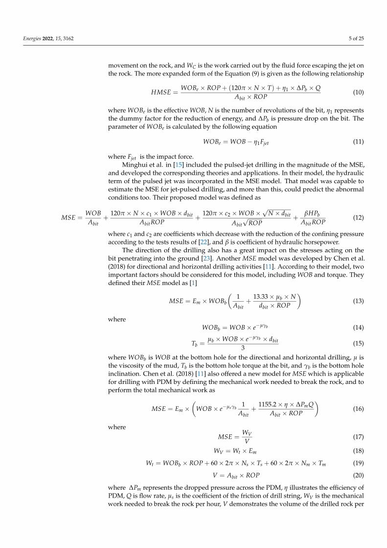
movement on the rock, and WC is the work carried out by the fluid force escaping the jet onthe rock. The more expanded form of the Equation (9) is given as the following relationship
HMSE =WOBe × ROP + (120π × N × T) + η1 × ∆Pb ×Q
Abit × ROP(10)
where WOBe is the effective WOB, N is the number of revolutions of the bit, η1 representsthe dummy factor for the reduction of energy, and ∆Pb is pressure drop on the bit. Theparameter of WOBe is calculated by the following equation
WOBe = WOB− η1Fjet (11)
where Fjet is the impact force.Minghui et al. in [15] included the pulsed-jet drilling in the magnitude of the MSE,
and developed the corresponding theories and applications. In their model, the hydraulicterm of the pulsed jet was incorporated in the MSE model. That model was capable toestimate the MSE for jet-pulsed drilling, and more than this, could predict the abnormalconditions too. Their proposed model was defined as
MSE =WOBAbit
+120π × N × c1 ×WOB× dbit
AbitROP+
120π × c2 ×WOB×√
N × dbit
Abit√
ROP+
βHPbAbitROP
(12)
where c1 and c2 are coefficients which decrease with the reduction of the confining pressureaccording to the tests results of [22], and β is coefficient of hydraulic horsepower.
The direction of the drilling also has a great impact on the stresses acting on thebit penetrating into the ground [23]. Another MSE model was developed by Chen et al.(2018) for directional and horizontal drilling activities [11]. According to their model, twoimportant factors should be considered for this model, including WOB and torque. Theydefined their MSE model as [1]
MSE = Em ×WOBb
(1
Abit+
13.33× µb × Ndbit × ROP
)(13)
whereWOBb = WOB× e−µγb (14)
Tb =µb ×WOB× e−µγb × dbit
3(15)
where WOBb is WOB at the bottom hole for the directional and horizontal drilling, µ isthe viscosity of the mud, Tb is the bottom hole torque at the bit, and γb is the bottom holeinclination. Chen et al. (2018) [11] also offered a new model for MSE which is applicablefor drilling with PDM by defining the mechanical work needed to break the rock, and toperform the total mechanical work as
MSE = Em ×(
WOB× e−µsγb1
Abit+
1155.2× η × ∆PmQAbit × ROP
)(16)
whereMSE =
WVV
(17)
WV = Wt × Em (18)
Wt = WOBb × ROP + 60× 2π × Ns × Ts + 60× 2π × Nm × Tm (19)
V = Abit × ROP (20)
where ∆Pm represents the dropped pressure across the PDM, η illustrates the efficiency ofPDM, Q is flow rate, µs is the coefficient of the friction of drill string, WV is the mechanicalwork needed to break the rock per hour, V demonstrates the volume of the drilled rock per
Energies 2022, 15, 3162 6 of 25
hour, Wt is the total mechanical work done by the bit during one hour, Ns represents the bitrotary speed, which is supplied via the surface rotation, Ts defines the provided torque bythe surface rotation, Nm defines the rotary speed by the PDM output, and lastly, Tm is thetorque provided via the PDM.
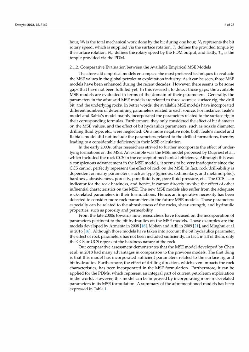
2.1.2. Comparative Evaluation between the Available Empirical MSE Models
The aforesaid empirical models encompass the most preferred techniques to evaluatethe MSE values in the global petroleum exploitation industry. As it can be seen, those MSEmodels have been enhanced during the recent decades. However, there seems to be somegaps that have not been fulfilled yet. In this research, to detect those gaps, the availableMSE models are evaluated in terms of the domain of their parameters. Generally, theparameters in the aforesaid MSE models are related to three sources: surface rig, the drillbit, and the underlying rocks. In better words, the available MSE models have incorporateddifferent numbers of determining parameters related to each source. For instance, Teale’smodel and Rabia’s model mainly incorporated the parameters related to the surface rig intheir corresponding formulas. Furthermore, they only considered the effect of bit diameteron the MSE values, and the effect of bit hydraulics parameters, such as nozzle diameter,drilling fluid type, etc., were neglected. On a more negative note, both Teale’s model andRabia’s model did not include the parameters related to the drilled formations, therebyleading to a considerable deficiency in their MSE calculation.
In the early 2000s, other researchers strived to further incorporate the effect of under-lying formations on the MSE. An example was the MSE model proposed by Dupriest et al.,which included the rock CCS in the concept of mechanical efficiency. Although this wasa conspicuous advancement in the MSE models, it seems to be very inadequate since theCCS cannot perfectly represent the effect of rock on the MSE. In fact, rock drill-ability isdependent on many parameters, such as type (igneous, sedimentary, and metamorphic),hardness, abrasiveness, porosity, pore fluid type, pore fluid pressure, etc. The CCS is anindicator for the rock hardness, and hence, it cannot directly involve the effect of otherinfluential characteristics on the MSE. The new MSE models also suffer from the adequaterock-related parameters in their formulations. Hence, an imperative necessity has beendetected to consider more rock parameters in the future MSE models. Those parametersespecially can be related to the abrasiveness of the rocks, shear strength, and hydraulicproperties, such as porosity and permeability.
From the late 2000s towards now, researchers have focused on the incorporation ofparameters pertinent to the bit hydraulics on the MSE models. Those examples are themodels developed by Armenta in 2008 [18], Mohan and Adil in 2009 [21], and Minghui et al.in 2016 [16]. Although those models have taken into account the bit hydraulics parameter,the effect of rock parameters has not been included sufficiently. In fact, in all of them, onlythe CCS or UCS represent the hardness nature of the rock.
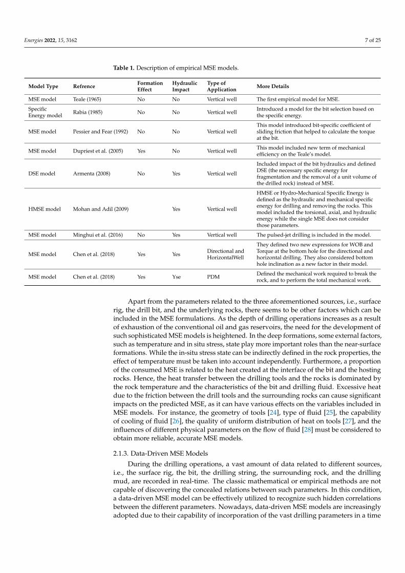
Our comparative assessment demonstrates that the MSE model developed by Chenet al. in 2018 had many advantages in comparison to the previous models. The first thingis that this model has incorporated sufficient parameters related to the surface rig andbit hydraulics. Furthermore, the effect of drilling direction, which even impacts the rockcharacteristics, has been incorporated in the MSE formulation. Furthermore, it can beapplied for the PDMs, which represent an integral part of current petroleum exploitationin the world. However, this model can be improved by incorporating more rock-relatedparameters in its MSE formulation. A summary of the aforementioned models has beenexpressed in Table 1.
Energies 2022, 15, 3162 7 of 25
Table 1. Description of empirical MSE models.
Model Type Refrence FormationEffect
HydraulicImpact
Type ofApplication More Details
MSE model Teale (1965) No No Vertical well The first empirical model for MSE.
SpecificEnergy model Rabia (1985) No No Vertical well Introduced a model for the bit selection based on
the specific energy.
MSE model Pessier and Fear (1992) No No Vertical wellThis model introduced bit-specific coefficient ofsliding friction that helped to calculate the torqueat the bit.
MSE model Dupriest et al. (2005) Yes No Vertical well This model included new term of mechanicalefficiency on the Teale’s model.
DSE model Armenta (2008) No Yes Vertical well
Included impact of the bit hydraulics and definedDSE (the necessary specific energy forfragmentation and the removal of a unit volume ofthe drilled rock) instead of MSE.
HMSE model Mohan and Adil (2009) Yes Vertical well
HMSE or Hydro-Mechanical Specific Energy isdefined as the hydraulic and mechanical specificenergy for drilling and removing the rocks. Thismodel included the torsional, axial, and hydraulicenergy while the single MSE does not considerthose parameters.
MSE model Minghui et al. (2016) No Yes Vertical well The pulsed-jet drilling is included in the model.
MSE model Chen et al. (2018) Yes Yes Directional andHorizontalWell
They defined two new expressions for WOB andTorque at the bottom hole for the directional andhorizontal drilling. They also considered bottomhole inclination as a new factor in their model.
MSE model Chen et al. (2018) Yes Yse PDM Defined the mechanical work required to break therock, and to perform the total mechanical work.
Apart from the parameters related to the three aforementioned sources, i.e., surfacerig, the drill bit, and the underlying rocks, there seems to be other factors which can beincluded in the MSE formulations. As the depth of drilling operations increases as a resultof exhaustion of the conventional oil and gas reservoirs, the need for the development ofsuch sophisticated MSE models is heightened. In the deep formations, some external factors,such as temperature and in situ stress, state play more important roles than the near-surfaceformations. While the in-situ stress state can be indirectly defined in the rock properties, theeffect of temperature must be taken into account independently. Furthermore, a proportionof the consumed MSE is related to the heat created at the interface of the bit and the hostingrocks. Hence, the heat transfer between the drilling tools and the rocks is dominated bythe rock temperature and the characteristics of the bit and drilling fluid. Excessive heatdue to the friction between the drill tools and the surrounding rocks can cause significantimpacts on the predicted MSE, as it can have various effects on the variables included inMSE models. For instance, the geometry of tools [24], type of fluid [25], the capabilityof cooling of fluid [26], the quality of uniform distribution of heat on tools [27], and theinfluences of different physical parameters on the flow of fluid [28] must be considered toobtain more reliable, accurate MSE models.
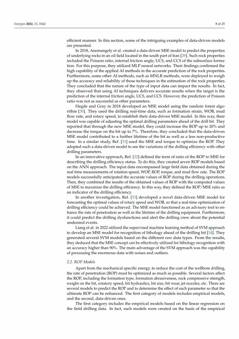
2.1.3. Data-Driven MSE Models
During the drilling operations, a vast amount of data related to different sources,i.e., the surface rig, the bit, the drilling string, the surrounding rock, and the drillingmud, are recorded in real-time. The classic mathematical or empirical methods are notcapable of discovering the concealed relations between such parameters. In this condition,a data-driven MSE model can be effectively utilized to recognize such hidden correlationsbetween the different parameters. Nowadays, data-driven MSE models are increasinglyadopted due to their capability of incorporation of the vast drilling parameters in a time
Energies 2022, 15, 3162 8 of 25
efficient manner. In this section, some of the intriguing examples of data-driven modelsare presented.
In 2018, Anemangely et al. created a data-driven MSE model to predict the propertiesof underlying rocks in an oil field located in the south part of Iran [29]. Such rock propertiesincluded the Poisson ratio, internal friction angle, UCS, and CCS of the subsurface forma-tion. For this purpose, they utilized MLP neural networks. Their findings confirmed thehigh capability of the applied AI methods in the accurate prediction of the rock properties.Furthermore, some other AI methods, such as MNLR methods, were deployed to weighup the accuracy and reliability of those techniques in the estimation of the rock properties.They concluded that the nature of the type of input data can impact the results. In fact,they observed that using AI techniques delivers accurate results when the target is theprediction of the internal friction angle, UCS, and CCS. However, the prediction of Poissonratio was not as successful as other parameters.
Hegde and Gray in 2018 developed an MSE model using the random forest algo-rithm [30]. They used the drilling real-time data, such as formation strain, WOB, mudflow rate, and rotary speed, to establish their data-driven MSE model. In this way, theirmodel was capable of adjusting the optimal drilling parameters ahead of the drill bit. Theyreported that through the new MSE model, they could increase the ROP up to 20% anddecrease the torque on the bit up to 7%. Therefore, they concluded that the data-drivenMSE model contributed to a further lifetime of the bit as well as a less non-productivetime. In a similar study, Ref. [31] used the MSE and torque to optimize the ROP. Theyadopted such a data-driven model to see the variations of the drilling efficiency with otherdrilling parameters.
In an innovative approach, Ref. [32] defined the term of ratio of the ROP to MSE fordescribing the drilling efficiency status. To do this, they created seven ROP models basedon the ANN approach. The input data encompassed large field data obtained during thereal time measurements of rotation speed, WOP, ROP, torque, and mud flow rate. The ROPmodels successfully anticipated the accurate values of ROP during the drilling operations.Then, they combined the results of the obtained values of ROP with the computed valuesof MSE to maximize the drilling efficiency. In this way, they defined the ROP/MSE ratio asan indicator of the drilling efficiency.
In another investigation, Ref. [33] developed a novel data-driven MSE model forforecasting the optimal values of rotary speed and WOB, so that a real-time optimization ofdrilling efficiency could be achieved. The MSE model functioned as an advisory tool to en-hance the rate of penetration as well as the lifetime of the drilling equipment. Furthermore,it could predict the drilling dysfunctions and alert the drilling crew about the potentialundesired events.
Liang et al. in 2022 utilized the supervised machine learning method of SVM approachto develop an MSE model for recognition of lithology ahead of the drilling bit [34]. Theygenerated several SVM models based on the different raw data types. From the results,they deduced that the MSE concept can be effectively utilized for lithology recognition withan accuracy higher than 90%. The main advantage of the SVM approach was the capabilityof processing the enormous data with noises and outliers.
2.2. ROP Models
Apart from the mechanical specific energy, to reduce the cost of the wellbore drilling,the rate of penetration (ROP) must be optimized as much as possible. Several factors affectthe ROP, including the formation type, formation abrasiveness, rock compressive strength,weight on the bit, rotatory speed, bit hydraulics, bit size, bit wear, jet nozzles, etc. There areseveral models to predict the ROP and to determine the effect of each parameter so that theultimate ROP can be enhanced. The first category of models includes empirical models,and the second, data-driven ones.
The first category includes the empirical models based on the linear regression onthe field drilling data. In fact, such models were created on the basis of the empirical
Energies 2022, 15, 3162 9 of 25
correlations between the ROP and parameters affecting it. The second categories are newand use artificial intelligence (AI) methods to predict the ROP.
2.2.1. Empirical ROP Models
Empirical or linear regression-based models for the prediction of ROP are summarizedas below:
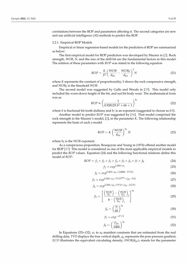
The first empirical model for ROP prediction was developed by Maurer in [2]. Rockstrength, WOB, N, and the size of the drill bit are the fundamental factors in this model.The relation of these parameters with ROP was stated in the following equation
ROP =KS2
(WOB
dbit− WOB0
dbit
)2N (21)
where K represents the constant of proportionality, S shows the rock compressive strength,and WOB0 is the threshold WOB.
The second model was suggested by Galle and Woods in [35]. This model onlyincluded the worn-down height of the bit, and not bit body wear. The mathematical formwas as
ROP ∝(
10.928125 h2 + 6h + 1
)b7
(22)
where h is fractional bit tooth dullness and b7 is an exponent (suggested to choose as 0.5).Another model to predict ROP was suggested by [36]. That model comprised the
rock strength in the Maurer’s model, [2], in the parameter K. The following relationshiprepresents the basis of such a model
ROP = K(
WOBdbit
)b5
N (23)
where b5 is the WOB exponent.As a conspicuous proposition, Bourgoyne and Young in (1974) offered another model
for ROP [37]. This model is considered as one of the most applicable empirical models topredict the ROP values. Equation (24) and the following functional relations define thismodel of ROP:
ROP = f1 × f2 × f3 × f4 × f5 × f6 × f7 × f8 (24)
f1 = exp2.303×a1 (25)
f2 = exp2.303×a2×(10000−TVD) (26)
f3 = exp2.303×a3×TVD0.69×(gp−9.0) (27)
f4 = exp2.303×a4×TVD×(gp−ECD) (28)
f5 =
(
WOBdbit
)−(
WOBdbit
)t
4−(
WOBdbit
)t
a5
(29)
f6 =
(N60
)a6
(30)
f7 = exp−a7×h (31)
f8 =
(FJet
1000
)a8
(32)
In Equations (25)–(32), a1 to a8 manifest constants that are estimated from the realdrilling data, TVD displays the true vertical depth, gp represents the pore pressure gradient,ECD illustrates the equivalent circulating density, (WOB/dbit)t stands for the parameter
Energies 2022, 15, 3162 10 of 25
of the threshold bit weight per inch of bit diameter when bit starts drilling (1000 lbf/in),(W/dbit) represents the bit weight per inch of bit diameter, and FJet demonstrates the fluidmotion force beneath the bit.
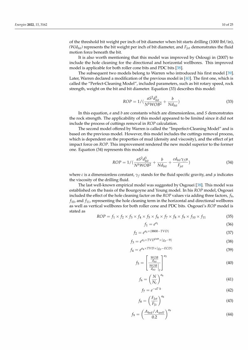
It is also worth mentioning that this model was improved by Oslougi in (2007) toinclude the hole cleaning for the directional and horizontal wellbores. This improvedmodel is applicable for both roller cone bits and PDC bits [38].
The subsequent two models belong to Warren who introduced his first model [39].Later, Warren declared a modification of the previous model in [40]. The first one, which iscalled the “Perfect-Cleaning Model”, included parameters, such as bit rotary speed, rockstrength, weight on the bit and bit diameter. Equation (33) describes this model:
ROP = 1/(aS2d3
bitNbWOB2 +
bNdbit
) (33)
In this equation, a and b are constants which are dimensionless, and S demonstratesthe rock strength. The applicability of this model appeared to be limited since it did notinclude the process of cuttings removal in ROP calculation.
The second model offered by Warren is called the “Imperfect-Cleaning Model” and isbased on the previous model. However, this model includes the cuttings removal process,which is dependent on the properties of mud (density and viscosity), and the effect of jetimpact force on ROP. This improvement rendered the new model superior to the formerone. Equation (34) represents this model as
ROP = 1/(aS2d3
bitNbWOB2 +
bNdbit
+cdbitγ f µ
Fjet) (34)
where c is a dimensionless constant, γ f stands for the fluid specific gravity, and µ indicatesthe viscosity of the drilling fluid.
The last well-known empirical model was suggested by Osgouei [38]. This model wasestablished on the basis of the Bourgoyne and Young model. In his ROP model, Osgoueiincluded the effect of the hole cleaning factor on the ROP values via adding three factors, f9,f10, and f11, representing the hole cleaning term in the horizontal and directional wellboresas well as vertical wellbores for both roller cone and PDC bits. Osgouei’s ROP model isstated as
ROP = f1 × f2 × f3 × f4 × f5 × f6 × f7 × f8 × f9 × f10 × f11 (35)
f1 = ea1 (36)
f2 = ea2×(8800−TVD) (37)
f3 = ea3×TVD0.69×(gp−9) (38)
f4 = ea4×TVD×(gp−ECD) (39)
f5 =
WOBdbit
WOBdbit
∣∣∣t
a5
(40)
f6 =
(NNc
)a6
(41)
f7 = e−a7 h (42)
f8 =
(FJet
FJc
)a8
(43)
f9 =
(Abed/Awell
0.2
)a9
(44)
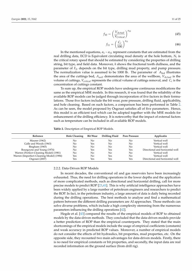
Energies 2022, 15, 3162 11 of 25
f10 =
(VActualVCritical
)a10
(45)
f11 =
(Cc
100
)a11
(46)
In the mentioned equations, a1 – a11 represent constants that are estimated from thereal drilling data, ECD is Equivalent circulating mud density at the hole bottom, Nc isthe critical rotary speed that should be estimated by considering the properties of drillingstring, bit type, and field data. Moreover, h shows the fractional tooth dullness, and theparameter of FJc depends on the bit type, drilling mud property, and pump pressure.The normalization value is assumed to be 1000 lb. The parameter of Abed illustratesthe area of the cuttings bed, Awell demonstrates the area of the wellbore, VActual is thevolume of cuttings, Vcritical represents the critical volume of cuttings removal, and Cc is theconcentration of cuttings constant.
To sum up, the empirical ROP models have undergone continuous modifications thesame as the empirical MSE models. In this research, it was found that the reliability of theavailable ROP models can be judged through incorporation of five factors in their formu-lations. Those five factors include the bit wear, pore pressure, drilling fluid, applicability,and hole cleaning. Based on such factors, a comparison has been performed in Table 2.As can be seen, the model proposed by Osgouei satisfies all of five parameters. Hence,this model is an efficient tool which can be adopted together with the MSE models forenhancement of the drilling efficiency. It is noteworthy that the impact of external factorssuch as temperature can be included in all available ROP models.
Table 2. Description of Empirical ROP Models.
Refrence Hole Cleaning Bit Wear Drilling Fluid Pore Pressure Applicatin
Maurer (1962) No No No No Vertical wellGalle and Woods (1963) No Yes No No Vertical well
Bingham (1965) No No No No Vertical wellBourgoyne and Young (1974) No Yes Yes Yes Directional and horizontal well
Warren (Perfect–Cleaning Model) (1981) No No No No Vertical wellWarren (Imperfect–Cleaning Model) (1984) Yes No Yes No Vertical well
Osgouei (2007) Yes Yes Yes Yes Directional and horizontal well
2.2.2. Data-Driven ROP Models
In recent decades, the conventional oil and gas reservoirs have been increasinglyexhausted. Thus, the need for drilling operations in the lower depths and the applicationof more complicated methods, such as directional and horizontal drilling, call for moreprecise models to predict ROP [23,41]. This is why artificial intelligence approaches havebeen widely applied by a large number of petroleum engineers and researchers to predictthe ROP. In fact, in the petroleum industry, a large amount of data is daily being recordedduring the drilling operations. The best methods to analyse and find a mathematicalpattern between the different drilling parameters are AI approaches. Those methods cansolve diverse problems, which include a high complexity stemming from the numerousparameters influencing the drilling operations [42].
Hegde et al. [43] compared the results of the empirical models of ROP to obtainedmodels by the data-driven methods. They concluded that the data-driven models providea better prediction of ROP than the empirical counterparts. They stated that the mainshortcomings of the empirical models include the usage of empirical coefficients (constants)and weak accuracy in predicted ROP values. Moreover, a number of empirical modelsdo not consider the effects of bit hydraulics, bit properties, mud properties, etc. On theopposite side, they recounted two main advantages for data-driven models. Firstly, thereis no need for empirical constants or bit properties, and secondly, the input data are realrecorded information on the ground surface (from drill rig).
Energies 2022, 15, 3162 12 of 25
Arehart [44] used neural networks to determine the bit grade (state of the bit wear)while drilling. He predicted the bit grade by using drilling input parameters, such as ROP,hydraulic horsepower per square inch, WOB, rotary speed, and torque. He stated that theresults of the bit grade predicted by the neural network were acceptably accurate. However,he pointed out that the input data were insufficient, and it was necessary to import moredata to extract a better fitted trend between the variables and grade of the bit wear.
Furthermore, Bilgesu et al. in [45] introduced a novel method for predicting ROP byusing the neural networks. They obtained 8000 measurements from a rig floor simulator.Those data included rotary speed, torque, WOB, formation drill-ability, the rate of mudpump circulating, bit type, bit tooth wear, bit bearing wear, and the rotation time of the bit.Those parameters were given to the neural network model to anticipate the values of ROP.Moreover, in his research, by using another data set, Bilgesu made a model to anticipatethe ROP values without using the bit bearing wear and bit tooth wear parameters. Thiswas because of the lack of underground data concerning the bits.
In addition, Amar and Ibrahim in 2012 used neural networks for predicting ROP byapplying seven parameters, including ECD, WOB, rotary speed, depth, tooth wear, porepressure gradient, and Reynolds number [46]. Similarly, Gidh et al. [47] applied neuralnetworks to anticipate the bit wear. Then, they used their findings to improve the valuesof ROP.
Machine learning (ML) approaches have also been adopted in the modeling of ROPto enhance the drilling operation [48–50]. Dunlop et al. in 2011 used the WOB androtary speed for the optimization of ROP during drilling activities. Furthermore, Ref. [51]developed a data-driven ROP model for anticipation of probable stuck pipe problems usingML techniques. Ref. [52] utilized the machine learning method to maximize the values ofROP using parameters, such as rotary speed, WOB, and mud flow rate.
2.3. Applications of MSE Models in Terrestrial Drilling
The quantification of MSE has been applied in several fields of drilling operations. Theconcept of MSE can be applied for planning and monitoring the whole drilling project aswell as for analyzing, predicting, and evaluating the rate of penetration (ROP). Furthermore,other initiative applications, such as predicting pore pressure and rock characterization, arealso feasible [53]. In the following section, the diverse applications of MSE concept in thedrilling operations are elaborated:
2.3.1. Drilling Optimization
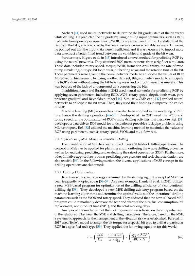
To enhance the specific energy consumed by the drilling rig, the concept of MSE hasbeen frequently adopted so far [54–57]. As a new example, Hamlawi et al. in 2021, utilizeda new MSE-based program for optimization of the drilling efficiency of a conventionaldrilling rig [58]. They developed a new MSE drilling advisory program based on themachine learning algorithms to determine the optimal values of the operational drillingparameters such as the WOB and rotary speed. They deduced that the new AI-based MSEprogram could remarkably decrease the tear and wear of the bits, fuel consumption, bitreplacement, non-product time (NPT), and the total working days.
Analysis of the mechanism of the rock fragmentation is based on the comprehensionof the relationship between the MSE and drilling parameters. Therefore, based on the MSE,a systematic approach for the management of the vibration risk was established. Fei et al. in2017 used Teale’s model to assign the bit torque for a special bit type to drill at a particularROP in a specified rock type [59]. They applied the following equation for this work:
T =
(CCSEm− 4×WOB
π × d2bit
)×(
d2bit × ROP480× N
)(47)
Energies 2022, 15, 3162 13 of 25
where CCS refers to the confined compressive strength of rock that is calculated for perme-able rock to the bottom-hole condition as follows:
CCS = UCS + DP + 2DP× sin ϕ/(1− sin ϕ) (48)
where UCS demonstrates the unconfined compressive strength of the rock, ϕ representsthe rock friction internal angle, DP is equal to the ECD pressure minus the pore pressure.To calculate the pore pressure for a vertical well drilled in an impermeable rock, they usedthe Skempton pore pressure to calculate the compressive strength of the rock as
CCSS = UCS + DPS + 2DPS × sin ϕ/(1− sin ϕ) (49)
where CCSS is the CCS for impermeable rock obtained using the Skempton pore pressure,and DPS is defined as the differential pressure between the ECD pressure and Skemptonpore pressure. Based on Equations (47)–(49), the modified MSE model was derived. Thisapproach was associated with identifying the vibration issue based on the MSE and mon-itoring the environment of the down-hole in the real time to enable the drilling crew foran immediate reaction by adjusting and changing the drilling parameters. This was aneffective approach to mitigate the effect of the stick-slip problems in drilling operations,and positively, it improved the ROP about 20% [59].
2.3.2. Estimation of the Rock Properties
Understanding of the rock properties, chiefly rock strength, contributes to the estab-lishment of a more efficient plan of drilling operations. Trivedi et al. in 2020 introduced anupdated MSE program to estimate the CCS of the subsurface formations [60]. Their MSEmodel included drill-string dysfunctions, such as vibration, mud motor dynamics, andfrictional losses along the drill-strings. They found that a reliable correlation between theactual MSE and CCS is developable. In their model, two new parameters were introduced.The first parameter was the hydraulic specific energy (HSE) that estimates the functionof the hydraulic impact force at the formation rather than the bit bottom. The secondparameter was the vibration specific energy (VSE), which estimates the energy pertinent tothe vibrations and its influence on the translational weight on the bit, and the rotationalenergy associated with the torque. The first parameter can be explained as follows
HSE = ∑Ni
(1− A−0.122
v
)IFNi /Ab, Ni
(50)
where Ni is number of nozzles, Av shows the ratio of jet fluid velocity for returning the fluidvelocity, Ab, Ni
is the bit area per nozzle, and IFNi can be obtained as following relationship
IFNi = 0.01823× Cd × (Q/Ni)√
MW × ∆pb (51)
where Cd represents the fluid discharge coefficient, Q is flow rate of the mud, and MWdemonstrates the mud weight.
The second introduced parameter can be explained as follows:
VSE = ∑ f (KE, PE, DE)/Areabit (52)
where the term of ∑(KE, PE, DE) describes the total kinetic, potential, and dissipationenergies related to the vibration amplitude. Furthermore, the term of f (KE, PE, DE)illustrates the force required for the total energy of the system, including mass matrix. Theparameter of Areabit is the cross-sectional area of the bit.
Considering those two introduced parameters, their actual MSE model contributingtowards the cutting process can be shown as follows:
Energies 2022, 15, 3162 14 of 25
MSEactual =
(WOBAriabit
)VSE
+120× π × (Nbit)mud−motor × Tbit(mud−motor, f riction, VSE)
Ariabit × ROP+ HSE (53)
where (Nbit)mud−motor and Tbit(mud−motor, f riction, VSE) can be calculated from the followingequations:
Tbit = Tbottom(VSE, f riction) +
(Tmaxmud−motor
DPmaxmud−motor
)× DPmud−motor ×
Nmaxmud−motorNmud−motor
(54)
Nbit = Ntop−drive +[Q× (RevV)mud−motor
](55)
where Tbottom is the torque at the bottom of each drill-string element, Tmaxmud−motor is themaximum torque rating of the mud-motor, DPmaxmud−motor is the maximum differentialpressure of the mud-motor, DPmud−motor indicates the actual differential pressure acrossthe mud-motor, Nmaxmud−motor is the maximum rotation per minutes (N) rating of themud-motor, Ntop−drive is the rotation per minutes (N) at top-drive, and (RevV)mud−motorrepresents the revolutions per mud volume of the mud-motor.
Calculating the MSE baselines and averaging them can be utilized to check the valuesof the MSE in real-time. The obtained information of MSE baseline could also be adoptedto manifest the UCS of the formations, and therefore, may be applied to formulate atrustworthy map of the hardness of the rock to improve the design of completion plan [61].Gurtej et al. in [39] deployed the MSE baselines to create a multivariate physics-baseddecision tree approach for automatically classification and identification of the differentdysfunction types. Some limitations in the technology, such as slow data rates, restrictedthe adoption of the MSE as an efficient approach for evaluation of the formation. However,this issue was solved by the modern coiled tubing drilling BHAs, which are designedfor the underbalanced drilling operations. Utilizing this method offers the acquisitionof information about the type of rock which is drilled in real time with an inch levelresolution [62].
Arnø et al. in [63] successfully developed a new deep learning method by using theconcept of MSE for real-time classification of the formation being drilled at the depth of bitpenetration. After training and validation of the model, its accuracy in classifying a varyingset of the different formations was examined. The tests were reported as very successfulsince the model could immediately report the type of layers at the different borders. Thisadvantage can rapidly alert the operator about the class of the new formation which thedrill bit commences to penetrate through.
2.3.3. Completion Optimization
As it was already mentioned, the MSE values could be applied to predict the UCSof the rock within each frac stage. This could be very beneficial to set the perforationclusters in the borehole sections with similar UCS values to reduce the negative influencesof the rock heterogeneity [64,65]. The drilling experts can take advantage of the MSE byrecognizing the close relationship between it and the unconfined compressive strength(UCS) for the completion operation. This close relation can be presented as follows:
MSE = UCS× De f f (56)
where De f f is the efficiency of transmitting the penetration power of the rig to the rock [66].The corrected mechanical specific energy (CMSE) can be utilized where there is need
to compute and account the friction losses in the wellbore and drill string in real time.The CMSE is applied for estimation of the geomechanical logs and creation of a livegeomechanical model being applied to steer the bit through the fracable rocks.
When the drilling is fulfilled, according to the CMSE outputs (including pore pressure,stresses, and natural fracture index), the frac stage spacing and cluster density will beadjusted [67]. The technology of using CMSE for predicting geomechanical logs is a
Energies 2022, 15, 3162 15 of 25
considerable step to optimize the completion process. Moreover, the most significantbenefit of this technology is its versatility in any drilling operation without the need to useadditional surface sensors, gauges, or down-hole measurement tools, thereby reducing thecosts and risks related to the potential wellbore issues.
Furthermore, another significant benefit of this technology is that there will be noneed for on-site personnel or authorizations since it uses the real-time drilling data toimmediately steer in the rock. Furthermore, the instant design of the completion stagebecomes feasible exactly at the end of the drilling operations. This technology is utilizedto estimate the multiple factors that create the frictional losses in the real time. Whenthese losses are perfectly assessed, they can be applied to MSE correction. In fact, CMSE isacquired from the surface drilling data that contain vital information which can be used fordesigning the optimal cluster placement [68].
2.3.4. Determination of Energy Flow, Lost and Location
Chen et al. in [69] pointed out that the term of MSE cannot directly provide informationabout the loss of energy in the components of the drilling system, such as drilling strings.In better words, during the drilling operations, a proportion of the provided energy mayreside within the drill string in the forms of strain and kinetic energy. Furthermore, the rootcause of the energy loss also remains undetected. They proposed an initiative approach forestimation of the drilling energy flow along the drilling string. In their method, the wholedrilling string was modeled from the top to the bit using a number of 3D beam elements.The dynamic response history of the elements were solved by a numerical program of finiteelement method.
MSE is a function incorporating the drilling parameters to determine the overalldrilling efficiency. However, it does not clearly distinguish the location of inefficiencies.This issue can be addressed by the concept of mechanical specific energy ratio (MSER). Thelocation of the inefficiencies could be more easily identified by using the ratio of the MSEsurface values to the MSE values of the down-hole. MSER can be defined as a correlationto optimize the drilling fulfillment in real time.
To find the ratio, firstly, it is necessary to calculate the MSE taken from the drillfloorvalues. The original MSE equation is changed by substituting the area of rock destroyedwith the diameter (d) variable to account for only the volume of rock which is destroyed bythe under-reamer. The following equations describe how the mechanical specific energywith drillfloor values and mechanical specific energy with MWD (Measuring while drilling)values are obtained.
MSEDrill f loor =WOBDF
Arock destroyed+
480× NDF × TDFArock destroyed × ROP
(57)
Arock destroyed =(πr2
under−reamer diameter)−(πr2
bit diameter)
(58)
MSEMWD =4×WOBMWD
π × d2bit
+480× NMWD × TMWD
d2bit × ROP
(59)
where MSEDrill f loor is mechanical specific energy from the drillfloor values, Arock destroyed isthe area of rock which is destroyed, WOBDF is WOB of drillfloor, NDF is N of drillfloor, TDFis drillfloor torque, MSEMWD is mechanical specific energy from MWD tool, r is radius, andWOBMWD, NMWD, TMWD are WOB, N, and T are obtained from the MWD tool respectively.The use of this ratio is applied in under-reaming process of the deep-water wells [70].
As a very useful application of MSE, it can be applied in the operation of reamingwhile drilling (RWD) that is limited to finer formations. A thermo-poroelastic model of MSEcan be utilized in order to apply the RWD for a particular formation and a recommendationfor reamer-pilot size ratio [71].
Energies 2022, 15, 3162 16 of 25
2.3.5. Bit and Cutter Design
Through the trial-and-error attempts together with the novel numerical modellingprograms, the process of rock cutting and bit performance have been broadly investigated.In such investigations, the focus has been to design a well-functioning bit or cutter so thatthe minimum energy was required for the fragmentation of the rock. Those studies wereconducted mostly for PDC drill bits, and can be categorized into two subgroups: PDCbit/rock interaction and PDC cutter/rock interaction [72]. One of the first pioneer PDCcutter/rock models was developed by Miedema [73], and it was used as a constitutivemodel for the subsequent investigations by the different researchers. The model wasappropriate for evaluation of the PDC cutter/rock interaction in formations, such as clay,rock, and sand. The model could predict the cutting forces and the values of MSE on thebasis of the force equilibrium equations.
A three-dimensional PDC cutter model developed by [72] to determine the forces atthe cutter/rock interaction phase. The model used the poro-elasticity theory to computethe drilling-induced stress regime within the rock while the rock cutting cycle. After thecalculation of stress state within the rock, the criterion of modified Lade was used toanticipate the rock failure. Their model was verified with the probe of the impact of thecontributing factors on the process of rock cutting. Such factors included the depth of cut,hydrostatic pressure, back rake angle, side-rake angle, and worn depth.
Chen et al. in [74] investigated the effect of two simultaneous PDC cutters on the rockfragmentation. They witnessed that the rock is fragmented in front of and between thetwo cutters. In this case, the cutting volume was remarkable, thereby leading to lowermagnitudes of MSE. They concluded that if double cutters are installed close to each otherso that the depth of cut would be large, the value of the MSE decreases by 5–25% in contrastto a single cutter. They calculated the MSE for a single cutter (MSEs) according to thefollowing equation:
MSEs =Rx
Ac cos α(60)
where Rx is the cutting force, Ac is the contact area between the cutter and rock, and αrepresents the angle that depends on the tooth bit direction towards the rock surface. Tocalculate the MSE for the double cutters, they used another equation as follows:
MSEd =RI
x + RI Ix
Acut(61)
where MSEd is the mechanical specific energy for double cutters, Acut is the cutting area oftwo cutters, RI
x and RI Ix are cutting forces by the two cutters. To facilitate the quantification
of the integrated influence of double cutters, they proposed a parameter, integrated indexζ, being defined as follows:
ζ =MSEs
MSEd(62)
The MSE concept was applied to develop a methodology for optimization of thedesign of polycrystalline diamond compact (PDC) bit for the entire hole section accordingto the modelled MSE and UCS values [57].
2.3.6. Estimation of Formation Pore Pressure
The mechanical response of the natural porous rocks is a function of their minerals andpore fluid pressure [75,76]. Pore pressure affects the drilling process through the concept ofeffective stress law [77,78]. The more pore pressure, the less effective stress. In the drillingfield, it has been long accepted that the energy required to drill the formation not only isdependent on the mud pressure but also on the formation pore pressure. Generally, it isaccepted as common sense that the formation requires less energy to drill if the fluid porepressure is higher. The cause is believed to be the weakening effect of the pore pressure.The effective principal stresses on the rock matrix decline due to the pore pressure, and
Energies 2022, 15, 3162 17 of 25
this leads to an easier failure of the rock as a frictional-cohesive material. It is also widelyobserved that the extent of this effect can be significantly different from one rock type toanother [79].
The first attempts to leverage the MSE in determining pore pressure from the drilling-mechanics data were not successful [80]. Akbari et al. [79] performed laboratory exper-iments to probe the impact of the pore pressure on the forces of a single PDC cutter byextracting the empirical correlations between the pore pressure and the MSE on a seriesof sandstone specimens. To perform the tests and extract the relevant correlations, theycontrolled the pore pressure and cell confining pressure, but the other conditions remainedconstant. The tests were conducted at two pore fluid pressure states; one state was atmo-spheric pore fluid pressure, and the second state pore fluid pressure was equalized to theconfining pressure (zero differential pressure). They used the performed experimental datato produce well-fitting correlations between the MSE, the differential pressure, and theconfining pressure that had a logarithmic nature. Their proposed correlation for estimatingof the MSE based on the two parameters of pore pressure and confining pressure wasdefined as:
MSE(
Pcon f ining, Pdi f f
)= UCS +
(a′ + b
′Pdi f fPcon f
)ln(Pcon f
Patm
)(63)
where Pcon f ining is confining pressure, Patm is the atmospheric pressure, Pdi f f is differentialpressure, UCS is uniaxial compressive strength, and a′ and b′ are two constants that canbe determined for a certain type of rock. The extracted correlation demonstrated that theimpact of pore fluid on the MSE is similar to the impact of the confining pressure, but itwas weakened via a coefficient.
Since, the required energy to remove a unite volume of the rock relies on the in-siturock strength along with the differential pressure acting on the rock, Majidi et al. in [81]developed a method to estimate the the values of pore fluid pressure from the subsurfacedrilling mechanics parameters together with the in-situ rock data using terms of MSE anddrilling efficiency (DE). The equation of DEMSE method or pore fluid pressure estimationmethod is defined as follows:
p = ECD− (DEtrend ×MSE−UCS)×(
1− sin ϕ
1 + sin ϕ
)(64)
where p represents the pore pressure and DEtrend illustrates the normal drilling-efficiencytrend line.
Through this approach, the concept of MSE for pore pressure estimation incorporatedboth WOB and torque to compute the energy needed to drill the rock. They showed thatan MSE-based approach, as an independent source of information, can give results that arecompatible favorably with the conventional petro-physical pore pressure estimation methods.
By performing a series of laboratory experiments, Curry et al. in [82] investigated theimpact of borehole pressure on the ROP and MSE in salt formations. They concluded thatthe borehole pressure does not have noticeable effect on the ROP and MSE in salt formations.Consequently, in such formations, there would be a little penetration rate penalty if highborehole pressure is needed for the wellbore stabilization. However, increasing the mudweight causes considerable changes in the properties of the drilling fluid, except its density.
2.3.7. Control of Salt Creep
In the most oil/gas sites, salt formations function commonly as the low-permeabilitycap rocks to seal the oil and gas reservoirs. Hence, those geological structures are strongindicators of potential hydrocarbon reservoirs under them. However, salt rocks are con-sidered as highly problematic formations in which the creep behavior can dramaticallyheighten the stresses around the wellbore. Prior to the drilling, the potentially available salt
Energies 2022, 15, 3162 18 of 25
formations in the site must be precisely studied to investigate their creep behavior affectingthe MSE and ROP during the drilling operations [83].
Recently, some researchers have concentrated on the studying of MSE while drillingin salt formations where the high MSE values have brought severe drilling problems, suchas vibrations, stuck pipe, and torsional resonance [84,85]. Pinto et al. in [85] developed aninitiative MSE-Index concept to control the salt creep and to increase the rate of drilling(penetration) in the Brazilian pre-salt formation.
For this purpose, they described the term of MSEi as the maximum limit of energy inwhich the entire energy applied in the drilling system is used to cut the rock. MSEi can beobtained through the following relationship:
MSEi = UCS + m× Pm (65)
where m is a dimensionless parameter that depends on the drill bit design, and Pm showsthe downhole pressure interpreted as the ECD. In fact, m is a coefficient that varies in therange of 3–20 for particular cutter structures [86].
The outstanding point of their work was the usage of the MSE concept for deter-mination of the proper lower bound of the equivalent circulating density (ECD) whiledrilling [63]. For years, it has been generally accepted that the creep behavior relies re-markably on the upper and lower limits of the operational ECD. Therefore, choosing aproper mud weight is of paramount significance to prevent the wellbore from the potentialclosure (convergence). The upper bound of the ECD can be determined through the leak-offtest (LOT), or alternatively, the formation integrity test (FIT). Hence, it is easy to estimate.During their studies on the Brazilian pre-salt formations, [85] observed that there is astrong relationship between the intensity of the creep behavior and MSE with depth. Thisrelationship was more precisely studied so that they could develop an MSE index term as afunction of drilling depth to predict the lower bound of the ECD [86]. This new conceptresulted in a reduction of the needed energy together with the delayed times of drilling inthe related projects.
2.4. Applications of MSE Models in Extraterrestrial Drilling
In recent decades, the idea of space colonization has received great attention fromthe side of both national and international space agencies. While before the 2000s, onlythe National Aeronautics and Space Administration (NASA) and Russian Federal SpaceAgency (currently as Roscosmos) were exploring the remote planets, in recent decades otherspace agencies from Europe, China, India, Japan, etc. have joined this discovery programs.As well as the potentially habitable planets, such as the Moon and Mars, the discoverieshave also been stretched to comets and asteroids [87,88]. The exponential growth of thetechnology has led to many improvements in the manufacturing, transportation, landing,and long-duration stay of the multipurpose shuttles, landers, robots, and rovers in theplanetary environments.
As the aforementioned agencies plan to execute diverse exploratory programs on thedifferent spots of the solar system, a large proportion of them have focused on the habitableplanets, such as the Moon and Mars [7]. Their objective is to study the inner lithosphereand outer atmosphere of such planets to colonize them as the second human civilizationin the Milky Way galaxy. So far, dozens of the exploratory programs have provided awealth of information about the surface characteristics of the Moon and Mars. However,the subsurface has remain markedly undiscovered. To reveal the nature of the subsurface,the drilling application on the planets is absolutely inevitable. Drilling applications on theMoon and Mars surfaces provide large information about the extinct and extant life onthose planets, solar system evolution, feasibility of mining, water extraction, developmentof permanent outposts, etc.
To do this, drilling is a pre-requisite for a wide range of different applications, in-cluding the outpost construction, sample coring, space mining, anchoring and foundation,water extraction, and potential underground tunneling on the planetary surfaces. For this
Energies 2022, 15, 3162 19 of 25
purpose, a large number of diverse drilling techniques and apparatuses have been designedand assembled [37–39].
2.4.1. Drilling Optimization
Nagaoka et al. in [89] introduced an extraterrestrial subsurface explorer being able toburrow itself to bury a scientific tool such as a seismometer. They explained that the spanof traditional in situ measurements to lunar regolith is restricted as it cannot be extendedmore than the limited areas around the sampling location. However, they examined theefficiency of their suggested drill, and concluded that their method could address suchproblems. They also introduced indexes for their experimental analyses to check the drillingperformance. In their study, the property of penetration in the chosen prototypes wasestimated by applying specific energy as a principal index.
Joshi et al. in [90] found that if they analyze the trends of MSE, RPM, and the torque,they can detect different dysfunctions, such as inefficient cuttings transport, auger choking,and drilling vibrations, that can be then utilized in optimization of the drilling proficiency.
2.4.2. Bit and Drill Rig Design
Bit design is considerably important in the drilling efficiency not only on Earth, butalso in space. In both Earth and space drilling, it is quite practical to compute the specificenergy needed for a certain bit to drill a special type of rock [91]. Hence, there have beennotable researches covering this subject to increase the efficiency of drilling performance,and consequently, to reduce the cost of those expensive projects. For this purpose, oneof the significant parameters that can be considered to design the bit is MSE. To obtainthis goal, Ref. [89] proposed two drills, including contra-rotor screw drill (CSD) and singlescrew drill (SSD). For comparison and evaluation of those drills, they used the conceptof MSE as it demonstrates the efficiency of the drilling system. Eventually, according totheir experimental analyses, based on specific energy (SE) and MSE, the proper drivingsituations of the CSD were evaluated.
2.4.3. Identification of the Ice Content
In the planetary space, water has applications ranging from drinking to propellantproduction. On the lunar poles, the presence of water–ice has been corroborated accordingto recent findings. The water available on the planetary bodies can considerably reduce thespace exploration costs, and provides the invaluable hydrogen, oxygen, and propellant.Joshi et al. in [92] used MSE, ROP, torque, and WOB to estimate the UCS of the water-bearing specimens to establish a mathematical approach for pattern recognition. Theycalculated the water content of the samples by using the UCS, which was estimated throughthe pattern recognition algorithm. The results of their experiments illustrated that the valuesof UCS is higher when the quantity of ice content in the rock is higher. In other words, thespecific energy increases significantly with ice content [90].
3. Results and Discussion
Drilling operations are commonly expensive, tough-to-do, and time-consuming. Fur-thermore, due to the exhaustion of conventional hydrocarbon reservoirs, the depth ofdrilling operations has increased dramatically in comparison to the past. In this situation,every drilling company seeks the optimization of drilling operations conducted in the field.To do this, MSE is considered as a prevalent concept to model, predict, and enhance thedrilling efficiency.
In this research, a comprehensive assessment has been performed to integrate andevaluate the available MSE models together with their assumptions, limitations, applica-tions, advantages, and disadvantages. Our close scrutiny has revealed that the empiricalMSE models require further modifications, especially from the perspective of drilled rockproperties. In reality, the amount of MSE consumed by drilling rig intensely relies on thedrill-ability of the subsurface formations. The drill-ability of a rock is a function of the
Energies 2022, 15, 3162 20 of 25
hardness (strength), abrasiveness, poro-elastic parameters, etc. It was concluded that themain shortcoming of the available, empirical MSE models is the insufficient incorporationof the rock geomechanical characteristics in their formulations. The majority of them haveincluded only the CCS of the rock to involve the rock drill-ability effect on the MSE.
To incorporate the geomechanical properties of the rock in the empirical MSE models,one drastic solution is the utilization of AI techniques. Through using such techniques,a larger proportion of geo-mechanical parameters, recorded during the real-time drillingoperations, can be incorporated in such MSE models. Consequently, those modified MSEmodels have more reliability than the traditional, empirical models, which are restrictedbecause of the inadequate or local input data. Amongst the available AI techniques,machine learning approaches can be effectively adopted to train the data-driven MSEmodels, and to test them. Using such ML approaches strongly reduces the uncertaintiesrelated to the subsurface formations. In addition, the real time analyses of MSE valueshelps to curtail probable issues, such as stuck drilling pipe, bit balling, lost circulation, etc.Nevertheless, the different AI techniques may predict different values of MSE due to thedifference in their approaches [93]. Since, during the drilling operation, the rock layerschange, using a consistent AI technique for all rock strata may not be adequately efficientand reliable. Providing different AI approaches for different subsurface lithology is asensible idea to tackle such issues. A good example of this application was provided by [94].
Furthermore, the effects of temperature and thermal properties of the surroundingrocks, bits, drill string, drilling fluid, and pore fluid are proposed to be included in thefuture empirical and data-driven MSE models. The reason for this is that the cooling perfor-mance of the drilling fluid [95,96], together with the geometry of the drilling tools [97,98],have a great impact on the friction generated on the rock/bit interface. Apparently, thisphenomenon affects the MSE and ROP of the drilling operation.
Empirical ROP models also require for incorporation of further geomechanical data intheir formulations. Such geomechanical parameters are rock shear strength, rock cuttings,pore pressure, and in situ stress regime (direction of the drilling). Moreover, a simultaneouscombination of MSE and ROP models can strongly enhance the whole drilling efficiency.Such a combination has been recently conducted by [32] through depicting the ratio of ROPto MSE during the real time drilling operation.
On the Earth, some of the most practicable applications of MSE models include thedrilling optimization, estimation of rock properties, completion optimization, determina-tion of energy flow and loss location, bit and cutter design, estimation of the formationpore pressure, and control of the salt creep. On the planetary bodies, those applicationsencompassed the drilling optimization, bit and drill rig design, and identification of icecontent in space. The applications of MSE models on the Earth are much broader thanspace. This can be justified due to the sporadic extraterrestrial drilling operations duemainly to the challenges on the planetary bodies. The effect of the different challengesand their relevant roles in affecting the values of MSE can be assessed through potentmathematical algorithms such as Monte Carlo simulation [99,100] as well as AI techniques.
While the current depth of the drilling operations conducted by the cutting-edgeextraterrestrial robots have not exceeded 305 cm [101], the prospective space explorationprograms tend to drill towards the much deeper formations. This objective necessitatesrobust drilling systems that are highly efficient in terms of the consumed MSE. So far, nospecific MSE model has been developed for the remote habitable planets, such as the Moonand Mars. Therefore, the development of such models represent an urgent demand forthe future space drilling programs. Obviously, since the challenges of energy supplementin space are considerably higher than on Earth, it is imperative to further work on MSEapplications in space to reduce the unnecessary energy consumption and its loss duringthe drilling operation.
Energies 2022, 15, 3162 21 of 25
4. Conclusions
The empirical models of MSE and ROP require more parameters in their formulationsto predict reliable, accurate values. Such parameters are mostly pertinent to the geome-chanical properties of the subsurface rocks. Rock abrasiveness, porosity, and pore pressureare the main examples of such geomechanical characteristics. Furthermore, the effect ofthermal features of the hosting rocks, drilling fluid, and drilling tools can be included toachieve more proper values of MSE.
The development of AI-based approaches and programs is also of significant impor-tance for future MSE models. Through such data-driven models, more geomechanicalparameters can be deployed to enhance the drilling efficiency by the prevention of predictedproblems, reducing the non-productive time and cost. It should be noted that for differentformations, the accuracy of a particular AI technique can be affected as a consequence ofthe nature of the input data. Therefore, it is a sensitive idea to predict the values of MSEvia several AI techniques. Then, the obtained results from those different AI techniquescan be compared with the real field data to select the most appropriate AI approach for thedevelopment of a reliable MSE model.
For extraterrestrial drilling, energy supply is very expensive, and problematic. Hence,further attempts must be made to develop some suitable MSE models for the design ofenergy-efficient drilling tools in off-Earth drilling applications. In addition, the mainchallenges, including the lack of atmospheric pressure, cryogenic temperature, nonuseof drilling fluids, and abrasiveness of the lunar and Martian regolith, intensify the MSEvalues in space drilling. Therefore, the future off-Earth MSE models must be establishedwith the consideration of such prohibitive challenges. Another limitation related to thedevelopment of the off-Earth MSE models is that, due to the huge transportation cost fromspace to the Earth, the terrestrial simulants are used instead of the extraterrestrial regolith(or rocks) for the design of drilling tools. This leads to less accuracy of the predicted MSEvalues in the laboratory settings in comparison to the real conditions in the remote space.
So far, in space drilling, the amount of consumed energy has been used for estimationof the regolith’s ice contact, design of drill bits, and optimization of the whole drillingefficiency. The concept of MSE can also be utilized to predict the undesirable dysfunctionsduring the real time off-Earth drilling operations. Such potential dysfunctions encompassthe auger choking, inefficient cuttings transport, drilling vibrations, and stuck pipe issues.Through this application, the values of MSE can be combined with accessible AI techniquesto prevent such operational problems.
To sum up, MSE models have provided an appreciable influence on the drillingoperations up to now. With the ongoing need to deploy more sophisticated drilling toolsin both on-Earth and off-Earth environments, the application of new methods to modifythe classic models can support a accurate evaluation and optimization of the drillingoperations. Such improvements will also extend the applications of MSE models for otherpossible purposes.
Author Contributions: Conceptualization, formal analysis, methodology, writing—review andediting, writing—original draft preparation, D.K. and M.K.; investigation, M.K.; supervision, vali-dation, project administration, D.K. All authors have read and agreed to the published version ofthe manuscript.
Funding: The project was supported by the AGH University of Science and Technology, Krakow,Poland, subsidy 16.16.190.779.
Institutional Review Board Statement: Not applicable.
Informed Consent Statement: Not applicable.
Data Availability Statement: All used data are accessible in the context of the article.
Conflicts of Interest: All authors of this paper declare no conflict of interest.
Energies 2022, 15, 3162 22 of 25
References1. Chen, X.; Gao, D. The Maximum-Allowable Well Depth While Performing Ultra-Extended-Reach Drilling From Shallow Water to
Deepwater Target. SPE J. 2018, 23, 224–236. [CrossRef]2. Maurer, W.C. The “Perfect-Cleaning” Theory of Rotary Drilling. J. Pet. Technol. 1962, 14, 1270–1274. [CrossRef]3. Teale, R. The Concept of Specific Energy in Rock Drilling. Int. J. Rock Mech. Min. 1965, 2, 57–73. [CrossRef]4. Bello, O.; Teodoriu, C.; Yaqoob, T.; Oppelt, J.; Holzmann, J.; Obiwanne, A. Application of artificial intelligence techniques in
drilling system design and operations: A state of the art review and future research pathways. In Proceedings of the SPE NigeriaAnnual International Conference and Exhibition, Lagos, Nigeria, 2–4 August 2016. [CrossRef]
5. Holdaway, K.R. Harness Oil and Gas Big Data with Analytics: Optimize Exploration and Production with Data-Driven Models; JohnWiley & Sons: Hoboken, NJ, USA, 2014; ISBN 978-1-118-77931-6.
6. Goebel, T.; Molina, R.V.; Vilalta, R.; Gupta, K.D. Landmark Graphics Corp, Method and System for Predicting a Drill String StuckPipe Event. U.S. Patent 8,752,648, 17 June 2014. Available online: https://www.google.com/patents/US8752648 (accessed on17 June 2014).
7. Knez, D.; Zamani, M.A.M. A Review of the Geomechanics Aspects in Space Exploration. Energies 2021, 14, 7522. [CrossRef]8. Guerrero, J.L.; Reiter, J.W.; Rumann, A.; Wu, D.; Wang, G.Y.; Meyers, M.; Craig, J.; Abbey, W.; Beegle, L.W. Robotic drilling
technology and applications to future space missions. In Proceedings of the 2006 American Geophysical Union Conference,American Geophysical Union, Washington, DC, USA, 11–15 December 2006.
9. Paulsen, G.; Zacny, K.; Chu, P.; Mumm, E.; Davis, K.; Frader, S.T.; Petrich, K.; Glaser, D.; Bartlett, P.; Cannon, H.; et al. Roboticdrill systems for planetary exploration. In Proceedings of the AIAA Space, San Jose, CA, USA, 19–21 September 2006. [CrossRef]
10. Knez, D.; Khalilidermani, M. A Review of Different Aspects of Off-Earth Drilling. Energies 2021, 14, 7351. [CrossRef]11. Chen, X.; Yang, J.; Gao, D. Drilling Performance Optimization Based on Mechanical Specific Energy Technologies; Intechopen Limited:
London, UK, 2018; ISBN 978-1-78984-303-3.12. Wisniowski, R.; Knez, D.; Hytros, Ł. Drillability and Mechanical Specific Energy Analysis on the Example of Drilling in the
Pomeranian Basin. AGH Drill. Oil Gas 2015, 32, 201. [CrossRef]13. Rafatian, N.; Miska, S.; Ledgerwood, L.W.W.; Ahmed, R.; Yu, M.; Takach, N. Experimental Study of MSE of a Single PDC Cutter
Interacting With Rock Under Simulated Pressurized Conditions. SPE Drill. Completion 2010, 25, 10–18. [CrossRef]14. Rabia, H. Specific Energy as a Criterion for Bit Selection. J. Pet. Technol. 1985, 37, 1225–1229. [CrossRef]15. Pessier, R.C.; Fear, M.J. Quantifying Common Drilling Problems with Mechanical Specific Energy and a Bit-Specific Coefficient of
Sliding Friction. In Proceedings of the SPE Annual Technical Conference and Exhibition, Washington, DC, USA, 4 October 1992;p. SPE-24584-MS.
16. Minghui, W.; Gensheng, L.; Huaizhong, S.; Shuaishuai, S.; Zhaokun, L.; Yi, Z. Theories and Applications of Pulsed-Jet DrillingWith Mechanical Specific Energy. SPE J. 2016, 21, 303–310. [CrossRef]
17. Dupriest, F.E.; Koederitz, W.L. Maximizing Drill Rates with Real-Time Surveillance of Mechanical Specific Energy. In Proceedingsof the SPE Annual Technical Conference and Exhibition, Amsterdam, The Netherlands, 23 February 2005; p. SPE-92194-MS.
18. Armenta, M. Identifying Inefficient Drilling Conditions Using Drilling-Specific Energy. In Proceedings of the SPE AnnualTechnical Conference and Exhibition, Denver, CO, USA, 21 September 2008; p. SPE-116667-MS.
19. Knez, D.; Mazur, S. Simulation of Fracture Conductivity Changes Due to Proppant Composition and Stress Cycles. J. Pol. Miner.Eng. Soc. 2019, 2, 231–234. [CrossRef]
20. Khalilidermani, M.; Knez, D.; Zamani, M.A.M. Empirical Correlations between the Hydraulic Properties Obtained from theGeoelectrical Methods and Water Well Data of Arak Aquifer. Energies 2021, 14, 5415. [CrossRef]
21. Mohan, K.; Adil, F.; Samuel, R. Tracking Drilling Efficiency Using Hydro-Mechanical Specific Energy. In Proceedings of the SPEAnnual Technical Conference and Exhibition, Amsterdam, The Netherlands, 17 March 2009; p. SPE-119421-MS.
22. Warren, T.M. Factors Affecting Torque for a Roller Cone Bit. J. Pet. Technol. 1984, 36, 1500–1508. [CrossRef]23. Knez, D. Stress State Analysis in Aspect of Wellbore Drilling Direction. Arch. Min. Sci. 2014, 59, 71–76. [CrossRef]24. Armin, M.; Gholinia, M.; Pourfallah, M.; Ranjbar, A.A. Investigation of the fuel injection angle/time on combustion, energy,
and emissions of a heavy-duty dual-fuel diesel engine with reactivity control compression ignition mode. Energy Rep. 2021, 7,5239–5247. [CrossRef]
25. Hadi, M.; Pourfallah, M.; Shaker, B.; Ranjbar, A.A. Simulation of a solar power plant with parabolic receivers in several parts ofIran in the presence of latent heat thermal energy storage system. Therm. Sci. Eng. Prog. 2022, 30, 101249. [CrossRef]
26. Gholinia, M.; Ranjbar, A.A.; Javidan, M.; Hosseinpour, A.A. Employing a new micro-spray model and (MWCNTs-SWCNTs)-H2Onanofluid on Si-IGBT power module for energy storage: A numerical simulation. Energy Rep. 2021, 7, 6844–6853. [CrossRef]
27. Shaker, B.; Gholinia, M.; Pourfallah, M.; Ganji, D.D. CFD analysis of Al2O3-syltherm oil Nanofluid on parabolic trough solarcollector with a new flange-shaped turbulator model. Theor. Appl. Mech. Lett. 2022, 100323. [CrossRef]
28. Ghobadi, A.H.; Armin, M.; Hassankolaei, S.G.; Gholinia Hassankolaei, M. A new thermal conductivity model of CNTs/C2H6O2–H2O hybrid base nanoliquid between two stretchable rotating discs with Joule heating. Int. J. Ambient Energy 2020, 41, 1–12.[CrossRef]
29. Anemangely, M.; Ramezanzadeh, A.; Behboud, M.M. Geomechanical parameter estimation from mechanical specific energyusing artificial intelligence. J. Pet. Sci. Eng. 2019, 175, 407–429. [CrossRef]
Energies 2022, 15, 3162 23 of 25
30. Hegde, C.; Gray, K. Evaluation of coupled machine learning models for drilling optimization. J. Nat. Gas Sci. Eng. 2018, 56,397–407. [CrossRef]
31. Hassan, A.; Al-Majed, A.; Elkatatny, S.; Mahmoud, M.; Abdulraheem, A.; Nader, M.; Abughaban, M.; Khamis, M. Developing anefficient drilling system by coupling torque modelling with mechanical specific energy. In Proceedings of the SPE Kingdom ofSaudi Arabia Annual Technical Symposium and Exhibition, Dammam, Saudi Arabia, 23–26 April 2018. [CrossRef]
32. Hassan, A.; Elkatatny, S.; Al-Majed, A. Coupling rate of penetration and mechanical specific energy to Improve the efficiency ofdrilling gas wells. J. Nat. Gas Sci. Eng. 2020, 83, 103558. [CrossRef]
33. Hamlawi, A.; Tawfiq, I.; Creegan, A.; Baptista, L.R.; Azizuddin, K.M. MSE Based Drilling Optimizer Project for Large NationalDrilling Contractor. In Proceedings of the Abu Dhabi International Petroleum Exhibition & Conference, Abu Dhabi, United ArabEmirates, 15–18 November 2021. [CrossRef]
34. Liang, H.; Chen, H.; Guo, J.; Bai, J.; Jiang, Y. Research on lithology identification method based on mechanical specific energyprinciple and machine learning theory. Expert Syst. Appl. 2022, 189, 116142. [CrossRef]
35. Galle, H.B.; Woods, E.M. Best Constant Weight and Rotary Speed for Rotary Rock Bits. In Drilling and Production Practice; HughesTool Co.: New York, NY, USA, 1963.
36. Bingham, M.G. A New Approach to Interpreting Rock Drill-Ability; Petroleum Pub. Co.: Tusla, OK, USA, 1965.37. Bourgoyne, A.T.; Young, F.S. A Multiple Regression Approach to Optimal Drilling and Abnormal Pressure Detection. Soc. Pet.
Eng. J. 1974, 14, 371–384. [CrossRef]38. Osgouei, R.E. Rate of Penetration Estimation Model for Directional and Horizontal Wells; Middle East Technical University: Ankara,
Turkey, 2007.39. Warren, T.M. Drilling Model for Soft-Formation Bits. J. Pet. Technol. 1981, 33, 963–970. [CrossRef]40. Warren, T.M. Penetration Rate Performance of Roller Cone Bits. SPE Drill. Eng. 1987, 2, 9–18. [CrossRef]41. Knez, D.; Calicki, A. Looking For a New Source of Natural Proppants in Poland. Bull. Pol. Acad. Sci. Tech. Sci. 2018, 66, 3–8.
[CrossRef]42. Pollock, J.; Stoecker-Sylvia, Z.; Veedu, V.; Panchal, N.; Elshahawi, H. Machine learning for improved directional drilling.
In Proceedings of the Offshore Technology Conference, Houston, TX, USA, 30 April–3 May 2018. [CrossRef]43. Hegde, C.; Daigle, H.; Millwater, H.; Gray, K. Analysis of Rate of Penetration (ROP) Prediction in Drilling Using Physics-Based
and Data-Driven Models. J. Pet. Sci. Eng. 2017, 159, 295–306. [CrossRef]44. Arehart, R.A. Drill-Bit Diagnosis with Neural Networks. SPE Comput. Appl. 1990, 2, 24–28. [CrossRef]45. Bilgesu, H.I.; Tetrick, L.T.; Altmis, U.; Mohaghegh, S.; Ameri, S. A New Approach for the Prediction of Rate of Penetration
(ROP) Values. In Proceedings of the SPE Annual Technical Conference and Exhibition, Lexington, Kentucky, 22 October 1997;p. SPE-39231-MS.
46. Amar, K.; Ibrahim, A. Rate of Penetration Prediction and Optimization Using Advances in Artificial Neural Networks, a Com-parative Study. In Proceedings of the 4th International Joint Conference on Computational Intelligence, Online Streaming,25–27 October 2021; SciTePress-Science and Technology Publications: Barcelona, Spain, 2012; pp. 647–652.
47. Gidh, Y.; Purwanto, A.; Bits, S. Artificial Neural Network Drilling Parameter Optimization System Improves ROP by Predict-ing/Managing Bit Wear. In Proceedings of the SPE Annual Technical Conference and Exhibition, Utrecht, The Netherlands,27 March 2012; p. SPE-149801-MS.
48. Dunlop, J.; Isangulov, R.; Aldred, W.D.; Sanchez, H.A.; Flores, J.L.; Herdoiza, J.A.; Belaskie, J.; Luppens, J.C. Increased rateof penetration through automation. In Proceedings of the SPE/IADC Drilling Conference and Exhibition, Amsterdam, TheNetherlands, 1–3 March 2011. [CrossRef]
49. Macpherson, J.D.; de Wardt, J.P.; Florence, F.; Chapman, C.D.; Zamora, M.; Laing, M.L.; Iversen, F.P. Drilling-systems automation:Current state, initiatives, and potential impact. In Proceedings of the SPE Annual Technical Conference and Exhibition, NewOrleans, LA, USA, 30 September–2 October 2013; pp. 296–308. [CrossRef]
50. Bilgesu, H.; Cox, Z.D.; Elshehabi, T.A.; Smith, C.; Idowu, G.O.; Florence, F.R. A real-time interactive drill-off test utilizing artificialintelligence algorithm for DSATS drilling automation university competition. In Proceedings of the SPE Western RegionalMeeting, Bakersfield, CA, USA, 23–27 April 2017. [CrossRef]
51. Stelzer, C. Drillpipe Failure and its Prediction Doctoral Dissertation; University of Leoben: Leoben, Austria, 2007.52. Hegde, C.; Gray, K.E. Use of Machine Learning and Data Analytics to Increase Drilling Efficiency for Nearby Wells. J. Nat. Gas Sci.
Eng. 2017, 40, 327–335. [CrossRef]53. Rickard, W.M.; McLennan, J.; Islam, N.; Rivas, E. Mechanical Specific Energy Analysis of the FORGE Utah Well. In Proceedings
of the 44th Workshop on Geothermal Reservoir Engineering Proceedings, Stanford, CA, USA, 11–13 February 2019; StanfordUniversity: Stanford, CA, USA, 2019.
54. Zijsling, D.H. Single Cutter Testing-A Key for PDC Bit Development. In Proceedings of the SPE Annual Technical Conference andExhibition, Aberdeen, UK, 8 September 1987; p. SPE-16529-MS.
55. Behr, S.M.; Warren, T.M.; Sinor, L.A.; Brett, J.F. 3D PDC Bit Model Predicts Higher Cutter Loads. SPE Drill. Completion 1993, 8,253–258. [CrossRef]
56. Glowka, D.A. Use of Single-Cutter Data in the Analysis of PDC Bit Designs: Part 1-Development of a PDC Cutting Force Model.J. Pet. Technol. 1989, 41, 797–849. [CrossRef]
Energies 2022, 15, 3162 24 of 25
57. Hammoutene, C.; Bits, S. FEA Modelled MSE/UCS Values Optimise PDC Design for Entire Hole Section. In Proceedings of theSPE Annual Technical Conference and Exhibition, Cairo, Egypt, 20 February 2012; p. SPE-149372-MS.
58. Al Hamlawi, I.T.; Creegan, A.; Baptista, L.R.; Azizuddin, K.M. MSE Based Drilling Optimizer Project for Large NationalDrilling Contractor. In Proceedings of the SPE Annual Technical Conference and Exhibition, Abu Dhabi, United Arab Emirates,9 December 2021; p. D032S234R001.
59. Fei, Z.; Haige, W.; Meng, C.; Huabei, Z.; Huiwen, P. Monitoring and Mitigating Downhole Vibration With MSE in XinJiangOil Filed of China. In Proceedings of the 51st U.S. Rock Mechanics/Geomechanics Symposium, San Francisco, CA, USA,25–28 June 2017; American Rock Mechanics Association: San Francisco, CA, USA, 25 June 2017.
60. Trivedi, A.S.; Clarkson, C.R.; Shor, R.J. Accounting for Hydraulics and Vibration in MSE Calculations to Estimate FormationProperties. In Proceedings of the SPE Annual Technical Conference and Exhibition, Galveston, TX, USA, 25 February 2020;p. D102S000R001.
61. Saini, G.S.; Hender, D.; James, C.; Sankaran, S.; Sen, V.; van Oort, E. An Automated Physics-Based Workflow for Identificationand Classification of Drilling Dysfunctions Drives Drilling Efficiency and Transparency for Completion Design. In Proceedings ofthe SPE Annual Technical Conference and Exhibition, San Antonio, TX, USA, 24 September 2020; p. D033S007R001.
62. Turner, D.R.; Head, P.F.; Yuratich, M.A.; Cameron, G. The ALL Electric BHA: Recent Developments toward an IntelligentCoiled-Tubing Drilling System. In Proceedings of the SPE Annual Technical Conference and Exhibition, Houston, TX, USA,25 May 1999; p. SPE-54469-MS.
63. Arnø, M.L.; Godhavn, J.M.; Aamo, O.M. Classification of Drilled Lithology in Real-Time Using Deep Learning with OnlineCalibration. SPE Drill. Completion 2021, 37, 26–37. [CrossRef]
64. Carpenter, C. Engineered Shale Completions Based on Common Drilling Data. J. Pet. Technol. 2016, 68, 86–88. [CrossRef]65. Logan, W.D. Engineered Shale Completions Based On Common Drilling Data. In Proceedings of the SPE Annual Technical
Conference and Exhibition, Houston, TX, USA, 28 September 2015; p. D031S041R001.66. VanderKooi, J. Utilizing Measured Drilling Parameters to Optimize Completions Design. In Proceedings of the AAPG DPA
Mid-Continent Playmakers Forum, Oklahoma City, OK, USA, 11 May 2017.67. Ouenes, A.; Dirksen, R.; Bari, M.; Rehman, S. Completion Optimization While Drilling-Geomechanical Steering Towards Fracable
Rock Using Corrected Mechanical Specific Energy. In Proceedings of the 5th Unconventional Resources Technology Conference,Austin, TX, USA, 24–26 July 2017; American Association of Petroleum Geologists: Austin, TX, USA, 2017.
68. Ouenes, A.; Dirksen, R.; Paryani, M.; Rehman, S.; Bari, M. Completion Optimization While Drilling-Geomechanical Steeringtowards Fracable Rock for Optimal Selection of Stage Spacing and Cluster Density in Unconventional Wells. In Proceedings ofthe SPE Annual Technical Conference and Exhibition, Dammam, Saudi Arabia, 24 April 2017; p. D023S003R002.
69. Chen, W.; Shen, Y.; Zhang, Z.; Bogath, C.; Harmer, R. Understand Drilling System Energy Beyond MSE. In Proceedings of the SPEAnnual Technical Conference and Exhibition, Alberta, Canada, 23 September 2019; p. D021S019R005.
70. Abbott, A. The MSE Ratio: The New Diagnostic Tool to Optimize Drilling Performance in Real-Time for Under-ReamingOperations. In Proceedings of the SPE Annual Technical Conference and Exhibition, Houston, TX, USA, 28 September 2015;p. D023S099R001.
71. Roohi, A.; Elmgerbi, A.; Nascimento, A.; Prohaska, M.; Thonhauser, G. Mathematical Approach of MSE in Thermo-Poro-ElasticConditions Improves Decision Making to Use RWD. In Proceedings of the SPE Annual Technical Conference and Exhibition,Grieghallen, Bergen, Norway, 20 April 2016; p. D012S011R008.
72. Chen, P.; Miska, S.; Yu, M.; Ozbayoglu, E. Modeling of Cutting Rock: From PDC Cutter to PDC Bit—Modeling of PDC Bit. SPE J.2021, 26, 3465–3487. [CrossRef]
73. Miedema, S.A. Calculation of the Cutting Forces When Cutting Water Saturated Sand; Delft University of Technology: Delft,The Netherlands, 1987.
74. Chen, P.; Meng, M.; Miska, S.; Yu, M.; Ozbayoglu, E.; Takach, N. Study on Integrated Effect of PDC Double Cutters. J. Pet. Sci.Eng. 2019, 178, 1128–1142. [CrossRef]
75. Rajaoalison, H.; Knez, D.; Zlotkowski, A. Changes of Dynamic Mechanical Properties of Brine-Saturated Istebna Sandstone underAction of Temperature and Stress. Przemysł Chem. 2019, 98, 801–804.
76. Knez, D.; Rajaoalison, H. Discrepancy between Measured Dynamic Poroelastic Parameters and Predicted Values from Wyllie’sEquation for Water-Saturated Istebna Sandstone. Acta Geophys. 2021, 69, 673–680. [CrossRef]
77. Knez, D.; Zamani, M.A.M. Empirical Formula for Dynamic Biot Coefficient of Sandstone Samples from South-West of Poland.Energies 2021, 14, 5514. [CrossRef]
78. Zamani, M.A.M.; Knez, D. A New Mechanical-Hydrodynamic Safety Factor Index for Sand Production Prediction. Energies 2021,14, 3130. [CrossRef]
79. Akbari, B.; Miska, S.; Yu, M.; Ozbayoglu, M. Experimental Investigations of the Effect of the Pore Pressure on the MSE and DrillingStrength of a PDC Bit. In Proceedings of the SPE Annual Technical Conference and Exhibition, Denver, CO, USA, 17 April 2014;p. SPE-169488-MS.
80. Cardona, R.J. Fundamental Investigation of Pore Pressure Prediction during Drilling from the Mechanical Behavior of Rock; Texas A & MUniversity: College Station, TX, USA, 2011.
81. Majidi, R.; Albertin, M.; Last, N. Pore-Pressure Estimation by Use of Mechanical Specific Energy and Drilling Efficiency. SPE Drill.Completion 2017, 32, 97–104. [CrossRef]
Energies 2022, 15, 3162 25 of 25
82. Curry, D.A.; Lourenço, A.M.; Ledgerwood, L.W.; Maharidge, R.L.; da Fontoura, S.; Inoue, N. The Effect of Borehole Pressure onthe Drilling Process in Salt. SPE Drill. Completion 2017, 32, 25–41. [CrossRef]
83. Wang, H.; Samuel, R. 3D Geomechanical Modeling of Salt-Creep Behavior on Wellbore Casing for Presalt Reservoirs. SPE Drill.Completion 2016, 31, 261–272. [CrossRef]
84. Pinto, C.N.; Lima, A.L. Mechanical Specific Energy for Drilling Optimization in Deepwater Brazilian Salt Environments.In Proceedings of the SPE Annual Technical Conference and Exhibition, Singapore, 22 August 2016; p. D011S005R003.
85. Pinto, C.N.; Lima, A.P.; Knabe, S.P. MSE-Index: A New Concept of Energy Management to Control Salt Creep and OptimizeDrilling Operations in Extensive Salt Intervals. In Proceedings of the Offshore Technology Conference Brasil, Rio de Janeiro,Brazil, 28 October 2019; p. D011S011R003.
86. Detournay, E.; Tan, C.P. Dependence of Drilling Specific Energy on Bottom-Hole Pressure in Shales. In Proceedings of the SPEAnnual Technical Conference and Exhibition, San Antonio, TX, USA, 20 October 2002; p. SPE-78221-MS.
87. Kawaguchi, J.; Fujiwara, A.; Uesugi, T. Hayabusa—Its Technology and Science Accomplishment Summary and Hayabusa-2. ActaAstronaut. 2008, 62, 639–647. [CrossRef]
88. Yada, T.; Fujimura, A.; Abe, M.; Nakamura, T.; Noguchi, T.; Okazaki, R.; Nagao, K.; Ishibashi, Y.; Shirai, K.; Zolensky, M.E.; et al.Hayabusa-Returned Sample Curation in the Planetary Material Sample Curation Facility of JAXA: Hayabusa Return SampleCuration in JAXA. Meteorit. Planet. Sci. 2014, 49, 135–153. [CrossRef]
89. Nagaoka, K.; Kubota, T.; Otsuki, M.; Tanaka, S. Experimental Analysis of a Screw Drilling Mechanism for Lunar RoboticSubsurface Exploration. Adv. Robot. 2010, 24, 1127–1147. [CrossRef]
90. Joshi, D.; Eustes, A.; Rostami, J.; Hanson, J.; Dreyer, C. High-Frequency Drilling Data Analysis to Characterize Water-Ice onthe Moon. In Proceedings of the SPE Annual Technical Conference and Exhibition, Houston, TX, USA, 25 February 2020;p. D082S000R003.
91. Bar-Cohen, Y.; Zacny, K. Drilling in Extreme Environments: Penetration and Sampling on Earth and Other Planets; Wiley-VCH:Weinheim, Germany, 2009; ISBN 978-3-527-62663-2.
92. Joshi, D.; Eustes, A.; Rostami, J.; Gottschalk, C.; Dreyer, C.; Liu, W.; Zody, Z.; Bottini, C. How Can Drilling Engineers HelpRevolutionize Space Transport and Colonize the Solar System: Focusing on Lunar Water-Ice. In Proceedings of the SPE AnnualTechnical Conference and Exhibition, Calgary, AB, Canada, 23 September 2019; p. D021S028R003.
93. Ambrus, A.; Pournazari, P.; Ashok, P.; Shor, R.; Oort, E.V. Overcoming Barriers to Adoption of Drilling Automation: MovingTowards Automated Well Manufacturing. In Proceedings of the SPE/IADC Drilling Conference and Exhibition, London, UK,17–19 March 2015. [CrossRef]
94. Mantha, B.; Samuel, R. ROP optimization using artificial intelligence techniques with statistical regression coupling. In Proceed-ings of the SPE Annual Technical Conference and Exhibition, Dubai, United Arab Emirates, 26–28 September 2016; Society ofPetroleum Engineers: Dubai, United Arab Emirates, 2016. [CrossRef]
95. Gholinia, M.; Pourfallah, M.; Chamani, H.R. Numerical investigation of heat transfers in the water jacket of heavy duty dieselengine by considering boiling phenomenon. Case Stud. Therm. Eng. 2018, 12, 497–509. [CrossRef]
96. Bisheh, M.M.; Pourfallah, M.; Gholinia, M. Impact of hybrid nanofluids (Ag-TiO2/H2O) on improving the performance of a heatexchanger with turbulent induction elements. Eng. Rep. 2022, e12502. [CrossRef]
97. Sani, F.H.; Pourfallah, M.; Gholinia, M. The effect of MoS2–Ag/H2O hybrid nanofluid on improving the performance of a solarcollector by placing wavy strips in the absorber tube. Case Stud. Therm. Eng. 2022, 30, 101760. [CrossRef]
98. Khandouzi, O.; Pourfallah, M.; Yoosefirad, E.; Shaker, B.; Gholinia, M.; Mouloodi, S. Evaluating and optimizing the geometry ofthermal foundation pipes for the utilization of the geothermal energy: Numerical simulation. J. Energy Storage 2021, 37, 102464.[CrossRef]
99. Quosay, A.A.; Knez, D. Sensitivity Analysis on Fracturing Pressure Using Monte Carlo Simulation Technique. Oil Gas Eur. Mag.2016, 42, 140–144.
100. Quosay, A.A.; Knez, D.; Ziaja, J. Hydraulic Fracturing: New Uncertainty Based Modeling Approach for Process Design UsingMonte Carlo Simulation Technique. PLoS ONE 2020, 15, e0236726. [CrossRef] [PubMed]
101. Slyuta, E.N. Physical and mechanical properties of the lunar soil (a review). Sol. Syst. Res. 2014, 48, 330–353. [CrossRef]


