Embed Size (px)
Citation preview

$�WXQDEOH�PXOWL�ZDYHOHQJWK�ODVHU�EDVHG�RQ�D�0DFKದ=HKQGHU�LQWHUIHURPHWHU�ZLWK�SKRWRQLF
FU\VWDO�ILEHU
This article has been downloaded from IOPscience. Please scroll down to see the full text article.
2013 Laser Phys. 23 055105
(http://iopscience.iop.org/1555-6611/23/5/055105)
Download details:IP Address: 187.194.101.241The article was downloaded on 27/07/2013 at 17:59
Please note that terms and conditions apply.
View the table of contents for this issue, or go to the journal homepage for more
Home Search Collections Journals About Contact us My IOPscience

IOP PUBLISHING LASER PHYSICS
Laser Phys. 23 (2013) 055105 (5pp) doi:10.1088/1054-660X/23/5/055105
A tunable multi-wavelength laser basedon a Mach–Zehnder interferometer withphotonic crystal fiber
J M Sierra-Hernandez1, R Rojas-Laguna1, E Vargas-Rodriguez1,J M Estudillo-Ayala1, R I Mata-Chavez1, D Jauregui-Vazquez1,J C Hernandez-Garcia1, J A Andrade-Lucio1 andJ C Gutierrez-Gutierrez2
1 Departamento de Ingenieria Electronica, Campus Irapuato-Salamanca, Universidad de Guanajuato,Carretera Salamanca-Valle de Santiago km 3.5+1.8, Comunidad Palo Blanco, Salamanca, Gto., Mexico2 Escuela de Ciencias, Universidad Autonoma ‘Benito Juarez’ de Oaxaca, Avenida Universidad S/N,Ex-Hacienda Cinco Senores, Oaxaca de Juarez, Oax., Mexico
E-mail: [email protected]
Received 26 October 2012Accepted for publication 10 December 2012Published 4 April 2013Online at stacks.iop.org/LP/23/055105
AbstractIn this paper a tunable multi-wavelength erbium doped fiber laser, based on a Mach–Zehnderinterferometer, is presented. Here the interferometer is achieved by splicing a piece ofphotonic crystal fiber (PCF) between two segments of a single-mode fiber. The laser can emita single, double, triple or quadruple line, which can be tuned from 1530 to 1556 nm bycontrolling the polarization state. Finally it is shown, by experimental results, that the laser hashigh stability at room temperature.
1. Introduction
In recent years multi-wavelength erbium doped fiber lasers(MWEDFLs) have been intensively studied due to theirnumerous applications in fields such as sensing, opticalprocessing, wavelength division multiplexing (WDM) forcommunication systems, and spectroscopy [1–5]. UsuallyMWEDFLs yield high output power, high stability and alsoare relatively inexpensive. Moreover, in some cases it ispossible to control the laser line position and to tune itby using a wavelength selective filter (WSF) [6–17]. Thisfilter can be implemented in different ways, such as fiberBragg gratings (FBG) [6, 7], Fabry–Perot interferometers(FPI) [8, 9], Sagnac interferometers (SI) [10, 11], acousticoptical filters (AOF) [12] and Mach–Zehnder interferometers(MZIs) [13–17]. For MWEDFL applications the MZI can beattractive since it is relatively simple to implement. In theliterature can be found several designs of MWEDFLs basedon MZIs, for instance the work presented by Castillo-Guzmanet al [13] in which the MZI was implemented by splicing a
multimode fiber segment (MMF) between two single modefibers (SMFs) and was capable of tuning the laser line from1549 to 1609 nm. Other examples of MWEDFLs using MZIscan be found in the works proposed by [14, 15], where theauthors reported lasers with tuning capabilities up to 30 nmand power fluctuations 0.5 dBm. In those works the MZIwas implemented by two concatenated couplers forming atwo-arm arrangement. Another example of a MWEDFL isthe one proposed by [16], where the MZI was based ona pair of special long-period gratings (LPGs) and permitstuning the emitted laser line from 1573.05 to 1595.75 nm.A further example of a MWEDFL is the switchable laserreported by [17], where the MZI was formed by splicing aphotonic crystal fiber (PCF) between two segments of SMF,in which the tuning range was from 1546 to 1556 nm.
In this paper a tunable MWEDFL based on a wavelength-selective filter is presented. Here our WSF is a MZI witha SMF–PCF–SMF structure. This laser can emit a single, adouble, or a triple line by controlling the polarization state.Furthermore, the line emissions can be tuned within the range
11054-660X/13/055105+05$33.00 c� 2013 Astro Ltd Printed in the UK & the USA
Laser Phys. 23 (2013) 055105 J M Sierra-Hernandez et al
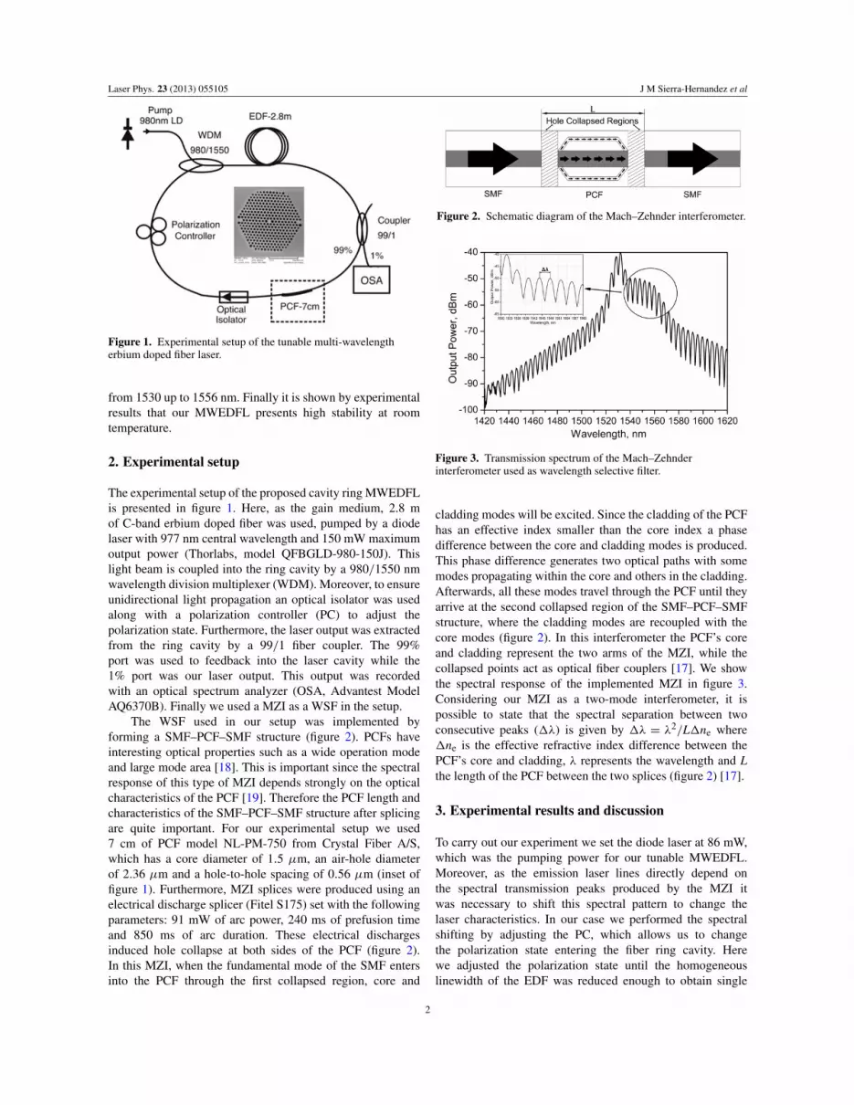
Figure 1. Experimental setup of the tunable multi-wavelengtherbium doped fiber laser.
from 1530 up to 1556 nm. Finally it is shown by experimentalresults that our MWEDFL presents high stability at roomtemperature.
2. Experimental setup
The experimental setup of the proposed cavity ring MWEDFLis presented in figure 1. Here, as the gain medium, 2.8 mof C-band erbium doped fiber was used, pumped by a diodelaser with 977 nm central wavelength and 150 mW maximumoutput power (Thorlabs, model QFBGLD-980-150J). Thislight beam is coupled into the ring cavity by a 980/1550 nmwavelength division multiplexer (WDM). Moreover, to ensureunidirectional light propagation an optical isolator was usedalong with a polarization controller (PC) to adjust thepolarization state. Furthermore, the laser output was extractedfrom the ring cavity by a 99/1 fiber coupler. The 99%port was used to feedback into the laser cavity while the1% port was our laser output. This output was recordedwith an optical spectrum analyzer (OSA, Advantest ModelAQ6370B). Finally we used a MZI as a WSF in the setup.
The WSF used in our setup was implemented byforming a SMF–PCF–SMF structure (figure 2). PCFs haveinteresting optical properties such as a wide operation modeand large mode area [18]. This is important since the spectralresponse of this type of MZI depends strongly on the opticalcharacteristics of the PCF [19]. Therefore the PCF length andcharacteristics of the SMF–PCF–SMF structure after splicingare quite important. For our experimental setup we used7 cm of PCF model NL-PM-750 from Crystal Fiber A/S,which has a core diameter of 1.5 µm, an air-hole diameterof 2.36 µm and a hole-to-hole spacing of 0.56 µm (inset offigure 1). Furthermore, MZI splices were produced using anelectrical discharge splicer (Fitel S175) set with the followingparameters: 91 mW of arc power, 240 ms of prefusion timeand 850 ms of arc duration. These electrical dischargesinduced hole collapse at both sides of the PCF (figure 2).In this MZI, when the fundamental mode of the SMF entersinto the PCF through the first collapsed region, core and
Figure 2. Schematic diagram of the Mach–Zehnder interferometer.
Figure 3. Transmission spectrum of the Mach–Zehnderinterferometer used as wavelength selective filter.
cladding modes will be excited. Since the cladding of the PCFhas an effective index smaller than the core index a phasedifference between the core and cladding modes is produced.This phase difference generates two optical paths with somemodes propagating within the core and others in the cladding.Afterwards, all these modes travel through the PCF until theyarrive at the second collapsed region of the SMF–PCF–SMFstructure, where the cladding modes are recoupled with thecore modes (figure 2). In this interferometer the PCF’s coreand cladding represent the two arms of the MZI, while thecollapsed points act as optical fiber couplers [17]. We showthe spectral response of the implemented MZI in figure 3.Considering our MZI as a two-mode interferometer, it ispossible to state that the spectral separation between twoconsecutive peaks (1�) is given by 1� = �2/L1ne where1ne is the effective refractive index difference between thePCF’s core and cladding, � represents the wavelength and Lthe length of the PCF between the two splices (figure 2) [17].
3. Experimental results and discussion
To carry out our experiment we set the diode laser at 86 mW,which was the pumping power for our tunable MWEDFL.Moreover, as the emission laser lines directly depend onthe spectral transmission peaks produced by the MZI itwas necessary to shift this spectral pattern to change thelaser characteristics. In our case we performed the spectralshifting by adjusting the PC, which allows us to changethe polarization state entering the fiber ring cavity. Herewe adjusted the polarization state until the homogeneouslinewidth of the EDF was reduced enough to obtain single
2

Laser Phys. 23 (2013) 055105 J M Sierra-Hernandez et al
Figure 4. (a) Single laser output spectrum, (b) independent tuning of one of the laser emissions, (c) measured output spectrum recordedevery 2 min and (d) laser output power variations.
laser emission (figure 4(a)). Moreover this single laseremission can be tuned from 1530.24 nm up to 1556.20 nmby performing a fine adjustment of the PC (figure 4(b)). Theside mode suppression ratio (SMSR) for this single line was32 dBm. To validate the power stability operation of the laserat room temperature, its spectrum was scanned repeatedly for50 min at intervals of 2 min (figure 4(c)). From these resultswe observed that output power variations were 0.07 dBm(figure 4(d)).
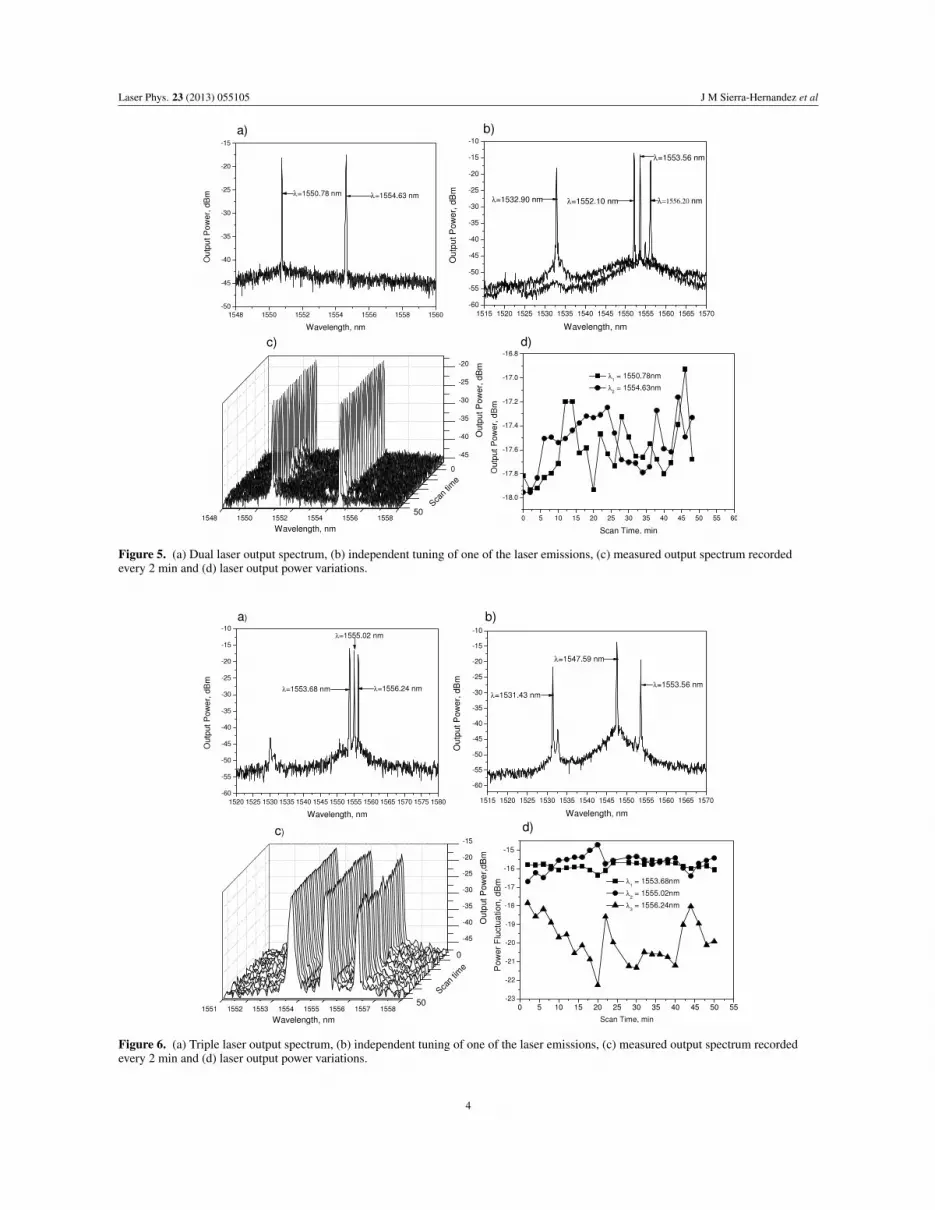
In order to obtain a dual wavelength laser it was necessaryto change the polarization state. In this way we obtained twoemission lines (figure 5(a)). Moreover, the spectral separationbetween these two lines could be varied by finely adjustingthe polarization controller (figure 5(b)). For this case it isimportant to comment that during the tuning process thereis a certain point where the two lines overlap in wavelength,producing a single line emission. Moreover, for the dual lasingcase the SMSR is 30 dBm. As in the single line case, thelaser spectrum was recorded every 2 min during 50 min(figure 5(c)) to observe its stability over time. In this way wemeasured, for the particular case when the laser emitted at1550.78 and 1554.63 nm, that the fluctuation output powerswere 1 and 0.7 dBm respectively (figure 5(d)).
To obtain a triple line laser we adjusted the PC untilthree laser lines were obtained. For instance, figure 6(a) showsmeasured emissions at 1553.68, 1555.02 and 1556.24 nm.Moreover, these lines can be tuned producing differentspectral separations between them. Hence, as an example,
we spectrally tuned the 1531 nm line, as can be observed infigure 6(b). It is important to point out that in certain casessome of these lines match in position with those obtainedin the single and double laser operation modes. We alsorecorded the spectral response of the laser every 2 min during50 min to determine its stability (figure 6(c)). For instance,we obtained that the measured SMSRs for the particular casewhen the laser emitted at 1553.68, 1555.02 and 1556.24 nmwere 27, 33 and 25 dBm respectively. Moreover we obtainedthat for the 1555.02 nm line the output power variation was2 dBm, while for the 1553.68 and the 1556.24 nm lines theoutput power variations were 1 and 4 dBm respectively(figure 6(d)).
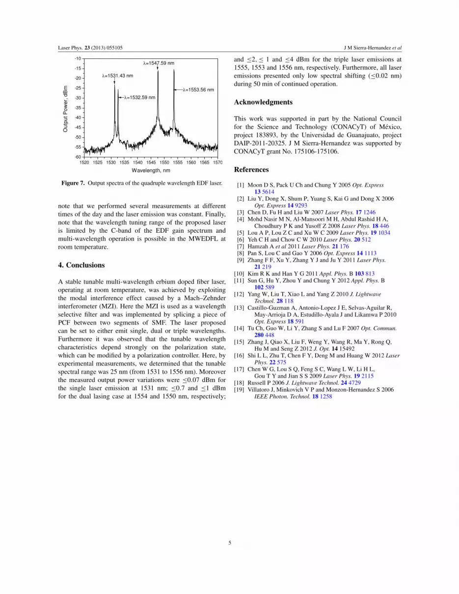
As in the other laser cases, by controlling polarizationwe even could obtain four line emissions. For example, infigure 7 we present the laser output spectrum with emissionsat 1531.43, 1532.29, 1547.59 and 1553.56 nm. Although thisis an interesting result in terms of the number of lines, itsperformance is more limited, since it can be observed that theline emissions have different powers. Furthermore, the laserin the quadruple line mode only operated in a stable way fora few minutes, after which the power fluctuation of the lineswas considerable.
In general the laser output power variations observedare related to the EDF properties and to the polarizationstate. Furthermore, for the three cases the measured laserwavelength shifting was 0.02 nm during 50 min ofcontinued operation at room temperature. It is important to
3
Laser Phys. 23 (2013) 055105 J M Sierra-Hernandez et al
Figure 5. (a) Dual laser output spectrum, (b) independent tuning of one of the laser emissions, (c) measured output spectrum recordedevery 2 min and (d) laser output power variations.
Figure 6. (a) Triple laser output spectrum, (b) independent tuning of one of the laser emissions, (c) measured output spectrum recordedevery 2 min and (d) laser output power variations.
4
Laser Phys. 23 (2013) 055105 J M Sierra-Hernandez et al
Figure 7. Output spectra of the quadruple wavelength EDF laser.
note that we performed several measurements at differenttimes of the day and the laser emission was constant. Finally,note that the wavelength tuning range of the proposed laseris limited by the C-band of the EDF gain spectrum andmulti-wavelength operation is possible in the MWEDFL atroom temperature.
4. Conclusions
A stable tunable multi-wavelength erbium doped fiber laser,operating at room temperature, was achieved by exploitingthe modal interference effect caused by a Mach–Zehnderinterferometer (MZI). Here the MZI is used as a wavelengthselective filter and was implemented by splicing a piece ofPCF between two segments of SMF. The laser proposedcan be set to either emit single, dual or triple wavelengths.Furthermore it was observed that the tunable wavelengthcharacteristics depend strongly on the polarization state,which can be modified by a polarization controller. Here, byexperimental measurements, we determined that the tunablespectral range was 25 nm (from 1531 to 1556 nm). Moreoverthe measured output power variations were 0.07 dBm forthe single laser emission at 1531 nm; 0.7 and 1 dBmfor the dual lasing case at 1554 and 1550 nm, respectively;
and 2, 1 and 4 dBm for the triple laser emissions at1555, 1553 and 1556 nm, respectively. Furthermore, all laseremissions presented only low spectral shifting (0.02 nm)during 50 min of continued operation.
Acknowledgments
This work was supported in part by the National Councilfor the Science and Technology (CONACyT) of Mexico,project 183893, by the Universidad de Guanajuato, projectDAIP-2011-20325. J M Sierra-Hernandez was supported byCONACyT grant No. 175106-175106.
References
[1] Moon D S, Pack U Ch and Chung Y 2005 Opt. Express13 5614
[2] Liu Y, Dong X, Shum P, Yuang S, Kai G and Dong X 2006Opt. Express 14 9293
[3] Chen D, Fu H and Liu W 2007 Laser Phys. 17 1246[4] Mohd Nasir M N, Al-Mansoori M H, Abdul Rashid H A,
Choudhury P K and Yusoff Z 2008 Laser Phys. 18 446[5] Lou A P, Lou Z C and Xu W C 2009 Laser Phys. 19 1034[6] Yeh C H and Chow C W 2010 Laser Phys. 20 512[7] Hamzah A et al 2011 Laser Phys. 21 176[8] Pan S, Lou C and Gao Y 2006 Opt. Express 14 1113[9] Zhang F F, Xu Y, Zhang Y J and Ju Y 2011 Laser Phys.
21 219[10] Kim R K and Han Y G 2011 Appl. Phys. B 103 813[11] Sun G, Hu Y, Zhou Y and Chung Y 2012 Appl. Phys. B
102 589[12] Yang W, Liu T, Xiao L and Yang Z 2010 J. Lightwave
Technol. 28 118[13] Castillo-Guzman A, Antonio-Lopez J E, Selvas-Aguilar R,
May-Arrioja D A, Estudillo-Ayala J and Likamwa P 2010Opt. Express 18 591
[14] Tu Ch, Guo W, Li Y, Zhang S and Lu F 2007 Opt. Commun.280 448
[15] Zhang J, Qiao X, Liu F, Weng Y, Wang R, Ma Y, Rong Q,Hu M and Seng Z 2012 J. Opt. 14 15492
[16] Shi L L, Zhu T, Chen F Y, Deng M and Huang W 2012 LaserPhys. 22 575
[17] Chen W G, Lou S Q, Feng S C, Wang L W, Li H L,Gou T Y and Jian S S 2009 Laser Phys. 19 2115
[18] Russell P 2006 J. Lightwave Technol. 24 4729[19] Villatoro J, Minkovich V P and Monzon-Hernandez S 2006
IEEE Photon. Technol. 18 1258
5


