Embed Size (px)
Citation preview

8 Accidental and Deliberate OilSpills in Europe: Detection,Sampling and SubsequentAnalyses
K. N. Timm# Springer
L. Peperzak1 . P. Kienhuis2 . C. P. D. Brussaard1,* . J. Huisman3
1Royal Netherlands Institute for Sea Research/NIOZ, Den Burg,The [email protected]
*[email protected] of Transport and Water Management, Waterdienst,
AA Lelystad, The [email protected] of Transport and Water Management, RWS-Noordzee,Lange Kleiweg, GK Rijswijk, The Netherlands
1
Introduction . . . . . . . . . . . . . . . . . . . . . . . . . . . . . . . . . . . . . . . . . . . . . . . . . . . . . . . . . . . . . . . . . . . . . . 34732
European and Regional Co-Operation . . . . . . . . . . . . . . . . . . . . . . . . . . . . . . . . . . . . . . . . . . 34733
Detection and Monitoring of Pollution . . . . . . . . . . . . . . . . . . . . . . . . . . . . . . . . . . . . . . . . . . 34743.1
Pollution Surveillance . . . . . . . . . . . . . . . . . . . . . . . . . . . . . . . . . . . . . . . . . . . . . . . . . . . . . . . . . . . . . . 34743.2
Instruments Capacity . . . . . . . . . . . . . . . . . . . . . . . . . . . . . . . . . . . . . . . . . . . . . . . . . . . . . . . . . . . . . . 34763.3
Side Looking Airborne Radar (SLAR) . . . . . . . . . . . . . . . . . . . . . . . . . . . . . . . . . . . . . . . . . . . . 34763.4
Synthetic Aperture Radar (SAR) . . . . . . . . . . . . . . . . . . . . . . . . . . . . . . . . . . . . . . . . . . . . . . . . . . 34763.5
Infrared Line Scanner or Camera (IR) . . . . . . . . . . . . . . . . . . . . . . . . . . . . . . . . . . . . . . . . . . . . 34773.6
Ultra Violet Line Scanners or Camera (UV) . . . . . . . . . . . . . . . . . . . . . . . . . . . . . . . . . . . . . . 34783.7
Microwave Radiometer (MWR) . . . . . . . . . . . . . . . . . . . . . . . . . . . . . . . . . . . . . . . . . . . . . . . . . . . 34783.8
Laser Fluorosensor (LFS) . . . . . . . . . . . . . . . . . . . . . . . . . . . . . . . . . . . . . . . . . . . . . . . . . . . . . . . . . . 34783.9
Photographic Camera (PHOTO) . . . . . . . . . . . . . . . . . . . . . . . . . . . . . . . . . . . . . . . . . . . . . . . . . . 34783.10
Visual Observation . . . . . . . . . . . . . . . . . . . . . . . . . . . . . . . . . . . . . . . . . . . . . . . . . . . . . . . . . . . . . . . . . 34783.11
Assessing the Oil Volume at Sea . . . . . . . . . . . . . . . . . . . . . . . . . . . . . . . . . . . . . . . . . . . . . . . . . . . 34803.12
The Bonn Agreement Oil Appearance Code . . . . . . . . . . . . . . . . . . . . . . . . . . . . . . . . . . . . . . 34803.13
Standard Procedure for Assessing the Volume . . . . . . . . . . . . . . . . . . . . . . . . . . . . . . . . . . . . 34804
Sampling at Sea, Analysis and Interpretation of the Results . . . . . . . . . . . . . . . . . . . 34814.1
CEN/TR 15522 Oil Spill Identification . . . . . . . . . . . . . . . . . . . . . . . . . . . . . . . . . . . . . . . . . . . . 34814.2
BONN-OSINET (Oil Spill Identification Network) . . . . . . . . . . . . . . . . . . . . . . . . . . . . . . 34824.3
Oil Sampling Purposes . . . . . . . . . . . . . . . . . . . . . . . . . . . . . . . . . . . . . . . . . . . . . . . . . . . . . . . . . . . . . 34824.4
Short Term Environmental Protection . . . . . . . . . . . . . . . . . . . . . . . . . . . . . . . . . . . . . . . . . . . . 3482is (ed.), Handbook of Hydrocarbon and Lipid Microbiology, DOI 10.1007/978-3-540-77587-4_271,
-Verlag Berlin Heidelberg, 2010

3472 8 Accidental and Deliberate Oil Spills in Europe: Detection, Sampling and Subsequent Analyses
4.5
Long Term Environmental Protection . . . . . . . . . . . . . . . . . . . . . . . . . . . . . . . . . . . . . . . . . . . . . 34834.6
Information Service . . . . . . . . . . . . . . . . . . . . . . . . . . . . . . . . . . . . . . . . . . . . . . . . . . . . . . . . . . . . . . . . 34834.7
Taking Samples: Thick Waterborne Layers, Oil Globules and Tar Balls . . . . . . . . . 34834.8
Taking Samples: Sampling of Thin Oil Films (Sheens) . . . . . . . . . . . . . . . . . . . . . . . . . . . 34844.9
Taking Samples: Use of a Sampling Buoy from an Airplane . . . . . . . . . . . . . . . . . . . . . 34854.10
Taking Samples: Water Samples for Bioassays . . . . . . . . . . . . . . . . . . . . . . . . . . . . . . . . . . . . 34854.11
Oil Sample Preparation . . . . . . . . . . . . . . . . . . . . . . . . . . . . . . . . . . . . . . . . . . . . . . . . . . . . . . . . . . . . 34864.12
GC-FID Analysis . . . . . . . . . . . . . . . . . . . . . . . . . . . . . . . . . . . . . . . . . . . . . . . . . . . . . . . . . . . . . . . . . . . 34864.13
GC-MS Analysis . . . . . . . . . . . . . . . . . . . . . . . . . . . . . . . . . . . . . . . . . . . . . . . . . . . . . . . . . . . . . . . . . . . . 34864.14
Databases for Oil Spill Identification . . . . . . . . . . . . . . . . . . . . . . . . . . . . . . . . . . . . . . . . . . . . . . 34885
Conclusions . . . . . . . . . . . . . . . . . . . . . . . . . . . . . . . . . . . . . . . . . . . . . . . . . . . . . . . . . . . . . . . . . . . . . . . 3488
Accidental and Deliberate Oil Spills in Europe: Detection, Sampling and Subsequent Analyses 8 3473
Abstract: Oil spills range from small deliberate bilge and slob discharges to extremely large
tanker accidents. Special monitoring programs in coastal areas are in force with airplanes to
detect smaller spills. Satellite detection is needed to track the transport of larger oil slicks,
especially in remote areas. A number of remote sensing techniques including Side Looking
Airborne Radar (SLAR), Synthetic Aperture Radar (SAR), Infrared and UV Line Scanning
and Microwave Radiometry (MWR) are discussed. The standard procedure of assessing oil
volumes at sea is presented. In the case of deliberate pollution or oil spill removal after an
accident when costs have to be reclaimed at the polluter, judicious oil sampling and sample
handling on-board is imperative. Sampling is different when bioassays will be used to measure
the toxicity of oil compounds in the water. Sample analyses include GC-FID and GC-MS.
Details of practical detection, sampling and analyses are provided.
1 Introduction
Oil spills range from small bilge or slob spillages of less than 1 ton to spills resulting from
stranded tankers and tanker collisions of up to 300,000 tonnes. Bilge and slob spills, oil
remains from the engine room and the ships tanks, are deliberate acts that do not attract
much public attention. On the other hand, accidental tanker strandings and collisions cause
wide-spread pollution and attract enormous attention by the media. At the international level
of the maritime community legislation with regard to pollution is laid down in the MARPOL
convention (www.imo.org). Deliberate pollution is a criminal offence and ship owners are
prosecuted and fined with increasing penalties when caught red-handed and when sufficient
proof has been brought to court. Accidental pollution in most cases results in extensive claims
for recovery of costs for counter pollution measurements and restoration of damaged goods.
Depending on spill size and chemical and physical characteristics of the oil, a decision has
to be taken to remove the spill (and how) or to let the spill disperse naturally. In the case of
spill removal the costs have to be reclaimed at the polluter. In all cases oil samples have to be
carefully taken and analyzed. In addition, bioassays can be used to measure the presence
and the direct toxicological effect of oil compounds in the water which needs a different
kind of sampling.
The process of oil detection, water sampling, on-board sample work-up and analysis will
be described in general from a legal perspective but with a high practical applicability.
2 European and Regional Co-Operation
Coastal States in Europe have established a close co-operation under the umbrella of
the European Maritime Safety Agency (www.emsa.eu.int) for detection of pollution in an
early stage, but also in finding a common approach in dealing with the pollution. Although
co-operation at the EU level is very relevant, it should be recognized that the coastal state co-
operation, defining issues of common interest, started at regional or even sub-regional level.
The BONN Agreement (www.bonnagreement.org), encompassing countries around the
North Sea is the oldest (1969) regional agreement. The 1974 HELSINKI Convention (www.
helcom.fi) covers the Baltic States while the Barcelona (1976) (www.rempec.org) and Lisbon
Conventions (1996) provide platforms for the coastal states around the Mediterranean.

3474 8 Accidental and Deliberate Oil Spills in Europe: Detection, Sampling and Subsequent Analyses
At sub-regional level one will find many bi- or multilateral operational plans focusing on a
specific sea area in which two or more EU member states have a common interest for
protection against pollution. An example is DenGerNeth, which is an operational plan for
the protection of the Wadden Sea area that is part of the jurisdiction of Denmark, Germany
and The Netherlands.
3 Detection and Monitoring of Pollution
The amount of accidentally spilled oil will decrease by evaporation, dissolution, biodegrada-
tion and sedimentation and winds and currents will transport oil slicks away from the spill
site. Satellite detection is used to track the resulting large-scale oil pattern. Bilge and slob spills
are more frequent but much smaller in size and special daily monitoring programs with
airplanes, using a range of detection techniques are needed to detect these spills.
A brief history shows that a few states started to overfly coastal areas with small
aircrafts in the mid sixties, mainly collecting data of passing vessels for navigational reasons.
However, because during this flights oil slicks were also observed, the priority of the
flight tasks shifted to catching ships when discharging. In the late seventies Side Looking
Airborne Radar (SLAR) was developed and this instrument provided a tool for long-range
detection.
Visual observation from an aircraft is very limited in use, firstly because only daylight
operations are possible and secondly, horizontal and vertical sight can be limited for the
human eye. With SLAR the area that could be monitored increased enormously.
Other instruments, such as InfraRed and microwave sensors, contributed to collecting
data of oil slicks because of their specific capabilities. In the beginning of the nineties satel-
lite SAR (radar) became available for pollution detection and monitoring (> Fig. 1). Satellites
supplement routine aircraft surveillance operations. A satellite nowadays is considered to be
the ‘‘first alert’’ sensor and when needed an aircraft will follow-up getting a closer picture of
what might be an oil slick.
Despite all electronic sensors that provide data, it is still the operator (human eye) who
recognizes the oil, can discriminate between different types of oil, assess the volume and, most
important, will advise response authorities on counter pollution measures. Finally, his official
statement will initiate proceedings if according to the public prosecutor sufficient evidence has
been gathered.
3.1 Pollution Surveillance
The primary task for a marine pollution surveillance aircrew is to detect, observe, investigate,
evaluate and report (oil) pollution. Assessing the volume of an oil slick is the result of a
calculation using variables recorded during the detection (remote sensing instruments) and
observation (visual) of related circumstances and conditions. The result of the calculation is
only an estimation; an indication of quantity.
In flight, all detections should be treated in the same way regardless of whether they are
considered legal or illegal, from whatever the source, known or unknown. All detections
should be investigated and the fullest data set possible collected and recorded using the

. Figure 1
Radar images of oil spills at sea: (a) Side Looking Airborne Radar (SLAR); the oil slick is just below
the cross in the top right. (b) Satellite Airborne Radar (SAR). Images courtesy RWS-Noordzee.
Accidental and Deliberate Oil Spills in Europe: Detection, Sampling and Subsequent Analyses 8 3475
available remote sensing and photographic equipment together with visual observation.
The data should be evaluated and a volume calculated. The estimated quantity of oil forms
the basis for the decision to respond, together with other essential information such as
location and weather.

3476 8 Accidental and Deliberate Oil Spills in Europe: Detection, Sampling and Subsequent Analyses
3.2 Instruments Capacity
To be of use in dealing with (oil) pollution incidents, remote sensing instruments have to
provide the capability to clearly and unambiguously indicate the pollution on the sea surface
from a reasonable distance under normal conditions. In addition, it is desirable to have means
to identify the type of pollution and the source of the pollution as well as means for estimating
the pollutant volume.
Sensors fall into broad categories according to their mode of operation. Active sensors
emit a signal and measure some feature of the interaction of the signal and the target, usually
by analyzing the return echo. Radar Systems and Laser Fluorimetry are examples of active
sensors used for pollution detection. Passive sensors do not emit a signal, but rely instead on
emissions from the target, usually the reflection or transmission of ambient electromagnetic
radiation. Ultra Violet and Infrared line scanners as well as passive microwave radiometers are
examples of these types of sensors. In general, active scanners can operate at any time of day
and to some extent can penetrate clouds. Passive sensors will only be functional when there is
sufficient ambient radiation, and this usually means during daytime.
3.3 Side Looking Airborne Radar (SLAR)
The SLAR is an active sensor that measures the roughness of the sea surface. Microwaves in the
region of 3 cm are transmitted in pulses and the reflection from the surface is used to build up
a radar picture on both sides of the aircraft. Oil on the sea surface will reduce its surface
tension, resulting in a dampening of the capillary waves that will show up against the
surrounding clear water (> Fig. 1a).
SLAR is the most common device in use at present. Under normal conditions, between
wind forces of 1 up to 7 Beaufort, the system will cover an area of up to 40 km on either side of
the aircraft. When flying undisturbed at an altitude along a straight track, the SLAR-image will
cover a total area of 80 km in width although there is a gap directly under the aircraft
corresponding with 1.5 times the altitude. Within the area covered the presence of even thin
layers of surface pollution can be detected, again provided that there is sufficient roughness at
the sea surface to detect clutter. The spatial resolution of SLAR lies on average at about 20 m.
This means that two objects at the same distance from the antenna should have a separation of
at least 20 m to be detected as separate objects. For oil detection the polarization of the system
is vertical, for ice detection horizontal polarization is often used.
The main disadvantage of the SLAR, common to all radar systems, is that it responds to
any phenomenon that suppresses capillary waves. For example, certain current patterns, ice,
and surface slicks associated with biological activity can all produce false targets. To conclude,
it is emphasized that though SLAR is the primary long-range detection sensor, the only
information obtained is an indication that ‘‘something’’ is floating at the surface that probably
requires further investigations.
3.4 Synthetic Aperture Radar (SAR)
With respect to the detection of sea surface pollution the SAR is similar to the SLAR
(> Fig 1b). However, from a technical point of view there are some important differences.
Accidental and Deliberate Oil Spills in Europe: Detection, Sampling and Subsequent Analyses 8 3477
Where the SLAR uses a fixed antenna length, the SAR system can define the antenna length by
sampling echo’s over a period of time. The advantage of the SAR is its improved spatial
resolution that remains the same over the entire area covered. At this stage of development
SAR is used in satellites and in special projects such as terrain height mapping. Operational use
of SAR in aircraft with the objective to detect oil is not yet common. Both SAR and SLAR
provide the capability to discriminate between sea areas with undisturbed wave patterns and
areas where capillary waves are suppressed. The radar systems can’t ‘‘see’’ oil.
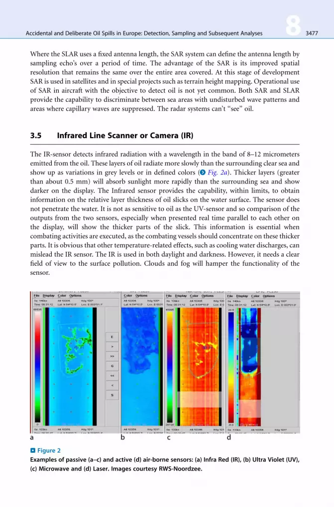
3.5 Infrared Line Scanner or Camera (IR)
The IR-sensor detects infrared radiation with a wavelength in the band of 8–12 micrometers
emitted from the oil. These layers of oil radiate more slowly than the surrounding clear sea and
show up as variations in grey levels or in defined colors (> Fig. 2a). Thicker layers (greater
than about 0.5 mm) will absorb sunlight more rapidly than the surrounding sea and show
darker on the display. The Infrared sensor provides the capability, within limits, to obtain
information on the relative layer thickness of oil slicks on the water surface. The sensor does
not penetrate the water. It is not as sensitive to oil as the UV-sensor and so comparison of the
outputs from the two sensors, especially when presented real time parallel to each other on
the display, will show the thicker parts of the slick. This information is essential when
combating activities are executed, as the combating vessels should concentrate on these thicker
parts. It is obvious that other temperature-related effects, such as cooling water discharges, can
mislead the IR sensor. The IR is used in both daylight and darkness. However, it needs a clear
field of view to the surface pollution. Clouds and fog will hamper the functionality of the
sensor.
. Figure 2
Examples of passive (a–c) and active (d) air-borne sensors: (a) Infra Red (IR), (b) Ultra Violet (UV),
(c) Microwave and (d) Laser. Images courtesy RWS-Noordzee.

3478 8 Accidental and Deliberate Oil Spills in Europe: Detection, Sampling and Subsequent Analyses
3.6 Ultra Violet Line Scanners or Camera (UV)
Surface pollution, especially oil, is a good reflector of the ultraviolet component of sunlight.
An ultraviolet scanner or camera is a passive device detecting reflected ultraviolet with a
wavelength of about 0.3 mm (> Fig. 2b). The sensor is mounted vertically in the belly of the
aircraft and can build up a continuous image of an entire slick, even the extremely thin areas, as
the aircraft passes over the slick. It cannot distinguish between types of pollution or different
layer thickness. The application of the sensor is limited to daylight conditions. The UV is very
similar in operation to the IR and the two are very often combined in a UV/IR Line Scanner.
3.7 Microwave Radiometer (MWR)
The passive MWR sensor is rather similar to the UV/IR-Line Scanner. It detects microwave
radiation with wavelengths between 0.3 and 3 cm. Oil appears always to be at higher
temperatures than seawater in the microwave region, and its temperature depends on the
thickness of the oil layer (> Fig. 2c). This relationship is not a simple one, but by careful
selection of operating wavelengths and careful analysis of the results, the system provides the
capability of a relatively accurate account of the volume of oil in the slick. A minimum layer
thickness of 0.1 mm of oil is required to make proper use of MWR. Operational discharges that
are allowed according theMARPOL regulations will not result in a layer thickness over 0.1 mm.
3.8 Laser Fluorosensor (LFS)
The LFS is an active sensor emitting an intense beam of coherent laser light to the sea surface
immediately below the aircraft. The receiving apparatus does not respond to the direct reflection
of the beam but it detects and analyses the fluorescence light emitted by pollution on the sea
surface (> Fig. 2d). The laser will not penetrate through clouds, but the instrument can be used
during both daylight and darkness. The experience with LSF is limited to just one country,
where it has shown to be capable to provide information on the type of pollution present.
3.9 Photographic Camera (PHOTO)
Conventional photography provides a valuable, simple and readily understood record of
the scene of an incident or operational discharge (> Fig. 3). When vertically mounted in the
aircraft, the camera contributes to the evidence of an official statement. Oblique photography
in general satisfies the public and the Courts as part of the evidence rather than the more
complex imagery from the other sensors. It is recommended that cameras are an integrated
part of the remote sensing system and that the photographs are date-annotated.
3.10 Visual Observation
Visual observation of the pollution and the polluter provides essential information about the
size, appearance and spatial coverage of the slick that are used for the initial estimate of

. Figure 3
Dutch oil-response vessel ‘‘Arca’’ combatting an oil slick. Image courtesy RWS-Noordzee.
Accidental and Deliberate Oil Spills in Europe: Detection, Sampling and Subsequent Analyses 8 3479
the volume of oil spilled. The visual form of an oil slick may also suggest the probable cause of
pollution. A long thin slick of oil sheen suggests a possibly illegal discharge of oil from a ship.
The cause is obvious if the ship is still discharging, as the slick will be connected to the ship,
but the slick may persist for some time after discharge has stopped; it will subsequently be
broken up and dispersed by wind and waves. A triangular slick with one side aligned with the
wind and another aligned with the prevailing current suggests a sub-sea release, such as that
from a sub-sea oil pipeline or oil slowly escaping from a sunken wreck.
The visual observation can be influenced by several factors, cloud, sunlight, weather, sea,
and angle of view, height, speed and local features as well as the type of oil. The observer
should be aware of these factors and try to make adjustments for as many as possible. It is
suggested that the ideal height to view the oil will vary from aircraft to aircraft. For example,
an ‘‘Islander’’ with its low speed allows observation at a lower level than a ‘‘Merlin’’ with its
higher speed. For an aircraft with a speed of around 150 knots a height of around 700 to 1,000 feet
is suggested.
It is recommended that the slick should be viewed from all sides by flying a racetrack
pattern around the oil. The best position to view the oil is considered to be with the sun behind
the observer and the observer looking at the object/subject from an angle of 40 to 45� to the
perpendicular. The oil appearances will generally follow a pattern. The thinner oils, sheen,
rainbow and metallic, will normally be at the edges of the thicker oils, discontinuous true color
and true color. It would be unusual to observe thick oil without the associated thinner oils;
however, this can occur if the oil has aged and/or weathered or if the oil is very heavy. Heavy oil
will tend to be mainly true color and have very sharp defined edges.
3480 8 Accidental and Deliberate Oil Spills in Europe: Detection, Sampling and Subsequent Analyses
According to MARPOL the oil quantity in water-bilge mixtures is limited to 15 ppm. In
special areas no discharge is permitted. Field studies in the Netherlands have proven that when
an operator visually observes oil in the wake of a vessel there is at least 50 ppm of oil in the
discharged water, thus a violation of MARPOL regulations.
3.11 Assessing the Oil Volume at Sea
The visible spectrum ranges from 400 to 750 nm (0.40–0.75 mm). Any visible color is a mixture
of wavelengths within the visible spectrum. White is a mixture of all wavelengths; black is
absence of all light. The color of an oil film depends on the way the light waves of different
lengths are reflected off the oil surface, transmitted through the oil (and reflected off the water
surface below the oil) and absorbed by the oil. The observed color is the result of a combina-
tion of these factors; it is also dependant on the type of oil spilled. An important variable is
optical density: the ability to block light. Distillate fuels and lubricant oils consist of the lighter
fractions of crude oil and will form very thin layers that are almost transparent. Crude oils vary
in their optical density; black oils block all the wavelengths to the same degree but even then
there are different ‘‘kinds of black,’’ residual fuels can block all light passing through, even in
thin layers.
3.12 The Bonn Agreement Oil Appearance Code
Since the color of the oil itself as well as the optical effects are influenced by meteorological
conditions, altitude, angle of observation and color of the sea water, an appearance cannot be
characterized purely in terms of apparent color or an ‘‘appearance’’ code. Therefore, using
terms independent of specific color names the Bonn Agreement Oil Appearance Code has
been developed as follows:
� In accordance with scientific literature and previously published scientific papers,
� Its theoretical basis is supported by small scale laboratory experiments,
� It is supported by mesoscale outdoor experiments,
� It is supported by controlled sea trials.
Due to slow changes in the continuum of light, overlaps in the different categories were found.
However, for operational reasons, the code has been designed without these overlaps. Using
thickness intervals provides a biased estimation of oil volumes that can be used both for legal
and for response procedures. For operational reasons grey and silver have been combined into
the generic term ‘sheen’. Thus, five levels of oil appearances are distinguished in code, with
details in >Table 1. Examples are given in > Fig. 4.
3.13 Standard Procedure for Assessing the Volume
The operator of a reconnaissance aircraft that is fully equipped with remote sensing instru-
ments has all assets available for providing reliable information on observed oil pollution.
On the SLAR display the oil slick is presented as a dark (grey-level) feature against a brighter
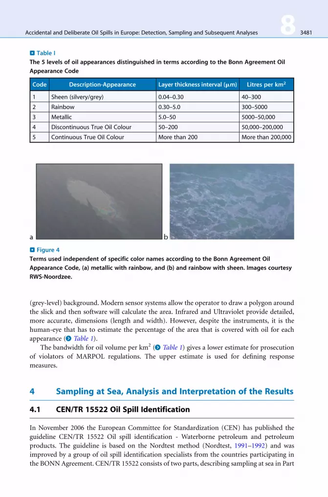
. Figure 4
Terms used independent of specific color names according to the Bonn Agreement Oil
Appearance Code, (a) metallic with rainbow, and (b) and rainbow with sheen. Images courtesy
RWS-Noordzee.
. Table I
The 5 levels of oil appearances distinguished in terms according to the Bonn Agreement Oil
Appearance Code
Code Description-Appearance Layer thickness interval (mm) Litres per km2
1 Sheen (silvery/grey) 0.04–0.30 40–300
2 Rainbow 0.30–5.0 300–5000
3 Metallic 5.0–50 5000–50,000
4 Discontinuous True Oil Colour 50–200 50,000–200,000
5 Continuous True Oil Colour More than 200 More than 200,000
Accidental and Deliberate Oil Spills in Europe: Detection, Sampling and Subsequent Analyses 8 3481
(grey-level) background. Modern sensor systems allow the operator to draw a polygon around
the slick and then software will calculate the area. Infrared and Ultraviolet provide detailed,
more accurate, dimensions (length and width). However, despite the instruments, it is the
human-eye that has to estimate the percentage of the area that is covered with oil for each
appearance (> Table 1).
The bandwidth for oil volume per km2 (> Table 1) gives a lower estimate for prosecution
of violators of MARPOL regulations. The upper estimate is used for defining response
measures.
4 Sampling at Sea, Analysis and Interpretation of the Results
4.1 CEN/TR 15522 Oil Spill Identification
In November 2006 the European Committee for Standardization (CEN) has published the
guideline CEN/TR 15522 Oil spill identification - Waterborne petroleum and petroleum
products. The guideline is based on the Nordtest method (Nordtest, 1991–1992) and was
improved by a group of oil spill identification specialists from the countries participating in
the BONNAgreement. CEN/TR 15522 consists of two parts, describing sampling at sea in Part

3482 8 Accidental and Deliberate Oil Spills in Europe: Detection, Sampling and Subsequent Analyses
1 and the analysis and interpretation of the results in Part 2. In order to be available when
a quick response is needed, the BONN Agreement decided to publish on their website a
summary of Part 1 as a free downloadable document (http://www.bonnagreement.org/eng/
doc/Chapter32 - Part I Oil Spill Identification - Sampling.doc). A summary of Part 2 is
described by Hansen et al. (2007).
4.2 BONN-OSINET (Oil Spill Identification Network)
In 2005 oil sample identification laboratories and experts in the European Union have formed
a network under the name BONN-OSINET (Oil Spill Identification Network).
The main purpose of the co-operation is to give mutual assistance, to maintain a high level
of professionalism and to accredit laboratories e.g., through Round Robin testing.
In case of large spills in which two or more countries are involved, the laboratories will
exchange sample identification results. By building a database on types of oil, reference
material is in place to compare sample analysis results. Information about BONN-OSINET
and reports of the annual Round Robins can be found of the BONN-agreement website (www.
bonnagreement.org).
4.3 Oil Sampling Purposes
Sampling and subsequent analysis should answer questions regarding the spills’ origin as well as
their properties and effects. To accomplish this, samples are taken to serve several different
purposes. Some spills may involve contacts and co-ordination with other countries regarding
sampling and analysis. On some occasions, the International Oil Pollution Compensation Funds
in London needs supplementing information. Occasionally, foreign agencies should be contacted
to exchange samples, analysis results, and examination reports. Furthermore, special analyses
can give important support information for the planning of response and cleanup work. It is
important to study chemical and physical property data of the substance when selecting
equipment and methods as well as safety routines for the response operation. All spills encoun-
tered and all potential sources of spills should be sampled. It is important to take samples from
both spill and source even on occasions where it seems quite clear fromwhere the spill originates.
If bio-assays will be performed, methods employing living organisms to measure the toxicity of
dissolved oil compounds in the water, care must be taken to sample the water layer underneath
the oil slick in order to prevent contamination by small oil droplets. Because bio-assays give a
relative measure of toxicity, samples should also be taken at pristine reference locations (e.g.,
Peperzak et al., in prep.). Reference locations are sites without oil contamination that share
environmental characteristics such as temperature and salinity with the contaminated site.
The most common types of sampling equipment and routines are described below.
4.4 Short Term Environmental Protection
The substance’s acute deleterious effects on the environment may vary considerably depending
on its chemical and physical properties. Extremely viscous oils have fewer tendencies to smear
beaches, plants and animals. Medium viscous oils create high risk for smearing. Low viscous

Accidental and Deliberate Oil Spills in Europe: Detection, Sampling and Subsequent Analyses 8 3483
oils give low risk for smearing, but dissolve greater amounts of dangerous components into the
water body. Besides the substance itself it may also be necessary to sample and analyze the
water column, sediment or organisms.
4.5 Long Term Environmental Protection
Certain substances may cause long term deleterious effects on the environment, and some
species may be knocked out, or the environment be polluted for a long time. Assessment
should be made to judge how the environment could be restored. It may be necessary to
sample and analyze the substance itself, as well as water, sediment and organisms.
4.6 Information Service
In any incident questions are asked about the substance’s properties and effects, especially
when facing a large or hazardous spillage. In such cases it is important to give rapid and correct
information in order to reduce anxiousness and circulating of rumors. Sampling and analysis
can thereby provide the basis for information to be given and for the choice of information
channels. When informing the public, and those who are directly affected by the spill, it is
important to account for certain data, for example,
� The spill’s origin and extension.
� The substance’s properties and spread in the environment.
� Effects on human and environment.
� Consequences for various parties and bodies.
� Ongoing work regarding response, cleanup and disposal.
The following types of procedures for sampling and taking soundings are commonly used
when oil spills have occurred
� Sampling on the water surface.
� Sampling on shorelines, including oiled animals.
� Sampling on board vessels to investigate suspected crimes.
� Sampling on board vessels to ascertain whether an oil is ‘‘persistent’’ according to the
criteria issued by the International Oil Pollution Compensation Funds in London.
4.7 Taking Samples: Thick Waterborne Layers, Oil Globulesand Tar Balls
Focus the sampling on thick parts of the spill. If the spill is large, it is important to take samples
in several positions within the spill to get a representative sample selection. Globules, balls and
thick parts can often be sampled directly by a sample bottle. Fill the bottle with as many balls as
possible or skim oil from the surface by repeated sweeps with the bottle. Remove the water that
has entered the bottle. One method of doing this is to close the lid and hold the bottle upside
down for a minute to let the oil float upwards to the bottom of the bottle so that the water can
3484 8 Accidental and Deliberate Oil Spills in Europe: Detection, Sampling and Subsequent Analyses
be drained by careful opening of the lid. Continue then to skim oil and try to get the bottle
approximately three-quarters full of dewatered oil.
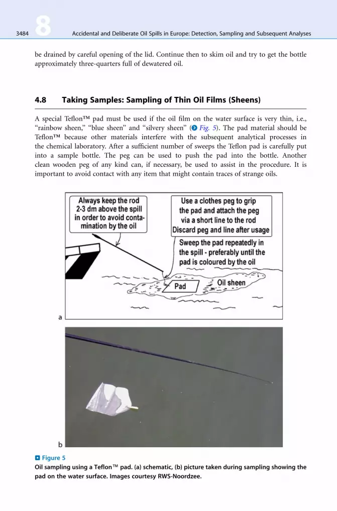
4.8 Taking Samples: Sampling of Thin Oil Films (Sheens)
A special Teflon™ pad must be used if the oil film on the water surface is very thin, i.e.,
‘‘rainbow sheen,’’ ‘‘blue sheen’’ and ‘‘silvery sheen’’ (> Fig. 5). The pad material should be
Teflon™ because other materials interfere with the subsequent analytical processes in
the chemical laboratory. After a sufficient number of sweeps the Teflon pad is carefully put
into a sample bottle. The peg can be used to push the pad into the bottle. Another
clean wooden peg of any kind can, if necessary, be used to assist in the procedure. It is
important to avoid contact with any item that might contain traces of strange oils.
. Figure 5
Oil sampling using a Teflon™ pad. (a) schematic, (b) picture taken during sampling showing the
pad on the water surface. Images courtesy RWS-Noordzee.

. Figure 6
Sampling buoy to be used from an airplane.
Accidental and Deliberate Oil Spills in Europe: Detection, Sampling and Subsequent Analyses 8 3485
4.9 Taking Samples: Use of a Sampling Buoy from an Airplane
It is possible to drop a sampling buoy into an oil spill from an aircraft. A Teflon™
pad is attached to the buoy in order to collect oil from the surrounding area (> Fig. 6).
After being recovered from the surface of the sea, the samples are sealed and secured and
with a guiding document stored on board until the bottles can be delivered ashore at the
accredited laboratory. Any transfer of the samples is noted and signed for in the guiding
document.
4.10 Taking Samples: Water Samples for Bioassays
Bioassays are used to test the toxicity of oil compounds in the water phase and therefore, in
contrast to the sampling methods above, the water should be devoid of oil from the surface or
oil droplets just below the slick. This can be achieved by navigating the ship from clean water
into the spill with a hose kept continuously under the water surface. In the spill, water is
pumped up through the hose, used directly in the assay, or stored in fully filled (hexane-) pre-
cleaned glass bottles with caps fitted with Teflon™ inlays and stored at �18�C. During an
experimental spill in the North Sea, samples under the oil slick were taken with a specially
designed sampler (Brussaard et al., in prep.). To be able to interpret bioassay results, control
samples should be taken at uncontaminated sites with clean equipment, not used in sampling
oil-contaminated sites.

3486 8 Accidental and Deliberate Oil Spills in Europe: Detection, Sampling and Subsequent Analyses
4.11 Oil Sample Preparation
Samples can be delivered at the lab as
� Pure crude oil or oil products based on mineral oil or vegetable oil.
� Mixtures of oil products from bilges and slop tanks.
� Feathers of birds contaminated with oil.
� Oil mixed with sand from the beaches.
� Oil dissolved in water.
Most inland samples contain mineral oil based products like diesel (gas oil), lubricating oil or
mixtures of diesel and lubricating oil (e.g., from ship bilges).
Most samples from the sea or coast contain crude oil, paraffins, bunker oil and/or
lubricating oil. Small humps of weathered vegetable oil have been found along rivers and on
beaches. It looks quite similar as paraffins and is therefore sent to the laboratory for identifi-
cation. Humps of vegetable oil can be recognized by the behavior of birds like sea gulls. They
eat from the vegetable oil, but not from the paraffin humps.
In the lab the samples are dissolved in or extracted with dichloromethane. To protect the
analytical system viscous black oil like Heavy Fuel Oil (HFO) is cleaned over silica to remove
the high molecular components like asphaltenes.
4.12 GC-FID Analysis
The samples are first analyzed by GC-FID: Gas Chromatography-Flame Ionization Detection.
A short column (10 m non-polar phase) and fast temperature program (slope of
>10�C min�1) is used to be able to give a first response in a short time.
The GC-FID analysis gives information about:
� The type of oil involved.
� The injection concentration.
(important in case of extracted samples)
� The degree of weathering.
� The similarity with oil samples from suspected sources.
Identification of the type of oil and the physical and chemical components is vital information
with regard the response measures. Sometimes the analysis can tell more about the origin of
the oil. Application of dispersant spraying is among others also based on these results. In the
case of deliberate pollution, when the discharging vessel was caught red-handed, it is impor-
tant for some European Member States to prove that the substance discharged at sea is a
mineral oil.
4.13 GC-MS Analysis
In case the oil from the oil spill must be compared with suspected source(s), a second analysis
with Gas Chromatography-Mass Spectrometry (GC-MS) is needed. Based on the information

Accidental and Deliberate Oil Spills in Europe: Detection, Sampling and Subsequent Analyses 8 3487
of the GC-FID, samples are selected and when needed adjusted in injection concentration. The
samples are analyzed in selected ion mode on a longer non-polar column (30–60 m) and a
slower temperature program (slope of about 5�C min�1) to detect the presence of a range of
PAH’s and biomarker compounds. Examples of chromatograms of the GC-FID and GC-MS
analyses are given by Dahlmann (2003).
The results of the GC-MS analysis are used to confirm the type of oil, based on the
presence or absence of specific compounds in the samples. In case of sample comparison,
all patterns must be compared. In the older Nordtest method the comparison is performed
by printing the ion chromatograms and to compare them visually. To reduce personal
bias CEN/TR 15522–2 demands that the peak height or peak area of a range of compounds
must be measured. From the peak areas, ratios must be calculated and compared. The
procedure assumes that the ratios can be analyzed with a standard deviation of less
than 5%. Rules to eliminate compounds influenced by weathering and small peaks with
a higher standard deviation are given. The relative difference between each ratio of a
suspected source and the spill sample is based on the repeatability limit and must be equal
or lower than 14%.
Results and conclusions of the GC-FID and GC-MS analyses are described in a report that
can be used for judicial procedures against offenders. CEN/TR 15522–2 applies the following
conclusion definitions:
� Identical
No differences observed in the chromatographic patterns of GC/FID and GC/MS apart
from those changes introduced after the spill (weathering, degradation etc.)
� Positive match
Differences in chromatographic patterns and diagnostic ratios of the samples submitted
for comparison are lower than the analytical variance of the method or can clearly be
explained by weathering. The samples are identical beyond reasonable doubt
� Probable match
Differences in chromatographic patterns and diagnostic ratios of the samples submitted
for comparison are larger than the analytical variances of the method, but can be explained
by external factors like contamination or heterogeneity of the samples. For example,
comparing lubricating oil with the lubricating oil part of a bilge sample may lead to a
probable match
� Inconclusive
Differences in chromatographic patterns and diagnostic ratios of the samples submitted
for comparison are larger than the analytical variance of the method and may only to some
extent be explained by external factors like weathering, contamination, heterogeneity of
the samples or too low amount of sample material
Note: Differences may be due to e.g., heterogeneities of the oil either within the spill or
within the suspected source (e.g., within the ship tank), that is not reflected in the available
samples analyzed, or differences are present because the samples do not originate from the
same source
� Non-match
Differences in chromatographic patterns and diagnostic ratios of the samples submitted
for comparison are distinct and larger than the analytical variance of the method, and they
cannot be explained by external factors like weathering, contamination and heterogeneity.
The samples are distinctly different.

3488 8 Accidental and Deliberate Oil Spills in Europe: Detection, Sampling and Subsequent Analyses
4.14 Databases for Oil Spill Identification
CEN/TR 15522-2 is a guideline describing how to compare samples within one case.
By the use of a database containing the results of many cases, more can be said about the
uniqueness of the samples. Kristin Sorheim of SINTEF (Norway) has developed a database in
Excel, which stores the ratios calculated according CEN/TR 15522–2 of each sample. By
copying the whole actual sample set into a PCA program the best fit can be found. Next the
chromatograms of the samples of interest can be compared.
Gerhard Dahlmann of BSH (Germany) has developed a database called COSI working in
Access (http://www.bsh.de/de/Meeresdaten/Umweltschutz/Oelidentifizierung/Oeldatenbank.
ppt). The original data in the form of the retention time/signal of each chromatogram are
loaded into the database. Integration on selected peaks is done automatically. Peaks are
searched for in a small retention time window and therefore a strict protocol is needed. The
ratios are calculated and stored in the database. By means of PCA formula’s the best fit for a
sample with all samples in the database is given, and the chromatograms are shown. At this
moment the database contains more than 1,000 samples including 250 crude oils and is used
by 3 labs in Germany, Estonia and The Netherlands. Sweden and Belgium intend to start using
the database in 2009. In case of emergencies, comma separated values (csv files) can be
exchanged by email and read into the database.
5 Conclusions
In roughly four decades individual observation by a coastal state has turned into a well spread
network between European Member States. Trans-boundary co-operation and co-ordination
results in building professionalism in the detection and monitoring of deliberate oil spills, but
also in the sample analysis methods for prosecuting discharging vessels. This policing work
provides a solid basis for a high level of preparedness in case of accidental spills.
Acknowledgments
This work was supported by a grant from the FP6 European Framework program (STREP
project FACEiT, contract number 018391).
References
Brussaard, et al. Experimental pollution: experimental
design, logistics, safety, sampling, analysis. In
Microbiology of Hydrocarbons, Oils, Lipids.
KN Timmis (ed.). Vol (in prep). Heidelberg:
Springer.
Dahlmann G (2003) Characteristic Features of Different
Oil Types in Oil Spill Identification. Berichte des
BSH (31): 48 (http://www.bsh.de/de/Produkte/Bue-
cher/Berichte_/Bericht31/Bericht31.pdf.
Etkin DS (1999) Historical overview of oil spills from all
sources (1960–1998) 1999 International Oil Spill
Conference, 8pp.
Hansen AG, et al. (2007) Oil Spill Environmental Foren-
sics. In Fingerprinting and Source Identification.
Z Wang and S Stout (eds.). Burlington, USA:
Academic Press, pp. 554.
Huang JC (1983)Review of the state-of-the-art of oil
spill fate/behavior models 1983 Oil Spill Conference

Accidental and Deliberate Oil Spills in Europe: Detection, Sampling and Subsequent Analyses 8 3489
(Prevention, Behavior,Control, Cleanup), American
Petroleum Institute, San Antonio, Texas,
pp. 313–322.
Nordtest (1991–1992). Nordtest Method. Oil Spill Iden-
tification. NT Chem 001, Edition 2. http://www.
nordicinnovation.net/nordtestfiler/chem001.pdf.
Peperzak L, Brussaard CPD (2009) Phytoplankton via-
bility assay for oil compounds in water. In Microbi-
ology of Hydrocarbons, Oils, Lipids. KN Timmis
(ed.). vol.5, chap. 90 (in prep.). Heidelberg: Springer.


