Embed Size (px)
Citation preview

Active Corrosion Protection in Chromate and Chromate-Free
Conversion Coatings
R.G. Buchheit, S.B. Mamidipally, P.Schmutz, H. Guan Fontana Corrosion Center
Department of Materials Science Ohio State University
Columbus, Ohio 43210
ABSTRACT
Chromate conversion coatings are noted for their ability to self-heal if damaged by mechanical or chemical action provided it is not too severe. Self-healing, or active corrosion protection, involves release of chromate from the coating, transport though solution, and action at the site of damage, namely pits. A simple exposure cell, named the "simulated scratch cell", was recently devised that enables examination for each of these elements in the self healing process in a manner that is reproducible from experiment to experiment. Using this paradigm for active corrosion protection and the simulated scratch cell several chromate-free conversion coatings were examined to determine if they exhibited active corrosion protection. Active corrosion protection is imparted to hydrotalcite by introducing, or modifying, it with Ce and Mn oxides. The key to ACP in these systems appears to be that these metals exhibit soluble high oxidation state forms and lower oxidation state forms with lower solubility. When high oxidation state oxides are introduced to hydrotalcite, they can be dissolved by a contacting solution, transported to defect sites on bare aluminum samples where they are reduced and precipitated to inhibit further corrosion. These experiments show that self-healing is possible with conversion coatings other than those based on chromates.
INTRODUCTION
Chromate conversion coatings have been a mainstay in the repertoire surface
finishing technologies for aluminum, zinc, ferrous alloys, cadmium, and others for over 50 years. These coatings provide good resistance against atmospheric corrosion, and are excellent bases for primers and paints. Chromate conversion coatings are distinguished by the ease with which they are applied, their applicability to a wide range of metals and alloys, and in many cases, their ability to resist corrosion by virtue of a built-in inhibitor reservoir that can provide additional corrosion protection beyond the barrier protection afforded by the thickened oxide layer.

Built-in, or “active” corrosion protection is distinguished from “passive” corrosion protection, which is afforded by thickening a barrier oxide film on a metal surface. Active corrosion protection (ACP) by conversion coatings is less important when the coating is used as base for paints and primers that are good barriers and contain soluble chromate inhibitors themselves. However, in situations where the conversion coating is the primary barrier against corrosion, ACP is critical. This allows the component surface to withstand minor mechanical and chemical damage during service without continued, detailed maintenance. As is now well documented, chromium is being eliminated as an ingredient in metal finishing operations due to its poisonous effects on people and the environment. Over the past 15 years, a vigorous effort to minimize chromium release into the environment has developed. Part of this activity has focussed on development of chromate-free conversion coating technologies. In the case of aluminum alloys, the search for a suitable replacement has been complicated by the stringent performance requirements imposed in industrial and military specifications. A plethora of chromate-free technologies have emerged and some are being used on a commercial basis. However, none are used as widely as chromate conversion coatings. Arguably, part of the reason for lack or widespread implementation is that few if any of the chromate-free conversion coatings exhibits active corrosion protection, otherwise known as "self-healing".
ACTIVE CORROSION PROTECTION AND CHROMATE CONVERSION COATINGS
According to the most current views, chromate conversion coatings are a mixture
of hydrated amorphous Cr(III)-Cr(VI) oxide (1), hydrated aluminum oxide, ferri/ferrocyanides (1,2,3), and small to moderate quantities of alloying elements from the substrate and minor ingredients added to commercial formulations. The total amount of Cr(VI) has been estimated to range anywhere from 6 to 50% (4,5,6). Some fraction is reversibly bound in the mixed oxide, and may be leached when solution contacts the coating. Otherwise, these coatings are largely insoluble and provide barrier protection of the underlying aluminum substrate. There is both indirect and direct evidence supporting the idea that leached Cr(VI) results in dynamic repair by interaction with incipient defects in the coating. Figures 1a and b show the accumulation of pitting damage as a function of time for chromate and chromate-free conversion coatings during salt spray testing (7). Results from chromate-free coatings are collected in Figure 1a, and results from chromate conversion coatings are collected in Figure 1b. In these figures, the larger the pitting resistance index (PRI), the greater the accumulation of pitting damage. A comparison of the data in these figures shows two distinct behaviors. In Figure 1a, the PRI for many of the chromate-free coatings is high initially, and remains high for times as long as 200 h. However, once

pitting damage is initiated, it accumulates very rapidly. Correspondingly, the PRI drops off precipitously. This behavior appears to be characteristic of barrier protection. An intact barrier film is capable of resisting attack initially, but once the barrier is breached exposing bare metal, corrosion damage accumulates quickly. A different behavior is exhibited by chromate conversion coatings exposed and evaluated under identical conditions. Figure 1b shows the PRI for several different commercial chromate conversion coatings. In this case, the PRI begins and remains high for over 1000 hours of exposure. Pitting does occur, as indicated by the slight decrease in PRI, but no precipitous decrease occurs during the course of this extended exposure. This behavior is attributed to active corrosion protection. Chromate leaches from the coating and acts at incipient pits prohibiting their propagation. Clearly, the interpretation offered above for the data in Figure 1 is debatable. However, recent experiments provide a far more definitive indication of active corrosion protection. To test for ACP, Zhao et al., devised a special cell consisting of a chromate conversion coated surface and an opposing, uncoated alloy surface separated by a 1.8 mm thick O-ring (8). The space inside the O-ring and between the opposing surfaces was filled with 0.1 M NaCl. Any chromate detected on the bare surface after exposure in this cell would presumably originate from the CCC, migrate through solution and deposit on the bare surface. This simple approach, termed a "simulated scratch cell", enables rigorous examination of several requisite elements of active corrosion protection in a manner that is reproducible from experiment to experiment. Zhao made polarization resistance measurements of initially bare surfaces after various lengths of exposure time in the simulated scratch cell. Polarization resistances increased from about 104 Ω.cm2 to 106 Ω.cm2 after 48 hours of exposure. In controls experiments where two uncoated surfaces were used to construct the cell, the polarization resistance decreases slightly over the same exposure time interval. Raman spectroscopy of the initially bare surface after 48 hours showed clear evidence of the formation of solid compound in and around small pits that was spectroscopically similar to a chromate conversion coating. Solid chromium oxide deposition on the unpitted surface was not detected, but was probably present at concentrations below the detection limit of the instrumentation. In parallel experiments, Raman spectroscopy of a solution droplet in contact with a freshly formed CCC showed that 30 to 40 ppm chromate accumulated in after about 48 hours. On a CCC aged in air for 10 days, chromate only accumulated to a level of about 10 to 20 ppm.
All together these results demonstrate that chromate is released from a CCC, which is then transported through solution to act a local sites of corrosion damage. Most importantly, this process results in an improvement in the corrosion resistance. On the basis of this experiment, it is possible to establish several distinct testable elements of ACP. The are:

1) the coating contains a reservoir of an inhibiting agent that is stable until needed 2) the inhibitor can be released into a contacting solution 3) the inhibitor can be transported through solution 4) the inhibitor acts on exposed metal to suppress further corrosion.
With these testable criteria and the simulated scratch cell as a test vehicle, it is possible to rigorously examine chromate-free coatings for evidence of active corrosion protection.
CERIUM-BASED CONVERSION COATINGS Background. In the mid-1980s Hinton and coworkers examined corrosion inhibition of high strength Al alloys by rare earth metal (REM) salts dissolved in aqueous solutions, and showed that these compounds were effective inhibitors for aluminum, ferrous and zinc alloys. This work has continued steadily over the years, but the essential elements of Ce corrosion inhibition were clearly established in earliest reports of this group (9). Early work showed that 100 to 1000 ppm additions of CeCl3 to chloride solutions suppressed corrosion of 7075-T6 in potentiodynamic polarization testing and in alternate immersion weight loss testing. Surface analysis showed incorporation of Ce into compact and protective surface films. Polarization tests showed inhibition of cathodic reaction kinetics, and, as is now less widely regarded, the anodic kinetics. Later work clearly established that Ce films formed at local cathodic sites on the alloy surface stifled oxygen reduction thereby limiting corrosion damage (10,11). Film formation was proposed to occur when local cathodic activity increased the near-surface solution pH stimulating precipitation of Ce hydroxide. Perhaps most importantly, it was shown that a film with persistent corrosion resistance could be formed by exposure of alloy surface to a CeCl3 solution. This result was the basis for conversion coating formulations based on the use of Ce salts (12).
Further study revealed that films grew by an island-growth mechanism (13). Films formed first at sites of local cathodic activity such as intermetallic particles and grain boundaries. Ce(IV) oxides detected in the coating were thought to arise by oxidation of Ce(III) in oxygenated alkaline solutions. This was later confirmed by x-ray absorption near edge structure (XANES) measurements (14). It was also shown that corrosion resistant Ce coatings could be formed on Al by immersion in aqueous CeCl3 solutions either at the open circuit potential, or under cathodic polarization. Coatings were also formed by contacting surface with Ce(NO3)3 dissolved in butoxyethanol (15). As in earlier experiments, corrosion resistance appeared to be due to suppressed reduction reaction kinetics and, or for long coating formation times, suppression of the anodic kinetics and elevation in the pitting potential. Other cations were shown to inhibit reduction reaction kinetics and improve corrosion resistance by forming thin surface films. The best inhibitors included Ni2+, Pr3+, Nd3+, and Ce3+ (16). Further studies indicated that cerium salts could be used to inhibit corrosion of zinc and steel substrates (17), and that several different Ce salts provided effective corrosion inhibition (18).

The lingering problem for Ce-based passivation was the long time required for the
protective film to form; up to one week in most cases. The Hinton group eventually learned that the kinetics of Ce deposition were substantially increased by using Ce(IV) solutions (12). Highly corrosion resistant films could be formed by contacting Al alloy surfaces with a slightly acidic 1000 – 10000 ppm CeCl3 solution containing several weight percent hydrogen peroxide. The peroxide oxidized Ce(III) to Ce(IV) in solution. Mixed Ce(III)-Ce(IV) coatings formed in 6 to 10 of minutes on a range of alloys. The coatings possessed outstanding corrosion resistance in both electrochemical and exposure (salt spray ) testing.
In the late 1980s, Mansfeld began to study the effectiveness of Ce-based passivation on Al alloys and Al-based metal matrix composites by electrochemical impedance spectroscopy (19). Results showed that the corrosion resistance of 6061-T6, 7075-T6, Al-SiC, and Al-graphite metal matrix composites in aerated 0.5M NaCl were greatly improved by pre-exposure to 1000 ppm CeCl3 solutions for one week. Shih and Mansfeld monitored the EIS response of 6061-T6 and 7075-T6 aluminum alloys with and without passivation in a variety of rare earth metal salt solutions to confirm the earlier results of Hinton indicating that long-term, low temperature exposure to these solutions promoted corrosion resistance (20).
Mansfeld combined elements from this work (and perhaps from the results of the
Hinton group) with ideas developed from studies of highly corrosion resistant supersaturated non-equilibrium Al-transition metal alloys (21,22) to develop a Ce-Mo surface modification process. In this three-step process, degreased and deoxidized Al alloy surfaces were 1) immersed in 10 mM Ce(NO3)3 at 100oC, 2) immersed in 10 mM CeCl3 also at 100oC, and 3) potentiostatically polarized at +0.5 Vsce in deaerated 0.1M Na2MoO4. Al alloys surfaces treated in this manner resisted pitting in aerated 0.5M NaCl solutions for 60 days.
Independent characterization of the coatings produced on 2024-T3 and 6061-T6 by Ce-Mo surface modification. The coating was analyzed after each stage in the process and the evolution in coating chemistry and thickness was determined. Results showed that the coating consisted primarily of hydrated aluminum oxide (23) with Ce was detected on and near cathodic intermetallic compounds such as Al7Cu2Fe in 2024 and Al12Si(Fe,Mn,Cr) in 6061-T6. Ce was not associated with active intermetallics like Al2CuMg. Rather, these intermetallics were dissolved during the anodic polarization in the molybdate solution, leaving Mo-rich pits. In general more Ce was detected in coatings on 2024-T3, than on 6061-T6. This work plainly showed the importance of alloy chemistry and microstructure in Ce-Mo coating formation. In terms of coating chemistry, Ce was detected in trivalent and tetravalent oxidation states, while Mo was detected only in its hexavalent form. It was argued that Mo(VI) in the coating provided self-healing, by reduction to Mo(IV), however no Mo(IV) was detected. XANES measurements of Ce-

Mo coatings after exposure to 0.5M NaCl for 30 days suggests that Mo(VI) is leached into solution and does not participate in self-healing (24).
Noting that the Ce-Mo surface modification process thickened the oxide film and imparted Ce and Mo into it, Kendig sought to determine how critical a role Ce and Mo played in determining the overall corrosion resistance (25). To isolate the role of these heavy metals, Kendig formed coatings using a Ce and Mo-free process consisting of 4h immersion in boiling 30 mM NaNO3 followed by 2 polarization at 0.5 Vsce in 0.1M borate solution. Coatings containing only Ce or Mo were also made to isolate effects due to either Ce or Mo. The corrosion resistance of these coatings were compared to that of coatings formed by Ce-Mo surface modification. Corrosion resistance during immersion in aerated 0.5 M NaCl solution was measured using EIS for exposure times up to two weeks. The data were analyzed by equivalent circuit analysis and the pitting resistance, Rpit , was used a figure of merit to estimate relative corrosion resistances. The pitting resistance of the coatings decreased in the order:
Ce-Mo > Mo-only > Ce Only > Ce-Mo-free.
The results suggested that Ce and Mo play a synergistic role in providing corrosion resistance. According to Kendig’s interpretation of the results Ce forms insoluble oxides that reinforce the hydrated aluminum oxide film and the oxidizing Mo species plays the role of active inhibitor. This latter comment is significant in that it is perhaps the first referral to and recognition of “active corrosion protection” in a Cr-free conversion coating system, though whether it actually occurs as described is an open question.
This fundamental work, which has evolved only over the past 15 years, has spawned a considerable amount of technological innovation in corrosion inhibition. REMs are used as corrosion inhibitors added to metals as alloying elements (26, 27), imparted into conversion and anodized coatings (28), and used as soluble corrosion inhibitors (29). A number of recent patents have been issued that describe the use of Cerium as a primary or supplemental ingredient in corrosion resistant coating formulations. These coating processes can be classified as follows: 1) Ce-sealed hydrothermal films. In these processes, thickened films are formed by hydrothermal treatment and then sealed in a Ce(III) or Ce(IV) solution. Examples include Ce sealed boehmite coatings formed by elevated temperature in water (30), or triethanolamine solutions (31). Hydrotalcite coatings may also be sealed by contact with Ce solutions (32). 2) Surface Modification. In these processes a potential is applied to the surface to induce deposition of Ce from solution. This can be accomplished by cathodic polarization, which develops alkaline conditions at the electrode surface and induces Ce precipitation (33).

As described above, Mansfeld uses slight anodic polarization to stimulate interaction of Mo with thickened hydrothermal layers sealed with Ce (34). 3) Cerating. These processes are analogs to Hinton’s immersion-based approach to developing REM coatings. Surfaces are contacted with a slightly acidic solution containing soluble Ce(III) or Ce(IV) as the primary film-forming agent (35). Active Corrosion Protection from Ce-modified Hydrotalcite. Cerium occurs in a moderately soluble +4 oxidation state and a comparatively insoluble +3 oxidation state. If a tetravalent oxide were to be introduced into a thickened barrier layer on aluminum, it might be possible to replicate active corrosion protection (ACP), or self-healing. Consider a scenario where a solution contacts a Ce(IV)-bearing coating. under these conditions, soluble Ce4+ would be released. If the Ce4+ ions encountered the reducing conditions associated with bare metal exposed through a coating defect, reduction to Ce(III) and precipitation would ensue. Precipitation of a hydrated Ce oxide at the defect might then stifle further corrosion.
To test whether this hypothesized self-healing scenario is plausible, a series of experiments were carried out based on the methods of Zhao et al. (8). As described earlier, Zhao devised a simulated scratch cell (SSC) to test for ACP in chromate conversion coatings. Modifications made to Zhao’s design are shown schematically in Figure 1. In the present experiment, one 2024-T3 surface is coated with Ce-modified hydrotalcite, the other bare 2024-T3. In these experiments, each surface was 5.1 cm2. The surfaces are separated by a 5 mm gap that was filled with a 0.5M NaCl solution. In this arrangement, the bare surface is examined for evidence of healing by release of Ce4+, from the Ce-modified hydrotalcite coating on the opposing surface.
For this experiment, Ce-modified hydrotalcite coatings were produced by a two step process. First, hydrotalcite was formed on degreased and deoxidized 2024-T3 (Al-4.4Cu-1.5Mg-0.6Mn) by contact for 10 minutes with a pH 12 bath containing 6.9 g/L LiNO3, 28.3 g/L KNO3, 2.4 g/L LiOH, and 0.06 g/L NaAlO2 held at 98oC. The hydrotalcite coated surfaces were then immediately immersed in a room temperature solution containing 10g/L Ce(NO3)3 plus 30% H2O2 to induce precipitation of an adherent deposit of Ce4+ hydrated oxide on the alkaline hydrotalcite. Coatings were rinsed and air dried for 24 hours before any further use. Ce-modified hydrotalcite coatings have been made that will pass 168h of ASTM B117 salt fog exposure on 2024-T3. However, the coatings produced in this study were not that corrosion resistant. Figure 3 is a Nyquist plot showing the corrosion resistance of Ce-modified hydrotalcite coatings, La-modified hydrotalcite (described below) compared to chromate conversion coatings and hydrotalcite sealed with Mg acetate. The coatings used in this study exhibited coating resistances, Rc, of about 105 ohm.cm2, which is about an order of magnitude less than a typical chromate conversion coating, and is an order of magnitude less than is exhibited by coatings that normally pass a salt spray test (36).

This simulated scratch cell is the primary vehicle used to test for elements of ACP. Aliquots of the gap solution were periodically extract and examined for evidence of soluble Ce. After exposure, the cell was disassembled and the bare side “simulated scratch” was examined for the presence and distribution of Ce deposition. The corrosion resistance measurements were made of the bare side to determine if its corrosion resistance had increased signaling healing. Additionally, the corrosion resistance of the coated side was examined to determine if Ce release had caused a decrease in its corrosion resistance.
Ultraviolet (UV) absorbance measurements were used to detect Ce released into the gap solution during simulated scratch experiments. UV absorbance is sensitive to Ce concentrations as low as 10-5M (Figure 4). It can distinguish between Ce3+ and Ce4+ at concentrations as low as 10-3M (Figure 5). Figure 6 shows UV absorbance peak heights from aliquots of solution extracted from the simulated scratch cell for times ranging from 4 to 48 hours. The fact that Ce is detected confirms that Ce can be released from Ce-modified hydrotalcite into solution. The absorbance peak heights range from 0.5 to 0.9, which correspond to soluble Ce concentrations of about 3x10⁻⁴ to 3x10⁻³M or 40 to 400 ppm. Inhibition of the bare surface in the SSC is expected under these conditions considering that Hinton reports that 10 ppm CeCl3 in 0.1 M NaCl is sufficient to reduce the corrosion rate of 7075-T6 (9).
To assess changes in corrosion resistance to the bare side sample of the SSC that might indicate healing, the SSC was disassembled after 48h of exposure and the bare side impedance was measured in aerated 0.05M NaCl. Figure 7 shows the coating corrosion resistance, Rc, determined by complex non-linear least squares fitting of EIS data to a simplified Randles circuit model that describes that single time constant behavior of the bare side of the SSC. Rc data are plotted as a function of exposure time in the 0.05 M NaCl test solution. For comparison, Rc data are shown for a bare 2024-T3 surface exposed to another, identical bare surface for 48 h in the SSC, and a polished 2024-T3 surface exposed only to the 0.05 M NaCl solution. The curves represent averages of three replicate runs; error bars have been omitted for clarity. Inspection of the data shows that the surface exposed in the SSC with the Ce-modified hydrotalcite exhibits Rc values that are nearly an order of magnitude greater than that of a surface exposed only to another bare surface. This result suggests that the bare surface in the SSC has been protected from corrosion by release of Ce from the Ce-modified hydrotalcite coating.
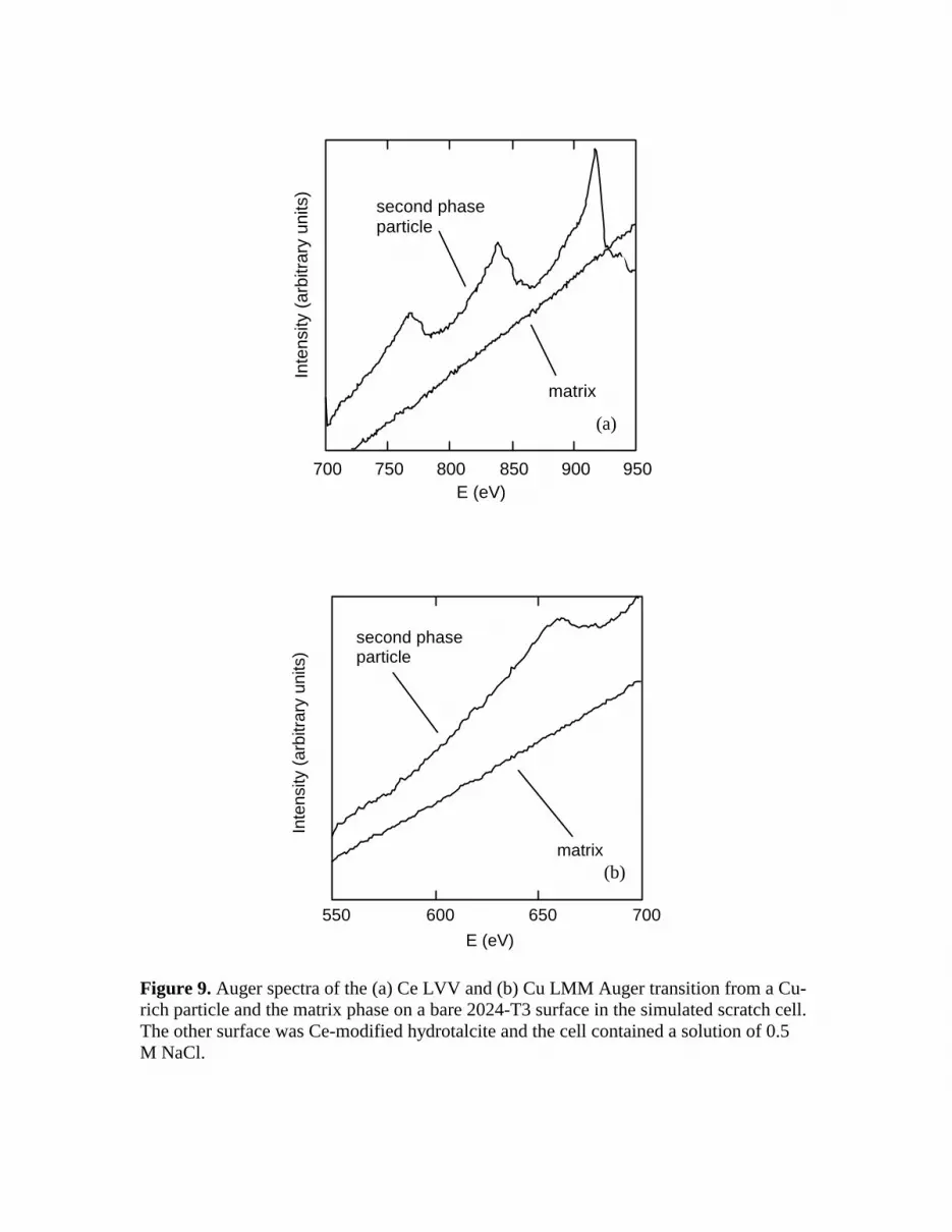
Scanning electron microscopy (SEM) and Auger electron spectroscopy (AES) were used to characterize the deposition and distribution of Ce on the bare side of the SSC. Figure 8 shows a secondary electron image of a bare surface exposed to Ce-modified hydrotalcite for 24 h in the SSC. Polishing marks are clearly visible in this image, but superimposed on those marks is a cracked surface film with locally heavier deposits. The figure indicates two areas where AES analysis was conducted. Area 1 is on a Cu-rich second phase and Area 2 on the matrix phase. Figure 9 shows AES profiles of the Ce MNN and Cu LMM transitions for both of the analysis areas. Ce is detected on the

second phase particle, but is absent on the matrix phase. This observation is consistent with Ce oxide deposition on Al alloys as it has come to be understood (18). Ce deposits initially and preferentially and on noble, Cu-rich intermetallic particles since they are sites that support reduction reactions, develop local alkalinity, and induces Ce precipitation (10,11).
In order to retain ACP for extended periods of time, it is necessary that the Ce(IV) introduced into the coating be stable. Results show that Ce in hydrotalcite coatings tends to remain or oxidize to Ce4+ in the presence of atmospheric oxygen, condensed moisture, and the prevailing alkaline conditions associated with hydrotalcites. This Ce4+ is easily liberated to provide inhibiting action at defects elsewhere in the coating. Figure 10 shows x-ray photoelectron spectroscopy (XPS) data from Ce3+- and Ce4+-modified hydrotalcite coatings both before and after 168 hours of ASTM B117 salt fog exposure. Coatings modified by immersion in a Ce(NO3)3 solution produce coatings with Ce predominantly in a +3 oxidation state. Coatings modified by immersion in a Ce(NO3)3 solution plus H2O2 contain Ce predominantly in a +4 oxidation state. These spectra are shown in the uppermost (Ce3+) and lowermost (Ce4+) plots in Figure 10. The spectra from Ce in a +4 oxidation state are readily distinguished from those due to Ce in a +3 state by the intense Ce satellite at 918.5 eV and intense features due to peak splitting in the Ce3d5/2 (885eV) and Ce3d3/2 (902eV) (37). XPS data collected from Ce3+- and Ce4+-modified hydrotalcite coatings after salt fog exposure are remarkably similar and exhibit peak splitting characteristic of Ce4+. This observation is in agreement with Davenport et al. who used x-ray absorption near edge spectroscopy to show that Ce3+ converted to Ce4+ in Ce-bearing coatings applied to Al-Mg alloys upon exposure to aerated chloride solutions (14). More importantly, this observation indicates that the Ce4+ in hydrotalcite coatings will be stabilized by the oxidizing power of natural environments until reducing conditions associated with the exposure of the aluminum substrate in defects is encountered. At those locations Ce4+ will be reduced and precipitated to inhibit corrosion. Lanthanum-modified hydrotalcite. Although Ce-modified hydrotalcite coatings are not always as corrosion resistant as chromate conversion coatings, the above data show that Ce-modified hydrotalcite coatings do, in fact, exhibit characteristics consistent with ACP. As a check, an identical series of experiments was carried out using lanthanum-modified hydrotalcite coatings. Lanthanum is an REM adjacent to Ce on the Periodic Table. La differs from Ce in that it does not exist in a tetravalent form. Like Ce, its trivalent oxide is insoluble under alkaline conditions, hence La-modified hydrotalcite coatings are not expected to exhibit the characteristics of ACP.
La-modified hydrotalcite coatings were formed using procedures identical to those used to form a Ce-modified coatings. La was introduced into the coating by immersion for 1 minute in a 10 g/L La(NO3)3 solution. The corrosion resistance of La-modified coatings was about 105 ohm-cm2 in EIS testing after 24 hour exposure to 0.5 M NaCl, which is similar to that of Ce-modified coatings.

Simulated scratch cell experiments were then conducted with La-modified coatings. Solution extracted from the cell was analyzed by inductively-coupled plasma atomic emission spectroscopy (ICP-AES) rather than by UV absorbance since La does not absorb at UV wavelengths. La was not detected in concentrations greater than 10-6M for any exposure time between 4 and 48 hours. By comparison, Ce was detected in concentrations greater than 3 x 10⁻⁴M. Consequently, Auger analysis was not able to detect La bare side of the SSC after 48 hours of exposure. As might be expected, no increase in the corrosion resistance of the bare surface was recorded.
The behavior of Ce-modified hydrotalcite in simulated scratch cell exposure is consistent with the key elements of ACP suggested by the study of Zhao, et al. (8). In these experiments, Ce deposits preferentially on Cu-rich intermetallic particles on the bare surface representing the scratch. This interaction is different that the observed for chromate, but is certainly consistent with the evolution of Ce conversion coatings reported by Hinton and others. Additionally, the absence of indications for ACP from La-modified hydrotalcite strongly suggest that ACP is not an artifact induced by the simulated scratch cell experiment. This test appears to be able to provide clear indication of the capacity of a coating system to self-heal.
MANGANESE-BASED CONVERSION COATINGS
Manganese. In many respects, manganese is chemically similar to chromium. Conversion coatings based on Mn chemistries are therefore a logical approach to the chromate-free conversion coating replacement problem. One of the best known surface conversion technologies that has evolved is based on permanganate sealing of hydrothermally grown aluminum oxide films (38,39). In this process Al alloys surfaces are immersed in boiling distilled water or steam for times ranging from tens of second to 5 minutes. This produces a 300 to 500nm thick hydrated aluminum oxide film, which is further thickened by immersion in an Al salt solution for at least one minutes. This surface is then immersed in a permanganate solution resulting in the deposition of reduced Mn oxides in the coating. A further sealing step is required to achieve corrosion resistance on unpainted 2XXX aluminum alloys. Unpainted permanganate conversion coatings have been observed to withstand 336 hours of ASTM B117 salt fog exposure without significant corrosion. When the permanganate-based process is used as a paint base, filiform corrosion resistance of polyurethane powder coated 6XXX and 3XXX alloys is comparable to when chromate conversion coatings are used. While the performance characteristics of permanganate coatings appear favorable, they are not yet widely used. Active corrosion protection from manganese-modified hydrotalcite. Manganese is especially interesting in conversion coating schemes due to its soluble high oxidation

state (Mn+7 ) and insoluble lower oxidation states ( Mn+3, Mn+2 ). As stated earlier, the existence of two oxidation states in the active agent appears to be important for ACP. It is also possible to modify hydrotalcites with permanganate using methods similar to those described with Ce and La. The behavior of Mn-modified hydrotalcite coatings was then examined in the simulated scratch cell. Mn-modified hydrotalcite coatings were formed on 2024-T3 panels surfaces by first washing, degreasing and deoxidizing surfaces. The samples were then coated by a 4 minute immersion in a hydrotalcite coating bath consisting of LiNO3, KNO3, LiOH, and NaAlO2. After a thin “primer” HT coating was formed, the samples were immersed for 2 minutes in a bath of similar composition, but with a small potassium permanganate addition. As a last step, the samples were sealed in a Mg acetate-based sealing bath. All baths were held at a constant temperature of 60oC. The coated samples were dried in air for at least 24 hrs before any further testing or examination. The Mn-modified hydrotalcite coating produced by this process is light gold in color. Examination of the coatings by scanning electron microscopy (SEM) showed no obvious morphology change associated with the modification by permanganate. Figure 11 shows the typical morphology of the coating. Figure 12 shows variation in the corrosion resistance of permanganate-modified hydrotalcite coating and chromate conversion coating during exposure to aerated 0.5 M NaCl solution. The hydrotalcite coating impedance increases with immersion time in the 0.5 M NaCl solution for the first 30 hours or so, then decreases and attains a stable value around 2 x 10⁶Ω . cm2. That is on the same order of magnitude with chromate conversion coating and 1000-fold higher than that of unprotected AA2024-T3. This value of Rc for on AA 2024-T3 indicates that a passing result in a 168-hrs salt spray test can be expected
(36). In fact, salt spray exposure of permanganate-modified hydrotalcite coated 2024-T3 produces little to no pitting after 168 hours of exposure. Figure 13 shows photographs of 2024-T3 with a permanganate modified hydrotalcite coating, a chromate conversion coating and no coating after 168 hours of exposure.
Permanganate-modified hydrotalcite coatings were examined for evidence of ACP using the simulated scratch cell. For these experiments, the cell was further modified to permit in situ measurements as shown in Figure 4. In the modified cell, an unprotected AA2024-T3 panel was fixed on the top of AA2024-T3 panel with HT- Mn coating using four plastic screws. A 5mm gap was created between the two panels by a rubber o-ring. The o-ring had a 40mm diameter and a 5mm thickness, thus the volume between the two samples were approximately 5ml. A platinum mesh was inserted into the small chamber through the rubber o-ring. A small hole was made on the top panel to fill 0.1 M NaCl solution and to accommodate a SCE reference electrode.
Exposures were carried out for a periods up to 460 hours. The untreated AA2024-T3 exposed to the HT-Mn coating was tested using EIS conducted in situ. Comparative experiments with CCC surface and surface without a coating present (both

samples untreated ) were also conducted. Figure 14 shows impedance for the untreated AA2024-T3 “simulated scratches” as a function of exposure time in the simulated scratch cell.
The initially untreated AA2024-T3 exposed to HT-Mn coating shown an
impedance of 8x 10⁴Ω . cm2 during the first 100 hrs. The impedance then increased continuously with exposure time to around 2x10⁵Ω . cm2 . A similar response was detected from the surface exposed to the chromate conversion coating. By comparison, the impedance of control sample became stable on a value of 6x 10⁴ Ω . cm2. These results indicate the possibility of manganese migration and subsequent protection. Analysis of the solution from permanganate-modified hydrotalcite simulated scratch cells has not yet been conducted. However, after exposure in the cell to the permanganate-modified hydrotalcite, bare surfaces contain several small pits, and are covered by a thin brown film suggesting transport on Mn species through solution and deposition in the form of a manganese oxide. Detailed surface analysis has not yet been conducted, but initial surveys be energy dispersive spectroscopy suggest that the Mn level of the surfaces is elevated after exposure in the simulated scratch cell.
SUMMARY On of the distinguishing characteristics of chromate conversion coatings is their ability to self-heal is damaged by modest mechanical or chemical attack. While this property has been the subject of much discussion, but the recently devised simulated scratch cell enables the phenomenon to be examined rigorous fashion. Self-healing or as has been referred to here, ACP, can be broken down into several testable characteristics. They are: 1) the coating contains a reservoir of an inhibiting agent that is stable until needed, 2) the inhibitor can be released into a contacting solution, 3) the inhibitor can be transported through solution, 4) the inhibitor acts on exposed metal to suppress further corrosion. Given these distinct characteristics, and a method of testing for them, it is possible to examine chromate-free conversion coatings for evidence of ACP. Results show that Ce-modified and Mn(permanganate)-modified hydrotalcite coatings exhibits signs of ACP. These characteristics arise due to the fact that the metals are introduced into the hydrotalcite as soluble high oxidation state hydrated oxides, but have insoluble lower oxidation state forms. When solution contacts these oxides, the dissolve and migrate through solution and are reduced when they contact the reducing Al surface elsewhere. Since these species are much less soluble in reduced form, they then precipitate on the bare surface and slow corrosion by stifling cathodic and possibly anodic kinetics. Similar experiments conducted with La-modified hydrotalcite do not show evidence of ACP. La exists only in a low solubility trivalent form. Once it is introduced to the hydrotalcite coating, it is not release and can not participate in the subsequent events that lead to Ce-like ACP. Finally, this result provides important evidence indicating that ACP, as described here, is not an artifact of the simulated scratch cell.

ACKNOWLEDGEMENTS The authors would like to acknowlege the financial support of the U.S. Department of Energy, Sandia National Laboratories, DARPA and SERDP. The authors would also like to thank M. Martinez, L. Montes, W. Buttry, and W. Zhang for various technical contributions.
REFERENCES 1) L. Xia, R. L. McCreery, J. Electrochem. Soc. (1999). 2) N. J. Newhard, Metal Finishing, 49, 66 (1972). 3) P. L. Hagans, C.M. Haas, Surface and Interf. Anal., 21, 65 (1994). 4) A. E. Hughes, R. J. Taylor, B. R. W. Hinton, Surface and Interf. Anal., 25, 223
(1997). 5) M. Koudlekova, J. Electrochem. Soc., 124, 1165 (1977). 6) A. J. Davenport, H. S. Isaacs, Corrosion Sci., 31, 105 (1990). 7) National Center for Manufacturing Sciences, “Alternatives to Chromium for Metal
Finishing,” NCMS Report 0273RE95, Ann Arbor, MI (1995). 8) J. Zhao, G. S. Frankel, R. L. McCreery, J. Electrochem. Soc., 145, 2258 (1998). 9) B.R.W. Hinton, D.R. Arnott, N.E. Ryan, Metals Forum, 7, 211 (1984). 10) A. J. Aldykewicz, Jr., H.S. Isaacs, A.J. Davenport, J. Electrochem. Soc., 142, 3342
(1995). 11) A. J. Aldykewicz, Jr., H.S. Isaacs, A.J. Davenport, J. Electrochem. Soc., ???,???
(1995). 12) B. W. R. Hinton patent. 13) D. R. Arnott, N. E. Ryan, B. R. W. Hinton, B. A. Sexton, A. E. Hughes, Applications
of Surface Science 22/23, 236 (1985). 14) A. J. Davenport, H. S Isaacs, M. W. Kendig, Corrosion Sci., 32, 653 (1991). 15) B. R. W. Hinton, D. R. Hinton, N. E. Ryan, Mater. Forum, 9, 162 (1986). 16) D. R. Arnott, B .R. W. Hinton, N. E. Ryan, Materials Perf., Aug., p. 42 (1987). 17) B. R. W. Hinton, D. R. Arnott, Microstructural Science, 17, 311 (1989). 18) B. R. W. Hinton, J. of Alloys and Compounds, 180, 15 (1992). 19) F. Mansfeld, S. Lin, S. Kim, H. Shih, Electrochim. Acta, 34, 1123 (1989), and F.
Mansfeld, S. Lin, S. Kim, H. Shih, Corrosion, 45, 615 (1989). 20) H. Shih, F. Mansfeld, "Passivation in Rare Earth Metal Chlorides—A New
Conversion Coating Process for Aluminum Alloys", p. 180, New Methods for Corrosion Testing of Aluminum Alloys, ASTM STP 1134, V. S. Argawala, G. M. Ugiansky, Eds., American Society for Testing and Materials, Philadelphia (1992).
21) B. A. Shaw, G. D. Davis, T. L. Fritz, K. A. Oliver, J. Electrochem. Soc., 137, 359 (1990).
22) W. C. Moshier, G. D. Davis, G. O. Cote, J. Electrochem. Soc., 133, 1063 (1990).

23) A. E. Hughes, J. D. Gorman, P. J. K. Patterson, Corrosion Science, 38, 1957 (1996), and J. D. Gorman, S. T. Johnson, P. N. Johnston, P. J. K. Paterson, A. E. Hughes, Corrosion Science, 38, 1977 (1996).
24) J. Wan, G. E. Thompson, K. Q. Lu, C. J. E. Smith, J. Phys. IV France, 7, c2, 1182 (1997).
25) M. Kendig, C. Thomas, J. Electrochem. Soc., 139, L103 (1992). 26) R. N. Singh, N. Verma, W. R. Singh, Corrosion, 45, 222 (1989). 27) A. C. Crossland, G. E. Thompson, P. Skeldon, G. C. Wood, C. J. E. Smith, H.
Habazaki, K. Shimizu, Corrosion Sci., 40, 871 (1998). 28) F. Mansfeld, C. Chen, C.B. Breslin, D. Dull, J. Electrochem. Soc., 145, 2792 (1998). 29) F. M. Seon, J. Less Common Metals, 148, 73 (1989). 30) A. Kindler, U.S. Patent 5,192,374, March (1993). 31) R. Rungta, U.S. Patent 5,362,335, November (1993). 32) R. G. Buchheit, M.A. Martinez, U.S. Patent 5,756,218, May (1998). 33) Ref the missouri guys. 34) F. B. Mansfeld, H. Shih, Y. Wang, U.S. Patent 5,194,138, March (1993). 35) S. Ikeda, U.S. Patent 4,992,115, February (1991), R.N.Miller, U.S. Patent 5,356,492,
October (1994). 36) NCMS paper 37) G. Praline, B. E. Koel, R. L. Hance, H-I. Lee, J. M. White, J. of Electron
Spectroscopy and Related Phenomena, 21, 17 (1980). 38) J. W. Bibber, Metal Finishing, Dec., 46 (1993). 39) J. W. Bibber, Metal Finihsing, April, 28 (1998).

0
10
20
30
40
50
0 200 400 600 800 1000
Pitti
ng R
esis
tanc
e In
dex
Exposure Time (hours)
0
10
20
30
40
50
0 200 400 600 800 1000
Pitti
ng R
esis
tanc
e In
dex
Exposure Time (hours)
Figure 1. Accumulation of pitting damage versus exposure time for (a) chromate-free, and (b) chromate conversion coating on 7075-T6 after ASTM B117 salt spray exposure testing. Larger pitting resistance indices correspond to a lower incidence of pitting. Figure 2. Simulated scratch cell
(a)
(b)

Figure 3. Nyquist plots of Ce- and La- modified hydrotalcite coatings and chromate conversion coatings exposed to aerated 0.5 NaCl for 24 h.
0.00
0.50
1.00
1.50
2.00
10-5 10-4 10-3 10-2 10-1
Abso
rban
ce
Concentration (M)
Ce4+
Ce3+
Figure 4. Absorbance versus Ce3+ and Ce4+ concentration.

0.0
0.3
0.6
0.9
1.2
200 300 400 500 600
Abso
rban
ce
Wavelength (nm)
Ce3+
Ce4+
10-3 M
Figure 5. Absorbance spectra for Ce3+ (Ce(NO3)3), and Ce4+ (Ce(NO3)3 + H2O2) in aqueous solution illustrating the differences in peak shape that can be used to distinguish these species at higher concentrations.
Figure 6. UV absorbance peak height from solution samples extracted from the simulated scratch cell after various exposure times. A 0.5 M NaCl solution was introduced into a cell in which bare 2024-T3 was exposed to Ce-modified hydrotalcite coated 2024-T3.

103
104
105
0 2 4 6 8 10 12
R c (ohm
. cm2 )
Exposure Time (h)
Ce-HT
Ce-CC
barecontrol
Figure 7. Rc determined by EIS after exposure to aerated 0.05 M NaCl for times up to 12 hours for 2024-T3 surfaces exposed in the simulated scratch cell with various other 2024-T3samples: Ce-HT, Ce-modified hydrotalcite coated; Ce-CC, cerium conversion coated; bare, uncoated 2024-T3; control, 2024-T3 exposed only to 0.05M NaCl for the times indicated in the figure.
Figure 8. Backscatter electron micrograph of a 2024-T3 surface exposed in the simulated scratch cell for 48 hours to 0.5 M NaCl. The other surface exposed in the cell was Ce-modified hydrotalcite. Two analysis regions are indicated. Region 1 is on a deposit located over a Cu-rich particle. Region 2 is on the matrix phase.
700 750 800 850 900 950
second phaseparticle
matrix
E (eV)
Inte
nsity
(arb
itrar
y un
its)
550 600 650 700
Inte
nsity
(arb
itrar
y un
its)
E (eV)
second phaseparticle
matrix
Figure 9. Auger spectra of the (a) Ce LVV and (b) Cu LMM Auger transition from a Cu-rich particle and the matrix phase on a bare 2024-T3 surface in the simulated scratch cell. The other surface was Ce-modified hydrotalcite and the cell contained a solution of 0.5 M NaCl.
(a)
(b)

Figure 10.
02468
10
880890900910920930
N(E
)/E
Binding Energy (eV)
02468
10
880890900910920930
N(E
)/E
Binding Energy (eV)
02468
10
880890900910920930
N(E
)/E
Binding Energy (eV)

Figure 11. Scanning electron micrograph of the permanganate-modified hydrotalcite coating. Figure 12. Coating resistance, determined by EIS, versus time for permanganate-modified hydrotalcite (HT-Mn), and a chromate conversion coatings (CCC) exposed to aerated 0.5 M NaCl solution.
EIS of HT-Mn coating in 0.5 M NaCl solution
Immersion Time ( hour)-20 0 20 40 60 80 100 120 140 160 180 200 220
CO
rros
ion
Res
ista
nce
( ohm
x c
m2 )
0
2e+6
4e+6
6e+6
8e+6
1e+7
HT-Mn CoatingCCC
Coating Resistance
(ΩΩΩΩ.cm2)
2 µm

(a) (b) (c) Figure 13. alloys 2024-T3 panels after 168 hours of ASTM B117 salt fog exposure; (a) permanganate-modified hydrotalcite, (b) chromate conversion coated, (c) no coating. Samples are 4 inches x 6 inches.

Figure 14. Schematic illustrations and photographs showing the simulated scratch cell modified for in situ measurement of ACP.

Figure 14. Corrosion resistance of bare 2024-T3 exposed to different conversion coatings in the modified simulated scratch cell. Rcorr was determined from EIS measurements. In the control experiment, two uncoated 2024-T3 samples were used in the cell.


