Embed Size (px)
Citation preview
Active Safety
“Decreasing the number and severity of pedestrian accidents by means of new technical systems in
the vehicle”
Department of Machine and Vehicle System
Students: Simon Corbin Thibault Fischer Vittorio Manente Thanaphon TangsikabuthEfe Tunc Hoda Yarmohamadi
Abstract
The aim of this report is to give to the reader an overview of the systems used,
nowadays or in the future, to reduce the number and the severity of the pedestrian
accidents.
The pedestrian accidents can be decreased both with onboard systems and with
“offboard” one as well. A review of onboard technologies like: Detecting Systems,
Warning Systems, Vehicle Systems and Car Design is shown. In the same way an
overview of “offboard” solutions, like new Infrastructures, is proposed.
The objective of this report is not only a technical description of the available
technologies but also an analysis of a low cost introduction of these systems on the
market and customer’s acceptance as well.
I
Table of Contents Abstract .......................................................................................................................... I Table of Contents.......................................................................................................... II 1 Background.................................................................................................................1
1.1 Statistic.................................................................................................................1 1.2 Pedestrian Injuries................................................................................................4
2 Detecting Systems.......................................................................................................6 2.1 Introduction..........................................................................................................6 2.2 Head-Up Display .................................................................................................6 2.3 “Intelligent” windscreen ......................................................................................7
2.3.1 Automatic windshield wiper .........................................................................7 2.3.2 Rain Repellent Windshields..........................................................................8
2.4 Vision Enhancement ............................................................................................9 2.4.1 Headlights .....................................................................................................9
2.5 Night Vision.......................................................................................................15 2.5.1 Active Night Vision ....................................................................................15 2.5.2 Passive Night Vision...................................................................................16 2.5.3 Further development and prospect..............................................................17
2.6 Video recognition...............................................................................................18 2.7 Conclusion .........................................................................................................18
3 Warning Systems ......................................................................................................19 3.1 Introduction........................................................................................................19 3.2 Blind corner monitor..........................................................................................19 3.3 Collision warning...............................................................................................21 3.4 Pedestrian Warning............................................................................................22 3.3 Conclusion .........................................................................................................24
4 Car Design ................................................................................................................25 4.1 Introduction........................................................................................................25 4.2 Bumper and Hood ..............................................................................................26
4.2.1 Bumper........................................................................................................27 4.2.2 Hood Edge ..................................................................................................27 4.2.3 Hood............................................................................................................28
4.3 Commercial Introduction of Pedestrian Friendly Design Concepts ..................29 5 Vehicle Systems........................................................................................................31
5.1 Introduction........................................................................................................31 5.2 Antilock Braking System, ABS .........................................................................31 5.3 Electronic Stability Program, ESP.....................................................................32 5.4 Electronic Brake Assistant, EBA.......................................................................33
6 Infrastructure.............................................................................................................34 6.1 Pedestrian Safety in Traffic: The Effect of infrastructure and car design .........34 6.2 Traffic Infrastructure and the Influence of Environment...................................34 6.3 New Technical Solution: LightGuard flashing cross walk system....................36
6.3.1 Commercial Introduction of LightGuard flashing cross walk system........37 Conclusion ...................................................................................................................39 References....................................................................................................................41
II
1 Background
1.1 Statistic Pedestrians account for about 10 percent of motor vehicle crash deaths, and they are
the second largest category of motor vehicle deaths after occupants.
Most of the pedestrian deaths are primarily an urban problem: many of them are killed
at crosswalks, sidewalks, median strips, and traffic islands. Physical separations like
overpasses, underpasses, and barriers can reduce the problem. Increased illumination
and improved signal timing at intersections also can be effective. Because traffic
speeds affect the risk and severity of pedestrian crashes, reducing speeds could reduce
pedestrian deaths.
Vehicle factors count, too, because the most serious injuries often result from
pedestrians being thrown onto the hoods, windshields, or tops of vehicles. Serious
injuries to people's head, pelvis, and legs are common, and the severity of such
injuries could be mitigated by improving vehicle designs and materials (Whitfield and
Fife1987).
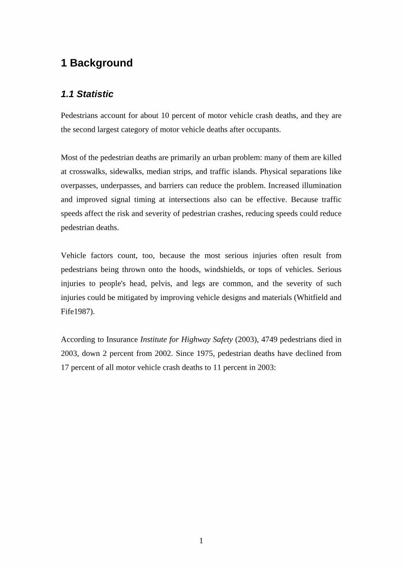
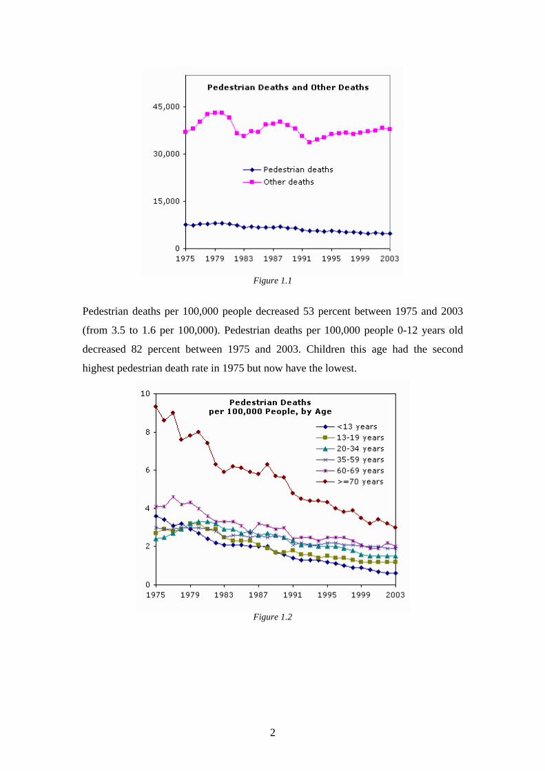
According to Insurance Institute for Highway Safety (2003), 4749 pedestrians died in
2003, down 2 percent from 2002. Since 1975, pedestrian deaths have declined from
17 percent of all motor vehicle crash deaths to 11 percent in 2003:
1
Wdko[kmcd
Figure 1.1
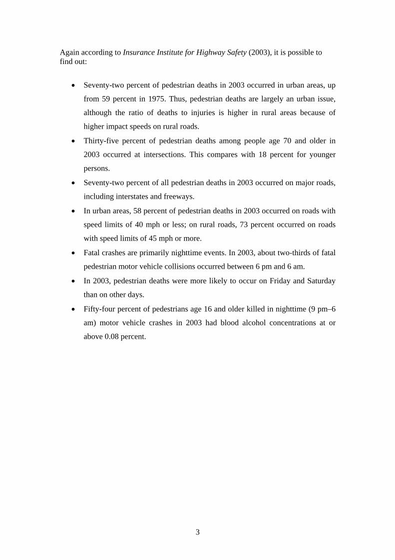
Pedestrian deaths per 100,000 people decreased 53 percent between 1975 and 2003
(from 3.5 to 1.6 per 100,000). Pedestrian deaths per 100,000 people 0-12 years old
decreased 82 percent between 1975 and 2003. Children this age had the second
highest pedestrian death rate in 1975 but now have the lowest.
Figure 1.2
2
Again according to Insurance Institute for Highway Safety (2003), it is possible to find out:
• Seventy-two percent of pedestrian deaths in 2003 occurred in urban areas, up
from 59 percent in 1975. Thus, pedestrian deaths are largely an urban issue,
although the ratio of deaths to injuries is higher in rural areas because of
higher impact speeds on rural roads.
• Thirty-five percent of pedestrian deaths among people age 70 and older in
2003 occurred at intersections. This compares with 18 percent for younger
persons.
• Seventy-two percent of all pedestrian deaths in 2003 occurred on major roads,
including interstates and freeways.
• In urban areas, 58 percent of pedestrian deaths in 2003 occurred on roads with
speed limits of 40 mph or less; on rural roads, 73 percent occurred on roads
with speed limits of 45 mph or more.
• Fatal crashes are primarily nighttime events. In 2003, about two-thirds of fatal
pedestrian motor vehicle collisions occurred between 6 pm and 6 am.
• In 2003, pedestrian deaths were more likely to occur on Friday and Saturday
than on other days.
• Fifty-four percent of pedestrians age 16 and older killed in nighttime (9 pm–6
am) motor vehicle crashes in 2003 had blood alcohol concentrations at or
above 0.08 percent.
3
1.2 Pedestrian Injuries
When a pedestrian is involved in an accident, it is possible to divide the action in two
different moments. The first one consist on the impact between the car and the
pedestrian, the second is the impact between the pedestrian and the road (Yang 2004).
These two phases are equal important in the pedestrian’s injuries and working on
these two points it is possible to reduce the severity of the consequences of the
impact.
If we consider the second impact, to reduce its severity, it is possible to work on the
asphalt characteristics. For instance we can think to use a smooth and soft asphalt to
prevent the broses and to absorb the impact energy. The introduction of smooth and
soft asphalt is an advantage from a pedestrian point of view but on the other hand it is
a disadvantage from a car’s prospective, because to have an asphalt with the same
features of rubber can increase the stopping distance and in the same time increase the
fuel consumption.
As described by Yang (2004), in the first impact we can distinguish three sub-
moments for an adult and two sub-moments for a child:
Adults
1- Impact between the leg and the bumper.
2- Impact between pelvis or abdomen and the hood’s edge.
3- Impact between the head and the hood or the windscreen; this third impact
depends on the size of the pedestrian.
Children
1- Impact of the upper part of the body (leg, abdomen) and bumper.
2- Impact between the head and the hood’s edge.
The consequences of these sub-moments are:
• Damages to tibia and/or fibula, hip bone.
• Bending of the knee joint.
• Damages to the pelvis.
4
• Damages to the torso and this means: sternum, heart, ribs, aorta, thoracic
spine, spleen and liver.
• Head injuries: skull and brain.
Sometimes the injuries, above mentioned, can be either fatal or they can have very
important consequences for the whole life of the crashed pedestrian. For this reason it
is necessary either to decrease and to avoid pedestrian injuries and this is possible if
there is the introduction of some countermeasures in the majors of active and passive
safety, and in the infrastructure as well.
5
2 Detecting Systems
2.1 Introduction In this part, we will discuss the different systems available in a near future (or already
present on few commercial cars) to improve the detection and the recognition of
pedestrians.
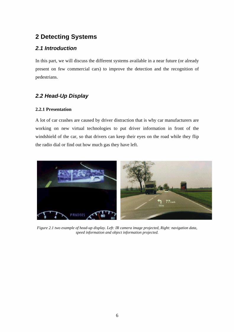
2.2 Head-Up Display 2.2.1 Presentation A lot of car crashes are caused by driver distraction that is why car manufacturers are
working on new virtual technologies to put driver information in front of the
windshield of the car, so that drivers can keep their eyes on the road while they flip
the radio dial or find out how much gas they have left.
Figure 2.1 two example of head-up display. Left: IR camera image projected, Right: navigation data,
speed information and object information projected.
6
2.2.2 How does it work? The virtual image is projected from the instrument panel onto the windscreen using
different mirrors. The problem is that the windscreen is not flat nor perpendicular to
the drivers eyes moreover it consists of two pieces of glass separated by a polymer
layer. So, the main difficulty of Head-Up Display is to provide an efficient optical
correction to make the image sharp and easy to read.
2.2.3 Commercial perspectives This technology is already available on the market but it is still relatively expensive
that is why, for the moment, only BMW use this technology on BMW 5 and 6
series… In the following years, this technology will probably be extended to all the
car market because it is a big progress in active safety field.
2.3 “Intelligent” windscreen We saw before that distraction was an important factor of car crashes, another one is
low visibility conditions. While the volume of traffic is only 20%, the rate of mortal
accidents during night hours is about 40% of all (Meinecke, 2003).
If poor sight is not caused by darkness but by rain, snow or dirt that is thrown on the
windshield it would be useful to have sensors for automatic wiper control and
automatic headlight activation or adjustment.
2.3.1 Automatic windshield wiper 2.3.1.1 Presentation Most of all rain detectors in the automotive domain are using light emitting diodes
(LED) and light sensitive diodes for rain recognition. The rain sensor is located
behind the windshield that means inside the vehicle.
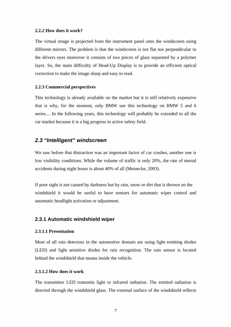
2.3.1.2 How does it work The transmitter LED transmits light or infrared radiation. The emitted radiation is
directed through the windshield glass. The external surface of the windshield reflects
7
the radiation directly to the receiver diodes due to total reflectance (interface glass –
air). The intensity of the radiation can be measured (Meinecke, 2003).
Figure 2.2 principle of rain detection by reflection measurement techniques on the windshield
2.3.1.3 Commercial perspectives At present, the cost of this technology is decreasing a lot and we can found it on
middle market car (Renault Megane). So, in a near future, this technology will
probably be present on all cars present on the market.
2.3.2 Rain Repellent Windshields 2.3.2.1 Presentation An other way to avoid water onto the windscreen is to use a rain repellent windshield.
With this technique, the water droplets rolling off the windscreen and clean it simply
carrying away contaminating particles.
2.3.2.2 How does it work
The model for this technique is the leave of the lotus plant which thanks to micro naps
and a sophisticated run-off system can effectively use rainwater for cleaning and
carries it off together with the dirt. Sanitation, roof tiles, windows and car lacquers
can thus be improved.
Lately advances in nano-layers have made possible to develop water-repelling
windshields (Meinecke, 2003).
8
2.3.2.3 Commercial perspectives This technology is currently in use for the windshield glass in the BMW Z8 Coupé.
Nonetheless, it seems that BMW don’t use this technique any more, it probably means
that it was not so reliable.
2.4 Vision Enhancement
2.4.1 Headlights Vehicle lighting is one of the oldest safety systems in the vehicle. More than 80% of
the information required for safe driving is perceived visually.
2.4.1.1 High intensity discharge headlight lamps (or xenon) 2.4.1.1.1 Presentation Headlights serve not only to light the road ahead but also to illuminate pedestrians,
cyclists and road signs. The major lighting manufacturers are then continually coming
up with some novel concepts like the High Intensity Discharge (HID) headlamps (or
xenon).
All the requirements for safe and comfortable driving make the High Intensity
Discharge (HID) headlamps (or xenon) a large area of interests. The Xenon gas used
in HID headlights emits virtually full spectrum white light, so objects illuminated by
it appear almost the same color as they do in daylight. That significantly improves
visibility on the road at night and changes the way we drive.
So High Intensity Discharge (HID) headlights are being installed on more car models
every year and we can expect a dramatic increase in the use of HID headlights for
many years to come (Gordon, 2005).
9
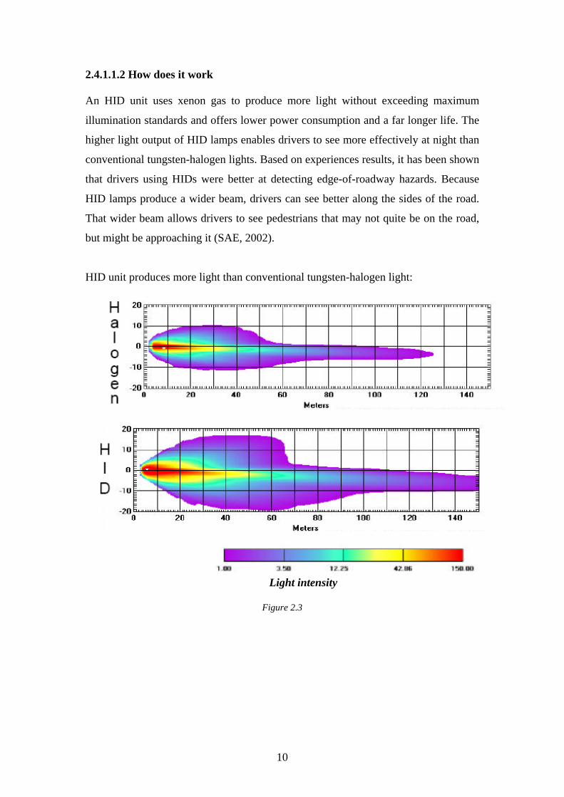
2.4.1.1.2 How does it work An HID unit uses xenon gas to produce more light without exceeding maximum
illumination standards and offers lower power consumption and a far longer life. The
higher light output of HID lamps enables drivers to see more effectively at night than
conventional tungsten-halogen lights. Based on experiences results, it has been shown
that drivers using HIDs were better at detecting edge-of-roadway hazards. Because
HID lamps produce a wider beam, drivers can see better along the sides of the road.
That wider beam allows drivers to see pedestrians that may not quite be on the road,
but might be approaching it (SAE, 2002).
HID unit produces more light than conventional tungsten-halogen light:
Light intensity
Figure 2.3
10
2.4.1.1.3 Commercial perspectives Although HID headlamps demonstrate obvious benefits, they are still an expensive
technology. This problem is due to the fact that they must be fitted with a self-
levelling control system that is now required by legislation. Industry sources estimate
that discharge headlamps typically cost five times more than the wholesale cost of
halogen lamp units (www.nuconverte.de).
2.4.1.2 Automotive cornering lamps 2.4.1.2.1 Presentation Another area of focus of intense development is the Advanced (or Adaptive) Front-
lighting System (AFS) in which the key parameters are road type, road shape and
driver requirements. The objective is to provide the driver with the best possible
visibility by cornering and varying the light distribution without dazzling oncoming
traffic.
2.4.1.2.2 How does it work ? Different models over the years have had the headlight beam mechanically following
the direction of the front wheels, the most well known perhaps being Citroën DS.
However this system was a little bit too dramatic for some situations and the concept
never caught on with other manufacturers (SAE, 2002).
Now a better solution is to keep one of the lamps steady and just swivel the in-board
one. A better solution would have consisted on swivel both but at different angles: the
in-board one swivelling into a wider angle and a little less on the outboard one.
Manufacturers are demonstrating two bending light systems: main bending light and
fixed bending light. Based on the use of xenon, the two systems are complementary
functions that can be used separately or in combination.
The main bending light headlight enhances vision in large curves at medium to high
speeds. This system consists of either a bi-xenon projector or reflector headlamp
motorised to rotate by up to 20 degrees from the normal position.
11
The fixed bending light enhances vision in sharp curves at low to medium speed and
at intersections. This system consists of an additional projector or reflector in order to
deliver an increased quantity of light into an on-coming road bend at a fixed angle,
usually 45 degrees.
In combination the two systems offer overall higher performance and enable drivers
to see more effectively at night and to detect more easily edge-of-roadway hazards
like pedestrians (www.autobusiness.co.uk).
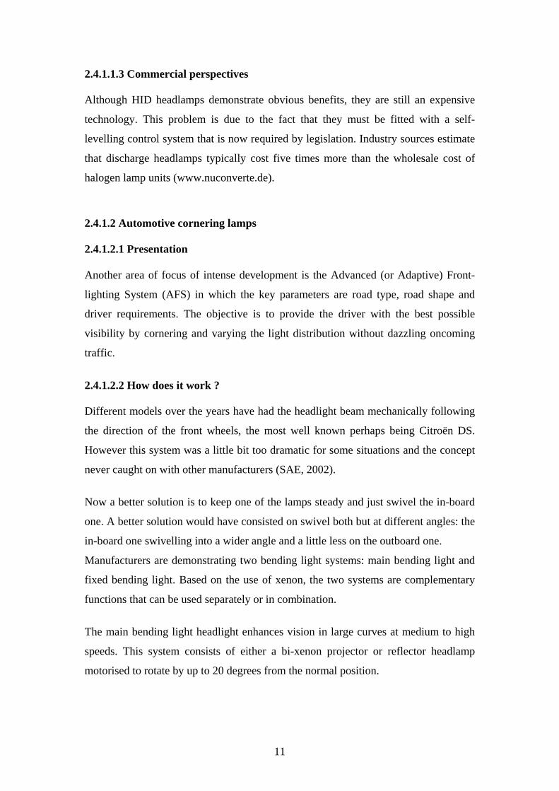
Conventional low-beam headlamps with asymmetrical light distribution:
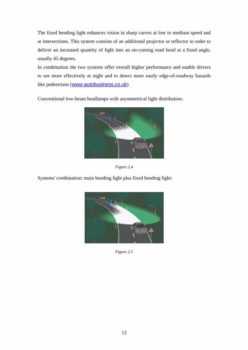
Figure 2.4 Systems' combination: main bending light plus fixed bending light:
Figure 2.5
12
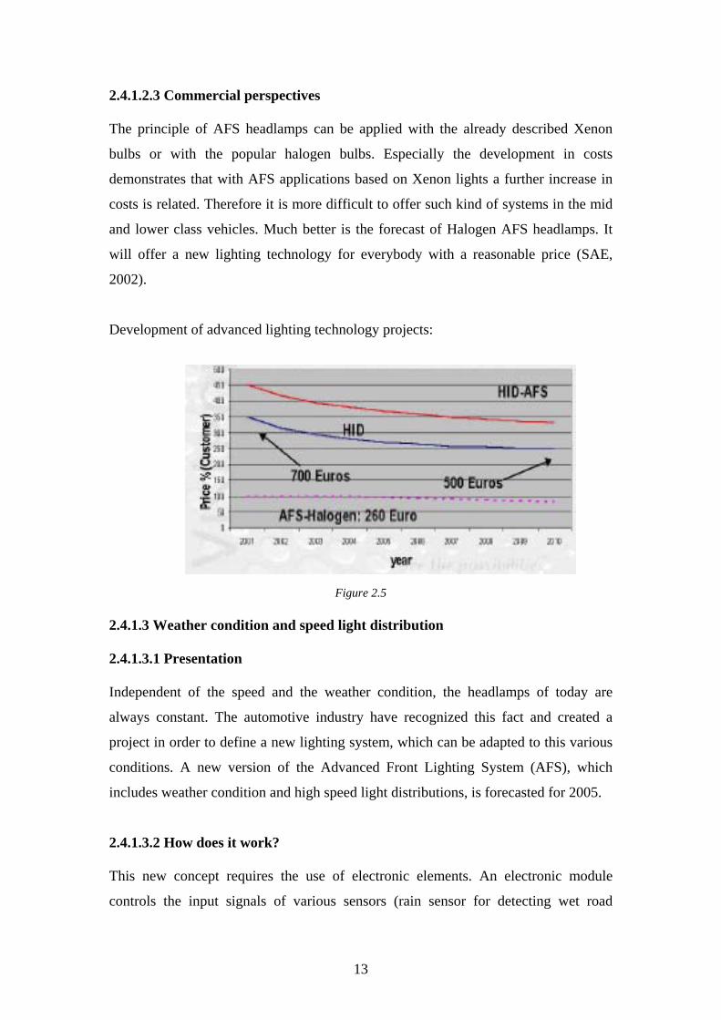
2.4.1.2.3 Commercial perspectives The principle of AFS headlamps can be applied with the already described Xenon
bulbs or with the popular halogen bulbs. Especially the development in costs
demonstrates that with AFS applications based on Xenon lights a further increase in
costs is related. Therefore it is more difficult to offer such kind of systems in the mid
and lower class vehicles. Much better is the forecast of Halogen AFS headlamps. It
will offer a new lighting technology for everybody with a reasonable price (SAE,
2002).
Development of advanced lighting technology projects:
Figure 2.5
2.4.1.3 Weather condition and speed light distribution 2.4.1.3.1 Presentation Independent of the speed and the weather condition, the headlamps of today are
always constant. The automotive industry have recognized this fact and created a
project in order to define a new lighting system, which can be adapted to this various
conditions. A new version of the Advanced Front Lighting System (AFS), which
includes weather condition and high speed light distributions, is forecasted for 2005.
2.4.1.3.2 How does it work? This new concept requires the use of electronic elements. An electronic module
controls the input signals of various sensors (rain sensor for detecting wet road
13
conditions for instance) and parameters to result in the correct variation of the light
distribution.
Via these sensors, which are oriented along the driving direction, the low beam light
pattern will be switched on and off automatically (auto light) as well as the
surrounding illumination level. That will guarantee the automatic switch on operation
during daytime, night, dawn, fog and also when driving through tunnels.
One showed that the application of visible light sources is one of the best choices in
recognizing obstacles, pedestrians and other objects. So the new upcoming regulation,
based on the European pedestrian protection assumptions, will soon require a
permanent daytime running light. The automatic switch on operation during daytime
will be then very useful (SAE, 2002).
2.4.1.3.3 Commercial perspectives Rather than developing individual aspects, it will be financially more interesting to
have an overall system integration vision, when driving with a vehicle.
The active safety aspect will be most beneficial, if we will be able to combine existing
information and use them to further improve seeing distance, vision at night within a
reasonable cost frame. This will give us the chance to a real improved safety for both
the drivers and the pedestrians.
14
2.5 Night Vision
2.5.1 Active Night Vision 2.5.1.1 Presentation We saw before that some technologies are now available to increase the efficiency of
headlights. Another way to enhance the pedestrian safety under poor visibility is to
use night vision systems. There are two kind of night vision systems: passive and
active night vision. According to Meinecke (2003) “Passive night vision […] systems
detect heat that is emitted by creatures or machines and are used for long-range
vision. In contrast to passive systems, active night vision emits IR itself and detects the
reflected fraction. From this point of view active night vision is similar to radar.”
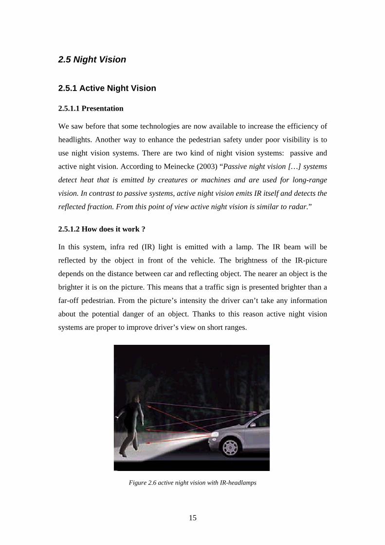
2.5.1.2 How does it work ? In this system, infra red (IR) light is emitted with a lamp. The IR beam will be
reflected by the object in front of the vehicle. The brightness of the IR-picture
depends on the distance between car and reflecting object. The nearer an object is the
brighter it is on the picture. This means that a traffic sign is presented brighter than a
far-off pedestrian. From the picture’s intensity the driver can’t take any information
about the potential danger of an object. Thanks to this reason active night vision
systems are proper to improve driver’s view on short ranges.
Figure 2.6 active night vision with IR-headlamps
15
2.5.1.3 Commercial perspectives Active systems have already made their commercial debut. Toyota released an active
system back in 2002 based on a halogen IR bulb. But the ideal system would be an
headlight combination of an IR high beam with a visible low beam. Ultimately, LED
illumination could prove to be the most cost-effective technique.
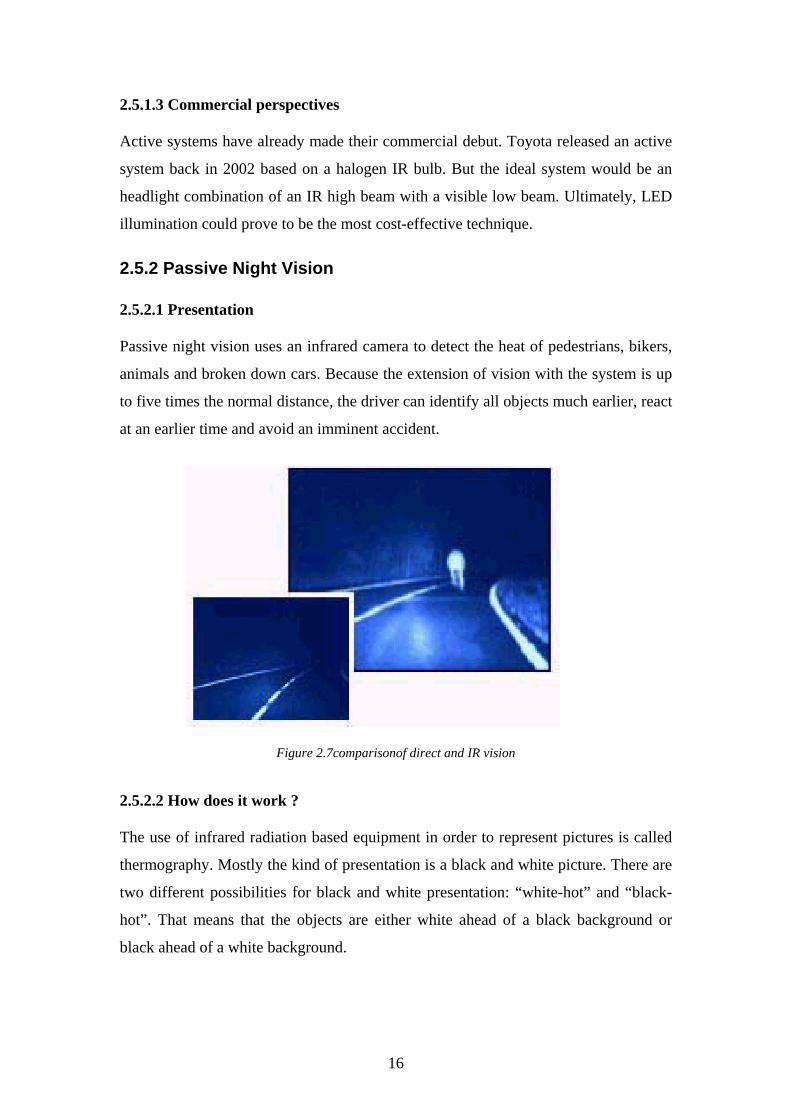
2.5.2 Passive Night Vision 2.5.2.1 Presentation Passive night vision uses an infrared camera to detect the heat of pedestrians, bikers,
animals and broken down cars. Because the extension of vision with the system is up
to five times the normal distance, the driver can identify all objects much earlier, react
at an earlier time and avoid an imminent accident.
Figure 2.7comparisonof direct and IR vision
2.5.2.2 How does it work ? The use of infrared radiation based equipment in order to represent pictures is called
thermography. Mostly the kind of presentation is a black and white picture. There are
two different possibilities for black and white presentation: “white-hot” and “black-
hot”. That means that the objects are either white ahead of a black background or
black ahead of a white background.
16
Thermal differences in the environment are generated into image signals by assistance
of an infrared camera. These signals are finally represented on a virtual display.
2.5.2.3 Commercial perspectives At the moment the night vision system is installed only in a few production cars. It
consists of two components: an infrared camera and a virtual display.
There are several possibilities to place the camera: behind the front grille, under the
rear edge of the hood or behind the windshield. Which position is used depends on the
type of car and size of camera.
This technology is particularly suitable to be use with an Head-Up Display (HUD) .
Compared to other displays it has decisive advantages. First of all the scale of the
HUD content is nearly 1:1. This eases the distance estimation to the object. Second,
the virtual clearance between image and driver amounts two to three meters. That
reduces the work of the eyes and thus the fatigue of eyes and driver. The HUD is easy
comprehensible and does not stress the driver.
2.5.3 Further development and prospect Meinecke (2003) gives us a good overview of problems concerning the introduction
of night vision systems on the market: “Customers desire for example a bigger image
cut-out and a better curve tracking. Car manufacturers see great store by other
points. For them aesthetic and economic aspects are as well in front as ergonomic
and required space aspects. By the system layout there are conflicts between a wide
view angle and a large reach in case of the camera and between the 1:1 presentation
and the limitation of required space in case of the HUD. That means a wide view
angle reduces the possibilities of detecting objects and lies to problems with required
space by the HUD. Because of that these conflicts have to be studied for each vehicle
in order to find an optimum for the special types.”
17
2.6 Video recognition 2.6.1 Presentation This part focuses on systems that can recognize automatically pedestrian or other
dangers using a camera coupled with a video analyser. The long-term goal is to
develop vision-based systems that could be successfully implemented in cars or driver
support in urban scenes or for autonomous driving.
2.6.2 How does it work? The detection of pedestrian using video recognition is confronted with many
difficulties. Indeed, there is not two pedestrians who look exactly the same. Each
pedestrian has different appearance, poses, body sizes and stand at different distance
from the car. Moreover, it is impossible to use background subtraction methods to
obtain foreground regions containing pedestrians because of the moving camera.
Furthermore, there are also real-time requirement which necessitate high CPU power.
We can now find mainly three systems : mono vision, stereo vision and radar with
computer vision.
2.6.3 Commercial perspectives Nowadays, no system is available on the market, they are at a laboratory stage.
Whereas, video cameras are cheap and because they do not emit signals, there are no
issues regarding interference with the environment.
The inconvenient of the video recognition is that it can only be performed efficiently
in broad daylight compare to infrared systems which can be used every time.
2.7 Conclusion The development of a mirror HUD in association with night vision system has the
advantage to show several information of interest. It is of great interest for customer’s
acceptance as well as for reduction of accident risk. The future of the night vision
system lies in image processing as well as in fusion with other sensors. Nevertheless,
a first stage in the improvement of pedestrian safety by night could be the adoption of
advanced headlight on passenger cars.
18
3 Warning Systems
3.1 Introduction A basic principle in the community of driver assistant system engineers is: “It is much
more effective for both pedestrian and host vehicle to avoid a crash, than to reduce the
accident severity of a crash” (Meinecke, 2003).
From this rule, if the car driver is warned early enough, the possibility of the collision
can be minimized in many critical road situations. When the driver is warned, his/her
eyes will be naturally directed to the front of the car immediately. With a good
maneuver, collision can be avoided.
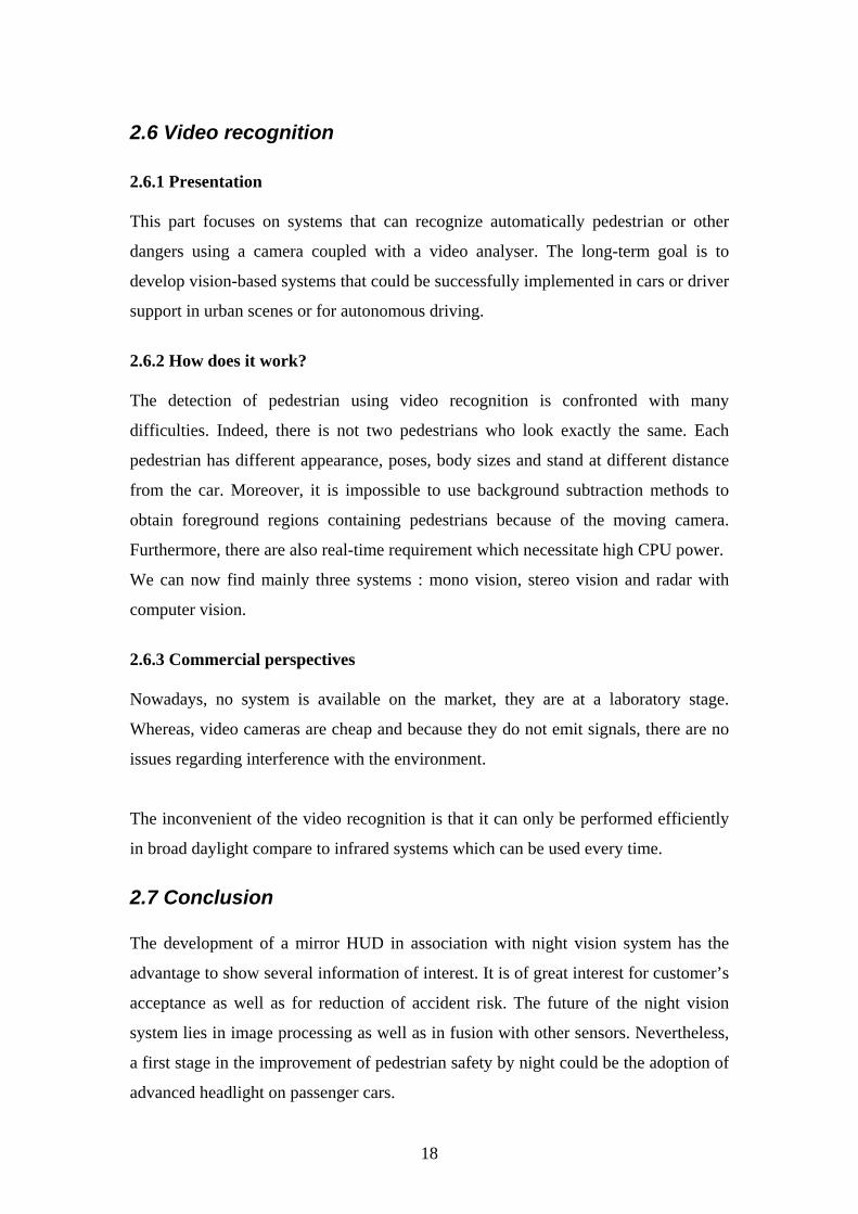
3.2 Blind corner monitor The safer driving can be achieved by providing such information not easily accessible
to the driver. These systems provide a visual display of the side view inaccessible to
the driver at a blind T-junction. The most important aspects of the representation of
such information to the driver are the ease of view, i.e. that the driver’s total attention
should not be required. In figure 3.1, two cameras are placed on the front of vehicles
to check left and right at a T-shaped intersection with an obstructed view, are used as
an example for explanation. Kishi and Sakata [1998] showed that the monitor should
• Display the left- and right-side images in ways that the driver’s total attention
is not in demand.
• Display both left- and right-side images simultaneously, rather than displaying
the left and right-side images separately, to give the feeling of comfort and
convenience.
19
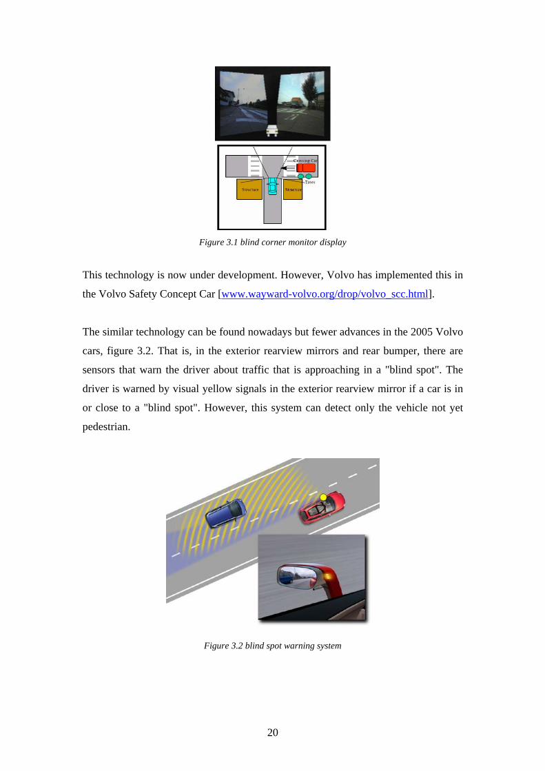
Figure 3.1 blind corner monitor display
This technology is now under development. However, Volvo has implemented this in
the Volvo Safety Concept Car [www.wayward-volvo.org/drop/volvo_scc.html].
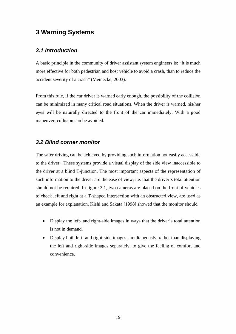
The similar technology can be found nowadays but fewer advances in the 2005 Volvo
cars, figure 3.2. That is, in the exterior rearview mirrors and rear bumper, there are
sensors that warn the driver about traffic that is approaching in a "blind spot". The
driver is warned by visual yellow signals in the exterior rearview mirror if a car is in
or close to a "blind spot". However, this system can detect only the vehicle not yet
pedestrian.
Figure 3.2 blind spot warning system
20
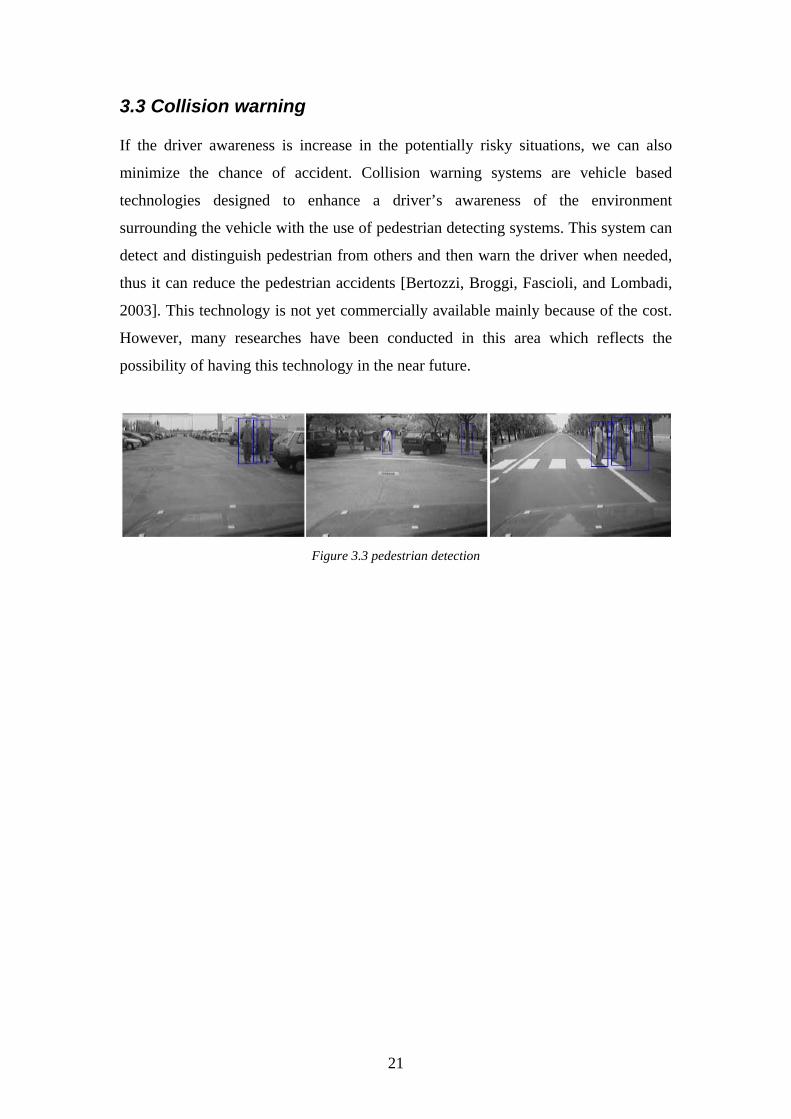
3.3 Collision warning If the driver awareness is increase in the potentially risky situations, we can also
minimize the chance of accident. Collision warning systems are vehicle based
technologies designed to enhance a driver’s awareness of the environment
surrounding the vehicle with the use of pedestrian detecting systems. This system can
detect and distinguish pedestrian from others and then warn the driver when needed,
thus it can reduce the pedestrian accidents [Bertozzi, Broggi, Fascioli, and Lombadi,
2003]. This technology is not yet commercially available mainly because of the cost.
However, many researches have been conducted in this area which reflects the
possibility of having this technology in the near future.
Figure 3.3 pedestrian detection
21
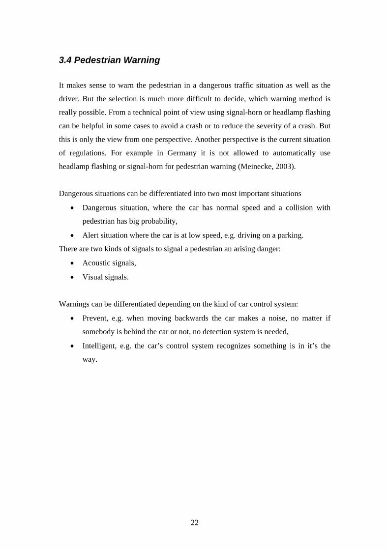
3.4 Pedestrian Warning
It makes sense to warn the pedestrian in a dangerous traffic situation as well as the
driver. But the selection is much more difficult to decide, which warning method is
really possible. From a technical point of view using signal-horn or headlamp flashing
can be helpful in some cases to avoid a crash or to reduce the severity of a crash. But
this is only the view from one perspective. Another perspective is the current situation
of regulations. For example in Germany it is not allowed to automatically use
headlamp flashing or signal-horn for pedestrian warning (Meinecke, 2003).
Dangerous situations can be differentiated into two most important situations
• Dangerous situation, where the car has normal speed and a collision with
pedestrian has big probability,
• Alert situation where the car is at low speed, e.g. driving on a parking.
There are two kinds of signals to signal a pedestrian an arising danger:
• Acoustic signals,
• Visual signals.
Warnings can be differentiated depending on the kind of car control system:
• Prevent, e.g. when moving backwards the car makes a noise, no matter if
somebody is behind the car or not, no detection system is needed,
• Intelligent, e.g. the car’s control system recognizes something is in it’s the
way.
22
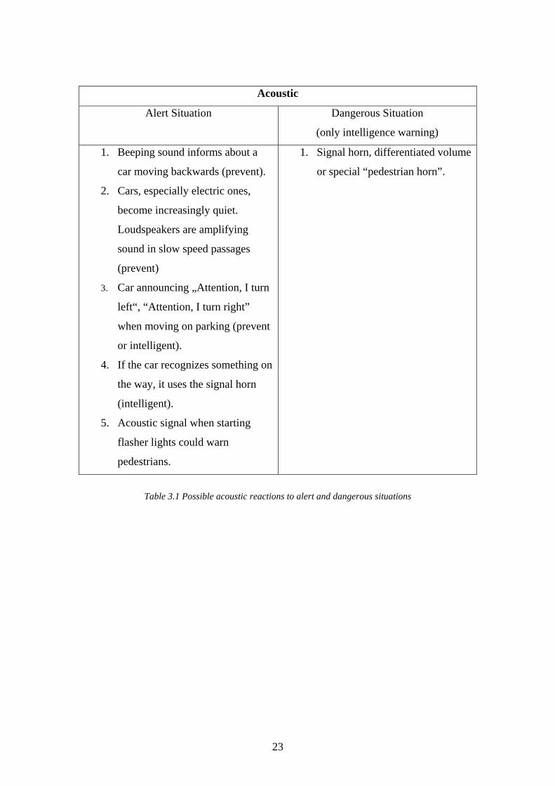
Acoustic
Alert Situation Dangerous Situation
(only intelligence warning)
1. Beeping sound informs about a
car moving backwards (prevent).
2. Cars, especially electric ones,
become increasingly quiet.
Loudspeakers are amplifying
sound in slow speed passages
(prevent)
3. Car announcing „Attention, I turn
left“, “Attention, I turn right”
when moving on parking (prevent
or intelligent).
4. If the car recognizes something on
the way, it uses the signal horn
(intelligent).
5. Acoustic signal when starting
flasher lights could warn
pedestrians.
1. Signal horn, differentiated volume
or special “pedestrian horn”.
Table 3.1 Possible acoustic reactions to alert and dangerous situations
23
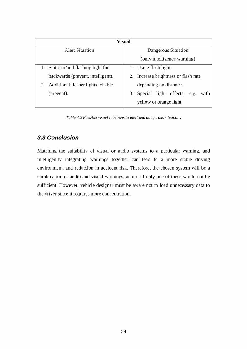
Visual
Alert Situation Dangerous Situation
(only intelligence warning)
1. Static or/and flashing light for
backwards (prevent, intelligent).
2. Additional flasher lights, visible
(prevent).
1. Using flash light.
2. Increase brightness or flash rate
depending on distance.
3. Special light effects, e.g. with
yellow or orange light.
Table 3.2 Possible visual reactions to alert and dangerous situations
3.3 Conclusion Matching the suitability of visual or audio systems to a particular warning, and
intelligently integrating warnings together can lead to a more stable driving
environment, and reduction in accident risk. Therefore, the chosen system will be a
combination of audio and visual warnings, as use of only one of these would not be
sufficient. However, vehicle designer must be aware not to load unnecessary data to
the driver since it requires more concentration.
24
4 Car Design
4.1 Introduction Vehicular injury is a major cause of death and disability in today’s world. While most
of the injuries are sustained by vehicle occupants, pedestrian injury is also a problem.
Despite its magnitude, pedestrian injury and its prevention have received inadequate
attention, basically for two reasons (Berkeley Uni., 2004).
First, urban planners and traffic engineers generally sacrifice pedestrian safety for the
sake of vehicular flow, resulting in adequate funding of pedestrian safety based urban
architectural projects and lack of legislations concerning car design and road
infrastructure (Malek, Guyer, and Lescohier, 1989). Second, and possibly the most
important, the customer behaviour regarding the sales of non-commercial vehicles
such does not involve required levels of attention on the people outside the vehicle.
This is mainly based on the perception of a safe car; a person searching for a suitable
car to buy acquires brand and product information through a number of sources most
effective of which are car magazines and test drives, though he never observes any
add concerning the safety of people on streets (Womack, Jones, Roos, 1990), because
as a normal member of humankind, he will not be willing to pay a considerable
amount of safety pack fee if it won’t help protect him and his family (Bouchenoire,
2003).
25
4.2 Bumper and Hood One of the most common ways to protect the pedestrian is to design the vehicle in a
way to give as less harm as possible in case of an incident. Since most of the
collisions between pedestrians and vehicles involve the impact of the frontal part of
the vehicle, decreasing the severity of the pedestrian injury strongly depends on the
shape and characteristics of the bumper, hood, and the edge of the hood (Harruff,
Avery, Alter-Pandya, 1998). According to “Design for Pedestrians in Impact” the
technical solutions regarding the frontal design of a pedestrian friendly car can be
summarized as follows: The bumper should have a deep profile for better absorption
of the impact energy. Furthermore, the stiffness of the bumper is an important aspect
of the design as local peaks in bumper stiffness resulting from screws and connection
profiles are of major “weapons” of the car (Harruff, Avery, Alter-Pandya, 1998). For
instance, Mazda has an aluminium bonnet and cone-type cushioning structures
underneath just to increase the energy absorbed (www.mazda.com). The bumper
height, on the other hand, shouldn’t be too low to allow the bending of the knee joint
during the crash and to decrease the pitch of the leg. Hood edge, alternatively, is
generally very stiff because of the reinforcements and the latch. Today’s cars are very
poor regarding the energy absorbed by the edge of the hood. This respectively
harmful part of the car body should be designed better so that it is able to absorb some
of the impact energy. Thereafter comes the hood. Local stiffness should be well
adjusted to allow deformation especially at around joints connecting the hood to the
chassis. Further strategies on the way to a better frontal design can be listed as
follows.
26
4.2.1 Bumper
• Increase the active thickness of the bumper so that it will have the place to
deform in case of an accident. Special energy absorbing elements made of
polypropylene which has good recovery characteristics can also be used. It
also helps minimise damage to the car at low speed collisions.
• Use low mounted exterior elements such as spoilers in order to reduce impact
loads on lower extremities, pitch of the legs, and the bending load on knee
joints.
• Increase the distance between the bumper and the stiff chassis structures
behind the bumper which normally form the front of the main impact
absorbent structure on the vehicle by either changing the position of the stiff
chassis structures or moving the bumper forward.
• Place the stiff elements such as screws or bolts at positions statistically safest
regarding a pedestrian involved accident or hide them under the bumper.4.2.2
* All the technical solutions described above are taken from: www.cardesignonline.com
4.2.2 Hood Edge
• Try to hide the fixtures such as catches under the surface.
• Place the latch on the rear end or sides of the structure.
• Reduce the stiffness of the edge either by suitable geometry or limited use of
reinforcement panels and bars.
* All the technical solutions described above are taken from: www.cardesignonline.com
27
4.2.3 Hood
• Keep the hood clear of the engine and other stiff structures under. This is to allow
the deformation of the hood in case of an impact so that it is able to absorb the
impact energy and distribute it to a broader time frame
(www.cardesignonline.com).
• Try to design the upper part of the engine as deformable as possible. Either use
deformable materials and components on top of the engine or specifically put
some breakable sections. Refrain from using steel (www.cardesignonline.com).
• Change the geometry and the material of the bonnet in a way to reduce stiffness
(www.cardesignonline.com).
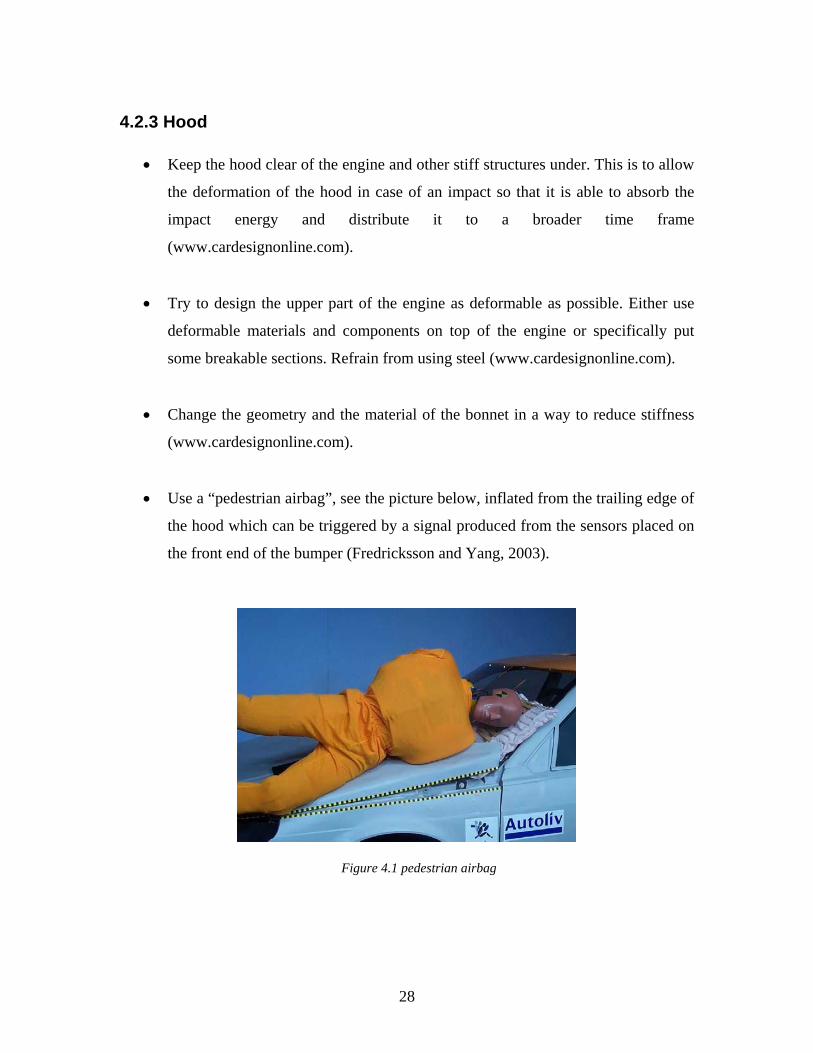
• Use a “pedestrian airbag”, see the picture below, inflated from the trailing edge of
the hood which can be triggered by a signal produced from the sensors placed on
the front end of the bumper (Fredricksson and Yang, 2003).
Figure 4.1 pedestrian airbag
28
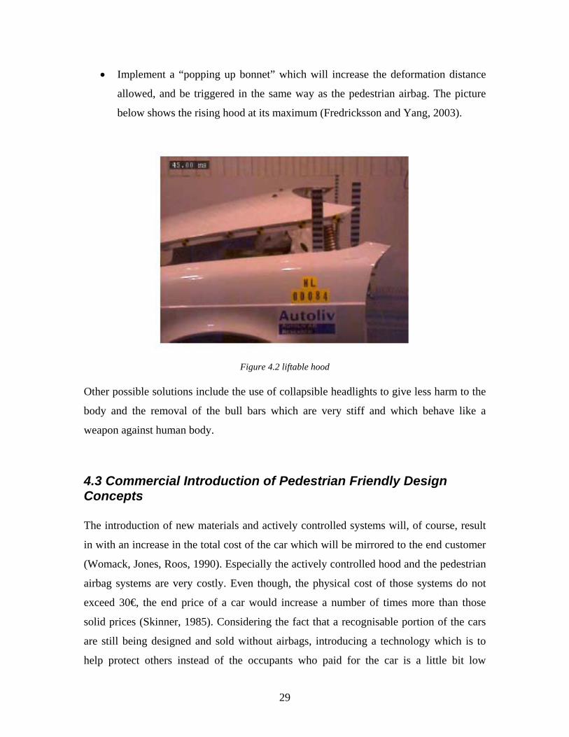
• Implement a “popping up bonnet” which will increase the deformation distance
allowed, and be triggered in the same way as the pedestrian airbag. The picture
below shows the rising hood at its maximum (Fredricksson and Yang, 2003).
Figure 4.2 liftable hood Other possible solutions include the use of collapsible headlights to give less harm to the
body and the removal of the bull bars which are very stiff and which behave like a
weapon against human body.
4.3 Commercial Introduction of Pedestrian Friendly Design Concepts The introduction of new materials and actively controlled systems will, of course, result
in with an increase in the total cost of the car which will be mirrored to the end customer
(Womack, Jones, Roos, 1990). Especially the actively controlled hood and the pedestrian
airbag systems are very costly. Even though, the physical cost of those systems do not
exceed 30€, the end price of a car would increase a number of times more than those
solid prices (Skinner, 1985). Considering the fact that a recognisable portion of the cars
are still being designed and sold without airbags, introducing a technology which is to
help protect others instead of the occupants who paid for the car is a little bit low
29
demand. It is important to perceive a low demand product as a possible and viable option
for the future; however, it is, also, of major importance to find ways to introduce a
beneficial product in the market (Tunc, 2004).
This could be achieved in a couple of different ways which necessitate state involvement.
First, the government can put medium level charges on vehicle manufacturer regarding
every pedestrian injury in an incident with one of their products. This will force the
manufacturers themselves find ways to sell cars with better pedestrian safety features.
Second, a tax reduction or another type of incentive can be introduced for the customers
who buy pedestrian safe cars. Third, public awareness may be increased by means of
written and visual media which will than create a namely “fake” demand for pedestrian
safe cars. It should be marked that the latter is almost ineffective in most of the countries.
Alternatively, a different commercial issue arises from the change of a car design;
aesthetics. Even though the automobile buyers do not list aesthetics on top of power,
comfort and so fort; it became a “must” for a passenger car to sustain. Kano quality
model (Hoyle, 2001) states that ”musts” are not the keys for a customer prefer one
product to another but the reasons not to buy one if not found. Vehicle manufacturers
know this very well and try to keep the shape futuristic but not irritating.
30
5 Vehicle Systems
5.1 Introduction If a driver detects an imminent crash against a pedestrian, probably his reaction is to
brake and to steer to avoid the impact. Since in that situations the driver pushes the brake
pedal very hard, if the vehicle is not equipped with ABS there is the possibility of locking
one or more wheels and consequently it is possible to lose the control of the car and to hit
the pedestrian. To have the control of the car in this dangerous situation it is necessary to
have systems like ABS and ESP, so it is possible to manoeuvre the vehicle and
consequently to save the lives of the road users involved in these moments.
5.2 Antilock Braking System, ABS When one or more wheels are lock up on a wet and slippery road or during a panic stop,
there is the possibility to lose the control of the vehicle. Antilock brakes keep the wheels
from locking up and so it is possible to maintain the directional control.
This is a system designed to help the drivers maintain control of the vehicle during
emergency braking situations, not necessarily make the car stop more quickly. ABS may
shorten stopping distances on wet or slippery roads and most systems may shorten
stopping distances on dry roads. On very soft surfaces, such as gravel or unpacked snow,
ABS may actually lengthen stopping distances (NHTSA 2000).
On the market there are more than one kind of ABS. Four-wheel systems, including those
found on cars and minivans, are designed to keep all four wheels from locking up. Rear-
wheel-only systems, found on some pickups, vans and sport-utility vehicles, keep the
vehicle from spinning out of control, but the front wheels may lock up, resulting in a loss
of steering control (NHTSA 2000).
31
5.3 Electronic Stability Program, ESP ESP monitors the vehicle's response to the driver's steering and braking inputs to detect
oversteer or understeer. If sensors detect that a skidding condition is developing, ESP
brakes individual front or rear wheels and/or reduces excess power as needed to help
keep the vehicle going in the direction the driver is steering.
The system extends the technology of the anti-lock braking and acceleration skid control
systems with a range of additional sensors which are used principally to detect yaw
motion (www.conti-online.com).
The ESP computer continuously compares the actual behavior of the vehicle with the
computed ideal values. The moment the car deviates from the direction intended by the
driver, specially developed control logic causes the system to intervene with split-second
speed to bring the car back on track. It does this in two ways:
• Precisely controlled braking at one or more wheels
• Reducing engine power.
32
5.4 Electronic Brake Assistant, EBA In dangerous situation, like when a driver detects a pedestrian the reaction can be both a
strong brake and sometimes, not rarely, a soft one. If there is a soft brake the
consequences can be serious, because the speed of the vehicle is high and when it crashes
into the pedestrian it is possible to have serious or fatal injuries.
The reduce the speed in these kind of situations, nowadays the Electronic Brake Assistant
(EBA) was introduced in many cars. A sensors measure how fast the brake pedal is
actuated, the system deduces from the pedal speed whether the driver intends to make a
hard stop and if this is the case, the brake assistant immediately provides full braking
pressure in the brake power assist unit. This system becomes inactive as soon as the
driver lets up on the brake pedal (www.conti-online.com).
In the feature the successor of the EBA, will be the Predictive Brake Assist, PBA. The
system builds up preventive brake pressure by placing the braking pads on the brake
disks as a matter of precaution and setting the hydraulic brake assistant into a state of
alert. If the driver actually brakes, he gets the fastest possible brake response with optimal
deceleration values and the shortest possible stopping distance. When there is no braking
action, the alert status is simply cancelled (www.bosch.com).
33
6 Infrastructure
6.1 Pedestrian Safety in Traffic: The Effect of infrastructure and car design Even though the current motive of vehicle manufacturers regarding pedestrian safety is in
favour of active systems installed on the vehicles, one of the most important aspects
influencing the risk and the severity is the actual shape and design of the vehicle. This
passive aspect of major importance is accompanied with the infrastructure present in the
environment. Therefore, particular attention is necessary. This part of the paper discusses
issues of infrastructure/environment and the design of the vehicle.
6.2 Traffic Infrastructure and the Influence of Environment Majority of the research investigating the relationship between pedestrian traffic safety
and the urban built environment showed that there is a serious correlation between non-
motorised road user safety and the environment. Government in developed countries are,
though late, taking action to provide people with a better and safer environment.
Improved road safety for all users (particularly children) is stressed everyday. Petch and
Henson (2000) argue that, as stated in the reports published by the governments (UK,
Australia, etc), towns and cities are places where people live; everyday activities and
behaviour should not be restricted by motor vehicles. Pedestrians and cyclists must, thus,
be provided with a safe environment, where they are not intimidated by traffic and have
priority in residential areas.
One big step towards solving the problem is to understand the sociological aspects of it.
The disproportionately large share of child pedestrian and cyclist traffic accidents in road
casualties attract much of the attention and it is logical to do it so. Department of
Transport (1997) reports that 34% of all pedestrian and cyclist casualties in the UK were
in the 0-14 year age band even though that group represented only 13% of the total
34
population. The other age groups can be considered as “less vulnerable” but not be
ignored.
The irregular and virtually artificial car and human life should be the focus of the
research. Schioldborg (1978) states that only physical separation can actually guarantee
the life, however, it seems of an extreme order of cost, along with other viability
problems, impossible to implement such a system. From this point of view, the necessity
of infrastructural devices and organised environment appears to be the only valid
solution.
Since the risk is not the same at all parts of traffic environment, the infrastructural safety
systems have to be placed carefully according to the priorities assessed. Preston (1976)
argues that the areas with high pedestrian accident rate include the areas with; the lack of
open spaces for children, street frontage access, limited off-street car parking provision
and high level of on street parking, and long and straight streets. The question is, “What
is wrong with those areas leading to pedestrian (particularly child) accidents?”
Long and straight streets make it easier for the drivers to drive at high speeds without
paying attention on the sidewalks and the people around. One easier and affectivity
proved way is to place speed bumps to slow the traffic down and surface textures and
carvings to actually make drivers feel the actual speed of the vehicle. On the other hand,
parked cars interfere with the ability of children to observe oncoming vehicles, and also
obstruct the vision of motor vehicle drivers (Petch, R. O., Henson, R. R., 2000). Maybe
the easiest way is to reduce the kerbside parking, but a more realistic approach would be
building the streets so that the pedestrians are more visible. Kerbside led lights, which are
planned to be placed along the streets, may make the pedestrians about to cross the road
much visible and, thus, prevent accidents. A non-infrastructural alternative to that is to
build cars sustaining park lights making both the vehicles and the pedestrians masked
visible. Further, the pedestrian crossings and edges of the roads could be equipped with
motion detecting signal lights, which run only when a pedestrian is about to cross the
road; and maybe extra spot lights for the cross way itself.
35

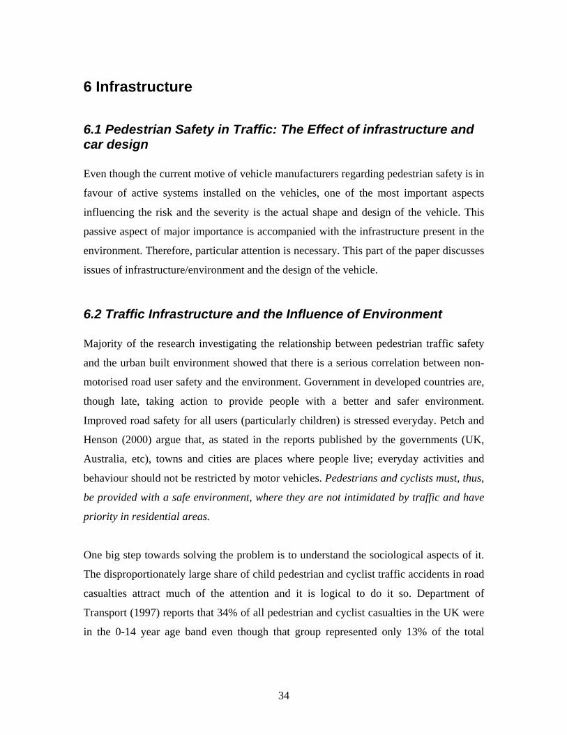
6.3 New Technical Solution: LightGuard flashing cross walk system The LightGuard System alerts motorists that they are approaching an occupied crosswalk
using amber LED flashing lights embedded in the roadway surface on both sides of a
crosswalk facing oncoming traffic. When activated by a pedestrian push button or
automatic activation mechanism, the flashing amber lights are visible to the approaching
motorist as an advance warning to permit vehicles to slow down and stop for a crossing
pedestrian. The flash-rate, placement, and aiming of the in-roadway LED signal heads
captures the attention of motorists and are visible down the entire motorist-viewing-path
conveying the simple message to "Pay attention, something is happening ahead!"
(www.lightguardsystems.com).
Automatic Activation Bollards and/or pedestrian push buttons on either side of the
crosswalk activates the System. A row of LED lights on the push button sign flash to
indicate that the System has been activated, however, the in-roadway LED lights were
designed to alert the approaching motorist, not the pedestrian, that the System is
operating. Approaching the crosswalk, the driver of the vehicle will see a series of amber
lights in the pavement flashing in unison at a pulse rate designed for maximum
recognition. When activated, the crosswalk device warns the approaching driver of the
possible presence of a pedestrian and the driver should react accordingly. Flashing amber
lights are the standard signal for hazardous conditions ahead and are readily recognized
by the motoring public (www.lightguardsystems.com).
36
Figure 6.1
The typical reaction of most drivers, upon seeing the activated in-roadway flashing LED
lights, is to let off the accelerator, slowing or breaking as they approach the crosswalk.
This creates a heightened state of driver awareness for the approaching motorist to come
to a safe stop for a pedestrian or pass safely through the crosswalk without impeding the
traffic flow. The flashing lights automatically shut off after a set period of time, usually
15-20 seconds.
6.3.1 Commercial Introduction of LightGuard flashing cross walk system The LightGuard System is available in various configurations; four-lane intersections to
two-lane intersections as well as custom configurations. Equipment prices can range from
$10,000.00 USD to $20,000.00 USD or more depending on the site configuration.
Installation is simple and costs are extra (www.lightguardsystems.com). The LightGuard
System is easy to maintain. LED technology ensures long lamp life and power to the
System is minimal. In-roadway warning signals are very durable and a snowplow
resistant model is available. The in-roadway warning signals are easy to install and can
be easily removed and reset for re-paving purposes. The LightGuard System is the only
production the market that has been independently and extensively tested for the
pedestrian crosswalk application. The City of Santa Rosa, California, initiated the testing
of the new concept in 1994. Subsequently, other locations in California have been tested.
37

These locations include the California cities of Fort Bragg, Lafayette, Orinda, Petaluma,
and Willits (Huang H., Hughes R., and Zegeer C., University of North Carolina).
38
Conclusion
Preventing the accidents involving pedestrians and reducing the severity of the incidents
are of significant importance as they represent the ten percent of the total fatalities in
motor vehicle accidents. This paper has summarised the technical solutions which may
help reduce the severity of the injuries and/or avoid accidents.
Some of the onboard systems have already been introduced together with the high end
products of some “luxurious-identity” brands, though, the others are yet to be re-
engineered to obtain commercially viable versions. In a couple of years, with the
reduction of prices, these systems (not yet viable) are going to appear on vehicle market
one by one, first as parts of optional upgrade packs of upper class niche products, then as
standards of much broad product ranges.
Government incentives and penalties mirroring the cost of fatalities to the manufacturers
may be helpful. Future crash safety regulations regarding pedestrians will push the
manufacturers build safer cars equipped with the systems designed.
The authors argue that a combination of systems such as, night vision incorporated with
head-up-display, and adaptive xenon front lights should be available in the short run, with
the intention of decreasing the severity and the number of pedestrian involved accidents,
yet, most of the systems suggested in this paper require significant changes in the
structural and technical design of the car, since they need extra space and human
interaction placements onboard.
The not well known, though important, aspect of the vehicle-driver system is the
permanent unconscious change of driver behaviour. Designing a car with active systems
such as ABS or brake-assist may have unpredictable effects on driver behaviours
depending on the frequency of use. On the other hand, warning systems may result in
with different driver responses, making it harder to estimate the benefit. It should be
investigated further to understand the facts behind the results of giving large amount of
information to the driver to keep it at an optimum level.
39

One other option is to go for the infrastructural improvements. A better road
infrastructure will provide better pedestrian safety for all the road users regardless of the
age and design of the cars on the move.
Finally, it is certain that all of those systems and solutions, even though some of them are
overlapping regarding the objectives and functions, will be helpful to save the pedestrian
as well as the occupant.
40
References
Anon, 2005. Designing for Pedestrians in Impact [online]. Available from:
http://www.cardesignonline.com/
Berkeley University (2004) Traffic Safety Centre Newsletter Vol.2 No.2, USA
Bouchenoire, J. L. (2003) [Interview with Anne Asensio] Steering the Brand in the
Auto Industry, Design Management Journal, winter, pp. 10-18
Continental, 2005. Electronic Stability Program (ESP) [online]. Available from:
www.conti-online.com.
Department of Transport (1997) Road Accidents in Great Britain: The Casualty
Report, HMSO, London
Gordon J., (2005). Vehicle Lighting: Xenon High Intensity Discharge Lamps
(HID).
Harruff R. C., Avery A., Alter-Pandya, A. S. (1998). Analysis of Circumstances and
Injuries in 217 Pedestrian Traffic Fatalities, Accident Analysis and Prevention, Vol.
30, No. 1, pp. 11-20
Hoyle, D., (2001), Quality Systems Handbook, Oxford: Butterworth –Heinemann,
UK
http://www.lightguardsystems.com
http://www.save-u.org/download/PDF/D6_V3.0.pdf
http://www.save-u.org/download/PDF/D6_V3.0.pdf
41
http://www.solutiaautomotive.com/en/lgi/hud.aspx
Insurance Institute for Highway Safety, 2003. Fatality Facts 2003: Pedestrians
[online]. Available from: http://www.iihs.org.
Malek, M., Guyer, B., Lescohier, I. (1989) The Epidemiology and Prevention of
Child
Mazda website, www.mazda.com, Accessed on 20th April 2005
NHTSA, 2000. Antilock Brake System (ABS) [online]. Available from:
http://www.nhtsa.dot.gov.
Pedestrian Injury, Accident Analysis and Prevention, Vol. 22 No. 4 pp. 301-313
Petch, R. O., Henson, R. R. (2000) Child Road safety in the urban environment,
Journal of Transport Geography, Vol. 8 pp. 197-211
Preston, B. (1976) Statistical Analysis of Child Pedestrian Accidents in Manchester
and Salford, Manchester Studies Publications, Manchester, UK
R. Fredricksson, J. Yang, 2003, Evaluation of new head injury protection system
with a sensor in the bumper and lifting of the bonnet’s rear part, Chalmers
University of Technology and Autolive, Gothenburg, Sweden.
Report of the conference Progress in Automotive Lighting 25–26 September 2001,
Darmstadt University of Technology, Germany: Driving into a clearer future.
SAE technical paper (2002). Visual Benefits of High-Intensity Discharge
Automotive Forward Lighting.
42
SAE technical paper, (2002) System Integration in Automotive Lighting -
Improvements in Visibility at Night.
SAE technical paper, (2002) System Integration in Automotive Lighting -
Improvements in Visibility at Night.
Schioldborg, P. (1978) Children in traffic, Institute of Transport Economics
Journal, June pp. 32-35.
Skinner, W. (1985) Manufacturing “The Formidable Competitive Weapon”, New
York, John Wiley & Sons publishing
Tunc, E. (2004), Commercial Viability of Hybrid and Electric Cars, The Warwick
Recordings for Engineers, Vol. 91 No. 4, pp. 244-286
U. Schmitt, P.Niederer, F. Waltz, (2004), Trauma Biomechanics, Zurich: Springer,
CH
Whitfield, R.A. and Fife, D. 1987. Changing patterns in motor vehicle crash
mortality, 1940-1980. Accident Analysis and Prevention.
Womack, J. P.,Jones D. T., Roos, D. (1990) The Machine That Changed the
World, New York, Macmillan Publishing
www.autobusiness.co.uk
www.bosch.com
www.cardesignonline.com.
www.compukiss.com/populartopics/ travel_transhtm/article1029.htm
43
www.conti-online.com
www.hella.com
www.nuconverter.de
www.uspto.gov
Yang, J, 2004. Vehicle-Pedestrian Impact Dynamics and Injury Prevention.
44


