Embed Size (px)
Citation preview
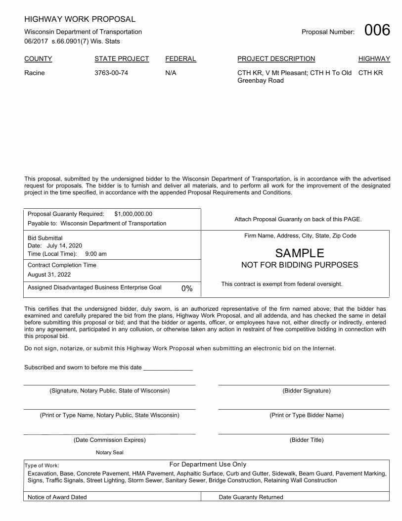
Proposal Number: 006HIGHWAY WORK PROPOSAL
Wisconsin Department of Transportation
06/2017 s.66.0901(7) Wis. Stats
COUNTY STATE PROJECT FEDERAL PROJECT DESCRIPTION HIGHWAY
3763-00-74 N/A CTH KR, V Mt Pleasant; CTH H To OldGreenbay Road
CTH KRRacine
This proposal, submitted by the undersigned bidder to the Wisconsin Department of Transportation, is in accordance with the advertisedrequest for proposals. The bidder is to furnish and deliver all materials, and to perform all work for the improvement of the designatedproject in the time specified, in accordance with the appended Proposal Requirements and Conditions.
Proposal Guaranty Required:
Payable to: Wisconsin Department of Transportation
$1,000,000.00Attach Proposal Guaranty on back of this PAGE.
Bid Submittal
Date:
Time (Local Time):
July 14, 2020
9:00 am
Contract Completion Time
August 31, 2022
Assigned Disadvantaged Business Enterprise Goal 0%
Firm Name, Address, City, State, Zip Code
This contract is exempt from federal oversight.
This certifies that the undersigned bidder, duly sworn, is an authorized representative of the firm named above; that the bidder hasexamined and carefully prepared the bid from the plans, Highway Work Proposal, and all addenda, and has checked the same in detailbefore submitting this proposal or bid; and that the bidder or agents, officer, or employees have not, either directly or indirectly, enteredinto any agreement, participated in any collusion, or otherwise taken any action in restraint of free competitive bidding in connection withthis proposal bid.
Do not sign, notarize, or submit this Highway Work Proposal when submitting an electronic bid on the Internet.
Subscribed and sworn to before me this date _______________
(Signature, Notary Public, State of Wisconsin)
(Print or Type Name, Notary Public, State Wisconsin)
(Date Commission Expires)
(Bidder Signature)
(Print or Type Bidder Name)
(Bidder Title)
For Department Use OnlyType of Work:
Notice of Award Dated Date Guaranty Returned
Notary Seal
SAMPLENOT FOR BIDDING PURPOSES
Excavation, Base, Concrete Pavement, HMA Pavement, Asphaltic Surface, Curb and Gutter, Sidewalk, Beam Guard, Pavement Marking,Signs, Traffic Signals, Street Lighting, Storm Sewer, Sanitary Sewer, Bridge Construction, Retaining Wall Construction

PLEASE ATTACH PROPOSAL GUARANTY HERE
1 of 2
Effective with November 2007 Letting
PROPOSAL REQUIREMENTS AND CONDITIONS
The bidder, signing and submitting this proposal, agrees and declares as a condition thereof, to be bound by the following conditions and requirements.
If the bidder has a corporate relationship with the proposal design engineering company, the bidder declares that it did not obtain any facts, data, or other information related to this proposal from the design engineering company that was not available to all bidders.
The bidder declares that they have carefully examined the site of, and the proposal, plans, specifications and contract forms for the work contemplated, and it is assumed that the bidder has investigated and is satisfied as to the conditions to be encountered, as to the character, quality, and quantities of work to be performed and materials to be furnished, and as to the requirements of the specifications, special provisions and contract. It is mutually agreed that submission of a proposal shall be considered conclusive evidence that the bidder has made such examination.
The bidder submits herewith a proposal guaranty in proper form and amount payable to the party as designated in the advertisement inviting proposals, to be retained by and become the property of the owner of the work in the event the undersigned shall fail to execute the contract and contract bond and return the same to the office of the engineer within fourteen (14) days after having been notified in writing to do so; otherwise to be returned.
The bidder declares that they understand that the estimate of quantities in the attached schedule is approximate only and that the attached quantities may be greater or less in accordance with the specifications.
The bidder agrees to perform the said work, for and in consideration of the payment of the amount becoming due on account of work performed, according to the unit prices bid in the following schedule, and to accept such amounts in full payment of said work.
The bidder declares that all of the said work will be performed at their own proper cost and expense, that they will furnish all necessary materials, labor, tools, machinery, apparatus, and other means of construction in the manner provided in the applicable specifications and the approved plans for the work together with all standard and special designs that may be designed on such plans, and the special provisions in the contract of which this proposal will become a part, if and when accepted. The bidder further agrees that the applicable specifications and all plans and working drawings are made a part hereof, as fully and completely as if attached hereto.
The bidder, if awarded the contract, agrees to begin the work not later than ten (10) days after the date of written notification from the engineer to do so, unless otherwise stipulated in the special provisions.
2 of 2
The bidder declares that if they are awarded the contract, they will execute the contract agreement and begin and complete the work within the time named herein, and they will file a good and sufficient surety bond for the amount of the contract for performance and also for the full amount of the contract for payment. The bidder, if awarded the contract, shall pay all claims as required by Section 779.14, Statutes of Wisconsin, and shall be subject to and discharge all liabilities for injuries pursuant to Chapter 102 of the Statutes of Wisconsin, and all acts amendatory thereto. They shall further be responsible for any damages to property or injury to persons occurring through their own negligence or that of their employees or agents, incident to the performance of work under this contract, pursuant to the Standard Specifications for Road and Bridge Construction applicable to this contract. In connection with the performance of work under this contract, the contractor agrees to comply with all applicable state and federal statutes relating to non-discrimination in employment. No otherwise qualified person shall be excluded from employment or otherwise be subject to discrimination in employment in any manner on the basis of age, race, religion, color, gender, national origin or ancestry, disability, arrest or conviction record (in keeping with s.111.32), sexual orientation, marital status, membership in the military reserve, honesty testing, genetic testing, and outside use of lawful products. This provision shall include, but not be limited to the following: employment, upgrading, demotion or transfer; recruitment or recruitment advertising; layoff or termination; rates of pay or other forms of compensation, and selection for training, including apprenticeship. The contractor further agrees to ensure equal opportunity in employment to all applicants and employees and to take affirmative action to attain a representative workforce. The contractor agrees to post notices and posters setting forth the provisions of the nondiscrimination clause, in a conspicuous and easily accessible place, available for employees and applicants for employment. If a state public official (section 19.42, Stats.) or an organization in which a state public official holds at least a 10% interest is a party to this agreement, this contract is voidable by the state unless appropriate disclosure is made to the State of Wisconsin Ethics Board.
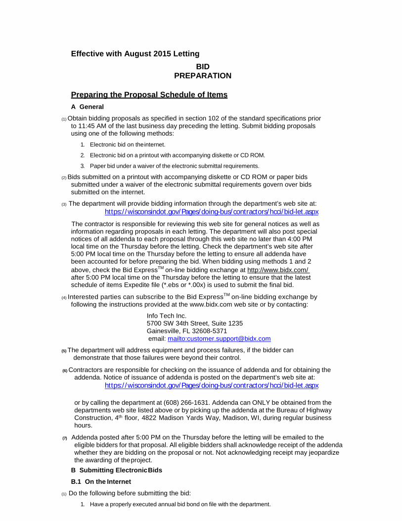
Effective with August 2015 Letting
BID PREPARATION
Preparing the Proposal Schedule of Items
A General
(1) Obtain bidding proposals as specified in section 102 of the standard specifications priorto 11:45 AM of the last business day preceding the letting. Submit bidding proposalsusing one of the following methods:
1. Electronic bid on the internet.
2. Electronic bid on a printout with accompanying diskette or CD ROM.
3. Paper bid under a waiver of the electronic submittal requirements.
(2) Bids submitted on a printout with accompanying diskette or CD ROM or paper bidssubmitted under a waiver of the electronic submittal requirements govern over bidssubmitted on the internet.
(3) The department will provide bidding information through the department’s web site at:https://wisconsindot.gov/Pages/doing-bus/contractors/hcci/bid-let.aspx
The contractor is responsible for reviewing this web site for general notices as well as information regarding proposals in each letting. The department will also post special notices of all addenda to each proposal through this web site no later than 4:00 PM local time on the Thursday before the letting. Check the department’s web site after 5:00 PM local time on the Thursday before the letting to ensure all addenda have been accounted for before preparing the bid. When bidding using methods 1 and 2 above, check the Bid ExpressTM on-line bidding exchange at http://www.bidx.com/ after 5:00 PM local time on the Thursday before the letting to ensure that the latest schedule of items Expedite file (*.ebs or *.00x) is used to submit the final bid.
(4) Interested parties can subscribe to the Bid ExpressTM on-line bidding exchange byfollowing the instructions provided at the www.bidx.com web site or by contacting:
Info Tech Inc. 5700 SW 34th Street, Suite 1235 Gainesville, FL 32608-5371 email: mailto:[email protected]
(5) The department will address equipment and process failures, if the bidder candemonstrate that those failures were beyond their control.
(6) Contractors are responsible for checking on the issuance of addenda and for obtaining theaddenda. Notice of issuance of addenda is posted on the department’s web site at:
https://wisconsindot.gov/Pages/doing-bus/contractors/hcci/bid-let.aspx
or by calling the department at (608) 266-1631. Addenda can ONLY be obtained from the departments web site listed above or by picking up the addenda at the Bureau of Highway Construction, 4th floor, 4822 Madison Yards Way, Madison, WI, during regular business hours.
(7) Addenda posted after 5:00 PM on the Thursday before the letting will be emailed to theeligible bidders for that proposal. All eligible bidders shall acknowledge receipt of the addendawhether they are bidding on the proposal or not. Not acknowledging receipt may jeopardizethe awarding of the project.
B Submitting Electronic Bids
B.1 On the Internet
(1) Do the following before submitting the bid:
1. Have a properly executed annual bid bond on file with the department.
2. Have a digital ID on file with and enabled by Info Tech Inc. Using this digital ID will constitute the bidder's signature for proper execution of the bidding proposal.
(2) In lieu of preparing, delivering, and submitting the proposal as specified in 102.6 and 102.9 of the standard specifications, submit the proposal on the internet as follows:
1. Download the latest schedule of items reflecting all addenda from the Bid ExpressTM web site.
2. Use ExpediteTM
software to enter a unit price for every item in the schedule of items.
3. Submit the bid according to the requirements of ExpediteTM
software and the Bid
ExpressTM
web site. Do not submit a bid on a printout with accompanying diskette or CD ROM or a paper bid. If the bidder does submit a bid on a printout with accompanying diskette or a paper bid in addition to the internet submittal, the department will disregard the internet bid.
4. Submit the bid before the hour and date the Notice to Contractors designates.
5. Do not sign, notarize, and return the bidding proposal described in 102.2 of the standard specifications.
(3) The department will not consider the bid accepted until the hour and date the Notice to Contractors designates.
B.2 On a Printout with Accompanying Diskette or CD ROM
(1) Download the latest schedule of items from the Wisconsin pages of the Bid ExpressTM web site reflecting the latest addenda posted on the department’s web site at:
https://wisconsindot.gov/Pages/doing-bus/contractors/hcci/bid-let.aspx
Use Expedite TM software to prepare and print the schedule of items. Provide a valid amount for all price fields. Follow instructions and review the help screens provided on the Bid ExpressTM web site to assure that the schedule of items is prepared properly.
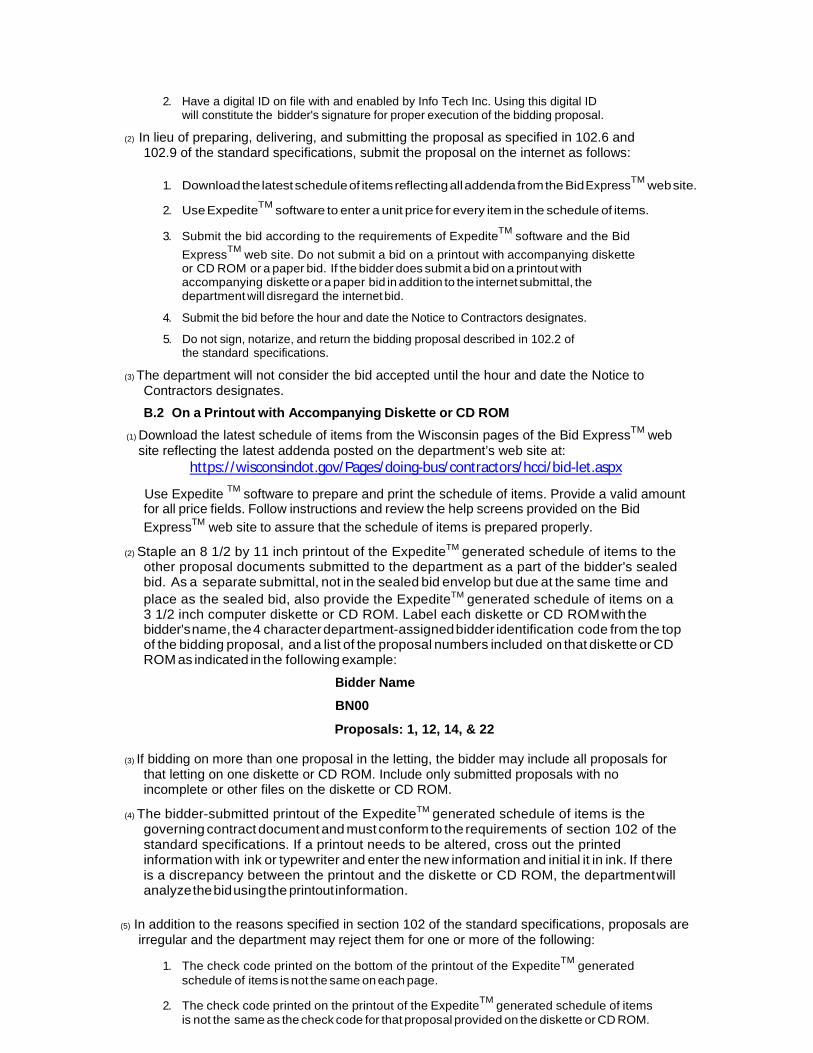
(2) Staple an 8 1/2 by 11 inch printout of the ExpediteTM generated schedule of items to the other proposal documents submitted to the department as a part of the bidder's sealed bid. As a separate submittal, not in the sealed bid envelop but due at the same time and place as the sealed bid, also provide the ExpediteTM generated schedule of items on a 3 1/2 inch computer diskette or CD ROM. Label each diskette or CD ROM with the bidder's name, the 4 character department-assigned bidder identification code from the top of the bidding proposal, and a list of the proposal numbers included on that diskette or CD ROM as indicated in the following example:
Bidder Name
BN00
Proposals: 1, 12, 14, & 22
(3) If bidding on more than one proposal in the letting, the bidder may include all proposals for that letting on one diskette or CD ROM. Include only submitted proposals with no incomplete or other files on the diskette or CD ROM.
(4) The bidder-submitted printout of the ExpediteTM generated schedule of items is the governing contract document and must conform to the requirements of section 102 of the standard specifications. If a printout needs to be altered, cross out the printed information with ink or typewriter and enter the new information and initial it in ink. If there is a discrepancy between the printout and the diskette or CD ROM, the department will analyze the bid using the printout information.
(5) In addition to the reasons specified in section 102 of the standard specifications, proposals are irregular and the department may reject them for one or more of the following:
1. The check code printed on the bottom of the printout of the ExpediteTM
generated schedule of items is not the same on each page.
2. The check code printed on the printout of the ExpediteTM
generated schedule of items is not the same as the check code for that proposal provided on the diskette or CD ROM.
3. The diskette or CD ROM is not submitted at the time and place the department designates.
C Waiver of Electronic Submittal
(1) The bidder may request a waiver of the electronic submittal requirements. Submit a written request for a waiver in lieu of bids submitted on the internet or on a printout with accompanying diskette or CD ROM. Use the waiver that was included with the paper bid document sent to the bidder or type up a waiver on the bidder’s letterhead. The department will waive the electronic submittal requirements for a bidding entity (individual, partnership, joint venture, corporation, or limited liability company) for up to 4 individual proposals in a calendar year. The department may allow additional waivers for equipment malfunctions.
(2) Submit a schedule of items on paper conforming to section 102 of the standard specifications. The department charges the bidder a $75 administrative fee per proposal, payable at the time and place the department designates for receiving bids, to cover the costs of data entry. The department will accept a check or money order payable to: "Wisconsin, Dept. of Transportation."
(3) In addition to the reasons specified in section 102 of the standard specifications, proposals are irregular and the department may reject them for one or more of the following:
1. The bidder fails to provide the written request for waiver of the electronic submittal requirements.
2. The bidder fails to pay the $75 administrative fee before the time the department designates for the opening of bids unless the bidder requests on the waiver that they be billed for the $75.
3. The bidder exceeds 4 waivers of electronic submittal requirements within a calendar year.
(4) In addition to the reasons specified in section 102 of the standard specifications, the department may refuse to issue bidding proposals for future contracts to a bidding entity that owes the department administrative fees for a waiver of electronic submittal requirements.
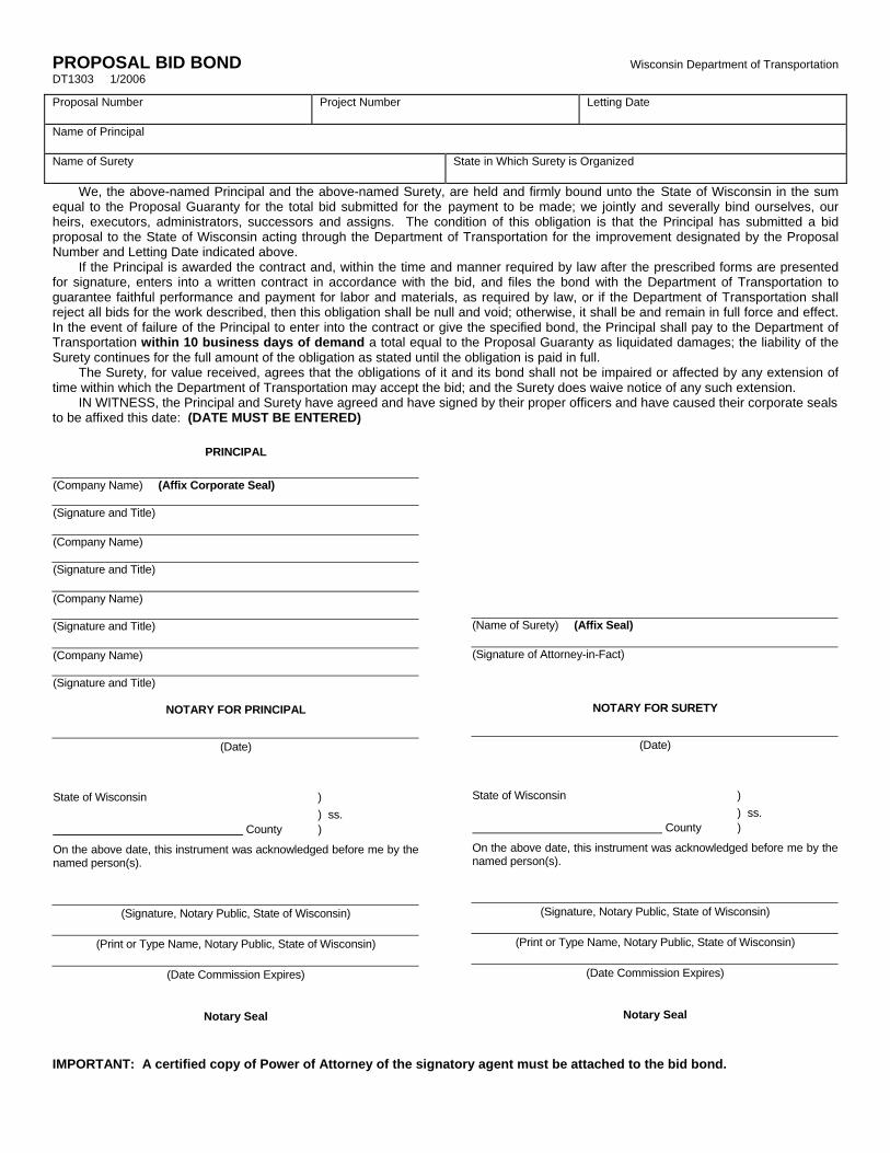
PROPOSAL BID BOND Wisconsin Department of Transportation DT1303 1/2006
Proposal Number Project Number Letting Date
Name of Principal
Name of Surety State in Which Surety is Organized
We, the above-named Principal and the above-named Surety, are held and firmly bound unto the State of Wisconsin in the sum equal to the Proposal Guaranty for the total bid submitted for the payment to be made; we jointly and severally bind ourselves, our heirs, executors, administrators, successors and assigns. The condition of this obligation is that the Principal has submitted a bid proposal to the State of Wisconsin acting through the Department of Transportation for the improvement designated by the Proposal Number and Letting Date indicated above. If the Principal is awarded the contract and, within the time and manner required by law after the prescribed forms are presented for signature, enters into a written contract in accordance with the bid, and files the bond with the Department of Transportation to guarantee faithful performance and payment for labor and materials, as required by law, or if the Department of Transportation shall reject all bids for the work described, then this obligation shall be null and void; otherwise, it shall be and remain in full force and effect. In the event of failure of the Principal to enter into the contract or give the specified bond, the Principal shall pay to the Department of Transportation within 10 business days of demand a total equal to the Proposal Guaranty as liquidated damages; the liability of the Surety continues for the full amount of the obligation as stated until the obligation is paid in full. The Surety, for value received, agrees that the obligations of it and its bond shall not be impaired or affected by any extension of time within which the Department of Transportation may accept the bid; and the Surety does waive notice of any such extension. IN WITNESS, the Principal and Surety have agreed and have signed by their proper officers and have caused their corporate seals to be affixed this date: (DATE MUST BE ENTERED)
PRINCIPAL
(Company Name) (Affix Corporate Seal)
(Signature and Title)
(Company Name)
(Signature and Title)
(Company Name)
(Signature and Title)
(Company Name)
(Signature and Title)
NOTARY FOR PRINCIPAL
(Date)
State of Wisconsin )
) ss. County )
On the above date, this instrument was acknowledged before me by thenamed person(s).
(Signature, Notary Public, State of Wisconsin)
(Print or Type Name, Notary Public, State of Wisconsin)
(Date Commission Expires)
Notary Seal
(Name of Surety) (Affix Seal)
(Signature of Attorney-in-Fact)
NOTARY FOR SURETY
(Date)
State of Wisconsin )
) ss. County )
On the above date, this instrument was acknowledged before me by thenamed person(s).
(Signature, Notary Public, State of Wisconsin)
(Print or Type Name, Notary Public, State of Wisconsin)
(Date Commission Expires)
Notary Seal
IMPORTANT: A certified copy of Power of Attorney of the signatory agent must be attached to the bid bond.

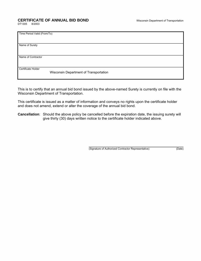
CERTIFICATE OF ANNUAL BID BOND Wisconsin Department of Transportation DT1305 8/2003
Time Period Valid (From/To)
Name of Surety
Name of Contractor
Certificate Holder
Wisconsin Department of Transportation
This is to certify that an annual bid bond issued by the above-named Surety is currently on file with the Wisconsin Department of Transportation.
This certificate is issued as a matter of information and conveys no rights upon the certificate holder and does not amend, extend or alter the coverage of the annual bid bond.
Cancellation: Should the above policy be cancelled before the expiration date, the issuing surety will give thirty (30) days written notice to the certificate holder indicated above.
(Signature of Authorized Contractor Representative) (Date)

March 2010
LIST OF SUBCONTRACTORSSection 66.0901(7), Wisconsin Statutes, provides that as a part of the proposal, the bidder also shall submit a list of the subcontractors the bidder proposes to contract with and the class of work to be performed by each. In order to qualify for inclusion in the bidder's list a subcontractor shall first submit a bid in writing, to the general contractor at least 48 hours prior to the time of the bid closing. The list may not be added to or altered without the written consent of the municipality. A proposal of a bidder is not invalid if any subcontractor and the class of work to be performed by the subcontractor has been omitted from a proposal; the omission shall be considered inadvertent or the bidder will perform the work personally.
No subcontract, whether listed herein or later proposed, may be entered into without the written consent of the Engineer as provided in Subsection 108.1 of the Standard Specifications.
Name of Subcontractor Class of Work Estimated Value
Page 1 of 2
DECEMBER 2000
CERTIFICATION REGARDING DEBARMENT, SUSPENSION, AND OTHER RESPONSIBILITY MATTERS - PRIMARY COVERED TRANSACTIONS
Instructions for Certification
1. By signing and submitting this proposal, the prospective contractor is providing thecertification set out below.
2. The inability of a person to provide the certification required below will not necessarilyresult in denial of participation in this covered transaction. The prospective contractor shallsubmit an explanation of why it cannot provide the certification set out below. Thecertification or explanation will be considered in connection with the department oragency's determination whether to enter into this transaction. However, failure of theprospective contractor to furnish a certification or an explanation shall disqualify suchperson from participation in this transaction.
3. The certification in this clause is a material representation of fact upon which reliance wasplaced when the department determined to enter into this transaction. If it is laterdetermined that the contractor knowingly rendered an erroneous certification in addition toother remedies available to the Federal Government the department may terminate thistransaction for cause or default.
4. The prospective contractor shall provide immediate written notice to the department towhom this proposal is submitted if at any time the prospective contractor learns that itscertification was erroneous when submitted or has become erroneous by reason of changedcircumstances.
5. The terms "covered transaction," "debarred," "suspended," "ineligible," "lower tier coveredtransaction," "participant," "person," "primary covered transaction," "principal," "proposal,"and "voluntarily excluded," as used in this clause, have the meanings set out in theDefinitions and Coverage sections of the rules implementing Executive Order 12549. Youmay contact the department to which this proposal is being submitted for assistance inobtaining a copy of those regulations.
6. The prospective contractor agrees by submitting this proposal that, should this contract beentered into, it shall not knowingly enter into any lower tier covered transaction with aperson who is debarred, suspended, declared ineligible, or voluntarily excluded fromparticipation in this covered transaction, unless authorized by the department entering intothis transaction.
7. The prospective contractor further agrees by submitting this proposal that it will include theclause titled "Certification Regarding Debarment, Suspension, Ineligibility and VoluntaryExclusion-Lower Tier Covered Transaction," which is included as an addendum to PR-1273 - "Required Contract Provisions Federal Aid Construction Contracts," without
Page 2 of 2
modification, in all lower tier covered transactions and in all solicitations for lower tier covered transactions.
8. The contractor may rely upon a certification of a prospective subcontractor/materials
supplier that it is not debarred, suspended, ineligible, or voluntarily excluded from the covered transaction, unless it knows that the certification is erroneous. A contractor may decide the method and frequency by which it determines the eligibility of its principals. Each contractor may, but is not required to, check the Disapproval List (telephone # 608/266/1631).
9. Nothing contained in the foregoing shall be construed to require establishment of a system
of records in order to render in good faith the certification required by this clause. The knowledge and information of a contractor is not required to exceed that which is normally possessed by a prudent person in the ordinary course of business dealings.
10. Except for transactions authorized under paragraph 6 of these instructions, if a contractor in
a covered transaction knowingly enters into a lower tier covered transaction with a person who is suspended, debarred, ineligible or voluntarily excluded from participation in this transaction, in addition to other remedies available to the Federal Government, the department may terminate this transaction for cause or default.
Certification Regarding Debarment, Suspension, and Other Responsibility Matters - Primary Covered Transactions (1) The prospective contractor certifies to the best of its knowledge and belief, that it and its
principals: (a) Are not presently debarred, suspended, proposed for debarment, declared ineligible,
or voluntarily excluded from covered transactions by any Federal department or agency;
(b) Have not within a three-year period preceding this proposal been convicted of or
had a civil judgment rendered against them for commission of fraud or a criminal offense in connection with obtaining, attempting to obtain, or performing a public (Federal, State or local) transaction or contract under a public transaction; violation of Federal or State antitrust statutes or commission of embezzlement, theft, forgery, bribery, falsification or destruction of records, making false statements or receiving stolen property;
(c) Are not presently indicted for or otherwise criminally or civilly charged by a
governmental entity (Federal, State or local) with commission of any of the offense enumerated in paragraph (1)(b) of this certification; and
(d) Have not within a three-year period preceding this proposal had one or more public transactions (Federal, State or local) terminated for cause or default.
(2) Where the prospective contractor is unable to certify to any of the statements in this
certification, such prospective contractor shall attach an explanation to this proposal.
3763-00-74 1 of 180
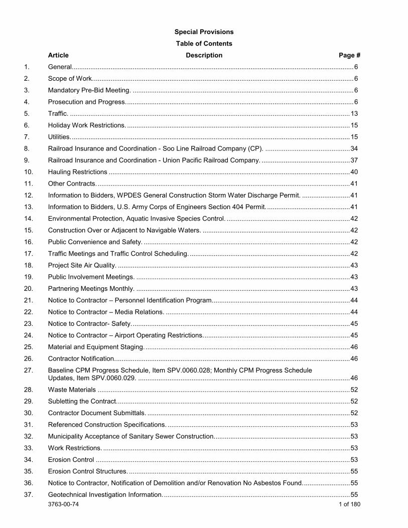
Special Provisions Table of Contents
Article Description Page # 1. General......................................................................................................................................................... 6
2. Scope of Work. ............................................................................................................................................. 6
3. Mandatory Pre-Bid Meeting. ........................................................................................................................ 6
4. Prosecution and Progress. ........................................................................................................................... 6
5. Traffic. ........................................................................................................................................................ 13
6. Holiday Work Restrictions. ......................................................................................................................... 15 7. Utilities. ....................................................................................................................................................... 15
8. Railroad Insurance and Coordination - Soo Line Railroad Company (CP). .............................................. 34
9. Railroad Insurance and Coordination - Union Pacific Railroad Company. ................................................ 37
10. Hauling Restrictions ................................................................................................................................... 40
11. Other Contracts. ......................................................................................................................................... 41
12. Information to Bidders, WPDES General Construction Storm Water Discharge Permit. .......................... 41 13. Information to Bidders, U.S. Army Corps of Engineers Section 404 Permit. ............................................. 41
14. Environmental Protection, Aquatic Invasive Species Control. ................................................................... 42
15. Construction Over or Adjacent to Navigable Waters. ................................................................................ 42
16. Public Convenience and Safety. ................................................................................................................ 42
17. Traffic Meetings and Traffic Control Scheduling. ....................................................................................... 42
18. Project Site Air Quality. .............................................................................................................................. 43 19. Public Involvement Meetings. .................................................................................................................... 43
20. Partnering Meetings Monthly. .................................................................................................................... 43
21. Notice to Contractor – Personnel Identification Program. .......................................................................... 44
22. Notice to Contractor – Media Relations. .................................................................................................... 44
23. Notice to Contractor- Safety. ...................................................................................................................... 45 24. Notice to Contractor – Airport Operating Restrictions. ............................................................................... 45
25. Material and Equipment Staging. ............................................................................................................... 46
26. Contractor Notification. ............................................................................................................................... 46
27. Baseline CPM Progress Schedule, Item SPV.0060.028; Monthly CPM Progress Schedule Updates, Item SPV.0060.029. ................................................................................................................... 46
28. Waste Materials ......................................................................................................................................... 52 29. Subletting the Contract. .............................................................................................................................. 52
30. Contractor Document Submittals. .............................................................................................................. 52
31. Referenced Construction Specifications. ................................................................................................... 53
32. Municipality Acceptance of Sanitary Sewer Construction. ......................................................................... 53
33. Work Restrictions. ...................................................................................................................................... 53
34. Erosion Control .......................................................................................................................................... 53 35. Erosion Control Structures. ........................................................................................................................ 55
36. Notice to Contractor, Notification of Demolition and/or Renovation No Asbestos Found. ......................... 55
37. Geotechnical Investigation Information. ..................................................................................................... 55
3763-00-74 2 of 180
38. Maintaining Drainage. ................................................................................................................................ 57
39. Removing Old Structure Over Waterway With Minimal Debris Station 566+00, Item 203.0600.S.200. Removing Old Structure Over Waterway With Minimal Debris Station 566+00, Item 203.0600.S.201. ................................................................................................................................. 57
40. Abandoning Sewer, Item 204.0291.S. ....................................................................................................... 58
41. Removing Riprap, Item 204.9035.S.001. ................................................................................................... 58
42. Removing Bulkhead, Item 204.9060.S.001. .............................................................................................. 59
43. Removing Draintile, Item 204.9090.S.001. ................................................................................................ 59
44. Removing Underdrain, Item 204.9090.S.002............................................................................................. 59 45. Removing or Abandoning Miscellaneous Structures. ................................................................................ 60
46. Removing Traffic Signals, CTH KR & STH 31, Item 204.9105.S.301; Removing Traffic Signals, CTH KR & Old Green Bay Road, Item 204.9105.S.302. ........................................................................... 60
47. Removing Loop Detector Wire and Lead-in Cable CTH KR & STH 31, Item 204.9105.S.303; Removing Loop Detector Wire and Lead-In Cable CTH KR & Old Green Bay Road, Item 204.9105.S.304. ......................................................................................................................................... 61
48. Excavation, Hauling, and Disposal of Petroleum Contaminated Soil, Item 205.0501.S. ........................... 62
49. Roadway Excavation .................................................................................................................................. 64
50. QMP Subgrade. ......................................................................................................................................... 65
51. Concrete Pavement Joint Layout, Item 415.5110.S. ................................................................................. 71
52. Cold Patch, Item 495.1000.S. .................................................................................................................... 71
53. Concrete Curing Materials. ........................................................................................................................ 72 54. Ice Hot Weather Concreting, Item 501.1000.S. ......................................................................................... 72
55. Bar Steel Reinforcement HS Stainless Structures, Item 505.0800.S. ....................................................... 73
56. Storm Sewer. ............................................................................................................................................. 75
57. Catch Basins, Manholes, and Inlets. .......................................................................................................... 76
58. Cover Plates Temporary, Item 611.8120.S. ............................................................................................... 77 59. Pipe Grates, Item 611.9800.S. ................................................................................................................... 77
60. Fence Safety, Item 616.0700.S. ................................................................................................................ 78
61. Pond Liner Clay, Item 640.1303.S. ............................................................................................................ 78
62. General Requirements for Electrical Work. ................................................................................................ 81
63. Electrical Conduit. ...................................................................................................................................... 81
64. Electrical Wiring. ........................................................................................................................................ 82 65. Electrical Service Meter Breaker Pedestal CTH KR & STH 31, Item 656.0200.301; Electrical
Service Meter Breaker Pedestal CTH KR & Old Green Bay Road, Item 656.0200.302; Electrical Service Meter Breaker Pedestal CTH KR & 90th St/72nd Ave, Item 656.0200.303; Electrical Service Meter Breaker Pedestal CTH KR & Trail Crossing, Item 656.0200.304; Electrical Service Meter Breaker Pedestal CTH A & CTH H, Item 656.0200.305. ................................................................. 82
66. Traffic Signals, General. ............................................................................................................................. 82 67. Traffic Signal Faces. .................................................................................................................................. 83
68. Pedestrian Push Buttons. ........................................................................................................................... 83
69. Temporary Traffic Signals for Intersections CTH KR & STH 31, Item 661.0200.301; Temporary Traffic Signals for Intersections STH 31 & CTH A, Item 661.0200.351. .................................................... 83
70. Intelligent Transportation Systems (ITS) – Control of Materials. ............................................................... 84 71. Intelligent Transportation Systems – General Requirements. ................................................................... 85
3763-00-74 3 of 180
72. Field System Integrator, Item 670.0100. .................................................................................................... 89
73. ITS Documentation, Item 670.0200. .......................................................................................................... 89
74. Communication System Testing, Item 678.0500. ...................................................................................... 89 75. Communication Systems. .......................................................................................................................... 89
76. Optimized Aggregate Gradation Incentive, Item 715.0710. ....................................................................... 89
77. Flexural Strength for Concrete Mix Design. ............................................................................................... 92
78. Crack and Damage Survey Parcel 802, Item 999.1500.S.001; Crack and Damage Survey Parcel 803, Item 999.1500.S.002; Crack and Damage Survey Parcel 839, Item 999.1500.S.003. ..................... 92
79. EBS Excavation, Item SPV.0035.001. ....................................................................................................... 93 80. EBS Backfill, Item SPV.0035.002. ............................................................................................................. 94
81. Roadway Embankment, Item SPV.0035.003............................................................................................. 95
82. Riffle Cobble, Item SPV.0035.004; No. 1 Aggregate, Item SPV.0035.005; Open-Graded Base Aggregate, Item SPV.0035.006; Sand/Woodchip Bed, Item SPV.0035.007; Compost, Item SPV.0035.008; Boulder Weir Cascade, Item SPV.0090.010. ................................................................... 96
83. Backfill Slurry, Item SPV.0035.009. ........................................................................................................... 99 84. Maintain, Remove and Dispose Field Office Left in Place Special Project 3763-00-74, Item
SPV.0135.001; Maintain Field Office Left in Place Special Utility Fees Project ID 3763-00-74, Item SPV.0055.001. ................................................................................................................................. 100
85. Temporary Stone Ditch Checks, Item SPV.0060.002. ............................................................................. 103
86. Sand Bags, Item SPV.0060.003. ............................................................................................................. 103
87. Temporary Sediment Traps, Item SPV.0060.004. ................................................................................... 104 88. Erosion Control Filter Bags, Item SPV.0060.005. .................................................................................... 104
89. Inlet Frame and Grate for Mountable Curb, Item SPV.0060.006............................................................. 105
90. Temporary Access Gates at CPRR, Item SPV.0060.007; Temporary Access Gates at UPRR, Item SPV.0060.008. ................................................................................................................................. 105
91. Mobilizations Emergency Pavement Repair, Item SPV.0060.009. .......................................................... 106 92. Section Corner Monuments, Item SPV.0060.010. ................................................................................... 107
93. Settlement Gauges, Item SPV.0060.011. ................................................................................................ 108
94. Manhole Beehive Grate, Item SPV.0060.012. ......................................................................................... 109
95. Connect Drain Tile, Item SPV.0060.013. ................................................................................................. 109
96. Pipe Connection to Existing Structure, Item SPV.0060.016. ................................................................... 110 97. Pond L Outlet Storm Sewer Structure, Item SPV.0060.020; Pond M Outlet Storm Sewer
Structure, ItemSPV.0060.021; Pond N Outlet Storm Sewer Structure, Item SPV.0060.022. ................. 110
98. Slip-In Check Valve for 24-Inch Inside Diameter Pipe, Item SPV.0060.024; Slip-In Check Valve for 30-Inch Inside Diameter Pipe, Item SPV.0060.025; Slip-In Check Valve for 36-Inch Inside Diameter Pipe, Item SPV.0060.026; Slip-In Check Valve for 42-Inch Inside Diameter Pipe, Item SPV.0060.027. ......................................................................................................................................... 111
99. Concrete Bases Monotube Type 9 & 10 Special Pole, Item SPV.0060.301. .......................................... 112 100. Transport and Install Poles Type 9, Item SPV.0060.302; Transport and Install Poles Type 9
Special, Item SPV.0060.303; Transport and Install Poles Type 10, Item SPV.0060.304; Transport and Install Poles Type 10 Special, Item SPV.0060.305; Transport and Install Monotube Arms 25-FT, Item SPV.0060.306; Transport and Install Monotube Arms 30-FT, Item SPV.0060.307; Transport and Install Monotube Arms 35-FT, Item SPV.0060.308; Transport and Install Luminaire Arms Steel 15-FT, Item SPV.0060.309; Transport and Install Monotube Arms 40-FT, Item SPV.0060.310; Transport and Install Monotube Arms 20-FT, Item SPV.0060.311. ............................... 112
101. Luminaire Utility LED C With House Side Shield, Item SPV.0060.501. .................................................. 113
3763-00-74 4 of 180
102. Connect to Existing Sanitary Manhole, Item SPV.0060.600. ................................................................... 114
103. Sanitary Sewer Manhole, Item SPV.0060.601. ....................................................................................... 115
104. Abandon Sanitary Manhole, Item SPV.0060.602. ................................................................................... 116 105. Adjust Sanitary Manhole, Item SPV.0060.603. ........................................................................................ 116
106. Adjusting Sanitary Manhole Village of Mount Pleasant, Item SPV.0060.610. ......................................... 117
107. Pavement Cleanup Project 3763-00-74, Item SPV.0075.001. ................................................................ 118
108. Heavy Duty Silt Fence, Item SPV.0090.001. ........................................................................................... 119
109. Pipe Underdrain 6-Inch Special, Item SPV.0090.002. ............................................................................. 121
110. Temporary Construction Access Road, Item SPV.00090.005. ................................................................ 121 111. Concrete Curb and Gutter 36-Inch Special Type A, Item SPV.0090.008. ............................................... 122
112. Fence Chain Link Polymer-Coated 6-Ft. B-30-145, Item SPV.0090.202; Fence Chain Link Polymer-Coated 6-Ft. B-30-146, Item SPV.0090.203; Fence Chain Link Polymer-Coated 6-Ft. B-30-147, Item SPV.0090.204; Fence Chain Link Polymer-Coated 6-Ft. B-30-148, Item SPV.0090.205; Fence Chain Link Polymer-Coated 6-Ft. R-30-65, Item SPV.0090.206; Fence Chain Link Polymer-Coated 6-Ft. R-30-66, Item SPV.0090.207; Fence Chain Link Polymer-Coated 6-Ft. R-30-67, Item SPV.0090.208; Fence Chain Link Polymer-Coated 6-Ft. R-30-68, Item SPV.0090.209. ................................................................................................................................. 122
113. Sanitary Sewer Pipe 8-Inch, Item SPV.0090.600. ................................................................................... 125
114. Building Service Pipe 6-Inch, Item SPV.0090.601. .................................................................................. 126
115. Removing Force Main Pipe, Item SPV.0090.610. ................................................................................... 126
116. Survey Project 3763-00-74, Item SPV.0105.001. .................................................................................... 127 117. Salvage Pedestrian Bridge Superstructure, Item SPV.0105.002. ........................................................... 129
118. Grading Shaping and Finishing Stream Bed Structure B-30-143 and B-30-144, Item SPV.0105.003. ......................................................................................................................................... 130
119. Pike River Site Restoration, Item SPV.0105.004. .................................................................................... 131
120. Geotechnical Instrumentation Data Collection, Item SPV.0105.005. ...................................................... 137 121. Transporting and Installing State Furnished EVP Detector Heads with Confirmation Beacons
CTH KR & STH 31, Item SPV.0105.301; Transporting and Installing State Furnished EVP Detector Heads with Confirmation Beacons CTH KR & Old Green Bay Road, Item SPV.0105.302; Transporting and Installing State Furnished EVP Detector Heads with Confirmation Beacons CTH KR & 90th Street/72nd Avenue, Item SPV.0105.303; Transporting and Installing State Furnished EVP Detector Heads with Confirmation Beacons CTH A at CTH H, Item SPV.0105.304. ......................................................................................................................................... 142
122. Temporary Radar/Microwave Vehicle Detection System for Intersections CTH KR & STH 31, Item SPV.0105.305; Temporary Radar/Microwave Vehicle Detection System for Intersections, STH 31 & CTH A, Item SPV.0105.352. ................................................................................................................. 142
123. Transporting and Installing State Furnished EVP Radar Detection System CTH A & CTH H, Item SPV.0105.306. ......................................................................................................................................... 144
124. Transporting and Installing State Furnished Traffic Signal Cabinet, CTH A & CTH H, Item SPV.0105.307; Transporting and Installing State Furnished Traffic Signal Cabinet CTH KR & STH 31, Item SPV.0105.308; Transporting and Installing State Furnished Traffic Signal Cabinet CTH KR & Old Green Bay Road, Item SPV.0105.309; Transporting and Installing State Furnished Traffic Signal Cabinet CTH KR & 90th Street/72nd Avenue, Item SPV.0105.310; Transporting and Installing State Furnished Traffic Signal Cabinet CTH KR & Trail Crossing, Item SPV.0105.311. ......... 144
125. Temporary Infrared EVP System, CTH KR & STH 31, Item SPV.0105.312; Temporary Infrared EVP System, STH 31 & CTH A, Item SPV.0105.351. ............................................................................. 145
126. Pedestrian Hybrid Beacon, CTH KR & Trail Crossing, Item SPV.0105.313. ........................................... 146
3763-00-74 5 of 180
127. Transporting and Installing State Furnished APS Pedestrian Pushbutton System CTH KR & Trail Crossing, Item SPV.0105.314. ................................................................................................................. 147
128. Patch Panel With Fiber Optic Cable Pigtail 8-CT CTH KR & 90th St / 72nd Ave, Item SPV.0105.340; Patch Panel With Fiber Optic Cable Pigtail 8-CT STH 31 & CTH KR, Item SPV.0105.341; Patch Panel With Fiber Optic Cable Pigtail 8-CT CTH KR & Old Green Bay Rd, Item SPV.0105.342; Patch Panel With Fiber Optic Cable Pigtail 8-CT CTH KR & Pedestrian Hybrid Beacon, Item SPV.0105.343. ....................................................................................................... 147
129. Wall Modular Block Mechanically Stabilized Earth, Item SPV.0165.001. ................................................ 148 130. Prestressed Precast Concrete Wall Panel R-30-65, Item SPV.0165.200; Prestressed Precast
Concrete Wall Panel R-30-66, Item SPV.0165.201; Prestressed Precast Concrete Wall Panel R-30-67, Item SPV.0165.202; Prestressed Precast Concrete Wall Panel R-30-68, Item SPV.0165.203. ......................................................................................................................................... 159
131. Wall Wire Faced Mechanically Stabilized Earth R-30-65, Item SPV.0165.205; Wall Wire Faced Mechanically Stabilized Earth R-30-66, Item SPV.0165.206; Wall Wire Faced Mechanically Stabilized Earth R-30-67, Item SPV.0165.207; Wall Wire Faced Mechanically Stabilized Earth R-30-68, Item SPV.0165.208. .................................................................................................................. 165
132. Removal and Disposal of Invasive Plant Species, Item SPV.0170.001. ................................................. 173
133. Topsoil Special, Item SPV.0180.001. ...................................................................................................... 174
134. RSC Restoration, Item SPV.0180.002. .................................................................................................... 176
135. Possible Management of Solid Waste, Item SPV.0195.001. ................................................................... 176 136. Reconstruct Sanitary Manhole Addition, Item SPV.0200.600; Reconstruct Sanitary Manhole
Subtraction, Item SPV.0200.601. ............................................................................................................. 179
3763-00-74 6 of 180
STSP’S Revised November 21, 2019 SPECIAL PROVISIONS
1. General. Perform the work under this construction contract for Project 3763-00-74, CTH KR, V Mt Pleasant, CTH H to Old Green Bay Road, CTH KR, Racine County, Wisconsin as the plans show and execute the work as specified in the State of Wisconsin, Department of Transportation, Standard Specifications for Highway and Structure Construction, 2020 Edition, as published by the department, and these special provisions.
If all or a portion of the plans and special provisions are developed in the SI metric system and the schedule of prices is developed in the US standard measure system, the department will pay for the work as bid in the US standard system. 100-005 (20191121)
2. Scope of Work. The work under this contract shall consist of removals, grading, base aggregate, embankment material, Structures B-30-143, 144, 145, 146, and 147, R-30-65, 66, 67, and 68, concrete pavement, storm sewer, stormwater ponds, erosion control, permanent signing, traffic signals, traffic control, pavement markings, restoration and all incidental items necessary to complete the work as shown on the plans and included in the proposal and contract. 104-005 (20090901)
3. Mandatory Pre-Bid Meeting. Add the following to standard spec 102.3.1:2
Prospective bidders are invited to attend a virtual, mandatory pre-bid meeting on Tuesday, June 16, 2020, at 9:00 AM. The meeting link is shown below and will also be published on the HCCI website. https://wisconsindot.webex.com/wisconsindot/j.php?MTID=m357a881d107df5890395f13d8310e1bf
To Join by phone
+1 (408) 418-9388
Meeting number (access code): 962 371 966
No meeting minutes will be prepared. Issues discovered at the meeting will be handled by addendum.
4. Prosecution and Progress. Begin work within ten calendar days after the engineer issues a written notice to do so.
Provide the start date to the engineer in writing within a month after executing the contract but at least 14 calendar days before the preconstruction conference. Upon approval, the engineer will issue the notice to proceed within ten calendar days before the approved start date.
To revise the start date, submit a written request to the engineer at least two weeks before the intended start date. The engineer will approve or deny that request based on the conditions cited in the request and its effect on the department’s scheduled resources.
Be advised that there may be multiple mobilizations and/or remobilizations to complete construction operations, for example, such items as grading, concrete pavement repair/replacement, paving, traffic control, signing, temporary and permanent pavement marking, finishing items and other incidental items. No additional payment will be made, by the department, for additional mobilizations.

3763-00-74 7 of 180
A Schedule of Operations The department anticipates that the general schedule for each stage shall be as shown. Any staging modifications require approval from the engineer.
Coordinate traffic control and work operations with other projects listed under the article Other Contracts.
Immediately after notice to proceed contact Canadian National and Union Pacific Railroads companies for flagging operations and temporary crossings.
Early Stage 1 – August 2020 Construction Activities
Install temporary signal at CTH A and STH 31 intersection. Install permanent signing and striping along CTH A from CTH H to STH 31. Complete early stage 1 activities prior to closing CTH KR.
Stage 1 – September to November 2020 Construction Activities
1) Construct new stormwater ponds L, M, & N. 2) Grade, place sanitary sewer & storm sewer, place breaker run & aggregate and pave binder layer
on South Frontage Road near UPRR. 3) Begin grading & fill placement on new CTH KR WB between CTH H & 90th Street, and ¼ mile east
of 90th Street to STH 31. 4) Begin grading & fill placement on new CTH KR EB at CPRR and UPRR approaches. 5) Begin grading & fill placement on new CTH KR EB from 72nd Ave to ¼ mile east of 90th Street. 6) Begin construction of Bridges B-30-144, B-30-145, B-30-146, B-30-147 & B-30-148. 7) Begin construction of Retaining Walls R-30-65, R-30-66, R-30-67 & R-30-68. 8) Begin storm sewer placement.
2020 Winter Shutdown Winter shutdown in the year 2020 will commence on with the opening of new South Frontage Road on layer. Do not resume work until March 1, 2021 unless approved by the engineer. Provide a start date in writing at least 14 days prior to planned start of construction in 2021. Upon approval the engineer will issue the notice to proceed within 10 days of the approved start date.
Stage 2 – March 2021 to June 2021 Construction Activities
1) Finish construction of Bridge B-30-144 2) Grade, place breaker & aggregate and pave CTH KR WB between South Frontage Road and
STH 31. 3) Grade, place breaker run & aggregate and pave STH 31 SB. 4) Construct regenerative stormwater conveyance ponds. 5) Continue grading & fill placement on new CTH KR WB between CTH H & 90th Street, and ¼ mile
east of 90th Street to South Frontage Road. 6) Continue grading & fill placement on new CTH KR EB at CPRR and UPRR approaches. 7) Continue grading & fill placement on new CTH KR EB from 72nd Ave to ¼ mile east of 90th Street. 8) Continue construction of Bridges B-30-145, B-30-146, B-30-147 & B-30-148. 9) Continue construction of Retaining Walls R-30-65, R-30-66, R-30-67 & R-30-68. 10) Continue placement of storm sewer. 11) Complete installation of permanent traffic signal at CTH A/CTH H intersection.
3763-00-74 8 of 180
Stage 3 – June 2021 to November 2021 West Construction Activities – CTH H to STH 31
1) Grade, place breaker run & aggregate and pave CTH KR EB between South Frontage Road and STH 31.
2) Construct Bridge B-30-143. 3) Pave finish layer of new South Frontage Road. 4) Finish earthwork, place breaker run & aggregate and pave new CTH KR EB from 72nd Avenue to
¼ mile east of 90th Street. 5) Grade, place breaker run & aggregate and pave 72nd Avenue. 6) Finish earthwork on new CTH KR WB between CTH H & 90th Street, and ¼ mile east of 90th Street
to South Frontage Road. 7) Finish earthwork on new CTH KR EB at CPRR and UPRR approaches. 8) Finish construction of Bridges B-30-145, B-30-146, B-30-147 & B-30-148. 9) Finish construction of Retaining Walls R-30-65, R-30-66, R-30-67 & R-30-68.
East Construction Activities – STH 31 to End of Project (EOP)
Stage A
1) Begin grading, storm sewer, and breaker run & aggregate placement on STH 31 NB. 2) Begin grading and storm sewer on CTH KR between STH 31 and Old Green Bay Road (OGBR). 3) Begin grading and storm sewer on CTH KR WB between OGBR and 43rd Avenue. 4) Construct temporary 43rd Street temporary access.
Stage B
1) Finish grading, storm sewer, breaker run & aggregate placement and pave STH 31 NB. 2) Continue construction on CTH KR between STH 31 and OGBR. 3) Continue construction on CTH KR WB between OGBR and 43rd Avenue. 4) Grade, place breaker & aggregate and pave CTH KR between 43rd Avenue and East end of Project. 5) Grade, place breaker & aggregate and pave 43rd Avenue. 6) Grade, place breaker & aggregate and pave Vicksburg Drive. 7) Continue placement of storm sewer.
Stage C
1) Finish grading, placing breaker run & aggregate and paving CTH KR between STH 31 and OGBR. 2) Finish grading, placing breaker run & aggregate and paving CTH KR WB between OGBR and 43rd
Avenue. 3) Grade, place breaker run & aggregate and pave CTH KR EB between OGBR and 43rd Avenue. 4) Grade, place breaker run & aggregate and pave OGBR. 5) Continue placement of storm sewer.
2021 Winter Shutdown Winter shutdown in the year 2021 will commence on with the completion of all work required to fully open new CTH KR eastbound and westbound roadways for through traffic from Station 540+00 to the east end of the project. Do not resume work until March 1, 2022 unless approved by the engineer. Provide a start date in writing at least 14 days prior to planned start of construction in 2022. Upon approval the engineer will issue the notice to proceed within 10 days of the approved start date.
3763-00-74 9 of 180
Stage 4 – March 2022 to August 2022 Construction Activities
Stage A
1) Place breaker & aggregate and pave CTH KR WB between CTH H and South Frontage Road (March-May 2022).
2) Grade, place breaker run & aggregate and pave 90th Street.
Stage B
1) Grade and place breaker run & aggregate on CTH KR EB between CTH H and CPRR fill, between CPRR fill and 72nd Street, and ¼ mile east of 90th Street to UPRR fill.
2) Pave new CTH KR EB between CTH H and South Frontage Road. 3) Finish placement of storm sewer. 4) Finish all incidental items.
B Work Restrictions Do not close CTH KR until September 8, 2020. All pavement marking and signing along CTH A must be installed, temporary signals must be fully operational at STH 31 and CTH A, and the CTH KR detour route must be installed prior to closing CTH KR.
Maintain CTH KR local traffic on a paved surface utilizing the existing or finished roadway at all times or otherwise approved by the engineer
Do not remove existing pavement between South Frontage Road and STH 31 until one direction of entire new roadway is open to local traffic.
Establish the new driveway at Station 523+08 right side to existing CTH KR prior to beginning construction on R-40-66.
Establish the new driveway at Station 546+71 left side to existing CTH KR prior to beginning construction of modular bock retaining wall.
Construction of STH 31 may not start until April 5, 2021 and must be completed by July 16, 2021.
Old Green Bay Road may be closed to traffic for up to 30 days.
Night time closures of Old Green Bay Road and STH 31are allowed to construct storm sewer across the Old Green Bay Road and STH 31. However, night time closure of Old Green Bay Road and STH 31 will not be allowed at the same time. During night time closure of Old Green Bay Road, maintain one lane of traffic in each direction on STH 31. During night time closure of STH 31, maintain one lane of traffic in each direction on Old Green Bay Road.
To allow for proper settlement of embankment fills, do not place concrete pavement and base course from Station 465+00 to 476+69; 478+25 to 489+00, 524+00 to 532+53; and 534+08 to 540+00 (bridge approaches to CPRR and UPRR) until May 1, 2022 or as approved by the engineer.Do not place final surface for the driveway at Station 554+15, RT until May 1, 2021.
Do not place pavement base and surface course for the portion of shared use path that will be used as contractor access road for hauling materials until all hauling is competed.
Access to and from 90th Street for field entrances, residents and businesses must be maintained at all times.
56th Avenue needs to be accessible to CTH KR when CTH KR is closed at STH 31.
Vicksburg can be closed as long as OGBR remains open so that access to neighborhood from north can be maintained.
C Migratory Birds Swallow and other migratory birds’ nests have been observed on or under the existing bridge. All active nests (when eggs or young are present) of migratory birds are protected under the federal Migratory Bird Treaty Act.
3763-00-74 10 of 180
The nesting season for swallows and other birds is usually between May 1 and August 30. Either prevent active nests from becoming established or apply for a depredation permit from the US Fish and Wildlife Service for work that may disturb or destroy active nests. The need for a permit may be avoided by removing the existing bridge structure prior to nest occupation by birds or clearing nests from all structures before the nests become active in early spring. As a last resort, prevent birds from nesting by installing a suitable netting device on the remaining structure prior to nesting activity. Include the cost for preventing nesting in the cost of Removing Old Structure Over Waterway with Minimal Debris. 0074 (20090901)
D Northern Long-eared Bat (Myotis septentrionalis) Northern Long-eared Bats (NLEB) have the potential to inhabit the project limits because they roost in trees. Roosts have been identified within 150 feet of the project limits. The species and all active roosts are protected by the Federal Endangered Species Act. If an individual bat or active roost is encountered during construction operations, stop work and notify the engineer and the WisDOT Regional Environmental Coordinator (REC).
To avoid adverse impacts upon the NLEBs, no Clearing is allowed between June 1 and July 31, both dates inclusive.
If the required Clearing is not completed by May 31, the department will suspend all clearing and associated work directly impacted by Clearing. The department will issue a notice to proceed with Clearing and associated work directly impacted by clearing after consulting with the United States Fish and Wildlife Service (USFWS).
Submit a schedule and description of Clearing operations with the ECIP 14 days prior to any Clearing operations. The department will determine, based on schedule and scope of work, what additional erosion control measures shall be implemented prior to the start of Clearing operations, and list those additional measures in the ECIP.
E Rusty Patched Bumble Bee (Bombus affinis)
The rusty patched bumble bee (Bombus affinis) was listed as endangered by the U.S. Fish and Wildlife Service (USFWS) under the Endangered Species Act, effective March 21, 2017. Construction activities such as grading outside the mowed shoulder area have the potential to impact ground nests and wildflowers that may serve as a food source for the bee. If an active rusty-patched bumblebee nest is encountered in construction areas, contact the WisDOT Regional Environmental Coordinator, who will coordinate with USFWS.
The project plan include native flowering seed mix 70A for the disturbed areas within the Rusty Patched Bumble Bee High Potential Zone (RPBB HPZ). The WisDOT construction manager will oversee planting disturbed areas and avoid tree clearing in the RPBB HPZ.
F Fish Spawning
There shall be no instream disturbance of the following waterways, as a result of construction activity under or for this contract, from March 1 to June 1, both dates inclusive, in order to avoid adverse impacts upon the spawning of fish.
Any change to this limitation will require submitting a written request by the contractor to the engineer, subsequent review and concurrence by the Department of Natural Resources in the request, and final approval by the engineer. The approval will include all conditions to the request as mutually agreed upon by WisDOT and DNR. Regardless of timeframe, culvert pipe checks for pipes at these waterways shall be removed immediately after completion of the pipework.
G Prairie Crayfish Crayfish may be present near the Pike River structure construction. If Prairie Crayfish are observed during construction, the WisDOT construction project manager will instruct the contractor to remove crayfish from the construction area and store them in a plastic bucket with soil from where the crayfish
3763-00-74 11 of 180
was found. The WisDOT construction project manager will contact the DNR who will relocate them off the project.
H Clearing and Grubbing Do not clear and grub trees in the forested area as shown on the plan between October 15 and March 15 (both days inclusive).
I Winter Maintenance. Kenosha County will perform snow removal operations for portions of existing CTH KR pavement and new pavement where local traffic require access during construction. Provide for snow removal in those areas closed to traffic as required to facilitate safe construction traffic operations and as required to eliminate snowmelt run-off from crossing active roadways. Provide Kenosha County Highway Maintenance and Kenosha & Racine County Sheriff's Department with a 24-hour emergency contact number for when maintenance is required.
J Interim Completion: (South Frontage Road, November 6, 2020) If the contractor fails to open new South Frontage Road to binder layer, prior to 12:01 AM November 7, 2020, to local traffic the department will assess the contractor $5,000 in interim liquidated damages for each calendar day contract work remains incomplete beyond 12:01 AM November 7, 2020. An entire calendar day will be charged for any period of time within a calendar day that the road remains closed beyond 12:01 AM.
Interim Completion: (June 4, 2021) If the contractor fails to complete all work required to open the new westbound lanes of CTH KR for local traffic from Station 540+00 to STH 31 (Station 574+50), and the southbound lanes of STH 31 for through traffic prior to 12:01 AM June 5, 2021, as shown in Stage 3 of the traffic control plans; and complete installation and operation of permanent traffic signal at CTH H/CTH A intersection, the department will assess the contractor $5,000 in interim liquidated damages for each calendar day contract work remains incomplete beyond 12:01 AM June 5, 2021. An entire calendar day will be charged for any period of time within a calendar day that the road remains closed beyond 12:01 AM.
Interim Completion: (July 16, 2021) If the contractor fails to complete all work required to open all lanes of STH 31 for through traffic as shown in Stage 3C (east construction) of the plans, prior to 12:01 AM July 17, 2021, the department will assess the contractor $5,000 in interim liquidated damages for each calendar day contract work remains incomplete beyond 12:01 AM July 17, 2021. An entire calendar day will be charged for any period of time within a calendar day that the road remains closed beyond 12:01 AM.
Interim Completion: (November 5, 2021) If the contractor fails to complete all work required to fully open new CTH KR eastbound and westbound roadways for through traffic from Station 540+00 to the east end of the project, and the shared-use path from 56th Avenue to the east end of the project as shown in Stage 4 of the traffic control plans, prior to 12:01 AM November 6, 2021, the department will assess the contractor $5,000 in interim liquidated damages for each calendar day contract work remains incomplete beyond 12:01 AM November 6, 2021. An entire calendar day will be charged for any period of time within a calendar day that the road remains closed beyond 12:01 AM.
If contract time expires prior to completing all work specified in the contract, additional liquidated damages will be affixed according to standard spec 108.11.
3763-00-74 12 of 180
K Shared use path Keep existing shared path from 56th Avenue to STH 31 open to bike and pedestrian traffic until removal of existing pedestrian structure in Stage 3.
M Temporary Railroad Crossings and Flagging The department has obtained a temporary crossing agreement from the Canadian Pacific Railroad.
Apply and obtain temporary at-grade crossing agreement if desired from the Union Pacific Railroad immediately after the contract award. Refer to Article Railroad Insurance and Coordination – Union Pacific Railroad Company for additional information. Provide two-week advance notice to the railroad companies to install timber planks and geotextile fabric at the temporary crossing. The Canadian Pacific and Union Pacific railroads require a 40-day notification for flaggers.
The approaches to temporary crossings are to be installed and maintained by the contractor.
Stop Railroad flagging operations once the bridge is cured and be able to carry the traffic.
Do not use temporary crossings once the bridge deck is cured and be able to carry the traffic as determined by the engineer.
Remove temporary crossings at the end of construction and or as directed by the engineer.
N Staging Areas The department has an agreement with the Village of Mount Pleasant for construction staging operations as shown on the plan.
Batch plants are not allowed in staging area 2.
Fence the entire perimeter of staging areas. Cost for fencing, grading, construction, maintenance, removal and restoration of staging areas to original condition is considered incidental to construction. No separate payment will be made as part of this contract.
Contractor is required to include the select site in the ECIP, if the contractor intends to use the staging areas as shown on the plan.
O Potential availability of embankment material A potential borrow site is identified as shown on the plan. Limited soil borings are available, see article Geotechnical Investigation Information. Contractor is responsible for exploring the borrow site, testing, and suitability of material as per standard specification. Contractor to coordinate with the Village of Mount Pleasant, Claude Lois at (262) 684-7860. The Village of Mount Pleasant requires a royalty fee for the use of material. If utilized, the borrow site must be submitted as a select site in the ECIP.
The department does not warrant or require the use of embankment material from the site identified on the plan.
P Geotechnical Project geotechnical information is available as stated elsewhere in this special provision.
Subgrade corrective work is required for roadway construction and pavement support and locations are shown on the plan. Settlement monitoring is required to evaluate future magnitude and rate of settlement prior to paving for bridge and approach embankments. Construct eastbound and westbound embankments at the same time. Delay paving and base placement as required under work restrictions to accommodate anticipated settlement.
3763-00-74 13 of 180
5. Traffic. General The construction sequence, including the associated traffic control, shall be substantially accomplished as detailed in the Traffic Control Plans, and as described herein.
Maintain access at all times to all driveways located along within the project limits unless otherwise noted in the plans. Notify the property occupant five days in advance of the driveway reconstruction to verify closure or staged driveway construction methods and document notification. Provide notification documentation to engineer.
Coordinate traffic requirements under this contract with other adjacent and concurrent department or local municipality projects. Implement and coordinate with other contractors all traffic control as shown on the plans. Modifications to the traffic control plan may be required by the engineer to be safe and consistent with adjacent work by others.
Unless detailed in the plans, do not begin or continue any work that closes traffic lanes outside the allowed time periods specified in this article.
Do not store equipment, vehicles, or materials on adjacent streets beyond the project limits without specific approval of the engineer.
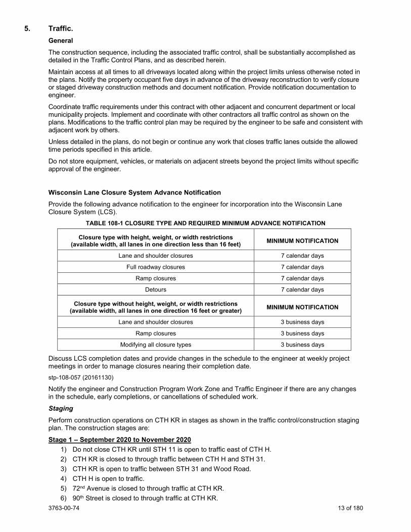
Wisconsin Lane Closure System Advance Notification Provide the following advance notification to the engineer for incorporation into the Wisconsin Lane Closure System (LCS).
TABLE 108-1 CLOSURE TYPE AND REQUIRED MINIMUM ADVANCE NOTIFICATION
Closure type with height, weight, or width restrictions (available width, all lanes in one direction less than 16 feet) MINIMUM NOTIFICATION
Lane and shoulder closures 7 calendar days
Full roadway closures 7 calendar days
Ramp closures 7 calendar days
Detours 7 calendar days
Closure type without height, weight, or width restrictions (available width, all lanes in one direction 16 feet or greater) MINIMUM NOTIFICATION
Lane and shoulder closures 3 business days
Ramp closures 3 business days
Modifying all closure types 3 business days
Discuss LCS completion dates and provide changes in the schedule to the engineer at weekly project meetings in order to manage closures nearing their completion date. stp-108-057 (20161130)
Notify the engineer and Construction Program Work Zone and Traffic Engineer if there are any changes in the schedule, early completions, or cancellations of scheduled work.
Staging Perform construction operations on CTH KR in stages as shown in the traffic control/construction staging plan. The construction stages are:
Stage 1 – September 2020 to November 2020 1) Do not close CTH KR until STH 11 is open to traffic east of CTH H. 2) CTH KR is closed to through traffic between CTH H and STH 31. 3) CTH KR is open to traffic between STH 31 and Wood Road. 4) CTH H is open to traffic. 5) 72nd Avenue is closed to through traffic at CTH KR. 6) 90th Street is closed to through traffic at CTH KR.
3763-00-74 14 of 180
7) 56th Avenue is closed to through traffic at CTH KR. 8) STH 31 is open to traffic. 9) Old Green Bay Road is open to traffic. 10) 43rd Avenue is open to traffic. 11) Vicksburg Drive is open to traffic. 12) Wood Road is open to traffic.
Stage 2 – March 2021 to June 2021 1) CTH KR is closed to through traffic between CTH H and STH 31. 2) CTH KR is open to traffic between STH 31 and Wood Road. 3) CTH H is open to traffic. 4) 72nd Avenue is closed to through traffic at CTH KR. 5) 90th Street is closed to through traffic at CTH KR. 6) 56th Avenue is closed to through traffic at CTH KR. 7) STH 31 is open to traffic (March to April 2021) 8) STH 31 is open to traffic to 1 lane in each direction on NB lanes (May to June 2021). 9) Old Green Bay Road is open to traffic. 10) 43rd Avenue is open to traffic. 11) Vicksburg Drive is open to traffic. 12) Wood Road is open to traffic.
Stage 3 – June 2021 to November 2021 1) CTH KR is closed to through traffic between CTH H and STH 31. 2) CTH KR is closed to through traffic between STH 31 and Wood Road (local residents only). 3) CTH H is open to traffic. 4) 72nd Avenue is closed to through traffic at CTH KR. 5) 90th Street is closed to through traffic at CTH KR. 6) 56th Avenue is closed to through traffic at CTH KR. 7) STH 31 is open to traffic to 1 lane in each direction on SB lanes (Stage 3A & 3B). 8) STH 31 is open to traffic (Stage 3C). 9) Old Green Bay Road is open to through traffic at CTH KR (Stage 3A & 3B). 10) Old Green Bay Road is closed to through traffic at CTH KR (Stage 3C). 11) 43rd Avenue is closed to through traffic at CTH KR (local residents only). 12) Vicksburg Drive is closed to through traffic at CTH KR (local residents only). 13) Woods Road is open to traffic.
Stage 4 – March 2022 to August 2022 1) CTH KR is closed to through traffic between CTH H and STH 31. 2) CTH KR is open to traffic between STH 31 and Wood Road. 3) CTH H is open to traffic. 4) 72nd Avenue is closed to through traffic at CTH KR. 5) 90th Street is closed to through traffic at CTH KR. 6) 56th Avenue is closed to through traffic at CTH KR. 7) STH 31 is open to traffic. 8) Old Green Bay Road is open to traffic. 9) 43rd Avenue is open to traffic. 10) Vicksburg Drive is open to traffic. 11) Wood Road is open to traffic. •
3763-00-74 15 of 180
6. Holiday Work Restrictions. Do not perform work on, nor haul materials of any kind along or across any portion of the highway carrying IH-94 traffic, and entirely clear the traveled way and shoulders of such portions of the highway of equipment, barricades, signs, lights, and any other material that might impede the free flow of traffic during the following holiday periods:
• From noon Friday, September 4, 2020 to 6:00 AM Tuesday, September 8, 2020 for Labor Day; • From noon Wednesday, November 25, 2020 to 6:00 AM Monday, November 30, 2020 for Thanksgiving; • From noon Wednesday, December 23, 2020 to 6:00 AM Monday, January 4, 2021 for Christmas and New
Year’s Day; • From noon Friday, May 28, 2021 to 6:00 AM Tuesday, June 1, 2021 for Memorial Day; • From noon Friday, July 2, 2021 to 6:00 AM Tuesday, July 6, 2021 for Independence Day; • From noon Friday, September 3, 2021 to 6:00 AM Tuesday, September 7, 2021 for Labor Day; • From noon Wednesday, November 24, 2021 to 6:00 AM Monday, November 29, 2021 for Thanksgiving; • From noon Thursday, December 23, 2021 to 6:00 AM Monday, January 3, 2022 for Christmas and New
Year’s Day; • From noon Friday, May 27, 2022 to 6:00 AM Tuesday, May 31, 2022 for Memorial Day; • From noon Friday, July 1, 2022 to 6:00 AM Tuesday, July 5, 2022 for Independence Day.
stp-107-005 (20181119)
7. Utilities. This contract does not come under the provisions of Wisconsin Administrative Code Chapter Trans 220.
Additional information regarding proposed and/or recently relocated utility facilities may be available on permits issued to the utility companies. These permits can be viewed at the Kenosha County Center during normal working hours. Contact Director of Kenosha County Highways Clement Abongwa at (262) 857-1872 for further information.
Underground and overhead utility facilities are located within the project limits. Utility adjustments are required for this construction project as noted below. Coordinate construction activities with a call to Diggers Hotline or a direct call to the utilities that have facilities in the area as required per state statute. Use caution to ensure the integrity of underground facilities and maintain code clearances from overhead facilities at all times.
Some utility work, as described below, is dependent on work being performed by the contractor at a specific site. Provide the engineer and the affected utility a good faith notice of when the utility is to start work at the site. Notice shall be given 14 to 16 calendar days in advance of when the site will be available to the utility. Follow up with a confirmation notice to the engineer and the utility not less than 3 working days before the site will be ready for the utility to begin its work.
Contact utility companies listed in the plans prior to preparing bids to obtain current information on existing utility locations and the status of any new utility relocation work.
Utility companies will be performing utility work and adjustments within the limits during the life of the project. The contractor shall cooperate and coordinate construction activities with these companies.
There may be discontinued utility facilities within the project limits. If a conflict with a discontinued utility facility is encountered, contact the appropriate utility owner/representative to coordinate construction activities and proper removal and disposal of said facility as necessary.
Known utilities in the project area are as follows:
American Transmission Company has an existing 138kV overhead electric transmission line within the project limits beginning beyond the southerly project limits and running northeasterly along a line 149’ westerly of and parallel to the westerly Canadian Pacific Railway right-of-way, crossing CTH KR at Station 531+29, and continuing northeasterly to a pole at Station 531+48, 211’LT. From there the line continues northeasterly to beyond the project limits. This line will remain in place without adjustment.
The American Transmission Company contact is Chris Dailey, (262) 506-6884.
3763-00-74 16 of 180
AT&T Legacy has an existing underground communication line beginning beyond the southerly project limits and running northerly along a line 31’ westerly of and parallel to the easterly Union Pacific Railway right-of-way, crossing CTH KR at Station 533+48, and continuing northerly to beyond the project limits. This line will remain in place without adjustment.
The AT&T Legacy contact is Ken Nine of JMC Engineers & Associates, (574) 842-8830 office / (574) 904-6336 cell.
AT&T Local Network has an existing underground communication line beginning beyond the southerly project limits and running northerly along a line 37’ easterly of and parallel to the westerly Union Pacific Railway right-of-way, crossing CTH KR at Station 533+15, and continuing northerly to beyond the project limits. This line will remain in place without adjustment.
The AT&T Local Network contact is Jennifer Navarro of Northwind Technical Services, (414) 459-3564.
AT&T Wisconsin has existing overhead and underground communications facilities within the project limits in the following locations:
- An existing overhead communications line beginning at a pole at Station 504+26, 37'LT and running easterly, crossing 90th Street, and ending at a pole at Station 506+75, 47’LT.
- An existing underground communication line beginning at a pole at Station 506+75, 47'LT and running northerly along the easterly 90th Street right-of-way to beyond the project limits.
- An existing underground communication line beginning at a pole at Station 506+75, 47'LT and running easterly to a pedestal at Station 513+30, 55’LT and then continuing easterly to a pedestal at Station 525+63, 23’RT. From there the line continues easterly and ends at a pole at Station 529+26, 24’RT.
- An existing overhead communications line on We Energies poles beginning at a pole at Station 504+26, 37'LT and running southeasterly, crossing CTH KR at Station 504+43, and continuing southeasterly to a pole at Station 504+51, 17’RT. From there the line runs southwesterly to a pole at Station 56+90, 7’LT and then runs southerly along a line 5’ westerly of and parallel to the easterly 72nd Avenue right-of-way to beyond the project limits.
- An existing underground communication line beginning at a pole at Station 536+26, 14'RT and running southerly across CTH KR to Station 536+26, 64’RT and then running southwesterly to a pedestal at Station 536+13, 80’RT where it turns and runs easterly to a pedestal at Station 536+73, 79’RT. From there the line continues easterly to Station 539+65, 75’RT and then continues easterly to a pedestal at Station 540+76, 67’RT. From there the line runs southerly to beyond the project limits.
- An existing underground communication line beginning at a pedestal at Station 536+73, 79'RT and running southerly and ending at Station 102+12, 32’RT.
- An existing overhead communication line beginning beyond the southerly project limits and running northerly to a pole at Station 547+83, 60’RT and then continuing northerly across CTH KR to a pole at Station 547+82, 2’RT. From there the line runs westerly on We Energies poles and ends at a pole at Station 545+21, 4’RT.
- An existing overhead communication line beginning at a pole at Station 555+98, 3'RT and running easterly along the existing northerly CTH KR right-of-way to a pole at Station 556+90, 3’RT. From there the line continues easterly and ends at a pole at Station 557+18, 2’RT.
- An existing overhead communication line beginning at a pole at Station 556+90, 3’RT and running southerly across CTH KR to a pole at Station 556+94, 68’RT and then continues southerly along a line 2’ westerly of the westerly 56th Avenue right-of-way to beyond the project limits.

3763-00-74 17 of 180
- An existing overhead communication line on We Energies poles beginning at a pole at Station 556+94, 68'RT and running easterly, crossing 56th Avenue at Station 202+33, and continuing easterly to a pole at Station 557+53, 66’RT and then continuing easterly to a pole at Station 564+03, 53’RT where it turns and runs southeasterly, crossing the Pike River, and continues southeasterly to a pole at Station 572+62, 66’RT and then continues southeasterly to a pole at Station 573+34, 92’RT. From there the line runs easterly, crossing STH 31 at Station 315+08, and continues easterly to a pole at Station 576+14, 80’RT where it turns and runs northeasterly to a pole at Station 576+96, 44’RT where it turns and runs easterly to a pole at Station 582+42, 21’RT. From there the line runs northeasterly, crossing CTH KR at Station 583+13, and continues northeasterly to a pole at Station 585+22, 55’LT and then runs easterly and ends at a pole at Station 588+11, 36’LT.
- An existing overhead communications line beginning beyond the southerly project limits and running northerly along the easterly side of 56th Avenue to a pole at Station 557+53, 66'RT and then running northwesterly across CTH KR to a pole at Station 557+18, 2’RT, where it turns and runs northeasterly to beyond the project limits.
- An existing overhead communication line beginning at a pole at Station 582+42, 21’RT and running easterly to a pole at Station 583+56, 11’RT and then continuing easterly and ending at a pole at Station 587+54, 52’RT.
- An existing underground communication line beginning at a pole at Station 587+54, 52'RT and running northeasterly, crossing CTH KR at Station 587+63, and continuing northeasterly to Station 587+76, 49’LT. From there it runs easterly and northeasterly along the westerly Old Green Bay Road right-of-way to a pedestal at Station 713+31, 73’LT and then runs southeasterly to Station 713+30, 44’LT and then runs northeasterly, crossing Old Green Bay Road at Station 713+63, and continues northeasterly to a pedestal at Station 714+09, 56’RT. From there the line runs northeasterly along the east side of Old Green Bay Road to beyond the project limits.
- An existing underground communication line beginning at a pedestal at Station 714+09, 56’RT and running southeasterly to Station 590+93, 22’LT where it turns and runs easterly to a pedestal at Station 593+02, 10’LT. From there the line continues easterly to a pedestal at Station 597+24, 1’LT and then continues easterly to a pedestal at Station 598+60, 16’LT and then continues easterly, crossing Vicksburg Drive at Station 900+23, and continues easterly and ends at a pole at Station 600+60, 10’LT.
- An existing overhead communications line beginning beyond the southerly project limits and running northeasterly along the easterly Old Green Bay Road right-of-way to a pole at Station 589+85, 51'RT where it turns and runs northeasterly, crossing CTH KR at Station 590+48, and continues northeasterly to a pole at Station 590+78, 24’LT. From there the line runs easterly to a pole at Station 594+27, 1’LT and then continues easterly to a pole at Station 597+26, 7’LT. From there the line continues easterly to a pole at Station 598+61, 16’LT and then continues easterly, crossing Vicksburg Drive at Station 900+22, and continues easterly to a pole at Station 600+60, 10’LT. From there the line continues easterly to a pole at Station 602+17, 2’LT and then continues easterly to a pole at Station 604+31, 3’LT beyond the project limits.
- An existing underground communications line beginning at a pedestal at Station 598+60, 16’LT and running northerly along the westerly Vicksburg Drive right-of-way to beyond the project limits.
- An existing underground communication line beginning at a pedestal at Station 598+60, 16'LT and running northerly to Station 598+62, 54’LT and then running easterly, crossing Vicksburg Drive at Station 900+59, and continuing easterly to Station 599+39, 53’LT. From there it runs southeasterly and easterly and ends at a pole at Station 600+60, 10’LT.
- An existing underground communication line beginning at a pole at Station 600+60, 10’LT and running westerly and northwesterly to Station 599+43, 43’LT and then running northerly along the east side of Vicksburg Drive to beyond the project limits.
- An existing underground communication line beginning beyond the southerly project limits and running northerly across CTH KR and ending at a pedestal at Station 597+24, 1'LT.
AT&T Wisconsin also has a discontinued underground communications line within the project limits beginning beyond the westerly project limits and running easterly to a manhole at Station 451+88, 90’RT and then running easterly to Station 454+54, 90’RT where it turns and runs northerly to a pedestal at Station 454+43, 43’RT and then runs easterly along a line 58’ northerly of and parallel to the southerly CTH KR right-of-way and ends at a pedestal at Station 474+90, 46’RT.
3763-00-74 18 of 180
Prior to construction, AT&T Wisconsin will construct new overhead and underground communications facilities in the following locations:
- A new underground communications line beginning at a pedestal at Station 536+13, 109’RT and running easterly along a line 2' southerly of and parallel to the proposed southerly CTH KR right-of-way to a pedestal at Station 540+79, 117’RT.
- A new underground communications line beginning at a new pedestal at Station 547+77, 66’LT and running westerly along a line 5’ northerly of and parallel to the proposed northerly CTH KR right-of-way to Station 544+75, 66’LT and then running southerly, crossing CTH KR at Station 544+75, and continuing southerly to Station 544+75, 70’RT. From there the line will run easterly along a line 2’ northerly of and parallel to the southerly CTH KR right-of-way to Station 556+59, 66’RT and then run southeasterly along a line 2’ easterly of and parallel to the proposed westerly 56th Avenue right-of-way to Station 201+41, 21’LT. From there the line will run southerly along a line 2’ easterly of the existing westerly 56th Avenue right-of-way to beyond the project limits.
- A new overhead communications line on We Energies poles beginning at a pole at Station 556+51, 66’RT and running easterly, crossing 56th Avenue at Station 202+26, and continuing easterly to a new pole at Station 557+52, 77’RT and then continuing easterly to a new pole at Station 561+72, 72’RT and then running southeasterly to a new pole at Station 564+82, 107’RT where it will turn and run southeasterly along said parallel line to a new pole at Station 566+58, 267’RT. From there the line will run easterly along said parallel line, crossing STH 31 at Station 314+22, and continuing easterly along a line parallel to the proposed southerly CTH KR right-of-way to a new pole at Station 582+01, 98’RT. From there the line will continue easterly along said parallel line to a new pole at Station 587+92, 148’RT and then run northeasterly, crossing Old Green Bay Road at Station 710+94, and continue northeasterly to a new pole at Station 590+34, 75’RT. From there the line will continue northeasterly to a new pole at Station 590+96, 66’RT and then continue northeasterly to a new pole at Station 591+96, 51’RT. From there the line will run easterly along the southerly CTH KR right-of-way, crossing 43rd Avenue at Station 801+37, and continue easterly to a new pole at Station 597+28, 51’RT. From there the line will run northeasterly, crossing CTH KR at Station 597+96, and continue northeasterly to a new pole at Station 598+50, 42’LT and then run easterly, crossing Vicksburg Drive at Station 900+45, and continuing easterly to an existing pole at Station 604+31, 3’LT beyond the project limits.
- A new overhead communications line on We Energies poles beginning at a new pole at Station 590+34, 75'RT and running southwesterly and ending at a new pole at the easterly Old Green Bay Road right-of-way at Station 710+26, 49’RT.
- A new overhead communications line on We Energies poles beginning at a pole at Station 590+96, 66’RT and running northwesterly, crossing CTH KR at Station 590+81, and continuing northwesterly to an existing pole at the easterly Old Green Bay Road right-of-way at Station 714+00, 59’RT.
- A new underground communications line beginning at an existing pole at the easterly Old Green Bay Road right-of-way at Station 714+00, 59’RT and running northeasterly and ending at a new vault on an existing underground communications line at Station 714+50, 54’RT.
- A new underground communications line beginning at a new pole at Station 598+50, 42’LT and running northerly to Station 598+53, 56’LT and then running easterly, crossing Vicksburg Drive at Station 900+63, and continuing easterly and ending at a new pedestal on an existing underground communications line at Station 900+56, 35’RT.
The AT&T Wisconsin contact is Mike VanBoven, (262) 636-0514 office / (262) 676-3958 cell.
CenturyLink Communications has an existing underground communications facility within the project limits beginning beyond the southerly project limits and running northerly along a line 9’ westerly of and parallel to the easterly Union Pacific Railway right-of-way to Station 533+71, 62’RT. From there the line continues northerly, crossing CTH KR at Station 533+73, and continuing northerly to beyond the project limits. This line will remain in place without adjustment.
The CenturyLink Communications contact is Shad Garcia, (414) 908-1009 office / (262) 606-0896 cell.
3763-00-74 19 of 180
Charter Communications has existing overhead and underground communications facilities within project limits in the following locations:
- An existing overhead communications line on We Energies poles beginning beyond the westerly project limits and running easterly along the southerly CTH KR right-of-way to a pole at Station 454+22, 99'RT and then running northeasterly, crossing CTH KR at Station 454+34, and continuing northeasterly to beyond the project limits.
- An existing overhead communications line beginning beyond the southerly project limits and running northerly along the easterly side of 56th Avenue to a pole at Station 557+53, 66'RT and then running northwesterly across CTH KR to a pole at Station 557+18, 2’RT, where it turns and runs northeasterly to beyond the project limits.
- An existing underground communication line beginning at a pole at Station 557+18, 2’RT and running easterly along the existing northerly CTH KR right-of-way to Station 564+26, 1’LT and then continuing easterly, crossing STH 31 at Station 316+41, and continuing easterly to Station 583+29, 45’LT. From there the line runs northeasterly to Station 585+22, 69’LT and runs easterly, crossing Old Green Bay Road at Station 712+61, and continues easterly to Station 590+43, 40’LT and then runs southeasterly and ends at a pole at Station 590+78, 24'LT.
- An existing overhead communication line on We Energies poles beginning at a pole at Station 557+53, 66’RT and then continuing easterly to a pole at Station 564+03, 53’RT where it turns and runs southeasterly, crossing the Pike River, and continues southeasterly to a pole at Station 572+62, 66’RT and then continues southeasterly to a pole at Station 573+34, 92’RT. From there the line runs easterly, crossing STH 31 at Station 315+08, and continues easterly to a pole at Station 576+14, 80’RT where it turns and runs northeasterly to a pole at Station 576+96, 44’RT where it turns and runs easterly to a pole at Station 582+42, 21’RT. From there the line runs northeasterly, crossing CTH KR at Station 583+13, and continues northeasterly to a pole at Station 585+22, 55’LT and then runs easterly and ends at a pole at Station 588+11, 36’LT.
- An existing overhead communications line beginning at a pole at Station 590+78, 24’LT and running easterly to a pole at Station 594+27, 1’LT and then continues easterly to a pole at Station 597+26, 7’LT. From there the line continues easterly to a pole at Station 598+61, 16’LT and then continues easterly, crossing Vicksburg Drive at Station 900+22, and continues easterly to a pole at Station 600+60, 10’LT. From there the line continues easterly to a pole at Station 602+17, 2’LT and then continues easterly to a pole at Station 604+31, 3’LT beyond the project limits.
- An existing overhead communications line beginning at a pole at Station 597+26, 7'LT and running southerly, crossing CTH KR at Station 597+26, and continuing southerly to beyond the project limits.
- An existing underground communication line beginning beyond the northerly project limits and running southerly along a line 7' easterly of and parallel to the westerly Vicksburg Drive right-of-way to Station 598+82, 38’LT and then running easterly, crossing Vicksburg Drive at Station 900+45, and continuing easterly to Station 599+44, 40’LT. From there the line runs southeasterly to Station 599+92, 19’LT and then runs southeasterly and ends at a pole at Station 600+60, 10’LT.
- An existing underground communication line beginning at Station 599+28, 39’LT and running northerly along a line 8' westerly of and parallel to the easterly Vicksburg Drive right-of-way to beyond the project limits.
Prior to construction, Charter Communications will construct new overhead and underground communications facilities in the following locations:
- A new overhead communications line on We Energies poles beginning at a pole at Station 557+52, 77'RT and running northwesterly, crossing CTH KR at Station 557+39, and continuing northwesterly and ending at a new pole at Station 557+28, 65’LT.
- A new overhead communications line on We Energies poles beginning at a new pole at Station 557+52, 77’RT and then running easterly to a new pole at Station 561+72, 72’RT and then running southeasterly to a new pole at Station 564+82, 107’RT where it will turn and run southeasterly along said parallel line to a new pole at Station 566+58, 267’RT. From there the line will run easterly along said parallel line, crossing STH 31 at Station 314+22, and continuing easterly along a line parallel to the proposed southerly CTH KR right-of-way to a new pole at Station 582+01, 98’RT. From there the line will continue easterly along said parallel line to a new pole at Station 587+92, 148’RT and then run northeasterly, crossing Old Green Bay Road at
3763-00-74 20 of 180
Station 710+94, and continue northeasterly to a new pole at Station 590+34, 75’RT. From there the line will continue northeasterly to a new pole at Station 590+96, 66’RT and then continue northeasterly to a new pole at Station 591+96, 51’RT. From there the line will run easterly along the southerly CTH KR right-of-way, crossing 43rd Avenue at Station 801+37, and continue easterly to a new pole at Station 597+28, 51’RT. From there the line will run northeasterly, crossing CTH KR at Station 597+96, and continue northeasterly to a new pole at Station 598+50, 42’LT and then run easterly, crossing Vicksburg Drive at Station 900+45, and continuing easterly to an existing pole at Station 602+17, 11’LT. From there the line will continue easterly and end at an existing pole at Station 604+31, 3’LT beyond the project limits.
- A new underground communications line beginning at a new We Energies pole at Station 599+87, 33’LT and running easterly and splicing into an existing underground line at Station 599+43, 37’LT.
The Charter Communications contact is Beau Abuya, (414) 908-1343 office / (414) 758-9241 cell.
Level 3 Communications has existing fiber optic cable in Rogers Telecom underground communications duct within the project limits beginning beyond the southerly project limits and running northerly along a line 41’ east of and parallel to the westerly Canadian Pacific Railway right-of-way, crossing CTH KR at Station 477+37, and continuing northerly to beyond the project limits. This line will remain in place without adjustment.
The Level 3 Communications contact is Brahim Gaddour, (414) 908-1027 office / (414) 704-1026 cell.
Mount Pleasant, Village of – Sewer has existing sanitary sewer facilities within the project limits in the following locations:
- An existing underground sanitary force main beginning beyond the northerly project limits and running southerly to Station 562+57, 12'LT and then running easterly to Station 566+62, 17’LT and then running southeasterly to Station 567+08, 0’LT. From there the main runs easterly, crossing STH 31 at Station 316+39, and continues easterly to Station 583+65, 44’LT where it turns and runs northeasterly to Station 584+89, 62’LT. From there the main runs easterly, crossing Old Green Bay Road at Station 712+48, and continues easterly to Station 590+44, 29’LT where it turns and runs southeasterly to Station 590+22, 13’RT and then and ends at a manhole at Station 590+96, 14’RT. Portions of this main will be relocated as noted below. The remaining portions of this main will remain in place without adjustment.
- An existing underground sanitary force main beginning beyond the northerly project limits and running southeasterly to Station 563+55, 169’LT and then running southerly to Station 563+59, 35’LT and then running southeasterly to Station 563+72, 23’LT. From there the main runs easterly to Station 566+64, 27’LT and then runs southeasterly to Station 567+09, 10’LT and then runs easterly to Station 573+41, 39’LT where it turns and runs northeasterly to Station 574+16, 78’LT and then runs easterly, crossing STH 31 at Station 316+91, and continues easterly to Station 576+41, 89’LT. From there the main runs southeasterly to Station 576+75, 58’LT and then runs easterly to Station 584+03, 60’LT where it turns and runs northeasterly to Station 584+89, 72’LT. From there the main runs easterly to Station 588+88, 45’LT and then runs northeasterly to Station 589+17, 50’LT and then runs easterly, crossing Old Green Bay Road at Station 712+65, and continues easterly to Station 590+49, 45’LT where it turns and runs southeasterly to Station 590+72, 13’LT and then runs southeasterly and ends at a manhole at Station 591+14, 17’RT. Portions of this main will be relocated as noted below. The remaining portions of this main will remain in place without adjustment.
- An existing underground sanitary sewer beginning beyond the northerly project limits and running southerly along the west side of the Pike River to Station 565+38, 152’LT where it turns and runs southwesterly to a manhole at Station 565+21, 142’LT and then runs westerly and ends at a lift station beyond the project limits. This line will remain in place without adjustment.
- An existing underground sanitary sewer beginning beyond the northerly project limits and running southwesterly along a line 33’ westerly of and parallel to the easterly Old Green Bay Road right-of-way to a manhole at 716+66, 32’RT and then continues southwesterly to a manhole at Station 713+36, 47’ RT. From there the line runs southeasterly to a manhole at Station 590+96, 14’RT and then runs southeasterly to a manhole at Station 591+14, 17’RT where it turns and runs easterly to a manhole at Station 596+93, 9’RT and then continues easterly to a manhole at
3763-00-74 21 of 180
Vicksburg Drive at Station 599+05, 3’LT. From there the line continues easterly to beyond the project limits. The line will be reconstructed between the existing manhole at Station 590+96, 14’RT and a new manhole at Station 592+46, 16’RT. The remainder of this line will remain in place without adjustment.
- An existing underground sanitary sewer beginning at a manhole at Station 599+05, 3'LT and running northerly along the centerline of Vicksburg Drive to beyond the project limits. This line will remain in place without adjustment.
Prior to construction, Village of Mount Pleasant will construct new sanitary sewer facilities in the following locations:
- A new underground sanitary sewer on behalf of the Town of Somers beginning at a new manhole at Station 561+25, 11’RT and running northeasterly to a new manhole at Station 563+37, 115’LT and then running easterly to a new manhole at Station 565+08, 117’LT and then running northeasterly and connecting to an existing Village of Mount Pleasant manhole at Station 565+21, 142’LT.
- A new underground sanitary force main beginning at a connection to the existing sanitary force main at Station 563+57, 110’LT and running southeasterly to Station 563+64, 103’LT and then running easterly to Station 568+51, 118’LT and then continuing easterly to Station 569+28, 122’LT. From there the main will run southeasterly to Station 571+98, 105’LT and then run easterly to Station 573+55, 111’LT and then run southeasterly to Station 573+92, 78’LT and then run easterly and connect to the existing sanitary force main at Station 574+16, 78’LT. The existing force main between Station 563+57, 110’LT and Station 574+16, 78’LT will be discontinued in place.
- A new underground sanitary force main beginning at Station 569+31, 128’LT and running southeasterly to Station 571+98, 111’LT and then running easterly and ending at Station 573+82, 119’LT.
During construction, the village will construct new sanitary sewer facilities in the following locations:
- A new underground sanitary force main beginning Station 568+51, 118’LT and running northeasterly to Station 569+02, 158’LT and then running easterly to a junction chamber at Station 569+15, 157’LT.
- A new underground sanitary force main beginning at Station 569+28, 122’LT and running northwesterly to Station 569+11, 143’LT and then running northeasterly to a junction chamber at Station 569+15, 157’LT.
- A new underground sanitary force main beginning at Station 569+31, 128’LT and running northwesterly to Station 569+17, 144’LT and then running northeasterly to a junction chamber at Station 569+15, 157’LT.
- Two sanitary force mains 6 feet apart beginning at a junction chamber at Station 569+15, 157’LT and running northeasterly to beyond the project limits.
- A new underground sanitary force main beginning at Station 573+55, 111’LT and running easterly to Station 573+83, 113’LT and then running northeasterly to Station 574+16, 128’LT. From there the main will run easterly, crossing STH 31 at Station 317+46, and continue easterly to Station 576+67, 141’RT and then run southeasterly to Station 577+32, 118’LT. From there the main will run easterly along a line 18’ southerly of and parallel to the proposed northerly CTH KR right-of-way to Station 589+13, 85’LT and then run northeasterly, crossing Old Green Bay Road at Station 713+25, and continue northeasterly to Station 589+98, 117’LT where it will turn and run southeasterly and end at a junction chamber at Station 591+13, 95’LT.
- A new underground sanitary force main beginning at Station 573+82, 119’LT and running northeasterly to Station 574+13, 134’LT. From there the main will run easterly, crossing STH 31 at Station 317+53, and continue easterly to Station 576+68, 147’RT and then run southeasterly to Station 577+33, 124’LT. From there the main will run easterly along a line 12’ southerly of and parallel to the proposed northerly CTH KR right-of-way to Station 589+12, 91’LT and then run northeasterly, crossing Old Green Bay Road at Station 713+32, and continue northeasterly to Station 590+06, 127’LT where it will turn and run southeasterly and end at a junction chamber at Station 591+15, 106’LT.
- A new underground sanitary sewer beginning at a new manhole at Station 590+96, 14’RT and running easterly to a new manhole at Station 592+46, 16’RT.
3763-00-74 22 of 180
- A new underground sanitary sewer beginning at a new junction chamber at Station 591+29, 92’LT and running southeasterly to a new manhole at Station 591+69, 85’LT and then running southeasterly, crossing CTH KR at Station 592+34, and continuing southeasterly to a new manhole at Station 592+46, 16’RT.
The village will construct the new facilities from STH 31 to the east side of Old Green Bay Road between June 1 and July 31, 2020. The village will construct the new facilities east of Old Green Bay Road between July 1 and October 31, 2020.
Adjust, remove or reconstruct existing sanitary sewer manholes as shown in the plans and bid items.
The Village of Mount Pleasant – Sewer contact is Anthony Beyer, (262) 664-7849.
Mount Pleasant, Village of – Storm Water District 1 has existing storm drainage facilities within the project limits in the following locations:
An existing storm drainage ditch on the north side of CTH KR between Station 518+50, LT and Station 521+50, LT.
Construct, adjust, grade, and leave in place portions of existing storm drainage facilities as shown in the plans and bid items.
The Village of Mount Pleasant – Storm Water District 1 contact is Anthony Beyer, (262) 664-7849.
PaeTec Communications has existing overhead and underground communications facilities within the project limits in the following locations:
- An existing overhead communications line on We Energies poles beginning beyond the southerly project limits and running northerly along the easterly side of 56th Avenue to a pole at Station 557+53, 66'RT. From there it turns easterly to a pole at Station 564+03, 53’RT where it turns and runs southeasterly, crossing the Pike River, and continues southeasterly to a pole at Station 572+62, 66’RT and then continues southeasterly to a pole at Station 573+34, 92’RT. From there the line runs easterly, crossing STH 31 at Station 315+08, and continues easterly to a pole at Station 576+14, 80’RT where it turns and runs northeasterly to a pole at Station 576+96, 44’RT where it turns and runs easterly to a pole at Station 582+42, 21’RT. From there the line runs northeasterly, crossing CTH KR at Station 583+13, and continues northeasterly to a pole at Station 585+22, 55’LT and then runs easterly and ends at a pole at Station 588+11, 36’LT.
- An existing underground communication line beginning at a pole at Station 588+11, 36'LT and running northeasterly to a pull box at Station 712+56, 70’LT and then continuing northeasterly along the west side of Old Green Bay Road to beyond the project limits.
Prior to construction, PaeTec will construct new overhead and underground communication facilities in the following locations:
- A new overhead communication line on We Energies poles beginning at a pole at Station 557+52, 77'RT and running northwesterly, crossing CTH KR at Station 557+39, and continuing northwesterly and ending at a new pole at Station 557+28, 65’LT.
- A new overhead communications line on We Energies poles beginning at a pole at Station 556+51, 66’RT and running easterly, crossing 56th Avenue at Station 202+26, and continuing easterly to a new pole at Station 557+52, 77’RT and then continuing easterly to a new pole at Station 561+72, 72’RT and then running southeasterly to a new pole at Station 564+82, 107’RT where it will turn and run southeasterly along said parallel line to a new pole at Station 566+58, 267’RT. From there the line will run easterly along said parallel line, crossing STH 31 at Station 314+22, and continuing easterly along a line parallel to the proposed southerly CTH KR right-of-way to a new pole at Station 582+01, 98’RT. From there the line will continue easterly along said parallel line to a new pole at Station 587+92, 148’RT and then run northeasterly, crossing Old Green Bay Road at Station 710+94, and continue northeasterly to a new pole at Station 590+34, 75’RT. From there the line will continue northeasterly to a new pole at Station 590+96, 66’RT and then turning and running northwesterly, crossing CTH KR at Station 590+81, and continuing northwesterly to an existing pole at the easterly Old Green Bay Road right-of-way at Station 714+00, 59’RT.
3763-00-74 23 of 180
- A new underground communications line beginning at an existing pole at the easterly Old Green Bay Road right-of-way at Station 714+00, 59’RT and running westerly, crossing Old Green Bay Road at Station 714+00, to Station 714+00, 49’LT where it turns and runs southwesterly to an existing pull box at Station 712+99, 59’LT.
The PaeTec contact is Mary Fisher, (414) 792-7938.
Racine County has existing traffic signal facilities at the intersection of Old Green Bay Road and CTH KR. Construct, reconstruct, relocate, remove, discontinue and leave in place portions of traffic signal facilities as shown in the plans and bid items.
The Racine County contact for traffic signal facilities is Roley Behm, (262) 886-8440.
Racine Water Works Commission (RWWC) has existing underground water facilities within the project limits in the following locations:
- An existing underground water main beginning beyond the westerly project limits and running easterly to Station 452+02, 91’LT and then running northeasterly to Station 452+49, 110’LT and then running easterly along a line 13' southerly of and parallel to the proposed northerly CTH KR right-of-way and ending at Station 454+78, 110'LT. This line will remain in place without adjustment.
- An existing underground water main beginning beyond the northerly project limits and running southwesterly along a line 42' westerly of and parallel to the existing easterly Old Green Bay Road right-of-way to Station 716+66, 23’RT and then continuing southwesterly to Station 713+71, 36’RT. From there the line runs southeasterly to Station 713+71, 45'RT and then runs southeasterly to Station 591+33, 33’LT and then runs easterly along the north side of CTH KR, crossing Vicksburg Drive at Station 900+32, and continuing easterly to Station 599+14, 25’LT. From there the line continues easterly Station 600+60, 25’LT and then runs southeasterly to Station 600+75, 10’LT and then runs easterly to beyond the project limits. This line will remain in place without adjustment. Prior to construction, RWWC will relocate or adjust existing hydrants at Station 713+88, 49’RT on Old Green Bay Road and at Station 594+84, 36’LT on CTH KR.
- An existing underground water main beginning at Station 599+14, 25'LT and running northerly along Vicksburg Drive to beyond the project limits. This line will remain in place without adjustment.
During construction and in conjunction with grading and paving operations, RWWC will adjust existing water valves to final roadway grade. Allow 3 days for RWWC to adjust the water valves.
The Racine Water Works Commission contact is Chad Regalia, (262) 497-4611. Rogers Telecom has an existing underground communications line within the project limits beginning beyond the southerly project limits and running northerly along a line 41’ east of and parallel to the westerly Canadian Pacific Railway right-of-way, crossing CTH KR at Station 477+37, and continuing northerly to beyond the project limits. This line will remain in place without adjustment.
The Rogers Telecom contact is Vickie Moran, (920) 395-7125.
Somers, Town of – Sewer has existing sanitary sewer facilities within the project limits in the following locations:
- An existing underground sanitary sewer beginning at a manhole at Station 534+34, 23'RT and running easterly along the existing northerly CTH KR edge of pavement to a manhole at Station 557+51, 12’RT and then continuing easterly to a manhole at Station 565+22, 8’RT and then running northerly to a Village of Mount Pleasant manhole at Station 565+21, 142’ LT. The portion of this line west of an existing manhole at Station 541+68, 20’RT line will be discontinued in place. The portion of this line east of a new manhole at Station 561+25, 11’RT will be discontinued in place. The remainder of this line will remain in place without adjustment.
3763-00-74 24 of 180
- An existing underground sanitary sewer beginning at a manhole at Station 557+51, 12’ RT and running southwesterly to a manhole at Station 557+36, 89’ RT and then running southerly along a line 26’ westerly of and parallel to the easterly 56th Avenue right-of-way to beyond the project limits. This line will remain in place without adjustment.
- An existing underground sanitary sewer beginning beyond the southerly project limits and running northeasterly along a line 11’ westerly of and parallel to the easterly Old Green Bay Road right-of-way to a manhole at Station 710+18, 40’ RT. From there it turns and runs northeasterly to a manhole at Station 590+48, 40' RT and then runs easterly to a manhole at Station 590+95, 42’ RT where it turns and runs northerly to a Village of Mount Pleasant manhole at Station 590+96, 14’RT. This line will remain in place without adjustment.
- An existing underground sanitary sewer beginning at a manhole at Station 592+29, 38' RT and running easterly along a line 14’ north of and parallel to the southerly CTH KR right-of-way to a manhole at Station 596+19, 40’RT. From there the line continues easterly along said parallel line to beyond the project limits. This line will remain in place without adjustment.
- An existing underground sanitary sewer beginning at a manhole at Station 596+19, 40' RT and running southerly to beyond the project limits. This line will remain in place without adjustment.
Construct, reconstruct, relocate, remove, discontinue and leave in place portions of the sanitary sewer west of the manhole at Station 541+68, 20’RT as shown in the plans and bid items. Adjust, remove or reconstruct remaining manholes as shown in the plans and bid items.
The Town of Somers – Sewer contact is Jerry Smith, (414) 859-2822.
Sprint Communications has an existing underground communications line within the project limits beginning beyond the southerly project limits and running northerly along a line 42’ easterly of and parallel to the westerly Union Pacific Railway right-of-way, crossing CTH KR at Station 533+19, and continuing northerly to beyond the project limits. This line will remain in place without adjustment.
The Sprint Communications contact is Dan Hilliard, (320) 281-0187 office / (612) 217-3526 cell.
Verizon Business has an existing underground communications line within the project limits beginning beyond the southerly project limits and running northerly along a line 24’ west of and parallel to the easterly Canadian Pacific Railway right-of-way, crossing CTH KR at Station 477+72, and continuing northerly to beyond the project limits. This line will remain in place without adjustment.
The Verizon Business contact is Tom Buher, (708) 458-6410 office / (708) 261-1394 cell.
We Energies – Electric has existing overhead and underground electric facilities within the project limits in the following locations:
- An existing overhead electric line beginning beyond the westerly project limits and running easterly along the existing southerly CTH KR right-of-way to a pole at Station 454+22, 99’RT and then continuing easterly along the right-of-way to a pole at Station 474+93, 101’RT. From there the line continues easterly along the southerly right-of-way, crossing the Canadian Pacific Railroad, and continuing easterly to a pole at Station 481+55, 97’RT. From there the line continues easterly along the right-of-way to a pole at Station 496+78, 44’RT and then continues easterly to a pole at Station 500+05, 33’RT where it continues along the right-of-way, crossing 72nd Avenue, and continues to a pole at Station 504+51, 17’RT. From there the line continues easterly along the right-of-way to a pole at Station 506+17, 11’RT and then continues easterly to a pole at Station 506+76, 8’RT. From there the line continues easterly to a pole at Station 510+56, 1’LT and then continues along the right-of-way to a pole at Station 519+19, 35’RT. From there it continues easterly to a pole at Station 523+53, 69’RT and then continues easterly to a pole at Station 525+59, 78’RT and then continues along the right-of-way to a pole at Station 529+22, 79’RT. From there the line continues easterly to a pole at Station 532+68, 76’RT where it turns and runs northeasterly, crossing the Union Pacific Railroad and existing CTH KR, and continuing northeasterly to a pole at Station 534+33, 17’RT. From there the line runs easterly along the existing northerly CTH KR right-of-way to a pole at Station 537+20, 15’RT and then continues easterly along the right-of-way to a pole at Station 554+40, 0’RT where it turns and runs southeasterly, crossing CTH KR, and continues southeasterly to a pole at Station 555+24,
3763-00-74 25 of 180
57’RT. From there the line runs easterly, crossing 56th Avenue at Station 202+36, and continues easterly to a pole at Station 557+53, 66’RT and then continues easterly to a pole at Station 559+44, 62’RT. From there the line runs easterly to a pole at Station 561+93, 56’RT and then continues easterly to a pole at Station 564+03, 53’RT where it turns and runs southeasterly, crossing the Pike River, and continues southeasterly to a pole at Station 572+62, 66’RT and then continues southeasterly to a pole at Station 573+34, 92’RT. From there the line runs easterly, crossing STH 31 at Station 315+08, and continues easterly to a pole at Station 576+14, 80’RT where it turns and runs northeasterly to a pole at Station 576+96, 44’RT where it turns and runs easterly to a pole at Station 582+42, 21’RT. From there the line runs northeasterly, crossing CTH KR at Station 583+13, and continues northeasterly to a pole at Station 585+22, 55’LT where it turns and runs easterly along a line 23' southerly of and parallel to the existing northerly CTH KR right-of-way, crossing Old Green Bay Road at Station 712+44, and continuing easterly to a pole at Station 590+78, 24’LT. From there the line continues easterly to a pole at Station 593+05, 9’LT and then continues easterly to a pole at Station 594+27, 1’LT and then continues easterly to a pole at Station 597+26, 7’LT. From there the line continues easterly to a pole at Station 598+61, 16’LT and then continues easterly, crossing Vicksburg Drive at Station 900+22, and continues easterly to a pole at Station 600+60, 10’LT. From there the line continues easterly to a pole at Station 602+17, 2’LT and then continues easterly to a pole at Station 604+31, 3’LT beyond the project limits. We Energies will reconstruct the existing line in place west of Station 466+97, 100'RT and relocate the existing line between Station 466+97, 100’RT and Station 604+31, 3’LT as noted below prior to construction.
- An existing overhead electric line beginning at a pole at Station 454+22, 99’RT and running northeasterly, crossing CTH KR at Station 454+35, and continuing northeasterly to beyond the project limits. We Energies will remove this line prior to construction.
- An existing overhead electric line beginning at a pole at Station 474+93, 101'RT and running northerly across CTH KR and ending at a pole at Station 474+94, 43’RT. We Energies will remove this line prior to construction.
- An existing overhead electric line beginning at a pole at Station 481+55, 97'RT and running northerly across CTH KR and ending at a pole at Station 481+56, 46’RT. We Energies will remove this line prior to construction.
- An existing overhead electric line beginning at a pole at Station 496+78, 44'RT and running northerly, crossing CTH KR at Station 496+77, and continuing northerly and ending at a pole at Station 496+76, 8’LT. We Energies will remove this line prior to construction.
- An existing overhead electric line beginning at a pole at Station 500+05, 33'RT and running northerly, crossing CTH KR at Station 500+02, and continuing northerly and ending at a pole at Station 500+00, 22’LT. We Energies will remove this line prior to construction.
- An existing overhead electric line beginning beyond the southerly project limits and running northerly along a line 6' westerly of and parallel to the existing easterly 72nd Avenue right-of-way to a pole at Station 56+90, 7’LT. From there the line runs northeasterly to a pole at Station 504+51, 17'RT and then runs northwesterly, crossing CTH KR at Station 504+43, and continues northwesterly and ends at a pole at Station 504+26, 37’LT. We Energies will relocate this line north of Station 51+08, 27’RT as noted below prior to construction. The existing line south of Station 51+08, 27’RT will remain in place without adjustment.
- An existing overhead electric line beginning at a pole at Station 504+51, 17'RT and running southwesterly across 72nd Avenue and ending at a light pole at Station 503+89, 38’RT. We Energies will remove this line prior to construction.
- An existing overhead electric line beginning at a pole at Station 506+17, 11'RT and running northerly, crossing CTH KR at Station 506+17, and continuing northerly and ending at a light pole at Station 506+18, 67’LT. We Energies will remove this line prior to construction.
- An existing overhead electric line beginning at a pole at Station 506+76, 8'RT and running northerly, crossing CTH KR at Station 506+76, and continuing northerly along a line 3' westerly of and parallel to the existing easterly 90th Street right-of-way to a pole at Station 63+66, 90’RT and then continuing northerly along said parallel line to beyond the project limits. We Energies will relocate this line south of Station 68+76, 24’RT as noted below prior to construction. The existing line north of Station 68+76, 24’RT will remain in place without adjustment.
3763-00-74 26 of 180
- An existing overhead electric line beginning at a pole at Station 63+66, 90'RT and running southwesterly across 90th Street and ending at a pole at Station 63+12, 29’RT. We Energies will remove this line prior to construction.
- An existing overhead electric line beginning at a pole at Station 510+56, 1'LT and running northeasterly across CTH KR to a pole at Station 510+67, 58’LT. From there turns and runs northeasterly to beyond the project limits. We Energies will relocate this line as noted below prior to construction.
- An existing overhead electric line beginning at a pole at Station 519+19, 35'RT and running northeasterly, crossing CTH KR at Station 519+33, and continuing northeasterly and ending at a pole at Station 519+39, 19’LT. We Energies will relocate this line as noted below prior to construction.
- An existing overhead electric line beginning at a pole at Station 523+53, 69'RT and running northeasterly across CTH KR and ending at a pole at Station 523+73, 15’RT. We Energies will remove this line prior to construction.
- An existing underground electric line beginning at a pole at Station 523+53, 69'RT and running westerly, northwesterly and northerly, crossing CTH KR at Station 522+84, and continuing northerly to beyond the project limits. We Energies will discontinue this line in place prior to construction.
- An existing underground electric line beginning at a pole at Station 524+22, 73'RT and running southerly to beyond the project limits. We Energies will discontinue this line in place north of Station 524+22, 88’RT prior to construction. The remainder of this line will remain in place without adjustment.
- An existing overhead electric line beginning at a pole at Station 525+59, 78'RT and running northerly across CTH KR and ending at a pole at Station 525+63, 21’RT. We Energies will remove this line prior to construction.
- An existing overhead electric line beginning at a pole at Station 529+22, 79'RT and running northeasterly across CTH KR and ending at a pole at Station 529+27, 23’RT. We Energies will remove this line prior to construction.
- An existing overhead electric line beginning at a pole at Station 533+82, 7’RT and running southeasterly to a pole at Station 534+33, 17'RT where it turns and runs southeasterly across CTH KR and ends at a pole at Station 534+57, 82’RT. We Energies will remove this line prior to construction.
- An existing overhead electric line beginning at a pole at Station 537+20, 15'RT and running southwesterly across CTH KR to a pole at Station 536+70, 75’RT where it turns and runs southerly and ends at a pole at Station 103+63, 28’RT. We Energies will remove this line north of a new pole at Station 536+71, 110’RT prior to construction. The remainder of this line will remain in place without adjustment.
- An existing overhead electric line beginning at a pole at Station 554+40, 0'RT and running easterly along the existing northerly CTH KR right-of-way to a pole at Station 557+18, 2’RT. We Energies will remove this line prior to construction.
- An existing overhead electric line beginning beyond the southerly project limits and running northerly along the east side of 56th Avenue to a pole at Station 557+53, 66 'RT where it turns and runs northwesterly across CTH KR to a pole at Station 557+18, 2’RT. From there the line runs northeasterly, crossing CTH KR at Station 557+19, and continues northeasterly to beyond the project limits. We Energies will relocate this line between a new pole at Station 557+52, 77’RT and a new pole at Station 557+28, 65’LT as noted below prior to construction. The remainder of this line will remain in place without adjustment.
- An existing overhead electric line beginning at a pole at Station 559+08, 62'RT and running northeasterly, crossing CTH KR at Station 559+36, and continuing northeasterly and ending at a pole at Station 559+56, 42’LT. We Energies will relocate this line as noted below prior to construction.
- An existing underground electric line beginning at a pole at Station 559+44, 62'RT and running northerly, crossing CTH KR at Station 559+45, and continuing northerly to beyond the project limits. We Energies will discontinue this line in place south of a new pole at Station 559+44, 87’LT prior to construction. The remainder of this line will remain in place without adjustment.
3763-00-74 27 of 180
- An existing underground electric line beginning at a pole at Station 561+93, 56'RT and running northeasterly to Station 562+53, 49’RT where it turns and runs northerly, crossing CTH KR at Station 562+53, and continues northerly to beyond the project limits. We Energies will discontinue this line in place south of a new pole at Station 562+51, 74’LT prior to construction. The remainder of this line will remain in place without adjustment.
- An existing underground electric line beginning at a pole at Station 564+03, 53 'RT and running southwesterly to Station 563+51, 62’RT, where it turns and runs southerly to beyond the project limits. We Energies will discontinue this line in place north of a new pole at Station 563+49, 89’RT prior to construction. The remainder of this line will remain in place without adjustment.
- An existing overhead guy line beginning at a pole at Station 572+62, 66’RT and running northeasterly and ending at a guy pole at Station 573+33, 64’LT. We Energies will remove this line prior to construction.
- An existing underground electric line beginning at a pole at Station 576+14, 80'RT and running northwesterly and ending at a meter pedestal at Station 575+92, 54’RT. We Energies will discontinue this line in place prior to construction.
- An existing overhead guy line beginning at a pole at Station 576+96, 44’RT and running northwesterly and ending at a guy pole at Station 576+73, 80’LT. We Energies will remove this line prior to construction.
- An existing overhead electric line beginning beyond the southerly project limits and running northeasterly along the easterly Old Green Bay Road right-of-way to a pole at Station 589+85, 51'RT where it turns and runs northeasterly, crossing CTH KR at Station 590+48, and continues northeasterly to a pole at Station 590+78, 24’LT. From there the line runs northwesterly to a pole at Station 514+00, 59’RT where it turns and runs northeasterly to a pole beyond the project limits at Station 718+48, 44’RT. We Energies will relocate this line between a new pole at Station 710+26, 49’RT and an existing pole at Station 714+00, 59’RT as noted below prior to construction. The remainder of this line will remain in place without adjustment.
- An existing overhead electric line beginning at a pole at Station 514+00, 59’RT and running northwesterly, crossing Old Green Bay Road at Station 715+11, and continuing northwesterly to a pole at Station 716+04, 49’LT. From there the line runs southwesterly and ends at a pole at Station 714+93, 43’LT. This line will remain in place without adjustment.
- An existing underground electric line beginning at a pole at Station 589+85, 51'RT and running easterly to Station 590+33, 44’RT where it turns and runs northeasterly, crossing CTH KR at Station 590+43, and continuing northeasterly to Station 590+46, 14’LT. From there the line runs northwesterly and ends at a meter pedestal at Station 590+20, 63’LT. We Energies will discontinue this line in place prior to construction.
- An existing overhead electric line beginning at a pole at Station 593+05, 9'LT and running southerly, crossing CTH KR at Station 593+05, and continuing southerly to a pole at Station 593+06, 55’RT. From there the line continues southerly to beyond the project limits. We Energies will remove this line north of the pole at Station 593+06, 55’RT prior to construction. The remainder of this line will remain in place without adjustment.
- An existing overhead electric line beginning at a pole at Station 594+27, 1’LT and running southerly and ending at a pole at Station 594+27, 52’RT. We Energies will remove this line prior to construction.
- An existing overhead electric line beginning at a pole at Station 597+26, 7'LT and running southerly, crossing CTH KR at Station 597+26, and continuing southerly to beyond the project limits. We Energies will remove this line north of a new pole at Station 597+28, 51’RT prior to construction. The remainder of this line will remain in place without adjustment.
- An existing overhead electric line beginning at a pole at Station 597+26, 7'LT and running southwesterly, crossing CTH KR at Station 597+13, and continuing southwesterly to a light pole at Station 596+18, 55’RT. We Energies will remove this line prior to construction.
- An existing overhead electric line beginning at a pole at Station 598+61, 16'LT and running southeasterly, crossing CTH KR at Station 598+77, and continuing southeasterly to a pole at Station 599+19, 45’RT where it turns and runs southerly to beyond the project limits. We Energies will reconstruct this line north of the pole at Station 599+19, 45’RT as noted below prior to construction.
3763-00-74 28 of 180
- An existing underground electric line beginning at a pole at Station 598+61, 16'LT and running northeasterly and northerly along the westerly Vicksburg Drive right-of-way to beyond the project limits. This line will remain in place without adjustment.
- An existing underground electric line beginning at a pole at Station 600+60, 10'LT and running northwesterly to Station 599+90, 16’LT where it turns and runs northwesterly to Station 599+43, 36’LT where it turns and runs westerly, crossing Vicksburg Drive at Station 900+42, and continues westerly to Station 598+79, 34’L. From there the line runs northerly along the westerly Vicksburg Drive right-of-way to beyond the project limits. This line will remain in place without adjustment. We Energies will connect the line to a new pole at Station 600+60, 17’LT prior to construction.
- An existing underground electric line beginning at Station 599+31, 36'LT and running northerly along the easterly Vicksburg Drive right-of-way to beyond the project limits. This line will remain in place without adjustment.
- An existing overhead electric line beginning at a pole at Station 602+17, 2'LT and running southeasterly, crossing CTH KR at Station 602+18, and continuing southeasterly and ending at a pole at Station 602+44, 58’RT. We Energies will remove this line prior to construction.
Prior to construction, We Energies will construct new overhead and underground electric facilities in the following locations:
- A new overhead electric line beginning beyond the westerly project limits and running easterly along the southerly CTH KR right-of-way to a new pole at Station 467+49, 100'RT. From there the line will run southeasterly and easterly along a line 10' northerly of and parallel to the proposed southerly CTH KR right-of-way to a new pole at Station 473+01, 185’RT where it turns and runs easterly, crossing the Canadian Pacific Railway, and continuing easterly to a new pole at Station 478+05, 177’RT and then continuing easterly along said parallel line, crossing 72nd Avenue at Station 56+88, and continuing easterly to a new pole at Station 505+21, 113’RT. From there it will continue easterly to a new pole at Station 506+79, 80’RT and then continue easterly to a new pole at Station 511+07, 69’RT and then continue easterly to a new pole at Station 516+59, 84’RT. From there the line will run northeasterly along a line 2' northerly of and parallel to the proposed southerly CTH KR right-of-way to a new pole at Station 522+00, 68’RT and then continue easterly along said parallel line and end at Station 524+22, 88’RT.
- A new overhead electric line beginning at a pole at Station 478+04, 177'RT and running northerly along the easterly Canadian Pacific Railway right-of-way and ending at an existing pole at Station 478+01, 101’RT.
- A new overhead electric line beginning beyond the southerly project limits and running northerly along the easterly 72nd Avenue right-of-way to a new pole at Station 51+08, 27’RT and then running northeasterly along a line 2’ westerly of and parallel to the proposed easterly 72nd Avenue right-of-way to a new pole at Station 505+21, 113'RT. From there the line will run northerly, crossing CTH KR at Station 505+22, and continue northerly to a new pole at Station 59+34, 72’RT and then run northeasterly along a line parallel to the proposed easterly 90th Street right-of-way to a new pole at Station 63+31, 35’RT. From there the line will continue northeasterly to a new pole at Station 65+24, 39’RT and then run northerly along a line 3’ westerly of and parallel to the existing easterly 90th Street right-of-way to a new pole at Station 66+96, 24’RT and continuing northerly beyond the project limits.
- A new overhead electric line beginning at Station 511+07, 69'RT and running northerly, crossing CTH KR at Station 511+07, and continuing northerly and ending at a new pole at Station 511+07, 104’LT.
- A new overhead electric line beginning at Station 519+58, 83'RT and running northwesterly, crossing CTH KR at Station 519+41, and continuing northwesterly to beyond the project limits.
- A new overhead electric line beginning at a new pole at Station 522+00, 68'RT and running northerly, crossing CTH KR at Station 522+00, and continuing northerly to a new pole at Station 522+00, 78’LT. From there it will run northeasterly along a line 2' southerly of and parallel to the proposed northerly CTH KR right-of-way to a new pole at Station 528+04, 177’LT and then continue easterly along a line 25’ southerly of and parallel to the proposed northerly CTH KR right-of-way to a new pole at Station 532+69, 177’LT. From there the line will run southeasterly, crossing the Union Pacific Railway, and continue southeasterly to a new pole at Station 539+00,
3763-00-74 29 of 180
115’LT and then continue southeasterly along said parallel line and end at a new pole at Station 545+00, 69’LT.
- A new underground electric line beginning beyond the southerly project limits and running northerly to Station 534+94, 120'RT and then running easterly to Station 540+70, 117’RT where it will turn and run southerly to beyond the project limits.
- A new underground electric line beginning at a new pole at Station 545+00, 69’LT and running southeasterly to Station 544+75, 73’LT and turning southerly, crossing CTH KR at Station 544+75, and continuing southerly to Station 544+75, 70'RT where it will run easterly along a line 2’ northerly of and parallel to the southerly CTH KR right-of-way and end at a new pole at Station 556+51, 66’RT.
- A new underground electric line beginning at a new pole at Station 545+00, 69’LT and running easterly along a line 4’ northerly of and parallel to the proposed northerly right-of-way of CTH KR and ending at an existing underground electric line at approximately Station 547+97, 72'LT.
- A new overhead electric line beginning at a pole at Station 556+51, 66’RT and running easterly, crossing 56th Avenue at Station 202+26, and continuing easterly to a new pole at Station 557+52, 77’RT and then continuing easterly to a new pole at Station 559+31, 76’RT. From there the line will continue easterly to a new pole at Station 561+72, 72’RT and then run southeasterly to a new pole at Station 564+82, 107’RT where it will turn and run southeasterly along said parallel line to a new pole at Station 566+58, 267’RT. From there the line will run easterly along said parallel line, crossing STH 31 at Station 314+22, and continuing easterly along a line parallel to the proposed southerly CTH KR right-of-way to a new pole at Station 582+01, 98’RT. From there the line will continue easterly along said parallel line to a new pole at Station 587+92, 148’RT and then run northeasterly, crossing Old Green Bay Road at Station 710+94, and continue northeasterly to a new pole at Station 590+34, 75’RT. From there the line will continue northeasterly to a new pole at Station 590+96, 66’RT and then continue northeasterly to a new pole at Station 591+96, 51’RT. From there the line will run easterly along the southerly CTH KR right-of-way, crossing 43rd Avenue at Station 801+37, and continue easterly to a new pole at Station 597+28, 51’RT. From there the line will run northeasterly, crossing CTH KR at Station 597+96, and continue northeasterly to a new pole at Station 598+50, 42’LT and then run easterly, crossing Vicksburg Drive at Station 900+45, and continuing easterly to an existing pole at Station 604+31, 3’LT. From there the line will continue easterly to beyond the project limits.
- A new overhead electric line beginning at a pole at Station 557+52, 77'RT and running northwesterly, crossing CTH KR at Station 557+39, and continuing northwesterly and ending at a new pole at Station 557+28, 65’LT.
- A new underground electric line beginning at a new pole at Station 557+28, 65’LT and running westerly along a line 4’ northerly of the proposed northerly CTH KR right-of-way to Station 554+59, 65’LT where it turns and runs northwesterly to beyond the project limits.
- A new overhead electric line beginning at a new pole at Station 559+45, 76’RT and running northerly, crossing CTH KR at Station 559+45, and continuing northerly to a new pole at Station 559+44, 67’LT where it will turn and run northerly and end at a new pole at Station 559+44, 87’LT.
- A new overhead electric line beginning at a new pole at Station 561+72, 72’RT and running northeasterly, crossing CTH KR at Station 561+79, and continuing northeasterly and ending at a new pole at Station 561+85, 72’LT.
- A new overhead electric line beginning at a new pole at Station 590+34, 75'RT and running southwesterly and ending at a new pole at the easterly Old Green Bay Road right-of-way at Station 710+26, 49’RT.
- A new overhead electric line beginning at a pole at Station 590+96, 66’RT and running northwesterly, crossing CTH KR at Station 590+81, and continuing northwesterly to an existing pole at the easterly Old Green Bay Road right-of-way at Station 714+00, 59’RT.
- A new overhead guy wire beginning at a pole at Station 591+96, 51’RT and running northwesterly, crossing CTH KR at Station 591+93, and continuing northwesterly and ending at a new pole at Station 591+86, 91’LT.
3763-00-74 30 of 180
- A new overhead guy wire beginning at a pole at Station 593+08, 51’RT and running northwesterly, crossing CTH KR at Station 593+05, and continuing northwesterly and ending at a new pole at Station 593+00, 61’LT.
- A new overhead electric line beginning at a new pole at Station 598+78, 40’LT and running southeasterly and ending at an existing pole at Station 599+19, 44’RT.
- A new underground electric line beginning at a new pole at Station 599+87, 33’LT and running easterly and splicing into an existing underground line at Station 599+43, 37’LT.
- A new overhead electric line beginning at a new pole at Station 602+38, 17’LT and running southerly, crossing CTH KR at Station 602+36, and continue southerly to a new pole at Station 602+36, 57’RT.
- A new overhead guy wire beginning at an existing pole at Station 604+31, 3’LT and running southerly, crossing CTH KR at Station 604+31, and continuing a new pole at Station 604+30, 50’RT.
The We Energies – Electric contact is Andy Doerflinger, (262) 884-6745 office / (262) 939-5601 cell.
We Energies – Gas has existing underground gas facilities within the project limits in the following locations:
- An existing underground gas line beginning beyond the westerly project limits and running easterly along a line 4’ northerly of and parallel to the southerly CTH KR right-of-way to Station 455+79, 97'RT where it turns and runs northerly across CTH KR to beyond the project limits. We Energies will discontinue this line in place prior to construction.
- An existing underground gas line beginning at Station 520+04, 42’RT and running easterly along a line 6' northerly of and parallel to the existing southerly CTH KR right-of-way to Station 524+18, 66’RT and then continuing easterly along said parallel line, crossing the Union Pacific Railway, and continuing easterly to Station 556+92, 58’RT. From there the line runs southeasterly and easterly to Station 557+01, 71’RT where it turns and runs easterly, crossing 56th Avenue at Station 202+30, and continues easterly to Station 560+29, 63’RT where it turns and runs southerly to Station 560+29, 95’RT. From there the line runs easterly to Station 562+49, 93’RT where it turns and runs southerly to beyond the project limits. We Energies will discontinue this line in place west of Station 558+03, 66’RT prior to construction.
- An existing underground gas line beginning at Station 524+18, 66'RT and running southerly to beyond the project limits. We Energies will discontinue this line in place north of Station 524+17, 82’RT prior to construction. The remainder of this line will remain in place without adjustment.
- An existing underground gas line beginning at Station 557+01, 71'RT and running southerly along a line 6’ easterly of and parallel to the westerly 56th Avenue right-of-way to beyond the project limits. We Energies will discontinue this line in place north of Station 201+87, 18’LT prior to construction. The remainder of this line will remain in place without adjustment.
- An existing underground gas line beginning beyond the southerly project limits and running northeasterly along a line 22’ westerly of and parallel to the existing easterly Old Green Bay Road right-of-way to Station 711+25, 34’RT and then continuing northeasterly, crossing CTH KR at Station 589+72, and continuing northeasterly to Station 713+53, 29’RT where it turns and runs northwesterly, crossing Old Green Bay Road at Station 713+50, and continuing northwesterly to Station 713+48, 24’LT. From there the line runs northwesterly to Station 713+75, 59’LT where it turns and runs northeasterly along the westerly Old Green Bay Road right-of-way to beyond the project limits. We Energies will discontinue this line in place between Station 710+95, 33’RT and Station 714+16, 56’LT prior to construction. The remainder of this line will remain in place without adjustment.
- An existing underground gas line beginning at Station 711+25, 34'RT and running northeasterly to Station 591+33, 41’RT and then running easterly along the south side of CTH KR to Station 595+71, 49’RT. From there the line continues easterly along a line 6’ northerly of and parallel to the southerly CTH KR right-of-way to Station 599+38, 46’RT and then continues easterly along said parallel line to beyond the project limits. We Energies will discontinue this line in place west of Station 600+66, 46’RT prior to construction. The remainder of this line will remain in place without adjustment.
3763-00-74 31 of 180
- An existing underground gas line beginning at Station 595+71, 49'RT and running southerly along a line 6’ easterly of and parallel to the westerly 43rd Avenue right-of-way to beyond the project limits. We Energies will discontinue this line in place north of Station 801+05, 23’LT prior to construction. The remainder of this line will remain in place without adjustment.
- An existing underground gas line beginning at Station 599+38, 46'RT and running northerly, crossing CTH KR at Station 599+36, and continuing northerly along the easterly Vicksburg Drive right-of-way to beyond the project limits. We Energies will discontinue this line in place south of Station 901+00, 27’RT prior to construction. The remainder of this line will remain in place without adjustment.
We Energies also has a discontinued underground gas line beginning beyond the southerly project limits and running northerly along a line 21’ easterly of the westerly Old Green Bay Road right-of-way to Station 709+16, 28’LT and then running northerly, crossing CTH KR at Station 588+48, and continuing northerly to Station 712+57, 100’LT. From there the line runs northeasterly along the westerly Old Green Bay Road right-of-way and ends at Station 713+75, 59’LT.
We Energies will construct new underground gas facilities in the following locations:
- A new high-pressure underground gas line beginning beyond the westerly project limits and running easterly along a line 40’ southerly of and parallel to the proposed northerly CTH KR right-of-way to Station 455+04, 83’LT where it will turn and run northeasterly to Station 455+39, 118’LT. From there it will run easterly along a line 5’ southerly of and parallel to the proposed right-of-way to Station 468+42, 117’LT where it will turn and run northerly along said parallel line to Station 472+65, 185’LT. From there it will run easterly along a line 10’ southerly of and parallel to the proposed northerly CTH KR right-of-way, crossing the Canadian Pacific Railway, and continuing easterly to Station 479+95, 185’LT where it will turn and run southeasterly along a line 5’ southerly of and parallel to the proposed northerly CTH KR right-of-way to Station 491+49, 102’LT. From there the line will run easterly, crossing 90th Street at Station 59+03, and continue easterly to Station 507+04, 102’LT and then run southeasterly along a line 12’ southerly of and parallel to the proposed CTH KR right-of-way to Station 510+51, 71’LT. From there the line will run easterly and northeasterly along said parallel line to Station 521+93, 67’LT and then run northeasterly along a line 12’ southerly of and parallel to the proposed CTH KR right-of-way to Station 527+81, 162’LT. From there the line will run easterly along a line 40’ southerly of and parallel to the proposed CTH KR right-of-way to Station 532+68, 162’LT. From there the line will run southeasterly, crossing the Union Pacific Railway, and continue southeasterly to Station 537+97, 110’LT and then run easterly along a line 12’ southerly of and parallel to the proposed CTH KR right-of-way to Station 545+30, 53’LT and then run easterly along a line 8’ southerly of and parallel to the right-of-way to Station 563+07, 63’LT where it will turn and run northeasterly to Station 563+44, 87’LTand then run easterly to Station 569+20, 92’LT. From there the line will run easterly, crossing STH 31 at Station 317+05, and continue easterly along a line 35’ southerly of and parallel to the proposed northerly CTH KR right-of-way, crossing Old Green Bay Road at Station 712+95, and continue easterly to Station 595+00, 43’LT. From there the line will run southeasterly to Station 595+21, 34’LT and then run easterly along a line 25’ southerly of and parallel to the proposed northerly CTH KR right-of-way to Station 597+80, 35’LT where it will turn and run southeasterly, crossing CTH KR at Station 598+15, and continue southeasterly to Station 598+38, 23’RT. From there the line will run easterly along the centerline of pavement of existing CTH KR to beyond the project limits. We Energies will construct this line during construction between March 2020 and August 2020.
- A new underground gas line beginning beyond the westerly project limits and running easterly along a line 14’ northerly of and parallel to the southerly CTH KR right-of-way to Station 456+00, 87'RT and then running southeasterly to Station 457+00, 94’RT where it will turn and run easterly along a line 7’ northerly of and parallel to the southerly right-of-way to Station 466+96, 95’RT. From there it will run southeasterly along a line 7’ northerly of and parallel to the proposed southerly CTH KR right-of-way to Station 473+01, 188’RT and then run easterly, crossing the Canadian Pacific Railway, and continuing easterly to Station 480+01, 174’RT. From there the line will run northeasterly and easterly along a line 7’ northerly of and parallel to the proposed southerly CTH KR right-of-way to Station 499+17, 99’RT and then run easterly, crossing 72nd Avenue at Station 57+19, and continue easterly to Station 505+12, 72’RT and then continue easterly to Station 516+60, 79’RT. From there the line will run northeasterly along a line 7’ northerly of the proposed southerly CTH KR right-of-way to Station 522+00, 63’RT and then run easterly to Station 525+49, 91’RT and then run easterly, crossing the Union Pacific Railway, and continue easterly to Station 534+83, 89’RT. From there the line will run southeasterly to Station
3763-00-74 32 of 180
534+94, 101’RT where it turns and runs easterly to Station 540+94, 99’RT where it will turn and run northeasterly to Station 541+18, 75’RT. From there the line will run easterly to Station 554+34, 71’RT and then turn northeasterly to Station 555+49, 59’RT and then continue easterly to Station 556+48, 56’RT. From there the line will turn and run southeasterly along the proposed westerly 56th Avenue right-of-way to Station 202+00, 43’LT. We Energies will construct this gas line prior to construction.
- A new underground gas line beginning at Station 202+00, 43’LT and running easterly, crossing 56th Avenue at Station 202+00, and continuing easterly to Station 202+00, 39’RT and then continuing easterly to Station 202+00, 52’RT where it will turn and run northeasterly and connect to an existing gas line at Station 557+92, 66’RT. We Energies will construct this gas line prior to construction.
- A new underground gas line beginning at Station 503+02, 80’RT and running northerly, crossing CTH KR at Station 503+00, and continuing northerly to Station 502+98, 82’LT and then running northeasterly along a line 3’ easterly of and parallel to the proposed westerly re-aligned 90th Street right-of-way to Station 60+20, 113’LT. We Energies will construct this gas line prior to construction.
- A new underground gas line beginning at Station 520+87, 71’RT and running northerly, crossing CTH KR at Station 520+87, and continuing to beyond the project limits. We Energies will construct this gas line prior to construction.
- A new underground gas line beginning at Station 525+49, 91’RT and running northerly, crossing CTH KR at Station 525+49, and continuing northerly to Station 525+48, 164’LT and then running northeasterly to beyond the project limits. We Energies will construct this gas line prior to construction.
- A new underground gas line beginning at Station 545+00, 74’RT and running northerly, crossing CTH KR at Station 545+00, and continuing to beyond the project limits. We Energies will construct this gas line prior to construction.
- A new underground gas line beginning at Station 546+84, 74’RT and running northerly, crossing CTH KR at Station 546+84, and continuing to beyond the project limits. We Energies will construct this gas line prior to construction.
- A new underground gas line beginning at Station 547+00, 74’RT and running northerly, crossing CTH KR at Station 547+00, and continuing to beyond the project limits. We Energies will construct this gas line prior to construction.
- A new underground gas line beginning at Station 555+75, 58’RT and running northerly, crossing CTH KR at Station 555+75, and continuing northeasterly and northerly to beyond the project limits. We Energies will construct this gas line prior to construction.
- A new underground gas line beginning at Station 202+00, 10’RT and running northerly, crossing CTH KR at Station 557+30, and then running northerly to Station 557+30, 47’LT and then running northeasterly to beyond the project limits. We Energies will construct this gas line prior to construction.
- A new underground gas line beginning at an existing main at Station 710+95, 33’RT and running easterly to Station 711+07, 81’RT and then running northeasterly to Station 590+40, 59’RT and then running easterly to Station 591+40, 56’RT. From there the line will run northerly to Station 591+40, 31’RT and then running easterly to Station 595+20, 35’RT and then running southerly to Station 595+20, 49’RT. From there the line will run easterly, southeasterly and easterly, crossing 43rd Avenue at Station 801+05, and continue easterly to Station 596+34, 84’RT and then run northeasterly to Station 596+49, 49’RT. From there the line will run easterly and connect to an existing gas line at Station 600+66, 46’RT. We Energies will construct this gas line prior to construction.
- A new underground gas line beginning at Station 593+44, 44’RT and running northerly, crossing CTH KR at Station 593+44, and continuing to Station 593+44, 76’LT. From there it turns and runs westerly-northwesterly to Station 590+48, 129’LT. From there the line will run northwesterly to Station 714+07, 45’RT and then run westerly, crossing Old Green Bay Road at Station 714+ 11, and continue westerly and connect to an existing gas line at Station 714+16, 56’LT. We Energies will construct this gas line prior to construction.
3763-00-74 33 of 180
- A new underground gas line beginning at Station 599+27, 48’RT and running northerly, crossing CTH KR at Station 599+27, and continuing northerly along the easterly Vicksburg Drive right-of-way to Station 901+00, 20’RT and then running easterly and connect to an existing gas line at Station 901+00, 27’RT. We Energies will construct this gas line prior to construction.
During construction and in conjunction with grading and paving operations, We Energies - Gas will adjust existing gas valves to final grade. Allow 3 days for We Energies - Gas to adjust the gas valves.
The We Energies – Gas contact is Matt Fehler, (414) 944-5646 office / (262) 210-1603 cell.
Windstream has existing overhead and underground communications facilities within the project limits in the following locations:
- An existing overhead communications line on We Energies poles beginning beyond the southerly project limits and running northerly along the easterly side of 56th Avenue to a pole at Station 557+53, 66'RT. From there it turns easterly to a pole at Station 564+03, 53’RT where it turns and runs southeasterly, crossing the Pike River, and continues southeasterly to a pole at Station 572+62, 66’RT and then continues southeasterly to a pole at Station 573+34, 92’RT. From there the line runs easterly, crossing STH 31 at Station 315+08, and continues easterly to a pole at Station 576+14, 80’RT where it turns and runs northeasterly to a pole at Station 576+96, 44’RT where it turns and runs easterly to a pole at Station 582+42, 21’RT. From there the line runs northeasterly, crossing CTH KR at Station 583+13, and continues northeasterly to a pole at Station 585+22, 55’LT and then runs easterly and ends at a pole at Station 588+11, 36’LT.
- An existing underground communication line beginning at a pole at Station 588+11, 36'LT and running northeasterly to a pull box at Station 712+99, 59’LT and then continuing northeasterly along the west side of Old Green Bay Road to beyond the project limits.
Prior to construction, Windstream will construct new overhead and underground communication facilities in the following locations:
- A new overhead communications line on We Energies poles beginning at a pole at Station 557+52, 77'RT and running northwesterly, crossing CTH KR at Station 557+39, and continuing northwesterly and ending at a new pole at Station 557+28, 65’LT.
- A new overhead communications line on We Energies poles beginning at a pole at Station 556+51, 66’RT and running easterly, crossing 56th Avenue at Station 202+26, and continuing easterly to a new pole at Station 557+52, 77’RT and then continuing easterly to a new pole at Station 561+72, 72’RT and then running southeasterly to a new pole at Station 564+82, 107’RT where it will turn and run southeasterly along said parallel line to a new pole at Station 566+58, 267’RT. From there the line will run easterly along said parallel line, crossing STH 31 at Station 314+22, and continuing easterly along a line parallel to the proposed southerly CTH KR right-of-way to a new pole at Station 582+01, 98’RT. From there the line will continue easterly along said parallel line to a new pole at Station 587+92, 148’RT and then run northeasterly, crossing Old Green Bay Road at Station 710+94, and continue northeasterly to a new pole at Station 590+34, 75’RT. From there the line will continue northeasterly to a new pole at Station 590+96, 66’RT and then turning and running northwesterly, crossing CTH KR at Station 590+81, and continuing northwesterly to an existing pole at the easterly Old Green Bay Road right-of-way at Station 714+00, 59’RT.
- A new underground communications line beginning at an existing pole at the easterly Old Green Bay Road right-of-way at Station 714+00, 59’RT and running westerly, crossing Old Green Bay Road at Station 714+00, to Station 714+00, 49’LT where it turns and runs southwesterly to an existing pull box at Station 712+99, 59’LT.
The Windstream contact is Mary Fisher, (414) 792-7938.
WisDOT has existing lighting facilities at the intersection of STH 31 and CTH KR. Construct, reconstruct, relocate, remove, discontinue and leave in place portions of lighting facilities as shown in the plans and bid items.
The WisDOT contact is Eric Perea, (262) 574-5422 office / (414) 750-0935 cell.
3763-00-74 34 of 180
WisDOT has existing traffic signal facilities at the intersection of STH 31 and CTH KR. Construct, reconstruct, relocate, remove, discontinue and leave in place portions of traffic signal facilities as shown in the plans and bid items.
The WisDOT contact for traffic signal facilities is Jarrett Gates, (262) 548-5894 office / (414) 750-2472 cell.
8. Railroad Insurance and Coordination - Soo Line Railroad Company (CP). A Description Comply with standard spec 107.17 for all work affecting Soo Line Railroad Company (CP) property and any existing tracks.
A.1 Railroad Insurance Requirements In addition to standard spec 107.26, provide railroad protective liability insurance coverage as specified in standard spec 107.17.3. Insurance is filed in the name of Soo Line Railroad Company d/b/a Canadian Pacific.
Notify evidence of the required coverage, and duration to Brian Osborne, Manager Public Works; Canadian Pacific Plaza, 120 South 6th Street, Suite 700, Minneapolis, MN 55402; Telephone (612) 330-4555; E-mail: [email protected].
Also send a copy to the following: Paul Derksen, SE Region Railroad Coordinator; 141 N. W. Barstow Street, Waukesha, WI 53188; Telephone (262) 548-8770; E-mail: [email protected].
Include the following information on the insurance document:
- Project: 3763-00-74 - Project Location: Mt. Pleasant WI - Route Name: CTH KR, Racine County - Crossing ID: 388 019R - Railroad Subdivision: C&M Sub - Railroad Milepost: 59.59 - Work Performed: Reconstruct Hwy bridge over CPRR.
A.2 Train Operation Approximately 16 passenger trains and 36 through freight trains operate daily through the construction site. Passenger trains operate at up to 79 mph. Through freight trains operate at up to 60 mph.
A.3 Names and Addresses of Railroad Representatives for Consultation and Coordination Construction Contact Brian Osborne, Manager Public Works; Canadian Pacific Plaza, 120 South 6th Street, Suite 700, Minneapolis, MN 55402; Telephone (612) 330-4555; E-mail [email protected] for consultation on railroad requirements during construction.
Amend standard spec 108.4 to include the railroad in the distribution of the initial bar chart, and monthly schedule updates. The bar chart shall specifically show work involving coordination with the railroad.
Flagging Contact Dave LeClaire, Supervisor of Public Works; Canadian Pacific Plaza, 120 South 6th Street, Suite 700, Minneapolis, MN 55402; Telephone (612) 330-4556; E-mail [email protected] Reference the Crossing ID, Wisconsin Milepost and Subdivision found in A.1.
* Contact Soo Line (CP) prior to letting for flagman work hour availability.
Cable Locate Contact In addition to contacting Diggers Hotline, contact CP Call Before You Dig line at (866) 291-0741, five working days before the location is needed. Reference the Crossing ID, Wisconsin Milepost and Subdivision found in A.1.
3763-00-74 35 of 180
Soo Line (CP) will only locate railroad owned facilities located in the railroad right-of-way. The railroad does not locate any other utilities.
A.4 Work by Railroad The railroad will perform the work described in this section, except for work described in other special provisions and will be accomplished without cost to the contractor. None.
Amend standard spec 108.4 to include the railroad in the distribution of the initial bar chart, and monthly schedule updates. The bar chart shall specifically show work involving coordination with the railroad.
A.5 Temporary Grade Crossing The department has made arrangements for a temporary grade crossing to be installed by the railroad at a location deemed appropriate for both contractor needs and railroad requirements. Contact the railroad representative named in A.3 at least 40 days prior to the time it is desired to have the crossing installed.
B Railroad Flagging Arrange with the railroad for the flagging of trains and safety of railroad operations if clearances specified in standard spec 107.17.1 are not maintained during construction operations.
The following conditions may also warrant flagging:
1. Cranes swinging (including length of boom/outriggers and /or appurtenances) or handling materials or equipment within 25 feet of the centerline of any track.
2. Construction operations that are in proximity of power lines or railroad signal and communication lines, underground cables, fuel oil facilities or pipelines and which might result in fire or damage to such facilities, danger to railroad operations or danger to the public in the transaction of business on railroad premises.
3. Excavation, tunneling, blasting, pile driving, placing, or removing cofferdams or sheeting, or similar activities that might cause the railroad’s tracks or buildings to be undermined, heaved out of normal level, shifted out of alignment, or otherwise impaired.
4. Bridge painting activities including rigging of falsework, scaffolding or similar activities over railroad tracks.
5. Deck removal activities over railroad tracks. 6. Pouring of bridge decks in spans over an operated track. 7. At any other time in railroad representative’s judgment, the contractor’s work or operations
constitute an intrusion into the track zone and create an extraordinary hazard to railroad traffic, and at any other time when flagging protection is necessary for safety to comply with the operating rules of the railroad.
Projects with concurrent activity may require more than one flagger.
Projects with heavy contractor activity within 25 feet of the centerline of any track or unusual or heavy impact on railroad facilities will normally require a full-time flagger.
The department and railroad will monitor operations for compliance with the above flagging requirements. Violations may result in removal from railroad property until arrangements to adhere to the flagging requirements are satisfied. If the railroad imposes additional flagging requirements beyond the above flagging requirements due to the previous violations, the contractor shall bear all costs of the additional flagging requirements.
C Flagging by Railroad– Railroad Does Not Pay Flagging Costs C.1 General Replace paragraph (4) of standard spec 107.17.1 with the following:
Comply with the railroad’s rules and regulations regarding operations on railroad right-of-way. If the railroad’s chief engineering officer requires, arrange with the railroad to obtain the services of qualified railroad employees to protect railroad traffic through the work area. Bear the cost of these services and make payment directly to the railroad. Notify the appropriate railroad representative as listed in section A.3 above, in writing, at least 40 business days before starting work near a track. Provide the specific time planned to start the operations.
Work that requires railroad flaggers to occupy the work zone for longer duration or longer than the normal workday will require 40 day written notice to the railroad.
3763-00-74 36 of 180
C.2 Rates - Soo Line Railroad Company (CP) The following rates, reimbursement provisions, and excluded conditions will be used to determine the contractor’s cost of flagging:
- $1,000 daily rate for an eight-hour day (including wages, labor surcharges, meals, lodging, vehicle and mileage expenses),
- $1,200 daily rate for an eight-hour day on Saturdays, Sundays or holidays (including wages, labor surcharges, meals, lodging, vehicle and mileage expenses),
- $150 per hour overtime rate for all time worked before or after the regular assigned eight hours on any day, or for a minimum three-hour call on Saturdays, Sundays, or Holidays.
If a flagger must be relieved due to hours of service requirements, arrangements will be made for a relief flagger.
The flagger is required to set flags each day in advance of the contractor commencing work that will require flagging. The flagger must also remove the flags each day after the completion of work that required flagging. Any time worked before or after the minimum eight-hour flagging day to set or remove flags will be billed at the overtime rate. The contractor is responsible for knowing the requirements of the railroad for arranging and terminating flagging services and for the associated costs of those services.
C.3 Reimbursement Provisions The actual cost for flagging will be billed by the railroad. After the completion of the work requiring flagging protection as provided in section B above, the department will reimburse 50% of the cost of such services up to the rates provided above based on paid railroad invoices, except for the excluded conditions enumerated below. In the event actual flagging rates exceed the rates stated above, the department will reimburse 100% of the portion of the rate that is greater than the rates stated above.
The department will not pay for flagging when the new bridge is able to carry the traffic as determined by the engineer.
C.4 Excluded Conditions The department will not reimburse any of the cost for additional flagging attributable to the following:
1. Additional flagging requirements imposed by the railroad beyond the flagging requirements provided in subsection B above due to violations by the contractor.
2. Temporary construction crossings arranged for by the contractor.
The contractor shall bear all costs of the additional flagging requirements for the excluded conditions.
C.5 Payment for Flagging The department will pay for the department’s portion of flagging reimbursement as specified in section C of this provision under the following item: ITEM NUMBER DESCRIPTION UNIT 801.0117 Railroad Flagging Reimbursement DOL
The reimbursement payment, as shown on the Schedule of Items, is solely for department accounting purposes. Actual flagging costs will vary based on the contractor’s means and methods.
Railroads may issue progressive invoices. Notify the railroad when the work is completed and request a final invoice from the railroad. Promptly pay railroad-flagging invoices, less any charges that may be in dispute. The department will withhold flagging reimbursement until any disputed charges are resolved and the final invoice is paid. No reimbursement for flagging will be made by the department if a violation of subsection B is documented.
D Rail Security Awareness and Contractor Orientation Prior to entry on railroad right-of-way, the contractor shall arrange for on-line security awareness and contractor orientation training and testing and be registered through "e-RAILSAFE" for all contractor and subcontractor employees working on railroad right-of-way. See e-railsafe.com "Information". The security awareness and contractor orientation training is shown under the railroad’s name.
The department has secured right of entry to railroad property; neither the contractor nor subcontractors or their employees will be required to sign a right of entry form.
3763-00-74 37 of 180
The security awareness and contractor orientation certification is valid for 2 year(s) and must be renewed for projects that will carry over beyond the 2 year period. Contractor and subcontractor employees shall wear the identification badge issued by e-RAILSAFE when on railroad right-of-way. Costs associated with training and registration are incidental to other items in the contract.
E Project Oversight Inspection Prior to and during construction railroad will have an employee designated as the Project Oversight Inspector. The duties of the inspector are, but not limited to the following:
• Act as Soo Line representative and point person for contractors’ questions, issues, and general coordination functions.
• Attend Preconstruction Meeting • Obtain and review Contractors Safety plan • Attend Project Meetings as necessary • Perform Weekly site inspections including:
− Safety assessment − Job site assessment − Coordinate corrective actions directly with contractor − Submit Site inspection report to all CP parties
• Coordinate Flagging needs • Perform final site inspections including:
− Site restoration − Measure final clearances
stp-107-034 (20190717)
9. Railroad Insurance and Coordination - Union Pacific Railroad Company. A. Description Comply with standard spec 107.17 for all work affecting Union Pacific Railroad Company property and any existing tracks.
A.1 Railroad Insurance Requirements In addition to standard spec 107.26, provide railroad protective liability insurance coverage as specified in standard spec 107.17.3. Insurance is filed in the name of Union Pacific Railroad Company.
Notify evidence of the required coverage, and duration to David C. LaPlante, Senior Manager-Real Estate-Special and Public Projects, 1400 Douglas St. STOP 1690, Omaha, NE 68179; Telephone: (402) 544-8563; E-mail: [email protected].
Also send a copy to the following: Paul Derksen, SE Region Railroad Coordinator; 141 N. W. Barstow Street, Waukesha, WI 53188; Telephone (262) 548-8770; E-mail: [email protected].
Include the following information on the insurance document:
- Project ID: 3763-00-74 - Project Location: Mount Pleasant WI - Route Name: CTH KR Racine Co - Crossing ID: 176 883P - Railroad Subdivision: Milwaukee Sub - Railroad Milepost: 58.36 - Work Performed: Construct Hwy bridge over UPRR
A.2 Train Operation Approximately 10 through freight trains operate daily at up to 50 mph. Switching movements occur at this crossing.
3763-00-74 38 of 180
A.3 Names and Addresses of Railroad Representatives for Consultation and Coordination Construction Contact Chris T. Keckeisen, Manager Special Projects - Industry & Public Projects Engineering Department; 1400 Douglas, MS 0910, Omaha, NE, 68179; Telephone (402) 5445131; E-mail [email protected] or Richard Ellison, Project coordinator, 207 Powell Avenue, Labadie, MO, 63055; Telephone (847) 323-7197; E-mail [email protected] for consultation on railroad requirements during construction.
Amend standard spec 108.4 to include the railroad in the distribution of the initial bar chart, and monthly schedule updates. The bar chart shall specifically show work involving coordination with the railroad.
Flagging Contact See Construction Contact. If more than 30 days of flagging is required contact UP 30 days prior to needing a flagger on site. Reference the Wisconsin Milepost and Subdivision located in A.1.
Cable Locate Contact In addition to contacting Diggers Hotline, contact the UP Call Before You Dig line at (800) 336-9193 at least five working days before the location is needed. Normal business hours are 6:30 AM to 6:30 PM, Central Time, Monday through Friday, except holidays and are subject to change. Calls will be routed at all times in case of an emergency. Reference the Wisconsin Milepost and Subdivision located in A.1.
UP will only locate railroad owned cable buried in the railroad right-of-way. The railroad does not locate any other utilities.
A.4 Work by Railroad The railroad will perform the work described in this section, except for work described in other special provisions and will be accomplished without cost to the contractor. None.
Amend standard spec 108.4 to include the railroad in the distribution of the initial bar chart, and monthly schedule updates. The bar chart shall specifically show work involving coordination with the railroad.
A.5 Temporary Grade Crossing If a temporary grade crossing is desired, submit a written request to the railroad representative named in A.3 at least 90 days prior to the time needed. Approval is subject to the discretion of the railroad. The department has made no arrangements for a temporary grade crossing.
A.6 Temporary Clearances During Construction Replace standard spec 107.17.1(3) items 4.1 and 4.2 with the following:
4.1 Provide 15 feet 0 inches plus 1.5 inches per degree of track curvature, measured horizontally from the track centerline.
4.2 Provide 21 feet 6 inch plus 1.5 compensation for super-elevated track, measured vertically above the top of the highest rails.
B Railroad Flagging Arrange with the railroad for the flagging of trains and safety of railroad operations if clearances specified in standard spec 107.17.1 are not maintained during construction operations.
The following conditions may also warrant flagging:
1. Cranes swinging (including length of boom/outriggers and /or appurtenances) or handling materials or equipment within 25 feet of the centerline of any track.
2. Construction operations that are in proximity of power lines or railroad signal and communication lines, underground cables, fuel oil facilities or pipelines and which might result in fire or damage to such facilities, danger to railroad operations or danger to the public in the transaction of business on railroad premises.
3. Excavation, tunneling, blasting, pile driving, placing, or removing cofferdams or sheeting, or similar activities that might cause the railroad’s tracks or buildings to be undermined, heaved out of normal level, shifted out of alignment, or otherwise impaired.
4. Bridge painting activities including rigging of falsework, scaffolding or similar activities over railroad tracks.
5. Deck removal activities over railroad tracks.
3763-00-74 39 of 180
6. Pouring of bridge decks in spans over an operated track. 7. At any other time in railroad representative’s judgment, the contractor’s work or operations
constitute an intrusion into the track zone and create an extraordinary hazard to railroad traffic, and at any other time when flagging protection is necessary for safety to comply with the operating rules of the railroad.
Projects with concurrent activity may require more than one flagger.
Projects with heavy contractor activity within 25 feet of the centerline of any track or unusual or heavy impact on railroad facilities will normally require a full-time flagger.
The department and railroad will monitor operations for compliance with the above flagging requirements. Violations may result in removal from railroad property until arrangements to adhere to the flagging requirements are satisfied. If the railroad imposes additional flagging requirements beyond the above flagging requirements due to the previous violations, the contractor shall bear all costs of the additional flagging requirements.
C Flagging by Railroad– Railroad Does Not Pay Flagging Costs C.1 General Replace paragraph (4) of standard spec 107.17.1 with the following:
Comply with the railroad’s rules and regulations regarding operations on railroad right-of-way. If the railroad’s chief engineering officer requires, arrange with the railroad to obtain the services of qualified railroad employees to protect railroad traffic through the work area. Bear the cost of these services and make payment directly to the railroad. Notify the appropriate railroad representative as listed in section A.3 above, in writing, at least 40 business days before starting work near a track. Provide the specific time planned to start the operations.
Work that requires railroad flaggers to occupy the work zone for longer duration or longer than the normal workday will require 40 day written notice to the railroad.
C.2 Rates - Union Pacific The following rates, reimbursement provisions, and excluded conditions will be used to determine the contractor’s cost of flagging:
- $1,000 daily rate for an eight-hour day (including wages, labor surcharges, lodging, vehicle and mileage expenses),
- $1,500 "Rest Time" or nightly rate for weekday overnight work for an eight-hour day (including wages, labor surcharges, lodging, vehicle and mileage expenses)
- $1,260 daily rate for an eight-hour day on Saturdays, Sundays, or holidays (including wages, labor surcharges, lodging, vehicle and mileage expenses)
- $1,500 "Rest Time" or nightly rate for weekend overnight work for an eight-hour day (including wages, labor surcharges, lodging, vehicle and mileage expenses)
- $150 per hour overtime rate for all time worked before or after the regular assigned eight hours on any day, or for a minimum three-hour call on Saturdays, Sundays, or Holidays.
The railroad will require pre-payment. The flagger is required to set flags each day in advance of the contractor commencing work that will require flagging. The flagger must also remove the flags each day after the completion of work that required flagging. Any time worked before or after the minimum eight-hour flagging day to set or remove flags will be billed at the overtime rate. The contractor is responsible for knowing the requirements of the railroad for arranging and terminating flagging services and for the associated costs of those services.
C.3 Reimbursement Provisions The actual cost for flagging will be billed by the railroad. After the completion of the work requiring flagging protection as provided in section B above, the department will reimburse 50% of the cost of such services up to the rates provided above based on paid railroad invoices, except for the excluded conditions enumerated below. In the event actual flagging rates exceed the rates stated above, the department will reimburse 100% of the portion of the rate that is greater than the rates stated above.
3763-00-74 40 of 180
C.4 Excluded Conditions The department will not reimburse any of the cost for additional flagging attributable to the following:
1. Additional flagging requirements imposed by the railroad beyond the flagging requirements provided in subsection B above due to violations by the contractor.
2. Temporary construction crossings arranged for by the contractor.
The contractor shall bear all costs of the additional flagging requirements for the excluded conditions.
C.5 Payment for Flagging The department will pay for the department’s portion of flagging reimbursement as specified in section C of this provision under the following item: ITEM NUMBER DESCRIPTION UNIT 801.0117 Railroad Flagging Reimbursement DOL
The reimbursement payment, as shown on the Schedule of Items, is solely for department accounting purposes. Actual flagging costs will vary based on the contractor’s means and methods.
Railroads may issue progressive invoices. Notify the railroad when the work is completed and request a final invoice from the railroad. Promptly pay railroad-flagging invoices, less any charges that may be in dispute. The department will withhold flagging reimbursement until any disputed charges are resolved and the final invoice is paid. No reimbursement for flagging will be made by the department if a violation of subsection B is documented.
D Rail Security Awareness and Contractor Orientation Review by Railroad Comply with “Union Pacific Railroad and BNSF Railway Guidelines for Railroad Separation Projects” for all submittals. This document is available from the Region Office or on the Union Pacific Railroad Website.
Railroad will charge for review of submittals. The department will reimburse 50% of the cost of such reviews, based on the paid invoices.
Prior to entry on railroad right-of-way, the contractor shall arrange for on-line security awareness and contractor orientation training and testing and be registered through "e-RAILSAFE" for all contractor and subcontractor employees working on railroad right-of-way. See e-railsafe.com "Information". The security awareness and contractor orientation training is shown under the railroad’s name.
The department has secured right of entry to railroad property; neither the contractor nor subcontractors or their employees will be required to sign a right of entry form.
The security awareness and contractor orientation certification is valid for 2 year(s) and must be renewed for projects that will carry over beyond the 2 year period. Contractor and subcontractor employees shall wear the identification badge issued by e-RAILSAFE when on railroad right-of-way. Costs associated with training and registration are incidental to other items in the contract. stp-107-034 (20190717)
10. Hauling Restrictions Approved local street haul routes are shown in the plan.
If additional haul routes are needed that are not shown in the plan, or part of the state trunk highway system, submit a New Haul Route Request Form detailing any additional haul routes three business days in advance of any proposed hauling to the department. Include the months, days of the week, time of day, number of trucks, types of trucks and maximum loads of trucks anticipated to accomplish the project work. The New Haul Route Request Form can be found on the department’s 511 website at the address listed below.
https://projects.511wi.gov/fdr/trucking/
3763-00-74 41 of 180
The department will review the request and either approve or provide a letter with comments and proposed revisions to the contractor within three business days of its receipt. If approved, the department will subsequently survey the existing condition of that haul route to establish a baseline for assessing damage that the contractor’s hauling operations might cause.
At all times, conduct operations in a manner that will cause a minimum of disruption to traffic on existing roads.
Do not use the portion of CTH KR open to public traffic between Station 540+00 to the Pike River as a haul road unless the otherwise approved by the engineer.
11. Other Contracts. Modifications to the traffic control plan may be required by the engineer to be safe and consistent with adjacent work by others.
It is expected that routine maintenance by the city and county personnel may be required at certain times concurrently with the work being done under this contract.
The following contracts are anticipated to be under construction within the time period of this contract unless otherwise indicated:
2018-2021 Development Roads
ID 1320-23-71, STH 11, CTH H intersection (2019-2020)
ID 1320-23-72, STH 11, 56th Road to WFR (2021)
ID 2704-09-71, Braun Road, CTH H to 90th Street
ID 3760-00-71, CTH H, Braun Road to STH 11
ID 2704-00-79, Development Roads Shared Use Paths
ID 2818-00-73, CTH H, Village of Sturtevant/Mount Pleasant, CTH KR to STH 20
ID 3723-01-70, 88th Avenue, Town of Somers, CTH A to CTH KR
ID 3765-04-70, 7th Street, Town of Somers, IH 41 East Frontage Road to CTH H
ID 2260-00-71, STH 31 to Kentucky Avenue
12. Information to Bidders, WPDES General Construction Storm Water Discharge Permit. The department has obtained coverage through the Wisconsin Department of Natural Resources to discharge stormwater associated with land-disturbing construction activities of this contract under the Wisconsin Pollutant Discharge Elimination System General Construction Storm Water Discharge Permit (WPDES Permit No. WI-S066796-1). A certificate of permit coverage is available from the regional office by contacting Steve Hoff at (262) 548-6718. Post the permit in a conspicuous place at the construction site.
stp-107-056 (20180628)
13. Information to Bidders, U.S. Army Corps of Engineers Section 404 Permit. The department has obtained a U.S. Army Corps of Engineers Section 404 permit. Comply with the requirements of the permit in addition to requirements of the special provisions. A copy of the permit application is available from the regional office by contacting Dobra Payant at (414) 750-2677.
3763-00-74 42 of 180
14. Environmental Protection, Aquatic Invasive Species Control. Invasive organisms such as VHS, zebra mussels, purple loosestrife, and Eurasian water milfoil are becoming more prolific in Wisconsin and pose adverse effects to waters of the state. Wisconsin State Statutes 30.07, “Transportation of Aquatic Plants and Animals; Placement of Objects in Navigable Waters”, details the state law that requires the removal of aquatic plants and zebra mussels each time equipment is put into state waters.
At construction sites that involve navigable water or wetlands, use the follow cleaning procedures to minimize the chance of invasive species infestation. Use these procedures for all equipment that comes in contact with waters of the state and/or infested water or potentially infested water in other states.
Ensure that all equipment that has been in contact with waters of the state, or with infested or potentially infested waters, has been decontaminated for aquatic plant materials and zebra mussels prior to being used in other waters of the state. Before using equipment on this project, thoroughly disinfect all equipment that has come into contact with potentially infested waters. Use the following inspection and removal procedures (guidelines from the Wisconsin Department of Natural Resources http://dnr.wi.gov/topic/fishing/documents/vhs/disinfection_protocols.pdf for disinfection:
1. Prior to leaving the contaminated site, wash machinery and ensure that the machinery is free of all soil and other substances that could possibly contain invasive species;
2. Drain all water from boats, trailers, bilges, live wells, coolers, bait buckets, engine compartments, and any other area where water may be trapped;
3. Inspect boat hulls, propellers, trailers, and other surfaces. Scrape off any attached mussels, remove any aquatic plant materials (fragments, stems, leaves, seeds, or roots), and dispose of removed mussels and plant materials in a garbage can prior to leaving the area or invested waters; and
4. Disinfect your boat, equipment, and gear by either: a. Washing with ~212º F water (steam clean), or b. Drying thoroughly for five days after cleaning with soap and water and/or high-pressure water,
or c. Disinfecting with either 200 ppm (0.5 oz per gallon or 1 Tablespoon per gallon) Chlorine for 10-
minute contact time or 1:100 solution (38 grams per gallon) of Virkon Aquatic for 20- to 30-minute contact time. Note: Virkon is not registered to kill zebra mussel veligers nor invertebrates like spiny water flea. Therefore, this disinfect should be used in conjunction with a hot water (>104º F) application.
Complete the inspection and removal procedure before equipment is brought to the project site and before the equipment leaves the project site.
15. Construction Over or Adjacent to Navigable Waters. The Pike River is classified as a state navigable waterway under standard spec 107.19. stp-107-060 (20171130)
16. Public Convenience and Safety. Revise standard spec 107.8(6) as follows:
Check for and comply with local ordinances governing the hours of operation of construction equipment. Do not operate motorized construction equipment from 7:00 PM until the following 7:00 AM, unless prior written approval is obtained from the engineer. stp-107-001 (20060512)
17. Traffic Meetings and Traffic Control Scheduling. Every Thursday by 9:00 AM, submit a detailed proposed 2-week look-ahead traffic closure schedule to the engineer. Type the detailed proposed 2-week look-ahead closure schedule into an excel spreadsheet provided by the engineer. Enter information such as closure dates, duration, work causing the closure and
3763-00-74 43 of 180
detours to be used. Also enter information such as ongoing long-term closures, emergency contacts, and general 2-month look-ahead closure information into the excel spreadsheet.
Meet with the engineer at 10:00 AM on Thursdays at the project field office to discuss and answer questions on the proposed schedule. Edit, delete and add closures to the detailed proposed 2-week look-ahead schedule, as directed by the engineer so that proposed closures meet specification requirements. Other edits, deletions or additions unrelated to meeting specification requirements may also be agreed upon with the engineer during the 10:00 AM meeting.
Every Thursday at 2:00 PM, or as scheduled by the engineer, attend a weekly traffic meeting. The meeting will bring local agencies, project stakeholders, owner-managers, owner engineers, contractors, document control and construction engineering personnel together to discuss traffic staging, closures and general impacts. Upon obtaining feedback from the meeting attendees, edit, delete and add information to the detailed 2-week look-ahead closure schedule, as needed. Submit the revised 2-week look-ahead to the engineer.
Obtain approval from the engineer for any mid-week changes to the closure schedule. Revise the 2-week look-ahead as required and obtain engineer approval.
18. Project Site Air Quality. Because fine particulate matter levels for Racine County are typically close to PM2.5 limits and the project is in a non-attainment area for the federal 8-hour ozone standard, contributions from construction activities can have a major impact well beyond the project limits. Take practical measures to mitigate the impact of operating construction equipment on the air quality in and around the project site.
Voluntarily establishing the staging zones for trucks waiting to load and unload is encouraged by the department. Locate staging zones where idling of diesel-powered equipment will have minimal impact on abutting properties and the general public. The department will make signs available to help identify these zones. Have truckers queue up in these zones whenever it is practical. The department further encourages drivers to shut down diesel trucks as soon as it appears likely that they will be queued up for more than 10 minutes. Notify employees and sub-contractors about fueling and engine idling.
Portable Concrete Crusher Plants
Portable concrete crusher plants need a NR 440 Concrete Crusher Plant Air Permit for air emissions. Please contact Wisconsin Department of Natural Resources to request additional information and permit application materials. Complete permit applications may take 3 months to process. sef-999-039 (20160929)
19. Public Involvement Meetings. Participate in department-sponsored public involvement meetings as the engineer requests. Ensure that representatives of subcontractors also participate in those meetings if the engineer requests. sef-999-040 (20160915)
20. Partnering Meetings Monthly. A Description The department will implement mandatory monthly leadership partnering meetings. Unless the department and contractor agree otherwise, the contractor, project design engineers, and department field personnel shall meet monthly from project start until the contractor accepts the tentative final estimate. The contractor and department field personal may mutually agree to invite other attendees.
This meeting is intended to facilitate a cooperative team environment that defines roles and responsibilities, determines common goals and objectives, and provides a platform to build trust and accountability. Meeting topics may include:

3763-00-74 44 of 180
- Issue and risk management - Dispute resolution procedures - Safety - Public outreach - Traffic management - Cost reducing incentives - Claim resolution - Scheduling issues - Quality control
All costs are incidental to the contract work. sef-108-040 (20171004)
21. Notice to Contractor – Personnel Identification Program. All contractor personnel will be required to register in the program prior to performing work. Valid photo identification which includes unexpired driver’s license, government issued identification cards, military identification, passport, or other identification approved by the department will be required to register. All personnel registered will be issued a hard hat sticker with an identification number by the department. Stickers shall be placed in a visible location on the hard hat.
Noncompliance with this contract provision may result in removal of contractor personnel from the project or suspension of work according to standard spec 108.6.
22. Notice to Contractor – Media Relations. a) The contractor shall not disseminate or publicize this Agreement, information relating to
this Agreement, their work responsibilities, or generally comment about the entire project without prior written consent from one of the department’s designated Project Communications Leaders listed under Section (d).
b) The contractor shall refer all information requests or interview requests made by external parties, including media sources, to all of the department’s designated Project Communications Leaders listed under Section (d).
c) The contractor agrees to coordinate with the department as to the form, content, and timing of any public announcement of this Agreement.
d) The Project Communications Leaders for the department shall be: i. The department’s project manager ii. Becky Kikkert
4802 Sheboygan Avenue Madison, WI 53705 Phone: (608) 266-3581 E-mail: [email protected]
iii. Michael Pyritz 141 NW Barstow Street P.O. Box 798 Waukesha, WI 53188 Phone: (262) 521-5373 E-mail: [email protected]
e) Noncompliance with this contract provision may result in removal of contractor personnel
from the project or suspension of work according to standard spec 108.6. f) Notwithstanding anything to the contrary contained herein, no provision of this Agreement
shall be interpreted to impede the contractor, or any individual, from reporting possible violations of state or federal law to any governmental agency or entity, or from making other
3763-00-74 45 of 180
disclosures under the whistleblower provisions of state or federal law. The contractor does not need the prior authorization of the department to make any such reports or disclosures and the contractor shall not be required to notify the department that such reports or disclosures have been made.
23. Notice to Contractor- Safety. All workers shall wear OSHA and ANSI compliant safety head protection, safety glasses, safety-toe protective footwear, hard hat, and safety vest at all times while within the project footprint.
The contractor and respective subcontractors shall provide a copy of their current Company Safety Plans to the department at the preconstruction meeting. All workers shall comply with the Safety Plans of their employer.
Noncompliance with this contract provision may result in removal of contractor personnel from the project or suspension of work according to standard spec 108.6.
24. Notice to Contractor – Airport Operating Restrictions. The Federal Aviation Administration (FAA) has height restrictions surrounding Kenosha County airport. The department is obtaining Temporary Determination of No Hazard to Air Navigation for all temporary structure (i.e. crane) erections associated with bridge and retaining wall construction for the project. These Determinations are anticipated to be received prior to letting. Once received, copies of the Determinations can be obtained through the engineer.
The Determinations are anticipated to include conditions such as red obstruction lights and orange/white checkered flags on cranes, as well as lowering the cranes to the ground when not in use and during the hours between sunset and sunrise.
Notify the manager of the applicable airport at least three business days prior to the temporary structure being erected and again when the structure is removed from the site. Contact the airport owner to disseminate a Notice to Airmen (NOTAM) when cranes are in use and construction is occurring.
Include dust control provisions near airports in the Dust Control Implementation Plan.
Any failure or malfunction that lasts more than 30 minutes and affects a top light or flashing obstruction light, regardless of its position, should be reported immediately to (877) 487-6867 so a Notice to Airmen (NOTAM) can be issued. As soon as the normal operation is restored, notify the same number.
Any height exceeding the above ground level (AGL) or above mean sea level (AMSL) in the Determinations will result in a substantial adverse effect and would warrant a Determination of Hazard to Air Navigation.
The Determinations will expire unless extended, revised or terminated by the issuing office. Contractor must request an extension of the effective period of the determination to be postmarked or delivered by the contractor at least 30 days prior to the expiration date to:
Federal Aviation Administration Air Traffic Airspace Branch, ASW-520 2601 Meacham Blvd. Fort Worth, TX 76137-0520
Once the Determinations are received, for questions on extensions to the effective period of the determinations, contact the FAA office at (847) 294-7575 and reference the Aeronautical Study Number.
Any changes in coordinates and/or heights will void the Determinations. Any future construction or alteration, including increase to heights, requires separate notice to the FAA.
Determinations include temporary construction equipment such as cranes, derricks, and other equipment, which may be used during actual construction of a structure. Equipment shall not exceed the overall heights as indicated above. Contractor must request separate notice to the FAA if equipment has a height greater than the studied structure.
Contractor must copy the engineer on any correspondence with the FAA as it relates to time extensions and new/revised Determinations.
3763-00-74 46 of 180
A Determination concerns the effect of temporary structures on the safe and efficient use of navigable airspace by aircraft and does not relieve the sponsor of compliance responsibilities relating to any law, ordinance, or regulation of any Federal, State, or local government body.
If drainage or pond designs need to be modified in the field, contact WisDOT Bureau of Aeronautics (Levi Eastlick, [email protected], (608) 267-5018 or Matt Malicki, [email protected], (608) 267-5273) to obtain input on minimizing wildlife attractants for the modified designs.
25. Material and Equipment Staging. Submit a map showing all proposed material stockpile or equipment storage locations to the engineer 14 days before either preconstruction or proposed use, whichever comes first. Identify the specific purposes for the location. Obtain written permits from the property owner and submit two copies to the engineer before use. Do not stockpile or store materials or equipment on wetlands. sef-999-020 (20170310)
Material and staging areas off the project limits shall be included in the ECIP for review.
26. Contractor Notification. Replace standard spec 104.2.2.2(2) with the following:
If the contractor discovers the differing condition, provide a written notice, as specified in standard spec 104.3.3, of the specific differing condition before further disturbing the site and before further performing the affected work.
104.3.2 (Vacant) 104.3.3 Contractor Initial Written Notice
Replace standard spec 104.3.2 and 104.3.3 with the following:
If required by standard spec 104.2, or if the contractor believes that the department’s action, the department's lack of action, or some other situation results in or necessitates a contract revision, promptly provide a written notice to the engineer. At a minimum, provide the following:
a) A written description of the nature of the issue. b) The time and date of discovering the problem or issue. c) If appropriate, the location of the issue.
Provide the additional information specified in standard spec 104.3.5 as early as possible to assist the engineer in the timely resolution of an identified issue. The engineer will not require, in subsequent submissions, duplication of information already provided. sef-104-005 (20141211)
27. Baseline CPM Progress Schedule, Item SPV.0060.028; Monthly CPM Progress Schedule Updates, Item SPV.0060.029. Replace standard spec 108.4 with the following:
108.4 Critical Path Method Progress Schedule
108.4.1 Definitions
(1) The department defines terms used in 108.4 as follows: Activity An administrative or construction task performed during the course of the
project with a defined duration and scheduled (or actual) start and finish dates.
Critical Path The longest continuous chain of activities through the CPM schedule that establishes the minimum overall project duration.
Construction Activity Construction activities are discrete work activities performed by the contractor, subcontractors, utilities, or third parties within the project limits.
3763-00-74 47 of 180
CPM Progress Schedule A Critical Path Method (CPM) Progress Schedule is a network of logically related activities. The CPM schedule calculates when activities can be performed and establishes the critical or longest continuous path or paths of activities through the project.
Float Float, as used in this special provision, is the total float of an activity; i.e., it is the amount of time between the date when an activity can start (the early start), and the date when an activity must start (the late start). In cases where the total float of an activity has a different value when calculated based on the finish dates, the lower (more critical) value will govern.
Forecast Completion Date The completion date predicted by the latest accepted CPM Update, which may be earlier or later than the contract completion date, depending on progress.
Fragnet A group of logically-related activities, typically inserted into an existing CPM schedule to model a portion of the project, such as the work associated with a change order.
Initial Work Plan The initial work plan is a time-scaled CPM schedule showing detailed activities for the first 90 calendar days of work and summary level activities for the remainder of the project.
Intermediate Milestone Date A contractually required date for the completion of a portion of the work, so that a subsequent portion of the work or stage of traffic phasing may proceed.
Department’s Master Program Schedule The department's master program schedule for the overall Wisconn Development Road Program, including interim and final completion dates, and containing codes for use as a template for the development of the contractor's schedule.
Work Breakdown Structure (WBS) A framework for organizing the activities that make up a project by breaking the project into successively greater detail by level. A WBS organizes the project work. It does not address the sequencing and scheduling of project activities.
108.4.2 Department's Master Program Schedule 108.4.2.1 Master Program Schedule
(1) Within five business days after award, the department will provide its current Master Program Schedule, containing intermediate milestone constraints, standard activity codes, and a standard WBS for the contractor to use to develop its schedule.
108.4.2.2 Use of Master Program Schedule
(1) The Master Program Schedule provides information to assist the contractor in preparing their schedule. The Master Program Schedule is not a contract document. The logic contained in the Master Program Schedule is not intended to alter or supplement contract requirements for the phasing of the work, but to reflect those requirements.
108.4.3 Contractor's Scheduling Responsibilities
(1) Prepare and submit a CPM progress schedule that accurately reflects the plan for the performance of the work, based on the physical requirements of the Work, and Traffic Phasing requirements. The CPM schedule is the contractor's committed plan to complete all work within the completion deadlines. Full responsibility is assumed for the prosecution of the work as shown. The CPM schedule is not part of the contract. Schedule the Work in the manner required to achieve the completion date and intermediate milestone dates specified in the Prosecution and Progress Special Provision. The contractor will schedule and attend a CPM Initial Workshop. If necessary, the engineer may modify the workshop schedule to ensure attendance by the necessary department and contractor personnel; however, the CPM Initial Workshop must be completed prior to issuing the Notice to Proceed. The CPM Initial workshop will include:
1. Department presentation of the use of CPM scheduling on the project and presentation of the department’s master program schedule.
2. Contractor presentation of the conceptual work plan for the project. 3. Department and contractor discussion of the level of detail on features in the CPM Initial Work Plan
and the Baseline CPM Progress Schedule.
(2) Use the department-provided Master Program Schedule as a template to develop the CPM Initial Work Plan and the Baseline CPM Progress Schedule. Use the Master Program Schedule's ID coding structure
3763-00-74 48 of 180
to categorize activities by Contract, Stage, Location, and Responsibility to ensure compatibility with the Master Program Schedule and with schedules prepared by other contractors. Add additional activity codes as necessary, but do not delete the coding structure provided.
(3) To ensure compatibility with the Master Program Schedule, use the latest version of Primavera P6 Project Management, by Oracle Corporation, Redwood Shores, CA, to prepare the Initial Work Plan, Baseline CPM Progress Schedule, and Monthly CPM Updates.
(4) Designate a Project Scheduler who will be responsible for scheduling the Work and submit a professional resume describing a minimum of three years of scheduling experience on urban, interstate-highway reconstruction work of similar size and complexity, including recent experience with P6. Obtain approval of the submitted resume before scheduling the work.
108.4.4 Submittals
108.4.4.1 Initial Work Plan
(1) Within ten business days after the CPM Initial Workshop, submit an Initial Work Plan as follows: 1. Develop the Initial Work Plan using the Master Program Schedule as a template. Identify the contemplated
start and completion dates for each activity. 2. Provide a detailed plan of activities to be performed within the first 90 calendar days of the contract. Provide
construction activities with durations not greater than 28 calendar days (20 business days), unless the engineer accepts requested exceptions.
3. Provide activities as necessary to depict administrative work, including submittals, reviews, and procurements that will occur within the first 90 calendar days of the contract. Show additional activities that require department review or approval. Activities other than construction activities may have durations greater than 28 calendar days (20 business days). Allow 21 calendar days (15 business days) for department review of submittals.
4. Provide summary activities for the balance of the project. Summary activities may have durations greater than 28 calendar days (20 business days).
5. Submit electronic copies of the Initial Work Plan and the corresponding Oracle Primavera P6 schedule file (XER) in a format acceptable to the engineer.
6. The engineer will accept the contractor's Initial Work Plan or provide comments within five business days after receipt of the Initial Work Plan. Address comments and resubmit the Initial Work Plan as necessary. Do not begin work until the engineer accepts the Initial Work Plan. The department will use the initial work plan to monitor the progress of the work until the Baseline CPM Progress Schedule is accepted.
7. Submit an updated version of the Initial Work Plan monthly until the engineer accepts the Baseline CPM Progress Schedule. With each update, include actual start dates, completion percentages, and remaining durations for activities started but not completed. Include actual finish dates for completed activities.
8. Ensure the Initial Work Plan shows completing the work within the interim completion dates and specified completion date.
9. Include activities that describe essential features of the work and activities that might potentially delay contract completion. Identify activities that are controlling items of work.
108.4.4.2 Baseline CPM Progress Schedule
(1) Within 15 business days after the CPM Initial Workshop, submit a Baseline CPM Progress Schedule and written narrative. The department will use the schedule to monitor the progress of the work.
1. Develop the Baseline CPM using the Master Program Schedule as a template. The Baseline CPM is the contractor's committed plan to complete the Work within the time frames required to achieve the contract completion date and intermediate milestone dates.
1.1. Provide a detailed plan of activities to be performed during the entire contract duration, including all administrative and construction activities required to complete the work as described in the contract documents. Provide construction activities with durations not greater than 28 calendar days (20 business days), unless the engineer accepts requested exceptions.
1.2. Provide activities as necessary to depict administrative work, including submittals, reviews, procurements, inspections, and all else necessary to complete the work as described in the contract documents. Activities other than construction activities may have durations greater than 28 calendar days (20 business days). Allow 21 calendar days (15 business days) for department review of submittals.
1.3. Submit a temporary drainage plan showing the interface between various stages of a project as well as the interface with adjacent projects.
1.4. Include activities that describe essential features of the work and activities that might potentially delay contract completion. Identify activities that are controlling items of work.
1.5. Show completing the work within interim completion dates and the specified completion date.
3763-00-74 49 of 180
1.6. Provide summary activities for the balance of the project. Summary activities may have durations greater than 28 calendar days (20 business days).
1.7. Provide activities as necessary to depict third party work related to the contract. 1.8. Make allowance for specified work restrictions, non-working days, time constraints, calendars, and
weather; and reflect involvement and reviews by the department, and coordination with adjacent contractors, utility owners, and other third parties.
1.9. With the exception of the Project Start Milestone and Project Completion Milestone, all activities must have predecessors and successors. The start of an activity shall have a Start-to-Start or Finish-to-Start relationship with preceding activities. The completion of an activity shall have a Finish-to-Start or Finish-to-Finish relationship with succeeding activities. Do not use Start-to-Finish relationships. Do not use Finish-to-Start relationships with a lag unless the engineer accepts requested exceptions.
1.10. Schedule all intermediate milestones in the proper sequence and input as either a "Start-no-Earlier-Than" or "Finish-no-Later-Than" date. Provide predecessors and successors for each intermediate milestone as necessary to model each Stage of the Work. Unless the engineer accepts a requested exception, the schedule should encompass all the time in the contract period between the starting date and the specified completion date.
1.11. Using the bid quantities and unit prices, develop an anticipated cash-flow curve for the project, based on the Baseline CPM.
2. Provide three hard copies of a hand-drawn or electronically drafted logic diagram depicting the CPM network. Organize the logic diagram by grouping related activities, based on the activity codes in the CPM.
3. Provide a written narrative with the baseline CPM explaining the planned sequence of work, as-planned critical path, critical activities for achieving intermediate milestone dates, traffic phasing, and planned labor and equipment resources. Use the narrative to further explain:
3.1. The basis for activity durations in terms of production rates for each major type of work (number of shifts per day and number of hours per shift), and equipment usage and limitations.
3.2. Use of constraints. 3.3. Use of calendars. 3.4. Estimated number of adverse weather days on a monthly-basis. 3.5. Scheduling of permit and environmental constraints, and coordination of the schedule with other
contractors, utilities, and public entities.
(1) Submit electronic copies of the Baseline CPM and the corresponding Oracle Primavera P6 schedule file (XER) in a format acceptable to the engineer.
(2) Within ten business days of receiving the Baseline CPM, the engineer will provide comments and schedule a meeting for the contractor to present its Baseline CPM and answer questions raised in the engineer's review.
(3) At the meeting scheduled by the engineer, provide a presentation of the Baseline CPM. In the presentation, include a discussion of the staging and sequencing of the work, understanding of traffic phasing, and application of labor and equipment resources to the Work. Address comments raised in the engineer's review.
(4) Within five business days after the meeting, the engineer will accept the contractor's Baseline CPM schedule or provide comments. Address the engineer's comments and resubmit a revised Baseline CPM within ten business days after the engineer's request. If the engineer requests justification for activity durations, provide information that may include estimated labor, equipment, unit quantities, and production rates used to determine the activity duration.
(5) The department will only make progress payments for the value of materials, as specified in 109.6.3.2, until the contractor has submitted the Baseline CPM Schedule. The department will retain 10 percent of each estimate until the department accepts the Baseline CPM Schedule.
(6) The engineer will accept the Baseline CPM based solely on whether the schedule is complete as specified in this section. The engineer's acceptance of the schedule does not modify the contract or validate the schedule.
(7) The department will not consider requests for contract time extensions as specified in 108.10 or additional compensation for delay specified in 109.4.7 until the department accepts the Baseline CPM schedule.
108.4.4.3 Monthly CPM Updates
(1) Submit CPM Updates on a monthly basis after acceptance of the Baseline CPM as follows: 1. Include actual start dates, completion percentages, and remaining durations for activities started but not
completed, and actual finish dates for completed activities, through the final acceptance of the project.
3763-00-74 50 of 180
2. Include additional activities as necessary to depict additions to the contract by changes and logic revisions as necessary to reflect changes in the contractor's plan for prosecuting the work.
3. Include a narrative report that includes a brief description of monthly progress, changes to the critical path from the previous update, sources of delay, potential problems, work planned for the next 30 calendar days, and changes to the CPM schedule. Changes to the logic of the CPM schedule include the addition or deletion of activities and changes to activity descriptions, original durations, relationships, constraints, calendars, or previously recorded actual dates. Justify changes to the CPM schedule in the narrative by describing associated changes in the planned methods or manner of performing the work or changes in the work itself.
4. Submit electronic copies of each CPM Update and the corresponding Oracle Primavera P6 schedule file (XER) in a format acceptable to the engineer.
5. If additions or changes were made to the CPM schedule since the previous update, submit an updated hard copy of the revised logic diagram.
(2) Within five business days of receiving each CPM Update, the engineer will provide comments and schedule a meeting as necessary to address comments raised in the engineer's review. Address the engineer's comments and resubmit a revised CPM Update within five business days after the engineer's request.
108.4.4.4 Three-Week Look-Ahead Schedules
(1) Submit Three-Week Look-Ahead Schedules on a weekly basis after the notice to proceed (NTP). The schedule can be hand drawn or generated by computer. With each Three-Week Look-Ahead include:
1. Activities underway and as-built dates for the past week. 2. Actual as-built dates for completed activities through final acceptance of the project. 3. Planned work for the upcoming two-week period. 4. The activities underway and critical RFIs and submittals, based on the CPM schedule. 5. Details on other activities not individually represented in the CPM schedule.
(2) On a weekly basis, the department and the contractor shall agree on the as-built dates depicted in the Three-Week Look-Ahead schedule or document all disagreements. Use the as-built dates from the Three-Week Look-Ahead schedules for the month when updating the CPM schedule.
108.4.4.5 Weekly Production Data
(1) Provide estimated and actual weekly production rates for items of work on a weekly basis as follows: 1. Data on the following items by area or station:
1.1. Retaining Walls 1.1.1. Leveling Pads - LF 1.1.2. Set Panels - SF 1.1.3. Parapets - LF 1.1.4. Wall Face - Bay 1.1.5. Tie Backs – Each 1.1.6. Anchor Slabs – LF 1.1.7. Drilling - Each 1.1.8. Coping – LF 1.1.9. Footing - LF
1.2. Bridge Construction 1.2.1. Footings—Each 1.2.2. Columns—Each 1.2.3. Abutments—Each 1.2.4. Pier Caps—Each 1.2.5. Girder Spans – Each 1.2.6. Decked Spans – Each 1.2.7. Poured Spans – Each
1.3. Roadway Excavation—CY per week 1.4. Roadway Structural Section
1.4.1. Grading/Subgrade Preparation—SY 1.4.2. Base Material Placement—Ton 1.4.3. Base Material Subgrade Preparation—SY
3763-00-74 51 of 180
1.4.4. Asphalt Pavement—Ton 1.4.5. Concrete Pavement – SY
1.5. Tunnels 1.5.1. Drilled Shafts – Each 1.5.2. Beam Seat/Cap - LF 1.5.3. Girders - Each 1.5.4. Deck – Percent
1.6. Noise Walls 1.6.1. Drill/Set Ground Mounted Posts - Each 1.6.2. Install Ground Mounted Panels - Each 1.6.3. Anchor/Set Structure Mounted Posts - Each 1.6.4. Install Structure Mounted Panels - Each
2. The actual daily production for the past week and the anticipated weekly production for the next week.
(2) Submit the data in an electronic spreadsheet format at the same time the Three-Week Look-Ahead is submitted. On a weekly basis, the department and the contractor shall agree on the production data or document all disagreements.
108.4.5 Progress Review Meetings
108.4.5.1 Weekly Progress Review Meetings
(1) After completing the weekly submittal of the Three-Week Look-Ahead and production data, attend a weekly meeting to review the submittals with the department. At the meeting, address comments as necessary, and document agreement or disagreement with the department.
108.4.5.2 Monthly Update Review Meetings
(1) After submitting the monthly update and receiving the engineer's comments, attend a job-site meeting, as scheduled by the engineer, to review the progress of the schedule. At that meeting, address comments as necessary, and document agreement or disagreement with the department. The monthly meeting will be coordinated to take place on the same day and immediately before or after a weekly meeting, whenever possible.
108.4.6 CPM Progress Schedule Revisions
(1) Revision by the contractor if necessary due to changes in the Work or project conditions and authorized by the engineer, a CPM Progress Schedule Revision may be submitted, although the next Monthly CPM Update is not yet due. Prepare the CPM Revision in the same format as required for Monthly CPM Updates, including justification for changes to the schedule. The process for comment and acceptance of a CPM Revision will be the same as for Monthly CPM Updates. If the CPM Revision is accepted, prepare the next monthly update based on the revised CPM. If the CPM Revision is rejected, prepare the next monthly update based on the previous month's update.
(2) Engineer's Right to Request Revisions—The engineer will monitor the progress of the work and may request revisions to the CPM schedule. Revise the schedule as requested by the engineer, and submit a CPM Progress Schedule Revision within ten business days of the request. The process for comment and acceptance of a CPM Revision will be the same as for Monthly CPM Updates. The engineer may request that the contractor revise the CPM schedule for one or more of the following reasons:
1. The forecast completion date is scheduled to occur more than 14 calendar days after the contract completion date.
2. An intermediate milestone is scheduled to occur more than 14 calendar days after the date required by the contract.
3. The engineer determines that the progress of the work differs significantly from the current schedule.
4. A contract change order requires the addition, deletion, or revision of activities that causes a change in the contractor's work sequence or the method and manner of performing the work.
108.4.7 Documentation Required for Time Extension Requests
(1) To request a time extension to an intermediate milestone date or the contract completion date associated with changes to the work, provide a narrative detailing the work added or deleted and the other activities affected, based on the latest accepted CPM Update. For added work, submit a proposed fragnet of
3763-00-74 52 of 180
activities to be added or revised in the CPM schedule, indicating how the fragnet is to be tied to the CPM schedule.
(2) To request a time extension to an intermediate milestone date or the contract completion date associated with delays to the work, provide a narrative detailing the affected activities and the cause of the delay, based on the latest accepted CPM Update. Requests for time extensions due to delays should meet the following criteria:
1. For requests to extend the contract completion date, include a description of how the delay affected the project's critical path, based on the latest accepted CPM Update.
2. For requests to extend an intermediate milestone date, include a description of how the delay affected the controlling (longest) path to the milestone, based on the latest accepted CPM Update.
3. The department and the contractor agree that the float is not for the exclusive use or financial benefit of either party. Either party has the full use of the float on a first come basis until it is depleted.
108.4.8 Payment for CPM Progress Schedule
(1) The department will pay for measured quantities at the contract unit price for work, acceptably completed under the following bid item: ITEM NUMBER DESCRIPTION UNIT SPV.0060.028 Baseline CPM Progress Schedule EACH SPV.0060.029 Monthly CPM Progress Schedule Updates EACH
(2) The department will only make progress payments for the value of materials, as specified in 109.6.3.2.1, until the Baseline CPM schedule has been submitted. The department will retain ten percent of each estimate until the department accepts the Baseline CPM schedule.
(3) The department will only make progress payments for the value of materials, as specified in 109.6.3.2.1, until the Monthly CPM schedule updates have been submitted. The department will retain ten percent of each estimate until the department accepts the Monthly CPM schedule update.
(4) Payment is full compensation for all work required under these bid items. The department will pay the contract unit price for the Baseline CPM schedule after the department accepts the schedule. Then, the department will pay the contract unit price for each Monthly CPM Update acceptably completed. sef-108-005 (20180404)
28. Waste Materials Delete paragraph 1 of standard spec 106.2.1 Waste Materials.
29. Subletting the Contract. Replace standard spec 108.1.1 (3) with the following:
If proposing to have a party other than a subcontractor perform work, notify the engineer and submit details of this arrangement in writing. The engineer will determine if that arrangement constitutes subcontracting. Submit copies of all other agreements between any parties regarding the performance of work under the contract with the Request to Sublet. sef-108-035 (20171004)
30. Contractor Document Submittals. This special provision describes minimum requirements for submitting project documents to the department. This special provision does not apply to shop drawing submittals.
Provide one electronic copy of all documents requiring department review, acceptance, or approval. Attach a completed engineer-provided transmittal sheet to each email submittal. The department will reject submittals with incomplete transmittal sheets and require re-submittal.
The department will return one reviewed, accepted, or approved original to the contractor. Additional return originals can be requested. Submit an additional original for each additional return original requested.
Submit electronic copies in Portable Document Format (PDF) to the engineer-designated folder within the department’s SharePoint site, and send alerts with a link to the document via email to (an) account(s) the
3763-00-74 53 of 180
engineer determines. If possible, translate original documents from their native format (e.g. Word, Excel, AutoCAD, etc.) using a Portable Document Format translation routine. Scan other documents to PDF format with a minimum resolution of 600 dpi.
All costs for contractor document submittals are incidental to the contract. sef-105-010 (20150619)
31. Referenced Construction Specifications. Construct the work enumerated below conforming to the Standard Specifications for Sewer and Water Construction in Wisconsin, latest edition and amendments (SSSW), and as hereinafter provided.
If there is a discrepancy or conflict between the referenced specification and the standard specifications regarding contract administration, part 1 of the standard specifications governs.
Conform to the referenced construction specifications for the following:
Connect to Existing Sanitary Manhole, Item SPV.0060.600 Sanitary Sewer Manhole, Item SPV.0060.601 Abandon Sanitary Manhole, Item SPV.0060.602 Adjust Sanitary Manhole, Item SPV.0060.603 Adjusting Sanitary Manhole Village of Mount Pleasant, Item SPV.0060.610 Reconstruct Sanitary Manhole Village of Mount Pleasant, Item SPV.0060.611 Sanitary Sewer Pipe, Item SPV.0090.600 Building Service Pipe, Item SPV.0090.601 Removing Force Main Pipe, Item SPV.0090.610
stp-105-002 (20130615)
32. Municipality Acceptance of Sanitary Sewer Construction. The department will inspect the construction and testing of sanitary sewer under this contract. Final acceptance of the sanitary sewer construction will be by the Village of Mount Pleasant and Village of Somers, respectively.
33. Work Restrictions. Check for and comply with local ordinances governing the hours of operation of construction equipment. Do not operate motorized construction equipment on weekdays from 7:00 PM until the following 7:00 AM, unless prior written approval is obtained from the engineer. If required to work outside of the allowable days and timeframes, furnish any ordinance variance or required permits to the engineer in writing 3 days before performing this work.
34. Erosion Control Add the following to standard spec 107.20:
Erosion control best management practices (BMP's) the plans show are at suggested locations. The actual locations shall be determined by the contractor's ECIP and by the engineer. Include each dewatering (mechanical pumping) operation in the ECIP submittal. The ECIP shall supplement information the plans show and not reproduce it. The ECIP shall identify how to implement the project's erosion control plan. ECIP shall demonstrate timely and diligently staged operations, continuing all construction operations methodically from the initial removals and topsoil stripping operations through the subsequent grading, paving, and re-application of topsoil to minimize the exposure to possible erosion.
Additional devices may be needed based on sequence of operations and field conditions. A ‘staged’ ECIP may be required for this project, as new areas are disturbed. Each new ‘stage’ of the ECIP needs to be submitted to the project staff and the WDNR liaison for review as an amendment to the ECIP with a
3763-00-74 54 of 180
standard 14-day review period. Work should not commence in new areas until the project staff and WDNR has reviewed and concurred with the corresponding ECIP amendment.
Provide the ECIP 14 days before the pre-construction conference. Provide 1 copy of the ECIP to the department and 1 copy of the ECIP to the WDNR Liaisons Kristina Betzold, (414) 263-8517, [email protected], and Craig Webster, (262) 574-2141, [email protected]. Do not implement the ECIP until department approval, and perform all work conforming to the approved ECIP.
Maintain Erosion Control BMP's until permanent vegetation is established or until the engineer determines that the BMP is no longer required.
Stockpile excess materials or spoils on upland areas away from wetlands, floodplains, and waterways. Install perimeter silt fence protection around stockpiles within a timeframe acceptable to the engineer. If stockpiled materials will be left for more than 14 days, install temporary seed and mulch or other temporary erosion control measures the engineer orders. Show the proposed stockpile locations in the ECIP.
Re-apply topsoil on graded areas, as designated by the engineer, within a timeframe acceptable to the engineer after grading is completed within those areas. Seed, fertilize, and mulch/erosion mat top-soiled areas, as designated by the engineer, within 5 days after placement of topsoil. If graded areas are left not completed and exposed for more than 14 days, seed those areas with temporary seed and mulch.
Do not allow excavation for; structures, utilities, grading, maintaining drainage that requires dewatering(mechanical pumping) of water containing sediments (sand, silt, and clay particles) to leave the worksite or discharge to a stormwater conveyance system without sediment removal treatment. Before each dewatering operation, submit to the department a separate ECIP amendment describing in words and pictorial format an appropriate BMP for sediment removal, conforming to WisDNR Storm Water Construction Technical Standard, Code 1061, Dewatering. Include reasoning, location, and schedule duration proposed for each operation. Per Code 1061, include all selection criteria: site assessment, dewatering practice selection, calculations, plans, specifications, operations, maintenance, and location of proposed treated water discharge. Provide a stabilized discharge area. If directing discharge towards or into an inlet structure, provide additional inlet protection for back-up protection. Do not house any dewatering technique in a wetland or floodplain.
All dewatering, including treatment to remove suspended solids, not covered underbid items is incidental to the contract.
The project team may identify ‘sensitive’ areas in the field that require additional temporary stabilization to protect resources from being contaminated by sediment-laden water discharging from the worksite. Any ‘release’ of sediment-laden water from the work site that enters a wetland or waterway should be reported to the WDNR liaison within 24 hours.
The contractor shall restrict the removal of vegetative cover and exposure of bare ground to the minimum amounts necessary to complete construction. Restoration of disturbed soils should take place as soon as conditions permit. If sufficient vegetative cover will not be achieved because of late-season construction, the site must be properly winterized. A plan for ‘over-wintering’ the project or a specific project area should be compiled and submitted to the project staff and WDNR for review in an amendment to the ECIP.
The DOT Select Site process must be adhered to for clean fill or any other material that leaves the worksite. The project staff and the WDNR liaison will review all proposed select sites and a site visit may be required. Filling of wetlands, waterways or floodplain is not allowed under the select site process unless the site owner has proof of required local/state/federal permits. No new impermeable surfaces can be left at a select site (including gravel roads or pads) unless the site owner attains required permits. Contaminated materials leaving the site need to adhere to the Hazardous Material Management Plan.
Construction materials and debris, including fuels, oil, and other liquid substances, will not be stored in the construction area in a manner that would allow them to enter a wetland or waterbody as a result of spillage, natural runoff, or flooding. If a spill of any potential pollutant should occur, it is the responsibility of the permittee to remove such material, to minimize any contamination resulting from this spill, and to immediately notify the State Duty Officer at 1 (800) 943-0003.
Construction of structures over navigable waterways shall be completed as quickly as possible in order to minimize disruption. Construction shall minimize the removal of shoreline vegetation below the ordinary high water mark (OHWM) unless otherwise directed by the WDNR Transportation Liaison. Construction equipment should not operate on the bed of the stream or below the OHWM, except for that which is necessary for the placement of the structure. The contractor must provide a means of separating the live
3763-00-74 55 of 180
flow channel of the waterway from disturbed areas (cofferdam, turbidity barrier, etc.). Any plan for diverting the flow of a navigable waterway (listed under Fish Spawning provision) needs to be submitted, reviewed and approved by the project staff.
If erosion mat is used along stream banks, DNR recommends that biodegradable non-netted mat be used (e.g. Class I Type A Urban, Class I Type B Urban, or Class II Type C). Long-term netted mats may cause animals to become entrapped while moving in and out of the stream. Avoid the use of fine mesh matting that is tied or bonded at the mesh intersection such that the openings in the mesh are fixed in size.
When performing concrete or asphalt saw cutting operations, the slurry shall be squeegeed off to the shoulder gravel or shoveled into the gravel behind curbs and not allowed into storm sewers, ditches, waterways or wetlands.
35. Erosion Control Structures. Within three calendar days after completing the excavation for a substructure unit, place riprap or other permanent erosion control items required by the contract or deemed necessary by the engineer around the unit at a minimum to a height equivalent to the calculated water elevation resulting from a storm that occurs on the average of once every two years (Q2) as shown on the plan, or as the engineer directs.
In the event that construction activity does not disturb the existing ground below the Q2 elevation, the above timing requirements for permanent erosion control shall be waived.
stp-107-070 (20191121)
36. Notice to Contractor, Notification of Demolition and/or Renovation No Asbestos Found. John Roelke of TC, License Number AII-119523, inspected Structure B-30-75 for asbestos on May 14, 2018. No regulated Asbestos Containing Material (RACM) was found on this structure. A copy of the inspection report is available from: Steve Hoff, 262-548-6718.
In accordance with NR447 and DHS159 , ensure that DNR or DHS receives a completed Notification of Demolition and/or Renovation (DNR Form 4500-113 (R 4/11), or subsequent revision) via U.S. mail, hand-delivery, or using the online notification system at least 10 working days before beginning any construction or demolition. Pay all associated fees. Provide a copy of the completed 4500-113 form to Andrew Malsom, [email protected] and DOT BTS-ESS attn: Hazardous Materials Specialist PO Box 7965, Madison, WI. 53707-7965. In addition, comply with all local or municipal asbestos requirements.
Use the following information to complete WisDNR form 4500-113: - Site Name: Structure B-30-75, CTH KR over Pike River - Site Address: CTH KR, Lat/Long coordinates: 424007.05/875221.27 - Ownership Information: Kenosha County, 19600 75th Street, Suite 122-1, Bristol, WI 53104 - Contact: Heather Sackman - Phone: 414-750-3233 - Age: 15 years old. This structure was constructed in 1994 - Area: 1872 SF of deck
Insert the following paragraph in Section 6.g.: - If asbestos not previously identified is found or previously non-friable asbestos becomes crumbled,
pulverized, or reduced to a powder, stop work immediately, notify the engineer, and the engineer will notify the department’s Bureau of Technical Services at 608-266-1476 for an emergency response as specified in standard spec 107.24. Keep material wet until it is abated or until it is determined to be non-asbestos containing material.
stp-107-125 (20120615)
37. Geotechnical Investigation Information. Replace standard spec 102.5(3) 2 with the following:
The following geotechnical information is available for review at the department’s Regions office. Contact Steve Hoff, 141 NW Barstow Street, Waukesha, WI 53187, (262) 548-6718.
3763-00-74 56 of 180
a) GEOTECHNICAL EXPLORATION, EMBANKMENT AND PAVEMENT SUBGRADE REPORT
FOR CTH KR: CTH H TO US 31 IH 94 N-S FREEWAY AND LOCAL ROADS RACINE COUNTY, WISCONSIN
b) GEOTECHNICAL SITE INVESTIGATION REPORT
FOR WISDOT STRUCTURES: -BRIDGES: B-30-147 AND B-30-148 -RETAINING WALLS: R-30-67 AND R-30-68 CTH KR OVER CANADIAN PACIFIC RAILROAD IH 94 N-S FREEWAY AND LOCAL ROADS RACINE COUNTY, WISCONSIN
c) GEOTECHNICAL SITE INVESTIGATION REPORT
FOR WISDOT STRUCTURES: -BRIDGES: B-30-145 AND B-30-146 -RETAINING WALLS: R-30-65 AND R-30-66 CTH KR OVER UNION PACIFIC RAILROAD IH 94 N-S FREEWAY AND LOCAL ROADS RACINE COUNTY, WISCONSIN
d) GEOTECHNICAL SITE INVESTIGATION REPORT
FOR WISDOT STRUCTURES: -BRIDGES: B-30-143 AND B-30-144 CTH KR OVER PIKE RIVER IH 94 N-S FREEWAY AND LOCAL ROADS RACINE COUNTY, WISCONSIN
e) GEOTECHNICAL SITE EXPLORATION REPORT
FOR DETENTION POND L CTH KR: CTH H TO US 31 IH 94 N-S FREEWAY AND LOCAL ROADS RACINE COUNTY, WISCONSIN
f) GEOTECHNICAL SITE EXPLORATION REPORT
FOR DETENTION POND M CTH KR: CTH H TO US 31 IH 94 N-S FREEWAY AND LOCAL ROADS RACINE COUNTY, WISCONSIN
g) GEOTECHNICAL SITE EXPLORATION REPORT
3763-00-74 57 of 180
FOR DETENTION POND N CTH KR: CTH H TO US 31 IH 94 N-S FREEWAY AND LOCAL ROADS RACINE COUNTY, WISCONSIN
Review the available information to determine if it is of use. The use or not of the geotechnical information does not relieve performing the work conforming to the plans and specifications.
38. Maintaining Drainage.
Maintain drainage at and through worksite during construction conforming to standard spec 107.22, 204, 205 and 520.
Use existing storm sewers, existing culvert pipes, existing drainage channels, temporary culvert pipes, or temporary drainage channels to maintain existing surface and pipe drainage. Pumps may be required to drain the surface, pipe, and structure discharges during construction. Costs for furnishing, operating, and maintaining the pumps is considered incidental to the project.
Dewatering (Mechanical Pumping) for Bypass Water (sediment-free) Operations
If dewatering bypass operations are required from one pipe structure to another downstream pipe structure or from the upstream to downstream end of a culvert and the bypass flow is not transporting sediments (sand, silt, and clay particles) from a tributary work site area, bypass pumping operations will be allowed provided that the department has been made aware of and approves operation. When pumping bypass flows, the discharge location will need to be stable and not produce erosion from the discharge velocity that would cause release of sediment downstream.
Dewatering (Mechanical Pumping) for treatment Water (sediment-laden) Operations
If dewatering operations require pumping of water containing sediments (sand, silt, and clay particles), the discharge will not be allowed to leave the worksite or discharge to a stormwater conveyance system without sediment removal treatment. Refer to article Erosion Control in these special provisions for additional requirements.
sef-107-016 (20170310)
39. Removing Old Structure Over Waterway With Minimal Debris Station 566+00, Item
203.0600.S.200. Removing Old Structure Over Waterway With Minimal Debris Station 566+00, Item 203.0600.S.201. Conform to standard spec 203 as modified in this special provision.
Add the following to standard spec 203:
203.3.6 Removals Over Waterways and Wetlands
203.3.6.2 Removing Old Structure Over Waterway with Minimal Debris
(1) Remove the existing 3-cell box culvert Structure B-30-75 over the Pike River in large sections and conforming to the contractor’s approved structure removal and clean-up plan. As shown in the plans item number 203.0600.S.200 is associated with B-30-143 for removal of the right side of the box culvert, and item number 203.0600.S.201 is associated with B-30-144 for removal of the left side of the box culvert.
During removal, prevent all large pieces and minimize the number of small pieces from entering the waterway or wetland. Remove all reinforcing steel, all concrete, and all other debris that falls into the waterway or wetland. The contractor may leave limited amounts of small concrete pieces scattered over the waterway floor or wetland only if the engineer allows.
(2) Submit a structure removal and clean-up plan as part of the erosion control implementation plan required under standard spec 107.20. Do not start work under the structure removal and clean-up plan without the department’s written approval of the plan. Include the following information in the structure removal and clean-up plan:
3763-00-74 58 of 180
- Methods and schedule to remove the structure. - Methods to control potentially harmful environmental impacts. - Methods for superstructure removal that prevent all large pieces and minimize the number of small
pieces from entering the waterway or wetlands. - Methods to control dust and contain slurry. - Methods for removing piers and abutments. If blasting in water, include restrictions that regulatory
agencies and the contract require. - Methods for cleaning the waterway or wetlands.
(3) If stockpiling spoil material, place it on an upland site an adequate distance from the waterway, wetland, or any open water created by excavation. Install silt fence between the spoil pile and the waterway, wetland, or excavation site.
Add the following Removing Old Structure bid item to standard spec 203.5.1: ITEM NUMBER DESCRIPTION UNIT 203.0600.S.200 Removing Old Structure Over Waterway With Minimal Debris Station 566+00 LS 203.0600.S.201 Removing Old Structure Over Waterway With Minimal Debris Station 566+00 LS
40. Abandoning Sewer, Item 204.0291.S. A Description This special provision describes abandoning existing sewer by filling it with cellular concrete according to the pertinent requirements of standard spec 204 and standard spec 501, as shown in the plans, and as hereinafter provided.
B Materials Provide cellular concrete meeting the following specifications: 1 part cement, 1 part fly ash, 8 parts sand, or an approved equal, and water. Provide cement meeting the requirements of standard spec 501.2.1 for Type 1 Portland Cement. Provide sand meeting the requirements of standard spec 501.2.5.3 Provide water meeting the requirements of standard spec 501.2.4.
C Construction Fill the abandoned sewer pipe with cellular concrete as directed by the engineer. In the event that the sewer cannot be completely filled from existing manholes, tap the sewer where necessary and fill from these locations.
D Measurement The department will measure Abandoning Sewer in volume by the cubic yard, according to standard spec 109.1.3.
E Payment The department will pay for measured quantities at the contract unit price under the following bid item: ITEM NUMBER DESCRIPTION UNIT 204.0291.S Abandoning Sewer CY
Payment is full compensation for furnishing all materials and excavating and backfilling where necessary.
204-050 (20080902)
41. Removing Riprap, Item 204.9035.S.001. A Description This special provision describes removing existing riprap according to the pertinent provisions of standard spec 204 and as hereinafter provided.
B (Vacant) C Construction
3763-00-74 59 of 180
Carefully remove the riprap and dispose of all materials.
D Measurement The department will measure Removing Riprap, acceptably completed.
E Payment Add the following to standard spec 204.5: ITEM NUMBER DESCRIPTION UNIT 204.9035.S.001 Removing Riprap CY
Carefully remove and dispose of all removed riprap material. stp-204-025 (20150630)
42. Removing Bulkhead, Item 204.9060.S.001. A Description This special provision describes removing existing bulkhead according to the pertinent provisions of standard spec 204 and as hereinafter provided.
B (Vacant) C Construction Carefully remove the bulkhead without damaging the pipe. Replace portion of damaged pipe with similar size and material.
D Measurement The department will measure Removing Bulkhead by each, acceptably completed.
E Payment Add the following to standard spec 204.5: ITEM NUMBER DESCRIPTION UNIT 204.9060.S.001 Removing Bulkhead EACH
stp-204-025 (20150630)
43. Removing Draintile, Item 204.9090.S.001. A Description This special provision describes removing draintile according to the pertinent provisions of standard spec 204 and as hereinafter provided.
B (Vacant) C Construction Conform to standard spec 204.
D Measurement The department will measure Removing Draintile by the linear feet, acceptably completed.
E Payment Add the following to standard spec 204.5: ITEM NUMBER DESCRIPTION UNIT 204.9090.S.001 Removing Draintile LF
stp-204-025 (20150630)
44. Removing Underdrain, Item 204.9090.S.002.
3763-00-74 60 of 180
A Description This special provision describes removing underdrain according to the pertinent provisions of standard spec 204 and as hereinafter provided.
B (Vacant) C (Vacant) D Measurement The department will measure Removing Underdrain in linear feet, acceptably completed.
E Payment Add the following to standard spec 204.5:
ITEM NUMBER DESCRIPTION UNIT 204.9090.S.002 Removing Underdrain LF
stp-204-025 (20150630)
45. Removing or Abandoning Miscellaneous Structures. Replace standard spec 204.5.1(3) with the following:
When backfilling with Backfill Granular as specified in this special provision article or as directed by the engineer, the item Backfill Granular is considered incidental to the appropriate bid item.
At locations where Backfill Granular is not specified, contractor may choose to use either Backfill or Backfill Granular, and no separate payments will be made for using Backfill Granular.
Add the following to standard spec 204.3.2.2:
Backfill existing storm sewer or existing storm sewer structure locations shown for removal or abandonment outside the new traveled way with native backfill immediately after completing the sewer work. Backfill according to standard spec 209 within the traveled way.
All backfill, including native material, provided for removal or abandonment of existing storm sewer structures and pipes is considered incidental to the appropriate bid item. SEF Rev. 14_1215
46. Removing Traffic Signals, CTH KR & STH 31, Item 204.9105.S.301; Removing Traffic Signals, CTH KR & Old Green Bay Road, Item 204.9105.S.302. A Description This special provision describes removing existing traffic signals at the intersections of CTH KR & STH 31, and CTH KR & Old Green Bay Road conforming to standard spec 204 and as follows. Specific removal items are noted in the plans.
B (Vacant) C Construction Arrange for the de-energizing of the traffic signals with the local electrical utility after receiving approval from the engineer that the existing traffic signals can be removed.
Notify the department’s Electrical Field Unit at (414) 266-1170 at least three (3) working days prior to the removal of the traffic signals. Complete the removal work as soon as possible following shut down of the equipment.
All existing equipment shall remain in operation until the temporary traffic signal is energized and fully operational. The existing signal equipment shall only be de-energized when the temporary equipment is energized and fully operational. The de-energizing and removal of the existing equipment may only take place after receiving the approval from the engineer. The existing equipment shall be removed the same day as to not obstruct the newly operating equipment.
3763-00-74 61 of 180
The department assumes that all equipment is in good condition and in working order prior to the contractor’s removal operation. Prior to removal, inspect and provide a list of any damaged or non-working traffic signal equipment to the engineer. Any equipment not identified as damaged or not working, prior to removal, will be replaced by the contractor at no cost to the department.
Remove all standards and poles per plan from their concrete footings and disassemble out of traffic. Remove the transformer bases from each pole. Remove the signal heads, emergency vehicle preemption heads (evp), mast arms, luminaires, wiring/cabling, and traffic signal mounting devices from each signal standard, arm or pole. Ensure that all access hand hole doors and all associated hardware remain intact. Dispose of the underground signal cable, internal wires and street lighting cable off the state right-of-way. Deliver the remaining materials to the West Allis Electrical Service Facility at 935 South 60th Street, West Allis, Milwaukee County. Contact the department’s Electrical Field Unit at (414) 266-1170 at least 5 working days prior to delivery to make arrangements.
Department forces shall remove the signal cabinet from the footing. The signal cabinet and associated signal cabinet equipment will be removed from the site by departmentOT forces and will remain the property of the department.
D Measurement The department will measure Remove Traffic Signals as a single lump sum unit of work for each intersection, acceptably completed.
E Payment Add the following to standard spec 204.5: ITEM NUMBER DESCRIPTION UNIT 204.9105.S.301 Removing Traffic Signals, CTH KR & STH 31 LS 204.9105.S.302 Removing Traffic Signals, CTH KR & Old Green Bay Road LS
Payment is full compensation for removing, transporting, disposal; and for all labor, tools, equipment and incidentals necessary to complete the work.
47. Removing Loop Detector Wire and Lead-in Cable CTH KR & STH 31, Item 204.9105.S.303; Removing Loop Detector Wire and Lead-In Cable CTH KR & Old Green Bay Road, Item 204.9105.S.304. A Description This special provision describes removing loop detector wire and lead-in cable at the intersections of CTH KR & STH 31 and CTH KR & Old Green Bay Road as the plans show, conforming to standard spec 204, and as follows.
B (Vacant) C Construction Notify the department’s Electrical Field Unit at (414) 266-1170 at least five (5) working days prior to the removal of the loop detector wire and lead-in cable.
Remove and dispose of detector lead-in cable including loop wire for abandoned loops off the project site.
D Measurement The department will measure Remove Loop Detector Wire and Lead-in Cable as a single lump sum unit for each intersection acceptably completed.
E Payment Add the following to standard spec 204.5: ITEM NUMBER DESCRIPTION UNIT 204.9105.S.303 Removing Loop Detector Wire and Lead-In Cable, CTH KR & STH 31 LS 204.9105.S.304 Removing Loop Detector Wire and Lead-In Cable, CTH KR & Old Green Bay Road LS
Payment is full compensation for removing, transporting, disposal; and for all labor, tools, equipment and incidentals necessary to complete the work.
3763-00-74 62 of 180
48. Excavation, Hauling, and Disposal of Petroleum Contaminated Soil, Item 205.0501.S. A Description A.1 General This special provision describes excavating, loading, hauling, and disposing of petroleum-contaminated soil at a WDNR-approved bioremediation facility. The closest WDNR-approved bioremediation facilities are:
Republic Services, Inc. Kestrel Hawk Landfill 1989 Oakes Road Racine, WI 53406
(262) 884-7081
Waste Management Pheasant Run Recycling and Disposal Facility 19414 60th Street Bristol, WI 53104 (262) 857-7956 Advanced Disposal Emerald Park Landfill W124 S10629 South 124th St. Muskego, WI 53150
(414) 529-1360
Perform this work according to standard spec 205 and with pertinent parts of Chapters NR 700-754 of the Wisconsin Administrative Code, as supplemented herein. Per NR 718.07, a solid waste collection and transportation service-operating license is required under NR 502.06 for each vehicle used to transport contaminated soil.
A.2 Notice to the Contractor – Contaminated Soil Locations
The department completed testing for soil contamination at locations within this project where excavation is required.
Testing indicated that petroleum-contaminated soil is present at the following location as shown on the plans:
• Station 562+50 to 563+50, from 20 feet left of reference line to project limits left, from 4 to 8+ feet below grade. The estimated volume of contaminated soil to be excavated at this location is 75 cubic yards (approximately 128 tons using a conversion factor of 1.7 tons per cubic yard).
Directly load soil excavated by the project at the above location into trucks that will transport the soil to a WDNR-licensed bioremediation facility.
If contaminated soils are encountered elsewhere on the project, terminate excavation activities in the area and notify the engineer.
Active groundwater monitoring wells were not observed within the construction limits during the hazardous materials assessment. If active groundwater monitoring wells are encountered during construction, notify the engineer and protect the wells to maintain their integrity. The environmental consultant will determine if monitoring wells need to be maintained. For monitoring wells that do need to be maintained, adjust the wells that do not conflict with structures or curb and gutter to be flush with the final grade. For wells that conflict with the previously mentioned items or if monitoring wells are not required to be maintained, they will be abandoned by others.
A.3 Excavation Management Plan The excavation management plan for this project has been designed to minimize the offsite disposal of contaminated material. The excavation management plan, including these special provisions, has been developed in cooperation with the WDNR. The WDNR concurrence letter is on file at the Wisconsin Department of Transportation. For further information regarding previous investigations, remediation activities and waste characterization within the project limits, contact:
3763-00-74 63 of 180
Name: Andrew Malsom Address: 141 NW Barstow Street, PO Box 798, Waukesha, WI 53187-0798 Phone: (262) 548-6705 Fax: (262) 548-6891 E-mail: [email protected]
A.4 Coordination Coordinate work under this contract with the environment consultant: Consultant: TRC Environmental Corporation Address: 150 N. Patrick Blvd., Ste. 180, Brookfield, WI 53045 Contact: Bryan Bergmann
Phone: (262) 901-2126 office / (262) 227-9210 cell Fax: (262) 879-1220
E-mail: [email protected]
The role of the environmental consultant will be limited to:
1. Determining the location and limits of contaminated soil to be excavated based on soil analytical results from previous investigations, visual observations, and field screening of soil that is excavated;
2. Identifying contaminated soils to be hauled to the bioremediation facility; 3. Documenting that activities associated with management of contaminated soil are in conformance
with the contaminated soil management methods for this project as specified herein; and 4. Obtaining the necessary approvals for disposal of contaminated soil from the bioremediation
facility.
Provide at least a 14-calendar day notice of the preconstruction conference date to the environmental consultant. At the preconstruction conference, provide a schedule for all excavation activities in the areas of contamination to the environmental consultant. Also notify the environmental consultant at least three calendar days prior to commencement of excavation activities in the contaminated area.
Coordinate with the environmental consultant to ensure that the environmental consultant is present during excavation activities in the contaminated area. Perform excavation work in each of the contaminated areas on a continuous basis until excavation work is completed.
Identify the DNR approved bioremediation facility that will be used for disposal of contaminated soils and provide this information to the environmental consultant no later than 30 calendar days prior to commencement of excavation activities in the contaminated areas or at the preconstruction conference, whichever comes first. The environmental consultant will be responsible for obtaining the necessary approvals for disposal of contaminated soils from the bioremediation facility. Do not transport contaminated soil offsite without prior approval from the environmental consultant.
A.5 Health and Safety Requirements Add the following to standard spec 107.1:
During excavation activities, expect to encounter soil contaminated with gasoline, diesel fuel, fuel oil, or other petroleum related products and metals. Site workers taking part in activities that will result in the reasonable probability of exposure to safety and health hazards associated with hazardous materials shall have completed health and safety training that meets the Occupational Safety and Health Administration (OSHA) requirements for Hazardous Waste Operations and Emergency Response (HAZWOPER), as provided in 29 CFR 1910.120
Prepare a site-specific Health and Safety Plan, and develop, delineate and enforce the health and safety exclusion zones for each contaminated site location as required by 29 CFR 1910.120. Submit the site-specific health and safety plan and written documentation of up-to-date OSHA training to the engineer prior to the start of work.
B (Vacant) C Construction Add the following to standard spec 205.3:
Control operations in the contaminated areas to minimize the quantity of contaminated soil excavated.
3763-00-74 64 of 180
The environmental consultant will periodically evaluate soil excavated from the contaminated areas to determine if the soil will require offsite bioremediation. The environmental consultant will evaluate excavated soil based on field screening results, visual observations, and soil analytical results from previous environmental investigations. Assist the environmental consultant in collecting soil samples for evaluation using excavation equipment. The sampling frequency shall be a maximum of one sample for every 20 cubic yards excavated.
Directly load and haul soils designated by the environmental consultant for offsite bioremediation to the DNR approved bioremediation facility. Use loading and hauling practices that are appropriate to prevent any spills or releases of petroleum-contaminated soils or residues. Prior to transport, sufficiently dewater soils designated for off-site bioremediation so as not to contain free liquids.
If dewatering is required in an area of known contamination, water generated from dewatering activities may contain contaminants and require testing, special handling, temporary storage, and disposal. Contaminated groundwater may be discharged to the sanitary sewer with prior approval from the Village of Mt. Pleasant and the City of Racine Waste Water Utility.
Contractor shall ensure continuous dewatering and excavation safety at all times. Provide, install, operate, maintain adequate pumping equipment, disassemble, and remove pumping equipment.
Costs associated with excavation and dewatering in the contaminated area are considered incidental to this pay item. The Wisconsin Department of Transportation will be the generator of regulated solid waste from the construction project.
Limit excavation in the location described in A.2 to minimize the handling of groundwater. Notify the engineer of any dewatering activities. Contractor shall obtain any permits necessary to discharge or dispose of contaminated water. Provide copies of such Permit to the engineer. Meet any requirements and pay any costs for obtaining and complying with such permit use. Follow all applicable legislative statutes, judiciary decisions, and regulations of the State of Wisconsin.
D Measurement The department will measure Excavation, Hauling, and Disposal of Petroleum Contaminated Soil in tons of contaminated soil, accepted by the bioremediation facility as documented by weight tickets generated by the bioremediation facility.
E Payment The department will pay for measured quantities at the contract unit price under the following bid item: ITEM NUMBER DESCRIPTION UNIT 205.0501.S Excavation, Hauling, and Disposal of Petroleum Contaminated Soil TON
Payment is full compensation for excavating, segregating, loading, hauling, and treatment via bioremediation of contaminated soil; obtaining solid waste collection and transportation service operating licenses; assisting in the collection soil samples for field evaluation; and dewatering of soils prior to transport, if necessary. stp-205-003 (20150630)
49. Roadway Excavation Add the following to standard spec 205.5.2(1):
Provide the department with an earth flow diagram within 15 calendar days of receiving the contract Notice to Proceed.
Identify all excavation required for the project, all sources of roadway embankment fill including offsite material, shrinkage and swell factors, proposed stockpile material, structure excavation (if used in embankments), waste, and fills anticipated to be treated with a soil drying agent. Provide start and finish dates for each grading area within the division. These dates should correspond to the dates shown on the project schedule.
Any deviation from the sequencing shown in the earth flow diagram will require approval from the engineer and will require an update to the earth flow diagram.
Attend biweekly earthwork meetings scheduled by the engineer to discuss earth flows, borrow sites, soil drying and strengthening, and other upcoming earthwork activities and technical issues.
3763-00-74 65 of 180
Add the following to standard spec 205.5.2(2):
The department will not pay EBS to remove frost from embankments or cut sections, unless directed by the engineer. It is the contractor’s responsibility to stage construction so that exposed subgrades do not freeze or to provide adequate frost protection. Any work necessary to remove and replace frozen materials from newly constructed embankments or exposed cut sections is considered incidental to the excavation bid items.
50. QMP Subgrade. A Description This special provision describes requirements for subgrade materials within the roadway and multi-use path foundation as defined in standard spec 101.3. Conform to standard spec 207 as modified in this special provision for all work within the roadway foundation at the following locations:
CTH KR, STH 31, Old Green Bay Road, 90th Street and 72nd Avenue
Provide and maintain a quality control program. A quality control program is defined as all activities, including process control inspection, sampling and testing, documentation, and necessary adjustments in the process that are related to the construction of subgrade which meets all the requirements of this provision.
Chapter 8 of the department's construction and materials manual (CMM) provides additional detailed guidance for QMP work and describes sampling and testing procedures. The contractor may obtain the CMM from the department's web site at:
https://wisconsindot.gov/Pages/doing-bus/eng-consultants/cnslt-rsrces/rdwy/default.aspx
B Materials
B.1 Quality Control Plan
Submit a comprehensive written quality control plan to the engineer at or before the pre-construction meeting. Do not perform grading work before the engineer reviews and accepts the plan. Construct the project as the plan provides.
Do not change the quality control plan without the engineer's review. Update the plan with changes as they become effective. Provide a current copy of the plan to the engineer and post in the contractor's laboratory as changes are adopted. Ensure that the plan provides the following elements:
- An organizational chart with names, telephone numbers, current certifications or titles, and roles and responsibilities of QC, QV, and IA personnel.
- The process used to disseminate QC information and corrective action efforts to the appropriate persons. Include a list of recipients, the communication process that will be used, and action time frames.
- An outline for resolving a process control problem. Include responsible personnel, required documentation, and appropriate communication steps.
- Location of the QC laboratory, retained sample storage, and control charts and other documentation.
- A summary of the locations and calculated quantities to be tested under this provision.
- An explanation regarding the basis of acceptance for material that cannot be tested by nuclear methods due to a high percentage of oversized particles.
B.2 Personnel Perform the quality control sampling, testing, and documentation required under this provision using HTCP certified technicians. Have a grading technician certified under HTCP at level I (or ACT Grading Technician under the direction of a certified technician) present at the site during all subgrade preparation, fill placement, compaction, and nuclear testing activities. Have a nuclear density technician certified under HTCP at level I perform field density and field moisture content testing.
B.3 Laboratory
3763-00-74 66 of 180
Perform quality control testing in a department-qualified laboratory. Obtain information on the Wisconsin laboratory qualification program from:
Materials Laboratory 3502 Kinsman Boulevard Madison, Wisconsin 53704-2583 Telephone: (608) 246-7938
https://wisconsindot.gov/Pages/doing-bus/eng-consultants/cnslt-rsrces/tools/appr-prod/qual-labs.aspx
B.4 Equipment Furnish the necessary equipment and supplies for performing quality control testing. Ensure that all testing equipment conforms to the equipment specifications applicable to the required testing methods. The engineer may inspect the measuring and testing devices to confirm both calibration and condition. Calibrate all testing equipment according to the CMM and maintain a calibration record at the laboratory.
Furnish nuclear gauges from the department's approved product list at:
http://www.atwoodsystems.com/.
Ensure that the gauge manufacturer or an approved calibration service calibrates the gauge within 12 months before using it on the project. Retain a copy of the calibration certificate with the gauge. Nuclear density gauge calibration verification is required daily when earthwork construction operations require testing under this special provision article. This calibration verification shall be performed using the departments "Validator" apparatus which is located at the 94 N-S construction field office. Establish a standard gauge reading for the "Validator" using the 10 test average method. The source emitter depth for calibration verification, in the direct transmission mode, will be determined by the engineer. This procedure will establish the "Validator" apparatus, as the contractor's project reference site.
Conform to ASTM D 2950 and CMM 8.15 for density testing and gauge monitoring methods. Perform nuclear gauge measurements using gamma radiation in the backscatter or direct transmission position. Perform each test for 4 minutes of nuclear gauge count time.
B.5 Soil Source Study
Conduct and submit a soil source study before beginning of grading operations. Ensure that this study identifies each distinct soil type on the project within the top 15 feet of cut areas and all borrow material. Provide the in-bank natural moisture content for each soil. Develop moisture-density curves for each identified soil type by utilizing AASHTO T 99, with a minimum of 5 individual points, and a zero air voids curve at a specific gravity of 2.65. If a different specific gravity is used perform a specific gravity test. Determine the maximum density and corresponding optimum moisture level for each soil type. Develop a site-specific family of Proctor curves for this contract from the completed soil source study and submit to the engineer for review and acceptance.
Perform characterization tests on each of the soil types selected for the soil source study. The tests for roadway include AASHTO T 89, AASHTO T 90, AASHTO T 27, and AASHTO T 11. Classify each soil type selected according to the AASHTO soil classification system based on the characterization tests. Do not begin grading operations until the engineer accepts the soil source study.
Use the soil types identified in the soil source study with corresponding maximum densities and optimum moisture values to determine the compaction compliance on the project. Continue the soil source study in those areas of cuts greater than 15 feet that were not accessible during the initial study. Include data on additional soil types if project conditions change. Ensure that tests of additional soil types are complete, and the engineer accepts the results before incorporating the material into the roadway foundation.
Split each Proctor sample and identify so as to provide comparison with the department's test results. Unless the engineer directs otherwise, retain the QC split samples for 14 calendar days and promptly deliver the department's split samples to the department at:
Regional Materials Laboratory Attn: Paul Emmons 935 S. 60th Street West Allis, Wisconsin 53214 Telephone: (414) 266-1158
Retain and identify two representative samples of each Proctor. Submit one sample to the engineer. Retain one sample on site for use when performing textural identification.
3763-00-74 67 of 180
B.6 Quality Control Documentation
B.6.1 Control Charts
Maintain separate control charts for the field density and field moisture content of each grading area. Designate grading areas within the project as follows:
- Embankment portions of the project, except within 200 feet of bridge abutments. - Embankment within 200 feet of bridge abutments. - Subgrade cut portions of the project. - Embankment in pipe culvert, sewer and waterline trenches. - Structure and granular backfill placed at bridge abutments. - Embankments of the project where embankments are 20 feet or higher regardless of location to
be known as special compaction area.
Ensure that all tests are recorded and become part of the project records. Plot required test results on the control charts. Include random and engineer-requested testing but only include the contractor's randomly selected QC test results in the 4-point running average. The contractor may plot other contractor-performed process control or informational tests on the control charts, but do not include them in 4-point running averages.
Post control charts in an engineer-approved location and update daily. Ensure that the control charts include the project number, the test number, each test element, the applicable control limits, the contractor's individual test results, the running average of the last 4 data points, and the engineer's quality verification test data points. Use the control charts as part of a process control system for identifying potential problems and assignable causes. Format control charts according to the CMM.
Submit control charts to the engineer in a neat and orderly manner within 10 business days after completing subgrade construction.
B.6.2 Records
Document all observations, inspection records, and adjustments to fill placement procedures, soil changes, and test results daily. Note the results of the observations and inspection records as they occur in a permanent field record.
Provide copies of the field density and field moisture running average calculation sheets, records of procedure adjustments, and soil changes to the engineer and QV personnel daily.
Submit original testing records to the engineer in a neat and orderly manner within 10 business days after completing subgrade construction.
B.7 Contractor Testing
B.7.1 General Have a grading technician certified under HTCP at level I (or ACT Grading Technician under the direction of a certified technician) present during all subgrade preparation, fill placement, compaction, and testing. Have a nuclear density technician certified under HTCP at level I perform the testing for field density and field moisture content. During subgrade construction, use sampling and testing methods identified in the CMM to perform the required tests at randomly selected locations at the indicated minimum frequency for each grading area.
Determine the cubic yards for testing based on a total load count system the engineer and contractor agree to.
For each test, provide the cubic yards represented and the test location to within 2 feet horizontally and 0.5 feet vertically. Use project stationing to determine horizontal location and grade stakes to determine vertical location.
Test areas of suspect compaction or areas which appear to be nonconforming as determined by the engineer.
B.7.2 Field Density and Field Moisture
Perform the field density and field moisture tests using the nuclear density meter method according to AASHTO T 310. Ensure that each field density test material is related to one of the specific soil types identified in the soil source study in determining the percent compaction. Use textural identification as the primary method of establishing this relationship. Use the representative samples retained from the soil
3763-00-74 68 of 180
source study when performing the textural identification. Use a coarse particle correction according to AASHTO T 224.
If field density and field moisture tests cannot be performed by the nuclear density method due to a high percentage of oversized particles as determined according to AASHTO T 99 for highway embankments, observe the placement of the embankment and document the basis of acceptance. Document daily quantities of untested embankment and locations where untested embankment is placed and keep a cumulative quantity of untested embankment material during the project. Include the daily documentation and a summary of the cumulative quantity of untested embankment material with the project records.
B.7.3 Testing Frequency
B.7.3.1 Subgrade Embankment portions of the project, except within 200 Feet of bridge abutments
Perform the required tests at the following frequencies:
Test Minimum Frequency
Field Density and Moisture (AASHTO T 310)
One per 2,000 cubic yards of fill per lift or one test per grading area per day whichever yields the most tests.
B.7.3.2 Subgrade Embankment Within 200 Feet of Bridge Abutments
Perform the required tests at the following frequencies:
Test Minimum Frequency
Field Density and Moisture (AASHTO T 310)
One per 1,000 cubic yards of fill per lift or one test per grading area per day whichever yields the most tests.
B.7.3.3 Subgrade Cut Perform the required tests at the following frequencies:
Test Minimum Frequency
Field Density and Moisture (AASHTO T 310)
One test per 1,000 linear feet of cut or one test per cut area whichever yields the most tests. The testing will be
completed at the finished subgrade elevation.
B.7.3.4 Subgrade Embankment in Pipe Removals, Pipe Culvert, Sewer and Waterline Trenches
Perform the required tests at the following minimum frequencies per trench run between structures. Test trenches individually at the frequency listed in this section. For example, lateral lines and trunk lines are to be considered individual trenches:
Test Minimum Frequency
Field Density and Moisture (AASHTO T 310)
One test per 100 CY of backfill placed per lift or one test per day whichever yields the most tests.
B.7.3.5 Structure and Granular Backfill at Bridge Abutments
Perform the required tests at the following minimum frequencies:
Test Minimum Frequency
Field Density and Moisture (AASHTO T 310)
One test per 2 feet of vertical backfill height per abutment.
B.7.3.6 Embankments of the project 20 feet or higher regardless of location to be known as special compaction area
Perform the required tests at the following minimum frequencies but exclude MSE wall backfill:
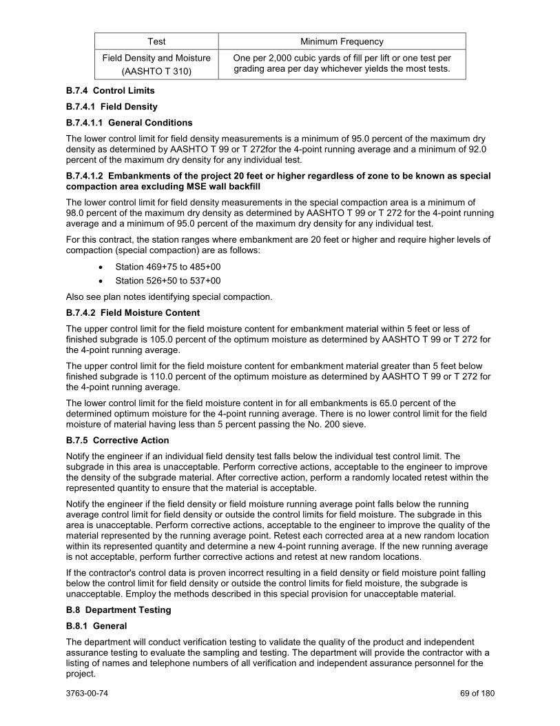
3763-00-74 69 of 180
Test Minimum Frequency
Field Density and Moisture (AASHTO T 310)
One per 2,000 cubic yards of fill per lift or one test per grading area per day whichever yields the most tests.
B.7.4 Control Limits
B.7.4.1 Field Density
B.7.4.1.1 General Conditions
The lower control limit for field density measurements is a minimum of 95.0 percent of the maximum dry density as determined by AASHTO T 99 or T 272for the 4-point running average and a minimum of 92.0 percent of the maximum dry density for any individual test.
B.7.4.1.2 Embankments of the project 20 feet or higher regardless of zone to be known as special compaction area excluding MSE wall backfill The lower control limit for field density measurements in the special compaction area is a minimum of 98.0 percent of the maximum dry density as determined by AASHTO T 99 or T 272 for the 4-point running average and a minimum of 95.0 percent of the maximum dry density for any individual test.
For this contract, the station ranges where embankment are 20 feet or higher and require higher levels of compaction (special compaction) are as follows:
• Station 469+75 to 485+00 • Station 526+50 to 537+00
Also see plan notes identifying special compaction.
B.7.4.2 Field Moisture Content The upper control limit for the field moisture content for embankment material within 5 feet or less of finished subgrade is 105.0 percent of the optimum moisture as determined by AASHTO T 99 or T 272 for the 4-point running average.
The upper control limit for the field moisture content for embankment material greater than 5 feet below finished subgrade is 110.0 percent of the optimum moisture as determined by AASHTO T 99 or T 272 for the 4-point running average.
The lower control limit for the field moisture content in for all embankments is 65.0 percent of the determined optimum moisture for the 4-point running average. There is no lower control limit for the field moisture of material having less than 5 percent passing the No. 200 sieve.
B.7.5 Corrective Action
Notify the engineer if an individual field density test falls below the individual test control limit. The subgrade in this area is unacceptable. Perform corrective actions, acceptable to the engineer to improve the density of the subgrade material. After corrective action, perform a randomly located retest within the represented quantity to ensure that the material is acceptable.
Notify the engineer if the field density or field moisture running average point falls below the running average control limit for field density or outside the control limits for field moisture. The subgrade in this area is unacceptable. Perform corrective actions, acceptable to the engineer to improve the quality of the material represented by the running average point. Retest each corrected area at a new random location within its represented quantity and determine a new 4-point running average. If the new running average is not acceptable, perform further corrective actions and retest at new random locations.
If the contractor's control data is proven incorrect resulting in a field density or field moisture point falling below the control limit for field density or outside the control limits for field moisture, the subgrade is unacceptable. Employ the methods described in this special provision for unacceptable material.
B.8 Department Testing
B.8.1 General The department will conduct verification testing to validate the quality of the product and independent assurance testing to evaluate the sampling and testing. The department will provide the contractor with a listing of names and telephone numbers of all verification and independent assurance personnel for the project.
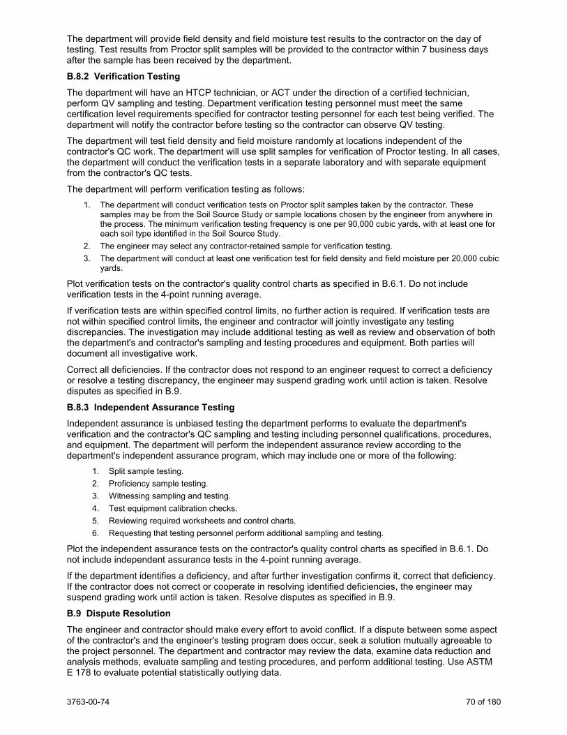
3763-00-74 70 of 180
The department will provide field density and field moisture test results to the contractor on the day of testing. Test results from Proctor split samples will be provided to the contractor within 7 business days after the sample has been received by the department.
B.8.2 Verification Testing
The department will have an HTCP technician, or ACT under the direction of a certified technician, perform QV sampling and testing. Department verification testing personnel must meet the same certification level requirements specified for contractor testing personnel for each test being verified. The department will notify the contractor before testing so the contractor can observe QV testing.
The department will test field density and field moisture randomly at locations independent of the contractor's QC work. The department will use split samples for verification of Proctor testing. In all cases, the department will conduct the verification tests in a separate laboratory and with separate equipment from the contractor's QC tests.
The department will perform verification testing as follows: 1. The department will conduct verification tests on Proctor split samples taken by the contractor. These
samples may be from the Soil Source Study or sample locations chosen by the engineer from anywhere in the process. The minimum verification testing frequency is one per 90,000 cubic yards, with at least one for each soil type identified in the Soil Source Study.
2. The engineer may select any contractor-retained sample for verification testing. 3. The department will conduct at least one verification test for field density and field moisture per 20,000 cubic
yards.
Plot verification tests on the contractor's quality control charts as specified in B.6.1. Do not include verification tests in the 4-point running average.
If verification tests are within specified control limits, no further action is required. If verification tests are not within specified control limits, the engineer and contractor will jointly investigate any testing discrepancies. The investigation may include additional testing as well as review and observation of both the department's and contractor's sampling and testing procedures and equipment. Both parties will document all investigative work.
Correct all deficiencies. If the contractor does not respond to an engineer request to correct a deficiency or resolve a testing discrepancy, the engineer may suspend grading work until action is taken. Resolve disputes as specified in B.9.
B.8.3 Independent Assurance Testing
Independent assurance is unbiased testing the department performs to evaluate the department's verification and the contractor's QC sampling and testing including personnel qualifications, procedures, and equipment. The department will perform the independent assurance review according to the department's independent assurance program, which may include one or more of the following:
1. Split sample testing. 2. Proficiency sample testing. 3. Witnessing sampling and testing. 4. Test equipment calibration checks. 5. Reviewing required worksheets and control charts. 6. Requesting that testing personnel perform additional sampling and testing.
Plot the independent assurance tests on the contractor's quality control charts as specified in B.6.1. Do not include independent assurance tests in the 4-point running average.
If the department identifies a deficiency, and after further investigation confirms it, correct that deficiency. If the contractor does not correct or cooperate in resolving identified deficiencies, the engineer may suspend grading work until action is taken. Resolve disputes as specified in B.9.
B.9 Dispute Resolution
The engineer and contractor should make every effort to avoid conflict. If a dispute between some aspect of the contractor's and the engineer's testing program does occur, seek a solution mutually agreeable to the project personnel. The department and contractor may review the data, examine data reduction and analysis methods, evaluate sampling and testing procedures, and perform additional testing. Use ASTM E 178 to evaluate potential statistically outlying data.
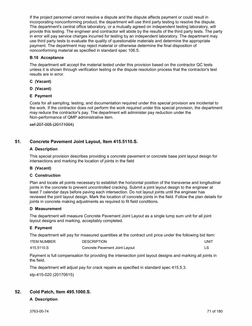
3763-00-74 71 of 180
If the project personnel cannot resolve a dispute and the dispute affects payment or could result in incorporating nonconforming product, the department will use third party testing to resolve the dispute. The department's central office laboratory, or a mutually agreed on independent testing laboratory, will provide this testing. The engineer and contractor will abide by the results of the third party tests. The party in error will pay service charges incurred for testing by an independent laboratory. The department may use third party tests to evaluate the quality of questionable materials and determine the appropriate payment. The department may reject material or otherwise determine the final disposition of nonconforming material as specified in standard spec 106.5.
B.10 Acceptance
The department will accept the material tested under this provision based on the contractor QC tests unless it is shown through verification testing or the dispute resolution process that the contractor's test results are in error.
C (Vacant) D (Vacant) E Payment Costs for all sampling, testing, and documentation required under this special provision are incidental to the work. If the contractor does not perform the work required under this special provision, the department may reduce the contractor's pay. The department will administer pay reduction under the Non-performance of QMP administrative item.
sef-207-005 (20171004)
51. Concrete Pavement Joint Layout, Item 415.5110.S. A Description This special provision describes providing a concrete pavement or concrete base joint layout design for intersections and marking the location of joints in the field
B (Vacant) C Construction Plan and locate all points necessary to establish the horizontal position of the transverse and longitudinal joints in the concrete to prevent uncontrolled cracking. Submit a joint layout design to the engineer at least 7 calendar days before paving each intersection. Do not layout joints until the engineer has reviewed the joint layout design. Mark the location of concrete joints in the field. Follow the plan details for joints in concrete making adjustments as required to fit field conditions.
D Measurement The department will measure Concrete Pavement Joint Layout as a single lump sum unit for all joint layout designs and marking, acceptably completed.
E Payment The department will pay for measured quantities at the contract unit price under the following bid item: ITEM NUMBER DESCRIPTION UNIT 415.5110.S Concrete Pavement Joint Layout LS
Payment is full compensation for providing the intersection joint layout designs and marking all joints in the field.
The department will adjust pay for crack repairs as specified in standard spec 415.5.3.
stp-415-020 (20170615)
52. Cold Patch, Item 495.1000.S. A Description
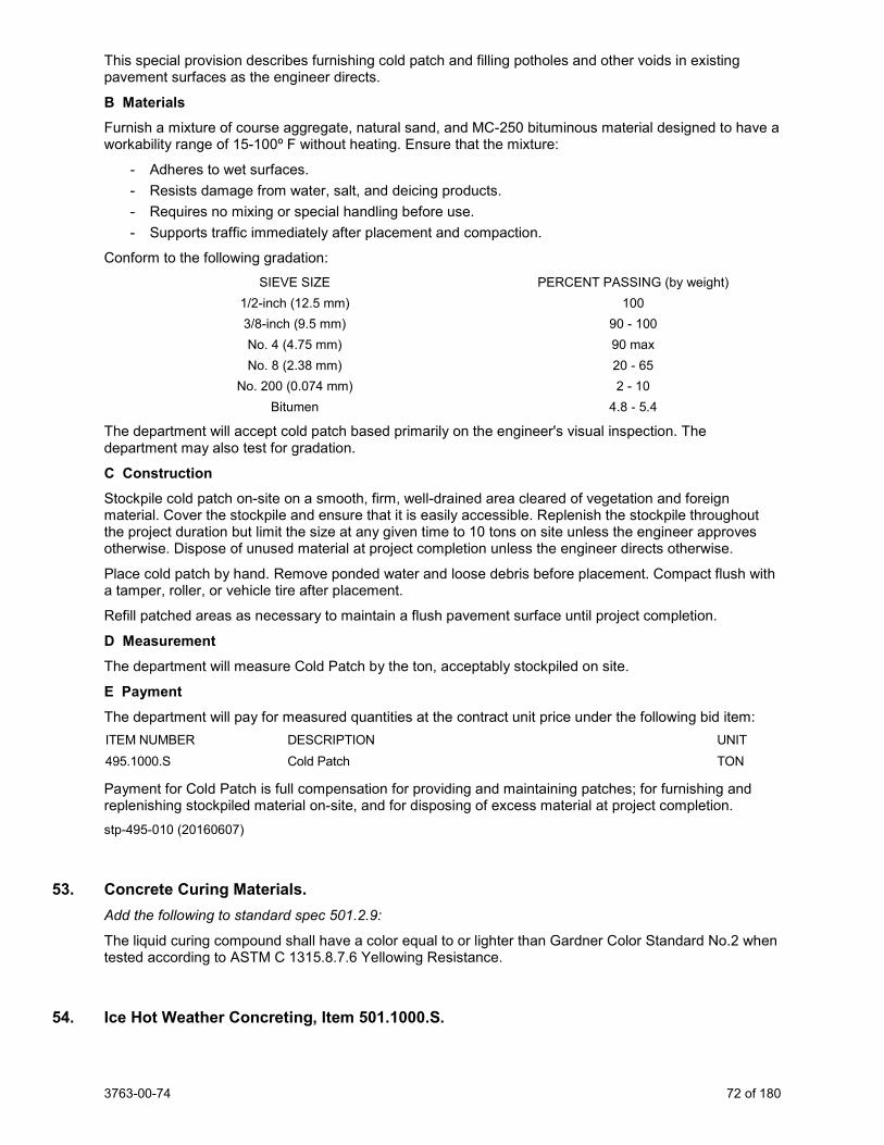
3763-00-74 72 of 180
This special provision describes furnishing cold patch and filling potholes and other voids in existing pavement surfaces as the engineer directs.
B Materials
Furnish a mixture of course aggregate, natural sand, and MC-250 bituminous material designed to have a workability range of 15-100º F without heating. Ensure that the mixture:
- Adheres to wet surfaces. - Resists damage from water, salt, and deicing products. - Requires no mixing or special handling before use. - Supports traffic immediately after placement and compaction.
Conform to the following gradation: SIEVE SIZE PERCENT PASSING (by weight) 1/2-inch (12.5 mm) 100 3/8-inch (9.5 mm) 90 - 100 No. 4 (4.75 mm) 90 max No. 8 (2.38 mm) 20 - 65 No. 200 (0.074 mm) 2 - 10 Bitumen 4.8 - 5.4
The department will accept cold patch based primarily on the engineer's visual inspection. The department may also test for gradation.
C Construction
Stockpile cold patch on-site on a smooth, firm, well-drained area cleared of vegetation and foreign material. Cover the stockpile and ensure that it is easily accessible. Replenish the stockpile throughout the project duration but limit the size at any given time to 10 tons on site unless the engineer approves otherwise. Dispose of unused material at project completion unless the engineer directs otherwise.
Place cold patch by hand. Remove ponded water and loose debris before placement. Compact flush with a tamper, roller, or vehicle tire after placement.
Refill patched areas as necessary to maintain a flush pavement surface until project completion.
D Measurement The department will measure Cold Patch by the ton, acceptably stockpiled on site.
E Payment The department will pay for measured quantities at the contract unit price under the following bid item: ITEM NUMBER DESCRIPTION UNIT 495.1000.S Cold Patch TON
Payment for Cold Patch is full compensation for providing and maintaining patches; for furnishing and replenishing stockpiled material on-site, and for disposing of excess material at project completion. stp-495-010 (20160607)
53. Concrete Curing Materials. Add the following to standard spec 501.2.9:
The liquid curing compound shall have a color equal to or lighter than Gardner Color Standard No.2 when tested according to ASTM C 1315.8.7.6 Yellowing Resistance.
54. Ice Hot Weather Concreting, Item 501.1000.S.
3763-00-74 73 of 180
Conform to standard spec 501.3.8.2 except the department will pay for ice at the contract unit price under the Ice Hot Weather Concreting bid item. This special provision only applies to work done under the following contract bid items:
Concrete Masonry Bridges Concrete Masonry Retaining Walls Concrete Masonry Bridges HES Concrete Masonry Retaining Walls HES Concrete Masonry Culverts Concrete Masonry Endwalls Concrete Masonry Culverts HES Concrete Masonry Overlay Decks High Performance Concrete (HPC) Masonry Structures
Replace standard spec 501.4 and 501.5 with the following:
501.4 Measurement
(1) The department will measure Ice Hot Weather Concreting by the pound, acceptably completed, measured only if the conditions prescribed in standard spec 501.3.8.2 are met.
501.5 Payment
(1) The department will pay for measured quantities at the contract unit price under the following bid item: ITEM NUMBER DESCRIPTION UNIT 501.1000.S Ice Hot Weather Concreting LB
(2) Payment for Ice Hot Weather Concreting is full compensation for ice used to cool concrete placed in hot weather as specified in standard spec 501.3.8.2.
(3) The department will not pay directly for the concrete specified under this section. Concrete is incidental to the various bid items using it. Payment under those bid items includes providing all materials, including aggregates and associated aggregate source testing, cement, fly ash, slag, and admixtures; for preparing, transporting, storing, protecting and curing concrete; and for contractor requirements related to testing specified in standard spec 501.3.10.
(4) If required to remove and replace any concrete damaged by lack of proper protection. Perform this work at no expense to the department.
stp-501-010 (20151210)
55. Bar Steel Reinforcement HS Stainless Structures, Item 505.0800.S. A Description
This special provision describes furnishing and placing stainless steel reinforcing bars and associated stainless steel bar couplers.
Conform to standard spec 505 as modified in this special provision.
B Materials B.1 General Furnish stainless steel reinforcing bars conforming to ASTM A955 and to one of the following Unified Numbering System (UNS) designations: S31653, S31803, S32205, or S32304. Supply grade 60 bars, all of the same UNS designation. Conform to the chemical composition specified for the given UNS designation in ASTM A276 table 1.
Supply bars that are free of dirt, mill scale, oil, and debris by pickling to a bright or uniform light finish. The department may reject bars displaying rust/oxidation, questionable blemishes, or lack of a bright or uniform pickled surface.
Furnish chairs or continuous supports made of stainless steel or recycled plastic to support high-strength stainless bar steel reinforcement subject to the plastic chair restriction stated in standard spec 505.3.4(1).
Furnish couplers made from one of the UNS alloys allowed for bar steel.
Furnish tie wire made from one of the UNS alloys allowed for bar steel or from an engineer-approved plastic or nonmetallic material. Ensure that stainless steel tie wire is dead soft annealed.
3763-00-74 74 of 180
B.2 Fabrication Before fabrication, supply test results from an independent testing agency certifying that the reinforcement meets the requirements of Annex A1 of ASTM A955.
Bend bars conforming to standard spec 505.3.2 and according to ASTM A955. Bend and cut bars using equipment thoroughly cleaned or otherwise modified to prevent contamination from carbon steel or other contaminants. Use tools dedicated solely to working with stainless steel.
B.3 Control of Material Identify reinforcement bars delivered to the project site with tags bearing the identification symbols used in the plans. Include the UNS designation, heat treat condition, heat number, grade corresponding to minimum yield strength level, and sufficient documentation to track each bar bundle to a mill test report.
Provide samples for department testing and acceptance according to CMM 8-50 Exhibit 1 requirements for concrete masonry reinforcement for uncoated bar steel.
Provide mill test reports for the project that do the following: 1. Verify that sampling and testing procedures and test results conform to ASTM A955, ASTM A276 table 1,
and these contract requirements. 2. Include a chemical analysis with the UNS designation, heat lot identification, and the source of the metal. 3. Include tensile strength, yield strength, and elongation tests results conforming to ASTM A955 for each size
furnished. 4. Certify that the bars have been pickled to a bright or uniform light finish.
C Construction
C.1 General Ship, handle, store, and place the stainless steel reinforcing as follows:
1. Separate from regular reinforcement during shipping. Pad points of contact with steel chains or banding, or secure with non-metallic straps.
2. Store on wooden cribbing separated from regular reinforcement. Cover with tarpaulins if stored outside. 3. Handle with non-metallic slings. 4. Do not flame cut or weld. Protect from contamination when cutting, grinding, or welding other steel products
above or near the stainless steel during construction. 5. Place on plastic or stainless steel bar chairs. If placing stainless steel chairs on steel beams, use chairs with
plastic-coated feet. 6. Tie with stainless steel wire or an engineer-approved plastic or nonmetallic material.
Do not tie stainless steel reinforcing bars to, or allow contact with, uncoated reinforcing bars or galvanized steel. Maintain at least 1 inch clearance between stainless steel bars or dowels and uncoated or galvanized steel. Where 1 inch clearance is not possible, sleeve bars with a continuous polyethylene or nylon tube at least 1/8 inch thick extending at least 1 inch in each direction and bind with nylon or polypropylene cable ties. Sleeves are not required between stainless steel bars and shear studs. Stainless steel bars can be in direct contact with undamaged epoxy-coated bars.
Cut flush with the top flange or remove uncoated fasteners, anchors, lifting loops, or other protrusions into a bridge deck before casting the deck on prestressed concrete beams.
C.2 Splices
Splice as the plans show. Provide stainless steel couplers conforming to the minimum capacity, certification, proof testing, and written approval requirements of standard spec 550.3.3.4. The contractor may substitute stainless steel couplers for lap slices the plans show if the engineer approves in writing.
If increasing or altering the number or type of bar splices the plans show, provide revised plan sheets to the engineer showing the reinforcement layout, type, length, and location of revised bar splices and revised bar lengths. Obtain engineer approval for the location of new lap splices or substitution of mechanical bar couplers before fabrication. Ensure that new lap splices are at least as long as those the plans show.
D Measurement The department will measure Bar Steel Reinforcement HS Stainless Structures by the pound acceptably completed, computed from the nominal weights of corresponding sizes for carbon steel deformed bars in
3763-00-74 75 of 180
AASHTO M31 regardless of stainless steel alloy provided. The department will not measure extra material used if the contractor alters the reinforcement layout as allowed under C.2, extra material for splices or couplers the plans do not show, or the weight of devices used to support or fasten the steel in position.
The department will measure the Bar Couplers Stainless bid items as each individual coupler, acceptably completed.
E Payment The department will pay for measured quantities at the contract unit price under the following bid item: ITEM NUMBER DESCRIPTION UNIT 505.0800.S Bar Steel Reinforcement HS Stainless Structures LB
Payment for Bar Steel Reinforcement HS Stainless Structures is full compensation for furnishing and placing stainless steel reinforcing bars, including supports. Where the plans specify bar couplers, the department will pay for the length of bars as detailed with no deduction or increase for installation of the coupler. stp-505-005 (20190618)
56. Storm Sewer. Add the following to standard spec 204.5.1:
QMP sampling, testing and documentation if applicable is incidental to removing storm sewer bid item and no separate payment will be made.
Add the following to standard spec 608.2:
Two weeks prior to start of storm sewer construction, provide a shoring design and installation sequence for each location where shoring is to be used. Have a professional engineer, currently registered in the State of Wisconsin and knowledgeable of the specific site conditions and requirements, verify the adequacy of the design. Submit one electronic copy in portable document format of each shoring design, signed and sealed by the same professional engineer verifying the design, to the engineer for incorporation into the permanent project record.
Add the following to standard spec 608.3.1:
(1) Incorporate excavated material in the work to the extent practicable. Use materials with suitable engineering properties for embankment.
(2) Dispose of surplus or unsuitable material as specified in standard spec 205.3.12.
Add the following to standard spec 608.3.4:
Place rubber gasket joints over the spigot end or tongue of the entering pipe for all round storm sewer pipes horizontal and elliptical pipes with a rise less than or equal to 40-inches. Clean the gasket and the ends of the pipe from sand and gravel. If the gasket provided is neither factory lubricated nor self-lubricating, lubricate the outside of the gasket and the inside of the bell or groove of the last pipe with an engineer - approved vegetable lubricant immediately before making the joint. Place the spigot or tongue of the pipe being laid with the gasket in place into the bell or groove end of the previously laid pipe. Set pipe carefully to line and grade and push or jack home. The engineer may order the use of a jack or “come-along” if deemed necessary to ensure that the joints are completely tight.
For horizontal elliptical pipe rise greater than 40-inches use mastic joint compound. Where factory lubricated rubber gasket joints are not available, clean the ends of the pipe from sand and gravel. Place engineer-approved mastic joint sealer on both the spigot and bell ends of the pipe being laid. Apply additional mastic around each joint exterior and wrap each joint with Geotextile Fabric Type DF laid flat
3763-00-74 76 of 180
meeting requirements of standard spec 645. Wrap each joint so that the Geotextile Fabric overlaps each joint a distance of approximately ½ of the pipe diameter.
Replace standard spec 608.5.2 with the following:
Payment for the Storm Sewer Pipe bid items is full compensation for providing all materials, including all special Y’s, mitered sections, elbows and connections required; for all submittals; for excavating and wasting excess material, except rock excavation; for providing rubber gaskets; Lubrication of rubber gaskets; mastic joint sealer; for supporting utilities in storm sewer trench; for shoring design, providing a signed and sealed copy of the design; for installation, monitoring, and removal of shoring; for forming foundation; for laying pipe; for sealing joints and making connections to new or existing features, bedding material; for backfilling and granular backfill material; for QMP sampling, testing and documentation; for cleaning out; and absent the pertinent contract bid items, for restoring the work site.
57. Catch Basins, Manholes, and Inlets. Add the following to standard spec 611.3.1:
Use a Grade "A" concrete for final adjustment of manhole cover. Provide a butyl rubber gasket or butyl rubber rope for joints of precast reinforced concrete manhole sections. Butyl Rubber gasket joint used for manholes conforms to 8.41.6 of the Standard Specification for Sewer and Water
Construction in Wisconsin, latest Edition. Provide non-rocking covers for all drainage structures subject to traffic loading.
Submit shop drawings for all drainage structures. For structures where WisDOT standard detail drawings are not available, provide shop drawings prepared, verified and stamped by a professional engineer currently registered in the State of Wisconsin. Submit one electronic copy of shop drawings in portable document format for engineer’s review two weeks before fabrication. Show clearly on shop drawings information for all pipe connections to the structure. The contractor is responsible for all errors of detailing and fabrication. The omission from the shop drawings of any pipe connection shall not relieve contractor of the responsibility of providing such materials, even though the shop drawings may have been reviewed and accepted by the engineer.
Add the following to standard spec 611.3.2:
Conform to storm sewer concrete collar detail for storm sewer pipes to structure connections as shown on the plans.
Add the following to standard spec 611.3.3:
Use monolithic concrete shimming as the plan shows for final adjustment of drainage structures located within the concrete pavement.
Add the following to standard spec 611.3.7:
Construct height adjustments of 4-inches or more with concrete grade rings. Never use grade rings less than 2-inches thick.
Replace standard spec 611.5.2 (1) with the following:
Payment for Catch Basins, Manholes, and Inlets bid items is full compensation for providing all submittals; materials, including all masonry, and concrete bricks, for Grade “A” concrete adjustments and monolithic concrete shimming; adjusting rings; conduit and sewer connections, steps, and other fittings; for providing and installing butyl rubber joints; for furnishing backfill, backfilling; all excavating, disposing of surplus material, and for cleaning out and restoring the work site; except that the department will pay for covers, including frames, grates and lids separately.
3763-00-74 77 of 180
Cost of non-rocking covers for all drainage structures subject to traffic loading is incidental to new cover on proposed structure or reconstructing/adjusting manholes or inlets on existing structure.
58. Cover Plates Temporary, Item 611.8120.S. A Description
This special provision describes providing and removing steel plates to cover and support asphaltic pavement and traffic loading at manholes, inlets and similar structures during milling and paving operations.
B Materials
Provide a 0.25 inch minimum thickness steel plate that extends to the outside edge of the existing masonry.
C (Vacant) D Measurement The department will measure Cover Plates Temporary as each individual unit, acceptably completed.
E Payment The department will pay for measured quantities at the contract unit price under the following bid item: ITEM NUMBER DESCRIPTION UNIT 611.8120.S Cover Plates Temporary EACH
Payment is full compensation for furnishing, installing, and removing the cover plates.
The steel plates shall become the property of the contractor when no longer needed in the contract work. stp-611-006 (20151210)
59. Pipe Grates, Item 611.9800.S. A Description
This special provision describes providing pipe grates on the ends of pipes.
B Materials
Furnish steel conforming to the requirements of standard spec 506.2.2.1. Furnish steel pipe conforming to the requirements of standard spec 506.2.3.6.
Furnish pipe grates galvanized according to ASTM A123.
Furnish angles and brackets galvanized according to ASTM A123.
Furnish required hardware galvanized according to ASTM A153.
C Construction
Repair pipes, rods, angles and brackets on which the galvanized coating has been damaged according to the requirements of AASHTO M36M.
D Measurement The department will measure Pipe Grates in units of work, where one unit is one grate, completed and accepted.
E Payment The department will pay for measured quantities at the contract unit price under the following bid item: ITEM NUMBER DESCRIPTION UNIT 611.9800.S Pipe Grates EACH
Payment is full compensation for furnishing and installing all materials; and for drilling and connecting grates to pipes.
3763-00-74 78 of 180
stp-611-010 (20030820)
60. Fence Safety, Item 616.0700.S. A Description
This special provision describes providing plastic fence at locations the plans show.
B Materials
Furnish notched conventional metal "T" or "U" shaped fence posts.
Furnish fence fabric meeting the following requirements.
Color: International orange (UV stabilized)
Roll Height: 4 feet
Mesh Opening: 1 inch min to 3 inch max
Resin/Construction: High density polyethylene mesh
Tensile Yield: Avg. 2000 lb per 4 ft. width (ASTM D638)
Ultimate Tensile Strength: Avg. 3000 lb per 4 ft. width (ASTM D638)
Elongation at Break (%): Greater than 100% (ASTM D638)
Chemical Resistance: Inert to most chemicals and acids
C Construction
Drive posts into the ground 12 to 18 inches. Space posts at 7 feet.
Use a minimum of three-wire ties to secure the fence at each post. Weave tension wire through the top row of strands to provide a top stringer that prevents sagging.
Overlap two rolls at a post and secure with wire ties.
D Measurement The department will measure Fence Safety by the linear foot along the base of the fence, center-to-center of posts, acceptably completed.
E Payment The department will pay for measured quantities at the contract unit price under the following bid item: ITEM NUMBER DESCRIPTION UNIT 616.0700.S Fence Safety LF
Payment is full compensation for furnishing and installing fence and posts; maintaining the fence and posts in satisfactory condition, and for removing and disposing of fence and posts at project completion.
stp-616-030 (20160607)
61. Pond Liner Clay, Item 640.1303.S. A Description
This special provision describes providing low permeable clay in areas the plans show.
B Materials
For each source, before excavating and hauling the low permeable clay to the project, submit the results of the laboratory tests described in Table 1. The laboratory testing shall document that the clay from the source meets or exceeds the requirements.
3763-00-74 79 of 180
The sample for the hydraulic conductivity test shall be remolded clay at a minimum dry density of 95% of the maximum dry density as determined by the Standard Proctor test AASHTO T-99 and at a moisture content required to achieve the required hydraulic conductivity, but with a minimum moisture content at or above the optimum moisture content as determined in the Standard Proctor test AASHTO T-99. Conduct the laboratory source testing at the frequency listed in Table 1. Submit the test results to the engineer for review, two weeks before construction.
C Construction
C.1 Low Permeable Clay Placement C.1.1 Subgrade
Compact the subgrade to a minimum density as defined in standard spec 207.3.6.2, Standard Compaction, or as otherwise specified in the contract requirements.
C.1.2 Erosion Protection
Do not place the low permeable clay until after all adjacent site grading has been completed and only after silt fence has been installed completely around the area of low permeable clay placement.
C.1.3 Low Permeable Clay Placement After the fine grading is complete, place and compact low permeable clay in completed 6-inch lifts. Place each lift of low permeable clay in one continuous lift. See plans for low permeable clay construction limits. Measure the thickness of the low permeable clay the plans show perpendicular to the surface.
Notify the engineer at least three days before starting construction of low permeable clay.
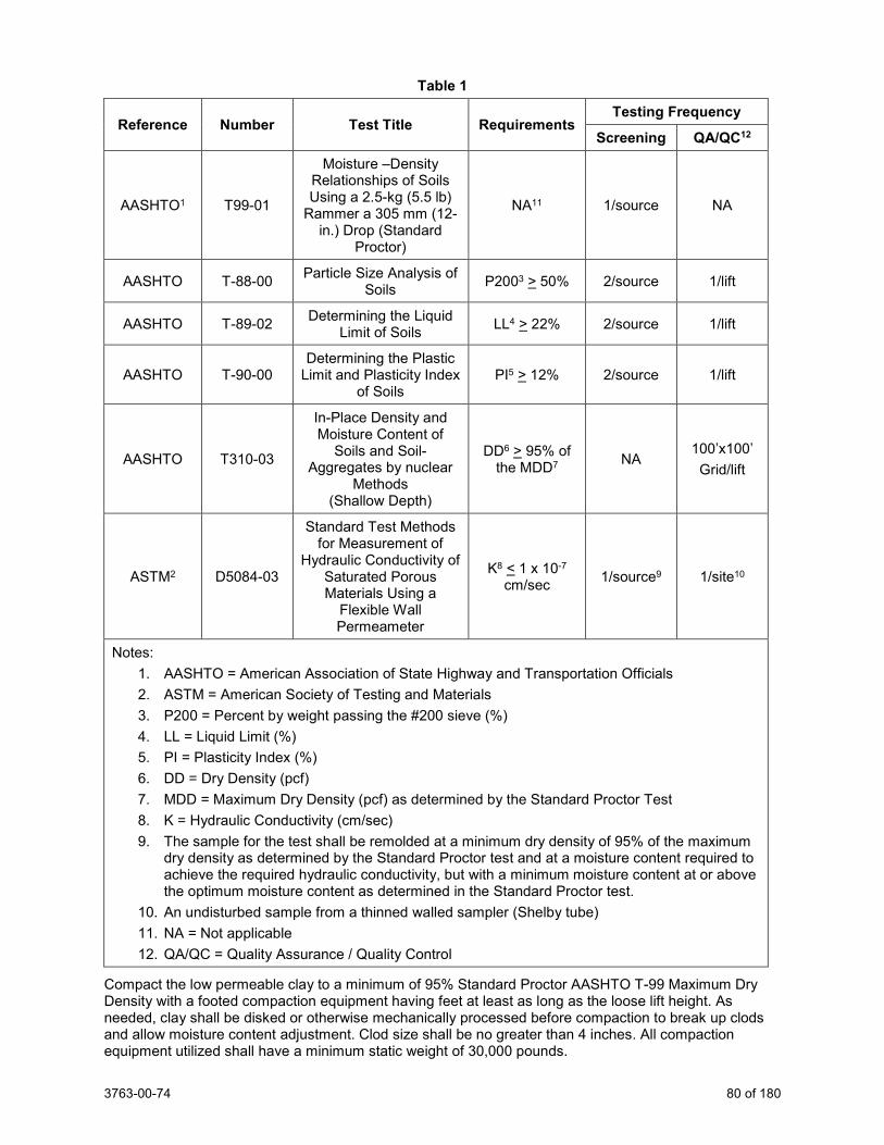
3763-00-74 80 of 180
Table 1
Reference Number Test Title Requirements Testing Frequency
Screening QA/QC12
AASHTO1 T99-01
Moisture –Density Relationships of Soils Using a 2.5-kg (5.5 lb)
Rammer a 305 mm (12-in.) Drop (Standard
Proctor)
NA11 1/source NA
AASHTO T-88-00 Particle Size Analysis of Soils P2003 > 50% 2/source 1/lift
AASHTO T-89-02 Determining the Liquid Limit of Soils LL4 > 22% 2/source 1/lift
AASHTO T-90-00 Determining the Plastic
Limit and Plasticity Index of Soils
PI5 > 12% 2/source 1/lift
AASHTO T310-03
In-Place Density and Moisture Content of
Soils and Soil-Aggregates by nuclear
Methods (Shallow Depth)
DD6 > 95% of the MDD7 NA
100’x100’ Grid/lift
ASTM2 D5084-03
Standard Test Methods for Measurement of
Hydraulic Conductivity of Saturated Porous Materials Using a
Flexible Wall Permeameter
K8 < 1 x 10⁻⁷ cm/sec 1/source9 1/site10
Notes: 1. AASHTO = American Association of State Highway and Transportation Officials 2. ASTM = American Society of Testing and Materials 3. P200 = Percent by weight passing the #200 sieve (%) 4. LL = Liquid Limit (%) 5. PI = Plasticity Index (%) 6. DD = Dry Density (pcf) 7. MDD = Maximum Dry Density (pcf) as determined by the Standard Proctor Test 8. K = Hydraulic Conductivity (cm/sec) 9. The sample for the test shall be remolded at a minimum dry density of 95% of the maximum
dry density as determined by the Standard Proctor test and at a moisture content required to achieve the required hydraulic conductivity, but with a minimum moisture content at or above the optimum moisture content as determined in the Standard Proctor test.
10. An undisturbed sample from a thinned walled sampler (Shelby tube) 11. NA = Not applicable 12. QA/QC = Quality Assurance / Quality Control
Compact the low permeable clay to a minimum of 95% Standard Proctor AASHTO T-99 Maximum Dry Density with a footed compaction equipment having feet at least as long as the loose lift height. As needed, clay shall be disked or otherwise mechanically processed before compaction to break up clods and allow moisture content adjustment. Clod size shall be no greater than 4 inches. All compaction equipment utilized shall have a minimum static weight of 30,000 pounds.
3763-00-74 81 of 180
Provide all equipment necessary to adjust low permeable clay to the proper moisture content for compaction.
Make sufficient number of passes of the compaction equipment over each lift of clay to ensure complete remolding of the clay.
Do not proceed with placement of additional lifts until all required low permeable clay testing and documentation has been completed for the previous lift.
During placement of the low permeable clay the minimum moisture content shall be as defined by the testing performed in the source evaluation and with the following limits:
- No drier than the optimum moisture content as determined by the Standard Proctor test.
If the in-place low permeable clay fails to meet the requirements of Table 1, then remove and replace or rework any portion of the low permeable clay not meeting the project requirements until project specifications are met. There shall be no compensation for removing, replacing and reworking low permeable clay not meeting the requirements in Table 1.
C.1.4 QA/QC Testing of the Low Permeable Clay
The department will perform the QA/QC testing at the frequency shown in Table 1. The department will record the thickness of low permeable clay on a 100 foot x 100 foot grid pattern.
Provide the following:
- Access for on-site testing, inspection, and documentation. - Machinery required to grade/blade density test locations. - Machinery required to collect undisturbed clay samples (i.e., with Shelby tubes). - Replace and recompact clay material removed for testing purposes.
D Measurement The department will measure Pond Liner Clay in volume by the cubic yards, acceptably completed.
E Payment The department will pay for measured quantities at the contract unit price under the following bid item: ITEM NUMBER DESCRIPTION UNIT 640.1303.S Pond Liner Clay CY
Payment is full compensation for dewatering areas of site where the low permeable clay is to be placed; for furnishing, placing and compacting the low permeable clay; and for performing all tests. stp-640-016 (20130615)
62. General Requirements for Electrical Work. Replace standard spec 651.3.3(3) with the following:
Request a signal inspection of the completed signal installation to the engineer at least 5 working days prior to the time of the requested inspection. Notify the department’s Electrical Field Unit at (414) 266-1170 to coordinate the inspection. The department’s Region Electrical personnel will perform the inspection. In the event of deficiencies, request a re-inspection when the work is corrected. The engineer will not authorize continuation of aboveground work or turn-on until the contractor corrects all deficiencies.
63. Electrical Conduit. Replace standard spec 652.5(2) with the following:
(2) Payment for Conduit Rigid Metallic, Conduit Rigid Nonmetallic, Conduit Reinforced Thermosetting Resin, and Conduit Special bid items is full compensation for providing the conduit, conduit bodies, and fittings; for providing all conduit hangers, clips, attachments, and fittings used to support conduit on structures; for pull wires or ropes; for expansion fittings and caps; for making necessary connections into existing pull box, manhole, junction box or communication vault; for excavating,
3763-00-74 82 of 180
bedding, and backfilling, including any sand, concrete, or other required materials; for disposing of surplus materials; and for making inspections.
Replace standard spec 652.5(5) with the following:
(5) Payment for Conduit Loop Detector is full compensation for providing all materials, including conduit, compacted backfill, surface sealer if required, pull wire if required, conduits, conduit fittings, and for making necessary connections into existing pull box, manhole, junction box or communication vault.
64. Electrical Wiring. Replace standard spec 655.5 (12) with the following:
Payment for Traffic Signal EVP Detector Cable is full compensation for providing emergency vehicle preemption detector cable and for making all necessary connections.
65. Electrical Service Meter Breaker Pedestal CTH KR & STH 31, Item 656.0200.301; Electrical Service Meter Breaker Pedestal CTH KR & Old Green Bay Road, Item 656.0200.302; Electrical Service Meter Breaker Pedestal CTH KR & 90th St/72nd Ave, Item 656.0200.303; Electrical Service Meter Breaker Pedestal CTH KR & Trail Crossing, Item 656.0200.304; Electrical Service Meter Breaker Pedestal CTH A & CTH H, Item 656.0200.305. Append standard spec 656.2.3 with the following:
(2) The department will be responsible for the electrical service installation request for any department maintained facility. If the signal is not department maintained, notify the maintaining authority that it is their responsibility to arrange for the electrical service installation.
(3) Electrical utility company service installation and energy cost will be billed to and paid for by the maintaining authority.
(4) Install the cabinet base and meter breaker pedestal first, so the electrical utility company can install the service lateral. Install a 3" conduit from the point of service from the utility to the meter breaker pedestal. Finish grade the service trench, replace topsoil that is lost or contaminated with other materials, fertilize, seed, and mulch all areas that are disturbed by the electrical utility company.
Append standard spec 656.5 with the following:
(8) Payment is full compensation for grading the service trench; replacing topsoil; and for fertilizing, seeding, and mulching to restore the disturbed area of the service trench.
66. Traffic Signals, General. All traffic signal work shall be according to the State of Wisconsin Department of Transportation Standard Specifications for Highway and Structure Construction, 2020 edition, the plans, and these special provisions.
Note that the failure to comply with the state standards and specifications may result in the cost of corrections to be made at the contractor’s expense. Also, any additional disruption of State-owned facilities shall be repaired or relocated as needed at the contractor’s expense. Notify the department’s Electrical Field Unit at (414) 266-1170 at least three weeks prior to the beginning of the traffic signal work.
3763-00-74 83 of 180
67. Traffic Signal Faces. Append standard spec 658.3 with the following:
(5) Connect all ungrounded conductors with wire nuts in the appropriate sections of the signal heads. Connect the neutral conductors to the terminal strip. Be certain to twist wires prior to installing the wire nuts. All wire nuts must be installed facing up to prevent the entrance of water.
68. Pedestrian Push Buttons. Replace standard spec 658.2(5) with the following:
(5) Furnish freeze-proof ADA compliant pedestrian push buttons made by a department-approved manufacturer. Place a Size 1, Type H reflective (R10-3EL, R, D) sign sticker (per state sign plate), message series – B directly above each push button. Include a directional arrow or arrows on the sign as the plans show.
69. Temporary Traffic Signals for Intersections CTH KR & STH 31, Item 661.0200.301; Temporary Traffic Signals for Intersections STH 31 & CTH A, Item 661.0200.351. Replace standard spec 661.2.1 (1) with the following:
(1) F urnish control cabinet and control equipment. The department will supply, maintain, and install a signal controller, cellular modem, and ethernet switch to establish remote communication to the signal controller and vehicle detection system. The cabinet must be equipped with at least two open non-GFI receptacles. Provide a cabinet with a Corbin #2 door lock and an access door that allows placing the control in emergency flash. Provide keys to the access door to the engineer and law enforcement agencies as required. Also provide a manual control accessible by the police. Test traffic signal control cabinets before installation. The department will provide the signal controller with the initial traffic signal timing, and the department will be responsible for all subsequent signal timing changes.
Replace standard spec 661.2.1 (3) with the following:
(3) The department has initiated the installation of the temporary electrical service with the electrical utility as it pertains to the service application and site sketch at the intersection(s) of CTH KR & STH 31 and STH 31 & CTH A to expedite the process. Contact Parwinder Virk at (262) 548-6717 to coordinate the temporary electrical service. The department will pay for all installation and Energy Costs associated with the operation of the Temporary Traffic Signal. It is the contractor’s responsibility to contact the electrical utility as it pertains to the affidavit and site ready card to arrange timely installation of the temporary service. If the control cabinet is not mounted on the electrical service pole, add a second electrical service disconnect to the outside of the control cabinet for the convenience of emergency personnel.
Furnish and install a generator to operate the temporary traffic signals for the times required to switch the existing permanent traffic signal over to the temporary traffic signal and for the time required to switch the temporary traffic signal back over to the permanent traffic signal.
Contact the local electrical utility at least four days prior to making the switch from the Temporary Traffic Signal to the new Permanent Traffic Signal.
Append standard spec 661.2.1 (6) with the following:
(6) Control equipment or controller equipment is defined as anything inside the control cabinet excluding the department furnished signal controller, cellular modem, and ethernet switch.
Replace standard spec 661.3.1 (2) with the following:
(2) Request a signal inspection of the completed temporary traffic signal installation to the engineer at least five working days prior to the time of the requested inspection. Notify the SE Region Electrical Field Unit at (414) 266-1170 to coordinate the inspection. The SE Region electrical personnel will perform the inspection.
3763-00-74 84 of 180
Append standard spec 661.3.1.4 (4) with the following:
(4) Arrange for every-other-week inspections with the engineer to check the height of the span wire above the roadways to ensure that the bottom of the traffic signal heads remain within the minimum and maximum heights allowed above the roadway. Make all height adjustments within 1-hour of an inspection indicating that adjustments are required. Notify the engineer in writing upon completion of all necessary adjustments. Maintain a written log to properly document the date of each every-other-week inspection, the heights above the roadway, the roadway clearance after adjustments have been made, and acceptance by the engineer. Provide all documentation related to the every-other-week span wire height checks as well as all records related to maintenance performed on the temporary traffic signal installations to the engineer.
Replace standard spec 661.3.2.6 (2) with the following:
(2) Upon acceptance of new signal and completion of work, the department will switch control of the intersection over to the permanent cabinet installation. Remove signal cable and wires, wood poles, wood posts, control cabinet, control equipment, and incidental materials. Upon deactivation of the controller, call the electrical utility immediately for the temporary electrical service disconnect. The department shall remove the signal controller, cellular modem, and ethernet switch.
Replace standard spec 661.3.2.7 (2) with the following:
(2) Respond within one hour of notification to provide corrective action to any emergency such as but not limited to knockdowns, signal cable problems, and controller equipment failures. If equipment becomes damaged or faulty beyond repair, replace it within one working day. In order to fulfill this requirement, maintain, in stock, sufficient materials and equipment to provide repairs. Replace the traffic signal control equipment including the cabinet and cabinet accessories within 4 hours. If the outcome of the response identifies damage to the department furnished signal controller, notify the Traffic Management Center at (800) 375-7302 who will then dispatch the SE Region Electrical Field Unit
Replace standard spec 661.5 (2) with the following:
(2) Payment for the Temporary Traffic Signals for Intersections bid item is full compensation for providing, maintaining, and repairing the complete temporary installation; and for removal. Payment also includes the following:
1. Furnishing and installing replacement equipment. 2. The cost of delivery and pick-up of the cabinet assemblies.
Payment is full compensation for drilling holes; furnishing and installing all materials, including bricks, and coarse aggregate; for excavation, bedding, and backfilling, including any sand or other required materials; furnishing and placing topsoil, fertilizer, seed, and mulch in disturbed areas; for properly disposing of surplus materials; for making inspections; for cleaning up and properly disposing of waste; and for furnishing all labor, tools, equipment, and incidentals necessary to complete the work.
70. Intelligent Transportation Systems (ITS) – Control of Materials. Standard spec 106.2 – Supply Source and Quality Add the following to standard spec 106.2:
The department will furnish a portion of equipment to be installed by the contractor. This department-furnished equipment includes the following:
Department-Furnished Items Fiber Optic Cable
Fiber Optic Splice Enclosures
3763-00-74 85 of 180
Pick-up small department-furnished equipment, such as communications devices, cameras, and controllers, from the department’s Statewide Traffic Operations Center (STOC), 433 W. St. Paul Ave., Milwaukee, WI 53203 at a mutually agreed upon time during normal state office hours. Contact the department’s STOC at (414) 227-2166 to coordinate pick-up of equipment.
Large department-furnished equipment, such as camera poles will be delivered by the supplier to a contractor-controlled site within Southeastern Wisconsin. Delivery will not necessarily be in a “just in time” manner. Store the equipment until field installation. Provide location details and a contact for delivery coordination upon receiving the contract’s Notice to Proceed.
Transportation of the equipment between the electric shop and the field or interim location(s) shall be the responsibility of the contractor.
Standard spec 106.3 – Approval of Materials Add the following to standard spec 106.3:
Design/Shop Drawings
Prior to the purchase and/or fabrication of any of the components listed herein, and for any non-catalog item shown on the Material and Equipment List specified above, and no more than 30 days after notice to proceed, submit five copies of design drawings and shop drawings, as required, to the department for review. The items and the drawings that represent them shall meet the requirements of the standard specifications.
Design drawing submissions shall consist of signed and certified designs, design drawings, calculations, and material specifications for required items.
Shop drawings will be required for, but not limited to the following:
1. Mounting assemblies for the vehicle speed and classification sensors, including their attachment to the structure.
2. Mounting LED warning signs to the sign structure. 3. Mounting detail for dynamic message signs. 4. Any contractor-designed structure or foundation.
The department will complete its review of the material within 30 days from the date of receipt of the submission, unless otherwise specified. The department will advise the contractor, in writing, as to the acceptability of the material submitted. The department may determine that if no exceptions were taken for the item, it is approved, and no further action is required by the contractor; or the item may be partially or totally rejected, in which case modify and/or amend the submittal as required by the department and resubmit the item within 14 days. At this time, the review and approval cycle described above will begin again. stp-670-005 (20150630)
71. Intelligent Transportation Systems – General Requirements. A Description A.1 General This contract includes furnishing and installing elements for an Intelligent Transportation System (ITS) in or along the existing roadway as shown on the plans.
Unusual aspects of this project include:
1. The project includes working on cables and equipment that are carrying data between roadside equipment and the department’s Statewide Traffic Operations Center (STOC). Interruption of this service is not expected to perform this work. If an interruption is determined necessary, it must be done on a weekend and must be done in a way that minimizes communication outages for the existing equipment. Notify the department’s STOC at least 48 hours in advance of the planned interruption.
2. The department will furnish some of the equipment to be installed. Make a reasonable effort to discover defects in that equipment prior to installing it.
3763-00-74 86 of 180
A.2 Surge Protection
Equip every ungrounded conductor wire entering or leaving any equipment cabinet with a surge protector. For purposes of this section, multiple cabinets on a single pole or foundation are considered a single cabinet.
B Materials B.1 General Only furnish equipment and component parts for this work that are new and have high-quality workmanship. All controls, indicators, and connectors shall be clearly and permanently labeled in a manner approved by the engineer. All equipment of each type shall be identical.
All electrical equipment shall conform to the standards and requirements of the Wisconsin Electrical Code, the National Electrical Manufacturers Association (NEMA), National Electric Safety Council (NESC), Underwriter’s Laboratory Inc. (UL) or the Electronic Industries Association (EIA), when applicable. All materials and workmanship shall conform to the requirements of the National Electrical Code (NEC), Rural Electrification Administration (REA), Standards of the American Society for Testing and Materials (ASTM), American Association of State Highway and Transportation Officials (AASHTO), requirements of the plans these special provisions, the standard specifications, and to any other codes, standards, or ordinances that may apply. All system wiring, conduit, grounding hardware, and circuit breakers shall be in conformance with the National Electrical Code. Whenever reference is made to any of the standards mentioned, the reference shall be considered to mean the code, ordinance, or standard that is in effect at the time of the bid advertisement.
B.2 Outdoor Equipment All conductive connectors, pins (except pins connected by soldering), and socket contacts shall be gold plated. Acrylic conformal coating shall protect each circuit board side that has conductive traces. Except for integrated circuits containing custom firmware, all components shall be soldered to the printed circuit board.
To prevent galvanic corrosion, all connections between dissimilar metals shall incorporate a means of keeping moisture out of the connection. Where the connection need not conduct electricity, interpose a non-absorbing, inert material or washer between the dissimilar metals. Use nonconductive liners and washers to insulate fasteners from dissimilar metals. Where the connection must conduct electricity, use a conductive sealant between the dissimilar metals. Alternatively, use an insulating gasket and a bond wire connecting the two metal parts.
B.3 Custom Equipment Equipment that is not part of the manufacturer’s standard product line, or that is made or modified specifically for this project, shall conform to the following requirements:
Where practical, electronics shall be modular plug-in assemblies to facilitate maintenance. Such assemblies shall be keyed to prevent incorrect insertion of modules into sockets.
All components shall be available from multiple manufacturers as part of the manufacturers’ standard product lines. All must be clearly labeled with the value, part number, tolerance, or other information sufficient to enable a technician to order an exact replacement part.
Lamps used for indicator purposes shall be light-emitting diodes.
The printed circuit boards shall be composed of “two-ounce” copper on 1/16-inch thick fiberglass epoxy or equivalent type construction. Holes that carry electrical connections from one side of the boards to the other shall be completely plated through. Multilayer printed circuit boards shall not be used. The name or reference number used for the board in the drawings and maintenance manuals supplied to the department shall be permanently affixed to each board.
All components shall be mounted so that the identifying markings are visible without moving or removing any part, if practical.
B.4 Environmental Conditions
Equipment shall continue to operate as specified under the following ranges of environmental conditions, except as noted in the specifications for individual pieces of equipment.
3763-00-74 87 of 180
1. Vibration and Shock: Vehicle speed and classification sensors and any other equipment mounted atop poles or on structures shall not be impaired by the continuous vibration caused by winds (up to 90 mph with a 30 percent gust factor) and traffic.
2. Duty Cycle: Continuous 3. Electromagnetic Radiation: The equipment shall not be impaired by ambient electrical or
magnetic fields, such as those caused by power lines, transformers, and motors. The equipment shall not radiate signals that adversely affect other equipment.
4. Electrical Power: a. Operating power: The equipment shall operate on 120-volts, 60-Hz, single-phase
unless otherwise specified. It shall conform to its specified performance requirements when the input voltage varies from 89 to 135 volts and the frequency varies +3 Hz.
b. High-frequency interference: The equipment operation shall be unaffected by power supply voltage spikes of up to 150 volts in amplitude and 10 microseconds duration.
c. Line voltage transients: The equipment operation shall be unaffected by voltage transients of plus or minus 20 percent of nominal line voltage for a maximum duration of 50 milliseconds. Equipment in the field shall meet the power service transient requirements of NEMA Standard TS-2 when connected to the surge protectors in the cabinets.
5. Temperature and Humidity: a. Field equipment: Equipment in the field shall meet the temperature and humidity
requirements of NEMA Standard TS-2. Liquid crystal displays shall be undamaged by temperatures as high as 165 degrees F, and shall produce a usable display at temperatures up to 120 degrees F.
b. Equipment in Controlled Environments shall operate normally at any combination of temperatures between 50 degrees F and 100 degrees F, and humidity’s between 5 percent and 90 percent, non-condensing, and with a temperature gradient of 9 degrees F per hour.
B.5 Patch Cables and Wiring
All cables and wiring between devices installed in a single cabinet, or in separate cabinets sharing a single concrete base, will be considered incidental to the installation of the devices and no separate payment will be made for them. It is anticipated that this will include fiber optic patch cables between termination panels and Ethernet switches, 10 / 100 MBPS Ethernet cables, RS-232 cables between individual devices and terminal servers, and power cables between individual devices and power sources within the cabinets.
B.6 Surge Protection
Low-voltage signal pairs, including twisted pair communication cable(s) entering each cabinet shall be protected by two-stage, plug-in surge protectors and shall be installed on both ends of camera control cables. The protectors shall meet or exceed the following minimum requirements:
1. The protectors shall suppress a peak surge current of up to 10k amps. 2. The protectors shall have a response time less than one nanosecond. 3. The protector shall clamp the voltage between the two wires at a voltage that is no more
than twice the peak signal voltage and clamp the voltage between each wire and ground at 50 volts.
4. The first stage of protection shall be a three-element gas discharge tube, and the second stage shall consist of silicon clamping devices.
5. The protector shall also contain a resettable fuse (PTC) to protect against excessive current.
6. There shall be no more than two pairs per protector. 7. It shall be possible to replace the protector without using tools.
Cables carrying power to curve signs shall be protected at the cabinet by grounded metal oxide varistors of appropriate voltages. The varistors must be at least 0.8 inch in diameter.
3763-00-74 88 of 180
C Construction C.1 Thread Protection Provide rust, corrosion, and anti-seize protection at all thread assemblies of metallic parts by coating (non-spray) the mating surfaces with an approved compound. Failure to use an approved compound will result in no payment for the items to which coating was to have been applied.
C.2 Cable Installation
When installing new cables into conduits containing existing cables, remove the existing cables and reinstall the existing cables simultaneously with the new cables. Take every precaution necessary to protect the existing cables. In the event of avoidable damage to the existing cables, replace all damaged cables, in-kind, at no additional expense to the department. When cables are pulled into conduit, use a cable pulling lubricant approved by the cable manufacturer. Submit documentation supporting manufacturer approval of the lubricant to the engineer.
C.3 Wiring
Every conductor, except a conductor contained entirely within a single piece of equipment, must terminate either in a connector or on a terminal block. Provide and install the connectors and terminal blocks where needed, without separate payment. Use approved splice kits instead of connectors and terminal blocks for underground power cable splices.
Permanently label and key connectors to preclude improper connection. Obtain prior engineer approval for the labeling method(s) prior to use.
Terminal blocks must be affixed to panels that permanently identify the block and what wire connects to each terminal. This may be accomplished by silk screening or by installing a laminated printed card under the terminal block, with the labels on portions of the card that extend beyond the block. Installation of terminal blocks by drilling holes in the exterior wall of the cabinet is not acceptable.
Use barriers to protect personnel from accidental contact with all dangerous voltages.
Do not install conductors carrying AC power in the same wiring harness as conductors carrying control or communication signals.
Arrange wiring, including fiber optic pigtails, so that any removable assembly can be removed without disturbing wiring that is not associated with the assembly being removed.
Communication and control cables may not be spliced underground, except where indicated on the plans.
Cables in the Statewide Traffic Operations Center or in communication hubs, which are not contained within a single cabinet, shall have at least 10 feet of slack.
C.4 System Operations
If the contractor’s operations unexpectedly interrupt Intelligent Transportation Systems (ITS) service, notify the engineer immediately and restore service within 24 hours. Repair all damaged facilities to the condition existing before the interruption. If service is not restored within 24 hours, the department may restore service to any operating device and deduct restoration costs from payments due the contractor.
C.5 Surge Protection
Arrange the equipment and cabinet wiring to minimize the distance between each conductor’s point of entry and its protector. Locate the protector as far as possible from electronic equipment. Ensure that all wiring between the surge protectors and the point of entry is free from sharp bends.
D Measurement No separate measurement will be made for the work described in this article.
E Payment No separate payment will be made for the work described in this article. All work described in this article shall be included under the ITS items in the contract. stp-670-010 (20100709)
3763-00-74 89 of 180
72. Field System Integrator, Item 670.0100. A Description
This item includes the field system integration for the project, including ITS and Traffic Signals.
73. ITS Documentation, Item 670.0200. A Description
This item includes the ITS Documentation for the project, including ITS and Traffic Signals.
74. Communication System Testing, Item 678.0500. A Description
This item includes the Communication System Testing for the project, including ITS and Traffic Signals.
75. Communication Systems. Replace standard spec 678.2.1(1) with the following:
(1) The department will furnish fiber optic cable, splice enclosures, termination panels, Ethernet switches, wireless antennas, and cellular modems.
Pick up the department furnished materials at the department’s Electrical Shop located at 935 South 60th Street, West Allis. Notify the department’s Electrical Field Unit at (414) 266-1170 and make arrangements for picking up the department furnished materials three working days prior to picking up the materials.
Replace standard spec 678.5(6) with the following:
(6) Payment for Install Ethernet Switches and Install Wireless Antennas is full compensation for transporting and installing the devices; for cables and connectors; and connecting the devices.
Replace standard spec 678.5(7) with the following:
(7) Payment for Install Cellular Modems is full compensation for transporting and installing the modem; for cables and connectors including rack mountable shelf; for connecting the devices; for programming and configuration; and for testing.
76. Optimized Aggregate Gradation Incentive, Item 715.0710. Description This special provision describes optional contractor optimized aggregate gradation, optional optimized mixture designs, and associated additional requirements for class 1 concrete used in concrete pavements. Conform to standard specification part 7 and as follows:
Optimized Aggregate Gradation Replace standard spec 715.2.2 with the following:
A Job Mix Formula (JMF) contains all of the following:
− Proportions for each aggregate fraction conforming to table 1.
− Individual gradations for each aggregate fraction.
− Composite gradation of the combined aggregates including working ranges on each sieve according to table 2.
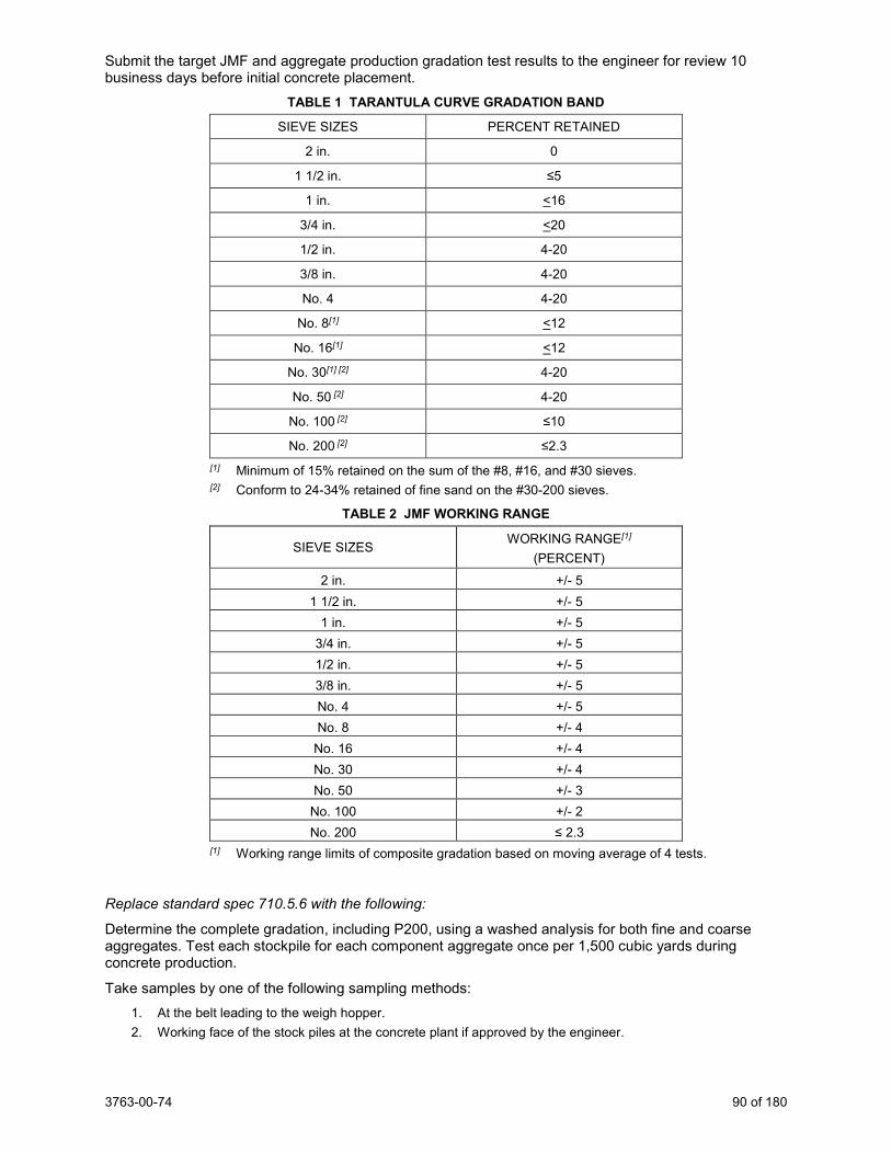
3763-00-74 90 of 180
Submit the target JMF and aggregate production gradation test results to the engineer for review 10 business days before initial concrete placement.
TABLE 1 TARANTULA CURVE GRADATION BAND
SIEVE SIZES PERCENT RETAINED
2 in. 0
1 1/2 in. ≤5
1 in. <16
3/4 in. <20
1/2 in. 4-20
3/8 in. 4-20
No. 4 4-20
No. 8[1] <12
No. 16[1] <12
No. 30[1] [2] 4-20
No. 50 [2] 4-20
No. 100 [2] ≤10
No. 200 [2] ≤2.3 [1] Minimum of 15% retained on the sum of the #8, #16, and #30 sieves. [2] Conform to 24-34% retained of fine sand on the #30-200 sieves.
TABLE 2 JMF WORKING RANGE
SIEVE SIZES WORKING RANGE[1] (PERCENT)
2 in. +/- 5 1 1/2 in. +/- 5
1 in. +/- 5 3/4 in. +/- 5 1/2 in. +/- 5 3/8 in. +/- 5 No. 4 +/- 5 No. 8 +/- 4
No. 16 +/- 4 No. 30 +/- 4 No. 50 +/- 3
No. 100 +/- 2 No. 200 ≤ 2.3
[1] Working range limits of composite gradation based on moving average of 4 tests.
Replace standard spec 710.5.6 with the following:
Determine the complete gradation, including P200, using a washed analysis for both fine and coarse aggregates. Test each stockpile for each component aggregate once per 1,500 cubic yards during concrete production.
Take samples by one of the following sampling methods: 1. At the belt leading to the weigh hopper. 2. Working face of the stock piles at the concrete plant if approved by the engineer.
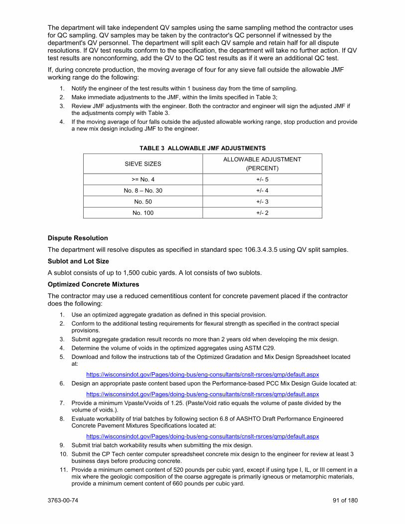
3763-00-74 91 of 180
The department will take independent QV samples using the same sampling method the contractor uses for QC sampling. QV samples may be taken by the contractor's QC personnel if witnessed by the department's QV personnel. The department will split each QV sample and retain half for all dispute resolutions. If QV test results conform to the specification, the department will take no further action. If QV test results are nonconforming, add the QV to the QC test results as if it were an additional QC test.
If, during concrete production, the moving average of four for any sieve fall outside the allowable JMF working range do the following:
1. Notify the engineer of the test results within 1 business day from the time of sampling. 2. Make immediate adjustments to the JMF, within the limits specified in Table 3; 3. Review JMF adjustments with the engineer. Both the contractor and engineer will sign the adjusted JMF if
the adjustments comply with Table 3. 4. If the moving average of four falls outside the adjusted allowable working range, stop production and provide
a new mix design including JMF to the engineer.
TABLE 3 ALLOWABLE JMF ADJUSTMENTS
SIEVE SIZES ALLOWABLE ADJUSTMENT
(PERCENT)
>= No. 4 +/- 5
No. 8 – No. 30 +/- 4
No. 50 +/- 3
No. 100 +/- 2
Dispute Resolution The department will resolve disputes as specified in standard spec 106.3.4.3.5 using QV split samples.
Sublot and Lot Size A sublot consists of up to 1,500 cubic yards. A lot consists of two sublots.
Optimized Concrete Mixtures The contractor may use a reduced cementitious content for concrete pavement placed if the contractor does the following:
1. Use an optimized aggregate gradation as defined in this special provision. 2. Conform to the additional testing requirements for flexural strength as specified in the contract special
provisions. 3. Submit aggregate gradation result records no more than 2 years old when developing the mix design. 4. Determine the volume of voids in the optimized aggregates using ASTM C29. 5. Download and follow the instructions tab of the Optimized Gradation and Mix Design Spreadsheet located
at:
https://wisconsindot.gov/Pages/doing-bus/eng-consultants/cnslt-rsrces/qmp/default.aspx 6. Design an appropriate paste content based upon the Performance-based PCC Mix Design Guide located at:
https://wisconsindot.gov/Pages/doing-bus/eng-consultants/cnslt-rsrces/qmp/default.aspx 7. Provide a minimum Vpaste/Vvoids of 1.25. (Paste/Void ratio equals the volume of paste divided by the
volume of voids.). 8. Evaluate workability of trial batches by following section 6.8 of AASHTO Draft Performance Engineered
Concrete Pavement Mixtures Specifications located at:
https://wisconsindot.gov/Pages/doing-bus/eng-consultants/cnslt-rsrces/qmp/default.aspx 9. Submit trial batch workability results when submitting the mix design. 10. Submit the CP Tech center computer spreadsheet concrete mix design to the engineer for review at least 3
business days before producing concrete. 11. Provide a minimum cement content of 520 pounds per cubic yard, except if using type I, IL, or III cement in a
mix where the geologic composition of the coarse aggregate is primarily igneous or metamorphic materials, provide a minimum cement content of 660 pounds per cubic yard.
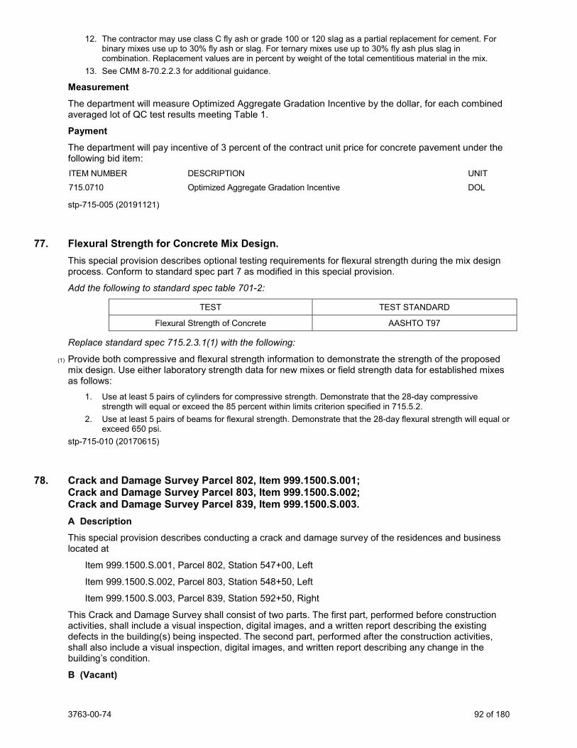
3763-00-74 92 of 180
12. The contractor may use class C fly ash or grade 100 or 120 slag as a partial replacement for cement. For binary mixes use up to 30% fly ash or slag. For ternary mixes use up to 30% fly ash plus slag in combination. Replacement values are in percent by weight of the total cementitious material in the mix.
13. See CMM 8-70.2.2.3 for additional guidance.
Measurement The department will measure Optimized Aggregate Gradation Incentive by the dollar, for each combined averaged lot of QC test results meeting Table 1.
Payment The department will pay incentive of 3 percent of the contract unit price for concrete pavement under the following bid item: ITEM NUMBER DESCRIPTION UNIT 715.0710 Optimized Aggregate Gradation Incentive DOL
stp-715-005 (20191121)
77. Flexural Strength for Concrete Mix Design. This special provision describes optional testing requirements for flexural strength during the mix design process. Conform to standard spec part 7 as modified in this special provision.
Add the following to standard spec table 701-2:
TEST TEST STANDARD
Flexural Strength of Concrete AASHTO T97
Replace standard spec 715.2.3.1(1) with the following:
(1) Provide both compressive and flexural strength information to demonstrate the strength of the proposed mix design. Use either laboratory strength data for new mixes or field strength data for established mixes as follows:
1. Use at least 5 pairs of cylinders for compressive strength. Demonstrate that the 28-day compressive strength will equal or exceed the 85 percent within limits criterion specified in 715.5.2.
2. Use at least 5 pairs of beams for flexural strength. Demonstrate that the 28-day flexural strength will equal or exceed 650 psi.
stp-715-010 (20170615)
78. Crack and Damage Survey Parcel 802, Item 999.1500.S.001; Crack and Damage Survey Parcel 803, Item 999.1500.S.002; Crack and Damage Survey Parcel 839, Item 999.1500.S.003. A Description
This special provision describes conducting a crack and damage survey of the residences and business located at
Item 999.1500.S.001, Parcel 802, Station 547+00, Left
Item 999.1500.S.002, Parcel 803, Station 548+50, Left
Item 999.1500.S.003, Parcel 839, Station 592+50, Right
This Crack and Damage Survey shall consist of two parts. The first part, performed before construction activities, shall include a visual inspection, digital images, and a written report describing the existing defects in the building(s) being inspected. The second part, performed after the construction activities, shall also include a visual inspection, digital images, and written report describing any change in the building’s condition.
B (Vacant)
3763-00-74 93 of 180
C Construction
Before any construction activities, thoroughly inspect the building structures for existing defects, including interior and exterior walls. Electronically submit a written report with the inspector’s name, date of inspection, descriptions and locations of defects, and digital images. The intent of the written report and digital images is to procure a record of the general physical condition of the building’s interior and exterior walls and foundation.
Use a digital camera capable of producing sharp, grain free, high-contrast colored digital images with good shadow details. Label each digital image with the following information:
ID: _________________________ Building Location: _________________________ View looking: _________________________ Date: _________________________ Photographer: _________________________
Before the start of any construction activities related to this survey, submit a copy of the written report and digital images to the engineer electronically.
After the construction activities are complete, conduct another survey in the same manner, take digital images, and submit another written report to the engineer electronically.
Instead of digital images, a digital video camera capable of producing sharp, high contrast, colored digital video with good shadow detail may be used to perform this work.
D Measurement The department will measure Crack and Damage Survey as single complete lump sum unit of work, acceptably completed.
E Payment The department will pay for measured quantities at the contract unit price under the following bid item: ITEM NUMBER DESCRIPTION UNIT SPV.999.1500.S.001 Crack and Damage Survey Parcel 802 LS SPV.999.1500.S.002 Crack and Damage Survey Parcel 803 LS SPV.999.1500.S.003 Crack and Damage Survey Parcel 839 LS
Payment is full compensation for providing the before and after written reports, and for photographs or video.
stp-999-010 (20170615)
79. EBS Excavation, Item SPV.0035.001. A Description This special provision describes excavating and disposing of material taken below the subgrade of future pavement structures at locations determined by the engineer. The removal of excess topsoil will be paid under common excavation as shown on the plan.
B Materials Excavate all materials below subgrade not classified as rock, stone piles and stone fences, or marsh excavation. Perform work according to standard spec 205.2.2 and as hereinafter provided.
C Construction Perform work according to the pertinent provisions of standard spec 205.3 and as hereinafter provided.
C.1 Yielding Subgrade After rough grading on all or a portion of the subgrade in cut areas and in areas requiring 2 feet or less embankment is complete, and the grade is ready for blue tops, point out areas of yielding subgrade to the engineer. The engineer will evaluate the subgrade to determine if EBS Excavation is required.
3763-00-74 94 of 180
If the engineer requests, provide loaded trucks and run the subgrade as the engineer directs to confirm yielding areas. Perform EBS Excavation in yielding areas as directed by the engineer.
C.2 Excavation Below Subgrade Excavate materials as directed by the engineer. Remove deposits of frost-heave material, unstable silty soils, wet and unstable soil, material salvaged from old road cores in marshes, topsoil containing considerable amounts of humus or vegetable matter, rocks, or other undesirable foundation material to the depth below finished grade as the engineer directs.
Compact, or prepare otherwise as required, the existing ground within the roadway foundation as necessary to support the roadway and attain the specified density.
Dispose of all excavated materials offsite at no expense to the department. Locate disposal sites outside the right-of-way and comply with all regulations relating to disposal of solid waste. Ensure that disposal sites are neatly constructed. In performing these operations, do not create a nuisance or cause pollution or siltation of natural watercourses, streams, lakes, wetlands, or reservoirs. Obtain written permits for disposal from the owner of the property where placing the material, unless disposing of the material at a licensed waste disposal operation. Furnish permits, or copies of permits, to the engineer before disposal. Do not deposit waste in wetlands.
C.3 Temporary Drainage During construction, slope and drain the excavation bottoms to prevent water accumulation. If it is necessary in the prosecution of the work to interrupt existing surface drainage, sewers, or under drainage, provide temporary drainage until completing permanent drainage work.
D Measurement The department will measure EBS Excavation by the cubic yard acceptably completed as computed using the method of average end areas, with no correction for curvature.
The department will not measure for payment materials excavated in forming benches or steps in preparing the foundation for embankments placed on slopes.
The department will not measure for payment materials excavated to remove frost from newly constructed embankments or cut subgrades unless directed by the engineer.
If undercutting designated slopes to provide for placing topsoil or salvaged topsoil, the undercut is incidental to the Topsoil Special bid item.
E Payment The department will pay for measured quantities at the contract unit price under the following bid item: ITEM NUMBER DESCRIPTION UNIT SPV.0035.001 EBS Excavation CY
Payment for EBS Excavation is full compensation for performing excavation below subgrade after receiving engineer approval; for the satisfactory disposal of all resulting material offsite; for obtaining and furnishing copies of permits; for furnishing, placing, and removing all temporary drainage installations; and for providing loaded trucks and running them on the subgrade to confirm yielding areas.
The department will only pay for engineer-approved EBS Excavation to correct problems beyond the contractor’s control. Work performed under standard spec 105.3 to correct unacceptable work is the contractor’s responsibility.
ASP-5 will be applied to this item. The Fuel Usage Factor is 0.29.
80. EBS Backfill, Item SPV.0035.002. A Description This special provision describes backfilling EBS Excavation with select crushed material.
B Materials Furnish all materials according to standard spec 311.2 and as hereinafter provided.
3763-00-74 95 of 180
C Construction Place select crushed material where EBS Excavation was performed or as the engineer directs. Compact select crushed material using standard compaction conforming to standard spec 301.3.
D Measurement The department will determine weight or volume, adjust for moisture, and convert between weight and volume as specified in standard spec 301.4.
The department will measure EBS Backfill by the cubic yard, acceptably completed.
E Payment The department will pay for measured quantities at the contract unit price under the following bid item: ITEM NUMBER DESCRIPTION UNIT SPV.0035.002 EBS Backfill CY
Payment for EBS Backfill is full compensation for providing and compacting select crushed material in areas of EBS Excavation.
The department will only pay for EBS Backfill at engineer-approved EBS Excavation locations. Work performed under standard spec 105.3 to correct unacceptable work is the contractor’s responsibility.
The department will not pay for EBS Backfill to replace materials excavated to remove frost from newly constructed embankments or cut subgrades.
81. Roadway Embankment, Item SPV.0035.003. A Description This special provision describes placing in embankments and in miscellaneous backfills, material obtained under the bid items in the roadway and drainage excavation or excavation for structure sections; or material obtained off site as specified under these special provisions.
B Materials B.1 Embankment Furnish roadway embankment conforming with standard spec 207.2 except as follows:
Add the following to standard spec 207.2(1):
If the contractor utilizes offsite material to construct embankments, the material shall conform to standard spec 208 except as follows:
Delete standard spec 208.2.2(2).
C Construction Construct roadway embankment according to standard spec 207.3 except as follows:
Add the following to standard spec 207.3.6:
Prior to placing any material for a succeeding layer, ensure the previous layer does not have excessive rutting, displacement, or distortion under the compacting or hauling equipment. If rutting, displacement, or distortion is observed, the contractor shall inform the engineer how yielding material will be addressed prior to continuing roadway embankment construction.
If off site material is utilized, construction must conform to standard spec 208.3.
Replace standard spec 205.3.2(4) with the following:
If placing embankment on side slopes 10 feet high or higher and steeper than one vertical to 3 horizontal, provide vertically-faced, horizontal benches at least 2 feet wide into the existing embankment slope every 2-foot of vertical height.
3763-00-74 96 of 180
If constructing embankment on only one side of abutments, wing walls, or piers, construct the embankment so that the area immediately adjacent to the structure is not compacted in a manner that causes overturning of or excessive pressure against the structure. If constructing embankment on both sides of a concrete wall, pipe, or box type structure, construct the embankment so that the elevation on both sides of the structure is always approximately the same.
D Measurement The department will measure Roadway Embankment without any correction for shrinkage or expansion factors by the cubic yard acceptably completed in its final location using the method of average end areas, except as follows:
a) The engineer and contractor mutually agree to an alternative volume calculation method. b) If it is not possible to compute volumes of the various classes of roadway and drainage
embankment by the method of average end areas due to erratic location of isolated deposits, the department may compute the volumes by three-dimensional measurements.
E Payment The department will pay for measured quantities at the contract unit price under the following bid item: ITEM NUMBER DESCRIPTION UNIT SPV.0035.003 Roadway Embankment CY
Payment is full compensation for furnishing offsite and onsite sources, for forming, compacting, shaping, sloping, trimming, finishing, and maintaining the embankments. If offsite materials are utilized for roadway embankments, payment includes full compensation for all items listed in standard spec 208.5 (2), for obtaining all required permits, and all other incidental work required under this section.
ASP-5 will be applied to this item. The Fuel Usage Factor is 0.23.
82. Riffle Cobble, Item SPV.0035.004; No. 1 Aggregate, Item SPV.0035.005; Open-Graded Base Aggregate, Item SPV.0035.006; Sand/Woodchip Bed, Item SPV.0035.007; Compost, Item SPV.0035.008; Boulder Weir Cascade, Item SPV.0090.010. A Description This special provision describes furnishing and installing Regenerative Stormwater Conveyance (RSC) as the plans show, and as hereinafter provided.
B Materials B.1 Pool Construct pools according to the plans. The pools consist of four layers - No. 1 Aggregate, Open Graded Base Aggregate, Sand/Woodchip Bed, and Compost.
B.1.1 No. 1 Aggregate Provide No. 1 Aggregate as open-graded coarse aggregate according to Section 501.2.5.4 Coarse Aggregate, size No. 1 specifications. Contractor must wash No. 1 Aggregate.
B.1.2 Open-Graded Base Aggregate Provide Base Aggregate Open-Graded as open-graded base coarse according to Section 310.2. Do not substitute No. 1 coarse aggregate for this layer. Contractor must wash aggregate.
B.1.3 Sand/Woodchip Bed The Sand/Woodchip Bed is composed of sand and woodchips.
Provide the sand component of the sand/woodchip bed to meet the ASTM-C33 standard, sized 0.02 inches to 0.04 inches. Provide sand composed primarily of SiO2. No “rock dust” can be used for sand. The sand makes up 70% to 80% of the sand/woodchip media mix, by volume.
3763-00-74 97 of 180
Provide the woodchip component as double-shredded hardwood chips/mulch. Add the woodchips to the sand mix, approximately 20% to 30% by volume, to increase organic content and promote plant growth and sustainability. Ensure woodchips are free of dyes, chromated copper arsenate and other preservatives.
Mix the media mixture at the distribution site, roughly mixed at the construction site, or within the media bed itself as each component is being placed.
B.1.4 Compost Place a 4-inch layer of compost on top of the sand layer within the pools of the RSC. Ensure that the compost is WDNR S100 certified or equivalent. Provide compost that is 100% organic with a pH between 6.0 and 7.0, a moisture content between 30% and 55%, and a particle size of 0.25 inches or less.
B.2 Grade Control Structures Grade control structures include bolder weirs and boulder weir cascades and located between pools and shall be constructed according to the plans. All grade control structures are associated with an upslope cobble apron and cobble riffle. The grade control structures are placed on a pyramid of No. 1 stone covered by geotextile fabric.
B.2.1 Delineators Temporary Place temporary delineators at the top and bottom of each grade control structure along the centerline and each edge according to standard spec 633.3.3.
B.2.2 Riffle Cobble Riffle cobble shall conform to standard spec 606.2.1 Riprap Stone, using the Ex-Light Riprap gradation. Provide a 12-inch depth of the riprap for the riffle and the cobble apron leaving the pool sections and along the riffles, per plans. B.2.3 Geotextile Geotextile shall conform to the standard specifications for Type HR (Heavy Riprap), standard spec 645.
B.2.4 Boulder Weir Cascade Provide boulders as hard and durable stone with less than 35 percent wear when tested for resistance to abrasion in conformance to ASTM C535. Bulk density shall not be less than 160 pounds per dry cubic foot. The least dimension of any one piece shall not be less than 1/3 the greatest dimension. Boulders shall be oblong, not round or square. Provide boulders with a minimum B-Axis diameter of 2 feet. (approximate weight of 1,500 to 2,000 lbs.).
The B-Axis is defined as the second largest dimension of the stone (i.e., use the dimensions of length, height, and width to describe the stone. Let length be the longest dimension of the stone: then the B-Axis is the longer of the height and width dimensions).
C Construction Construct the RSC prior to adjacent CTH KR roadway construction commences. Construct the RSC per the construction plans, and as described in the section below. Engineer must approve any in-field adjustments to layout and elevations (Design Engineer Adrienne Cizek, PhD, PE at Stormwater Solutions Engineering, LLC 414-810-1245.)
Submit certifications for compliance with standards mentioned herein prior to use for the following materials intended for use on the project:
a. Sand/Woodchip bed. b. Compost. c. Boulder Weir Cascade.
C.1 Construction Warnings Ensure that all grading related to RSC is outside of the 20-foot clear zone from the back of the roadside curb.
Do not use the RSC as a sediment control device during the roadway construction phase. Provide upstream controls during adjacent construction so as not to contaminate the system.
3763-00-74 98 of 180
During RSC construction, use the existing roadside ditch to direct runoff around the RSC. Stabilize riffles and pools at the end of each work day.
C.2 RSC Construction Sequence Before construction begins, stake the proposed center line of the RSC at the grade control and outlet structures. Use stakes to mark the edges of the boulder weir locations along the RSC. Consider marking the top and bottom of a cascade section with a different color marker. The engineer must approve the location of the weirs. Design Engineer Adrienne Cizek, PhD, PE at Stormwater Solutions Engineering, LLC, (414) 810-1245.
Excavate a trench along the RSC centerline. Excavate the base of the trench 25 feet wide, extending the full width of the pool bottom at pool locations. Excavate only where needed per the construction plans. Install manhole, underdrains, and other outlet structures. Place a minimum 18-inch layer of No.1 Aggregate along the channel to bring the channel to desired pool bottom grade for the length of the RSC. Clean, tracked equipment less than 2000 lbs can drive on the gravel bed to more easily distribute media and place boulders as necessary.
Beginning at the downstream weir location, build an aggregate pyramid base for the boulder weir. Lay the geotextile over the aggregate pyramid base and extend it a minimum of 2 feet over the 18-inch base of No. 1 aggregate on the downstream side of the pyramid base. Place the anchor stones starting in the center and working towards the outward edges in a parabolic shape in both the vertical and horizontal dimensions. Anchor stones along the centerline shall be placed on the geotextile over the 18-inch No. 1 aggregate. The edges of the boulder weir shall be tied into the native soil as indicated in the plans. The edges of the boulder weir shall be tied in approximately 4 feet downstream and 1.75 feet higher in elevation than the centerline boulder invert. Adjust and build the aggregate pyramid base as necessary to ensure that all the boulders are securely in place. Place the next row of boulder weirs such that they overlap the footer row by a minimum of 6 inches. Ensure that the back of the boulder lies securely on the gravel base. Tie edge boulders into parent soil. Continue to place the boulders in this fashion, building layers until the invert of the parabolic boulder weir is at the indicated elevation. Key edge boulders into parent soil.
Once the weir construction is complete, fill the downstream pool with the open-graded base aggregate and the sand/woodchip bed per the elevation table shown in the construction drawings.
Begin construction of the next upstream weir. Repeat the construction sequence for creating grade control structures. When the grade control structures downstream and upstream of a pool is complete, fill between the structures with the open-graded base aggregate and the sand/woodchip bed per the elevation table shown in the construction drawings.
Once the media is filled both upstream and downstream of a weir, place a 12-inch layer of riffle cobble atop the sand/woodchip bed for 4-feet approaching the cobble riffle and along the 5 foot long riffle segment. The surface of the cobble layer should be parabolic when viewing from downstream (mirroring the boulder weir), with the invert elevation of the riffle 4 inches below the edge of riffle elevations. The riffle upstream invert elevation shall be above the downstream boulder weir invert elevation as described for each riffle/weir/pool in the construction drawings. The riffle shall extend the full width of the boulder weir.
Continue construction as described for the remaining pools, boulder weirs, and riffles. Stabilize each pool by spraying/placing a 4-inch compost layer and restore per Site Restoration Section described in these special provisions.
D Measurement The department will measure Boulder Weir Cascade by linear feet, acceptably constructed.
The department will measure Riffle Cobble by cubic yards, acceptably placed.
The department will measure No. 1 Aggregate by cubic yards, acceptably placed.
The department will measure Open-Graded Base Aggregate by cubic yards, acceptably placed.
The department will measure Sand/Woodchip Bed by cubic yards, acceptably placed.
The department will measure Compost by cubic yards, acceptably completed.
3763-00-74 99 of 180
E Payment The department will pay for measured quantities at the contract unit price under the following bid items: ITEM NUMBER DESCRIPTION UNIT SPV.0035.004 RSC Riffle Cobble CY SPV.0035.005 No. 1 Aggregate CY SPV.0035.006 Open-Graded Base Aggregate CY SPV.0035.007 RSC Sand/Woodchip Bed CY SPV.0035.008 Compost CY SPV.0090.010 RSC Boulder Weir Cascade LF
Payment is full compensation for furnishing and installing the RSC materials and appurtenances according to the drawings and details.
The department will pay separately for Excavation, Geotextile, Manholes, Underdrain and Storm Sewer furnishing and materials under the other bid items in this contract.
83. Backfill Slurry, Item SPV.0035.009. A Description This special provision describes furnishing and placing Backfill Slurry. Conform to standard spec 209 except as follows.
B Materials Replace standard spec 209.2.2 with the following:
(1) Use aggregates that conform to the gradation conforming to standard spec 501.2.5.3 for fine aggregate and for Size No. 1 in standard spec 501.2.5.4. Provide aggregates in the same proportion by weight as for Grade A concrete as in standard spec 501.3.2.2. Weigh aggregates at a batch plant suitable for batching concrete masonry. Mix and deliver to the project site using a truck mixer. Add enough water meeting the requirements of standard spec 501.2.4 to enable the mixture to flow readily.
C Construction Replace standard spec 209.3 with the following:
Discharge from the truck in a manner to prevent segregation. Completely fill excavation in a single operation. Consolidation or compaction effort will not be required. Twelve hours shall elapse before paving over the backfill.
D Measurement Replace standard spec 209.4 with the following:
The department will measure Backfill Slurry in volume by the cubic yard of material placed acceptably completed. Such volume shall be computed from actual measurements of the dimensions of the area to be backfilled. In irregular or inaccessible areas, the engineer may allow volume to be determined by other appropriate methods.
E Payment The department will pay for measured quantities at the contract unit price under the following bid item: ITEM NUMBER DESCRIPTION UNIT SPV.0035.009 Backfill Slurry CY
Payment is full compensation conforming to standard spec 209.5.(2) and 209.5.(5). SER-209-001 (20161208)
3763-00-74 100 of 180
84. Maintain, Remove and Dispose Field Office Left in Place Special Project 3763-00-74, Item SPV.0135.001; Maintain Field Office Left in Place Special Utility Fees Project ID 3763-00-74, Item SPV.0055.001. A Description This special provision describes maintaining, removing, disposing and equipping a field office facility assembled from modular field office units left in place from a previous contract and coordination of transfer from the previous contractor. The field office will become the property of the contractor at the end of contract. The field office is located at the old park and ride lot at the southeast quadrant of I94 and STH 11.
B Materials The following facilities, equipment, supplies, and maintenance services are anticipated to be left in place from the previous contractor and continued under this contract:
1) Field office constructed of 6 modular office building units. Total area of approximately 4,320 square feet interior useable floor space, including shared spaces, such as office areas, storage areas, conference rooms, meeting areas, hallways, and temporary toilet facilities.
a. Maintain these facilities with suitable natural and artificial lighting. b. Provide adequate heating and air conditioning equipment and fuel or power necessary to
maintain a temperature range from 68 F to 80 F in all units. c. All components of the heating and air-conditioning system, shall be maintained by the
contractor, including monthly replacement of filters. d. Doors and windows with locks. e. Exterior doors with dead bolt locks and an integrated proximity keypad access control
system for entry. f. All windows shall be barred. g. Skirting for exterior of the modular units. h. Fire Alarms and Smoke Detectors per all local, state, and federal applicable health, fire,
and building codes and standards. i. Windstrap tie downs for Modular Office Building Units. j. First aid kit in each field office, readily accessible to project personnel per OSHA 1910.151
and meeting the minimum requirements of ANSI Z308.1-1998. Check and replenish the contents of each kit at least once a week. Ensure that each kit contains, at a minimum, a supply of nitrile examination gloves, CPR masks, adhesive tape, pressure and cling bandages, antiseptic wipes, bite/sting swabs, cold packs, and safety goggles.
k. 6-pound or larger fire extinguisher in each modular unit, conforming to class A, B, and C of the NFPA Code. Inspection and maintenance of all fire extinguishers shall be incidental to the field office.
l. Main entrance wood stairway and ramp, constructed with 2”x6” and 4”x4” pressure treated wood types with various lengths. Stairs and ramp to remain ADA compliant and built per municipal building codes, and OSHA compliant railings required around perimeter of stairs and ramp.
m. Meeting Area: includes 10-72” x 30” wood tables and 50 stacking chairs to accommodate regularly scheduled meetings of up to 50 people. Includes a wireless ceiling mounted 1080-pixel liquid crystal display projector with a minimum of 3,000 lumens, a 4’ x 8’ white board, and phone jack. Minimum space of 30’ x 20’ needed for Meeting Area 1.
n. Common area with desk and phone jack at the main entrance of the office. o. 9 private rooms with a minimum of 120 sf each, 2 private rooms with a minimum of 120 sf
each, 2 storage/server rooms with a minimum of 50 sf each, kitchen area; all rooms equipped with 3 110V electrical outlets. Interior doors to these rooms shall have locks, independent of the main access key security.
p. Access controlled server room with a minimum of 50 sf. The server room shall be equipped with an uninterruptable power supply, and 110 V electric outlets sufficient to run all necessary equipment.
3763-00-74 101 of 180
q. The following office equipment distributed amongst the 11 private rooms: 22-72” x 30” wood tables, 18 office chairs, 6 four-shelf bookcases, 6 large lockable wood storage cabinets, and 6-4’ x 3’ whiteboards with dry-erase markers.
r. Minimum 30 high speed broad band internet connections with a minimum download connection speed of 100 Mbps download, and 10 Mbps for uploads.
i. Includes one communications pull box and up to 200 LF of trenched 2” rigid non-metallic conduit to accommodate the internet service to the field office.
ii. Use the state provided internet service provider, Badger Net, a BITS approved Dynamic IP Address (DHCP), a wireless router, a Digital Subscriber Loop (DSL) or Cable Modem Router.
iii. The package will accommodate IPSec based VPN products. iv. The department will provide the internet service to the field office. v. Contact Keith Waier at (608) 266-2492, two weeks in advance of transferring the
field office from the previous contract. s. 4 four-line programmable touch-tone telephones and telephone exchanges with local and
long-distance service. At least one will be a cordless type operating at least 2.4 GHz. The voice exchanges are to be configured so that the incoming calls for any voice exchange utilize an open exchange. Includes a voice mail answering service. The telephones and the communication services are for the sole use of the department staff.
t. 2 wireless high-capacity color printer/photocopier/scanner capable of printing and copying up to 11" x 17" paper, with the ability to perform duplexing, sorting, stapling, and multiple sheet auto feeding, with a built-in scanner with the capability to scan black and white and color up to 11" x 17" at a minimum of 1200dpi, and with a network connection.
u. Provide and maintain an adequate supply of bottled drinking water. v. 1 refrigerator with a minimum 18 cubic foot capacity, including a freezer. w. 2 microwave ovens with a minimum 1.1 cubic foot capacity, a minimum of 1000 watts,
and a removable glass turntable. x. Maintain the field office equipment and provide supplies for the photocopiers (paper and
ink) as requested by the engineer. 2) External power and landline data sources for the facility.
a. Standalone meter pedestal for the power service. b. One standalone shipping container, to serve as power/transformer and telecom data
room with distribution panels to service entire distribution of field office. c. This standalone unit shall have a single access and secured main door. d. Walls lined with ¾” fired rated plywood for attaching of electrical items. e. All cabling to be run with rigid PVC conduit as per local codes.
3) One of the 6 modular office units will serve as a temporary lavatory, including separate men’s and women’s temporary bathroom facilities.
a. The water and septic lines to all units must withstand freezing conditions and remain operational during freezing conditions.
b. Provide; maintain in clean good working condition; and stock lavatories with sanitary supplies, including a sufficient supply of soap; hand sanitizer; toilet paper; and paper towels.
c. The on-site sanitary facilities must meet Federal, State, and local health department requirements at all times. Sanitary facilities must be emptied/replenished as needed based on field office usage.
d. Comply with OSHA standards for number of sanitary facilities required. 4) Clearly marked recycling and waste receptacles within the field office, and separate recycling and
waste dumpsters near the field office. Outdoor containers shall be covered to keep out rain, and snow. Provide regularly scheduled recycling and waste pick-up.
5) Adjacent, no-fee, lighted parking lot large enough to accommodate the needs of the field office at peak usage, as approved by the engineer. Maintain the parking lot and egress, including snow removal and salting of the parking lot and entrance steps/deck of the field office.
3763-00-74 102 of 180
By submitting a bid, the contractor takes ownership of the as-is condition of the building components and assumes responsibility for all maintenance requirements. Contact information for the previous contractor is: Ryan Peterson, ryan.peterson@jpsbp, (715) 965-6626. Contact information for the department is: Heather Sackman, [email protected], (414) 750-3233. Contact the department to request a review of the field office facilities.
C Construction Upon execution of this contract, coordinate transfer of all field office facilities, equipment, supplies, services, utilities, and incidentals from the STH 11 contract 1320-23-70 (EFR to Wisconn Valley Way) and 1320-23-73 (Wisconn Valley Way to CTH H) to this contract.
The field office becomes the property of the contractor at the end of this contract.
Maintain the field office for department use including all parking; lighting; field office units; office supplies, equipment, and furniture; lavatory supplies and equipment; secured access; telecommunications and IT equipment and services; utility services; cleaning and maintenance services; and all incidentals listed within this special provision until the engineer directs to remove and dispose the field office. Repair or replace any office equipment damaged by routine use during the course of this contract.
Provide professional weekly cleaning of the field office during regular business hours. Routine cleaning of the floors and mats of the trailer as requested by the engineer.
Under the Maintain Field Office Left in Place Special Utility Fees item, provide payment for phone and electric utility charges. Provide paid invoices to the engineer for reimbursement.
Any and all service requests shall be addressed and serviced within a 24 hour time period from time of notification.
These field facilities are for the sole use of the department. The field office shall remain available for the department under this contract until the engineer approves removing and disposing of the field office and its content.
Make arrangements to disconnect all utilities before removing and disposing the field office. Do not damage the field office site while removing and disposing the field office. Repairing the damaged site to the satisfaction of the engineer is considered incidental.
D Measurement The department will measure Maintain, Remove and Dispose Field Office Left in Place Special by the month, or partial month where applicable, removing and disposing as acceptably completed. The department will measure Maintain Field Office Left in Place Special Utility Fees by the dollar based on submitted paid invoices for phone and electric.
E Payment The department will pay for measured quantities at the contract unit price under the following bid item: ITEM NUMBER DESCRIPTION UNIT SPV.0135.001 Maintain, Remove and Dispose Field Office Left in Place Special Project 3763-00-74 MON SPV.0055.001 Maintain Field Office Left in Place Special Utility Fees Project 3763-00-74 DOL
Payment for Maintain, Remove and Dispose Field Office Left In Place Special is full compensation for equipping, securing and providing employee access, cleaning and maintaining the facility and associated parking lot; for maintaining telecommunications equipment; and for maintaining and providing all incidentals, including bottled water, refrigerator/freezer, microwave, fuel, safety, ventilation, maintenance of temporary toilet facilities, and office supplies as well as equipment and furniture as required, either independently or jointly, for coordination and transfer of all Maintain Field Office Left In Place Special facilities and utilities from the previous contractor, and for disconnection and coordination of all Maintain Field Office Left in Place Special facilities and utilities; and for safely removing and disposing for the Field Office Left in Place Payment also includes setting up utility accounts and providing paid invoices. Utility fees will be reimbursed under the Maintain Field Office Left in Place Special Utility Fees bid item.
Payment for Maintain Field Office Left in Place Special Utility Fees is reimbursement for submitted paid invoices. Payment will only be made for the actual value of the invoice and only applies to electrical and phone utilities. Costs for other services are incidental to the Maintain Field Office Left in Place Special bid item. sef-642-005 (20171025)
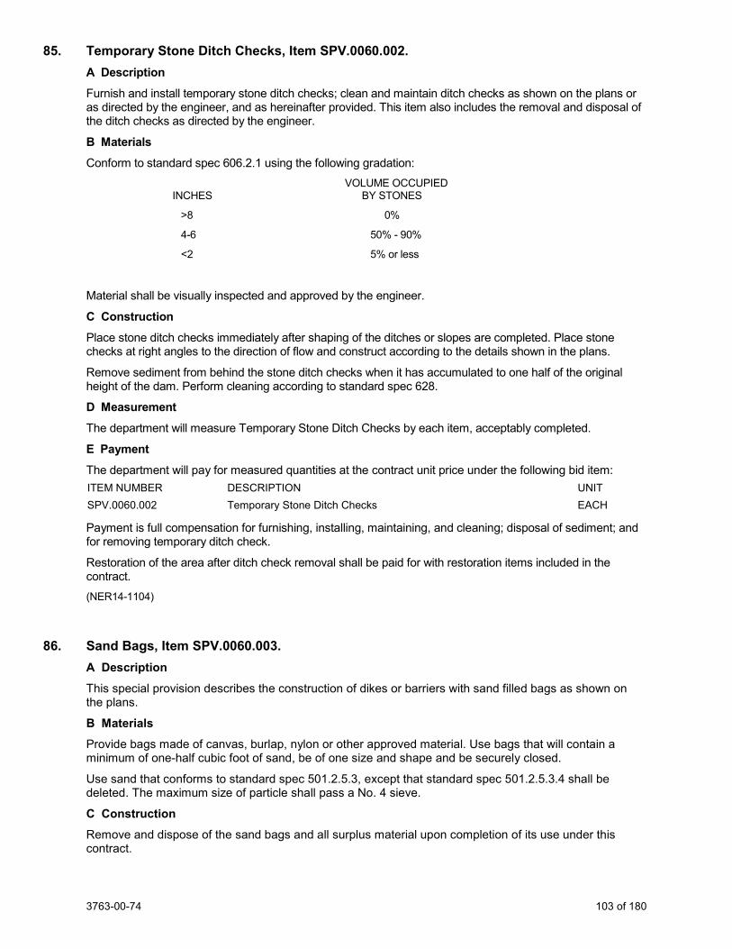
3763-00-74 103 of 180
85. Temporary Stone Ditch Checks, Item SPV.0060.002. A Description
Furnish and install temporary stone ditch checks; clean and maintain ditch checks as shown on the plans or as directed by the engineer, and as hereinafter provided. This item also includes the removal and disposal of the ditch checks as directed by the engineer.
B Materials Conform to standard spec 606.2.1 using the following gradation: VOLUME OCCUPIED INCHES BY STONES
>8 0%
4-6 50% - 90%
<2 5% or less
Material shall be visually inspected and approved by the engineer.
C Construction
Place stone ditch checks immediately after shaping of the ditches or slopes are completed. Place stone checks at right angles to the direction of flow and construct according to the details shown in the plans.
Remove sediment from behind the stone ditch checks when it has accumulated to one half of the original height of the dam. Perform cleaning according to standard spec 628.
D Measurement The department will measure Temporary Stone Ditch Checks by each item, acceptably completed.
E Payment The department will pay for measured quantities at the contract unit price under the following bid item: ITEM NUMBER DESCRIPTION UNIT SPV.0060.002 Temporary Stone Ditch Checks EACH
Payment is full compensation for furnishing, installing, maintaining, and cleaning; disposal of sediment; and for removing temporary ditch check.
Restoration of the area after ditch check removal shall be paid for with restoration items included in the contract. (NER14-1104)
86. Sand Bags, Item SPV.0060.003. A Description This special provision describes the construction of dikes or barriers with sand filled bags as shown on the plans.
B Materials Provide bags made of canvas, burlap, nylon or other approved material. Use bags that will contain a minimum of one-half cubic foot of sand, be of one size and shape and be securely closed.
Use sand that conforms to standard spec 501.2.5.3, except that standard spec 501.2.5.3.4 shall be deleted. The maximum size of particle shall pass a No. 4 sieve.
C Construction Remove and dispose of the sand bags and all surplus material upon completion of its use under this contract.
3763-00-74 104 of 180
D Measurement The department will measure Sand Bags as each individual sand bag, placed and accepted.
E Payment The department will pay for measured quantities at the contract unit price under the following bid item. ITEM NUMBER DESCRIPTION UNIT SPV.0060.003 Sand Bags EACH
Payment is full compensation for furnishing and installing sand filled bags; for all excavation; for removal and disposal of the sand bags and all waste or surplus materials, including eroded materials and for shaping and restoring the area.
Any required topsoiling, fertilizing, seeding or mulching will be paid for under the applicable bid item. SER-207.1 (20101021) EROC
87. Temporary Sediment Traps, Item SPV.0060.004. A Description Design, construct, and maintain temporary sediment traps used to intercept sediment-laden runoff and to retain the sediment.
B Materials Materials shall be according to Wisconsin DNR Technical Standard 1063 (Sediment Trap).
C Construction Design, construct, maintain and remove temporary sediment traps following the guidance in Wisconsin DNR Technical Standard 1063 (Sediment Trap) and according to the detail shown in the plans, and at the direction of the engineer. Locations as directed by the engineer. General locations requiring Temporary Sediment Traps are upstream of streams and wetlands which receive sediment laden runoff. Install prior to major grading operations. Do not remove until directed by the engineer.
D Measurement The department will measure Temporary Sediment Traps as each individual sediment trap, installed according to the contract and acceptably completed.
E Payment The department will pay for measured quantities at the contract unit price under the following bid item: ITEM NUMBER DESCRIPTION UNIT SPV.0060.004 Temporary Sediment Traps EACH
Payment is full compensation for design; furnishing and maintaining each basin; for removal of the basin; and for stabilization of disturbed area after removal.
88. Erosion Control Filter Bags, Item SPV.0060.005. A Description This special provision describes furnishing, installing, maintaining, and removing erosion control filter bags under other contract items at locations designated on the plans or as directed by the engineer, and according to plan details and as hereinafter provided.
B Materials Bags shall be made of synthetic net with a mesh size of 1/8-inches by 1/8-inches that is of sufficient strength to hold the aggregate and to be lifted vertically.
Fill material shall be clean, sound, hard, durable coarse aggregate meeting the approval of the engineer and conforming to the size and gradation requirements for Size No. 1 coarse aggregate as specified in standard spec 501.2.5.4.5.
3763-00-74 105 of 180
C Construction Furnish bags filled with fill material as specified, secured to prevent loss of fill material during transportation, placement, maintenance and removal operations as hereinafter described. Completed erosion control filter bags shall have minimum in-place filled dimensions of 24-inches long by 12-inches wide by 6-inches high.
Install the erosion control filter bags as directed by the engineer and per plan detail. Place erosion control filter bags before starting any construction operation that may cause sedimentation or siltation at the site of the proposed filter bags.
D Measurement The department will measure Erosion Control Filter Bags by each individual erosion control filter bag, acceptably completed.
The department will not measure individual erosion control filter bags specified to be installed as part of silt fence drainage outlet protection. In those installations erosion control filter bags are part of and, incidental to the appropriate bid items.
E Payment The department will pay for measured quantities at the contract unit price under the following bid item: ITEM NUMBER DESCRIPTION UNIT SPV.0060.005 Erosion Control Filter Bags EACH
Payment is full compensation for furnishing all specified materials; for delivering, assembling, placing, maintaining, and removing and disposing erosion control filter bags; for removing and disposing of the accumulated sediments; and for repairing and restoring damaged areas.
89. Inlet Frame and Grate for Mountable Curb, Item SPV.0060.006. A Description The work under these items shall be according to the requirements of standard spec 611 and the details as shown on the plans.
B (Vacant) C (Vacant) D Measurement The department will measure Inlet Frame and Grate for Mountable Curb by the unit in place, furnished, installed and acceptably completed.
E Payment The department will pay for measured quantities at the contract unit price under the following bid items: ITEM NUMBER DESCRIPTION UNIT SPV.0060.006 Inlet Frame and Grate for Mountable Curb EACH
Payment shall conform to standard spec 611.5.
90. Temporary Access Gates at CPRR, Item SPV.0060.007; Temporary Access Gates at UPRR, Item SPV.0060.008. A Description This special provision describes furnishing and erecting an access gate and any necessary approach work per plan detail at the location shown on the plans and as directed by the engineer.
B (Vacant)
3763-00-74 106 of 180
C Construction Construct these gates at least 12 feet outside of any railroad tracks. Gates must be constructed so they do not swing toward the railroad tracks.
Equip gate with a chain or cable and a key lock. Keep gates locked in the closed position when not in use. Remove gate upon completion of the project.
Provide any approach work necessary to move equipment up to the railroad tracks, in-between the tracks and through the gate. The track crossing will be installed by the railroad. Provide any drainage measures necessary to maintain the existing drainage when the approach work, crossings and gates are in place. Remove these gates, any approach work and any drainage measures, and restore the existing drainage pattern.
D Measurement The department will measure Temporary Access Gates as each individual access gate, acceptably completed.
E Payment The department will pay for measured quantities at the contract unit price under the following bid item: SPV.0060.007 Temporary Access Gates at CPRR EACH SPV.0060.008 Temporary Access Gates at UPRR EACH
Payment is full compensation for furnishing all materials; for erecting posts and gates; for constructing any necessary approach work; for constructing any drainage measures; for removing all items discussed in this special provision.
91. Mobilizations Emergency Pavement Repair, Item SPV.0060.009. A Description This special provision describes furnishing and mobilizing personnel, equipment, traffic control, and materials to the project site to repair the existing pavement for emergencies as the engineer directs. An emergency is a sudden occurrence of a serious and urgent nature, beyond normal maintenance of the existing pavement.
B (Vacant) C Construction Mobilize with sufficient personnel, equipment, traffic control, materials, and incidentals on the jobsite within 4 hours of the engineer's written order to repair the existing pavement on an emergency basis.
D Measurement The department will measure Mobilizations Emergency Pavement Repair as each individual mobilization, acceptably completed. The department will not include delivering and installing pavement repair or maintenance materials provided for in specific contract bid items. All traffic control items used for each Mobilization will be considered incidental to the Mobilization.
E Payment The department will pay for measured quantities at the contract unit price under the following bid items: ITEM NUMBER DESCRIPTION UNIT SPV.0060.009 Mobilizations Emergency Pavement Repair EACH
Payment is full compensation for the staged moving of personnel, moving equipment, setting up and removing traffic control, traffic control materials, and moving materials. The department will pay separately for delivery and installation of pavement repair materials under the other bid items in this contract. The department will not pay separately for traffic control items and materials even though they may be included in other bid items in this contract and will consider them incidental to each Mobilization. sef-999-025 (20170310)
3763-00-74 107 of 180
92. Section Corner Monuments, Item SPV.0060.010. A Description Coordinate with Southeastern Wisconsin Regional Planning Commission (SEWRPC) for the perpetuation and replacement of a section corner (Public Land Survey System- PLSS) monument.
B Materials SEWRPC will provide a pre-cast concrete monument or brass disk to be used to mark the PLSS corner.
Furnish base aggregate dense materials that conform to standard spec 305 and concrete, asphalt, topsoil or other materials depending on the surface surrounding the corner.
C Construction SEWRPC will perpetuate existing section corner monument. The contractor is responsible to coordinate with SEWRPC and the WisDOT Project Manager throughout the perpetuation and replacement process. The engineer will contact SEWRPC at (262) 953-4295 at least two weeks before starting construction operations or the preconstruction meeting to allow for section corner monument perpetuation.
Contractor must excavate and completely remove the existing monument. Contractor is responsible for providing a backfilled 3 to 4 foot deep hole where existing monument was removed. Contractor is responsible to coordinate the materials and methodology to complete the construction of the surface surrounding the monument. This may include but is not limited to a 2’ x 2’ “box out” or 24” diameter core hole in concrete, asphalt pavement/paving rings, coring to facilitate poured in place monuments, topsoil, seed and mulching or other materials or methodologies as agreed to by the contractor and SEWPRC.
Contact Information: Attn: John Washburn Southeastern Wisconsin Regional Planning Commission W239 N1812 Rockwood Drive P.O. Box 1607 Waukesha, WI 53187-1607 Phone (262) 547-6721 Cell (262) 953-4295 Fax (262) 547-1103 E-mail: [email protected] and Attn: Rob Merry Southeastern Wisconsin Regional Planning Commission W239 N1812 Rockwood Drive P.O. Box 1607 Waukesha, WI 53187-1607
D Measurement The department will measure Section Corner Monuments Special by the individual unit, acceptably completed.
E Payment The department will pay for measured quantities at the contract unit price under the following bid item: ITEM NUMBER DESCRIPTION UNIT SPV.0060.010 Section Corner Monuments EACH
Payment is full compensation for all excavating; removal of existing monument, for placing and compacting backfill material; for disposing of surplus materials; for concrete or asphalt material, finishing of roadway or other surfaces, for all coordination with SEWRPC; and for furnishing all labor, tools, and equipment. SER-621.1 (20170530)
3763-00-74 108 of 180
93. Settlement Gauges, Item SPV.0060.011. A Description This special provision describes furnishing and installing settlement gauges and extensions according to the details shown in the plans and as herein provided.
B (Vacant) C Construction Install the settlement gauges at field locations as determined by the engineer and under the supervision of the department’s Foundation and Pavement Unit and at the following locations:
Settlement Gauge Locations
Station Off set, Location
472+50 Centerline, CPRR West Approach
*476+25 Centerline, CPRR West Approach (install two (2) settlement plates)
*478+75 Centerline, CPRR East Approach (install two (2) settlement plates)
480+50 Centerline, CPRR East Approach
528+50 Centerline, UPRR West Approach
*531+00 Centerline, UPRR West Approach (install two (2) settlement plates)
*534+50 Centerline, UPRR East Approach (install two (2) settlement plates)
536+50 Centerline, UPRR East Approach
531+00 50 ft Right, UPRR South Wall West Approach. Settlement monitoring includes areas of proposed walls
532+00 50 ft Right, UPRR South Wall West Approach
534+50 50 ft Right, UPRR South Wall East Approach
536+50 50 ft Right, UPRR South Wall East Approach
*At locations having two settlement gauges: install one settlement gauge at prepared subgrade elevation. Install one settlement gauge at depth of 3 feet below finished subgrade elevation
The bottom of the plate shall be level and riser pipe shall be vertical. Mortar may be used to level the 2-foot x 2-foot x 0.5-inch thick plate. The elevation of the plate shall be determined by the engineer and the lengths of any added riser pipe(s) shall be accurately measured and recorded.
Embankment and retaining wall material in the vicinity of the riser pipe shall be compacted to specification requirements, taking precautions to keep alignment of the riser and the cover pipes vertical at all times.
Take all necessary precautions to ensure that the settlement gauges are not damaged, displaced, or misaligned. If a gauge is damaged, it shall immediately be repaired or replaced by the contractor at this/her own expense. Contractor to protect and maintain all settlement gauges installed as part of this contract.
D Measurement The department will measure Settlement Gauges as each unit, complete in place.
3763-00-74 109 of 180
E Payment The department will pay for measured quantities at the contract unit price under the following bid item: ITEM NUMBER DESCRIPTION UNIT SPV.0060.011 Settlement Gauges EACH
Payment is full compensation for furnishing and placing all materials including extensions; for excavation; and for all labor, tools, equipment and incidentals necessary to complete the work according to the plans and contract.
94. Manhole Beehive Grate, Item SPV.0060.012. A Description The work under these items shall be according to the requirements of standard spec 611 and the details as shown on the plans.
B Materials Conform to standard spec 611.
C Construction Conform to standard spec 611.
D Measurement The department will measure Manhole Beehive Grate by each grate, acceptably completed.
E Payment The department will pay for measured quantities at the contract unit price under the following bid items: ITEM NUMBER DESCRIPTION UNIT SPV.0060.012 Manhole Beehive Grate EACH
Payment is full compensation conforming to standard spec 611.5.
95. Connect Drain Tile, Item SPV.0060.013. A Description
This special provision describes connecting existing drain tiles to proposed structures or proposed storm sewer pipes.
B (Vacant) C Construction
Identify drain tile invert elevations through Drain Tile Exploration. Connect the exposed drain tile with the appropriate coupling, concrete collar or by means approved by the engineer to reestablish the connection. Use concrete masonry for concrete collar conforming to standard spec 520.2.4. Ensure that the connection does not negatively impact the current flow capacity of the drain tile.
D Measurement The department will measure Connect Drain Tile as each new drain tile connection to a structure or pipe, acceptably completed. Measurement will include connections of new underdrain structures placed in previous stages of the project, in addition to pipe or structures constructed under previous projects.
E Payment The department will pay for measured quantities at the contract unit price under the following bid item: ITEM NUMBER DESCRIPTION UNIT SPV.0060.013 Connect Drain Tile EACH
3763-00-74 110 of 180
Payment is full compensation for performing all work; removing seals, end walls and concrete collars, providing all materials, couplings, concrete collars. Any additional pipe or materials required to connect the drain tile shall be considered incidental to this bid item. The new pipe that restores drainage will be paid separately under their respective bid items.
96. Pipe Connection to Existing Structure, Item SPV.0060.016. A Description This special provision describes connecting new storm sewer pipe to existing structure.
B Materials Conform to standard spec 608.2 and standard spec 611.2
C Construction Conform to standard spec 607.3 and standard spec 611.3
D Measurement The department will measure Pipe Connection to Existing Structure by each pipe connected, acceptably completed.
E Payment The department will pay for measured quantities at the contract unit price under the following bid item: ITEM NUMBER DESCRIPTION UNIT SPV.0060.016 Pipe Connection to Existing Structure EACH
Payment is full compensation for performing all work; excavation, backfilling, furnishing, masonry and fittings; disposing of surplus material, coring holes in existing structure to connect new pipe; and installing all materials, couplings, concrete collars, and pipe.
97. Pond L Outlet Storm Sewer Structure, Item SPV.0060.020; Pond M Outlet Storm Sewer Structure, ItemSPV.0060.021; Pond N Outlet Storm Sewer Structure, Item SPV.0060.022. A Description Furnish and install pond outlet Storm Sewer Structure according to the pertinent provisions of standard spec 611, as shown on the plans and as hereinafter provided. Furnish and install trash racks on the outlet Storm Sewer Structure. Furnish and install trash racks according to the pertinent provisions of standard spec 506 and 513, as shown on the plans and as hereinafter provided. Provide orifice holes and anti-seep collar as shown on the plan.
B Materials
Furnish manhole materials according to standard spec 611.
Furnish steel conforming to the requirements of standard spec 506.2.2.1. Furnish steel galvanized according to ASTM A123 and ASTM 1153 as applicable.
Trash racks shall be fabricated from structural steel shapes, flat bar and plates and shall be galvanized after fabrication. Shop drawings for the trash racks shall be submitted to the engineer for approval prior to fabricating the trash racks.
Furnish bolts, nuts and washers for the installation of the trash racks onto the Outlet Storm Sewer Structures. Bolts, nuts and washers according to standard spec 513.2.2.5.
C (Vacant) D Measurement The department will measure Pond Outlet (name) Storm Sewer Structure as each individual unit, acceptably completed.
3763-00-74 111 of 180
E Payment The department will pay for measured quantities at the contract unit price under the following bid item: ITEM NUMBER DESCRIPTION UNIT SPV.0060.020 Pond L Outlet Storm Sewer Structure EACH SPV.0060.021 Pond M Outlet Storm Sewer Structure EACH SPV.0060.022 Pond N Outlet Storm Sewer Structure EACH
Payment is full compensation for providing and placing all materials, including all masonry, steel and pipe connections, and other fittings; furnishing and installing trash racks; for providing orifice holes and anti-seep collars; for furnishing all excavating, backfilling, disposing of surplus material, and for cleaning out and restoring the work site.
98. Slip-In Check Valve for 24-Inch Inside Diameter Pipe, Item SPV.0060.024; Slip-In Check Valve for 30-Inch Inside Diameter Pipe, Item SPV.0060.025; Slip-In Check Valve for 36-Inch Inside Diameter Pipe, Item SPV.0060.026; Slip-In Check Valve for 42-Inch Inside Diameter Pipe, Item SPV.0060.027. A Description The specification covers furnishing and installing Slip-In Check Valves (Check Valves) at locations as shown on the plans and according to manufacturer’s instructions.
B Materials Contractor shall provide an in-line elastomeric type check valve with compression clamps and a slip-in cuff connection. Check Valve shall slip into downstream end of RCCP pond outlets and be attached with 316 stainless steel expansion clamps which shall expand outward to seal the valve against the RCCP pipe wall without use of a separate valve body or pipe.
Check Valve shall be one-piece pure gum rubber construction with reinforcement throughout the body, disc, and bill and resilient to freezing and UV exposure.
Check Valve shall open to allow passage of flow in one direction when line pressure exceeds the backpressure. When backpressure exceeds line pressure the bill and disc are forced closed preventing reverse flow. Valves shall be designed to crack open with less than 2-inch water depth above the valve invert and the following parameters:
The (size) Check Valve into structure at location as shown on the plan shall be designed to open with less than 2-inches of line pressure and rated for a maximum of 20 feet of backpressure. Check Valve shall have less than 0.2-feet of head loss for the 2-year design flow rate of 5 cubic feet per second.
Manufacturer shall have designed, fabricated and have at least three current installation of this style of check valves within a size range of 24” to 72” diameters within the United States. Manufacturer shall provide documentation, including project name, location, and references.
Manufacturer shall have conducted hydraulic testing to determine head loss, jet velocity and vertical opening height characteristics on a minimum of three sizes of valves. The testing must have been conducted for free discharge (pressurized and open channel flow discharging to atmosphere) and submerged conditions.
C Construction Furnish and install Check Valve at the locations identified on the plans.
Check Valves will be placed Inside the diameter pipes. Due to small variations in RCCP fabrication depending on manufacturer, the contractor is responsible for providing the proper size Check Valve for the actual inside diameter of the RCCP being used. Check Valve shall be sized to fit such that the upstream and downstream sections of the valve shall be circumferentially in tight contact with the inside diameter of the outlet pipe. After installation, the Check Valve shall not protrude beyond the end of the outlet pipe.
Contractor to provide any clamps or hardware required for installation of Check Valve. Such items are considered incidental to this work.
3763-00-74 112 of 180
The contractor will be responsible for installing the Check Valve as shown in the plans and details and per the manufacturer’s instructions. Contractor shall make manufacturer’s authorized representative available to assist during valve installation.
D Measurement The department will measure Slip-In Check Valve (size) Inside Diameter Pipe by each individual unit installed in place, and the quantity measured for payment shall be the number of units each of the various locations, completed and accepted according to the contract and plans. All clamps and hardware necessary for installing Check Valve are considered incidental to this work.
E Payment The department will pay for measured quantities at the contract unit price under the following bid item: ITEM NUMBER DESCRIPTION UNIT SPV.0060.024 Slip–In Check Valve for 24-Inch Inside Diameter Pipe EACH SPV.0060.025 Slip–In Check Valve for 30-Inch Inside Diameter Pipe EACH SPV.0060.026 Slip-In Check Valve for 36-Inch Inside Diameter Pipe EACH SPV.0060.027 Slip-In Check Valve for 42-Inch Inside Diameter Pipe EACH
Payment is full compensation for providing all labor, materials, incidentals, and hardware necessary for installing Slip-In Check Valve for (size) Inside Diameter Pipe.
99. Concrete Bases Monotube Type 9 & 10 Special Pole, Item SPV.0060.301. A Description This special provision describes constructing concrete bases for Type 9 &10 Special Traffic Signal Base conforming to standard spec 654, construction detail shown in the plans.
B Materials Materials shall be according to standard spec 654.
C Construction Construction shall be according to standard spec 654.
D Measurement The department will measure Concrete Base Monotube Type 9 & 10 Special Pole at the contract unit price, acceptably completed.
E Payment The department will pay for measured quantities at the contract unit price under the following bid item:
ITEM NUMBER DESCRIPTION UNIT SPV.0060.301 Concrete Base Monotube Type 9 & 10 Special Pole EACH
Payment is full compensation for providing concrete bases; for embedded conduit and electrical components; for nuts and washers; for bar steel reinforcement; for excavating, backfilling, and disposing of surplus materials.
100. Transport and Install Poles Type 9, Item SPV.0060.302; Transport and Install Poles Type 9 Special, Item SPV.0060.303; Transport and Install Poles Type 10, Item SPV.0060.304; Transport and Install Poles Type 10 Special, Item SPV.0060.305; Transport and Install Monotube Arms 25-FT, Item SPV.0060.306; Transport and Install Monotube Arms 30-FT, Item SPV.0060.307; Transport and Install Monotube Arms 35-FT, Item SPV.0060.308; Transport and Install Luminaire Arms Steel 15-FT, Item SPV.0060.309; Transport and Install Monotube Arms 40-FT, Item SPV.0060.310; Transport and Install Monotube Arms 20-FT, Item SPV.0060.311.
3763-00-74 113 of 180
A Description This special provision describes transporting and installing state furnished materials conforming to standard spec 657, details shown in the plans, and as modified in this special provision.
B Materials The department will furnish the monotube poles, monotube arms and luminaire arms.
Pick up the department furnished materials at the department’s Electrical Shop located at 935 South 60th Street, West Allis. Notify the department’s Electrical Field Unit at (414) 266-1170 and make arrangements for picking up the department furnished materials 5 working days prior to picking the materials up.
Provide any all other necessary material required to complete the installation as the plans show. needed materials in conformance with standard spec 651.2, 652.2, 653.2, 654.2, 655.2, 656.2, 657.2, 658.2 and 659.2 C Construction Perform work according to standard spec 651.3, 652.3, 653.3, 654.3, 655.3, 656.3, 657.3, 658.3 and 659.3.
D Measurement The department will measure Transport and Install [Equipment] at the contract unit price, acceptably completed.
E Payment The department will pay for measured quantities at the contract unit price under the following bid item: ITEM NUMBER DESCRIPTION UNIT SPV.0060.302 Transport and Install Poles Type 9 EACH SPV.0060.303 Transport and Install Poles Type 9 Special EACH SPV.0060.304 Transport and Install Poles Type 10 EACH SPV.0060.305 Transport and Install Poles Type 10 Special EACH SPV.0060.306 Transport and Install Monotube Arms 25-FT EACH SPV.0060.307 Transport and Install Monotube Arms 30-FT EACH SPV.0060.308 Transport and Install Monotube Arms 35-FT EACH SPV.0060.309 Transport and Install Luminaire Arms Steel 15-FT EACH SPV.0060.310 Transport and Install Monotube Arms 40-FT EACH SPV.0060.311 Transport and Install Monotube Arms 20-FT EACH
Payment is full compensation for transporting and installing all materials, including all associated hardware, fittings, mounting devices, and attachments necessary to completely install the poles and arms.
101. Luminaire Utility LED C With House Side Shield, Item SPV.0060.501. A Description
This special provision describes furnishing and installing Light Emitting Diode (LED) roadway luminaires Category C (LED-C) with House Side Shield to reduce backlight behind luminaires.
B Materials
Furnish Luminaires Utility LED from the department qualified product list. Luminaires shall conform to applicable portions of Section 659.2 and the WisDOT Specifications for LED Roadway Luminaires. The luminaire housing shall be all aluminum with factory finished durable corrosion and UV resistant gray powder-coated or anodized aluminum finish. Housing access shall be tool-free. The luminaire/arm mounting configuration shall fit the specified pole fitter being used per the plan. The luminaire shall be UL listed, IP 66 rated.
LED lamps shall be in the 4000K color temperature range with a minimum of 70 CRI. A NEMA sized “Category Label” label shall be fixed to the bottom of the luminaire and be visible from a passing vehicle.
3763-00-74 114 of 180
The luminaire shall be equipped with a voltage-sensing LED driver, to accommodate 120-277V with 90% power factor and THD 20% max at full load. Surge protection shall be provided and tested according to the specifications. The luminaire shall also be equipped with a quick-disconnect plug for connecting the pole riser wires to the terminal block. A strain relief shall retain the pole riser wires within the luminaire.
The acceptable luminaires are as follows:
Category C:
• Philips: RFM-160W48LED4K-G2-R3M-UNV-PH9/RCD-GY3 • Cree: TRVLG-A-HT-3ME-16L-40K7-UL-GY-N-W10-01 • Leoteck: GCL1-60G-MV-NW-3R-700-PCR7-WL-WISDOT-C-SC • American Electric: ATB0 30LEDE15 MVOLT R3 P7 SH • Eaton: ARCH-M-AF48-130-D-U-T3-4N7-10MSP-K-AP-WISDOT
Furnish shop drawings as specified in 506.3.2, except submit 5 copies with the materials list. Ensure the drawings contain sufficient detail to allow satisfactory review and show the dimensions of all equipment shown in the plans.
C Construction Furnish and install luminaires, house side shiled and all necessary miscellaneous accessories and hardware to complete the installation of the luminaires.
The contractor shall follow manufacturer’s instructions regarding luminaire installation.
Three single-conductor No. 12 stranded wires shall be used to connect the luminaires to their respective branch conductors in the pole base. Each luminaire feeder wire shall be protected by one 5-amp fuse. Fuses and fuse holders shall be as per the details in the Plan.
All exposed threaded equipment mounting hardware shall be stainless steel.
The contractor shall coat all threaded stainless steel hardware and dissimilar metal, threaded hardware with an approved zinc-based anti-seize compound (Loctite or Jet-Lube prior to assembly.
There shall be a sticker placed on the bottom of the luminaire to (paid separately) clearly identify the WisDOT Luminaire Category A, B, C, or D as applicable. The sticker should be visible from to a person standing on the ground.
D Measurement The department will measure Luminaire Utility LED Category C with House Side Shield as each individual lighting unit, acceptably completed.
E Payment The department will pay for measured quantities at the contract unit price under the following bid item: ITEM NUMBER DESCRIPTION UNIT SPV.0060.501 Luminaire Utility LED C With House Side Shield EACH
Payment is full compensation for furnishing and installing all materials, including luminaire, accessories, hardware, house side shield and fittings necessary to install the luminaire workable first class condition.
102. Connect to Existing Sanitary Manhole, Item SPV.0060.600. A Description This special provision describes the connection of a new sanitary sewer pipe to an existing manhole.
B Materials The contractor shall supply all equipment, sealing materials, fittings, slurry backfill, and other necessary items required to perform the work.
3763-00-74 115 of 180
C Construction Core a new hole in the existing manhole and install a flexible rubber water-tight connector in the cored hole. Fill the existing hole with water-tight material. Remove the existing concrete bench in the manhole as needed and reform the bench to create a smooth trough from the outlet pipe to the new inlet pipe. Install a cap on the end of the existing sanitary sewer to be abandoned-in-place. Backfill the excavation with slurry backfill.
Additional items of work include excavation dewatering, finish grading, removal and disposal of waste excavated materials, and location, protection, and repair of existing utilities.
D Measurement The department will measure Connect to Existing Sanitary Manhole as a unit for each connection to existing manhole, acceptably completed.
E Payment The department will pay for measured quantities at the contract unit price under the following bid item: ITEM NUMBER DESCRIPTION UNIT SPV.0060.600 Connect to Existing Sanitary Manhole EACH
Payment is full compensation for furnishing and installing all materials including flexible rubber water-tight connector; sealing materials, fittings; for furnishing and placing slurry backfill, for furnishing all excavation, dewatering, sheathing and shoring, forming foundation, and masonry work; for coring of existing manhole and making sanitary sewer connections; for removing sheeting and shoring; for disposal of all surplus or waste material; and for clean-up.
103. Sanitary Sewer Manhole, Item SPV.0060.601. A Description This special provision describes the installation of new sanitary sewer manholes during open cut sewer installation.
B Materials The contractor shall supply the following:
1. Precast manhole sections complying with ASTM C478. 2. Eccentric cones. 3. Precast reinforced concrete monolithic base. 4. Tongue and groove joints with water-tight gaskets. 5. Internal/External frame seal.
a. Adaptor, Inc., Cretex Specialty Products, or equal. 6. Exterior joint protection.
a. 8-inch minimum width. 7. Exterior surface treatment.
a. Water-based acrylic coating. 8. Frame and cover.
a. Neenah R-1580, East Jordan Iron Works 1140, or equal, concealed pickholes, non-rocking.
C Construction Construct invert channels to be smooth and semicircular. Do not construct steps over the pipe inlet locations.
Additional items of work include excavation dewatering, finish grading, removal and disposal of waste excavated materials, and location, protection, and repair of existing utilities.
3763-00-74 116 of 180
D Measurement The department will measure Sanitary Sewer Manhole as a unit for each individual manhole, acceptably completed.
E Payment The department will pay for measured quantities at the contract unit price under the following bid item: ITEM NUMBER DESCRIPTION UNIT SPV.0060.601 Sanitary Sewer Manhole EACH
Payment is full compensation for furnishing and installing all materials including pre-cast manhole base, riser, bench, cone section, frames, grates or lids, and chimney adjustment rings; for installing gaskets, joint seals, steps, bedding material, backfill material, for furnishing and placing slurry backfill, for furnishing all excavation, dewatering, sheathing and shoring, forming foundation, and masonry work; for making sanitary sewer connections; for making lateral connections; for removing sheeting and shoring; for disposal of all surplus or waste material; and for clean-up.
104. Abandon Sanitary Manhole, Item SPV.0060.602. A Description This special provision describes the abandonment of existing sanitary manholes.
B Materials The contractor shall supply necessary equipment and slurry backfill materials to perform the work.
C Construction Contractor shall remove the frame and cone section from the existing manholes and deliver to the Village Public Works Department. Plug the sewer pipe inlets and outlets and fill the remaining portion of the manhole with slurry backfill materials.
D Measurement The department will measure Abandon Sanitary Manhole as a unit for each individual abandoned manhole, acceptably completed.
E Payment The department will pay for measured quantities at the contract unit price under the following bid item: ITEM NUMBER DESCRIPTION UNIT SPV.0060.602 Abandon Sanitary Manhole EACH
Payment is full compensation for furnishing and installing all materials; for providing positive drainage of the area to be backfilled; for furnishing and placing slurry backfill; for salvaging frames and covers and for disposing of materials.
105. Adjust Sanitary Manhole, Item SPV.0060.603. A Description This special provision describes the adjustment of existing sanitary manhole frames as necessary during surface restoration. This item is intended generally for manholes requiring less than 12-inches of total adjustment.
B Materials The contractor shall supply all concrete adjusting rings, mortar, and butyl material necessary to perform the work. Provide Adaptor, Inc., Cretex Specialty Products, or equal internal/external chimney seal.
C Construction Adjust sanitary frames to match surface elevations as necessary. Remove or add concrete rings as required. Install new chimney seal.
3763-00-74 117 of 180
D Measurement The department will measure Adjust Sanitary Manhole as a unit per each adjustment, acceptably completed.
E Payment The department will pay for measured quantities at the contract unit price under the following bid item: ITEM NUMBER DESCRIPTION UNIT SPV.0060.603 Adjust Sanitary Manhole EACH
Payment is full compensation for providing and installing all required materials including adjusting rings, internal frame/chimney seals, and masonry and fittings; for salvaging and reinstalling existing or new covers, including frames and lids; for excavating, backfilling, and compacting; for furnishing and placing slurry backfill; for disposing of surplus materials; and for cleaning out and restoring the structure.
106. Adjusting Sanitary Manhole Village of Mount Pleasant, Item SPV.0060.610. A Description This work includes adjusting sanitary manholes to an elevation as determined by the engineer as well as installing frame and lid, internal frame/chimney seal, according to the Standard Specifications for Sewer and Water Construction in Wisconsin, latest edition and amendments (SSSW) and as hereinafter provided.
Add or remove masonry adjusting rings as needed. This item applies to structures to be lowered less than 6 inches or raised less than 12 inches.
B Materials B.1 Adjusting Rings Adjustment rings shall be concrete with steel reinforcement in conformance with ASTM C-478. Precast concrete rings shall have an inside diameter to match the manhole opening, be not less than 2 inches nor more than 6 inches high and have a wall thickness of 6 inches unless otherwise specified. The rings shall contain a minimum of one No. 2 reinforcing rod centered within the ring. Do not use any cracked or broken rings. The top of precast manhole cones shall be set a maximum of 18 inches lower than established grade in unimproved areas, with the top of the manhole cover being ringed up flush with the existing ground. The minimum number of adjusting rings shall be one 2-inch ring. The maximum height of adjusting rings shall be 8 inches in paved areas. All joints between the adjusting rings shall be filled with grout or mortar, including between the cone and the adjusting ring and the adjusting ring and the frame. Rings shall be grooved to receive a step.
B.2 Manhole Seal Furnish new internal frame/chimney seal as manufactured by Cretex Specialty Products, Adaptor, Inc., or equal. The seal shall meet the material requirements of section 8.42.3 and the performance requirements of section 8.42.4 of the SSSW.
B.3 Backfill Slurry Backfill slurry shall meet the material and construction requirements of section 8.43.8 of the SSSW.
C Construction C.1 General The location of existing sanitary manholes to be adjusted is indicated on the plans. Adjust these items as shown in the plans. Adjust manholes as necessary so that the frames and lid when placed will be at the established required grade. Install seals according to the manufacturer’s recommended installation procedures. Furnish and use backfill slurry in the manhole excavation area to existing surface or to appropriate depth for pavement restoration. Salvage and reinstall existing frames and lids.
3763-00-74 118 of 180
C.2 Surface Preparation Remove manhole cover and power wire brush the lower 3 inches of the manhole frame to remove any loose rust or scale and repair any imperfections by either grinding smooth or filling with mortar. A smooth, clean sealing surface is required. Realign the casting if it is offset more than approximately 2 inches from the chimney. Remove all loose and protruding mortar and brick from the upper 7-Inch chimney and clean surface by power wire brushing. Provide a 4-Inch wide sealing surface starting 2 inches down from the bottom of the frame.
All sealing surfaces must be circular, reasonably smooth, clean and free of any loose material or excessive voids. If such a surface does not exist for the bottom of the sleeve to seal against, use one-component, quick-set, high strength, non-shrink, polymer modified patching mortar which has been formulated for vertical or overhead use. If the bottom of the sleeve is to seal against the top of an eccentric (straight side) cone and an inadequately high vertical surface does not exist, contact the manufacturer to obtain details to build the required vertical surface.
Use caulk to fill minor irregularities in the bottom sealing surface. The caulk shall be a butyl rubber caulk conforming to AASHTO M-198, Type B. Apply a single bead of the caulk to the center portion of the lower sealing surface of the sleeve.
Any flaws in the manhole frame, such as minor cracks, pits or protrusions, shall be repaired by either filling with mortar or grinding smooth.
C.3 Manhole Seal Seals shall cover from the frame across all rings and onto the cone.
D Measurement The department will measure Adjusting Sanitary Manhole Village of Mount Pleasant as a unit per each adjustment, acceptably completed.
E Payment The department will pay for measured quantities at the contract unit price under the following bid item: ITEM NUMBER DESCRIPTION UNIT SPV.0060.610 Adjusting Sanitary Manhole, Village of Mount Pleasant EACH
Payment is full compensation for providing and installing all required materials including adjusting rings, internal frame/chimney seals, and masonry and fittings; for salvaging and reinstalling existing or new covers, including frames and lids; for excavating, backfilling, and compacting; for furnishing and placing backfill slurry; for disposing of surplus materials; and for cleaning out and restoring the structure.
107. Pavement Cleanup Project 3763-00-74, Item SPV.0075.001. A Description This special provision describes cleanup of dust and debris from pavements as the engineer directs.
B Materials
B.1 Pavement Cleanup
Furnish a vacuum-type street sweeper equipped with a power broom, water spray system, and a vacuum collection system.
Use vacuum equipment with a self-contained particulate collector capable of preventing discharge from the collection bin into the atmosphere.
Use a vacuum-type sweeper as the primary sweeper, except as specified in this special provision or approved by the engineer.
C Construction
C.1 Surveillance
Provide daily surveillance of active haul routes to identify if material is being tracked from the jobsite. Document the condition of the roads and all sweeping recommendations in a daily report. Submit reports to the engineer daily, including hourly metered tickets for that day’s sweeping activities.
3763-00-74 119 of 180
C.2 Pavement Cleanup
Keep all pavements, sidewalks, driveways, curb lanes and gutters within the project boundaries, free of dust and debris generated from all activity under the contract.
Conduct sweepings as the engineer directs or approves, to eliminate dust problems that might arise during off-work hours or emergencies. Provide the engineer with a contact person available at all times to respond to requests for emergency sweeping. Coordinate with engineer to determine deadlines for responding to emergency sweeping requests and cleaning up spillage and material tracked to/from the project.
Skid steers with mechanical power brooms may only be used on sidewalks and driveways whose pavements will not support the weight of a street sweeper, unless otherwise approved by the engineer. Do not dry sweep. Ensure all broomed equipment used for sweeping has a functioning water bar.
D Measurement The department will measure Pavement Cleanup (Project) by the hour, acceptably completed and only with prior approval by the engineer.
Tickets shall include:
− Date − Company − Operator name − Equipment make/model − Routes swept − Total hours.
Total hours shall be to the nearest 0.25 hour that work under this item was performed.
E Payment The department will pay for measured quantities at the contract unit price under the following bid item: ITEM NUMBER DESCRIPTION UNIT SPV.0075.001 Pavement Cleanup Project 3763-00-74 HR
Payment is full compensation for daily surveillance; preparing and submitting the daily surveillance report with hourly metered tickets; mobilization; sweeping; and disposing of materials.
sef-104-006 (20170323)
108. Heavy Duty Silt Fence, Item SPV.0090.001. A Description
This special provision describes the delivery, installation, maintenance, and removal of Heavy Duty Silt Fence. Install fence as directed by the engineer. Do not remove fence until directed by the engineer.
B Materials Provide Heavy Duty Silt Fence consisting of a composite of woven wire fence fabric, posts, geotextile, fasteners, and to be assembled by the contractor. Woven wire fence fabric shall be a standard field fence type a minimum of 4 feet high, a maximum mesh spacing of 6-inches and minimum 14-1/2 gauge wire.
Provide “studded tee” or “U” type metal posts with a minimum length of 7 feet –6 inches and a minimum weight of 1.3 lb/ft.
3763-00-74 120 of 180
Provide geotextile fabric meeting the following requirements:
Furnish a manufacturer’s Certified Report of Test or Analysis that the geotextile fabric delivered for use in the work meets the above requirements to the engineer at least 15 days prior to use in the work. Provide geotextile fabric bearing markings to clearly identify it with the applicable test report furnished to the engineer.
Supply material in 15’9” wide rolls and cut in half.
C Construction
Install the Heavy Duty Silt Fence as directed by the engineer and shown on the attached detail drawing. Space ties and anchors to adequately support system. Include or add acceptable guy lines, where required, for additional support.
Maintenance work, when required, will be specified on erosion control orders. Maintenance includes replacement of failed 12GA wire ties; re-anchoring of metal posts (standing lying sections back-up); entrenchment of the bottom fabric; and guy line repairs, if required. Geotextile fabric and woven wire fence fabric replacement not required for maintenance.
D Measurement The department will measure Heavy Duty Silt Fence by the linear foot, acceptably completed. The department will measure along the base of the fence, center-to-center of end post, for each section of fence.
E Payment The department will pay for measured quantities at the contract unit price under the following bid item: ITEM NUMBER DESCRIPTION UNIT SPV.0090.001 Heavy Duty Silt Fence LF
Payment is full compensation for all furnishing, assembling, erecting, maintaining, and removal of the silt fence; and for anchoring the silt fence.
Property Unit Test Method Minimum Average Roll Value
Grab Tensile Strength LB. ASTM D4632 380
Grab Tensile Elongation
% ASTM D4632 50
Puncture Strength
LB.
ASTM D4833 240
Trapezoid Tear Strength
LB. ASTM D4533 145
Apparent Opening Size
U.S. Standard Sieve ASTM D4751 170 (0.09 mm)
Permittivity
sec-1
ASTM D4491 0.7
Water Flow Rate
Gal/min/ft2 ASTM D4491 50
UV Resistance after 500 hours
% strength retained
ASTM D4355 70
3763-00-74 121 of 180
109. Pipe Underdrain 6-Inch Special, Item SPV.0090.002. A Description This special provision describes providing necessary subsurface drainage by constructing trenches, placing the required geotextile fabric, installing the designated pipes or drainage devices, connecting the wrapped underdrain to receiving structures, providing cored connection holes, back-plastering and or mortaring connections to storm sewer structures (both on the external and internal sides of the receiving structure), providing and installing PVC or HDPE fittings, and caps or plugs ,for excavating, plowing, backfilling the trenches with the specified backfill material according to standard spec 310, 612 and 645, salvaging; disposing of surplus material; and restoring the work site as shown on the plans and details, and as hereinafter provided.
B Materials B.1 Base Aggregate Use only base aggregate open graded conforming to standard spec 310.2.
B.2 Geotextile Fabric Utilize geotextile fabric consisting of Type DF Schedule A and conforming to standard spec 645.2.4. Completely wrap the installation trench with geotextile fabric.
C (Vacant) D Measurement The department will measure Pipe Underdrain 6-Inch Special by the linear foot, acceptably completed. The department will measure along the centerline of the pipe, center to center of junctions and fittings.
E Payment The department will pay for measured quantities at the contract unit price under the following bid item: ITEM NUMBER DESCRIPTION UNIT SPV.0090.002 Pipe Underdrain 6-inch Special LF
Payment is full compensation for providing, handling, and placing all materials, including pipe, base aggregate open graded, geotextile fabric Type DF Schedule A, providing cored connections, making all necessary connections to the receiving structures, performing back-plastering and or mortaring of wrapped underdrain connections to storm sewer structures, providing and installing all fittings, and caps or plugs; for furnishing all excavating, plowing, and re-compacting, salvaging; disposing of surplus material; and restoring the work site.
110. Temporary Construction Access Road, Item SPV.00090.005. A Description Construct a temporary construction access road to facilitate the construction of CTH KR between CPRR and the Pike River for placing fill materials, construction of structures over CP and UP railroad, and hauling of materials from staging areas. This item provides for the construction and maintenance of the temporary access road, removal of the temporary access road prior to the end of construction, and the restoration of the site.
B Materials Obtain approval of the engineer for all materials and conform to the pertinent requirements of the standard specifications.
C Construction Address temporary erosion control in the erosion control implementation plan.
Provide topsoil, seeding, fertilizer, mulching, and erosion control for the temporary access road and for the restored area after removal of the road.
Though not expected to be necessary, if necessary, provide for installation of a temporary culvert. Coordinate temporary culvert with the Wisconsin Department of Natural Resources.
3763-00-74 122 of 180
Contractor to clear snow along the temporary construction access road. Municipalities or Counties will not be responsible for clearing snow along the temporary construction access road.
When removing the temporary access road, restore the surface as closely as possible to its natural state. Thoroughly remove all access road materials from disturbed area and the Tributary No. 18 to the Kilbourn Road Ditch.
D Measurement The department will measure Temporary Construction Access Road by the linear foot measured along the centerline of access of road, acceptably completed.
E Payment The department will pay for measured quantities at the contract unit price under the following bid item: ITEM NUMBER DESCRIPTION UNIT SPV.0090.005 Temporary Construction Access Road LF
Payment is full compensation for any additional agency coordination and/or permitting; for furnishing all materials; for constructing and maintaining the temporary access road; for snow removal, for the removal of all temporary access road materials; for installation and removal of temporary erosion control along the temporary access road; for installation and removal of temporary culvert, and for restoration of the site after removal of the road.
111. Concrete Curb and Gutter 36-Inch Special Type A, Item SPV.0090.008. A Description Perform this work according to the pertinent requirements of standard spec 601 and conform to the construction detail shown in the plans.
B Materials Use materials as described in the construction detail shown in the plans and as described in standard spec 601.2.
C Construction Perform work according to standard spec 601.3.
D Measurement The department will measure Concrete Curb and Gutter 36-Inch Special Type A by the linear foot, acceptably completed, measured along the flow line of the gutter.
E Payment The department will pay for measured quantities at the contract unit price under the following bid item: ITEM NUMBER DESCRIPTION UNIT SPV.0090.008 Concrete Curb and Gutter 36-Inch Special Type A LF
Payment is full compensation for preparing the foundation; all special construction required at driveway entrances or curb ramps; for providing all materials, including concrete, and expansion joints; for placing, finishing, protecting, and curing concrete.
112. Fence Chain Link Polymer-Coated 6-Ft. B-30-145, Item SPV.0090.202; Fence Chain Link Polymer-Coated 6-Ft. B-30-146, Item SPV.0090.203; Fence Chain Link Polymer-Coated 6-Ft. B-30-147, Item SPV.0090.204; Fence Chain Link Polymer-Coated 6-Ft. B-30-148, Item SPV.0090.205; Fence Chain Link Polymer-Coated 6-Ft. R-30-65, Item SPV.0090.206; Fence Chain Link Polymer-Coated 6-Ft. R-30-66, Item SPV.0090.207; Fence Chain Link Polymer-Coated 6-Ft. R-30-67, Item SPV.0090.208; Fence Chain Link Polymer-Coated 6-Ft. R-30-68, Item SPV.0090.209.
3763-00-74 123 of 180
A Description This special provision describes furnishing and installing a new polymer-coated fence system on structures in conforming to the pertinent plan details and as directed by the engineer. The color of all components in this fence system shall be the same and shall be as specified on the plans.
B Materials All materials for this fence system shall be new stock, free from defects impairing strength, durability, and appearance. Fabric shall be produced by methods recognized as good commercial practice. Wire used in the manufacture of the fabric shall be capable of being woven into fabric without the polymer-coating cracking or peeling. Pipes used in framework shall be straight, true to section and free of defects. All burrs at the ends of pipes shall be removed before galvanizing. The polymer-coating shall be a dense impervious covering, applied without voids, tears or cuts that reveal the substrate. Excessive roughness, bubbles, blisters and flaking in the polymer-coating will be a basis for rejection.
B.1 Fabric Provide steel chain link fence fabric conforming to the requirements of ASTM F668, Class 2b, a polymer-coating fused and adhered to wire that is zinc-coated. Provide fabric woven from 9-gage wire using plan specified mesh size, diamond pattern, with both the top and bottom selvages knuckled. The minimum breaking strength of the wire shall be 1290 lbs. The color of polymer-coating shall conform to the requirements of ASTM F934.
B.2 Framework Provide steel rails, posts and post sleeves conforming to the requirements of ASTM F1083, Standard Weight Pipe (Schedule 40) of the size (O.D.) and weight as shown on the plans. The minimum yield strength shall be 30,000 psi and the minimum tensile strength shall be 48,000 psi. These components shall be zinc-coated inside and outside by the hot-dip process as stated in ASTM F1083. Provide polymer-coating over zinc-coating conforming to ASTM F1043. The color of polymer-coating shall conform to the requirements of ASTM F934, and match the color of the other fence components. Weld base plate to posts or post sleeves and complete any additional welding of components before galvanizing.
B.3 Fittings Provide end post caps, line post caps, top rail sleeves, rail ends, line rail clamps, brace bands, tension bands, tension bars, and tie wires that are steel and conform to the requirements of ASTM F626. Tie wires shall be round and 9-gage wire. These components (excluding tie wires) shall be zinc-coated by the hot-dip process as stated in ASTM F626. Provide polymer-coating over zinc-coating on components (excluding tie wires) that conforms to the requirements of ASTM F626. For tie wires, provide polymer-coating on wire that is zinc-coated using the same procedure as used for the wires in the fence fabric. End post caps and line post caps shall fit tightly over posts to prevent moisture intrusion. Supply dome style caps for end posts and loop type caps for line posts. The color of polymer-coating shall conform to the requirements of ASTM F934, and match the color of the other fence components.
B.4 Bolts All bolts are to be supplied with lock washers and nuts. Use galvanized steel bolts, nuts and washers per plan details.
B.5 Tests B.5.1 Fabric and Tie Wire Breaking Strength: ASTM A370
Zinc-Coating Requirements
Weight of Zinc-Coating: ASTM A90
Polymer-Coating Requirements
Thickness of Polymer-Coating: ASTM F668
Adhesion: ASTM F668
Accelerated Aging Test: ASTM F668, D1499
Mandrel Bend Test: ASTM F668
3763-00-74 124 of 180
B.5.2 Framework Tensile and Yield Strength: ASTM E8
Zinc-Coating Requirements
Weight of Zinc-Coating: ASTM A90
Polymer-Coating Requirements
Thickness of Polymer-Coating: ASTM E376
Adhesion: ASTM F1043
Accelerated Aging Test: ASTM F1043, D1499
B.5.3 Fittings Zinc-Coating Requirements
Weight of Zinc-Coating: ASTM A90
Polymer-Coating Requirements
Thickness of Polymer-Coating: ASTM F626
Adhesion: ASTM F1043 (same test as for framework)
Accelerated Aging Test: ASTM F1043, D1499 (same test as for framework)
B.6 Submittals In addition to the engineer, send submittals listed in this section to the name below for informational purposes:
David Nelson WisDOT (Bureau of Structures) 4802 Sheboygan Ave. (Room 601) PO Box 7916 Madison, WI 53707
B.6.1 Shop Drawings Submit shop drawings showing the details of fence construction. Show the fence height, post spacing, rail location, and all dimensions necessary for the construction of the chain link fence. Label the end posts, line posts, rails, post sleeves, top rail sleeves, bolts and fittings. State the polymer-coating type used on the fabric, framework and fittings and the Class of coating used on the fabric. State the color of polymer-coating to be used on the fence components. For the fabric, state the wire gage, mesh size, and type of selvages used. For the framework, state the size (O.D.) and unit weight for the posts and rails. For the fittings, state the size for top rail sleeves, brace bands, tension bands, tension bars, line rail clamps, size and type of bolts, and the tie wire gage. State the material type used for fabric, framework, and fittings. Also give the breaking strength for the fabric wire and the tensile and yield strength properties for the framework.
B.6.2 Specification Compliance Submit certification of compliance with material specifications. Provide material certification and test documentation for fabric, framework, fittings and hardware that shows that all materials meet or exceed the specifications of this contract and the tests in section B5 of this specification. This document shall provide the name, address and phone number of the manufacturer, and the name of a contact person.
C Construction C.1 Delivery, Storage and Handling Deliver material to the site in an undamaged condition. Upon receipt at the job site, all materials shall be thoroughly inspected to ensure that no damage occurred during shipping or handling and condition of materials is in conformance with these specifications. If polymer-coating is damaged, contractor shall repair or replace components as necessary to the approval of the engineer at no additional cost to the owner. Carefully store material off the ground to ensure proper ventilation and drainage and to provide protection against damage caused by ground moisture. Handle all polymer-coated material with care.
3763-00-74 125 of 180
C.2 Touch-up and Repair For minor damage caused by shipping, handling or installation to polymer-coated surfaces, touch-up the finish conforming to the manufacturer’s recommendations. Provide touch-up coating such that repairs are not visible from a distance of 6-feet. If damage is beyond repair, the fencing component shall be replaced at no additional cost to the owner. The contractor shall provide the engineer with a copy of the manufacturer’s recommended repair procedure and materials before repairing damaged coatings.
C.3 General Install the chain link fence conforming to ASTM F567 and the manufacturer’s instructions. The contractor shall provide staff that is thoroughly familiar with the type of construction involved and materials and techniques specified. Chain link fabric shall be installed on the side of the posts indicated on the plans. Fabric shall be attached to the end posts with tension bars and tension bands. It shall be attached to rails, and posts without tension bands, with tie wires. The fabric shall be installed and pulled taut to provide a smooth and uniform appearance free from sag, without permanently distorting the fabric diamond or reducing the fabric height. Install top rail to pass through line post caps and form a continuous brace between end posts. Minimum length of top rail between splices shall be 20-feet. Splice top rail at joints with sleeves for a rigid connection. Locate splices near 1/4-point of post spacing. Heads of bolts shall be on the side of the fence adjacent to pedestrian traffic.
D Measurement The department will measure Fence Chain Link Polymer-Coated 6-Ft. (Structure) by the linear foot, acceptably furnished and installed.
E Payment The department will pay for measured quantities at the contract unit price under the following bid item: ITEM NUMBER DESCRIPTION UNIT SPV.0090.200 Fence Chain Link Polymer-Coated 6-FT B-30-143 LF SPV.0090.201 Fence Chain Link Polymer-Coated 6-FT B-30-143 LF SPV.0090.202 Fence Chain Link Polymer-Coated 6-FT B-30-145 LF SPV.0090.203 Fence Chain Link Polymer-Coated 6-FT B-30-146 LF SPV.0090.204 Fence Chain Link Polymer-Coated 6-FT B-30-147 LF SPV.0090.205 Fence Chain Link Polymer-Coated 6-FT B-30-148 LF
Payment for Fence Chain Link Polymer-Coated 6-Ft. (structure) is full compensation for fabricating, galvanizing and polymer-coating all fence components, and transporting to jobsite; and for erecting components to create a polymer-coated fence system, including any touch-up and repairs.
113. Sanitary Sewer Pipe 8-Inch, Item SPV.0090.600. A Description This special provision describes installing sanitary sewer as shown on the drawings.
B Materials The contractor shall supply PVC SDR 26 sanitary sewer pipe, bedding and cover material, slurry backfill material, and other necessary items required to perform the work.
C Construction Install sanitary sewer complete in place by open cut, including sawcutting, removal and disposal of existing pavements; excavation; bracing, sheeting and shoring; installation of pipe; bedding and covering of pipe; trench dewatering including erosion and sedimentation control of pumping operations; backfilling with slurry backfill; testing; finish grading, removal and disposal of waste excavated materials, and location, protection, and repair of existing utilities.
Perform closed circuit television inspection of the pipe and provide video to the owner for review.
D Measurement The department will measure Sanitary Sewer Pipe 8-Inch by the linear foot of sewer, acceptably completed, from the center of manholes of the size indicated.
3763-00-74 126 of 180
E Payment The department will pay for measured quantities at the contract unit price under the following bid item: ITEM NUMBER DESCRIPTION UNIT SPV.0090.600 Sanitary Sewer Pipe 8-Inch LF
Payment is full compensation for providing all materials including all pipe materials, fittings, and accessories required; for providing and placing pipe bedding and cover material; for laying pipe; for sealing joints and making connections to new or existing facilities; for backfilling and compaction; for furnishing and placing slurry backfill; for leakage testing; for providing and maintaining all necessary bypass pumping for sanitary sewer relay; for removing existing pipe, for cleaning out and restoring the work site.
114. Building Service Pipe 6-Inch, Item SPV.0090.601. A Description This special provision describes installing building service pipes as shown on the drawings.
B Materials The contractor shall supply PVC SDR 26 sanitary sewer pipe, “stiff-walled” couplers, wye fittings and other fittings as necessary, single strand 10 gauge tracer wire, heavy duty tracer wire boxes, and other necessary items required to perform the work.
C Construction Install building service pipes complete in place by open cut, including sawcutting, removal and disposal of existing pavements; excavation; bracing, sheeting and shoring; installation of pipe; bedding and covering of pipe; trench dewatering including erosion and sedimentation control of pumping operations; backfilling with slurry backfill; testing; finish grading, removal and disposal of waste excavated materials, and location, protection, and repair of existing utilities.
Install wye fitting on new sanitary sewer. Connect new service pipe to the existing pipe within the proposed right-of-way. Place tracer wire box near the location of the connection unless under pavement. Remove or abandon in place any existing building service pipe not being utilized by plugging the end(s) with a plug fitting.
D Measurement The department will measure Building Service Pipe 6-Inch by the linear foot of sewer, acceptably completed, from the center of mainline sewer to the connection location of the size indicated.
E Payment The department will pay for measured quantities at the contract unit price under the following bid item: ITEM NUMBER DESCRIPTION UNIT SPV.0090.601 Building Service Pipe 6-Inch LF
Payment is full compensation for providing all materials including all pipe materials, fittings, and accessories required; for providing and placing pipe bedding and cover material; for laying pipe; for sealing joints and making connections to new or existing facilities; for backfilling and compaction; for furnishing and placing slurry backfill; for leakage testing; for providing and maintaining all necessary bypass pumping for sanitary sewer relay; for removing existing pipe, for cleaning out and restoring the work site.
115. Removing Force Main Pipe, Item SPV.0090.610. A Description This special provision describes completely or partially removing existing utilities and disposing of all resulting materials according to the plans, standard specifications, Standard Specifications for Sewer and Water Construction in Wisconsin, latest edition and amendments (SSSW), and as hereinafter provided and these special provisions.
3763-00-74 127 of 180
This item includes removing existing 30-inch diameter ductile iron force main pipe as shown on the plans. Under a previous contract the existing 30-inch diameter ductile iron force main pipe was discontinued and filled with a flowable fill concrete.
B Materials Furnish Backfill Granular according to the pertinent requirements of standard spec 209 for use as backfill material as directed by the engineer.
C Construction Perform work according to standard spec 204 and as hereinafter provided. The contractor is responsible for the safe methods and sequence of controlled removal operations. As directed by the engineer, completely remove the existing force main pipe to the extent required to avoid interfering with new construction work.
Thoroughly clean the ends of the existing pipe and bulkhead the existing utility connections to remain with brick or concrete block masonry, or with any grade of concrete specified under standard spec 501.3.1.3, or any engineer-approved commercial grade of concrete, or plug by other engineer-approved method.
Backfill all excavations or voids not occupied by other work under this contract according to standard spec 204.3.1.2.
D Measurement The department will measure Removing Force Main Pipe bid item by the linear foot, acceptably completed, measured horizontally to the nearest foot from face to face of bulkheads or plugs along the centerline of the pipe.
E Payment The department will pay for measured quantities at the contract unit price under the following bid item: ITEM NUMBER DESCRIPTION UNIT SPV.0090.610 Removing Force Main Pipe LF
Payment is full compensation for all excavating; for cutting and removing existing force main pipe; for furnishing any required brick, concrete block, or concrete; for all plugging and bulkheading; for all backfilling; for furnishing, placing, and compacting Backfill Granular; for hauling and disposing of all materials.
116. Survey Project 3763-00-74, Item SPV.0105.001. A Description This special provision describes modifying standard spec 105.6 and 650 to define the requirements for construction staking for this contract. Conform to standard spec 105.6 and 650 except as modified in this special provision.
Replace standard spec 650.1 with the following:
This section describes the contractor-performed construction staking required under individual contract bid items to establish the horizontal and vertical position for all aspects of construction including:
− storm sewer − subgrade − base − curb − gutter − curb and gutter − curb ramps − pipe culverts − drainage structures − structure layout
3763-00-74 128 of 180
− bridges − all retaining wall layout − pavement − pavement markings (temporary and permanent) − barriers (temporary and permanent) − overhead signs − freeway and local street lighting − electrical installations − supplemental control − slope stakes − detention ponds − traffic signals − ITS − FTMS − paths − utilities − conduit − landscaping elements − installation of community sensitive design elements − traffic control items − fencing − multi-use path − MSE retaining walls
B (Vacant) C Construction
Supplement standard spec 650.3.1 (5) with the following:
Global positioning methods will not be allowed to establish the following:
1. Structure layout horizontal or vertical locations. 2. Concrete pavement vertical locations. 3. Curb, gutter, and curb and gutter vertical locations. 4. Concrete barrier vertical locations. 5. Storm Sewer layout horizontal or vertical locations, including structure centers, offsets, access
openings, rim and invert elevations.
Replace standard spec 650.3.1(6) with the following:
(6) Maintain neat, orderly, and complete survey notes, drawings, and computations used in establishing the lines and grades. This includes:
− Raw data files − Digital stakeout reports − Control check reports − Supplemental control files (along with method used to establish coordinates and elevation) − Calibration report
Make the survey notes and computations available to the engineer within 24 hours as the work progresses unless a longer period is approved by the engineer.
3763-00-74 129 of 180
Replace standard spec 650.3.3.1 with the following:
Under the Survey Project bid item, global positioning system (GPS) machine guidance for conventional subgrade staking on all or part of the work may be substituted. The engineer may require reverting to conventional subgrade staking methods for all or part of the work at any point during construction if the GPS machine guidance is producing unacceptable results.
Replace standard spec 650.3.3.3.4.1 with the following:
The department will provide the contractor staking packet as described in the Construction and Materials Manual (CMM) 7.10. At any time after the contract is awarded, the available survey and design information may be requested. The department will provide that information within 5 business days of receiving the contractor's request. The department incurs no additional liability beyond that specified in standard spec 105.6 or standard spec 650 by having provided this additional information.
Add the following to standard spec 650.3.3.3.6.2 as paragraph (4):
Record all subgrade elevation checks and submit a hard copy to the engineer within 24 hours or as requested by the engineer.
D Measurement Replace standard spec 650.4 with the following:
(1) The department will measure Survey Project (project ID) as a single lump sum unit of work, acceptably completed.
E Payment Replace standard spec 650.5 with the following:
The department will pay for measured quantities at the contract unit price under the following bid item: ITEM NUMBER DESCRIPTION UNIT SPV.0105.001 Survey Project 3763-00-74 LS
Payment is full compensation for performing all survey work required to lay out and construct all work under this contract and for adjusting stakes to ensure compatibility with existing field conditions. The department will not make final payment for this item until the contractor submits all survey notes and computations used to establish the required lines and grades to the engineer within 24 hours of completing this work. Re-staking due to construction disturbance and knock-outs will be performed at no additional cost to the department. sef-650-005 (20180104)
117. Salvage Pedestrian Bridge Superstructure, Item SPV.0105.002. A Description Remove, transport and place existing pedestrian bridge superstructure and the four approach railing sections to the location as shown on the plan.
B Vacant C Construction Contact Clement Abongwa, Kenosha County Director of Division of Highways and Highway Commissioner, Public Works Department, 19600 75th Street, Suite 122, Bristol, WI 53104, (262) 653-1870 office, (262) 220-0805 mobile, 7 business days in advance of bridge removal. Kenosha County will have their personnel on site during bridge removal, transporting, and placing of the bridge superstructure and the four approach railing sections to the location as shown on the plan
Before performing any salvaging activities, conduct a visual inspection, take digital images, and provide a written report describing the condition of the bridge superstructure and the four approach railing sections by clearly identifying any defects. Contractor to confirm the bridge super structure condition and the four approach railing sections with the Kenosha County personnel prior to the salvage process. After removing, salvaging, transporting, and placing of the bridge superstructure and the four approach railing
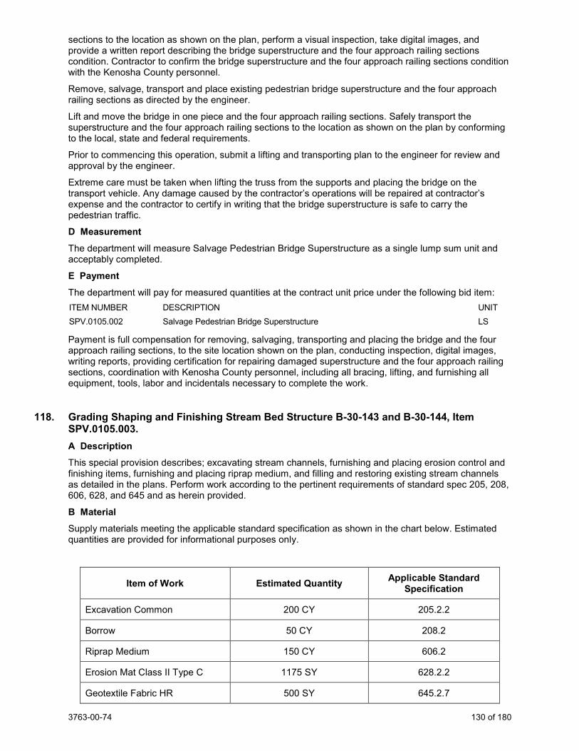
3763-00-74 130 of 180
sections to the location as shown on the plan, perform a visual inspection, take digital images, and provide a written report describing the bridge superstructure and the four approach railing sections condition. Contractor to confirm the bridge superstructure and the four approach railing sections condition with the Kenosha County personnel.
Remove, salvage, transport and place existing pedestrian bridge superstructure and the four approach railing sections as directed by the engineer.
Lift and move the bridge in one piece and the four approach railing sections. Safely transport the superstructure and the four approach railing sections to the location as shown on the plan by conforming to the local, state and federal requirements.
Prior to commencing this operation, submit a lifting and transporting plan to the engineer for review and approval by the engineer.
Extreme care must be taken when lifting the truss from the supports and placing the bridge on the transport vehicle. Any damage caused by the contractor’s operations will be repaired at contractor’s expense and the contractor to certify in writing that the bridge superstructure is safe to carry the pedestrian traffic.
D Measurement The department will measure Salvage Pedestrian Bridge Superstructure as a single lump sum unit and acceptably completed.
E Payment The department will pay for measured quantities at the contract unit price under the following bid item: ITEM NUMBER DESCRIPTION UNIT SPV.0105.002 Salvage Pedestrian Bridge Superstructure LS
Payment is full compensation for removing, salvaging, transporting and placing the bridge and the four approach railing sections, to the site location shown on the plan, conducting inspection, digital images, writing reports, providing certification for repairing damaged superstructure and the four approach railing sections, coordination with Kenosha County personnel, including all bracing, lifting, and furnishing all equipment, tools, labor and incidentals necessary to complete the work.
118. Grading Shaping and Finishing Stream Bed Structure B-30-143 and B-30-144, Item SPV.0105.003. A Description This special provision describes; excavating stream channels, furnishing and placing erosion control and finishing items, furnishing and placing riprap medium, and filling and restoring existing stream channels as detailed in the plans. Perform work according to the pertinent requirements of standard spec 205, 208, 606, 628, and 645 and as herein provided.
B Material Supply materials meeting the applicable standard specification as shown in the chart below. Estimated quantities are provided for informational purposes only.
Item of Work Estimated Quantity Applicable Standard Specification
Excavation Common 200 CY 205.2.2
Borrow 50 CY 208.2
Riprap Medium 150 CY 606.2
Erosion Mat Class II Type C 1175 SY 628.2.2
Geotextile Fabric HR 500 SY 645.2.7
3763-00-74 131 of 180
C Construction Perform work according to the pertinent requirements of standard spec 205, 208, 606, 628, and 645 and as detailed in the plans.
D Measurement The department will measure Grading, Shaping and Finishing Stream Bed, Structure B-30-143 and B-30-144 as a single lump sum unit for all required stream bed work for Structure B-30-143 and 144, acceptably completed.
E Payment The department will pay for measured quantities at the contract unit price under the following bid item:
ITEM NUMBER DESCRIPTION UNIT SPV.0105.003 Grading, Shaping and Finishing Stream Bed Structure B-30-143 and B-30-144 LS
Payment is full compensation for excavating stream channels, furnishing and placing erosion control and finishing items, furnishing and placing riprap medium, and filling and restoring existing stream channels.
119. Pike River Site Restoration, Item SPV.0105.004. A Description This special provision describes; the preparation of seed beds, preparation of salvaged topsoil, creation of uneven surfaces, furnishing and placing of seed, watering, erosion prevention and repairs, and establishment of vegetation over all areas as shown on the Plans, as specified herein.
B Material Seed Mixes
Use only seed native to Wisconsin and purchased from a reliable Wisconsin nursery. All seed and any substitutions must be approved by the WisDOT. Possible sources of seed and plants can be found at the WDNR WI Native Plant Nurseries webpage link: https://dnr.wi.gov/files/pdf/pubs/er/er0698.pdf
Additional information about native planting can be found at this DNR webpage link: https://dnr.wi.gov/topic/endangeredresources/nativeplants.html
C Construction 1. Site Preparation and Seeding Methods.
a. Conform seeding with supplier certifications or standard spec 630.
b. For wetland and prairie seed mix areas, amend standard spec 630.3.2(2) to read as follows:
i. "After spreading topsoil and just before seeding, break up the subsoil in the area to be seeded to a minimum depth of 12 inches, then work the area with discs, harrows, or other appropriate equipment, including dragging if required, to obtain a reasonably even, loose, and level seedbed."
c. Free the planting area of weeds prior to seeding. If weeds are present, particularly in areas where no grading that has taken place, treat the site with a glyphosate-based herbicide (i.e., Roundup) and lightly tilled (no more than 4 inches in depth) 10 to 20 days later. If a large weed seed bank is predicted, the weeds can be allowed to grow, and a second treatment of herbicide and follow-up tilling can be performed. Plant the native seed in such a manner to make good soil contact. Sowing options include no-till methods such as using a Brillion seeder, or Truex drill, or broadcast spreading followed by dragging a harrow over the seeded area. Do not apply fertilizers. In wetter areas, hand seeding followed by hand raking or using a small harrow may be more practical.
d. All disturbed areas restored with other than rural seed mix shall be erosion matted unless otherwise noted on the Plans. All disturbed areas restored with rural seed mix shall be mulched, unless otherwise noted on the Plans.
e. Contractor to furnish all empty seed bags to WisDOT.
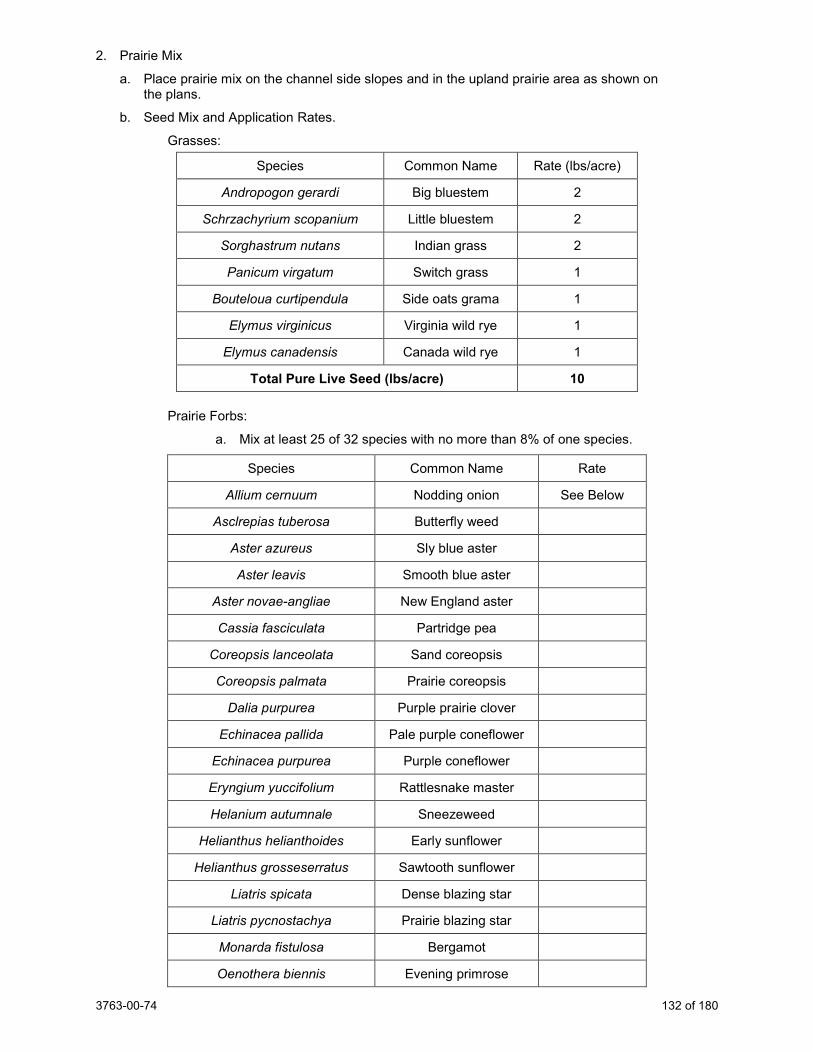
3763-00-74 132 of 180
2. Prairie Mix
a. Place prairie mix on the channel side slopes and in the upland prairie area as shown on the plans.
b. Seed Mix and Application Rates.
Grasses:
Species Common Name Rate (lbs/acre)
Andropogon gerardi Big bluestem 2
Schrzachyrium scopanium Little bluestem 2
Sorghastrum nutans Indian grass 2
Panicum virgatum Switch grass 1
Bouteloua curtipendula Side oats grama 1
Elymus virginicus Virginia wild rye 1
Elymus canadensis Canada wild rye 1
Total Pure Live Seed (lbs/acre) 10
Prairie Forbs:
a. Mix at least 25 of 32 species with no more than 8% of one species.
Species Common Name Rate
Allium cernuum Nodding onion See Below
Asclrepias tuberosa Butterfly weed
Aster azureus Sly blue aster
Aster leavis Smooth blue aster
Aster novae-angliae New England aster
Cassia fasciculata Partridge pea
Coreopsis lanceolata Sand coreopsis
Coreopsis palmata Prairie coreopsis
Dalia purpurea Purple prairie clover
Echinacea pallida Pale purple coneflower
Echinacea purpurea Purple coneflower
Eryngium yuccifolium Rattlesnake master
Helanium autumnale Sneezeweed
Helianthus helianthoides Early sunflower
Helianthus grosseserratus Sawtooth sunflower
Liatris spicata Dense blazing star
Liatris pycnostachya Prairie blazing star
Monarda fistulosa Bergamot
Oenothera biennis Evening primrose
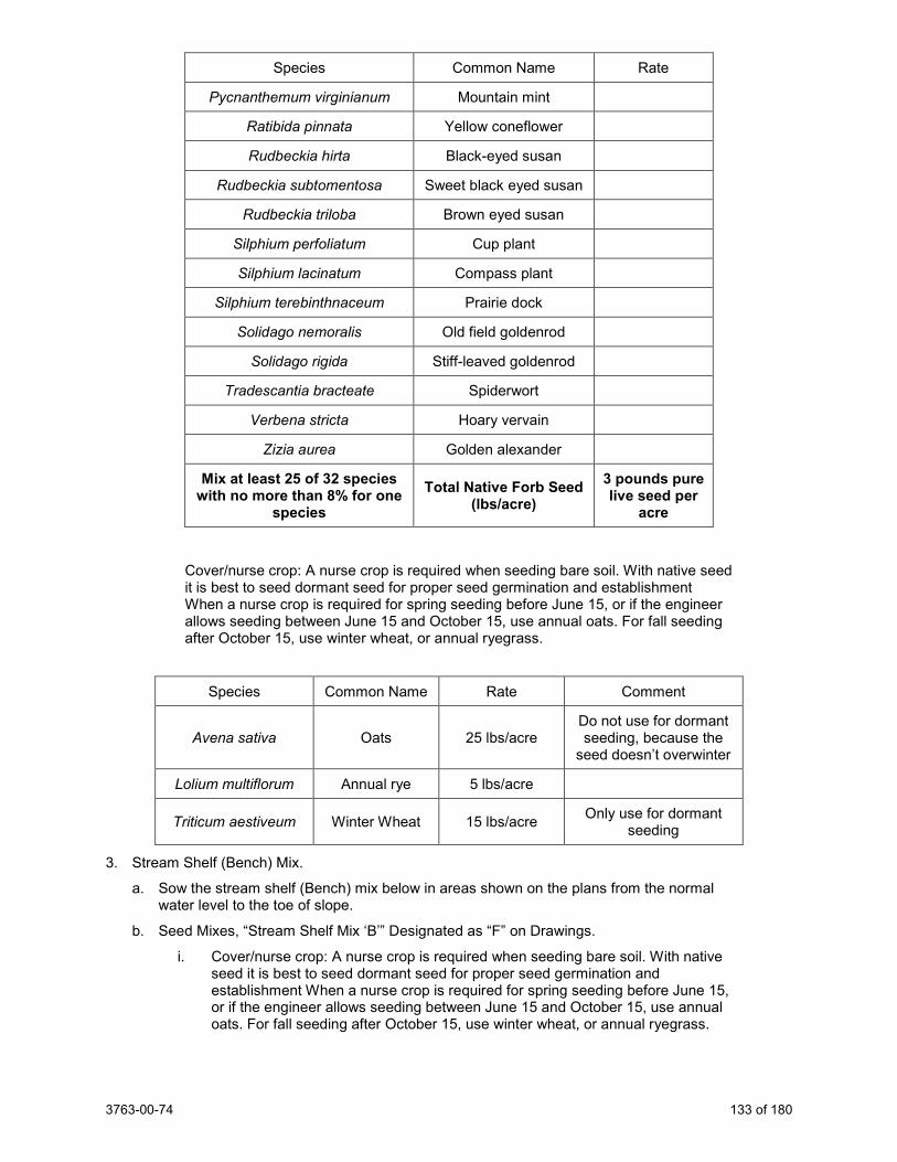
3763-00-74 133 of 180
Species Common Name Rate
Pycnanthemum virginianum Mountain mint
Ratibida pinnata Yellow coneflower
Rudbeckia hirta Black-eyed susan
Rudbeckia subtomentosa Sweet black eyed susan
Rudbeckia triloba Brown eyed susan
Silphium perfoliatum Cup plant
Silphium lacinatum Compass plant
Silphium terebinthnaceum Prairie dock
Solidago nemoralis Old field goldenrod
Solidago rigida Stiff-leaved goldenrod
Tradescantia bracteate Spiderwort
Verbena stricta Hoary vervain
Zizia aurea Golden alexander
Mix at least 25 of 32 species with no more than 8% for one
species Total Native Forb Seed
(lbs/acre) 3 pounds pure live seed per
acre
Cover/nurse crop: A nurse crop is required when seeding bare soil. With native seed it is best to seed dormant seed for proper seed germination and establishment When a nurse crop is required for spring seeding before June 15, or if the engineer allows seeding between June 15 and October 15, use annual oats. For fall seeding after October 15, use winter wheat, or annual ryegrass.
Species Common Name Rate Comment
Avena sativa Oats 25 lbs/acre Do not use for dormant seeding, because the
seed doesn’t overwinter
Lolium multiflorum Annual rye 5 lbs/acre
Triticum aestiveum Winter Wheat 15 lbs/acre Only use for dormant seeding
3. Stream Shelf (Bench) Mix.
a. Sow the stream shelf (Bench) mix below in areas shown on the plans from the normal water level to the toe of slope.
b. Seed Mixes, “Stream Shelf Mix ‘B’” Designated as “F” on Drawings.
i. Cover/nurse crop: A nurse crop is required when seeding bare soil. With native seed it is best to seed dormant seed for proper seed germination and establishment When a nurse crop is required for spring seeding before June 15, or if the engineer allows seeding between June 15 and October 15, use annual oats. For fall seeding after October 15, use winter wheat, or annual ryegrass.
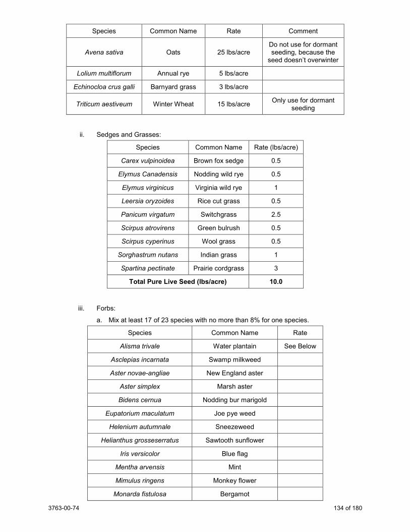
3763-00-74 134 of 180
Species Common Name Rate Comment
Avena sativa Oats 25 lbs/acre Do not use for dormant seeding, because the
seed doesn’t overwinter
Lolium multiflorum Annual rye 5 lbs/acre
Echinocloa crus galli Barnyard grass 3 lbs/acre
Triticum aestiveum Winter Wheat 15 lbs/acre Only use for dormant seeding
ii. Sedges and Grasses:
Species Common Name Rate (lbs/acre)
Carex vulpinoidea Brown fox sedge 0.5
Elymus Canadensis Nodding wild rye 0.5
Elymus virginicus Virginia wild rye 1
Leersia oryzoides Rice cut grass 0.5
Panicum virgatum Switchgrass 2.5
Scirpus atrovirens Green bulrush 0.5
Scirpus cyperinus Wool grass 0.5
Sorghastrum nutans Indian grass 1
Spartina pectinate Prairie cordgrass 3
Total Pure Live Seed (lbs/acre) 10.0
iii. Forbs:
a. Mix at least 17 of 23 species with no more than 8% for one species.
Species Common Name Rate
Alisma trivale Water plantain See Below
Asclepias incarnata Swamp milkweed
Aster novae-angliae New England aster
Aster simplex Marsh aster
Bidens cernua Nodding bur marigold
Eupatorium maculatum Joe pye weed
Helenium autumnale Sneezeweed
Helianthus grosseserratus Sawtooth sunflower
Iris versicolor Blue flag
Mentha arvensis Mint
Mimulus ringens Monkey flower
Monarda fistulosa Bergamot
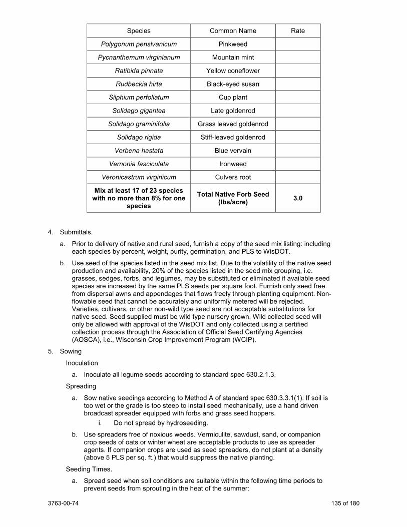
3763-00-74 135 of 180
Species Common Name Rate
Polygonum penslvanicum Pinkweed
Pycnanthemum virginianum Mountain mint
Ratibida pinnata Yellow coneflower
Rudbeckia hirta Black-eyed susan
Silphium perfoliatum Cup plant
Solidago gigantea Late goldenrod
Solidago graminifolia Grass leaved goldenrod
Solidago rigida Stiff-leaved goldenrod
Verbena hastata Blue vervain
Vernonia fasciculata Ironweed
Veronicastrum virginicum Culvers root
Mix at least 17 of 23 species with no more than 8% for one
species Total Native Forb Seed
(lbs/acre) 3.0
4. Submittals.
a. Prior to delivery of native and rural seed, furnish a copy of the seed mix listing: including each species by percent, weight, purity, germination, and PLS to WisDOT.
b. Use seed of the species listed in the seed mix list. Due to the volatility of the native seed production and availability, 20% of the species listed in the seed mix grouping, i.e. grasses, sedges, forbs, and legumes, may be substituted or eliminated if available seed species are increased by the same PLS seeds per square foot. Furnish only seed free from dispersal awns and appendages that flows freely through planting equipment. Non-flowable seed that cannot be accurately and uniformly metered will be rejected. Varieties, cultivars, or other non-wild type seed are not acceptable substitutions for native seed. Seed supplied must be wild type nursery grown. Wild collected seed will only be allowed with approval of the WisDOT and only collected using a certified collection process through the Association of Official Seed Certifying Agencies (AOSCA), i.e., Wisconsin Crop Improvement Program (WCIP).
5. Sowing
Inoculation
a. Inoculate all legume seeds according to standard spec 630.2.1.3.
Spreading
a. Sow native seedings according to Method A of standard spec 630.3.3.1(1). If soil is too wet or the grade is too steep to install seed mechanically, use a hand driven broadcast spreader equipped with forbs and grass seed hoppers.
i. Do not spread by hydroseeding.
b. Use spreaders free of noxious weeds. Vermiculite, sawdust, sand, or companion crop seeds of oats or winter wheat are acceptable products to use as spreader agents. If companion crops are used as seed spreaders, do not plant at a density (above 5 PLS per sq. ft.) that would suppress the native planting.
Seeding Times.
a. Spread seed when soil conditions are suitable within the following time periods to prevent seeds from sprouting in the heat of the summer:
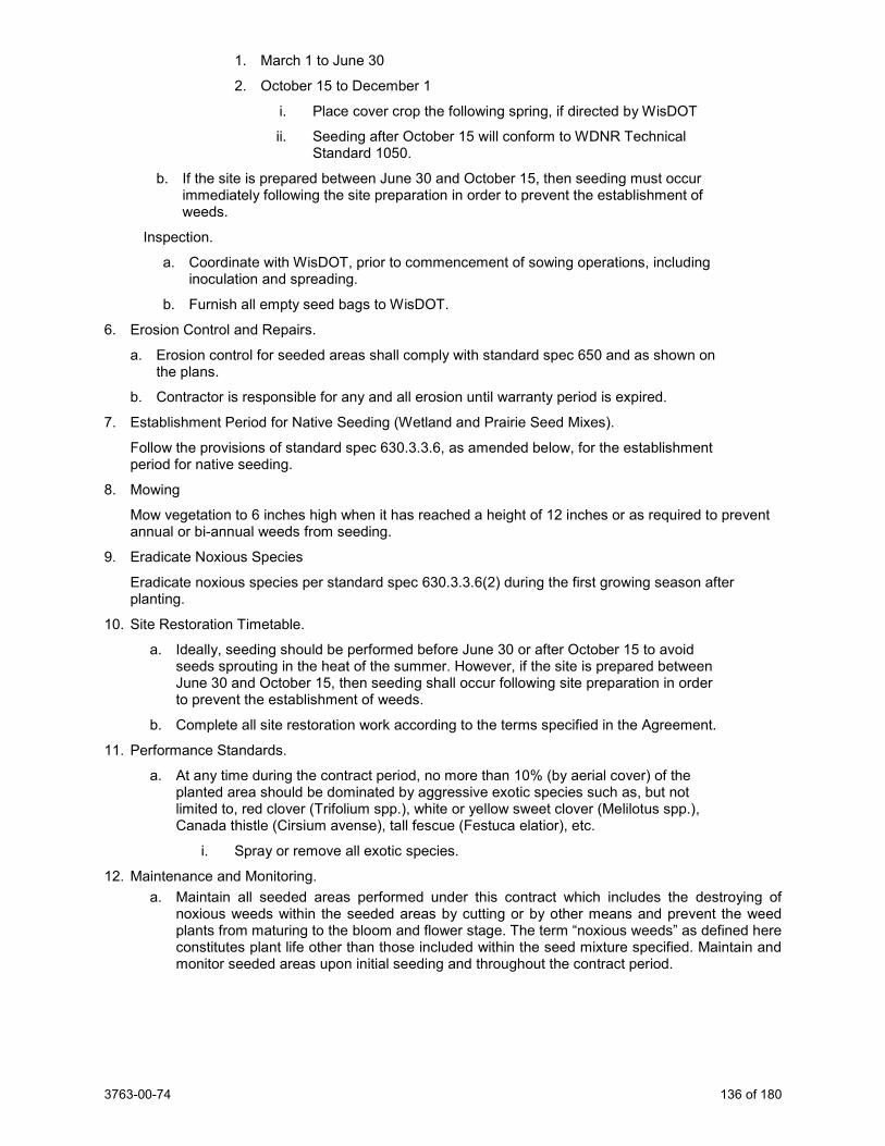
3763-00-74 136 of 180
1. March 1 to June 30
2. October 15 to December 1
i. Place cover crop the following spring, if directed by WisDOT
ii. Seeding after October 15 will conform to WDNR Technical Standard 1050.
b. If the site is prepared between June 30 and October 15, then seeding must occur immediately following the site preparation in order to prevent the establishment of weeds.
Inspection.
a. Coordinate with WisDOT, prior to commencement of sowing operations, including inoculation and spreading.
b. Furnish all empty seed bags to WisDOT.
6. Erosion Control and Repairs.
a. Erosion control for seeded areas shall comply with standard spec 650 and as shown on the plans.
b. Contractor is responsible for any and all erosion until warranty period is expired.
7. Establishment Period for Native Seeding (Wetland and Prairie Seed Mixes).
Follow the provisions of standard spec 630.3.3.6, as amended below, for the establishment period for native seeding.
8. Mowing
Mow vegetation to 6 inches high when it has reached a height of 12 inches or as required to prevent annual or bi-annual weeds from seeding.
9. Eradicate Noxious Species
Eradicate noxious species per standard spec 630.3.3.6(2) during the first growing season after planting.
10. Site Restoration Timetable.
a. Ideally, seeding should be performed before June 30 or after October 15 to avoid seeds sprouting in the heat of the summer. However, if the site is prepared between June 30 and October 15, then seeding shall occur following site preparation in order to prevent the establishment of weeds.
b. Complete all site restoration work according to the terms specified in the Agreement.
11. Performance Standards.
a. At any time during the contract period, no more than 10% (by aerial cover) of the planted area should be dominated by aggressive exotic species such as, but not limited to, red clover (Trifolium spp.), white or yellow sweet clover (Melilotus spp.), Canada thistle (Cirsium avense), tall fescue (Festuca elatior), etc.
i. Spray or remove all exotic species.
12. Maintenance and Monitoring. a. Maintain all seeded areas performed under this contract which includes the destroying of
noxious weeds within the seeded areas by cutting or by other means and prevent the weed plants from maturing to the bloom and flower stage. The term “noxious weeds” as defined here constitutes plant life other than those included within the seed mixture specified. Maintain and monitor seeded areas upon initial seeding and throughout the contract period.
3763-00-74 137 of 180
b. Plant Maintenance.
i. Maintenance will begin immediately after seeding and will continue through the contract period.
ii. Maintain seeded areas by weeding, hand-pulling, and/or herbicide applications. Herbicide treatments will be performed by licensed applicators who are experienced with native and non-native plant identification. Use herbicides in full conformance with label requirements and application techniques that will limit overspray and damage to off-target species. Maintain all plants through the guarantee period.
13. Final Acceptance.
a. All restored areas shall exhibit no bare areas exceeding 2 square feet in area or up to 10 percent of the entire restoration areas.
b. Final acceptance will be granted upon WisDOT and DNR approval of satisfactory vegetation establishment and verification that disturbed areas are fully stabilized to prevent soil erosion. “Fully Stabilized” means that all land disturbing construction activities at the construction site have been completed and that a uniform, perennial, vegetative cover has been established, with a density of at least 80% of the cover.
D Measurement The department will measure Pike River Site Restoration as a single lump sum unit, acceptably completed.
E Payment The department will pay for measured quantities at the contract unit price under the following bid item: ITEM NUMBER DESCRIPTION UNIT SPV.0105.004 Pike River Site Restoration LS
Payment is full compensation for preparation of seed beds, preparation of salvaged topsoil, creation of uneven surfaces, furnishing and placing of seed, watering, erosion prevention and repairs, submittals, mowing, maintenance, and monitoring.
120. Geotechnical Instrumentation Data Collection, Item SPV.0105.005. A Description A.1 General This special provision describes geotechnical instrumentation data collection for the project for the purpose of monitoring ground movement in the vicinity of structures and nearby adjacent property and movement during construction of the retaining wall and embankments. The instrumentation program specified herein and shown on the plans is not intended to be used to ensure the safety of the work.
Collect the required ground monitoring data as specified herein. The instrumentation program required by this article does not relieve the contractor of responsibility for providing additional instrumentation and monitoring if, in the contractor's opinion, such additional instrumentation and monitoring are necessary to accomplish the work.
This article covers the work necessary to maintaining installed instruments, taking initial and subsequent instrument readings, and removal and abandonment, if necessary, of the instruments after construction.
A.2 Submittals Submit the following specific information for information only, at least 30 days prior to the start of instrument installation, except submit copies of DNR forms as soon as possible after instruments are installed or abandoned:
1. Submit qualifications and experience of instrumentation specialists and personnel. 2. Instrumentation shop drawings detailing locations, depths based on general information shown on
the plans, type, details, and other pertinent information showing the installation details for each type of instrumentation required.
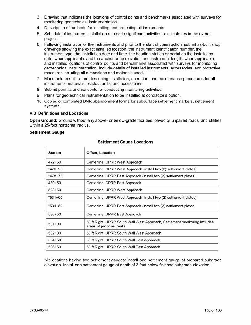
3763-00-74 138 of 180
3. Drawing that indicates the locations of control points and benchmarks associated with surveys for monitoring geotechnical instrumentation.
4. Description of methods for installing and protecting all instruments. 5. Schedule of instrument installation related to significant activities or milestones in the overall
project. 6. Following installation of the instruments and prior to the start of construction, submit as-built shop
drawings showing the exact installed location, the instrument identification number, the instrument type, the installation date and time, the heading station or portal on the installation date, when applicable, and the anchor or tip elevation and instrument length, when applicable, and installed locations of control points and benchmarks associated with surveys for monitoring geotechnical instrumentation. Include details of installed instruments, accessories, and protective measures including all dimensions and materials used.
7. Manufacturer's literature describing installation, operation, and maintenance procedures for all instruments, materials, readout units, and accessories.
8. Submit permits and consents for conducting monitoring activities. 9. Plans for geotechnical instrumentation to be installed at contractor’s option. 10. Copies of completed DNR abandonment forms for subsurface settlement markers, settlement
systems.
A.3 Definitions and Locations Open Ground: Ground without any above- or below-grade facilities, paved or unpaved roads, and utilities within a 25-foot horizontal radius.
Settlement Gauge
Settlement Gauge Locations
Station Offset, Location
472+50 Centerline, CPRR West Approach
*476+25 Centerline, CPRR West Approach (install two (2) settlement plates)
*478+75 Centerline, CPRR East Approach (install two (2) settlement plates)
480+50 Centerline, CPRR East Approach
528+50 Centerline, UPRR West Approach
*531+00 Centerline, UPRR West Approach (install two (2) settlement plates)
*534+50 Centerline, UPRR East Approach (install two (2) settlement plates)
536+50 Centerline, UPRR East Approach
531+00 50 ft Right, UPRR South Wall West Approach, Settlement monitoring includes areas of proposed walls
532+00 50 ft Right, UPRR South Wall West Approach
534+50 50 ft Right, UPRR South Wall East Approach
536+50 50 ft Right, UPRR South Wall East Approach
*At locations having two settlement gauges: install one settlement gauge at prepared subgrade elevation. Install one settlement gauge at depth of 3 feet below finished subgrade elevation.
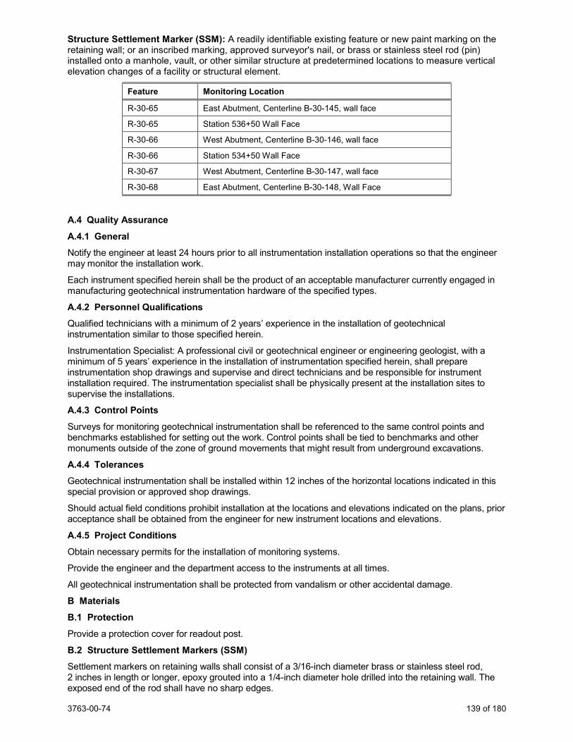
3763-00-74 139 of 180
Structure Settlement Marker (SSM): A readily identifiable existing feature or new paint marking on the retaining wall; or an inscribed marking, approved surveyor's nail, or brass or stainless steel rod (pin) installed onto a manhole, vault, or other similar structure at predetermined locations to measure vertical elevation changes of a facility or structural element.
Feature Monitoring Location
R-30-65 East Abutment, Centerline B-30-145, wall face
R-30-65 Station 536+50 Wall Face
R-30-66 West Abutment, Centerline B-30-146, wall face
R-30-66 Station 534+50 Wall Face
R-30-67 West Abutment, Centerline B-30-147, wall face
R-30-68 East Abutment, Centerline B-30-148, Wall Face
A.4 Quality Assurance A.4.1 General Notify the engineer at least 24 hours prior to all instrumentation installation operations so that the engineer may monitor the installation work.
Each instrument specified herein shall be the product of an acceptable manufacturer currently engaged in manufacturing geotechnical instrumentation hardware of the specified types.
A.4.2 Personnel Qualifications Qualified technicians with a minimum of 2 years’ experience in the installation of geotechnical instrumentation similar to those specified herein.
Instrumentation Specialist: A professional civil or geotechnical engineer or engineering geologist, with a minimum of 5 years’ experience in the installation of instrumentation specified herein, shall prepare instrumentation shop drawings and supervise and direct technicians and be responsible for instrument installation required. The instrumentation specialist shall be physically present at the installation sites to supervise the installations.
A.4.3 Control Points Surveys for monitoring geotechnical instrumentation shall be referenced to the same control points and benchmarks established for setting out the work. Control points shall be tied to benchmarks and other monuments outside of the zone of ground movements that might result from underground excavations.
A.4.4 Tolerances Geotechnical instrumentation shall be installed within 12 inches of the horizontal locations indicated in this special provision or approved shop drawings.
Should actual field conditions prohibit installation at the locations and elevations indicated on the plans, prior acceptance shall be obtained from the engineer for new instrument locations and elevations.
A.4.5 Project Conditions Obtain necessary permits for the installation of monitoring systems.
Provide the engineer and the department access to the instruments at all times.
All geotechnical instrumentation shall be protected from vandalism or other accidental damage.
B Materials B.1 Protection
Provide a protection cover for readout post.
B.2 Structure Settlement Markers (SSM) Settlement markers on retaining walls shall consist of a 3/16-inch diameter brass or stainless steel rod, 2 inches in length or longer, epoxy grouted into a 1/4-inch diameter hole drilled into the retaining wall. The exposed end of the rod shall have no sharp edges.
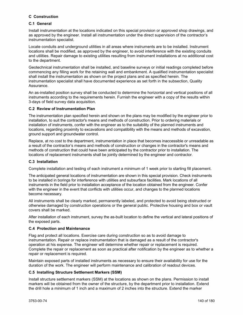
3763-00-74 140 of 180
C Construction C.1 General Install instrumentation at the locations indicated on this special provision or approved shop drawings, and as approved by the engineer. Install all instrumentation under the direct supervision of the contractor’s instrumentation specialist.
Locate conduits and underground utilities in all areas where instruments are to be installed. Instrument locations shall be modified, as approved by the engineer, to avoid interference with the existing conduits and utilities. Repair damage to existing utilities resulting from instrument installations at no additional cost to the department.
Geotechnical instrumentation shall be installed, and baseline surveys or initial readings completed before commencing any filling work for the retaining wall and embankment. A qualified instrumentation specialist shall install the instrumentation as shown on the project plans and as specified herein. The instrumentation specialist shall have documented experience as set forth in the subsection, Quality Assurance.
An as-installed position survey shall be conducted to determine the horizontal and vertical positions of all instruments according to the requirements herein. Furnish the engineer with a copy of the results within 3-days of field survey data acquisition.
C.2 Review of Instrumentation Plan The instrumentation plan specified herein and shown on the plans may be modified by the engineer prior to installation, to suit the contractor's means and methods of construction. Prior to ordering materials or installation of instruments, confer with the engineer as to the suitability of the planned instruments and locations, regarding proximity to excavations and compatibility with the means and methods of excavation, ground support and groundwater control.
Replace, at no cost to the department, instrumentation in place that becomes inaccessible or unreadable as a result of the contractor’s means and methods of construction or changes in the contractor's means and methods of construction that could have been anticipated by the contractor prior to installation. The locations of replacement instruments shall be jointly determined by the engineer and contractor.
C.3 Installation
Complete installation and testing of each instrument a minimum of 1 week prior to starting fill placement.
The anticipated general locations of instrumentation are shown in this special provision. Check instruments to be installed in borings for interference with utilities and subsurface facilities. Mark locations of all instruments in the field prior to installation acceptance of the location obtained from the engineer. Confer with the engineer in the event that conflicts with utilities occur, and changes to the planned locations become necessary.
All instruments shall be clearly marked, permanently labeled, and protected to avoid being obstructed or otherwise damaged by construction operations or the general public. Protective housing and box or vault covers shall be marked.
After installation of each instrument, survey the as-built location to define the vertical and lateral positions of the exposed parts.
C.4 Protection and Maintenance Flag and protect all locations. Exercise care during construction so as to avoid damage to instrumentation. Repair or replace instrumentation that is damaged as a result of the contractor's operation at his expense. The engineer will determine whether repair or replacement is required. Complete the repair or replacement as soon as practical after notification by the engineer as to whether a repair or replacement is required.
Maintain exposed parts of installed instruments as necessary to ensure their availability for use for the duration of the work. The engineer will perform maintenance and calibration of readout devices.
C.5 Installing Structure Settlement Markers (SSM) Install structure settlement markers (SSM) at the locations as shown on the plans. Permission to install markers will be obtained from the owner of the structure, by the department prior to installation. Extend the drill hole a minimum of 1 inch and a maximum of 2 inches into the structure. Extend the marker
3763-00-74 141 of 180
1/2 inch from the face of the structure, or the minimum distance necessary to allow vertical positioning of an optical survey level rod. Install the marker so as not to damage the surface finish of the structure.
C.6 Schedule of Instruments Installed For the retaining wall, install instruments of the number and type, at the location and to the depths indicated on this special provision.
C.7 Initial Readings Record initial readings for each instrument before construction of the retaining wall and embankment. Notify the engineer when initial readings will be made, and the engineer may elect to participate or observe in taking initial readings.
Record initial readings of settlement markers a minimum of 24 hours after completing each settlement marker installation and prior to any fill placement. Obtain a minimum of two readings. The arithmetic average of the two initial recorded data readings will be recorded as the initial baseline reading.
C.8 Monitoring Instruments Obtain and record data readings at regular intervals as specified herein. Submit any newly obtained recorded data to the engineer within 24 hours of obtaining new readings.
After initial readings, obtain and record subsequent regular data readings at each structure or embankment area on regular intervals based on the following criteria:
1. Prior to retaining wall and embankment construction: Record a minimum of one reading per week per instrument.
2. During retaining wall and embankment construction: Record one reading per instrument for every 5 feet of vertical retaining wall and embankment
construction or at least every day, whichever is the shorter interval. 3. After retaining wall and embankment construction is completed:
Record a minimum of one reading per instrument every three days for the first month and once per week thereafter, unless directed otherwise by the engineer.
4. Obtain weekly readings from all settlement markers for a minimum of two months after retaining wall and embankment backfill placement is complete and until readings indicate further monitoring is not necessary.
Based on evaluation of the data collected, the engineer will determine if continued instrumentation readings are necessary. If additional readings are necessary, the readings will be obtained by the engineer.
C.9 Abandonment of Instrumentation
At the completion of the job or as directed by the engineer, abandon or remove instrumentation. Grout the full depth of instrument casings and pipes by tremie method or by pressure injection from the ground surface. Grout shall consist of cement and water, with the minimum amount of water necessary to allow pumping.
C.10 Protection Protect instrumentation and terminal boxes from damage as a result of construction activity. Replace any instrumentation and terminal boxes at the contractor costs. Extend existing settlement gauges as part of this work.
D Measurement The department will measure Geotechnical Instrumentation as a complete single unit of work on a lump sum basis, acceptably completed.
E Payment The department will pay for measured quantities at the contract unit price under the following bid item: ITEM NUMBER DESCRIPTION UNIT SPV.0105.007 Geotechnical Instrumentation LS
Payment is full compensation for providing submittals, furnishing materials, installation, testing, protection, maintenance, replacement or repair of damaged instruments or installations, obtaining data readings, and abandonment.
3763-00-74 142 of 180
Settlement gauges are paid under a separate bid item.
121. Transporting and Installing State Furnished EVP Detector Heads with Confirmation Beacons CTH KR & STH 31, Item SPV.0105.301; Transporting and Installing State Furnished EVP Detector Heads with Confirmation Beacons CTH KR & Old Green Bay Road, Item SPV.0105.302; Transporting and Installing State Furnished EVP Detector Heads with Confirmation Beacons CTH KR & 90th Street/72nd Avenue, Item SPV.0105.303; Transporting and Installing State Furnished EVP Detector Heads with Confirmation Beacons CTH A at CTH H, Item SPV.0105.304. A Description This special provision describes transporting and installing department furnished Emergency Vehicle Preemption (EVP) Detector Heads, Confirmation Beacons and mounting brackets as the plans show and as follows.
B Materials Pick up the department furnished materials at the department’s Electrical Shop located at 935 South 60th Street, West Allis. Notify the department’s Electrical Field Unit at (414) 266-1170 and make arrangements for picking up the department furnished materials five working days prior to picking the materials up.
C Construction Install the EVP detector heads and confirmation beacons as shown on the plans. The department will determine the exact location to ensure that the installation does not create a sight obstruction. Mount the EVP detector heads and wire them per manufacturer instructions. Mount the confirmation beacons. For a cabinet that is not operating the signal, the contractor will terminate the ends and install the discriminators and card rack in the cabinet. If the cabinet is operating the signal, the cabinet wiring will be done by the department.
Notify the department’s Electrical shop at (414) 266-1170 upon completion of the installation of the Emergency Vehicle Preemption (EVP) Detector Heads with Confirmation Beacons.
D Measurement The department will measure Transporting and Installing State Furnished EVP Detector Heads with Confirmation Beacons [Location] as a single lump sum unit and acceptably completed.
E Payment The department will pay for measured quantities at the contract unit price under the following bid item: ITEM NUMBER DESCRIPTION UNIT SPV.0105.301 Transporting and Installing State Furnished EVP Detector Heads with
Confirmation Beacons CTH KR & STH 31 LS
SPV.0105.302 Transporting and Installing State Furnished EVP Detector Heads with Confirmation Beacons CTH KR & Old Green Bay Road
LS
SPV.0105.303 Transporting and Installing State Furnished EVP Detector Heads with Confirmation Beacons CTH KR & 90th Street/72nd Avenue
LS
SPV.0105.304 Transporting and Installing State Furnished EVP Detector Heads with Confirmation Beacons CTH A & CTH H
LS
Payment is full compensation for transporting and installing department furnished Emergency Vehicle Preemption (EVP) Detector Heads, Confirmation Beacons and mounting brackets.
122. Temporary Radar/Microwave Vehicle Detection System for Intersections CTH KR & STH 31, Item SPV.0105.305; Temporary Radar/Microwave Vehicle Detection System for Intersections, STH 31 & CTH A, Item SPV.0105.352.
3763-00-74 143 of 180
A Description This work shall consist of furnishing, installing, maintaining and placing into operation a temporary radar/microwave vehicle detection system (RMDS) as shown on the plans, and as directed by the engineer in the field.
B Materials This specification sets forth the minimum requirements for a system that detects vehicles on a roadway and provides detection outputs to a traffic signal controller. The materials shall also include all brackets, mounting hardware, cable, terminations, interface panels, and all other incidentals for the installation of the radar/microwave vehicle detection equipment. This equipment shall meet the NEMA environmental, power and surge ratings as set forth in NEMA TS2 specifications.
All detection equipment, components, and terminations supplied under this item shall be fully compatible with the temporary traffic signal controller supplied for the project. The system architecture shall fully support Ethernet networking of system components. All required interface equipment needed for transmitting and receiving data shall be provided with the RMDS.
The RMDS shall provide flexible detection zone placement anywhere and at any orientation. Preferred detector configurations shall be detection zones placed across lanes of traffic for optimal count accuracy, detection zones placed parallel to lanes of traffic for optimal presence detection accuracy of moving or stopped vehicles. Detection zones shall be able to be overlapped for optimal road coverage.
C Construction The temporary RMDS shall be installed by supplier factory-certified installers and as recommended by the supplier and documented in installation materials provided by the supplier.
In the event, at installation or turn on date, a noticeable obstruction is present in line with the detection zone(s), the contractor shall be obligated to advise the engineer before setting the zone.
The radar/microwave vehicle detection system, as shown in the traffic signal construction plans, shall be complete, in place, tested, and in full operation during each stage of construction.
Maintain all temporary radar/microwave detection zones as the plans show or as the engineer directs. The temporary vehicle detection zones shall be set near the vicinity and with approximate distance from the stop bar as shown on the plans. Check temporary vehicle detection zones every other week and at the opening of each stage of temporary traffic signal operation to ensure that they are working properly and aimed properly. Periodic adjustment of the detection zones and/or moving of the temporary vehicle detection sensors will be required due to changes in traffic control, staging, or other construction operations.
Ensure the radar/microwave vehicle detection system stays in clean working order. Periodic cleaning of the equipment may be required due to dirt and dust build-up.
D Measurement The department will measure Temporary Radar/Microwave Vehicle Radar Detection System for Intersections [Location] as a single lump sum unit and accepted.
E Payment The department will pay for measured quantities at the contract unit price under the following bid item: ITEM NUMBER DESCRIPTION UNIT SPV.0105.305 Temporary Radar/Microwave Vehicle Detection System for Intersections
CTH KR & STH 31 LS
SPV.0105.353 Temporary Radar/Microwave Vehicle Detection System for Intersections STH 31 & CTH A
LS
Payment is full compensation for furnishing and installing the temporary radar/microwave vehicle detection system, including cabling, mounting brackets, mounting hardware, terminations, interface panels, testing and set up; for periodic checking and resetting of detection zones; for periodic cleaning for dirt and dust build-up; and for removing all equipment at the completion of the project.
3763-00-74 144 of 180
123. Transporting and Installing State Furnished EVP Radar Detection System CTH A & CTH H, Item SPV.0105.306. A Description This special provision describes the transporting and installing of department furnished EVP Radar Detection System for installation on monotube poles or arms.
B Materials Pick up the department furnished EVP Radar System at the department’s electrical shop located at 935 South 60th Street, West Allis. Notify the department’s electrical field unit (EFU) at (414) 266-1170 to make arrangements for picking up the department furnished materials at least 5 working days prior to material pick-up.
C Construction Contact the EFU at (414) 266-1170 to coordinate the locations of the radar units at least 5 working days prior to installation. Install the department furnished pole/arm mounting brackets, extension arms (if required), and radar units per manufacturer recommendations. Install the power and communication cables to run continuously (without splices) from the traffic signal cabinet to the radar units plus an additional 16-feet in each pull box and an extra 10-feet in the monotube pole handhole. Terminate the ends of the cables, if required, and make all connections to the radar units. The EFU will install all required cabinet equipment in the traffic signal control cabinet. Make all final cable connections in the traffic signal cabinet.
Mark each end of the lead in the traffic signal cabinet and each cable in the monotube handhole to indicate the equipment label (i.e. RA1, RA2, etc.). For a cabinet that is not operating the signal, the contractor will terminate the ends.
Notify department’s Electrical Shop at (414) 266-1170 upon completion of the installation.
The department will provide notification of the radar detection system vendor and provide the vendor’s contact information. Coordinate directly with the department’s radar detection system vendor to arrange for the vendor to program the radar detection system on-site. Notify the department and vendor at least 5 working days prior to the date of programming. Assist the department and vendor with adjusting the radar units during the radar system programming.
D Measurement The department will measure Transporting and Installing State Furnished EVP Radar Detection System as a single lump sum unit of work for each intersection, acceptably completed.
E Payment The department will pay for measured quantities at the contract unit price under the following bid items: ITEM NUMBER DESCRIPTION UNIT SPV.0105.306 Transporting and Installing EVP State Furnished Radar Detection System
CTH A & CTH H LS
Payment is full compensation for transporting and installing the radar detection system, cable, mounting hardware, and radar units; arranging for and providing programming by the vendor; assisting the department and vendor during the radar system programming.
124. Transporting and Installing State Furnished Traffic Signal Cabinet, CTH A & CTH H, Item SPV.0105.307; Transporting and Installing State Furnished Traffic Signal Cabinet CTH KR & STH 31, Item SPV.0105.308; Transporting and Installing State Furnished Traffic Signal Cabinet CTH KR & Old Green Bay Road, Item SPV.0105.309; Transporting and Installing State Furnished Traffic Signal Cabinet CTH KR & 90th Street/72nd Avenue, Item SPV.0105.310; Transporting and Installing State Furnished Traffic Signal Cabinet CTH KR & Trail Crossing, Item SPV.0105.311.
3763-00-74 145 of 180
A Description This special provision describes the transporting and installing the state furnished traffic signal cabinet, signal controller, and other cabinet equipment for traffic signals, and for making the cabinet fully operational as shown in the plans.
B Materials Use materials furnished by the department including: the traffic signal controller and the traffic signal cabinet.
Pick up the state furnished materials at the department’s Electrical Shop located at 935 South 60th Street, West Allis. Notify the department’s Electrical Field Unit at (414) 266-1170 and make arrangements for picking up the state furnished materials five (5) working days prior to picking up the materials.
Provide all other needed materials in conformance with standard spec 651.2, 652.2, 653.2, 654.2, 655.2, 656.2, 657.2, 658.2 and 659.2.
C Construction Perform work according to standard spec 651.3, 652.3, 653.3, 654.3, 655.3, 656.3, 657.3, 658.3 and 659.3 except as specified below.
Install the state furnished traffic signal cabinet on the concrete control cabinet base the same day it is delivered to the site location.
Request a signal inspection of the completed signal installation to the project engineer at least five (5) working days prior to the time of the requested inspection. The department’s Region Electrical personnel will perform the inspection.
Coordinate directly with the department’s traffic signal cabinet vendor {TAPCO at (262) 814-7327 or [email protected] / TCC at (651) 439-1737 or mallwood@trafficcontrolcorp} to schedule the cabinet acceptance testing. Coordinate with the department’s Electrical Field Unit (414) 266-1170 to participate in the acceptance testing. The department has final determination of the cabinet acceptance testing date and time.
D Measurement The department will measure Transporting and Installing State Furnished Traffic Signal Cabinet as a single lump sum unit of work, acceptably completed.
E Payment The department will pay for measured quantities at the contract unit price under the following bid items: ITEM NUMBER DESCRIPTION UNIT SPV.0105.307 Transporting and Installing State Furnished Traffic Signal Cabinet, CTH A & CTH H LS SPV.0105.308 Transporting and Installing State Furnished Traffic Signal Cabinet, CTH KR & STH 31 LS SPV.0105.309 Transporting and Installing State Furnished Traffic Signal Cabinet, CTH KR & Old
Green Bay Road LS
SPV.0105.310 Transporting and Installing State Furnished Traffic Signal Cabinet, CTH KR & 90th Street/72nd Avenue
LS
SPV.0105.311 Transporting and Installing State Furnished Traffic Signal Cabinet, CTH KR & Trail Crossing
LS
Payment is full compensation for installing and testing the Traffic Signal Cabinet and cabinet equipment; for furnishing and installing all other items necessary (such as, wire nuts, splice kits and/or connectors, tape, insulating varnish, ground lug fasteners, etc.) to make the proposed system complete from the source of supply to the most remote unit; and for clean-up and waste disposal.
125. Temporary Infrared EVP System, CTH KR & STH 31, Item SPV.0105.312; Temporary Infrared EVP System, STH 31 & CTH A, Item SPV.0105.351. A Description This special provision describes furnishing, installing, maintaining and maintaining temporary infrared EVP systems with confirmation lights at the temporary signalized intersection as shown in the plans.
3763-00-74 146 of 180
B Materials Furnish an infrared emergency vehicle preemption system with confirmation lights compatible with the local municipal systems and users.
C Construction The temporary infrared EVP system with confirmation lights, as shown in the temporary traffic signal plans or as directed by the engineer, shall be complete in place, tested, and in full operation during each stage and sub-stage of construction.
Install the temporary infrared EVP system with confirmation lights as shown in the plans and according to the manufacturer’s recommendations. Detectors and lights may be mounted on the temporary traffic signal span wire or wood poles. It shall be the contractor’s responsibility to relocate the temporary infrared EVP detectors and lights to a suitable location if there is impedance on the sensor operation. Arrange for testing of equipment prior to acceptance of the installation for each construction stage.
All cables associated with the temporary infrared EVP system with confirmation lights shall be routed to the cabinet. Each lead shall be appropriately marked as to which EVP channel it is associated.
Periodic adjustment and/or moving of the temporary infrared EVP detectors and confirmation lights may be required due to changes in traffic control, staging, or other construction operations.
Ensure that the temporary infrared EVP system and confirmation lights stay in clean working order. Periodic cleaning of the equipment may be required due to dirt and dust build-up.
Remove the temporary EVP system upon project completion.
Provide the engineer records of all EVP settings used during construction.
The temporary EVP system with confirmation lights may not be used for the permanent installation.
D Measurement The department will measure Temporary Infrared EVP System, furnished, installed, and completely operational, as a single complete unit of work per intersection, complete in place and accepted.
E Payment The department will pay for measured quantities at the contract unit price under the following bid items: ITEM NUMBER DESCRIPTION UNIT SPV.0105.312 Temporary Infrared EVP System, CTH KR & STH 31 LS SPV.0105.351 Temporary Infrared EVP System, STH 31 & CTH A LS
Payment is full compensation for furnishing and installing all required equipment, materials, and supplies; for maintaining and changing the EVP detectors and confirmation lights to match the plans, traffic control, and construction staging; for relocating the temporary EVP detectors and confirmation lights due to construction activities, if required; for testing the EVP system with confirmation lights for each stage and sub-stage of construction; for periodically cleaning all temporary EVP detectors and confirmation lights; for cleaning up and properly disposing of waste; and incidentals necessary to complete the contract work.
126. Pedestrian Hybrid Beacon, CTH KR & Trail Crossing, Item SPV.0105.313. A Description This special provision describes the furnishing and installation of a Pedestrian Hybrid Beacon including 3-section signal faces, backplates, and all other necessary items not otherwise itemized.
B Materials Pedestrian Hybrid Beacons shall be assembled according to standard spec 658 and the project plans.
C Construction All work shall be according to the standard specifications, these special provisions, and the project plans.
D Measurement Pedestrian Hybrid Beacon will be measured as each individual unit, acceptably completed.
3763-00-74 147 of 180
E Payment The department will pay for measured quantities at the contract unit price under the following bid items: ITEM NUMBER DESCRIPTION UNIT SPV.0105.313 Pedestrian Hybrid Beacon, CTH KR & Trail Crossing LS
Payment is full compensation for furnishing and installing all necessary hardware and fittings.
127. Transporting and Installing State Furnished APS Pedestrian Pushbutton System CTH KR & Trail Crossing, Item SPV.0105.314. A Description This special provision describes the transporting and installing of department furnished APS Pedestrian Pushbuttons and control units.
B Materials Pick up the department furnished equipment at the department’s electrical shop located at 935 South 60th Street, West Allis. Notify the department’s electrical field unit (EFU) at (414) 266-1170 to make arrangements for picking up the department furnished materials at least 5 working days prior to material pick-up.
C Construction Perform work according to standard spec 658. The contractor is responsible for programming the units.
D Measurement The department will measure Transporting and Installing State Furnished APD Pedestrian Pushbutton System as a single lump sum unit of work for each intersection, acceptably completed.
E Payment The department will pay for measured quantities at the contract unit price under the following bid items: ITEM NUMBER DESCRIPTION UNIT SPV.0105.314 Transporting and Installing State Furnished APS Pedestrian Pushbutton
System CTH KR & Trail Crossing LS
Payment is full compensation for transporting and installing the radar detection system, cable, mounting hardware, and radar units; arranging for and providing programming by the vendor; assisting the department and vendor during the radar system programming.
128. Patch Panel With Fiber Optic Cable Pigtail 8-CT CTH KR & 90th St / 72nd Ave, Item SPV.0105.340; Patch Panel With Fiber Optic Cable Pigtail 8-CT STH 31 & CTH KR, Item SPV.0105.341; Patch Panel With Fiber Optic Cable Pigtail 8-CT CTH KR & Old Green Bay Rd, Item SPV.0105.342; Patch Panel With Fiber Optic Cable Pigtail 8-CT CTH KR & Pedestrian Hybrid Beacon, Item SPV.0105.343. A Description This special provision describes the transporting and installing of fiber optic cable pigtail 8-ct in traffic signal cabinets.
B Materials The department will furnish the pre-terminated fiber optic patch panel. The material will be provided with the traffic signal cabinet. The patch panel will have a pre-terminated fiber optic cable pigtail. Provide all patch panel attachment hardware.
3763-00-74 148 of 180
C Construction Install the patch panel on the side of the traffic signal cabinet opposite the electrical service at a location as approved by the engineer. Install the pre-terminated fiber optic cable in conduit from the patch panel to the communication vault as specified in standard spec 678.3.1. Fiber optic cable ends shall be covered securely to protect open ends during installation in raceways. Leave the remainder of the fiber optic cable coiled in the communication vault.
D Measurement The department will measure Transport and Install State Furnished FO Cable Pigtail 8-Ct [Location] as a single lump sum unit and acceptably completed.
E Payment The department will pay for measured quantities at the contract unit price under the following bid item: ITEM NUMBER DESCRIPTION UNIT SPV.0105.340 Patch Panel With Fiber Optic Cable Pigtail 8-CT CTH KR & 90th St / 72nd Ave LS SPV.0105.341 Patch Panel With Fiber Optic Cable Pigtail 8-CT STH 31 & CTH KR LS SPV.0105.342 Patch Panel With Fiber Optic Cable Pigtail 8-CT CTH KR & Old Green Bay Rd LS SPV.0105.343 Patch Panel With Fiber Optic Cable Pigtail 8-CT CTH KR & Pedestrian Hybrid
Beacon LS
Payment is full compensation for transporting and installing pre-terminated patch panels; furnishing and installing attachment hardware; and cleaning up and disposing of waste.
129. Wall Modular Block Mechanically Stabilized Earth, Item SPV.0165.001. A Description This special provision describes designing, furnishing materials and erecting a permanent earth retention system according to the lines, dimension, elevations and details as shown on the plans and provided in the contract. The design life of the wall and all wall components shall be 75 years minimum.
This special provision describes the quality management program (QMP) for Mechanically Stabilized Earth (MSE) walls. A quality management program is defined as all activities, including process control, inspection, sampling and testing, and necessary adjustments in the process that are related to the construction of the MSE wall, which meets all the requirements of this provision.
This special provision describes contractor quality control (QC) sampling and testing for backfill density testing, documenting those results, and documenting related production and placement process changes. This special provision also describes department quality verification (QV), independent assurance (IA), and dispute resolution.
Chapter 8 of the department’s construction and materials manual (CMM) provides additional detailed guidance for QMP work and describes sampling and testing procedures.
B Materials B.1 Proprietary Wall Systems The supplied wall system must be from the department’s approved list of Modular Block Mechanically Stabilized Earth Wall systems. Proprietary wall systems must conform to the requirements of this specification and be pre-approved for use by the department’s Bureau of Structures. The department maintains a list of pre-approved proprietary wall systems. The name of the pre-approved proprietary wall system selected shall be furnished to the engineer within 25 days after the award of contract. The location of the plant manufacturing the facing units shall be furnished to the engineer at least 14 days prior to the project delivery.
To be eligible for use on this project, a system must have been pre-approved by the Bureau of Structures and added to that list prior to the bid closing date. To receive pre-approval, the retaining wall system must comply with all pertinent requirements of this provision and be prepared according to the requirements of Chapter 14 of the department’s LRFD Bridge Manual. Information and assistance with the pre-approval process can be obtained by contacting the Bureau of Structures, Structures Maintenance Section at the following email address: [email protected].

3763-00-74 149 of 180
B.2 Design Requirements It is the responsibility of the contractor to submit a design and supporting documentation as required by this special provision, for review and acceptance by the department, to show the proposed wall design is in compliance with the design specifications. The submittal shall include the following items for review: detailed plans and shop drawings, complete design calculations, explanatory notes, supporting materials, and specifications. The detailed plans and shop drawings shall include all details, dimensions, quantities and cross-sections necessary to construct the walls. Submit shop drawings to the engineer conforming to 105.2 with electronic submittal to the fabrication library under 105.2.2. Certify that shop drawings conform to quality control standards by submitting department form DT2329 with each set of shop drawings. Department review does not relieve the contractor from responsibility for errors or omissions on shop drawings. Submit no later than 60 days from the date of notification to proceed with the project and a minimum of 30 days prior to the date proposed to begin wall construction.
The plans and shop drawings shall be prepared on reproducible sheets 11 inch x 17 inch, including borders. Each sheet shall have a title block in the lower right corner. The title block shall include the WisDOT project identification number and structure number. Design calculations and notes shall be on 8 ½ inch x 11 inch sheets, and shall contain the project identification number, name or designation of the wall, date of preparation, initials of designer and checker, and page number at the top of the page. All plans, shop drawings, and calculations shall be signed, sealed and dated by a professional engineer licensed in the State of Wisconsin.
The design of the wall shall be in compliance with the current American Association of State Highway and Transportation Officials LRFD (AASHTO LRFD) Bridge Design Specifications with latest interim specifications for Mechanically Stabilized Earth Walls, WisDOT’s current Standard Specifications for Highway and Structure Construction (standard spec), Chapter 14 of the WisDOT LRFD Bridge Manual and standard engineering design procedures as determined by the department. Loads, load combinations, load and resistance factors shall be as specified in AASHTO LRFD Section 11. The associated resistance factors shall be defined according to Table 11.5.7-1 in AASHTO LRFD.
Design and construct the walls according to the lines, grades, heights and dimensions shown on the plans, as herein specified, and as directed by the engineer.
Walls parallel to supporting highway traffic shall be designed for the effects of highway surcharge loading equivalent of 2 feet soil surcharge weight or 240 psf. The design shall also consider the traffic barrier impact where applicable. Walls that do not carry highway traffic shall be designed for a live load surcharge of 100 psf according to Chapter 14 of the WisDOT LRFD Bridge Manual or as stated on the plans.
A maximum value of the angle of internal friction of the wall backfill material used for design shall be assumed to be 30 degrees without a certified report of tests. If a certified report of tests yields an angle of internal friction greater than 30 degrees, the larger test value may be used for design, up to a maximum value of 36 degrees.
An external stability check at critical wall stations showing Capacity Demand Ratio (CDR) for sliding, eccentricity, and bearing checks is provided by the department and are provided on the wall plans.
The design of the wall by the contractor shall consider the internal and compound stability of the wall mass according to AASHTO LRFD 11.10.6. The internal stability shall include soil reinforcement pullout, soil reinforcement rupture, and wall facing-reinforcement connection failure at each soil reinforcement level. The design shall be performed using the Simplified Method or Coherent Gravity Method. Calculations for factored stresses and resistances shall be based upon assumed conditions at the end of the design life. Compound stability shall be computed for the applicable strength limits. Sample analyses and hand calculations shall be submitted to verify the output of any software used. The design calculations and notes shall clearly indicate the Capacity to Demand Ratios (CDR) for all internal and external stabilities as defined in AASHTO LRFD.
Wall facing units shall be designed according to AASHTO LRFD 11.10.2.3.
The minimum length of soil reinforcement measured from the back face of the wall shall be equal to 0.7 of the wall height or as shown on the plan. In no case shall this length be less than 6.0 feet. The soil reinforcement length shall be the same from the bottom to the top of the wall. All soil reinforcement layers shall be connected to facings. The soil reinforcement shall extend a minimum of 3.0 feet beyond the theoretical failure plane in all cases. The maximum vertical spacing of soil reinforcement layers shall be two times the block width (front face to back face) or 32 inches, whichever is less. The first (bottom) layer of reinforcement shall be placed no further than 12 inches above the top of the leveling pad or the height
3763-00-74 150 of 180
of the block, but at least one block height above the leveling pad. The last (top) layer of soil reinforcement shall be no further than 21 inches below the top of the uppermost block.
All soil reinforcement required for the reinforced soil zone shall be connected to the wall facing.
Soil reinforcement shall be fabricated or designed to avoid piling, drainage structures or other obstacles in the fill without field modifications. Unless approved by the Bureau of Structures cutting or altering of the basic structural section of either the strip or grid at the site is prohibited, a minimum clearance of 3” shall be maintained between any obstruction and reinforcement, and splicing reinforcement is not allowed.
The minimum embedment of the wall shall be 1 foot 6 inches below finished grade, or as given on the plans. All walls shall be provided with a concrete leveling pad. Minimum wall embedment does not include the leveling pad depth. Step the leveling pad to follow the general slope of the ground line. Frost depth shall not be considered in designing the wall for depth of leveling pad.
Wall facing units shall be installed on a leveling pad.
B.3 Wall System Components Materials furnished for wall system components under this contract shall conform to the requirements of this specification. All documentation related to material and components of the wall systems specified in this subsection shall be submitted to the engineer.
B.3.1 Wall Facing Wall facing units shall consist of precast modular concrete blocks. Furnish concrete produced by a dry-cast or wet-cast process. Concrete for all blocks shall not contain less than 565 pounds of cementitious materials per cubic yard. The contractor may use cement conforming to standard spec. 501.2.1 or may substitute for portland cement at the time of batching conforming to standard spec. 501.2.6 for fly, 501.2.7 for slag, or 501.2.8 for other pozzolans. In either case the maximum total supplementary cementitious content is limited to 30% of the total cementitious content by weight.
Dry-cast concrete blocks shall be manufactured according to ASTM C1372 and this specification.
All units shall incorporate a mechanism or devices that develop a mechanical connection between vertical block layers. Units that are broken, have cracks wider than 0.02” and longer than 25% of the nominal height of the unit, chips larger than 1”, have excessive efflorescence, or are otherwise deemed unacceptable by the engineer, shall not be used within the wall. A single block front face style shall be used throughout each wall. The color and surface texture of the block shall be as given on the plan.
The top course of facing units shall be as noted on the plans, either:
• Solid precast concrete unit designed to be compatible with the remainder of the wall. The finishing course shall be bonded to the underlying facing units with a durable, high strength, flexible adhesive compound compatible with the block material.
• A formed cast-in-place concrete cap. A cap of this type shall have texture, color, and appearance, as noted on the plans. The vertical dimension of the cap shall not be less than 3 1/2 inches. Expansion joints shall be placed in the cap at a maximum spacing of 20 feet unless noted otherwise on the plan. Use Grade A, A-FA, A-S, A-T, A-IS, A-IP or A-IT concrete conforming to standard spec 501 as modified in standard spec 716. Provide QMP for cast in place cap and coping concrete as specified in standard spec 716, Class II Concrete.
Block dimensions may vary no more than ±1/8 inch from the standard values published by the manufacturer. Blocks must have a minimum width (front face to back face) of 8 inches. The minimum front face thickness of blocks shall be 4 inches measured perpendicular from the front face to inside voids greater than 4 square inches. The minimum allowed thickness of any other portions of the block is 1¾ inches. The front face of the blocks shall conform to plan requirements for color, texture, or patterns.
If pins are used to align modular block facing units, they shall consist of a non-degrading polymer, or hot dipping galvanized steel and be made for the express use with the modular block units supplied, to develop mechanical interlock between facing unit block layers. Connecting pins shall be capable of holding the wall in the proper position during backfilling. Furnish documentation that establishes and substantiates the design life of such devices.
B.3.1.1 Material Testing Provide independent quality verification testing of project materials according to the following requirements:
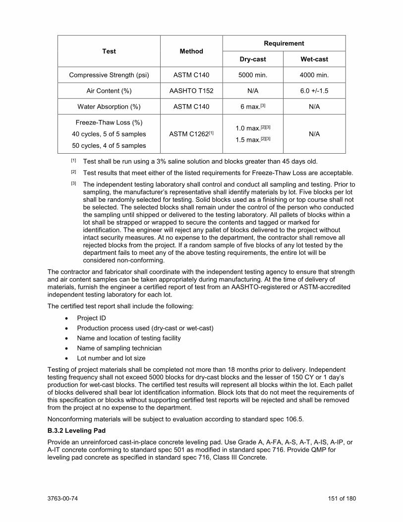
3763-00-74 151 of 180
Test Method Requirement
Dry-cast Wet-cast
Compressive Strength (psi) ASTM C140 5000 min. 4000 min.
Air Content (%) AASHTO T152 N/A 6.0 +/-1.5
Water Absorption (%) ASTM C140 6 max.[3] N/A
Freeze-Thaw Loss (%)
40 cycles, 5 of 5 samples
50 cycles, 4 of 5 samples
ASTM C1262[1] 1.0 max.[2][3]
1.5 max.[2][3] N/A
[1] Test shall be run using a 3% saline solution and blocks greater than 45 days old. [2] Test results that meet either of the listed requirements for Freeze-Thaw Loss are acceptable. [3] The independent testing laboratory shall control and conduct all sampling and testing. Prior to
sampling, the manufacturer’s representative shall identify materials by lot. Five blocks per lot shall be randomly selected for testing. Solid blocks used as a finishing or top course shall not be selected. The selected blocks shall remain under the control of the person who conducted the sampling until shipped or delivered to the testing laboratory. All pallets of blocks within a lot shall be strapped or wrapped to secure the contents and tagged or marked for identification. The engineer will reject any pallet of blocks delivered to the project without intact security measures. At no expense to the department, the contractor shall remove all rejected blocks from the project. If a random sample of five blocks of any lot tested by the department fails to meet any of the above testing requirements, the entire lot will be considered non-conforming.
The contractor and fabricator shall coordinate with the independent testing agency to ensure that strength and air content samples can be taken appropriately during manufacturing. At the time of delivery of materials, furnish the engineer a certified report of test from an AASHTO-registered or ASTM-accredited independent testing laboratory for each lot.
The certified test report shall include the following:
• Project ID • Production process used (dry-cast or wet-cast) • Name and location of testing facility • Name of sampling technician • Lot number and lot size
Testing of project materials shall be completed not more than 18 months prior to delivery. Independent testing frequency shall not exceed 5000 blocks for dry-cast blocks and the lesser of 150 CY or 1 day’s production for wet-cast blocks. The certified test results will represent all blocks within the lot. Each pallet of blocks delivered shall bear lot identification information. Block lots that do not meet the requirements of this specification or blocks without supporting certified test reports will be rejected and shall be removed from the project at no expense to the department.
Nonconforming materials will be subject to evaluation according to standard spec 106.5.
B.3.2 Leveling Pad Provide an unreinforced cast-in-place concrete leveling pad. Use Grade A, A-FA, A-S, A-T, A-IS, A-IP, or A-IT concrete conforming to standard spec 501 as modified in standard spec 716. Provide QMP for leveling pad concrete as specified in standard spec 716, Class III Concrete.
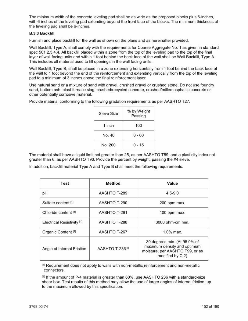
3763-00-74 152 of 180
The minimum width of the concrete leveling pad shall be as wide as the proposed blocks plus 6-inches, with 6-inches of the leveling pad extending beyond the front face of the blocks. The minimum thickness of the leveling pad shall be 6-inches.
B.3.3 Backfill Furnish and place backfill for the wall as shown on the plans and as hereinafter provided.
Wall Backfill, Type A, shall comply with the requirements for Coarse Aggregate No. 1 as given in standard spec 501.2.5.4.4. All backfill placed within a zone from the top of the leveling pad to the top of the final layer of wall facing units and within 1 foot behind the back face of the wall shall be Wall Backfill, Type A. This includes all material used to fill openings in the wall facing units.
Wall Backfill, Type B, shall be placed in a zone extending horizontally from 1 foot behind the back face of the wall to 1 foot beyond the end of the reinforcement and extending vertically from the top of the leveling pad to a minimum of 3 inches above the final reinforcement layer.
Use natural sand or a mixture of sand with gravel, crushed gravel or crushed stone. Do not use foundry sand, bottom ash, blast furnace slag, crushed/recycled concrete, crushed/milled asphaltic concrete or other potentially corrosive material.
Provide material conforming to the following gradation requirements as per AASHTO T27.
Sieve Size % by Weight Passing
1 inch 100
No. 40 0 - 60
No. 200 0 - 15
The material shall have a liquid limit not greater than 25, as per AASHTO T89, and a plasticity index not greater than 6, as per AASHTO T90. Provide the percent by weight, passing the #4 sieve.
In addition, backfill material Type A and Type B shall meet the following requirements.
Test Method Value
pH AASHTO T-289 4.5-9.0
Sulfate content [1] AASHTO T-290 200 ppm max.
Chloride content [1] AASHTO T-291 100 ppm max.
Electrical Resistivity [1] AASHTO T-288 3000 ohm-cm min.
Organic Content [1] AASHTO T-267 1.0% max.
Angle of Internal Friction AASHTO T-236[2]
30 degrees min. (At 95.0% of maximum density and optimum
moisture, per AASHTO T99, or as modified by C.2)
[1] Requirement does not apply to walls with non-metallic reinforcement and non-metallic connectors.
[2] If the amount of P-4 material is greater than 60%, use AASHTO 236 with a standard-size shear box. Test results of this method may allow the use of larger angles of internal friction, up to the maximum allowed by this specification.
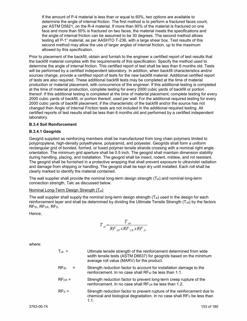
3763-00-74 153 of 180
If the amount of P-4 material is less than or equal to 60%, two options are available to determine the angle of internal friction. The first method is to perform a fractured faces count, per ASTM D5821, on the R-4 material. If more than 90% of the material is fractured on one face and more than 50% is fractured on two faces, the material meets the specifications and the angle of internal friction can be assumed to be 30 degrees. The second method allows testing all P-1” material, as per AASHTO T-236, with a large shear box. Test results of this second method may allow the use of larger angles of internal friction, up to the maximum allowed by this specification.
Prior to placement of the backfill, obtain and furnish to the engineer a certified report of test results that the backfill material complies with the requirements of this specification. Specify the method used to determine the angle of internal friction. This certified report of test shall be less than 6 months old. Tests will be performed by a certified independent laboratory. In addition, when backfill characteristics and/or sources change, provide a certified report of tests for the new backfill material. Additional certified report of tests are also required. These additional backfill tests may be completed at the time of material production or material placement, with concurrence of the engineer. If this additional testing is completed at the time of material production, complete testing for every 2000 cubic yards of backfill or portion thereof. If this additional testing is completed at the time of material placement, complete testing for every 2000 cubic yards of backfill, or portion thereof, used per wall. For the additional required testing for every 2000 cubic yards of backfill placement, if the characteristic of the backfill and/or the source has not changed then Angle of Internal Friction tests are not included in the additional required testing. All certified reports of test results shall be less than 6 months old and performed by a certified independent laboratory.
B.3.4 Soil Reinforcement B.3.4.1 Geogrids Geogrid supplied as reinforcing members shall be manufactured from long chain polymers limited to polypropylene, high-density polyethylene, polyaramid, and polyester. Geogrids shall form a uniform rectangular grid of bonded, formed, or fused polymer tensile strands crossing with a nominal right angle orientation. The minimum grid aperture shall be 0.5 inch. The geogrid shall maintain dimension stability during handling, placing, and installation. The geogrid shall be insect, rodent, mildew, and rot resistant. The geogrid shall be furnished in a protective wrapping that shall prevent exposure to ultraviolet radiation and damage from shipping or handling. The geogrid shall be kept dry until installed. Each roll shall be clearly marked to identify the material contained.
The wall supplier shall provide the nominal long-term design strength (Tal) and nominal long-term connection strength, Talc as discussed below.
Nominal Long-Term Design Strength (Tal)
The wall supplier shall supply the nominal long-term design strength (Tal) used in the design for each reinforcement layer and shall be determined by dividing the Ultimate Tensile Strength (Tult) by the factors RFID, RFCR, RFD.
Hence,
DCRID
ultal RFxRFxRF
TT =
where:
Tult = Ultimate tensile strength of the reinforcement determined from wide width tensile tests (ASTM D6637) for geogrids based on the minimum average roll value (MARV) for the product.
RFID = Strength reduction factor to account for installation damage to the reinforcement. In no case shall RFID be less than 1.1.
RFCR = Strength reduction factor to prevent long-term creep rupture of the reinforcement. In no case shall RFCR be less than 1.2.
RFD = Strength reduction factor to prevent rupture of the reinforcement due to chemical and biological degradation. In no case shall RFD be less than 1.1.
3763-00-74 154 of 180
Values for RFID, RFCR, and RFD shall be determined from product specific test results. Guidelines for determining RFID, RFCR, and RFD from product specific data are provided in FHWA Publication No. FHWA-NHI-10-024 and FHWA–NHI-10-025 “Design and Construction of Mechanically Stabilized Earth Walls and Reinforced Soll Slopes”.
Nominal Long-term Connection Strength Tac
The nominal long term connection strength, Tac, shall be based on laboratory geogrid connection tests between wall facing and geogrids. Tac shall be as given below
D
crultac RF
CRTT
*=
where:
Tac = Nominal long-term reinforcement facing connection strength per unit reinforcement width at a specified confining pressure.
Tult = Ultimate tensile strength of the reinforcement for geogrids defined as the minimum average roll value (MARV) for the product.
CRcr = Long term connection strength reduction factor to account for reduced ultimate strength resulting from connection.
RFD = Strength reduction factor to prevent rupture of the reinforcement due to chemical and biological degradation.
Tac shall be developed from the tests conducted by an independent laboratory on the same facing blocks and geogrids as proposed for the wall and shall cover a range of overburden pressures comparable to those anticipated in the proposed wall. The connection strength reduction factor CRcr shall be determined according to long-term connection test as described in Appendix B of FHWA Publication No. FHWA-NHI 10-025 “Design and Construction of Mechanically Stabilized Earth Walls and Reinforced Soil Slopes”. CRcr may also be obtained from the short term connection test meeting the requirements of NCMA test method SRWU-1 in Simac et al 1993 or ASTM D4884.
The contractor shall provide a manufacturer’s certificate that the Tult (MARV) of the supplied geogrid has been determined according to ASTM D4595 or ASTM D6637 as appropriate. Contractor shall also provide block to block and block to reinforcement connection test reports prepared and certified by an independent laboratory. Also provide calculations according to AASHTO LRFD, and using the results of laboratory tests, that the block-geogrid connections shall be capable of resisting 100% of the maximum tension load in the soil reinforcements at any level within the wall, for the design life of the wall system.
B.3.4.2 Galvanized Metal Reinforcement In lieu of polymeric geogrid earth reinforcement, galvanized metal reinforcement may be used. Design and materials shall be according to AASHTO LRFD 11.10.6.4.2. The design life of steel soil reinforcements shall also comply with AASHTO LRFD. Steel soil reinforcement shall be prefabricated into single or multiple elements before galvanizing.
C Construction C.1 Excavation and Backfill Excavation and preparation of the foundation for the MSE wall and the leveling pad shall be according to standard spec 206. The volume of excavation covered is limited to the width of the reinforced mass and to the depth of the leveling pad unless shown or noted otherwise on the plan. At the end of each working day, provide good temporary drainage such that the backfill shall not become contaminated with run-off soil or water if it should rain. Do not stockpile or store materials or large equipment within 10 feet of the back of the wall.
Place backfill materials in the areas as indicated on the plans and as detailed in this specification. Backfill lifts shall be no more than 8-inches in depth, after compaction. Backfilling shall closely follow erection of each course of wall facing units.
Conduct backfilling operations in such a manner as to prevent damage or misalignment of the wall facing units, soil reinforcement, or other wall components. At no expense to the department, correct any such damage or misalignment as directed by the engineer. A field representative of the wall supplier shall be available during wall construction to provide technical assistance to the contractor and the engineer.
3763-00-74 155 of 180
Place and compact the MSE backfill to the level of the next higher layer of MSE reinforcement before placing the MSE reinforcement or connecting it to the wall facing. Place and compact material beyond the reinforced soil zone to allow for proper compaction of material within the reinforced zone. The MSE reinforcement shall lay horizontally on top of the most recently placed and compacted layer of MSE backfill.
Do not operate tracked or wheeled equipment on the backfill within 3 feet from the back face of modular blocks. The engineer may order the removal of any large or heavy equipment that may cause damage or misalignment of the wall facing units.
C.2 Compaction Compact wall backfill Type A with at least three passes of lightweight manually operated compaction equipment acceptable to the engineer.
Compact all backfill Type B as specified in standard spec 207.3.6. Compact the backfill Type B to 95.0% of maximum dry density as determined by AASHTO T-99 (modified to compute densities to the nearest 0.1 pcf).
Ensure adequate moisture is present in the backfill during placement and compaction to prevent segregation and to help achieve compaction.
Compaction of backfill within 3 feet of the back face of the wall should be accomplished using lightweight compaction devices. Use of heavy compaction equipment or vehicles should be avoided within 3 feet of the modular blocks. Do not use sheepsfoot or padfoot rollers within the reinforced soil zone.
A minimum of 6 inches of backfill shall be placed over the MSE reinforcement prior to working above the reinforcement.
C.3 Wall Components C.3.1 General Erect wall facing units and other associated elements according to the wall manufacturer’s construction guide and to the lines, elevations, batter, and tolerances as shown on the plans. Center the initial layer of facing units on the leveling pad; then level them and properly align them. Fill formed voids or openings in the facing units with wall backfill, Type A. Remove all debris on the top of each layer of facing units, before placing the next layer of facing units.
Install all pins, rods, clips, or other devices used to develop mechanical interlock between facing unit layers according to the manufacturer’s directions.
The MSE reinforcement shall lay horizontally on the top of the most recently placed and compacted layer of MSE backfill. Bending of MSE reinforcement that result in a kink in the reinforcement shall not be allowed. If skewing of the reinforcement is required due to obstructions in the reinforced fill, the maximum skew angle shall not exceed 15 degrees from the normal position unless a greater angle is shown on the plans. The adequacy of the skewed reinforcement in such a case shall be addressed by supporting calculations.
C.3.2 Leveling Pad Provide an unreinforced cast-in-place concrete leveling pad as shown on the plans.
Vertical tolerances shall not exceed 3/4-inch when measured along a 10-foot straight edge. Allow the concrete to set at least 12 hours prior to placing wall facing units.
The bottom row of wall facing units shall be horizontal and 100% of the unit surface shall bear on the leveling pad.
C.3.3 Soil Reinforcement C.3.3.1 Geogrid Layers Place soil reinforcement at the positions and to the lengths as indicated on the accepted shop drawings. Take care that backfill placement over the positioned soil reinforcement elements does not cause damage or misalignment of these elements. Correct any such damage or misalignment as directed by the engineer. Do not operate wheeled or tracked equipment directly on the soil reinforcement. A minimum cover of 6 inches is required before such operation is allowed.
3763-00-74 156 of 180
Place and anchor geogrid material between wall unit layers in the same manner as used to determine the Geogrid Block-to-Connection Strength. Place the grid material so that the machine direction of the grid is perpendicular to the wall face. Each grid layer shall be continuous throughout the lengths indicated on the plans. Join grid strips with straps, rings, hooks or other mechanical devices to prevent movement during backfilling operations. Prior to placing backfill on the grid, pull the grid taunt and hold in position with pins, stakes or other methods approved by the engineer.
C.3.3.2 Steel Layers Place the steel reinforcement full width in one piece as shown on the plans. No splicing will be allowed. Maintain elements in position during backfilling.
C.4 Quality Management Program C.4.1 Quality Control Plan Submit a comprehensive written quality control plan to the engineer at or before the pre-construction meeting. Do not perform MSE wall construction work before the engineer reviews and accepts the plan. Construct the project as the plan provides.
Do not change the quality control plan without the engineer’s review and acceptance. Update the plan with changes as they become effective. Provide a current copy of the plan to the engineer and post in the contractor’s laboratory as changes are adopted. Ensure that the plan provides the following elements:
1. An organizational chart with names, telephone numbers, current certifications and/or titles, and roles and responsibilities of QC personnel.
2. The process used to disseminate QC information and corrective action efforts to the appropriate persons. Include a list of recipients, the communication process that will be used, and action time frames.
3. A list of source locations, section and quarter descriptions, for all aggregate materials requiring QC testing.
4. Descriptions of stockpiling and hauling methods. 5. An outline for resolving a process control problem. Include responsible personnel, required
documentation, and appropriate communication steps. 6. Location of the QC laboratory retained sample storage, and other documentation. 7. A summary of the locations and calculated quantities to be tested under this provision. 8. A proposed sequencing plan of wall construction operations and random test locations.
C.4.2 Quality Control Personnel Perform the quality control sampling, testing, and documentation required under this provision using HTCP certified technicians. Have a HTCP Grading Technician I (GRADINGTEC-I); or Assistant Certified Technician, Grading (ACT-GRADING); or Aggregate Technician I (AGGTEC-I); or Assistant Certified Technician, Aggregate (ACT-AGG) present at each grading site during all wall backfill placement, compaction, and nuclear testing activities. Have a HTCP Nuclear Density Technician I (NUCDENSITYTEC-I) or Assistant Certified Technician, Nuclear Density Gauge Operator (ACT-NUC) perform field density and field moisture content testing.
If an Assistant Certified Technician (ACT) is performing sampling or testing, a certified technician must coordinate and take responsibility for the work an ACT performs. Have a certified technician Ensure that all sampling and testing is performed correctly, analyze test results, and post resulting data. No more than one ACT can work under a single certified technician.
C.4.3 Equipment Furnish the necessary equipment and supplies for performing quality control testing. Ensure that all testing equipment conforms to the equipment specifications applicable to the required testing methods. The engineer may inspect the measuring and testing devices to confirm both calibration and condition. Calibrate all testing equipment according to the CMM and maintain a calibration record at the laboratory.
Furnish nuclear gauges from the department’s approved product list at:
https://wisconsindot.gov/Pages/doing-bus/eng-consultants/cnslt-rsrces/tools/appr-prod/default.aspx
3763-00-74 157 of 180
Ensure that the nuclear gauge manufacturer or an approved calibration service calibrates the gauge the same calendar year it is used on the project. Retain a copy of the calibration certificate with the gauge.
Conform to AASHTO T310 and CMM 8-15 for density testing and gauge monitoring methods.
Split each Proctor sample and identify so as to provide comparison with the department's test results. Unless the engineer directs otherwise, retain the QC split samples for 14 calendar days and promptly deliver the department’s split samples to the department
C.4.4 Documentation
(1) Document all observations, inspection records, and process adjustments daily. Submit test results to the department's project materials coordinator on the same day they become available.
(2) Use forms provided in CMM Chapter 8. Note other information in a permanent field record and as a part of process control documentation enumerated in the contractor's quality control plan. Enter QC data and backfill material certified report results into the applicable materials reporting system (MRS) software within 5 business days after results are available.
(3) Submit final testing records and other documentation to the engineer electronically within 10 business days after all contract-required information becomes available. The engineer may allow submission of scanned copies of hand-written documentation.
C.4.5 Quality Control (QC) Testing Perform compaction testing on the backfill. Conform to CMM 8-15 for testing and gauge monitoring methods. Conduct testing at a minimum frequency of 1 test per 150 cubic yards of backfill, or major portion thereof in each lift. A minimum of one test for every lift is required. Deliver documentation of all compaction testing results to the engineer at the time of testing.
Perform 1 gradation test every 750 cubic yards of fill and one 5-point Proctor test (or as modified in C.2) every 2,250 cubic yards of fill. Provide the region split samples of both within 72 hours of sampling, at the region laboratory. Test sites shall be selected using ASTM Method D3665. Provide Proctor test results to the engineer within 48 hours of sampling. Provide gradation test results to the engineer within 24 hours of sampling.
C.4.6 Department Testing C.4.6.1 General
(1) The department will conduct verification testing to validate the quality of the product and independent assurance testing to evaluate the sampling and testing. The department will provide the contractor with a listing of names and telephone numbers of all QV and IA personnel for the project and provide test results to the contractor within 2 business days after the department obtains the sample.
C.4.6.2 Quality Verification (QV) Testing
(1) The department will have an HTCP technician, or ACT working under a certified technician, perform QV sampling and testing. Department verification testing personnel must meet the same certification level requirements specified in C.4.2 for contractor testing personnel for each test result being verified. The department will notify the contractor before sampling so the contractor can observe QV sampling.
(2) The department will conduct QV tests at the minimum frequency of 30% of the required contractor density, Proctor and gradation tests.
(3) The department will locate density tests and gradation samples randomly, at locations independent of the contractor’s QC work. The department will split each Proctor and gradation QV sample, testing half for QV, and retaining the remaining half for 10 business days.
(4) The department will conduct QV Proctor and gradation tests in a separate laboratory and with separate equipment from the contractor’s QC tests. The department will use the same methods specified for QC testing.
3763-00-74 158 of 180
(5) The department will assess QV results by comparing to the appropriate specification limits. If QV test results conform to this special provision, the department will take no further action. If density QV test results are nonconforming, the area shall be reworked until the density requirements of this special provision are met. If the gradation test results are nonconforming, standard spec 106.5 will apply. Differing QC and QV nuclear density values of more than 1.5 pcf will be investigated and resolved. QV density tests will be based on the appropriate QC Proctor test results, unless the QV and QC Proctor result difference is greater than 3.0 pcf. Differing QC and QV Proctor values of more than 3.0 pcf will be investigated and resolved.
C.4.6.3 Independent Assurance (IA)
(1) Independent assurance is unbiased testing the department performs to evaluate the department’s QV and the contractor’s QC sampling and testing, including personnel qualifications, procedures, and equipment. The department will perform an IA review according to the department’s independent assurance program. That review may include one or more of the following:
1. Split sample testing. 2. Proficiency sample testing. 3. Witnessing sampling and testing. 4. Test equipment calibration checks. 5. Reviewing required worksheets and control charts. 6. Requesting that testing personnel perform additional sampling and testing.
(2) If the department identifies a deficiency, and after further investigation confirms it, correct that deficiency. If the contractor does not correct or fails to cooperate in resolving identified deficiencies, the engineer may suspend placement until action is taken. Resolve disputes as specified in C.4.6.4.
C.4.6.4 Dispute Resolution
(1) The engineer and contractor should make every effort to avoid conflict. If a dispute between some aspect of the contractor’s and the engineer’s testing program does occur, seek a solution mutually agreeable to the project personnel. The department and contractor may review the data, examine data reduction and analysis methods, evaluate sampling and testing procedures, and perform additional testing. Use ASTM E178 to evaluate potential statistically outlying data.
(2) Production test results, and results from other process control testing, may be considered when resolving a dispute.
(3) If the project personnel cannot resolve a dispute, and the dispute affects payment or could result in incorporating non-conforming product or work, the department will use third party testing to resolve the dispute. The department’s central office laboratory, or a mutually agreed on independent testing laboratory, will provide this testing. The engineer and contractor will abide by the results of the third party tests. The party in error will pay service charges incurred for testing by an independent laboratory. The department may use third party test results to evaluate the quality of questionable materials and determine the appropriate payment. The department may reject material or otherwise determine the final disposition of nonconforming material as specified in standard spec 106.5.
C.5 Geotechnical Information Geotechnical data to be used in the design of the wall is given on the wall plan. After completing wall excavation of the entire reinforced soil zone, notify the department and allow the Regional Soils Engineer two working days to review the foundation.
D Measurement The department will measure Wall Modular Block Mechanically Stabilized Earth by the square foot acceptably completed. The department will compute measured quantities from the theoretical pay limits the contract plans show. The department will make no allowance for wall area constructed above or below the theoretical pay limits. All work beyond the theoretical pay limits is incidental to the cost of work. The department will make no allowance for as-built quantities.
3763-00-74 159 of 180
E Payment The department will pay for measured quantities at the contract unit price under the following bid item: ITEM NUMBER DESCRIPTION UNIT SPV.0165.001 Wall Modular Block Mechanically Stabilized Earth SF
Payment is full compensation for supplying a design and shop drawings; preparing the site, including all necessary excavation and disposal of materials; supplying all necessary wall components to produce a functional wall system including cap, copings, leveling pad, and leveling pad steps; constructing the retaining system and providing temporary drainage; providing backfill, backfilling, compacting, developing/completing/documenting the quality management program, and performing compaction testing.
The department will pay separately for parapets, traffic barriers, railings, and other items above the wall cap or coping.
130. Prestressed Precast Concrete Wall Panel R-30-65, Item SPV.0165.200; Prestressed Precast Concrete Wall Panel R-30-66, Item SPV.0165.201; Prestressed Precast Concrete Wall Panel R-30-67, Item SPV.0165.202; Prestressed Precast Concrete Wall Panel R-30-68, Item SPV.0165.203. A Description This special provision describes constructing precast prestressed concrete wall panels with heights and patterns as shown on the plans including product design, fabrication, transportation, erection, anchorage and other related items. The design life of the precast concrete wall panels and all panel components shall be 75 years.
These specifications provide for prestressing concrete panels by the pre-tensioning method. In this method, stress the reinforcing tendons initially, then place and cure the concrete and release the stress from the anchorages to the concrete after developing specified concrete strength.
B Materials B.1 Design Requirements
It is the responsibility of the contractor to submit a design and supporting documentation as required by this special provision, for review and acceptance by the department, to show the proposed wall design is in compliance with the design specifications. The submittal shall include the following items for review: erection drawings, production drawings, complete design calculations, explanatory notes, supporting materials, and specifications.
Erection drawings shall conform to the contract plans and consist of member piece marks and completely dimensioned size and shape of each member; plans and/or elevations locating and defining all products furnished by manufacturer; sections and details showing connections, cast-in items and their relation to the structure; relationship to adjacent material including footings and copings; joints between members and structure; description of all loose, cast-in and field hardware; field installed anchor location drawings; erection sequences, when required to satisfy stability, and handling requirements; and all dead, live and other applicable loads used in the design.
Production drawings shall conform to the contract plans and consist of elevation view of each member; sections and details to indicate quantities and position of reinforcing steel, anchors, inserts, etc.; handling devices; dimensions and finishes; prestress strand quantities; initial prestress forces; material strengths; estimated cambers; and methods for storage and transportation.
The plans and shop drawings shall be prepared on reproducible sheets 11 inch x 17 inch, including borders. Each sheet shall have a title block in the lower right corner. The title block shall include the WisDOT project identification number and structure number. Design calculations and notes shall be on 8-1/2 inch x 11 inch sheets, and shall contain the project identification number, name or designation of the wall, date of preparation, initials of designer and checker, and page number at the top of the page. All plans, shop drawings, and calculations shall be signed, sealed and dated by a professional engineer licensed in the State of Wisconsin, experienced in the design of Prestressed Precast Concrete Wall Panels.
3763-00-74 160 of 180
The design of the Prestressed Precast Concrete Wall Panel shall conform to the current American Association of State Highway and Transportation Officials LRFD (AASHTO LRFD) Bridge Design Specifications with latest interim specifications for Mechanically Stabilized Earth Walls, WisDOT’s current Standard Specifications for Highway and Structure Construction (standard spec), Chapter 14 of the WisDOT LRFD Bridge Manual and standard engineering design procedures as determined by the department. Loads, load combinations, load and resistance factors shall be as specified in AASHTO LRFD.
Design and construct the panels per the lines, grades, heights and dimensions shown on the plans, as herein specified, and as directed by the engineer. Design panels and components to withstand initial handling, transportation, and erection stress limits; dead loads; wind load of 40 pounds per square foot; suction load of 20 pounds per square foot; thermal stresses; and other loads specified. Although the cavity shall remain free of backfill and debris, consider backfill within the cavity not exceeding the finish grade elevation at the front face of wall for design. In addition to the above loads also design inserts and connection assemblies for the loads indicated on the plans and a horizontal force equal to at least 20% of the dead weight of the panel and coping.
Provide a minimum prestress of 250 pounds per square inch after losses and minimum temperature and shrinkage reinforcement as required by AASHTO LRFD 5.10.8.
B.2 Submittals Submit on request reports on materials, compressive strength tests on concrete and water absorption tests on units.
Submit to the engineer, for acceptance and placing on file before commencing, one set of the submittals that the contractor has checked. In addition, provide two sets to the Region office, (Steve Hoff, (262) 548-6718), and one set to the Bureau of Structures for acceptance and inspection purposes. Only after acceptance by the Region may panel fabrication commence. The engineer may refuse prints of submittals that are not clear and legible. If the engineer requests, submit one additional copy of submittals for review. After acceptance, furnish as many copies of submittals as required. Submit no later than 60 days from the date of notification to proceed with the project and a minimum of 30 days prior to the date proposed to erect the wall panels.
The submittals become a part of the contract, provided any differences between the production drawings and the plans are approved by the engineer and provided those changes are made at no additional expense to the department.
After initial submittal and acceptance, make no deviation from the production drawings or changes to them without the engineer’s further review and acceptance.
The engineer's review of submittals is only a review of the character and sufficiency of the details and does not relieve the contractor from responsibility in regard to errors or omissions on those drawings.
B.3 Wall System Components Materials furnished for wall system components under this contract shall conform to the requirements of this specification. All certifications related to material and components of the wall systems specified in this subsection shall be submitted to the engineer.
B.3.1 General Furnish materials conforming to the following:
Material Standard Spec Section
Masonry Anchors 502 Coated High Strength Bar Steel Reinforcement 505 Pretensioning Reinforcement 503 Welded Steel Wire Fabric for Concrete Reinforcement 505 Structural Steel and Miscellaneous Metals 506 Elastomeric Bearing Pads 506
3763-00-74 161 of 180
Galvanize or furnish stainless steel materials for all hardware incorporated into the finished structures. (Not including reinforcement bars or pretensioning reinforcement.)
B.3.2 Concrete Furnish concrete as specified in standard spec 501 and 716.
Ensure concrete attains a minimum 28-day compressive strength of 5,000 pounds per square inch. Base all tests on 6 inch by 12-inch cylinders, or 4 inch by 8-inch cylinders, provided the engineer develops and approves a correlation factor. Mold concrete cylinders in suitable steel or plastic molds. Cure concrete cylinders according to AASHTO T23, except cure the cylinders with the member until release strength is obtained, then cure the cylinders according to AASHTO T23.
Make and test the cylinders and make available to the engineer all information relating to the making and testing of cylinders. Notify the engineer immediately if concrete cylinder compressive strengths are less than the required 28-day strength. Keep neatly documented records of all cylinder testing on the day of the test and make them available to the engineer. Provide copies of the tests to the engineer by contract completion.
Furnish precast prestressed concrete panels cast from air entrained concrete. Use type I, IS, I(SM), IP, II, or III cement. The contractor may replace up to 30 percent of type I, II, or III portland cement with an equal weight of fly ash conforming to standard spec 501.2.6 or slag conforming to standard spec 501.2.7. Use only one source and replacement rate for work under a single bid item. Use a department-approved air entraining admixture conforming to standard spec 501.2.2 for air entrained concrete. Use only size No. 1 coarse aggregate conforming to standard spec 501.2.5.4.
Determine proportions for the mix within the following limitations:
Proportion Limitation
Water cement ratio 0.45 max. Cement content 610 lbs/cy min. Air content of concrete 3.5%-6.0% Slump of mixed concrete 4 inches max.
If the mix does not contain a high range water reducer admixture, use a department- approved set retarding admixture as specified in standard spec 501.2.3.2 at the recommended rate if the ambient air temperature is 70 degrees F (21 degrees C) or higher. The contractor may use it at their option if the ambient air temperature is less than 70 degrees F (21 degrees C).
Do not add more admixtures or water after mixing is complete.
Use admixtures that do not have significant chlorides or chlorides added during manufacture.
Use admixtures that are compatible with all ingredients of the concrete mixture.
B.3.3 Pretensioning Reinforcement Use high tensile strength, 7-wire strands conforming to ASTM A416, grade 270.
B.3.4 Lifting Devices The type, number and locations of lifting devices and the method of handling the Prestressed Precast Concrete Wall Panels is determined by the fabricator and approved by the engineer. Lifting devices shall not be located on the exposed front face of the panel.
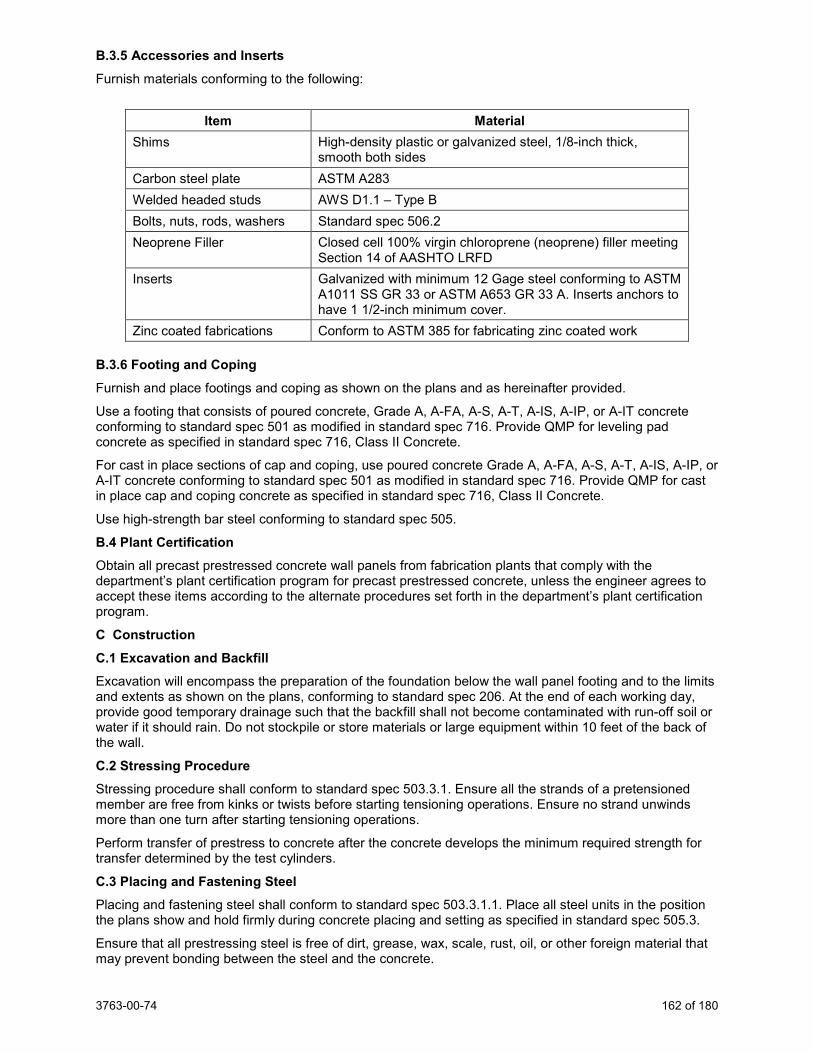
3763-00-74 162 of 180
B.3.5 Accessories and Inserts Furnish materials conforming to the following:
Item Material
Shims High-density plastic or galvanized steel, 1/8-inch thick, smooth both sides
Carbon steel plate ASTM A283 Welded headed studs AWS D1.1 – Type B Bolts, nuts, rods, washers Standard spec 506.2 Neoprene Filler Closed cell 100% virgin chloroprene (neoprene) filler meeting
Section 14 of AASHTO LRFD Inserts Galvanized with minimum 12 Gage steel conforming to ASTM
A1011 SS GR 33 or ASTM A653 GR 33 A. Inserts anchors to have 1 1/2-inch minimum cover.
Zinc coated fabrications Conform to ASTM 385 for fabricating zinc coated work B.3.6 Footing and Coping Furnish and place footings and coping as shown on the plans and as hereinafter provided.
Use a footing that consists of poured concrete, Grade A, A-FA, A-S, A-T, A-IS, A-IP, or A-IT concrete conforming to standard spec 501 as modified in standard spec 716. Provide QMP for leveling pad concrete as specified in standard spec 716, Class II Concrete.
For cast in place sections of cap and coping, use poured concrete Grade A, A-FA, A-S, A-T, A-IS, A-IP, or A-IT concrete conforming to standard spec 501 as modified in standard spec 716. Provide QMP for cast in place cap and coping concrete as specified in standard spec 716, Class II Concrete.
Use high-strength bar steel conforming to standard spec 505.
B.4 Plant Certification Obtain all precast prestressed concrete wall panels from fabrication plants that comply with the department’s plant certification program for precast prestressed concrete, unless the engineer agrees to accept these items according to the alternate procedures set forth in the department’s plant certification program.
C Construction C.1 Excavation and Backfill Excavation will encompass the preparation of the foundation below the wall panel footing and to the limits and extents as shown on the plans, conforming to standard spec 206. At the end of each working day, provide good temporary drainage such that the backfill shall not become contaminated with run-off soil or water if it should rain. Do not stockpile or store materials or large equipment within 10 feet of the back of the wall.
C.2 Stressing Procedure Stressing procedure shall conform to standard spec 503.3.1. Ensure all the strands of a pretensioned member are free from kinks or twists before starting tensioning operations. Ensure no strand unwinds more than one turn after starting tensioning operations.
Perform transfer of prestress to concrete after the concrete develops the minimum required strength for transfer determined by the test cylinders.
C.3 Placing and Fastening Steel Placing and fastening steel shall conform to standard spec 503.3.1.1. Place all steel units in the position the plans show and hold firmly during concrete placing and setting as specified in standard spec 505.3.
Ensure that all prestressing steel is free of dirt, grease, wax, scale, rust, oil, or other foreign material that may prevent bonding between the steel and the concrete.
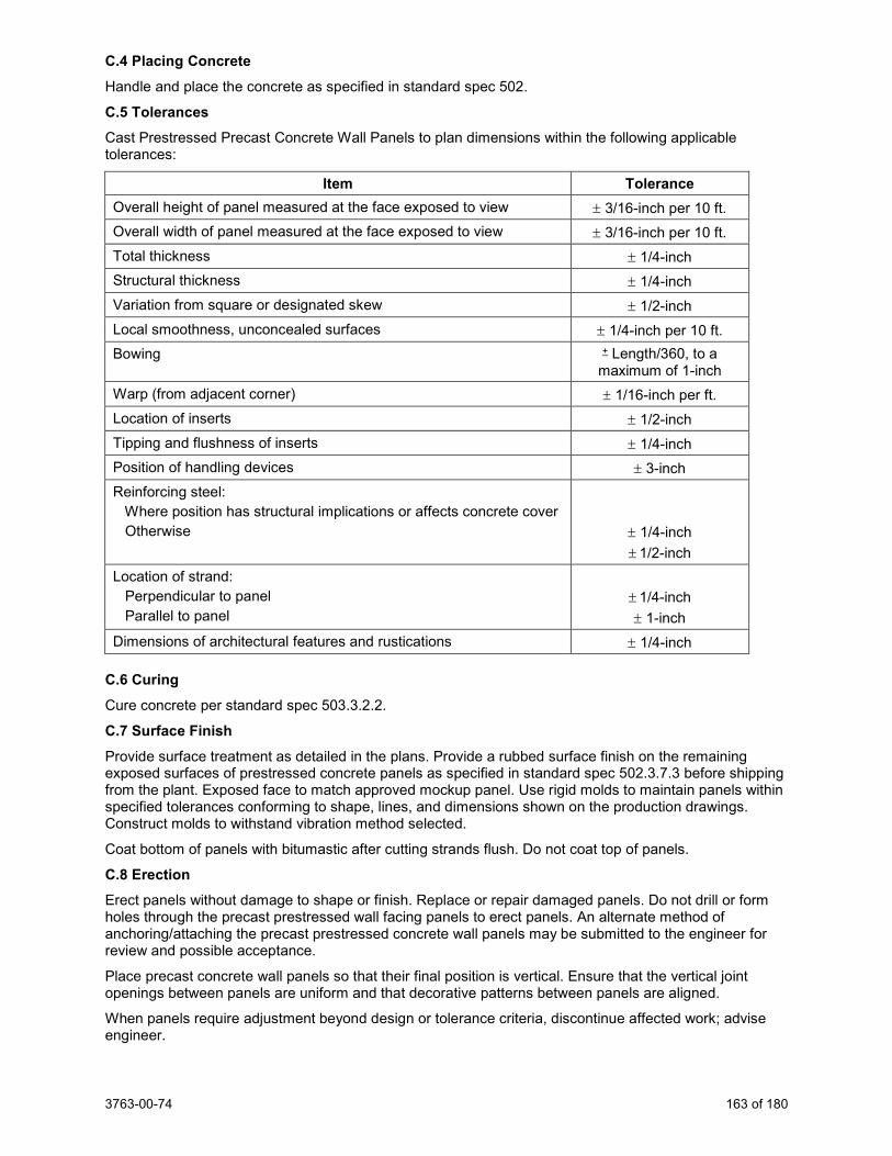
3763-00-74 163 of 180
C.4 Placing Concrete Handle and place the concrete as specified in standard spec 502.
C.5 Tolerances Cast Prestressed Precast Concrete Wall Panels to plan dimensions within the following applicable tolerances:
Item Tolerance Overall height of panel measured at the face exposed to view ± 3/16-inch per 10 ft. Overall width of panel measured at the face exposed to view ± 3/16-inch per 10 ft. Total thickness ± 1/4-inch Structural thickness ± 1/4-inch Variation from square or designated skew ± 1/2-inch Local smoothness, unconcealed surfaces ± 1/4-inch per 10 ft. Bowing + Length/360, to a
maximum of 1-inch Warp (from adjacent corner) ± 1/16-inch per ft. Location of inserts ± 1/2-inch Tipping and flushness of inserts ± 1/4-inch Position of handling devices ± 3-inch Reinforcing steel: Where position has structural implications or affects concrete cover Otherwise
± 1/4-inch ± 1/2-inch
Location of strand: Perpendicular to panel Parallel to panel
± 1/4-inch ± 1-inch
Dimensions of architectural features and rustications ± 1/4-inch C.6 Curing Cure concrete per standard spec 503.3.2.2.
C.7 Surface Finish Provide surface treatment as detailed in the plans. Provide a rubbed surface finish on the remaining exposed surfaces of prestressed concrete panels as specified in standard spec 502.3.7.3 before shipping from the plant. Exposed face to match approved mockup panel. Use rigid molds to maintain panels within specified tolerances conforming to shape, lines, and dimensions shown on the production drawings. Construct molds to withstand vibration method selected.
Coat bottom of panels with bitumastic after cutting strands flush. Do not coat top of panels.
C.8 Erection Erect panels without damage to shape or finish. Replace or repair damaged panels. Do not drill or form holes through the precast prestressed wall facing panels to erect panels. An alternate method of anchoring/attaching the precast prestressed concrete wall panels may be submitted to the engineer for review and possible acceptance.
Place precast concrete wall panels so that their final position is vertical. Ensure that the vertical joint openings between panels are uniform and that decorative patterns between panels are aligned.
When panels require adjustment beyond design or tolerance criteria, discontinue affected work; advise engineer.
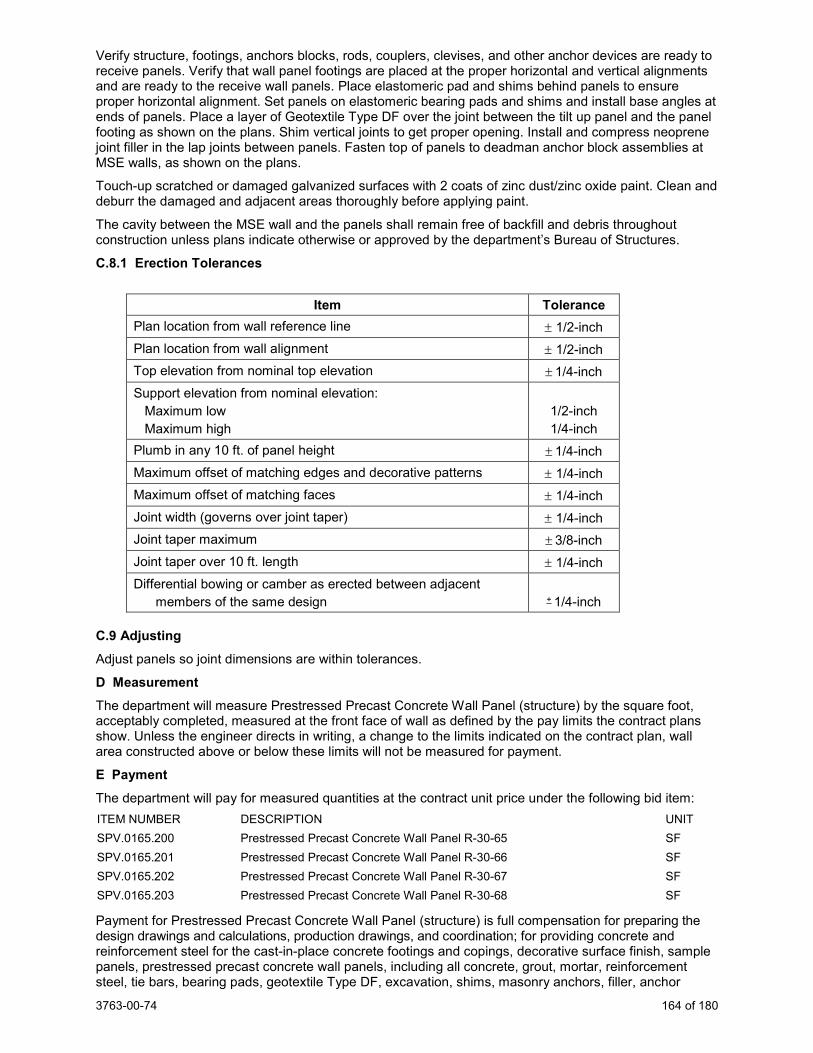
3763-00-74 164 of 180
Verify structure, footings, anchors blocks, rods, couplers, clevises, and other anchor devices are ready to receive panels. Verify that wall panel footings are placed at the proper horizontal and vertical alignments and are ready to the receive wall panels. Place elastomeric pad and shims behind panels to ensure proper horizontal alignment. Set panels on elastomeric bearing pads and shims and install base angles at ends of panels. Place a layer of Geotextile Type DF over the joint between the tilt up panel and the panel footing as shown on the plans. Shim vertical joints to get proper opening. Install and compress neoprene joint filler in the lap joints between panels. Fasten top of panels to deadman anchor block assemblies at MSE walls, as shown on the plans.
Touch-up scratched or damaged galvanized surfaces with 2 coats of zinc dust/zinc oxide paint. Clean and deburr the damaged and adjacent areas thoroughly before applying paint.
The cavity between the MSE wall and the panels shall remain free of backfill and debris throughout construction unless plans indicate otherwise or approved by the department’s Bureau of Structures.
C.8.1 Erection Tolerances
Item Tolerance Plan location from wall reference line ± 1/2-inch Plan location from wall alignment ± 1/2-inch Top elevation from nominal top elevation ± 1/4-inch Support elevation from nominal elevation: Maximum low Maximum high
1/2-inch 1/4-inch
Plumb in any 10 ft. of panel height ± 1/4-inch Maximum offset of matching edges and decorative patterns ± 1/4-inch Maximum offset of matching faces ± 1/4-inch Joint width (governs over joint taper) ± 1/4-inch Joint taper maximum ± 3/8-inch Joint taper over 10 ft. length ± 1/4-inch Differential bowing or camber as erected between adjacent members of the same design
+ 1/4-inch C.9 Adjusting Adjust panels so joint dimensions are within tolerances.
D Measurement The department will measure Prestressed Precast Concrete Wall Panel (structure) by the square foot, acceptably completed, measured at the front face of wall as defined by the pay limits the contract plans show. Unless the engineer directs in writing, a change to the limits indicated on the contract plan, wall area constructed above or below these limits will not be measured for payment.
E Payment The department will pay for measured quantities at the contract unit price under the following bid item: ITEM NUMBER DESCRIPTION UNIT SPV.0165.200 Prestressed Precast Concrete Wall Panel R-30-65 SF SPV.0165.201 Prestressed Precast Concrete Wall Panel R-30-66 SF SPV.0165.202 Prestressed Precast Concrete Wall Panel R-30-67 SF SPV.0165.203 Prestressed Precast Concrete Wall Panel R-30-68 SF
Payment for Prestressed Precast Concrete Wall Panel (structure) is full compensation for preparing the design drawings and calculations, production drawings, and coordination; for providing concrete and reinforcement steel for the cast-in-place concrete footings and copings, decorative surface finish, sample panels, prestressed precast concrete wall panels, including all concrete, grout, mortar, reinforcement steel, tie bars, bearing pads, geotextile Type DF, excavation, shims, masonry anchors, filler, anchor
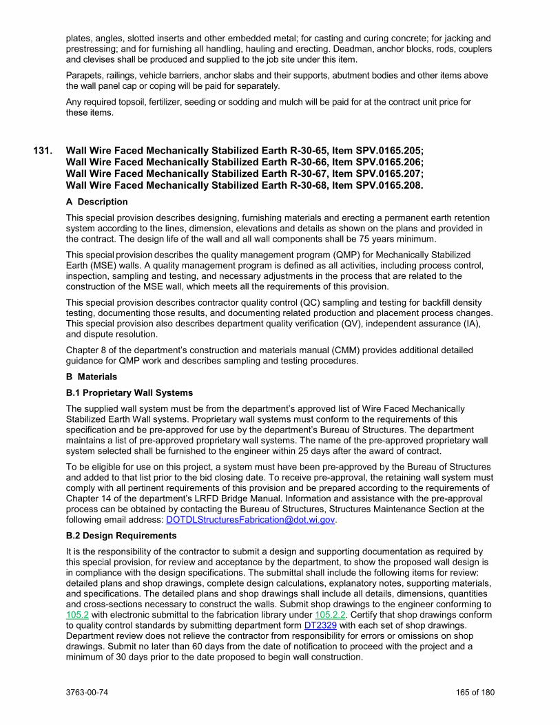
3763-00-74 165 of 180
plates, angles, slotted inserts and other embedded metal; for casting and curing concrete; for jacking and prestressing; and for furnishing all handling, hauling and erecting. Deadman, anchor blocks, rods, couplers and clevises shall be produced and supplied to the job site under this item.
Parapets, railings, vehicle barriers, anchor slabs and their supports, abutment bodies and other items above the wall panel cap or coping will be paid for separately.
Any required topsoil, fertilizer, seeding or sodding and mulch will be paid for at the contract unit price for these items.
131. Wall Wire Faced Mechanically Stabilized Earth R-30-65, Item SPV.0165.205; Wall Wire Faced Mechanically Stabilized Earth R-30-66, Item SPV.0165.206; Wall Wire Faced Mechanically Stabilized Earth R-30-67, Item SPV.0165.207; Wall Wire Faced Mechanically Stabilized Earth R-30-68, Item SPV.0165.208. A Description This special provision describes designing, furnishing materials and erecting a permanent earth retention system according to the lines, dimension, elevations and details as shown on the plans and provided in the contract. The design life of the wall and all wall components shall be 75 years minimum.
This special provision describes the quality management program (QMP) for Mechanically Stabilized Earth (MSE) walls. A quality management program is defined as all activities, including process control, inspection, sampling and testing, and necessary adjustments in the process that are related to the construction of the MSE wall, which meets all the requirements of this provision.
This special provision describes contractor quality control (QC) sampling and testing for backfill density testing, documenting those results, and documenting related production and placement process changes. This special provision also describes department quality verification (QV), independent assurance (IA), and dispute resolution.
Chapter 8 of the department’s construction and materials manual (CMM) provides additional detailed guidance for QMP work and describes sampling and testing procedures.
B Materials B.1 Proprietary Wall Systems The supplied wall system must be from the department’s approved list of Wire Faced Mechanically Stabilized Earth Wall systems. Proprietary wall systems must conform to the requirements of this specification and be pre-approved for use by the department’s Bureau of Structures. The department maintains a list of pre-approved proprietary wall systems. The name of the pre-approved proprietary wall system selected shall be furnished to the engineer within 25 days after the award of contract.
To be eligible for use on this project, a system must have been pre-approved by the Bureau of Structures and added to that list prior to the bid closing date. To receive pre-approval, the retaining wall system must comply with all pertinent requirements of this provision and be prepared according to the requirements of Chapter 14 of the department’s LRFD Bridge Manual. Information and assistance with the pre-approval process can be obtained by contacting the Bureau of Structures, Structures Maintenance Section at the following email address: [email protected].
B.2 Design Requirements It is the responsibility of the contractor to submit a design and supporting documentation as required by this special provision, for review and acceptance by the department, to show the proposed wall design is in compliance with the design specifications. The submittal shall include the following items for review: detailed plans and shop drawings, complete design calculations, explanatory notes, supporting materials, and specifications. The detailed plans and shop drawings shall include all details, dimensions, quantities and cross-sections necessary to construct the walls. Submit shop drawings to the engineer conforming to 105.2 with electronic submittal to the fabrication library under 105.2.2. Certify that shop drawings conform to quality control standards by submitting department form DT2329 with each set of shop drawings. Department review does not relieve the contractor from responsibility for errors or omissions on shop drawings. Submit no later than 60 days from the date of notification to proceed with the project and a minimum of 30 days prior to the date proposed to begin wall construction.
3763-00-74 166 of 180
The plans and shop drawings shall be prepared on reproducible sheets 11 inch x 17 inch, including borders. Each sheet shall have a title block in the lower right corner. The title block shall include the WisDOT project identification number and structure number. Design calculations and notes shall be on 8 ½ inch x 11 inch sheets, and shall contain the project identification number, name or designation of the wall, date of preparation, initials of designer and checker, and page number at the top of the page. All plans, shop drawings, and calculations shall be signed, sealed and dated by a professional engineer licensed in the State of Wisconsin.
The design of the wall shall be in compliance with the current American Association of State Highway and Transportation Officials LRFD (AASHTO LRFD) Bridge Design Specifications with latest interim specifications for Mechanically Stabilized Earth Walls, WisDOT’s current Standard Specifications for Highway and Structure Construction (standard spec), Chapter 14 of the WisDOT LRFD Bridge Manual and standard engineering design procedures as determined by the department. Loads, load combinations, load and resistance factors shall be as specified in AASHTO LRFD Section 11. The associated resistance factors shall be defined according to Table 11.5.7-1 in AASHTO LRFD.
Design and construct the walls according to the lines, grades, heights and dimensions shown on the plans, as herein specified, and as directed by the engineer. If the wall is installed in front of a bridge abutment or wing, it shall also be designed to resist the applied abutment/bridge lateral forces specified on the plans.
Walls parallel to supporting highway traffic shall be designed for the effects of highway surcharge loading equivalent of 2 feet soil surcharge weight or 240 psf. The design shall also consider the traffic barrier impact where applicable. Walls that do not carry highway traffic shall be designed for a live load surcharge of 100 psf according to Chapter 14 of the WisDOT LRFD Bridge Manual or as stated on the plans.
A maximum value of the angle of internal friction of the wall backfill material used for design shall be assumed to be 30 degrees without a certified report of tests. If a certified report of tests yields an angle of internal friction greater than 30 degrees, the larger test value may be used for design, up to a maximum value of 36 degrees.
An external stability check at critical wall stations showing Capacity Demand Ratios (CDR) for sliding, eccentricity, and bearing checks is performed by the department and are provided in the wall plans.
The design of the wall by the contractor shall consider the internal and compound stability of the wall mass according to AASHTO LRFD 11.10.6. The internal stability shall include soil reinforcement pullout, soil reinforcement rupture, and panel-reinforcement connection failure at each soil reinforcement level. The design shall be performed using the Simplified Method or Coherent Gravity Method. Calculations for factored stresses and resistances shall be based upon assumed conditions at the end of the design life. Compound stability shall be computed for the applicable strength limits. Sample analyses and hand calculations shall be submitted to verify the output of any software used. The design calculations and notes shall clearly indicate the Capacity to Demand Ratios (CDR) for all internal and external stabilities as defined in AASHTO LRFD.
The wall facings shall be designed according to AASHTO LRFD 11.10.2.3. A fine metallic screen and a geotextile shall be used at the front face of the wall to retain the fines of the soil mass.
The minimum length of soil reinforcement measured from the back face of the wall shall be equal to 0.7 of the wall height or as shown on the plan. In no case shall this length be less than 8 feet. The soil reinforcement shall be the same length from the bottom to the top of the wall. All soil reinforcement layers shall be connected to wire facing panels. The soil reinforcement shall extend a minimum of 3.0 feet beyond the theoretical failure plane in all cases. The maximum vertical spacing of soil reinforcement layers shall be 24 inches. The uppermost layer of the reinforcement shall be located between 6 inches and 12 inches below the bottom of an overlying slab, footing or top of the wall. The upper layers of the soil reinforcement shall also be checked to verify that they have sufficient tensile resistance against traffic barrier impact where applicable.
The nominal long term design strength to be used in steel reinforcement and connector design shall consider the corrosion losses and be based upon conditions at the end of the design life, as described in Chapter 14 of the WisDOT LRFD Bridge Manual and AASHTO LRFD Section 11.
3763-00-74 167 of 180
Soil reinforcement shall be fabricated or designed to avoid piling, drainage structures or other obstacles in the fill without field modifications. Unless approved by the Bureau of Structures cutting or altering of the basic structural section of either the strip or grid at the site is prohibited, a minimum clearance of 3” shall be maintained between any obstruction and reinforcement, and splicing steel reinforcement is not allowed.
The minimum embedment of the MSE wall shall be 4 feet below finished grade, or as given on the plans. Step the wall to follow the general slope of the ground line.
B.3 Wall System Components Materials furnished for wall system components under this contract shall conform to the requirements of this specification. All documentation related to material and components of the wall systems specified in this subsection shall be submitted to the engineer.
B.3.1 Steel Components All steel components (except the metallic screen) of the MSE Walls shall be galvanized according to ASTM A123. Provide steel reinforcement that meets the following requirements: Welded Wire Fabric Soil Reinforcement
Provide shop fabricated welded wire reinforcement from cold drawn steel wire that has a yield stress of 65,000 psi and conforming to the minimum requirements of ASTM A1064 and be welded into the finished configuration according to ASTM A1064. A minimum galvanization coating of 2 oz/ft2 or 3.4 mils thickness is required. Replace welded wire fabric that has been damaged during handling, placing or backfilling at the direction of the engineer, at no expense to the department.
Steel Reinforcing Strips and Tie Strips
As an alternate to welded wire reinforcing mesh, provide steel reinforcing strips or ladder reinforcing strips or equal, hot-rolled from bars, to the required shape and dimensions meeting the requirements of ASTM A-572 Grade 65 minimum and galvanized to a minimum thickness of 3.4 mils. Tie strips shall be shop fabricated of hot-rolled steel meeting the requirements of ASTM A-1011 Grade 50.
Welded Wire Fabric Facing Panels
Provide welded wire fabric that is used to fabricate the facings of the wire-faced wall that has a yield stress of 65,000 psi. All steel shall be shop fabricated of cold drawn steel wire conforming to the minimum requirements of ASTM A1064 and be welded into the finished configuration according to ASTM A1064. Replace welded wire fabric that has been damaged during handling, placing or backfilling at the direction of the engineer, at no expense to the department.
Fasteners
Galvanized high strength bolts meeting the requirements of AASHTO M164 or equivalent.
Connector Pins and Mat Bars
Connector pins and mat bars fabricated from cold drawn steel wire meeting the requirements of ASTM A82 and galvanized to according to ASTM A123 to a minimum thickness of 3.4 mils.
Metallic Screen
Provide a stainless steel or galvanized steel metallic screen per ASTM A740. The metallic screen should have an approximate opening of 1/4” and be made of 0.025” (minimum) gauge wire.
B.3.2 Geotextile
Geotextile shall be used behind the metallic screen. Use geotextile as recommended by the wall manufacturer. If none is recommended, use Type DF (schedule B) as shown in standard spec 645 or as specified on the contract plans. Deliver in a protective wrap and keep protected from ultraviolet light until incorporated into the work.
B.3.3 Backfill Furnish and place backfill for the wall as shown on the plans and as herein provided.
Place backfill in a zone extending horizontally from the back face of the wall facing to 1 foot minimum beyond the end of the reinforcement and extending vertically as shown on the plans.
3763-00-74 168 of 180
Use natural sand or a mixture of sand with gravel, crushed gravel or crushed stone. Do not use foundry sand, bottom ash, blast furnace slag, crushed/recycled concrete, crushed/milled asphaltic concrete or other potentially corrosive material.
Provide material that conforms to the following gradation requirements as per AASHTO T27.
Sieve Size % by Weight Passing
1 inch 100
No. 40 0-60
No. 200 0-15
The material shall have a liquid limit not greater than 25, as per AASHTO T89, and a plasticity index not greater than 6, as per AASHTO T90. Provide the percent by weight, passing the #4 sieve.
In addition, backfill material shall meet the following requirements.
Test Method Value
pH AASHTO T-289 5.0 – 10.0
Sulfate content AASHTO T-290 200 ppm max.
Chloride content AASHTO T-291 100 ppm max.
Electrical Resistivity AASHTO T-288 3000 ohm-cm min.
Organic Content AASHTO T-267 1.0% max.
Angle of Internal Friction AASHTO T-236[1]
30 degrees min. (At 95.0% of maximum density and optimum moisture, per
AASHTO T99, or as modified by C.2)
[1] If the amount of P-4 material is greater than 60%, use AASHTO 236 with a standard-size shear box. Test results of this method may allow the use of larger angles of internal friction, up to the maximum allowed by this specification.
If the amount of P-4 material is less than or equal to 60%, two options are available to determine the angle of internal friction. The first method is to perform a fractured faces count, per ASTM D5821, on the R-4 material. If more than 90% of the material is fractured on one face and more than 50% is fractured on two faces, the material meets the specifications and the angle of internal friction can be assumed to be 30 degrees. The second method allows testing all P-1” material, as per AASHTO T-236, with a large shear box. Test results of this second method may allow the use of larger angles of internal friction, up to the maximum allowed by this specification.
Prior to placement of the backfill, obtain and furnish to the engineer a certified report of test results that the backfill material complies with the requirements of this specification. Specify the method used to determine the angle of internal friction. This certified report of test shall be less than 6 months old. Tests will be performed by a certified independent laboratory. In addition, when backfill characteristics and/or sources change, provide a certified report of tests for the new backfill material. Additional certified report of tests are also required. These additional backfill tests may be completed at the time of material production or material placement, with concurrence of the engineer. If this additional testing is completed at the time of material production, complete testing for every 2000 cubic yards of backfill or portion thereof. If this additional testing is completed at the time of material placement, complete testing for every 2000 cubic yards of backfill, or portion thereof, used per wall. For the additional required testing for every 2000 cubic yards of backfill placement, if the characteristic of the backfill and/or the source has not
3763-00-74 169 of 180
changed then Angle of Internal Friction tests are not included in the additional required testing. All certified reports of test results shall be less than 6 months old and performed by a certified independent laboratory.
C Construction C.1 Excavation and Backfill Excavation and preparation of the foundation for the MSE Walls shall be according to standard spec 206. The volume of excavation covered is limited to the width of the reinforced mass and to the depth of the bottom of the wall unless shown or noted otherwise on the plan. At the end of each working day, provide good temporary drainage such that the backfill shall not become contaminated with run-off soil or water if it should rain. Do not stockpile or store any materials or large equipment within 10 feet of the back of the wall.
Place backfill materials in the areas as indicated on the plans and as detailed in this specification. Backfill lifts shall be no more than 8-inches in depth, after compaction.
Conduct backfilling operations in such a manner as to prevent damage or misalignment of the wall facings, soil reinforcement, or other wall components. At no expense to the department, correct any such damage or misalignment as directed by the engineer. A field representative of the wall supplier shall be available during wall construction to provide technical assistance to the contractor and the engineer.
Place and compact the MSE backfill to the level of the next higher layer of MSE reinforcement before placing the MSE reinforcement or connecting it to the wall facing. Place and compact material beyond the reinforced soil zone to allow for proper compaction of material within the reinforced zone. The MSE reinforcement shall lay horizontally on top of the most recently placed and compacted layer of MSE backfill.
Do not operate tracked or wheeled equipment on the backfill within 3 feet from the back face wall facing. The engineer may order the removal of any large or heavy equipment that may cause damage or misalignment of the wall facing.
C.2 Compaction Compact all backfill behind the wall as specified in standard spec 207.3.6. Compact the backfill to 95.0% of maximum dry density as determined by AASHTO T-99 (modified to compute densities to the nearest 0.1 pcf).
Ensure adequate moisture is present in the backfill during placement and compaction to prevent segregation and to help achieve compaction.
Compaction of backfill within 3 feet from the back face of wall facing should be accomplished using lightweight compaction devices. Use of heavy compaction equipment or vehicles should be avoided within 3 feet from the back face of wall facing. Do not use sheepsfoot or padfoot rollers within the reinforced soil zone.
A minimum of 3 inches of backfill shall be placed over the MSE reinforcement prior to working above the reinforcement.
C.3 Wall Components C.3.1 General Erect welded wire facing and other associated elements according to the wall manufacturer’s construction guide. Place and compact the MSE backfill to the level of the next higher layer of MSE reinforcement before placing the MSE reinforcement or connecting it to the wall facing. Place remaining courses in vertical or battered positions as shown on the contract plans.
The MSE reinforcement shall lay horizontally on top of the most recently placed and compacted layer of MSE backfill. Bending of MSE reinforcement that result in a kink in the reinforcement shall not be allowed. If skewing of the reinforcement is required due to obstruction in the reinforced fill, the maximum skew angle shall not exceed 15 degrees from the normal position unless a greater angle is shown on the plans. The adequacy of the skewed reinforcement in such a case shall be addressed by supporting calculations.
When the installation of a permanent wall facing will not occur for four (4) months or more after placement of any geotextile material, cover the exposed geotextile material in the wall as quickly as practical, to prevent damage caused by exposure to ultraviolet light.

3763-00-74 170 of 180
C.3.2 Tolerances
• The overall vertical tolerance of the wall and the horizontal alignment tolerance shall not exceed 2 inches per 10 feet for permanent installations.
• Where a cast-in-place facing or a precast concrete panel facing is installed, the overall vertical tolerance shall not exceed ±1 inch or as shown on the contract plans.
• For battered wire facing, the final deviation from the design batter shall be within ±3/4 inch for each 10 feet of battered wall height.
• The offset limit between consecutive rows of facing shall not exceed one inch.
C.4 Quality Management Program C.4.1 Quality Control Plan Submit a comprehensive written quality control plan to the engineer at or before the pre-construction meeting. Do not perform MSE wall construction work before the engineer reviews and accepts the plan. Construct the project as the plan provides.
Do not change the quality control plan without the engineer’s review and acceptance. Update the plan with changes as they become effective. Provide a current copy of the plan to the engineer and post in the contractor’s laboratory as changes are adopted. Ensure that the plan provides the following elements:
1. An organizational chart with names, telephone numbers, current certifications and/or titles, and roles and responsibilities of QC personnel.
2. The process used to disseminate QC information and corrective action efforts to the appropriate persons. Include a list of recipients, the communication process that will be used, and action time frames.
3. A list of source locations, section and quarter descriptions, for all aggregate materials requiring QC testing.
4. Descriptions of stockpiling and hauling methods. 5. An outline for resolving a process control problem. Include responsible personnel, required
documentation, and appropriate communication steps. 6. Location of the QC laboratory retained sample storage, and other documentation. 7. A summary of the locations and calculated quantities to be tested under this provision. 8. A proposed sequencing plan of wall construction operations and random test locations.
C.4.2 Quality Control Personnel Perform the quality control sampling, testing, and documentation required under this provision using HTCP certified technicians. Have a HTCP Grading Technician I (GRADINGTEC-I); or Assistant Certified Technician, Grading (ACT-GRADING); or Aggregate Technician I (AGGTEC-I); or Assistant Certified Technician, Aggregate (ACT-AGG) present at each grading site during all wall backfill placement, compaction, and nuclear testing activities. Have a HTCP Nuclear Density Technician I (NUCDENSITYTEC-I) or Assistant Certified Technician, Nuclear Density Gauge Operator (ACT-NUC) perform field density and field moisture content testing.
If an Assistant Certified Technician (ACT) is performing sampling or testing, a certified technician must coordinate and take responsibility for the work an ACT performs. Have a certified technician ensure that all sampling and testing is performed correctly, analyze test results, and post resulting data. No more than one ACT can work under a single certified technician.
C.4.3 Equipment Furnish the necessary equipment and supplies for performing quality control testing. Ensure that all testing equipment conforms to the equipment specifications applicable to the required testing methods. The engineer may inspect the measuring and testing devices to confirm both calibration and condition. Calibrate all testing equipment according to the CMM and maintain a calibration record at the laboratory.
Furnish nuclear gauges from the department’s approved product list at:
https://wisconsindot.gov/Pages/doing-bus/eng-consultants/cnslt-rsrces/tools/appr-prod/default.aspx
Ensure that the nuclear gauge manufacturer or an approved calibration service calibrates the gauge the same calendar year it is used on the project. Retain a copy of the calibration certificate with the gauge.
3763-00-74 171 of 180
Conform to AASHTO T310 and CMM 8-15 for density testing and gauge monitoring methods.
Split each Proctor sample and identify so as to provide comparison with the department's test results. Unless the engineer directs otherwise, retain the QC split samples for 14 calendar days and promptly deliver the department’s split samples to the department.
C.4.4 Documentation
(1) Document all observations, inspection records, and process adjustments daily. Submit test results to the department's project materials coordinator on the same day they become available.
(2) Use forms provided in CMM Chapter 8. Note other information in a permanent field record and as a part of process control documentation enumerated in the contractor's quality control plan. Enter QC data and backfill material certified report results into the applicable materials reporting system (MRS) software within 5 business days after results are available.
(3) Submit final testing records and other documentation to the engineer electronically within 10 business days after all contract-required information becomes available. The engineer may allow submission of scanned copies of hand-written documentation.
C.4.5 Quality Control (QC) Testing Perform compaction testing on the backfill. Conform to CMM 8-15 for testing and gauge monitoring methods. Conduct testing at a minimum frequency of 1 test per 150 cubic yards of backfill, or major portion thereof in each lift. A minimum of one test for every lift is required. Deliver documentation of all compaction testing results to the engineer at the time of testing.
Perform 1 gradation test every 750 cubic yards of fill and one 5-point Proctor test (or as modified in C.1) every 2,250 cubic yards of fill. Provide the region split samples of both within 72 hours of sampling, at the region laboratory. Test sites shall be selected using ASTM D3665. Provide Proctor test results to the engineer within 48 hours of sampling. Provide gradation test results to the engineer within 24 hours of sampling.
C.4.6 Department Testing C.4.6.1 General
(1) The department will conduct verification testing to validate the quality of the product and independent assurance testing to evaluate the sampling and testing. The department will provide the contractor with a listing of names and telephone numbers of all QV and IA personnel for the project, and provide test results to the contractor within 2 business days after the department obtains the sample.
C.4.6.2 Quality Verification (QV) Testing
(1) The department will have an HTCP technician, or ACT working under a certified technician, perform QV sampling and testing. Department verification testing personnel must meet the same certification level requirements specified in C.3.2 for contractor testing personnel for each test result being verified. The department will notify the contractor before sampling so the contractor can observe QV sampling.
(2) The department will conduct QV tests at the minimum frequency of 30% of the required contractor density, Proctor and gradation tests.
(3) The department will locate density tests and gradation samples randomly, at locations independent of the contractor’s QC work. The department will split each Proctor and gradation QV sample, testing half for QV, and retaining the remaining half for 10 business days.
(4) The department will conduct QV Proctor and gradation tests in a separate laboratory and with separate equipment from the contractor’s QC tests. The department will use the same methods specified for QC testing.
(5) The department will assess QV results by comparing to the appropriate specification limits. If QV test results conform to this special provision, the department will take no further action. If density QV test results are nonconforming, the area shall be reworked until the density requirements of this special provision are met. If the gradation test results are nonconforming, standard spec 106.5 will apply. Differing QC and QV nuclear density values of more than 1.5 pcf will be investigated and resolved. QV density tests will be based on the appropriate QC Proctor test results, unless the QV and QC Proctor result difference is greater than 3.0 pcf. Differing QC and QV Proctor values of more than 3.0 pcf will be investigated and resolved.
3763-00-74 172 of 180
C.4.6.3 Independent Assurance (IA)
(1) Independent assurance is unbiased testing the department performs to evaluate the department’s QV and the contractor’s QC sampling and testing, including personnel qualifications, procedures, and equipment. The department will perform an IA review according to the department’s independent assurance program. That review may include one or more of the following:
1. Split sample testing. 2. Proficiency sample testing. 3. Witnessing sampling and testing. 4. Test equipment calibration checks. 5. Reviewing required worksheets and control charts. 6. Requesting that testing personnel perform additional sampling and testing.
(2) If the department identifies a deficiency, and after further investigation confirms it, correct that deficiency. If the contractor does not correct or fails to cooperate in resolving identified deficiencies, the engineer may suspend placement until action is taken. Resolve disputes as specified in C.4.6.4.
C.4.6.4 Dispute Resolution
(1) The engineer and contractor should make every effort to avoid conflict. If a dispute between some aspect of the contractor’s and the engineer’s testing program does occur, seek a solution mutually agreeable to the project personnel. The department and contractor may review the data, examine data reduction and analysis methods, evaluate sampling and testing procedures, and perform additional testing. Use ASTM E 178 to evaluate potential statistically outlying data.
(2) Production test results, and results from other process control testing, may be considered when resolving a dispute.
(3) If the project personnel cannot resolve a dispute, and the dispute affects payment or could result in incorporating non-conforming product or work, the department will use third party testing to resolve the dispute. The department’s central office laboratory, or a mutually agreed on independent testing laboratory, will provide this testing. The engineer and contractor will abide by the results of the third party tests. The party in error will pay service charges incurred for testing by an independent laboratory. The department may use third party test results to evaluate the quality of questionable materials and determine the appropriate payment. The department may reject material or otherwise determine the final disposition of nonconforming material as specified in standard spec 106.5.
C.5 Geotechnical Information Geotechnical data to be used in the design of the wall is given on the wall plan. After completing wall excavation of the entire reinforced soil zone, notify the department and allow the Regional Soils Engineer two working days to review the foundation.
D Measurement The department will measure Wall Wire Faced Mechanically Stabilized Earth (structrure) by the square foot, acceptably completed. The department will compute measured quantities from the theoretical pay limits the contract plans show. The department will make no allowance for wall area constructed above or below the theoretical pay limits. All work beyond the theoretical pay limits is incidental to the cost of work. The department will make no allowance for as-built quantities.
E Payment The department will pay for measured quantities at the contract unit price under the following bid item: ITEM NUMBER DESCRIPTION UNIT SPV.0165.205 Wall Wire Faced Mechanically Stabilized Earth R-30-65 SF SPV.0165.206 Wall Wire Faced Mechanically Stabilized Earth R-30-66 SF SPV.0165.207 Wall Wire Faced Mechanically Stabilized Earth R-30-67 SF SPV.0165.208 Wall Wire Faced Mechanically Stabilized Earth R-30-68 SF
3763-00-74 173 of 180
Payment is full compensation for supplying a design and shop drawings; preparing the site, including all necessary excavation and disposal of materials; supplying all necessary wall components to produce a functional wall system including cap, copings, leveling pad, and leveling pad steps; constructing the retaining system and providing temporary drainage; providing backfill, backfilling, compacting, developing/completing/documenting the quality management program, and performing compaction testing.
The department will pay separately for parapets, traffic barriers, railings, and other items above the wall cap or coping.
132. Removal and Disposal of Invasive Plant Species, Item SPV.0170.001. A Description
(1) This work shall consist of removing and disposal of invasive plant species, including but not limited to Phragmites, Cut-leaved teasel and Wild Parsnip per the Invasive Species Identification, Classification, and Control Rule (Chapter NR 40, Wis. Adm. Code). Plants shall be removed and disposed from areas designated as follows. It shall include furnishing all necessary materials and performing all necessary work such as excavating topsoil, cutting stems, removing individual plants including roots, disposing of plants, and such work necessary and incidental to complete the item according to the plans, specifications, and contract.
B (Vacant) C Construction
(1) The WDNR Liaison will determine locations of invasive plant species.
C.1 Removing and Disposing of Phragmites (Common Reed)
(1) All phragmite plants shall be removed from areas designated by the WDNR Liaison. Removal of phragmites shall include removal of the entire plant and root system. Removal shall be performed by removal of all existing topsoil and plant biomass from the areas designated by the WDNR Liaison. Topsoil and biomass removed from invasive plant areas shall be kept in a separate stockpile than topsoil intended for reuse on the project under the Salvaged Topsoil item.
(2) All plants removed shall be disposed either on-site under a minimum of 5 feet of fill or plants shall be taken to a solid waste landfill. Transport of plants to any location other than a licensed landfill shall require approval by the WisDNR. Disposal of plants under fill or at a licensed landfill shall occur within one day of removal.
C.2 Removing and Disposing of Cut-leaved Teasel and/or Wild Parsnip
(1) All Cut-leaved Teasel and/or Wild Parsnip plants shall be removed from areas designated by the WDNR Liaison. Removal of Cut-leaved Teasel and Wild Parsnip shall by cut at the stem or completely excavated. Removal shall be performed by either removal of each individual plant by hand or by removal of all existing topsoil and plant biomass from the areas designated by the WDNR Liaison. If excavation methods are used to remove plants, the topsoil shall be kept in a separate stockpile than topsoil intended for reuse on the project under the Salvaged Topsoil item.
(2) All plants removed shall be disposed either on-site under a minimum of 5 feet of fill or plants shall be taken to a solid waste landfill. Transport of plants to any location other than a licensed landfill shall require approval by the WisDNR. Disposal of plants under fill or at a licensed landfill shall occur within 1 day of removal.
C.3 Wild Parsnip Safety
(1) Care shall be taken when handling Wild Parsnip. When sap contacts skin in the presence of sunlight, it can result in severe rashes, blisters, and discoloration of the skin (phytophotodematitis). Wear gloves, long sleeves, and long pants when handling this species.
3763-00-74 174 of 180
C.3 404 Permit
(1) Areas of invasive species designated by the WDNR Liaison may be outside of wetland fill areas covered under the 404 permit. Excavation shall not be performed in these areas. For Cut-leaved Teasel and Wild Parsnip in these areas, the plants shall be cut at the stem, removed and disposed according to Section C.2.
C.5 DNR Contact
(1) A minimum of two weeks prior to excavation within invasive plant species areas, contact WisDNR for identification and delineation of invasive species in the field. The DNR contact is:
Kristina Betzold Environmental Analysis and Review Specialist Wisconsin Department of Natural Resources 2300 North Dr. Martin Luther King Jr. Drive Milwaukee, WI 53212 Phone: (414) 507-4946 [email protected]
D Measurement The department will measure Removal and Disposal of Invasive Plant Species by the full 100-foot station, acceptably completed, measured along the roadway reference line with each full 100-foot station starting and ending at a +00 station. The department will measure along the project reference line and will apply for a removal and disposal of invasives required from the outside topsoil removal limits.
E Payment The department will pay for measured quantities at the contract unit price under the following bid item: ITEM NUMBER DESCRIPTION UNIT SPV.0170.001 Removal and Disposal of Invasive Plant Species STA
Payment is full compensation for removing, stockpiling, excavating, loading, hauling, and either on-site disposal or licensed landfill disposal of these invasive plants.
If invasive plants are removed by excavation methods, the department will pay for restoring topsoil under the Salvaged Topsoil or Topsoil items.
133. Topsoil Special, Item SPV.0180.001. A Description
This special provision section describes furnishing, placing, spreading, and finishing humus-bearing soil, adapted to sustain plant life, commonly known as topsoil, from locations the contractor furnishes beyond the limits of the right-of-way.
This special provision also describes removing topsoil from the sites of proposed roadway excavations and embankments in quantities and depths available and necessary to cover the work slopes. This work also includes reclamation, placing, spreading, and finishing of this topsoil.
B Materials
Furnish material that is relatively free from large roots, sticks, weeds, brush, stones, litter, and waste products.
Furnish material, either obtained offsite, or material obtained within project limits, consisting of loam, sandy loam, silt loam, silty clay loam, or clay loam humus-bearing soils adapted to sustain plant life. Do not use surface soils from ditch bottoms, drained ponds, and eroded areas, or soils which are supporting growth of NR 40 listed plants and noxious weeds or other undesirable vegetation. Ensure that the material conforms to the following:
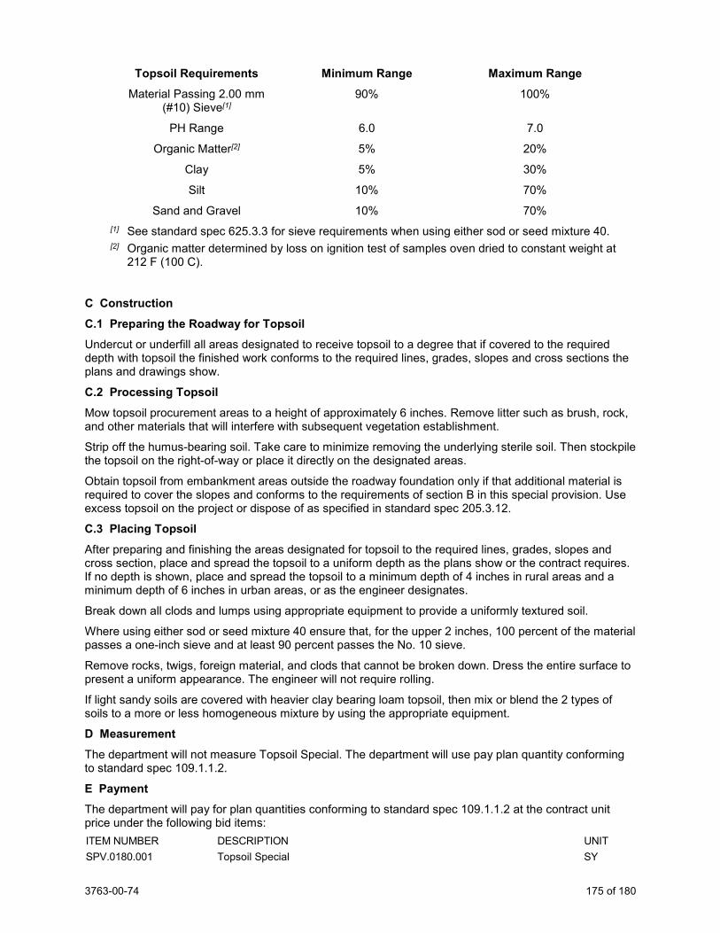
3763-00-74 175 of 180
Topsoil Requirements Minimum Range Maximum Range Material Passing 2.00 mm
(#10) Sieve[1] 90% 100%
PH Range 6.0 7.0
Organic Matter[2] 5% 20%
Clay 5% 30%
Silt 10% 70%
Sand and Gravel 10% 70% [1] See standard spec 625.3.3 for sieve requirements when using either sod or seed mixture 40. [2] Organic matter determined by loss on ignition test of samples oven dried to constant weight at
212 F (100 C).
C Construction C.1 Preparing the Roadway for Topsoil Undercut or underfill all areas designated to receive topsoil to a degree that if covered to the required depth with topsoil the finished work conforms to the required lines, grades, slopes and cross sections the plans and drawings show.
C.2 Processing Topsoil Mow topsoil procurement areas to a height of approximately 6 inches. Remove litter such as brush, rock, and other materials that will interfere with subsequent vegetation establishment.
Strip off the humus-bearing soil. Take care to minimize removing the underlying sterile soil. Then stockpile the topsoil on the right-of-way or place it directly on the designated areas.
Obtain topsoil from embankment areas outside the roadway foundation only if that additional material is required to cover the slopes and conforms to the requirements of section B in this special provision. Use excess topsoil on the project or dispose of as specified in standard spec 205.3.12.
C.3 Placing Topsoil After preparing and finishing the areas designated for topsoil to the required lines, grades, slopes and cross section, place and spread the topsoil to a uniform depth as the plans show or the contract requires. If no depth is shown, place and spread the topsoil to a minimum depth of 4 inches in rural areas and a minimum depth of 6 inches in urban areas, or as the engineer designates.
Break down all clods and lumps using appropriate equipment to provide a uniformly textured soil.
Where using either sod or seed mixture 40 ensure that, for the upper 2 inches, 100 percent of the material passes a one-inch sieve and at least 90 percent passes the No. 10 sieve.
Remove rocks, twigs, foreign material, and clods that cannot be broken down. Dress the entire surface to present a uniform appearance. The engineer will not require rolling.
If light sandy soils are covered with heavier clay bearing loam topsoil, then mix or blend the 2 types of soils to a more or less homogeneous mixture by using the appropriate equipment.
D Measurement The department will not measure Topsoil Special. The department will use pay plan quantity conforming to standard spec 109.1.1.2.
E Payment The department will pay for plan quantities conforming to standard spec 109.1.1.2 at the contract unit price under the following bid items: ITEM NUMBER DESCRIPTION UNIT SPV.0180.001 Topsoil Special SY
3763-00-74 176 of 180
Payment for Topsoil Special is full compensation for removing, stockpiling, reclaiming, providing, processing, excavating, loading, hauling, and placing this material; and for undercutting excavations, or underfilling embankments necessary to receive this material. The department will make no deductions from the Excavation bid items for quantities of Topsoil Special obtained from cut sections. The department will not measure or pay for volumes of Topsoil Special obtained from the sites of proposed embankments under the Excavation bid items. Additionally, the department will make no allowance, adjustment, or measurement for payment under the Excavation bid items for undercutting cut sections necessary to receive Topsoil Special. The department will not measure and pay for volumes of topsoil placed under the Roadway Embankment bid item.
If an area is damaged by erosion after partial acceptance, the department will pay for restoring topsoil in these areas at a unit price determined by multiplying the contract unit price bid for Topsoil multiplied by 3, the department will pay for restoration under the Restoration Post Acceptance Topsoil administrative item.
The department will not pay for removing topsoil from outside the roadway foundation in embankment areas unless that material is necessary to cover the slopes.
sef-625-005 (20170310)
134. RSC Restoration, Item SPV.0180.002. A Description This special provision describes the site restoration for Regenerative Stormwater Conveyance, including mulch, seed, and tackify, as indicated on the RSC Erosion control plan.
B Materials B.1 Mulch Acceptable mulch product includes wood or wood fiber materials specified in standard spec 627.2.
B.1.1 WisDOT Seed Mix No. 80 Provide WisDOT seed mix No. 80 in and around the RSC as indicated on the construction plans.
C Construction Apply seed and mulch according to Method B as specified in standard spec 627.3.2.2 and standard spec 630.3.3.3.
D Measurement The department will measure RSC Restoration by square yards, acceptably completed. E Payment The department will pay for measured quantities at the contract unit price under the following bid items: ITEM NUMBER DESCRIPTION UNIT SPV.0180.002 RSC Restoration SY
Payment is full compensation for furnishing and installing the RSC materials and appurtenances according to the drawings and details.
The department will pay separately for Excavation, Geotextile, Manholes, Underdrain and Storm Sewer furnishing and materials under the other bid items in this contract.
135. Possible Management of Solid Waste, Item SPV.0195.001. The department completed a review of environmental documents and databases for soil contamination at locations within this project where excavation is required. The review indicated that solid waste (contaminated soil) is likely to be encountered during excavation near the Canadian Pacific Railway and Union Pacific Railway at the following location:
3763-00-74 177 of 180
1. CTH KR Station 476+65 to 478+25, from approximately 150 feet left to 150 feet right of reference line, from approximately 0 to 4+ feet below existing grade.
2. CTH KR Station 532+75 to 533+75, from approximately 150 feet left to 150 feet right of reference line, from approximately 0 to 4+ feet below existing grade.
Coordinate with the environmental consultant to ensure that the environmental consultant is present during excavation activities in the area of the railroad crossing described above.
The environmental consultant for this project is: Consultant: TRC Environmental Corporation Address: 150 N. Patrick Blvd., Suite 180, Brookfield, WI 53045 Contact: Bryan Bergmann Phone: (262) 901-2126 office / (262) 227-9210 cell Fax: (262) 879-1220 E-mail: [email protected]
Information regarding the department’s hazardous materials assessment and the potential for handling and disposal of contaminated soil is available by contacting:
Name: Andrew Malsom Address: 141 NW Barstow St., Waukesha, WI 53187 Phone: (262) 548-6705 E-mail: [email protected]
Control construction operations at the location described above to ensure that they do not extend beyond the excavation limits indicated in the plans.
Soil samples collected during construction from the area identified above will be submitted to a laboratory for analytical testing. The results of the laboratory testing will be used to determine if the soil requires landfill disposal or can be considered common excavation. The soil sampling, laboratory testing, and approval for landfill disposal (if necessary) is estimated to take up to 10 calendar days to complete.
Soil samples shall be collected from test pits excavated by the contractor at the location described above or from a temporary stockpile if the contractor excavates soil from the location described prior to testing. Test pits and temporary stockpiling of soil is incidental to the contract. The stockpile shall be located within the right-of-way and placed on plastic and covered with plastic according to NR 718.05 of the Wisconsin Administrative Code.
If analytical testing indicates the stockpiled soil requires landfill disposal, the closest landfills to the project would be the following.
Republic Services, Inc. Kestrel Hawk Landfill 1989 Oakes Road Racine, WI 53406 (262) 884-7081 Waste Management Pheasant Run Recycling and Disposal Facility 19414 60th Street Bristol, WI 53104 (262) 857-7956 Advanced Disposal Emerald Park Landfill W124 S10629 South 124th St. Muskego, WI 53150 (414) 529-1360
Perform this work according to standard spec 205 and with pertinent parts of Chapter NR 700-754 of the Wisconsin Administrative Code, as supplemented herein. Per NR718.07, a solid waste collection and transportation service-operating license is required under NR 502.06 for each vehicle used to transport contaminated soil,
If contaminated soil is encountered at this site or elsewhere on the project during excavation, terminate excavation in the area and notify the engineer.
3763-00-74 178 of 180
A.1 Excavation Management Plan The excavation management plan for this project has been designed to minimize the offsite landfilling of contaminated material. The excavation management plan, including these special provisions, has been developed in cooperation with the WDNR. The WDNR concurrence letter is on file at the Wisconsin Department of Transportation. For further information regarding previous investigation and remediation activities at this site contact: Name: Andrew Malsom Address: 141 NW Barstow Street, PO Box 798, Waukesha, WI 53187-0798 Phone: (262) 548-6705 Fax: (262) 548-6891 E-mail: [email protected]
A.2 Coordination Coordinate work under this contract with the environment consultant: Consultant: TRC Environmental Corporation Address: 150 N. Patrick Blvd., Ste. 180, Brookfield, WI 53045 Contact: Bryan Bergmann
Phone: (262) 901-2126 office / (262) 227-9210 cell Fax: (262 879-1220
E-mail: [email protected]
The role of the environmental consultant will be limited to:
1. Determining the location and limits of contaminated soil to be excavated as expressed on the project plans and described in the special provisions;
2. Coordinating lab testing for landfill acceptance; 3. Identifying contaminated soils to be hauled to the landfill; 4. Obtaining landfill permitting and documentation of proper landfill disposal; 5. Documenting that activities associated with management of contaminated soil are in
conformance with the contaminated soil management methods for this project as specified herein.
Provide at least a 14-calendar day notice of the preconstruction conference date to the environmental consultant. At the preconstruction conference, provide a schedule for all excavation activities in the area of possible contaminated soil to the environmental consultant. Also notify the environmental consultant at least three calendar days prior to commencement of excavation activities in the area with possible contaminated soil.
Identify the landfill that will be used for disposal of contaminated soil and provide this information to the environmental consultant no later than 30 calendar days prior to commencement of excavation activities in the possible contaminated soil area or at the preconstruction conference, whichever comes first. The environmental consultant will be responsible for obtaining the necessary approvals for disposal. Do not transport contaminated soil offsite without prior approval from the environmental consultant.
A.3 Health and Safety Requirements Add the following to standard spec 107.1:
During excavation activities, expect to encounter soil possibly contaminated with Volatile Organic Compounds (VOCs), Semi-Volatile Organic Compounds (SVOCs), and/or Metals. Site workers taking part in activities that will result in the reasonable probability of exposure to safety and health hazards associated with hazardous materials shall have completed health and safety training that meets the Occupational Safety and Health Administration (OSHA) requirements for Hazardous Waste Operations and Emergency Response (HAZWOPER), as provided in 29 CFR 1910.120.
Prepare a site-specific Health and Safety Plan, and develop, delineate and enforce the health and safety exclusion zones for each contaminated site location as required by 29 CFR 1910.120. Submit the site-specific health and safety plan and written documentation of up-to-date OSHA training to the engineer prior to the start of work.
B (Vacant)
3763-00-74 179 of 180
C Construction Add the following to standard spec 205.3:
Control operations in the possible contaminated soil area to minimize the quantity of contaminated soil excavated.
Excavate the possible contaminated soil in the area shown in the plan. Stockpile the material within the project footprint of DOT right-of-way, pending lab results and landfill acceptance (if necessary). Construct and maintain a temporary stockpile of the material according to NR 718.05(3), including, but not limited to, placement of the contaminated soil/fill material on an impervious surface and covering the stockpile with impervious material to prevent infiltration and precipitation. In lieu of temporary stockpiling the possible contaminated soil, excavate test pits as directed by the environmental consultant prior to excavation in the area of possible contaminated soil.
The environmental consultant will coordinate analytical testing of possible contaminated soil for landfill acceptance. 5 business days should be allowed for the laboratory to conduct this testing and issue results. In the event the laboratory analytical test results do not indicate contamination is present, the stockpiled material may be considered common excavation and can be handled according to the erosion control implementation plan (ECIP).
Once landfill acceptance permitting is complete (if necessary), directly load and haul soils to the landfill as directed by the environmental consultant. Use loading and hauling practices that are appropriate to prevent any spills or releases of contaminated soil or residues. Prior to transport, sufficiently dewater soils designated for off-site bioremediation so as not to contain free liquids. Verify that the vehicles used to transport contaminated materials are licensed for such activity according to applicable state and federal regulations.
When material is encountered outside the above-identified limits of possible contaminated soil that appears to have been impacted with petroleum or chemical products or when other obvious potentially contaminated materials are encountered or material exhibits characteristics of industrial-type wastes, such as fly ash, foundry sand, and cinders, or when underground storage tanks are encountered, suspend excavation in that area and notify the engineer and the environmental consultant.
D Measurement The department will measure Possible Management of Solid Waste in tons of contaminated soil, accepted by the landfill as documented by weight tickets generated by the landfill.
E Payment Temporary stockpiling of soil is incidental to the contract.
The department will pay for measured quantities at the contract unit price under the following bid item: ITEM NUMBER DESCRIPTION UNIT SPV.0195.001 Possible Management of Solid Waste TON
Payment is full compensation for excavating, stockpiling (including contractor-provided plastic sheeting to cover as well as place the material on), loading, and hauling the solid waste soil to a landfill; obtaining solid waste collection and transportation service operating licenses; assisting in the collection soil samples for field evaluation; and dewatering of soils prior to transport, if necessary. 107-100 (20050901)
136. Reconstruct Sanitary Manhole Addition, Item SPV.0200.600; Reconstruct Sanitary Manhole Subtraction, Item SPV.0200.601. A Description This special provision describes the reconstruction of existing sanitary manholes as necessary to match the proposed surface elevations.
B Materials Supply all concrete manhole sections, concrete adjusting rings, mortar, and butyl material necessary to perform the work. Provide Adaptor, Inc., Cretex Specialty Products, or equal internal/external chimney seal.
3763-00-74 180 of 180
C Construction Reconstruct sanitary manholes to match surface elevations as necessary. Remove or add concrete manhole sections as required. Rebuild chimney with new rings, seals and reinstall existing frame and cover.
D Measurement The department will measure Reconstruct Sanitary Manhole Addition and Reconstruct Sanitary Manhole Subtraction by the vertical foot, acceptably completed, per final surface elevation difference.
E Payment The department will pay for measured quantities at the contract unit price under the following bid item: ITEM NUMBER DESCRIPTION UNIT SPV.0200.600 Reconstruct Sanitary Manhole Addition VF SPV.0200.601 Reconstruct Sanitary Manhole Subtraction VF
Payment is full compensation for providing and installing all required materials including barrel sections, adjusting rings, internal frame/chimney seals, joints, steps, elastomeric waterproofing sealer, plastic sheet, and masonry and fittings; for salvaging and reinstalling existing or new covers, including frames and lids; for excavating, backfilling, and compacting; for furnishing and placing slurry backfill; for disposing of surplus materials; and for cleaning out and restoring the structure
November 2013 ASP-4
ADDITIONAL SPECIAL PROVISION 4
Payment to First-Tier Subcontractors Within 10 calendar days of receiving a progress payment for work completed by a subcontractor, pay the subcontractor for that work. The prime contractor may withhold payment to a subcontractor if, within 10 calendar days of receipt of that progress payment, the prime contractor provides written notification to the subcontractor and the department documenting "just cause" for withholding payment.
The prime contractor may also withhold routine retainage from payments due subcontractors.
Payment to Lower-Tier Subcontractors Ensure that subcontracting agreements at all tiers provide prompt payment rights to lower-tier subcontractors that parallel those granted first-tier subcontractors in this provision.
Release of Routine Retainage After granting substantial completion the department may reduce the routine retainage withheld from the prime contractor to 75 percent of the original total amount retained.
When the Department sends the semi-final estimate the department may reduce the routine retainage withheld from the prime contractor to 10 percent of the original total amount retained.
Within 30 calendar days of receiving the semi-final estimate from the department, submit written certification that subcontractors at all tiers are paid in full for acceptably completed work and that no routine retainage is being withheld. The department will pay the prime contractor in full and reduce the routine retainage withheld from the prime contractor to zero when the department approves the final estimate.
This special provision does not limit the right of the department, prime contractor, or subcontractors at any tier to withhold payment for work not acceptably completed or work subject to an unresolved contract dispute.
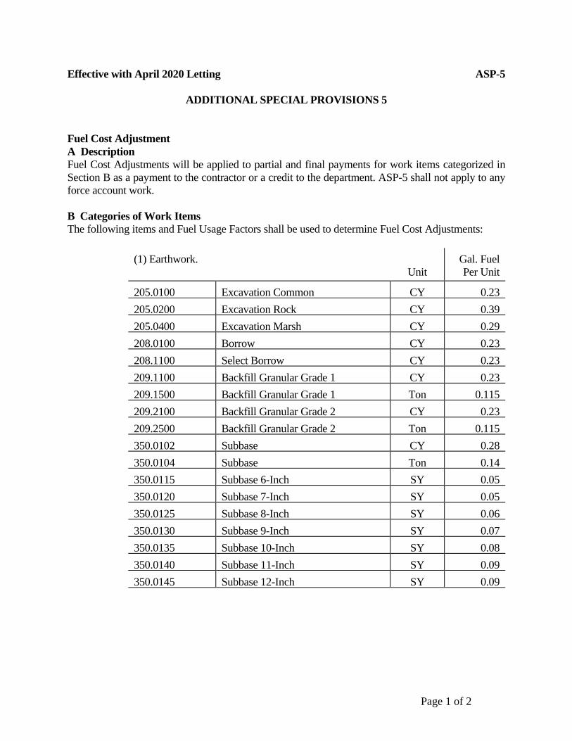
Page 1 of 2
Effective with April 2020 Letting ASP-5 ADDITIONAL SPECIAL PROVISIONS 5 Fuel Cost Adjustment A Description Fuel Cost Adjustments will be applied to partial and final payments for work items categorized in Section B as a payment to the contractor or a credit to the department. ASP-5 shall not apply to any force account work. B Categories of Work Items The following items and Fuel Usage Factors shall be used to determine Fuel Cost Adjustments: (1) Earthwork.
Unit Gal. Fuel Per Unit
205.0100 Excavation Common CY 0.23 205.0200 Excavation Rock CY 0.39 205.0400 Excavation Marsh CY 0.29 208.0100 Borrow CY 0.23 208.1100 Select Borrow CY 0.23 209.1100 Backfill Granular Grade 1 CY 0.23 209.1500 Backfill Granular Grade 1 Ton 0.115 209.2100 Backfill Granular Grade 2 CY 0.23 209.2500 Backfill Granular Grade 2 Ton 0.115 350.0102 Subbase CY 0.28 350.0104 Subbase Ton 0.14 350.0115 Subbase 6-Inch SY 0.05 350.0120 Subbase 7-Inch SY 0.05 350.0125 Subbase 8-Inch SY 0.06 350.0130 Subbase 9-Inch SY 0.07 350.0135 Subbase 10-Inch SY 0.08 350.0140 Subbase 11-Inch SY 0.09 350.0145 Subbase 12-Inch SY 0.09
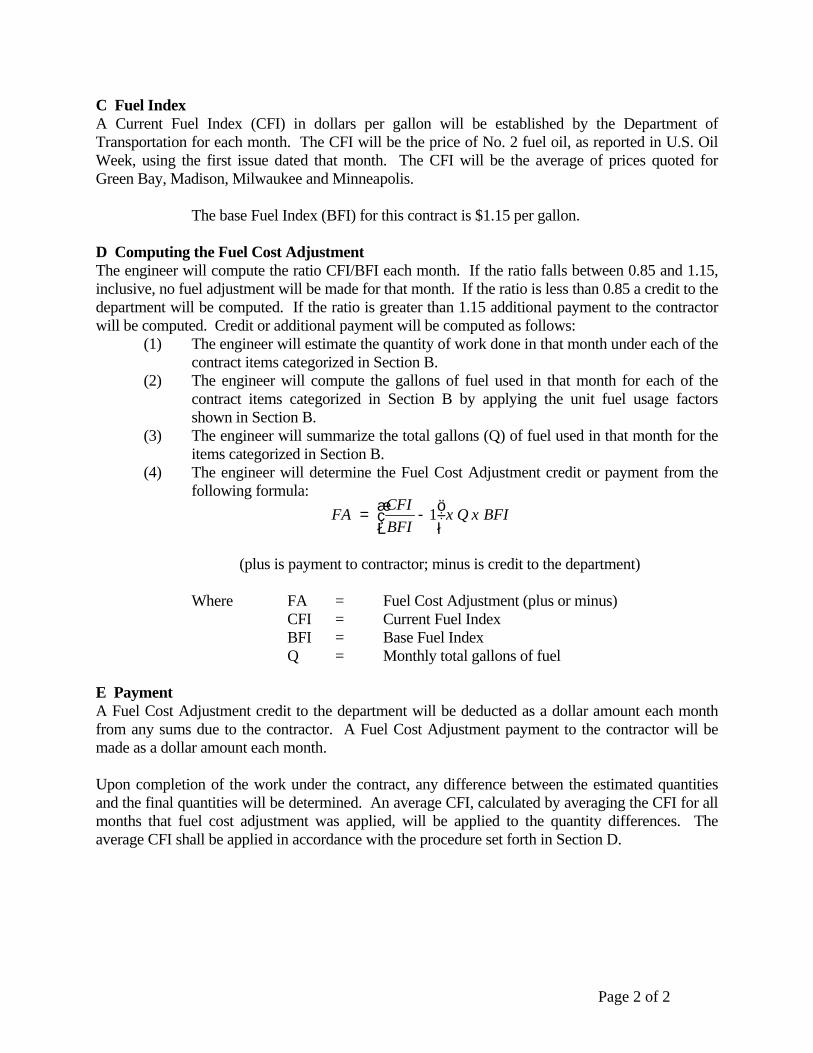
Page 2 of 2
C Fuel Index A Current Fuel Index (CFI) in dollars per gallon will be established by the Department of Transportation for each month. The CFI will be the price of No. 2 fuel oil, as reported in U.S. Oil Week, using the first issue dated that month. The CFI will be the average of prices quoted for Green Bay, Madison, Milwaukee and Minneapolis. The base Fuel Index (BFI) for this contract is $1.15 per gallon. D Computing the Fuel Cost Adjustment The engineer will compute the ratio CFI/BFI each month. If the ratio falls between 0.85 and 1.15, inclusive, no fuel adjustment will be made for that month. If the ratio is less than 0.85 a credit to the department will be computed. If the ratio is greater than 1.15 additional payment to the contractor will be computed. Credit or additional payment will be computed as follows:
(1) The engineer will estimate the quantity of work done in that month under each of the contract items categorized in Section B.
(2) The engineer will compute the gallons of fuel used in that month for each of the contract items categorized in Section B by applying the unit fuel usage factors shown in Section B.
(3) The engineer will summarize the total gallons (Q) of fuel used in that month for the items categorized in Section B.
(4) The engineer will determine the Fuel Cost Adjustment credit or payment from the following formula:
(plus is payment to contractor; minus is credit to the department) Where FA = Fuel Cost Adjustment (plus or minus) CFI = Current Fuel Index BFI = Base Fuel Index Q = Monthly total gallons of fuel E Payment A Fuel Cost Adjustment credit to the department will be deducted as a dollar amount each month from any sums due to the contractor. A Fuel Cost Adjustment payment to the contractor will be made as a dollar amount each month. Upon completion of the work under the contract, any difference between the estimated quantities and the final quantities will be determined. An average CFI, calculated by averaging the CFI for all months that fuel cost adjustment was applied, will be applied to the quantity differences. The average CFI shall be applied in accordance with the procedure set forth in Section D.
BFIxQxBFICFIFA ÷
øö
çèæ -= 1

Effective with June 2020 Letting ASP-6
page 1 of 18
Additional Special Provision 6 ASP 6 - Modifications to the standard specifications
Make the following revisions to the standard specifications:
104.3 Contractor Notification Replace the entire text with the following effective with the December 2019 letting:
104.3.1 General (1) Subsection 104.3 specifies the step-by-step communication process to be followed to expedite the
resolution of potential contract revisions identified by the contractor. Both contractor actions and department responses are outlined. The contractor's non-compliance with the requirements of 104.3 may constitute a waiver of entitlement to a pay adjustment under 109.4 or a time extension under 108.10. The department and contractor can mutually agree to extend any time frame specified throughout 104.3. 104.3.2 Contractor Initial Oral Notification
(1) If required by 104.2, or if the contractor believes that the department’s action, the department's lack of action, or some other situation results in or necessitates a contract revision, the contractor must promptly provide oral notification to the project engineer. Upon notification, the project engineer will attempt to resolve the identified issue. 104.3.3 Contractor 5-Day Written Statement
(1) If the project engineer has not responded or resolved the identified issue within 5 business days after receipt of initial notification, provide a contractor written statement to the project engineer in the following format: Part 1 - Executive Summary (label page 1.1 through page 1.x)
Include a detailed, factual statement of the request for additional compensation and contract time. Include the date the issue was identified, the date initial notification was given to the project engineer, and the dates and specific locations of work involved.
Part 2 - Contractor’s Basis of Entitlement (label page 2.1 through page 2.x) Include references to relevant contract provisions and a narrative summarizing how the contract provisions support the request for a revision to the original contract.
Part 3 - Contractor’s Request for Damages (label page 3.1 through page 3.x) When requesting additional compensation, include an itemized list of costs with a narrative supporting the requested amount and explaining how the costs are tied to the requested contract revision. When requesting additional contract time, include a copy of the schedule that was in effect when the issue occurred and a detailed narrative explaining how the issue impacted controlling items of work. Provide a time impact analysis utilizing base and updated schedules. If the full extent of either compensation or time is not known at the date of submittal of the contractor 5-Day written statement, provide a brief statement as to why, and include estimated compensation and time.
Part 4 - Supporting Documentation (label page 4.1 through page 4.x) Include copies of the following:
A. Relevant excerpts from specifications, special provisions, plans, change orders, or other contract documents.
B. Communication on the issue, including: letters, e-mails, meeting minutes, etc. C. Any other documentation to support or clarify the contractor’s position, including: daily work records,
cost summary sheets, weigh tickets, test results, sketches, etc. (2) With the submittal of the written statement, the contractor may also request a meeting with the region.
104.3.4 Region One-Day Written Acknowledgment (1) Within one business day after the contractor provides the 5-day written statement, the project engineer
will provide a region one-day written acknowledgment to the contractor. The project engineer will continue to resolve the issue. 104.3.5 Region 5-Day Written Response
(1) Within 5 business days after receiving the contractor 5-day written statement, the project engineer may request specific additional information to allow the project engineer to decide whether item 1 or 2 of 104.3.6(1) applies. The project engineer will state the information needed and date it is to be
Effective with June 2020 Letting ASP-6
page 2 of 18
received for further review. Submit additional information as an amendment to the contractor 5-day written statement. 104.3.6 Region Final Decision
(1) Within 10 business days after receiving the contractor 5-day written statement or additional information requested in 104.3.5(1), whichever comes last, the region will consider all information and provide a region final decision in writing to the contractor with one or more of the following responses:
1. The region will confirm that the contractor is entitled to a contract revision and a contract change order is necessary as specified in 104.2. The project engineer will give direction concerning the potential change.
2. The region will deny that the contractor is entitled to a contract revision. The project engineer will provide a statement as to why the issue is not a change to the contract. At a minimum, the project engineer will respond to the contractor’s issues and refer to the contract to show why the issues are not a change from the original contract.
(2) If the contractor does not agree with the region's decision the contractor may pursue the issue as a claim as specified in 105.13. Alternatively, if the contractor and department mutually agree, the department will get a third-party advisory opinion according to the department’s dispute resolution procedures.
(3) If a third party reviews the issue, their recommendation is not binding on either party. The region has 10 business days after receipt of the third party's written recommendation to render a decision. If the department fails to respond in writing within those 10 business days or the contractor disagrees with the region's decision, the contractor may pursue the issue as a claim as specified in 105.13.
104.6.1.2.1 General Replace paragraph one with the following effective with the December 2019 letting: (1) Conduct construction operations and provide facilities required to maintain the portion of the project
open to the public in a condition that safely and adequately accommodates public traffic. Use barricades, signs, flaggers, and temporary barrier as specified in part VI, of the WMUTCD and ensure that the contractor's use of the right-of-way conforms to 107.9. Throughout the life of the contract, and as the engineer directs, conduct construction operations and provide facilities as follows:
- Conduct flagging operations conforming to plan details and the department's flagging handbook. - Use drums, barricades, and temporary barrier to delineate and shield abrupt drop-offs and other hazards. - Furnish, erect, and maintain traffic control devices and facilities conforming to 643. - Furnish, erect, and maintain temporary pedestrian devices and facilities conforming to 644.
104.6.1.2.2 Flagging Replace paragraph three with the following effective with the December 2019 letting: (3) Provide associated advanced warning signs that meet the retroreflective requirements of 637.2.2.2.
Provide temporary portable rumble strips from the department's APL installed according to manufacturer's instructions and as specified in the flagging plan details. Provide guidance service through the worksite using pilot vehicles if required.
Replace paragraph five with the following effective with the December 2019 letting: (5) Flagging is incidental to the contract and includes costs for advance signing, temporary portable
rumble strips, and pilot vehicle guidance service.
Effective with June 2020 Letting ASP-6
page 3 of 18
104.8 Rights in the Use of Materials Found on the Project Replace paragraph two with the following effective with the December 2019 letting: (2) Do not excavate or remove material from within the right-of-way that is not within the vertical and
horizontal excavation limits the plans show except as follows: - If the contract does not identify potential source areas, obtain written authorization from the engineer to
use those sources. Complete required environmental documentation and obtain necessary permits. The department will reduce pay by $1.50 per cubic yard under the Material from Right-of-Way administrative item for material obtained from those areas.
- If the contract identifies potential source areas that were evaluated and permitted in the original environmental document, do not begin excavating in those areas until the engineer allows in writing. Additional environmental documentation and environmental permits are not required. The department will not reduce pay for material obtained from those areas.
The department may suspend use of these sources if the contractor's operation affects the essential functions or characteristics of the project.
104.10.1 General Replace paragraph one with the following effective with the December 2019 letting: (1) Subsection 104.10 specifies a 2-step process for contractors to follow in submitting a cost reduction
incentive (CRI) for modifying the contract in order to reduce direct construction costs computed at contract bid prices. The initial submittal is referred to as a CRI concept and the second submittal is a CRI proposal. The contractor and the department will equally share all savings generated to the contract due to a CRI as specified in 104.10.4.2(1). The department encourages the contractor to submit CRI concepts for the following situations:
1. The contractor generates the original cost savings idea and formulates it into a concept. 2. The department generates the original cost savings idea and obtains the contractor’s assistance to
formulate the idea into a concept. Replace paragraph five with the following effective with the December 2019 letting: (5) The department will consider a CRI that changes but does not impair the essential functions or
characteristics of the project. These functions or characteristics include, but are not limited to, appearance, service life, economy of operations, ease of maintenance, design, and safety of structures and pavements, construction phasing or procedures, or other contract requirements. The department will not consider a CRI that changes the following:
- Permanent pavement type. - Permanent structural cross section above the subgrade.
104.10.2 Submittal and Review of a CRI Concept Replace paragraphs five and six with the following effective with the December 2019 letting: (5) The department may consider a CRI concept that addresses a potential change under 104.2. (6) The department will not implement a contractor-initiated CRI concept, or portion of that concept,
without sharing the cost savings with the contractor as specified in 104.10.4.2. (7) The savings generated by the CRI must be sufficient to warrant its review and processing and offset
the level of risk. The department will assess the risk of the CRI relative to departmental design policies and criteria for the project. The department may reject a CRI concept for the following reasons:
1. It requires excessive time or costs for the contractor to develop the CRI proposal. 2. It requires excessive time or costs for review, evaluation, investigation, or implementation. 3. It introduces an inappropriate level of risk.
Effective with June 2020 Letting ASP-6
page 4 of 18
104.10.4.2 Payment for the CRI Work Replace paragraph one with the following effective with the December 2019 letting: (1) The department will pay for completed CRI work as specified for progress payments under 109.6. The
department will pay for CRI's under the Cost Reduction Incentive administrative item. When all CRI costs are determined, the department will execute a contract change order that does the following:
1. Adjusts the contract time, interim completion dates, or both. 2. Pays the contractor for the unpaid balance of the CRI work. 3. Pays the contractor 50 percent of the net savings resulting from the CRI, calculated as follows:
NS = CW - CRW - CC - DC Where:
NS = Net Savings CW = The cost of the work required by the original contract that is revised by
the CRI. CW is computed at contract bid prices if applicable. CRW = The cost of the revised work, computed at contract bid prices if
applicable. CC = The contractor’s cost of developing the CRI proposal. DC = The department’s cost for investigating, evaluating, and implementing
the CRI proposal.
105.13 Claims Process for Unresolved Changes Replace the entire text with the following effective with the December 2019 letting:
105.13.1 General (1) Before submitting a claim, the department and contractor can mutually agree to have the department
get a third-party advisory opinion as specified in 104.3.6. (2) The department and contractor can mutually agree to extend any time frame specified throughout
105.13 and can mutually agree to utilize an alternative dispute resolution method at any point before the department renders its final decision.
(3) The department and contractor share costs related to referral to a dispute review board (DRB) as prescribed in the department's dispute resolution procedures. 105.13.2 Notice of Claim
(1) If the contractor has followed the procedures for revising the contract specified in 104.2 and provided the notification specified in 104.3, but still disagrees with the region, the contractor may pursue the issue as a claim. File a notice of claim with the project engineer concerning the disagreement within 14 calendar days of receiving the region's decision under 104.3.6(1).
(2) The project engineer may deny the applicable portion of a claim if the contractor does not do the following:
1. File the notice of claim within 14 calendar days as specified in 105.13.2(1). 2. Give the project engineer sufficient access to keep a record of the actual labor, materials, and equipment
used to perform the claimed work. (3) Upon filing the notice of claim, maintain records as specified for force account statements in 109.4.5.
Unless the project engineer issues a suspension, continue to perform the disputed work. The department will continue to make progress payments to the contractor as specified in 109.6. 105.13.3 Submission of Claim
(1) Submit the claim to the project engineer as promptly as possible following the submission of the Notice of Claim, but not later than the end of the time allowed under 109.7 for the contractor to respond in writing to the engineer-issued semi-final estimate. If the contractor does not submit the claim within that response time, the department will deny the claim.
(2) The department will not accept the submission of a claim until the resolution process in 104.3 has been completed and the contractor makes no further requests to submit updated information that may affect the region’s final decision.
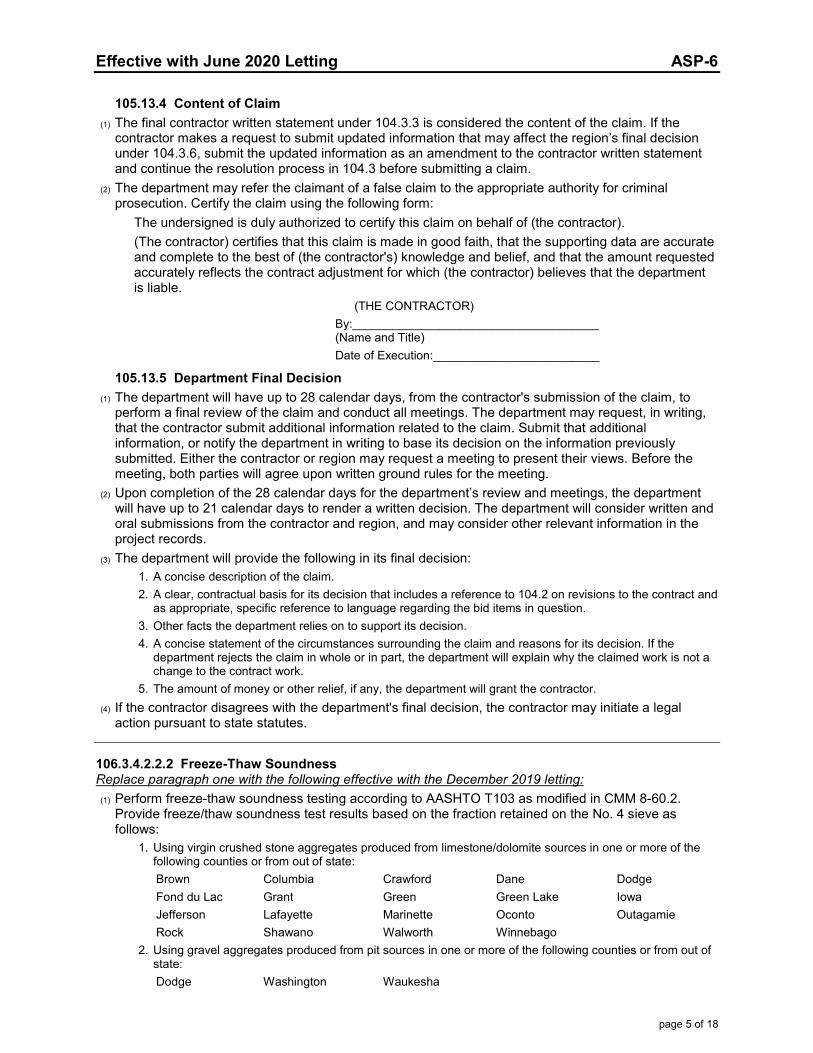
Effective with June 2020 Letting ASP-6
page 5 of 18
105.13.4 Content of Claim (1) The final contractor written statement under 104.3.3 is considered the content of the claim. If the
contractor makes a request to submit updated information that may affect the region’s final decision under 104.3.6, submit the updated information as an amendment to the contractor written statement and continue the resolution process in 104.3 before submitting a claim.
(2) The department may refer the claimant of a false claim to the appropriate authority for criminal prosecution. Certify the claim using the following form:
The undersigned is duly authorized to certify this claim on behalf of (the contractor). (The contractor) certifies that this claim is made in good faith, that the supporting data are accurate and complete to the best of (the contractor's) knowledge and belief, and that the amount requested accurately reflects the contract adjustment for which (the contractor) believes that the department is liable.
(THE CONTRACTOR) By:_____________________________________ (Name and Title) Date of Execution:_________________________
105.13.5 Department Final Decision (1) The department will have up to 28 calendar days, from the contractor's submission of the claim, to
perform a final review of the claim and conduct all meetings. The department may request, in writing, that the contractor submit additional information related to the claim. Submit that additional information, or notify the department in writing to base its decision on the information previously submitted. Either the contractor or region may request a meeting to present their views. Before the meeting, both parties will agree upon written ground rules for the meeting.
(2) Upon completion of the 28 calendar days for the department’s review and meetings, the department will have up to 21 calendar days to render a written decision. The department will consider written and oral submissions from the contractor and region, and may consider other relevant information in the project records.
(3) The department will provide the following in its final decision: 1. A concise description of the claim. 2. A clear, contractual basis for its decision that includes a reference to 104.2 on revisions to the contract and
as appropriate, specific reference to language regarding the bid items in question. 3. Other facts the department relies on to support its decision. 4. A concise statement of the circumstances surrounding the claim and reasons for its decision. If the
department rejects the claim in whole or in part, the department will explain why the claimed work is not a change to the contract work.
5. The amount of money or other relief, if any, the department will grant the contractor. (4) If the contractor disagrees with the department's final decision, the contractor may initiate a legal
action pursuant to state statutes.
106.3.4.2.2.2 Freeze-Thaw Soundness Replace paragraph one with the following effective with the December 2019 letting: (1) Perform freeze-thaw soundness testing according to AASHTO T103 as modified in CMM 8-60.2.
Provide freeze/thaw soundness test results based on the fraction retained on the No. 4 sieve as follows:
1. Using virgin crushed stone aggregates produced from limestone/dolomite sources in one or more of the following counties or from out of state: Brown Columbia Crawford Dane Dodge Fond du Lac Grant Green Green Lake Iowa Jefferson Lafayette Marinette Oconto Outagamie Rock Shawano Walworth Winnebago
2. Using gravel aggregates produced from pit sources in one or more of the following counties or from out of state: Dodge Washington Waukesha
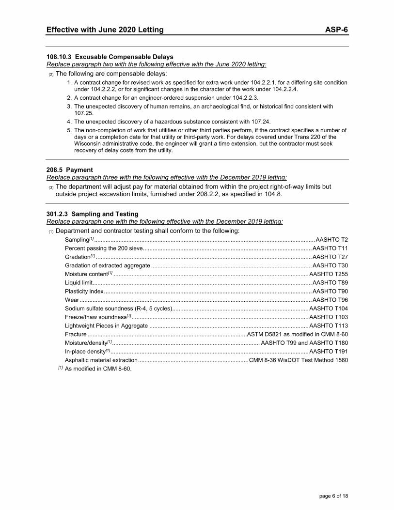
Effective with June 2020 Letting ASP-6
page 6 of 18
108.10.3 Excusable Compensable Delays Replace paragraph two with the following effective with the June 2020 letting: (2) The following are compensable delays: 1. A contract change for revised work as specified for extra work under 104.2.2.1, for a differing site condition
under 104.2.2.2, or for significant changes in the character of the work under 104.2.2.4. 2. A contract change for an engineer-ordered suspension under 104.2.2.3. 3. The unexpected discovery of human remains, an archaeological find, or historical find consistent with
107.25. 4. The unexpected discovery of a hazardous substance consistent with 107.24. 5. The non-completion of work that utilities or other third parties perform, if the contract specifies a number of
days or a completion date for that utility or third-party work. For delays covered under Trans 220 of the Wisconsin administrative code, the engineer will grant a time extension, but the contractor must seek recovery of delay costs from the utility.
208.5 Payment Replace paragraph three with the following effective with the December 2019 letting: (3) The department will adjust pay for material obtained from within the project right-of-way limits but
outside project excavation limits, furnished under 208.2.2, as specified in 104.8.
301.2.3 Sampling and Testing Replace paragraph one with the following effective with the December 2019 letting: (1) Department and contractor testing shall conform to the following:
Sampling[1] ........................................................................................................................................ AASHTO T2 Percent passing the 200 sieve ........................................................................................................ AASHTO T11 Gradation[1] ..................................................................................................................................... AASHTO T27 Gradation of extracted aggregate ................................................................................................... AASHTO T30 Moisture content[1] ........................................................................................................................ AASHTO T255 Liquid limit ....................................................................................................................................... AASHTO T89 Plasticity index ................................................................................................................................ AASHTO T90 Wear ............................................................................................................................................... AASHTO T96 Sodium sulfate soundness (R-4, 5 cycles) .................................................................................... AASHTO T104 Freeze/thaw soundness[1] ............................................................................................................. AASHTO T103 Lightweight Pieces in Aggregate .................................................................................................. AASHTO T113 Fracture .................................................................................................. ASTM D5821 as modified in CMM 8-60 Moisture/density[1] ........................................................................................... AASHTO T99 and AASHTO T180 In-place density[1] .......................................................................................................................... AASHTO T191 Asphaltic material extraction .................................................................... CMM 8-36 WisDOT Test Method 1560
[1] As modified in CMM 8-60.
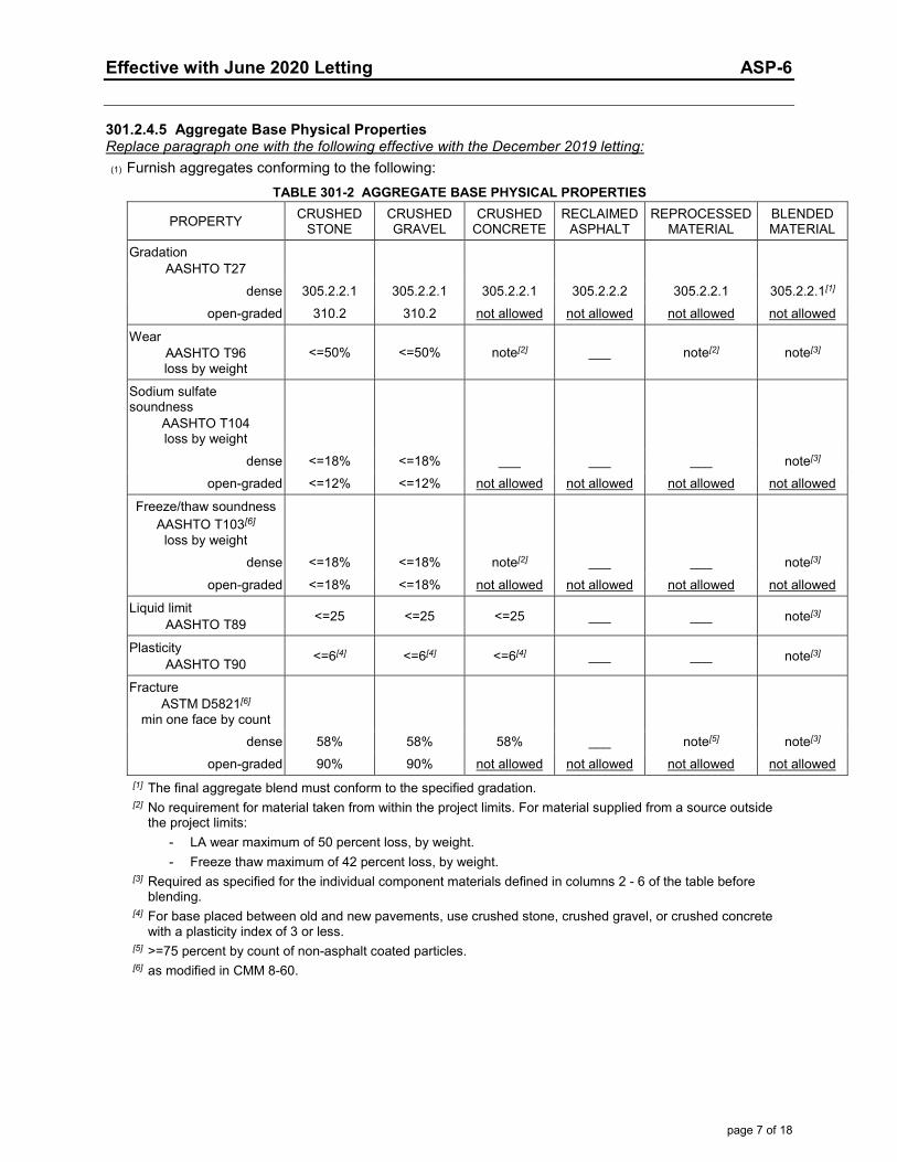
Effective with June 2020 Letting ASP-6
page 7 of 18
301.2.4.5 Aggregate Base Physical Properties Replace paragraph one with the following effective with the December 2019 letting: (1) Furnish aggregates conforming to the following:
TABLE 301-2 AGGREGATE BASE PHYSICAL PROPERTIES
PROPERTY CRUSHED STONE
CRUSHED GRAVEL
CRUSHED CONCRETE
RECLAIMED ASPHALT
REPROCESSED MATERIAL
BLENDED MATERIAL
Gradation AASHTO T27
dense 305.2.2.1 305.2.2.1 305.2.2.1 305.2.2.2 305.2.2.1 305.2.2.1[1] open-graded 310.2 310.2 not allowed not allowed not allowed not allowed
Wear AASHTO T96 loss by weight
<=50% <=50% note[2] ___ note[2] note[3]
Sodium sulfate soundness
AASHTO T104 loss by weight
dense <=18% <=18% ___ ___ ___ note[3] open-graded <=12% <=12% not allowed not allowed not allowed not allowed
Freeze/thaw soundness AASHTO T103[6]
loss by weight
dense <=18% <=18% note[2] ___ ___ note[3]
open-graded <=18% <=18% not allowed not allowed not allowed not allowed
Liquid limit AASHTO T89 <=25 <=25 <=25 ___ ___ note[3]
Plasticity AASHTO T90 <=6[4] <=6[4] <=6[4] ___ ___ note[3]
Fracture ASTM D5821[6]
min one face by count
dense 58% 58% 58% ___ note[5] note[3] open-graded 90% 90% not allowed not allowed not allowed not allowed
[1] The final aggregate blend must conform to the specified gradation. [2] No requirement for material taken from within the project limits. For material supplied from a source outside
the project limits: - LA wear maximum of 50 percent loss, by weight. - Freeze thaw maximum of 42 percent loss, by weight.
[3] Required as specified for the individual component materials defined in columns 2 - 6 of the table before blending.
[4] For base placed between old and new pavements, use crushed stone, crushed gravel, or crushed concrete with a plasticity index of 3 or less.
[5] >=75 percent by count of non-asphalt coated particles. [6] as modified in CMM 8-60.
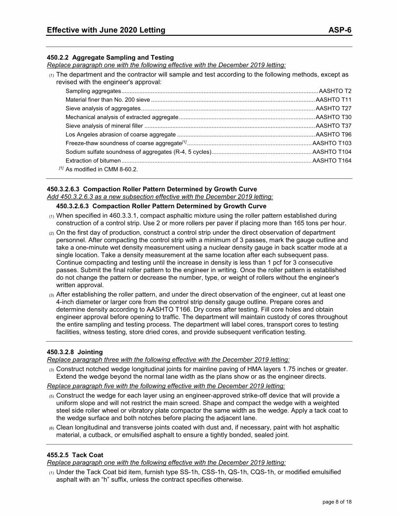
Effective with June 2020 Letting ASP-6
page 8 of 18
450.2.2 Aggregate Sampling and Testing Replace paragraph one with the following effective with the December 2019 letting: (1) The department and the contractor will sample and test according to the following methods, except as
revised with the engineer's approval: Sampling aggregates ........................................................................................................................ AASHTO T2 Material finer than No. 200 sieve .................................................................................................... AASHTO T11 Sieve analysis of aggregates .......................................................................................................... AASHTO T27 Mechanical analysis of extracted aggregate ................................................................................... AASHTO T30 Sieve analysis of mineral filler ........................................................................................................ AASHTO T37 Los Angeles abrasion of coarse aggregate .................................................................................... AASHTO T96 Freeze-thaw soundness of coarse aggregate[1] ............................................................................ AASHTO T103 Sodium sulfate soundness of aggregates (R-4, 5 cycles) ............................................................. AASHTO T104 Extraction of bitumen .................................................................................................................... AASHTO T164
[1] As modified in CMM 8-60.2.
450.3.2.6.3 Compaction Roller Pattern Determined by Growth Curve Add 450.3.2.6.3 as a new subsection effective with the December 2019 letting:
450.3.2.6.3 Compaction Roller Pattern Determined by Growth Curve (1) When specified in 460.3.3.1, compact asphaltic mixture using the roller pattern established during
construction of a control strip. Use 2 or more rollers per paver if placing more than 165 tons per hour. (2) On the first day of production, construct a control strip under the direct observation of department
personnel. After compacting the control strip with a minimum of 3 passes, mark the gauge outline and take a one-minute wet density measurement using a nuclear density gauge in back scatter mode at a single location. Take a density measurement at the same location after each subsequent pass. Continue compacting and testing until the increase in density is less than 1 pcf for 3 consecutive passes. Submit the final roller pattern to the engineer in writing. Once the roller pattern is established do not change the pattern or decrease the number, type, or weight of rollers without the engineer's written approval.
(3) After establishing the roller pattern, and under the direct observation of the engineer, cut at least one 4-inch diameter or larger core from the control strip density gauge outline. Prepare cores and determine density according to AASHTO T166. Dry cores after testing. Fill core holes and obtain engineer approval before opening to traffic. The department will maintain custody of cores throughout the entire sampling and testing process. The department will label cores, transport cores to testing facilities, witness testing, store dried cores, and provide subsequent verification testing.
450.3.2.8 Jointing Replace paragraph three with the following effective with the December 2019 letting: (3) Construct notched wedge longitudinal joints for mainline paving of HMA layers 1.75 inches or greater.
Extend the wedge beyond the normal lane width as the plans show or as the engineer directs. Replace paragraph five with the following effective with the December 2019 letting: (5) Construct the wedge for each layer using an engineer-approved strike-off device that will provide a
uniform slope and will not restrict the main screed. Shape and compact the wedge with a weighted steel side roller wheel or vibratory plate compactor the same width as the wedge. Apply a tack coat to the wedge surface and both notches before placing the adjacent lane.
(6) Clean longitudinal and transverse joints coated with dust and, if necessary, paint with hot asphaltic material, a cutback, or emulsified asphalt to ensure a tightly bonded, sealed joint.
455.2.5 Tack Coat Replace paragraph one with the following effective with the December 2019 letting: (1) Under the Tack Coat bid item, furnish type SS-1h, CSS-1h, QS-1h, CQS-1h, or modified emulsified
asphalt with an “h” suffix, unless the contract specifies otherwise.
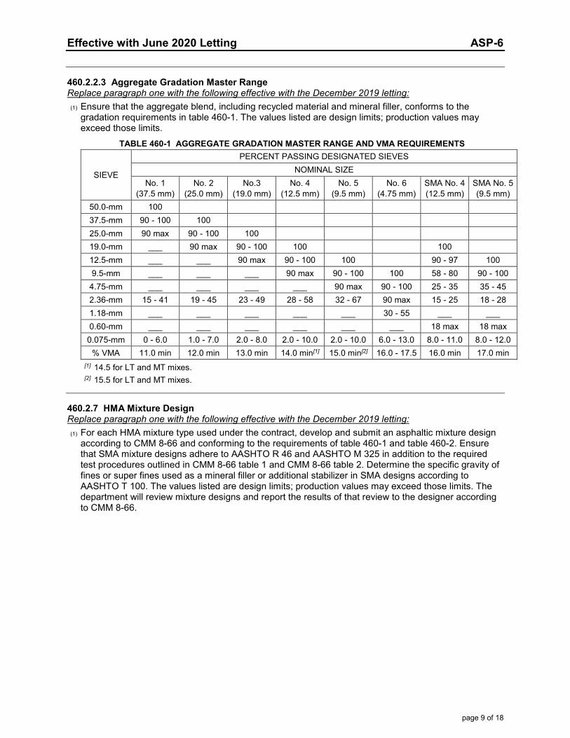
Effective with June 2020 Letting ASP-6
page 9 of 18
460.2.2.3 Aggregate Gradation Master Range Replace paragraph one with the following effective with the December 2019 letting: (1) Ensure that the aggregate blend, including recycled material and mineral filler, conforms to the
gradation requirements in table 460-1. The values listed are design limits; production values may exceed those limits.
TABLE 460-1 AGGREGATE GRADATION MASTER RANGE AND VMA REQUIREMENTS
SIEVE
PERCENT PASSING DESIGNATED SIEVES NOMINAL SIZE
No. 1 (37.5 mm)
No. 2 (25.0 mm)
No.3 (19.0 mm)
No. 4 (12.5 mm)
No. 5 (9.5 mm)
No. 6 (4.75 mm)
SMA No. 4 (12.5 mm)
SMA No. 5 (9.5 mm)
50.0-mm 100 37.5-mm 90 - 100 100 25.0-mm 90 max 90 - 100 100 19.0-mm ___ 90 max 90 - 100 100 100 12.5-mm ___ ___ 90 max 90 - 100 100 90 - 97 100 9.5-mm ___ ___ ___ 90 max 90 - 100 100 58 - 80 90 - 100
4.75-mm ___ ___ ___ ___ 90 max 90 - 100 25 - 35 35 - 45 2.36-mm 15 - 41 19 - 45 23 - 49 28 - 58 32 - 67 90 max 15 - 25 18 - 28 1.18-mm ___ ___ ___ ___ ___ 30 - 55 ___ ___ 0.60-mm ___ ___ ___ ___ ___ ___ 18 max 18 max
0.075-mm 0 - 6.0 1.0 - 7.0 2.0 - 8.0 2.0 - 10.0 2.0 - 10.0 6.0 - 13.0 8.0 - 11.0 8.0 - 12.0 % VMA 11.0 min 12.0 min 13.0 min 14.0 min[1] 15.0 min[2] 16.0 - 17.5 16.0 min 17.0 min
[1] 14.5 for LT and MT mixes. [2] 15.5 for LT and MT mixes.
460.2.7 HMA Mixture Design Replace paragraph one with the following effective with the December 2019 letting: (1) For each HMA mixture type used under the contract, develop and submit an asphaltic mixture design
according to CMM 8-66 and conforming to the requirements of table 460-1 and table 460-2. Ensure that SMA mixture designs adhere to AASHTO R 46 and AASHTO M 325 in addition to the required test procedures outlined in CMM 8-66 table 1 and CMM 8-66 table 2. Determine the specific gravity of fines or super fines used as a mineral filler or additional stabilizer in SMA designs according to AASHTO T 100. The values listed are design limits; production values may exceed those limits. The department will review mixture designs and report the results of that review to the designer according to CMM 8-66.
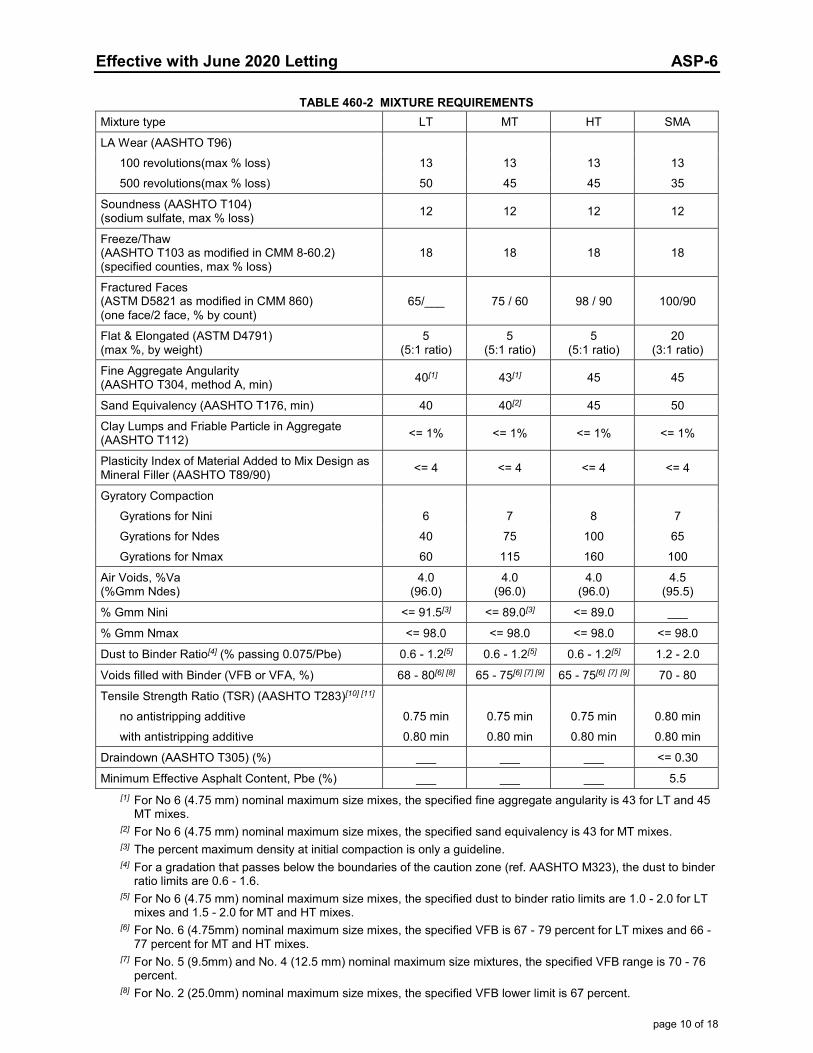
Effective with June 2020 Letting ASP-6
page 10 of 18
TABLE 460-2 MIXTURE REQUIREMENTS
Mixture type LT MT HT SMA
LA Wear (AASHTO T96) 100 revolutions(max % loss) 13 13 13 13 500 revolutions(max % loss) 50 45 45 35
Soundness (AASHTO T104) (sodium sulfate, max % loss) 12 12 12 12
Freeze/Thaw (AASHTO T103 as modified in CMM 8-60.2) (specified counties, max % loss)
18 18 18 18
Fractured Faces (ASTM D5821 as modified in CMM 860) (one face/2 face, % by count)
65/___ 75 / 60 98 / 90 100/90
Flat & Elongated (ASTM D4791) (max %, by weight)
5 (5:1 ratio)
5 (5:1 ratio)
5 (5:1 ratio)
20 (3:1 ratio)
Fine Aggregate Angularity (AASHTO T304, method A, min) 40[1] 43[1] 45 45
Sand Equivalency (AASHTO T176, min) 40 40[2] 45 50
Clay Lumps and Friable Particle in Aggregate (AASHTO T112) <= 1% <= 1% <= 1% <= 1%
Plasticity Index of Material Added to Mix Design as Mineral Filler (AASHTO T89/90) <= 4 <= 4 <= 4 <= 4
Gyratory Compaction Gyrations for Nini 6 7 8 7 Gyrations for Ndes 40 75 100 65 Gyrations for Nmax 60 115 160 100
Air Voids, %Va (%Gmm Ndes)
4.0 (96.0)
4.0 (96.0)
4.0 (96.0)
4.5 (95.5)
% Gmm Nini <= 91.5[3] <= 89.0[3] <= 89.0 ___
% Gmm Nmax <= 98.0 <= 98.0 <= 98.0 <= 98.0
Dust to Binder Ratio[4] (% passing 0.075/Pbe) 0.6 - 1.2[5] 0.6 - 1.2[5] 0.6 - 1.2[5] 1.2 - 2.0
Voids filled with Binder (VFB or VFA, %) 68 - 80[6] [8] 65 - 75[6] [7] [9] 65 - 75[6] [7] [9] 70 - 80
Tensile Strength Ratio (TSR) (AASHTO T283)[10] [11] no antistripping additive 0.75 min 0.75 min 0.75 min 0.80 min with antistripping additive 0.80 min 0.80 min 0.80 min 0.80 min
Draindown (AASHTO T305) (%) ___ ___ ___ <= 0.30
Minimum Effective Asphalt Content, Pbe (%) ___ ___ ___ 5.5
[1] For No 6 (4.75 mm) nominal maximum size mixes, the specified fine aggregate angularity is 43 for LT and 45 MT mixes.
[2] For No 6 (4.75 mm) nominal maximum size mixes, the specified sand equivalency is 43 for MT mixes. [3] The percent maximum density at initial compaction is only a guideline. [4] For a gradation that passes below the boundaries of the caution zone (ref. AASHTO M323), the dust to binder
ratio limits are 0.6 - 1.6. [5] For No 6 (4.75 mm) nominal maximum size mixes, the specified dust to binder ratio limits are 1.0 - 2.0 for LT
mixes and 1.5 - 2.0 for MT and HT mixes. [6] For No. 6 (4.75mm) nominal maximum size mixes, the specified VFB is 67 - 79 percent for LT mixes and 66 -
77 percent for MT and HT mixes. [7] For No. 5 (9.5mm) and No. 4 (12.5 mm) nominal maximum size mixtures, the specified VFB range is 70 - 76
percent. [8] For No. 2 (25.0mm) nominal maximum size mixes, the specified VFB lower limit is 67 percent.
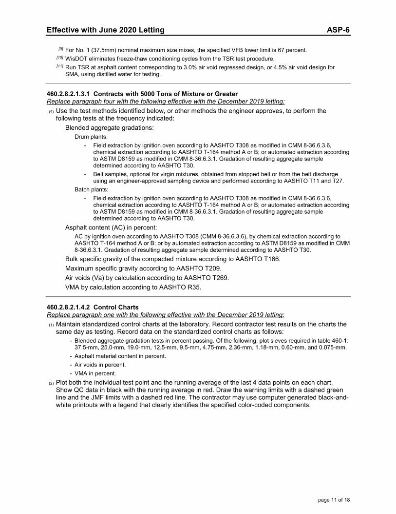
Effective with June 2020 Letting ASP-6
page 11 of 18
[9] For No. 1 (37.5mm) nominal maximum size mixes, the specified VFB lower limit is 67 percent. [10] WisDOT eliminates freeze-thaw conditioning cycles from the TSR test procedure. [11] Run TSR at asphalt content corresponding to 3.0% air void regressed design, or 4.5% air void design for
SMA, using distilled water for testing.
460.2.8.2.1.3.1 Contracts with 5000 Tons of Mixture or Greater Replace paragraph four with the following effective with the December 2019 letting: (4) Use the test methods identified below, or other methods the engineer approves, to perform the
following tests at the frequency indicated: Blended aggregate gradations:
Drum plants: - Field extraction by ignition oven according to AASHTO T308 as modified in CMM 8-36.6.3.6,
chemical extraction according to AASHTO T-164 method A or B; or automated extraction according to ASTM D8159 as modified in CMM 8-36.6.3.1. Gradation of resulting aggregate sample determined according to AASHTO T30.
- Belt samples, optional for virgin mixtures, obtained from stopped belt or from the belt discharge using an engineer-approved sampling device and performed according to AASHTO T11 and T27.
Batch plants: - Field extraction by ignition oven according to AASHTO T308 as modified in CMM 8-36.6.3.6,
chemical extraction according to AASHTO T-164 method A or B; or automated extraction according to ASTM D8159 as modified in CMM 8-36.6.3.1. Gradation of resulting aggregate sample determined according to AASHTO T30.
Asphalt content (AC) in percent: AC by ignition oven according to AASHTO T308 (CMM 8-36.6.3.6), by chemical extraction according to AASHTO T-164 method A or B; or by automated extraction according to ASTM D8159 as modified in CMM 8-36.6.3.1. Gradation of resulting aggregate sample determined according to AASHTO T30.
Bulk specific gravity of the compacted mixture according to AASHTO T166. Maximum specific gravity according to AASHTO T209. Air voids (Va) by calculation according to AASHTO T269. VMA by calculation according to AASHTO R35.
460.2.8.2.1.4.2 Control Charts Replace paragraph one with the following effective with the December 2019 letting: (1) Maintain standardized control charts at the laboratory. Record contractor test results on the charts the
same day as testing. Record data on the standardized control charts as follows: - Blended aggregate gradation tests in percent passing. Of the following, plot sieves required in table 460-1:
37.5-mm, 25.0-mm, 19.0-mm, 12.5-mm, 9.5-mm, 4.75-mm, 2.36-mm, 1.18-mm, 0.60-mm, and 0.075-mm. - Asphalt material content in percent. - Air voids in percent. - VMA in percent.
(2) Plot both the individual test point and the running average of the last 4 data points on each chart. Show QC data in black with the running average in red. Draw the warning limits with a dashed green line and the JMF limits with a dashed red line. The contractor may use computer generated black-and-white printouts with a legend that clearly identifies the specified color-coded components.
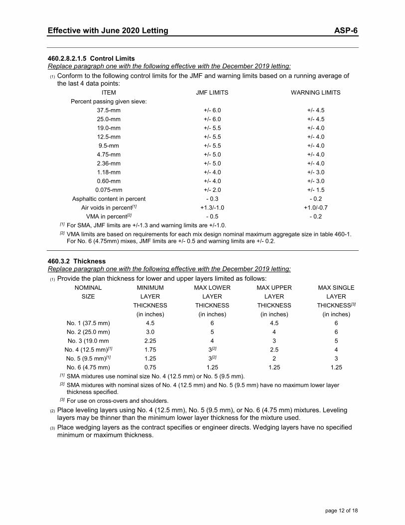
Effective with June 2020 Letting ASP-6
page 12 of 18
460.2.8.2.1.5 Control Limits Replace paragraph one with the following effective with the December 2019 letting: (1) Conform to the following control limits for the JMF and warning limits based on a running average of
the last 4 data points: ITEM JMF LIMITS WARNING LIMITS Percent passing given sieve: 37.5-mm +/- 6.0 +/- 4.5 25.0-mm +/- 6.0 +/- 4.5 19.0-mm +/- 5.5 +/- 4.0 12.5-mm +/- 5.5 +/- 4.0 9.5-mm +/- 5.5 +/- 4.0 4.75-mm +/- 5.0 +/- 4.0 2.36-mm +/- 5.0 +/- 4.0 1.18-mm +/- 4.0 +/- 3.0 0.60-mm +/- 4.0 +/- 3.0 0.075-mm +/- 2.0 +/- 1.5 Asphaltic content in percent - 0.3 - 0.2 Air voids in percent[1] +1.3/-1.0 +1.0/-0.7 VMA in percent[2] - 0.5 - 0.2
[1] For SMA, JMF limits are +/-1.3 and warning limits are +/-1.0. [2] VMA limits are based on requirements for each mix design nominal maximum aggregate size in table 460-1.
For No. 6 (4.75mm) mixes, JMF limits are +/- 0.5 and warning limits are +/- 0.2.
460.3.2 Thickness Replace paragraph one with the following effective with the December 2019 letting: (1) Provide the plan thickness for lower and upper layers limited as follows:
NOMINAL MINIMUM MAX LOWER MAX UPPER MAX SINGLE SIZE LAYER LAYER LAYER LAYER THICKNESS THICKNESS THICKNESS THICKNESS[3] (in inches) (in inches) (in inches) (in inches) No. 1 (37.5 mm) 4.5 6 4.5 6 No. 2 (25.0 mm) 3.0 5 4 6 No. 3 (19.0 mm 2.25 4 3 5 No. 4 (12.5 mm)[1] 1.75 3[2] 2.5 4 No. 5 (9.5 mm)[1] 1.25 3[2] 2 3 No. 6 (4.75 mm) 0.75 1.25 1.25 1.25
[1] SMA mixtures use nominal size No. 4 (12.5 mm) or No. 5 (9.5 mm). [2] SMA mixtures with nominal sizes of No. 4 (12.5 mm) and No. 5 (9.5 mm) have no maximum lower layer
thickness specified. [3] For use on cross-overs and shoulders. (2) Place leveling layers using No. 4 (12.5 mm), No. 5 (9.5 mm), or No. 6 (4.75 mm) mixtures. Leveling
layers may be thinner than the minimum lower layer thickness for the mixture used. (3) Place wedging layers as the contract specifies or engineer directs. Wedging layers have no specified
minimum or maximum thickness.
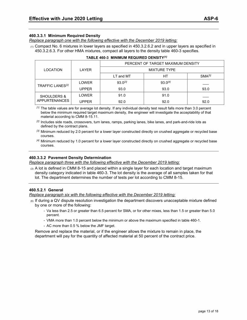
Effective with June 2020 Letting ASP-6
page 13 of 18
460.3.3.1 Minimum Required Density Replace paragraph one with the following effective with the December 2019 letting: (1) Compact No. 6 mixtures in lower layers as specified in 450.3.2.6.2 and in upper layers as specified in
450.3.2.6.3. For other HMA mixtures, compact all layers to the density table 460-3 specifies. TABLE 460-3 MINIMUM REQUIRED DENSITY[1]
LOCATION LAYER
PERCENT OF TARGET MAXIMUM DENSITY
MIXTURE TYPE
LT and MT HT SMA[5]
TRAFFIC LANES[2] LOWER 93.0[3] 93.0[4] ___
UPPER 93.0 93.0 93.0
SHOULDERS & APPURTENANCES
LOWER 91.0 91.0 ___
UPPER 92.0 92.0 92.0
[1] The table values are for average lot density. If any individual density test result falls more than 3.0 percent below the minimum required target maximum density, the engineer will investigate the acceptability of that material according to CMM 8-15.11.
[2] Includes side roads, crossovers, turn lanes, ramps, parking lanes, bike lanes, and park-and-ride lots as defined by the contract plans.
[3] Minimum reduced by 2.0 percent for a lower layer constructed directly on crushed aggregate or recycled base courses.
[4] Minimum reduced by 1.0 percent for a lower layer constructed directly on crushed aggregate or recycled base courses.
460.3.3.2 Pavement Density Determination Replace paragraph three with the following effective with the December 2019 letting: (3) A lot is defined in CMM 8-15 and placed within a single layer for each location and target maximum
density category indicated in table 460-3. The lot density is the average of all samples taken for that lot. The department determines the number of tests per lot according to CMM 8-15.
460.5.2.1 General Replace paragraph six with the following effective with the December 2019 letting: (6) If during a QV dispute resolution investigation the department discovers unacceptable mixture defined
by one or more of the following: - Va less than 2.5 or greater than 6.5 percent for SMA, or for other mixes, less than 1.5 or greater than 5.0
percent. - VMA more than 1.0 percent below the minimum or above the maximum specified in table 460-1. - AC more than 0.5 % below the JMF target.
Remove and replace the material, or if the engineer allows the mixture to remain in place, the department will pay for the quantity of affected material at 50 percent of the contract price.
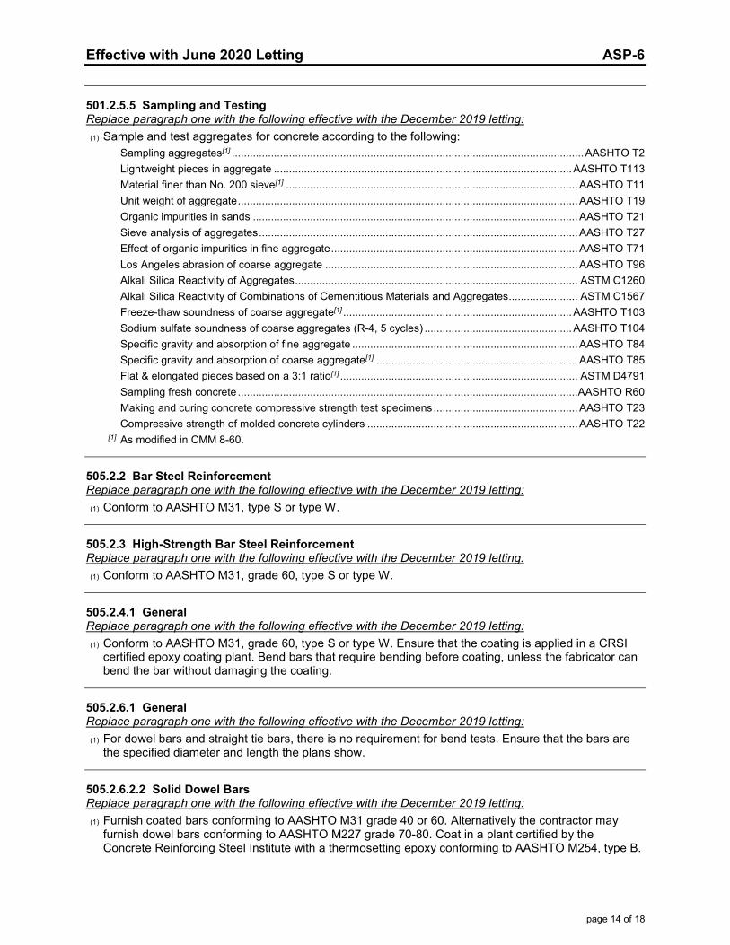
Effective with June 2020 Letting ASP-6
page 14 of 18
501.2.5.5 Sampling and Testing Replace paragraph one with the following effective with the December 2019 letting: (1) Sample and test aggregates for concrete according to the following:
Sampling aggregates[1] ..................................................................................................................... AASHTO T2 Lightweight pieces in aggregate ................................................................................................... AASHTO T113 Material finer than No. 200 sieve[1] ................................................................................................. AASHTO T11 Unit weight of aggregate ................................................................................................................. AASHTO T19 Organic impurities in sands ............................................................................................................ AASHTO T21 Sieve analysis of aggregates .......................................................................................................... AASHTO T27 Effect of organic impurities in fine aggregate .................................................................................. AASHTO T71 Los Angeles abrasion of coarse aggregate .................................................................................... AASHTO T96 Alkali Silica Reactivity of Aggregates .............................................................................................. ASTM C1260 Alkali Silica Reactivity of Combinations of Cementitious Materials and Aggregates ....................... ASTM C1567 Freeze-thaw soundness of coarse aggregate[1] ............................................................................ AASHTO T103 Sodium sulfate soundness of coarse aggregates (R-4, 5 cycles) ................................................. AASHTO T104 Specific gravity and absorption of fine aggregate ........................................................................... AASHTO T84 Specific gravity and absorption of coarse aggregate[1] ................................................................... AASHTO T85 Flat & elongated pieces based on a 3:1 ratio[1] ............................................................................... ASTM D4791 Sampling fresh concrete ................................................................................................................. AASHTO R60 Making and curing concrete compressive strength test specimens ................................................ AASHTO T23 Compressive strength of molded concrete cylinders ...................................................................... AASHTO T22
[1] As modified in CMM 8-60.
505.2.2 Bar Steel Reinforcement Replace paragraph one with the following effective with the December 2019 letting: (1) Conform to AASHTO M31, type S or type W.
505.2.3 High-Strength Bar Steel Reinforcement Replace paragraph one with the following effective with the December 2019 letting: (1) Conform to AASHTO M31, grade 60, type S or type W.
505.2.4.1 General Replace paragraph one with the following effective with the December 2019 letting: (1) Conform to AASHTO M31, grade 60, type S or type W. Ensure that the coating is applied in a CRSI
certified epoxy coating plant. Bend bars that require bending before coating, unless the fabricator can bend the bar without damaging the coating.
505.2.6.1 General Replace paragraph one with the following effective with the December 2019 letting: (1) For dowel bars and straight tie bars, there is no requirement for bend tests. Ensure that the bars are
the specified diameter and length the plans show.
505.2.6.2.2 Solid Dowel Bars Replace paragraph one with the following effective with the December 2019 letting: (1) Furnish coated bars conforming to AASHTO M31 grade 40 or 60. Alternatively the contractor may
furnish dowel bars conforming to AASHTO M227 grade 70-80. Coat in a plant certified by the Concrete Reinforcing Steel Institute with a thermosetting epoxy conforming to AASHTO M254, type B.
Effective with June 2020 Letting ASP-6
page 15 of 18
520.3.7 Deflection Testing Replace paragraphs three and four with the following effective with the June 2020 letting:
(3) Test 100 percent of the installed length of pipe 24 inches or greater in diameter. Ensure that the mandrel passes through the entire section in one pass when pulled by hand without using excessive force. If the designated length of pipe fails, the engineer may require additional testing.
(4) For pipe less than 24 inches in diameter, the engineer will designate at least 10 percent of the installed length of pipe for testing. The mandrel must pass through the entire section in one pass when pulled by hand without using excessive force. If the designated length of pipe fails, engineer may require additional testing.
(5) Relay or replace pipe that does not pass deflection testing. Retest all relayed or replaced pipe.
608.3.7 Deflection Testing Replace paragraphs three and four with the following effective with the June 2020 letting:
(3) Test 100 percent of the installed length of pipe 24 inches or greater in diameter. Ensure that the mandrel passes through the entire section in one pass when pulled by hand without using excessive force. If the designated length of pipe fails, the engineer may require additional testing.
(4) For pipe less than 24 inches in diameter, the engineer will designate at least 10 percent of the installed length of pipe for testing. The mandrel must pass through the entire section in one pass when pulled by hand without using excessive force. If the designated length of pipe fails, engineer may require additional testing.
(5) Relay or replace pipe that does not pass deflection testing. Retest all relayed or replaced pipe.
625.3.2 Processing Topsoil or Salvaged Topsoil Delete paragraph four effective with the December 2019 letting.
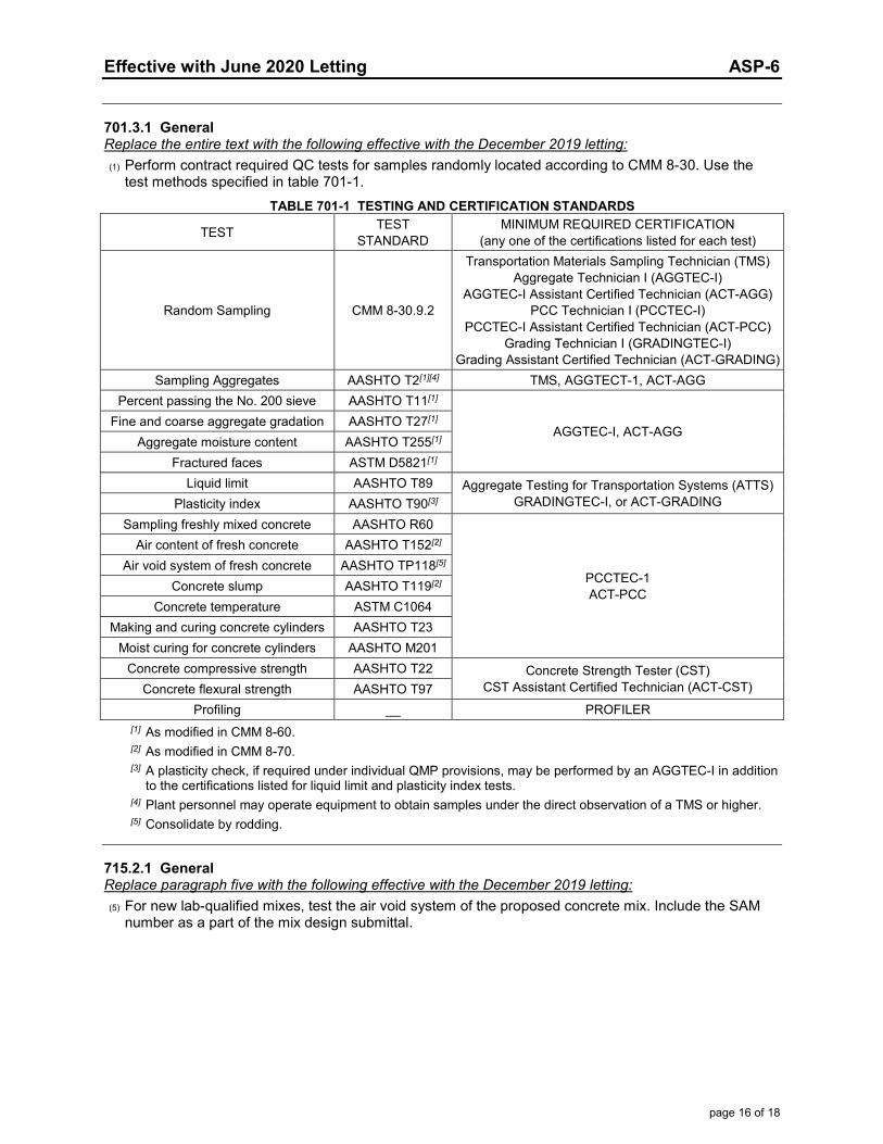
Effective with June 2020 Letting ASP-6
page 16 of 18
701.3.1 General Replace the entire text with the following effective with the December 2019 letting: (1) Perform contract required QC tests for samples randomly located according to CMM 8-30. Use the
test methods specified in table 701-1. TABLE 701-1 TESTING AND CERTIFICATION STANDARDS
TEST TEST STANDARD
MINIMUM REQUIRED CERTIFICATION (any one of the certifications listed for each test)
Random Sampling CMM 8-30.9.2
Transportation Materials Sampling Technician (TMS) Aggregate Technician I (AGGTEC-I)
AGGTEC-I Assistant Certified Technician (ACT-AGG) PCC Technician I (PCCTEC-I)
PCCTEC-I Assistant Certified Technician (ACT-PCC) Grading Technician I (GRADINGTEC-I)
Grading Assistant Certified Technician (ACT-GRADING) Sampling Aggregates AASHTO T2[1][4] TMS, AGGTECT-1, ACT-AGG
Percent passing the No. 200 sieve AASHTO T11[1]
AGGTEC-I, ACT-AGG Fine and coarse aggregate gradation AASHTO T27[1]
Aggregate moisture content AASHTO T255[1] Fractured faces ASTM D5821[1]
Liquid limit AASHTO T89 Aggregate Testing for Transportation Systems (ATTS) GRADINGTEC-I, or ACT-GRADING Plasticity index AASHTO T90[3]
Sampling freshly mixed concrete AASHTO R60
PCCTEC-1 ACT-PCC
Air content of fresh concrete AASHTO T152[2] Air void system of fresh concrete AASHTO TP118[5]
Concrete slump AASHTO T119[2] Concrete temperature ASTM C1064
Making and curing concrete cylinders AASHTO T23 Moist curing for concrete cylinders AASHTO M201
Concrete compressive strength AASHTO T22 Concrete Strength Tester (CST) CST Assistant Certified Technician (ACT-CST) Concrete flexural strength AASHTO T97
Profiling __ PROFILER
[1] As modified in CMM 8-60. [2] As modified in CMM 8-70. [3] A plasticity check, if required under individual QMP provisions, may be performed by an AGGTEC-I in addition
to the certifications listed for liquid limit and plasticity index tests. [4] Plant personnel may operate equipment to obtain samples under the direct observation of a TMS or higher. [5] Consolidate by rodding.
715.2.1 General Replace paragraph five with the following effective with the December 2019 letting: (5) For new lab-qualified mixes, test the air void system of the proposed concrete mix. Include the SAM
number as a part of the mix design submittal.

Effective with June 2020 Letting ASP-6
page 17 of 18
715.3.1.1 General Replace paragraph two with the following effective with the December 2019 letting: (2) Test the air void system at least once per lot and enter the SAM number in the MRS for information
only. SAM testing is not required for the following: - For lots with less than 4 sublots. - High early strength (HES) concrete. - Special high early strength (SHES) concrete. - Concrete placed under the following bid items:
- Concrete Pavement Approach Slab - Concrete Masonry Culverts - Concrete Masonry Retaining Walls - Steel Grid Floor Concrete Filled - Crash Cushions Permanent - Crash Cushions Permanent Low Maintenance - Crash Cushions Temporary
730.3.1 General Replace paragraph three with the following effective with the December 2019 letting: (3) Stockpile tests[1] can be used for multiple projects. If placement on a project does not begin within 120
calendar days after the date the stockpile sample was obtained, retest the stockpile before placement begins.
[1] Replace the stockpile test with an in-place production test for concrete pavement recycled and processed on-site; test on the first day of production.
730.3.2 Contractor QC Testing Replace paragraph four with the following effective with the December 2019 letting: (4) Submit test results to the engineer within one business day of obtaining the sample, except any
aggregate classification with recycled asphalt may be submitted within two business days.
730.3.4.1 Contractor QC Testing Replace the entire text with the following effective with the December 2019 letting: (1) For small quantity contracts with <= 500 tons, submit 2 production tests or 1 stockpile test. Production
tests are valid for 3 years from the date the production sample was obtained. Begin placement within 3 years of the date sampled.
(2) For small quantity contracts with <= 6000 tons and >= 500 tons, do the following: 1. Conduct one QC stockpile test before placement. 2. Submit 2 production tests or conduct 1 loadout test instead of placement tests. Production tests are valid
for 3 years from the date the production sample was obtained; the first day of placement must be within 3 years of the date sampled.
3. If the actual quantity placed is more than 6000 tons, on the next day of placement perform one additional random QC test for each 3000 tons of overrun, or fraction thereof.
740.3.2 Contractor QC Testing Replace paragraph three with the following effective with the December 2019 letting: (3) Field-locate the beginning and ending points for each profile run. Measure the profiles of each
standard and partial segment. Define primary segments starting at a project terminus and running contiguously along the mainline to the other project terminus. Define segments one wheel path wide and distinguished by length as follows:
1. Standard segments are 500 feet long. 2. Partial segments are less than 500 feet long.
Effective with June 2020 Letting ASP-6
page 18 of 18
Errata
104.6.1.2.3 Drop-Off and Hazard Protection Correct errata by changing 2 inches or greater to greater than 2 inches. (1) Eliminate vertical drop-offs greater than 2 inches and edge slopes steeper than 3:1 between adjacent
lanes open to traffic.
305.3.3.3 Shoulders Adjacent to Asphaltic Pavement or Surfacing Correct errata by changing 2-inch or more to greater than 2-inch. (2) If the roadway remains open to through traffic during construction and a greater than 2-inch drop-off
occurs within 3 feet or less from the edge of the traveled way, eliminate the drop-off within 48 hours after completing that days paving. Unless the special provisions specify otherwise, provide aggregate shoulder material compacted to a temporary 3:1 or flatter cross slope from the surface of the pavement edge.
501.3.2.2 Concrete Proportions Correct errata in footnote [8] by allowing either grade 100 or grade 120 slag in C-S concrete. [8] For grade C-S concrete, use grade 100 or grade 120 slag.
614.3.6 Thrie Beam Structure Approach Retro Fits Correct errata by deleting the galvanization reference already required under 614.3.1. (2) Install posts and drill holes into existing thrie beam conforming to 614.3.2.
628.3.7 Mobilizations for Erosion Control Correct errata by clarifying that mobilizations for erosion control include proceeding with the work. (1) Move personnel, equipment, and materials to the project site and promptly proceed with construction
of erosion control items at the stages the contract indicates or the engineer directs.
Page 1 of 1
Effective with December 2017 Letting ASP 7
ADDITIONAL SPECIAL PROVISION 7
A. Reporting 1st Tier and DBE Payments During Construction
1. Comply with reporting requirements specified in the department’s Civil RightsCompliance, Contractor’s User Manual, Sublets and Payments.
2. Report payments to all DBE firms within 10 calendar days of receipt of a progresspayment by the department or a contractor for work performed, materials furnished, ormaterials stockpiled by a DBE firm. Report the payment as specified in A(1) for all worksatisfactorily performed and for all materials furnished or stockpiled.
3. Report payments to all first tier subcontractor relationships within 10 calendar days ofreceipt of a progress payment by the department for work performed. Report thepayment as specified in A(1) for all work satisfactorily performed.
4. All tiers shall report payments as necessary to comply with the DBE paymentrequirement as specified in A(2).
5. Require all first tier relationships, DBE firms and all other tier relationships necessaryto comply with the DBE payment requirement in receipt of a progress payment bycontractor to acknowledge receipt of payment as specified in A(1), (2), (3) and (4).
6. All agreements made by a contractor shall include the provisions in A(1), (2), (3), (4)and (5), and shall be binding on all first tier subcontractor relationships and allcontractors and subcontractors utilizing DBE firms on the project.
B. Costs for conforming to this special provision are incidental to the contract.
NOTE: CRCS Prime Contractor payment is currently not automated and will need to be manually loaded into the Civil Rights Compliance System. Copies of prime contractor payments received (check or ACH) will have to be forwarded to [email protected] within 5 days of payment receipt to be logged manually.
***Additionally, for information on Subcontractor Sublet assignments, Subcontractor Payments and Payment Tracking, please refer to the CRCS Payment and Sublets manual at:
https://wisconsindot.gov/Documents/doing-bus/civil-rights/labornwage/crcs-payments-sublets-manual.pdf

Effective January 2019 Letting ASP 9
ADDITIONAL SPECIAL PROVISION 9 Electronic Certified Payroll or Labor Data Submittal
(1) Use the department's Civil Rights Compliance System (CRCS) to electronically submit certifiedpayroll reports for contracts with federal funds and labor data for contracts with state funds only.Details are available online through the department’s highway construction contractor information(HCCI) site on the Labor, Wages, and EEO Information page at:
https://wisconsindot.gov/Pages/doing-bus/civil-rights/labornwage/default.aspx
(2) Ensure that all tiers of subcontractors, including all trucking firms, either submit theirweekly certified payroll reports (contracts with federal funds) or labor data (contracts withstate funds only) electronically through CRCS. These payrolls or labor data are due withinseven calendar days following the close of the payroll period. Every firm providing physicallabor towards completing the project is a subcontractor under this special provision.
(3) Upon receipt of contract execution, promptly make all affected firms aware of therequirements under this special provision and arrange for them to receive CRCS training as theyare about to begin their submittals. The department will provide training either in a classroomsetting at one of our regional offices or by telephone. Contact Paul Ndon at (414) 438-4584 toschedule the training.
(4) The department will reject all paper submittals for information required under thisspecial provision. All costs for conforming to this special provision are incidental to thecontract.
(5) Firms wishing to export payroll/labor data from their computer system into CRCSshould have their payroll coordinator contact Paul Ndon at [email protected]. Notevery contractor’s payroll system is capable of producing export files. For details, seeSection 4.8 CPR Auto Submit (Data Mapping) on pages 49-50; 66-71 of the CRCS PayrollManual at:
https://wisconsindot.gov/Documents/doing-bus/civil-rights/labornwage/crcs-payroll-manual.pdf
Page 1 of 3
Non-discrimination Provisions
During the performance of this contract, the contractor, for itself, its assignees, and successors in interest (hereinafter referred to as the "contractor") agrees as follows:
1. Compliance with Regulations: The contractor (hereinafter includes consultants) will complywith the Acts and the Regulations relative to Non-discrimination in Federally-assisted programsof the U.S. Department of Transportation, Federal Highway Administration, as they may beamended from time to time, which are herein incorporated by reference and made a part of thiscontract.
2. Non-discrimination: The contractor, with regard to the work performed by it during thecontract, will not discriminate on the grounds of race, color, or national origin in the selection andretention of subcontractors, including procurements of materials and leases of equipment. Thecontractor will not participate directly or indirectly in the discrimination prohibited by the Actsand the Regulations, including employment practices when the contract covers any activity,project, or program set forth in Appendix B of 49 CFR Part 21.
3. Solicitations for Subcontracts, Including Procurements of Materials and Equipment: Inall solicitations, either by competitive bidding, or negotiation made by the contractor for work tobe performed under a subcontract, including procurements of materials, or leases of equipment,each potential subcontractor or supplier will be notified by the contractor of the contractor'sobligations under this contract and the Acts and the Regulations relative to Non-discrimination onthe grounds of race, color, or national origin.
4. Information and Reports: The contractor will provide all information and reports required bythe Acts, the Regulations, and directives issued pursuant thereto and will permit access to its books,records, accounts, other sources of information, and its facilities as may be determined by theRecipient or the Federal Highway Administration to be pertinent to ascertain compliance with suchActs, Regulations, and instructions. Where any information required of a contractor is in theexclusive possession of another who fails or refuses to furnish the information, the contractor willso certify to the Recipient or the Federal Highway Administration, as appropriate, and will setforth what efforts it has made to obtain the information.
5. Sanctions for Noncompliance: In the event of a contractor's noncompliance with the Non-discrimination provisions of this contract, the Recipient will impose such contract sanctions as itor the Federal Highway Administration may determine to be appropriate, including, but not limitedto:
a. Withholding payments to the contractor under the contract until the contractorcomplies; and/or
b. Cancelling, terminating, or suspending a contract, in whole or in part.
Page 2 of 3
6. Incorporation of Provisions: The contractor will include the provisions of paragraphs one through six in every subcontract, including procurements of materials and leases of equipment, unless exempt by the Acts, the Regulations and directives issued pursuant thereto. The contractor will take action with respect to any subcontract or procurement as the Recipient or the Federal Highway Administration may direct as a means of enforcing such provisions including sanctions for noncompliance. Provided, that if the contractor becomes involved in, or is threatened with litigation by a subcontractor, or supplier because of such direction, the contractor may request the Recipient to enter into any litigation to protect the interests of the Recipient. In addition, the contractor may request the United States to enter into the litigation to protect the interests of the United States.
During the performance of this contract, the contractor, for itself, its assignees, and successors in interest (hereinafter referred to as the "contractor") agrees to comply with the following non-discrimination statutes and authorities; including but not limited to:
Pertinent Non-Discrimination Authorities:
• Title VI of the Civil Rights Act of 1964 (42 U.S.C. § 2000d et seq., 78 stat. 252), (prohibits discrimination on the basis of race, color, national origin); and 49 CFR Part 21.
• The Uniform Relocation Assistance and Real Property Acquisition Policies Act of 1970, (42 U.S.C. § 4601), (prohibits unfair treatment of persons displaced or whose property has been acquired because of Federal or Federal-aid programs and projects);
• Federal-Aid Highway Act of 1973, (23 U.S.C. § 324 et seq.), (prohibits discrimination on the basis of sex);
• Section 504 of the Rehabilitation Act of 1973, (29 U.S.C. § 794 et seq.), as amended, (prohibits discrimination on the basis of disability); and 49 CFR Part 27;
• The Age Discrimination Act of 1975, as amended, (42 U.S.C. § 6101 et seq.), (prohibits discrimination on the basis of age);
• Airport and Airway Improvement Act of 1982, (49 USC § 471, Section 47123), as amended, (prohibits discrimination based on race, creed, color, national origin, or sex);
• The Civil Rights Restoration Act of 1987, (PL 100-209), (Broadened the scope, coverage and applicability of Title VI of the Civil Rights Act of 1964, The Age Discrimination Act of 1975 and Section 504 of the Rehabilitation Act of 1973, by expanding the definition of the terms "programs or activities" to include all of the programs or activities of the Federal-aid recipients, sub-recipients and contractors, whether such programs or activities are Federally funded or not);
• Titles II and III of the Americans with Disabilities Act, which prohibit discrimination on the basis of disability in the operation of public entities, public and private transportation systems, places of public accommodation, and certain testing entities (42 U.S.C. §§ 12131-12189) as implemented by Department of Transportation regulations at 49 C.F.R. parts 37 and 38;
• The Federal Aviation Administration's Non-discrimination statute (49 U.S.C. § 47123) (prohibits discrimination on the basis of race, color, national origin, and sex);
Page 3 of 3
• Executive Order 12898, Federal Actions to Address Environmental Justice in Minority Populations and Low-Income Populations, which ensures Non-discrimination against minority populations by discouraging programs, policies, and activities with disproportionately high and adverse human health or environmental effects on minority and low-income populations;
• Executive Order 13166, Improving Access to Services for Persons with Limited English Proficiency, and resulting agency guidance, national origin discrimination includes discrimination because of Limited English proficiency (LEP). To ensure compliance with Title VI, you must take reasonable steps to ensure that LEP persons have meaningful access to your programs (70 Fed. Reg. at 74087 to 74100);
• Title IX of the Education Amendments of 1972, as amended, which prohibits you from discriminating because of sex in education programs or activities (20 U.S.C. 1681 et seq).
1 of 1
Effective August 2015 letting
BUY AMERICA PROVISION
All steel and iron materials permanently incorporated in this project shall be domestic products and all manufacturing and coating processes for these materials from smelting forward in the manufacturing process must have occurred within the United States. Coating includes epoxy coating, galvanizing, painting and any other coating that protects or enhances the value of a material subject to the requirements of Buy America. The exemption of this requirement is the minimal use of foreign materials if the total cost of such material permanently incorporated in the product does not exceed one-tenth of one percent (1/10 of 1%) of the total contract cost or $2,500.00, whichever is greater. For purposes of this paragraph, the cost is that shown to be the value of the subject products as they are delivered to the project. The contractor shall take actions and provide documentation conforming to CMM 2-28.5 to ensure compliance with this “Buy America” provision.
https://wisconsindot.gov/rdwy/cmm/cm-02-28.pdf
Upon completion of the project certify to the engineer, in writing using department form WS4567, that all steel, iron, and coating processes for steel or iron incorporated into the contract work conform to these "Buy America" provisions. Attach a list of exemptions and their associated costs to the certification form. Department form WS4567 is available at:
https://wisconsindot.gov/hcciDocs/contracting-info/ws4567.doc
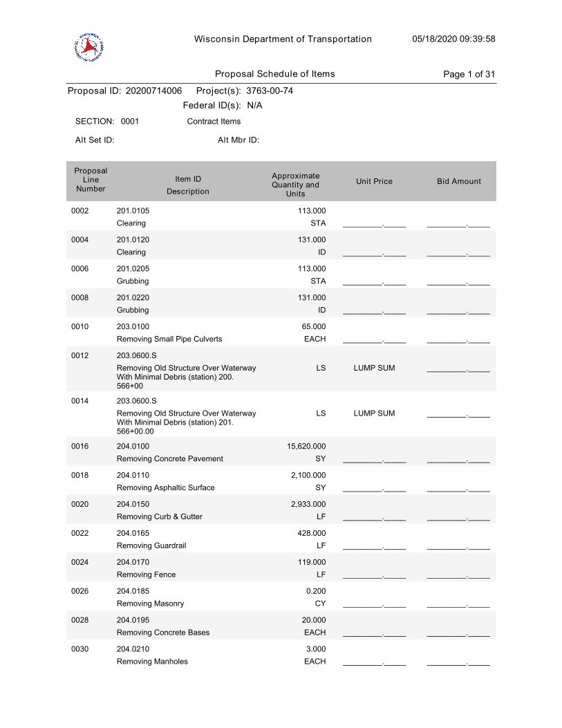
Wisconsin Department of Transportation 05/18/2020 09:39:58
Proposal ID: 20200714006 Project(s): 3763-00-74
Federal ID(s): N/A
0001 Contract ItemsSECTION:
Alt Set ID: Alt Mbr ID:
Bid AmountUnit PriceApproximateQuantity and
UnitsDescription
Item IDProposal
LineNumber
0002 201.0105
Clearing STA
113.000
_________._____ _________._____
0004 201.0120
Clearing ID
131.000
_________._____ _________._____
0006 201.0205
Grubbing STA
113.000
_________._____ _________._____
0008 201.0220
Grubbing ID
131.000
_________._____ _________._____
0010 203.0100
Removing Small Pipe Culverts EACH
65.000
_________._____ _________._____
0012 203.0600.S
Removing Old Structure Over WaterwayWith Minimal Debris (station) 200.566+00
LUMP SUM _________._____LS
0014 203.0600.S
Removing Old Structure Over WaterwayWith Minimal Debris (station) 201.566+00.00
LUMP SUM _________._____LS
0016 204.0100
Removing Concrete Pavement SY
15,620.000
_________._____ _________._____
0018 204.0110
Removing Asphaltic Surface SY
2,100.000
_________._____ _________._____
0020 204.0150
Removing Curb & Gutter LF
2,933.000
_________._____ _________._____
0022 204.0165
Removing Guardrail LF
428.000
_________._____ _________._____
0024 204.0170
Removing Fence LF
119.000
_________._____ _________._____
0026 204.0185
Removing Masonry CY
0.200
_________._____ _________._____
0028 204.0195
Removing Concrete Bases EACH
20.000
_________._____ _________._____
0030 204.0210
Removing Manholes EACH
3.000
_________._____ _________._____
Proposal Schedule of Items Page 1 of 31
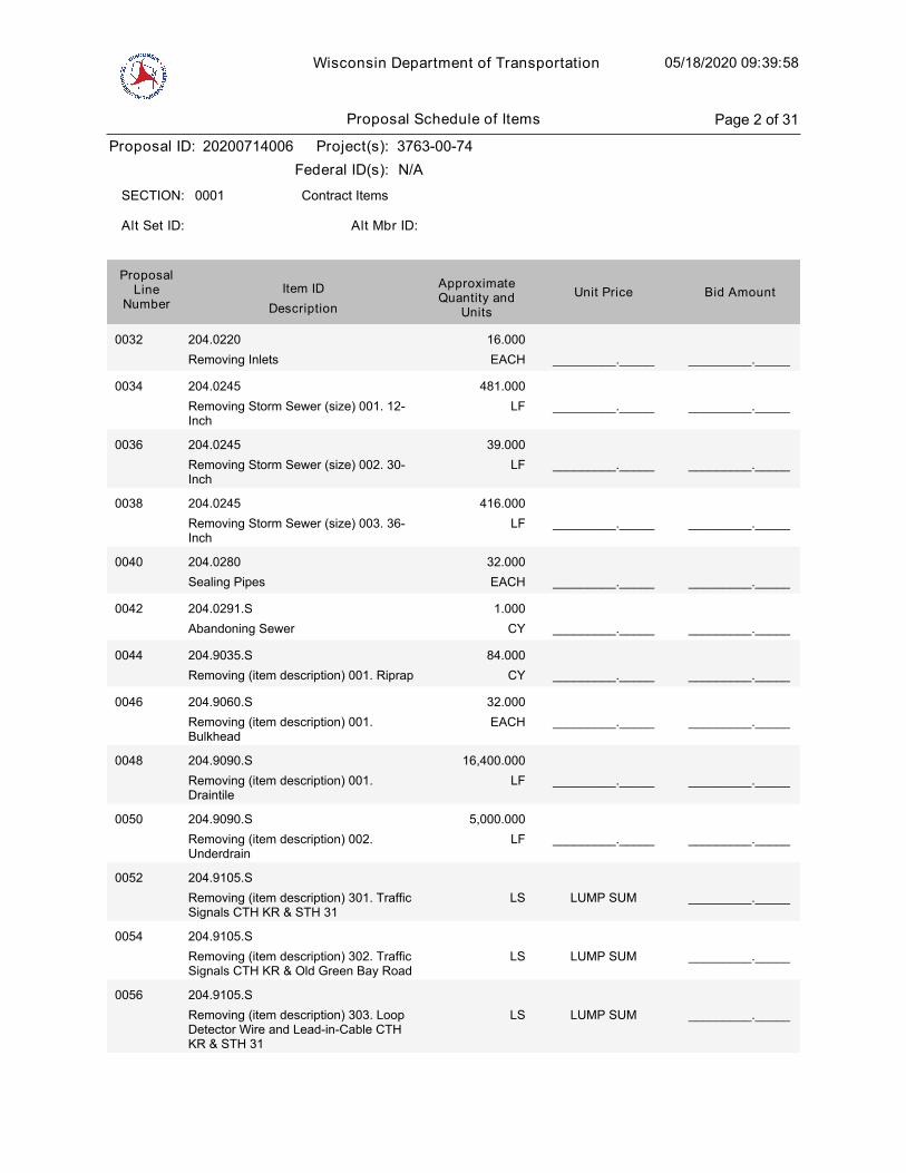
Wisconsin Department of Transportation 05/18/2020 09:39:58
Proposal ID: 20200714006 Project(s): 3763-00-74
Federal ID(s): N/A
0001 Contract ItemsSECTION:
Alt Set ID: Alt Mbr ID:
Bid AmountUnit PriceApproximateQuantity and
UnitsDescription
Item IDProposal
LineNumber
0032 204.0220
Removing Inlets EACH
16.000
_________._____ _________._____
0034 204.0245
Removing Storm Sewer (size) 001. 12-Inch
LF
481.000
_________._____ _________._____
0036 204.0245
Removing Storm Sewer (size) 002. 30-Inch
LF
39.000
_________._____ _________._____
0038 204.0245
Removing Storm Sewer (size) 003. 36-Inch
LF
416.000
_________._____ _________._____
0040 204.0280
Sealing Pipes EACH
32.000
_________._____ _________._____
0042 204.0291.S
Abandoning Sewer CY
1.000
_________._____ _________._____
0044 204.9035.S
Removing (item description) 001. Riprap CY
84.000
_________._____ _________._____
0046 204.9060.S
Removing (item description) 001.Bulkhead
EACH
32.000
_________._____ _________._____
0048 204.9090.S
Removing (item description) 001.Draintile
LF
16,400.000
_________._____ _________._____
0050 204.9090.S
Removing (item description) 002.Underdrain
LF
5,000.000
_________._____ _________._____
0052 204.9105.S
Removing (item description) 301. TrafficSignals CTH KR & STH 31
LUMP SUM _________._____LS
0054 204.9105.S
Removing (item description) 302. TrafficSignals CTH KR & Old Green Bay Road
LUMP SUM _________._____LS
0056 204.9105.S
Removing (item description) 303. LoopDetector Wire and Lead-in-Cable CTHKR & STH 31
LUMP SUM _________._____LS
Proposal Schedule of Items Page 2 of 31

Wisconsin Department of Transportation 05/18/2020 09:39:58
Proposal ID: 20200714006 Project(s): 3763-00-74
Federal ID(s): N/A
0001 Contract ItemsSECTION:
Alt Set ID: Alt Mbr ID:
Bid AmountUnit PriceApproximateQuantity and
UnitsDescription
Item IDProposal
LineNumber
0058 204.9105.S
Removing (item description) 304. LoopDetector Wire and Lead-in-Cable CTHKR & Old Green Bay Rd
LUMP SUM _________._____LS
0060 205.0100
Excavation Common CY
351,023.000
_________._____ _________._____
0062 205.0501.S
Excavation, Hauling, and Disposal ofPetroleum Contaminated Soil
TON
128.000
_________._____ _________._____
0064 206.1000
Excavation for Structures Bridges(structure) 200. B-30-143
LUMP SUM _________._____LS
0066 206.1000
Excavation for Structures Bridges(structure) 201. B-30-144
LUMP SUM _________._____LS
0068 206.3000
Excavation for Structures RetainingWalls (structure) 200. Structure R-30-65
LUMP SUM _________._____LS
0070 206.3000
Excavation for Structures RetainingWalls (structure) 201. Structure R-30-66
LUMP SUM _________._____LS
0072 206.3000
Excavation for Structures RetainingWalls (structure) 202. Structure R-30-67
LUMP SUM _________._____LS
0074 206.3000
Excavation for Structures RetainingWalls (structure) 203. Structure R-30-68
LUMP SUM _________._____LS
0076 209.1100
Backfill Granular Grade 1 CY
95,767.000
_________._____ _________._____
0078 210.1500
Backfill Structure Type A TON
2,536.000
_________._____ _________._____
0080 213.0100
Finishing Roadway (project) 001. 3763-00-74
EACH
1.000
_________._____ _________._____
0082 305.0110
Base Aggregate Dense 3/4-Inch TON
1,265.000
_________._____ _________._____
0084 305.0120
Base Aggregate Dense 1 1/4-Inch TON
88,164.000
_________._____ _________._____
Proposal Schedule of Items Page 3 of 31
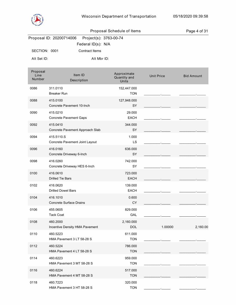
Wisconsin Department of Transportation 05/18/2020 09:39:58
Proposal ID: 20200714006 Project(s): 3763-00-74
Federal ID(s): N/A
0001 Contract ItemsSECTION:
Alt Set ID: Alt Mbr ID:
Bid AmountUnit PriceApproximateQuantity and
UnitsDescription
Item IDProposal
LineNumber
0086 311.0110
Breaker Run TON
152,447.000
_________._____ _________._____
0088 415.0100
Concrete Pavement 10-Inch SY
127,948.000
_________._____ _________._____
0090 415.0210
Concrete Pavement Gaps EACH
29.000
_________._____ _________._____
0092 415.0410
Concrete Pavement Approach Slab SY
344.000
_________._____ _________._____
0094 415.5110.S
Concrete Pavement Joint Layout LS
1.000
_________._____ _________._____
0096 416.0160
Concrete Driveway 6-Inch SY
636.000
_________._____ _________._____
0098 416.0260
Concrete Driveway HES 6-Inch SY
742.000
_________._____ _________._____
0100 416.0610
Drilled Tie Bars EACH
723.000
_________._____ _________._____
0102 416.0620
Drilled Dowel Bars EACH
139.000
_________._____ _________._____
0104 416.1010
Concrete Surface Drains CY
0.600
_________._____ _________._____
0106 455.0605
Tack Coat GAL
829.000
_________._____ _________._____
1.00000
0108 460.2000
Incentive Density HMA Pavement DOL
2,160.000
2,160.00
0110 460.5223
HMA Pavement 3 LT 58-28 S TON
611.000
_________._____ _________._____
0112 460.5224
HMA Pavement 4 LT 58-28 S TON
786.000
_________._____ _________._____
0114 460.6223
HMA Pavement 3 MT 58-28 S TON
959.000
_________._____ _________._____
0116 460.6224
HMA Pavement 4 MT 58-28 S TON
517.000
_________._____ _________._____
0118 460.7223
HMA Pavement 3 HT 58-28 S TON
320.000
_________._____ _________._____
Proposal Schedule of Items Page 4 of 31
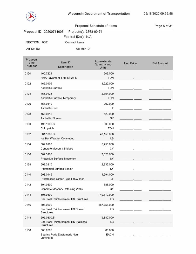
Wisconsin Department of Transportation 05/18/2020 09:39:58
Proposal ID: 20200714006 Project(s): 3763-00-74
Federal ID(s): N/A
0001 Contract ItemsSECTION:
Alt Set ID: Alt Mbr ID:
Bid AmountUnit PriceApproximateQuantity and
UnitsDescription
Item IDProposal
LineNumber
0120 460.7224
HMA Pavement 4 HT 58-28 S TON
203.000
_________._____ _________._____
0122 465.0105
Asphaltic Surface TON
4,922.000
_________._____ _________._____
0124 465.0125
Asphaltic Surface Temporary TON
2,354.000
_________._____ _________._____
0126 465.0310
Asphaltic Curb LF
202.000
_________._____ _________._____
0128 465.0315
Asphaltic Flumes SY
120.000
_________._____ _________._____
0130 495.1000.S
Cold patch TON
300.000
_________._____ _________._____
0132 501.1000.S
Ice Hot Weather Concreting LB
43,153.000
_________._____ _________._____
0134 502.0100
Concrete Masonry Bridges CY
5,753.000
_________._____ _________._____
0136 502.3200
Protective Surface Treatment SY
7,028.000
_________._____ _________._____
0138 502.3210
Pigmented Surface Sealer SY
2,935.000
_________._____ _________._____
0140 503.0146
Prestressed Girder Type I 45W-Inch LF
4,994.000
_________._____ _________._____
0142 504.0500
Concrete Masonry Retaining Walls CY
688.000
_________._____ _________._____
0144 505.0400
Bar Steel Reinforcement HS Structures LB
49,810.000
_________._____ _________._____
0146 505.0600
Bar Steel Reinforcement HS CoatedStructures
LB
887,755.000
_________._____ _________._____
0148 505.0800.S
Bar Steel Reinforcement HS StainlessStructures
LB
9,880.000
_________._____ _________._____
0150 506.2605
Bearing Pads Elastomeric Non-Laminated
EACH
88.000
_________._____ _________._____
Proposal Schedule of Items Page 5 of 31
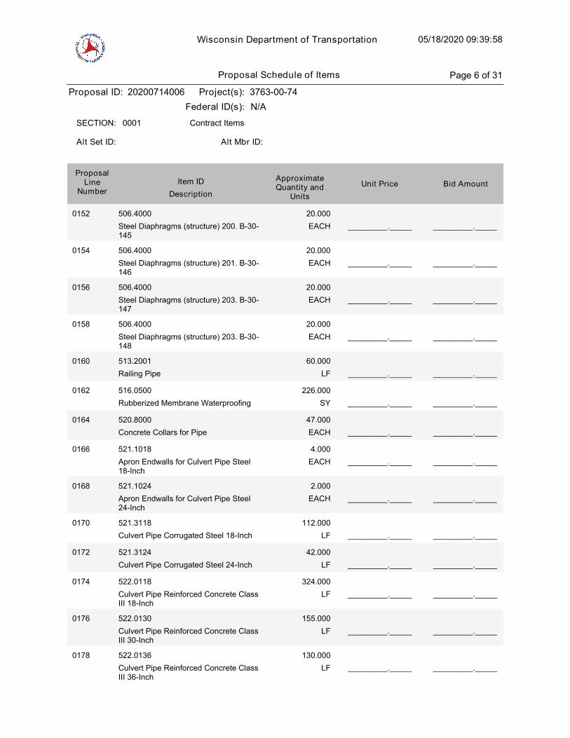
Wisconsin Department of Transportation 05/18/2020 09:39:58
Proposal ID: 20200714006 Project(s): 3763-00-74
Federal ID(s): N/A
0001 Contract ItemsSECTION:
Alt Set ID: Alt Mbr ID:
Bid AmountUnit PriceApproximateQuantity and
UnitsDescription
Item IDProposal
LineNumber
0152 506.4000
Steel Diaphragms (structure) 200. B-30-145
EACH
20.000
_________._____ _________._____
0154 506.4000
Steel Diaphragms (structure) 201. B-30-146
EACH
20.000
_________._____ _________._____
0156 506.4000
Steel Diaphragms (structure) 203. B-30-147
EACH
20.000
_________._____ _________._____
0158 506.4000
Steel Diaphragms (structure) 203. B-30-148
EACH
20.000
_________._____ _________._____
0160 513.2001
Railing Pipe LF
60.000
_________._____ _________._____
0162 516.0500
Rubberized Membrane Waterproofing SY
226.000
_________._____ _________._____
0164 520.8000
Concrete Collars for Pipe EACH
47.000
_________._____ _________._____
0166 521.1018
Apron Endwalls for Culvert Pipe Steel18-Inch
EACH
4.000
_________._____ _________._____
0168 521.1024
Apron Endwalls for Culvert Pipe Steel24-Inch
EACH
2.000
_________._____ _________._____
0170 521.3118
Culvert Pipe Corrugated Steel 18-Inch LF
112.000
_________._____ _________._____
0172 521.3124
Culvert Pipe Corrugated Steel 24-Inch LF
42.000
_________._____ _________._____
0174 522.0118
Culvert Pipe Reinforced Concrete ClassIII 18-Inch
LF
324.000
_________._____ _________._____
0176 522.0130
Culvert Pipe Reinforced Concrete ClassIII 30-Inch
LF
155.000
_________._____ _________._____
0178 522.0136
Culvert Pipe Reinforced Concrete ClassIII 36-Inch
LF
130.000
_________._____ _________._____
Proposal Schedule of Items Page 6 of 31
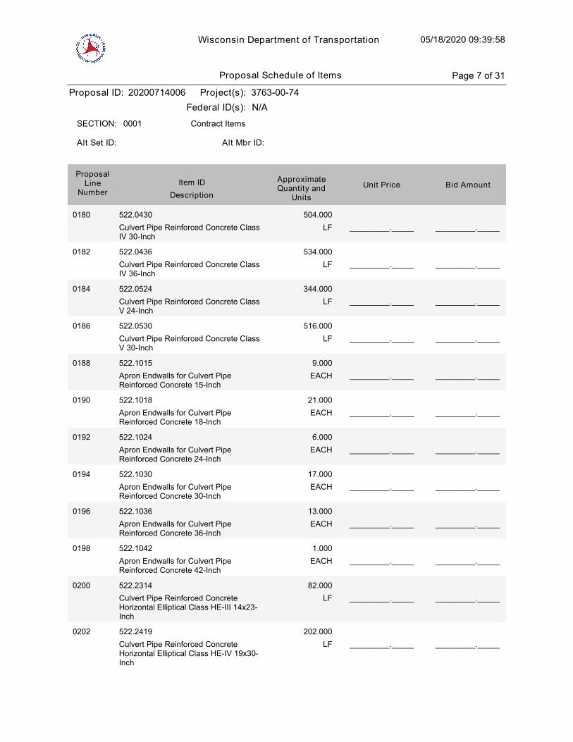
Wisconsin Department of Transportation 05/18/2020 09:39:58
Proposal ID: 20200714006 Project(s): 3763-00-74
Federal ID(s): N/A
0001 Contract ItemsSECTION:
Alt Set ID: Alt Mbr ID:
Bid AmountUnit PriceApproximateQuantity and
UnitsDescription
Item IDProposal
LineNumber
0180 522.0430
Culvert Pipe Reinforced Concrete ClassIV 30-Inch
LF
504.000
_________._____ _________._____
0182 522.0436
Culvert Pipe Reinforced Concrete ClassIV 36-Inch
LF
534.000
_________._____ _________._____
0184 522.0524
Culvert Pipe Reinforced Concrete ClassV 24-Inch
LF
344.000
_________._____ _________._____
0186 522.0530
Culvert Pipe Reinforced Concrete ClassV 30-Inch
LF
516.000
_________._____ _________._____
0188 522.1015
Apron Endwalls for Culvert PipeReinforced Concrete 15-Inch
EACH
9.000
_________._____ _________._____
0190 522.1018
Apron Endwalls for Culvert PipeReinforced Concrete 18-Inch
EACH
21.000
_________._____ _________._____
0192 522.1024
Apron Endwalls for Culvert PipeReinforced Concrete 24-Inch
EACH
6.000
_________._____ _________._____
0194 522.1030
Apron Endwalls for Culvert PipeReinforced Concrete 30-Inch
EACH
17.000
_________._____ _________._____
0196 522.1036
Apron Endwalls for Culvert PipeReinforced Concrete 36-Inch
EACH
13.000
_________._____ _________._____
0198 522.1042
Apron Endwalls for Culvert PipeReinforced Concrete 42-Inch
EACH
1.000
_________._____ _________._____
0200 522.2314
Culvert Pipe Reinforced ConcreteHorizontal Elliptical Class HE-III 14x23-Inch
LF
82.000
_________._____ _________._____
0202 522.2419
Culvert Pipe Reinforced ConcreteHorizontal Elliptical Class HE-IV 19x30-Inch
LF
202.000
_________._____ _________._____
Proposal Schedule of Items Page 7 of 31
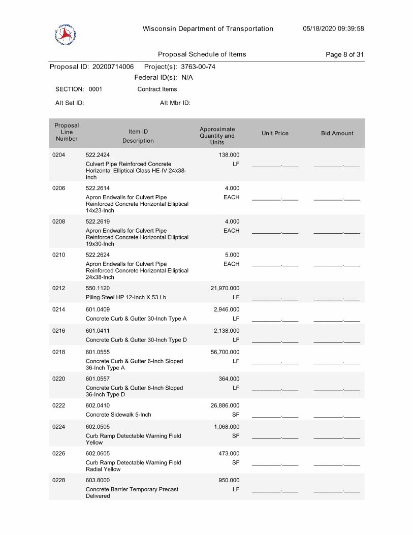
Wisconsin Department of Transportation 05/18/2020 09:39:58
Proposal ID: 20200714006 Project(s): 3763-00-74
Federal ID(s): N/A
0001 Contract ItemsSECTION:
Alt Set ID: Alt Mbr ID:
Bid AmountUnit PriceApproximateQuantity and
UnitsDescription
Item IDProposal
LineNumber
0204 522.2424
Culvert Pipe Reinforced ConcreteHorizontal Elliptical Class HE-IV 24x38-Inch
LF
138.000
_________._____ _________._____
0206 522.2614
Apron Endwalls for Culvert PipeReinforced Concrete Horizontal Elliptical14x23-Inch
EACH
4.000
_________._____ _________._____
0208 522.2619
Apron Endwalls for Culvert PipeReinforced Concrete Horizontal Elliptical19x30-Inch
EACH
4.000
_________._____ _________._____
0210 522.2624
Apron Endwalls for Culvert PipeReinforced Concrete Horizontal Elliptical24x38-Inch
EACH
5.000
_________._____ _________._____
0212 550.1120
Piling Steel HP 12-Inch X 53 Lb LF
21,970.000
_________._____ _________._____
0214 601.0409
Concrete Curb & Gutter 30-Inch Type A LF
2,946.000
_________._____ _________._____
0216 601.0411
Concrete Curb & Gutter 30-Inch Type D LF
2,138.000
_________._____ _________._____
0218 601.0555
Concrete Curb & Gutter 6-Inch Sloped36-Inch Type A
LF
56,700.000
_________._____ _________._____
0220 601.0557
Concrete Curb & Gutter 6-Inch Sloped36-Inch Type D
LF
364.000
_________._____ _________._____
0222 602.0410
Concrete Sidewalk 5-Inch SF
26,886.000
_________._____ _________._____
0224 602.0505
Curb Ramp Detectable Warning FieldYellow
SF
1,068.000
_________._____ _________._____
0226 602.0605
Curb Ramp Detectable Warning FieldRadial Yellow
SF
473.000
_________._____ _________._____
0228 603.8000
Concrete Barrier Temporary PrecastDelivered
LF
950.000
_________._____ _________._____
Proposal Schedule of Items Page 8 of 31

Wisconsin Department of Transportation 05/18/2020 09:39:58
Proposal ID: 20200714006 Project(s): 3763-00-74
Federal ID(s): N/A
0001 Contract ItemsSECTION:
Alt Set ID: Alt Mbr ID:
Bid AmountUnit PriceApproximateQuantity and
UnitsDescription
Item IDProposal
LineNumber
0230 603.8125
Concrete Barrier Temporary PrecastInstalled
LF
1,750.000
_________._____ _________._____
0232 604.0400
Slope Paving Concrete SY
226.000
_________._____ _________._____
0234 606.0100
Riprap Light CY
0.500
_________._____ _________._____
0236 606.0200
Riprap Medium CY
641.000
_________._____ _________._____
0238 606.0300
Riprap Heavy CY
887.000
_________._____ _________._____
0240 608.0312
Storm Sewer Pipe Reinforced ConcreteClass III 12-Inch
LF
1,054.000
_________._____ _________._____
0242 608.0315
Storm Sewer Pipe Reinforced ConcreteClass III 15-Inch
LF
5,771.000
_________._____ _________._____
0244 608.0318
Storm Sewer Pipe Reinforced ConcreteClass III 18-Inch
LF
303.000
_________._____ _________._____
0246 608.0321
Storm Sewer Pipe Reinforced ConcreteClass III 21-Inch
LF
208.000
_________._____ _________._____
0248 608.0324
Storm Sewer Pipe Reinforced ConcreteClass III 24-Inch
LF
4,218.000
_________._____ _________._____
0250 608.0330
Storm Sewer Pipe Reinforced ConcreteClass III 30-Inch
LF
3,849.000
_________._____ _________._____
0252 608.0336
Storm Sewer Pipe Reinforced ConcreteClass III 36-Inch
LF
876.000
_________._____ _________._____
0254 608.0412
Storm Sewer Pipe Reinforced ConcreteClass IV 12-Inch
LF
185.000
_________._____ _________._____
0256 608.0415
Storm Sewer Pipe Reinforced ConcreteClass IV 15-Inch
LF
4,643.000
_________._____ _________._____
Proposal Schedule of Items Page 9 of 31

Wisconsin Department of Transportation 05/18/2020 09:39:58
Proposal ID: 20200714006 Project(s): 3763-00-74
Federal ID(s): N/A
0001 Contract ItemsSECTION:
Alt Set ID: Alt Mbr ID:
Bid AmountUnit PriceApproximateQuantity and
UnitsDescription
Item IDProposal
LineNumber
0258 608.0418
Storm Sewer Pipe Reinforced ConcreteClass IV 18-Inch
LF
303.000
_________._____ _________._____
0260 608.0424
Storm Sewer Pipe Reinforced ConcreteClass IV 24-Inch
LF
2,698.000
_________._____ _________._____
0262 608.0430
Storm Sewer Pipe Reinforced ConcreteClass IV 30-Inch
LF
207.000
_________._____ _________._____
0264 608.0436
Storm Sewer Pipe Reinforced ConcreteClass IV 36-Inch
LF
916.000
_________._____ _________._____
0266 608.0442
Storm Sewer Pipe Reinforced ConcreteClass IV 42-Inch
LF
337.000
_________._____ _________._____
0268 608.2324
Storm Sewer Pipe Reinforced ConcreteHorizontal Elliptical Class HE-III 24x38-Inch
LF
112.000
_________._____ _________._____
0270 608.2329
Storm Sewer Pipe Reinforced ConcreteHorizontal Elliptical Class HE-III 29x45-Inch
LF
406.000
_________._____ _________._____
0272 608.2424
Storm Sewer Pipe Reinforced ConcreteHorizontal Elliptical Class HE-IV 24x38-Inch
LF
584.000
_________._____ _________._____
0274 608.2429
Storm Sewer Pipe Reinforced ConcreteHorizontal Elliptical Class HE-IV 29x45-Inch
LF
546.000
_________._____ _________._____
0276 608.2434
Storm Sewer Pipe Reinforced ConcreteHorizontal Elliptical Class HE-IV 34x53-Inch
LF
140.000
_________._____ _________._____
0278 611.0420
Reconstructing Manholes EACH
17.000
_________._____ _________._____
0280 611.0430
Reconstructing Inlets EACH
4.000
_________._____ _________._____
Proposal Schedule of Items Page 10 of 31
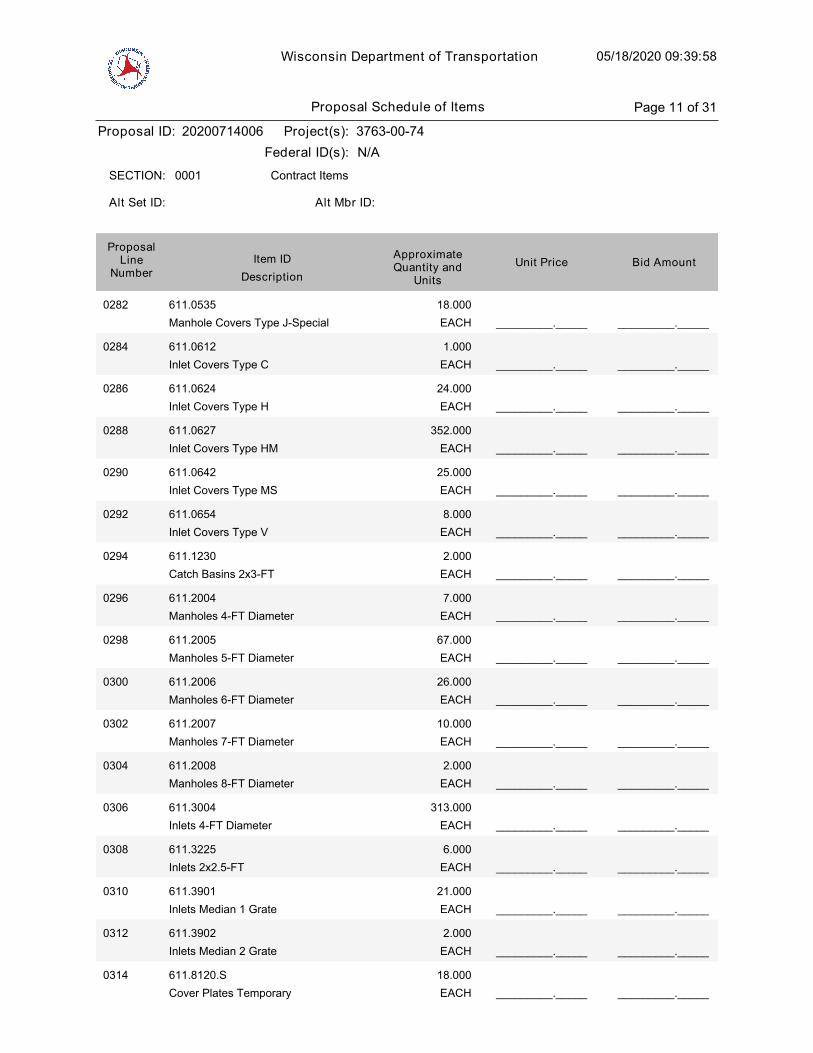
Wisconsin Department of Transportation 05/18/2020 09:39:58
Proposal ID: 20200714006 Project(s): 3763-00-74
Federal ID(s): N/A
0001 Contract ItemsSECTION:
Alt Set ID: Alt Mbr ID:
Bid AmountUnit PriceApproximateQuantity and
UnitsDescription
Item IDProposal
LineNumber
0282 611.0535
Manhole Covers Type J-Special EACH
18.000
_________._____ _________._____
0284 611.0612
Inlet Covers Type C EACH
1.000
_________._____ _________._____
0286 611.0624
Inlet Covers Type H EACH
24.000
_________._____ _________._____
0288 611.0627
Inlet Covers Type HM EACH
352.000
_________._____ _________._____
0290 611.0642
Inlet Covers Type MS EACH
25.000
_________._____ _________._____
0292 611.0654
Inlet Covers Type V EACH
8.000
_________._____ _________._____
0294 611.1230
Catch Basins 2x3-FT EACH
2.000
_________._____ _________._____
0296 611.2004
Manholes 4-FT Diameter EACH
7.000
_________._____ _________._____
0298 611.2005
Manholes 5-FT Diameter EACH
67.000
_________._____ _________._____
0300 611.2006
Manholes 6-FT Diameter EACH
26.000
_________._____ _________._____
0302 611.2007
Manholes 7-FT Diameter EACH
10.000
_________._____ _________._____
0304 611.2008
Manholes 8-FT Diameter EACH
2.000
_________._____ _________._____
0306 611.3004
Inlets 4-FT Diameter EACH
313.000
_________._____ _________._____
0308 611.3225
Inlets 2x2.5-FT EACH
6.000
_________._____ _________._____
0310 611.3901
Inlets Median 1 Grate EACH
21.000
_________._____ _________._____
0312 611.3902
Inlets Median 2 Grate EACH
2.000
_________._____ _________._____
0314 611.8120.S
Cover Plates Temporary EACH
18.000
_________._____ _________._____
Proposal Schedule of Items Page 11 of 31
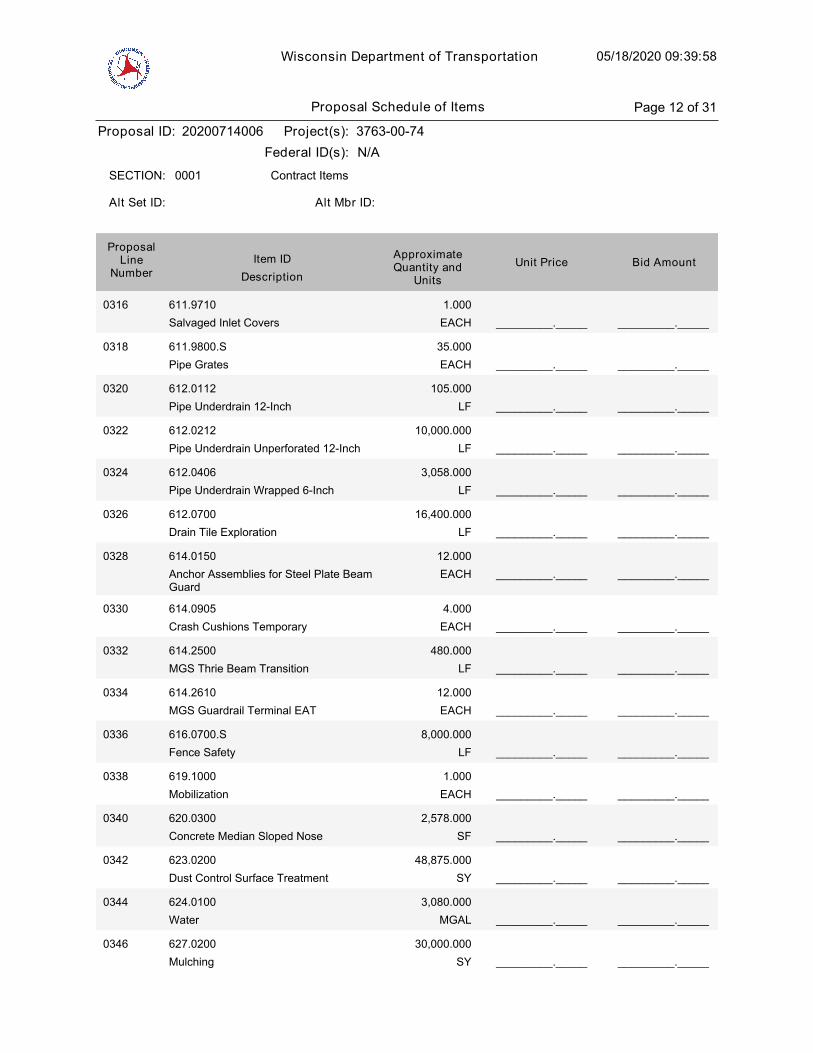
Wisconsin Department of Transportation 05/18/2020 09:39:58
Proposal ID: 20200714006 Project(s): 3763-00-74
Federal ID(s): N/A
0001 Contract ItemsSECTION:
Alt Set ID: Alt Mbr ID:
Bid AmountUnit PriceApproximateQuantity and
UnitsDescription
Item IDProposal
LineNumber
0316 611.9710
Salvaged Inlet Covers EACH
1.000
_________._____ _________._____
0318 611.9800.S
Pipe Grates EACH
35.000
_________._____ _________._____
0320 612.0112
Pipe Underdrain 12-Inch LF
105.000
_________._____ _________._____
0322 612.0212
Pipe Underdrain Unperforated 12-Inch LF
10,000.000
_________._____ _________._____
0324 612.0406
Pipe Underdrain Wrapped 6-Inch LF
3,058.000
_________._____ _________._____
0326 612.0700
Drain Tile Exploration LF
16,400.000
_________._____ _________._____
0328 614.0150
Anchor Assemblies for Steel Plate BeamGuard
EACH
12.000
_________._____ _________._____
0330 614.0905
Crash Cushions Temporary EACH
4.000
_________._____ _________._____
0332 614.2500
MGS Thrie Beam Transition LF
480.000
_________._____ _________._____
0334 614.2610
MGS Guardrail Terminal EAT EACH
12.000
_________._____ _________._____
0336 616.0700.S
Fence Safety LF
8,000.000
_________._____ _________._____
0338 619.1000
Mobilization EACH
1.000
_________._____ _________._____
0340 620.0300
Concrete Median Sloped Nose SF
2,578.000
_________._____ _________._____
0342 623.0200
Dust Control Surface Treatment SY
48,875.000
_________._____ _________._____
0344 624.0100
Water MGAL
3,080.000
_________._____ _________._____
0346 627.0200
Mulching SY
30,000.000
_________._____ _________._____
Proposal Schedule of Items Page 12 of 31
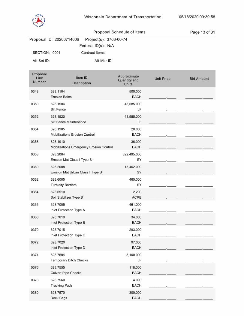
Wisconsin Department of Transportation 05/18/2020 09:39:58
Proposal ID: 20200714006 Project(s): 3763-00-74
Federal ID(s): N/A
0001 Contract ItemsSECTION:
Alt Set ID: Alt Mbr ID:
Bid AmountUnit PriceApproximateQuantity and
UnitsDescription
Item IDProposal
LineNumber
0348 628.1104
Erosion Bales EACH
500.000
_________._____ _________._____
0350 628.1504
Silt Fence LF
43,585.000
_________._____ _________._____
0352 628.1520
Silt Fence Maintenance LF
43,585.000
_________._____ _________._____
0354 628.1905
Mobilizations Erosion Control EACH
20.000
_________._____ _________._____
0356 628.1910
Mobilizations Emergency Erosion Control EACH
36.000
_________._____ _________._____
0358 628.2004
Erosion Mat Class I Type B SY
322,495.000
_________._____ _________._____
0360 628.2008
Erosion Mat Urban Class I Type B SY
13,462.000
_________._____ _________._____
0362 628.6005
Turbidity Barriers SY
465.000
_________._____ _________._____
0364 628.6510
Soil Stabilizer Type B ACRE
2.200
_________._____ _________._____
0366 628.7005
Inlet Protection Type A EACH
461.000
_________._____ _________._____
0368 628.7010
Inlet Protection Type B EACH
34.000
_________._____ _________._____
0370 628.7015
Inlet Protection Type C EACH
293.000
_________._____ _________._____
0372 628.7020
Inlet Protection Type D EACH
97.000
_________._____ _________._____
0374 628.7504
Temporary Ditch Checks LF
5,100.000
_________._____ _________._____
0376 628.7555
Culvert Pipe Checks EACH
118.000
_________._____ _________._____
0378 628.7560
Tracking Pads EACH
4.000
_________._____ _________._____
0380 628.7570
Rock Bags EACH
300.000
_________._____ _________._____
Proposal Schedule of Items Page 13 of 31

Wisconsin Department of Transportation 05/18/2020 09:39:58
Proposal ID: 20200714006 Project(s): 3763-00-74
Federal ID(s): N/A
0001 Contract ItemsSECTION:
Alt Set ID: Alt Mbr ID:
Bid AmountUnit PriceApproximateQuantity and
UnitsDescription
Item IDProposal
LineNumber
0382 629.0210
Fertilizer Type B CWT
158.200
_________._____ _________._____
0384 630.0140
Seeding Mixture No. 40 LB
4,523.000
_________._____ _________._____
0386 630.0171
Seeding Mixture No. 70A LB
262.000
_________._____ _________._____
0388 630.0200
Seeding Temporary LB
6,788.000
_________._____ _________._____
0390 630.0500
Seed Water MGAL
3,500.000
_________._____ _________._____
0392 633.1100
Delineators Temporary EACH
21.000
_________._____ _________._____
0394 633.5200
Markers Culvert End EACH
70.000
_________._____ _________._____
0396 634.0618
Posts Wood 4x6-Inch X 18-FT EACH
270.000
_________._____ _________._____
0398 637.2210
Signs Type II Reflective H SF
2,097.690
_________._____ _________._____
0400 637.2215
Signs Type II Reflective H Folding SF
184.840
_________._____ _________._____
0402 637.2230
Signs Type II Reflective F SF
822.500
_________._____ _________._____
0404 638.2102
Moving Signs Type II EACH
4.000
_________._____ _________._____
0406 638.2602
Removing Signs Type II EACH
215.000
_________._____ _________._____
0408 638.3000
Removing Small Sign Supports EACH
139.000
_________._____ _________._____
0410 638.4000
Moving Small Sign Supports EACH
3.000
_________._____ _________._____
0412 640.1303.S
Pond Liner Clay CY
10,845.000
_________._____ _________._____
0414 643.0300
Traffic Control Drums DAY
95,139.000
_________._____ _________._____
Proposal Schedule of Items Page 14 of 31
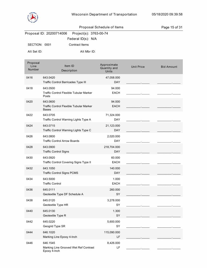
Wisconsin Department of Transportation 05/18/2020 09:39:58
Proposal ID: 20200714006 Project(s): 3763-00-74
Federal ID(s): N/A
0001 Contract ItemsSECTION:
Alt Set ID: Alt Mbr ID:
Bid AmountUnit PriceApproximateQuantity and
UnitsDescription
Item IDProposal
LineNumber
0416 643.0420
Traffic Control Barricades Type III DAY
47,058.000
_________._____ _________._____
0418 643.0500
Traffic Control Flexible Tubular MarkerPosts
EACH
94.000
_________._____ _________._____
0420 643.0600
Traffic Control Flexible Tubular MarkerBases
EACH
94.000
_________._____ _________._____
0422 643.0705
Traffic Control Warning Lights Type A DAY
71,324.000
_________._____ _________._____
0424 643.0715
Traffic Control Warning Lights Type C DAY
21,123.000
_________._____ _________._____
0426 643.0800
Traffic Control Arrow Boards DAY
2,020.000
_________._____ _________._____
0428 643.0900
Traffic Control Signs DAY
218,704.000
_________._____ _________._____
0430 643.0920
Traffic Control Covering Signs Type II EACH
60.000
_________._____ _________._____
0432 643.1050
Traffic Control Signs PCMS DAY
140.000
_________._____ _________._____
0434 643.5000
Traffic Control EACH
1.000
_________._____ _________._____
0436 645.0111
Geotextile Type DF Schedule A SY
260.000
_________._____ _________._____
0438 645.0120
Geotextile Type HR SY
3,278.000
_________._____ _________._____
0440 645.0130
Geotextile Type R SY
1.300
_________._____ _________._____
0442 645.0220
Geogrid Type SR SY
5,600.000
_________._____ _________._____
0444 646.1020
Marking Line Epoxy 4-Inch LF
115,090.000
_________._____ _________._____
0446 646.1545
Marking Line Grooved Wet Ref ContrastEpoxy 4-Inch
LF
8,426.000
_________._____ _________._____
Proposal Schedule of Items Page 15 of 31
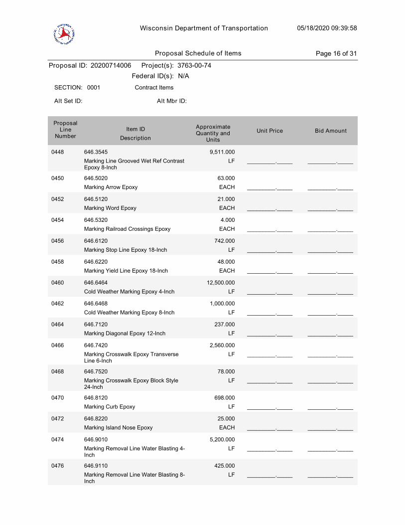
Wisconsin Department of Transportation 05/18/2020 09:39:58
Proposal ID: 20200714006 Project(s): 3763-00-74
Federal ID(s): N/A
0001 Contract ItemsSECTION:
Alt Set ID: Alt Mbr ID:
Bid AmountUnit PriceApproximateQuantity and
UnitsDescription
Item IDProposal
LineNumber
0448 646.3545
Marking Line Grooved Wet Ref ContrastEpoxy 8-Inch
LF
9,511.000
_________._____ _________._____
0450 646.5020
Marking Arrow Epoxy EACH
63.000
_________._____ _________._____
0452 646.5120
Marking Word Epoxy EACH
21.000
_________._____ _________._____
0454 646.5320
Marking Railroad Crossings Epoxy EACH
4.000
_________._____ _________._____
0456 646.6120
Marking Stop Line Epoxy 18-Inch LF
742.000
_________._____ _________._____
0458 646.6220
Marking Yield Line Epoxy 18-Inch EACH
48.000
_________._____ _________._____
0460 646.6464
Cold Weather Marking Epoxy 4-Inch LF
12,500.000
_________._____ _________._____
0462 646.6468
Cold Weather Marking Epoxy 8-Inch LF
1,000.000
_________._____ _________._____
0464 646.7120
Marking Diagonal Epoxy 12-Inch LF
237.000
_________._____ _________._____
0466 646.7420
Marking Crosswalk Epoxy TransverseLine 6-Inch
LF
2,560.000
_________._____ _________._____
0468 646.7520
Marking Crosswalk Epoxy Block Style24-Inch
LF
78.000
_________._____ _________._____
0470 646.8120
Marking Curb Epoxy LF
698.000
_________._____ _________._____
0472 646.8220
Marking Island Nose Epoxy EACH
25.000
_________._____ _________._____
0474 646.9010
Marking Removal Line Water Blasting 4-Inch
LF
5,200.000
_________._____ _________._____
0476 646.9110
Marking Removal Line Water Blasting 8-Inch
LF
425.000
_________._____ _________._____
Proposal Schedule of Items Page 16 of 31
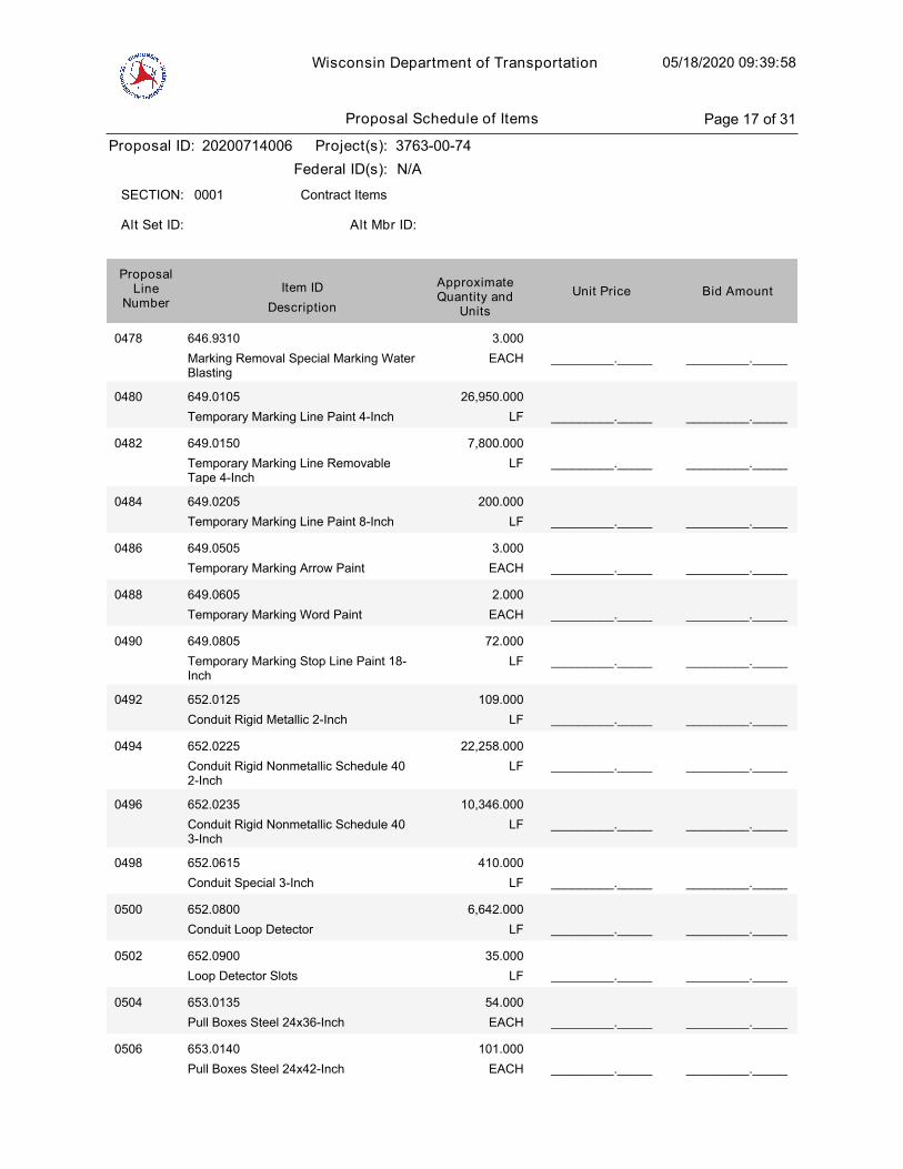
Wisconsin Department of Transportation 05/18/2020 09:39:58
Proposal ID: 20200714006 Project(s): 3763-00-74
Federal ID(s): N/A
0001 Contract ItemsSECTION:
Alt Set ID: Alt Mbr ID:
Bid AmountUnit PriceApproximateQuantity and
UnitsDescription
Item IDProposal
LineNumber
0478 646.9310
Marking Removal Special Marking WaterBlasting
EACH
3.000
_________._____ _________._____
0480 649.0105
Temporary Marking Line Paint 4-Inch LF
26,950.000
_________._____ _________._____
0482 649.0150
Temporary Marking Line RemovableTape 4-Inch
LF
7,800.000
_________._____ _________._____
0484 649.0205
Temporary Marking Line Paint 8-Inch LF
200.000
_________._____ _________._____
0486 649.0505
Temporary Marking Arrow Paint EACH
3.000
_________._____ _________._____
0488 649.0605
Temporary Marking Word Paint EACH
2.000
_________._____ _________._____
0490 649.0805
Temporary Marking Stop Line Paint 18-Inch
LF
72.000
_________._____ _________._____
0492 652.0125
Conduit Rigid Metallic 2-Inch LF
109.000
_________._____ _________._____
0494 652.0225
Conduit Rigid Nonmetallic Schedule 402-Inch
LF
22,258.000
_________._____ _________._____
0496 652.0235
Conduit Rigid Nonmetallic Schedule 403-Inch
LF
10,346.000
_________._____ _________._____
0498 652.0615
Conduit Special 3-Inch LF
410.000
_________._____ _________._____
0500 652.0800
Conduit Loop Detector LF
6,642.000
_________._____ _________._____
0502 652.0900
Loop Detector Slots LF
35.000
_________._____ _________._____
0504 653.0135
Pull Boxes Steel 24x36-Inch EACH
54.000
_________._____ _________._____
0506 653.0140
Pull Boxes Steel 24x42-Inch EACH
101.000
_________._____ _________._____
Proposal Schedule of Items Page 17 of 31
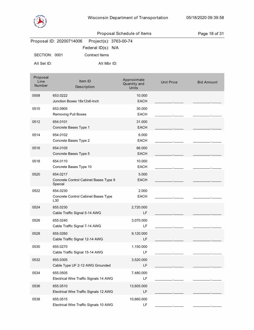
Wisconsin Department of Transportation 05/18/2020 09:39:58
Proposal ID: 20200714006 Project(s): 3763-00-74
Federal ID(s): N/A
0001 Contract ItemsSECTION:
Alt Set ID: Alt Mbr ID:
Bid AmountUnit PriceApproximateQuantity and
UnitsDescription
Item IDProposal
LineNumber
0508 653.0222
Junction Boxes 18x12x6-Inch EACH
10.000
_________._____ _________._____
0510 653.0905
Removing Pull Boxes EACH
30.000
_________._____ _________._____
0512 654.0101
Concrete Bases Type 1 EACH
31.000
_________._____ _________._____
0514 654.0102
Concrete Bases Type 2 EACH
6.000
_________._____ _________._____
0516 654.0105
Concrete Bases Type 5 EACH
86.000
_________._____ _________._____
0518 654.0110
Concrete Bases Type 10 EACH
10.000
_________._____ _________._____
0520 654.0217
Concrete Control Cabinet Bases Type 9Special
EACH
5.000
_________._____ _________._____
0522 654.0230
Concrete Control Cabinet Bases TypeL30
EACH
2.000
_________._____ _________._____
0524 655.0230
Cable Traffic Signal 5-14 AWG LF
2,720.000
_________._____ _________._____
0526 655.0240
Cable Traffic Signal 7-14 AWG LF
3,070.000
_________._____ _________._____
0528 655.0260
Cable Traffic Signal 12-14 AWG LF
9,120.000
_________._____ _________._____
0530 655.0270
Cable Traffic Signal 15-14 AWG LF
1,150.000
_________._____ _________._____
0532 655.0305
Cable Type UF 2-12 AWG Grounded LF
3,520.000
_________._____ _________._____
0534 655.0505
Electrical Wire Traffic Signals 14 AWG LF
7,480.000
_________._____ _________._____
0536 655.0510
Electrical Wire Traffic Signals 12 AWG LF
13,605.000
_________._____ _________._____
0538 655.0515
Electrical Wire Traffic Signals 10 AWG LF
10,660.000
_________._____ _________._____
Proposal Schedule of Items Page 18 of 31
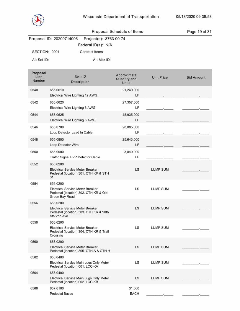
Wisconsin Department of Transportation 05/18/2020 09:39:58
Proposal ID: 20200714006 Project(s): 3763-00-74
Federal ID(s): N/A
0001 Contract ItemsSECTION:
Alt Set ID: Alt Mbr ID:
Bid AmountUnit PriceApproximateQuantity and
UnitsDescription
Item IDProposal
LineNumber
0540 655.0610
Electrical Wire Lighting 12 AWG LF
21,240.000
_________._____ _________._____
0542 655.0620
Electrical Wire Lighting 8 AWG LF
27,357.000
_________._____ _________._____
0544 655.0625
Electrical Wire Lighting 6 AWG LF
48,935.000
_________._____ _________._____
0546 655.0700
Loop Detector Lead In Cable LF
28,085.000
_________._____ _________._____
0548 655.0800
Loop Detector Wire LF
25,643.000
_________._____ _________._____
0550 655.0900
Traffic Signal EVP Detector Cable LF
3,840.000
_________._____ _________._____
0552 656.0200
Electrical Service Meter BreakerPedestal (location) 301. CTH KR & STH31
LUMP SUM _________._____LS
0554 656.0200
Electrical Service Meter BreakerPedestal (location) 302. CTH KR & OldGreen Bay Road
LUMP SUM _________._____LS
0556 656.0200
Electrical Service Meter BreakerPedestal (location) 303. CTH KR & 90thSt/72nd Ave
LUMP SUM _________._____LS
0558 656.0200
Electrical Service Meter BreakerPedestal (location) 304. CTH KR & TrailCrossing
LUMP SUM _________._____LS
0560 656.0200
Electrical Service Meter BreakerPedestal (location) 305. CTH A & CTH H
LUMP SUM _________._____LS
0562 656.0400
Electrical Service Main Lugs Only MeterPedestal (location) 001. LCC-KA
LUMP SUM _________._____LS
0564 656.0400
Electrical Service Main Lugs Only MeterPedestal (location) 002. LCC-KB
LUMP SUM _________._____LS
0566 657.0100
Pedestal Bases EACH
31.000
_________._____ _________._____
Proposal Schedule of Items Page 19 of 31
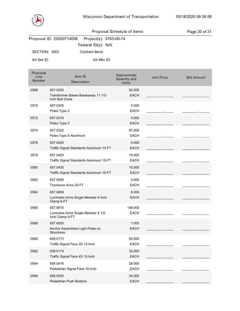
Wisconsin Department of Transportation 05/18/2020 09:39:58
Proposal ID: 20200714006 Project(s): 3763-00-74
Federal ID(s): N/A
0001 Contract ItemsSECTION:
Alt Set ID: Alt Mbr ID:
Bid AmountUnit PriceApproximateQuantity and
UnitsDescription
Item IDProposal
LineNumber
0568 657.0255
Transformer Bases Breakaway 11 1/2-Inch Bolt Circle
EACH
92.000
_________._____ _________._____
0570 657.0305
Poles Type 2 EACH
2.000
_________._____ _________._____
0572 657.0310
Poles Type 3 EACH
4.000
_________._____ _________._____
0574 657.0322
Poles Type 5-Aluminum EACH
87.000
_________._____ _________._____
0576 657.0420
Traffic Signal Standards Aluminum 13-FT EACH
6.000
_________._____ _________._____
0578 657.0425
Traffic Signal Standards Aluminum 15-FT EACH
15.000
_________._____ _________._____
0580 657.0430
Traffic Signal Standards Aluminum 10-FT EACH
10.000
_________._____ _________._____
0582 657.0590
Trombone Arms 20-FT EACH
4.000
_________._____ _________._____
0584 657.0609
Luminaire Arms Single Member 4-InchClamp 6-FT
EACH
6.000
_________._____ _________._____
0586 657.0610
Luminaire Arms Single Member 4 1/2-Inch Clamp 6-FT
EACH
148.000
_________._____ _________._____
0588 657.6005
Anchor Assemblies Light Poles onStructures
EACH
1.000
_________._____ _________._____
0590 658.0173
Traffic Signal Face 3S 12-Inch EACH
50.000
_________._____ _________._____
0592 658.0174
Traffic Signal Face 4S 12-Inch EACH
32.000
_________._____ _________._____
0594 658.0416
Pedestrian Signal Face 16-Inch EACH
28.000
_________._____ _________._____
0596 658.0500
Pedestrian Push Buttons EACH
34.000
_________._____ _________._____
Proposal Schedule of Items Page 20 of 31
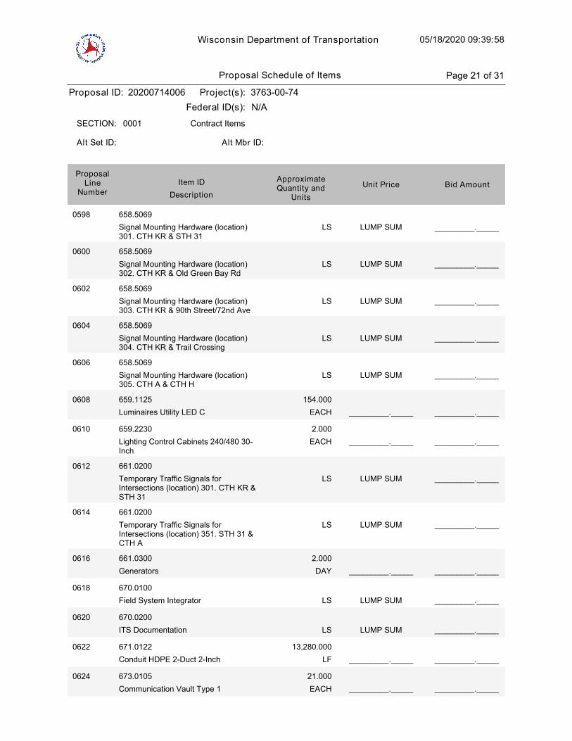
Wisconsin Department of Transportation 05/18/2020 09:39:58
Proposal ID: 20200714006 Project(s): 3763-00-74
Federal ID(s): N/A
0001 Contract ItemsSECTION:
Alt Set ID: Alt Mbr ID:
Bid AmountUnit PriceApproximateQuantity and
UnitsDescription
Item IDProposal
LineNumber
0598 658.5069
Signal Mounting Hardware (location)301. CTH KR & STH 31
LUMP SUM _________._____LS
0600 658.5069
Signal Mounting Hardware (location)302. CTH KR & Old Green Bay Rd
LUMP SUM _________._____LS
0602 658.5069
Signal Mounting Hardware (location)303. CTH KR & 90th Street/72nd Ave
LUMP SUM _________._____LS
0604 658.5069
Signal Mounting Hardware (location)304. CTH KR & Trail Crossing
LUMP SUM _________._____LS
0606 658.5069
Signal Mounting Hardware (location)305. CTH A & CTH H
LUMP SUM _________._____LS
0608 659.1125
Luminaires Utility LED C EACH
154.000
_________._____ _________._____
0610 659.2230
Lighting Control Cabinets 240/480 30-Inch
EACH
2.000
_________._____ _________._____
0612 661.0200
Temporary Traffic Signals forIntersections (location) 301. CTH KR &STH 31
LUMP SUM _________._____LS
0614 661.0200
Temporary Traffic Signals forIntersections (location) 351. STH 31 &CTH A
LUMP SUM _________._____LS
0616 661.0300
Generators DAY
2.000
_________._____ _________._____
0618 670.0100
Field System Integrator LUMP SUM _________._____LS
0620 670.0200
ITS Documentation LUMP SUM _________._____LS
0622 671.0122
Conduit HDPE 2-Duct 2-Inch LF
13,280.000
_________._____ _________._____
0624 673.0105
Communication Vault Type 1 EACH
21.000
_________._____ _________._____
Proposal Schedule of Items Page 21 of 31
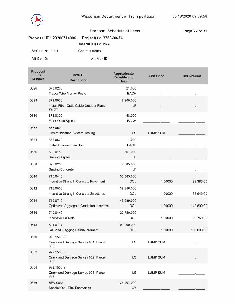
Wisconsin Department of Transportation 05/18/2020 09:39:58
Proposal ID: 20200714006 Project(s): 3763-00-74
Federal ID(s): N/A
0001 Contract ItemsSECTION:
Alt Set ID: Alt Mbr ID:
Bid AmountUnit PriceApproximateQuantity and
UnitsDescription
Item IDProposal
LineNumber
0626 673.0200
Tracer Wire Marker Posts EACH
21.000
_________._____ _________._____
0628 678.0072
Install Fiber Optic Cable Outdoor Plant72-CT
LF
16,205.000
_________._____ _________._____
0630 678.0300
Fiber Optic Splice EACH
58.000
_________._____ _________._____
0632 678.0500
Communication System Testing LUMP SUM _________._____LS
0634 678.0600
Install Ethernet Switches EACH
4.000
_________._____ _________._____
0636 690.0150
Sawing Asphalt LF
667.000
_________._____ _________._____
0638 690.0250
Sawing Concrete LF
2,085.000
_________._____ _________._____
1.00000
0640 715.0415
Incentive Strength Concrete Pavement DOL
38,385.000
38,385.00
1.00000
0642 715.0502
Incentive Strength Concrete Structures DOL
38,646.000
38,646.00
1.00000
0644 715.0710
Optimized Aggregate Gradation Incentive DOL
149,699.000
149,699.00
1.00000
0646 740.0440
Incentive IRI Ride DOL
22,750.000
22,750.00
1.00000
0648 801.0117
Railroad Flagging Reimbursement DOL
100,000.000
100,000.00
0650 999.1500.S
Crack and Damage Survey 001. Parcel802
LUMP SUM _________._____LS
0652 999.1500.S
Crack and Damage Survey 002. Parcel803
LUMP SUM _________._____LS
0654 999.1500.S
Crack and Damage Survey 003. Parcel839
LUMP SUM _________._____LS
0656 SPV.0035
Special 001. EBS Excavation CY
25,907.000
_________._____ _________._____
Proposal Schedule of Items Page 22 of 31

Wisconsin Department of Transportation 05/18/2020 09:39:58
Proposal ID: 20200714006 Project(s): 3763-00-74
Federal ID(s): N/A
0001 Contract ItemsSECTION:
Alt Set ID: Alt Mbr ID:
Bid AmountUnit PriceApproximateQuantity and
UnitsDescription
Item IDProposal
LineNumber
0658 SPV.0035
Special 002. EBS Backfill CY
25,907.000
_________._____ _________._____
0660 SPV.0035
Special 003. Roadway Embankment CY
635,684.000
_________._____ _________._____
0662 SPV.0035
Special 004. Riffle Cobble CY
36.000
_________._____ _________._____
0664 SPV.0035
Special 005. No. 1 Aggregate CY
1,582.000
_________._____ _________._____
0666 SPV.0035
Special 006. Open-Graded BaseAggregate
CY
170.000
_________._____ _________._____
0668 SPV.0035
Special 007. Sand/Woodchip Bed CY
829.000
_________._____ _________._____
0670 SPV.0035
Special 008. Compost CY
170.000
_________._____ _________._____
0672 SPV.0035
Special 009. Backfill Slurry CY
85.000
_________._____ _________._____
0674 SPV.0055
Special 001. Maintain Field Office Left inPlace Special Utility Fees Project 3763-00-74
DOL
100,000.000
_________._____ _________._____
0676 SPV.0060
Special 002. Temporary Stone DitchChecks
EACH
50.000
_________._____ _________._____
0678 SPV.0060
Special 003. Sand Bags EACH
500.000
_________._____ _________._____
0680 SPV.0060
Special 004. Temporary Sediment Traps EACH
25.000
_________._____ _________._____
0682 SPV.0060
Special 005. Erosion Control Filter Bags EACH
400.000
_________._____ _________._____
0684 SPV.0060
Special 006. Inlet Frame and Grate forMountable Curb
EACH
26.000
_________._____ _________._____
0686 SPV.0060
Special 007. Temporary Access Gates atCPRR
EACH
2.000
_________._____ _________._____
Proposal Schedule of Items Page 23 of 31
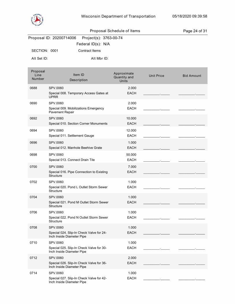
Wisconsin Department of Transportation 05/18/2020 09:39:58
Proposal ID: 20200714006 Project(s): 3763-00-74
Federal ID(s): N/A
0001 Contract ItemsSECTION:
Alt Set ID: Alt Mbr ID:
Bid AmountUnit PriceApproximateQuantity and
UnitsDescription
Item IDProposal
LineNumber
0688 SPV.0060
Special 008. Temporary Access Gates atUPRR
EACH
2.000
_________._____ _________._____
0690 SPV.0060
Special 009. Mobilizations EmergencyPavement Repair
EACH
2.000
_________._____ _________._____
0692 SPV.0060
Special 010. Section Corner Monuments EACH
10.000
_________._____ _________._____
0694 SPV.0060
Special 011. Settlement Gauge EACH
12.000
_________._____ _________._____
0696 SPV.0060
Special 012. Manhole Beehive Grate EACH
1.000
_________._____ _________._____
0698 SPV.0060
Special 013. Connect Drain Tile EACH
50.000
_________._____ _________._____
0700 SPV.0060
Special 016. Pipe Connection to ExistingStructure
EACH
7.000
_________._____ _________._____
0702 SPV.0060
Special 020. Pond L Outlet Storm SewerStructure
EACH
1.000
_________._____ _________._____
0704 SPV.0060
Special 021. Pond M Outlet Storm SewerStructure
EACH
1.000
_________._____ _________._____
0706 SPV.0060
Special 022. Pond N Outlet Storm SewerStructure
EACH
1.000
_________._____ _________._____
0708 SPV.0060
Special 024. Slip-In Check Valve for 24-Inch Inside Diameter Pipe
EACH
1.000
_________._____ _________._____
0710 SPV.0060
Special 025. Slip-In Check Valve for 30-Inch Inside Diameter Pipe
EACH
1.000
_________._____ _________._____
0712 SPV.0060
Special 026. Slip-In Check Valve for 36-Inch Inside Diameter Pipe
EACH
2.000
_________._____ _________._____
0714 SPV.0060
Special 027. Slip-In Check Valve for 42-Inch Inside Diameter Pipe
EACH
1.000
_________._____ _________._____
Proposal Schedule of Items Page 24 of 31

Wisconsin Department of Transportation 05/18/2020 09:39:58
Proposal ID: 20200714006 Project(s): 3763-00-74
Federal ID(s): N/A
0001 Contract ItemsSECTION:
Alt Set ID: Alt Mbr ID:
Bid AmountUnit PriceApproximateQuantity and
UnitsDescription
Item IDProposal
LineNumber
0716 SPV.0060
Special 028. Baseline CPM ProgressSchedule
EACH
1.000
_________._____ _________._____
0718 SPV.0060
Special 029. Monthly CPM ProgressSchedule Updates
EACH
24.000
_________._____ _________._____
0720 SPV.0060
Special 301. Concrete Bases MonotubeType 9 & 10 Special Pole
EACH
6.000
_________._____ _________._____
0722 SPV.0060
Special 302. Transport and Install PolesType 9
EACH
2.000
_________._____ _________._____
0724 SPV.0060
Special 303. Transport and Install PolesType 9 Special
EACH
2.000
_________._____ _________._____
0726 SPV.0060
Special 304. Transport and Install PolesType 10
EACH
8.000
_________._____ _________._____
0728 SPV.0060
Special 305. Transport and Install PolesType 10 Special
EACH
4.000
_________._____ _________._____
0730 SPV.0060
Special 306. Transport and InstallMonotube Arms 25-Ft
EACH
4.000
_________._____ _________._____
0732 SPV.0060
Special 307. Transport and InstallMonotube Arms 30-Ft
EACH
5.000
_________._____ _________._____
0734 SPV.0060
Special 308. Transport and InstallMonotube Arms 35-Ft
EACH
3.000
_________._____ _________._____
0736 SPV.0060
Special 309. Transport and InstallLuminaire Arms Steel 15-Ft
EACH
20.000
_________._____ _________._____
0738 SPV.0060
Special 310. Transport and InstallMonotube Arms 40-Ft
EACH
3.000
_________._____ _________._____
0740 SPV.0060
Special 311. Transport and InstallMonotube Arms 20-Ft
EACH
1.000
_________._____ _________._____
Proposal Schedule of Items Page 25 of 31
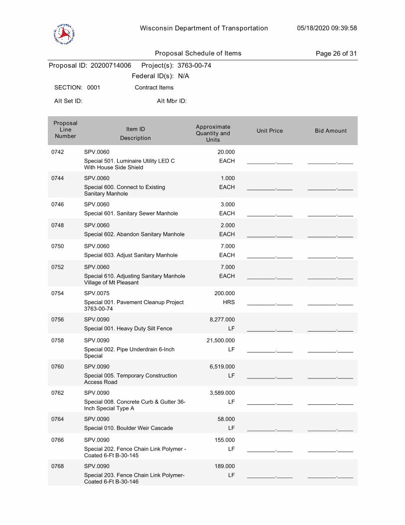
Wisconsin Department of Transportation 05/18/2020 09:39:58
Proposal ID: 20200714006 Project(s): 3763-00-74
Federal ID(s): N/A
0001 Contract ItemsSECTION:
Alt Set ID: Alt Mbr ID:
Bid AmountUnit PriceApproximateQuantity and
UnitsDescription
Item IDProposal
LineNumber
0742 SPV.0060
Special 501. Luminaire Utility LED CWith House Side Shield
EACH
20.000
_________._____ _________._____
0744 SPV.0060
Special 600. Connect to ExistingSanitary Manhole
EACH
1.000
_________._____ _________._____
0746 SPV.0060
Special 601. Sanitary Sewer Manhole EACH
3.000
_________._____ _________._____
0748 SPV.0060
Special 602. Abandon Sanitary Manhole EACH
2.000
_________._____ _________._____
0750 SPV.0060
Special 603. Adjust Sanitary Manhole EACH
7.000
_________._____ _________._____
0752 SPV.0060
Special 610. Adjusting Sanitary ManholeVillage of Mt Pleasant
EACH
7.000
_________._____ _________._____
0754 SPV.0075
Special 001. Pavement Cleanup Project3763-00-74
HRS
200.000
_________._____ _________._____
0756 SPV.0090
Special 001. Heavy Duty Silt Fence LF
8,277.000
_________._____ _________._____
0758 SPV.0090
Special 002. Pipe Underdrain 6-InchSpecial
LF
21,500.000
_________._____ _________._____
0760 SPV.0090
Special 005. Temporary ConstructionAccess Road
LF
6,519.000
_________._____ _________._____
0762 SPV.0090
Special 008. Concrete Curb & Gutter 36-Inch Special Type A
LF
3,589.000
_________._____ _________._____
0764 SPV.0090
Special 010. Boulder Weir Cascade LF
58.000
_________._____ _________._____
0766 SPV.0090
Special 202. Fence Chain Link Polymer -Coated 6-Ft B-30-145
LF
155.000
_________._____ _________._____
0768 SPV.0090
Special 203. Fence Chain Link Polymer-Coated 6-Ft B-30-146
LF
189.000
_________._____ _________._____
Proposal Schedule of Items Page 26 of 31
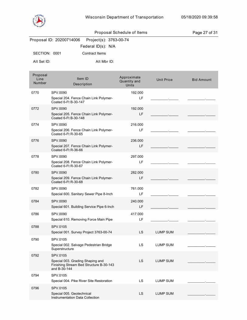
Wisconsin Department of Transportation 05/18/2020 09:39:58
Proposal ID: 20200714006 Project(s): 3763-00-74
Federal ID(s): N/A
0001 Contract ItemsSECTION:
Alt Set ID: Alt Mbr ID:
Bid AmountUnit PriceApproximateQuantity and
UnitsDescription
Item IDProposal
LineNumber
0770 SPV.0090
Special 204. Fence Chain Link Polymer-Coated 6-Ft B-30-147
LF
192.000
_________._____ _________._____
0772 SPV.0090
Special 205. Fence Chain Link Polymer-Coated 6-Ft B-30-148
LF
192.000
_________._____ _________._____
0774 SPV.0090
Special 206. Fence Chain Link Polymer-Coated 6-Ft R-30-65
LF
216.000
_________._____ _________._____
0776 SPV.0090
Special 207. Fence Chain Link Polymer-Coated 6-Ft R-36-66
LF
236.000
_________._____ _________._____
0778 SPV.0090
Special 208. Fence Chain Link Polymer-Coated 6-Ft R-30-67
LF
297.000
_________._____ _________._____
0780 SPV.0090
Special 209. Fence Chain Link Polymer-Coated 6-Ft R-30-68
LF
282.000
_________._____ _________._____
0782 SPV.0090
Special 600. Sanitary Sewer Pipe 8-Inch LF
761.000
_________._____ _________._____
0784 SPV.0090
Special 601. Building Service Pipe 6-Inch LF
240.000
_________._____ _________._____
0786 SPV.0090
Special 610. Removing Force Main Pipe LF
417.000
_________._____ _________._____
0788 SPV.0105
Special 001. Survey Project 3763-00-74 LUMP SUM _________._____LS
0790 SPV.0105
Special 002. Salvage Pedestrian BridgeSuperstructure
LUMP SUM _________._____LS
0792 SPV.0105
Special 003. Grading Shaping andFinishing Stream Bed Structure B-30-143and B-30-144
LUMP SUM _________._____LS
0794 SPV.0105
Special 004. Pike River Site Restoration LUMP SUM _________._____LS
0796 SPV.0105
Special 005. GeotechnicalInstrumentation Data Collection
LUMP SUM _________._____LS
Proposal Schedule of Items Page 27 of 31
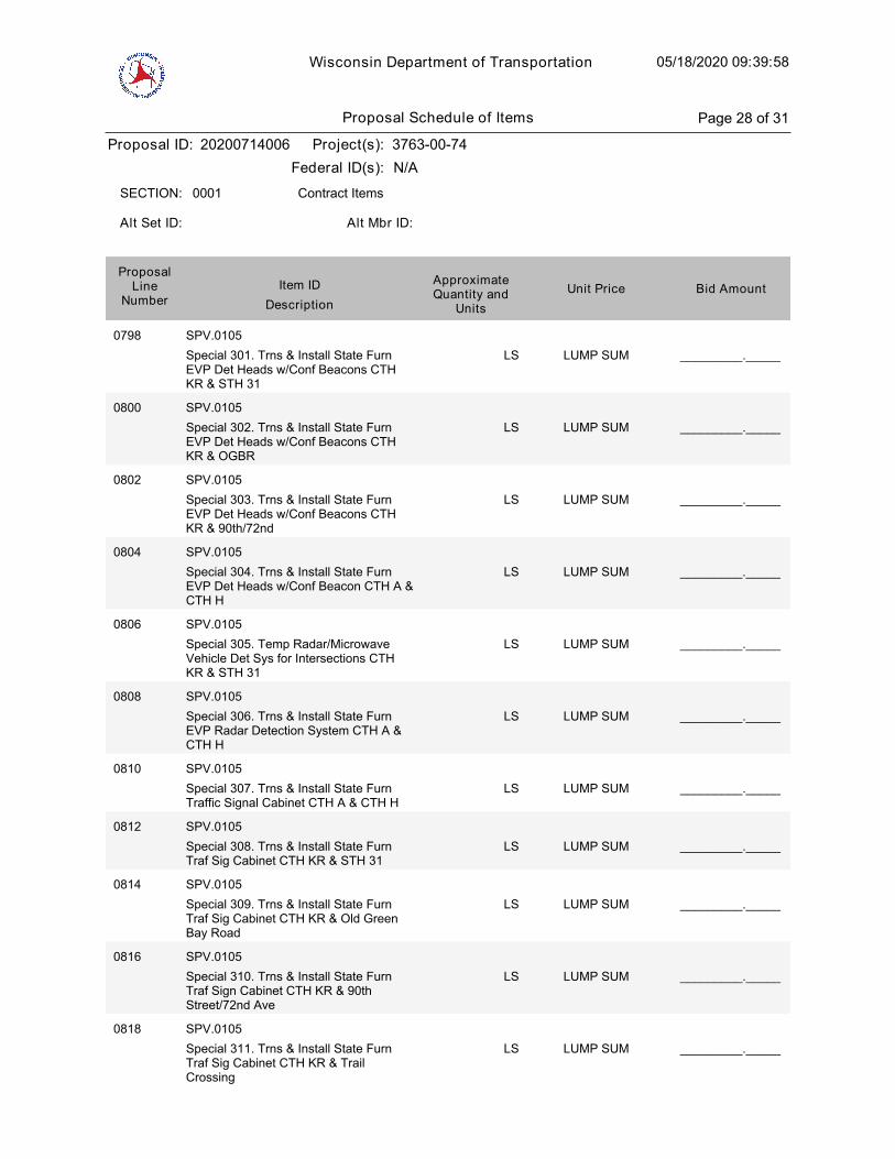
Wisconsin Department of Transportation 05/18/2020 09:39:58
Proposal ID: 20200714006 Project(s): 3763-00-74
Federal ID(s): N/A
0001 Contract ItemsSECTION:
Alt Set ID: Alt Mbr ID:
Bid AmountUnit PriceApproximateQuantity and
UnitsDescription
Item IDProposal
LineNumber
0798 SPV.0105
Special 301. Trns & Install State FurnEVP Det Heads w/Conf Beacons CTHKR & STH 31
LUMP SUM _________._____LS
0800 SPV.0105
Special 302. Trns & Install State FurnEVP Det Heads w/Conf Beacons CTHKR & OGBR
LUMP SUM _________._____LS
0802 SPV.0105
Special 303. Trns & Install State FurnEVP Det Heads w/Conf Beacons CTHKR & 90th/72nd
LUMP SUM _________._____LS
0804 SPV.0105
Special 304. Trns & Install State FurnEVP Det Heads w/Conf Beacon CTH A &CTH H
LUMP SUM _________._____LS
0806 SPV.0105
Special 305. Temp Radar/MicrowaveVehicle Det Sys for Intersections CTHKR & STH 31
LUMP SUM _________._____LS
0808 SPV.0105
Special 306. Trns & Install State FurnEVP Radar Detection System CTH A &CTH H
LUMP SUM _________._____LS
0810 SPV.0105
Special 307. Trns & Install State FurnTraffic Signal Cabinet CTH A & CTH H
LUMP SUM _________._____LS
0812 SPV.0105
Special 308. Trns & Install State FurnTraf Sig Cabinet CTH KR & STH 31
LUMP SUM _________._____LS
0814 SPV.0105
Special 309. Trns & Install State FurnTraf Sig Cabinet CTH KR & Old GreenBay Road
LUMP SUM _________._____LS
0816 SPV.0105
Special 310. Trns & Install State FurnTraf Sign Cabinet CTH KR & 90thStreet/72nd Ave
LUMP SUM _________._____LS
0818 SPV.0105
Special 311. Trns & Install State FurnTraf Sig Cabinet CTH KR & TrailCrossing
LUMP SUM _________._____LS
Proposal Schedule of Items Page 28 of 31
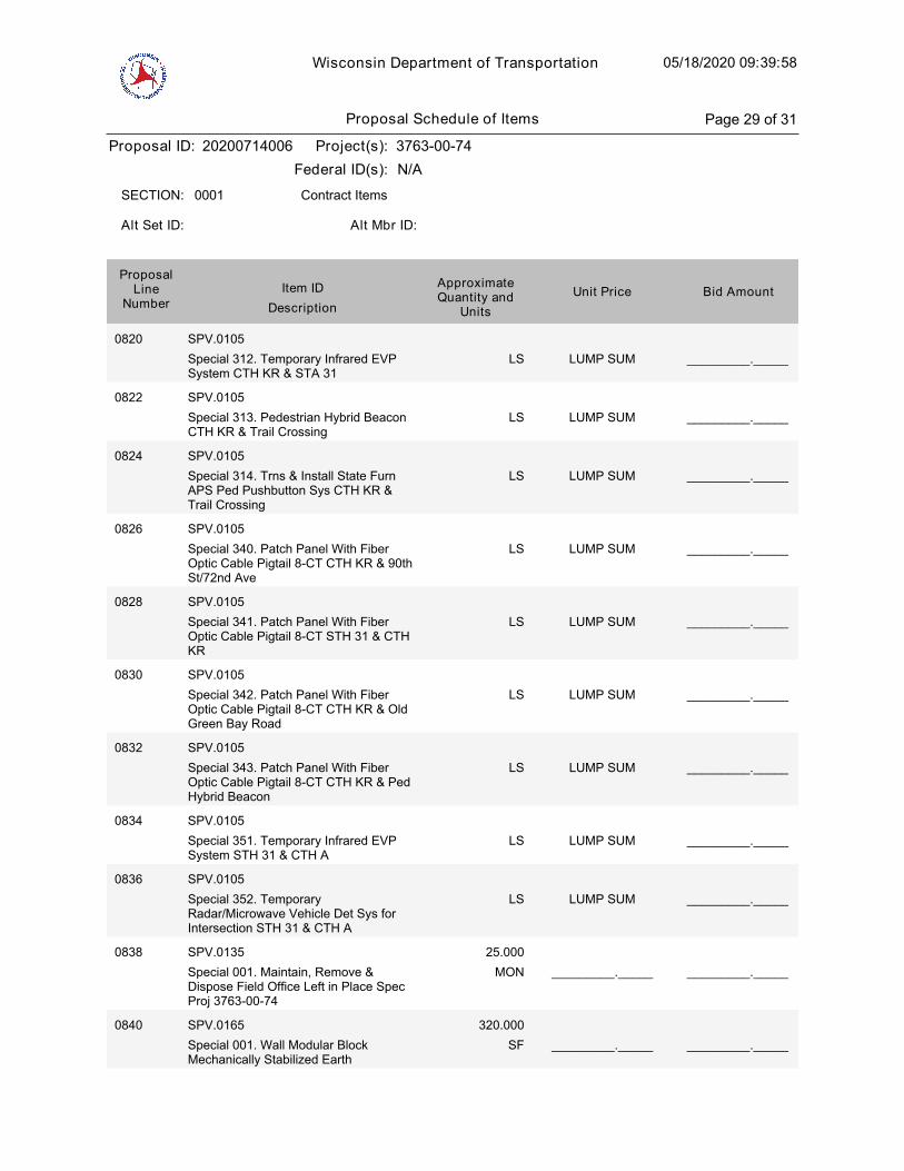
Wisconsin Department of Transportation 05/18/2020 09:39:58
Proposal ID: 20200714006 Project(s): 3763-00-74
Federal ID(s): N/A
0001 Contract ItemsSECTION:
Alt Set ID: Alt Mbr ID:
Bid AmountUnit PriceApproximateQuantity and
UnitsDescription
Item IDProposal
LineNumber
0820 SPV.0105
Special 312. Temporary Infrared EVPSystem CTH KR & STA 31
LUMP SUM _________._____LS
0822 SPV.0105
Special 313. Pedestrian Hybrid BeaconCTH KR & Trail Crossing
LUMP SUM _________._____LS
0824 SPV.0105
Special 314. Trns & Install State FurnAPS Ped Pushbutton Sys CTH KR &Trail Crossing
LUMP SUM _________._____LS
0826 SPV.0105
Special 340. Patch Panel With FiberOptic Cable Pigtail 8-CT CTH KR & 90thSt/72nd Ave
LUMP SUM _________._____LS
0828 SPV.0105
Special 341. Patch Panel With FiberOptic Cable Pigtail 8-CT STH 31 & CTHKR
LUMP SUM _________._____LS
0830 SPV.0105
Special 342. Patch Panel With FiberOptic Cable Pigtail 8-CT CTH KR & OldGreen Bay Road
LUMP SUM _________._____LS
0832 SPV.0105
Special 343. Patch Panel With FiberOptic Cable Pigtail 8-CT CTH KR & PedHybrid Beacon
LUMP SUM _________._____LS
0834 SPV.0105
Special 351. Temporary Infrared EVPSystem STH 31 & CTH A
LUMP SUM _________._____LS
0836 SPV.0105
Special 352. TemporaryRadar/Microwave Vehicle Det Sys forIntersection STH 31 & CTH A
LUMP SUM _________._____LS
0838 SPV.0135
Special 001. Maintain, Remove &Dispose Field Office Left in Place SpecProj 3763-00-74
MON
25.000
_________._____ _________._____
0840 SPV.0165
Special 001. Wall Modular BlockMechanically Stabilized Earth
SF
320.000
_________._____ _________._____
Proposal Schedule of Items Page 29 of 31

Wisconsin Department of Transportation 05/18/2020 09:39:58
Proposal ID: 20200714006 Project(s): 3763-00-74
Federal ID(s): N/A
0001 Contract ItemsSECTION:
Alt Set ID: Alt Mbr ID:
Bid AmountUnit PriceApproximateQuantity and
UnitsDescription
Item IDProposal
LineNumber
0842 SPV.0165
Special 200. Prestressed PrecastConcrete Wall Panel R-30-65
SF
12,447.000
_________._____ _________._____
0844 SPV.0165
Special 201. Prestressed PrecastConcrete Wall Panel R-30-66
SF
22,840.000
_________._____ _________._____
0846 SPV.0165
Special 202. Prestressed PrecastConcrete Wall Panel R-30-67
SF
4,488.000
_________._____ _________._____
0848 SPV.0165
Special 203. Prestressed PrecastConcrete Wall Panel R-30-68
SF
3,790.000
_________._____ _________._____
0850 SPV.0165
Special 205. Wall Wire FacedMechanically Stabilized Earth R-30-65
SF
12,447.000
_________._____ _________._____
0852 SPV.0165
Special 206. Wall Wire FacedMechanically Stabilized Earth R-30-66
SF
22,840.000
_________._____ _________._____
0854 SPV.0165
Special 207. Wall Wire FacedMechanically Stabilized Earth R-30-67
SF
4,488.000
_________._____ _________._____
0856 SPV.0165
Special 208. Wall Wire FacedMechanically Stabilized Earth R-30-68
SF
3,790.000
_________._____ _________._____
0858 SPV.0170
Special 001. Removal and Disposal ofInvasive Plant Species
STA
35.000
_________._____ _________._____
0860 SPV.0180
Special 001. Topsoil Special SY
241,095.000
_________._____ _________._____
0862 SPV.0180
Special 002. RSC Restoration SY
6,260.000
_________._____ _________._____
0864 SPV.0195
Special 001. Possible Management ofWaste Material
TON
4,515.000
_________._____ _________._____
0866 SPV.0200
Special 600. Reconstruct SanitaryManhole Addition
VF
16.000
_________._____ _________._____
Proposal Schedule of Items Page 30 of 31
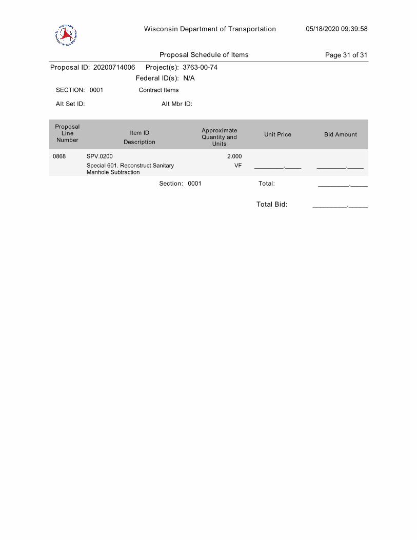
Wisconsin Department of Transportation 05/18/2020 09:39:58
Proposal ID: 20200714006 Project(s): 3763-00-74
Federal ID(s): N/A
0001 Contract ItemsSECTION:
Alt Set ID: Alt Mbr ID:
Bid AmountUnit PriceApproximateQuantity and
UnitsDescription
Item IDProposal
LineNumber
0868 SPV.0200
Special 601. Reconstruct SanitaryManhole Subtraction
VF
2.000
_________._____ _________._____
Section: 0001 _________._____Total:
Total Bid: _________._____
Proposal Schedule of Items Page 31 of 31


PLEASE ATTACH SCHEDULE OF ITEMS HERE
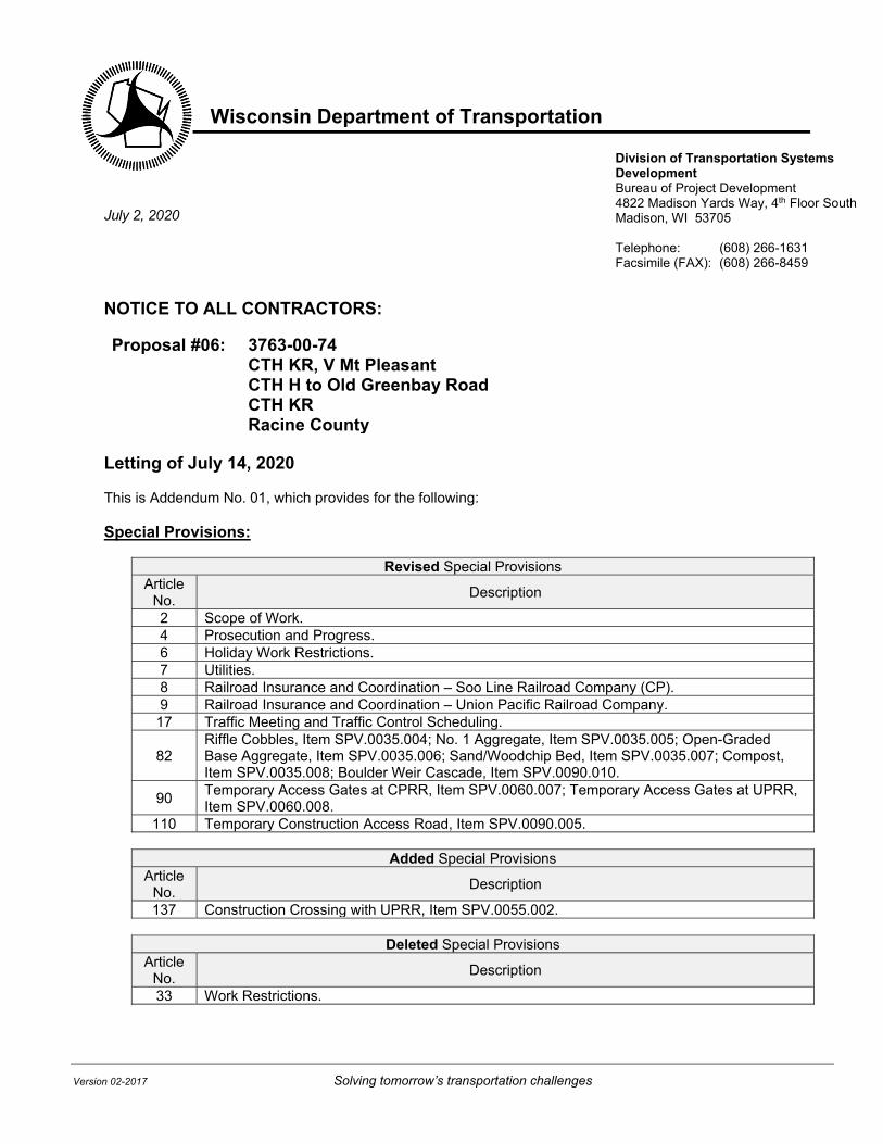
Wisconsin Department of Transportation
Version 02-2017 Solving tomorrow’s transportation challenges
Division of Transportation Systems Development Bureau of Project Development 4822 Madison Yards Way, 4th Floor South Madison, WI 53705 Telephone: (608) 266-1631 Facsimile (FAX): (608) 266-8459
July 2, 2020
NOTICE TO ALL CONTRACTORS: Proposal #06: 3763-00-74
CTH KR, V Mt Pleasant CTH H to Old Greenbay Road CTH KR Racine County
Letting of July 14, 2020 This is Addendum No. 01, which provides for the following: Special Provisions:
Revised Special Provisions Article
No. Description
2 Scope of Work. 4 Prosecution and Progress. 6 Holiday Work Restrictions. 7 Utilities. 8 Railroad Insurance and Coordination – Soo Line Railroad Company (CP). 9 Railroad Insurance and Coordination – Union Pacific Railroad Company. 17 Traffic Meeting and Traffic Control Scheduling.
82 Riffle Cobbles, Item SPV.0035.004; No. 1 Aggregate, Item SPV.0035.005; Open-Graded Base Aggregate, Item SPV.0035.006; Sand/Woodchip Bed, Item SPV.0035.007; Compost, Item SPV.0035.008; Boulder Weir Cascade, Item SPV.0090.010.
90 Temporary Access Gates at CPRR, Item SPV.0060.007; Temporary Access Gates at UPRR, Item SPV.0060.008.
110 Temporary Construction Access Road, Item SPV.0090.005.
Added Special Provisions Article
No. Description
137 Construction Crossing with UPRR, Item SPV.0055.002.
Deleted Special Provisions Article
No. Description
33 Work Restrictions.
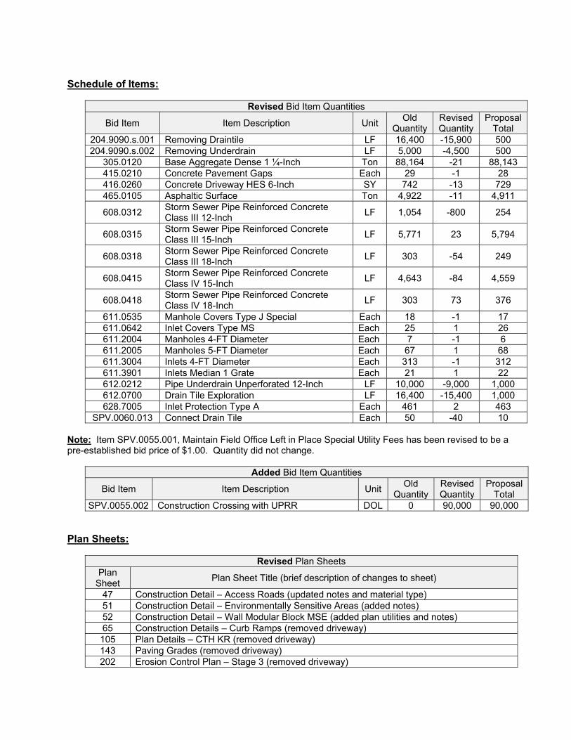
Schedule of Items:
Revised Bid Item Quantities
Bid Item Item Description Unit Old
Quantity Revised Quantity
Proposal Total
204.9090.s.001 Removing Draintile LF 16,400 -15,900 500 204.9090.s.002 Removing Underdrain LF 5,000 -4,500 500
305.0120 Base Aggregate Dense 1 ¼-Inch Ton 88,164 -21 88,143 415.0210 Concrete Pavement Gaps Each 29 -1 28 416.0260 Concrete Driveway HES 6-Inch SY 742 -13 729 465.0105 Asphaltic Surface Ton 4,922 -11 4,911
608.0312 Storm Sewer Pipe Reinforced Concrete Class III 12-Inch
LF 1,054 -800 254
608.0315 Storm Sewer Pipe Reinforced Concrete Class III 15-Inch
LF 5,771 23 5,794
608.0318 Storm Sewer Pipe Reinforced Concrete Class III 18-Inch
LF 303 -54 249
608.0415 Storm Sewer Pipe Reinforced Concrete Class IV 15-Inch
LF 4,643 -84 4,559
608.0418 Storm Sewer Pipe Reinforced Concrete Class IV 18-Inch
LF 303 73 376
611.0535 Manhole Covers Type J Special Each 18 -1 17 611.0642 Inlet Covers Type MS Each 25 1 26 611.2004 Manholes 4-FT Diameter Each 7 -1 6 611.2005 Manholes 5-FT Diameter Each 67 1 68 611.3004 Inlets 4-FT Diameter Each 313 -1 312 611.3901 Inlets Median 1 Grate Each 21 1 22 612.0212 Pipe Underdrain Unperforated 12-Inch LF 10,000 -9,000 1,000 612.0700 Drain Tile Exploration LF 16,400 -15,400 1,000 628.7005 Inlet Protection Type A Each 461 2 463
SPV.0060.013 Connect Drain Tile Each 50 -40 10 Note: Item SPV.0055.001, Maintain Field Office Left in Place Special Utility Fees has been revised to be a pre-established bid price of $1.00. Quantity did not change.
Added Bid Item Quantities
Bid Item Item Description Unit Old
Quantity Revised Quantity
Proposal Total
SPV.0055.002 Construction Crossing with UPRR DOL 0 90,000 90,000 Plan Sheets:
Revised Plan Sheets Plan
Sheet Plan Sheet Title (brief description of changes to sheet)
47 Construction Detail – Access Roads (updated notes and material type) 51 Construction Detail – Environmentally Sensitive Areas (added notes) 52 Construction Detail – Wall Modular Block MSE (added plan utilities and notes) 65 Construction Details – Curb Ramps (removed driveway) 105 Plan Details – CTH KR (removed driveway) 143 Paving Grades (removed driveway) 202 Erosion Control Plan – Stage 3 (removed driveway)
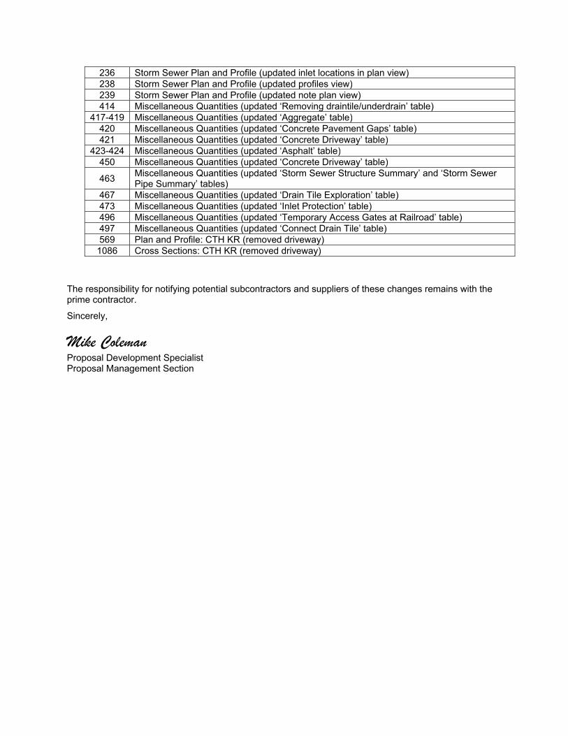
236 Storm Sewer Plan and Profile (updated inlet locations in plan view) 238 Storm Sewer Plan and Profile (updated profiles view) 239 Storm Sewer Plan and Profile (updated note plan view) 414 Miscellaneous Quantities (updated ‘Removing draintile/underdrain’ table)
417-419 Miscellaneous Quantities (updated ‘Aggregate’ table) 420 Miscellaneous Quantities (updated ‘Concrete Pavement Gaps’ table) 421 Miscellaneous Quantities (updated ‘Concrete Driveway’ table)
423-424 Miscellaneous Quantities (updated ‘Asphalt’ table) 450 Miscellaneous Quantities (updated ‘Concrete Driveway’ table)
463 Miscellaneous Quantities (updated ‘Storm Sewer Structure Summary’ and ‘Storm Sewer Pipe Summary’ tables)
467 Miscellaneous Quantities (updated ‘Drain Tile Exploration’ table) 473 Miscellaneous Quantities (updated ‘Inlet Protection’ table) 496 Miscellaneous Quantities (updated ‘Temporary Access Gates at Railroad’ table) 497 Miscellaneous Quantities (updated ‘Connect Drain Tile’ table) 569 Plan and Profile: CTH KR (removed driveway)
1086 Cross Sections: CTH KR (removed driveway)
The responsibility for notifying potential subcontractors and suppliers of these changes remains with the prime contractor.
Sincerely,
Mike Coleman Proposal Development Specialist Proposal Management Section
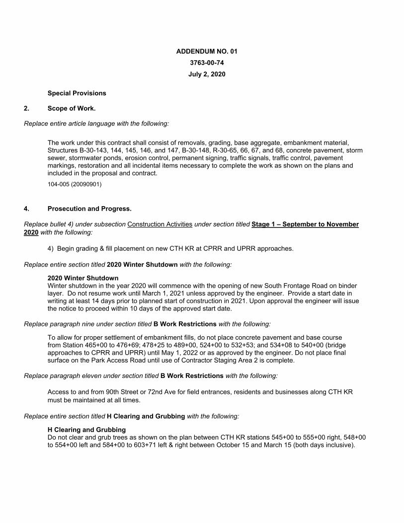
ADDENDUM NO. 01
3763-00-74
July 2, 2020
Special Provisions
2. Scope of Work.
Replace entire article language with the following:
The work under this contract shall consist of removals, grading, base aggregate, embankment material, Structures B-30-143, 144, 145, 146, and 147, B-30-148, R-30-65, 66, 67, and 68, concrete pavement, storm sewer, stormwater ponds, erosion control, permanent signing, traffic signals, traffic control, pavement markings, restoration and all incidental items necessary to complete the work as shown on the plans and included in the proposal and contract.
104-005 (20090901)
4. Prosecution and Progress.
Replace bullet 4) under subsection Construction Activities under section titled Stage 1 – September to November 2020 with the following:
4) Begin grading & fill placement on new CTH KR at CPRR and UPRR approaches.
Replace entire section titled 2020 Winter Shutdown with the following:
2020 Winter Shutdown Winter shutdown in the year 2020 will commence with the opening of new South Frontage Road on binder layer. Do not resume work until March 1, 2021 unless approved by the engineer. Provide a start date in writing at least 14 days prior to planned start of construction in 2021. Upon approval the engineer will issue the notice to proceed within 10 days of the approved start date.
Replace paragraph nine under section titled B Work Restrictions with the following:
To allow for proper settlement of embankment fills, do not place concrete pavement and base course from Station 465+00 to 476+69; 478+25 to 489+00, 524+00 to 532+53; and 534+08 to 540+00 (bridge approaches to CPRR and UPRR) until May 1, 2022 or as approved by the engineer. Do not place final surface on the Park Access Road until use of Contractor Staging Area 2 is complete.
Replace paragraph eleven under section titled B Work Restrictions with the following:
Access to and from 90th Street or 72nd Ave for field entrances, residents and businesses along CTH KR must be maintained at all times.
Replace entire section titled H Clearing and Grubbing with the following:
H Clearing and Grubbing Do not clear and grub trees as shown on the plan between CTH KR stations 545+00 to 555+00 right, 548+00 to 554+00 left and 584+00 to 603+71 left & right between October 15 and March 15 (both days inclusive).
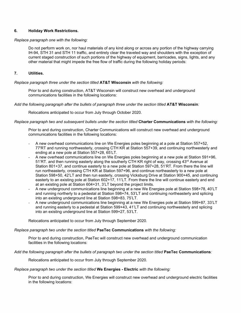
6. Holiday Work Restrictions.
Replace paragraph one with the following:
Do not perform work on, nor haul materials of any kind along or across any portion of the highway carrying IH-94, STH 31 and STH 11 traffic, and entirely clear the traveled way and shoulders with the exception of current staged construction of such portions of the highway of equipment, barricades, signs, lights, and any other material that might impede the free flow of traffic during the following holiday periods:
7. Utilities.
Replace paragraph three under the section titled AT&T Wisconsin with the following:
Prior to and during construction, AT&T Wisconsin will construct new overhead and underground communications facilities in the following locations:
Add the following paragraph after the bullets of paragraph three under the section titled AT&T Wisconsin:
Relocations anticipated to occur from July through October 2020.
Replace paragraph two and subsequent bullets under the section titled Charter Communications with the following:
Prior to and during construction, Charter Communications will construct new overhead and underground communications facilities in the following locations: - A new overhead communications line on We Energies poles beginning at a pole at Station 557+52,
77'RT and running northwesterly, crossing CTH KR at Station 557+39, and continuing northwesterly and ending at a new pole at Station 557+28, 65’LT.
- A new overhead communications line on We Energies poles beginning at a new pole at Station 591+96, 51’RT. and then running easterly along the southerly CTH KR right of way, crossing 43rd Avenue at Station 801+37, and continue easterly to a new pole at Station 597+28, 51’RT. From there the line will run northeasterly, crossing CTH KR at Station 597+96, and continue northeasterly to a new pole at Station 598+50, 42’LT and then run easterly, crossing Vicksburg Drive at Station 900+45, and continuing easterly to an existing pole at Station 602+17, 11’LT. From there the line will continue easterly and end at an existing pole at Station 604+31, 3’LT beyond the project limits.
- A new underground communications line beginning at a new We Energies pole at Station 598+78, 40’LT and running northerly to a pedestal at Station 598+74, 53’LT and continuing northeasterly and splicing into an existing underground line at Station 598+83, 75’LT.
- A new underground communications line beginning at a new We Energies pole at Station 599+87, 33’LT and running easterly to a pedestal at Station 599+43, 41’LT and continuing northwesterly and splicing into an existing underground line at Station 599+27, 53’LT.
Relocations anticipated to occur from July through September 2020.
Replace paragraph two under the section titled PaeTec Communications with the following:
Prior to and during construction, PaeTec will construct new overhead and underground communication facilities in the following locations:
Add the following paragraph after the bullets of paragraph two under the section titled PaeTec Communications:
Relocations anticipated to occur from July through September 2020.
Replace paragraph two under the section titled We Energies - Electric with the following:
Prior to and during construction, We Energies will construct new overhead and underground electric facilities in the following locations:
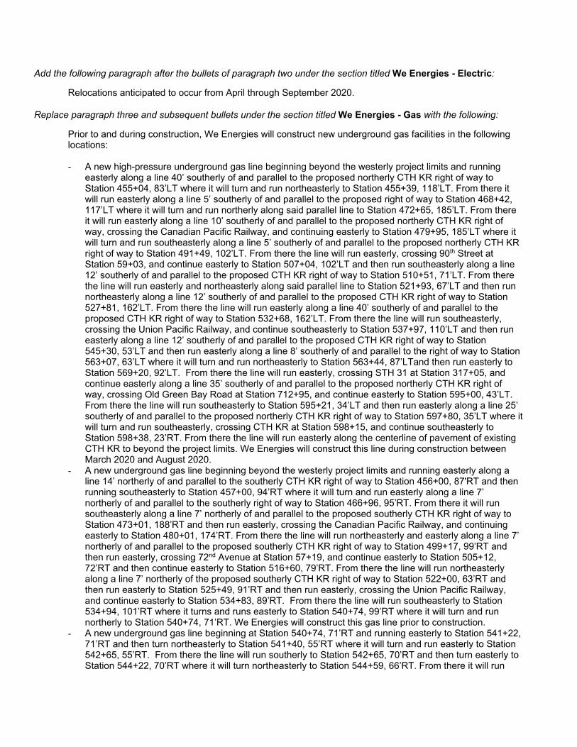
Add the following paragraph after the bullets of paragraph two under the section titled We Energies - Electric:
Relocations anticipated to occur from April through September 2020.
Replace paragraph three and subsequent bullets under the section titled We Energies - Gas with the following:
Prior to and during construction, We Energies will construct new underground gas facilities in the following locations:
- A new high-pressure underground gas line beginning beyond the westerly project limits and running
easterly along a line 40’ southerly of and parallel to the proposed northerly CTH KR right of way to Station 455+04, 83’LT where it will turn and run northeasterly to Station 455+39, 118’LT. From there it will run easterly along a line 5’ southerly of and parallel to the proposed right of way to Station 468+42, 117’LT where it will turn and run northerly along said parallel line to Station 472+65, 185’LT. From there it will run easterly along a line 10’ southerly of and parallel to the proposed northerly CTH KR right of way, crossing the Canadian Pacific Railway, and continuing easterly to Station 479+95, 185’LT where it will turn and run southeasterly along a line 5’ southerly of and parallel to the proposed northerly CTH KR right of way to Station 491+49, 102’LT. From there the line will run easterly, crossing 90th Street at Station 59+03, and continue easterly to Station 507+04, 102’LT and then run southeasterly along a line 12’ southerly of and parallel to the proposed CTH KR right of way to Station 510+51, 71’LT. From there the line will run easterly and northeasterly along said parallel line to Station 521+93, 67’LT and then run northeasterly along a line 12’ southerly of and parallel to the proposed CTH KR right of way to Station 527+81, 162’LT. From there the line will run easterly along a line 40’ southerly of and parallel to the proposed CTH KR right of way to Station 532+68, 162’LT. From there the line will run southeasterly, crossing the Union Pacific Railway, and continue southeasterly to Station 537+97, 110’LT and then run easterly along a line 12’ southerly of and parallel to the proposed CTH KR right of way to Station 545+30, 53’LT and then run easterly along a line 8’ southerly of and parallel to the right of way to Station 563+07, 63’LT where it will turn and run northeasterly to Station 563+44, 87’LTand then run easterly to Station 569+20, 92’LT. From there the line will run easterly, crossing STH 31 at Station 317+05, and continue easterly along a line 35’ southerly of and parallel to the proposed northerly CTH KR right of way, crossing Old Green Bay Road at Station 712+95, and continue easterly to Station 595+00, 43’LT. From there the line will run southeasterly to Station 595+21, 34’LT and then run easterly along a line 25’ southerly of and parallel to the proposed northerly CTH KR right of way to Station 597+80, 35’LT where it will turn and run southeasterly, crossing CTH KR at Station 598+15, and continue southeasterly to Station 598+38, 23’RT. From there the line will run easterly along the centerline of pavement of existing CTH KR to beyond the project limits. We Energies will construct this line during construction between March 2020 and August 2020.
- A new underground gas line beginning beyond the westerly project limits and running easterly along a line 14’ northerly of and parallel to the southerly CTH KR right of way to Station 456+00, 87'RT and then running southeasterly to Station 457+00, 94’RT where it will turn and run easterly along a line 7’ northerly of and parallel to the southerly right of way to Station 466+96, 95’RT. From there it will run southeasterly along a line 7’ northerly of and parallel to the proposed southerly CTH KR right of way to Station 473+01, 188’RT and then run easterly, crossing the Canadian Pacific Railway, and continuing easterly to Station 480+01, 174’RT. From there the line will run northeasterly and easterly along a line 7’ northerly of and parallel to the proposed southerly CTH KR right of way to Station 499+17, 99’RT and then run easterly, crossing 72nd Avenue at Station 57+19, and continue easterly to Station 505+12, 72’RT and then continue easterly to Station 516+60, 79’RT. From there the line will run northeasterly along a line 7’ northerly of the proposed southerly CTH KR right of way to Station 522+00, 63’RT and then run easterly to Station 525+49, 91’RT and then run easterly, crossing the Union Pacific Railway, and continue easterly to Station 534+83, 89’RT. From there the line will run southeasterly to Station 534+94, 101’RT where it turns and runs easterly to Station 540+74, 99’RT where it will turn and run northerly to Station 540+74, 71’RT. We Energies will construct this gas line prior to construction.
- A new underground gas line beginning at Station 540+74, 71’RT and running easterly to Station 541+22, 71’RT and then turn northeasterly to Station 541+40, 55’RT where it will turn and run easterly to Station 542+65, 55’RT. From there the line will run southerly to Station 542+65, 70’RT and then turn easterly to Station 544+22, 70’RT where it will turn northeasterly to Station 544+59, 66’RT. From there it will run
easterly to Station 545+37, 66’RT and then turn northerly to Station 545+37, 55’RT and then turn easterly to Station 552+21, 54’RT. From there it will turn southerly to Station 552+21, 65’RT and then turn easterly to 554+59, 64’RT and then turn northeasterly to Station 555+49, 59’RT and then continue easterly to Station 556+48, 56’RT. From there the line will turn and run southeasterly along the proposed westerly 56th Avenue right of way to Station 202+00, 43’LT. We Energies will construct this gas line prior to and during construction.
- A new underground gas line beginning at Station 202+00, 43’LT and running easterly, crossing 56th Avenue at Station 202+00, and continuing easterly to Station 202+00, 39’RT and then continuing easterly to Station 202+00, 52’RT where it will turn and run northeasterly and connect to an existing gas line at Station 557+92, 66’RT. We Energies will construct this gas line prior to and during construction.
- A new underground gas line beginning at Station 503+02, 80’RT and running northerly, crossing CTH KR at Station 503+00, and continuing northerly to Station 502+98, 82’LT and then running northeasterly along a line 3’ easterly of and parallel to the proposed westerly re-aligned 90th Street right of way to Station 60+20, 113’LT. We Energies will construct this gas line prior to and during construction.
- A new underground gas line beginning at Station 520+87, 71’RT and running northerly, crossing CTH KR at Station 520+87, and continuing to beyond the project limits. We Energies will construct this gas line prior to and during construction.
- A new underground gas line beginning at Station 525+49, 91’RT and running northerly, crossing CTH KR at Station 525+49, and continuing northerly to Station 525+48, 164’LT and then running northeasterly to beyond the project limits. We Energies will construct this gas line prior to and during construction.
- A new underground gas line beginning at Station 545+00, 74’RT and running northerly, crossing CTH KR at Station 545+00, and continuing to beyond the project limits. We Energies will construct this gas line prior to and during construction.
- A new underground gas line beginning at Station 546+84, 74’RT and running northerly, crossing CTH KR at Station 546+84, and continuing to beyond the project limits. We Energies will construct this gas line prior to and during construction.
- A new underground gas line beginning at Station 547+00, 74’RT and running northerly, crossing CTH KR at Station 547+00, and continuing to beyond the project limits. We Energies will construct this gas line prior to and during construction.
- A new underground gas line beginning at Station 555+75, 58’RT and running northerly, crossing CTH KR at Station 555+75, and continuing northeasterly and northerly to beyond the project limits. We Energies will construct this gas line prior to and during construction.
- A new underground gas line beginning at Station 202+00, 10’RT and running northerly, crossing CTH KR at Station 557+30, and then running northerly to Station 557+30, 47’LT and then running northeasterly to beyond the project limits. We Energies will construct this gas line prior to and during construction.
- A new underground gas line beginning at an existing main at Station 710+95, 33’RT and running easterly to Station 711+07, 81’RT and then running northeasterly to Station 590+40, 59’RT and then running easterly to Station 591+40, 56’RT. From there the line will run northerly to Station 591+40, 31’RT and then running easterly to Station 595+20, 35’RT and then running southerly to Station 595+20, 49’RT. From there the line will run easterly, southeasterly and easterly, crossing 43rd Avenue at Station 801+05, and continue easterly to Station 596+34, 84’RT and then run northeasterly to Station 596+49, 49’RT. From there the line will run easterly and connect to an existing gas line at Station 600+66, 46’RT. We Energies will construct this gas line prior to and during construction.
- A new underground gas line beginning at Station 593+44, 44’RT and running northerly, crossing CTH KR at Station 593+44, and continuing to Station 593+44, 76’LT. From there it turns and runs westerly-northwesterly to Station 590+48, 129’LT. From there the line will run northwesterly to Station 714+07, 45’RT and then run westerly, crossing Old Green Bay Road at Station 714+ 11, and continue westerly and connect to an existing gas line at Station 714+16, 56’LT. We Energies will construct this gas line prior to and during construction.
- A new underground gas line beginning at Station 599+27, 48’RT and running northerly, crossing CTH KR at Station 599+27, and continuing northerly along the easterly Vicksburg Drive right of way to Station 901+00, 20’RT and then running easterly and connect to an existing gas line at Station 901+00, 27’RT. We Energies will construct this gas line prior to and during construction.
Replace paragraph two under the section titled Windstream with the following:
Prior to and during construction, Windstream will construct new overhead and underground communication facilities in the following locations:
Add the following paragraph after the bullets of paragraph two under the section titled Windstream:
Relocations anticipated to occur from July through September 2020.
8. Railroad Insurance and Coordination – Soo Line Railroad Company (CP).
Replace the paragraph one under section titled A.4 Work by Railroad with the following:
The railroad will perform the work described in this section, except for work described in other special provisions and will be accomplished without cost to the contractor. Install and remove construction crossing at locations shown in the plans.
9. Railroad Insurance and Coordination – Union Pacific Railroad Company.
Replace the paragraph under subsection titled Flagging Contract under section titled A.3 Names and Addresses of Rail Road Representatives for Consultation and Coordination with the following:
See Construction Contact. If more than 30 days of flagging is required contact UP 40 days prior to needing a flagger on site. Reference the Wisconsin Milepost and Subdivision located in A.1.
Replace paragraph one under section titled A.4 Work by Railroad with the following:
The railroad will perform the work described in this section, except for work described in other special provisions and will be accomplished without cost to the contractor. See special provision Construction Crossing with UPRR, Item SPV.0050.002.
17. Traffic Meeting and Traffic Control Scheduling.
Replace the entire article language with the following:
Every Wednesday by 8:00 AM, submit a detailed proposed 2-week look-ahead traffic closure schedule to the engineer. Type the detailed proposed 2-week look-ahead closure schedule into an excel spreadsheet provided by the engineer. Enter information such as closure dates, duration, work causing the closure and detours to be used. Also enter information such as ongoing long-term closures, emergency contacts, and general 2-month look-ahead closure information into the excel spreadsheet. Meet with the engineer at 10:00 AM on Wednesdays at the project field office to discuss and answer questions on the proposed schedule. Edit, delete and add closures to the detailed proposed 2-week look-ahead schedule, as directed by the engineer so that proposed closures meet specification requirements. Other edits, deletions or additions unrelated to meeting specification requirements may also be agreed upon with the engineer during the 10:00 AM meeting. Every Wednesday at 2:00 PM, or as scheduled by the engineer, attend a weekly traffic meeting. The meeting will bring local agencies, project stakeholders, owner-managers, owner engineers, contractors, document control and construction engineering personnel together to discuss traffic staging, closures and general impacts. Upon obtaining feedback from the meeting attendees, edit, delete and add information to the detailed 2-week look-ahead closure schedule, as needed. Submit the revised 2-week look-ahead to the engineer.
Obtain approval from the engineer for any mid-week changes to the closure schedule. Revise the 2-week look-ahead as required and obtain engineer approval.
33. DELETE.
82. Riffle Cobbles, Item SPV.0035.004; No. 1 Aggregate, Item SPV.0035.005; Open-Graded Base
Aggregate, Item SPV.0035.006; Sand/Woodchip Bed, Item SPV.0035.007; Compost, Item SPV.0035.008; Boulder Weir Cascade, Item SPV.0090.010. Replace the paragraph under B.1.4 Compost with the following: Place a 4-inch layer of compost on top of the sand layer within the pools of the RSC. Ensure that the compost is WDNR S100 certified or equivalent.
90. Temporary Access Gates at CPRR, Item SPV.0060.007; Temporary Access Gates at UPRR, Item SPV.0060.008.
Replace paragraph one under section titled C Construction with the following:
Construct gates 16 feet outside of railroad right-of-way.
110. Temporary Construction Access Road, Item SPV.00090.005.
Update title to Temporary Construction Access Road, Item SPV.0090.005.
137. Construction Crossing with UPRR, Item SPV.0055.002.
A Description This special provision describes coordinating with Union Pacific Railroad (UPRR) to obtain a temporary crossing permit and, if UPRR grants the permit, the work that UPRR would complete to install the temporary crossing within their railroad right of way as shown on the plans. B (Vacant) C Construction Work to be performed by UPRR 1) Install one (1) rail-timber, single-track crossing, track and other track material (OTM) 32-feet long, including
Geotextile fabric on top of the ballast for construction access near the CTH KR overpass structure, in a location as shown on the plan. The final location will be mutually agreeable to the Department and the UPRR.
2) Remove the temporary grade crossings at a time that is mutually agreeable to the Department and UPRR. Work to be performed by the Contractor 1) Perform grading and provide for adequate drainage for temporary approaches to the construction crossing. 2) Install Temporary Gates with Locks at each approach to the crossings. Provide UPRR with key to locks. 3) Remove gates, grading for the temporary approaches and restore drainage at a time that is mutually agreeable
to the Department and the UPRR.
4) Keep gate locked at all times when not actively used by the contractor.
5) Only use crossing under the protection of a flagman. Design and Construction: The installation of the temporary construction crossing, and modification of the railroad facilities described herein above shall be in conformance with the approved project plans. All such work shall be performed under normal UPRR practices and the applicable requirements of the Department and of the United States Department of Transportation, Federal Highway Administration, as set forth in 23 CFR Part 646 Subpart B. Maintenance: The UPRR, at Contractor’s expense, agrees to maintain the railroad crossings described herein as a temporary construction crossing as long as so used or required by the Departments contractor for the highway project. D Measurement The department will measure Construction Crossing with UPRR by the dollar based on UPRR submitted invoices. E Payment
The department will pay for measured quantities at the contract unit price under the following bid item:
ITEM NUMBER DESCRIPTION UNIT
SPV.0055.002 Construction Crossing with UPRR DOL
The actual cost for UPRR crossing work will be billed by the railroad. The department will reimburse the cost of such services based on paid railroad invoices. Coordination and working with UPRR for temporary permit crossing are considered incidental to construction.
Payment for contractor work at UPRR construction crossing approaches are paid under bid item Temporary Access Gates at UPRR. Access road constructed outside UPRR construction crossing approaches are paid under a separate bid item Temporary Construction Access Road Schedule of Items Attached, dated July 2, 2020, are the revised Schedule of Items Pages 2 – 5, 9 – 13, 23, 24, and 31. Plan Sheets The following 8½ x 11-inch sheets are attached and made part of the plans for this proposal: Revised: 47, 51-52, 65, 105, 143, 202, 236, 238-239, 414, 417-421, 423-424, 450, 463, 467, 473, 496-497, 569 and 1086.
END OF ADDENDUM
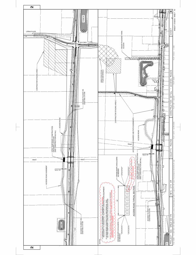
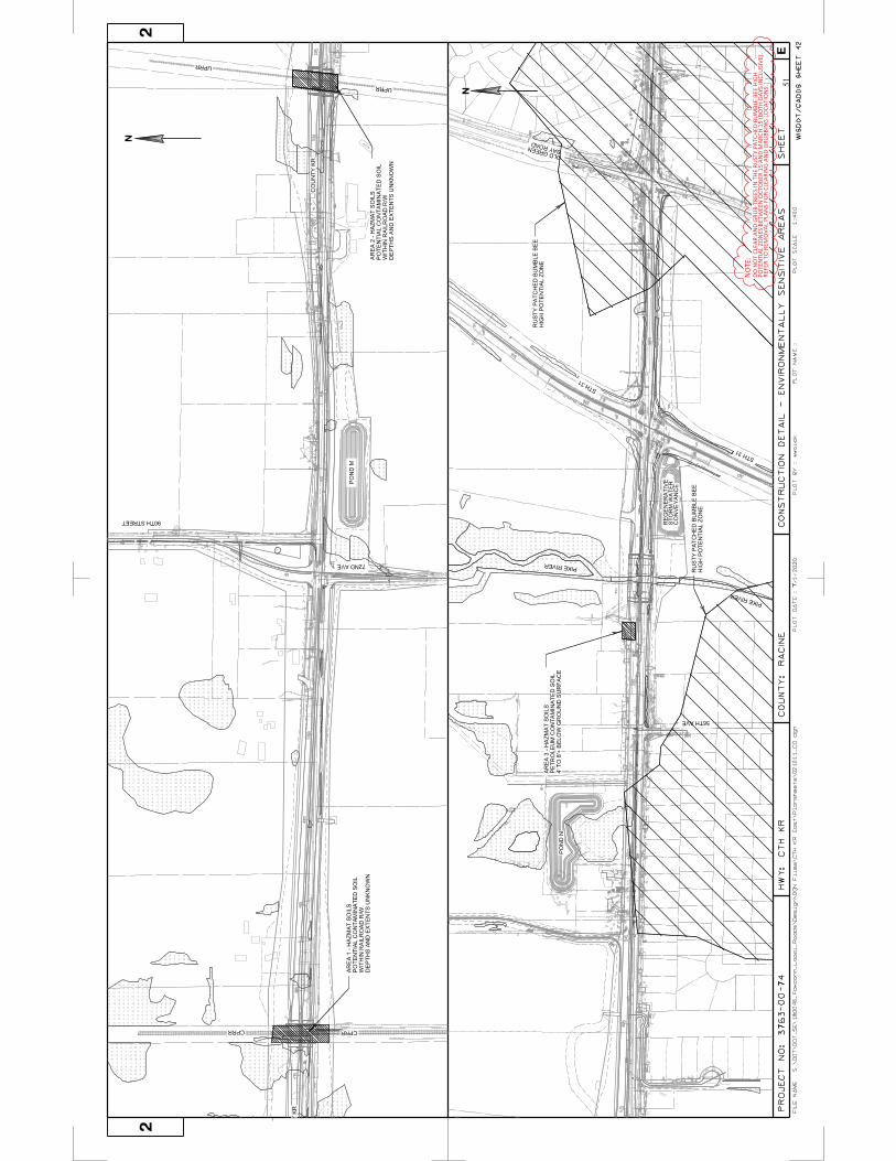
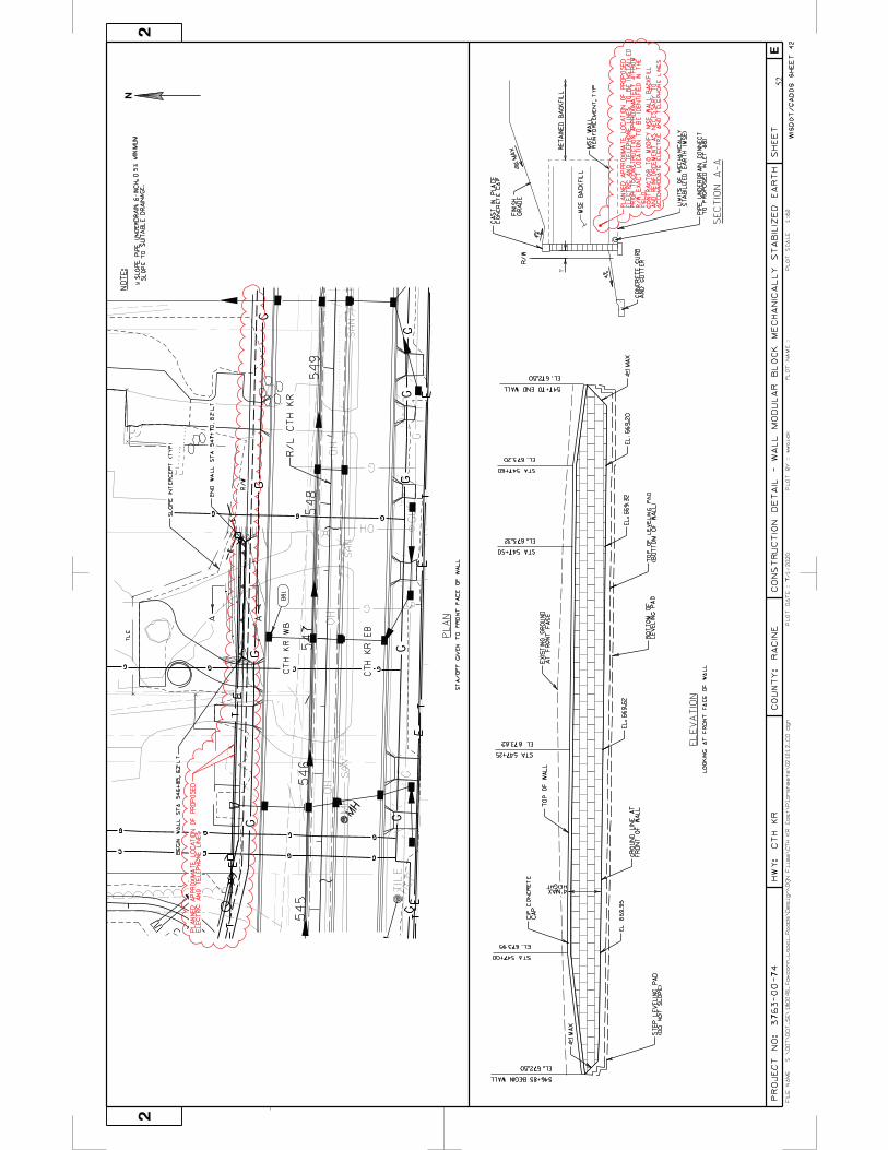
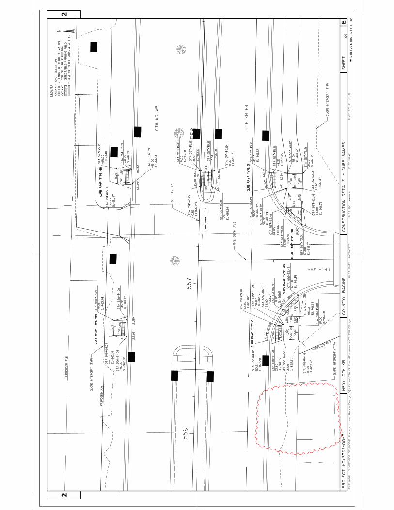
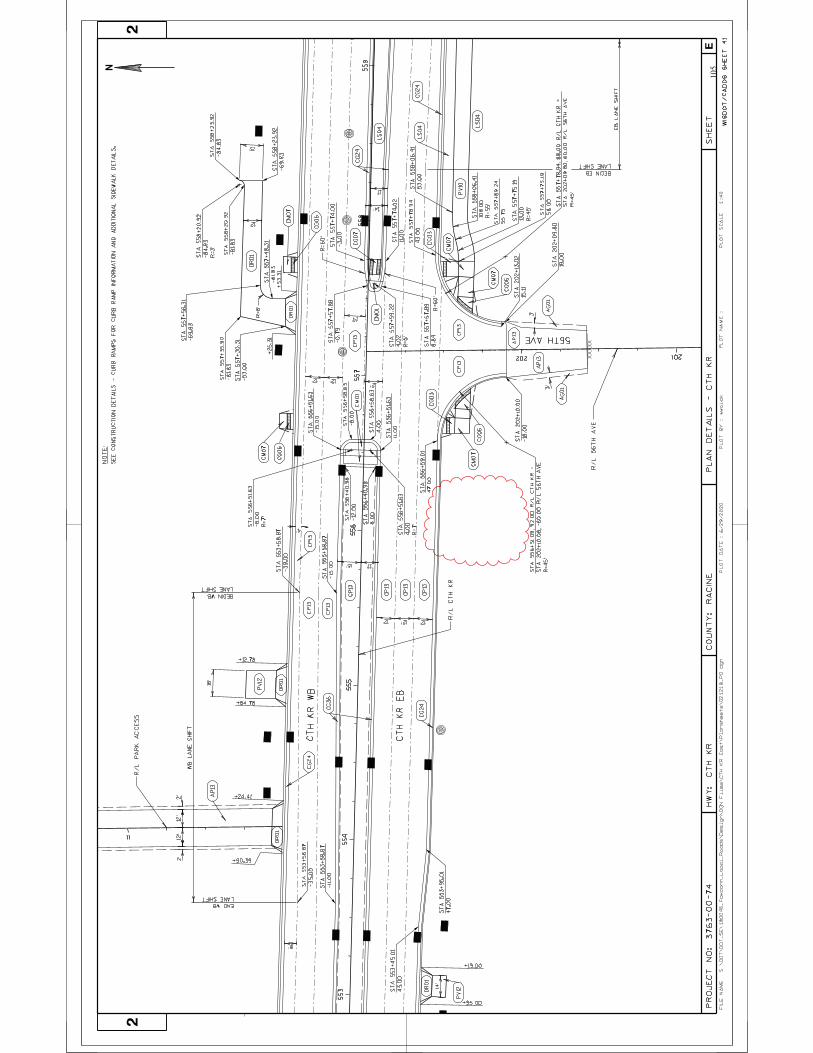
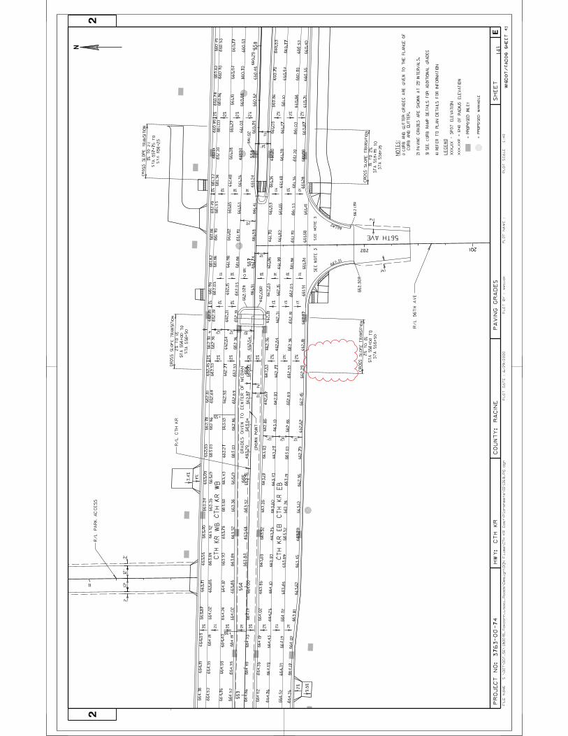
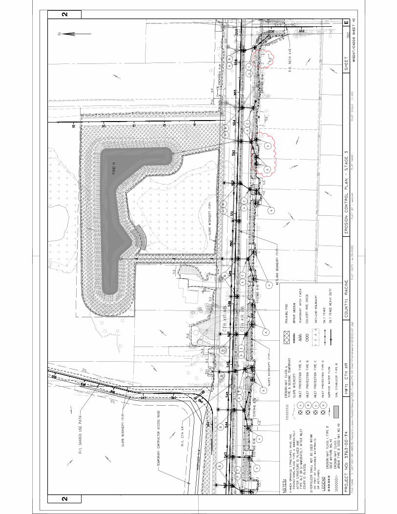
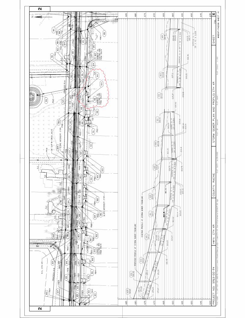
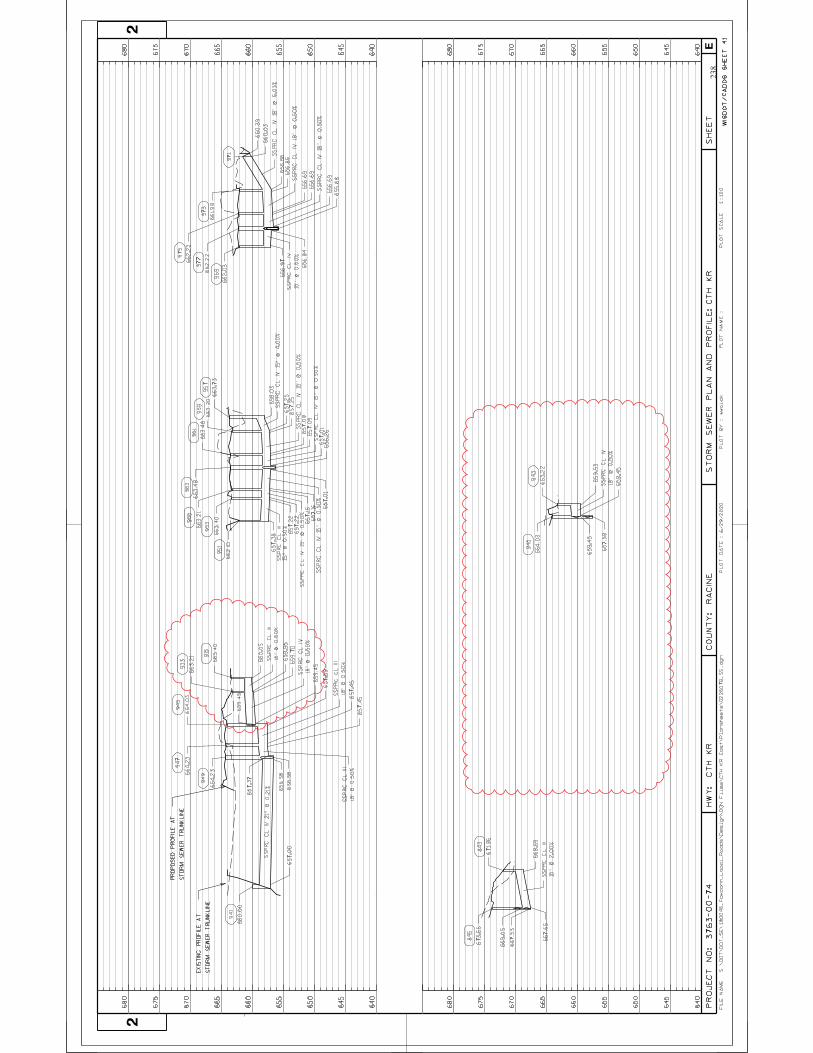
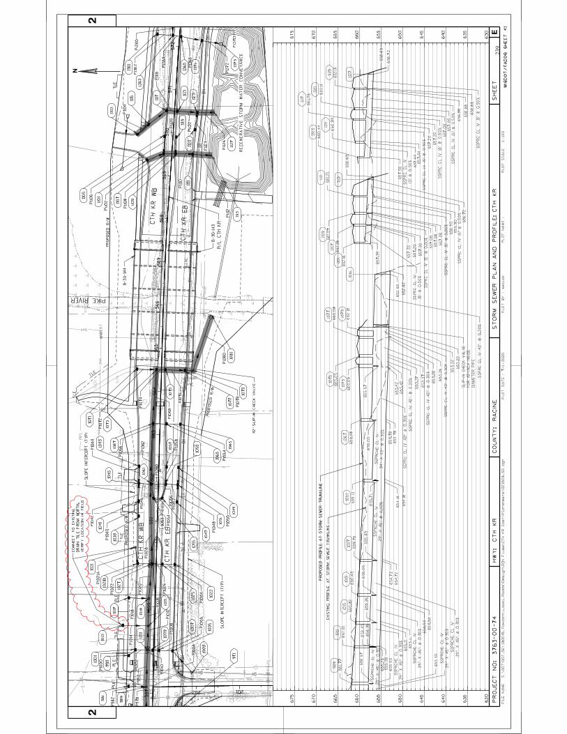
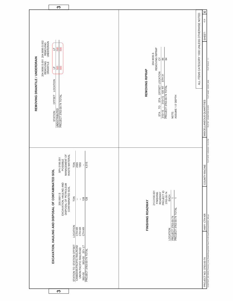
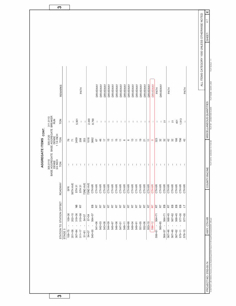
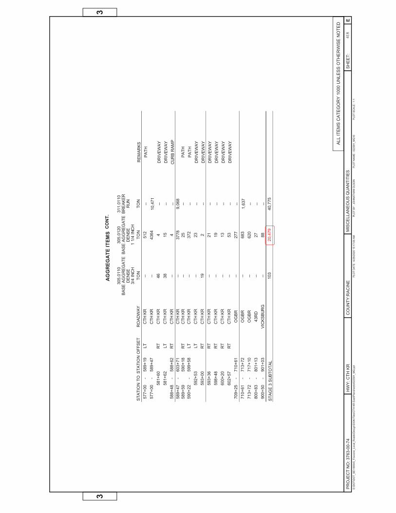
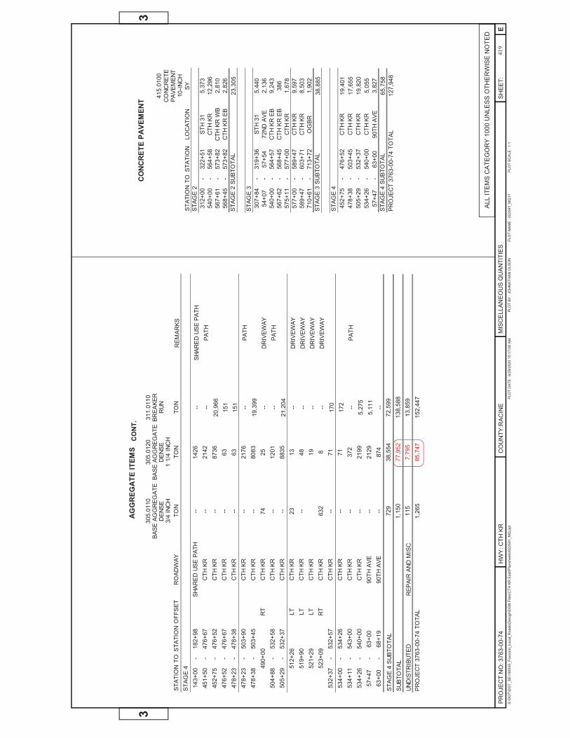
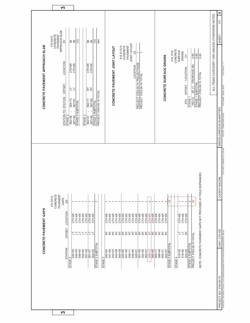
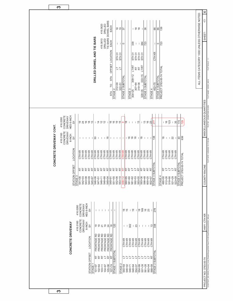
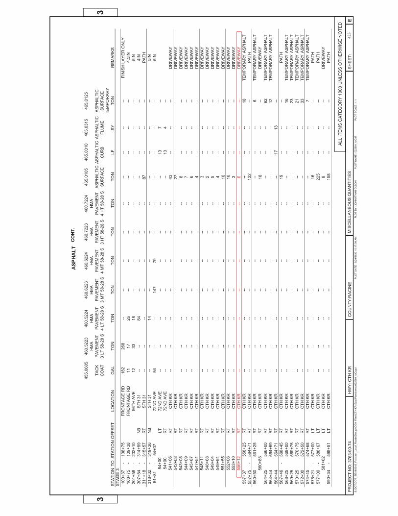
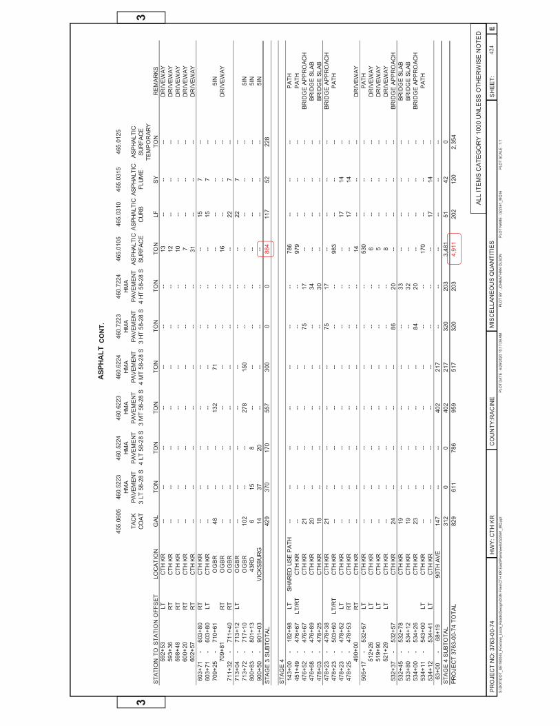
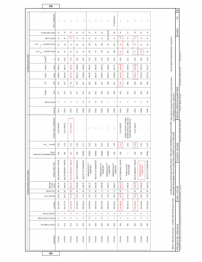
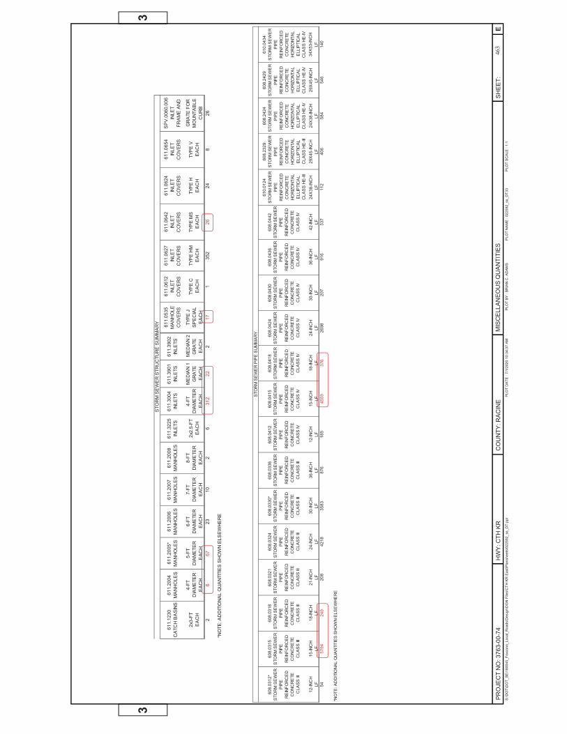
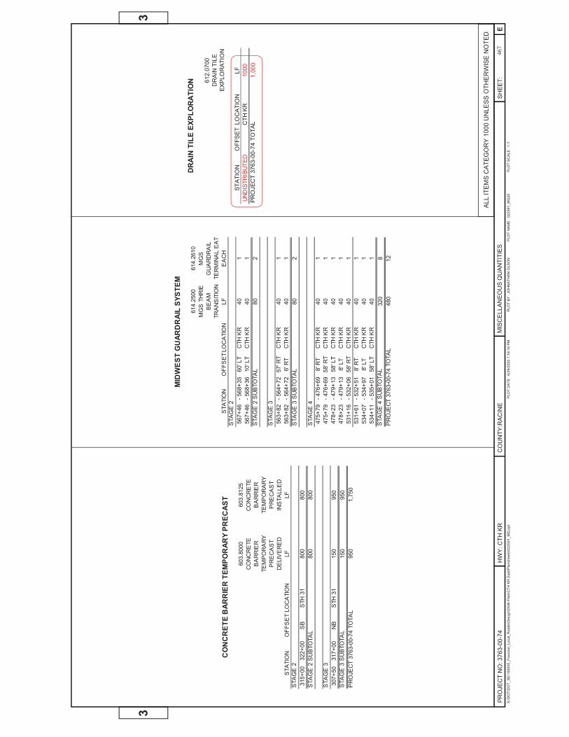
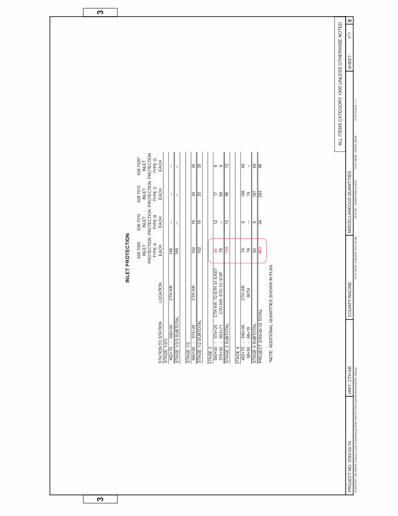
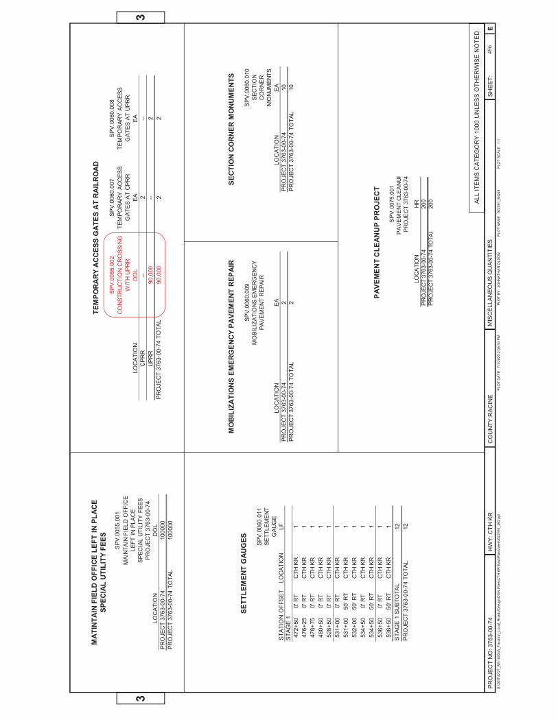
496
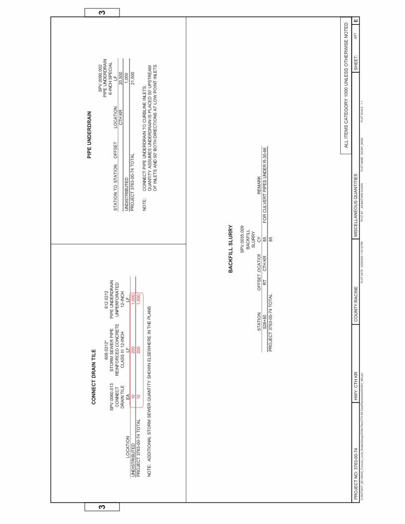
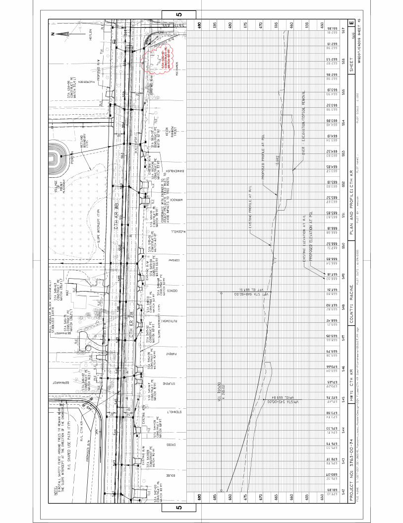
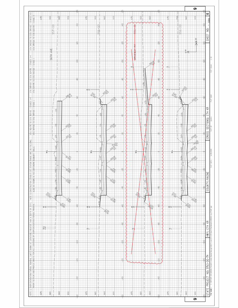

Wisconsin Department of Transportation 07/02/2020 08:22:27
Proposal ID: 20200714006 Project(s): 3763-00-74
Federal ID(s): N/A
0001 Contract ItemsSECTION:
Alt Set ID: Alt Mbr ID:
Bid AmountUnit PriceApproximateQuantity and
UnitsDescription
Item IDProposal
LineNumber
0032 204.0220
Removing Inlets EACH
16.000
_________._____ _________._____
0034 204.0245
Removing Storm Sewer (size) 001. 12-Inch
LF
481.000
_________._____ _________._____
0036 204.0245
Removing Storm Sewer (size) 002. 30-Inch
LF
39.000
_________._____ _________._____
0038 204.0245
Removing Storm Sewer (size) 003. 36-Inch
LF
416.000
_________._____ _________._____
0040 204.0280
Sealing Pipes EACH
32.000
_________._____ _________._____
0042 204.0291.S
Abandoning Sewer CY
1.000
_________._____ _________._____
0044 204.9035.S
Removing (item description) 001. Riprap CY
84.000
_________._____ _________._____
0046 204.9060.S
Removing (item description) 001.Bulkhead
EACH
32.000
_________._____ _________._____
0048 204.9090.S
Removing (item description) 001.Draintile
LF
500.000
_________._____ _________._____
0050 204.9090.S
Removing (item description) 002.Underdrain
LF
500.000
_________._____ _________._____
0052 204.9105.S
Removing (item description) 301. TrafficSignals CTH KR & STH 31
LUMP SUM _________._____LS
0054 204.9105.S
Removing (item description) 302. TrafficSignals CTH KR & Old Green Bay Road
LUMP SUM _________._____LS
0056 204.9105.S
Removing (item description) 303. LoopDetector Wire and Lead-in-Cable CTHKR & STH 31
LUMP SUM _________._____LS
Proposal Schedule of Items Page 2 of 31

Wisconsin Department of Transportation 07/02/2020 08:22:27
Proposal ID: 20200714006 Project(s): 3763-00-74
Federal ID(s): N/A
0001 Contract ItemsSECTION:
Alt Set ID: Alt Mbr ID:
Bid AmountUnit PriceApproximateQuantity and
UnitsDescription
Item IDProposal
LineNumber
0058 204.9105.S
Removing (item description) 304. LoopDetector Wire and Lead-in-Cable CTHKR & Old Green Bay Rd
LUMP SUM _________._____LS
0060 205.0100
Excavation Common CY
351,023.000
_________._____ _________._____
0062 205.0501.S
Excavation, Hauling, and Disposal ofPetroleum Contaminated Soil
TON
128.000
_________._____ _________._____
0064 206.1000
Excavation for Structures Bridges(structure) 200. B-30-143
LUMP SUM _________._____LS
0066 206.1000
Excavation for Structures Bridges(structure) 201. B-30-144
LUMP SUM _________._____LS
0068 206.3000
Excavation for Structures RetainingWalls (structure) 200. Structure R-30-65
LUMP SUM _________._____LS
0070 206.3000
Excavation for Structures RetainingWalls (structure) 201. Structure R-30-66
LUMP SUM _________._____LS
0072 206.3000
Excavation for Structures RetainingWalls (structure) 202. Structure R-30-67
LUMP SUM _________._____LS
0074 206.3000
Excavation for Structures RetainingWalls (structure) 203. Structure R-30-68
LUMP SUM _________._____LS
0076 209.1100
Backfill Granular Grade 1 CY
95,767.000
_________._____ _________._____
0078 210.1500
Backfill Structure Type A TON
2,536.000
_________._____ _________._____
0080 213.0100
Finishing Roadway (project) 001. 3763-00-74
EACH
1.000
_________._____ _________._____
0082 305.0110
Base Aggregate Dense 3/4-Inch TON
1,265.000
_________._____ _________._____
0084 305.0120
Base Aggregate Dense 1 1/4-Inch TON
88,143.000
_________._____ _________._____
Proposal Schedule of Items Page 3 of 31

Wisconsin Department of Transportation 07/02/2020 08:22:27
Proposal ID: 20200714006 Project(s): 3763-00-74
Federal ID(s): N/A
0001 Contract ItemsSECTION:
Alt Set ID: Alt Mbr ID:
Bid AmountUnit PriceApproximateQuantity and
UnitsDescription
Item IDProposal
LineNumber
0086 311.0110
Breaker Run TON
152,447.000
_________._____ _________._____
0088 415.0100
Concrete Pavement 10-Inch SY
127,948.000
_________._____ _________._____
0090 415.0210
Concrete Pavement Gaps EACH
28.000
_________._____ _________._____
0092 415.0410
Concrete Pavement Approach Slab SY
344.000
_________._____ _________._____
0094 415.5110.S
Concrete Pavement Joint Layout LS
1.000
_________._____ _________._____
0096 416.0160
Concrete Driveway 6-Inch SY
636.000
_________._____ _________._____
0098 416.0260
Concrete Driveway HES 6-Inch SY
729.000
_________._____ _________._____
0100 416.0610
Drilled Tie Bars EACH
723.000
_________._____ _________._____
0102 416.0620
Drilled Dowel Bars EACH
139.000
_________._____ _________._____
0104 416.1010
Concrete Surface Drains CY
0.600
_________._____ _________._____
0106 455.0605
Tack Coat GAL
829.000
_________._____ _________._____
1.00000
0108 460.2000
Incentive Density HMA Pavement DOL
2,160.000
2,160.00
0110 460.5223
HMA Pavement 3 LT 58-28 S TON
611.000
_________._____ _________._____
0112 460.5224
HMA Pavement 4 LT 58-28 S TON
786.000
_________._____ _________._____
0114 460.6223
HMA Pavement 3 MT 58-28 S TON
959.000
_________._____ _________._____
0116 460.6224
HMA Pavement 4 MT 58-28 S TON
517.000
_________._____ _________._____
0118 460.7223
HMA Pavement 3 HT 58-28 S TON
320.000
_________._____ _________._____
Proposal Schedule of Items Page 4 of 31

Wisconsin Department of Transportation 07/02/2020 08:22:27
Proposal ID: 20200714006 Project(s): 3763-00-74
Federal ID(s): N/A
0001 Contract ItemsSECTION:
Alt Set ID: Alt Mbr ID:
Bid AmountUnit PriceApproximateQuantity and
UnitsDescription
Item IDProposal
LineNumber
0120 460.7224
HMA Pavement 4 HT 58-28 S TON
203.000
_________._____ _________._____
0122 465.0105
Asphaltic Surface TON
4,911.000
_________._____ _________._____
0124 465.0125
Asphaltic Surface Temporary TON
2,354.000
_________._____ _________._____
0126 465.0310
Asphaltic Curb LF
202.000
_________._____ _________._____
0128 465.0315
Asphaltic Flumes SY
120.000
_________._____ _________._____
0130 495.1000.S
Cold patch TON
300.000
_________._____ _________._____
0132 501.1000.S
Ice Hot Weather Concreting LB
43,153.000
_________._____ _________._____
0134 502.0100
Concrete Masonry Bridges CY
5,753.000
_________._____ _________._____
0136 502.3200
Protective Surface Treatment SY
7,028.000
_________._____ _________._____
0138 502.3210
Pigmented Surface Sealer SY
2,935.000
_________._____ _________._____
0140 503.0146
Prestressed Girder Type I 45W-Inch LF
4,994.000
_________._____ _________._____
0142 504.0500
Concrete Masonry Retaining Walls CY
688.000
_________._____ _________._____
0144 505.0400
Bar Steel Reinforcement HS Structures LB
49,810.000
_________._____ _________._____
0146 505.0600
Bar Steel Reinforcement HS CoatedStructures
LB
887,755.000
_________._____ _________._____
0148 505.0800.S
Bar Steel Reinforcement HS StainlessStructures
LB
9,880.000
_________._____ _________._____
0150 506.2605
Bearing Pads Elastomeric Non-Laminated
EACH
88.000
_________._____ _________._____
Proposal Schedule of Items Page 5 of 31
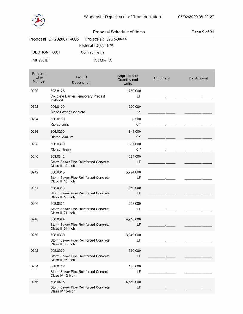
Wisconsin Department of Transportation 07/02/2020 08:22:27
Proposal ID: 20200714006 Project(s): 3763-00-74
Federal ID(s): N/A
0001 Contract ItemsSECTION:
Alt Set ID: Alt Mbr ID:
Bid AmountUnit PriceApproximateQuantity and
UnitsDescription
Item IDProposal
LineNumber
0230 603.8125
Concrete Barrier Temporary PrecastInstalled
LF
1,750.000
_________._____ _________._____
0232 604.0400
Slope Paving Concrete SY
226.000
_________._____ _________._____
0234 606.0100
Riprap Light CY
0.500
_________._____ _________._____
0236 606.0200
Riprap Medium CY
641.000
_________._____ _________._____
0238 606.0300
Riprap Heavy CY
887.000
_________._____ _________._____
0240 608.0312
Storm Sewer Pipe Reinforced ConcreteClass III 12-Inch
LF
254.000
_________._____ _________._____
0242 608.0315
Storm Sewer Pipe Reinforced ConcreteClass III 15-Inch
LF
5,794.000
_________._____ _________._____
0244 608.0318
Storm Sewer Pipe Reinforced ConcreteClass III 18-Inch
LF
249.000
_________._____ _________._____
0246 608.0321
Storm Sewer Pipe Reinforced ConcreteClass III 21-Inch
LF
208.000
_________._____ _________._____
0248 608.0324
Storm Sewer Pipe Reinforced ConcreteClass III 24-Inch
LF
4,218.000
_________._____ _________._____
0250 608.0330
Storm Sewer Pipe Reinforced ConcreteClass III 30-Inch
LF
3,849.000
_________._____ _________._____
0252 608.0336
Storm Sewer Pipe Reinforced ConcreteClass III 36-Inch
LF
876.000
_________._____ _________._____
0254 608.0412
Storm Sewer Pipe Reinforced ConcreteClass IV 12-Inch
LF
185.000
_________._____ _________._____
0256 608.0415
Storm Sewer Pipe Reinforced ConcreteClass IV 15-Inch
LF
4,559.000
_________._____ _________._____
Proposal Schedule of Items Page 9 of 31
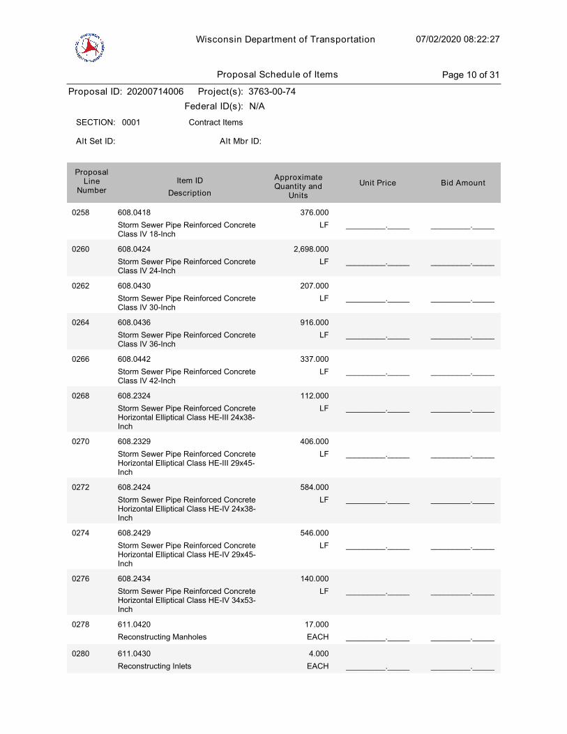
Wisconsin Department of Transportation 07/02/2020 08:22:27
Proposal ID: 20200714006 Project(s): 3763-00-74
Federal ID(s): N/A
0001 Contract ItemsSECTION:
Alt Set ID: Alt Mbr ID:
Bid AmountUnit PriceApproximateQuantity and
UnitsDescription
Item IDProposal
LineNumber
0258 608.0418
Storm Sewer Pipe Reinforced ConcreteClass IV 18-Inch
LF
376.000
_________._____ _________._____
0260 608.0424
Storm Sewer Pipe Reinforced ConcreteClass IV 24-Inch
LF
2,698.000
_________._____ _________._____
0262 608.0430
Storm Sewer Pipe Reinforced ConcreteClass IV 30-Inch
LF
207.000
_________._____ _________._____
0264 608.0436
Storm Sewer Pipe Reinforced ConcreteClass IV 36-Inch
LF
916.000
_________._____ _________._____
0266 608.0442
Storm Sewer Pipe Reinforced ConcreteClass IV 42-Inch
LF
337.000
_________._____ _________._____
0268 608.2324
Storm Sewer Pipe Reinforced ConcreteHorizontal Elliptical Class HE-III 24x38-Inch
LF
112.000
_________._____ _________._____
0270 608.2329
Storm Sewer Pipe Reinforced ConcreteHorizontal Elliptical Class HE-III 29x45-Inch
LF
406.000
_________._____ _________._____
0272 608.2424
Storm Sewer Pipe Reinforced ConcreteHorizontal Elliptical Class HE-IV 24x38-Inch
LF
584.000
_________._____ _________._____
0274 608.2429
Storm Sewer Pipe Reinforced ConcreteHorizontal Elliptical Class HE-IV 29x45-Inch
LF
546.000
_________._____ _________._____
0276 608.2434
Storm Sewer Pipe Reinforced ConcreteHorizontal Elliptical Class HE-IV 34x53-Inch
LF
140.000
_________._____ _________._____
0278 611.0420
Reconstructing Manholes EACH
17.000
_________._____ _________._____
0280 611.0430
Reconstructing Inlets EACH
4.000
_________._____ _________._____
Proposal Schedule of Items Page 10 of 31
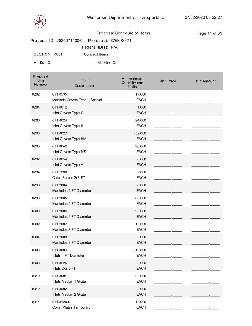
Wisconsin Department of Transportation 07/02/2020 08:22:27
Proposal ID: 20200714006 Project(s): 3763-00-74
Federal ID(s): N/A
0001 Contract ItemsSECTION:
Alt Set ID: Alt Mbr ID:
Bid AmountUnit PriceApproximateQuantity and
UnitsDescription
Item IDProposal
LineNumber
0282 611.0535
Manhole Covers Type J-Special EACH
17.000
_________._____ _________._____
0284 611.0612
Inlet Covers Type C EACH
1.000
_________._____ _________._____
0286 611.0624
Inlet Covers Type H EACH
24.000
_________._____ _________._____
0288 611.0627
Inlet Covers Type HM EACH
352.000
_________._____ _________._____
0290 611.0642
Inlet Covers Type MS EACH
26.000
_________._____ _________._____
0292 611.0654
Inlet Covers Type V EACH
8.000
_________._____ _________._____
0294 611.1230
Catch Basins 2x3-FT EACH
2.000
_________._____ _________._____
0296 611.2004
Manholes 4-FT Diameter EACH
6.000
_________._____ _________._____
0298 611.2005
Manholes 5-FT Diameter EACH
68.000
_________._____ _________._____
0300 611.2006
Manholes 6-FT Diameter EACH
26.000
_________._____ _________._____
0302 611.2007
Manholes 7-FT Diameter EACH
10.000
_________._____ _________._____
0304 611.2008
Manholes 8-FT Diameter EACH
2.000
_________._____ _________._____
0306 611.3004
Inlets 4-FT Diameter EACH
312.000
_________._____ _________._____
0308 611.3225
Inlets 2x2.5-FT EACH
6.000
_________._____ _________._____
0310 611.3901
Inlets Median 1 Grate EACH
22.000
_________._____ _________._____
0312 611.3902
Inlets Median 2 Grate EACH
2.000
_________._____ _________._____
0314 611.8120.S
Cover Plates Temporary EACH
18.000
_________._____ _________._____
Proposal Schedule of Items Page 11 of 31

Wisconsin Department of Transportation 07/02/2020 08:22:27
Proposal ID: 20200714006 Project(s): 3763-00-74
Federal ID(s): N/A
0001 Contract ItemsSECTION:
Alt Set ID: Alt Mbr ID:
Bid AmountUnit PriceApproximateQuantity and
UnitsDescription
Item IDProposal
LineNumber
0316 611.9710
Salvaged Inlet Covers EACH
1.000
_________._____ _________._____
0318 611.9800.S
Pipe Grates EACH
35.000
_________._____ _________._____
0320 612.0112
Pipe Underdrain 12-Inch LF
105.000
_________._____ _________._____
0322 612.0212
Pipe Underdrain Unperforated 12-Inch LF
1,000.000
_________._____ _________._____
0324 612.0406
Pipe Underdrain Wrapped 6-Inch LF
3,058.000
_________._____ _________._____
0326 612.0700
Drain Tile Exploration LF
1,000.000
_________._____ _________._____
0328 614.0150
Anchor Assemblies for Steel Plate BeamGuard
EACH
12.000
_________._____ _________._____
0330 614.0905
Crash Cushions Temporary EACH
4.000
_________._____ _________._____
0332 614.2500
MGS Thrie Beam Transition LF
480.000
_________._____ _________._____
0334 614.2610
MGS Guardrail Terminal EAT EACH
12.000
_________._____ _________._____
0336 616.0700.S
Fence Safety LF
8,000.000
_________._____ _________._____
0338 619.1000
Mobilization EACH
1.000
_________._____ _________._____
0340 620.0300
Concrete Median Sloped Nose SF
2,578.000
_________._____ _________._____
0342 623.0200
Dust Control Surface Treatment SY
48,875.000
_________._____ _________._____
0344 624.0100
Water MGAL
3,080.000
_________._____ _________._____
0346 627.0200
Mulching SY
30,000.000
_________._____ _________._____
Proposal Schedule of Items Page 12 of 31

Wisconsin Department of Transportation 07/02/2020 08:22:27
Proposal ID: 20200714006 Project(s): 3763-00-74
Federal ID(s): N/A
0001 Contract ItemsSECTION:
Alt Set ID: Alt Mbr ID:
Bid AmountUnit PriceApproximateQuantity and
UnitsDescription
Item IDProposal
LineNumber
0348 628.1104
Erosion Bales EACH
500.000
_________._____ _________._____
0350 628.1504
Silt Fence LF
43,585.000
_________._____ _________._____
0352 628.1520
Silt Fence Maintenance LF
43,585.000
_________._____ _________._____
0354 628.1905
Mobilizations Erosion Control EACH
20.000
_________._____ _________._____
0356 628.1910
Mobilizations Emergency Erosion Control EACH
36.000
_________._____ _________._____
0358 628.2004
Erosion Mat Class I Type B SY
322,495.000
_________._____ _________._____
0360 628.2008
Erosion Mat Urban Class I Type B SY
13,462.000
_________._____ _________._____
0362 628.6005
Turbidity Barriers SY
465.000
_________._____ _________._____
0364 628.6510
Soil Stabilizer Type B ACRE
2.200
_________._____ _________._____
0366 628.7005
Inlet Protection Type A EACH
463.000
_________._____ _________._____
0368 628.7010
Inlet Protection Type B EACH
34.000
_________._____ _________._____
0370 628.7015
Inlet Protection Type C EACH
293.000
_________._____ _________._____
0372 628.7020
Inlet Protection Type D EACH
97.000
_________._____ _________._____
0374 628.7504
Temporary Ditch Checks LF
5,100.000
_________._____ _________._____
0376 628.7555
Culvert Pipe Checks EACH
118.000
_________._____ _________._____
0378 628.7560
Tracking Pads EACH
4.000
_________._____ _________._____
0380 628.7570
Rock Bags EACH
300.000
_________._____ _________._____
Proposal Schedule of Items Page 13 of 31

Wisconsin Department of Transportation 07/02/2020 08:22:27
Proposal ID: 20200714006 Project(s): 3763-00-74
Federal ID(s): N/A
0001 Contract ItemsSECTION:
Alt Set ID: Alt Mbr ID:
Bid AmountUnit PriceApproximateQuantity and
UnitsDescription
Item IDProposal
LineNumber
0658 SPV.0035
Special 002. EBS Backfill CY
25,907.000
_________._____ _________._____
0660 SPV.0035
Special 003. Roadway Embankment CY
635,684.000
_________._____ _________._____
0662 SPV.0035
Special 004. Riffle Cobble CY
36.000
_________._____ _________._____
0664 SPV.0035
Special 005. No. 1 Aggregate CY
1,582.000
_________._____ _________._____
0666 SPV.0035
Special 006. Open-Graded BaseAggregate
CY
170.000
_________._____ _________._____
0668 SPV.0035
Special 007. Sand/Woodchip Bed CY
829.000
_________._____ _________._____
0670 SPV.0035
Special 008. Compost CY
170.000
_________._____ _________._____
0672 SPV.0035
Special 009. Backfill Slurry CY
85.000
_________._____ _________._____
1.00000
0674 SPV.0055
Special 001. Maintain Field Office Left inPlace Special Utility Fees Project 3763-00-74
DOL
100,000.000
100,000.00
0676 SPV.0060
Special 002. Temporary Stone DitchChecks
EACH
50.000
_________._____ _________._____
0678 SPV.0060
Special 003. Sand Bags EACH
500.000
_________._____ _________._____
0680 SPV.0060
Special 004. Temporary Sediment Traps EACH
25.000
_________._____ _________._____
0682 SPV.0060
Special 005. Erosion Control Filter Bags EACH
400.000
_________._____ _________._____
0684 SPV.0060
Special 006. Inlet Frame and Grate forMountable Curb
EACH
26.000
_________._____ _________._____
0686 SPV.0060
Special 007. Temporary Access Gates atCPRR
EACH
2.000
_________._____ _________._____
Proposal Schedule of Items Page 23 of 31

Wisconsin Department of Transportation 07/02/2020 08:22:27
Proposal ID: 20200714006 Project(s): 3763-00-74
Federal ID(s): N/A
0001 Contract ItemsSECTION:
Alt Set ID: Alt Mbr ID:
Bid AmountUnit PriceApproximateQuantity and
UnitsDescription
Item IDProposal
LineNumber
0688 SPV.0060
Special 008. Temporary Access Gates atUPRR
EACH
2.000
_________._____ _________._____
0690 SPV.0060
Special 009. Mobilizations EmergencyPavement Repair
EACH
2.000
_________._____ _________._____
0692 SPV.0060
Special 010. Section Corner Monuments EACH
10.000
_________._____ _________._____
0694 SPV.0060
Special 011. Settlement Gauge EACH
12.000
_________._____ _________._____
0696 SPV.0060
Special 012. Manhole Beehive Grate EACH
1.000
_________._____ _________._____
0698 SPV.0060
Special 013. Connect Drain Tile EACH
10.000
_________._____ _________._____
0700 SPV.0060
Special 016. Pipe Connection to ExistingStructure
EACH
7.000
_________._____ _________._____
0702 SPV.0060
Special 020. Pond L Outlet Storm SewerStructure
EACH
1.000
_________._____ _________._____
0704 SPV.0060
Special 021. Pond M Outlet Storm SewerStructure
EACH
1.000
_________._____ _________._____
0706 SPV.0060
Special 022. Pond N Outlet Storm SewerStructure
EACH
1.000
_________._____ _________._____
0708 SPV.0060
Special 024. Slip-In Check Valve for 24-Inch Inside Diameter Pipe
EACH
1.000
_________._____ _________._____
0710 SPV.0060
Special 025. Slip-In Check Valve for 30-Inch Inside Diameter Pipe
EACH
1.000
_________._____ _________._____
0712 SPV.0060
Special 026. Slip-In Check Valve for 36-Inch Inside Diameter Pipe
EACH
2.000
_________._____ _________._____
0714 SPV.0060
Special 027. Slip-In Check Valve for 42-Inch Inside Diameter Pipe
EACH
1.000
_________._____ _________._____
Proposal Schedule of Items Page 24 of 31

Wisconsin Department of Transportation 07/02/2020 08:22:27
Proposal ID: 20200714006 Project(s): 3763-00-74
Federal ID(s): N/A
0001 Contract ItemsSECTION:
Alt Set ID: Alt Mbr ID:
Bid AmountUnit PriceApproximateQuantity and
UnitsDescription
Item IDProposal
LineNumber
0868 SPV.0200
Special 601. Reconstruct SanitaryManhole Subtraction
VF
2.000
_________._____ _________._____
1.00000
0870 SPV.0055
Special 002. Construction Crossing withUPRR
DOL
90,000.000
90,000.00
Section: 0001 _________._____Total:
Total Bid: _________._____
Proposal Schedule of Items Page 31 of 31
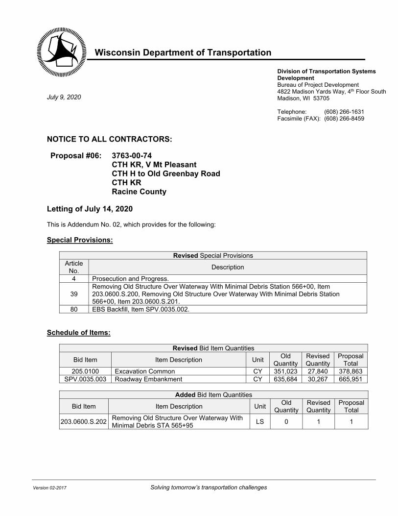
Wisconsin Department of Transportation
Version 02-2017 Solving tomorrow’s transportation challenges
Division of Transportation Systems Development Bureau of Project Development 4822 Madison Yards Way, 4th Floor South Madison, WI 53705 Telephone: (608) 266-1631 Facsimile (FAX): (608) 266-8459
July 9, 2020
NOTICE TO ALL CONTRACTORS: Proposal #06: 3763-00-74
CTH KR, V Mt Pleasant CTH H to Old Greenbay Road CTH KR Racine County
Letting of July 14, 2020 This is Addendum No. 02, which provides for the following: Special Provisions:
Revised Special Provisions Article
No. Description
4 Prosecution and Progress.
39 Removing Old Structure Over Waterway With Minimal Debris Station 566+00, Item 203.0600.S.200, Removing Old Structure Over Waterway With Minimal Debris Station 566+00, Item 203.0600.S.201.
80 EBS Backfill, Item SPV.0035.002. Schedule of Items:
Revised Bid Item Quantities
Bid Item Item Description Unit Old
Quantity Revised Quantity
Proposal Total
205.0100 Excavation Common CY 351,023 27,840 378,863 SPV.0035.003 Roadway Embankment CY 635,684 30,267 665,951
Added Bid Item Quantities
Bid Item Item Description Unit Old
Quantity Revised Quantity
Proposal Total
203.0600.S.202 Removing Old Structure Over Waterway With Minimal Debris STA 565+95
LS 0 1 1
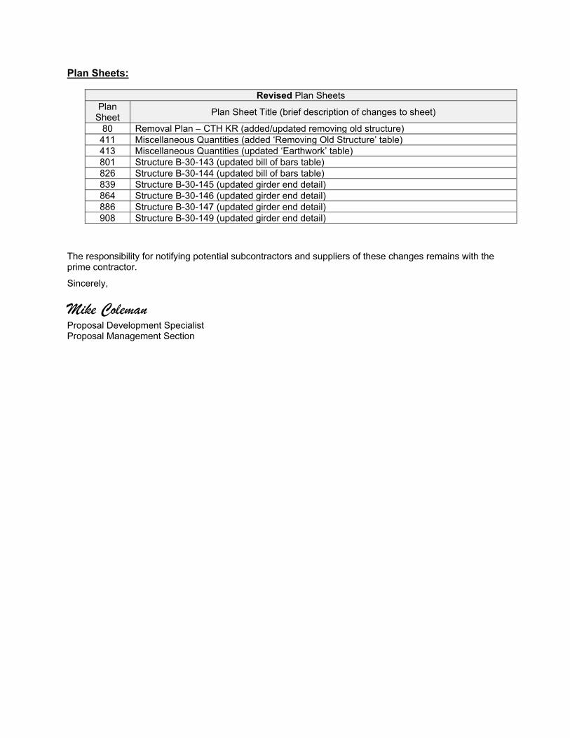
Plan Sheets:
Revised Plan Sheets Plan
Sheet Plan Sheet Title (brief description of changes to sheet)
80 Removal Plan – CTH KR (added/updated removing old structure) 411 Miscellaneous Quantities (added ‘Removing Old Structure’ table) 413 Miscellaneous Quantities (updated ‘Earthwork’ table) 801 Structure B-30-143 (updated bill of bars table) 826 Structure B-30-144 (updated bill of bars table) 839 Structure B-30-145 (updated girder end detail) 864 Structure B-30-146 (updated girder end detail) 886 Structure B-30-147 (updated girder end detail) 908 Structure B-30-149 (updated girder end detail)
The responsibility for notifying potential subcontractors and suppliers of these changes remains with the prime contractor.
Sincerely,
Mike Coleman Proposal Development Specialist Proposal Management Section
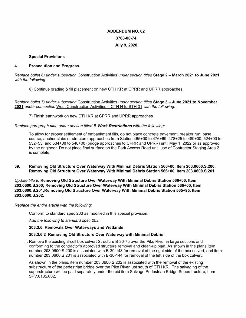
ADDENDUM NO. 02
3763-00-74
July 9, 2020
Special Provisions
4. Prosecution and Progress.
Replace bullet 6) under subsection Construction Activities under section titled Stage 2 – March 2021 to June 2021 with the following:
6) Continue grading & fill placement on new CTH KR at CPRR and UPRR approaches
Replace bullet 7) under subsection Construction Activities under section titled Stage 3 – June 2021 to November 2021 under subsection West Construction Activities – CTH H to STH 31 with the following:
7) Finish earthwork on new CTH KR at CPRR and UPRR approaches
Replace paragraph nine under section titled B Work Restrictions with the following:
To allow for proper settlement of embankment fills, do not place concrete pavement, breaker run, base course, anchor slabs or structure approaches from Station 465+00 to 476+69; 478+25 to 489+00, 524+00 to 532+53; and 534+08 to 540+00 (bridge approaches to CPRR and UPRR) until May 1, 2022 or as approved by the engineer. Do not place final surface on the Park Access Road until use of Contractor Staging Area 2 is complete.
39. Removing Old Structure Over Waterway With Minimal Debris Station 566+00, Item 203.0600.S.200, Removing Old Structure Over Waterway With Minimal Debris Station 566+00, Item 203.0600.S.201.
Update title to Removing Old Structure Over Waterway With Minimal Debris Station 566+00, Item 203.0600.S.200; Removing Old Structure Over Waterway With Minimal Debris Station 566+00, Item 203.0600.S.201;Removing Old Structure Over Waterway With Minimal Debris Station 565+95, Item 203.0600.S.202.
Replace the entire article with the following:
Conform to standard spec 203 as modified in this special provision.
Add the following to standard spec 203:
203.3.6 Removals Over Waterways and Wetlands
203.3.6.2 Removing Old Structure Over Waterway with Minimal Debris
(1) Remove the existing 3-cell box culvert Structure B-30-75 over the Pike River in large sections and conforming to the contractor’s approved structure removal and clean-up plan. As shown in the plans item number 203.0600.S.200 is associated with B-30-143 for removal of the right side of the box culvert, and item number 203.0600.S.201 is associated with B-30-144 for removal of the left side of the box culvert.
As shown in the plans, item number 203.0600.S.202 is associated with the removal of the existing substructure of the pedestrian bridge over the Pike River just south of CTH KR. The salvaging of the superstructure will be paid separately under the bid item Salvage Pedestrian Bridge Superstructure, Item SPV.0105.002.
During removal, prevent all large pieces and minimize the number of small pieces from entering the waterway or wetland. Remove all reinforcing steel, all concrete, and all other debris that falls into the waterway or wetland. The contractor may leave limited amounts of small concrete pieces scattered over the waterway floor or wetland only if the engineer allows.
(2) Submit a structure removal and clean-up plan as part of the erosion control implementation plan required under standard spec 107.20. Do not start work under the structure removal and clean-up plan without the department’s written approval of the plan. Include the following information in the structure removal and clean-up plan:
- Methods and schedule to remove the structure.
- Methods to control potentially harmful environmental impacts.
- Methods for superstructure removal that prevent all large pieces and minimize the number of small pieces from entering the waterway or wetlands.
- Methods to control dust and contain slurry.
- Methods for removing piers and abutments. If blasting in water, include restrictions that regulatory agencies and the contract require.
- Methods for cleaning the waterway or wetlands.
(3) If stockpiling spoil material, place it on an upland site an adequate distance from the waterway, wetland, or any open water created by excavation. Install silt fence between the spoil pile and the waterway, wetland, or excavation site.
Add the following Removing Old Structure bid item to standard spec 203.5.1:
ITEM NUMBER DESCRIPTION UNIT
203.0600.S.200 Removing Old Structure Over Waterway With Minimal Debris Station 566+00 LS
203.0600.S.201 Removing Old Structure Over Waterway With Minimal Debris Station 566+00 LS
203.0600.S.202 Removing Old Structure Over Waterway With Minimal Debris Station 565+95 LS
80. EBS Backfill, Item SPV.0035.002.
Replace the entire article with the following:
A Description
This special provision describes backfilling EBS Excavation with breaker run or backfill granular grade 1.
B Materials
Furnish all materials according to standard spec 209.2, and standard spec 311.2 and as hereinafter provided.
C Construction
Place breaker run or backfill granular grade 1 where EBS Excavation was performed or as the engineer directs. Compact breaker run using standard compaction conforming to standard spec 301.3. Compact backfill granular grade 1 using standard compaction conforming to standard spec 209.3.
D Measurement
The department will determine weight or volume, adjust for moisture, and convert between weight and volume as specified in standard spec 301.4.
The department will measure EBS Backfill by the cubic yard, acceptably completed.
E Payment
The department will pay for measured quantities at the contract unit price under the following bid item:
ITEM NUMBER DESCRIPTION UNIT
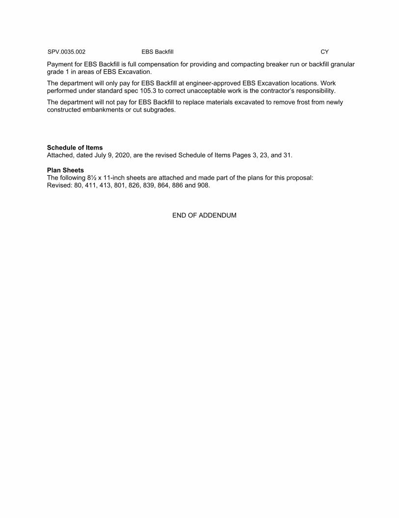
SPV.0035.002 EBS Backfill CY
Payment for EBS Backfill is full compensation for providing and compacting breaker run or backfill granular grade 1 in areas of EBS Excavation.
The department will only pay for EBS Backfill at engineer-approved EBS Excavation locations. Work performed under standard spec 105.3 to correct unacceptable work is the contractor’s responsibility.
The department will not pay for EBS Backfill to replace materials excavated to remove frost from newly constructed embankments or cut subgrades.
Schedule of Items Attached, dated July 9, 2020, are the revised Schedule of Items Pages 3, 23, and 31. Plan Sheets The following 8½ x 11-inch sheets are attached and made part of the plans for this proposal: Revised: 80, 411, 413, 801, 826, 839, 864, 886 and 908.
END OF ADDENDUM
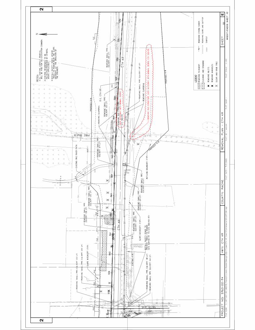
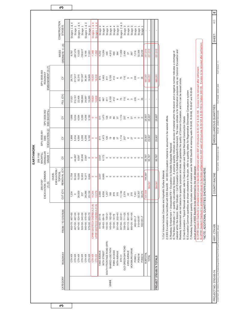
Sta
ges
1 & 4
Sta
ge 1
Sta
ges
1 & 4
Sta
ge 1
Sta
ges
1 & 3
Sta
ge 3
Sta
ges
1 & 4
Sta
ges
1 & 4
Sta
ge 3
Sta
ge 4
Sta
ge 1
Sta
ge 4
Sta
ge 4
Sta
ge 3
Sta
ges
2 & 3
Sta
ge 3
Sta
ge 3
Sta
ge 3
Sta
ge 1
Sta
ge 1
Sta
ge 1
- -
10
00
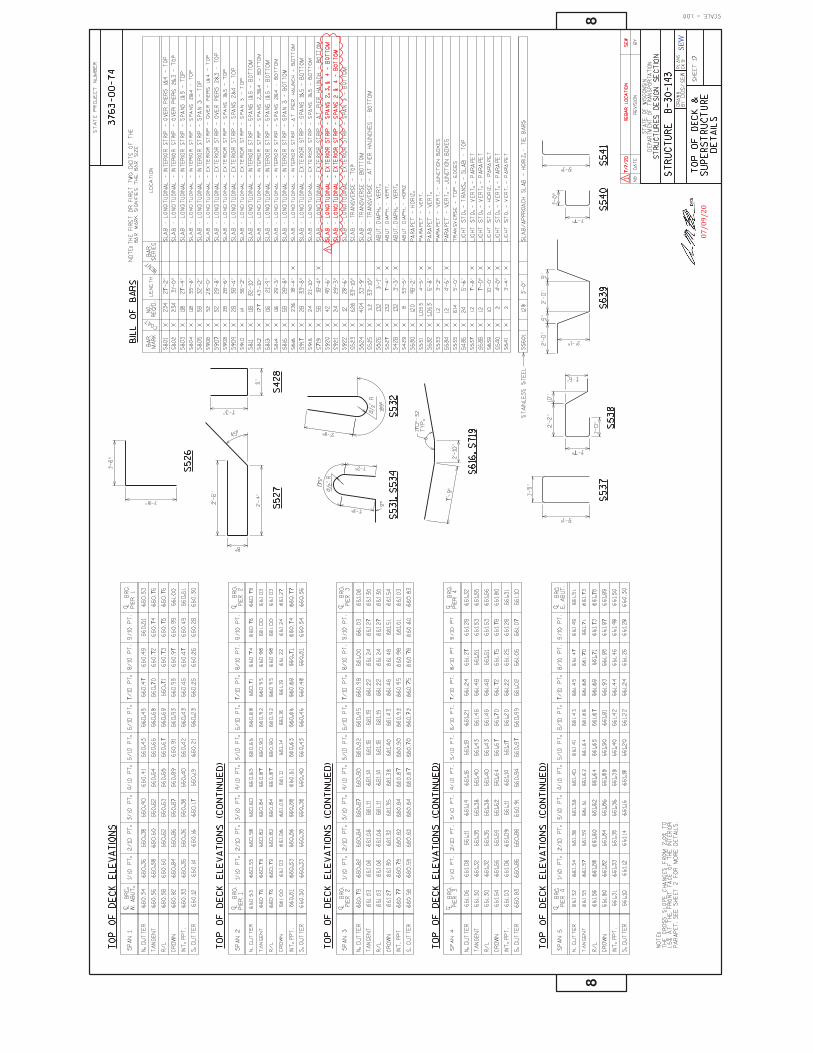
07/09/20
SEW
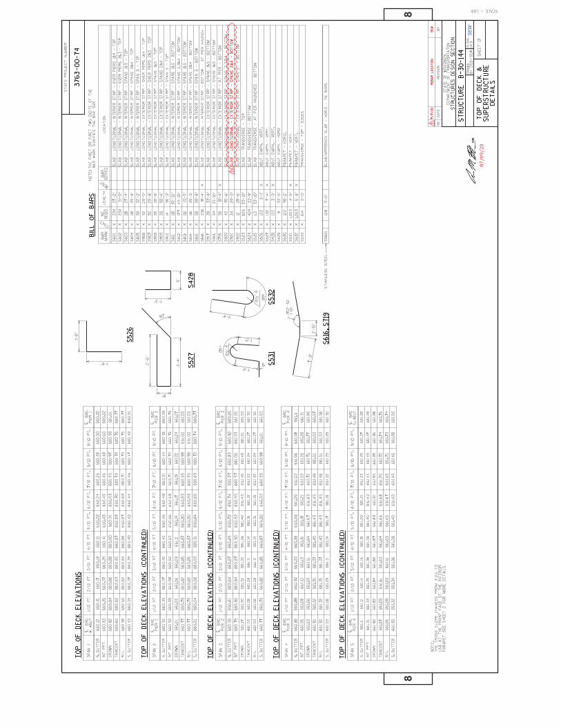
07/09/20
SEW

EMK
07/09/20

EMK
07/09/20
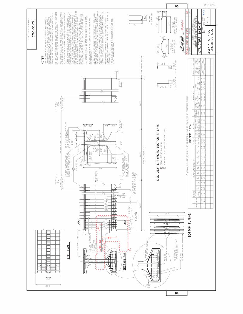
EMK
07/09/20

EMK
07/09/20
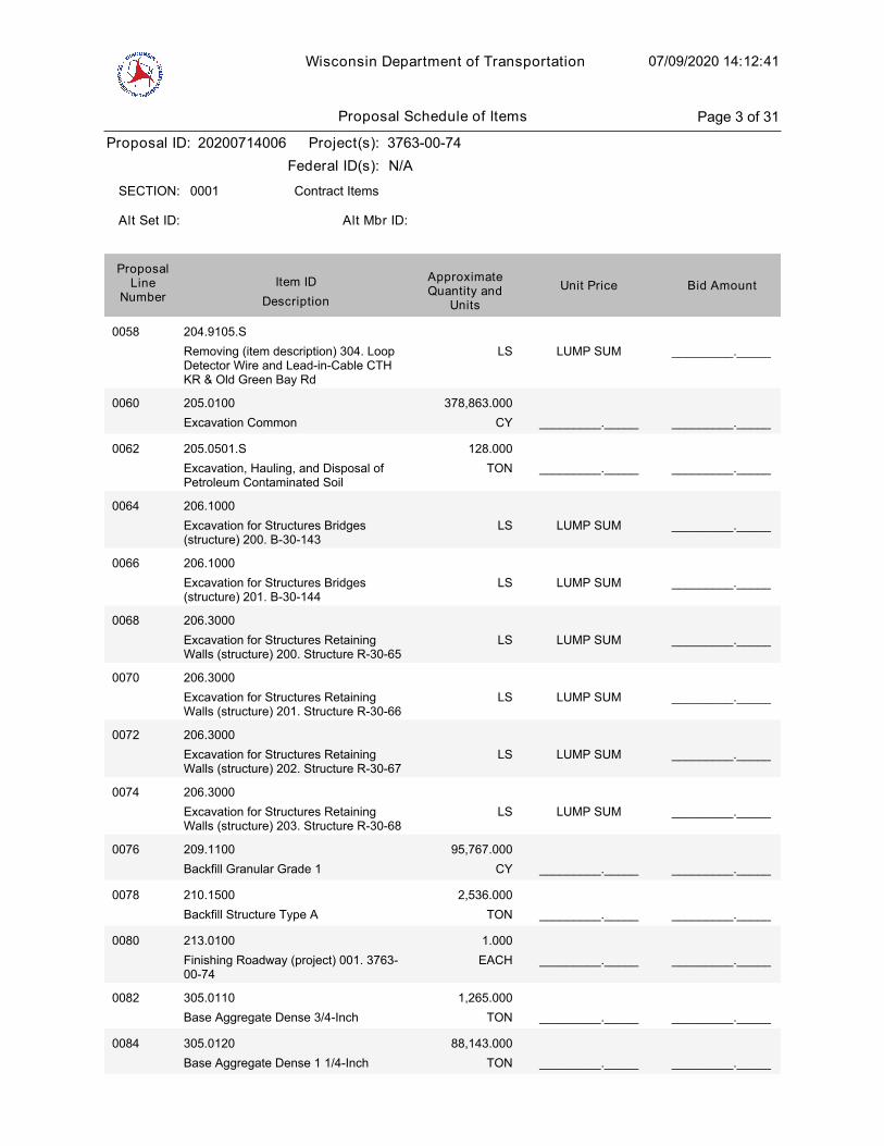
Wisconsin Department of Transportation 07/09/2020 14:12:41
Proposal ID: 20200714006 Project(s): 3763-00-74
Federal ID(s): N/A
0001 Contract ItemsSECTION:
Alt Set ID: Alt Mbr ID:
Bid AmountUnit PriceApproximateQuantity and
UnitsDescription
Item IDProposal
LineNumber
0058 204.9105.S
Removing (item description) 304. LoopDetector Wire and Lead-in-Cable CTHKR & Old Green Bay Rd
LUMP SUM _________._____LS
0060 205.0100
Excavation Common CY
378,863.000
_________._____ _________._____
0062 205.0501.S
Excavation, Hauling, and Disposal ofPetroleum Contaminated Soil
TON
128.000
_________._____ _________._____
0064 206.1000
Excavation for Structures Bridges(structure) 200. B-30-143
LUMP SUM _________._____LS
0066 206.1000
Excavation for Structures Bridges(structure) 201. B-30-144
LUMP SUM _________._____LS
0068 206.3000
Excavation for Structures RetainingWalls (structure) 200. Structure R-30-65
LUMP SUM _________._____LS
0070 206.3000
Excavation for Structures RetainingWalls (structure) 201. Structure R-30-66
LUMP SUM _________._____LS
0072 206.3000
Excavation for Structures RetainingWalls (structure) 202. Structure R-30-67
LUMP SUM _________._____LS
0074 206.3000
Excavation for Structures RetainingWalls (structure) 203. Structure R-30-68
LUMP SUM _________._____LS
0076 209.1100
Backfill Granular Grade 1 CY
95,767.000
_________._____ _________._____
0078 210.1500
Backfill Structure Type A TON
2,536.000
_________._____ _________._____
0080 213.0100
Finishing Roadway (project) 001. 3763-00-74
EACH
1.000
_________._____ _________._____
0082 305.0110
Base Aggregate Dense 3/4-Inch TON
1,265.000
_________._____ _________._____
0084 305.0120
Base Aggregate Dense 1 1/4-Inch TON
88,143.000
_________._____ _________._____
Proposal Schedule of Items Page 3 of 31
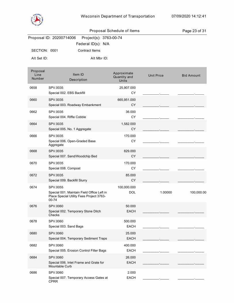
Wisconsin Department of Transportation 07/09/2020 14:12:41
Proposal ID: 20200714006 Project(s): 3763-00-74
Federal ID(s): N/A
0001 Contract ItemsSECTION:
Alt Set ID: Alt Mbr ID:
Bid AmountUnit PriceApproximateQuantity and
UnitsDescription
Item IDProposal
LineNumber
0658 SPV.0035
Special 002. EBS Backfill CY
25,907.000
_________._____ _________._____
0660 SPV.0035
Special 003. Roadway Embankment CY
665,951.000
_________._____ _________._____
0662 SPV.0035
Special 004. Riffle Cobble CY
36.000
_________._____ _________._____
0664 SPV.0035
Special 005. No. 1 Aggregate CY
1,582.000
_________._____ _________._____
0666 SPV.0035
Special 006. Open-Graded BaseAggregate
CY
170.000
_________._____ _________._____
0668 SPV.0035
Special 007. Sand/Woodchip Bed CY
829.000
_________._____ _________._____
0670 SPV.0035
Special 008. Compost CY
170.000
_________._____ _________._____
0672 SPV.0035
Special 009. Backfill Slurry CY
85.000
_________._____ _________._____
1.00000
0674 SPV.0055
Special 001. Maintain Field Office Left inPlace Special Utility Fees Project 3763-00-74
DOL
100,000.000
100,000.00
0676 SPV.0060
Special 002. Temporary Stone DitchChecks
EACH
50.000
_________._____ _________._____
0678 SPV.0060
Special 003. Sand Bags EACH
500.000
_________._____ _________._____
0680 SPV.0060
Special 004. Temporary Sediment Traps EACH
25.000
_________._____ _________._____
0682 SPV.0060
Special 005. Erosion Control Filter Bags EACH
400.000
_________._____ _________._____
0684 SPV.0060
Special 006. Inlet Frame and Grate forMountable Curb
EACH
26.000
_________._____ _________._____
0686 SPV.0060
Special 007. Temporary Access Gates atCPRR
EACH
2.000
_________._____ _________._____
Proposal Schedule of Items Page 23 of 31
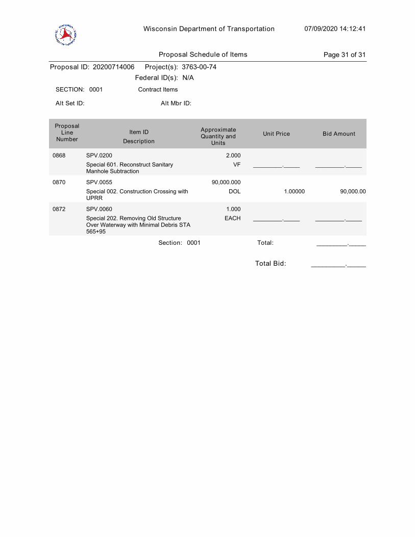
Wisconsin Department of Transportation 07/09/2020 14:12:41
Proposal ID: 20200714006 Project(s): 3763-00-74
Federal ID(s): N/A
0001 Contract ItemsSECTION:
Alt Set ID: Alt Mbr ID:
Bid AmountUnit PriceApproximateQuantity and
UnitsDescription
Item IDProposal
LineNumber
0868 SPV.0200
Special 601. Reconstruct SanitaryManhole Subtraction
VF
2.000
_________._____ _________._____
1.00000
0870 SPV.0055
Special 002. Construction Crossing withUPRR
DOL
90,000.000
90,000.00
0872 SPV.0060
Special 202. Removing Old StructureOver Waterway with Minimal Debris STA565+95
EACH
1.000
_________._____ _________._____
Section: 0001 _________._____Total:
Total Bid: _________._____
Proposal Schedule of Items Page 31 of 31


