Embed Size (px)
Citation preview
Administration for Network Connectivity for Avaya
Communication Manager
555-233-504Issue 10
June 2005
Copyright 2005, Avaya Inc.All Rights ReservedThis document contains information related to Replace variable w/ product name software (as defined below) and Documentation (“Product”). “Documentation” means this document and Avaya’s information manuals in printed or electronic form containing operating instructions and performance specifications that Avaya or its suppliers generally make available to users of its products, and which Avaya delivers to End User with the Products. “End User” means any customer of Avaya or its authorized resellers, or any end user of the Product. See the Software and Documentation DVD/CD inserts for additional legal and licensing information.
NoticeChanges and corrections to the information in this document may be incorporated in future releases.
DisclaimerAvaya, its affiliates or subsidiaries (“Avaya”) are not responsible for any modifications, additions or deletions to the original published version of the Documentation unless such modifications, additions or deletions were performed by Avaya. End User agrees to indemnify and hold harmless Avaya, Avaya's agents, servants, directors, officers, and employees against all claims, lawsuits, demands and judgments arising out of, or in connection with, subsequent modifications, additions or deletions to the Documentation to the extent made by the End User.
WarrantyAvaya provides a limited warranty on the Product. Refer to your customer sales agreement to establish the terms of the limited warranty. In addition, Avaya’s standard warranty language as well as information regarding support for the Product, while under warranty, is available through the following web site: http://www.avaya.com/support.
LicenseUSE OR INSTALLATION OF THE PRODUCT INDICATES THE END USER’S ACCEPTANCE OF THE GENERAL LICENSE TERMS AVAILABLE ON THE AVAYA WEBSITE AT: http://www.avaya.com/support (“GENERAL LICENSE TERMS”). DO NOT USE THE PRODUCT IF YOU DO NOT WISH TO BE BOUND BY THE GENERAL LICENSE TERMS. IN ADDITION TO THE GENERAL LICENSE TERMS, THE FOLLOWING LICENSE TERMS AND RESTRICTIONS WILL APPLY TO THE PRODUCT.
Avaya grants End User a license within the scope of the license types described below. The applicable number of licenses and units of capacity for which the license is granted will be one (1), unless a different number of licenses or units of capacity is specified in the Documentation or other materials available to End User. “Designated Processor” means a single stand-alone computing device. “Server” means a Designated Processor that hosts a software application to be accessed by multiple users. “Software” means the computer programs in object code, originally licensed by Avaya and ultimately utilized by End User, whether as stand-alone products or pre-installed on Hardware. “Hardware” means the standard hardware products, originally sold by Avaya and ultimately utilized by End User.If your system is running in a TDM environment, the following license restriction applies:Designated System(s) License (DS). End User may install and use each copy of the Software on only one Designated Processor, unless a different number of Designated Processors is indicated in the Documentation or other materials available to End User. Avaya may require the Designated Processor(s) to be identified by type, serial number, feature key, location or other specific designation, or to be provided by End User to Avaya through electronic means established by Avaya specifically for this purpose.If your system is running in an IP environment, the following license restriction applies:Concurrent User License (CU). End User may install and use the Software on multiple Designated Processors or one or more Servers, so long as only the licensed number of Units are accessing and using the Software at any given time. A “Unit” means the unit on which Avaya, at its sole discretion, bases the pricing of its licenses and can be, without limitation, an agent, port or user, an e-mail or voice mail account in the name of a person or corporate function (e.g., webmaster or helpdesk), or a directory entry in the administrative database utilized by the Product that permits one user to interface with the Software. Units may be linked to a specific, identified Server.
For all systems, the following license restriction applies:Shrinkwrap License (SR). With respect to Software that contains elements provided by third party suppliers, End User may install and use the Software in accordance with the terms and conditions of the “shrinkwrap” or “clickwrap” license accompanying the Software (“Shrinkwrap License”). The text of the Shrinkwrap License will be available from Avaya upon End User’s request (see “Copyright” below for more information).
CopyrightExcept where expressly stated otherwise, the Product is protected by copyright and other laws respecting proprietary rights. Unauthorized reproduction, transfer, and or use can be a criminal, as well as a civil, offense under the applicable law.Certain Software programs or portions thereof included in the Product may contain software distributed under third party agreements (“Third Party Components”), which may contain terms that expand or limit rights to use certain portions of the Product (“Third Party Terms”). Information identifying Third Party Components and the Third Party Terms that apply to them is available on Avaya’s web site at http://support.avaya.com/ThirdPartyLicense/.
The disclaimers of warranties and limitations of liability set forth in the Third Party Terms do not affect any express warranty or limitation of liability that may be provided to you by Avaya pursuant to the license terms covering the Product contained in a separate written agreement between you and Avaya. To the extent there is a conflict between the General License Terms or your customer sales agreement and any Third Party Terms, the Third Party Terms shall prevail solely for such Third Party Components.
Security and virus disclaimerEnd User's decision to acquire products from third parties is End User's sole responsibility, even if Avaya helps End User identify, evaluate or select them. Avaya is not responsible for, and will not be liable for, the quality or performance of such third party products or their suppliers.
ALL INFORMATION IS BELIEVED TO BE CORRECT AT THE TIME OF PUBLICATION AND IS PROVIDED "AS IS". AVAYA DISCLAIMS ALL WARRANTIES, EITHER EXPRESS OR IMPLIED, INCLUDING THE WARRANTIES OF MERCHANTABILITY AND FITNESS FOR A PARTICULAR PURPOSE AND FURTHERMORE, AVAYA MAKES NO REPRESENTATIONS OR WARRANTIES THAT THE STEPS RECOMMENDED WILL ELIMINATE SECURITY OR VIRUS THREATS TO END USER’ SYSTEMS. IN NO EVENT SHALL AVAYA BE LIABLE FOR ANY DAMAGES WHATSOEVER ARISING OUT OF OR IN CONNECTION WITH THE INFORMATION OR RECOMMENDED ACTIONS PROVIDED HEREIN, INCLUDING DIRECT, INDIRECT, CONSEQUENTIAL DAMAGES, LOSS OF BUSINESS PROFITS OR SPECIAL DAMAGES, EVEN IF AVAYA HAS BEEN ADVISED OF THE POSSIBILITY OF SUCH DAMAGES.
Avaya does not warrant that this Product is immune from or will prevent unauthorized use of telecommunication services or facilities accessed through or connected to it. Avaya is not responsible for any damages or charges that result from either unauthorized uses or from incorrect installations of the security patches that are made available from time to time.Suspected security vulnerabilities with Avaya products should be reported to Avaya by sending mail to [email protected].
Trademarks
All trademarks identified by ® and TM are registered trademarks or trademarks of Avaya Inc. All other trademarks are the property of their respective owners.
Issue 10 June 2005 3
Contents
About this document . . . . . . . . . . . . . . . . . . . . . . . . . . . . 13Purpose. . . . . . . . . . . . . . . . . . . . . . . . . . . . . . . . . . . . . . . . . 13
Content . . . . . . . . . . . . . . . . . . . . . . . . . . . . . . . . . . . . . . . . . 13
Conventions used in this book . . . . . . . . . . . . . . . . . . . . . . . . . . . . 14Terminology . . . . . . . . . . . . . . . . . . . . . . . . . . . . . . . . . . . . 14Typographic . . . . . . . . . . . . . . . . . . . . . . . . . . . . . . . . . . . . 15Admonishments . . . . . . . . . . . . . . . . . . . . . . . . . . . . . . . . . . 16Physical dimensions . . . . . . . . . . . . . . . . . . . . . . . . . . . . . . . 16
How to get this book. . . . . . . . . . . . . . . . . . . . . . . . . . . . . . . . . . 16On the Web . . . . . . . . . . . . . . . . . . . . . . . . . . . . . . . . . . . . . 16Non-Web . . . . . . . . . . . . . . . . . . . . . . . . . . . . . . . . . . . . . . 17
Toll-free numbers . . . . . . . . . . . . . . . . . . . . . . . . . . . . . . . 17Non-800 numbers . . . . . . . . . . . . . . . . . . . . . . . . . . . . . . . 17
How to get technical assistance . . . . . . . . . . . . . . . . . . . . . . . . . . . 17
Security. . . . . . . . . . . . . . . . . . . . . . . . . . . . . . . . . . . . . . . . . 18
Antistatic protection . . . . . . . . . . . . . . . . . . . . . . . . . . . . . . . . . . 18
Remove/Install circuit packs . . . . . . . . . . . . . . . . . . . . . . . . . . . . . 19
Standards compliance. . . . . . . . . . . . . . . . . . . . . . . . . . . . . . . . . 19Environmental requirements and safety standards . . . . . . . . . . . . . . . 19Network standards. . . . . . . . . . . . . . . . . . . . . . . . . . . . . . . . . 20EMC standards. . . . . . . . . . . . . . . . . . . . . . . . . . . . . . . . . . . 21
Tell us what you think . . . . . . . . . . . . . . . . . . . . . . . . . . . . . . . . . 21
Chapter 1: Networking overview . . . . . . . . . . . . . . . . . . . . . . 23What is a network . . . . . . . . . . . . . . . . . . . . . . . . . . . . . . . . . . . 23
About “network” terminology. . . . . . . . . . . . . . . . . . . . . . . . . . . . . 23
What’s in a digital phone call . . . . . . . . . . . . . . . . . . . . . . . . . . . . . 24
About network regions . . . . . . . . . . . . . . . . . . . . . . . . . . . . . . . . 25
Establishing inter-switch trunk connections . . . . . . . . . . . . . . . . . . . . 25Interconnecting port networks . . . . . . . . . . . . . . . . . . . . . . . . . . 26Networking branch offices . . . . . . . . . . . . . . . . . . . . . . . . . . . . 26Control Networks . . . . . . . . . . . . . . . . . . . . . . . . . . . . . . . . . 27Enabling spanning tree protocol (STP) . . . . . . . . . . . . . . . . . . . . . 27Inter-Gateway Alternate Routing (IGAR) . . . . . . . . . . . . . . . . . . . . . 28
Network quality management . . . . . . . . . . . . . . . . . . . . . . . . . . . . . 28Sending and receiving IP packets . . . . . . . . . . . . . . . . . . . . . . . . 29
Contents
4 Administration for Network Connectivity for Avaya Communication Manager
About VoIP-transmission hardware . . . . . . . . . . . . . . . . . . . . . . . 29TN799 (C-LAN) . . . . . . . . . . . . . . . . . . . . . . . . . . . . . . . . . 29TN802B (IP-Interface) . . . . . . . . . . . . . . . . . . . . . . . . . . . . . 30TN2302AP (IP Media Processor) . . . . . . . . . . . . . . . . . . . . . . . 30TN2602AP IP Media Resource 320 . . . . . . . . . . . . . . . . . . . . . . 30TN2312 (IP Server Interface) . . . . . . . . . . . . . . . . . . . . . . . . . 31G700/G350 Media Gateway VoIP processors . . . . . . . . . . . . . . . . 31MM760 VoIP Media Module . . . . . . . . . . . . . . . . . . . . . . . . . . 31
About call connections . . . . . . . . . . . . . . . . . . . . . . . . . . . . . . . . 32Connection types . . . . . . . . . . . . . . . . . . . . . . . . . . . . . . . . . 33
Providing LAN security . . . . . . . . . . . . . . . . . . . . . . . . . . . . . . . . 36
Connection Preservation . . . . . . . . . . . . . . . . . . . . . . . . . . . . . . . 37H.248 and H.323 Link Recovery. . . . . . . . . . . . . . . . . . . . . . . . . . 38Auto fallback to primary. . . . . . . . . . . . . . . . . . . . . . . . . . . . . . 38Local Survivable Processor (LSP) . . . . . . . . . . . . . . . . . . . . . . . . 38Enterprise Survivable Servers (ESS) . . . . . . . . . . . . . . . . . . . . . . . 39Standard Local Survivability (SLS) . . . . . . . . . . . . . . . . . . . . . . . . 39
Chapter 2: Control Networks for S8700-Series and S8500 Media Servers 41Control network C . . . . . . . . . . . . . . . . . . . . . . . . . . . . . . . . . . . 41
Sample configuration: Multi-site private CNA, CNB, with remote PNs on public LAN . . . . . . . . . . . . . . . . . . . . . . . . . 42
Combining fiber-connected and IP-connected portnetworks in a single configuration . . . . . . . . . . . . . . . . . . . . . . . . . 43
Sample configurations . . . . . . . . . . . . . . . . . . . . . . . . . . . . . . 43Network connectivity between S8700-series servers and port networks . 43Control network on customer LAN (CNOCL) . . . . . . . . . . . . . . . . 51
Chapter 3: Administering converged networks . . . . . . . . . . . . . . 53About Voice over IP converged networks . . . . . . . . . . . . . . . . . . . . . . 53
Providing a network assessment . . . . . . . . . . . . . . . . . . . . . . . . . 54
About VoIP hardware . . . . . . . . . . . . . . . . . . . . . . . . . . . . . . . . . 55TN464HP/TN2464CP Universal DS1 circuit packs andMM710 T1/E1Media Module . . . . . . . . . . . . . . . . . . . . . . . . . . . 55
Working with echo cancellation . . . . . . . . . . . . . . . . . . . . . . . 55Administering echo cancellation on the DS1 circuit packor MM710 media module . . . . . . . . . . . . . . . . . . . . . . . . . . . 56
Administering echo cancellation on trunks . . . . . . . . . . . . . . . . . 59TN799DP Control LAN . . . . . . . . . . . . . . . . . . . . . . . . . . . . . . 60
Physical addressing for the C-LAN board . . . . . . . . . . . . . . . . . . 61
Contents
Issue 10 June 2005 5
IP addressing techniques for the C-LAN board . . . . . . . . . . . . . . . 61Installing the TN799DP C-LAN . . . . . . . . . . . . . . . . . . . . . . . . 61Administering the C-LAN bus bridge (Avaya DEFINITY Server csi only) . 62Installing C-LAN cables to a hub or ethernet switch . . . . . . . . . . . . 63Assigning IP node names . . . . . . . . . . . . . . . . . . . . . . . . . . 64Defining a LAN default gateway . . . . . . . . . . . . . . . . . . . . . . . 65Setting up Alternate Gatekeeper andC-LAN load balancing . . . . . . . . . . . . . . . . . . . . . . . . . . . . 66
TN802B MAPD (IP Interface Assembly) . . . . . . . . . . . . . . . . . . . . . 67TN2302AP IP Media Processor . . . . . . . . . . . . . . . . . . . . . . . . . . 68
Improving theTN2302AP transmission interface . . . . . . . . . . . . . . 68Supporting TN2302AP hairpinning . . . . . . . . . . . . . . . . . . . . . . 68Testing TN2302AP ports. . . . . . . . . . . . . . . . . . . . . . . . . . . . 68Enabling a survivable remote EPN . . . . . . . . . . . . . . . . . . . . . . 69
TN2602AP IP Media Resource 320 . . . . . . . . . . . . . . . . . . . . . . . . 69Features . . . . . . . . . . . . . . . . . . . . . . . . . . . . . . . . . . . . 69Load balancing. . . . . . . . . . . . . . . . . . . . . . . . . . . . . . . . . 70Firmware download . . . . . . . . . . . . . . . . . . . . . . . . . . . . . . 70I/O adapter . . . . . . . . . . . . . . . . . . . . . . . . . . . . . . . . . . . 70
Comparison of the TN2602AP and TN2302AP circuit packs . . . . . . . . . . 71TN2312BP IP Server Interface (IPSI) . . . . . . . . . . . . . . . . . . . . . . . 73MM760 VoIP Media Module . . . . . . . . . . . . . . . . . . . . . . . . . . . . 74
What is the MM760 Ethernet interface . . . . . . . . . . . . . . . . . . . . 74Supporting voice compression on the MM760. . . . . . . . . . . . . . . . 74
Administration of Avaya gateways . . . . . . . . . . . . . . . . . . . . . . . . . . 76Adding a G600/G650 Media Gateway to an S8500 or S8700-series Media Server . . . . . . . . . . . . . . . . . . . . . . 76
What S8500, S8700-series attributes this procedure assumes . . . . . . . 76Adding a G250, G350, or G700 Media Gateway to an S8300 Media Server . . . . . . . . . . . . . . . . . . . . . . . . . . . . . . . 78
What the G250, G350, or G700 configurations provide . . . . . . . . . . . 79What S8300 attributes this procedure assumes . . . . . . . . . . . . . . . 79
Administering the G250, G350, or G700 on an S8300 Media Server . . . . . . . . . . . . . . . . . . . . . . . . . . . . . . . 79
Administration of IP trunks . . . . . . . . . . . . . . . . . . . . . . . . . . . . . . 82Administering SIP trunks . . . . . . . . . . . . . . . . . . . . . . . . . . . . . 82Administering H.323 trunks . . . . . . . . . . . . . . . . . . . . . . . . . . . . 82
Setting up H.323 trunks for administration . . . . . . . . . . . . . . . . . 83Administering H.323 trunks . . . . . . . . . . . . . . . . . . . . . . . . . . 91Dynamic generation of private/public calling party numbers. . . . . . . . 98
Contents
6 Administration for Network Connectivity for Avaya Communication Manager
Administration of Avaya phones . . . . . . . . . . . . . . . . . . . . . . . . . . . 100Administering IP Softphones . . . . . . . . . . . . . . . . . . . . . . . . . . . 100
Administering the IP Softphone . . . . . . . . . . . . . . . . . . . . . . . 100Installing and administering Avaya IP telephones . . . . . . . . . . . . . . . 104
About the 46xx IP telephone series. . . . . . . . . . . . . . . . . . . . . . 104About IP telephone hardware/software requirements. . . . . . . . . . . . 105Administering Avaya IP telephones . . . . . . . . . . . . . . . . . . . . . 105
About hairpinning and shuffling . . . . . . . . . . . . . . . . . . . . . . . . . 107What hardware and endpoints are required . . . . . . . . . . . . . . . . . 108What are shuffled audio connections . . . . . . . . . . . . . . . . . . . . 108What are shuffling examples . . . . . . . . . . . . . . . . . . . . . . . . . 109What are hairpinned audio connections . . . . . . . . . . . . . . . . . . . 111What is an example hairpinned call . . . . . . . . . . . . . . . . . . . . . 112
Hairpinning and shuffling administration interdependencies . . . . . . . . . 114About Network Address Translation (NAT) . . . . . . . . . . . . . . . . . . . 115
What are the types of NAT . . . . . . . . . . . . . . . . . . . . . . . . . . 116What are the issues between NAT and H.323 . . . . . . . . . . . . . . . . 117Avaya Communication Manager NAT Shuffling feature. . . . . . . . . . . 117
Administering hairpinning and shuffling. . . . . . . . . . . . . . . . . . . . . 119Choosing how to administer hairpinning and shuffling. . . . . . . . . . . 119Administering hairpinning and shuffling at the system-level. . . . . . . . 119Administering hairpinning and shuffling in network regions. . . . . . . . 121Administering H.323 trunks for hairpinning and shuffling (S8500/S8700) . 124Administering IP endpoints for hairpinning and shuffling . . . . . . . . . 126Upgrade interactions for hairpinning and shuffling . . . . . . . . . . . . . 127Administering IP endpoint signal loss . . . . . . . . . . . . . . . . . . . . 128
Administering FAX, modem, TTY, and H.323 clear channel calls over IP Trunks . 129What is relay mode . . . . . . . . . . . . . . . . . . . . . . . . . . . . . . . . 129What pass-through mode is. . . . . . . . . . . . . . . . . . . . . . . . . . . . 130Overview of steps to administer FAX, TTY, modem, and clear channel calls over IP trunks . . . . . . . . . . . . . . . . . . . . . 132
FAX, TTY, modem, and clear channel transmission modes and speeds . . . 133Considerations for administering FAX, TTY, modem, and clear channel transmission . . . . . . . . . . . . . . . . . . . . . . . . . 136
Bandwidth for FAX, modem, TTY, and clear channel calls over IP networks . 139AES/AEA Media Encryption . . . . . . . . . . . . . . . . . . . . . . . . . . . . 140
Contents
Issue 10 June 2005 7
Chapter 4: Network quality administration . . . . . . . . . . . . . . . . 141About factors causing voice degradation . . . . . . . . . . . . . . . . . . . . . . 141
Packet delay and loss . . . . . . . . . . . . . . . . . . . . . . . . . . . . . . . 143Echo . . . . . . . . . . . . . . . . . . . . . . . . . . . . . . . . . . . . . . . . 143
Echo cancellers . . . . . . . . . . . . . . . . . . . . . . . . . . . . . . . . 144Echo cancellation plans (TN464HP/TN2464CP circuit packs) . . . . . . . 144Echo cancellation plans (TN464GP/TN2464BP circuit packs) . . . . . . . 145
Transcoding . . . . . . . . . . . . . . . . . . . . . . . . . . . . . . . . . . . . 147Bandwidth . . . . . . . . . . . . . . . . . . . . . . . . . . . . . . . . . . . . . 147
About Quality of Service (QoS) andvoice quality administration . . . . . . . . . . . . . . . . . . . . . . . . . . . . . 148
Layer 3 QoS . . . . . . . . . . . . . . . . . . . . . . . . . . . . . . . . . . . . 149DiffServ . . . . . . . . . . . . . . . . . . . . . . . . . . . . . . . . . . . . . 149RSVP . . . . . . . . . . . . . . . . . . . . . . . . . . . . . . . . . . . . . . 149
Layer 2 QoS: 802.1p/Q. . . . . . . . . . . . . . . . . . . . . . . . . . . . . . . 149Using VLANs . . . . . . . . . . . . . . . . . . . . . . . . . . . . . . . . . . 150
Administering IP CODEC sets . . . . . . . . . . . . . . . . . . . . . . . . . . 152Administering IP network regions . . . . . . . . . . . . . . . . . . . . . . . . 158
Defining an IP network region . . . . . . . . . . . . . . . . . . . . . . . . 159Setting up Inter-Gateway Alternate Routing (IGAR) . . . . . . . . . . . . . 164Conferencing . . . . . . . . . . . . . . . . . . . . . . . . . . . . . . . . . . 165Network Region Wizard (NRW) . . . . . . . . . . . . . . . . . . . . . . . . 166Expanded Meet-Me Conferencing . . . . . . . . . . . . . . . . . . . . . . 167Manually interconnecting the network regions . . . . . . . . . . . . . . . 168Administering inter-network region connections . . . . . . . . . . . . . . 170Pair-wise administration of IGAR between network regions . . . . . . . . 170Port network to network region mapping for boards other than IP boards 172Status of inter-region usage . . . . . . . . . . . . . . . . . . . . . . . . . 173Reviewing the administration . . . . . . . . . . . . . . . . . . . . . . . . . 174
Setting network performance thresholds . . . . . . . . . . . . . . . . . . . . 175Enabling spanning tree protocol (STP). . . . . . . . . . . . . . . . . . . . 177
Adjusting jitter buffers . . . . . . . . . . . . . . . . . . . . . . . . . . . . . . 179Configuring UDP ports . . . . . . . . . . . . . . . . . . . . . . . . . . . . . . 179
About Media Encryption. . . . . . . . . . . . . . . . . . . . . . . . . . . . . . . . 179What is Media Encryption? . . . . . . . . . . . . . . . . . . . . . . . . . . . . 180What limitations does Media Encryption have? . . . . . . . . . . . . . . . . . 180What are the requirements for Media Encryption? . . . . . . . . . . . . . . . 181Is there a license file requirement?. . . . . . . . . . . . . . . . . . . . . . . . 182
Is Media Encryption currently enabled? . . . . . . . . . . . . . . . . . . . 182

Contents
8 Administration for Network Connectivity for Avaya Communication Manager
Administering Media Encryption . . . . . . . . . . . . . . . . . . . . . . . . . 183Administering Media Encryption for IP codec sets . . . . . . . . . . . . . 183Administering Media Encryption for signaling groups . . . . . . . . . . . 185Viewing encryption status for stations and trunks . . . . . . . . . . . . . 187
About legal wiretapping . . . . . . . . . . . . . . . . . . . . . . . . . . . . . . 188About possible failure conditions . . . . . . . . . . . . . . . . . . . . . . . . 188How does Media Encryption interact with other features? . . . . . . . . . . . 189
About network management . . . . . . . . . . . . . . . . . . . . . . . . . . . . . 190About H.248 link loss recovery . . . . . . . . . . . . . . . . . . . . . . . . . . 190Auto fallback to primary controller for H.248 media gateways . . . . . . . . . . . . . . . . . . . . . . . . . . . . . . 191
Basic feature operation . . . . . . . . . . . . . . . . . . . . . . . . . . . . 192G250 interworking . . . . . . . . . . . . . . . . . . . . . . . . . . . . . . . 194G350 interworking . . . . . . . . . . . . . . . . . . . . . . . . . . . . . . . 194G700 interworking . . . . . . . . . . . . . . . . . . . . . . . . . . . . . . . 195Older media gateway loads . . . . . . . . . . . . . . . . . . . . . . . . . . 195Administering auto fallback to primary . . . . . . . . . . . . . . . . . . . 195
Enterprise Survivable Servers (ESS) . . . . . . . . . . . . . . . . . . . . . . . 201Controlling QoS policies . . . . . . . . . . . . . . . . . . . . . . . . . . . . . 202Monitoring network performance. . . . . . . . . . . . . . . . . . . . . . . . . 204
Chapter 5: Administering dedicated networks . . . . . . . . . . . . . . 205Distributed Communications System . . . . . . . . . . . . . . . . . . . . . . . . 207
Prerequisite DCS administration . . . . . . . . . . . . . . . . . . . . . . . . . 208Uniform Dial Plan . . . . . . . . . . . . . . . . . . . . . . . . . . . . . . . 208Private Network Access . . . . . . . . . . . . . . . . . . . . . . . . . . . . 209Extension Number Portability. . . . . . . . . . . . . . . . . . . . . . . . . 210
DCS signaling . . . . . . . . . . . . . . . . . . . . . . . . . . . . . . . . . . . 212Gateway switch . . . . . . . . . . . . . . . . . . . . . . . . . . . . . . . . . . 212
DCS over ISDN-PRI D-channel (DCS+) . . . . . . . . . . . . . . . . . . . . 212Asynchronous PPP over analog trunks . . . . . . . . . . . . . . . . . . . 216ISDN/X.25 gateway . . . . . . . . . . . . . . . . . . . . . . . . . . . . . . . 216
Italian DCS Protocol . . . . . . . . . . . . . . . . . . . . . . . . . . . . . . . . 217Administering Italian DCS (Enhanced DCS) . . . . . . . . . . . . . . . . . 217
DCS configurations with AUDIX . . . . . . . . . . . . . . . . . . . . . . . . . 218Caller response interval . . . . . . . . . . . . . . . . . . . . . . . . . . . . 218Administering a 2-node private network with AUDIX . . . . . . . . . . . . 218Administering a 3-node public/private network with AUDIX . . . . . . . . 222
Contents
Issue 10 June 2005 9
QSIG . . . . . . . . . . . . . . . . . . . . . . . . . . . . . . . . . . . . . . . . . . 230Overview . . . . . . . . . . . . . . . . . . . . . . . . . . . . . . . . . . . . . . 230QSIG/DCS interworking . . . . . . . . . . . . . . . . . . . . . . . . . . . . . . 231Offer level functionality . . . . . . . . . . . . . . . . . . . . . . . . . . . . . . 231Basic call setup . . . . . . . . . . . . . . . . . . . . . . . . . . . . . . . . . . 233
Transit counter (TC) . . . . . . . . . . . . . . . . . . . . . . . . . . . . . . 233Basic supplementary services . . . . . . . . . . . . . . . . . . . . . . . . 233Diversion (call forwarding) . . . . . . . . . . . . . . . . . . . . . . . . . . 234Call Transfer . . . . . . . . . . . . . . . . . . . . . . . . . . . . . . . . . . 235Call Offer . . . . . . . . . . . . . . . . . . . . . . . . . . . . . . . . . . . . 235Call Completion . . . . . . . . . . . . . . . . . . . . . . . . . . . . . . . . 236
QSIG Centralized INTUITY AUDIX . . . . . . . . . . . . . . . . . . . . . . . . 238What you get with QSIG Centralized INTUITY AUDIX . . . . . . . . . . . . 238What you do not get with QSIG Centralized AUDIX . . . . . . . . . . . . . 239Other QSIG Centralized Messaging. . . . . . . . . . . . . . . . . . . . . . 239
Path Replacement . . . . . . . . . . . . . . . . . . . . . . . . . . . . . . . . . 240Transfer into QSIG Message Center . . . . . . . . . . . . . . . . . . . . . . . 241Value-Added (VALU) MSI . . . . . . . . . . . . . . . . . . . . . . . . . . . . . 241QSIG Centralized Attendant Services (CAS) . . . . . . . . . . . . . . . . . . . 242
What are the CAS functions. . . . . . . . . . . . . . . . . . . . . . . . . . 242Call-independent Signaling Connection (CISCs) . . . . . . . . . . . . . . . . 243About Non-Call Associated Temporary Signaling Connection (NCA-TSC) . . 243Administering QSIG . . . . . . . . . . . . . . . . . . . . . . . . . . . . . . . . 244
Basic QSIG administration . . . . . . . . . . . . . . . . . . . . . . . . . . 244Administering QSIG supplementary services . . . . . . . . . . . . . . . . 248Call completion administration . . . . . . . . . . . . . . . . . . . . . . . . 249Transfer into Avaya QSIG Message Center (Octel Serenade only) . . . . . 249QSIG/DCS+ Voice Mail Interworking . . . . . . . . . . . . . . . . . . . . . 249Administering Centralized Attendant Services . . . . . . . . . . . . . . . 250Administering QSIG VALU Call Coverage . . . . . . . . . . . . . . . . . . 250QSIG-related phone administration. . . . . . . . . . . . . . . . . . . . . . 252QSIG-related Hunt Group administration . . . . . . . . . . . . . . . . . . 253QSIG-related Terminating Extension Groups administration. . . . . . . . 253QSIG-related AUDIX/Message Center administration . . . . . . . . . . . . 253
Migrating to QSIG: some considerations . . . . . . . . . . . . . . . . . . . . 254Feature Parity . . . . . . . . . . . . . . . . . . . . . . . . . . . . . . . . . 254Virtual Private Networking . . . . . . . . . . . . . . . . . . . . . . . . . . 255Voice Messaging Integration . . . . . . . . . . . . . . . . . . . . . . . . . 255DCS/DCS+ and QSIG Interworking . . . . . . . . . . . . . . . . . . . . . . 255
Contents
10 Administration for Network Connectivity for Avaya Communication Manager
Centralized Attendant Service . . . . . . . . . . . . . . . . . . . . . . . . . . . . 256What is Centralized Attendant Service (CAS) . . . . . . . . . . . . . . . . . . 256
CAS Queues . . . . . . . . . . . . . . . . . . . . . . . . . . . . . . . . . . 257CAS Backup Service. . . . . . . . . . . . . . . . . . . . . . . . . . . . . . 257CAS Remote Hold . . . . . . . . . . . . . . . . . . . . . . . . . . . . . . . 257Branch-generated call-identification tones . . . . . . . . . . . . . . . . . 257CAS Outgoing Call Routing . . . . . . . . . . . . . . . . . . . . . . . . . . 258CAS Incoming Call Routing . . . . . . . . . . . . . . . . . . . . . . . . . . 258
Administering CAS . . . . . . . . . . . . . . . . . . . . . . . . . . . . . . . . 259
Extended Trunk Access . . . . . . . . . . . . . . . . . . . . . . . . . . . . . . . . 260What is Extended Trunk Access (ETA). . . . . . . . . . . . . . . . . . . . . . 260Administering Extended Trunk Access . . . . . . . . . . . . . . . . . . . . . 261
Examples of ETA administration . . . . . . . . . . . . . . . . . . . . . . . 261About Extended Trunk Access interactions . . . . . . . . . . . . . . . . . . . 262
Inter-PBX Attendant Service . . . . . . . . . . . . . . . . . . . . . . . . . . . . . 263What is Inter-PBX Attendant Service (IAS) . . . . . . . . . . . . . . . . . . . . 263Administering Inter-PBX Attendant Service . . . . . . . . . . . . . . . . . . . 263About Inter-PBX Attendant Service interactions . . . . . . . . . . . . . . . . 264
ISDN Feature Plus . . . . . . . . . . . . . . . . . . . . . . . . . . . . . . . . . . . 265What is ISDN Feature Plus . . . . . . . . . . . . . . . . . . . . . . . . . . . . 265Administering ISDN Feature Plus . . . . . . . . . . . . . . . . . . . . . . . . 266
Differences in Inserted Digits field . . . . . . . . . . . . . . . . . . . . . . 267About interrogation between message center and served user switches . . . 267About ISDN Feature Plus interactions . . . . . . . . . . . . . . . . . . . . . . 268
Centralized Voice Mail . . . . . . . . . . . . . . . . . . . . . . . . . . . . . . . . . 270About centralized voice mail . . . . . . . . . . . . . . . . . . . . . . . . . . . 270
Features that are supported. . . . . . . . . . . . . . . . . . . . . . . . . . 270Features that are not supported . . . . . . . . . . . . . . . . . . . . . . . 270
What are mode code centralized voice mail configuration requirements . . . 271Centralized voice mail configuration using mode code example . . . . . 271
Administering Centralized Voice Mail . . . . . . . . . . . . . . . . . . . . . . 272
Japan TTC Q931-a . . . . . . . . . . . . . . . . . . . . . . . . . . . . . . . . . . . 275About Japan TTC Q931-a . . . . . . . . . . . . . . . . . . . . . . . . . . . . . 275Considerations about TTC Basic Call Setup with Number Identification Supplementary Service . . . . . . . . . . . . . . . . . 275
What are the TTC Q931-a Protocols . . . . . . . . . . . . . . . . . . . . . . . 276Administering Japan TTC Q931-a . . . . . . . . . . . . . . . . . . . . . . . . 276
Contents
Issue 10 June 2005 11
Chapter 6: Feature interactions and considerations . . . . . . . . . . . 279Distributed Communication System . . . . . . . . . . . . . . . . . . . . . . . . . 279
Extension Number Portability considerations . . . . . . . . . . . . . . . . . . 279DCS over ISDN-PRI D-channel considerationsand interactions . . . . . . . . . . . . . . . . . . . . . . . . . . . . . . . . . 279
Considerations . . . . . . . . . . . . . . . . . . . . . . . . . . . . . . . . . 279Interactions. . . . . . . . . . . . . . . . . . . . . . . . . . . . . . . . . . . 280
Enhanced DCS considerations and interactions . . . . . . . . . . . . . . . . 281Considerations . . . . . . . . . . . . . . . . . . . . . . . . . . . . . . . . . 281Interactions. . . . . . . . . . . . . . . . . . . . . . . . . . . . . . . . . . . 281
DCS feature descriptions, interactionsand considerations . . . . . . . . . . . . . . . . . . . . . . . . . . . . . . . . 281
Call Coverage considerations . . . . . . . . . . . . . . . . . . . . . . . . . . 291Exceptions to DCS Call Coverage . . . . . . . . . . . . . . . . . . . . . . 292
DCS with Rerouting considerations . . . . . . . . . . . . . . . . . . . . . . . 293Alphanumeric Display interactions. . . . . . . . . . . . . . . . . . . . . . . . 294Call Coverage interactions . . . . . . . . . . . . . . . . . . . . . . . . . . . . 295DCS with Rerouting interactions . . . . . . . . . . . . . . . . . . . . . . . . . 296IGAR interactions . . . . . . . . . . . . . . . . . . . . . . . . . . . . . . . . . 296
Basic system . . . . . . . . . . . . . . . . . . . . . . . . . . . . . . . . . . 296Networking . . . . . . . . . . . . . . . . . . . . . . . . . . . . . . . . . . . 298Trunk signaling & protocols . . . . . . . . . . . . . . . . . . . . . . . . . 300
QSIG interactions . . . . . . . . . . . . . . . . . . . . . . . . . . . . . . . . . . . 301QSIG/DCS Interworking . . . . . . . . . . . . . . . . . . . . . . . . . . . . . . 301Call Forwarding (Diversion) . . . . . . . . . . . . . . . . . . . . . . . . . . . . 301Call Transfer . . . . . . . . . . . . . . . . . . . . . . . . . . . . . . . . . . . . 303Transfer Into QSIG Voice Mail . . . . . . . . . . . . . . . . . . . . . . . . . . 303QSIG Name and Number Identification. . . . . . . . . . . . . . . . . . . . . . 303Path Replacement (PR) . . . . . . . . . . . . . . . . . . . . . . . . . . . . . . 304Transit Counter (TC) . . . . . . . . . . . . . . . . . . . . . . . . . . . . . . . . 305Call Completion (CC) . . . . . . . . . . . . . . . . . . . . . . . . . . . . . . . 305Message Waiting Indicators (MWI) . . . . . . . . . . . . . . . . . . . . . . . . 307Called/Busy Name and Number. . . . . . . . . . . . . . . . . . . . . . . . . . 309VALU Call Coverage . . . . . . . . . . . . . . . . . . . . . . . . . . . . . . . . 309QSIG Centralized Attendant Service . . . . . . . . . . . . . . . . . . . . . . . 311
Centralized Attendant Service (CAS)interactions and considerations. . . . . . . . . . . . . . . . . . . . . . . . . . . 317
CAS Interactions . . . . . . . . . . . . . . . . . . . . . . . . . . . . . . . . . . 317CAS considerations . . . . . . . . . . . . . . . . . . . . . . . . . . . . . . . . 319
Italian TGU/TGE (main and satellite) interactions . . . . . . . . . . . . . . . . . . 320
Contents
12 Administration for Network Connectivity for Avaya Communication Manager
Hairpinning and shuffling feature interactions . . . . . . . . . . . . . . . . . . . 321
Fax, TTY, and modem over IP feature interactions . . . . . . . . . . . . . . . . . 346
Inter-Gateway Alternate Routing feature interactions. . . . . . . . . . . . . . . . 347Attendant . . . . . . . . . . . . . . . . . . . . . . . . . . . . . . . . . . . . . . 347
Attendant-seeking calls . . . . . . . . . . . . . . . . . . . . . . . . . . . . 347Attendant direct trunk group selection (DTGS) . . . . . . . . . . . . . . . 347Attendant direct extension selection (DXS) . . . . . . . . . . . . . . . . . 348Trunk identification by attendant . . . . . . . . . . . . . . . . . . . . . . . 348
Basic system . . . . . . . . . . . . . . . . . . . . . . . . . . . . . . . . . . . . 348Alternate facility restriction levels . . . . . . . . . . . . . . . . . . . . . . 348Call redirection . . . . . . . . . . . . . . . . . . . . . . . . . . . . . . . . . 348Data calls . . . . . . . . . . . . . . . . . . . . . . . . . . . . . . . . . . . . 348Firmware download . . . . . . . . . . . . . . . . . . . . . . . . . . . . . . 348Meet-me conferencing. . . . . . . . . . . . . . . . . . . . . . . . . . . . . 349Message retrieval: voice systhesis . . . . . . . . . . . . . . . . . . . . . . 349Message sequence tracer (MST. . . . . . . . . . . . . . . . . . . . . . . . 349Restriction features . . . . . . . . . . . . . . . . . . . . . . . . . . . . . . 349
Networking . . . . . . . . . . . . . . . . . . . . . . . . . . . . . . . . . . . . . 349Automatic circuit assurance (ACA). . . . . . . . . . . . . . . . . . . . . . 349Call detail recording (CDR) . . . . . . . . . . . . . . . . . . . . . . . . . . 350Distributed communication service (DCS) . . . . . . . . . . . . . . . . . . 350Emergency calls (E911) . . . . . . . . . . . . . . . . . . . . . . . . . . . . 351Multi-vendor private-network QSIG connectivity (including SBS) . . . . . 351Personal central office line (PCOL) . . . . . . . . . . . . . . . . . . . . . . 351Routing a call. . . . . . . . . . . . . . . . . . . . . . . . . . . . . . . . . . 352Trunk-to-trunk transfer . . . . . . . . . . . . . . . . . . . . . . . . . . . . 352Trunk access code (TAC) dialing . . . . . . . . . . . . . . . . . . . . . . . 352
Trunk signaling & protocols . . . . . . . . . . . . . . . . . . . . . . . . . . . 352
Appendix A: Using IP Routes. . . . . . . . . . . . . . . . . . . . . . . . 353Using IP routes. . . . . . . . . . . . . . . . . . . . . . . . . . . . . . . . . . . . . 353
Setting up IP routing. . . . . . . . . . . . . . . . . . . . . . . . . . . . . . 353IP route example: PPP connections . . . . . . . . . . . . . . . . . . . . . 354IP route example: PPP with Ethernet Connections . . . . . . . . . . . . . 356IP route example: Ethernet-only connections . . . . . . . . . . . . . . . . 359
Appendix B: Internet Control Message Protocol (ICMP) ECHO messages 363
Index . . . . . . . . . . . . . . . . . . . . . . . . . . . . . . . . . . 367
Issue 10 June 2005 13
About this document
PurposeThis document describes how to implement Voice over IP (VoIP) applications on IP and DCS networks through Avaya Communication Manager administration. It is intended primarily for persons involved in planning, designing, or administering VoIP networks. For installation or upgrade procedures between VoIP components or for connecting adjuncts/peripherals to a configuration, refer to the upgrades and installation documents for the respective equipment.
In addition to VoIP applications, considerable information is provided as well on the design and administration of:
● Distributed Communications System on page 207
● Extended Trunk Access on page 260
● Inter-PBX Attendant Service on page 263
● Centralized Voice Mail on page 270
● Japan TTC Q931-a on page 275
ContentThe information in this book is presented as follows:
● Chapter 1: Networking overview provides an overview of network connectivity and IP addressing.
● Chapter 3: Administering converged networks provides procedures for initial administration of server-to-gateway connections, including a sample network configuration procedure with administration screens, IP trunks using H.323 IP connections, DCS AUDIX and CMS adjunct administration, installing and administering Avaya IP telephones, and administering IP-to-IP connections.
● Chapter 4: Network quality administration provides instructions for administering Quality of Service on telephony and network equipment.
● Chapter 5: Administering dedicated networks describes several types of private networks and related services.
● Chapter 6: Feature interactions and considerations describes the DCS, QSIG, and Italian TGU/TGE features and feature interactions.
About this document
14 Administration for Network Connectivity for Avaya Communication Manager
● Appendix A: Using IP Routes describes when to use IP routes and how to administer them.
● Appendix B: Internet Control Message Protocol (ICMP) ECHO messages presents a current listing of when and why the IMCP pings are used, and the consequences of ping failures caused by real network outages or ICMP message filtering or suppression.
Note:Note: "Chapter 5: Troubleshooting" in the June, 2004, issue has been removed and
incorporated into Maintenance Procedures for Avaya Communication Manager 2.2, Media Gateways and Servers, 03-300192, Issue 3, January 2005.
Conventions used in this book
Terminology
● System — a general term encompassing all references to the Avaya servers running Avaya Communication Manager.
● Circuit pack codes (for example, TN780 or TN2182B) are shown with the minimum acceptable alphabetic suffix (like the “B” in the code TN2182B).
Generally, an alphabetic suffix higher than that shown is also acceptable. However, not every vintage of either the minimum suffix or a higher suffix code is necessarily acceptable. A suffix of “P” means that firmware can be downloaded to that circuit pack.
● ASAI — a term synonymous with the newer CallVisor ASAI.
● UUCSS — a code that refers to a circuit pack address in cabinet-carrier-slot order.
nnnVxx is the code that refers to a media module address in gateway-V-slot order.
Recent termminology changes that are important to note include:
● Avaya Communication Manager — the application that provides call control and the Avaya telephony feature set.
This application was referred to as MultiVantage Software or as Avaya Call Processing (ACP) in previous releases. The term Multivantage is still used in some CLI commands and in the Web interface. In most of these cases, it is synonymous with Communication Manager.
● Service pack — a software update.
This term was often referred to as a patch or update in previous releases. The terms update and patch are still used in some CLI commands and in the Web interface. In most of these cases, they are synonymous with service pack.
Conventions used in this book
Issue 10 June 2005 15
Typographic
Other terms and conventions might help you use this book.
● Names or titles of screens, windows, or dialog boxes are printed in bold italic, as follows: screen_name.
● Commands are printed in bold face as follows: command.
We show complete commands in this book, but you can usually type an abbreviated version of the command. For example, list configuration station can be typed as list config sta.
● Command variables are printed in bold italics as follows: variable.
● Screen displays are printed in constant width as follows: screen display.
A screen is any form displayed on your computer or terminal monitor.
● Names of fields on screens or in dialog boxes are printed in bold face, as follows: field_name.
● Keys, buttons, mouse clicks, and other types of input are printed as follows: Key.
● To move to a certain field, you can use the Tab key, arrows, or the Enter key (the Enter key may appear as the Return key on your keyboard).
● If you use terminal emulation software, you need to determine what keys correspond to ENTER, RETURN, CANCEL, HELP, NEXT PAGE, etc.
● In this book we use the terms “telephone” and “voice terminal” to refer to phones.
● If you need help constructing a command or completing a field entry, remember to use Help.
- When you press Help at any point on the command line, a list of available commands appears.
- When you press Help with your cursor in a field on a screen, a list of valid entries for that field appears.
● The status line or message line can be found near the bottom of your monitor display. This is where the system displays messages for you. Check the message line to see how the system responds to your input. Write down the message if you need to call our helpline.
● When a procedure requires you to press Enter to save your changes, the screen you were working on clears and the cursor returns to the command prompt.
The message line shows command successfully completed to indicate that the system accepted your changes.
About this document
16 Administration for Network Connectivity for Avaya Communication Manager
AdmonishmentsAdmonishments in this book have the following meanings:
! CAUTION:CAUTION: Denotes possible harm to software, possible loss of data, or possible service
interruptions.
! WARNING:WARNING: Denotes possible harm to hardware or equipment.
! DANGER:DANGER: Denotes possible harm or injury to your body.
Physical dimensions● Physical dimensions in this book are in inches (in.) followed by metric centimeters (cm) in
parentheses.
● Wire gauge measurements follow the AWG standard followed by the cross-sectional area in millimeters squared (mm2) in parentheses.
How to get this book
On the WebIf you have Internet access, you can view and download the latest version of this book. To view the book, you must have a copy of Acrobat Reader.
To access the latest version of this book
1. At your browser, go to the Avaya web site:
http://www.avaya.com
2. Select Support.
3. Select Product Documentation.
4. Select Communication Systems from the left menu bar.
5. Scroll down to find the latest release of DEFINITY or Avaya Communication Manager documents.
How to get technical assistance
Issue 10 June 2005 17
Non-Web
This book and any other DEFINITY or Avaya Communication Manager books can be ordered directly from:
Globalware Solutions200 Ward Hill AvenueHaverhill, MA 01835 USA
Toll-free numbers
+1-800-457-1235 (phone)+1-800-457-1764 (fax)
Non-800 numbers
+1 207-866-6701 (phone)+1 207-626-7269 (fax)
How to get technical assistance
To get technical assistance and trouble escalation
1. At your browser, go to the Avaya web site:
http://www.avaya.com
2. Select Support.
3. Select 1-800 Support Directory.
● If you are within the United States
- The Avaya RTS Support link lists toll-free numbers for various support services.
- The Escalation Lists link contains additional links to regional service centers.
● If you are outside the United States, select click Avaya Centers of Excellence for non-USA, which includes phone numbers for the regional Centers of Excellence.
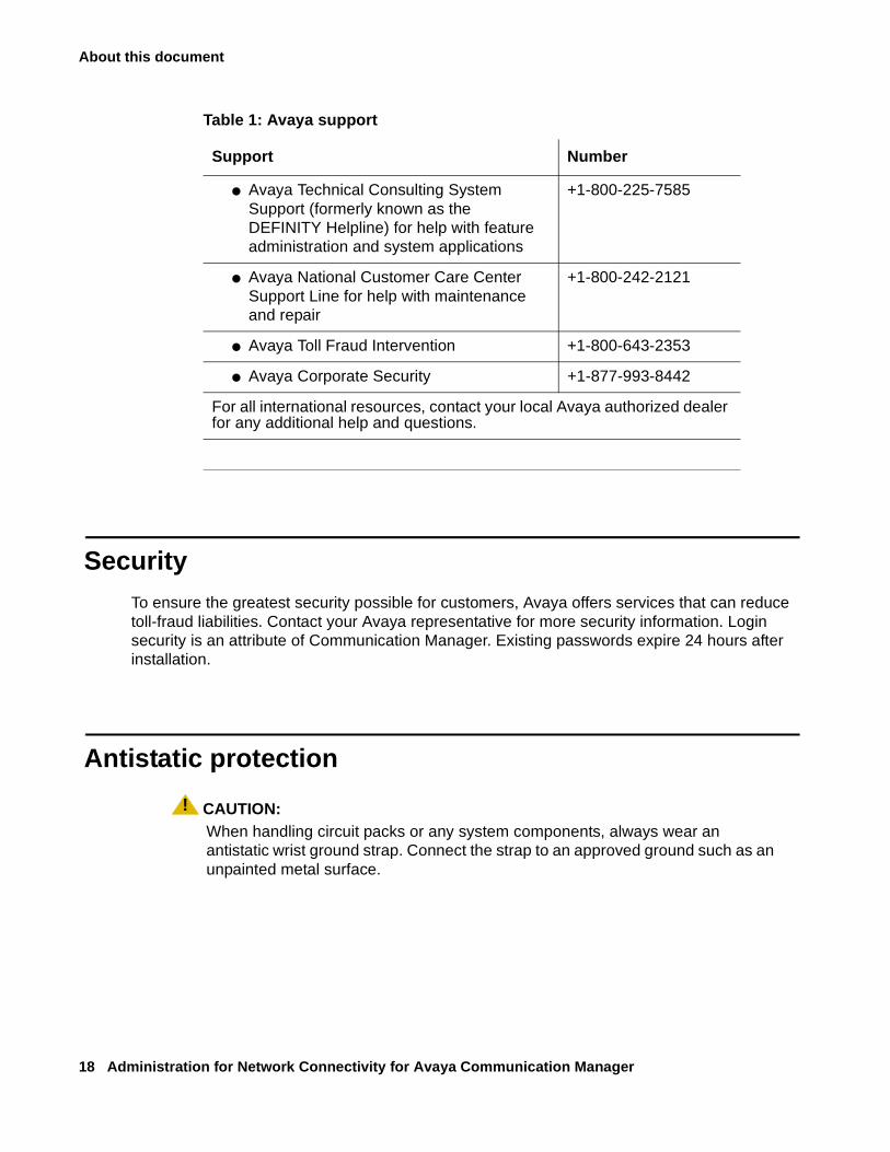
If you do not have Web access, use the phone numbers in Table 1: Avaya support on page 18.
Note:Note: You may need to purchase an extended service agreement to use some of these
resources. See your Avaya representative for more information.
About this document
18 Administration for Network Connectivity for Avaya Communication Manager
SecurityTo ensure the greatest security possible for customers, Avaya offers services that can reduce toll-fraud liabilities. Contact your Avaya representative for more security information. Login security is an attribute of Communication Manager. Existing passwords expire 24 hours after installation.
Antistatic protection
! CAUTION:CAUTION: When handling circuit packs or any system components, always wear an
antistatic wrist ground strap. Connect the strap to an approved ground such as an unpainted metal surface.
Table 1: Avaya support
Support Number
● Avaya Technical Consulting System Support (formerly known as the DEFINITY Helpline) for help with feature administration and system applications
+1-800-225-7585
● Avaya National Customer Care Center Support Line for help with maintenance and repair
+1-800-242-2121
● Avaya Toll Fraud Intervention +1-800-643-2353
● Avaya Corporate Security +1-877-993-8442
For all international resources, contact your local Avaya authorized dealer for any additional help and questions.
Remove/Install circuit packs
Issue 10 June 2005 19
Remove/Install circuit packs
! CAUTION:CAUTION: When the power is on:
● The control circuit packs cannot be removed or installed.
● The port circuit packs can be removed or installed.
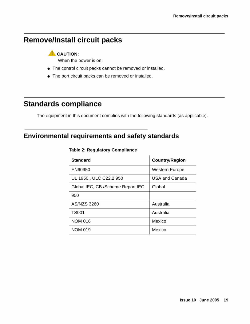
Standards complianceThe equipment in this document complies with the following standards (as applicable).
Environmental requirements and safety standards
Table 2: Regulatory Compliance
Standard Country/Region
EN60950 Western Europe
UL 1950., ULC C22.2.950 USA and Canada
Global IEC, CB /Scheme Report IEC Global
950
AS/NZS 3260 Australia
TS001 Australia
NOM 016 Mexico
NOM 019 Mexico
About this document
20 Administration for Network Connectivity for Avaya Communication Manager
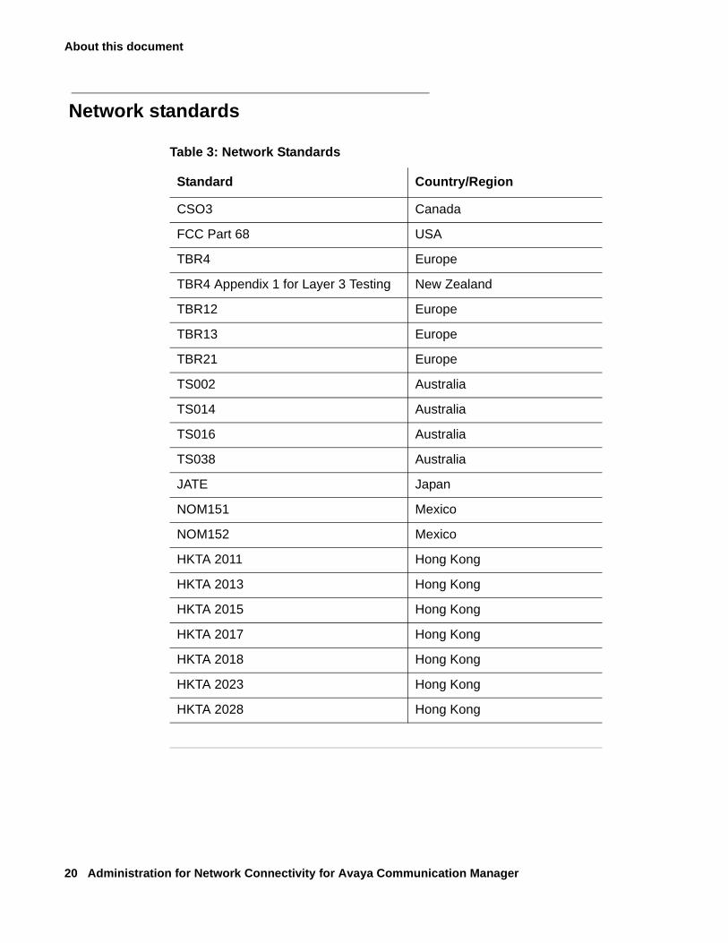
Network standards
Table 3: Network Standards
Standard Country/Region
CSO3 Canada
FCC Part 68 USA
TBR4 Europe
TBR4 Appendix 1 for Layer 3 Testing New Zealand
TBR12 Europe
TBR13 Europe
TBR21 Europe
TS002 Australia
TS014 Australia
TS016 Australia
TS038 Australia
JATE Japan
NOM151 Mexico
NOM152 Mexico
HKTA 2011 Hong Kong
HKTA 2013 Hong Kong
HKTA 2015 Hong Kong
HKTA 2017 Hong Kong
HKTA 2018 Hong Kong
HKTA 2023 Hong Kong
HKTA 2028 Hong Kong
Tell us what you think
Issue 10 June 2005 21
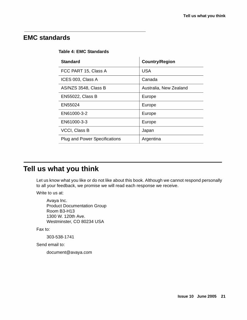
EMC standards
Tell us what you thinkLet us know what you like or do not like about this book. Although we cannot respond personally to all your feedback, we promise we will read each response we receive.
Write to us at:
Avaya Inc.Product Documentation GroupRoom B3-H131300 W. 120th Ave.Westminster, CO 80234 USA
Fax to:
303-538-1741
Send email to:
Table 4: EMC Standards
Standard Country/Region
FCC PART 15, Class A USA
ICES 003, Class A Canada
AS/NZS 3548, Class B Australia, New Zealand
EN55022, Class B Europe
EN55024 Europe
EN61000-3-2 Europe
EN61000-3-3 Europe
VCCI, Class B Japan
Plug and Power Specifications Argentina

About this document
22 Administration for Network Connectivity for Avaya Communication Manager
Issue 10 June 2005 23
Chapter 1: Networking overview
This chapter provides background information to help you understand and use the information in this book. Telephony delivered over digital networks capitalizes on the flexibility of technology itself, and can be implemented in a variety of ways. Users might find that they need to reference only a portion of the information in this book; others might need most of its information before understanding how to tailor a telephony network to suit their needs.
What is a network
An Avaya Communication Manager network can contain multiple interconnected media servers and all of the equipment, including data networking devices, under those media servers’ control. Such equipment may be geographically dispersed among a variety of sites, and the equipment at each site may be segregated into distinct logical groupings, referred to as network regions. A single media server system is comprised of one or more network regions. Each network region is a logical grouping of endpoints, including stations, trunks, and media gateways. In cases where one media server is insufficient for controlling all of the equipment, multiple systems can be networked together. So, a network region is a component of a site, which is a component of a system, which is a component of a network.
About “network” terminologyFor the purposes of this book and to clarify what we mean by the word, consider these uses of the word “network”:
● Businesses often have a “customer network,” meaning a Local Area Network (LAN) or a Wide Area Network (WAN), over which they distribute E-mail, data files, run applications, access the Internet, and send and receive fax and modem calls.
We use non-dedicated to describe this type of network and the traffic that it bears. This means that the network is a heterogeneous mix of data types.
● When a non-dedicated network carries digitized voice signals along with other mixed-data types, we call this a converged network, because it is a confluence of voice and non-voice data.
Networking overview
24 Administration for Network Connectivity for Avaya Communication Manager
● Network segments that exclusively carry telephony traffic are dedicated, since they carry only telephony-related information.
The section What’s in a digital phone call describes the types of data that are exchanged through dedicated networks.
● When a digital network carries telephony and non-telephony data in a packet-switched (TCP/IP), instead of a circuit-switched (TDM) environment, we call this an IP network.
What’s in a digital phone callA digital phone call consists of voice (bearer) data and call-signaling messages. Some transmission protocols require sending signaling data over a separate network, virtual path, or “channel,” from the voice data. The following list describes the data that are transmitted between switches during a phone call:
● Voice (bearer) data — digitized voice signals
● Call-signaling data — control messages
- Set up the call connection
- Maintain the connection during the call
- Tear down the connection when the call is finished
● Distributed Communications System (DCS) signaling data — an Avaya DEFINITY® Server proprietary signaling protocol.
Distributed Communications System (DCS) allows you to configure 2 or more switches as if they were a single, large switch. DCS provides attendant and voice-terminal features between these switch locations. DCS simplifies dialing procedures and allows transparent use of some of the Communication Manager features. (Feature transparency means that features are available to all users on DCS regardless of the switch location.)
Note:Note: DCS is different from call-signaling data. See Distributed Communications
System on page 207 for more information.
About network regions
Issue 10 June 2005 25
About network regions
A network region is a group of IP endpoints that share common characteristics and resources. Every IP endpoint on an Avaya Communication Manager system belongs to a network region. By default all IP endpoints are in network region 1, and if left as such they would all share the same characteristics defined by network region 1, and use the same resources. But in many cases this is not sufficient, and multiple network regions should be configured.
The most common of these cases are:
● One group of endpoints requires a different codec set than another group.
This could be based on requirements related to bandwidth or encryption.
● Calls between separate groups of endpoints require a different codec set than calls within a single group of endpoints, again based on requirements related to bandwidth or encryption.
● Specific C-LAN or MedPro or other resources must be accessible to only a specific group of endpoints.
● One group of endpoints requires a different UDP port range or QoS parameters than another group.
● One group of endpoints reports to a different VoIP Monitoring Manager server than another group.
Somewhat related to network regions is the concept of locations. The location parameter is used to identify distinct geographic locations, primarily for call routing purposes. In other words, the location parameter is used primarily to insure that calls access the proper trunks, based on the origin and destination of each call.
Establishing inter-switch trunk connectionsAvaya equipment is configured in different ways for various reasons. Connected switches enable people within an enterprise to communicate easily with one another, regardless of their physical location or the particular communications server they use. Inter-switch connections also provide shared communications resources such as messaging and Call Center services.
Networking overview
26 Administration for Network Connectivity for Avaya Communication Manager
Switches communicate with each other over trunk connections. There many types of trunks that provide different sets of services. Commonly-used trunk types are:
● Central Office (CO) trunks that provide connections to the public telephone network through a central office.
● H.323 trunks that transmit voice and fax data over the Internet to other systems with H.323 trunk capability.
H.323 trunks that support DCS+ and QSIG signalling.
● Tie trunks that provide connections between switches in a private network.
These and other common trunk types are described in the Administrator Guide for Avaya Communication Manager, 03-300509.
Interconnecting port networks
Multi-Connect systems with more than four port networks (PNs) may use a center stage switch (CSS) to interconnect the PNs. It is now possible to separate the CSS geographically in two types of configurations.
For systems with more than 16 PNs, requiring more than a single switch node carrier (SNC), the first switch node (1A) is at location 1 and the second switch node (2A) is at location 2. For duplicated systems, the duplicate switch nodes are similarly separated. These duplicate switch nodes (1A to 2A) and (1B to 2B) are linked together by fiber connections between locations.
In the second configuration type, the duplicated switch nodes are separated. The switch nodes 1A and 2A are at location one, and the switch nodes 1B and 2B are at location 2. At each location the switch nodes are linked together by fiber connections.
For more information, see http://support.avaya.com.
Networking branch offices
For Avaya Communication Manager environments, The MultiVOIP™ voice over IP gateways (Multi-Tech Systems, Inc.) provide distributed networking capabilities to small branch offices of large corporations. MultiVOIP extends the call features of a centralized Avaya Media Server and provides local office survivability to branch offices of up to 15 users using analog or IP phones.
For more information, see: http://www.multitech.com/partners/avaya/Avaya%20DevConnDatasheet.pdf.
Establishing inter-switch trunk connections
Issue 10 June 2005 27
Control Networks
Control networks are the networks over which the servers, such as the S8700-series or S8500 Media Servers, communicate with the IPSI boards in the Port Networks.
With Communication Manager 3.0, Avaya extends “Control Network on Customer LAN” functionality to simplify network configuration by allowing combining fiber-connected and IP-connected port networks in a single configuration, essentially blurring the line between IP Connect and MultiConnect offers. With combined port network functionality, enterprises can attach IP-connected, ATM-connected, or center-stage-connected Port Networks to their S8700, S8710, or S8500 media servers.
To support combined port networks, Avaya has enhanced the flexibility of Control Networks for Port Network attachment. To private Control Networks A and B, Avaya allows the “Customer LAN” Ethernet interface to be used as a third, public control network, Control Network C.
Control Network C is a new feature introduced in Avaya Communication Manager 3.0. It allows control connectivity to be passed through what has been known as the customer interface. This functionality is introduced to simplify the network design for enterprises with local private control networks (CNA and CNB), who wish to use their corporate (public) network to support remote IPSI-controlled Port Networks.
Control Network C functionality is useful in situations where an enterprise is adding distributed Port Networks at remote sites connected to a centralized S8700-series or S8500-series server. Using Control Network C allows the enterprise to maintain the security and reliability of existing Port Networks connected to Control Networks A and B, while allowing new Port Networks to connect to the media server without extending the control networks to remote sites or requiring static routes on the S8700-series or S8500-series media servers.
Enabling spanning tree protocol (STP)
Spanning Tree Protocol (STP) is a loop avoidance protocol. If you don't have loops in your network, you don't need STP. The "safe" option is to always leave STP enabled. Failure to do so on a network with a loop (or a network where someone inadvertently plugs the wrong cable into the wrong ports) will lead to a complete cessation of all traffic.
STP is slow, however. It is slow to converge after a network failure, and slow to allow a new port into the network (~50 sec by default). In early generations of phones, this delay caused phone DHCP requests to time out, and the phones didn't recover gracefully, so there was a recommendation to use "port fast" (Cisco) or "fast start" (some Cajuns). Because Cajun P330s didn't support those features, the recommendation was modified to disable STP on phone ports on those switches. This soon came to be understood as disable STP everywhere, which was not necessary.
Since that time, Rapid Spanning Tree emerged, which converges faster than the earlier STP, and enables new ports much faster (sub-second) than the older protocol. Rapid Spanning Tree works with all Avaya equipment, and can be recommended.
Networking overview
28 Administration for Network Connectivity for Avaya Communication Manager
Inter-Gateway Alternate Routing (IGAR)
For single-server systems that use the IP-WAN to connect bearer between port networks or media gateways, Inter-Gateway Alternate Routing (IGAR) provides a means of alternately using the PSTN when the IP-WAN is incapable of carrying the bearer connection. IGAR may request that bearer connections be provided by the PSTN under the following conditions:
● The number of calls allocated or bandwidth allocated via Call Admission Control- Bandwidth Limits (CAC-BL) has been reached.
● VoIP RTP resource exhaustion in a MG/PN is encountered.
● A codec set is not specified between a network region pair.
● Forced redirection between a pair of network regions is configured.
IGAR takes advantage of existing public and private-network facilities provisioned in a network region. Most trunks in use today can be used for IGAR. Examples of the better trunk facilities for use by IGAR would be:
● Public or Private ISDN PRI/BRI
● R2MFC
IGAR provides enhanced Quality of Service (QoS) to large distributed single-server configurations.
Network quality managementA successful Voice over Internet Protocol (VoIP) implementation involves quality of service (QoS) management that is impacted by three major factors:
● Delay: Significant end-to-end delay may result in echo and talker overlap.
Echo becomes a problem when one-way network delay is more than 50 milliseconds. VoIP systems must implement some means of echo cancellation. If the round-trip delay is greater than 250 milliseconds (ms), talker overlap, or one caller “stepping on” the other talker's speech, is likely. For adequate quality of service, we recommend that the total network delay should be less than 50ms. See Packet delay and loss on page 143 for more information.
● Packet Loss: Under peak network loads and periods of congestion, voice data packets may be dropped.
Because voice transmission is highly time-sensitive, normal TCP-based re-transmission schemes are not suitable. Methods to compensate for packet loss include interpolation of speech by re-playing the last packet and sending of redundant information. The maximum packet loss between network endpoints should not exceed 0.2%. See Packet delay and loss on page 143 for more information.
Network quality management
Issue 10 June 2005 29
● Jitter (Delay Variability): Jitter results when data packets arrive at their destination at irregular intervals as a result of variable transmission delay over the network.
To remove jitter, the VoIP engine must collect and hold data packets in a buffer long enough for the slowest packet to arrive and be played in sequence. A jitter buffer, however, adds to delay. Jitter of less than 20ms. between endpoints is normally required. See Packet delay and loss on page 143 for more information.
Sending and receiving IP packets
Prior to transmission over an IP network a voice signal is converted from analog to digital form, usually at a rate of 8,000 samples per second. Then the digital bit stream is sampled or compressed through A-law, mu-law, or bit-rate companding methods, and finally grouped into packets for transmission. To use network bandwidth efficiently, a silence suppression algorithm that detects when there are periods of silence does not transmit packets in those brief spaces.
When the packets are received, several processes occur:
● Packets are put in proper order and converted back to an analog voice signal
● Jitter is removed
● The effects of packet loss are mitigated through various algorithms
● Silence suppression is eliminated by adding artificial samples, often in the form of comfort noise, a random, low-level signal that gives the impression that the connection is still alive during periods of silence.
● Echo-cancellation eliminates acoustic or electronic network reflection effects.
About VoIP-transmission hardware
For more detailed descriptions and administration procedures for the equipment listed below, see About VoIP hardware on page 55.
TN799 (C-LAN)
The C-LAN circuit pack provides the data link interface between the switch processor and the transmission facilities. C-LAN prepares the signaling information for TCP/IP transmission over one of two pathways:
● Ethernet connection — the signaling data is sent out on a 10/100Base-T network, which is connected directly to the C-LAN Ethernet port.
● PPP connection — C-LAN inserts the signaling data on the TDM bus for subsequent inclusion (through the switching fabric) in the same DS1 bit stream as the voice transmissions.
Networking overview
30 Administration for Network Connectivity for Avaya Communication Manager
TN802B (IP-Interface)
The IP Interface circuit pack (TN802B) enables two switches to transmit voice between them over an IP network. The TN802B normally operates in the MedPro mode, which supports H.323-compliant endpoints or applications.
TN2302AP (IP Media Processor)
The TN2302AP transmits voice and fax data (non-DCS signaling) over IP connections. It also improves quality of service through its dynamic jitter buffers, echo cancellation, and silence suppression, making it suitable for H.323 multimedia applications and other H.323-compliant endpoints. This circuit pack also performs DTMF detection and conferencing.
The TN2302AP IP Media Processor can work in the same server with the TN802B IP Interface Assembly. The software chooses media processing resources for an IP endpoint from the TN2302AP over the TN802B when both types of media processing are available on the system.
TN2602AP IP Media Resource 320
The TN2602AP IP Media Resource 320 provides high-capacity voice over Internet protocol (VoIP) audio access to the switch for local stations and outside trunks. The IP Media Resource 320 provides audio processing for the following types of calls:
● TDM-to-IP and IP-to-TDM
● IP-to-IP
The TN2602AP IP Media Resource 320 circuit pack has two capacity options, both of which are determined by the license file installed on Communication Manager:
● 320 voice channels, considered the standard IP Media Resource 320
● 80 voice channels, considered the low-density IP Media Resource 320
Up to two TN2602AP circuit packs may be installed in a single port network for load balancing. The TN2602AP circuit pack is also compatible with and can share load balancing with the TN2302 IP Media Processor circuit pack. Actual capacity may be affected by a variety of factors, including the codec used for a call and fax support. Unlike the TN2302AP, the TN2602AP capacity is not affected when also applying media encryption or fax relay. The codecs supported include:
● G.711
● G.726
● G.729
Note:Note: The TN2602AP IP Media Resource 320 is not supported in CMC1 and G600
Media Gateways.
Network quality management
Issue 10 June 2005 31
TN2312 (IP Server Interface)
The TN2312 IP Server Interface circuit pack (IPSI) provides an interface between the Avaya Media Servers and up to 5 port networks. The IPSI connects to the S8700 Media Server through Ethernet.
G700/G350 Media Gateway VoIP processors
The VoIP processor on the G700 Media Gateway motherboard performs IP/UDP/RTP processing, echo cancellation, G.711 A-/µ-law, G.729 and G723.1 encode/decode, FAX relay, silence suppression, jitter buffer management, and packet-loss concealment. The VoIP Engine supports 64 channels. If more than 64 channels are needed, an MM760 VoIP Media Module is required.
The G700 Media Gateway supports the G.711 codec for up to 64 concurrent calls, the G.729/G.723 codec for up to 32 concurrent calls, and FAX/Modem Relays up to 16. The G350 Media Gateway supports 32 G.711, 16 G.729/G.723, and 8 FAX/Modem Relays.
MM760 VoIP Media Module
The MM760 VoIP Media Module is a duplicate of the VoIP processor in the G700 motherboard. The capacity of the MM760 is 64 G.711 TDM/IP simultaneous calls, or 32 compression codec, G.729 or G.723, TDM/IP simultaneous calls. These call types can be mixed on the same resource. In other words, the simultaneous call capacity of the resource is 64 G.711 Equivalent Calls.
Networking overview
32 Administration for Network Connectivity for Avaya Communication Manager
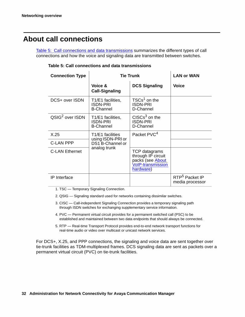
About call connectionsTable 5: Call connections and data transmissions summarizes the different types of call connections and how the voice and signaling data are transmitted between switches.
For DCS+, X.25, and PPP connections, the signaling and voice data are sent together over tie-trunk facilities as TDM-multiplexed frames. DCS signaling data are sent as packets over a permanent virtual circuit (PVC) on tie-trunk facilities.
Table 5: Call connections and data transmissions
Connection Type Tie Trunk LAN or WAN
Voice & Call-Signaling
DCS Signaling Voice
DCS+ over ISDN T1/E1 facilities, ISDN-PRI B-Channel
TSCs1 on the ISDN-PRI D-Channel
1. TSC — Temporary Signaling Connection.
QSIG2 over ISDN
2. QSIG — Signaling standard used for networks containing dissimilar switches.
T1/E1 facilities, ISDN-PRI B-Channel
CISCs3 on the ISDN-PRI D-Channel
3. CISC — Call-independent Signaling Connection provides a temporary signaling path through ISDN switches for exchanging supplementary service information.
X.25 T1/E1 facilities using ISDN-PRI or DS1 B-Channel or analog trunk
Packet PVC4
4. PVC — Permanent virtual circuit provides for a permanent switched call (PSC) to be established and maintained between two data endpoints that should always be connected.
C-LAN PPP
C-LAN Ethernet TCP datagrams through IP circuit packs (see About VoIP-transmission hardware)
IP Interface RTP5 Packet IP media processor
5. RTP — Real-time Transport Protocol provides end-to-end network transport functions for real-time audio or video over multicast or unicast network services.
About call connections
Issue 10 June 2005 33
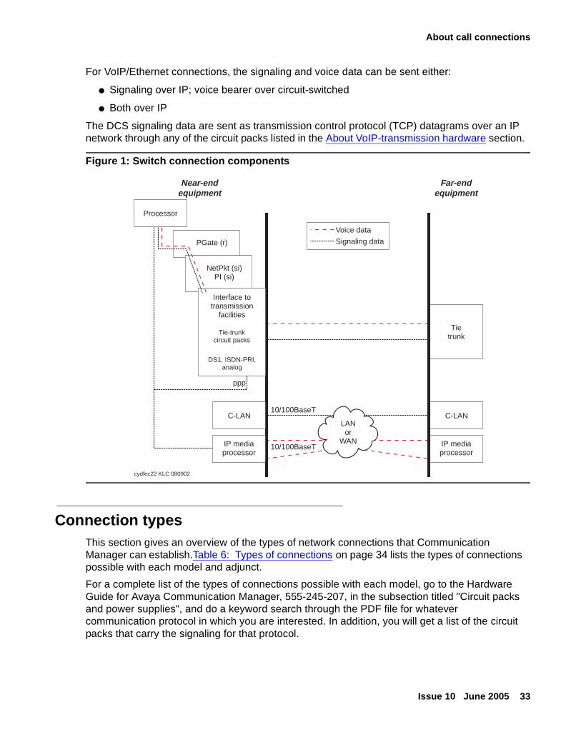
For VoIP/Ethernet connections, the signaling and voice data can be sent either:
● Signaling over IP; voice bearer over circuit-switched
● Both over IP
The DCS signaling data are sent as transmission control protocol (TCP) datagrams over an IP network through any of the circuit packs listed in the About VoIP-transmission hardware section.
Figure 1: Switch connection components
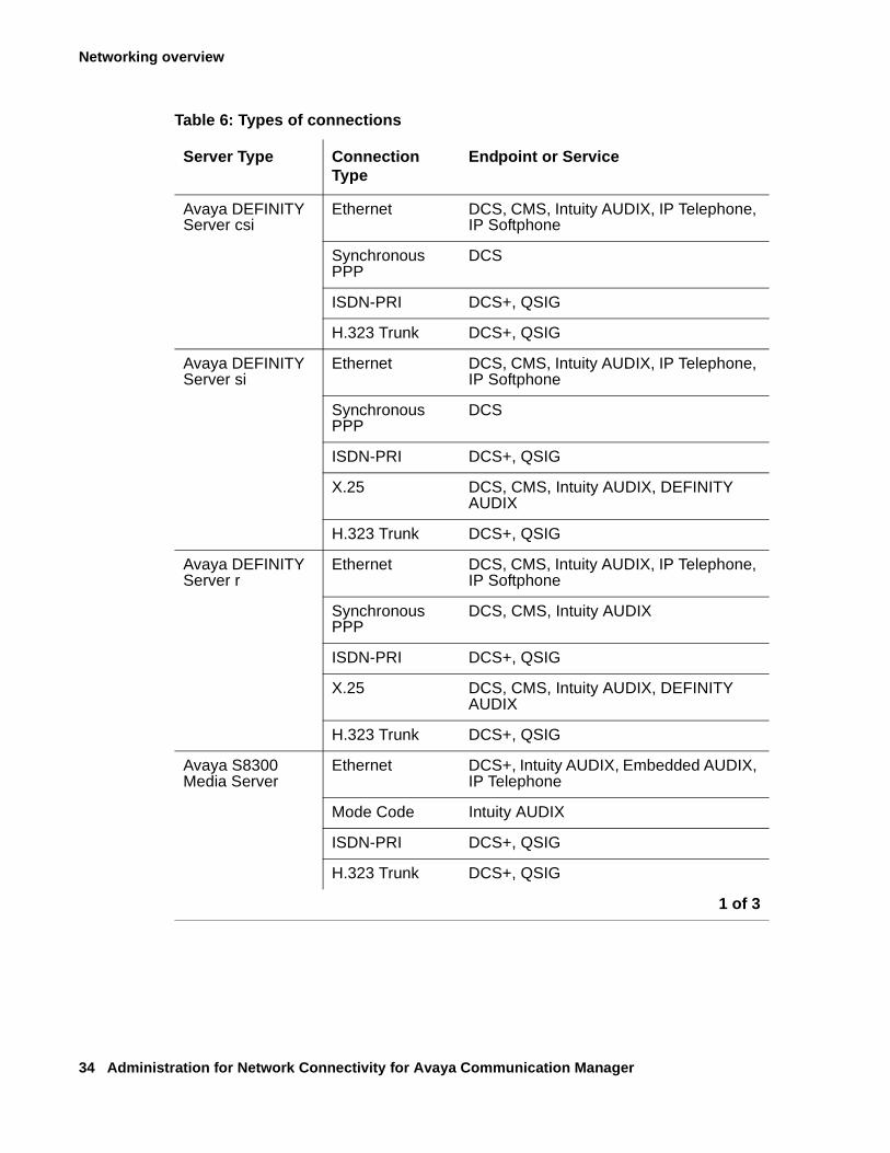
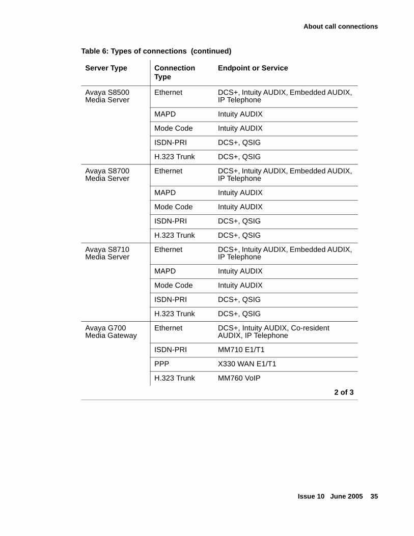
Connection typesThis section gives an overview of the types of network connections that Communication Manager can establish.Table 6: Types of connections on page 34 lists the types of connections possible with each model and adjunct.
For a complete list of the types of connections possible with each model, go to the Hardware Guide for Avaya Communication Manager, 555-245-207, in the subsection titled "Circuit packs and power supplies", and do a keyword search through the PDF file for whatever communication protocol in which you are interested. In addition, you will get a list of the circuit packs that carry the signaling for that protocol.
C-LAN
IP mediaprocessor
Tietrunk
Far-endequipment
cydfec22 KLC 080902
C-LAN
IP mediaprocessor
PGate (r)
NetPkt (si)PI (si)
Interface totransmission
facilities
Tie-trunkcircuit packs
DS1, ISDN-PRI,analog
ppp
Processor
Near-endequipment
10/100BaseT
10/100BaseT
LANor
WAN
Voice data
Signaling data
Networking overview
34 Administration for Network Connectivity for Avaya Communication Manager
Table 6: Types of connections
Server Type Connection Type
Endpoint or Service
Avaya DEFINITY Server csi
Ethernet DCS, CMS, Intuity AUDIX, IP Telephone, IP Softphone
Synchronous PPP
DCS
ISDN-PRI DCS+, QSIG
H.323 Trunk DCS+, QSIG
Avaya DEFINITY Server si
Ethernet DCS, CMS, Intuity AUDIX, IP Telephone, IP Softphone
Synchronous PPP
DCS
ISDN-PRI DCS+, QSIG
X.25 DCS, CMS, Intuity AUDIX, DEFINITY AUDIX
H.323 Trunk DCS+, QSIG
Avaya DEFINITY Server r
Ethernet DCS, CMS, Intuity AUDIX, IP Telephone, IP Softphone
Synchronous PPP
DCS, CMS, Intuity AUDIX
ISDN-PRI DCS+, QSIG
X.25 DCS, CMS, Intuity AUDIX, DEFINITY AUDIX
H.323 Trunk DCS+, QSIG
Avaya S8300 Media Server
Ethernet DCS+, Intuity AUDIX, Embedded AUDIX, IP Telephone
Mode Code Intuity AUDIX
ISDN-PRI DCS+, QSIG
H.323 Trunk DCS+, QSIG
1 of 3
About call connections
Issue 10 June 2005 35
Avaya S8500 Media Server
Ethernet DCS+, Intuity AUDIX, Embedded AUDIX, IP Telephone
MAPD Intuity AUDIX
Mode Code Intuity AUDIX
ISDN-PRI DCS+, QSIG
H.323 Trunk DCS+, QSIG
Avaya S8700 Media Server
Ethernet DCS+, Intuity AUDIX, Embedded AUDIX, IP Telephone
MAPD Intuity AUDIX
Mode Code Intuity AUDIX
ISDN-PRI DCS+, QSIG
H.323 Trunk DCS+, QSIG
Avaya S8710 Media Server
Ethernet DCS+, Intuity AUDIX, Embedded AUDIX, IP Telephone
MAPD Intuity AUDIX
Mode Code Intuity AUDIX
ISDN-PRI DCS+, QSIG
H.323 Trunk DCS+, QSIG
Avaya G700 Media Gateway
Ethernet DCS+, Intuity AUDIX, Co-resident AUDIX, IP Telephone
ISDN-PRI MM710 E1/T1
PPP X330 WAN E1/T1
H.323 Trunk MM760 VoIP
Table 6: Types of connections (continued)
Server Type Connection Type
Endpoint or Service
2 of 3
Networking overview
36 Administration for Network Connectivity for Avaya Communication Manager
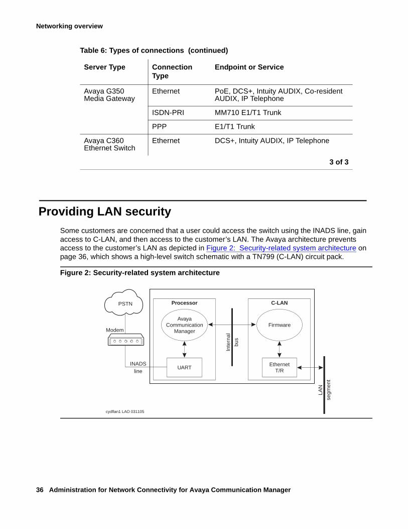
Providing LAN securitySome customers are concerned that a user could access the switch using the INADS line, gain access to C-LAN, and then access to the customer’s LAN. The Avaya architecture prevents access to the customer’s LAN as depicted in Figure 2: Security-related system architecture on page 36, which shows a high-level switch schematic with a TN799 (C-LAN) circuit pack.
Figure 2: Security-related system architecture
Avaya G350 Media Gateway
Ethernet PoE, DCS+, Intuity AUDIX, Co-resident AUDIX, IP Telephone
ISDN-PRI MM710 E1/T1 Trunk
PPP E1/T1 Trunk
Avaya C360 Ethernet Switch
Ethernet DCS+, Intuity AUDIX, IP Telephone
Table 6: Types of connections (continued)
Server Type Connection Type
Endpoint or Service
3 of 3
AvayaCommunication
ManagerFirmware
Inte
rnal
bus
LAN
segm
ent
UARTINADS
line
Modem
EthernetT/R
Processor C-LAN
cydflan1 LAO 031105
PSTN
Connection Preservation
Issue 10 June 2005 37
Logins through the INADS line terminate in software; software communicates with firmware over an internal bus through a limited message set. There are two main reasons why a user cannot access a customer’s LAN through the INADS line:
● A user logging into software cannot obtain direct access to the C-LAN firmware.
The user can only enter SAT commands that request C-LAN information or to configure C-LAN connections.
● The C-LAN application TFTP is currently disabled and cannot be enabled by Avaya Communication Manager.
TELNET only interconnects C-LAN Ethernet clients to the system management application on the switch. FTP exists only as a server, is used only for firmware downloads, and it cannot connect to the client network.
For more information about LAN security, see
● Security Topics for the Avaya S8700 Media Server Configurations
● Security for the Avaya 8700 Media Server
Connection Preservation
The Connection Preserving Migration (CPM) feature preserves existing bearer (voice) connections while an H.248 media gateway migrates from one Communication Manager server to another because of network or server failure. However, users on connection-preserved calls cannot use such features as Hold, Conference, or Transfer, etc. In addition to preserving the audio voice paths, CPM extends the time period for recovery operations and functions during Avaya’s complementary recovery strategies:
● H.248 and H.323 Link Recovery
● Auto fallback to primary
● Local Survivable Processor (LSP)
● Enterprise Survivable Servers (ESS)
● Standard Local Survivability (SLS) on the G250 Media Gateway only
Networking overview
38 Administration for Network Connectivity for Avaya Communication Manager
H.248 and H.323 Link Recovery
H.248 Link Recovery is an automated way in which the media gateway reacquires the H.248 link when it is lost from either a primary call controller or an LSP. The H.248 link between a media server running Avaya Communication Manager and a media gateway, and the H.323 link between a media gateway and an H.323-compliant IP endpoint, provide the signaling protocol for:
● Call setup
● Call control (user actions such as Hold, Conference, or Transfer) while the call is in progress
● Call tear-down
If the link goes down, Link Recovery preserves any existing calls and attempts to re-establish the original link. If the gateway/endpoint cannot reconnect to the original server/gateway, then Link Recovery automatically attempts to connect with alternate TN799DP (C-LAN) circuit packs within the original server’s configuration or to a Local Survivable Processor (LSP).
Auto fallback to primary
The intent of the auto fallback to primary controller feature is to return a fragmented network, in which a number of H.248 Media Gateways are being serviced by one or more LSPs (Local Survivable Processors), to the primary media server in an automatic fashion. This feature is targeted towards all H.248 media gateways. By migrating the media gateways back to the primary automatically, the distributed telephony switch network can be made whole sooner without human intervention, which is required today.
Local Survivable Processor (LSP)
The S8300 Media Server can act as a survivable call-processing server for remote or branch customer locations. As an LSP, the S8300 Media Server carries a complete set of Communication Manager features, and its license file allows it to function as a survivable call processor. If the link between the remote G700 Media Gateways and the primary controller is broken, those telephones and G700s that are designated to receive backup service from the LSP will register with the LSP. The LSP will provide control to those registered devices in a license error mode (see Hardware Guide for Avaya Communication Manager, 555-245-207).
Note:Note: The LSP, in contrast to the SLS feature on the G250 Media Gateway, is also
known as ELS, or Enhanced Local Survivability.
Connection Preservation
Issue 10 June 2005 39
Enterprise Survivable Servers (ESS)
The Enterprise Survivable Servers (ESS) feature provides survivability to Port Networks by allowing backup servers to be placed in various locations in the customer’s network. The backup servers supply service to Port Networks in the case where the S8500-series media server, or the S8700-series media server pair fails, or connectivity to the main Communication Manager server(s) is lost. ESS servers can be either S8500-series or S8700-series media servers, and offer full Avaya Communication Manager functionality when in survivable mode, provided sufficient connectivity exists to other Avaya components (for example, endpoints, gateways, and messaging servers).
Standard Local Survivability (SLS)
Standard Local Survivability (SLS) consists of a module built into the G250 Media Gateway to provide partial backup media gateway controller functionality, in the event that the connection with the primary controller is lost. This feature allows a G250, with no S8300 installed locally, to provide a degree of Communication Manager functionality when no link is available to an external controller. It is configured on a system-wide basis, or, alternatively, it can be configured on an individual G250 using the CLI.
Note:Note: Compare SLS with the LSP functionality, known as Enhanced Local Survivability
(ELS).

Networking overview
40 Administration for Network Connectivity for Avaya Communication Manager
Issue 10 June 2005 41
Chapter 2: Control Networks for S8700-Series and S8500 Media Servers
Control networks are the networks over which the servers, such as the S8700-series or S8500 Media Servers, communicate with the IPSI boards in the port networks. This chapter provides information on how to set up control networks. Topics covered include:
● Control network C
● Combining fiber-connected and IP-connected port networks in a single configuration
● Network connectivity between S8700-series servers and port networks
● Control network on customer LAN (CNOCL)
Control network CControl Network C is a new feature introduced in Avaya Communication Manager 3.0. It allows control connectivity to be passed through what has been known as the customer interface. This functionality is introduced to simplify the network design for enterprises with local private control networks (CNA and CNB); who wish to use their corporate (public) network to support remote IPSI-controlled Port Networks.
Control Network C functionality is useful in situations where an enterprise is adding distributed Port Networks at remote sites connected to a centralized S8700-series or S8500-series server. Using Control Network C allows the enterprise to maintain the security and reliability of existing Port Networks connected to Control Networks A and B, while allowing new Port Networks to connect to the media server without extending the control networks to remote sites or requiring static routes on the S8700-series or S8500-series media servers.
! Important:Important: Control Network C is a server enhancement. Control Network C could be used in
an all IP scenario, as well as a scenario in which fiber-connected and IP-connected port networks are connected in a single configuration.
From the S8700/S8710 or S8500 Linux bash shell, use the commands:
● cnc on – to enable Control Network C
● cnc off – to disable Control Network C
● cnc status – to report whether or not cnc functionality is enabled
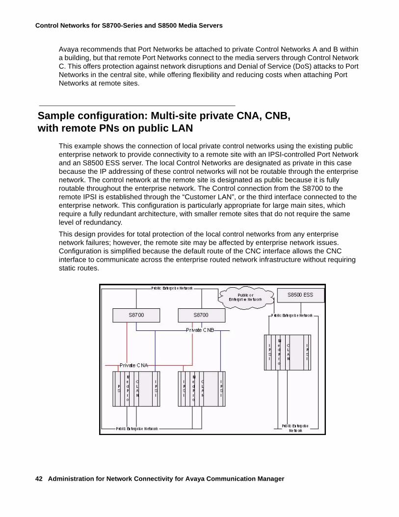
Control Networks for S8700-Series and S8500 Media Servers
42 Administration for Network Connectivity for Avaya Communication Manager
Avaya recommends that Port Networks be attached to private Control Networks A and B within a building, but that remote Port Networks connect to the media servers through Control Network C. This offers protection against network disruptions and Denial of Service (DoS) attacks to Port Networks in the central site, while offering flexibility and reducing costs when attaching Port Networks at remote sites.
Sample configuration: Multi-site private CNA, CNB, with remote PNs on public LAN
This example shows the connection of local private control networks using the existing public enterprise network to provide connectivity to a remote site with an IPSI-controlled Port Network and an S8500 ESS server. The local Control Networks are designated as private in this case because the IP addressing of these control networks will not be routable through the enterprise network. The control network at the remote site is designated as public because it is fully routable throughout the enterprise network. The Control connection from the S8700 to the remote IPSI is established through the “Customer LAN”, or the third interface connected to the enterprise network. This configuration is particularly appropriate for large main sites, which require a fully redundant architecture, with smaller remote sites that do not require the same level of redundancy.
This design provides for total protection of the local control networks from any enterprise network failures; however, the remote site may be affected by enterprise network issues. Configuration is simplified because the default route of the CNC interface allows the CNC interface to communicate across the enterprise routed network infrastructure without requiring static routes.
Combining fiber-connected and IP-connected port networks in a single configuration
Issue 10 June 2005 43
Advantages: - The dedicated Control Network provides total isolation from outages in the enterprise network, so all local TDM communication at the main site can remain active during total enterprise network failure. There are no static routes to maintain.
Disadvantages: - The remote site can be affected by public enterprise network issues. The remote ESS server cannot control the Port Networks at the main site.
Combining fiber-connected and IP-connected portnetworks in a single configuration
With Communication Manager 3.0, Avaya extends “Control Network on Customer LAN” functionality to simplify network configuration by allowing combining fiber-connected and IP-connected port networks in a single configuration, essentially blurring the line between IP Connect and MultiConnect offers. With combined port network functionality, enterprises can attach IP-connected, ATM-connected, or center-stage-connected Port Networks to their S8700, S8710, or S8500 media servers.
To support combined port networks, Avaya has enhanced the flexibility of Control Networks for Port Network attachment. To private Control Networks A and B, Avaya allows the “Customer LAN” Ethernet interface to be used as a third, public control network, Control Network C.
Sample configurations
Network connectivity between S8700-series servers and port networks
The Avaya S8700 solution requires IP connectivity between S8700-series interfaces and Avaya media gateways. IP-Connected port networks use IPSI cards in the Port Networks to communicate with the Media Server. This connection will be referred to as the “Control Connection”. There are many network options to provide this connectivity, and it is at the enterprise’s discretion how this is best implemented in its environment.
If IP connectivity, including the control connection, between the server and Port Network is lost, the server will be unable to provide call control, resulting in an unstable system. Although the Avaya S8700-series media server interfaces provide for Denial of Service protection, they cannot affect the ability of the network to successfully forward packets during a virus or worm attack, or when the network becomes unstable due to network outages or administrative errors.
In hybrid environments (such as, IP and TDM endpoints and trunks), the incentive to minimize disruption of the IP control connection is increased. By maintaining the control connection when other network components have failed, TDM-connected endpoints will continue to function.
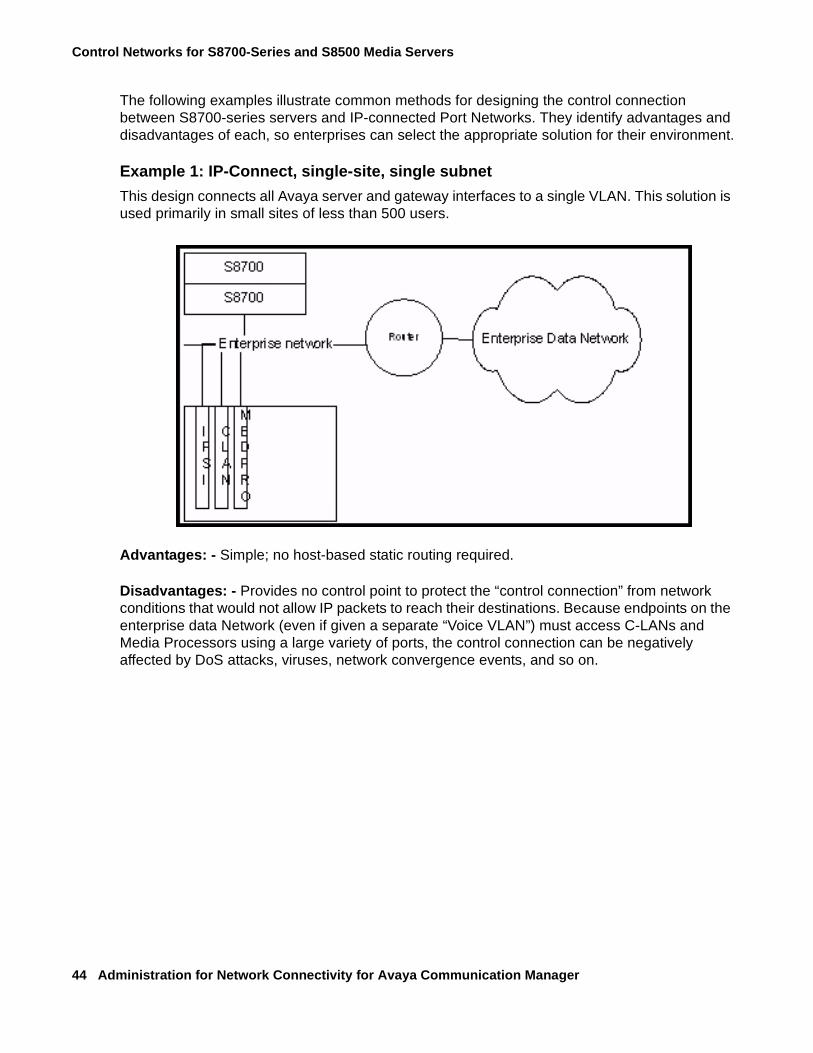
Control Networks for S8700-Series and S8500 Media Servers
44 Administration for Network Connectivity for Avaya Communication Manager
The following examples illustrate common methods for designing the control connection between S8700-series servers and IP-connected Port Networks. They identify advantages and disadvantages of each, so enterprises can select the appropriate solution for their environment.
Example 1: IP-Connect, single-site, single subnet
This design connects all Avaya server and gateway interfaces to a single VLAN. This solution is used primarily in small sites of less than 500 users.
Advantages: - Simple; no host-based static routing required.
Disadvantages: - Provides no control point to protect the “control connection” from network conditions that would not allow IP packets to reach their destinations. Because endpoints on the enterprise data Network (even if given a separate “Voice VLAN”) must access C-LANs and Media Processors using a large variety of ports, the control connection can be negatively affected by DoS attacks, viruses, network convergence events, and so on.
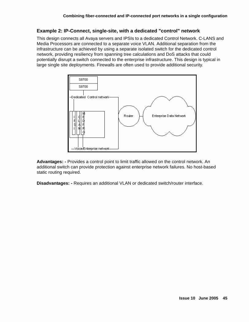
Combining fiber-connected and IP-connected port networks in a single configuration
Issue 10 June 2005 45
Example 2: IP-Connect, single-site, with a dedicated "control" network
This design connects all Avaya servers and IPSIs to a dedicated Control Network. C-LANS and Media Processors are connected to a separate voice VLAN. Additional separation from the infrastructure can be achieved by using a separate isolated switch for the dedicated control network, providing resiliency from spanning tree calculations and DoS attacks that could potentially disrupt a switch connected to the enterprise infrastructure. This design is typical in large single site deployments. Firewalls are often used to provide additional security.
Advantages: - Provides a control point to limit traffic allowed on the control network. An additional switch can provide protection against enterprise network failures. No host-based static routing required.
Disadvantages: - Requires an additional VLAN or dedicated switch/router interface.
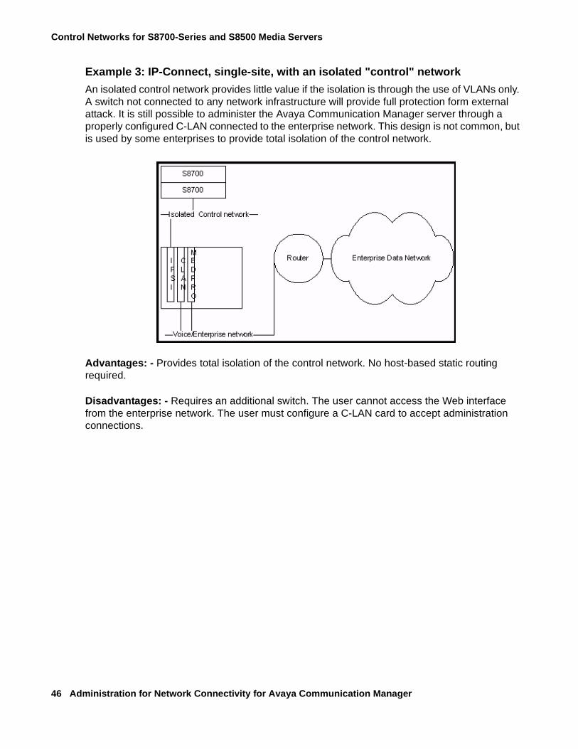
Control Networks for S8700-Series and S8500 Media Servers
46 Administration for Network Connectivity for Avaya Communication Manager
Example 3: IP-Connect, single-site, with an isolated "control" network
An isolated control network provides little value if the isolation is through the use of VLANs only. A switch not connected to any network infrastructure will provide full protection form external attack. It is still possible to administer the Avaya Communication Manager server through a properly configured C-LAN connected to the enterprise network. This design is not common, but is used by some enterprises to provide total isolation of the control network.
Advantages: - Provides total isolation of the control network. No host-based static routing required.
Disadvantages: - Requires an additional switch. The user cannot access the Web interface from the enterprise network. The user must configure a C-LAN card to accept administration connections.
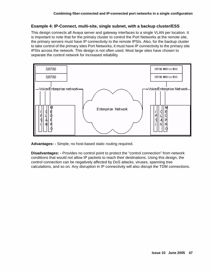
Combining fiber-connected and IP-connected port networks in a single configuration
Issue 10 June 2005 47
Example 4: IP-Connect, multi-site, single subnet, with a backup cluster/ESS
This design connects all Avaya server and gateway interfaces to a single VLAN per location. It is important to note that for the primary cluster to control the Port Networks at the remote site, the primary servers must have IP connectivity to the remote IPSIs. Also, for the backup cluster to take control of the primary sites Port Networks, it must have IP connectivity to the primary site IPSIs across the network. This design is not often used. Most large sites have chosen to separate the control network for increased reliability.
Advantages: - Simple; no host-based static routing required.
Disadvantages: - Provides no control point to protect the “control connection” from network conditions that would not allow IP packets to reach their destinations. Using this design, the control connection can be negatively affected by DoS attacks, viruses, spanning tree calculations, and so on. Any disruption in IP connectivity will also disrupt the TDM connections.
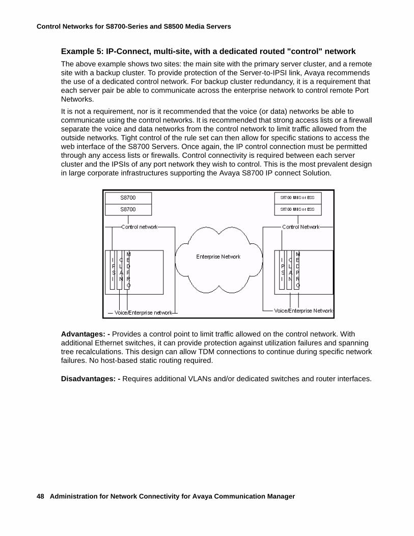
Control Networks for S8700-Series and S8500 Media Servers
48 Administration for Network Connectivity for Avaya Communication Manager
Example 5: IP-Connect, multi-site, with a dedicated routed "control" network
The above example shows two sites: the main site with the primary server cluster, and a remote site with a backup cluster. To provide protection of the Server-to-IPSI link, Avaya recommends the use of a dedicated control network. For backup cluster redundancy, it is a requirement that each server pair be able to communicate across the enterprise network to control remote Port Networks.
It is not a requirement, nor is it recommended that the voice (or data) networks be able to communicate using the control networks. It is recommended that strong access lists or a firewall separate the voice and data networks from the control network to limit traffic allowed from the outside networks. Tight control of the rule set can then allow for specific stations to access the web interface of the S8700 Servers. Once again, the IP control connection must be permitted through any access lists or firewalls. Control connectivity is required between each server cluster and the IPSIs of any port network they wish to control. This is the most prevalent design in large corporate infrastructures supporting the Avaya S8700 IP connect Solution.
Advantages: - Provides a control point to limit traffic allowed on the control network. With additional Ethernet switches, it can provide protection against utilization failures and spanning tree recalculations. This design can allow TDM connections to continue during specific network failures. No host-based static routing required.
Disadvantages: - Requires additional VLANs and/or dedicated switches and router interfaces.
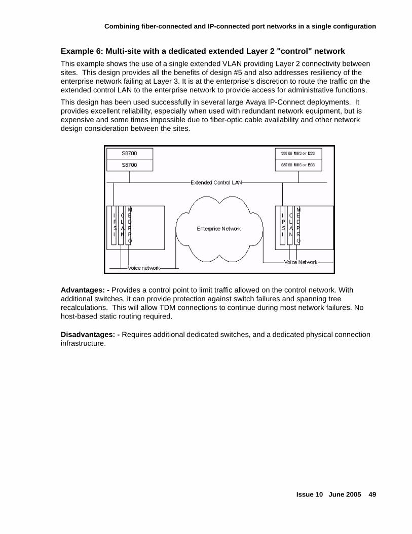
Combining fiber-connected and IP-connected port networks in a single configuration
Issue 10 June 2005 49
Example 6: Multi-site with a dedicated extended Layer 2 "control" network
This example shows the use of a single extended VLAN providing Layer 2 connectivity between sites. This design provides all the benefits of design #5 and also addresses resiliency of the enterprise network failing at Layer 3. It is at the enterprise’s discretion to route the traffic on the extended control LAN to the enterprise network to provide access for administrative functions.
This design has been used successfully in several large Avaya IP-Connect deployments. It provides excellent reliability, especially when used with redundant network equipment, but is expensive and some times impossible due to fiber-optic cable availability and other network design consideration between the sites.
Advantages: - Provides a control point to limit traffic allowed on the control network. With additional switches, it can provide protection against switch failures and spanning tree recalculations. This will allow TDM connections to continue during most network failures. No host-based static routing required.
Disadvantages: - Requires additional dedicated switches, and a dedicated physical connection infrastructure.
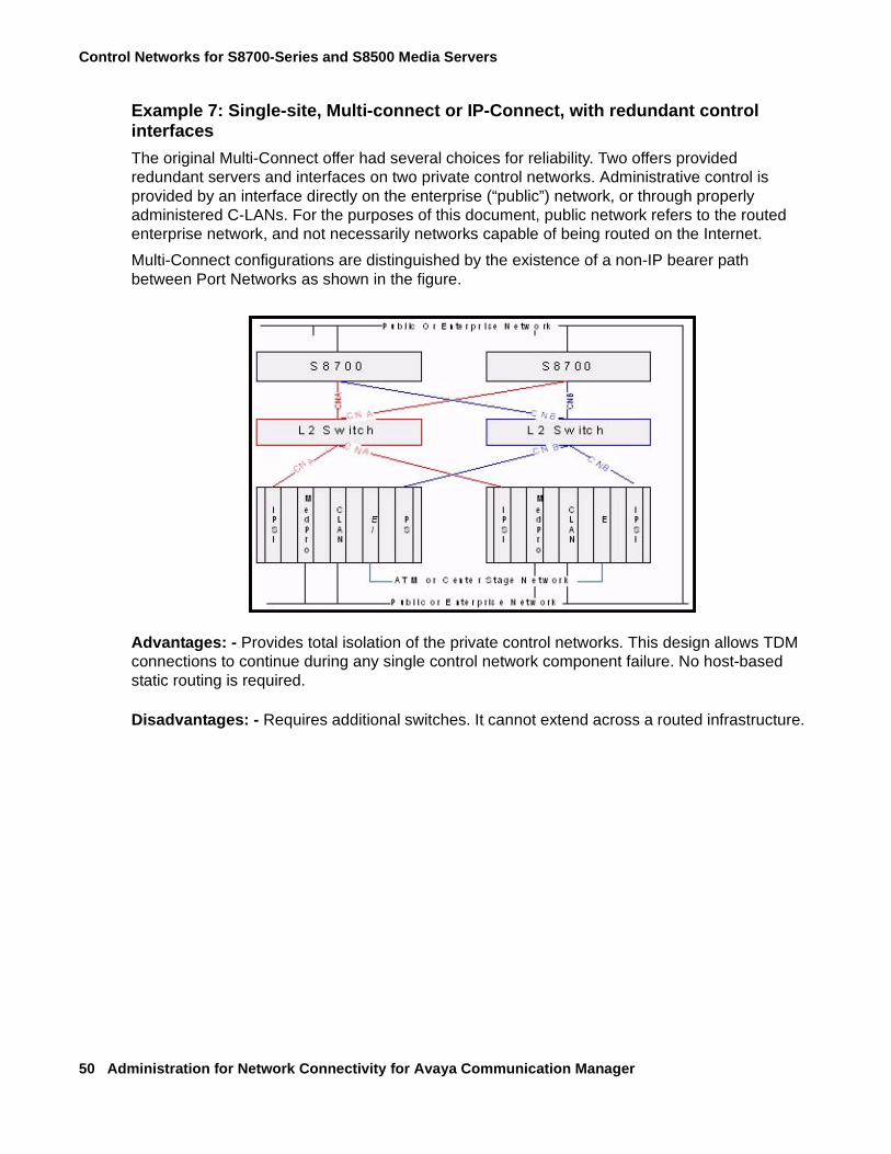
Control Networks for S8700-Series and S8500 Media Servers
50 Administration for Network Connectivity for Avaya Communication Manager
Example 7: Single-site, Multi-connect or IP-Connect, with redundant control interfaces
The original Multi-Connect offer had several choices for reliability. Two offers provided redundant servers and interfaces on two private control networks. Administrative control is provided by an interface directly on the enterprise (“public”) network, or through properly administered C-LANs. For the purposes of this document, public network refers to the routed enterprise network, and not necessarily networks capable of being routed on the Internet.
Multi-Connect configurations are distinguished by the existence of a non-IP bearer path between Port Networks as shown in the figure.
Advantages: - Provides total isolation of the private control networks. This design allows TDM connections to continue during any single control network component failure. No host-based static routing is required.
Disadvantages: - Requires additional switches. It cannot extend across a routed infrastructure.
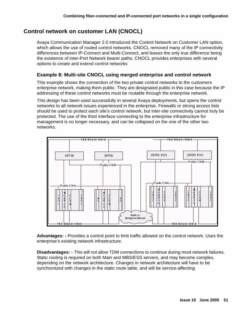
Combining fiber-connected and IP-connected port networks in a single configuration
Issue 10 June 2005 51
Control network on customer LAN (CNOCL)
Avaya Communication Manager 2.0 introduced the Control Network on Customer LAN option, which allows the use of routed control networks. CNOCL removed many of the IP connectivity differences between IP-Connect and Multi-Connect, and leaves the only true difference being the existence of inter-Port Network bearer paths. CNOCL provides enterprises with several options to create and extend control networks
Example 8: Multi-site CNOCL using merged enterprise and control network
This example shows the connection of the two private control networks to the customers enterprise network, making them public. They are designated public in this case because the IP addressing of these control networks must be routable through the enterprise network.
This design has been used successfully in several Avaya deployments, but opens the control networks to all network issues experienced in the enterprise. Firewalls or strong access lists should be used to protect each site’s control network, but inter-site connectivity cannot truly be protected. The use of the third interface connecting to the enterprise infrastructure for management is no longer necessary, and can be collapsed on the one of the other two networks.
Advantages: - Provides a control point to limit traffic allowed on the control network. Uses the enterprise’s existing network infrastructure.
Disadvantages: - This will not allow TDM connections to continue during most network failures. Static routing is required on both Main and MBS/ESS servers, and may become complex, depending on the network architecture. Changes in network architecture will have to be synchronized with changes in the static route table, and will be service-affecting.
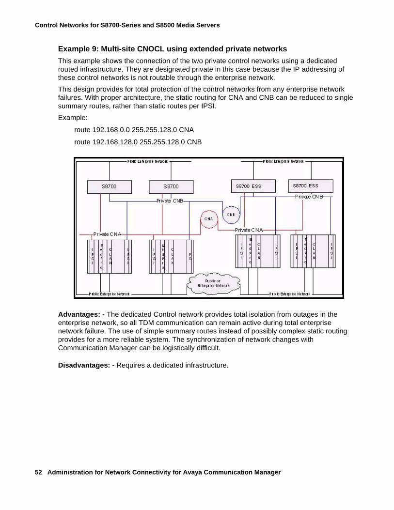
Control Networks for S8700-Series and S8500 Media Servers
52 Administration for Network Connectivity for Avaya Communication Manager
Example 9: Multi-site CNOCL using extended private networks
This example shows the connection of the two private control networks using a dedicated routed infrastructure. They are designated private in this case because the IP addressing of these control networks is not routable through the enterprise network.
This design provides for total protection of the control networks from any enterprise network failures. With proper architecture, the static routing for CNA and CNB can be reduced to single summary routes, rather than static routes per IPSI.
Example:
route 192.168.0.0 255.255.128.0 CNA
route 192.168.128.0 255.255.128.0 CNB
Advantages: - The dedicated Control network provides total isolation from outages in the enterprise network, so all TDM communication can remain active during total enterprise network failure. The use of simple summary routes instead of possibly complex static routing provides for a more reliable system. The synchronization of network changes with Communication Manager can be logistically difficult.
Disadvantages: - Requires a dedicated infrastructure.
Issue 10 June 2005 53
Chapter 3: Administering converged networks
This section provides information for administering converged network components.
● About Voice over IP converged networks
● Providing a network assessment
● About VoIP hardware
● Adding a G600/G650 Media Gateway to an S8500 or S8700-series Media Server
● Adding a G250, G350, or G700 Media Gateway to an S8300 Media Server
● Administering H.323 trunks
● Administering IP Softphones
● Installing and administering Avaya IP telephones
● About hairpinning and shuffling
About Voice over IP converged networksUntil recently, voice, video, and data were delivered over dedicated, single-purpose networks. A converged network brings all forms of communication together: voice, data, and video. Avaya’s products use Voice over IP (VoIP) technology as their means of connection. VoIP technology provides a cost-effective and flexible way of building enterprise communications systems through a converged network.
Some of the flexible elements include:
● Separation of call control and switching functions (see the Separation of Bearer and Signaling Job Aid, 555-245-770, on the library CD, 555-233-825)
● Different techniques for handling data, voice, and FAX
● Communications standards and protocols for different network segments
● Constant and seamless reformatting of data for differing media streams
Digital data and voice communications superimposed in a converged network compete for the network bandwidth, or the total information throughput that the network can deliver. Data traffic tends to require significant network bandwidth for short periods of time, while voice traffic demands a steady, relatively constant transmission path. Data traffic can tolerate delays, while voice transmission degrades, if delayed. Data networks handle data flow effectively, but when digitized voice signals are added to the mix, networks must be managed differently to ensure constant, real-time transmission needed by voice.
Administering converged networks
54 Administration for Network Connectivity for Avaya Communication Manager
Providing a network assessment
Even if your network appears to perform acceptably, adding VoIP taxes network resources and performance, because VoIP requires dedicated bandwidth and is more sensitive to network problems than data applications alone. Many customer IP infrastructures appear to be stable and perform at acceptable levels but have performance and stability issues that create problems for Avaya VoIP Solutions. While the customer network appears to be ready for full-duplex VoIP, Avaya cannot assure performance and quality without a network assessment.
The network assessment services for Avaya VoIP consist of 2 phases:
● Basic Network Assessment — is a high-level LAN/WAN infrastructure evaluation that determines the suitability of an existing network for VoIP.
● Detailed Network Assessment — is typically the second phase in the Network Assessment for IP Telephony solutions.
The detailed network assessment takes information gathered in the basic network assessment, performs problem diagnosis, and provides functional requirements for the network to implement Avaya VoIP. For more information, see http://netassess.avaya.com.
Avaya Communication Solutions and Integration (CSI) supports a portfolio of consulting and engineering offers to help plan and design:
● IP Telephony
● Data Networking Services
● Network Security Services.
How to contact the CSI
● On the Web -- http://csi.avaya.com.
● E-Mail: [email protected]
● Phone: +1 866 282 9266
About VoIP hardware
Issue 10 June 2005 55
About VoIP hardwareThis section contains descriptions and administration for the following circuit packs and media modules:
● TN464HP/TN2464CP Universal DS1 circuit packs and MM710 T1/E1Media Module
● TN799DP Control LAN
● TN802B MAPD (IP Interface Assembly)
● TN2302AP IP Media Processor
● TN2602AP IP Media Resource 320
● TN2312BP IP Server Interface (IPSI)
● MM760 VoIP Media Module
TN464HP/TN2464CP Universal DS1 circuit packs andMM710 T1/E1Media Module
The TN464HP/TN2464CP circuit packs and the MM710 Media Module (version 3 and later) have the same functionality as other DS1 circuit packs, with the addition of echo cancellation circuitry. The TN464HP/TN2464CP and MM710 offer echo cancellation tail lengths of up to 96 milliseconds (ms). The TN574, TN2313, and TN2464 DS1 circuit packs do not support echo cancellation.
The TN464HP/TN2464CP and MM710 are intended for users who encounter echo over circuits connected to the Direct Distance Dialing (DDD) network. Echo is most likely to occur when Avaya Communication Manager is configured for ATM, IP, and wideband. In addition, echo can occur on system interfaces to local service providers that do not routinely install echo cancellation equipment in all their circuits.
Echo cancellation is a software right-to-use feature that supports voice channels, and is not intended for data. When a data call is received, these circuit packs detect a modem tone and turn off echo cancellation for the duration of the data call.
Working with echo cancellation
You can determine whether echo cancellation is enabled for TN464HP/TN2464CP circuit packs and MM710 T1/E1 Media Modules using the system-parameters customer-options screen.
Administering converged networks
56 Administration for Network Connectivity for Avaya Communication Manager
To determine if echo cancellation is enabled for TN464HP/TN2464CP circuit packs and MM710 T1/E1 Media Modules
1. Type display system-parameters customer-options.
Note:Note: The Customer Options screen is display-only. The License File controls the
system software release, the Offer Category, features, and capacities. The init login cannot change the customer options, offer options, or special applications screens, unless a feature is enabled but not turned on in the License File.
2. Find and review the following fields.
The fields may appear on different pages of the screen.
3. Exit the screen.
Administering echo cancellation on the DS1 circuit packor MM710 media module
The DS1 Circuit Pack screen for the TN464HP/TN2464CP circuit packs and MM710 media module has fields to support echo cancellation: Echo Cancellation, EC Direction, and EC Configuration. The Echo Cancellation field appears when the Echo Cancellation feature is activated on the System-Parameters Customer Options screen. The EC Direction and EC Configuration fields appear when the DS1 Echo Cancellation field is enabled.
● EC Direction determines the direction from which echo will be eliminated, ether inward or outward.
● EC Configuration is the set of parameters used when cancelling echo.
This information is stored in firmware on the UDS1 circuit pack.
To administer the DS1 circuit pack and MM710 media module
1. Type add ds1 <port> and press Enter to open the DS1 Circuit Pack screen,
where <port> is the location of the DS1 circuit pack, or the MM710 media module.
Field Conditions/CommentsMaximum Number of DS1 Boards with Echo Cancellation
Specifies the number of DS1 boards that have echo cancellation turned on.
DS1 Echo Cancellation If y, echo cancellation is enabled.
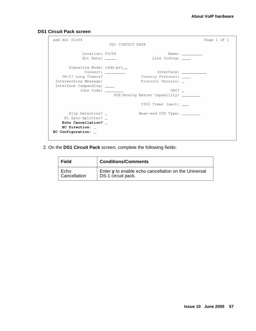
About VoIP hardware
Issue 10 June 2005 57
DS1 Circuit Pack screen
2. On the DS1 Circuit Pack screen, complete the following fields:
add ds1 01c04 Page 1 of 1DS1 CIRCUIT PACK
Location: 01C04 Name: _________ Bit Rate: _____ Line Coding: ____ Signaling Mode: isdn-pri__ Connect: _________ Interface: ___________
TN-C7 Long Timers? Country Protocol: ____ Interworking Message: Protocol Version: _
Interface Companding: ____ Idle Code: ________ CRC? _
DCP/Analog Bearer Capability: ________
T303 Timer (sec): ___
Slip Detection? _ Near-end CSU Type: ________ E1 Sync-Splitter? _
Echo Cancellation? _ EC Direction: _ EC Configuration: _
Field Conditions/Comments
Echo Cancellation
Enter y to enable echo cancellation on the Universal DS-1 circuit pack.
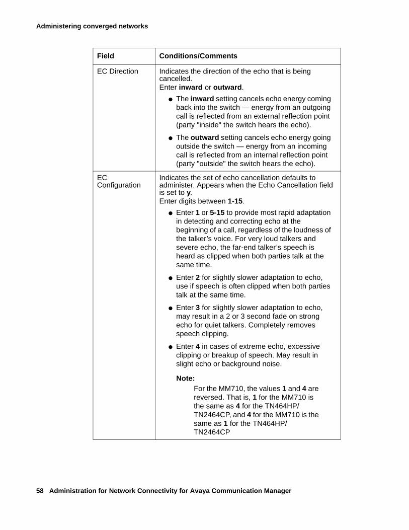
Administering converged networks
58 Administration for Network Connectivity for Avaya Communication Manager
EC Direction Indicates the direction of the echo that is being cancelled.Enter inward or outward.
● The inward setting cancels echo energy coming back into the switch — energy from an outgoing call is reflected from an external reflection point (party "inside" the switch hears the echo).
● The outward setting cancels echo energy going outside the switch — energy from an incoming call is reflected from an internal reflection point (party "outside" the switch hears the echo).
EC Configuration
Indicates the set of echo cancellation defaults to administer. Appears when the Echo Cancellation field is set to y.Enter digits between 1-15.
● Enter 1 or 5-15 to provide most rapid adaptation in detecting and correcting echo at the beginning of a call, regardless of the loudness of the talker’s voice. For very loud talkers and severe echo, the far-end talker’s speech is heard as clipped when both parties talk at the same time.
● Enter 2 for slightly slower adaptation to echo, use if speech is often clipped when both parties talk at the same time.
● Enter 3 for slightly slower adaptation to echo, may result in a 2 or 3 second fade on strong echo for quiet talkers. Completely removes speech clipping.
● Enter 4 in cases of extreme echo, excessive clipping or breakup of speech. May result in slight echo or background noise.
Note:Note: For the MM710, the values 1 and 4 are
reversed. That is, 1 for the MM710 is the same as 4 for the TN464HP/TN2464CP, and 4 for the MM710 is the same as 1 for the TN464HP/TN2464CP
Field Conditions/Comments
About VoIP hardware
Issue 10 June 2005 59
Administering echo cancellation on trunks
Echo cancellation is turned on or off on a per trunk-group basis using the change trunk-group command. If the trunk group field, DS1 Echo Cancellation is y, echo cancellation is applied to every TN464HP/TN2464CP trunk member in that trunk group. The echo cancellation parameters used for a given trunk member are determined by the EC Configuration number administered on the DS1 Circuit Pack screen for that specific trunk’s board.
Echo cancellation applies to voice channels and supports echo cancellation on the following trunk group types:
● CO
● TIE
● ISDN-PRI
● FX
● WATS
● DID
● DIOD
● DMI-BOS
● Tandem
● Access
● APLT
Administration of echo cancellation on a trunk group is done on the TRUNK FEATURES screen.
To administer a trunk group for echo cancellation
1. Type change trunk-group n
where n is the trunk group number.
2. Go to page 2.
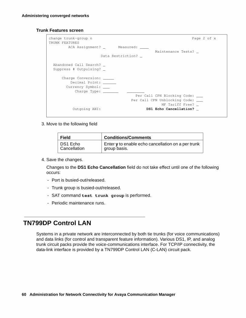
Administering converged networks
60 Administration for Network Connectivity for Avaya Communication Manager
Trunk Features screen
3. Move to the following field
4. Save the changes.
Changes to the DS1 Echo Cancellation field do not take effect until one of the following occurs:
- Port is busied-out/released.
- Trunk group is busied-out/released.
- SAT command test trunk group is performed.
- Periodic maintenance runs.
TN799DP Control LAN
Systems in a private network are interconnected by both tie trunks (for voice communications) and data links (for control and transparent feature information). Various DS1, IP, and analog trunk circuit packs provide the voice-communications interface. For TCP/IP connectivity, the data-link interface is provided by a TN799DP Control LAN (C-LAN) circuit pack.
change trunk-group n Page 2 of xTRUNK FEATURES ACA Assignment? _ Measured: ____
Maintenance Tests? _Data Restriction? _
Abandoned Call Search? _ Suppress # Outpulsing? _
Charge Conversion: _____Decimal Point: ______
Currency Symbol: ___Charge Type: _______ ________
Per Call CPN Blocking Code: ___ Per Call CPN Unblocking Code: ___
MF Tariff Free? _Outgoing ANI: DS1 Echo Cancellation? _
Field Conditions/CommentsDS1 Echo Cancellation
Enter y to enable echo cancellation on a per trunk group basis.
About VoIP hardware
Issue 10 June 2005 61
The C-LAN handles the data-link signaling information in one of two configurations: Ethernet, or point-to-point (PPP). The C-LAN circuit pack has one 10/100baseT ethernet connection and up to 16 DS0 physical interfaces for PPP connections. C-LAN also extends ISDN capabilities to csi models by providing packet-bus access.
● In the Ethernet configuration, the C-LAN passes the signaling information over a separate TCP/IP network, usually by means of a hub or Ethernet switch.
Avaya recommends an Ethernet switch for optimal performance. For this configuration, install the C-LAN circuit pack and connect the appropriate pins of the C-LAN I/O field to the hub or Ethernet switch.
● In the PPP configuration, the C-LAN passes the data-link signaling to the DS1 for inclusion in the same DS1 bit stream as the DCS voice transmissions.
For this configuration, install the C-LAN circuit pack; no other connections are needed. The appropriate DS1 circuit packs must be installed, if they are not already present.
Physical addressing for the C-LAN board
The Address Resolution Protocol (ARP) on the C-LAN circuit pack relates the 32-bit IP address configured in software to the 48-bit MAC address of the C-LAN circuit pack. The MAC address is burned into the board at the factory. The C-LAN board has an ARP table that contains the IP addresses associated with each hardware address. This table is used to route messages across the network. Each C-LAN board has one MAC address, one Ethernet address, and up to 16 PPP addresses.
IP addressing techniques for the C-LAN board
The C-LAN supports both Classless Inter-domain Routing and Variable-Length Subnet Masks. These addressing techniques provide greater flexibility in addressing and routing than class addressing alone.
Installing the TN799DP C-LAN
TCP/IP connections (Ethernet or PPP) require a TN799DP C-LAN circuit pack, unless your system has embedded Ethernet capabilities. Before you install the C-LAN circuit pack, be sure you understand the requirements of your LAN. Go to http://www.extremenetworks.com/LIBRARIES/Avaya/AvayaIPvoiceQualityNetworkRequirements.pdf and look in the white paper Avaya IP Voice Quality Network Requirements (EF-LB1500).
The following steps describe installation for the TN799DP C-LAN.
To insert TN799DP C-LAN circuit packs
1. Determine the carrier/slot assignments of the circuit packs to be added.
You can insert the C-LAN circuit pack into any port slot.
2. Insert the circuit packs into the slots specified in step 1.
Note:Note: You do not need to power down the cabinet to install a C-LAN circuit pack.
Administering converged networks
62 Administration for Network Connectivity for Avaya Communication Manager
Administering the C-LAN bus bridge (Avaya DEFINITY Server csi only)
For the Avaya DEFINITY Server csi only, complete the following steps to administer the bus bridge for the C-LAN circuit pack. Only an Avaya representative using the craft or higher login can change the maintenance parameters.
Note:Note: If there are 2 C-LAN circuit packs installed in this csi switch, administer the bus
bridge for only one of them.
To administer the C-LAN bus bridge (Avaya DEFINITY Server csi only)
1. Type change system-parameters maintenance.
2. Move to the Packet Intf2 field and enter y.
3. Enter the location of the C-LAN circuit pack in the Bus Bridge field
(for example, 01a08 for cabinet 1, carrier A, and slot 8).
4. Enter the port bandwidths or use the defaults in the Pt0, Pt1, and Pt2 Inter-Board Link Timeslots fields.
5. Submit the screen.
6. Verify that the bus bridge LED is lit on the C-LAN circuit pack.
This indicates that the packet bus is enabled.
Testing the packet bus and C-LAN circuit pack
In order to test the packet bus and the TN799DP C-LAN circuit pack, the cabinet needs an installed TN771D Maintenance/Test circuit pack.
To test the packet bus and C-LAN circuit pack
1. If there is no TN771D circuit pack in the cabinet, place one in a port slot.
This is for testing purposes only, and you will remove the board when finished.
2. Enter test pkt port-network 1 long
For more information about these tests, refer to the test pkt command section in Maintenance Commands for Avaya Communication Manager 2.1, Media Gateways and Servers, 03-300191.
3. If the TN771D circuit pack was already in the cabinet, leave it there.
4. If you added the TN771D circuit pack to the cabinet in order to test the TN799DP circuit pack, remove it from the cabinet.
About VoIP hardware
Issue 10 June 2005 63
Installing C-LAN cables to a hub or ethernet switch
In the Ethernet configuration, the C-LAN passes the signaling information over a separate TCP/IP network, usually by means of a hub or Ethernet switch. Connect the appropriate pins of the C-LAN I/O field to the hub or Ethernet switch.
To install C-LAN cables to a hub or ethernet switch
See Figure 3: Cable connection for C-LAN connectivity.
1. Connect the 259A connector to the backplane connector of the port slot containing the C-LAN circuit pack.
2. Connect the Category 5 UTP cable between the 259A connector and a hub or Ethernet switch.
This connects port 17 on the C-LAN circuit pack to the LAN.
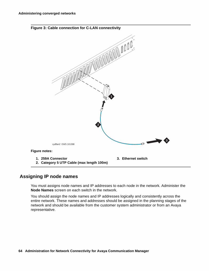
Administering converged networks
64 Administration for Network Connectivity for Avaya Communication Manager
Figure 3: Cable connection for C-LAN connectivity
Assigning IP node names
You must assigns node names and IP addresses to each node in the network. Administer the Node Names screen on each switch in the network.
You should assign the node names and IP addresses logically and consistently across the entire network. These names and addresses should be assigned in the planning stages of the network and should be available from the customer system administrator or from an Avaya representative.
Figure notes:
1. 259A Connector2. Category 5 UTP Cable (max length 100m)
3. Ethernet switch
1
2
3cydflan2 EWS 101398
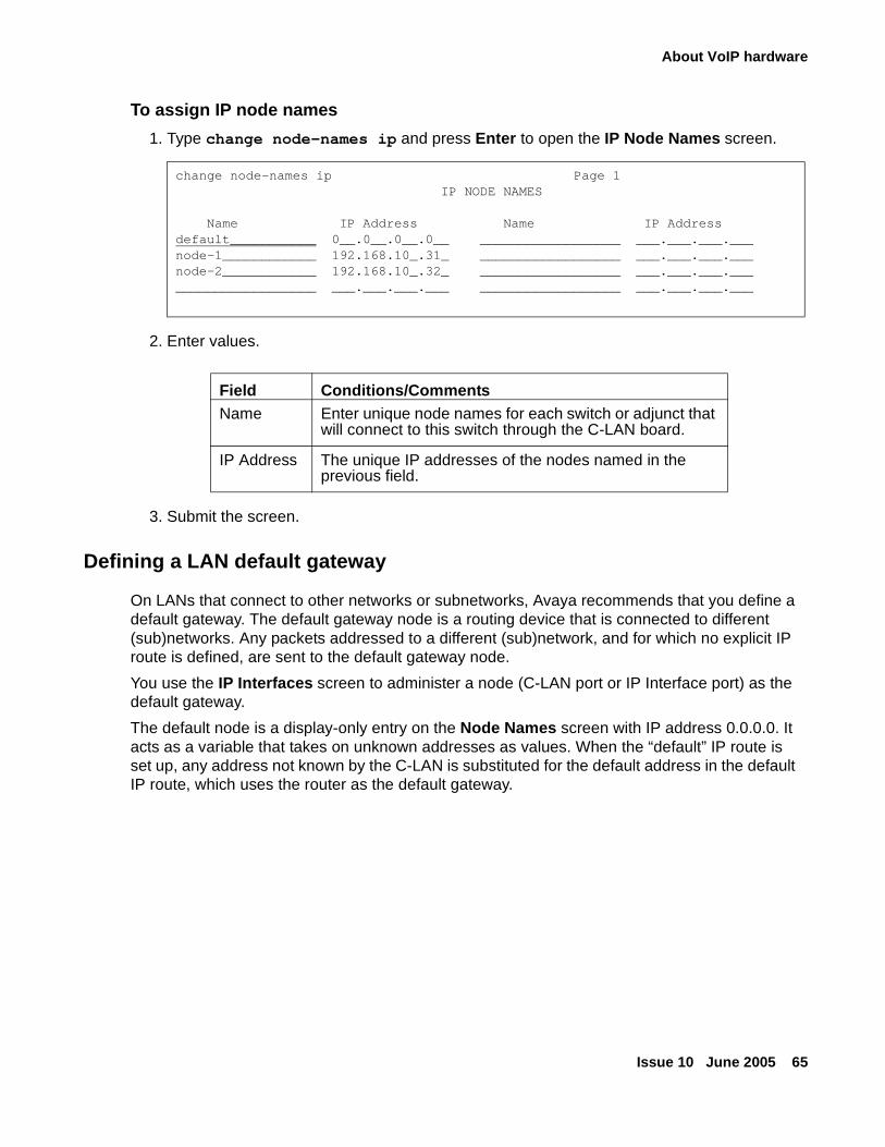
About VoIP hardware
Issue 10 June 2005 65
To assign IP node names
1. Type change node-names ip and press Enter to open the IP Node Names screen.
2. Enter values.
3. Submit the screen.
Defining a LAN default gateway
On LANs that connect to other networks or subnetworks, Avaya recommends that you define a default gateway. The default gateway node is a routing device that is connected to different (sub)networks. Any packets addressed to a different (sub)network, and for which no explicit IP route is defined, are sent to the default gateway node.
You use the IP Interfaces screen to administer a node (C-LAN port or IP Interface port) as the default gateway.
The default node is a display-only entry on the Node Names screen with IP address 0.0.0.0. It acts as a variable that takes on unknown addresses as values. When the “default” IP route is set up, any address not known by the C-LAN is substituted for the default address in the default IP route, which uses the router as the default gateway.
change node-names ip Page 1 IP NODE NAMES
Name IP Address Name IP Addressdefault___________ 0__.0__.0__.0__ __________________ ___.___.___.___node-1____________ 192.168.10_.31_ __________________ ___.___.___.___node-2____________ 192.168.10_.32_ __________________ ___.___.___._____________________ ___.___.___.___ __________________ ___.___.___.___
Field Conditions/CommentsName Enter unique node names for each switch or adjunct that
will connect to this switch through the C-LAN board.
IP Address The unique IP addresses of the nodes named in the previous field.
Administering converged networks
66 Administration for Network Connectivity for Avaya Communication Manager
Setting up Alternate Gatekeeper andC-LAN load balancing
Alternate Gatekeeper gives IP endpoints a list of available C-LAN circuit packs. Alternate Gatekeeper addresses and C-LAN load-balancing spread IP endpoint registration across more than one C-LAN circuit pack. The C-LAN load-balancing algorithm allocates endpoint registrations within a network region to the C-LAN with the least number of sockets in use. This increases system performance and reliability.
If registration with the original C-LAN circuit pack IP address is successful, the software sends back the IP addresses of all the C-LAN circuit packs in the same network region as the IP endpoint. If the network connection to one C-LAN circuit pack fails, the IP endpoint re-registers with a different C-LAN. If the system uses network regions based on IP address, the software also sends the IP addresses of C-LANs in interconnected regions. These alternate C-LAN addresses are also called gatekeeper addresses. These addresses can also be used if the data network carrying the call signaling from the original C-LAN circuit pack fails.
IP Telephones can be programmed to search for a gatekeeper independently of load-balancing. The IP Telephone accepts gatekeeper addresses in the message from the Dynamic Host Configuration Protocol (DHCP) server or in the script downloaded from the Trivial File Transfer Protocol (TFTP) server. If the phone cannot contact the first gatekeeper address, it uses an alternate address. If the extension and password is rejected by the first gatekeeper, the IP Telephone contacts the next gatekeeper. The number of gatekeeper addresses the phone accepts depends on the length of the addresses administered on the DHCP server.
Note:Note: A single Alternate Gatekeeper list is typically used in configurations with multiple
media servers. In this case, the DHCP server sends the same Alternate Gatekeeper list to all IP endpoints, but a given IP endpoint may not be able to register with some of the gatekeepers in the list and a registration attempt to those gatekeepers will be rejected.
C-LAN load balancing and alternate gatekeeper addresses require IP stations that accept multiple IP addresses, such as:
● IP telephone
● IP Softphone
● Avaya IP Agent
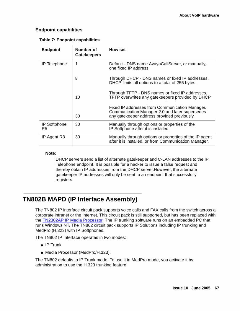
About VoIP hardware
Issue 10 June 2005 67
Endpoint capabilities
Note:Note: DHCP servers send a list of alternate gatekeeper and C-LAN addresses to the IP
Telephone endpoint. It is possible for a hacker to issue a false request and thereby obtain IP addresses from the DHCP server.However, the alternate gatekeeper IP addresses will only be sent to an endpoint that successfully registers.
TN802B MAPD (IP Interface Assembly)
The TN802 IP interface circuit pack supports voice calls and FAX calls from the switch across a corporate intranet or the Internet. This circuit pack is still supported, but has been replaced with the TN2302AP IP Media Processor. The IP trunking software runs on an embedded PC that runs Windows NT. The TN802 circuit pack supports IP Solutions including IP trunking and MedPro (H.323) with IP Softphones.
The TN802 IP Interface operates in two modes:
● IP Trunk
● Media Processor (MedPro/H.323).
The TN802 defaults to IP Trunk mode. To use it in MedPro mode, you activate it by administration to use the H.323 trunking feature.
Table 7: Endpoint capabilities
Endpoint Number of Gatekeepers
How set
IP Telephone 1
8
10
30
Default - DNS name AvayaCallServer, or manually, one fixed IP address
Through DHCP - DNS names or fixed IP addresses. DHCP limits all options to a total of 255 bytes.
Through TFTP - DNS names or fixed IP addresses. TFTP overwrites any gatekeepers provided by DHCP
Fixed IP addresses from Communication Manager. Communication Manager 2.0 and later supersedes any gatekeeper address provided previously.
IP Softphone R5
30 Manually through options or properties of the IP Softphone after it is installed.
IP Agent R3 30 Manually through options or properties of the IP agent after it is installed, or from Communication Manager.
Administering converged networks
68 Administration for Network Connectivity for Avaya Communication Manager
TN2302AP IP Media Processor
Use the TN2302AP IP Media Processor to transmit voice and FAX data (non-DCS signaling) over IP connections, and for H.323 multimedia applications in H.323 V2 compliant endpoints.
The TN2302AP IP Media Processor provides port network connectivity on an IP-Connect configuration. The TN2302AP IP Media Processor includes a 10/100BaseT Ethernet interface to support H.323 endpoints for IP trunks and H.323 endpoints, and its design improves voice quality through its dynamic jitter buffers.
The TN2302AP IP Media Processor additionally performs the functions:
● Echo cancellation
● Silence suppression
● DTMF detection
● Conferencing
It supports the following codecs, FAX detection for them, and conversion between them:
● G.711 (mu-law or a-law, 64Kbps)
● G.723.1 (6.3Kbps or 5.3Kbps audio)
● G.729 (8Kbps audio)
Improving theTN2302AP transmission interface
The TN2302AP IP Media Processor provides improved voice quality through its dynamic jitter buffers. The TN2302AP’s digital signal processors (DSPs), by default, insert 5.0 dB of loss in the signal from the IP endpoints, and insert 5.0 dB of gain in the signal to the IP endpoints. System administrators can administer loss/gain, based on country code on the terminal-parameters screen.
Supporting TN2302AP hairpinning
The TN2302AP IP Media Processor supports 64 ports of shallow hairpin. IP packets that do not require speech codec transcoding can be looped back at the UDP/IP layers with a simple change of addressing. This reduces delay and leaves DSP resources available.
Testing TN2302AP ports
The TN2302AP IP Media Processor is a service circuit pack, not a trunk circuit pack. Therefore, an H.323 tie trunk cannot be used for facility test calls. Use the ping command to test the TN2302AP ports.
About VoIP hardware
Issue 10 June 2005 69
Enabling a survivable remote EPN
Any survivable remote EPN containing a C-LAN board and H.323 station sets should also contain a TN2302AP IP Media Processor.
TN2602AP IP Media Resource 320
The TN2602AP IP Media Resource 320 provides high-capacity voice over Internet protocol (VoIP) audio access to the switch for local stations and outside trunks. The IP Media Resource 320 provides audio processing for the following types of calls:
● TDM-to-IP and IP-to-TDM
● IP-to-IP
The TN2602AP IP Media Resource 320 circuit pack has two capacity options, both of which are determined by the license file installed on Communication Manager:
● 320 voice channels, considered the standard IP Media Resource 320
● 80 voice channels, considered the low-density IP Media Resource 320
Up to two TN2602AP circuit packs may be installed in a single port network for load balancing. The TN2602AP circuit pack is also compatible with and can share load balancing with the TN2302 IP Media Processor circuit pack. Actual capacity may be affected by a variety of factors, including the codec used for a call and fax support.
Note:Note: The TN2602AP IP Media Resource 320 is not supported in CMC1 and G600
Media Gateways.
Features
The IP Media Resource 320 supports hairpin connections and the shuffling of calls between TDM connections and IP-to-IP direct connections. The IP Media Resource 320 can also perform the following functions:
● Echo cancellation
● Silence suppression
● Adaptive jitter buffer (120 ms)
● Dual-tone multi-frequency (DTMF) detection
● AEA Version 2 and AES media encryption
● Conferencing
● 802.1p and 802.Q layer 2 QoS mechanisms
● RSVP protocol
Administering converged networks
70 Administration for Network Connectivity for Avaya Communication Manager
The TN2602AP IP Media Resource 320 circuit pack supports the following codecs for voice, conversion between codecs, and fax detection:
● G.711, A-law or Mu-law, 64 kbps
● G.726A 32 kbps
● G.729 A/AB, 8 kbps audio
The TN2602AP also supports transport of the following devices:
● Fax, Teletypewriter device (TTY), and modem calls over a corporate IP intranet using pass-through mode
● Fax and TTY calls using proprietary relay mode
Note:Note: The path between endpoints for fax and modem transmissions must use Avaya
telecommunications and networking equipment. In addition, T.38 fax is not supported.
! SECURITY ALERT:SECURITY ALERT: Faxes sent to non-Avaya endpoints cannot be encrypted.
● 64-kbps clear channel transport in support of firmware downloads, BRI secure telephones, and data appliances
Load balancing
Communication Manager can distribute traffic load between an IP Media Resource 320 and the following:
● A second IP Media Resource 320 installed in the same port network
● TN2302AP and TN802B circuit packs installed in the same port network
Firmware download
The IP Media Resource 320 can serve as an FTP server for firmware downloads to itself. However, this capability is activated by and available for authorized services personnel only.
I/O adapter
The TN2602AP IP Media Resource 320 circuit pack has a services Ethernet port in the faceplate. The TN2602AP circuit pack also requires an input/output adapter that provides for one RS-232 serial port and two 10/100 Mbs Ethernet ports for LAN connections (though only the first Ethernet port is used). This Ethernet connection is made at the back of the IP Media Resource 320 slot.
Note:Note: The TN2302AP can also use this I/O adapter.
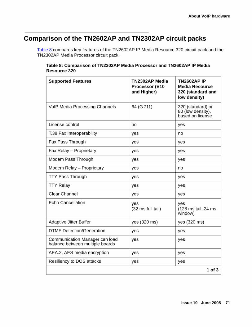
About VoIP hardware
Issue 10 June 2005 71
Comparison of the TN2602AP and TN2302AP circuit packs
Table 8 compares key features of the TN2602AP IP Media Resource 320 circuit pack and the TN2302AP Media Processor circuit pack.
Table 8: Comparison of TN2302AP Media Processor and TN2602AP IP Media Resource 320
Supported Features TN2302AP Media Processor (V10 and Higher)
TN2602AP IP Media Resource 320 (standard and low density)
VoIP Media Processing Channels 64 (G.711) 320 (standard) or 80 (low density), based on license
License control no yes
T.38 Fax Interoperability yes no
Fax Pass Through yes yes
Fax Relay – Proprietary yes yes
Modem Pass Through yes yes
Modem Relay – Proprietary yes no
TTY Pass Through yes yes
TTY Relay yes yes
Clear Channel yes yes
Echo Cancellation yes(32 ms full tail)
yes(128 ms tail, 24 ms window)
Adaptive Jitter Buffer yes (320 ms) yes (320 ms)
DTMF Detection/Generation yes yes
Communication Manager can load balance between multiple boards
yes yes
AEA.2, AES media encryption yes yes
Resiliency to DOS attacks yes yes
1 of 3
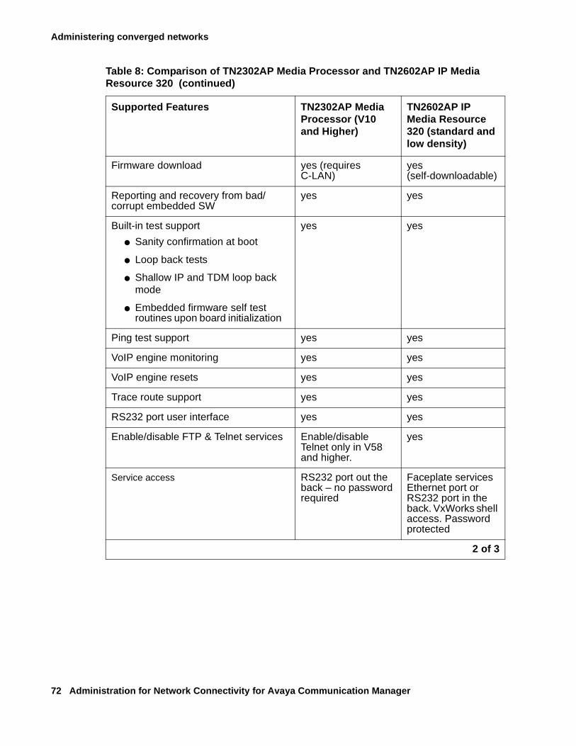
Administering converged networks
72 Administration for Network Connectivity for Avaya Communication Manager
Firmware download yes (requires C-LAN)
yes (self-downloadable)
Reporting and recovery from bad/corrupt embedded SW
yes yes
Built-in test support
● Sanity confirmation at boot
● Loop back tests
● Shallow IP and TDM loop back mode
● Embedded firmware self test routines upon board initialization
yes yes
Ping test support yes yes
VoIP engine monitoring yes yes
VoIP engine resets yes yes
Trace route support yes yes
RS232 port user interface yes yes
Enable/disable FTP & Telnet services Enable/disable Telnet only in V58 and higher.
yes
Service access RS232 port out the back – no password required
Faceplate services Ethernet port or RS232 port in the back. VxWorks shell access. Password protected
Table 8: Comparison of TN2302AP Media Processor and TN2602AP IP Media Resource 320 (continued)
Supported Features TN2302AP Media Processor (V10 and Higher)
TN2602AP IP Media Resource 320 (standard and low density)
2 of 3
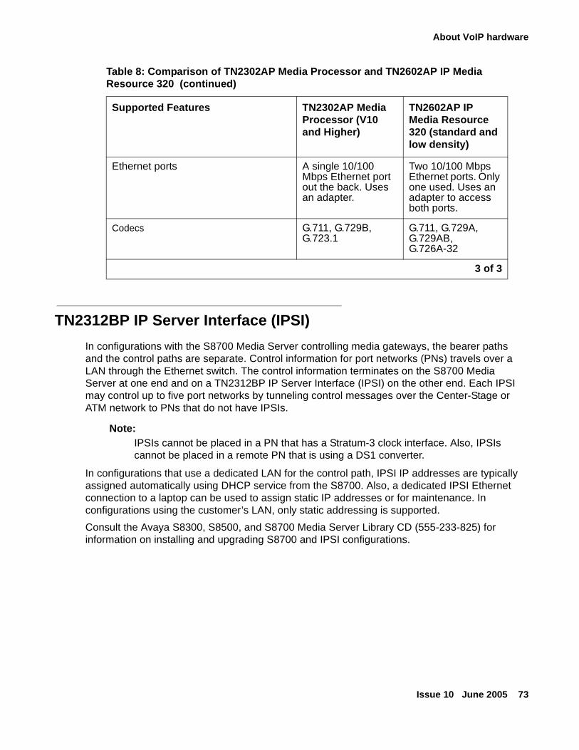
About VoIP hardware
Issue 10 June 2005 73
TN2312BP IP Server Interface (IPSI)
In configurations with the S8700 Media Server controlling media gateways, the bearer paths and the control paths are separate. Control information for port networks (PNs) travels over a LAN through the Ethernet switch. The control information terminates on the S8700 Media Server at one end and on a TN2312BP IP Server Interface (IPSI) on the other end. Each IPSI may control up to five port networks by tunneling control messages over the Center-Stage or ATM network to PNs that do not have IPSIs.
Note:Note: IPSIs cannot be placed in a PN that has a Stratum-3 clock interface. Also, IPSIs
cannot be placed in a remote PN that is using a DS1 converter.
In configurations that use a dedicated LAN for the control path, IPSI IP addresses are typically assigned automatically using DHCP service from the S8700. Also, a dedicated IPSI Ethernet connection to a laptop can be used to assign static IP addresses or for maintenance. In configurations using the customer’s LAN, only static addressing is supported.
Consult the Avaya S8300, S8500, and S8700 Media Server Library CD (555-233-825) for information on installing and upgrading S8700 and IPSI configurations.
Ethernet ports A single 10/100 Mbps Ethernet port out the back. Uses an adapter.
Two 10/100 Mbps Ethernet ports. Only one used. Uses an adapter to access both ports.
Codecs G.711, G.729B, G.723.1
G.711, G.729A, G.729AB, G.726A-32
Table 8: Comparison of TN2302AP Media Processor and TN2602AP IP Media Resource 320 (continued)
Supported Features TN2302AP Media Processor (V10 and Higher)
TN2602AP IP Media Resource 320 (standard and low density)
3 of 3
Administering converged networks
74 Administration for Network Connectivity for Avaya Communication Manager
MM760 VoIP Media Module
The Avaya MM760 Media Module is a clone of the motherboard VoIP engine.The MM760 provides the audio bearer channels for voice over IP calls, and is under control of the G700. Based on system administration of audio codecs, a MM760 can handle either 64 or 32 simultaneous channels of H.323 audio processing. If the IP Parameters form specifies only G.711 mu-law or G.711 a-law as the audio codecs, the MM760 can service 64 channels. If any other codec type (G.723-5.3K, G.723-6.3K, or G.729) is administered, the MM760 can only service 32 channels. These call types can be mixed on the same resource. In other words, the simultaneous call capacity of the resource is 64 G.711 Equivalent Calls.
Note:Note: The MM760 is not supported on the G350 and G250 Media Gateways.
Note:Note: Customers who want an essentially non-blocking system must add an additional
MM760 Media Module, if they use more than two MM710 Media Modules in a single chassis. The additional MM760 provides an additional 64 channels.
What is the MM760 Ethernet interface
The MM760 must have its own Ethernet address. The MM760 requires a 10/100 Base T Ethernet interface to support H.323 endpoints for DEFINITY IP trunks and stations from another G700 Media Gateway.
Supporting voice compression on the MM760
The MM760 supports on-board resources for compression and decompression of voice for G.711 (A- and µ-law), G.729 and 729B, and G.723 (5.3K and 6.3K). The VoIP engine supports the following functionality:
● RTP and RTCP interfaces
● Dynamic jitter buffers
● DTMF detection
● Hybrid echo cancellation
● Silence suppression
● Comfort noise generation
● Packet loss concealment
About VoIP hardware
Issue 10 June 2005 75
The MM760 also supports transport of the following:
● Teletypewriter device (TTY) tone relay over the Internet
● Faxes over a corporate IP intranet
Note:Note: The path between endpoints for FAX transmissions must use Avaya telecommunications
and networking equipment.
! SECURITY ALERT:SECURITY ALERT: Faxes sent to non-Avaya endpoints cannot be encrypted.
● Modem tones over a corporate IP intranet
Note:Note: The path between endpoints for modem tone transmissions must use Avaya
telecommunications and networking equipment.
Administering converged networks
76 Administration for Network Connectivity for Avaya Communication Manager
Administration of Avaya gatewaysThe following sections describe the administration of the Avaya gateways:
Adding a G600/G650 Media Gateway to an S8500 or S8700-series Media Server
Adding a G250, G350, or G700 Media Gateway to an S8300 Media Server
Adding a G600/G650 Media Gateway to an S8500 or S8700-series Media Server
Note:Note: The procedure that follows is a synopsis of the essential network administration.
Depending on the specific configuration, additional administration might be required. For more information, see the Avaya S8300, S8500, and S8700 Media Server Library CD (555-233-825).
What S8500, S8700-series attributes this procedure assumes
This procedure assumes that the Avaya Media Server:
● is installed and cabled
● is configured as a server
● is running Communication Manager
● has an administered IP Server Interface (IPSI) circuit pack with
- an IP address
- a gateway address
- a physical network connection
Note:Note: In order to successfully complete this procedure, you must have the IP address of
each IPSI circuit pack. Use the list ip-interface command at the media server SAT interface to look up this information.
To add a G600 or G650 Media Gateway to an S8500 or S8700-series Media Server
1. Open a SAT session and locate IPSI circuit pack(s) with the list configuration all command.
Ensure that you understand which IPSI circuit pack is supporting the gateway connection.
2. Check the previous cabinet administration with the list cabinet command.
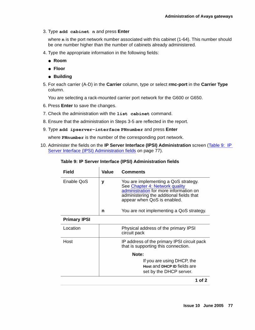
Administration of Avaya gateways
Issue 10 June 2005 77
3. Type add cabinet n and press Enter
where n is the port network number associated with this cabinet (1-64). This number should be one number higher than the number of cabinets already administered.
4. Type the appropriate information in the following fields:
● Room
● Floor
● Building
5. For each carrier (A-D) in the Carrier column, type or select rmc-port in the Carrier Type column.
You are selecting a rack-mounted carrier port network for the G600 or G650.
6. Press Enter to save the changes.
7. Check the administration with the list cabinet command.
8. Ensure that the administration in Steps 3-5 are reflected in the report.
9. Type add ipserver-interface PNnumber and press Enter
where PNnumber is the number of the corresponding port network.
10. Administer the fields on the IP Server Interface (IPSI) Administration screen (Table 9: IP Server Interface (IPSI) Administration fields on page 77).
Table 9: IP Server Interface (IPSI) Administration fields
Field Value Comments
Enable QoS y
n
You are implementing a QoS strategy. See Chapter 4: Network quality administration for more information on administering the additional fields that appear when QoS is enabled.
You are not implementing a QoS strategy.
Primary IPSI
Location Physical address of the primary IPSI circuit pack
Host IP address of the primary IPSI circuit pack that is supporting this connection.
Note:Note: If you are using DHCP, the
Host and DHCP ID fields are set by the DHCP server.
1 of 2
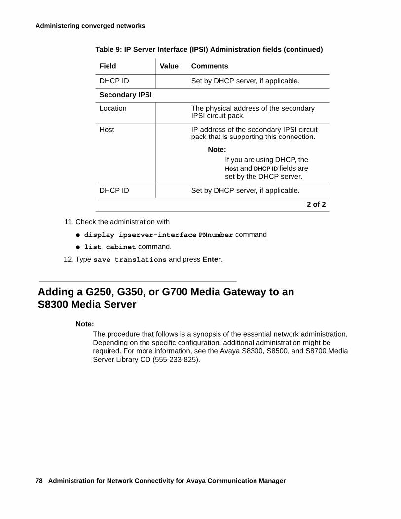
Administering converged networks
78 Administration for Network Connectivity for Avaya Communication Manager
11. Check the administration with
● display ipserver-interface PNnumber command
● list cabinet command.
12. Type save translations and press Enter.
Adding a G250, G350, or G700 Media Gateway to an S8300 Media Server
Note:Note: The procedure that follows is a synopsis of the essential network administration.
Depending on the specific configuration, additional administration might be required. For more information, see the Avaya S8300, S8500, and S8700 Media Server Library CD (555-233-825).
DHCP ID Set by DHCP server, if applicable.
Secondary IPSI
Location The physical address of the secondary IPSI circuit pack.
Host IP address of the secondary IPSI circuit pack that is supporting this connection.
Note:Note: If you are using DHCP, the
Host and DHCP ID fields are set by the DHCP server.
DHCP ID Set by DHCP server, if applicable.
Table 9: IP Server Interface (IPSI) Administration fields (continued)
Field Value Comments
2 of 2
Administration of Avaya gateways
Issue 10 June 2005 79
What the G250, G350, or G700 configurations provide
The Avaya G250, G350, and G700 Media Gateways provide a highly flexible, scalable communications solution that can be incorporated in customer networks in two general configurations:
● Paired with an Avaya S8300 Media Server primary controller, it can serve as a standalone gateway within a small or medium sized office.
● Using a remote S8300, S8500, or S8700/S8710 Media Server for its primary controller, it may serve as a gateway in a large branch office networked through a WAN to a central location.
In both configurations, a G250, G350, or G700 may be equipped with an S8300 configured as an LSP (Local Survivable Processor), which takes over call control if the connection to the server is lost.
What S8300 attributes this procedure assumes
This procedure assumes that the Avaya Media Server S8300 has the following attributes:
● Installed and cabled
● Configured as a server
● Running Communication Manager
Administering the G250, G350, or G700 on an S8300 Media Server
In adding a G250, G350, or G700 Media Gateway to an S8300 Media Server, use the following procedures:
● To look up the media gateway serial number
● To administer the media gateway controller
● To ensure that Communication Manager is running
● To add the media gateway
● To administer the IP interface (S8300 Only)
Administering converged networks
80 Administration for Network Connectivity for Avaya Communication Manager
To look up the media gateway serial number
1. Using HyperTerminal, connect to the Media Gateway Processor (MGP) command line interface.
2. Type show system and press Enter.
3. Record the number in the Serial No field.
The media gateway serial number is required by the media server to establish a connection.
Note:Note: The serial number is case-sensitive; record the serial number carefully.
To administer the media gateway controller
1. Using HyperTerminal, connect to the MGP command line interface.
2. Type set mgc list 135.122.xxx.xxx, 135.122.xxx.xxx (2nd IP address is for multiple gateway controllers).
3. Type show mgc and press Enter.
4. Check that the configuration information is correct.
5. Type reset mgp and press Enter to reset the media gateway processor.
Wait for the media gateway to come back up.
6. Type show system and press Enter.
To ensure that Communication Manager is running
1. Log into the media server by launching the Maintenance Web interface.
2. In the left-hand pane under the Server category select Process Status.
The Process Status screen asks you for additional parameters.
3. In the content section, enable the Summary button.
4. In the frequency section, enable the Display Once button.
5. Click on View.
The View Process Status Results screen shows the status of the server’s key components.
6. Verify that the CommunicaMgr field reads UP.
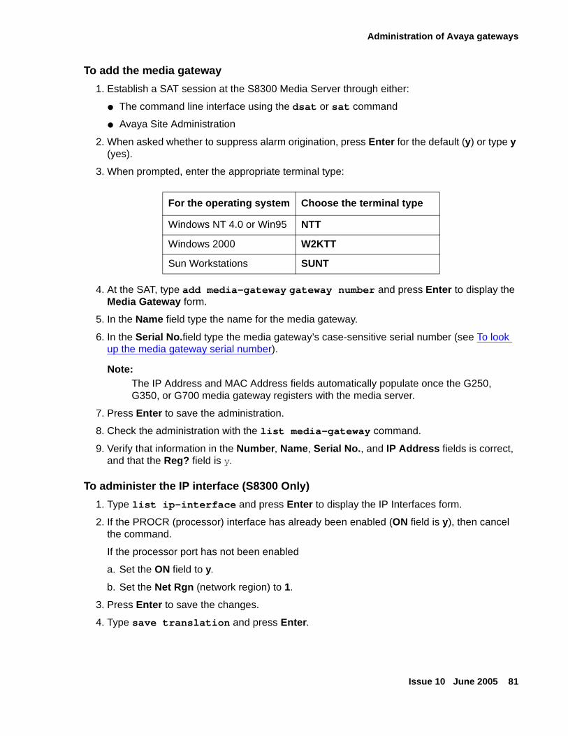
Administration of Avaya gateways
Issue 10 June 2005 81
To add the media gateway
1. Establish a SAT session at the S8300 Media Server through either:
● The command line interface using the dsat or sat command
● Avaya Site Administration
2. When asked whether to suppress alarm origination, press Enter for the default (y) or type y (yes).
3. When prompted, enter the appropriate terminal type:
4. At the SAT, type add media-gateway gateway number and press Enter to display the Media Gateway form.
5. In the Name field type the name for the media gateway.
6. In the Serial No.field type the media gateway’s case-sensitive serial number (see To look up the media gateway serial number).
Note:Note: The IP Address and MAC Address fields automatically populate once the G250,
G350, or G700 media gateway registers with the media server.
7. Press Enter to save the administration.
8. Check the administration with the list media-gateway command.
9. Verify that information in the Number, Name, Serial No., and IP Address fields is correct, and that the Reg? field is y.
To administer the IP interface (S8300 Only)
1. Type list ip-interface and press Enter to display the IP Interfaces form.
2. If the PROCR (processor) interface has already been enabled (ON field is y), then cancel the command.
If the processor port has not been enabled
a. Set the ON field to y.
b. Set the Net Rgn (network region) to 1.
3. Press Enter to save the changes.
4. Type save translation and press Enter.
For the operating system Choose the terminal type
Windows NT 4.0 or Win95 NTT
Windows 2000 W2KTT
Sun Workstations SUNT
Administering converged networks
82 Administration for Network Connectivity for Avaya Communication Manager
Administration of IP trunksThe following sections describe the administration of IP trunks:
Administering SIP trunks
Administering H.323 trunks
Administering SIP trunks
SIP is the Session Initiated Protocol, an endpoint-oriented messaging standard defined by the Internet Engineering Task Force (IETF). As implemented by Avaya for release 2.0 of Communication Manager, SIP "trunking" functionality will be available on any of the Linux-based media servers (S8300, S8500 or S8700-series). These media servers will function as Plain Old Telephone Service (POTS) gateways, and they will also support name/number delivery between and among the various non-SIP endpoints supported by Communication Manager (analog, DCP or H.323 stations and analog, digital or IP trunks), and new SIP-enabled endpoints, such as the Avaya 4602SIP Telephone. In addition to its calling capabilities, IP Softphone R5 and later also will include instant-messaging client software, which is a SIP-enabled application, while continuing its full support of the existing H.323 standard for call control.
For more information on SIP administration and usage, see SIP Support in Avaya Communication Manager 2.0, 555-245-206, and Converged Communications Server Installation and Administration, 555-245-705.
Administering H.323 trunks
H.323 trunks use an ITU-T IP standard for LAN-based multimedia telephone systems. IP-connected trunks allow trunk groups to be defined as ISDN-PRI-equivalent tie lines between switches over an IP network. Trunks that use IP connectivity reduce costs and simplify management.
Benefits include:
● Reduction in long distance voice and FAX expenses
● Facilitation of global communications
● Full-function networks with data and voice convergence
● Network optimization by using the existing network resources
The TN2302AP enables H.323 trunk service using IP connectivity between an Avaya IP solution and another H.323 v2-compliant endpoint.
Administration of IP trunks
Issue 10 June 2005 83
H.323 trunk groups can be configured as:
● Tie trunks supporting ISDN trunk features such as DCS+ and QSIG
● Generic tie-trunks permitting interconnection with other vendors’ H.323 v2-compliant switches
● Direct-inward-dial (DID) type public trunks, providing access to the switch for unregistered users
This section cover:
Setting up H.323 trunks for administration
Administering H.323 trunks
Setting up H.323 trunks for administration
This section describes the preliminary administration steps needed to set up H.323 trunks. Before you can administer an H.323 trunk, perform the following tasks:
● Verifying customer options for H.323 trunking
● Administering C-LAN and IP Media Processor circuit packs (S8500/S8700-series)
Note:Note: These circuit packs are not required if your system has built-in Ethernet
capabilities (S8300).
● Administering QoS parameters
● Assigning IP node names and IP addresses
● Defining IP interfaces
● Assigning link through Ethernet data module (S8500/S8700)
● Implementing Best Service Routing (optional)
Verifying customer options for H.323 trunking
Verify that H.323 trunking is set up correctly on the system-parameters customer-options screen. If any changes need to be made to fields on this screen, call your Avaya representative for more information.
Note:Note: The system-parameters customer-options screen is display only. Use the
display system-parameters customer-options command to review the screen. The License File controls the system software release, the Offer Category, features, and capacities. The init login does not have the ability to change the customer options, offer options, or special applications screens.
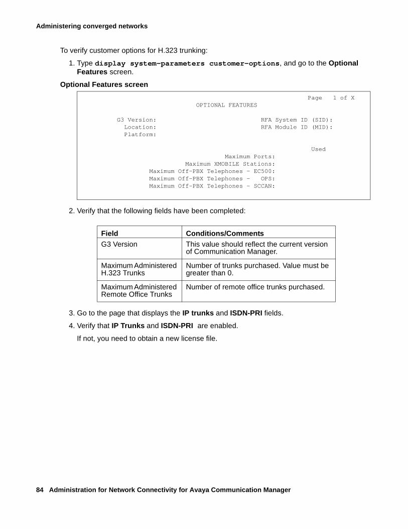
Administering converged networks
84 Administration for Network Connectivity for Avaya Communication Manager
To verify customer options for H.323 trunking:
1. Type display system-parameters customer-options, and go to the Optional Features screen.
Optional Features screen
2. Verify that the following fields have been completed:
3. Go to the page that displays the IP trunks and ISDN-PRI fields.
4. Verify that IP Trunks and ISDN-PRI are enabled.
If not, you need to obtain a new license file.
Page 1 of XOPTIONAL FEATURES
G3 Version: RFA System ID (SID): Location: RFA Module ID (MID):Platform:
UsedMaximum Ports:
Maximum XMOBILE Stations:Maximum Off-PBX Telephones - EC500:Maximum Off-PBX Telephones - OPS:Maximum Off-PBX Telephones - SCCAN:
Field Conditions/CommentsG3 Version This value should reflect the current version
of Communication Manager.
Maximum Administered H.323 Trunks
Number of trunks purchased. Value must be greater than 0.
Maximum Administered Remote Office Trunks
Number of remote office trunks purchased.
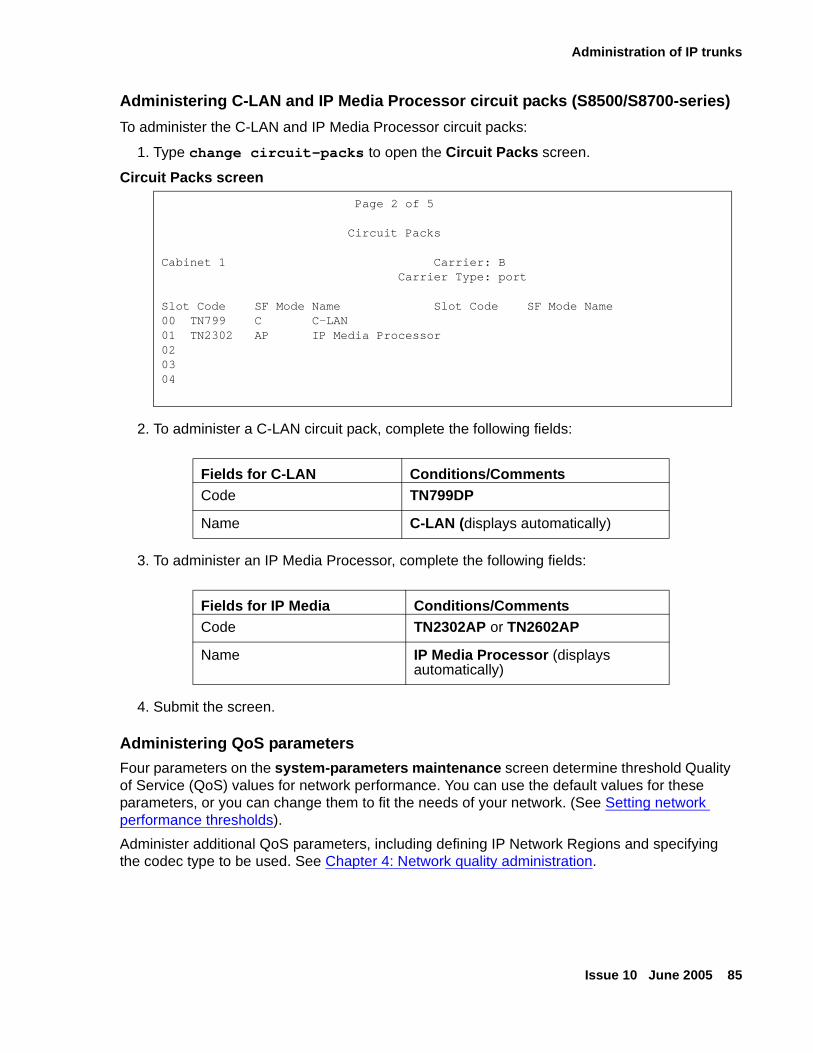
Administration of IP trunks
Issue 10 June 2005 85
Administering C-LAN and IP Media Processor circuit packs (S8500/S8700-series)
To administer the C-LAN and IP Media Processor circuit packs:
1. Type change circuit-packs to open the Circuit Packs screen.
Circuit Packs screen
2. To administer a C-LAN circuit pack, complete the following fields:
3. To administer an IP Media Processor, complete the following fields:
4. Submit the screen.
Administering QoS parameters
Four parameters on the system-parameters maintenance screen determine threshold Quality of Service (QoS) values for network performance. You can use the default values for these parameters, or you can change them to fit the needs of your network. (See Setting network performance thresholds).
Administer additional QoS parameters, including defining IP Network Regions and specifying the codec type to be used. See Chapter 4: Network quality administration.
Page 2 of 5
Circuit Packs
Cabinet 1 Carrier: BCarrier Type: port
Slot Code SF Mode Name Slot Code SF Mode Name00 TN799 C C-LAN01 TN2302 AP IP Media Processor020304
Fields for C-LAN Conditions/CommentsCode TN799DP
Name C-LAN (displays automatically)
Fields for IP Media Conditions/CommentsCode TN2302AP or TN2602AP
Name IP Media Processor (displays automatically)
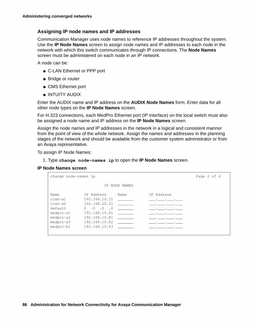
Administering converged networks
86 Administration for Network Connectivity for Avaya Communication Manager
Assigning IP node names and IP addresses
Communication Manager uses node names to reference IP addresses throughout the system. Use the IP Node Names screen to assign node names and IP addresses to each node in the network with which this switch communicates through IP connections. The Node Names screen must be administered on each node in an IP network.
A node can be:
● C-LAN Ethernet or PPP port
● Bridge or router
● CMS Ethernet port
● INTUITY AUDIX
Enter the AUDIX name and IP address on the AUDIX Node Names form. Enter data for all other node types on the IP Node Names screen.
For H.323 connections, each MedPro Ethernet port (IP interface) on the local switch must also be assigned a node name and IP address on the IP Node Names screen.
Assign the node names and IP addresses in the network in a logical and consistent manner from the point of view of the whole network. Assign the names and addresses in the planning stages of the network and should be available from the customer system administrator or from an Avaya representative.
To assign IP Node Names:
1. Type change node-names ip to open the IP Node Names screen.
IP Node Names screen
change node-names ip Page 2 of 6
IP NODE NAMES
Name IP Address Name IP Addressclan-a1 192.168.10.31 _______ ___.___.___.___clan-a2 192.168.20.31 _______ ___.___.___.___default 0 .0 .0 .0 _______ ___.___.___.___medpro-a1 192.168.10.81 _______ ___.___.___.___medpro-a2 192.168.10.B1 _______ ___.___.___.___medpro-a3 192.168.10.82 _______ ___.___.___.___medpro-b1 192.168.10.83 _______ ___.___.___.___
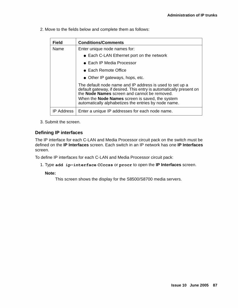
Administration of IP trunks
Issue 10 June 2005 87
2. Move to the fields below and complete them as follows:
3. Submit the screen.
Defining IP interfaces
The IP interface for each C-LAN and Media Processor circuit pack on the switch must be defined on the IP Interfaces screen. Each switch in an IP network has one IP Interfaces screen.
To define IP interfaces for each C-LAN and Media Processor circuit pack:
1. Type add ip-interface CCccss or procr to open the IP Interfaces screen.
Note:Note: This screen shows the display for the S8500/S8700 media servers.
Field Conditions/CommentsName Enter unique node names for:
● Each C-LAN Ethernet port on the network
● Each IP Media Processor
● Each Remote Office
● Other IP gateways, hops, etc.
The default node name and IP address is used to set up a default gateway, if desired. This entry is automatically present on the Node Names screen and cannot be removed.When the Node Names screen is saved, the system automatically alphabetizes the entries by node name.
IP Address Enter a unique IP addresses for each node name.
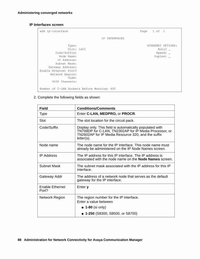
Administering converged networks
88 Administration for Network Connectivity for Avaya Communication Manager
IP Interfaces screen
2. Complete the following fields as shown:
add ip-interface Page 1 of 1
IP INTERFACES
Type: ETHERNET OPTIONS:Slot: 1a03 Auto? _
Code/Suffix: Speed: _Node Name: Duplex: _IP Address: Subnet Mask:
Gateway Address: Enable Ethernet Port?
Network Region: VLAN:
VOIP Channels:
Number of C-LAN Sockets Before Warning: 400
Field Conditions/CommentsType Enter C-LAN, MEDPRO, or PROCR.
Slot The slot location for the circuit pack.
Code/Suffix Display only. This field is automatically populated with TN799DP for C-LAN, TN2302AP for IP Media Processor, or TN2602AP for IP Media Resource 320, and the suffix letter(s).
Node name The node name for the IP interface. This node name must already be administered on the IP Node Names screen.
IP Address The IP address for this IP interface. The IP address is associated with the node name on the Node Names screen.
Subnet Mask The subnet mask associated with the IP address for this IP interface.
Gateway Addr The address of a network node that serves as the default gateway for the IP interface.
Enable Ethernet Port?
Enter y
Network Region The region number for the IP interface.Enter a value between
● 1-80 (si only)
● 1-250 (S8300, S8500, or S8700)
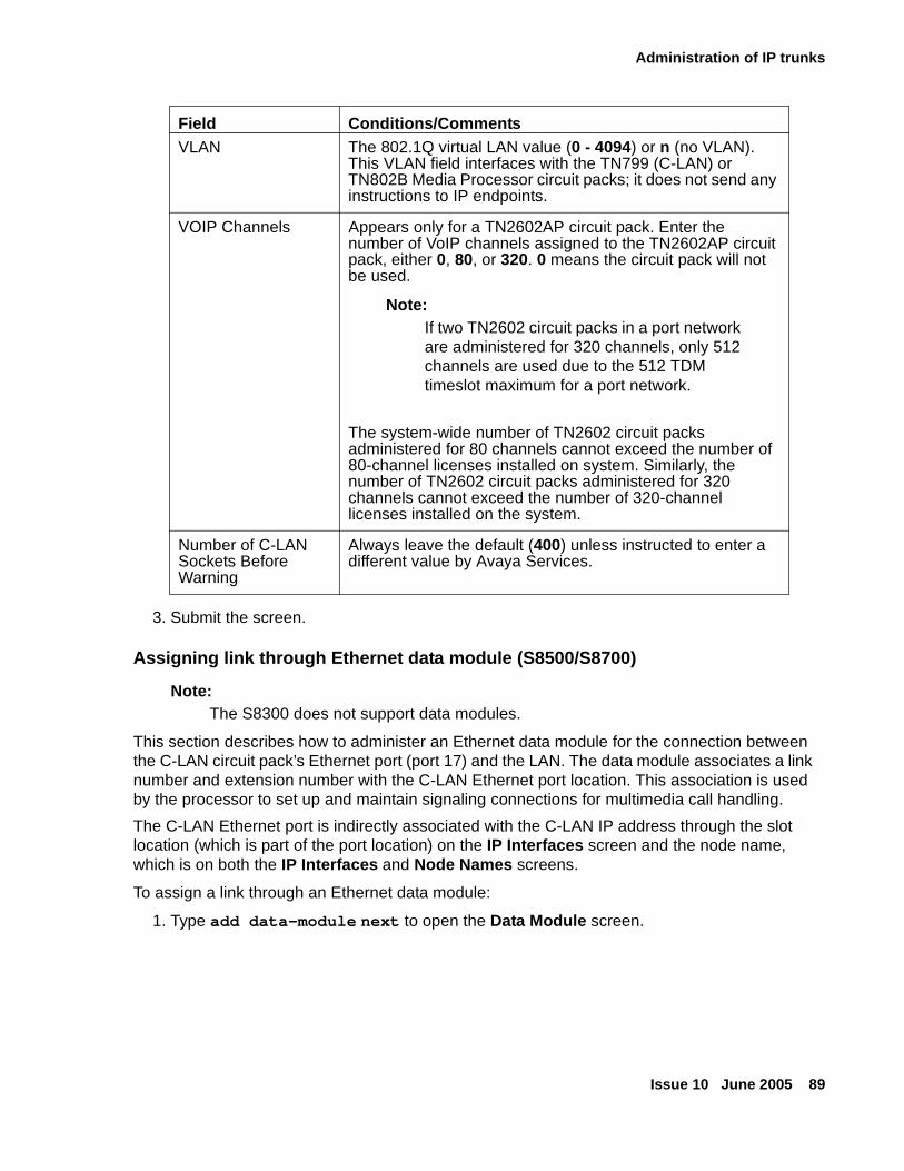
Administration of IP trunks
Issue 10 June 2005 89
3. Submit the screen.
Assigning link through Ethernet data module (S8500/S8700)
Note:Note: The S8300 does not support data modules.
This section describes how to administer an Ethernet data module for the connection between the C-LAN circuit pack’s Ethernet port (port 17) and the LAN. The data module associates a link number and extension number with the C-LAN Ethernet port location. This association is used by the processor to set up and maintain signaling connections for multimedia call handling.
The C-LAN Ethernet port is indirectly associated with the C-LAN IP address through the slot location (which is part of the port location) on the IP Interfaces screen and the node name, which is on both the IP Interfaces and Node Names screens.
To assign a link through an Ethernet data module:
1. Type add data-module next to open the Data Module screen.
VLAN The 802.1Q virtual LAN value (0 - 4094) or n (no VLAN). This VLAN field interfaces with the TN799 (C-LAN) or TN802B Media Processor circuit packs; it does not send any instructions to IP endpoints.
VOIP Channels Appears only for a TN2602AP circuit pack. Enter the number of VoIP channels assigned to the TN2602AP circuit pack, either 0, 80, or 320. 0 means the circuit pack will not be used.
Note:Note: If two TN2602 circuit packs in a port network
are administered for 320 channels, only 512 channels are used due to the 512 TDM timeslot maximum for a port network.
The system-wide number of TN2602 circuit packs administered for 80 channels cannot exceed the number of 80-channel licenses installed on system. Similarly, the number of TN2602 circuit packs administered for 320 channels cannot exceed the number of 320-channel licenses installed on the system.
Number of C-LAN Sockets Before Warning
Always leave the default (400) unless instructed to enter a different value by Avaya Services.
Field Conditions/Comments
Administering converged networks
90 Administration for Network Connectivity for Avaya Communication Manager
Data Module screen
2. Complete the following fields as shown:
3. Submit the screen.
add data-module next Page 1 of 1 DATA MODULE Data Extension: Name:__________ BBC: _ Type: Ethernet COS: _ Remote Loop-Around Test? _ Port: COR: _ Secondary Data Module? _
ITC: TN: _ Connected To: _
ABBREVIATED DIALING List1: _
SPECIAL DIALING OPTION:
ASSIGNED MEMBER <Station with a data extension button for this data module> Ext (first 26 characters) 1:_____
Field Conditions/CommentsData Extension Populated automatically with the next qualifier
or type the extension number.
Type Enter Ethernet. This indicates the data-module type for this link.
Port Ethernet connections must be assigned to port 17 on the C-LAN circuit pack.
Link Enter the link number, a link not previously assigned on this switch.
Name Display only. The name appears in lists generated by the list data module command.
Network uses 1’s for broadcast addresses
Enter y if the private network contains only Avaya switches and adjuncts.Enter n if the network includes non-Avaya switches that use the 0’s method of forming broadcast addresses.
Administration of IP trunks
Issue 10 June 2005 91
Implementing Best Service Routing (optional)
Use H.323 trunks to implement Best Service Routing (BSR). You can use H.323 trunks for polling, or for both polling and interflow. Because polling requires only a small amount of data exchange, the additional network traffic is insignificant. However, interflow requires a significant amount of bandwidth to carry the voice data. Depending on the other uses of the LAN/WAN and its overall utilization rate, voice quality could be degraded to unacceptable levels.
Avaya recommends that if H.323 trunks are used for BSR interflow, the traffic should be routed to a low-occupancy or unshared LAN/WAN segment. Alternatively, you might want to route internal interflow traffic, which may have lower quality-of-service requirements, over H.323 trunks, and route customer interflow traffic over circuit-switched tie trunks.
Administering H.323 trunks
You have completed the pre-administration tasks to set up H.323 trunks (see Setting up H.323 trunks for administration). This section describes the tasks that you need to complete to administer an H.323 trunk. Sample values are used to populate the fields to show the relationships between the screens and fields. Perform the following tasks:
● Creating an H323 trunk signaling group
Create a signaling group for the H.323 trunks that connect this switch to a far-end switch.
● Creating a trunk group for H.323 trunks
● Modifying the H.323 trunk signaling group
Modify the signaling group by entering the H.323 trunk group number in the Trunk Group for the Channel Selection field of the Signaling Group screen.
Creating an H323 trunk signaling group
Create a signaling group that is associated with H.323 trunks that connect this switch to a far-end switch. One or more unique signaling groups must be established for each far-end node to which this switch is connected through H.323 trunks.
Note:Note: The following steps address only those fields that are specifically related to H.323
trunks. The other fields are described in the Administrator’s Guide for Avaya Communication Manager (555-233-506).
To create an H.323 trunk signaling group, do the following:
1. Type add signaling-group number to open the Signaling Group screen.
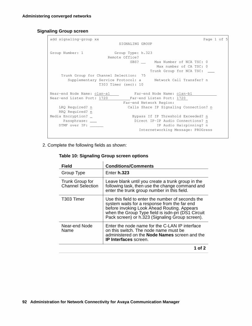
Administering converged networks
92 Administration for Network Connectivity for Avaya Communication Manager
Signaling Group screen
2. Complete the following fields as shown:
add signaling-group xx Page 1 of 5 SIGNALING GROUP
Group Number: 1 Group Type: h.323Remote Office? SBS? __ Max Number of NCA TSC: 0
Max number of CA TSC: 0Trunk Group for NCA TSC: ___
Trunk Group for Channel Selection: 75Supplementary Service Protocol: a Network Call Transfer? n
T303 Timer (sec): 10
Near-end Node Name: clan-a1 Far-end Node Name: clan-b1 Near-end Listen Port: 1720 Far-end Listen Port: 1720
Far-end Network Region: LRQ Required? n Calls Share IP Signaling Connection? n RRQ Required? n
Media Encryption? _ Bypass If IP Threshold Exceeded? n Passphrase: ___ Direct IP-IP Audio Connections? n
DTMF over IP: ______ IP Audio Hairpinning? nInternetworking Message: PROGress
Table 10: Signaling Group screen options
Field Conditions/CommentsGroup Type Enter h.323
Trunk Group for Channel Selection
Leave blank until you create a trunk group in the following task, then use the change command and enter the trunk group number in this field.
T303 Timer Use this field to enter the number of seconds the system waits for a response from the far end before invoking Look Ahead Routing. Appears when the Group Type field is isdn-pri (DS1 Circuit Pack screen) or h.323 (Signaling Group screen).
Near-end Node Name
Enter the node name for the C-LAN IP interface on this switch. The node name must be administered on the Node Names screen and the IP Interfaces screen.
1 of 2
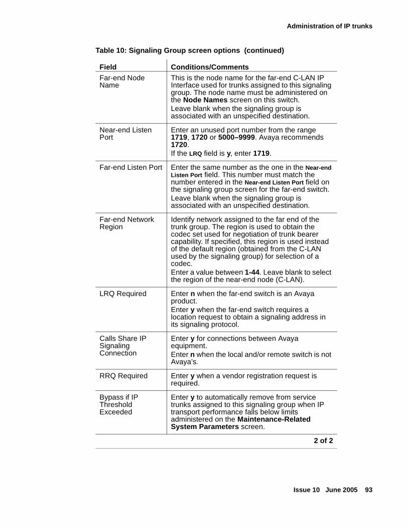
Administration of IP trunks
Issue 10 June 2005 93
Far-end Node Name
This is the node name for the far-end C-LAN IP Interface used for trunks assigned to this signaling group. The node name must be administered on the Node Names screen on this switch.Leave blank when the signaling group is associated with an unspecified destination.
Near-end Listen Port
Enter an unused port number from the range 1719, 1720 or 5000–9999. Avaya recommends 1720.If the LRQ field is y, enter 1719.
Far-end Listen Port Enter the same number as the one in the Near-end Listen Port field. This number must match the number entered in the Near-end Listen Port field on the signaling group screen for the far-end switch.Leave blank when the signaling group is associated with an unspecified destination.
Far-end Network Region
Identify network assigned to the far end of the trunk group. The region is used to obtain the codec set used for negotiation of trunk bearer capability. If specified, this region is used instead of the default region (obtained from the C-LAN used by the signaling group) for selection of a codec. Enter a value between 1-44. Leave blank to select the region of the near-end node (C-LAN).
LRQ Required Enter n when the far-end switch is an Avaya product.Enter y when the far-end switch requires a location request to obtain a signaling address in its signaling protocol.
Calls Share IP Signaling Connection
Enter y for connections between Avaya equipment. Enter n when the local and/or remote switch is not Avaya’s.
RRQ Required Enter y when a vendor registration request is required.
Bypass if IP Threshold Exceeded
Enter y to automatically remove from service trunks assigned to this signaling group when IP transport performance falls below limits administered on the Maintenance-Related System Parameters screen.
Table 10: Signaling Group screen options (continued)
Field Conditions/Comments
2 of 2
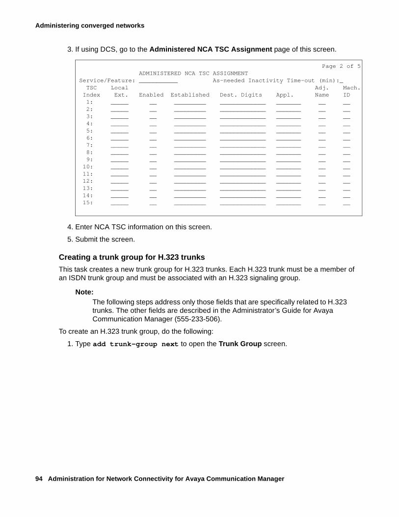
Administering converged networks
94 Administration for Network Connectivity for Avaya Communication Manager
3. If using DCS, go to the Administered NCA TSC Assignment page of this screen.
4. Enter NCA TSC information on this screen.
5. Submit the screen.
Creating a trunk group for H.323 trunks
This task creates a new trunk group for H.323 trunks. Each H.323 trunk must be a member of an ISDN trunk group and must be associated with an H.323 signaling group.
Note:Note: The following steps address only those fields that are specifically related to H.323
trunks. The other fields are described in the Administrator’s Guide for Avaya Communication Manager (555-233-506).
To create an H.323 trunk group, do the following:
1. Type add trunk-group next to open the Trunk Group screen.
Page 2 of 5ADMINISTERED NCA TSC ASSIGNMENT
Service/Feature: ___________ As-needed Inactivity Time-out (min):_ TSC Local Adj. Mach.
Index Ext. Enabled Established Dest. Digits Appl. Name ID1: _____ __ _________ _____________ _______ __ __2: _____ __ _________ _____________ _______ __ __3: _____ __ _________ _____________ _______ __ __4: _____ __ _________ _____________ _______ __ __5: _____ __ _________ _____________ _______ __ __6: _____ __ _________ _____________ _______ __ __7: _____ __ _________ _____________ _______ __ __8: _____ __ _________ _____________ _______ __ __9: _____ __ _________ _____________ _______ __ __
10: _____ __ _________ _____________ _______ __ __11: _____ __ _________ _____________ _______ __ __12: _____ __ _________ _____________ _______ __ __13: _____ __ _________ _____________ _______ __ __14: _____ __ _________ _____________ _______ __ __15: _____ __ _________ _____________ _______ __ __
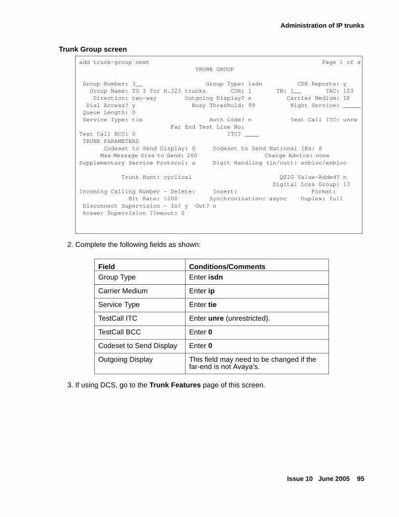
Administration of IP trunks
Issue 10 June 2005 95
Trunk Group screen
2. Complete the following fields as shown:
3. If using DCS, go to the Trunk Features page of this screen.
add trunk-group next Page 1 of x TRUNK GROUP
Group Number: 3__ Group Type: isdn CDR Reports: y Group Name: TG 3 for H.323 trunks COR: 1 TN: 1__ TAC: 103 Direction: two-way Outgoing Display? n Carrier Medium: IP Dial Access? y Busy Threshold: 99 Night Service: _____ Queue Length: 0 Service Type: tie Auth Code? n Test Call ITC: unre
Far End Test Line No:Test Call BCC: 0 ITC? ____ TRUNK PARAMETERS
Codeset to Send Display: 0 Codeset to Send National IEs: 6Max Message Size to Send: 260 Charge Advice: none
Supplementary Service Protocol: a Digit Handling (in/out): enbloc/enbloc
Trunk Hunt: cyclical QSIG Value-Added? n Digital Loss Group: 13Incoming Calling Number - Delete: Insert: Format: Bit Rate: 1200 Synchronization: async Duplex: full Disconnect Supervision - In? y Out? n Answer Supervision Timeout: 0
Field Conditions/CommentsGroup Type Enter isdn
Carrier Medium Enter ip
Service Type Enter tie
TestCall ITC Enter unre (unrestricted).
TestCall BCC Enter 0
Codeset to Send Display Enter 0
Outgoing Display This field may need to be changed if the far-end is not Avaya’s.
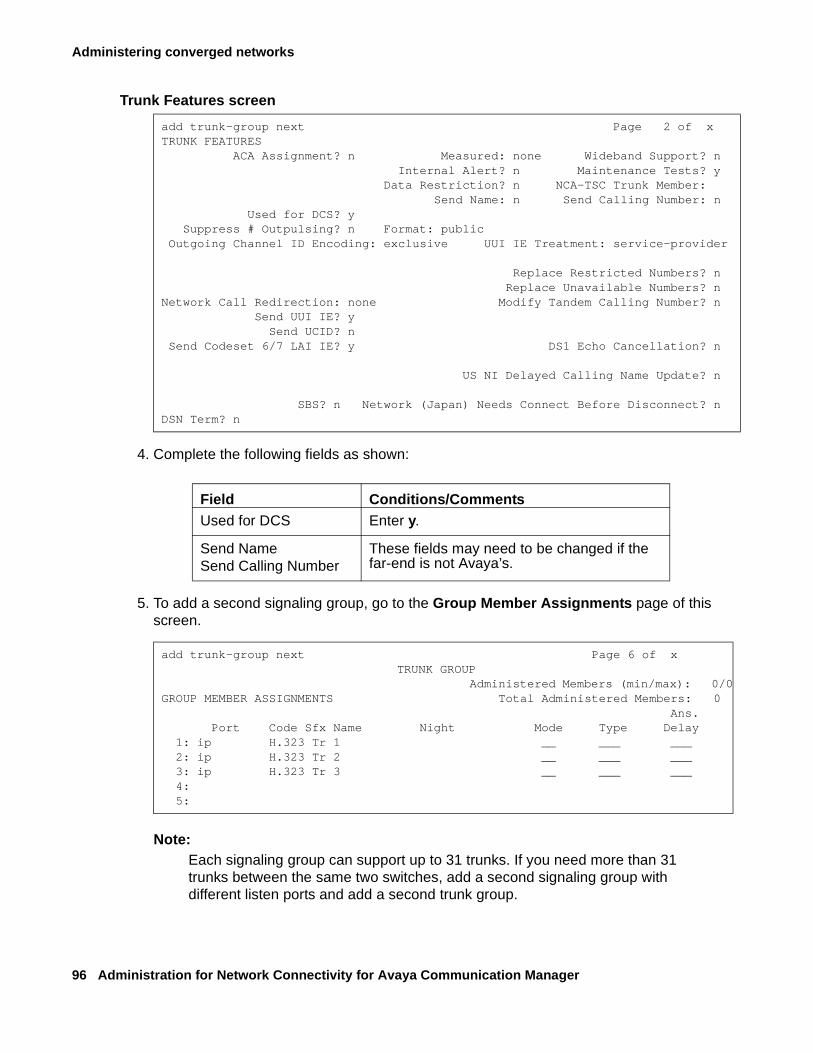
Administering converged networks
96 Administration for Network Connectivity for Avaya Communication Manager
Trunk Features screen
4. Complete the following fields as shown:
5. To add a second signaling group, go to the Group Member Assignments page of this screen.
Note:Note: Each signaling group can support up to 31 trunks. If you need more than 31
trunks between the same two switches, add a second signaling group with different listen ports and add a second trunk group.
add trunk-group next Page 2 of x TRUNK FEATURES ACA Assignment? n Measured: none Wideband Support? n
Internal Alert? n Maintenance Tests? yData Restriction? n NCA-TSC Trunk Member:
Send Name: n Send Calling Number: n Used for DCS? y Suppress # Outpulsing? n Format: public Outgoing Channel ID Encoding: exclusive UUI IE Treatment: service-provider
Replace Restricted Numbers? n Replace Unavailable Numbers? nNetwork Call Redirection: none Modify Tandem Calling Number? n
Send UUI IE? ySend UCID? n
Send Codeset 6/7 LAI IE? y DS1 Echo Cancellation? n
US NI Delayed Calling Name Update? n
SBS? n Network (Japan) Needs Connect Before Disconnect? nDSN Term? n
Field Conditions/CommentsUsed for DCS Enter y.
Send NameSend Calling Number
These fields may need to be changed if the far-end is not Avaya’s.
add trunk-group next Page 6 of x TRUNK GROUP
Administered Members (min/max): 0/0GROUP MEMBER ASSIGNMENTS Total Administered Members: 0 Ans. Port Code Sfx Name Night Mode Type Delay 1: ip H.323 Tr 1 __ ___ ___ 2: ip H.323 Tr 2 __ ___ ___ 3: ip H.323 Tr 3 __ ___ ___ 4: 5:
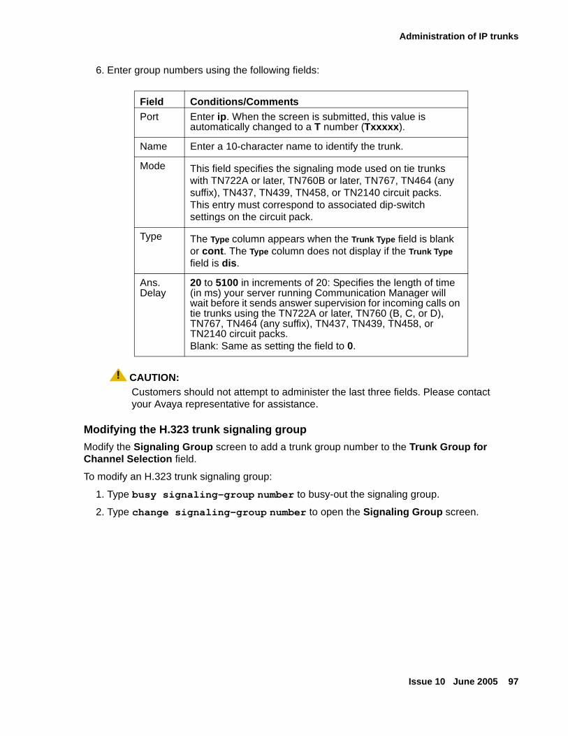
Administration of IP trunks
Issue 10 June 2005 97
6. Enter group numbers using the following fields:
! CAUTION:CAUTION: Customers should not attempt to administer the last three fields. Please contact
your Avaya representative for assistance.
Modifying the H.323 trunk signaling group
Modify the Signaling Group screen to add a trunk group number to the Trunk Group for Channel Selection field.
To modify an H.323 trunk signaling group:
1. Type busy signaling-group number to busy-out the signaling group.
2. Type change signaling-group number to open the Signaling Group screen.
Field Conditions/CommentsPort Enter ip. When the screen is submitted, this value is
automatically changed to a T number (Txxxxx).
Name Enter a 10-character name to identify the trunk.
Mode This field specifies the signaling mode used on tie trunks with TN722A or later, TN760B or later, TN767, TN464 (any suffix), TN437, TN439, TN458, or TN2140 circuit packs. This entry must correspond to associated dip-switch settings on the circuit pack.
Type The Type column appears when the Trunk Type field is blank or cont. The Type column does not display if the Trunk Type field is dis.
Ans. Delay
20 to 5100 in increments of 20: Specifies the length of time (in ms) your server running Communication Manager will wait before it sends answer supervision for incoming calls on tie trunks using the TN722A or later, TN760 (B, C, or D), TN767, TN464 (any suffix), TN437, TN439, TN458, or TN2140 circuit packs.Blank: Same as setting the field to 0.
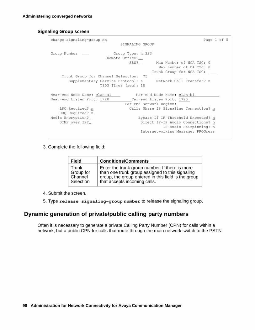
Administering converged networks
98 Administration for Network Connectivity for Avaya Communication Manager
Signaling Group screen
3. Complete the following field:
4. Submit the screen.
5. Type release signaling-group number to release the signaling group.
Dynamic generation of private/public calling party numbers
Often it is necessary to generate a private Calling Party Number (CPN) for calls within a network, but a public CPN for calls that route through the main network switch to the PSTN.
change signaling-group xx Page 1 of 5 SIGNALING GROUP
Group Number ___ Group Type: h.323Remote Office?__ SBS?__ Max Number of NCA TSC: 0
Max number of CA TSC: 0Trunk Group for NCA TSC: ___
Trunk Group for Channel Selection: 75Supplementary Service Protocol: a Network Call Transfer? n
T303 Timer (sec): 10
Near-end Node Name: clan-a1 Far-end Node Name: clan-b1 Near-end Listen Port: 1720 Far-end Listen Port: 1720
Far-end Network Region: LRQ Required? n Calls Share IP Signaling Connection? n RRQ Required? n
Media Encryption?_ Bypass If IP Threshold Exceeded? n DTMF over IP?_ Direct IP-IP Audio Connections? n
IP Audio Hairpinning? nInternetworking Message: PROGress
Field Conditions/CommentsTrunk Group for Channel Selection
Enter the trunk group number. If there is more than one trunk group assigned to this signaling group, the group entered in this field is the group that accepts incoming calls.
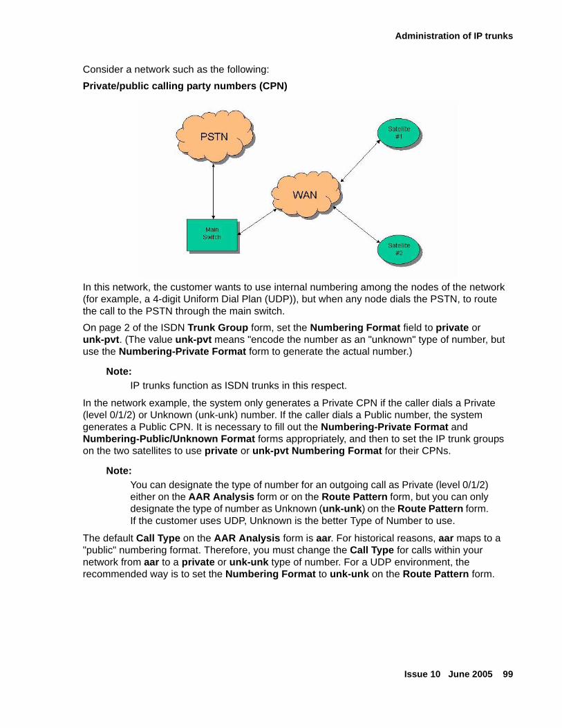
Administration of IP trunks
Issue 10 June 2005 99
Consider a network such as the following:
Private/public calling party numbers (CPN)
In this network, the customer wants to use internal numbering among the nodes of the network (for example, a 4-digit Uniform Dial Plan (UDP)), but when any node dials the PSTN, to route the call to the PSTN through the main switch.
On page 2 of the ISDN Trunk Group form, set the Numbering Format field to private or unk-pvt. (The value unk-pvt means "encode the number as an "unknown" type of number, but use the Numbering-Private Format form to generate the actual number.)
Note:Note: IP trunks function as ISDN trunks in this respect.
In the network example, the system only generates a Private CPN if the caller dials a Private (level 0/1/2) or Unknown (unk-unk) number. If the caller dials a Public number, the system generates a Public CPN. It is necessary to fill out the Numbering-Private Format and Numbering-Public/Unknown Format forms appropriately, and then to set the IP trunk groups on the two satellites to use private or unk-pvt Numbering Format for their CPNs.
Note:Note: You can designate the type of number for an outgoing call as Private (level 0/1/2)
either on the AAR Analysis form or on the Route Pattern form, but you can only designate the type of number as Unknown (unk-unk) on the Route Pattern form. If the customer uses UDP, Unknown is the better Type of Number to use.
The default Call Type on the AAR Analysis form is aar. For historical reasons, aar maps to a "public" numbering format. Therefore, you must change the Call Type for calls within your network from aar to a private or unk-unk type of number. For a UDP environment, the recommended way is to set the Numbering Format to unk-unk on the Route Pattern form.
Administering converged networks
100 Administration for Network Connectivity for Avaya Communication Manager
Administration of Avaya phonesThe following sections describe the installation and administration of Avaya IP telephones:
● Administering IP Softphones
● Installing and administering Avaya IP telephones
Administering IP Softphones
IP Softphones operate on a PC equipped with Microsoft Windows and with TCP/IP connectivity through Communication Manager. Avaya offers three different Softphone applications:
● IP Softphone for any phone user
● IP Agent for call center agents
● Softconsole for attendants
IP Softphones can be configured to operate in any of the following modes:
● Road-warrior mode consists of a PC running the Avaya IP Softphone application and Avaya iClarity IP Audio, with a single IP connection to an Avaya server or gateway.
● Telecommuter mode consists of a PC running the Avaya IP Softphone application with an IP connection to the server, and a standard telephone with a separate PSTN connection to the server.
● Shared Control mode provides a registration endpoint configuration that will allow an IP Softphone and a non-Softphone telephone to be in service on the same extension at the same time. In this new configuration, the call control is provided by both the Softphone and the telephone endpoint. The audio is provided by the telephone endpoint.
Documentation on how to set up and use the IP Softphones is included on the CD-ROM containing the IP Softphone software. Procedures for administering Communication Manager to support IP Softphones are given in Administrator’s Guide for Avaya Communication Manager (555-233-506).
Administering the IP Softphone
This section focuses on administration for the trunk side of the Avaya IP Solutions offer, plus a brief checklist of IP Softphone administration. Comprehensive information on the administration of IP Softphones is given in Administrator’s Guide for Avaya Communication Manager (555-233-506).
There are two main types of IP Softphone configurations:
● Administering a Telecommuter phone
● Administering a Road-warrior phone
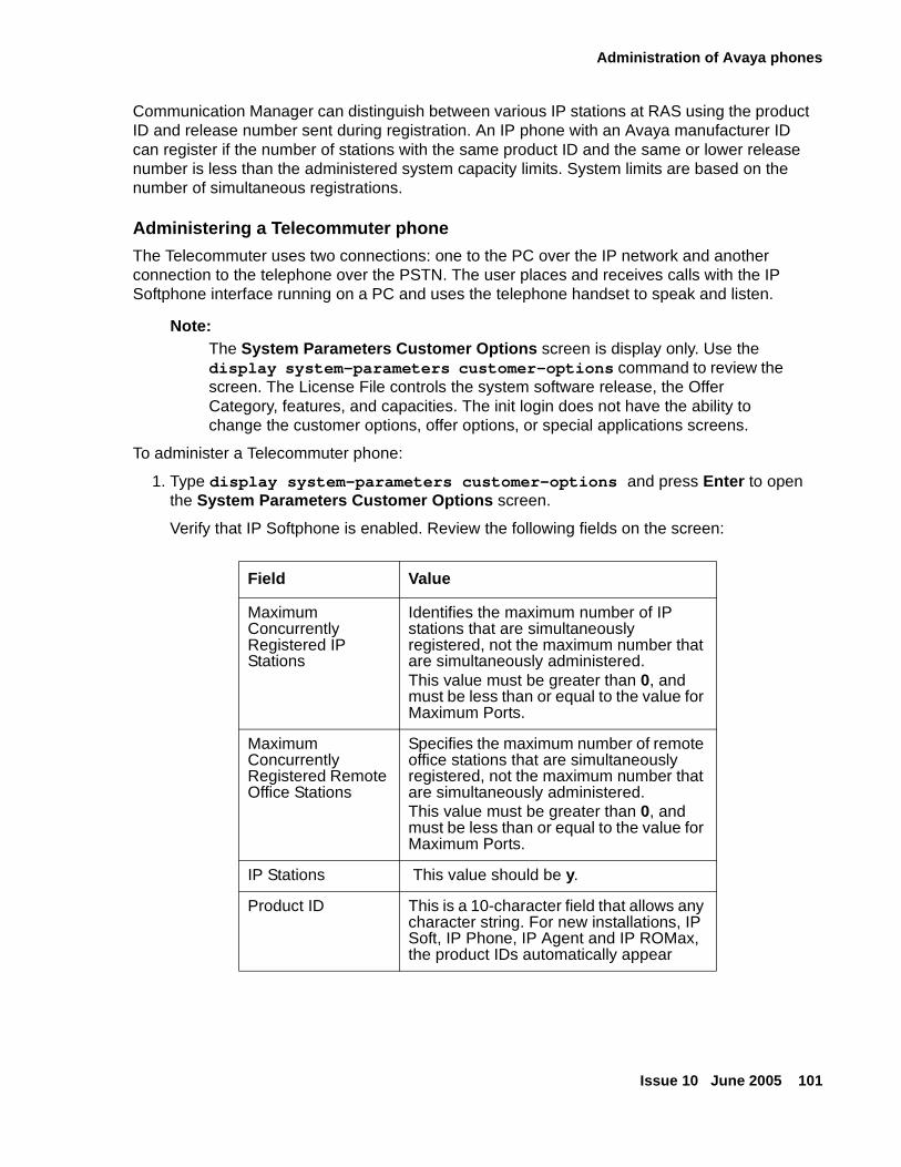
Administration of Avaya phones
Issue 10 June 2005 101
Communication Manager can distinguish between various IP stations at RAS using the product ID and release number sent during registration. An IP phone with an Avaya manufacturer ID can register if the number of stations with the same product ID and the same or lower release number is less than the administered system capacity limits. System limits are based on the number of simultaneous registrations.
Administering a Telecommuter phone
The Telecommuter uses two connections: one to the PC over the IP network and another connection to the telephone over the PSTN. The user places and receives calls with the IP Softphone interface running on a PC and uses the telephone handset to speak and listen.
Note:Note: The System Parameters Customer Options screen is display only. Use the
display system-parameters customer-options command to review the screen. The License File controls the system software release, the Offer Category, features, and capacities. The init login does not have the ability to change the customer options, offer options, or special applications screens.
To administer a Telecommuter phone:
1. Type display system-parameters customer-options and press Enter to open the System Parameters Customer Options screen.
Verify that IP Softphone is enabled. Review the following fields on the screen:
Field Value
Maximum Concurrently Registered IP Stations
Identifies the maximum number of IP stations that are simultaneously registered, not the maximum number that are simultaneously administered.This value must be greater than 0, and must be less than or equal to the value for Maximum Ports.
Maximum Concurrently Registered Remote Office Stations
Specifies the maximum number of remote office stations that are simultaneously registered, not the maximum number that are simultaneously administered.This value must be greater than 0, and must be less than or equal to the value for Maximum Ports.
IP Stations This value should be y.
Product ID This is a 10-character field that allows any character string. For new installations, IP Soft, IP Phone, IP Agent and IP ROMax, the product IDs automatically appear
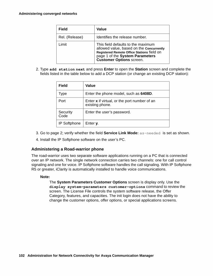
Administering converged networks
102 Administration for Network Connectivity for Avaya Communication Manager
2. Type add station next and press Enter to open the Station screen and complete the fields listed in the table below to add a DCP station (or change an existing DCP station):
3. Go to page 2; verify whether the field Service Link Mode: as-needed is set as shown.
4. Install the IP Softphone software on the user’s PC.
Administering a Road-warrior phone
The road-warrior uses two separate software applications running on a PC that is connected over an IP network. The single network connection carries two channels: one for call control signaling and one for voice. IP Softphone software handles the call signaling. With IP Softphone R5 or greater, iClarity is automatically installed to handle voice communications.
Note:Note: The System Parameters Customer Options screen is display only. Use the
display system-parameters customer-options command to review the screen. The License File controls the system software release, the Offer Category, features, and capacities. The init login does not have the ability to change the customer options, offer options, or special applications screens.
Rel. (Release) Identifies the release number.
Limit This field defaults to the maximum allowed value, based on the Concurrently Registered Remote Office Stations field on page 1 of the System Parameters Customer Options screen.
Field Value
Type Enter the phone model, such as 6408D.
Port Enter x if virtual, or the port number of an existing phone.
Security Code
Enter the user’s password.
IP Softphone Enter y.
Field Value
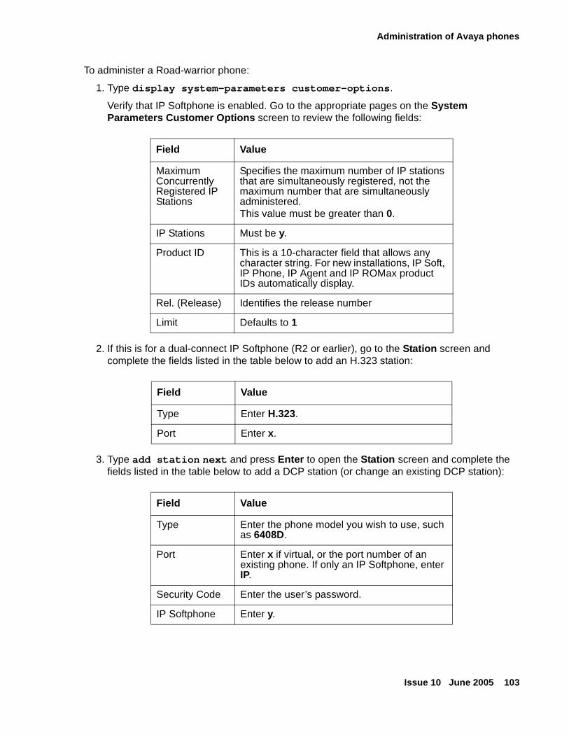
Administration of Avaya phones
Issue 10 June 2005 103
To administer a Road-warrior phone:
1. Type display system-parameters customer-options.
Verify that IP Softphone is enabled. Go to the appropriate pages on the System Parameters Customer Options screen to review the following fields:
2. If this is for a dual-connect IP Softphone (R2 or earlier), go to the Station screen and complete the fields listed in the table below to add an H.323 station:
3. Type add station next and press Enter to open the Station screen and complete the fields listed in the table below to add a DCP station (or change an existing DCP station):
Field Value
Maximum Concurrently Registered IP Stations
Specifies the maximum number of IP stations that are simultaneously registered, not the maximum number that are simultaneously administered.This value must be greater than 0.
IP Stations Must be y.
Product ID This is a 10-character field that allows any character string. For new installations, IP Soft, IP Phone, IP Agent and IP ROMax product IDs automatically display.
Rel. (Release) Identifies the release number
Limit Defaults to 1
Field Value
Type Enter H.323.
Port Enter x.
Field Value
Type Enter the phone model you wish to use, such as 6408D.
Port Enter x if virtual, or the port number of an existing phone. If only an IP Softphone, enter IP.
Security Code Enter the user’s password.
IP Softphone Enter y.
Administering converged networks
104 Administration for Network Connectivity for Avaya Communication Manager
4. Go to page 2; Service Link Mode: as-needed.
Install the IP Softphone software on the user’s PC (iClarity automatically installed with the IP Softphone R2 or greater).
5. For pre-R2 IP Softphones, an H.323 V2-compliant audio application (such as Microsoft NetMeeting) must be installed.
Installing and administering Avaya IP telephones
The Avaya line of digital business phones uses Internet Protocol (IP) technology with Ethernet line interfaces and has downloadable firmware.
IP Telephones provide support for dynamic host configuration protocol (DHCP) and trivial file transfer protocol (TFTP) over IPv4/UDP, which enhance the administration and servicing of the phones.
For more information on installing and administering Avaya IP telephones, see 4600 Series IP Telephone R2.1 LAN Administrator’s Guide, 555-233-507.
About the 46xx IP telephone series
The 46xx IP Telephone product line possesses a number of shared model features and capabilities. All models also feature
● Downloadable firmware
● Automatic IP address resolution through DHCP
● Manual IP address programming.
The 46xx IP Telephone product line includes the following telephones:
● Avaya 4601 IP telephone
● Avaya 4602 IP telephone
● 4602SIP IP telephone
● Avaya 4602SW IP telephone
● Avaya 4606 IP telephone
● Avaya 4610SW IP telephone
● Avaya 4620 IP telephone
● Avaya 4620SW IP telephone
● Avaya 4624 IP telephone
● Avaya 4630SW IP Screenphone
● Avaya 4690 IP conference telephone
Administration of Avaya phones
Issue 10 June 2005 105
For information on the feature functionality of the IP telephones, see the Hardware Guide for Avaya Communication Manager (555-245-207), the 4600 Series IP Telephone Installation Guide (555-233-128), or the appropriate 4600 series IP Telephone user’s guide.
About IP telephone hardware/software requirements
Note:Note: Communication Manager requires that IP telephones still running R1.1 or earlier
software be upgraded to R1.51 or newer software. The earlier software used a dual connection architecture that is no longer supported.
46xx IP Telephones are shipped from the factory with operational firmware installed. Some system-specific software applications are downloaded from a TFTP server through automatic power-up or reset. The 46xx IP Telephones search and download new firmware from the TFTP server before attempting to register with the Communication Manager.
The software treats the 46xx IP Telephones as any new station type, including the capability to list/display/change/duplicate/alias/remove station.
Note:Note: Audio capability for the IP Telephones requires the presence of the TN2302AP IP
Media Processor circuit pack, which provides hairpinning and IP-IP direct connections. This conserves TDM bus and timeslot resources and improves voice quality.
The 46xx IP Telephone also requires a TN799DP Control-LAN (C-LAN) circuit pack for the signaling capability on the DEFINITY Server csi and si platforms. You do not need a C-LAN circuit pack to connect an IP Telephone if your system has built-in Ethernet capability (for example Avaya S8300 Media Server or Avaya S8700 Media Server).
To install required TN2302AP, TN2602AP, and TN799DP circuit Packs, if necessary
1. Determine the carrier/slot assignments of the circuit packs to be added.
2. Insert the circuit pack into the slot specified in step 1.
Note:Note: You do not have to power down the cabinet to install the circuit packs.
Administering Avaya IP telephones
IP Telephones R1.5 or greater use a single connection, and you only need to administer the station type.
To add an IP telephone
1. Type add station next to go to the Station screen.
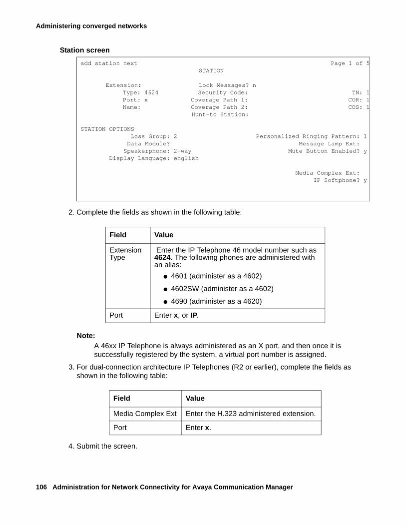
Administering converged networks
106 Administration for Network Connectivity for Avaya Communication Manager
Station screen
2. Complete the fields as shown in the following table:
Note:Note: A 46xx IP Telephone is always administered as an X port, and then once it is
successfully registered by the system, a virtual port number is assigned.
3. For dual-connection architecture IP Telephones (R2 or earlier), complete the fields as shown in the following table:
4. Submit the screen.
add station next Page 1 of 5 STATION
Extension: Lock Messages? n Type: 4624 Security Code: TN: 1 Port: x Coverage Path 1: COR: 1 Name: Coverage Path 2: COS: 1
Hunt-to Station:
STATION OPTIONS Loss Group: 2 Personalized Ringing Pattern: 1
Data Module? Message Lamp Ext:Speakerphone: 2-way Mute Button Enabled? y
Display Language: english
Media Complex Ext:IP Softphone? y
Field Value
Extension Type
Enter the IP Telephone 46 model number such as 4624. The following phones are administered with an alias:
● 4601 (administer as a 4602)
● 4602SW (administer as a 4602)
● 4690 (administer as a 4620)
Port Enter x, or IP.
Field Value
Media Complex Ext Enter the H.323 administered extension.
Port Enter x.
Administration of Avaya phones
Issue 10 June 2005 107
About hairpinning and shuffling
Avaya Communication Manager can shuffle or hairpin call path connections between two IP endpoints by rerouting the voice channel away from the usual TDM bus connection and creating a direct IP-to-IP connection. Shuffling and hairpinning are similar because they preserve connection and conversion resources that might not be needed, depending on the compatibility of the endpoints that are attempting to interconnect.
Shuffling and hairpinning techniques differ in the way that they bypass the unnecessary call-path resources (compare either Figure 4: Shuffled audio connection between IP endpoints in the same network region on page 109 or Figure 5: Shuffled audio connection between IP endpoints in different network regions on page 110 with Figure 6: Hairpinned audio connection between 2 IP endpoints in the same network region on page 113).
Shuffled or hairpinned connections:
● Conserve channels on the TN2302AP IP Media Processor and TN2602AP IP Media Resource 320.
● Bypass the TDM bus, conserving timeslots.
● Improve voice quality by bypassing the codec on the TN2302AP IP Media Processor and TN2602AP IP Media Resource 320 circuit packs.
Because shuffling frees up more resources on the TN2302AP IP Media Processor and TN2602AP IP Media Resource 320 circuit packs than hairpinning does, Communication Manager first checks both endpoints to determine whether the Determining if shuffling is possible on page 108 are met. If the shuffling criteria are not met, Communication Manager routes the call according to the What are the criteria for hairpinning on page 112, if hairpinning is enabled. If hairpinning is not enabled, Communication Manager routes the call to the TDM bus. Both endpoints must connect through the same TN2302AP IP Media Processor and TN2602AP IP Media Resource 320 for Communication Manager to shuffle or hairpin the audio connection.
For information on interdependencies that enable hairpinning and shuffling audio connections, see Hairpinning and shuffling administration interdependencies on page 114. For a discussion of Network Address Translation (NAT), see About Network Address Translation (NAT) on page 115.
Note:Note: See Chapter 6: Feature interactions and considerations for feature interaction
information and other considerations for using shuffling and hairpinning.
Administering converged networks
108 Administration for Network Connectivity for Avaya Communication Manager
What hardware and endpoints are required
The TN2302AP IP Media Processor or TN2602AP IP Media Resource 320 circuit pack is required for shuffling or hairpinning audio connections.
The specific endpoint types that you can administer for hairpinning or shuffling are:
● All Avaya IP stations
● Other vendors’ H.323-compatible stations
What are shuffled audio connections
Shuffling an audio connection between two IP endpoints means rerouting voice channel away from the usual TDM bus connection and creating a direct IP-to-IP connection. Shuffling saves such resources as TN2302AP or TN2602AP channels and TDM bus time slots and improves voice quality because the shuffled connection bypasses the TN2302AP’s or TN2602AP’s codec. Both endpoints must be capable of shuffling (support H.245 protocol) before Communication Manager can shuffle a call.
Determining if shuffling is possible
Communication Manager uses the following criteria to determine whether a shuffled audio connection is possible:
● A point-to-point voice connection exists between two endpoints.
● No other active call (in-use or held) that requires TDM connectivity (for example, applying tones, announcement, conferencing, and others) exists on either endpoint.
● The endpoints are in the same network region or in different, interconnected regions.
● Both endpoints or connection segments are administered for shuffling by setting the Direct IP-IP Audio Connections field on the Station screen on page 126 or the Signaling group screen on page 125) to y.
● If the Direct IP-IP Audio Connections field is y (yes), but during registration the endpoint indicates that it does not support audio shuffling, then a call cannot be shuffled.
If the Direct IP-IP Audio Connections field is n (no), but during registration the endpoint indicates that it can support audio shuffling, then calls to that endpoint cannot be shuffled, giving precedence to the endpoint administration.
● The rules for Inter-network region connection management on page 121 are met.
● There is at least one common codec between the endpoints involved and the Inter-network region Connection Management codec list.
● The endpoints have at least one codec in common as shown in their current codec negotiations between the endpoint and the switch.
● Both endpoints can connect through the same TN2302AP IP Media Processor or TN2602AP IP Media Resource 320 circuit packs.
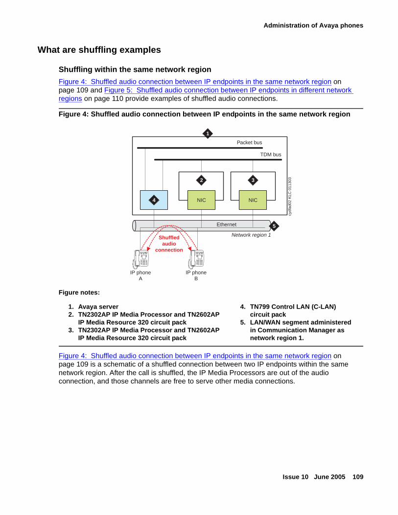
Administration of Avaya phones
Issue 10 June 2005 109
What are shuffling examples
Shuffling within the same network region
Figure 4: Shuffled audio connection between IP endpoints in the same network region on page 109 and Figure 5: Shuffled audio connection between IP endpoints in different network regions on page 110 provide examples of shuffled audio connections.
Figure 4: Shuffled audio connection between IP endpoints in the same network region
Figure 4: Shuffled audio connection between IP endpoints in the same network region on page 109 is a schematic of a shuffled connection between two IP endpoints within the same network region. After the call is shuffled, the IP Media Processors are out of the audio connection, and those channels are free to serve other media connections.
Figure notes:
1. Avaya server2. TN2302AP IP Media Processor and TN2602AP
IP Media Resource 320 circuit pack3. TN2302AP IP Media Processor and TN2602AP
IP Media Resource 320 circuit pack
4. TN799 Control LAN (C-LAN) circuit pack
5. LAN/WAN segment administered in Communication Manager as network region 1.
1
Packet bus
TDM bus
IP phoneA
Shuffledaudio
connection
IP phoneB
Network region 1
Ethernet 5
cydf
ad02
KLC
011
303
NIC
3
4
2
NIC
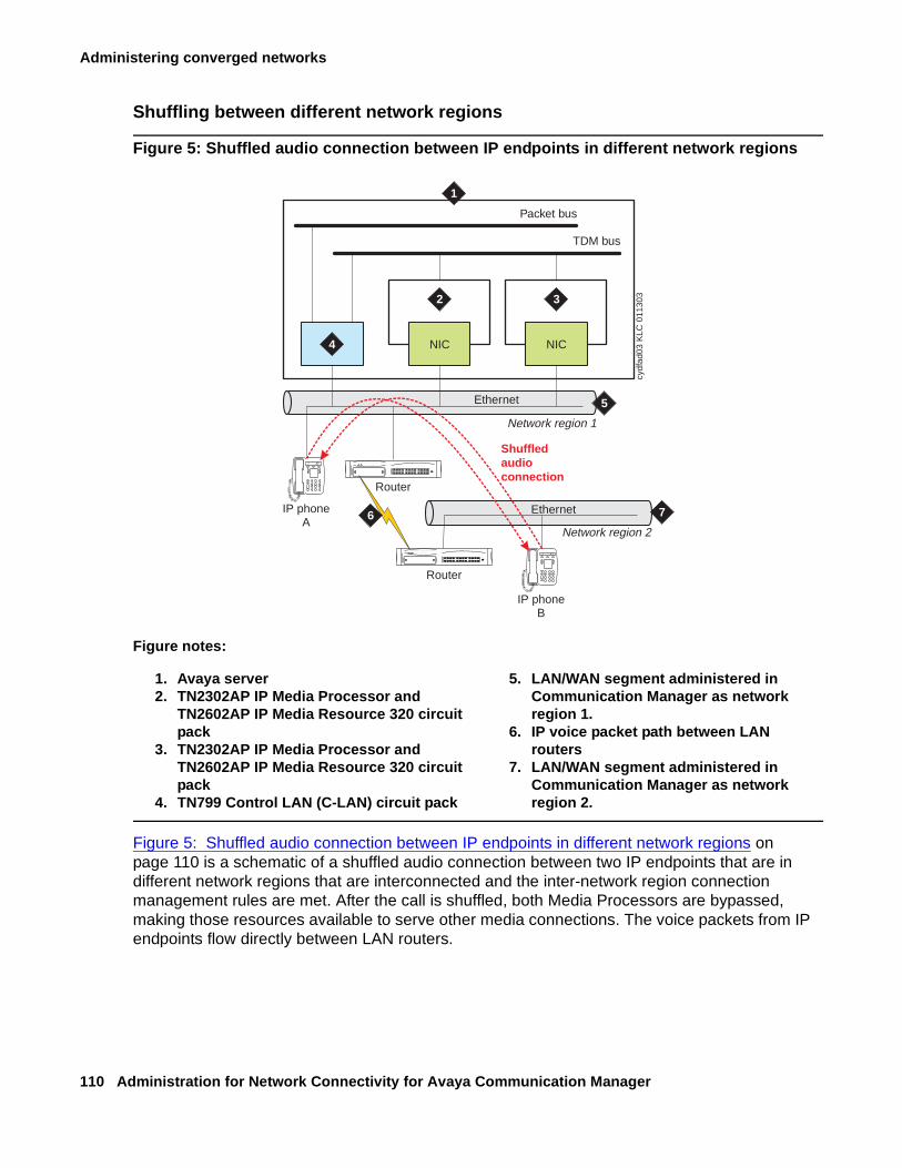
Administering converged networks
110 Administration for Network Connectivity for Avaya Communication Manager
Shuffling between different network regions
Figure 5: Shuffled audio connection between IP endpoints in different network regions
Figure 5: Shuffled audio connection between IP endpoints in different network regions on page 110 is a schematic of a shuffled audio connection between two IP endpoints that are in different network regions that are interconnected and the inter-network region connection management rules are met. After the call is shuffled, both Media Processors are bypassed, making those resources available to serve other media connections. The voice packets from IP endpoints flow directly between LAN routers.
Figure notes:
1. Avaya server2. TN2302AP IP Media Processor and
TN2602AP IP Media Resource 320 circuit pack
3. TN2302AP IP Media Processor and TN2602AP IP Media Resource 320 circuit pack
4. TN799 Control LAN (C-LAN) circuit pack
5. LAN/WAN segment administered in Communication Manager as network region 1.
6. IP voice packet path between LAN routers
7. LAN/WAN segment administered in Communication Manager as network region 2.
Router
1
Packet bus
TDM bus
IP phoneA
Router
IP phoneB
Network region 1
Network region 2
Ethernet
Ethernet
5
7
cydf
ad03
KLC
011
303
NIC NIC
2 3
4
Shuffledaudioconnection
6
Administration of Avaya phones
Issue 10 June 2005 111
Determining whether an endpoint supports shuffling
Placing a test call from an endpoint that is capable of shuffling to another endpoint whose shuffling capability is unknown can help you to determine whether an endpoint supports audio shuffling or not.
To determine whether an endpoint supports shuffling:
1. Administer the Direct IP-IP Audio Connections field on page 2 as y (yes) on both endpoint’s station form (change station extension).
2. From the endpoint that can support shuffling, place a call to the endpoint that you are testing.
Wait 2 minutes.
3. At the SAT type status station extension (administered extension of the endpoint that you are testing) and press Enter to display the Station screen for this extension.
4. Note the Port field value in the GENERAL STATUS section of page 1.
5. Scroll to page 4
In the AUDIO CHANNEL section note the value of the Audio field under the Switch Port column.
● If the values are the same, the endpoint is capable of shuffling.
Administer the Direct IP-IP Audio Connections field (change station extension, page 2) as y (yes).
● If the values are different, then the endpoint cannot shuffle calls.
Administer the Direct IP-IP Audio Connections field (change station extension, page 2) as n (no).
Administrable loss plan
To prevent audio levels from changing when a 2-party call changes from the TDM bus to a shuffled or hairpinned connection, two party connections between IP endpoints are not subject to the switch’s administrable loss plan. Although IP endpoints can be assigned to administrable loss groups, the switch is only able to change loss on IP Softphone calls including circuit-switched endpoints. Conference calls of three parties or more are subject to the administrable loss plan, whether those calls involve IP endpoints or not.
What are hairpinned audio connectionsHairpinning means rerouting the voice channel connecting two IP endpoints so that the voice channel goes through the TN2302AP IP Media Processor and TN2602AP IP Media Resource 320 circuit packs in IP format instead of through the TDM bus. Communication Manager provides only shallow hairpinning, meaning that only the IP and Real Time Protocol (RTP) packet headers are changed as the voice packets go through the TN2302AP or TN2602AP circuit pack. This requires that both endpoints use the same codec (coder/decoder), a circuit that takes a varying-voltage analog signal through a digital conversion algorithm to its digital equivalent or vice-versa (digital to analog). Throughout this section, when the word “hairpin” is used, it means shallow hairpinning.
Administering converged networks
112 Administration for Network Connectivity for Avaya Communication Manager
What are the criteria for hairpinning
Communication Manager uses the following criteria to determine whether to hairpin the connection:
● A point-to-point voice connection exists between two endpoints.
● The endpoints are in the same network region, or in different, interconnected regions.
● A single TN2302AP IP Media Processor or TN2602AP IP Media Resource 320 circuit pack serves both endpoints.
● The endpoints use a single, common codec.
● The endpoints are administered for hairpinning: the Direct IP-IP Audio Connections field on the Station screen on page 126 or the Signaling group screen on page 125) is y.
● If the IP Audio Hairpinning field is y (yes), but during registration the endpoint indicates that it does not hairpinning, then a call cannot be hairpinned.
If the IP Audio Hairpinning field is n (no), but during registration the endpoint indicates that it can support hairpinning, then calls to that endpoint cannot be hairpinned, giving precedence to the endpoint administration.
● The Determining if shuffling is possible on page 108 are not met.
● Both endpoints can connect through the same TN2302AP IP Media Processor or TN2602AP IP Media Resource 320 circuit pack.
What is an example hairpinned call
Hairpinned audio connections:
● Set up within approximately 50 ms
● Preserve the Real-Time Protocol (RTP) header (for example the timestamp and packet sequence number).
● Do not require volume adjustments on Avaya endpoints, however non-Avaya endpoints might require volume adjustment after the hairpinned connection is established.
Figure 6: Hairpinned audio connection between 2 IP endpoints in the same network region on page 113 is a schematic of a hairpinned audio connection between two IP endpoints in the same network region.
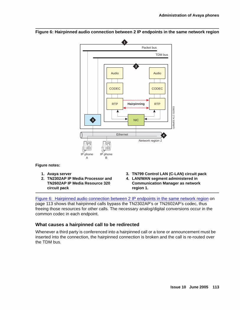
Administration of Avaya phones
Issue 10 June 2005 113
Figure 6: Hairpinned audio connection between 2 IP endpoints in the same network region
Figure 6: Hairpinned audio connection between 2 IP endpoints in the same network region on page 113 shows that hairpinned calls bypass the TN2302AP’s or TN2602AP’s codec, thus freeing those resources for other calls. The necessary analog/digital conversions occur in the common codec in each endpoint.
What causes a hairpinned call to be redirected
Whenever a third party is conferenced into a hairpinned call or a tone or announcement must be inserted into the connection, the hairpinned connection is broken and the call is re-routed over the TDM bus.
Figure notes:
1. Avaya server2. TN2302AP IP Media Processor and
TN2602AP IP Media Resource 320 circuit pack
3. TN799 Control LAN (C-LAN) circuit pack4. LAN/WAN segment administered in
Communication Manager as network region 1.
1
2
Packet bus
TDM bus
Audio
CODEC
RTP
Audio
CODEC
RTPHairpinning
3 NIC
IP phoneA
IP phoneB
Network region 1
Ethernet 4
cydf
ad01
KLC
010
903
Administering converged networks
114 Administration for Network Connectivity for Avaya Communication Manager
Determining which TN2302AP or TN2602AP circuit pack is hairpinning
Whenever a TN2302AP IP Media Processor or TN2602AP IP Media Resource 320 circuit pack is hairpinning any calls, its yellow LED is on steady. Although there is no simple way to identify all of the extension numbers that are hairpinning through a particular TN2302AP or TN2602AP circuit pack, you can determine which TN2302AP or TN2602AP circuit pack a particular extension is using for hairpinning.
To determine which TN2302AP or TN2602AP circuit pack is hairpinning:
1. At the SAT, type status station extension and press Enter to display the Station form for that extension.
2. Scroll to page 4 of the report.
3. In the AUDIO CHANNEL section, check whether there is a value in the Audio field under the Switch Port column.
If there is no port listed, then the call is hairpinned.
Hairpinning and shuffling administration interdependencies
Table 11: Hairpinning and shuffling administration on page 115 summarizes the Communication Manager interdependencies that enable hairpinning and shuffling audio connections.
Note:Note: In order to use hairpinning or shuffling with either Category A or B features, the
Software Version field (list configuration software-versions) must be R9 or greater.
! Important:Important: Encryption must be disabled for hairpinning to work, because encryption
requires the involvement of resources that are not used in the shallow hairpinning connection. This not the case for shuffling, however.
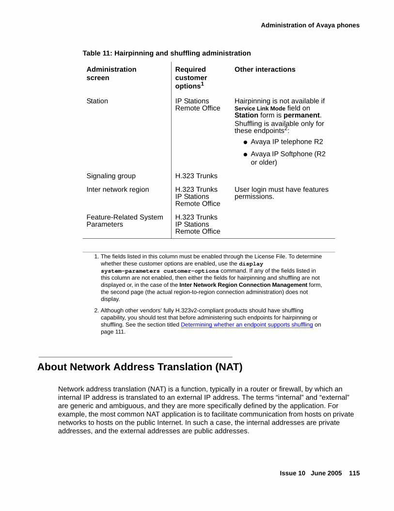
Administration of Avaya phones
Issue 10 June 2005 115
About Network Address Translation (NAT)
Network address translation (NAT) is a function, typically in a router or firewall, by which an internal IP address is translated to an external IP address. The terms “internal” and “external” are generic and ambiguous, and they are more specifically defined by the application. For example, the most common NAT application is to facilitate communication from hosts on private networks to hosts on the public Internet. In such a case, the internal addresses are private addresses, and the external addresses are public addresses.
Table 11: Hairpinning and shuffling administration
Administrationscreen
Required customer options1
1. The fields listed in this column must be enabled through the License File. To determine whether these customer options are enabled, use the display system-parameters customer-options command. If any of the fields listed in this column are not enabled, then either the fields for hairpinning and shuffling are not displayed or, in the case of the Inter Network Region Connection Management form, the second page (the actual region-to-region connection administration) does not display.
Other interactions
Station IP StationsRemote Office
Hairpinning is not available if Service Link Mode field on Station form is permanent.Shuffling is available only for these endpoints2:
● Avaya IP telephone R2
● Avaya IP Softphone (R2 or older)
2. Although other vendors’ fully H.323v2-compliant products should have shuffling capability, you should test that before administering such endpoints for hairpinning or shuffling. See the section titled Determining whether an endpoint supports shuffling on page 111.
Signaling group H.323 Trunks
Inter network region H.323 TrunksIP StationsRemote Office
User login must have features permissions.
Feature-Related System Parameters
H.323 TrunksIP StationsRemote Office
Administering converged networks
116 Administration for Network Connectivity for Avaya Communication Manager
Note:Note: This common NAT application does not use a web proxy server, which would be
an entirely different scenario.
Another common NAT application is for some VPN clients. The internal address in this case is the physical address, and the external address is the virtual address. This physical address does not necessarily have to be a private address as shown here, as the subscriber could pay for a public address from the broadband service provider. But regardless of the nature of the physical address, the point is that it cannot be used to communicate back to the enterprise through a VPN tunnel. Once the tunnel is established, the enterprise VPN gateway assigns a virtual address to the VPN client application on the enterprise host. This virtual address is part of the enterprise IP address space, and it must be used to communicate back to the enterprise.
The application of the virtual address varies among VPN clients. Some VPN clients integrate with the operating system in such a way that packets from IP applications (for example, FTP or telnet) on the enterprise host are sourced from the virtual IP address. That is, the IP applications inherently use the virtual IP address. With other VPN clients this does not occur. Instead, the IP applications on the enterprise host inherently use the physical IP address, and the VPN client performs a NAT to the virtual IP address. This NAT is no different than if a router or firewall had done the translation.
What are the types of NAT
Static 1-to-1 NAT
Static 1-to-1 NAT is what has already been covered up to this point. In static 1-to-1 NAT, for every internal address there is an external address, with a static 1-to-1 mapping between internal and external addresses. It is the simplest yet least efficient type of NAT, in terms of address preservation, because every internal host requires an external IP address. This limitation is often impractical when the external addresses are public IP addresses. Sometimes the primary reason for using NAT is to preserve public IP addresses, and for this case there are two other types of NAT: many-to-1 and many-to-a-pool.
Dynamic Many-to-1 NAT
Dynamic many-to-1 NAT is as the name implies. Many internal addresses are dynamically translated to a single external address. Multiple internal addresses can be translated to the same external address, when the TCP/UDP ports are translated in addition to the IP addresses. This is known as network address port translation (NAPT) or simply port address translation (PAT). It appears to the external server that multiple requests are coming from a single IP address, but from different TCP/UDP ports. The NAT device remembers which internal source ports were translated to which external source ports.
Administration of Avaya phones
Issue 10 June 2005 117
In the simplest form of many-to-1 NAT, the internal host must initiate the communication to the external host, which then generates a port mapping within the NAT device, allowing the external host to reply back to the internal host. It is a paradox with this type of NAT (in its simplest form) that the external host cannot generate a port mapping to initiate the communication with the internal host, and without initiating the communication, there is no way to generate the port mapping. This condition does not exist with 1-to-1 NAT, as there is no mapping of ports.
Dynamic Many-to-a-Pool NAT
Many-to-a-pool NAT combines some of the characteristics of both 1-to-1 and many-to-1 NAT. The general idea behind many-to-a-pool NAT is that a 1-to-1 mapping is not desired, but there are too many internal hosts to use a single external address. Therefore, a pool of multiple external addresses is used for NAT. There are enough external addresses in the pool to support all the internal hosts, but not nearly as many pool addresses as there are internal hosts.
What are the issues between NAT and H.323
Some of the hurdles that NAT presents to H.323 include:
● H.323 messages, which are part of the IP payload, have embedded IP addresses in them.
NAT translates the IP address in the IP header, but not the embedded addresses in the H.323 messages. This is a problem that can be and has been addressed with H.323-aware NAT devices. It has also been addressed with Avaya Communication Manager 1.3 and later versions of the NAT feature.
● When an endpoint (IP telephone) registers with the gatekeeper (call server), that endpoint’s IP address must stay the same for the duration of the registration.
This rules out almost all current implementations of many-to-a-pool NAT.
● TCP/UDP ports are involved in all aspects of IP telephony — endpoint registration, call signaling, and RTP audio transmission.
These ports must remain unchanged for the duration of an event, duration of the registration, or duration of a call. Also, the gatekeeper must know ahead of time which ports will be used by the endpoints for audio transmission, and the ports can vary per call. These requirements make it very difficult for H.323 to work with NAPT, which rules out almost all current implementations of many-to-1 and many-to-a-pool NAT.
Avaya Communication Manager NAT Shuffling feature
The Avaya Communication Manager NAT Shuffling feature permits IP telephones and IP Softphones to work behind a NAT device. This feature was available prior to release 1.3, but it did not work with shuffled calls (Direct IP-IP Audio enabled). The NAT feature now works with shuffled calls.
Administering converged networks
118 Administration for Network Connectivity for Avaya Communication Manager
Terms:
The following terms are used to describe the NAT Shuffling feature:
● Native Address — The original IP address configured on the device itself (internal address)
● Translated Address — The IP address after it has gone through NAT, as seen by devices on the other side of the translation (external address)
● Gatekeeper — The Avaya device that is handling call signaling.
It could be a portal to the gatekeeper, such as a C-LAN, or the gatekeeper itself, such as an S8300 Media Server.
● Gateway — The Avaya device that is handling media conversion between TDM and IP, such as a MedPro board, G700 VoIP Media Module, or G350 Media Gateway.
The essence of this feature is that Communication Manager keeps track of the native and translated IP addresses for every IP station (IP telephone or IP Softphone). If an IP station registration appears with different addresses in the IP header and the RAS message, the call server stores the two addresses and alerts the station that NAT has taken place.
This feature works with static 1-to-1 NAT. It does not work with NAPT, so the TCP/UDP ports sourced by the IP stations must not be changed. Consequently, this feature does not work with many-to-1 NAT. This feature may work with many-to-a-pool NAT, if a station’s translated address remains constant for as long as the station is registered, and there is no port translation.
The NAT device must perform plain NAT – not H.323-aware NAT. Any H.323-aware feature in the NAT device must be disabled, so that there are not two independent devices trying to compensate for H.323 at the same time.
Rules:
The following rules govern the NAT Shuffling feature. The Direct IP-IP Audio parameters are configured on the SAT ip-network-region form.
1. When Direct IP-IP Audio is enabled (default) and a station with NAT and a station without NAT talk to one another, the translated address is always used.
2. When two stations with NAT talk to one another, the native addresses are used (default) when Yes or Native (NAT) is specified for Direct IP-IP Audio, and the translated addresses are used when Translated (NAT) is specified.
3. The Gatekeeper and Gateway must not be enabled for NAT. As long as this is true, they may be assigned to any network region.
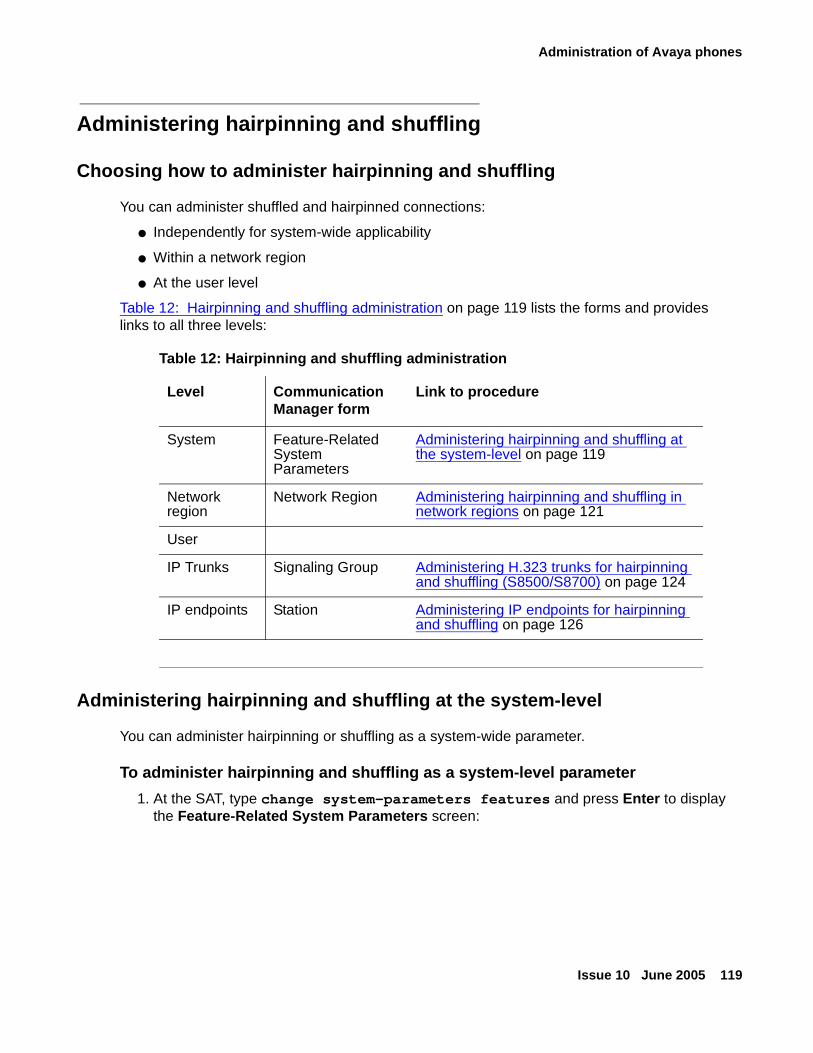
Administration of Avaya phones
Issue 10 June 2005 119
Administering hairpinning and shuffling
Choosing how to administer hairpinning and shuffling
You can administer shuffled and hairpinned connections:
● Independently for system-wide applicability
● Within a network region
● At the user level
Table 12: Hairpinning and shuffling administration on page 119 lists the forms and provides links to all three levels:
Administering hairpinning and shuffling at the system-level
You can administer hairpinning or shuffling as a system-wide parameter.
To administer hairpinning and shuffling as a system-level parameter
1. At the SAT, type change system-parameters features and press Enter to display the Feature-Related System Parameters screen:
Table 12: Hairpinning and shuffling administration
Level Communication Manager form
Link to procedure
System Feature-Related System Parameters
Administering hairpinning and shuffling at the system-level on page 119
Network region
Network Region Administering hairpinning and shuffling in network regions on page 121
User
IP Trunks Signaling Group Administering H.323 trunks for hairpinning and shuffling (S8500/S8700) on page 124
IP endpoints Station Administering IP endpoints for hairpinning and shuffling on page 126
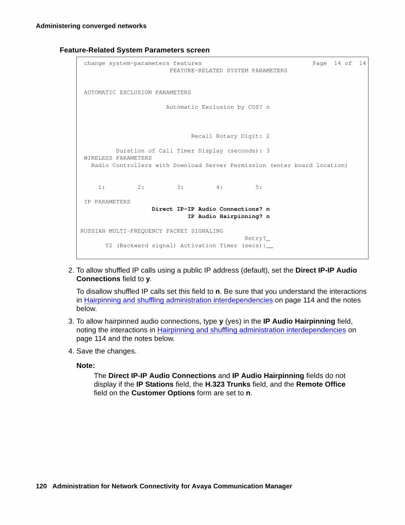
Administering converged networks
120 Administration for Network Connectivity for Avaya Communication Manager
Feature-Related System Parameters screen
2. To allow shuffled IP calls using a public IP address (default), set the Direct IP-IP Audio Connections field to y.
To disallow shuffled IP calls set this field to n. Be sure that you understand the interactions in Hairpinning and shuffling administration interdependencies on page 114 and the notes below.
3. To allow hairpinned audio connections, type y (yes) in the IP Audio Hairpinning field, noting the interactions in Hairpinning and shuffling administration interdependencies on page 114 and the notes below.
4. Save the changes.
Note:Note: The Direct IP-IP Audio Connections and IP Audio Hairpinning fields do not
display if the IP Stations field, the H.323 Trunks field, and the Remote Office field on the Customer Options form are set to n.
change system-parameters features Page 14 of 14 FEATURE-RELATED SYSTEM PARAMETERS
AUTOMATIC EXCLUSION PARAMETERS
Automatic Exclusion by COS? n
Recall Rotary Digit: 2
Duration of Call Timer Display (seconds): 3 WIRELESS PARAMETERS Radio Controllers with Download Server Permission (enter board location)
1: 2: 3: 4: 5:
IP PARAMETERS Direct IP-IP Audio Connections? n IP Audio Hairpinning? n
RUSSIAN MULTI-FREQUENCY PACKET SIGNALING Retry?_ T2 (Backward signal) Activation Timer (secs):__
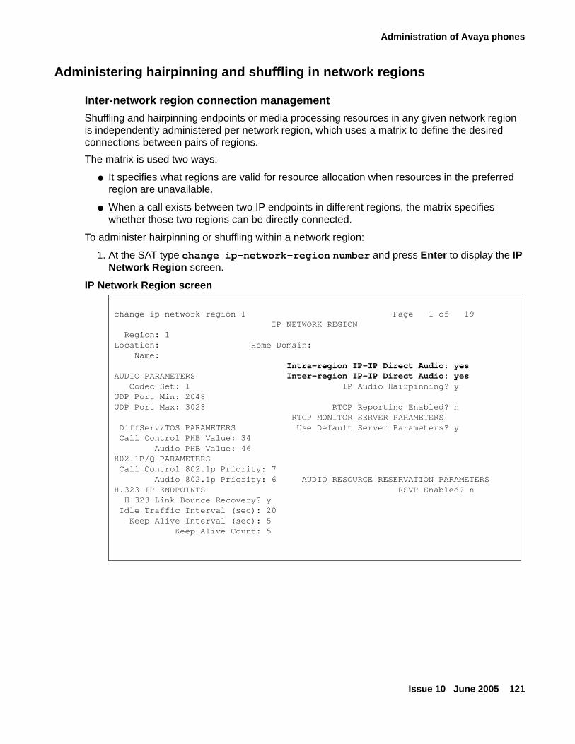
Administration of Avaya phones
Issue 10 June 2005 121
Administering hairpinning and shuffling in network regions
Inter-network region connection management
Shuffling and hairpinning endpoints or media processing resources in any given network region is independently administered per network region, which uses a matrix to define the desired connections between pairs of regions.
The matrix is used two ways:
● It specifies what regions are valid for resource allocation when resources in the preferred region are unavailable.
● When a call exists between two IP endpoints in different regions, the matrix specifies whether those two regions can be directly connected.
To administer hairpinning or shuffling within a network region:
1. At the SAT type change ip-network-region number and press Enter to display the IP Network Region screen.
IP Network Region screen
change ip-network-region 1 Page 1 of 19 IP NETWORK REGIONRegion: 1
Location: Home Domain: Name:
Intra-region IP-IP Direct Audio: yesAUDIO PARAMETERS Inter-region IP-IP Direct Audio: yes Codec Set: 1 IP Audio Hairpinning? yUDP Port Min: 2048UDP Port Max: 3028 RTCP Reporting Enabled? n RTCP MONITOR SERVER PARAMETERS DiffServ/TOS PARAMETERS Use Default Server Parameters? y Call Control PHB Value: 34
Audio PHB Value: 46802.1P/Q PARAMETERS Call Control 802.1p Priority: 7 Audio 802.1p Priority: 6 AUDIO RESOURCE RESERVATION PARAMETERSH.323 IP ENDPOINTS RSVP Enabled? nH.323 Link Bounce Recovery? y
Idle Traffic Interval (sec): 20 Keep-Alive Interval (sec): 5 Keep-Alive Count: 5
Administering converged networks
122 Administration for Network Connectivity for Avaya Communication Manager
2. Administer the IP-IP Direct Audio fields:
● The Intra-region IP-IP Direct Audio field permits shuffling if both endpoints are in the same region.
● The Inter-region IP-IP Direct Audio field permits shuffling if the two endpoints are in two different regions.
The allowable values for both fields are:
- y -- permits shuffling the call
- n -- disallows shuffling the call
- native-- the IP address of a phone itself, or no translation by a Network Address Translation (NAT) device
- translated -- the translated IP address that a Network Address Translation (NAT) device provides for the native address
Note:Note: If there is no NAT device in use at all, then the native and translated addresses
are the same. For more information on NAT, see the Administrator’s Guide for Avaya Communication Manager (555-233-506) and Avaya Application Solutions IP Telephony Deployment Guide, 555-245-600.
Note:Note: The hairpinning and shuffling fields on the IP Network Regions screen do not
display unless the IP Stations, the H.323 Trunks, or the Remote Office field is set to y (yes) on the Optional Features (display system-parameter customer-options) screen. These features must be enabled in the system’s License File.
3. Go to page 3 and administer the common codec sets on the Inter Network Region Connection Management form (Inter Network Region Connection Management form on page 123).
Note:Note: You cannot connect IP endpoints in different network regions or share TN799
C-LAN or TN2032 IP Media Processor resources between/among network regions unless you make a codec entry in this matrix specifying the codec set to be used.
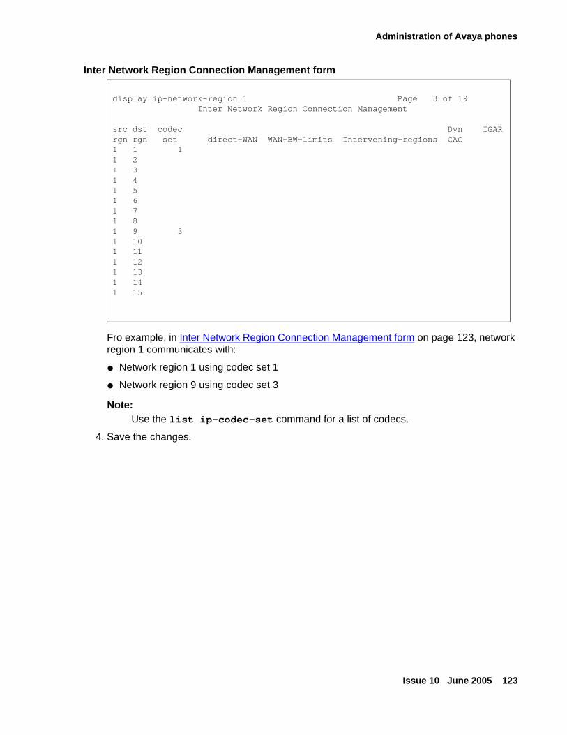
Administration of Avaya phones
Issue 10 June 2005 123
Inter Network Region Connection Management form
Fro example, in Inter Network Region Connection Management form on page 123, network region 1 communicates with:
● Network region 1 using codec set 1
● Network region 9 using codec set 3
Note:Note: Use the list ip-codec-set command for a list of codecs.
4. Save the changes.
display ip-network-region 1 Page 3 of 19 Inter Network Region Connection Management
src dst codec Dyn IGARrgn rgn set direct-WAN WAN-BW-limits Intervening-regions CAC1 1 11 21 31 41 51 61 71 81 9 31 101 111 121 131 141 15
Administering converged networks
124 Administration for Network Connectivity for Avaya Communication Manager
Administering and selecting codecs
When an IP endpoint calls another IP endpoint, Communication Manager asks that the 2nd endpoint choose the same codec that the 1st endpoint offered at call setup. However, if the 2nd endpoint cannot match codecs with the 1st’s, the call is set up with each endpoint’s administered (preferred) codec, and the data streams are converted between them, often resulting in degraded audio quality because of the series of different compressions/decompressions or multiple use of the same codec.
When an endpoint (station or trunk) initially connects to the server, Communication Manager selects the first codec that is common to both the server and the endpoint. The Inter Network Region Connection Management screen specifies codec set(s) to use within an individual region (intra-region) and a codec set to use between/among (inter-region) network regions. Depending upon the network region of the requesting H.323 endpoint or trunk and the network region of the TN2302AP IP Media Processor or TN2602AP IP Media Resource 320 circuit pack:
● If the endpoint and the TN2302AP or TN2602AP are in same region, the administered intra-region codec set is chosen.
● If the endpoint and the TN2302AP or TN2602AP are in different regions, the administered inter-region codec set is chosen.
For example, a region might have its intra-network codec administered as G.711 as the first choice, followed by the other low bit rate codecs. The Inter Network Region Connection Management screen for the inter-network region might have G.729 (a low-bit codec that preserves bandwidth) as the only choice. Initially, when a call is set up between these two interconnected regions, the TN2302AP IP Media Processor or TN2602AP IP Media Resource 320 provides the audio stream conversion between G.711 and G.729. When the media stream is shuffled away from a TDM-based connection, the two endpoints can use only the G.729 codec.
Note:Note: If you are administering an H.323 trunk that uses Teletype for the Deaf (TTD),
use the G.711 codec as the primary choice for those trunks. This ensures accurate TTD tone transmission through the connection.
Administering H.323 trunks for hairpinning and shuffling (S8500/S8700)
To administer an H.323 trunk for hairpinning or shuffling
1. At the SAT, type change signaling group number and press Enter to display the Signaling Group screen (Signaling group screen on page 125).
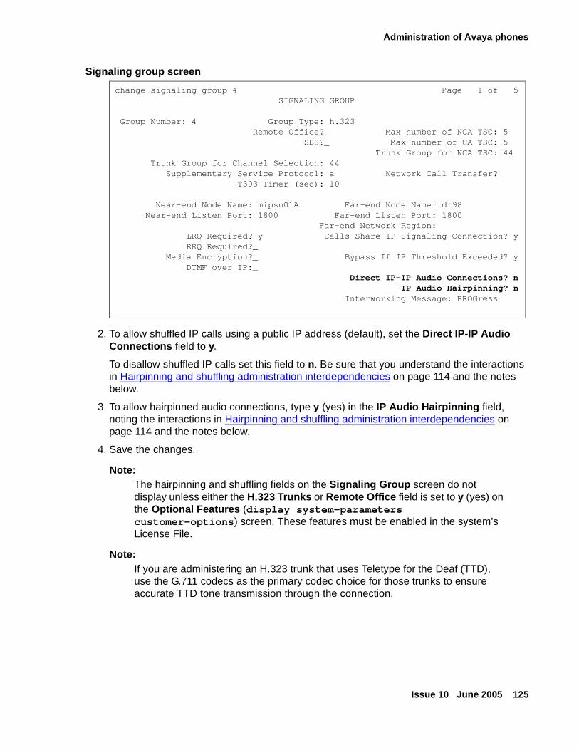
Administration of Avaya phones
Issue 10 June 2005 125
Signaling group screen
2. To allow shuffled IP calls using a public IP address (default), set the Direct IP-IP Audio Connections field to y.
To disallow shuffled IP calls set this field to n. Be sure that you understand the interactions in Hairpinning and shuffling administration interdependencies on page 114 and the notes below.
3. To allow hairpinned audio connections, type y (yes) in the IP Audio Hairpinning field, noting the interactions in Hairpinning and shuffling administration interdependencies on page 114 and the notes below.
4. Save the changes.
Note:Note: The hairpinning and shuffling fields on the Signaling Group screen do not
display unless either the H.323 Trunks or Remote Office field is set to y (yes) on the Optional Features (display system-parameters customer-options) screen. These features must be enabled in the system’s License File.
Note:Note: If you are administering an H.323 trunk that uses Teletype for the Deaf (TTD),
use the G.711 codecs as the primary codec choice for those trunks to ensure accurate TTD tone transmission through the connection.
change signaling-group 4 Page 1 of 5 SIGNALING GROUP
Group Number: 4 Group Type: h.323 Remote Office?_ Max number of NCA TSC: 5 SBS?_ Max number of CA TSC: 5 Trunk Group for NCA TSC: 44 Trunk Group for Channel Selection: 44 Supplementary Service Protocol: a Network Call Transfer?_
T303 Timer (sec): 10
Near-end Node Name: mipsn01A Far-end Node Name: dr98 Near-end Listen Port: 1800 Far-end Listen Port: 1800 Far-end Network Region:_ LRQ Required? y Calls Share IP Signaling Connection? y RRQ Required?_ Media Encryption?_ Bypass If IP Threshold Exceeded? y DTMF over IP:_
Direct IP-IP Audio Connections? nIP Audio Hairpinning? n
Interworking Message: PROGress
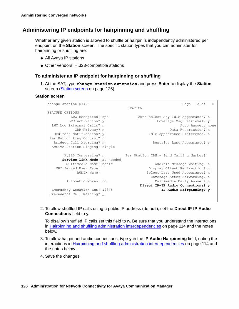
Administering converged networks
126 Administration for Network Connectivity for Avaya Communication Manager
Administering IP endpoints for hairpinning and shuffling
Whether any given station is allowed to shuffle or hairpin is independently administered per endpoint on the Station screen. The specific station types that you can administer for hairpinning or shuffling are:
● All Avaya IP stations
● Other vendors’ H.323-compatible stations
To administer an IP endpoint for hairpinning or shuffling
1. At the SAT, type change station extension and press Enter to display the Station screen (Station screen on page 126)
Station screen
2. To allow shuffled IP calls using a public IP address (default), set the Direct IP-IP Audio Connections field to y.
To disallow shuffled IP calls set this field to n. Be sure that you understand the interactions in Hairpinning and shuffling administration interdependencies on page 114 and the notes below.
3. To allow hairpinned audio connections, type y in the IP Audio Hairpinning field, noting the interactions in Hairpinning and shuffling administration interdependencies on page 114 and the notes below.
4. Save the changes.
change station 57493 Page 2 of 4 STATION
FEATURE OPTIONS LWC Reception: spe Auto Select Any Idle Appearance? n LWC Activation? y Coverage Msg Retrieval? y LWC Log External Calls? n Auto Answer: none CDR Privacy? n Data Restriction? n Redirect Notification? y Idle Appearance Preference? n Per Button Ring Control? n Bridged Call Alerting? n Restrict Last Appearance? y Active Station Ringing: single
H.320 Conversion? n Per Station CPN - Send Calling Number? Service Link Mode: as-needed Multimedia Mode: basic Audible Message Waiting? n MWI Served User Type: Display Client Redirection? n AUDIX Name: Select Last Used Appearance? n Coverage After Forwarding? s Automatic Moves: no Multimedia Early Answer? n Direct IP-IP Audio Connections? y Emergency Location Ext: 12345 IP Audio Hairpinning? y Precedence Call Waiting? _
Administration of Avaya phones
Issue 10 June 2005 127
Note:Note: The hairpinning and shuffling fields on the Station screen do not display unless
either the IP Stations or Remote Office field is set to y (yes) on the Optional Features (display system-parameter customer-options) screen. These features must be enabled in the system’s License File.
Note:Note: The Direct IP-IP Audio Connections field cannot be set to y if the Service Link
Mode field is set to permanent.
Contradictory IP station administration
● If an IP station is administered for dual-connect, and if the two extension numbers for that station have differing values administered in their Direct IP-IP audio Connections fields, then the station cannot shuffle calls.
● If an IP station is administered for dual-connect, and if the two extension numbers for that station have differing values administered in their IP-IP Audio Hairpinning fields, then the station cannot hairpin calls.
IP stations used for call center service-observing
If a Call Center agent is active on a shuffled call, and a Call Center supervisor wants to service-observe the call, the agent might notice the 200 ms break in the speech while the call is redirected to the TDM bus. For this reason, Avaya recommends that you administer the shuffling and hairpinning fields as n (no) for stations that are used for service-observing.
Upgrade interactions for hairpinning and shuffling
Upgrading from Release 8 to Release 9 or higher
If the Inter-region IP connectivity allowed field on the IP-interfaces form is y (yes), then the entries for all interconnections among regions 1 to 10 on the new (upgraded) IP-Network Region form are set to 1.
Upgrading to Release 9 or higher
The Direct IP-IP Audio Connections and IP Audio Hairpinning fields default to n (no), just as they do for a new installation.
Administering converged networks
128 Administration for Network Connectivity for Avaya Communication Manager
Administering IP endpoint signal loss
The amount of loss applied between any two endpoints on a call is administrable. However, the Telecommunications Industry Association (TIA) has published standards for the levels that IP endpoints should use. The IP endpoints will always transmit audio at TIA standard levels, and expect to receive audio at TIA standard levels. If an IP audio signal goes to or comes from the TDM bus through a TN2302AP Media Processor or TN2602AP IP Media Resource 320, the circuit pack will adjust the levels to be approximately equal the levels of a signal to or from a Digital Communications Protocol (DCP) set. By default, IP endpoints are the same loss group as DCP sets, Group 2.
Adjusting loss to USA DCP levels
The switch instructs the TN2302AP or TN2602AP circuit pack to insert loss into the signal coming from the IP phone, and insert gain in the signal going to the IP phone, to equal the levels of a signal to or from a DCP set.
Note:Note: The voice level on a shuffled call is not affected by entries administered in the
2-Party Loss Plan screen.
Note:Note: The loss that is applied to a hairpinned or shuffled audio connection is constant
for all three connection types:
- station-to-station
- station-to-trunk
- trunk-to-trunk
Administering FAX, modem, TTY, and H.323 clear channel calls over IP Trunks
Issue 10 June 2005 129
Administering FAX, modem, TTY, and H.323 clear channel calls over IP Trunks
Avaya Communication Manager transports FAX, modem, TTY, and clear channel calls over IP interfaces using relay mode (see What is relay mode on page 129), pass-through mode (see What pass-through mode is on page 130), or both. As a result, Communication Manager supports transport of the following:
● Teletypewriter device (TTY) tone relay over the corporate IP intranet and the Internet
● Faxes over a corporate IP intranet
Note:Note: The path between endpoints for FAX transmissions must use Avaya
telecommunications and networking equipment.
Note:Note: Faxes sent to non-Avaya endpoints cannot be encrypted.
● T.38 FAX over the Internet (including endpoints connected to non-Avaya systems)
● Modem tones over a corporate IP intranet
● Clear channel data calls over IP
The path between endpoints for modem tone transmissions must use Avaya telecommunications and networking equipment.
What is relay mode
In relay mode, the firmware on the device (the G700/G350 media gateway, the MM760 VoIP media module, TN2302AP Media Processor, or TN2602AP IP Media Resource 320) detects the tones of the call (FAX, modem, or TTY) and uses the appropriate modulation protocol (for FAX or modem) or Baudot transport representation (TTY) to terminate or originate the call so that it can be carried over the IP network. The modulation and demodulation for FAX and modem calls reduces bandwidth use over the IP network and improves the reliability of transmission. The correct tones are regenerated before final delivery to the endpoint.
Note:Note: The number of simultaneous calls that a device (gateway, media module,
TN2302AP or TN2602AP) can handle is reduced by the modulation and demodulation that the device must perform for relay mode.
Administering converged networks
130 Administration for Network Connectivity for Avaya Communication Manager
What pass-through mode is
In pass-through mode, the firmware on the device (the G700/G350 media gateway, the MM760 VoIP media module, TN2302AP Media Processor, or TN2602AP IP Media Resource 320) detects the tones of the call (FAX, modem, or TTY) and uses G.711 encoding to carry the call over the IP network. pass-through mode provides higher quality transmission when endpoints in the network are all synchronized to the same clock source. The call is un-encoded before final delivery to the endpoint.
Note:Note: Though pass-through mode increases the bandwidth usage (per channel), it
allows the same number of simultaneous FAX/modem calls on the device as the number of simultaneous voice calls. For example, on a G700 Media Gateway, pass-through allows 64 simultaneous FAX/modem calls instead of only 16 with relay.
Note:Note: For pass-through mode on modem and TTY calls over an IP network, the
sending and receiving servers should have a common synchronization source. Sychronized clocks can be established by using a source on the public network. See Figure 7: IP network connections over which FAX, modem, and TTY calls are made on page 131.
Note:Note: You cannot send FAXes in pass-through mode with the T.38 standard.
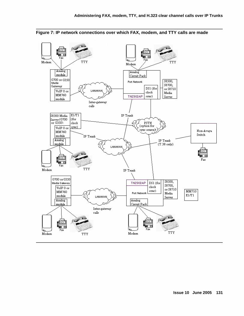
Administering FAX, modem, TTY, and H.323 clear channel calls over IP Trunks
Issue 10 June 2005 131
Figure 7: IP network connections over which FAX, modem, and TTY calls are made
Administering converged networks
132 Administration for Network Connectivity for Avaya Communication Manager
Overview of steps to administer FAX, TTY, modem, and clear channel calls over IP trunks
The information in this section assumes the following:
● The endpoints sending and receiving the calls are connected to a private network that uses H.323 trunking or LAN connections between gateways and/or port networks.
● Calls can either be passed over the public network using ISDN-PRI trunks or passed over an H.323 private network to Communication Manager switches that are similarly enabled.
To administer FAX, TTY, modem, and clear channel calls over IP trunks, first consider the following:
● FAX, TTY, modem, and clear channel transmission modes and speeds on page 133
● Considerations for administering FAX, TTY, modem, and clear channel transmission on page 136
● Bandwidth for FAX, modem, TTY, and clear channel calls over IP networks on page 139
● AES/AEA Media Encryption on page 140
After considering the criteria from the preceding list, complete the following tasks:
1. Create one or more IP Codec sets that enable the appropriate transmission modes for the endpoints on your gateways. See Administering IP CODEC sets on page 152.
Note:Note: You create the FAX, modem, TTY, and clear channel settings (including
redundancy) on the second page of the IP Codec Set screen.
2. Assign each codec set to the appropriate network region. See Administering IP network regions on page 158.
3. Assign the network region to the appropriate device(s):
● TN2302AP or TN2602AP (see Defining IP interfaces on page 87)
● G350 or G700 Media Gateway (see To add the media gateway on page 81)
4. If the TN2302AP or TN2602AP resources are shared among administered network regions, administer inter-network region connections. See Figure 10: IGAR system parameter on page 169.
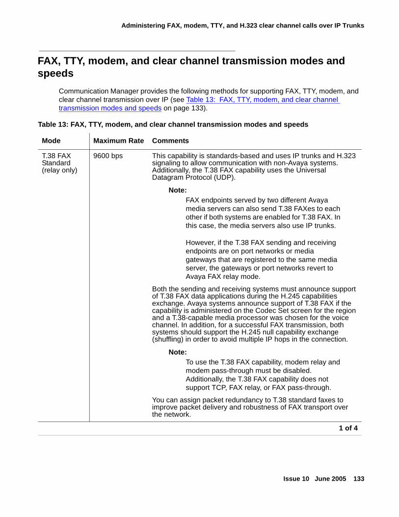
Administering FAX, modem, TTY, and H.323 clear channel calls over IP Trunks
Issue 10 June 2005 133
FAX, TTY, modem, and clear channel transmission modes and speeds
Communication Manager provides the following methods for supporting FAX, TTY, modem, and clear channel transmission over IP (see Table 13: FAX, TTY, modem, and clear channel transmission modes and speeds on page 133).
Table 13: FAX, TTY, modem, and clear channel transmission modes and speeds
Mode Maximum Rate Comments
T.38 FAX Standard (relay only)
9600 bps This capability is standards-based and uses IP trunks and H.323 signaling to allow communication with non-Avaya systems. Additionally, the T.38 FAX capability uses the Universal Datagram Protocol (UDP).
Note:Note: FAX endpoints served by two different Avaya
media servers can also send T.38 FAXes to each other if both systems are enabled for T.38 FAX. In this case, the media servers also use IP trunks.
However, if the T.38 FAX sending and receiving endpoints are on port networks or media gateways that are registered to the same media server, the gateways or port networks revert to Avaya FAX relay mode.
Both the sending and receiving systems must announce support of T.38 FAX data applications during the H.245 capabilities exchange. Avaya systems announce support of T.38 FAX if the capability is administered on the Codec Set screen for the region and a T.38-capable media processor was chosen for the voice channel. In addition, for a successful FAX transmission, both systems should support the H.245 null capability exchange (shuffling) in order to avoid multiple IP hops in the connection.
Note:Note: To use the T.38 FAX capability, modem relay and
modem pass-through must be disabled. Additionally, the T.38 FAX capability does not support TCP, FAX relay, or FAX pass-through.
You can assign packet redundancy to T.38 standard faxes to improve packet delivery and robustness of FAX transport over the network.
1 of 4
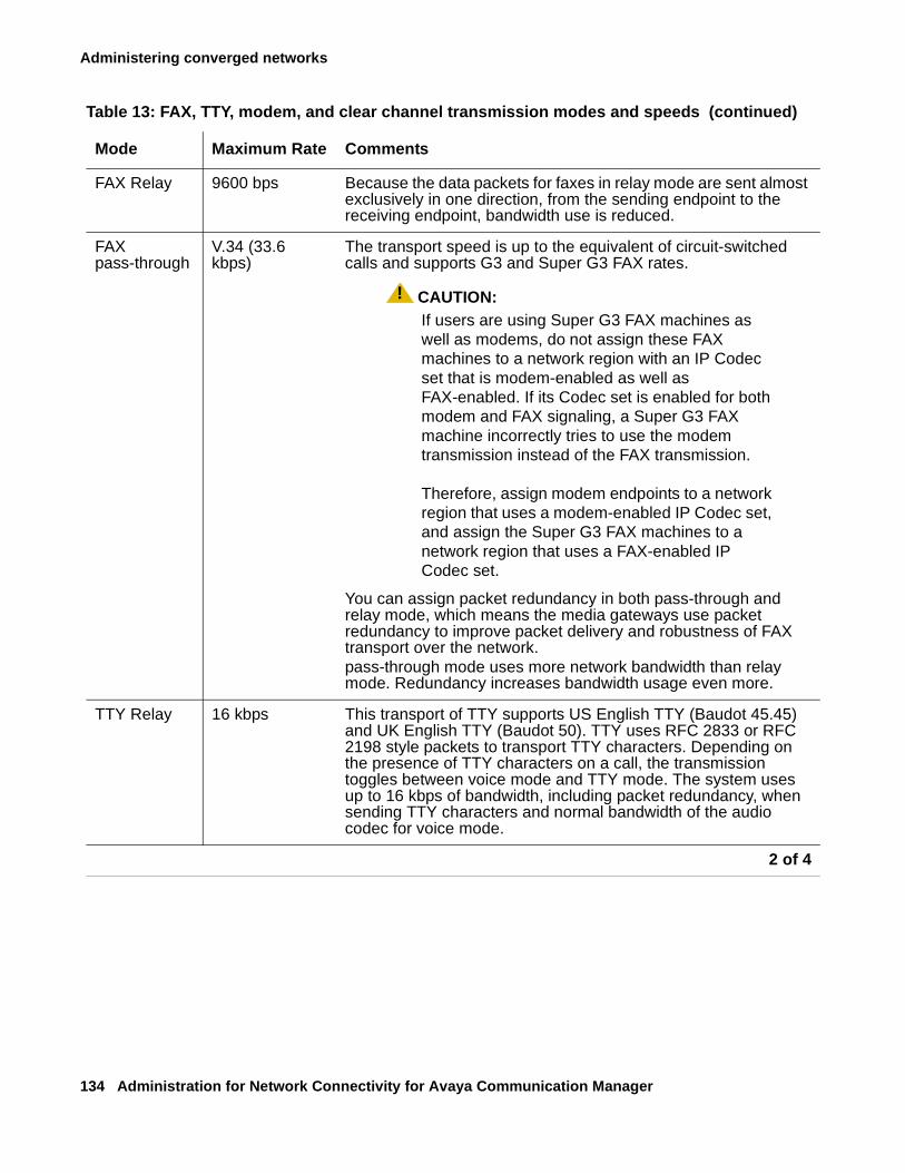
Administering converged networks
134 Administration for Network Connectivity for Avaya Communication Manager
FAX Relay 9600 bps Because the data packets for faxes in relay mode are sent almost exclusively in one direction, from the sending endpoint to the receiving endpoint, bandwidth use is reduced.
FAX pass-through
V.34 (33.6 kbps)
The transport speed is up to the equivalent of circuit-switched calls and supports G3 and Super G3 FAX rates.
! CAUTION:CAUTION: If users are using Super G3 FAX machines as
well as modems, do not assign these FAX machines to a network region with an IP Codec set that is modem-enabled as well as FAX-enabled. If its Codec set is enabled for both modem and FAX signaling, a Super G3 FAX machine incorrectly tries to use the modem transmission instead of the FAX transmission.
Therefore, assign modem endpoints to a network region that uses a modem-enabled IP Codec set, and assign the Super G3 FAX machines to a network region that uses a FAX-enabled IP Codec set.
You can assign packet redundancy in both pass-through and relay mode, which means the media gateways use packet redundancy to improve packet delivery and robustness of FAX transport over the network. pass-through mode uses more network bandwidth than relay mode. Redundancy increases bandwidth usage even more.
TTY Relay 16 kbps This transport of TTY supports US English TTY (Baudot 45.45) and UK English TTY (Baudot 50). TTY uses RFC 2833 or RFC 2198 style packets to transport TTY characters. Depending on the presence of TTY characters on a call, the transmission toggles between voice mode and TTY mode. The system uses up to 16 kbps of bandwidth, including packet redundancy, when sending TTY characters and normal bandwidth of the audio codec for voice mode.
Table 13: FAX, TTY, modem, and clear channel transmission modes and speeds (continued)
Mode Maximum Rate Comments
2 of 4
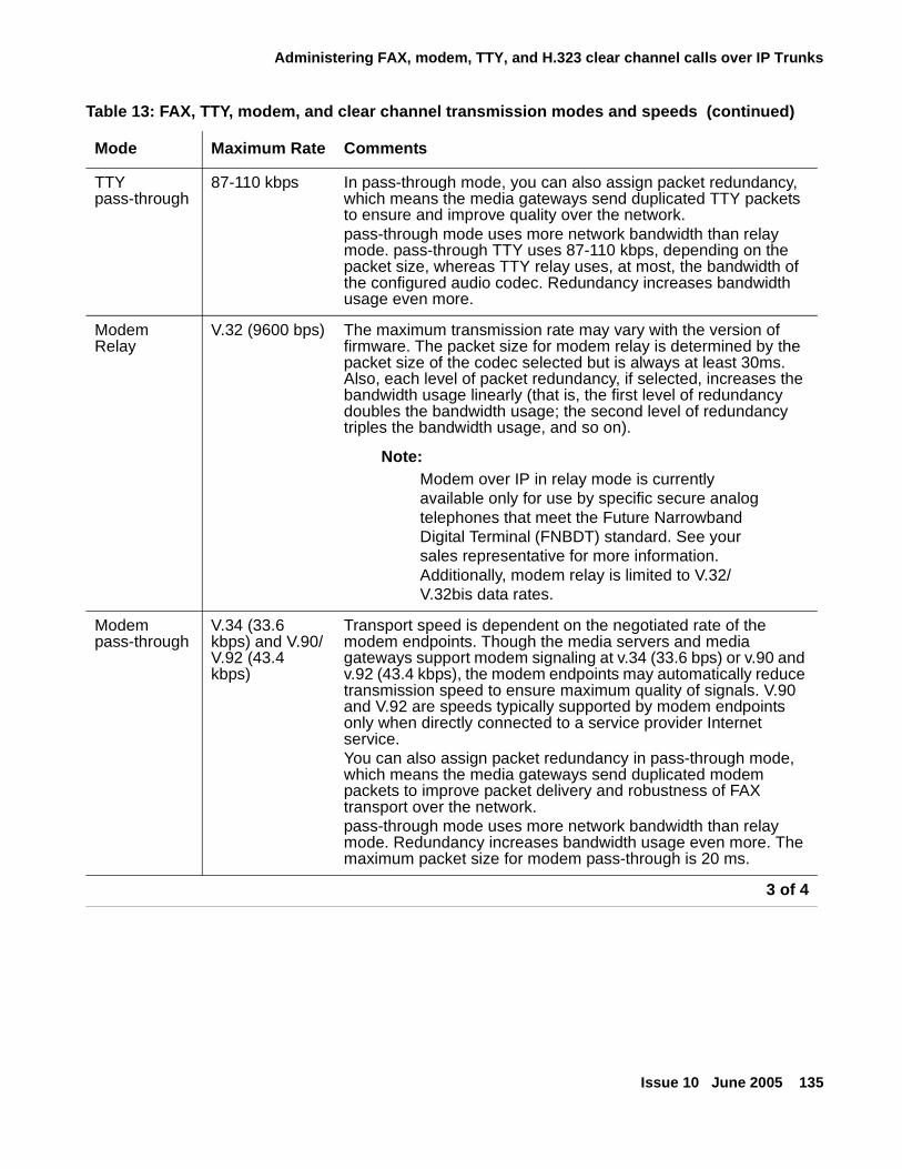
Administering FAX, modem, TTY, and H.323 clear channel calls over IP Trunks
Issue 10 June 2005 135
TTY pass-through
87-110 kbps In pass-through mode, you can also assign packet redundancy, which means the media gateways send duplicated TTY packets to ensure and improve quality over the network.pass-through mode uses more network bandwidth than relay mode. pass-through TTY uses 87-110 kbps, depending on the packet size, whereas TTY relay uses, at most, the bandwidth of the configured audio codec. Redundancy increases bandwidth usage even more.
Modem Relay
V.32 (9600 bps) The maximum transmission rate may vary with the version of firmware. The packet size for modem relay is determined by the packet size of the codec selected but is always at least 30ms. Also, each level of packet redundancy, if selected, increases the bandwidth usage linearly (that is, the first level of redundancy doubles the bandwidth usage; the second level of redundancy triples the bandwidth usage, and so on).
Note:Note: Modem over IP in relay mode is currently
available only for use by specific secure analog telephones that meet the Future Narrowband Digital Terminal (FNBDT) standard. See your sales representative for more information. Additionally, modem relay is limited to V.32/V.32bis data rates.
Modem pass-through
V.34 (33.6 kbps) and V.90/V.92 (43.4 kbps)
Transport speed is dependent on the negotiated rate of the modem endpoints. Though the media servers and media gateways support modem signaling at v.34 (33.6 bps) or v.90 and v.92 (43.4 kbps), the modem endpoints may automatically reduce transmission speed to ensure maximum quality of signals. V.90 and V.92 are speeds typically supported by modem endpoints only when directly connected to a service provider Internet service.You can also assign packet redundancy in pass-through mode, which means the media gateways send duplicated modem packets to improve packet delivery and robustness of FAX transport over the network. pass-through mode uses more network bandwidth than relay mode. Redundancy increases bandwidth usage even more. The maximum packet size for modem pass-through is 20 ms.
Table 13: FAX, TTY, modem, and clear channel transmission modes and speeds (continued)
Mode Maximum Rate Comments
3 of 4
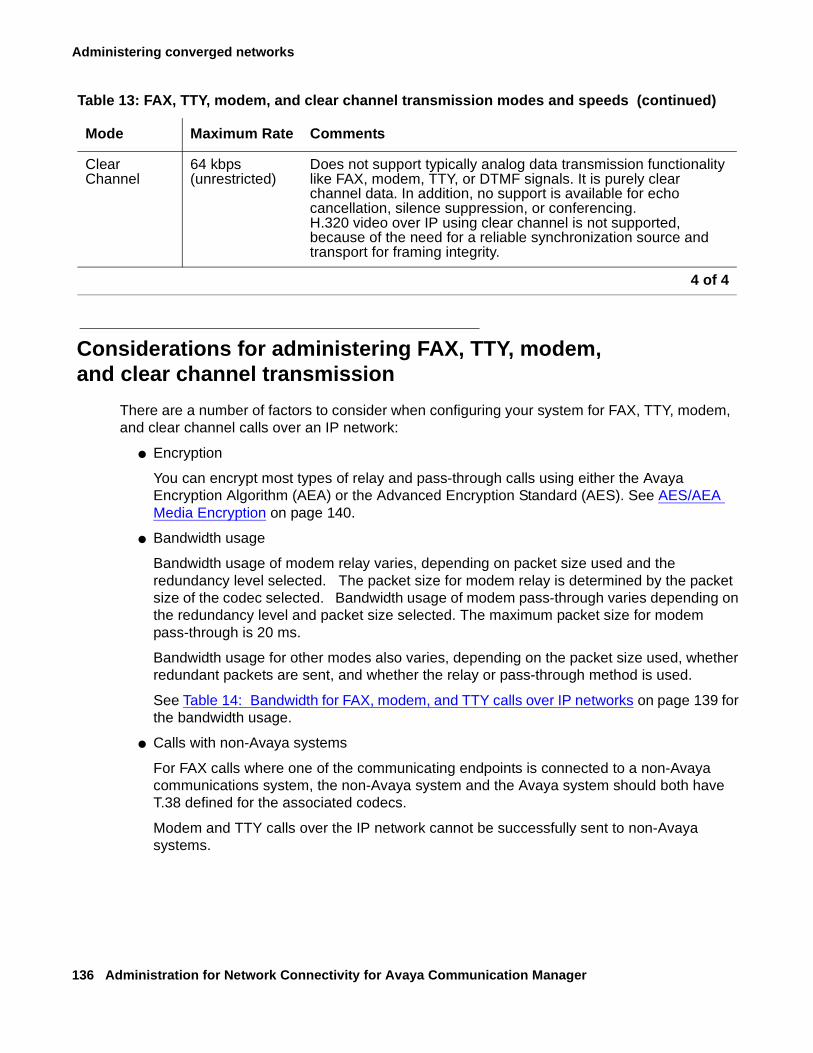
Administering converged networks
136 Administration for Network Connectivity for Avaya Communication Manager
Considerations for administering FAX, TTY, modem, and clear channel transmission
There are a number of factors to consider when configuring your system for FAX, TTY, modem, and clear channel calls over an IP network:
● Encryption
You can encrypt most types of relay and pass-through calls using either the Avaya Encryption Algorithm (AEA) or the Advanced Encryption Standard (AES). See AES/AEA Media Encryption on page 140.
● Bandwidth usage
Bandwidth usage of modem relay varies, depending on packet size used and the redundancy level selected. The packet size for modem relay is determined by the packet size of the codec selected. Bandwidth usage of modem pass-through varies depending on the redundancy level and packet size selected. The maximum packet size for modem pass-through is 20 ms.
Bandwidth usage for other modes also varies, depending on the packet size used, whether redundant packets are sent, and whether the relay or pass-through method is used.
See Table 14: Bandwidth for FAX, modem, and TTY calls over IP networks on page 139 for the bandwidth usage.
● Calls with non-Avaya systems
For FAX calls where one of the communicating endpoints is connected to a non-Avaya communications system, the non-Avaya system and the Avaya system should both have T.38 defined for the associated codecs.
Modem and TTY calls over the IP network cannot be successfully sent to non-Avaya systems.
Clear Channel
64 kbps (unrestricted)
Does not support typically analog data transmission functionality like FAX, modem, TTY, or DTMF signals. It is purely clear channel data. In addition, no support is available for echo cancellation, silence suppression, or conferencing.H.320 video over IP using clear channel is not supported, because of the need for a reliable synchronization source and transport for framing integrity.
Table 13: FAX, TTY, modem, and clear channel transmission modes and speeds (continued)
Mode Maximum Rate Comments
4 of 4
Administering FAX, modem, TTY, and H.323 clear channel calls over IP Trunks
Issue 10 June 2005 137
● Differing transmission methods at the sending/receiving endpoints
The transmission method or methods used on both the sending and receiving ends of a FAX/modem/TTY/clear channel call should be the same.
In some cases, a call succeeds even though the transmission method for the sending and receiving endpoints is different. Generally, however, for a call to succeed, the two endpoints must be administered for the same transmission method.
● H.320 Video over IP using Clear Channel
H.320 video is not supported over IP using clear channel, because H.320 video requires a reliable synchronization source and transport for framing integrity of the channels; however, there is no such provision over IP networks. H.320 video might work in some cases for a time, but eventually, the connection would drop because of delay and synchronization problems.
● Hardware requirements
The relay and pass-through capabilities require the following hardware:
- For DEFINITY CSI servers, S8500/S8500B Media Servers, or S8700/S8710 Media Servers, Hardware Vintage 10 or later of the TN2302AP or TN2602AP circuit pack with firmware version 90 or later is required.
- For the G700 Media Gateway, G700 firmware version 22.14.0, and VoIP firmware Vintage 40 or greater to support Communication Manager 2.2 is required. An MM760 Media Module with firmware Vintage 40 or greater may be used for additional VoIP capacity.
- For the G350 Media Gateway, G350 firmware version 22.14.0 or greater to support Communication Manager 2.2 is required.
- For T.38 FAX capability, endpoints on other non-Avaya T.38 compliant communications systems may send FAX calls to or receive FAX calls from endpoints on Avaya systems.
● Multiple hops and multiple conversions
If a FAX call must undergo more than one conversion cycle (from TDM protocol to IP protocol and back to TDM protocol), FAX pass-through should be used. If FAX relay mode is used, the call may fail due to delays in processing through more than one conversion cycle. A modem or TTY call may undergo no more than one conversion cycle (from TDM protocol to IP protocol and back to TDM protocol) on the communication path. If multiple conversion cycles occur, the call fails. As a result, both endpoint gateways and any intermediate servers in a path containing multiple hops must support shuffling for a modem or TTY call to succeed.
For example, in Figure 8: Shuffling for FAX, modem, and TTY calls over IP on page 138, a hop occurs in either direction for calls between Port Network A and Media Gateway C because the calls are routed through Port Network D. In this case, shuffling is required on Port Network A for calls going to Media Gateway C, and shuffling is required on Port Network D for calls going from Media Gateway C to Port Network A.
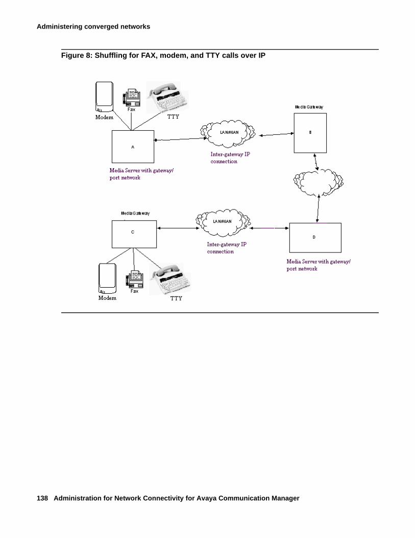
Administering converged networks
138 Administration for Network Connectivity for Avaya Communication Manager
Figure 8: Shuffling for FAX, modem, and TTY calls over IP
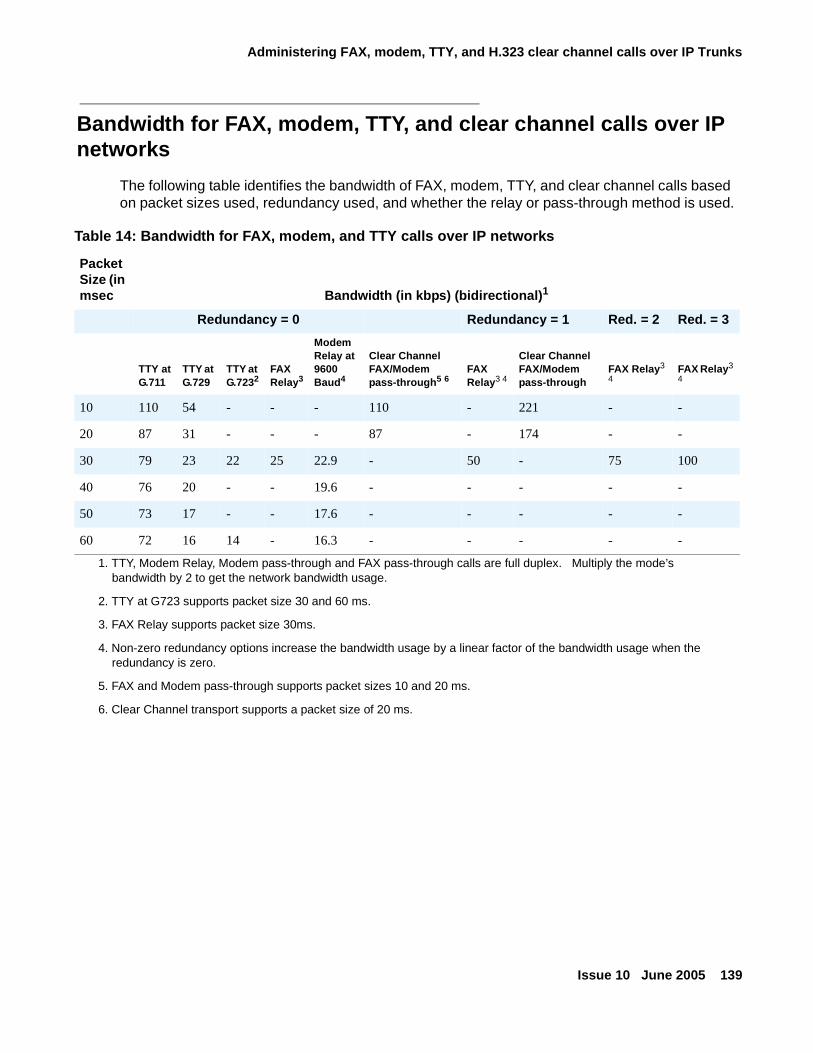
Administering FAX, modem, TTY, and H.323 clear channel calls over IP Trunks
Issue 10 June 2005 139
Bandwidth for FAX, modem, TTY, and clear channel calls over IP networks
The following table identifies the bandwidth of FAX, modem, TTY, and clear channel calls based on packet sizes used, redundancy used, and whether the relay or pass-through method is used.
Table 14: Bandwidth for FAX, modem, and TTY calls over IP networks
Packet Size (in msec Bandwidth (in kbps) (bidirectional)1
Redundancy = 0 Redundancy = 1 Red. = 2 Red. = 3
TTY atG.711
TTY at G.729
TTY at G.7232
FAXRelay3
Modem Relay at 9600 Baud4
Clear Channel FAX/Modem pass-through5 6
FAXRelay3 4
Clear Channel FAX/Modem pass-through
FAX Relay3
4FAX Relay3
4
10 110 54 - - - 110 - 221 - -
20 87 31 - - - 87 - 174 - -
30 79 23 22 25 22.9 - 50 - 75 100
40 76 20 - - 19.6 - - - - -
50 73 17 - - 17.6 - - - - -
60 72 16 14 - 16.3 - - - - -
1. TTY, Modem Relay, Modem pass-through and FAX pass-through calls are full duplex. Multiply the mode’s bandwidth by 2 to get the network bandwidth usage.
2. TTY at G723 supports packet size 30 and 60 ms.
3. FAX Relay supports packet size 30ms.
4. Non-zero redundancy options increase the bandwidth usage by a linear factor of the bandwidth usage when the redundancy is zero.
5. FAX and Modem pass-through supports packet sizes 10 and 20 ms.
6. Clear Channel transport supports a packet size of 20 ms.
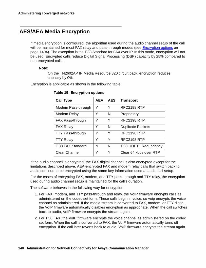
Administering converged networks
140 Administration for Network Connectivity for Avaya Communication Manager
AES/AEA Media Encryption
If media encryption is configured, the algorithm used during the audio channel setup of the call will be maintained for most FAX relay and pass-through modes (see Encryption options on page 1404). The exception is the T.38 Standard for FAX over IP. In this mode, encryption will not be used. Encrypted calls reduce Digital Signal Processing (DSP) capacity by 25% compared to non-encrypted calls.
Note:Note: On the TN2602AP IP Media Resource 320 circuit pack, encryption reduces
capacity by 0%.
Encryption is applicable as shown in the following table.
If the audio channel is encrypted, the FAX digital channel is also encrypted except for the limitations described above. AEA-encrypted FAX and modem relay calls that switch back to audio continue to be encrypted using the same key information used at audio call setup.
For the cases of encrypting FAX, modem, and TTY pass-through and TTY relay, the encryption used during audio channel setup is maintained for the call’s duration.
The software behaves in the following way for encryption:
1. For FAX, modem, and TTY pass-through and relay, the VoIP firmware encrypts calls as administered on the codec set form. These calls begin in voice, so voip encrypts the voice channel as administered. If the media stream is converted to FAX, modem, or TTY digital, the VoIP firmware automatically disables encryption as appropriate. When the call switches back to audio, VoIP firmware encrypts the stream again.
2. For T.38 FAX, the VoIP firmware encrypts the voice channel as administered on the codec set form. When the call is converted to FAX, the VoIP firmware automatically turns off encryption. If the call later reverts back to audio, VoIP firmware encrypts the stream again.
Table 15: Encryption options
Call Type AEA AES Transport
Modem Pass-through Y Y RFC2198 RTP
Modem Relay Y N Proprietary
FAX Pass-through Y Y RFC2198 RTP
FAX Relay Y N Duplicate Packets
TTY Pass-through Y Y RFC2198 RTP
TTY Relay Y Y RFC2198 RTP
T.38 FAX Standard N N T.38 UDPTL Redundancy
Clear Channel Y Y Clear 64 kbps over RTP
Issue 10 June 2005 141
Chapter 4: Network quality administration
This section provides information for improving voice quality by adjusting the voice packet traffic behavior through an IP network, also known as implementing Quality of Service (QoS). The section covers these topics:
● About factors causing voice degradation introduces the types of voice degradation and their causes.
● About Quality of Service (QoS) and voice quality administration tells you how to administer your Avaya equipment for better voice quality and offers suggestions for other network problems.
● The About Media Encryption section discusses media encryption capabilities, requirements, and administration in Communication Manager.
● The About network management section includes information about administering H.248 Link Recovery and the Avaya Policy Manager (APM) and Avaya VoIP Monitoring Manager network monitoring tools.
Note:Note: Implementing QoS requires administration adjustments to Avaya equipment as
well as LAN/WAN equipment (switches, routers, hubs, etc.).
For more information on implementing QoS, see the White Paper, Avaya IP Voice Quality Network Requirements (EF-LB1500), at http://www1.avaya.com/enterprise/whitepapers/ip_networking.pdf.
About factors causing voice degradationVoIP applications put severe constraints on the amount of end-to-end transfer delay of the voice signal and routing. If these constraints are not met, users complain of garbled or degraded voice quality, gaps, and pops. Due to human voice perception, VoIP applications can afford to randomly lose a few voice packets and the user can still understand the conversation. However, if voice packets are delayed or systematically lost, the destination experiences a momentary loss of sound, often with some unpleasing artifacts like clicks or pops. Some of the general complaints and their causes are listed in Table 16: User complaints and their causes on page 142.
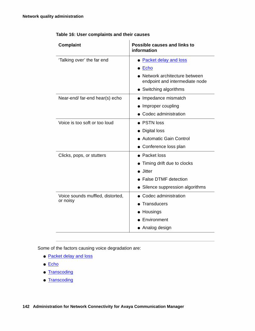
Network quality administration
142 Administration for Network Connectivity for Avaya Communication Manager
Some of the factors causing voice degradation are:
● Packet delay and loss
● Echo
● Transcoding
● Transcoding
Table 16: User complaints and their causes
Complaint Possible causes and links to information
‘Talking over’ the far end ● Packet delay and loss
● Echo
● Network architecture between endpoint and intermediate node
● Switching algorithms
Near-end/ far-end hear(s) echo ● Impedance mismatch
● Improper coupling
● Codec administration
Voice is too soft or too loud ● PSTN loss
● Digital loss
● Automatic Gain Control
● Conference loss plan
Clicks, pops, or stutters ● Packet loss
● Timing drift due to clocks
● Jitter
● False DTMF detection
● Silence suppression algorithms
Voice sounds muffled, distorted, or noisy
● Codec administration
● Transducers
● Housings
● Environment
● Analog design
About factors causing voice degradation
Issue 10 June 2005 143
Packet delay and loss
The causes of voice degradation include:
● Packet delay (latency)
- Buffer delays
- Queuing delays in switches and routers
- Bandwidth restrictions
● Jitter (statistical average variance in end-to-end packet travel times)
● Packet loss
- Network overloaded
- Jitter buffers filled
- Echo
For a detailed discussion of packet delay and loss, see the section on "Voice quality network requirements" in Avaya Application Solutions: IP Telephony Deployment Guide, 555-245-600.
Tip:
Tip: Avaya recommends a network assessment that measures and solves latency issues before implementing VoIP solutions (see Avaya Application Solutions: IP Telephony Deployment Guide, 555-245-600).
Echo
When you hear your own voice reflected back with a slight delay, this is echo and it happens for the following reasons:
● Electrical -- from unbalanced impedances or cross-talk
● Acoustical -- introduced by speakerphone or room size
The total round-trip time from when a voice packet enters the network to the time it is returned to the originator is echo path delay. In general, calls over a WAN normally have a longer echo path delay compared to calls over a LAN.
Note:Note: VoIP itself is not a cause of echo. However, significant amounts of delay and/or
jitter associated with VoIP can make echo perceptible that would otherwise not be perceived.
Network quality administration
144 Administration for Network Connectivity for Avaya Communication Manager
Echo cancellers
Echo cancellers minimize echo by comparing the original voice pattern with the received patterns, and canceling the echo if the patterns match. However echo cancellers are not perfect, especially:
● When the round-trip delay from the echo canceller to the echo reflection point and back is longer than the time that the original (non-echoed) signal is buffered in the echo canceller memory. The larger the echo canceller’s memory the longer the signal is held in the buffer, maximizing the number of packets that the canceller can compare in the allotted time.
● During Voice Activity Detection (VAD), which monitors the level of the received signal:
- An energy drop of at least 3dB weaker than the original signal indicates echo.
- An energy level 3dB greater indicates far-end speech.
Echo cancellers do not work well over analog trunks and with speakerphones with volume controls that permit strong signals. Although VADs can greatly conserve bandwidth, overly-aggressive VADs can cause voice clipping and reduce voice quality. VAD administration is done on the station form for the particular IP phone.
Analog trunks in IP configurations need careful network balance settings to minimize echo. A test tone of known power is sent out and the return signal measured to determine the balance setting, which is critical for reducing echo on IP calls across these trunks.
Echo cancellation plans (TN464HP/TN2464CP circuit packs)
The following summarizes the echo cancellation plans that are available exclusively for the TN464HP/TN2464CP circuit packs. For echo cancellation plans that are available for the TN464GP/TN2464BP circuit packs, see Echo cancellation plans (TN464GP/TN2464BP circuit packs) on page 145.
Echo Cancellation Configuration 1 - TN464HP/TN2464CP
This plan is the recommended choice. It has comfort noise generation and residual echo suppression turned on. During "single talk", background noise and residual echo from the distant station may be suppressed and replaced with comfort noise. The comfort noise substitution reduces the perception of background noise pumping, as observed by the talker. In this plan, the EC direction is assumed chosen to cancel the talker’s echo. Since this plan turns on comfort noise and echo suppression, it is similar to EC plans 8 and 9 for the TN464GP/TN2464BP circuit packs.
Echo Cancellation Configuration 2 - TN464HP/TN2464CP
This configuration has comfort noise generation turned off and residual echo suppression turned on. This plan may work well in a quiet background environment. In a noisy background environment, background noise pumping/clipping may be heard by the talker. In this case, EC direction is assumed chosen to cancel the talker’s echo. This plan my be a good compromise for a small percent of users, who do not care for the comfort noise and prefer the silence during the residual echo suppression periods. Since the plan turns off comfort noise and turns on residual suppression, it is similar to EC configurations 1-6 for the TN464GP/TN2464BP circuit packs.
About factors causing voice degradation
Issue 10 June 2005 145
Echo Cancellation Configuration 3 - TN464HP/TN2464CP
This configuration has comfort noise generation and residual echo suppression turned off. This configuration can be a good choice only if EC plans 1 and 2 do not satisfy the user’s preferences. Situations that require configuration 3 should be very rare. (For example, the user does not care for the sound of comfort noise nor the pumping/clipping of background noise.) This configuration allows the user to hear sound from the earpiece as natural as possible. However, the user may hear residual echo during training periods, or all the time if echo is sufficiently high and residual echo is always present. Convergence may be very slow. Since comfort noise and residual suppression are turned off, this configuration is similar to EC configuration 7 for the TN464GP/TN2464BP circuit packs.
Echo cancellation plans (TN464GP/TN2464BP circuit packs)
Communication Manager supports several echo cancellation (EC) plans for the TN464GP/TN2464BP circuit packs.
Note:Note: An EC configuration setting can be changed in real time.The change takes effect
immediately. That is, it is not necessary to busyout/release the circuit pack – you simply change the setting on the DS1 Circuit Pack form. This can be done without disruption to existing calls - in fact, you immediately hear the effect of the change.
! Important:Important: When there are TN2302AP or TN2602AP circuit pack(s) and TN464GP/
TN2464BP circuit pack(s) being used for a call, the echo canceller on the TN2302AP or TN2602AP is turned off and the echo canceller on the TN464GP/TN2454BP is used instead, because it has the greater echo canceller.
The following summarizes the echo cancellation plans that are available for the TN464GP/TN2464BP circuit packs. For echo cancellation plans that are available exclusively for the TN464HP/TN2464CP circuit packs, see Echo cancellation plans (TN464HP/TN2464CP circuit packs) on page 144.
Echo Cancellation Configuration 1 – Highly Aggressive Echo Control
This configuration can control very strong echo from a distant party. It (as well as Echo Cancellation Configuration 4) provides the most rapid convergence in detecting and correcting echo at the beginning of a call. The initial echo fades faster than the other settings (generally in a small fraction of a second), regardless of the loudness of the talker’s voice. EC Configurations 1 and 4 are the same except for loss. EC Configuration 1 has 6dB of loss and EC 4 has 0dB of loss. This makes EC Configuration 1 a good choice for consistently high network signal levels. EC Configuration 1 can cause low-volume complaints and/or complaints of clipped speech utterances, particularly when both parties speak simultaneously (doubletalk). Because EC Configuration 1 relies strongly on echo suppression to help control echo, “pumping” of the distant party’s background noise may occur and lead to complaints. Prior to Communication Manager Release 2.0, EC Configuration 1 was the default configuration.
Network quality administration
146 Administration for Network Connectivity for Avaya Communication Manager
The 6dB of loss in EC Configuration 1 is in one direction only and depends on the setting of the EC Direction field on the DS1 Board form. If the direction is set to inward, then the 6dB of loss is inserted in the path out from the board towards the T1/E1 circuit. Conversely, if the setting is outward, then the 6dB of loss is inserted into the path from the T1/E1 circuit towards the TDM bus.
Echo Cancellation Configuration 2 – Aggressive, Stable Echo Control
This configuration is nearly identical to EC Configuration 1, except that it does not inject an additional 6dB of signal loss, and convergence of the echo canceller is slower, but more stable than that provided by EC Configuration 1. If EC Configuration 1 is found to diverge during doubletalk conditions – noticeable by the sudden onset of audible echo, EC Configuration 2 should be used in place of EC Configuration 1. Because the echo canceller converges somewhat slower, some initial echo may be noticeable at the start of a call, while the system is “training”. EC Configuration 2 can cause complaints of clipped speech utterances, particularly during doubletalk. Because EC Configuration 2 relies strongly on echo suppression to help control echo, “pumping” of the distant party’s background noise may occur and lead to complaints.
Echo Cancellation Configuration 3 – Aggressive, Very Stable Echo Control
This configuration is nearly identical to EC Configuration 2, but is even more stable. Because the echo canceller converges somewhat slower, some initial echo may be noticeable at the start of a call. EC Configuration 3 can cause complaints of clipped speech utterances, particularly during doubletalk. Because EC Configuration 3 relies strongly on echo suppression to help control echo, “pumping” of the distant party’s background noise may occur and lead to complaints.
Echo Cancellation Configuration 4 – Highly Aggressive Echo Control
Echo Cancellation Configuration 4 is identical to EC Configuration 1, but does not provide the 6dB loss option as described for EC Configuration 1. All other comments from EC Configuration 1 apply to EC Configuration 4. EC Configuration 4 can cause complaints of clipped speech utterances, particularly during doubletalk. Because EC Configuration 4 strongly relies on echo suppression to help control echo, “pumping” of the distant party’s background noise may occur, and lead to complaints.
Echo Cancellation Configuration 5 – Very Moderate, Very Stable Echo Control
Echo Cancellation Configuration 5 departs significantly from EC Configurations 1 –4. The echo canceller is slower to converge and is very stable once it converges. Some initial echo may be heard at the beginning of a call. EC Configuration 5 will not, in general, lead to complaints of clipped speech or pumping of the distant party’s background noise.
About factors causing voice degradation
Issue 10 June 2005 147
Echo Cancellation Configuration 6 – Highly Aggressive Echo Control
Echo Cancellation Configuration 6 is identical to EC Configuration 4, but reliance on the echo suppressor to control echo is about one-half that of EC Configuration 4. As a result, EC Configuration 6 will not clip speech as much as EC Configuration 4, but may cause somewhat more audible echo, particularly at the start of a call. Some pumping of the distant party’s background noise may be perceptible.
Echo Cancellation Configuration 7 – Extremely Moderate & Stable Echo Control
Echo Cancellation Configuration 7 provides very stable and transparent control of weak to low-level echoes. For connections having audible echo at the start of a call, the residual echo may linger for several seconds as the echo canceller converges.
Echo Cancellation Configuration 8 –Aggressive, Very Transparent Echo Control 1
Echo Cancellation Configuration 8 provides aggressive control of echo at the start of a call and more moderate control during the call. Unlike all prior settings, EC Configuration 8 uses “comfort noise” injection to match the actual noise level of the distant party’s speech signal. The effect is one of echo canceller “transparency,” in which complaints of clipped speech or noise pumping should be few to none. To many people, EC Configuration 8 and EC Configuration 9 will be indistinguishable.
Echo Cancellation Configuration 9 – Aggressive, Transparent Echo Control 2
Echo Cancellation Configuration 9 is nearly identical to EC Configuration 8, but provides somewhat more residual echo control at a slight expense of transparency. To many people, EC Configuration 8 and EC Configuration 9 will be indistinguishable.
Transcoding
When IP endpoints are connected through more than one network region, it is important that each region use the same CODEC, the circuitry that converts an audio signal into its digital equivalent and assigns its companding properties. Packet delays occur when different CODECs are used within the same network region. In this case the IP Media Processor acts as a gateway translating the different CODECs, and an IP-direct (shuffled) connection is not possible.
Bandwidth
In converged networks that contain coexistent voice and data traffic, the volume of either type of traffic is unpredictable. For example, transferring a file using the File Transfer Protocol (FTP) can cause a sharp burst in the network traffic. At other times there may be no data in the network.
Network quality administration
148 Administration for Network Connectivity for Avaya Communication Manager
While most data applications are insensitive to small delays, the recovery of lost and corrupted voice packets poses a significant problem. For example, users might not really be concerned if the reception of E-mail or files from file transfer applications is delayed by a few seconds. In a voice call, the most important expectation is the real-time exchange of speech. To achieve this the network resources are required for the complete duration of the call. If in any instance, there are no resources or the network too busy to carry the voice packets, then the destination experiences clicks, pops and stutters. Therefore, there is a continuous need for a fixed amount of bandwidth during the call to keep it real-time and clear.
About Quality of Service (QoS) andvoice quality administration
Of the VoIP network issues described in the About factors causing voice degradation section, delay is the most crucial. And because many of the other causes are highly interdependent with delay, the primary goal is to reduce delay by improving the routing in the network, or by reducing the processing time within the end points and the intermediate nodes.
For example, when delay is minimized:
● Jitter and electrically-induced echo abate.
● Intermediate node and jitter buffer resources are released making packet loss insignificant.
As packets move faster in the network, the resources at each node are available for the next packet that arrives, and packets will not be dropped because of lack of resources.
Delay cannot be eliminated completely from VoIP applications, because delay includes the inevitable processing time at the endpoints plus the transmission time. However, the delay that is caused due to network congestion or queuing can be minimized by adjusting these Quality of Service (QoS) parameters:
● Layer 3 QoS
- DiffServ
- RSVP
● Layer 2 QoS: 802.1p/Q
These parameters are administered on the IP Network Region form (see Administering IP network regions on page 158).
About Quality of Service (QoS) and voice quality administration
Issue 10 June 2005 149
Layer 3 QoS
DiffServ
The Differentiated Services Code Point (DSCP) or “DiffServ” is a packet prioritization scheme that uses the Type of Service (ToS) byte in the packet header to indicate the packet’s forwarding class and Per Hop Behaviors (PHBs). After the packets are marked with their forwarding class, the interior routers and gateways use this ToS byte to differentiate the treatment of packets.
A DiffServ policy must be established across the entire IP network, and the DiffServ values used by Communication Manager and by the IP network infrastructure must be the same.
If you have a Service Level Agreement (SLA) with a service provider, the amount of traffic of each class that you can inject into the network is limited by the SLA. The forwarding class is directly encoded as bits in the packet header. After the packets are marked with their forwarding class, the interior nodes (routers & gateways) can use this information to differentiate the treatment of packets.
RSVP
Resources ReSerVation Protocol (RSVP) can be used to lower DiffServ priorities of new calls when bandwidth is scarce. The RSVP signaling protocol transmits requests for resource reservations to routers on the path between the sender and the receiver for the voice bearer packets only, not the call setup or call signaling packets.
Layer 2 QoS: 802.1p/Q
802.1p is an Ethernet tagging mechanism that can instruct Ethernet switches to give priority to voice packets.
! CAUTION:CAUTION: If you change 802.1p/Q on the IP Network Region screen, it changes the format
of the Ethernet frames. 802.1p/Q settings in Communication Manager must match similar settings in your network elements.
The 802.1p feature is important to the endpoint side of the network since PC-based endpoints must prioritize audio traffic over routine data traffic.
IEEE standard 802.1Q allows you to specify both a virtual LAN (VLAN) and a frame priority at layer 2 for LAN switches or Ethernet switches, which allows for routing based on MAC addresses.
802.1p/Q provides for 8 priority levels and for a large number of Virtual LAN identifiers. Interpretation of the priority is controlled by the Ethernet switch and is usually based on highest priority first. The VLAN identifier permits segregation of traffic within Ethernet switches to reduce traffic on individual links. 802.1p operates on the MAC layer. The switch always sends
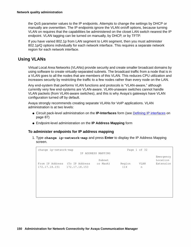
Network quality administration
150 Administration for Network Connectivity for Avaya Communication Manager
the QoS parameter values to the IP endpoints. Attempts to change the settings by DHCP or manually are overwritten. The IP endpoints ignore the VLAN on/off options, because turning VLAN on requires that the capabilities be administered on the closet LAN switch nearest the IP endpoint. VLAN tagging can be turned on manually, by DHCP, or by TFTP.
If you have varied 802.1p from LAN segment to LAN segment, then you must administer 802.1p/Q options individually for each network interface. This requires a separate network region for each network interface.
Using VLANs
Virtual Local Area Networks (VLANs) provide security and create smaller broadcast domains by using software to create virtually-separated subnets. The broadcast traffic from a node that is in a VLAN goes to all the nodes that are members of this VLAN. This reduces CPU utilization and increases security by restricting the traffic to a few nodes rather than every node on the LAN.
Any end-system that performs VLAN functions and protocols is “VLAN-aware,” although currently very few end-systems are VLAN-aware. VLAN-unaware switches cannot handle VLAN packets (from VLAN-aware switches), and this is why Avaya’s gateways have VLAN configuration turned off by default.
Avaya strongly recommends creating separate VLANs for VoIP applications. VLAN administration is at two levels:
● Circuit pack-level administration on the IP-Interfaces form (see Defining IP interfaces on page 87)
● Endpoint-level administration on the IP Address Mapping form
To administer endpoints for IP address mapping
1. Type change ip-network-map and press Enter to display the IP Address Mapping screen.
change ip-network-map Page 1 of 32 IP ADDRESS MAPPING
Emergency Subnet LocationFrom IP Address (To IP Address or Mask) Region VLAN Extension172.17.18.151 172.17.18.153 114 n
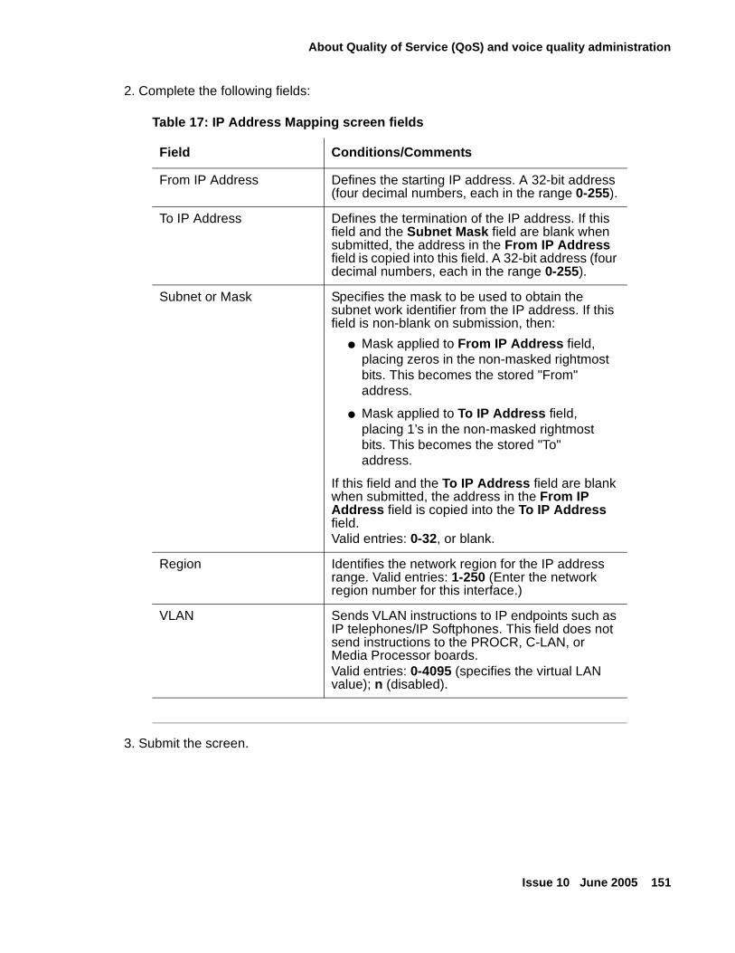
About Quality of Service (QoS) and voice quality administration
Issue 10 June 2005 151
2. Complete the following fields:
3. Submit the screen.
Table 17: IP Address Mapping screen fields
Field Conditions/Comments
From IP Address Defines the starting IP address. A 32-bit address (four decimal numbers, each in the range 0-255).
To IP Address Defines the termination of the IP address. If this field and the Subnet Mask field are blank when submitted, the address in the From IP Address field is copied into this field. A 32-bit address (four decimal numbers, each in the range 0-255).
Subnet or Mask Specifies the mask to be used to obtain the subnet work identifier from the IP address. If this field is non-blank on submission, then:
● Mask applied to From IP Address field, placing zeros in the non-masked rightmost bits. This becomes the stored "From" address.
● Mask applied to To IP Address field, placing 1’s in the non-masked rightmost bits. This becomes the stored "To" address.
If this field and the To IP Address field are blank when submitted, the address in the From IP Address field is copied into the To IP Address field.Valid entries: 0-32, or blank.
Region Identifies the network region for the IP address range. Valid entries: 1-250 (Enter the network region number for this interface.)
VLAN Sends VLAN instructions to IP endpoints such as IP telephones/IP Softphones. This field does not send instructions to the PROCR, C-LAN, or Media Processor boards. Valid entries: 0-4095 (specifies the virtual LAN value); n (disabled).
Network quality administration
152 Administration for Network Connectivity for Avaya Communication Manager
Administering IP CODEC sets
The IP Codec Set screen allows you to specify the type of CODEC used for voice encoding and companding, and compression/decompression. The CODECs on the IP Codec Set screen are listed in the order of preferred use. A call across a trunk between two systems is set up to use the first common CODEC listed.
Note:Note: The CODEC order must be administered the same for each system of an H.323
trunk connection. The set of CODECs listed does not have to be the same, but the order of the listed CODECs must.
The IP Codec Set screen allows you to define the CODECs and packet sizes used by each IP network region. You can also enable or disable silence suppression for each CODEC in the set. The screen dynamically displays the packet size in milliseconds (ms) for each CODEC in the set, based on the number of frames you administer per packet.
Finally, you use this screen to assign the following characteristics to a codec set:
● Whether or not endpoints in the assigned network region can route FAX, modem, TTY, or clear channel calls over IP trunks
● Which mode the system uses to route the FAX, modem, TTY, or clear channel calls
● Whether or not redundant packets will be added to the transmission for higher reliability and quality
These characteristics must be assigned to the codec set, and the codec set must be assigned to a network region for endpoints in that region to be able to use the capabilities established on this screen.
! CAUTION:CAUTION: If users are using Super G3 FAX machines as well as modems, do not assign
these FAX machines to a network region with an IP Codec set that is modem-enabled as well as FAX-enabled. If its Codec set is enabled for both modem and FAX signaling, a Super G3 FAX machine incorrectly tries to use the modem transmission instead of the FAX transmission.
Therefore, assign modem endpoints to a network region that uses a modem-enabled IP Codec set, and assign the Super G3 FAX machines to a network region that uses a FAX-enabled IP Codec set.
To administer an IP Codec set
1. Type change ip-codec-set set# and press Enter to open the IP Codec Set screen.
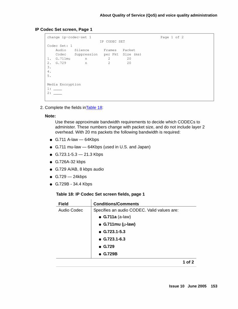
About Quality of Service (QoS) and voice quality administration
Issue 10 June 2005 153
IP Codec Set screen, Page 1
2. Complete the fields inTable 18:
Note:Note: Use these approximate bandwidth requirements to decide which CODECs to
administer. These numbers change with packet size, and do not include layer 2 overhead. With 20 ms packets the following bandwidth is required:
● G.711 A-law — 64Kbps
● G.711 mu-law — 64Kbps (used in U.S. and Japan)
● G.723.1-5.3 — 21.3 Kbps
● G.726A-32 kbps
● G.729 A/AB, 8 kbps audio
● G.729 — 24kbps
● G.729B - 34.4 Kbps
change ip-codec-set 1 Page 1 of 2 IP CODEC SET
Codec Set: 1Audio Silence Frames PacketCodec Suppression per Pkt Size (ms)
1. G.711mu n 2 202. G.729 n 2 203.4.5.
Media Encryption1: ____2: ____
Table 18: IP Codec Set screen fields, page 1
Field Conditions/CommentsAudio Codec Specifies an audio CODEC. Valid values are:
● G.711a (a-law)
● G.711mu (µ-law)
● G.723.1-5.3
● G.723.1-6.3
● G.729
● G.729B
1 of 2
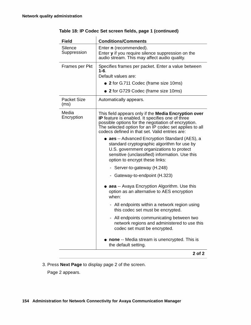
Network quality administration
154 Administration for Network Connectivity for Avaya Communication Manager
3. Press Next Page to display page 2 of the screen.
Page 2 appears.
Silence Suppression
Enter n (recommended).Enter y if you require silence suppression on the audio stream. This may affect audio quality.
Frames per Pkt Specifies frames per packet. Enter a value between 1-6. Default values are:
● 2 for G.711 Codec (frame size 10ms)
● 2 for G729 Codec (frame size 10ms)
Packet Size (ms)
Automatically appears.
Media Encryption
This field appears only if the Media Encryption over IP feature is enabled. It specifies one of three possible options for the negotiation of encryption. The selected option for an IP codec set applies to all codecs defined in that set. Valid entries are:
● aes -- Advanced Encryption Standard (AES), a standard cryptographic algorithm for use by U.S. government organizations to protect sensitive (unclassified) information. Use this option to encrypt these links:
- Server-to-gateway (H.248)
- Gateway-to-endpoint (H.323)
● aea -- Avaya Encryption Algorithm. Use this option as an alternative to AES encryption when:
- All endpoints within a network region using this codec set must be encrypted.
- All endpoints communicating between two network regions and administered to use this codec set must be encrypted.
● none -- Media stream is unencrypted. This is the default setting.
Table 18: IP Codec Set screen fields, page 1 (continued)
Field Conditions/Comments
2 of 2
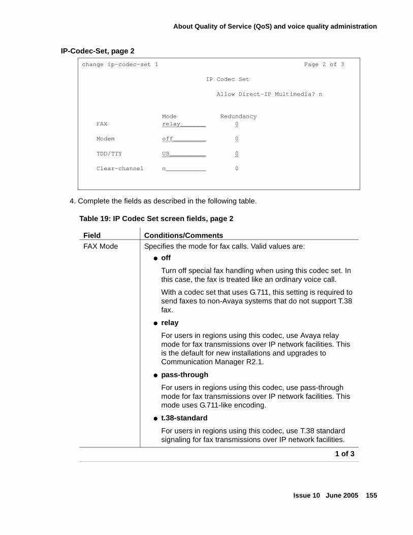
About Quality of Service (QoS) and voice quality administration
Issue 10 June 2005 155
IP-Codec-Set, page 2
4. Complete the fields as described in the following table.
change ip-codec-set 1 Page 2 of 3
IP Codec Set
Allow Direct-IP Multimedia? n
Mode RedundancyFAX relay_______ 0
Modem off_________ 0
TDD/TTY US__________ 0
Clear-channel n___________ 0
Table 19: IP Codec Set screen fields, page 2
Field Conditions/CommentsFAX Mode Specifies the mode for fax calls. Valid values are:
● off
Turn off special fax handling when using this codec set. In this case, the fax is treated like an ordinary voice call.
With a codec set that uses G.711, this setting is required to send faxes to non-Avaya systems that do not support T.38 fax.
● relay
For users in regions using this codec, use Avaya relay mode for fax transmissions over IP network facilities. This is the default for new installations and upgrades to Communication Manager R2.1.
● pass-through
For users in regions using this codec, use pass-through mode for fax transmissions over IP network facilities. This mode uses G.711-like encoding.
● t.38-standard
For users in regions using this codec, use T.38 standard signaling for fax transmissions over IP network facilities.
1 of 3
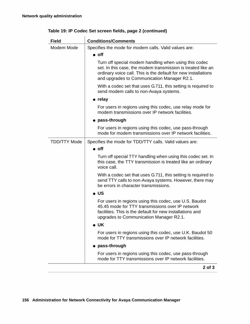
Network quality administration
156 Administration for Network Connectivity for Avaya Communication Manager
Modem Mode Specifies the mode for modem calls. Valid values are:
● off
Turn off special modem handling when using this codec set. In this case, the modem transmission is treated like an ordinary voice call. This is the default for new installations and upgrades to Communication Manager R2.1.
With a codec set that uses G.711, this setting is required to send modem calls to non-Avaya systems.
● relay
For users in regions using this codec, use relay mode for modem transmissions over IP network facilities.
● pass-through
For users in regions using this codec, use pass-through mode for modem transmissions over IP network facilities.
TDD/TTY Mode Specifies the mode for TDD/TTY calls. Valid values are:
● off
Turn off special TTY handling when using this codec set. In this case, the TTY transmission is treated like an ordinary voice call.
With a codec set that uses G.711, this setting is required to send TTY calls to non-Avaya systems. However, there may be errors in character transmissions.
● US
For users in regions using this codec, use U.S. Baudot 45.45 mode for TTY transmissions over IP network facilities. This is the default for new installations and upgrades to Communication Manager R2.1.
● UK
For users in regions using this codec, use U.K. Baudot 50 mode for TTY transmissions over IP network facilities.
● pass-through
For users in regions using this codec, use pass-through mode for TTY transmissions over IP network facilities.
Table 19: IP Codec Set screen fields, page 2 (continued)
Field Conditions/Comments
2 of 3
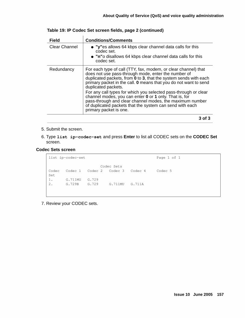
About Quality of Service (QoS) and voice quality administration
Issue 10 June 2005 157
5. Submit the screen.
6. Type list ip-codec-set and press Enter to list all CODEC sets on the CODEC Set screen.
Codec Sets screen
7. Review your CODEC sets.
Clear Channel ● "y"es allows 64 kbps clear channel data calls for this codec set.
● "n"o disallows 64 kbps clear channel data calls for this codec set.
Redundancy For each type of call (TTY, fax, modem, or clear channel) that does not use pass-through mode, enter the number of duplicated packets, from 0 to 3, that the system sends with each primary packet in the call. 0 means that you do not want to send duplicated packets. For any call types for which you selected pass-through or clear channel modes, you can enter 0 or 1 only. That is, for pass-through and clear channel modes, the maximum number of duplicated packets that the system can send with each primary packet is one.
list ip-codec-set Page 1 of 1
Codec SetsCodec Codec 1 Codec 2 Codec 3 Codec 4 Codec 5 Set 1. G.711MU G.7292. G.729B G.729 G.711MU G.711A
Table 19: IP Codec Set screen fields, page 2 (continued)
Field Conditions/Comments
3 of 3
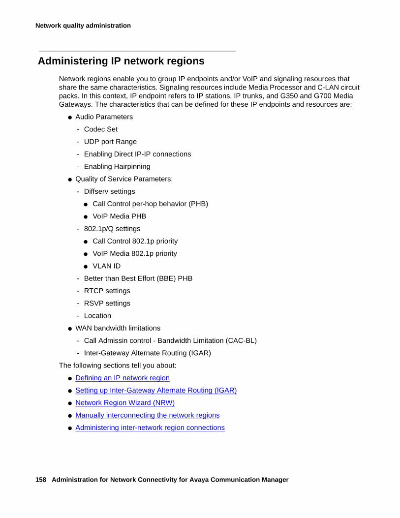
Network quality administration
158 Administration for Network Connectivity for Avaya Communication Manager
Administering IP network regions
Network regions enable you to group IP endpoints and/or VoIP and signaling resources that share the same characteristics. Signaling resources include Media Processor and C-LAN circuit packs. In this context, IP endpoint refers to IP stations, IP trunks, and G350 and G700 Media Gateways. The characteristics that can be defined for these IP endpoints and resources are:
● Audio Parameters
- Codec Set
- UDP port Range
- Enabling Direct IP-IP connections
- Enabling Hairpinning
● Quality of Service Parameters:
- Diffserv settings
● Call Control per-hop behavior (PHB)
● VoIP Media PHB
- 802.1p/Q settings
● Call Control 802.1p priority
● VoIP Media 802.1p priority
● VLAN ID
- Better than Best Effort (BBE) PHB
- RTCP settings
- RSVP settings
- Location
● WAN bandwidth limitations
- Call Admissin control - Bandwidth Limitation (CAC-BL)
- Inter-Gateway Alternate Routing (IGAR)
The following sections tell you about:
● Defining an IP network region
● Setting up Inter-Gateway Alternate Routing (IGAR)
● Network Region Wizard (NRW)
● Manually interconnecting the network regions
● Administering inter-network region connections
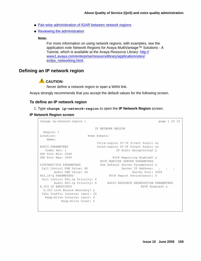
About Quality of Service (QoS) and voice quality administration
Issue 10 June 2005 159
● Pair-wise administration of IGAR between network regions
● Reviewing the administration
Note:Note: For more information on using network regions, with examples, see the
application note Network Regions for Avaya MultiVantage™ Solutions - A Tutorial, which is available at the Avaya Resource Library: http://www1.avaya.com/enterprise/resourcelibrary/applicationnotes/eclips_networking.html.
Defining an IP network region
! CAUTION:CAUTION: Never define a network region to span a WAN link.
Avaya strongly recommends that you accept the default values for the following screen.
To define an IP network region
1. Type change ip-network-region to open the IP Network Region screen.
IP Network Region screen
change ip-network-region 1 page 1 of 19
IP NETWORK REGION Region: 1Location: Home Domain: Name: Intra-region IP-IP Direct Audio: noAUDIO PARAMETERS Inter-region IP-IP Direct Audio: no Codec Set: 1 IP Audio Hairpinning? yUDP Port Min: 2048 UDP Port Max: 3049 RTCP Reporting Enabled? y RTCP MONITOR SERVER PARAMETERSDIFFSERV/TOS PARAMETERS Use Default Server Parameters? n Call Control PHB Value: 46 Server IP Address: . . . Audio PHB Value: 46 Server Port: 5005802.1P/Q PARAMETERS RTCP Report Period(secs): 5 Call Control 802.1p Priority: 6 Audio 802.1p Priority: 6 AUDIO RESOURCE RESERVATION PARAMETERSH.323 IP ENDPOINTS RSVP Enabled? n H.323 Link Bounce Recovery? y Idle Traffic Interval (sec): 20 Keep-Alive Interval (sec): 6 Keep-Alive Count: 5
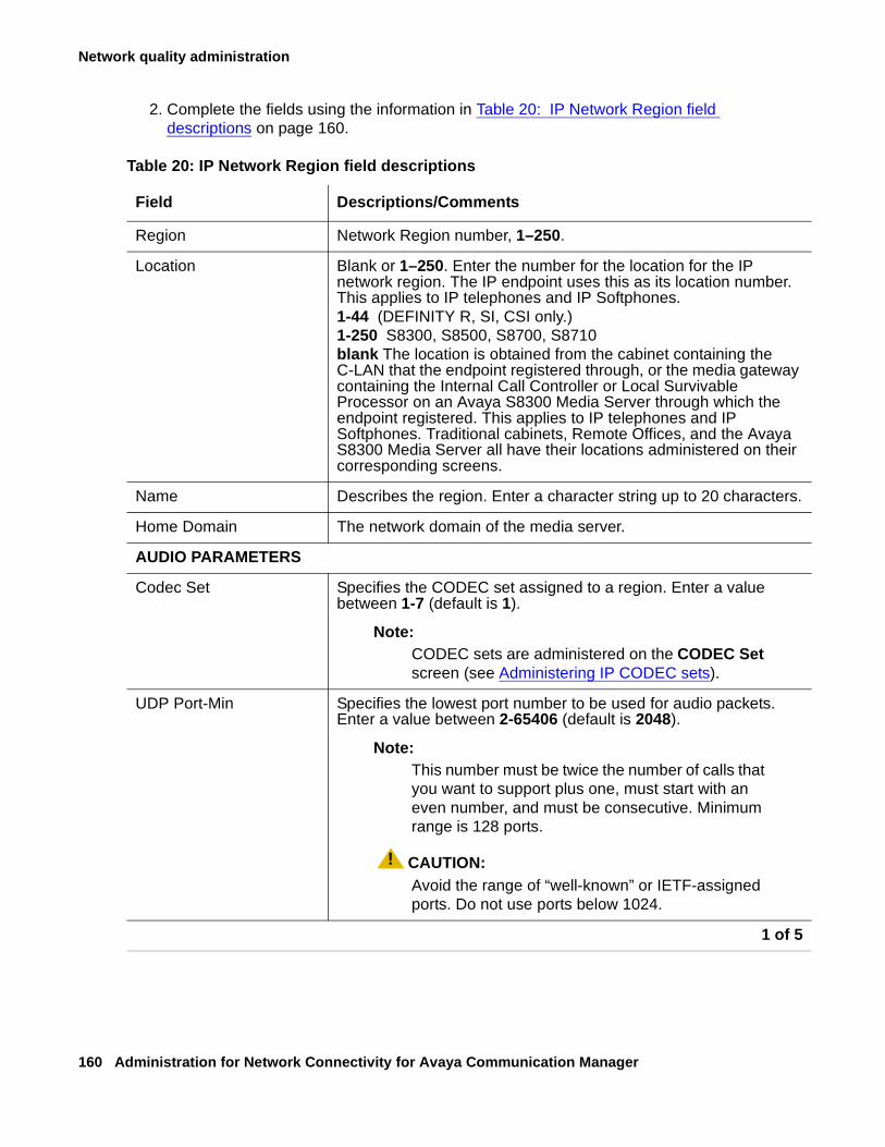
Network quality administration
160 Administration for Network Connectivity for Avaya Communication Manager
2. Complete the fields using the information in Table 20: IP Network Region field descriptions on page 160.
Table 20: IP Network Region field descriptions
Field Descriptions/Comments
Region Network Region number, 1–250.
Location Blank or 1–250. Enter the number for the location for the IP network region. The IP endpoint uses this as its location number. This applies to IP telephones and IP Softphones.1-44 (DEFINITY R, SI, CSI only.) 1-250 S8300, S8500, S8700, S8710blank The location is obtained from the cabinet containing the C-LAN that the endpoint registered through, or the media gateway containing the Internal Call Controller or Local Survivable Processor on an Avaya S8300 Media Server through which the endpoint registered. This applies to IP telephones and IP Softphones. Traditional cabinets, Remote Offices, and the Avaya S8300 Media Server all have their locations administered on their corresponding screens.
Name Describes the region. Enter a character string up to 20 characters.
Home Domain The network domain of the media server.
AUDIO PARAMETERS
Codec Set Specifies the CODEC set assigned to a region. Enter a value between 1-7 (default is 1).
Note:Note: CODEC sets are administered on the CODEC Set
screen (see Administering IP CODEC sets).
UDP Port-Min Specifies the lowest port number to be used for audio packets. Enter a value between 2-65406 (default is 2048).
Note:Note: This number must be twice the number of calls that
you want to support plus one, must start with an even number, and must be consecutive. Minimum range is 128 ports.
! CAUTION:CAUTION: Avoid the range of “well-known” or IETF-assigned
ports. Do not use ports below 1024.
1 of 5
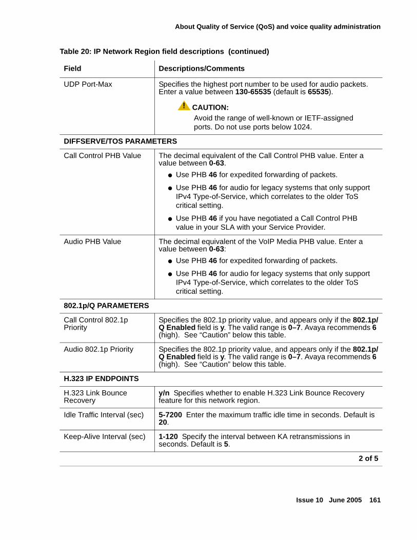
About Quality of Service (QoS) and voice quality administration
Issue 10 June 2005 161
UDP Port-Max Specifies the highest port number to be used for audio packets. Enter a value between 130-65535 (default is 65535).
! CAUTION:CAUTION: Avoid the range of well-known or IETF-assigned
ports. Do not use ports below 1024.
DIFFSERVE/TOS PARAMETERS
Call Control PHB Value The decimal equivalent of the Call Control PHB value. Enter a value between 0-63.
● Use PHB 46 for expedited forwarding of packets.
● Use PHB 46 for audio for legacy systems that only support IPv4 Type-of-Service, which correlates to the older ToS critical setting.
● Use PHB 46 if you have negotiated a Call Control PHB value in your SLA with your Service Provider.
Audio PHB Value The decimal equivalent of the VoIP Media PHB value. Enter a value between 0-63:
● Use PHB 46 for expedited forwarding of packets.
● Use PHB 46 for audio for legacy systems that only support IPv4 Type-of-Service, which correlates to the older ToS critical setting.
802.1p/Q PARAMETERS
Call Control 802.1p Priority
Specifies the 802.1p priority value, and appears only if the 802.1p/Q Enabled field is y. The valid range is 0–7. Avaya recommends 6 (high). See “Caution” below this table.
Audio 802.1p Priority Specifies the 802.1p priority value, and appears only if the 802.1p/Q Enabled field is y. The valid range is 0–7. Avaya recommends 6 (high). See “Caution” below this table.
H.323 IP ENDPOINTS
H.323 Link Bounce Recovery
y/n Specifies whether to enable H.323 Link Bounce Recovery feature for this network region.
Idle Traffic Interval (sec) 5-7200 Enter the maximum traffic idle time in seconds. Default is 20.
Keep-Alive Interval (sec) 1-120 Specify the interval between KA retransmissions in seconds. Default is 5.
Table 20: IP Network Region field descriptions (continued)
Field Descriptions/Comments
2 of 5
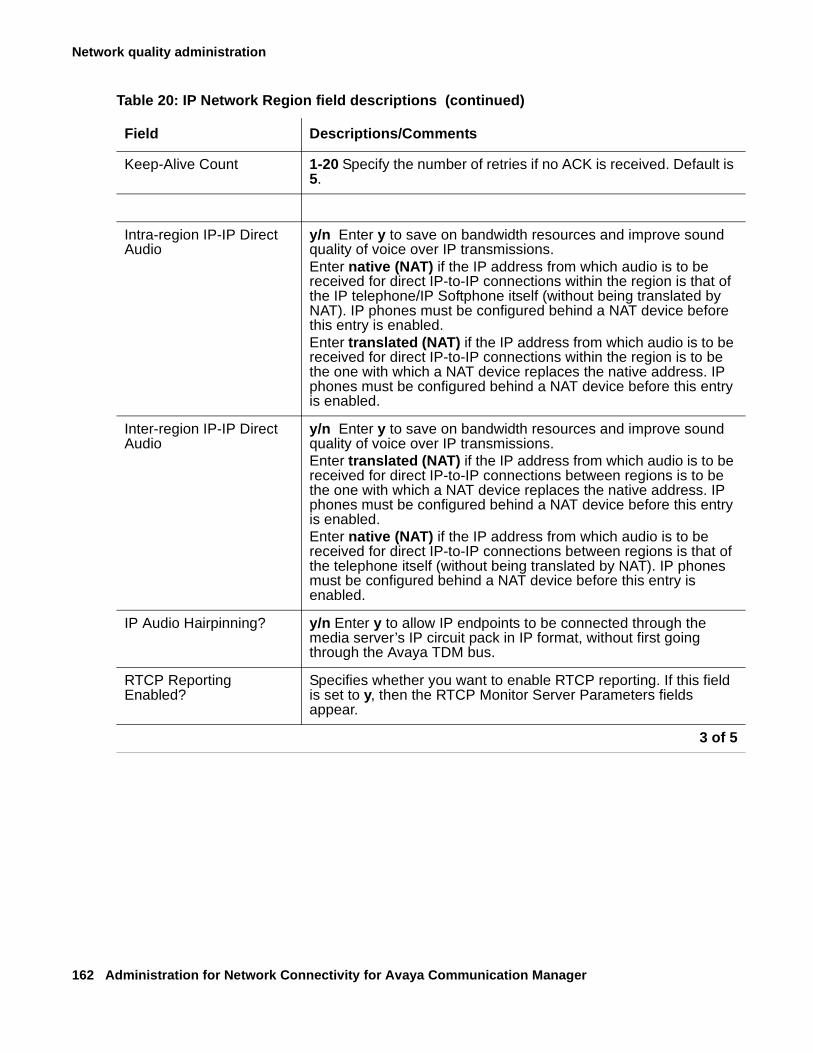
Network quality administration
162 Administration for Network Connectivity for Avaya Communication Manager
Keep-Alive Count 1-20 Specify the number of retries if no ACK is received. Default is 5.
Intra-region IP-IP Direct Audio
y/n Enter y to save on bandwidth resources and improve sound quality of voice over IP transmissions.Enter native (NAT) if the IP address from which audio is to be received for direct IP-to-IP connections within the region is that of the IP telephone/IP Softphone itself (without being translated by NAT). IP phones must be configured behind a NAT device before this entry is enabled.Enter translated (NAT) if the IP address from which audio is to be received for direct IP-to-IP connections within the region is to be the one with which a NAT device replaces the native address. IP phones must be configured behind a NAT device before this entry is enabled.
Inter-region IP-IP Direct Audio
y/n Enter y to save on bandwidth resources and improve sound quality of voice over IP transmissions.Enter translated (NAT) if the IP address from which audio is to be received for direct IP-to-IP connections between regions is to be the one with which a NAT device replaces the native address. IP phones must be configured behind a NAT device before this entry is enabled.Enter native (NAT) if the IP address from which audio is to be received for direct IP-to-IP connections between regions is that of the telephone itself (without being translated by NAT). IP phones must be configured behind a NAT device before this entry is enabled.
IP Audio Hairpinning? y/n Enter y to allow IP endpoints to be connected through the media server’s IP circuit pack in IP format, without first going through the Avaya TDM bus.
RTCP Reporting Enabled?
Specifies whether you want to enable RTCP reporting. If this field is set to y, then the RTCP Monitor Server Parameters fields appear.
Table 20: IP Network Region field descriptions (continued)
Field Descriptions/Comments
3 of 5
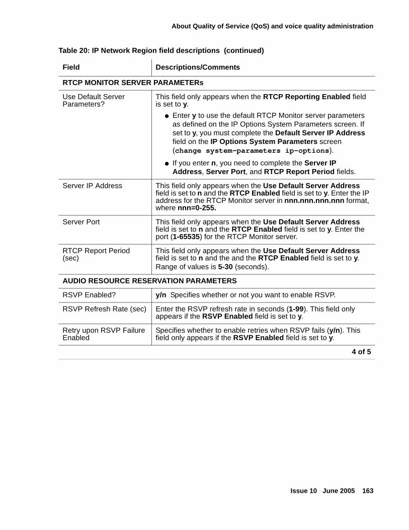
About Quality of Service (QoS) and voice quality administration
Issue 10 June 2005 163
RTCP MONITOR SERVER PARAMETERs
Use Default Server Parameters?
This field only appears when the RTCP Reporting Enabled field is set to y.
● Enter y to use the default RTCP Monitor server parameters as defined on the IP Options System Parameters screen. If set to y, you must complete the Default Server IP Address field on the IP Options System Parameters screen (change system-parameters ip-options).
● If you enter n, you need to complete the Server IP Address, Server Port, and RTCP Report Period fields.
Server IP Address This field only appears when the Use Default Server Address field is set to n and the RTCP Enabled field is set to y. Enter the IP address for the RTCP Monitor server in nnn.nnn.nnn.nnn format, where nnn=0-255.
Server Port This field only appears when the Use Default Server Address field is set to n and the RTCP Enabled field is set to y. Enter the port (1-65535) for the RTCP Monitor server.
RTCP Report Period (sec)
This field only appears when the Use Default Server Address field is set to n and the and the RTCP Enabled field is set to y.Range of values is 5-30 (seconds).
AUDIO RESOURCE RESERVATION PARAMETERS
RSVP Enabled? y/n Specifies whether or not you want to enable RSVP.
RSVP Refresh Rate (sec) Enter the RSVP refresh rate in seconds (1-99). This field only appears if the RSVP Enabled field is set to y.
Retry upon RSVP Failure Enabled
Specifies whether to enable retries when RSVP fails (y/n). This field only appears if the RSVP Enabled field is set to y.
Table 20: IP Network Region field descriptions (continued)
Field Descriptions/Comments
4 of 5
Network quality administration
164 Administration for Network Connectivity for Avaya Communication Manager
! CAUTION:CAUTION: If you change 802.1p/Q on the IP Network Region screen, it changes the format
of the Ethernet frames. 802.1p/Q settings in Communication Manager must match those in all of the interfacing elements in your data network.
3. Press Enter to save the changes.
Setting up Inter-Gateway Alternate Routing (IGAR)
Whenever Communication Manager needs an inter-gateway connection and sufficient IP bandwidth is not available, it attempts to substitute a trunk connection for the IP connection. This happens in any of a large variety of scenarios, including the following examples:
● A party in one Network Region (NR) calls a party in another NR, or
● A station in one NR bridges onto a call appearance of a station in another NR, or
● An incoming trunk in one NR routes to a hunt group with agents in another NR, or
● An announcement or music source from one NR must be played to a party in another NR.
RSVP Profile This field only appears if the RSVP Enabled field is set to y. You set this field to what you have configured on your network
● guaranteed-service places a limit on the end-to-end queuing delay from the sender tot he receiver. This is the most appropriate setting for VoIP applications.
● controlled-load (a subset of guaranteed-service) provides for a traffic specifier but not the end-to-end queuing delay.
RSVP unreserved (BBE) PHB Value
Provides scalable service discrimination in the Internet without per-flow state and signaling at every hop. Enter the decimal equivalent of the DiffServ Audio PHB value, 0-63. This field only appears if the RSVP Enabled field is set to y.Note: The "per-flow state and signaling" is RSVP, and when RSVP is not successful, the BBE value is used to discriminate between Best Effort and voice traffic that has attempted to get an RSVP reservation, but failed.
Table 20: IP Network Region field descriptions (continued)
Field Descriptions/Comments
5 of 5
About Quality of Service (QoS) and voice quality administration
Issue 10 June 2005 165
Communication Manager software shall automatically attempt to use a trunk for inter-region voice bearer connection when all of the following five conditions are met:
● An inter-gateway connection is needed.
● IGAR has been “triggered” by one (or more) of the following conditions:
- The administered bandwidth limit between two NRs has been exhausted, or
- The VoIP resources between two PN/MGs have been exhausted, or
- IGAR has been “forced” between two NRs, or
- The codec set is set to pstn.
● IGAR is enabled for the NRs associated with each end of the call.
● The System Parameter Enable Inter-Gateway Alternate Routing is set to ‘y’. See Figure 10.
● The number of trunks used by IGAR in each of the two NRs has not reached the limit administered for that NR.
A Trunk IGC is established using ARS to route a trunk call from one NR to the IGAR LDN Extension administered for other NR. Because the Trunk IGC is independent of the actual call being placed, Communication Manager can originate the IGC in either direction — that is, from the calling party’s NR to the NR of the called party, or vice versa. However, because some customers wish to use Facility Restriction Levels or Toll Restriction to determine who gets access to IGAR resources during a WAN outage, the calling user is considered the originator of the Trunk IGC for the purposes of authorization (for example, FRL checking) and routing (for example, determining which Location-specific ARS and Toll tables to use). However, if the outgoing trunk group is administered to send the Calling Number, the IGAR Extension in the originating NR is used to create this number using the appropriate administration (public/unknown or private numbering form).
The following are examples of certain failure conditions and how Communication Manager handles them:
● On a direct call, the call proceeds to the first coverage point of the unreachable called endpoint, or if no coverage path is assigned, busy tone is played to the calling party.
● If the unreachable endpoint is being accessed through a coverage path, it is skipped.
● If the unreachable endpoint is the next available agent in a hunt group, that agent is considered unavailable, and the system tries to terminate to another agent using the administered group type (Circular, Percent Allocation Distribution, etc.).
Conferencing
For all features without selective listening (for example, Whisper Page), one Trunk IGC is used for all parties in a NR on the same call. In other words, Communication Manager software organizes multi-party conference calls into “dumbbell” configurations, with multiple parties in the same NR connected together and a single Trunk IGC connecting them. Figure 9 illustrates a "dumbbell" conferencing configuration.
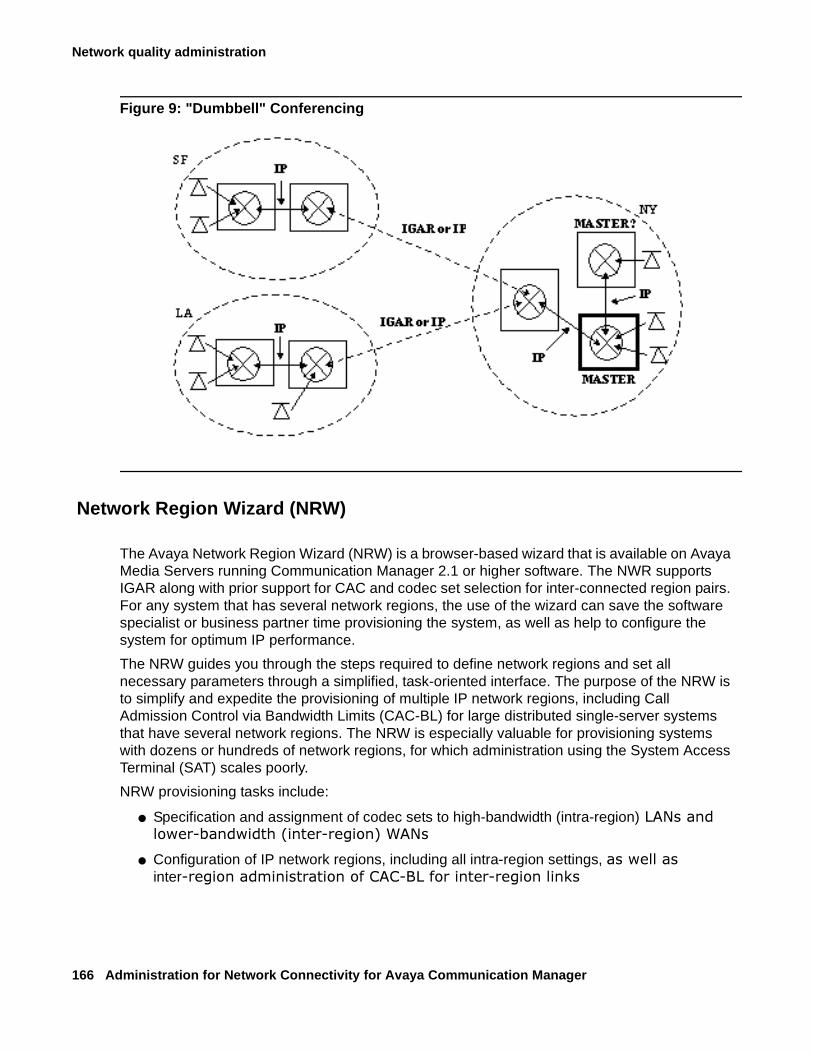
Network quality administration
166 Administration for Network Connectivity for Avaya Communication Manager
Figure 9: "Dumbbell" Conferencing
Network Region Wizard (NRW)
The Avaya Network Region Wizard (NRW) is a browser-based wizard that is available on Avaya Media Servers running Communication Manager 2.1 or higher software. The NWR supports IGAR along with prior support for CAC and codec set selection for inter-connected region pairs. For any system that has several network regions, the use of the wizard can save the software specialist or business partner time provisioning the system, as well as help to configure the system for optimum IP performance.
The NRW guides you through the steps required to define network regions and set all necessary parameters through a simplified, task-oriented interface. The purpose of the NRW is to simplify and expedite the provisioning of multiple IP network regions, including Call Admission Control via Bandwidth Limits (CAC-BL) for large distributed single-server systems that have several network regions. The NRW is especially valuable for provisioning systems with dozens or hundreds of network regions, for which administration using the System Access Terminal (SAT) scales poorly.
NRW provisioning tasks include:
● Specification and assignment of codec sets to high-bandwidth (intra-region)������������ ���������������� � ����������
● Configuration of IP network regions, including all intra-region settings, ���������inter� ������������� ��������������� ����� � ���������
About Quality of Service (QoS) and voice quality administration
Issue 10 June 2005 167
● Ongoing network region administration by the customer as well as by Avaya technicians and Business Partners to accommodate changes in ���������� ����� �������������
● Assignment of VoIP resources (C-LANs, MedPro/Prowler cards, Media ������ ��!��������"�������#$����� �� �����%
The NRW simplifies and expedites network region provisioning in several ways:
● NRW uses algorithms and heuristics based on graph theory to greatly reduce the repetitive manual entry required by the SAT to configure codecs, and CAC-BL for inter-region links. With the SAT, the number of inter-region links that need to be configured by the user does not scale well; with the NRW, the number of region pairs that require manual administration will increase linearly with the number of �����%
● NRW provides templates of widely applicable default values for codec sets and intra-region parameter settings. Users have the ability to ������&�����������"�������������� ����������������%
● NRW runs on any Internet browser supported by the Avaya Integrated Management (IM) product line, and takes advantage of browser capabilities to offer user-friendly prompting and context-sensitive �������"%
The NRW has its own Job Aid (available from http://support.avaya.com/avayaiw), and is a standard IM support tool delivered with every Linux-based Communication Manager system.
Expanded Meet-Me Conferencing
The Expanded Meet-me Conferencing feature of Avaya Communication Manager enables users of Communication Manager to create multi-party conferences consisting of more than the current Communication Manager-based conferencing limit of 6 parties. Supported on all Linux platforms running Communication Manager Release 3.0 (S8300, S8500, S8700-series), this feature is based on enhancements to the meet-me conferencing feature, where calls to these meet-me numbers are routed to an external device for audio mixing instead of being handled by Communication Manager. Standard trunk interfaces (could be ISDN, IP or SIP) can be used to integrate with an external conference bridge. For conferences consisting of up to 6 parties, the current methods of establishing a conference remain unchanged – that is, the user can set up a conference by using the ‘conference’ button on the phone, or by using the Communication Manager-based Meet-me conferencing feature, and the external bridge is not involved in the conference.
In Release 3.0, Communication Manager provides Expanded Meet-me conferencing based on a SIP trunk interface to a conference bridge, which acts as the audio conferencing device. System users request, and own, these enhanced meet-me conference bridges the same way as the existing meet-me bridges.
The feature is available to all endpoints of Communication Manager – including non-IP (analog, DCP, BRI, etc.), IP, and OPTIM SIP endpoints. It is only applicable to Meet-me Conferences where the conferees are expected to dial in to the conference VDN (Vector Directory Number). It is not applicable to ad-hoc conferences that users establish by using the ‘conference’ button on a phone.
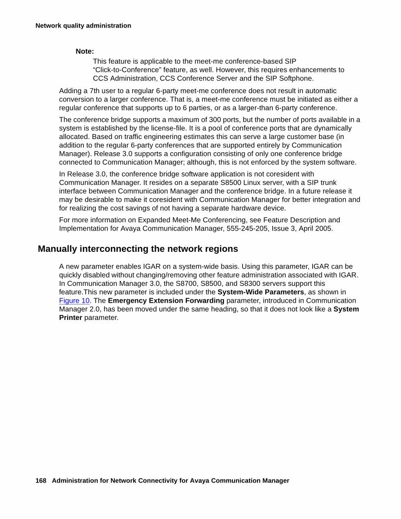
Network quality administration
168 Administration for Network Connectivity for Avaya Communication Manager
Note:Note: This feature is applicable to the meet-me conference-based SIP
“Click-to-Conference” feature, as well. However, this requires enhancements to CCS Administration, CCS Conference Server and the SIP Softphone.
Adding a 7th user to a regular 6-party meet-me conference does not result in automatic conversion to a larger conference. That is, a meet-me conference must be initiated as either a regular conference that supports up to 6 parties, or as a larger-than 6-party conference.
The conference bridge supports a maximum of 300 ports, but the number of ports available in a system is established by the license-file. It is a pool of conference ports that are dynamically allocated. Based on traffic engineering estimates this can serve a large customer base (in addition to the regular 6-party conferences that are supported entirely by Communication Manager). Release 3.0 supports a configuration consisting of only one conference bridge connected to Communication Manager; although, this is not enforced by the system software.
In Release 3.0, the conference bridge software application is not coresident with Communication Manager. It resides on a separate S8500 Linux server, with a SIP trunk interface between Communication Manager and the conference bridge. In a future release it may be desirable to make it coresident with Communication Manager for better integration and for realizing the cost savings of not having a separate hardware device.
For more information on Expanded Meet-Me Conferencing, see Feature Description and Implementation for Avaya Communication Manager, 555-245-205, Issue 3, April 2005.
Manually interconnecting the network regions
A new parameter enables IGAR on a system-wide basis. Using this parameter, IGAR can be quickly disabled without changing/removing other feature administration associated with IGAR. In Communication Manager 3.0, the S8700, S8500, and S8300 servers support this feature.This new parameter is included under the System-Wide Parameters, as shown in Figure 10. The Emergency Extension Forwarding parameter, introduced in Communication Manager 2.0, has been moved under the same heading, so that it does not look like a System Printer parameter.
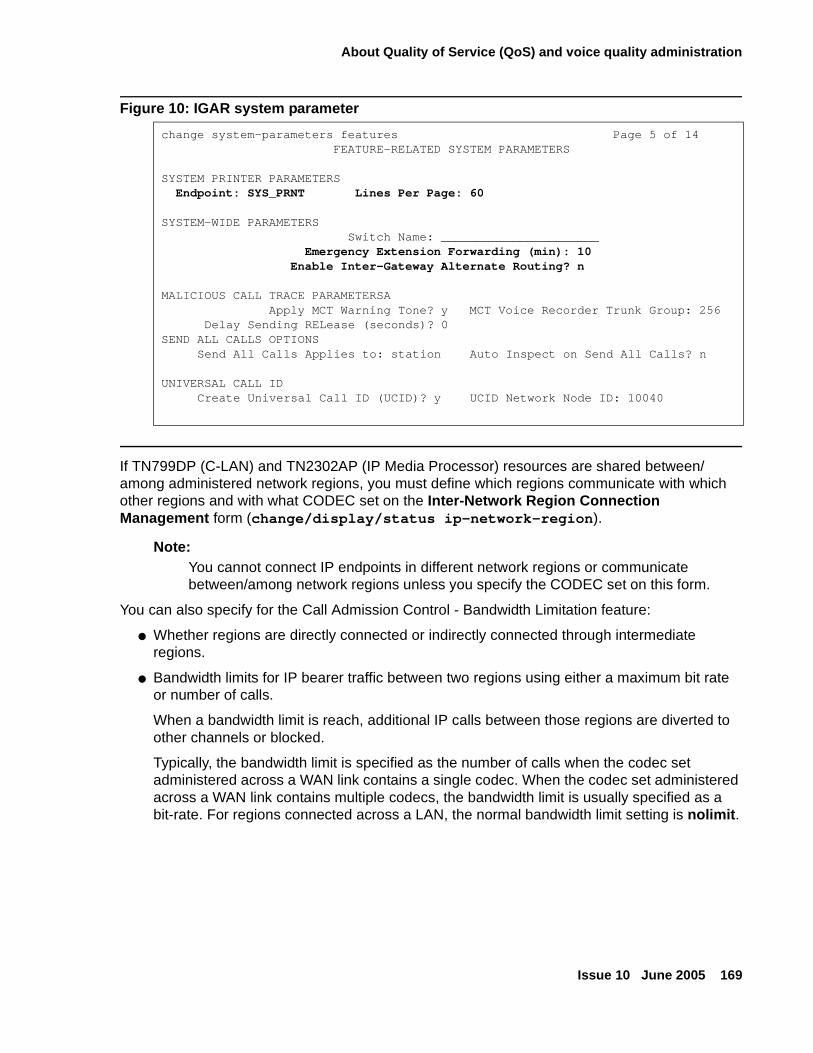
About Quality of Service (QoS) and voice quality administration
Issue 10 June 2005 169
Figure 10: IGAR system parameter
If TN799DP (C-LAN) and TN2302AP (IP Media Processor) resources are shared between/among administered network regions, you must define which regions communicate with which other regions and with what CODEC set on the Inter-Network Region Connection Management form (change/display/status ip-network-region).
Note:Note: You cannot connect IP endpoints in different network regions or communicate
between/among network regions unless you specify the CODEC set on this form.
You can also specify for the Call Admission Control - Bandwidth Limitation feature:
● Whether regions are directly connected or indirectly connected through intermediate regions.
● Bandwidth limits for IP bearer traffic between two regions using either a maximum bit rate or number of calls.
When a bandwidth limit is reach, additional IP calls between those regions are diverted to other channels or blocked.
Typically, the bandwidth limit is specified as the number of calls when the codec set administered across a WAN link contains a single codec. When the codec set administered across a WAN link contains multiple codecs, the bandwidth limit is usually specified as a bit-rate. For regions connected across a LAN, the normal bandwidth limit setting is nolimit.
change system-parameters features Page 5 of 14FEATURE-RELATED SYSTEM PARAMETERS
SYSTEM PRINTER PARAMETERSEndpoint: SYS_PRNT Lines Per Page: 60
SYSTEM-WIDE PARAMETERSSwitch Name: ______________________
Emergency Extension Forwarding (min): 10Enable Inter-Gateway Alternate Routing? n
MALICIOUS CALL TRACE PARAMETERSAApply MCT Warning Tone? y MCT Voice Recorder Trunk Group: 256
Delay Sending RELease (seconds)? 0SEND ALL CALLS OPTIONS
Send All Calls Applies to: station Auto Inspect on Send All Calls? n
UNIVERSAL CALL IDCreate Universal Call ID (UCID)? y UCID Network Node ID: 10040
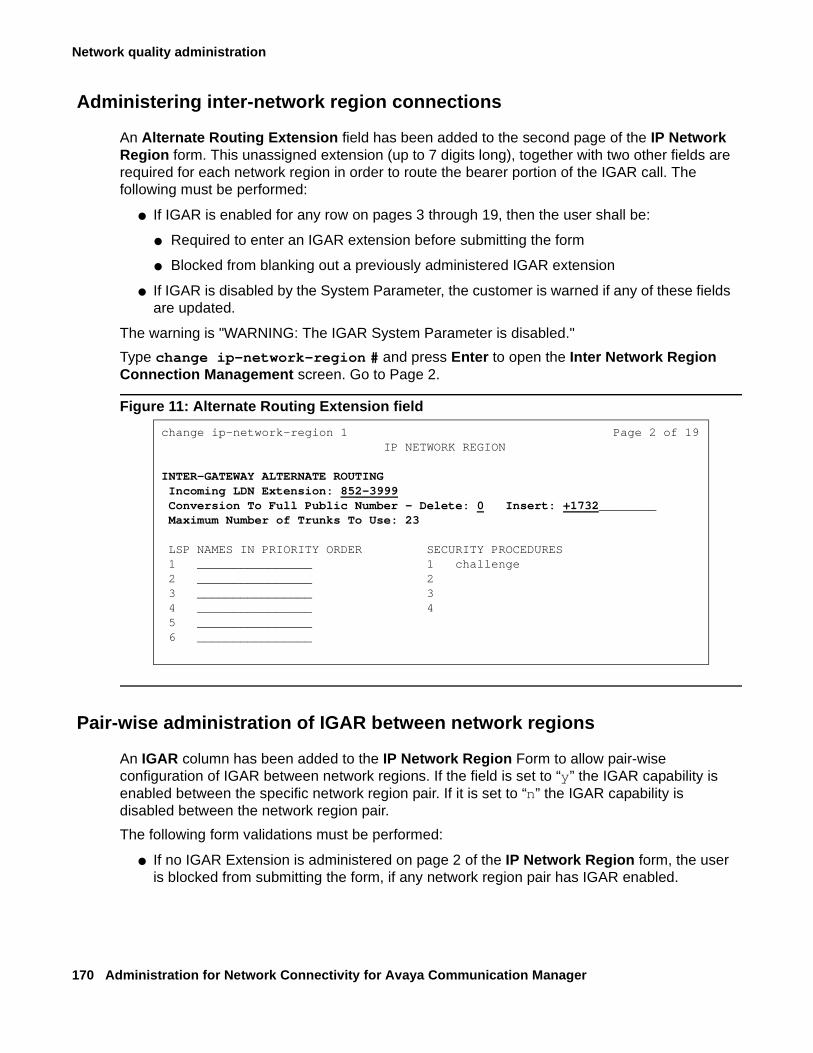
Network quality administration
170 Administration for Network Connectivity for Avaya Communication Manager
Administering inter-network region connections
An Alternate Routing Extension field has been added to the second page of the IP Network Region form. This unassigned extension (up to 7 digits long), together with two other fields are required for each network region in order to route the bearer portion of the IGAR call. The following must be performed:
● If IGAR is enabled for any row on pages 3 through 19, then the user shall be:
● Required to enter an IGAR extension before submitting the form
● Blocked from blanking out a previously administered IGAR extension
● If IGAR is disabled by the System Parameter, the customer is warned if any of these fields are updated.
The warning is "WARNING: The IGAR System Parameter is disabled."
Type change ip-network-region # and press Enter to open the Inter Network Region Connection Management screen. Go to Page 2.
Figure 11: Alternate Routing Extension field
Pair-wise administration of IGAR between network regions
An IGAR column has been added to the IP Network Region Form to allow pair-wise configuration of IGAR between network regions. If the field is set to “y” the IGAR capability is enabled between the specific network region pair. If it is set to “n” the IGAR capability is disabled between the network region pair.
The following form validations must be performed:
● If no IGAR Extension is administered on page 2 of the IP Network Region form, the user is blocked from submitting the form, if any network region pair has IGAR enabled.
change ip-network-region 1 Page 2 of 19IP NETWORK REGION
INTER-GATEWAY ALTERNATE ROUTINGIncoming LDN Extension: 852-3999Conversion To Full Public Number - Delete: 0 Insert: +1732________Maximum Number of Trunks To Use: 23
LSP NAMES IN PRIORITY ORDER SECURITY PROCEDURES1 ________________ 1 challenge2 ________________ 23 ________________ 34 ________________ 45 ________________6 ________________
About Quality of Service (QoS) and voice quality administration
Issue 10 June 2005 171
● If IGAR is disabled using the System Parameter, the customer will be warned, if IGAR is enabled for any network region pair.
The warning is “WARNING: The IGAR System Parameter is disabled.”
Normally, the administration between Network Region pairs would have a codec set identified for compressing voice across the IP WAN. Only if bandwidth in the IP WAN is exceeded, and the IGAR field is set to “y”, would the voice bearer be routed across an alternate trunk facility. However, under some conditions you may wish to force all calls to the PSTN.
The “forced” option can be used during initial installation to verify the alternative PSTN facility selected for a Network Region pair. This option may also be used to move traffic off of the IP WAN temporarily, if an edge router is having problems, or an edge router needs to be replaced between a Network Region pair.
When the codec set type is set to “pstn” the following fields are defaulted:
● IGAR field defaults to “y”. Options: f(orced), n(o), y(es).
This field must be defaulted to “y” because the Alternate Trunk Facility is the only means of routing the voice bearer portion of the call.
● When the codec set is set to “pstn” the following fields are hidden:
- Direct-WAN
- WAN-BW Limits, and
- Intervening Regions
When the codec set is not “pstn” and not blank, the IGAR field is defaulted to “n”.
A “f(orced)” option is supported in the IGAR column in addition to the options “n(o)” and “y(es)”.
Figure 12: Inter network region connection management
change ip-network-region 3 Page 3of 19
Inter Network Region Connection Management
src dst codec direct Audio Video Dynrgn rgn set WAN WAN-BW Limits WAN-BW Limits Intervening-Regions CAC IGAR3 1 1___ y 256:Kbits f3 2 1___ n 1__ ___ ___ ___ y3 3 1___ n3 4 1___ n 1__ ___ ___ ___ n3 5 1___ n 6__ ___ ___ ___ y3 6 1 ___:NoLimit y3 7 1___ y _10:Calls n3 8 pstn y3 9 pstn y3 103 11
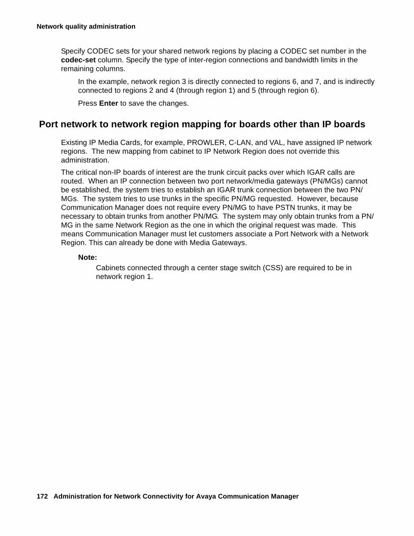
Network quality administration
172 Administration for Network Connectivity for Avaya Communication Manager
Specify CODEC sets for your shared network regions by placing a CODEC set number in the codec-set column. Specify the type of inter-region connections and bandwidth limits in the remaining columns.
In the example, network region 3 is directly connected to regions 6, and 7, and is indirectly connected to regions 2 and 4 (through region 1) and 5 (through region 6).
Press Enter to save the changes.
Port network to network region mapping for boards other than IP boards
Existing IP Media Cards, for example, PROWLER, C-LAN, and VAL, have assigned IP network regions. The new mapping from cabinet to IP Network Region does not override this administration.
The critical non-IP boards of interest are the trunk circuit packs over which IGAR calls are routed. When an IP connection between two port network/media gateways (PN/MGs) cannot be established, the system tries to establish an IGAR trunk connection between the two PN/MGs. The system tries to use trunks in the specific PN/MG requested. However, because Communication Manager does not require every PN/MG to have PSTN trunks, it may be necessary to obtain trunks from another PN/MG. The system may only obtain trunks from a PN/MG in the same Network Region as the one in which the original request was made. This means Communication Manager must let customers associate a Port Network with a Network Region. This can already be done with Media Gateways.
Note:Note: Cabinets connected through a center stage switch (CSS) are required to be in
network region 1.
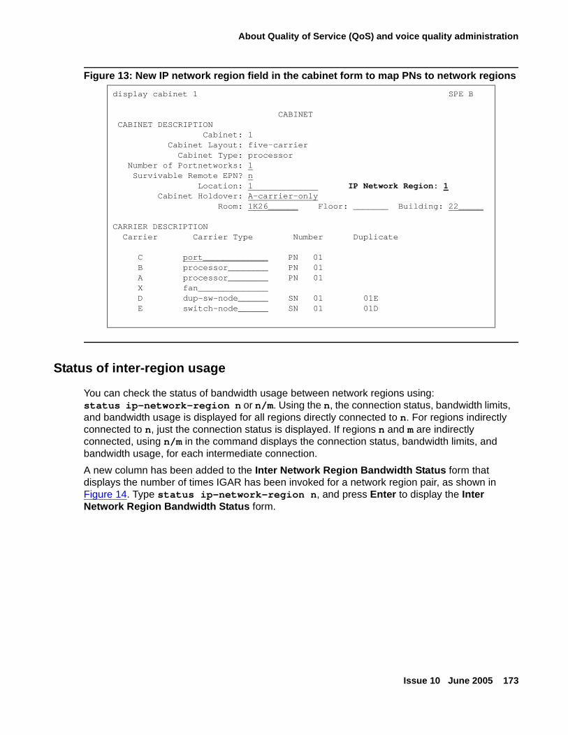
About Quality of Service (QoS) and voice quality administration
Issue 10 June 2005 173
Figure 13: New IP network region field in the cabinet form to map PNs to network regions
Status of inter-region usage
You can check the status of bandwidth usage between network regions using:status ip-network-region n or n/m. Using the n, the connection status, bandwidth limits, and bandwidth usage is displayed for all regions directly connected to n. For regions indirectly connected to n, just the connection status is displayed. If regions n and m are indirectly connected, using n/m in the command displays the connection status, bandwidth limits, and bandwidth usage, for each intermediate connection.
A new column has been added to the Inter Network Region Bandwidth Status form that displays the number of times IGAR has been invoked for a network region pair, as shown in Figure 14. Type status ip-network-region n, and press Enter to display the Inter Network Region Bandwidth Status form.
display cabinet 1 SPE B
CABINETCABINET DESCRIPTION
Cabinet: 1Cabinet Layout: five-carrier
Cabinet Type: processorNumber of Portnetworks: 1Survivable Remote EPN? n
Location: 1 IP Network Region: 1Cabinet Holdover: A-carrier-only
Room: 1K26______ Floor: _______ Building: 22_____
CARRIER DESCRIPTIONCarrier Carrier Type Number Duplicate
C port_____________ PN 01B processor________ PN 01A processor________ PN 01X fan______________D dup-sw-node______ SN 01 01EE switch-node______ SN 01 01D
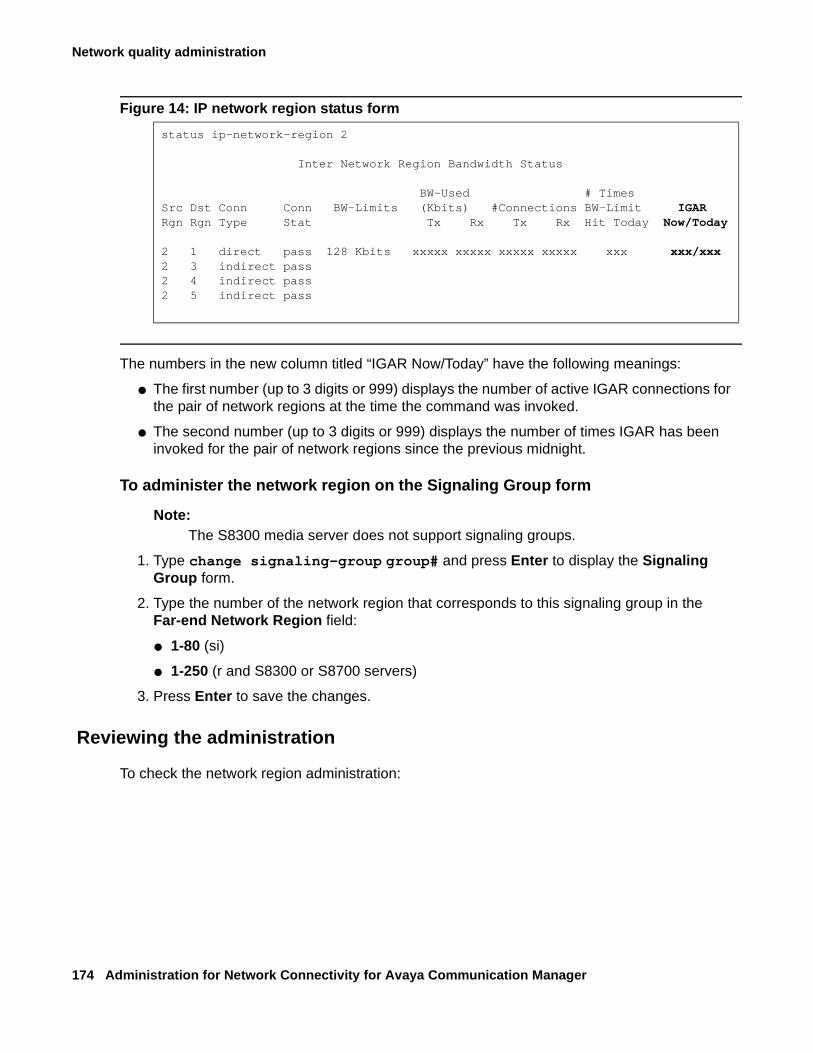
Network quality administration
174 Administration for Network Connectivity for Avaya Communication Manager
Figure 14: IP network region status form
The numbers in the new column titled “IGAR Now/Today” have the following meanings:
● The first number (up to 3 digits or 999) displays the number of active IGAR connections for the pair of network regions at the time the command was invoked.
● The second number (up to 3 digits or 999) displays the number of times IGAR has been invoked for the pair of network regions since the previous midnight.
To administer the network region on the Signaling Group form
Note:Note: The S8300 media server does not support signaling groups.
1. Type change signaling-group group# and press Enter to display the Signaling Group form.
2. Type the number of the network region that corresponds to this signaling group in the Far-end Network Region field:
● 1-80 (si)
● 1-250 (r and S8300 or S8700 servers)
3. Press Enter to save the changes.
Reviewing the administration
To check the network region administration:
status ip-network-region 2
Inter Network Region Bandwidth Status
BW-Used # TimesSrc Dst Conn Conn BW-Limits (Kbits) #Connections BW-Limit IGARRgn Rgn Type Stat Tx Rx Tx Rx Hit Today Now/Today
2 1 direct pass 128 Kbits xxxxx xxxxx xxxxx xxxxx xxx xxx/xxx2 3 indirect pass2 4 indirect pass2 5 indirect pass
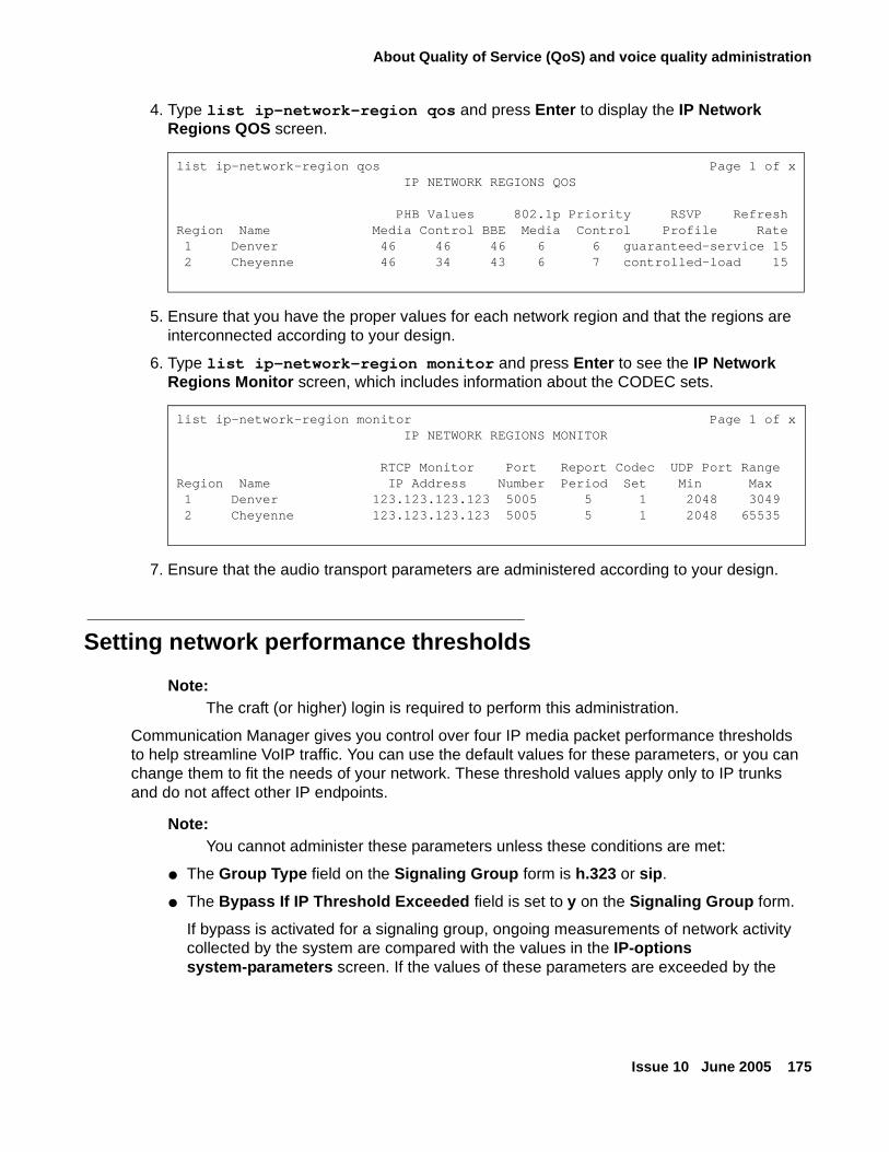
About Quality of Service (QoS) and voice quality administration
Issue 10 June 2005 175
4. Type list ip-network-region qos and press Enter to display the IP Network Regions QOS screen.
5. Ensure that you have the proper values for each network region and that the regions are interconnected according to your design.
6. Type list ip-network-region monitor and press Enter to see the IP Network Regions Monitor screen, which includes information about the CODEC sets.
7. Ensure that the audio transport parameters are administered according to your design.
Setting network performance thresholds
Note:Note: The craft (or higher) login is required to perform this administration.
Communication Manager gives you control over four IP media packet performance thresholds to help streamline VoIP traffic. You can use the default values for these parameters, or you can change them to fit the needs of your network. These threshold values apply only to IP trunks and do not affect other IP endpoints.
Note:Note: You cannot administer these parameters unless these conditions are met:
● The Group Type field on the Signaling Group form is h.323 or sip.
● The Bypass If IP Threshold Exceeded field is set to y on the Signaling Group form.
If bypass is activated for a signaling group, ongoing measurements of network activity collected by the system are compared with the values in the IP-options system-parameters screen. If the values of these parameters are exceeded by the
list ip-network-region qos Page 1 of x IP NETWORK REGIONS QOS
PHB Values 802.1p Priority RSVP RefreshRegion Name Media Control BBE Media Control Profile Rate1 Denver 46 46 46 6 6 guaranteed-service 152 Cheyenne 46 34 43 6 7 controlled-load 15
list ip-network-region monitor Page 1 of x IP NETWORK REGIONS MONITOR
RTCP Monitor Port Report Codec UDP Port RangeRegion Name IP Address Number Period Set Min Max1 Denver 123.123.123.123 5005 5 1 2048 30492 Cheyenne 123.123.123.123 5005 5 1 2048 65535
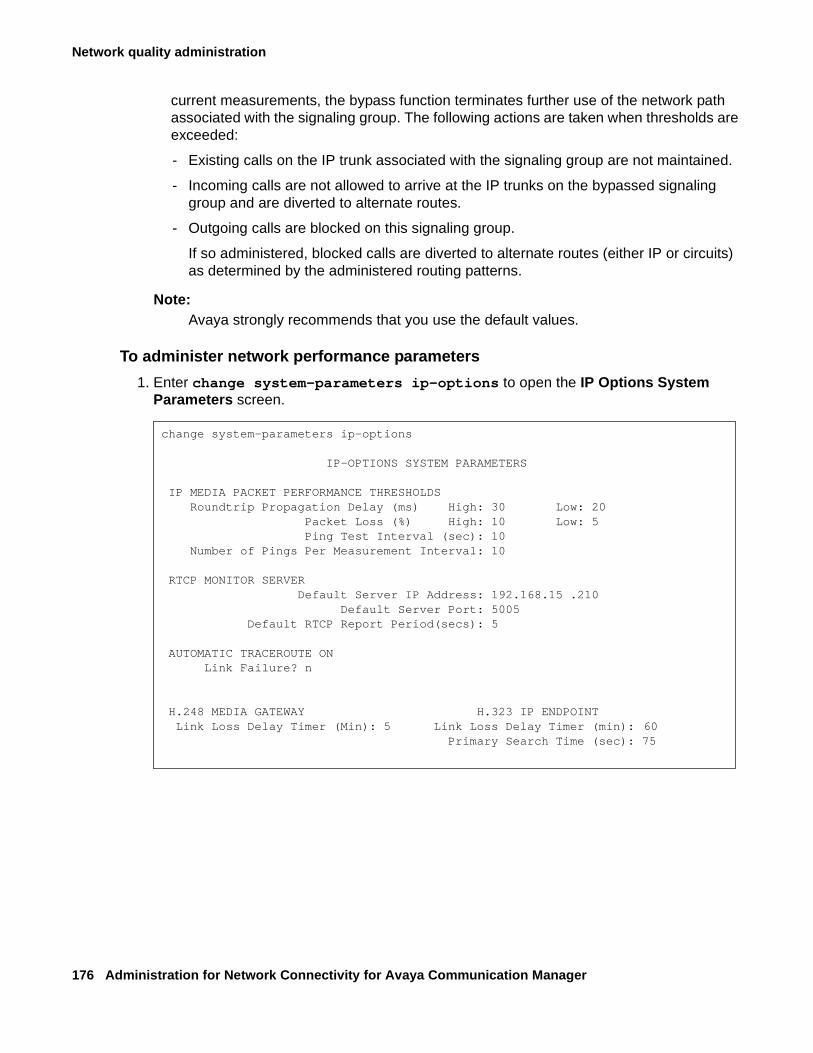
Network quality administration
176 Administration for Network Connectivity for Avaya Communication Manager
current measurements, the bypass function terminates further use of the network path associated with the signaling group. The following actions are taken when thresholds are exceeded:
- Existing calls on the IP trunk associated with the signaling group are not maintained.
- Incoming calls are not allowed to arrive at the IP trunks on the bypassed signaling group and are diverted to alternate routes.
- Outgoing calls are blocked on this signaling group.
If so administered, blocked calls are diverted to alternate routes (either IP or circuits) as determined by the administered routing patterns.
Note:Note: Avaya strongly recommends that you use the default values.
To administer network performance parameters
1. Enter change system-parameters ip-options to open the IP Options System Parameters screen.
change system-parameters ip-options
IP-OPTIONS SYSTEM PARAMETERS
IP MEDIA PACKET PERFORMANCE THRESHOLDS Roundtrip Propagation Delay (ms) High: 30 Low: 20 Packet Loss (%) High: 10 Low: 5 Ping Test Interval (sec): 10 Number of Pings Per Measurement Interval: 10
RTCP MONITOR SERVER Default Server IP Address: 192.168.15 .210 Default Server Port: 5005 Default RTCP Report Period(secs): 5
AUTOMATIC TRACEROUTE ON Link Failure? n
H.248 MEDIA GATEWAY H.323 IP ENDPOINT Link Loss Delay Timer (Min): 5 Link Loss Delay Timer (min): 60
Primary Search Time (sec): 75
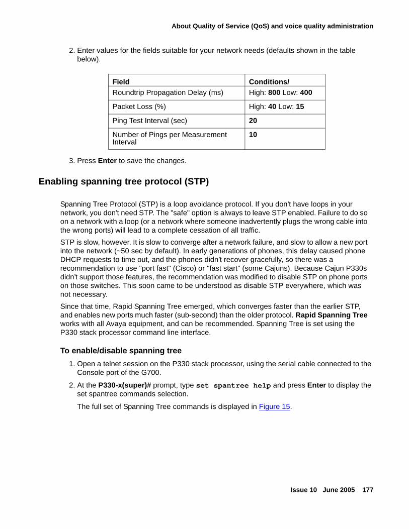
About Quality of Service (QoS) and voice quality administration
Issue 10 June 2005 177
2. Enter values for the fields suitable for your network needs (defaults shown in the table below).
3. Press Enter to save the changes.
Enabling spanning tree protocol (STP)
Spanning Tree Protocol (STP) is a loop avoidance protocol. If you don’t have loops in your network, you don’t need STP. The "safe" option is always to leave STP enabled. Failure to do so on a network with a loop (or a network where someone inadvertently plugs the wrong cable into the wrong ports) will lead to a complete cessation of all traffic.
STP is slow, however. It is slow to converge after a network failure, and slow to allow a new port into the network (~50 sec by default). In early generations of phones, this delay caused phone DHCP requests to time out, and the phones didn’t recover gracefully, so there was a recommendation to use "port fast" (Cisco) or "fast start" (some Cajuns). Because Cajun P330s didn’t support those features, the recommendation was modified to disable STP on phone ports on those switches. This soon came to be understood as disable STP everywhere, which was not necessary.
Since that time, Rapid Spanning Tree emerged, which converges faster than the earlier STP, and enables new ports much faster (sub-second) than the older protocol. Rapid Spanning Tree works with all Avaya equipment, and can be recommended. Spanning Tree is set using the P330 stack processor command line interface.
To enable/disable spanning tree
1. Open a telnet session on the P330 stack processor, using the serial cable connected to the Console port of the G700.
2. At the P330-x(super)# prompt, type set spantree help and press Enter to display the set spantree commands selection.
The full set of Spanning Tree commands is displayed in Figure 15.
Field Conditions/Roundtrip Propagation Delay (ms) High: 800 Low: 400
Packet Loss (%) High: 40 Low: 15
Ping Test Interval (sec) 20
Number of Pings per Measurement Interval
10
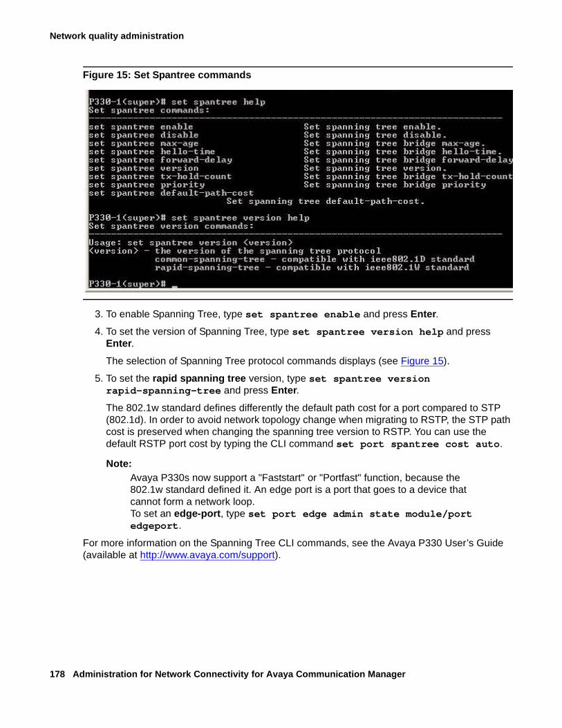
Network quality administration
178 Administration for Network Connectivity for Avaya Communication Manager
Figure 15: Set Spantree commands
3. To enable Spanning Tree, type set spantree enable and press Enter.
4. To set the version of Spanning Tree, type set spantree version help and press Enter.
The selection of Spanning Tree protocol commands displays (see Figure 15).
5. To set the rapid spanning tree version, type set spantree version rapid-spanning-tree and press Enter.
The 802.1w standard defines differently the default path cost for a port compared to STP (802.1d). In order to avoid network topology change when migrating to RSTP, the STP path cost is preserved when changing the spanning tree version to RSTP. You can use the default RSTP port cost by typing the CLI command set port spantree cost auto.
Note:Note: Avaya P330s now support a "Faststart" or "Portfast" function, because the
802.1w standard defined it. An edge port is a port that goes to a device that cannot form a network loop. To set an edge-port, type set port edge admin state module/port edgeport.
For more information on the Spanning Tree CLI commands, see the Avaya P330 User’s Guide (available at http://www.avaya.com/support).
About Media Encryption
Issue 10 June 2005 179
Adjusting jitter buffers
Since network packet delay is usually a factor, jitter buffers should be no more than twice the size of the largest statistical variance between packets. The best solution is to have dynamic jitter buffers that change size in response to network conditions. Avaya equipment uses dynamic jitter buffers.
● Check for network congestion
● Bandwidth too small
● Route changes (can interact with network congestion or lack of bandwidth)
Configuring UDP ports
Communication Manager allows users to configure User Datagram Protocol (UDP) port ranges that are used by VoIP packets. Network data equipment uses these port ranges to assign priority throughout the network. Communication Manager can download default values to the endpoint when those values are not provided by the endpoint installer or the user.
About Media EncryptionThis section provides information on the use and administration of Avaya Communication Manager Media Encryption. Use any of the following links to go to the appropriate section:
● What is Media Encryption?
● What limitations does Media Encryption have?
● What are the requirements for Media Encryption?
● Is there a license file requirement?
● Administering Media Encryption
● How does Media Encryption interact with other features?
● About legal wiretapping
● About possible failure conditions
Network quality administration
180 Administration for Network Connectivity for Avaya Communication Manager
What is Media Encryption?
To provide privacy for media streams that are carried over IP networks, Avaya Communication Manager supports encryption for IP bearer channel (RTP Audio) between any combination of media gateways and IP endpoints.
Digitally encrypting the audio (voice) portion of a VoIP call can reduce the risk of electronic eavesdropping. IP packet monitors, sometimes called sniffers, are to VoIP calls what wiretaps are to circuit-switched (TDM) calls, except that an IP packet monitor can watch for and capture unencrypted IP packets and can play back the conversation in real-time or store it for later playback.
With media encryption enabled, Communication Manager encrypts IP packets before they traverse the IP network. An encrypted conversation sounds like white noise or static when played through an IP monitor. End users do not know that a call is encrypted because there are:
● No visual or audible indicators to indicate that the call is encrypted.
● No appreciable voice quality differences between encrypted calls and non-encrypted calls.
What limitations does Media Encryption have?
! SECURITY ALERT:SECURITY ALERT: Be sure that you understand these important media encryption limitations:
1. Any call that involves a circuit-switched (TDM) endpoint such as a DCP or analog phone is vulnerable to conventional wire-tapping techniques.
2. Any call that involves an IP endpoint or gateway that does not support encryption can be a potential target for IP monitoring. Common examples are IP trunks to 3rd-party vendor switches.
3. Any party that is not encrypting an IP conference call exposes all parties on the IP call between the unencrypted party and its supporting media processor to monitoring, even though the other IP links are encrypting.
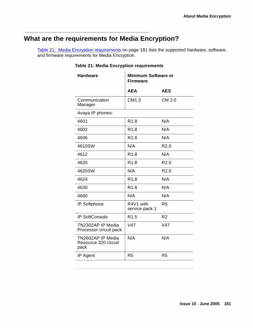
About Media Encryption
Issue 10 June 2005 181
What are the requirements for Media Encryption?
Table 21: Media Encryption requirements on page 181 lists the supported hardware, software, and firmware requirements for Media Encryption.
Table 21: Media Encryption requirements
Hardware Minimum Software or Firmware
AEA AES
Communication Manager
CM1.3 CM 2.0
Avaya IP phones:
4601 R1.8 N/A
4602 R1.8 N/A
4606 R1.8 N/A
4610SW N/A R2.0
4612 R1.8 N/A
4620 R1.8 R2.0
4620SW N/A R2.0
4624 R1.8 N/A
4630 R1.8 N/A
4690 N/A N/A
IP Softphone R4V1 with service pack 1
R5
IP SoftConsole R1.5 R2
TN2302AP IP Media Processor circuit pack
V47 V47
TN2602AP IP Media Resource 320 circuit pack
N/A N/A
IP Agent R5 R5
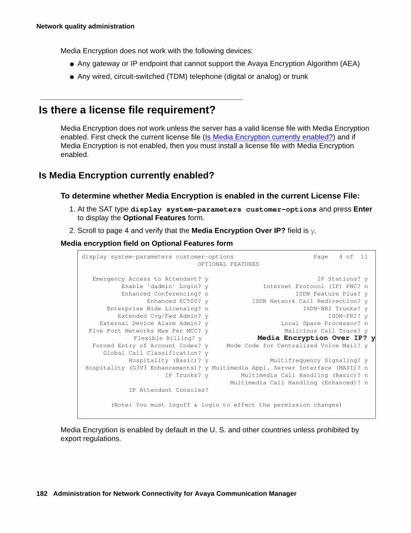
Network quality administration
182 Administration for Network Connectivity for Avaya Communication Manager
Media Encryption does not work with the following devices:
● Any gateway or IP endpoint that cannot support the Avaya Encryption Algorithm (AEA)
● Any wired, circuit-switched (TDM) telephone (digital or analog) or trunk
Is there a license file requirement?
Media Encryption does not work unless the server has a valid license file with Media Encryption enabled. First check the current license file (Is Media Encryption currently enabled?) and if Media Encryption is not enabled, then you must install a license file with Media Encryption enabled.
Is Media Encryption currently enabled?
To determine whether Media Encryption is enabled in the current License File:
1. At the SAT type display system-parameters customer-options and press Enter to display the Optional Features form.
2. Scroll to page 4 and verify that the Media Encryption Over IP? field is y.
Media encryption field on Optional Features form
Media Encryption is enabled by default in the U. S. and other countries unless prohibited by export regulations.
display system-parameters customer-options Page 4 of 11 OPTIONAL FEATURES
Emergency Access to Attendant? y IP Stations? y Enable ’dadmin’ Login? y Internet Protocol (IP) PNC? n Enhanced Conferencing? n ISDN Feature Plus? y Enhanced EC500? y ISDN Network Call Redirection? y Enterprise Wide Licensing? n ISDN-BRI Trunks? y Extended Cvg/Fwd Admin? y ISDN-PRI? y External Device Alarm Admin? y Local Spare Processor? n Five Port Networks Max Per MCC? y Malicious Call Trace? y Flexible Billing? y Media Encryption Over IP? y Forced Entry of Account Codes? y Mode Code for Centralized Voice Mail? y Global Call Classification? y Hospitality (Basic)? y Multifrequency Signaling? y Hospitality (G3V3 Enhancements)? y Multimedia Appl. Server Interface (MASI)? n IP Trunks? y Multimedia Call Handling (Basic)? n Multimedia Call Handling (Enhanced)? n IP Attendant Consoles?
(Note: You must logoff & login to effect the permission changes)
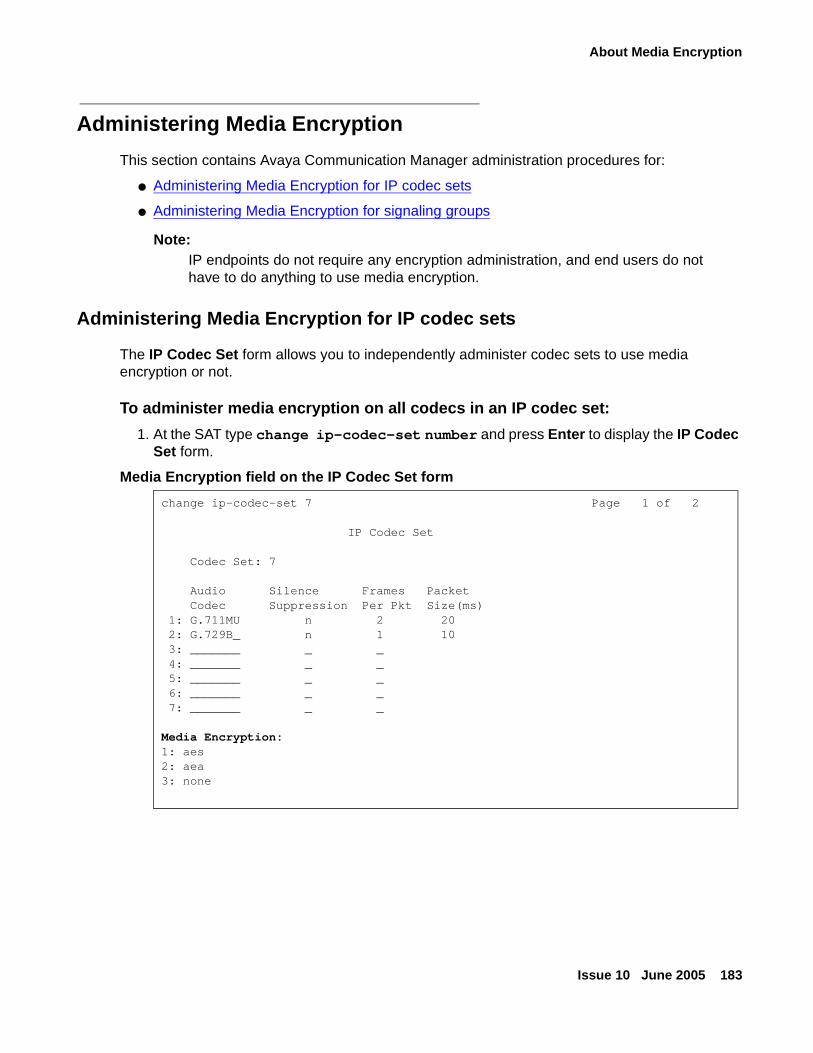
About Media Encryption
Issue 10 June 2005 183
Administering Media Encryption
This section contains Avaya Communication Manager administration procedures for:
● Administering Media Encryption for IP codec sets
● Administering Media Encryption for signaling groups
Note:Note: IP endpoints do not require any encryption administration, and end users do not
have to do anything to use media encryption.
Administering Media Encryption for IP codec sets
The IP Codec Set form allows you to independently administer codec sets to use media encryption or not.
To administer media encryption on all codecs in an IP codec set:
1. At the SAT type change ip-codec-set number and press Enter to display the IP Codec Set form.
Media Encryption field on the IP Codec Set form
change ip-codec-set 7 Page 1 of 2
IP Codec Set
Codec Set: 7
Audio Silence Frames Packet Codec Suppression Per Pkt Size(ms) 1: G.711MU n 2 20 2: G.729B_ n 1 10 3: _______ _ _ 4: _______ _ _ 5: _______ _ _ 6: _______ _ _ 7: _______ _ _
Media Encryption:1: aes2: aea3: none
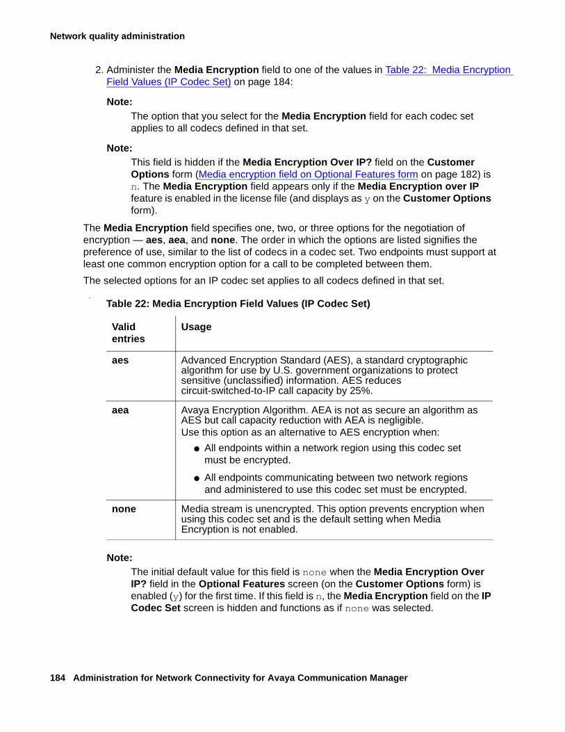
Network quality administration
184 Administration for Network Connectivity for Avaya Communication Manager
2. Administer the Media Encryption field to one of the values in Table 22: Media Encryption Field Values (IP Codec Set) on page 184:
Note:Note: The option that you select for the Media Encryption field for each codec set
applies to all codecs defined in that set.
Note:Note: This field is hidden if the Media Encryption Over IP? field on the Customer
Options form (Media encryption field on Optional Features form on page 182) is n. The Media Encryption field appears only if the Media Encryption over IP feature is enabled in the license file (and displays as y on the Customer Options form).
The Media Encryption field specifies one, two, or three options for the negotiation of encryption — aes, aea, and none. The order in which the options are listed signifies the preference of use, similar to the list of codecs in a codec set. Two endpoints must support at least one common encryption option for a call to be completed between them.
The selected options for an IP codec set applies to all codecs defined in that set..
Note:Note: The initial default value for this field is none when the Media Encryption Over
IP? field in the Optional Features screen (on the Customer Options form) is enabled (y) for the first time. If this field is n, the Media Encryption field on the IP Codec Set screen is hidden and functions as if none was selected.
Table 22: Media Encryption Field Values (IP Codec Set)
Valid entries
Usage
aes Advanced Encryption Standard (AES), a standard cryptographic algorithm for use by U.S. government organizations to protect sensitive (unclassified) information. AES reduces circuit-switched-to-IP call capacity by 25%.
aea Avaya Encryption Algorithm. AEA is not as secure an algorithm as AES but call capacity reduction with AEA is negligible.Use this option as an alternative to AES encryption when:
● All endpoints within a network region using this codec set must be encrypted.
● All endpoints communicating between two network regions and administered to use this codec set must be encrypted.
none Media stream is unencrypted. This option prevents encryption when using this codec set and is the default setting when Media Encryption is not enabled.
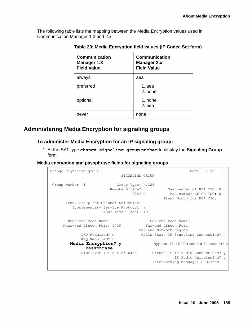
About Media Encryption
Issue 10 June 2005 185
The following table lists the mapping between the Media Encryption values used in Communication Manager 1.3 and 2.x.
Administering Media Encryption for signaling groups
To administer Media Encryption for an IP signaling group:
1. At the SAT type change signaling-group number to display the Signaling Group form
Media encryption and passphrase fields for signaling groups
Table 23: Media Encryption field values (IP Codec Set form)
CommunicationManager 1.3Field Value
CommunicationManager 2.xField Value
always aea
preferred 1. aea2. none
optional 1. none2. aea
never none
change signaling-group 1 Page 1 of 5 SIGNALING GROUP
Group Number: 1 Group Type: h.323 Remote Office? n Max number of NCA TSC: 0 SBS? n Max number of CA TSC: 0 Trunk Group for NCA TSC: Trunk Group for Channel Selection: Supplementary Service Protocol: a
T303 Timer (sec): 10
Near-end Node Name: Far-end Node Name: Near-end Listen Port: 1720 Far-end Listen Port: Far-end Network Region: LRQ Required? n Calls Share IP Signaling Connection? n RRQ Required? n Media Encryption? y Bypass If IP Threshold Exceeded? n Passphrase: DTMF over IP: out of band Direct IP-IP Audio Connections? y IP Audio Hairpinning? y Interworking Message: PROGress
Network quality administration
186 Administration for Network Connectivity for Avaya Communication Manager
2. Type y in the Media Encryption? field to enable Media Encryption on trunk calls using this signaling group.
Note:Note: Leaving this field in the default state (n) overrides the encryption administration
on the IP Codec Set form (Media Encryption field on the IP Codec Set form on page 183) for any trunk call using this signaling group. That is, if the IP codec set that is used between two networks is administered as aes or aea (Table 22: Media Encryption Field Values (IP Codec Set) on page 184), then a call between two endpoints over a H.323 trunk using this IP codec set fails because there is no voice path.
This field does not display if the Media Encryption Over IP? field is n on the Customer Options form (Media encryption field on Optional Features form on page 182).
3. Type an 8- to 30-character string in the Passphrase field.
This string:
● Must contain at least 1 alphabetic and 1 numeric symbol
● Can include letters, numerals, and!&*?;’^(),.:-
● Is case-sensitive
You must administer the same passphrase on both signaling group forms at each end of the IP trunk connection. For example, if you have two systems A and B with trunk A-B between them, you must administer both Signaling Group forms with exactly the same passphrase for the A-to-B trunk connection.
If you have previously administered a passphrase, a single asterisk (*) appears in this field. If you have not administered a passphrase, the field is blank.
Note:Note: This field does not display if either the:
● Media Encryption Over IP? field on the Customer Options form (Media encryption field on Optional Features form on page 182) is n.
or
● Media Encryption? field on the Signaling Group form (Media encryption and passphrase fields for signaling groups on page 185) is n.
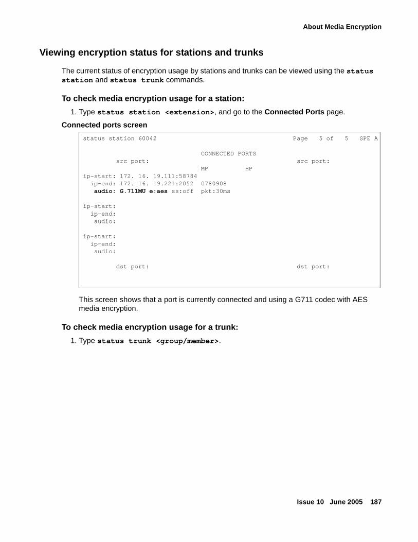
About Media Encryption
Issue 10 June 2005 187
Viewing encryption status for stations and trunks
The current status of encryption usage by stations and trunks can be viewed using the status station and status trunk commands.
To check media encryption usage for a station:
1. Type status station <extension>, and go to the Connected Ports page.
Connected ports screen
This screen shows that a port is currently connected and using a G711 codec with AES media encryption.
To check media encryption usage for a trunk:
1. Type status trunk <group/member>.
status station 60042 Page 5 of 5 SPE A
CONNECTED PORTS src port: src port: MP HPip-start: 172. 16. 19.111:58784 ip-end: 172. 16. 19.221:2052 0780908 audio: G.711MU e:aes ss:off pkt:30ms
ip-start: ip-end: audio:
ip-start: ip-end: audio: dst port: dst port:
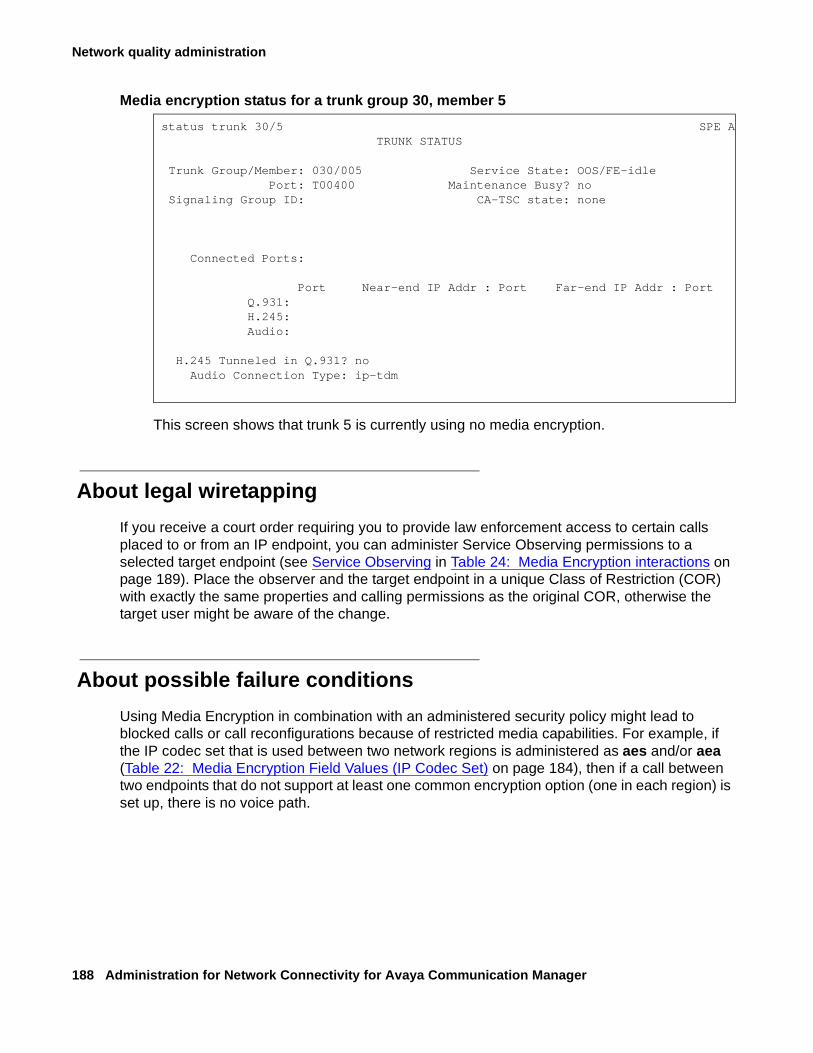
Network quality administration
188 Administration for Network Connectivity for Avaya Communication Manager
Media encryption status for a trunk group 30, member 5
This screen shows that trunk 5 is currently using no media encryption.
About legal wiretapping
If you receive a court order requiring you to provide law enforcement access to certain calls placed to or from an IP endpoint, you can administer Service Observing permissions to a selected target endpoint (see Service Observing in Table 24: Media Encryption interactions on page 189). Place the observer and the target endpoint in a unique Class of Restriction (COR) with exactly the same properties and calling permissions as the original COR, otherwise the target user might be aware of the change.
About possible failure conditions
Using Media Encryption in combination with an administered security policy might lead to blocked calls or call reconfigurations because of restricted media capabilities. For example, if the IP codec set that is used between two network regions is administered as aes and/or aea (Table 22: Media Encryption Field Values (IP Codec Set) on page 184), then if a call between two endpoints that do not support at least one common encryption option (one in each region) is set up, there is no voice path.
status trunk 30/5 SPE A TRUNK STATUS
Trunk Group/Member: 030/005 Service State: OOS/FE-idle Port: T00400 Maintenance Busy? no Signaling Group ID: CA-TSC state: none
Connected Ports:
Port Near-end IP Addr : Port Far-end IP Addr : Port Q.931: H.245: Audio:
H.245 Tunneled in Q.931? no Audio Connection Type: ip-tdm
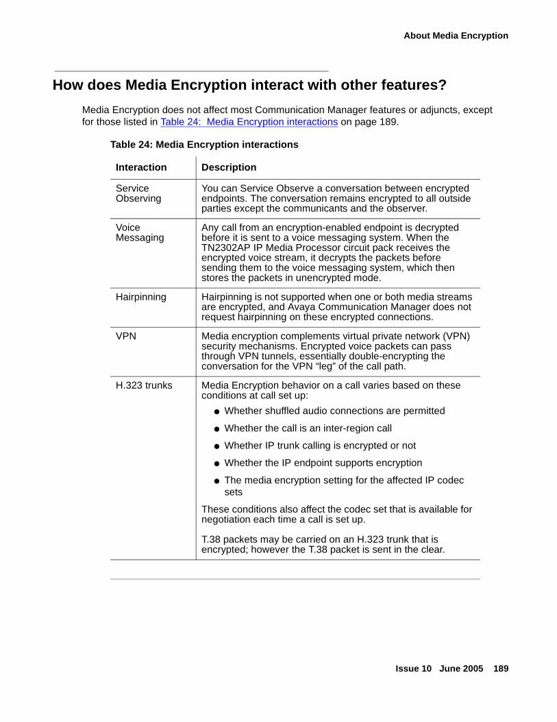
About Media Encryption
Issue 10 June 2005 189
How does Media Encryption interact with other features?
Media Encryption does not affect most Communication Manager features or adjuncts, except for those listed in Table 24: Media Encryption interactions on page 189.
Table 24: Media Encryption interactions
Interaction Description
Service Observing
You can Service Observe a conversation between encrypted endpoints. The conversation remains encrypted to all outside parties except the communicants and the observer.
Voice Messaging
Any call from an encryption-enabled endpoint is decrypted before it is sent to a voice messaging system. When the TN2302AP IP Media Processor circuit pack receives the encrypted voice stream, it decrypts the packets before sending them to the voice messaging system, which then stores the packets in unencrypted mode.
Hairpinning Hairpinning is not supported when one or both media streams are encrypted, and Avaya Communication Manager does not request hairpinning on these encrypted connections.
VPN Media encryption complements virtual private network (VPN) security mechanisms. Encrypted voice packets can pass through VPN tunnels, essentially double-encrypting the conversation for the VPN “leg” of the call path.
H.323 trunks Media Encryption behavior on a call varies based on these conditions at call set up:
● Whether shuffled audio connections are permitted
● Whether the call is an inter-region call
● Whether IP trunk calling is encrypted or not
● Whether the IP endpoint supports encryption
● The media encryption setting for the affected IP codec sets
These conditions also affect the codec set that is available for negotiation each time a call is set up.
T.38 packets may be carried on an H.323 trunk that is encrypted; however the T.38 packet is sent in the clear.
Network quality administration
190 Administration for Network Connectivity for Avaya Communication Manager
About network managementNetwork management is the practice of using specialized software tools to monitor and maintain network components. Proper network management is a key component to the high availability of data networks.
The two basic network management models are:
● Distributed. Specialized, nonintegrated tools (and sometimes organizations) to manage discrete components
● Centralized. Integrating network management tools and organizations for a more coherent management strategy.
For a detailed discussion of Avaya’s network management products, common third-party tools, and the distributed and centralized management models, see Avaya Application Solutions: IP Telephony Deployment Guide, 555-245-600.
This section touches on the following topics:
● About H.248 link loss recovery
● Auto fallback to primary controller for H.248 media gateways
● Enterprise Survivable Servers (ESS)
● Controlling QoS policies
● Monitoring network performance
About H.248 link loss recovery
H.248 Link Loss Recovery is an automated way in which the media gateway reacquires the H.248 link when it is lost from either a primary call controller or an LSP. The H.248 link between a media server running Avaya Communication Manager and a media gateway, and the H.323 link between a media gateway and an H.323-compliant IP endpoint, provide the signaling protocol for:
● Call setup
● Call control (user actions such as Hold, Conference, or Transfer) while the call is in progress
● Call tear-down
If the link goes down, Link Recovery preserves any existing calls and attempts to re-establish the original link. If the gateway/endpoint cannot reconnect to the original server/gateway, then Link Recovery automatically attempts to connect with alternate TN799DP (C-LAN) circuit packs within the original server’s configuration or to a Local Survivable Processor (LSP).
About network management
Issue 10 June 2005 191
Overlap with the Auto fallback to primary controller for H.248 media gateways feature occurs when the Link Loss Recovery starts while the media gateway is trying to migrate back to the primary, with its new registration message indicating that service is being obtained from elsewhere.
A race condition may exist in which there is an outstanding media gateway registration to the primary while the link to the LSP is lost. The media gateway awaits a denial or acceptance from the primary call controller. If it is an acceptance, then the Link Loss Recovery is terminated, and the media gateway is serviced by the primary call controller. If it is a denial, then the media gateway immediately sends a new registration to the primary call controller indicating no service, and the existing H.248 Link Loss Recovery feature takes over.
These features are similar in that they both attempt to return service to the primary call controller; however, Link Loss Recovery does it based upon a link failure, whereas auto fallback to primary does it based upon a working fragmented network.
For more information on H.248 Link Loss Recovery, see Maintenance Procedures for Avaya Communication Manager 2.2, Media Gateways and Servers, (03-300192), for details of the link recovery process and administration options.
Auto fallback to primary controller for H.248 media gateways
The intent of the auto fallback to primary controller feature is to return a fragmented network, in which a number of H.248 Media Gateways are being serviced by one or more LSPs (Local Survivable Processors), to the primary media server in an automatic fashion. This feature is targeted towards all H.248 media gateways. By migrating the media gateways back to the primary automatically, the distributed telephony switch network can be made whole sooner without human intervention, which is required today.
The auto-fallback migration, in combination with the connection preservation feature for H.248 gateways is connection-preserving. Stable connections are preserved; unstable connections (such as ringing calls) are not. There still may be a very short interval without dialtone for new calls.
The media gateway presents a new registration parameter that indicates that Service is being obtained from an LSP, and indicates the number of active user calls on the media gateway platform. The server administers each media gateway to have its own set of rules for Time of Day migration, enable/disable, and the setting of call threshold rules for migration.
This feature allows the administrator to define any of the following rules for migration:
● The media gateway should migrate to the primary automatically, or not.
● The media gateway should migrate immediately when possible, regardless of active call count.
● The media gateway should only migrate if the active call count is 0.
Network quality administration
192 Administration for Network Connectivity for Avaya Communication Manager
● The media gateway should only be allowed to migrate within a window of opportunity, by providing day of the week and time intervals per day. This option does not take call count into consideration.
● The media gateway should be migrated within a window of opportunity by providing day of the week and time of day, or immediately if the call count reaches 0. Both rules are active at the same time.
Internally, the primary call controller gives priority to registration requests from those media gateways that are currently not being serviced by an LSP. This priority is not administrable.
There are several reasons for denying an auto-fallback, which can result from general system performance requirements, or from administrator-imposed requirements. General system performance requirements can include denial of registration because:
● Too many simultaneous media gateway registration requests
Administrator-imposed requirements for denial of a registration can include:
● Registrations restricted to a windowed time of day
● Migration restricted to a condition of 0 active calls, that is, there are no users on calls within the media gateway in question.
● The administered minimum time for network stability has not been exceeded.
Other characteristics of this feature include:
● This feature does not preclude an older GW firmware release from working with Communication Manager 3.0 or vice versa; however, the auto-fallback feature would not be available.
For this feature to work, the call controller is required to have Communication Manager 3.0, while the media gateway is required to have the GW firmware available at the time of the Communication Manager 3.0 release.
● Existing H.248 media gateways are the targets.
● LSP operation is completely unaffected.
The LSP simply sees that a particular media gateway has lost its connection with the LSP. The existing H.248 Link Loss Recovery algorithm on the LSP cleans up all outstanding call records within the LSP after the prescribed time interval.
Basic feature operation
The following steps illustrate the basic operation of the auto-fallback to primary for H.248 media gateways feature. While not exactly so, the steps are approximately sequential.
1. The media gateway/media server by default has this feature disabled.
If the media gateway is initially registered with an older media server, the version information exchange is sufficient for the media gateway to know not to attempt to fallback to the primary automatically.
About network management
Issue 10 June 2005 193
2. By means of administration on the media server, this feature can be enabled for any or all media gateways controlled by that media server.
The enable/disable administration on the media server determines whether the media server will accept/deny registration requests containing the new parameter that service is being obtained from an LSP. The media gateway continuously attempts to register with the media server, however, even if the media server has been administered never to accept the registration request (that is, the auto-fallback feature is disabled on the media server). In such a case, a manual return of the media gateway is required, which generates a different registration message that is accepted by the media server.
Note:Note: There is still value in receiving the registration messages when auto-fallback is
disabled on the media server, and that value is to see the stability of the network over time, since those messages act as "keep-alive" messages.
3. The permission-based rules that include time of day and context information are only known to the media server.
There is no need for the LSP to have any of these translations.
4. When associated with a primary controller running Communication Manager 3.0, the media gateway attempts to register with the primary controller whenever it is connected to an LSP.
This registration attempt happens every 30 seconds, once the media gateway is able to communicate with the primary controller. The registration message contains an element that indicates:
- that the media gateway is being serviced by an LSP, and
- the number of active user calls on that media gateway.
5. Upon the initial registration request, the primary controller initializes the encrypted TCP link for H.248 messaging.
This is performed regardless of whether that initial registration is honored or not, and that encryption is maintained throughout the life of the registration requests. The encryption is also maintained once a registration is accepted by the primary controller. Encryption of the signaling link is performed at the outset during this automatic fallback process to ensure the security of the communication between the primary call controller and the media gateway.
6. The primary controller, based upon its administered rules, may allow or deny a registration.
If the primary controller gets a registration message without Service State information, for example, an older media gateway, or if a new media gateway states it does not have service, then the primary honors those registration requests above all others immediately.
7. If the registration is denied, the media gateway continues to send the registration message every 30 seconds, which acts as a de facto ‘"keep-alive" message.
8. The media gateway constantly monitors the call count on its platform, and asynchronously sends a registration message whenever 0 context is achieved.
9. Once the registration message is accepted by the primary, then the H.248 link to the LSP is dropped.
Network quality administration
194 Administration for Network Connectivity for Avaya Communication Manager
G250 interworking
When calls are made on the media gateway while it is controlled by Standard Local Survivability (SLS), the G250 behaves as any LSP might behave. The SLS, using its administration and dial analysis plan, can allow local calls to be established from:
● Local station to local station (analog or registered IP)
● Local station to local analog two-way CO trunks
While operating in SLS mode, the G250 attempts to re-register with the primary controller on its MGC list. As soon as the gateway is able to re-register with the primary controller, it un-registers with SLS, and re-registers with the primary controller. In terms of re-registration with the primary controller, the Auto Fallback to Primary feature would therefore work in a similar way with the G250 SLS as it does with the LSPs in the G350 or G700.
Note:Note: The connection preserving aspects of this feature will not be available on the
G250 for this release.
G350 interworking
The G350 FW loads use the new Object Identifier (OID) that has the longer Non-Standard Data format in the registration message. This format is only backward compatible to Communication Manager 2.0 loads. Older loads respond with a protocol error as the denial cause for the rejection of the new registration message. Given that the G350 was only introduced in the Communication Manager 2.0 timeframe, it is not backwards compatible with previous Communication Manager releases.
In a startup scenario, there is an exchange of version information between Communication Manager and the media gateway. If the Communication Manager load is pre-Communication Manager 3.0, then the auto-fallback mechanism remains disabled for the media gateway. Any subsequent registration with a primary controller (from the MGC list) that is running release Communication Manager 3.0 results in the auto fall-back feature being enabled for the media gateway.
The only time when the media gateway may send a registration message to an older primary call controller is in the rare case when the primary controller has been downgraded while the media gateway has been receiving service from an LSP. In this case, the media gateway receives a protocol error that can be used to send a registration message consistent with Communication Manager 2.0. Downgrading to earlier than Communication Manager 2.0 with a G350 would result in the G350 not being able to register at all.
About network management
Issue 10 June 2005 195
G700 interworking
The G700 Media Gateway, even in Communication Manager 2.0, still used the same OID as when it was originally deployed. The new OID available for the G350 was not ported to the G700. The auto fallback to primary feature requires that all G700s, running the Communication Manager 3.0-compliant firmware load, use the new OID format. The NSD (Non-Standard Data) expansion with the new OID is used to carry the context count.
If the media gateway receives any of the following errors in response to a registration message, then the media gateway sends the original OID registration message prior to the expansion of the NSD.
● 284 - NSD OID invalid
● 283 - NSD OID wrong length
● 345 - NSD Wrong Length - for Communication Manager 1.3 and earlier systems
Though not directly necessary for this feature, the media gateway responds to any of the aforementioned protocol errors by attempting to register with the lowest common denominator registration message. This allows new media gateways to be backward compatible with even older releases. This modification only applies to the G700.
Older media gateway loads
The auto-fallback feature on the media server is passive in nature; therefore, an older media gateway load trying to register with the new Communication Manager 3.0 load registers with priority, since the value of the Service-State is that of a media gateway without service. Any defined rules for the media gateway are ignored, given that an older media gateway firmware release only tries to register when it no longer has service from another media server; therefore, the administration of rules for old media gateway firmware loads are irrelevant.
Administering auto fallback to primary
For each media gateway, the following administration must be performed:
● Adding Recovery Rule to Media Gateway screen
● Administering the System Parameters Media Gateway Automatic Recovery Rule screens to schedule the auto-fallback within the system-parameters area.
Adding Recovery Rule to Media Gateway screenThe Media Gateway form (change media-gateway n) has a field called Recovery Rule with the following attributes:
● Acceptable values for the field are none, 1 - 50, or 1 - 250, where
- 50 is the maximum number of supported media gateways on an S8300 Media Server, and
- 250 is the maximum number of supported media gateways on an S8500 or S8700-series Media Server.
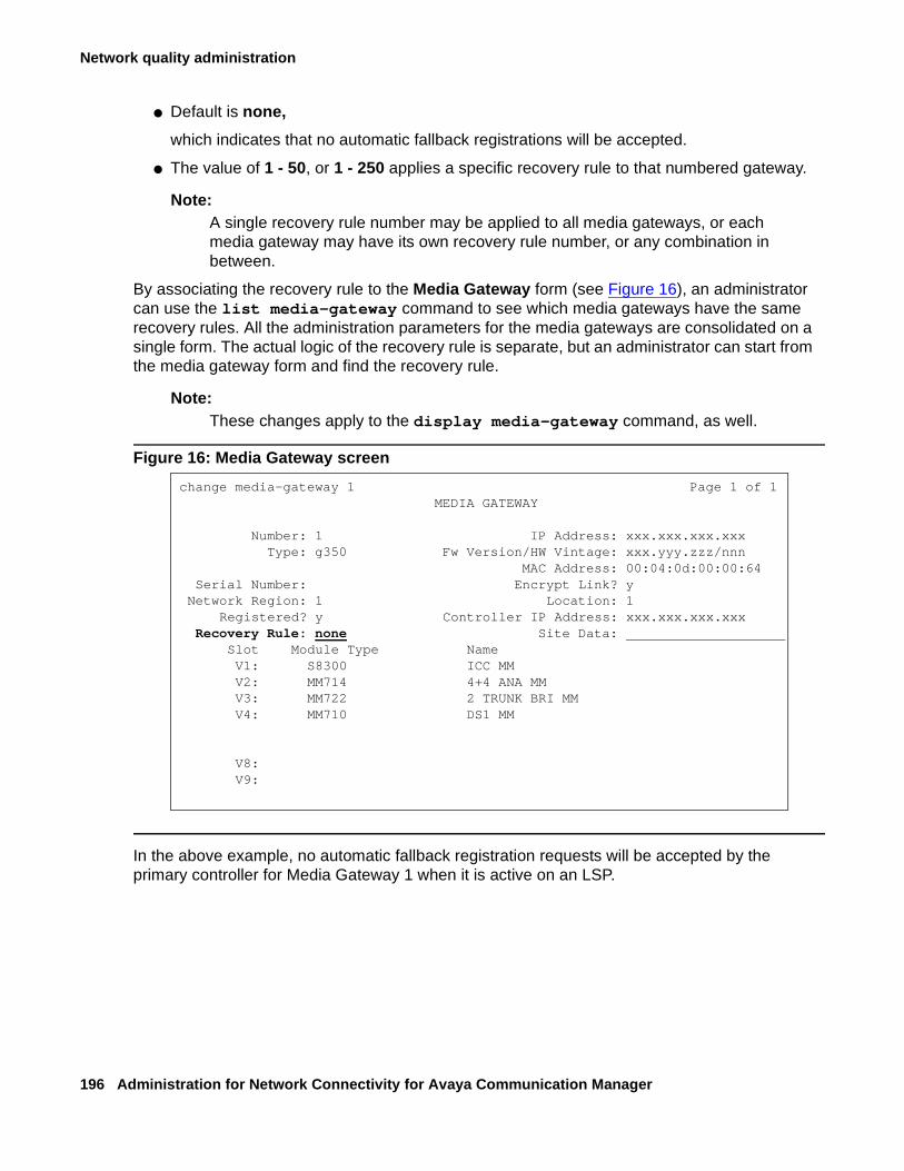
Network quality administration
196 Administration for Network Connectivity for Avaya Communication Manager
● Default is none,
which indicates that no automatic fallback registrations will be accepted.
● The value of 1 - 50, or 1 - 250 applies a specific recovery rule to that numbered gateway.
Note:Note: A single recovery rule number may be applied to all media gateways, or each
media gateway may have its own recovery rule number, or any combination in between.
By associating the recovery rule to the Media Gateway form (see Figure 16), an administrator can use the list media-gateway command to see which media gateways have the same recovery rules. All the administration parameters for the media gateways are consolidated on a single form. The actual logic of the recovery rule is separate, but an administrator can start from the media gateway form and find the recovery rule.
Note:Note: These changes apply to the display media-gateway command, as well.
Figure 16: Media Gateway screen
In the above example, no automatic fallback registration requests will be accepted by the primary controller for Media Gateway 1 when it is active on an LSP.
change media-gateway 1 Page 1 of 1MEDIA GATEWAY
Number: 1 IP Address: xxx.xxx.xxx.xxxType: g350 Fw Version/HW Vintage: xxx.yyy.zzz/nnn
MAC Address: 00:04:0d:00:00:64Serial Number: Encrypt Link? y
Network Region: 1 Location: 1Registered? y Controller IP Address: xxx.xxx.xxx.xxx
Recovery Rule: none Site Data: Slot Module Type NameV1: S8300 ICC MMV2: MM714 4+4 ANA MMV3: MM722 2 TRUNK BRI MMV4: MM710 DS1 MM
V8:V9:
About network management
Issue 10 June 2005 197
Administering the System Parameters Media Gateway Automatic Recovery Rule screens
Definition of recovery rules occurs on the System Parameters Media Gateway Automatic Recovery Rule screens (change system-parameters mg-recovery-rule <n>. This screen is contained within the ’system-parameters’ area of administration screens. The maximum number of screens that can be administered correspond to the maximum number of media gateways supported by the media server in question, and are:
● Up to 50 for the S8300 Media Server
● Up to 250 for the S8500 and S8700-series Media Servers
These screens provide a field, Migrate H248 MG to primary, with 4 administrable options:
Note:Note: For detailed information on all four options, see Administrator Guide for Avaya
Communication Manager, 03-300509.
1. immediately — which means that the first media gateway registration that comes from the media gateway is honored, regardless of context count or time of day.
The Warning displayed in Figure 17 is visible when a user selects this option. This option is the default for all rules.
2. 0-active calls — which means that the first media gateway registration reporting “0 active calls” is honored (see Figure 18).
3. Time-day-window — means that a valid registration message received during any part of this interval is honored (see Figure 19).
Note:Note: Time of day is local to the media gateway.
There are no constraints on the number of active calls. The time scale provided for each day of the week goes from 00-23 hundred hours (military time). The user must specify an ‘x’ or ‘X’ for each hour where they want to permit the return migration. If they do not want to permit a given hour, then they leave it blank. This method gets around overlapping time issues between days of the week. Users can specify as many intervals as they wish.
4. Time-window-OR-0-active-calls — means that a valid registration is accepted anytime, when a 0 active call count is reported OR if a valid registration with any call count is received during the specified time/day intervals (see Figure 20).
Note:Note: Time of day is local to the media gateway.
The time scale provided for each day of the week goes from 00-23 hundred hours (military time). The user must specify an ‘x’ or ‘X’ for each hour where they want to permit the return migration. If they do not want to permit a given hour then they leave it blank. This method gets around overlapping time issues between days of the week. Users can specify as many intervals as they wish.
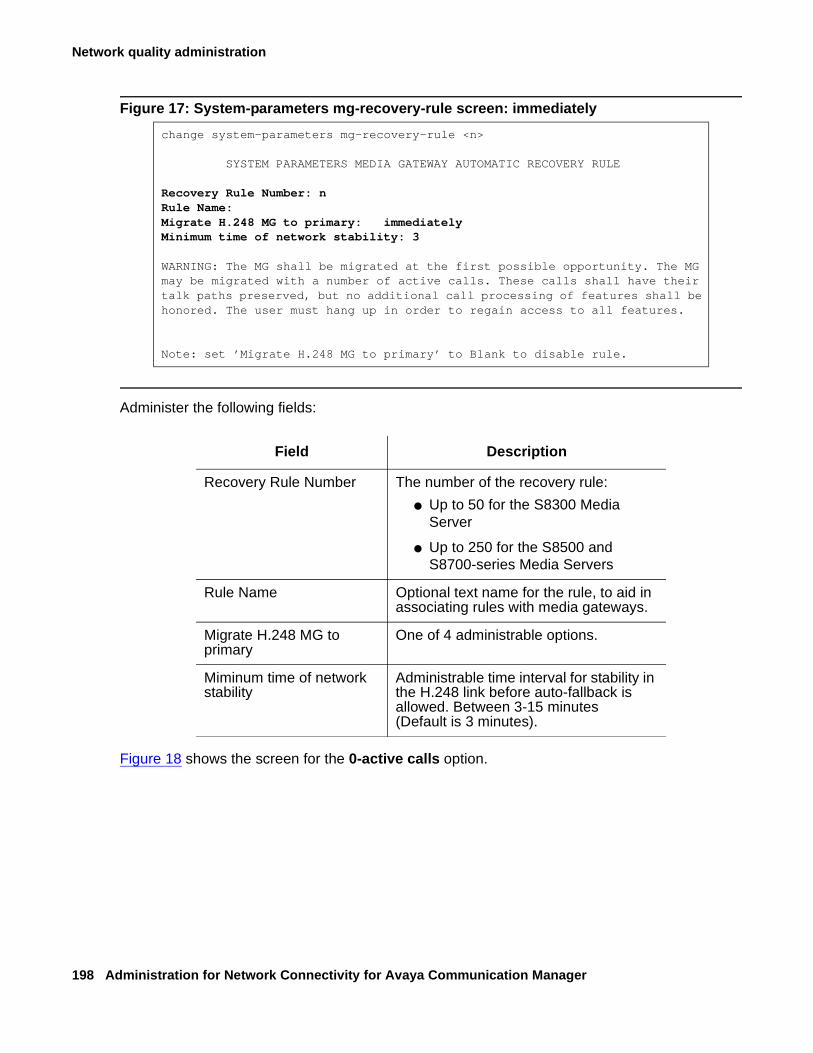
Network quality administration
198 Administration for Network Connectivity for Avaya Communication Manager
Figure 17: System-parameters mg-recovery-rule screen: immediately
Administer the following fields:
Figure 18 shows the screen for the 0-active calls option.
change system-parameters mg-recovery-rule <n>
SYSTEM PARAMETERS MEDIA GATEWAY AUTOMATIC RECOVERY RULE
Recovery Rule Number: nRule Name:Migrate H.248 MG to primary: immediatelyMinimum time of network stability: 3
WARNING: The MG shall be migrated at the first possible opportunity. The MG may be migrated with a number of active calls. These calls shall have their talk paths preserved, but no additional call processing of features shall be honored. The user must hang up in order to regain access to all features.
Note: set ’Migrate H.248 MG to primary’ to Blank to disable rule.
Field Description
Recovery Rule Number The number of the recovery rule:
● Up to 50 for the S8300 Media Server
● Up to 250 for the S8500 and S8700-series Media Servers
Rule Name Optional text name for the rule, to aid in associating rules with media gateways.
Migrate H.248 MG to primary
One of 4 administrable options.
Miminum time of network stability
Administrable time interval for stability in the H.248 link before auto-fallback is allowed. Between 3-15 minutes(Default is 3 minutes).
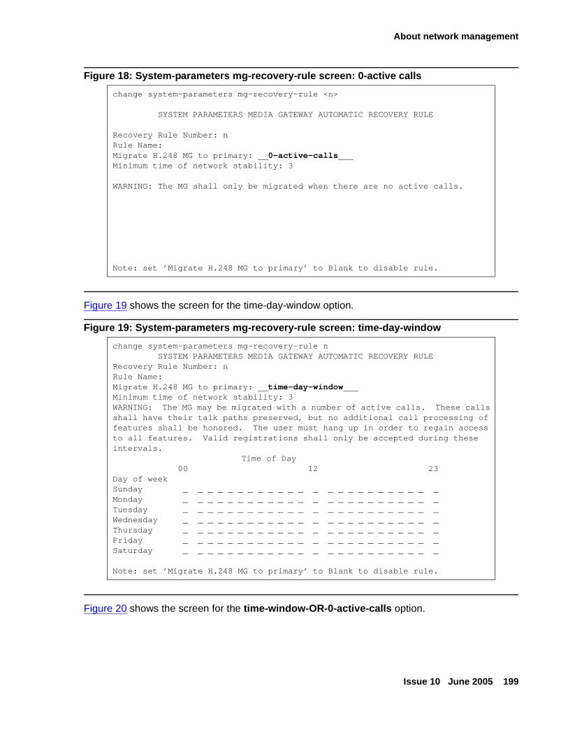
About network management
Issue 10 June 2005 199
Figure 18: System-parameters mg-recovery-rule screen: 0-active calls
Figure 19 shows the screen for the time-day-window option.
Figure 19: System-parameters mg-recovery-rule screen: time-day-window
Figure 20 shows the screen for the time-window-OR-0-active-calls option.
change system-parameters mg-recovery-rule <n>
SYSTEM PARAMETERS MEDIA GATEWAY AUTOMATIC RECOVERY RULE
Recovery Rule Number: nRule Name:Migrate H.248 MG to primary: 0-active-callsMinimum time of network stability: 3
WARNING: The MG shall only be migrated when there are no active calls.
Note: set ’Migrate H.248 MG to primary’ to Blank to disable rule.
change system-parameters mg-recovery-rule nSYSTEM PARAMETERS MEDIA GATEWAY AUTOMATIC RECOVERY RULE
Recovery Rule Number: nRule Name:Migrate H.248 MG to primary: time-day-windowMinimum time of network stability: 3WARNING: The MG may be migrated with a number of active calls. These calls shall have their talk paths preserved, but no additional call processing of features shall be honored. The user must hang up in order to regain access to all features. Valid registrations shall only be accepted during these intervals.
Time of Day 00 12 23Day of weekSunday _ _ _ _ _ _ _ _ _ _ _ _ _ _ _ _ _ _ _ _ _ _ _ _Monday _ _ _ _ _ _ _ _ _ _ _ _ _ _ _ _ _ _ _ _ _ _ _ _Tuesday _ _ _ _ _ _ _ _ _ _ _ _ _ _ _ _ _ _ _ _ _ _ _ _Wednesday _ _ _ _ _ _ _ _ _ _ _ _ _ _ _ _ _ _ _ _ _ _ _ _Thursday _ _ _ _ _ _ _ _ _ _ _ _ _ _ _ _ _ _ _ _ _ _ _ _Friday _ _ _ _ _ _ _ _ _ _ _ _ _ _ _ _ _ _ _ _ _ _ _ _Saturday _ _ _ _ _ _ _ _ _ _ _ _ _ _ _ _ _ _ _ _ _ _ _ _
Note: set ’Migrate H.248 MG to primary’ to Blank to disable rule.
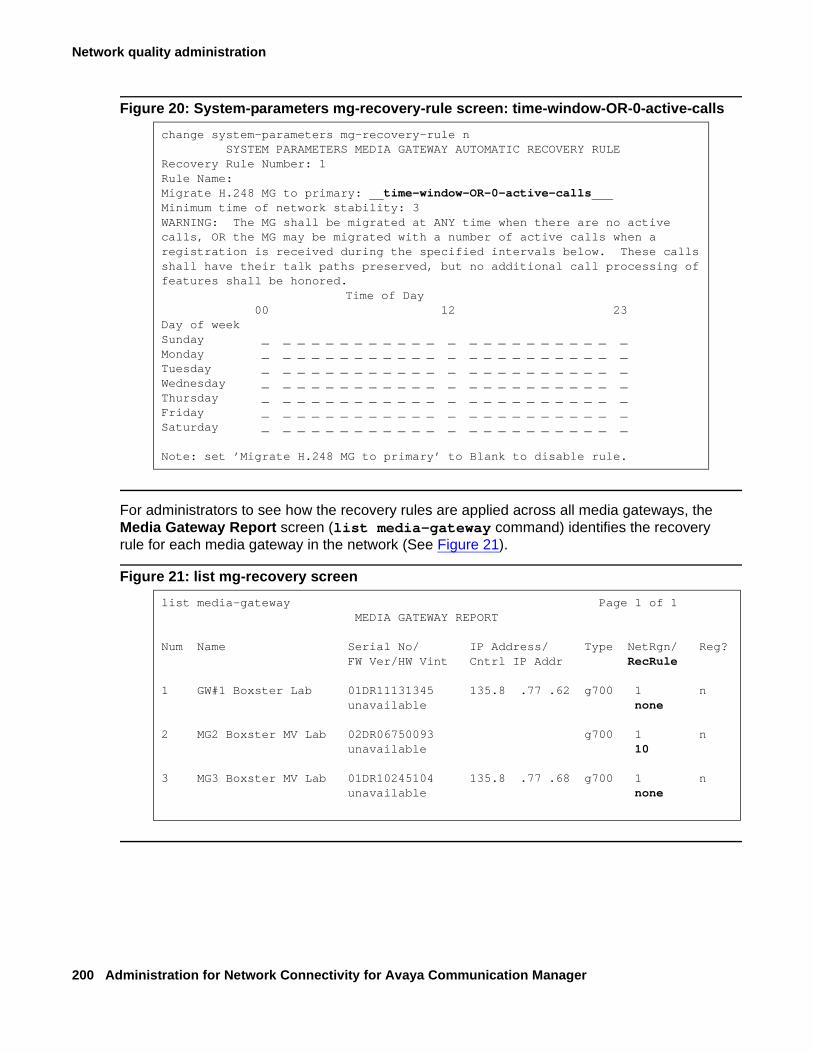
Network quality administration
200 Administration for Network Connectivity for Avaya Communication Manager
Figure 20: System-parameters mg-recovery-rule screen: time-window-OR-0-active-calls
For administrators to see how the recovery rules are applied across all media gateways, the Media Gateway Report screen (list media-gateway command) identifies the recovery rule for each media gateway in the network (See Figure 21).
Figure 21: list mg-recovery screen
change system-parameters mg-recovery-rule nSYSTEM PARAMETERS MEDIA GATEWAY AUTOMATIC RECOVERY RULE
Recovery Rule Number: 1Rule Name:Migrate H.248 MG to primary: time-window-OR-0-active-callsMinimum time of network stability: 3WARNING: The MG shall be migrated at ANY time when there are no active calls, OR the MG may be migrated with a number of active calls when a registration is received during the specified intervals below. These calls shall have their talk paths preserved, but no additional call processing of features shall be honored.
Time of Day 00 12 23Day of weekSunday _ _ _ _ _ _ _ _ _ _ _ _ _ _ _ _ _ _ _ _ _ _ _ _Monday _ _ _ _ _ _ _ _ _ _ _ _ _ _ _ _ _ _ _ _ _ _ _ _Tuesday _ _ _ _ _ _ _ _ _ _ _ _ _ _ _ _ _ _ _ _ _ _ _ _Wednesday _ _ _ _ _ _ _ _ _ _ _ _ _ _ _ _ _ _ _ _ _ _ _ _Thursday _ _ _ _ _ _ _ _ _ _ _ _ _ _ _ _ _ _ _ _ _ _ _ _Friday _ _ _ _ _ _ _ _ _ _ _ _ _ _ _ _ _ _ _ _ _ _ _ _Saturday _ _ _ _ _ _ _ _ _ _ _ _ _ _ _ _ _ _ _ _ _ _ _ _
Note: set ’Migrate H.248 MG to primary’ to Blank to disable rule.
list media-gateway Page 1 of 1MEDIA GATEWAY REPORT
Num Name Serial No/ IP Address/ Type NetRgn/ Reg?FW Ver/HW Vint Cntrl IP Addr RecRule
1 GW#1 Boxster Lab 01DR11131345 135.8 .77 .62 g700 1 nunavailable none
2 MG2 Boxster MV Lab 02DR06750093 g700 1 nunavailable 10
3 MG3 Boxster MV Lab 01DR10245104 135.8 .77 .68 g700 1 nunavailable none
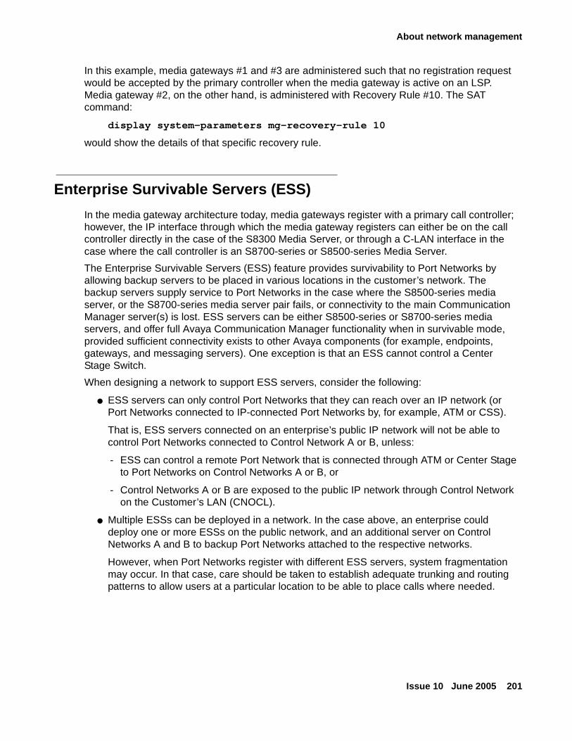
About network management
Issue 10 June 2005 201
In this example, media gateways #1 and #3 are administered such that no registration request would be accepted by the primary controller when the media gateway is active on an LSP. Media gateway #2, on the other hand, is administered with Recovery Rule #10. The SAT command:
display system-parameters mg-recovery-rule 10
would show the details of that specific recovery rule.
Enterprise Survivable Servers (ESS)
In the media gateway architecture today, media gateways register with a primary call controller; however, the IP interface through which the media gateway registers can either be on the call controller directly in the case of the S8300 Media Server, or through a C-LAN interface in the case where the call controller is an S8700-series or S8500-series Media Server.
The Enterprise Survivable Servers (ESS) feature provides survivability to Port Networks by allowing backup servers to be placed in various locations in the customer’s network. The backup servers supply service to Port Networks in the case where the S8500-series media server, or the S8700-series media server pair fails, or connectivity to the main Communication Manager server(s) is lost. ESS servers can be either S8500-series or S8700-series media servers, and offer full Avaya Communication Manager functionality when in survivable mode, provided sufficient connectivity exists to other Avaya components (for example, endpoints, gateways, and messaging servers). One exception is that an ESS cannot control a Center Stage Switch.
When designing a network to support ESS servers, consider the following:
● ESS servers can only control Port Networks that they can reach over an IP network (or Port Networks connected to IP-connected Port Networks by, for example, ATM or CSS).
That is, ESS servers connected on an enterprise’s public IP network will not be able to control Port Networks connected to Control Network A or B, unless:
- ESS can control a remote Port Network that is connected through ATM or Center Stage to Port Networks on Control Networks A or B, or
- Control Networks A or B are exposed to the public IP network through Control Network on the Customer’s LAN (CNOCL).
● Multiple ESSs can be deployed in a network. In the case above, an enterprise could deploy one or more ESSs on the public network, and an additional server on Control Networks A and B to backup Port Networks attached to the respective networks.
However, when Port Networks register with different ESS servers, system fragmentation may occur. In that case, care should be taken to establish adequate trunking and routing patterns to allow users at a particular location to be able to place calls where needed.
Network quality administration
202 Administration for Network Connectivity for Avaya Communication Manager
● ESS servers register to the main server(s) through a C-LAN. Each ESS must be able to communicate with a C-LAN in order to download translations. The ESS-to-C-LAN link uses the following ports:
- UDP/1719 – ESS registers with the main server
- ?/21873 – Main server sends translations to the ESS (Release 3.0 and above; also for LSP translations)
- ?/21874 – Main server sends translations to the LSP(s) (pre-Release 3.0)
The media gateway cannot distinguish between registration through a C-LAN or registration to an S8300 directly. Prior to Communication Manager 3.0, without ESS, if a media gateway successfully registered with a primary call controller IP address, then the media gateway was properly registered with the primary call controller. However, in Communication Manager 3.0, when a media gateway completes a successful registration through an IP address defined as a primary call controller address, if that address is a C-LAN, the media gateway may not necessrily be registered with the true primary call controller. The port network that houses the C-LAN may be under control of an ESS; but the media gateway will not know that it is registered with an ESS.
When the traditional port network migrates back to the primary call controller, then the media gateway loses its H.248 link, and the Link Loss Recovery algorithm engages, and that should be sufficient. The Auto Fallback to Primary feature only engages if the media gateway drops the connection and registers with an LSP. The ESS migration should only occur if the port network is reasonably certain to return to the primary call controller, so the media gateway would simply return to the same C-LAN interface. Now, when the media gateway returns to the same C-LAN interface, the Link Loss Recovery feature performs a context audit with the primary controller and learns that the primary call controller is not aware of the media gateway. The controller in this case issues a warm start request to the media gateway, or potentially different behavior if connection preservation is active at the same time. The auto-fallback feature is not affected by ESS.
For more information on ESS, see the Avaya Enterprise Survivable Servers (ESS) Users Guide, 03-300428.
Controlling QoS policies
Avaya Policy Manager is a network management tool that allows you to control Quality of Service (QoS) policies in your IP voice network consistently:
● Avaya Policy Manager helps you implement QoS policies consistently for both the data and the voice networks.
● QoS policies are assigned according to network regions and are distributed through the Enterprise Directory Gateway to your systems and to routers and switching devices.
Figure 22: Avaya Policy Manager application sequence on page 203 illustrates how Avaya Policy Manager works.
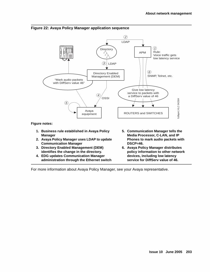
About network management
Issue 10 June 2005 203
Figure 22: Avaya Policy Manager application sequence
For more information about Avaya Policy Manager, see your Avaya representative.
Figure notes:
1. Business rule established in Avaya Policy Manager
2. Avaya Policy Manager uses LDAP to update Communication Manager
3. Directory Enabled Management (DEM) identifies the change in the directory.
4. EDG updates Communication Manager administration through the Ethernet switch
5. Communication Manager tells the Media Processor, C-LAN, and IP Phones to mark audio packets with DSCP=46.
6. Avaya Policy Manager distributes policy information to other network devices, including low latency service for DiffServ value of 46.
Directory
“Mark audio packetswith DiffServ value 46”
OSSI
Avayaequipment
APM Rule:Voice traffic getslow latency service
SNMP, Telnet, etc.
ROUTERS and SWITCHES
LDAP
LDAP
5
4
3
2
1
6Directory EnabledManagement (DEM)
Give low latencyservice to packets witha DiffServ value of 46
fcdf
apm
1 K
LC 0
4150
4
Network quality administration
204 Administration for Network Connectivity for Avaya Communication Manager
Monitoring network performance
The Avaya VoIP Monitoring Manager, a VoIP Network Quality monitoring tool, allows you to monitor these quality-affecting network factors:
● Jitter levels
● Packet loss
● Delay
● CODECs used
● RSVP status
For more information about Avaya VoIP Monitoring Manager, see Avaya Application Solutions: IP Telephony Deployment Guide, 555-245-600.
Issue 10 June 2005 205
Chapter 5: Administering dedicated networks
This chapter contains these main sections:
● Distributed Communications System contains a description of DCS and the features that can be used transparently on a DCS network. This section also contains a description of some pre-requisite DCS features:
- Prerequisite DCS administration
- DCS signaling
- Gateway switch
- Italian DCS Protocol
- DCS configurations with AUDIX
● QSIG contains a description of QSIG and how to administer it.
- Overview
- QSIG/DCS interworking
- Offer level functionality
- Basic call setup
- Transfer into QSIG Message Center
- Value-Added (VALU) MSI
- QSIG Centralized Attendant Services (CAS)
- Call-independent Signaling Connection (CISCs)
- About Non-Call Associated Temporary Signaling Connection (NCA-TSC)
- Migrating to QSIG: some considerations
● Centralized Attendant Service contains a description of CAS and features, considerations, and feature interactions.
- What is Centralized Attendant Service (CAS)
- Administering CAS
● Extended Trunk Access contains description, administration, and feature interactions for ETA.
- What is Extended Trunk Access (ETA)
- Administering Extended Trunk Access
Administering dedicated networks
206 Administration for Network Connectivity for Avaya Communication Manager
● Inter-PBX Attendant Service contains description, administration, and feature interactions for Inter-PBX Attendant Service.
- What is Inter-PBX Attendant Service (IAS)
- Administering Inter-PBX Attendant Service
- About Inter-PBX Attendant Service interactions
● ISDN Feature Plus is a description of ISDN Plus networking capabilities.
- What is ISDN Feature Plus
- Administering ISDN Feature Plus
- Differences in Inserted Digits field
- About interrogation between message center and served user switches
● Centralized Voice Mail describes how to administer Centralized Voice Mail with Mode codes.
- About centralized voice mail
- What are mode code centralized voice mail configuration requirements
- Administering Centralized Voice Mail
● Japan TTC Q931-a is a brief description of Japan TTC private networking protocols.
- About Japan TTC Q931-a
- Considerations about TTC Basic Call Setup with Number Identification Supplementary Service
- What are the TTC Q931-a Protocols
- Administering Japan TTC Q931-a
Note:Note: See Chapter 6: Feature interactions and considerations for feature interaction
information and other considerations for using the features described in this chapter.
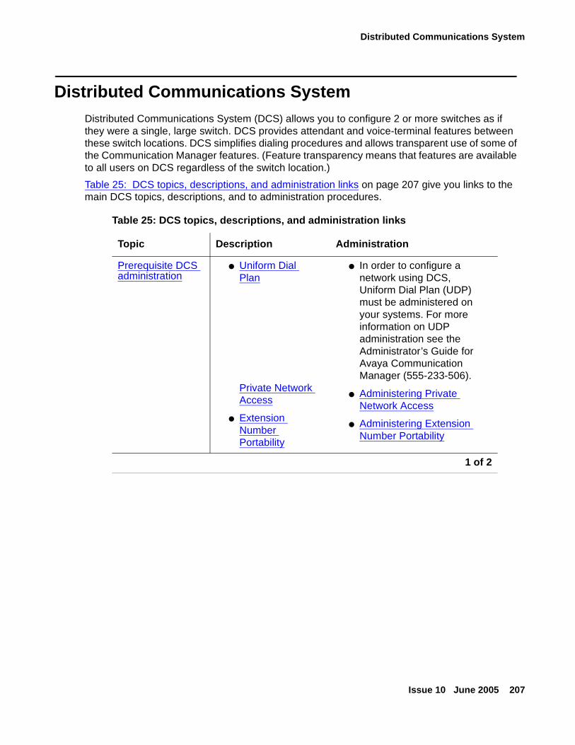
Distributed Communications System
Issue 10 June 2005 207
Distributed Communications System Distributed Communications System (DCS) allows you to configure 2 or more switches as if they were a single, large switch. DCS provides attendant and voice-terminal features between these switch locations. DCS simplifies dialing procedures and allows transparent use of some of the Communication Manager features. (Feature transparency means that features are available to all users on DCS regardless of the switch location.)
Table 25: DCS topics, descriptions, and administration links on page 207 give you links to the main DCS topics, descriptions, and to administration procedures.
Table 25: DCS topics, descriptions, and administration links
Topic Description Administration
Prerequisite DCS administration
● Uniform Dial Plan
Private Network Access
● Extension Number Portability
● In order to configure a network using DCS, Uniform Dial Plan (UDP) must be administered on your systems. For more information on UDP administration see the Administrator’s Guide for Avaya Communication Manager (555-233-506).
● Administering Private Network Access
● Administering Extension Number Portability
1 of 2
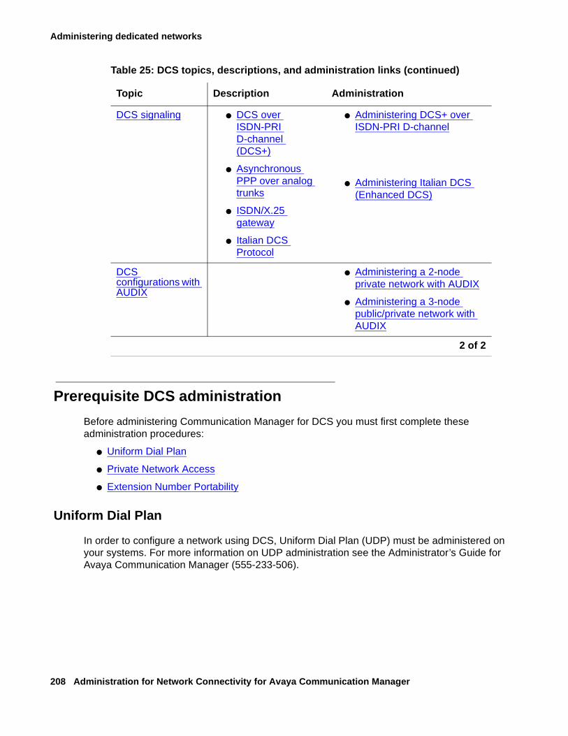
Administering dedicated networks
208 Administration for Network Connectivity for Avaya Communication Manager
Prerequisite DCS administration
Before administering Communication Manager for DCS you must first complete these administration procedures:
● Uniform Dial Plan
● Private Network Access
● Extension Number Portability
Uniform Dial Plan
In order to configure a network using DCS, Uniform Dial Plan (UDP) must be administered on your systems. For more information on UDP administration see the Administrator’s Guide for Avaya Communication Manager (555-233-506).
DCS signaling ● DCS over ISDN-PRI D-channel (DCS+)
● Asynchronous PPP over analog trunks
● ISDN/X.25 gateway
● Italian DCS Protocol
● Administering DCS+ over ISDN-PRI D-channel
● Administering Italian DCS (Enhanced DCS)
DCS configurations with AUDIX
● Administering a 2-node private network with AUDIX
● Administering a 3-node public/private network with AUDIX
Table 25: DCS topics, descriptions, and administration links (continued)
Topic Description Administration
2 of 2
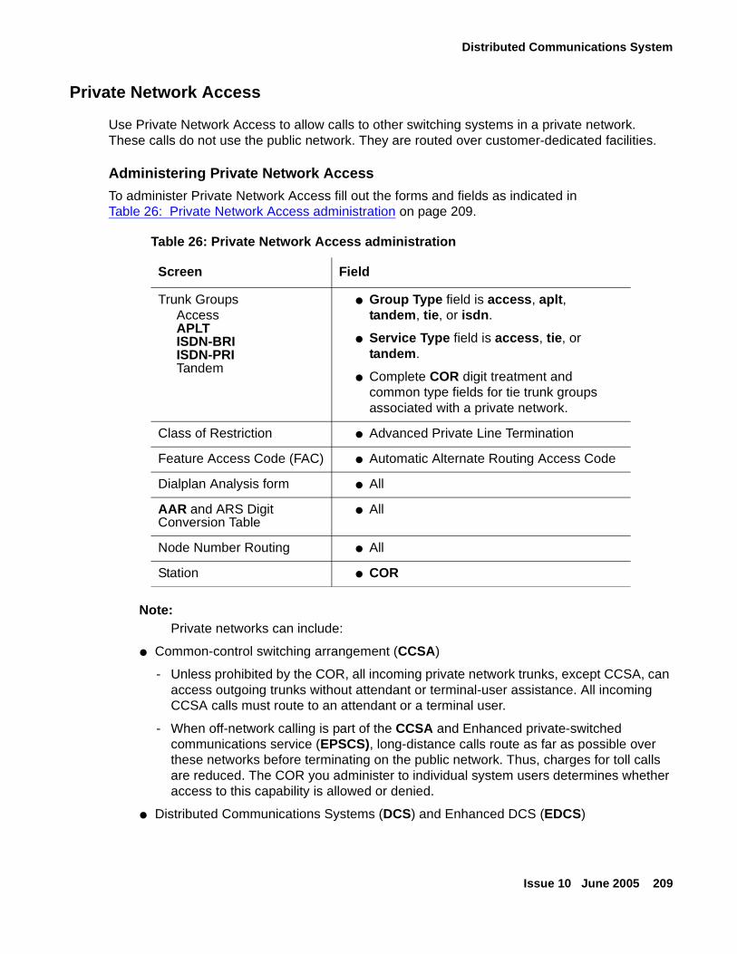
Distributed Communications System
Issue 10 June 2005 209
Private Network Access
Use Private Network Access to allow calls to other switching systems in a private network. These calls do not use the public network. They are routed over customer-dedicated facilities.
Administering Private Network Access
To administer Private Network Access fill out the forms and fields as indicated in Table 26: Private Network Access administration on page 209.
Note:Note: Private networks can include:
● Common-control switching arrangement (CCSA)
- Unless prohibited by the COR, all incoming private network trunks, except CCSA, can access outgoing trunks without attendant or terminal-user assistance. All incoming CCSA calls must route to an attendant or a terminal user.
- When off-network calling is part of the CCSA and Enhanced private-switched communications service (EPSCS), long-distance calls route as far as possible over these networks before terminating on the public network. Thus, charges for toll calls are reduced. The COR you administer to individual system users determines whether access to this capability is allowed or denied.
● Distributed Communications Systems (DCS) and Enhanced DCS (EDCS)
Table 26: Private Network Access administration
Screen Field
Trunk GroupsAccessAPLTISDN-BRIISDN-PRITandem
● Group Type field is access, aplt, tandem, tie, or isdn.
● Service Type field is access, tie, or tandem.
● Complete COR digit treatment and common type fields for tie trunk groups associated with a private network.
Class of Restriction ● Advanced Private Line Termination
Feature Access Code (FAC) ● Automatic Alternate Routing Access Code
Dialplan Analysis form ● All
AAR and ARS Digit Conversion Table
● All
Node Number Routing ● All
Station ● COR
Administering dedicated networks
210 Administration for Network Connectivity for Avaya Communication Manager
● Electronic tandem network (ETN)
● Enhanced private-switched communications service (EPSCS)
● Tandem-tie-trunk network (TTTN)
● Italian Traslatore Giunzione Uscente/Entrante/Interno (TGU/TGE/TGI) trunks. These trunks provide private network access between 2 switching systems. They also provide some feature transparency for COR (Inward Restriction), DID (when reaching busy stations), and Intrusion.
● QSIG Trunks (for more information, see Overview on page 230)
● IP Trunks
Extension Number Portability
The ENP Numbering Plan allows you to set 4- or 5-digit extensions in the ENP subnetwork to a 7-digit AAR-like number that is sent to other nodes in the network. Only the first 1 or 2 leading digits of the extension are significant. ENP Codes are distinguished from AAR location codes because ENP Codes are home on every node within the ENP subnetwork, and ENP Codes are administered in the ENP Numbering Plan table as well as in the AAR Analysis table. Since ENP Codes are home on every node, they cannot be used as AAR location codes.
UDP extensions are converted to ENP numbers if node number routing is specified for the extensions in the UDP table.
Note:Note: One ENP code is required for a 4-digit ENP subnetwork. A 5-digit UDP requires
one ENP code for each leading digit of extensions used within the ENP subnetwork.
DCS message signaling links are not required to support ENP. As a result, many multiple switch configurations are possible with ENP. Typically the ENP network will be a subnetwork of a UDP or Electronic Tandem Network (ETN).
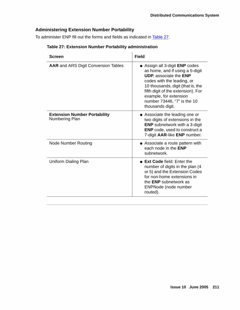
Distributed Communications System
Issue 10 June 2005 211
Administering Extension Number Portability
To administer ENP fill out the forms and fields as indicated in Table 27.
Table 27: Extension Number Portability administration
Screen Field
AAR and ARS Digit Conversion Tables ● Assign all 3-digit ENP codes as home, and if using a 5-digit UDP, associate the ENP codes with the leading, or 10 thousands, digit (that is, the fifth digit of the extension). For example, for extension number 73446, “7” is the 10 thousands digit.
Extension Number Portability Numbering Plan
● Associate the leading one or two digits of extensions in the ENP subnetwork with a 3-digit ENP code, used to construct a 7-digit AAR-like ENP number.
Node Number Routing ● Associate a route pattern with each node in the ENP subnetwork.
Uniform Dialing Plan ● Ext Code field: Enter the number of digits in the plan (4 or 5) and the Extension Codes for non-home extensions in the ENP subnetwork as ENPNode (node number routed).
Administering dedicated networks
212 Administration for Network Connectivity for Avaya Communication Manager
DCS signaling
In addition to tie-trunk connections for the transmission of voice and call-control data, DCS requires a special signaling connection to carry the information needed to make the DCS features work.
This signaling connection, or link, between two switches in a DCS network can be implemented in one of four ways:
● Over an Integrated Services Digital Network (ISDN) - Primary Rate Interface (PRI) signaling (or “D”) channel (see DCS over ISDN-PRI D-channel (DCS+)).
● Over Asynchronous PPP over analog trunks
● Over ISDN/X.25 gateway
● Over a TCP/IP— either
- point-to-point protocol (PPP) connection
or
- 10/100Base-T Ethernet connection
Gateway switch
When a DCS network uses a mixture of two or three of the different DCS signaling types, one or more switches in the network must act as a gateway. A gateway switch is connected between two switches using different signaling protocols, enabling the two end switches to communicate by converting the signaling messages between the two protocols. A gateway switch can provide conversion between two or all three of the signaling protocols, but only one protocol can be used for DCS signaling between any two switches.
DCS over ISDN-PRI D-channel (DCS+)
AT&T SDN, as well as MCI N-Quest Service provide for the transmission of the DCS protocol across the public network, as a virtual private network. DCS Over ISDN-PRI D-channel (DCS+) permits access to the public network for DCS connectivity between DCS switch nodes.
ISDN B-channel (bearer)
ISDN is a widely-adopted means of private networking that uses the 24-channel ISDN-PRI trunk with a bandwidth of 1.544 Mb/sec. Channels 1-23 are used for voice (bearer) data, digitized conversations that can be interleaved among the 23 bearer channels.
Distributed Communications System
Issue 10 June 2005 213
ISDN D-channel (signaling)
Channel 24 is reserved for call signaling messages that perform basic call set-up, maintenance, and tear-down as well as DCS+ or QSIG messages that can seamlessly integrate two switches in different locations of an enterprise network.
MA-UUI
DCS Over ISDN-PRI utilizes the Message-Associated User-to-User Information (MA-UUI) and Temporary Signaling Connections (TSC) to transport certain DCS control information (see Temporary signaling connections (TSC)). MA-UUI allows additional user-specific information to be transported along with certain ISDN call-control messages.
Note:Note: Use this feature only over DS1/E1 or T1 circuit packs that are administered to
Country Protocol Option 1, Protocol Version A (even in a private network environment) independent of what country the system is in.
DCS+ configurations
DCS+ network configurations can be:
● TCP/IP DCS network — A DCS network configured with 2 or more switches using TCP/IP (PPP or 10/100BaseT Ethernet) signaling for transporting DCS feature transparency information.
● Traditional DCS network — A DCS network configured with 2 or more switches using BX.25 signaling for transporting DCS feature transparency information.
● D-channel DCS network (private network only) — A DCS network that includes a switch using the ISDN-PRI D-channel DCS transparency information (D-channel signaling). ISDN-PRI facilities with this type of network use only private-line facilities.
● D-channel DCS network (public network access/egress) — A DCS network that includes a switch using D-channel signaling. At least one of these ISDN-PRI facilities uses a public network ISDN-PRI.
● Integrated DCS network (private network only) — A DCS network that contains a variety of switches using TCP/IP, BX.25, or D-channel signaling methods. At least one Avaya switch serves as an ISDN-PRI DCS Gateway node. This node can interwork DCS transparency information between the three signaling protocols.
An ISDN-PRI DCS Gateway node provides backward compatibility to existing traditional DCS networks.
● Integrated DCS network (public network access) — The same as D-channel DCS Network (Private Network Only), but the D-channel of at least one ISDN- PRI facility uses a public network ISDN-PRI.
Administering dedicated networks
214 Administration for Network Connectivity for Avaya Communication Manager
For more information on DCS+ configurations use these links to the ATAC 2003 Connectivity Guide:
● Associates: http://associate2.avaya.com/sales_market/tools/proposal-create/CG/
● Business Partners: https://www.avaya.com/doc/gpp/public/?_requestid=102567 (does not include a Chapter on UPS Power)
● All others: http://www.avayaups.com/ (Website outside the Avaya firewall and available to customers)
Temporary signaling connections (TSC)
A TSC provides a temporary signaling path through ISDN switches for exchanging supplementary service information on ISDN-PRI D-channels. There is no B-channel related to the connection; no data or voice transmissions take place.
There are two types of temporary signaling connections:
● Call Associated TSC
● Non-Call Associated (NCA-TSC)
Call Associated TSC
Call Associated TSC (CA-TSC) refers to a service for exchanging USER INFORMATION messages associated with an ISDN B-channel connection by the call reference value of the call control data packets. On an Avaya switch, this type of TSC is used only for DCS features on ISDN-PRI Signaling Groups administered with Supplementary Service Protocol a.
Non-Call Associated (NCA-TSC)
An NCA-TSC is a connection not related with any ISDN B-channel connections. Communication Manager supports two types of NCA-TSC that conform to two different protocol standards:
● The AT&T type of NCA-TSC is used for the DCS Over ISDN-PRI D-channel and DCS AUDIX applications. Only ISDN-PRI Signaling Groups administered with Supplementary Service Protocol a support AT&T NCA-TSCs.
An AT&T NCA-TSC is an administered virtual connection established for exchanging USER INFORMATION messages on the ISDN D-channel. Once an AT&T NCA-TSC has been administered and enabled, it is active for an extended period of time. There are two types of administered NCA-TSCs depending on their setup mechanism:
- Permanent (can be established by near-end or far-end)
- As-needed
Once enabled, a permanent NCA-TSC remains established while the system is running. If the permanent NCA-TSC drops for any reason, the system attempts to reestablish the connection. An as-needed administered NCA-TSC is established based on user request and the availability of TSC facilities. The connection drops after an administered period of inactivity.
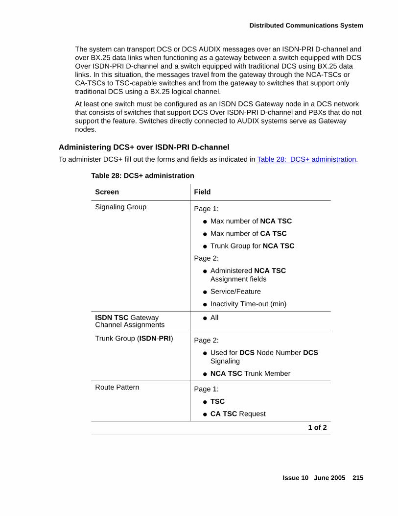
Distributed Communications System
Issue 10 June 2005 215
The system can transport DCS or DCS AUDIX messages over an ISDN-PRI D-channel and over BX.25 data links when functioning as a gateway between a switch equipped with DCS Over ISDN-PRI D-channel and a switch equipped with traditional DCS using BX.25 data links. In this situation, the messages travel from the gateway through the NCA-TSCs or CA-TSCs to TSC-capable switches and from the gateway to switches that support only traditional DCS using a BX.25 logical channel.
At least one switch must be configured as an ISDN DCS Gateway node in a DCS network that consists of switches that support DCS Over ISDN-PRI D-channel and PBXs that do not support the feature. Switches directly connected to AUDIX systems serve as Gateway nodes.
Administering DCS+ over ISDN-PRI D-channel
To administer DCS+ fill out the forms and fields as indicated in Table 28: DCS+ administration.
Table 28: DCS+ administration
Screen Field
Signaling Group Page 1:
● Max number of NCA TSC
● Max number of CA TSC
● Trunk Group for NCA TSC
Page 2:
● Administered NCA TSC Assignment fields
● Service/Feature
● Inactivity Time-out (min)
ISDN TSC Gateway Channel Assignments
● All
Trunk Group (ISDN-PRI) Page 2:
● Used for DCS Node Number DCS Signaling
● NCA TSC Trunk Member
Route Pattern Page 1:
● TSC
● CA TSC Request
1 of 2
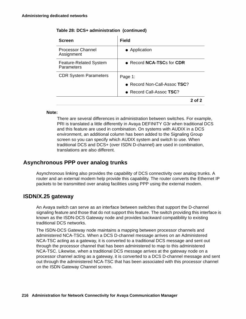
Administering dedicated networks
216 Administration for Network Connectivity for Avaya Communication Manager
Note:Note: There are several differences in administration between switches. For example,
PRI is translated a little differently in Avaya DEFINITY G3r when traditional DCS and this feature are used in combination. On systems with AUDIX in a DCS environment, an additional column has been added to the Signaling Group screen so you can specify which AUDIX system and switch to use. When traditional DCS and DCS+ (over ISDN D-channel) are used in combination, translations are also different.
Asynchronous PPP over analog trunks
Asynchronous linking also provides the capability of DCS connectivity over analog trunks. A router and an external modem help provide this capability. The router converts the Ethernet IP packets to be transmitted over analog facilities using PPP using the external modem.
ISDN/X.25 gateway
An Avaya switch can serve as an interface between switches that support the D-channel signaling feature and those that do not support this feature. The switch providing this interface is known as the ISDN-DCS Gateway node and provides backward compatibility to existing traditional DCS networks.
The ISDN-DCS Gateway node maintains a mapping between processor channels and administered NCA-TSCs. When a DCS D-channel message arrives on an Administered NCA-TSC acting as a gateway, it is converted to a traditional DCS message and sent out through the processor channel that has been administered to map to this administered NCA-TSC. Likewise, when a traditional DCS message arrives at the gateway node on a processor channel acting as a gateway, it is converted to a DCS D-channel message and sent out through the administered NCA-TSC that has been associated with this processor channel on the ISDN Gateway Channel screen.
Processor Channel Assignment
● Application
Feature-Related System Parameters
● Record NCA-TSCs for CDR
CDR System Parameters Page 1:
● Record Non-Call-Assoc TSC?
● Record Call-Assoc TSC?
Table 28: DCS+ administration (continued)
Screen Field
2 of 2
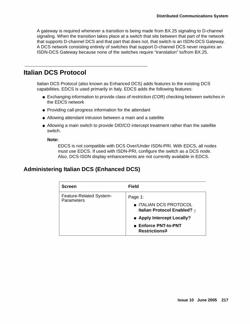
Distributed Communications System
Issue 10 June 2005 217
A gateway is required whenever a transition is being made from BX.25 signaling to D-channel signaling. When the transition takes place at a switch that sits between that part of the network that supports D-channel DCS and that part that does not, that switch is an ISDN-DCS Gateway. A DCS network consisting entirely of switches that support D-channel DCS never requires an ISDN-DCS Gateway because none of the switches require “translation” to/from BX.25.
Italian DCS Protocol
Italian DCS Protocol (also known as Enhanced DCS) adds features to the existing DCS capabilities. EDCS is used primarily in Italy. EDCS adds the following features:
● Exchanging information to provide class of restriction (COR) checking between switches in the EDCS network
● Providing call-progress information for the attendant
● Allowing attendant intrusion between a main and a satellite
● Allowing a main switch to provide DID/CO intercept treatment rather than the satellite switch.
Note:Note: EDCS is not compatible with DCS Over/Under ISDN-PRI. With EDCS, all nodes
must use EDCS. If used with ISDN-PRI, configure the switch as a DCS node. Also, DCS-ISDN display enhancements are not currently available in EDCS.
Administering Italian DCS (Enhanced DCS)
Screen Field
Feature-Related System- Parameters
Page 1:
● ITALIAN DCS PROTOCOL Italian Protocol Enabled? y
● Apply Intercept Locally?
● Enforce PNT-to-PNT Restrictions?
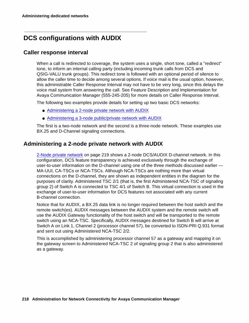
Administering dedicated networks
218 Administration for Network Connectivity for Avaya Communication Manager
DCS configurations with AUDIX
Caller response interval
When a call is redirected to coverage, the system uses a single, short tone, called a "redirect" tone, to inform an internal calling party (including incoming trunk calls from DCS and QSIG-VALU trunk groups). This redirect tone is followed with an optional period of silence to allow the caller time to decide among several options. If voice mail is the usual option, however, this administrable Caller Response Interval may not have to be very long, since this delays the voice mail system from answering the call. See Feature Description and Implementation for Avaya Communication Manager (555-245-205) for more details on Caller Response Interval.
The following two examples provide details for setting up two basic DCS networks:
● Administering a 2-node private network with AUDIX
● Administering a 3-node public/private network with AUDIX
The first is a two-node network and the second is a three-node network. These examples use BX.25 and D-Channel signaling connections.
Administering a 2-node private network with AUDIX
2-Node private network on page 219 shows a 2-node DCS/AUDIX D-channel network. In this configuration, DCS feature transparency is achieved exclusively through the exchange of user-to-user information on the D-channel using one of the three methods discussed earlier — MA-UUI, CA-TSCs or NCA-TSCs. Although NCA-TSCs are nothing more than virtual connections on the D-channel, they are shown as independent entities in the diagram for the purposes of clarity. Administered TSC 2/1 (that is, the first Administered NCA-TSC of signaling group 2) of Switch A is connected to TSC 4/1 of Switch B. This virtual connection is used in the exchange of user-to-user information for DCS features not associated with any current B-channel connection.
Notice that for AUDIX, a BX.25 data link is no longer required between the host switch and the remote switch(es). AUDIX messages between the AUDIX system and the remote switch will use the AUDIX Gateway functionality of the host switch and will be transported to the remote switch using an NCA-TSC. Specifically, AUDIX messages destined for Switch B will arrive at Switch A on Link 1, Channel 2 (processor channel 57), be converted to ISDN-PRI Q.931 format and sent out using Administered NCA-TSC 2/2.
This is accomplished by administering processor channel 57 as a gateway and mapping it on the gateway screen to Administered NCA-TSC 2 of signaling group 2 that is also administered as a gateway.
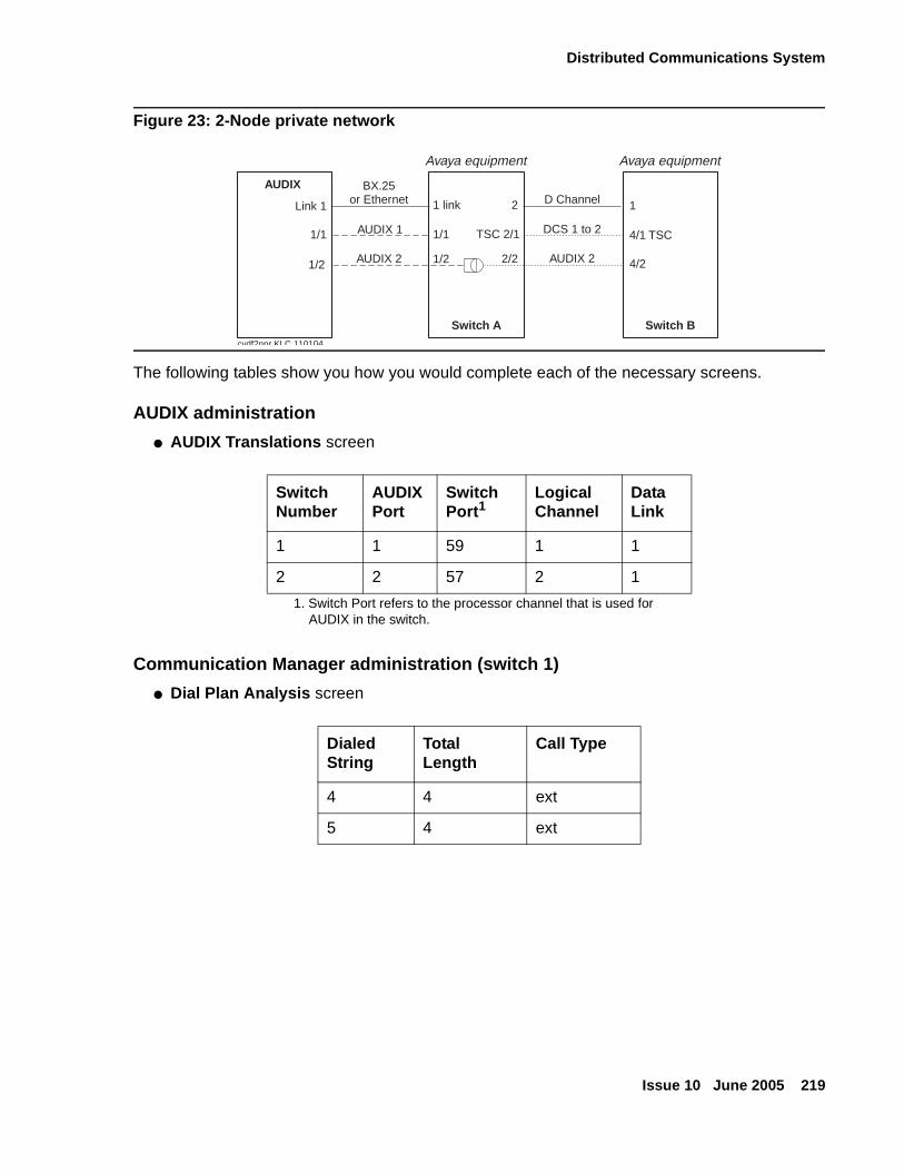
Distributed Communications System
Issue 10 June 2005 219
Figure 23: 2-Node private network
The following tables show you how you would complete each of the necessary screens.
AUDIX administration
● AUDIX Translations screen
Communication Manager administration (switch 1)
● Dial Plan Analysis screen
Switch Number
AUDIX Port
Switch Port1
1. Switch Port refers to the processor channel that is used for AUDIX in the switch.
Logical Channel
Data Link
1 1 59 1 1
2 2 57 2 1
Dialed String
Total Length
Call Type
4 4 ext
5 4 ext
AUDIX
Switch A Switch B
Link 1
1/1
1/2 1/2
BX.25or Ethernet
AUDIX 1
AUDIX 2
Avaya equipment Avaya equipment
1 link
1/1
2
TSC 2/1
2/2
D Channel
DCS 1 to 2
AUDIX 2
1
4/1 TSC
4/2
cydf2npr KLC 110104
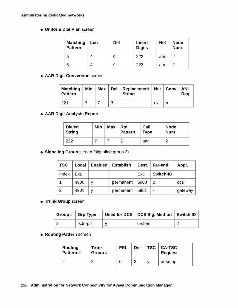
Administering dedicated networks
220 Administration for Network Connectivity for Avaya Communication Manager
● Uniform Dial Plan screen
● AAR Digit Conversion screen
● AAR Digit Analysis Report
● Signaling Group screen (signaling group 2)
● Trunk Group screen
● Routing Pattern screen
MatchingPattern
Len Del InsertDigits
Net Node Num
5 4 0 222 aar 2
6 4 0 223 aar 2
MatchingPattern
Min Max Del ReplacementString
Net Conv ANI Req
221 7 7 3 - ext n
Dialed String
Min Max Rte Pattern
Call Type
Node Num
222 7 7 2 aar 2
TSC Local Enabled Establish Dest. Far-end Appl.
Index Ext. Ext. Switch-ID
1 4900 y permanent 5900 2 dcs
2 4901 y permanent 5901 - gateway
Group # Grp Type Used for DCS DCS Sig. Method Switch ID
2 isdn-pri y d-chan 2
Routing Pattern #
Trunk Group #
FRL Del TSC CA-TSC Request
2 2 0 3 y at-setup
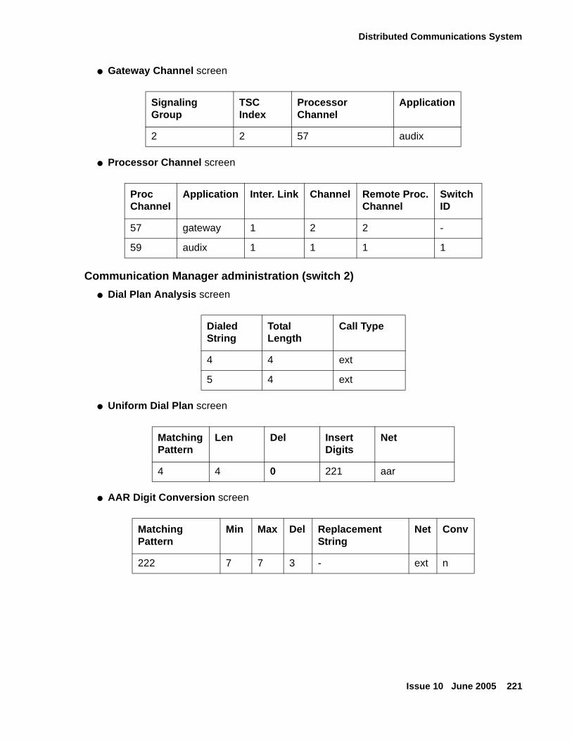
Distributed Communications System
Issue 10 June 2005 221
● Gateway Channel screen
● Processor Channel screen
Communication Manager administration (switch 2)
● Dial Plan Analysis screen
● Uniform Dial Plan screen
● AAR Digit Conversion screen
Signaling Group
TSC Index
Processor Channel
Application
2 2 57 audix
Proc Channel
Application Inter. Link Channel Remote Proc.Channel
Switch ID
57 gateway 1 2 2 -
59 audix 1 1 1 1
Dialed String
Total Length
Call Type
4 4 ext
5 4 ext
MatchingPattern
Len Del InsertDigits
Net
4 4 0 221 aar
Matching Pattern
Min Max Del Replacement String
Net Conv
222 7 7 3 - ext n
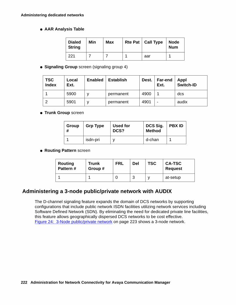
Administering dedicated networks
222 Administration for Network Connectivity for Avaya Communication Manager
● AAR Analysis Table
● Signaling Group screen (signaling group 4)
● Trunk Group screen
● Routing Pattern screen
Administering a 3-node public/private network with AUDIX
The D-channel signaling feature expands the domain of DCS networks by supporting configurations that include public network ISDN facilities utilizing network services including Software Defined Network (SDN). By eliminating the need for dedicated private line facilities, this feature allows geographically dispersed DCS networks to be cost effective. Figure 24: 3-Node public/private network on page 223 shows a 3-node network.
Dialed String
Min Max Rte Pat Call Type Node Num
221 7 7 1 aar 1
TSC Index
Local Ext.
Enabled Establish Dest. Far-endExt.
Appl Switch-ID
1 5900 y permanent 4900 1 dcs
2 5901 y permanent 4901 - audix
Group #
Grp Type Used for DCS?
DCS Sig. Method
PBX ID
1 isdn-pri y d-chan 1
Routing Pattern #
Trunk Group #
FRL Del TSC CA-TSC Request
1 1 0 3 y at-setup
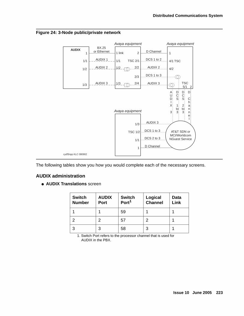
Distributed Communications System
Issue 10 June 2005 223
Figure 24: 3-Node public/private network
The following tables show you how you would complete each of the necessary screens.
AUDIX administration
● AUDIX Translations screen
Switch Number
AUDIX Port
Switch Port1
1. Switch Port refers to the processor channel that is used for AUDIX in the PBX.
Logical Channel
Data Link
1 1 59 1 1
2 2 57 2 1
3 3 58 3 1
AUDIX1
1/1
1/2 1/2
1/3 1/3
BX.25or Ethernet
AUDIX 1
AUDIX 2
AUDIX 3
1 link
1/1
2
TSC 2/1
2/2
2/3
2/4
D Channel
DCS 1 to 2
DCS 2 to 3
D Channel
AUDIX 2
DCS 1 to 3
DCS 1 to 3
AUDIX 3
AUDIX 3
1
4/1 TSC
4/2
TSC5/1 2
AUDIX
3
DCS
1to3
DCS
2to3
D
Channel
cydf3npp KLC 080902
AT&T SDN orMCI/WorldcomNGuest Service
Avaya equipment Avaya equipment
1/3
TSC 1/2
1/1
1
Avaya equipment
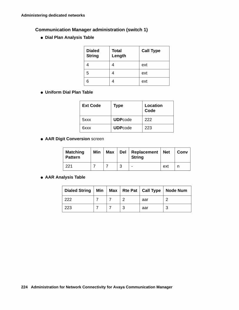
Administering dedicated networks
224 Administration for Network Connectivity for Avaya Communication Manager
Communication Manager administration (switch 1)
● Dial Plan Analysis Table
● Uniform Dial Plan Table
● AAR Digit Conversion screen
● AAR Analysis Table
Dialed String
Total Length
Call Type
4 4 ext
5 4 ext
6 4 ext
Ext Code Type Location Code
5xxx UDPcode 222
6xxx UDPcode 223
Matching Pattern
Min Max Del ReplacementString
Net Conv
221 7 7 3 - ext n
Dialed String Min Max Rte Pat Call Type Node Num
222 7 7 2 aar 2
223 7 7 3 aar 3
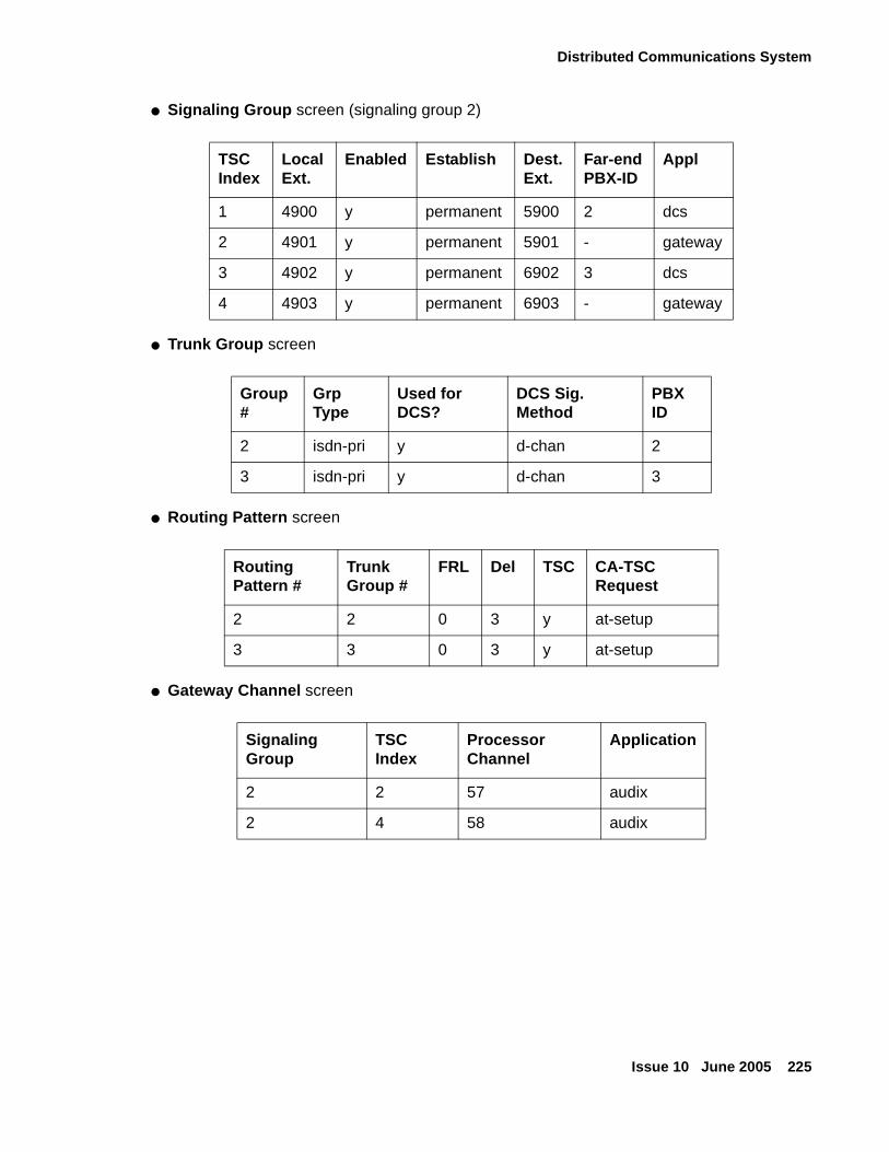
Distributed Communications System
Issue 10 June 2005 225
● Signaling Group screen (signaling group 2)
● Trunk Group screen
● Routing Pattern screen
● Gateway Channel screen
TSC Index
LocalExt.
Enabled Establish Dest. Ext.
Far-end PBX-ID
Appl
1 4900 y permanent 5900 2 dcs
2 4901 y permanent 5901 - gateway
3 4902 y permanent 6902 3 dcs
4 4903 y permanent 6903 - gateway
Group #
Grp Type
Used for DCS?
DCS Sig. Method
PBX ID
2 isdn-pri y d-chan 2
3 isdn-pri y d-chan 3
Routing Pattern #
Trunk Group #
FRL Del TSC CA-TSC Request
2 2 0 3 y at-setup
3 3 0 3 y at-setup
Signaling Group
TSC Index
Processor Channel
Application
2 2 57 audix
2 4 58 audix
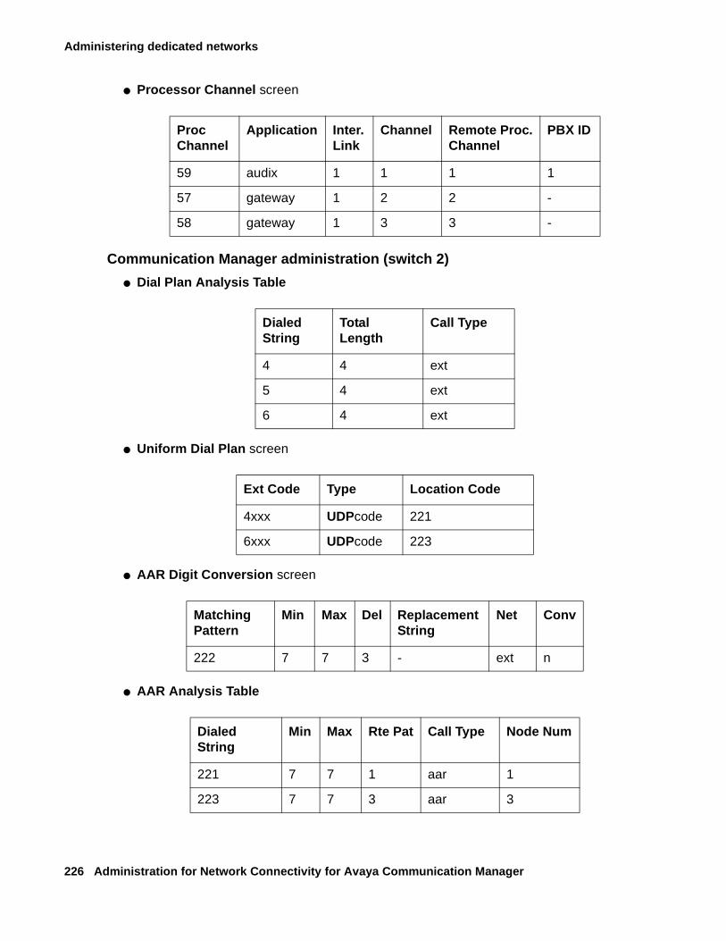
Administering dedicated networks
226 Administration for Network Connectivity for Avaya Communication Manager
● Processor Channel screen
Communication Manager administration (switch 2)
● Dial Plan Analysis Table
● Uniform Dial Plan screen
● AAR Digit Conversion screen
● AAR Analysis Table
Proc Channel
Application Inter.Link
Channel Remote Proc.Channel
PBX ID
59 audix 1 1 1 1
57 gateway 1 2 2 -
58 gateway 1 3 3 -
Dialed String
Total Length
Call Type
4 4 ext
5 4 ext
6 4 ext
Ext Code Type Location Code
4xxx UDPcode 221
6xxx UDPcode 223
Matching Pattern
Min Max Del Replacement String
Net Conv
222 7 7 3 - ext n
Dialed String
Min Max Rte Pat Call Type Node Num
221 7 7 1 aar 1
223 7 7 3 aar 3
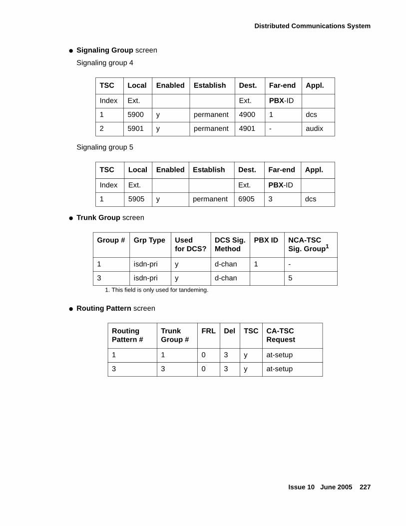
Distributed Communications System
Issue 10 June 2005 227
● Signaling Group screen
Signaling group 4
Signaling group 5
● Trunk Group screen
● Routing Pattern screen
TSC Local Enabled Establish Dest. Far-end Appl.
Index Ext. Ext. PBX-ID
1 5900 y permanent 4900 1 dcs
2 5901 y permanent 4901 - audix
TSC Local Enabled Establish Dest. Far-end Appl.
Index Ext. Ext. PBX-ID
1 5905 y permanent 6905 3 dcs
Group # Grp Type Usedfor DCS?
DCS Sig.Method
PBX ID NCA-TSC Sig. Group1
1. This field is only used for tandeming.
1 isdn-pri y d-chan 1 -
3 isdn-pri y d-chan 5
Routing Pattern #
Trunk Group #
FRL Del TSC CA-TSC Request
1 1 0 3 y at-setup
3 3 0 3 y at-setup
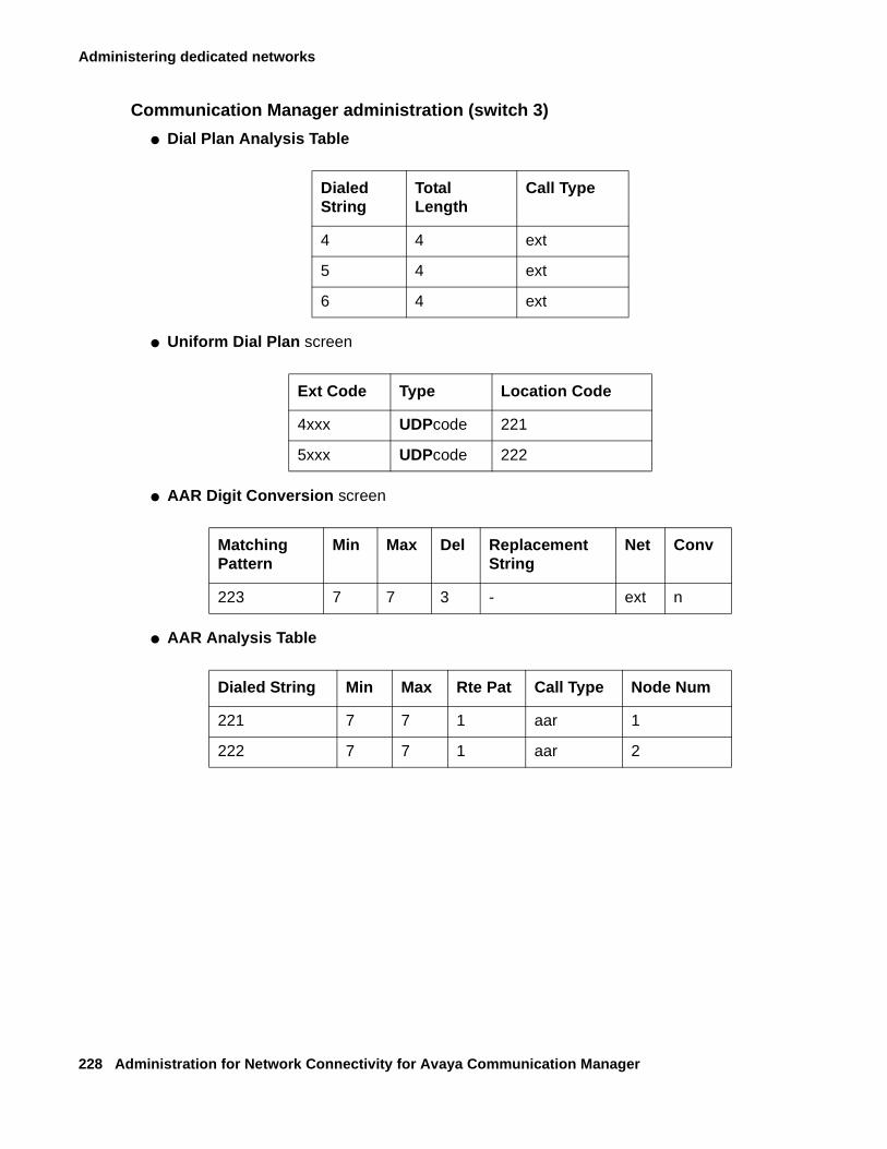
Administering dedicated networks
228 Administration for Network Connectivity for Avaya Communication Manager
Communication Manager administration (switch 3)
● Dial Plan Analysis Table
● Uniform Dial Plan screen
● AAR Digit Conversion screen
● AAR Analysis Table
Dialed String
Total Length
Call Type
4 4 ext
5 4 ext
6 4 ext
Ext Code Type Location Code
4xxx UDPcode 221
5xxx UDPcode 222
Matching Pattern
Min Max Del Replacement String
Net Conv
223 7 7 3 - ext n
Dialed String Min Max Rte Pat Call Type Node Num
221 7 7 1 aar 1
222 7 7 1 aar 2
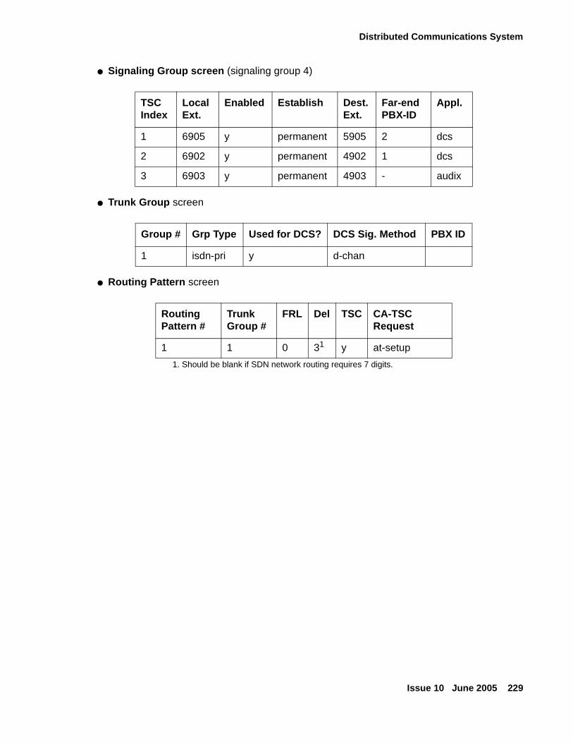
Distributed Communications System
Issue 10 June 2005 229
● Signaling Group screen (signaling group 4)
● Trunk Group screen
● Routing Pattern screen
TSC Index
LocalExt.
Enabled Establish Dest. Ext.
Far-end PBX-ID
Appl.
1 6905 y permanent 5905 2 dcs
2 6902 y permanent 4902 1 dcs
3 6903 y permanent 4903 - audix
Group # Grp Type Used for DCS? DCS Sig. Method PBX ID
1 isdn-pri y d-chan
Routing Pattern #
Trunk Group #
FRL Del TSC CA-TSC Request
1 1 0 31
1. Should be blank if SDN network routing requires 7 digits.
y at-setup
Administering dedicated networks
230 Administration for Network Connectivity for Avaya Communication Manager
QSIGThe main QSIG topics in this section include
● Overview
● QSIG/DCS interworking
● Offer level functionality
● Basic call setup
● QSIG Centralized INTUITY AUDIX
● Path Replacement
● Transfer into QSIG Message Center
● Value-Added (VALU) MSI
● QSIG Centralized Attendant Services (CAS)
● Call-independent Signaling Connection (CISCs)
● About Non-Call Associated Temporary Signaling Connection (NCA-TSC)
● Administering QSIG
● Migrating to QSIG: some considerations
Note:Note: See Chapter 6: Feature interactions and considerations for feature interaction
information and other considerations when using QSIG.
OverviewQSIG is the generic name for a family of signaling protocols. The Q reference point or interface is the logical point where signaling is passed between two peers in a private network. QSIG signaling allows certain features to work in a single-vendor or multi-vendor network.
In the mid-1980s the networking signaling protocols of PBX manufacturers’ were proprietary, causing problems for customers using several different PBX systems in their networks. Under the auspices of the ISDN Private Network Systems (IPNS) Forum, an initiative was started in Europe to create a standardized network signaling protocol to link dissimilar PBXs intelligently. The resulting signaling standard, QSIG, supports:
● Basic call set-up and tear-down
● Limited-digit dialing across PBXs through a common dial plan
● Sending and receiving telephone display information (for example calling name and number)
● Feature-transparency for a limited set of features
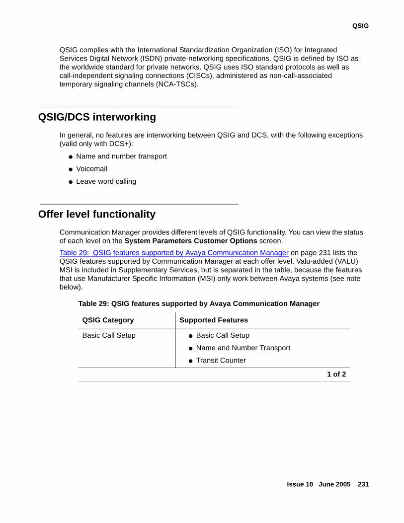
QSIG
Issue 10 June 2005 231
QSIG complies with the International Standardization Organization (ISO) for Integrated Services Digital Network (ISDN) private-networking specifications. QSIG is defined by ISO as the worldwide standard for private networks. QSIG uses ISO standard protocols as well as call-independent signaling connections (CISCs), administered as non-call-associated temporary signaling channels (NCA-TSCs).
QSIG/DCS interworking
In general, no features are interworking between QSIG and DCS, with the following exceptions (valid only with DCS+):
● Name and number transport
● Voicemail
● Leave word calling
Offer level functionality
Communication Manager provides different levels of QSIG functionality. You can view the status of each level on the System Parameters Customer Options screen.
Table 29: QSIG features supported by Avaya Communication Manager on page 231 lists the QSIG features supported by Communication Manager at each offer level. Valu-added (VALU) MSI is included in Supplementary Services, but is separated in the table, because the features that use Manufacturer Specific Information (MSI) only work between Avaya systems (see note below).
Table 29: QSIG features supported by Avaya Communication Manager
QSIG Category Supported Features
Basic Call Setup ● Basic Call Setup
● Name and Number Transport
● Transit Counter
1 of 2
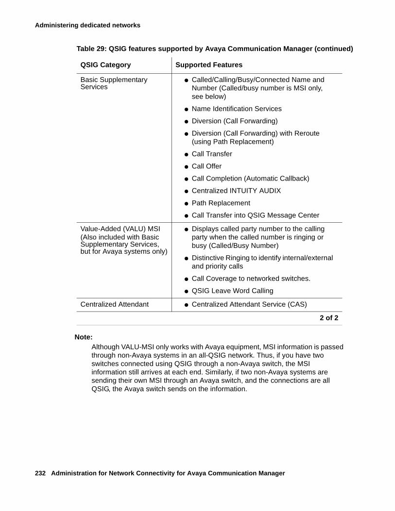
Administering dedicated networks
232 Administration for Network Connectivity for Avaya Communication Manager
Note:Note: Although VALU-MSI only works with Avaya equipment, MSI information is passed
through non-Avaya systems in an all-QSIG network. Thus, if you have two switches connected using QSIG through a non-Avaya switch, the MSI information still arrives at each end. Similarly, if two non-Avaya systems are sending their own MSI through an Avaya switch, and the connections are all QSIG, the Avaya switch sends on the information.
Basic Supplementary Services
● Called/Calling/Busy/Connected Name and Number (Called/busy number is MSI only, see below)
● Name Identification Services
● Diversion (Call Forwarding)
● Diversion (Call Forwarding) with Reroute (using Path Replacement)
● Call Transfer
● Call Offer
● Call Completion (Automatic Callback)
● Centralized INTUITY AUDIX
● Path Replacement
● Call Transfer into QSIG Message Center
Value-Added (VALU) MSI(Also included with Basic Supplementary Services, but for Avaya systems only)
● Displays called party number to the calling party when the called number is ringing or busy (Called/Busy Number)
● Distinctive Ringing to identify internal/external and priority calls
● Call Coverage to networked switches.
● QSIG Leave Word Calling
Centralized Attendant ● Centralized Attendant Service (CAS)
Table 29: QSIG features supported by Avaya Communication Manager (continued)
QSIG Category Supported Features
2 of 2
QSIG
Issue 10 June 2005 233
Basic call setup
Transit counter (TC)
Communication Manager provides QSIG TC as defined in ISO/IEC 6B032 and 6B033. It prevents infinite looping, connections giving poor transmission performance, and inefficient use of network resources.
TC is invoked automatically for ISDN basic calls and the Route Pattern screen indicates the number of switches through which a call may be routed.
Basic supplementary services
Called/calling/busy/connected name and number
Enables the calling party to see the name and number of the called party at the following times:
● While the call is ringing at the called party’s terminal
● While listening to a busy tone because the called party’s terminal was busy
Called/calling/busy/connected name is similar to the display provided for local on-switch calls, as well as for the DCS calls, with the following exceptions:
● Names longer than 15 characters are truncated; only the first 15 characters display.
● The number does not display unless QSIG VALU is enabled.
Name and number identification
Name and number identification allows a switch to send and receive the calling number, calling name, connected number, and connected name. Name and number identification displays up to 15 characters for the calling and connected name and up to 15 digits for the calling and connected number across ISDN interfaces.
You can administer outgoing calls as “yes”, “no”, or “restricted.” Restricted means that Communication Manager sends the information but sends it “presentation restricted,” which indicates to the receiving switch that the information should not be displayed. A received restricted number is included on the Call Detail Record (CDR).
Administering dedicated networks
234 Administration for Network Connectivity for Avaya Communication Manager
Transit switch information
When Avaya equipment acts as a transit switch, the QSIG standards require it to pass on all supplementary service information that is not addressed to it. This includes name information. (A “transit” switch is a switch that routes an incoming call administered for Supplementary Services Protocol B to a trunk also administered for Supplementary Services Protocol B.) However, Basic Call Setup and number information is subject to modification by the transit switch. This means that trunk group administration on a transit switch does not override incoming name information, but may override incoming number information (as long as this does not lower the restriction on the information).
For example, if a non-restricted calling name and number are received by Avaya equipment acting as a transit switch, and if the outgoing trunk is administered for presentation restricted for both name and number, the number is passed on as “restricted” and name is passed on as “unrestricted.”
Tandem switch information
However, in the case of tandemed calls (calls involving two ISDN trunks that are not both administered for Supplementary Service Protocol B), trunk group administration may override both incoming name and number information, as long as doing so does not lower the restriction on the information.
For example, a tandemed call that comes in with restricted name information is sent out with restricted name information even if the outgoing trunk is administered for presentation unrestricted. However, non-restricted data is sent restricted if the trunk group administration is set for “presentation restricted.”
ISDN numbering formats
Numbering is specified on the ISDN Public-Unknown-Numbering and/or ISDN Private-Numbering screens. The numbering screen you use depends on how you administer the ISDN trunk group Numbering Format field.
However, if you format the Called Party Number with public numbering, the Calling/Connected Party Number is created in the public format even if you specify “private” on the ISDN trunk group screen. This provides the caller or called party a number that can be used to reach the other party. Since the call routes through the public network, the public Calling/Connected Party Number is a more accurate address.
Diversion (call forwarding)
Call forwarding works over a QSIG network.
When a call has already been forwarded 3 times over a QSIG trunk, it is not forwarded again but instead terminates at the final forwarded-to terminal. Remote activation and deactivation of this feature are not supported.
QSIG
Issue 10 June 2005 235
Diversion (call forwarding) with rerouting
A forwarded call can be rerouted in a private network to find a more cost-effective or resource-efficient path.
Note:Note: A forwarded call is typically not rerouted through the system that controls the
forwarding party. This impacts certain features such as Call Coverage because that system no longer has control over the call. For example, the call cannot follow the forwarding user’s coverage path if the forwarded call is not answered; instead, it follows the forwarded-to user’s coverage path.
Call Transfer
QSIG Call Transfer is based on the current Communication Manager Transfer and Trunk-to-Trunk Transfer features. QSIG Transfer signaling occurs as long as one of the calls involves a QSIG trunk between the two switches.
Once a call is transferred, the transferring switch is unnecessary. Additional Network Feature-Path Replacement (PR) is invoked automatically to connect the transferred call more efficiently in the private network. QSIG Call Transfer attempts to connect the two parties more efficiently and drops the unnecessary switches.
QSIG Call Transfer provides the same functionality as the standard Transfer or Trunk-to-Trunk Transfer features, with additional call information available to the connected parties after the transfer completes.
Depending upon QSIG Identification Services administration, the connected parties’ displays show each other’s name and/or number. If the name and number are not available, the display of a connected party updates with the name of the involved trunk group.
Call Offer
This feature is the QSIG equivalent of Call Waiting.
A Private Telecommunication Network (PTN) offers up to four ways of invoking QSIG Call Offer (CO) (listed below). Communication Manager uses only the first method.
● Network invocation (immediate) — the PTN automatically invokes CO whenever the calling user makes a call to a user that is busy, if required by the service profile of the calling user.
● Consultation — the calling user, on being informed that a call has failed because it is busy at the destination and that CO may be possible, is able, within a defined time period (consultation timer), to request invocation of CO.
Administering dedicated networks
236 Administration for Network Connectivity for Avaya Communication Manager
● Immediate invocation — the calling user is able to request invocation of CO as part of the initial call set-up.
● Network invocation (delayed) — the network, having informed the calling user that a call has failed because it is busy at the destination, invokes CO automatically unless the calling user initiates call clearing within a defined time period (automatic call offer invocation timer).
The effect of QSIG CO on the terminating end is similar to the DCS Call Waiting feature with the exception that for Call Waiting, the calling side (user or switch) does not have to convey any special message to invoke the feature. The Call Waiting Termination feature is driven based on the terminating user (for instance, single line analog set user with Call Waiting enabled).
For QSIG Call Offer, the system takes advantage of the additional information available from the far end, if QSIG Call Offer invokes successfully, and provides similar information to the calling user as the Call Waiting feature provides for internal calls, with the exception that the display update will be “offered” instead of “wait” to reflect invocation of QSIG Call Offer service.
On successful invocation of the QSIG Call Offer service, the system provides the following:
● To the busy analog set user, the same tone as Call Waiting Termination feature.
● To the busy multi call-appearance set (for instance, at least one call-appearance is busy for an active call and at least one call-appearance is available for incoming calls) user, the available appearance rings normally.
For incoming QSIG calls, the QSIG Call Offer service may use path retention which is a generic mechanism to retain the signaling connection so that the originating party can decide whether to invoke the supplementary service. The network connection can be retained for more than one of the supplementary services for which path retention has been invoked.
Call Completion
Completion of Calls to Busy Subscribers (CCBS) and Completion of Calls on No Reply (CCNR) are the equivalent QSIG features of Automatic Callback (ACB) on busy and ACB on no answer, respectively.
An analog voice terminal user activates CCBS or CCNR by pressing the Recall button or flashing the switchhook and then dialing the Automatic Callback (ACB) activation feature access code. An analog user can activate only one ACB call at any given time.
A multi-appearance voice terminal user can activate CCBS or CCNR for the number of ACB buttons assigned to the terminal.
QSIG
Issue 10 June 2005 237
CC options
QSIG CC has the following major options that are negotiated between the Originating and the Terminating switch:
● Path reservation — there are two methods of establishing the CC call:
- Path reservation method
- Non-reservation method
● Retention of signaling connection — there are two ways in which CC uses call independent signaling connections:
- Connection retention method
- Connection release method
● Service retention — there are two possible behaviors when User B is found to be busy again after User A responds to CC recall:
- Service retention method
- Service cancellation method
As an originating switch for QSIG CC, Communication Manager selects the following major options:
● Non-reservation method for the Path Retention option
● Connection release method for the retention of signaling connection option
● Service cancellation method for the Service Retention option
As a Terminating switch for QSIG CC, Communication Manager selects the following major options:
● Non-reservation method for the Path Retention option
● Either the connection release method or the connection retention method for the retention of signaling connection option, depending on which the originating switch requests.
● Service cancellation method for the Service Retention option
Path Retention
Path Retention is a generic mechanism for retaining a network connection that can be used by supplementary services during call establishment.
The originating switch invokes path retention for one supplementary service or for several simultaneous supplementary services. Invoking a particular supplementary service means retaining the network connection, if the terminating switch encounters the appropriate conditions. The originating switch is informed of the reason for retaining the connection. It then decides (for example, by consulting the calling user) whether to invoke the supplementary service. Under some circumstances, in which the network connection is retained, more than one of the supplementary services for which path retention has been invoked may be applicable.
Administering dedicated networks
238 Administration for Network Connectivity for Avaya Communication Manager
Successive retentions of the network connection by the terminating switch following a single path-retention invocation by the originating switch are possible. This is a result of different conditions being encountered at the terminating switch. When an attempt is made to invoke a supplementary service for which the network connection has been retained, a further condition can be encountered that can cause the network connection to be retained again for the same or a different supplementary service.
Path retention is specified in terms of a Path Retention entity existing within the coordination function at the originating switch and at the terminating switch.
QSIG Centralized INTUITY AUDIX
QSIG allows users on a remote node (served user switch) to “cover” to an INTUITY AUDIX system on another node (message center switch). The original calling party information, called party information, and reason for coverage is provided to the INTUITY AUDIX system so that each is identified properly during message recording/retrieval.
To use a centralized INTUITY AUDIX system, you must use QSIG Diversion. On a served user switch, the call goes to call coverage using Diversion to the hunt group assigned to the INTUITY AUDIX system on the message center switch. Then the message center switch sends all the appropriate information to the INTUITY AUDIX system so that it correctly answers the call.
QSIG Centralized INTUITY AUDIX also uses path optimization using QSIG Diversion with Reroute.
Transfer into INTUITY AUDIX works when transferring from a served-user switch into an INTUITY AUDIX system at the message center switch.
What you get with QSIG Centralized INTUITY AUDIX
● Calls to users on a branch cover or forward correctly and are answered by the INTUITY AUDIX system:
- With a personalized greeting
- With an appropriate busy or not available greeting, depending upon the reason the call was redirected
Caller can leave a message for the called party.
● Once a subscriber logs into the INTUITY AUDIX system (by dialing the INTUITY AUDIX number and entering the extension and password), the subscriber can perform the following activities:
- Listen to or delete messages (voice, fax, or text).
- Leave a message for other subscribers on the same INTUITY AUDIX system without calling them.
- Forward a message to another subscriber on the same INTUITY AUDIX system.
QSIG
Issue 10 June 2005 239
- Access the INTUITY AUDIX directory to address a message (*A).
- Access the INTUITY AUDIX directory to find a subscriber’s extension (**N).
- Record or change his/her greeting.
- Transfer out of INTUITY AUDIX system (*T or 0).
● Message Waiting Indication (typically a lamp, but may also be a stutter dial tone or display) indicates the presence of new messages.
If another vendor’s system, acting as a served user switch, does not provide this functionality, the end user will not receive an MWI indication.I
● When a remote subscriber logs in to an INTUITY AUDIX system from the subscriber’s phone, the subscriber does not need to enter his or her extension.
Instead of entering the extension, *, the password, and *, the subscriber can enter *, the password, and then #.
● Leave Word Calling works for users on a single switch, and across served user switches.
With Release 11 or newer software, LWC will work across a QSIG network.
What you do not get with QSIG Centralized AUDIX
● With Release 11 or newer software, Transfer into INTUITY AUDIX does not work from a served-user switch.
Other QSIG Centralized Messaging
With a QSIG centralized messaging system, the remote switch is called a served user switch. The messaging system connected to the network using the QSIG protocol is called the message center switch. The Octel Serenade is such a messaging system.
QSIG allows an Avaya switch to be a served user switch of a non-Avaya message center switch. Therefore, when the messaging system is the message center switch, it can serve the Avaya switch if that messaging system has a QSIG interface. The Octel Serenade is such a messaging system.
For users in a QSIG messaging network, only one message center can be administered for each Avaya served user switch on all-Avaya platforms.
With path optimization using QSIG Diversion with Reroute, the system will attempt to reroute a call when the following options are enabled:
● ISDN-PRI or ISDN-BRI (qsig-mwi type of hunt group)
● QSIG Basic Call Setup
● QSIG Supplementary Services with Rerouting
Administering dedicated networks
240 Administration for Network Connectivity for Avaya Communication Manager
Path Replacement
Path Replacement (PR) is the process of routing an established call over a new, more efficient path, after which the old call is torn down leaving those resources free. Path Replacement offers customers potential savings by routing calls more efficiently, saving resources and trunk usage.
Path Replacement occurs with Call Transfer, and in the following cases:
● Call forwarding by forward switching supplementary service, including the case where Call Diversion by Rerouting fails, and call forwarding is accomplished using forward switching
● Gateway scenarios where Avaya equipment, serving as an incoming or outgoing gateway, invokes PR to optimize the path between the gateways
● Calls in queue/vector processing even though no true user is on the call yet
● QSIG Look-ahead Interflow call, Best Service Route call, or adjunct route
! CAUTION:CAUTION: Depending on the version of Call Management System (CMS) you are using,
some calls may go unrecorded if you administer your system for Path Replacement in queue/vector processing. Please see your Avaya representative for more information.
Communication Manager provides QSIG Path Replacement (PR) as defined in ISO/IEC 13863 and 13874. With this feature, a call’s connections between switches in a private network can be replaced with new connections while the call is active.
PR is invoked when a call is transferred and improvements may be made in the routes. For example, after a call is transferred, the two parties on the transferred call can be connected directly and the unnecessary trunks are dropped off the call.
PR requires Rerouting (RR) to be turned on in both switches. The routing administered at the endpoints allows for a more efficient route connection. In some cases, where all or some of the original route is the most effective route, Path Retention is invoked.
PR selects the best route based on the preference assigned to routes in the route pattern form. Least cost Supplementary Service B (SSB) routes must be first, followed by more expensive routes.
Note:Note: When routes to SSB trunks are included with routes to non-SSB trunks, SSB
trunks must appear first on the Route Pattern screen. This is because as soon as PR encounters a non-SSB trunk in the route pattern, it stops looking.
Class of Restriction (COR) and Facility Restriction Levels (FRL) are followed in routing calls. PR is not invoked on data calls because there is a period of time when information can be lost.
QSIG
Issue 10 June 2005 241
Transfer into QSIG Message Center
This feature uses QSIG Call Transfer, along with a manufacturer-specific information (MSI) message, to transfer a call directly into a subscriber’s mailbox, when the voice mail system is connected to the served user switch by a QSIG link. The voice mail system must be an Avaya system that supports the QSIG transfer into QSIG Message Center MSI operation.
Note:Note: This feature currently works only with the Octel 200/300 Serenade voice mail
system. This feature does not work with a QSIG Centralized INTUITY AUDIX system, unless the system is at R11 or newer.
The entire route must be QSIG, from the switch activating Transfer into Message Center to the message center switch/ voice mail system.
Value-Added (VALU) MSI
Value-Added (VALU) Manufacturer-specific information (MSI) adds the following feature transparency to QSIG networks:
● Called/busy number — The system sends and displays across the network the called party’s number to the calling party during alerting. It updates the display to “connected number” when the called party answers the call. It also sends and displays a busy party’s number. This serves to confirm to the caller that he or she dialed the correct number.
The called/busy number feature is an extension to QSIG called/busy name. For additional information, see Name and number identification on page 233.
The called/busy number never displays alone; it displays only if the called/busy name is available (for instance, received from the far end and marked “presentation allowed”). In contrast, upon receipt of a calling number without a calling name, the number displays with the words “CALL FROM.”
● Distinctive ringing — QSIG VALU provides two kinds of distinctive ringing across the network: internal and external.
● Call coverage — The system allows calls to be covered by extensions across the network. This coverage operates similarly to DCS Call Coverage, though the connectivity of the network itself differs. If administered, path replacement is invoked after coverage.
Administering dedicated networks
242 Administration for Network Connectivity for Avaya Communication Manager
QSIG Centralized Attendant Services (CAS)
The CAS feature enables one or more branches to concentrate their attendants on one main. CAS provides most features that are normally available to the basic attendant service between switches. All current QSIG features are available with CAS. CAS functionality is enabled through the Centralized Attendant field on the Customer Options form (page 7, QSIG Optional Features).
Note:Note: If the Centralized Attendant field is y, the IAS Branch field on the Console
Parameters form does not appear.
Note:Note: QISG-CAS does not interwork with RLT-CAS.
Potential CAS limitations
There are a few potential limitations when using CAS:
● Path Replacement does not work immediately.
This means that resources are being utilized longer with CAS.
● Path Replacement is not guaranteed.
● Path Replacement does not enable a branch to act as a gateway.
● No Path Replacement functionality takes place during or after a conference.
What are the CAS functions
The following are CAS functions:
● Attendant-seeking calls at a branch reach the attendant at the main.
● Attendant splitting away and calling the extended to party.
● Night service.
● Monitoring agents, per attendant group.
● Announcements for attendant seeking calls.
● Attendant calls enter the attendant queue, with priorities (calls that originate from the branch do not have different priorities in the queue).
● Attendant display of user’s COR.
● Attendant split/swap.
● Path Replacement after a transfer.
● Attendant return call (release loop operation, returns to same attendant, if available; if not, then the attendant group).
QSIG
Issue 10 June 2005 243
● Display enhancements.
● Attendant conference.
Call-independent Signaling Connection (CISCs)
A Call-independent Signaling Connection (CISC) provides a temporary signaling path through ISDN switches for exchanging supplementary service information; for example, exchange Facility Information Elements in call control messages, FACILITY messages, or a combination of both on ISDN D-channels. There is no B-channel related to the connection; no data or voice transmissions take place.
CISCs are administered in the same way as Non-Call Associated Temporary Signaling Connections (NCA-TSCs).
About Non-Call Associated Temporary Signaling Connection (NCA-TSC)
A Non-Call Associated Temporary Signaling Connection (NCA-TSC) is a connection not related with any ISDN B-channel connections. Communication Manager supports two types of NCA-TSC that conform to two different protocol standards:
● The non-QSIG type of NCA-TSC is used for the DCS over ISDN-PRI D-channel and DCS AUDIX applications. Only ISDN-PRI signaling groups administered with supplementary service protocol a support AT&T and WorldCom NCA-TSCs.
● The QSIG type of NCA-TSC is required for certain QSIG features such as Call Completion (Automatic Call Back). This type of NCA-TSC is referred to in the QSIG protocol standards as a Call-Independent Signaling Connection (CISC). Only ISDN-PRI signaling groups administered with supplementary service protocol b support QSIG NCA-TSCs. In addition, BRI trunk D-channels support QSIG NCA-TSCs.
Note:Note: You will not see a second page (Administered NCA-TSC Assignment) on the
Signaling Group screen when you set the supplementary service protocol to b for QSIG.
An NCA-TSC for QSIG is not administered ahead of time, but is invoked dynamically by the QSIG feature that needs it. Some QSIG features remove the NCA-TSC when it is no longer needed; others leave it active for a longer period of time.
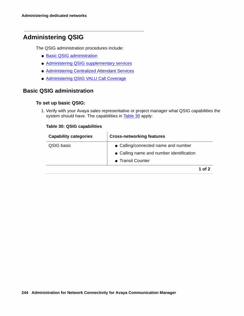
Administering dedicated networks
244 Administration for Network Connectivity for Avaya Communication Manager
Administering QSIG
The QSIG administration procedures include:
● Basic QSIG administration
● Administering QSIG supplementary services
● Administering Centralized Attendant Services
● Administering QSIG VALU Call Coverage
Basic QSIG administration
To set up basic QSIG:
1. Verify with your Avaya sales representative or project manager what QSIG capabilities the system should have. The capabilities in Table 30 apply:
Table 30: QSIG capabilities
Capability categories Cross-networking features
QSIG basic ● Calling/connected name and number
● Calling name and number identification
● Transit Counter
1 of 2
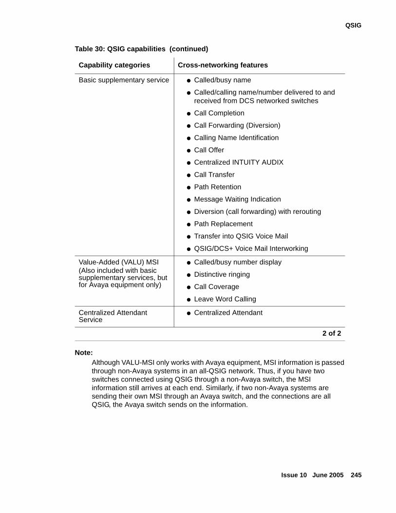
QSIG
Issue 10 June 2005 245
Note:Note: Although VALU-MSI only works with Avaya equipment, MSI information is passed
through non-Avaya systems in an all-QSIG network. Thus, if you have two switches connected using QSIG through a non-Avaya switch, the MSI information still arrives at each end. Similarly, if two non-Avaya systems are sending their own MSI through an Avaya switch, and the connections are all QSIG, the Avaya switch sends on the information.
Basic supplementary service ● Called/busy name
● Called/calling name/number delivered to and received from DCS networked switches
● Call Completion
● Call Forwarding (Diversion)
● Calling Name Identification
● Call Offer
● Centralized INTUITY AUDIX
● Call Transfer
● Path Retention
● Message Waiting Indication
● Diversion (call forwarding) with rerouting
● Path Replacement
● Transfer into QSIG Voice Mail
● QSIG/DCS+ Voice Mail Interworking
Value-Added (VALU) MSI(Also included with basic supplementary services, but for Avaya equipment only)
● Called/busy number display
● Distinctive ringing
● Call Coverage
● Leave Word Calling
Centralized Attendant Service
● Centralized Attendant
Table 30: QSIG capabilities (continued)
Capability categories Cross-networking features
2 of 2
Administering dedicated networks
246 Administration for Network Connectivity for Avaya Communication Manager
2. Determine whether the system is using ISDN-PRI, ISDN-BRI, or ATM for the QSIG network connections. Your sales representative or project manager should know this. (If the system is using ATM trunking for QSIG, see ATM Installation, Upgrades, and Administration (555-233-124).
3. Enter display system-parameters customer-options on the SAT command line of your system administration screen.
4. On page 1, verify fields as follows:
- G3 Version field is V11 or later.
5. If the system is using ATM for QSIG, go to page 3 and verify the following field:
- Async. Transfer Mode (ATM) Trunking field is y.
6. On page 4, verify fields as follows:
If the system is using ISDN-BRI for QSIG:
- ISDN-BRI Trunks field is y.
If the system is using ISDN-PRI for QSIG:
- ISDN-PRI field is y.
If the system is using QSIG supplementary services with or without rerouting:
- Restrict Call Forward Off Net field is n (page 5).
7. On page 8, verify fields as follows:
- Basic Call Setup field is y.
If the system is using QSIG supplementary services:
- Basic Supplementary Services field is y.
If the system is using QSIG supplementary services with rerouting:
- Supplementary Services with Rerouting field is y.
If the system is using QSIG VALU:
- Value-Added (VALU) field is y.
8. (For ISDN-PRI only). Administer or check the QSIG DS-1 circuit pack. Check for the following field entries:
When connecting two Avaya switches:
● Connect field - pbx.
● Interface - user or network.
● Country protocol - 1.
● Protocol version - a.
● Signaling mode - isdn-pri or isdn-ext.
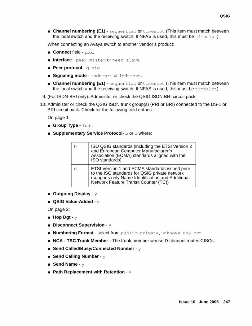
QSIG
Issue 10 June 2005 247
● Channel numbering (E1) - sequential or timeslot (This item must match between the local switch and the receiving switch. If NFAS is used, this must be timeslot).
When connecting an Avaya switch to another vendor’s product:
● Connect field - pbx.
● Interface - peer-master or peer-slave.
● Peer protocol - q-sig.
● Signaling mode - isdn-pri or isdn-ext.
● Channel numbering (E1) - sequential or timeslot (This item must match between the local switch and the receiving switch. If NFAS is used, this must be timeslot).
9. (For ISDN-BRI only). Administer or check the QSIG ISDN-BRI circuit pack.
10. Administer or check the QSIG ISDN trunk group(s) (PRI or BRI) connected to the DS-1 or BRI circuit pack. Check for the following field entries:
On page 1:
● Group Type - isdn
● Supplementary Service Protocol- b or d where:
● Outgoing Display - y
● QSIG Value-Added - y
On page 2:
● Hop Dgt - y
● Disconnect Supervision - y
● Numbering Format - select from public, private, unknown, unk-pvt
● NCA - TSC Trunk Member - The trunk member whose D-channel routes CISCs.
● Send Called/Busy/Connected Number - y
● Send Calling Number - y
● Send Name - y
● Path Replacement with Retention - y
b ISO QSIG standards (including the ETSI Version 2 and European Computer Manufacturer’s Association (ECMA) standards aligned with the ISO standards)
d ETSI Version 1 and ECMA standards issued prior to the ISO standards for QSIG private network (supports only Name Identification and Additional Network Feature Transit Counter (TC))
Administering dedicated networks
248 Administration for Network Connectivity for Avaya Communication Manager
Administering QSIG supplementary services
To set up QSIG supplementary services:
1. Administer or check the ISDN Numbering - Public/Unknown screen, as necessary.
2. Administer or check the ISDN Numbering - Private screen, as necessary.
3. Administer or check the Signaling Group screen, as necessary.
Check for the following field entries to ensure proper operation of Call Completion:
● Supplementary Service Protocol - b
● Max Number of NCA TSC - greater than 0
4. Administer or check the Route Pattern screen, as necessary.
Check for the following field entries to ensure proper operation of Call Completion and Transit Counter:
● TSC - y (necessary if switch is a transit node for TSC)
● Hop Lmt - between 1 and 32
5. Administer or check the Feature-Related System Parameters screen.
Check for the following field entries to ensure proper operation of Call Completion and Call Transfer:
● Trunk-to-Trunk Transfer - all (page 1)
● QSIG TSC Extension - valid extension number to serve as TSC for both incoming and outgoing QSIG network calls (page 8).
● Automatic Callback - No Answer Timeout Interval (rings) - enter the number of times, 2 to 9, a callback call should ring at the caller’s phone before the callback is cancelled (page 1).
● (For AUDIX only) MWI - Number of Digits per AUDIX Subscriber (page 8) - enter the number of digits in messaging subscriber extensions, if any.
The value in this field must match the value of the Extension Length field on the Switch Interface Administration screen of the AUDIX system.
● (For Octel Serenade and Aria) Number of Digits Per Subscriber is set by the leading digit.
Please refer to your Octel documentation for more information.
● (For AUDIX/Octel Serenade support only) Unknown Numbers Internal for AUDIX - y if, when the switch cannot identify a calling number as internal or external, the switch should treat it as internal for AUDIX use (page 8).
QSIG
Issue 10 June 2005 249
6. Administer or check the Class of Service (COS) screen for each COS that may be using the QSIG network.
Check for the following field entries to ensure proper operation of Auto Callback, Call Offer, and Call Forward:
● Restrict Call Forward Off-Net - n
● Auto Callback - y
● QSIG Call Offer Originations - y
Call completion administration
In addition to the Basic QSIG Supplementary Services administration described above, complete the following administration.
To administer for call completion:
1. On the Trunk Group screen, page 1, set the Supplementary Service Protocol field to b and administer the trunk for Call Independent Signalling Connections (NCA-TSCs).
Transfer into Avaya QSIG Message Center (Octel Serenade only)
In addition to the Basic QSIG Supplementary Services administration described above, complete the following administration
To transfer into Avaya ASIG message center (Octel Serenade only):
1. On the System-Parameters Customer-Options screen, page 8, the Transfer Into QSIG Voice Mail field must be set to y.
2. On the Feature Access Code (FAC) screen, page 4, assign a Feature Access Code in the Transfer to Voice Mail Access Code field.
3. A hunt group must be in the coverage path of the user’s mailbox to be transferred into, as administered on the Station and Coverage Path screens.
On the Hunt Group screen, page 2, for this hunt group, qsig-mwi must be entered in the Message Center field and the number for the voice mail system must be entered in the Voice Mail Number field.
QSIG/DCS+ Voice Mail Interworking
QSIG/DCS Voice Mail Interworking requires Release 9 or later software. Also, on page 8 of the System-Parameters Customer-Options screen, the Interworking with DCS field under QSIG Optional Features must be enabled. This feature allows an INTUITY AUDIX system, or an Octel Serenade system to act as a centralized voice mail server in a DCS/QSIG mixed network environment.
Administering dedicated networks
250 Administration for Network Connectivity for Avaya Communication Manager
Administering Centralized Attendant Services
Note:Note: An attendant console must be administered at the main, before administering
Centralized Attendant Services. See the Administrator’s Guide for Avaya Communication Manager (555-233-506) for instructions on administering an attendant console.
To administer centralized attendant services:
1. Enable QSIG Supplementary Services with Rerouting on the System-Parameters Customer-Options screen, page 8, as described above.
2. On the System-Parameters Customer-Options screen, page 8, enter y in the Centralized Attendant field.
3. On the Console Parameters screen, enter QSIG-main or QSIG-branch in the CAS field.
a. If QSIG-branch is entered in the CAS field, then enter a number in the QSIG CAS Number field.
b. If QSIG-branch is entered in the CAS field, then the AAR/ARS Access Code field is optional.
4. On the QSIG ISDN Trunk Groups screen, enter b for the Supplementary Service Protocol field.
5. Assign an extension to attd on the Dial Plan Analysis screen at the main switch.
6. Administer each QSIG Supplementary Service that will be used by attendants.
Administering QSIG VALU Call Coverage
To set up QSIG VALU Call Coverage:
1. Enable (y) the QSIG Basic Supplementary Services field on the System-Parameters Customer-Options screen, page 8, described above.
2. Enable (y) Value-Added (VALU) on the System-Parameters Customer-Options screen, page 8, as described above.
3. On a Trunk Group screen, page 1 enter y in the QSIG Value-Added field, and enter b in the Supplementary Service Protocol: field.
QSIG
Issue 10 June 2005 251
4. Administer the System-Parameters Call-Coverage/Call-Forwarding screen as normal, with the inclusion of the following fields:
● Immediate Redirection on Receipt of PROGRESS Inband Information, page 1 — Enter y to speed up redirection of subsequent coverage points or call processing.
This may be necessary in cases where coverage path endpoints over non-Avaya switches are unavailable but the QSIG networked switch (or the public network) sends PROGRESS messages that delay the local switch from redirecting the call elsewhere. If the QSIG network contains only Avaya switches, enter n.
● QSIG VALU Coverage Overrides QSIG Diversion with Rerouting, page 1 — Enter y to ensure that the “coverage after forwarding” activation/deactivation defined at a user’s phone (on the Station screen) takes precedence over the system-wide “coverage after forwarding” activation/deactivation selection (on the System Parameters Call Coverage/Call Forwarding screen).
With QSIG Diversion with Rerouting active, the system-wide selection takes precedence unless you enter y.
Table 31: QSIG Diversion with Rerouting examples on page 251 lists examples of these field values and a description of the rerouting pattern.
Table 31: QSIG Diversion with Rerouting examples
Field
Cvg. After Fwd (Station screen)
Cvg. After Fwd(System Parameters - Coverage screen)
QSIG VALU Coverage Overrides QSIG Diversion
Rerouting pattern
y n n Call does not go to local user’s coverage after failed forward attempt. Call control passed to switch to which call forwarded.
y n y Call goes to local user’s coverage after failed forward attempt.
1 of 2
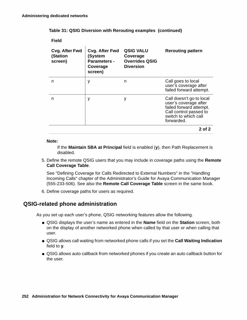
Administering dedicated networks
252 Administration for Network Connectivity for Avaya Communication Manager
Note:Note: If the Maintain SBA at Principal field is enabled (y), then Path Replacement is
disabled.
5. Define the remote QSIG users that you may include in coverage paths using the Remote Call Coverage Table.
See "Defining Coverage for Calls Redirected to External Numbers" in the "Handling Incoming Calls" chapter of the Administrator’s Guide for Avaya Communication Manager (555-233-506). See also the Remote Call Coverage Table screen in the same book.
6. Define coverage paths for users as required.
QSIG-related phone administration
As you set up each user’s phone, QSIG networking features allow the following.
● QSIG displays the user’s name as entered in the Name field on the Station screen, both on the display of another networked phone when called by that user or when calling that user.
● QSIG allows call waiting from networked phone calls if you set the Call Waiting Indication field to y.
● QSIG allows auto callback from networked phones if you create an auto callback button for the user.
n y n Call goes to local user’s coverage after failed forward attempt.
n y y Call doesn’t go to local user’s coverage after failed forward attempt. Call control passed to switch to which call forwarded.
Table 31: QSIG Diversion with Rerouting examples (continued)
Field
Cvg. After Fwd (Station screen)
Cvg. After Fwd(System Parameters - Coverage screen)
QSIG VALU Coverage Overrides QSIG Diversion
Rerouting pattern
2 of 2
QSIG
Issue 10 June 2005 253
QSIG-related Hunt Group administration
As you set up each hunt group, you must enter either grp-name or mbr-name in the ISDN Caller Disp field, page 1. This entry determines which of the following the system displays on a QSIG networked phone that calls the hunt group:
● The hunt group name/extension
● The hunt group member’s name/extension
QSIG-related Terminating Extension Groups administration
As you set up each terminating extension group, you must enter either grp-name or mbr-name in the ISDN Caller Disp field. This entry determines which of the following the system displays on a QSIG networked phone that calls the terminating extension group:
● The group name/extension
● The group member’s name/extension
QSIG-related AUDIX/Message Center administration
Follow these steps to set up Related Administration of AUDIX/Message Centers.
Note:Note: Set up QSIG TSCs before you administer messaging. See Call Completion.
To administer QSIG-related AUDIX/Message Center:
1. (Local node message center switch only) Complete the Processor Channel Assignment screen.
2. (Local node message center switch only) Complete the Message Waiting Indication Subscriber Number Prefixes screen.
3. (Local node message center switch only. This requires bx.25 or C-LAN integration) Complete the Station screen as specified in the AUDIX documentation.
Verify the following field entry:
● MWI Served User Type - qsig-mwi
Administering dedicated networks
254 Administration for Network Connectivity for Avaya Communication Manager
4. (Served user switch only) On the Hunt Group screen, set the following fields for the AUDIX hunt group:
● Message Center - qsig-mwi (page 2)
● Voice Mail Number and Routing Digits (for example, AAR/ARS Access Code):
Digits entered in these fields should be selected so that the processing of these digits by the served user switch results in a call being redirected to the message center switch by an ISDN-PRI supplementary service protocol b facility. For example, if the message center switch is an Avaya switch, the digits entered should reroute the call to the AUDIX hunt group on the message center switch.
● Calling Party Number to AUDIX - y
Migrating to QSIG: some considerations
If you are planning to migrate your network from DCS to QSIG, then there are some issues you need to consider. The following is a list of some of the issues:
● Feature Parity
● Virtual Private Networking
● Voice Messaging Integration
● DCS/DCS+ and QSIG Interworking
This section offers only an overview of the above issues. For more details, please contact your Avaya representative.
Feature Parity
The QSIG protocol was created as a set of standards and specifications for interoperability in multi-vendor network environments. This was a response to the many proprietary protocols (such as Avaya’s DCS) which did not interoperate among vendors.
In order to ensure that features exclusive to proprietary protocols would not be lost when a network is migrated to QSIG, vendors are able to create Manufacturer Specific Information (MSI) messages. By QSIG standards, these messages are passed on, unchanged by any intermediate switches in a network, even if the intermediate switches are from a different manufacturer than the sending and terminating ones.
Communication Manager has MSI features that emulate DCS features not standard with QSIG.
QSIG
Issue 10 June 2005 255
Virtual Private Networking
Some telecommunication companies have provided for DCS+ Virtual Private Networking by transporting Temporary Signaling Connection (TSC) messages in their public switched ISDN networks. There are currently no such provisions by any service provider for QSIG Call Independent Signaling Connections.
Voice Messaging Integration
Before migrating from DCS to QSIG, it is important to know whether or not the existing messaging infrastructure will support integration with QSIG networking.
Mode Code signaling is a common integration method, but is not supported over QSIG networking in Communication Manager. Mode Code signaling uses ISDN tandem trunk signaling to pass messages, but this ISDN signaling was not made to interwork with QSIG.
DCS/DCS+ and QSIG Interworking
Migration of segments of the network, as opposed to all at once, is feasible. However, there is limited interworking functionality between DCS+ and QSIG, and no interworking functionality between traditional DCS and QSIG.
The following features may be interworked between a DCS+ network and QSIG:
● Basic call with name and number
● Leave word calling (LWC)
● Message waiting indication (MWI)
● Centralized voice mail
Note:Note: For DCS+ leave word calling interworking with QSIG, all systems must be running
Communication Manager. LWC activates MWI lamps on Avaya phones only.
Administering dedicated networks
256 Administration for Network Connectivity for Avaya Communication Manager
Centralized Attendant ServiceThe main Centralized Attendant Service (CAS) topics in this section are
● What is Centralized Attendant Service (CAS)
● Administering CAS
Note:Note: See Chapter 6: Feature interactions and considerations for feature interaction
information and other considerations when using CAS.
What is Centralized Attendant Service (CAS)
Centralized Attendant Service allows attendants in a private network of switching systems to be concentrated at a central or main location. Thus, CAS reduces the number of attendants required at a branch. For example, a chain of department stores can have a centralized attendant location at the main store to handle calls for the branch stores.
Each branch in a CAS has its own Listed Directory Number (LDN) or other type of access from the public network. Incoming trunk calls to the branch, as well as attendant-seeking voice terminal calls, route to the centralized attendants over release link trunks (RLT).
The CAS attendants are at the main location. The CAS main switch operates independently of the CAS branch switches. Operation for CAS main-switch traffic is identical to operation of a stand-alone switch.
A branch in a CAS network can connect to only one main. Each branch connects to the main by way of RLTs. These trunks provide paths for:
● Sending incoming attendant-seeking trunk calls at the branch to the main for processing and extending them back to the branch (both parts of a call use the same trunk)
● Returning timed-out waiting and held calls from the branch to the main
● Routing calls from the branch to the main
This following sub-sections cover the topics:
● CAS Queues
● CAS Backup Service
● CAS Remote Hold
● Branch-generated call-identification tones
● CAS Outgoing Call Routing
● CAS Incoming Call Routing
Centralized Attendant Service
Issue 10 June 2005 257
CAS Queues
Two queues are associated with CAS calls: one at the main and one at the branch. If idle RLTs are available from the branch to the main, RLTs are seized and CAS calls are queued at the main along with other attendant-seeking calls. If all RLTs are in use, CAS calls to the attendant are queued at the branch in a RLT queue. The length of the queue can vary from 1 to 100, as set during administration of the RLT group.
CAS Backup Service
Backup service sends all CAS calls to a backup extension in the branch if all RLTs are maintenance-busy or out of service, or if the attendant presses a backup button that is not lighted.
To activate the CAS backup service feature and provide notification that backup service is in effect:
1. Assign the backup extension to a Backup button and associated status lamp.
The status lamp remains lighted as long as backup service is in effect.
To deactivate the CAS backup service feature:
1. The attendant presses the Backup button while the status lamp is lighted.
Calls are not sent to the backup extension unless all RLTs are maintenance-busy or out of service.
CAS Remote Hold
The attendant can put a CAS call from a branch on Remote Hold. The branch holds the call and drops the RLT. After a time-out (same as the timed reminder for an attendant-held call), the branch automatically attempts to route the call back to the attendant. The returning call can queue for the RLT. Attendants use Remote Hold when they have to put a call on hold to keep RLTs from being tied up unnecessarily.
Branch-generated call-identification tones
The branch in a CAS network generates call-identification tones and transmits them to the CAS attendant by way of the RLT. These tones indicate the type of call coming from the branch or the status of a call extended to or held at the branch. The attendant hears these tones in the console handset before being connected to the caller. The tones may vary by country. See Console Operations for information on these tones.
Administering dedicated networks
258 Administration for Network Connectivity for Avaya Communication Manager
CAS Outgoing Call Routing
The centralized attendant at the main has access, through RLTs, to all outgoing trunk facilities at the branches in a CAS network. The attendant can extend an incoming LDN call to an outgoing trunk at a branch by dialing the access code and allowing the caller to dial the rest of the number or by dialing the complete outgoing number.
CAS Incoming Call Routing
Calls extended to busy single-line voice terminals at the branch wait automatically. If there is a call in queue, the user hears a busy signal. When station hunting and send all calls is administered, the call routes along the administered path. Not answering any waiting extended call within an administered interval causes the branch switch to return the call to the attendant. Call Waiting does not apply to multiappearance terminals; if no appearances are available, busy tone is sent to the attendant, who tells the caller that the line is busy.
Calls from voice terminals at the branch to an attendant also route over RLTs seized by the branch switch. A branch caller reaches the attendant by dialing the attendant-group access code. The access code is administrable; the default is 0. The conversation between the branch caller and the attendant ties up the seized RLT, but calls of this type are usually short.
If an extended call returns to the main attendant unanswered, the called party at the branch does not drop but continues to be alerted until the caller releases. This allows the attendant to talk to the caller, then extend the call again, if the caller wishes, without redialing the number.
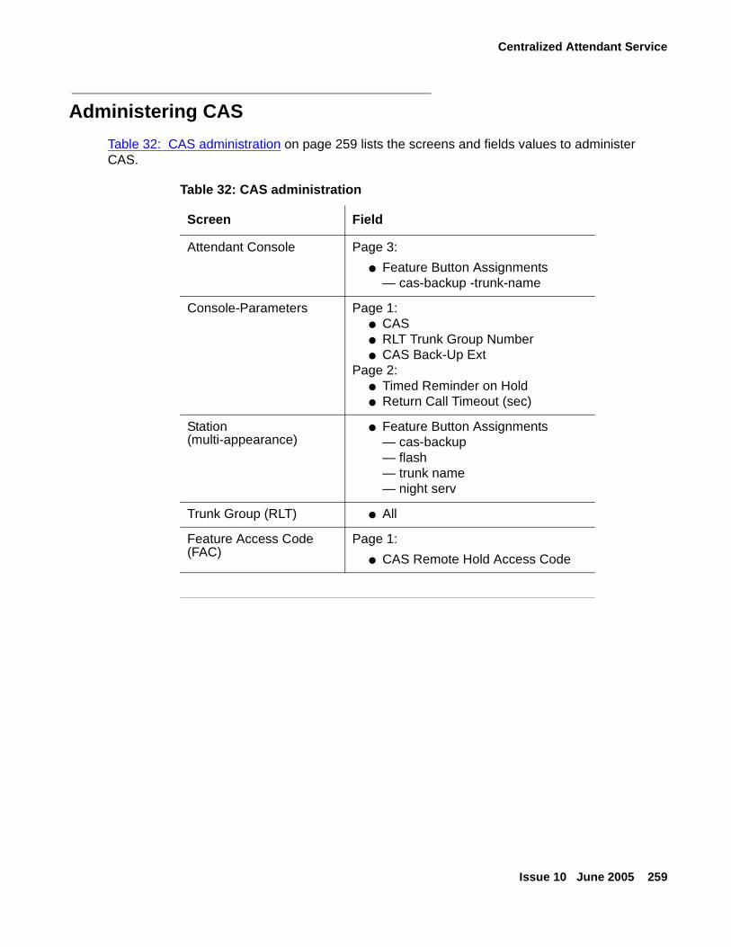
Centralized Attendant Service
Issue 10 June 2005 259
Administering CAS
Table 32: CAS administration on page 259 lists the screens and fields values to administer CAS.
Table 32: CAS administration
Screen Field
Attendant Console Page 3:
● Feature Button Assignments— cas-backup -trunk-name
Console-Parameters Page 1:● CAS● RLT Trunk Group Number● CAS Back-Up Ext
Page 2:● Timed Reminder on Hold● Return Call Timeout (sec)
Station (multi-appearance)
● Feature Button Assignments— cas-backup— flash— trunk name— night serv
Trunk Group (RLT) ● All
Feature Access Code (FAC)
Page 1:
● CAS Remote Hold Access Code
Administering dedicated networks
260 Administration for Network Connectivity for Avaya Communication Manager
Extended Trunk AccessThe main Extended Trunk Access (ETA) topics in this section are
● What is Extended Trunk Access (ETA)
● Administering Extended Trunk Access
● About Extended Trunk Access interactions
What is Extended Trunk Access (ETA)
Use Extended Trunk Access in conjunction with Uniform Dial Plan (UDP) to allow a switch to send any unrecognized number (such as an extension not administered locally) to another switch for analysis and routing. Such unrecognized numbers can be Facility Access Codes, Trunk Access Codes, or extensions that are not in the UDP table. Non-UDP numbers are administered on either the First Digit Table (on the Dial Plan Record screen) or the Second Digit Table. They also are not administered on the ETA Call Screening Table. ETA helps you make full use of automatic routing and UDP.
Historically, ETA has been used by satellite switches to access stations, trunks, and features at the main switch. ETA frees you from having to enumerate the entire dial plan for the main or satellite complex. Calls that would get intercept treatment without ETA are routed to a remote switch to be reprocessed. The following processing takes place when ETA is administered:
● ETA call is identified because it fails all other routing possibilities.
● The dialed string is not in the ETA Call Screening Table.
● An available route pattern is selected based on the Dial Plan screen ETA Routing Pattern or ETA Node Number entries.
● The dialed string is sent to the remote switch.
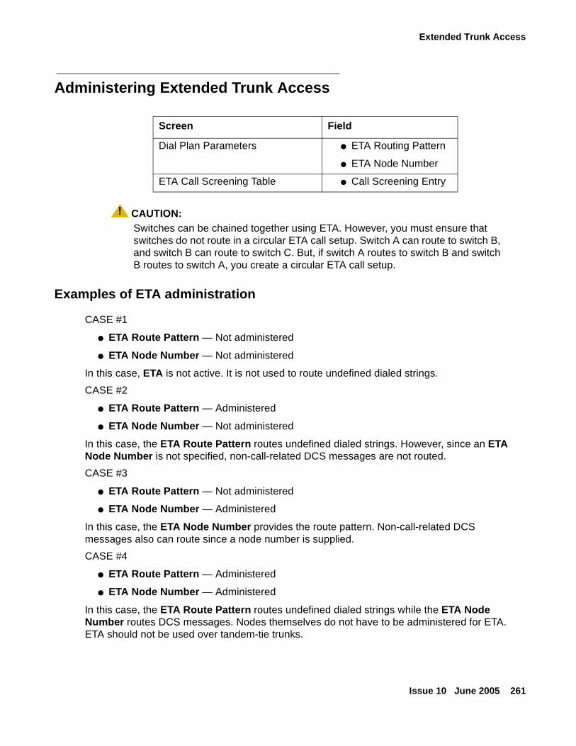
Extended Trunk Access
Issue 10 June 2005 261
Administering Extended Trunk Access
! CAUTION:CAUTION: Switches can be chained together using ETA. However, you must ensure that
switches do not route in a circular ETA call setup. Switch A can route to switch B, and switch B can route to switch C. But, if switch A routes to switch B and switch B routes to switch A, you create a circular ETA call setup.
Examples of ETA administration
CASE #1
● ETA Route Pattern — Not administered
● ETA Node Number — Not administered
In this case, ETA is not active. It is not used to route undefined dialed strings.
CASE #2
● ETA Route Pattern — Administered
● ETA Node Number — Not administered
In this case, the ETA Route Pattern routes undefined dialed strings. However, since an ETA Node Number is not specified, non-call-related DCS messages are not routed.
CASE #3
● ETA Route Pattern — Not administered
● ETA Node Number — Administered
In this case, the ETA Node Number provides the route pattern. Non-call-related DCS messages also can route since a node number is supplied.
CASE #4
● ETA Route Pattern — Administered
● ETA Node Number — Administered
In this case, the ETA Route Pattern routes undefined dialed strings while the ETA Node Number routes DCS messages. Nodes themselves do not have to be administered for ETA. ETA should not be used over tandem-tie trunks.
Screen Field
Dial Plan Parameters ● ETA Routing Pattern
● ETA Node Number
ETA Call Screening Table ● Call Screening Entry
Administering dedicated networks
262 Administration for Network Connectivity for Avaya Communication Manager
About Extended Trunk Access interactions
● Abbreviated Dialing
Abbreviated Dialing calls are routed by means of ETA.
● Attendant
Attendants calls are routed by means of ETA.
● Data-Call Setup
Analog and digital endpoints can access ETA. The digit string goes to the remote switch like any other digit string is sent. The remote switch handles the data-call setup from that point forward.
● Facility Restriction Levels
It is possible to restrict trunks that are being used in conjunction with ETA by assigning FRLs.
● Last Number Dialed
If a number is routed by means of ETA to a remote switch and you want to reaccess that number, then reaccess uses ETA.
● Modem Pooling
Modems in Modem Pools are treated like all other trunks.
● Remote Access
Remote-access trunks are able to access the ETA feature just as any other trunk or station does.
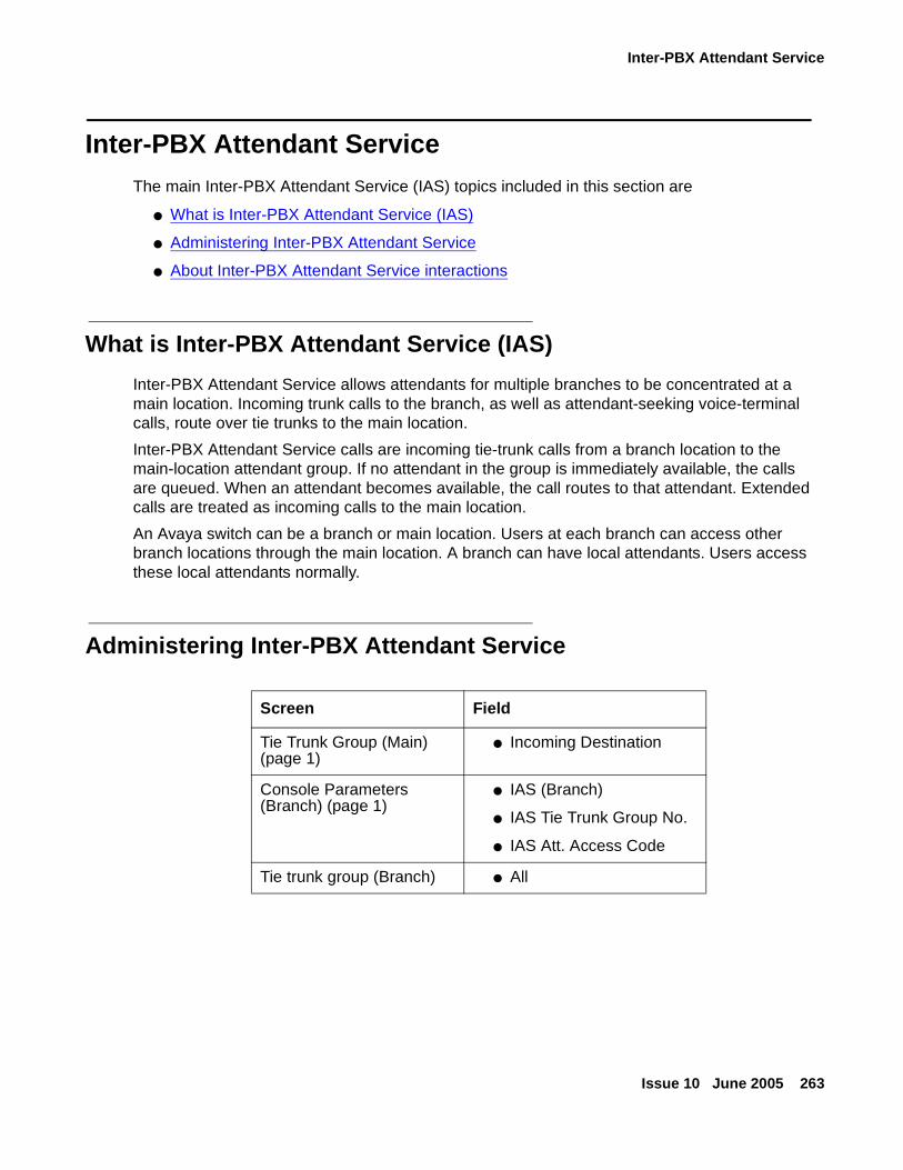
Inter-PBX Attendant Service
Issue 10 June 2005 263
Inter-PBX Attendant ServiceThe main Inter-PBX Attendant Service (IAS) topics included in this section are
● What is Inter-PBX Attendant Service (IAS)
● Administering Inter-PBX Attendant Service
● About Inter-PBX Attendant Service interactions
What is Inter-PBX Attendant Service (IAS)
Inter-PBX Attendant Service allows attendants for multiple branches to be concentrated at a main location. Incoming trunk calls to the branch, as well as attendant-seeking voice-terminal calls, route over tie trunks to the main location.
Inter-PBX Attendant Service calls are incoming tie-trunk calls from a branch location to the main-location attendant group. If no attendant in the group is immediately available, the calls are queued. When an attendant becomes available, the call routes to that attendant. Extended calls are treated as incoming calls to the main location.
An Avaya switch can be a branch or main location. Users at each branch can access other branch locations through the main location. A branch can have local attendants. Users access these local attendants normally.
Administering Inter-PBX Attendant Service
Screen Field
Tie Trunk Group (Main) (page 1)
● Incoming Destination
Console Parameters (Branch) (page 1)
● IAS (Branch)
● IAS Tie Trunk Group No.
● IAS Att. Access Code
Tie trunk group (Branch) ● All
Administering dedicated networks
264 Administration for Network Connectivity for Avaya Communication Manager
About Inter-PBX Attendant Service interactions
● Attendant Control of Trunk-Group Access
If a call at a branch attempts to access a controlled trunk group, the call routes to a branch attendant, if there is one. If there is no branch attendant, the call routes to the attendant group at the main location.
● Attendant Display and DCS Attendant Display
In a DCS environment, an incoming call from a branch displays at the attendant console at the main location as a local call.
In a non-DCS environment, an incoming call displays at the attendant console at the main location as an incoming tie-trunk call.
● Attendant Recall
If an attendant at the main location holds a call, the calling parties at the branch cannot recall the attendant.
● Call Coverage
A call redirected to a coverage path with the attendant group as a coverage point skips that coverage point. It goes to the next coverage point at the branch, if administered, or continues to ring at the previous coverage point. If the attendant group 0 is the only coverage point, it continues to ring at the principal’s extension.
● Centralized Attendant Service
CAS and Inter-PBX attendant calling cannot be used at the same time.
● Dial Access to Attendant
Administer Dial Access to Attendant using the dial platform to the same digit on both the IAS main switch and the IAS branch switch. On the branch switch, administer the PBX attendant access code (Console Parameters screen) to match the main PBX attendant-group dial access code.
● Night Service
Inter-PBX Attendant Calls deactivates when a branch goes into night service, and reactivates when the branch comes out of night service.
ISDN Feature Plus
Issue 10 June 2005 265
ISDN Feature PlusThe main ISDN Feature Plus topics included in this section are
● What is ISDN Feature Plus
● Administering ISDN Feature Plus
● About interrogation between message center and served user switches
● About ISDN Feature Plus interactions
What is ISDN Feature Plus
ISDN Feature Plus is an international feature, and does not apply to systems in the U.S. This feature allows you to have basic feature transparency over public networks without having a dedicated leased line. This provides a lower cost option using the switched public network.
ISDN Feature Plus uses Communication Manager proprietary signaling protocol. The features do not function in the same way as their QSIG or DCS counterparts.
To use Feature Plus, Phase I, you need Direct Inward Dialing (DID) extensions. In addition to the general Feature Plus call handling,
Feature Plus includes the following:
● Centralized AUDIX — A simple, one step “coverage” to voice mail. If voice mail is unavailable for any reason, the call does not cover elsewhere.
● Call Diversion — You can divert (or forward) calls unconditionally, upon busy or no reply, to another extension including forwarding voice mail.
● Calling Number ID — You can display the calling party’s number to the called party during alerting and after answer.
● Calling Name — You can assign the Calling Name Feature Plus identifier with a maximum size of 15 bytes or the maximum network subaddress size, whichever is lower.
● Connected Line Identification Presentation (COLP) — You can assign display forwarded-to party information to the calling user’s display.
● Call Transfer - Basic — You can transfer calls between parties across the public network. Display updates at the time of transfer or upon completion of transfer, however, are not supported.
● Served User PBX for Centralized AUDIX — Determines where to send messages destined for the AUDIX hunt group.
● Message Waiting Indication — You can display a message waiting indication on a user’s voice terminal.
Administering dedicated networks
266 Administration for Network Connectivity for Avaya Communication Manager
Administering ISDN Feature Plus
Note:Note: Starting with Release 10, the system software release, Offer Category, features,
and system capacities are controlled through the License File. The init login does not have the ability to change the customer options, offer options, and special applications screens. However, these screens are still available through the display system-parameters customer-options command.
To administer ISDN feature plus:
1. On the System-Parameters Customer-Options screen, verify that the:
- G3 Version is V7 or higher (page 1).
- ISDN Feature Plus field is set to y (page 4).
2. On the same page, verify either one or both of the following:
- ISDN-PRI field is set to y, or
- ISDN-BRI Trunks field is set to y.
3. Verify either one or both of the following:
- ISDN-BRI Trunk Group — Verify the Supplementary Service Protocol field is set to f
- ISDN-PRI Trunk Group — Verify the Supplementary Service Protocol field is set to f.
4. On the Feature-Related System-Parameters screen (page 8), set the Feature Plus Ext field to the local extension used to terminate Feature Plus signaling for ISDN Feature Plus.
5. On the Hunt Group screen (page 2), to add a centralized AUDIX system, set the Message Center field to fp-mwi.
To start Message Waiting Indication at the Message Center PBX:
1. On the Feature-Related System-Parameters screen (page 8), set the MWI - Number of Digits per AUDIX Subscriber field to the desired number.
2. On the Processor Channel Assignment, set the Application field to fp-mwi.
3. Type change isdn mwi-prefixes and press Enter.
Administer the Message Waiting Indication Subscriber Number Prefixes screen.
To start the Calling Name feature:
1. On the ISDN-BRI or ISDN-PRI Trunk Group screen (whichever you are using), set the Send Name field to y.
ISDN Feature Plus
Issue 10 June 2005 267
Differences in Inserted Digits field
There is a difference in how the Inserted Digits to form Complete Number field on the Message Waiting Indication Subscriber Number Prefixes screen is used for QSIG and for Feature Plus. This difference is because of how the Feature Plus and QSIG-TSC platforms operate:
● For Feature Plus, the Feature Plus extension must be included in the Inserted Digits to form Complete Number field
● For QSIG, only the higher order digits need to be included. (In QSIG MWI, the subscriber number is appended to the inserted digits and the resulting number is used to route over a QSIG TSC.)
For example, Dallas is a Message Center PBX and Denver is a remote PBX:
● If Feature Plus is running between Dallas and Denver and the Feature Plus extension in Denver is 82000, the Inserted Digits to form Complete Number field administered in Dallas to get to Denver must be 3035382000.
The Routing Digits (AAR/ARS Access Code) field also needs to be filled in appropriately.
● If QSIG is running between Denver and Dallas, the Inserted Digits to form Complete Number field must contain 30353.
The Routing Digits (AAR/ARS Access Code) field also must be filled in appropriately.)
About interrogation between message center and served user switches
When performing an audit, the Served User switch sends a request towards the Message Center switch. As a Message Center PBX, the Avaya switch receives the request message, maps it into a MW STATUS REQUEST - SINGLE STATION message, and sends it to AUDIX on the BX.25 link. When the AUDIX system replies to the DEFINITY or Avaya system on the BX.25 link with a MW STATUS UPDATE, the Message Center switch sends the information on to the appropriate Served User switch.
● If it is a Message Center PBX, the MW STATUS UPDATE indicates whether there are any messages waiting, not how many messages are waiting, or what media types are these messages. If the MW STATUS UPDATE indicates that there are new messages, then the Message Center PBX sends a message telling the Served User PBX to activate the message waiting indication. Similarly, if the MW STATUS UPDATE indicates that there are no new messages, then the Message Center PBX sends a message telling the Served User PBX to deactivate the message waiting indication.
● If it is a Served User PBX, when the Served User PBX receives the result, it makes sure that the result received from the Message Center matches the state of the Served User’s light.
Administering dedicated networks
268 Administration for Network Connectivity for Avaya Communication Manager
About ISDN Feature Plus interactions
● Automatic Circuit Assurance
Automatic Circuit Assurance (including Referrals) is not activated for calls terminating at the Feature Plus extension.
● Distributed Communication System (DCS)
Feature Plus signaling links do not support DCS.
● Feature Plus Centralized AUDIX
- Calling Line Identification Presentation (CLIP)
If the public network supports CLIP and the called user has subscribed to the service, calling party information is available to the called user when messages are retrieved.
- Feature Plus Diversion
Feature Plus Centralized AUDIX relies upon Feature Plus Diversion. When a call covers to AUDIX, it must invoke Feature Plus Diversion to identify the called party to AUDIX.
- Feature Plus Message Waiting
When a calling party leaves a message using Feature Plus Centralized AUDIX, Feature Plus Message Waiting engages and turns on that subscriber’s message waiting indicator.
● Feature Plus Forwarding (Diversion)
- Calling Line Identification Presentation (CLIP)
If the public network supports CLIP and the forwarded-to user has subscribed to the service, then calling party information is available to the forwarded-to user’s display.
- Connection Line Identification Presentation (COLP)
If the public network supports COLP and the calling user has subscribed to the service, then forwarded-to party information is available to the calling user’s display.
- Feature Plus Centralized AUDIX
Feature Plus Centralized AUDIX relies upon Feature Plus Diversion. Invoke Feature Plus Diversion first to enable the Centralized AUDIX feature.
- Call Coverage
● Terminating call has coverage active
If a call is forwarded off-switch, and the terminating switch has call coverage activated and the criteria are met, the call will not go to the forwarding coverage path. It goes to the terminating coverage path.
● Forwarding and Coverage
If the last coverage point in the coverage path is a number that routes over an ISDN SSF trunk, no Feature Plus Diversion information passes to the coverage PBX.
ISDN Feature Plus
Issue 10 June 2005 269
- Automatic Callback
If automatic callback was activated before the called voice terminal user activated Call Forwarding over an ISDN SSF trunk, the callback call attempt is redirected to the forwarded-to party over the SSF trunk.
- Call Park
If a forwarded-to (diverted-to) extension user parks a call that has been forwarded from an ISDN SSF trunk, the call normally is parked on the forwarded-to extension, not on the forwarded-from (called user) of the ISDN SSF trunk.
● Feature Plus Message Waiting Indication
- Audio Information Exchange (AUDIX)
Feature Plus MWI depends on the presence of a Message Center. Whenever an Avaya switch acts as a Message Center switch, there is an interaction between the switch and the AUDIX system. The switch must be able to receive messages from the AUDIX system then, if applicable, send the appropriate Feature Plus MWI message to the network. Similarly, if the switch receives a Feature Plus MWI message, the switch translates the Feature Plus message into the appropriate AUDIX message and passes it to the AUDIX system.
The only messages that Communication Manager handles are AUDIX messages along the BX.25 link. Feature Plus MWI can interwork with Basic AUDIX, including INTUITY AUDIX, and with DEFINITY AUDIX with the DCIU control link. Feature Plus MWI does not work with the DEFINITY AUDIX that emulates a DCP voice terminal or with versions of AUDIX that communicate to Avaya mode codes.
Implementation requires that all users on a Served User switch use the same Feature Plus Message Center. Some of the served users can use a Feature Plus Message Center, while others use a local message center and/or a DCS Remote Message Center and/or a QSIG Message Center. However, some served users on a switch cannot use one Feature Plus Message Center while other served users on the same switch use a different Feature Plus Message Center.
- Off-Premise Station
Feature Plus MWI does not work with an off-premise station implemented with a DS1 circuit pack.
● QSIG
Feature Plus signaling links do not support QSIG.
Administering dedicated networks
270 Administration for Network Connectivity for Avaya Communication Manager
Centralized Voice MailThe main Centralized Voice Mail topics included in this section are
● About centralized voice mail
● What are mode code centralized voice mail configuration requirements
● Administering Centralized Voice Mail
About centralized voice mail
You can use a single voice mail system to support multiple Avaya switches and Merlin Legend/Magix systems in a network using mode code.
This capability is available for:
● Avaya system software (Release 8 or later)
● Merlin Legend R6.1or later
● Merlin Magix 1.0 or later
Voice mail systems that support these connections are:
● Intuity AUDIX R4.4 or higher running on a MAP5, with up to 18 ports
● Octel 100, with up to 16 ports
Features that are supported
● Calling party name/number sending/retrieval
● Message waiting light activation
● Remote coverage to voice mail
● Fax, as well as voice, mail
Features that are not supported
The following capabilities are not supported in Centralized Voice Mail through mode code:
● Most DCS feature transparency
● Centralized voice mail for a tandem switch (does not have a direct connection to the hub switch)
● Transfer into voice mail
Centralized Voice Mail
Issue 10 June 2005 271
What are mode code centralized voice mail configuration requirements
Centralized voice mail using mode code requires the following:
● An Avaya switch as the hub of the voice mail network, with the voice mail system directly connected to it.
● Direct ISDN PRI tandem trunk connections, using DS1 service between the hub and the switches the voice mail supports.
The system uses the D-channel to transmit mode code signals to light message waiting lights on remote extensions.
● A uniform dial plan for all switches in the network, with a 4-digit plan if Merlin Legend/Magix is part of the network.
● One and only one mailbox for each extension in the network.
Note:Note: DCS software, X.25 hardware, and C-LAN hardware/software are not required for
this type of network. Additionally, you cannot network switches simultaneously using both mode code and DCS.
Note:Note: For Centralized Voice Mail using Mode Code, you’re network must be in a hub/
spoke configuration, with no more than ten DCS network nodes.
Centralized voice mail configuration using mode code example
Figure 25: Example of a Centralized Voice Mail configuration on page 272 shows what a configuration of centralized voice mail using mode code might look like.
In this configuration, system A is the hub. Voice mail system X is the centralized voice mail system. All other systems in the network are supported by voice mail system X except Legend system E and system D. These switches do not have a direct ISDN-PRI connection to the hub.
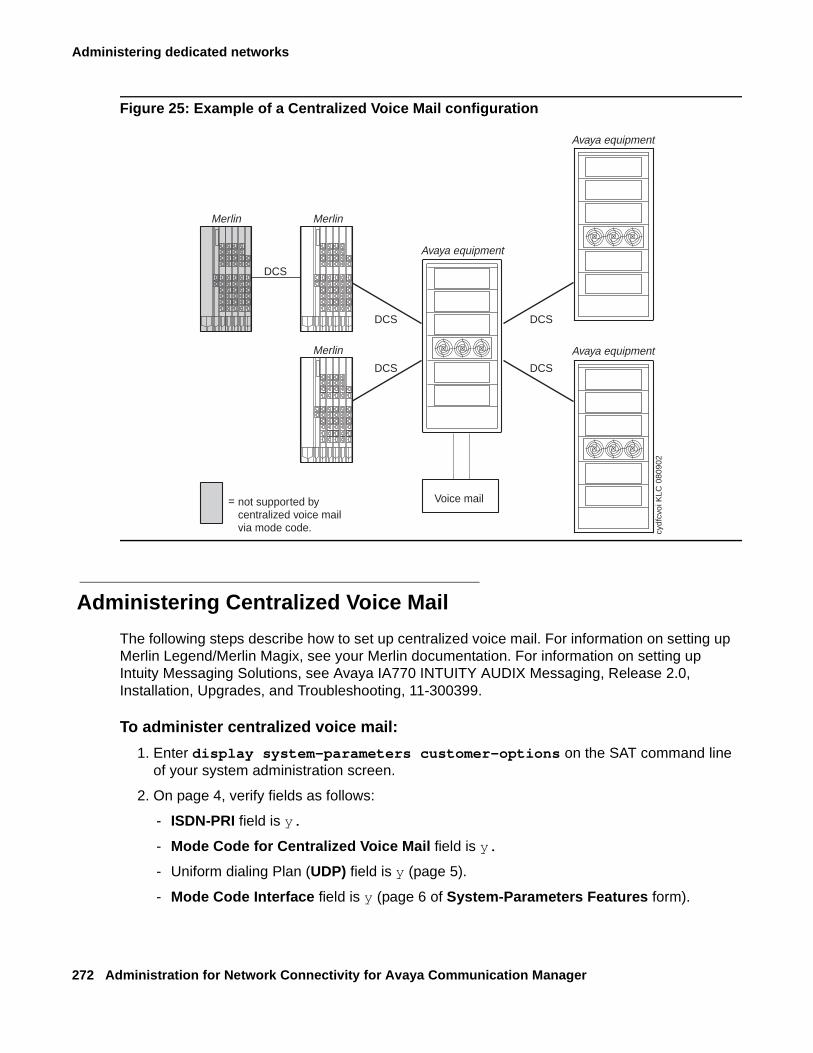
Administering dedicated networks
272 Administration for Network Connectivity for Avaya Communication Manager
Figure 25: Example of a Centralized Voice Mail configuration
Administering Centralized Voice Mail
The following steps describe how to set up centralized voice mail. For information on setting up Merlin Legend/Merlin Magix, see your Merlin documentation. For information on setting up Intuity Messaging Solutions, see Avaya IA770 INTUITY AUDIX Messaging, Release 2.0, Installation, Upgrades, and Troubleshooting, 11-300399.
To administer centralized voice mail:
1. Enter display system-parameters customer-options on the SAT command line of your system administration screen.
2. On page 4, verify fields as follows:
- ISDN-PRI field is y.
- Mode Code for Centralized Voice Mail field is y.
- Uniform dialing Plan (UDP) field is y (page 5).
- Mode Code Interface field is y (page 6 of System-Parameters Features form).
Merlin Merlin
Merlin
DCSDCS
DCSDCS
DCS
Voice mailnot supported bycentralized voice mailvia mode code.
=
cydf
cvoi
KLC
080
902
Avaya equipment
Avaya equipment
Avaya equipment
Centralized Voice Mail
Issue 10 June 2005 273
3. On the hub switch, enter add trunk group xxxx on the command line of your system administration screen,
where xxxx is the number of the ISDN-PRI trunk group connecting the hub with the remote switch.
4. On page 1, verify fields as follows:
- Group Type field is ISDN.
- Service Type field is TIE.
5. On page 2, verify fields as follows:
- Send Name field is y.
- Send Calling Number field is y.
- Format field is Private.
- Send Connected Number field is y.
6. On each remote switch, repeat steps 3-5.
7. On each switch in the network, enter change dialplan analysis on the SAT command line of your system administration screen.
8. Administer the dial plan for each node in the network.
Usually the hub is considered Node 1.
9. For each node, enter change feature-access-codes on the command line.
10. On page 2, verify fields as follows:
- Leave Word Calling Send a Message field is #90.
- Leave Word Calling Cancel a Message field is #91.
Note:Note: All nodes in the system and the Voice Mail system must match this setting.
11. For each node, enter add ds1 UUCSS on the command line, where UUCSS is the address of the DS1 circuit pack.
12. On page 1, verify fields as follows:
- Line Coding field is B8ZS.
- Framing field is extended superframe.
- Signaling Mode field is isdn/pri.
- Connect field is PBX.
- Interface field is network (for the hub) and user (for the remote switch).
Note:Note: Mode Codes will not work with D4 or SuperFrame
Administering dedicated networks
274 Administration for Network Connectivity for Avaya Communication Manager
13. For each node, enter change signaling-group next on the SAT command line.
Administer the signaling group.
14. For each node, enter change private-numbering, and verify fields as follows:
- Set Network Level field is 0.
This setting overrides the signaling on the D channel, allowing the Message Waiting lamp activation signal to be sent
15. On the Avaya node, enter change system-parameters mode-code on the SAT command line.
16. On the hub switch, set the VMS Hunt Group Extension field to the voice mail hunt group extension.
17. On the remote switches, repeat Step 15.
Enter the voice mail hunt group extension in the Remote VMS Extension - First field.
18. For each node, enter change aar analysis on the SAT command line.
19. Verify the following:
- Call Type field is lev0.
20. On the hub switch, enter change station extension for each port extension in the voice mail hunt group.
21. On Page 1, verify the following:
- Type field is vmi.
22. On Page 2 of the Station screen, administer or verify the following:
- LWC Reception field is msa-spe (Message Server Adjunct-System Processing Element).
- Leave Word Calling field is y.
- Adjunct Supervision field is y.
- Distinctive Audible Alert field is n.
- Switchhook Flash field is y.
- LWC Activation field is y.
23. For each remote node, enter change coverage remote on the SAT command line.
24. Administer or verify the following:
- 01 contains the extension of the voice mail hunt group.
Japan TTC Q931-a
Issue 10 June 2005 275
Japan TTC Q931-aThe main Japan TTI Q931-a topics included in this section are:
● About Japan TTC Q931-a
● Considerations about TTC Basic Call Setup with Number Identification Supplementary Service
● What are the TTC Q931-a Protocols
● Administering Japan TTC Q931-a
About Japan TTC Q931-a
The Telecommunications Technology Committee (TTC) of Japan defines national standards that are to be used in domestic public and private network facilities. The TTC typically modifies other international standards as defined by ITU-T for use in Japan with additional national protocols to enhance operation for their customers.
The TTC has defined a family of Q931-a private networking protocols that allows for a level of feature transparency between different switches within a single vendor or multi-vendor private network. Communication Manager provides connectivity into the Japanese private networking environment through two methods:
● Channel Associated Signaling
● ISDN (Integrated Services Digital Network) PRI (Primary Rate Interface) — TTC specific protocol. Communication Manager supports Basic Call with Number Identification services.
Considerations about TTC Basic Call Setup with Number Identification Supplementary Service
Communication Manager allows the display of the calling party number to the called party. Communication Manager also displays the connected number to the calling party after the call connects to the called number of another destination. For many protocols, Number Identification is considered to be part of Basic Call service; however, the TTC protocol defines Number Identification services to be part of their supplementary services offering. No additional supplementary services are supported at this time.
You can administer outgoing calls as “yes”, “no”, or “restricted.” Restricted means that Communication Manager sends the information but sends it “presentation restricted,” which indicates to the receiving switch that the information should not be displayed. A received restricted number is included on the Call Detail Record (CDR), however.
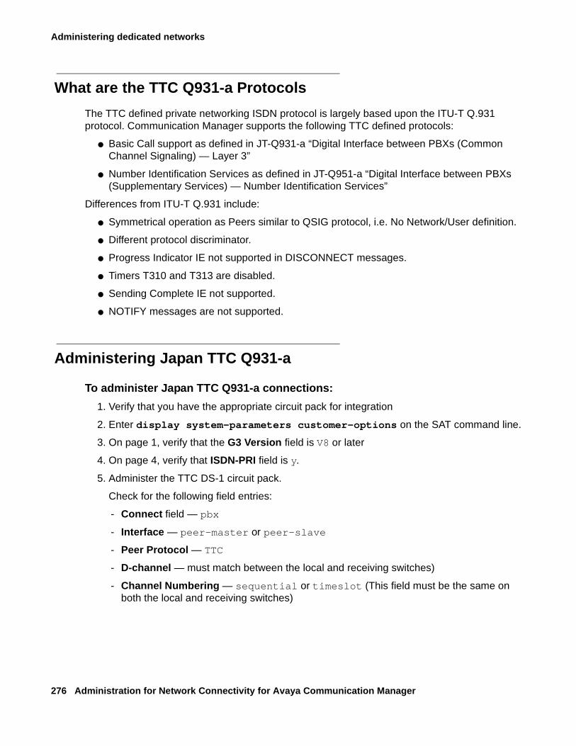
Administering dedicated networks
276 Administration for Network Connectivity for Avaya Communication Manager
What are the TTC Q931-a Protocols
The TTC defined private networking ISDN protocol is largely based upon the ITU-T Q.931 protocol. Communication Manager supports the following TTC defined protocols:
● Basic Call support as defined in JT-Q931-a “Digital Interface between PBXs (Common Channel Signaling) — Layer 3”
● Number Identification Services as defined in JT-Q951-a “Digital Interface between PBXs (Supplementary Services) — Number Identification Services”
Differences from ITU-T Q.931 include:
● Symmetrical operation as Peers similar to QSIG protocol, i.e. No Network/User definition.
● Different protocol discriminator.
● Progress Indicator IE not supported in DISCONNECT messages.
● Timers T310 and T313 are disabled.
● Sending Complete IE not supported.
● NOTIFY messages are not supported.
Administering Japan TTC Q931-a
To administer Japan TTC Q931-a connections:
1. Verify that you have the appropriate circuit pack for integration
2. Enter display system-parameters customer-options on the SAT command line.
3. On page 1, verify that the G3 Version field is V8 or later
4. On page 4, verify that ISDN-PRI field is y.
5. Administer the TTC DS-1 circuit pack.
Check for the following field entries:
- Connect field — pbx
- Interface — peer-master or peer-slave
- Peer Protocol — TTC
- D-channel — must match between the local and receiving switches)
- Channel Numbering — sequential or timeslot (This field must be the same on both the local and receiving switches)
Japan TTC Q931-a
Issue 10 June 2005 277
6. Administer or check the TTC ISDN trunk group(s) associated with the DS1 circuit pack.
Check for the following field entries on page 1 of the Trunk Group screen:
- Group type — isdn
- Supplementary Service protocol — a
- Outgoing Display — y
- Disconnect Supervision — In?__Out?__
Check for the following field entries on page 2 of the Trunk Group screen:
- Format — public, private, unknown, unk-pvt
- Send Connected Number — y
- Sending Calling Number — y
- Send Name — n

Administering dedicated networks
278 Administration for Network Connectivity for Avaya Communication Manager
Issue 10 June 2005 279
Chapter 6: Feature interactions and considerations
This appendix contains feature descriptions, considerations, and interactions for
● Distributed Communication System
● QSIG interactions
● Centralized Attendant Service (CAS) interactions and considerations
● Italian TGU/TGE (main and satellite) interactions
● Hairpinning and shuffling feature interactions
Distributed Communication System
Extension Number Portability considerations
● If you use DCS, the Extension Number Portability (ENP) node numbers must correspond to DCS node numbers.
DCS over ISDN-PRI D-channel considerationsand interactions
Considerations
● The gateway node serves as the terminating node to the D-channel DCS network as well as the terminating node to the traditional DCS network.
A switch serving as an ISDN DCS Gateway node introduces some interesting situations when administering processor channels in an associated traditional DCS system. In a traditional DCS network, (BX.25 processor channel links) Remote Port in the Processor Channel Assignments screen refers to the processor channel of the destination switch. In an Integrated DCS network, Remote Proc Chan in the Processor Channel Assignments screen refers to the processor channel of the Gateway switch (if the destination switch is an ISDN DCS system), not the destination switch.
On the contrary, Machine-ID in the Processor Channel Assignments screen refers to the destination switch, either an ISDN DCS system or a traditional DCS system. The Gateway switch number must not be used in this field if the destination switch is an ISDN DCS system.
Feature interactions and considerations
280 Administration for Network Connectivity for Avaya Communication Manager
Interactions
● ASAI
For incoming calls on DCS over ISDN-PRI, ASAI applications receive the ISDN-PRI Calling Party Information, not the DCS Calling Party Information.
● Attendant DXS with Busy Lamp Field
An attempt by the attendant to select directly an extension that has been previously administered as belonging to an administered NCA-TSC results in the intercept tone being received.
● CDR
CDR records both the status and the use of TSCs. Both CA-TSCs and NCA-TSCs can be recorded. For more information, consult the CDR description in this manual or the CDR manual.
● D-channel Backup
In the event of a D-channel switchover (primary to secondary or secondary back to primary) in a private network, administered NCA-TSCs that were active are assumed to have remained active. Any unacknowledged user-user service requests are assumed to be rejected, and administered NCA-TSCs which were in the process of being established at the time of the switchover are dropped when the switchover occurs. Those administered NCA-TSCs that were dropped are reattempted again.
If a D-channel switchover occurs on a D-channel going to the public network then all TSCs are dropped. A maintenance-provided “heartbeat” message periodically is sent over each permanent administered NCA-TSC to ensure that such a situation is detected and rectified.
● Distributed Communications System AUDIX (DCS AUDIX)
The DCS over ISDN-PRI D-channel feature can be used to support DCS AUDIX. (The connection between si and the AUDIX system should be BX.25 or C-LAN.)
● GRS
GRS selects TSC compatible facilities when routing NCA-TSCs. In other words, a NCA-TSC request can only select a routing preference that supports TSCs.
In a tandem node, GRS first selects facilities that support TSCs if the call falls into any one of the following two conditions:
- It requests a CA-TSC explicitly
- It contains a DCS information element in the SETUP message
Once a trunk group with available members is selected, the call proceeds even if all the TSCs belonging to the associated signaling group are active. In other words, the completion of a call is given priority over DCS transparency.
Distributed Communication System
Issue 10 June 2005 281
● AT&T SDN or MCI N-Quest
The DCS over ISDN-PRI (DCS+) D-channel feature allows the system to access public networks, such as AT&T SDN or MCI N-Quest. DCS+ supports all DCS features except for the following:
- DCS Attendant Control of Trunk Group Access
- DCS Attendant Direct Trunk Group Selection
- DCS Busy Verification of Terminals and Trunks
● Voice Terminals
An attempt to dial an extension that has been previously administered as belonging to an administered NCA-TSC results in the intercept tone being received.
Enhanced DCS considerations and interactions
Considerations
● If the DCS link fails, the administrator can choose to allow calls to continue without class of restriction checking or to block all DCS calls to inward-restricted stations.
Interactions
● Class of Restriction
When a call goes to coverage, it is the called party’s (not the covering party’s) restrictions that are used.
DCS feature descriptions, interactionsand considerations
Table 33: DCS feature descriptions, interactions, and considerations on page 282 lists DCS features, gives a brief description, and describes the feature interactions and considerations for their use.
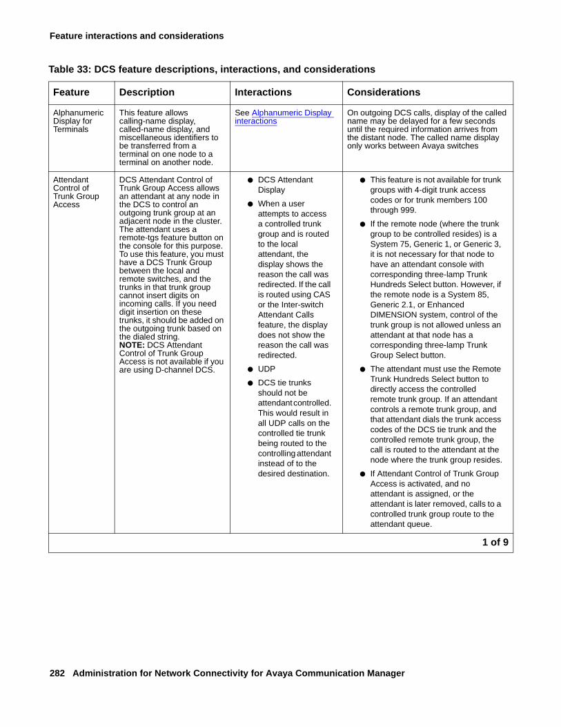
Feature interactions and considerations
282 Administration for Network Connectivity for Avaya Communication Manager
Table 33: DCS feature descriptions, interactions, and considerations
Feature Description Interactions Considerations
Alphanumeric Display for Terminals
This feature allows calling-name display, called-name display, and miscellaneous identifiers to be transferred from a terminal on one node to a terminal on another node.
See Alphanumeric Display interactions
On outgoing DCS calls, display of the called name may be delayed for a few seconds until the required information arrives from the distant node. The called name display only works between Avaya switches
Attendant Control of Trunk Group Access
DCS Attendant Control of Trunk Group Access allows an attendant at any node in the DCS to control an outgoing trunk group at an adjacent node in the cluster. The attendant uses a remote-tgs feature button on the console for this purpose.To use this feature, you must have a DCS Trunk Group between the local and remote switches, and the trunks in that trunk group cannot insert digits on incoming calls. If you need digit insertion on these trunks, it should be added on the outgoing trunk based on the dialed string.NOTE: DCS Attendant Control of Trunk Group Access is not available if you are using D-channel DCS.
● DCS Attendant Display
● When a user attempts to access a controlled trunk group and is routed to the local attendant, the display shows the reason the call was redirected. If the call is routed using CAS or the Inter-switch Attendant Calls feature, the display does not show the reason the call was redirected.
● UDP
● DCS tie trunks should not be attendant controlled. This would result in all UDP calls on the controlled tie trunk being routed to the controlling attendant instead of to the desired destination.
● This feature is not available for trunk groups with 4-digit trunk access codes or for trunk members 100 through 999.
● If the remote node (where the trunk group to be controlled resides) is a System 75, Generic 1, or Generic 3, it is not necessary for that node to have an attendant console with corresponding three-lamp Trunk Hundreds Select button. However, if the remote node is a System 85, Generic 2.1, or Enhanced DIMENSION system, control of the trunk group is not allowed unless an attendant at that node has a corresponding three-lamp Trunk Group Select button.
● The attendant must use the Remote Trunk Hundreds Select button to directly access the controlled remote trunk group. If an attendant controls a remote trunk group, and that attendant dials the trunk access codes of the DCS tie trunk and the controlled remote trunk group, the call is routed to the attendant at the node where the trunk group resides.
● If Attendant Control of Trunk Group Access is activated, and no attendant is assigned, or the attendant is later removed, calls to a controlled trunk group route to the attendant queue.
1 of 9
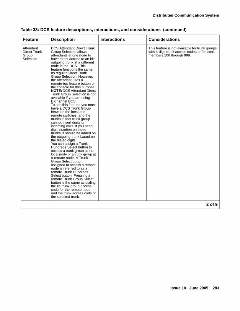
Distributed Communication System
Issue 10 June 2005 283
Attendant Direct Trunk Group Selection
DCS Attendant Direct Trunk Group Selection allows attendants at one node to have direct access to an idle outgoing trunk at a different node in the DCS. This feature functions the same as regular Direct Trunk Group Selection. However, the attendant uses a remote-tgs feature button on the console for this purpose.NOTE: DCS Attendant Direct Trunk Group Selection is not available if you are using D-channel DCS.To use this feature, you must have a DCS Trunk Group between the local and remote switches, and the trunks in that trunk group cannot insert digits on incoming calls. If you need digit insertion on these trunks, it should be added on the outgoing trunk based on the dialed digits.You can assign a Trunk Hundreds Select button to access a trunk group at the local node or a trunk group at a remote node. A Trunk Group Select button assigned to access a remote node is referred to as a remote Trunk Hundreds Select button. Pressing a remote Trunk Group Select button is the same as dialing the tie trunk group access code for the remote node and the trunk access code of the selected trunk.
This feature is not available for trunk groups with 4-digit trunk access codes or for trunk members 100 through 999.
Table 33: DCS feature descriptions, interactions, and considerations (continued)
Feature Description Interactions Considerations
2 of 9
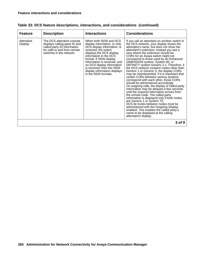
Feature interactions and considerations
284 Administration for Network Connectivity for Avaya Communication Manager
Attendant Display
The DCS attendant console displays calling-party ID and called-party ID information for calls to and from remote switches in the network.
When both ISDN and DCS display information, or only DCS display information, is received, the switch displays the DCS display information in the DCS format. If ISDN display information is received, and no DCS display information is received, then the ISDN display information displays in the ISDN formats.
If you call an attendant on another switch in the DCS network, your display shows the attendant’s name, but does not show the attendant’s extension, instead you see a zero where the extension should be.CORs for an Avaya switch might not correspond to those used by an Enhanced DIMENSION system, System 85, or DEFINITY system Generic 2.1. Therefore, if the DCS network contains nodes other than Generic 1 or Generic 3, the display CORs may be misinterpreted. If it is important that certain CORs between various systems correspond with each other, those CORs should be administered accordingly.On outgoing calls, the display of called party information may be delayed a few seconds until the required information arrives from the remote node. The called party information is displayed only if both nodes are Generic 1 or System 75.DCS tie trunks between nodes must be administered with the Outgoing Display enabled. This enables the called party’s name to be displayed at the calling attendant’s display.
Table 33: DCS feature descriptions, interactions, and considerations (continued)
Feature Description Interactions Considerations
3 of 9
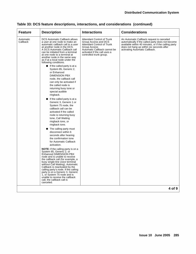
Distributed Communication System
Issue 10 June 2005 285
Automatic Callback
DCS Automatic Callback allows a user at one node to make an automatic callback call to a user at another node in the DCS. A DCS Automatic Callback call can be initiated from a terminal at one node to a terminal at another node in the same way as if at a local node under the following conditions.
● If the called party is at a System 85, Generic 2, or Enhanced DIMENSION PBX node, the callback call can only be activated if the called node is returning busy tone or special audible ringback.
● If the called party is at a Generic 3, Generic 1 or System 75 node, the callback call can be activated if the called node is returning busy tone, Call Waiting ringback tone, or ringback tone.
● The calling party must disconnect within 6 seconds after hearing the confirmation tone for Automatic Callback activation.
NOTE: If the calling party is on a System 85, Generic 2, or Enhanced DIMENSION PBX node and is unable to receive the callback call (for example, a busy single-line voice terminal without Call Waiting), Automatic Callback is reactivated by the calling party’s node. If the calling party is on a Generic 3, Generic 1, or System 75 node and is unable to receive the callback call, the callback call is canceled.
Attendant Control of Trunk Group Access and DCS Attendant Control of Trunk Group AccessAutomatic Callback cannot be activated if the call uses a controlled trunk group.
An Automatic Callback request is canceled automatically if the called party does not become available within 40 minutes, or if the calling party does not hang up within six seconds after activating Automatic Callback.
Table 33: DCS feature descriptions, interactions, and considerations (continued)
Feature Description Interactions Considerations
4 of 9
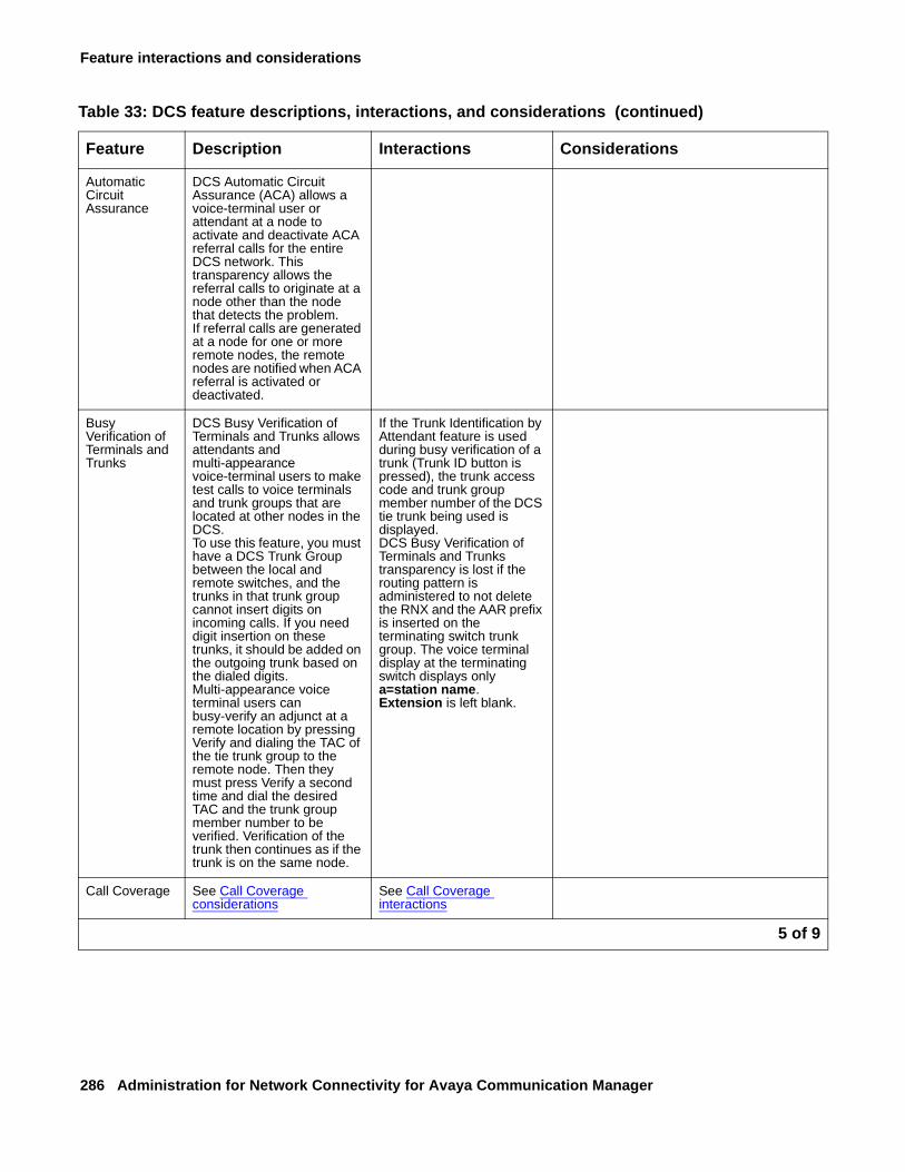
Feature interactions and considerations
286 Administration for Network Connectivity for Avaya Communication Manager
Automatic Circuit Assurance
DCS Automatic Circuit Assurance (ACA) allows a voice-terminal user or attendant at a node to activate and deactivate ACA referral calls for the entire DCS network. This transparency allows the referral calls to originate at a node other than the node that detects the problem.If referral calls are generated at a node for one or more remote nodes, the remote nodes are notified when ACA referral is activated or deactivated.
Busy Verification of Terminals and Trunks
DCS Busy Verification of Terminals and Trunks allows attendants and multi-appearance voice-terminal users to make test calls to voice terminals and trunk groups that are located at other nodes in the DCS.To use this feature, you must have a DCS Trunk Group between the local and remote switches, and the trunks in that trunk group cannot insert digits on incoming calls. If you need digit insertion on these trunks, it should be added on the outgoing trunk based on the dialed digits.Multi-appearance voice terminal users can busy-verify an adjunct at a remote location by pressing Verify and dialing the TAC of the tie trunk group to the remote node. Then they must press Verify a second time and dial the desired TAC and the trunk group member number to be verified. Verification of the trunk then continues as if the trunk is on the same node.
If the Trunk Identification by Attendant feature is used during busy verification of a trunk (Trunk ID button is pressed), the trunk access code and trunk group member number of the DCS tie trunk being used is displayed.DCS Busy Verification of Terminals and Trunks transparency is lost if the routing pattern is administered to not delete the RNX and the AAR prefix is inserted on the terminating switch trunk group. The voice terminal display at the terminating switch displays only a=station name. Extension is left blank.
Call Coverage See Call Coverage considerations
See Call Coverage interactions
Table 33: DCS feature descriptions, interactions, and considerations (continued)
Feature Description Interactions Considerations
5 of 9
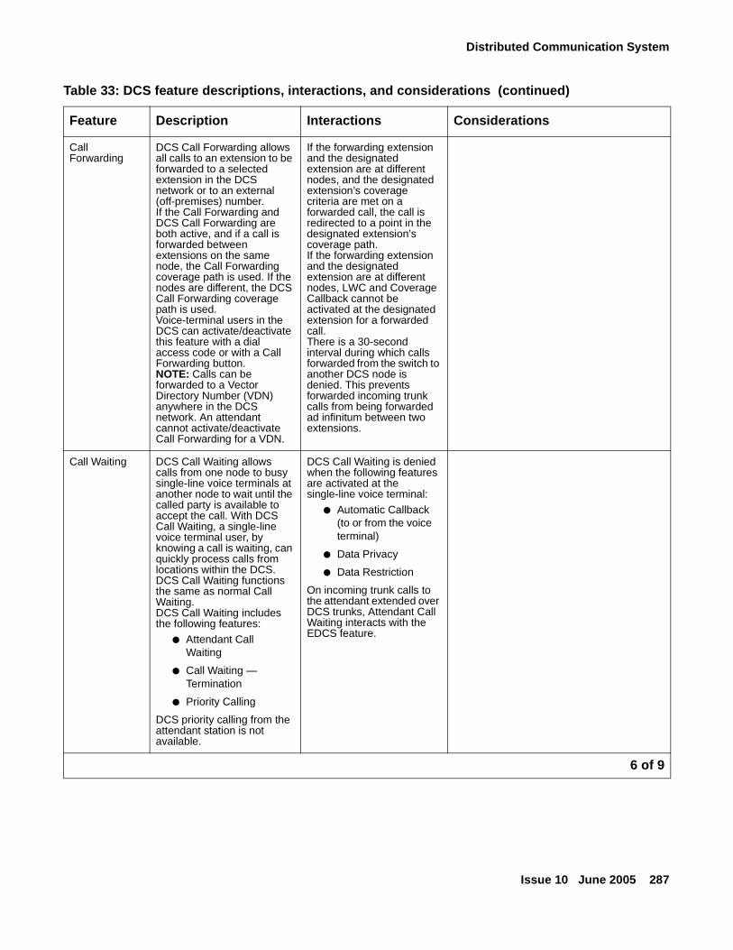
Distributed Communication System
Issue 10 June 2005 287
Call Forwarding
DCS Call Forwarding allows all calls to an extension to be forwarded to a selected extension in the DCS network or to an external (off-premises) number.If the Call Forwarding and DCS Call Forwarding are both active, and if a call is forwarded between extensions on the same node, the Call Forwarding coverage path is used. If the nodes are different, the DCS Call Forwarding coverage path is used.Voice-terminal users in the DCS can activate/deactivate this feature with a dial access code or with a Call Forwarding button. NOTE: Calls can be forwarded to a Vector Directory Number (VDN) anywhere in the DCS network. An attendant cannot activate/deactivate Call Forwarding for a VDN.
If the forwarding extension and the designated extension are at different nodes, and the designated extension’s coverage criteria are met on a forwarded call, the call is redirected to a point in the designated extension’s coverage path.If the forwarding extension and the designated extension are at different nodes, LWC and Coverage Callback cannot be activated at the designated extension for a forwarded call.There is a 30-second interval during which calls forwarded from the switch to another DCS node is denied. This prevents forwarded incoming trunk calls from being forwarded ad infinitum between two extensions.
Call Waiting DCS Call Waiting allows calls from one node to busy single-line voice terminals at another node to wait until the called party is available to accept the call. With DCS Call Waiting, a single-line voice terminal user, by knowing a call is waiting, can quickly process calls from locations within the DCS. DCS Call Waiting functions the same as normal Call Waiting.DCS Call Waiting includes the following features:
● Attendant Call Waiting
● Call Waiting — Termination
● Priority Calling
DCS priority calling from the attendant station is not available.
DCS Call Waiting is denied when the following features are activated at the single-line voice terminal:
● Automatic Callback (to or from the voice terminal)
● Data Privacy
● Data Restriction
On incoming trunk calls to the attendant extended over DCS trunks, Attendant Call Waiting interacts with the EDCS feature.
Table 33: DCS feature descriptions, interactions, and considerations (continued)
Feature Description Interactions Considerations
6 of 9
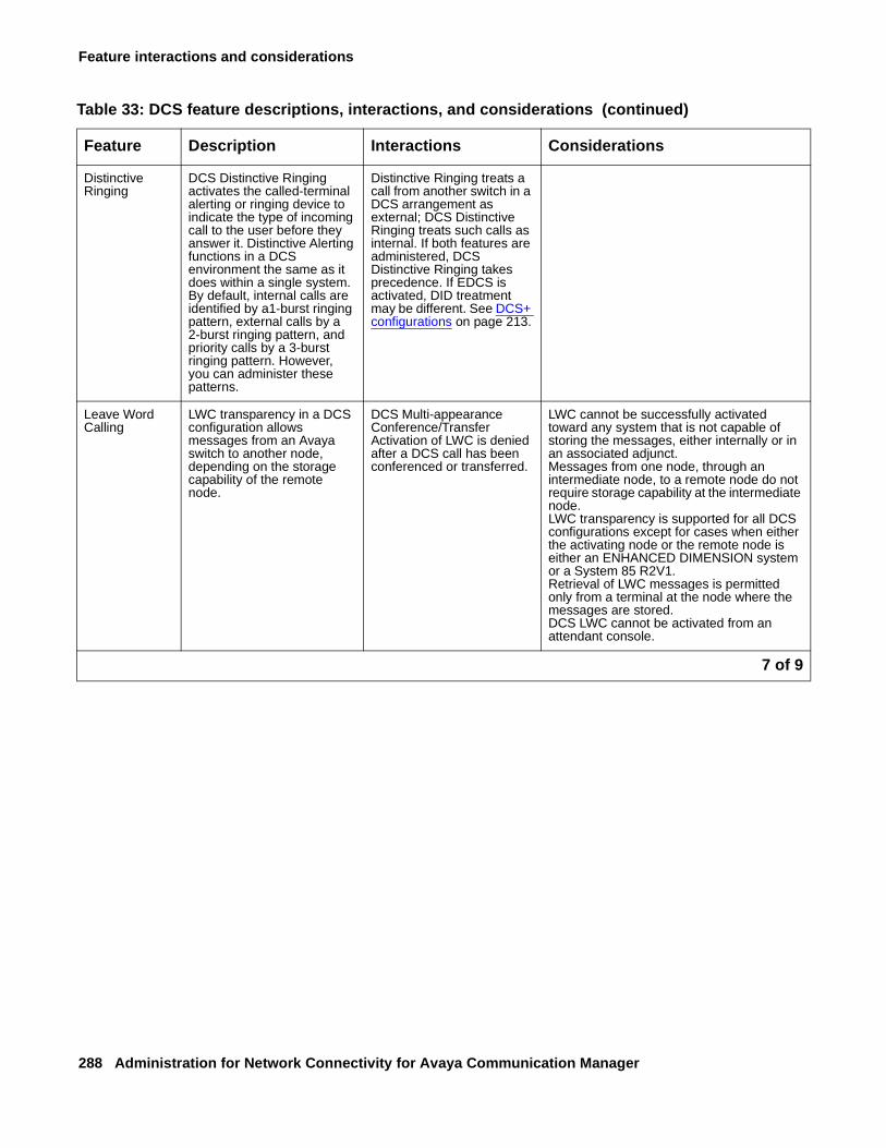
Feature interactions and considerations
288 Administration for Network Connectivity for Avaya Communication Manager
Distinctive Ringing
DCS Distinctive Ringing activates the called-terminal alerting or ringing device to indicate the type of incoming call to the user before they answer it. Distinctive Alerting functions in a DCS environment the same as it does within a single system.By default, internal calls are identified by a1-burst ringing pattern, external calls by a 2-burst ringing pattern, and priority calls by a 3-burst ringing pattern. However, you can administer these patterns.
Distinctive Ringing treats a call from another switch in a DCS arrangement as external; DCS Distinctive Ringing treats such calls as internal. If both features are administered, DCS Distinctive Ringing takes precedence. If EDCS is activated, DID treatment may be different. See DCS+ configurations on page 213.
Leave Word Calling
LWC transparency in a DCS configuration allows messages from an Avaya switch to another node, depending on the storage capability of the remote node.
DCS Multi-appearance Conference/TransferActivation of LWC is denied after a DCS call has been conferenced or transferred.
LWC cannot be successfully activated toward any system that is not capable of storing the messages, either internally or in an associated adjunct.Messages from one node, through an intermediate node, to a remote node do not require storage capability at the intermediate node.LWC transparency is supported for all DCS configurations except for cases when either the activating node or the remote node is either an ENHANCED DIMENSION system or a System 85 R2V1.Retrieval of LWC messages is permitted only from a terminal at the node where the messages are stored.DCS LWC cannot be activated from an attendant console.
Table 33: DCS feature descriptions, interactions, and considerations (continued)
Feature Description Interactions Considerations
7 of 9
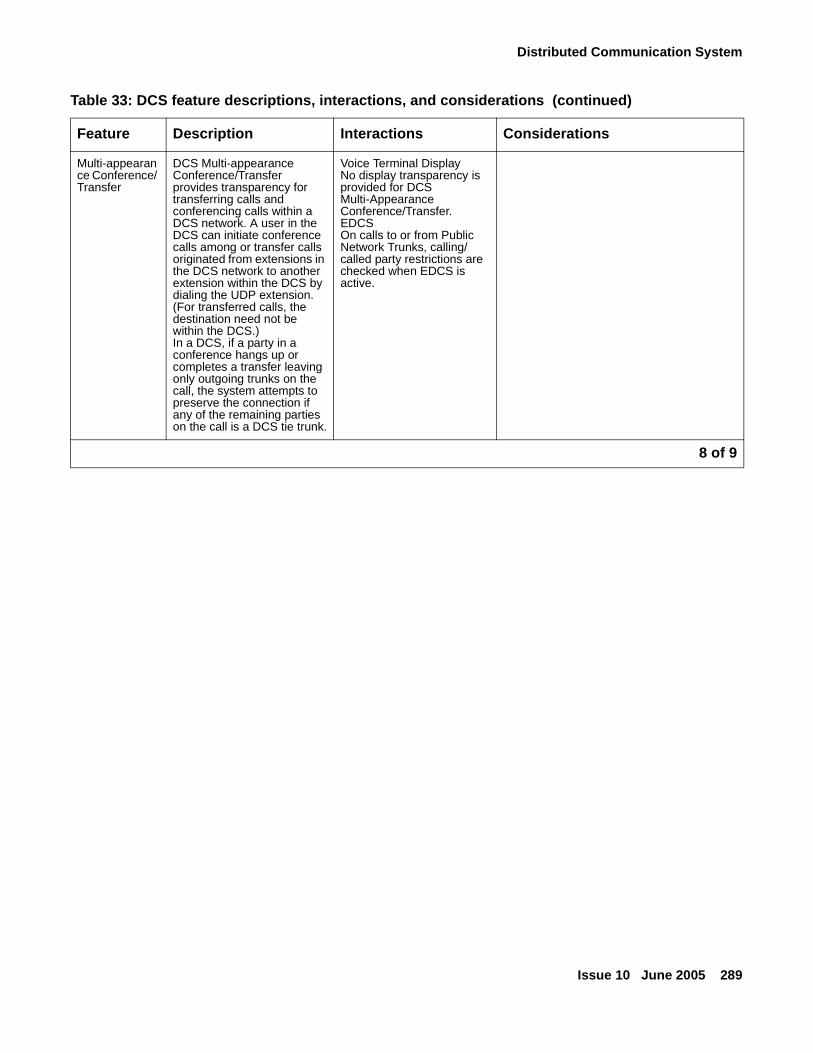
Distributed Communication System
Issue 10 June 2005 289
Multi-appearance Conference/ Transfer
DCS Multi-appearance Conference/Transfer provides transparency for transferring calls and conferencing calls within a DCS network. A user in the DCS can initiate conference calls among or transfer calls originated from extensions in the DCS network to another extension within the DCS by dialing the UDP extension. (For transferred calls, the destination need not be within the DCS.)In a DCS, if a party in a conference hangs up or completes a transfer leaving only outgoing trunks on the call, the system attempts to preserve the connection if any of the remaining parties on the call is a DCS tie trunk.
Voice Terminal DisplayNo display transparency is provided for DCS Multi-Appearance Conference/Transfer.EDCSOn calls to or from Public Network Trunks, calling/called party restrictions are checked when EDCS is active.
Table 33: DCS feature descriptions, interactions, and considerations (continued)
Feature Description Interactions Considerations
8 of 9
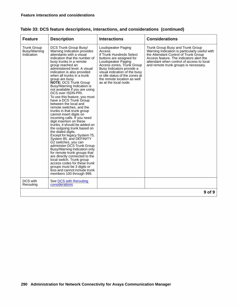
Feature interactions and considerations
290 Administration for Network Connectivity for Avaya Communication Manager
Trunk Group Busy/Warning Indication
DCS Trunk Group Busy/Warning Indication provides attendants with a visual indication that the number of busy trunks in a remote group reached an administered level. A visual indication is also provided when all trunks in a trunk group are busy.NOTE: DCS Trunk Group Busy/Warning Indication is not available if you are using DCS over ISDN-PRI.To use this feature, you must have a DCS Trunk Group between the local and remote switches, and the trunks in that trunk group cannot insert digits on incoming calls. If you need digit insertion on these trunks, it should be added on the outgoing trunk based on the dialed digits.Except for legacy System 75, System 85, and DEFINITY G2 switches, you can administer DCS Trunk Group Busy/Warning Indication only for remote trunk groups that are directly connected to the local switch. Trunk group access codes for these trunk groups must be 3 digits or less and cannot include trunk members 100 through 999.
Loudspeaker Paging AccessIf Trunk Hundreds Select buttons are assigned for Loudspeaker Paging Access zones, Trunk Group Busy Indicators provide a visual indication of the busy or idle status of the zones at the remote location as well as at the local node.
Trunk Group Busy and Trunk Group Warning Indication is particularly useful with the Attendant Control of Trunk Group Access feature. The indicators alert the attendant when control of access to local and remote trunk groups is necessary.
DCS with Rerouting
See DCS with Rerouting considerations
Table 33: DCS feature descriptions, interactions, and considerations (continued)
Feature Description Interactions Considerations
9 of 9
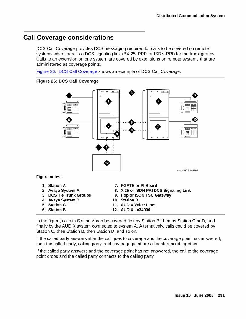
Distributed Communication System
Issue 10 June 2005 291
Call Coverage considerations
DCS Call Coverage provides DCS messaging required for calls to be covered on remote systems when there is a DCS signaling link (BX.25, PPP, or ISDN-PRI) for the trunk groups. Calls to an extension on one system are covered by extensions on remote systems that are administered as coverage points.
Figure 26: DCS Call Coverage shows an example of DCS Call Coverage.
Figure 26: DCS Call Coverage
In the figure, calls to Station A can be covered first by Station B, then by Station C or D, and finally by the AUDIX system connected to system A. Alternatively, calls could be covered by Station C, then Station B, then Station D, and so on.
If the called party answers after the call goes to coverage and the coverage point has answered, then the called party, calling party, and coverage point are all conferenced together.
If the called party answers and the coverage point has not answered, the call to the coverage point drops and the called party connects to the calling party.
Figure notes:
1. Station A2. Avaya System A3. DCS Tie Trunk Groups4. Avaya System B5. Station C6. Station B
7. PGATE or PI Board8. X.25 or ISDN PRI DCS Signaling Link9. Hop or ISDN TSC Gateway
10. Station D 11. AUDIX Voice Lines12. AUDIX - x34000
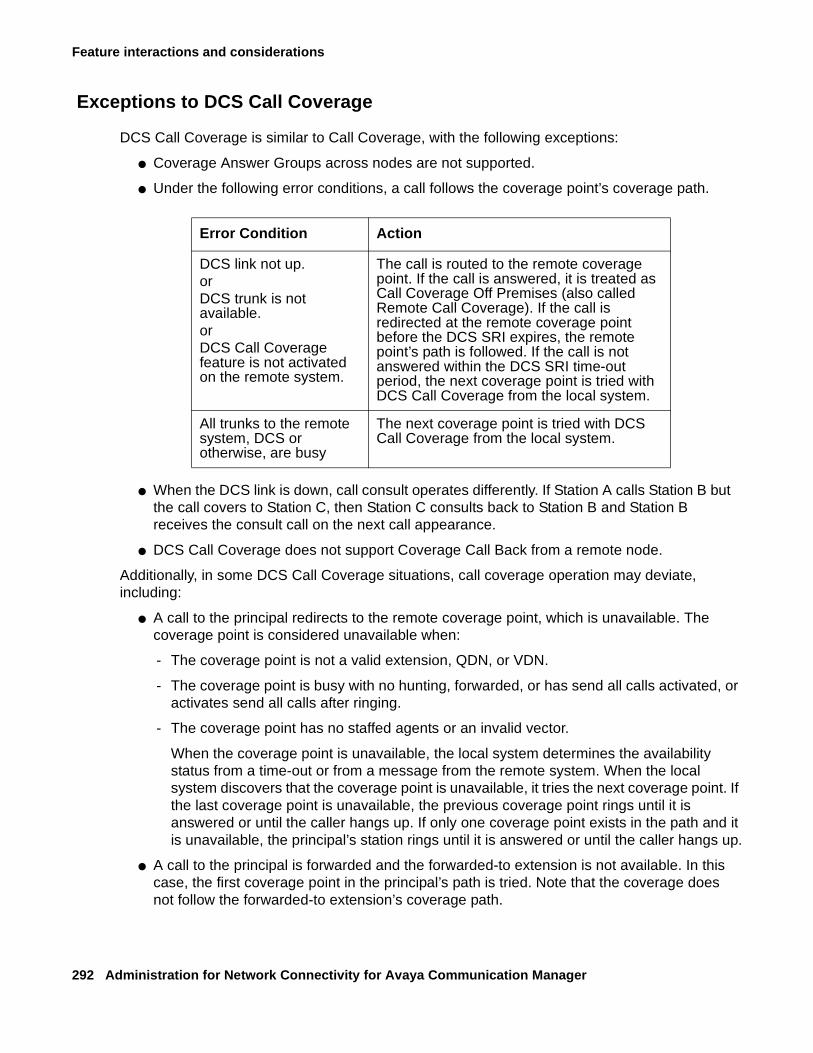
Feature interactions and considerations
292 Administration for Network Connectivity for Avaya Communication Manager
Exceptions to DCS Call Coverage
DCS Call Coverage is similar to Call Coverage, with the following exceptions:
● Coverage Answer Groups across nodes are not supported.
● Under the following error conditions, a call follows the coverage point’s coverage path.
● When the DCS link is down, call consult operates differently. If Station A calls Station B but the call covers to Station C, then Station C consults back to Station B and Station B receives the consult call on the next call appearance.
● DCS Call Coverage does not support Coverage Call Back from a remote node.
Additionally, in some DCS Call Coverage situations, call coverage operation may deviate, including:
● A call to the principal redirects to the remote coverage point, which is unavailable. The coverage point is considered unavailable when:
- The coverage point is not a valid extension, QDN, or VDN.
- The coverage point is busy with no hunting, forwarded, or has send all calls activated, or activates send all calls after ringing.
- The coverage point has no staffed agents or an invalid vector.
When the coverage point is unavailable, the local system determines the availability status from a time-out or from a message from the remote system. When the local system discovers that the coverage point is unavailable, it tries the next coverage point. If the last coverage point is unavailable, the previous coverage point rings until it is answered or until the caller hangs up. If only one coverage point exists in the path and it is unavailable, the principal’s station rings until it is answered or until the caller hangs up.
● A call to the principal is forwarded and the forwarded-to extension is not available. In this case, the first coverage point in the principal’s path is tried. Note that the coverage does not follow the forwarded-to extension’s coverage path.
Error Condition Action
DCS link not up.orDCS trunk is not available.orDCS Call Coverage feature is not activated on the remote system.
The call is routed to the remote coverage point. If the call is answered, it is treated as Call Coverage Off Premises (also called Remote Call Coverage). If the call is redirected at the remote coverage point before the DCS SRI expires, the remote point’s path is followed. If the call is not answered within the DCS SRI time-out period, the next coverage point is tried with DCS Call Coverage from the local system.
All trunks to the remote system, DCS or otherwise, are busy
The next coverage point is tried with DCS Call Coverage from the local system.
Distributed Communication System
Issue 10 June 2005 293
● A call to the principal redirects to the remote coverage point, which answers. Subsequently, the principal goes off hook. In this case, the local system bridges the principal onto the call between the calling party and coverage point creating a conference among the three. The principal receives the call on the same call appearance as the original call.
● A call to the principal redirects to the remote coverage point. While the remote coverage point is ringing, the principal answers the call. In this case the call is not cut through to the coverage point. Instead, ringing and ringback is removed from the coverage point and the call is cut through to the principal.
DCS with Rerouting considerations
DCS with Rerouting allows a call’s connection between two Avaya switches to be replaced by a new connection. All of the trunks used in the original path must be DCS+ (DCS over PRI) and the new path utilizes only DCS+ trunks. DCS with Rerouting provides the following capabilities:
● Attempts to obtain a better (generally less expensive) connection.
● May replace the current path of a call with a route that is better in terms of Automatic Alternate Routing/Automatic Route Selection (AAR/ARS) routing preferences administered on an Avaya switch.
● Frees up resources being used unnecessarily.
DCS with Rerouting must be enabled on a switch-wide basis and the trunk groups involved must be administered as SSE. DCS with Rerouting primarily provides you with the ability to be more effective with the usage of Trunk groups administered for Supplementary Services Protocol Option E (SSE) during the existence of an active call. This means using a preferred route (in terms of UDP/AAR/ARS routing preferences administered on the switch) between the switches involved.
DCS with Rerouting can be invoked after Call Coverage. This Call Coverage also applies to AUDIX calls.
To invoke DCS with Rerouting:
1. On page 1 of the System-Parameters Call Coverage/Call Forwarding screen, enter n in the Maintain SBA at Principal field.
DCS with rerouting can only occur if you do not need to maintain a simulated bridged appearance at the principal.
2. On page 3 of the System-Parameters Customer-Options screen, verify DCS with Rerouting field set to y.
Feature interactions and considerations
294 Administration for Network Connectivity for Avaya Communication Manager
3. On page 1 of the Trunk Group screen, enter e in the Supplementary Services Protocol field.
This option allows limited QSIG signaling over DCS trunks.
To enable this value (e), review the following fields on this screen for the appropriate values:
● DCS with Rerouting must be set to y.
● Service Type must not be set to dmi_mos or SDDN.
4. On page 2 of the Trunk Group screen, review the following fields for the appropriate values:
● Used for DCS must be set to y.
● Send Name can only be set to y or n. You cannot use restricted.
Users can invoke DCS with Rerouting by Call Transfer, Transfer out of AUDIX, and dial 0 out of AUDIX.
Alphanumeric Display interactions
The following features allow transparency with respect to Calling or Called Name Display and miscellaneous ID.
● Call Coverage
At the calling terminal, the miscellaneous id “cover” is not displayed.
● Call Forwarding
When a system user calls a party on a different node in the DCS and the call is forwarded, the miscellaneous ID “forward” is not displayed. At the covering (forwarded-to) user’s terminal, only the calling party’s name is shown; the called party’s name is not displayed.
● Call Park
When a DCS call between a local system user and a user on another node is parked by the remote user, the miscellaneous ID “park” is not displayed at the local terminal.
● Call Pickup
When a DCS call from a system user to another node is answered by way of Call Pickup, the miscellaneous ID “cover” is not displayed at the caller’s terminal.
● Call Waiting
When a DCS call from a system user to another node is waiting at the called terminal, the miscellaneous ID “wait” is not displayed at the caller’s terminal.
● CAS
When a user dials the extension for CAS, a RLT is seized or the caller is queued for an RLT. The caller’s terminal displays the trunk group identifier, such as OPERATOR.
Distributed Communication System
Issue 10 June 2005 295
● ISDN-PRI
If both DCS and ISDN-PRI features are provided with a system, the ISDN-PRI display information displays in DCS format.
Call Coverage interactions
DCS Call Coverage has the same interactions as Call Coverage plus the following additional interactions:
● Call Coverage Off Premises
If the coverage point is a non-UDP number in the remote call coverage table, Call Coverage Off Premises is applied to the call rather than DCS Call Coverage, even if a DCS link exists to the remote system.
● Coverage Answer Groups
DCS Call Coverage to Coverage Answer Groups on remote systems are not supported by DCS Call Coverage. Coverage answer groups cannot be administered on a system other than the principal’s system.
● Coverage Call Back
DCS Call Coverage does not support Coverage Call Back from a remote node.
● Displays
The displays on the DCS Call Coverage point’s terminal may be different than those associated with the Call Coverage feature in the following situations:
- When the call from the calling party to the principal or the redirected call to the coverage point travel over ISDN-PRI trunk groups.
- When the calling party is on a System 85 or Generic 2.
- When the DCS name message is not received by the remote (coverage point’s) system.
● Go to Cover
Go to Cover is not supported over DCS and therefore is not supported with DCS Call Coverage.
● Leave Word Calling Back to Principal
With DCS Call Coverage, a covering user on a different node cannot press their LWC button to leave a message for the principal to call the covering user.
● Queuing
DCS Call Coverage interacts with queuing in the following way. If a call is queued to a coverage point, such as a queue to a hunt group or an ACD split, and the queue is not full, the call remains in the queue without subsequent redirection until answered or until the caller hangs up.
Feature interactions and considerations
296 Administration for Network Connectivity for Avaya Communication Manager
DCS with Rerouting interactions
● When interworking with non-ISDN trunks or non-Supplementary Service Option E ISDN trunks, the system acts as a gateway in the following sense:
- When a call is tandeming through an Avaya switch from a non-ISDN trunk to an SSE trunk or from a non-Option E to an SSE trunk, the system acts as an incoming gateway.
- When a call is tandeming through an Avaya switch from an SSE trunk to a non-ISDN trunk or from an SSE trunk to a non-Option E trunk, the system acts as an outgoing gateway.
As an example, when calls come in from the public network to the DCS network and then are transferred to another extension within the private network, the Avaya switch functions as an incoming gateway and rerouting occurs.
● If a conference call is transferred, rerouting will not occur.
IGAR interactions
One primary factor affects how features operate when a system uses trunks as Inter-Gateway Connections: delays. Specifically, it takes longer to establish a connection between gateways using trunks. The longer it takes for a trunk to reach the active or "answered" state, the more significant this delay will be. If the Intentional Delay introduced to allow the IGC to become active were not implemented, users would notice that the two parties are unable to hear each other for several seconds whenever an incoming inter-PN/MG call is answered "too quickly."
Note:Note: Intentional Delay applies only when IGAR is triggered by a call placed by a
particular user (or an incoming trunk). When IGAR is triggered by a user “answering” the call (using call pickup, bridging, etc.), the user may hear silence for a few seconds until the Trunk IGC is active.
Basic system
Facility restriction levels (FRLs)
Facility Restriction Levels (FRLs) can be used to limit the number of users that have access to the IGAR feature. Specifically, IGAR will take the FRL of the calling party into account when selecting a trunk. This can cause users to notice that sometimes they are able to place an “intra-switch” call from a low-FRL station, while other times (for example, when IGAR is active), the call fails or is routed immediately to coverage, because all the trunks accessible from that station were busy or otherwise not available.
Distributed Communication System
Issue 10 June 2005 297
Alternate facility restriction levels - If a user has invoked their Alternate FRL, IGAR will use it instead of their default FRL when selecting a trunk.
Call redirection
IGAR, if enabled, routes the call to the destination using the alternate route specified regardless of the redirection feature active on the extension. After the call reaches the destination using IGAR, normal call redirection will occur.
Data calls
With data calls, there is typically no human involved, so it is not essential to prevent several quiet seconds from elapsing before the trunk is set up (Intentional Delay). However, since most data handshake protocols are able to handle such delays, these calls are treated in the same way as voice calls.
Firmware download
Firmware can be downloaded to a circuit pack, media module, media gateway, or voice terminal over a LAN or WAN. Therefore, customers must allocate sufficient bandwidth for firmware downloads when setting up CAC Bandwidth Limits. IGAR will not be invoked to download firmware when insufficient bandwidth exists. If a download fails, the system may retry later, or make it known that the download must be retried manually or rescheduled.
Meet-me conferencing
The announcement that typically prompts for a password at the beginning of a Meet-Me Conference is covered under Call Center - Announcement Delays below. Thus, a caller into a Meet-Me Conference will hear the entire announcement. If the first Meet-Me vector step is not an announcement, but IGAR is triggered for the call, the caller may hear silence for a few seconds until the Trunk IGC is active.
Message retrieval: voice systhesis
Voice Synthesis messages are not expected to be played across network regions. Each NR should be configured with enough Voice Synthesis boards to support the users in that NR.
Message sequence tracer (MST
In a future CM release, MST may be enhanced to include a link between an IGAR trunk call and the internal call with which the trunk call is associated.
Restriction features
In CM 3.0, the typical Class of Restriction (CoR) attribute that determines whether or not IGAR is able to select a trunk is the Facility Restriction Level (FRL). In addition, stations that are locked and have a station lock CoR, such that the CoR does not allow making outward calls, are not allowed to make IGAR calls. Other restrictions such as Toll Restriction do not apply. In a future CM release, the customer may be allowed to select whether or not, or to what degree, these restrictions apply.
Feature interactions and considerations
298 Administration for Network Connectivity for Avaya Communication Manager
Networking
Automatic circuit assurance (ACA)
If Trunk IGCs are cached, trunks may stay active for a very long time when IGAR is in effect. IGAR calls will also generate ACA short/long calls similar to trunk calls. Customers should consider this when activating ACA for long-held trunk calls.
Call detail recording (CDR)
CDR records are created for Trunk IGCs. The customer can recognize them by the calling/called number:
● For an outgoing trunk IGC, the local IGAR extension is recorded as the originator, and the IGAR number for the far end is recorded as the dialed digits.
● For an incoming trunk IGC, the originator is the caller ID/ANI/CPN (as usual), and the destination is the local IGAR extension.
Note:Note: If Trunk IGCs are cached, the incoming and outgoing CDR records are not
generated when the associated call drops, but rather when the Trunk IGC “expires” and is flushed from the cache.
For unanswered IGAR calls, in general, two CDR records are generated:
1. For the IGAR user to trunk portion of the call.
2. For the incoming trunk to the IGAR user.
Examples of this outcome are:
● Station-to-station calls in which IGAR is invoked to complete the call
● Incoming trunk calls that land onto another network region invoking IGAR
● Outgoing trunk calls that require a trunk in another network region
Charge advice - Charge advice received from the PSTN for an outgoing ISDN Trunk IGC is recorded in the CDR record for the Trunk IGC, and not for the internal connection or call that triggered IGAR.
Periodic pulse metering (PPM) - The number of PPM pulses received from the PSTN for an outgoing non-ISDN Trunk IGC is recorded in the CDR record for the Trunk IGC, and not for the internal connection or call that triggered IGAR.
Distributed communication service (DCS)
Customers may configure their ARS routing to select a DCS trunk group. This is particularly likely for North American customers that use DCS+ over the AT&T SDN (or a similar service offered by other service providers). If IGAR selects a DCS trunk group, this does not affect feature transparency for the call that triggered IGAR. Since that call must be an internal call, full feature functionality is available.
Distributed Communication System
Issue 10 June 2005 299
CM software may occasionally need a Trunk IGC to connect a calling user to an outgoing DCS trunk group, or to connect an incoming DCS trunk group to the called party, if the users and the trunk group are not in the same Network Region. If this occurs, DCS feature functionality works as though no Trunk IGC were needed.
If in the above scenario a call is transferred and no parties remain on the call at a particular DCS node, two events occur simultaneously:
● The IGAR feature drops the Trunk IGC (or moves it to the cache).
● The DCS Reroute feature drops the DCS trunk, if a more optimal path is found.
Emergency calls (E911)
If a voice station dials an emergency number (for example, 911 in North America), and the only available outgoing trunk is in a network region accessible only by IGAR, the appropriate calling party information will be sent over the outgoing trunk while the IGAR connection is set up. Thus, even if the IGAR connection fails, emergency responders will be notified of the emergency call.
Note:Note: Customers should not configure systems this way — emergency calls should be
routed out over trunks in the local NR. However, this may still happen in an emergency that takes the local trunks out of service.
Multi-vendor private-network QSIG connectivity (including SBS)
Customers may configure their ARS routing to select a QSIG trunk group. However, because QSIG does not work over the public network, and because SBS trunk groups are not eligible for use by IGAR, this is unlikely. But even if it were to happen, the call that triggered IGAR is an internal call, and so full feature functionality is available.
CM software may occasionally need a Trunk IGC to connect a calling user to an outgoing QSIG or SBS trunk group, or to connect an incoming QSIG or SBS trunk group to the called party, if the users and the trunk group are not in the same network region. If this occurs, QSIG feature functionality will work as though no Trunk IGC were needed.
If in the above scenario a call is transferred and no parties remain on the call at a particular QSIG node, two events occur simultaneously:
● The IGAR feature drops the Trunk IGC (or moves it to the cache).
● The QSIG Path Replacement feature drops the QSIG trunk, if a more optimal path is found.
Personal central office line (PCOL)
If the PCOL button on a voice terminal is associated with a trunk in a different network region, IGAR may be required to set up the connection. The user hears local dial tone, and any digits dialed are buffered and sent when the IGAR trunk becomes active; however, some delay may be noticeable by that user. In general the PCOL trunk should be in the same network region as the voice terminal.
Feature interactions and considerations
300 Administration for Network Connectivity for Avaya Communication Manager
Routing a call
IGAR trunk selection follows all ARS routing steps. Exceptions are noted in the following subsections.
Automatic alternate routing (AAR) - Although selection of a trunk for IGAR starts out using ARS, the customer may use ARS Digit Conversion to convert the number to a private-network number and use AAR instead.
Generalized route selection - IGAR assumes a Bearer Capability Class 0 (voice/3.1 kHz) when searching for an available trunk. BCC 0 originators can select a Route Pattern Preference with data BCC, but BCC 0 preferences are attempted first. In a future CM release, IGAR may be allowed to specify a BCC other than 0, if a Trunk IGC is needed specifically for a data connection.
Tenant partitioning - Tenant Partitioning can block a tenant from calling another tenant, and can block a tenant from using trunks allocated to another tenant. These restrictions are administered as a unit. Therefore, if IGAR is triggered on a call between tenants, IGAR can use trunks assigned to either tenant (or any other tenant the calling user can access) to set up the Trunk IGC.
Trunk-to-trunk transfer
The Trunk-to-Trunk Transfer system parameter does not control whether a call that includes a Trunk IGC can be transferred.
Trunk access code (TAC) dialing
When a user dials the TAC of a trunk group in a different network region, IGAR may be required to set up the connection. The user will in most cases hear local dial tone, and any digits dialed will be buffered and sent when the IGAR trunk becomes active; however, some delay may be noticeable by that user.
Trunk signaling & protocols
The trunk signaling required to set up a Trunk IGC takes place in parallel with the inter-PN/MG IP signaling that sets up the internal call. Clearly then, the faster the trunk, the less noticeable IGAR will be to the parties involved in the call.
QSIG interactions
Issue 10 June 2005 301
QSIG interactionsQSIG interactions included in this section are
● QSIG/DCS Interworking
● Call Forwarding (Diversion)
● Call Transfer
● Transfer Into QSIG Voice Mail
● QSIG Name and Number Identification
● Path Replacement (PR)
● Transit Counter (TC)
● Call Completion (CC)
● Message Waiting Indicators (MWI)
● Called/Busy Name and Number
● VALU Call Coverage
● QSIG Centralized Attendant Service
QSIG/DCS Interworking
No features are interworking between QSIG and traditional DCS. With DCS+, only the following features are interworking:
● Name and number transport
● Voicemail
● Leave word calling
Call Forwarding (Diversion)
The interactions that apply to the standard Call Forwarding features also apply to Call Forwarding (Diversion) with QSIG. The following are additional interactions.
● Alternate Facilities Restriction Levels
The AFRL of the original call is the AFRL used for Call Forwarding with Reroute.
● Authorization Codes
Call Forwarding with Reroute is denied to calls that require an Authorization Code.
Feature interactions and considerations
302 Administration for Network Connectivity for Avaya Communication Manager
● Automatic Alternate Routing and Automatic Route Selection
Call Forwarding with Reroute uses AAR and ARS to reroute the original call.
● Call Detail Recording
Call Forwarding with Reroute is denied to calls that require Forced Entry of Account Codes.
● Call Transfer
When a forwarded call transfers, the forwarding indication displays to the caller until the call is answered. This display includes the trunk group name and word “forward.” When the call is answered, the word “forward” is removed and the name and number of the answering party displays.
● Distributed Communications Systems
Call Forwarding feature transparency does not exist on calls tandemed between a QSIG (Supplementary Service protocol b) network and a traditional DCS network. However, the basic call continues.
● Facility Restriction Levels and Traveling Class Marks
The FRL (and TCM) of the original call is the FRL used for Call Forwarding with Reroute.
● Forwarding and Coverage
If a coverage point is a number that routes over an ISDN (Supplementary Service protocol b) trunk, QSIG diversion information is passed to the coverage switch.
● QSIG Name and Number Identification
Availability of name and/or number display at the originating and diverted-to users depends upon how QSIG Name and Number Identification has been administered for the switches involved.
● Terminating Call has Coverage Active
If a call is forwarded off switch, and Cover after Forward is set to y on the Feature-Related System-Parameters screen, then the call will follow the original called party’s cover path. If the Cover after Forward field is set to n, the terminating switch has call coverage activated, and the criteria are met, the call does not route to the forwarding party’s coverage path. It routes to the terminating station’s coverage path.
QSIG interactions
Issue 10 June 2005 303
Call Transfer
● Call Forwarding (Diversion)
When a call is forwarded and transferred or transferred and forwarded, the forwarding indication displays to the caller until the call is answered. This display includes the trunk group name and word “forward.” When the call is answered, the word “forward” is removed and the name and number of the answering party displays.
● Distributed Communications Systems
The only DCS transparency that exists when a call is transferred in a DCS network and passed over a QSIG administered trunk is calling name and number.
● QSIG Path Replacement
PR is invoked whenever a QSIG transferred call is answered.
● QSIG Name and Number Identification
Availability of name and/or number display at the connected parties depends upon how QSIG Name and Number Identification has been administered for the switches involved.
Transfer Into QSIG Voice Mail
● QSIG Path Replacement
After a call is transferred into QSIG voice mail and the voice mail system answers the call, Path Replacement is attempted.
QSIG Name and Number Identification
● Distributed Communications Systems (DCS+)
In a DCS+ network, Communication Manager displays the DCS called name/number information or it will display ISDN connected name/number information, depending upon who answers the call.
When an incoming ISDN call is routed back out over a non-ISDN trunk group, Communication Manager can send the name of the non-ISDN trunk group as the connected name if the Send Non-ISDN Trunk Group Name as Connected Name field is y on the Feature-Related System-Parameters screen.
Communication Manager interworks called/calling/connected name and number identification between DCS+ and QSIG.
Feature interactions and considerations
304 Administration for Network Connectivity for Avaya Communication Manager
Path Replacement (PR)
● Basic Call Management System
On a connection monitored by a BCMS entity, PR is allowed.
● Call Detail Recording
Codes for recording the new connections of PR calls are code J for incoming trunk calls and code K for outgoing trunk calls. When a path is replaced, you also may receive records for short-duration calls that are not directly linked to the J and K records.
● Call Management System
On a connection monitored by a CMS entity, PR is allowed.
Note:Note: Communication Manager sends updates for transfer and conference to BCMS
and CMS to make reports complete. Path Replacement is allowed.
● Call Vectoring
A transferred call that terminates at a vector and is answered can have its path replaced.
● Data-Call Setup
A data call is denied PR.
● Data Privacy
If Data Privacy is active, PR is denied.
● Data Restriction
If Data Restriction is active, PR is denied.
● Malicious Call Trace
If MCT is active, PR is denied.
● Recorded Announcement
A call that is connected to a recorded announcement cannot have its path replaced.
● Trunk Access Code
If the old connection was made using a TAC, PR is denied.
● Restriction Features
PR is denied when restriction features such as COR of the Voice Terminal do not allow new connections to be established, unless the COS assigned to the old/new connections override the restrictions.
QSIG interactions
Issue 10 June 2005 305
● Voice Terminals
Voice terminal displays that show trunk group name should update with new trunk group information after PR occurs. Calling and connected party displays are not disturbed when PR takes place if the original display shows the connected party name, number, or both.
Transit Counter (TC)
● Call Forwarding (Diversion)
When call forwarding (Diversion) occurs and the TC feature is enabled, the transit counter is set to zero.
● ISDN Trunk Group Administration
If all of the conditions are satisfied for both the Tandem Hop Limitation and TC, TC takes precedence. In situations where the switch is an Incoming or Outgoing Gateway, either makes use of the hop count/transit count information provided by the other.
● Trunk Access Code (TAC)
TC does not apply to TAC calls.
Call Completion (CC)
● Adjunct Switch Applications Interface (ASAI)
ASAI cannot invoke/initiate QSIG-CC.
● Attendant Calling Waiting and Call Waiting Termination
If you activate QSIG-CC to a single line voice terminal, the Attendant Call Waiting and Call Waiting Termination features are denied.
● Attendant Console Group
You cannot activate QSIG-CC toward the attendant console group or towards an individual attendant extension.
● Attendant Control of Trunk Group Access
You cannot activate QSIG-CC if the call uses a controlled trunk group.
● AUDIX
You cannot activate QSIG-CC towards AUDIX. CC to any transferred-to station is not allowed.
Feature interactions and considerations
306 Administration for Network Connectivity for Avaya Communication Manager
● Automatic Call Distribution (ACD)
You cannot activate QSIG-CC towards a voice terminal after dialing the ACD group extension. It is possible to invoke CC towards a station when dialing the individual’s extension number. You can activate CC from any ACD agent.
● Bridged Call Appearance
You cannot activate QSIG-CC from a bridged call appearance. When a call originates from a primary extension number, the return call notification rings at all bridged call appearances.
● Busy Verification
After the called party in a QSIG-CC call hangs up, neither extension number can be busy-verified until both the calling and called parties are connected or the callback attempt is canceled (by the activating party or by time-out of the callback interval).
● Diversion
QSIG-CC requests are always activated at the principal user and not coverage points. Similar to ACB, QSIG-CC calls to the called user can redirect to coverage.
● Call Forwarding
You cannot activate CCBS or CCNR towards a called station that has Call Forwarding enabled.
● Call Pickup
On recall at the originating side, a group member cannot answer a QSIG-CC call for another group member.
● Call Waiting
Call Waiting is denied when QSIG-CC is activated to the single-line voice terminal.
● Conference and Transfer
You cannot activate QSIG-CC towards a transferred-to party.
● Hold
A single-line voice terminal cannot receive a QSIG-CC call while it has a call on hold.
● Hotline Service
A station originating a hotline service call cannot request CC.
● Internal Automatic Answer (IAA)
If the IAA feature is enabled, QSIG-CC calls are not answered automatically.
● Manual Originating Line Service
A manual originating service cannot request QSIG-CC.
● Multimedia Endpoints
You cannot activate QSIG-CC towards multimedia data endpoints.
QSIG interactions
Issue 10 June 2005 307
● Restriction Features
- Class of Restriction (COR): Any terminal that is Origination-restricted cannot activate CC. Any terminal that is Termination-restricted cannot have CC activated towards it.
- Class of Service (COS): To invoke CC, the ACB field on the Class of Service screen of the calling terminal must be set to y.
● Ringback Queuing
Ringback Queueing and ACB share the same button to indicate that they are active. If the user has only one ACB button, then both features cannot be active at the same time.
● Outgoing Trunk Queuing
Outgoing Trunk Queueing cannot be invoked after the calling party answers the priority call back call and no trunks are available. The CCBS and CCNR request cancels at both switches.
● Termination Extension Group (TEG)
You cannot activate QSIG-CC towards a TEG extension, but QSIG-CC requests can be activated towards a single member in the group.
● Uniform Call Distribution and Direct Department Calling
You cannot activate QSIG-CC towards a uniform call distribution group or a direct department calling group extension, but you can activate it when calling a single member in the group.
● Vector Directory Number (VDN)
You cannot activate CC towards a VDN extension.
Message Waiting Indicators (MWI)
● Automatic Alternate Routing/Automatic Route Selection (AAR/ARS) Partitioning
All QSIG MWI messages use Partition Group 1 for routing.
● Alternate Facilities Restriction Levels
QSIG MWI messages have unrestricted COR.
● DCP and Mode Code links to AUDIX
QSIG MWI does not work with the DEFINITY AUDIX that emulates a DCP phone. A csi switch that communicates with an AUDIX system by using mode codes cannot be a QSIG message center switch complex.
● Authorization Codes
The authorization codes do not block routing because the routing of temporary signaling connections (TSCs) used for QSIG MWI uses Facility Restriction Level 7 (FRL 7) (unrestricted).
Feature interactions and considerations
308 Administration for Network Connectivity for Avaya Communication Manager
● Automatic Alternate Routing (AAR)
AAR may be used to route the QSIG TSCs.
● Automatic Route Selection (ARS)
ARS may be used to route the QSIG TSCs.
● Call Coverage Features
The served user switch uses call coverage paths to divert calls to users in the served user switch to the AUDIX hunt group on the Message Center switch.
● Class of Restriction (COR)
QSIG MWI messages use the default COR of unrestricted.
● Class of Service (COS)
QSIG MWI messages use the default COS of unrestricted.
● Facility Restriction Levels and Traveling Class Marks
A QSIG MWI TSC always uses FRL 7 (unrestricted).
● Generalized Route Selection
GRS uses the “TSC” column on the Route Pattern screen to select a preference for carrying QSIG MWI TSCs.
● ISDN - QSIG - BRI
QSIG MWI is dependent on QSIG TSCs. QSIG MWI is possible over QSIG BRI lines.
● Message Sequence Tracer (MST)
MST traces QSIG MWI messages.
● Off-Premises Station
If a DS1 is used to implement an off-premises station, QSIG MWI does not work with the off-premises station. DS1 off-premise stations do not receive system message waiting indicators.
● Uniform Dial Plan (UDP)
It is possible to route QSIG MWI messages by using UDP.
QSIG interactions
Issue 10 June 2005 309
Called/Busy Name and Number
● Adjunct Switch Applications Interface (ASAI)
A Connected Number is sent in the Connected Event to ASAI adjuncts. Therefore, upon receipt of a Called/Busy Number, it is stored in such a way that it is not sent accidentally as a Connected Number if no actual Connected Number is received in the CONNECT message when the call is answered.
● Call Diversion (including Reroute) for ISDN QSIG
Both the Called Name and Called Number are sent to the ringing/busy extension.
● Call Transfer for ISDN QSIG
Both the Called Name and Called Number of a ringing party is sent to the transferred-to party in the QSIG “Call Transfer Complete” message.
VALU Call Coverage
The interactions that apply to DCS call coverage apply to VALU call coverage, with the exceptions listed below. See Call Coverage interactions on page 295 in for more information.
● Call Coverage Off Premises
Unlike DCS, QSIG-VALU can handle non-UDP numbers in the remote call coverage table. It is not limited to route only on UDP numbers.
● Consult
Consult from the remote covering user to principal user is not supported.
● Displays
When a Principal user bridges on the call, its display is updated with “CONFERENCE” and counted for the number of parties on the call. The remote covering user and calling user (local and remote) display is not updated with the word “CONFERENCE”.
● QSIG Centralized Attendant Service (CAS)
The calls that cover from a QSIG CAS branch to main are not treated as QSIG-VALU Coverage calls. This is because calls covered to “attd” (administered as a coverage point on a Coverage Path screen) do not use the Remote Call Coverage table and QSIG-VALU Call Coverage is supported only for coverage points associated with the Remote Call Coverage table. The implication of this is that the attendant on the main will lose QSIG-VALU Call Coverage display information and QSIG Path Replacement will not be invoked after the call is answered by the covering attendant.
Feature interactions and considerations
310 Administration for Network Connectivity for Avaya Communication Manager
● Coverage of Calls Redirected Off-Net (CCRON)
If both QSIG-VALU coverage is enabled and CCRON is enable, the QSIG-VALU coverage will have a higher precedence than CCRON.
● Privacy - Manual Exclusion
With the Call Coverage feature, when the principal user bridges onto a call that went to coverage and has been answered at the coverage point, the user is not dropped when Privacy - Manual Exclusion is activated by the Covering user.
With QSIG-VALU Coverage, if the Principal bridges on the call after the remote covering user has answered the call. then the remote coverage user stays bridged until the call clears or the covering user goes on-hook.
● Simulated Bridged Appearance (SBA)
With QSIG-VALU, maintaining SBA for Principal user will be based on the administration of the field Maintain SBA at Principal on the System Parameters Call Coverage / Call Forwarding screen.
Note:Note: SBAs are lost when Path Replacement occurs
● Temporary Bridged Appearance (TBA)
Same interaction as Simulated Bridged Appearance.
● AUDIX / Centralized AUDIX
The AUDIX system is usually specified as the last coverage point. When a call is routed to an AUDIX system (local or remote centralized place), the TBA is not maintained for the Principal user (that is, the Principal user can not bridge on to the call after it routes to the AUDIX system).
For the last coverage point, which does not require control at the Principal user’s switch, the QSIG-VALU Coverage shall divert the call as QSIG Diversion by Rerouting instead of QSIG Diversion by Forward-Switching and let the remote calling user’s switch route the call directly to the remote covering number. If the Rerouting switch indicates failure, then the Principal user’s switch (that is, the Served User’s switch in terms of QSIG Diversion) shall revert to the normal QSIG-VALU Coverage handling. The advantage of this approach is that it saves trunk resources and provide path optimization without QSIG Path Replacement.
QSIG interactions
Issue 10 June 2005 311
QSIG Centralized Attendant Service
● Abbreviated Dialing
The main attendant can use abbreviated dialing buttons to extend QSIG-CAS calls.
● Attendant Auto-manual Splitting
The attendant can split away from a call to call another party privately by pressing the START button.
● Attendant Auto Start and Don’t Split
The attendant can initiate a call while on an active call by pressing any button, without pressing the START button first. The system automatically splits the call and dials the next call. To deactivate Auto Start, press the Don’t Split button.
● Attendant Backup Alerting
If attendant backup alerting is turned on, other users on the main may have the ability to answer attendant seeking calls.
● Attendant Call Waiting
Attendant call waiting is available for calls that originate on the main.
● Attendant Calling of Inward and Public Restricted Stations
A user who is inward restricted cannot receive a call originated or extended by the attendant at the QSIG CAS main. A user who is public restricted is able to receive calls originated and extended by the QSIG CAS main attendant, provided these calls are routed over QSIG ISDN tie trunks.
● Attendant Conference
By using the attendant split/swap feature, it is possible for the attendant to conference join the attendant, calling party, and extended party together in conference. If the attendant drops out of the conference, leaving just the calling party and extended party, path replacement is not attempted.
● Attendant Direct Extension Selection (DXS) With Busy Lamp (standard and enhanced)
For QSIG-CAS the DXS allows attendants to monitor and place calls to users on the main and to place calls to users on a branch only when UDP is used.
● Attendant Group and Tenant Partitioning
Attendant Group and Tenant Partitioning are local features that do not require QSIG signaling.
Attendant Group and Tenant Partitioning do not function on a CAS branch. You can administer tenant partitioning and multiple attendant groups on a branch. However, all attendant-seeking calls at the branch are directed to the QSIG-CAS number, as administered on the console-parameters screen, regardless of any tenant partition. If the QSIG-CAS number corresponds to the Dial Access to Attendant number at the main or to a
Feature interactions and considerations
312 Administration for Network Connectivity for Avaya Communication Manager
Vector Directory Number (VDN) that eventually routes to the Dial Access to Attendant number at the main, the call is directed to the attendant group assigned to the tenant partition of the incoming trunk to the main.
● Attendant Interposition Calling and Transfer
Attendant Interposition calling and transfer is a local feature that remains unchanged by QSIG-CAS. Attendants on the main still have the ability to call and transfer to each other using Individual Attendant Extensions.
● Attendant Intrusion
Intrusion is not available in QSIG-CAS to calls that are incoming from a branch.
● Attendant Misoperation
Misoperation is used only in France and Italy. It is a local feature and does not require QSIG signaling. If the system goes into Night Service while an attendant has a call on hold, the call re-alerts at the attendant console. If it is unanswered after an administrable amount of time, the call begins alerting at the night service destination.
● Attendant Override of Diversion
Override of Diversion is not available in QSIG-CAS for incoming calls from a branch.
● Attendant Recall
Attendant Recall is not available in QSIG-CAS to calls incoming from the branch.
● Attendant Release Loop Operation
Attendant Release Loop Operation is a local switch feature. It allows an unanswered extended call on the main to return to the attendant after an administrable amount of time. The call first tries to return to the same attendant that originally answered the call and, if that attendant is not available, the call goes to the next available attendant (waiting in the Attendant Queue if necessary).
● Attendant Return Call
Attendant Return Call functions in the following manner: Suppose a call comes into the attendant from a branch. If the attendant extends the call and it is unanswered after an administrable amount of time the call returns to the attendant. Initially, the call attempts to return to the same attendant that originally handled the call. If that attendant is unavailable, then the call goes to the next available attendant (waiting in the Attendant Queue if necessary).
● Attendant Serial Calling
Attendant Serial Calling is not available in QSIG-CAS to incoming calls from the branch.
● Attendant Tones
Call identification tones are not heard by attendants answering calls from a QSIG-CAS branch.
QSIG interactions
Issue 10 June 2005 313
● Attendant Trunk Group Busy/Warning Indicators
The attendant can only receive busy/warning indicators for trunks at the main. The attendant cannot receive information about branch trunks.
● Attendant Vectoring
The attendant vectoring feature is available to QSIG-CAS at the branch and the main. An attendant-seeking call terminating at the main follows any vector steps that are defined at the main.
The QSIG-CAS Number should not contain the number of a remote VDN. Note that there is no check to block such administration, but QSIG CAS may not function correctly.
● Automatic Circuit Assurance (ACA)
The CAS attendant cannot receive ACA referral calls from a branch because any administered ACA referral extension must be local.
● Call coverage
The attendant group is allowed to be a coverage point.
If the call diverts from the branch to the main over a non-QSIG ISDN trunk, then the call is treated as a forwarded call. That is, Call Coverage Off Net (CCRON) procedures do not apply and the call is not brought back to the branch.
Note:Note: In order to obtain the full functionality of QSIG CAS, it is recommended that
routing patterns are set up so that a QSIG trunk is used when sending a call from the branch to the main.
If the call diverts from the branch to the main over a QSIG trunk (not QSIG VALU), then QSIG Diversion procedures apply.
If the call diverts from the branch to the main over a QSIG VALU trunk, then QSIG VALU Call Coverage procedures apply.
● Call forwarding
Forwarding calls to the QSIG-CAS number is allowed.
● Call park
If a call is parked and the Call Park Timeout Interval (as set on the Feature Related System Parameters screen) expires, the call is sent to the attendant.
● Call Record Handling Option
Calls are sent to the attendant as non-CDR calls if the following conditions all hold:
- the call is subject to CDR, and
- the CDR buffer is full, and
- the attendant is administered as the Call Record Handling Option on the CDR System Parameters screen.
Feature interactions and considerations
314 Administration for Network Connectivity for Avaya Communication Manager
● CDR Reports
The format of the CDR data report is an administrable option on the CDR Systems Parameters screen. Customers can select from a list of pre-defined formats or create their own. The content of the CDR records is unchanged by QSIG-CAS.
CDR records generated at the main are covered by existing procedures. Calls incoming to the attendant look like incoming trunk calls. Calls originated or extended by the attendant look like outgoing calls.
● CAS Back-Up Extension
The CAS Back-Up Extension is used in a Release Link Trunk (RLT)-CAS environment but has no benefit in QSIG-CAS.
● Conference
If a user on a branch conferences an attendant onto a call, the attendant’s display is not updated with “conference”. There is no QSIG standard defined for Conference and Avaya has not implemented conference using Manufacturer Specific Information (MSI).
● Centralized AUDIX
When a user zero’s out of AUDIX, if the destination is the attendant and the host is a QSIG-CAS branch, then the call is sent to the QSIG-CAS attendant.
● DCS+
On an incoming attendant-seeking call, calling-party information may be received at the branch if a call comes over a DCS+ trunk in the network.
● Dial Access to Attendant
When a user on a branch dials the Dial Access to Attendant number, as administered on the Dial Plan Analysis screen, the call is sent to an attendant on the main.
● DID/Tie/ISDN Intercept
DID, Tie, and ISDN trunk calls that are intercepted are sent to the attendant on the main.
● Emergency access to attendant
Emergency access may be administered so that if stations are off hook for an extended period of time, then a call is placed to the attendant, or a user can dial an Emergency access to attendant feature access code. Emergency access to calls invoked at a CAS branch attendant do not go to the attendant on the main. Instead, the call goes to an attendant on the branch. If there is no branch attendant, the call is denied.
● Individual Attendant Access
An attendant may be assigned an individual extension so that it is possible to dial that attendant directly rather than dialing the attendant group.
● ISDN (non-QSIG)
On an incoming attendant-seeking call, calling party information may be received at the branch for a call coming in over an ISDN trunk.
QSIG interactions
Issue 10 June 2005 315
● Leave word calling (LWC)
System-wide LWC Message Retrieval is not available at the CAS main attendant for a branch user’s messages.
● Malicious Call Trace (MCT)
MCT is a feature that works on existing calls. MCT will work in QSIG-CAS provided the attendants performing MCT-Activate, MCT-Control, and MCT-Deactivate are all on the same switch. That is, an attendant on the main cannot work with an attendant on the branch to perform MCT. ETSI MCT and Australia MCT cannot be invoked remotely either.
● Multifrequency Signaling
Calls coming into a branch over Multifrequency trunks are subject to intercept and may be sent to the attendant at the main. Multifrequency signaling can indicate that an incoming call on a multifrequency (MF) trunk terminate at the attendant, regardless of the dialed extension.
● Night Service
Night Service is available to QSIG-CAS. If a branch is in night service, then all attendant-seeking calls for that branch are routed to the night service destination, not the CAS attendant. If the main is in night service, then all attendant seeking calls at the main (either incoming from the main or branch) are routed to the night service destination. The night service destination must be local.
Communication Manager supports the following night service features:
- Hunt Group Night Service — allows an attendant to assign a hunt group to night service
- Night Console Service — allows a console to be designated as the night service destination
- Night Station Service — allows a station to be designated as the night service destination
- Trunk Answer from Any Station (TAAS) — allows voice terminal users to answer attendant seeking calls
- Trunk Group Night Service — allows an attendant or designated night service terminal user to assign one or more trunk groups to night service
● Outgoing Trunk Queuing
Attendant-seeking calls from branch to main can be queued at the outgoing branch trunk group.
● QSIG
All the existing QSIG features and services are available in QSIG-CAS. QSIG-CAS is available in any QSIG-CAS ISDN network (PRI, BRI, PRI/ATM, and IP).
● QSIG Call Offer
Calls extended by the attendant can invoke Call Offer. If a call invokes Call Offer, attendant return call procedures still apply.
Feature interactions and considerations
316 Administration for Network Connectivity for Avaya Communication Manager
● Extending a Call
QSIG CAS ensures that QSIG Path Replacement is attempted after split/swap, provided that all three parties (original calling party, the attendant, and the called party) are never conferenced together. That is, if the attendant toggles between the other two parties for any number of times, never conferencing all three together, and then joins the two parties together (with the attendant now out of the picture and ready to handle other calls), Path Replacement is attempted.
● Security Violation Notification (SVN)
The CAS attendant cannot receive SVN referral calls from a branch. Any administered SVN referral extension must be local.
● Special Application 8140 - Attendant Dial 0 Redirect
Attendant Dial 0 Redirect allows calls to the attendant group to be routed to one of two attendant groups based on their call priority level, and to alert with emergency ring. The two groups are the default attendant group and the priority attendant group. Administration of whether a priority level routes to the priority group is done on the Console Parameters screen.
Administration on the Console Parameters screen at the main determines to which attendant group the priority level routes, and whether calls of that priority level alert with emergency tone.
● Special Application 8141 - Listed Directory Number (LDN) Attendant Queue Priority
Calls coming to the main from a QSIG-CAS branch cannot be queued by LDN Priority. QSIG-CAS does not change the ability to of LDN Queue Priority to function for calls coming directly into the main.
● Special Application 8156 - Attendant Queuing by COR
Calls coming to the main from a QSIG-CAS branch cannot be queued by COR Priority. QSIG-CAS does not change the ability to of Attendant Queueing by COR to function for calls coming directly into or originating at the main.
● Timed reminder and Attendant timers
Attendant timers are:
- Timed Reminder on Hold — starts when an attendant puts a call on hold. When this timer expires, the held call alerts the attendant.
- Return Call Timeout — starts when a call is extended and then released from an attendant console. If this timer expires, the call is returned to the attendant.
- Time In Queue Warning — indicates the amount of time a call can wait in the attendant queue before activating an alert.
Centralized Attendant Service (CAS) interactions and considerations
Issue 10 June 2005 317
- No Answer Timeout — Calls that terminate at an attendant console ring with primary alerting until this timeout value is reached. When this timeout value is reached, the call rings with a secondary, higher pitch.
- Alerting — notifies, using secondary alerting, other attendants in an attendant group of an unanswered call. The Attendant Alerting Timed Reminder starts when a call reaches the Attendant No Answer Timeout maximum value.
● Transfer Out of AUDIX by Dialing 0
Attendant seeking calls that transfer out of AUDIX by dialing 0, whose host switch is a branch, are sent to the QSIG-CAS attendant on the main whenever the dial 0 out of AUDIX destination corresponds to the attendant group.
Centralized Attendant Service (CAS)interactions and considerations
CAS Interactions
● Abbreviated Dialing
The main attendant can use an Abbreviated Dialing button to extend CAS calls after obtaining branch dial tone.
● Attendant Auto-Manual Splitting
The SPLIT lamp and button do not function on CAS main calls extended using the RLT trunk. Attendant conference does not function on CAS calls.
● Attendant Control of Trunk-Group Access
If a branch attendant has control of an outgoing RLT trunk group, new attendant-seeking calls route to the branch attendant.
● Attendant Override of Diversion
Use Attendant Override of Diversion with CAS.
● Attendant Serial Calling
Attendant Serial Calling does not work for CAS calls.
● Automatic Alternate Routing and Automatic Route Selection
CAS calls can be routed using AAR and ARS.
Feature interactions and considerations
318 Administration for Network Connectivity for Avaya Communication Manager
● Busy-Indicator Buttons
Busy indicators can identify incoming calls over an RLT. You can also use Busy indicators to dial after the attendant starts to extend a call.
● Call Coverage
Redirect calls to a centralized attendant by Call Coverage. Do not redirect calls to a CAS backup extension for backup service using Send All Calls to the backup extension’s coverage path.
● Call Detail Recording (CDR)
If the CAS main RLT trunk has the CDR option selected, CDR records generate for incoming CAS calls.
● Call Forwarding
Do not forward calls to a CAS extension.
● DCS Operation
If an RLT trunk group is administered as a DCS trunk, the following interaction applies: On an incoming CAS call to the attendant, the DCS message displays instead of the name of the incoming RLT trunk group. Upon answering the call, the attendant hears call-identification tones, indicating that the call is a CAS call. Use a TRUNK-NAME button to obtain the name of the RLT trunk group.
● Direct Extension Selection (DXS) and Direct Trunk Group Selection (DTGS) Buttons
DXS and DTGS buttons at the main attendant console can be used with CAS. However, with DXS buttons, it takes a few seconds before the attendant hears ringback tone.
● Emergency Access to the Attendant
CAS Branch Emergency Access calls generated by a Feature Access Code route Off-Hook Alert to the branch attendant group. If there is no attendant in the branch, the call routes to the branch’s administered Emergency Access Redirection Extension. When the branch switch is in CAS Backup Service, the calls route to the backup station and the call is treated as a normal call.
● Hunt Groups
If an incoming CAS call directs to a hunt group, the call does not redirect to the hunt group’s coverage path. Depending on the circumstances, the attendant can get a busy tone or ringing.
● Leave Word Calling
If a message is left for a branch user and the attendant at the CAS switch tries to retrieve the message by using LWC message retrieval, permission is denied.
● Night Service — Night Console Service
When the CAS main enters night service, CAS calls terminate at the CAS main night-service destination. When the branch enters Night Service, CAS calls route to the branch night console, the LDN night station, or the Trunk Answer from Any Station (TAAS).
Centralized Attendant Service (CAS) interactions and considerations
Issue 10 June 2005 319
● Night Service — Trunk Answer from Any Station (TAAS)
In a multiswitch DCS environment with CAS, the result of transferring incoming trunk calls using Night Service Extension or Trunk Answer from Any Station varies depending on the home switch of the transferred-to station, the home switch of the connected trunk, and the type of night-service function chosen (Night Service Extension, Trunk Answer from Any Station, or both).
● Non-attendant Console Handling of CAS Calls
The CAS branch calls terminate at the CAS main based on the incoming RLT trunk-group day destination or night-service destination. You can also answer a CAS call by the Trunk Answer from Any Station feature.
CAS considerations
Branch Attendants
● A branch can have an attendant. Access to the branch attendant must be by way of an individual attendant extension. Incoming trunk calls in a CAS network can bypass branch attendants but can be routed back to them by the centralized attendant.
● Branch calls terminate on the CAS main switch based on the incoming RLT trunk-group day-destination or night-service destination. An attendant console is not always answering or extending incoming CAS calls. If someone other than an attendant answers a CAS call, that person can extend the call back to the branch by pressing the FLASH button on a multi-appearance voice terminal or flashing the switchhook on a single-line voice terminal. The branch reaction to Flash Signals and the branch application of tones is the same whether an attendant or someone other than an attendant answers or extends the call.
● When an analog-station call goes to coverage, the station drops from the call. This is the exception to the branch leaving the extended-to party ringing. If the main attendant extends a call to an analog station and that call goes to coverage and later returns to the main attendant, the call is treated as an incoming LDN call and the attendant must re-extend the call, if requested by the user.
● On an incoming CAS call to the main attendant, the Name field from the Trunk Group screen for that RLT displays to the attendant. Therefore, you should administer the field to provide meaningful branch identification information.
● Music-on-Hold feature at branch applies to two stages of LDN calls: during call extension and Remote Hold.
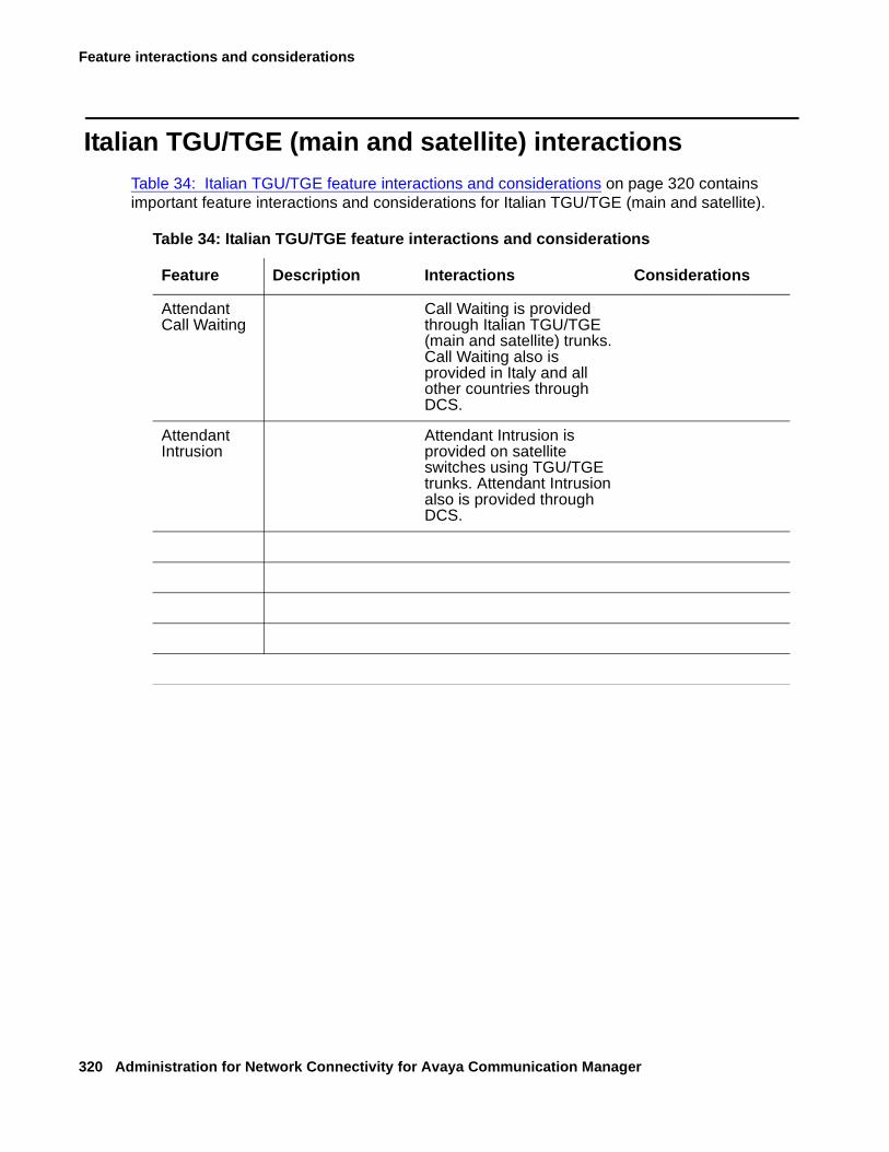
Feature interactions and considerations
320 Administration for Network Connectivity for Avaya Communication Manager
Italian TGU/TGE (main and satellite) interactionsTable 34: Italian TGU/TGE feature interactions and considerations on page 320 contains important feature interactions and considerations for Italian TGU/TGE (main and satellite).
Table 34: Italian TGU/TGE feature interactions and considerations
Feature Description Interactions Considerations
Attendant Call Waiting
Call Waiting is provided through Italian TGU/TGE (main and satellite) trunks. Call Waiting also is provided in Italy and all other countries through DCS.
Attendant Intrusion
Attendant Intrusion is provided on satellite switches using TGU/TGE trunks. Attendant Intrusion also is provided through DCS.
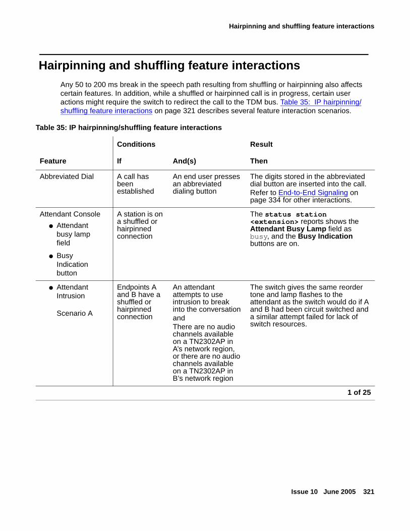
Hairpinning and shuffling feature interactions
Issue 10 June 2005 321
Hairpinning and shuffling feature interactionsAny 50 to 200 ms break in the speech path resulting from shuffling or hairpinning also affects certain features. In addition, while a shuffled or hairpinned call is in progress, certain user actions might require the switch to redirect the call to the TDM bus. Table 35: IP hairpinning/shuffling feature interactions on page 321 describes several feature interaction scenarios.
Table 35: IP hairpinning/shuffling feature interactions
Conditions Result
Feature If And(s) Then
Abbreviated Dial A call has been established
An end user presses an abbreviated dialing button
The digits stored in the abbreviated dial button are inserted into the call.Refer to End-to-End Signaling on page 334 for other interactions.
Attendant Console
● Attendant busy lamp field
● Busy Indication button
A station is on a shuffled or hairpinned connection
The status station <extension> reports shows the Attendant Busy Lamp field as busy, and the Busy Indication buttons are on.
● Attendant Intrusion
Scenario A
Endpoints A and B have a shuffled or hairpinned connection
An attendant attempts to use intrusion to break into the conversationandThere are no audio channels available on a TN2302AP in A’s network region, or there are no audio channels available on a TN2302AP in B’s network region
The switch gives the same reorder tone and lamp flashes to the attendant as the switch would do if A and B had been circuit switched and a similar attempt failed for lack of switch resources.
1 of 25
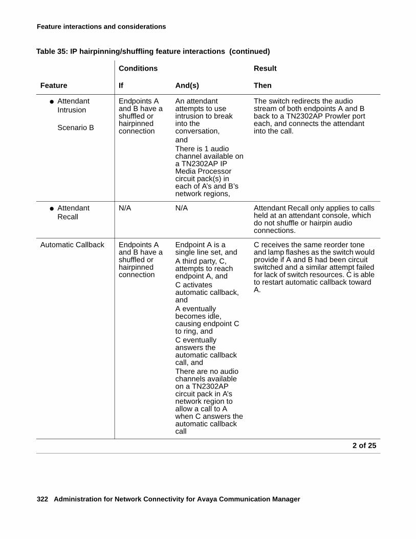
Feature interactions and considerations
322 Administration for Network Connectivity for Avaya Communication Manager
● Attendant Intrusion
Scenario B
Endpoints A and B have a shuffled or hairpinned connection
An attendant attempts to use intrusion to break into the conversation,andThere is 1 audio channel available on a TN2302AP IP Media Processor circuit pack(s) in each of A’s and B’s network regions,
The switch redirects the audio stream of both endpoints A and B back to a TN2302AP Prowler port each, and connects the attendant into the call.
● Attendant Recall
N/A N/A Attendant Recall only applies to calls held at an attendant console, which do not shuffle or hairpin audio connections.
Automatic Callback Endpoints A and B have a shuffled or hairpinned connection
Endpoint A is a single line set, andA third party, C, attempts to reach endpoint A, andC activates automatic callback, andA eventually becomes idle, causing endpoint C to ring, andC eventually answers the automatic callback call, andThere are no audio channels available on a TN2302AP circuit pack in A’s network region to allow a call to A when C answers the automatic callback call
C receives the same reorder tone and lamp flashes as the switch would provide if A and B had been circuit switched and a similar attempt failed for lack of switch resources. C is able to restart automatic callback toward A.
Table 35: IP hairpinning/shuffling feature interactions (continued)
Conditions Result
Feature If And(s) Then
2 of 25
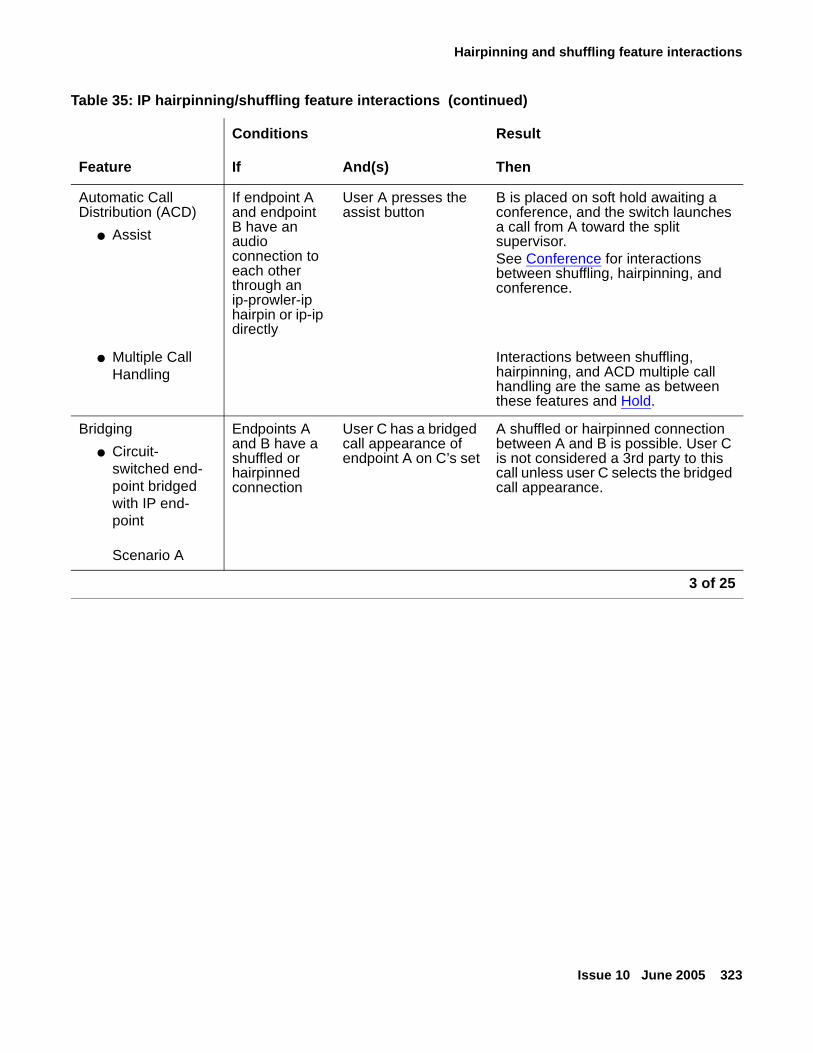
Hairpinning and shuffling feature interactions
Issue 10 June 2005 323
Automatic Call Distribution (ACD)
● Assist
If endpoint A and endpoint B have an audio connection to each other through an ip-prowler-ip hairpin or ip-ip directly
User A presses the assist button
B is placed on soft hold awaiting a conference, and the switch launches a call from A toward the split supervisor. See Conference for interactions between shuffling, hairpinning, and conference.
● Multiple Call Handling
Interactions between shuffling, hairpinning, and ACD multiple call handling are the same as between these features and Hold.
Bridging
● Circuit-switched end-point bridged with IP end-point
Scenario A
Endpoints A and B have a shuffled or hairpinned connection
User C has a bridged call appearance of endpoint A on C’s set
A shuffled or hairpinned connection between A and B is possible. User C is not considered a 3rd party to this call unless user C selects the bridged call appearance.
Table 35: IP hairpinning/shuffling feature interactions (continued)
Conditions Result
Feature If And(s) Then
3 of 25
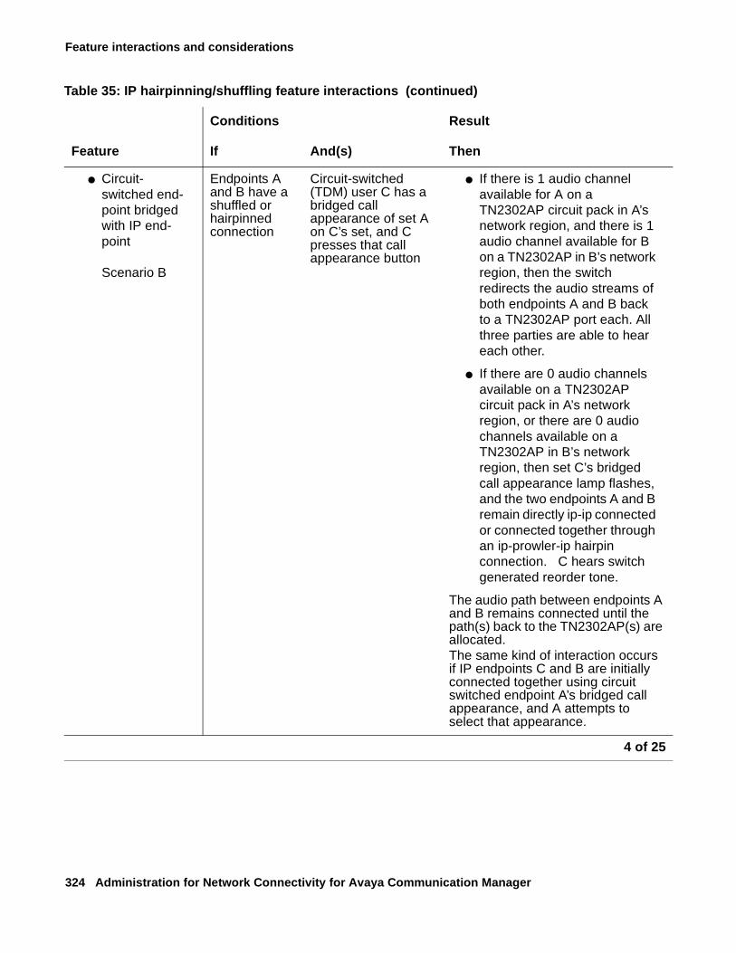
Feature interactions and considerations
324 Administration for Network Connectivity for Avaya Communication Manager
● Circuit-switched end-point bridged with IP end-point
Scenario B
Endpoints A and B have a shuffled or hairpinned connection
Circuit-switched (TDM) user C has a bridged call appearance of set A on C’s set, and C presses that call appearance button
● If there is 1 audio channel available for A on a TN2302AP circuit pack in A’s network region, and there is 1 audio channel available for B on a TN2302AP in B’s network region, then the switch redirects the audio streams of both endpoints A and B back to a TN2302AP port each. All three parties are able to hear each other.
● If there are 0 audio channels available on a TN2302AP circuit pack in A’s network region, or there are 0 audio channels available on a TN2302AP in B’s network region, then set C’s bridged call appearance lamp flashes, and the two endpoints A and B remain directly ip-ip connected or connected together through an ip-prowler-ip hairpin connection. C hears switch generated reorder tone.
The audio path between endpoints A and B remains connected until the path(s) back to the TN2302AP(s) are allocated. The same kind of interaction occurs if IP endpoints C and B are initially connected together using circuit switched endpoint A’s bridged call appearance, and A attempts to select that appearance.
Table 35: IP hairpinning/shuffling feature interactions (continued)
Conditions Result
Feature If And(s) Then
4 of 25
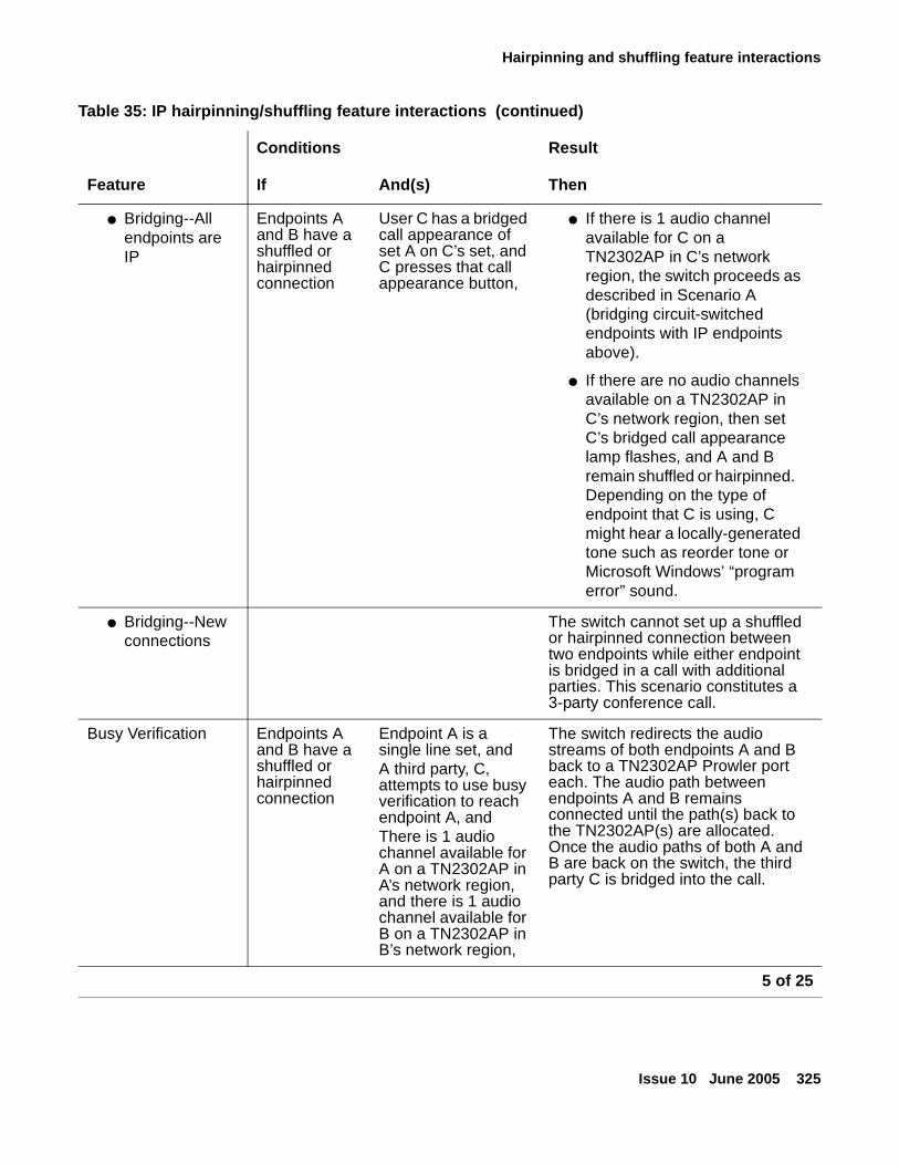
Hairpinning and shuffling feature interactions
Issue 10 June 2005 325
● Bridging--All endpoints are IP
Endpoints A and B have a shuffled or hairpinned connection
User C has a bridged call appearance of set A on C’s set, and C presses that call appearance button,
● If there is 1 audio channel available for C on a TN2302AP in C’s network region, the switch proceeds as described in Scenario A (bridging circuit-switched endpoints with IP endpoints above).
● If there are no audio channels available on a TN2302AP in C’s network region, then set C’s bridged call appearance lamp flashes, and A and B remain shuffled or hairpinned. Depending on the type of endpoint that C is using, C might hear a locally-generated tone such as reorder tone or Microsoft Windows’ “program error” sound.
● Bridging--New connections
The switch cannot set up a shuffled or hairpinned connection between two endpoints while either endpoint is bridged in a call with additional parties. This scenario constitutes a 3-party conference call.
Busy Verification Endpoints A and B have a shuffled or hairpinned connection
Endpoint A is a single line set, and A third party, C, attempts to use busy verification to reach endpoint A, andThere is 1 audio channel available for A on a TN2302AP in A’s network region, and there is 1 audio channel available for B on a TN2302AP in B’s network region,
The switch redirects the audio streams of both endpoints A and B back to a TN2302AP Prowler port each. The audio path between endpoints A and B remains connected until the path(s) back to the TN2302AP(s) are allocated. Once the audio paths of both A and B are back on the switch, the third party C is bridged into the call.
Table 35: IP hairpinning/shuffling feature interactions (continued)
Conditions Result
Feature If And(s) Then
5 of 25
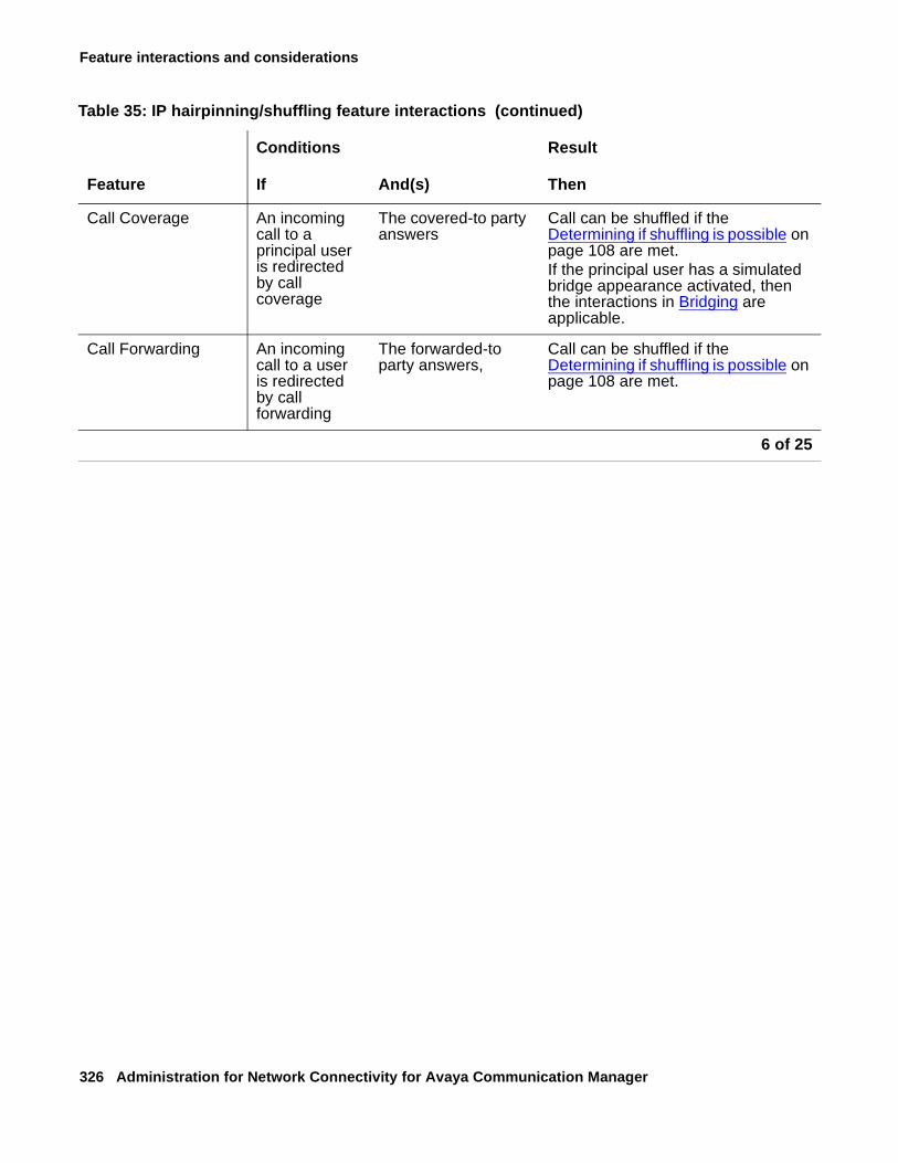
Feature interactions and considerations
326 Administration for Network Connectivity for Avaya Communication Manager
Call Coverage An incoming call to a principal user is redirected by call coverage
The covered-to party answers
Call can be shuffled if the Determining if shuffling is possible on page 108 are met.If the principal user has a simulated bridge appearance activated, then the interactions in Bridging are applicable.
Call Forwarding An incoming call to a user is redirected by call forwarding
The forwarded-to party answers,
Call can be shuffled if the Determining if shuffling is possible on page 108 are met.
Table 35: IP hairpinning/shuffling feature interactions (continued)
Conditions Result
Feature If And(s) Then
6 of 25
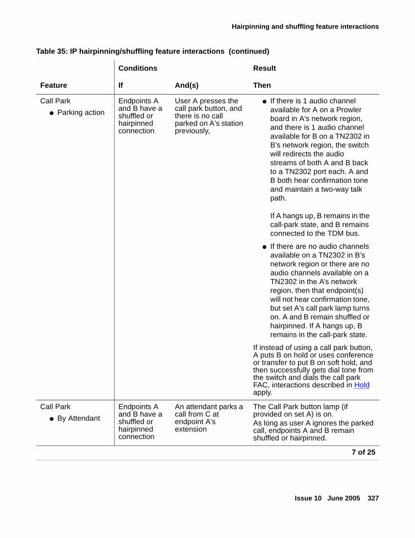
Hairpinning and shuffling feature interactions
Issue 10 June 2005 327
Call Park
● Parking action
Endpoints A and B have a shuffled or hairpinned connection
User A presses the call park button, and there is no call parked on A’s station previously,
● If there is 1 audio channel available for A on a Prowler board in A’s network region, and there is 1 audio channel available for B on a TN2302 in B’s network region, the switch will redirects the audio streams of both A and B back to a TN2302 port each. A and B both hear confirmation tone and maintain a two-way talk path.
If A hangs up, B remains in the call-park state, and B remains connected to the TDM bus.
● If there are no audio channels available on a TN2302 in B’s network region or there are no audio channels available on a TN2302 in the A’s network region, then that endpoint(s) will not hear confirmation tone, but set A's call park lamp turns on. A and B remain shuffled or hairpinned. If A hangs up, B remains in the call-park state.
If instead of using a call park button, A puts B on hold or uses conference or transfer to put B on soft hold, and then successfully gets dial tone from the switch and dials the call park FAC, interactions described in Hold apply.
Call Park
● By Attendant
Endpoints A and B have a shuffled or hairpinned connection
An attendant parks a call from C at endpoint A's extension
The Call Park button lamp (if provided on set A) is on. As long as user A ignores the parked call, endpoints A and B remain shuffled or hairpinned.
Table 35: IP hairpinning/shuffling feature interactions (continued)
Conditions Result
Feature If And(s) Then
7 of 25
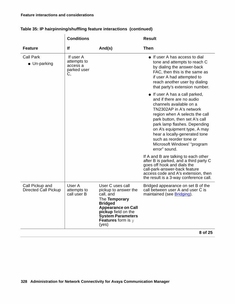
Feature interactions and considerations
328 Administration for Network Connectivity for Avaya Communication Manager
Call Park
● Un-parking
If user A attempts to access a parked user C,
● If user A has access to dial tone and attempts to reach C by dialing the answer-back FAC, then this is the same as if user A had attempted to reach another user by dialing that party’s extension number.
● If user A has a call parked, and if there are no audio channels available on a TN2302AP in A’s network region when A selects the call park button, then set A’s call park lamp flashes. Depending on A’s equipment type, A may hear a locally-generated tone such as reorder tone or Microsoft Windows' “program error” sound.
If A and B are talking to each other after B is parked, and a third party C goes off hook and dials the call-park-answer-back feature access code and A's extension, then the result is a 3-way conference call.
Call Pickup and Directed Call Pickup
User A attempts to call user B
User C uses call pickup to answer the call, andThe Temporary Bridged Appearance on Call pickup field on the System Parameters Features form is y (yes)
Bridged appearance on set B of the call between user A and user C is maintained (see Bridging).
Table 35: IP hairpinning/shuffling feature interactions (continued)
Conditions Result
Feature If And(s) Then
8 of 25
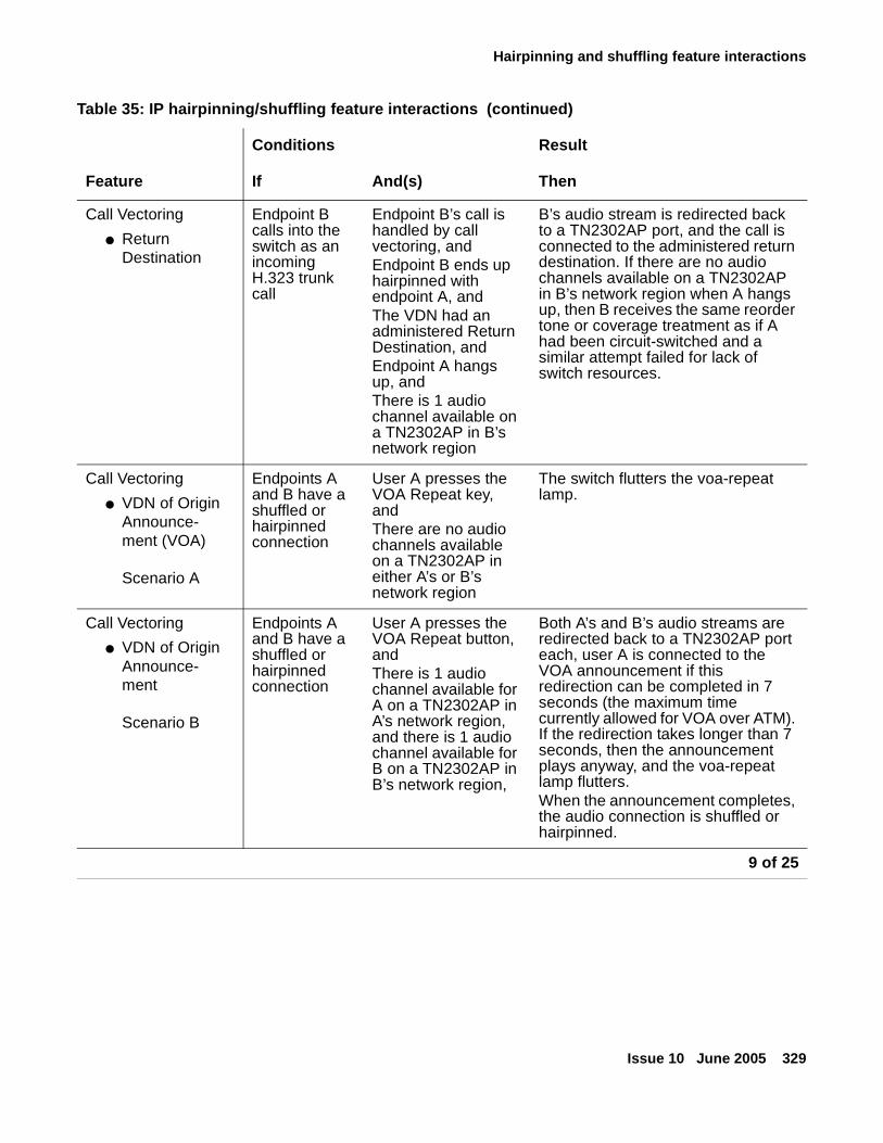
Hairpinning and shuffling feature interactions
Issue 10 June 2005 329
Call Vectoring
● Return Destination
Endpoint B calls into the switch as an incoming H.323 trunk call
Endpoint B’s call is handled by call vectoring, andEndpoint B ends up hairpinned with endpoint A, andThe VDN had an administered Return Destination, and Endpoint A hangs up, andThere is 1 audio channel available on a TN2302AP in B’s network region
B’s audio stream is redirected back to a TN2302AP port, and the call is connected to the administered return destination. If there are no audio channels available on a TN2302AP in B’s network region when A hangs up, then B receives the same reorder tone or coverage treatment as if A had been circuit-switched and a similar attempt failed for lack of switch resources.
Call Vectoring
● VDN of Origin Announce-ment (VOA)
Scenario A
Endpoints A and B have a shuffled or hairpinned connection
User A presses the VOA Repeat key, andThere are no audio channels available on a TN2302AP in either A’s or B’s network region
The switch flutters the voa-repeat lamp.
Call Vectoring
● VDN of Origin Announce-ment
Scenario B
Endpoints A and B have a shuffled or hairpinned connection
User A presses the VOA Repeat button, andThere is 1 audio channel available for A on a TN2302AP in A’s network region, and there is 1 audio channel available for B on a TN2302AP in B’s network region,
Both A’s and B’s audio streams are redirected back to a TN2302AP port each, user A is connected to the VOA announcement if this redirection can be completed in 7 seconds (the maximum time currently allowed for VOA over ATM). If the redirection takes longer than 7 seconds, then the announcement plays anyway, and the voa-repeat lamp flutters. When the announcement completes, the audio connection is shuffled or hairpinned.
Table 35: IP hairpinning/shuffling feature interactions (continued)
Conditions Result
Feature If And(s) Then
9 of 25
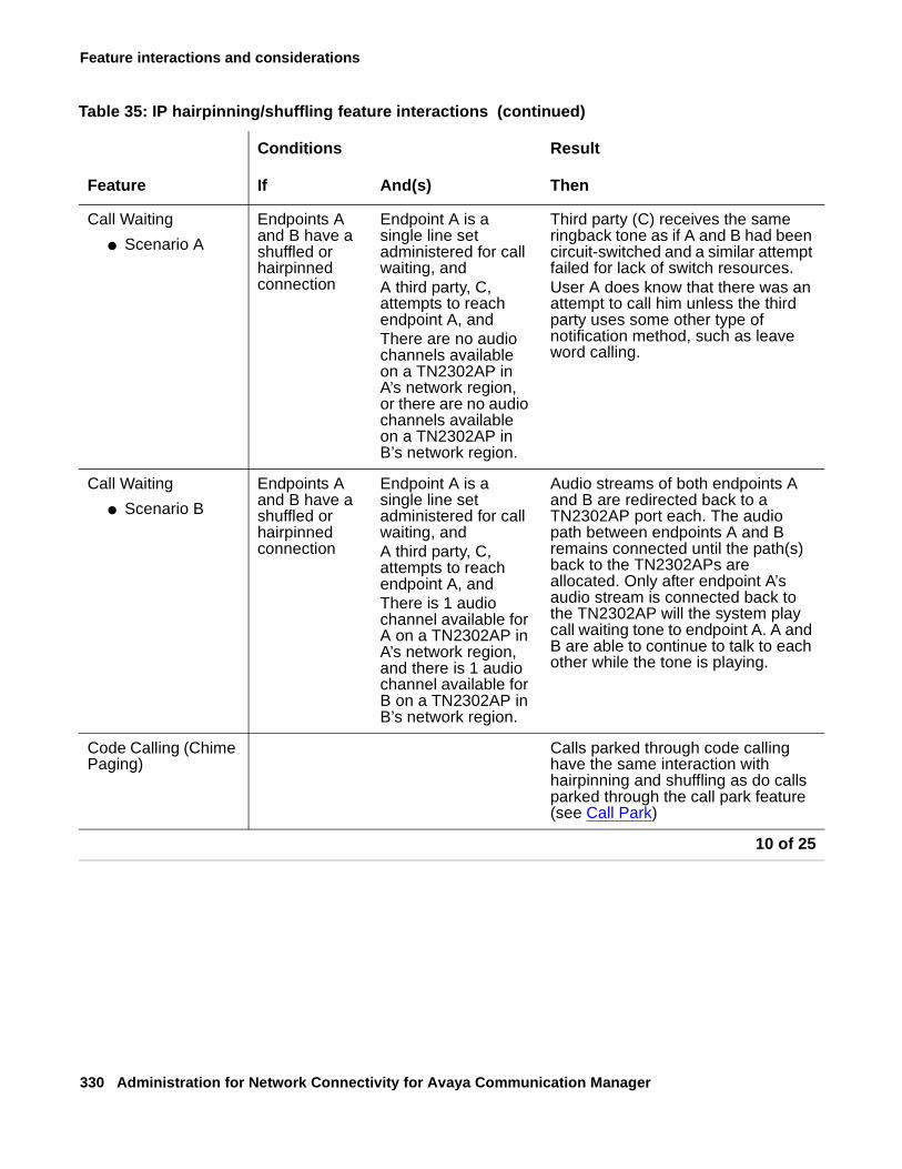
Feature interactions and considerations
330 Administration for Network Connectivity for Avaya Communication Manager
Call Waiting
● Scenario A
Endpoints A and B have a shuffled or hairpinned connection
Endpoint A is a single line set administered for call waiting, andA third party, C, attempts to reach endpoint A, andThere are no audio channels available on a TN2302AP in A’s network region, or there are no audio channels available on a TN2302AP in B’s network region.
Third party (C) receives the same ringback tone as if A and B had been circuit-switched and a similar attempt failed for lack of switch resources.User A does know that there was an attempt to call him unless the third party uses some other type of notification method, such as leave word calling.
Call Waiting
● Scenario B
Endpoints A and B have a shuffled or hairpinned connection
Endpoint A is a single line set administered for call waiting, andA third party, C, attempts to reach endpoint A, andThere is 1 audio channel available for A on a TN2302AP in A’s network region, and there is 1 audio channel available for B on a TN2302AP in B’s network region.
Audio streams of both endpoints A and B are redirected back to a TN2302AP port each. The audio path between endpoints A and B remains connected until the path(s) back to the TN2302APs are allocated. Only after endpoint A’s audio stream is connected back to the TN2302AP will the system play call waiting tone to endpoint A. A and B are able to continue to talk to each other while the tone is playing.
Code Calling (Chime Paging)
Calls parked through code calling have the same interaction with hairpinning and shuffling as do calls parked through the call park feature (see Call Park)
Table 35: IP hairpinning/shuffling feature interactions (continued)
Conditions Result
Feature If And(s) Then
10 of 25
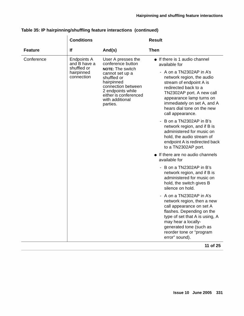
Hairpinning and shuffling feature interactions
Issue 10 June 2005 331
Conference Endpoints A and B have a shuffled or hairpinned connection
User A presses the conference buttonNOTE: The switch cannot set up a shuffled or hairpinned connection between 2 endpoints while either is conferenced with additional parties.
● If there is 1 audio channel available for
- A on a TN2302AP in A’s network region, the audio stream of endpoint A is redirected back to a TN2302AP port. A new call appearance lamp turns on immediately on set A, and A hears dial tone on the new call appearance.
- B on a TN2302AP in B’s network region, and if B is administered for music on hold, the audio stream of endpoint A is redirected back to a TN2302AP port.
● If there are no audio channels available for
- B on a TN2302AP in B’s network region, and if B is administered for music on hold, the switch gives B silence on hold.
- A on a TN2302AP in A’s network region, then a new call appearance on set A flashes. Depending on the type of set that A is using, A may hear a locally- generated tone (such as reorder tone or “program error” sound).
Table 35: IP hairpinning/shuffling feature interactions (continued)
Conditions Result
Feature If And(s) Then
11 of 25
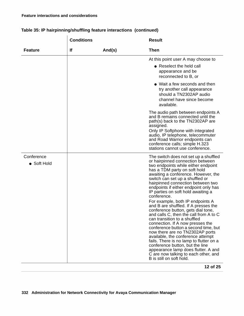
Feature interactions and considerations
332 Administration for Network Connectivity for Avaya Communication Manager
At this point user A may choose to
● Reselect the held call appearance and be reconnected to B, or
● Wait a few seconds and then try another call appearance should a TN2302AP audio channel have since become available.
The audio path between endpoints A and B remains connected until the path(s) back to the TN2302AP are assigned. Only IP Softphone with integrated audio, IP telephone, telecommuter and Road Warrior endpoints can conference calls; simple H.323 stations cannot use conference.
Conference
● Soft Hold
The switch does not set up a shuffled or hairpinned connection between two endpoints while either endpoint has a TDM party on soft hold awaiting a conference. However, the switch can set up a shuffled or hairpinned connection between two endpoints if either endpoint only has IP parties on soft hold awaiting a conference.For example, both IP endpoints A and B are shuffled. If A presses the conference button, gets dial tone, and calls C, then the call from A to C can transition to a shuffled connection. If A now presses the conference button a second time, but now there are no TN2302AP ports available, the conference attempt fails. There is no lamp to flutter on a conference button, but the line appearance lamp does flutter. A and C are now talking to each other, and B is still on soft hold.
Table 35: IP hairpinning/shuffling feature interactions (continued)
Conditions Result
Feature If And(s) Then
12 of 25
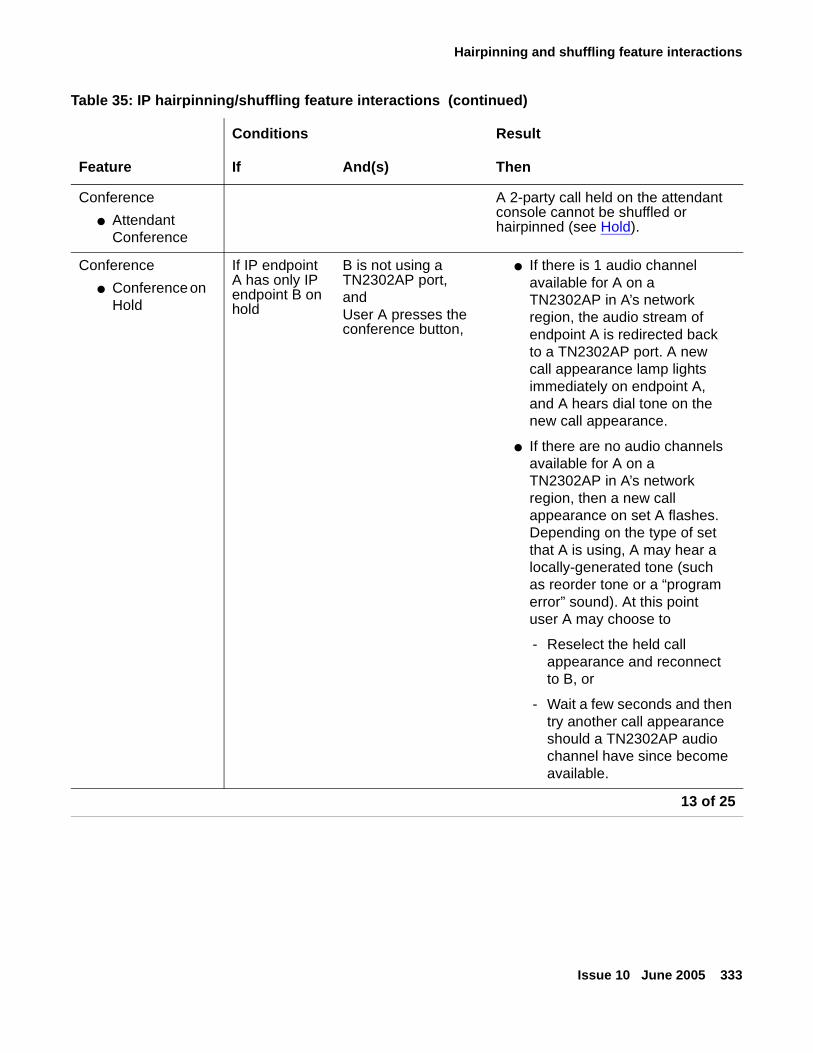
Hairpinning and shuffling feature interactions
Issue 10 June 2005 333
Conference
● Attendant Conference
A 2-party call held on the attendant console cannot be shuffled or hairpinned (see Hold).
Conference
● Conference on Hold
If IP endpoint A has only IP endpoint B on hold
B is not using a TN2302AP port, and User A presses the conference button,
● If there is 1 audio channel available for A on a TN2302AP in A’s network region, the audio stream of endpoint A is redirected back to a TN2302AP port. A new call appearance lamp lights immediately on endpoint A, and A hears dial tone on the new call appearance.
● If there are no audio channels available for A on a TN2302AP in A’s network region, then a new call appearance on set A flashes. Depending on the type of set that A is using, A may hear a locally-generated tone (such as reorder tone or a “program error” sound). At this point user A may choose to
- Reselect the held call appearance and reconnect to B, or
- Wait a few seconds and then try another call appearance should a TN2302AP audio channel have since become available.
Table 35: IP hairpinning/shuffling feature interactions (continued)
Conditions Result
Feature If And(s) Then
13 of 25
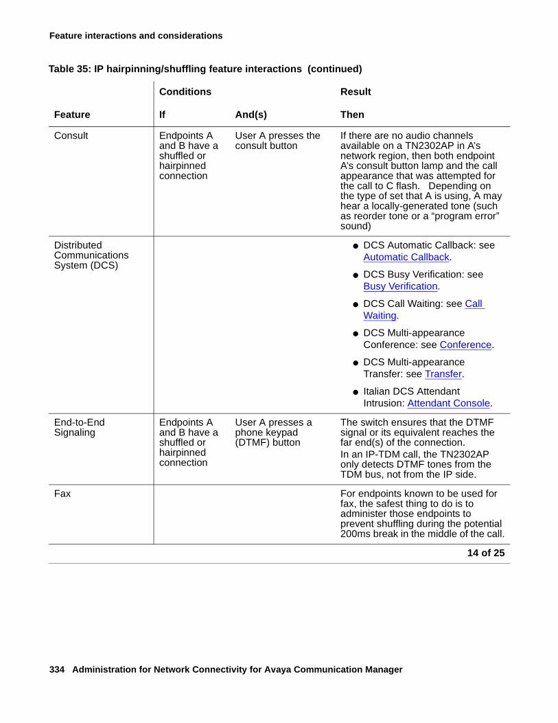
Feature interactions and considerations
334 Administration for Network Connectivity for Avaya Communication Manager
Consult Endpoints A and B have a shuffled or hairpinned connection
User A presses the consult button
If there are no audio channels available on a TN2302AP in A’s network region, then both endpoint A’s consult button lamp and the call appearance that was attempted for the call to C flash. Depending on the type of set that A is using, A may hear a locally-generated tone (such as reorder tone or a “program error” sound)
Distributed Communications System (DCS)
● DCS Automatic Callback: see Automatic Callback.
● DCS Busy Verification: see Busy Verification.
● DCS Call Waiting: see Call Waiting.
● DCS Multi-appearance Conference: see Conference.
● DCS Multi-appearance Transfer: see Transfer.
● Italian DCS Attendant Intrusion: Attendant Console.
End-to-End Signaling
Endpoints A and B have a shuffled or hairpinned connection
User A presses a phone keypad (DTMF) button
The switch ensures that the DTMF signal or its equivalent reaches the far end(s) of the connection.In an IP-TDM call, the TN2302AP only detects DTMF tones from the TDM bus, not from the IP side.
Fax For endpoints known to be used for fax, the safest thing to do is to administer those endpoints to prevent shuffling during the potential 200ms break in the middle of the call.
Table 35: IP hairpinning/shuffling feature interactions (continued)
Conditions Result
Feature If And(s) Then
14 of 25
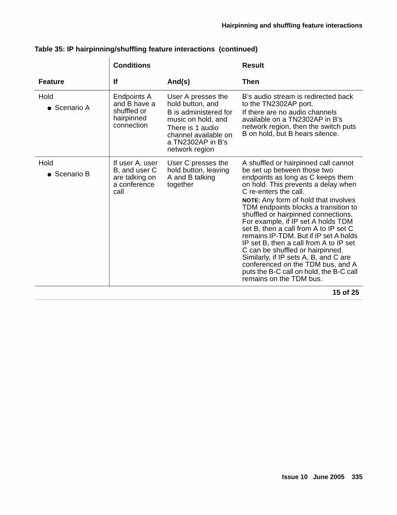
Hairpinning and shuffling feature interactions
Issue 10 June 2005 335
Hold
● Scenario A
Endpoints A and B have a shuffled or hairpinned connection
User A presses the hold button, andB is administered for music on hold, andThere is 1 audio channel available on a TN2302AP in B’s network region
B’s audio stream is redirected back to the TN2302AP port. If there are no audio channels available on a TN2302AP in B’s network region, then the switch puts B on hold, but B hears silence.
Hold
● Scenario B
If user A, user B, and user C are talking on a conference call
User C presses the hold button, leaving A and B talking together
A shuffled or hairpinned call cannot be set up between those two endpoints as long as C keeps them on hold. This prevents a delay when C re-enters the call.NOTE: Any form of hold that involves TDM endpoints blocks a transition to shuffled or hairpinned connections. For example, if IP set A holds TDM set B, then a call from A to IP set C remains IP-TDM. But if IP set A holds IP set B, then a call from A to IP set C can be shuffled or hairpinned. Similarly, if IP sets A, B, and C are conferenced on the TDM bus, and A puts the B-C call on hold, the B-C call remains on the TDM bus.
Table 35: IP hairpinning/shuffling feature interactions (continued)
Conditions Result
Feature If And(s) Then
15 of 25
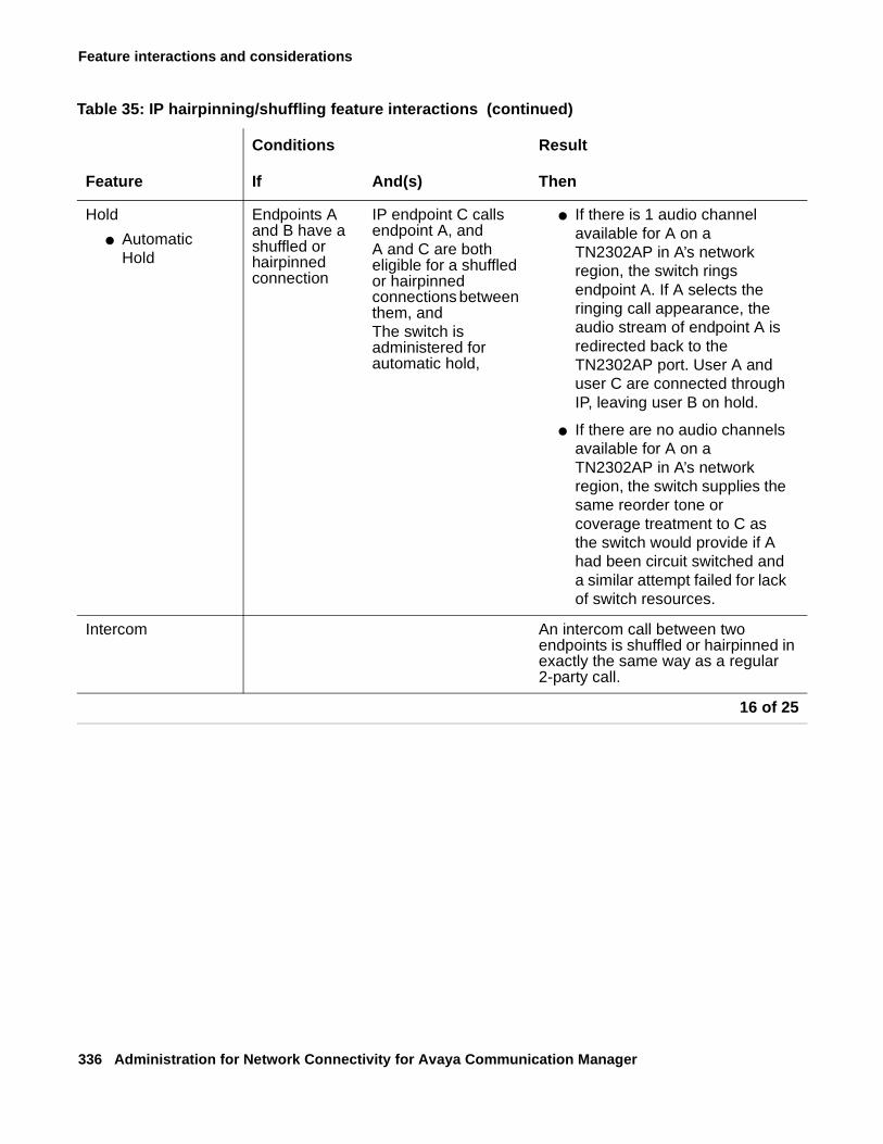
Feature interactions and considerations
336 Administration for Network Connectivity for Avaya Communication Manager
Hold
● Automatic Hold
Endpoints A and B have a shuffled or hairpinned connection
IP endpoint C calls endpoint A, andA and C are both eligible for a shuffled or hairpinned connections between them, and The switch is administered for automatic hold,
● If there is 1 audio channel available for A on a TN2302AP in A’s network region, the switch rings endpoint A. If A selects the ringing call appearance, the audio stream of endpoint A is redirected back to the TN2302AP port. User A and user C are connected through IP, leaving user B on hold.
● If there are no audio channels available for A on a TN2302AP in A’s network region, the switch supplies the same reorder tone or coverage treatment to C as the switch would provide if A had been circuit switched and a similar attempt failed for lack of switch resources.
Intercom An intercom call between two endpoints is shuffled or hairpinned in exactly the same way as a regular 2-party call.
Table 35: IP hairpinning/shuffling feature interactions (continued)
Conditions Result
Feature If And(s) Then
16 of 25
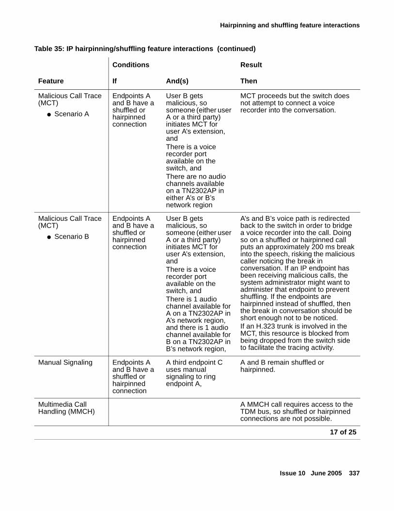
Hairpinning and shuffling feature interactions
Issue 10 June 2005 337
Malicious Call Trace (MCT)
● Scenario A
Endpoints A and B have a shuffled or hairpinned connection
User B gets malicious, so someone (either user A or a third party) initiates MCT for user A’s extension, andThere is a voice recorder port available on the switch, andThere are no audio channels available on a TN2302AP in either A’s or B’s network region
MCT proceeds but the switch does not attempt to connect a voice recorder into the conversation.
Malicious Call Trace (MCT)
● Scenario B
Endpoints A and B have a shuffled or hairpinned connection
User B gets malicious, so someone (either user A or a third party) initiates MCT for user A’s extension, andThere is a voice recorder port available on the switch, andThere is 1 audio channel available for A on a TN2302AP in A’s network region, and there is 1 audio channel available for B on a TN2302AP in B’s network region,
A’s and B’s voice path is redirected back to the switch in order to bridge a voice recorder into the call. Doing so on a shuffled or hairpinned call puts an approximately 200 ms break into the speech, risking the malicious caller noticing the break in conversation. If an IP endpoint has been receiving malicious calls, the system administrator might want to administer that endpoint to prevent shuffling. If the endpoints are hairpinned instead of shuffled, then the break in conversation should be short enough not to be noticed. If an H.323 trunk is involved in the MCT, this resource is blocked from being dropped from the switch side to facilitate the tracing activity.
Manual Signaling Endpoints A and B have a shuffled or hairpinned connection
A third endpoint C uses manual signaling to ring endpoint A,
A and B remain shuffled or hairpinned.
Multimedia Call Handling (MMCH)
A MMCH call requires access to the TDM bus, so shuffled or hairpinned connections are not possible.
Table 35: IP hairpinning/shuffling feature interactions (continued)
Conditions Result
Feature If And(s) Then
17 of 25
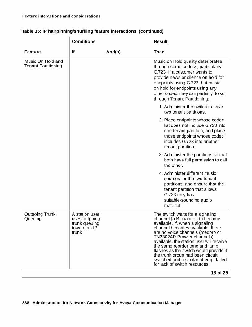
Feature interactions and considerations
338 Administration for Network Connectivity for Avaya Communication Manager
Music On Hold and Tenant Partitioning
Music on Hold quality deteriorates through some codecs, particularly G.723. If a customer wants to provide news or silence on hold for endpoints using G.723, but music on hold for endpoints using any other codec, they can partially do so through Tenant Partitioning:
1. Administer the switch to have two tenant partitions.
2. Place endpoints whose codec list does not include G.723 into one tenant partition, and place those endpoints whose codec includes G.723 into another tenant partition.
3. Administer the partitions so that both have full permission to call the other.
4. Administer different music sources for the two tenant partitions, and ensure that the tenant partition that allows G.723 only has suitable-sounding audio material.
Outgoing Trunk Queuing
A station user uses outgoing trunk queuing toward an IP trunk
The switch waits for a signaling channel (a B channel) to become available. If, when a signaling channel becomes available, there are no voice channels (medpro or TN2302AP Prowler channels) available, the station user will receive the same reorder tone and lamp flashes as the switch would provide if the trunk group had been circuit switched and a similar attempt failed for lack of switch resources.
Table 35: IP hairpinning/shuffling feature interactions (continued)
Conditions Result
Feature If And(s) Then
18 of 25
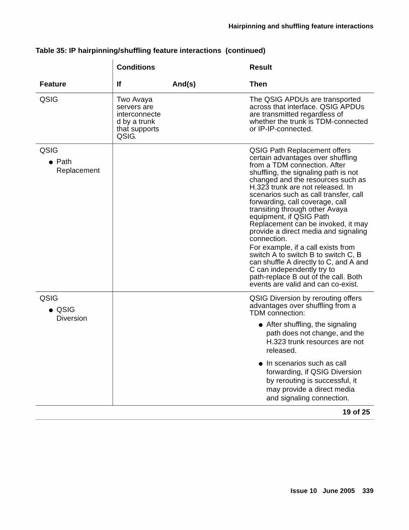
Hairpinning and shuffling feature interactions
Issue 10 June 2005 339
QSIG Two Avaya servers are interconnected by a trunk that supports QSIG.
The QSIG APDUs are transported across that interface. QSIG APDUs are transmitted regardless of whether the trunk is TDM-connected or IP-IP-connected.
QSIG
● Path Replacement
QSIG Path Replacement offers certain advantages over shuffling from a TDM connection. After shuffling, the signaling path is not changed and the resources such as H.323 trunk are not released. In scenarios such as call transfer, call forwarding, call coverage, call transiting through other Avaya equipment, if QSIG Path Replacement can be invoked, it may provide a direct media and signaling connection.For example, if a call exists from switch A to switch B to switch C, B can shuffle A directly to C, and A and C can independently try to path-replace B out of the call. Both events are valid and can co-exist.
QSIG
● QSIG Diversion
QSIG Diversion by rerouting offers advantages over shuffling from a TDM connection:
● After shuffling, the signaling path does not change, and the H.323 trunk resources are not released.
● In scenarios such as call forwarding, if QSIG Diversion by rerouting is successful, it may provide a direct media and signaling connection.
Table 35: IP hairpinning/shuffling feature interactions (continued)
Conditions Result
Feature If And(s) Then
19 of 25
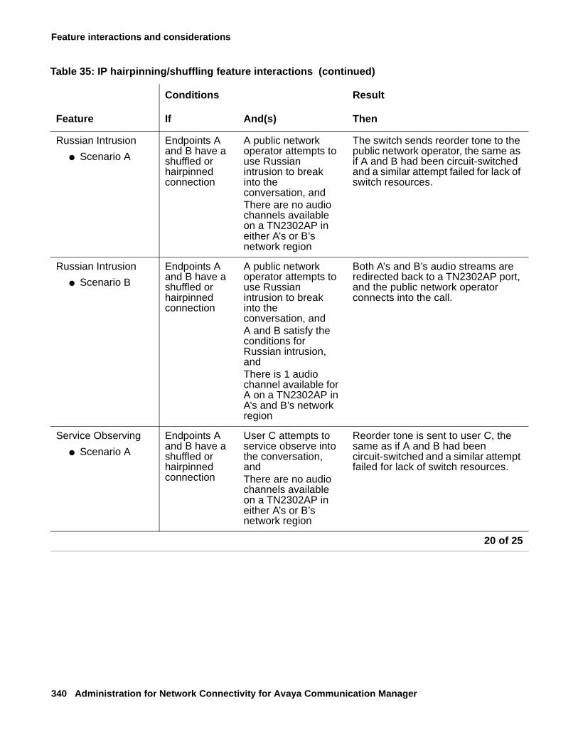
Feature interactions and considerations
340 Administration for Network Connectivity for Avaya Communication Manager
Russian Intrusion
● Scenario A
Endpoints A and B have a shuffled or hairpinned connection
A public network operator attempts to use Russian intrusion to break into the conversation, andThere are no audio channels available on a TN2302AP in either A’s or B’s network region
The switch sends reorder tone to the public network operator, the same as if A and B had been circuit-switched and a similar attempt failed for lack of switch resources.
Russian Intrusion
● Scenario B
Endpoints A and B have a shuffled or hairpinned connection
A public network operator attempts to use Russian intrusion to break into the conversation, andA and B satisfy the conditions for Russian intrusion, andThere is 1 audio channel available for A on a TN2302AP in A’s and B’s network region
Both A’s and B’s audio streams are redirected back to a TN2302AP port, and the public network operator connects into the call.
Service Observing
● Scenario A
Endpoints A and B have a shuffled or hairpinned connection
User C attempts to service observe into the conversation, andThere are no audio channels available on a TN2302AP in either A’s or B’s network region
Reorder tone is sent to user C, the same as if A and B had been circuit-switched and a similar attempt failed for lack of switch resources.
Table 35: IP hairpinning/shuffling feature interactions (continued)
Conditions Result
Feature If And(s) Then
20 of 25
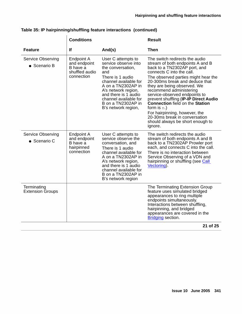
Hairpinning and shuffling feature interactions
Issue 10 June 2005 341
Service Observing
● Scenario B
Endpoint A and endpoint B have a shuffled audio connection
User C attempts to service observe into the conversation, andThere is 1 audio channel available for A on a TN2302AP in A’s network region, and there is 1 audio channel available for B on a TN2302AP in B’s network region,
The switch redirects the audio stream of both endpoints A and B back to a TN2302AP port, and connects C into the call.The observed parties might hear the 20-300ms break and deduce that they are being observed. We recommend administering service-observed endpoints to prevent shuffling (IP-IP Direct Audio Connection field on the Station form is n.)For hairpinning, however, the 20-30ms break in conversation should always be short enough to ignore.
Service Observing
● Scenario C
Endpoint A and endpoint B have a hairpinned connection
User C attempts to service observe the conversation, andThere is 1 audio channel available for A on a TN2302AP in A’s network region, and there is 1 audio channel available for B on a TN2302AP in B’s network region
The switch redirects the audio stream of both endpoints A and B back to a TN2302AP Prowler port each, and connects C into the call.There is no interaction between Service Observing of a VDN and hairpinning or shuffling (see Call Vectoring).
Terminating Extension Groups
The Terminating Extension Group feature uses simulated bridged appearances to ring multiple endpoints simultaneously. Interactions between shuffling, hairpinning, and bridged appearances are covered in the Bridging section.
Table 35: IP hairpinning/shuffling feature interactions (continued)
Conditions Result
Feature If And(s) Then
21 of 25
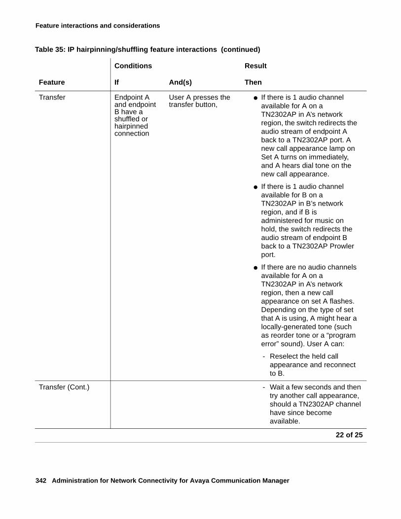
Feature interactions and considerations
342 Administration for Network Connectivity for Avaya Communication Manager
Transfer Endpoint A and endpoint B have a shuffled or hairpinned connection
User A presses the transfer button,
● If there is 1 audio channel available for A on a TN2302AP in A’s network region, the switch redirects the audio stream of endpoint A back to a TN2302AP port. A new call appearance lamp on Set A turns on immediately, and A hears dial tone on the new call appearance.
● If there is 1 audio channel available for B on a TN2302AP in B’s network region, and if B is administered for music on hold, the switch redirects the audio stream of endpoint B back to a TN2302AP Prowler port.
● If there are no audio channels available for A on a TN2302AP in A’s network region, then a new call appearance on set A flashes. Depending on the type of set that A is using, A might hear a locally-generated tone (such as reorder tone or a “program error” sound). User A can:
- Reselect the held call appearance and reconnect to B.
Transfer (Cont.) - Wait a few seconds and then try another call appearance, should a TN2302AP channel have since become available.
Table 35: IP hairpinning/shuffling feature interactions (continued)
Conditions Result
Feature If And(s) Then
22 of 25
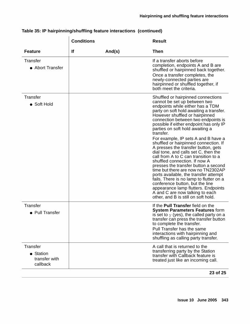
Hairpinning and shuffling feature interactions
Issue 10 June 2005 343
Transfer
● Abort Transfer
If a transfer aborts before completion, endpoints A and B are shuffled or hairpinned back together.Once a transfer completes, the newly-connected parties are hairpinned or shuffled together, if both meet the criteria.
Transfer
● Soft Hold
Shuffled or hairpinned connections cannot be set up between two endpoints while either has a TDM party on soft hold awaiting a transfer. However shuffled or hairpinned connection between two endpoints is possible if either endpoint has only IP parties on soft hold awaiting a transfer. For example, IP sets A and B have a shuffled or hairpinned connection. If A presses the transfer button, gets dial tone, and calls set C, then the call from A to C can transition to a shuffled connection. If now A presses the transfer button a second time but there are now no TN2302AP ports available, the transfer attempt fails. There is no lamp to flutter on a conference button, but the line appearance lamp flutters. Endpoints A and C are now talking to each other, and B is still on soft hold.
Transfer
● Pull Transfer
If the Pull Transfer field on the System Parameters Features form is set to y (yes), the called party on a transfer can press the transfer button to complete the transfer.Pull Transfer has the same interactions with hairpinning and shuffling as calling party transfer.
Transfer
● Station transfer with callback
A call that is returned to the transferring party by the Station transfer with Callback feature is treated just like an incoming call.
Table 35: IP hairpinning/shuffling feature interactions (continued)
Conditions Result
Feature If And(s) Then
23 of 25
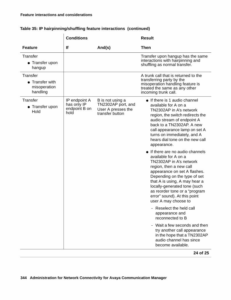
Feature interactions and considerations
344 Administration for Network Connectivity for Avaya Communication Manager
Transfer
● Transfer upon hangup
Transfer upon hangup has the same interactions with hairpinning and shuffling as normal transfer.
Transfer
● Transfer with misoperation handling
A trunk call that is returned to the transferring party by the misoperation handling feature is treated the same as any other incoming trunk call.
Transfer
● Transfer upon Hold
IP endpoint A has only IP endpoint B on hold
B is not using a TN2302AP port, and User A presses the transfer button
● If there is 1 audio channel available for A on a TN2302AP in A’s network region, the switch redirects the audio stream of endpoint A back to a TN2302AP. A new call appearance lamp on set A turns on immediately, and A hears dial tone on the new call appearance.
● If there are no audio channels available for A on a TN2302AP in A’s network region, then a new call appearance on set A flashes. Depending on the type of set that A is using, A may hear a locally-generated tone (such as reorder tone or a “program error” sound). At this point user A may choose to
- Reselect the held call appearance and reconnected to B
- Wait a few seconds and then try another call appearance in the hope that a TN2302AP audio channel has since become available.
Table 35: IP hairpinning/shuffling feature interactions (continued)
Conditions Result
Feature If And(s) Then
24 of 25
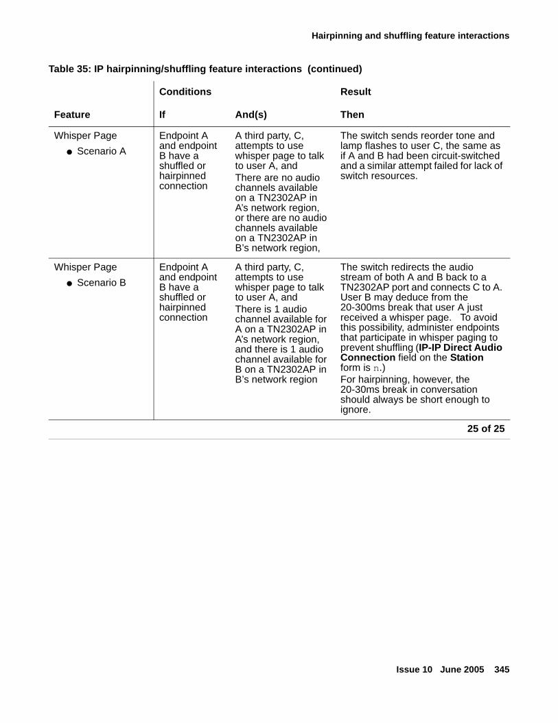
Hairpinning and shuffling feature interactions
Issue 10 June 2005 345
Whisper Page
● Scenario A
Endpoint A and endpoint B have a shuffled or hairpinned connection
A third party, C, attempts to use whisper page to talk to user A, andThere are no audio channels available on a TN2302AP in A’s network region, or there are no audio channels available on a TN2302AP in B’s network region,
The switch sends reorder tone and lamp flashes to user C, the same as if A and B had been circuit-switched and a similar attempt failed for lack of switch resources.
Whisper Page
● Scenario B
Endpoint A and endpoint B have a shuffled or hairpinned connection
A third party, C, attempts to use whisper page to talk to user A, andThere is 1 audio channel available for A on a TN2302AP in A’s network region, and there is 1 audio channel available for B on a TN2302AP in B’s network region
The switch redirects the audio stream of both A and B back to a TN2302AP port and connects C to A. User B may deduce from the 20-300ms break that user A just received a whisper page. To avoid this possibility, administer endpoints that participate in whisper paging to prevent shuffling (IP-IP Direct Audio Connection field on the Station form is n.)For hairpinning, however, the 20-30ms break in conversation should always be short enough to ignore.
Table 35: IP hairpinning/shuffling feature interactions (continued)
Conditions Result
Feature If And(s) Then
25 of 25
Feature interactions and considerations
346 Administration for Network Connectivity for Avaya Communication Manager
Fax, TTY, and modem over IP feature interactions● Call Admission Control
Call Admission Control (CAC) uses the administered values when considering bandwidth availability for a specific call and allows or denies the call accordingly. However, when a call originates as an audio call and then changes to a digitized FAX or modem call, CAC may allow the call due to resource availability, but then deny the call because of the additional bandwidth necessary.
● Modular Messaging
Modular Messaging supports fax and TTY transport over IP networks
● IP Office
IP Office supports fax and TTY transport over IP networks
● Multi-Tech MultiVOIP
The T.38 FAX capability works with Multi-Tech MultiVOIP.
● Call Detail Recording (CDR)
You can send call records for FAX, modem, or TTY calls over an IP network to a CDR device. Call records are recorded in the same way as any other calls over an IP network, depending on trunk group administration.
● Conference/Transfer/Hold
For fax and modem calls over the IP network, failures will occur (that is, data will be lost) when a call is placed on hold (for the Hold, Conference, or Transfer features). In addition, failures will occur (that is, data will be lost) as a result of a conference that causes the master gateway of a call to change in the middle of a call.
● Call Management System (CMS)
Originating or terminating endpoints or trunk groups that are involved in a FAX, modem or TTY call can be measured by CMS.
● Interactive Response
Interactive Response does not support FAX and modem calls received over an IP network. Interactive Response treats TTY calls sent over an IP network in the same way it treats TTY calls arriving over any other trunk facility.
● Shuffling / Direct IP Connections
Audio Shuffling and Direct IP Connections are supported on fax, modem, and TTY calls.
Inter-Gateway Alternate Routing feature interactions
Issue 10 June 2005 347
Inter-Gateway Alternate Routing feature interactionsOne primary factor affects how features operate when a system uses trunks as Inter-Gateway Connections: delays. Specifically, it takes longer to establish a connection between gateways using trunks. The longer it takes for a trunk to reach the active or "answered" state, the more significant this delay will be. If the Intentional Delay introduced to allow the IGC to become active were not implemented, users would notice that the two parties are unable to hear each other for several seconds whenever an incoming inter-PN/MG call is answered "too quickly."
Note, however, that the Intentional Delay applies only when IGAR is triggered by a call placed by a particular user (or an incoming trunk). When IGAR is triggered by a user “answering” the call (using call pickup, bridging, etc.), the user may hear silence for a few seconds until the Trunk IGC is active.
Attendant
Attendant-seeking calls
Intentional Delay applies to attendant-seeking calls such as the following:
● Attendant Return Call
● Call Park Timeout to Attendant
● Centralized Attendant Service
● Emergency Access to the Attendant
● Individual Attendant Access
● Night Service (Unattended Console Service)
That is, if a call placed directly to or redirected to the attendant group is routed to a distant attendant using IGAR, that attendant will not be alerted until the trunk is active. The same applies for a direct call to a specific attendant.
Note:Note: IGAR does not alter the algorithm by which the “next” available attendant is
selected — unlike with trunk groups, a PN/MG preference algorithm does not apply.
Attendant direct trunk group selection (DTGS)
When an attendant presses a DTGS button to access a trunk group on a distant PN/MG, IGAR may be required to set up the connection. The attendant will in most cases hear local dial tone, and any digits dialed will be buffered and sent when the IGAR trunk becomes active; however, some delay may be noticeable by that attendant.
Feature interactions and considerations
348 Administration for Network Connectivity for Avaya Communication Manager
Attendant direct extension selection (DXS)
When an attendant presses a DXS button to access a station on a distant PN/MG, IGAR may be required to set up the connection. The inherent delay will be noticeable by the attendant.
Trunk identification by attendant
If an attendant (or any display station) with a Trunk-ID or Trunk-Name button presses that button on a call involving a Trunk IGC, information about that trunk will not appear on the display.
Basic system
Alternate facility restriction levels
If a user has invoked their Alternate FRL, IGAR will use it instead of their default FRL when selecting a trunk.
Call redirection
IGAR, if enabled, routes the call to the destination using the alternate route specified regardless of the redirection feature active on the extension. After the call reaches the destination using IGAR, normal call redirection will occur.
Data calls
With data calls, there is typically no human involved, so it is not essential to prevent several quiet seconds from elapsing before the trunk is set up (Intentional Delay). However, since most data handshake protocols are able to handle such delays, these calls are treated in the same way as voice calls.
Firmware download
Firmware can be downloaded to a circuit pack, media module, media gateway, or voice terminal over a LAN or WAN. Therefore, customers must allocate sufficient bandwidth for firmware downloads when setting up CAC Bandwidth Limits. IGAR will not be invoked to download firmware when insufficient bandwidth exists. If a download fails, the system may retry later, or make it known that the download must be retried manually or rescheduled.
Inter-Gateway Alternate Routing feature interactions
Issue 10 June 2005 349
Meet-me conferencing
The announcement that typically prompts for a password at the beginning of a Meet-Me Conference is covered under Call Center - Announcement Delays below. Thus, a caller into a Meet-Me Conference will hear the entire announcement. If the first Meet-Me vector step is not an announcement, but IGAR is triggered for the call, the caller may hear silence for a few seconds until the Trunk IGC is active.
Message retrieval: voice systhesis
Voice Synthesis messages are not expected to be played across network regions. Each NR should be configured with enough Voice Synthesis boards to support the users in that NR.
Message sequence tracer (MST
In a future CM release, MST may be enhanced to include a link between an IGAR trunk call and the internal call with which the trunk call is associated.
Restriction features
In CM 3.0, the typical Class of Restriction (CoR) attribute that determines whether or not IGAR is able to select a trunk is the Facility Restriction Level (FRL). In addition, stations that are locked and have a station lock CoR, such that the CoR does not allow making outward calls, are not allowed to make IGAR calls. Other restrictions such as Toll Restriction do not apply. In a future CM release, the customer may be allowed to select whether or not, or to what degree, these restrictions apply.
Networking
Automatic circuit assurance (ACA)
If Trunk IGCs are cached, trunks may stay active for a very long time when IGAR is in effect. IGAR calls will also generate ACA short/long calls similar to trunk calls. Customers should consider this when activating ACA for long-held trunk calls.
Feature interactions and considerations
350 Administration for Network Connectivity for Avaya Communication Manager
Call detail recording (CDR)
CDR records are created for Trunk IGCs. The customer can recognize them by the calling/called number:
● For an outgoing trunk IGC, the local IGAR extension is recorded as the originator, and the IGAR number for the far end is recorded as the dialed digits.
● For an incoming trunk IGC, the originator is the caller ID/ANI/CPN (as usual), and the destination is the local IGAR extension.
Note:Note: If Trunk IGCs are cached, the incoming and outgoing CDR records are not
generated when the associated call drops, but rather when the Trunk IGC “expires” and is flushed from the cache.
For unanswered IGAR calls, in general, two CDR records are generated:
1. For the IGAR user to trunk portion of the call.
2. For the incoming trunk to the IGAR user.
Examples of this outcome are:
● Station-to-station calls in which IGAR is invoked to complete the call
● Incoming trunk calls that land onto another network region invoking IGAR
● Outgoing trunk calls that require a trunk in another network region
Charge advice
Charge advice received from the PSTN for an outgoing ISDN Trunk IGC is recorded in the CDR record for the Trunk IGC, and not for the internal connection or call that triggered IGAR.
Periodic pulse metering (PPM)
The number of PPM pulses received from the PSTN for an outgoing non-ISDN Trunk IGC is recorded in the CDR record for the Trunk IGC, and not for the internal connection or call that triggered IGAR.
Distributed communication service (DCS)
Customers may configure their ARS routing to select a DCS trunk group. This is particularly likely for North American customers that use DCS+ over the AT&T SDN (or a similar service offered by other service providers). If IGAR selects a DCS trunk group, this does not affect feature transparency for the call that triggered IGAR. Since that call must be an internal call, full feature functionality is available.
CM software may occasionally need a Trunk IGC to connect a calling user to an outgoing DCS trunk group, or to connect an incoming DCS trunk group to the called party, if the users and the trunk group are not in the same Network Region. If this occurs, DCS feature functionality works as though no Trunk IGC were needed.
Inter-Gateway Alternate Routing feature interactions
Issue 10 June 2005 351
If in the above scenario a call is transferred and no parties remain on the call at a particular DCS node, two events occur simultaneously:
● The IGAR feature drops the Trunk IGC (or moves it to the cache).
● The DCS Reroute feature drops the DCS trunk, if a more optimal path is found.
Emergency calls (E911)
If a voice station dials an emergency number (for example, 911 in North America), and the only available outgoing trunk is in a network region accessible only by IGAR, the appropriate calling party information will be sent over the outgoing trunk while the IGAR connection is set up. Thus, even if the IGAR connection fails, emergency responders will be notified of the emergency call.
Note:Note: Customers should not configure systems this way — emergency calls should be
routed out over trunks in the local NR. However, this may still happen in an emergency that takes the local trunks out of service.
Multi-vendor private-network QSIG connectivity (including SBS)
Customers may configure their ARS routing to select a QSIG trunk group. However, because QSIG does not work over the public network, and because SBS trunk groups are not eligible for use by IGAR, this is unlikely. But even if it were to happen, the call that triggered IGAR is an internal call, and so full feature functionality is available.
CM software may occasionally need a Trunk IGC to connect a calling user to an outgoing QSIG or SBS trunk group, or to connect an incoming QSIG or SBS trunk group to the called party, if the users and the trunk group are not in the same network region. If this occurs, QSIG feature functionality will work as though no Trunk IGC were needed.
If in the above scenario a call is transferred and no parties remain on the call at a particular QSIG node, two events occur simultaneously:
● The IGAR feature drops the Trunk IGC (or moves it to the cache).
● The QSIG Path Replacement feature drops the QSIG trunk, if a more optimal path is found.
Personal central office line (PCOL)
If the PCOL button on a voice terminal is associated with a trunk in a different network region, IGAR may be required to set up the connection. The user hears local dial tone, and any digits dialed are buffered and sent when the IGAR trunk becomes active; however, some delay may be noticeable by that user. In general the PCOL trunk should be in the same network region as the voice terminal.
Feature interactions and considerations
352 Administration for Network Connectivity for Avaya Communication Manager
Routing a call
IGAR trunk selection follows all ARS routing steps. Exceptions are noted in the following subsections.
Automatic alternate routing (AAR)
Although selection of a trunk for IGAR starts out using ARS, the customer may use ARS Digit Conversion to convert the number to a private-network number and use AAR instead.
Generalized route selection
IGAR assumes a Bearer Capability Class 0 (voice/3.1 kHz) when searching for an available trunk. BCC 0 originators can select a Route Pattern Preference with data BCC, but BCC 0 preferences are attempted first. In a future CM release, IGAR may be allowed to specify a BCC other than 0, if a Trunk IGC is needed specifically for a data connection.
Tenant partitioning
Tenant Partitioning can block a tenant from calling another tenant, and can block a tenant from using trunks allocated to another tenant. These restrictions are administered as a unit. Therefore, if IGAR is triggered on a call between tenants, IGAR can use trunks assigned to either tenant (or any other tenant the calling user can access) to set up the Trunk IGC.
Trunk-to-trunk transfer
The Trunk-to-Trunk Transfer system parameter does not control whether a call that includes a Trunk IGC can be transferred.
Trunk access code (TAC) dialing
When a user dials the TAC of a trunk group in a different network region, IGAR may be required to set up the connection. The user will in most cases hear local dial tone, and any digits dialed will be buffered and sent when the IGAR trunk becomes active; however, some delay may be noticeable by that user.
Trunk signaling & protocols
The trunk signaling required to set up a Trunk IGC takes place in parallel with the inter-PN/MG IP signaling that sets up the internal call. Clearly then, the faster the trunk, the less noticeable IGAR will be to the parties involved in the call.
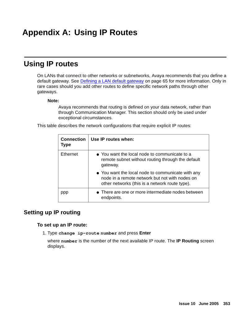
Issue 10 June 2005 353
Appendix A: Using IP Routes
Using IP routesOn LANs that connect to other networks or subnetworks, Avaya recommends that you define a default gateway. See Defining a LAN default gateway on page 65 for more information. Only in rare cases should you add other routes to define specific network paths through other gateways.
Note:Note: Avaya recommends that routing is defined on your data network, rather than
through Communication Manager. This section should only be used under exceptional circumstances.
This table describes the network configurations that require explicit IP routes:
Setting up IP routing
To set up an IP route:
1. Type change ip-route number and press Enter
where number is the number of the next available IP route. The IP Routing screen displays.
ConnectionType
Use IP routes when:
Ethernet ● You want the local node to communicate to a remote subnet without routing through the default gateway.
● You want the local node to communicate with any node in a remote network but not with nodes on other networks (this is a network route type).
ppp ● There are one or more intermediate nodes between endpoints.
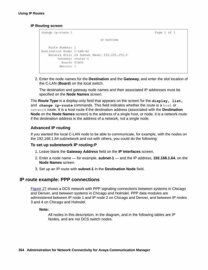
Using IP Routes
354 Administration for Network Connectivity for Avaya Communication Manager
IP Routing screen
2. Enter the node names for the Destination and the Gateway, and enter the slot location of the C-LAN (Board) on the local switch.
The destination and gateway node names and their associated IP addresses must be specified on the Node Names screen.
The Route Type is a display-only field that appears on the screen for the display, list, and change ip-route commands. This field indicates whether the route is a host or network route. It is a host route if the destination address (associated with the Destination Node on the Node Names screen) is the address of a single host, or node. It is a network route if the destination address is the address of a network, not a single node.
Advanced IP routing
If you wanted the local C-LAN node to be able to communicate, for example, with the nodes on the 192.168.1.64 subnetwork and not with others, you could do the following:
To set up subnetwork IP routing:P
1. Leave blank the Gateway Address field on the IP Interfaces screen.
2. Enter a node name — for example, subnet-1 — and the IP address, 192.168.1.64, on the Node Names screen.
3. Set up an IP route with subnet-1 in the Destination Node field.
IP route example: PPP connections
Figure 27 shows a DCS network with PPP signaling connections between systems in Chicago and Denver, and between systems in Chicago and Holmdel. PPP data modules are administered between IP node 1 and IP node 2 on Chicago and Denver, and between IP nodes 3 and 4 on Chicago and Holmdel.
Note:Note: All nodes in this description, in the diagram, and in the following tables are IP
Nodes, and are not DCS switch nodes.
change ip-route 1 Page 1 of 1
IP ROUTING
Route Number: 1Destination Node: C-LAN-A2
Network Bits: 24 Subnet Mask: 255.255.255.0Gateway: router-1
Board: 01B05Metric: 1
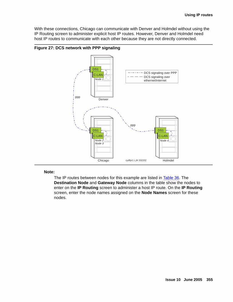
Using IP routes
Issue 10 June 2005 355
With these connections, Chicago can communicate with Denver and Holmdel without using the IP Routing screen to administer explicit host IP routes. However, Denver and Holmdel need host IP routes to communicate with each other because they are not directly connected.
Figure 27: DCS network with PPP signaling
Note:Note: The IP routes between nodes for this example are listed in Table 36. The
Destination Node and Gateway Node columns in the table show the nodes to enter on the IP Routing screen to administer a host IP route. On the IP Routing screen, enter the node names assigned on the Node Names screen for these nodes.
Denver
Chicago Holmdel
DCS signaling over PPPDCS signaling overethernet/internet
ppp
ppp
Node 1
C-LAN
DS1
Node 4
C-LAN
DS1
Node 2Node 3
C-LAN
DS1
cydfipr1 LJK 032202
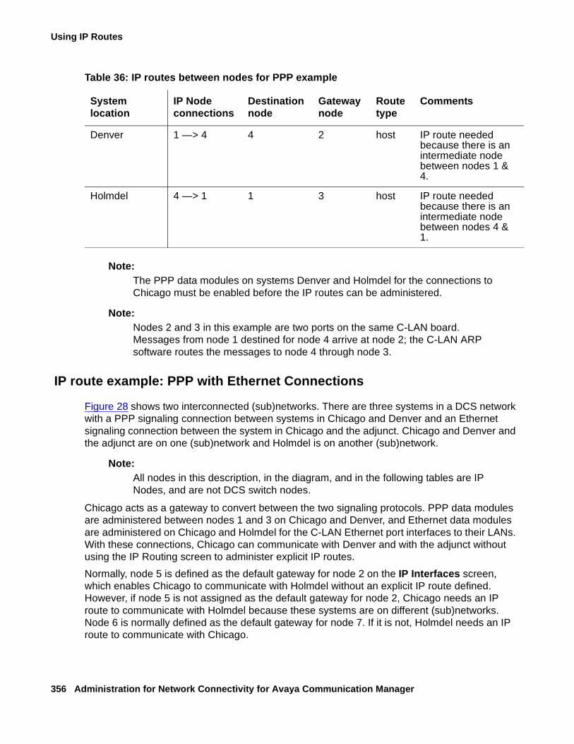
Using IP Routes
356 Administration for Network Connectivity for Avaya Communication Manager
Note:Note: The PPP data modules on systems Denver and Holmdel for the connections to
Chicago must be enabled before the IP routes can be administered.
Note:Note: Nodes 2 and 3 in this example are two ports on the same C-LAN board.
Messages from node 1 destined for node 4 arrive at node 2; the C-LAN ARP software routes the messages to node 4 through node 3.
IP route example: PPP with Ethernet Connections
Figure 28 shows two interconnected (sub)networks. There are three systems in a DCS network with a PPP signaling connection between systems in Chicago and Denver and an Ethernet signaling connection between the system in Chicago and the adjunct. Chicago and Denver and the adjunct are on one (sub)network and Holmdel is on another (sub)network.
Note:Note: All nodes in this description, in the diagram, and in the following tables are IP
Nodes, and are not DCS switch nodes.
Chicago acts as a gateway to convert between the two signaling protocols. PPP data modules are administered between nodes 1 and 3 on Chicago and Denver, and Ethernet data modules are administered on Chicago and Holmdel for the C-LAN Ethernet port interfaces to their LANs. With these connections, Chicago can communicate with Denver and with the adjunct without using the IP Routing screen to administer explicit IP routes.
Normally, node 5 is defined as the default gateway for node 2 on the IP Interfaces screen, which enables Chicago to communicate with Holmdel without an explicit IP route defined. However, if node 5 is not assigned as the default gateway for node 2, Chicago needs an IP route to communicate with Holmdel because these systems are on different (sub)networks. Node 6 is normally defined as the default gateway for node 7. If it is not, Holmdel needs an IP route to communicate with Chicago.
Table 36: IP routes between nodes for PPP example
System location
IP Node connections
Destinationnode
Gateway node
Route type
Comments
Denver 1 —> 4 4 2 host IP route needed because there is an intermediate node between nodes 1 & 4.
Holmdel 4 —> 1 1 3 host IP route needed because there is an intermediate node between nodes 4 & 1.
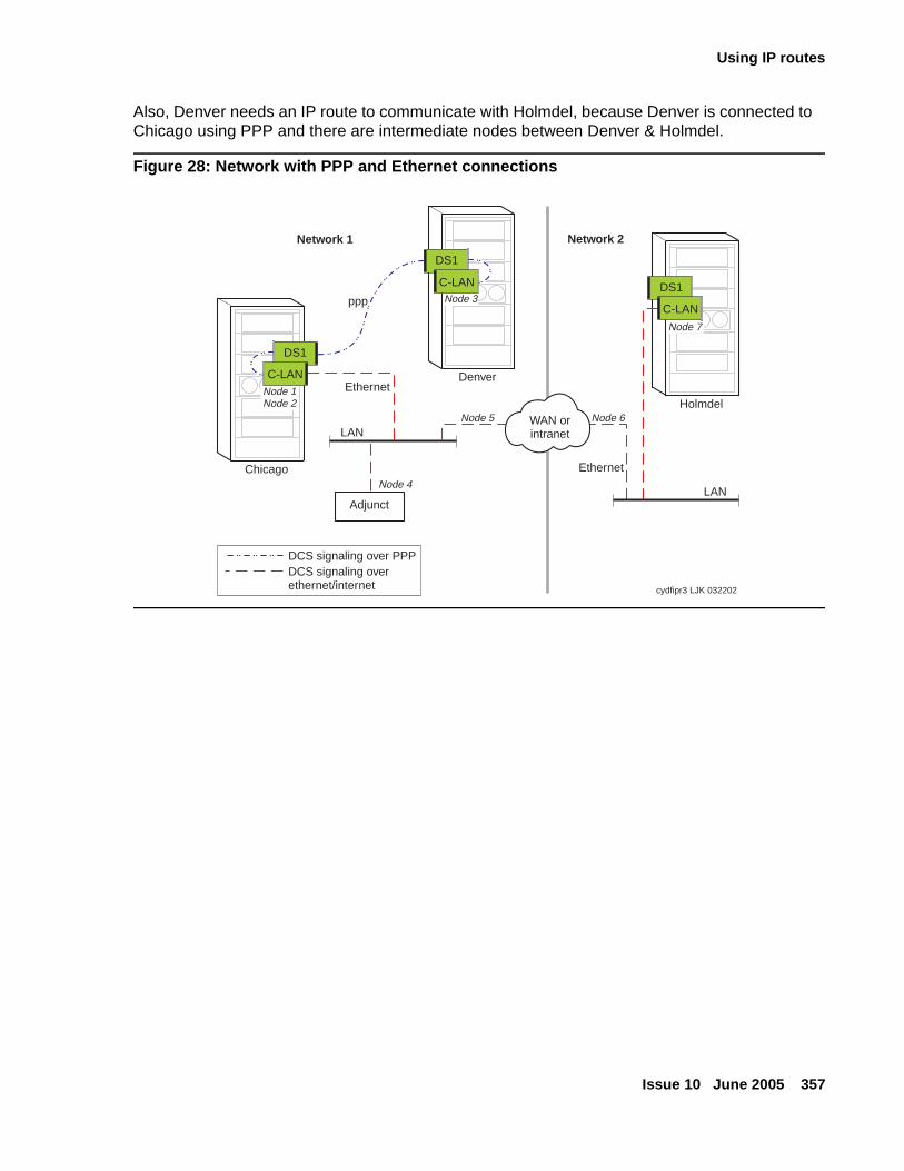
Using IP routes
Issue 10 June 2005 357
Also, Denver needs an IP route to communicate with Holmdel, because Denver is connected to Chicago using PPP and there are intermediate nodes between Denver & Holmdel.
Figure 28: Network with PPP and Ethernet connections
Denver
Chicago
Holmdel
DCS signaling over PPPDCS signaling overethernet/internet
Node 4
Node 5 Node 6
cydfipr3 LJK 032202
Network 1 Network 2
WAN orintranetLAN
Adjunct
Node 3
C-LAN
DS1
Node 1Node 2
C-LAN
DS1
ppp
Ethernet
Ethernet
LAN
Node 7
C-LAN
DS1
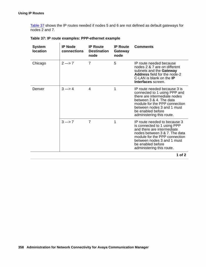
Using IP Routes
358 Administration for Network Connectivity for Avaya Communication Manager
Table 37 shows the IP routes needed if nodes 5 and 6 are not defined as default gateways for nodes 2 and 7.
Table 37: IP route examples: PPP-ethernet example
System location
IP Node connections
IP Route Destination node
IP Route Gateway node
Comments
Chicago 2 —> 7 7 5 IP route needed because nodes 2 & 7 are on different subnets and the Gateway Address field for the node-2 C-LAN is blank on the IP Interfaces screen.
Denver 3 —> 4 4 1 IP route needed because 3 is connected to 1 using PPP and there are intermediate nodes between 3 & 4. The data module for the PPP connection between nodes 3 and 1 must be enabled before administering this route.
3 —> 7 7 1 IP route needed to because 3 is connected to 1 using PPP and there are intermediate nodes between 3 & 7. The data module for the PPP connection between nodes 3 and 1 must be enabled before administering this route.
1 of 2
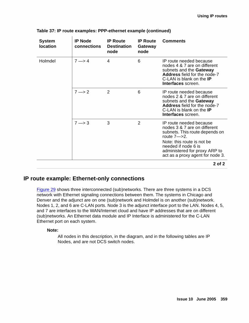
Using IP routes
Issue 10 June 2005 359
IP route example: Ethernet-only connections
Figure 29 shows three interconnected (sub)networks. There are three systems in a DCS network with Ethernet signaling connections between them. The systems in Chicago and Denver and the adjunct are on one (sub)network and Holmdel is on another (sub)network. Nodes 1, 2, and 6 are C-LAN ports. Node 3 is the adjunct interface port to the LAN. Nodes 4, 5, and 7 are interfaces to the WAN/Internet cloud and have IP addresses that are on different (sub)networks. An Ethernet data module and IP Interface is administered for the C-LAN Ethernet port on each system.
Note:Note: All nodes in this description, in the diagram, and in the following tables are IP
Nodes, and are not DCS switch nodes.
Holmdel 7 —> 4 4 6 IP route needed because nodes 4 & 7 are on different subnets and the Gateway Address field for the node-7 C-LAN is blank on the IP Interfaces screen.
7 —> 2 2 6 IP route needed because nodes 2 & 7 are on different subnets and the Gateway Address field for the node-7 C-LAN is blank on the IP Interfaces screen.
7 —> 3 3 2 IP route needed because nodes 3 & 7 are on different subnets. This route depends on route 7—>2.Note: this route is not be needed if node 6 is administered for proxy ARP to act as a proxy agent for node 3.
Table 37: IP route examples: PPP-ethernet example (continued)
System location
IP Node connections
IP Route Destination node
IP Route Gateway node
Comments
2 of 2
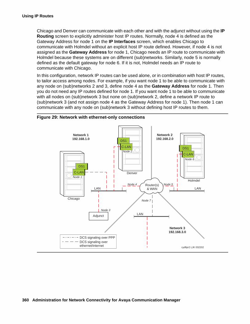
Using IP Routes
360 Administration for Network Connectivity for Avaya Communication Manager
Chicago and Denver can communicate with each other and with the adjunct without using the IP Routing screen to explicitly administer host IP routes. Normally, node 4 is defined as the Gateway Address for node 1 on the IP Interfaces screen, which enables Chicago to communicate with Holmdel without an explicit host IP route defined. However, if node 4 is not assigned as the Gateway Address for node 1, Chicago needs an IP route to communicate with Holmdel because these systems are on different (sub)networks. Similarly, node 5 is normally defined as the default gateway for node 6. If it is not, Holmdel needs an IP route to communicate with Chicago.
In this configuration, network IP routes can be used alone, or in combination with host IP routes, to tailor access among nodes. For example, if you want node 1 to be able to communicate with any node on (sub)networks 2 and 3, define node 4 as the Gateway Address for node 1. Then you do not need any IP routes defined for node 1. If you want node 1 to be able to communicate with all nodes on (sub)network 3 but none on (sub)network 2, define a network IP route to (sub)network 3 (and not assign node 4 as the Gateway Address for node 1). Then node 1 can communicate with any node on (sub)network 3 without defining host IP routes to them.
Figure 29: Network with ethernet-only connections
Denver
Chicago
Holmdel
DCS signaling over PPPDCS signaling overethernet/internet
Node 3
Node 4 Node 5
Node 7
cydfipr2 LJK 032202
Network 1192.168.1.0
Network 2192.168.2.0
Network 3192.168.3.0
Router(s)& WAN
LANAdjunct
LAN
Node 1
C-LAN
DS1
Node 2
C-LAN
DS1
Node 6
C-LAN
DS1
LAN
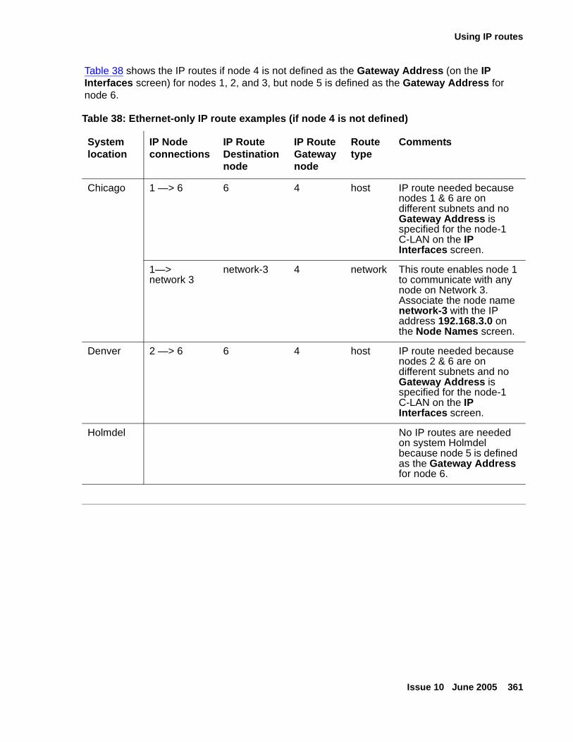
Using IP routes
Issue 10 June 2005 361
Table 38 shows the IP routes if node 4 is not defined as the Gateway Address (on the IP Interfaces screen) for nodes 1, 2, and 3, but node 5 is defined as the Gateway Address for node 6.
Table 38: Ethernet-only IP route examples (if node 4 is not defined)
System location
IP Node connections
IP Route Destination node
IP Route Gateway node
Route type
Comments
Chicago 1 —> 6 6 4 host IP route needed because nodes 1 & 6 are on different subnets and no Gateway Address is specified for the node-1 C-LAN on the IP Interfaces screen.
1—>network 3
network-3 4 network This route enables node 1 to communicate with any node on Network 3. Associate the node name network-3 with the IP address 192.168.3.0 on the Node Names screen.
Denver 2 —> 6 6 4 host IP route needed because nodes 2 & 6 are on different subnets and no Gateway Address is specified for the node-1 C-LAN on the IP Interfaces screen.
Holmdel No IP routes are needed on system Holmdel because node 5 is defined as the Gateway Address for node 6.

Using IP Routes
362 Administration for Network Connectivity for Avaya Communication Manager
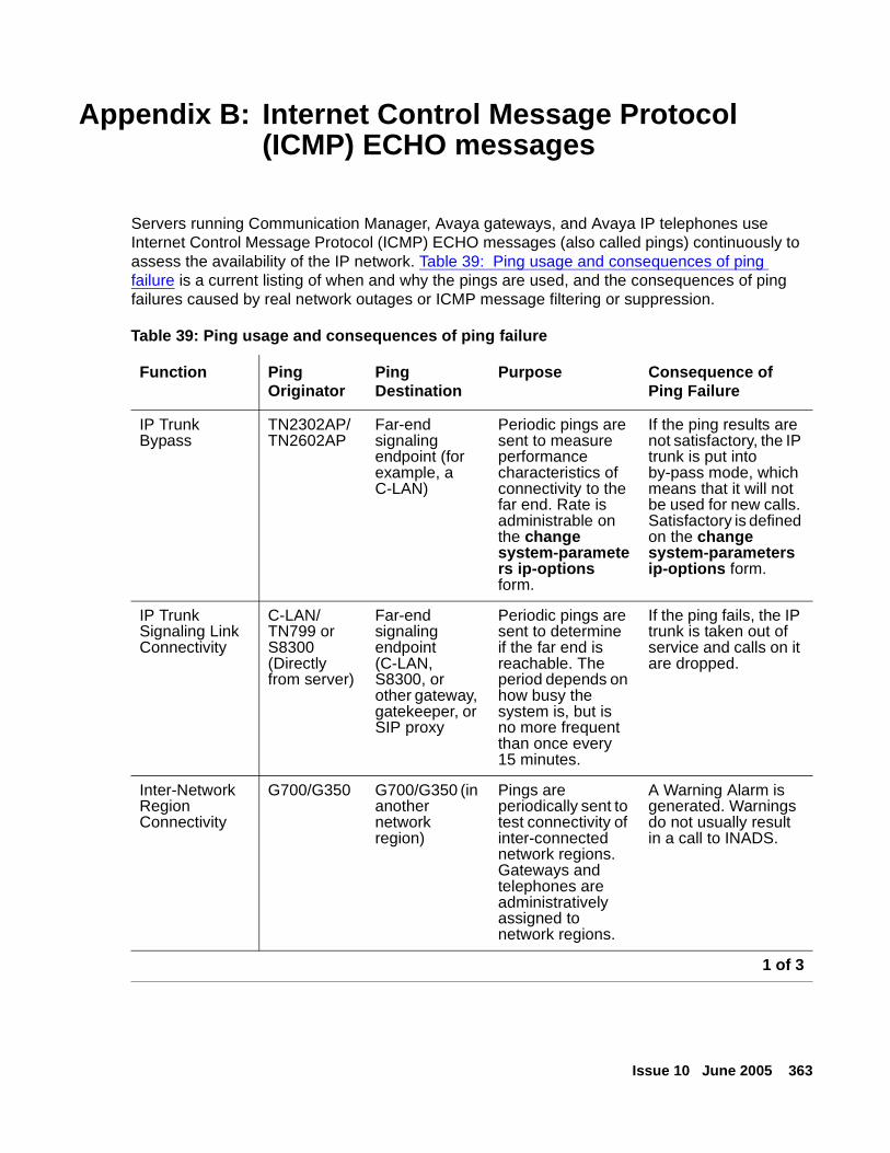
Issue 10 June 2005 363
Appendix B: Internet Control Message Protocol (ICMP) ECHO messages
Servers running Communication Manager, Avaya gateways, and Avaya IP telephones use Internet Control Message Protocol (ICMP) ECHO messages (also called pings) continuously to assess the availability of the IP network. Table 39: Ping usage and consequences of ping failure is a current listing of when and why the pings are used, and the consequences of ping failures caused by real network outages or ICMP message filtering or suppression.
Table 39: Ping usage and consequences of ping failure
Function Ping Originator
Ping Destination
Purpose Consequence of Ping Failure
IP Trunk Bypass
TN2302AP/TN2602AP
Far-end signaling endpoint (for example, a C-LAN)
Periodic pings are sent to measure performance characteristics of connectivity to the far end. Rate is administrable on the change system-parameters ip-options form.
If the ping results are not satisfactory, the IP trunk is put into by-pass mode, which means that it will not be used for new calls. Satisfactory is defined on the change system-parameters ip-options form.
IP Trunk Signaling Link Connectivity
C-LAN/TN799 or S8300 (Directly from server)
Far-end signaling endpoint (C-LAN, S8300, or other gateway, gatekeeper, or SIP proxy
Periodic pings are sent to determine if the far end is reachable. The period depends on how busy the system is, but is no more frequent than once every 15 minutes.
If the ping fails, the IP trunk is taken out of service and calls on it are dropped.
Inter-Network Region Connectivity
G700/G350 G700/G350 (in another network region)
Pings are periodically sent to test connectivity of inter-connected network regions. Gateways and telephones are administratively assigned to network regions.
A Warning Alarm is generated. Warnings do not usually result in a call to INADS.
1 of 3
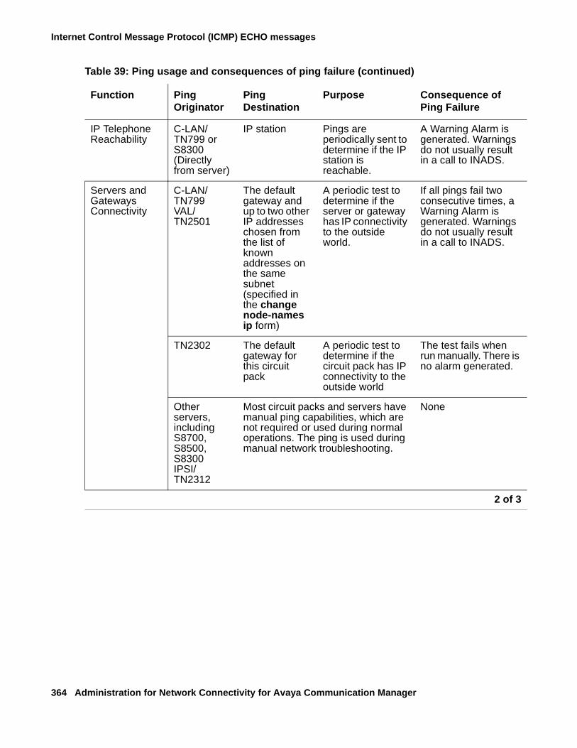
Internet Control Message Protocol (ICMP) ECHO messages
364 Administration for Network Connectivity for Avaya Communication Manager
IP Telephone Reachability
C-LAN/TN799 or S8300 (Directly from server)
IP station Pings are periodically sent to determine if the IP station is reachable.
A Warning Alarm is generated. Warnings do not usually result in a call to INADS.
Servers and Gateways Connectivity
C-LAN/TN799VAL/TN2501
The default gateway and up to two other IP addresses chosen from the list of known addresses on the same subnet (specified in the change node-names ip form)
A periodic test to determine if the server or gateway has IP connectivity to the outside world.
If all pings fail two consecutive times, a Warning Alarm is generated. Warnings do not usually result in a call to INADS.
TN2302 The default gateway for this circuit pack
A periodic test to determine if the circuit pack has IP connectivity to the outside world
The test fails when run manually. There is no alarm generated.
Other servers, including S8700, S8500, S8300IPSI/TN2312
Most circuit packs and servers have manual ping capabilities, which are not required or used during normal operations. The ping is used during manual network troubleshooting.
None
Table 39: Ping usage and consequences of ping failure (continued)
Function Ping Originator
Ping Destination
Purpose Consequence of Ping Failure
2 of 3
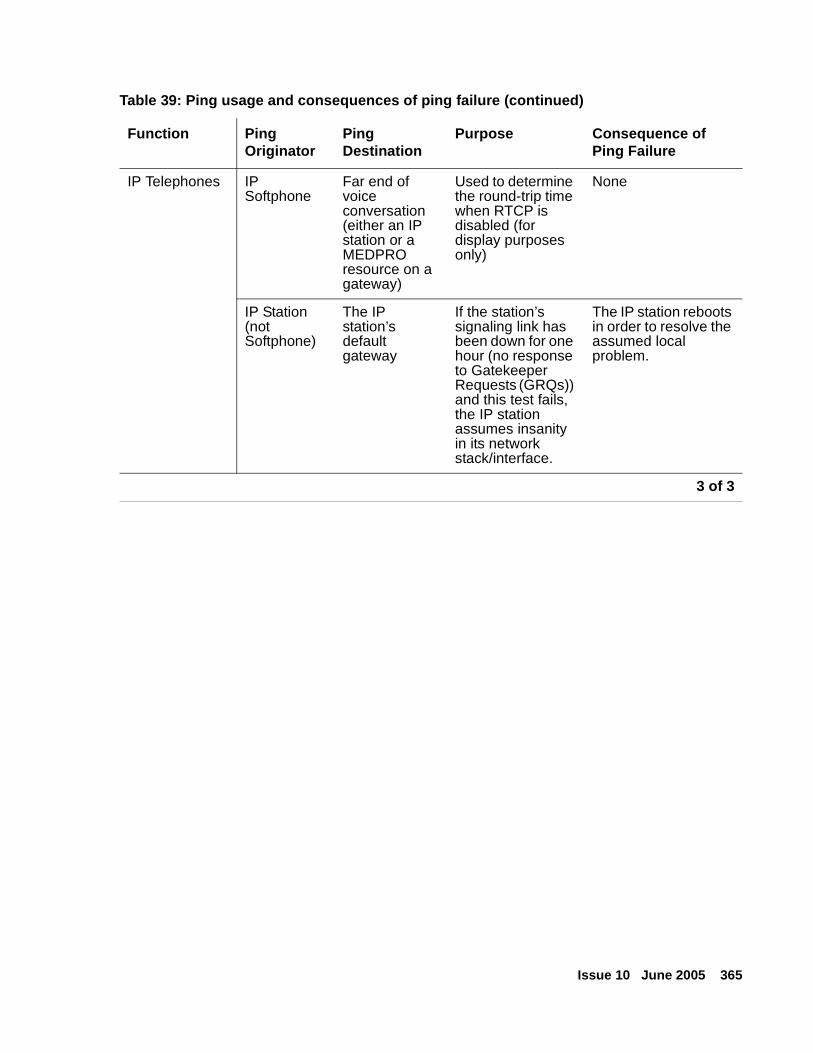
Issue 10 June 2005 365
IP Telephones IP Softphone
Far end of voice conversation (either an IP station or a MEDPRO resource on a gateway)
Used to determine the round-trip time when RTCP is disabled (for display purposes only)
None
IP Station (not Softphone)
The IP station’s default gateway
If the station’s signaling link has been down for one hour (no response to Gatekeeper Requests (GRQs)) and this test fails, the IP station assumes insanity in its network stack/interface.
The IP station reboots in order to resolve the assumed local problem.
Table 39: Ping usage and consequences of ping failure (continued)
Function Ping Originator
Ping Destination
Purpose Consequence of Ping Failure
3 of 3

Internet Control Message Protocol (ICMP) ECHO messages
366 Administration for Network Connectivity for Avaya Communication Manager
Issue 10 June 2005 367
Index
Index
Numerical46xx IP phone, installation . . . . . . . . . . . . . 10546xx IP phones . . . . . . . . . . . . . . . . . . 104
AAAR and ARS features
interactionsCentralized Attendant Service (CAS) . . . . . 317QSIG Call Forwarding (Diversion) . . . . . . 302QSIG Message Waiting Indication . . . . . . 308
AAR and ARS Partitioning featureinteractions
QSIG Message Waiting Indication . . . . . . 307Abbreviated Dialing (AD) feature
interactionsCentralized Attendant Service (CAS) . . . . . 317Extended Trunk Access (ETA) . . . . . . . . 262
administrationcentralized voice mail via mode code . . . . . . 272H.323 Trunk . . . . . . . . . . . . . . . . . . 82H.323 Trunk, task detail . . . . . . . . . . . . . 91H.323 Trunks . . . . . . . . . . . . . . . . . . 83IP telephones. . . . . . . . . . . . . . . . . . 105QSIG . . . . . . . . . . . . . . . . . . . . . 244UDS1 circuit pack. . . . . . . . . . . . . . . . 55
Alternate Facility Restriction Levels (AFRL) featureinteractions
QSIG Call Forwarding (Diversion) . . . . . . 301Alternate Facility Restriction Levels feature
interactionsQSIG Message Waiting Indication . . . . . . 307
Attendant Auto Manual Splitting featureinteractions
Centralized Attendant Service (CAS) . . . . . 317Attendant Call Waiting feature
interactionsDCS Alphanumeric Display for Terminals . . . 294QSIG Supplementary Service - Call
Completion . . . . . . . . . . . . . 305, 306Attendant Console feature
interactionsQSIG Supplementary Service - Call
Completion . . . . . . . . . . . . . . . . 305
Attendant Control of Trunk Group Access featureinteractions
Centralized Attendant Service (CAS) . . . . 317DCS Automatic Callback (ACB) . . . . . . . 285Inter-PBX Attendant Service (IAS). . . . . . 264QSIG Supplementary Service - Call
Completion . . . . . . . . . . . . . . . . 305Attendant Direct Extension Selection (DXS) with
Busy Light Field featureinteractions
DCS Over ISDN–PRI D-Channel (DCS+) . . 280Attendant Display feature
interactionsInter-PBX Attendant Service (IAS). . . . . . 264
Attendant Override of Diversion Features featureinteractions
Centralized Attendant Service (CAS) . . . . 317Attendant Recall feature
interactionsInter-PBX Attendant Service (IAS). . . . . . 264
Attendant Serial Calling featureinteractions
Centralized Attendant Service (CAS) . . . . 317AUDIX
interactionsQSIG Message Waiting Indication . . . . . . 307QSIG Supplementary Service - Call
Completion . . . . . . . . . . . . . . . . 305Authorization Codes feature
interactionsQSIG Call Forwarding (Diversion) . . . . . . 301QSIG Message Waiting Indication . . . . . . 307
auto fallback to primary . . . . . . . . . . . . . . . 38Automatic Call Distribution (ACD) feature
interactionsQSIG Supplementary Service - Call
Completion . . . . . . . . . . . . . . . . 306Automatic Callback (ACB) feature
interactionsDCS Call Waiting. . . . . . . . . . . . . . 287
Automatic Callback featureinteractions
ISDN Feature Plus . . . . . . . . . . . . . 269Automatic Circuit Assurance feature
interactionsISDN Feature Plus . . . . . . . . . . . . . 268
368 Administration for Network Connectivity for Avaya Communication Manager
Index
BBackup buttons . . . . . . . . . . . . . . . . . . 257bandwidth limitation . . . . . . . . . . . . . . . . 169Basic Call Management System (BCMS) feature
interactionsQSIG Additional Network Feature Path
Replacement (ANF–PR) . . . . . . . . . . 304Best Service Routing (BSR) . . . . . . . . . . . . 91Bridged Call Appearance feature
interactionsQSIG Supplementary Service - Call
Completion . . . . . . . . . . . . . . . . 306bus bridge . . . . . . . . . . . . . . . . . . . . . 62Busy Indicator buttons . . . . . . . . . . . . . . . 318Busy name . . . . . . . . . . . . . . . . . . . . 233Busy Verification of Terminals and Trunks (Verify)
featureVerify buttons. . . . . . . . . . . . . . . . . . 286
Ccables, C-LAN . . . . . . . . . . . . . . . . . . . 63Call Admission Control (CAC) . . . . . . . . . . . 169call associated–temporary signaling connections
(CA–TSC) . . . . . . . . . . . . . . . . . . . . 214Call Coverage feature
interactionsCentralized Attendant Service (CAS) . . . . . 318DCS Alphanumeric Display for Terminals . . . 294DCS Call Coverage . . . . . . . . . . . . . 295Inter-PBX Attendant Service (IAS) . . . . . . 264ISDN Feature Plus. . . . . . . . . . . . . . 268QSIG Call Forwarding (Diversion) . . . . . . 302QSIG Message Waiting Indication . . . . . . 308QSIG Supplementary Service - Call
Completion . . . . . . . . . . . . . . . . 306Call Detail Recording (CDR) feature
interactionsCentralized Attendant Service (CAS) . . . . . 318DCS Over ISDN–PRI D-Channel (DCS+) . . . 280QSIG Additional Network Feature Path
Replacement (ANF–PR) . . . . . . . . . . 304QSIG Call Forwarding (Diversion) . . . . . . 302
Call Forwarding featureinteractions
Centralized Attendant Service (CAS) . . . . . 318DCS Alphanumeric Display for Terminals . . . 294QSIG Additional Network Feature–Transit
Counter (ANF–TC) . . . . . . . . . . . . . 305QSIG Call Forwarding (Diversion) . . . . . . 302QSIG Call Transfer . . . . . . . . . . . . . 303QSIG Supplementary Service - Call
Completion . . . . . . . . . . . . . . . . 306call identification tones . . . . . . . . . . . . . . . 257
Call Management System (CMS) featureinteractions
QSIG Additional Network Feature Path Replacement (ANF–PR). . . . . . . . . . 304
Call Park featureinteractions
DCS Alphanumeric Display for Terminals . . 294ISDN Feature Plus . . . . . . . . . . . . . 269
Call Pickup featureinteractions
DCS Alphanumeric Display for Terminals . . 294QSIG Supplementary Service - Call
Completion . . . . . . . . . . . . . . . . 306Call Vectoring feature
interactionsQSIG Additional Network Feature Path
Replacement (ANF–PR). . . . . . . . . . 304Call Waiting Termination feature
interactionsQSIG Supplementary Service - Call
Completion . . . . . . . . . . . . . . . . 305Called name . . . . . . . . . . . . . . . . . . . 233Caller Response Interval . . . . . . . . . . . . . 218CallVisor ASAI feature
interactionsDCS Over ISDN–PRI D-Channel (DCS+) . . 280QSIG Supplementary Service - Call Completion305
Caution, meaning of . . . . . . . . . . . . . . . . 16Centralized Attendant Service (CAS) feature . . . . 256
backup service . . . . . . . . . . . . . . . . 257branch generated call identification tones . . . . 257considerations . . . . . . . . . . . . . . . . 317interactions
AAR and ARS . . . . . . . . . . . . . . . 317Abbreviated Dialing (AD) . . . . . . . . . . 317Attendant Auto Manual Splitting . . . . . . . 317Attendant Control of Trunk Group Access . . 317Attendant Override of Diversion Features . . 317Attendant Serial Calling. . . . . . . . . . . 317Busy Indicator buttons . . . . . . . . . . . 318Call Coverage . . . . . . . . . . . . . . . 318Call Detail Recording (CDR) . . . . . . . . 318Call Forwarding . . . . . . . . . . . . . . 318DCS Alphanumeric Display for Terminals . . 294Distributed Communications System (DCS) . 318DTGS buttons . . . . . . . . . . . . . . . 318DXS buttons . . . . . . . . . . . . . . . . 318Emergency Access to Attendant. . . . . . . 318Hunt Groups . . . . . . . . . . . . . . . . 318Inter-PBX Attendant Service (IAS). . . . . . 264Leave Word Calling (LWC) . . . . . . . . . 318Night Service . . . . . . . . . . . . . 318, 319nonattendant consoles . . . . . . . . . . . 319
queues . . . . . . . . . . . . . . . . . . . . 257release link trunks (RLT) . . . . . . . . . . . . 256remote hold . . . . . . . . . . . . . . . . . . 257
Issue 10 June 2005 369
Index
Channel Associated Signaling . . . . . . . . . . . 275circuit packs
C-LAN . . . . . . . . . . . . . . . . . . . . . 29C-LAN . . . . . . . . . . . . . . . . . . . . . . 29
cables . . . . . . . . . . . . . . . . . . . . . 63installation . . . . . . . . . . . . . . . . . . . 61testing . . . . . . . . . . . . . . . . . . . . . 62
C-LAN circuit pack . . . . . . . . . . . . . . . . . 60Class of Restriction (COR) feature
interactionsEnhanced DCS (EDCS) . . . . . . . . . . . 281QSIG Message Waiting Indication . . . . . . 308
Class of Service (COS) featureinteractions
QSIG Message Waiting Indication . . . . . . 308CNOCL . . . . . . . . . . . . . . . . . . . . . . 51combined port network . . . . . . . . . . . . . . . 43common control switching arrangements (CCSA) . . 209connecting switches . . . . . . . . . . . . . . . . 25connection preservation . . . . . . . . . . . . . . 37connection types. . . . . . . . . . . . . . . . . . 33control network C . . . . . . . . . . . . . . . . . 41Control Network on Customer LAN . . . . . . . . . 51conventions used in this book
Caution . . . . . . . . . . . . . . . . . . . . 16Danger. . . . . . . . . . . . . . . . . . . . . 16Warning . . . . . . . . . . . . . . . . . . . . 16
converged networks . . . . . . . . . . . . . . . . 53country protocol options . . . . . . . . . . . . . . 213coverage answer groups . . . . . . . . . . . . . . 295Coverage Callback feature
interactionsDCS Call Coverage . . . . . . . . . . . . . 295DCS Call Forwarding . . . . . . . . . . . . 287
DD-channel backups
DCS Over ISDN–PRI D-Channel (DCS+). . . . . 280Danger, meaning of . . . . . . . . . . . . . . . . 16Data Call Setup feature
interactionsExtended Trunk Access (ETA) . . . . . . . . 262QSIG Additional Network Feature Path
Replacement (ANF–PR) . . . . . . . . . . 304Data Privacy feature
interactionsDCS Call Waiting . . . . . . . . . . . . . . 287QSIG Additional Network Feature Path
Replacement (ANF–PR) . . . . . . . . . . 304Data Restriction feature
interactionsDCS Call Waiting . . . . . . . . . . . . . . 287QSIG Additional Network Feature Path
Replacement (ANF–PR) . . . . . . . . . . 304
DCS Alphanumeric Display for Terminals feature . . 282interactions
Attendant Call Waiting . . . . . . . . . . . 294Call Coverage . . . . . . . . . . . . . . . 294Call Forwarding . . . . . . . . . . . . . . 294Call Park . . . . . . . . . . . . . . . . . 294Call Pickup . . . . . . . . . . . . . . . . 294Centralized Attendant Service (CAS) . . . . 294ISDN–PRI . . . . . . . . . . . . . . . . . 295
DCS Attendant Control of Trunk Group Access feature . . . . . . . . . . . . . . . . . . . . . 282
interactionsDCS Attendant Display . . . . . . . . . . . 282DCS Automatic Callback (ACB) . . . . . . . 285Uniform Dial Plan (UDP) . . . . . . . . . . 282
DCS Attendant Direct Trunk Group Selection feature 283DCS Attendant Display feature . . . . . . . . . . 284
interactionsDCS Attendant Control of Trunk Group Access 282Inter-PBX Attendant Service (IAS). . . . . . 264
DCS Automatic Callback (ACB) feature . . . . . . 285interactions
Attendant Control of Trunk Group Access . . 285DCS Attendant Control of Trunk Group Access 285
DCS Automatic Circuit Assurance (ACA) feature . . 286DCS Busy Verification of Terminals and Trunks
feature . . . . . . . . . . . . . . . . . . . . . 286interactions
routing patterns . . . . . . . . . . . . . . 286Trunk Identification by Attendant . . . . . . 286
DCS Call Coverage feature . . . . . . . . . . 291-292interactions
Call Coverage off premises . . . . . . . . . 295coverage answer groups . . . . . . . . . . 295Coverage Callback . . . . . . . . . . . . . 295displays . . . . . . . . . . . . . . . . . . 295Go to Cover . . . . . . . . . . . . . . . . 295Leave Word Calling (LWC) . . . . . . . . . 295queuing . . . . . . . . . . . . . . . . . . 295
operation under normal conditions . . . . . . . 292DCS Call Forwarding feature . . . . . . . . . . . 287
interactionsCoverage Callback . . . . . . . . . . . . . 287DCS nodes . . . . . . . . . . . . . . . . 287Leave Word Calling (LWC) . . . . . . . . . 287
DCS Call Waiting feature . . . . . . . . . . . . . 287interactions
Automatic Callback (ACB) . . . . . . . . . 287Data Privacy . . . . . . . . . . . . . . . . 287Data Restriction . . . . . . . . . . . . . . 287Enhanced DCS (EDCS) . . . . . . . . . . 287
DCS Distinctive Ringing feature . . . . . . . . . . 288ringing patterns . . . . . . . . . . . . . . . . 288
DCS Leave Word Calling (LWC) feature . . . . . . 288interactions
DCS Multiappearance Conference/Transfer . 288
370 Administration for Network Connectivity for Avaya Communication Manager
Index
DCS Multiappearance Conference/Transfer feature . 289interactions
DCS Leave Word Calling (LWC) . . . . . . . 288Enhanced DCS (EDCS) . . . . . . . . . . . 289Voice Terminal Display . . . . . . . . . . . 289
DCS Over ISDN–PRI D-Channel (DCS+) feature . . 212call associated–temporary signaling connections
(CA–TSC) . . . . . . . . . . . . . . . . . . 214considerations . . . . . . . . . . . . . . . . . 279gateway nodes . . . . . . . . . . . . . . . . . 215interactions
Attendant Direct Extension Selection (DXS)with Busy Light Field . . . . . . . . . . . . 280
Call Detail Recording (CDR) . . . . . . . . . 280CallVisor ASAI . . . . . . . . . . . . . . . 280D-channel backup . . . . . . . . . . . . . . 280DCS AUDIX. . . . . . . . . . . . . . . . . 280Generalized Route Selection (GRS) . . . . . 280software defined networks (SDN) . . . . . . . 281voice terminals . . . . . . . . . . . . . . . 281
noncall associated–temporary signaling connections (NCA–TSC). . . . . . . . . . . . 214
DCS Trunk Group Busy/Warning Indication feature . 290interactions
Loudspeaker Paging Access . . . . . . . . . 290DCS with Rerouting feature
description . . . . . . . . . . . . . . . . . . . 293interactions. . . . . . . . . . . . . . . . . . . 296
default gateway . . . . . . . . . . . . . . . . . . 65default node . . . . . . . . . . . . . . . . . . . . 65Dial Access to Attendant feature
interactionsInter-PBX Attendant Service (IAS) . . . . . . 264
Differentiated Services Code (DSCP) . . . . . . . . 149DiffServ . . . . . . . . . . . . . . . . . . . . . . 149direct department calling (DDC)
QSIG Supplementary Service - Call Completion . 307direct extension selection
DXS buttons . . . . . . . . . . . . . . . . . . 318Distributed Communication System (DCS) feature
interactionsISDN Feature Plus feature . . . . . . . . . . 268
Distributed Communications System (DCS) feature . 2072-Node private network with AUDIX . . . . . . . 2183-Node public/private network with AUDIX . . . . 222administration for switch 1 . . . . . . . . . 219, 224administration for switch 2 . . . . . . . . . 221, 226administration for switch 3 . . . . . . . . . . . . 228AUDIX administration . . . . . . . . . . . 219, 223AUDIX configuration examples . . . . . . . . . 218interactions
Centralized Attendant Service (CAS) . . . . . 318QSIG Call Forwarding (Diversion) . . . . . . 302QSIG Call Transfer . . . . . . . . . . . . . 303QSIG Name and Number Identification . . . . 303
network configurations . . . . . . . . . . . . . 213
DSCP . . . . . . . . . . . . . . . . . . . . . . 149DTGS buttons . . . . . . . . . . . . . . . . . . 318
Eecho cancellation . . . . . . . . . . . . . . . 143, 144
plans (TN464GP/TN2464BP circuit packs) . . . 145plans (TN464HP/TN2464CP circuit packs) . . . 144
echo path delay . . . . . . . . . . . . . . . . . 143electronic tandem networks (ETN)
Private Network Access . . . . . . . . . . . . 210ELS . . . . . . . . . . . . . . . . . . . . . . . . 38EMC standards. . . . . . . . . . . . . . . . . . . 21Emergency Access to Attendant feature
interactionsCentralized Attendant Service (CAS) . . . . 318
encryption, media. . . . . . . . . . . . . . . . . 179Enhanced DCS (EDCS) feature . . . . . . . . 217, 281
interactionsClass of Restriction (COR) . . . . . . . . . 281DCS Call Waiting. . . . . . . . . . . . . . 287DCS Multiappearance Conference/Transfer . 289
Enhanced Local Survivability (ELS) . . . . . . . . . 38enhanced private switched communications service
(EPSCS) . . . . . . . . . . . . . . . . . . . . 210Enterprise Survivable Servers (ESS). . . . . . . . . 39Extended Trunk Access (ETA) feature . . . . . 260-262
cautions . . . . . . . . . . . . . . . . . . . 261forms . . . . . . . . . . . . . . . . . . . . . 261interactions
Abbreviated Dialing (AD) . . . . . . . . . . 262attendant calls . . . . . . . . . . . . . . . 262Data Call Setup . . . . . . . . . . . . . . 262Facility Restriction Levels (FRL) and Traveling
Class Marks (TCM) . . . . . . . . . . . . 262Last Number Dialed . . . . . . . . . . . . 262Modem Pooling . . . . . . . . . . . . . . 262Remote Access . . . . . . . . . . . . . . 262
Extension Number Portability (ENP) feature . . . . 210ENP codes . . . . . . . . . . . . . . . . . . 210ENP numbering plans . . . . . . . . . . . . . 210
FFacility Restriction Levels (FRL) and Traveling Class Marks
(TCM) featuresinteractions
Extended Trunk Access (ETA) . . . . . . . 262QSIG Call Forwarding (Diversion) . . . . . . 302QSIG Message Waiting Indication . . . . . . 308
Fax over IPadministration overview . . . . . . . . . . . . 132interactions . . . . . . . . . . . . . . . . . . 346overview . . . . . . . . . . . . . . . . . . . 129Super G3 fax machine . . . . . . . . . . . . . 152
Issue 10 June 2005 371
Index
Fax pass throughadministration . . . . . . . . . . . . . . . . . 155bandwidths . . . . . . . . . . . . . . . . . . . 139considerations for configuration . . . . . . . . . 136description . . . . . . . . . . . . . . . . . . . 134encryption . . . . . . . . . . . . . . . . . . . 140rates . . . . . . . . . . . . . . . . . . . . . . 134
Fax relayadministration . . . . . . . . . . . . . . . . . 155bandwidths . . . . . . . . . . . . . . . . . . . 139considerations for configuration . . . . . . . . . 136description . . . . . . . . . . . . . . . . . . . 134encryption . . . . . . . . . . . . . . . . . . . 140rates . . . . . . . . . . . . . . . . . . . . . . 134
features. See Private Networking Features
Ggateway
default . . . . . . . . . . . . . . . . . . . . . 65gateway nodes . . . . . . . . . . . . . . . . . . 215Generalized Route Selection (GRS) feature
interactionsDCS Over ISDN–PRI D-Channel (DCS+) . . . 280QSIG Message Waiting Indication . . . . . . 308
Go to Cover featureinteractions
DCS Call Coverage . . . . . . . . . . . . . 295
HH.248 auto fallback to primary . . . . . . . . . 38, 191H.248 link recovery . . . . . . . . . . . . . . . . 38H.323 clear channel over IP . . . . . . . . . . . . 129H.323 link recovery . . . . . . . . . . . . . . . . 38H.323 Trunk
administration . . . . . . . . . . . . . . . .82, 83hardware interface . . . . . . . . . . . . . . . . . 29Hold feature
interactionsQSIG Supplementary Service - Call Completion306
host IP route. . . . . . . . . . . . . . . . . . . . 353Hotline Service feature
interactionsQSIG Supplementary Service - Call Completion306
Hunt Groups featureinteractions
Centralized Attendant Service (CAS) . . . . . 318
IiClarity . . . . . . . . . . . . . . . . . . . 102, 104IGAR . . . . . . . . . . . . . . . . . . . . . . . 28IGAR interactions . . . . . . . . . . . . . . . . . 296
installationC-LAN . . . . . . . . . . . . . . . . . . . . . 61
Inter-PBX Attendant Service (IAS) feature . . . . . 263interactions
Attendant Control of Trunk Group Access . . 264Attendant Display . . . . . . . . . . . . . 264Attendant Recall . . . . . . . . . . . . . . 264Call Coverage . . . . . . . . . . . . . . . 264Centralized Attendant Service (CAS) . . . . 264DCS Attendant Display . . . . . . . . . . . 264Dial Access to Attendant . . . . . . . . . . 264Night Service . . . . . . . . . . . . . . . 264
Inter-Gateway Alternate Routing (IGAR) . . . . .28, 164Internal Automatic Answer (IAA) feature
interactionsQSIG Supplementary Service - Call
Completion . . . . . . . . . . . . . . . . 306IP codec sets
administering . . . . . . . . . . . . . . . . . 152IP interfaces . . . . . . . . . . . . . . . . . . . . 87IP network regions . . . . . . . . . . . . . . . . 158IP packets
sending and receiving . . . . . . . . . . . . . . 29IP route
host . . . . . . . . . . . . . . . . . . . . . 353network . . . . . . . . . . . . . . . . . . 353, 360when to use. . . . . . . . . . . . . . . . . . 353
IP SoftPhoneAlternate Gatekeeper . . . . . . . . . . . . . . 66
IP Softphones . . . . . . . . . . . . . . . . . . 100IP telephone . . . . . . . . . . . . . . . . . . . 104IP telephone, administration . . . . . . . . . . . . 105ISDN
B-channel (bearer) . . . . . . . . . . . . 212, 213ISDN Feature Plus feature . . . . . . . . . . 265-269
description . . . . . . . . . . . . . . . . . . 265differences in Inserted Digits field. . . . . . . . 267how to administer . . . . . . . . . . . . . . . 266interactions
Automatic Circuit Assurance . . . . . . . . 268Distributed Communication System (DCS) . . 268Feature Plus Centralized AUDIX
Calling Line Identification Presentation (CLIP) . . . . . . . . . . . . . . . . 268
Feature Plus Diversion . . . . . . . . . 268Feature Plus Message Waiting. . . . . . 268
Feature Plus Forwarding (Diversion)Automatic Callback . . . . . . . . . . . 269Call Coverage . . . . . . . . . . . . . 268Call Park . . . . . . . . . . . . . . . . 269Calling Line Identification Presentation
(CLIP) . . . . . . . . . . . . . . . . 268Connection Line Identification Presentation
(COLP) . . . . . . . . . . . . . . . . 268Feature Plus Centralized AUDIX . . . . . 268
372 Administration for Network Connectivity for Avaya Communication Manager
Index
ISDN Feature Plus feature, interactions, (continued)Feature Plus Message Waiting Indication
Audio Information Exchange (AUDIX) . . . 269Off-Premise Station. . . . . . . . . . . . 269
QSIG . . . . . . . . . . . . . . . . . . . . 269ISDN–PRI
interactionsDCS Alphanumeric Display for Terminals . . . 295QSIG Additional Network Feature–Transit
Counter (ANF–TC) . . . . . . . . . . . . . 305Italian DCS Protocol . . . . . . . . . . . . . . . . 217Italy
Enhanced DCS (EDCS) . . . . . . . . . . . . . 217traslatore giunzione uscente/entrante/interno
(TGU/TGE/TGI) trunks. . . . . . . . . . . . . 210
Jjitter . . . . . . . . . . . . . . . . . . . . . . . . 29
LLast Number Dialed feature
interactionsExtended Trunk Access (ETA) . . . . . . . . 262
Leave Word Calling (LWC) featureinteractions
Centralized Attendant Service (CAS) . . . . . 318DCS Call Coverage . . . . . . . . . . . . . 295DCS Call Forwarding . . . . . . . . . . . . 287
link recovery . . . . . . . . . . . . . . . . . . . . 38Listed Directory Numbers (LDN) feature
see also Centralized Attendant Service (CAS)local survivable processor . . . . . . . . . . . . . 38Loudspeaker Paging Access feature
interactionsDCS Trunk Group Busy/Warning Indication . . 290
LSP . . . . . . . . . . . . . . . . . . . . . . . . 38
MMalicious Call Trace (MCT) feature
interactionsQSIG Additional Network Feature Path
Replacement (ANF–PR) . . . . . . . . . . 304Manual Originating Line Service feature
interactionsQSIG Supplementary Service - Call Completion306
media encryption . . . . . . . . . . . . . . . . . 179message associated–user to user information
(MA–UUI) . . . . . . . . . . . . . . . . . . . . 213Message Waiting Indication
how to start administration. . . . . . . . . . . . 266mode code, with Centralized Voice Mail . . . . . . . 270
Modem over IPadministration overview . . . . . . . . . . . . 132interactions . . . . . . . . . . . . . . . . . . 346overview . . . . . . . . . . . . . . . . . . . 129
Modem pass throughadministration . . . . . . . . . . . . . . . . . 155bandwidths . . . . . . . . . . . . . . . . . . 139considerations for configuration . . . . . . . . 136description . . . . . . . . . . . . . . . . . . 135encryption . . . . . . . . . . . . . . . . . . 140rates . . . . . . . . . . . . . . . . . . . . . 135
Modem Pooling featureinteractions
Extended Trunk Access (ETA) . . . . . . . 262Modem relay
admininstration . . . . . . . . . . . . . . . . 155bandwidths . . . . . . . . . . . . . . . . . . 139considerations for configuration . . . . . . . . 136description . . . . . . . . . . . . . . . . . . 135encryption . . . . . . . . . . . . . . . . . . 140rates . . . . . . . . . . . . . . . . . . . . . 135
multimedia endpoints . . . . . . . . . . . . . . . 306
NNAT . . . . . . . . . . . . . . . . . . . . . . . .115Network Address Translation . . . . . . . . . . . .115
NAT and H.323 issues . . . . . . . . . . . . . .117Nat Shuffling feature. . . . . . . . . . . . . . .117types of NAT . . . . . . . . . . . . . . . . . .116
network IP route . . . . . . . . . . . . . . . . . 360network regions, IP . . . . . . . . . . . . . . . . 158network standards . . . . . . . . . . . . . . . . . 20Night Service features
interactionsInter-PBX Attendant Service (IAS). . . . . . 264
night console serviceCentralized Attendant Service (CAS) . . . . 318
trunk answer from any station (TAAS)Centralized Attendant Service (CAS) . . . . 319
nodedefault . . . . . . . . . . . . . . . . . . . . . 65
node names, assigning . . . . . . . . . . . . . . . 86nonattendant consoles . . . . . . . . . . . . . . 319noncall associated–temporary signaling
connections (NCA–TSC) . . . . . . . . . . 214, 243
OOff-Premises Station feature
interactionsQSIG Message Waiting Indication . . . . . . 308
outgoing trunk queueing . . . . . . . . . . . . . 307
Issue 10 June 2005 373
Index
overviewconverged networks . . . . . . . . . . . . . . 53sending and receiving IP packets . . . . . . . . 29
PPass through mode for fax, modem, TTY over IP . . 130Per Hop Behaviors (PHB) . . . . . . . . . . . . . 149plans . . . . . . . . . . . . . . . . . . . . . . . 144Private Network Access feature . . . . . . . . .209-210
forms . . . . . . . . . . . . . . . . . . . . . 209Private Networking features
Centralized Attendant Service (CAS). . . . . . . 256DCS Alphanumeric Display for Terminals. . . . . 282DCS Attendant Control of Trunk Group Access . . 282DCS Attendant Direct Trunk Group Selection . . . 283DCS Attendant Display . . . . . . . . . . . . . 284DCS Automatic Callback (ACB) . . . . . . . . . 285DCS Automatic Circuit Assurance (ACA) . . . . . 286DCS Busy Verification of Terminals and Trunks. . 286DCS Call Coverage . . . . . . . . . . . . . . . 291DCS Call Forwarding . . . . . . . . . . . . . . 287DCS Call Waiting . . . . . . . . . . . . . . . . 287DCS Distinctive Ringing . . . . . . . . . . . . . 288DCS Leave Word Calling (LWC) . . . . . . . . . 288DCS Multiappearance Conference/Transfer . . . 289DCS Over ISDN–PRI D-Channel (DCS+). . . . . 212DCS Trunk Group Busy/Warning Indication. . . . 290Distributed Communications System (DCS) . . . 207Enhanced DCS (EDCS) . . . . . . . . . . . . . 217Extended Trunk Access (ETA). . . . . . . . . . 260Extension Number Portability (ENP) . . . . . . . 210Inter-PBX Attendant Service (IAS) . . . . . . . . 263Italian DCS Protocol DCS . . . . . . . . . . . . 217Private Network Access . . . . . . . . . . . . . 209QSIG Call Forwarding (Diversion) . . . . . 234, 235QSIG Call Transfer . . . . . . . . . . . . . . . 235
proxy ARP. . . . . . . . . . . . . . . . . . . . . 359
QQoS. . . . . . . . . . . . . . . . . . . . . . . . 28Q-reference points . . . . . . . . . . . . . . . . . 230QSIG Additional Network Feature Path Replacement
(ANF–PR) feature . . . . . . . . . . . . . . . . 240interactions
Basic Call Management System (BCMS) . . . 304Call Detail Recording (CDR) . . . . . . . . . 304Call Management System (CMS) . . . . . . . 304Call Vectoring . . . . . . . . . . . . . . . . 304Data Call Setup . . . . . . . . . . . . . . . 304Data Privacy . . . . . . . . . . . . . . . . 304Data Restriction . . . . . . . . . . . . . . . 304Malicious Call Trace (MCT) . . . . . . . . . 304QSIG Call Transfer . . . . . . . . . . . . . 303
QSIG Additional Network Feature Path Replacement (ANF–PR) feature, interactions, (continued)
Recorded Announcement . . . . . . . . . . 304trunk access codes (TAC) . . . . . . . . . 304Voice Terminal Display . . . . . . . . . . . 305
QSIG Additional Network Feature–Transit Counter (ANF–TC) feature . . . . . . . . . . . . . . 233, 305
QSIG Call Forwarding (Diversion) featureinteractions
AAR and ARS . . . . . . . . . . . . . . . 302Alternate Facility Restriction Levels (AFRL) . 301Authorization Codes . . . . . . . . . . . . 301Call Coverage . . . . . . . . . . . . . . . 302Call Detail Recording (CDR) . . . . . . . . 302Call Forwarding . . . . . . . . . . . . . . 302Distributed Communications System (DCS) . 302Facility Restriction Levels (FRL) and Traveling
Class Marks (TCM) . . . . . . . . . . . . 302QSIG Name and Number Identification . . . 302terminating call has coverage active . . . . . 302Transfer . . . . . . . . . . . . . . . . . . 302
QSIG Call Transfer feature . . . . . . . . . . . . 235interactions
Call Forwarding . . . . . . . . . . . . . . 303Distributed Communications System (DCS) . 303QSIG Additional Network Feature Path
Replacement (ANF–PR). . . . . . . . . . 303QSIG Name and Number Identification . . . 303
QSIG Centralized AUDIX . . . . . . . . . . . . . 238what you get with QSIG Centralized AUDIX . . . 238
QSIG featureinteractions
ISDN Feature Plus . . . . . . . . . . . . . 269QSIG Features
QSIG NCA-TSC. . . . . . . . . . . . . . . . 243QSIG features . . . . . . . . . . . . . . . . . . 238
Busy name . . . . . . . . . . . . . . . . . . 233Call Completion . . . . . . . . . . . . . . . . 236Call Offer . . . . . . . . . . . . . . . . . . . 235Called name . . . . . . . . . . . . . . . . . 233noncall associated–temporary signaling
connections (NCA–TSC) . . . . . . . . . . . 243QSIG Path Retention . . . . . . . . . . . . . 237
QSIG Message Waiting Indication . . . . . . . . . 239QSIG Centralized AUDIX . . . . . . . . . . . 238what you get with QSIG Centralized AUDIX . . . 238
QSIG Message Waiting Indication feature . . . . . 239interactions
AAR/ARS Partitioning . . . . . . . . . . . 307Alternate Facilities Restriction Levels . . . . 307Audio Information Exchange (AUDIX) . . . . 307Authorization Codes . . . . . . . . . . . . 307Automatic Alternate Routing (AAR) . . . . . 308Automatic Route Selection (ARS) . . . . . . 308Call Coverage Features . . . . . . . . . . 308Class of Restriction. . . . . . . . . . . . . 308
374 Administration for Network Connectivity for Avaya Communication Manager
Index
QSIG Message Waiting Indication feature, interactions, (continued)
Class of Service . . . . . . . . . . . . . . . 308Facility Restriction Levels (FRL) and Traveling
Class Marks (TCM). . . . . . . . . . . . . 308Generalized Route Selection . . . . . . . . . 308ISDN-QSIG-BRI . . . . . . . . . . . . . . . 308Message Sequence Tracer. . . . . . . . . . 308Off-Premises Station. . . . . . . . . . . . . 308Uniform Dial Plan (UDP) . . . . . . . . . . . 308
QSIG Name and Number Identification feature. . . . 233interactions
Distributed Communications System (DCS) . . 303QSIG Call Forwarding (Diversion) . . . . . . 302QSIG Call Transfer . . . . . . . . . . . . . 303
ISDN numbering formats . . . . . . . . . . . . 234tandem switch information. . . . . . . . . . . . 234transit switch information . . . . . . . . . . . . 234
QSIG NCA-TSC . . . . . . . . . . . . . . . . . . 243QSIG Path Retention. . . . . . . . . . . . . . . . 237QSIG Supplementary Service - Call Completion
feature. . . . . . . . . . . . . . . . . . . . . . 307detailed description . . . . . . . . . . . . . . . 236interactions
Adjunct Switch Applications Interface (ASAI) . 305Attendant Call Waiting . . . . . . . . . . . . 305Attendant Console Group . . . . . . . . . . 305Attendant Control of Trunk Group Access . . . 305AUDIX . . . . . . . . . . . . . . . . . . . 305Automatic Call Distribution (ACD). . . . . . . 306Bridged Call Appearance. . . . . . . . . . . 306Call Coverage . . . . . . . . . . . . . . . . 306Call Forwarding . . . . . . . . . . . . . . . 306Call Pickup . . . . . . . . . . . . . . . . . 306Call Waiting . . . . . . . . . . . . . . . . . 306Call Waiting Termination . . . . . . . . . . . 305Direct Department Calling . . . . . . . . . . 307Hold . . . . . . . . . . . . . . . . . . . . 306Hotline Service . . . . . . . . . . . . . . . 306Internal Automatic Answer (IAA) . . . . . . . 306Manual Originating Line Service . . . . . . . 306Multimedia Endpoints . . . . . . . . . . . . 306Outgoing Trunk Queueing . . . . . . . . . . 307Termination Extension Group (TEG) . . . . . 307Transfer. . . . . . . . . . . . . . . . . . . 306Uniform Call Distribution . . . . . . . . . . . 307Vector Directory Numbers . . . . . . . . . . 307
QSIG Supplementary Service – Call Offer feature . . 235invoking . . . . . . . . . . . . . . . . . . . . 235
Quality of Service . . . . . . . . . . . . . . . . . 28queues
Centralized Attendant Service (CAS). . . . . . . 257DCS Call Coverage . . . . . . . . . . . . . . . 295
RRecorded Announcement feature
interactionsQSIG Additional Network Feature Path
Replacement (ANF–PR). . . . . . . . . . 304regulatory compliance . . . . . . . . . . . . . . . 19Relay mode for fax, modem, TTY over IP . . . . . 129release link trunks (RLT) . . . . . . . . . . . . . 256Remote Access feature
interactionsExtended Trunk Access (ETA) . . . . . . . 262
remote hold . . . . . . . . . . . . . . . . . . . 257
Ssatellite switches . . . . . . . . . . . . . . . . . 260Session Initiated Protocol . . . . . . . . . . . . . . 82shuffled connections . . . . . . . . . . . . . . . 147signaling group . . . . . . . . . . . . . . . . . 91, 97SIP trunks . . . . . . . . . . . . . . . . . . . . . 82SLS . . . . . . . . . . . . . . . . . . . . . . . . 39software defined networks (SDN) . . . . . . . . . 281spanning tree protocol (STP) . . . . . . . . . . 27, 177Standard Local survivability (SLS) . . . . . . . . . . 39STP . . . . . . . . . . . . . . . . . . . . . .27, 177Super G3 fax machine . . . . . . . . . . . . . . 152supplementary service B (SSB) routes . . . . . . . 240survivability . . . . . . . . . . . . . . . . . . . . 37
TT.38 fax
administration . . . . . . . . . . . . . . . . . 155bandwidths . . . . . . . . . . . . . . . . 139, 140considerations for configuration . . . . . . . . 136description . . . . . . . . . . . . . . . . . . 133interactions . . . . . . . . . . . . . . . . . . 346overview . . . . . . . . . . . . . . . . . . . 129rates . . . . . . . . . . . . . . . . . . . . . 133
tablesEMC standards . . . . . . . . . . . . . . . . . 21network standards . . . . . . . . . . . . . . . . 20regulatory compliance . . . . . . . . . . . . . . 19
tandem tie trunk networks (TTTN) . . . . . . . . . 210task
assign node names . . . . . . . . . . . . . . . 64telephone . . . . . . . . . . . . . . . . . . . . 104temporary signaling connections (TSC) . . . . . . 213Termination Extension Group (TEG) feature
interactionsQSIG Supplementary Service - Call Completion307
TN2302 . . . . . . . . . . . . . . . . . . . . . . 68
Issue 10 June 2005 375
Index
TN2308 DID Trunk for Brazil (8 ports) . . . . . . . . 73TN2602AP IP Media Resource 320 . . . . . . . .30, 69TN799 (C-LAN)
Alternate Gatekeeper . . . . . . . . . . . . . . 66TN802B MAPD IP Interface Assembly. . . . . . . . 67tones
call identification . . . . . . . . . . . . . . . . 257Transfer feature
interactionsQSIG Call Forwarding (Diversion) . . . . . . 302QSIG Supplementary Service - Call
Completion . . . . . . . . . . . . . . . . 306trunk access codes (TAC)
QSIG Additional Network Feature Path Replacement (ANF–PR) . . . . . . . . . . . . 304
QSIG Additional Network Feature–Transit Counter (ANF–TC) . . . . . . . . . . . . . . 305
trunk group . . . . . . . . . . . . . . . . . . . . 94Trunk Group Select buttons. . . . . . . . . . . . . 283Trunk Identification by Attendant feature
interactionsDCS Busy Verification of Terminals and
Trunks. . . . . . . . . . . . . . . . . . . 286Trunk ID buttons . . . . . . . . . . . . . . . . 286
trunks,SIP . . . . . . . . . . . . . . . . . . . . . 82TTC (Telecommunications Technology Committee) . 275TTY over IP
administration overview . . . . . . . . . . . . . 132interactions. . . . . . . . . . . . . . . . . . . 346overview . . . . . . . . . . . . . . . . . . . . 129
TTY pass throughadministration . . . . . . . . . . . . . . . . . 155bandwitdths . . . . . . . . . . . . . . . . . . 139considerations for configuration . . . . . . . . . 136description . . . . . . . . . . . . . . . . . . . 135encryption . . . . . . . . . . . . . . . . . . . 140rates . . . . . . . . . . . . . . . . . . . . . . 135
TTY relayadministration . . . . . . . . . . . . . . . . . 155bandwitdths . . . . . . . . . . . . . . . . . . 139considerations for configuration . . . . . . . . . 136description . . . . . . . . . . . . . . . . . . . 134encryption . . . . . . . . . . . . . . . . . . . 140rates . . . . . . . . . . . . . . . . . . . . . . 134
Type of Service (TOS) . . . . . . . . . . . . . . . 149
UUDS1 . . . . . . . . . . . . . . . . . . . . . . . 55uniform call distribution (UCD)
QSIG Supplementary Service - Call Completion . 307Uniform Dial Plan (UDP) feature
interactionsDCS Attendant Control of Trunk Group Access 282QSIG Message Waiting Indication . . . . . . 308
Universal DS1 (UDS1) circuit pack. . . . . . . . . . 55USD1 circuit pack, administration . . . . . . . . . . 55
Vvector directory numbers (VDN)
QSIG Supplementary Service - Call Completion . 307Voice Activity Detection (VAD). . . . . . . . . . . 144Voice Terminal Display feature
interactionsDCS Multiappearance Conference/Transfer . 289QSIG Additional Network Feature Path
Replacement (ANF–PR). . . . . . . . . . 305voice terminals, see phones
WWarning, meaning of . . . . . . . . . . . . . . . . 16

376 Administration for Network Connectivity for Avaya Communication Manager
Index


