Embed Size (px)
Citation preview

Oracle® Hospitality Cruise ShipboardProperty Management SystemAdministration User Guide
Release 20.2F44428-01September 2021

Oracle Hospitality Cruise Shipboard Property Management System Administration User Guide, Release 20.2
F44428-01
Copyright © 1995, 2021, Oracle and/or its affiliates.
This software and related documentation are provided under a license agreement containing restrictions onuse and disclosure and are protected by intellectual property laws. Except as expressly permitted in yourlicense agreement or allowed by law, you may not use, copy, reproduce, translate, broadcast, modify, license,transmit, distribute, exhibit, perform, publish, or display any part, in any form, or by any means. Reverseengineering, disassembly, or decompilation of this software, unless required by law for interoperability, isprohibited.
The information contained herein is subject to change without notice and is not warranted to be error-free. Ifyou find any errors, please report them to us in writing.
If this is software or related documentation that is delivered to the U.S. Government or anyone licensing it onbehalf of the U.S. Government, then the following notice is applicable:
U.S. GOVERNMENT END USERS: Oracle programs (including any operating system, integrated software,any programs embedded, installed or activated on delivered hardware, and modifications of such programs)and Oracle computer documentation or other Oracle data delivered to or accessed by U.S. Government endusers are "commercial computer software" or "commercial computer software documentation" pursuant to theapplicable Federal Acquisition Regulation and agency-specific supplemental regulations. As such, the use,reproduction, duplication, release, display, disclosure, modification, preparation of derivative works, and/oradaptation of i) Oracle programs (including any operating system, integrated software, any programsembedded, installed or activated on delivered hardware, and modifications of such programs), ii) Oraclecomputer documentation and/or iii) other Oracle data, is subject to the rights and limitations specified in thelicense contained in the applicable contract. The terms governing the U.S. Government’s use of Oracle cloudservices are defined by the applicable contract for such services. No other rights are granted to the U.S.Government.
This software or hardware is developed for general use in a variety of information management applications.It is not developed or intended for use in any inherently dangerous applications, including applications thatmay create a risk of personal injury. If you use this software or hardware in dangerous applications, then youshall be responsible to take all appropriate fail-safe, backup, redundancy, and other measures to ensure itssafe use. Oracle Corporation and its affiliates disclaim any liability for any damages caused by use of thissoftware or hardware in dangerous applications.
Oracle, Java, and MySQL are registered trademarks of Oracle and/or its affiliates. Other names may betrademarks of their respective owners.
Intel and Intel Inside are trademarks or registered trademarks of Intel Corporation. All SPARC trademarks areused under license and are trademarks or registered trademarks of SPARC International, Inc. AMD, Epyc,and the AMD logo are trademarks or registered trademarks of Advanced Micro Devices. UNIX is a registeredtrademark of The Open Group.
This software or hardware and documentation may provide access to or information about content, products,and services from third parties. Oracle Corporation and its affiliates are not responsible for and expresslydisclaim all warranties of any kind with respect to third-party content, products, and services unless otherwiseset forth in an applicable agreement between you and Oracle. Oracle Corporation and its affiliates will not beresponsible for any loss, costs, or damages incurred due to your access to or use of third-party content,products, or services, except as set forth in an applicable agreement between you and Oracle.

Contents
Preface
Prerequisite, Supported Systems and Compatibility
1 Administration
2 System Setup
Harbour Setup 2-2
Setting Up a Harbour/Port 2-2
Removing a Harbour/Port 2-3
System Cruise Setup 2-3
Creating System Cruise 2-4
Adding Port Day to Cruise 2-4
Removing Port Day 2-4
Copying Cruise Day 2-5
Removing a Cruise 2-5
System Date Change 2-5
Performing System Date Change 2-6
System Cruise Change 2-6
Performing System Cruise Change 2-6
Database Parameters 2-7
Defining the days to keep log files 2-8
Airport Setup 2-9
Adding Airport Code Manually 2-9
Company Entity 2-9
Assigning Company ID 2-11
Time Zone Change 2-11
Batch Reports Printing Setup 2-11
Adding Report to Batch Printing 2-12
Copying Batch Details to Other Report 2-13
iii

Deleting Batch Report Details 2-13
Reports Setup 2-13
Adding New Report 2-15
Removing a Report 2-16
Exporting a Report 2-17
Change Debark/Embark Date 2-17
Labels Setup 2-17
3 Financial Setup
Department Codes 3-1
Main Department 3-1
Adding a Main Department Code 3-2
Deleting a Main Department 3-2
Sub-Department 3-2
Adding a Debit Sub-Department 3-5
Adding a Credit Sub-Department 3-5
Deleting Sub-Department Code 3-5
Currencies 3-6
Adding Currency Rate 3-6
Merchant Details 3-6
Pre-Selection Groups 3-7
Stateroom Upgrade Setup 3-7
Discount Templates 3-7
Quick Posting Template 3-8
Import Credit Card Bin 3-8
Disallow Manual Posting Applications 3-8
Department Grouping 3-8
VAT Handling 3-8
VAT Tax Class 3-9
VAT Tax Rate 3-9
Activating a Tax Rate 3-10
VAT Tax Reminder 3-10
4 Itinerary Setup
Adding an Activity 4-1
Copying an Activity Setup 4-2
Add Package Price 4-3
Adding Team/Time Frame 4-3
iv

Removing an Activity 4-3
5 Events
Adding an Event 5-2
Setting Up Event Location 5-2
Adding Event Table/Seat 5-2
Adding an Event Exception 5-3
6 Vendors
Setting Up a Vendor 6-1
7 Safety Setup
Safety Setup Type 7-1
Configuring Safety Codes in Standard Drill 7-5
Setting Up Muster Station 7-5
Setting Up Lifeboat/Liferaft 7-6
Setting Up Drill Definition 7-7
Setting Up Course and Certificates 7-7
Advance Safety Drill Mode 7-8
Setting Up Muster Station In Advance Drill Mode 7-9
Setting Up Lifeboat/Liferaft in Advance Drill Mode 7-10
Setting Up Safety Function in Advance Drill Mode 7-10
Setting Up Drill Type 7-11
Setting Up Drill Definition in Advance Drill Mode 7-11
Setting Up Drill Template in Advance Drill Mode 7-12
Setting Up Course and Certificates in Advance Drill Mode 7-13
8 Stateroom Setup
Adding, Editing and Copying A Stateroom 8-1
Editinga a Cabin 8-2
Copying a Cabin Code 8-2
Batch Check-In/Out 8-2
Feature/Amenity Item 8-3
Cabin Cleaning State Color 8-3
Deck Plan Designer 8-4
Editing a Deck Plan 8-5
Linking a Plan 8-5
Deck Plan Setup 8-5
v

Ving Card Crew Key Type 8-5
Common Access Area 8-5
Common Access Area Name 8-6
Common Access Area Definition 8-6
9 System Codes
Setting Up System Codes 9-2
Nationality Codes 9-2
Setting Up Nationality Groups 9-2
Setting Up Nationality Codes 9-3
Setting Up Document Types 9-3
Setting Up General Reason Code 9-4
Setting Up Comment Departments 9-4
Enabling/Disabling Log Entry 9-5
10
Package Plans
11
Maintenance Code Setup
Workers in Workgroup 11-2
Adding Task Code 11-2
Adding Items Code 11-3
12
Gift Card
13
POS Discount
14
Security Display Setup
15
Visa Type Setup
vi

16
Multimedia File Maintenance
17
Board Card Printing Template
Creating Board Card Printing Template 17-4
Removing Template 17-4
18
Security Alert Setup
19
Beeper Setup
20
Security
21
Photo Setup
Upload/Export Photos 21-1
Export Document 21-5
vii
Preface
Oracle Hospitality Cruise Shipboard Property Management System (SPMS) solutionoffers the ship side users an access to the ship data. The Administration module is thebackbone of the SPMS, where system codes are built according to the approvedShip’s Operational guidelines and requirements. As each of these codes may link toother fields or require other codes to be setup first, it is advisable to study andunderstand the relationship of each requirement before you start coding. The SystemAdministrator, Chief Purser, Accounting Purser, Crew Purser, Cruise Director, GroupCoordinator and Safety Officer are the key personnels responsible in configuring andmaintaining these codes.
Audience
This document is for technical personnel, application specialist and users of SPMS.
Customer Support
To contact Oracle Customer Support, access My Oracle Support at the following URL:
https://support.oracle.com
When contacting Customer Support, please provide the following:
• Product version and program/module name
• Functional and technical description of the problem (include business impact)
• Detailed step-by-step instructions to re-create
• Exact error message received
• Screenshots of each step you take
Documentation
Oracle Hospitality product documentation is available on the Oracle Help Center at http://docs.oracle.com/en/industries/hospitality/.
Revision History
Table 1 Revision History
Date Description of Change
September 2021 Initial Publication
Preface
viii

Prerequisite, Supported Systems andCompatibility
This section describes the minimum requirements for the Administration module.
Prerequisites
• OHC Administration.exe
Compatibility
SPMS version 20.2 or later. For customers operating on version 20.2 and below, databaseupgrade to the recommended or latest version is required
ix
1Administration
The Administration Menu comprises of configuration input fields require by the ShipOperation. Some of these codes depend on another set of codes, and may result in somefunctions not working as desire if they are not properly setup. Consult Oracle HospitalityCruise Support if you have any questions about configuring the codes.
1-1

2System Setup
In Administration, System Setup Menu, configurations such as Port of call, System Cruise,System Date Change, System Cruise Change and Database Parameters are setup.
Figure 2-1 Administration Menu
2-1

Harbour SetupThe Harbour Setup function enable you to maintain the Port the ship embark and thelocal agent handling the port administration.
Setting Up a Harbour/Port
Figure 2-2 Harbour Setup
1. From the Administration Menu, select System Setup, then Harbour Setupunder the sub-category.
2. In the left pane of the Harbour Setup window, right-click and select Add New toadd a new code.
3. In the Description field, enter the short code and description of the harbour name.
4. In the Comment field, enter the ISO Port Codes using an angle bracket <> andcomma as separator, if any. The system also inserts the standard ISO Port codesfrom APIS during installation/update in the Comment field.
5. Select the Country from the drop-down list, if any.
6. In the Port Agent Info section, enter the Port Agent information and the clickApply to save the entry. The Enabled check box is checked by default. Uncheckthe check box to disable the code from the selection window.
Chapter 2Harbour Setup
2-2
Removing a Harbour/Port1. From the Harbour Setup window, right-click the Port code and select Remove.
2. Click OK to save and close the window.
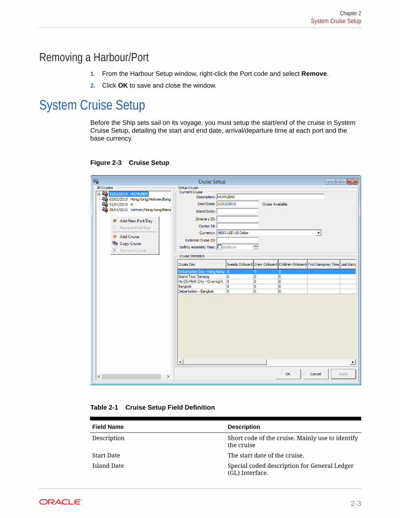
System Cruise SetupBefore the Ship sets sail on its voyage, you must setup the start/end of the cruise in SystemCruise Setup, detailing the start and end date, arrival/departure time at each port and thebase currency.
Figure 2-3 Cruise Setup
Table 2-1 Cruise Setup Field Definition
Field Name Description
Description Short code of the cruise. Mainly use to identifythe cruise
Start Date The start date of the cruise.
Island Date Special coded description for General Ledger(GL) Interface.
Chapter 2System Cruise Setup
2-3

Table 2-1 (Cont.) Cruise Setup Field Definition
Field Name Description
Itinerary ID An identifier for the voyage/cruise.
Center ID Special coded description for GL.
Currency Official on board currency. See Financial Setup,Currencies
External Cruise ID Cruise ID from an external party.
Safety Assembly Time Schedule Safety Assembly Time for the cruise.
Creating System Cruise1. Select System Setup, then System Cruise Setup from the drop-down list.
2. In the Cruise Setup window, right-click the All Cruises pane and select AddCruise to open a blank setup form.
3. Enter the Description, Start Date, Island Date, Itinerary and Currency.
4. Click Apply to save.
Adding Port Day to Cruise1. At the All Cruises section of the Cruise Setup form, right-click on the Cruise
Name and select Add New Port/Day.
2. At the Setup Cruise form, enter the Date, Description, Port Comments, Weatherand select from the drop-down list the Arrival Port, IPM Port Type, ArrivalCountry, Arrival Time and Departure Date/Time.
3. Click Apply to save the form.
4. Repeat the above steps for additional port day.
Note:
You cannot alter the Port Day once the date is entered. You are requireto first remove and re-enter the port day before adding the remainingport day.
Removing Port Day1. At the All Cruises pane, right-click on the Port Date you wish to remove.
2. Select Remove Port/Day option.
Chapter 2System Cruise Setup
2-4

Note:
The system validates all reservations against the port day before a port/day orcruise is removed. If there are linked reservations found, amend the bookingbefore proceeding.
Copying Cruise DayThe Copy Cruise function copies the same cruise setup/itineraries into a future date. If theinformation is completely different, we recommend that you create the cruise from scratchand add the port day individually.
1. In the All Cruise section, select the Cruise Day, then right-click and select Copy Cruise.
Figure 2-4 Duplicate Cruise
2. Insert the Start Date and Description in the Duplicate Cruise window, then click Add.The copy cruise is not allowed if a Start Date exist.
3. Click OK to confirm and populate the information in All Cruises section.
Removing a CruiseYou can only remove a cruise when there are no reservation records attached to the cruiseday. This option is dimmed when the system detects there is a link to a port day.
1. At the All Cruises section, expand the Cruise Day container and select the port day toremove by right-clicking the date.
2. Repeat above step until all the port day for that cruise is removed.
3. Right-click on the Cruise Day and select Remove Cruise.
4. Click OK to exit and return to System Cruise setup.
System Date ChangeThe Night Auditor or appointed user from the Finance Department is responsible to performthe System Date Change nightly. Before you run the System Date Change, all revenue
Chapter 2System Date Change
2-5
centers must be in balance, and this includes the Point-of-Sale (POS) System,Cashbook and other processes deem necessary by the ship operator.
Performing System Date Change1. From the System Setup drop-down menu, select System Date Change.
Note:
You are not allowed to proceed when the Cashier’s sessions is stillactive.
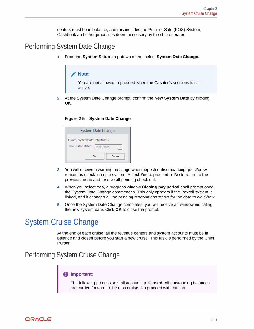
2. At the System Date Change prompt, confirm the New System Date by clickingOK.
Figure 2-5 System Date Change
3. You will receive a warning message when expected disembarking guest/crewremain as check-in in the system. Select Yes to proceed or No to return to theprevious menu and resolve all pending check out.
4. When you select Yes, a progress window Closing pay period shall prompt oncethe System Date Change commences. This only appears if the Payroll system islinked, and it changes all the pending reservations status for the date to No-Show.
5. Once the System Date Change completes, you will receive an window indicatingthe new system date. Click OK to close the prompt.
System Cruise ChangeAt the end of each cruise, all the revenue centers and system accounts must be inbalance and closed before you start a new cruise. This task is performed by the ChiefPurser.
Performing System Cruise Change
Important:
The following process sets all accounts to Closed. All outstanding balancesare carried forward to the next cruise. Do proceed with caution
Chapter 2System Cruise Change
2-6
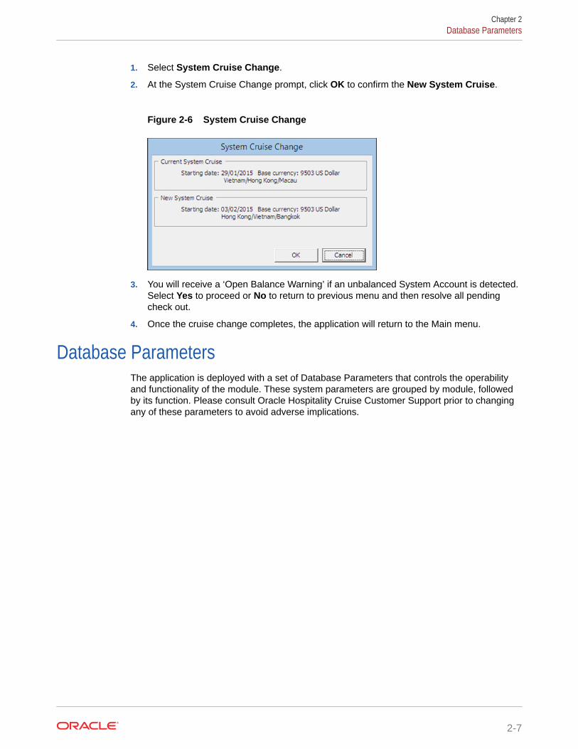
1. Select System Cruise Change.
2. At the System Cruise Change prompt, click OK to confirm the New System Cruise.
Figure 2-6 System Cruise Change
3. You will receive a ‘Open Balance Warning’ if an unbalanced System Account is detected.Select Yes to proceed or No to return to previous menu and then resolve all pendingcheck out.
4. Once the cruise change completes, the application will return to the Main menu.
Database ParametersThe application is deployed with a set of Database Parameters that controls the operabilityand functionality of the module. These system parameters are grouped by module, followedby its function. Please consult Oracle Hospitality Cruise Customer Support prior to changingany of these parameters to avoid adverse implications.
Chapter 2Database Parameters
2-7

Figure 2-7 Database Parameter
1. From the System Setup menu, select Database Parameters.
2. In the Database Parameters Setup window, click the plus (+) key to expand thegroup or navigate to Quick Search section, and search the parameter name inGroup/Name field and then click Search.
3. Changing the value at the Parameter Details changes the behavior of thefunctions.
a. Enabled: By default, all parameters are set to Enabled. In order to disable aparameter, change the value to 0 (0 = Disabled/ 1 = Enabled).
b. Value: The acceptable value is defined in the description.
Defining the days to keep log filesYou can to keep an activity log of certain functions, particularly the Interfaces. Thenumber of days is keep is set up in Database Parameter:
• Group Interface, Days to keep log file.
• Group Gangway, Gangway Log Days
Once defined, the system checks the log entries when the module starts and purgeentries older than the days enter.
Chapter 2Database Parameters
2-8

Airport SetupThe Airport Setup code is used in Crew and Management Module, Flight Overview window. Itallow you to arrange a passenger or crew arrival pickup or departure drop-off. You can alsoimport an airport list instead of inserting the details manually, and this list must be save ineXtensible Markup Language (XML) format (IATA_AIRPORT_List.XML) in Oracle HospitalityCruise folder.
1. From the System Setup menu, select Airport Setup (IATA).
2. In the Airport (IATA) setup window, the import commences once it detects theIATA_AIRPORT_List.xml file.
3. Click Yes at the Admin prompt to confirm the data to import, and then OK when theimport is successful.
Adding Airport Code Manually1. At the Airport Setup (IATA) setup, All Airport section, right-click and select Add New.
2. Enter a short code and description in the Description field.
3. Enter a comment in the Comment field, if any.
4. Click Apply to save.
Company EntityThis function allows you to enter the company entity of the ship.
1. From the System Setup menu, select Company Entity Setup.
2. Right-click on the left pane of the form and select Add New.
3. Enter all the information in the Entity Details section and then click Apply.
Chapter 2Airport Setup
2-9

Figure 2-8 Company Entities Setup
Table 2-2 Field Definition of Company Entities Setup
Field Name Description
Entity ID Company Entity ID, provided by SPMS
Code Company or Ship Code
Name Company or Ship name
Enabled Set to True
Record ID Defines the record ID representing anentity
Type Type of Entity• 1 = Vessel/Ship• 2 = Headquarter• 3 = Warehouse
Address Address of entity
City & Country Code Country of entity
Phone Phone
Fax Fax
Email Email address
Print Order Report ID Print Order Report ID used by MaterialsManagement System (MM)
License License Code provided by SPMS
Chapter 2Company Entity
2-10

Table 2-2 (Cont.) Field Definition of Company Entities Setup
Field Name Description
IDEA Enabled Field use by MMS and is defaulted toFalse
Assigning Company ID1. At the left pane of Company Entity Setup window, right-click the entity name and select
Set Who Am I.
2. At the confirmation prompt, select Yes to update information to Parameter Who Am Ilink.
3. Restart the application for change to take effect.
Time Zone ChangeThis function enables you to set the ship’s clock forward or backward when the ship travelsthrough different time zones, thus recording an accurate crew work hours. This function isonly used in Time & Attendance module.
1. From the System Setup option, select Timezone Change Setup.
2. At the Timezone Change Setup window, right-click on the left pane and select Add.
3. In the Details section, select the Data and Time from the drop-down list when the changeshould take place.
4. Enter the number of hours in the Change Hours filed and a remark of the change.
5. Click Apply to save.
Batch Reports Printing SetupThe function enable you to setup a group of reports to print at a scheduled time and itrequires the OHC Auto Report application to be running at all times.
1. At the System Setup option, select Reports Batch Printing Setup.
Chapter 2Time Zone Change
2-11

Figure 2-9 Batch Reports Printing Setup
2. In the Batch Reports Printing Setup window ribbon bar, click the Add New button.
3. Enter the all the required fields and then click Save.
Adding Report to Batch Printing1. Select the Report Group from the Batch Printing tree.
2. In the Report Parameters tab, select an Action Type from the drop-down list.
Table 2-3 Batch Report Printing Options
Option Description
1 – Skip Option to skip the selection process.
2 – Report Enable a search option and reportselection from existing report database.
3 – External Program The function call an external programwhen running the Batch Report. Onlyexternal program that is defined inParameter, “General”,“ExternalProgram List” is allowed to be save.
4 – Call Batch Printing Enable to link and include existing reportgroup to the current.
3. In the Report Name field, click Search to look up for the report.
4. Select the day of the week from the Schedule drop-down field.
5. Choose the Output method from the drop-down list. If the selected methods is tosave to file, enter the Export File name and path and Email Address for the filesto be sent to the specific user.
Chapter 2Batch Reports Printing Setup
2-12

6. Click Save at the ribbon bar to save.
Copying Batch Details to Other Report1. Select the Report Group from the tree and then click the Copy button at the ribbon bar.
2. In the Report Group to copy to, click Add New and then Paste.
3. Click the Save button to save.
Deleting Batch Report Details1. Select the Report Group from the Batch Printing tree and then click Delete button at the
ribbon bar.
2. At the confirmation prompt, click Yes to proceed.
Note:
This action deletes the record permanently. Please proceed with caution.
Reports SetupThe Report Setup function allows you to add customized Crystal reports to the existingSystem report set, or export the report template for use on another ship or for furthercustomization.
Chapter 2Reports Setup
2-13

Figure 2-10 Report Setup
Table 2-4 Setup Functions In Report
Figure Description
1 Tools function that uploads reporttemplates from a public folder.
2 List of report set available, including thosethat was manually uploaded.
3 Search function that enables you to searchfor a report.
4 Report detail of the report. For example,Report ID, User Access, Report Group.
5 Default printer configuration.
6 Formula embedded in the Crystal Reporttemplate.
7 Selection criterion input required from theuser prior to generating a report.
Chapter 2Reports Setup
2-14

Adding New Report1. From the System Setup option, select Reports Setup.
2. In the User Customizable Report Setup, Current Report List pane, right-click andselect Add New Report to enable the fields on the right pane.
3. Navigate to the right pane and select Upload New Report (Load Variables From theReport Template) or Upload Report.
4. Search for the .RPT file on your local drive if you are uploaded a report template.
5. In the Report Details section, enter the following information:
a. Report ID: Unique ID of customized report.
b. Report File Name: Crystal Report file name, for example, pabxnationbreak.rpt.
c. Report Title: Report name to show in Current Report List.
d. Report Access: User Access Right to view/print report.
e. Report Sort: Sort order of the report within the assigned report group.
f. Report Group: Group this report belongs to. Select from the drop-down list.
g. Report Comments: Additional comments/Information pertaining to this report.
Chapter 2Reports Setup
2-15

Figure 2-11 Default Standard for Report
6. In the Print Default section, select the Printer Type, Number of Copies and thePrint Orientation.
7. Click Save to add the report to the list.
8. Click OK at the ‘Save New Report’ prompt. The newly added report name isshown at the bottom of the screen
Removing a Report1. In the User Customizable Report Setup window, expand the Current Report List
tree by clicking the plus (+) key.
2. Right-click the report name you wish to remove and then select Remove Report.
3. Click Yes when prompt.
Chapter 2Reports Setup
2-16

Exporting a Report1. In the User Customizable Report Setup window, expand the Current Report List tree.
2. Click the Export to Crystal button in the Default Standard tab.
3. Select the location to save the file and note that the file type is indicated as CrystalReport.
Change Debark/Embark DateThis function allows you to change the bulk change a Debark or Embark Date when the needarises. For example, passengers are not allowed to debark due to severe weather condition.
1. From the System Setup option, select Change Debark Date or Change Embark Date.
2. Select the date from the From/To Date field and check the applicable passenger typeand the status.
3. Select a New Date and check the Reset Boardcards check box if you need to issue newboardcard.
4. Click OK and then select Yes to proceed or No to abort.
Labels SetupThe system is pre-installed with a range of hard coded labels for use in various functions. Youmay modify the description of the labels to suit the Ship’s operation. Consult OracleHospitality Cruise Support if you wish to change the description of these labels.
Chapter 2Change Debark/Embark Date
2-17

3Financial Setup
In the Financial Setup function, you can create and manage the Ship's accounting codes,ensuring the daily revenues/expenses are correctly mapped to the codes configured. Agreater financial reporting can be achieved through a well thought out system of accounts. Itis highly recommended for shore side accounting personnel to play a key role in creating/developing the accounts and revisit this setup from time to time. Configuration of these codesis under the responsibility of System Administrator, Chief Purser and Accounting Purser.
Department CodesThe Department Codes is where all debit and credit posting codes are stored, and codesentered are mapped to the Back Office Accounting System using the General Ledger (GL) ID.These codes are sub-divided into several codes within a Main Group.
Figure 3-1 Main/Sub-Department Setup
Main DepartmentThe Main Department code is the higher level of grouping of the approved Chart of Accountand in this instance, the revenue or cost centers. The Main Department Setup comprises oftwo tabs; a Debit and Credit tab. In general, the Debit departments are the revenue centersand outlets, where as the Credit department represents the payment methods accepted bythe Ship. All the codes are entered through Administration, Financial Setup, DepartmentCodes.
3-1

Adding a Main Department Code1. From the Administration, Financial Setup menu, select Department Codes
option.
2. Select either a debit or a credit tab.
3. Click the New button located at the bottom of the screen.
4. Enter the code, description and other required fields approved in by your FinancialDepartment and then click OK to save.
Table 3-1 Main Department Code
Field Description
Code Department code in numeric character
Description Description or name of the code
Other Description Alternative name or other description ofthe code, if any
Sub-Department Code Pre-defined Sub-Department code ofAutomatic Service Charge
Percentage to distribute Percentage value of Automatic ServiceCharge to distribute
% for Team Server 1 % of Service Charge to distribute byTeam
% for Team Server 2 % of Service Charge to distribute byTeam
% for Pool Distribution % of Service Charge to distribute fromService Charge Pool.
External ID Department Location ID
Credit Limit Overall Floor Limit Allowed
Deleting a Main Department1. From the Main Department Codes setup, select the code and then click the Delete
button.
2. At the confirmation prompt, click Yes to proceed.
Note:
Once a code is used and has transactions linked, you are not allowed todelete it. You can choose to hide the code using the Hide button.
Sub-DepartmentYou can only add a Sub-Department when Main Department code is present. Theinformation required in a debit sub-department code defers from credit sub-departmentcode although the process to create them are similar.
Chapter 3Department Codes
3-2
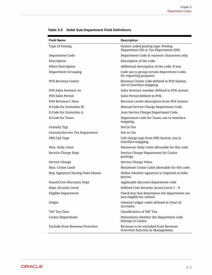
Table 3-2 Debit Sub-Department Field Definitions
Field Name Description
Type of Posting System coded posting type: PostingDepartment (D) or Tax Department (DX)
Department Code Department Code in numeric characters only.
Description Description of the code.
Other Description Additional description of the code, if any.
Department Grouping Code use to group certain department codesfor reporting purposes.
POS Revenue Center Revenue Center code defined in POS System,use in Interface mapping.
POS Sales Itemizer no Sales Itemizer number defined in POS system.
POS Sales Period Sales Period defined in POS.
POS Revenue C.Desc Revenue center description from POS System.
D.Code for Gratuities M. Manual Service Charge Department Code.
D.Code for Gratuities A. Auto Service Charge Department Code.
D.Code for Taxes Department code for Taxes, use in Interfacemapping.
Gratuity Typ Not in Use
Gratuity/Service Tax Department Not in Use
PBX Call Type Call charge type from PBX System, use inInterface mapping.
Max. Daily Limit Maximum Daily Limit allowable for this code.
Service Charge Dept. Service Charge Department for Casinopostings.
Service Charge Service Charge Value.
Max. Cruise Limit Maximum Cruise Limit allowable for this code.
Req. Signature During Folio Payout Define whether signature is required on foliopayout.
Guest/Crew Discounts Dept. Applicable discount department code
Dept. Security Level Defined User Security Access Level 1 – 9.
Eligible Department Check box that determines the department arenon-eligible for refund.
Origin General Ledger codes defined in Chart ofAccounts.
VAT Tax Class Classification of VAT Tax.
Casino Department Determines whether the department codebelongs to Casino.
Exclude from Revenue Overview Revenue to be excluded from RevenueOverview function in Management.
Chapter 3Department Codes
3-3

Table 3-3 Credit Sub-Department Field Definitions
Field Name Description
Payment Type The payment type of this code. Forexample, Cash, Foreign Currency, CreditCard, Check, Cabin Charge, City Ledger
Department Code Department Code in numeric charactersonly.
Description Description of the code.
Other Description Additional description of the code, if any.
Department Grouping Code use to group certain departmentcodes for reporting purposes.
Credit Card Digits Acceptable credit card digits associatedwith the type of credit card.
Credit Card ID Short code of credit card type.
Credit Card Internal ID Internal credit card id preset by the system.
Credit Card Merchant ID Card Merchant ID.
Foreign Currency Code ISO Currency codes. Refer to Typ_Cur whenthe payment type=CF Foreign Currency.
Floor Limit Maximum limit allowed in guest accountfor this card type.
Crew Floor Limit Maximum limit allowed in Crew accountfor this card type.
Minimum Authorization Value Minimum amount to obtain from cardmerchant.
Commission Department Department code for chargeablecommission.
Commission Rate % of applicable commission or valuedefined if 'Commission is fix value' ischecked.
Daily Limit Daily Posting limit.
Debit Card No Commission Commission is exempted if checked.
Commission is fixed value Applicable commission is value basedinstead of %.
Auto Balance (Interface) Auto Balance function for cash/credit cardposting via interface.
Rewards Card Denotes Rewards Card if checked.
Gift Card Denotes Gift card if checked.
POS Tender Type No. Tender Media Number defined in POSSystem
System Account No. The Account Number defined in SystemAccount
Incentives Payout Group Incentive payout group setup from CrewIncentive.
External Department ID External Department ID for payment from3rd party system.
Chapter 3Department Codes
3-4

Table 3-3 (Cont.) Credit Sub-Department Field Definitions
Field Name Description
External Itemizer ID External Itemizer ID from third–partysystem.
Allow Posting to Guest Cabin Posting allowed via Micros POS System.
Allow Posting to Crew Cabin Posting allowed via Micros POS System.
Allow Posting to Gift Card Posting allowed via Micros POS System.
G.Ledger Id. General Ledger codes in Chart of Accounts.
Eligible Department If the check box is checked, the departmentare non-eligible for refund.
Dept. Security Level Defined User Security Access Level 1 – 9
Req. Signature During Folio Payout Define whether signature is required onfolio payout
Credit Card Disclaimer Note Disclaimer note to print on invoice whenpayment is by credit card.
Department for routing Payment Type allowed for routing.
Adding a Debit Sub-Department1. From the Main Department Setup window, select the Debit tab and then the
Department Code.
2. Click New to open the Debit Department Code Setup form.
3. Enter the code, description and other required fields approved by your Financial System.
4. Click OK to save.
Adding a Credit Sub-Department1. From the Main Department Setup window, select the Credit tab and then the
Department Code.
2. Click New to open the Payment Setup form.
3. Enter the code, description and other required fields approved by your Financial System.
4. Click OK to save.
Note:
No posting is allowed when a credit code does not have a floor limit assigned orthe value is 0.00. The parameter “General”,”Check Buyer Limit” and “CheckCredit Limit” is used to validate and manage the credit limit during posting.
Deleting Sub-Department Code1. From the Main Department Setup window, select the Sub-Department to delete.
2. Click the Delete button located at the bottom of the screen.
Chapter 3Department Codes
3-5

3. At the confirmation prompt, select Yes to delete the code.
Note:
It is not possible to delete a code that has transaction linked to it. Oncethe code is deleted, is not reversible. If the code is no longer in use anddeleting is not possible, use the Hide/Show function to disable them.
CurrenciesThis Currencies function enables you to input the currency rate used in CurrencyExchange module. You can also update the exchange rates from Currency Exchangemodule itself. This feature uses the Currency Codes configured in Credit Sub-Department.
Adding Currency Rate1. From the Financial Setup menu, select Currencies.
2. In the All Currencies section, right-click and select Add Rate.
3. Navigate to Setup Exchange Rates section and select the currency code fromCurrency/Check drop-down list.
4. Enter the Valid From date, Minimum Denomination (Buy/Sell) and select theRate Calculation method from the drop-down list.
5. Checking the Disable From check box disables the currency from showing in theCurrency Exchange module from date specified. Disabled currency are markedwith an asterisk *.
6. Enter the Available Notes, if any. If you have specified the Available Notes, thesystem uses the Available Notes for calculation and ignore the MinimumDenomination setup.
7. Enter the Exchange Rates and Commission % or Min. Commission, then clickOK to save.
Removing Currency RateA currency rates can be easily removed by right-clicking the currency rate and selectRemove Rate.
Merchant DetailsFor every credit card provider the Ship deals with, you must create a Merchantcredential to facilitate the credit card authorization and handling. Such information isprovided by the third-party service provider.
1. From the Financial Setup menu, select Credit Card Merchant Setup.
2. On the left pane of the setup screen, right-click and select Add New.
3. Select the Credit Card Type and Currency from the drop-down list.
4. Enter the Terminal ID, Bank ID, Decimal, IP Port, Merchant Login ID andMerchant Password.
Chapter 3Department Codes
3-6

5. Click OK to save.
6. Repeat the above steps for other credit card type accepted by the merchant.
Pre-Selection GroupsThe Pre-Selection Groups allow you to categorize numerous department codes into a group,for use in Routing and Discount assignment.
1. From the Financial Setup menu, select the Department Groups Setup.
2. On the left pane of the setup screen, right-click and select Add Department Group.
3. In the Department Groups section, enter the Description of the group and theDepartment Codes.
4. Click OK to save.
Stateroom Upgrade SetupIn the Stateroom Upgrade Setup function, you can create a price table and manage the pricedifferences to charge when a performing a cabin upgrade.
1. From the Financial Setup menu, select Stateroom Upgrade Setup.
2. In the Price Table for Upgrades screen, click New.
3. In the Edit Upgrade Prices window, select a category from the Category Identifier.
Note:
The Cabin Categories only appears if these are set up in Stateroom setup.Sorting the category pricing from higher to lower is recommended.
4. Enter the Sorting, Price and Maximum Person allowed.
5. Click OK to save.
Discount TemplatesThe Discount Templates function enable you set up various discount types template, for usein Discount, Routing and Package Handling.
1. From the Financial Setup menu, select Discount Templates.
2. On the left pane of the setup screen, right-click and select Add New.
3. Navigate to the Fidelio Department section and then click Add. This launches theDiscounts window.
4. In the Discounts window, enter the Percentage, number of count to apply in the HowMuch section. When the Percentage check box is unchecked, the discount becomes avalue based discount. If the Apply Count field is blank, this discount is unlimited.
5. Select the applicable Department Code and then click OK to apply.
Chapter 3Department Codes
3-7

Quick Posting TemplateThis function enable you to create a criterion filter to be use in Quick Posting functionin Cashier Function. For example, a posting to specific nationality.
1. From the Financial Setup menu, select Quick Posting Templates.
2. On the left panel of the setup screen, right-click and select Add New.
3. Enter the short code and description in the Description field and then insert thecriterion in the Comments field.
4. Click OK to save.
Import Credit Card BinYou can import a complete set of eligible Bank Identification Number (BIN) provided bythe Credit card provider by and overrides the previously loaded BIN information duringthe reload process.
1. From the Financial Setup menu, select Import Credit Card Bin file.
2. At the bottom of the screen, select the BIN file to import.
3. By default, all the check boxes are check. Click Import to save the information intothe BIN table.
4. Click Close to exit.
Disallow Manual Posting ApplicationsThis function is use to prevent users from manually posting a transaction through thelisted application when the posting is set to No in the guest account.
1. From the Financial Setup menu, select Disallow Manual Posting Applications.
2. Right-click on the left pane and select Add New.
3. Enter a short code and the application name in the Description field.
4. Click Apply to save.
Department GroupingThis function allow you to categorize a department group for use as financialclassification and in report grouping.
1. From the Financial Setup menu, select Department Grouping.
2. Right-click the left pane and select Add New.
3. Enter a short code and description in the Description Field and then click OK tosave.
VAT HandlingBefore you use the VAT Handling, these VAT components must be in place.
• VAT Tax Class
Chapter 3Department Codes
3-8

• VAT Tax Rate
VAT Tax ClassThe VAT Tax Class a tax group classification. For example, a Regular Tax, Reduced Tax andothers.
1. From the Financial Setup menu, select VAT Tax Class.
2. On the left pane of the setup screen, right-click and select Add New.
3. Enter the short code and the application name in the Description Field and click Applyto save.
VAT Tax RateThe VAT Tax Rate code is used to define the various tax rate applicable to each country orclass, and the tax posting code.
Figure 3-2 VAT Tax Rate Per Country Setup
1. From the Financial Setup menu, select VAT Tax Rate.
Chapter 3Department Codes
3-9

2. Click Add New at the ribbon bar and then select the Country code from the drop-down list.
3. Click Save.
4. Expand the Country container and select the Tax Class.
5. Insert the tax rate in the VAT Tax Rate field and select the Tax Department codefrom the drop-down list.
6. Click Save to save the changes.
Activating a Tax RateThis function enable you to apply the correct Tax Rate based on the cruise locationand stores the information in Parameter, “General”,”Current VAT Tax Country”. Asystem restart is required on all posting modules for changes to take effect.
1. From the Financial Setup menu, select Activate Tax Rate.
2. Select the country tax to activate from the drop-down list and then click OK.
3. At the confirmation prompt, select Yes to activate.
VAT Tax ReminderA reminder can be added to remind you when to activate the tax country on datespecified.
Figure 3-3 VAT Tax Reminder
1. Front the Financial Setup menu, select VAT Tax Reminder.
2. Click Add New at the ribbon bar, and then select the Date and Time from thedrop-down list.
3. At the Active Tax Country, select the Country the tax to be activated.
4. Click Save to save and exit.
Chapter 3Department Codes
3-10

4Itinerary Setup
The Itinerary Setup is function that enables you to plan the daily activities available for eachvoyage by Location, Events, Packages or through an Agent. The information entered hereare shown as an information board in the Management, Itinerary Overview , and they areentered through Administration, Itinerary Setup.
Adding an Activity
Figure 4-1 Activities Setup
Table 4-1 Field Description of Activities Setup
Field Name Description
Type/Title The type of activity and title
Language The language offered in this activity
Title Title of the activity
Description Brief description of the activity
Start DateTime Start date and time of the activity
4-1

Table 4-1 (Cont.) Field Description of Activities Setup
Field Name Description
Duration Time Duration of the activity
Deadline DateTime Booking deadline date/time
Setup Time Setup time require in minutes
Dates Accuracy Activity dates accuracy (1-All Accurate, 2-AllApproximate, 3-Starting Approx., 4-DurationApprox.)
Clean-up Time Clean up time in minutes
Location Location of the activity
Comments Comments for the activity
Waiting List Waiting List is allowed/disallowed
Booking Status Activity booking status (Enable/Disable)
Booking Options Activity booking options — Booking isrequired or not.
Min/Max Available Minimum or Maximum number of bookingsallowed
Agent/Vendor Agent/Vendor Name
Adult Cost Price Agent/Vendor Cost Price
Child Cost Price Agent/Vendor Cost Price
Department Agent/Vendor Posting Department
1. From the Itinerary Setup menu, select Activities.
2. One the left pane, right-click on the selected Cruise Day.
3. Select Add Activity from option menu.
4. In the Setup Activity section, update the all the activities details.
5. Click the More Details button to insert the Meeting Date/Time, clothingrequirements and other information and click OK to return to previous screen.
6. In the Reservation section, select the appropriate booking options from the drop-down list.
7. Enter the pricing and select the Agent/Vendor providing the service.
8. Click OK to save.
Copying an Activity SetupAn existing activity can be copied into the future cruise by day or by activity instead ofre-creating every single activity.
1. From the Activities setup window, right-click on the Cruise Day and select CopyDay/Activity.
2. In the Duplicate whole day window, enter the date to copy to, then click Add.
3. Click OK to copy the activities.
Chapter 4Copying an Activity Setup
4-2

Note:
To copy a single activity, select an Activity instead of by Cruise Day.
Add Package PriceThe Add Package/Price is an additional information field for the activity and they are notmeant for posting.
Adding Team/Time FrameYou can add the team member required to handle the activities by indicating the time andnumber of member required.
1. In the Activities Setup window, right-click on the activities details and select Add Team/Time Frame.
2. In the Team/Time Frame section, enter the number of team member and select the timeto reserve from and duration.
3. Click OK to save.
Removing an ActivityActivities that are no longer required or has been added as duplicate can be easily removedby right-clicking on the activity and select Remove Activity. If the activity has a Team/TimeFrame or Packages/Price information, you must remove these first before removing theactivity.
Chapter 4Add Package Price
4-3
5Events
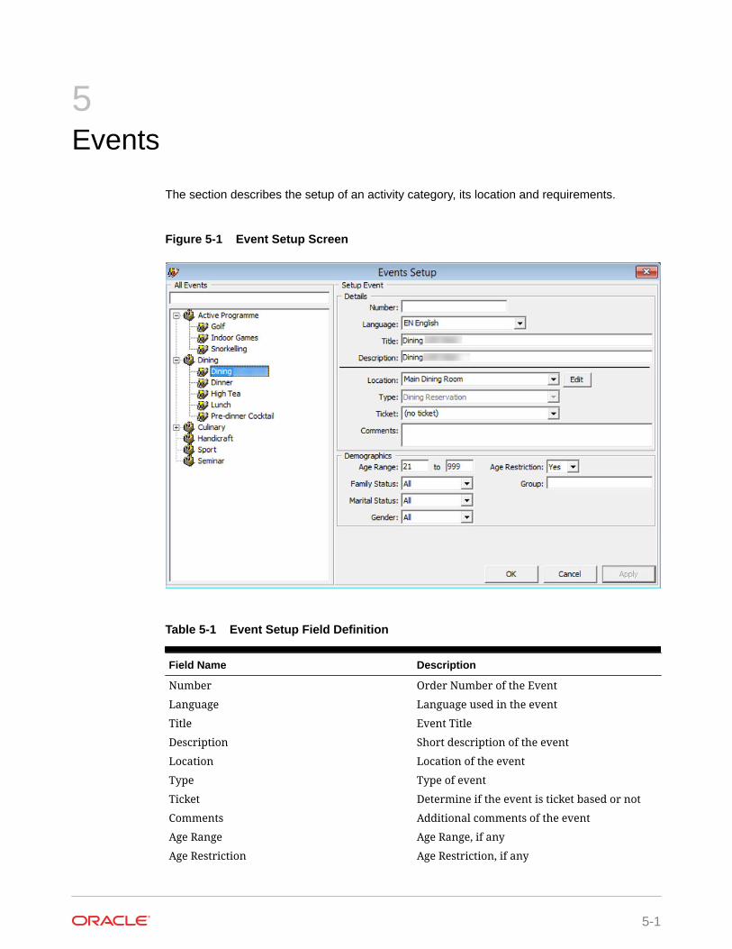
The section describes the setup of an activity category, its location and requirements.
Figure 5-1 Event Setup Screen
Table 5-1 Event Setup Field Definition
Field Name Description
Number Order Number of the Event
Language Language used in the event
Title Event Title
Description Short description of the event
Location Location of the event
Type Type of event
Ticket Determine if the event is ticket based or not
Comments Additional comments of the event
Age Range Age Range, if any
Age Restriction Age Restriction, if any
5-1

Table 5-1 (Cont.) Event Setup Field Definition
Field Name Description
Family Status Family Status of attendees, if any
Marital Status Marital Status, if any
Gender Target gender, if any
Group Group name for special event
Adding an Event1. From the Itinerary Setup drop-down menu, select Events.
2. In the All Events section, right-click and select Add Event Type.
3. Enter a short code and description in the Description field and then click OK.
4. Select the Event Type, then right-click and select Add Event.
5. In the Details section, enter the event number, title and description of the event.
6. Select a Location, Type and Ticket from the drop-down list.
7. In the Demographics section, enter the Age Range and select the FamilyStatus, Marital Status, Gender and Age Restriction from the drop-down list.
8. Click OK to save the entry.
Setting Up Event LocationThe Location is use to describe to the location where event/activity is held.
1. From the Itinerary Setup menu, select Locations.
2. In the All Locations section, right-click and select All Location.
3. In the Setup Location Section, enter a code and description in the Title field, selectthe Deck from the drop-down list and attach a picture, if any.
4. Select the Availability Status and appropriate prompt to use for an overbookedlocation and click OK to save.
5. Select the Location, the right-click and select Add Table/Seat.
6. In the Details section, enter the even number, title and description.
7. Select a Location, Type and Ticket from the drop-down list.
8. In the Demographics section, enter the Age Range and select the Family Status,Marital Status, Gender and Age Restriction from the down-down list.
Adding Event Table/Seat1. In the Location Setup window, right-click on the location.
2. Click Add Table/Seats.
3. Fill in all the fields.
4. Click OK to save.
Chapter 5Adding an Event
5-2

Adding an Event Exception1. At the Location Setup window, right-click and select Add Exception.
2. Fill in the information and select the Reason from the drop-down list.
3. Click OK to save.
4. Location that has an exception are marked with an Exclamation mark.
Chapter 5Setting Up Event Location
5-3

6Vendors
The Vendors/Agents Setup is used for storing store contact information of vendors/agentshandling the events.
Figure 6-1 Agents/Vendors Setup
Setting Up a Vendor1. From the Agents/Vendors Setup window, right-click and select Add Agent.
2. Enter the Agents details and then navigate to Comments tab to add the additionalcomments or document image.
3. In the Comments tab, click Add Comment to enter a new comment and the relevantdetails.
4. Navigate to the Document tab to upload, scan or export an image file.
5. Click Save.
6. Click OK to save the Agent details.
6-1

7Safety Setup
The Safety Setup contains all the codes required in Standard Safety Drill and Advance SafetyDrill modes. The setup varies depending on the mode defined in Parameter group, Safety,Advance Safety Drill (0=Standard Safety Drill / 1 = Advance Safety Drill).
Safety Setup TypeIn below figures, you will see the list of codes available to Standard Safety Drill andAdvanced Safety Drill mode.
Below is the function codes available to Standard Safety Drill mode where Parameter,Safety, Advance Safety Drill set to “0”.
7-1

Figure 7-1 Standard Safety Drill Setup Codes
Below is the function codes available to Advanced Safety Drill mode whereParameter, Safety, Advance Safety Drill set to “1”
Chapter 7Safety Setup Type
7-2

Figure 7-2 Advance Safety Drill Setup Codes
Table 7-1 Safety Setup Configuration Codes
Function Name Definition
Deck Setup Define the deck location in Muster StationSetup. Available in Advance Safety Drill.
Fire Zone Setup Define the Fire Zone for the drill in MusterStation Setup. Available in Advance SafetyDrill.
Chapter 7Safety Setup Type
7-3

Table 7-1 (Cont.) Safety Setup Configuration Codes
Function Name Definition
Stair Well Setup Define the stairwell location in Muster StationSetup. Available in Advance Safety Drill.
Muster Station Setup (definable label -TYP_LBL = SFTMST)
Define the assembly location.
Lifeboat Setup (definable label - TYP_LBL =SFTBOT)
Define the lifeboat or life raft capacity.
Gangway Locations Define the location of gangway.
Safety Department (definable label - TYP_LBL= SFTDIV)
Define the department responsible for safetyfor each location.
Safety Group (definable label - TYP_LBL =SFTSGP)
Define the responsibilities and task of eachsafety group.
Safety Position (definable label - TYP_LBL =SFTCRW)
Define the position of the crew.
Safety Role (definable label - TYP_CLBL =SFTROL)
Define the role of the safety crew.
Safety Function (definable label – TYP_LBL =SFTFCT)
Define the role of crew in command ofSurvival Craft.
Safety Drill Type Define the type of drills.
Drill Location Define the location of the schedule drill.Available in Standard Safety Drill only.
Drill Instructorship Define the instructor responsible for thescheduled drill. Available in Standard SafetyDrill only.
Drill Definition Definition of drills.
Drill Template Setup Template for each drill type.
Absence Reason Absent reason from attending safety drill.Available in Advance Safety Drill only.
Excuse Request Reason Reason to be excused from attending safetydrill. Available in Advance Safety Drill only.
Excuse Unapproved Reason Reason for not approving the excuse request.Available in Advance Safety Drill only.
Interview Comment A comment field used during interview as apredefined comment, or you can input usingfree text. Available in Advance Safety Drillonly.
Course & Certificates Type of Courses and Certification required foreach drill type.
Proficiency Level Proficiency level offered in Courses andCertification.
Accredited Training Centers Reputable Safety training centres recognizedby the ship.
Chapter 7Safety Setup Type
7-4

Configuring Safety Codes in Standard DrillMajority of the setup windows are the same in Standard Safety Drill mode and below are thesteps to configure the new codes for Gangway Locations, Safety Department, Safety Group,Safety Position, Safety Role, Safety Function, Safety Drill Type, Drill Location, DrillInstructorship, Course Type and Accredited Training Centers.
1. From the Safety Setup menu, select the code to configure.
2. Right-click the blank space on the left and select Add New.
3. Enter a short code and the name, and further describe the code in the Comments field.
4. The Enabled field is checked by default. Un-checking the box will disable the code.
5. Click Apply to save the code.
6. Right-clicking the code and select Remove will delete the code from the system.
Setting Up Muster StationA Muster Station is a required field in the Safety Drill setup and this must be setup before youconfigure any Safety Drill. The layout of the configuration screen differs, depending on themode setup in Parameter group, Safety, Advance Safety Drill.
1. From the Safety Setup menu, select Muster Station.
2. Right-click on the blank space and select Add Muster Station.
3. Enter a short code, field name and the Capacity allowed.
4. Select the Lifeboat Type from the drop-down list and insert an Emergency Phone No, ifany.
5. Right-clicking the code and select Copy Muster Station allow you to copy theinformation and add more codes.
6. In the Duplicate Muster Station window, enter the Muster Station and description.
7. Click Apply to save.
Figure 7-3 Muster Station Setup
Chapter 7Configuring Safety Codes in Standard Drill
7-5

Setting Up Lifeboat/LiferaftA lifeboat/liferaft has a maximum capacity and does require a number of qualified crewto handle them in the event of an emergency.
Figure 7-4 Lifeboat/Liferaft Setup
Table 7-2 Lifeboat/Liferaft Setup Field Definition
Field Name Description
Description Short code and description of the lifeboat/liferaft.
Type The type of lifeboat/liferaft. These codesare predefined and hard coded.
Min. Crew with CPSC Required Minimum number of CPSC certified crewon lifeboat/liferaft.
Max Capacity Maximum capacity allowed per lifeboat/liferaft.
Operators/Crew Assigned Number of crew assigned to this lifeboat/raft.
Max Certified Capacity Maximum certified capacity of the lifeboat/raft.
Muster Station Raft Crane Raft crane the lifeboat is assigned to inMuster Station.
Launch Sequence Launch sequence of the lifeboat.
Remarks Additional remarks of the lifeboat.
To setup the codes, repeat steps in Setting Up Muster Station. You can also duplicatean existing Lifeboat code using the same steps.
Chapter 7Configuring Safety Codes in Standard Drill
7-6

Setting Up Drill DefinitionIn the Drill Definition code setup, this is where you defines the type of drills, attendancerequirement and identify drills that are Course and Certificate related.
Figure 7-5 Drill Definition Setup
1. From the Safety Setup menu, select the Drill Definition.
2. To add a new drill, click Add New.
3. Select the Status from the drop-down list. and enter the Drill Code and description.
4. In the Drill Definition section, select the Drill Type from the drop-down list.
5. Enter the Unit of Frequency and Required x Days after embarkation.
6. Click Save to save the record.
7. Select the drill and click Modify.
8. Enter the Location, Instructor, Required Operational Positions and AssignedManning Number.
9. At the Location and Instructor section, right-click and select Add New.
10. Select the location from the drop-down list and enter the comment or function, if any.
11. At the Required Operational Positions section, right-click and select Add New.
12. Add a position individually or select Add All to select multiple positions or all.
13. In the Assigned Manning Number section, repeat step 7 and select Assigned Manningnumber.
Setting Up Course and CertificatesThe Courses and Certificates code allow you to define the type Courses and Certificationsrequired for each drill type, and identify the certificates expiry during on Emergency # (ENumber) change.
Chapter 7Configuring Safety Codes in Standard Drill
7-7
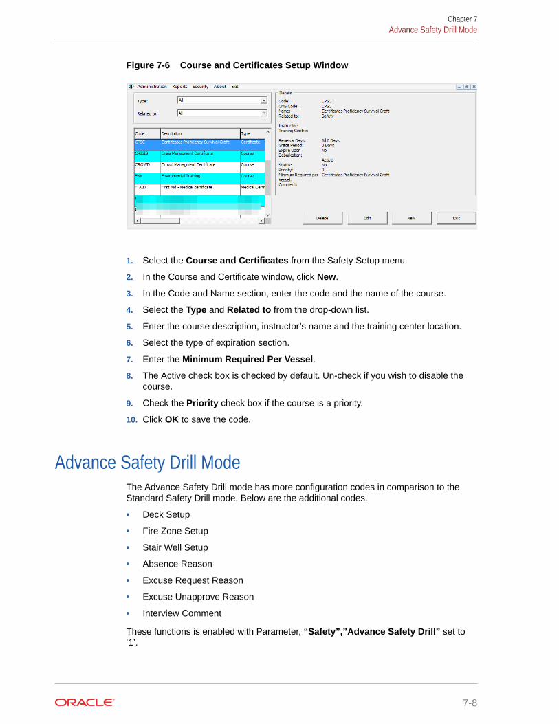
Figure 7-6 Course and Certificates Setup Window
1. Select the Course and Certificates from the Safety Setup menu.
2. In the Course and Certificate window, click New.
3. In the Code and Name section, enter the code and the name of the course.
4. Select the Type and Related to from the drop-down list.
5. Enter the course description, instructor’s name and the training center location.
6. Select the type of expiration section.
7. Enter the Minimum Required Per Vessel.
8. The Active check box is checked by default. Un-check if you wish to disable thecourse.
9. Check the Priority check box if the course is a priority.
10. Click OK to save the code.
Advance Safety Drill ModeThe Advance Safety Drill mode has more configuration codes in comparison to theStandard Safety Drill mode. Below are the additional codes.
• Deck Setup
• Fire Zone Setup
• Stair Well Setup
• Absence Reason
• Excuse Request Reason
• Excuse Unapprove Reason
• Interview Comment
These functions is enabled with Parameter, “Safety”,”Advance Safety Drill” set to‘1’.
Chapter 7Advance Safety Drill Mode
7-8

The majority of the screen layout and configuration of the codes are the same as StandardSafety Drill mode, with the exception of the below listed codes, which has additional fields orfunctions. The steps to create these codes are described in the following topic.
• Muster Station
• Lifeboat/Liferate
• Safety Function
• Drill Type
• Drill Definition
• Drill Template Setup
• Courses & Certificates
See chapter Configuring Safety Codes in Standard Safety Drill on how to set up new SafetyDrill codes
Setting Up Muster Station In Advance Drill ModeThe Muster Station is a required field in the Safety Drill setup and this must be setup beforeyou configure any Safety Drill. The layout of the configuration screen differs from theStandard Safety Drill mode.
1. From the Safety Setup menu, select Muster Station.
2. Right-click on the blank space and select Add Muster Station.
3. Enter a short code, field name and the Capacity allowed.
4. Select the Lifeboat Type from the drop-down list
5. In the Location section, check the correct Deck, Fire Zone, Stair Well and Side of theship for each muster station.
6. Right-clicking the code and select Copy Muster Station allow you to copy theinformation and add more codes.
7. In the Duplicate Muster Station window, enter the Muster Station and description.
8. Click Apply to save.
Chapter 7Advance Safety Drill Mode
7-9
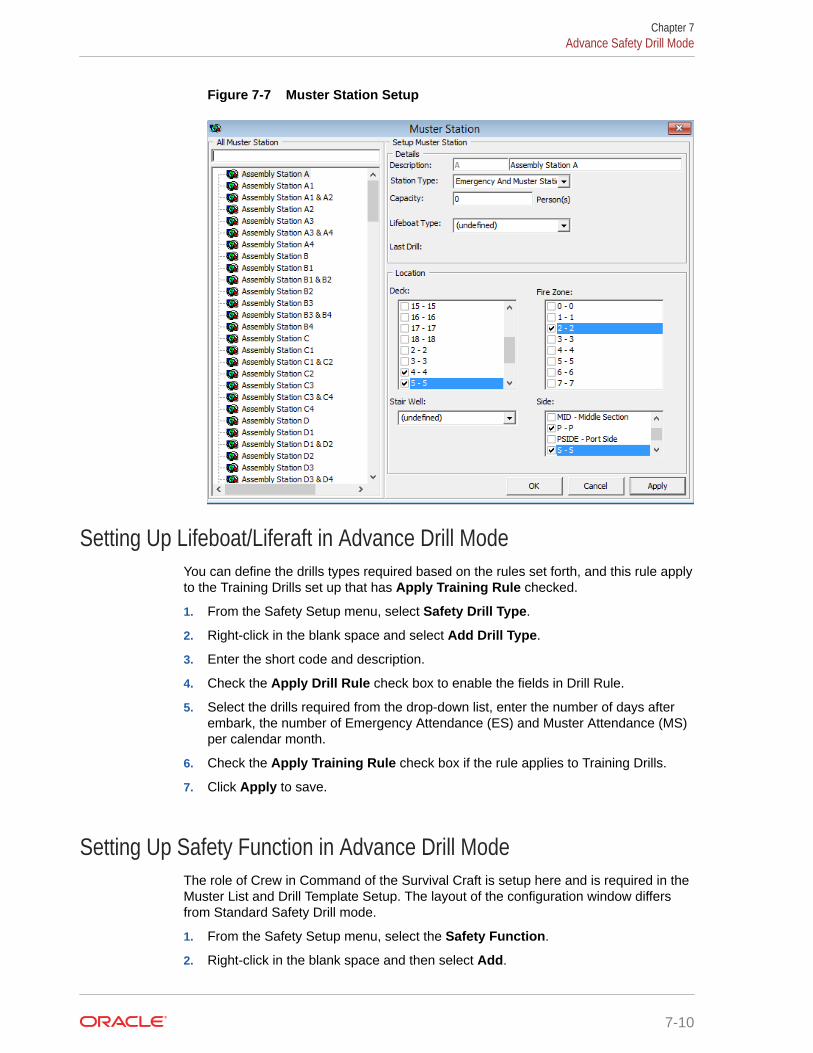
Figure 7-7 Muster Station Setup
Setting Up Lifeboat/Liferaft in Advance Drill ModeYou can define the drills types required based on the rules set forth, and this rule applyto the Training Drills set up that has Apply Training Rule checked.
1. From the Safety Setup menu, select Safety Drill Type.
2. Right-click in the blank space and select Add Drill Type.
3. Enter the short code and description.
4. Check the Apply Drill Rule check box to enable the fields in Drill Rule.
5. Select the drills required from the drop-down list, enter the number of days afterembark, the number of Emergency Attendance (ES) and Muster Attendance (MS)per calendar month.
6. Check the Apply Training Rule check box if the rule applies to Training Drills.
7. Click Apply to save.
Setting Up Safety Function in Advance Drill ModeThe role of Crew in Command of the Survival Craft is setup here and is required in theMuster List and Drill Template Setup. The layout of the configuration window differsfrom Standard Safety Drill mode.
1. From the Safety Setup menu, select the Safety Function.
2. Right-click in the blank space and then select Add.
Chapter 7Advance Safety Drill Mode
7-10

3. Enter a short code, description and comments, if any.
4. Select the Commander/2nd Commander check box if needed.
5. Click Apply to save the code
Setting Up Drill TypeThe Safety drill type defines the type of drills required based on the rules set forth, and therules is applicable to Training Drills if the Apply Training Rule is checked.
Figure 7-8 Drill Type Setup
1. From the Safety Setup, select the Safety Drill Type.
2. Right-click the All Drill Type section and select Add Drill Type.
3. Enter a code and description in the Description field.
4. Check the Apply Drill Rule to enable input of the rule.
5. Update all the fields in the Apply Drill Rule.
6. Check Apply Training Rule if the rule applies to Training.
7. Click Apply to save.
Setting Up Drill Definition in Advance Drill ModeThe Drill Definition code defines the type of drills, attendance requirements and identifywhether drills are Course and Certificate related.
Chapter 7Advance Safety Drill Mode
7-11

Figure 7-9 Drill Definition Window
1. From the Safety Setup menu, select the Drill Definition.
2. Click Add New to add a new drill.
3. At the definition grid, update the following.
a. Status
b. Drill Code and Description
c. Type
d. Attendance Requirement
e. Course and Certificate
4. Click Save
Setting Up Drill Template in Advance Drill ModeA drill template is setup to assist you in generating a crew list under Proposed Crewsection using the criteria defined when creating a drill.
Chapter 7Advance Safety Drill Mode
7-12

Figure 7-10 Drill Template Setup
1. Select Drill Template from the Safety Setup menu.
2. Right-click the blank space and select Add Template.
3. In the Details section, enter a short code and description, and then select the applicablecode in all the fields.
4. Click Apply to save the template.
5. Click OK to exit.
6. Click Reset to clear the selected information from the screen.
Setting Up Course and Certificates in Advance Drill ModeThe Courses and Certificates code allow you to define the type Courses and Certificationsrequired for each drill type, and identify the certificates expiry during on Emergency # (ENumber) change.
Chapter 7Advance Safety Drill Mode
7-13

Figure 7-11 Course and Certificate Setup Advance Drill Mode
Figure 7-12 Edit Course/Certificate Window
1. Select the Course and Certificates from the Safety Setup menu.
2. In the Course and Certificate window, click New.
3. In the Code and Name section, enter the code and the name of the course.
4. Select the Type and Related to and Master Cert from the drop-down list.
5. In the Description section, enter the course description, instructor’s name and thetraining center location.
6. In the Expiration section, Select the type of expiration.
7. Enter the Minimum Required Per Vessel, Proficiency and check the Re-qualifying Course, if required.
Chapter 7Advance Safety Drill Mode
7-14

8. The Active check box is checked by default. Un-check if you wish to disable the course.
9. Check the Priority check box if the course is a priority.
10. Click OK to save the code.
Chapter 7Advance Safety Drill Mode
7-15

8Stateroom Setup
The Stateroom Setup is a function used to define both the passenger and crew cabins.Before you begin coding the cabin, you must have the following:
• Cabin features codes
• Exact location of the cabin in Safety Plan
• Housekeeping sections
Figure 8-1 Cabin Setup Window
Adding, Editing and Copying A Stateroom1. From the Stateroom Setup menu, select Staterooms from the drop-down list.
2. In the Cabin Setup window, click New.
3. In the New Cabin form, enter the Cabin number, No of Berth, Berth Setup and selectthe Deck from the drop-down list.
4. In the Feature section, select the Type, Category, Features, Classification andCommon Access Area.
5. Check theWith Special Need Feature if the cabin is equipped with special needsamenities.
6. Select the HK Section, Life Boat, Muster Station, Location and Vertical Zone in theAssignments section.
8-1

7. In the Crew Assignment section, select the Keeper, Assistant Keeper, HeadWaiter, Waiter and Assistant Waiter.
8. Enter the Phone extension of the cabin in the Phone Numbers section.
9. If the cabin is linked to another cabin and has a common door, check the cabinnumber in the Link Cabin section.
10. Click OK to save the cabin number.
11. Repeat the same for the remaining cabin or use Copy Cabin to copy cabin of thesame category and features.
Editinga a Cabin1. Select the Cabin number from the Cabin Setup window.
2. Click Edit.
3. Click OK to save the changes.
Copying a Cabin CodeThe Copy Cabin function enable you to copy the cabin of the same type, category andhas the same features.
1. In the Cabin Setup window, select the cabin number to copy.
2. In the Cabin Setup form, enter the new cabin number and the telephone number.
3. Click Add to List.
4. Continue to add the cabin number until you complete the list.
5. Click OK to save.
Batch Check-In/OutThe Batch Check-In/Out function allow you to send triggers by batch to enable/disablethe Telephone, ITV or Dining System.
Figure 8-2 Batch Check In/Out Window
Chapter 8Batch Check-In/Out
8-2

Table 8-1 Batch Check-In/Out Filters
Field Name Description
Include All Check In Guest/Crew Sends triggers for all check-in/out for all guest.
Include Check In Guest Only Sends triggers for check in/out guest only.
Include Check In Crew Only Sends triggers for check in/out crew only.
Include Guest/Crew with belowdisembarkation date
Sends triggers for check/out guest/crew withspecified disembarkation date.
Include Guest Only with belowdisembarkation date
Sends triggers for check/out guest withspecified disembarkation date.
Include Crew Only with below disembarkationdate
Sends triggers for check/out crew withspecified disembarkation date.
1. From the Stateroom Setup menu, select Batch Check-In/Out.
2. Choose from the available filter and select a Date.
3. Select the type of batch to execute.
4. Click Close to exit.
Feature/Amenity ItemThe Feature/Amenity Item is for you to set up the special request codes offered inReservation.
1. SelectFeature or Amenity Items from the Stateroom Setup menu.
2. Right-click on the blank space and select Add New.
3. Enter a code and description, and a comment if any.
4. Click OK to save.
Cabin Cleaning State ColorThe Cleaning State Color allow you to define the cabin state according to its cleaning status,if you choose not to use the system defaulted color. If you are defining your own cabin statecolor, you must update the color in the Deck Plan Setup.
Chapter 8Feature/Amenity Item
8-3

Figure 8-3 Cleaning State Color Setup
1. Select the Cleaning State Color from the Stateroom Setup menu.
2. Select the Cleaning Status
3. In the Color field, click to change the background color.
4. Click OK to save.
Deck Plan DesignerUsing the Deck Plan Designer, you can create a deck plan by linking the cabin numberto the plan This would provide a layout view of the cabin in Management module.
Figure 8-4 Deck Plan Setup
1. Select the Deck Plan Designer from the Stateroom Setup menu.
2. Click New Plan and insert the Plan name.
3. Click Load Picture to load the base plan from file.
4. Click New Element and then drag the element box to the desired location.
5. Select the Cabin Number from drop-down list, then click the element box toassign the cabin.
6. Repeat steps 4 and 5 until all cabin number for the deck is assigned.
Chapter 8Deck Plan Designer
8-4

7. Click Save Plan to save the changes.
Editing a Deck Plan1. From the Deck Plan Designer window, right-click the element you wish to edit.
2. Select the option from the menu.
3. Click Save Plan to save the changes.
Linking a PlanThe system allow you to link a deck plan to the next plan, enabling you to navigate from oneplan to another with a single click. To link a plan, you must have multiple plans saved in DeckPlan Designer
1. Select a Plan Name to edit.
2. Select the Next Plan from the drop-down list.
3. Click New Element and place the element near a staircase of the diagram.
4. Click Save Plan.
Deck Plan SetupDeck Plan Setup enable you to define the cabin color by the cabin cleaning status. It isrecommended that you use the same color scheme as the Cabin Cleaning State color.
1. Select Stateroom Setup, Deck Plan Setup from the Administration menu.
2. Click the Font Color or Back Color for the status and select the color from chart.
3. Select the default plan to display in Management module from the Default Deck Plan.
Note:
Checking the Show Deck Plan by default will change the cabin selectionwindow from Classic View to Deck Plan View in Management module.
Ving Card Crew Key TypeThis feature is designed to enable you to create the crew key card by berth instead of cabinnumber, and is based on their embarkation/disembarkation.
1. In the Stateroom Setup, select Ving Card Crew Key Type.
2. Right-click on the left panel and select Add New.
3. Enter the Code, Description and Comment
4. Click OK to save.
Common Access AreaThis feature enables you to create the common area accessible by guest or crew which youcan encode into their keycard.
Chapter 8Ving Card Crew Key Type
8-5

Common Access Area Name1. Select Common Access Area Name from the drop-down list.
2. Right-click on the left panel and select Add New.
3. Enter a Code, Description and Comment.
4. Click OK to save.
Common Access Area DefinitionThis feature grouped the common area accessible by guest and are linked in theCabin Setup or Guest Handling.
Figure 8-5 Common Access Area Definition
1. Select Common Access Area Name Definition from the drop-down list.
2. Right-click on the left panel and select Add New.
3. Enter a Code, Description and Comment.
4. Check the respective common area for this code and click Apply.
5. Repeat above until you have created all the area.
6. Click OK to save.
Chapter 8Common Access Area
8-6

9System Codes
The Systems Codes is an area where you would configure majority of the guest relatedcodes. These codes is use to manage the guest preferences, requests and statistic tracking.These system codes are entered from Administration, System Codes and the setup issimilar for most of the codes, with the exception for those marked with an asterisk (*).
Table 9-1 System Codes Field Definition
Function Name Description
Action Codes A follow up code for services.
Amenity Codes Amenities provided to guest.
VIP Codes Use in defining the type of VIP categories.
Session Codes Defines the session use in Cashbook module.
Handicap Codes Defines the type of disability/accessibilityrequired by guest.
Nationality Groups * Defines group of nationality for use in ShoreDenied list.
Accounts Categories Defines the category of accounts group
Document Types * Defines the acceptable type of legaldocuments.
Guest Categories Defines the classification of guest types.
Dining Times Defines the available dining time slots.
General Reason Codes * Defines the reason codes use in variousmodules, for example, cabin change reason,voiding a transaction, etc.
Marital Status Codes Defines the guest/crew marital status.
Payroll Pension Plan Type Defines the available pension plan offered tocrew.
Nationality Codes * Defines the nationality codes in ISO codes.
Travel Insurance Defines the Travel Insurance plan available.
Comment Types Defines the type of comments received. Forexample, Service, pricing, food quality andothers.
Comment Report Types Defines the method comments were received.
Comment Departments Involved * Defines the department involves in handlingthe comments.
Resolution Types Defines the resolution codes use in Comment
Comment Category Defines the comment by category/group.
Chips Workstation Defines the Chips & Pin workstation name.
Enable/Disable Log Entry Defines the functions to be enable/disable inthe log entry, besides the default value.
9-1

Table 9-1 (Cont.) System Codes Field Definition
Function Name Description
eOne Enable Contingency Mode Reason Code Defines the reason use when enablingcontingency mode.
eOne Disable Contingency Mode Reason Code Defines the reason use when disablingcontingency mode.
Nationality Flag Defines the additional Nationality Flag forCrew.
Setting Up System Codes1. From the System Codes menu, select the code to setup.
2. In the Codes Setup window, right-click at the blank space and select Add New.
3. Enter a Code, Description and Comment, if any.
4. Click OK to save.
Nationality Codes
Setting Up Nationality Groups
Figure 9-1 Nationality Groups Setup
1. From the System Codes menu, select the Nationality Groups.
2. In the Nationality Setup window, right-click the blank space at the left panel andselect Add Nationality Group.
3. Enter the description, the Nationality Codes with a hyphen (-) before and after thecode and a comma (,) to separate the codes.
4. Enter a Comment, if any.
Chapter 9Setting Up System Codes
9-2

5. Click Apply to save.
Setting Up Nationality Codes
Figure 9-2 Nationality Codes Setup
A set of standard ISO nationality code is pre-installed in the system. The steps to configurethe Nationality Codes is same as the above. You can define the language use for eachnationality code by changing the default language.
Setting Up Document TypesA wide range of travel document types is accepted by the ship. in order to provide anelectronic pre-arrival and departure manifest data on all passengers and crew to bordersecurity. These document types must be mapped in the Advanced Passenger InformationSystem (APIS) code.
Chapter 9Setting Up Document Types
9-3

Figure 9-3 Document Types Setup
1. Select the Document Types Setup from the System Codes menu.
2. Right-click the blank space on the left panel and select Add New.
3. Enter the Doc.Type, Description and maximum file size allow in the File SizeLimit (MB).
4. In the APIS<ID_TYPE> Mapping, enter the corresponding APIS Doc Type.
5. Click Apply to save.
Setting Up General Reason CodeThe General Reason Codes is used when voiding a charge, changing a cabin or anychanges that require a reason. These codes can by module specific or shared.
1. Select the General Reason Codes from the System Codes menu.
2. Right-click the blank space on the left panel and select Add New.
3. Enter the Code, Description and the Comment.
4. Select the Module from the drop-down list if it is module specific.
5. Click Apply to save.
Setting Up Comment DepartmentsThe Common Departments feature enable you to create and group variousdepartment involved in handling a request or comment received.
Chapter 9Setting Up General Reason Code
9-4

Figure 9-4 Comment Departments Involved
1. Select the Comment Departments Involved from the System Codes menu.
2. Right-click the blank space on the left panel and select Add New.
3. Enter the Code, Description and the Comment.
4. Click Apply to save.
Enabling/Disabling Log EntryThe Log Entry Setup lists the default log entry available in SPMS for use in reporting. Thesecodes are enabled by default. You can disable this feature by select the feature from the list,uncheck the Enable check box and click OK to save.
Chapter 9Enabling/Disabling Log Entry
9-5
10Package Plans
The Package Plan is a function that manages components purchased at a fixed packagevalue. Package components typically comprises of cabin charge, food and beverage, and/ortours or spa. These posting are generally routed from the Point of Sale (POS) system toSPMS through an interface.
For more detail on Package Plan setup and usage, see Package Plan Handling.
10-1
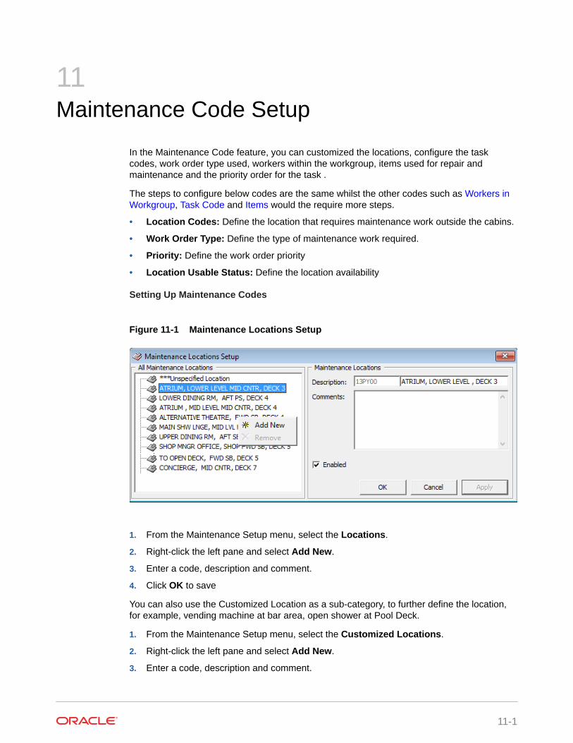
11Maintenance Code Setup
In the Maintenance Code feature, you can customized the locations, configure the taskcodes, work order type used, workers within the workgroup, items used for repair andmaintenance and the priority order for the task .
The steps to configure below codes are the same whilst the other codes such as Workers inWorkgroup, Task Code and Items would the require more steps.
• Location Codes: Define the location that requires maintenance work outside the cabins.
• Work Order Type: Define the type of maintenance work required.
• Priority: Define the work order priority
• Location Usable Status: Define the location availability
Setting Up Maintenance Codes
Figure 11-1 Maintenance Locations Setup
1. From the Maintenance Setup menu, select the Locations.
2. Right-click the left pane and select Add New.
3. Enter a code, description and comment.
4. Click OK to save
You can also use the Customized Location as a sub-category, to further define the location,for example, vending machine at bar area, open shower at Pool Deck.
1. From the Maintenance Setup menu, select the Customized Locations.
2. Right-click the left pane and select Add New.
3. Enter a code, description and comment.
11-1

4. Click Apply to save.
5. Right-click the newly created location and select Add Location or Add Category,depending on your requirement.
6. Enter a code, description and comment.
7. Check the Crew Supervision Assignment if that task requires supervision.
8. Click OK to save.
Workers in WorkgroupThe Worker in Workgroup is a sub-category of Work Order Type, where workers aregrouped according to their skills and expertise.
1. Select Workers in Workgroup from the Maintenance Setup menu.
2. Right-click and select Add Group.
3. Enter a code, description and comments.
4. Click Apply to save.
5. Right-click on the newly created code and select Add Worker.
6. Select to Assign by Crew or Assign by Operation Position, then select the crewname or position from the Name field.
7. Enter a description then click Apply to save.
8. Click OK to close the window.
Adding Task CodeThe Task Code is used to define the required task, crew involved and its priority.
Figure 11-2 Maintenance Task Codes
1. Select Maintenance Task Code Setup from the Maintenance Setup menu.
Chapter 11Workers in Workgroup
11-2

2. Right-click and select Add New.
3. Enter a code, description and comments, then select the Work Types, Work Group andPriority from the drop-down list.
4. Click Apply to save.
Adding Items CodeThe Item codes is used to describe the items required for repair work and you can add a costand inventory to the items.
Figure 11-3 Maintenance Item Setup
1. Select Items from the Maintenance Setup menu.
2. Right-click on the left pane and select Add Item Type.
3. Enter a code, description and comments.
4. Click Apply to save.
Chapter 11Adding Items Code
11-3

Figure 11-4 Maintenance Item Type
5. Right-click on the newly created item code and select Add Item Type.
6. Enter the Item Code, Description, Average Price and Stock On Hand.
7. Click OK to save.
Chapter 11Adding Items Code
11-4

12Gift Card
Gift card be used offered as a consumer incentive or integrate into a reward point program toincrease the sales volumes. The Gift card can also be given and use as pre-paid credit whilston-board the ship.
For more detail on Gift Card setup and usage, see Gift Card Handling Guide.
12-1

13POS Discount
There are two methods to set up the POS discount:
• A Basic Setup with discount applicable to MICROS discount itemizer level.
• An Advance Setup with discount applicable to MICROS major group, family group, andmenu item level.
You can choose to set up with one or both methods to provide for different type of discounts.The POS Discount Handling guide provides more information on how to configure thediscounts, linking the MICROS Server and usage.
13-1

14Security Display Setup
In Security Display Setup, you can customize additional information for displayed in SecurityWPF module. To use these customized fields, you must insert the precise data field names.
Figure 14-1 Security Display Setup Window
1. Select the Security Display Setup from the Administration menu.
2. Right-click the space on the left panel and select Add New.
3. In the Account Type field, enter a code and description.
4. In the User Defined field, insert the name field, followed by the data field name using thesquare bracket [ ]. Use a comma(,) to separate the field.
5. Click Apply to save.
14-1

15Visa Type Setup
In the Visa Types Setup, you can create the type of travel visa recognized by the ship.
1. Select the Visa Type Setup from the Administration menu.
2. Right-click the space on the left panel and select Add New.
3. Enter the Code, Description and Comment, if any
4. Click OK to save.
15-1

16Multimedia File Maintenance
The system supports use of multimedia file such as .AVI or MP3 for promotion presentation,alert or as standard template use on signature device. You can also link a web page for easeof access.
Figure 16-1 Multimedia File Setup
1. Select the Multimedia File Maintenance from the Administration menu.
2. Navigate to the tab you wish to add the multimedia file or image.
3. Click Select and choose the file from the window explorer.
4. Click OK to save.
5. Click Play or Preview to view the file .
16-1

17Board Card Printing Template
This feature allow you to set up predefine information to print on the board card.
Figure 17-1 Board Card Batch Printing Template
Table 17-1 Board Card Batch Printing Template Field Definition
Field Name Description
Description Template Name
Card Type Type of card to print, for example: Guest,Crew, Group, Visitor, Gift Card or Prompt todefine the criteria in Advance BCard Printingwindow.
Make a copy of existing card Prints board card with the same account ID ornew account ID.
17-1

Table 17-1 (Cont.) Board Card Batch Printing Template Field Definition
Field Name Description
Custom Report Template Prints board card using customize reporttemplate instead of System Default report.Report template must be available whensetting up the Board Card Template setup.
Shore Res ID Prints board card by Shore Reservation ID.
Age Prints board card by age range.
Cabin Prints board card by cabin range.
Manifest Prints board card by manifest number range.
Reservation Status Prints board card by reservation status:• Checked-In• Prompt Reservation Date — A user define
date in Advance BCard printing window attime of printing.
• Pre-define Reservation Date— Printsaccording to date set in the template.
Group Name Prints board card by Group Name andapplicable to Card Type = Group
Name Print board card by name range.
Nationality Prints board card for:• All nationalities• US Citizens only• Non-US Citizens
Product / Pre-Product / Award Level Prints board card by Product:• All (Field value is both null and not null)• Only when specified (Field value is not
null)• Only when not specified (Field value is
null)
Chapter 17
17-2

Figure 17-2 Board Card Batch Printing Template-User Define Filter
Table 17-2 Board Card Batch Printing Template User Define Filter Field Definition
Field Name Description
Description Name of the Filter
Field Name Field name to filter. Reference to field name ofSystem Data table.
SQL Query for reference Additional Filter using SQL Command
Figure 17-3 Board Card Batch Printing Template Sort Options
Chapter 17
17-3

There are two sort options you can choose from:
• Prompt User when printing the board card
• Pre-define by field using Custom SQL.
Creating Board Card Printing Template1. Select Board Card Batch Printing Template from the Administration menu.
2. At the Board Card Batch Printing Template Setup window, right-click and selectAdd Template.
3. Enter the name of the template in Description field and select the Card Type fromthe drop-down list.
4. Check the applicable prompt button when generating the card or use thepredefined option. If you choose to use the Predefine option, enter the value inthe field next to it.
5. Click Apply to save the selection and navigate to User Define Filter tab.
6. At the User Define Filter, enter
a. The filter name in the Description field.
b. Field name (reference to System data table) or
c. Check the User Define radio button and insert a value.
7. Click the Validate Field to verify.
8. Use the SQL Query to filter the fields further by inserting the SQL Command, andthen click the Validate SQL Query.
9. Navigate to the Sorting tab and select the sorting type.
10. Click Apply to save the filter.
11. Click OK to save the template.
Removing TemplateYou can remove a template by right-clicking the Template name and select RemoveTemplate.
Chapter 17Creating Board Card Printing Template
17-4

18Security Alert Setup
You can set to alert the security at a check point when there is a security breach. This featureis can only be configured by the Implementation team. Please contact Oracle HospitalityCustomer Support if you wish to use this feature.
18-1

19Beeper Setup
The Beeper Setup feature enable you to configure the beeper number for used in the ChildLocation function. You can configure the beeper unit using the same steps as System Codes.See System Codes for more information.
19-1

20Security
In this Security function, you can find information such as User Login, Statistic Count for thepassengers on-board or at shore, Port/Visa Requirement
Login
The Login Function enable you to log in/out from current session, either using a Function Key(F8) or select the option from the Security menu.
User Logfile
The User Logfile records all transactions performed by the users in date/time order. You canretrieve the information using the available fields such as by user, type of activities, date, timeor workstation. The transaction log is printable and exportable.
Gangway Logfile
The Gangway Logfile records all the gangway movement for all passengers going ashore orcoming onboard. You can search the information by location, movement directions, type ofpassengers, date, time, cabin number and name. Information is printable and exportable tosupported file format.
Count Onboard/Shoreside
The Count Onboard/Shoreside gives you a total passenger count that are onboard or ashoreand by the type of passenger you select. This count can be reset by clicking the ResetSecurity button.
Note:
Do pay attention to the message prompt when resetting the status as the messagein each prompt is different.
20-1

Guest/Crew Onboard
Figure 20-1 Current Guest/Crew Onboard Listing
The Guest/Crew Onboard lists all passengers onboard and display the last time-stampthe last passenger comes onboard.
• Clicking the Go Ashore will set the selected passenger status from Onboard toAshore.
• Clicking the Gangway Log will open the Gangway movement log.
Guest/Crew Shoreside
This function is the same as the Guest/Crew Onboard, and only display passenger'sthat are Ashore.
• Clicking the Go Onboard will set the selected passenger status from Ashore toOnboard.
Port/Visa Requirement
This function restricts passenger that has travel restrictions on their travel documentsfrom going ashore on port day. Once this is set up, when a restricted passengerswipes their travel document at the Gangway, you will receive a system prompt.
Chapter 20
20-2

Figure 20-2 Port/Visa Requirement Window
1. From the Security options, select Port/Visa Requirement.
2. Click Add New.
3. Enter the Date/Time From/To field and select the Port from the drop-down list.
4. Select the applicable passenger type.
5. In the Conditions Setup section, select the Nationality and Visa Type from the drop-down list.
6. Click Save.
7. At the Insert Confirmation prompt, select Yes to confirm, then click Close to exit.
Chapter 20
20-3

21Photo Setup
The Photo Setup allows you to configure the photos of the Guests, Crews, Visitors and Staffs.To access the functionality, go to the Administration menu and choose either:
• Upload Photos
• Export Photos
• Export Documents
Upload/Export PhotosUpload Photos
The Upload Photos allow you to either upload the photos by batch or individually. Below arethe steps.
21-1

Figure 21-1 Upload Photos
1. Click the Administration option from the main menu.
2. Select the Photo Upload option from the menu.
3. At the Upload Photos form, select the Account Categories and Account Status.
4. Click the Scan button to populate the names under the Name Lists section.
5. Browse the file location that contain the files to upload.
6. Select the Upload file format from the drop-down list.
Chapter 21Upload/Export Photos
21-2

Note:
If you are uploading the photos using the RES_ACC format, ensure the filename is the same as the guest booking number.
7. Check the Delete files from directory after upload and then click Upload.
8. Click Close to exit.
Batch Upload
For batch upload to work, you need to rename every single photos of the person with the folionumber so that the system recognizes them. The photo will not update correctly if you namethem wrongly. For example, picture name is “123456.jpg” for folio number 123456. Once youcomplete renaming the photos, you can proceed to upload using below steps.
1. Repeat the above steps.
2. At the Batch Upload section, browse and select the folder path where the photos arestored.
3. Click the Upload button and the photos will be uploaded as the unique ID, which is thereservation account number.
Individual Upload
Figure 21-2 Individual Upload
1. For Individual Upload, select the file path where the photo is stored.
2. Click the Upload button and you will see the photo on the bottom right corner.
Export Photos
This function allow you to export the photos by guest type and account status. You must haveSecurity Access rights #338 — Export Photos in Single or Batch to perform this function.
Chapter 21Upload/Export Photos
21-3

Figure 21-3 Export Photos
1. Select Export Photo option from the Administration menu.
2. At the Export Photos, Customize Export section, browse and select adestination location.
3. Choose the categories to export by checking the respective check boxes.
4. Select the Export File Name. You may choose from
• Save using unique ID (The unique ID is the reservation account number),
• Save using custom ID,
• Save using crew external ID, or
• Save using crew internal ID.
5. Select the Account Status.
6. You can either select All Date or specify a date range.
7. Click Scan to begin.
8. A list of names will populate in the Name Lists section.
9. Individually check the account you wish to export or click the Check All option toexport all.
10. Click Export to begin export.
Chapter 21Upload/Export Photos
21-4

Export DocumentThis feature enable you to export documents to a support file format. The steps to export thedocument is the same as Export Photos. See Upload/Export Photos for steps to export thedocument.
Chapter 21Export Document
21-5


