Embed Size (px)
Citation preview
Agilent Technologies 89400-SeriesGPIB Command Reference
Agilent Technologies Part Number 89400-90039For instruments with firmware version A.08.00Printed in U.S.A.
Print Date: May, 2000© Agilent Technologies, Inc., 1992, 1994, 1995, 1996, 1998, 1999, 2000 .All rights reserved.8600 Soper Hill Road Everett, Washington 98205-1209 U.S.A.

TABLE OF CONTENTS
1 GPIB Programming with Agilent 89400-Series
Analyzers 1
Introduction to GPIB Programming 2
In This Book 2
GPIB Setup and Verification 3
Equipment and Software Required 3Procedure 3
GPIB Interface Capabilities 4
General Status Register Model 5
Overview 5Condition Register 6Transition Registers 6Event Register 6Enable Register 7An Example Sequence 7How to Use Registers 8
The Service Request Process 9
Generating a Service Request 9
The Agilent 89400A’s Register Sets 11
Register Summary 11Status Byte Register Set 12Device State Register Set 13Questionable Status Register Set 14Questionable Voltage Register Set 15Questionable Frequency Register Set 16Questionable Modulation Register Set 17Standard Event Register Set 18Operational Status Register Set 19User Status Register Set 21
Agilent 89400 Series Register Set Summary 22
2 The SCPI Instrument Model 23
Introduction 24
ROUTe 24
INPut 25
SENSe 25
iii
CALCulate 25
OUTPut 25
SOURce 25
TRIGger 25ARM-TRIGger Model 26Model Layers 26
MEMory 28
FORMat 28
Hard COPy 28
DISPlay 28
Mass MEMory 28
3 Command Reference 29
A Error Messages 457
SYSTem:ERRor? 458
The Error/Event Queue 458Error numbers 459No Error 459Command Error 460Execution Error 463Device-Specific Error 466Query Error 467
Instrument-Specific Error Messages468
B Sockets Example Program 475
iv
COMMAND LISTING
*CAL? . . . . . . . . . . . . . . . . . . . . . . . . . . . . . . 31
*CLS . . . . . . . . . . . . . . . . . . . . . . . . . . . . . . . 32
*ESE . . . . . . . . . . . . . . . . . . . . . . . . . . . . . . . 33
*ESR? . . . . . . . . . . . . . . . . . . . . . . . . . . . . . . 34
*IDN? . . . . . . . . . . . . . . . . . . . . . . . . . . . . . . 35
*OPC . . . . . . . . . . . . . . . . . . . . . . . . . . . . . . . 36
*OPT? . . . . . . . . . . . . . . . . . . . . . . . . . . . . . . 37
*PCB . . . . . . . . . . . . . . . . . . . . . . . . . . . . . . . 38
*PSC . . . . . . . . . . . . . . . . . . . . . . . . . . . . . . . 39
*RST . . . . . . . . . . . . . . . . . . . . . . . . . . . . . . . 40
*SRE . . . . . . . . . . . . . . . . . . . . . . . . . . . . . . . 41
*STB? . . . . . . . . . . . . . . . . . . . . . . . . . . . . . . 42
*TRG . . . . . . . . . . . . . . . . . . . . . . . . . . . . . . . 43
*TST? . . . . . . . . . . . . . . . . . . . . . . . . . . . . . . 44
*WAI . . . . . . . . . . . . . . . . . . . . . . . . . . . . . . . 45
ABORt . . . . . . . . . . . . . . . . . . . . . . . . . . . . . . 46
ARM:DELay . . . . . . . . . . . . . . . . . . . . . . . . . . . . 47
ARM:LEVel . . . . . . . . . . . . . . . . . . . . . . . . . . . . 48
ARM:REGion . . . . . . . . . . . . . . . . . . . . . . . . . . . 49
ARM:SOURce . . . . . . . . . . . . . . . . . . . . . . . . . . . 50
CALCulate:CCDF:COUNt? . . . . . . . . . . . . . . . . . . . . . 51
CALCulate:CCDF:POWer? . . . . . . . . . . . . . . . . . . . . . 52
CALCulate:DATA? . . . . . . . . . . . . . . . . . . . . . . . . . 53
CALCulate:DATA:HEADer:POINts? . . . . . . . . . . . . . . . . . 54
CALCulate:FEED . . . . . . . . . . . . . . . . . . . . . . . . . . 55
CALCulate:FORMat . . . . . . . . . . . . . . . . . . . . . . . . 57
CALCulate:GDAPerture:APERture . . . . . . . . . . . . . . . . . 59
CALCulate:MARKer:BAND:STARt . . . . . . . . . . . . . . . . . 60
CALCulate:MARKer:BAND:STOP . . . . . . . . . . . . . . . . . . 61
CALCulate:MARKer:COUPled[:STATe] . . . . . . . . . . . . . . . 62
CALCulate:MARKer:FCOunt . . . . . . . . . . . . . . . . . . . . 63
CALCulate:MARKer:FCOunt:RESult? . . . . . . . . . . . . . . . . 64
CALCulate:MARKer:FUNCtion . . . . . . . . . . . . . . . . . . . 65
CALCulate:MARKer:FUNCtion:DDEMod:RESult? . . . . . . . . . . 66
CALCulate:MARKer:FUNCtion:RESult? . . . . . . . . . . . . . . . 68
CALCulate:MARKer:FUNCtion:STATistics . . . . . . . . . . . . . . 69
CALCulate:MARKer:FUNCtion:STATistics:PPCT . . . . . . . . . . . 70
CALCulate:MARKer:FUNCtion:STATistics:RESult? . . . . . . . . . . 71
CALCulate:MARKer:FUNCtion:STATistics:SMPL? . . . . . . . . . . 72
CALCulate:MARKer:MAXimum . . . . . . . . . . . . . . . . . . . 73
CALCulate:MARKer:MAXimum:LEFT . . . . . . . . . . . . . . . . 74
CALCulate:MARKer:MAXimum:NEXT . . . . . . . . . . . . . . . 75
CALCulate:MARKer:MAXimum:RIGHt . . . . . . . . . . . . . . . 76
CALCulate:MARKer:MAXimum:TRACk . . . . . . . . . . . . . . . 77
CALCulate:MARKer:MINimum[:GLOBal] . . . . . . . . . . . . . . 78
CALCulate:MARKer:OFFSet[:STATe] . . . . . . . . . . . . . . . . 79
CALCulate:MARKer:OFFSet:X . . . . . . . . . . . . . . . . . . . 80
CALCulate:MARKer:OFFSet:Y . . . . . . . . . . . . . . . . . . . 81
CALCulate:MARKer:OFFSet:Z . . . . . . . . . . . . . . . . . . . 82
CALCulate:MARKer:OFFSet:ZERO . . . . . . . . . . . . . . . . . 83
CALCulate:MARKer:POLar:UNIT:POWer . . . . . . . . . . . . . . 84
CALCulate:MARKer:READout . . . . . . . . . . . . . . . . . . . 85
CALCulate:MARKer:SEARch:BUFFer[:STATe] . . . . . . . . . . . . 86
CALCulate:MARKer:SEARch:LEFT . . . . . . . . . . . . . . . . . 87
CALCulate:MARKer:SEARch:OFFSet . . . . . . . . . . . . . . . . 88
CALCulate:MARKer:SEARch:RIGHt . . . . . . . . . . . . . . . . . 89
CALCulate:MARKer:SEARch:TARGet . . . . . . . . . . . . . . . . 90
CALCulate:MARKer[:STATe] . . . . . . . . . . . . . . . . . . . . 91
CALCulate:MARKer:TRACe . . . . . . . . . . . . . . . . . . . . 92
CALCulate:MARKer:X[:ABSolute] . . . . . . . . . . . . . . . . . 93
CALCulate:MARKer:X:ACHannel? . . . . . . . . . . . . . . . . . 94
CALCulate:MARKer:X:CCHannel? . . . . . . . . . . . . . . . . . 95
CALCulate:MARKer:X:CLAYer? . . . . . . . . . . . . . . . . . . 96
CALCulate:MARKer:X:CSTatus? . . . . . . . . . . . . . . . . . . 97
CALCulate:MARKer:X:RELative? . . . . . . . . . . . . . . . . . . 98
CALCulate:MARKer:Y? . . . . . . . . . . . . . . . . . . . . . . 99
CALCulate:MARKer:Y:RELative? . . . . . . . . . . . . . . . . . 100
CALCulate:MARKer:Z[:ABSolute] . . . . . . . . . . . . . . . . . 101
CALCulate:MARKer:Z:RELative? . . . . . . . . . . . . . . . . . 103
CALCulate:MARKer:Z:UNIT . . . . . . . . . . . . . . . . . . . 104
v
CALCulate:MATH:CONStant . . . . . . . . . . . . . . . . . . . 105
CALCulate:MATH:CONStant:IMAG . . . . . . . . . . . . . . . . 106
CALCulate:MATH:CONStant:MAG . . . . . . . . . . . . . . . . 107
CALCulate:MATH:CONStant:PHASe . . . . . . . . . . . . . . . 108
CALCulate:MATH:CONStant:REAL . . . . . . . . . . . . . . . . 109
CALCulate:MATH:CONStant:STEP . . . . . . . . . . . . . . . . 110
CALCulate:MATH[:EXPRession] . . . . . . . . . . . . . . . . . 111
CALCulate:MATH:SELect . . . . . . . . . . . . . . . . . . . . 112
CALCulate:MATH:STATe . . . . . . . . . . . . . . . . . . . . . 113
CALCulate:STATe . . . . . . . . . . . . . . . . . . . . . . . . 114
CALCulate:UNIT:AM . . . . . . . . . . . . . . . . . . . . . . . 115
CALCulate:UNIT:ANGLe . . . . . . . . . . . . . . . . . . . . . 116
CALCulate:UNIT:FREQuency . . . . . . . . . . . . . . . . . . . 117
CALCulate:UNIT:POWer . . . . . . . . . . . . . . . . . . . . . 118
CALCulate:UNIT:TIME . . . . . . . . . . . . . . . . . . . . . . 119
CALCulate:UPHase:CREFerence . . . . . . . . . . . . . . . . . 120
CALCulate:UPHase:OFFSet . . . . . . . . . . . . . . . . . . . . 121
CALCulate:X:UNIT:CODE . . . . . . . . . . . . . . . . . . . . . 122
CALCulate:X:UNIT:FREQuency . . . . . . . . . . . . . . . . . . 123
CALCulate:X:UNIT:POW . . . . . . . . . . . . . . . . . . . . . 124
CALCulate:X:UNIT:TIME . . . . . . . . . . . . . . . . . . . . . 125
CALibration:AUTO . . . . . . . . . . . . . . . . . . . . . . . . 126
CALibration:ZERO:AUTO . . . . . . . . . . . . . . . . . . . . . 127
CONTinue . . . . . . . . . . . . . . . . . . . . . . . . . . . . 128
DISPlay:ANNotation[:ALL] . . . . . . . . . . . . . . . . . . . . 129
DISPlay:BRIGhtness . . . . . . . . . . . . . . . . . . . . . . . 130
DISPlay:CMAP:COLor:HSL . . . . . . . . . . . . . . . . . . . . 131
DISPlay:CMAP:DEFault . . . . . . . . . . . . . . . . . . . . . 132
DISPlay:ENABle . . . . . . . . . . . . . . . . . . . . . . . . . 133
DISPlay:FORMat . . . . . . . . . . . . . . . . . . . . . . . . 134
DISPlay:MFUNction . . . . . . . . . . . . . . . . . . . . . . . 135
DISPlay:PROGram[:MODE] . . . . . . . . . . . . . . . . . . . 136
DISPlay:TCAPture:ENVelope . . . . . . . . . . . . . . . . . . . 137
DISPlay[:WINDow]:ACTive . . . . . . . . . . . . . . . . . . . . 138
DISPlay[:WINDow]:SPECtrogram:COLors . . . . . . . . . . . . . 139
DISPlay[:WINDow]:SPECtrogram:ENHance . . . . . . . . . . . . 140
DISPlay[:WINDow]:SPECtrogram:MAP . . . . . . . . . . . . . . 141
DISPlay[:WINDow]:SPECtrogram[:STATe] . . . . . . . . . . . . 142
DISPlay[:WINDow]:SPECtrogram:THReshold . . . . . . . . . . . 143
DISPlay[:WINDow]:TRACe:BUFFer . . . . . . . . . . . . . . . . 144
DISPlay[:WINDow]:TRACe:DCARrier . . . . . . . . . . . . . . . 145
DISPlay[:WINDow]:TRACe:EYE:COUNt . . . . . . . . . . . . . . 146
DISPlay[:WINDow]:TRACe:GRATicule:GRID[:STATe] . . . . . . . 147
DISPlay[:WINDow]:TRACe:INDicator . . . . . . . . . . . . . . . 148
DISPlay[:WINDow]:TRACe:INDicator:SIZE . . . . . . . . . . . . 149
DISPlay[:WINDow]:TRACe:INFO . . . . . . . . . . . . . . . . . 150
DISPlay[:WINDow]:TRACe:LABel? . . . . . . . . . . . . . . . . 151
DISPlay[:WINDow]:TRACe:LABel:AUTO . . . . . . . . . . . . . 152
DISPlay[:WINDow]:TRACe:LABel:USER . . . . . . . . . . . . . 153
DISPlay[:WINDow]:TRACe[:STATe] . . . . . . . . . . . . . . . 154
DISPlay[:WINDow]:TRACe:SYMBol . . . . . . . . . . . . . . . 155
DISPlay[:WINDow]:TRACe:SYMBol:FORMat . . . . . . . . . . . 156
DISPlay[:WINDow]:TRACe:X[:SCALe]:AUTO . . . . . . . . . . . 157
DISPlay[:WINDow]:TRACe:X[:SCALe]:LEFT . . . . . . . . . . . . 158
DISPlay[:WINDow]:TRACe:X[:SCALe]:RIGHt . . . . . . . . . . . 159
DISPlay[:WINDow]:TRACe:X[:SCALe]:RLEVel . . . . . . . . . . . 160
DISPlay[:WINDow]:TRACe:X[:SCALe]:SPACing . . . . . . . . . . 161
DISPlay[:WINDow]:TRACe:Y:RLINe . . . . . . . . . . . . . . . 162
DISPlay[:WINDow]:TRACe:Y[:SCALe]:AUTO . . . . . . . . . . . 163
DISPlay[:WINDow]:TRACe:Y[:SCALe]:PDIVision . . . . . . . . . . 164
DISPlay[:WINDow]:TRACe:Y[:SCALe]:RLEVel . . . . . . . . . . . 165
DISPlay[:WINDow]:TRACe:Y[:SCALe]:RLEVel:AUTO . . . . . . . . 166
DISPlay[:WINDow]:TRACe:Y[:SCALe]:RPOSition . . . . . . . . . 167
DISPlay[:WINDow]:WATerfall:AZIMuth . . . . . . . . . . . . . . 168
DISPlay[:WINDow]:WATerfall:BLINe[:STATe] . . . . . . . . . . . 169
DISPlay[:WINDow]:WATerfall:ELEVation . . . . . . . . . . . . . 170
DISPlay[:WINDow]:WATerfall:HEIGht . . . . . . . . . . . . . . 171
DISPlay[:WINDow]:WATerfall:HLINe[:STATe] . . . . . . . . . . . 172
DISPlay[:WINDow]:WATerfall[:STATe] . . . . . . . . . . . . . . 173
DISPlay[:WINDow]:WATerfall:THReshold . . . . . . . . . . . . . 174
FORMat[:DATA] . . . . . . . . . . . . . . . . . . . . . . . . . 175
HCOPy:ABORt . . . . . . . . . . . . . . . . . . . . . . . . . 176
HCOPy:DATA? . . . . . . . . . . . . . . . . . . . . . . . . . 177
HCOPy:DESTination . . . . . . . . . . . . . . . . . . . . . . . 178
HCOPy:DEVice:CMAP:DEFault . . . . . . . . . . . . . . . . . . 179
HCOPy:DEVice:COLor . . . . . . . . . . . . . . . . . . . . . . 180
HCOPy:DEVice:LANGuage . . . . . . . . . . . . . . . . . . . . 181
HCOPy:DEVice:RESolution . . . . . . . . . . . . . . . . . . . . 182
HCOPy:DEVice:SPEed . . . . . . . . . . . . . . . . . . . . . . 183
HCOPy[:IMMediate] . . . . . . . . . . . . . . . . . . . . . . . 184
HCOPy:ITEM:ALL[:IMMediate] . . . . . . . . . . . . . . . . . . 185
HCOPy:ITEM:ANNotation:COLor . . . . . . . . . . . . . . . . . 186
HCOPy:ITEM:FFEed:STATe . . . . . . . . . . . . . . . . . . . 187
HCOPy:ITEM:TDSTamp:CFORmat . . . . . . . . . . . . . . . . 188
HCOPy:ITEM:TDSTamp:FORMat . . . . . . . . . . . . . . . . . 189
HCOPy:ITEM:TDSTamp:STATe . . . . . . . . . . . . . . . . . . 190
Command Listing
vi

HCOPy:ITEM[:WINDow]:TRACe:COLor . . . . . . . . . . . . . . 191
HCOPy:ITEM[:WINDow]:TRACe:GRATicule:COLor . . . . . . . . . 192
HCOPy:ITEM[:WINDow]:TRACe:GRATicule[:IMMediate] . . . . . . 193
HCOPy:ITEM[:WINDow]:TRACe[:IMMediate] . . . . . . . . . . . 194
HCOPy:ITEM[:WINDow]:TRACe:LTYPe . . . . . . . . . . . . . . 195
HCOPy:ITEM[:WINDow]:TRACe:MARKer:COLor . . . . . . . . . 196
HCOPy:ITEM[:WINDow]:TRACe:MARKer[:IMMediate] . . . . . . . 197
HCOPy:ITEM[:WINDow]:TRACe:MARKer:OFFSet[:IMMediate] . . . 198
HCOPy:PAGE:DIMensions:AUTO . . . . . . . . . . . . . . . . . 199
HCOPy:PAGE:DIMensions:USER:LLEFt . . . . . . . . . . . . . . 200
HCOPy:PAGE:DIMensions:USER:URIGht . . . . . . . . . . . . . 201
HCOPy:PLOT:ADDRess . . . . . . . . . . . . . . . . . . . . . 202
HCOPy:PRINt:ADDRess . . . . . . . . . . . . . . . . . . . . . 203
INITiate:CONTinuous . . . . . . . . . . . . . . . . . . . . . . 204
INITiate[:IMMediate] . . . . . . . . . . . . . . . . . . . . . . 205
INPut:COUPling . . . . . . . . . . . . . . . . . . . . . . . . . 206
INPut:FILTer[:LPASs][:STATe] . . . . . . . . . . . . . . . . . . 207
INPut:IMPedance . . . . . . . . . . . . . . . . . . . . . . . . 208
INPut[:STATe] . . . . . . . . . . . . . . . . . . . . . . . . . 209
INSTrument:NSELect . . . . . . . . . . . . . . . . . . . . . . 210
INSTrument[:SELect] . . . . . . . . . . . . . . . . . . . . . . 211
MEMory:DELete[:NAME] . . . . . . . . . . . . . . . . . . . . 212
MEMory:MALLocate:APPLication . . . . . . . . . . . . . . . . 213
MEMory:MALLocate:MEASurement:DEFault . . . . . . . . . . . 214
MEMory:MALLocate:MEASurement:FPOints . . . . . . . . . . . 215
MEMory:MALLocate:MEASurement:MAXSpan . . . . . . . . . . 216
MEMory:MALLocate:MEASurement:MSSRate . . . . . . . . . . 217
MEMory:MALLocate:MEASurement:MTEMp . . . . . . . . . . . 218
MEMory:MALLocate:MEASurement:TPOints . . . . . . . . . . . 219
MEMory:MALLocate:PROGram . . . . . . . . . . . . . . . . . 220
MMEMory:COPY . . . . . . . . . . . . . . . . . . . . . . . . 221
MMEMory:DATA . . . . . . . . . . . . . . . . . . . . . . . . 222
MMEMory:DELete . . . . . . . . . . . . . . . . . . . . . . . . 223
MMEMory:FSYStem? . . . . . . . . . . . . . . . . . . . . . . 224
MMEMory:INITialize . . . . . . . . . . . . . . . . . . . . . . . 225
MMEMory:LOAD:APPLication . . . . . . . . . . . . . . . . . . 227
MMEMory:LOAD:CONTinue . . . . . . . . . . . . . . . . . . . 228
MMEMory:LOAD:MATH . . . . . . . . . . . . . . . . . . . . . 229
MMEMory:LOAD:PROGram . . . . . . . . . . . . . . . . . . . 230
MMEMory:LOAD:STATe . . . . . . . . . . . . . . . . . . . . . 231
MMEMory:LOAD:TCAPture . . . . . . . . . . . . . . . . . . . 232
MMEMory:LOAD:TRACe . . . . . . . . . . . . . . . . . . . . . 233
MMEMory:LOAD:TRACe:BUFFer . . . . . . . . . . . . . . . . . 234
MMEMory:MOVE . . . . . . . . . . . . . . . . . . . . . . . . 235
MMEMory:MSIS . . . . . . . . . . . . . . . . . . . . . . . . 236
MMEMory:NAME . . . . . . . . . . . . . . . . . . . . . . . . 237
MMEMory:STORe:CONTinue . . . . . . . . . . . . . . . . . . 239
MMEMory:STORe:MATH . . . . . . . . . . . . . . . . . . . . 240
MMEMory:STORe:PROGram . . . . . . . . . . . . . . . . . . 241
MMEMory:STORe:STATe . . . . . . . . . . . . . . . . . . . . 242
MMEMory:STORe:TCAPture . . . . . . . . . . . . . . . . . . . 243
MMEMory:STORe:TRACe . . . . . . . . . . . . . . . . . . . . 244
MMEMory:STORe:TRACe:BUFFer . . . . . . . . . . . . . . . . 245
OUTPut:FILTer[:LPASs][:STATe] . . . . . . . . . . . . . . . . . 246
OUTPut:IMPedance . . . . . . . . . . . . . . . . . . . . . . . 247
OUTPut[:STATe] . . . . . . . . . . . . . . . . . . . . . . . . 248
PAUSe . . . . . . . . . . . . . . . . . . . . . . . . . . . . . 249
PROGram:EXPLicit:DEFine . . . . . . . . . . . . . . . . . . . . 250
PROGram[:SELected]:DEFine . . . . . . . . . . . . . . . . . . . 251
PROGram[:SELected]:DELete:ALL . . . . . . . . . . . . . . . . 252
PROGram[:SELected]:DELete[:SELected] . . . . . . . . . . . . . 253
PROGram[:SELected]:MALLocate . . . . . . . . . . . . . . . . 254
PROGram[:SELected]:NAME . . . . . . . . . . . . . . . . . . . 255
PROGram[:SELected]:NUMBer . . . . . . . . . . . . . . . . . . 256
PROGram[:SELected]:STATe . . . . . . . . . . . . . . . . . . . 258
PROGram[:SELected]:STRing . . . . . . . . . . . . . . . . . . 259
ROUTe:RECeiver . . . . . . . . . . . . . . . . . . . . . . . . 260
SCReen:CONTents . . . . . . . . . . . . . . . . . . . . . . . 261
[SENSe:]AVERage:COUNt . . . . . . . . . . . . . . . . . . . . 262
[SENSe:]AVERage:COUNt:INTermediate? . . . . . . . . . . . . 263
[SENSe:]AVERage:IRESult:RATE . . . . . . . . . . . . . . . . . 264
[SENSe:]AVERage:IRESult[:STATe] . . . . . . . . . . . . . . . . 265
[SENSe:]AVERage[:STATe] . . . . . . . . . . . . . . . . . . . 266
[SENSe:]AVERage:TCONtrol . . . . . . . . . . . . . . . . . . . 267
[SENSe:]AVERage:TYPE . . . . . . . . . . . . . . . . . . . . . 268
[SENSe:]BANDwidth:MODE:ARBitrary . . . . . . . . . . . . . . 269
[SENSe:]BANDwidth[:RESolution] . . . . . . . . . . . . . . . . 270
[SENSe:]BANDwidth[:RESolution]:AUTO . . . . . . . . . . . . . 271
[SENSe:]BANDwidth[:RESolution]:AUTO:OFFSet . . . . . . . . . 272
[SENSe:]CORRection:EDELay[:TIME] . . . . . . . . . . . . . . . 273
[SENSe:]CORRection:EXTernal[:STATe] . . . . . . . . . . . . . . 274
[SENSe:]CORRection:FILTer:XTIMe:STATe . . . . . . . . . . . . 275
[SENSe:]CORRection:IMPedance[:INPut][:MAGNitude] . . . . . . 276
[SENSe:]CORRection:LOSS[:INPut]:MAGNitude . . . . . . . . . . 277
[SENSe:]CORRection:OFFS . . . . . . . . . . . . . . . . . . . . 278
[SENSe:]DATA . . . . . . . . . . . . . . . . . . . . . . . . . 279
Command Listing
vii
[SENSe:]DATA:HEADer:POINts? . . . . . . . . . . . . . . . . . 280
[SENSe:]DDEMod:ADAPt . . . . . . . . . . . . . . . . . . . . 281
[SENSe:]DDEMod:CLOCk . . . . . . . . . . . . . . . . . . . . 282
[SENSe:]DDEMod:CNVRg . . . . . . . . . . . . . . . . . . . . 283
[SENSe:]DDEMod:CRATe . . . . . . . . . . . . . . . . . . . . 284
[SENSe:]DDEMod:DVBQam:NSTate . . . . . . . . . . . . . . . 285
[SENSe:]DDEMod:EDGE . . . . . . . . . . . . . . . . . . . . . 286
[SENSe:]DDEMod:EQFLen . . . . . . . . . . . . . . . . . . . . 287
[SENSe:]DDEMod:EQRE . . . . . . . . . . . . . . . . . . . . . 288
[SENSe:]DDEMod:EQUalize . . . . . . . . . . . . . . . . . . . 289
[SENSe:]DDEMod:FILTer:ALPHa . . . . . . . . . . . . . . . . . 290
[SENSe:]DDEMod:FILTer:MEASurement . . . . . . . . . . . . . 291
[SENSe:]DDEMod:FILTer:MEASurement:USER:FEED . . . . . . . 292
[SENSe:]DDEMod:FILTer:REFerence . . . . . . . . . . . . . . . 293
[SENSe:]DDEMod:FILTer:REFerence:USER:FEED . . . . . . . . . 294
[SENSe:]DDEMod:FORMat . . . . . . . . . . . . . . . . . . . . 295
[SENSe:]DDEMod:FREQuency:MIRRor . . . . . . . . . . . . . . 296
[SENSe:]DDEMod:FSK:NSTate . . . . . . . . . . . . . . . . . . 297
[SENSe:]DDEMod:LCODe . . . . . . . . . . . . . . . . . . . . 298
[SENSe:]DDEMod:LCODe:GROup . . . . . . . . . . . . . . . . . 299
[SENSe:]DDEMod:LCODe:MODE . . . . . . . . . . . . . . . . . 300
[SENSe:]DDEMod:MLENgth . . . . . . . . . . . . . . . . . . . 301
[SENSe:]DDEMod:MSK:FORMat . . . . . . . . . . . . . . . . . 302
[SENSe:]DDEMod:NORMalize . . . . . . . . . . . . . . . . . . 303
[SENSe:]DDEMod:PRATe . . . . . . . . . . . . . . . . . . . . 304
[SENSe:]DDEMod:PRESet . . . . . . . . . . . . . . . . . . . . 305
[SENSe:]DDEMod:PSK:NSTate . . . . . . . . . . . . . . . . . . 306
[SENSe:]DDEMod:QAM:NSTate . . . . . . . . . . . . . . . . . 307
[SENSe:]DDEMod:QPSK:FORMat . . . . . . . . . . . . . . . . . 308
[SENSe:]DDEMod:SEARch:PULSe:STATe . . . . . . . . . . . . . 309
[SENSe:]DDEMod:SEARch:SYNC:OFFSet . . . . . . . . . . . . . 310
[SENSe:]DDEMod:SEARch:SYNC:PATTern . . . . . . . . . . . . 311
[SENSe:]DDEMod:SEARch:SYNC:STATe . . . . . . . . . . . . . 312
[SENSe:]DDEMod:SEARch:TIME . . . . . . . . . . . . . . . . . 313
[SENSe:]DDEMod:SELect . . . . . . . . . . . . . . . . . . . . 314
[SENSe:]DDEMod:SRATe . . . . . . . . . . . . . . . . . . . . 315
[SENSe:]DDEMod:TIME . . . . . . . . . . . . . . . . . . . . . 316
[SENSe:]DDEMod:TIME:CCHannel . . . . . . . . . . . . . . . . 317
[SENSe:]DDEMod:TIME:CLAYer . . . . . . . . . . . . . . . . . 318
[SENSe:]DDEMod:TIME:GATE:DELay . . . . . . . . . . . . . . . 319
[SENSe:]DDEMod:TIME:GATE[:SPAN] . . . . . . . . . . . . . . 320
[SENSe:]DDEMod:TIME:GATE:STATe . . . . . . . . . . . . . . . 321
[SENSe:]DDEMod:VSB:NSTate . . . . . . . . . . . . . . . . . . 322
[SENSe:]DDEMod:WCDMa:FILTer:ALPHa . . . . . . . . . . . . . 323
[SENSe:]DEMod . . . . . . . . . . . . . . . . . . . . . . . . . 324
[SENSe:]DEMod:CARRier:AUTO . . . . . . . . . . . . . . . . . 325
[SENSe:]DEMod:CARRier:AUTO:PM . . . . . . . . . . . . . . . 326
[SENSe:]DEMod:CARRier:FREQ? . . . . . . . . . . . . . . . . . 327
[SENSe:]DETector[:FUNCtion] . . . . . . . . . . . . . . . . . . 328
[SENSe:]FEED . . . . . . . . . . . . . . . . . . . . . . . . . . 329
[SENSe:]FREQuency:BASeband . . . . . . . . . . . . . . . . . 330
[SENSe:]FREQuency:CENTer . . . . . . . . . . . . . . . . . . . 331
[SENSe:]FREQuency:CENTer:TRACk . . . . . . . . . . . . . . . 332
[SENSe:]FREQuency:EXTernal:BANDwidth . . . . . . . . . . . . 333
[SENSe:]FREQuency:EXTernal:CENTer . . . . . . . . . . . . . . 334
[SENSe:]FREQuency:EXTernal:COMMunicate . . . . . . . . . . . 335
[SENSe:]FREQuency:EXTernal:COMMunicate:ADDRess . . . . . . 336
[SENSe:]FREQuency:EXTernal:MAXimum . . . . . . . . . . . . . 337
[SENSe:]FREQuency:EXTernal:MINimum . . . . . . . . . . . . . 338
[SENSe:]FREQuency:EXTernal:MIRRor . . . . . . . . . . . . . . 339
[SENSe:]FREQuency:MANual . . . . . . . . . . . . . . . . . . 340
[SENSe:]FREQuency:SPAN . . . . . . . . . . . . . . . . . . . . 341
[SENSe:]FREQuency:SPAN:FULL . . . . . . . . . . . . . . . . . 342
[SENSe:]FREQuency:SPAN:PCHirp . . . . . . . . . . . . . . . . 343
[SENSe:]FREQuency:SPAN:WIDE . . . . . . . . . . . . . . . . 344
[SENSe:]FREQuency:STARt . . . . . . . . . . . . . . . . . . . 345
[SENSe:]FREQuency:STEP:AUTO . . . . . . . . . . . . . . . . . 346
[SENSe:]FREQuency:STEP[:INCRement] . . . . . . . . . . . . . 347
[SENSe:]FREQuency:STOP . . . . . . . . . . . . . . . . . . . . 348
[SENSe:]SWEep:MODE . . . . . . . . . . . . . . . . . . . . . 349
[SENSe:]SWEep:OVERlap . . . . . . . . . . . . . . . . . . . . 350
[SENSe:]SWEep:POINts . . . . . . . . . . . . . . . . . . . . . 351
[SENSe:]SWEep:TIME:DELay . . . . . . . . . . . . . . . . . . 352
[SENSe:]SWEep:TIME:GATE:DELay . . . . . . . . . . . . . . . 353
[SENSe:]SWEep:TIME:GATE:DELay:STEP[:INCRement] . . . . . . 354
[SENSe:]SWEep:TIME:GATE[:SPAN] . . . . . . . . . . . . . . . 355
[SENSe:]SWEep:TIME:GATE:STATe . . . . . . . . . . . . . . . 356
[SENSe:]SWEep:TIME:OVERlap . . . . . . . . . . . . . . . . . 357
[SENSe:]SWEep:TIME:RESolution:AUTO . . . . . . . . . . . . . 358
[SENSe:]SWEep:TIME[:SPAN] . . . . . . . . . . . . . . . . . . 359
[SENSe:]TCAPture:ABORt . . . . . . . . . . . . . . . . . . . . 360
[SENSe:]TCAPture:DIRection . . . . . . . . . . . . . . . . . . 361
[SENSe:]TCAPture[:IMMediate] . . . . . . . . . . . . . . . . . 362
[SENSe:]TCAPture:LENGth . . . . . . . . . . . . . . . . . . . 363
[SENSe:]TCAPture:POSition? . . . . . . . . . . . . . . . . . . 364
[SENSe:]TCAPture:RANGe . . . . . . . . . . . . . . . . . . . . 365
Command Listing
viii
[SENSe:]TCAPture:STARt . . . . . . . . . . . . . . . . . . . . 366
[SENSe:]TCAPture:STOP . . . . . . . . . . . . . . . . . . . . . 367
[SENSe:]VOLTage[:DC]:RANGe:AUTO . . . . . . . . . . . . . . 368
[SENSe:]VOLTage[:DC]:RANGe:AUTO:DIRection . . . . . . . . . 369
[SENSe:]VOLTage[:DC]:RANGe:UNIT:VOLTage . . . . . . . . . . 370
[SENSe:]VOLTage[:DC]:RANGe[:UPPer] . . . . . . . . . . . . . . 371
[SENSe:]VOLTage:PROTection:CLEar . . . . . . . . . . . . . . . 372
[SENSe:]WINDow:GATE . . . . . . . . . . . . . . . . . . . . . 373
[SENSe:]WINDow:GATE:COUPling . . . . . . . . . . . . . . . . 374
[SENSe:]WINDow[:TYPE] . . . . . . . . . . . . . . . . . . . . 375
SOURce:FREQuency[:CW] . . . . . . . . . . . . . . . . . . . . 376
SOURce:FREQuency:OFFSet . . . . . . . . . . . . . . . . . . . 377
SOURce:FUNCtion[:SHAPe] . . . . . . . . . . . . . . . . . . . 378
SOURce:FUNCtion:USER:FEED . . . . . . . . . . . . . . . . . . 379
SOURce:IFINput:STATe . . . . . . . . . . . . . . . . . . . . . 380
SOURce:RF . . . . . . . . . . . . . . . . . . . . . . . . . . . 381
SOURce:USER:REPeat . . . . . . . . . . . . . . . . . . . . . . 382
SOURce:VOLTage[:LEVel][:IMMediate][:AMPLitude] . . . . . . . . 383
SOURce:VOLTage[:LEVel][:IMMediate]:OFFSet . . . . . . . . . . 385
SOURce:VOLTage[:LEVel]:UNIT:VOLTage . . . . . . . . . . . . . 386
SOURce:VOLTage:PROTection:CLEar . . . . . . . . . . . . . . . 387
STATus:DEVice:CONDition? . . . . . . . . . . . . . . . . . . . 388
STATus:DEVice:ENABle . . . . . . . . . . . . . . . . . . . . . 389
STATus:DEVice[:EVENt]? . . . . . . . . . . . . . . . . . . . . 390
STATus:DEVice:NTRansition . . . . . . . . . . . . . . . . . . . 391
STATus:DEVice:PTRansition . . . . . . . . . . . . . . . . . . . 392
STATus:OPERation:CONDition? . . . . . . . . . . . . . . . . . 393
STATus:OPERation:ENABle . . . . . . . . . . . . . . . . . . . 394
STATus:OPERation[:EVENt]? . . . . . . . . . . . . . . . . . . . 395
STATus:OPERation:NTRansition . . . . . . . . . . . . . . . . . 396
STATus:OPERation:PTRansition . . . . . . . . . . . . . . . . . 397
STATus:PRESet . . . . . . . . . . . . . . . . . . . . . . . . . 398
STATus:QUEStionable:CONDition? . . . . . . . . . . . . . . . . 399
STATus:QUEStionable:ENABle . . . . . . . . . . . . . . . . . . 400
STATus:QUEStionable[:EVENt]? . . . . . . . . . . . . . . . . . 401
STATus:QUEStionable:FREQuency:CONDition? . . . . . . . . . . 402
STATus:QUEStionable:FREQuency:ENABle . . . . . . . . . . . . 403
STATus:QUEStionable:FREQuency[:EVENt]? . . . . . . . . . . . 404
STATus:QUEStionable:FREQuency:NTRansition . . . . . . . . . . 405
STATus:QUEStionable:FREQuency:PTRansition . . . . . . . . . . 406
STATus:QUEStionable:MODulation:CONDition? . . . . . . . . . . 407
STATus:QUEStionable:MODulation:ENABle . . . . . . . . . . . . 408
STATus:QUEStionable:MODulation[:EVENt]? . . . . . . . . . . . 409
STATus:QUEStionable:MODulation:NTRansition . . . . . . . . . . 410
STATus:QUEStionable:MODulation:PTRansition . . . . . . . . . . 411
STATus:QUEStionable:NTRansition . . . . . . . . . . . . . . . . 412
STATus:QUEStionable:PTRansition . . . . . . . . . . . . . . . . 413
STATus:QUEStionable:VOLTage:CONDition? . . . . . . . . . . . 414
STATus:QUEStionable:VOLTage:ENABle . . . . . . . . . . . . . 415
STATus:QUEStionable:VOLTage[:EVENt]? . . . . . . . . . . . . 416
STATus:QUEStionable:VOLTage:NTRansition . . . . . . . . . . . 417
STATus:QUEStionable:VOLTage:PTRansition . . . . . . . . . . . 418
STATus:USER:ENABle . . . . . . . . . . . . . . . . . . . . . . 419
STATus:USER[:EVENt]? . . . . . . . . . . . . . . . . . . . . . 420
STATus:USER:PULSe . . . . . . . . . . . . . . . . . . . . . . 421
SYSTem:BEEPer:STATe . . . . . . . . . . . . . . . . . . . . . 422
SYSTem:COMMunicate:GPIB:ADDRess . . . . . . . . . . . . . 423
SYSTem:COMMunicate:LAN:EADDress? . . . . . . . . . . . . . 424
SYSTem:COMMunicate:LAN:IPADdress . . . . . . . . . . . . . 425
SYSTem:COMMunicate:LAN:PORT . . . . . . . . . . . . . . . . 426
SYSTem:COMMunicate:LAN:ROUTe:GATeway . . . . . . . . . . 427
SYSTem:COMMunicate:LAN:ROUTe:SMASk . . . . . . . . . . . 428
SYSTem:COMMunicate:LAN:STATe . . . . . . . . . . . . . . . 429
SYSTem:COMMunicate:LAN:XWINdow:HOSTname . . . . . . . . 430
SYSTem:COMMunicate:LAN:XWINdow:RATE . . . . . . . . . . 431
SYSTem:COMMunicate:LAN:XWINdow[:STATe] . . . . . . . . . 432
SYSTem:COMMunicate:SERial:CONTrol:DTR . . . . . . . . . . . 433
SYSTem:COMMunicate:SERial[:RECeive]:BAUD . . . . . . . . . . 434
SYSTem:COMMunicate:SERial[:RECeive]:PACE . . . . . . . . . . 435
SYSTem:COMMunicate:SERial[:RECeive]:PARity[:TYPE] . . . . . . 436
SYSTem:DATE . . . . . . . . . . . . . . . . . . . . . . . . . 437
SYSTem:ERRor? . . . . . . . . . . . . . . . . . . . . . . . . 438
SYSTem:GPIB:ECHO . . . . . . . . . . . . . . . . . . . . . . 439
SYSTem:KEY . . . . . . . . . . . . . . . . . . . . . . . . . . 440
SYSTem:KLOCk . . . . . . . . . . . . . . . . . . . . . . . . . 442
SYSTem:PRESet . . . . . . . . . . . . . . . . . . . . . . . . 443
SYSTem:TIME . . . . . . . . . . . . . . . . . . . . . . . . . 444
TRACe:BUFFer:COPY . . . . . . . . . . . . . . . . . . . . . . 445
TRACe:COPY . . . . . . . . . . . . . . . . . . . . . . . . . . 446
TRACe[:DATA] . . . . . . . . . . . . . . . . . . . . . . . . . 447
TRACe[:DATA]:HEADer:POINts? . . . . . . . . . . . . . . . . . 449
TRACe:X[:DATA]? . . . . . . . . . . . . . . . . . . . . . . . . 450
TRACe:X:UNIT? . . . . . . . . . . . . . . . . . . . . . . . . . 451
TRIGger:HOLDoff:DELay . . . . . . . . . . . . . . . . . . . . . 452
TRIGger:HOLDoff:STATe . . . . . . . . . . . . . . . . . . . . 453
TRIGger:LEVel . . . . . . . . . . . . . . . . . . . . . . . . . 454
Command Listing
ix

TRIGger:SLOPe . . . . . . . . . . . . . . . . . . . . . . . . . 455
TRIGger:SOURce . . . . . . . . . . . . . . . . . . . . . . . . 456
Command Listing
x
1
GPIB Programming withAgilent 89400-Series Analyzers
1
Introduction to GPIB Programming
For an introduction to GPIB programming, read the GPIB Programmer’s Guide. It is provided tohelp those not familiar with GPIB programming or remote control of an instrument. The bookintroduces the basic concepts of GPIB programming and describes the Standard Commands forProgrammable Instruments (SCPI). It also describes how to operate an instrument in an GPIBsystem and how to transfer data between an external controller and an instrument.
In This Book
This is the GPIB Command Reference for the Agilent 89400-Series Vector Signal Analyzer. Itcontains the command syntax, structure, and a detailed description of each GPIB commandavailable for the Agilent 89400-Series analyzers.
Chapter 1 presents GPIB programming information specific to the analyzer:
How to connect the analyzer to an external controller and verify that it works.A description of the analyzer’s status registers.
Chapter 2 describes the SCPI instrument model.
Chapter 3 is the command reference. It contains a detailed description of each GPIB command.The commands are organized alphabetically.
Appendix A discusses SCPI error messaging and lists error messages reported by this instrument.
Appendix B is an example program listing which demonstrates the sockets feature of option UFG.
Also, a card containing a command quick-reference is included.
Note Most front-panel key presses that change the configuration or initiate an actioncorrespond to one SCPI command but some require more than one (see[SENSe:]AVERage:TYPE). To display the SCPI command strings that correspondto front-panel keys, activate the SCPI command echo by pressing [ Local/Setup ],[ SCPI cmd echo on ] or sending “SYST:GPIB:ECHO 1”. Subsequent SCPI commandstrings are displayed in the upper-lefthand corner of the display.
Introduction to GPIB Programming
2
GPIB Setup and Verification
This section contains a procedure for configuring the Agilent 89400-Series Vector Signal Analyzerand an external controller in a simple GPIB system. Although an HP 9000 Series 340 computer isused in this procedure example, other computers that support an GPIB interface can be used. Ifyou are using a computer other than the Series 340, the configuration procedure should be usedas a general guide. Consult your computer’s documentation for more complete information.
Equipment and Software Required
Agilent 89400-Series Vector Signal AnalyzerHP 9000 Series 340 computerGPIB cable (Agilent 10833A, B, C or D)Agilent Technologies BASIC programming language
Procedure
1. Turn off the analyzer and the HP 9000 Series 340
2. Connect them with the GPIB cable.
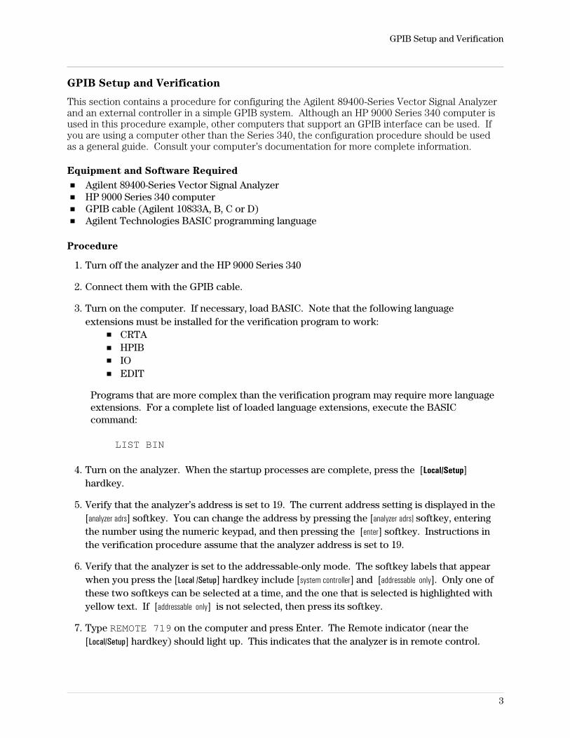
3. Turn on the computer. If necessary, load BASIC. Note that the following languageextensions must be installed for the verification program to work:
CRTAHPIBIOEDIT
Programs that are more complex than the verification program may require more languageextensions. For a complete list of loaded language extensions, execute the BASICcommand:
LIST BIN
4. Turn on the analyzer. When the startup processes are complete, press the [Local/Setup]hardkey.
5. Verify that the analyzer’s address is set to 19. The current address setting is displayed in the[analyzer adrs] softkey. You can change the address by pressing the [analyzer adrs] softkey, enteringthe number using the numeric keypad, and then pressing the [enter] softkey. Instructions inthe verification procedure assume that the analyzer address is set to 19.
6. Verify that the analyzer is set to the addressable-only mode. The softkey labels that appearwhen you press the [Local /Setup] hardkey include [system controller] and [addressable only]. Only one ofthese two softkeys can be selected at a time, and the one that is selected is highlighted withyellow text. If [addressable only] is not selected, then press its softkey.
7. Type REMOTE 719 on the computer and press Enter. The Remote indicator (near the[Local/Setup] hardkey) should light up. This indicates that the analyzer is in remote control.
GPIB Setup and Verification
3
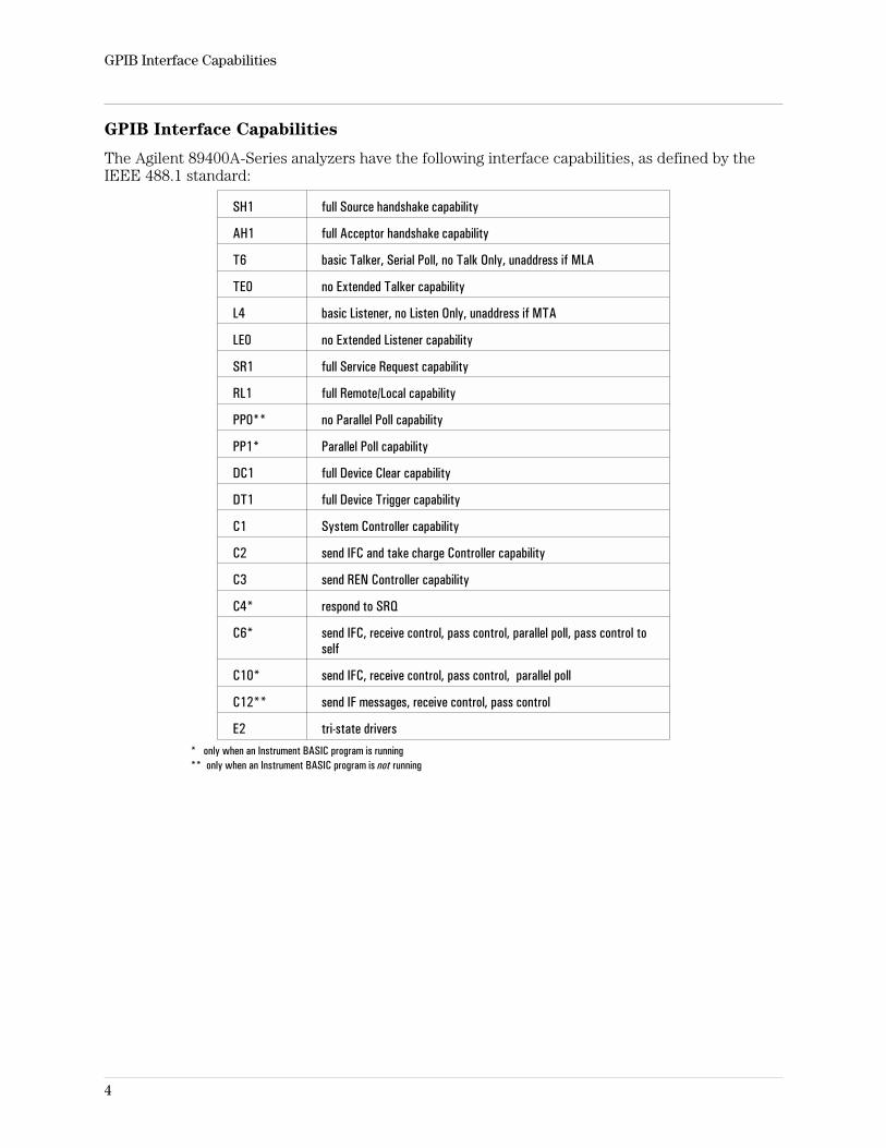
GPIB Interface Capabilities
The Agilent 89400A-Series analyzers have the following interface capabilities, as defined by theIEEE 488.1 standard:
SH1 full Source handshake capability
AH1 full Acceptor handshake capability
T6 basic Talker, Serial Poll, no Talk Only, unaddress if MLA
TE0 no Extended Talker capability
L4 basic Listener, no Listen Only, unaddress if MTA
LE0 no Extended Listener capability
SR1 full Service Request capability
RL1 full Remote/Local capability
PP0** no Parallel Poll capability
PP1* Parallel Poll capability
DC1 full Device Clear capability
DT1 full Device Trigger capability
C1 System Controller capability
C2 send IFC and take charge Controller capability
C3 send REN Controller capability
C4* respond to SRQ
C6* send IFC, receive control, pass control, parallel poll, pass control toself
C10* send IFC, receive control, pass control, parallel poll
C12** send IF messages, receive control, pass control
E2 tri-state drivers* only when an Instrument BASIC program is running** only when an Instrument BASIC program is not running
GPIB Interface Capabilities
4
General Status Register Model
Overview
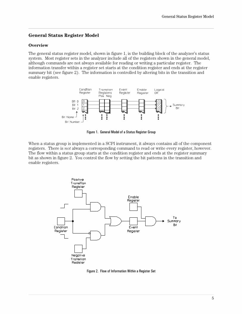
The general status register model, shown in figure 1, is the building block of the analyzer’s statussystem. Most register sets in the analyzer include all of the registers shown in the general model,although commands are not always available for reading or writing a particular register. Theinformation transfer within a register set starts at the condition register and ends at the registersummary bit (see figure 2). The information is controlled by altering bits in the transition andenable registers.
Figure 1. General Model of a Status Register Group
When a status group is implemented in a SCPI instrument, it always contains all of the componentregisters. There is not always a corresponding command to read or write every register, however.The flow within a status group starts at the condition register and ends at the register summarybit as shown in figure 2. You control the flow by setting the bit patterns in the transition andenable registers.
Figure 2. Flow of Information Within a Register Set
General Status Register Model
5
Condition Register
Condition registers continuously monitor hardware and firmware status. They represent thecurrent state of the instrument. Bits in a condition register are not latched or buffered. They areupdated in real time. When the condition monitored by a particular bit becomes true, the bit is setto 1. When the condition becomes false, the bit is reset to 0. Condition registers are read-only.
Transition Registers
Transition registers control the reporting of condition changes to the event registers. Theyspecify which types of changes in the condition register set corresponding bits in the eventregister. Transition registers are read-write.
Transition register bits may be configured to signal positive changes, negative changes, or both.Positive changes in the state of a condition bit (0 to 1) are reported to the event register if thecorresponding positive transition bit is set to 1. Negative changes in the state of a condition bit (1to 0) are reported to the event register if the corresponding negative transition bit is set to 1. Ifyou set both transition bits to 1, positive and negative changes are reported to the correspondingevent bit.
Transition registers are not affected by *CLS (clear status) or queries. They are set to defaultvalues when power is turned on and after receiving *RST. Some registers have a fixed setting ifthere are no commands to access a particular transition register. This fixed setting, along withdependent values, are specified in the GPIB Command Reference.
Event Register
Event registers latch any reported condition changes. When a transition bit allows a conditionchange to be reported, the corresponding event bit is set to 1. Once set, an event bit is no longeraffected by condition changes. It remains set until the event register is cleared— either when youread the register or when you send the *CLS (clear status) command. Event registers areread-only.
Notes Reading the Event Register, clears the Event Register.All event registers are cleared by the *CLS command.
General Status Register Model
6
Enable Register
Enable registers control the reporting of events (which are latched condition register information)to the register summary bit. If an enable bit is set to one, the corresponding event bit is includedin the logical ORing process that determines the state of the summary bit. (The summary bit isonly set to 1 if one or more enabled event bits are set to 1.) You can read and write all enableregisters.
Enable registers are cleared by the *CLS (clear status) command. Querying enable registers doesnot affect them. All enable registers have commands to read and write them.
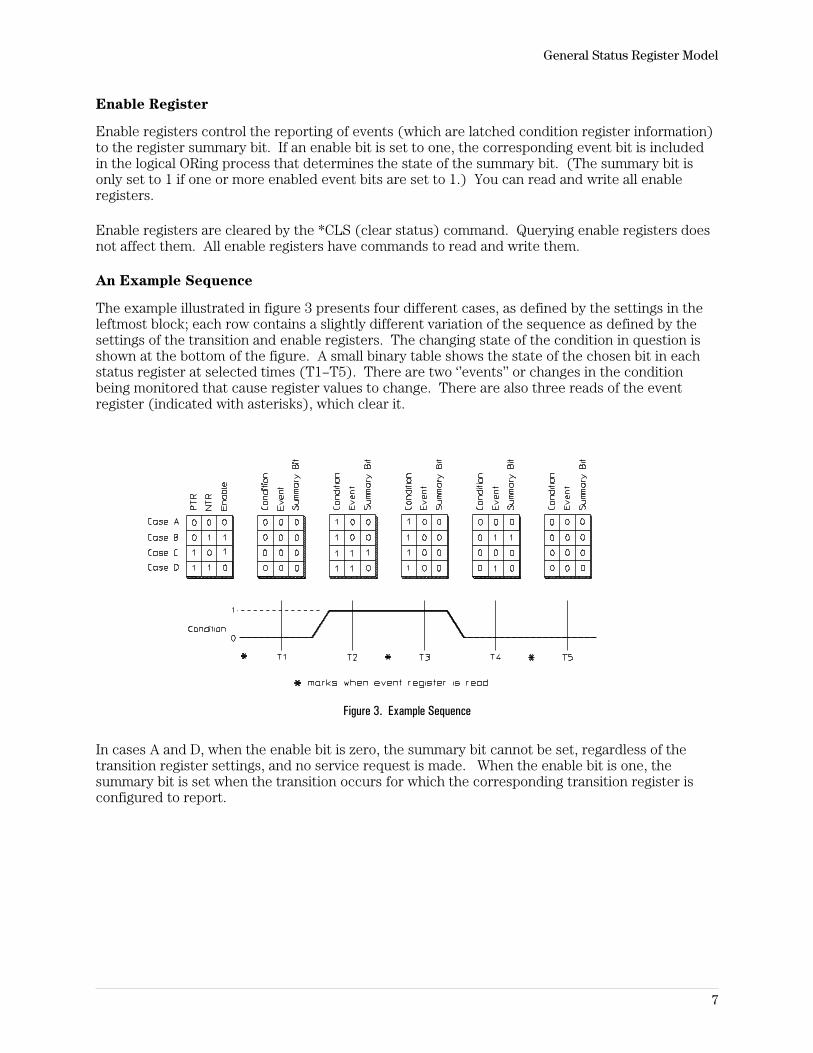
An Example Sequence
The example illustrated in figure 3 presents four different cases, as defined by the settings in theleftmost block; each row contains a slightly different variation of the sequence as defined by thesettings of the transition and enable registers. The changing state of the condition in question isshown at the bottom of the figure. A small binary table shows the state of the chosen bit in eachstatus register at selected times (T1–T5). There are two ‘’events’’ or changes in the conditionbeing monitored that cause register values to change. There are also three reads of the eventregister (indicated with asterisks), which clear it.
Figure 3. Example Sequence
In cases A and D, when the enable bit is zero, the summary bit cannot be set, regardless of thetransition register settings, and no service request is made. When the enable bit is one, thesummary bit is set when the transition occurs for which the corresponding transition register isconfigured to report.
General Status Register Model
7
How to Use Registers
There are two methods you can use to access the information in status registers:
The polling method.The service request (SRQ) method.
In the polling method, the analyzer has a passive role. It only tells the controller that conditionshave changed when the controller asks the right question. In the SRQ method, the analyzer takesa more active role. It tells the controller when there has been a condition change without thecontroller asking. Either method allows you to monitor one or more conditions.
The polling method works well if you do not need to know about changes the moment they occur.The SRQ method should be used if you must know immediately when a condition changes. Todetect a change using the polling method, the program must repeatedly read the registers.
Use the SRQ method when:
– you need time-critical notification of changes– you are monitoring more than one device which supports SRQs– you need to do have the controller do something else while waiting– you can’t afford the performance penalty inherent to polling
Use polling when:
– your language/development environment does not support SRQ interrupts– you want to write a simple, single-purpose program and don’t want the added complexity
of setting up an SRQ handler.
To monitor a condition:
1. Determine which register contains the bit that reports the condition.2. Send the unique GPIB query that reads that register.3. Examine the bit to see if the condition has changed.
General Status Register Model
8
The Service Request Process
When you monitor a condition with the SRQ method, you must:
1. Determine which bit monitors the condition.2. Determine how that bit reports to the request service (RQS) bit of the Status Byte.3. Send GPIB commands to enable the bit that monitors the condition and to enable the
summary bits that report the condition to the RQS bit.4. Enable the controller to respond to service requests.
When the condition changes, the analyzer sets its RQS bit and the GPIB’s SRQ line. The controlleris informed of the change as soon as it occurs. The time the controller would otherwise have usedto monitor the condition can now be used to perform other tasks. Your program determines howthe controller responds to the SRQ.
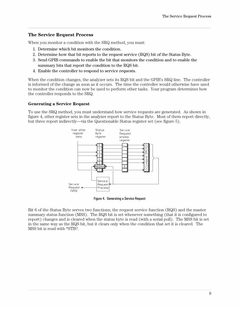
Generating a Service Request
To use the SRQ method, you must understand how service requests are generated. As shown infigure 4, other register sets in the analyzer report to the Status Byte. Most of them report directly,but three report indirectly—via the Questionable Status register set (see figure 5).
Figure 4. Generating a Service Request
Bit 6 of the Status Byte serves two functions; the request service function (RQS) and the mastersummary status function (MSS). The RQS bit is set whenever something (that it is configured toreport) changes and is cleared when the status byte is read (with a serial poll). The MSS bit is setin the same way as the RQS bit, but it clears only when the condition that set it is cleared. TheMSS bit is read with *STB?.
The Service Request Process
9
When a register set causes its summary bit in the Status Byte to change from 0 to 1, the analyzercan initiate the service request (SRQ) process. However, the process is only initiated if both ofthe following conditions are true:
The corresponding bit of the Service Request Enable register is also set to 1.The analyzer does not have a service request pending. (A service request is considered to bepending between the time the analyzer’s SRQ process is initiated and the time the controllerreads the Status Byte register with a serial poll.)
The SRQ process sets the GPIB’s SRQ line true. It also sets the Status Byte’s request service(RQS) bit to 1. Both actions are necessary to inform the controller the analyzer requires service.Setting the SRQ line only informs the controller that some device on the bus requires service.Setting the RQS bit allows the controller to determine that the Agilent 89400-series analyzer, inparticular, requires service.
If your program enables the controller to detect and respond to service requests, it should instructthe controller to perform a serial poll when the GPIB’s SRQ line is set true. Each device on thebus returns the contents of its Status Byte register in response to this poll. The device whoseRQS bit is set to 1 is the device that requested service.
Notes When you read the analyzer’s Status Byte with a serial poll, the RQS bit is reset to0. Other bits in the register are not affected.
Restarting a measurement (INIT) can cause the measuring bit to pulse low,which causes an SRQ if the status register is configured to SRQ onend-of-measurement. To avoid this:
1. INIT:CONT OFF2. Set/enable status registers3. Restart measurement (send INIT)
The Service Request Process
10
The Agilent 89400A’s Register Sets
Register Summary
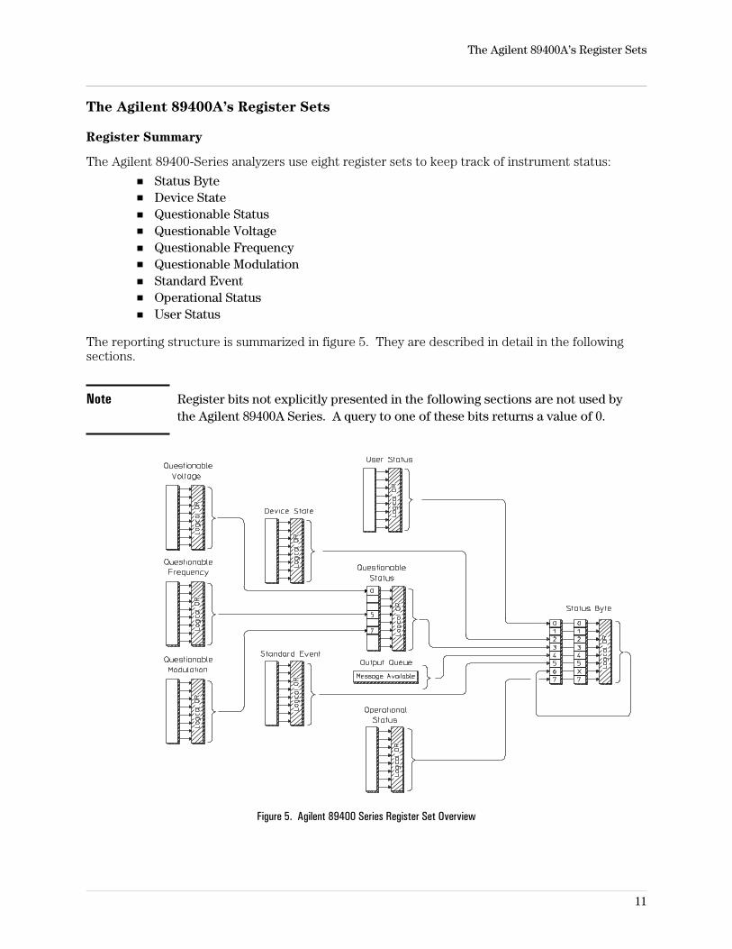
The Agilent 89400-Series analyzers use eight register sets to keep track of instrument status:
Status ByteDevice StateQuestionable StatusQuestionable VoltageQuestionable FrequencyQuestionable ModulationStandard EventOperational StatusUser Status
The reporting structure is summarized in figure 5. They are described in detail in the followingsections.
Note Register bits not explicitly presented in the following sections are not used bythe Agilent 89400A Series. A query to one of these bits returns a value of 0.
Figure 5. Agilent 89400 Series Register Set Overview
The Agilent 89400A’s Register Sets
11
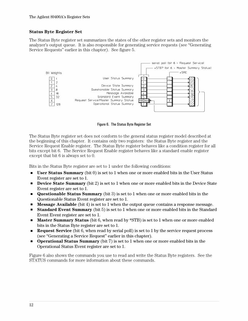
Status Byte Register Set
The Status Byte register set summarizes the states of the other register sets and monitors theanalyzer’s output queue. It is also responsible for generating service requests (see “GeneratingService Requests” earlier in this chapter). See figure 5.
Figure 6. The Status Byte Register Set
The Status Byte register set does not conform to the general status register model described atthe beginning of this chapter. It contains only two registers: the Status Byte register and theService Request Enable register. The Status Byte register behaves like a condition register for allbits except bit 6. The Service Request Enable register behaves like a standard enable registerexcept that bit 6 is always set to 0.
Bits in the Status Byte register are set to 1 under the following conditions:
User Status Summary (bit 0) is set to 1 when one or more enabled bits in the User StatusEvent register are set to 1.Device State Summary (bit 2) is set to 1 when one or more enabled bits in the Device StateEvent register are set to 1.Questionable Status Summary (bit 3) is set to 1 when one or more enabled bits in theQuestionable Status Event register are set to 1.Message Available (bit 4) is set to 1 when the output queue contains a response message.Standard Event Summary (bit 5) is set to 1 when one or more enabled bits in the StandardEvent Event register are set to 1.Master Summary Status (bit 6, when read by *STB) is set to 1 when one or more enabledbits in the Status Byte register are set to 1.Request Service (bit 6, when read by serial poll) is set to 1 by the service request process(see “Generating a Service Request” earlier in this chapter).Operational Status Summary (bit 7) is set to 1 when one or more enabled bits in theOperational Status Event register are set to 1.
Figure 6 also shows the commands you use to read and write the Status Byte registers. See theSTATUS commands for more information about these commands.
The Agilent 89400A’s Register Sets
12
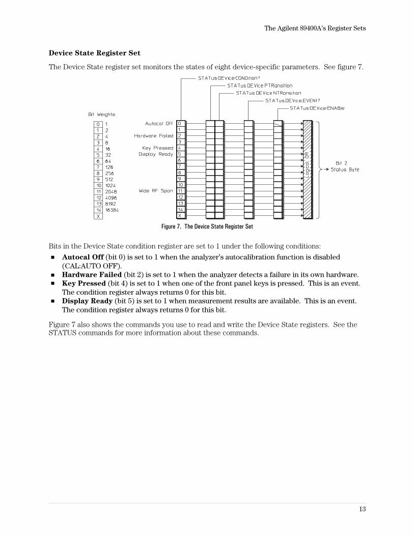
Device State Register Set
The Device State register set monitors the states of eight device-specific parameters. See figure 7.
Figure 7. The Device State Register Set
Bits in the Device State condition register are set to 1 under the following conditions:
Autocal Off (bit 0) is set to 1 when the analyzer’s autocalibration function is disabled(CAL:AUTO OFF).Hardware Failed (bit 2) is set to 1 when the analyzer detects a failure in its own hardware.Key Pressed (bit 4) is set to 1 when one of the front panel keys is pressed. This is an event.The condition register always returns 0 for this bit.Display Ready (bit 5) is set to 1 when measurement results are available. This is an event.The condition register always returns 0 for this bit.
Figure 7 also shows the commands you use to read and write the Device State registers. See theSTATUS commands for more information about these commands.
The Agilent 89400A’s Register Sets
13
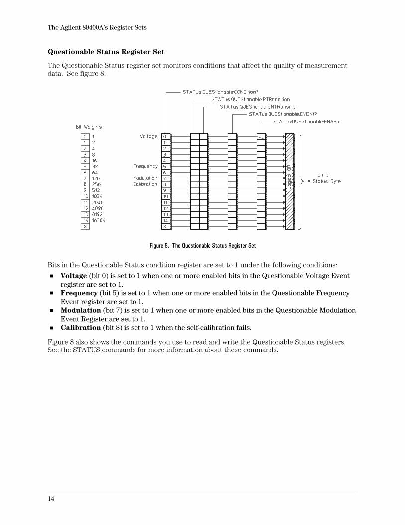
Questionable Status Register Set
The Questionable Status register set monitors conditions that affect the quality of measurementdata. See figure 8.
Figure 8. The Questionable Status Register Set
Bits in the Questionable Status condition register are set to 1 under the following conditions:
Voltage (bit 0) is set to 1 when one or more enabled bits in the Questionable Voltage Eventregister are set to 1.Frequency (bit 5) is set to 1 when one or more enabled bits in the Questionable FrequencyEvent register are set to 1.Modulation (bit 7) is set to 1 when one or more enabled bits in the Questionable ModulationEvent Register are set to 1.Calibration (bit 8) is set to 1 when the self-calibration fails.
Figure 8 also shows the commands you use to read and write the Questionable Status registers.See the STATUS commands for more information about these commands.
The Agilent 89400A’s Register Sets
14
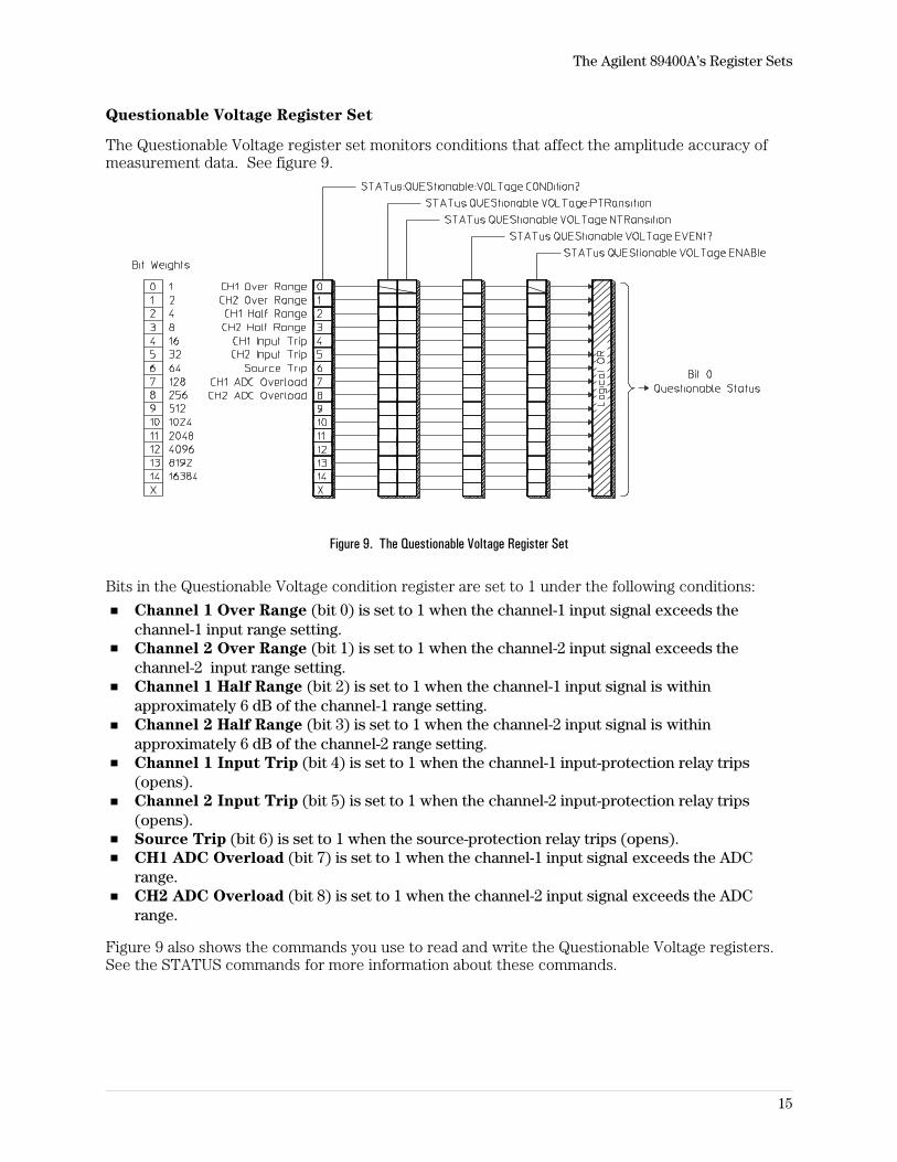
Questionable Voltage Register Set
The Questionable Voltage register set monitors conditions that affect the amplitude accuracy ofmeasurement data. See figure 9.
Figure 9. The Questionable Voltage Register Set
Bits in the Questionable Voltage condition register are set to 1 under the following conditions:
Channel 1 Over Range (bit 0) is set to 1 when the channel-1 input signal exceeds thechannel-1 input range setting.Channel 2 Over Range (bit 1) is set to 1 when the channel-2 input signal exceeds thechannel-2 input range setting.Channel 1 Half Range (bit 2) is set to 1 when the channel-1 input signal is withinapproximately 6 dB of the channel-1 range setting.Channel 2 Half Range (bit 3) is set to 1 when the channel-2 input signal is withinapproximately 6 dB of the channel-2 range setting.Channel 1 Input Trip (bit 4) is set to 1 when the channel-1 input-protection relay trips(opens).Channel 2 Input Trip (bit 5) is set to 1 when the channel-2 input-protection relay trips(opens).Source Trip (bit 6) is set to 1 when the source-protection relay trips (opens).CH1 ADC Overload (bit 7) is set to 1 when the channel-1 input signal exceeds the ADCrange.CH2 ADC Overload (bit 8) is set to 1 when the channel-2 input signal exceeds the ADCrange.
Figure 9 also shows the commands you use to read and write the Questionable Voltage registers.See the STATUS commands for more information about these commands.
The Agilent 89400A’s Register Sets
15
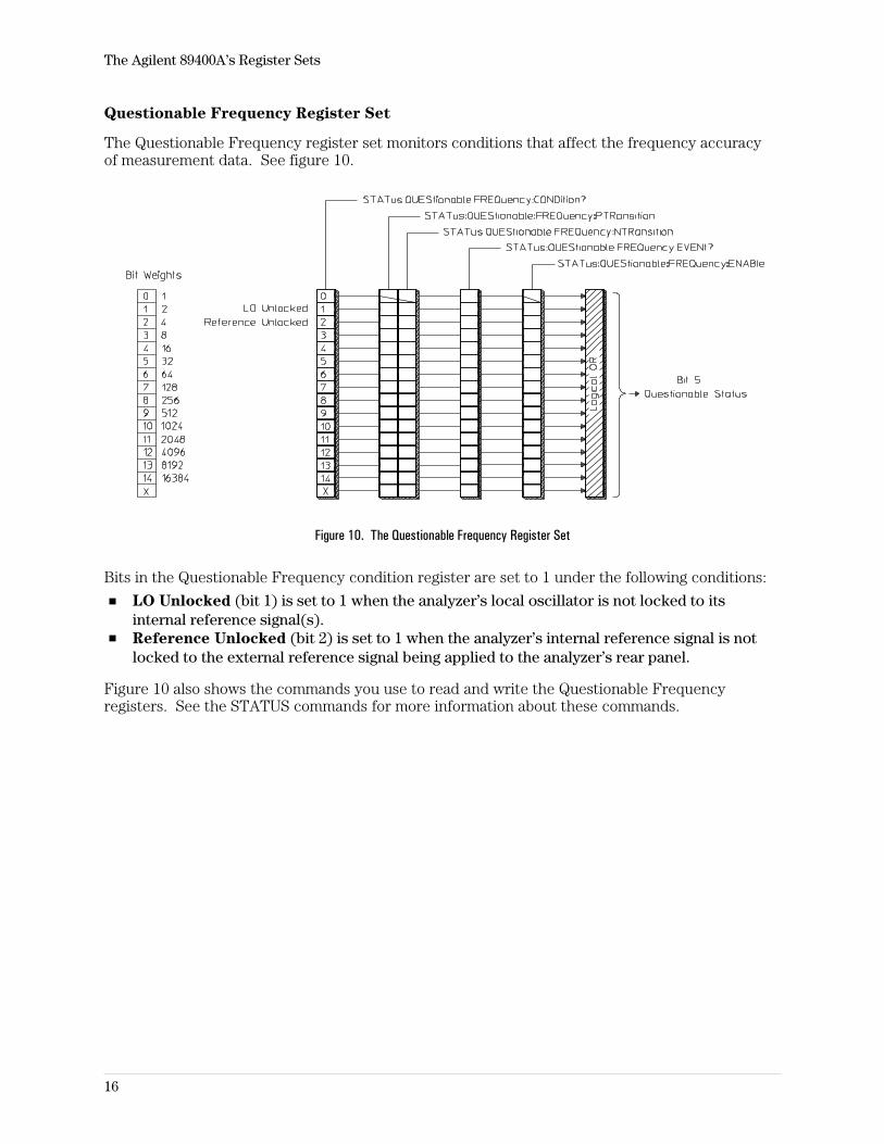
Questionable Frequency Register Set
The Questionable Frequency register set monitors conditions that affect the frequency accuracyof measurement data. See figure 10.
Figure 10. The Questionable Frequency Register Set
Bits in the Questionable Frequency condition register are set to 1 under the following conditions:
LO Unlocked (bit 1) is set to 1 when the analyzer’s local oscillator is not locked to itsinternal reference signal(s).Reference Unlocked (bit 2) is set to 1 when the analyzer’s internal reference signal is notlocked to the external reference signal being applied to the analyzer’s rear panel.
Figure 10 also shows the commands you use to read and write the Questionable Frequencyregisters. See the STATUS commands for more information about these commands.
The Agilent 89400A’s Register Sets
16
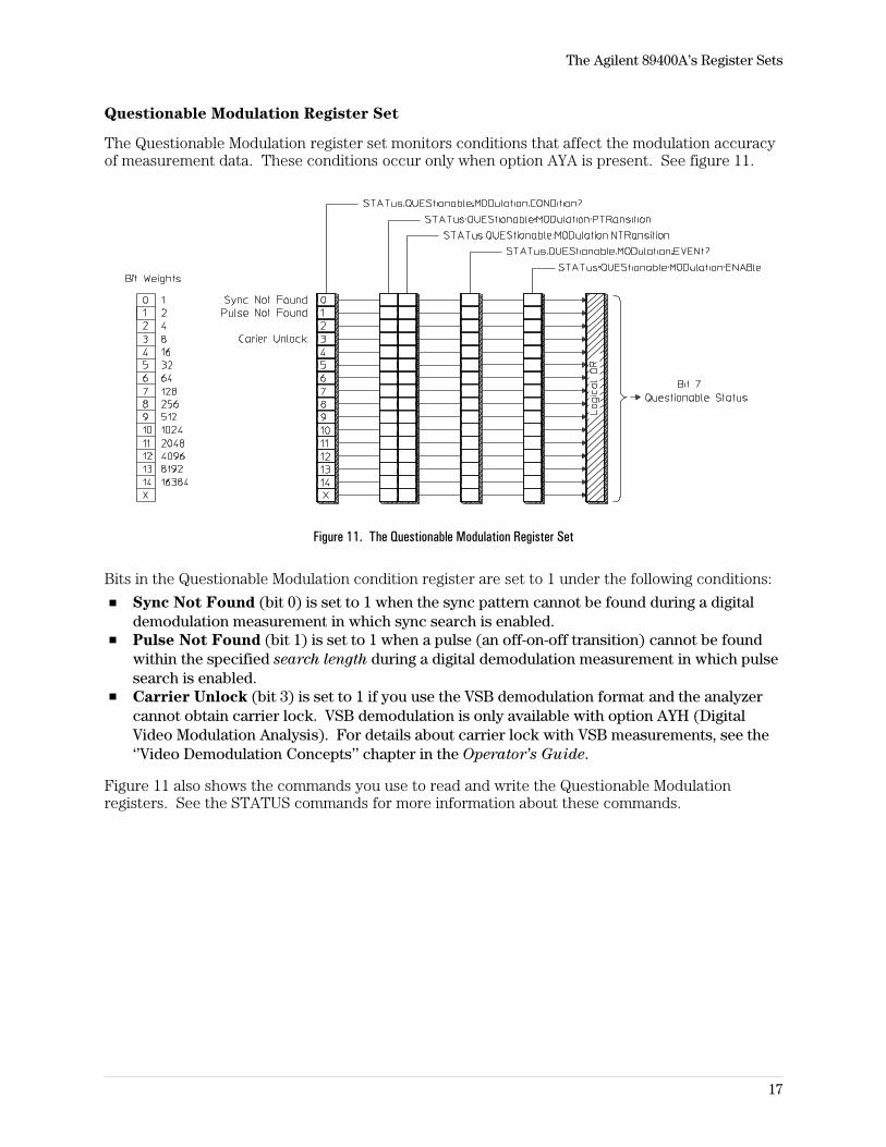
Questionable Modulation Register Set
The Questionable Modulation register set monitors conditions that affect the modulation accuracyof measurement data. These conditions occur only when option AYA is present. See figure 11.
Figure 11. The Questionable Modulation Register Set
Bits in the Questionable Modulation condition register are set to 1 under the following conditions:
Sync Not Found (bit 0) is set to 1 when the sync pattern cannot be found during a digitaldemodulation measurement in which sync search is enabled.Pulse Not Found (bit 1) is set to 1 when a pulse (an off-on-off transition) cannot be foundwithin the specified search length during a digital demodulation measurement in which pulsesearch is enabled.Carrier Unlock (bit 3) is set to 1 if you use the VSB demodulation format and the analyzercannot obtain carrier lock. VSB demodulation is only available with option AYH (DigitalVideo Modulation Analysis). For details about carrier lock with VSB measurements, see the‘’Video Demodulation Concepts’’ chapter in the Operator’s Guide.
Figure 11 also shows the commands you use to read and write the Questionable Modulationregisters. See the STATUS commands for more information about these commands.
The Agilent 89400A’s Register Sets
17
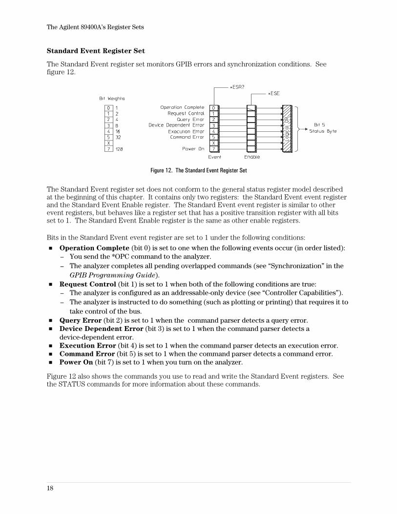
Standard Event Register Set
The Standard Event register set monitors GPIB errors and synchronization conditions. Seefigure 12.
Figure 12. The Standard Event Register Set
The Standard Event register set does not conform to the general status register model describedat the beginning of this chapter. It contains only two registers: the Standard Event event registerand the Standard Event Enable register. The Standard Event event register is similar to otherevent registers, but behaves like a register set that has a positive transition register with all bitsset to 1. The Standard Event Enable register is the same as other enable registers.
Bits in the Standard Event event register are set to 1 under the following conditions:
Operation Complete (bit 0) is set to one when the following events occur (in order listed):– You send the *OPC command to the analyzer.– The analyzer completes all pending overlapped commands (see “Synchronization” in the
GPIB Programming Guide).Request Control (bit 1) is set to 1 when both of the following conditions are true:– The analyzer is configured as an addressable-only device (see “Controller Capabilities”).– The analyzer is instructed to do something (such as plotting or printing) that requires it to
take control of the bus.Query Error (bit 2) is set to 1 when the command parser detects a query error.Device Dependent Error (bit 3) is set to 1 when the command parser detects adevice-dependent error.Execution Error (bit 4) is set to 1 when the command parser detects an execution error.Command Error (bit 5) is set to 1 when the command parser detects a command error.Power On (bit 7) is set to 1 when you turn on the analyzer.
Figure 12 also shows the commands you use to read and write the Standard Event registers. Seethe STATUS commands for more information about these commands.
The Agilent 89400A’s Register Sets
18
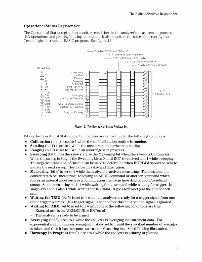
Operational Status Register Set
The Operational Status register set monitors conditions in the analyzer’s measurement process,disk operations, and printing/plotting operations. It also monitors the state of current AgilentTechnologies Instrument BASIC program. See figure 13.
Figure 13. The Operational Status Register Set
Bits in the Operational Status condition register are set to 1 under the following conditions:
Calibrating (bit 0) is set to 1 while the self-calibration routine is running.Settling (bit 1) is set to 1 while the measurement hardware is settling.Ranging (bit 2) is set to 1 while an autorange is in progress.Sweeping (bit 3) has the same state as the Measuring bit when the sweep is Continuous.When the sweep is Single, the Sweeping bit is 0 until INIT is received and 1 while sweeping.The negative transition of this bit can be used to determine when INIT:IMM should be sent toinitiate the next sweep. See following table and illustration.Measuring (bit 4) is set to 1 while the analyzer is actively measuring. The instrument isconsidered to be ‘’measuring’’ following an ABOR command or another command whichforces an internal abort such as a configuration change in time data or zoom/basebandstatus. So the measuring bit is 1 while waiting for an arm and while waiting for trigger. Insingle-sweep it is also 1 while waiting for INT:IMM. It goes low briefly at the end of eachscan.Waiting for TRIG (bit 5) is set to 1 when the analyzer is ready for a trigger signal from oneof the trigger sources. (If a trigger signal is sent before this bit is set, the signal is ignored.)Waiting for ARM (bit 6) is set to 1 when both of the following conditions are true:– External arm is on (ARM:SOURce EXTernal).– The analyzer is ready to be armed.Averaging (bit 8) is set to 1 while the analyzer is averaging measurement data. Forexponential and continuous averaging, it stays set to 1 until the specified number of averagesis taken, and then it has the same state as the Measuring bit. See following illustration.Hardcopy In Progress (bit 9) is set to 1 while the analyzer is printing or plotting.
The Agilent 89400A’s Register Sets
19
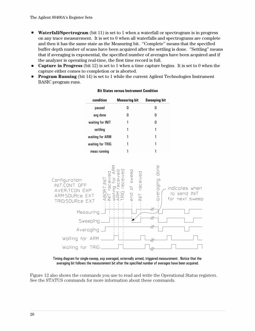
Waterfall/Spectrogram (bit 11) is set to 1 when a waterfall or spectrogram is in progresson any trace measurement. It is set to 0 when all waterfalls and spectrograms are completeand then it has the same state as the Measuring bit. ‘’Complete’’ means that the specifiedbuffer depth number of scans have been acquired after the settling is done. ‘’Settling’’ meansthat if averaging is exponential, the specified number of averages have been acquired and ifthe analyzer is operating real-time, the first time record is full.Capture in Progress (bit 12) is set to 1 when a time capture begins. It is set to 0 when thecapture either comes to completion or is aborted.Program Running (bit 14) is set to 1 while the current Agilent Technologies InstrumentBASIC program runs.
Bit States versus Instrument Condition
condition Measuring bit Sweeping bit
paused 0 0
avg done 0 0
waiting for INIT 1 0
settling 1 1
waiting for ARM 1 1
waiting for TRIG 1 1
meas running 1 1
Timing diagram for single-sweep, exp averaged, externally armed, triggered measurement. Notice that theaveraging bit follows the measurement bit after the specified number of averages have been acquired.
Figure 12 also shows the commands you use to read and write the Operational Status registers.See the STATUS commands for more information about these commands.
The Agilent 89400A’s Register Sets
20
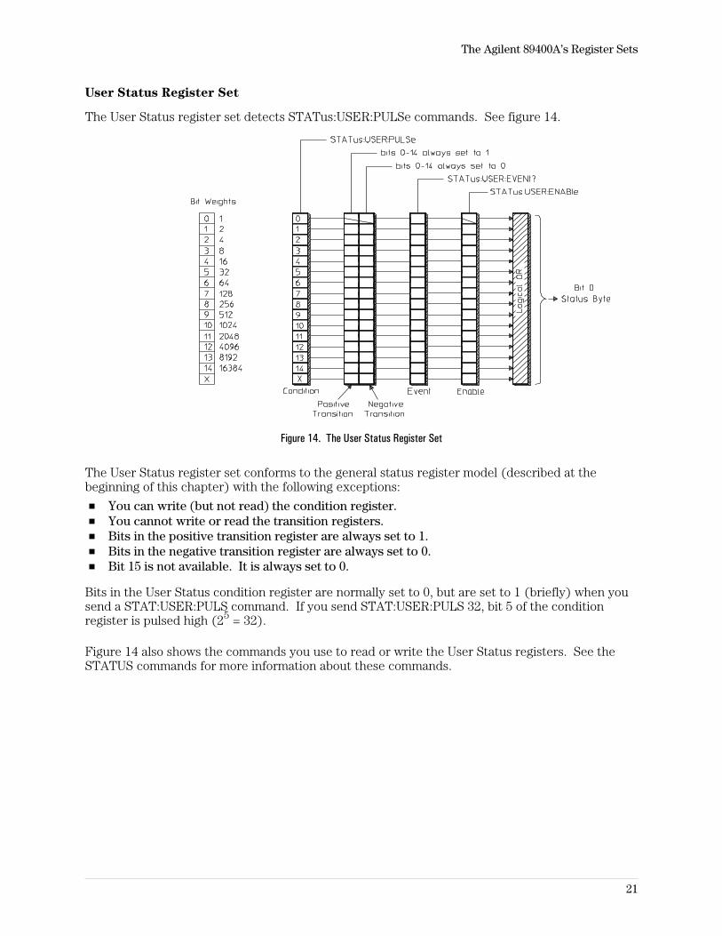
User Status Register Set
The User Status register set detects STATus:USER:PULSe commands. See figure 14.
Figure 14. The User Status Register Set
The User Status register set conforms to the general status register model (described at thebeginning of this chapter) with the following exceptions:
You can write (but not read) the condition register.You cannot write or read the transition registers.Bits in the positive transition register are always set to 1.Bits in the negative transition register are always set to 0.Bit 15 is not available. It is always set to 0.
Bits in the User Status condition register are normally set to 0, but are set to 1 (briefly) when yousend a STAT:USER:PULS command. If you send STAT:USER:PULS 32, bit 5 of the conditionregister is pulsed high (25 = 32).
Figure 14 also shows the commands you use to read or write the User Status registers. See theSTATUS commands for more information about these commands.
The Agilent 89400A’s Register Sets
21
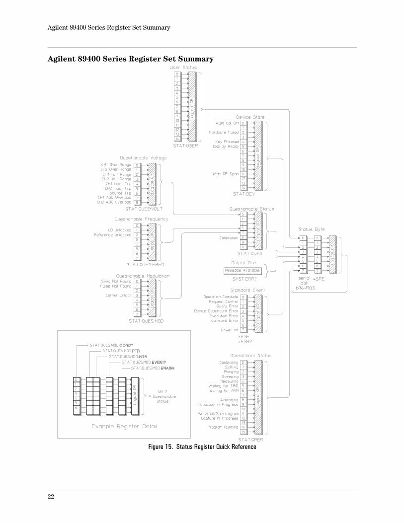
Agilent 89400 Series Register Set Summary
Figure 15. Status Register Quick Reference
Agilent 89400 Series Register Set Summary
22
2
The SCPI Instrument Model
23
Introduction
A model is used within SCPI as a means of achieving compatibility. SCPI concerns itself withthree types of compatibility. The first form of compatibility is called vertical compatibility.Vertical compatibility is where two instruments of the same type have identical controls.
The second form of compatibility is called horizontal compatibility. Horizontal compatibility iswhere two instruments can make the same measurement, regardless of the actual measurementtechniques used. To be horizontally compatibile, both instruments would use the samecommands to make this measurement. For example, both an oscilloscope and a counter canperform a risetime measurement on a pulse. The two instruments are said to be horizontallycompatible if the same command is used in both instruments.
The third form of compatibility is called functional compatibility. Functional compatibility is wheretwo instruments which perform the same function do so with the same commands. For example,a spectrum analyzer and an rf source may both sweep in frequency. If the same frequency andsweep commands are used in both instruments, they would be functionally compatible in this area.
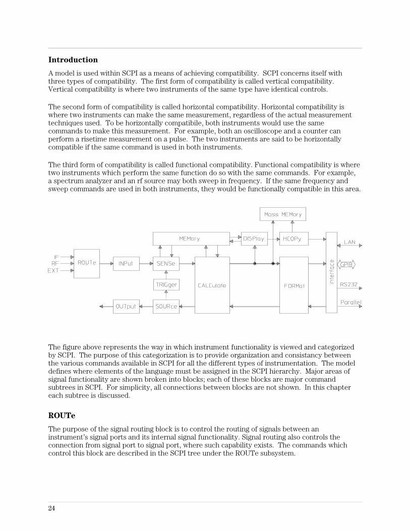
The figure above represents the way in which instrument functionality is viewed and categorizedby SCPI. The purpose of this categorization is to provide organization and consistancy betweenthe various commands available in SCPI for all the different types of instrumentation. The modeldefines where elements of the language must be assigned in the SCPI hierarchy. Major areas ofsignal functionality are shown broken into blocks; each of these blocks are major commandsubtrees in SCPI. For simplicity, all connections between blocks are not shown. In this chaptereach subtree is discussed.
ROUTe
The purpose of the signal routing block is to control the routing of signals between aninstrument’s signal ports and its internal signal functionality. Signal routing also controls theconnection from signal port to signal port, where such capability exists. The commands whichcontrol this block are described in the SCPI tree under the ROUTe subsystem.
24
INPut
The purpose of the INPut block is to condition the incoming signal before it is converted into databy the SENSe block. INPut block functions include filtering, biasing, frequency conversion (suchas a mixer or prescaler function), and attenuation.
SENSe
The purpose of the SENSe block is to convert signal(s) into internal data that can be manipulatedby normal computer techniques. The commands associated with the SENSe block control thevarious characteristics of the conversion process. Examples are range, resolution, bandwidth, andgate time. This block does not include any mathematical manipulation of the data after it hasbeen converted.
CALCulate
In the measurement function path, the purpose of the CALCulate block is to convert sensed datainto a form more useful to the application. Typical calculations include converting units andpostprocessing calculations.
OUTPut
The purpose of the OUTPut block is to condition the outgoing signal after it has been generated.The OUTPut block functions include filtering, biasing, frequency conversion (such as a mixerfunction), and attenuation.
SOURce
The purpose of the SOURce block is to generate a signal based on specified characteristics and/orsupplied data. The commands associated with this block describe the characteristics of thegenerated signal.
TRIGger
The trigger subsystem is used to synchronize device action(s) with events. A device action mightbe the acquisition of a measurement or the application of a stimulus. The trigger subsystemconsists of the expanded capability model which is capable of describing very complex devicetrigger systems. It also makes provision, through the ARM-TRIGger model, for simple descriptionsof less complicated trigger systems. These two models are consistent and compatible with eachother. The ARM-TRIGger model represents a subset of the capability available in the expandedcapability model.
Special terms in the following discussion are defined as follows. A box in a flow chart diagramidentifies a state of a transition diagram and is referred to as a layer. A sequence is a set ofvertically connected layers. A solid line defines flow of control between states and a dashed linedefines signals used as semaphores.
25
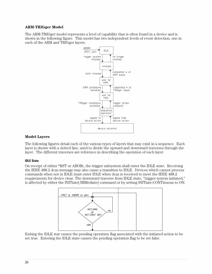
ARM-TRIGger Model
The ARM-TRIGger model represents a level of capability that is often found in a device and isshown in the following figure. This model has two independent levels of event detection, one ineach of the ARM and TRIGger layers.
Model Layers
The following figures detail each of the various types of layers that may exist in a sequence. Eachlayer is shown with a dotted line, used to divide the upward and downward traverses through thelayer. The different traverses are reference in describing the operation of each layer.
IDLE State
On receipt of either *RST or ABORt, the trigger subsystem shall enter the IDLE state. Receivingthe IEEE 488.2 dcas message may also cause a transition to IDLE. Devices which cannot processcommands when not in IDLE must enter IDLE when dcas is received to meet the IEEE 488.2requirements for device clear. The downward traverse from IDLE state, ‘’trigger system initiated,’’is affected by either the INITiate[:IMMediate] command or by setting INITiate:CONTinuous to ON.
Exiting the IDLE stat causes the pending operation flag associated with the initiated action to beset true. Entering the IDLE state causes the pending operation flag to be set false.
26
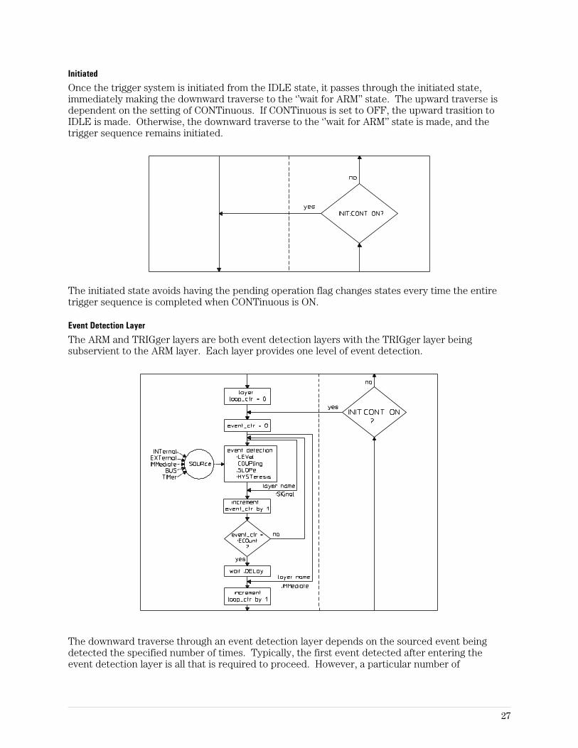
Initiated
Once the trigger system is initiated from the IDLE state, it passes through the initiated state,immediately making the downward traverse to the ‘’wait for ARM’’ state. The upward traverse isdependent on the setting of CONTinuous. If CONTinuous is set to OFF, the upward trasition toIDLE is made. Otherwise, the downward traverse to the ‘’wait for ARM’’ state is made, and thetrigger sequence remains initiated.
The initiated state avoids having the pending operation flag changes states every time the entiretrigger sequence is completed when CONTinuous is ON.
Event Detection Layer
The ARM and TRIGger layers are both event detection layers with the TRIGger layer beingsubservient to the ARM layer. Each layer provides one level of event detection.
The downward traverse through an event detection layer depends on the sourced event beingdetected the specified number of times. Typically, the first event detected after entering theevent detection layer is all that is required to proceed. However, a particular number of
27
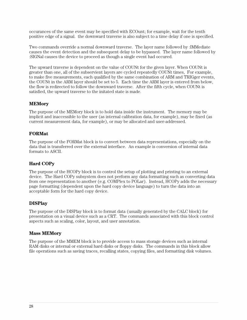
occurances of the same event may be specified with ECOunt; for example, wait for the tenthpositive edge of a signal. the downward traverse is also subject to a time delay if one is specified.
Two commands override a normal downward traverse. The layer name followed by :IMMediatecauses the event detection and the subsequent delay to be bypassed. The layer name followed by:SIGNal causes the device to proceed as though a single event had occured.
The upward traverse is dependent on the value of COUNt for the given layer. When COUNt isgreater than one, all of the subservient layers are cycled repeatedly COUNt times, For example,to make five measurements, each qualified by the same combination of ARM and TRIGger events,the COUNt in the ARM layer should be set to 5. Each time the ARM layer is entered from below,the flow is redirected to follow the downward traverse. After the fifth cycle, when COUNt issatisfied, the upward traverse to the initated state is made.
MEMory
The purpose of the MEMory block is to hold data inside the instrument. The memory may beimplicit and inaccessible to the user (as internal calibration data, for example), may be fixed (ascurrent measurement data, for example), or may be allocated and user-addressed.
FORMat
The purpose of the FORMat block is to convert between data representations, especially on thedata that is transferred over the external interface. An example is conversion of internal dataformats to ASCII.
Hard COPy
The purpose of the HCOPy block is to control the setup of plotting and printing to an externaldevice. The Hard COPy subsystem does not perform any data formatting such as converting datafrom one representation to another (e.g. COMPlex to POLar). Instead, HCOPy adds the necessarypage formatting (dependent upon the hard copy device language) to turn the data into anacceptable form for the hard copy device.
DISPlay
The purpose of the DISPlay block is to format data (usually generated by the CALC block) forpresentation on a visual device such as a CRT. The commands associated with this block controlaspects such as scaling, color, layout, and user annotation.
Mass MEMory
The purpose of the MMEM block is to provide access to mass storage devices such as internalRAM disks or internal or external hard disks or floppy disks. The commands in this block allowfile operations such as saving traces, recalling states, copying files, and formatting disk volumes.
28
3
Command Reference
29

Command Reference
30
*CAL? queryCalibrates the analyzer and returns the (pass/fail) result.
Query Syntax: *CAL?
Example Statements: OUTPUT 719;"*CAL?"OUTPUT 719;"*cal?"
Return Format: Integer
Attribute Summary: Synchronization Required: noPreset State: not applicableSCPI Compliance: confirmed
Description:
The analyzer performs a full calibration when it receives this query. If the calibration completeswithout error, the analyzer returns 0. If the calibration fails, the analyzer returns 1.
See also, the calibration commands.
Command Reference
31
*CLS commandClears the Status Byte by emptying the error queue and clearing all event registers.
Command Syntax: *CLS
Example Statements: OUTPUT 719;"*Cls"OUTPUT 719;"*CLS"
Attribute Summary: Synchronization Required: noPreset State: not applicableSCPI Compliance: confirmed
Description:
This command clears the Status Byte register. It does so by emptying the error queue andclearing (setting to 0) all bits in the event registers of the following register sets:
User Status.Device State.Questionable Voltage.Questionable Frequency.Limit Fail.Questionable Status.Operation Status.
In addition, *CLS cancels any preceding *OPC command or query. This ensures that bit 0 of theStandard Event register is not set to 1 and that a response is not placed in the analyzer’s outputqueue when pending overlapped commands are completed.
*CLS does not change the current state of enable registers or transition filters.
Note To guarantee that the Status Byte’s Message Available and Master SummaryStatus bits are cleared, send *CLS immediately following a Program MessageTerminator.
Command Reference
32
*ESE command/querySets bits in the Standard Event Enable register.
Command Syntax: *ESE <number>|<bound>
<number> ::= a real number (NRf data)limits: 0:255
<bound> ::= MAX|MIN
Example Statements: OUTPUT 719;"*ese 0"OUTPUT 719;"*Ese 30"
Query Syntax: *ESE?
Return Format: Integer
Attribute Summary: Synchronization Required: noPreset State: dependent on setting of *PSCSCPI Compliance: confirmed
Description:
This command allows you to set bits in the Standard Event Enable register. Assign a decimalweight to each bit you want set (to 1) according to the following formula:
2(bit_number)
Acceptable values for bit_number are 0 through 7. Add the weights and then send the sum withthis command.
When an enable register bit is set to 1, the corresponding bit of the Standard Event Event registeris enabled. All enabled bits are logically ORed to create the Standard Event summary, whichreports to bit 5 of the Status Byte. Bit 5 is only set to 1 if both of the following are true:
One or more bits in the Standard Event event register are set to 1.At least one set bit is enabled by a corresponding bit in the Standard Event Enable register.
The setting last specified with *ESE is saved in nonvolatile memory. It can be recalled atpower-up, depending on the setting of the Power-on Status Clear flag (set with *PSC). When theflag is 0 at power-up, all bits in the Standard Event Enable register are set according to the saved*ESE value. When the flag is 1 at power-up, all bits in the Standard Event Enable register areinitialized to 0.
The query returns the current state of the Standard Event Enable register. The state is returnedas a sum of the decimal weights of all set bits.
Command Reference
33
*ESR? queryReads and clears the Standard Event Enable register.
Query Syntax: *ESR?
Example Statements: OUTPUT 719;"*esr?"OUTPUT 719;"*Esr?"
Return Format: Integer
Attribute Summary: Synchronization Required: noPreset State: undefined valueSCPI Compliance: confirmed
Description:
This query returns the current state of the Standard Event Enable register. The state is returnedas a sum of the decimal weights of all set bits. The decimal weight for each bit is assignedaccording to the following formula:
2(bit_number)
Acceptable values for bit_number are 0 through 7.
The register is cleared after being read by this query.
A bit in this register is set to 1 when the condition it monitors becomes true. A set bit remainsset, regardless of further changes in the condition it monitors, until one of the following occurs:
You read the register with this query.You clear all event registers with the *CLS command.
Command Reference
34
*IDN? queryReturns a comma-separated list of arbitrary ascii response data items that uniquely identifies theanalyzer.
Query Syntax: *IDN?
Example Statements: OUTPUT 719;"*IDN?"OUTPUT 719;"*idn?"
Return Format: ARB_ASCII
Attribute Summary: Synchronization Required: noPreset State: instrument-specificSCPI Compliance: confirmed
Description:
The response to this query is in the form:
<manufacturer name>,<model number>,<serial number>,<firmware version>
Here is an example: HEWLETT-PACKARD,89410A,3046A00132,A.00.01
The response to this query uniquely identifies your analyzer.
Command Reference
35
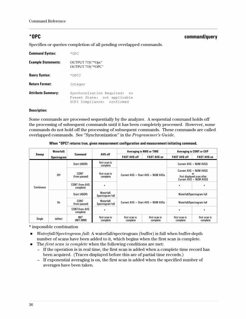
*OPC command/querySpecifies or queries completion of all pending overlapped commands.
Command Syntax: *OPC
Example Statements: OUTPUT 719;"*Opc"OUTPUT 719;"*OPC"
Query Syntax: *OPC?
Return Format: Integer
Attribute Summary: Synchronization Required: noPreset State: not applicableSCPI Compliance: confirmed
Description:
Some commands are processed sequentially by the analyzer. A sequential command holds offthe processing of subsequent commands until it has been completely processed. However, somecommands do not hold off the processing of subsequent commands. These commands are calledoverlapped commands. See ‘’Synchronization’’ in the Programmer’s Guide.
When *OPC? returns true, given measurement configuration and measurement-initiating command.
SweepWaterfall/
SpectrogramCommand AVG off
Averaging is RMS or TIME Averaging is CONT or EXP
FAST AVG off FAST AVG on FAST AVG off FAST AVG on
Continuous
Off
Start (ABOR) first scan iscomplete
Current AVG = Start AVG + NUM AVGs
Current AVG = NUM AVGS
CONT(from paused)
first scan iscomplete
Current AVG = NUM AVGSor
first displayed scan afterCurrent AVG = NUM AVGS
CONT (from AVGcomplete) * * *
On
Start (ABOR) Waterfall/Spectrogram full
Current AVG = Start AVG + NUM AVGs
Waterfall/Spectrogram full
CONT(from paused)
Waterfall/Spectrogram full Waterfall/Spectrogram full
CONT(from AVGcomplete) * * *
Single (either) INIT(INIT:IMM)
first scan iscomplete
first scan iscomplete
first scan iscomplete
first scan iscomplete
first scan iscomplete
* impossible combination
Waterfall/Spectrogram full: A waterfall/spectrogram (buffer) is full when buffer-depthnumber of scans have been added to it, which begins when the first scan is complete.The first scan is complete when the following conditions are met:– If the operation is in real time, the first scan is added when a complete time record has
been acquired. (Traces displayed before this are of partial time records.)– If exponential averaging is on, the first scan is added when the specified number of
averages have been taken.
Command Reference
36
*OPT? queryReturns a comma-separated list as a string that identifies the analyzer’s option configuration.
Query Syntax: *OPT?
Example Statements: OUTPUT 719;"*opt?"OUTPUT 719;"*Opt?"
Return Format: STRING
Attribute Summary: Synchronization Required: noPreset State: not applicableSCPI Compliance: confirmed
Description:
The response to this query identifies the analyzer’s option configuration. For example, if youranalyzer has the second input (receiver) channel installed, it returns AY7 to this query. Optionsare identified by the following:
AY7 Second (10 MHz) input channel1C2 IBASICAY9 1 Msample memory for time captureAYA Vector modulation analysis (IQ demod)AYB Waterfall and spectrogram displaysAYH Digital Video Modulation Analysis. AYA required.UTH Add 20 MBytes Memory and basic LANUG7 Advanced LAN: X11 and FTP.B73 Digital Wideband CDMA AnalysisB79 Digital ARIB 1.0-1.2 Wideband CDMA AnalysisB7A Enhanced Data rates for GSM Evolution (EDGE)
For the 89410A:
AY5 Precision frequency reference (oven)
For the 89441A:
AY8 Internal RF sourceAY4 Reported if crystal oven is absent from down converter section (lower cabinet)
The query returns a null string (“”"") if special options are not installed in the analyzer.
Command Reference
37
*PCB commandSets the pass-control-back address.
Command Syntax: *PCB <number>[, <number>]
<number> ::= a real number (NRf data)limits: 0:30
Example Statements: OUTPUT 719;"*PCB 19"OUTPUT 719;"*pcb 19, 1"
Attribute Summary: Synchronization Required: noPreset State: not affected by PresetSCPI Compliance: confirmed
Description:
Use this command to specify the address of your controller before you pass control of the GPIBto the analyzer. When the analyzer completes the operation that required it to have control ofthe bus, it automatically passes control back to the controller at the specified address.
The optional second number is only used for controllers that support extended addressing. It isinterpreted as the secondary address of the controller.
The address last specified with this command is saved in nonvolatile memory, so it is unaffectedwhen you turn the analyzer off and on. It is also unaffected by the *RST command.
Command Reference
38
*PSC command/querySets the state of the Power-on Status Clear flag.
Command Syntax: *PSC <number>
<number> ::= a real number (NRf data)limits: -32767:32767
Example Statements: OUTPUT 719;"*psc 0"OUTPUT 719;"*PSC 1"
Query Syntax: *PSC?
Return Format: Integer
Attribute Summary: Synchronization Required: noPreset State: not affected by PresetSCPI Compliance: confirmed
Description:
This command lets you specify whether or not the Service Request Enable register and the EventStatus Enable register should be cleared (all bits reset to 0) at power-up.
Sending *PSC 0 sets the power-on-status-clear flag false which allows instruments to assert SRQafter power-on. Use of any value other than 0 sets the power-on-status-clear flag to true whichEnables the power-on clear status and disallows any SRQ assertion after power-on.
The settings of the Service Request Enable register and the Event Status Enable register aresaved in nonvolatile memory when you turn the analyzer off. These settings can be restoredwhen you turn the analyzer on, but only if the Power-on Status Clear (PSC) flag is set to 0. Whenthe PSC flag is set to 1, the two enable registers are cleared at power-up.
The number last specified with *PSC is saved in nonvolatile memory, so it is unaffected whenyou turn the analyzer off and back on. It is also unaffected by the *RST command.
If you want to generate a service request at power-up, bit 7 of the Event Status Enable and bit 5of the Status Byte register must be enabled. This is only possible if the PSC flag is reset to 0
The query returns the current state of the PSC flag (0|1).
Command Reference
39
*RST commandExecutes a device reset.
Command Syntax: *RST
Example Statements: OUTPUT 719;"*RST"OUTPUT 719;"*rst"
Attribute Summary: Synchronization Required: noPreset State: not applicableSCPI Compliance: confirmed
Description:
This command returns the analyzer to a reset state. In addition, *RST cancels any pending *OPCcommands or query.
If a file named AUTO_ST containing an instrument state exists on any drive, that state is loadedand becomes active at power-on.
The reset state is similar to the preset state. The preset state of each command is listed in theAttribute Summary for that command. In some cases, a command’s reset state differs from itspreset state (SYST:PRES). These commands (and their reset states) are:
CALibration:AUTO is set to 0 (off).INIT:CONT is set to OFF.
Note This command is not equivalent to a front-panel preset (SYST:PRES).
The following are not affected by the *RST command (or SYST:PRES):
The state of the Power-on Status Clear flag.The state of all enabled and transition registers.The GPIB input and output queues.The time and date (SYST:TIME and SYST:DATE).The GPIB address settings.– SYST:COMM:GPIB:ADDR– HCOP:PLOT:ADDR– HCOP:PRIN:ADDRThe memory configuration.The GPIB controller capability setting.The default disk selection (MMEM:MSIS).External disk address.External receiver address.Contents of data registers.Contents of math function and constant registers.Contents of the RAM and NVRAM disks.Calibration constants.LAN configuration.
Command Reference
40
*SRE command/querySets bits in the Service Request Enable register (masks status byte).
Command Syntax: *SRE <number>
<number> ::= a real number (NRf data)limits: 0:255
Example Statements: OUTPUT 719;"*sre 0"OUTPUT 719;"*SRE 5"
Query Syntax: *SRE?
Return Format: Integer
Attribute Summary: Synchronization Required: noPreset State: dependent on setting of *PSCSCPI Compliance: confirmed
Description:
Use this command to set the Service Request Enable register to mask, or select, the events whichcause a service request (SRQ). See the section Status Byte Register Set in ‘’Using StatusRegisters.’’
Assign a decimal weight to each bit you want set (to 1) according to the following formula:
2(bit_number)
Acceptable values for bit_number are 0 through 7. Add the weights and then send the sum withthis command. Sending *SRE 0 disables SRQ; *SRE 5 enables bits 0 and 2, User Status Summaryand Device State Summary.
Note The analyzer ignores the setting specified for bit 6 of the Service Request Enableregister. The corresponding bit of the Status Byte register is always enabled.
The analyzer requests service from the active controller when one of the following occurs:
– A bit in the Status Byte register changes from 0 to 1 while the corresponding bit of theService Request Enable register is set to 1.
– A bit in the Service Request Enable register changes from 0 to 1 while the correspondingbit of the Status Byte register is set to 1.
The setting last specified with *SRE is saved in nonvolatile memory. It can be recalled atpower-up, depending on the setting of the Power-on Status Clear flag (set with *PSC). When theflag is 0 at power-up, all bits in the Service Request Enable register are set according to the saved*SRE value. When the flag is 1 at power-up, all bits in the Service Request Enable register areinitialized to 0.
The query returns the current state of the Service Request Enable register. The state is returnedas a sum of the decimal weights of all set bits.
Command Reference
41
*STB? queryReads the Status Byte register.
Query Syntax: *STB?
Example Statements: OUTPUT 719;"*Stb?"OUTPUT 719;"*STB?"
Return Format: Integer
Attribute Summary: Synchronization Required: noPreset State: not applicableSCPI Compliance: IEEE 488.2
Description:
This command allows you to read the Status Byte register. The state is returned as a sum of thedecimal weights of all set bits. The decimal weight for each bit is assigned according to thefollowing formula:
2(bit_number)
Acceptable values for bit_number are 0 through 7.
The register is not cleared by this query. To clear the Status Byte register, you must send the*CLS command.
Bits in the Status Byte register are defined as follows:
Bit 0 summarizes all enabled bits of the User Status register.Bit 1 is reserved.Bit 2 summarizes all enabled bits of the Device State register.Bit 3 summarizes all enabled bits of the Questionable Status register.Bit 4 is the Message Available (MAV) bit. It is set whenever there is something in theanalyzer’s output queue.Bit 5 summarizes all enabled bits of the Standard Event Status register.Bit 6, when read with this query (*STB?), acts as the Master Summary Status (MSS) bit. Itsummarizes all enabled bits of the Status Byte register. (Bit 6 acts as the Request Service(RQS) bit when it is read by a serial poll.Bit 7 summarizes all enabled bits of the Operation Status register.
For more information on the Status Byte register, see chapter 1.
Command Reference
42

*TRG commandTriggers the analyzer when TRIG:SOUR is BUS.
Command Syntax: *TRG
Example Statements: OUTPUT 719;"*trg"OUTPUT 719;"*Trg"
Attribute Summary: Synchronization Required: noPreset State: not applicableSCPI Compliance: confirmed
Description:
This command triggers the analyzer when the following two conditions are met:
The GPIB is designated as the trigger source (send the TRIG:SOUR BUS command.)The analyzer is waiting to trigger. (Bit 5 of the Operation Status register, waiting for trigger,must be set).
Command Reference
43
*TST? queryTests the analyzer hardware and returns the result.
Query Syntax: *TST?
Example Statements: OUTPUT 719;"*TST?"OUTPUT 719;"*tst?"
Return Format: Integer
Attribute Summary: Synchronization Required: noPreset State: not applicableSCPI Compliance: IEEE 488.2
Description:
The analyzer’s self-test performs a full calibration and then compares the calibration results tospecified limits. If the results are within specified limits, the analyzer returns 0. If the resultsexceed the specified limits, the analyzer returns 1.
Command Reference
44
*WAI commandHolds off processing of subsequent commands until all preceding commands have beenprocessed.
Command Syntax: *WAI
Example Statements: OUTPUT 719;"*Wai"OUTPUT 719;"*WAI"
Attribute Summary: Synchronization Required: noPreset State: not applicableSCPI Compliance: confirmed
Description:
Use *WAI to hold off the processing of subsequent commands until all pending overlappedcommands have been completed. See also, *OPC.
Some commands are processed sequentially by the analyzer. A sequential command holds offthe processing of any subsequent commands until it has been completely processed. However,some commands do not hold off the processing of subsequent commands; they are referred to asoverlapped commands. *WAI ensures that overlapped commands are completely processedbefore subsequent commands (those sent after *WAI) are processed.
Command Reference
45
ABORt commandAbort the current measurement in progress.
Command Syntax: ABORt
Example Statements: OUTPUT 719;"abor"OUTPUT 719;"Abort"
Attribute Summary: Synchronization Required: yesPreset State: not applicableSCPI Compliance: confirmed
Description:
This command aborts any measurement in progress and resets the trigger system. Any actionsrelated to the trigger system that are in progress, such as a sweep or taking a measurement areaborted and the NPO (no pending operations) flag is set false.
Sets the Measuring and Averaging bits in the Operational Status register to 0.ABOR;INIT:IMM serves a special synchronization function.If INIT:CONT is OFF, then INIT:IMM starts a new measurement.If INIT CONT is ON, a new measurement begins immediately.
The ABORt command is an important part of synchronizing measurements. To assure that themeasured data is the result of the current configuration, use one of the methods described inChapter 3 of the GPIB Programmer’s Guide.
Command Reference
46
ARM:DELay command/querySpecifies the delay after arming occurs before triggering may occur.
Command Syntax: ARM:DELay <number>[<unit>]|<step>|<bound>
<number> ::= a real number (NRf data)limits: 0:41.94 S in 2.5 us steps
<unit> ::= S
<step> ::= UP|DOWN
<bound> ::= MAX|MIN
Example Statements: OUTPUT 719;":ARM:DEL 2"OUTPUT 719;"arm:delay 220E-3"
Query Syntax: ARM:DELay?
Return Format: Real
Attribute Summary: Synchronization Required: noPreset State: 0 secondsSCPI Compliance: confirmed
Description:
If ARM:SOUR is EXT, the analyzer must be armed before triggering can occur. ARM is eitherEXTernal or IMMediate (external arm on/off). External arm is activated with the ARM:SOUREXT command. See TRIG:SOUR for more information.
This command has no effect if ARM:SOUR is IMM (external arm off).
Command Reference
47
ARM:LEVel command/querySpecifies the threshold value for external arm.
Command Syntax: ARM:LEVel <number>[<unit>]|<step>|<bound>
<number> ::= a real number (NRf data)limits: -11:11
<unit> ::= V
<step> ::= UP|DOWN
<bound> ::= MAX|MIN
Example Statements: OUTPUT 719;"Arm:Level -3"OUTPUT 719;"ARM:LEV 4V"
Query Syntax: ARM:LEVel?
Return Format: Real
Attribute Summary: Synchronization Required: noPreset State: 0VSCPI Compliance: confirmed
Description:
If ARM:SOUR is EXT, the analyzer must be armed before triggering can occur. ARM is eitherEXTernal or IMMediate (external arm on/off). External arm is activated with the ARM:SOUREXT command. See TRIG:SOUR for more information.
This command has no effect if ARM:SOUR is IMM (external arm off).
Command Reference
48
ARM:REGion command/queryWhen ARM:SOUR is EXT, this command specifies whether arming occurs when the external armsignal is positive-with-respect-to or negative-with-respect-to the specified trigger level.
Command Syntax: ARM:REGion ABOVe|BELow
Example Statements: OUTPUT 719;":ARM:REGION ABOVE"OUTPUT 719;"arm:reg BELOW"
Query Syntax: ARM:REGion?
Return Format: CHAR
Attribute Summary: Synchronization Required: noPreset State: ABOVSCPI Compliance: instrument-specific
Description:
If ARM:SOUR is EXT, the analyzer must be armed before triggering can occur. ARM is eitherEXTernal or IMMediate (external arm on/off). External arm is activated with the ARM:SOUREXT command. See TRIG:SOUR for more information.
This command has no effect if ARM:SOUR is IMM (external arm off).
Command Reference
49
ARM:SOURce command/querySelects either external arming or immediate (continuous) arming.
Command Syntax: ARM:SOURce IMMediate|EXTernal
Example Statements: OUTPUT 719;"Arm:Sour IMMEDIATE"OUTPUT 719;"ARM:SOUR IMMEDIATE"
Query Syntax: ARM:SOURce?
Return Format: CHAR
Attribute Summary: Synchronization Required: noPreset State: IMMSCPI Compliance: confirmed
Description:
Immediate triggering corresponds to turning external arm off. In this state the analyzeroperates as usual–it makes a measurement when the trigger conditions are met.
External triggering corresponds to turning external arm on. In this state the analyzer makes ameasurement when these conditions are met, in this order:
1. The analyzer receives a valid ‘’external arm’’ signal.2. Trigger conditions are met.
The external-arm signal is valid when it meets the conditions set with the ARM’s LEVEL,REGION, and DELAY commands. The external-arm signal is input via the EXT ARM (BNC)connector on the analyzer’s rear panel.
When the external-arm signal is valid (as defined by the level and region), it arms the analyzer.Once armed, the analyzer remains armed regardless of the value of the EXT ARM signal. If theanalyzer receives multiple valid external-arm signals, the first valid signal arms the analyzer; theothers do nothing.
Command Reference
50
CALCulate[1|2|3|4]:CCDF:COUNt? queryReturns the current number of data samples in the CCDF measurement.
Query Syntax: CALCulate[1|2|3|4]:CCDF:COUNt?
Example Statements: OUTPUT 719;":calc4:ccdf:coun?"OUTPUT 719;"Calculate4:Ccdf:Coun?"
Return Format: Integer
Attribute Summary: Synchronization Required: noPreset State: not applicableSCPI Compliance: instrument-specific
Description:
Command Reference
51
CALCulate[1|2|3|4]:CCDF:POWer? queryReturns the signal average power used to compute the CCDF measurement.
Query Syntax: CALCulate[1|2|3|4]:CCDF:POWer?
Example Statements: OUTPUT 719;"CALCULATE3:CCDF:POWER?"OUTPUT 719;"calc:ccdf:power?"
Return Format: Real
Attribute Summary: Synchronization Required: noPreset State: not applicableSCPI Compliance: instrument-specific
Description:
The analyzer plots the CCDF (Complementary Cumulative Density Function) using units ofpercent (%) for the y-axis (using a logarithmic scale) and power (dB) for the x-axis. Power onthe x-axis is relative to the signal average power in units of dBm.
This command returns the signal average power when CCDF measurement data is in the activetrace.
For details about CCDF measurements, see the Operator’s Guide and see online help for the[CCDF] softkey.
Command Reference
52
CALCulate[1|2|3|4]:DATA? queryReturns trace data that’s transformed to current coordinate system (CALC:FORM).
Query Syntax: CALCulate[1|2|3|4]:DATA?
Example Statements: OUTPUT 719;":Calc:Data?"OUTPUT 719;"CALC:DATA?"
Return Format: DEF_USER
Attribute Summary: Synchronization Required: noPreset State: not applicableSCPI Compliance: confirmed
Description:
This query returns a block of coordinate transformed trace data for the trace specified with anumber 1 through 4. The block is returned as a series of Y-axis values. The units for these valuesis determined with the CALC:UNIT:<unit> queries. Units are the same as the reference levelunits. The X-axis value for a given point is implied by the order of the points.
For more information on definite-length blocks (DEF_BLOCK), see ‘’Block Parameters’’ inchapter 4 of the Programmer’s Guide or refer to the example in the documentation forTRAC:DATA.
Note CALC:DATA cannot be used to transfer trace data to the analyzer. (seeTRAC:DATA)
Related Commands:
To load a trace into the analyzer from a mass-storage device, use MMEM:LOAD:TRAC.To store trace data in a data register, use TRACE[:DATA].To specify whether the data transferred is in ASCII or REAL format, use FORMAT[:DATA].To determine how many points are in the trace, use CALC:DATA:HEAD:POIN?.
Command Reference
53
CALCulate[1|2|3|4]:DATA:HEADer:POINts? queryReturns the number of points in the data returned with the CALC:DATA? query.
Query Syntax: CALCulate[1|2|3|4]:DATA:HEADer:POINts?
Example Statements: OUTPUT 719;"calculate:data:header:poin?"OUTPUT 719;"Calc:Data:Head:Points?"
Return Format: Integer
Attribute Summary: Synchronization Required: noPreset State: not applicableSCPI Compliance: instrument-specific
Description:
The display’s X axis is divided into discrete points. The CALC:DATA:HEAD:POIN query returnsthe number of points on the X axis.
Command Reference
54
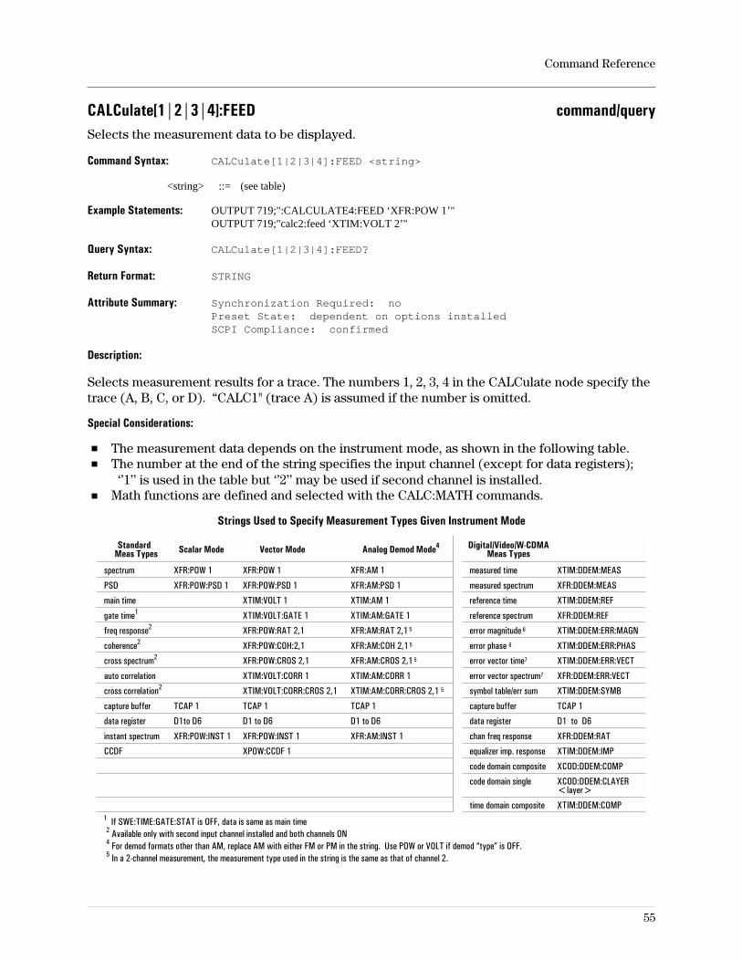
CALCulate[1|2|3|4]:FEED command/querySelects the measurement data to be displayed.
Command Syntax: CALCulate[1|2|3|4]:FEED <string>
<string> ::= (see table)
Example Statements: OUTPUT 719;":CALCULATE4:FEED ‘XFR:POW 1’"OUTPUT 719;"calc2:feed ‘XTIM:VOLT 2’"
Query Syntax: CALCulate[1|2|3|4]:FEED?
Return Format: STRING
Attribute Summary: Synchronization Required: noPreset State: dependent on options installedSCPI Compliance: confirmed
Description:
Selects measurement results for a trace. The numbers 1, 2, 3, 4 in the CALCulate node specify thetrace (A, B, C, or D). “CALC1" (trace A) is assumed if the number is omitted.
Special Considerations:
The measurement data depends on the instrument mode, as shown in the following table.The number at the end of the string specifies the input channel (except for data registers);‘’1’’ is used in the table but ‘’2’’ may be used if second channel is installed.
Math functions are defined and selected with the CALC:MATH commands.
Strings Used to Specify Measurement Types Given Instrument Mode
StandardMeas Types Scalar Mode Vector Mode Analog Demod Mode4 Digital/Video/W-CDMA
Meas Types
spectrum XFR:POW 1 XFR:POW 1 XFR:AM 1 measured time XTIM:DDEM:MEAS
PSD XFR:POW:PSD 1 XFR:POW:PSD 1 XFR:AM:PSD 1 measured spectrum XFR:DDEM:MEAS
main time XTIM:VOLT 1 XTIM:AM 1 reference time XTIM:DDEM:REF
gate time1 XTIM:VOLT:GATE 1 XTIM:AM:GATE 1 reference spectrum XFR:DDEM:REF
freq response2 XFR:POW:RAT 2,1 XFR:AM:RAT 2,1 5 error magnitude 6 XTIM:DDEM:ERR:MAGN
coherence2 XFR:POW:COH:2,1 XFR:AM:COH 2,1 5 error phase 6 XTIM:DDEM:ERR:PHAS
cross spectrum2 XFR:POW:CROS 2,1 XFR:AM:CROS 2,1 5 error vector time7 XTIM:DDEM:ERR:VECT
auto correlation XTIM:VOLT:CORR 1 XTIM:AM:CORR 1 error vector spectrum7 XFR:DDEM:ERR:VECT
cross correlation2 XTIM:VOLT:CORR:CROS 2,1 XTIM:AM:CORR:CROS 2,1 5 symbol table/err sum XTIM:DDEM:SYMB
capture buffer TCAP 1 TCAP 1 TCAP 1 capture buffer TCAP 1
data register D1to D6 D1 to D6 D1 to D6 data register D1 to D6
instant spectrum XFR:POW:INST 1 XFR:POW:INST 1 XFR:AM:INST 1 chan freq response XFR:DDEM:RAT
CCDF XPOW:CCDF 1 equalizer imp. response XTIM:DDEM:IMP
code domain composite XCOD:DDEM:COMP
code domain single XCOD:DDEM:CLAYER<layer>
time domain composite XTIM:DDEM:COMP1 If SWE:TIME:GATE:STAT is OFF, data is same as main time2 Available only with second input channel installed and both channels ON4 For demod formats other than AM, replace AM with either FM or PM in the string. Use POW or VOLT if demod “type” is OFF.5 In a 2-channel measurement, the measurement type used in the string is the same as that of channel 2.
Command Reference
55

5 Use POW or VOLT instead of AM, FM, or PM if demod is OFF.6 Called “carrier error” magnitude and phase for FSK demodulation.7 Called “FSK error” for FSK demodulation.
Command Reference
56
CALCulate[1|2|3|4]:FORMat command/querySpecifies the coordinates of the indicated trace.
Command Syntax: CALCulate[1|2|3|4]:FORMat <param>
<param> ::= MLIN|MLOG|PHASe|UPH|REAL|IMAG|GDELay|COMP|CONS|IEYE|QEYE|TEYE
Example Statements: OUTPUT 719;":CALC4:FORM UPHASE"OUTPUT 719;"calculate:form QEYE"
Query Syntax: CALCulate[1|2|3|4]:FORMat?
Return Format: CHAR
Attribute Summary: Synchronization Required: noPreset State: MLOGSCPI Compliance: instrument-specific
Description:
The numbers 1 through 4 used with the CALCulate node specify which trace (A, B, C, or D) is tobe affected by the command. If no number is used in the command line, “CALC1" is assumed andthe command affects trace A.
MLIN specifies linear magnitude trace coordinates. When this coordinate type is active, thetrace data is displayed with time or frequency data on the X axis and SQRT(RE2 + IM2) on the Yaxis.
MLOG specifies log-magnitude trace coordinates. When this coordinate type is active and thedisplay units are dB, the trace data is displayed with time or frequency on the X axis and 10log(RE2 + IM2)on the Y axis if the data is in power units, or 20 log(RE2 + IM2) if the data is linear(volts). If the Y-axis units are dBm, the trace data is displayed with time or frequency on the X
axis and 10 log(Magrms2 ⁄.001 × Z) on the Y axis where Mag is the input magnitude and Z is the receiver
input impedance (50Ω). The impedance value may be changed with the INP:IMP command.
PHAS specifies wrapped phase trace coordinates. When this coordinate type is active, the Y axisis phase in degrees. The default scale is ±225°.
UPH specifies unwrapped phase trace coordinates. When this coordinate type is active, thezero-phase reference and unwrapped-phase offset are values specified by the CALC:UPH:CREFcommand (in Hz) and CALC:UPH:OFFS command (in degrees), respectively.
REAL specifies real y-axis trace coordinates versus time or frequency. The real part of timewaveforms is correctly scaled for either baseband or zoom.
IMAG specifies imaginary y-axis coordinates versus time or frequency and displays theimaginary part of complex data. If the data is purely real, zero values are displayed. Complextime waveforms have an imaginary part corresponding to the Hilbert transform of the real part(due to zooming). So, a 2Vpk sine wave input in zoom mode results in a Real Part display of a(frequency shifted) 2Vpk sine wave, and the Imag Part display will also be a (frequency shifted)2Vpk sine wave shifted in phase.
Command Reference
57
GDEL specifies group delay trace coordinates. Group delay is the derivative of phase withrespect to frequency, −dϕ⁄df. In this analyzer it is approximated by the function −∆ϕ⁄∆f. Theaperture (∆f) is specified with the CALC:GDAP:APER command.
Note Digital demodulation features are implemented only if option AYA (vectormodulation analysis) is installed in the analyzer.
The following display formats are part of option AYA.
COMP specifies a complex polar vector diagram, with the real part on the x axis and theimaginary part on the y axis. When the instrument mode is digital demod, this is an IQ diagram,with the in-phase signal on the x axis and the quadrature-phase signal on the y axis.
The complex diagram differs from the constellation diagram in that the constellation diagramshows information only at specified time intervals; the symbol clock times.
CONS specifies a constellation polar vector diagram. This is a time-domain diagram. It displaysinformation only at symbol clock times (detection decision-points) and the displayed points arecalled symbols.
IEYE specifies the in-phase eye diagram.
QEYE specifies the quadrature-phase eye diagram.
TEYE specifies the trellis eye diagram.
For more information on these display types, see online help and the concepts discussion in theOperator’s Guide.
Command Reference
58
CALCulate[1|2|3|4]:GDAPerture:APERture command/querySpecifies the group delay aperture.
Command Syntax: CALCulate[1|2|3|4]:GDAPerture:APERture <param>
<param> ::= <number>[<unit>]|<step>|<bound>
<number> ::= a real number (NRf data)limits: 0.0625:16
<unit> ::= PCT
<step> ::= UP|DOWN
<bound> ::= MAX|MIN
Example Statements: OUTPUT 719;"Calc3:Gdapterture:Aper 16PCT"OUTPUT 719;"CALC:GDAP:APER .0625"
Query Syntax: CALCulate[1|2|3|4]:GDAPerture:APERture?
Return Format: Real
Attribute Summary: Synchronization Required: noPreset State: +5E-1SCPI Compliance: instrument-specific
Description:
Values are rounded to the nearest acceptable values which are: .0625%,.125%,.25%,.5%,1%, 2%, 4%,8%, or 16% of span.
The numbers 1 through 4 used with the CALCulate node specify which trace (A, B, C, or D) is tobe affected by the command. If no number is used in the command line, “CALC1" is assumed andthe command affects trace A.
Command Reference
59
CALCulate[1|2|3|4]:MARKer:BAND:STARt command/querySpecifies the start (left) band marker position.
Command Syntax: CALCulate[1|2|3|4]:MARKer:BAND:STARt <param>
<param> ::= <number>[<unit>]|<step>|<bound>
<number> ::= a real number (NRf data)limits: -3.40282347E+38:3.40282347E+38
<unit> ::= HZ|S|CODE
<step> ::= UP|DOWN
<bound> ::= MAX|MIN
Example Statements: OUTPUT 719;"Calculate3:Mark:Band:Start 1e6;Stop 2e6"OUTPUT 719;"CALC:MARKER:BAND:START 10 us;STOP 15 us"
Query Syntax: CALCulate[1|2|3|4]:MARKer:BAND:STARt?
Return Format: Real
Attribute Summary: Synchronization Required: noPreset State: 4.5 MHz, 10.09375 usSCPI Compliance: instrument-specific
Description:
This command is used with CALC:MARK:BAND:STOP to define the band in which power orsignal-to-noise measurements are made.
Related Commands:
To set the band function, use CALC:MARK:FUNC.To read the band marker data, query with CALC:MARK:FUNC:RES?.
Command Reference
60
CALCulate[1|2|3|4]:MARKer:BAND:STOP command/querySpecifies the stop (right) band marker position.
Command Syntax: CALCulate[1|2|3|4]:MARKer:BAND:STOP <param>
<param> ::= <number>[<unit>]|<step>|<bound>
<number> ::= a real number (NRf data)limits: -3.40282347E+38:3.40282347E+38
<unit> ::= HZ|S|CODE
<step> ::= UP|DOWN
<bound> ::= MAX|MIN
Example Statements: OUTPUT 719;"Calculate3:Mark:Band:Start 1e6;Stop 2e6"OUTPUT 719;"CALC:MARKER:BAND:START 10 us;STOP 15 us"
Query Syntax: CALCulate[1|2|3|4]:MARKer:BAND:STOP?
Return Format: Real
Attribute Summary: Synchronization Required: noPreset State: 5.5 MHz, 12.09375 usSCPI Compliance: instrument-specific
Description:
This command is used with CALC:MARK:BAND:STARt to define the band in which power orsignal-to-noise measurements are made.
Related Commands:
To set the band function, use CALC:MARK:FUNC.To read the band marker data, query with CALC:MARK:FUNC:RES?.
Command Reference
61
CALCulate[1|2|3|4]:MARKer:COUPled[:STATe] command/queryTurns marker coupling on and off.
Command Syntax: CALCulate[1|2|3|4]:MARKer:COUPled[:STATe] OFF|0|ON|1
Example Statements: OUTPUT 719;"Calculate2:Mark:Coup:State OFF"OUTPUT 719;"CALC:MARKER:COUP ON"
Query Syntax: CALCulate[1|2|3|4]:MARKer:COUPled[:STATe]?
Return Format: Integer
Attribute Summary: Synchronization Required: noPreset State: 0SCPI Compliance: instrument-specific
Description:
Marker coupling ties the X values of the inactive traces to that of the active trace. This commandcouples the markers no matter which trace is specified. No trace number is needed, as inCALC:MARK:COUP 1.
Marker coupling is applicable only between traces that have the same x-axis coordinates. Forexample, marker coupling is meaningless if one trace has x-axis units of Hertz and another tracehas x-axis units of seconds. When coupling is on, changing the position of one marker causesthe marker(s) on other traces of the same type (frequency or time) to move to the same position.
Related Commands:
To place a marker at a particular position on the X axis, use CALC:MARK:X.To display four traces, use DISP:FORM FOUR.
Command Reference
62
CALCulate[1|2|3|4]:MARKer:FCOunt command/queryTurns the marker frequency counter on/off.
Command Syntax: CALCulate[1|2|3|4]:MARKer:FCOunt OFF|0|ON|1
Example Statements: OUTPUT 719;":calc4:marker:fco OFF"OUTPUT 719;"Calculate3:Mark:Fco OFF"
Query Syntax: CALCulate[1|2|3|4]:MARKer:FCOunt?
Return Format: Integer
Attribute Summary: Synchronization Required: noPreset State: 0 (OFF)SCPI Compliance: instrument-specific
Description:
For a description of this function, see Help Text under the Help hardkey.
Command Reference
63
CALCulate[1|2|3|4]:MARKer:FCOunt:RESult? queryQuery results of the marker frequency counter measurement.
Query Syntax: CALCulate[1|2|3|4]:MARKer:FCOunt:RESult?
Example Statements: OUTPUT 719;"CALCULATE:MARK:FCOUNT:RES?"OUTPUT 719;"calc:marker:fco:result?"
Return Format: Real
Attribute Summary: Synchronization Required: noPreset State: not applicableSCPI Compliance: instrument-specific
Description:
CALC:MARK:FCOUNT must be ON for there to be data available for this query.
Command Reference
64
CALCulate[1|2|3|4]:MARKer:FUNCtion command/queryInitiate special band power marker functions.
Command Syntax: CALCulate[1|2|3|4]:MARKer:FUNCtion OFF|0|BPOWer|BRMS|BCN|BCNO
Example Statements: OUTPUT 719;":Calc2:Mark:Function BCN"OUTPUT 719;"CALC2:MARKER:FUNC OFF"
Query Syntax: CALCulate[1|2|3|4]:MARKer:FUNCtion?
Return Format: OFF|BPOW|BRMS|BCN|BCNO
Attribute Summary: Synchronization Required: noPreset State: OFFSCPI Compliance: instrument-specific
Description:
This command starts a marker measurement whose type is as follows:
BPOW calculates band power. The marker positions are set with CALC:MARK:BAND:STARTand STOP.
BRMS calculates rms-square-root of the band power. The marker positions are set withCALC:MARK:BAND:START and STOP.
BCN calculates the band carrier-to-noise ratio (C/N). The carrier position value used is theposition of the X marker (set with CALC:MARK:X). If the marker is off, this command calculatesnoise instead of carrier-to-noise ratio.
BCNO calculates the band carrier-to-noise density ratio. The carrier position value used is theposition of the X marker (set with CALCMARKX). If the marker is off, this command calculatesnoise density instead of carrier-to-noise density ratio.
The selected measurement runs and updates itself with every time record gathered (or, for caseslike averaging where multiple time records are needed to create a measurement result, everytime a measurement result is available). To run the same measurement on another set of data,change the variable of interest, synchronize, and query again.
The query returns the type of measurement that is currently being calculated. To query the data,use CALC:MARK:FUNC:RES?.
Command Reference
65
CALCulate[1|2|3|4]:MARKer:FUNCtion:DDEMod:RESult? queryQueries error parameters for digital or video demodulation or wideband CDMA.
Query Syntax: CALCulate[1|2|3|4]:MARKer:FUNCtion:DDEMod:RESult? <param><param>::=ADR|DEV|EVRM|EVPK|EVPS|EVPA|EVNF|FERR|FSRM|FSPK|FSPS|IQOF|LCOD|MERM|MEPK|MEPS|PERM|PBIT|PEPK|PEPS|PLEV|RHO|RHOE|SNR|SLOT|TDPC|TFRM|TSLT|TTRG
Example Statements: OUTPUT 719;"calc3:marker:func:ddemod:res? SNR"OUTPUT 719;"Calc:Marker:Func:Ddemod:Res? FERR"
Return Format: Real
Attribute Summary: Option: AYA (vector modulation analysis) andB7A (Enhanced Data rates for GSM Evolution (EDGE)) orB73 (Digital Wideband CDMA analysis) or080 Digital 3GPP Wideband CDMA analysis
Synchronization Required: noPreset State: not applicableSCPI Compliance: instrument-specific
Description:
ADR is the amplitude droop in dB/symbol.
DEV is the FSK deviation in Hz.
EVRM is error vector magnitude in %rms units.
EVNF is the error vector magnitude (EVM) below which 95% of the individual EVM’s occur(option B7A).
EVPA is the mean (average) of the peak error vector magnitudes—- one per measurment(option B7A).
EVPK is the peak (largest) error vector magnitude in %pk units (option B7A).
EVPS is the symbol number at which the peak (largest) error vector magnitude occurred.
FERR is the frequency error (carrier frequency offset) in Hz.
FSPK is the peak FSK error in %pk units.
FSPS is the symbol number at which the peak FSK error occured.
FSRM is the FSK error in %rms units.
IQOF is the IQ offset in dB.
LCOD is a Wideband CDMA parameter that shows the scrambling code (also called long code)used to despread the signal.
MERM is the magnitude error in %rms units.
Command Reference
66
MEPK is the peak (largest) magnitude error in %pk units.MEPS is the symbol number at whichthe peak (largest) magnitude error occurred.
PBIT is the number of pilot bits detected in the DCPH for the selected channel and codelayer (Option 080).
PERM is phase error in degrees-rms units.
PEPK is the peak (largest) phase error in degrees-pk.
PEPS is the symbol number at which the peak (largest) phase error occurred.
PLEV is the VSB pilot level.
RHO is the modulation accuracy.
RHOE is a Wideband CDMA parameter that shows the estimation of RHO for the W-CDMAcomposite signal.
SLOT is a Wideband CDMA parameter that shows the slot number associated with the start ofthe displayed result.
SNR is the signal-to-noise ratio.
TDPC is the tDPCH timing value for the DPCH for the selected channel and codelayer (Option 080)
TFRM is a Wideband CDMA parameter that shows the selected code channel offset, TFrame
(option B73 or B79).
TSLT is a Wideband CDMA parameter that shows the selected code channel offset, TSlot(option
(options B73 or B79).
TTRG is a Wideband CDMA parameter that shows the amount of time, in chips, from the triggerto the start of the sync symbol.
For more information, see online help (press the [ Help ] key on the front panel, then press thesoftkey of interest) and see the concepts discussion in the Operator’s Guide.
Command Reference
67
CALCulate[1|2|3|4]:MARKer:FUNCtion:RESult? queryRetrieves the marker measurement data created by the CALC:MARK:FUNC command.
Query Syntax: CALCulate[1|2|3|4]:MARKer:FUNCtion:RESult?
Example Statements: OUTPUT 719;":CALC:MARKER:FUNC:RESULT?"OUTPUT 719;"calc3:mark:function:res?"
Return Format: Real
Attribute Summary: Synchronization Required: noPreset State: not applicableSCPI Compliance: instrument-specific
Description:
CALC:MARK:FUNC selects the type of measurement to make and it begins running immediately.The selected measurement runs and updates itself with every time record gathered (or, for caseslike averaging where multiple time records are needed to create a measurement result, everytime a measurement result is available). To run the same measurement on another set of data,change the variable of interest, synchronize, and query again.
Command Reference
68
CALCulate[1|2|3|4]:MARKer:FUNCtion:STATistics command/querySelects or turns off statistical-power measurements.
Command Syntax: CALCulate[1|2|3|4]:MARKer:FUNCtion:STATistics OFF|0|PEAK|PKAV|AVER
Example Statements: OUTPUT 719;"Calculate:Mark:Func:Statistics OFF"OUTPUT 719;"CALC:MARKER:FUNC:STAT PKAV"
Query Syntax: CALCulate[1|2|3|4]:MARKer:FUNCtion:STATistics?
Return Format: OFF|PEAK|PKAV|AVER
Attribute Summary: Synchronization Required: noPreset State: OFFSCPI Compliance: instrument-specific
Description:
This command selects a statistical-power measurement or turns the selected statistical-powermeasurement off. You can select peak power, average power, and peak-to-average power (theratio of peak-to-average). CALC1 selects trace A for the measurement, CALC2 selects trace B,and so forth. If no trace is specified, CALC1 is assumed.
To compute the selected power measurement, the trace must contain time-domain data and theinstrument mode cannot be Scalar. You select trace data with the CALCulate:FEED command.You select the instrument mode with the INSTrument[:SELect] command.
For peak and peak-to-average power, the analyzer uses the value specified byCALC:MARK:FUNC:STAT:PPCT to compute peak power. For details, see online help for the[peak percent] softkey and the [statistics on/off] softkey (on the analyzer, press [Help], [MarkerFunction], [peak/average statistics], [statistics on/off] or [peak percent]).
Related Commands:
To return the statistical-power value, use CALC:MARK:FUNC:STAT:RES?.To set peak percent used in peak-power measurements, use CALC:MARK:FUNC:STAT:PPCT.To return the number of samples used in the power measurement, useCALC:MARK:FUNC:STAT:SMPL?.
Command Reference
69
CALCulate[1|2|3|4]:MARKer:FUNCtion:STATistics:PPCT command/querySpecifies the peak-percent value to use with peak power and peak-to-average powermeasurements.
Command Syntax: CALCulate[1|2|3|4]:MARKer:FUNCtion:STATistics:PPCT<number>[<unit>]|<step>|<bound>
<number> ::= a real number (NRf data)limits: 90:99.99
<unit> ::= [PCT]
<step> ::= UP|DOWN
<bound> ::= MAX|MIN
Example Statements: OUTPUT 719;"calc3:mark:function:stat:ppct 95"OUTPUT 719;"CALC:MARK:FUNCTION:STAT:PPCT 99.8"
Query Syntax: CALCulate[1|2|3|4]:MARKer:FUNCtion:STATistics:PPCT?
Return Format: Real
Attribute Summary: Synchronization Required: noPreset State: 99.99SCPI Compliance: instrument-specific
Description:
You enable peak-power or peak-to-average power measurements with theCALC:MARK:FUNC:STAT command. Peak percent is used in peak-power measurements tospecify the probability of peak power. Since peak-to-average power is the ratio of peak power toaverage power, peak percent affects peak-to-average power measurements as well aspeak-power measurements.
Peak percent specifies the probability of peak power. For example, a peak percent of 99.8%means that the instantaneous power will be less-than-or-equal-to the peak power reported by theanalyzer 99.8% of the time. Alternatively, you could say that the instantaneous power will exceedthe peak power reported by the analyzer 0.2% of the time (100% - 99.8%).
CALC 1 sets the peak percent for trace A, CALC2 sets it for trace B, and so forth. If no trace isspecified, CALC1 is assumed. The value is used only when peak power or peak-to-average poweris enabled (by sending CALC[1|2|3|4]:MARK:FUNC:STAT PEAK orCALC[1|2|3|4]:MARK:FUNC:STAT PKAV).
For additional details, see online help for the [peak power] softkey (on the analyzer, press [Help],[Marker Function], [peak/average statistics], [peak power]).
Command Reference
70
CALCulate[1|2|3|4]:MARKer:FUNCtion:STATistics:RESult? queryReturns the results of statistical-power measurements.
Query Syntax: CALCulate[1|2|3|4]:MARKer:FUNCtion:STATistics:RESult?
Example Statements: OUTPUT 719;":calculate3:mark:function:stat:res?"OUTPUT 719;"Calculate4:Mark:Function:Stat:Res?"
Return Format: Real
Attribute Summary: Synchronization Required: noPreset State: not applicableSCPI Compliance: instrument-specific
Description:
This command returns the results of a statistical-power measurement for the selected trace.CALC1 returns the results for trace A, CALC2 for trace B, and so forth. If no trace is specified,CALC1 is assumed.
For details about statistical-power measurements, see the CALC:MARK:FUNC:STAT command.
Command Reference
71
CALCulate[1|2|3|4]:MARKer:FUNCtion:STATistics:SMPL? queryReturns the number of samples used in statistical-power measurements.
Query Syntax: CALCulate[1|2|3|4]:MARKer:FUNCtion:STATistics:SMPL?
Example Statements: OUTPUT 719;"CALCULATE4:MARK:FUNCTION:STAT:SMPL?"OUTPUT 719;"calculate:mark:function:stat:smpl?"
Return Format: Real
Attribute Summary: Synchronization Required: noPreset State: not applicableSCPI Compliance: instrument-specific
Description:
You use the CALC:MARK:FUNC:STAT command to enable or disable statistical-powermeasurements. These measurements compute power using samples from all time records sincethe statistical-power measurement began.
The number of samples used is set to zero when you start or restart the statistical-powermeasurement. You start the measurement by sending CALC:MARK:FUNC:STAT and enabling astatistical-power measurement. You restart the measurement by sending the ABOR;*WAIcommand or most commands that change measurement parameters (such as range, trigger, orfrequency).
Note that changing the peak percent (CALC:MARK:FUNC:STAT:PPCT) does not restart thepower measurement. Also note that selecting another statistical-power measurement does notrestart the power measurement (for example, switching from peak power to average orpeak-to-average power).
Use CALC:MARK:FUNC:STAT:SMPL? to report the number of samples used in thestatistical-power measurement. CALC1 reports the number of samples used in thestatistical-power measurement on trace A, CALC2 reports it for trace B, and so forth. If no traceis specified, CALC1 is assumed. If no statistical-power measurement is selected for the specifiedtrace, the command returns zero.
Command Reference
72
CALCulate[1|2|3|4]:MARKer:MAXimum commandMoves the marker to the highest peak (largest value) in the active trace.
Command Syntax: CALCulate[1|2|3|4]:MARKer:MAXimum
Example Statements: OUTPUT 719;":Calculate4:Mark:Maximum"OUTPUT 719;"CALC:MARK:MAXIMUM"
Attribute Summary: Synchronization Required: noPreset State: not applicableSCPI Compliance: instrument-specific
Description:
If the marker is OFF when this command is issued, the marker is turned ON. Therefore, it is notnecessary to check the marker state before using this command.
If no number is given in the CALC branch, “1" is assumed.
See Marker Search in Help Text for hints on peak searching.
Related Commands:
To read marker position, use CALC:MARK:X? and CALC:MARK:Y?.To find the minimum value of the trace, use CALC:MARK:MIN.To continually move the marker to the maximum value of the trace as it is updated, useCALC:MARK:MAX:TRAC.To find other peaks in the trace, use CALC:MARK:MAX:NEXT, CALC:MARK:MAX:LEFT, andCALC:MARK:MAX:RIGH.To search for a specific value, use the CALC:MARK:SEAR commands.
Command Reference
73
CALCulate[1|2|3|4]:MARKer:MAXimum:LEFT commandMoves the marker left to the next local maximum in the trace.
Command Syntax: CALCulate[1|2|3|4]:MARKer:MAXimum:LEFT
Example Statements: OUTPUT 719;"calc:marker:max:left"OUTPUT 719;"Calculate:Mark:Maximum:Left"
Attribute Summary: Synchronization Required: noPreset State: not applicableSCPI Compliance: instrument-specific
Description:
If the marker is OFF when this command is issued, the marker is turned ON. Therefore, it is notnecessary to check the marker state before using this command.
If no number is given in the CALC branch, “1" is assumed.
See Marker Search in Help Text for hints on peak searching.
Related Commands:
To read marker position, use CALC:MARK:X? and CALC:MARK:Y?.To find the maximum value of the trace, use CALC:MARK:MAX.To find the minimum value of the trace, use CALC:MARK:MIN.To continually move the marker to the maximum value of the trace as it is updated, useCALC:MARK:MAX:TRAC.To find other peaks in the trace, use CALC:MARK:MAX:RIGH and CALC:MARK:MAX:NEXT.To search for a specific value, use the CALC:MARK:SEAR commands.
Command Reference
74
CALCulate[1|2|3|4]:MARKer:MAXimum:NEXT commandMoves the marker to the next-highest peak in the active trace.
Command Syntax: CALCulate[1|2|3|4]:MARKer:MAXimum:NEXT
Example Statements: OUTPUT 719;":CALC:MARKER:MAX:NEXT"OUTPUT 719;"calc4:mark:maximum:next"
Attribute Summary: Synchronization Required: noPreset State: not applicableSCPI Compliance: instrument-specific
Description:
If the marker is OFF when this command is issued, the marker is turned ON. Therefore, it is notnecessary to check the marker state before using this command.
If no number is given in the CALC branch, “1" is assumed.
See Marker Search in Help Text for hints on peak searching.
Related Commands:
To read marker position, use CALC:MARK:X? and CALC:MARK:Y?.To find the maximum value of the trace, use CALC:MARK:MAX.To find the minimum value of the trace, use CALC:MARK:MIN.To continually move the marker to the maximum value of the trace as it is updated, useCALC:MARK:MAX:TRAC.To find other peaks in the trace, use CALC:MARK:MAX:LEFT and CALC:MARK:MAX:RIGH.To search for a specific value, use the CALC:MARK:SEAR commands.
Command Reference
75
CALCulate[1|2|3|4]:MARKer:MAXimum:RIGHt commandMoves the marker right to the next local maximum in the trace.
Command Syntax: CALCulate[1|2|3|4]:MARKer:MAXimum:RIGHt
Example Statements: OUTPUT 719;"Calculate:Mark:Max:Right"OUTPUT 719;"CALC:MARKER:MAX:RIGH"
Attribute Summary: Synchronization Required: noPreset State: not applicableSCPI Compliance: instrument-specific
Description:
If the marker is OFF when this command is issued, the marker is turned ON. Therefore, it is notnecessary to check the marker state before using this command.
If no number is given in the CALC branch, “1" is assumed.
See Marker Search in Help Text for hints on peak searching.
Related Commands:
To read marker position, use CALC:MARK:X? and CALC:MARK:Y?.To find the maximum value of the trace, use CALC:MARK:MAX.To find the minimum value of the trace, use CALC:MARK:MIN.To continually move the marker to the maximum value of the trace as it is updated, useCALC:MARK:MAX:TRAC.To find other peaks in the trace, use CALC:MARK:MAX:LEFT and CALC:MARK:MAX:NEXT.To search for a specific value, use the CALC:MARK:SEAR commands.
Command Reference
76
CALCulate[1|2|3|4]:MARKer:MAXimum:TRACk command/queryTurns peak tracking on and off.
Command Syntax: CALCulate[1|2|3|4]:MARKer:MAXimum:TRACk OFF|0|ON|1
Example Statements: OUTPUT 719;":calculate3:mark:maximum:trac ON"OUTPUT 719;"Calc4:Marker:Max:Track ON"
Query Syntax: CALCulate[1|2|3|4]:MARKer:MAXimum:TRACk?
Return Format: Integer
Attribute Summary: Synchronization Required: noPreset State: 0 (OFF)SCPI Compliance: instrument-specific
Description:
When peak tracking is on, the analyzer continuously moves the marker to the peak value in theactive trace. If peak track is on for more than one trace, each marker follows the peak for itsrespective trace, unless marker coupling is on. If peak tracking is on and markers are coupled,only the peak on the active trace is tracked and the X-position of the other marker(s) follows thatof the active trace.
Command Reference
77
CALCulate[1|2|3|4]:MARKer:MINimum[:GLOBal] commandMoves the active marker to the minimum value in the active trace.
Command Syntax: CALCulate[1|2|3|4]:MARKer:MINimum[:GLOBal]
Example Statements: OUTPUT 719;"CALC2:MARK:MINIMUM:GLOB"OUTPUT 719;"calculate:mark:min"
Attribute Summary: Synchronization Required: noPreset State: not applicableSCPI Compliance: instrument-specific
Description:
If the marker is OFF when this command is issued, the marker is turned ON. Therefore, it is notnecessary to check the marker state before using this command.
If no number is given in the CALC branch, “1" is assumed.
See Marker Search in Help Text for hints on peak searching.
Related Commands:
To read marker position, use CALC:MARK:X? and CALC:MARK:Y?.To find the maximum value of the trace, use CALC:MARK:MAX.To find other peaks in the trace, use CALC:MARK:MAX:RIGH and CALC:MARK:MAX:NEXT.To search for a specific value, use the CALC:MARK:SEAR commands.
Command Reference
78
CALCulate[1|2|3|4]:MARKer:OFFSet[:STATe] command/queryTurns the offset marker on and off.
Command Syntax: CALCulate[1|2|3|4]:MARKer:OFFSet[:STATe] OFF|0|ON|1
Example Statements: OUTPUT 719;":Calculate2:Mark:Offset OFF"OUTPUT 719;"CALC3:MARK:OFFSET:STAT OFF"
Query Syntax: CALCulate[1|2|3|4]:MARKer:OFFSet[:STATe]?
Return Format: Integer
Attribute Summary: Synchronization Required: noPreset State: 0SCPI Compliance: instrument-specific
Description:
If no number is given in the CALC branch, “1" is assumed.
Absolute marker values may be read without turning the offset marker off with CALC:MARK:Y?.
Related Commands:
To set the offset marker’s X and Y values, use CALC:MARK:OFFS:X andCALC:MARK:OFFS:Y.To read out the offset values, use CALC:MARK:OFFS:X? and CALC:MARK:OFFS:Y?.To change the offset marker’s X and Y values to those of the current marker values, useCALC:MARK:OFFS:ZERO.
Command Reference
79
CALCulate[1|2|3|4]:MARKer:OFFSet:X command/querySpecifies the X value of the offset marker.
Command Syntax: CALCulate[1|2|3|4]:MARKer:OFFSet:X <param>
<param> ::= <number>[<unit>]|<step>|<bound>
<number> ::= a real number (NRf data)limits: -3.40282e+38:3.40282e+38
<unit> ::= HZ|S|CODE
<step> ::= UP|DOWN
<bound> ::= MAX|MIN
Example Statements: OUTPUT 719;":calc:marker:offs:x 2 MHZ"OUTPUT 719;"Calculate3:Mark:Offset:X 3.14159E+006"
Query Syntax: CALCulate[1|2|3|4]:MARKer:OFFSet:X?
Return Format: Real
Attribute Summary: Synchronization Required: noPreset State: 0 (HZ or s)SCPI Compliance: instrument-specific
Description:
If no number is given in the CALC branch, “1" is assumed.
Related Commands:
To turn on the offset marker, use CALC:MARK:OFFS 1.To specify the Y value of the offset marker, use CALC:MARK:OFFS:Y.To position the offset marker at the values of the main marker, useCALC:MARK:OFFSET:ZERO.To read the relative marker (offset) values, use CALC:MARK:X:REL? andCALC:MARK:Y:REL?.
Command Reference
80
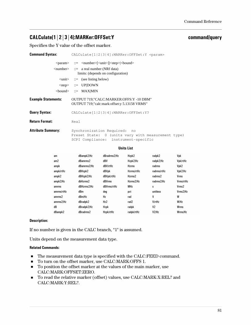
CALCulate[1|2|3|4]:MARKer:OFFSet:Y command/querySpecifies the Y value of the offset marker.
Command Syntax: CALCulate[1|2|3|4]:MARKer:OFFSet:Y <param>
<param> ::= <number>[<unit>]|<step>|<bound>
<number> ::= a real number (NRf data)limits: (depends on configuration)
<unit> ::= (see listing below)
<step> ::= UP|DOWN
<bound> ::= MAX|MIN
Example Statements: OUTPUT 719;"CALC:MARKER:OFFS:Y -10 DBM"OUTPUT 719;"calc:mark:offset:y 5.13158 VRMS"
Query Syntax: CALCulate[1|2|3|4]:MARKer:OFFSet:Y?
Return Format: Real
Attribute Summary: Synchronization Required: noPreset State: 0 (units vary with measurement type)SCPI Compliance: instrument-specific
Units List
am dBampk2/Hz dBradrms2/Hz Hzpk2 radpk2 Vpk
am2 dBamrms2 dBV Hzpk2/Hz radpk2/Hz Vpk/rtHz
ampk dBamrms2/Hz dBV/rtHz Hzrms radrms Vpk2
ampk/rtHz dBHzpk2 dBVpk Hzrms/rtHz radrms/rtHz Vpk2/Hz
ampk2 dBHzpk2/Hz dBVpk/rtHz Hzrms2 radrms2 Vrms
ampk2/Hz dbHzrms2 dBVrms Hzrms2/Hz radrms2/Hz Vrms/rtHz
amrms dBHzrms2/Hz dBVrms/rtHz MHz s Vrms2
amrms/rtHz dBm deg pct unitless Vrms2/Hz
amrms2 dBm/Hz Hz rad V W
amrms2/Hz dBradpk2 Hz2 rad2 V/rtHz W/Hz
dB dBradpk2/Hz Hzpk radpk V2 Wrms
dBampk2 dBradrms2 Hzpk/rtHz radpk/rtHz V2/Hz Wrms/Hz
Description:
If no number is given in the CALC branch, “1" is assumed.
Units depend on the measurement data type.
Related Commands:
The measurement data type is specified with the CALC:FEED command.To turn on the offset marker, use CALC:MARK:OFFS 1.To position the offset marker at the values of the main marker, useCALC:MARK:OFFSET:ZERO.To read the relative marker (offset) values, use CALC:MARK:X:REL? andCALC:MARK:Y:REL?.
Command Reference
81
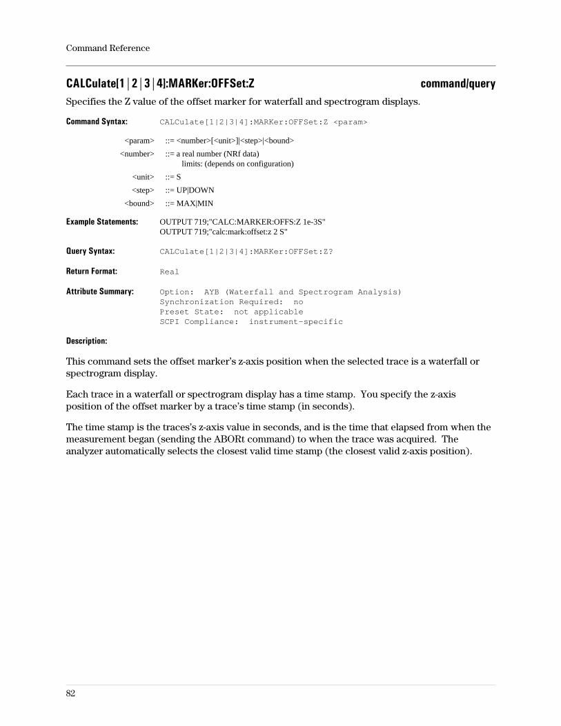
CALCulate[1|2|3|4]:MARKer:OFFSet:Z command/querySpecifies the Z value of the offset marker for waterfall and spectrogram displays.
Command Syntax: CALCulate[1|2|3|4]:MARKer:OFFSet:Z <param>
<param> ::= <number>[<unit>]|<step>|<bound>
<number> ::= a real number (NRf data)limits: (depends on configuration)
<unit> ::= S
<step> ::= UP|DOWN
<bound> ::= MAX|MIN
Example Statements: OUTPUT 719;"CALC:MARKER:OFFS:Z 1e-3S"OUTPUT 719;"calc:mark:offset:z 2 S"
Query Syntax: CALCulate[1|2|3|4]:MARKer:OFFSet:Z?
Return Format: Real
Attribute Summary: Option: AYB (Waterfall and Spectrogram Analysis)Synchronization Required: noPreset State: not applicableSCPI Compliance: instrument-specific
Description:
This command sets the offset marker’s z-axis position when the selected trace is a waterfall orspectrogram display.
Each trace in a waterfall or spectrogram display has a time stamp. You specify the z-axisposition of the offset marker by a trace’s time stamp (in seconds).
The time stamp is the traces’s z-axis value in seconds, and is the time that elapsed from when themeasurement began (sending the ABORt command) to when the trace was acquired. Theanalyzer automatically selects the closest valid time stamp (the closest valid z-axis position).
Command Reference
82
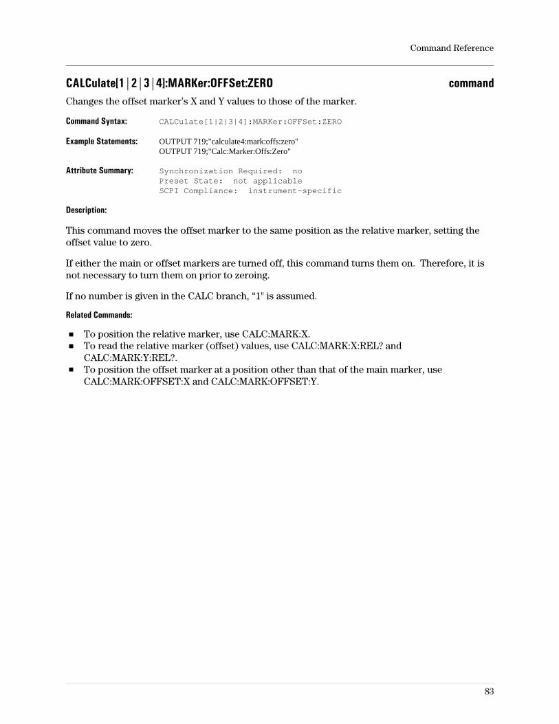
CALCulate[1|2|3|4]:MARKer:OFFSet:ZERO commandChanges the offset marker’s X and Y values to those of the marker.
Command Syntax: CALCulate[1|2|3|4]:MARKer:OFFSet:ZERO
Example Statements: OUTPUT 719;"calculate4:mark:offs:zero"OUTPUT 719;"Calc:Marker:Offs:Zero"
Attribute Summary: Synchronization Required: noPreset State: not applicableSCPI Compliance: instrument-specific
Description:
This command moves the offset marker to the same position as the relative marker, setting theoffset value to zero.
If either the main or offset markers are turned off, this command turns them on. Therefore, it isnot necessary to turn them on prior to zeroing.
If no number is given in the CALC branch, “1" is assumed.
Related Commands:
To position the relative marker, use CALC:MARK:X.To read the relative marker (offset) values, use CALC:MARK:X:REL? andCALC:MARK:Y:REL?.To position the offset marker at a position other than that of the main marker, useCALC:MARK:OFFSET:X and CALC:MARK:OFFSET:Y.
Command Reference
83
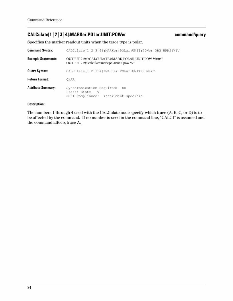
CALCulate[1|2|3|4]:MARKer:POLar:UNIT:POWer command/querySpecifies the marker readout units when the trace type is polar.
Command Syntax: CALCulate[1|2|3|4]:MARKer:POLar:UNIT:POWer DBM|WRMS|W|V
Example Statements: OUTPUT 719;":CALCULATE4:MARK:POLAR:UNIT:POW Wrms"OUTPUT 719;"calculate:mark:polar:unit:pow W"
Query Syntax: CALCulate[1|2|3|4]:MARKer:POLar:UNIT:POWer?
Return Format: CHAR
Attribute Summary: Synchronization Required: noPreset State: VSCPI Compliance: instrument-specific
Description:
The numbers 1 through 4 used with the CALCulate node specify which trace (A, B, C, or D) is tobe affected by the command. If no number is used in the command line, “CALC1" is assumed andthe command affects trace A.
Command Reference
84
CALCulate[1|2|3|4]:MARKer:READout command/querySpecifies marker readout type when trace type is polar.
Command Syntax: CALCulate[1|2|3|4]:MARKer:READout MPHase|RIMaginary
Example Statements: OUTPUT 719;"Calculate:Mark:Readout MPHASE"OUTPUT 719;"CALC:MARK:READOUT MPHASE"
Query Syntax: CALCulate[1|2|3|4]:MARKer:READout?
Return Format: CHAR
Attribute Summary: Synchronization Required: noPreset State: MPHSCPI Compliance: instrument-specific
Description:
MPHase specifies magnitude-phase coordinates.
RIMaginary specifies real-imaginary coordinates.
The numbers 1 through 4 used with the CALCulate node specify which trace (A, B, C, or D) is tobe affected by the command. If no number is used in the command line, “CALC1" is assumed andthe command affects trace A.
Command Reference
85
CALCulate[1|2|3|4]:MARKer:SEARch:BUFFer[:STATe] command/queryControls buffer search for waterfall and spectrogram displays.
Command Syntax: CALCulate[1|2|3|4]:MARKer:SEARch:BUFFer[:STATe] OFF|0|ON|1
Example Statements: OUTPUT 719;":calc4:marker:sear:buff OFF"OUTPUT 719;"Calculate3:Mark:Search:Buff:Stat ON"
Query Syntax: CALCulate[1|2|3|4]:MARKer:SEARch:BUFFer[:STATe]?
Return Format: CHAR
Attribute Summary: Option: AYB (Waterfall and Spectrogram Analysis)Synchronization Required: noPreset State: 0 (OFF)SCPI Compliance: instrument-specific
Description:
This command controls the analyzer’s buffer search feature. When this feature is on,marker-to-peak, next peak, and marker-to-minimum search operations are performed over alltraces in waterfall and spectrogram displays. When this feature is off, these search operationsare only performed on the selected trace (the trace selected by CALC:MARK:Z).
Related Commands:
To search for the highest peak, use CALC:MARK:MAX.To search for the next highest peak, use CALC:MARK:MAX:NEXT.To search for the smallest peak, use CALC:MARK:MIN.
Command Reference
86
CALCulate[1|2|3|4]:MARKer:SEARch:LEFT commandMoves the marker left from its present location to the first occurrence of the Y-axis target value.
Command Syntax: CALCulate[1|2|3|4]:MARKer:SEARch:LEFT
Example Statements: OUTPUT 719;"CALCULATE3:MARK:SEARCH:LEFT"OUTPUT 719;"calc:marker:sear:left"
Attribute Summary: Synchronization Required: noPreset State: not applicableSCPI Compliance: instrument-specific
Description:
Related Commands:
To specify the target value, use CALC:MARK:SEAR:TARG.To move the marker to the largest value on the trace, use CALC:MARK:MAX.To turn on the offset marker and place it on the main marker, use CALC:MARK:OFFS:ZERO.To read marker position (X and Y-axis values), use CALC:MARK:X? and CALC:MARK:Y?.
Command Reference
87
CALCulate[1|2|3|4]:MARKer:SEARch:OFFSet commandMoves the regular marker to the position of the reference or offset marker.
Command Syntax: CALCulate[1|2|3|4]:MARKer:SEARch:OFFSet
Example Statements: OUTPUT 719;":Calc2:Mark:Search:Offs"OUTPUT 719;"CALCULATE2:MARK:SEAR:OFFSET"
Attribute Summary: Synchronization Required: noPreset State: not applicableSCPI Compliance: instrument-specific
Description:
Related Commands:
To move the offset marker to the current position of the regular marker (also called zero theoffset marker), use CALC:MARK:OFFS:ZERO.
Command Reference
88
CALCulate[1|2|3|4]:MARKer:SEARch:RIGHt commandMoves the marker right from its present position to the first occurrence of the Y-axis target value.
Command Syntax: CALCulate[1|2|3|4]:MARKer:SEARch:RIGHt
Example Statements: OUTPUT 719;"calc2:marker:sear:righ"OUTPUT 719;"Calculate:Mark:Search:Righ"
Attribute Summary: Synchronization Required: noPreset State: not applicableSCPI Compliance: instrument-specific
Description:
Related Commands:
To specify the target value, use CALC:MARK:SEAR:TARG.To move the marker to the largest value on the trace, use CALC:MARK:MAX.To turn on the offset marker and place it on the main marker, use CALC:MARK:OFFS:ZERO.To read marker position (X and Y-axis values), use CALC:MARK:X? and CALC:MARK:Y?.
Command Reference
89
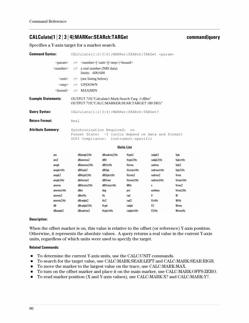
CALCulate[1|2|3|4]:MARKer:SEARch:TARGet command/querySpecifies a Y-axis target for a marker search.
Command Syntax: CALCulate[1|2|3|4]:MARKer:SEARch:TARGet <param>
<param> ::= <number>[<unit>]|<step>|<bound>
<number> ::= a real number (NRf data)limits: -600:600
<unit> ::= (see listing below)
<step> ::= UP|DOWN
<bound> ::= MAX|MIN
Example Statements: OUTPUT 719;"Calculate1:Mark:Search:Targ -3 dBm"OUTPUT 719;"CALC:MARKER:SEAR:TARGET 180 DEG"
Query Syntax: CALCulate[1|2|3|4]:MARKer:SEARch:TARGet?
Return Format: Real
Attribute Summary: Synchronization Required: noPreset State: -3 (units depend on data and format)SCPI Compliance: instrument-specific
Units List
am dBampk2/Hz dBradrms2/Hz Hzpk2 radpk2 Vpk
am2 dBamrms2 dBV Hzpk2/Hz radpk2/Hz Vpk/rtHz
ampk dBamrms2/Hz dBV/rtHz Hzrms radrms Vpk2
ampk/rtHz dBHzpk2 dBVpk Hzrms/rtHz radrms/rtHz Vpk2/Hz
ampk2 dBHzpk2/Hz dBVpk/rtHz Hzrms2 radrms2 Vrms
ampk2/Hz dbHzrms2 dBVrms Hzrms2/Hz radrms2/Hz Vrms/rtHz
amrms dBHzrms2/Hz dBVrms/rtHz MHz s Vrms2
amrms/rtHz dBm deg pct unitless Vrms2/Hz
amrms2 dBm/Hz Hz rad V W
amrms2/Hz dBradpk2 Hz2 rad2 V/rtHz W/Hz
dB dBradpk2/Hz Hzpk radpk V2 Wrms
dBampk2 dBradrms2 Hzpk/rtHz radpk/rtHz V2/Hz Wrms/Hz
Description:
When the offset marker is on, this value is relative to the offset (or reference) Y-axis position.Otherwise, it represents the absolute values. A query returns a real value in the current Y-axisunits, regardless of which units were used to specify the target.
Related Commands:
To determine the current Y-axis units, use the CALC:UNIT commands.To search for the target value, use CALC:MARK:SEAR:LEFT and CALC:MARK:SEAR:RIGH.To move the marker to the largest value on the trace, use CALC:MARK:MAX.To turn on the offset marker and place it on the main marker, use CALC:MARK:OFFS:ZERO.To read marker position (X and Y-axis values), use CALC:MARK:X? and CALC:MARK:Y?.
Command Reference
90
CALCulate[1|2|3|4]:MARKer[:STATe] command/queryTurns markers on and off.
Command Syntax: CALCulate[1|2|3|4]:MARKer[:STATe] OFF|0|ON|1
Example Statements: OUTPUT 719;":CALC3:MARKER ON"OUTPUT 719;"calc:marker:stat ON"
Query Syntax: CALCulate[1|2|3|4]:MARKer[:STATe]?
Return Format: Integer
Attribute Summary: Synchronization Required: noPreset State: 1 (on)SCPI Compliance: instrument-specific
Description:
Turns the marker on or off for the specified trace. If no number is given in the CALC branch, “1"is assumed.
The trace is specified with the numbers in CALC[1|2|3|4] which correspond to the front-paneltrace designations A, B, C, and D. If no trace number is used with this command, a “1" isassumed and the marker on trace A is turned on or off.
To find the X and Y values of the marker’s position, use CALC:MARK:X? and CALC:MARK:Y?.To specify the marker’s X position, use CALC:MARK:X.To make marker measurements relative to a reference other than 0,0, see theCALC:MARK:OFFSet commands.
Note Measurements run faster with markers off.
Command Reference
91
CALCulate[1|2|3|4]:MARKer:TRACe command/queryTurns the waterfall/spectrogram trace select marker on and off.
Command Syntax: CALCulate[1|2|3|4]:MARKer:TRACe OFF|0|ON|1
Example Statements: OUTPUT 719;"Calc:Marker:Trac ON"OUTPUT 719;"CALCULATE:MARK:TRAC OFF"
Query Syntax: CALCulate[1|2|3|4]:MARKer:TRACe?
Return Format: Integer
Attribute Summary: Option: AYB (waterfall & spectrogram display)Synchronization Required: noPreset State: 0 (OFF)SCPI Compliance: instrument-specific
Description:
The trace select marker allows selection of a scan of data in the z-direction (time history) forfurther analysis.
For more information on waterfall and spectrogram display types, see online help and theconcepts discussion in the Operator’s Guide.
Command Reference
92
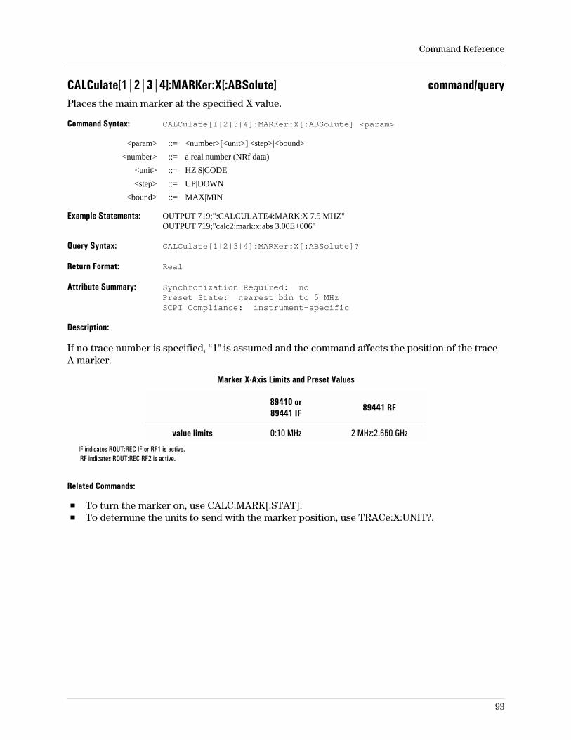
CALCulate[1|2|3|4]:MARKer:X[:ABSolute] command/queryPlaces the main marker at the specified X value.
Command Syntax: CALCulate[1|2|3|4]:MARKer:X[:ABSolute] <param>
<param> ::= <number>[<unit>]|<step>|<bound>
<number> ::= a real number (NRf data)
<unit> ::= HZ|S|CODE
<step> ::= UP|DOWN
<bound> ::= MAX|MIN
Example Statements: OUTPUT 719;":CALCULATE4:MARK:X 7.5 MHZ"OUTPUT 719;"calc2:mark:x:abs 3.00E+006"
Query Syntax: CALCulate[1|2|3|4]:MARKer:X[:ABSolute]?
Return Format: Real
Attribute Summary: Synchronization Required: noPreset State: nearest bin to 5 MHzSCPI Compliance: instrument-specific
Description:
If no trace number is specified, “1" is assumed and the command affects the position of the traceA marker.
Marker X-Axis Limits and Preset Values
89410 or89441 IF
89441 RF
value limits 0:10 MHz 2 MHz:2.650 GHz
IF indicates ROUT:REC IF or RF1 is active.RF indicates ROUT:REC RF2 is active.
Related Commands:
To turn the marker on, use CALC:MARK[:STAT].To determine the units to send with the marker position, use TRACe:X:UNIT?.
Command Reference
93
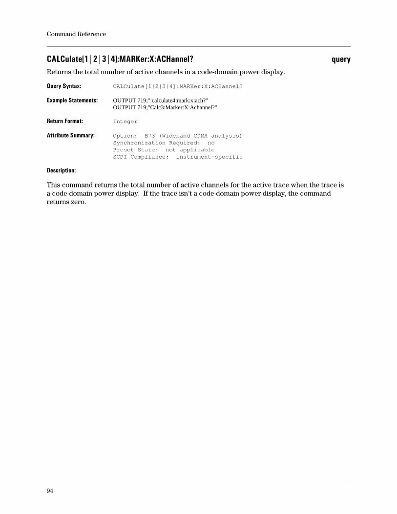
CALCulate[1|2|3|4]:MARKer:X:ACHannel? queryReturns the total number of active channels in a code-domain power display.
Query Syntax: CALCulate[1|2|3|4]:MARKer:X:ACHannel?
Example Statements: OUTPUT 719;":calculate4:mark:x:ach?"OUTPUT 719;"Calc3:Marker:X:Achannel?"
Return Format: Integer
Attribute Summary: Option: B73 (Wideband CDMA analysis)Synchronization Required: noPreset State: not applicableSCPI Compliance: instrument-specific
Description:
This command returns the total number of active channels for the active trace when the trace isa code-domain power display. If the trace isn’t a code-domain power display, the commandreturns zero.
Command Reference
94
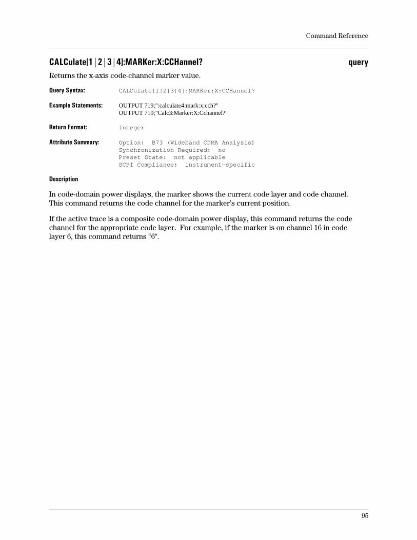
CALCulate[1|2|3|4]:MARKer:X:CCHannel? queryReturns the x-axis code-channel marker value.
Query Syntax: CALCulate[1|2|3|4]:MARKer:X:CCHannel?
Example Statements: OUTPUT 719;":calculate4:mark:x:cch?"OUTPUT 719;"Calc3:Marker:X:Cchannel?"
Return Format: Integer
Attribute Summary: Option: B73 (Wideband CDMA Analysis)Synchronization Required: noPreset State: not applicableSCPI Compliance: instrument-specific
Description
In code-domain power displays, the marker shows the current code layer and code channel.This command returns the code channel for the marker’s current position.
If the active trace is a composite code-domain power display, this command returns the codechannel for the appropriate code layer. For example, if the marker is on channel 16 in codelayer 6, this command returns “6".
Command Reference
95
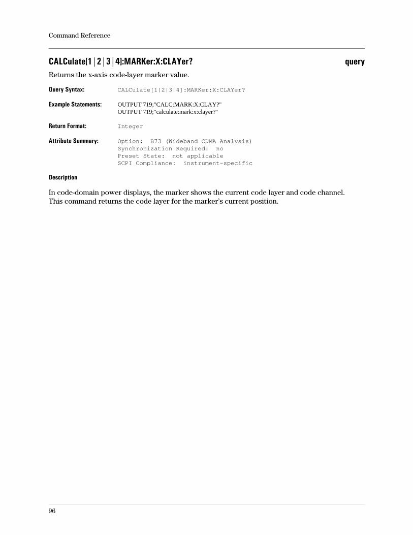
CALCulate[1|2|3|4]:MARKer:X:CLAYer? queryReturns the x-axis code-layer marker value.
Query Syntax: CALCulate[1|2|3|4]:MARKer:X:CLAYer?
Example Statements: OUTPUT 719;"CALC:MARK:X:CLAY?"OUTPUT 719;"calculate:mark:x:clayer?"
Return Format: Integer
Attribute Summary: Option: B73 (Wideband CDMA Analysis)Synchronization Required: noPreset State: not applicableSCPI Compliance: instrument-specific
Description
In code-domain power displays, the marker shows the current code layer and code channel.This command returns the code layer for the marker’s current position.
Command Reference
96
CALCulate[1|2|3|4]:MARKer:X:CSTatus? queryReturns the marker status for code-domain power displays.
Query Syntax: CALCulate[1|2|3|4]:MARKer:X:CSTatus?
Example Statements: OUTPUT 719;":Calc4:Marker:X:Cst?"OUTPUT 719;"CALCULATE4:MARK:X:CST?"
Return Format: Integer
Attribute Summary: Option: B73 (Wideband CDMA Analysis)Synchronization Required: noPreset State: not applicableSCPI Compliance: instrument-specific
Description
This command is applicable only when the active trace is code-domain power. It returns 0 (zero)if the marker is not on an active channel; 1 if the marker is on an active channel.
Command Reference
97
CALCulate[1|2|3|4]:MARKer:X:RELative? queryReturns the X-axis offset marker value (relative to the offset marker position).
Query Syntax: CALCulate[1|2|3|4]:MARKer:X:RELative?
Example Statements: OUTPUT 719;"calc3:marker:x:relative?"OUTPUT 719;"Calc:Mark:X:Rel?"
Return Format: Real
Attribute Summary: Synchronization Required: noPreset State: not applicableSCPI Compliance: instrument-specific
Description:
Related Commands:
To return the absolute marker value, use CALC:MARK:Y?.To determine the X-axis units, use TRAC:X:UNIT?.
Command Reference
98
CALCulate[1|2|3|4]:MARKer:Y? queryReads the Y-axis value of the main marker.
Query Syntax: CALCulate[1|2|3|4]:MARKer:Y?
Example Statements: OUTPUT 719;":CALCULATE2:MARK:Y?"OUTPUT 719;"calculate2:mark:y?"
Return Format: Real
Attribute Summary: Synchronization Required: noPreset State: not applicableSCPI Compliance: instrument-specific
Description:
This command is used to read the Y-axis value of the main marker. It reads out the absolutevalue regardless of the offset marker state.
Related Commands:
To determine the Y-axis units, use CALC:UNIT:<unit>?To read the X-axis value, use CALC:MARK:X?.To determine the X-axis units, use TRAC:X:UNIT?.To move the main marker, use CALC:MARK:X.To turn the marker on/off, use CALC:MARK[:STATE].
Command Reference
99
CALCulate[1|2|3|4]:MARKer:Y:RELative? queryReturns the Y-axis offset marker value (relative to the reference marker position.
Query Syntax: CALCulate[1|2|3|4]:MARKer:Y:RELative?
Example Statements: OUTPUT 719;"Calc:Mark:Y:Rel?"OUTPUT 719;"CALCULATE:MARK:Y:RELATIVE?"
Return Format: Real
Attribute Summary: Synchronization Required: noPreset State: not applicableSCPI Compliance: instrument-specific
Description:
Related Commands:
To return the absolute marker value, use CALC:MARK:Y?.To determine the X-axis units, use TRAC:X:UNIT?.
Command Reference
100
CALCulate[1|2|3|4]:MARKer:Z[:ABSolute] command/querySpecifies which trace in a waterfall or spectrogram display is being measured with the marker(s).
Command Syntax: CALCulate[1|2|3|4]:MARKer:Z[:ABSolute] <param>
<param> ::= <number>|<step>|<bound>
<number> ::= a real number (NRf data)limits: 1:(see discussion)
<step> ::= UP|DOWN
<bound> ::= MAX|MIN
Example Statements: OUTPUT 719;"calculate2:mark:z:absolute 23"OUTPUT 719;"Calc2:Marker:Z 99"
Query Syntax: CALCulate[1|2|3|4]:MARKer:Z[:ABSolute]?
Return Format: Real
Attribute Summary: Option: AYB (waterfall & spectrogram display)Synchronization Required: noPreset State: (see discussion)SCPI Compliance: instrument-specific
Description:
This command is useful when a waterfall or spectrogram measurement has been made and themeasurement is paused. Before using it, you must turn the trace-analysis feature on; see relatedcommands listed below.
You can select a trace by its trace number or its time stamp. Trace number 1 represents theearliest (oldest) data and larger numbers represet more-recent data. If the buffer depth is 100and 100 traces are displayed, then sending calc:mark:z 100 specifies analysis of themost-recent measurement trace.
The time stamp is the traces’s z-axis value in seconds, and is the time that elapsed from when themeasurement began (sending the ABORt command) to when the trace was acquired.
The MARKer:Z:UNIT command determines the units returned with CALC:MARK:Z? The numberreturned is the absolute number, even if the offset marker is on. If the offset marker is on andyou want to query the marker position relative to the offset marker, send CALC:MARK:Z:REL?.
Limits:
The buffer depth determines the largest trace number or time stamp that you can specify(DISP:WIND:TRAC:BUFF). If larger numbers are sent, they are interpreted as the largest validnumber and no error messages are generated. The buffer depth is limited by available memory.
Preset Value:
On preset, waterfall and spectrogram displays are turned off. A query issued immediately after apreset returns the buffer depth value, which is not affected by preset. For a running
waterfall/spectrogram measurement:
If the number of traces displayed hasn’t reached the buffer depth, the value returned with a
Command Reference
101

query is that of the most recent trace.If the number of traces displayed has reached the buffer depth, the value returned is thebuffer depth.
Related Commands:
To set the buffer depth, use DISP:WIND:TRAC:BUFF.To turn on the spectrogram/waterfall trace-analysis feature, use CALC:MARK:TRAC.
Command Reference
102
CALCulate[1|2|3|4]:MARKer:Z:RELative? queryReturns the Z-axis marker value (in seconds) relative to the offset marker position.
Query Syntax: CALCulate[1|2|3|4]:MARKer:Z:RELative?
Example Statements: OUTPUT 719;":calc4:marker:z:rel?"OUTPUT 719;"Calculate4:Mark:Z:Rel?"
Return Format: Real
Attribute Summary: Option: AYB (Waterfall and Spectrogram Analysis)Synchronization Required: noPreset State: not applicableSCPI Compliance: instrument-specific
Description:
This command returns the value of the z-axis marker, relative to the offset marker, when theselected trace is a waterfall or spectrogram display.
Related Commands:
To return the absolute marker value, use CALC:MARK:Z?.
Command Reference
103
CALCulate[1|2|3|4]:MARKer:Z:UNIT command/querySets the units for commands that query the z-axis marker in waterfall or spectrogram displays.
Command Syntax: CALCulate[1|2|3|4]:MARKer:Z:UNIT S|UNITLESS
Example Statements: OUTPUT 719;"CALC4:MARKER:Z:UNIT s"OUTPUT 719;"calc:mark:z:unit unitless"
Query Syntax: CALCulate[1|2|3|4]:MARKer:Z:UNIT?
Return Format: CHAR
Attribute Summary: Option: AYB (Waterfall and Spectrogram Analysis)Synchronization Required: noPreset State: UNITLESSSCPI Compliance: instrument-specific
Description:
Sending CALC:MARK:Z:UNIT S sets the z-axis units to seconds, which is the trace’s time stamp.Sending CALC:MARK:Z:UNIT UNITLESS sets the z-axis units to a unitless number, which is thetrace number.
This command determines the units returned with the CALC:MARK:Z? query.
Command Reference
104
CALCulate[1|2|3|4]:MATH:CONStant[1|2|3|4|5] command/queryDefines a complex constant in real,imaginary form.
Command Syntax: CALCulate[1|2|3|4]:MATH:CONStant[1|2|3|4|5]:STEP <r>, <i>
<r> ::= <number>|<bound>
<i> ::= <number>|<bound>
<number> ::= a real number (NRf data)limits: -3.40282e+38:3.40282e+38
<bound> ::= MAX|MIN
Example Statements: OUTPUT 719;":CALCULATE:MATH:CONSTANT2 -2560, 19.84"OUTPUT 719;"calc:math:cons3 7.53334e6, 2.45e3"
Query Syntax: CALCulate[1|2|3|4]:MATH:CONStant[1|2|3|4|5]?
Return Format: Real, Real
Attribute Summary: Synchronization Required: noPreset State: not affected by presetSCPI Compliance: instrument-specific
Description:
<r> represents the real part and <i> represents the imaginary part.
Complex constants may be defined with either real/imaginary or magnitude and phase values.
The numbers in the calculate node have no effect on this command.
Command Reference
105
CALCulate[1|2|3|4]:MATH:CONStant[1|2|3|4|5]:IMAG command/queryDefines the imaginary part of a math constant.
Command Syntax: CALCulate[1|2|3|4]:MATH:CONStant[1|2|3|4|5]:IMAG <param>
<param> ::= <number>|<step>|<bound>
<number> ::= a real number (NRf data)limits: -3.40282e+38:3.40282e+38
<step> ::= UP|DOWN
<bound> ::= MAX|MIN
Example Statements: OUTPUT 719;":CALCULATE:MATH:CONSTANT2:IMAG -256"OUTPUT 719;"calc:math:cons:imag 7.53334e6"
Query Syntax: CALCulate[1|2|3|4]:MATH:CONStant[1|2|3|4|5]:IMAG?
Return Format: Real
Attribute Summary: Synchronization Required: noPreset State: not affected by presetSCPI Compliance: instrument-specific
Description:
Complex constants may be defined with either real/imaginary or magnitude and phase values.
The numbers in the calculate node have no effect on this command.
To specify step size for use with UP|DOWN, use CALC:MATH:CONS:STEP.
If the step size is zero (0), the UP|DOWN argument changes the value byincrementing/decrementing the third-most-significant digit. For example, a value of 6027 wouldbe incremented to 6037 or decremented to 6017; a value of 53 would be incremented to 53.1 ordecremented to 52.9. If you increment/decrement the value of the step size, it changes in thesame manner.
Command Reference
106
CALCulate[1|2|3|4]:MATH:CONStant[1|2|3|4|5]:MAG command/queryDefines the magnitude value of a complex math constant.
Command Syntax: CALCulate[1|2|3|4]:MATH:CONStant[1|2|3|4|5]:MAG <param>
<param> ::= <number>|<step>|<bound>
<number> ::= a real number (NRf data)limits: 0.0:3.40282e+38
<step> ::= UP|DOWN
<bound> ::= MAX|MIN
Example Statements: OUTPUT 719;":CALCULATE:MATH:CONSTANT2:MAG 256"OUTPUT 719;"calc:math:cons:mag 7.53334e6"
Query Syntax: CALCulate[1|2|3|4]:MATH:CONStant[1|2|3|4|5]:MAG?
Return Format: Real
Attribute Summary: Synchronization Required: noPreset State: not affected by presetSCPI Compliance: instrument-specific
Description:
Complex constants may be defined with either real/imaginary or magnitude and phase values.
The numbers in the calculate node have no effect on this command.
Command Reference
107
CALCulate[1|2|3|4]:MATH:CONStant[1|2|3|4|5]:PHASe command/queryDefines the phase value of a complex math constant.
Command Syntax: CALCulate[1|2|3|4]:MATH:CONStant[1|2|3|4|5]:PHASe <param>
<param> ::= <number>[<unit>]|<step>|<bound>
<number> ::= a real number (NRf data)limits: -3.40282e+38:3.40282e+38
<unit> ::= DEG|RAD
<step> ::= UP|DOWN
<bound> ::= MAX|MIN
Example Statements: OUTPUT 719;":CALCULATE:MATH:CONSTANT2:PHASE -2.56e3"OUTPUT 719;"calc:math:cons:phas 7.53334e6"
Query Syntax: CALCulate[1|2|3|4]:MATH:CONStant[1|2|3|4|5]:PHASe?
Return Format: Real
Attribute Summary: Synchronization Required: noPreset State: not affected by presetSCPI Compliance: instrument-specific
Description:
Complex constants may be defined with either real/imaginary or magnitude and phase values.
The numbers in the calculate node have no effect on this command.
To specify step size for use with UP|DOWN, use CALC:MATH:CONS:STEP.
If the step size is zero (0), the UP|DOWN argument changes the value byincrementing/decrementing the third-most-significant digit. For example, a value of 6027 wouldbe incremented to 6037 or decremented to 6017; a value of 53 would be incremented to 53.1 ordecremented to 52.9. If you increment/decrement the value of the step size, it changes in thesame manner.
Command Reference
108
CALCulate[1|2|3|4]:MATH:CONStant[1|2|3|4|5]:REAL command/queryDefines the real part of a math constant.
Command Syntax: CALCulate[1|2|3|4]:MATH:CONStant[1|2|3|4|5]:REAL <param>
<param> ::= <number>|<step>|<bound>
<number> ::= a real number (NRf data)limits: -3.40282e+38:3.40282e+38
<step> ::= UP|DOWN
<bound> ::= MAX|MIN
Example Statements: OUTPUT 719;":CALCULATE:MATH:CONSTANT2:REAL -2560"OUTPUT 719;"calc:math:cons:real 7.53334e6"
Query Syntax: CALCulate[1|2|3|4]:MATH:CONStant[1|2|3|4|5]:REAL?
Return Format: Real
Attribute Summary: Synchronization Required: noPreset State: not affected by presetSCPI Compliance: instrument-specific
Description:
Complex constants may be defined with either real/imaginary or magnitude and phase values.
The numbers in the calculate node have no effect on this command.
To specify step size for use with UP|DOWN, use CALC:MATH:CONS:STEP.
If the step size is zero (0), the UP|DOWN argument changes the value byincrementing/decrementing the third-most-significant digit. For example, a value of 6027 wouldbe incremented to 6037 or decremented to 6017; a value of 53 would be incremented to 53.1 ordecremented to 52.9. If you increment/decrement the value of the step size, it changes in thesame manner.
Command Reference
109
CALCulate[1|2|3|4]:MATH:CONStant[1|2|3|4|5]:STEP command/querySpecifies the step size used to change math constant values with the UP|DOWN parameters.
Command Syntax: CALCulate[1|2|3|4]:MATH:CONStant[1|2|3|4|5]:STEP <param>
<param> ::= <number>|<step>|<bound>
<number> ::= a real number (NRf data)limits: -3.40282e+38:3.40282e+38
<step> ::= UP|DOWN
<bound> ::= MAX|MIN
Example Statements: OUTPUT 719;":CALCULATE:MATH:CONSTANT2:STEP -256"OUTPUT 719;"calc:math:cons:step 7.53334e6"
Query Syntax: CALCulate[1|2|3|4]:MATH:CONStant[1|2|3|4|5]:STEP?
Return Format: Real
Attribute Summary: Synchronization Required: noPreset State: not affected by presetSCPI Compliance: instrument-specific
Description:
If the step size is zero (0), the UP|DOWN argument changes the value byincrementing/decrementing the third-most-significant digit. For example, a value of 6027 wouldbe incremented to 6037 or decremented to 6017; a value of 53 would be incremented to 53.1 ordecremented to 52.9. If you increment/decrement the value of the step size, it changes in thesame manner.
Complex constants may be defined with either real/imaginary or magnitude and phase values.
The numbers in the calculate and constant nodes have no effect on this command.
Command Reference
110
CALCulate[1|2|3|4]:MATH[:EXPRession[1|2|...|6]] command/queryDefines math functions.
Command Syntax: CALCulate[1|2|3|4]:MATH[:EXPRession[1|2|...|6]] <EXPR>
Example Statements: OUTPUT 719;"CALCULATE:MATH:EXPR2 (SPEC2/D2)"OUTPUT 719;"calc4:math:expr (ACORR1-K1)"OUTPUT 719;"calc:math:expr3 (MEASTIME1_XC_D1)"
Query Syntax: CALCulate[1|2|3|4]:MATH[:EXPRession[1|2|...|6]]?
Return Format: STRING
Attribute Summary: Synchronization Required: noPreset State: not affected by presetSCPI Compliance: instrument-specific
Description:
The numbers in the calculate node have no effect on this command. If no number is used in theexpression node, 1 is assumed. Math expressions may be formed with the following:
Measurement Data (for channel 1 or 2):– SPEC1 or SPEC2 (spectrums)– PSD1 or PSD2 (power spectral density)– TIME1 or TIME2 (main time)– GTIME1 or GTIME2 (gated time)– ACORR1 or ACORR2 (auto correlation)– ISPEC1 or ISPEC2 (instantaneous spectrum)
If vector modulation analysis (option AYA) is installed, measurement data choices include:– MEASTIME (measured time)– MEASSPEC (measured spectrum)– REFTIME (reference time)– REFSPEC (reference spectrum)– MAGERR (magnitude error)– PHASEERR (phase error)– ERRTIME (error time)– ERRSPEC (error spectrum)
If the second input channel is installed (option AY7), measurement data choices include:– FRES (frequency response)– COH (coherence)– XPOWER (cross spectrum)– XCORR (cross correlation)Data registers: D1, D2, D3, D4, D5, D6Math constants: K1, K2, K3, K4, K5Math functions: F1, F2, F3, F4, F5, F6jωOperations: CONJ, MAG, PHASE, REAL, IMAG, SQRT, FFT, IFFT, ln, expMath operators: +, −, *, /, (, ), _XC_ (cross correlation; see examples)
Command Reference
111
CALCulate[1|2|3|4]:MATH:SELect command/querySpecifies a user-defined math function to be displayed on the specified trace.
Command Syntax: CALCulate[1|2|3|4]:MATH:SELect F1|F2|F3|F4|F5|F6
Example Statements: OUTPUT 719;":Calculate:Math:Sel F5"OUTPUT 719;"CALCULATE3:MATH:SELECT F2"
Query Syntax: CALCulate[1|2|3|4]:MATH:SELect?
Return Format: CHAR
Attribute Summary: Synchronization Required: noPreset State: trace 1 is F1, 2 is F2, 3 is F3, 4 is F4SCPI Compliance: instrument-specific
Description:
Selecting a math function turns math on (CALC:MATH:STATE ON) if it is not already on.
Related Commands
To define a math function, use CALC:MATH:EXPR.
The numbers 1 through 4 used with the CALCulate node specify which trace (A, B, C, or D) is tobe affected by the command. If no number is used in the command line, “CALC1" is assumed andthe command affects trace A.
Command Reference
112
CALCulate[1|2|3|4]:MATH:STATe command/queryTurns math on or off.
Command Syntax: CALCulate[1|2|3|4]:MATH:STATe OFF|0|ON|1
Example Statements: OUTPUT 719;"calc3:math:state ON"OUTPUT 719;"Calc:Math:Stat OFF"
Query Syntax: CALCulate[1|2|3|4]:MATH:STATe?
Return Format: Integer
Attribute Summary: Synchronization Required: noPreset State: +0SCPI Compliance: confirmed
Description:
When math is turned on, the selected math function (CALC:MATH:SEL) is displayed for thespecified trace (1, 2, 3, or 4). Must be ON for math to be performed.
Related Commands
To define a function, use CALC:MATH:EXPR.To define a constant, use CALC:MATH:CONS.To display a math function, use CALC:MATH:SEL.
The numbers 1 through 4 used with the CALCulate node specify which trace (A, B, C, or D) is tobe affected by the command. If no number is used in the command line, “CALC1" is assumed andthe command affects trace A.
Command Reference
113
CALCulate[1|2|3|4]:STATe command/queryTurns postprocessing calculations on and off.
Command Syntax: CALCulate[1|2|3|4]:STATe OFF|0|ON|1
Example Statements: OUTPUT 719;":CALC:STATE ON"OUTPUT 719;"calc:state ON"
Query Syntax: CALCulate[1|2|3|4]:STATe?
Return Format: Integer
Attribute Summary: Synchronization Required: noPreset State: ON (all traces)SCPI Compliance: confirmed
Description:
When calculation is off, data postprocessing is not computed or displayed for the trace. Thisimproves measurement speed. When calculation is on, data postprocessing is performed.
Data postprocessing is the computation of measurement data, it’s coordinate transformation,and display. When CALC:STATE is OFF, data for the specified trace is invalid for GPIBcommands that try to access it (such as CALC:DATA? and TRAC:DATA?). All other CALCcommands are received and processed but no data is computed unless CALC:STAT is ON.
The numbers 1 through 4 used with the CALCulate node specify which trace (A, B, C, or D) is tobe affected by the command. If no number is used in the command line, “CALC1" is assumed andthe command affects trace A.
Command Reference
114
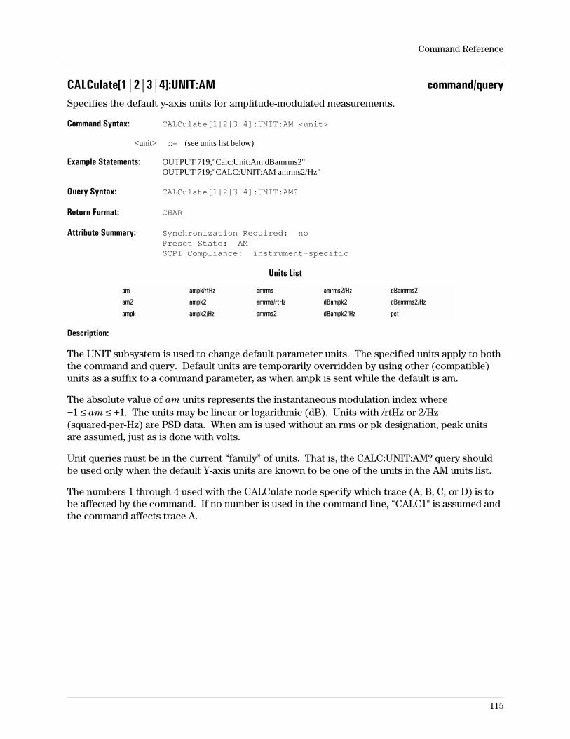
CALCulate[1|2|3|4]:UNIT:AM command/querySpecifies the default y-axis units for amplitude-modulated measurements.
Command Syntax: CALCulate[1|2|3|4]:UNIT:AM <unit>
<unit> ::= (see units list below)
Example Statements: OUTPUT 719;"Calc:Unit:Am dBamrms2"OUTPUT 719;"CALC:UNIT:AM amrms2/Hz"
Query Syntax: CALCulate[1|2|3|4]:UNIT:AM?
Return Format: CHAR
Attribute Summary: Synchronization Required: noPreset State: AMSCPI Compliance: instrument-specific
Units List
am ampk/rtHz amrms amrms2/Hz dBamrms2
am2 ampk2 amrms/rtHz dBampk2 dBamrms2/Hz
ampk ampk2/Hz amrms2 dBampk2/Hz pct
Description:
The UNIT subsystem is used to change default parameter units. The specified units apply to boththe command and query. Default units are temporarily overridden by using other (compatible)units as a suffix to a command parameter, as when ampk is sent while the default is am.
The absolute value of am units represents the instantaneous modulation index where−1 ≤ am ≤ +1. The units may be linear or logarithmic (dB). Units with /rtHz or 2/Hz(squared-per-Hz) are PSD data. When am is used without an rms or pk designation, peak unitsare assumed, just as is done with volts.
Unit queries must be in the current “family” of units. That is, the CALC:UNIT:AM? query shouldbe used only when the default Y-axis units are known to be one of the units in the AM units list.
The numbers 1 through 4 used with the CALCulate node specify which trace (A, B, C, or D) is tobe affected by the command. If no number is used in the command line, “CALC1" is assumed andthe command affects trace A.
Command Reference
115
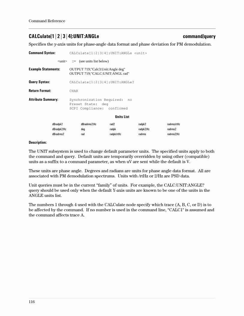
CALCulate[1|2|3|4]:UNIT:ANGLe command/querySpecifies the y-axis units for phase-angle data format and phase deviation for PM demodulation.
Command Syntax: CALCulate[1|2|3|4]:UNIT:ANGLe <unit>
<unit> ::= (see units list below)
Example Statements: OUTPUT 719;"Calc3:Unit:Angle deg"OUTPUT 719;"CALC:UNIT:ANGL rad"
Query Syntax: CALCulate[1|2|3|4]:UNIT:ANGLe?
Return Format: CHAR
Attribute Summary: Synchronization Required: noPreset State: degSCPI Compliance: confirmed
Units List
dBradpk2 dBradrms2/Hz rad2 radpk2 radrms/rtHz
dBradpk2/Hz deg radpk radpk2/Hz radrms2
dBradrms2 rad radpk/rtHz radrms radrms2/Hz
Description:
The UNIT subsystem is used to change default parameter units. The specified units apply to boththe command and query. Default units are temporarily overridden by using other (compatible)units as a suffix to a command parameter, as when uV are sent while the default is V.
These units are phase angle. Degrees and radians are units for phase angle data format. All areassociated with PM demodulation spectrums. Units with /rtHz or 2/Hz are PSD data.
Unit queries must be in the current “family” of units. For example, the CALC:UNIT:ANGLE?query should be used only when the default Y-axis units are known to be one of the units in theANGLE units list.
The numbers 1 through 4 used with the CALCulate node specify which trace (A, B, C, or D) is tobe affected by the command. If no number is used in the command line, “CALC1" is assumed andthe command affects trace A.
Command Reference
116
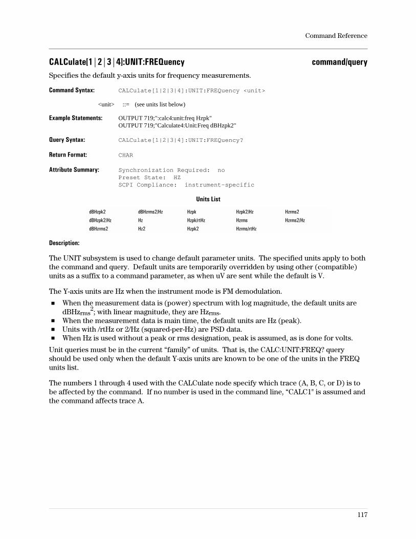
CALCulate[1|2|3|4]:UNIT:FREQuency command/querySpecifies the default y-axis units for frequency measurements.
Command Syntax: CALCulate[1|2|3|4]:UNIT:FREQuency <unit>
<unit> ::= (see units list below)
Example Statements: OUTPUT 719;":calc4:unit:freq Hzpk"OUTPUT 719;"Calculate4:Unit:Freq dBHzpk2"
Query Syntax: CALCulate[1|2|3|4]:UNIT:FREQuency?
Return Format: CHAR
Attribute Summary: Synchronization Required: noPreset State: HZSCPI Compliance: instrument-specific
Units List
dBHzpk2 dBHzrms2/Hz Hzpk Hzpk2/Hz Hzrms2
dBHzpk2/Hz Hz Hzpk/rtHz Hzrms Hzrms2/Hz
dBHzrms2 Hz2 Hzpk2 Hzrms/rtHz
Description:
The UNIT subsystem is used to change default parameter units. The specified units apply to boththe command and query. Default units are temporarily overridden by using other (compatible)units as a suffix to a command parameter, as when uV are sent while the default is V.
The Y-axis units are Hz when the instrument mode is FM demodulation.
When the measurement data is (power) spectrum with log magnitude, the default units aredBHzrms
2; with linear magnitude, they are Hzrms.When the measurement data is main time, the default units are Hz (peak).Units with /rtHz or 2/Hz (squared-per-Hz) are PSD data.When Hz is used without a peak or rms designation, peak is assumed, as is done for volts.
Unit queries must be in the current “family” of units. That is, the CALC:UNIT:FREQ? queryshould be used only when the default Y-axis units are known to be one of the units in the FREQunits list.
The numbers 1 through 4 used with the CALCulate node specify which trace (A, B, C, or D) is tobe affected by the command. If no number is used in the command line, “CALC1" is assumed andthe command affects trace A.
Command Reference
117
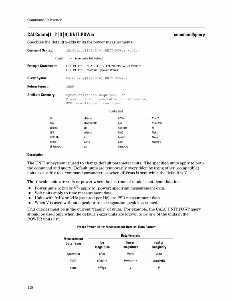
CALCulate[1|2|3|4]:UNIT:POWer command/querySpecifies the default y-axis units for power measurements.
Command Syntax: CALCulate[1|2|3|4]:UNIT:POWer <unit>
<unit> ::= (see units list below)
Example Statements: OUTPUT 719;"CALCULATE:UNIT:POWER Vrms2"OUTPUT 719;"calc:unit:power Wrms"
Query Syntax: CALCulate[1|2|3|4]:UNIT:POWer?
Return Format: CHAR
Attribute Summary: Synchronization Required: noPreset State: (see table in discussion)SCPI Compliance: confirmed
Units List
dB dBVrms V2/Hz Vrms2
dBm dBVrms/rtHz Vpk Vrms2/Hz
dBm/Hz pct Vpk/rtHz W
dBV unitless Vpk2 W/Hz
dBV/rtHz V Vpk2/Hz Wrms
dBVpk V/rtHz Vrms Wrms/Hz
dBVpk/rtHz V2 Vrms/rtHz
Description:
The UNIT subsystem is used to change default parameter units. The specified units apply to boththe command and query. Default units are temporarily overridden by using other (compatible)units as a suffix to a command parameter, as when dBVrms is sent while the default is V.
The Y-scale units are volts or power when the instrument mode is not demodulation.
Power units (dBm or V2) apply to (power) spectrum measurement data.Volt units apply to time measurement data.Units with /rtHz or 2/Hz (squared-per-Hz) are PSD measurement data.When V is used without a peak or rms designation, peak is assumed.
Unit queries must be in the current “family” of units. For example, the CALC:UNIT:POW? queryshould be used only when the default Y-axis units are known to be one of the units in thePOWER units list.
Preset Power Units: Measurement Data vs. Data Format
MeasurementData Types
Data Formats
logmagnitude
linearmagnitude
real orimaginary
spectrum dBm Vrms Vrms
PSD dBm/Hz Vrms/rtHz Vrms/rtHz
time dBVpk V V
Command Reference
118
CALCulate[1|2|3|4]:UNIT:TIME command/querySpecifies the default y-axis units for time measurements.
Command Syntax: CALCulate[1|2|3|4]:UNIT:TIME S
Example Statements: OUTPUT 719;":Calc2:Unit:Time S"OUTPUT 719;"CALC3:UNIT:TIME S"
Query Syntax: CALCulate[1|2|3|4]:UNIT:TIME?
Return Format: CHAR
Attribute Summary: Synchronization Required: noPreset State: S (seconds)SCPI Compliance: instrument-specific
Description:
The UNIT subsystem is used to change default parameter units. The specified units apply to boththe command and query. Default units are temporarily overridden by using other (compatible)units as a suffix to a command parameter, as when uV are sent while the default is V.
The Y-axis units are time when the data format is group delay. The list of time units consists ofone entry; seconds. It is provided for consistency in program queries written to determinewhether units of seconds, minutes, hours, days, weeks, ... are default.
Unit queries must be in the current “family” of units. For example, the CALC:UNIT:ANGLE?query should be used only when the default Y-axis units are known to be one of the units in theANGLE units list.
The numbers 1 through 4 used with the CALCulate node specify which trace (A, B, C, or D) is tobe affected by the command. If no number is used in the command line, “CALC1" is assumed andthe command affects trace A.
Command Reference
119
CALCulate[1|2|3|4]:UPHase:CREFerence command/querySpecifies the x-axis value about which the phase values are to be unwrapped.
Command Syntax: CALCulate[1|2|3|4]:UPHase:CREFerence <param>
<param> ::= <number>[<unit>]|<step>|<bound>
<number> ::= a real number (NRf data)limits: 0.0:3.40282347E+38
<unit> ::= HZ|S|CODE
<step> ::= UP|DOWN
<bound> ::= MAX|MIN
Example Statements: OUTPUT 719;":calculate2:uph:cref 5E-6 HZ"OUTPUT 719;"CALC:UPH:CREF 10E-6 S"
Query Syntax: CALCulate[1|2|3|4]:UPHase:CREFerence?
Return Format: Real
Attribute Summary: Synchronization Required: noPreset State: 0SCPI Compliance: instrument-specific
Description:
This would typically be a well-known point in a measurement such as the passband of aband-pass filter.
The numbers 1 through 4 used with the CALCulate node specify which trace (A, B, C, or D) is tobe affected by the command. If no number is used in the command line, “CALC1" is assumed andthe command affects trace A.
Command Reference
120
CALCulate[1|2|3|4]:UPHase:OFFSet command/querySpecifies a phase offset to be applied to all unwrapped phase values.
Command Syntax: CALCulate[1|2|3|4]:UPHase:OFFSet <param>
<param> ::= <number>[<unit>]|<step>|<bound>
<number> ::= a real number (NRf data)limits: (range depends on configuration)
<unit> ::= DEG|RAD
<step> ::= UP|DOWN
<bound> ::= MAX|MIN
Example Statements: OUTPUT 719;"calculate3:uph:offs 0"OUTPUT 719;"Calculate:Uph:Offset 0"
Query Syntax: CALCulate[1|2|3|4]:UPHase:OFFSet?
Return Format: Real
Attribute Summary: Synchronization Required: noPreset State: 0SCPI Compliance: instrument-specific
Description:
Specifies a phase offset to be applied to all unwrapped phase values.
The numbers 1 through 4 used with the CALCulate node specify which trace (A, B, C, or D) is tobe affected by the command. If no number is used in the command line, “CALC1" is assumed andthe command affects trace A.
Command Reference
121
CALCulate[1|2|3|4]:X:UNIT:CODE command/querySpecifies the default x-axis units when the x axis is the code domain.
Command Syntax: CALCulate[1|2|3|4]:X:UNIT:CODE CODE
Example Statements: OUTPUT 719;":CALC4:X:UNIT:CODE Code"OUTPUT 719;"calculate4:x:unit:code Code"
Query Syntax: CALCulate[1|2|3|4]:X:UNIT:CODE?
Return Format: CHAR
Attribute Summary: Option: B73 (Wideband CDMA Analysis)Synchronization Required: noPreset State: CODESCPI Compliance: instrument-specific
Description:
The UNIT subsystem is used to change default parameter units. The specified units apply to boththe command and query. The only units you can specify are units of CODE, which is the default.
Command Reference
122
CALCulate[1|2|3|4]:X:UNIT:FREQuency command/querySpecifies the default x-axis units when the x axis is the frequency domain.
Command Syntax: CALCulate[1|2|3|4]:X:UNIT:FREQuency HZ
Example Statements: OUTPUT 719;"Calc4:X:Unit:Freq Hz"OUTPUT 719;"CALCULATE:X:UNIT:FREQ Hz"
Query Syntax: CALCulate[1|2|3|4]:X:UNIT:FREQuency?
Return Format: CHAR
Attribute Summary: Synchronization Required: noPreset State: HZSCPI Compliance: instrument-specific
Description:
The UNIT subsystem is used to change default parameter units. The specified units apply to boththe command and query.
Unit queries must be in the current “family” of units. That is, the CALC:X:UNIT:FREQ? queryshould be used only when the default x-axis units are known to be one of the units in the FREQunits list.
The numbers 1 through 4 used with the CALCulate node specify which trace (A, B, C, or D) is tobe affected by the command. If no number is used in the command line, “CALC1" is assumed andthe command affects trace A.
Command Reference
123
CALCulate[1|2|3|4]:X:UNIT:POW command/querySpecifies the default x-axis units when the x axis is the code domain.
Command Syntax: CALCulate[1|2|3|4]:X:UNIT:POW DB
Example Statements: OUTPUT 719;":calc4:x:unit:pow Db"OUTPUT 719;"Calc2:X:Unit:Pow Db"
Query Syntax: CALCulate[1|2|3|4]:X:UNIT:POW?
Return Format: CHAR
Attribute Summary: Option: B73 (Wideband CDMA Analysis)Synchronization Required: noPreset State: CODESCPI Compliance: instrument-specific
Description:
The UNIT subsystem is used to change default parameter units. The specified units apply to boththe command and query. The only units you can specify are DB, which are the default units.
Command Reference
124
CALCulate[1|2|3|4]:X:UNIT:TIME command/querySpecifies the default x-axis units when the x axis is the time domain.
Command Syntax: CALCulate[1|2|3|4]:X:UNIT:TIME S|SYM|SLOT
Example Statements: OUTPUT 719;"CALCULATE4:X:UNIT:TIME s"OUTPUT 719;"calc:x:unit:time sym"
Query Syntax: CALCulate[1|2|3|4]:X:UNIT:TIME?
Return Format: CHAR
Attribute Summary: Synchronization Required: noPreset State: HZSCPI Compliance: instrument-specific
Description:
The UNIT subsystem is used to change default parameter units. The specified units apply to boththe command and query.
S specifies units of seconds and SYM specifies units of symbols, as defined for digitalmodulation.
Unit queries must be in the current “family” of units. That is, the CALC:X:UNIT:TIME? queryshould be used only when the default x-axis units are known to be one of the units in the TIMEunits list.
The numbers 1 through 4 used with the CALCulate node specify which trace (A, B, C, or D) is tobe affected by the command. If no number is used in the command line, “CALC1" is assumed andthe command affects trace A.
The SLOT unit is only allowed in the W-CDMA instrument mode.
Command Reference
125
CALibration:AUTO command/queryEnable or disable the analyzer’s autocalibration function or perform a single calibration.
Command Syntax: CALibration:AUTO OFF|0|ON|1|ONCE
Example Statements: OUTPUT 719;":Calibration:Auto OFF"OUTPUT 719;"CALIBRATION:AUTO OFF"
Query Syntax: CALibration:AUTO?
Return Format: Integer
Attribute Summary: Synchronization Required: noPreset State: not affected by presetSCPI Compliance: instrument-specific
Description:
When calibration occurs, all amplitude ranges and all frequencies are calibrated regardless ofinstrument setup. The current value is stored in non-volatile RAM and is not affected by preset.
When autocal is enabled, the analyzer automatically calibrates several times during the first twohours of operation. After that, it automatically calibrates at intervals of 2 hours 20 minutes.When autocal is disabled, the analyzer calibrates only when CAL:AUTO ONCE is used.
If calibration occurs while an averaged measurement is paused, then CONTinue has the sameeffect as ABORt; the averaging process is restarted (average counter set to zero).
The autocalibration state value is stored in non-volatile memory and is not affected by preset.
Note During calibration, a small ac voltage (approximately 2 mV) appears at thesource output connector.
Command Reference
126
CALibration:ZERO:AUTO command/queryControls the auto-zero calibration function.
Command Syntax: CALibration:ZERO:AUTO OFF|0|ON|1|ONCE
Example Statements: OUTPUT 719;"cal:zero:auto ON"OUTPUT 719;"Calibration:Zero:Auto OFF"
Query Syntax: CALibration:ZERO:AUTO?
Return Format: Integer
Attribute Summary: Synchronization Required: noPreset State: 1SCPI Compliance: instrument-specific
Description:
Auto zero corrects for residual DC in the input amplifiers. If zeroing is not performed, the DCvalue adds to the input signal giving incorrect measurement values and (worst case) may becomelarge enough to cause ADC overloads or incorrect triggering. Residual DC is the calibrationelement most likely to change with time or operating temperature.
The differences between calibration and auto zeroing are:
Auto zeroing takes much less time for the analyzer to perform than a complete calibrationrequires.Auto zeroing has less effect on measurement accuracy than calibration.
The auto-zero feature is a part of calibration that may be activated when automatic calibration isoff. If calibration is on, zeroing cannot be turned off. Turning auto zero off allows you to controlthe analyzer without interruptions caused by automatically-initiated operations. If you intend torun a series of measurements with auto zero turned off, you may want to turn auto zero off andthen perform CAL:ZERO:AUTO ONCE just before beginning.
Note Selecting ONCE zeros the input and then turns auto zero off. Single auto-zerocalibrations should be performed every 30 minutes or whenever there is asignificant change in the analyzer’s operating temperature.
Command Reference
127
CONTinue commandContinue a paused measurement.
Command Syntax: CONTinue
Example Statements: OUTPUT 719;":CONTINUE"OUTPUT 719;"cont"
Attribute Summary: Synchronization Required: yesPreset State: not applicableSCPI Compliance: instrument-specific
Description:
Characteristics:
Continues a paused measurement.Continues a completed averaged measurement allowing an additional N (number of)averages (measurement scans) to be acquired.CONT is ignored if measurement is not paused.Restarts data acquisition stopped by PAUSE.
Command Reference
128
DISPlay:ANNotation[:ALL] command/queryTurns display annotation on and off.
Command Syntax: DISPlay:ANNotation[:ALL] OFF|0|ON|1
Example Statements: OUTPUT 719;"Display:Ann:All ON"OUTPUT 719;"DISPLAY:ANN OFF"
Query Syntax: DISPlay:ANNotation[:ALL]?
Return Format: Integer
Attribute Summary: Synchronization Required: noPreset State: +1 (ON)SCPI Compliance: confirmed
Description:
When display annotation is off, no frequency/time (below grid) or marker (above grid)annotation is displayed; nor does it appear in plots.
Annotation that is not affected by this command includes amplitude scale information, trace titleinformation, measurement status, average count, and overload information.
To blank the entire display, use DISP:ENAB OFF.
Command Reference
129
DISPlay:BRIGhtness command/querySpecifies the display brightness.
Command Syntax: DISPlay:BRIGhtness <number>[<unit>]|<step>|<bound>
<number> ::= a real number (NRf data)limits: 20:100
<unit> ::= [PCT]
<step> ::= UP|DOWN
<bound> ::= MAX|MIN
Example Statements: OUTPUT 719;":display:brig 40.8674"OUTPUT 719;"Disp:Brightness 44.2263"
Query Syntax: DISPlay:BRIGhtness?
Return Format: Real
Attribute Summary: Synchronization Required: noPreset State: not affected by PresetSCPI Compliance: confirmed
Description:
Controls the intensity of the display. The range of the parameter is 20 to 100, where 100 is fullintensity and 20 is dim.
To blank the entire display, use DISP:ENAB OFF.
Command Reference
130
DISPlay:CMAP:COLor[1|2|...|256]:HSL command/querySpecifies the hue, saturation, and luminosity of the colors.
Command Syntax: DISPlay:CMAP:COLor:HSL [1|2|...|256] <hue>, <sat>, <lum>
<hue> ::= <number>|<step>|<bound>
<sat> ::= <number>|<step>|<bound>
<lum> ::= <number>|<step>|<bound>
<number> ::= a real number (NRf data)limits: 0.0:1.0
<step> ::= UP|DOWN
<bound> ::= MAX|MIN
Example Statements: OUTPUT 719;":disp:cmap:col1:hsl 0, 0, 0"OUTPUT 719;"Disp:Cmap:Col3:hsl .25, .85, .4"
Query Syntax: DISPlay:CMAP:COLor[1|2|...|256]:HSL?
Return Format: Real, Real, Real
Attribute Summary: Synchronization Required: noPreset State: not documentedSCPI Compliance: confirmed
Description:
The CMAP subsystem controls the physical color associated with each logical color number inthe color map of the display. The numbers 1 through 256 correspond to various display elementsas described in Help Text.
The HSL command sets the instrument’s color map based on the Hue/Saturation/Luminancelevels color model for the user-defined color maps. Before issuing color changes with thiscommand, select one of the two user-defined color maps with the DISP:WIND:SPEC:MAPcommand.
Hue ranges from zero to one, circularly, with a value of zero resulting in the same hue as a valueof one. The approximate color progression is (starting at zero): red, orange, yellow, green, cyan,blue, magenta, and back to red.
Saturation is the amount of pure color versus white. The saturation value ranges from zero toone, with zero specifying no color (all white or gray, depending on brightness*) and onespecifying no white.
Luminance specifies the brightness per unit area of the color. A luminance of zero results inblack; a luminance of one results in the brightest color available.
Command Reference
131
* See the DISP:BRIG command.
DISPlay:CMAP:DEFault commandReturns all color settings to their default settings.
Command Syntax: DISPlay:CMAP:DEFault
Example Statements: OUTPUT 719;"DISP:CMAP:DEF"OUTPUT 719;"disp:cmap:def"
Attribute Summary: Synchronization Required: noPreset State: not applicableSCPI Compliance: confirmed
Description:
The display color map is loaded with predefined color definitions.
Command Reference
132
DISPlay:ENABle command/queryTurns the display on and off.
Command Syntax: DISPlay:ENABle OFF|0|ON|1
Example Statements: OUTPUT 719;":Display:Enab ON"OUTPUT 719;"DISP:ENABLE OFF"
Query Syntax: DISPlay:ENABle?
Return Format: Integer
Attribute Summary: Synchronization Required: noPreset State: +1 (ON)SCPI Compliance: confirmed
Description:
The message ‘’Display Blanking On’’ appears in the center of the display when the display is off.Plots that occur when the display is off also show only the blanking message.
Menu information appears only when analyzer is in local (front-panel) operation. Issuing anyremote command blanks the softkey menus.
Command Reference
133
DISPlay:FORMat command/querySpecifies the number of grids on which to display traces.
Command Syntax: DISPlay:FORMat SINGle|TWO|FOUR|QUAD
Example Statements: OUTPUT 719;"disp:format FOUR"OUTPUT 719;"Disp:Form TWO"
Query Syntax: DISPlay:FORMat?
Return Format: CHAR
Attribute Summary: Synchronization Required: noPreset State: SINGSCPI Compliance: instrument-specific
Description:
When more than one grid is turned on, the same number of traces are also turned on. More thanone trace may be displayed on a grid in SINGLE or TWO grid formats.
The selections SINGLE, TWO, and FOUR are full screen-width grids. QUAD displays four gridsin a quadrant arrangement in which the traces are a half screen-width wide with two grids on theright and two on the left.
Traces are turned on and off with DISP:WIND:TRAC[:STAT].
Command Reference
134
DISPlay:MFUNction command/queryTurns display of the math function definitions on and off.
Command Syntax: DISPlay:MFUNction OFF|0|ON|1
Example Statements: OUTPUT 719;":DISPLAY:MFUN ON"OUTPUT 719;"display:mfun ON"
Query Syntax: DISPlay:MFUNction?
Return Format: Integer
Attribute Summary: Synchronization Required: noPreset State: 0 (OFF)SCPI Compliance: instrument-specific
Command Reference
135
DISPlay:PROGram[:MODE] command/querySelects the portion of the analyzers screen to be used for Instrument BASIC program output.
Command Syntax: DISPlay:PROGram[:MODE] OFF|0|FULL|UPPer|LOWer
Example Statements: OUTPUT 719;"Disp:Program:Mode FULL"OUTPUT 719;"DISPLAY:PROG LOWER"
Query Syntax: DISPlay:PROGram[:MODE]?
Return Format: CHAR
Attribute Summary: Option: 1C2 Agilent Technologies Instrument BASICSynchronization Required: noPreset State: +0SCPI Compliance: confirmed
Description:
FULL allocates the entire trace box for program output.UPP allocates the upper trace box.LOW allocates the lower trace box.
If DISP:PROG is OFF, the analyzer does not allocate any portion of the trace box for programoutput.
Command Reference
136
DISPlay:TCAPture:ENVelope command/queryTurns the time capture envelope (detector) function on/off.
Command Syntax: DISPlay:TCAPture:ENVelope OFF|0|ON|1
Example Statements: OUTPUT 719;":disp:tcapture:env ON"OUTPUT 719;"Display:Tcap:Env OFF"
Query Syntax: DISPlay:TCAPture:ENVelope?
Return Format: Integer
Attribute Summary: Synchronization Required: noPreset State: 1 (ON)SCPI Compliance: instrument-specific
Description:
The time capture buffer usually holds many more points than can be displayed simultaneouslywith CALC:FEED ‘TCAP1’, so some are not displayed. This command determines whether everynth point is displayed (OFF) or points of maximum magnitude (taken n-at-a-time) are displayed(ON). In this discussion, n is the ratio of points in the capture buffer to the maximum number offrequency points defined with MEM:MALL:MEAS:FPO, which is (MaxNumFreqPts − 1)×2.56 forbaseband and (MaxNumFreqPts − 1)×1.28 for zoom.
The envelope (ON) shows transients. To view periodic waveforms, you may want to turn theenvelope OFF.
The numbers 1 and 2 used with the TCAPture node specify which input channel (1 or 2) is to beaffected by the command. If no number appears in the node, “TCAP1" is assumed and thecommand affects channel 1.
Command Reference
137

DISPlay[:WINDow[1|2|3|4]]:ACTive command/queryControls active state of the four traces.
Command Syntax: DISPlay[:WINDow[1|2|3|4]]:ACTive OFF|0|ON|1|ONCE
Example Statements: OUTPUT 719;"DISPLAY:WIND4:ACTIVE OFF"OUTPUT 719;"disp:act ON"
Query Syntax: DISPlay[:WINDow[1|2|3|4]]:ACTive?
Return Format: Integer
Attribute Summary: Synchronization Required: noPreset State: 1 ON; 2, 3, and 4 OFFSCPI Compliance: instrument-specific
Description:
Windows 1–4 correspond to traces A, B, C, D. If no number is specified in the WINDOW node orthe node is not included, the command will affect trace A.
If more than one trace is displayed (DISP:FORM is TWO or FOUR, or more than oneDISP:WIND:TRAC:STAT is ON) this command specifies which are active.
ON activates the trace corresponding to the window specified. More than one trace may beactive at the same time. If only one trace is displayed, it is (by definition) active.
OFF deactivates the trace corresponding to the window specified. At least one trace is alwaysactive.
ONCE activates the trace corresponding to the window specified and sets all others to ACTIVEOFF.
Command Reference
138
DISPlay[:WINDow[1|2|3|4]]:SPECtrogram:COLors command/querySpecifies the number of colors in the spectrogram display.
Command Syntax: DISPlay[:WINDow[1|2|3|4]]:SPECtrogram:COLors <param>
<param> ::= <number>|<step>|<bound>
<number> ::= a real number (NRf data)limits: 2:64
<step> ::= UP|DOWN
<bound> ::= MAX|MIN
Example Statements: OUTPUT 719;":Display:Spec:Colors 20"OUTPUT 719;"DISP:WIND2:SPECTROGRAM:COL 43"
Query Syntax: DISPlay[:WINDow[1|2|3|4]]:SPECtrogram:COLors?
Return Format: Integer
Attribute Summary: Option: AYB (waterfall & spectrogram display)Synchronization Required: noPreset State: not affected by PresetSCPI Compliance: instrument-specific
Description:
This command affects all active traces regardless of whether a specific window/trace is used(e.g. DISP:WIND2).
For more information on waterfall and spectrogram display types, see online help and theconcepts discussion in the Operator’s Guide.
Command Reference
139
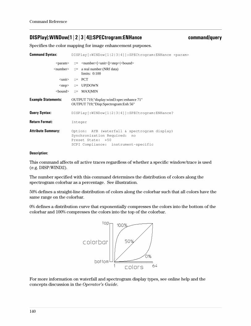
DISPlay[:WINDow[1|2|3|4]]:SPECtrogram:ENHance command/querySpecifies the color mapping for image enhancement purposes.
Command Syntax: DISPlay[:WINDow[1|2|3|4]]:SPECtrogram:ENHance <param>
<param> ::= <number>[<unit>]|<step>|<bound>
<number> ::= a real number (NRf data)limits: 0:100
<unit> ::= PCT
<step> ::= UP|DOWN
<bound> ::= MAX|MIN
Example Statements: OUTPUT 719;"display:wind3:spec:enhance 71"OUTPUT 719;"Disp:Spectrogram:Enh 56"
Query Syntax: DISPlay[:WINDow[1|2|3|4]]:SPECtrogram:ENHance?
Return Format: Integer
Attribute Summary: Option: AYB (waterfall & spectrogram display)Synchronization Required: noPreset State: +50SCPI Compliance: instrument-specific
Description:
This command affects all active traces regardless of whether a specific window/trace is used(e.g. DISP:WIND2).
The number specified with this command determines the distribution of colors along thespectrogram colorbar as a percentage. See illustration.
50% defines a straight-line distribution of colors along the colorbar such that all colors have thesame range on the colorbar.
0% defines a distribution curve that exponentially compresses the colors into the bottom of thecolorbar and 100% compresses the colors into the top of the colorbar.
For more information on waterfall and spectrogram display types, see online help and theconcepts discussion in the Operator’s Guide.
Command Reference
140
DISPlay[:WINDow[1|2|3|4]]:SPECtrogram:MAP command/querySpecifies the color map for all active spectrogram displays.
Command Syntax: DISPlay[:WINDow]:SPECtrogram:MAP <param>
<param> ::= COLor|RCOLor|GREY|RGRey|MAP1|MAP2
Example Statements: OUTPUT 719;":DISP:SPECTROGRAM:MAP MAP1"OUTPUT 719;"display:wind:spec:map GREY"
Query Syntax: DISPlay[:WINDow[1|2|3|4]]:SPECtrogram:MAP?
Return Format: CHAR
Attribute Summary: Option: AYB (waterfall & spectrogram display)Synchronization Required: noPreset State: not affected by PresetSCPI Compliance: instrument-specific
Description:
This command affects all active traces regardless of whether a specific window/trace is used(e.g. DISP:WIND2).
The color map determines the colors that may be used in the spectrogram display. A color mapconsists of 64 colors, all of which may or may not be used, as specified by DISP:SPEC:COLcommand.
COLOR is a map of 64 colors. This map has a maximum amplitude hue of 0% (red) and aminimum amplitude hue of 70% (blue). The hue of the other 62 colors are linearly distributedbetween 0% and 70%. The saturation and luminosity remain constant for all 64 colors.
RCOLOR is identical to COLOR except that the colors are reversed. The maximum amplitudehue is 70% and the minimum amplitude hue is 0%.
GREY is a color map of 64 shades of grey. The maximum amplitude has a luminosity of 100%(lightest shade of grey) and the minimum amplitude has a luminosity of 10% (darkest shade ofgrey). The other 62 colors’ luminosity are linearly distributed between 10% and 100%. The hueand saturation remain constant for all 64 colors.
RGREY is identical to GREY except that the shades of grey are reversed.
MAP1 and MAP2 are used to specify a user-defined color map. These maps may be defined withthe DISP:CMAP:COLOR:HSL command for colors numbered 129 through 192. If you want todefine MAP1, select it with this command, then send the color:hsl commands to define the 64colors. These definitions are stored in non-volatile RAM.
For more information on waterfall and spectrogram display types, see online help and theconcepts discussion in the Operator’s Guide.
Command Reference
141
DISPlay[:WINDow[1|2|3|4]]:SPECtrogram[:STATe] command/queryTurns spectrogram display on or off.
Command Syntax: DISPlay[:WINDow[1|2|3|4]]:SPECtrogram[:STATe] OFF|0|ON|1
Example Statements: OUTPUT 719;"Disp:Window3:Spec:Stat ON"OUTPUT 719;"DISPLAY:SPEC ON"
Query Syntax: DISPlay[:WINDow[1|2|3|4]]:SPECtrogram[:STATe]?
Return Format: Integer
Attribute Summary: Option: AYB (waterfall & spectrogram display)Synchronization Required: noPreset State: 0 (off)SCPI Compliance: instrument-specific
Description:
The number used in the WINDow node of the command specifies which trace becomes aspectrogram display. If no number is specified, “1" is assumed.
For more information on waterfall and spectrogram display types, see online help and theconcepts discussion in the Operator’s Guide.
Command Reference
142
DISPlay[:WINDow[1|2|3|4]]:SPECtrogram:THReshold command/querySets the threshold for all active spectrogram displays.
Command Syntax: DISPlay[:WINDow[1|2|3|4]]:SPECtrogram:THReshold <param>
<param> ::= <number>[<unit>]|<step>|<bound>
<number> ::= a real number (NRf data)limits: 0:100
<unit> ::= PCT
<step> ::= UP|DOWN
<bound> ::= MAX|MIN
Example Statements: OUTPUT 719;":display:spec:thr 18"OUTPUT 719;"Display:Wind4:Spectrogram:Thr 94"
Query Syntax: DISPlay[:WINDow[1|2|3|4]]:SPECtrogram:THReshold?
Return Format: Integer
Attribute Summary: Option: AYB (waterfall & spectrogram display)Synchronization Required: noPreset State: 0 (%)SCPI Compliance: instrument-specific
Description:
This command is useful for removing noise-floor clutter from the spectrogram display. Thepercentage reference is the height of the colorbar such that, with a threshold of 50%, the analyzerdisplays only the colors in the upper half of the colorbar. Trace signals below the threshold aredisplayed in the color at the bottom of the color bar.
This command affects all active traces regardless of whether a specific window/trace is used(e.g. DISP:WIND2).
For more information on waterfall and spectrogram display types, see online help and theconcepts discussion in the Operator’s Guide.
Command Reference
143
DISPlay[:WINDow[1|2|3|4]]:TRACe:BUFFer command/querySpecifies the number of waterfall/spectrogram traces stored in memory.
Command Syntax: DISPlay[:WINDow[1|2|3|4]]:TRACe:BUFFer <param>
<param> ::= <number>|<step>|<bound>
<number> ::= a real number (NRf data)limits: 0:(see discussion)
<step> ::= UP|DOWN
<bound> ::= MAX|MIN
Example Statements: OUTPUT 719;"DISP:WINDOW:TRAC:BUFFER 0"OUTPUT 719;"disp:trac:buffer 0"
Query Syntax: DISPlay[:WINDow[1|2|3|4]]:TRACe:BUFFer?
Return Format: Integer
Attribute Summary: Option: AYB (waterfall & spectrogram display)Synchronization Required: noPreset State: not affected by PresetSCPI Compliance: instrument-specific
Description:
The number of traces specified with this command are stored in measurement memory such thatthe measurement can be paused and the marker(s) used to make measurements on the storedtraces. The number of traces buffered is not the same as the number of traces displayed which isdetermined by the vertical height of the grid and the elevation between traces.
Limits:
The maximum number of buffered traces is limited only by the amount of available memory.Press the memory useage softkey under the System Utility hardkey for a listing.
Command Reference
144
DISPlay[:WINDow[1|2|3|4]]:TRACe:DCARrier command/queryTurns the demodulate-carrier function on/off.
Command Syntax: DISPlay[:WINDow[1|2|3|4]]:TRACe:DCARrier OFF|0|ON|1
Example Statements: OUTPUT 719;":Disp:Trace:Dcar OFF"OUTPUT 719;"DISP:WINDOW:TRAC:DCARRIER ON"
Query Syntax: DISPlay[:WINDow[1|2|3|4]]:TRACe:DCARrier?
Return Format: Integer
Attribute Summary: Synchronization Required: noPreset State: 0 (OFF)SCPI Compliance: instrument-specific
Description:
For a description of this function, see Help Text under the Help hardkey.
Command Reference
145
DISPlay[:WINDow[1|2|3|4]]:TRACe:EYE:COUNt command/querySpecifies the length of the eye and trellis diagrams.
Command Syntax: DISPlay[:WINDow[1|2|3|4]]:TRACe:EYE:COUNt <number>|<step>|<bound>
<number> ::= a real number (NRf data)limits: 0.1:40
<step> ::= UP|DOWN
<bound> ::= MAX|MIN
Example Statements: OUTPUT 719;"disp:wind4:trace:eye:count 35"OUTPUT 719;"Disp:Trac:Eye:Coun 30"
Query Syntax: DISPlay[:WINDow[1|2|3|4]]:TRACe:EYE:COUNt?
Return Format: Integer
Attribute Summary: Option: AYA (vector modulation analysis)Synchronization Required: noPreset State: +2SCPI Compliance: instrument-specific
Description:
For more information on digital demodulation, see online help and the concepts discussion inthe Operator’s Guide.
Command Reference
146
DISPlay[:WINDow[1|2|3|4]]:TRACe:GRATicule:GRID[:STATe] command/queryTurns the trace grids on or off.
Command Syntax: DISPlay[:WINDow[1|2|3|4]]:TRACe:GRATicule:GRID[:STATe] OFF|0|ON|1
Example Statements: OUTPUT 719;":DISPLAY:TRAC:GRAT:GRID OFF"OUTPUT 719;"disp:window3:trac:grat:grid:stat ON"
Query Syntax: DISPlay[:WINDow[1|2|3|4]]:TRACe:GRATicule:GRID[:STATe]?
Return Format: Integer
Attribute Summary: Synchronization Required: noPreset State: +1 (ON)SCPI Compliance: confirmed
Description:
When grids are off they are neither displayed nor plotted.
The numbers in the Window node have no effect on this command; all grids are turned on/offregardless of the window specified.
Command Reference
147
DISPlay[:WINDow[1|2|3|4]]:TRACe:INDicator command/queryDetermines the character used to identify ideal states in a vector diagram when DigitalDemodulation is selected.
Command Syntax: DISPlay[:WINDow[1|2|3|4]]:TRACe:INDicator CROSs|CIRCle
Example Statements: OUTPUT 719;"Display:Wind2:Trac:Indicator CIRCLE"OUTPUT 719;"DISP:TRACE:IND CROSS"
Query Syntax: DISPlay[:WINDow[1|2|3|4]]:TRACe:INDicator?
Return Format: CHAR
Attribute Summary: Option: AYA (vector modulation analysis)Synchronization Required: noPreset State: CrossSCPI Compliance: instrument-specific
Description:
This command affects all active traces regardless of whether a specific window/trace is used(e.g. DISP:WIND2).
This command lets you select a cross-hair or circle to represent the ideal states (ideal symbollocations) in a vector diagram. The size of the circle or cross-hair corresponds to somepercentage of Error Vector Magnitude (EVM), and is set with DISP:WIND:TRAC:IND:SIZE.
For additional details, see online help for the [ideal state] softkey.
Command Reference
148
DISPlay[:WINDow[1|2|3|4]]:TRACe:INDicator:SIZE command/queryDetermines the size, as a percentage of EVM, of ideal states in vector diagrams.
Command Syntax: DISPlay[:WINDow[1|2|3|4]]:TRACe:INDicator:SIZE<number>[<unit>]|<step>|<bound>
<number> ::= a real number (NRf data)limits: 0.1:50
<unit> ::= [PCT]
<step> ::= UP|DOWN
<bound> ::= MAX|MIN
Example Statements: OUTPUT 719;":disp:trace:ind:size 6"OUTPUT 719;"Disp:Wind:Trace:Ind:Size 24"
Query Syntax: DISPlay[:WINDow[1|2|3|4]]:TRACe:INDicator:SIZE?
Return Format: Integer
Attribute Summary: Option: AYA (vector modulation analysis)Synchronization Required: noPreset State: +15.0SCPI Compliance: instrument-specific
Description:
This command affects all active traces regardless of whether a specific window/trace is used(e.g. DISP:WIND2).
This command determines the size of the cross-hairs or circles used to indicate ideal states invector diagrams when Digital Demodulation is selected.
The size is specified as a percentage of Error Vector Magnitude (EVM), and determines theradius of the circle or cross-hair. For example, if you specify a size of 15%, the radius of thecircle or cross-hair represents and EVM of 15%.
For additional details, see online help for the [state size] softkey.
Command Reference
149
DISPlay[:WINDow[1|2|3|4]]:TRACe:INFO command/querySpecifies user-defined alphanumeric content for trace information.
Command Syntax: DISPlay[:WINDow[1|2|3|4]]:TRACe:INFO <STRING>
Example Statements: OUTPUT 719;":Disp:Trac:Info ‘Prototype 11, platform A7, test 53’"OUTPUT 719;"DISP:WINDOW4:TRAC:INFO ‘3rd IF, repeater site 4’"OUTPUT 719;"DISP:WINDOW4:TRAC:INFO ‘’"
Query Syntax: DISPlay[:WINDow[1|2|3|4]]:TRACe:INFO?
Return Format: STRING
Attribute Summary: Synchronization Required: noPreset State: not applicableSCPI Compliance: instrument-specific
Description:
This information appears on the same line as the trace title, at the right side of the display area.Maximum string size is 30 characters.
To remove this information from the screen, send a null string as shown in the third exampleabove.
Related Commands:
To define a trace title, use DISP:TRAC:LAB:USER.To switch between default and user-defined titles, use DISP:TRAC:LAB:AUTO.To query the currently displayed trace title, use DISP:TRAC:LAB.
Command Reference
150
DISPlay[:WINDow[1|2|3|4]]:TRACe:LABel? queryReturns the current trace title.DISPlay[[:WINDow]]:TRACe:LABel?[display:window:trace:label?]
Query Syntax: DISPlay[:WINDow[1|2|3|4]]:TRACe:LABel?
Example Statements: OUTPUT 719;"DISP:WIND2:TRACE:LAB?"OUTPUT 719;"display:trac:lab?"
Return Format: STRING
Attribute Summary: Synchronization Required: noPreset State: not applicableSCPI Compliance: instrument-specific
Description:
If the default trace title is ON, this query returns the default trace title. If the default trace title isOFF, this query returns the user-defined trace title.
Related Commands:
To enter a user-defined trace title, use DISP:WIND:TRAC:LAB:USER.To display a user-defined trace title, use DISP:WIND:TRAC:LAB:AUTO OFF.
The Window node is default (use is optional). This specifies which trace (A, B, C, or D) is to beaffected by the command. If the Window node is not used in the command line, “WIND1" isassumed and the command affects trace A. If WIND is used but no trace number is specified, ”1"is assumed and the command affects trace A.
Command Reference
151
DISPlay[:WINDow[1|2|3|4]]:TRACe:LABel:AUTO command/querySwitches between displaying the default trace title and a user-defined trace title.
Command Syntax: DISPlay[:WINDow[1|2|3|4]]:TRACe:LABel:AUTO OFF|0|ON|1
Example Statements: OUTPUT 719;":Display:Trac:Label:Auto OFF"OUTPUT 719;"DISP:WINDOW:TRAC:LABEL:AUTO ON"
Query Syntax: DISPlay[:WINDow[1|2|3|4]]:TRACe:LABel:AUTO?
Return Format: Integer
Attribute Summary: Synchronization Required: noPreset State: not applicableSCPI Compliance: instrument-specific
Description:
ON displays the default trace title. OFF displays the user-defined trace title.
Related Commands:
To define a trace title, use DISP:TRAC:LAB:USER.To query the currently displayed trace title, use DISP:TRAC:LAB?.
The Window node is default (use is optional). This specifies which trace (A, B, C, or D) is to beaffected by the command. If the Window node is not used in the command line, “WIND1" isassumed and the command affects trace A. If WIND is used but no trace number is specified, ”1"is assumed and the command affects trace A.
Command Reference
152
DISPlay[:WINDow[1|2|3|4]]:TRACe:LABel:USER command/querySpecifies the alphanumeric content of a user-defined display title.
Command Syntax: DISPlay[:WINDow[1|2|3|4]]:TRACe:LABel:USER <STRING>
Example Statements: OUTPUT 719;"Disp:Window2:Trac:Lab:User ‘Phase Noise’"OUTPUT 719;"DISP:TRAC:LAB:USER ‘Friday Data’"
Query Syntax: DISPlay[:WINDow[1|2|3|4]]:TRACe:LABel:USER?
Return Format: STRING
Attribute Summary: Synchronization Required: noPreset State: not applicableSCPI Compliance: instrument-specific
Description:
The alpha-numeric string replaces the default titles above the trace when DISP:TRAC:LAB:AUTOis OFF. Sending the user-defined trace label command automatically turnsDISP:TRAC:LAB:AUTO OFF. Maximum string length is 15 characters.
The query form returns the user-defined trace title, whether or not it is currently displayed.
Related Commands:
To switch between the default trace title and a user-defined trace title, useDISP:TRAC:LAB:AUTO.To query the currently-displayed trace title, use DISP:TRAC:LAB?.
The Window node is default (use is optional). This specifies which trace (A, B, C, or D) is to beaffected by the command. If the Window node is not used in the command line, “WIND1" isassumed and the command affects trace A. If WIND is used but no trace number is specified, ”1"is assumed and the command affects trace A.
Command Reference
153

DISPlay[:WINDow[1|2|3|4]]:TRACe[:STATe] command/queryTurns specific traces on and off.
Command Syntax: DISPlay[:WINDow[1|2|3|4]]:TRACe[:STATe] OFF|0|ON|1
Example Statements: OUTPUT 719;"disp:window:trac:state ON"OUTPUT 719;"Disp:Trac OFF"
Query Syntax: DISPlay[:WINDow[1|2|3|4]]:TRACe[:STATe]?
Return Format: Integer
Attribute Summary: Synchronization Required: noPreset State: 1 is ON; 2, 3, 4, are OFFSCPI Compliance: confirmed
Description:
The Window node is default (use is optional). This specifies which trace (A, B, C, or D) is to beaffected by the command. If the Window node is not used in the command line, “WIND1" isassumed and the command affects trace A. If WIND is used but no trace number is specified, ”1"is assumed and the command affects trace A.
Related Commands:
To specify the number of grids on which the traces are displayed, use DISP:FORM.To control whether graticules are displayed, use DISP:TRAC:GRAT:GRID.
Command Reference
154
DISPlay[:WINDow[1|2|3|4]]:TRACe:SYMBol command/querySpecifies the use of either dots or bars to indicate symbol points on a time-domain display.
Command Syntax: DISPlay[:WINDow[1|2|3|4]]:TRACe:SYMBol DOTS|BARS|OFF|0
Example Statements: OUTPUT 719;":DISPLAY:TRAC:SYMBOL OFF"OUTPUT 719;"disp:wind:trace:symb DOTS"
Query Syntax: DISPlay[:WINDow[1|2|3|4]]:TRACe:SYMBol?
Return Format: CHAR
Attribute Summary: Option: AYA (vector modulation analysis)Synchronization Required: noPreset State: 0 (off)SCPI Compliance: instrument-specific
Description:
For more information on digital demodulation, see online help and the concepts discussion inthe Operator’s Guide.
Command Reference
155
DISPlay[:WINDow[1|2|3|4]]:TRACe:SYMBol:FORMat command/queryDetermines the data format (hexadecimal or binary ) for symbol tables.
Command Syntax: DISPlay[:WINDow[1|2|3|4]]:TRACe:SYMBol:FORMat BIN|HEX
Example Statements: OUTPUT 719;"Display:Wind3:Trac:Symbol:Form HEX"OUTPUT 719;"DISPLAY:TRAC:SYMB:FORMAT BIN"
Query Syntax: DISPlay[:WINDow[1|2|3|4]]:TRACe:SYMBol:FORMat?
Return Format: CHAR
Attribute Summary: Synchronization Required: noPreset State: BINarySCPI Compliance: instrument-specific
Description:
This command affects all active traces regardless of whether a specific window/trace is used(e.g. DISP:WIND2).
This command lets you choose the data format for symbol tables. You can select betweenhexadecimal and binary data formats. The default is binary.
Command Reference
156
DISPlay[:WINDow[1|2|3|4]]:TRACe:X[:SCALe]:AUTO command/queryControls automatic scaling of the X-axis.
Command Syntax: DISPlay[:WINDow[1|2|3|4]]:TRACe:X[:SCALe]:AUTO OFF|0|ON|1|ONCE
Example Statements: OUTPUT 719;":disp:trace:x:auto OFF"OUTPUT 719;"Display:Wind2:Trace:X:Scal:Auto ONCE"
Query Syntax: DISPlay[:WINDow[1|2|3|4]]:TRACe:X[:SCALe]:AUTO?
Return Format: Integer
Attribute Summary: Synchronization Required: noPreset State: 1 (ON)SCPI Compliance: confirmed
Description:
X-axis autoscaling is similar to Y-axis scaling if you understand that the conventional method ofdisplaying measurement information maps the first measurement data to the left-most X-axisvalue and the last measurement data to the right-most X-axis value. This corresponds to X-axisautoscaling being ON. When it is OFF, other time or frequency values may be mapped to theseX-axis points, as defined by DISP:WIND:TRAC:X:LEFT and RIGHt, respectively.
ON changes the X scale to be the full range of the current data. Sending ON corresponds topressing the softkey X full scale (under Ref Lvl/Scale, X scale markers keys). When the tracedisplays frequency information, for example, this corresponds to the start and stop frequenciesbeing mapped to the left-most and right-most values on the X axis. This is the conventionalmethod of displaying frequency domain data.
OFF corresponds to pressing the softkey hold scale (under Ref Lvl/Scale, X scale markers keys).This allows the display settings given by the DISP:WIND:TRAC:X:LEFT and RIGHt commands tobe the left-most and right-most values on the X axis. When this is the active display state, theinitial and last display values are not necessarily at the limits of the measurements.
ONCE has no corresponding softkey. It changes the values of the current measurement valuesfor the left-most and right-most data values to the current values of the LEFT and RIGHT settingsand then turns AUTO OFF.
The Window node is default (use is optional). This specifies which trace (A, B, C, or D) is to beaffected by the command. If the Window node is not used in the command line, “WIND1" isassumed and the command affects trace A. If WIND is used but no trace number is specified, ”1"is assumed and the command affects trace A.
Command Reference
157
DISPlay[:WINDow[1|2|3|4]]:TRACe:X[:SCALe]:LEFT command/querySpecifies the first X-axis value on the display.
Command Syntax: DISPlay[:WINDow[1|2|3|4]]:TRACe:X[:SCALe]:LEFT <param>
<param> ::= <number>[<unit>]|<bound>
<number> ::= a real number (NRf data)limits: -3.40282347E+38:3.40282347E+38
<unit> ::= Hz|s|Code
<bound> ::= MAX|MIN
Example Statements: OUTPUT 719;":DISP:WIND4:TRACE:X:LEFT 10us; RIGH 15us"OUTPUT 719;"disp:trace:x:scale:left 2.5025 MHz; right 2.5026 MHz"
Query Syntax: DISPlay[:WINDow[1|2|3|4]]:TRACe:X[:SCALe]:LEFT?
Return Format: Real
Attribute Summary: Synchronization Required: noPreset State: 25% of full scaleSCPI Compliance: confirmed
Description:
This command specifies the value of the first (left-most) X-axis point on the display. This,combined with the RIGHT command, is equivalent to the X-Scale Markers feature in front-paneloperation (under the Ref Lvl/Scale hardkey) which allows you to expand or magnify a narrowregion of data. No new data is taken; existing data is displayed differently.
The Window node is default (use is optional). This specifies which trace (A, B, C, or D) is to beaffected by the command. If the Window node is not used in the command line, “WIND1" isassumed and the command affects trace A. If WIND is used but no trace number is specified, ”1"is assumed and the command affects trace A.
Related Commands:
To reset the X-axis scale to full scale, use DISP:WIND:TRAC:X[:SCALE]:AUTO ONCE.
Command Reference
158
DISPlay[:WINDow[1|2|3|4]]:TRACe:X[:SCALe]:RIGHt command/querySpecifies the last X-axis value on the display.
Command Syntax: DISPlay[:WINDow[1|2|3|4]]:TRACe:X[:SCALe]:RIGHt
<param> ::= <number>[<unit>]|<bound>
<number> ::= a real number (NRf data)limits: -3.40282347E+38:3.40282347E+38
<unit> ::= Hz|s|Code
<bound> ::= MAX|MIN
Example Statements: OUTPUT 719;":DISP:WIND4:TRACE:X:LEFT 10us; RIGH 15us"OUTPUT 719;"disp:trace:x:scale:left 2.5025 MHz; right 2.5026 MHz"
Query Syntax: DISPlay[:WINDow[1|2|3|4]]:TRACe:X[:SCALe]:RIGHt?
Return Format: Real
Attribute Summary: Synchronization Required: noPreset State: 75% of full scaleSCPI Compliance: confirmed
Description:
This command specifies the value of the last (most right) X-axis point on the display. This,combined with the LEFT command, is equivalent to the X-Scale Markers feature in front-paneloperation (under the Ref Lvl/Scale hardkey) which allows you to expand or magnify a narrowregion of data. No new data is taken; existing data is displayed differently.
The Window node is default (use is optional). This specifies which trace (A, B, C, or D) is to beaffected by the command. If the Window node is not used in the command line, “WIND1" isassumed and the command affects trace A. If WIND is used but no trace number is specified, ”1"is assumed and the command affects trace A.
Command Reference
159
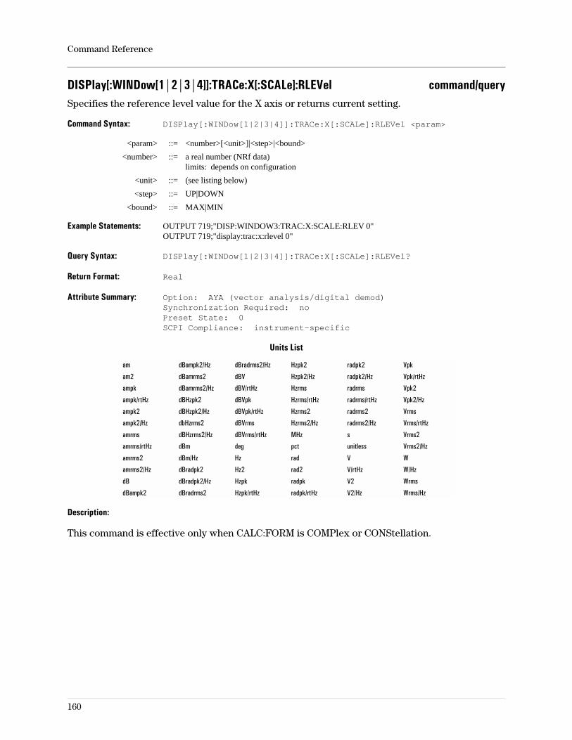
DISPlay[:WINDow[1|2|3|4]]:TRACe:X[:SCALe]:RLEVel command/querySpecifies the reference level value for the X axis or returns current setting.
Command Syntax: DISPlay[:WINDow[1|2|3|4]]:TRACe:X[:SCALe]:RLEVel <param>
<param> ::= <number>[<unit>]|<step>|<bound>
<number> ::= a real number (NRf data)limits: depends on configuration
<unit> ::= (see listing below)
<step> ::= UP|DOWN
<bound> ::= MAX|MIN
Example Statements: OUTPUT 719;"DISP:WINDOW3:TRAC:X:SCALE:RLEV 0"OUTPUT 719;"display:trac:x:rlevel 0"
Query Syntax: DISPlay[:WINDow[1|2|3|4]]:TRACe:X[:SCALe]:RLEVel?
Return Format: Real
Attribute Summary: Option: AYA (vector analysis/digital demod)Synchronization Required: noPreset State: 0SCPI Compliance: instrument-specific
Units List
am dBampk2/Hz dBradrms2/Hz Hzpk2 radpk2 Vpk
am2 dBamrms2 dBV Hzpk2/Hz radpk2/Hz Vpk/rtHz
ampk dBamrms2/Hz dBV/rtHz Hzrms radrms Vpk2
ampk/rtHz dBHzpk2 dBVpk Hzrms/rtHz radrms/rtHz Vpk2/Hz
ampk2 dBHzpk2/Hz dBVpk/rtHz Hzrms2 radrms2 Vrms
ampk2/Hz dbHzrms2 dBVrms Hzrms2/Hz radrms2/Hz Vrms/rtHz
amrms dBHzrms2/Hz dBVrms/rtHz MHz s Vrms2
amrms/rtHz dBm deg pct unitless Vrms2/Hz
amrms2 dBm/Hz Hz rad V W
amrms2/Hz dBradpk2 Hz2 rad2 V/rtHz W/Hz
dB dBradpk2/Hz Hzpk radpk V2 Wrms
dBampk2 dBradrms2 Hzpk/rtHz radpk/rtHz V2/Hz Wrms/Hz
Description:
This command is effective only when CALC:FORM is COMPlex or CONStellation.
Command Reference
160
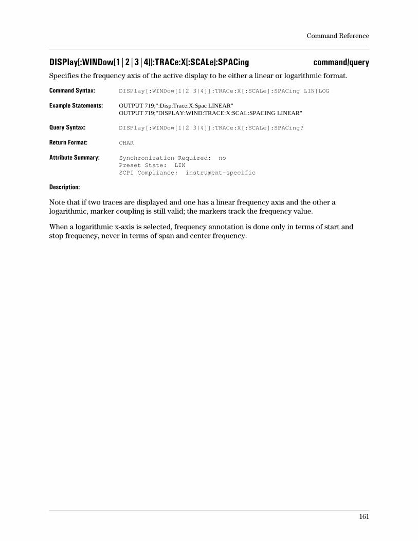
DISPlay[:WINDow[1|2|3|4]]:TRACe:X[:SCALe]:SPACing command/querySpecifies the frequency axis of the active display to be either a linear or logarithmic format.
Command Syntax: DISPlay[:WINDow[1|2|3|4]]:TRACe:X[:SCALe]:SPACing LIN|LOG
Example Statements: OUTPUT 719;":Disp:Trace:X:Spac LINEAR"OUTPUT 719;"DISPLAY:WIND:TRACE:X:SCAL:SPACING LINEAR"
Query Syntax: DISPlay[:WINDow[1|2|3|4]]:TRACe:X[:SCALe]:SPACing?
Return Format: CHAR
Attribute Summary: Synchronization Required: noPreset State: LINSCPI Compliance: instrument-specific
Description:
Note that if two traces are displayed and one has a linear frequency axis and the other alogarithmic, marker coupling is still valid; the markers track the frequency value.
When a logarithmic x-axis is selected, frequency annotation is done only in terms of start andstop frequency, never in terms of span and center frequency.
Command Reference
161
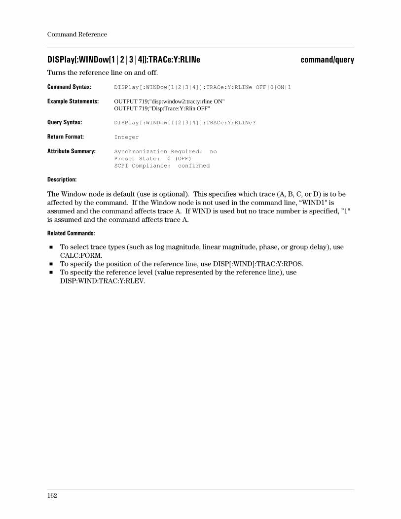
DISPlay[:WINDow[1|2|3|4]]:TRACe:Y:RLINe command/queryTurns the reference line on and off.
Command Syntax: DISPlay[:WINDow[1|2|3|4]]:TRACe:Y:RLINe OFF|0|ON|1
Example Statements: OUTPUT 719;"disp:window2:trac:y:rline ON"OUTPUT 719;"Disp:Trace:Y:Rlin OFF"
Query Syntax: DISPlay[:WINDow[1|2|3|4]]:TRACe:Y:RLINe?
Return Format: Integer
Attribute Summary: Synchronization Required: noPreset State: 0 (OFF)SCPI Compliance: confirmed
Description:
The Window node is default (use is optional). This specifies which trace (A, B, C, or D) is to beaffected by the command. If the Window node is not used in the command line, “WIND1" isassumed and the command affects trace A. If WIND is used but no trace number is specified, ”1"is assumed and the command affects trace A.
Related Commands:
To select trace types (such as log magnitude, linear magnitude, phase, or group delay), useCALC:FORM.To specify the position of the reference line, use DISP[:WIND]:TRAC:Y:RPOS.To specify the reference level (value represented by the reference line), useDISP:WIND:TRAC:Y:RLEV.
Command Reference
162
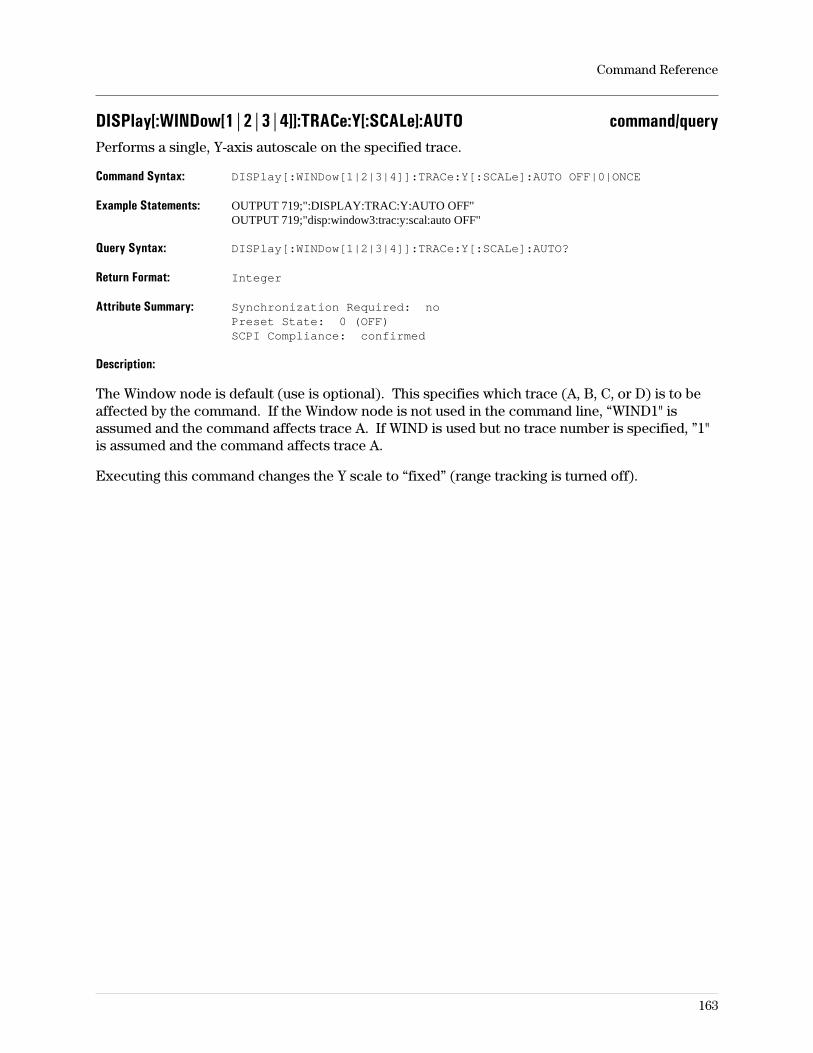
DISPlay[:WINDow[1|2|3|4]]:TRACe:Y[:SCALe]:AUTO command/queryPerforms a single, Y-axis autoscale on the specified trace.
Command Syntax: DISPlay[:WINDow[1|2|3|4]]:TRACe:Y[:SCALe]:AUTO OFF|0|ONCE
Example Statements: OUTPUT 719;":DISPLAY:TRAC:Y:AUTO OFF"OUTPUT 719;"disp:window3:trac:y:scal:auto OFF"
Query Syntax: DISPlay[:WINDow[1|2|3|4]]:TRACe:Y[:SCALe]:AUTO?
Return Format: Integer
Attribute Summary: Synchronization Required: noPreset State: 0 (OFF)SCPI Compliance: confirmed
Description:
The Window node is default (use is optional). This specifies which trace (A, B, C, or D) is to beaffected by the command. If the Window node is not used in the command line, “WIND1" isassumed and the command affects trace A. If WIND is used but no trace number is specified, ”1"is assumed and the command affects trace A.
Executing this command changes the Y scale to “fixed” (range tracking is turned off).
Command Reference
163
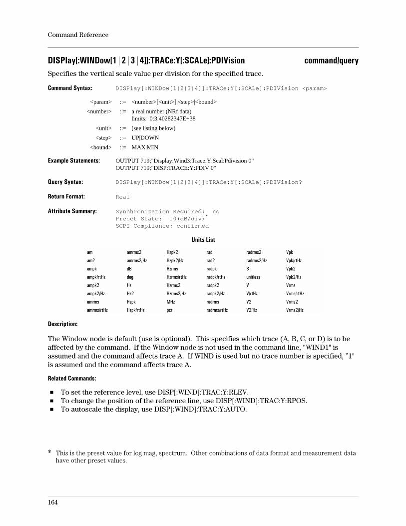
DISPlay[:WINDow[1|2|3|4]]:TRACe:Y[:SCALe]:PDIVision command/querySpecifies the vertical scale value per division for the specified trace.
Command Syntax: DISPlay[:WINDow[1|2|3|4]]:TRACe:Y[:SCALe]:PDIVision <param>
<param> ::= <number>[<unit>]|<step>|<bound>
<number> ::= a real number (NRf data)limits: 0:3.40282347E+38
<unit> ::= (see listing below)
<step> ::= UP|DOWN
<bound> ::= MAX|MIN
Example Statements: OUTPUT 719;"Display:Wind3:Trace:Y:Scal:Pdivision 0"OUTPUT 719;"DISP:TRACE:Y:PDIV 0"
Query Syntax: DISPlay[:WINDow[1|2|3|4]]:TRACe:Y[:SCALe]:PDIVision?
Return Format: Real
Attribute Summary: Synchronization Required: noPreset State: 10(dB/div)*
SCPI Compliance: confirmed
Units List
am amrms2 Hzpk2 rad radrms2 Vpk
am2 amrms2/Hz Hzpk2/Hz rad2 radrms2/Hz Vpk/rtHz
ampk dB Hzrms radpk S Vpk2
ampk/rtHz deg Hzrms/rtHz radpk/rtHz unitless Vpk2/Hz
ampk2 Hz Hzrms2 radpk2 V Vrms
ampk2/Hz Hz2 Hzrms2/Hz radpk2/Hz V/rtHz Vrms/rtHz
amrms Hzpk MHz radrms V2 Vrms2
amrms/rtHz Hzpk/rtHz pct radrms/rtHz V2/Hz Vrms2/Hz
Description:
The Window node is default (use is optional). This specifies which trace (A, B, C, or D) is to beaffected by the command. If the Window node is not used in the command line, “WIND1" isassumed and the command affects trace A. If WIND is used but no trace number is specified, ”1"is assumed and the command affects trace A.
Related Commands:
To set the reference level, use DISP[:WIND]:TRAC:Y:RLEV.To change the position of the reference line, use DISP[:WIND]:TRAC:Y:RPOS.To autoscale the display, use DISP[:WIND]:TRAC:Y:AUTO.
Command Reference
164
* This is the preset value for log mag, spectrum. Other combinations of data format and measurement datahave other preset values.
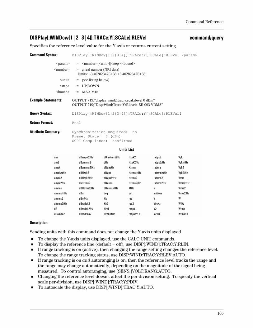
DISPlay[:WINDow[1|2|3|4]]:TRACe:Y[:SCALe]:RLEVel command/querySpecifies the reference level value for the Y axis or returns current setting.
Command Syntax: DISPlay[:WINDow[1|2|3|4]]:TRAce:Y[:SCALe]:RLEVel <param>
<param> ::= <number>[<unit>]|<step>|<bound>
<number> ::= a real number (NRf data)limits: -3.40282347E+38:+3.40282347E+38
<unit> ::= (see listing below)
<step> ::= UP|DOWN
<bound> ::= MAX|MIN
Example Statements: OUTPUT 719;"display:wind2:trac:y:scal:rlevel 0 dBm"OUTPUT 719;"Disp:Wind:Trace:Y:Rlevel: -5E-003 VRMS"
Query Syntax: DISPlay[:WINDow[1|2|3|4]]:TRACe:Y[:SCALe]:RLEVel?
Return Format: Real
Attribute Summary: Synchronization Required: noPreset State: 0 (dBm)SCPI Compliance: confirmed
Units List
am dBampk2/Hz dBradrms2/Hz Hzpk2 radpk2 Vpk
am2 dBamrms2 dBV Hzpk2/Hz radpk2/Hz Vpk/rtHz
ampk dBamrms2/Hz dBV/rtHz Hzrms radrms Vpk2
ampk/rtHz dBHzpk2 dBVpk Hzrms/rtHz radrms/rtHz Vpk2/Hz
ampk2 dBHzpk2/Hz dBVpk/rtHz Hzrms2 radrms2 Vrms
ampk2/Hz dbHzrms2 dBVrms Hzrms2/Hz radrms2/Hz Vrms/rtHz
amrms dBHzrms2/Hz dBVrms/rtHz MHz s Vrms2
amrms/rtHz dBm deg pct unitless Vrms2/Hz
amrms2 dBm/Hz Hz rad V W
amrms2/Hz dBradpk2 Hz2 rad2 V/rtHz W/Hz
dB dBradpk2/Hz Hzpk radpk V2 Wrms
dBampk2 dBradrms2 Hzpk/rtHz radpk/rtHz V2/Hz Wrms/Hz
Description:
Sending units with this command does not change the Y-axis units displayed.
To change the Y-axis units displayed, use the CALC:UNIT commands.To display the reference line (default = off), use DISP[:WIND]:TRAC:Y:RLIN.If range tracking is on (active), then changing the range setting changes the reference level.To change the range tracking status, use DISP:WIND:TRAC:Y:RLEV:AUTO.If range tracking is on and autoranging is on, then the reference level tracks the range andthe range may change automatically, depending on the magnitude of the signal beingmeasured. To control autoranging, use [SENS:]VOLT:RANG:AUTO.Changing the reference level doesn’t affect the per-division setting. To specify the verticalscale per-division, use DISP[:WIND]:TRAC:Y:PDIV.To autoscale the display, use DISP[:WIND]:TRAC:Y:AUTO.
Command Reference
165
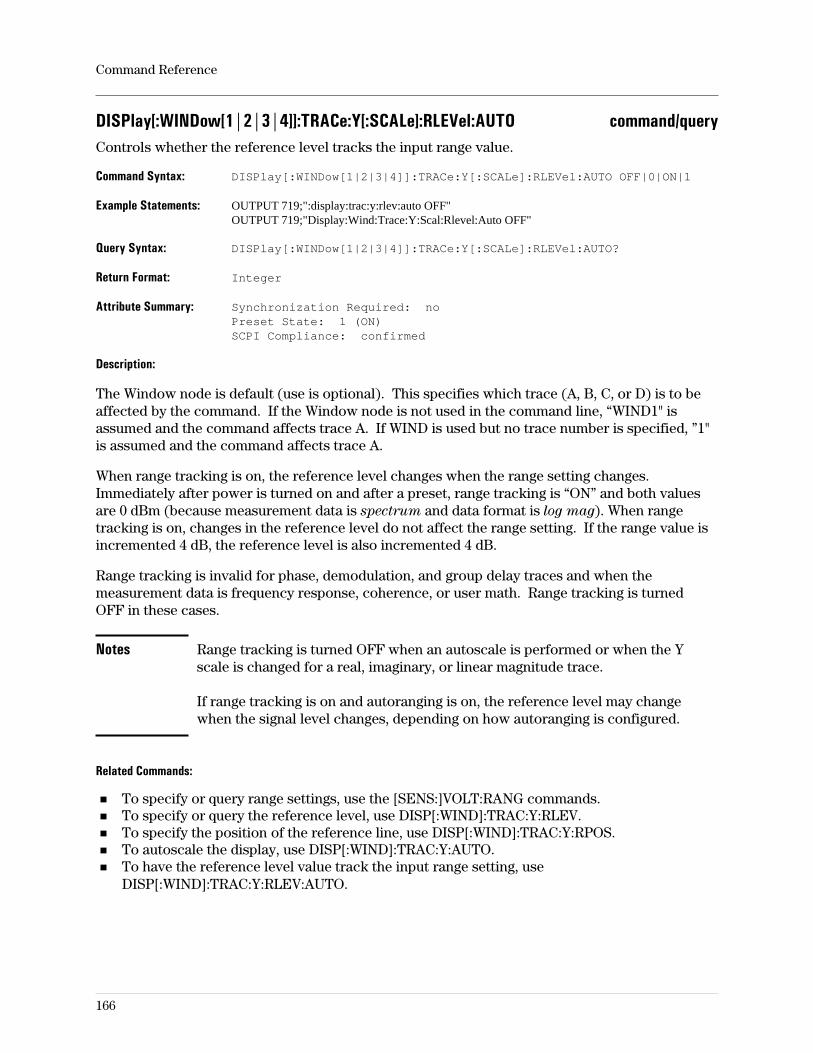
DISPlay[:WINDow[1|2|3|4]]:TRACe:Y[:SCALe]:RLEVel:AUTO command/queryControls whether the reference level tracks the input range value.
Command Syntax: DISPlay[:WINDow[1|2|3|4]]:TRACe:Y[:SCALe]:RLEVel:AUTO OFF|0|ON|1
Example Statements: OUTPUT 719;":display:trac:y:rlev:auto OFF"OUTPUT 719;"Display:Wind:Trace:Y:Scal:Rlevel:Auto OFF"
Query Syntax: DISPlay[:WINDow[1|2|3|4]]:TRACe:Y[:SCALe]:RLEVel:AUTO?
Return Format: Integer
Attribute Summary: Synchronization Required: noPreset State: 1 (ON)SCPI Compliance: confirmed
Description:
The Window node is default (use is optional). This specifies which trace (A, B, C, or D) is to beaffected by the command. If the Window node is not used in the command line, “WIND1" isassumed and the command affects trace A. If WIND is used but no trace number is specified, ”1"is assumed and the command affects trace A.
When range tracking is on, the reference level changes when the range setting changes.Immediately after power is turned on and after a preset, range tracking is “ON” and both valuesare 0 dBm (because measurement data is spectrum and data format is log mag). When rangetracking is on, changes in the reference level do not affect the range setting. If the range value isincremented 4 dB, the reference level is also incremented 4 dB.
Range tracking is invalid for phase, demodulation, and group delay traces and when themeasurement data is frequency response, coherence, or user math. Range tracking is turnedOFF in these cases.
Notes Range tracking is turned OFF when an autoscale is performed or when the Yscale is changed for a real, imaginary, or linear magnitude trace.
If range tracking is on and autoranging is on, the reference level may changewhen the signal level changes, depending on how autoranging is configured.
Related Commands:
To specify or query range settings, use the [SENS:]VOLT:RANG commands.To specify or query the reference level, use DISP[:WIND]:TRAC:Y:RLEV.To specify the position of the reference line, use DISP[:WIND]:TRAC:Y:RPOS.To autoscale the display, use DISP[:WIND]:TRAC:Y:AUTO.To have the reference level value track the input range setting, useDISP[:WIND]:TRAC:Y:RLEV:AUTO.
Command Reference
166
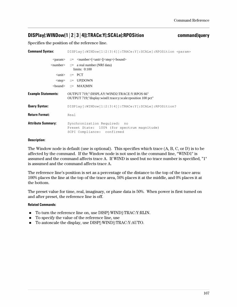
DISPlay[:WINDow[1|2|3|4]]:TRACe:Y[:SCALe]:RPOSition command/querySpecifies the position of the reference line.
Command Syntax: DISPlay[:WINDow[1|2|3|4]]:TRACe:Y[:SCALe]:RPOSition <param>
<param> ::= <number>[<unit>]|<step>|<bound>
<number> ::= a real number (NRf data)limits: 0:100
<unit> ::= PCT
<step> ::= UP|DOWN
<bound> ::= MAX|MIN
Example Statements: OUTPUT 719;":DISPLAY:WIND2:TRACE:Y:RPOS 66"OUTPUT 719;"display:wind1:trace:y:scale:rposition 100 pct"
Query Syntax: DISPlay[:WINDow[1|2|3|4]]:TRACe:Y[:SCALe]:RPOSition?
Return Format: Real
Attribute Summary: Synchronization Required: noPreset State: 100% (for spectrum magnitude)SCPI Compliance: confirmed
Description:
The Window node is default (use is optional). This specifies which trace (A, B, C, or D) is to beaffected by the command. If the Window node is not used in the command line, “WIND1" isassumed and the command affects trace A. If WIND is used but no trace number is specified, ”1"is assumed and the command affects trace A.
The reference line’s position is set as a percentage of the distance to the top of the trace area:100% places the line at the top of the trace area, 50% places it at the middle, and 0% places it atthe bottom.
The preset value for time, real, imaginary, or phase data is 50%. When power is first turned onand after preset, the reference line is off.
Related Commands:
To turn the reference line on, use DISP[:WIND]:TRAC:Y:RLIN.To specify the value of the reference line, useTo autoscale the display, use DISP[:WIND]:TRAC:Y:AUTO.
Command Reference
167
DISPlay[:WINDow[1|2|3|4]]:WATerfall:AZIMuth command/querySpecifies the Z-axis skew for all active waterfall traces.
Command Syntax: DISPlay[:WINDow[1|2|3|4]]:WATerfall:AZIMuth <param>
<param> ::= <number>[<unit>]|<step>|<bound>
<number> ::= a real number (NRf data)limits: -99:99
<unit> ::= PIXEL
<step> ::= UP|DOWN
<bound> ::= MAX|MIN
Example Statements: OUTPUT 719;"DISPLAY:WIND2:WAT:AZIMUTH -16"OUTPUT 719;"disp:waterfall:azim 39"
Query Syntax: DISPlay[:WINDow[1|2|3|4]]:WATerfall:AZIMuth?
Return Format: Integer
Attribute Summary: Option: AYB (waterfall & spectrogram display)Synchronization Required: noPreset State: not affected by PresetSCPI Compliance: instrument-specific
Description:
The waterfall display draws a new trace at the top of the screen as older traces move toward thebottom. The azimuth value specifies how many pixels each successively-lower trace is shiftedsideways. The top trace is not shifted by the azimuth value.
If the azimuth is 0, the waterfall traces do not shift sideways as they move down the trace box.Positive azimuth values shift the traces to the right as they move toward the bottom of the tracebox. Negative azimuth values shift the traces to the left as they move toward the bottom of thetrace box.
Related Commands:
To turn waterfall displays on/off, use DISP:WAT.To set the elevation, use DISP:WAT:ELEV.To set the trace height, use DISP:WAT:HEIGTo set the threshold, use DISP:WAT:THR.
For more information on waterfall and spectrogram display types, see online help and theconcepts discussion in the Operator’s Guide.
Command Reference
168
DISPlay[:WINDow[1|2|3|4]]:WATerfall:BLINe[:STATe] command/queryTurns waterfall display baseline on/off.
Command Syntax: DISPlay[:WINDow[1|2|3|4]]:WATerfall:BLINe[:STATe] OFF|0|ON|1
Example Statements: OUTPUT 719;":Disp:Waterfall:Blin OFF"OUTPUT 719;"DISPLAY:WIND:WAT:BLINE:STAT ON"
Query Syntax: DISPlay[:WINDow[1|2|3|4]]:WATerfall:BLINe[:STATe]?
Return Format: Integer
Attribute Summary: Option: AYB (waterfall & spectrogram display)Synchronization Required: noPreset State: not affected by PresetSCPI Compliance: instrument-specific
Description:
Baselines are used in conjunction with threshold settings to define the floor of the currentscaling view. This is especially useful when the elevation setting is such that the display consistsof many, overlapping traces.
Related Commands:
To turn waterfall displays on/off, use DISP:WAT.To set the elevation, use DISP:WAT:ELEV.To set the trace height, use DISP:WAT:HEIGTo set the threshold, use DISP:WAT:THR.
For more information on waterfall and spectrogram display types, see online help and theconcepts discussion in the Operator’s Guide.
Command Reference
169
DISPlay[:WINDow[1|2|3|4]]:WATerfall:ELEVation command/querySpecifies the number of pixels between traces (vertically) in the waterfall dislay.
Command Syntax: DISPlay[:WINDow[1|2|3|4]]:WATerfall:ELEVation <param>
<param> ::= <number>[<unit>]|<step>|<bound>
<number> ::= a real number (NRf data)limits: 0:(see discussion)
<unit> ::= PIXEL
<step> ::= UP|DOWN
<bound> ::= MAX|MIN
Example Statements: OUTPUT 719;"display:wind3:wat:elevation 0"OUTPUT 719;"Disp:Waterfall:Elev 0"
Query Syntax: DISPlay[:WINDow[1|2|3|4]]:WATerfall:ELEVation?
Return Format: Integer
Attribute Summary: Option: AYB (waterfall & spectrogram display)Synchronization Required: noPreset State: not affected by PresetSCPI Compliance: instrument-specific
Description:
The waterfall display draws a new trace at the top of the screen as older traces move toward thebottom. The height of a grid is determined by the number of vertically stacked grids. When thenumber of grids is single, the vertical height is approximately 300 pixels. When two grids aredisplayed, vertical height is approximately 140 pixels.
Limits:
The maximum number of pixels accepted for this command is the number defined underDISP:FORM SING, which is about 300. This is true, regardless of the active display format(number of grids). The above discussion is a description of practical limits; setting the elevationand trace height to values that add to more than what is available just means part of the trace isnot displayed.
To set the number of grids, use DISP:FORM.To turn waterfall displays on/off, use DISP:WAT.To set the elevation, use DISP:WAT:ELEV.To set the azimuth, use DISP:WAT:AZIM.To set the threshold, use DISP:WAT:THR.To set the trace height, use DISP:WAT:HEIG
For more information on waterfall and spectrogram display types, see online help and theconcepts discussion in the Operator’s Guide.
Command Reference
170
DISPlay[:WINDow[1|2|3|4]]:WATerfall:HEIGht command/querySpecifies the vertical height (in pixels) of all active waterfall traces.
Command Syntax: DISPlay[:WINDow[1|2|3|4]]:WATerfall:HEIGht <param>
<param> ::= <number>[<unit>]|<step>|<bound>
<number> ::= a real number (NRf data)limits: 1:(see discussion)
<unit> ::= PIXEL
<step> ::= UP|DOWN
<bound> ::= MAX|MIN
Example Statements: OUTPUT 719;":DISP:WATERFALL:HEIG 0"OUTPUT 719;"display:wind:wat:height 0"
Query Syntax: DISPlay[:WINDow[1|2|3|4]]:WATerfall:HEIGht?
Return Format: Integer
Attribute Summary: Option: AYB (waterfall & spectrogram display)Synchronization Required: noPreset State: not affected by PresetSCPI Compliance: instrument-specific
Description:
The waterfall display draws a new trace at the top of the screen as older traces move toward thebottom. The height of a grid is determined by the number of vertically stacked grids. When thenumber of grids is single, the vertical height is approximately 300 pixels. When two grids aredisplayed, vertical height is approximately 140 pixels.
Limits:
The maximum number of pixels accepted for this command is the number defined underDISP:FORM SING, which is about 300. This is true, regardless of the active display format(number of grids). The above discussion is a description of practical limits; setting the elevationand trace height to values that add to more than what is available just means part of the trace isnot displayed.
Related Commands:
To set the number of grids, use DISP:FORM.To turn waterfall displays on/off, use DISP:WAT.To set the elevation, use DISP:WAT:ELEV.To set the azimuth, use DISP:WAT:AZIM.To set the threshold, use DISP:WAT:THR.
For more information on waterfall and spectrogram display types, see online help and theconcepts discussion in the Operator’s Guide.
Command Reference
171
DISPlay[:WINDow[1|2|3|4]]:WATerfall:HLINe[:STATe] command/queryTurns waterfall hidden lines on/off.
Command Syntax: DISPlay[:WINDow[1|2|3|4]]:WATerfall:HLINe[:STATe] OFF|0|ON|1
Example Statements: OUTPUT 719;"Disp:Window4:Wat:Hlin:State OFF"OUTPUT 719;"DISP:WATERFALL:HLIN ON"
Query Syntax: DISPlay[:WINDow[1|2|3|4]]:WATerfall:HLINe[:STATe]?
Return Format: Integer
Attribute Summary: Option: AYB (waterfall & spectrogram display)Synchronization Required: noPreset State: not affected by PresetSCPI Compliance: instrument-specific
Description:
If enabled, the part of the current measurement trace that is obscured by the previous tracebecause the elevation between traces was not sufficient to separate the two, is blanked orhidden. This allows signals to become significantly more visible when the waterfall is displayedwith many traces and a small elevation value is active.
This command affects all active traces regardless of whether a specific window/trace is used(e.g. DISP:WIND2).
For more information on waterfall and spectrogram display types, see online help and theconcepts discussion in the Operator’s Guide.
Command Reference
172
DISPlay[:WINDow[1|2|3|4]]:WATerfall[:STATe] command/queryTurns waterfall display on/off for active traces.
Command Syntax: DISPlay[:WINDow[1|2|3|4]]:WATerfall[:STATe] OFF|0|ON|1
Example Statements: OUTPUT 719;":disp:waterfall OFF"OUTPUT 719;"Disp:Window:Wat:Stat OFF"
Query Syntax: DISPlay[:WINDow[1|2|3|4]]:WATerfall[:STATe]?
Return Format: Integer
Attribute Summary: Option: AYB (waterfall & spectrogram display)Synchronization Required: noPreset State: 0 (off)SCPI Compliance: instrument-specific
Description:
The waterfall display draws new traces at the top of the screen as older traces move toward thebottom. The height of each trace, and elevation between spaces may be user-defined as well asfeatures such as hidden line, threshold, and baseline.
Related Commands:
To specify which traces are active, use DISP:ACT.To set the threshold, use DISP:WAT:THR.To set the elevation, use DISP:WAT:ELEV.To set the trace height, use DISP:WAT:HEIG
For more information on waterfall and spectrogram display types, see online help and theconcepts discussion in the Operator’s Guide.
Command Reference
173
DISPlay[:WINDow[1|2|3|4]]:WATerfall:THReshold command/querySets the threshold for all active waterfall displays.
Command Syntax: DISPlay[:WINDow[1|2|3|4]]:WATerfall:THReshold <param>
<param> ::= <number>[<unit>]|<step>|<bound>
<number> ::= a real number (NRf data)limits: 0:100
<unit> ::= PCT
<step> ::= UP|DOWN
<bound> ::= MAX|MIN
Example Statements: OUTPUT 719;"DISPLAY:WIND2:WATERFALL:THR 21"OUTPUT 719;"disp:waterfall:thr 63"
Query Syntax: DISPlay[:WINDow[1|2|3|4]]:WATerfall:THReshold?
Return Format: Integer
Attribute Summary: Option: AYB (waterfall & spectrogram display)Synchronization Required: noPreset State: 0 (%)SCPI Compliance: instrument-specific
Description:
This command is useful for removing noise-floor clutter from the waterfall display. Thethreshold level is the percentage of the trace height, below which the signal is not displayed.
This command affects all active traces regardless of whether a specific window/trace is used(e.g. DISP:WIND2).
Related Commands:
To turn waterfall displays on/off, use DISP:WAT.To set the elevation, use DISP:WAT:ELEV.To set the azimuth, use DISP:WAT:AZIM.To set the trace height, use DISP:WAT:HEIG
For more information on waterfall and spectrogram display types, see online help and theconcepts discussion in the Operator’s Guide.
Command Reference
174
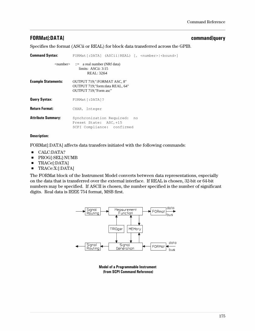
FORMat[:DATA] command/querySpecifies the format (ASCii or REAL) for block data transferred across the GPIB.
Command Syntax: FORMat[:DATA] (ASCii|REAL) [, <number>|<bound>]
<number> ::= a real number (NRf data)limits: ASCii: 3:15
REAL: 32|64
Example Statements: OUTPUT 719;":FORMAT ASC, 8"OUTPUT 719;"form:data REAL, 64"OUTPUT 719;"Form asc"
Query Syntax: FORMat[:DATA]?
Return Format: CHAR, Integer
Attribute Summary: Synchronization Required: noPreset State: ASC,+15SCPI Compliance: confirmed
Description:
FORMat[:DATA] affects data transfers initiated with the following commands:
CALC:DATA?PROG[:SEL]:NUMBTRACe[:DATA]TRACe:X:[:DATA]
The FORMat block of the Instrument Model converts between data representations, especiallyon the data that is transferred over the external interface. If REAL is chosen, 32-bit or 64-bitnumbers may be specified. If ASCII is chosen, the number specified is the number of significantdigits. Real data is IEEE 754 format, MSB first.
Model of a Programmable Instrument(from SCPI Command Reference)
Command Reference
175
HCOPy:ABORt commandAborts a plot or print operation.
Command Syntax: HCOPy:ABORt
Example Statements: OUTPUT 719;":Hcopy:Abor"OUTPUT 719;"HCOP:ABORT"
Attribute Summary: Synchronization Required: noPreset State: not applicableSCPI Compliance: confirmed
Command Reference
176
HCOPy:DATA? queryQueries the plot data which is returned in an indefinite length data block.
Query Syntax: HCOPy:DATA?
Example Statements: OUTPUT 719;"hcop:data?"OUTPUT 719;"Hcop:Data?"
Return Format: DEF_USER
Attribute Summary: Synchronization Required: yesPreset State: not applicableSCPI Compliance: instrument-specific
Command Reference
177
HCOPy:DESTination command/querySelects the I/O port for hard copy output.
Command Syntax: HCOPy:DESTination <CMDSTR>
<CMDSTR> ::= ‘SYST:COMM:GPIB’
‘SYST:COMM:SER1’
‘SYST:COMM:SER2’
‘SYST:COMM:CENT’
‘MMEM’
Example Statements: OUTPUT 719;":hcop:destination ‘syst:comm:gpib’"OUTPUT 719;"Hcop:Dest ‘syst:comm:cent’"
Query Syntax: HCOPy:DESTination?
Return Format: STRING
Attribute Summary: Synchronization Required: noPreset State: not affected by presetSCPI Compliance: confirmed
Description:
GPIB is the GPIB connector for which an address must be supplied. If you choose the GPIBport, control of the bus must be passed to the analyzer so that it can perform the plotting.
SER1 is the first RS-232 serial interface port; it is labeled COM 1 on the rear panel.
If the RF section of the 89441 is in use, SER1 is the only serial port available for hard copyoutput; SER2 (COM2) is used to control the RF section.
SER2 is the second RS-232 serial interface port; it is labeled COM 2 on the rear panel.
If the RF section of the 89441 is in use, SER2 is not available for hard copy output; SER2(COM2) is used to control the RF section.
CENT is the Centronics (parallel) port on the rear panel.
MMEM is the mass memory specifier. This signifies plotting or printing to a file. UseMMEM:NAME to specify the filename.
Command Reference
178
HCOPy:DEVice:CMAP:DEFault commandSpecifies that default values be used for the plotter pen assignments.
Command Syntax: HCOPy:DEVice:CMAP:DEFault
Example Statements: OUTPUT 719;":HCOPY:DEV:CMAP:DEF"OUTPUT 719;"hcop:device:cmap:default"
Attribute Summary: Synchronization Required: noPreset State: (see discussion)SCPI Compliance: confirmed
Description:
The default plotter pen assignments are:
text 6grid 1marker1 2marker2 2marker3 7marker4 2trace1 3trace2 7trace3 2trace4 6
Command Reference
179
HCOPy:DEVice:COLor command/queryControls color (on/off) for TIFF output over the GPIB.
Command Syntax: HCOPy:DEVice:COLor OFF|0|ON|1
Example Statements: OUTPUT 719;"Hcop:Dev:Color OFF"OUTPUT 719;"HCOP:DEVICE:COL ON"
Query Syntax: HCOPy:DEVice:COLor?
Return Format: Integer
Attribute Summary: Synchronization Required: yesPreset State: 1 (on)SCPI Compliance: instrument-specific
Description:
ON specifies color for TIFF files. To override this, use this command after the languageselection is made.
OFF specifies that TIFF color is turned off; the images are black and white.
Note TIFF files transferred with the LAN file-transfer protocol, FTP (available inoption UG7) are always color, regardless of this command setting.
Command Reference
180
HCOPy:DEVice:LANGuage command/querySelects type of output from the hard copy output.
Command Syntax: HCOPy:DEVice:LANGuage PCL|HPGL|PHPGl|TIFF
Example Statements: OUTPUT 719;":hcop:device:lang PCL"OUTPUT 719;"Hcopy:Dev:Lang HPGL"
Query Syntax: HCOPy:DEVice:LANGuage?
Return Format: CHAR
Attribute Summary: Synchronization Required: noPreset State: HPGLSCPI Compliance: confirmed
Description:
PCL is the language used by Hewlett-Packard LaserJet printers.
HPGL is the graphics language used by Hewlett-Packard plotters.
PHPGL is the HP-GL language as supported by some Hewlett-Packard PCL LaserJet printers(such as Series III).
TIFF is the Tagged Information File Format (TIFF is a trademark of Aldus Corporation).
Command Reference
181
HCOPy:DEVice:RESolution command/querySpecifies dots per inch for screen dumps to PCL printers.
Command Syntax: HCOPy:DEVice:RESolution <number>|<bound>
<number> ::= a real number (NRf data)limits: 0:600
<bound> ::= MAX|MIN
Example Statements: OUTPUT 719;":Hcop:Device:Res 150"OUTPUT 719;"HCOPY:DEV:RES 300"
Query Syntax: HCOPy:DEVice:RESolution?
Return Format: Real
Attribute Summary: Synchronization Required: noPreset State: not affected by presetSCPI Compliance: confirmed
Description:
This information is not used for HPGL language output.
Command Reference
182
HCOPy:DEVice:SPEed command/querySpecifies the pen-movement speed (cm/s) for plot operations initiated by the analyzer.
Command Syntax: HCOPy:PLOT:SPEed <number>|<step>|<bound>
<number> ::= a real number (NRf data)limits: 0:100
<step> ::= UP|DOWN
<bound> ::= MAX|MIN
Example Statements: OUTPUT 719;"Hcop:Dev:Spe 50"OUTPUT 719;"HCOP:DEVICE:SPE 10"
Query Syntax: HCOPy:DEVice:SPEed?
Return Format: Integer
Attribute Summary: Synchronization Required: noPreset State: +100SCPI Compliance: confirmed
Description:
This information is not used for PCL language output.
This command specifies the pen-movement speed in centimeters per second (cm/s). Check theplotter’s documentation to be sure that it supports the specified speed.
The value 0 causes the plotter to use it’s default speed, which is normally its highest speedcapability.
Command Reference
183
HCOPy[:IMMediate] commandPlots or prints the entire screen.
Command Syntax: HCOPy[:IMMediate]
Example Statements: OUTPUT 719;"HCOPY:IMM"OUTPUT 719;"hcopy"
Attribute Summary: Synchronization Required: yesPreset State: not applicableSCPI Compliance: confirmed
Description:
The entire screen is output to the port defined by HCOP:DEST using the language defined byHCOP:DEV:LANG. If the GPIB port is the destination, the data is directed to an GPIB devicewhose address is specified with HCOP:PLOT:ADDR or HCOP:PRIN:ADDR. If one of the serialports is the destination, serial port parameter are defined with the SYST:COMM:SER commands.
HPGL will use HCOP:PLOT:ADDR for the GPIB address, and PCL and PHPGL will useHCOP:PRINT:ADDR for the GPIB address.
This command has the same effect as HCOP:ITEM:ALL[:IMM].
Note To Plot or print to the GPIB port, the analyzer must be the active controller onthe bus. The active controller must pass control to the analyzer. After thecommand has been executed, the analyzer will return control to the controller.
Whole-screen graphics files may also be created in any of the supported graphics outputformats/languages and moved to the controller with the LAN file-transfer utility, FTP (optionUG7).
Command Reference
184
HCOPy:ITEM:ALL[:IMMediate] commandPlots or prints the entire screen.
Command Syntax: HCOPy:ITEM:ALL[:IMMediate]
Example Statements: OUTPUT 719;":Hcop:Item:All"OUTPUT 719;"HCOP:ITEM:ALL:IMM"
Attribute Summary: Synchronization Required: yesPreset State: not applicableSCPI Compliance: confirmed
Description:
The entire screen is output to the port defined by HCOP:DEST using the language defined byHCOP:DEV:LANG. If the GPIB port is the destination, the data is directed to an GPIB devicewhose address is specified with HCOP:PLOT:ADDR or HCOP:PRIN:ADDR. If one of the serialports is the destination, serial port parameter are defined with the SYST:COMM:SER commands.
HPGL will use HCOP:PLOT:ADDR for the GPIB address, and PCL and PHPGL will useHCOP:PRINT:ADDR for the GPIB address.
This command has the same effect as HCOP[:IMM].
Note To Plot or print to the GPIB port, the analyzer must be the active controller onthe bus. The active controller must pass control to the analyzer. After thecommand has been executed, the analyzer must pass control back to thecontroller.
Whole-screen graphics files may also be created in any of the supported graphics outputformats/languages and moved to the controller with the LAN file-transfer utility, FTP (optionUG7).
Command Reference
185
HCOPy:ITEM:ANNotation:COLor command/querySpecifies the pen used to plot miscellaneous annotations.
Command Syntax: HCOPy:ITEM:ANNotation:COLOR <number>|<step>|<bound>
<number> ::= a real number (NRf data)limits: 0:16
<step> ::= UP|DOWN
<bound> ::= MAX|MIN
Example Statements: OUTPUT 719;"hcop:item:annotation:colo 3"OUTPUT 719;":HCOP:ITEM:ANN:COLOR 15"
Query Syntax: HCOPy:ITEM:ANNotation:COLor?
Return Format: Integer
Attribute Summary: Synchronization Required: noPreset State: +4SCPI Compliance: confirmed
Description:
The annotation pen is used to plot the following:
Instrument state.Disk catalog.State information.Time stamp.Status or error messages.
Nothing is plotted for items with pen values of 0 or for which the pen value exceeds the limits ofthe plotter in use.
All output device configuration information is sent when the HCOP command is executed.
This information is not used for PCL language output.
Command Reference
186
HCOPy:ITEM:FFEed:STATe command/querySpecifies a (plotter) eject or (printer) form feed after the operation is complete.
Command Syntax: HCOPy:ITEM:FFEed:STATe OFF|0|ON|1
Example Statements: OUTPUT 719;"hcopy:item:ffeed:stat OFF"OUTPUT 719;"Hcop:Item:Ffe:State ON"
Query Syntax: HCOPy:ITEM:FFEed:STATe?
Return Format: Integer
Attribute Summary: Synchronization Required: noPreset State: +0SCPI Compliance: confirmed
Description:
Enables or disables the plotter page-eject feature or a printer form feed feature. The specifiedstate is used for all plotting and printing operations initiated by the analyzer. Check the outputdevice’s documentation to be sure that it supports the requested the page-eject state.
Command Reference
187
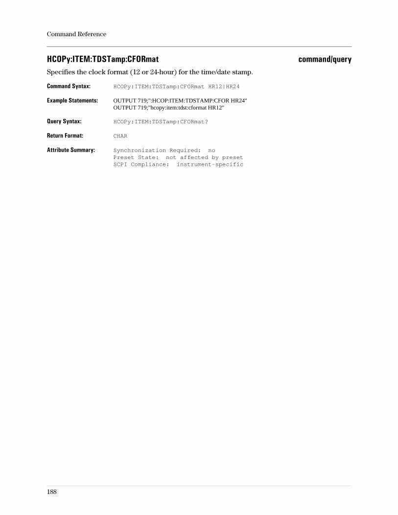
HCOPy:ITEM:TDSTamp:CFORmat command/querySpecifies the clock format (12 or 24-hour) for the time/date stamp.
Command Syntax: HCOPy:ITEM:TDSTamp:CFORmat HR12|HR24
Example Statements: OUTPUT 719;":HCOP:ITEM:TDSTAMP:CFOR HR24"OUTPUT 719;"hcopy:item:tdst:cformat HR12"
Query Syntax: HCOPy:ITEM:TDSTamp:CFORmat?
Return Format: CHAR
Attribute Summary: Synchronization Required: noPreset State: not affected by presetSCPI Compliance: instrument-specific
Command Reference
188
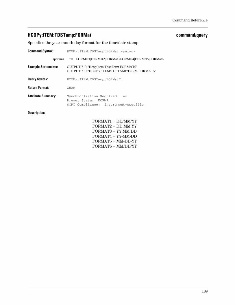
HCOPy:ITEM:TDSTamp:FORMat command/querySpecifies the year-month-day format for the time/date stamp.
Command Syntax: HCOPy:ITEM:TDSTamp:FORMat <param>
<param> ::= FORMat1|FORMat2|FORMat3|FORMat4|FORMat5|FORMat6
Example Statements: OUTPUT 719;"Hcop:Item:Tdst:Form FORMAT6"OUTPUT 719;"HCOPY:ITEM:TDSTAMP:FORM FORMAT5"
Query Syntax: HCOPy:ITEM:TDSTamp:FORMat?
Return Format: CHAR
Attribute Summary: Synchronization Required: noPreset State: FORM4SCPI Compliance: instrument-specific
Description:
FORMAT1 = DD/MM/YYFORMAT2 = DD.MM.YYFORMAT3 = YY MM DDFORMAT4 = YY-MM-DDFORMAT5 = MM-DD-YYFORMAT6 = MM/DD/YY
Command Reference
189
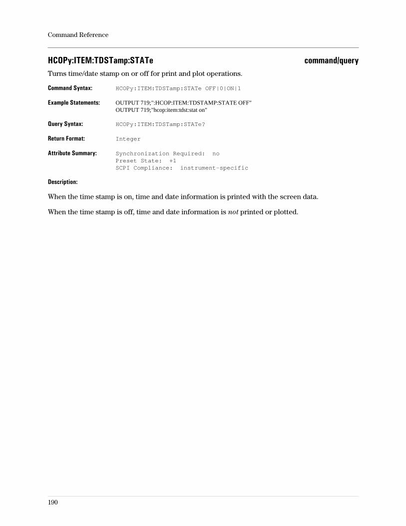
HCOPy:ITEM:TDSTamp:STATe command/queryTurns time/date stamp on or off for print and plot operations.
Command Syntax: HCOPy:ITEM:TDSTamp:STATe OFF|0|ON|1
Example Statements: OUTPUT 719;":HCOP:ITEM:TDSTAMP:STATE OFF"OUTPUT 719;"hcop:item:tdst:stat on"
Query Syntax: HCOPy:ITEM:TDSTamp:STATe?
Return Format: Integer
Attribute Summary: Synchronization Required: noPreset State: +1SCPI Compliance: instrument-specific
Description:
When the time stamp is on, time and date information is printed with the screen data.
When the time stamp is off, time and date information is not printed or plotted.
Command Reference
190
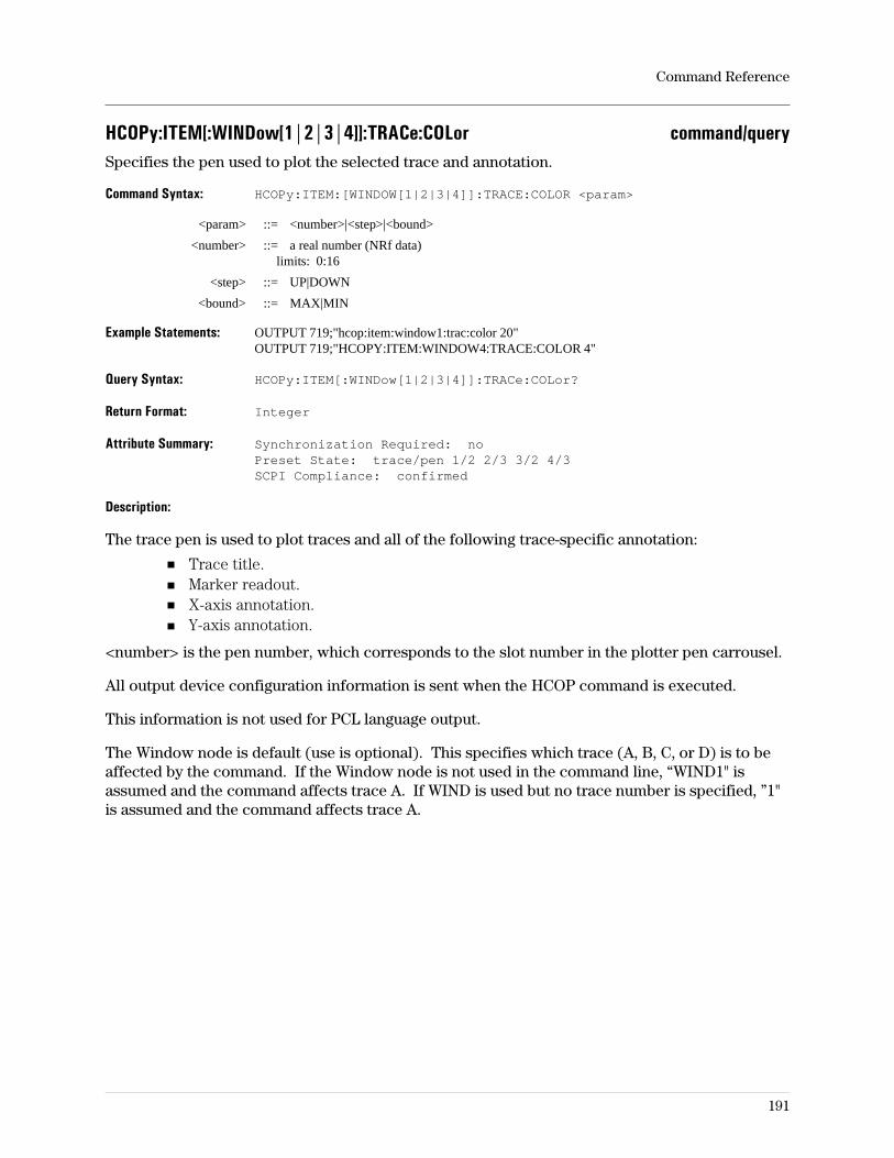
HCOPy:ITEM[:WINDow[1|2|3|4]]:TRACe:COLor command/querySpecifies the pen used to plot the selected trace and annotation.
Command Syntax: HCOPy:ITEM:[WINDOW[1|2|3|4]]:TRACE:COLOR <param>
<param> ::= <number>|<step>|<bound>
<number> ::= a real number (NRf data)limits: 0:16
<step> ::= UP|DOWN
<bound> ::= MAX|MIN
Example Statements: OUTPUT 719;"hcop:item:window1:trac:color 20"OUTPUT 719;"HCOPY:ITEM:WINDOW4:TRACE:COLOR 4"
Query Syntax: HCOPy:ITEM[:WINDow[1|2|3|4]]:TRACe:COLor?
Return Format: Integer
Attribute Summary: Synchronization Required: noPreset State: trace/pen 1/2 2/3 3/2 4/3SCPI Compliance: confirmed
Description:
The trace pen is used to plot traces and all of the following trace-specific annotation:
Trace title.Marker readout.X-axis annotation.Y-axis annotation.
<number> is the pen number, which corresponds to the slot number in the plotter pen carrousel.
All output device configuration information is sent when the HCOP command is executed.
This information is not used for PCL language output.
The Window node is default (use is optional). This specifies which trace (A, B, C, or D) is to beaffected by the command. If the Window node is not used in the command line, “WIND1" isassumed and the command affects trace A. If WIND is used but no trace number is specified, ”1"is assumed and the command affects trace A.
Command Reference
191
HCOPy:ITEM[:WINDow[1|2|3|4]]:TRACe:GRATicule:COLor command/querySpecifies the pen used to plot the trace graticule.
Command Syntax: HCOPy:ITEM[:WINDOW[1|2|3|4]]:TRACe:GRATicule:COLor <param>
<param> ::= <number>|<step>|<bound>
<number> ::= a real number (NRf data)limits: 0:16
<step> ::= UP|DOWN
<bound> ::= MAX|MIN
Example Statements: OUTPUT 719;":Hcopy:Item:Trace:Grat:Color 1"OUTPUT 719;"HCOP:ITEM:WIND3:TRAC:GRAT:COL 12"
Query Syntax: HCOPy:ITEM[:WINDow[1|2|3|4]]:TRACe:GRATicule:COLor?
Return Format: Integer
Attribute Summary: Synchronization Required: noPreset State: +1SCPI Compliance: confirmed
Description:
The grid, or graticule, pen is used to plot the graticule overlaying the trace, the border around theinstrument state, and the border around the disk catalog.
All output device configuration information is sent when the HCOP command is executed.
This information is not used for PCL language output.
The Window node has no effect in this command. Whatever value is set for any trace is theactive value for all traces.
Command Reference
192
HCOPy:ITEM[:WINDow[1|2|3|4]]:TRACe:GRATicule[:IMMediate] commandPlots or prints the graticule, only.
Command Syntax: HCOPy:ITEM[:WINDow[1|2|3|4]]:TRACe:GRATicule[:IMMediate]
Example Statements: OUTPUT 719;":hcop:item:trac:graticule"OUTPUT 719;"Hcop:Item:Window:Trac:Graticule:Imm"
Attribute Summary: Synchronization Required: yesPreset State: not applicableSCPI Compliance: instrument-specific
Description:
Whole-screen graphics files may also be created in any of the supported graphics outputformats/languages and moved to the controller with the LAN file-transfer utility, FTP (optionUG7).
Command Reference
193
HCOPy:ITEM[:WINDow[1|2|3|4]]:TRACe[:IMMediate] commandPlots the specified trace, only (not applicable to printing).
Command Syntax: HCOPy:ITEM[:WINDow[1|2|3|4]]:TRACe[:IMMediate]
Example Statements: OUTPUT 719;"HCOP:ITEM:WIND3:TRACE:IMM"OUTPUT 719;"hcop:item:trac"
Attribute Summary: Synchronization Required: yesPreset State: not applicableSCPI Compliance: confirmed
Description:
This command plots all traces currently displayed.
If the current language is PCL, this command returns an error.
Whole-screen graphics files may also be created in any of the supported graphics outputformats/languages and moved to the controller with the LAN file-transfer utility, FTP (optionUG7).
Command Reference
194
HCOPy:ITEM[:WINDow[1|2|3|4]]:TRACe:LTYPe command/querySpecifies the plot line type for the selected trace.
Command Syntax: HCOPy:ITEM[:WINDow[1|2|3|4]:TRACe:LTYPe <param>
<param> ::= SOLid|DOTTed|DASHed|STY0|STY1|STY2|STY3|STY4|STY5|STY6
Example Statements: OUTPUT 719;":Hcopy:Item:Trac:Ltype SOLID"OUTPUT 719;"HCOP:ITEM:WIND4:TRAC:LTYPE STYLE2"
Query Syntax: HCOPy:ITEM[:WINDow[1|2|3|4]]:TRACe:LTYPe?
Return Format: CHAR
Attribute Summary: Synchronization Required: noPreset State: SOLSCPI Compliance: confirmed
Description:
DOTTed is the same as STYLe1 and DASHed is the same as STYLe2. The other style types aredevice-dependent; see the plotter documentation (linetype HPGL command LT) to determinehow these are interpreted.
All output device configuration information is sent when the HCOP command is executed.
This information is not used for PCL language output.
The Window node is default (use is optional). This specifies which trace (A, B, C, or D) is to beaffected by the command. If the Window node is not used in the command line, “WIND1" isassumed and the command affects trace A. If WIND is used but no trace number is specified, ”1"is assumed and the command affects trace A.
Command Reference
195
HCOPy:ITEM[:WINDow[1|2|3|4]]:TRACe:MARKer:COLor command/querySpecifies the pen used to plot markers for the selected trace.
Command Syntax: HCOPy:ITEM[:WINDow[1|2|3|4]]:TRACe:MARKer:COLor <param>
<param> ::= <number>|<step>|<bound>
<number> ::= a real number (NRf data)limits: 0:16
<step> ::= UP|DOWN
<bound> ::= MAX|MIN
Example Statements: OUTPUT 719;"hcopy:item:wind2:trace:mark:color 6"OUTPUT 719;"Hcop:Item:Wind3:Trac:Marker:Col 9"
Query Syntax: HCOPy:ITEM[:WINDow[1|2|3|4]]:TRACe:MARKer:COLor?
Return Format: Integer
Attribute Summary: Synchronization Required: noPreset State: trace/pen 1/5 2/6 3/5 4/6SCPI Compliance: confirmed
Description:
<number> is the pen number corresponding to the slot number in the plotter pen carrousel. Thepen specified with this command is used to plot main marker, reference marker, and markerfunction text and graphics for the specified trace.
The Window node is default (use is optional). This specifies which trace (A, B, C, or D) is to beaffected by the command. If the Window node is not used in the command line, “WIND1" isassumed and the command affects trace A. If WIND is used but no trace number is specified, ”1"is assumed and the command affects trace A.
Nothing is plotted for items with pen values of 0 or for which the pen value exceeds the limits ofthe plotter in use.
All output device configuration information is sent when the HCOP command is executed.
This information is not used for PCL language output.
Command Reference
196
HCOPy:ITEM[:WINDow[1|2|3|4]]:TRACe:MARKer[:IMMediate] commandPlots or prints the specified marker, only.
Command Syntax: HCOPy:ITEM[:WINDow[1|2|3|4]]:TRACe:MARKer[:IMMediate]
Example Statements: OUTPUT 719;"hcop:item:wind:trac:marker:imm"OUTPUT 719;"Hcopy:Item:Trac:Marker"
Attribute Summary: Synchronization Required: yesPreset State: not applicableSCPI Compliance: instrument-specific
Description:
This command plots all trace markers currently displayed.
If the current language is PCL, this command returns an error.
Whole-screen graphics files may also be created in any of the supported graphics outputformats/languages and moved to the controller with the LAN file-transfer utility, FTP (optionUG7).
Command Reference
197
HCOPy:ITEM[:WINDow[1|2|3|4]]:TRACe:MARKer:OFFSet[:IMMediate] commandPlots or prints the specified offset marker, only.
Command Syntax: HCOPy:ITEM[:WINDow[1|2|3|4]]:TRACe:MARKer:OFFSet[:IMMediate]
Example Statements: OUTPUT 719;":HCOP:ITEM:TRAC:MARK:OFFSET"OUTPUT 719;"hcop:item:wind:trac:marker:offs:immediate"
Attribute Summary: Synchronization Required: yesPreset State: not applicableSCPI Compliance: instrument-specific
Description:
This command plots all offset markers currently displayed.
If the current language is PCL, this command returns an error.
Whole-screen graphics files may also be created in any of the supported graphics outputformats/languages and moved to the controller with the LAN file-transfer utility, FTP (optionUG7).
Command Reference
198

HCOPy:PAGE:DIMensions:AUTO command/querySpecifies whether default or user-defined settings for P1 and P2 are used to define pagedimensions.
Command Syntax: HCOPy:PAGE:DIMensions:AUTO OFF|0|ON|1
Example Statements: OUTPUT 719;"Hcop:Page:Dimensions:Auto OFF"OUTPUT 719;"HCOPY:PAGE:DIM:AUTO ON"
Query Syntax: HCOPy:PAGE:DIMensions:AUTO?
Return Format: Integer
Attribute Summary: Synchronization Required: noPreset State: +1SCPI Compliance: confirmed
Description:
All output device configuration information is sent when the HCOP command is executed. IfHCOP:PAGE:DIM:AUTO is on, no page dimension commands are sent; the current plottersettings are used. If AUTO is OFF, the user-defined values are sent.
To define values for P1 and P2, use HCOP:PAGE:DIM:USER:LLEFt and URIGht.
This information is not used for PCL language output.
Command Reference
199
HCOPy:PAGE:DIMensions:USER:LLEFt command/querySets or queries the x,y position of the lower-left corner of the plotter page (P1).
Command Syntax: HCOPy:PAGE:DIMensions:USER:LLEFt <param>, <param>
<param> ::= <number>|<step>|<bound>
<number> ::= a real number (NRf data)limits: -32767:32767
<step> ::= UP|DOWN
<bound> ::= MAX|MIN
Example Statements: OUTPUT 719;":hcop:page:dim:user:lleft 12683, 22198"OUTPUT 719;"Hcop:Page:Dim:User:Lleft 15708, 9913"
Query Syntax: HCOPy:PAGE:DIMensions:USER:LLEFt?
Return Format: Integer, Integer
Attribute Summary: Synchronization Required: noPreset State: +250,+596SCPI Compliance: instrument-specific
Description:
All output device configuration information is sent when the HCOP command is executed.
This information is not used for PCL language output.
Command Reference
200
HCOPy:PAGE:DIMensions:USER:URIGht command/querySets or queries the x,y position of the upper-right corner of the plotter page (P2).
Command Syntax: HCOPy:PAGE:DIMensions:USER:URIGht <param>, <param>
<param> ::= <number>|<step>|<bound>
<number> ::= a real number (NRf data)limits: -32767:32767
<step> ::= UP|DOWN
<bound> ::= MAX|MIN
Example Statements: OUTPUT 719;"HCOP:PAGE:DIM:USER:URIGHT 11675, 5060"OUTPUT 719;"hcop:page:dim:user:uright -14868, 28532"
Query Syntax: HCOPy:PAGE:DIMensions:USER:URIGht?
Return Format: Integer, Integer
Attribute Summary: Synchronization Required: noPreset State: +10250,+7796SCPI Compliance: instrument-specific
Description:
All output device configuration information is sent when the HCOP command is executed.
This information is not used for PCL language output.
Command Reference
201
HCOPy:PLOT:ADDRess command/querySpecifies the GPIB address assigned to the plot device.
Command Syntax: HCOPy:PLOT:ADDRess <number>|<step>|<bound>
<number> ::= a real number (NRf data)limits: 0:30
<step> ::= UP|DOWN
<bound> ::= MAX|MIN
Example Statements: OUTPUT 719;":HCOPY:PLOT:ADDR 5"OUTPUT 719;"hcopy:plot:address 9"
Query Syntax: HCOPy:PLOT:ADDRess?
Return Format: Integer
Attribute Summary: Synchronization Required: noPreset State: not affected by PresetSCPI Compliance: instrument-specific
Description:
This address is used for HPGL and PHPGL output formats and data output to the GPIB port. Theplotter address must be specified with this command before the HCOP[:IMM] command isexecuted. If a plotter device is not at the specified address, the plot operation times out afterabout 20 seconds.
Command Reference
202
HCOPy:PRINt:ADDRess command/querySpecifies the GPIB address assigned to the print device.
Command Syntax: HCOPy:PRINt:ADDRess <number>|<step>|<bound>
<number> ::= a real number (NRf data)limits: 0:30
<step> ::= UP|DOWN
<bound> ::= MAX|MIN
Example Statements: OUTPUT 719;":hcopy:prin:addr 3"OUTPUT 719;"Hcopy:Prin:Address 1"
Query Syntax: HCOPy:PRINt:ADDRess?
Return Format: Integer
Attribute Summary: Synchronization Required: noPreset State: not affected by PresetSCPI Compliance: instrument-specific
Description:
This address is used for PCL and TIF output formats and data output to the GPIB port. Theprinter address must be specified with this command before the HCOP[:IMM] command isexecuted. If a printer device is not at the specified address, the print operation times out afterabout 20 seconds.
Command Reference
203
INITiate:CONTinuous command/querySpecifies continuous or single sweeps.
Command Syntax: INITiate:CONTinuous OFF|0|ON|1
Example Statements: OUTPUT 719;":Init:Continuous ON"OUTPUT 719;"INIT:CONT OFF"
Query Syntax: INITiate:CONTinuous?
Return Format: Integer
Attribute Summary: Synchronization Required: noPreset State: ON (continuous)SCPI Compliance: instrument-specific
Description:
ON is continuous-sweep operation.
OFF is single-sweep operation. When this state is active, a single sweep occurs whenINIT[:IMM] is sent.
Command Reference
204
INITiate[:IMMediate] commandForces the trigger system to exit the idle state.
Command Syntax: INITiate[:IMMediate]
Example Statements: OUTPUT 719;"initiate:imm"OUTPUT 719;"Initiate"
Attribute Summary: Synchronization Required: yesPreset State: not applicableSCPI Compliance: confirmed
Description:
Characteristics:
Ignored unless INIT:CONT is OFF (in single sweep operation).Forces the process to exit idle state (in SCPI trigger model) and the trigger system to initiateand complete one full trigger cycle.Ensures that changes to the analyzer’s state are incorporated in the collection andpresentation of new measurement results. See Synchronization in the GPIB Programmer’s
Guide.Equivalent to the Single hardkey when in single-sweep mode.
Command Reference
205
INPut[1|2]:COUPling command/querySelects ac or dc coupling for the selected channel.
Command Syntax: INPut[1|2]:COUPling AC|DC
Example Statements: OUTPUT 719;":INP2:COUP AC"OUTPUT 719;"input:coup DC"
Query Syntax: INPut[1|2]:COUPling?
Return Format: CHAR
Attribute Summary: Synchronization Required: noPreset State: ACSCPI Compliance: confirmed
Description:
Note Use dc coupling for small spans at low frequencies to avoid the filter effectassociated with ac coupling (signal is down 3 dB at 1 Hz).
Command Reference
206
INPut[1|2]:FILTer[:LPASs][:STATe] command/queryEnables or disables the anti-alias circuits.
Command Syntax: INPut[1|2]:FILTer[:LPASs][:STATe] OFF|0|ON|1
Example Statements: OUTPUT 719;"Input2:Filt:Lpas:State OFF"OUTPUT 719;"INP:FILTER OFF"
Query Syntax: INPut[1|2]:FILTer[:LPASs][:STATe]?
Return Format: Integer
Attribute Summary: Synchronization Required: noPreset State: 1SCPI Compliance: confirmed
Description:
By default, the analyzer’s anti-alias filter is enabled. Use this command to disable the anti-aliasfilter.
Notes If the anti-alias filter is off, published specifications for the analyzer are notguaranteed.
The analyzer always applies dc offset correction, regardless of the anti-aliasfilters status.
Command Reference
207
INPut[1|2]:IMPedance command/querySelects the internal termination impedance.
Command Syntax: INPut[1|2]:IMPedance <number>[<unit>]
<number> ::= 50|75|1000000
<unit> ::= OHM
Example Statements: OUTPUT 719;":input1:imp 50"OUTPUT 719;"Inp2:Imp 1MOHM"OUTPUT 719;"INPUT1:IMP 1e6"
Query Syntax: INPut[1|2]:IMPedance?
Return Format: Real
Attribute Summary: Synchronization Required: noPreset State: 50SCPI Compliance: confirmed
Description:
Related Commands:
When 1 MΩ is active, you can specify the reference impedance used to calculate dBm withthe CORR:IMP command.
Note For the 89441A, the 1 MΩ selection is not valid for channel 1 (input1) if thereceiver type is RF (ROUT:REC RF2). Channel 2 impedance is not limited byreceiver type, but may not be installed.
Command Reference
208
INPut[1|2][:STATe] command/queryThis key turns on/off the selected channel.
Command Syntax: INPut[1|2][:STATe] OFF|0|ON|1
Example Statements: OUTPUT 719;"INP1:STATE ON"OUTPUT 719;"inp2 on"
Query Syntax: INPut[1|2][:STATe]?
Return Format: Integer
Attribute Summary: Synchronization Required: noPreset State: +1SCPI Compliance: confirmed
Description:
Turning a channel off increases the measurement rate in some cases, since no calculations aremade for a channel that is off. It also doubles the time capture record length for the channel thatis on.
If you send a command without specifying a channel, the command affects channel 1.If you send a query without specifying a channel, the analyzer returns the state of channel 1.If you query a channel that is not installed, the analyzer returns a blank field.
Note The second input channel is optional and may not be installed on the analyzer inyour system. To determine which options are installed, use the *OPT? query.
Command Reference
209
INSTrument:NSELect command/querySelect instrument mode by sending an integer number.
Command Syntax: INSTrument:NSELect <number>|<bound>
<number> ::= a real number (NRf data)limits: 1:5
<bound> := MAX|MIN
Example Statements: OUTPUT 719;"INSTRUMENT:NSEL 1"OUTPUT 719;"inst:nselect 3"
Query Syntax: INSTrument:NSELect?
Return Format: Integer
Attribute Summary: Synchronization Required: noPreset State: 89410: 3, 89441: 1SCPI Compliance: confirmed
Description:
This command performs the same function as INST:SEL except that it sends numbers to specifythe mode type as follows:
1 = SCALar2 = ADEModulation3 = VECTor4 = DDEModulation5 = VDEModulation6 = WCDma (Wideband CDMA)
Note Digital demodulation is valid only when option AYA is installed. Videodemodulation is valid only when both option AYA and option AYH are installed.Wideband CDMA is valid only when option B73 is installed.
Command Reference
210
INSTrument[:SELect] command/querySelects the instrument mode.
Command Syntax: INSTrument[:SELect] SCALar|DEMod|ADEMod|DDEMod|VECTor|VDEMod|WCDMa
Example Statements: OUTPUT 719;":Inst ADEM"OUTPUT 719;"INSTRUMENT:SEL VECTOR"
Query Syntax: INSTrument[:SELect]?
Return Format: CHAR
Attribute Summary: Option: AYA (Vector Mod. Analysis) for DDEModAYH (Digital Video Analysis) for VDEModB73 (Wideband CDMA analysis) for WCDMa
Synchronization Required: noPreset State: 89410: VECTor, 89441: SCALarSCPI Compliance: confirmed
Description:
SCAL selects Scalar Measurements as the instrument mode. This mode configures the analyzerto perform scalar measurements (no phase) on either channel. This mode uses stepped FFTmeasurement techniques to achieve lower resolution bandwidths. Gated time is NOT available inScaler mode.
ADEM and DEM selects the Analog Demodulation Measurements mode. This mode configuresthe analyzer to allow AM, PM, and FM demodulation measurements. DEM providescompatibility with earlier software revisions. Gated time is available in the Analog Demod mode.
DDEM selects Digital Demodulation as the instrument mode. This mode exists only in analyzersthat have option AYA. This mode configures the analyzer to examine signals such as QPSK,
DQPSK,π4DQPSK, BPSK, 8PSK, 16 QAM, 32 QAM, MSK, and FSK modulation formats. It offers
automatic carrier and symbol locking. Gated time is NOT available in Digital Demod mode.
VECT selects Vector Measurements as the instrument mode. This mode configures the analyzerto perform vector measurements (magnitude and phase) on either channel. This mode does not
use stepped FFT, and thus can not achieve the low resolution bandwidths possible in the Scalarmode. Gated time is available in the Vector mode.
VDEM selects Video Demodulation Measurements as the instrument mode. This mode existsonly in analyzers that have both options AYA and AYH.
WCDMa selects Wideband CDMA Measurements as the instrument mode. This mode exists onlyin analyzers that have option B73.
Note The instrument mode may also be specified using integer numbers with theINST:NSEL command.
Command Reference
211
MEMory:DELete[:NAME] commandPurges the memory allocated for a specific item.
Command Syntax: MEMory:DELete[:NAME] RDISk|D1|D2|D3|D4|D5|D6|DREG|MSCan
Example Statements: OUTPUT 719;"MEM:DEL RDIS"OUTPUT 719;"mem:delete:name rdisk"
Attribute Summary: Synchronization Required: noPreset State: not applicableSCPI Compliance: confirmed
Description:
This command deletes an item from existence, freeing the memory allotted to it for reuse.
RDISK identifies the (nonvolatile) RAM disk.
D1|D2|D3|D4|D5|D6 identifies one of the six data registers.
DREG identifies all data registers.
Command Reference
212
MEMory:MALLocate:APPLication command/querySpecifies amount of memory to allocate for downloadable programs.
Command Syntax: MEMory:MALLocate:APPLication <number>|<step>|<bound>
<number> ::= a real number (NRf data)limits: 0:3.40282347E+38
<step> ::= UP|DOWN
<bound> ::= MAX|MIN
Example Statements: OUTPUT 719;":mem:mall:application 2147483647"OUTPUT 719;"Mem:Mallocate:Appl 2147483647"
Query Syntax: MEMory:MALLocate:APPLication?
Return Format: Integer
Attribute Summary: Synchronization Required: noPreset State: not applicableSCPI Compliance: instrument-specific
Description:
This GPIB command specifies how much memory to allocate (in bytes) for applications. Forbest performance, set application memory to zero if there are no applications in the analyzer.
Before you load an application into the analyzer, see the documentation shipped with theapplication to determine the amount of memory required for the application.
Command Reference
213
MEMory:MALLocate:MEASurement:DEFault commandReset the memory configuration to default setup.
Command Syntax: MEMory:MALLocate:MEASurement:DEFault
Example Statements: OUTPUT 719;"MEM:MALLOCATE:MEAS:DEFAULT"OUTPUT 719;"mem:mall:measurement:def"
Attribute Summary: Synchronization Required: noPreset State: not applicableSCPI Compliance: instrument-specific
Description:
This command allocates memory not already allocated to Instrument BASIC or as RAM disk, todata and math registers. Data registers may be used to save traces, to define math functions, andas a source of arbitrary source signals. Math registers hold interim results of math calculations.The size of these registers depends on the largest number of points in a trace that a user maywish to use. This parameter is called the Maximum Number of Frequency Points. The defaultconfiguration is:
Data Registers: 6Math Registers: 6Maximum Number of Frequency Points: 3201
This command does not change the settings for the RAM disk or the amount of memory allocatedfor IBASIC programming. If the amount of memory allocated to these two uses is sufficientlylarge, the DEFAULT command may not be able to allocate the configuration specified above. Ifthis occurs, the value of the Maximum Number of Frequency Points is reduced until theconfiguration fits into the available memory.
Note The number of frequency points used is different from the maximum number offrequency points in that the latter is used to define the amount of memoryallocated to the math and data registers. Each register is configured to acceptthe maximum number of frequency points, so making this number larger causesthe register configuration to use more memory.
Related Commands:
To specify the number of frequency points in a trace, use SWE:POIN.To specify the maximum number of frequency points in a trace, use MEM:MALL:MEAS:FPO.To specify the Max number of time points, use MEM:MALL:MEAS:TPO.To specify the number of data registers, use MEM:MALL:MEAS:REG.To specify the number of math temporary registers, use MEM:MALL:MTEM.If the IBASIC option (1C2) is installed, program memory is allocated with theMEM:MALL:PROG command. Option UTH adds 20MB of RAM that may be allocated toIBASIC programming or a RAM disk volume.To specify the RAM disk size, use MMEM:INIT.
Command Reference
214
MEMory:MALLocate:MEASurement:FPOints command/querySpecifies the maximum number of frequency points.
Command Syntax: MEMory:MALLocate:MEASurement:FPOints <number>|<step>|<bound>
<number> ::= a real number (NRf data)limits: 51:3201
<step> ::= UP|DOWN
<bound> ::= MAX|MIN
Example Statements: OUTPUT 719;"MEM:MALL:MEAS:FPO 801"OUTPUT 719;"memory:mall:meas:fpoints 201"
Query Syntax: MEMory:MALLocate:MEASurement:FPOints?
Return Format: Integer
Attribute Summary: Synchronization Required: noPreset State: not affected by presetSCPI Compliance: instrument-specific
Description:
Valid values for this parameter are 51, 101, 201, 401, 801, 1601, or 3201. The current value isstored in non-volatile RAM and is not affected by preset. The factory default is 1601.
The value specified with this command must be equal to or greater than:
The number of frequency points for the trace.The number of points in any stored trace that you wish to recall.
Note The number of frequency points used is different from the maximum number offrequency points in that the latter is used to define the amount of memoryallocated to the math and data registers as well as setting a limit on the numberof frequency points currently selected. Each register is configured to accept themaximum number of frequency points, so making this number larger causes theregister configuration to use more memory.
The standard amount of RAM is supplemented with a 20 MB RAM board (option UTH), whichincludes additional I/O (another GPIB connector and a LAN interface).
Related Commands:
To allocate memory for IBASIC programs, use MEM:MALL:PROG.To specify the Max number of time points, use MEM:MALL:MEAS:TPO.To specify the number of data registers, use MEM:MALL:MEAS:REG.To specify the number of math temporary registers, use MEM:MALL:MEAS:MTEM.To specify the RAM disk size, use MMEM:INIT.To remove the RAM disk, use MEM:DEL RDIS.To specify the number of frequency points in a trace, use SWE:POIN.
Command Reference
215
MEMory:MALLocate:MEASurement:MAXSpan command/querySets the maximum frequency span for W-CDMA measurements.
Command Syntax: MEMory:MALLocate:MEASurement:MAXSpan<number>[<unit]|<step>|<bound>
<number> ::= a real number (NRf data)limits: 5000000:20000000
<step> ::= UP|DOWN
<bound> ::= MAX|MIN
Example Statements: OUTPUT 719;"mem:mallocate:meas:maxs 5000000"OUTPUT 719;"Memory:Mall:Measurement:Maxspan 10000000"
Query Syntax: MEMory:MALLocate:MEASurement:MAXSpan?
Return Format: Real
Attribute Summary: Option: B73 (Wideband CDMA analysis)Synchronization Required: noPreset State: not applicableSCPI Compliance: instrument-specific
Description:
W-CDMA measurements require large amounts of memory. The analyzer allocates enoughmemory to accomodate the frequency span set by this command. Reducing the amount ofmemory allocated for W-CDMA measurments frees memory for other purposes.
For best performance, set the maximum W-CDMA span to the smallest frequency span that youwill measure.
The maximum W-CDMA span may limit the maximum chip rate. If you cannot set the chip rateto its maximum value, increase the maximum W-CDMA span.
Command Reference
216
MEMory:MALLocate:MEASurement:MSSRate command/querySpecifies the ratio MaxSpan/SymbolRate which affects memory allocation.
Command Syntax: MEMory:MALLocate:MEASurement:MSSRate <number>|<step>|<bound>
<number> ::= a real number (NRf data)limits: 16.0:100.0
<step> ::= UP|DOWN
<bound> ::= MAX|MIN
Example Statements: OUTPUT 719;"mem:mallocate:meas:mssr 16.0"OUTPUT 719;"Memory:Mall:Measurement:Mssr 50.8"
Query Syntax: MEMory:MALLocate:MEASurement:MSSRate?
Return Format: Real
Attribute Summary: Synchronization Required: noPreset State: not affected by presetSCPI Compliance: instrument-specific
Description:
All digital demodulation types have span limitations defined by a ratio of the maximum span persymbol rate. For a given symbol rate, this ratio limits the maximum span to conserve memoryusage. All digital demodulation types except FSK have a fixed MSSR ratio of 15.625. Only theMSSR for FSK can be user-defined. Increasing the ratio value increases the amount of memoryallocated for the measurement.
This memory configuration command is valid only for the FSK modulation type. The currentvalue is stored in non-volatile RAM and is not affected by preset. The factory default is 30.
The standard amount of RAM is supplemented with a 20 MB RAM board (listed in the options asoption UTH). The 20 MB RAM board includes additional I/O (another GPIB connector and a LANinterface).
Related Commands:
To specify the frequency span, use FREQ:SPAN.To specify the symbol rate, use DDEM:SRAT.To allocate memory for IBASIC programs, use MEM:MALL:PROG.To specify the Max number of time points, use MEM:MALL:MEAS:TPO.To specify the number of data registers, use MEM:MALL:MEAS:REG.To specify the number of math temporary registers, use MEM:MALL:MEAS:MTEM.To specify the RAM disk size, use MMEM:INIT.To remove the RAM disk, use MEM:DEL RDIS.
Command Reference
217
MEMory:MALLocate:MEASurement:MTEMp command/querySpecifies the number of temporary math buffers.
Command Syntax: MEMory:MALLocate:MEASurement:MTEMp <number>|<step>|<bound>
<number> ::= a real number (NRf data)limits: 0:100
<step> ::= UP|DOWN
<bound> ::= MAX|MIN
Example Statements: OUTPUT 719;"memory:mall:measurement:mtem 74"OUTPUT 719;"Mem:Mallocate:Meas:Mtemp 25"
Query Syntax: MEMory:MALLocate:MEASurement:MTEMp?
Return Format: Integer
Attribute Summary: Synchronization Required: noPreset State: (see note below)SCPI Compliance: instrument-specific
Description:
Temporary math buffers are used to hold interim math results needed to evaluate complexexpressions. They are not directly related to math functions even though there are six functionsand the default number of math buffers is six.
The math buffer size is specified by the value entered for Maximum Number of FrequencyPoints. See the discussion of the MEM:MALL:MEAS:DEF command for more information onmemory configuration.
Note The default number of math registers is six. This configuration is created byMEM:MALL:MEAS:DEF. The configuration is stored in non-volatile RAM whichis not affected by preset.
Command Reference
218
MEMory:MALLocate:MEASurement:TPOints command/querySpecifies the maximum number of time points in Digital Demod instrument mode.
Command Syntax: MEMory:MALLocate:MEASurement:TPOints <number>|<step>|<bound>
<number> ::= a real number (NRf data)limits: 64:4096
<step> ::= UP|DOWN
<bound> ::= MAX|MIN
Example Statements: OUTPUT 719;"MEM:MALL:MEAS:TPO 512"OUTPUT 719;"memory:mall:meas:tpoints 4096"
Query Syntax: MEMory:MALLocate:MEASurement:TPOints?
Return Format: Integer
Attribute Summary: Synchronization Required: noPreset State: not affected by presetSCPI Compliance: instrument-specific
Description:
Valid values for this parameter are 64, 128, 256, 512, 1024, 2048, or 4096. The current value isstored in non-volatile RAM and is not affected by preset. The factory default is 2048.
The value specified with this command must be equal to or greater than:
The number of time points for the trace.The number of points in any stored trace that you wish to recall.
The standard amount of RAM is supplemented with a 20 MB RAM board (listed under the optionsas option UTH). The 20 MB RAM board includes additional I/O (another GPIB connector and aLAN interface).
Related Commands:
To specify the maximum number of frequency points in a trace, use MEM:MALL:MEAS:FPO.To allocate memory for IBASIC programs, use MEM:MALL:PROG.To specify the number of math temporary registers, use MEM:MALL:MEAS:MTEM.To specify the RAM disk size, use MMEM:INIT.To remove the RAM disk, use MEM:DEL RDIS.To specify the number of frequency points in a trace, use SWE:POIN.
Command Reference
219
MEMory:MALLocate:PROGram command/querySpecifies amount of memory to allocate for BASIC programs.
Command Syntax: MEMory:MALLocate:PROGram <number>|<step>|<bound>
<number> ::= a real number (NRf data)limits: 0:3.40282347E+38
<step> ::= UP|DOWN
<bound> ::= MAX|MIN
Example Statements: OUTPUT 719;":MEM:MALL:PROGRAM 2147483647"OUTPUT 719;"mem:mallocate:prog 2147483647"
Query Syntax: MEMory:MALLocate:PROGram?
Return Format: Integer
Attribute Summary: Option: 1C2Synchronization Required: noPreset State: not applicableSCPI Compliance: instrument-specific
Description:
Note This command is available only if the Instrument BASIC option (1C2) is installed.To determine whether or not the option is installed use the *OPT? query.
RAM may be used for measurements, data registers, math registers, and RAM disk, as well as forInstrument BASIC programs.
The limits specified in the command syntax define what numbers are syntactically correct. Thereal limits are defined by how much memory is installed and how much is presently unallocated.If you need more memory than is available, consider reducing the Max frequency points value,the number of data registers, the number of math temporary registers, or reducing the size of theRAM disk.
The standard amount of RAM is supplemented with a 20 MB RAM board (listed under the optionsas option UTH). The 20 MB RAM board includes additional I/O (another GPIB connector and aLAN interface).
Related Commands:
To specify the Max number of frequency points, use MEM:MALL:MEAS:FPO.To specify the Max number of time points, use MEM:MALL:MEAS:TPO.To specify the number of data registers, use MEM:MALL:MEAS:REG.To specify the number of math temporary registers, use MEM:MALL:MEAS:MTEM.To specify the RAM disk size, use MMEM:INIT.To remove the RAM disk, use MEM:DEL RDIS.
Command Reference
220
MMEMory:COPY commandCopies the contents of one disk to another or one file to another.
Command Syntax: MMEMory:COPY <source>,<destination>
<source> ::= ‘<device>[<filename>]’
<destination> ::= ‘<device>[<filename>]’
<device> ::= NVRAM:|RAM:|INT:|EXT[,<device_selector>[,<unit_number>]]:
<device_selector> ::= a real number (NRf data)limits: 700:730
<unit_number> ::= a real number (NRf data)limits: 0:3
<filename> ::= ASCII characters(see MMEM:NAME for filename conventions)
Example Statements: OUTPUT 719;"mmem:copy ‘int:file1’, ‘ext:file1’"OUTPUT 719;"MMEM:COPY ‘EXT:’, ‘INT:’"
Attribute Summary: Synchronization Required: noPreset State: not applicableSCPI Compliance: confirmed
Description:
To copy a file, include a filename with the source device. To copy a file and change the name,include filenames with both source and destination devices. <device> values are defined underMMEM:MSIS. If the destination filename is not specified, the source and destination must bedifferent devices. Files may also be moved with the LAN file-transfer utility, FTP (option UG7).
To copy an entire disk, use the mass storage unit specifier (device) for the <source> and<destination> with no filenames. The device selector and unit number specifiers are valid onlywith the EXT: specifier. See MMEM:NAME for filename conventions and wildcard usage.
Caution All files on the destination are overwritten by a disk copy operation.
Related Commands:
To rename a file, use the MMEM:MOVE command.To specify the default device, use MMEM:MSIS (mass storage is).To display directory listings, use SCR:CONT MMEM.
Notes When the control program instructs the analyzer to access the external massstorage device (EXT:), the controller must temporarily pass control (of the bus)to the analyzer. After the command has been executed, the analyzer passescontrol back. See GPIB Programmer’s Guide for more on passing control.
Be aware of the filename and data format differences when copying between LIFand DOS file systems. The copy is performed but no conversions occur.
Command Reference
221
MMEMory:DATA command/queryTransfer a file between a disk and the GPIB port.
Command Syntax: MMEMory:DATA ‘<device>[<filename>]’
<device> ::= NVRAM:|RAM:|INT:
<filename> ::= ASCII characters(see MMEM:NAME for filename conventions)
Example Statements: OUTPUT 719;"mmem:data ‘FILENAME’ “OUTPUT 719;”Mmem:Data ‘INT:FILENAME’ “
Query Syntax: MMEMory:DATA? ‘<device>[<filename>]’
Return Format: DEF_USER
Attribute Summary: Synchronization Required: noPreset State: not applicableSCPI Compliance: instrument-specific
Description:
Use this command to transfer a file from a disk to the GPIB port or from the GPIB port to a disk.Use MMEM:DATA to send a file to the GPIB port, use MMEM:DATA? to read a file from the GPIBport. The file is transferred as a definite-length block of data. For information on data blocktransfers, see “Block Parameters” in chapter 4 of the Programmer’s Guide.
You cannot use this command to transfer a file to or from an external disk.
Command Reference
222
MMEMory:DELete commandDeletes one file or the entire contents of a disk.
Command Syntax: MMEMory:DELete ‘<device>[<filename>]’
<device> ::= NVRAM:|RAM:|INT:|EXT[,<device_selector>[,<unit_number>]]:
<device_selector> ::= a real number (NRf data)limits: 700:730
<unit_number> ::= a real number (NRf data)limits: 0:3
<filename> ::= ASCII characters(see MMEM:NAME for filename conventions)
Example Statements: OUTPUT 719;"MMEMory:DEL ‘INT:JUNK’"OUTPUT 719;"mmem:del ‘ext:/path1/state.sta’"
Attribute Summary: Synchronization Required: noPreset State: not applicableSCPI Compliance: confirmed
Description:
To delete all files from a mass storage device, specify only the disk (mass storage unit). Thedevice selector and unit number specifiers are valid only with the EXT: disk specifier.
Wildcard characters are accepted in filenames, as in *.DAT. See MMEM:NAME for filenameconventions and wildcard usage.
The <device> values are defined under MMEM:MSIS.
Related Commands:
To rename a file, use the MMEM:MOVE command.To specify the default drive, use MMEM:MSIS (mass storage is).To display the directory contents, use SCR:CONT MMEM.
Note When the control program instructs the analyzer to access the external massstorage device (EXT:), the controller must temporarily pass control (of the bus)to the analyzer. After the command has been executed, the analyzer must passcontrol back. See GPIB Programmer’s Guide for more on passing control.
Command Reference
223
MMEMory:FSYStem? queryReturns the type of file system for the default disk.
Query Syntax: MMEMory:FSYStem?
Example Statements: OUTPUT 719;":MMEMORY:FSYS?"OUTPUT 719;"mmem:fsystem?"
Return Format: CHAR
CHAR ::= LIF|DOS
Attribute Summary: Synchronization Required: noPreset State: not applicableSCPI Compliance: instrument-specific
Description:
This query returns the type of file system on the default disk.
Related Commands:
To specify the default disk, use the MMEMory:MSIS command.To display the directory contents, use SCR:CONT MMEM.
Command Reference
224
MMEMory:INITialize commandFormats a mass storage unit.
Command Syntax: MMEMory:INITialize [‘<device>’[,(LIF|DOS)[,<format>[,<i>]]]]
<device> ::= NVRAM:|RAM:|INT:|EXT[,<device_selector>[,<unit_number>]]:
<device_selector> ::= a real number (NRf data)limits: 700:730
<unit_number> ::= a real number (NRf data)limits: 0:3
<format> ::= a real number (NRf data)limits: 0:(see discussion on <format>)
<i> ::= a real number (NRf data)limits: 0:256
Example Statements: OUTPUT 719;"mmem:init ‘NVRAM’, LIF"OUTPUT 719;"MMEM:INIT ‘RAM:’, DOS, 100000"OUTPUT 719;"mmemory:initialize ‘int:’, lif, 0, 3"
Attribute Summary: Synchronization Required: noPreset State: not applicableSCPI Compliance: confirmed
Description:
<device> is the mass storage unit specifier; usually a disk drive, but also used to indicate RAMor NVRAM volumes (which perform as very fast drives) or any external mass storage device(EXT:).
<device_selector> and <unit_number> specifiers are valid only with the EXT: device specifier.A device_selector is composed of the select_code (usually 7) and the GPIB address (0-30). Theunit-number specifies the drive within a drive unit as would be the case for a dual floppy drive.
LIF|DOS specifies the disk file system type. The default selection is DOS. LIF (logicalinterchange format) is used by most HP hard disks. DOS (disk operating system) is used on IBMpersonal computers. The RAM disk is formatted every time power is turned on, using a volumesize stored in NVRAM and the same file system type as NVRAM.
Note If you plan to move data in NVRAM or RAM to an external system, it is best toinitialize NVRAM and RAM disks with the same file system type (LIF or DOS) asthe destination system uses to avoid having to convert filenames and dataformats.
<format> specifies the tracks/sector-format for a flexible disk, either internal (INT:) or external(EXT:). The default value is 0. See table. For a hard drive, <format> should be 0.
For flexible disk drives, the value determines the disk’s capacity as shown in the followingtable. For DOS disks, <format> should be 16. If DOS is specified and <format> is not, 16 isused.For device = NVRAM, <format> is ignored. See first example.For device = RAM, <format> specifies the amount of memory to allocate (for a RAM volume)
Command Reference
225
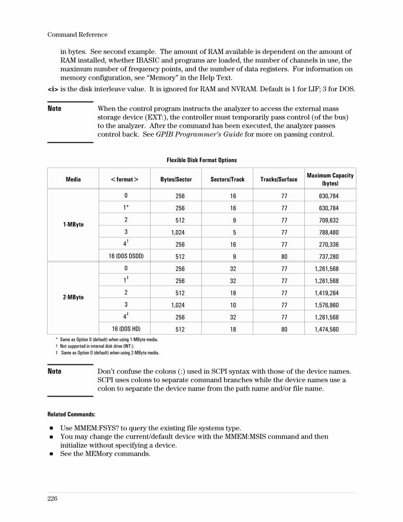
in bytes. See second example. The amount of RAM available is dependent on the amount ofRAM installed, whether IBASIC and programs are loaded, the number of channels in use, themaximum number of frequency points, and the number of data registers. For information onmemory configuration, see “Memory” in the Help Text.
<i> is the disk interleave value. It is ignored for RAM and NVRAM. Default is 1 for LIF; 3 for DOS.
Note When the control program instructs the analyzer to access the external massstorage device (EXT:), the controller must temporarily pass control (of the bus)to the analyzer. After the command has been executed, the analyzer passescontrol back. See GPIB Programmer’s Guide for more on passing control.
Flexible Disk Format Options
Media <format> Bytes/Sector Sectors/Track Tracks/SurfaceMaximum Capacity
(bytes)
1-MByte
0 256 16 77 630,784
1* 256 16 77 630,784
2 512 9 77 709,632
3 1,024 5 77 788,480
4† 256 16 77 270,336
16 (DOS DSDD) 512 9 80 737,280
2-MByte
0 256 32 77 1,261,568
1‡ 256 32 77 1,261,568
2 512 18 77 1,419,264
3 1,024 10 77 1,576,960
4‡ 256 32 77 1,261,568
16 (DOS HD) 512 18 80 1,474,560* Same as Option 0 (default) when using 1-MByte media.† Not supported in internal disk drive (INT:).‡ Same as Option 0 (default) when using 2-MByte media.
Note Don’t confuse the colons (:) used in SCPI syntax with those of the device names.SCPI uses colons to separate command branches while the device names use acolon to separate the device name from the path name and/or file name.
Related Commands:
Use MMEM:FSYS? to query the existing file systems type.You may change the current/default device with the MMEM:MSIS command and theninitialize without specifying a device.See the MEMory commands.
Command Reference
226
MMEMory:LOAD:APPLication commandLoads the specified application.
Command Syntax: MMEMory:LOAD:APPLication ‘[<msus>]<filespec>’<msus> ::= RAM:|NVRAM:|INT:|EXT:<filespec> ::= ASCII characters
(see MMEM:NAME for filename restrictions)
Example Statements: OUTPUT 719;"mmem:load:application ‘int:hp89450a.app’"OUTPUT 719;"MMEM:LOAD:APPL ‘HP89450A.APP’"
Attribute Summary: Synchronization Required: noPreset State: not applicableSCPI Compliance: instrument-specific
Description:
This command loads an application (such as the Agilent 89450A Radio Test Personality) into theanalyzer. The application is loaded into the analyzer’s application memory. Before loading theapplication, you must allocate sufficient memory for the application—for details, seeMEM:MALL:APPL.
If <msus> is not included in the syntax, the currently selected mass storage unit (disk) isassumed. To query or change the currently selected msus, use MMEM:MSIS.
Command Reference
227
MMEMory:LOAD:CONTinue command/queryContinues the load operation of time capture files stored on multiple disks.
Command Syntax: MMEMory:LOAD:CONTinue
Example Statements: OUTPUT 719;"Mmem:Load:Cont"OUTPUT 719;"MMEMORY:LOAD:CONT"
Query Syntax: MMEMory:LOAD:CONTinue?
Return Format: Integer
Attribute Summary: Synchronization Required: noPreset State: not applicableSCPI Compliance: instrument-specific
Description:
Time capture files that are too large to fit on the current disk may be split and stored on morethan one disk with the MMEM:STOR:CONT command. The MMEM:LOAD:CONT command isused to load these split files back into the analyzer.
When the analyzer has completed loading the first part of the split file (for example, filename_1),it generates the message, ‘’Media full; Insert next disk with ‘filename_2’.’’ Insert the diskcontaining the file named filename_2 and send MMEM:LOAD:CONT to continue loading the file.
Use MMEM:LOAD:CONT? to verify that the file has been transferred. If the query returns a +1,the transfer is not complete. The query returns a 0 when the transfer is complete.
When a trace buffer or time capture file is merged, you are prompted to change media at the endof each file. Pressing the Local/Setup key (or any key) on the front panel in Local mode causesthe file merging operation to terminate. SCPI commands, however, sent between operations donot terminate the file operation.
Large files may also be transferred between the analyzer and a controller with the LANfile-transfer utility, FTP (option UG7).
For more information on the generation of split files, see the MMEM:STOR:CONT command.
Command Reference
228
MMEMory:LOAD:MATH commandLoads a complete set of math definitions into the analyzer from the specified file.
Command Syntax: MMEMory:LOAD:MATH ‘[<msus>]<filespec>’
<msus> ::= RAM:|NVRAM:|INT:|EXT:
<filespec> ::= ASCII characters(see MMEM:NAME for filename restrictions)
Example Statements: OUTPUT 719;"Mmem:Load:Math ‘EXT:math’"OUTPUT 719;"MMEMORY:LOAD:MATH ‘RAM:math1’"
Attribute Summary: Synchronization Required: noPreset State: not applicableSCPI Compliance: instrument-specific
Description:
This command loads a file to define the analyzer’s math functions (F1 through F6) and constants(K1 through K5). The file must have been created with the MMEM:STOR:MATH command.
If <msus> is not included in the syntax, the currently selected mass storage unit (disk) isassumed. To query or change the currently selected msus, use MMEM:MSIS.
The math function definitions can also be transferred between the analyzer and a controller withthe LAN file-transfer utility, FTP (option UG7).
Command Reference
229
MMEMory:LOAD:PROGram commandLoads an Instrument BASIC program into the analyzer from a file on the mass storage unitspecified (msus).
Command Syntax: MMEMory:LOAD:PROGram ‘[<msus>]<filespec>’
<msus> ::= RAM:|NVRAM:|INT:|EXT:
<filespec> ::= ASCII characters(see MMEM:NAME for filename restrictions)
Example Statements: OUTPUT 719;"Mmem:Load:Prog ‘myprog’"OUTPUT 719;"MMEMORY:LOAD:PROG ‘RAM:prog1’"
Attribute Summary: Synchronization Required: noPreset State: not applicableSCPI Compliance: instrument-specific
Description:
This command loads an Instrument BASIC program into the program buffer previously selectedwith the PROG:NAME command. Only one program may be loaded at a time (there is only oneprogram buffer).
To load an Instrument BASIC program directly from the controller, use PROG[:SEL]:DEF.
If <msus> is not included in the syntax, the currently selected mass storage unit (disk) isassumed. To query or change the currently selected msus, use MMEM:MSIS.
Command Reference
230
MMEMory:LOAD:STATe commandLoads an instrument state into the analyzer from the mass storage unit specified (msus).
Command Syntax: MMEMory:LOAD:STATe <number>,<filename>
<number> ::= a real number (state number)limits: 1:1
<filename> ::= ‘[<msus>]<filespec>’
<msus> ::= RAM:|NVRAM:|INT:|EXT:
<filespec> ::= ASCII characters(see MMEM:NAME for filename restrictions)
Example Statements: OUTPUT 719;"mmemory:load:state 1, ‘ext:mystate’"OUTPUT 719;"MMEM:LOAD:STAT 1, ‘INT:IFsetup.sta’"
Attribute Summary: Synchronization Required: noPreset State: not applicableSCPI Compliance: confirmed
Description:
This command uses the contents of a file to redefine the instrument state. The file can only becreated by saving an existing state with the MMEM:STOR:STAT command.
If <msus> is not included in the syntax, the currently selected mass storage unit (disk) isassumed. To query or change the currently selected msus, use MMEM:MSIS.
The instrument state can also be transferred between the analyzer and a controller with the LANfile-transfer utility, FTP (option UG7).
Command Reference
231
MMEMory:LOAD:TCAPture commandLoads a time capture file from the mass storage unit specified (msus).
Command Syntax: MMEMory:STORe:TCAPture ‘[<msus>]<filespec>’
<msus> ::= RAM:|NVRAM:|INT:|EXT:
<filespec> ::= ASCII characters(see MMEM:NAME for filename restrictions)
Example Statements: OUTPUT 719;"mmem:load:tcap, ‘int:tcap-01’"OUTPUT 719;"MMEM:LOAD:TCAPTURE, ‘TIME-REF’"
Attribute Summary: Synchronization Required: noPreset State: not applicableSCPI Compliance: instrument-specific
Description:
This command loads the contents of a file into the time capture buffer. The file must have beencreated by saving with the MMEM:STOR:TCAP command.
If <msus> is not included in the syntax, the currently selected mass storage unit (disk) isassumed. To query or change the currently selected msus, use MMEM:MSIS.
The time capture buffer data can also be transferred between the analyzer and a controller withthe LAN file-transfer utility, FTP (option UG7).
Related Commands:
To display the time capture buffer in one of the four traces, use the CALC:FEED‘TCAP[1|2|3|4]’ command.To continue loading a file stored on more than one disk, use the MMEM:LOAD:CONTcommand.
Command Reference
232
MMEMory:LOAD:TRACe commandLoads a trace into the analyzer from the mass storage unit specified.
Command Syntax: MMEMory:LOAD:TRACe <label>,<filename>
<label> ::= D1|D2|D3|D4|D5|D6|
<filename> ::= ‘[<msus>]<filespec>’
<msus> ::= RAM:|NVRAM:|INT:|EXT:
<filespec> ::= ASCII characters(see MMEM:NAME for filename restrictions)
Example Statements: OUTPUT 719;"mmem:load:trac D1, ‘int:test.trc’"OUTPUT 719;"MMEM:LOAD:TRACE D3, ‘MYTRACE’"
Attribute Summary: Synchronization Required: noPreset State: not applicableSCPI Compliance: confirmed
Description:
This command loads the contents of a file into one of the analyzer’s six data registers. The firstparameter specifies the destination. The second parameter specifies the source.
The file must have been created by saving a trace with the MMEM:STOR:TRAC command. Afterloading the data register, it is displayed with the CALC:FEED ‘D1|2...|6’ command.
If <msus> is not included in the syntax, the currently selected mass storage unit (disk) isassumed. To query or change the currently selected msus, use MMEM:MSIS.
The trace data can also be transferred between the analyzer and a controller with the LANfile-transfer utility, FTP (option UG7).
Command Reference
233
MMEMory:LOAD:TRACe:BUFFer commandLoads a waterfall/spectrogram trace buffer into the analyzer from the mass storage unit specified(msus).
Command Syntax: MMEMory:LOAD:TRACe:BUFFer <label>,<filename>
<label> ::= D1|D2|D3|D4|D5|D6|
<filename> ::= ‘[<msus>]<filespec>’
<msus> ::= RAM:|NVRAM:|INT:|EXT:
<filespec> ::= ASCII characters(see MMEM:NAME for filename restrictions)
Example Statements: OUTPUT 719;"mmem:load:trac:buff D1, ‘int:test.trc’"OUTPUT 719;"MMEM:LOAD:TRACE:BUFFER D3, ‘MYTRACE’"
Attribute Summary: Option: AYB (waterfall/spectrogram display)Synchronization Required: noPreset State: not applicableSCPI Compliance: instrument-specific
Description:
This command loads the contents of a file into one of the analyzer’s six data registers. The firstparameter specifies the destination. The second parameter specifies the source.
The file must have been created by saving a trace with the MMEM:STOR:TRAC:BUFF command.After loading the data register, it is displayed with the CALC:FEED ‘D1|2...|6’ command.
If <msus> is not included in the syntax, the currently selected mass storage unit (disk) isassumed. To query or change the currently selected msus, use MMEM:MSIS.
This command differs from the TRAC:BUF:COPY command in that MMEM:LOAD:TRAC:BUFloads data into a data register from a file and TRAC:BUF:COPY copies trace data to one of thedata registers.
The waterfall/spectrogram data can also be transferred between the analyzer and a controllerwith the LAN file-transfer utility, FTP (option UG7).
Command Reference
234
MMEMory:MOVE commandMoves a file from one device to another or renames a file.
Command Syntax: MMEMory:MOVE <source>,<destination>
<source> ::= ‘[<device>]<filename>’
<destination> ::= ‘[<device>]<filename>’
<device> ::= NVRAM:|RAM:|INT:|EXT[,<device_selector>[,<unit_number>]]:
<device_selector> ::= a real number (NRf data)limits: 700:730
<unit_number> ::= a real number (NRf data)limits: 0:3
<filename> ::= ASCII characters(see MMEM:NAME for information on filename conventions)
Example Statements: OUTPUT 719;"mmemory:move ‘int:file1’, ‘myfile’"OUTPUT 719;"MMEM:MOVE ‘TESTFILE’, ‘FILE3’"
Attribute Summary: Synchronization Required: noPreset State: not applicableSCPI Compliance: confirmed
Description:
This command may be used to copy one or more files to another device or directory,automatically deleting the source file(s), or to rename a file. It may be also be used to move a fileand rename it. Wildcards may be used to specify filenames in the <source> but not in the<destination>. See MMEM:NAME for filename conventions and wildcard usage.
The <device> values are defined under MMEM:MSIS.
Related Commands:
Use MMEM:MSIS (mass storage is) to specify the default device.Use MMEM:COPY to copy files from one device and/or path to another without deleting thesource.Use SCR:CONT MMEM to display directory listings.
Note When the control program instructs the analyzer to access the external massstorage device (EXT:), the controller must temporarily pass control (of the bus)to the analyzer. After the command has been executed, the analyzer must passcontrol back. See GPIB Programmer’s Guide for more on passing control.
Command Reference
235
MMEMory:MSIS command/querySpecifies a default mass storage device (disk) and (for DOS) directory.
Command Syntax: MMEMory:MSIS ‘<device>’
<device> ::= NVRAM:|RAM:|INT:|EXT[,<device_selector>[,<unit_number>]]:
<device_selector> ::= a real number (NRf data)limits: 700:730
<unit_number> ::= a real number (NRf data)limits: 0:3
Example Statements: OUTPUT 719;":Mmem:Msis ‘INT:’"OUTPUT 719;"MMEMORY:MSIS ‘RAM:’"OUTPUT 719;"mmem:msis ‘int:/data/friday’"
Query Syntax: MMEMory:MSIS?
Return Format: STRING
Attribute Summary: Synchronization Required: noPreset State: saved in non-volatile memorySCPI Compliance: confirmed
Description:
<device> is the mass storage unit specifier; usually a disk drive, but also used to indicate RAMor NVRAM volumes (which perform as very fast drives) or any external mass storage device(EXT:). For DOS file systems, a directory may also be specified (see third example). The devicetypes are:
NVRAM: selects the non-volatile RAM drive.RAM: selects the volatile RAM drive.INT: selects the internal drive.EXT: selects the external drive.
<device_selector> and <unit_number> specifiers are valid only with the EXT: devicespecifier. A device_selector is composed of the select_code (usually 7) and the GPIB address(0-30). The unit-number specifies the subunit within a volume as for a dual floppy drive. Ifdevice_selector and unit_number are specified with this command, they become the default forthe external (EXT:) specifier.
Related Commands:
To determine the type of file system for the default disk, send the MMEM:FSYStem? query.To display the directory contents, use SCR:CONT MMEM.
Note When the control program instructs the analyzer to access the external massstorage device (EXT:), the controller must temporarily pass control (of the bus)to the analyzer. After the command has been executed, the analyzer must passcontrol back. See GPIB Programmer’s Guide for more on passing control.
Command Reference
236
MMEMory:NAME command/querySpecifies the filename for printing or plotting to a file.
Command Syntax: MMEMory:NAME ‘[<device>]<filename>’
<device> ::= RAM:|NVRAM:|INT:|EXT[,<select_code>[,<unit_number>]]:
<select_code> ::= a real number (NRf data)limits: 700:730
<unit_number> ::= a real number (NRf data)limits: 0:3
<filename> ::= ASCII characters(see description for <filename> conventions)
Example Statements: OUTPUT 719;":Mmemory:Name ‘plot1.hpg’"OUTPUT 719;"MMEM:NAME ‘INT:3RD-IF_PCL’"
Query Syntax: MMEMory:NAME?
Return Format: STRING
Attribute Summary: Synchronization Required: noPreset State: “plotfile”SCPI Compliance: confirmed
Description:
This command is used to specify a filename when printing or plotting to a file. Specifying FILEas the output destination is done with the HCOP:DEST FILE command.
If no mass storage unit specifier (msus) is given, the device specified with the last MSIS (massstorage is) command is used. If MSIS has not been used since the last preset, then msus =NVRAM (non-volatile RAM).
If EXT is specified, control of the bus must be passed to the analyzer.
Filename and Wildcard Conventions:
DOS filenames are limited in length to 8 ASCII characters followed by a period and an(optional) extension of one to three characters. Both the period and extension are optional. Theperiod is not part of the filename; it separates the name and extension. DOS filenames are notcase sensitive. Valid special characters are _, ^, $, ~, !, #, %, &, -, , , (, ), @, ‘, ‘. A name may notcontain spaces, commas, backslashes, or periods (except the period that separates the name andextension). Reserved names that may not be used are CLOCK$, CON, AUX, COMn (n = 1–4),LPTn (n = 1–3), NUL, and PRN.
LIF filenames are limited in length to 10 characters which may include any character except :, <,and |. The first character must be a letter. LIF filenames are case sensitive.
Wildcards allow you to identify more than one file when a filename is used as a command’sargument, such as for copy or delete. A wildcard character can match part or all of the filename.Two characters are used as wildcards: ? matches any single character and * matches allcharacters to the end of the name. To match all filenames starting with B, use B*. You can usethe asterisk to identify files that have common first characters, but not files with matching
Command Reference
237
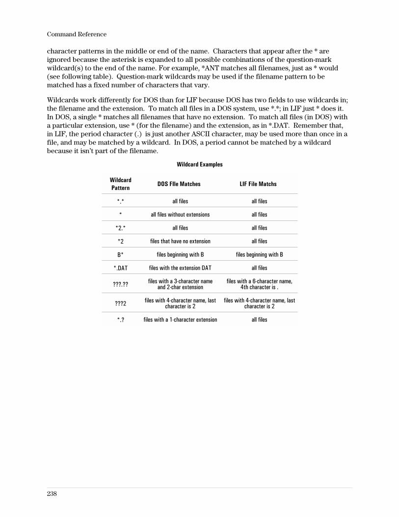
character patterns in the middle or end of the name. Characters that appear after the * areignored because the asterisk is expanded to all possible combinations of the question-markwildcard(s) to the end of the name. For example, *ANT matches all filenames, just as * would(see following table). Question-mark wildcards may be used if the filename pattern to bematched has a fixed number of characters that vary.
Wildcards work differently for DOS than for LIF because DOS has two fields to use wildcards in;the filename and the extension. To match all files in a DOS system, use *.*; in LIF just * does it.In DOS, a single * matches all filenames that have no extension. To match all files (in DOS) witha particular extension, use * (for the filename) and the extension, as in *.DAT. Remember that,in LIF, the period character (.) is just another ASCII character, may be used more than once in afile, and may be matched by a wildcard. In DOS, a period cannot be matched by a wildcardbecause it isn’t part of the filename.
Wildcard Examples
WildcardPattern
DOS FIle Matches LIF File Matchs
*.* all files all files
* all files without extensions all files
*2.* all files all files
*2 files that have no extension all files
B* files beginning with B files beginning with B
*.DAT files with the extension DAT all files
???.?? files with a 3-character nameand 2-char extension
files with a 6-character name,4th character is .
???2 files with 4-character name, lastcharacter is 2
files with 4-character name, lastcharacter is 2
*.? files with a 1-character extension all files
Command Reference
238
MMEMory:STORe:CONTinue command/queryAllows a large time capture file to be split over multiple disks.
Command Syntax: MMEMory:STORe:CONTinue
Example Statements: OUTPUT 719;":mmemory:stor:continue"OUTPUT 719;"Mmem:Stor:Continue"
Query Syntax: MMEMory:STORe:CONTinue?
Return Format: Integer
Attribute Summary: Synchronization Required: noPreset State: not applicableSCPI Compliance: instrument-specific
Description:
If the amount of time capture data to be stored is more than the available space on thedestination disk, the error message, ‘’Media full; File too large’’ is generated. This error messageis generated before the store operation begins. Send the MMEM:STOR:CONT message to beginthe store operation.
MMEM:STOR:CONT adds a numeric specifier to the filename. Split files appear as filename_1,filename_2, etc. in the disk catalog (see DISP:CONT MMEM).
MMEM:STOR:CONT? returns a +1 when queried before the transfer is complete. Insert anotherdisk and send MMEM:STOR:CONT to continue the store operation. The query returns a 0 whenthe entire file has been stored.
When a trace buffer or time capture file is split, you are prompted to change media at the end ofeach file. Pressing the Local/Setup key (or any key) on the front panel in Local mode causes thefile splitting operation to terminate. SCPI commands, however, sent between operations do not
terminate the file operation.
Large files may also be transferred between the analyzer and a controller with the LANfile-transfer utility, FTP (option UG7).
Command Reference
239
MMEMory:STORe:MATH commandSaves a complete set of math definitions to the mass storage unit specified (msus).
Command Syntax: MMEMory:STORe:MATH ‘[<msus>]<filespec>’
<msus> ::= RAM:|NVRAM:|INT:|EXT:
<filespec> ::= ASCII characters(see MMEM:NAME for filename restrictions)
Example Statements: OUTPUT 719;"Mmem;Store:Math ‘EXT:math’"OUTPUT 719;"MMEMORY:STOR:MATH ‘RAM:math1’"
Attribute Summary: Synchronization Required: noPreset State: not applicableSCPI Compliance: instrument-specific
Description:
A complete set of math definitions includes the current values in all of the function registers (F1through F6) and all of the constant registers (K1 through k5). If the filename you specify withthis command matches the name of another file on the mass storage unit specified, the existingfile is overwritten.
If <msus> is not included in the syntax, the currently selected mass storage unit (disk) isassumed. To query or change the currently selected msus, use MMEM:MSIS.
The math function definitions can also be transferred between the analyzer and a controller withthe LAN file-transfer utility, FTP (option UG7).
Command Reference
240
MMEMory:STORe:PROGram commandStores an Instrument BASIC program to a file on the specified disk.
Command Syntax: MMEMory:STORe:PROGram ‘[<msus>]<filespec>’
<msus> ::= RAM:|NVRAM:|INT:|EXT:
<filespec> ::= ASCII characters(see MMEM:NAME for filename restrictions)
Example Statements: OUTPUT 719;"Mmem:Stor:Prog ‘EXT:ibprog’"OUTPUT 719;"MMEMORY:STORE:PROGRAM ‘int:myprog’"
Attribute Summary: Synchronization Required: noPreset State: not applicableSCPI Compliance: instrument-specific
Description:
This command stores the currently active Instrument BASIC program to the mass storage unitspecified. The program must be located in the active program buffer (see the PROG:NAMEcommand). If the active program buffer does not contain a program, the analyzer generates theerror message, ‘’Program Error, No program exists.’’
If the specified filename is the same as an existing file, the analyzer generates the error message,‘’Program Error, Duplicate file name,’’ and it aborts the store operation. This command will notoverwrite an existing file. See the MMEM:DEL command for information about deleting existingfiles from a disk.
If <msus> is not included in the syntax, the currently selected mass storage unit (disk) isassumed. To query or change the currently selected msus, use MMEM:MSIS.
Command Reference
241
MMEMory:STORe:STATe commandSaves the instrument state to a file on the specified mass storage unit.
Command Syntax: MMEMory:STORe:STATe <number>,<filename>
<number> ::= a real number (state number)limits: 1:1
<filename> ::= ‘[<msus>]<filespec>’
<msus> ::= RAM:|NVRAM:|INT:|EXT:
<filespec> ::= ASCII characters(see MMEM:NAME for filename restrictions)
Example Statements: OUTPUT 719;"mmemory:store:state 1, ‘ext:mystate’"OUTPUT 719;"MMEM:STOR:STAT 1, ‘INT:IFsetup.sta’"
Attribute Summary: Synchronization Required: noPreset State: not applicableSCPI Compliance: confirmed
Description:
If the filename matches that of another file on the mass storage unit specified (msus), thiscommand overwrites the existing file.
If msus is not included in the syntax, the currently selected mass storage unit (disk) is assumed.
The instrument state can also be transferred between the analyzer and a controller with the LANfile-transfer utility, FTP (option UG7).
Related Commands:
To query or change the currently selected msus, use MMEM:MSIS (mass storage is).
Command Reference
242
MMEMory:STORe:TCAPture commandStores the time capture buffer to a file on the mass storage unit specified (msus).
Command Syntax: MMEMory:STORe:TCAPture ‘[<msus>]<filespec>’
<msus> ::= RAM:|NVRAM:|INT:|EXT:
<filespec> ::= ASCII characters(see MMEM:NAME for filename restrictions)
Example Statements: OUTPUT 719;"mmem:stor:tcap, ‘int:tcap-01’"OUTPUT 719;"MMEM:STORE:TCAPTURE, ‘TIME-REF’"
Attribute Summary: Synchronization Required: noPreset State: not applicableSCPI Compliance: instrument-specific
Description:
If the contents of the time capture buffer is too large for the mass storage unit, the error message‘’Media full; File too large’’ is generated. Use the MMEM:STOR:CONT command to split the fileover multiple disks. See MMEM:STOR:CONT command for more information about splitting atime capture file on multiple disks.
If the filename matches the name of another file on the mass storage unit, this commandoverwrites the old file.
If <msus> is not included in the syntax, the currently selected mass storage unit (disk) isassumed. To query or change the currently selected msus, use MMEM:MSIS.
The time capture buffer data can also be transferred between the analyzer and a controller withthe LAN file-transfer utility, FTP (option UG7).
Note If you plan to transfer this file to a PC, refer to the Standard Data Format
Utilities Users Guide for information on format conversion.
Command Reference
243
MMEMory:STORe:TRACe commandSaves the trace to a file on the mass storage unit specified (msus).
Command Syntax: MMEMory:STORe:TRACe <label>,<filename>
<label> ::= TRACe1|TRACe2|TRACe3|TRACe4
<filename> ::= ‘[<msus>]<filespec>’
<msus> ::= RAM:|NVRAM:|INT:|EXT:
<filespec> ::= ASCII characters(see MMEM:NAME for filename restrictions)
Example Statements: OUTPUT 719;"mmem:stor:trac trac1, ‘int:test.trc’"OUTPUT 719;"MMEM:STORE:TRACE TRACE3, ‘MYTRACE’"
Attribute Summary: Synchronization Required: noPreset State: not applicableSCPI Compliance: confirmed
Description:
The first parameter specifies which trace is stored. The second parameter specifies the massstorage unit (disk) and filename. If the filename matches the name of another file on the disk,this command overwrites the existing file.
If <msus> is not included in the syntax, the currently selected mass storage unit (disk) isassumed. To query or change the currently selected msus, use MMEM:MSIS.
This command differs from the TRAC:DATA command in that MMEM:STOR:TRAC stores data toa file and TRAC:DATA stores trace data to one of the data registers.
The trace data can also be transferred between the analyzer and a controller with the LANfile-transfer utility, FTP (option UG7).
Note If you plan to transfer this file to a PC, refer to the Standard Data Format
Utilities Users Guide for information on format conversion.
Command Reference
244
MMEMory:STORe:TRACe:BUFFer commandSaves the waterfall/spectrogram trace buffer to a file on the mass storage unit specified (msus).
Command Syntax: MMEMory:STORe:TRACe:BUFFer <label>,<filename>
<label> ::= TRACe1|TRACe2|TRACe3|TRACe4
<filename> ::= ‘[<msus>]<filespec>’
<msus> ::= RAM:|NVRAM:|INT:|EXT:
<filespec> ::= ASCII characters(see MMEM:NAME for filename restrictions)
Example Statements: OUTPUT 719;"mmem:stor:trac;buff trac1, ‘int:test.buf’"OUTPUT 719;"MMEM:STORE:TRACE:BUFF TRACE3, ‘SPECTRO1’"
Attribute Summary: Option: AYB (waterfall/spectrogram display)Synchronization Required: noPreset State: not applicableSCPI Compliance: instrument-specific
Description:
The first parameter specifies which trace buffer is stored. The second parameter specifies themass storage unit (disk) and filename. If the filename matches the name of another file on thedisk, this command overwrites the existing file.
If <msus> is not included in the syntax, the currently selected mass storage unit (disk) isassumed. To query or change the currently selected msus, use MMEM:MSIS.
This command differs from the TRAC:BUF:COPY command in that MMEM:STOR:TRAC:BUFstores data to a file and TRAC:BUF:COPY stores trace data to one of the data registers.
The waterfall/spectrogram data can also be transferred between the analyzer and a controllerwith the LAN file-transfer utility, FTP (option UG7).
Note If you plan to transfer this file to a PC, refer to the Standard Data Format
Utilities Users Guide for information on format conversion.
Command Reference
245
OUTPut:FILTer[:LPASs][:STATe] command/queryTurns the source output lowpass filter on and off.
Command Syntax: OUTPut:FILTer[:LPASs][:STATe] OFF|0|ON|1
Example Statements: OUTPUT 719;"OUTP:FILTER:LPAS:STAT OFF"OUTPUT 719;"output:filt OFF"
Query Syntax: OUTPut:FILTer[:LPASs][:STATe]?
Return Format: Integer
Attribute Summary: Synchronization Required: noPreset State: 1SCPI Compliance: confirmed
Description:
This command is available only for the 89410A or for the 89441A when ROUT:REC is IF.
This 10 MHz low-pass filter limits the bandwidth of the source output signal as the final step inconverting a digital signal to an analog signal. Some arbitrary source signals may require thatthis filter be removed.
Command Reference
246
OUTPut:IMPedance command/querySelects the output termination impedance.
Command Syntax: OUTPut:IMPedance <number>
<number> ::= 50 | 75
Example Statements: OUTPUT 719;"Outp:Imp 50"OUTPUT 719;"outp:imp 75"
Query Syntax: OUTPut:IMPedance?
Return Format: Real
Attribute Summary: Synchronization Required: noPreset State: 50SCPI Compliance: confirmed
Description:
This command is available for the 89441A only when ROUT:REC is IF.
Command Reference
247
OUTPut[:STATe] command/queryTurns the source output on and off.
Command Syntax: OUTPut[:STATe] OFF|0|ON|1
Example Statements: OUTPUT 719;":Output ON"OUTPUT 719;"OUTP:STAT OFF"
Query Syntax: OUTPut[:STATe]?
Return Format: Integer
Attribute Summary: Synchronization Required: noPreset State: 0SCPI Compliance: confirmed
Description:
The source is off when the analyzer is first turned on and is turned off whenever the analyzer ispreset (with the *RST command).
Source type is selected with the SOUR:FUNC command.Source level is set with the SOUR:VOLT command.
Note It is good practice to specify the source level before the source is turned on.When the source is turned on, the output voltage level is whatever value wasactive when it was turned off. At turn-on and preset, the level is −10 dBm(100 mV). The active value may be large enough to damage sensitive devices.
Command Reference
248
PAUSe commandPause the measurement in progress.
Command Syntax: PAUSe
Example Statements: OUTPUT 719;"pause"OUTPUT 719;"Paus"
Attribute Summary: Synchronization Required: noPreset State: not applicableSCPI Compliance: instrument-specific
Description:
Characteristics:
Pauses a measurement process.In Vector or Demod modes, current average is completed before pause occurs.In Scalar mode, analyzer may pause in the middle of a sweep, even if averaging is on.Data is not affected by PAUSE. It is valid and may be manipulated (with CALC:FORM,CALC:FEED, or CALC:MATH).CONT restarts a paused measurement without affecting data.ABORT, ABORT;INIT, and *RST destroy existing data and restart a paused measurement.A paused measurement does not respond to INIT:IMM.
Command Reference
249
PROGram:EXPLicit:DEFine command/queryLoads an Instrument BASIC program into a program buffer from an external controller.
Command Syntax: PROGram:EXPLicit:DEFine <prog_list>,<program>
<prog_list> ::= PROGram1
<program> ::= <block>
Example Statements: For an indefinite-length block:
OUTPUT 719;"PROG:EXPL:DEF PROG1,#0";OUTPUT 719;"10 PRINT “”HELLO WORLD"""&CHR$(10);OUTPUT 719;"20 END"&CHR$(10) END
For a definite-length block:
OUTPUT 719;"PROG:EXPL:DEF PROG1,#230";OUTPUT 719;"10 PRINT “”HELLO WORLD"""&CHR$(10);OUTPUT 719;"20 END"&CHR$(10);
Query Syntax: PROGram:EXPLicit:DEFine?
Return Format: definite-length block
Attribute Summary: Option: 1C2 Agilent Technologies Instrument BASICSynchronization Required: noPreset State: not applicableSCPI Compliance: confirmed
Description:
This command transfers a program between the analyzer and the controller. This allowsprograms developed on a controller to be loaded into the analyzer. The first parameter specifiesthe analyzer’s program buffer (the destination), which becomes the active program buffer. Thesecond parameter is the Instrument BASIC program.
A program may be transferred to the analyzer with either the definite-length or theindefinite-length block syntax. The simplest way to load an Instrument BASIC program is tosend this command followed by #0, followed by all the characters making up the program(including line numbers and line feeds at the end of each program statement). Terminate theentire command with line feed character (ASCII decimal 10) and <^END> (the GPIB ENDmessage, EOI set true). See example above.
When the analyzer returns the program to your controller, it always uses the definite-lengthblock syntax. See ‘’Block Data’’ in the GPIB Programmer’s Guide for more information.
Command Reference
250
PROGram[:SELected]:DEFine command/queryLoads an Instrument BASIC program from an external controller into the active program buffer.
Command Syntax: PROGram[:SELected]:DEFine <program>
<program> ::= <block>
Example Statements: For an indefinite-length block:
OUTPUT 719;"PROG:DEF #0";OUTPUT 719;"10 PRINT “”HELLO WORLD"""&CHR$(10);OUTPUT 719;"20 END"&CHR$(10) END
For a definite-length block:
OUTPUT 719;"PROG:DEF #230";OUTPUT 719;"10 PRINT “”HELLO WORLD"""&CHR$(10);OUTPUT 719;"20 END"&CHR$(10);
Query Syntax: PROGram[:SELected]:DEFine?
Return Format: definite-length block
Attribute Summary: Option: 1C2 Agilent Technologies Instrument BASICSynchronization Required: noPreset State: not applicableSCPI Compliance: confirmed
Description:
This command transfers a program between the analyzer and the controller. This allowsprograms developed on a controller to be loaded into the analyzer.
Use the PROG[:SEL]:NAME to select the active program buffer.
A program may be transferred to the analyzer with either the definite-length or theindefinite-length block syntax. The simplest way to load an Instrument BASIC program is tosend this command followed by #0, followed by all the characters making up the program(including line numbers and line feeds at the end of each program statement). Terminate theentire command with line feed character (ASCII decimal 10) and <^END> (the GPIB ENDmessage, EOI set true). See example above.
When the analyzer returns the program to your controller, it always uses the definite-lengthblock syntax. See ‘’Block Data’’ in the GPIB Programmer’s Guide for more information.
Command Reference
251
PROGram[:SELected]:DELete:ALL commandDeletes all Instrument BASIC programs stored in the analyzer.
Command Syntax: PROGram[:SELected]:DELete:ALL
Example Statements: OUTPUT 719;":PROGRAM:DEL:ALL"OUTPUT 719;"program:sel:delete:all"
Attribute Summary: Option: 1C2 Agilent Technologies Instrument BASICSynchronization Required: noPreset State: not applicableSCPI Compliance: confirmed
Description:
In addition to deleting the active program, this command deletes all of the resident InstrumentBASIC programs. Program variables—both those in COM and those not in COM are deleted aswell.
Command Reference
252
PROGram[:SELected]:DELete[:SELected] commandDeletes the active Instrument BASIC program.
Command Syntax: PROGram[:SELected]:DELete[:SELected]
Example Statements: OUTPUT 719;"Prog:Selected:Del:Selected"OUTPUT 719;"PROG:DEL"
Attribute Summary: Option: 1C2 Agilent Technologies Instrument BASICSynchronization Required: noPreset State: not applicableSCPI Compliance: confirmed
Description:
In addition to deleting the active program, this command deletes all of the programvariables—both those in COM and those not in COM. Specify the active program with thePROG:NAME command.
Command Reference
253
PROGram[:SELected]:MALLocate command/queryAllocates memory space for Instrument BASIC programs.
Command Syntax: PROGram[:SELected]:MALLocate <number>|<bound>|DEFault
<number> ::= a real number (NRf data)limits: 1200:(see discussion)
<bound> ::= MAX|MIN
Example Statements: OUTPUT 719;"program:sel:mall 134987"OUTPUT 719;"Prog:Mall 250982"
Query Syntax: PROGram[:SELected]:MALLocate?
Return Format: Integer
Attribute Summary: Option: 1C2 Agilent Technologies Instrument BASICSynchronization Required: noPreset State: not affected by PresetSCPI Compliance: confirmed
Description:
Upper limit depends on the amount of memory available for IBASIC use. Largest number parsedis 500000.
PROG:MALL DEF causes the analyzer to resize the stack space to fit the current active program.In some cases, the analyzer may allocate more memory than the program needs.
Use MEM:FREE to determine current memory availability and usage.
Note If the message, ‘’ERROR 2 Memory overflow’’ is displayed while the program isrunning, allocate more memory.
Command Reference
254

PROGram[:SELected]:NAME command/querySelects an Instrument BASIC program.
Command Syntax: PROGram[:SELected]:NAME <prog_list>
<prog_list> ::= PROGram1
Example Statements: OUTPUT 719;"Program:Name PROG1"OUTPUT 719;"PROGRAM:SEL:NAME PROGram1"
Query Syntax: PROGram[:SELected]:NAME?
Return Format: CHAR
Attribute Summary: Option: 1C2 Agilent Technologies Instrument BASICSynchronization Required: noPreset State: not affected by PresetSCPI Compliance: confirmed
Description:
Use this command to designate an Instrument BASIC program buffer as the ‘’active’’ programbuffer.
For example, use this command to select a program buffer when you load an Instrument BASICprogram into the analyzer with the PROG:DEF command.
Command Reference
255
PROGram[:SELected]:NUMBer command/queryLoads a new value for the specified numeric variable in the active Instrument BASIC program.
Command Syntax: PROGram[:SELected]:NUMBer ‘<variable>’, <block>
<variable> ::= name of a numeric variable
When data is ASCII-encoded (FORM ASC):<block> ::= <number>[,<number>] . . .
<number> ::= a real number (NRf data)limits: -9.9e37:9.9e37
When data is binary-encoded (FORM REAL):<block> ::= #<byte>[<length>]<number>[,<number>] . . .
<byte> ::= number of length bytes to follow (ASCII encoded)
<length> ::= number of data bytes to follow (ASCII encoded)
<number> ::= a real number (or 64-bit binary floating point)
Example Statements: For ASCII blocks:
OUTPUT 719;"FORM ASC"OUTPUT 719;"PROG:NUMB ‘A’, 12.345"
For real, indefinite-length blocks:
ASSIGN @Dev TO 719OUTPUT @Dev;"FORM REAL"ASSIGN @Dev;FORMAT OFFOUTPUT @Dev;"PROG:NUMB ‘A’, #0";12.345 ENDASSIGN @Dev;FORMAT ON
For real, definite-length blocks:
ASSIGN @Dev TO 719OUTPUT @Dev;"FORM REAL"ASSIGN @Dev;FORMAT OFFOUTPUT @Dev;"PROG:NUMB ‘A’, #18";12.345ASSIGN @Dev;FORMAT ON
Query Syntax: PROGram[:SELected]:NUMBer?
Return Format: definite-length block
Attribute Summary: Option: 1C2 Agilent Technologies Instrument BASICSynchronization Required: noPreset State: not applicableSCPI Compliance: confirmed
Description:
Set or query the value of numeric variables from the currently selected IBASIC program. Thesevariables can be either arrays or single values. If the specified variable is not defined in thecurrent program, the error “Illegal variable name” (-283) is generated. The second parameter in a
Command Reference
256

set command is a list of values for the variable or array to be assigned. This list may either beASCII numbers separated by commas or a definite or indefinite block. The response is generatedin the current format (specified by the FORMat[:DATA] command).
When an array is loaded with this command, values in the <block> parameter are loaded into the1st through nth elements of the array (where n is number of values in the block).
Related Commands:
To specify the active program, use PROG:NAME.To load string variables, use PROG:STR.
Command Reference
257
PROGram[:SELected]:STATe command/querySelects the state of the active Instrument BASIC program.
Command Syntax: PROGram[:SELected]:STATe STOP|PAUSe|RUN|CONTinue
Example Statements: OUTPUT 719;":program:stat STOP"OUTPUT 719;"Program:Sel:Stat PAUSE"
Query Syntax: PROGram[:SELected]:STATe?
Return Format: CHAR
Attribute Summary: Option: 1C2 Agilent Technologies Instrument BASICSynchronization Required: noPreset State: not affected by PresetSCPI Compliance: confirmed
Description:
This command is used to run, pause, stop or continue the active Instrument BASIC program.
The analyzer generates an error message, ‘’Settings conflict; Invalid program state changerequested,’’ if you send RUN or CONT while a program is running. It also generates the error ifyou send CONT while a program is stopped.
Use the PROG:NAME command to select the active program.
Command Reference
258
PROGram[:SELected]:STRing command/queryLoads a new value for the specified string variable for the active Instrument BASIC program.
Command Syntax: PROGram[:SELected]:STRing ‘<variable>’,’<string>’
<variable> ::= name of string variable(mandatory $ at the end of the name)
<string> ::= ASCII characters 0 through 255maximum number of characters: 32766
Example Statements: OUTPUT 719;"PROG:SELECTED:STR ‘A$’, ‘Done’"OUTPUT 719;"prog:string ‘Message$’,’Measuring’"
Query Syntax: PROGram[:SELected]:STRing?
Return Format: <string>
Attribute Summary: Option: 1C2 Agilent Technologies Instrument BASICSynchronization Required: noPreset State: not applicableSCPI Compliance: confirmed
Description:
This command sets or queries the contents of a string variable in the active Instrument BASICprogram. Use the PROG:NAME to designate the active program.
Use the PROG[:SEL]:NUMB command to load or query numeric variables.
Command Reference
259
ROUTe:RECeiver command/querySpecifies receiver type.
Command Syntax: ROUTe:RECeiver INPut|RF1|RF2|IF|COMBine|EXTernal
Example Statements: OUTPUT 719;"rout:receiver INPUT"OUTPUT 719;"rout:receiver COMBINE"OUTPUT 719;":Route:Rec EXT"
Query Syntax: ROUTe:RECeiver?
Return Format: CHAR
Attribute Summary: Option: (see COMBine discussion)Synchronization Required: noPreset State: 89410: INP, 89441: RF2SCPI Compliance: instrument-specific
Description:
INPut specifies the configuration in which the signal to be measured is connected to thefront-panel connector labeled Channel 1. This is the default selection for the 89410A. It is validonly for the 89410A.
RF2 specifies the configuration in which the signal to be measured is connected to the inputconnector of the RF Section and the spectrum of interest is between 2 MHz and 2.650 GHz for the89441A. This is the default selection for the 89441A. It is valid only for the 89441A.
RF1 specifies the configuration in which the signal to be measured is connected to the inputconnector of the RF Section and the spectrum of interest is between 0 Hz and 10 MHz. This issimilar to the IF configuration but offers the advantage of not changing the input cableconnections. For best 75Ω impedance matching and calibration of measurement results, use IF.This selection is valid only for the 89441A.
IF specifies the configuration in which the signal to be measured is connected to the Channel 1connector of the IF Section and the spectrum of interest is between 0 Hz and 10 MHz. This issimilar to the RF1 configuration but offers the advantage of better matching for 75Ω impedances(as opposed to using a minimum loss pad on the RF Section) and better calibration ofmeasurement results. It’s disadvantage is that it requires reconfiguring the input cabling if youwere previously making measurements above 10 MHz. This selection is valid only for the 89441A.
COMBine specifies the configuration in which data from both input channels are combined as I+ jQ (Ch1 + j*Ch2). This feature is part of option AYA (vector analysis/digital demod) andrequires the presence of option AY7 (the second 10 MHz input channel). For more informationon I + jQ, see online help (press the [ Help ] key, press 1 to show the index, use the knob orarrow keys to move through the list to input section (Ch1+jCh2), then press 4 to jump to thediscussion).
EXTernal specifies the configuration in which the input comes from an external downconvertersuch as the Agilent 89411A. This configuration has more commands under [SENS:]FREQ:EXT.
Command Reference
260
SCReen:CONTents command/querySpecifies what is displayed on the analyzer screen.
Command Syntax: SCReen:CONTents TRACe|MSTate|ISTate|MMEMory|MEMory|OPTions|TCAPture
Example Statements: OUTPUT 719;"SCREEN:CONT TCAPTURE"OUTPUT 719;"screen:cont TRACE"
Query Syntax: SCReen:CONTents?
Return Format: CHAR
Attribute Summary: Synchronization Required: noPreset State: TRACSCPI Compliance: instrument-specific
Description:
TRACe displays the standard measurement trace/grid.
MSTate displays the measurement state display. This shows the instrument mode, frequencyparameters, RBW/window settings, etc.
ISTate displays the instrument state display. This shows the range/input, trigger, and sourcesettings.
MMEMory displays the current disk (mass memory) catalog.
MEMory displays the active memory configuration.
OPTions displays the options configuration.
TCAPture displays the time capture statistics.
Command Reference
261
[SENSe:]AVERage:COUNt command/querySpecifies the number of traces to be averaged or the weighting factor for exponential averaging.
Command Syntax: [SENSe:]AVERage:COUNt <number>|<step>|<bound>
<number> ::= an integer (NRf data)limits: 1:99999
<step> ::= UP|DOWN
<bound> ::= MAX|MIN
Example Statements: OUTPUT 719;":AVERAGE:COUN 100"OUTPUT 719;"sens:average:coun 20"
Query Syntax: [SENSe:]AVERage:COUNt?
Return Format: Integer
Attribute Summary: Synchronization Required: noPreset State: 10SCPI Compliance: confirmed 1992.0
Description:
Averaging overview:
Averaging is turned on with the AVER ON command.AVER:IRES turns fast averaging on and off.AVER:IRES:RATE specifies the fast averaging update rate.AVER:TYPE specifies the average type: RMS (power), complex (time), or max (peak hold).AVER:TCON specifies termination control types which are normal, exponential, or repeat.– For normal averaging (AVER:TCON NORM), AVER:COUN specifies the number of
measurement results that are averaged together. When the specified number ofmeasurements have been taken and averaged together, the analyzer quits taking data andsets the NPO flag (No Pending Operations) to 1.
– If repeat averaging is on (AVER:TCON REP), the averaging process restarts immediatelyafter the current average is completed.
– For exponential averaging (AVER:TCON EXP), AVER:COUN specifies a weighting factorwhich determines how the results of previous (averaged) measurement data (AVGi−1) iscombined with the current measurement data (Xi). The data is combined point-by-pointas described by:
AVGi = 1nXi +
n−1n
AVGi−1
where n is the weighting factor specified by AVER:COUN. Note that for small values ofn, the new data is a significant part of the average; for large values of n, new data hasmuch less weight in the calculated average.
Note For exponential averaging, the averaging process does not stop after n
measurements. The NPO flag is set to 1 after n measurements.
Command Reference
262
[SENSe:]AVERage:COUNt:INTermediate? queryReturns the current average count.
Query Syntax: [SENSe:]AVERage:COUNt:INTermediate?
Example Statements: OUTPUT 719;":Aver:Count:Int?"OUTPUT 719;"SENSE:AVER:COUN:INTERMEDIATE?"
Return Format: Integer
Attribute Summary: Synchronization Required: noPreset State: not applicableSCPI Compliance: instrument-specific
Description:
This command returns the number of averages that have been completed. The number ofaverages that the analyzer performs is determined by [SENSE:]AVERage:COUNt.
Command Reference
263
[SENSe:]AVERage:IRESult:RATE command/querySets the value of the display update rate for fast averaging.
Command Syntax: [SENSe:]AVERage:IRESult:RATE <number>|<step>|<bound>
<number> ::= an integer (NRf datalimits: 1:99999
<step> ::= UP|DOWN
<bound> ::= MAX|MIN
Example Statements: OUTPUT 719;":AVERAGE:IRES:RATE 100"OUTPUT 719;"sense:aver:iresult:rate 300"
Query Syntax: [SENSe:]AVERage:IRESult:RATE?
Return Format: Integer
Attribute Summary: Synchronization Required: noPreset State: 10SCPI Compliance: instrument-specific
Description:
Fast averaging allows the numeric processing to run faster by reducing the time spent updatingthe display. The user selects a number that specifies how often the display is updated and turnsfast averaging on. If 5 is entered, the display is updated once every 5 averages.
Fast averaging is turned on and off with the AVER:IRES command.Averaging is turned on and off with the AVER command.
The larger the update rate, the faster the average gets to the specified count, N.
Command Reference
264

[SENSe:]AVERage:IRESult[:STATe] command/queryTurns the fast average on and off.
Command Syntax: [SENSe:]AVERage:IRESult[:STATe] OFF|0|ON|1
Example Statements: OUTPUT 719;"sens:average:ires:stat OFF"OUTPUT 719;"Average:Ires ON"
Query Syntax: [SENSe:]AVERage:IRESult[:STATe]?
Return Format: Integer
Attribute Summary: Synchronization Required: noPreset State: 0SCPI Compliance: instrument-specific
Description:
Fast averaging allows the numeric processing to run faster by reducing the time spent updatingthe display. The display is updated once every X number of averages, where X is a user-selectedvalue.
The fast average update rate is set with AVER:IRES:RATE.Averaging is turned on with AVER ON.
Command Reference
265
[SENSe:]AVERage[:STATe] command/queryTurns averaging on and off.
Command Syntax: [SENSe:]AVERage[:STATe] OFF|0|ON|1
Example Statements: OUTPUT 719;":AVERAGE OFF"OUTPUT 719;"sens:aver:state ON"
Query Syntax: [SENSe:]AVERage[:STATe]?
Return Format: Integer
Attribute Summary: Synchronization Required: noPreset State: +0SCPI Compliance: confirmed
Description:
When averaging is off, each trace represents the results of a single measurement. Whenaveraging is on, each trace represents the combined results of several measurements.
AVER:TYPE specifies how results are combined.AVER:TCON (terminal control) specifies how the averaging process terminates.AVER:COUN specifies the number of measurements to be averaged together (for normalaveraging) or a weighting factor (for exponential averaging).AVER:IRES turns fast averaging on and off.AVER:IRES:RATE specifies the fast averaging update rate.
To determine when averaged measurement data is available, use *OPC (operation complete) asdescribed in chapter 3 of the GPIB Programmer’s Guide under “Synchronization.”
When averaging is off, the NPO flag (No Pending Operation) is set when the currentmeasurement scan is complete.When averaging is on, the NPO flag is set when the number of averages requested has beencompleted. Even when the type is exponential and the number of averages is used as aweighting factor (the averaging process never stops), the NPO flag does eventually get set.
If the measurement is restarted with the *ABOR command, the NPO flag is not set until therequested number of averages is taken.
Note Trigger conditions must be met for each measurement; even when averaging ison.
Command Reference
266
[SENSe:]AVERage:TCONtrol command/queryTerminal Control specifies the action of the AVERage subsystem when AVERage:COUNtmeasurement results are generated.
Command Syntax: [SENSe:]AVERage:TCONtrol EXPonential|NORMal|REPeat
Example Statements: OUTPUT 719;"Sens:Average:Tcon EXPONENTIAL"OUTPUT 719;"AVER:TCONTROL REPEAT"
Query Syntax: [SENSe:]AVERage:TCONtrol?
Return Format: CHAR
Attribute Summary: Synchronization Required: noPreset State: EXPSCPI Compliance: confirmed
Description:
The parameters have the following meanings:
NORMal: Additional averages continue to be accumulated according to the average typeselected.
REPeat: Clear average data and counter and restart the average process.
EXPonential: Continue the average with an exponential weighting applied to old values. Forcomplex types, the additional averages are weighted as follows:
AVGi = 1nXi +
n−1n
AVGi−1
For RMS averaging the weighting is:
AVGi = √1n
|Xi|2 + n−1n
|AVGi−1|2
where n is the weighting factor specified with AVER:COUNt, AVGi is the most recent averagevalue, Xi is the most recent measurement data, and AVGi−1 is the previous average value
Command Reference
267
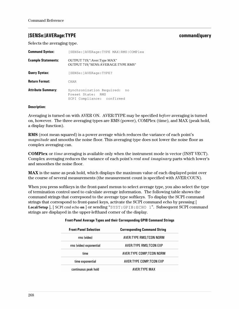
[SENSe:]AVERage:TYPE command/querySelects the averaging type.
Command Syntax: [SENSe:]AVERage:TYPE MAX|RMS|COMPlex
Example Statements: OUTPUT 719;":Aver:Type MAX"OUTPUT 719;"SENS:AVERAGE:TYPE RMS"
Query Syntax: [SENSe:]AVERage:TYPE?
Return Format: CHAR
Attribute Summary: Synchronization Required: noPreset State: RMSSCPI Compliance: confirmed
Description:
Averaging is turned on with AVER ON. AVER:TYPE may be specified before averaging is turnedon, however. The three averaging types are RMS (power), COMPlex (time), and MAX (peak hold,a display function).
RMS (root mean squared) is a power average which reduces the variance of each point’smagnitude and smooths the noise floor. This averaging type does not lower the noise floor ascomplex averaging can.
COMPlex or time averaging is available only when the instrument mode is vector (INST VECT).Complex averaging reduces the variance of each point’s real and imaginary parts which lower’sand smoothes the noise floor.
MAX is the same as peak hold, which displays the maximum value of each displayed point overthe course of several measurements (the measurement count is specified with AVER:COUN).
When you press softkeys in the front-panel menus to select average type, you also select the typeof termination control used to calculate average information. The following table shows thecommand strings that correpsond to the average type softkeys. To display the SCPI commandstrings that correspond to front-panel keys, activate the SCPI command echo by pressing [Local/Setup ], [ SCPI cmd echo on ] or sending “SYST:GPIB:ECHO 1”. Subsequent SCPI commandstrings are displayed in the upper-lefthand corner of the display.
Front-Panel Average Types and their Corresponding GPIB Command Strings
Front-Panel Selection Corresponding Command String
rms (video) AVER:TYPE RMS;TCON NORM
rms (video) exponential AVER:TYPE RMS;TCON EXP
time AVER:TYPE COMP;TCON NORM
time exponential AVER:TYPE COMP;TCON EXP
continuous peak hold AVER:TYPE MAX
Command Reference
268
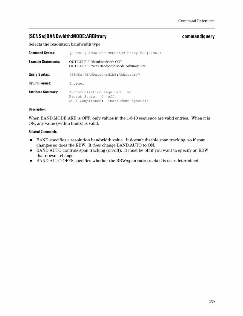
[SENSe:]BANDwidth:MODE:ARBitrary command/querySelects the resolution bandwidth type.
Command Syntax: [SENSe:]BANDwidth:MODE:ARBitrary OFF|0|ON|1
Example Statements: OUTPUT 719;":band:mode:arb ON"OUTPUT 719;"Sens:Bandwidth:Mode:Arbitrary ON"
Query Syntax: [SENSe:]BANDwidth:MODE:ARBitrary?
Return Format: Integer
Attribute Summary: Synchronization Required: noPreset State: 0 (off)SCPI Compliance: instrument-specific
Description:
When BAND:MODE:ARB is OFF, only values in the 1-3-10 sequence are valid entries. When it isON, any value (within limits) is valid.
Related Commands:
BAND specifies a resolution bandwidth value. It doesn’t disable span tracking, so if spanchanges so does the RBW. It does change BAND:AUTO to ON.BAND:AUTO controls span tracking (on/off). It must be off if you want to specify an RBWthat doesn’t change.BAND:AUTO:OFFS specifies whether the RBW/span ratio tracked is user-determined.
Command Reference
269
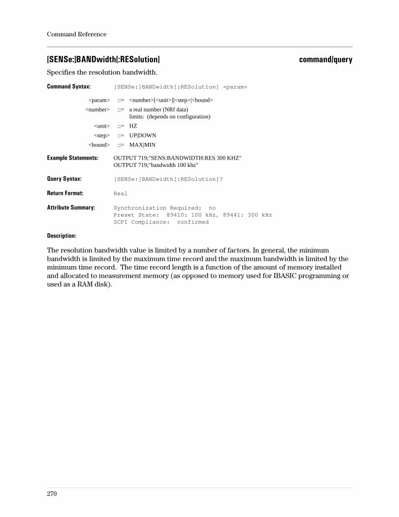
[SENSe:]BANDwidth[:RESolution] command/querySpecifies the resolution bandwidth.
Command Syntax: [SENSe:]BANDwidth[:RESolution] <param>
<param> ::= <number>[<unit>]|<step>|<bound>
<number> ::= a real number (NRf data)limits: (depends on configuration)
<unit> ::= HZ
<step> ::= UP|DOWN
<bound> ::= MAX|MIN
Example Statements: OUTPUT 719;"SENS:BANDWIDTH:RES 300 KHZ"OUTPUT 719;"bandwidth 100 khz"
Query Syntax: [SENSe:]BANDwidth[:RESolution]?
Return Format: Real
Attribute Summary: Synchronization Required: noPreset State: 89410: 100 kHz, 89441: 300 kHzSCPI Compliance: confirmed
Description:
The resolution bandwidth value is limited by a number of factors. In general, the minimumbandwidth is limited by the maximum time record and the maximum bandwidth is limited by theminimum time record. The time record length is a function of the amount of memory installedand allocated to measurement memory (as opposed to memory used for IBASIC programming orused as a RAM disk).
Command Reference
270
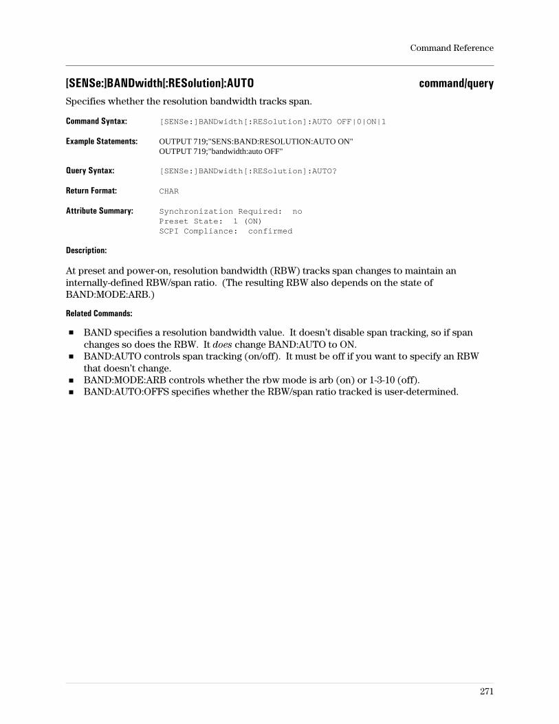
[SENSe:]BANDwidth[:RESolution]:AUTO command/querySpecifies whether the resolution bandwidth tracks span.
Command Syntax: [SENSe:]BANDwidth[:RESolution]:AUTO OFF|0|ON|1
Example Statements: OUTPUT 719;"SENS:BAND:RESOLUTION:AUTO ON"OUTPUT 719;"bandwidth:auto OFF"
Query Syntax: [SENSe:]BANDwidth[:RESolution]:AUTO?
Return Format: CHAR
Attribute Summary: Synchronization Required: noPreset State: 1 (ON)SCPI Compliance: confirmed
Description:
At preset and power-on, resolution bandwidth (RBW) tracks span changes to maintain aninternally-defined RBW/span ratio. (The resulting RBW also depends on the state ofBAND:MODE:ARB.)
Related Commands:
BAND specifies a resolution bandwidth value. It doesn’t disable span tracking, so if spanchanges so does the RBW. It does change BAND:AUTO to ON.BAND:AUTO controls span tracking (on/off). It must be off if you want to specify an RBWthat doesn’t change.BAND:MODE:ARB controls whether the rbw mode is arb (on) or 1-3-10 (off).BAND:AUTO:OFFS specifies whether the RBW/span ratio tracked is user-determined.
Command Reference
271
[SENSe:]BANDwidth[:RESolution]:AUTO:OFFSet command/querySpecifies whether the RBW/span ratio tracked when BAND:AUTO is ON is user-determined.
Command Syntax: [SENSe:]BANDwidth[:RESolution]:AUTO:OFFSet OFF|0|ON|1
Example Statements: OUTPUT 719;":Band:Auto:Offs ON"OUTPUT 719;"SENSE:BAND:RES:AUTO:OFFS OFF"
Query Syntax: [SENSe:]BANDwidth[:RESolution]:AUTO:OFFSet?
Return Format: Integer
Attribute Summary: Synchronization Required: noPreset State: 0 (off)SCPI Compliance: instrument-specific
Description:
With BAND:AUTO ON and BAND:AUTO:OFFS OFF, the RBW tracks span changes to maintainan internally-defined RBW/span ratio. (The resulting RBW also depends on the state ofBAND:MODE:ARB.)
If BAND:AUTO is ON, BAND:AUTO:OFFS is automatically turned on when you enter an RBWvalue (with BAND). Subsequent changes in span will cause the RBW to track it such that itmaintains the new RBW/span ratio.
The BAND:AUTO:OFFS command has no effect if BAND:AUTO is OFF.
Command Reference
272
[SENSe:]CORRection[1|2]:EDELay[:TIME] command/queryAdjusts the delay, in small increments, for the specified input channel.
Command Syntax: [SENSe:]CORRection[1|2]:EDELay[:TIME] <param>
<param> ::= <number>[<unit>]|<step>|<bound>
<number> ::= -100 nanoseconds to +100 nanoseconds
<unit> ::= S
<step> ::= UP|DOWN
<bound> ::= MAX|MIN
Example Statements: OUTPUT 719;"sense:corr:edel:time 0"OUTPUT 719;"Corr2:Edelay 0"
Query Syntax: [SENSe:]CORRection[1|2]:EDELay[:TIME]?
Return Format: Real
Attribute Summary: Synchronization Required: noPreset State: not applicableSCPI Compliance: confirmed
Description:
By default, the delay for an input channel is zero. Use this command to adjust an input channel’sdelay to compensate for external devices (such as cables or attenuators). CORR1 selects inputchannel 1; CORR2 selects input channel 2. The delay that you specify is not used until you sendsense:correction[1|2]:external:state ON.
For additional details, see online help for the [System Utility] [more cal setup] [externalcalibration] softkey.
Command Reference
273

[SENSe:]CORRection[1|2]:EXTernal[:STATe] command/queryEnables or disables the use of user-defined calibration coefficients.
Command Syntax: [SENSe:]CORRection[1|2]:EXTernal[:STATe] OFF|0|ON|1
Example Statements: OUTPUT 719;":CORR:EXT ON"OUTPUT 719;"sense:corr:external:stat OFF"
Query Syntax: [SENSe:]CORRection[1|2]:EXTernal[:STATe]?
Return Format: Integer
Attribute Summary: Synchronization Required: noPreset State: 0SCPI Compliance: instrument-specific
Description:
You can adjust the gain and delay calibration coefficients for each input channel. By default, thegain of an input channel is one, the delay is zero seconds. You can adjust these values using thesense:correction:loss:magnitude and sense:correction:edelay commands.
The values that you specify are not used until you send sense:correction:external ON. To returnto the default gain and delay values, send sense:correction:external OFF.
For additional details, see online help for the [System Utility] [more cal setup] [externalcalibration] softkey.
Command Reference
274
[SENSe:]CORRection[1|2]:FILTer:XTIMe:STATe command/queryEnables or disables time-domain corrections.
Command Syntax: [SENSe:]CORRection[1|2]:FILTer:XTIMe:STATe OFF|0|ON|1
Example Statements: OUTPUT 719;"Sens:Correction2:Filt:Xtime:Stat ON"OUTPUT 719;"CORR2:FILTER:XTIM:STATE OFF"
Query Syntax: [SENSe:]CORRection[1|2]:FILTer:XTIMe:STATe?
Return Format: Integer
Attribute Summary: Synchronization Required: noPreset State: OffSCPI Compliance: instrument-specific
Description:
Time calibrations compensate the time data for the magnitude and phase characteristics of eachinput channel. For the greatest accuracy, time calibrations should be used whenever demod isenabled, or accurate time data is desired. It should be turned off whenever measurement speedis a high priority.
Accuracy of frequency domain results is not affected by this command.
Command Reference
275
[SENSe:]CORRection[1|2]:IMPedance[:INPut][:MAGNitude] command/querySets the dBm reference impedance when the 1 MΩ input termination is selected.
Command Syntax: [SENSe:]CORRection[1|2]:IMPedance <number>[<unit>]
<number> ::= a real number (NRf data)limits: .001:10E9
<unit> ::= OHM
Example Statements: OUTPUT 719;":Corr1:Impedance 600"OUTPUT 719;"SENS:CORRECTION2:IMP 150"
Query Syntax: [SENSe:]CORRection[1|2]:IMPedance[:INPut][:MAGNitude]?
Return Format: Real
Attribute Summary: Synchronization Required: noPreset State: 50SCPI Compliance: instrument-specific
Description:
This command changes the reference impedance used to calculate dBm when the selectedimpedance is 1 MΩ (INP:IMP 1e6). Each input channel may be given a value independent of theother (assuming channel 2, which is optional, is installed).
Related Commands:
The input impedance is set to 1 MΩ with the command: “INP[1|2]:IMP 1e6"
Note The input signal is terminated with 1 MΩ when this command is effective.
Command Reference
276
[SENSe:]CORRection[1|2]:LOSS[:INPut]:MAGNitude command/queryAdjusts the gain for the specified input channel.
Command Syntax: [SENSe:]CORRection[1|2]:LOSS[:INPut]:MAGNitude <param>
<param> ::= <number>|<step>|<bound>
<number> ::= 0.000001 to 1000000
<step> ::= UP|DOWN
<bound> ::= MAX|MIN
Example Statements: OUTPUT 719;"SENSE:CORR:LOSS:INPUT:MAGN .001"
Query Syntax: [SENSe:]CORRection[1|2]:LOSS[:INPut]:MAGNitude?
Return Format: Real
Attribute Summary: Synchronization Required: noPreset State: not applicableSCPI Compliance: confirmed
Description:
By default, the gain for an input channel is one. Use this command to adjust an input channel’sgain to compensate for external devices (such as cables or attenuators). CORR1 selects inputchannel 1; CORR2 selects input channel 2. The gain that you specify is not used until you sendsense:correction:external:state ON.
For additional details, see online help for the [System Utility] [more cal setup] [externalcalibration] softkey.
Command Reference
277
[SENSe:]CORRection[1|2]:OFFS command/queryAdjusts the DC offset, in small increments, for the specified input channel.
Command Syntax: [SENSe:]CORRection[1|2]:OFFS <param>
<param> ::= <number>[<unit>]|<step>|<bound>
<number> ::= -20 volts to +20 volts
<unit> ::= V
<step> ::= UP|DOWN
<bound> ::= MAX|MIN
Example Statements: OUTPUT 719;":corr:offs 0"OUTPUT 719;"Sense:Corr:Offs 0"
Query Syntax: [SENSe:]CORRection[1|2]:OFFS?
Return Format: Real
Attribute Summary: Synchronization Required: noPreset State: not applicableSCPI Compliance: confirmed
Description:
By default, the offset for an input channel is zero. Use this command to adjust an input channel’sDC offset to compensate for external devices. The offset is compensated for mathematically.With DC coupling, the input range must still be adjusted to handle both the AC and DCcomponents of the signal. The offset that you specify is only applied in the IF receiver modesand only after you send sense:correction[1|2]:external:state ON. Also, for a receiver mode ofIF(0-10MHz), the time data must be baseband.
For additional details, see online help for the [System Utility] [more cal setup] [externalcalibration] softkey.
Command Reference
278
[SENSe:]DATA command/queryUploads or downloads time-capture data between the analyzer and the controller.
Command Syntax: [SENSe:]DATA TCAP1|TCAP2,<DATA>
<DATA> ::= <DEF_BLOCK>
::= <NRf>,<NRf>,<NRf>, . . .
Example Statements: OUTPUT 719;":data tcap1, USER2"OUTPUT 719;"Sense:Data Tcap2, USER2"
Query Syntax: [SENSe:]DATA?
Return Format: DEF_USER
Attribute Summary: Synchronization Required: noPreset State: not applicableSCPI Compliance: instrument-specific
Description:
In the example statements, USER2 is a definite-length data block as defined in Chapter 4 of theGPIB Programmer’s User Guide. The TCAP1 parameter designates the channel-1, time-capturebuffer and TCAP2 designates the channel-2, time-capture buffer.
The analyzer can’t load indefinite-length blocks; the data must be definite-length blocks or ASCIIdata. The data is stored internally in 32-bit integers but the data transferred with this commandis floating-point. The floating-point numbers are scaled and converted to integers with thetime-capture range value specified with the [SENSE:]TCAP[1|2]:RANG values. Using thetime-capture range to scale the data yields the best dynamic range.
The query form of this command requires the use of a parameter: TCAP1|TCAP2 as in
DATA? TCAP1
Related Commands:
To query the number of measurement points in the time-capture buffer, use[SENSe:]DATA:HEAD:POINts?.
Time capture data may also be transferred between the analyzer and a controller with the LANfile-transfer utility, FTP (option UG7).
Command Reference
279
[SENSe:]DATA:HEADer:POINts? queryReturns the number of points for the time-capture buffer specified.
Query Syntax: [SENSe:]DATA:HEADer:POINts? TCAP1|TCAP2
Example Statements: OUTPUT 719;"SENS:DATA:HEADER:POIN? TCAP2"OUTPUT 719;"data:head:poin? TCAP1"
Return Format: Integer
Attribute Summary: Synchronization Required: noPreset State: not applicableSCPI Compliance: instrument-specific
Description:
This query is used to determine the number of data points in the specified time-capture buffer.This information may be required to transfer the contents of the buffer from the analyzer to thecontroller.
Related Commands:
To transfer time-capture data, use [SENSe:]DATA.
Command Reference
280
[SENSe:]DDEMod:ADAPt command/queryEnables adaptive equalization on/off.
Command Syntax: [SENSe:]DDEMod:ADAPt OFF|0|ON|1
Example Statements: OUTPUT 719;"sense:ddem:adapt ON"OUTPUT 719;"Ddem:Adap OFF"
Query Syntax: [SENSe:]DDEMod:ADAPt?
Return Format: Integer
Attribute Summary: Option: AYA (vector modulation analysis)Synchronization Required: noPreset State: affected by PresetSCPI Compliance: instrument-specific
Description:
ON The equaliztion filter coefficients are updated with each measurement
OFF The equalization filter coefficients do not change
For more information on digital demodulation, see online help (press the [ Help ] key on thefront panel, then press the softkey of interest) and the concepts discussion in the Operator’s
Guide.
Command Reference
281
[SENSe:]DDEMod:CLOCk command/querySpecifies the clock offset in symbols.
Command Syntax: [SENSE:]DDEMod:CLOCk <number>[unit]|<step>|<bound>
<number> ::= a real number (NRf data)limits: depends on configuration
<unit> ::= SYM
<step> ::= UP|DOWN
<bound> ::= MAX|MIN
Example Statements: OUTPUT 719;":DDEMOD:CLOC 0"OUTPUT 719;"sense:ddem:cloc 0"
Query Syntax: [SENSe:]DDEMod:CLOCk?
Return Format: Real
Attribute Summary: Option: AYA (vector modulation analysis)Synchronization Required: noPreset State: not affected by PresetSCPI Compliance: instrument-specific
Description:
This commands corresponds to clock adjust as discussed in the online Help.
For more information on digital demodulation, see online help (press the [ Help ] key on thefront panel, then press the softkey of interest) and the concepts discussion in the Operator’s
Guide.
Command Reference
282
[SENSe:]DDEMod:CNVRg command/querySpecifies the convergence rate.
Command Syntax: [SENSe:]DDEMod:CNVRg <number>|<step>|<bound>
<number> ::= a real number (NRf data)limits: 0:1
<step> ::= UP|DOWN
<bound> ::= MAX|MIN
Example Statements: OUTPUT 719;"Sense:Ddem:Cnvrg 0"OUTPUT 719;"DDEM:CNVR 0"
Query Syntax: [SENSe:]DDEMod:CNVRg?
Return Format: Real
Attribute Summary: Option: AYA (vector modulation analysis)Synchronization Required: noPreset State: affected by PresetSCPI Compliance: instrument-specific
Description:
This commands specifies the rate at which the LMS equalizer converges. Larger values convergefaster, but may be unstable and result in higher residual errors. The value can be changed whilethe equalizer is adapting.
Command Reference
283
[SENSe:]DDEMod:CRATe command/querySets the chip rate for Wideband CDMA measurements.
Command Syntax: [SENSe:]DDEMod:CRATe <number>[<unit>]
<number> ::= a real number (NRf data)limits: 4086000:8212000 (16424000 for the ch1 + j*ch2 receiver)
<unit> ::= [HZ]
Example Statements: OUTPUT 719;":ddemod:crat 4096000"OUTPUT 719;"Sense:Ddem:Crat 4096000"
Query Syntax: [SENSe:]DDEMod:CRATe?
Return Format: Real
Attribute Summary: Option: B73 (Digital Wideband CDMA analysis) orB79 (Digital ARIB 1.0-1.2 Wideband CDMA analysis or080 (Digital 3GPP Wideband CDMA analysis)
Synchronization Required: noPreset State: not applicableSCPI Compliance: instrument-specific
Description
This command sets the chip rate for W-CDMA measurements. The default chip rate is 4.096 MHz(Opt. B73, B79) or 3.84 MHz (Opt. 080). Sending this command as a query returns the currentchip rate, in Hz.
The maximum chip rate that you can select is limited by the maximum W-CDMA span parameter(MEM:MALL:MEAS:MAXS).
Command Reference
284
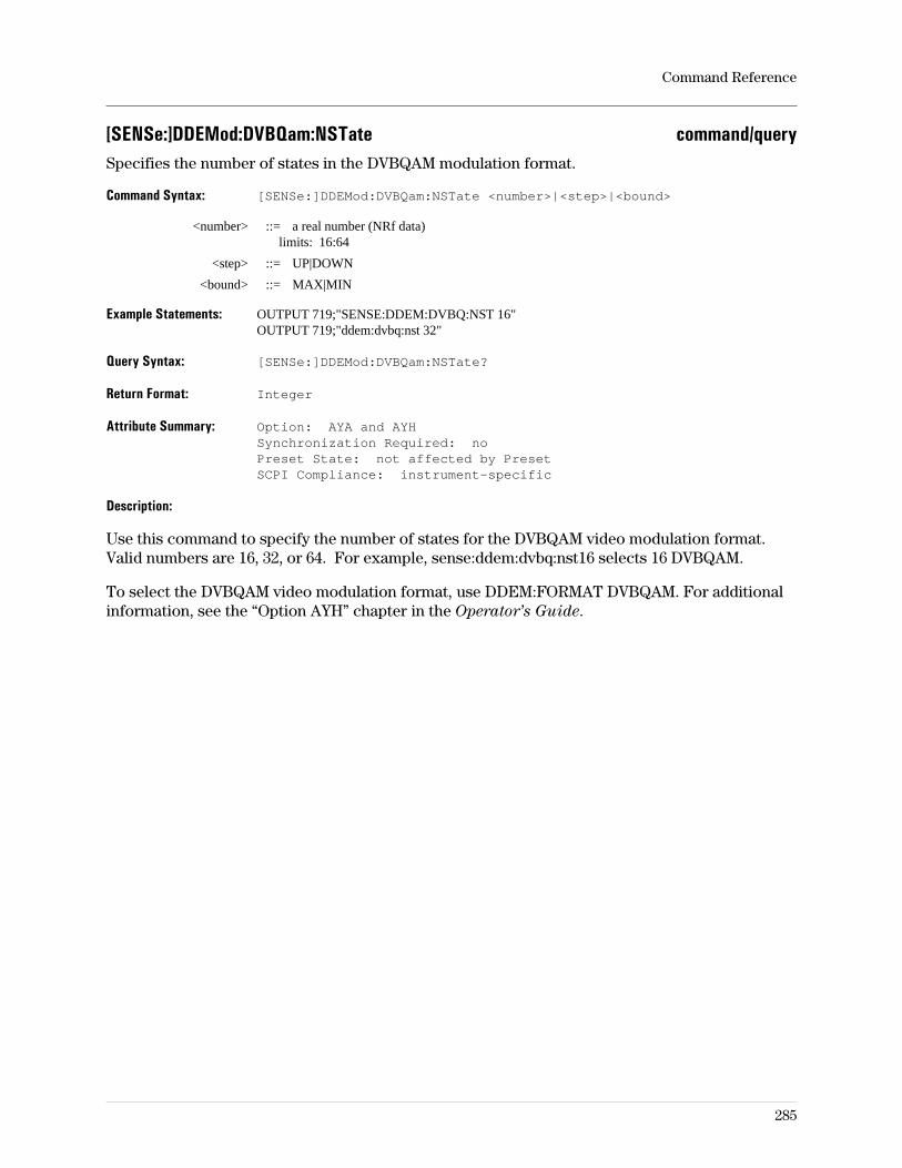
[SENSe:]DDEMod:DVBQam:NSTate command/querySpecifies the number of states in the DVBQAM modulation format.
Command Syntax: [SENSe:]DDEMod:DVBQam:NSTate <number>|<step>|<bound>
<number> ::= a real number (NRf data)limits: 16:64
<step> ::= UP|DOWN
<bound> ::= MAX|MIN
Example Statements: OUTPUT 719;"SENSE:DDEM:DVBQ:NST 16"OUTPUT 719;"ddem:dvbq:nst 32"
Query Syntax: [SENSe:]DDEMod:DVBQam:NSTate?
Return Format: Integer
Attribute Summary: Option: AYA and AYHSynchronization Required: noPreset State: not affected by PresetSCPI Compliance: instrument-specific
Description:
Use this command to specify the number of states for the DVBQAM video modulation format.Valid numbers are 16, 32, or 64. For example, sense:ddem:dvbq:nst16 selects 16 DVBQAM.
To select the DVBQAM video modulation format, use DDEM:FORMAT DVBQAM. For additionalinformation, see the “Option AYH” chapter in the Operator’s Guide.
Command Reference
285
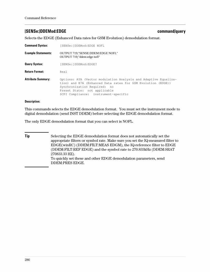
[SENSe:]DDEMod:EDGE command/querySelects the EDGE (Enhanced Data rates for GSM Evolution) demodulation format.
Command Syntax: [SENSe:]DDEMod:EDGE NOFL
Example Statements: OUTPUT 719;"SENSE:DDEM:EDGE NOFL"OUTPUT 719;"ddem:edge nofl"
Query Syntax: [SENSe:]DDEMod:EDGE?
Return Format: Real
Attribute Summary: Options: AYA (Vector modulation Analysis and Adaptive Equaliza-tion) and B7A (Enhanced Data rates for GSM Evolution (EDGE))Synchronization Required: noPreset State: not applicableSCPI Compliance: instrument-specific
Description:
This commands selects the EDGE demodulation format. You must set the instrument mode todigital demodulation (send INST DDEM) before selecting the EDGE demodulation format.
The only EDGE demodulation format that you can select is NOFL.
Tip Selecting the EDGE demodulation format does not automatically set theappropriate filters or symbol rate. Make sure you set the IQ-measured filter toEDGE(winRC) (DDEM:FILT:MEAS EDGM), the IQ-reference filter to EDGE(DDEM:FILT:REF EDGE) and the symbol rate to 270.833kHz (DDEM:SRAT270833.33 HZ).To quickly set these and other EDGE demodulation parameters, sendDDEM:PRES EDGE.
Command Reference
286
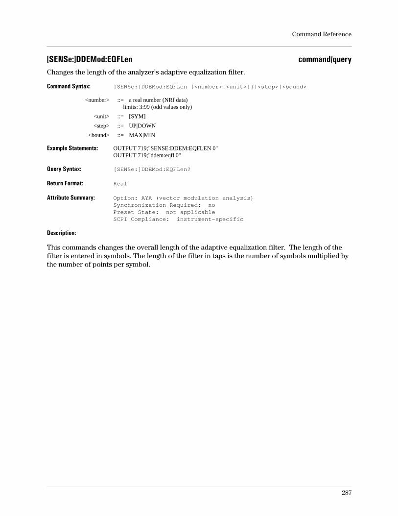
[SENSe:]DDEMod:EQFLen command/queryChanges the length of the analyzer’s adaptive equalization filter.
Command Syntax: [SENSe:]DDEMod:EQFLen <number>[<unit>]|<step>|<bound>
<number> ::= a real number (NRf data)limits: 3:99 (odd values only)
<unit> ::= [SYM]
<step> ::= UP|DOWN
<bound> ::= MAX|MIN
Example Statements: OUTPUT 719;"SENSE:DDEM:EQFLEN 0"OUTPUT 719;"ddem:eqfl 0"
Query Syntax: [SENSe:]DDEMod:EQFLen?
Return Format: Real
Attribute Summary: Option: AYA (vector modulation analysis)Synchronization Required: noPreset State: not applicableSCPI Compliance: instrument-specific
Description:
This commands changes the overall length of the adaptive equalization filter. The length of thefilter is entered in symbols. The length of the filter in taps is the number of symbols multiplied bythe number of points per symbol.
Command Reference
287
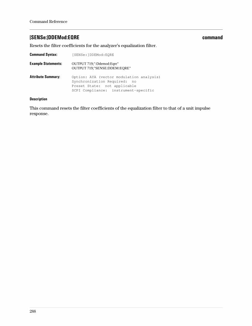
[SENSe:]DDEMod:EQRE commandResets the filter coefficients for the analyzer’s equalization filter.
Command Syntax: [SENSe:]DDEMod:EQRE
Example Statements: OUTPUT 719;":Ddemod:Eqre"OUTPUT 719;"SENSE:DDEM:EQRE"
Attribute Summary: Option: AYA (vector modulation analysis)Synchronization Required: noPreset State: not applicableSCPI Compliance: instrument-specific
Description
This command resets the filter coefficients of the equalization filter to that of a unit impulseresponse.
Command Reference
288
[SENSe:]DDEMod:EQUalize command/queryTurns equalization on/off for Digital and Video demodulation.
Command Syntax: [SENSe:]DDEMod:EQUalize OFF|0|ON|1
Example Statements: OUTPUT 719;"sense:ddem:equalize ON"OUTPUT 719;"Ddem:Equ OFF"
Query Syntax: [SENSe:]DDEMod:EQUalize?
Return Format: Integer
Attribute Summary: Option: AYA (vector modulation analysis)Synchronization Required: noPreset State: affected by PresetSCPI Compliance: instrument-specific
Description:
ON Applies the equaliztion filter to the IQ Measured data
OFF The equalization filter is available, but not used.
For more information on using equalization in digital and video demodulation, see online help(press the [ Help ] key on the front panel, then press the softkey of interest) and the conceptsdiscussion in the Operator’s Guide.
Command Reference
289
[SENSe:]DDEMod:FILTer:ALPHa command/querySpecifies the alpha of the Nyquist filters and BT for Gaussian filters.
Command Syntax: [SENSe:]DDEMod:FILTer:ALPHa <number>|<step>|<bound>
<number> ::= a real number (NRf data)limits: 0.05 to 100
<step> ::= UP|DOWN
<bound> ::= MAX|MIN
Example Statements: OUTPUT 719;":DDEMOD:FILT:ALPHA 0"OUTPUT 719;"sens:ddem:filter:alph 0"
Query Syntax: [SENSe:]DDEMod:FILTer:ALPHa?
Return Format: Real
Attribute Summary: Option: AYA (vector modulation analysis)Synchronization Required: noPreset State: not affected by PresetSCPI Compliance: instrument-specific
Description:
This command corresponds to the alpha / BT softkey. It sets the value of the α andbandwidth-time variables for both the measurement filter and the reference filter when theinstrument mode is Digital or Video demodulation.
To set the filter alpha for the Wideband CDMA instrument mode, use[SENSe:]DDEMod:WCDMa:FILTer:ALPHa.
For more information on Digital and Video demodulation, see online help (press the [ Help ] keyon the front panel, then press the softkey of interest) and the concepts discussion in theOperator’s Guide.
Command Reference
290
[SENSe:]DDEMod:FILTer:MEASurement command/querySpecifies the type of filter used in digital or video demodulation measurements.
Command Syntax: [SENSe:]DDEMod:FILTer:MEASurement <param>
<param> ::= OFF|0|RECTangular|RCOSine|RRCosine|GAUSsian|PHEQualize|USER|EDGM|LPASs
Example Statements: OUTPUT 719;"Sense:Ddem:Filt:Measurement USER"OUTPUT 719;"DDEM:FILTER:MEAS RRCOSINE"
Query Syntax: [SENSe:]DDEMod:FILTer:MEASurement?
Return Format: CHAR
Attribute Summary: Option: AYA (vector modulation analysis)orB7A (Enhanced Data rates for GSM Evolution (EDGE))Synchronization Required: noPreset State: not affected by PresetSCPI Compliance: instrument-specific
Description:
OFF|0 specifies no filtering.
RECT specifies the use of a rect filter.
RCOS specifies the use of a raised-cosine filter. The value of the alpha variable is specified withthe DDEM:FILT:ALPH command.
RRC specifies the use of a root raised-cosine filter. The value of the alpha variable is specifiedwith the DDEM:FILT:ALPH command.
GAUS specifies the use of a Gaussian filter. The value of the BT variable is specified with theDDEM:FILT:ALPH command.
LPAS specifies the use of a low-pass filter. This is a Gaussian filter with BT = 0.5 and T = 1/(4.0 *symbol_rate).
USER specifies the use of a user-defined filter. These are defined solely by data in the dataregisters (alpha and BT have no effect). Data is loaded into the data registers with theMMEM:LOAD:TRAC command. The data register used for the filter is specified with theDDEM:FILT:MEAS:USER:FEED command.
EDGM specifies the use of the windowed raised-cosine filter. This is an EDGE demodulationspecific measurement filter, not affected by alpha.
The reference filter type is specified with the DDEM:FILT:REF command.
For more information on digital demodulation, see online help (press the [ Help ] key on thefront panel, then press the softkey of interest) and the concepts discussion in the Operator’s
Guide.
Command Reference
291

[SENSe:]DDEMod:FILTer:MEASurement:USER:FEED command/querySpecifies which data register is used to define the user-defined digital demod measurement filter.
Command Syntax: [SENSe:]DDEMod:FILTer:MEASurement:USER:FEED D1|D2|D3|D4|D5|D6
Example Statements: OUTPUT 719;"Ddem:Filter:Meas:User:Feed D2"OUTPUT 719;"SENS:DDEMOD:FILT:MEAS:USER:FEED D5"
Query Syntax: [SENSe:]DDEMod:FILTer:MEASurement:USER:FEED?
Return Format: STRING
Attribute Summary: Option: AYA (vector modulation analysis)Synchronization Required: noPreset State: not applicableSCPI Compliance: instrument-specific
Description:
Before the data register is selected, the user-defined data should be loaded into it and theuser-defined filter type selected.
Related Commands:
To specify that the measurement filter is user-defined, use DDEM:FILT:MEAS USER.To load the filter definition data into a data register, use MMEM:LOAD:TRAC.
For more information on digital demodulation, see online help (press the [ Help ] key on thefront panel, then press the softkey of interest) and the concepts discussion in the Operator’s
Guide.
Command Reference
292
[SENSe:]DDEMod:FILTer:REFerence command/querySpecifies the type of filter used as the digital demod reference.
Command Syntax: [SENSe:]DDEMod:FILTer:REFerence <param> <param> ::= RECTangu-lar|RCOSine|RRCosine|CHEByshev|GAUSsian|EDGE|USER
Example Statements: OUTPUT 719;":ddem:filter:ref RECT"OUTPUT 719;"Sense:Ddem:Filt:Reference RRCOSINE"
Query Syntax: [SENSe:]DDEMod:FILTer:REFerence?
Return Format: CHAR
Attribute Summary: Option: AYA (vector modulation analysis)orB7A (Enhanced Data rates for GSM Evolution (EDGE))
Synchronization Required: noPreset State: not affected by PresetSCPI Compliance: instrument-specific
Description:
RECT specifies the use of a rectangular filter (the impulse response is the rect function).
RCOS specifies the use of a raised-cosine filter. The value of the alpha variable is specified withthe DDEM:FILT:ALPH command.
RRC specifies the use of a root raised-cosine filter. The value of the alpha variable is specifiedwith the DDEM:FILT:ALPH command.
GAUS specifies the use of a Gaussian filter. The value of the BT variable is specified with theDDEM:FILT:ALPH command.
EDGE specifies the use of an EDGE filter. When the measurement filter is set to OFF, it is theEDGE TX (transmit) filter. When the measurement filter is set to EDGE (winRC), it is theconvolution of the EDGE TX and measurement filters. This selection requires Option B7A.
USER specifies the use of a user-defined filter. These are defined solely by data in the dataregisters (alpha and BT have no effect). Data is loaded into the data registers with theMMEM:LOAD:TRAC command. The data register used for the filter is specified with theDDEM:FILT:REF:USER:FEED command.
The measurement filter type is specified with the DDEM:FILT:MEAS command.
For more information on digital demodulation, see online help (press the [ Help ] key on thefront panel, then press the softkey of interest) and the concepts discussion in the Operator’s
Guide.
Command Reference
293
[SENSe:]DDEMod:FILTer:REFerence:USER:FEED command/querySpecifies which data register is used as the user-defined digital demod reference filter.
Command Syntax: [SENSe:]DDEMod:FILTer:REFerence:USER:FEED D1|D2|D3|D4|D5|D6
Example Statements: OUTPUT 719;"SENSE:DDEM:FILTER:REF:USER:FEED ‘D2’"OUTPUT 719;"ddem:filter:ref:user:feed ‘D5’"
Query Syntax: [SENSe:]DDEMod:FILTer:REFerence:USER:FEED?
Return Format: STRING
Attribute Summary: Option: AYA (vector modulation analysis)Synchronization Required: noPreset State: not applicableSCPI Compliance: instrument-specific
Description:
Before the data register is selected, the user-defined data should be loaded into it and theuser-defined filter type selected.
Related Commands:
To specify that the reference filter is user-defined, use DDEM:FILT:REF USER.To load the filter definition data into a data register, use MMEM:LOAD:TRAC.
For more information on digital demodulation, see online help (press the [ Help ] key on thefront panel, then press the softkey of interest) and the concepts discussion in the Operator’s
Guide.
Command Reference
294
[SENSe:]DDEMod:FORMat command/querySpecifies the demodulation format for digital modulation or video modulation.
Command Syntax: [SENSe:]DDEMod:FORMat QPSK|PSK|QAM|MSK|FSK|DVBQam|VSB|EDGE
Example Statements: OUTPUT 719;"SENS:DDEMOD:FORM PSK"OUTPUT 719;"ddem:format QAM"
Query Syntax: [SENSe:]DDEMod:FORMat?
Return Format: CHAR
Attribute Summary: Option: AYA and, for some, AYH or B7A (see below)Synchronization Required: noPreset State: not affected by PresetSCPI Compliance: instrument-specific
Description:
This command corresponds to the softkey selections under the demod format menu. You mustset the instrument mode to digital demodulation (send INST DDEM) to select QPSK, PSK, QAM,MSK, FSK, and EDGE. You must set the instrument mode to video demodulation (sendINST VDEM) to select DVBQ, VSB or 16|32|64|256 QAM.
QPSK selects quadrature phase-shift keying (requires option AYA).PSK selects phase-shift keying (requires option AYA).QAM selects quadrature amplitude modulation (requires option AYA).MSK selects minimum-shift keying (requires option AYA).FSK selects frequency-shift keying (requires option AYA).DVBQ selects digital video broadcast QAM (requires options AYA and AYH)VSB selects vestidual side-band (requires options AYA and AYH).EDGE selects Enhanced Data rates for GSM Evolution (requires option B7A).
Command Combinations:
To specify normal or pi/4 DQPSK, use DDEM:QPSK:FORM DIFF or DPI4.To specify BPSK or 8 PSK, use DDEM:FORM PSK;PSK:NST 2 | 8.To specify different Digital Demod 16|32 QAM formats, use DDEM:QAM:NST 16 | 32.To specify MSK type 1 or type 2, use DDEM:MSK:FORM TYP1 or TYP2To specify FSK 2 or FSK 4, use DDEM:FSK:NST 2 | 4.To specify 8 | 16 VSB, use DDEM:VSG:NST 8 | 16.To specify DVB QAM 16 | 32 | 64, use DDEM:DVBQ:NST 16 | 32 | 64.To specify different Video Demod 16|32|64|256 QAM formats, use DDEM:QAM:NST16|32|64|256.You can also specify the EDGE format with DDEM:EDGE:FORM NOFL.
For more information on digital demodulation and on video demodulation, see the Operator’s
Guide. See also DDEM:QPSK:FORM, DDEM:PSK:NSTate, DDEM:QAM:NSTate,DDEM:FSK:NSTate, DDEM:DVBQ:NSTate, DDEM:EDGE:FORM, and DDEM:VSB:NSTate.
Command Reference
295
[SENSe:]DDEMod:FREQuency:MIRRor command/queryTurns frequency mirroring on or off.
Command Syntax: [SENSe:]DDEMod:FREQuency:MIRRor OFF|0|ON|1
Example Statements: OUTPUT 719;":Ddem:Frequency:Mirr OFF"OUTPUT 719;"SENS:DDEMOD:FREQ:MIRROR OFF"
Query Syntax: [SENSe:]DDEMod:FREQuency:MIRRor?
Return Format: Integer
Attribute Summary: Option: AYH (video modulation analysis)B73 (Wideband CDMA Analysis)
Synchronization Required: noPreset State: +0 (OFF)SCPI Compliance: instrument-specific
Description:
Sending ddemod:freq:mirror ON turns mirroring on. When mirroring is on, the analyzer “flips”or “mirrors” the displayed spectrum around the analyzer’s center frequency.
Command Reference
296
[SENSe:]DDEMod:FSK:NSTate command/querySpecifies the number of states in the FSK modulation format.
Command Syntax: [SENSe:]DDEMod:FSK:NSTate <number>|<step>|<bound>
<number> ::= a real number (NRf data)limits: 2:4
<step> ::= UP|DOWN
<bound> ::= MAX|MIN
Example Statements: OUTPUT 719;"sens:ddem:fsk:nst 3"OUTPUT 719;"Ddemod:Fsk:Nst 3"
Query Syntax: [SENSe:]DDEMod:FSK:NSTate?
Return Format: Integer
Attribute Summary: Option: AYA (vector modulation analysis)Synchronization Required: noPreset State: not affected by PresetSCPI Compliance: instrument-specific
Description:
The valid values for this command are 2 or 4.
Related Commands:
To select the FSK modulation format, use DDEM:FORMAT FSK.
For more information on digital demodulation, see online help (press the [ Help ] key on thefront panel, then press the softkey of interest) and the concepts discussion in the Operator’s
Guide.
Command Reference
297
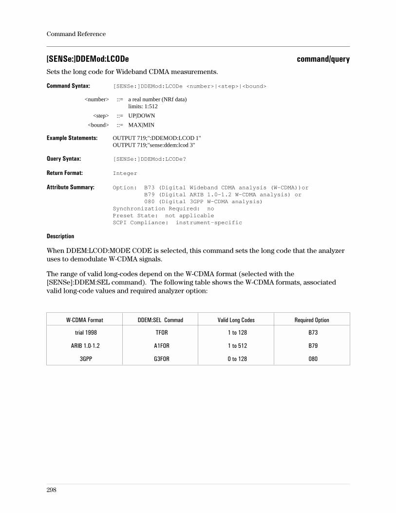
[SENSe:]DDEMod:LCODe command/querySets the long code for Wideband CDMA measurements.
Command Syntax: [SENSe:]DDEMod:LCODe <number>|<step>|<bound>
<number> ::= a real number (NRf data)limits: 1:512
<step> ::= UP|DOWN
<bound> ::= MAX|MIN
Example Statements: OUTPUT 719;":DDEMOD:LCOD 1"OUTPUT 719;"sense:ddem:lcod 3"
Query Syntax: [SENSe:]DDEMod:LCODe?
Return Format: Integer
Attribute Summary: Option: B73 (Digital Wideband CDMA analysis (W-CDMA))orB79 (Digital ARIB 1.0-1.2 W-CDMA analysis) or080 (Digital 3GPP W-CDMA analysis)
Synchronization Required: noPreset State: not applicableSCPI Compliance: instrument-specific
Description
When DDEM:LCOD:MODE CODE is selected, this command sets the long code that the analyzeruses to demodulate W-CDMA signals.
The range of valid long-codes depend on the W-CDMA format (selected with the[SENSe]:DDEM:SEL command). The following table shows the W-CDMA formats, associatedvalid long-code values and required analyzer option:
W-CDMA Format DDEM:SEL Commad Valid Long Codes Required Option
trial 1998 TFOR 1 to 128 B73
ARIB 1.0-1.2 A1FOR 1 to 512 B79
3GPP G3FOR 0 to 128 080
Command Reference
298
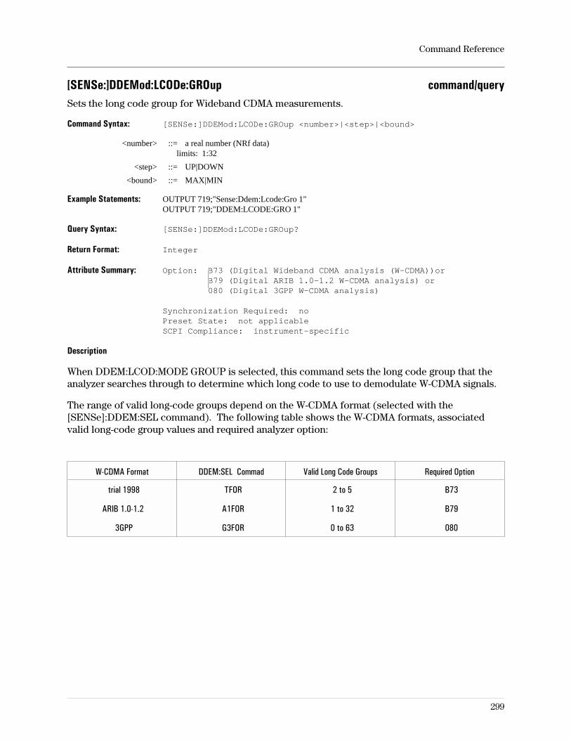
[SENSe:]DDEMod:LCODe:GROup command/querySets the long code group for Wideband CDMA measurements.
Command Syntax: [SENSe:]DDEMod:LCODe:GROup <number>|<step>|<bound>
<number> ::= a real number (NRf data)limits: 1:32
<step> ::= UP|DOWN
<bound> ::= MAX|MIN
Example Statements: OUTPUT 719;"Sense:Ddem:Lcode:Gro 1"OUTPUT 719;"DDEM:LCODE:GRO 1"
Query Syntax: [SENSe:]DDEMod:LCODe:GROup?
Return Format: Integer
Attribute Summary: Option: B73 (Digital Wideband CDMA analysis (W-CDMA))orB79 (Digital ARIB 1.0-1.2 W-CDMA analysis) or080 (Digital 3GPP W-CDMA analysis)
Synchronization Required: noPreset State: not applicableSCPI Compliance: instrument-specific
Description
When DDEM:LCOD:MODE GROUP is selected, this command sets the long code group that theanalyzer searches through to determine which long code to use to demodulate W-CDMA signals.
The range of valid long-code groups depend on the W-CDMA format (selected with the[SENSe]:DDEM:SEL command). The following table shows the W-CDMA formats, associatedvalid long-code group values and required analyzer option:
W-CDMA Format DDEM:SEL Commad Valid Long Code Groups Required Option
trial 1998 TFOR 2 to 5 B73
ARIB 1.0-1.2 A1FOR 1 to 32 B79
3GPP G3FOR 0 to 63 080
Command Reference
299
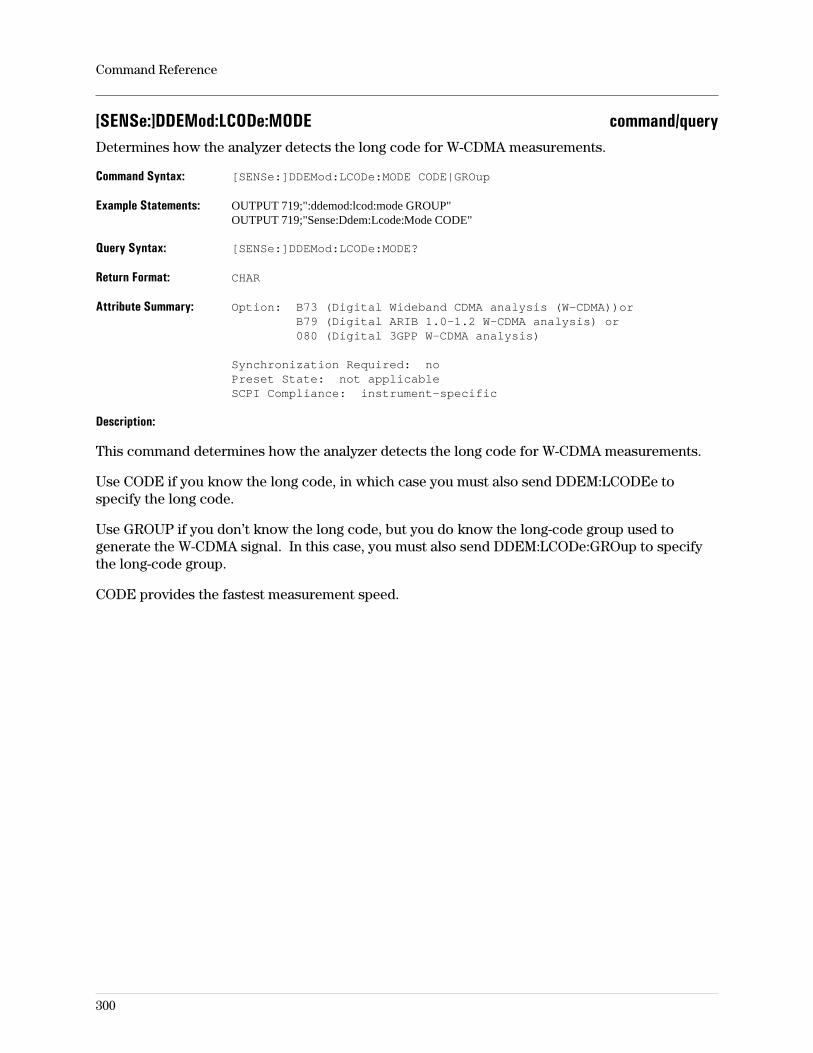
[SENSe:]DDEMod:LCODe:MODE command/queryDetermines how the analyzer detects the long code for W-CDMA measurements.
Command Syntax: [SENSe:]DDEMod:LCODe:MODE CODE|GROup
Example Statements: OUTPUT 719;":ddemod:lcod:mode GROUP"OUTPUT 719;"Sense:Ddem:Lcode:Mode CODE"
Query Syntax: [SENSe:]DDEMod:LCODe:MODE?
Return Format: CHAR
Attribute Summary: Option: B73 (Digital Wideband CDMA analysis (W-CDMA))orB79 (Digital ARIB 1.0-1.2 W-CDMA analysis) or080 (Digital 3GPP W-CDMA analysis)
Synchronization Required: noPreset State: not applicableSCPI Compliance: instrument-specific
Description:
This command determines how the analyzer detects the long code for W-CDMA measurements.
Use CODE if you know the long code, in which case you must also send DDEM:LCODEe tospecify the long code.
Use GROUP if you don’t know the long code, but you do know the long-code group used togenerate the W-CDMA signal. In this case, you must also send DDEM:LCODe:GROup to specifythe long-code group.
CODE provides the fastest measurement speed.
Command Reference
300
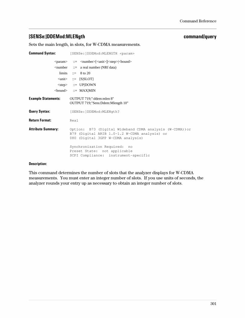
[SENSe:]DDEMod:MLENgth command/querySets the main length, in slots, for W-CDMA measurements.
Command Syntax: [SENSe:]DDEMod:MLENGTH <param>
<param> ::= <number>[<unit>]|<step>|<bound>
<number ::= a real number (NRf data)
limits ::= 8 to 20
<unit> ::= [S|SLOT]
<step> ::= UP|DOWN
<bound> ::= MAX|MIN
Example Statements: OUTPUT 719;":ddem:mlen 8"OUTPUT 719;"Sens:Ddem:Mlength 10"
Query Syntax: [SENSe:]DDEMod:MLENgth?
Return Format: Real
Attribute Summary: Option: B73 (Digital Wideband CDMA analysis (W-CDMA))orB79 (Digital ARIB 1.0-1.2 W-CDMA analysis) or080 (Digital 3GPP W-CDMA analysis)
Synchronization Required: noPreset State: not applicableSCPI Compliance: instrument-specific
Description:
This command determines the number of slots that the analyzer displays for W-CDMAmeasurements. You must enter an integer number of slots. If you use units of seconds, theanalyzer rounds your entry up as necessary to obtain an integer number of slots.
Command Reference
301
[SENSe:]DDEMod:MSK:FORMat command/querySpecifies the form of MSK (minimum-shift key) modulation format.
Command Syntax: [SENSe:]DDEMod:MSK:FORMat TYPe1|TYPe2
Example Statements: OUTPUT 719;":Ddemod:Msk:Format TYPE1"OUTPUT 719;"SENS:DDEM:MSK:FORM TYPE1"
Query Syntax: [SENSe:]DDEMod:MSK:FORMat?
Return Format: CHAR
Attribute Summary: Option: AYA (vector modulation analysis)Synchronization Required: noPreset State: not applicableSCPI Compliance: instrument-specific
Description:
For more information on digital demodulation, see online help (press the [ Help ] key on thefront panel, then press the softkey of interest) and the concepts discussion in the Operator’s
Guide.
Command Reference
302
[SENSe:]DDEMod:NORMalize command/queryTurns digital demod normalization on/off.
Command Syntax: [SENSe:]DDEMod:NORMalize OFF|0|ON|1
Example Statements: OUTPUT 719;"sense:ddem:norm OFF"OUTPUT 719;"Ddemod:Norm OFF"
Query Syntax: [SENSe:]DDEMod:NORMalize?
Return Format: Integer
Attribute Summary: Option: AYA (vector modulation analysis) andB7A (Enhanced Data rates for GSM gsm Evolution (EDGE)) orB73 (Digital Wideband CDMA analysis (W-CDMA)) orB79 (Digital ARIB 1.0-1.2 W-CDMA analysis) or080 (Digital 3GPP W-CDMA analysis)
Synchronization Required: noPreset State: not affected by PresetSCPI Compliance: instrument-specific
Description:
ON performs a minimum square error calculation of the all constellation states and sets thesystem gain such that the outer states have a magnitude of 1. For W-CDMA code-domain powerdisplays, ON normalizes code-domain power relative to the total signal power in the codedomain.
OFF means you can interpret the measurement data in volts.
For more information on digital demodulation, see online help (press the [ Help ] key on thefront panel, then press the softkey of interest) and the concepts discussion in the Operator’s
Guide.
Command Reference
303
[SENSe:]DDEMod:PRATe command/querySpecifies the number of points per symbol for vector modulation analysis.
Command Syntax: [SENSe:]DDEMod:PRATe <number>|<step>|<bound>
<number> ::= a real number (NRf data)limits: (depends on configuration)
<step> ::= UP|DOWN
<bound> ::= MAX|MIN
Example Statements: OUTPUT 719;":DDEMOD:PRAT 2"OUTPUT 719;"sens:ddemod:prat 10"
Query Syntax: [SENSe:]DDEMod:PRATe?
Return Format: Integer
Attribute Summary: Option: AYA (vector modulation analysis)Synchronization Required: noPreset State: not affected by PresetSCPI Compliance: instrument-specific
Description:
The acceptable argument values for this command are 1, 2, 3, 4, 10, and 20. The maximumnumber of points between symbols is 20 but the analyzer decreases this value if theresult-length × PRATE is greater than the maximum number of time points.
For more information on digital demodulation, see online help and the concepts discussion inthe Operator’s Guide.
Command Reference
304
[SENSe:]DDEMod:PRESet commandPresets the digital demodulation configuration to be one of the standard configurations listedbelow.
Command Syntax: [SENSe:]DDEMod:PRESet <standard>
<standard> ::=NADC|PDC|GSM|PHP|DECT|CDPD|TETRa|CDMB|CDMM|ATV8|ATV16|DVB16|DVB32|DVB64|APCO|EDGE|WCDM|WCD5|WCD10|WCD20|BLU
Example Statements: OUTPUT 719;":DDEMOD:PRES ATV16, 2.66409e+06"OUTPUT 719;"sens:ddemod:pres TETRA, 8.70895e+06"
Attribute Summary: Option: AYA (vector modulation analysis) andB7A (Enhanced Data rates for GSM gsm Evolution (EDGE)) orB73 (Digital Wideband CDMA analysis (W-CDMA)) orB79 (Digital ARIB 1.0-1.2 W-CDMA analysis) or080 (Digital 3GPP W-CDMA analysis)
Synchronization Required: noPreset State: not applicableSCPI Compliance: instrument-specific
Description:
This command corresponds to the softkey selections under the standard setups menu. Note thatCDMB selects the CDMA Base standard setup; CDMM selects the CDMA Mobile standard setup.
You must set the instrument mode to video demodulation (send INST:VDEM) to select ATV8,ATV16, DVB16, DVB32, and DVB64 (Option AYA).
You must set the instrument mode to Wideband CDMA (send INST:WCDMa) to select WCD5,WCD10, or WCD20 (Option B73, B79). WCD5 is the only preset for Option 080 (Digital 3GPPW-CDMA analysis).
Note WCDM is available in both the Wideband CDMA and Digital Demodulationinstrument modes. For the Wideband CDMA instrument mode, WCDM isidentical to WCD5.
You must set the instrument mode to digital demodulation (send INST DDEM) to select all otherstandard setups.
For more information on digital or video demodulation or on Wideband CDMA, see online help(press the [ Help ] key on the front panel, then press the softkey of interest). Or see the conceptsdiscussion in the Operator’s Guide.
Command Reference
305
[SENSe:]DDEMod:PSK:NSTate command/querySpecifies the number of states in the PSK modulation format.
Command Syntax: [SENSe:]DDEMod:PSK:NSTate <number>|<step>|<bound>
<number> ::= a real number (NRf data)limits: 2:8
<step> ::= UP|DOWN
<bound> ::= MAX|MIN
Example Statements: OUTPUT 719;":ddem:psk:nstate 2"OUTPUT 719;"Sens:Ddemod:Psk:Nst 8"
Query Syntax: [SENSe:]DDEMod:PSK:NSTate?
Return Format: Integer
Attribute Summary: Option: AYA (vector modulation analysis)Synchronization Required: noPreset State: not affected by PresetSCPI Compliance: instrument-specific
Description:
Valid values for this command are 2 or 8.
Related Commands:
To select the PSK modulation format, use DDEM:FORMAT PSK.
For more information on digital demodulation, see online help (press the [ Help ] key on thefront panel, then press the softkey of interest) and the concepts discussion in the Operator’s
Guide.
Command Reference
306
[SENSe:]DDEMod:QAM:NSTate command/querySpecifies the number of states in the QAM modulation format.
Command Syntax: [SENSe:]DDEMod:QAM:NSTate <number>|<step>|<bound>
<number> ::= a real number (NRf data)limits: 16:256
<step> ::= UP|DOWN
<bound> ::= MAX|MIN
Example Statements: OUTPUT 719;"SENSE:DDEM:QAM:NST 16"OUTPUT 719;"ddem:qam:nst 32"
Query Syntax: [SENSe:]DDEMod:QAM:NSTate?
Return Format: Integer
Attribute Summary: Option: AYA and, for 64 or 256 QAM, option AYH (see below)Synchronization Required: noPreset State: not affected by PresetSCPI Compliance: instrument-specific
Description:
Use this command to select the number of states for the QAM modulation format. Valid valuesare 16 or 32. If you have option AYH, you can also specify 64 or 256.
To select the QAM modulation format, use DDEM:FORMAT QAM.
For additional information on digital demodulation or video demodulation, see the Operator’s
Guide.
Command Reference
307
[SENSe:]DDEMod:QPSK:FORMat command/querySpecifies the form of QPSK modulation format.
Command Syntax: [SENSe:]DDEMod:QPSK:FORMat NORMal|OFFSet|DIFFerential|DPI4
Example Statements: OUTPUT 719;"Sense:Ddem:Qpsk:Format NORMAL"OUTPUT 719;"DDEM:QPSK:FORM OFFSET"
Query Syntax: [SENSe:]DDEMod:QPSK:FORMat?
Return Format: CHAR
Attribute Summary: Option: AYA (vector modulation analysis)Synchronization Required: noPreset State: not applicableSCPI Compliance: instrument-specific
Description:
For more information on digital demodulation, see online help (press the [ Help ] key on thefront panel, then press the softkey of interest) and the concepts discussion in the Operator’s
Guide.
Command Reference
308
[SENSe:]DDEMod:SEARch:PULSe:STATe command/queryTurns pulse search on or off.
Command Syntax: [SENSe:]DDEMod:SEARch:PULSe:STATe OFF|0|ON|1
Example Statements: OUTPUT 719;":ddem:search:puls:state OFF"OUTPUT 719;"Sens:Ddem:Search:Puls:State ON"
Query Syntax: [SENSe:]DDEMod:SEARch:PULSe:STATe?
Return Format: Integer
Attribute Summary: Option: AYA (vector modulation analysis)Synchronization Required: noPreset State: not affected by PresetSCPI Compliance: instrument-specific
Description:
This corresponds to pulse search as discussed in online help. A pulse is defined as an off-on-offcarrier transition.
For more information on digital demodulation, see online help and the concepts discussion inthe Operator’s Guide.
Command Reference
309
[SENSe:]DDEMod:SEARch:SYNC:OFFSet command/querySpecifies the offset for sync search in digital demodulation.
Command Syntax: [SENSe:]DDEMod:SEARch:SYNC:OFFSet <param>
<param> ::= <number>[<unit>]|<step>|<bound>
<number> ::= a real number (NRf data)limits: depends on configuration
<unit> ::= SYM
<step> ::= UP|DOWN
<bound> ::= MAX|MIN
Example Statements: OUTPUT 719;":DDEM:SEAR:SYNC:OFFS 14"OUTPUT 719;"sense:ddem:sear:sync:offs 60"
Query Syntax: [SENSe:]DDEMod:SEARch:SYNC:OFFSet?
Return Format: Integer
Attribute Summary: Option: AYA (vector modulation analysis)Synchronization Required: noPreset State: not affected by PresetSCPI Compliance: instrument-specific
Description:
This command takes integer numbers of symbols. If a real number is used, the fractional part ofthe number is ignored. If no units are specified, SYM is assumed.
For more information on digital demodulation, see online help and the concepts discussion inthe Operator’s Guide.
Command Reference
310
[SENSe:]DDEMod:SEARch:SYNC:PATTern command/querySpecifies the sync pattern for digital demodulation.
Command Syntax: [SENSe:]DDEMod:SEARch:SYNC:PATTern <STRING>
Example Statements: OUTPUT 719;"SENS:DDEM:SEAR:SYNC:PATT ‘1010100100011101111001001010’"OUTPUT 719;"ddemod:sear:sync:patt ‘11001010110100011’"
Query Syntax: [SENSe:]DDEMod:SEARch:SYNC:PATTern?
Return Format: STRING
Attribute Summary: Option: AYA (vector modulation analysis)Synchronization Required: noPreset State: not affected by PresetSCPI Compliance: instrument-specific
Description:
The analyzer accepts only the characters one (1) or zero (0) in these strings. All other charactersare ignored.
For more information on digital demodulation, see online help and the concepts discussion inthe Operator’s Guide.
Command Reference
311
[SENSe:]DDEMod:SEARch:SYNC:STATe command/queryTurns sync search on or off.
Command Syntax: [SENSe:]DDEMod:SEARch:SYNC:STATe OFF|0|ON|1
Example Statements: OUTPUT 719;"SENS:DDEM:SEARCH:SYNC:STATE OFF"OUTPUT 719;"ddem:sear:sync:stat ON"
Query Syntax: [SENSe:]DDEMod:SEARch:SYNC:STATe?
Return Format: Integer
Attribute Summary: Option: AYA (vector modulation analysis)Synchronization Required: noPreset State: not affected by PresetSCPI Compliance: instrument-specific
Description:
For more information on digital demodulation, see online help and the concepts discussion inthe Operator’s Guide.
Related Commands:
To specify the sync pattern, use DDEM:SEAR:SYNC:PATT.To specify the sync offset, use DDEM:SEAR:SYNC:OFFS.
Command Reference
312
[SENSe:]DDEMod:SEARch:TIME command/querySpecifies the amount of data that is demodulated.
Command Syntax: [SENSe:]DDEMod:SEARch:TIME <param>
<param> ::= <number>[<unit>]|<step>|<bound>
<number> ::= a real number (NRf data)limits: depends on configuration
<unit> ::= S|SYM
<step> ::= UP|DOWN
<bound> ::= MAX|MIN
Example Statements: OUTPUT 719;"sens:ddem:search:time +6.70781893E-3S"OUTPUT 719;"Ddem:Sear:Time 150sym"
Query Syntax: [SENSe:]DDEMod:SEARch:TIME?
Return Format: Real
Attribute Summary: Option: AYA (vector modulation analysis)Synchronization Required: noPreset State: not affected by PresetSCPI Compliance: instrument-specific
Description:
Determines the amount of data that is demodulated when pulse search or sync search is on. Youcan specify search length in number of symbols or units of time. The amount of data displayed isspecified with DDEM:TIME (result length).
DDEM:SEAR:TIME corresponds to search length as discussed in the online help.
Command Reference
313
[SENSe:]DDEMod:SELect command/querySelects base-station W-CDMA measurements when the instrument mode is Wideband CDMA.
Command Syntax: [SENSe:]DDEMod:SELect BASE|A1For|TFOR|SOR
Example Statements: OUTPUT 719;":Ddemod:Sel TFOR"OUTPUT 719;"SENS:DDEMOD:SEL TFOR"
Query Syntax: [SENSe:]DDEMod:SELect?
Return Format: CHAR
Attribute Summary: Option: B73 (Digital Wideband CDMA analysis (W-CDMA))orB79 (Digital ARIB 1.0-1.2 W-CDMA analysis) or080 (Digital 3GPP W-CDMA analysis)
Synchronization Required: noPreset State: not applicableSCPI Compliance: instrument-specific
Description
Selects the type of base-station measurement used for W-CDMA measurements.
TFOR and BASE configure the analyzer to measure W-CDMA signals that conform to theJapanese Experimental System (also called trial 1998 forward link). BASE is provided forbackward compatibility (Requires option B73).
A1FOR configures the analyzer to measure W-CDMA signals that conform to the ARIB 1.0-1.2standard (Requires option B79).
G3FOR configures the analyzer to measure W-CDMA signals that conform to the 3GPP standard(Requires option 080).
Command Reference
314
[SENSe:]DDEMod:SRATe command/querySpecifies the digital modulation symbol rate.
Command Syntax: [SENSe:]DDEMod:SRATe <param> <param> ::=<number>[<unit>]|<step>|<bound> <number> ::= a real number(NRf data)limits: depends on configuration <unit> ::= HZ <step>::= UP|DOWN <bound> ::= MAX|MIN
Example Statements: OUTPUT 719;":ddem:srate 2.43e4"OUTPUT 719;"Sens:Ddem:Srate 270833 HZ"
Query Syntax: [SENSe:]DDEMod:SRATe?
Return Format: Real
Attribute Summary: Option: AYA (vector modulation analysis)Synchronization Required: noPreset State: not affected by PresetSCPI Compliance: instrument-specific
Description:
This command corresponds to the symbol rate softkey.
For more information on digital demodulation, see online help (press the [ Help ] key on thefront panel, then press the softkey of interest) and the concepts discussion in the Operator’s
Guide.
Note In the digital demodulation instrument mode, the maximum span is limited bythe MaxSpan/SymbolRate ratio. For a given symbol rate, this ratio limits themaximum span to conserve memory usage. For all demod types except FSK, thisratio is 15.625 and cannot be changed. For the FSK demod type the ratio may bechanged to values between 16 and 100, but larger values use more memory. SeeMEM:MALL:MEAS:MSSR.
Command Reference
315
[SENSe:]DDEMod:TIME command/querySpecifies how much demodulated data is displayed.
Command Syntax: [SENSe:]DDEMod:TIME <param>
<param> ::= <number>[<unit>]|<step>|<bound>
<number> ::= a real number (NRf data)limits: depends on configuration
<unit> ::= SYM
<step> ::= UP|DOWN
<bound> ::= MAX|MIN
Example Statements: OUTPUT 719;"SENS:DDEMOD:TIME 1.56e2"OUTPUT 719;"ddem:time 2e3"
Query Syntax: [SENSe:]DDEMod:TIME?
Return Format: Real
Attribute Summary: Option: AYA (vector modulation analysis)Synchronization Required: noPreset State: not affected by PresetSCPI Compliance: instrument-specific
Description:
This parameter corresponds to result length, as discussed in the online help. DDEM:SEAR:TIMEshould be larger than DDEM:TIME. If you set the search length less than the result length, theanalyzer displays a warning message and sets the result length equal to the search length.
To specify how much demodulated data is displayed for Wideband CDMA measurements, useDDEMod:MLENgth.
Command Reference
316
[SENSe:]DDEMod:TIME:CCHannel command/querySets the code channel for Wideband CDMA analysis.
Command Syntax: [SENSe:]DDEMod:TIME:CCHannel <number>[<unit>]|<step>|<bound>
<number> ::= a real number (NRf data)limits: 0:2047
<unit> ::= [CODE]
<step> ::= UP|DOWN
<bound> ::= MAX|MIN
Example Statements: OUTPUT 719;"sense:ddem:time:cchannel 0"OUTPUT 719;"Ddem:Time:Cch 0"
Query Syntax: [SENSe:]DDEMod:TIME:CCHannel?
Return Format: Integer
Attribute Summary: Option: B73 (Digital Wideband CDMA analysis (W-CDMA))orB79 (Digital ARIB 1.0-1.2 W-CDMA analysis) or080 (Digital 3GPP W-CDMA analysis)
Synchronization Required: noPreset State: not applicableSCPI Compliance: instrument-specific
Description
When the instrument mode is Wideband CDMA, all time-domain measurement data (exceptcomposite time-domain data) and symbol table/error summary information is for a single codelayer and a single code channel.
This command and the DDEMod:TIME:CLAYer command set the code channel and code layer.For example, if you want the symbol table to show data for channel 3 in code layer 16000 sym/s,send “DDEMod:TIME:CCHannel 3" to select code channel 3; send ”DDEM:TIME:CLAY 16000" toselect code layer 16000 sym/s.
NOTE Option 080 use code layer 16000 sym/s.Options B73 and B79 use code layer 15000 sym/s.
Command Reference
317
[SENSe:]DDEMod:TIME:CLAYer command/querySets the code layer for Wideband CDMA analysis.
Command Syntax: [SENSe:]DDEMod:TIME:CLAYer <number>|<bound>
<number> ::= a real number (NRf data)limits: 8000:4096000
<bound> ::= MAX|MIN
Example Statements: OUTPUT 719;":DDEM:TIME:CLAY 8000"OUTPUT 719;"sense:ddem:time:clayer 2048000"
Query Syntax: [SENSe:]DDEMod:TIME:CLAYer?
Return Format: Integer
Attribute Summary: Option: B73 (Digital Wideband CDMA analysis (W-CDMA))orB79 (Digital ARIB 1.0-1.2 W-CDMA analysis) or080 (Digital 3GPP W-CDMA analysis)
Synchronization Required: noPreset State: not applicableSCPI Compliance: instrument-specific
Description
When the instrument mode is Wideband CDMA, all time-domain measurement data (exceptcomposite time-domain data) and symbol table/error summary information is for a single codelayer and a single code channel.
This command and the DDEMod:TIME:CCHannel command set the code channel and code layer.For example, if you want the symbol table to show data for channel 3 in code layer 16000 sym/s,send “DDEMod:TIME:CCHannel 3" to select code channel 3; send ”DDEM:TIME:CLAY 16000" toselect code layer 16000 sym/s.
NOTE Option 080 use code layer 16000 sym/s.Options B73 and B79 use code layer 15000 sym/s.
The available code layers are determined by the demod format (set with the SENSe:DDEM:SELcommand) and the chip rate (set with the SENSe:DDEM:CRATe command).
Command Reference
318
[SENSe:]DDEMod:TIME:GATE:DELay command/querySets the gate delay when time gating is on for Wideband CDMA measurements.
Command Syntax: [SENSe:]DDEMod:TIME:GATE:DELay <number>[<unit>]|<step>|<bound>
<number> ::= a real number (NRf data)limits: 0:15 slots
<unit> ::= [S|SLOT]
<step> ::= UP|DOWN
<bound> ::= MAX|MIN
Example Statements: OUTPUT 719;"Sens:Ddemod:Time:Gate:Delay 0"OUTPUT 719;"DDEM:TIME:GATE:DEL 0"
Query Syntax: [SENSe:]DDEMod:TIME:GATE:DELay?
Return Format: Real
Attribute Summary: Option: B73 (Wideband CDMA analysis)Synchronization Required: noPreset State: not applicableSCPI Compliance: instrument-specific
Description
This command sets the gate delay (in whole slots) when time gating is used in the WidebandCDMA instrument mode. For details about time gating, seeSENSe:]DDEMod:TIME:GATE:STATe.
Command Reference
319
[SENSe:]DDEMod:TIME:GATE[:SPAN] command/querySets the gate length (span) when time gating is on for Wideband CDMA measurements.
Command Syntax: [SENSe:]DDEMod:TIME:GATE[:SPAN] <number>[<unit>]|<step>|<bound>
<number> ::= a real number (NRf data)limits: 1:16 slots
<unit> ::= [S|SLOT]
<step> ::= UP|DOWN
<bound> ::= MAX|MIN
Example Statements: OUTPUT 719;":ddemod:time:gate 1"OUTPUT 719;"Sens:Ddem:Time:Gate:Span 4"
Query Syntax: [SENSe:]DDEMod:TIME:GATE[:SPAN]?
Return Format: Real
Attribute Summary: Option: B73 (Wideband CDMA analysis)Synchronization Required: noPreset State: not applicableSCPI Compliance: instrument-specific
Description
This command sets the gate length (in whole slots) when time gating is used in the WidebandCDMA instrument mode. For details about time gating, seeSENSe:]DDEMod:TIME:GATE:STATe.
Command Reference
320
[SENSe:]DDEMod:TIME:GATE:STATe command/queryTurns time gating on or off for Wideband CDMA measurements.
Command Syntax: [SENSe:]DDEMod:TIME:GATE:STATe OFF|0|ON|1
Example Statements: OUTPUT 719;"SENS:DDEM:TIME:GATE:STATE OFF"OUTPUT 719;"ddem:time:gate:stat ON"
Query Syntax: [SENSe:]DDEMod:TIME:GATE:STATe?
Return Format: Integer
Attribute Summary: Option: B73 (Wideband CDMA analysis)Synchronization Required: noPreset State: not applicableSCPI Compliance: instrument-specific
Description
When the instrument mode is Wideband CDMA, this command turns time gating on or off. Whentime gating is on, the analyzer uses the values of DDEMod:TIME:GATE[:SPAN] andDDEMod:TIME:GATE:DELay for the gate length and gate delay.
Gate length sets the width of the gate (in whole slots); gate delay determines the delay, or offset,of the gate (in whole slots). For example, a gate length of 3 and gate delay of 1 displays resultsfor three slots, starting at slot two— in other words, slots 2-4.
For further details about time gating, select the Wideband CDMA instrument mode on theanalzyer and see online help for the [gate on/off] softkey (under the [Time] hardkey).
Command Reference
321
[SENSe:]DDEMod:VSB:NSTate command/querySpecifies the number of states in the VSB modulation format.
Command Syntax: [SENSe:]DDEMod:VSB:NSTate <number>|<step>|<bound>
<number> ::= a real number (NRf data)limits: 8:16
<step> ::= UP|DOWN
<bound> ::= MAX|MIN
Example Statements: OUTPUT 719;"SENSE:DDEM:VSB:NST 8"OUTPUT 719;"ddem:VSB:nst 16"
Query Syntax: [SENSe:]DDEMod:VSB:NSTate?
Return Format: Integer
Attribute Summary: Option: AYA and AYHSynchronization Required: noPreset State: not affected by PresetSCPI Compliance: instrument-specific
Description:
Use this command to select the number of states for the VSB modulation format. Valid valuesare 8 and 16. To select the VSB modulation format, use DDEM:FORMAT VSB.
For additional information on video demodulation, see the Operator’s Guide.
Command Reference
322
[SENSe:]DDEMod:WCDMa:FILTer:ALPHa command/querySets the alpha of the root-cosine filter used in W-CDMA measurements.
Command Syntax: [SENSe:]DDEMod:WCDMa:FILTer:ALPHa <number>|<step>|<bound>
<number> ::= a real number (NRf data)limits: .05:100
<step> ::= UP|DOWN
<bound> ::= MAX|MIN
Example Statements: OUTPUT 719;":Ddemod:Wcdm:Filt:Alpha 0"OUTPUT 719;"SENS:DDEMOD:WCDM:FILT:ALPHA 0"
Query Syntax: [SENSe:]DDEMod:WCDMa:FILTer:ALPHa?
Return Format: Real
Attribute Summary: Option: B73 (Digital Wideband CDMA analysis (W-CDMA))orB79 (Digital ARIB 1.0-1.2 W-CDMA analysis) or080 (Digital 3GPP W-CDMA analysis)
Synchronization Required: noPreset State: not applicableSCPI Compliance: instrument-specific
Description:
This command sets the alpha of the raised root-cosine filter used in W-CDMA measurements.For details, see the “Wideband CDMA Concepts” chapter in the Operator’s Guide.
Command Reference
323
[SENSe:]DEMod[1|2] command/querySelects the demodulation result.
Command Syntax: [SENSe:]DEMod[1|2] OFF|0|AM|PM|FM|BASeband
Example Statements: OUTPUT 719;"sens:demod2 BASEBAND"OUTPUT 719;"Dem AM"
Query Syntax: [SENSe:]DEMod[1|2]?
Return Format: CHAR
Attribute Summary: Option: AYA (vector modulation analysis)Synchronization Required: noPreset State: 0SCPI Compliance: instrument-specific
Description:
OFF|0 turns demodulation off.
AM turns on AM demodulation.
PM turns on PM demodulation.
FM turns on FM demodulation.
BASeband may be specified for input channel 2 when channel 1 is in demodulation. When thisis specified for channel 2, the LO is set to 0 Hz for channel 2. This allows comparison ofbaseband data on channel 2 with channel 1 demod (baseband) results.
Command Reference
324
[SENSe:]DEMod[1|2]:CARRier:AUTO command/queryTurns automatic carrier compensation on and off.
Command Syntax: [SENSe:]DEMod[1|2]:CARRier:AUTO OFF|0|ON|1
Example Statements: OUTPUT 719;":DEM2:CARRIER:AUTO OFF"OUTPUT 719;"sense:dem:carr:auto OFF"
Query Syntax: [SENSe:]DEMod[1|2]:CARRier:AUTO?
Return Format: Integer
Attribute Summary: Option: AYA (vector modulation analysis)Synchronization Required: noPreset State: +1 (ON)SCPI Compliance: instrument-specific
Description:
This feature determines how the analyzer locks to the carrier frequency. Has no effect on AMdemodulation.
ON uses an algorithm to lock to the carrier frequency. The center frequency of the analyzershould be set to or near the frequency of the carrier (the modulation format must not besuppressed-carrier).
OFF assumes the carrier to be at the analyzer’s center frequency. The accuracy of the settingaffects phase accuracy in PM demodulation and dc offsets in FM demodulation. This method isuseful when the carrier is too small to detect, when the carrier frequency is hopping within thespan, or when the analyzer is locked to an external reference which is locked to the carrier. Theaccuracy required for setting the center frequency on the carrier varies with the span setting, butkeeping it within 0.5% of the carrier frequency is recommended for PM.
Command Reference
325

[SENSe:]DEMod[1|2]:CARRier:AUTO:PM command/querySpecifies the type of automatic carrier compensation for PM demod.
Command Syntax: [SENSe:]DEMod[1|2]:CARRier:AUTO:PM PAFReq|PHASe
Example Statements: OUTPUT 719;"Sens:Demod:Carr:Auto:Pm PAFREQ"OUTPUT 719;"DEM2:CARRIER:AUTO:PM PAFREQ"
Query Syntax: [SENSe:]DEMod[1|2]:CARRier:AUTO:PM?
Return Format: CHAR
Attribute Summary: Option: AYA (vector modulation analysis)Synchronization Required: noPreset State: PAFRSCPI Compliance: instrument-specific
Description:
This setting has meaning only when PM demodulation is active and the DEM:CARR:AUTO is ON.It determines how the analyzer detects the PM carrier frequency.
PHASe detects phase offset between the analyzer’s local oscillator and the carrier and producesa zero-mean phase record.
PAFReq detects phase and frequency differences. Corrects for phase offset and removes phaseramping due to frequency difference between the analyzer’s local oscillator and the carrier.
Command Reference
326
[SENSe:]DEMod[1|2]:CARRier:FREQ? queryQuery the results of the demod carrier display.
Query Syntax: [SENSe:]DEMod[1|2]:CARRier:FREQ?
Example Statements: OUTPUT 719;":demod2:carr:freq?"OUTPUT 719;"Sens:Dem:Carrier:Freq?"
Return Format: Real
Attribute Summary: Synchronization Required: noPreset State: not applicableSCPI Compliance: instrument-specific
Description:
The instrument mode must be demod and DISP:WIND:TRAC:DCARR must be ON for there to bedata available for this query.
Command Reference
327
[SENSe:]DETector[:FUNCtion] command/querySelects the detector method used.
Command Syntax: [SENSe:]DETector[:FUNCtion] SIGNal|SAMPle|POSitive
Example Statements: OUTPUT 719;"SENSE:DET:FUNC SAMPLE"OUTPUT 719;"detector SIGNAL"
Query Syntax: [SENSe:]DETector[:FUNCtion]?
Return Format: CHAR
Attribute Summary: Synchronization Required: noPreset State: POSSCPI Compliance: confirmed
Description:
The detector function operates only in scaler instrument mode and only when there are moredata points than display points. Then it is used to select which data points are displayed.
SIGNal peak detection tests whether the signal rises and falls within the cell represented by agiven data point. When the signal both rises and falls, the odd-numbered data point indicates themaximum value and the even-numbered data point indicates the minimum value encounteredduring its cell. This algorithm does a good job of combining noise and discrete spectralcomponents, but does not give a true randomness of noise.
SAMPle detection digitizes the instantaneous value of the signal at the end of each cell. It is thebest way to indicate the randomness of noise.
POSitive detection insures that all sinusoids maximum value encountered in each cell isdisplayed. This mode does not give a good representation of random noise either, because itcaptures the crests of the noise.
Command Reference
328
[SENSe:]FEED command/querySpecifies input to be either time capture or receiver channel input.
Command Syntax: [SENSe:]FEED ‘INPut’|’TCAPure’
Example Statements: OUTPUT 719;":feed ‘INPUT’"OUTPUT 719;"Sense:Feed ‘TCAPTURE’"
Query Syntax: [SENSe:]FEED?
Return Format: STRING
Attribute Summary: Synchronization Required: noPreset State: INPSCPI Compliance: instrument-specific
Description:
When time capture is selected, the analyzer is configured to capture time data and store it inmemory. Measurements are made on the captured data in memory rather than on the datacoming in over the instrument channels (as happens when FEED is INP).
The analyzer cannot capture time data when the current instrument mode is Scalar.
Command Reference
329
[SENSe:]FREQuency:BASeband command/querySpecifies either zoomed or baseband operation for vector measurements.
Command Syntax: [SENSe:]FREQuency:BASeband OFF|0|ON|1
Example Statements: OUTPUT 719;":Freq:Baseband ON"OUTPUT 719;"SENS:FREQ:BASEBAND OFF"
Query Syntax: [SENSe:]FREQuency:BASeband?
Return Format: Integer
Attribute Summary: Synchronization Required: noPreset State: +0SCPI Compliance: instrument-specific
Description:
This command has no effect if INST:SEL is ADEM, DDEM, or SCAL or if ROUT:REC is RF2,COMB, or EXT.
Command Reference
330
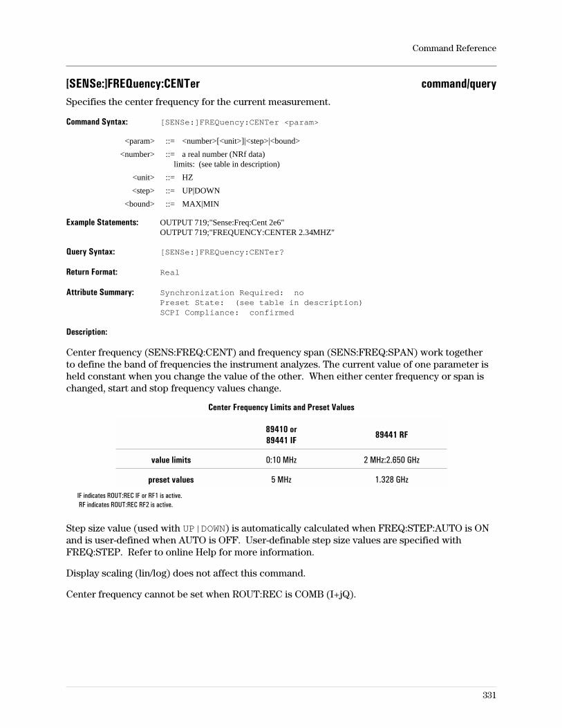
[SENSe:]FREQuency:CENTer command/querySpecifies the center frequency for the current measurement.
Command Syntax: [SENSe:]FREQuency:CENTer <param>
<param> ::= <number>[<unit>]|<step>|<bound>
<number> ::= a real number (NRf data)limits: (see table in description)
<unit> ::= HZ
<step> ::= UP|DOWN
<bound> ::= MAX|MIN
Example Statements: OUTPUT 719;"Sense:Freq:Cent 2e6"OUTPUT 719;"FREQUENCY:CENTER 2.34MHZ"
Query Syntax: [SENSe:]FREQuency:CENTer?
Return Format: Real
Attribute Summary: Synchronization Required: noPreset State: (see table in description)SCPI Compliance: confirmed
Description:
Center frequency (SENS:FREQ:CENT) and frequency span (SENS:FREQ:SPAN) work togetherto define the band of frequencies the instrument analyzes. The current value of one parameter isheld constant when you change the value of the other. When either center frequency or span ischanged, start and stop frequency values change.
Center Frequency Limits and Preset Values
89410 or89441 IF
89441 RF
value limits 0:10 MHz 2 MHz:2.650 GHz
preset values 5 MHz 1.328 GHz
IF indicates ROUT:REC IF or RF1 is active.RF indicates ROUT:REC RF2 is active.
Step size value (used with UP|DOWN) is automatically calculated when FREQ:STEP:AUTO is ONand is user-defined when AUTO is OFF. User-definable step size values are specified withFREQ:STEP. Refer to online Help for more information.
Display scaling (lin/log) does not affect this command.
Center frequency cannot be set when ROUT:REC is COMB (I+jQ).
Command Reference
331
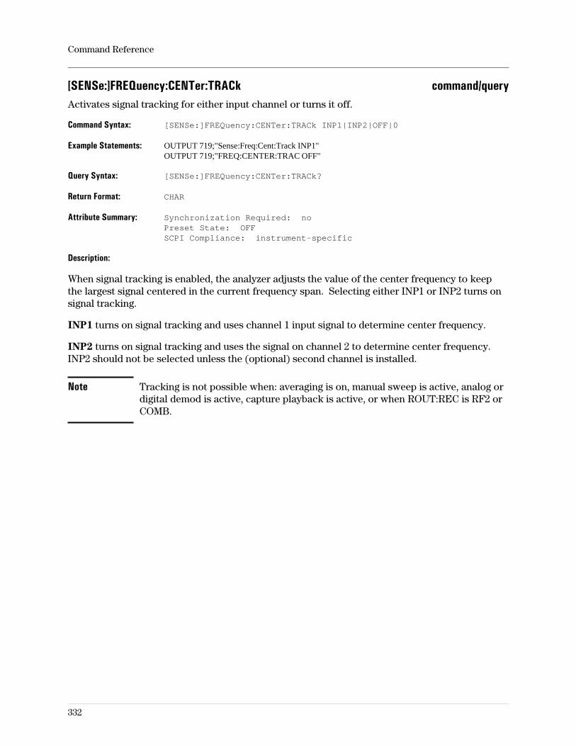
[SENSe:]FREQuency:CENTer:TRACk command/queryActivates signal tracking for either input channel or turns it off.
Command Syntax: [SENSe:]FREQuency:CENTer:TRACk INP1|INP2|OFF|0
Example Statements: OUTPUT 719;"Sense:Freq:Cent:Track INP1"OUTPUT 719;"FREQ:CENTER:TRAC OFF"
Query Syntax: [SENSe:]FREQuency:CENTer:TRACk?
Return Format: CHAR
Attribute Summary: Synchronization Required: noPreset State: OFFSCPI Compliance: instrument-specific
Description:
When signal tracking is enabled, the analyzer adjusts the value of the center frequency to keepthe largest signal centered in the current frequency span. Selecting either INP1 or INP2 turns onsignal tracking.
INP1 turns on signal tracking and uses channel 1 input signal to determine center frequency.
INP2 turns on signal tracking and uses the signal on channel 2 to determine center frequency.INP2 should not be selected unless the (optional) second channel is installed.
Note Tracking is not possible when: averaging is on, manual sweep is active, analog ordigital demod is active, capture playback is active, or when ROUT:REC is RF2 orCOMB.
Command Reference
332
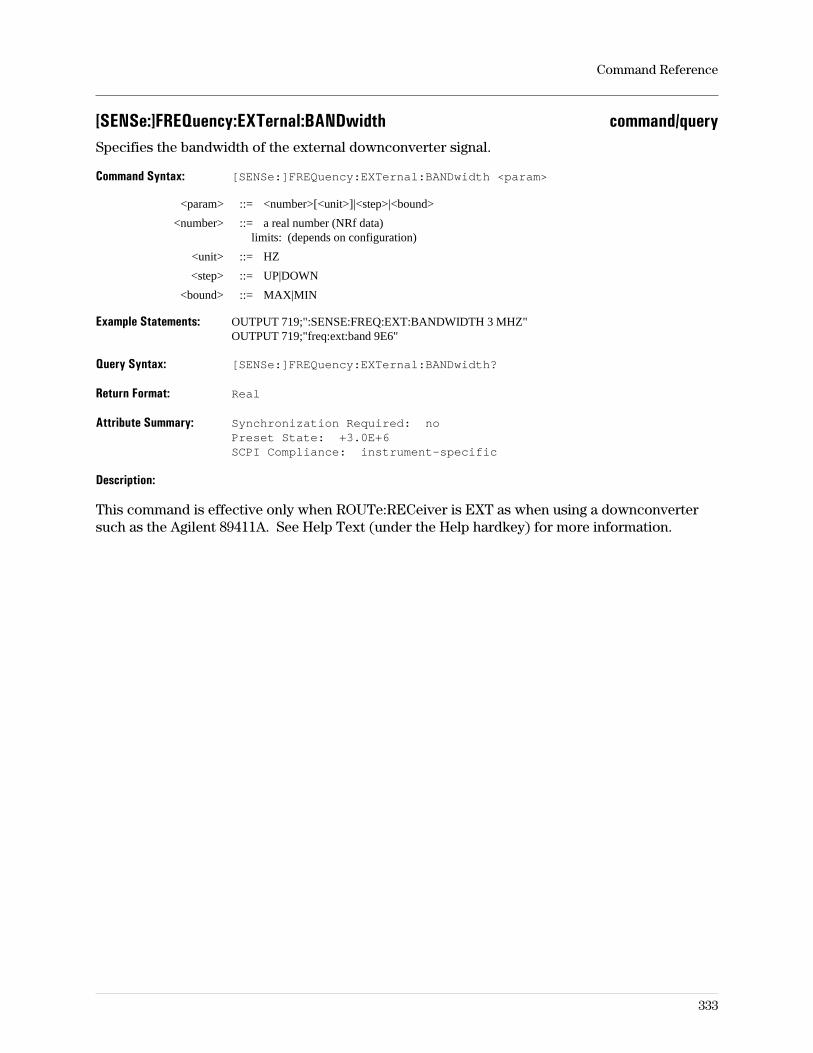
[SENSe:]FREQuency:EXTernal:BANDwidth command/querySpecifies the bandwidth of the external downconverter signal.
Command Syntax: [SENSe:]FREQuency:EXTernal:BANDwidth <param>
<param> ::= <number>[<unit>]|<step>|<bound>
<number> ::= a real number (NRf data)limits: (depends on configuration)
<unit> ::= HZ
<step> ::= UP|DOWN
<bound> ::= MAX|MIN
Example Statements: OUTPUT 719;":SENSE:FREQ:EXT:BANDWIDTH 3 MHZ"OUTPUT 719;"freq:ext:band 9E6"
Query Syntax: [SENSe:]FREQuency:EXTernal:BANDwidth?
Return Format: Real
Attribute Summary: Synchronization Required: noPreset State: +3.0E+6SCPI Compliance: instrument-specific
Description:
This command is effective only when ROUTe:RECeiver is EXT as when using a downconvertersuch as the Agilent 89411A. See Help Text (under the Help hardkey) for more information.
Command Reference
333
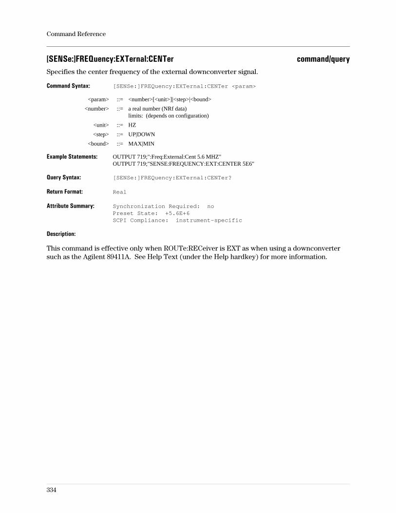
[SENSe:]FREQuency:EXTernal:CENTer command/querySpecifies the center frequency of the external downconverter signal.
Command Syntax: [SENSe:]FREQuency:EXTernal:CENTer <param>
<param> ::= <number>[<unit>]|<step>|<bound>
<number> ::= a real number (NRf data)limits: (depends on configuration)
<unit> ::= HZ
<step> ::= UP|DOWN
<bound> ::= MAX|MIN
Example Statements: OUTPUT 719;":Freq:External:Cent 5.6 MHZ"OUTPUT 719;"SENSE:FREQUENCY:EXT:CENTER 5E6"
Query Syntax: [SENSe:]FREQuency:EXTernal:CENTer?
Return Format: Real
Attribute Summary: Synchronization Required: noPreset State: +5.6E+6SCPI Compliance: instrument-specific
Description:
This command is effective only when ROUTe:RECeiver is EXT as when using a downconvertersuch as the Agilent 89411A. See Help Text (under the Help hardkey) for more information.
Command Reference
334
[SENSe:]FREQuency:EXTernal:COMMunicate command/queryEnables or disables the remote control of an external RF or microwave analyzer.
Command Syntax: [SENSe:]FREQuency:EXTernal:COMMunicate OFF|0|ON|1
Example Statements: OUTPUT 719;"sens:frequency:ext:comm ON"OUTPUT 719;"Frequency:Ext:Communicate OFF"
Query Syntax: [SENSe:]FREQuency:EXTernal:COMMunicate?
Return Format: Integer
Attribute Summary: Synchronization Required: noPreset State: not affected by presetSCPI Compliance: instrument-specific
Description:
To achieve remote control of the analyzer used as a downconverter front end, the GPIBperipheral address must be set to the address of the external analyzer withFREQ:EXT:COMM:ADDR.
Command Reference
335
[SENSe:]FREQuency:EXTernal:COMMunicate:ADDRess command/querySpecifies the address of the external analyzer used as a downconverter.
Command Syntax: [SENSe:]FREQuency:EXTernal:COMMunicate:ADDress <param>
<param> ::= <number>|<step>|<bound>
<number> ::= a real number (NRf data)limits: 0:30
<step> ::= UP|DOWN
<bound> ::= MAX|MIN
Example Statements: OUTPUT 719;":FREQ:EXT:COMMUNICATE:ADDR 8"OUTPUT 719;"sense:freq:ext:communicate:addr 15"
Query Syntax: [SENSe:]FREQuency:EXTernal:COMMunicate:ADDRess?
Return Format: Integer
Attribute Summary: Synchronization Required: noPreset State: not affected by PresetSCPI Compliance: instrument-specific
Description:
This command is useful only when ROUT:REC is EXT and FREQ:EXT:COMM is ON.
Command Reference
336
[SENSe:]FREQuency:EXTernal:MAXimum command/querySpecifies the the maximum frequency to which an external receiver can be tuned.
Command Syntax: [SENSe:]FREQuency:EXTernal:MAXimum <param>
<param> ::= <number>[<unit>]|<step>|<bound>
<number> ::= a real number (NRf data)limits: (depends on configuration)
<unit> ::= HZ
<step> ::= UP|DOWN
<bound> ::= MAX|MIN
Example Statements: OUTPUT 719;"sens:freq:ext:max 15 GHZ"OUTPUT 719;":Frequency:Ext:Max 1.5E10"
Query Syntax: [SENSe:]FREQuency:EXTernal:MAXimum?
Return Format: Real
Attribute Summary: Synchronization Required: noPreset State: +2.2E+10SCPI Compliance: instrument-specific
Description:
This command is effective only when ROUTe:RECeiver is EXT as when using a downconvertersuch as the Agilent 89411A. See Help Text (under the Help hardkey) for more information.
Command Reference
337
[SENSe:]FREQuency:EXTernal:MINimum command/querySpecifies the the minimum frequency to which an external receiver can be tuned.
Command Syntax: [SENSe:]FREQuency:EXTernal:MINimum <param>
<param> ::= <number>[<unit>]|<step>|<bound>
<number> ::= a real number (NRf data)limits: (depends on configuration)
<unit> ::= HZ
<step> ::= UP|DOWN
<bound> ::= MAX|MIN
Example Statements: OUTPUT 719;"sens:freq:ext:min 100 KHZ"OUTPUT 719;":Frequency:Ext:Min 1E6"
Query Syntax: [SENSe:]FREQuency:EXTernal:MINimum?
Return Format: Real
Attribute Summary: Synchronization Required: noPreset State: 0E0SCPI Compliance: instrument-specific
Description:
This command is effective only when ROUTe:RECeiver is EXT as when using a downconvertersuch as the Agilent 89411A. See Help Text (under the Help hardkey) for more information.
Command Reference
338
[SENSe:]FREQuency:EXTernal:MIRRor command/queryLets you reverse the spectrum when using the external or ch1+j*ch2 receiver.
Command Syntax: [SENSe:]FREQuency:EXTernal:MIRRor OFF|0|ON|1
Example Statements: OUTPUT 719;"Sense:Freq:Ext:Mirror OFF"OUTPUT 719;"FREQ:EXTERNAL:MIRR ON"
Query Syntax: [SENSe:]FREQuency:EXTernal:MIRRor?
Return Format: CHAR
Attribute Summary: Synchronization Required: noPreset State: 0 (OFF)SCPI Compliance: instrument-specific
Description:
This command is effective only when ROUTe:RECeiver is EXT as when using a downconvertersuch as the Agilent 89411A, or when ROUTe:RECeiver is COMBine (COMBine selects thech1+j*ch2 receiver). See Help Text (under the Help hardkey) for more information.
Command Reference
339
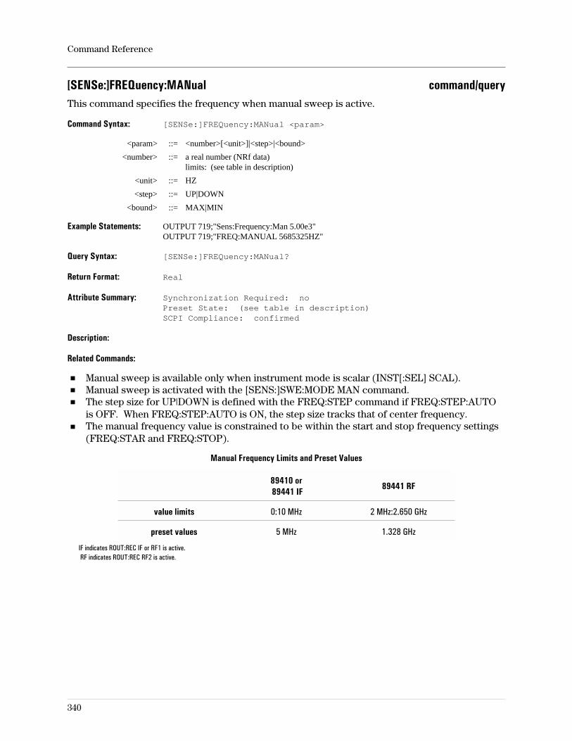
[SENSe:]FREQuency:MANual command/queryThis command specifies the frequency when manual sweep is active.
Command Syntax: [SENSe:]FREQuency:MANual <param>
<param> ::= <number>[<unit>]|<step>|<bound>
<number> ::= a real number (NRf data)limits: (see table in description)
<unit> ::= HZ
<step> ::= UP|DOWN
<bound> ::= MAX|MIN
Example Statements: OUTPUT 719;"Sens:Frequency:Man 5.00e3"OUTPUT 719;"FREQ:MANUAL 5685325HZ"
Query Syntax: [SENSe:]FREQuency:MANual?
Return Format: Real
Attribute Summary: Synchronization Required: noPreset State: (see table in description)SCPI Compliance: confirmed
Description:
Related Commands:
Manual sweep is available only when instrument mode is scalar (INST[:SEL] SCAL).Manual sweep is activated with the [SENS:]SWE:MODE MAN command.The step size for UP|DOWN is defined with the FREQ:STEP command if FREQ:STEP:AUTOis OFF. When FREQ:STEP:AUTO is ON, the step size tracks that of center frequency.The manual frequency value is constrained to be within the start and stop frequency settings(FREQ:STAR and FREQ:STOP).
Manual Frequency Limits and Preset Values
89410 or89441 IF
89441 RF
value limits 0:10 MHz 2 MHz:2.650 GHz
preset values 5 MHz 1.328 GHz
IF indicates ROUT:REC IF or RF1 is active.RF indicates ROUT:REC RF2 is active.
Command Reference
340
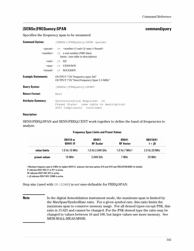
[SENSe:]FREQuency:SPAN command/querySpecifies the frequency span to be measured.
Command Syntax: [SENSe:]FREQuency:SPAN <param>
<param> ::= <number>[<unit>]|<step>|<bound>
<number> ::= a real number (NRf data)limits: (see table in description)
<unit> ::= HZ
<step> ::= UP|DOWN
<bound> ::= MAX|MIN
Example Statements: OUTPUT 719;"frequency:span 2e6"OUTPUT 719;"Sens:Frequency:Span 5.5 MHz"
Query Syntax: [SENSe:]FREQuency:SPAN?
Return Format: Real
Attribute Summary: Synchronization Required: noPreset State: (see table in description)SCPI Compliance: confirmed
Description:
SENS:FREQ:SPAN and SENS:FREQ:CENT work together to define the band of frequencies toanalyze.
Frequency Span Limits and Preset Values
89410 or89441 IF
89441RF Scalar
89441RF Vector
89410/41I + jQ
value limits 1.0 Hz:10 MHz 1.0 Hz:2.648 GHz 1.0 Hz:7 MHz† 2.0 Hz:20 MHz
preset values 10 MHz 2.648 GHz 7 MHz 20 MHz
† Maximum frequency span is 8 MHz for Agilent 89441A analyzers that have options AYA and AYH (see FREQ:SPAN:WIDE for details).IF indicates ROUT:REC IF or RF1 is active.RF indicates ROUT:REC RF2 is active.I+jQ indicates ROUT:REC COMB is active.
Step size (used with UP|DOWN) is not user-definable for FREQ:SPAN.
Note In the digital demodulation instrument mode, the maximum span is limited bythe MaxSpan/SymbolRate ratio. For a given symbol rate, this ratio limits themaximum span to conserve memory usage. For all demod types except FSK, thisratio is 15.625 and cannot be changed. For the FSK demod type the ratio may bechanged to values between 16 and 100, but larger values use more memory. SeeMEM:MALL:MEAS:MSSR.
Command Reference
341
[SENSe:]FREQuency:SPAN:FULL commandSets the analyzer to the widest frequency span possible.
Command Syntax: [SENSe:]FREQuency:SPAN:FULL
Example Statements: OUTPUT 719;":freq:span:full"OUTPUT 719;"Sense:Freq:Span:Full"
Attribute Summary: Synchronization Required: noPreset State: not applicableSCPI Compliance: confirmed
Description:
Sets the maximum frequency span possible, depending on instrument mode.
For the 89410A:
When ROUT:REC is not COMB, full span is 10 MHz.When ROUT:REC is COMB, full span is 20 MHz.
For the 89441A:
When ROUT:REC is RF1 or IF, full span is 10 MHz.When ROUT:REC is COMB, full span is 20 MHz.When ROUT:REC is RF2 and instrument mode is vector or analog demodulation, full span is7 MHz. If you have an Agilent 89441A with option AYH, you can extend full span to 8 MHz(see FREQ:SPAN:WIDE for details).When ROUT:REC is RF2 and instrument mode is scalar, full span is:– 89441A 2.648 GHz
Command Reference
342
[SENSe:]FREQuency:SPAN:PCHirp command/queryDetermines the period of the periodic chirp source type.
Command Syntax: [SENSe:]FREQuency:SPAN:PCHirp EXACt|NEARest
Example Statements: OUTPUT 719;"SENS:FREQUENCY:SPAN:PCH NEAREST"OUTPUT 719;"frequency:span:pchirp NEAREST"
Query Syntax: [SENSe:]FREQuency:SPAN:PCHirp?
Return Format: CHAR
Attribute Summary: Synchronization Required: noPreset State: not applicableSCPI Compliance: instrument-specific
Description:
This feature is active only when the source type is periodic chirp, RBW mode is arb, and RBWcoupling is auto. See help text for further information.
Command Reference
343
[SENSe:]FREQuency:SPAN:WIDE command/queryApplicable only to Agilent 89441A analyzers that have option AYH; extends the maximumfrequency span to 8 MHz.
Command Syntax: [SENSe:]FREQuency:SPAN:WIDE OFF|0|ON|1
Example Statements: OUTPUT 719;":Freq:Span:Wide OFF"OUTPUT 719;"SENS:FREQUENCY:SPAN:WIDE ON"
Query Syntax: [SENSe:]FREQuency:SPAN:WIDE?
Return Format: Integer
Attribute Summary: Option: AYA (Vector Modulation Analysis) and AYH (Digital VideoModulation Analysis)Synchronization Required: noPreset State: not applicableSCPI Compliance: instrument-specific
Description:
This GPIB command is applicable only to Agilent 89441A analyzers that have option AYH. ThisGPIB command corresponds to the [RF (2-1800 MHz) wide] softkey and determines themaximum frequency span available when ROUT:REC RF2 is selected.
When ROUT:REC RF2 is selected, sending ON extends the maximum frequency span to 8 MHz.Sending OFF (default selection) returns the maximum frequency span to 7 MHz.
There are several details you need to know when using the 8 MHz frequency span. For details,see the Operator’s Guide and see online help for the [Instrument Mode][receiver] [RF (2-1800 MHz)] softkey.
Command Reference
344
[SENSe:]FREQuency:STARt command/queryDefines the start (lowest) frequency for the measurement band.
Command Syntax: [SENSe:]FREQuency:STARt <param>
<param> ::= <number>[<unit>]|<step>|<bound>
<number> ::= a real number (NRf data)limits: (see table in description)
<unit> ::= HZ
<step> ::= UP|DOWN
<bound> ::= MAX|MIN
Example Statements: OUTPUT 719;"SENS:FREQUENCY:STAR 50000"OUTPUT 719;"frequency:star 2e+4"
Query Syntax: [SENSe:]FREQuency:STARt?
Return Format: Real
Attribute Summary: Synchronization Required: noPreset State: (see table in description)SCPI Compliance: confirmed
Description:
Start frequency (SENS:FREQ:STAR) and stop frequency (SENS:FREQ:STOP) work together todefine the band of frequencies the instrument analyzes. SENS:FREQ:STAR defines the band’slower limit, SENS:FREQ:STOP defines its upper limit.
Start Frequency Limits and Preset Values
89410 or89441 IF
89441 RF
Scalar Vector
value limits −5 MHz:10 MHz −1.324 GHz:2.65 GHz −1.5 MHz:2.65 GHz
preset values 0 Hz 2 MHz 1.328 GHz
IF indicates ROUT:REC IF or RF1 is active.RF indicates ROUT:REC RF2 is active.
If ROUT:REC is not COMB, start and stop values are independent except STARt + 1.0 HZ ≤ STOP.
When ROUT:REC is COMB, only span and stop may be specified and START = −STOP. The stoprange is 1 Hz:10 MHz and the preset value is 10 MHz.
Step size value (used with UP|DOWN) is automatically calculated when FREQ:STEP:AUTO is ONand is user-defined when AUTO is OFF. User-definable step size values are specified withFREQ:STEP. Refer to online Help for more information.
Command Reference
345
[SENSe:]FREQuency:STEP:AUTO command/querySpecifies whether step size is automatic or not.
Command Syntax: [SENSe:]FREQuency:STEP:AUTO OFF|0|ON|1
Example Statements: OUTPUT 719;"sense:freq:step:auto ON"OUTPUT 719;"Freq:Step:Auto ON"
Query Syntax: [SENSe:]FREQuency:STEP:AUTO?
Return Format: Integer, Integer
Attribute Summary: Synchronization Required: noPreset State: ONSCPI Compliance: instrument-specific
Description:
When step size is automatic (AUTO ON), the step size is determined by the analyzer for centerfrequency, start frequency, stop frequency, source-sine frequency, and manual-sweep frequency.Frequency span is always automatic. See online Help for more information.
User-defined step size is entered with the FREQ:STEP[:INCR] command. Steps to increment ordecrement a value are accomplished with the UP or DOWN parameters.
Command Reference
346
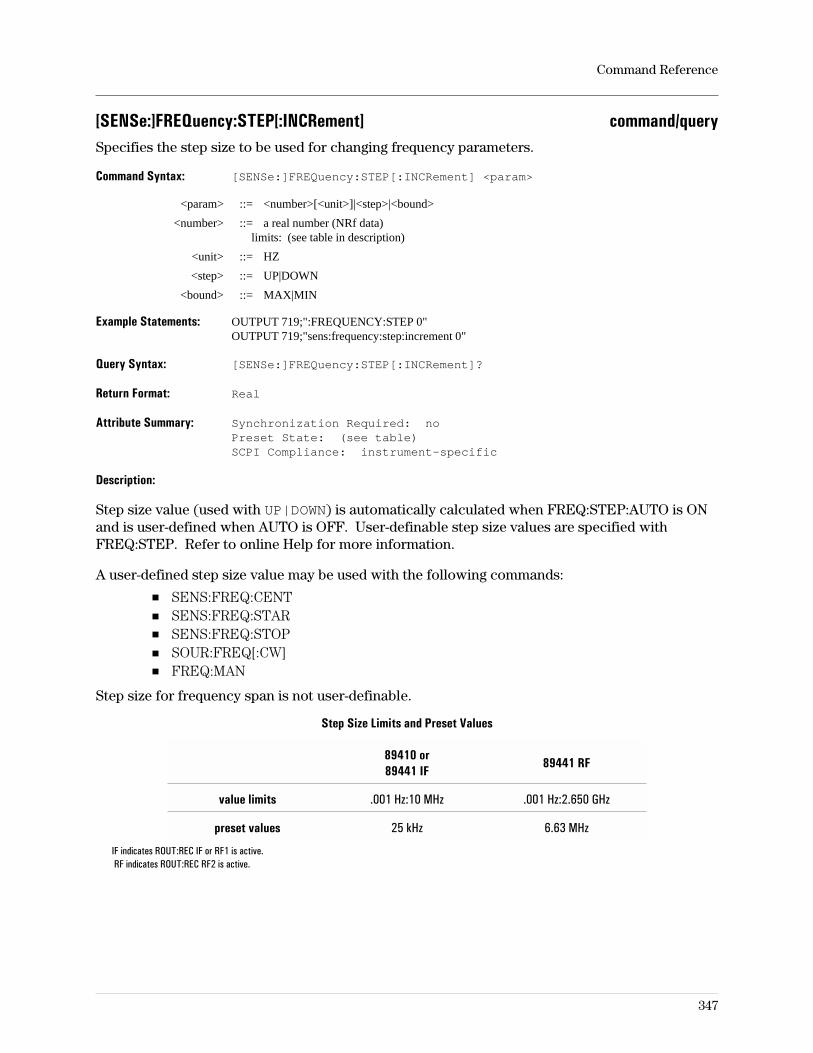
[SENSe:]FREQuency:STEP[:INCRement] command/querySpecifies the step size to be used for changing frequency parameters.
Command Syntax: [SENSe:]FREQuency:STEP[:INCRement] <param>
<param> ::= <number>[<unit>]|<step>|<bound>
<number> ::= a real number (NRf data)limits: (see table in description)
<unit> ::= HZ
<step> ::= UP|DOWN
<bound> ::= MAX|MIN
Example Statements: OUTPUT 719;":FREQUENCY:STEP 0"OUTPUT 719;"sens:frequency:step:increment 0"
Query Syntax: [SENSe:]FREQuency:STEP[:INCRement]?
Return Format: Real
Attribute Summary: Synchronization Required: noPreset State: (see table)SCPI Compliance: instrument-specific
Description:
Step size value (used with UP|DOWN) is automatically calculated when FREQ:STEP:AUTO is ONand is user-defined when AUTO is OFF. User-definable step size values are specified withFREQ:STEP. Refer to online Help for more information.
A user-defined step size value may be used with the following commands:
SENS:FREQ:CENTSENS:FREQ:STARSENS:FREQ:STOPSOUR:FREQ[:CW]FREQ:MAN
Step size for frequency span is not user-definable.
Step Size Limits and Preset Values
89410 or89441 IF
89441 RF
value limits .001 Hz:10 MHz .001 Hz:2.650 GHz
preset values 25 kHz 6.63 MHz
IF indicates ROUT:REC IF or RF1 is active.RF indicates ROUT:REC RF2 is active.
Command Reference
347
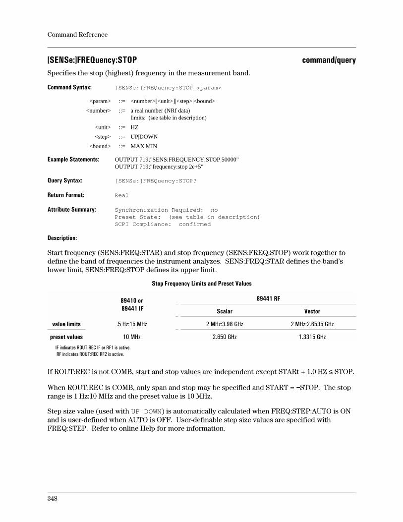
[SENSe:]FREQuency:STOP command/querySpecifies the stop (highest) frequency in the measurement band.
Command Syntax: [SENSe:]FREQuency:STOP <param>
<param> ::= <number>[<unit>]|<step>|<bound>
<number> ::= a real number (NRf data)limits: (see table in description)
<unit> ::= HZ
<step> ::= UP|DOWN
<bound> ::= MAX|MIN
Example Statements: OUTPUT 719;"SENS:FREQUENCY:STOP 50000"OUTPUT 719;"frequency:stop 2e+5"
Query Syntax: [SENSe:]FREQuency:STOP?
Return Format: Real
Attribute Summary: Synchronization Required: noPreset State: (see table in description)SCPI Compliance: confirmed
Description:
Start frequency (SENS:FREQ:STAR) and stop frequency (SENS:FREQ:STOP) work together todefine the band of frequencies the instrument analyzes. SENS:FREQ:STAR defines the band’slower limit, SENS:FREQ:STOP defines its upper limit.
Stop Frequency Limits and Preset Values
89410 or89441 IF
89441 RF
Scalar Vector
value limits .5 Hz:15 MHz 2 MHz:3.98 GHz 2 MHz:2.6535 GHz
preset values 10 MHz 2.650 GHz 1.3315 GHz
IF indicates ROUT:REC IF or RF1 is active.RF indicates ROUT:REC RF2 is active.
If ROUT:REC is not COMB, start and stop values are independent except STARt + 1.0 HZ ≤ STOP.
When ROUT:REC is COMB, only span and stop may be specified and START = −STOP. The stoprange is 1 Hz:10 MHz and the preset value is 10 MHz.
Step size value (used with UP|DOWN) is automatically calculated when FREQ:STEP:AUTO is ONand is user-defined when AUTO is OFF. User-definable step size values are specified withFREQ:STEP. Refer to online Help for more information.
Command Reference
348
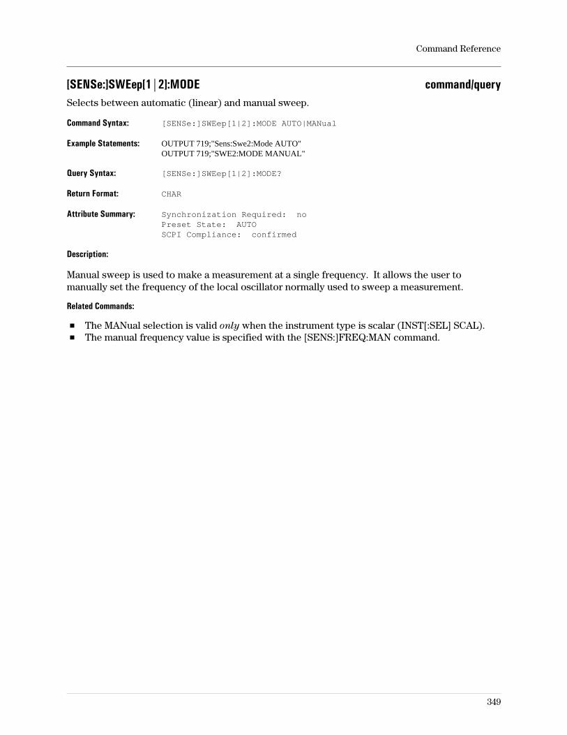
[SENSe:]SWEep[1|2]:MODE command/querySelects between automatic (linear) and manual sweep.
Command Syntax: [SENSe:]SWEep[1|2]:MODE AUTO|MANual
Example Statements: OUTPUT 719;"Sens:Swe2:Mode AUTO"OUTPUT 719;"SWE2:MODE MANUAL"
Query Syntax: [SENSe:]SWEep[1|2]:MODE?
Return Format: CHAR
Attribute Summary: Synchronization Required: noPreset State: AUTOSCPI Compliance: confirmed
Description:
Manual sweep is used to make a measurement at a single frequency. It allows the user tomanually set the frequency of the local oscillator normally used to sweep a measurement.
Related Commands:
The MANual selection is valid only when the instrument type is scalar (INST[:SEL] SCAL).The manual frequency value is specified with the [SENS:]FREQ:MAN command.
Command Reference
349
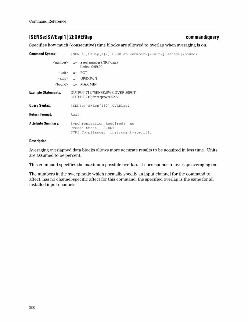
[SENSe:]SWEep[1|2]:OVERlap command/querySpecifies how much (consecutive) time blocks are allowed to overlap when averaging is on.
Command Syntax: [SENSe:]SWEep[1|2]:OVERlap <number>[<unit>]|<step>|<bound>
<number> ::= a real number (NRF data)limits: 0:99.99
<unit> ::= PCT
<step> ::= UP|DOWN
<bound> ::= MAX|MIN
Example Statements: OUTPUT 719;"SENSE:SWE:OVER 30PCT"OUTPUT 719;"sweep:over 52.5"
Query Syntax: [SENSe:]SWEep[1|2]:OVERlap?
Return Format: Real
Attribute Summary: Synchronization Required: noPreset State: 0.00%SCPI Compliance: instrument-specific
Description:
Averaging overlapped data blocks allows more accurate results to be acquired in less time. Unitsare assumed to be percent.
This command specifies the maximum possible overlap. It corresponds to overlap: averaging on.
The numbers in the sweep node which normally specify an input channel for the command toaffect, has no channel-specific affect for this command; the specified overlap is the same for allinstalled input channels.
Command Reference
350
[SENSe:]SWEep[1|2]:POINts command/querySpecifies the number of alias-protected frequency points.
Command Syntax: [SENSe:]SWEep:POINts <number>|<step>|<bound>
<number> ::= 51|101|201|401|801|1601|3201
<step> ::= UP|DOWN
<bound> ::= MAX|MIN
Example Statements: OUTPUT 719;":Sweep:Poin 101"OUTPUT 719;"SENS:SWEEP:POIN 801"
Query Syntax: [SENSe:]SWEep[1|2]:POINts?
Return Format: Integer
Attribute Summary: Synchronization Required: noPreset State: 401SCPI Compliance: confirmed
Description:
Changing the number of frequency points affects the display resolution as follows.
display resolution =span
number of points − 1
Command Reference
351
[SENSe:]SWEep[1|2]:TIME:DELay command/querySpecifies the delay between the trigger and the beginning of the time record.
Command Syntax: [SENSe:]SWEep[1|2]:TIME:DELay <param>
<param> ::= <number>[<unit>]|<step>|<bound>
<number> ::= a real number (NRf data)limits: (see discussion)
<unit> ::= S
<step> ::= UP|DOWN
<bound> ::= MAX|MIN
Example Statements: OUTPUT 719;"Sens:Sweep1:Time:Delay 5ms"OUTPUT 719;"SWE1:TIME:DEL (SWE1:TIME:GATE:DEL?)"
Query Syntax: [SENSe:]SWEep[1|2]:TIME:DELay?
Return Format: Real
Attribute Summary: Synchronization Required: noPreset State: 0 SSCPI Compliance: instrument-specific
Description:
The sweep node numbers (1|2) specify which input (receiver) channel is affected by thecommand. If no number is specified, the command is applied to channel 1. Note that channel 2is optional (AY7) and may not be installed in the analyzer. To determine whether the secondchannel is installed, send *OPT? and see if AY7 (second channel) is returned.
Limits:
Pretrigger ‘’delay’’ is the amount of time before the trigger occurs that you want data; the triggeroccurs after the point in time that you want to begin collecting data. This is specified by enteringa negative number and is limited by the size of the time capture RAM available for themeasurement.
Without the time capture RAM (option AY9), there are 64K samples (65,536) available. When asecond channel is installed and enabled, the pretrigger delay limit is half what it is when only onechannel is enabled; 32K per channel. With deep capture RAM, option AY9, there are 1M samples(1,048,576) available; .5M per channel if the optional second channel is enabled. The amount oftime represented by these sample sizes depends on the time each sample represents, whichvaries with span (∆t).
Post-trigger delay is the amount of time after the trigger occurs that you want to begin the timerecord. This is limited by the range of a counter that can count to 2G (2,147,483,648) samples.This parameter is not affected by the presence of the capture RAM or second-channel options.Again, the time represented by this count depends on the time each sample represents, whichvaries with span (∆t).
In scalar mode, the analyzer picks the span used for the measurement. This affects the resolutionin that ∆t becomes a function of measurement parameters other than the user-specified span.
Command Reference
352
[SENSe:]SWEep[1|2]:TIME:GATE:DELay command/querySpecifies when the time gate begins relative to the beginning of the main time record.
Command Syntax: [SENSe:]SWEep[1|2]:TIME:GATE:DELay <param>
<param> ::= <number>[<unit>]|<step>|<bound>
<number> ::= a real number (NRf data)limits: (see discussion)
<unit> ::= S
<step> ::= UP|DOWN
<bound> ::= MAX|MIN
Example Statements: OUTPUT 719;":swe:time:gate:del 15 us"OUTPUT 719;"Sense:Swe:Time:Gate:Del 40e-3"
Query Syntax: [SENSe:]SWEep[1|2]:TIME:GATE:DELay?
Return Format: Real
Attribute Summary: Synchronization Required: noPreset State: 0 SSCPI Compliance: instrument-specific
Description:
The sweep node numbers (1|2) specify which input (receiver) channel is affected by thecommand. If no number is specified, the command is applied to channel 1. Note that channel 2is optional (AY7) and may not be installed in the analyzer. To determine whether the secondchannel is installed, send *OPT? and see if AY7 (second channel) is returned.
Note Time operations do not function when the instrument mode is scalar. When themeasurement is zoomed, a local oscillator signal is mixed with the measurementdata and time data is not baseband. Time gating is not available in digital demod.
Limits: The time gate is defined by the gate delay, which defines its starting time relative the thebeginning of the main time record, and gate length, which defines when it stops relative to itsstart. Both start and stop values must be within the main time record, also called main time. Sothe lower limit of the gate delay is zero and the upper limit depends on the gate length definedwith SWE:TIME:GATE[:SPAN] as follows:
maximum gate delay = main length − gate length
The minimum gate delay is 0.
Related Commands:
To set the gate delay step size, use SWE:TIME:GATE:DEL:STEP.To turn the gate on, use SWE:TIME:GATE:STATE.To set the gate time, use SWE:TIME.
Command Reference
353
[SENSe:]SWEep[1|2]:TIME:GATE:DELay:STEP[:INCRement] command/querySpecifies the step size used to increment or decrement the time gate delay.
Command Syntax: [SENSe:]SWEep[1|2]:TIME:GATE:DELay:STEP[:INCRement] <param>
<param> ::= <number>[<unit>]|<step>|<bound>
<number> ::= a real number (NRf data)limits: (see discussion)
<unit> ::= S
<step> ::= UP|DOWN
<bound> ::= MAX|MIN
Example Statements: OUTPUT 719;":swe:time:gate:del:step 0"OUTPUT 719;"Sens:Swe:Time:Gate:Delay:Step:Incr 0"
Query Syntax: [SENSe:]SWEep[1|2]:TIME:GATE:DELay:STEP[:INCRement]?
Return Format: Real
Attribute Summary: Synchronization Required: noPreset State: (see discussion)SCPI Compliance: instrument-specific
Description:
The numbers in the sweep node which normally specify an input channel for the command toaffect, has no channel-specific affect for this command; the step value is the same for all installedinput channels.
Note Time operations do not function when the instrument mode is scalar. When themeasurement is zoomed, a local oscillator signal is mixed with the measurementdata and time data is not baseband. Time gating is not available in digital demod.
Limits:
The minimum step size is 0.
The maximum limit is main time length − gate length.
The resolution is ∆t.
Preset Values:
When ROUT:REC is INP, IF, RF1, or COMB, the preset value is 39.0625 ns
When ROUT:REC is RF2, the preset value is 111.607143 ns
When ROUT:REC is EXT, the preset value is 260.41667 ns.
Command Reference
354
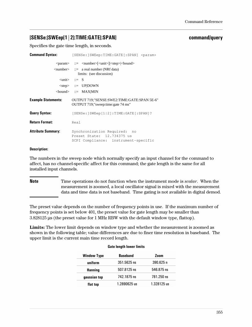
[SENSe:]SWEep[1|2]:TIME:GATE[:SPAN] command/querySpecifies the gate time length, in seconds.
Command Syntax: [SENSe:]SWEep:TIME:GATE[:SPAN] <param>
<param> ::= <number>[<unit>]|<step>|<bound>
<number> ::= a real number (NRf data)limits: (see discussion)
<unit> ::= S
<step> ::= UP|DOWN
<bound> ::= MAX|MIN
Example Statements: OUTPUT 719;"SENSE:SWE2:TIME:GATE:SPAN 5E-6"OUTPUT 719;"sweep:time:gate 74 ms"
Query Syntax: [SENSe:]SWEep[1|2]:TIME:GATE[:SPAN]?
Return Format: Real
Attribute Summary: Synchronization Required: noPreset State: 12.734375 usSCPI Compliance: instrument-specific
Description:
The numbers in the sweep node which normally specify an input channel for the command toaffect, has no channel-specific affect for this command; the gate length is the same for allinstalled input channels.
Note Time operations do not function when the instrument mode is scalar. When themeasurement is zoomed, a local oscillator signal is mixed with the measurementdata and time data is not baseband. Time gating is not available in digital demod.
The preset value depends on the number of frequency points in use. If the maximum number offrequency points is set below 401, the preset value for gate length may be smaller than3.828125 µs (the preset value for 1 MHz RBW with the default window type, flattop).
Limits: The lower limit depends on window type and whether the measurement is zoomed asshown in the following table; value differences are due to finer time resolution in baseband. Theupper limit is the current main time record length.
Gate length lower limits
Window Type Baseband Zoom
uniform 351.5625 ns 390.625 n
Hanning 507.8125 ns 546.875 ns
gaussian top 742.1875 ns 781.250 ns
flat top 1.2890625 us 1.328125 us
Command Reference
355
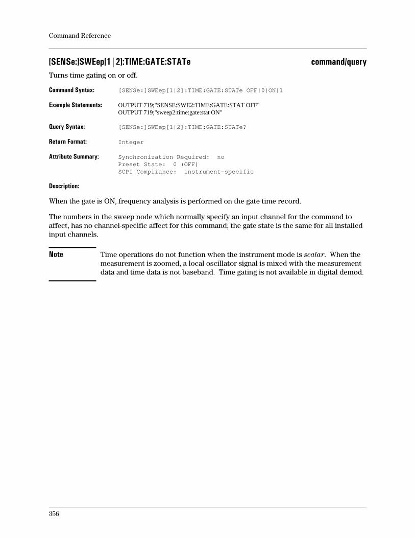
[SENSe:]SWEep[1|2]:TIME:GATE:STATe command/queryTurns time gating on or off.
Command Syntax: [SENSe:]SWEep[1|2]:TIME:GATE:STATe OFF|0|ON|1
Example Statements: OUTPUT 719;"SENSE:SWE2:TIME:GATE:STAT OFF"OUTPUT 719;"sweep2:time:gate:stat ON"
Query Syntax: [SENSe:]SWEep[1|2]:TIME:GATE:STATe?
Return Format: Integer
Attribute Summary: Synchronization Required: noPreset State: 0 (OFF)SCPI Compliance: instrument-specific
Description:
When the gate is ON, frequency analysis is performed on the gate time record.
The numbers in the sweep node which normally specify an input channel for the command toaffect, has no channel-specific affect for this command; the gate state is the same for all installedinput channels.
Note Time operations do not function when the instrument mode is scalar. When themeasurement is zoomed, a local oscillator signal is mixed with the measurementdata and time data is not baseband. Time gating is not available in digital demod.
Command Reference
356
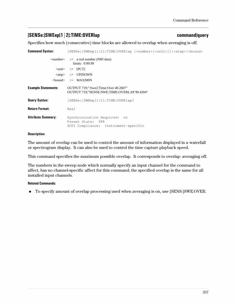
[SENSe:]SWEep[1|2]:TIME:OVERlap command/querySpecifies how much (consecutive) time blocks are allowed to overlap when averaging is off.
Command Syntax: [SENSe:]SWEep[1|2]:TIME:OVERlap <number>[<unit>]|<step>|<bound>
<number> ::= a real number (NRf data)limits: 0:99.99
<unit> ::= [PCT]
<step> ::= UP|DOWN
<bound> ::= MAX|MIN
Example Statements: OUTPUT 719;":Swe2:Time:Over 40.2607"OUTPUT 719;"SENSE:SWE:TIME:OVERLAP 90.4304"
Query Syntax: [SENSe:]SWEep[1|2]:TIME:OVERlap?
Return Format: Real
Attribute Summary: Synchronization Required: noPreset State: 98%SCPI Compliance: instrument-specific
Description:
The amount of overlap can be used to control the amount of information displayed in a waterfallor spectrogram display. It can also be used to control the time capture playback speed.
This command specifies the maximum possible overlap. It corresponds to overlap: averaging off.
The numbers in the sweep node which normally specify an input channel for the command toaffect, has no channel-specific affect for this command; the specified overlap is the same for allinstalled input channels.
Related Commands:
To specify amount of overlap processing used when averaging is on, use [SENS:]SWE:OVER.
Command Reference
357
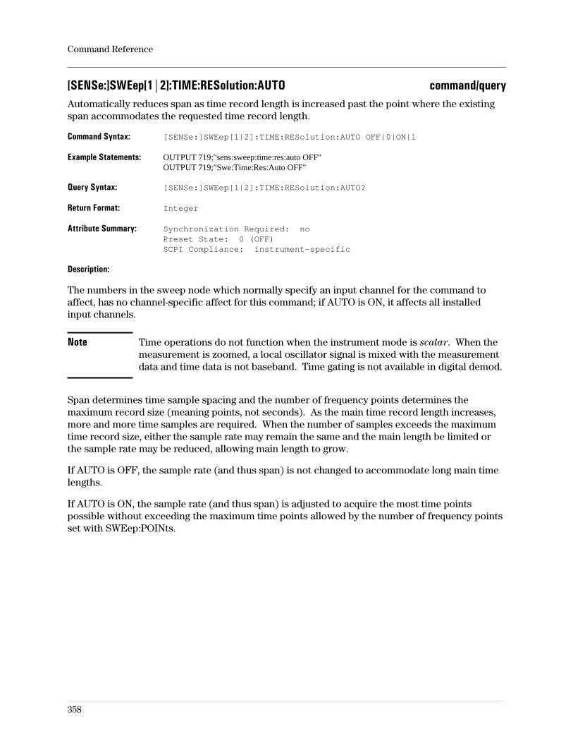
[SENSe:]SWEep[1|2]:TIME:RESolution:AUTO command/queryAutomatically reduces span as time record length is increased past the point where the existingspan accommodates the requested time record length.
Command Syntax: [SENSe:]SWEep[1|2]:TIME:RESolution:AUTO OFF|0|ON|1
Example Statements: OUTPUT 719;"sens:sweep:time:res:auto OFF"OUTPUT 719;"Swe:Time:Res:Auto OFF"
Query Syntax: [SENSe:]SWEep[1|2]:TIME:RESolution:AUTO?
Return Format: Integer
Attribute Summary: Synchronization Required: noPreset State: 0 (OFF)SCPI Compliance: instrument-specific
Description:
The numbers in the sweep node which normally specify an input channel for the command toaffect, has no channel-specific affect for this command; if AUTO is ON, it affects all installedinput channels.
Note Time operations do not function when the instrument mode is scalar. When themeasurement is zoomed, a local oscillator signal is mixed with the measurementdata and time data is not baseband. Time gating is not available in digital demod.
Span determines time sample spacing and the number of frequency points determines themaximum record size (meaning points, not seconds). As the main time record length increases,more and more time samples are required. When the number of samples exceeds the maximumtime record size, either the sample rate may remain the same and the main length be limited orthe sample rate may be reduced, allowing main length to grow.
If AUTO is OFF, the sample rate (and thus span) is not changed to accommodate long main timelengths.
If AUTO is ON, the sample rate (and thus span) is adjusted to acquire the most time pointspossible without exceeding the maximum time points allowed by the number of frequency pointsset with SWEep:POINts.
Command Reference
358
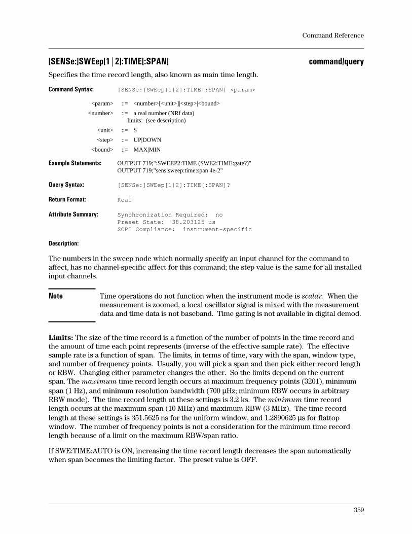
[SENSe:]SWEep[1|2]:TIME[:SPAN] command/querySpecifies the time record length, also known as main time length.
Command Syntax: [SENSe:]SWEep[1|2]:TIME[:SPAN] <param>
<param> ::= <number>[<unit>]|<step>|<bound>
<number> ::= a real number (NRf data)limits: (see description)
<unit> ::= S
<step> ::= UP|DOWN
<bound> ::= MAX|MIN
Example Statements: OUTPUT 719;":SWEEP2:TIME (SWE2:TIME:gate?)"OUTPUT 719;"sens:sweep:time:span 4e-2"
Query Syntax: [SENSe:]SWEep[1|2]:TIME[:SPAN]?
Return Format: Real
Attribute Summary: Synchronization Required: noPreset State: 38.203125 usSCPI Compliance: instrument-specific
Description:
The numbers in the sweep node which normally specify an input channel for the command toaffect, has no channel-specific affect for this command; the step value is the same for all installedinput channels.
Note Time operations do not function when the instrument mode is scalar. When themeasurement is zoomed, a local oscillator signal is mixed with the measurementdata and time data is not baseband. Time gating is not available in digital demod.
Limits: The size of the time record is a function of the number of points in the time record andthe amount of time each point represents (inverse of the effective sample rate). The effectivesample rate is a function of span. The limits, in terms of time, vary with the span, window type,and number of frequency points. Usually, you will pick a span and then pick either record lengthor RBW. Changing either parameter changes the other. So the limits depend on the currentspan. The maximum time record length occurs at maximum frequency points (3201), minimumspan (1 Hz), and minimum resolution bandwidth (700 µHz; minimum RBW occurs in arbitraryRBW mode). The time record length at these settings is 3.2 ks. The minimum time recordlength occurs at the maximum span (10 MHz) and maximum RBW (3 MHz). The time recordlength at these settings is 351.5625 ns for the uniform window, and 1.2890625 µs for flattopwindow. The number of frequency points is not a consideration for the minimum time recordlength because of a limit on the maximum RBW/span ratio.
If SWE:TIME:AUTO is ON, increasing the time record length decreases the span automaticallywhen span becomes the limiting factor. The preset value is OFF.
Command Reference
359
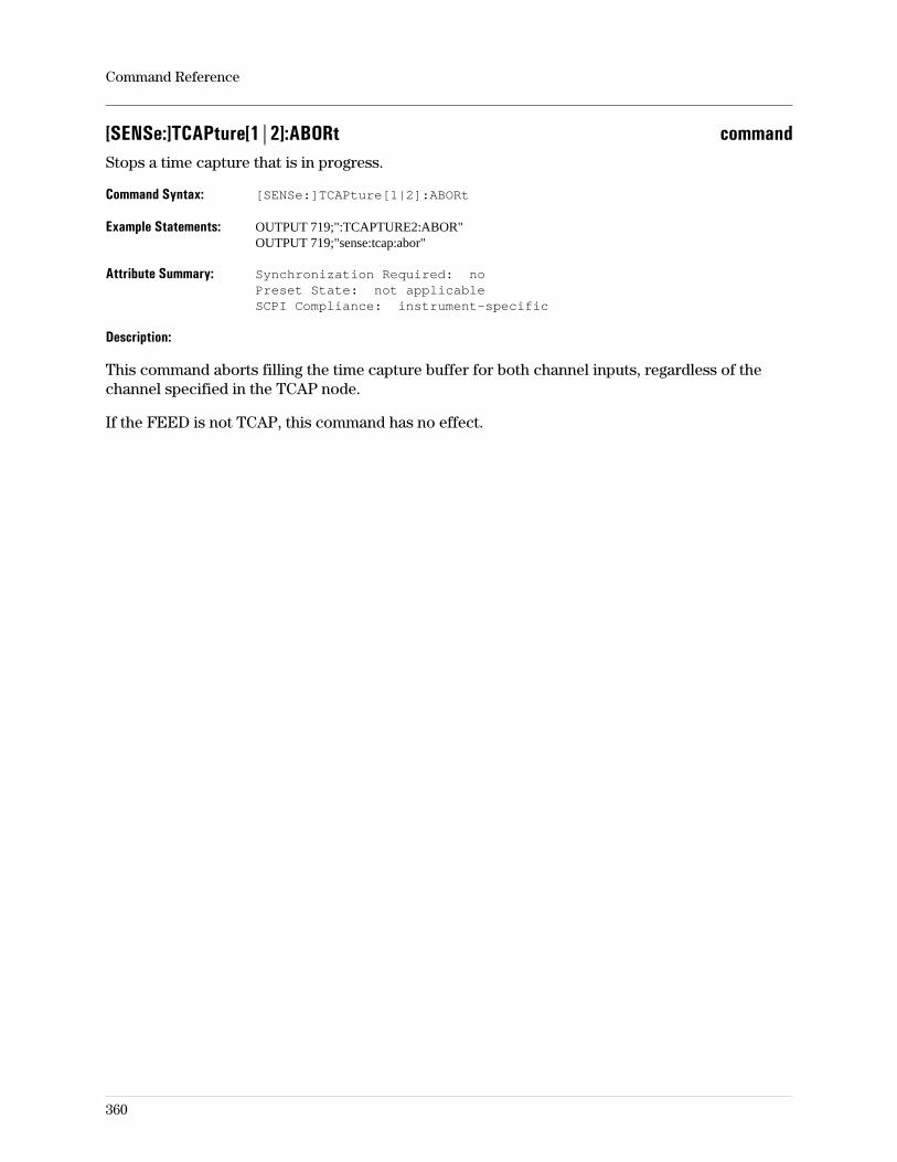
[SENSe:]TCAPture[1|2]:ABORt commandStops a time capture that is in progress.
Command Syntax: [SENSe:]TCAPture[1|2]:ABORt
Example Statements: OUTPUT 719;":TCAPTURE2:ABOR"OUTPUT 719;"sense:tcap:abor"
Attribute Summary: Synchronization Required: noPreset State: not applicableSCPI Compliance: instrument-specific
Description:
This command aborts filling the time capture buffer for both channel inputs, regardless of thechannel specified in the TCAP node.
If the FEED is not TCAP, this command has no effect.
Command Reference
360
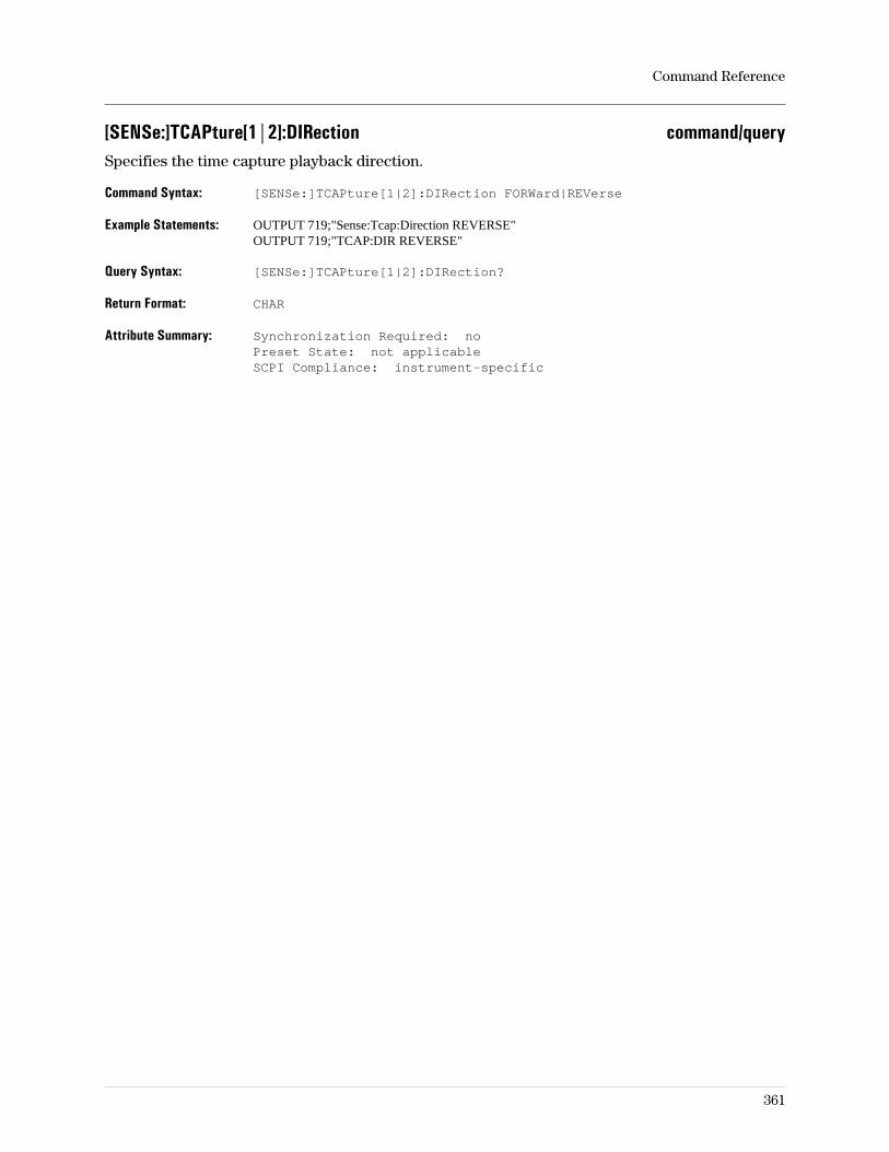
[SENSe:]TCAPture[1|2]:DIRection command/querySpecifies the time capture playback direction.
Command Syntax: [SENSe:]TCAPture[1|2]:DIRection FORWard|REVerse
Example Statements: OUTPUT 719;"Sense:Tcap:Direction REVERSE"OUTPUT 719;"TCAP:DIR REVERSE"
Query Syntax: [SENSe:]TCAPture[1|2]:DIRection?
Return Format: CHAR
Attribute Summary: Synchronization Required: noPreset State: not applicableSCPI Compliance: instrument-specific
Command Reference
361
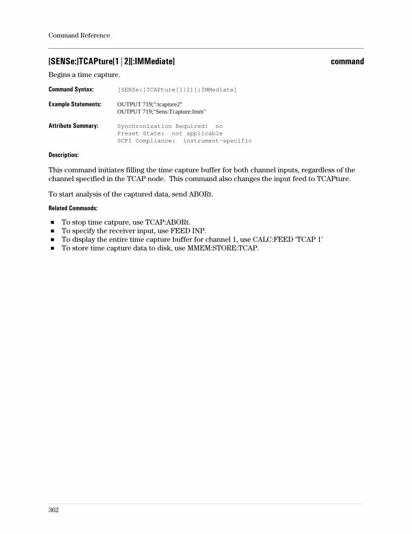
[SENSe:]TCAPture[1|2][:IMMediate] commandBegins a time capture.
Command Syntax: [SENSe:]TCAPture[1|2][:IMMediate]
Example Statements: OUTPUT 719;":tcapture2"OUTPUT 719;"Sens:Tcapture:Imm"
Attribute Summary: Synchronization Required: noPreset State: not applicableSCPI Compliance: instrument-specific
Description:
This command initiates filling the time capture buffer for both channel inputs, regardless of thechannel specified in the TCAP node. This command also changes the input feed to TCAPture.
To start analysis of the captured data, send ABORt.
Related Commands:
To stop time catpure, use TCAP:ABORt.To specify the receiver input, use FEED INP.To display the entire time capture buffer for channel 1, use CALC:FEED ‘TCAP 1’To store time capture data to disk, use MMEM:STORE:TCAP.
Command Reference
362
[SENSe:]TCAPture[1|2]:LENGth command/querySets the length of the time capture record.
Command Syntax: [SENSe:]TCAPture[1|2]:LENGth <param>
<param> ::= <number>[<unit>]|<step>|<bound>
<number> ::= a real number (NRf data)limits: (see discussion)
<unit> ::= S|POINTS|RECORDS
<step> ::= UP|DOWN
<bound> ::= MAX|MIN
Example Statements: OUTPUT 719;"SENS:TCAPTURE:LENG 0"OUTPUT 719;"tcapture:leng 0"
Query Syntax: [SENSe:]TCAPture[1|2]:LENGth?
Return Format: Real
Attribute Summary: Synchronization Required: noPreset State: +3.2768E+4 (POINTS)SCPI Compliance: instrument-specific
Description:
Option AY9 adds 1 Megasample RAM for time capture.
Limits: The limits are defined by a number of things. The first limit is set by the amount ofinstalled time capture memory. Without the optional time capture RAM, the capacity is 32KSamples in two channels. (If the analyzer has only one channel or channel 2 is off, the capacityis 64 KSamples.) With the optional time capture RAM, the capacity is 512 KSamples in twochannels. (If the analyzer has only one channel or channel 2 is off, the capacity is 1024 KSamplesor 1 MSample.)
Each sample takes 8 bytes, 4 real and 4 imaginary. If the data is moved out of the analyzer,baseband data is real-only (4 bytes) and zoomed data is real/imaginary (4/4 bytes). If data iscaptured and transferred out of the analyzer, be aware that the capture was done in /2 spans.When the captured data is analyzed in the analyzer, this limitation is eliminated by resampling toget arbitrary (other-than- /2) spans.
To determine how much time is available (limits in terms of seconds) you must also consider thespan and resolution bandwidth settings. The relationship between these values is as follows:L = N × ∆t, where L is record length, N is the number of samples, and the time between samples
is ∆t = 1(span × 2.56)
. We also know that N = k × 2.56 × span
RBWwhere k is window bandwidth,
and RBW is resolution bandwidth.
Substituting for N and ∆t we get L = k
RBWas long as N is not larger than the installed memory
(standard = 32 KSamples, option = 1 MSample). See concepts for values of k.
Command Reference
363
[SENSe:]TCAPture[1|2]:POSition? queryReturns the current position in the time capture buffer.
Query Syntax: [SENSe:]TCAPture[1|2]:POSition?
Example Statements: OUTPUT 719;":Tcap2:Position?"OUTPUT 719;"SENS:TCAPTURE:POS?"
Return Format: Real
Attribute Summary: Synchronization Required: noPreset State: not applicableSCPI Compliance: instrument-specific
Command Reference
364
[SENSe:]TCAPture[1|2]:RANGe command/querySpecifies range value for time capture data.
Command Syntax: [SENSe:]TCAPture[1|2]:RANGe <number>|<bound>
<number> ::= a real number (NRf data)limits: 1.0E-20:1.0E20
<bound> ::= MAX|MIN
Example Statements: OUTPUT 719;"sens:tcapture2:rang 4.01739e+19"OUTPUT 719;"Tcapture2:Rang 9.85167e+19"
Query Syntax: [SENSe:]TCAPture[1|2]:RANGe?
Return Format: Real
Attribute Summary: Synchronization Required: noPreset State: 0SCPI Compliance: instrument-specific
Description:
The range must be specified before time data is loaded into the capture buffers from a controller.This value (in Volts) is used as a reference to convert the data to integer format. To get full 32-bitaccuracy, the value sent should be the same as the largest data value to be loaded.
Note Any data values larger than the range value will be clipped.
Related Commands:
To load data into the analyzer, use [SENS:]DATA.To define the data format for the transfer, use FORM:DATA.
Command Reference
365
[SENSe:]TCAPture[1|2]:STARt command/querySpecifies the position in the time capture buffer to begin analysis.
Command Syntax: [SENSe:]TCAPture[1|2]:STARt <param>
<param> ::= <number>[<unit>]|<step>|<bound>
<number> ::= a real number (NRf data)limits: (depends on configuration)
<unit> ::= S|POINTS|RECORDS
<step> ::= UP|DOWN
<bound> ::= MAX|MIN
Example Statements: OUTPUT 719;":TCAP2:START 0"OUTPUT 719;"sens:tcapture:star 0"
Query Syntax: [SENSe:]TCAPture[1|2]:STARt?
Return Format: Real
Attribute Summary: Synchronization Required: noPreset State: 0 (seconds)SCPI Compliance: instrument-specific
Description:
Related Commands:
To specify the end of the time capture data on which to performa analysis, use TCAP:STOP.To begin filling the time capture buffer(s), use TCAP.To specify the size of the time capture in points, use TCAP:LENG.
Command Reference
366
[SENSe:]TCAPture[1|2]:STOP command/querySpecifies the position in the waveform capture buffer to end analysis.
Command Syntax: [SENSe:TCAPture[1|2]:STOP <param>
<param> ::= <number>[unit]|<step>|<bound>
<number> ::= a real number (NRf data)limits: (limits depend on configuration)
<unit> ::= S|POINTS|RECORDS
<step> ::= UP|DOWN
<bound> ::= MAX|MIN
Example Statements: OUTPUT 719;"Sens:Tcapture:Stop 0"OUTPUT 719;"TCAPTURE2:STOP 0"
Query Syntax: [SENSe:]TCAPture[1|2]:STOP?
Return Format: Real
Attribute Summary: Synchronization Required: noPreset State: 0SCPI Compliance: instrument-specific
Description:
After filling the time capture buffer, this parameter is set to the end of the buffer.
Related Commands:
To specify the start of the time capture data on which to performa analysis, use TCAP:STAR.To begin filling the time capture buffer(s), use TCAP.To specify the size of the time capture in points, use TCAP:LENG.
Command Reference
367
[SENSe:]VOLTage[1|2][:DC]:RANGe:AUTO command/queryTurns autoranging on or off.
Command Syntax: [SENSe:]VOLTage[1|2][:DC]:RANGe:AUTO OFF|0|ON|1|ONCE
Example Statements: OUTPUT 719;":volt2:range:auto OFF"OUTPUT 719;"Sense:Volt:Dc:Range:Auto OFF"
Query Syntax: [SENSe:]VOLTage[1|2][:DC]:RANGe:AUTO?
Return Format: Integer
Attribute Summary: Synchronization Required: noPreset State: 0 (OFF)SCPI Compliance: confirmed
Description:
Related commands:
To set the autorange direction, use SENS:VOLT:RANG:AUTO:DIR.To execute one autorange, send SENS:VOLT:RANG:AUTO ONCE. The analyzer then samplesthe input signal value and selects a fixed range setting (autoranging is turned off).
The voltage node numbers (1|2) specify which input (receiver) channel is affected by thecommand. In a single-channel 89441A, the channel specifier does nothing. If no number isspecified, the command is applied to channel 1. Note that channel 2 is optional (AY7) and maynot be installed in the analyzer. To determine whether the second channel is installed, press theMeasurement Data hardkey and see if the softkeys have ch1/ch2 designations.
Note When the analyzer is configured such that it measures signals from adownconverter (like the RF section or the Agilent 89411A; whenROUTe:RECeiver is RF1, RF2, or EXT), autoranging is not available. It isavailable when the measured signal is connected directly to the IF input.
Command Reference
368
[SENSe:]VOLTage[1|2][:DC]:RANGe:AUTO:DIRection command/querySets the direction in which the range setting may be changed when autoranging is active.
Command Syntax: [SENSe:]VOLTage[1|2][:DC]:RANGe:AUTO:DIRection UP|EITHer
Example Statements: OUTPUT 719;"SENSE:VOLT:DC:RANGE:AUTO:DIRECTION EITHER"OUTPUT 719;"volt2:rang:auto:dir EITHER"
Query Syntax: [SENSe:]VOLTage[1|2][:DC]:RANGe:AUTO:DIRection?
Return Format: CHAR
Attribute Summary: Synchronization Required: noPreset State: EITHSCPI Compliance: confirmed
Description:
By default, autoranging is off.
UP sets the direction of autoranging value changes to be larger (up) but not smaller (down).This mode is better than EITHer for setting the range to measure transient signals because itavoids the measurement interruptions caused by frequent autoranging but may not have theoptimum range setting for best signal-to-noise ratio.
EITH sets the direction of autoranging value changes to be either up or down. This mode tracksthe signal amplitude, if it changes slowly, and optimizes the range for best signal-to-noise ratio.If the signal of interest is transient, the EITHer setting may spend too much time selecting a newrange instead of making measurements.
Note When the analyzer is configured such that it measures signals from adownconverter (like the RF section or the Agilent 89411A; whenROUTe:RECeiver is RF1, RF2, or EXT), autoranging is not available. It isavailable when the measured signal is connected directly to the IF input labeledChannel 1.
Related commands:
To execute one autorange, send SENS:VOLT:RANG:AUTO ONCE.
The voltage node numbers (1|2) specify which input (receiver) channel is affected by thecommand. In a single-channel 89441A, the channel specifier does nothing. If no number isspecified, the command is applied to channel 1. Note that channel 2 is optional (AY7) and maynot be installed in the analyzer. To determine whether the second channel is installed, press theMeasurement Data hardkey and see if the softkeys have ch1/ch2 designations.
Command Reference
369
[SENSe:]VOLTage[1|2][:DC]:RANGe:UNIT:VOLTage command/querySets or queries the input range unit.
Command Syntax: [SENSe:]VOLTage[1|2][:DC]:RANGe:UNIT:VOLTage <param>
<param> ::= dBm|dBV|dBVrms|dBVpk|V|Vpk|Vrms|W|Wrms
Example Statements: OUTPUT 719;":Voltage:Rang:Unit:Voltage W"OUTPUT 719;"SENS:VOLTAGE:DC:RANG:UNIT:VOLT dBVpk"
Query Syntax: [SENSe:]VOLTage[1|2][:DC]:RANGe:UNIT:VOLTage?
Return Format: CHAR
Attribute Summary: Synchronization Required: noPreset State: DBMSCPI Compliance: confirmed
Command Reference
370
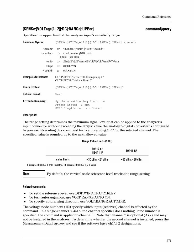
[SENSe:]VOLTage[1|2][:DC]:RANGe[:UPPer] command/querySpecifies the upper limit of the analyzer input’s sensitivity range.
Command Syntax: [SENSe:]VOLTage[1|2][:DC]:RANGe[:UPPer] <param>
<param> ::= <number>[<unit>]|<step>|<bound>
<number> ::= a real number (NRf data)limits: (see table)
<unit> ::= dBm|dBV|dBVrms|dBVpk|V|Vpk|Vrms|W|Wrms
<step> ::= UP|DOWN
<bound> ::= MAX|MIN
Example Statements: OUTPUT 719;"sense:volt:dc:range:upp 0"OUTPUT 719;"Voltage:Rang 0"
Query Syntax: [SENSe:]VOLTage[1|2][:DC]:RANGe[:UPPer]?
Return Format: Real
Attribute Summary: Synchronization Required: noPreset State: 0 dBmSCPI Compliance: confirmed
Description:
The range setting determines the maximum signal level that can be applied to the analyzer’sinput connector without exceeding the largest value the analog-to-digital converter is configuredto process. Executing this command turns autoranging OFF for the selected channel. Thespecified value is rounded up to the next allowed value.
Range Value Limits (50Ω)
89410 or89441 IF
89441 RF
value limits −30 dBm:+24 dBm −50 dBm:+25 dBm
IF indicates ROUT:REC IF or RF1 is active. RF indicates ROUT:REC RF2 is active.
Note By default, the vertical scale reference level tracks the range setting.
Related commands:
To set the reference level, use DISP:WIND:TRAC:Y:RLEV.To turn autoranging on, use VOLT:RANGE:AUTO ON.To specify autoranging direction, use VOLT:RANGE:AUTO:DIR.
The voltage node numbers (1|2) specify which input (receiver) channel is affected by thecommand. In a single-channel 89441A, the channel specifier does nothing. If no number isspecified, the command is applied to channel 1. Note that channel 2 is optional (AY7) and maynot be installed in the analyzer. To determine whether the second channel is installed, press theMeasurement Data hardkey and see if the softkeys have ch1/ch2 designations.
Command Reference
371
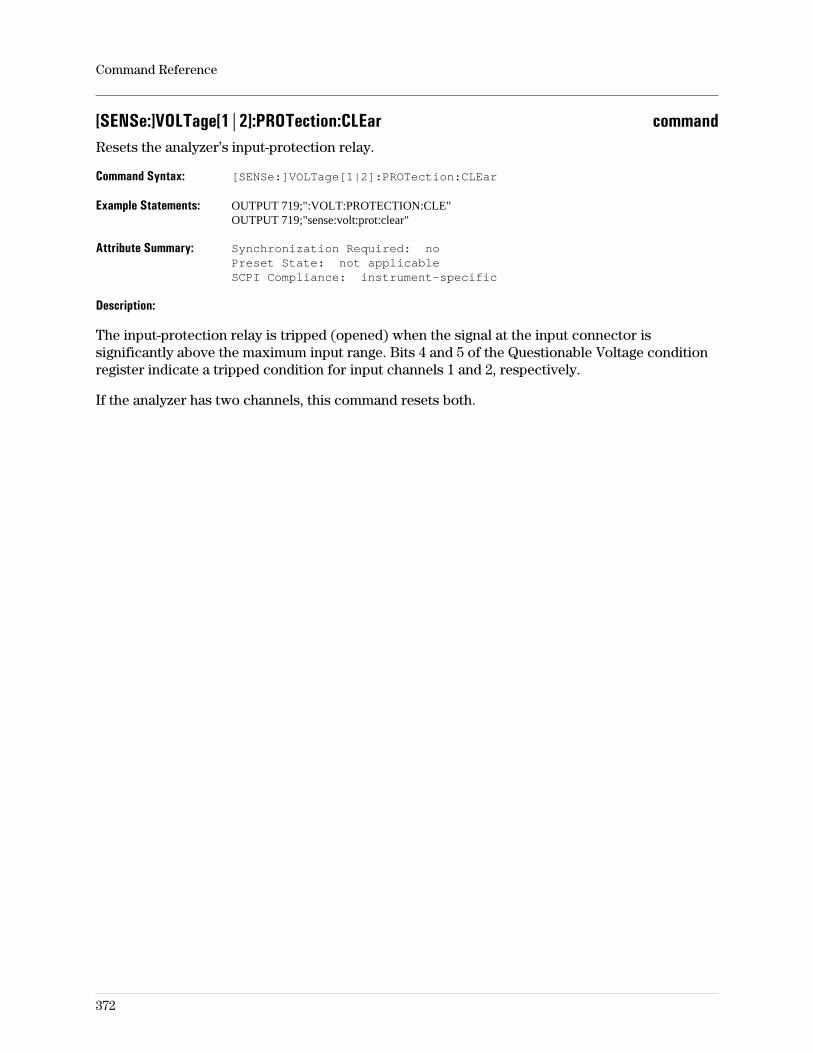
[SENSe:]VOLTage[1|2]:PROTection:CLEar commandResets the analyzer’s input-protection relay.
Command Syntax: [SENSe:]VOLTage[1|2]:PROTection:CLEar
Example Statements: OUTPUT 719;":VOLT:PROTECTION:CLE"OUTPUT 719;"sense:volt:prot:clear"
Attribute Summary: Synchronization Required: noPreset State: not applicableSCPI Compliance: instrument-specific
Description:
The input-protection relay is tripped (opened) when the signal at the input connector issignificantly above the maximum input range. Bits 4 and 5 of the Questionable Voltage conditionregister indicate a tripped condition for input channels 1 and 2, respectively.
If the analyzer has two channels, this command resets both.
Command Reference
372
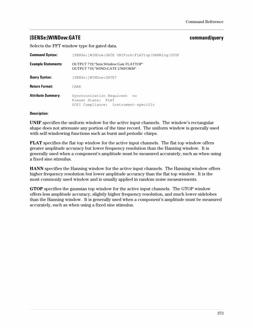
[SENSe:]WINDow:GATE command/querySelects the FFT window type for gated data.
Command Syntax: [SENSe:]WINDow:GATE UNIForm|FLATtop|HANNing|GTOP
Example Statements: OUTPUT 719;"Sens:Window:Gate FLATTOP"OUTPUT 719;"WIND:GATE UNIFORM"
Query Syntax: [SENSe:]WINDow:GATE?
Return Format: CHAR
Attribute Summary: Synchronization Required: noPreset State: FLATSCPI Compliance: instrument-specific
Description:
UNIF specifies the uniform window for the active input channels. The window’s rectangularshape does not attenuate any portion of the time record. The uniform window is generally usedwith self-windowing functions such as burst and periodic chirps.
FLAT specifies the flat top window for the active input channels. The flat top window offersgreater amplitude accuracy but lower frequency resolution than the Hanning window. It isgenerally used when a component’s amplitude must be measured accurately, such as when usinga fixed sine stimulus.
HANN specifies the Hanning window for the active input channels. The Hanning window offershigher frequency resolution but lower amplitude accuracy than the flat top window. It is themost commonly used window and is usually applied in random noise measurements.
GTOP specifies the gaussian top window for the active input channels. The GTOP windowoffers less amplitude accuracy, slightly higher frequency resolution, and much lower sidelobesthan the Hanning window. It is generally used when a component’s amplitude must be measuredaccurately, such as when using a fixed sine stimulus.
Command Reference
373
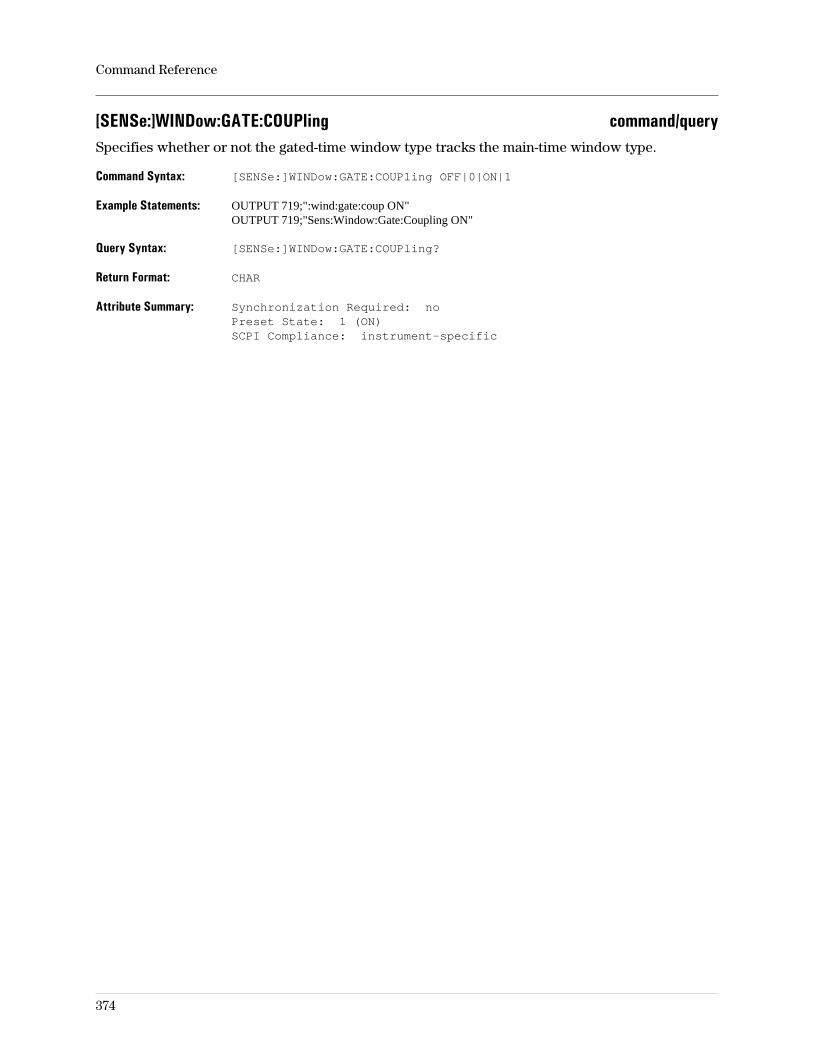
[SENSe:]WINDow:GATE:COUPling command/querySpecifies whether or not the gated-time window type tracks the main-time window type.
Command Syntax: [SENSe:]WINDow:GATE:COUPling OFF|0|ON|1
Example Statements: OUTPUT 719;":wind:gate:coup ON"OUTPUT 719;"Sens:Window:Gate:Coupling ON"
Query Syntax: [SENSe:]WINDow:GATE:COUPling?
Return Format: CHAR
Attribute Summary: Synchronization Required: noPreset State: 1 (ON)SCPI Compliance: instrument-specific
Command Reference
374

[SENSe:]WINDow[:TYPE] command/querySelects the FFT window type.
Command Syntax: [SENSe:]WINDow[:TYPE] UNIForm|FLATtop|HANNing|GTOP
Example Statements: OUTPUT 719;"SENS:WIND:TYPE UNIFORM"OUTPUT 719;"wind GTOP"
Query Syntax: [SENSe:]WINDow[:TYPE]?
Return Format: CHAR
Attribute Summary: Synchronization Required: noPreset State: FLATSCPI Compliance: instrument-specific
Description:
UNIF specifies the uniform window for the active input channels. The window’s rectangularshape does not attenuate any portion of the time record. The uniform window is generally usedwith self-windowing functions such as burst and periodic chirps.
FLAT specifies the flat top window for the active input channels. The flat top window offersgreater amplitude accuracy but lower frequency resolution than the Hanning window. It isgenerally used when a component’s amplitude must be measured accurately, such as when usinga fixed sine stimulus.
HANN specifies the Hanning window for the active input channels. The Hanning window offershigher frequency resolution but lower amplitude accuracy than the flat top window. It is themost commonly used window and is usually applied in random noise measurements.
GTOP specifies the gaussian top window for the active input channels. The GTOP windowoffers less amplitude accuracy, slightly higher frequency resolution, and much lower sidelobesthan the Hanning window. It is generally used when a component’s amplitude must be measuredaccurately, such as when using a fixed sine stimulus.
Command Reference
375
SOURce:FREQuency[:CW] command/querySpecifies the frequency for the fixed sine source type.
Command Syntax: SOURce:FREQuency[:CW] <param>
<param> ::= <number>[<unit>]|<step>|<bound>
<number> ::= a real number (NRf data)limits: 0:10e+6 (see restriction in description)
<unit> ::= HZ
<step> ::= UP|DOWN
<bound> ::= MAX|MIN
Example Statements: OUTPUT 719;"SOUR:FREQ 5 MHz"OUTPUT 719;"Sour:Freq 1e6"
Query Syntax: SOURce:FREQuency[:CW]?
Return Format: Real
Attribute Summary: Synchronization Required: noPreset State: 1 MHz (see restriction in description)SCPI Compliance: instrument-specific
Description:
For the 89441A, the source fixed-sine frequency may be specified only when ROUT:REC is IF,RF1, or COMB (I+jQ).
Related Commands
The fixed-sine (or CW) source type is specified with the SOUR:FUNC SIN command.The source signal level is specified with the SOUR:VOLT command.Entries are accepted when the source is OFF or the source type is not fixed sine.
Command Reference
376
SOURce:FREQuency:OFFSet command/querySpecifies the offset frequency (from IF center) for the fixed sine source type.
Command Syntax: SOURce:FREQuency:OFFSet <param>
<param> ::= <number>[<unit>]|<step>|<bound>
<number> ::= a real number (NRf data)limits: -3.5 MHz:3.5 MHz
<unit> ::= HZ
<step> ::= UP|DOWN
<bound> ::= MAX|MIN
Example Statements: OUTPUT 719;"sour:freq:offset 0"OUTPUT 719;"Sour:Frequency:Offs 0"
Query Syntax: SOURce:FREQuency:OFFSet?
Return Format: Real
Attribute Summary: Synchronization Required: noPreset State: 0 HzSCPI Compliance: confirmed
Description:
In RF operation (when ROUT:REC is RF2), the source center frequency tracks the receiverfrequency during the sweep. The offset frequency allows the source to track the receiver sweepwith a constant frequency difference.
This command is not available for the 89410A.For the 89441A, this command is available only when ROUT:REC is RF2.
Command Reference
377
SOURce:FUNCtion[:SHAPe] command/querySelects the source output signal type.
Command Syntax: SOURce:FUNCtion[:SHAPe] SINusoid|USER|RANDom|PCHirp
Example Statements: OUTPUT 719;":SOUR:FUNCTION USER"OUTPUT 719;"sour:function:shap SINUSOID"
Query Syntax: SOURce:FUNCtion[:SHAPe]?
Return Format: CHAR
Attribute Summary: Synchronization Required: noPreset State: SINSCPI Compliance: confirmed
Description:
After preset and when power is first turned on, the source is off.
The OUTP 1 command may be used to turn it on.The amplitude value is specified with the SOUR:VOLT command.
Arguments used with the SOUR:FUNC command are as follows:
SIN selects fixed sine as the source output type. The signal is a continuous sine wave output atthe center frequency of the current measurement or sub-measurement. The frequency of thissignal is specified with the SOUR:FREQ command.
RAND selects random noise (with a Gaussian distribution) as the source output type. Thissource type’s peak-to-rms ratio is not as low as the chirp signal, but the energy at any of the tonesis not concentrated at a particular point in time, making it useful for measuring some dispersivenetworks.
Random noise yields a fast, linear estimate of the system under test. Because it is notperiodic in the time record, random noise requires windowing; usually the Hanning window.The bandwidth of the random noise is set so that most of the energy in the source signal iswithin the measured span.
PCH selects periodic chirp as the source output type. The signal has a low peak-to-rms ratio,useful for network measurements.
USER selects a user-defined source signal stored in one of the six data registers, D1–D6. Theparticular data register is selected with the SOUR:FUNC:USER:FEED command. The data mustbe in SDF format. Data for arbitrary source signals may have been time-domain traces that weresaved earlier, created with commercial software such as PC Matlab, or defined with a BASICprogram.
Command Reference
378
SOURce:FUNCtion:USER:FEED command/querySelects one of six data registers containing user-defined source signals.
Command Syntax: SOURce:FUNCtion:USER:FEED <string>
<string> ::= ‘D1’|’D2’|’D3’|’D4’|’D5’|’D6’
Example Statements: OUTPUT 719;"SOUR:FUNCTION:USER:FEED ‘D3’"OUTPUT 719;"source:func:user:feed ‘D1’"
Query Syntax: SOURce:FUNCtion:USER:FEED?
Return Format: STRING
Attribute Summary: Synchronization Required: noPreset State: D1SCPI Compliance: instrument-specific
Description:
This user-defined signal is used as the source output when the selected source type is USER(SOUR:FUNC USER).
Command Reference
379
SOURce:IFINput:STATe command/querySelects a stimulus for the analyzer’s RF source.
Command Syntax: SOURce:IFINput:STATe OFF|0|ON|1
Example Statements: OUTPUT 719;"Sour:Ifinput:Stat ON"OUTPUT 719;"SOURCE:IFIN:STAT ON"
Query Syntax: SOURce:IFINput:STATe?
Return Format: Integer
Attribute Summary: Option: AY8 (Internal RF Source)Synchronization Required: noPreset State: OFFSCPI Compliance: instrument-specific
Description:
This command is applicable only in Agilent 89441A analyzers that have the optional RF source.Send SOURCE:IFINPUT:STATE:ON to drive the analyzer’s RF source with an external signal.Send SOURCE:IFINPUT:STATE:OFF (default) to drive the RF source with the source signal fromthe analyzer’s IF Section.
For additional details, see online help for the [ext IF input on/off] softkey. To display online helpfor this softkey, press [Help], press 1 to display the online help index, then page through theindex and select this topic: ‘’Source, external signals, using as input to source’’.
Command Reference
380
SOURce:RF command/querySwitches the source output range between 0–10 MHz and RF (GHz)./
Command Syntax: SOURce:RF OFF|0|ON|1
Example Statements: OUTPUT 719;":source:rf OFF"OUTPUT 719;"Source:Rf ON"
Query Syntax: SOURce:RF?
Return Format: Integer
Attribute Summary: Synchronization Required: noPreset State: ONSCPI Compliance: instrument-specific
Description:
This command is available only for the 89441A and only if the optional RF source (AY8) isinstalled and ROUT:REC is RF2.
ON specifies the RF source (2–2646 MHz for the 89441A).
OFF specifies the 0–10 MHz source.
Command Reference
381
SOURce:USER:REPeat command/querySpecifies whether the arbitrary and chirp source signals occur once (data record played once) orrepeatedly.
Command Syntax: SOURce:USER:REPeat OFF|0|ON|1
Example Statements: OUTPUT 719;"SOUR:USER:REP ON"OUTPUT 719;"source:user:rep ON"
Query Syntax: SOURce:USER:REPeat?
Return Format: Integer
Attribute Summary: Synchronization Required: noPreset State: 1SCPI Compliance: instrument-specific
Description:
This function (repeating source) is available only when the source type is periodic chirp orarbitrary, the trigger type is not free run, and the source is on. See help text for information.
When repeat is on, the analyzer outputs data to the source connector continuously, withoutinterruption.
When repeat is off, the source behavior is affected by trigger mode. In free run trigger, sourceoutput is continuous, just as it is with repeat on. For any other trigger mode, the source beginsits output only when a trigger occurs and shuts off after all the data in the register has beenoutput. This happens each time a trigger occurs.
Related Commands
To specify the source type, use SOUR:FUNC.To specify the trigger type, use TRIG:SOUR.To turn the source on/off, use OUTP[:STAT].
Command Reference
382
SOURce:VOLTage[:LEVel][:IMMediate][:AMPLitude] command/querySpecifies the source output level.
Command Syntax: SOURce:VOLTage[:LEVel][:IMMediate][:AMPLitude] <param>
<param> ::= <number>[<unit>]|<step>|<bound>
<number> ::= a real number (NRf data)limits: (see table)
<unit> ::= dBm|dBV|dBVrms|dBVpk|V|Vpk|Vrms|W|Wrms
<step> ::= UP|DOWN
<bound> ::= MAX|MIN
Example Statements: OUTPUT 719;"SOUR:VOLTAGE:LEV:IMM:AMPLITUDE -10DBM"OUTPUT 719;"sour:volt .1V"
Query Syntax: SOURce:VOLTage[:LEVel][:IMMediate][:AMPLitude]?
Return Format: Real
Attribute Summary: Synchronization Required: noPreset State: -10 dBm (100 mV)SCPI Compliance: confirmed
Description:
Specifies a source output level that applies to all waveform types. For random noise or periodicchirp, the level is the total wideband level (the summation of the waveform measured at fullspan). For smaller spans, not all of the energy appears in the measurement because some of thewaveform’s power is outside the selected span. If the level is specified for random noise in Vrms,when the source type is changed, the analyzer maintains the rms level for the new type. Thesame is true for Vpk. Because the ratio of peak/rms varies for different signal types, the peakvalue changes when the analyzer maintains the rms value. If a new rms value would require apeak value outside the limits of the source voltage, the level is set to the limit. Limits are ±5 Vpkand include offset as well as level. If no units are entered with the number, dBm are assumed.
Source Output Level Limits
89410 or89441 SOUR:RF 0
89441SOUR:RF 1
value limits −110 dBm:+24 dBm0 Vpk:5.013 Vpk
−40 dBm:+23 dBm(see following text)
Command Reference
383
For the Agilent 89441A, you can set the source output level as high as +23 dBm. However, theoutput level for the Agilent 89441A is specified only to +13 dBm. Source performance is notspecified beyond +13 dBm. For additional details, see the specifications shipped with theAgilent 89441A Installation & Verification Guide.
Notes - It is good practice to specify the source level before the source is turned on.When the source is turned on, the output voltage level is whatever value wasactive when it was turned off. The active value may be large enough to damagesensitive devices. At turn-on and preset, the level is −10 dBm (100 mV).- Changing instrument mode does not turn the source off nor change the sourceoutput value.
Command Reference
384
SOURce:VOLTage[:LEVel][:IMMediate]:OFFSet command/querySpecifies the source output dc offset in volts.
Command Syntax: SOURce:VOLTage[:LEVel][:IMMediate]:OFFSet <param>
<param> ::= <number>[<unit>]|<step>|<bound>
<number> ::= a real number (NRf data)limits: -3.42:+3.42
<unit> ::= V
<step> ::= UP|DOWN
<bound> ::= MAX|MIN
Example Statements: OUTPUT 719;":Source:Volt:Offset 0"OUTPUT 719;"SOUR:VOLT:LEVEL:IMM:OFFSET 0"
Query Syntax: SOURce:VOLTage[:LEVel][:IMMediate]:OFFSet?
Return Format: Real
Attribute Summary: Synchronization Required: noPreset State: 0VSCPI Compliance: confirmed
Description:
The maximum value for the source output is ±5 Vpk. This value is a sum of the dc offset andpeak value of the source amplitude. So the limits of the source offset are dependent on thesource level.
Step size (used with UP|DOWN) varies in a 1, 2, 5 pattern starting with 100 uVpk.
Command Reference
385
SOURce:VOLTage[:LEVel]:UNIT:VOLTage command/querySets or queries the source level unit.
Command Syntax: SOURce:VOLTage[:LEVel]:UNIT:VOLTage <param>
<param> ::= dBm|dBV|dBVrms|dBVpk|V|Vpk|Vrms|W|Wrms
Example Statements: OUTPUT 719;"sour:volt:level:unit:voltage Wrms"OUTPUT 719;"Sour:Volt:Unit:Volt Vrms"
Query Syntax: SOURce:VOLTage[:LEVel]:UNIT:VOLTage?
Return Format: CHAR
Attribute Summary: Synchronization Required: noPreset State: DBMSCPI Compliance: confirmed
Command Reference
386
SOURce:VOLTage:PROTection:CLEar commandClears the source output protection circuitry.
Command Syntax: SOURce:VOLTage:PROTection:CLEar
Example Statements: OUTPUT 719;":SOURCE:VOLT:PROT:CLEAR"OUTPUT 719;"sour:voltage:prot:cle"
Attribute Summary: Synchronization Required: noPreset State: not applicableSCPI Compliance: confirmed
Description:
The source-protection relay opens when approximately ±13 volts or greater is applied to theSOURCE BNC connector. A message on the screen tells you when the relay has been tripped.
To detect a source-tripped condition, set the status registers to report a source trip in thequestionable voltage register set.
Command Reference
387
STATus:DEVice:CONDition? queryReads and clears the Device State Condition register.
Query Syntax: STATus:DEVice:CONDition?
Example Statements: OUTPUT 719;"Status:Dev:Condition?"OUTPUT 719;"STAT:DEV:CONDITION?"
Return Format: Integer
Attribute Summary: Synchronization Required: noPreset State: not affected by PresetSCPI Compliance: instrument-specific
Description:
This query returns the sum of the decimal weights of all bits currently set to 1 in the Device StateCondition register. (The decimal weight of a bit is 2n, where n is the bit number.)
See ‘’Device State Register Set’’ for a definition of bits in the register set. See ‘’General StatusRegister Model’’ for information about the role of condition registers in register sets.
Command Reference
388

STATus:DEVice:ENABle command/querySets and queries bits in the Device State Enable register.
Command Syntax: STATus:DEVice:ENABle <number>
<number> ::= a real number (NRf data)limits: 0:32767
Example Statements: OUTPUT 719;"STAT:DEVICE:ENAB 1024"OUTPUT 719;"stat:device:enab 768"
Query Syntax: STATus:DEVice:ENABle?
Return Format: Integer
Attribute Summary: Synchronization Required: noPreset State: not affected by PresetSCPI Compliance: instrument-specific
Description:
To set a single bit in the Device State Enable register to 1, send the bit’s decimal weight with thiscommand. To set more than one bit to 1, send the sum of the decimal weights of all the bits.(The decimal weight of a bit is 2n, where n is the bit number.)
All bits are initialized to 0 when the analyzer is turned on. However, the current bit setting is not
modified by the *RST command.
See ‘’Device State Register Set’’ for a definition of bits in the register set. See ‘’General StatusRegister Model’’ for information about the role of enable registers in register sets.
Command Reference
389
STATus:DEVice[:EVENt]? queryReads and clears the Device State Event register.
Query Syntax: STATus:DEVice[:EVENt]?
Example Statements: OUTPUT 719;":stat:device?"OUTPUT 719;"Stat:Dev:Event?"
Return Format: Integer
Attribute Summary: Synchronization Required: noPreset State: not affected by PresetSCPI Compliance: instrument-specific
Description:
This query returns the sum of the decimal weights of all bits currently set to 1 in the Device StateEvent register. (The decimal weight of a bit is 2n, where n is the bit number.)
Note The Device State Event register is automatically cleared after it is read by thisquery.
See ‘’Device State Register Set’’ for a definition of bits in the register set. See ‘’General StatusRegister Model’’ for information about the role of event registers in register sets.
Command Reference
390

STATus:DEVice:NTRansition command/querySets and queries bits in the Device Status Negative Transition register.
Command Syntax: STATus:DEVice:NTRansition <number>
<number> ::= a real number (NRf data)limtis: 0:32767
Example Statements: OUTPUT 719;":STAT:DEV:NRTRANSITION 67"OUTPUT 719;"stat:device:ptr 4098"
Query Syntax: STATus:DEVice:NTRansition?
Return Format: Integer
Attribute Summary: Synchronization Required: noPreset State: not affected by PresetSCPI Compliance: instrument-specific
Description:
To set a single bit in the Device Status Negative Transition register to 1, send the bit’s decimalweight with this command. To set more than one bit to 1, send the sum of the decimal weights ofall the bits. (The decimal weight of a bit is 2n, where n is the bit number.)
All bits are initialized to 0 when the analyzer is turned on. However, the current bit setting is not
modified by the *RST command.
See ‘’Device Status Register Set’’ for a definition of bits in the register set. See ‘’General StatusRegister Model’’ for information about the role of negative transition registers in register sets.
Command Reference
391
STATus:DEVice:PTRansition command/querySets and queries bits in the Device State Positive Transition register.
Command Syntax: STATus:DEVice:PTRansition <number>
<number> ::= a real number (NRf data)limtis: 0:32767
Example Statements: OUTPUT 719;":STAT:DEV:PRTRANSITION 513"OUTPUT 719;"stat:device:ptr 1025"
Query Syntax: STATus:DEVice:PTRansition?
Return Format: Integer
Attribute Summary: Synchronization Required: noPreset State: not affected by PresetSCPI Compliance: instrument-specific
Description:
To set a single bit in the Device State Positive Transition register to 1, send the bit’s decimalweight with this command. To set more than one bit to 1, send the sum of the decimal weights ofall the bits. (The decimal weight of a bit is 2n, where n is the bit number.)
All bits are initialized to 1 when the analyzer is turned on. However, the current bit setting is not
modified by the *RST command.
See ‘’Device State Register Set’’ for a definition of bits in the register set. See ‘’General StatusRegister Model’’ for information about the role of positive transition registers in register sets.
Command Reference
392
STATus:OPERation:CONDition? queryReads the Operational Status Condition register.
Query Syntax: STATus:OPERation:CONDition?
Example Statements: OUTPUT 719;"STAT:OPERATION:COND?"OUTPUT 719;"stat:operation:cond?"
Return Format: Integer
Attribute Summary: Synchronization Required: noPreset State: not affected by PresetSCPI Compliance: confirmed
Description:
This query returns the sum of the decimal weights of all bits currently set to 1 in the OperationalStatus Condition register. (The decimal weight of a bit is 2n, where n is the bit number.)
See ‘’Operational Status Register Set’’ for a definition of bits in the register set. See ‘’GeneralStatus Register Model’’ for information about the role of condition registers in register sets.
Command Reference
393
STATus:OPERation:ENABle command/querySets and queries bits in the Operational Status Enable register.
Command Syntax: STATus:OPERation:ENABle <number>|<bound>
<number> ::= a real number (NRf data)limits: 0:32767
<bound> ::= MAX|MIN
Example Statements: OUTPUT 719;":Status:Oper:Enab 9488"OUTPUT 719;"STATUS:OPER:ENABLE 32231"
Query Syntax: STATus:OPERation:ENABle?
Return Format: Integer
Attribute Summary: Synchronization Required: noPreset State: not affected by PresetSCPI Compliance: confirmed
Description:
To set a single bit in the Operational Status Enable register to 1, send the bit’s decimal weightwith this command. To set more than one bit to 1, send the sum of the decimal weights of all thebits. (The decimal weight of a bit is 2n, where n is the bit number.)
See ‘’Operational Status Register Set’’ for a definition of bits in the register set. See ‘’GeneralStatus Register Model’’ for information about the role of enable registers in register sets.
Command Reference
394
STATus:OPERation[:EVENt]? queryReads and clears the Operational Status Event register.
Query Syntax: STATus:OPERation[:EVENt]?
Example Statements: OUTPUT 719;"stat:oper:event?"OUTPUT 719;"Stat:Operation?"
Return Format: Integer
Attribute Summary: Synchronization Required: noPreset State: not applicableSCPI Compliance: confirmed
Description:
This query returns the sum of the decimal weights of all bits currently set to 1 in the OperationalStatus Event register. (The decimal weight of a bit is 2n, where n is the bit number.)
Note The Operational Status Event register is automatically cleared after it is read bythis query.
See ‘’Operational Status Register Set’’ for a definition of bits in the register set. See ‘’GeneralStatus Register Model’’ for information about the role of event registers in register sets.
Command Reference
395

STATus:OPERation:NTRansition command/querySets and queries bits in the Operational Status Negative Transition register.
Command Syntax: STATus:OPERation:NTRansition <number>
<number> ::= a real number (NRf data)limits: 0:32767
Example Statements: OUTPUT 719;":Stat:Operation:Ntr 5"OUTPUT 719;"STAT:OPERATION:NTR 53"
Query Syntax: STATus:OPERation:NTRansition?
Return Format: Integer
Attribute Summary: Synchronization Required: noPreset State: not affected by PresetSCPI Compliance: confirmed
Description:
To set a single bit in the Operational Status negative transition register to 1, send the bit’sdecimal weight with this command. To set more than one bit to 1, send the sum of the decimalweights of all the bits. (The decimal weight of a bit is 2n, where n is the bit number.)
All bits are initialized to 0 when the analyzer is turned on. However, the current bit setting is not
modified by the *RST command.
See ‘’Operational Status Register Set’’ for a definition of bits in the register set. See ‘’GeneralStatus Register Model’’ for information about the role of negative transition registers in registersets.
Command Reference
396
STATus:OPERation:PTRansition command/querySets bits in the Operational Status Positive Transition register.
Command Syntax: STATus:OPERation:PTRansition <number>
<number> ::= a real number (NRf data)limits: 0:32767
Example Statements: OUTPUT 719;"status:oper:ptr 5"OUTPUT 719;"Status:Oper:Ptransition 55"
Query Syntax: STATus:OPERation:PTRansition?
Return Format: Integer
Attribute Summary: Synchronization Required: noPreset State: not affected by PresetSCPI Compliance: confirmed
Description:
To set a single bit in the Operational Status positive transition register to 1, send the bit’s decimalweight with this command. To set more than one bit to 1, send the sum of the decimal weights ofall the bits. (The decimal weight of a bit is 2n, where n is the bit number.)
All bits are initialized to 1 when the analyzer is turned on. However, the current bit setting is not
modified by the *RST command.
See ‘’Operational Status Register Set’’ for a definition of bits in the register set. See ‘’GeneralStatus Register Model’’ for information about the role of positive transition registers in registersets.
Command Reference
397
STATus:PRESet commandSets bits in most enable and transition registers to their default state.
Command Syntax: STATus:PRESet
Example Statements: OUTPUT 719;":STAT:PRES"OUTPUT 719;"status:pres"
Attribute Summary: Synchronization Required: noPreset State: not applicableSCPI Compliance: confirmed
Description:
STAT:PRESet effects on the Questionable Voltage and Questionable Frequency register set asfollowss:
Sets all enable register bits to 1.Sets all positive transition register bits to 1.Sets all negative transition register bits to 0.
STATUS:PRESet brings all events to the second-level register sets (the Device State,Questionable Status, and Operation Status) without creating an SRQ or reflecting events in aserial poll.
It also affects these register sets, (the Device State, Questionable Status, and Operation Status)as follows:
Sets all enable register bits to 0.Sets all positive transition register bits to 1.Sets all negative transition register bits to 0.
STAT:PRESet sets all bits in the User Defined Enable register to 0. It does not affect any otherregister.
Command Reference
398
STATus:QUEStionable:CONDition? queryReads and clears the Questionable Status Condition register.
Query Syntax: STATus:QUEStionable:CONDition?
Example Statements: OUTPUT 719;"Status:Ques:Cond?"OUTPUT 719;"STATUS:QUES:CONDITION?"
Return Format: Integer
Attribute Summary: Synchronization Required: noPreset State: not affected by PresetSCPI Compliance: confirmed
Description:
This query returns the sum of the decimal weights of all bits currently set to 1 in theQuestionable Status Condition register. (The decimal weight of a bit is 2n, where n is the bitnumber.)
See ‘’Questionable Status Register Set’’ for a definition of bits in the register set. See ‘’GeneralStatus Register Model’’ for information about the role of condition registers in register sets.
Command Reference
399

STATus:QUEStionable:ENABle command/querySets and queries bits in the Questionable Status Enable register.
Command Syntax: STATus:QUEStional:ENABle <number>
<number> ::= a real number (NRf data)limits: 0:32767
Example Statements: OUTPUT 719;":stat:ques:enable 28055"OUTPUT 719;"Stat:Questionable:Enab 2478"
Query Syntax: STATus:QUEStionable:ENABle?
Return Format: Integer
Attribute Summary: Synchronization Required: noPreset State: not affected by PresetSCPI Compliance: confirmed
Description:
To set a single bit in the Questionable Status Enable register to 1, send the bit’s decimal weightwith this command. To set more than one bit to 1, send the sum of the decimal weights of all thebits. (The decimal weight of a bit is 2n, where n is the bit number.)
All bits are initialized to 0 when the analyzer is turned on. However, the current bit setting is not
modified by the *RST command.
See ‘’Questionable Status Register Set’’ for a definition of bits in the register set. See ‘’GeneralStatus Register Model’’ for information about the role of enable registers in register sets.
Command Reference
400

STATus:QUEStionable[:EVENt]? queryReads and clears the Questionable Status Event register.
Query Syntax: STATus:QUEStionable[:EVENt]?
Example Statements: OUTPUT 719;"STAT:QUESTIONABLE:EVEN?"OUTPUT 719;"status:ques?"
Return Format: Integer
Attribute Summary: Synchronization Required: noPreset State: not applicableSCPI Compliance: confirmed
Description:
This query returns the sum of the decimal weights of all bits currently set to 1 in theQuestionable Status Event register. (The decimal weight of a bit is 2n, where n is the bit number.)
Note The Questionable Status Event register is automatically cleared after it is read bythis query.
See ‘’Questionable Status Register Set’’ for a definition of bits in the register set. See ‘’GeneralStatus Register Model’’ for information about the role of event registers in register sets.
Command Reference
401
STATus:QUEStionable:FREQuency:CONDition? queryReads and clears the Questionable Frequency Event register.
Query Syntax: STATus:QUEStionable:FREQuency:CONDition?
Example Statements: OUTPUT 719;":Stat:Questionable:Freq:Condition?"OUTPUT 719;"STAT:QUES:FREQUENCY:COND?"
Return Format: Integer
Attribute Summary: Synchronization Required: noPreset State: not affected by PresetSCPI Compliance: confirmed
Description:
Note The Questionable Frequency Condition register is automatically cleared after it isread by this query.
See ‘’Questionable Frequency Register Set’’ for a definition of bits in the register set. See‘’General Status Register Model’’ for information about the role of event registers in register sets.
Command Reference
402
STATus:QUEStionable:FREQuency:ENABle command/querySets and queries bits in the Questionable Frequency Enable register.
Command Syntax: STATus:QUEStionable:FREQuency:ENABle <number>
<number> ::= a real number (NRf data)limits: 0:32767
Example Statements: OUTPUT 719;":Stat:Ques:Frequency:Enab 27"OUTPUT 719;"STATUS:QUES:FREQ:ENABLE 168"
Query Syntax: STATus:QUEStionable:FREQuency:ENABle?
Return Format: Integer
Attribute Summary: Synchronization Required: noPreset State: not affected by PresetSCPI Compliance: confirmed
Description:
To set a single bit in the Questionable Frequency Enable register to 1, send the bit’s decimalweight with this command. To set more than one bit to 1, send the sum of the decimal weights ofall the bits. (The decimal weight of a bit is 2n, where n is the bit number.)
All bits are initialized to 0 when the analyzer is turned on. However, the current bit setting is not
modified by the *RST command.
See ‘’Questionable Frequency Register Set’’ for a definition of bits in the register set. See‘’General Status Register Model’’ for information about the role of enable registers in register sets.
Command Reference
403

STATus:QUEStionable:FREQuency[:EVENt]? queryReads and clears the Questionable Frequency Event register.
Query Syntax: STATus:QUEStionable:FREQuency[:EVENt]?
Example Statements: OUTPUT 719;"status:ques:freq:event?"OUTPUT 719;"Stat:Questionable:Freq?"
Return Format: Integer
Attribute Summary: Synchronization Required: noPreset State: not applicableSCPI Compliance: confirmed
Description:
This query returns the sum of the decimal weights of all bits currently set to 1 in theQuestionable Frequency Event register. (The decimal weight of a bit is 2n, where n is the bitnumber.)
Note The Questionable Frequency Event register is automatically cleared after it isread by this query.
See ‘’Questionable Frequency Register Set’’ definition of bits in the register set. See ‘’GeneralStatus Register Model’’ for information about the role of event registers in register sets.
Command Reference
404
STATus:QUEStionable:FREQuency:NTRansition command/querySets and queries bits in the Questionable Frequency Negative Transition register.
Command Syntax: STATus:QUEStionable:FREQuency:NTRansition <number>
<number> ::= a real number (NRf data)limits: 0:32767
Example Statements: OUTPUT 719;":Status Ques:Frequency:Ntr 978"OUTPUT 719;"STAT:QUESTIONABLE:FREQ:NTRANSITION 63"
Query Syntax: STATus:QUEStionable:FREQuency:NTRansition?
Return Format: Integer
Attribute Summary: Synchronization Required: noPreset State: not affected by PresetSCPI Compliance: confirmed
Description:
To set a single bit in the Questionable Frequency Negative Transition register to 1, send the bit’sdecimal weight with this command. To set more than one bit to 1, send the sum of the decimalweights of all the bits. (The decimal weight of a bit is 2n, where n is the bit number.)
All bits are initialized to 0 when the analyzer is turned on. However, the current bit setting is not
modified by the *RST command.
See ‘’Questionable Frequency Register Set’’ for a definition of bits in the register set. See‘’General Status Register Model’’ for information about the role of negative transition registers inregister sets.
Command Reference
405
STATus:QUEStionable:FREQuency:PTRansition command/querySets bits in the Questionable Frequency Positive Transition register.
Command Syntax: STATus:QUEStionable:FREQuency:PTRansition <number>
<number> ::= a real number (NRf data)limits: 0:32767
Example Statements: OUTPUT 719;"Stat:Questionable:Freq:Ptr 512"OUTPUT 719;"STATUS:QUES:FREQUENCY:PTR 677"
Query Syntax: STATus:QUEStionable:FREQuency:PTRansition?
Return Format: Integer
Attribute Summary: Synchronization Required: noPreset State: not affected by PresetSCPI Compliance: confirmed
Description:
To set a single bit in the Questionable Frequency Positive Transition register to 1, send the bit’sdecimal weight with this command. To set more than one bit to 1, send the sum of the decimalweights of all the bits. (The decimal weight of a bit is 2n, where n is the bit number.)
All bits are initialized to 1 when the analyzer is turned on. However, the current bit setting is not
modified by the *RST command.
See ‘’Questionable Frequency Register Set’’ for a definition of bits in the register set. See‘’General Status Register Model’’ for information about the role of positive transition registers inregister sets.
Command Reference
406
STATus:QUEStionable:MODulation:CONDition? queryReads and clears the Questionable Modulation Event register.
Query Syntax: STATus:QUEStionable:MODulation:CONDition?
Example Statements: OUTPUT 719;":STAT:QUESTIONABLE:MOD:CONDITION?"OUTPUT 719;"stat:ques:modulation:cond?"
Return Format: Integer
Attribute Summary: Synchronization Required: noPreset State: not affected by PresetSCPI Compliance: confirmed
Description:
Note The Questionable Modulation Condition register is automatically cleared after itis read by this query.
See ‘’Questionable Modulation Register Set’’ for a definition of bits in the register set. See‘’General Status Register Model’’ for information about the role of event registers in register sets.
Command Reference
407
STATus:QUEStionable:MODulation:ENABle command/querySets and queries bits in the Questionable Modulation Enable register.
Command Syntax: STATus:QUEStionable:MODulation:ENABle <number>
<number> ::= a real number (NRf data)limits: 0:32767
Example Statements: OUTPUT 719;":Stat:Ques:Modulation:Enab 1"OUTPUT 719;"STATUS:QUES:MOD:ENABLE 3"
Query Syntax: STATus:QUEStionable:MODulation:ENABle?
Return Format: Integer
Attribute Summary: Synchronization Required: noPreset State: not affected by PresetSCPI Compliance: confirmed
Description:
To set a single bit in the Questionable Modulation Enable register to 1, send the bit’s decimalweight with this command. To set more than one bit to 1, send the sum of the decimal weights ofall the bits. (The decimal weight of a bit is 2n, where n is the bit number.)
All bits are initialized to 0 when the analyzer is turned on. However, the current bit setting is not
modified by the *RST command.
See ‘’Questionable Modulation Register Set’’ for a definition of bits in the register set. See‘’General Status Register Model’’ for information about the role of enable registers in register sets.
Command Reference
408
STATus:QUEStionable:MODulation[:EVENt]? queryReads and clears the Questionable Modulation Event register.
Query Syntax: STATus:QUEStionable:MODulation[:EVENt]?
Example Statements: OUTPUT 719;"Status:Ques:Mod:Event?"OUTPUT 719;"STAT:QUESTIONABLE:MOD?"
Return Format: Integer
Attribute Summary: Synchronization Required: noPreset State: not applicableSCPI Compliance: confirmed
Description:
This query returns the sum of the decimal weights of all bits currently set to 1 in theQuestionable Modulation Event register. (The decimal weight of a bit is 2n, where n is the bitnumber.)
Note The Questionable Modulation Event register is automatically cleared after it isread by this query.
See ‘’Questionable Modulation Register Set’’ definition of bits in the register set. See ‘’GeneralStatus Register Model’’ for information about the role of event registers in register sets.
Command Reference
409
STATus:QUEStionable:MODulation:NTRansition command/querySets and queries bits in the Questionable Modulation Negative Transition register.
Command Syntax: STATus:QUEStionable:MODulation:NTRansition <number>
<number> ::= a real number (NRf data)limits: 0:32767
Example Statements: OUTPUT 719;":Status Ques:Modulation:Ntr 3"OUTPUT 719;"STAT:QUESTIONABLE:MOD:NTRANSITION 2"
Query Syntax: STATus:QUEStionable:MODulation:NTRansition?
Return Format: Integer
Attribute Summary: Synchronization Required: noPreset State: not affected by PresetSCPI Compliance: confirmed
Description:
To set a single bit in the Questionable Modulation Negative Transition register to 1, send the bit’sdecimal weight with this command. To set more than one bit to 1, send the sum of the decimalweights of all the bits. (The decimal weight of a bit is 2n, where n is the bit number.)
All bits are initialized to 0 when the analyzer is turned on. However, the current bit setting is not
modified by the *RST command.
See ‘’Questionable Modulation Register Set’’ for a definition of bits in the register set. See‘’General Status Register Model’’ for information about the role of negative transition registers inregister sets.
Command Reference
410

STATus:QUEStionable:MODulation:PTRansition command/querySets and queries bits in the Questionable Modulation Positive Transition register.
Command Syntax: STATus:QUEStionable:MODulation:PTRansition <number>
<number> ::= a real number (NRf data)limits: 0:32767
Example Statements: OUTPUT 719;"Stat:Questionable:Mod:Ptr 1"OUTPUT 719;"STATUS:QUES:MODULATION:PTR 3"
Query Syntax: STATus:QUEStionable:MODulation:PTRansition?
Return Format: Integer
Attribute Summary: Synchronization Required: noPreset State: not affected by PresetSCPI Compliance: confirmed
Description:
To set a single bit in the Questionable Modulation Positive Transition register to 1, send the bit’sdecimal weight with this command. To set more than one bit to 1, send the sum of the decimalweights of all the bits. (The decimal weight of a bit is 2n, where n is the bit number.)
All bits are initialized to 1 when the analyzer is turned on. However, the current bit setting is not
modified by the *RST command.
See ‘’Questionable Modulation Register Set’’ for a definition of bits in the register set. See‘’General Status Register Model’’ for information about the role of positive transition registers inregister sets.
Command Reference
411

STATus:QUEStionable:NTRansition command/querySets and queries bits in the Questionable Status Negative Transition register.
Command Syntax: STATus:QUEStionable:NTRansition <number>
<number> ::= a real number (NRf)limits: 0:32767
Example Statements: OUTPUT 719;":Stat:Questionable:Ntr 5"OUTPUT 719;"STATUS:QUES:NTR 54"
Query Syntax: STATus:QUEStionable:NTRansition?
Return Format: Integer
Attribute Summary: Synchronization Required: noPreset State: not affected by PresetSCPI Compliance: confirmed
Description:
To set a single bit in the Questionable Status negative transition register to 1, send the bit’sdecimal weight with this command. To set more than one bit to 1, send the sum of the decimalweights of all the bits. (The decimal weight of a bit is 2n, where n is the bit number.)
All bits are initialized to 0 when the analyzer is turned on. However, the current bit setting is not
modified by the *RST command.
See ‘’Questionable Status Register Set’’ for a definition of bits in the register set. See ‘’GeneralStatus Register Model’’ for information about the role of negative transition registers in registersets.
Command Reference
412
STATus:QUEStionable:PTRansition command/querySets and queries bits in the Questionable Status Positive Transition register.
Command Syntax: STATus:QUEStionable:PTRansition <number>
<number> ::= a real number (NRf data)limits: 0:32767
Example Statements: OUTPUT 719;"status:ques:ptransition 5"OUTPUT 719;"Stat:Ques:Ptransition 53"
Query Syntax: STATus:QUEStionable:PTRansition?
Return Format: Integer
Attribute Summary: Synchronization Required: noPreset State: not affected by PresetSCPI Compliance: confirmed
Description:
To set a single bit in the Questionable Status Positive Transition register to 1, send the bit’sdecimal weight with this command. To set more than one bit to 1, send the sum of the decimalweights of all the bits. (The decimal weight of a bit is 2n, where n is the bit number.)
All bits are initialized to 1 when the analyzer is turned on. However, the current bit setting is not
modified by the *RST command.
See ‘’Questionable Status Register Set’’ for a definition of bits in the register set. See ‘’GeneralStatus Register Model’’ for information about the role of positive transition registers in registersets.
Command Reference
413

STATus:QUEStionable:VOLTage:CONDition? queryReads and clears the Questionable Voltage Event register.
Query Syntax: STATus:QUEStionable:VOLTage:CONDition?
Example Statements: OUTPUT 719;":stat:questionable:volt:condition?"OUTPUT 719;"Stat:Ques:Voltage:Cond?"
Return Format: Integer
Attribute Summary: Synchronization Required: noPreset State: not applicableSCPI Compliance: instrument-specific
Description:
Note The Questionable Voltage Condition register is automatically cleared after it isread by this query.
See ‘’Questionable Voltage Register Set’’ for a definition of bits in the register set. See ‘’GeneralStatus Register Model’’ for information about the role of event registers in register sets.
Command Reference
414
STATus:QUEStionable:VOLTage:ENABle command/querySets and queries bits in the Questionable Voltage Enable register.
Command Syntax: STATus:QUEStionable:VOLTage:ENABle <number>
<number> ::= a real number (NRf data)limits: 0:32767
Example Statements: OUTPUT 719;"Stat:Questionable:Volt:Enable 5"OUTPUT 719;"STAT:QUES:VOLTAGE:ENAB 23"
Query Syntax: STATus:QUEStionable:VOLTage:ENABle?
Return Format: Integer
Attribute Summary: Synchronization Required: noPreset State: not affected by PresetSCPI Compliance: confirmed
Description:
To set a single bit in the Questionable Voltage Enable register to 1, send the bit’s decimal weightwith this command. To set more than one bit to 1, send the sum of the decimal weights of all thebits. (The decimal weight of a bit is 2n, where n is the bit number.)
All bits are initialized to 0 when the analyzer is turned on. However, the current bit setting is not
modified by the *RST command.
See ‘’Questionable Voltage Register Set’’ for a definition of bits in the register set. See ‘’GeneralStatus Register Model’’ for information about the role of enable registers in register sets.
Command Reference
415

STATus:QUEStionable:VOLTage[:EVENt]? queryReads and clears the Questionable Voltage Event register.
Query Syntax: STATus:QUEStionable:VOLTage[:EVENt]?
Example Statements: OUTPUT 719;"STATUS:QUES:VOLT:EVENT?"OUTPUT 719;"stat:questionable:volt?"
Return Format: Integer
Attribute Summary: Synchronization Required: noPreset State: not applicableSCPI Compliance: confirmed
Description:
This query returns the sum of the decimal weights of all bits currently set to 1 in theQuestionable Voltage Event register. (The decimal weight of a bit is 2n, where n is the bitnumber.)
Note The Questionable Voltage Event register is automatically cleared after it is readby this query.
See ‘’Questionable Voltage Register Set’’ for a definition of bits in the register set. See ‘’GeneralStatus Register Model’’ for information about the role of event registers in register sets.
Command Reference
416

STATus:QUEStionable:VOLTage:NTRansition command/querySets and queries bits in the Questionable Voltage Negative Transition register.
Command Syntax: STATus:QEUStionable:VOLTage:NTRansition <number>
<number> ::= a real number (NRf)limits: 0:32767
Example Statements: OUTPUT 719;"STAT:QUESTIONABLE:VOLT:NTRANSITION 7"OUTPUT 719;"stat:ques:voltage:ntr 37"
Query Syntax: STATus:QUEStionable:VOLTage:NTRansition?
Return Format: Integer
Attribute Summary: Synchronization Required: noPreset State: not affected by PresetSCPI Compliance: confirmed
Description:
To set a single bit in the Questionable Voltage Negative Transition register to 1, send the bit’sdecimal weight with this command. To set more than one bit to 1, send the sum of the decimalweights of all the bits. (The decimal weight of a bit is 2n, where n is the bit number.)
All bits are initialized to 0 when the analyzer is turned on. However, the current bit setting is not
modified by the *RST command.
See ‘’Questionable Voltage Register Set’’ for a definition of bits in the register set. See ‘’GeneralStatus Register Model’’ for information about the role of negative transition registers in registersets.
Command Reference
417
STATus:QUEStionable:VOLTage:PTRansition command/querySets bits in the Questionable Voltage Positive Transition register.
Command Syntax: STATus:QEUStionable:VOLTage:PTRansition <number>
<number> ::= a real number (NRf)limits: 0:32767
Example Statements: OUTPUT 719;"STAT:QUESTIONABLE:VOLT:PTRANSITION 4"OUTPUT 719;"stat:ques:voltage:ptr 33"
Query Syntax: STATus:QUEStionable:VOLTage:PTRansition?
Return Format: Integer
Attribute Summary: Synchronization Required: noPreset State: not affected by PresetSCPI Compliance: confirmed
Description:
To set a single bit in the Questionable Voltage Positive Transition register to 1, send the bit’sdecimal weight with this command. To set more than one bit to 1, send the sum of the decimalweights of all the bits. (The decimal weight of a bit is 2n, where n is the bit number.)
All bits are initialized to 1 when the analyzer is turned on. However, the current bit setting is not
modified by the *RST command.
See ‘’Questionable Voltage Register Set’’ for a definition of bits in the register set. See ‘’GeneralStatus Register Model’’ for information about the role of positive transition registers in registersets.
Command Reference
418

STATus:USER:ENABle command/querySets and queries bits in the User Defined Enable register.
Command Syntax: STATus:USER:ENABle <number>
<number> ::= a real number (NRf data)limits: 0:32767
Example Statements: OUTPUT 719;"status:user:enable 127"OUTPUT 719;"Stat:User:Enable 511"
Query Syntax: STATus:USER:ENABle?
Return Format: Integer
Attribute Summary: Synchronization Required: noPreset State: not affected by PresetSCPI Compliance: instrument-specific
Description:
To set a single bit in the User Defined Enable register to 1, send the bit’s decimal weight with thiscommand. To set more than one bit to 1, send the sum of the decimal weights of all the bits.(The decimal weight of a bit is 2n, where n is the bit number.)
All bits are initialized to 0 when the analyzer is turned on. However, the current bit setting is not
modified by the *RST command.
See ‘’User Defined Register Set’’ for a definition of bits in the register set. See ‘’General StatusRegister Model’’ for information about the role of enable registers in register sets.
Command Reference
419

STATus:USER[:EVENt]? queryReads and clears the User Defined Event register.
Query Syntax: STATus:USER[:EVENt]?
Example Statements: OUTPUT 719;":Stat:User?"OUTPUT 719;"STAT:USER:EVEN?"
Return Format: Integer
Attribute Summary: Synchronization Required: noPreset State: not applicableSCPI Compliance: instrument-specific
Description:
This query returns the sum of the decimal weights of all bits currently set to 1 in the UserDefined Event register. (The decimal weight of a bit is 2n, where n is the bit number.)
Note The User Defined Event register is automatically cleared after it is read by thisquery.
See ‘’User Defined Register Set’’ for a definition of bits in the register set. See ‘’General StatusRegister Model’’ for information about the role of event registers in register sets.
Command Reference
420
STATus:USER:PULSe commandSets bits in the User Defined Event register.
Command Syntax: STATus:USER:PULSe <number>
<number> ::= a real number (NRf data)limits: 0:32767
Example Statements: OUTPUT 719;"Stat:User:Puls 4096"OUTPUT 719;"STAT:USER:PULS 32"
Attribute Summary: Synchronization Required: noPreset State: not applicableSCPI Compliance: instrument-specific
Description:
Each bit in the User Defined Event register is set to 1 when you send the bit’s decimal weightwith the STAT:USER:PULS command. (The decimal weight of a bit is 2n, where n is the bitnumber.)
See the ‘’User Status Register Set’’ for more information.
Command Reference
421
SYSTem:BEEPer:STATe command/queryTurns the analyzer’s beeper on or off.
Command Syntax: SYSTem:BEEPer:STATe OFF|0|ON|1
Example Statements: OUTPUT 719;"syst:beeper:stat ON"OUTPUT 719;"System:Beep:Stat OFF"
Query Syntax: SYSTem:BEEPer:STATe?
Return Format: Integer
Attribute Summary: Synchronization Required: noPreset State: not applicableSCPI Compliance: confirmed
Description:
The beeper (audible alarm) sounds when error messages, warning messages, or other(informative) messages are displayed.
The beeper state is saved in non-volatile RAM; it is not affected by preset.
Command Reference
422
SYSTem:COMMunicate[1|2]:GPIB:ADDRess command/querySets the GP-IB address of the analyzer.
Command Syntax: SYSTem:COMMunicate[1|2]:GPIB:ADDRess <number>|<step>|<bound>
<number> ::= a real number (NRf data)limits: 0:33
<step> ::= UP|DOWN
<bound> ::= MAX|MIN
Example Statements: OUTPUT 719;":SYSTEM:COMM2:GPIB:ADDR 24"OUTPUT 719;"syst:communicate:gpib:address 4"
Query Syntax: SYSTem:COMMunicate[1|2]:GPIB:ADDRess?
Return Format: Integer
Attribute Summary: Synchronization Required: noPreset State: not affected by PresetSCPI Compliance: confirmed
Description:
The address is set to 19 at the factory.
The [1|2] in the communicate node has no effect for this command.
There is another board in the backpanel that has 20 MB of RAM, 2 LAN connectors, and an GPIBconnector on it. The GPIB connector on this board is called the System Interconnect and is usedexclusively to control other instruments that serve as a downconverter. When the analyzerinstructs another instrument (connected to the System Interconnect) to talk, it also addressesitself to listen and the address used is 1 plus the value of the address set for the main (first) GPIBconnector with this command.
For example, sending SYST:COMM:GPIB:ADDR 17 sets the System Inteconnect address to 18.
Related Commands:
To set the address of the external analyzer, use [SENS:]FREQ:EXT:COMM:ADDR.To enable/disable remote control of an external analyzer, use [SENS:]FREQ:EXT:COMM.
Command Reference
423

SYSTem:COMMunicate[1|2]:LAN:EADDress? queryQueries the instrument ethernet address.
Query Syntax: SYSTem:COMMunicate[1|2]:LAN:EADDress?
Example Statements: OUTPUT 719;"Syst:Comm2:Lan:Eadd?"OUTPUT 719;"SYSTEM:COMM:LAN:EADDRESS?"
Return Format: STRING
Attribute Summary: Synchronization Required: noPreset State: not affected by PresetSCPI Compliance: instrument-specific
Description:
This parameter represents the Ethernet Station Address assigned to the particular networkinterface being used in the instrument.
Note This number is unique for each hardware interface and is assigned by the factory.This value can only be set by qualified factory personnel.
The [1|2] in the communicate node has no effect for this command.
Command Reference
424
SYSTem:COMMunicate[1|2]:LAN:IPADdress command/querySets the device Internet Protocol address.
Command Syntax: SYSTem:COMMunicate[1|2]:LAN:IPADdress <param>
<param> ::= (dotted-decimal IP address in STRING format)
Example Statements: OUTPUT 719;"System:Comm:Lan:Ipaddress ‘15.1.221.235’"
Query Syntax: SYSTem:COMMunicate[1|2]:LAN:IPADdress?
Return Format: STRING
Attribute Summary: Synchronization Required: noPreset State: not applicableSCPI Compliance: instrument-specific
Description:
This parameter determines the device Internet Protocol address used for communicationbetween network nodes. The IP address is entered and displayed in dotted-decimal notation.For example, 15.1.221.235. The assignment of an IP address is done by your local networkadministrator.
Notes Changing this parmeter requires cycling power on the analyzer.Changing this paramater while open TCP/IP connections exist will cause theopen connections to hang.
The [1|2] in the communicate node has no effect for this command.
Command Reference
425
SYSTem:COMMunicate[1|2]:LAN:PORT command/querySpecifies which of the two LAN connectors to use.
Command Syntax: SYSTem:COMMunicate[1|2]:LAN:PORT BNC|AUI
Example Statements: OUTPUT 719;":syst:communicate:lan:port BNC"OUTPUT 719;"System:Comm:Lan:Port BNC"
Query Syntax: SYSTem:COMMunicate[1|2]:LAN:PORT?
Return Format: CHAR
Attribute Summary: Synchronization Required: noPreset State: not affected by PresetSCPI Compliance: instrument-specific
Description:
Only one port should have a network connected to it. When the BNC (thinLAN) port is selected,any MAUs plugged into the AUI port should be removed.
Note If you are controlling the analyzer via the LAN interface, executing this commandterminates the control link.
The [1|2] in the communicate node has no effect for this command.
Command Reference
426
SYSTem:COMMunicate[1|2]:LAN:ROUTe:GATeway command/querySets the IP address for a LAN gateway.
Command Syntax: SYSTem:COMMunicate[1|2]:LAN:ROUTe:GATeway <param>
<param> ::= (dotted-decimal IP address in STRING format)
Example Statements: OUTPUT 719;"SYST:COMM:LAN:ROUT:GATEWAY ‘15.1.221.235’"
Query Syntax: SYSTem:COMMunicate[1|2]:LAN:ROUTe:GATeway?
Return Format: STRING
Attribute Summary: Synchronization Required: noPreset State: not affected by PresetSCPI Compliance: instrument-specific
Description:
This parameter determines the IP address of a gateway used for routing packets to destinationswhich are not on the local subnet. The subnet mask determines how this decision is made. Thisparameter is entered in dotted decimal notation. For example, 15.1.221.235. This value shouldbe obtained from your local network administrator.
Note A value of zero disables gateway routing.
The [1|2] in the communicate node has no effect for this command.
Command Reference
427
SYSTem:COMMunicate[1|2]:LAN:ROUTe:SMASk command/querySets the subnet mask.
Command Syntax: SYSTem:COMMunicate[1|2]:LAN:ROUTe:SMASk <param>
<param> ::= (dotted-decimal mask in STRING format)
Example Statements: OUTPUT 719;"Syst:Comm:Lan:Rout:Smask ‘255.255.248.0’"
Query Syntax: SYSTem:COMMunicate[1|2]:LAN:ROUTe:SMASk?
Return Format: STRING
Attribute Summary: Synchronization Required: noPreset State: not affected by PresetSCPI Compliance: instrument-specific
Description:
This parameter is the subnet mask. The subnet mask is used to determine if a packet needs to berouted to a gateway rather than directly to the receiver. You can disable use of the gatewayrouting by setting the network mask to zero. This parameter is entered in dotted decimalnotation. For example, 255.255.248.0. This value should be obtained from your local networkadministrator.
The [1|2] in the communicate node has no effect for this command.
Command Reference
428
SYSTem:COMMunicate[1|2]:LAN:STATe command/queryTurns networking on/off.
Command Syntax: SYSTem:COMMunicate[1|2]:LAN:STATe OFF|0|ON|1
Example Statements: OUTPUT 719;"SYST:COMMUNICATE:LAN:STATE ON"OUTPUT 719;"syst:comm:lan:stat OFF"
Query Syntax: SYSTem:COMMunicate[1|2]:LAN:STATe?
Return Format: Integer
Attribute Summary: Synchronization Required: noPreset State: not affected by PresetSCPI Compliance: instrument-specific
Description:
When networking is off more memory may be available for other uses. This memoryreconfiguration requires that the analyzer power switch be turned off and back on.
The [1|2] in the communicate node has no effect for this command.
Command Reference
429
SYSTem:COMMunicate[1|2]:LAN:XWINdow:HOSTname command/querySpecifies the IP address of an external X11 display server.
Command Syntax: SYSTem:COMMunicate:LAN:XWINdow:HOSTname <param>
<param> ::= (dotted-decimal IP address in STRING format)
Example Statements: OUTPUT 719;":SYST:COMMUNICATE:LAN:XWIN:HOSTNAME ‘15.1.221.235’"
Query Syntax: SYSTem:COMMunicate[1|2]:LAN:XWINdow:HOSTname?
Return Format: STRING
Attribute Summary: Option: UG7 (advanced LAN)Synchronization Required: noPreset State: not affected by PresetSCPI Compliance: instrument-specific
Description:
This command must be issued before activating the X11 Window feature. The “hostname” is thehost’s IP address entered in dotted-decimal notation. For example, 15.1.221.235.
The [1|2] in the communicate node has no effect for this command.
Command Reference
430
SYSTem:COMMunicate[1|2]:LAN:XWINdow:RATE command/querySpecifies the maximum update rate for the X11 window display.
Command Syntax: SYSTem:COMMunicate[1|2]:LAN:XWINdow:Rate <param>
<param> ::= <number>[<unit>]|<step>|<bound>
<number> ::= a real number (NRf data)limits: 0:60
<unit> ::= [HZ]
<step> ::= UP|DOWN
<bound> ::= MAX|MIN
Example Statements: OUTPUT 719;":System:Comm:Lan:Xwindow:Rate 47"OUTPUT 719;"SYSTEM:COMM:LAN:XWINDOW:RATE 44"
Query Syntax: SYSTem:COMMunicate[1|2]:LAN:XWINdow:RATE?
Return Format: Integer
Attribute Summary: Synchronization Required: noPreset State: not applicableSCPI Compliance: instrument-specific
Description:
Setting the value to 0 places no limit on the rate while setting it to a value places an upper limiton the update rate. On some computer systems this setting is important to limit the amount ofLAN traffic being sent to the display for either network bandwidth considerations or for loadingon the destination computer system.
The [1|2] in the communicate node has no effect for this command.
Command Reference
431
SYSTem:COMMunicate[1|2]:LAN:XWINdow[:STATe] command/queryTurns the X11 Window display capability on/off.
Command Syntax: SYSTem:COMMunicate[1|2]:LAN:XWINdow[:STATe] OFF|0|ON|1
Example Statements: OUTPUT 719;"system:comm:lan:xwindow:stat OFF"OUTPUT 719;"System:Comm:Lan:Xwindow OFF"
Query Syntax: SYSTem:COMMunicate[1|2]:LAN:XWINdow[:STATe]?
Return Format: Integer
Attribute Summary: Option: UG7 (advanced LAN)Synchronization Required: noPreset State: not affected by PresetSCPI Compliance: instrument-specific
Description:
The host X11 server must be configured to allow the analyzer permission to open a window forthis command to complete successfully. This is done with the xhost command for UNIXsystems.
Preqequisites:
The LAN must be active (ON) for the XWindows feature to work. SeeSYST:COMM:LAN:STATe.Before setting STATE to ON, the user should set the Display IP address with theSYSTEM:COMMUNICATE:LAN:XWINDOW:HOSTNAME command.
After this command is issued, no analyzer activity takes place until the X11 window on theworkstation is positioned and placed with the mouse.
The [1|2] in the communicate node has no effect for this command.
Command Reference
432
SYSTem:COMMunicate[1|2]:SERial:CONTrol:DTR command/querySpecifies hardware handshake type for the serial ports.
Command Syntax: SYSTem:COMMunicate[1|2]:SERial:CONTrol:DTR OFF|IBFULL
Example Statements: OUTPUT 719;"Syste,:Comm2:Ser:Control:Dtr OFF"OUTPUT 719;"SYSTEM:COMM:SER:CONTROL:DTR IBF"
Query Syntax: SYSTem:COMMunicate[1|2]:SERial:CONTrol:DTR?
Return Format: CHAR
Attribute Summary: Synchronization Required: noPreset State: not affected by PresetSCPI Compliance: confirmed
Description:
(DTR is a serial interface signal signifying data-terminal-ready.) When this command is set toIBFull, hardware pacing is used for the serial ports; the analyzer unasserts DTR if it is unable toreceive data and it does not send data if the CTS line (clear-to-send) is not asserted.
When DTR is OFF, the analyzer uses the CTS line for transmit pacing and it leaves the DTR lineunasserted.
The 1|2 in the communicate node selects the particular serial port to be configured. If no numberis specified, 1 is assumed.
Note The 89441A uses the SERIAL 2 port to control the downconverter portion of theanalyzer. While the analyzer is configured as an 89441A, none of the serialcommunication parameters may be changed for the SERIAL 2 port.
Command Reference
433
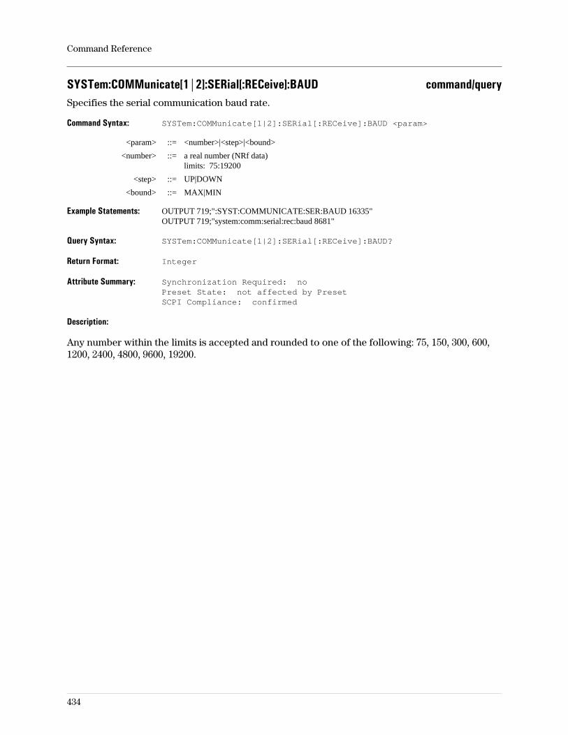
SYSTem:COMMunicate[1|2]:SERial[:RECeive]:BAUD command/querySpecifies the serial communication baud rate.
Command Syntax: SYSTem:COMMunicate[1|2]:SERial[:RECeive]:BAUD <param>
<param> ::= <number>|<step>|<bound>
<number> ::= a real number (NRf data)limits: 75:19200
<step> ::= UP|DOWN
<bound> ::= MAX|MIN
Example Statements: OUTPUT 719;":SYST:COMMUNICATE:SER:BAUD 16335"OUTPUT 719;"system:comm:serial:rec:baud 8681"
Query Syntax: SYSTem:COMMunicate[1|2]:SERial[:RECeive]:BAUD?
Return Format: Integer
Attribute Summary: Synchronization Required: noPreset State: not affected by PresetSCPI Compliance: confirmed
Description:
Any number within the limits is accepted and rounded to one of the following: 75, 150, 300, 600,1200, 2400, 4800, 9600, 19200.
Command Reference
434
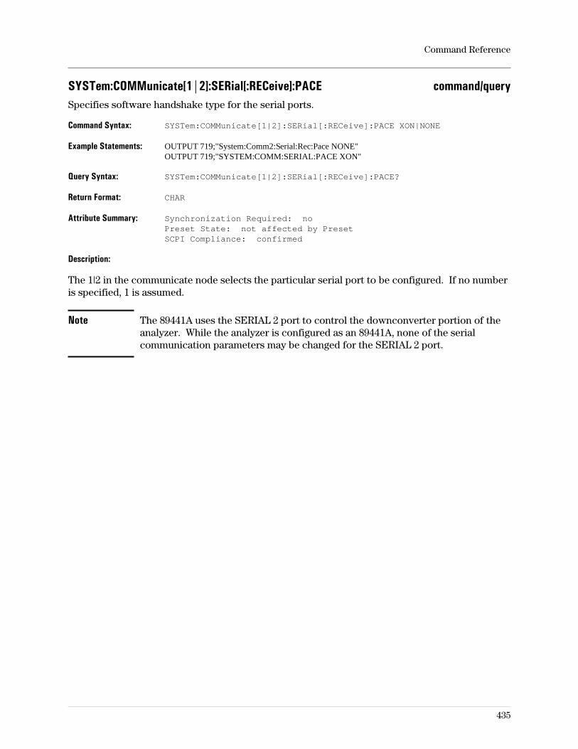
SYSTem:COMMunicate[1|2]:SERial[:RECeive]:PACE command/querySpecifies software handshake type for the serial ports.
Command Syntax: SYSTem:COMMunicate[1|2]:SERial[:RECeive]:PACE XON|NONE
Example Statements: OUTPUT 719;"System:Comm2:Serial:Rec:Pace NONE"OUTPUT 719;"SYSTEM:COMM:SERIAL:PACE XON"
Query Syntax: SYSTem:COMMunicate[1|2]:SERial[:RECeive]:PACE?
Return Format: CHAR
Attribute Summary: Synchronization Required: noPreset State: not affected by PresetSCPI Compliance: confirmed
Description:
The 1|2 in the communicate node selects the particular serial port to be configured. If no numberis specified, 1 is assumed.
Note The 89441A uses the SERIAL 2 port to control the downconverter portion of theanalyzer. While the analyzer is configured as an 89441A, none of the serialcommunication parameters may be changed for the SERIAL 2 port.
Command Reference
435
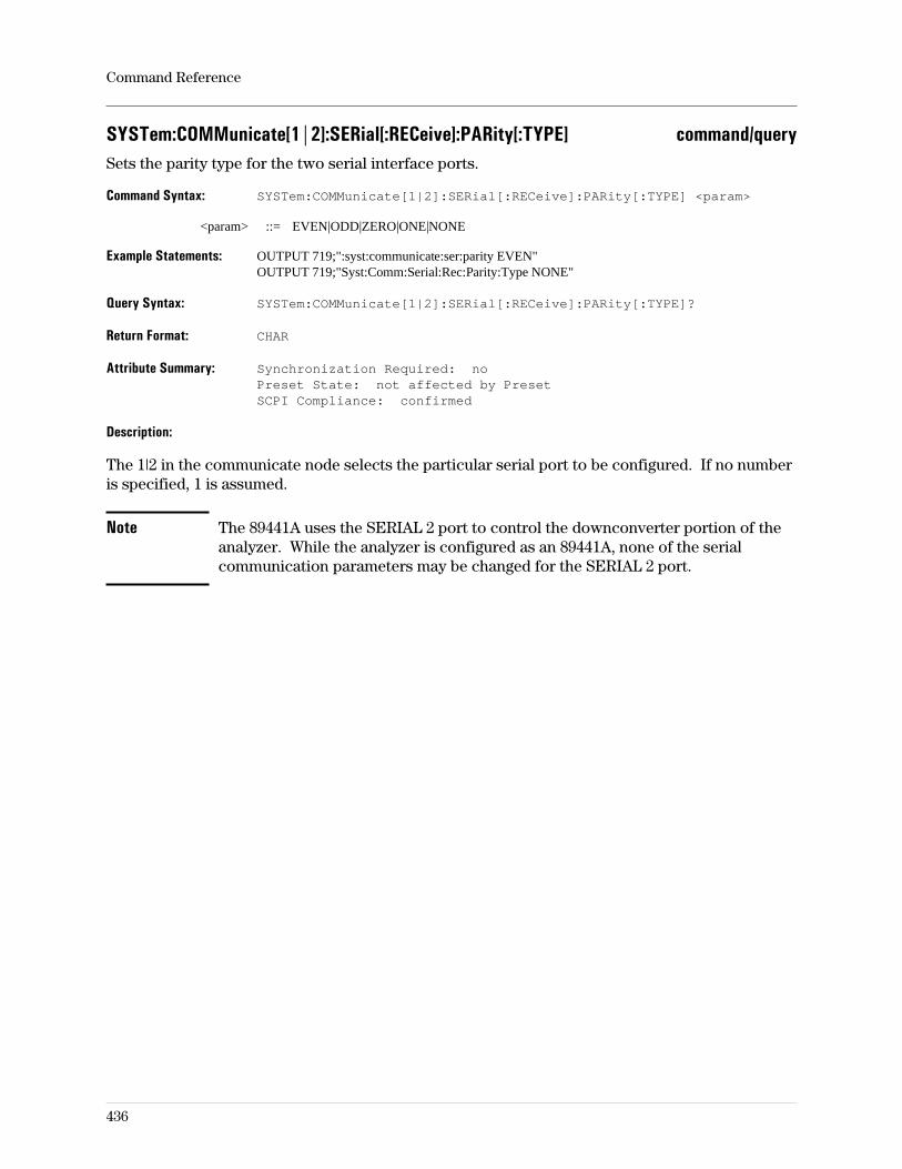
SYSTem:COMMunicate[1|2]:SERial[:RECeive]:PARity[:TYPE] command/querySets the parity type for the two serial interface ports.
Command Syntax: SYSTem:COMMunicate[1|2]:SERial[:RECeive]:PARity[:TYPE] <param>
<param> ::= EVEN|ODD|ZERO|ONE|NONE
Example Statements: OUTPUT 719;":syst:communicate:ser:parity EVEN"OUTPUT 719;"Syst:Comm:Serial:Rec:Parity:Type NONE"
Query Syntax: SYSTem:COMMunicate[1|2]:SERial[:RECeive]:PARity[:TYPE]?
Return Format: CHAR
Attribute Summary: Synchronization Required: noPreset State: not affected by PresetSCPI Compliance: confirmed
Description:
The 1|2 in the communicate node selects the particular serial port to be configured. If no numberis specified, 1 is assumed.
Note The 89441A uses the SERIAL 2 port to control the downconverter portion of theanalyzer. While the analyzer is configured as an 89441A, none of the serialcommunication parameters may be changed for the SERIAL 2 port.
Command Reference
436
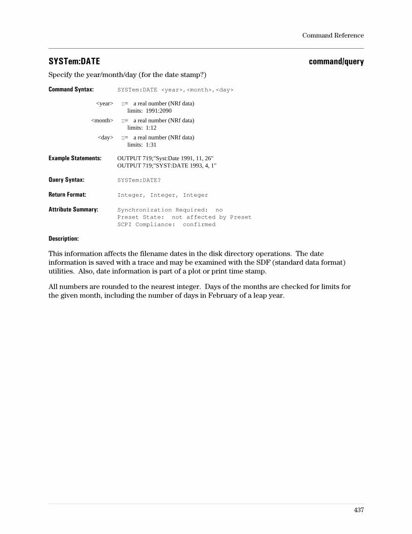
SYSTem:DATE command/querySpecify the year/month/day (for the date stamp?)
Command Syntax: SYSTem:DATE <year>,<month>,<day>
<year> ::= a real number (NRf data)limits: 1991:2090
<month> ::= a real number (NRf data)limits: 1:12
<day> ::= a real number (NRf data)limits: 1:31
Example Statements: OUTPUT 719;"Syst:Date 1991, 11, 26"OUTPUT 719;"SYST:DATE 1993, 4, 1"
Query Syntax: SYSTem:DATE?
Return Format: Integer, Integer, Integer
Attribute Summary: Synchronization Required: noPreset State: not affected by PresetSCPI Compliance: confirmed
Description:
This information affects the filename dates in the disk directory operations. The dateinformation is saved with a trace and may be examined with the SDF (standard data format)utilities. Also, date information is part of a plot or print time stamp.
All numbers are rounded to the nearest integer. Days of the months are checked for limits forthe given month, including the number of days in February of a leap year.
Command Reference
437
SYSTem:ERRor? queryReturns one error message from the analyzer’s error queue.
Query Syntax: SYSTem:ERRor?
Example Statements: OUTPUT 719;"SYST:ERROR?"OUTPUT 719;"syst:error?"
Return Format: Integer, STRING
Attribute Summary: Synchronization Required: noPreset State: not affected by PresetSCPI Compliance: confirmed
Description:
The error queue temporarily stores up to 20 error messages. When you send the SYST:ERRquery, one message is moved from the error queue to the output queue so your controller canread the message. The error queue delivers messages to the output queue in the order received.
If more than 20 error messages are reported before any are read from the queue, the oldest (first)error messages are saved. The last error message indicates more error messages were receivedthan the queue could hold. If there are no errors in the queue, the query returns +0,"No error".For more information about error messages, see “Error Messages” in the appendix.
Note The error queue is cleared when the analyzer is turned on and when it receivesthe *CLS command.
Command Reference
438
SYSTem:GPIB:ECHO command/queryTurns the echo (display) of GPIB command mnemonics on/off.
Command Syntax: SYSTem:GPIB:ECHO OFF|0|ON|1
Example Statements: OUTPUT 719;":Syst:Gpib:Echo OFF"OUTPUT 719;"SYST:GPIB:ECHO OFF"
Query Syntax: SYSTem:GPIB:ECHO?
Return Format: Integer
Attribute Summary: Synchronization Required: noPreset State: 0 (OFF)SCPI Compliance: instrument-specific
Description:
Commands are displayed in the upper left-hand corner of the analyzer’s display screen.
Command Reference
439
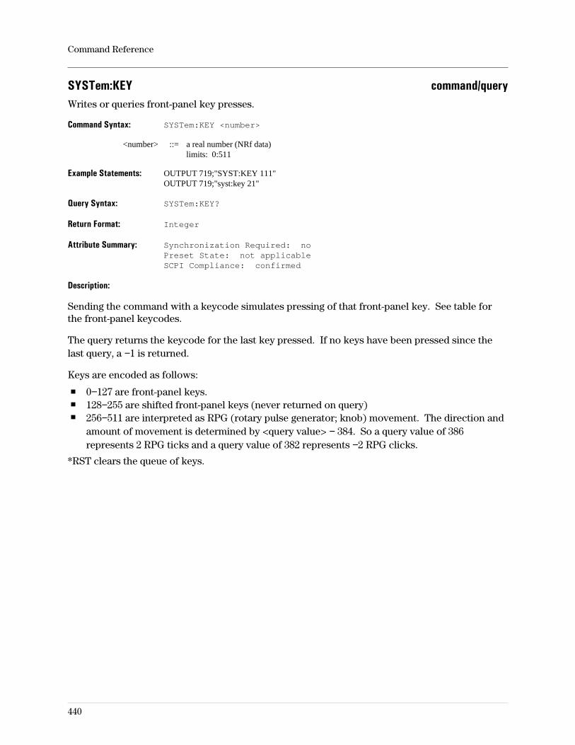
SYSTem:KEY command/queryWrites or queries front-panel key presses.
Command Syntax: SYSTem:KEY <number>
<number> ::= a real number (NRf data)limits: 0:511
Example Statements: OUTPUT 719;"SYST:KEY 111"OUTPUT 719;"syst:key 21"
Query Syntax: SYSTem:KEY?
Return Format: Integer
Attribute Summary: Synchronization Required: noPreset State: not applicableSCPI Compliance: confirmed
Description:
Sending the command with a keycode simulates pressing of that front-panel key. See table forthe front-panel keycodes.
The query returns the keycode for the last key pressed. If no keys have been pressed since thelast query, a −1 is returned.
Keys are encoded as follows:
0−127 are front-panel keys.128−255 are shifted front-panel keys (never returned on query)256−511 are interpreted as RPG (rotary pulse generator; knob) movement. The direction andamount of movement is determined by <query value> − 384. So a query value of 386represents 2 RPG ticks and a query value of 382 represents −2 RPG clicks.
*RST clears the queue of keys.
Command Reference
440
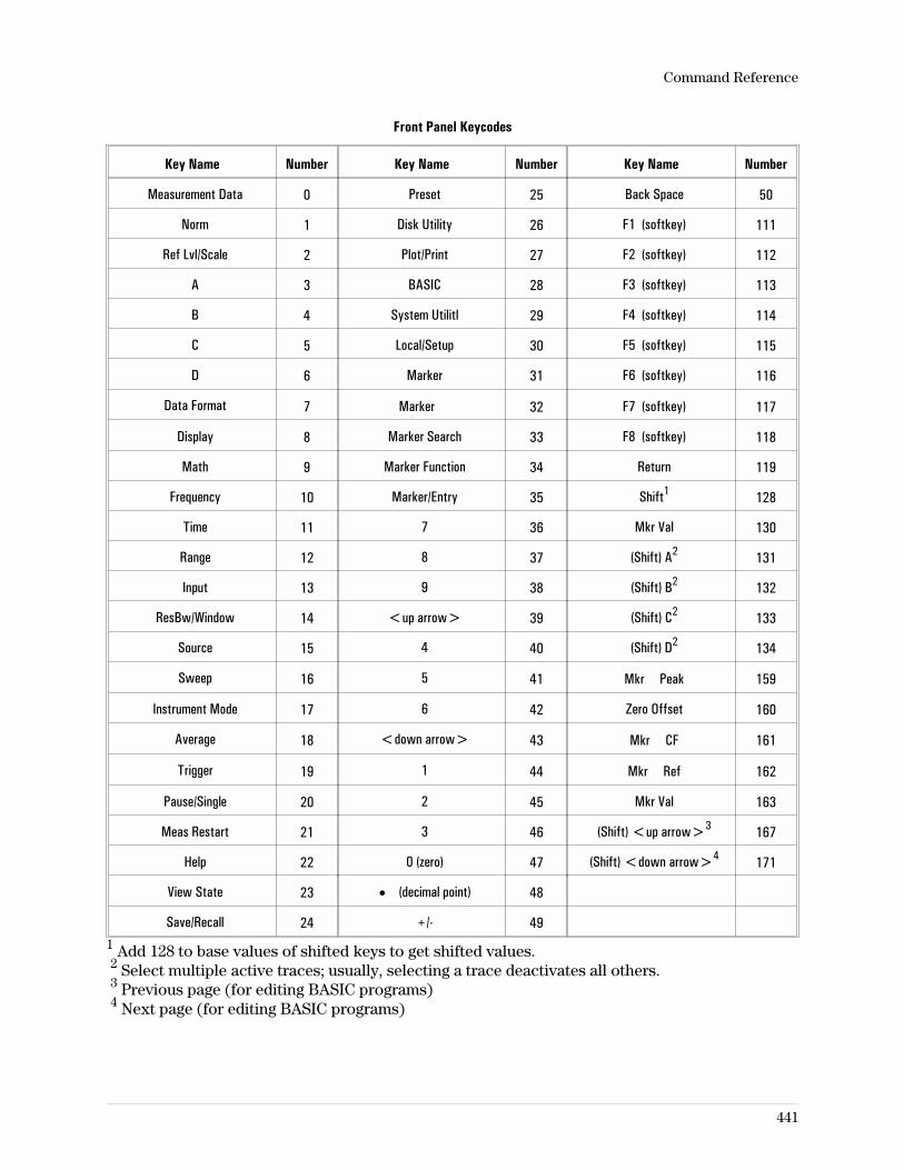
Front Panel Keycodes
Key Name Number Key Name Number Key Name Number
Measurement Data 0 Preset 25 Back Space 50
Norm 1 Disk Utility 26 F1 (softkey) 111
Ref Lvl/Scale 2 Plot/Print 27 F2 (softkey) 112
A 3 BASIC 28 F3 (softkey) 113
B 4 System Utilitl 29 F4 (softkey) 114
C 5 Local/Setup 30 F5 (softkey) 115
D 6 Marker 31 F6 (softkey) 116
Data Format 7 Marker 32 F7 (softkey) 117
Display 8 Marker Search 33 F8 (softkey) 118
Math 9 Marker Function 34 Return 119
Frequency 10 Marker/Entry 35 Shift1 128
Time 11 7 36 Mkr Val 130
Range 12 8 37 (Shift) A2 131
Input 13 9 38 (Shift) B2 132
ResBw/Window 14 <up arrow> 39 (Shift) C2 133
Source 15 4 40 (Shift) D2 134
Sweep 16 5 41 Mkr Peak 159
Instrument Mode 17 6 42 Zero Offset 160
Average 18 <down arrow> 43 Mkr CF 161
Trigger 19 1 44 Mkr Ref 162
Pause/Single 20 2 45 Mkr Val 163
Meas Restart 21 3 46 (Shift) <up arrow>3 167
Help 22 0 (zero) 47 (Shift) <down arrow>4 171
View State 23 • (decimal point) 48
Save/Recall 24 +/- 491 Add 128 to base values of shifted keys to get shifted values.2 Select multiple active traces; usually, selecting a trace deactivates all others.3 Previous page (for editing BASIC programs)4 Next page (for editing BASIC programs)
Command Reference
441
SYSTem:KLOCk command/queryKeyboard lockout; disables the keyboard.
Command Syntax: SYSTem:KLOCk OFF|0|ON|1
Example Statements: OUTPUT 719;"syst:klock OFF"OUTPUT 719;"Syst:Klock OFF"
Query Syntax: SYSTem:KLOCk?
Return Format: Integer
Attribute Summary: Synchronization Required: noPreset State: +0SCPI Compliance: confirmed
Description:
This command allows your controller to disable the keyboard. This affects the front-panel keysas well as the DIN/QWERTY remote keyboard and provides local lockout capability during therunning of Instrument BASIC programs.
The query returns 1 if the keyboard is disabled.
Note At *RST, the value is +0 (OFF).
Command Reference
442
SYSTem:PRESet commandSets most of the analyzer parameters to their default (power-on) state.
Command Syntax: SYSTem:PRESet
Example Statements: OUTPUT 719;":SYST:PRES"OUTPUT 719;"system:pres"
Attribute Summary: Synchronization Required: noPreset State: not applicableSCPI Compliance: instrument-specific
Description:
The default value for each parameter is listed in the Attribute Summary section of the commanddescription page in the command reference.
This command is similiar to *RST. For differences, see *RST.
If a file named AUTO_ST containing an instrument state exists on any drive, that state is loadedand becomes active at power-on.
The following are not affected by the SYST:PRES command (or *RST):
The state of the Power-on Status Clear flag.The state of all enabled and transition registers.The GPIB input and output queues.The time and date (SYST:TIME and SYST:DATE).The GPIB address settings.– SYST:COMM:GPIB:ADDR– HCOP:PLOT:ADDR– HCOP:PRIN:ADDRThe memory configuration.The GPIB controller capability setting.The default disk selection (MMEM:MSIS).External disk address.External receiver address.Contents of data registers.Contents of math function and constant registers.Contents of the RAM and NVRAM disks.Calibration constants.LAN configuration.
Command Reference
443
SYSTem:TIME command/querySpecifies the system time.
Command Syntax: SYSTem:TIME <hour>,<minute>,<second>
<hour> ::= a real number (NRf data)limits: 1:23
<minute> ::= a real number (NRf data)limits: 0:59
<second> ::= a real number (NRF data)limits: 0:59
Example Statements: OUTPUT 719;"SYSTEM:TIME 15,55,0"OUTPUT 719;"syst:time 8,30,20"
Query Syntax: SYSTem:TIME?
Return Format: Integer, Integer, Integer
Attribute Summary: Synchronization Required: noPreset State: not affected by PresetSCPI Compliance: confirmed
Description:
This information affects the filename times in the disk directory operations. The timeinformation is saved with a trace and may be examined with the SDF (standard data format)utilities. Also, time information is part of a plot or print time stamp.
All numbers are rounded to the nearest integer, except for <second>, which is rounded to theresolution of the system clock.
Hours are specified and queried in the 24-hour format.
Command Reference
444
TRACe:BUFFer:COPY commandCopies the specified waterfall/spectrogram trace buffer into a data register.
Command Syntax: TRACE:BUFFer:COPY <label1>, <label2>
<label1> ::= D1|D2|D3|D4|D5|D6
<label2> ::= TRACe1|TRACe2|TRACe3|TRACe4|CAL1|CAL2
Example Statements: OUTPUT 719;"trac:buff:copy D1, trac4"OUTPUT 719;"Trac:Buff:Copy D2, TRACe1"OUTPUT 719;"Trac:Buff:Copy D4, CAL1"
Attribute Summary: Option: AYB (waterfall/spectrogram display)Synchronization Required: noPreset State: not applicableSCPI Compliance: instrument-specific
Description:
CAL1|CAL2 represent trace information consisting of calibration data for input channels 1 and2, respectively.
Related Commands:
To display the contents of a data register as a trace, use CALC:FEED.To store the contents of a data register to disk, use TRACE[:DATA]?.To move waterfall/spectrogram data between the trace buffers and mass storage units (suchas disks), use MMEM:STOR:TRAC:BUFF and MMEMLOAD:TRAC:BUFF.To query the number of points in the data register, use TRAC[:DATA]:HEADer:POINTs?.
Command Reference
445
TRACe:COPY commandCopies the specified trace into a data register.
Command Syntax: TRACE:COPY <label1>, <label2>
<label1> ::= D1|D2|D3|D4|D5|D6
<label2> ::= TRACe1|TRACe2|TRACe3|TRACe4|CAL1|CAL2
Example Statements: OUTPUT 719;"trac:copy D1, trac4"OUTPUT 719;"Trac:Copy D2, TRACe1"OUTPUT 719;"Trac:Copy D4, CAL1"
Attribute Summary: Synchronization Required: noPreset State: not applicableSCPI Compliance: confirmed
Description:
CAL1|CAL2 represent trace information consisting of calibration data for input channels 1 and2, respectively.
Related Commands:
To display the contents of a data register as a trace, use CALC:FEED.To store the contents of a data register to disk, use TRACE[:DATA]?.To move trace data between the trace registers and mass storage units (as disk files), useMMEM:STOR:TRAC and MMEM:LOAD:TRAC.To query the number of points in the data register, use TRAC[:DATA]:HEADer:POINts?.
Trace data may be transferred directly to the controller with the LAN file-transfer utility, FTP(option UG7).
Command Reference
446
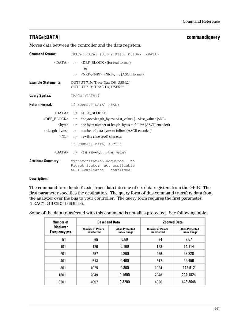
TRACe[:DATA] command/queryMoves data between the controller and the data registers.
Command Syntax: TRACe[:DATA] D1|D2|D3|D4|D5|D6, <DATA>
<DATA> ::= <DEF_BLOCK> (for real format)
or
::= <NRf>,<NRf>,<NRf>, . . . (ASCII format)
Example Statements: OUTPUT 719;"Trace:Data D6, USER2"OUTPUT 719;"TRAC D4, USER2"
Query Syntax: TRACe[:DATA]?
Return Format: If FORMat[:DATA] REAL:
<DATA> ::= <DEF_BLOCK>
<DEF_BLOCK> ::= #<byte><length_bytes><1st_value>[...<last_value>]<NL>
<byte> ::= one byte; number of length_bytes to follow (ASCII encoded)
<length_bytes> ::= number of data bytes to follow (ASCII encoded)
<NL> ::= newline (line feed) character
If FORMat[:DATA] ASCii:
<DATA> ::= <1st_value>,[. . . ,<last_value>]
Attribute Summary: Synchronization Required: noPreset State: not applicableSCPI Compliance: confirmed
Description:
The command form loads Y-axis, trace data into one of six data registers from the GPIB. Thefirst parameter specifies the destination. The query form of this command transfers data fromthe analyzer over the bus to your controller. The query form requires the first parameter:TRAC? D1|D2|D3|D4|D5|D6.
Some of the data transferred with this command is not alias-protected. See following table.
Number ofDisplayed
Frequency pts.
Baseband Data Zoomed Data
Number of PointsTransferred
Alias-ProtectedIndex Range
Number of PointsTransferred
Alias-ProtectedIndex Range
51 65 0:50 64 7:57
101 129 0:100 128 14:114
201 257 0:200 256 28:228
401 513 0:400 512 56:456
801 1025 0:800 1024 112:912
1601 2049 0:1600 2048 224:1824
3201 4097 0:3200 4096 448:3648
Command Reference
447
Related Commands:
To store a trace to a file, use MMEM:STOR:TRAC.To copy trace data between data registers or between a data register and a trace register, useTRACE:COPY.To get X-axis trace data, use TRAC:X[:DATA]?.To get coordinate-transformed data from a trace, use CALC:DATA?.To specify whether the data transformed is in ASCII or REAL, use FORM[:DATA].
Notes Sending block data to a data register is valid only if the data register containsdata. That is, you can only replace existing data in the data register. You cannot
transfer block data to an empty data register. For more information abouttransferring block data, see the GPIB Programmer’s Guide, ‘’Block Parameters.’’
It is not possible to query Y-axis units – they depend on what measurement wassaved in the data register. In general, they are Vpk for spectrums and time traces,Vpk
2/Hz for PSD, and Vpk2 for correlation.
Trace data may be transferred directly to the controller with the LANfile-transfer utility, FTP (option UG7). Data transferred with FTP is in StandardData Format (SDF).
Command Reference
448
TRACe[:DATA]:HEADer:POINts? queryReturns the number of points for the specified data register.
Query Syntax: TRACe[:DATA]:HEADer:POINts? D1|D2|D3|D4|D5|D6
Example Statements: OUTPUT 719;":trace:head:points? D5"OUTPUT 719;"Trac:Data:Header:Poin? D6"
Return Format: Integer
Attribute Summary: Synchronization Required: noPreset State: not applicableSCPI Compliance: instrument-specific
Description:
This query is used to determine the number of data points in the specified data register. Thisinformation may be required to transfer the contents of the register from the analyzer to thecontroller.
The data points may be complex or real. If it is complex, then TRAC:DATA? outputs 2 numbersper point, corresponding to the real and imaginary parts of the data point.
Related Commands:
To transfer trace data to a data register, use TRACe:COPY.To transfer the contents of the data register to or from the controller, use TRACe[:DATA].To copy a trace directly to disk, use MMEM:STOR:TRAC.
Command Reference
449
TRACe:X[:DATA]? queryReturns the X-axis data for trace displays.
Query Syntax: TRACe:X[:DATA]? D1|D2|D3|D4|D5|D6|TRACe1|TRACe2|TRACe3|TRACe4
Example Statements: OUTPUT 719;"TRACE:X:DATA? D2"OUTPUT 719;"trace:x? D6"
Return Format: If FORMat[:DATA] REAL:
<DATA> ::= <DEF_BLOCK>
<DEF_BLOCK> ::= #<byte><length_bytes><1st_value>[. . .<last_value>]<NL>
<byte> ::= one byte specifying the number of length_bytesto follow (ASCII encoded)
<length_bytes> ::= number of data bytes to follow (ASCII encoded)
<NL> ::= newline (linefeed) character
If FORMat[:DATA] ASCii:
<DATA> ::= <1st_value>,[. . . ,<last_value>]
Attribute Summary: Synchronization Required: noPreset State: not applicableSCPI Compliance: instrument-specific
Description:
This query returns the values along the X-axis for any display. The values identify each bin in thetrace. This is the companion command for TRACE:DATA? which returns (alias-protected) datafrom the data registers.
Related Commands:
To determine the units for the X-axis send TRAC:X:UNIT?.
Command Reference
450
TRACe:X:UNIT? queryReturns the x-axis units for trace displays.
Query Syntax: TRACe:X:UNIT? D1|D2|D3|D4|D5|D6|TRACe1|TRACe2|TRACe3|TRACe4
Example Statements: OUTPUT 719;":Trace:X:Unit? D1"OUTPUT 719;"TRACE:X:UNIT? D3"
Return Format: STRING
Attribute Summary: Synchronization Required: noPreset State: not applicableSCPI Compliance: instrument-specific
Description:
The unit for the X-axis is dependent upon the type of measurement data selected.
Related Commands:
To query the values along the X axis, use TRAC:X[:DATA]?.To query the Y-axis trace data, use TRAC[:DATA]?.
Command Reference
451
TRIGger:HOLDoff:DELay command/querySpecifies the delay after IF trig occurs before next trigger accepted.
Command Syntax: TRIGger:HOLDoff:DELay <number>[<unit>]|<step>|<bound>
<number> ::= a real number (NRf data)limits: 0:41.94
<unit> ::= [S]
<step> ::= UP|DOWN
<bound> ::= MAX|MIN
Example Statements: OUTPUT 719;"trig:hold:delay 6.61666"OUTPUT 719;"Trig:Holdoff:Del 22.9661"
Query Syntax: TRIGger:HOLDoff:DELay?
Return Format: Real
Attribute Summary: Synchronization Required: noPreset State: 0 sSCPI Compliance: instrument-specific
Description:
For more information on this feature, see online help (press the [ Help ] key on the front panel,then press the softkey of interest).
Related Commands:
To activate trigger holdoff, use TRIG:HOLD:STAT.To specify the IF trigger type, use TRIG:SOUR.
Command Reference
452
TRIGger:HOLDoff:STATe command/querySpecifies the state (on/off) of the trigger holdoff.
Command Syntax: TRIGger:HOLDoff:STATe OFF|0|ON|1
Example Statements: OUTPUT 719;":TRIG:HOLDOFF:STAT OFF"OUTPUT 719;"trigger:hold:stat OFF"
Query Syntax: TRIGger:HOLDoff:STATe?
Return Format: Integer
Attribute Summary: Synchronization Required: noPreset State: 0 (OFF)SCPI Compliance: instrument-specific
Description:
For more information on this feature, see online help (press the [ Help ] key on the front panel,then press the softkey of interest).
Related Commands:
To specify the amount of trigger holdoff delay, use TRIG:HOLD:DEL.To specify the IF trigger type, use TRIG:SOUR.
Command Reference
453
TRIGger:LEVel command/querySpecifies the signal level at which a measurement is triggered.
Command Syntax: TRIGger:LEVel <param>
<param> ::= <number>[<unit>]|<step>|<bound>
<number> ::= a real number (NRf data)limits: (range depends on configuration)
<unit> ::= PCT|V (and dB for IF trigger)
<step> ::= UP|DOWN
<bound> ::= MAX|MIN
Example Statements: OUTPUT 719;"TRIG:LEV 5V"OUTPUT 719;"trig:level -2"
Query Syntax: TRIGger:LEVel?
Return Format: Real
Attribute Summary: Synchronization Required: noPreset State: 0%SCPI Compliance: confirmed
Description:
If the trigger typs is internal channel (TRIG:SOUR INT1), the trigger level is entered as a percentof the input range (VOLT:RANG).
If the trigger type is external trigger (TRIG:SOUR EXT), the trigger signal is connected to thefront panel connector labeled EXT TRIGGER and trigger level is entered in units of volts or %.The level is an analog voltage between −11V and +11V or −110% to +110%.
If the trigger type is IF, the trigger level may be entered in units of volts, %, or dB.
Trigger level is not applicable for GPIB trigger (TRIG:SOUR BUS), source trigger (TRIG:SOUROUTP), or free run (TRIG:SOUR IMM).
Trigger level can be entered over GPIB in percentage or as a fraction. A query always returns thefractional value. If the trigger type is external, the trigger level is entered in Volts and thereturned value is in volts. IF trigger also returns volts.
See TRIG:SOUR for more information.
Command Reference
454
TRIGger:SLOPe command/querySpecifies whether a trigger occurs when the selected trigger source signal ispositive-with-respect-to or negative-with-respect-to the specified trigger level.
Command Syntax: TRIGger:SLOPe POSitive|NEGative
Example Statements: OUTPUT 719;"Trigger:Slop POSITIVE"OUTPUT 719;"TRIGGER:SLOP POSITIVE"
Query Syntax: TRIGger:SLOPe?
Return Format: CHAR
Attribute Summary: Synchronization Required: noPreset State: POSSCPI Compliance: confirmed
Description:
Slope does not apply to free run, source, or GPIB trigger types. These trigger types operateindependently of the slope setting. Trigger delay may also be specified with the SWE:TIM:DELcommand.
Trigger type is specified with the TRIG:SOUR command.Trigger level is specified with the TRIG:LEV command.
The analyzer must be armed before triggering can start a measurement. See ARM:SOUR for moreinformation.
Command Reference
455
TRIGger:SOURce command/querySpecifies the source (or type) of triggering used to start measurements.
Command Syntax: TRIGger:SOURce <param>
<param> ::= IMMediate|INT1|INT2|IF1|IF2|OUTPut|BUS|EXTernal
Example Statements: OUTPUT 719;"trigger:source INT1"OUTPUT 719;"Trig:Source OUTP"
Query Syntax: TRIGger:SOURce?
Return Format: CHAR
Attribute Summary: Synchronization Required: noPreset State: IMMSCPI Compliance: confirmed
Description:
The analyzer must be armed before triggering can occur. See ARM:SOUR.
IMM (immediate or free run) specifies that successive data blocks are to be taken as quickly aspossible without waiting for a trigger signal.
INT1|INT2 specifies that the input data blocks should be acquired when the channel (1|2)sampled input data stream matches the trigger conditions (slope and level are set withTRIG:SLOP and TRIG:LEV). Note that the second channel is an option and may not be installedin the analyzer.
IF1|IF2 specifies the IF signal from either input channel 1 or 2 as the trigger signal. This meansthe analyzer begins a measurement when the IF signal meets the specified trigger slope and levelconditions. IF trigger is a narrow-band trigger compared to the INT trigger. Some signal typesmay require the use of trigger holdoff; see TRIG:HOLD. Note that the second channel is anoption and may not be installed in the analyzer.
OUTP specifies that the input data blocks should be acquired synchronously with the source.
BUS specifies that the input data blocks should be acquired when the GPIB Group ExecuteTrigger command is received.
EXT specifies that the input data blocks are acquired when the front panel EXT TRIGGER signalmeets the level and slope criteria set with the TRIG:LEV and TRIG:SLOP commands. The level isan analog voltage between −11.0V and +11.0V. Slope, in this case, indicates which side of thelevel value the external signal must be to trigger a measurement (POS means ‘’more positive’’ andNEG means ‘’more negative’’).
Note Channel 2 is optional and may not be installed. If the second channel is notinstalled, IF2 and INT2 generate error messages. If no number is used, “1" isassumed.
Command Reference
456
A
Error Messages
457
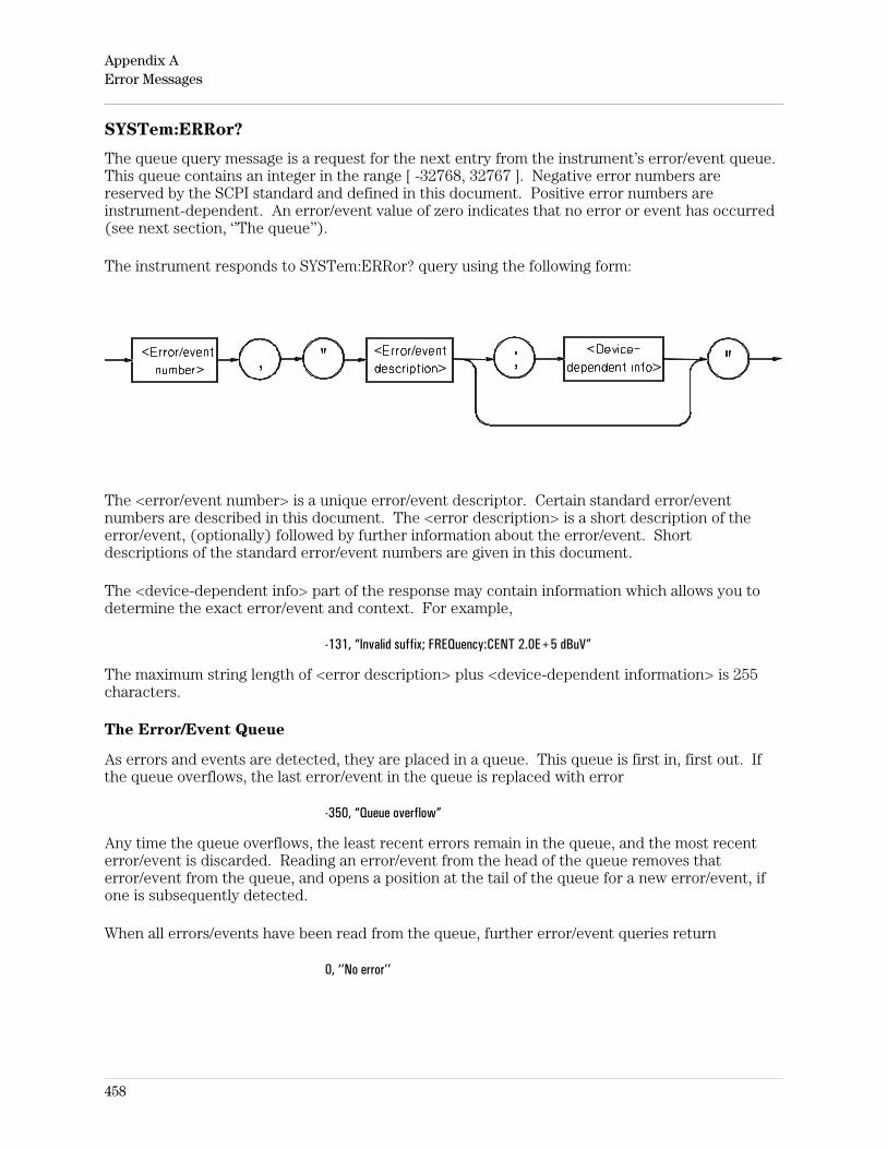
SYSTem:ERRor?
The queue query message is a request for the next entry from the instrument’s error/event queue.This queue contains an integer in the range [ -32768, 32767 ]. Negative error numbers arereserved by the SCPI standard and defined in this document. Positive error numbers areinstrument-dependent. An error/event value of zero indicates that no error or event has occurred(see next section, ‘’The queue’’).
The instrument responds to SYSTem:ERRor? query using the following form:
The <error/event number> is a unique error/event descriptor. Certain standard error/eventnumbers are described in this document. The <error description> is a short description of theerror/event, (optionally) followed by further information about the error/event. Shortdescriptions of the standard error/event numbers are given in this document.
The <device-dependent info> part of the response may contain information which allows you todetermine the exact error/event and context. For example,
-131, “Invalid suffix; FREQuency:CENT 2.0E+5 dBuV”
The maximum string length of <error description> plus <device-dependent information> is 255characters.
The Error/Event Queue
As errors and events are detected, they are placed in a queue. This queue is first in, first out. Ifthe queue overflows, the last error/event in the queue is replaced with error
-350, “Queue overflow”
Any time the queue overflows, the least recent errors remain in the queue, and the most recenterror/event is discarded. Reading an error/event from the head of the queue removes thaterror/event from the queue, and opens a position at the tail of the queue for a new error/event, ifone is subsequently detected.
When all errors/events have been read from the queue, further error/event queries return
0, ‘’No error’’
Appendix AError Messages
458
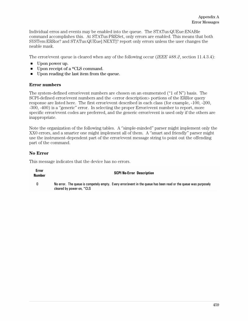
Individual erros and events may be enabled into the queue. The STATus:QUEue:ENABlecommand accomplishes this. At STATus:PRESet, only errors are enabled. This means that bothSYSTem:ERRor? and STATus:QUEue[:NEXT]? report only errors unless the user changes theneable mask.
The error/event queue is cleared when any of the following occur (IEEE 488.2, section 11.4.3.4):
Upon power up.Upon receipt of a *CLS command.Upon reading the last item from the queue.
Error numbers
The system-defined error/event numbers are chosen on an enumerated (“1 of N”) basis. TheSCPI-defined error/event numbers and the <error description> portions of the ERRor queryresponse are listed here. The first error/event described in each class (for example, -100, -200,-300, -400) is a ‘’generic’’ error. In selecting the proper Error/event number to report, morespecific error/event codes are preferred, and the generic error/event is used only if the others areinappropriate.
Note the organization of the following tables. A ‘’simple-minded’’ parser might implement only theXX0 errors, and a smarter one might implement all of them. A ‘’smart and friendly’’ parser mightuse the instrument-dependent part of the error/event message string to point out the offendingpart of the command.
No Error
This message indicates that the device has no errors.
ErrorNumber
SCPI No-Error Description
0 No error. The queue is competely empty. Every error/event in the queue has been read or the queue was purposelycleared by power-on, *CLS
Appendix AError Messages
459
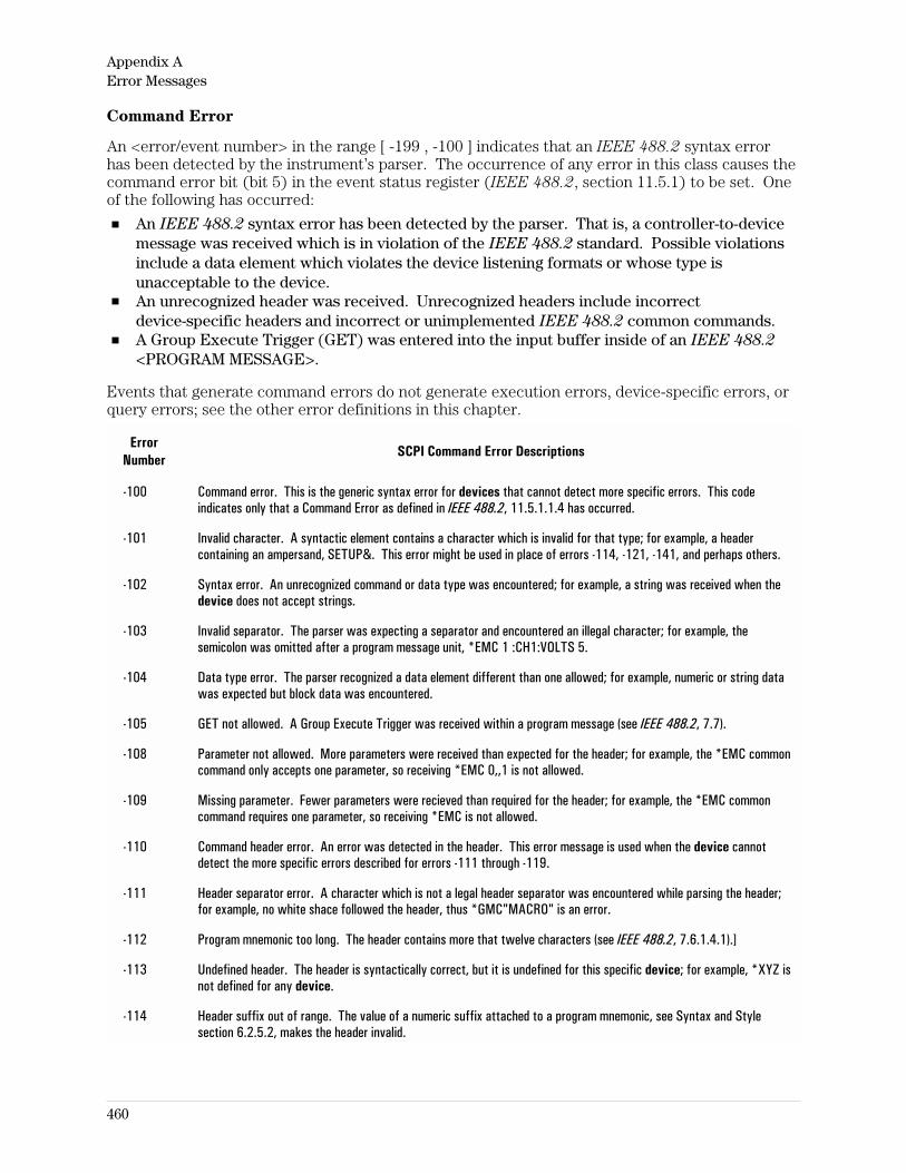
Command Error
An <error/event number> in the range [ -199 , -100 ] indicates that an IEEE 488.2 syntax errorhas been detected by the instrument’s parser. The occurrence of any error in this class causes thecommand error bit (bit 5) in the event status register (IEEE 488.2, section 11.5.1) to be set. Oneof the following has occurred:
An IEEE 488.2 syntax error has been detected by the parser. That is, a controller-to-devicemessage was received which is in violation of the IEEE 488.2 standard. Possible violationsinclude a data element which violates the device listening formats or whose type isunacceptable to the device.An unrecognized header was received. Unrecognized headers include incorrectdevice-specific headers and incorrect or unimplemented IEEE 488.2 common commands.A Group Execute Trigger (GET) was entered into the input buffer inside of an IEEE 488.2
<PROGRAM MESSAGE>.
Events that generate command errors do not generate execution errors, device-specific errors, orquery errors; see the other error definitions in this chapter.
ErrorNumber
SCPI Command Error Descriptions
-100 Command error. This is the generic syntax error for devices that cannot detect more specific errors. This codeindicates only that a Command Error as defined in IEEE 488.2, 11.5.1.1.4 has occurred.
-101 Invalid character. A syntactic element contains a character which is invalid for that type; for example, a headercontaining an ampersand, SETUP&. This error might be used in place of errors -114, -121, -141, and perhaps others.
-102 Syntax error. An unrecognized command or data type was encountered; for example, a string was received when thedevice does not accept strings.
-103 Invalid separator. The parser was expecting a separator and encountered an illegal character; for example, thesemicolon was omitted after a program message unit, *EMC 1 :CH1:VOLTS 5.
-104 Data type error. The parser recognized a data element different than one allowed; for example, numeric or string datawas expected but block data was encountered.
-105 GET not allowed. A Group Execute Trigger was received within a program message (see IEEE 488.2, 7.7).
-108 Parameter not allowed. More parameters were received than expected for the header; for example, the *EMC commoncommand only accepts one parameter, so receiving *EMC 0,,1 is not allowed.
-109 Missing parameter. Fewer parameters were recieved than required for the header; for example, the *EMC commoncommand requires one parameter, so receiving *EMC is not allowed.
-110 Command header error. An error was detected in the header. This error message is used when the device cannotdetect the more specific errors described for errors -111 through -119.
-111 Header separator error. A character which is not a legal header separator was encountered while parsing the header;for example, no white shace followed the header, thus *GMC"MACRO" is an error.
-112 Program mnemonic too long. The header contains more that twelve characters (see IEEE 488.2, 7.6.1.4.1).]
-113 Undefined header. The header is syntactically correct, but it is undefined for this specific device; for example, *XYZ isnot defined for any device.
-114 Header suffix out of range. The value of a numeric suffix attached to a program mnemonic, see Syntax and Stylesection 6.2.5.2, makes the header invalid.
Appendix AError Messages
460
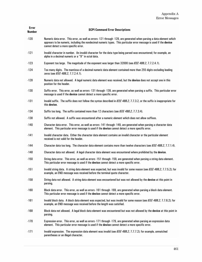
ErrorNumber
SCPI Command Error Descriptions
-120 Numeric data error. This error, as well as errors -121 through -129, are generated when parsing a data element whichapprears to be numeric, including the nondecimal numeric types. This particular error message is used if the devicecannot detect a more specific error.
-121 Invalid character in number. An invalid character for the data type being parsed was encountered; for example, analpha in a decimal numeric or a ‘’9’’ in octal data.
-123 Exponent too large. The magnitude of the exponent was larger than 32000 (see IEEE 488.2, 7.7.2.4.1).
-124 Too many digits. The mantissa of a decimal numeric data element contained more than 255 digits excluding leadingzeros (see IEEE 488.2, 7.7.2.4.1).
-128 Numeric data not allowed. A legal numeric data element was received, but the device does not accept one in thisposition for the header.
-130 Suffix error. This error, as well as errors -131 through -139, are generated when parsing a suffix. This particular errormessage is used if the device cannot detect a more specific error.
-131 Invalid suffix. The suffix does not follow the syntax described in IEEE 488.2, 7.7.3.2, or the suffix is inappropriate forthis device.
-134 Suffix too long. The suffix contained more than 12 characters (see IEEE 488.2, 7.7.3.4).
-138 Suffix not allowed. A suffix was encountered after a numeric element which does not allow suffixes.
-140 Character data error. This error, as well as errors -141 through -149, are generated when parsing a character dataelement. This particular error message is used if the device cannot detect a more specific error.
-141 Invalid character data. Either the character data element contains an invalid character or the particular elementreceived is not valid for the header.
-144 Character data too long. The character data element contains more than twelve characters (see IEEE 488.2, 7.7.1.4).
-148 Character data not allowed. A legal character data element was encountered where prohibited by the device.
-150 String data error. This error, as well as errors -151 through -159, are generated when parsing a string data element.This particular error message is used if the device cannot detect a more specific error.
-151 Invalid string data. A string data element was expected, but was invalid for some reason (see IEEE 488.2, 7.7.5.2); forexample, an END message was received before the terminal quote character.
-158 String data not allowed. A string data element was encountered but was not allowed by the device at this point inparsing.
-160 Block data error. This error, as well as errors -161 through -169, are generated when parsing a block data element.This particular error message is used if the device cannot detect a more specific error.
-161 Invalid block data. A block data element was expected, but was invalid for some reason (see IEEE 488.2, 7.7.6.2); forexample, an END message was received before the length was satisfied.
-168 Block data not allowed. A legal block data element was encountered but was not allowed by the device at this point inparsing.
-170 Expression error. This error, as well as errors -171 through -179, are generated when parsing an expression dataelement. This particular error message is used if the device cannot detect a more specific error.
-171 Invalid expression. The expression data element was invalid (see IEEE 488.2, 7.7.7.2); for example, unmatchedparentheses or an illegal character.
Appendix AError Messages
461
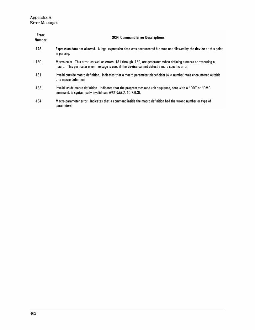
ErrorNumber
SCPI Command Error Descriptions
-178 Expression data not allowed. A legal expression data was encountered but was not allowed by the device at this pointin parsing.
-180 Macro error. This error, as well as errors -181 through -189, are generated when defining a macro or executing amacro. This particular error message is used if the device cannot detect a more specific error.
-181 Invalid outside macro definition. Indicates that a macro parameter placeholder ($<number) was encountered outsideof a macro definition.
-183 Invalid inside macro definition. Indicates that the program message unit sequence, sent with a *DDT or *DMCcommand, is syntactically invalid (see IEEE 488.2, 10.7.6.3).
-184 Macro parameter error. Indicates that a command inside the macro definition had the wrong number or type ofparameters.
Appendix AError Messages
462
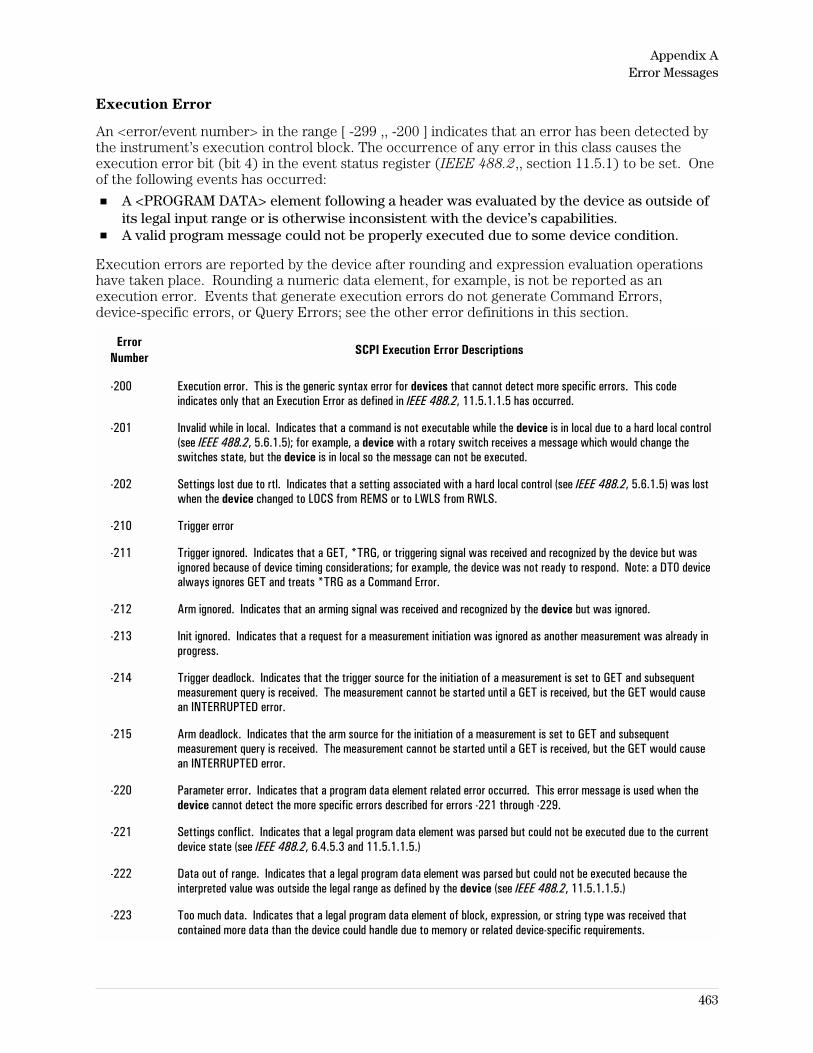
Execution Error
An <error/event number> in the range [ -299 ,, -200 ] indicates that an error has been detected bythe instrument’s execution control block. The occurrence of any error in this class causes theexecution error bit (bit 4) in the event status register (IEEE 488.2,, section 11.5.1) to be set. Oneof the following events has occurred:
A <PROGRAM DATA> element following a header was evaluated by the device as outside ofits legal input range or is otherwise inconsistent with the device’s capabilities.A valid program message could not be properly executed due to some device condition.
Execution errors are reported by the device after rounding and expression evaluation operationshave taken place. Rounding a numeric data element, for example, is not be reported as anexecution error. Events that generate execution errors do not generate Command Errors,device-specific errors, or Query Errors; see the other error definitions in this section.
ErrorNumber
SCPI Execution Error Descriptions
-200 Execution error. This is the generic syntax error for devices that cannot detect more specific errors. This codeindicates only that an Execution Error as defined in IEEE 488.2, 11.5.1.1.5 has occurred.
-201 Invalid while in local. Indicates that a command is not executable while the device is in local due to a hard local control(see IEEE 488.2, 5.6.1.5); for example, a device with a rotary switch receives a message which would change theswitches state, but the device is in local so the message can not be executed.
-202 Settings lost due to rtl. Indicates that a setting associated with a hard local control (see IEEE 488.2, 5.6.1.5) was lostwhen the device changed to LOCS from REMS or to LWLS from RWLS.
-210 Trigger error
-211 Trigger ignored. Indicates that a GET, *TRG, or triggering signal was received and recognized by the device but wasignored because of device timing considerations; for example, the device was not ready to respond. Note: a DT0 devicealways ignores GET and treats *TRG as a Command Error.
-212 Arm ignored. Indicates that an arming signal was received and recognized by the device but was ignored.
-213 Init ignored. Indicates that a request for a measurement initiation was ignored as another measurement was already inprogress.
-214 Trigger deadlock. Indicates that the trigger source for the initiation of a measurement is set to GET and subsequentmeasurement query is received. The measurement cannot be started until a GET is received, but the GET would causean INTERRUPTED error.
-215 Arm deadlock. Indicates that the arm source for the initiation of a measurement is set to GET and subsequentmeasurement query is received. The measurement cannot be started until a GET is received, but the GET would causean INTERRUPTED error.
-220 Parameter error. Indicates that a program data element related error occurred. This error message is used when thedevice cannot detect the more specific errors described for errors -221 through -229.
-221 Settings conflict. Indicates that a legal program data element was parsed but could not be executed due to the currentdevice state (see IEEE 488.2, 6.4.5.3 and 11.5.1.1.5.)
-222 Data out of range. Indicates that a legal program data element was parsed but could not be executed because theinterpreted value was outside the legal range as defined by the device (see IEEE 488.2, 11.5.1.1.5.)
-223 Too much data. Indicates that a legal program data element of block, expression, or string type was received thatcontained more data than the device could handle due to memory or related device-specific requirements.
Appendix AError Messages
463
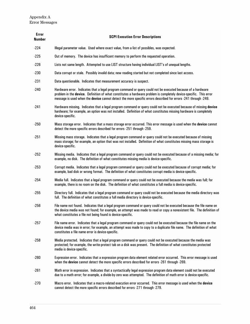
ErrorNumber
SCPI Execution Error Descriptions
-224 Illegal parameter value. Used where exact value, from a list of possibles, was expected.
-225 Out of memory. The device has insufficent memory to perform the requested operation.
-226 Lists not same length. Attempted to use LIST structure having individual LIST’s of unequal lengths.
-230 Data corrupt or stale. Possibly invalid data; new reading started but not completed since last access.
-231 Data questionable. Indicates that measurement accuracy is suspect.
-240 Hardware error. Indicates that a legal program command or query could not be executed because of a hardwareproblem in the device. Definition of what constitutes a hardware problem is completely device-specific. This errormessage is used when the device cannot detect the more specific errors described for errors -241 through -249.
-241 Hardware missing. Indicates that a legal program command or query could not be executed because of missing devicehardware; for example, an option was not installed. Definition of what constitutes missing hardware is completelydevice-specific.
-250 Mass storage error. Indicates that a mass storage error occurred. This error message is used when the device cannotdetect the more specific errors described for errors -251 through -259.
-251 Missing mass storage. Indicates that a legal program command or query could not be executed because of missingmass storage; for example, an option that was not installed. Definition of what constitutes missing mass storage isdevice-specific.
-252 Missing media. Indicates that a legal program command or query could not be executed because of a missing media; forexample, no disk. The definition of what constitutes missing media is device-specific.
-253 Corrupt media. Indicates that a legal program command or query could not be executed because of corrupt media; forexample, bad disk or wrong format. The definition of what constitutes corrupt media is device-specific.
-254 Media full. Indicates that a legal program command or query could not be executed because the media was full; forexample, there is no room on the disk. The definition of what constitutes a full media is device-specific.
-255 Directory full. Indicates that a legal program command or query could not be executed because the media directory wasfull. The definition of what constitutes a full media directory is device-specific.
-256 File name not found. Indicates that a legal program command or query could not be executed because the file name onthe device media was not found; for example, an attempt was made to read or copy a nonexistent file. The definition ofwhat constitutes a file not being found is device-specific.
-257 File name error. Indicates that a legal program command or query could not be executed because the file name on thedevice media was in error; for example, an attempt was made to copy to a duplicate file name. The definition of whatconstitutes a file name error is device-specific.
-258 Media protected. Indicates that a legal program command or query could not be executed because the media wasprotected; for example, the write-protect tab on a disk was present. The definition of what constitutes protectedmedia is device-specific.
-260 Expression error. Indicates that a expression program data element related error occurred. This error message is usedwhen the device cannot detect the more specific errors described for errors -261 through -269.
-261 Math error in expression. Indicates that a syntactically legal expression program data element could not be executeddue to a math error; for example, a divide-by-zero was attempted. The definition of math error is device-specific.
-270 Macro error. Indicates that a macro-related execution error occurred. This error message is used when the devicecannot detect the more specific errors described for errors -271 through -279.
Appendix AError Messages
464
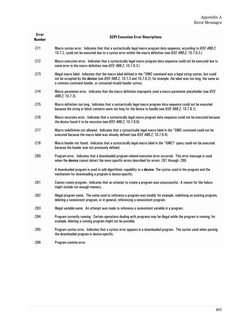
ErrorNumber
SCPI Execution Error Descriptions
-271 Macro syntax error. Indicates that that a syntactically legal macro program data sequence, according to IEEE 488.2,10.7.2, could not be executed due to a syntax error within the macro definition (see IEEE 488.2, 10.7.6.3.)
-272 Macro execution error. Indicates that a syntactically legal macro program data sequence could not be executed due tosome error in the macro definition (see IEEE 488.2, 10.7.6.3.)
-273 Illegal macro label. Indicates that the macro label defined in the *DMC command was a legal string syntax, but couldnot be accepted by the device (see IEEE 488.2, 10.7.3 and 10.7.6.2); for example, the label was too long, the same asa common command header, or contained invalid header syntax.
-274 Macro parameter error. Indicates that the macro definition improperly used a macro parameter placeholder (see IEEE488.2, 10.7.3).
-275 Macro definition too long. Indicates that a syntactically legal macro program data sequence could not be executedbecause the string or block contents were too long for the device to handle (see IEEE 488.2, 10.7.6.1).
-276 Macro recursion error. Indicates that a syntactically legal macro program data sequence could not be executed becausethe device found it to be recursive (see IEEE 488.2, 10.7.6.6).
-277 Macro redefinition not allowed. Indicates that a syntactically legal macro label in the *DMC command could not beexecuted because the macro label was already defined (see IEEE 488.2, 10.7.6.4).
-278 Macro header not found. Indicates that a syntactically legal macro label in the *GMC? query could not be executedbecause the header was not previously defined.
-280 Program error. Indicates that a downloaded program-related execution error occurred. This error message is usedwhen the device cannot detect the more specific errors described for errors -281 through -289.
A downloaded program is used to add algorithmic capability to a device. The syntax used in the program and themechanism for downloading a program is device-specific.
-281 Cannot create program. Indicates that an attempt to create a program was unsuccessful. A reason for the failuremight include not enough memory.
-282 Illegal program name. The name used to reference a program was invalid; for example, redefining an existing program,deleting a nonexistent program, or in general, referencing a nonexistent program.
-283 Illegal variable name. An attempt was made to reference a nonexistent variable in a program.
-284 Program currently running. Certain operations dealing with programs may be illegal while the program is running; forexample, deleting a running program might not be possible.
-285 Program syntax error. Indicates that a syntax error appears in a downloaded program. The syntax used when parsingthe downloaded program is device-specific.
-286 Program runtime error
Appendix AError Messages
465
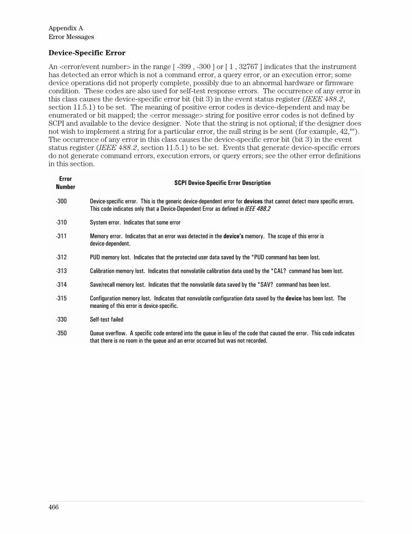
Device-Specific Error
An <error/event number> in the range [ -399 , -300 ] or [ 1 , 32767 ] indicates that the instrumenthas detected an error which is not a command error, a query error, or an execution error; somedevice operations did not properly complete, possibly due to an abnormal hardware or firmwarecondition. These codes are also used for self-test response errors. The occurrence of any error inthis class causes the device-specific error bit (bit 3) in the event status register (IEEE 488.2,section 11.5.1) to be set. The meaning of positive error codes is device-dependent and may beenumerated or bit mapped; the <error message> string for positive error codes is not defined bySCPI and available to the device designer. Note that the string is not optional; if the designer doesnot wish to implement a string for a particular error, the null string is be sent (for example, 42,"").The occurrence of any error in this class causes the device-specific error bit (bit 3) in the eventstatus register (IEEE 488.2, section 11.5.1) to be set. Events that generate device-specific errorsdo not generate command errors, execution errors, or query errors; see the other error definitionsin this section.
ErrorNumber
SCPI Device-Specific Error Description
-300 Device-specific error. This is the generic device-dependent error for devices that cannot detect more specific errors.This code indicates only that a Device-Dependent Error as defined in IEEE 488.2
-310 System error. Indicates that some error
-311 Memory error. Indicates that an error was detected in the device’s memory. The scope of this error isdevice-dependent.
-312 PUD memory lost. Indicates that the protected user data saved by the *PUD command has been lost.
-313 Calibration memory lost. Indicates that nonvolatile calibration data used by the *CAL? command has been lost.
-314 Save/recall memory lost. Indicates that the nonvolatile data saved by the *SAV? command has been lost.
-315 Configuration memory lost. Indicates that nonvolatile configuration data saved by the device has been lost. Themeaning of this error is device-specific.
-330 Self-test failed
-350 Queue overflow. A specific code entered into the queue in lieu of the code that caused the error. This code indicatesthat there is no room in the queue and an error occurred but was not recorded.
Appendix AError Messages
466
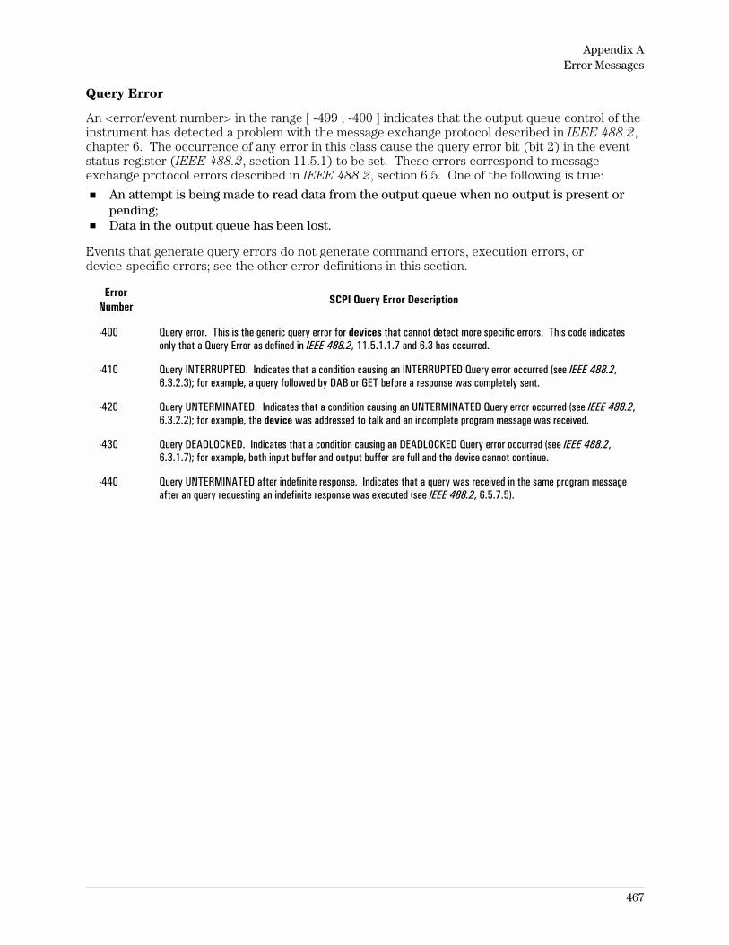
Query Error
An <error/event number> in the range [ -499 , -400 ] indicates that the output queue control of theinstrument has detected a problem with the message exchange protocol described in IEEE 488.2,chapter 6. The occurrence of any error in this class cause the query error bit (bit 2) in the eventstatus register (IEEE 488.2, section 11.5.1) to be set. These errors correspond to messageexchange protocol errors described in IEEE 488.2, section 6.5. One of the following is true:
An attempt is being made to read data from the output queue when no output is present orpending;Data in the output queue has been lost.
Events that generate query errors do not generate command errors, execution errors, ordevice-specific errors; see the other error definitions in this section.
ErrorNumber
SCPI Query Error Description
-400 Query error. This is the generic query error for devices that cannot detect more specific errors. This code indicatesonly that a Query Error as defined in IEEE 488.2, 11.5.1.1.7 and 6.3 has occurred.
-410 Query INTERRUPTED. Indicates that a condition causing an INTERRUPTED Query error occurred (see IEEE 488.2,6.3.2.3); for example, a query followed by DAB or GET before a response was completely sent.
-420 Query UNTERMINATED. Indicates that a condition causing an UNTERMINATED Query error occurred (see IEEE 488.2,6.3.2.2); for example, the device was addressed to talk and an incomplete program message was received.
-430 Query DEADLOCKED. Indicates that a condition causing an DEADLOCKED Query error occurred (see IEEE 488.2,6.3.1.7); for example, both input buffer and output buffer are full and the device cannot continue.
-440 Query UNTERMINATED after indefinite response. Indicates that a query was received in the same program messageafter an query requesting an indefinite response was executed (see IEEE 488.2, 6.5.7.5).
Appendix AError Messages
467
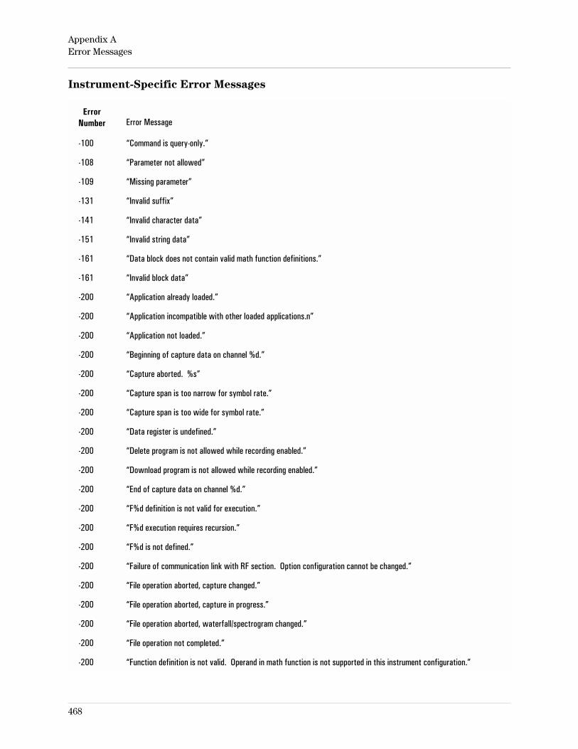
Instrument-Specific Error Messages
ErrorNumber Error Message
-100 “Command is query-only.”
-108 “Parameter not allowed”
-109 “Missing parameter”
-131 “Invalid suffix”
-141 “Invalid character data”
-151 “Invalid string data”
-161 “Data block does not contain valid math function definitions.”
-161 “Invalid block data”
-200 “Application already loaded.”
-200 “Application incompatible with other loaded applications.n”
-200 “Application not loaded.”
-200 “Beginning of capture data on channel %d.”
-200 “Capture aborted. %s”
-200 “Capture span is too narrow for symbol rate.”
-200 “Capture span is too wide for symbol rate.”
-200 “Data register is undefined.”
-200 “Delete program is not allowed while recording enabled.”
-200 “Download program is not allowed while recording enabled.”
-200 “End of capture data on channel %d.”
-200 “F%d definition is not valid for execution.”
-200 “F%d execution requires recursion.”
-200 “F%d is not defined.”
-200 “Failure of communication link with RF section. Option configuration cannot be changed.”
-200 “File operation aborted, capture changed.”
-200 “File operation aborted, capture in progress.”
-200 “File operation aborted, waterfall/spectrogram changed.”
-200 “File operation not completed.”
-200 “Function definition is not valid. Operand in math function is not supported in this instrument configuration.”
Appendix AError Messages
468
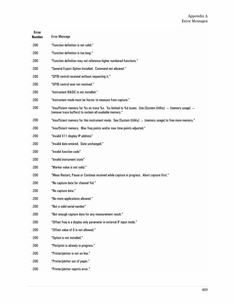
ErrorNumber Error Message
-200 “Function definition is not valid.”
-200 “Function definition is too long.”
-200 “Function definition may not reference higher numbered functions.”
-200 “General Export Option Installed. Command not allowed.”
-200 “GPIB control received without requesting it.”
-200 “GPIB control was not received.”
-200 “Instrument BASIC is not installed.”
-200 “Instrument mode must be Vector to measure from capture.”
-200 “Insufficient memory for %s on trace %s. %s limited to %d scans. Use [System Utility] → [memory usage] →[remove trace buffers] to reclaim all available memory.”
-200 “Insufficient memory for this instrument mode. See [System Utility] → [memory usage] to free more memory.”
-200 “Insufficient memory. Max freq points and/or max time points adjusted.”
-200 “Invalid X11 display IP address”
-200 “Invalid date entered. Date unchanged.”
-200 “Invalid function code”
-200 “Invalid instrument state”
-200 “Marker value is not valid.”
-200 “Meas Restart, Pause or Continue received while capture in progress. Abort capture first.”
-200 “No capture data for channel %d.”
-200 “No capture data.”
-200 “No more applications allowed.”
-200 “Not a valid serial number”
-200 “Not enough capture data for any measurement result.”
-200 “Offset freq is a display only paramater in external IF input mode.”
-200 “Offset value of 0 is not allowed.”
-200 “Option is not installed.”
-200 “Plot/print is already in progress.”
-200 “Printer/plotter is not on line.”
-200 “Printer/plotter out of paper.”
-200 “Printer/plotter reports error.”
Appendix AError Messages
469
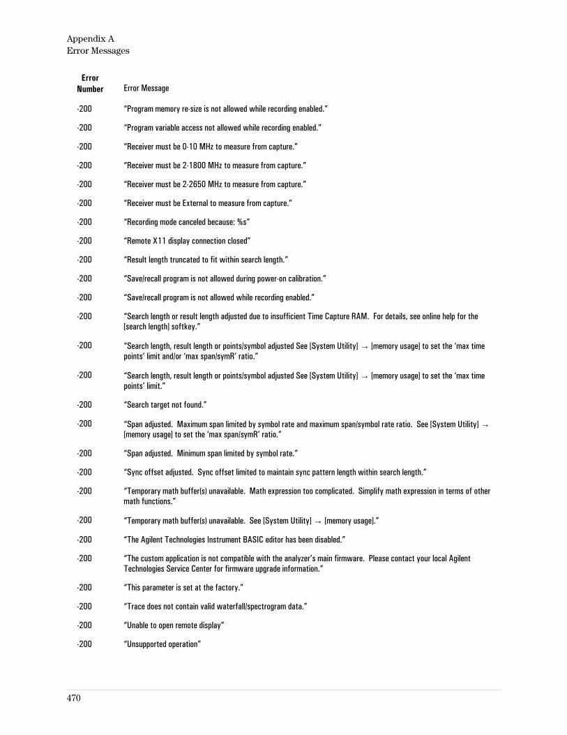
ErrorNumber Error Message
-200 “Program memory re-size is not allowed while recording enabled.”
-200 “Program variable access not allowed while recording enabled.”
-200 “Receiver must be 0-10 MHz to measure from capture.”
-200 “Receiver must be 2-1800 MHz to measure from capture.”
-200 “Receiver must be 2-2650 MHz to measure from capture.”
-200 “Receiver must be External to measure from capture.”
-200 “Recording mode canceled because: %s”
-200 “Remote X11 display connection closed”
-200 “Result length truncated to fit within search length.”
-200 “Save/recall program is not allowed during power-on calibration.”
-200 “Save/recall program is not allowed while recording enabled.”
-200 “Search length or result length adjusted due to insufficient Time Capture RAM. For details, see online help for the[search length] softkey.”
-200 “Search length, result length or points/symbol adjusted See [System Utility] → [memory usage] to set the ‘max timepoints’ limit and/or ‘max span/symR’ ratio.”
-200 “Search length, result length or points/symbol adjusted See [System Utility] → [memory usage] to set the ‘max timepoints’ limit.”
-200 “Search target not found.”
-200 “Span adjusted. Maximum span limited by symbol rate and maximum span/symbol rate ratio. See [System Utility] →[memory usage] to set the ‘max span/symR’ ratio.”
-200 “Span adjusted. Minimum span limited by symbol rate.”
-200 “Sync offset adjusted. Sync offset limited to maintain sync pattern length within search length.”
-200 “Temporary math buffer(s) unavailable. Math expression too complicated. Simplify math expression in terms of othermath functions.”
-200 “Temporary math buffer(s) unavailable. See [System Utility] → [memory usage].”
-200 “The Agilent Technologies Instrument BASIC editor has been disabled.”
-200 “The custom application is not compatible with the analyzer’s main firmware. Please contact your local AgilentTechnologies Service Center for firmware upgrade information.”
-200 “This parameter is set at the factory.”
-200 “Trace does not contain valid waterfall/spectrogram data.”
-200 “Unable to open remote display”
-200 “Unsupported operation”
Appendix AError Messages
470
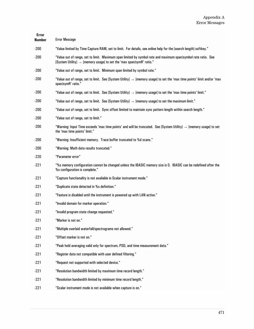
ErrorNumber Error Message
-200 “Value limited by Time Capture RAM, set to limit. For details, see online help for the [search length] softkey.”
-200 “Value out of range, set to limit. Maximum span limited by symbol rate and maximum span/symbol rate ratio. See[System Utility] → [memory usage] to set the ‘max span/symR’ ratio.”
-200 “Value out of range, set to limit. Minimum span limited by symbol rate.”
-200 “Value out of range, set to limit. See [System Utility] → [memory usage] to set the ‘max time points’ limit and/or ‘maxspan/symR’ ratio.”
-200 “Value out of range, set to limit. See [System Utility] → [memory usage] to set the ‘max time points’ limit.”
-200 “Value out of range, set to limit. See [System Utility] → [memory usage] to set the maximum limit.”
-200 “Value out of range, set to limit. Sync offset limited to maintain sync pattern length within search length.”
-200 “Value out of range, set to limit.”
-200 “Warning: Input Time exceeds ‘max time points’ and will be truncated. See [System Utility] → [memory usage] to setthe ‘max time points’ limit.”
-200 “Warning: Insufficient memory. Trace buffer truncated to %d scans.”
-200 “Warning: Math data results truncated.”
-220 “Parameter error”
-221 “%s memory configuration cannot be changed unless the IBASIC memory size is 0. IBASIC can be redefined after the%s configuration is complete.”
-221 “Capture functionality is not available in Scalar instrument mode.”
-221 “Duplicate state detected in %s definition.”
-221 “Feature is disabled until the instrument is powered up with LAN active.”
-221 “Invalid domain for marker operation.”
-221 “Invalid program state change requested.”
-221 “Marker is not on.”
-221 “Multiple overlaid waterfall/spectrograms not allowed.”
-221 “Offset marker is not on.”
-221 “Peak hold averaging valid only for spectrum, PSD, and time measurement data.”
-221 “Register data not compatible with user defined filtering.”
-221 “Request not supported with selected device.”
-221 “Resolution bandwidth limited by maximum time record length.”
-221 “Resolution bandwidth limited by minimum time record length.”
-221 “Scalar instrument mode is not available when capture is on.”
Appendix AError Messages
471
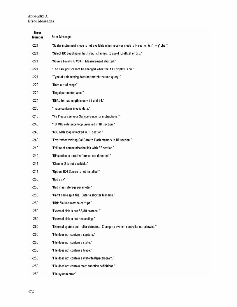
ErrorNumber Error Message
-221 “Scalar instrument mode is not available when receiver mode is IF section (ch1 + j*ch2)”
-221 “Select DC coupling on both input channels to avoid IQ offset errors.”
-221 “Source Level is 0 Volts. Measurement aborted.”
-221 “The LAN port cannot be changed while the X11 display is on.”
-221 “Type of unit setting does not match the unit query.”
-222 “Data out of range”
-224 “Illegal parameter value”
-224 “REAL format length is only 32 and 64.”
-230 “Trace contains invalid data.”
-240 “%s Please see your Service Guide for instructions.”
-240 “10 MHz reference loop unlocked in RF section.”
-240 “600 MHz loop unlocked in RF section.”
-240 “Error when writing Cal Data to Flash memory in RF section.”
-240 “Failure of communication link with RF section.”
-240 “RF section external reference not detected.”
-241 “Channel 2 is not available.”
-241 “Option 1D4 Source is not installed.”
-250 “Bad disk”
-250 “Bad mass storage parameter”
-250 “Can’t name split file. Enter a shorter filename.”
-250 “Disk file/unit may be corrupt.”
-250 “External disk is not SS/80 protocol.”
-250 “External disk is not responding.”
-250 “External system controller detected. Change to system controller not allowed.”
-250 “File does not contain a capture.”
-250 “File does not contain a state.”
-250 “File does not contain a trace.”
-250 “File does not contain a waterfall/spectrogram.”
-250 “File does not contain math function definitions.”
-250 “File system error”
Appendix AError Messages
472
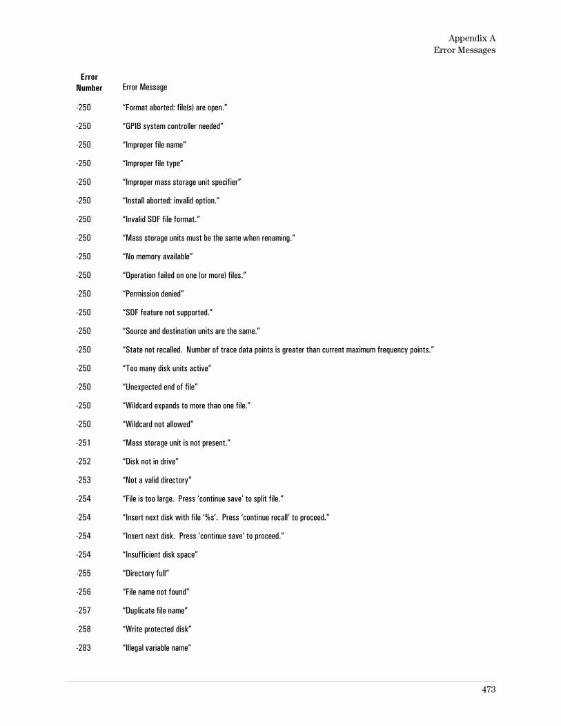
ErrorNumber Error Message
-250 “Format aborted: file(s) are open.”
-250 “GPIB system controller needed”
-250 “Improper file name”
-250 “Improper file type”
-250 “Improper mass storage unit specifier”
-250 “Install aborted: invalid option.”
-250 “Invalid SDF file format.”
-250 “Mass storage units must be the same when renaming.”
-250 “No memory available”
-250 “Operation failed on one (or more) files.”
-250 “Permission denied”
-250 “SDF feature not supported.”
-250 “Source and destination units are the same.”
-250 “State not recalled. Number of trace data points is greater than current maximum frequency points.”
-250 “Too many disk units active”
-250 “Unexpected end of file”
-250 “Wildcard expands to more than one file.”
-250 “Wildcard not allowed”
-251 “Mass storage unit is not present.”
-252 “Disk not in drive”
-253 “Not a valid directory”
-254 “File is too large. Press ‘continue save’ to split file.”
-254 “Insert next disk with file ‘%s’. Press ‘continue recall’ to proceed.”
-254 “Insert next disk. Press ‘continue save’ to proceed.”
-254 “Insufficient disk space”
-255 “Directory full”
-256 “File name not found”
-257 “Duplicate file name”
-258 “Write protected disk”
-283 “Illegal variable name”
Appendix AError Messages
473
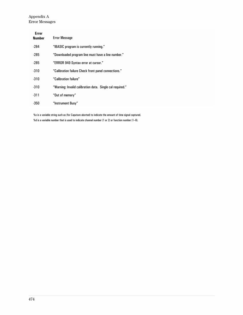
ErrorNumber Error Message
-284 “IBASIC program is currently running.”
-285 “Downloaded program line must have a line number.”
-285 “ERROR 949 Syntax error at cursor.”
-310 “Calibration failure Check front panel connections.”
-310 “Calibration failure”
-310 “Warning: Invalid calibration data. Single cal required.”
-311 “Out of memory”
-350 “Instrument Busy”
%s is a variable string such as (for Caputure aborted) to indicate the amount of time signal captured.
%d is a variable number that is used to indicate channel number (1 or 2) or function number (1–6).
Appendix AError Messages
474
B
Sockets Example Program
475
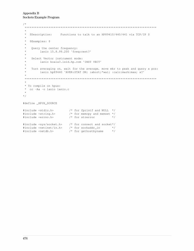
/******************************************************************************** $Description: Functions to talk to an HP89410/440/441 via TCP/IP $** $Examples: $** Query the center frequency:* lanio 15.8.99.200 ‘freq:cent?’** Select Vector instrument mode:* lanio koala3.lsid.hp.com ‘INST VECT’** Turn averaging on, wait for the average, move mkr to peak and query x pos:* lanio hp89440 ‘AVER:STAT ON; :abort;*wai; :calc:mark:max; x?’******************************************************************************** To compile on hpux:* cc -Aa -o lanio lanio.c*
*/
#define _HPUX_SOURCE
#include <stdio.h> /* for fprintf and NULL */#include <string.h> /* for memcpy and memset */#include <errno.h> /* for strerror */
#include <sys/socket.h> /* for connect and socket*/#include <netinet/in.h> /* for sockaddr_in */#include <netdb.h> /* for gethostbyname */
Appendix BSockets Example Program
476
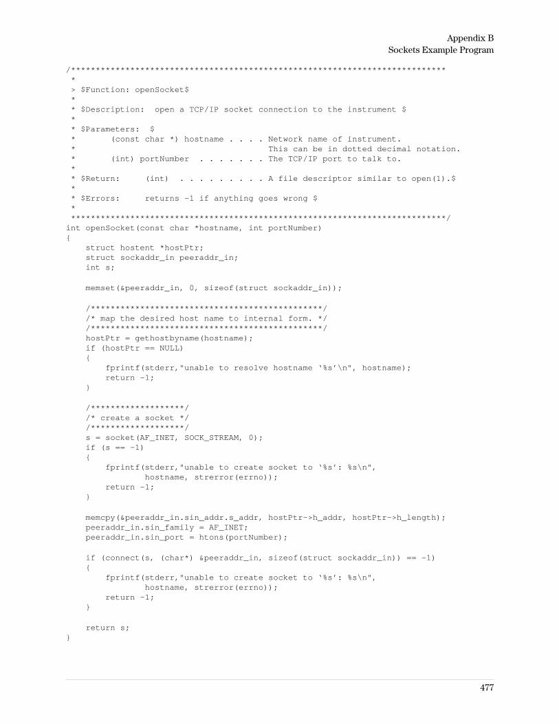
/*****************************************************************************> $Function: openSocket$** $Description: open a TCP/IP socket connection to the instrument $** $Parameters: $* (const char *) hostname . . . . Network name of instrument.* This can be in dotted decimal notation.* (int) portNumber . . . . . . . The TCP/IP port to talk to.** $Return: (int) . . . . . . . . . A file descriptor similar to open(1).$** $Errors: returns -1 if anything goes wrong $*****************************************************************************/
int openSocket(const char *hostname, int portNumber)
struct hostent *hostPtr;struct sockaddr_in peeraddr_in;int s;
memset(&peeraddr_in, 0, sizeof(struct sockaddr_in));
/***********************************************//* map the desired host name to internal form. *//***********************************************/hostPtr = gethostbyname(hostname);if (hostPtr == NULL)
fprintf(stderr,"unable to resolve hostname ‘%s’\n", hostname);return -1;
/*******************//* create a socket *//*******************/s = socket(AF_INET, SOCK_STREAM, 0);if (s == -1)
fprintf(stderr,"unable to create socket to ‘%s’: %s\n",hostname, strerror(errno));
return -1;
memcpy(&peeraddr_in.sin_addr.s_addr, hostPtr->h_addr, hostPtr->h_length);peeraddr_in.sin_family = AF_INET;peeraddr_in.sin_port = htons(portNumber);
if (connect(s, (char*) &peeraddr_in, sizeof(struct sockaddr_in)) == -1)
fprintf(stderr,"unable to create socket to ‘%s’: %s\n",hostname, strerror(errno));
return -1;
return s;
Appendix BSockets Example Program
477
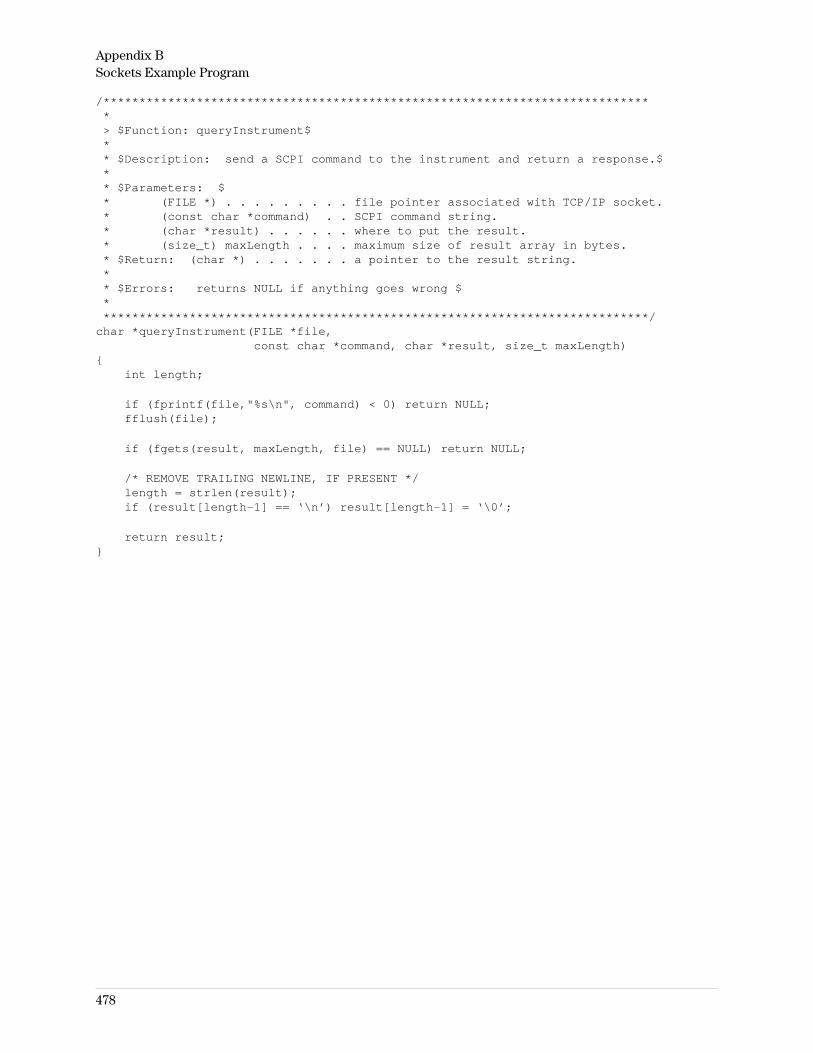
/*****************************************************************************> $Function: queryInstrument$** $Description: send a SCPI command to the instrument and return a response.$** $Parameters: $* (FILE *) . . . . . . . . . file pointer associated with TCP/IP socket.* (const char *command) . . SCPI command string.* (char *result) . . . . . . where to put the result.* (size_t) maxLength . . . . maximum size of result array in bytes.* $Return: (char *) . . . . . . . a pointer to the result string.** $Errors: returns NULL if anything goes wrong $*****************************************************************************/
char *queryInstrument(FILE *file,const char *command, char *result, size_t maxLength)
int length;
if (fprintf(file,"%s\n", command) < 0) return NULL;fflush(file);
if (fgets(result, maxLength, file) == NULL) return NULL;
/* REMOVE TRAILING NEWLINE, IF PRESENT */length = strlen(result);if (result[length-1] == ‘\n’) result[length-1] = ‘\0’;
return result;
Appendix BSockets Example Program
478
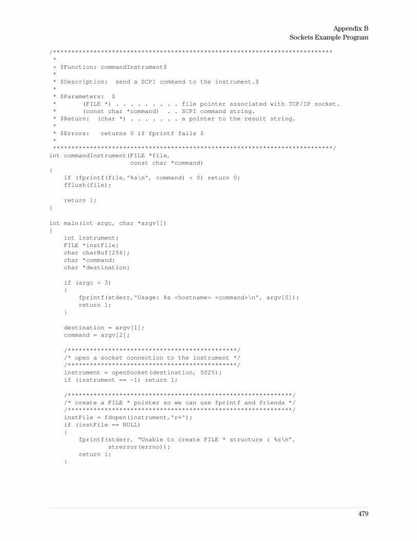
/*****************************************************************************> $Function: commandInstrument$** $Description: send a SCPI command to the instrument.$** $Parameters: $* (FILE *) . . . . . . . . . file pointer associated with TCP/IP socket.* (const char *command) . . SCPI command string.* $Return: (char *) . . . . . . . a pointer to the result string.** $Errors: returns 0 if fprintf fails $*****************************************************************************/
int commandInstrument(FILE *file,const char *command)
if (fprintf(file,"%s\n", command) < 0) return 0;fflush(file);
return 1;
int main(int argc, char *argv[])
int instrument;FILE *instFile;char charBuf[256];char *command;char *destination;
if (argc < 3)
fprintf(stderr,"Usage: %s <hostname> <command>\n", argv[0]);return 1;
destination = argv[1];command = argv[2];
/**********************************************//* open a socket connection to the instrument *//**********************************************/instrument = openSocket(destination, 5025);if (instrument == -1) return 1;
/*************************************************************//* create a FILE * pointer so we can use fprintf and friends *//*************************************************************/instFile = fdopen(instrument,"r+");if (instFile == NULL)
fprintf(stderr, “Unable to create FILE * structure : %s\n”,strerror(errno));
return 1;
Appendix BSockets Example Program
479
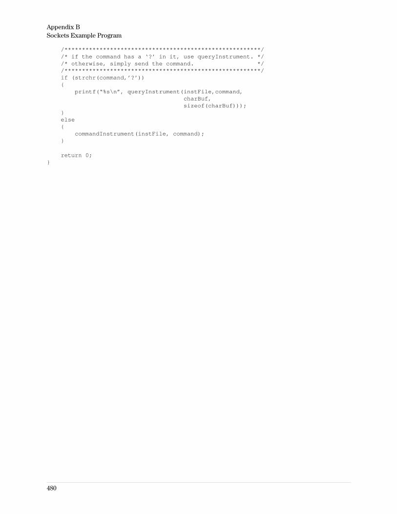
/********************************************************//* if the command has a ‘?’ in it, use queryInstrument. *//* otherwise, simply send the command. *//********************************************************/if (strchr(command,’?’))
printf(“%s\n”, queryInstrument(instFile,command,charBuf,sizeof(charBuf)));
else
commandInstrument(instFile, command);
return 0;
Appendix BSockets Example Program
480
INDEX
AABORt 46abort print/plot 176aborting time capture 360ac input coupling 206active traces 138address
downconverter 423downconverter (GPIB) 336ethernet 424gateway (LAN) 427instrument (GPIB) 423internet protocol 425plotter 202printer (GPIB) 203system interconnect (2nd GPIB) 423
Agilent Technologies Instrument BASICProgram Running bit 20
allocating memory 214 - 215, 218 - 220alpha (digital Nyquist filter) 290amplitude droop 66analyzer address 423annotation color 186annotation display 129anti-alias filters, on/off 207APCO 25 configuration 305aperture 59arbitrary bandwidth 269arbitrary source
function 379repeat 382
armwaiting-for-ARM bit 19
ARM:SOURce 50assistance (by phone) iaudible alarm on/off 422AUI LAN 426auto correlation display 55auto demod carrier 325auto frequency steps 346auto zero (calibration) 127auto-state 40, 443Autocal Off bit 13autocalibration 126
automatic sweep 349autorange direction 369autoranging on/off 368autoscale
x-axis 157y-axis 163
averagingaveraging bit 19complex 268continue 128count 263counter/weighting factor 262exponential 267fast, on/off 265fast, update rate 264max (peak hold) 268normal 267on/off 266overlap processing 350overview 262repeat 267RMS 268termination control 267time 268type 268
azimuth (waterfall) 168
Bband markers 60 - 61band power marker 65bandwidth 270
coupling 271type 269
bars/dots (digital demod) 155baseband on/off 330baseline on/off (waterfall) 169BASIC programming
memory allocated for 220baud rate (serial comm) 434beeper on/off 422blank screen 133BNC LAN 426brightness, display 130BT (digital Gaussian filter) 290
buffer size, time capture 280burst digital demod
SEE pulsebus address 423bus trigger 43, 456
CC/N measurement 65C/No measurement 65CALCulate description 25calculate on/off 114CALCulate:DATA:HEADer:POINts? 54CALCulate:DATA? 53CALCulate:FEED 55CALCulate:FORMat 57CALCulate:GDAPerture:APERture 59CALCulate:MARKer:BAND:STARt 60CALCulate:MARKer:BAND:STOP 61CALCulate:MARKer:COUPled[:STATe] 62CALCulate:MARKer:FCOunt 63CALCulate:MARKer:FCOunt:RESult? 64CALCulate:MARKer:FUNCtion 65CALCulate:MARKer:FUNCtion:DDEMod:RESult 66CALCulate:MARKer:FUNCtion:RESult? 68CALCulate:MARKer:MAXimum 73CALCulate:MARKer:MAXimum:LEFT 74CALCulate:MARKer:MAXimum:NEXT 75CALCulate:MARKer:MAXimum:RIGHt 76CALCulate:MARKer:MAXimum:TRACk 77CALCulate:MARKer:MINimum[:GLOBal] 78CALCulate:MARKer:OFFSet:X 80CALCulate:MARKer:OFFSet:Y 81CALCulate:MARKer:OFFSet:Z 82CALCulate:MARKer:OFFSet:ZERO 83CALCulate:MARKer:OFFSet[:STATe] 79CALCulate:MARKer:POLar:UNIT:POWer 84CALCulate:MARKer:READout 85CALCulate:MARKer:SEARch:LEFT 87CALCulate:MARKer:SEARch:OFFSet 88CALCulate:MARKer:SEARch:RIGHt 89CALCulate:MARKer:SEARch:TARGet 90CALCulate:MARKer:X:RELative? 98CALCulate:MARKer:X[:ABSolute] 93, 95 - 96CALCulate:MARKer:Y:RELative? 100CALCulate:MARKer:Y? 99CALCulate:MARKer:Z[:ABSolute] 101CALCulate:MARKer:Z:RELative? 103CALCulate:MARKer[:STATe] 91CALCulate:MATH:CONStant 105CALCulate:MATH:CONStant:IMAG 106CALCulate:MATH:CONStant:MAG 107CALCulate:MATH:CONStant:PHASe 108CALCulate:MATH:CONStant:REAL 109CALCulate:MATH:CONStant:STEP 110CALCulate:MATH[:EXPRession] 111CALCulate:MATH:STATe 113CALCulate:STATe 114
CALCulate:UNIT:AM 115CALCulate:UNIT:ANGLe 116CALCulate:UNIT:FREQuency 117CALCulate:UNIT:POWer 118CALCulate:UNIT:TIME 119CALCulate:UPHase:CREFerence 120CALCulate:UPHase:OFFSet 121CALCulate:X:UNIT:FREQuency 123CALCulate:X:UNIT:POW 124CALCulate:X:UNIT:TIME 125calibration
auto on/off/once 126bit 19*CAL? 31SEE ALSO correctionsresults 31status bit 14test 44zero on/off/once 127
CALIbration:AUTO 126CALibration:ZERO:AUTO 127capture
SEE time capturecarrier
auto demod 325 - 326compensation on/off 325compensation type 326demodulate 145frequency 327
carrier-to-noise 65catalog display 261CDPD configuration 305center frequency 331center frequency tracking 332Ch1 + j*Ch2 operation 260changing directory (DOS) 236channel
state (on/off) 209trigger 456
chip ratesetting 284
chirp period 343choose instrument mode 210 - 211clear input trip 372clock
marks (digital demod) 155offset (digital demod) 282setting (time) 444
*CLS (clear status byte) 32code
units 124coherence display 55color
annotation 186disk catalog border 192display 131graticule 192map 141marker pens 196
Index
on/off (TIFF) 180plot 179skew (spectrogram) 140spectrogram 140trace pens 191
combined channels 260command echo on/off 439command error 460complex
constants 105 - 110display type 57
configuration display 261configuring memory 214 - 215, 218 - 220constant, math 105 - 110constellation display 57continue
loading a large file 228program execution 258storing a large file 239
CONTinue (a measurement) 128continuous sweeps 204control passing 38conventions, filenames 237coordinate types 57coordinates, rectangular/polar 85copy
BASIC program from disk 230BASIC program to disk 241data registers to/from controller 447file 221instrument state from disk 231instrument state to disk 242large files 228, 239SEE ALSO load and storemath definitions to disk 240time capture from disk 232time capture to disk 243trace from disk 233trace to data register 446trace to disk 244waterfall/spectrogram from disk 234waterfall/spectrogram to data register 445waterfall/spectrogram to disk 245
correction impedance 276corrections, time-domain 275counter, frequency 63coupled
bandwidth 271markers 62
coupling, input 206cross correlation display 55CW frequency 376
Ddata
affects of PAUS, ABOR 249header, number of points 280
postprocessing on/off 114transfer (trace/register) 447transfer format 175
data copymath definitions to disk 240time capture from disk 232time capture to disk 243trace from disk 233trace to data register 446trace to disk 244waterfall/spectrogram from disk 234waterfall/spectrogram to data register 445waterfall/spectrogram to disk 245
data registersdisplay 55number of points 449
date 437date-stamp format 189date/time stamp 190dc
input coupling 206offset, source 385
DECT configuration 305default
disk selection 236memory settings 214values 443
defineconstant 105 - 110function 111
delayaperture 59gated time 353
deletefile 223programs 252 - 253
demod (analog)carrier compensation 326carrier frequency 327carrier on/off 145carrier, auto 325result 324
demod mode, selecting 211detector
time capture 137type 328
device selector 225, 236Device Status register
Condition: read & clear 388description 13Enable: set & query 389Event: read & clear 390Neg transition: set & query 391Pos transition: set & query 392preset 398
device-specific error 466differential quadrature phase-shift keyed 308digital demod
adapt 281
Index
clock marks 155clock offset 282equalize 289error measurements 66eye count 146filter alpha 290filter BT 290FSK marker data 66FSK memory allocation 216 - 217MaxSpan/SymbolRate 216 - 217measurement filter 291memory allocation (FSK) 216 - 217modulation formats 295MSK 302normalize 303number of DVBQAM states 285number of FSK states 297number of PSK states 306number of QAM states 307points/symbol 304pulse search on/off 309QPSK format type 308QPSK, PSK, QAM, MSK, FSK, VSB, DVB 295reference filter 293result length 316search time 313span limits 315, 341symbol marks 155symbol rate 315sync offset 310sync pattern 311sync search on/off 312trellis length 146user-defined filter 292, 294
digital demodulation mode, selecting 211direction of playback 361directory, changing (DOS) 236disk
catalog 261copy 221default selection 236formatting 225
displaybaselines 169coordinates 57hidden lines 172IBASIC programs 136information 261math function 112math function definitions 135meas data selection 55number of grids 134number of traces 144on/off 133points 351spectrogram 139 - 143types 57waterfall 168 - 174
DISPlay description 28
DISPlay:ANNotation[:ALL] 129DISPlay:BRIGhtness 130DISPlay:CMAP:COLor:HSL 131DISPlay:ENABle 133DISPlay:FORMat 134DISPlay:MFUNction 135DISPlay:PROGram[:MODE] 136DISPlay:TCAPture:ENVelope 137DISPlay[:WINDow]:WATerfall[:STATe] 173DISPlay[:WINDow]:ACTive 138DISPlay[:WINDow]:SPECtrogram:COLors 139DISPlay[:WINDow]:SPECtrogram:ENHance 140DISPlay[:WINDow]:SPECtrogram:MAP 141DISPlay[:WINDow]:SPECtrogram[:STATe] 142DISPlay[:WINDow]:SPECtrogram:THReshold 143DISPlay[:WINDow]:TRACe:BUFFer 144DISPlay[:WINDow]:TRACe:DCARrier 145DISPlay[:WINDow]:TRACe:EYE:COUNt 146DISPlay[:WINDow]:TRACe:GRATicule:GRID[:STATe] 147DISPlay[:WINDow]:TRACe:LABel:USER 153DISPlay[:WINDow]:TRACe[:STATe] 154DISPlay[:WINDow]:TRACe:SYMBol 155DISPlay[:WINDow]:TRACe:X[:SCALe]:SPACing 161DISPlay[:WINDow]:WATerfall:AZIMuth 168DISPlay[:WINDow]:WATerfall:BLIN[:STATe] 169DISPlay[:WINDow]:WATerfall:ELEVation 170DISPlay[:WINDow]:WATerfall:HEIGht 171DISPlay[:WINDow]:WATerfall:THReshold 174DISPlay[:WINDow]:TRACe:X[:SCALe]:AUTO 157DISPlay[:WINDow]:TRACe:X[:SCALe]:LEFT 158DISPlay[:WINDow]:TRACe:X[:SCALe]:RIGHt 159DISPlay[:WINDow]:TRACe:X[:SCALe]:RLEVel 160DISPlay[:WINDow]:TRACe:Y:RLINe 162DISPlay[:WINDow]:TRACe:Y[:SCALe]:AUTO 163DISPlay[:WINDow]:TRACe:Y[:SCALe]:PDIVision 164DISPlay[:WINDow]:TRACe:Y[:SCALe]:RLEVel 165DISPlay[:WINDow]:TRACe:Y[:SCALe]:RLEVel:AUTO 166DISPlay[:WINDow]:TRACe:Y[:SCALe]:RPOSition 167DOS filename conventions 237dots/bars (digital demod) 155downconverter use 333 - 335, 337 - 339
analyzer address 336, 423DQPSK modulation format 308drive devices defined 236DTR OFF|IBFull 433DVB modulation format 295DVBQAM
number of states 285
EEDGE (Enhanced Data rages for GSM Evol.) 293EDGE, standard setup
standard configurations 305eject page 187enable display 133equalize, digital demod 281, 289equation
Index
SEE math functionerror
messages 468numbers 459query/message 438queue size 438
error vector magnitude 66error/event queue 458*ESE (enable std events) 33*ESR? (enable std event query) 34ethernet address 424event status enable 39example sockets program 475execution error 463exponential averaging 267expression, math 111external
arm 50drives 236trigger 456
eyecount (digital demod) 146diagrams 57
Ffast averaging
on/off 265update rate 264
fast measurements 114faster measurements 91feed command 329FFT window types 375file
copy 221delete 223move 235remove 223rename 235
file-system-type query 224filename conventions 237filter
alpha (Nyquist) 290BT (Gaussian) 290Gaussian (digital demod) 291, 293input, on/off 207low-pass (digital demod) 291raised cosine (digital demod) 291, 293rectangular (digital demod) 291, 293root raised-cosine filter 291, 293source, on/off 246type (digital demod) 291, 293user-defined (digital demod) 291 - 294
findminimum 78next peak 75next peak left 74next peak right 76
peak 73firmware version 35fixed bandwidth 271flattop window (FFT) 375flip spectrum
SEE mirror spectrumform feed 187format
disk 225interleave factor 225options for disk 226transferred data (ASC or REAL) 175
FORMat description 28FORMat[:DATA] 175free run trigger 456frequency
center 331counter 63 - 64demod carrier 327error 66log/lin 161manual sweep 340points 351source (sine) 376source offset 377source ranges 381spacing, log/lin 161span 341start 345step size 347steps, auto 346stop 348track center 332units 123
frequency dataSEE x-axis data
frequency response display 55frequency shift key 297front-panel lockout 442FSK error 66FSK modulation format 295, 297full span 342function, math 111, 135function, source 378
Ggain adjust, digital demod 303gate delay 353
step size 354gate time 355gate window 373
couple to main 374gated time display 55gateway address 427gating on/off 356Gaussian
filter (digital demod) 291, 293
Index
filter BT (digital demod) 290window (FFT) 375
GPIB2nd GPIB connector 423connector on UFG or UTH board 423downconverter address 336instrument address 423interface capabilities 4plotter address 202printer address 203system interconnect 423trigger 43
graticule, print/plot 193grids
color 192number displayed 134on/off 147
group delayaperture 59coordinates 57
GSM configuration 305
Hhandshake, serial 433, 435Hanning window (FFT) 375Hard Copy description 28HCOPy:ABORt 176HCOPy:DATA? 177HCOPy:DESTination 178HCOPy:DEVice:CMAP:DEFault 179HCOPy:DEVice:COLor 180HCOPy:DEVice:LANGuage 181HCOPy:DEVice:RESolution 182HCOPy:DEVice:SPEed 183HCOPy[:IMMediate] 184HCOPy:ITEM:ALL[:IMMediate] 185HCOPy:ITEM:ANNotation:COLor 186HCOPy:ITEM:FFEed:STATe 187HCOPy:ITEM:GRATicule[:IMMediate] 193HCOPy:ITEM:TDSTamp:FORMat 189HCOPy:ITEM:TDSTamp:STATe 190HCOPy:ITEM[:WINDow]:TRACe:COLor 191HCOPy:ITEM[:WINDow]:TRACe:GRATicule:COLor 192HCOPy:ITEM[:WINDow]:TRACe[:IMMediate] 194HCOPy:ITEM[:WINDow]:TRACe:LTYPe 195HCOPy:ITEM[:WINDow]:TRACe:MARKer:COLor 196HCOPy:ITEM[:WINDow]:TRACe:MARKer[:IMMediate] 197HCOPy:ITEM[:WINDow]:TRACe:MARKer:OFFSet[:IMMediate] 198HCOPy:PAGE:DIMensions:AUTO 199HCOPy:PAGE:DIMensions:USER:LLEFt 200HCOPy:PAGE:DIMensions:USER:URIGht 201HCOPy:PLOT:ADDRess 202HCOPy:PRINt:ADDRess 203help (by phone) ihelp, online 260hidden lines (waterfall) 172holdoff
trigger delay 452 - 453hostname (LAN/XWindows) 430HP-GL output 181hue, display color 131
II + jQ 260identification (*IDN?) 35IF trigger 456imag constant 106imaginary coordinates 57immediate
arm 50trigger 456
impedanceinput 208reference for dBm calculations 276source 247
improving measurement speed 91index, online help 260initialize disk 225INITiate:CONTinuous 204INITiate[:IMMediate] 205input
autozero 127coupling 206filters on/off 207impedance 208impedance reference 276on/off 209range 371range units 370resetting the protection relay 372trigger 456trip, clearing 372zero calibration 127
INPut description 25installed options 37instrument
address 423mode, selection 211model 23reset 40
instrument mode selection 210instrument state
display 261loading 231power-on 40, 443storing 242
INSTrument:NSELect 210INSTrument[:SELect] 211interface capabilities 4interleave factor 225internal drive 236IP address (LAN) 425IQ offset 66
Index
Kkeyboard lockout 442keypresses, simulating/querying 440
LLAN
ethernet address 424gateway address 427IP address 425on/off 429sockets example program 475subnet mask 428type (BNC|AUI) 426vs memory use 429X11 Window hostname/address 430X11 Window on/off 432X11 Window update rate 431
large filesloading 228storing 239
LIF filename conventions 237line type 195linear magnitude display 57linear x axis 161loading
instrument state 231large files 228math registers 229programs 230string values 259time-capture buffers 232traces 233waterfall/spectrogram buffer 234
local oscillator frequency 349lockout keyboard 442log magnitude display 57log x axis 161low-pass filter (digital demod) 291lowering the noise floor
SEE time averagingluminosity, display color 131
Mmagnitude constant 107magnitude error 66magnitude/phase polar readout 85main time length 359manual sweep
frequency 340on/off 349
manufacturer name 35marker
band power 65
band start 60band stop 61coupling on/off 62digital demod data 66find max 73find minimum 78find next peak 75find next peak left 74find next peak right 76noise power 65offset on/off 79offset position 80 - 82on/off 91peak tracking 77pen color 196polar readout 85position 93, 95 - 96power units 84print/plot 197print/plot (offset) 198search target 90target search, left 87target search, right 89to minimum 78to next peak 75to next peak left 74to next peak right 76to offset marker 88to peak 73units 84Y-axis value query 99zero offset 83
marker offseton/off 79position 80 - 82X-axis value query 98Y-axis value query 100Z-axis value query 103
maskLAN subnet mask 428Standard Event register 33status byte 41
Mass MEMory description 28mass storage is ... 236master summary status 9math
constant 105 - 109function 111function display 112function display on|off 135on/off 113
math registersloading from disk 229storing to disk 240
MAV bit 12measurement
filter (digital demod) 291 - 292pause/continue 128, 249restart (abort) 46
Index
speed 114measurement data
measuring bit 19measurement state display 261memory
BASIC programming 220, 254default settings 214FSK MaxSpan/SymbolRate ratio 216 - 217LAN use 429math temp registers 218max number of frequency points 215max number of time points 219program 220
memory configurationSEE Help Text, “Memory”
MEMory description 28memory state display 261MEMory:MALLocate:MEASurement:DEFault 214MEMory:MALLocate:MEASurement:FPOints 215MEMory:MALLocate:MEASurement:MSSRate 216 - 217MEMory:MALLocate:MEASurement:MTEMp 218MEMory:MALLocate:MEASurement:TPOints 219MEMory:MALLocate:PROGram 220Message Available bit 12message, error 438minimum shift key 302mirror spectrum 339MMEMory:FSYStem? 224MMEMory:LOAD:CONTinue 228MMEMory:LOAD:MATH 229MMEMory:LOAD:PROGram 230MMEMory:LOAD:STATe 231MMEMory:LOAD:TCAPture 232MMEMory:LOAD:TRACe 233MMEMory:LOAD:TRACe:BUFFer 234MMEMory:NAME 237MMEMory:STORe:CONTinue 239MMEMory:STORe:MATH 240MMEMory:STORe:PROGram 241MMEMory:STORe:STATe 242MMEMory:STORe:TCAPture 243MMEMory:STORe:TRACe 244MMEMory:STORe:TRACe:BUFFer 245mnemonic echo on/off 439mode: scalar, vector, demod, video, wbcdma 211model number 35model, instrument 23modulation
index units 115status bit 14
modulation formatFSK 297MSK 302selecting 295
modulation, digitalSEE digital demod
move file 235moving time-capture data 279
MSK modulation format 295, 302MSS bit 9
NNADC configuration 305name conventions (file) 237network
ethernet address 424gateway address 427IP address 425on/off 429subnet mask 428type (BNC|AUI) 426vs memory use 429X11 Window hostname/address 430X11 Window on/off 432X11 Window update rate 431
noisedensity 65measurement 65
noise floor, loweringSEE time averaging
normal averaging 267normalize, digital demod 303NPO flag 262, 266null search 78number of
data header points 280displayed points 351DVBQAM states (digital demod) 285grids 134points, data register 449PSK states (digital demod) 306QAM states (digital and video demod) 307traces (waterfall) 144traces to average 262VSB states (video demod) 322
NVRAM drive 236Nyquist filter alpha 290
Ooffset
clock (digital demod) 282digital demod sync 310RBW tracking 272source frequency 377source voltage 385
offset markeron/off 79position 80 - 82zero 83
offset-coupled bandwidth 271operation complete command (*OPC) 36Operation Status register
Condition: query 393
Index
description 19Enable: set & query 394Event: read & clear 395Neg transition: set & query 396Pos transition: set & query 397preset 398
optionsdisplay 261installed (*OPT?) 37
outputarbitrary 378 - 379chirp 378DC offset 385filter on/off 246frequency 376function 378impedance 247level 383noise 378offset frequency 377on/off 248port 178repeat on/off 382signal type 378sine 378trip, clearing 387user-defined 378
OUTPut description 25OUTPut:FILTer[:LPASs][:STATe] 246OUTPut:IMPedance 247OUTPut[:STATe] 248overlap processing 350, 357overlapped command processing 36, 45
PP1 & P2 settings 199 - 201pace, serial interface
hardware (DTR/CTS) 433software (XON/XOFF) 435
pagedimensions 199 - 201eject 187
PAgilent configuration 305parity 436pass control back 38pass/fail analyzer test 44pattern match, digital demod 311PAUSe 249pause program 258*PCB (pass control back) 38PCL output 181PDC configuration 305peak
hold 268search 73, 75search left 74search right 76
tracking 77pen selection
annotation 186default assignments 179graticule/grid 192markers 196trace 191
pen speed 183per-division 164percent overlap 350, 357period, chirp 343phase
constant 108coordinates 57display 57error 66offset 121reference 120unwrapped coordinates 57
phone assistance ipi/4 modulation format 308playback direction, time capture 361plot
abort 176colors 179graticule 193hardcopy-in-progress bit 19marker 197marker (offset) 198query data 177start 184 - 185time/date stamp format 189trace 194
plotteraddress (GPIB) 202annotation color 186graticule color 192language 181line type 195marker color 196output port 178page eject 187page reference points 200 - 201pen assignments 179pen speed 183time/date stamp 190trace color 191
points displayed 351points/symbol 304polar
(IQ) coordinates 57marker coordinates 85marker readout 85marker units 84
position marker 93, 95 - 96postprocessing on/off 114power
average 69marker meas 65
Index
marker units 84peak 69peak-to-average 69
power-onstate 40status clear 39
power-on state 443preset 443
digital demod configurations 305print
abort 176graticule 193hardcopy-in-progress status bit 19marker 197marker (offset) 198start 184 - 185
printeraddress (GPIB) 203form feed 187language 181output port 178resolution 182
programdisplay 136example, LAN/sockets 475load program 250 - 251load string value 259load variable value 256loading 230memory 220storing 241
PROGram:EXPLicit:DEFine 250PROGram[:SELected]:DEFine 251PROGram[:SELected]:DELete:ALL 252PROGram[:SELected]:DELete[:SELected] 253PROGram[:SELected]:MALLocate 254PROGram[:SELected]:NAME 255PROGram[:SELected]:NUMBer 256PROGram[:SELected]:STATe 258PROGram[:SELected]:STRing 259protection
input, clear 372source, clear 387
*PSC (power-on status clear) 39PSD display 55PSK
number of states 306modulation format 295
pulse definition 17pulse search, on/off 309
QQAM
number of states 307QAM modulation format 295QPSK modulation format 295, 308quadrature
phase-shift keyed 308phase-shift keyed modulation 295
query error 467query, bus-only
calibration results 31device status condition 388device status enable 389device status event 390device status neg transition 391device status pos transition 392file system type 224installed options 37instrument identification 35keypress 440marker Y-axis value query 99offset marker X-axis value 98offset marker Y-axis value 100offset marker Z-axis value 103op status condition 393op status enable 394op status event 395op status neg transition 396op status pos transition 397operation complete? 36questionable freq condition 402questionable freq enable 403questionable freq event 404questionable freq neg transition 405questionable freq pos transition 406questionable mod condition 407questionable mod event 409questionable mod neg transition 410questionable mod pos transition 411questionable modulation enable 408questionable status condition 399questionable status event 400 - 401questionable status neg transition 412questionable status pos transition 413questionable voltage condition 414questionable voltage enable 415questionable voltage event 416questionable voltage neg transition 417questionable voltage pos transition 418self-test results 44SRQ enabled? 39SRQ mask 41standard event mask 33Status Byte 42trace data upload 53upload, number of data points 54user status enable 419user status event 420
Questionable Frequency registerCondition: read & clear 402description 16Enable: set & query 403Event: read & clear 404Neg transition: set & query 405
Index
Pos transition: set & query 406preset 398
Questionable Modulation registerCondition: read & clear 407description 17Enable: set & query 408Event: read & clear 409Neg transition: set & query 410Pos transition: set & query 411
Questionable Status registerCondition: read & clear 399description 14Enable: set & query 400Event: read & clear 401Neg transition: set & query 412Pos transition: set & query 413preset 398
Questionable Voltage registerCondition: read & clear 414description 15Enable: set & query 415Event: read & clear 416Neg transition: set & query 417Pos transition: set & query 418preset 398
queue size, error 438
Rraised-cosine filter 291raised-cosine filter (digital demod) 293RAM drive 236range 371
ranging bit 19time capture 365tracking, ref. level 166units 370
RBWtracking 272versus time record length 359
readmarker Y-axis value 99offset marker X-axis value 98offset marker Y-axis value 100offset marker Z-axis value 103SEE query
reading status 42real
constant 109coordinates 57
real/imaginary polar readout 85recall
SEE loadreceiver selection 260rectangular
filter (digital demod) 291, 293marker coordinates 85window (FFT) 375
reducing measurement time 91reference
filter (digital demod) 293 - 294impedance 276level, range tracking 166level, setting/querying 160, 165line on/off 162line position 167
register setDevice State 13Operation Status 19Questionable Frequency 16Questionable Modulation 17Questionable Status 14Questionable Voltage 15Standard Event 18Status Byte 12summary 11, 22User Status 21
relative markersSEE offset marker
remove file 223rename file 235repeat
arb source 382averaging 267
request service 9reset instrument (*RST) 40resolution
bandwidth 270printer 182
restart measurement 46result length, digital demod 316rf source control 381RMS averaging 268root raised-cosine filter 291, 293ROUTe description 24ROUTe:RECeiver 260RQS bit 9 - 10run program 258
Ssaturation, display color 131saving
SEE storingscalar mode, selecting 211scale units
am (modulation index) 115angle 116frequency 117power 118time 119
scale, per-division 164scaling time capture data 279SCPI instrument model 23screen blanking 133SCReen:CONTents 261
Index
searchlength 17next-highest peak 75null 78peak 73peak, left 74peak, right 76pulse (digital demod) 309sync (digital demod) 312time (digital demod) 313
selectcode 225, 236default mass storage 236instrument mode 210 - 211program 255trace (waterfall/spectrogram 101
self test 44SENSe description 25[SENSe:]AVERAGE[:STATe] 266[SENSe:]BANDwidth:AUTO 271[SENSe:]BANDwidth:MODE:ARBitrary 269[SENSe:]BANDwidth[:RESolution] 270[SENSe:]BANDwidth[:RESolution]:AUTO:OFFSet 272[SENSe:]CORRection:FILTer:XTIMe:STATe 275[SENSe:]DATA 279[SENSe:]DATA:HEADer:POINts? 280[SENSe:]DDEMod:ADAPt 281[SENSe:]DDEMod:CLOCk 282[SENSe:]DDEMod:EQUAlize 289[SENSe:]DDEMod:FILTer:ALPHa 290[SENSe:]DDEMod:FILTer:MEASurement 291[SENSe:]DDEMod:FILTer:MEASurement:USER:FEED 292[SENSe:]DDEMod:FILTer:REFerence 293[SENSe:]DDEMod:FILTer:REFerence:USER:FEED 294[SENSe:]DDEMod:FORMat 295[SENSe:]DDEMod:FSK:NSTAte 297[SENSe:]DDEMod:MSK:FORMat 302[SENSe:]DDEMod:NORMalize 303[SENSe:]DDEMod:PRATe 304[SENSe:]DDEMod:PRESet 305[SENSe:]DDEMod:PSK:NSTate 306[SENSe:]DDEMod:DVBQAM:NSTate 285, 307, 322[SENSe:]DDEMod:QPSK:FORMat 308[SENSe:]DDEMod:SEARch:PULSe:STATe 309[SENSe:]DDEMod:SEARch:SYNC:OFFSet 310[SENSe:]DDEMod:SEARch:SYNC:PATTern 311[SENSe:]DDEMod:SEARch:SYNC:STATe 312[SENSe:]DDEMod:SEARch:TIME 313[SENSe:]DDEMod:SRATe 315[SENSe:]DDEMod:TIME 316[SENSe:]DEMod 324[SENSe:]DEMod:CARRier:AUTO 325[SENSe:]DEMod:CARRier:AUTO:PM 326[SENSe:]DEMod:CARRier:FREQ? 327[SENSe:]DETector[:FUNCtion] 328[SENSe:]FEED 329[SENSe:]FREQuency:BASeband 330[SENSe:]FREQuency:CENTer 331[SENSe:]FREQuency:CENTer:TRACk 332
[SENSe:]FREQuency:EXTernal:BANDwidth 333[SENSe:]FREQuency:EXTernal:CENTer 334[SENSe:]FREQuency:EXTernal:COMMunicate:ADDRess 336[SENSe:]FREQuency:EXTernal:COMMunicate 335[SENSe:]FREQuency:EXTernal:MAXimum 337[SENSe:]FREQuency:EXTernal:MINimum 338[SENSe:]FREQuency:MIRRor 339[SENSe:]FREQuency:SPAN 341 - 342[SENSe:]FREQuency:SPAN:PCHirp 343[SENSe:]FREQuency:STARt 345[SENSe:]FREQuency:STEP:AUTO 346[SENSe:]FREQuency:STEP[:INCRement] 347[SENSe:]FREQuency:STOP 348[SENSe:]SWEep:OVERlap 350[SENSe:]SWEep:POINts 351[SENSe:]SWEep:TIME:DELay 352[SENSe:]SWEep:TIME:GATE:DELay 353[SENSe:]SWEep:TIME:GATE:DELay:STEP[:INCRement] 354[SENSe:]SWEep:TIME:GATE[:SPAN] 355[SENSe:]SWEep:TIME:GATE:STATe 356[SENSe:]SWEep:TIME:OVERlap 357[SENSe:]SWEep:TIME:RESolution:AUTO 358[SENSe:]SWEep:TIME[:SPAN] 359[SENSe:]TCAPture:ABORt 360[SENSe:]TCAPture:DIRection 361[SENSe:]TCAPture[:IMMediate] 362[SENSe:]TCAPture:LENGth 363[SENSe:]TCAPture:RANGe 365[SENSe:]TCAPture:STARt 364, 366[SENSe:]TCAPture:STOP 367[SENSe:]VOLTage[:DC]:RANGe:AUTO 368[SENSe:]VOLTage[:DC]:RANGe:AUTO:DIRection 369[SENSe:]VOLTage[:DC]:RANGe:UNIT:VOLTage 370[SENSe:]VOLTage[:DC]:RANGe[:UPPer] 371[SENSe:]WINDow:GATE 373[SENSe:]WINDow:GATE:COUPling 374[SENSe:]WINDow[:TYPE] 375serial
baud rate 434handshake 435interface, handshake 433interface, hardware pacing 433interface, software pacing 435number 35parity type 436poll 10
service assistance (by phone) iservice request 9Service Request (SRQ) 8 - 10
enable 39, 41generating 9initiating SRQ 10
settling bit 19signal, source 378simulating keypresses 440single sweep 204single-frequency measurement
SEE manual sweepskew (waterfall) 168
Index
sockets programing example 475source
arbitrary 378 - 379chirp 378DC offset 385filter on/off 246frequency 376function 378impedance 247level 383noise 378offset frequency 377on/off 248repeat on/off 382signal type 378sine 378trigger 456trip, clearing 387type 378units 386user-defined 378
SOURce description 25SOURce:FREQuency[:CW] 376SOURce:FREQuency:OFFSet 377SOURce:FUNCtion[:SHAPe] 378SOURce:FUNCtion:USER:FEED 379SOURce:RF 381SOURce:USER:REPeat 382SOURce:VOLTage[:LEVel][:IMMediate][:AMPLitude] 383SOURce:VOLTage[:LEVEL][:IMMediate]:OFFSet 385SOURce:VOLTage[:LEVel]:UNIT:VOLTage 386SOURce:VOLTage:PROTection:CLEar 387spacing, log/lin 161span 341
digital demod, MaxSpan/SymbolRate 216 - 217full 342limits 315, 341setting, automatic 358versus time record length 358
speaker controlSEE beeper
spectrogramcolor map 141color skew 140colors 139display control 357enhance 140in-progress status bit 20loading 234map selection 141number of traces 144state (on/off) 142storing data 245threshold 143trace selection 101
spectrum display 55*SRE (service request enable) 41SRQ 9SRQ enable 39, 41
stamp, time/date 190standard digital demod configurations 305Standard Event Enable
mask/query 33read and clear 34
Standard Event registerdescription 18
start frequency 345start plot/print 184 - 185statistical power measurements 69statistics, time capture 261status
at power-on 39calibration 14event enable 39frequency 14modulation 14SRQ enable 39voltage 14
Status Byte register 10, 12clearing 32enable SRQ 41mask 41reading 42
status registers 11 - 21general model 5 - 8how to use 8
STATus:DEVice[:EVENt]? 390STATus:DEVice:CONDition? 388STATus:DEVice:ENABle 389STATus:DEVice:NTRansition 391STATus:DEVice:PTRansition 392STATus:OPERation:CONDition? 393STATus:OPERation:ENABle 394STATus:OPERation[:EVENt] 395STATus:OPERation:NTRansition 396STATus:OPERation:PTRansition 397STATus:PRESet 398STATus:QUEStionable:CONDition? 399STATus:QUEStionable:ENABle 400STATus:QUEStionable[:EVENt] 401STATus:QUEStionable:FREQuency:CONDition? 402STATus:QUEStionable:FREQuency:ENABle 403STATus:QUEStionable:FREQuency[:EVENt]? 404STATus:QUEStionable:FREQuency:NTRansition 405STATus:QUEStionable:FREQuency:PTRansition 406STATus:QUEStionable:MODulation:CONDition? 407STATus:QUEStionable:MODulation:ENABle 408STATus:QUEStionABLE:MODulation[:EVENt]? 409STATus:QUEStionable:MODulation:NTRansition 410STATus:QUEStionable:MODulation:PTRansition 411STATus:QUEStionable:NTRansition 412STATus:QUEStionable:PTRansition 413STATus:QUEStionable:VOLTage:CONDition? 414STATus:QUEStionable:VOLTage:ENABle 415STATus:QUEStionable:VOLTage[:EVENt]? 416STATus:QUEStionable:VOLTage:NTRansition 417STATus:QUEStionable:VOLTage:PTRansition 418STATus:USER:ENABle 419
Index
STATus:USER[:EVENt]? 420STATus:USER:PULSe 421*STB? (status byte query) 42step size
frequency 347gate delay 354math constant 110zero 110
stopfrequency 348printing/plotting 176program 258
storinginstrument state 242large files 239math registers 240programs 241time capture 243waterfall/spectrogram buffer 245
storing:trace data 244string values
loading to program 259subnet mask (LAN) 428sweep
manual/automatic 349overlap processing 357single/continuous 204time delay 352time gate length 355
sweeping bit 19symbol marks (digital demod) 155symbol number 66symbol rate 315symbols
number to search 313sync
offset, digital demod 310pattern 311search on/off 312
synchronizing commands 36, 45SEE ALSO GPIB Programmer’s Guide
system interconnect 423SYSTem:BEEPer:STATe 422SYSTem:COMMunicate:LAN:XWINdow:HOSTname 430SYSTem:COMMunicate:LAN:XWINdow[:STATe] 432SYSTem:COMMunicate:SERial[:RECeive]:BAUD 434SYSTem:COMMunicate:SERial[:RECeive]:PACE 433, 435SYSTem:COMMunicate:SERial[:RECeive]:PARity[:TYPE] 436SYSTem:COMMunicat:LAN:IPADdress 425SYSTem:COMMunicate:GPIB:ADDRess 423SYSTem:COMMunicate:LAN:EADDress 424SYSTem:COMMunicate:LAN:PORT 426SYSTem:COMMunicate:LAN:ROUTe:GATeway 427SYSTem:COMMunicate:LAN:ROUTe:SMASk 428SYSTem:COMMunicate:LAN:XWINdow:RATe 431SYStem:DATE 437SYStem:ERRor? 438SYSTem:GPIB:ECHO 439SYSTem:KEY 440
SYSTem:KLOCk 442SYSTem:PRESet 443SYStem:TIME 444
Ttelephone assistance itest analyzer 44thinLAN 426threshold
spectrogram 143waterfall 174
TIFFcolor control (on/off) 180output language 181
timeaveraging 268delay 353digital demod result length 316display 55gate delay step size 354gate length 355gating on/off 356overlap processing 350, 357search (digital demod) 313trigger delay 352units 125
time captureabort 360data conversion 279envelope 137file transfer 228fill buffer 362in-progress status bit 20length 363playback direction 361playback speed 357range 365scaling data 279selecting 329starting point 364, 366statistics display 261stop position 367storing files 243
time dataSEE x-axis data
time record length 359versus span 358
time setting 444time-capture
buffer size 280loading data 232moving data 279
time-domain corrections on/off 275time-stamp format 189time/date stamp 190trace
active 138
Index
baseline 169buffer 144coordinates 57displayed 154elevation 170height 171loading 233markers on/off 91number of 144on/off 154pen color 191plotting 194selection (waterfall) 101skew (waterfall) 168space between 170storing data 244, 447threshold 174title query 151
trace data, upload 53TRACe:BUFFer:COPY 445TRACe:COPY 446TRACe[:DATA]:HEADer:POINts? 449TRACe:[DATA] 447TRACe:X[:DATA]? 450TRACe:X:UNIT? 451tracking
center frequency 332RBW 272
transfer datacopy files/disks 221data registers 447format 175IBASIC program 230, 241instrument state 231, 242large files 228, 239math functions 229, 240move files 235time capture data 232, 243, 279trace data 233, 244trace-to-data register 446waterfall/spectrogram data 234, 245waterfall/spectrogram-to-data register 445
trellis eye diagram 57, 146*TRG (trigger) 43trigger
bus 43delay 352delay (holdoff) 452 - 453holdoff delay 452 - 453level 454type 456waiting-for-TRIG bit 19
TRIGger description 25TRIGger:HOLDoff:DELay 452TRIGGER:LEVEL 454TRIGger:SOURce 456trip
input 372
source 387*TST (test) 44
Uuniform window 375unit number 225, 236units
am (modulation index) 115angle 116code 124frequency 117power 118range 371range (input) 370source 383, 386time 119, 125x-axis 451x-axis frequency 123
unwrappedphase coordinates 57phase offset 121phase reference 120
update rate, X11 Window 431User Status register
description 21Enable: set & query 419Event: query 420Event: setting 421
Vvector mode, selecting 211version, firmware 35video demod
error measurements 66number of QAM states 307number of VSB states 322
video demodulation mode, selecting 211VSB
number of states 322VSB modulation format 295
Wwait (*WAI) 45waterfall
azimuth 168baseline on/off 169display control 357elevation 170height, trace 171hidden lines 172in-progress status bit 20loading 234number of traces 144
Index
on/off 173skew 168storing data 245threshold 174trace height 171trace selection 101
WCDMAARIB 1.0-1.2 314chip rate, setting 284configuration 314Japanese Experimental System 314Trial 1998 Forward Link 314
WCDMA 1.25 MHz configuration 305WCDMA 10 MHz configuration304 305WCDMA 20 MHz configuration 305WCDMA 5 MHz configuration 305WCDMA configuration 305wideband CDMA
error measurements 66wideband CDMA, selecting 211window
FFT types 375time gate (FFT) 373types, coupling gate/main 374X11 432
Xx scale
markers 158 - 159reference level 160
x-axisautoscale 157data 450phase-wrap value 120spacing 161units 122 - 125, 451
X11 Windowhostname/address 430IP address 430on/off 432update rate 431
XON/XOFF 435
Yy scale
range tracking 166reference level 165reference position 167
y-axis autoscale 163y-axis units
am (modulation index) 115angle 116frequency 117power 118time 119
Zzero (input calibration) 127zoom on/off 330
Index

Need Assistance?
If you need assistance, contact your nearest Agilent Technologies Sales andService Office listed in the Agilent Catalog. You can also find a list of localservice representatives on the Web at:http://www.agilent-tech.com/services/English/index.html or contact yournearest regional office listed below.
If you are contacting Agilent Technologies about a problem with your Agilent89400A Vector Signal Analyzer, please provide the following information:
Model number: Agilent 89400A
Serial number:
Options:
Date the problem was first encountered:
Circumstances in which the problem was encountered:
Can you reproduce the problem?
What effect does this problem have on you?
You may find the serial number and options from the front panel of youranalyzer by executing the following:
Press [System Utility], [more], [serial number].
Press [System Utility], [options setup].
If you do not have access to the Internet, one of these centers can direct you toyour nearest representative:
United States Test and Measurement Call Center(800) 452-4844 (Toll free in US)
Canada (905) 206-4725
Europe (31 20) 547 9900
Japan Measurement Assistance Center(81) 426 56 7832(81) 426 56 7840 (FAX)
Latin America (305) 267 4245(305) 267 4288 (FAX)
Australia/New Zealand 1 800 629 485 (Australia)0800 738 378 (New Zealand)
Asia-Pacific (852) 2599 7777(FAX) (852) 2506 9285