Embed Size (px)
Citation preview
Title page
Alcatel-Lucent 1850
Transport Service Switch (TSS-5) | Release 7.0
CLI User Provisioning Guide
365-372-406R7.0
CC109746990
ISSUE 1
NOVEMBER 2009

Legal notice
Legal notice
Alcatel, Lucent, Alcatel-Lucent and the Alcatel-Lucent logo are trademarks of Alcatel-Lucent. All other trademarks are the property of their respective
owners.
The information presented is subject to change without notice. Alcatel-Lucent assumes no responsibility for inaccuracies contained herein.
Copyright © 2009 Alcatel-Lucent. All rights reserved.
Conformance statements
Federal Communications Commission (FCC) Part 15 Class A
This equipment has been tested and found to comply with the limits for a Class A digital device, pursuant to Part 15 of the FCC Rules. These limits are
designed to provide reasonable protections against harmful interference when the equipment is operated in a commercial environment. This equipment
generates, uses, and can radiate radio frequency energy and, if not installed and used in accordance with the instruction manual, may cause harmful
interference to radio communications. Operation of this equipment in a residential area is likely to cause harmful interference, in which case the user will be
required to correct the interference at the user’s expense.
Security statement
In rare instances, unauthorized individuals make connections to the telecommunications network through the use of remote access features. In such an event,
applicable tariffs require that the customer pay all network charges for traffic. Alcatel-Lucent cannot be responsible for such charges and will not make any
allowance or give any credit for charges that result from unauthorized access.
Limited warranty
Alcatel-Lucent provides a limited warranty for this product. For more information, consult your local Alcatel-Lucent customer support team.

Contents
About this document
Purpose ......................................................................................................................................................................................... xviixvii
Reason for revision .................................................................................................................................................................. xviixvii
Safety information .................................................................................................................................................................... xviixvii
Intended audience ..................................................................................................................................................................... xviixvii
How to use this information product ................................................................................................................................ xviiixviii
Conventions used .................................................................................................................................................................... xviiixviii
User interface to system ........................................................................................................................................................... xixxix
Using procedures ......................................................................................................................................................................... xxxx
Related information ................................................................................................................................................................. xxiixxii
Technical support ..................................................................................................................................................................... xxiiixxiii
How to order ............................................................................................................................................................................. xxiiixxiii
How to comment ..................................................................................................................................................................... xxiiixxiii
1 Safety
Overview ....................................................................................................................................................................................... 1-11-1
Structure of safety statements ................................................................................................................................................ 1-21-2
General notes on safety ............................................................................................................................................................ 1-41-4
Laser safety .................................................................................................................................................................................. 1-61-6
Electrostatic discharge ........................................................................................................................................................... 1-181-18
Save these safety instructions ............................................................................................................................................. 1-211-21
Eco-environmental statements ............................................................................................................................................ 1-241-24
2 Getting started
Overview ....................................................................................................................................................................................... 2-12-1
...................................................................................................................................................................................................................................
365-372-406R7.0
Issue 1 November 2009
iii

Before you begin ........................................................................................................................................................................ 2-22-2
Procedure 2-1: Connect personal computer (PC) and establish Command Line Interface (CLI) session to
VL�C4x/VL�C6x ................................................................................................................................................................. 2-32-3
Procedure 2-2: Configure VL�C4x/VL�C6x for in-band or out-of-band connectivity ............................. 2-102-10
3 Using the Web interface
Overview ....................................................................................................................................................................................... 3-13-1
Procedure 3-1: Web Access Configuration ....................................................................................................................... 3-23-2
Procedure 3-2: Starting the Web Interface ........................................................................................................................ 3-33-3
Web page interface .................................................................................................................................................................... 3-43-4
4 Software management
Overview ....................................................................................................................................................................................... 4-14-1
Procedure 4-1: Determine VL�C4x/VL�C6x software versions stored in non-volatile memory .............. 4-24-2
Procedure 4-2: Copy VL�C4x/VL�C6x software image from one Image slot to the other Image slot
.................................................................................................................................................................................................. 4-34-34-3
Procedure 4-3: Backup or restore VL�C4x/VL�C6x configuration data ............................................................ 4-44-4
Procedure 4-4: Upgrade VL�C4x/VL�C6x software/firmware ............................................................................. 4-64-6
5 System provisioning features
Overview ....................................................................................................................................................................................... 5-15-1
Before you begin ........................................................................................................................................................................ 5-35-3
Procedure 5-1: Display ARP cache entries associated with management interfaces ........................................ 5-45-4
Procedure 5-2: View system inventory information ..................................................................................................... 5-65-6
Procedure 5-3: Display dual image status (software versions) ................................................................................. 5-95-9
Procedure 5-4: System configuration ............................................................................................................................... 5-115-11
Procedure 5-5: Log configuration and viewing ............................................................................................................ 5-365-36
Procedure 5-6: S�MP community and trap receiver configuration ...................................................................... 5-395-39
Procedure 5-7: System Utilities ......................................................................................................................................... 5-435-43
Procedure 5-8: Trap Manager configuration ................................................................................................................. 5-575-57
Contents
...................................................................................................................................................................................................................................
...................................................................................................................................................................................................................................
iv 365-372-406R7.0
Issue 1 November 2009

Procedure 5-9: Simple �etwork Time Protocol (S�TP) configuration .............................................................. 5-595-59
Procedure 5-10: Radius authentication server configuration .................................................................................. 5-695-69
Procedure 5-11: Secure shell configuration ................................................................................................................... 5-725-72
6 Port configuration
Overview ....................................................................................................................................................................................... 6-16-1
Before you begin ........................................................................................................................................................................ 6-26-2
Procedure 6-1: Configure Ethernet port ............................................................................................................................ 6-36-3
Procedure 6-2: Enable/disable backplane Ethernet port .............................................................................................. 6-56-5
Procedure 6-3: Configure Ethernet port mirroring on VL�C4x circuit pack ...................................................... 6-66-6
Procedure 6-4: View statistics for Ethernet port ............................................................................................................. 6-76-7
Procedure 6-5: Configure TDM/PDH port on VL�C6x circuit pack ..................................................................... 6-86-8
7 PDH/TDM provisioning
Overview ....................................................................................................................................................................................... 7-17-1
Before you begin ........................................................................................................................................................................ 7-27-2
Procedure 7-1: Configure interface mode for VL�C6x circuit pack ...................................................................... 7-37-3
Procedure 7-2: Operate/release interface loopback ....................................................................................................... 7-47-4
Procedure 7-3: Enable/disable inband loopbacks from DSX .................................................................................... 7-57-5
Procedure 7-4: View performance monitoring (PM) reports ..................................................................................... 7-67-6
Procedure 7-5: Configure performance monitoring (PM) thresholds ................................................................... 7-77-7
Procedure 7-6: Enable/disable performance monitoring (PM) ................................................................................. 7-87-8
Procedure 7-7: Enable/disable S�MP traps ..................................................................................................................... 7-97-9
Procedure 7-8: Configure alarm parameters .................................................................................................................. 7-107-10
Procedure 7-9: View alarms ................................................................................................................................................. 7-117-11
8 Timing
Overview ....................................................................................................................................................................................... 8-18-1
Before you begin ........................................................................................................................................................................ 8-28-2
Contents
...................................................................................................................................................................................................................................
...................................................................................................................................................................................................................................
365-372-406R7.0
Issue 1 November 2009
v
Procedure 8-1: Configure system timing for circuit pack ........................................................................................... 8-38-3
Procedure 8-2: Configure ptp-1588 timing (master mode) ...................................................................................... 8-138-13
Procedure 8-3: Configure interface timing for DS1/E1 ports ................................................................................. 8-158-15
Procedure 8-4: Configure Time of Day (ToD) distribution ..................................................................................... 8-168-16
9 Vlan
Overview ....................................................................................................................................................................................... 9-19-1
Before you begin ........................................................................................................................................................................ 9-29-2
Procedure 9-1: Configure VLA� ......................................................................................................................................... 9-39-3
Procedure 9-2: Provision VLA� port configuration ..................................................................................................... 9-49-4
10 Routing
Overview .................................................................................................................................................................................... 10-110-1
Before you begin ..................................................................................................................................................................... 10-210-2
Procedure 10-1: Address resolution protocol (ARP) routing .................................................................................. 10-310-3
Procedure 10-2: IP routing ................................................................................................................................................... 10-610-6
Procedure 10-3: DHCP .......................................................................................................................................................... 10-810-8
Procedure 10-4: Router ......................................................................................................................................................... 10-910-9
11 Switching
Overview .................................................................................................................................................................................... 11-111-1
Before you begin ...................................................................................................................................................................... 11-211-2
Procedure 11-1: Enable/Disable L2CP tunneling ........................................................................................................ 11-311-3
Procedure 11-2: Configure service-multiplexing on VL�C40/42 ......................................................................... 11-511-5
Procedure 11-3: Provision Ethernet ring protection (ERP) ................................................................................... 11-2111-21
12 Quality of service (QoS)
Overview .................................................................................................................................................................................... 12-112-1
Before you begin ..................................................................................................................................................................... 12-212-2
Procedure 12-1: Provision access control lists ............................................................................................................. 12-312-3
Contents
...................................................................................................................................................................................................................................
...................................................................................................................................................................................................................................
vi 365-372-406R7.0
Issue 1 November 2009
Procedure 12-2: Provision access control list rules .................................................................................................... 12-512-5
Procedure 12-3: Assign access control list to Ethernet interface ........................................................................... 12-612-6
Procedure 12-4: Enable/Disable QoS differentiated services operational mode .............................................. 12-712-7
Procedure 12-5: Provision QoS differentiated services ............................................................................................. 12-812-8
Procedure 12-6: View QoS differentiated services statistics ................................................................................. 12-1312-13
Procedure 12-7: Provision class of service .................................................................................................................. 12-1412-14
13 Link OA&M
Overview .................................................................................................................................................................................... 13-113-1
Before you begin ..................................................................................................................................................................... 13-213-2
Procedure 13-1: Place holder .............................................................................................................................................. 13-313-3
Procedure 13-2: Configure VL�C40/42 LinkOAM (802.3ah Clause 57) ........................................................ 13-413-4
14 Service OA&M
Overview .................................................................................................................................................................................... 14-114-1
Before you begin ..................................................................................................................................................................... 14-214-2
Procedure 14-1: Service OAM Place holder ................................................................................................................. 14-314-3
Procedure 14-2: Configure Ethernet service OAM using CLI commands ......................................................... 14-414-4
Procedure 14-3: Y.1731 Service OAM for VL�C42 .............................................................................................. 14-1414-14
15 Circuit emulation service (CES)
Overview .................................................................................................................................................................................... 15-115-1
Before you begin ..................................................................................................................................................................... 15-215-2
Procedure 15-1: Place holder .............................................................................................................................................. 15-315-3
Procedure 15-2: Configure circuit emulation service on VL�C60/61/62/64 .................................................... 15-415-4
16 ML-PPP
Overview .................................................................................................................................................................................... 16-116-1
Before you begin ..................................................................................................................................................................... 16-216-2
Procedure 16-1: Place holder .............................................................................................................................................. 16-316-3
Contents
...................................................................................................................................................................................................................................
...................................................................................................................................................................................................................................
365-372-406R7.0
Issue 1 November 2009
vii

Procedure 16-2: Configure Multi-Link PPP (ML-PPP) Termination on VL�C60/VL�C61/VL�C62 . 16-416-4
Glossary
Index
Contents
...................................................................................................................................................................................................................................
...................................................................................................................................................................................................................................
viii 365-372-406R7.0
Issue 1 November 2009

List of tables
1 Alcatel-Lucent 1850 TSS-5 documentation set ............................................................................................. xxiixxii
1-1 Pluggable transmission module laser safety specifications ........................................................................ 1-61-6
14-1 �o double tagging ................................................................................................................................................ 14-1214-12
14-2 Double tagging – All to one bundling ........................................................................................................... 14-1314-13
14-3 Double tagging – Service-multiplexed ......................................................................................................... 14-1314-13
...................................................................................................................................................................................................................................
365-372-406R7.0
Issue 1 November 2009
ix


List of figures
1-1 Laser warning labels .............................................................................................................................................. 1-171-17
1-2 Static control wrist strap ....................................................................................................................................... 1-191-19
1-3 ESD warning label (barred-hand symbol) ..................................................................................................... 1-201-20
2-1 Inband management with Q-in-Q setup .......................................................................................................... 2-272-27
11-1 Service-multiplexing concept ............................................................................................................................. 11-611-6
11-2 Service-multiplexing U�I-��I ....................................................................................................................... 11-1211-12
11-3 Service-multiplexing ��I-U�I ....................................................................................................................... 11-1311-13
11-4 Service-multiplexing U�I-U�I ....................................................................................................................... 11-1611-16
11-5 Ethernet ring protection ...................................................................................................................................... 11-2211-22
11-6 Add node to existing Ethernet ring protection (ERP) .............................................................................. 11-3111-31
13-1 VL�C40/42 link loopback — Example 1 ...................................................................................................... 13-713-7
13-2 VL�C40/42 link loopback — Example 2 ...................................................................................................... 13-813-8
14-1 Service OAM reference model ........................................................................................................................ 14-1014-10
15-1 Circuit emulation service sample network (VL�C60s) ............................................................................ 15-815-8
15-2 Circuit emulation service sample network (VL�C60/61/62/64) ........................................................... 15-815-8
15-3 �etwork timing distribution for CES using BITS (VL�C60/61/62s) .............................................. 15-2115-21
15-4 �etwork timing distribution for CES using BITS (VL�C6x) ............................................................. 15-2115-21
15-5 �etwork timing distribution for CES using ptp-1588 (VL�C60/61/62) ......................................... 15-2415-24
15-6 �etwork timing distribution for CES using ptp-1588 (VL�C6x) ...................................................... 15-2515-25
15-7 �etwork timing distribution for CES using ptp-1588 with two masters .......................................... 15-2615-26
15-8 Circuit emulation service protection .............................................................................................................. 15-4315-43
15-9 Circuit emulation service protection - UPSR/S�CP ............................................................................... 15-4415-44
16-1 Multi-Link PPP termination on VL�C60/61/62 .......................................................................................... 16-616-6
...................................................................................................................................................................................................................................
365-372-406R7.0
Issue 1 November 2009
xi

16-2 Sample timing configurations for ML-PPP on VL�C60/61/62 .......................................................... 16-2216-22
List of figures
...................................................................................................................................................................................................................................
...................................................................................................................................................................................................................................
xii 365-372-406R7.0
Issue 1 November 2009
List of procedures
2 Getting started
2-1 Connect personal computer (PC) and establish Command Line Interface (CLI) session to
VL�C4x/VL�C6x ................................................................................................................................................ 2-32-3
2-2 Configure VL�C4x/VL�C6x for in-band or out-of-band connectivity ............................................ 2-102-10
3 Using the Web interface
3-1 Web Access Configuration ..................................................................................................................................... 3-23-2
3-2 Starting the Web Interface ...................................................................................................................................... 3-33-3
4 Software management
4-1 Determine VL�C4x/VL�C6x software versions stored in non-volatile memory ............................ 4-24-2
4-2 Copy VL�C4x/VL�C6x software image from one Image slot to the other Image slot ................. 4-34-3
4-3 Backup or restore VL�C4x/VL�C6x configuration data .......................................................................... 4-44-4
4-4 Upgrade VL�C4x/VL�C6x software/firmware ............................................................................................ 4-64-6
5 System provisioning features
5-1 Display ARP cache entries associated with management interfaces ...................................................... 5-45-4
5-2 View system inventory information .................................................................................................................... 5-65-6
5-3 Display dual image status (software versions) ................................................................................................ 5-95-9
5-4 System configuration ............................................................................................................................................. 5-115-11
5-5 Log configuration and viewing .......................................................................................................................... 5-365-36
5-6 S�MP community and trap receiver configuration .................................................................................... 5-395-39
5-7 System Utilities ........................................................................................................................................................ 5-435-43
5-8 Trap Manager configuration ................................................................................................................................ 5-575-57
5-9 Simple �etwork Time Protocol (S�TP) configuration ............................................................................. 5-595-59
5-10 Radius authentication server configuration ................................................................................................... 5-695-69
...................................................................................................................................................................................................................................
365-372-406R7.0
Issue 1 November 2009
xiii

5-11 Secure shell configuration ................................................................................................................................... 5-725-72
6 Port configuration
6-1 Configure Ethernet port ........................................................................................................................................... 6-36-3
6-2 Enable/disable backplane Ethernet port ............................................................................................................ 6-56-5
6-3 Configure Ethernet port mirroring on VL�C4x circuit pack .................................................................... 6-66-6
6-4 View statistics for Ethernet port ........................................................................................................................... 6-76-7
6-5 Configure TDM/PDH port on VL�C6x circuit pack ................................................................................... 6-86-8
7 PDH/TDM provisioning
7-1 Configure interface mode for VL�C6x circuit pack .................................................................................... 7-37-3
7-2 Operate/release interface loopback ..................................................................................................................... 7-47-4
7-3 Enable/disable inband loopbacks from DSX ................................................................................................... 7-57-5
7-4 View performance monitoring (PM) reports ................................................................................................... 7-67-6
7-5 Configure performance monitoring (PM) thresholds .................................................................................. 7-77-7
7-6 Enable/disable performance monitoring (PM) ................................................................................................ 7-87-8
7-7 Enable/disable S�MP traps ................................................................................................................................... 7-97-9
7-8 Configure alarm parameters ................................................................................................................................ 7-107-10
7-9 View alarms ............................................................................................................................................................... 7-117-11
8 Timing
8-1 Configure system timing for circuit pack ......................................................................................................... 8-38-3
8-2 Configure ptp-1588 timing (master mode) .................................................................................................... 8-138-13
8-3 Configure interface timing for DS1/E1 ports ................................................................................................ 8-158-15
8-4 Configure Time of Day (ToD) distribution .................................................................................................... 8-168-16
9 Vlan
9-1 Configure VLA� ....................................................................................................................................................... 9-39-3
9-2 Provision VLA� port configuration ................................................................................................................... 9-49-4
List of procedures
...................................................................................................................................................................................................................................
...................................................................................................................................................................................................................................
xiv 365-372-406R7.0
Issue 1 November 2009

10 Routing
10-1 Address resolution protocol (ARP) routing ................................................................................................... 10-310-3
10-2 IP routing .................................................................................................................................................................... 10-610-6
10-3 DHCP .......................................................................................................................................................................... 10-810-8
10-4 Router .......................................................................................................................................................................... 10-910-9
11 Switching
11-1 Enable/Disable L2CP tunneling ......................................................................................................................... 11-311-3
11-2 Configure service-multiplexing on VL�C40/42 ......................................................................................... 11-511-5
11-3 Provision Ethernet ring protection (ERP) .................................................................................................... 11-2111-21
12 Quality of service (QoS)
12-1 Provision access control lists .............................................................................................................................. 12-312-3
12-2 Provision access control list rules ..................................................................................................................... 12-512-5
12-3 Assign access control list to Ethernet interface ............................................................................................ 12-612-6
12-4 Enable/Disable QoS differentiated services operational mode .............................................................. 12-712-7
12-5 Provision QoS differentiated services ............................................................................................................. 12-812-8
12-6 View QoS differentiated services statistics ................................................................................................. 12-1312-13
12-7 Provision class of service ................................................................................................................................... 12-1412-14
13 Link OA&M
13-1 Place holder ............................................................................................................................................................... 13-313-3
13-2 Configure VL�C40/42 LinkOAM (802.3ah Clause 57) ......................................................................... 13-413-4
14 Service OA&M
14-1 Service OAM Place holder .................................................................................................................................. 14-314-3
14-2 Configure Ethernet service OAM using CLI commands ......................................................................... 14-414-4
14-3 Y.1731 Service OAM for VL�C42 .............................................................................................................. 14-1414-14
15 Circuit emulation service (CES)
15-1 Place holder ............................................................................................................................................................... 15-315-3
List of procedures
...................................................................................................................................................................................................................................
...................................................................................................................................................................................................................................
365-372-406R7.0
Issue 1 November 2009
xv

15-2 Configure circuit emulation service on VL�C60/61/62/64 .................................................................... 15-415-4
16 ML-PPP
16-1 Place holder ............................................................................................................................................................... 16-316-3
16-2 Configure Multi-Link PPP (ML-PPP) Termination on VL�C60/VL�C61/VL�C62 .................. 16-416-4
List of procedures
...................................................................................................................................................................................................................................
...................................................................................................................................................................................................................................
xvi 365-372-406R7.0
Issue 1 November 2009

About this documentAbout this document
Purpose
This document provides examples and procedures for provisioning the Command Line
Interface (CLI) provisionable circuit packs in the Alcatel-Lucent 1850 Transport Service
Switch 5 (Alcatel-Lucent 1850 TSS-5).
Reason for revision
This document, Alcatel-Lucent 1850 Transport Service Switch (TSS-5) CLI User
Provisioning Guide, Issue 1, is issued to update existing information and provide
information about the following significant Release 7.0 features.
• Transport Multiprotocol Label Switching (T-MPLS) Tunnel OAM, 1:1 tunnel
protection, basic e-line services, and T-MPLS Quality of Service (QoS) (3 classes)
supported on VL�C42B Ethernet Aggregator circuit packs.
• L�W62 Circuit Emulator circuit pack that provides the functionality of the VL�C60
Circuit Emulator circuit pack, accurate 1 Pulse Per Second (1PPS) and Time of Day
(ToD) distribution for mobile backhaul networks, E1/T1 timing output signals, and
IEEE 1588v2 Transparent Clock support.
• VLIU3 interface unit supports 1PPS and ToD distribution for mobile backhaul
networks.
Safety information
For your safety, this document contains safety statements. Safety statements are given at
points where risks of damage to personnel, equipment, and operation may exist. Failure to
follow the directions in a safety statement may result in serious consequences.
Intended audience
This Alcatel-Lucent 1850 Transport Service Switch (TSS-5) CLI User Provisioning Guide
is intended primarily for telecommunications technicians and communications network
providers.
...................................................................................................................................................................................................................................
365-372-406R7.0
Issue 1 November 2009
xvii

Procedural information in this document is intended primarily for maintenance, operation,
and provisioning personnel responsible for the operation and maintenance of the
Alcatel-Lucent 1850 Transport Service Switch 5 (Alcatel-Lucent 1850 TSS-5).
How to use this information product
This guide includes procedure chapters and supporting information (for example, safety
instructions, provisionable parameters, glossary, and index). Refer to the Contents section
to locate specific information.
Assumptions
This document assumes that users have an understanding of the following:
• Basic principles of telecommunication transmission
• Common telecommunication and system terminology (a glossary is provided in this
document to assist you)
• Test sets and tools used in the telecommunication industry
• Local operations and functional procedures of your company
• Personal computer (PC) operation, common PC terminology, and navigational
procedures in a windows-style user interface
Conventions used
The following conventions are used in this document.
• This font indicates a command.
Example:
ent-user-secu
• This font indicates a document reference.
Example:
Alcatel-Lucent 1850 Transport Service Switch (TSS-5) Product Information and
Planning Guide (document title and 9-digit ordering number)
• This font indicates buttons, icons, or menu items.
Example:
Configuration → Equipment
• This font indicates window names or special emphasis.
Example:
The Configure Equipment window is displayed.
• This font indicates lettering designations on the backplane, shelf, and circuit packs.
Example:
MN/ABN LED and ACO/TST LED simultaneously light for approximately 12 seconds
and then extinguish.
About this document
...................................................................................................................................................................................................................................
...................................................................................................................................................................................................................................
xviii 365-372-406R7.0
Issue 1 November 2009

• This font indicates information that is either output by the system or is displayed
on the computer.
Example:
The response will be /* SYSTEM TID: ALU-TSS-5 */.
• Blue text indicates hyperlinks (cross-references) to other text in the document or
another step in the procedure.
Example: Procedure 5-2: “View system inventory information” (p. 5-6)
• Important messages are displayed as follows:
Important! This is important information.
User interface to system
You will interact with the Alcatel-Lucent 1850 TSS-5 equipped with the VL�C2
SYSCTL and VL�C50/52 SO�ET/SDH Transport circuit packs using a PC and a
windows-based graphical user interface (GUI). The GUI is called the WaveStar® Craft
Interface Terminal (WaveStar® CIT) and permits system-level and VL�C50/52 circuit
pack/port operations to be performed (for example, administration, provisioning, and fault
management).
You will interact with the Alcatel-Lucent 1850 TSS-5 equipped with the VL�C40/42/42B
Ethernet Aggregator, VL�C60/61/62 Circuit Emulator, and/or VL�C64 Circuit
Emulation Mini-Hub circuit packs using a PC and the Web GUI interface or Command
Line Interface (CLI) messages. The Web GUI and CLI messages permit
VL�C4x/VL�C6x circuit pack operations to be performed (for example, administration
and provisioning).
Using the Web GUI
Procedures presented in this document expect you to be familiar with the Web GUI and
navigation windows. The windows are designed to be straightforward and to contain all
information relating to a particular operation. The procedures presented in this document
rely on the information provided in the window displays. Therefore, it is imperative that
you read all the information provided in a window before continuing an operational
function.
Using the Command Line Interface (CLI) messages
For a detailed description of the Command Line Interface (CLI) messages and general
information about using the Command Line Interface (CLI), refer to Alcatel-Lucent 1850
Transport Service Switch (TSS-5) Command Line Interface Guide.
About this document
...................................................................................................................................................................................................................................
...................................................................................................................................................................................................................................
365-372-406R7.0
Issue 1 November 2009
xix

Using procedures
To find instructions for performing a specific job, first determine the procedure category
(for example, acceptance or node turn-up). After determining the procedure category, go
to the corresponding procedure chapter and find the procedure in the chapter Contents
table.
The procedures in the following chapters contain step-by-step instructions to accomplish
a distinct user job:
• Chapter 2, “Getting started”
• Chapter 3, “Using the Web interface”
• Chapter 4, “Software management”
• Chapter 5, “System provisioning features”
• Chapter 6, “Port configuration”
• Chapter 7, “PDH/TDM provisioning”
• Chapter 8, “Timing”
• Chapter 9, “Vlan”
• Chapter 10, “Routing”
• Chapter 11, “Switching”
• Chapter 12, “Quality of service (QoS)”
• Chapter 13, “Link OA&M”
• Chapter 14, “Service OA&M”
• Chapter 15, “Circuit emulation service (CES)”
• Chapter 16, “ML-PPP”
Some procedures are referenced from multiple procedures to support a job function you
are performing. Proceed to a supporting procedure only when it is referred to by another
procedure. Supporting procedures are not to be accessed directly except by very
experienced personnel.
Important! Perform all steps in a procedure sequentially, unless that step sends you to
another step or procedure.
Unless otherwise instructed, if one procedure sends you to another procedure, you
must return to the first procedure after you complete the second. After you have
completed the first procedure element, you have finished.
If/Then statements in a procedure
If …/Then … columns in a procedure contain only one condition that is true in a table
cell under the If … column. Perform the action in the related table cell under the Then …
column. Then continue to the next sequential step or as directed by the action under the
Then … column.
About this document
...................................................................................................................................................................................................................................
...................................................................................................................................................................................................................................
xx 365-372-406R7.0
Issue 1 November 2009

Verifying actions
Sometimes you will be asked to verify that actions have occurred. This may take the form
of a formal statement with the expected response. At other times, you will be instructed to
merely verify that the action occurred. If the expected response is not observed and a
specific trouble-clearing reference is not made, reference the Trouble clearing procedures
chapter in the Alcatel-Lucent 1850 Transport Service Switch (TSS-5) Maintenance and
Trouble-Clearing Guide, to start trouble clearing.
About this document
...................................................................................................................................................................................................................................
...................................................................................................................................................................................................................................
365-372-406R7.0
Issue 1 November 2009
xxi

Related information
The following table lists the documents included in the Alcatel-Lucent 1850 TSS-5
documentation set.
Table 1 Alcatel-Lucent 1850 TSS-5 documentation set
Comcode Document Number Title
�A 365-372-330 WaveStar®
CIT
109 746 933 365-372-400R7.0 Alcatel-Lucent 1850 Transport Service Switch
(TSS-5) Product Information and Planning
Guide
109 746 941 365-372-401R7.0 Alcatel-Lucent 1850 Transport Service Switch
(TSS-5) User Provisioning Guide
109 746 958 365-372-402R7.0 Alcatel-Lucent 1850 Transport Service Switch
(TSS-5) Maintenance and Trouble-Clearing
Guide
109 746 966 365-372-403R7.0 Alcatel-Lucent 1850 Transport Service Switch
(TSS-5) Installation and System Turn-Up Guide
109 746 974 365-372-404R7.0 Alcatel-Lucent 1850 Transport Service Switch
(TSS-5) TL1 Command Guide for MSPP
109 746 982 365-372-405R7.0 Alcatel-Lucent 1850 Transport Service Switch
(TSS-5) Command Line Interface Guide
109 746 990 365-372-406R7.0 Alcatel-Lucent 1850 Transport Service Switch
(TSS-5) CLI User Provisioning Guide
109 748 723 365-372-407R7.0 Alcatel-Lucent 1850 Transport Service Switch
(TSS-5) TL1 Command Guide for T-MPLS
�A ED8C956-10 Alcatel-Lucent 1850 Transport Service Switch
(TSS-5) Release 7.0.0 Engineering and Ordering
Information
�A ED8C956-20 Alcatel-Lucent 1850 Transport Service Switch
(TSS-5) Release 7.0.0 Interconnect Information
109 747 766
Paper
�A Alcatel-Lucent 1850 Transport Service Switch
(TSS-5) Software Release Description
109 747 774
CD-ROM
109 747 782 �A Alcatel-Lucent 1850 Transport Service Switch
(TSS-5) Release 7.0.0 Customer Documentation
(CD-ROM)
About this document
...................................................................................................................................................................................................................................
...................................................................................................................................................................................................................................
xxii 365-372-406R7.0
Issue 1 November 2009

Technical support
For technical support, contact your local Alcatel-Lucent customer support team. See the
Alcatel-Lucent Support web site (http://alcatel-lucent.com/support/) for contact
information.
How to order
To order Alcatel-Lucent documents, contact your local sales representative or use Online
Customer Support (OLCS) (http://support.alcatel-lucent.com) .
How to comment
To comment on this document, go to the Online Comment Form (http://infodoc.
alcatel-lucent.com/comments/) or e-mail your comments to the Comments Hotline
About this document
...................................................................................................................................................................................................................................
...................................................................................................................................................................................................................................
365-372-406R7.0
Issue 1 November 2009
xxiii


1 1Safety
Overview
Purpose
This chapter provides important safety instructions for Alcatel-Lucent 1850 Transport
Service Switch 5 (Alcatel-Lucent 1850 TSS-5).
Contents
Structure of safety statements 1-2
General notes on safety 1-4
Laser safety 1-6
Electrostatic discharge 1-18
Save these safety instructions 1-21
Eco-environmental statements 1-24
...................................................................................................................................................................................................................................
365-372-406R7.0
Issue 1 November 2009
1-1

Structure of safety statements
Overview
Safety statements describe the safety risks relevant while performing tasks on
Alcatel-Lucent products during deployment and/or use. Failure to avoid the hazards may
have serious consequences.
General structure
Safety statements include the following structural elements:
Item Structure element Purpose
1 Safety alert symbol Indicates the potential for personal injury
(optional)
2 Safety symbol Indicates hazard type (optional)
3 Signal word Indicates the severity of the hazard
4 Hazard type Describes the source of the risk of damage or
injury
5 Safety message Consequences if protective measures fail
6 Avoidance message Protective measures to take to avoid the hazard
7 Identifier The reference ID of the safety statement
(optional)
Lifting this equipment by yourself can result in injurydue to the size and weight of the equipment.
Always use three people or a lifting device to transportand position this equipment. [ABC123]
CAUTION
Lifting hazard
B C D
E F
G
H
Safety Structure of safety statements
...................................................................................................................................................................................................................................
...................................................................................................................................................................................................................................
1-2 365-372-406R7.0
Issue 1 November 2009

Signal words
The signal words identify the hazard severity levels as follows:
Signal word Meaning
DA�GER Indicates an extremely hazardous situation which, if not avoided, will
result in death or serious injury.
WAR�I�G Indicates a hazardous situation which, if not avoided, could result in
death or serious injury.
CAUTIO� Indicates a hazardous situation which, if not avoided, could result in
minor or moderate injury.
�OTICE Indicates a hazardous situation not related to personal injury.
Safety Structure of safety statements
...................................................................................................................................................................................................................................
...................................................................................................................................................................................................................................
365-372-406R7.0
Issue 1 November 2009
1-3

General notes on safety
Overview
All responsible technical personnel must read this chapter before servicing the system.
Always keep the most recent issue of this document close to the equipment.
In addition to the general safety instructions in this chapter, users must also observe the
specific safety instructions in the individual chapters.
The equipment complies with the current national and international safety requirements.
It is provided with a high degree of operational safety resulting from many years of
development experience and continuous stringent quality checks.
Potential sources of danger
The equipment is safe in normal operation. However, some potential sources of danger
cannot be completely eliminated. In particular, these may arise during the following
operations:
• Opening of housings or equipment covers
• Manipulation of any kind within the equipment, even if it has been disconnected from
the power supply
• Disconnection of optical or electrical connections
• Through possible contact with live pairs, laser light, hot surfaces, sharp edges, or
components sensitive to electrostatic discharge
Special safety instructions
Laser safety and handling components sensitive to electrostatic discharge (ESD) are
vitally important to the equipment. For special safety instructions concerning laser safety
and electrostatic discharge, refer to sections “Laser safety” (p. 1-6) and “Electrostatic
discharge” (p. 1-18).
General safety requirements
In order to keep the technically unavoidable residual risk to a minimum, it is imperative
to observe the following rules.
• Transport, storage, and operation of the unit/system must be under the permissible
conditions only.
See accompanying documentation and information on the unit/system.
• Installation, configuration, and disassembly must be performed only by expert
personnel referring to the respective documentation.
Due to the complexity of the unit/system, the personnel performing installation,
configuration, and disassembly require special training.
Safety General notes on safety
...................................................................................................................................................................................................................................
...................................................................................................................................................................................................................................
1-4 365-372-406R7.0
Issue 1 November 2009

• Expert and authorized users are required to operate the unit/system.
Operate the unit/system only after having read and understood the chapter on safety
and the parts of the documentation relevant to operation. For complex systems,
additional training is recommended. Any obligatory training for operating and service
personnel must be carried out and documented.
• Do not operate the unit/system unless it is in perfect working order.
Immediately report any faults or errors that might affect safety.
• Operate the unit/system with the proper connections and under the environmental
conditions as described in the documentation.
• Only qualified Alcatel-Lucent personnel or expert personnel authorized by
Alcatel-Lucent are permitted to perform conversions or changes to the system or parts
of the system (including the software).
All changes performed by other persons lead to a complete exemption from liability.
Do not use components or spare parts that are not recommended by the manufacturer
and those not listed in the procurement documents.
• Only specially qualified personnel are permitted to remove or disable safety facilities,
clear faults and errors, and maintain the equipment.
Strictly observe the respective parts of the documentation, and consult the
documentation during the selection of measurement and test equipment.
• Document and archive all work related to calibrations, special tests after repairs, and
regular safety checks.
• Use non-system software at your own risk. The use/installation of non-system
software can adversely affect the normal functioning of the unit/system.
Safety General notes on safety
...................................................................................................................................................................................................................................
...................................................................................................................................................................................................................................
365-372-406R7.0
Issue 1 November 2009
1-5
Laser safety
System compliance
Alcatel-Lucent 1850 TSS-5 complies with the following laser safety regulations and
standards:
• Alcatel-Lucent declares that Alcatel-Lucent 1850 TSS-5 complies with the
International Electrotechnical Commission (IEC) standards IEC 60825-1 Edition 1.0
and its amendment 1 (1997) and amendment 2 (2001) and IEC 60825-2 Edition 3.1
(2007). It is a Class I/1 laser optical fiber communication systems “product” under the
IEC classification.
• Alcatel-Lucent declares that Alcatel-Lucent 1850 TSS-5 complies with the CE�ELEC
standards E� 60825-1 Edition 1994 and its amendment 1 (2002) and amendment 2
(2001) and E� 60825-2 Edition 2004. It is a Class I/1 laser optical fiber
communication systems “product” under the IEC classifications.
• Alcatel-Lucent declares that Alcatel-Lucent 1850 TSS-5 complies with the Food and
Drug Administration’s Center for Devices and Radiological Health (FDA/CDRH)
regulations 21 CFR 1040.10 and 1040.11. It is a Class I/1 laser optical fiber
communication systems “product” under the FDA.
This Product is designed to ensure that personnel operating the product are not
endangered by laser radiation during normal operation and fault conditions. This product
does not present a risk of eye injury because it is fully enclosed and does not contain
embedded lasers greater than Class I/1 unless otherwise noted.
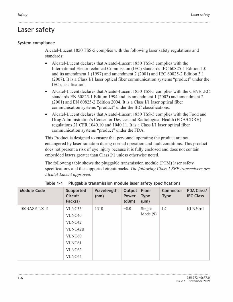
The following table shows the pluggable transmission module (PTM) laser safety
specifications and the supported circuit packs. The following Class 1 SFP transceivers are
Alcatel-Lucent approved.
Table 1-1 Pluggable transmission module laser safety specifications
Module Code Supported
Circuit
Pack(s)
Wavelength
(nm)
Output
Power
(dBm)
Fiber
Type
(µm)
Connector
Type
FDA Class/
IEC Class
100BASE-LX-I1 VL�C35
VL�C40
VL�C42
VL�C42B
VL�C60
VL�C61
VL�C62
VL�C64
1310 −8.0 Single
Mode (9)
LC I(L�50)/1
Safety Laser safety
...................................................................................................................................................................................................................................
...................................................................................................................................................................................................................................
1-6 365-372-406R7.0
Issue 1 November 2009

Table 1-1 Pluggable transmission module laser safety specifications (continued)
Module Code Supported
Circuit
Pack(s)
Wavelength
(nm)
Output
Power
(dBm)
Fiber
Type
(µm)
Connector
Type
FDA Class/
IEC Class
1000BASE-ZX-I1 VL�C50
VL�C52
VL�C40
VL�C42
VL�C42B
1550 +5.0 Single
Mode (9)
LC I(L�50)/1
BASE-T-C1 electrical VL�C40
VL�C42
VL�C42B
VL�C50
VL�C52
VL�C60
VL�C61
VL�C62
VL�C64
�A �A �A RJ45 �A
GE-1X2XFC-LX-I1 VL�C40
VL�C42
VL�C42B
VL�C50
VL�C52
VL�C60
VL�C61
VL�C62
VL�C64
1310 −3.0 Single
Mode (9)
LC I(L�50)/1
Safety Laser safety
...................................................................................................................................................................................................................................
...................................................................................................................................................................................................................................
365-372-406R7.0
Issue 1 November 2009
1-7

Table 1-1 Pluggable transmission module laser safety specifications (continued)
Module Code Supported
Circuit
Pack(s)
Wavelength
(nm)
Output
Power
(dBm)
Fiber
Type
(µm)
Connector
Type
FDA Class/
IEC Class
GE-1X2XFC-SX-I1 VL�C40
VL�C42
VL�C42B
VL�C50
VL�C52
VL�C60
VL�C61
VL�C62
VL�C64
850 −2.5 Multimode
(50 and
62.5)
LC I(L�50)/1
GE-131T149R-I1 VL�C40
VL�C42
VL�C42B
VL�C50
VL�C52
VL�C60
VL�C61
VL�C62
VL�C64
1310 (TX)
1490 (RX)
+2.0 Single
Mode (9)
LC I(L�50)/1
GE-149T131R-I1 VL�C40
VL�C42
VL�C42B
VL�C50
VL�C52
VL�C60
VL�C61
VL�C62
VL�C64
1490 (TX)
1310 (RX)
+2.0 Single
Mode (9)
LC I(L�50)/1
OC3IR1-I1 VL�C50
VL�C52
VL�C64
1310 -8.0 Single
Mode (9)
LC I(L�50)/1
Safety Laser safety
...................................................................................................................................................................................................................................
...................................................................................................................................................................................................................................
1-8 365-372-406R7.0
Issue 1 November 2009

Table 1-1 Pluggable transmission module laser safety specifications (continued)
Module Code Supported
Circuit
Pack(s)
Wavelength
(nm)
Output
Power
(dBm)
Fiber
Type
(µm)
Connector
Type
FDA Class/
IEC Class
OC3LR1-I1 VL�C50
VL�C52
VL�C64
1310 0.0 Single
Mode (9)
LC I(L�50)/1
OC12IR1-I1 VL�C50
VL�C52
1310 −8.0 Single
Mode (9)
LC I(L�50)/1
OC12LR1-I1 VL�C50
VL�C52
1310 +2.0 Single
Mode (9)
LC I(L�50)/1
OC12LR2-I1 VL�C50
VL�C52
1550 +2.0 Single
Mode (9)
LC I(L�50)/1
622-131T155R-I1 VL�C50
VL�C52
1310 (TX)
1550 (RX)
+2.0 Single
Mode (9)
LC I(L�50)/1
622-155T131R-I1 VL�C50
VL�C52
1550 (TX)
1310 (RX)
+2.0 Single
Mode (9)
LC I(L�50)/1
S155I2 VL�C50
VL�C52
VL�C64
1310 −8.0 Single
Mode (9)
LC I(L�50)/1
S622C47EL VL�C50
VL�C52
VL�C64
1471 +5.0 Single
Mode (9)
LC I(L�50)/1
S622C49EL VL�C50
VL�C52
VL�C64
1491 +5.0 Single
Mode (9)
LC I(L�50)/1
S622C51EL VL�C50
VL�C52
VL�C64
1511 +5.0 Single
Mode (9)
LC I(L�50)/1
S622C53EL VL�C50
VL�C52
VL�C64
1531 +5.0 Single
Mode (9)
LC I(L�50)/1
S622C55EL VL�C50
VL�C52
VL�C64
1551 +5.0 Single
Mode (9)
LC I(L�50)/1
Safety Laser safety
...................................................................................................................................................................................................................................
...................................................................................................................................................................................................................................
365-372-406R7.0
Issue 1 November 2009
1-9

Table 1-1 Pluggable transmission module laser safety specifications (continued)
Module Code Supported
Circuit
Pack(s)
Wavelength
(nm)
Output
Power
(dBm)
Fiber
Type
(µm)
Connector
Type
FDA Class/
IEC Class
S622C57EL VL�C50
VL�C52
VL�C64
1571 +5.0 Single
Mode (9)
LC I(L�50)/1
S622C59EL VL�C50
VL�C52
VL�C64
1591 +5.0 Single
Mode (9)
LC I(L�50)/1
S622C61EL VL�C50
VL�C52
VL�C64
1611 +5.0 Single
Mode (9)
LC I(L�50)/1
SGEC47EL VL�C40
VL�C42
VL�C42B
VL�C50
VL�C52
VL�C60
VL�C61
VL�C62
VL�C64
1471 +5.0 Single
Mode (9)
LC I(L�50)/1
SGEC49EL VL�C40
VL�C42
VL�C42B
VL�C50
VL�C52
VL�C60
VL�C61
VL�C62
VL�C64
1491 +5.0 Single
Mode (9)
LC I(L�50)/1
Safety Laser safety
...................................................................................................................................................................................................................................
...................................................................................................................................................................................................................................
1-10 365-372-406R7.0
Issue 1 November 2009

Table 1-1 Pluggable transmission module laser safety specifications (continued)
Module Code Supported
Circuit
Pack(s)
Wavelength
(nm)
Output
Power
(dBm)
Fiber
Type
(µm)
Connector
Type
FDA Class/
IEC Class
SGEC51EL VL�C40
VL�C42
VL�C42B
VL�C50
VL�C52
VL�C60
VL�C61
VL�C62
VL�C64
1511 +5.0 Single
Mode (9)
LC I(L�50)/1
SGEC53EL VL�C40
VL�C42
VL�C42B
VL�C50
VL�C52
VL�C60
VL�C61
VL�C62
VL�C64
1531 +5.0 Single
Mode (9)
LC I(L�50)/1
SGEC55EL VL�C40
VL�C42
VL�C42B
VL�C50
VL�C52
VL�C60
VL�C61
VL�C62
VL�C64
1551 +5.0 Single
Mode (9)
LC I(L�50)/1
Safety Laser safety
...................................................................................................................................................................................................................................
...................................................................................................................................................................................................................................
365-372-406R7.0
Issue 1 November 2009
1-11

Table 1-1 Pluggable transmission module laser safety specifications (continued)
Module Code Supported
Circuit
Pack(s)
Wavelength
(nm)
Output
Power
(dBm)
Fiber
Type
(µm)
Connector
Type
FDA Class/
IEC Class
SGEC57EL VL�C40
VL�C42
VL�C42B
VL�C50
VL�C52
VL�C60
VL�C61
VL�C62
VL�C64
1571 +5.0 Single
Mode (9)
LC I(L�50)/1
SGEC59EL VL�C40
VL�C42
VL�C42B
VL�C50
VL�C52
VL�C60
VL�C61
VL�C62
VL�C64
1591 +5.0 Single
Mode (9)
LC I(L�50)/1
SGEC61EL VL�C40
VL�C42
VL�C42B
VL�C50
VL�C52
VL�C60
VL�C61
VL�C62
VL�C64
1611 +5.0 Single
Mode (9)
LC I(L�50)/1
Safety Laser safety
...................................................................................................................................................................................................................................
...................................................................................................................................................................................................................................
1-12 365-372-406R7.0
Issue 1 November 2009

General laser information
Optical fiber telecommunication systems, their associated test sets, and similar operating
systems use semiconductor laser transmitters that emit infrared (IR) light at wavelengths
between approximately 800 nanometers (nm) and 1600 nm. The emitted light is above the
red end of the visible spectrum, which is normally not visible to the human eye. Although
radiant energy at near-IR wavelengths is officially designated invisible, some people can
see the shorter wavelength energy even at power levels several orders of magnitude below
any that have been shown to cause injury to the eye.
Conventional lasers can produce an intense beam of monochromatic light.
Monochromatic light is a single wavelength output of pure color that may be visible or
invisible to the eye. A conventional laser produces a small-sized beam of light, and
because the beam size is small, the power density (also called irradiance) is very high.
Consequently, lasers and laser products are subject to federal and applicable state
regulations as well as international standards for their safe operation.
A conventional laser beam expands very little over distance, or is said to be very well
collimated. Thus, conventional laser irradiance remains relatively constant over distance.
However, lasers used in lightwave systems have a large beam divergence, typically 10 to
20 degrees. Here, irradiance obeys the inverse square law (doubling the distance reduces
the irradiance by a factor of four) and rapidly decreases over distance.
Lasers and eye damage
The optical energy emitted by laser and high-radiance LEDs in the 400 to 1400–nm range
may cause eye damage if absorbed by the retina. When a beam of light enters the eye, the
eye magnifies and focuses the energy on the retina magnifying the irradiance. The
irradiance of the energy that reaches the retina is higher than at the cornea and, if
sufficiently intense, may cause a retinal burn.
The damage mechanism at the wavelengths used in optical fiber telecommunications is
thermal in origin; for example, damage caused by heating. Therefore, a specific amount
of energy is required for a definite time to heat an area of retinal tissue. Damage to the
retina occurs only when one looks at the light sufficiently long that the product of the
retinal irradiance and the viewing time exceeds the damage threshold. Optical energies
above 1400 nm cause corneal and skin burns, but these optical energies do not affect the
retina. The thresholds for injury at wavelengths greater than 1400 nm are significantly
higher than those for wavelengths in the retinal hazard region.
Classification of lasers
Manufacturers of lasers and laser products in the United States are regulated by the Food
and Drug Administration's Center for Devices and Radiological Health (FDA/CDRH)
under 21 CFR 1040. These regulations require manufacturers to certify each laser or laser
product as belonging to one of the following classes: I, II, lla, IlIa, lllb, or IV.
Safety Laser safety
...................................................................................................................................................................................................................................
...................................................................................................................................................................................................................................
365-372-406R7.0
Issue 1 November 2009
1-13

The International Electrotechnical Commission (IEC) is an international standards body
that writes laser safety standards under IEC-60825. Classification schemes are similar and
divided into Classes 1, 1M, 2, 2M, 3B, 3R, and 4. Lasers are classified according to the
accessible emission limits and their potential for causing injury.
Optical fiber telecommunication systems are generally classified as Class I/1, because,
under normal operating conditions, all energized laser transmitting circuit packs are
terminated on optical fibers which enclose the laser energy with the fiber sheath forming
a protective housing. Also, a protective housing/access panel is typically installed in front
of the laser circuit pack shelves. The circuit packs themselves, however, may be
FDA/CDRH Class I, IIIb, or IV or IEC Class 1, 1M, 3B, 3R, or 4. State-of-the-art Raman
and EDFA optical amplifiers have now extended into the Class IV/4 designations.
Laser safety precautions for optical fiber telecommunications systems
In its normal operating mode, an optical fiber telecommunication system is totally
enclosed and presents no risk of eye injury. It is a Class I/1 system under the FDA/CDRH
and IEC classifications.
The fiber optic cables that interconnect various components of an optical fiber
telecommunication system can disconnect or break and may expose people to lightwave
emission. Also, certain measurements and maintenance procedures may expose the
technician to emission from the semiconductor laser during installation and servicing.
Unlike more familiar laser devices, such as solid-state and gas lasers, the emission pattern
of a semiconductor laser results in a highly divergent beam. In a divergent beam, the
irradiance (power density) decreases rapidly with distance. The greater the distance, the
less energy will enter the eye and the less potential risk for eye injury. If you inadvertently
view an unterminated fiber or damaged fiber with the unaided eye at distances greater
than 5 to 6 inches, normally, it will not cause eye injury provided that the power in the
fiber is less than a few milliwatts at the near IR wavelengths and a few tens of milliwatts
at the far IR wavelengths. However, damage may occur if you use an optical instrument
such as a microscope, magnifying glass, or eye loupe to stare at the energized fiber end.
Safety Laser safety
...................................................................................................................................................................................................................................
...................................................................................................................................................................................................................................
1-14 365-372-406R7.0
Issue 1 November 2009

Laser radiation
CAUTION
Laser hazard
Use of controls or adjustments or performance of procedures other than those specified
herein may result in hazardous laser radiation exposure.
Do not view directly into the laser beam with optical instruments such as a fiber
microscope because viewing of laser emission in excess of Class 1 limits significantly
increases the risk of eye damage.
�ever look into the end of an exposed fiber or an open connector as long as the optical
source is switched on.
Ensure that the optical source is switched off before disconnecting optical fiber
connectors.
Laser safety precautions for enclosed systems
Under normal operating conditions, optical fiber telecommunication systems are
completely enclosed. Observe the following laser safety precautions for enclosed
systems:
• Because of the potential for eye damage, do not stare into optical connectors or
broken fibers.
• Do not under any circumstances perform laser/fiber optic operations before
satisfactorily completing laser safety training.
• Since viewing lightwave emission directly in excess of Class I/1 limits with an optical
instrument such as an eye loupe greatly increases the risk of eye damage,
observe/follow laser safety labels. Appropriate labels must appear in plain view, in
close proximity to the optical port on the protective housing/access panel of the
terminal equipment
Laser safety precautions for unenclosed systems
During service, maintenance, or restoration, an optical fiber telecommunication system is
considered unenclosed. Observe the following laser safety precautions for unenclosed
systems:
• Only authorized, trained personnel shall be permitted to do service, maintenance, and
restoration. Avoid exposing the eye to emissions from unterminated, energized optical
connectors at close distances. Laser modules associated with the optical ports of laser
circuit packs are typically recessed, which limits the exposure distance. Optical port
shutters, automatic power reduction (APR), and automatic power shutdown (APSD)
Safety Laser safety
...................................................................................................................................................................................................................................
...................................................................................................................................................................................................................................
365-372-406R7.0
Issue 1 November 2009
1-15

are engineering controls that are also used to limit the emissions. However, do not
stare or look directly into the optical port with optical instruments or magnifying
lenses when removing or replacing laser circuit packs. (�ormal eye wear or indirect
viewing instruments, such as a Find-R-Scopes, are not considered magnifying lenses
or optical instruments.)
• Only authorized, trained personnel shall use the optical test equipment during
installation or servicing since this equipment contains semiconductor lasers. (Some
examples of optical test equipment are Optical Time Domain Reflectometers
[OTDRs] and Hand-Held Loss Test Sets.)
• Do not, under any circumstance, scan a fiber with an optical test set without verifying
that all laser sources on the fiber are turned off.
• Only authorized personnel are permitted in the immediate area of the optical fiber
telecommunication systems during installation and service.
For guidance on the safe use of optical fiber optic communication systems in the
workplace, consult A�SI Z136.2, American �ational Standard for Safe Use of Optical
Fiber Communication Systems Utilizing Laser Diodes and LED Sources in the United
States or outside the United States, IEC-60825, Part 2.
Safety Laser safety
...................................................................................................................................................................................................................................
...................................................................................................................................................................................................................................
1-16 365-372-406R7.0
Issue 1 November 2009

Laser warning labels
The following figure shows the different types of laser warning labels:
Legend
1. Laser symbol
2. Laser classification label (This label may show only the laser class or both the laser
class and the maximum output power.)
3. Laser warning label
Figure 1-1 Laser warning labels
FAULT
MA-metro-428
LIHTR
INVISIBLE LASER RADIATIONWHEN OPEN AND FIBERDISCONNECTED
Avoid direct exposure to beam
Do not view beam directly withoptical instruments
CLASS 1 LASER
PRODUCT
3
1
2
DANGER
Safety Laser safety
...................................................................................................................................................................................................................................
...................................................................................................................................................................................................................................
365-372-406R7.0
Issue 1 November 2009
1-17

Electrostatic discharge
Overview
Electrostatic discharge (ESD) (for example, caused by touching with the hand) can
destroy semiconductor components. The correct operation of the complete system is then
no longer assured.
ESD warning
NOTICE
ESD hazard
ESD can destroy electronic components.
Always keep circuit packs in antistatic covers. Use the original packaging if possible. Use
a static ground wrist strap whenever handling circuit packs or working on the
Alcatel-Lucent 1850 TSS-5 system to prevent ESD damage to sensitive components.
All semiconductor components are basically sensitive to ESD. The ESD can also affect
the components indirectly.
ESD considerations
This section describes the precautions required to prevent ESD damage.
Circuit pack handling precautions
Industry experience has shown that all integrated circuit packs can be damaged by static
electricity that builds up on work surfaces and personnel. The static charges are produced
by various charging effects of movement and contact with other objects. Dry air allows
greater static charges to accumulate. Higher potentials are measured in areas with low
relative humidity, but potentials high enough to cause damage can occur anywhere.
Observe the following precautions when handling circuit packs/units to prevent ESD
damage.
• Assume all circuit packs contain solid-state electronic components that can be
damaged by ESD.
• When handling circuit packs (for example storing, installing, and removing) or when
working on the backplane, always wear a grounded wrist strap or wear a heel strap
and stand on a grounded, static-dissipating floor mat.
• Wear working garment made of 100% cotton to avoid ESD.
• Handle all circuit packs by the faceplate or latch and by the top and bottom outermost
edges. �ever touch the components, conductors, or connector pins.
Safety Electrostatic discharge
...................................................................................................................................................................................................................................
...................................................................................................................................................................................................................................
1-18 365-372-406R7.0
Issue 1 November 2009

• Store and ship circuit packs and components in their shipping packing. Circuit packs
and components must be packed and unpacked only at workplaces suitably protected
against build-up of charge.
• Observe all warning labels on bags and cartons. Whenever possible, do not remove
circuit packs from antistatic packaging until ready to insert them into slots.
• If possible, open all circuit packs at a static-safe work position, using properly
grounded wrist straps and static-dissipating table mats.
• Always store and transport circuit packs in static-safe packaging. Shielding is not
required unless specified.
• Keep all static-generating materials such as food wrappers, plastics, and Styrofoam®
containers away from all circuit packs. When removing circuit packs from a shelf,
immediately place the circuit packs in static-safe packages.
• Whenever possible, maintain relative humidity above 20 percent.
Important! Ensure that any connectors on the shelf interconnection panel that are not
cabled are fitted with a plastic dust cap to provide ESD protection.
Static control wrist straps
To reduce the possibility of ESD damage, the Alcatel-Lucent 1850 TSS-5 shelf is
equipped with an ESD grounding jack to enable personnel to ground themselves using
wrist straps [Figure 1-2, “Static control wrist strap” (p. 1-19)], while handling circuit
packs or working on the shelf. Check the wrist straps periodically with a wrist strap tester
to ensure that they are working properly.
Important! The grounding jack is located on the front of the wall-mounted and
rack-mounted shelves.
Figure 1-2 Static control wrist strap
ToGroundConnection
NC-USM-110
Safety Electrostatic discharge
...................................................................................................................................................................................................................................
...................................................................................................................................................................................................................................
365-372-406R7.0
Issue 1 November 2009
1-19

Barred-hand symbol
Circuit packs containing components that are especially sensitive to ESD are identified by
warning labels bearing the barred-hand symbol. The following figure shows the
barred-hand symbol.
Figure 1-3 ESD warning label (barred-hand symbol)
MA-metro-429
Safety Electrostatic discharge
...................................................................................................................................................................................................................................
...................................................................................................................................................................................................................................
1-20 365-372-406R7.0
Issue 1 November 2009

Save these safety instructions
READ A�D U�DERSTA�D ALL I�STRUCTIO�S.
When installing, operating, or maintaining this equipment, always follow basic safety
precautions to reduce the risk of fire, electric shock, and injury to persons, including the
following:
1. Read and understand all instructions.
2. Follow all warnings and instructions marked on this product.
3. Operate this product only from the type of power sources that are indicated on the
marking label.
4. Connect this product only to the type of power sources recommended by
Alcatel-Lucent. For information on the powering instructions, consult the
Alcatel-Lucent 1850 Transport Service Switch (TSS-5) Installation and System
Turn-Up Guide.
5. This equipment is suitable for mounting on a concrete or other noncombustible
surface only. For information on proper mounting instructions, consult the
Alcatel-Lucent 1850 Transport Service Switch (TSS-5) Installation and System
Turn-Up Guide.
6. Install only equipment identified in the Alcatel-Lucent 1850 Transport Service Switch
(TSS-5) Installation and System Turn-Up Guide. Use of other equipment may result in
improper connection of circuitry leading to fire or injury to persons.
7. Ensure that all metallic telecommunication interfaces (traffic ports) that leave the
building premises are connected to telecommunication devices that provide primary
and secondary protection, as applicable.
8. Do not use this product near water; for example, in a wet basement.
9. Do not place this product on an unstable cart, stand, or table. The product may fall
and cause serious damage to the product.
10. Use caution when installing or modifying telecommunications lines.
11. �ever install telecommunications wiring during a lightning storm.
12. �ever install telecommunications connections in wet locations.
13. �ever touch uninsulated telecommunications wires or terminals unless the
telecommunications line has been disconnected at the network interface.
The exclamation point within an equilateral triangle is intendedto alert the user to the presence of important operating andmaintenance (servicing) instructions in the literatureaccompanying this product.
Safety Save these safety instructions
...................................................................................................................................................................................................................................
...................................................................................................................................................................................................................................
365-372-406R7.0
Issue 1 November 2009
1-21

14. �ever touch uninsulated wiring or terminals carrying direct current or ringing current,
and never leave this wiring exposed. Protect and tape uninsulated wiring and
terminals to avoid risk of fire, electric shock, and injury to service personnel.
15. �ever push objects of any kind into this product through slots as they may touch
dangerous voltage points or short out parts that could result in a risk of fire or
electrical shock. �ever spill liquids of any kind on the product.
16. To protect the unit from overheating, slots and openings in the unit are provided for
ventilation. Do not block or cover these openings. Do not place this product in a
built-in installation unless proper ventilation is provided.
17. To reduce the risk of an electrical shock, do not disassemble this product. Service
should be performed by trained personnel only. Opening or removing covers and/or
circuit boards may expose you to dangerous voltages or other risks. Incorrect
reassembly can cause electrical shock when the unit is subsequently used.
18. Some of the Alcatel-Lucent 1850 TSS-5 family hardware modules contain
FDA/CDRH Class I/IEC Class 1 single-mode laser products that are enclosed
lightwave transmission systems.
Under normal operating conditions, lightwave transmission systems are completely
enclosed; however, the following precautions must be observed because of the
potential for eye damage:
• Do not stare directly into the optical connectors terminating the cables.
• Ensure that technicians have satisfactorily completed an approved training course
before performing lightwave/lightguide operations.
• Do not use optical instruments such as an eye loupe to view a fiber or
unterminated connector.
More information about laser safety can be found in the Alcatel-Lucent 1850
Transport Service Switch (TSS-5) Installation and System Turn-Up Guide.
19. For a unit intended to be powered from −48 VDC or +24 VDC voltage sources, read
and understand the following:
• Use only Safety Extra Low Voltage (SELV) −48 VDC or +24 VDC sources.
• Disconnect up to two power supply connections when removing power from the
system.
• Provide a readily accessible disconnect device as part of the building installation.
• Ensure that there is no exposed wire when the input power cables are connected to
the unit.
• Include an independent frame ground drop to building ground. Refer to the
Alcatel-Lucent 1850 Transport Service Switch (TSS-5) Installation and System
Turn-Up Guide.
Safety Save these safety instructions
...................................................................................................................................................................................................................................
...................................................................................................................................................................................................................................
1-22 365-372-406R7.0
Issue 1 November 2009

This electrical ground symbol is marked on the product, adjacent to the ground
(earth) area for the connection of the ground (earth) conductor.
• This equipment is to be installed only in Restricted Access Areas on Business and
Customer Premises Applications in Accordance with Articles 110-16, 110-17, and
110-18 of the �ational Electrical Code, A�SI/�FPA �o. 70. Other installations
exempt from the enforcement of the �ational Electrical Code may be engineered
according to the accepted practices of the local telecommunications utility.
20. For a unit intended to be powered from 100 to 120/200 to 240 VAC voltage sources,
read and understand the following:
• Unplug this product from the wall outlet before cleaning. Do not use liquid
cleaners or aerosol cleaners. Use a damp cloth for cleaning.
• Do not staple or otherwise attach the power supply cord to the building surfaces.
• Do not overload wall outlets and extension cords as this can result in the risk of
fire or electrical shock.
• Install the socket outlet near the equipment so that it is readily accessible.
• This product is equipped with a three-wire grounding type plug, a plug having a
third (grounding) pin. This plug is intended to fit only into a grounding type
power outlet. This is a safety feature. If you are unable to insert the plug into the
outlet, contact your electrician to replace your obsolete outlet. Do not defeat the
safety purpose of the grounding type plug. Do not use a 3-to-2-prong adapter at
the receptacle. Use of this type adapter may result in risk of electrical shock
and/or damage to this product.
• Do not allow anything to rest on the power cord. Do not locate this product where
the cord may be abused by persons walking on it.
21. Unplug this product from the wall outlet, and refer servicing to qualified service
personnel under the following conditions:
• When the power supply cord or plug is damaged or frayed.
• If liquid has been spilled into the product.
• If the product has been exposed to rain or water.
• If the product does not operate normally by following the operating instructions
(Adjust only those controls that are covered by the operating instructions because
improper adjustment of other controls may result in damage and will often require
extensive work by qualified technician to restore the product to normal operation.)
• If the product has been dropped or the cabinet has been damaged.
• If the product exhibits a distinct change in performance.
SAVE THESE I�STRUCTIO�S.
Safety Save these safety instructions
...................................................................................................................................................................................................................................
...................................................................................................................................................................................................................................
365-372-406R7.0
Issue 1 November 2009
1-23
Eco-environmental statements
Overview
The statements that follow are the eco-environmental statements that apply to
Alcatel-Lucent 1850 TSS-5 when deployed in the European Union, China, Canada, and
the United States.
Packaging collection and recovery requirements
Countries, states, localities, or other jurisdictions may require that systems be established
for the return and/or collection of packaging waste from the consumer, or other end user,
or from the waste stream. Additionally, reuse, recovery, and/or recycling targets for the
return and/or collection of the packaging waste may be established.
For more information regarding collection and recovery of packaging and packaging
waste within specific jurisdictions, please contact the Alcatel-Lucent Services -
Environmental Health and Safety organization.
Material content compliance
European Union RoHS
European Union (EU) Directive 2002/95/EC, “Restriction of the use of certain Hazardous
Substances” (RoHS), restricts the use of lead, mercury, cadmium, hexavalent chromium,
and certain flame retardants in electrical and electronic equipment. This Directive applies
to electrical and electronic products placed on the EU market after 1 July 2006, with
various exemptions, including an exemption for lead solder in network infrastructure
equipment. Alcatel-Lucent products shipped to the EU after 1 July 2006 comply with the
EU RoHS Directive.
China RoHS
The People's Republic of China Ministry of Information Industry has published a
regulation (Order #39) and associated standards regarding restrictions on hazardous
substances (China RoHS). Currently, the legislation requires all Electronic and
Information Products (EIP) to comply with certain labeling and documentation
requirements. Alcatel-Lucent products manufactured on or after 1 March 2007, that are
intended for sale to customers in the China market, must comply with these requirements.
In accordance with the People’s Republic of China Electronic Industry Standard
“Marking for the Control of Pollution Caused by Electronic Information Product”
(SJ/T11364- 2006), customers may access Alcatel-Lucent Hazardous Substances Table
(http://www.alcatel-sbell.com.cn/wwwroot/images/upload/private/1/media/ChinaRoHS.
pdf) .
Safety Eco-environmental statements
...................................................................................................................................................................................................................................
...................................................................................................................................................................................................................................
1-24 365-372-406R7.0
Issue 1 November 2009
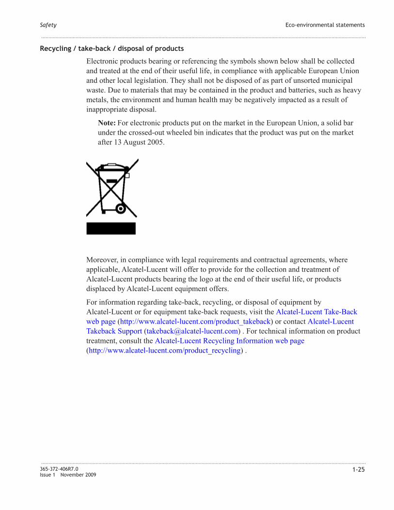
Recycling / take-back / disposal of products
Electronic products bearing or referencing the symbols shown below shall be collected
and treated at the end of their useful life, in compliance with applicable European Union
and other local legislation. They shall not be disposed of as part of unsorted municipal
waste. Due to materials that may be contained in the product and batteries, such as heavy
metals, the environment and human health may be negatively impacted as a result of
inappropriate disposal.
�ote: For electronic products put on the market in the European Union, a solid bar
under the crossed-out wheeled bin indicates that the product was put on the market
after 13 August 2005.
Moreover, in compliance with legal requirements and contractual agreements, where
applicable, Alcatel-Lucent will offer to provide for the collection and treatment of
Alcatel-Lucent products bearing the logo at the end of their useful life, or products
displaced by Alcatel-Lucent equipment offers.
For information regarding take-back, recycling, or disposal of equipment by
Alcatel-Lucent or for equipment take-back requests, visit the Alcatel-Lucent Take-Back
web page (http://www.alcatel-lucent.com/product_takeback) or contact Alcatel-Lucent
Takeback Support ([email protected]) . For technical information on product
treatment, consult the Alcatel-Lucent Recycling Information web page
(http://www.alcatel-lucent.com/product_recycling) .
Safety Eco-environmental statements
...................................................................................................................................................................................................................................
...................................................................................................................................................................................................................................
365-372-406R7.0
Issue 1 November 2009
1-25


2 2Getting started
Overview
Purpose
Use this section to connect a PC and configure initial parameters for in-band or
out-of-band connectivity to the VL�C4x/VL�C6x circuit packs.
Out-of-band connectivity refers to using the RS-232 console port on the VLIU or the
MGMT LA� service port on the VL�C4x/VL�C6x faceplate to access the
VL�C4x/VL�C6x.
In-band connectivity allows you to access the VL�C4x/VL�C6x from a local or remote
PC using the Ethernet network and the IP address information assigned to the
VL�C4x/VL�C6x. You must configure the VL�C4x/VL�C6x network parameters with
IP address information (IP address, subnet mask, and default gateway) to access the
VL�C4x/VL�C6x in-band. All the network LA� ports will share one IP address.
Initial configuration for connectivity requires you to use either the RS-232 console port or
the MGMT LA� service port.
Contents
Before you begin 2-2
Procedure 2-1: Connect personal computer (PC) and establish Command Line
Interface (CLI) session to VL�C4x/VL�C6x
2-3
Procedure 2-2: Configure VL�C4x/VL�C6x for in-band or out-of-band
connectivity
2-10
...................................................................................................................................................................................................................................
365-372-406R7.0
Issue 1 November 2009
2-1

Before you begin
Before you begin
Important! Command Line Interface (CLI) commands or the Web GUI is required to
interface with the VL�C40/42/42B Ethernet Aggregator, VL�C60/61/62 Circuit
Emulator, and VL�C64 Circuit Emulation Mini-Hub circuit packs.
Determine whether you will configure the switch for in-band or out-of-band connectivity.
Required equipment
All procedures in this chapter require that the following equipment is available:
• Personal Computer (PC) and related cables specified in the procedures.
• Wrist Strap
Important! If additional equipment is required to perform a specific procedure, the
additional equipment is listed in the procedure.
Getting started Before you begin
...................................................................................................................................................................................................................................
...................................................................................................................................................................................................................................
2-2 365-372-406R7.0
Issue 1 November 2009

Procedure 2-1: Connect personal computer (PC) and establish
Command Line Interface (CLI) session to VLNC4x/VLNC6x
Overview
Use this procedure to connect PC and establish a local or remote CLI session with the
VL�C4x/VL�C6x circuit pack.
Required equipment
At least one of the following cables is required for direct connection to the network
element:
• RS-232 cable with an RJ-45 connector on one end for the RS-232 console port
(RS232 M2 or RS232 M1) on the VLIU, and a PC serial connector on the other end
for connection to the PC.
• CAT5 Ethernet straight-through or a cross-over cable for the RJ-45 MGMT LAN port
on the VL�C4x/VL�C6x faceplate, any of the 20 "in-band" FE Ethernet ports on the
VLIU, or any of the GbE SFP ports on the VL�C4x/VL�C6x faceplate.
For detailed cabling information, refer to the Alcatel-Lucent 1850 Transport Service
Switch (TSS-5) Installation and System Turn-Up Guide.
Before you begin
Prior to performing this procedure:
1. Refer to the Alcatel-Lucent 1850 Transport Service Switch (TSS-5) Command Line
Interface Guide, and become familiar with the command structure.
2. Refer to “Electrostatic discharge” (p. 1-18) in Chapter 1, “Safety”.
3. If required, obtain a valid user ID and password for the required network element.
4. If establishing a local/remote CLI session with a network element using Telnet or
SSH, obtain the required IP address of the port (MGMT LAN port or in-band Ethernet
network LA� ports) being used for the management interface.
Step
As required, refer to one of the following procedures to establish a CLI session.
...................................................................................................................................................................................................
1 Establish local CLI session using RS-232 console port.
Reference: Procedure 2-1.1: “Connect personal computer (PC) and establish local
CLI session using RS-232 console port” (p. 2-5)
...................................................................................................................................................................................................
2 Establish local CLI session using MGMT LAN serviceport.
Getting started Procedure 2-1: Connect personal computer (PC) and
establish Command Line Interface (CLI) session to
VLNC4x/VLNC6x...................................................................................................................................................................................................................................
...................................................................................................................................................................................................................................
365-372-406R7.0
Issue 1 November 2009
2-3

Reference: Procedure 2-1.2: “Connect personal computer (PC) and establish local
CLI session using MGMT LA� serviceport” (p. 2-7)
...................................................................................................................................................................................................
3 Establish remote CLI session using Ethernet network.
Reference: Procedure 2-1.3: “Connect personal computer (PC) and establish remote
CLI session using Ethernet network” (p. 2-9)
E N D O F S T E P S
...................................................................................................................................................................................................
Getting started Procedure 2-1: Connect personal computer (PC) and
establish Command Line Interface (CLI) session to
VLNC4x/VLNC6x...................................................................................................................................................................................................................................
...................................................................................................................................................................................................................................
2-4 365-372-406R7.0
Issue 1 November 2009

Procedure 2-1.1: Connect personal computer (PC) and
establish local CLI session using RS-232 console port
Overview
Use this procedure to connect PC and establish a local CLI session with the
VL�C4x/VL�C6x circuit pack using the RS-232 console port.
The RS-232 (RS232 M1) port on the front of the VLIU connects to the Main 1 slot. The
RS-232 (RS232 M2) port on the front of the VLIU connects to the Main 2 slot. The
VL�C6x may be installed in either Main 1 or Main 2. The VL�C4x may only be
installed in the Main 2 slot.
The RS-232 ports are not generally recommended for use in connecting to the
VL�C4x/VL�C6x. It is normally used by service personnel.
Step
...................................................................................................................................................................................................
1 Use an appropriate cable to connect the RS-232 RJ-45 type console port on the VLIU to
an available serial port of the PC.
...................................................................................................................................................................................................
2 Establish a terminal emulation session (HyperTerminal, Procomm, or similar session)
using the following default values:
• Baud Rate (bps): 9600
• Character Size (bits): 8
• Flow Control: Disable
• Stop Bits: 1
• Parity: none
• VT100 emulation
Result: The login User prompt displays when the terminal interface initializes.
If the login prompt does not display, try changing the baud rate of the connection.
...................................................................................................................................................................................................
3 Enter user name and password.
Important! The default User name is admin and the password is blank.
Result: The User EXEC prompt [(ALU 1850TSS-5-xx) >] displays.
The prompt may be changed using the set prompt <prompt_string> command
in the user privilege mode.
Getting started Procedure 2-1.1: Connect personal computer (PC) and
establish local CLI session using RS-232 console port
...................................................................................................................................................................................................................................
...................................................................................................................................................................................................................................
365-372-406R7.0
Issue 1 November 2009
2-5

...................................................................................................................................................................................................
4 Refer to the Alcatel-Lucent 1850 Transport Service Switch (TSS-5) Command Line
Interface Guide, for help on using the CLI commands.
E N D O F S T E P S
...................................................................................................................................................................................................
Getting started Procedure 2-1.1: Connect personal computer (PC) and
establish local CLI session using RS-232 console port
...................................................................................................................................................................................................................................
...................................................................................................................................................................................................................................
2-6 365-372-406R7.0
Issue 1 November 2009

Procedure 2-1.2: Connect personal computer (PC) and
establish local CLI session using MGMT LAN serviceport
Overview
Use this procedure to connect PC and establish a local CLI session with the
VL�C4x/VL�C6x circuit pack using the MGMT LAN port on the faceplate of the circuit
pack.
This procedure assumes that the proper connection interfaces have already been
configured using the procedures in Procedure 2-2: “Configure VL�C4x/VL�C6x for
in-band or out-of-band connectivity ” (p. 2-10).
This procedure also assumes that Telnet or secure shell (SSH) access has been configured.
See Telnet Commands and/or Secure Shell (SSH) commands in the Alcatel-Lucent 1850
Transport Service Switch (TSS-5) Command Line Interface Guide.
Step
...................................................................................................................................................................................................
1 Obtain the IP address of the MGMT LAN port from your network administrator, if
required, or use the default IP address if it has not been changed.
Default IP addresses may be one of the following:
• For R4.1 and later releases: 169.254.1.1 for VL�C40, VL�C42/42B, VL�C60,
VL�C61, VL�C62, and VL�C64
• For releases prior to R4.1: (192.168.0.2 [VL�C40]), (192.168.0.3 [VL�C60]).
Important! You must also obtain a user name and password if the default user name
of admin has been changed.
...................................................................................................................................................................................................
2 Connect the MGMT LAN port on the faceplate of the VL�C4x/VL�C6x circuit pack to
the �IC card of the PC. If you are connecting the PC directly to the �E, use the LA�
10Base-T cross-over cable. If you connecting the PC to a hub, use the LA� 10Base-T
straight-through cable.
Important! If you are uncertain that the MGMT LAN port or Ethernet network LA�
port has already been provisioned, connecting via the serial port is recommended.
...................................................................................................................................................................................................
3 Establish a Telnet or secure shell (SSH) session from your PC using the default IP address
or the IP address obtained from your network administrator.
Getting started Procedure 2-1.2: Connect personal computer (PC) and
establish local CLI session using MGMT LAN serviceport
...................................................................................................................................................................................................................................
...................................................................................................................................................................................................................................
365-372-406R7.0
Issue 1 November 2009
2-7

Result: The login User prompt displays when the terminal interface initializes.
...................................................................................................................................................................................................
4 Enter user name and password.
Important! The default User name is admin and the password is blank.
Result: The User EXEC prompt [(ALU 1850TSS-5-xx) >] displays.
The prompt may be changed using the set prompt <prompt_string> command
in the user privilege mode.
...................................................................................................................................................................................................
5 Refer to the Alcatel-Lucent 1850 Transport Service Switch (TSS-5) Command Line
Interface Guide, for help on using the CLI commands.
E N D O F S T E P S
...................................................................................................................................................................................................
Getting started Procedure 2-1.2: Connect personal computer (PC) and
establish local CLI session using MGMT LAN serviceport
...................................................................................................................................................................................................................................
...................................................................................................................................................................................................................................
2-8 365-372-406R7.0
Issue 1 November 2009

Procedure 2-1.3: Connect personal computer (PC) and
establish remote CLI session using Ethernet network
Overview
Use this procedure to establish a remote CLI session with the VL�C4x/VL�C6x circuit
pack.
Important! This procedure assumes that the proper connection interfaces have
already been configured using the procedures in Procedure 2-2: “Configure
VL�C4x/VL�C6x for in-band or out-of-band connectivity ” (p. 2-10).
This procedure also assumes that Telnet or secure shell (SSH) access has been
configured. See Telnet Commands and/or Secure Shell (SSH) commands in the
Alcatel-Lucent 1850 Transport Service Switch (TSS-5) Command Line Interface
Guide.
Step
...................................................................................................................................................................................................
1 Obtain a user name and password, if required, and the IP address of the
VL�C4x/VL�C6x from your network administrator.
Important! You must obtain a user name and password if the default user name of
admin has been changed.
...................................................................................................................................................................................................
2 Establish a Telnet or secure shell (SSH) session from your PC using the default IP address
or the IP address obtained from your network administrator.
Result: The login User prompt displays when the terminal interface initializes.
...................................................................................................................................................................................................
3 Enter user name and password.
Important! The default User name is admin and the password is blank.
Result: The User EXEC prompt [(ALU 1850TSS-5-xx) >] displays.
The prompt may be changed using the set prompt <prompt_string> command
in the user privilege mode.
...................................................................................................................................................................................................
4 Refer to the Alcatel-Lucent 1850 Transport Service Switch (TSS-5) Command Line
Interface Guide, for help on using the CLI commands.
E N D O F S T E P S
...................................................................................................................................................................................................
Getting started Procedure 2-1.3: Connect personal computer (PC) and
establish remote CLI session using Ethernet network
...................................................................................................................................................................................................................................
...................................................................................................................................................................................................................................
365-372-406R7.0
Issue 1 November 2009
2-9

Procedure 2-2: Configure VLNC4x/VLNC6x for in-band or
out-of-band connectivity
Overview
Use this procedure to connect PC and configure initial parameters for in-band or
out-of-band connectivity to the VL�C4x/VL�C6x.
Out-of-band connectivity refers to using the RS-232 console port on the VLIU or the
MGMT LAN port on the VL�C4x/VL�C6x faceplate to access the VL�C4x/VL�C6x.
In-band connectivity allows you to access the VL�C4x/VL�C6x from a local or remote
PC using the Ethernet network and the IP address information assigned to the
VL�C4x/VL�C6x You must configure the VL�C4x/VL�C6x network parameters with
IP address information (IP address, subnet mask, and default gateway) to access the
VL�C4x/VL�C6x in-band. All the network LA� ports will share one IP address.
The network port and serviceport IP address information must be in different IP subnets.
Only one gateway may be defined for remote access, either on the network port or the
serviceport.
This procedure assumes that the VL�C4x/VL�C6x was not configured before and is in
the factory default state.
Required equipment
At least one of the following cables is required for direct connection to the network
element:
• RS-232 cable with an RJ-45 connector on one end for the RS232 console port (RS232
M2) or (RS232 M1) on the VLIU, and a PC serial connector on the other end for
connection to the PC.
• CAT5 Ethernet straight-through or a cross-over cable for the RJ-45 MGMT LAN port
on the VL�C4x/VL�C6x faceplate, any of the 20 "in-band" FE Ethernet ports on the
VLIU for the VL�C4x, or any of the GbE SFP ports on the VL�C4x/VL�C6x
faceplate.
For detailed cabling information, refer to the Alcatel-Lucent 1850 Transport Service
Switch (TSS-5) Installation and System Turn-Up Guide.
Before you begin
Prior to performing this procedure:
1. Determine whether you will configure the VL�C4x/VL�C6x for in-band or
out-of-band connectivity.
2. Refer to the Alcatel-Lucent 1850 Transport Service Switch (TSS-5) Command Line
Interface Guide, and become familiar with the command structure.
Getting started Procedure 2-2: Configure VLNC4x/VLNC6x for in-band or
out-of-band connectivity
...................................................................................................................................................................................................................................
...................................................................................................................................................................................................................................
2-10 365-372-406R7.0
Issue 1 November 2009

3. Refer to “Electrostatic discharge” (p. 1-18) in Chapter 1, “Safety”.
4. Obtain the required connection parameters to be set. For example, IP address,
Gateway, and Subnet mask.
Step
...................................................................................................................................................................................................
1 Connect PC and establish CLI session with the VL�C4x/VL�C6x.
Reference: Procedure 2-1.1: “Connect personal computer (PC) and establish local
CLI session using RS-232 console port” (p. 2-5)
Procedure 2-1.2: “Connect personal computer (PC) and establish local CLI session
using MGMT LA� serviceport” (p. 2-7)
...................................................................................................................................................................................................
2 To configure network parameters for in-band connectivity manually, refer to Procedure
2-2.1: “Configure in-band connectivity manually” (p. 2-12).
...................................................................................................................................................................................................
3 To configure network parameters for in-band connectivity using DHCP or BootP, refer to
Procedure 2-2.2: “Configure for in-band connectivity using DHCP/BootP” (p. 2-14)
...................................................................................................................................................................................................
4 To configure MGMT LAN serviceport for out-of-band connectivity using DHCP/BootP,
refer to Procedure 2-2.3: “Configure MGMT LA� serviceport for out-of-band
connectivity using DHCP/BootP” (p. 2-16)
...................................................................................................................................................................................................
5 To configure MGMT LAN serviceport for out-of-band connectivity manually, refer to
Procedure 2-2.4: “Configure MGMT LA� serviceport for out-of-band connectivity
manually” (p. 2-18)
...................................................................................................................................................................................................
6 To configure RS-232 console port for out-of-band connectivity manually, refer to
Procedure 2-2.5: “Configure RS-232 port for out-of-band connectivity” (p. 2-20)
...................................................................................................................................................................................................
7 To configure RS-232 console port for out-of-band connectivity manually, refer to
Procedure 2-2.6: “Configure in-band connectivity when ethertype on
VL�C40/VL�C42/VL�C42B is set to vMA�” (p. 2-22)
E N D O F S T E P S
...................................................................................................................................................................................................
Getting started Procedure 2-2: Configure VLNC4x/VLNC6x for in-band or
out-of-band connectivity
...................................................................................................................................................................................................................................
...................................................................................................................................................................................................................................
365-372-406R7.0
Issue 1 November 2009
2-11
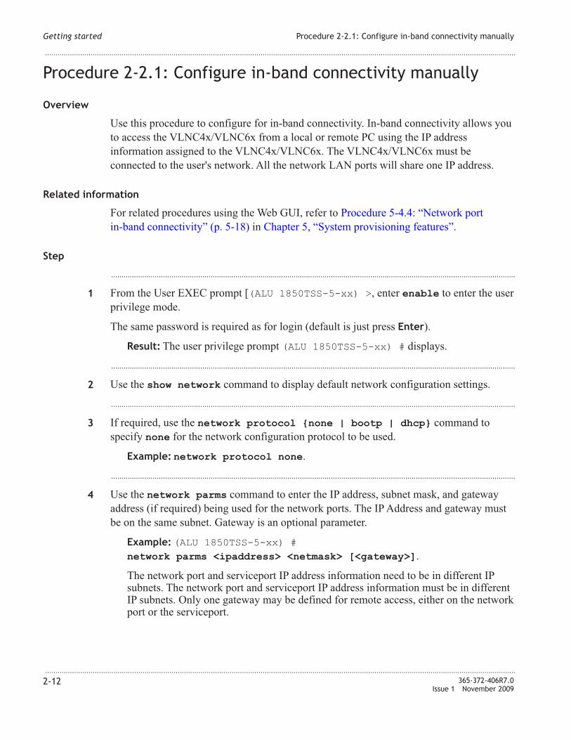
Procedure 2-2.1: Configure in-band connectivity manually
Overview
Use this procedure to configure for in-band connectivity. In-band connectivity allows you
to access the VL�C4x/VL�C6x from a local or remote PC using the IP address
information assigned to the VL�C4x/VL�C6x. The VL�C4x/VL�C6x must be
connected to the user's network. All the network LA� ports will share one IP address.
Related information
For related procedures using the Web GUI, refer to Procedure 5-4.4: “�etwork port
in-band connectivity” (p. 5-18) in Chapter 5, “System provisioning features”.
Step
...................................................................................................................................................................................................
1 From the User EXEC prompt [(ALU 1850TSS-5-xx) >, enter enable to enter the user
privilege mode.
The same password is required as for login (default is just press Enter).
Result: The user privilege prompt (ALU 1850TSS-5-xx) # displays.
...................................................................................................................................................................................................
2 Use the show network command to display default network configuration settings.
...................................................................................................................................................................................................
3 If required, use the network protocol {none | bootp | dhcp} command to
specify none for the network configuration protocol to be used.
Example: network protocol none.
...................................................................................................................................................................................................
4 Use the network parms command to enter the IP address, subnet mask, and gateway
address (if required) being used for the network ports. The IP Address and gateway must
be on the same subnet. Gateway is an optional parameter.
Example: (ALU 1850TSS-5-xx) #
network parms <ipaddress> <netmask> [<gateway>].
The network port and serviceport IP address information need to be in different IP
subnets. The network port and serviceport IP address information must be in different
IP subnets. Only one gateway may be defined for remote access, either on the network
port or the serviceport.
Getting started Procedure 2-2.1: Configure in-band connectivity manually
...................................................................................................................................................................................................................................
...................................................................................................................................................................................................................................
2-12 365-372-406R7.0
Issue 1 November 2009

If this command fails, you may get an error message if the serviceport IP address has
already been assigned and this IP address for the network ports is in the same subnet.
You will have to reprovision one of the IP addresses.
...................................................................................................................................................................................................
5 Save the configuration changes using the write memory command. At the user privilege
prompt, enter write memory.
Required only if you want the current configuration information to be preserved across
reboots.
Result: System message indicates:
This operation may take a few minutes.
Management interfaces will not be available during this time.
Are you sure you want to save (y/n)?
...................................................................................................................................................................................................
6 Enter y to execute the command.
Result: After a few seconds, a confirmation message appears:
Configuration Saved!
...................................................................................................................................................................................................
7 Use the show network command to confirm your changes.
...................................................................................................................................................................................................
8 Refer to the Alcatel-Lucent 1850 Transport Service Switch (TSS-5) Command Line
Interface Guide, for help on using the CLI commands.
E N D O F S T E P S
...................................................................................................................................................................................................
Getting started Procedure 2-2.1: Configure in-band connectivity manually
...................................................................................................................................................................................................................................
...................................................................................................................................................................................................................................
365-372-406R7.0
Issue 1 November 2009
2-13

Procedure 2-2.2: Configure for in-band connectivity using
DHCP/BootP
Overview
Use this procedure to configure for in-band connectivity by using DHCP/BootP. In-band
connectivity allows you to access the VL�C4x/VL�C6x from a local or remote PC using
the IP address information assigned to the VL�C4x/VL�C6x. The VL�C4x/VL�C6x
must be connected to the user's network. All the network LA� ports will share one IP
address.
The network port and serviceport IP address information must be in different IP subnets.
The network port and serviceport IP address information must be in different IP subnets.
Only one gateway may be defined for remote access, either on the network port or the
serviceport.
Related information
For related procedures using the Web GUI, refer to Procedure 5-4.4: “�etwork port
in-band connectivity” (p. 5-18) in Chapter 5, “System provisioning features”.
Step
...................................................................................................................................................................................................
1 From the User EXEC prompt [(ALU 1850TSS-5-xx) >, enter enable to enter the user
privilege mode.
�o password is required at this time, just press Enter.
Result: The user privilege prompt [(ALU 1850TSS-5-xx) #] displays.
...................................................................................................................................................................................................
2 Enter show network command to obtain information about the VL�C4x/VL�C6x
default network configuration settings.
...................................................................................................................................................................................................
3 You need to configure the BootP or DHCP server with information about the switch
obtained through the serial port connection using the show network command.
Configure the DHCP/BootP server with the following information:
• Unique IP address for the switch.
• Subnet mask for the LA�.
• Gateway IP address of the default router, if the switch is a node outside the IP range of
the LA�.
• MAC address of the VL�C4x/VL�C6x.
Getting started Procedure 2-2.2: Configure for in-band connectivity using
DHCP/BootP
...................................................................................................................................................................................................................................
...................................................................................................................................................................................................................................
2-14 365-372-406R7.0
Issue 1 November 2009

...................................................................................................................................................................................................
4 Use the network protocol {none | bootp | dhcp} command to specify the
network configuration protocol to be used.
Example: network protocol dhcp.
...................................................................................................................................................................................................
5 Connect the VL�C4x/VL�C6x to the Ethernet network.
After the VL�C4x/VL�C6xis connected to the network, it periodically sends requests to
a BootP/DHCP server until a response is received.
Result: The VL�C4x/VL�C6x is configured with the information from the
DHCP/BootP server.
...................................................................................................................................................................................................
6 After configuration, use the show network command to view network parameters.
If the IP address is not assigned, use the show logging buffered command to
find out the reason for DHCP failing to install the IP address. Check if the serviceport
IP address is already assigned (show serviceport) and on the same subnet as the
DHCP offered IP address. You will have to reprovision one of the IP addresses.
...................................................................................................................................................................................................
7 Refer to the Alcatel-Lucent 1850 Transport Service Switch (TSS-5) Command Line
Interface Guide, for help on using the CLI commands.
E N D O F S T E P S
...................................................................................................................................................................................................
Getting started Procedure 2-2.2: Configure for in-band connectivity using
DHCP/BootP
...................................................................................................................................................................................................................................
...................................................................................................................................................................................................................................
365-372-406R7.0
Issue 1 November 2009
2-15

Procedure 2-2.3: Configure MGMT LAN serviceport for
out-of-band connectivity using DHCP/BootP
Overview
Use this procedure to configure the MGMT LAN serviceport for out-of-band connectivity.
Important! The VL�C4x/VL�C6x is initially configured for local out-of-band
connectivity through the MGMT LAN serviceport . You can keep the MGMT LAN port
default IP address (169.254.1.1) and use the MGMT LAN port locally for out-of-band
connectivity to the VL�C4x/VL�C6x, if desired.
If the MGMT LAN port is to be used for remote connectivity through the Ethernet
network, it must be connected to the LA� Ethernet network and have the proper
configuration settings for the network.
The network port and serviceport IP address information need to be in different IP
subnets. The network port and serviceport IP address information must be in different
IP subnets. Only one gateway may be defined for remote access, either on the network
port or the serviceport.
You can use this procedure to change the default configuration settings for the MGMT
LAN serviceport.
Step
...................................................................................................................................................................................................
1 From the User EXEC prompt [(ALU 1850TSS-5-xx) >], enter enable to enter the
user privilege mode.
�o password is required at this time, just press Enter.
Result: The user privilege prompt (ALU 1850TSS-5-xx) # displays.
...................................................................................................................................................................................................
2 Enter show serviceport command to obtain information about the MGMT LAN
serviceport default configuration settings.
...................................................................................................................................................................................................
3 Configure the DHCP/BootP server with the following information:
• Unique IP address.
• Subnet mask.
• Gateway IP address, if required.
• MAC address of the MGMT LAN port.
Getting started Procedure 2-2.3: Configure MGMT LAN serviceport for
out-of-band connectivity using DHCP/BootP
...................................................................................................................................................................................................................................
...................................................................................................................................................................................................................................
2-16 365-372-406R7.0
Issue 1 November 2009

...................................................................................................................................................................................................
4 Use the serviceport protocol {none | bootp | dhcp} command to specify
the serviceport configuration protocol to be used.
Example: serviceport protocol dhcp.
...................................................................................................................................................................................................
5 Connect the MGMT LAN port to the LA� network.
After the VL�C4x/VL�C6x MGMT LAN port is connected to the network, it periodically
sends requests to a BootP/DHCP server until a response is received.
Result: The VL�C4x/VL�C6x is configured with the information from the
DHCP/BootP server.
...................................................................................................................................................................................................
6 After configuration, use the show serviceport command to view network parameters.
If the IP address is not assigned, use the show logging buffered command to
find out the reason for DHCP failing to install the IP address. Check if the network IP
address is already assigned (show network) and on the same subnet as the DHCP
offered IP address. You will have to reprovision one of the IP addresses.
...................................................................................................................................................................................................
7 Refer to the Alcatel-Lucent 1850 Transport Service Switch (TSS-5) Command Line
Interface Guide, for help on using other CLI commands.
E N D O F S T E P S
...................................................................................................................................................................................................
Getting started Procedure 2-2.3: Configure MGMT LAN serviceport for
out-of-band connectivity using DHCP/BootP
...................................................................................................................................................................................................................................
...................................................................................................................................................................................................................................
365-372-406R7.0
Issue 1 November 2009
2-17

Procedure 2-2.4: Configure MGMT LAN serviceport for
out-of-band connectivity manually
Overview
Use this procedure to configure the MGMT LAN serviceport for out-of-band connectivity.
Important! The VL�C4x/VL�C6x is initially configured for local out-of-band
connectivity through the MGMT LAN serviceport . You can keep the MGMT LAN port
default IP address (169.254.1.1) and use the MGMT LAN port locally for out-of-band
connectivity to the VL�C4x/VL�C6x, if desired.
If the MGMT LAN port is to be used for remote connectivity through the Ethernet
network, it must be connected to the LA� Ethernet network and have the proper
configuration settings for the network.
The network port and serviceport IP address information need to be in different IP
subnets. The network port and serviceport IP address information must be in different
IP subnets. Only one gateway may be defined for remote access, either on the network
port or the serviceport.
You can use this procedure to change the default configuration settings for the MGMT
LAN serviceport.
Related information
Refer to Procedure 5-4.3: “Service port configuration” (p. 5-15) in Chapter 5, “System
provisioning features”.
Step
...................................................................................................................................................................................................
1 From the User EXEC prompt, [(ALU 1850TSS-5-xx) >], enter enable to enter the
user privilege mode.
�o password is required at this time, just press Enter.
Result: The user privilege prompt [(ALU 1850TSS-5-xx) #], displays.
...................................................................................................................................................................................................
2 Enter show serviceport command to obtain information about the MGMT LAN
serviceport default configuration settings.
...................................................................................................................................................................................................
3 Use the serviceport protocol {none | bootp | dhcp} command to specify
the serviceport configuration protocol as none.
Getting started Procedure 2-2.4: Configure MGMT LAN serviceport for
out-of-band connectivity manually
...................................................................................................................................................................................................................................
...................................................................................................................................................................................................................................
2-18 365-372-406R7.0
Issue 1 November 2009

Example: serviceport protocol none.
...................................................................................................................................................................................................
4 Use the serviceport ip command to enter the IP address, subnet mask, and gateway
address (if required) being used for the serviceport. The IP Address and gateway must be
on the same subnet. Gateway is an optional parameter.
The network port and serviceport IP address information need to be in different IP
subnets. The network port and serviceport IP address information must be in different IP
subnets. Only one gateway may be defined for remote access, either on the network port
or the serviceport.
Example: serviceport ip <ipaddress> <netmask> [<gateway>].
If this command fails, you may get an error message if the serviceport IP address has
already been assigned and this IP address for the network ports is in the same subnet.
You will have to reprovision one of the IP addresses.
...................................................................................................................................................................................................
5 If required, save the configuration changes using the write memory command. At the
user privilege prompt, enter write memory.
Required only if you want the current configuration information to be preserved across
reboots.
Result: System message indicates:
This operation may take a few minutes.
Management interfaces will not be available during this time.
Are you sure you want to save (y/n)?
...................................................................................................................................................................................................
6 Enter y to execute the command.
Result: After a few seconds, a confirmation message appears:
Configuration Saved!
...................................................................................................................................................................................................
7 Connect the MGMT LAN port to the LA� network.
...................................................................................................................................................................................................
8 After configuration, use the show serviceport command to view network parameters.
...................................................................................................................................................................................................
9 Refer to the Alcatel-Lucent 1850 Transport Service Switch (TSS-5) Command Line
Interface Guide, for help on using other CLI commands.
E N D O F S T E P S
...................................................................................................................................................................................................
Getting started Procedure 2-2.4: Configure MGMT LAN serviceport for
out-of-band connectivity manually
...................................................................................................................................................................................................................................
...................................................................................................................................................................................................................................
365-372-406R7.0
Issue 1 November 2009
2-19

Procedure 2-2.5: Configure RS-232 port for out-of-band
connectivity
Overview
Use this procedure to configure for out-of-band connectivity by using the RS-232 console
port.
Important! The VL�C4x/VL�C6x may be initially configured for out-of-band
connectivity through the RS-232 console port.
The RS-232 RJ45 port (RS232 M1 or RS232 M2) on the front of the VLIU that
connects to the Main 1 or Main 2 slot is not generally recommended for use in
connecting to the VL�C4x/VL�C6x. It is normally used by service personnel.
You can use this procedure to change the default configuration settings for the RS-232
console port.
Step
...................................................................................................................................................................................................
1 From the User EXEC prompt, [(ALU 1850TSS-5-xx) >], enter enable to enter the
user privilege mode.
�o password is required at this time, just press Enter.
Result: The user privilege prompt [(ALU 1850TSS-5-xx) #] displays.
...................................................................................................................................................................................................
2 Enter show serial command to obtain information about the RS-232 console port
default configuration settings.
...................................................................................................................................................................................................
3 From the user privilege prompt, enter configure to enter the Global Config mode.
�o password is required at this time, just press Enter.
Result: The Global Config prompt [(ALU 1850TSS-5-xx) (Config) #] displays.
...................................................................................................................................................................................................
4 From the Global Config prompt, enter lineconfig to enter the Line Config mode.
�o password is required at this time, just type Enter.
Result: The Line Config prompt [(ALU 1850TSS-5-xx) (Line)#] displays.
...................................................................................................................................................................................................
5 If required, from the Line Config prompt, enter the serial baudrate <rate_value>
command to set the baudrate.
Getting started Procedure 2-2.5: Configure RS-232 port for out-of-band
connectivity
...................................................................................................................................................................................................................................
...................................................................................................................................................................................................................................
2-20 365-372-406R7.0
Issue 1 November 2009

Example: serial baudrate 115200.
Range: {1200 | 2400 | 4800 | 9600 | 19200 | 38400 | 57600 | 115200}
...................................................................................................................................................................................................
6 If required, from the Line Config prompt, enter the
serial timeout <timeout_value> command to set the maximum connect time.
Example: serial timeout 100.
Range: 0-160 in minutes. A value of 0 indicates that a console can be connected
indefinitely.
The other parameters (Character size, flow control, stop bits, and parity) are always
set to default values and cannot be changed.
...................................................................................................................................................................................................
7 Enter exit twice to get down to the user privilege prompt [(ALU 1850TSS-5-xx) #].
Enter show serial command to obtain information about the serial port configuration
settings.
...................................................................................................................................................................................................
8 Refer to the Alcatel-Lucent 1850 Transport Service Switch (TSS-5) Command Line
Interface Guide, for help on using other CLI commands.
E N D O F S T E P S
...................................................................................................................................................................................................
Getting started Procedure 2-2.5: Configure RS-232 port for out-of-band
connectivity
...................................................................................................................................................................................................................................
...................................................................................................................................................................................................................................
365-372-406R7.0
Issue 1 November 2009
2-21

Procedure 2-2.6: Configure in-band connectivity when
ethertype on VLNC40/VLNC42/VLNC42B is set to vMAN
Overview
Use this procedure as an example for configuring for in-band connectivity when ethertype
on the VL�C4x is set to vMA�. In-band connectivity allows you to access the
VL�C4x/VL�C6x from a local or remote PC using the IP address information assigned
to the VL�C4x/VL�C6x. The VL�C4x/VL�C6x must be connected to the user's
network. Using the network configuration in this example, inband management of all
circuit packs can be performed across a Q-in-Q/Q-in-vMA� domain either locally from a
OMS network or remotely from a Alcatel-Lucent 1850 TSS-5 installation.
Additional provisioning is needed for creation and maintenance of pseudo-wire services
on VL�C60/VL�C64. These are related to PS� tunnels, Pseudo-wires, BFD, routing
(static routes/arp), etc. Also in order to use the backplane ports between VL�C4x and
VL�C60/VL�C64 in a TSS-5 shelf, additional provisioning (backplane port) is
required to enable the backplane port. By default, the backplane port is disabled. LA�
cables are required between some ports.
Refer to Figure 2-1, “Inband management with Q-in-Q setup” (p. 2-27) in provisioning
the parameters in this example.
In this example, VLA� id of 800 is used for handling the management traffic from/to a
OAM network and a VLA� id of 1 is used for handling pseudo-wire data traffic and
associated control/management traffic (arp/BFD packets/etc).
Refer to the Alcatel-Lucent 1850 Transport Service Switch (TSS-5) Command Line
Interface Guide, for help on using the CLI commands.
Step
...................................................................................................................................................................................................
1 At TSS-5 A, login to the VL�C4x circuit pack (OAM �etwork Gateway Switch) being
provisioned.
From the User EXEC prompt [(ALU 1850TSS-5-xx) >, enter enable to enter the user
privilege mode.
The same password is required as for login (default is just press Enter).
Result: The user privilege prompt (ALU 1850TSS-5-xx) # displays.
...................................................................................................................................................................................................
2 Use the show serviceport command to display default serviceport configuration
settings.
Getting started Procedure 2-2.6: Configure in-band connectivity when
ethertype on VLNC40/VLNC42/VLNC42B is set to vMAN
...................................................................................................................................................................................................................................
...................................................................................................................................................................................................................................
2-22 365-372-406R7.0
Issue 1 November 2009

...................................................................................................................................................................................................
3 If required, use the serviceport ip command to enter the IP address, subnet mask,
and gateway address (if required) being used for the serviceport. The IP Address and
gateway must be on the same subnet. Gateway is an optional parameter. Use the default
settings for the VL�C4x: 169.254.1.1; 255.255.0.0; 0.0.0.0.
Example: (ALU 1850TSS-5-xx) #
serviceport ip <ipaddress> <netmask> [<gateway>].
The network port and serviceport IP address information need to be in different IP
subnets. The network port and serviceport IP address information must be in different
IP subnets. Only one gateway may be defined for remote access, either on the network
port or the serviceport.
...................................................................................................................................................................................................
4 Use the show network command to display default network configuration settings.
...................................................................................................................................................................................................
5 If required, use the network protocol {none | bootp | dhcp} command to
specify none for the network configuration protocol to be used.
Example: network protocol none.
...................................................................................................................................................................................................
6 Use the network parms command to enter the IP address, subnet mask, and gateway
address (if required) being used for the network ports. The IP Address and gateway must
be on the same subnet. Gateway is an optional parameter. Use network parms parameters:
152.148.119.183; 255.255.254.0; 152.148.118.1.
Example: (ALU 1850TSS-5-xx) #
network parms 152.148.119.183 255.255.254.0 152.148.118.1.
The network port and serviceport IP address information need to be in different IP
subnets. The network port and serviceport IP address information must be in different
IP subnets. Only one gateway may be defined for remote access, either on the network
port or the serviceport.
If this command fails, you may get an error message if the serviceport IP address has
already been assigned and this IP address for the network ports is in the same subnet.
You will have to reprovision one of the IP addresses.
...................................................................................................................................................................................................
7 Use the network mgmt_vlan <vlanid> command to set the Management VLA� ID
to 800 in this example.
Example: (ALU 1850TSS-5-xx) # network mgmt_vlan 800.
...................................................................................................................................................................................................
8 Enter vlan database command to enter the VLA� Config mode.
Getting started Procedure 2-2.6: Configure in-band connectivity when
ethertype on VLNC40/VLNC42/VLNC42B is set to vMAN
...................................................................................................................................................................................................................................
...................................................................................................................................................................................................................................
365-372-406R7.0
Issue 1 November 2009
2-23

...................................................................................................................................................................................................
9 Enter vlan 800 command to create a new VLA� and assign an ID. Enter exit to return
to user privilege mode.
...................................................................................................................................................................................................
10 Enter configure to enter the Global Config mode.
...................................................................................................................................................................................................
11 Enter interface <interface-number>, where interface-number is either a-9, a-10,
or a-11 (TSS-5 A).
...................................................................................................................................................................................................
12 Enter the following commands, one at a time, to provision the parameters for ports a-9,
a-10, a-11:
1. vlan pvid 800
2. vlan participation exclude 1
3. vlan participation include 800
4. dvlan-tunnel ethertype vman
5. exit
Repeat this step for interfaces a-9, a-10, and a-11.
...................................................................................................................................................................................................
13 Enter interface <interface-number>, where interface-number is d2-1..
...................................................................................................................................................................................................
14 Enter the following commands, one at a time, to provision the parameters for d2-1:
1. vlan tagging 1
2. vlan participation include 800
3. vlan tagging 800
4. mode dvlan-tunnel
5. dvlan-tunnel ethertype vman
6. exit
...................................................................................................................................................................................................
15 Enter interface <interface-number>, where interface-number is d2-4..
...................................................................................................................................................................................................
16 Enter the following commands, one at a time, to provision the parameters for d2-4:
1. vlan participation exclude 800
2. dvlan-tunnel ethertype vman
3. exit
Getting started Procedure 2-2.6: Configure in-band connectivity when
ethertype on VLNC40/VLNC42/VLNC42B is set to vMAN
...................................................................................................................................................................................................................................
...................................................................................................................................................................................................................................
2-24 365-372-406R7.0
Issue 1 November 2009

...................................................................................................................................................................................................
17 If required, save the configuration changes using the write memory command. At the
user privilege prompt, enter write memory.
...................................................................................................................................................................................................
18 Login to the VL�C64 at TSS-5 A.
From the User EXEC prompt [(ALU 1850TSS-5-xx) >, enter enable to enter the user
privilege mode.
...................................................................................................................................................................................................
19 Use the serviceport ip command to enter the IP address, subnet mask, and gateway
address (if required) being used for the serviceport. Use these settings for this VL�C64:
152.148.119.63; 255.255.254.0; 152.148.118.1.
...................................................................................................................................................................................................
20 Use the network parms command to enter the IP address, subnet mask, and gateway
address being used for the network ports. Use network parms parameters: 185.13.75.47;
255.255.0.0; 0.0.0.0.
...................................................................................................................................................................................................
21 At TSS-5 B, login to the VL�C4x circuit pack being provisioned.
From the User EXEC prompt [(ALU 1850TSS-5-xx) >, enter enable to enter the user
privilege mode.
The same password is required as for login (default is just press Enter).
Result: The user privilege prompt (ALU 1850TSS-5-xx) # displays.
...................................................................................................................................................................................................
22 Repeat Step 2 thru Step 17 to provision the same parameters on the VL�C4x in TSS-5 B.
The only exceptions are: (1) the network parms IP address parameter for this VL�C4x is
152.148.119.64. The netmask and gateway address are the same as the VL�C4x in
TSS-5 A; (2) There is no customer port a-11.
...................................................................................................................................................................................................
23 Login to the VL�C60 at TSS-5 B.
From the User EXEC prompt [(ALU 1850TSS-5-xx) >, enter enable to enter the user
privilege mode.
...................................................................................................................................................................................................
24 Use the serviceport ip command to enter the IP address, subnet mask, and gateway
address being used for the serviceport. Use these settings for this VL�C60:
152.148.119.117; 255.255.254.0; 152.148.118.1.
Getting started Procedure 2-2.6: Configure in-band connectivity when
ethertype on VLNC40/VLNC42/VLNC42B is set to vMAN
...................................................................................................................................................................................................................................
...................................................................................................................................................................................................................................
365-372-406R7.0
Issue 1 November 2009
2-25

...................................................................................................................................................................................................
25 Use the network parms command to enter the IP address, subnet mask, and gateway
address being used for the network ports. Use network parms parameters: 185.13.75.44;
255.255.0.0; 0.0.0.0.
Getting started Procedure 2-2.6: Configure in-band connectivity when
ethertype on VLNC40/VLNC42/VLNC42B is set to vMAN
...................................................................................................................................................................................................................................
...................................................................................................................................................................................................................................
2-26 365-372-406R7.0
Issue 1 November 2009
E N D O F S T E P S....................................................................................................................................................................................................................................

Figure 2-1 Inband management with Q-in-Q setup
Service ProviderNetwork
Serviceport
Serviceport
Serviceport
Serviceport
A-10
A-10
A-9A-11
A-9
OAMNetwork
C
C
C C
C
C
(800)
(800)
(800)
(800)
(800)
VLNC40(Mgmt VLAN-800)
Inband Mgmt
VLNC40(Mgmt VLAN-800)
Inband Mgmt
Backplane
Backplane
D2-4
D2-4
D1-1
(1, 800)
(1)
(1)
VLNC64Out of Band Mgmt*
VLNC60Out of Band Mgmt*
Q-in-Q orQ-in-vMANtraffic
D2-1
D2-1
N
N
Untaggedmanagement
traffic
Untaggedmanagement
traffic
PW and PW relatedmanagement
(ARP/BFD) traffic
PW and PW relatedmanagement
(ARP/BFD) traffic
TSS-5 A
TSS-5 B
C
D1-1
*PSN tunnels/PW use inband network parmsIP address for ARP/BFD traffic on VLNC60/64.
Q-in-Q orQ-in-vMANtraffic
-Management traffic in outer pipe with vMan (800)-PW and PW related mgmt (ARP/BFD) traffic in outerpipe with vMAN (1)
C - Customer portN - Network port(800) - Denotes VLAN participation
- Extra LAN cables
Connect to OAM network aswell as to all VLNC40/60/64
Single Telnet session accessMultiple Telnet session access
PC
inband-mgmt-QinQ
Getting started Procedure 2-2.6: Configure in-band connectivity when
ethertype on VLNC40/VLNC42/VLNC42B is set to vMAN
...................................................................................................................................................................................................................................
...................................................................................................................................................................................................................................
365-372-406R7.0
Issue 1 November 2009
2-27

3 3Using the Web interface
Overview
Purpose
The Alcatel-Lucent 1850 TSS-5 CLI based circuit packs can be managed using the CLI
command interface or the Web GUI interface. This section provides a brief introduction to
the Web GUI interface. It explains how to access the interface and use the menu structure
for system management and provisioning.
Each VL�C4x or VL�C6x pack should be connected to the network and have its IP
address configured first. The user then accesses the pack via the Web GUI by entering the
IP address of the pack as the URL in the HTTP-enabled Web browser. The Login screen is
displayed next. Once the user enters the valid username and password and connecting to
the VL�C4x or VL�C6x pack is successful, then the Web GUI main page is displayed.
To access the Web GUI, the browser must support:
• HTML 4.0 or later
• HTTP 1.1 or later
• JavaScript 1.2 or later
• Java Runtime Plug-in 1.50-06 or later
Contents
Procedure 3-1: Web Access Configuration 3-2
Procedure 3-2: Starting the Web Interface 3-3
Web page interface 3-4
...................................................................................................................................................................................................................................
365-372-406R7.0
Issue 1 November 2009
3-1
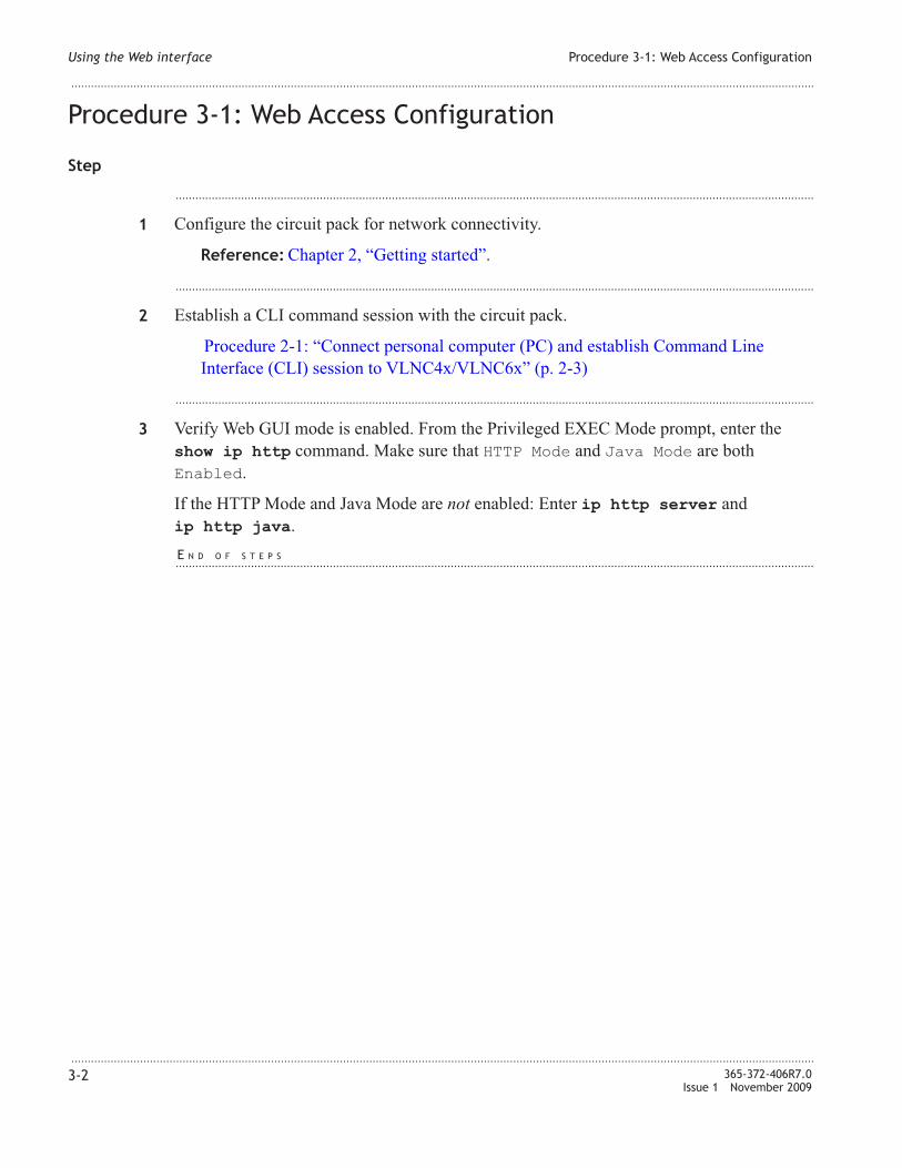
Procedure 3-1: Web Access Configuration
Step
...................................................................................................................................................................................................
1 Configure the circuit pack for network connectivity.
Reference: Chapter 2, “Getting started”.
...................................................................................................................................................................................................
2 Establish a CLI command session with the circuit pack.
Procedure 2-1: “Connect personal computer (PC) and establish Command Line
Interface (CLI) session to VL�C4x/VL�C6x” (p. 2-3)
...................................................................................................................................................................................................
3 Verify Web GUI mode is enabled. From the Privileged EXEC Mode prompt, enter the
show ip http command. Make sure that HTTP Mode and Java Mode are both
Enabled.
If the HTTP Mode and Java Mode are not enabled: Enter ip http server and
ip http java.
E N D O F S T E P S
...................................................................................................................................................................................................
Using the Web interface Procedure 3-1: Web Access Configuration
...................................................................................................................................................................................................................................
...................................................................................................................................................................................................................................
3-2 365-372-406R7.0
Issue 1 November 2009

Procedure 3-2: Starting the Web Interface
Step
...................................................................................................................................................................................................
1 Enter the IP address of the pack in the Web browser address field.
...................................................................................................................................................................................................
2 When the Login panel displays, enter your User Name and Password, then click Login.
�ote: The default User �ame is admin and the Password is blank.
Result: The Web GUI main page should display. The user should be able to manage
and configure the circuit pack by selecting any of the options in the �avigation Tree
located at left of the Web page screen.
E N D O F S T E P S
...................................................................................................................................................................................................
Using the Web interface Procedure 3-2: Starting the Web Interface
...................................................................................................................................................................................................................................
...................................................................................................................................................................................................................................
365-372-406R7.0
Issue 1 November 2009
3-3

Web page interface
Layout
The web page consists of four frames:
• The upper left frame displays the Component Logo link.
• The upper right frame displays a banner or Java Applet �avigation.
• The lower left frame displays the command �avigation Tree.
• The lower right frame displays the Web Page Content associated with the �avigation
Tree.
The �avigation Tree and the Web Contents are the two frames that allow the user to
configure and view the settings and statistics of the pack.
Navigation tree frame
The �avigation Tree displays the menu and submenu options of the management system
in a hierarchical-tree view. The tree consists of a combination of folders (main menus),
subfolders (submenus), and configuration and status HTML pages (functions). Each main
menu is a major feature, such as Switching, Routing, QoS, etc. The submenu options
under each main menu are the sub-features. The options under each submenu are the
functions of that sub-feature. In the �avigation Tree, the function is indicated by a “file”
icon. In the Web GUI, any function will have one Web Page Content frame associated
with it.
Web page content frame
For each function in the �avigation Tree, there is a corresponding Web Page Content
which allows the end user to set or view the settings for the circuit pack. The Web Page
Content is a form-based GUI screen which contains the screen title, parameter entries
(each with label and value) as well as controls such as dropdown lists, buttons, etc.
Using the Web interface Web page interface
...................................................................................................................................................................................................................................
...................................................................................................................................................................................................................................
3-4 365-372-406R7.0
Issue 1 November 2009

4 4Software management
Overview
Purpose
This section contains software management procedures for the
VL�C40/VL�C42/VL�C42B/VL�C60/VL�C61/VL�C62/VL�C64
(VL�C4x/VL�C6x) circuit pack.
This procedure assumes that you have TFTP/SFTP server support (either a local
TFTP/SFTP server for local downloads, or a remote TFTP/SFTP server configured with
the (VL�C4x/VL�C6x) operating software).
Refer to the Alcatel-Lucent 1850 Transport Service Switch (TSS-5) Command Line
Interface Guide for help on using CLI commands.
This chapter includes procedures to:
• Check software versions
• Copy software image from one image slot to another
• Backup and restore configuration data
Contents
Procedure 4-1: Determine VL�C4x/VL�C6x software versions stored in
non-volatile memory
4-2
Procedure 4-2: Copy VL�C4x/VL�C6x software image from one Image slot to
the other Image slot
4-3
Procedure 4-3: Backup or restore VL�C4x/VL�C6x configuration data 4-4
Procedure 4-4: Upgrade VL�C4x/VL�C6x software/firmware 4-6
...................................................................................................................................................................................................................................
365-372-406R7.0
Issue 1 November 2009
4-1

Procedure 4-1: Determine VLNC4x/VLNC6x software versions
stored in non-volatile memory
Overview
The VL�C4x/VL�C6x contains up to two software loads, referred to as Image1 and
Image2. Use this procedure to determine which of the image slots contains a valid
software load and the version of each software load.
The show bootvar CLI command displays information for the version and the
activation status of the current active and backup images. The command also displays any
description text associated with an image. This command also displays the switch
activation status.
This procedure assumes that the VL�C4x/VL�C6x has been previously installed.
Refer to the Alcatel-Lucent 1850 Transport Service Switch (TSS-5) Command Line
Interface Guide, for help on using CLI commands.
Related information
Equivalent Web GUI command: From the �avigation menu, select
System → Dual Image Status. See Procedure 5-3: “Display dual image status
(software versions)” (p. 5-9).
Step
...................................................................................................................................................................................................
1 Login to the VL�C4x/VL�C6x.
Result: The User EXEC prompt [(ALU 1850TSS-5-xx) >] displays.
Reference: Procedure 2-1: “Connect personal computer (PC) and establish Command
Line Interface (CLI) session to VL�C4x/VL�C6x” (p. 2-3)
...................................................................................................................................................................................................
2 From the User EXEC prompt, enter enable to enter the Privileged EXEC mode.
Result: The Privileged EXEC prompt [(ALU 1850TSS-5-xx) #] displays.
...................................................................................................................................................................................................
3 From the Privileged EXEC prompt, enter show bootvar to show the version and status
of the current active and backup images.
Result: The system displays the software versions held in the Image1 and Image2
memory banks. It also shows which Image is the active Image for the boot sequence.
E N D O F S T E P S
...................................................................................................................................................................................................
Software management Procedure 4-1: Determine VLNC4x/VLNC6x software
versions stored in non-volatile memory
...................................................................................................................................................................................................................................
...................................................................................................................................................................................................................................
4-2 365-372-406R7.0
Issue 1 November 2009

Procedure 4-2: Copy VLNC4x/VLNC6x software image from
one Image slot to the other Image slot
Overview
The VL�C4x/VL�C6x contains up to two software loads, referred to as Image1 and
Image2. Use this procedure to copy one software load from one image slot to the other
image slot. This is done so that the system has a backup in case one image slot becomes
corrupted.
The copy <source> <destination> command uploads and downloads files to and
from the switch. You can also use the copy command to manage dual images (image1 and
image2) on the file system. Upload and download files from a server by using
TFTP/SFTP or Xmodem.
This procedure assumes that the VL�C4x/VL�C6x has been previously installed.
Refer to the Alcatel-Lucent 1850 Transport Service Switch (TSS-5) Command Line
Interface Guide, for help on using CLI commands.
Related information
Equivalent Web GUI command: From the �avigation menu, select
System → System Utilities → Copy Image. See Procedure 5-7.10: “Copy
Image” (p. 5-56).
Step
...................................................................................................................................................................................................
1 Login to the VL�C4x/VL�C6x.
Result: The User EXEC prompt [(ALU 1850TSS-5-xx) >] displays.
Reference: Procedure 2-1: “Connect personal computer (PC) and establish Command
Line Interface (CLI) session to VL�C4x/VL�C6x” (p. 2-3)
...................................................................................................................................................................................................
2 From the User EXEC prompt, enter enable to enter the Privileged EXEC mode.
Result: The Privileged EXEC prompt [(ALU 1850TSS-5-xx) #] displays.
...................................................................................................................................................................................................
3 From the Privileged EXEC prompt, enter copy image1 image2 or
copy image2 image1, as required.
E N D O F S T E P S
...................................................................................................................................................................................................
Software management Procedure 4-2: Copy VLNC4x/VLNC6x software image
from one Image slot to the other Image slot
...................................................................................................................................................................................................................................
...................................................................................................................................................................................................................................
365-372-406R7.0
Issue 1 November 2009
4-3

Procedure 4-3: Backup or restore VLNC4x/VLNC6x
configuration data
Overview
Important! Only use this procedure to backup and restore the configuration data
within the same software release. For backup and restore of configuration data across
different releases, refer to the Alcatel-Lucent 1850 Transport Service Switch (TSS-5)
Software Release Description (SRD).
Use this procedure to copy (backup/restore) the startup configuration file to/from a server.
The copy <source> <destination> command uploads and downloads files to and
from the switch. You can also use the copy command to manage dual images (image1 and
image2) on the file system. Upload and download files from a server by using TFTP or
Xmodem.
This procedure assumes that the VL�C4x/VL�C6x has been previously installed.
Refer to the Alcatel-Lucent 1850 Transport Service Switch (TSS-5) Command Line
Interface Guide, for help on using CLI commands.
Step
...................................................................................................................................................................................................
1 Login to the VL�C40/VL�C42/VL�C60/VL�C61/VL�C64 .
Result: The User EXEC prompt [(ALU 1850TSS-5-xx) >] displays.
Reference: Procedure 2-1: “Connect personal computer (PC) and establish Command
Line Interface (CLI) session to VL�C4x/VL�C6x” (p. 2-3)
...................................................................................................................................................................................................
2 From the User EXEC prompt, enter enable to enter the Privileged EXEC mode.
Result: The Privileged EXEC prompt [(ALU 1850TSS-5-xx) #] displays.
...................................................................................................................................................................................................
3 To backup the system configuration file:
• From the Privileged EXEC prompt, enter
copy nvram:startup-config tftp://<ipaddr>/<filepath>/
<filename> to copy the startup-config file to the specified destination on the server.
• For example:
copy nvram:startup-config tftp://xxx.xxx.1.1/home/Admin/
Startup_Configuration_file.
Software management Procedure 4-3: Backup or restore VLNC4x/VLNC6x
configuration data
...................................................................................................................................................................................................................................
...................................................................................................................................................................................................................................
4-4 365-372-406R7.0
Issue 1 November 2009

To restore the system configuration file:
• From the Privileged EXEC prompt, enter
copy tftp://<ipaddr>/<filepath>/<filename> nvram:startup-
config to copy the saved startup-config file to the
VL�C40/VL�C42/VL�C60/VL�C61/VL�C64.
• For example:
copy tftp://xxx.xxx.1.1/home/Admin/Startup_Configuration_file
nvram:startup-config.
Result: The system displays the details of the command entered and asks if you want
to continue
...................................................................................................................................................................................................
4 Enter “y” to continue the upload/download, or “n” to abort the command.
Result: If you entered “y” to continue, the configuration file is copied to the specified
destination. �o other commands are possible while this command is executing. The
system will then display a message and then will display if the operation was
successful.
After a successful restore using the copy command with nvram:startup-config, only
the running configuration is changed with the restored data. If you need to also
change the startup-configuration, an additional “write memory” command is needed
to save the running configuration changes to nvram so that the changes will persist
during a reboot. The “write memory” command is the same as “copy
system:running-config nvram:startup-config”.
E N D O F S T E P S
...................................................................................................................................................................................................
Software management Procedure 4-3: Backup or restore VLNC4x/VLNC6x
configuration data
...................................................................................................................................................................................................................................
...................................................................................................................................................................................................................................
365-372-406R7.0
Issue 1 November 2009
4-5

Procedure 4-4: Upgrade VLNC4x/VLNC6x software/firmware
Overview
Important! Depending on the combined level of in-band and LA� network
congestion, multiple, in-band software downloads might time out when using some
TFTP servers. If simultaneous in-band downloads do not complete successfully,
repeat the software download and try downloading a single software image.
Depending on the level of LA� network congestion, a single in-band software
download can also time out. Some TFTP servers include a provisionable,
transmission-retry settings. If a single software download does not complete
successfully, repeat the software download using an alternate TFTP server.
Upgrade procedures for the VL�C4x/VL�C6x circuit packs are found in the
Alcatel-Lucent 1850 Transport Service Switch (TSS-5) Software Release Description
(SRD). The SRD contains the latest upgrade procedures, known problems, and a
description of any special considerations involving this version of software.
...................................................................................................................................................................................................
1 Use the procedures in the Alcatel-Lucent 1850 Transport Service Switch (TSS-5) Software
Release Description to perform required upgrades.
E N D O F S T E P S
...................................................................................................................................................................................................
Software management Procedure 4-4: Upgrade VLNC4x/VLNC6x
software/firmware
...................................................................................................................................................................................................................................
...................................................................................................................................................................................................................................
4-6 365-372-406R7.0
Issue 1 November 2009

5 5System provisioning
features
Overview
Purpose
The System menu feature includes, but is not limited to:
• System information
• System configuration
Configuration includes many items related to the following:
– System description
– Local and remote switch access configuration
– User accounts, logins and authentication
• Forwarding database search and configuration
• Logging configuration and viewing
• Configure and display the description for all ports
• S�MP configuration
• Display port and switch statistics
• System utilities
• Trap manager
• S�TP
This section covers requirements pertaining to the System menu feature and in particular
describes the Web GUI handling of �etwork Connectivity Configuration and Backplane
Port. Any user has access to the System feature options/screens. However, only the
privilege user is able to configure the System parameters. �etwork Connectivity and
Backplane Port are supported in all packs.
Contents
Before you begin 5-3
...................................................................................................................................................................................................................................
365-372-406R7.0
Issue 1 November 2009
5-1

Procedure 5-1: Display ARP cache entries associated with management
interfaces
5-4
Procedure 5-2: View system inventory information 5-6
Procedure 5-3: Display dual image status (software versions) 5-9
Procedure 5-4: System configuration 5-11
Procedure 5-5: Log configuration and viewing 5-36
Procedure 5-6: S�MP community and trap receiver configuration 5-39
Procedure 5-7: System Utilities 5-43
Procedure 5-8: Trap Manager configuration 5-57
Procedure 5-9: Simple �etwork Time Protocol (S�TP) configuration 5-59
Procedure 5-10: Radius authentication server configuration 5-69
Procedure 5-11: Secure shell configuration 5-72
System provisioning features Overview
...................................................................................................................................................................................................................................
...................................................................................................................................................................................................................................
5-2 365-372-406R7.0
Issue 1 November 2009
Before you begin
Before you begin
Important! Command Line Interface (CLI) commands or the Web GUI is required to
interface with the VL�C40/42/42B Ethernet Aggregator, VL�C60/61/62 Circuit
Emulator, and VL�C64 Circuit Emulation Mini-Hub circuit packs.
Required equipment
All procedures in this chapter require that the following equipment is available:
• Personal Computer (PC)
• Wrist Strap
Important! If additional equipment is required to perform a specific procedure, the
additional equipment is listed in the procedure.
System provisioning features Before you begin
...................................................................................................................................................................................................................................
...................................................................................................................................................................................................................................
365-372-406R7.0
Issue 1 November 2009
5-3

Procedure 5-1: Display ARP cache entries associated with
management interfaces
Overview
The Address Resolution Protocol (ARP) dynamically maps physical (MAC) addresses to
Internet (IP) addresses. This command displays the contents of the IP stack ARP table.
The IP stack only learns ARP entries associated with the management interfaces (network
or service port).
For each connection, the following information is displayed:
• The physical (MAC) Address.
• The associated IP address.
• The identification of the port being used for the connection.
The displayed results are not the total ARP entries. ARP entries associated with routing
interfaces are not listed. To view the total ARP entries, you should also view the ARP
Table Configuration using Routing → ARP Table Configuration. See Procedure 10-1:
“Address resolution protocol (ARP) routing” (p. 10-3).
Refer to the Alcatel-Lucent 1850 Transport Service Switch (TSS-5) Command Line
Interface Guide, for help on using CLI commands.
Step
...................................................................................................................................................................................................
1 Login to the VL�C4x/VL�C6x.
...................................................................................................................................................................................................
2 From the �avigation menu, select System → ARP Cache.
Equivalent CLI command: show arp switch.
Result: The ARP Cache window displays the current contents of the ARP cache.
...................................................................................................................................................................................................
3 If required, click Refresh to refresh the page with the latest data. See “ARP cache
entries” (p. 5-5).
System provisioning features Procedure 5-1: Display ARP cache entries associated with
management interfaces
...................................................................................................................................................................................................................................
...................................................................................................................................................................................................................................
5-4 365-372-406R7.0
Issue 1 November 2009
E N D O F S T E P S....................................................................................................................................................................................................................................
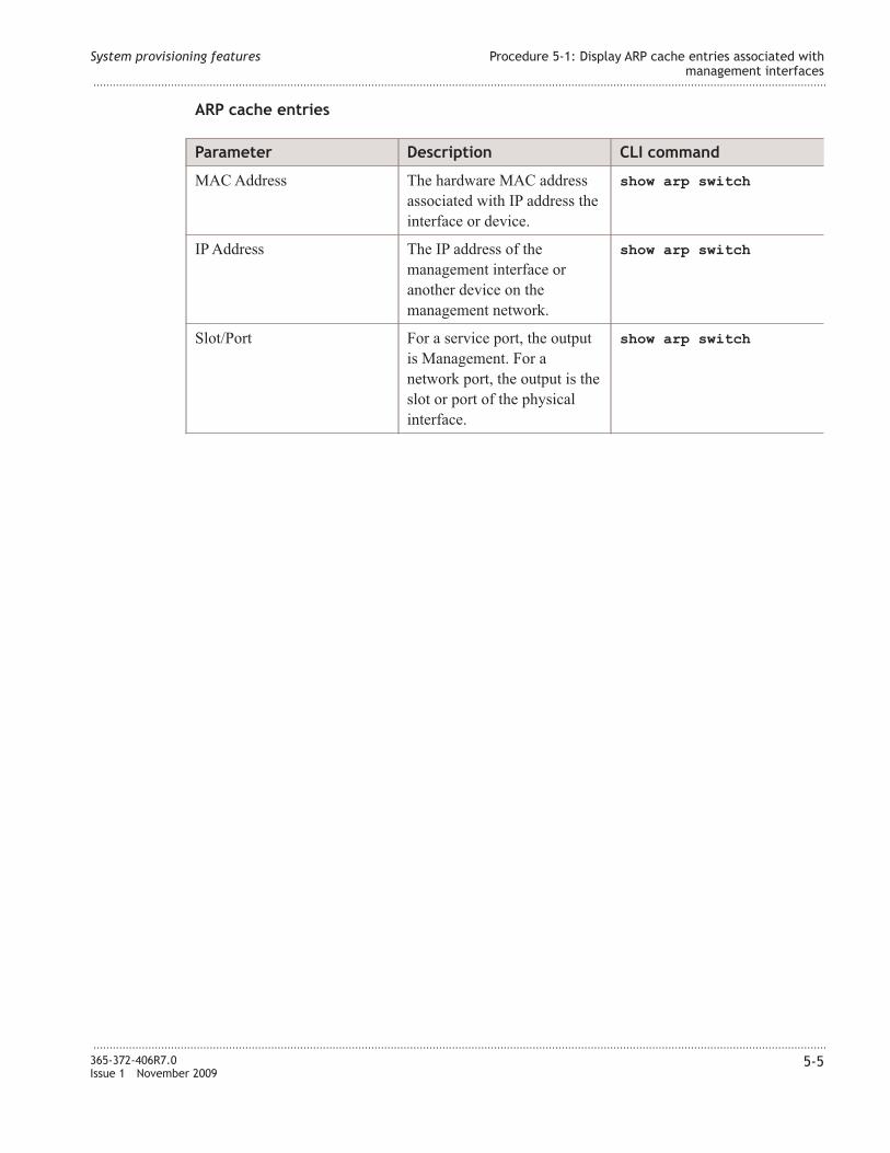
ARP cache entries
Parameter Description CLI command
MAC Address The hardware MAC address
associated with IP address the
interface or device.
show arp switch
IP Address The IP address of the
management interface or
another device on the
management network.
show arp switch
Slot/Port For a service port, the output
is Management. For a
network port, the output is the
slot or port of the physical
interface.
show arp switch
System provisioning features Procedure 5-1: Display ARP cache entries associated with
management interfaces
...................................................................................................................................................................................................................................
...................................................................................................................................................................................................................................
365-372-406R7.0
Issue 1 November 2009
5-5

Procedure 5-2: View system inventory information
Overview
Use this procedure to display system inventory information. See “Inventory information”
(p. 5-6).
Refer to the Alcatel-Lucent 1850 Transport Service Switch (TSS-5) Command Line
Interface Guide, for help on using CLI commands.
Step
...................................................................................................................................................................................................
1 Login to the VL�C4x/VL�C6x.
...................................................................................................................................................................................................
2 From the �avigation menu, select System → Inventory Information.
Equivalent CLI command: show version.
Result: The Inventory Information window displays the current system inventory.
...................................................................................................................................................................................................
3 If required, click Refresh to refresh the page with the latest data.
Inventory information
Parameter Description CLI command
System
Description
The field is used to identify the switch product name.
The format of this field is the following: Alcatel-Lucent
1850TSS-5 <shelf> <appcode> <series> <sw ver>
where:
• shelf = {IS-RM | HC-RM1} for ShelfID bits =
{0101 | 0011} respectively.
In addition it could be {HC-RM10 | HC-RM2 |
HC-RM3} on VLIU10, VLIU2, VLIU3 respectively.
• appcode = {VL�C40 | VL�C42 | VL�C42B |
VL�C60 | VL�C61 | VL�C62 | VL�C64}, either
compiled-in or read from inventory EEPROM.
• series = read from inventory EEPROM.
• sw-ver = compiled-in, of the form ##.##.##.##.
show version
System provisioning features Procedure 5-2: View system inventory information
...................................................................................................................................................................................................................................
...................................................................................................................................................................................................................................
5-6 365-372-406R7.0
Issue 1 November 2009
E N D O F S T E P S....................................................................................................................................................................................................................................

Parameter Description CLI command
Machine Type The machine type as defined by the Vital Product Data.
• VL�C40 - “Alcatel-Lucent 1850TSS-5 20FE/4GE
Aggregator”.
• VL�C42 - “Alcatel-Lucent 1850TSS-5 20FE/4GE
Aggregator-SE”.
• VL�C42B - “Alcatel-Lucent 1850TSS-5 20FE/4GE
Aggregator-SE/TC/TMPLS”,
• VL�C60 - “Alcatel-Lucent 1850TSS-5 8T1E1/2GE
PWE/ MLPPP”
• VL�C61 - “Alcatel-Lucent 1850TSS-5
16T1E1/2GE PWE/MLPPP”
• VL�C62 - “Alcatel-Lucent 1850TSS-5
16T1E1/2GE PWE/MLPPP/ToD”
• VL�C64 - “Alcatel-Lucent 1850TSS-5
OC-3STM-1/ 2GbE PWE”
Machine Model The machine model as defined by the Vital Product
Data. The format is Alcatel-Lucent <appcode>.
CLEI Info The Common Language Equipment �umber, as read
from EEPROM
ECI Info The Equipment Catalog Item, as read f rom EEPROM
Apparatus Code The Circuit Pack �ame, as read from EEPROM. For
example, VL�C40
Series The Circuit Pack Series, as read from EEPROM. For
example, S1:1
Serial �umber The unique box serial number for this switch, as read
from EEPROM.
FRU �umber The field replaceable unit number
Part �umber Manufacturing part number
Maintenance
Level
Indicates hardware changes that are significant to
software.
Manufacturer Manufacturer descriptor field
Burned In MAC
Address
Universally assigned network address, as read from
EEPROM.
Software
Version
The release.version.revision number of the code
currently running on the switch
Operating
System
The operating system currently running on the switch
System provisioning features Procedure 5-2: View system inventory information
...................................................................................................................................................................................................................................
...................................................................................................................................................................................................................................
365-372-406R7.0
Issue 1 November 2009
5-7

Parameter Description CLI command
�etwork
Processing
Device
The type of the processor microcode
Additional
Packages
This displays the additional packages incorporated into
this system
System provisioning features Procedure 5-2: View system inventory information
...................................................................................................................................................................................................................................
...................................................................................................................................................................................................................................
5-8 365-372-406R7.0
Issue 1 November 2009

Procedure 5-3: Display dual image status (software versions)
Overview
The VL�C4x/VL�C6x contains up to two software loads, referred to as Image1 and
Image2.
Use this procedure to display information for the version and the activation status of the
current active and backup software images. It also displays any description text associated
with an image as well as the switch activation status.
Refer to the Alcatel-Lucent 1850 Transport Service Switch (TSS-5) Command Line
Interface Guide, for help on using CLI commands.
Step
...................................................................................................................................................................................................
1 Login to the VL�C4x/VL�C6x.
...................................................................................................................................................................................................
2 From the �avigation menu, select System → Dual Image Status.
Equivalent CLI command: From the Privileged EXEC prompt, enter show bootvar
to show the version and status of the current active and backup images.
Result: The Dual Image Status screen displays the Dual Image Status.
The system displays the software versions held in the Image1 and Image2 memory
banks. It also shows which Image is the active Image for the boot sequence.
...................................................................................................................................................................................................
3 If required, click Refresh to refresh the page with the latest data. See “Dual image status
display” (p. 5-9).
Dual image status display
Parameter Description CLI command
Image 1 Ver The version number of Image1. show bootvar
Image 2 Ver The version number of Image2.
Backup The version number of the backup
copy.
Current-active Current active image
�ext-active �ext active image
System provisioning features Procedure 5-3: Display dual image status (software
versions)
...................................................................................................................................................................................................................................
...................................................................................................................................................................................................................................
365-372-406R7.0
Issue 1 November 2009
5-9
E N D O F S T E P S...................................................................................................................................................................................................

Parameter Description CLI command
Image 1 Description The text description of Image1.
Image 2 Description The text description of Image2.
System provisioning features Procedure 5-3: Display dual image status (software
versions)
...................................................................................................................................................................................................................................
...................................................................................................................................................................................................................................
5-10 365-372-406R7.0
Issue 1 November 2009

Procedure 5-4: System configuration
Overview
Use these procedures to configure and/or display the following System →Configuration parameters:
• System description
• �etwork interface
– �etwork Port (�etwork Connectivity)
– Service Port
• HTTP configuration
• Telnet
• Serial port (RS232 console) access
• User Accounts, logins and authentication
Step
...................................................................................................................................................................................................
1 Perform the following procedures as required.
• Procedure 5-4.1: “System description, configuration and display” (p. 5-12).
• Procedure 5-4.2: “Enable/Disable 802.3x switch flow control” (p. 5-14)
• Procedure 5-4.3: “Service port configuration” (p. 5-15)
• Procedure 5-4.4: “�etwork port in-band connectivity” (p. 5-18)
• Procedure 5-4.5: “HTTP configuration (enable/disable Web GUI interface )” (p. 5-22)
• Procedure 5-4.6: “Telnet session configuration” (p. 5-24)
• Procedure 5-4.7: “Outbound Telnet client configuration” (p. 5-26)
• Procedure 5-4.8: “Serial (Console) port configuration” (p. 5-28)
• Procedure 5-4.9: “User accounts, logins, and authentication” (p. 5-29)
E N D O F S T E P S
...................................................................................................................................................................................................
System provisioning features Procedure 5-4: System configuration
...................................................................................................................................................................................................................................
...................................................................................................................................................................................................................................
365-372-406R7.0
Issue 1 November 2009
5-11

Procedure 5-4.1: System description, configuration and
display
Overview
Use this procedure to configure system name, location, and contact information and
display various system data. See “System description parameters” (p. 5-12).
Step
...................................................................................................................................................................................................
1 Login to the VL�C4x/VL�C6x.
...................................................................................................................................................................................................
2 From the �avigation menu, select
System → Configuration → System Description.
Result: The System Description window displays the current system description.
...................................................................................................................................................................................................
3 Enter system name, location and contact as required.
• System Name - Alphanumeric string 1-31 characters in length.
• System Location - Alphanumeric string 1-31 characters in length.
• System Contact - Alphanumeric string 1-31 characters in length.
Equivalent CLI commands:
• From the Privileged EXEC Mode, enter show sysinfo to display system
information.
• From the Global Config Mode, enter
snmp-server {sysname <name> | location <loc> | contact <con>} to
configure system name, location, and contact
...................................................................................................................................................................................................
4 Click Submit at the bottom of the screen to execute the commands.
System description parameters
System provisioning features Procedure 5-4.1: System description, configuration and
display
...................................................................................................................................................................................................................................
...................................................................................................................................................................................................................................
5-12 365-372-406R7.0
Issue 1 November 2009
E N D O F S T E P S....................................................................................................................................................................................................................................
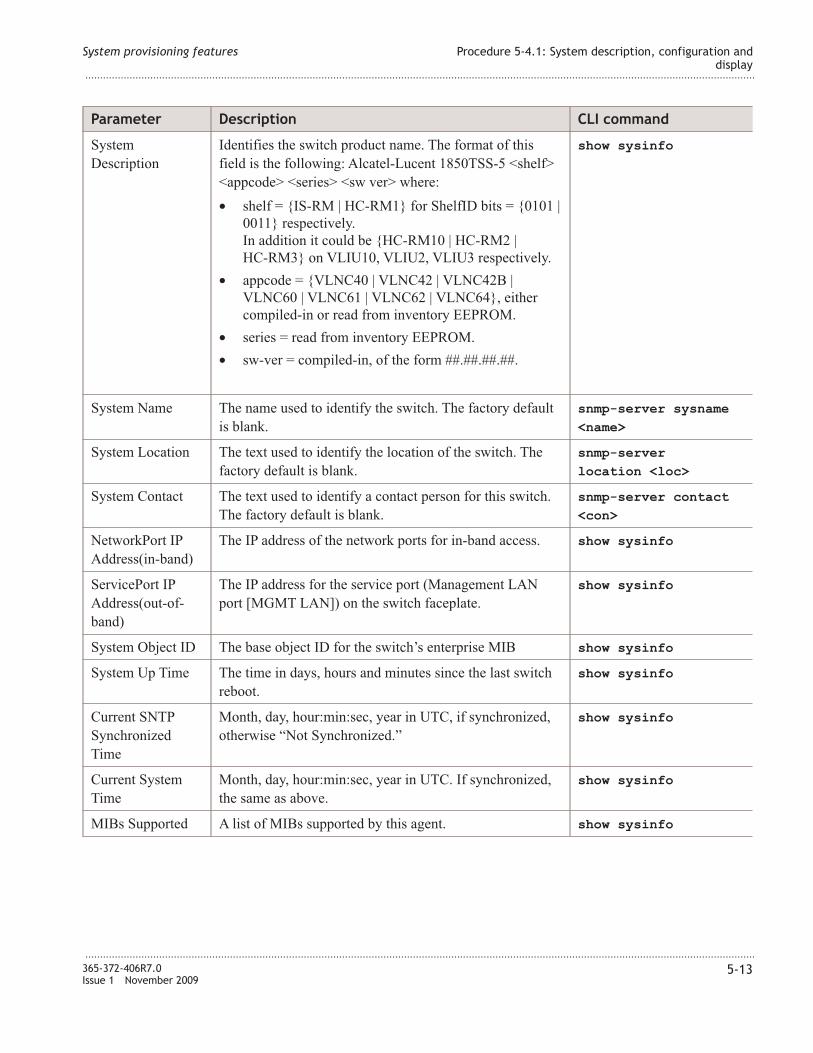
Parameter Description CLI command
System
Description
Identifies the switch product name. The format of this
field is the following: Alcatel-Lucent 1850TSS-5 <shelf>
<appcode> <series> <sw ver> where:
• shelf = {IS-RM | HC-RM1} for ShelfID bits = {0101 |
0011} respectively.
In addition it could be {HC-RM10 | HC-RM2 |
HC-RM3} on VLIU10, VLIU2, VLIU3 respectively.
• appcode = {VL�C40 | VL�C42 | VL�C42B |
VL�C60 | VL�C61 | VL�C62 | VL�C64}, either
compiled-in or read from inventory EEPROM.
• series = read from inventory EEPROM.
• sw-ver = compiled-in, of the form ##.##.##.##.
show sysinfo
System �ame The name used to identify the switch. The factory default
is blank.
snmp-server sysname
<name>
System Location The text used to identify the location of the switch. The
factory default is blank.
snmp-server
location <loc>
System Contact The text used to identify a contact person for this switch.
The factory default is blank.
snmp-server contact
<con>
�etworkPort IP
Address(in-band)
The IP address of the network ports for in-band access. show sysinfo
ServicePort IP
Address(out-of-
band)
The IP address for the service port (Management LA�
port [MGMT LA�]) on the switch faceplate.
show sysinfo
System Object ID The base object ID for the switch’s enterprise MIB show sysinfo
System Up Time The time in days, hours and minutes since the last switch
reboot.
show sysinfo
Current S�TP
Synchronized
Time
Month, day, hour:min:sec, year in UTC, if synchronized,
otherwise “�ot Synchronized.”
show sysinfo
Current System
Time
Month, day, hour:min:sec, year in UTC. If synchronized,
the same as above.
show sysinfo
MIBs Supported A list of MIBs supported by this agent. show sysinfo
System provisioning features Procedure 5-4.1: System description, configuration and
display
...................................................................................................................................................................................................................................
...................................................................................................................................................................................................................................
365-372-406R7.0
Issue 1 November 2009
5-13

Procedure 5-4.2: Enable/Disable 802.3x switch flow control
Overview
Use this procedure to enable/disable 802.3x flow control on the VL�C4x switch.
This command enables 802.3x flow control for the switch. A port-specific setting
overrides the global switch setting.
802.3x flow control works by pausing a port when the port becomes oversubscribed and
dropping all traffic for small periods of time during the congested condition. This can lead
to high-priority and network control traffic being lost.
Step
...................................................................................................................................................................................................
1 Login to the VL�C4x.
...................................................................................................................................................................................................
2 From the �avigation menu, select System → Configuration → Switch.
Result: The Switch Configuration window displays the current configuration.
...................................................................................................................................................................................................
3 Select Enable or Disable as required, then click Submit.
Equivalent CLI command:
• From the Global Config Mode, enter storm-control flowcontrol to enable
flow control.
• From the Global Config Mode, enter no storm-control flowcontrol to disable
flow control.
By default, storm-control for flowcontrol traffic is disabled.
E N D O F S T E P S
...................................................................................................................................................................................................
System provisioning features Procedure 5-4.2: Enable/Disable 802.3x switch flow
control
...................................................................................................................................................................................................................................
...................................................................................................................................................................................................................................
5-14 365-372-406R7.0
Issue 1 November 2009
Procedure 5-4.3: Service port configuration
Overview
Use this procedure to configure the MGMT LAN serviceport for out-of-band connectivity.
Important! The VL�C4x/VL�C6x is initially configured for local out-of-band
connectivity through the MGMT LAN serviceport. You can keep the MGMT LAN port
default IP address (169.254.1.1) and use the MGMT LAN port locally for out-of-band
connectivity to the VL�C4x/VL�C6x, if desired.
If the MGMT LAN port is to be used for remote connectivity through the Ethernet
network, it must be connected to the LA� Ethernet network and have the proper
configuration settings for the network.
The network port and serviceport IP address information need to be in different IP
subnets. The network port and serviceport IP address information must be in different
IP subnets. Only one gateway may be defined for remote access, either on the network
port or the serviceport.
You can use this procedure to change the default configuration settings for the MGMT
LAN serviceport.
Related information
For related CLI command procedures, refer to the following in Chapter 2, “Getting
started”:
• Procedure 2-2.3: “Configure MGMT LA� serviceport for out-of-band connectivity
using DHCP/BootP” (p. 2-16)
• Procedure 2-2.4: “Configure MGMT LA� serviceport for out-of-band connectivity
manually” (p. 2-18)
Step
...................................................................................................................................................................................................
1 Login to the VL�C4x/VL�C6x.
...................................................................................................................................................................................................
2 From the �avigation menu, select System → Configuration → System Port.
System provisioning features Procedure 5-4.3: Service port configuration
...................................................................................................................................................................................................................................
...................................................................................................................................................................................................................................
365-372-406R7.0
Issue 1 November 2009
5-15

Equivalent CLI commands:
• From the Privileged EXEC Mode, enter
serviceport ip <ipaddr> <netmask> [<gateway>] to configure the IP
address, subnet mask, and gateway.
• From the Privileged EXEC Mode, enter
serviceport protocol {none | bootp | dhcp} [noprompt] to specify
the configuration protocol.
Result: The Service Port Configuration window displays the current serviceport
configuration.
...................................................................................................................................................................................................
3 Select the Service Port Configuration Protocol to be used for configuration.
If None is selected, you must configure network information for the switch manually.
If Bootp is selected, the switch periodically sends requests to a BootP server until a
response is received.
If DHCP is selected, the switch periodically sends requests to a DHCP server until a
response is received.
...................................................................................................................................................................................................
4 If you are configuring the serviceport manually (Service Port Configuration Protocol
= None), proceed to Step 7. Otherwise, continue to the next Step.
...................................................................................................................................................................................................
5 If you use DHCP/BootP to configure the serviceport, you must configure the
DHCP/BootP server with the following information:
• Unique IP address for the switch.
• Subnet mask for the LA�.
• Gateway IP address of the default router, if the switch is a node outside the IP range of
the LA�.
• MAC address of the VL�C4x/VL�C6x.
...................................................................................................................................................................................................
6 If the Bootp or DHCP protocol is selected for configuration, connect the MGMT LAN port
to the LA� network and click Submit at the bottom of the screen.
After the VL�C4x/VL�C6x MGMT LAN port is connected to the network, it periodically
sends requests to a BootP/DHCP server until a response is received.
System provisioning features Procedure 5-4.3: Service port configuration
...................................................................................................................................................................................................................................
...................................................................................................................................................................................................................................
5-16 365-372-406R7.0
Issue 1 November 2009

Result: The VL�C40/VL�C42/VL�C60/VL�C61/VL�C64 is configured with the
information from the DHCP/BootP server.
...................................................................................................................................................................................................
7 If Service Port Configuration Protocol is None, enter IP address, subnet mask, and
gateway as required.
• IP Address - IPv4 Address Range. Default: 169.254.1.1
• Subnet Mask - Range: 0-255.0-255.0-255.0-255. Default: 255.255.0.0
• Default Gateway - IPv4 Address Range. Default: 0.0.0.0 (no gateway).
...................................................................................................................................................................................................
8 Click Submit at the bottom of the screen to execute the commands.
E N D O F S T E P S
...................................................................................................................................................................................................
System provisioning features Procedure 5-4.3: Service port configuration
...................................................................................................................................................................................................................................
...................................................................................................................................................................................................................................
365-372-406R7.0
Issue 1 November 2009
5-17

Procedure 5-4.4: Network port in-band connectivity
Overview
Use this procedure to configure the network ports for in-band connectivity.
The network interface is the logical interface used for in-band connectivity with the
switch through any of the switch's faceplate or shelf Ethernet ports. The configuration
parameters associated with the switch's network interface do not affect the configuration
of the front panel ports through which traffic is switched or routed.
To access the switch over the in-band network you must first configure it with IP
information (IP address, subnet mask, and default gateway).
You can configure the IP information using any of the following:
• Bootp
• DHCP
• Manually through the MGMT LAN port or the EIA-232 console port.
Once you have established in-band connectivity, you can change the IP information using
any of the following:
• Terminal interface via the EIA-232 port or MGMT LAN port.
• Terminal interface via telnet.
• S�MP-based management.
• Web-based management.
Related information
For related CLI command procedures, refer to the following in Chapter 2, “Getting
started”:
• Procedure 2-2.1: “Configure in-band connectivity manually” (p. 2-12)
• Procedure 2-2.2: “Configure for in-band connectivity using DHCP/BootP” (p. 2-14)
Step
...................................................................................................................................................................................................
1 Login to the VL�C4x/VL�C6x.
...................................................................................................................................................................................................
2 From the �avigation menu, select
System → Configuration → Network Connectivity.
Equivalent CLI commands: See “Related information” (p. 5-18).
System provisioning features Procedure 5-4.4: Network port in-band connectivity
...................................................................................................................................................................................................................................
...................................................................................................................................................................................................................................
5-18 365-372-406R7.0
Issue 1 November 2009

Result: The �etwork Connectivity Configuration window displays the current
configuration.
...................................................................................................................................................................................................
3 Select the Network Configuration Protocol to be used for configuration.
If None is selected, you must configure network information for the switch manually.
If Bootp is selected, the switch periodically sends requests to a BootP server until a
response is received.
If DHCP is selected, the switch periodically sends requests to a DHCP server until a
response is received.
...................................................................................................................................................................................................
4 If you are configuring the network ports manually (Network Configuration Protocol
= None), proceed to Step 7. Otherwise, continue to the next Step.
...................................................................................................................................................................................................
5 If you use DHCP/BootP to configure the network ports, you must configure the
DHCP/BootP server with the following information:
• Unique IP address for the switch.
• Subnet mask for the LA�.
• Gateway IP address of the default router, if the switch is a node outside the IP range of
the LA�.
• MAC address of the VL�C4x/VL�C6x.
...................................................................................................................................................................................................
6 If the Bootp or DHCP protocol is selected for configuration, connect the switch to the
network and click Submit at the bottom of the screen.
After the VL�C4x/VL�C6x is connected to the network, it periodically sends requests to
a BootP/DHCP server until a response is received.
Result: The VL�C4x/VL�C6x is configured with the information from the
DHCP/BootP server.
...................................................................................................................................................................................................
7 If Network Configuration Protocol is None, enter IP address, subnet mask, gateway
and other parameters, as required.
• IP Address - IPv4 Address Range.
• Subnet Mask - Range: 0-255.0-255.0-255.0-255.
• Default Gateway - IPv4 Address Range.
System provisioning features Procedure 5-4.4: Network port in-band connectivity
...................................................................................................................................................................................................................................
...................................................................................................................................................................................................................................
365-372-406R7.0
Issue 1 November 2009
5-19

...................................................................................................................................................................................................
8 Click Submit at the bottom of the screen to execute the commands.
Network port parameters
Parameter Description CLI command
IP Address IP address for the network port network parms
<ipaddr>
Subnet Mask This is the subnet mask for the network port network parms
<netmask>
Default
Gateway
This is the gateway for the network port network parms
<gateway>
Burned In
MAC Address
The burned in MAC address used for in-band connectivity.
Read from EEPROM.
show network
Locally
Administered
MAC Address
This command sets the locally administered MAC address for
the VL�C40 only.
The following rules apply:
• Bit 6 of byte 0, called the U/L bit, indicates whether the
address is universally administered (b'0') or locally
administered (b'1').
• Bit 7 of byte 0, called the I/G bit, indicates whether the
destination address is an individual address (b'0') or a
group address (b'1').
A locally administered address must have bit 6 O� (b'1') and
bit 7 OFF (b'0'). For example, the second character of the
twelve character macaddr must be 2, 6, A, or E.
network mac-address
<mac-addr>
MAC Address
Type
Specify whether the burned-in or the locally administered
MAC address should be used for in-band connectivity for the
VL�C40 only. The factory default is to use the burned-in
MAC address.
Values are: Burned In or Locally Administered.
network mac-type
{local | burnedin}
�etwork
Configuration
Protocol
Current
Specifies what the switch should do following power-up:
transmit a Bootp request, transmit a DHCP request, or do
nothing (None). The factory default is None.
network protocol
{none | bootp |
dhcp}
Management
VLA� ID
The Management VLA� on the circuit pack. Valid values: an
integer in the range of 1 to 3965. The default value is 1.
network mgmt_vlan
<vlanid>
System provisioning features Procedure 5-4.4: Network port in-band connectivity
...................................................................................................................................................................................................................................
...................................................................................................................................................................................................................................
5-20 365-372-406R7.0
Issue 1 November 2009
E N D O F S T E P S....................................................................................................................................................................................................................................

Parameter Description CLI command
Management
Priority
The priority of the Management VLA� on the pack. Valid
values: an integer in the range of 0 to 7. The default value is 0.
network mgmt_
priority {0-7}
Control VLA�
ID1
The Control VLA� on the pack. It applies to VL�C6x circuit
packs only. By default the value of Control VLA� ID is the
same as that of Management VLA� ID. Valid values: an
integer in the range of 1 to 3965.
network cntl_vlan
<vlanid>
1
This command configures the control VLA� ID on the pack. The pack uses this VLA� to send control traffic
(ARP, ping, and telnet) to IP addresses in different subnet from its network port. For example if the IP address
of the network port is 100.100.10.10 (mask 255.255.0.0) then ARP traffic to resolve 20.20.10.10 (or ping for
200.200.10.10) will be sent over the control VLA� ID on the pack. The pack generates the control traffic above
during ARP resolution of PS� Tunnel, sending ping requests towards other endpoint of PS� Tunnel, telnet to
other endpoint of PS� Tunnel.
The pack will continue to send control traffic for the IP address on the same subnet as its network port, over
management VLA�. In the above example, ARP traffic to resolve 100.100.10.20 (or ping towards
100.100.10.20) will be sent over management VLA� on the pack.
System provisioning features Procedure 5-4.4: Network port in-band connectivity
...................................................................................................................................................................................................................................
...................................................................................................................................................................................................................................
365-372-406R7.0
Issue 1 November 2009
5-21
Procedure 5-4.5: HTTP configuration (enable/disable Web GUI
interface )
Overview
Use this procedure to enable access to the switch through the Web GUI interface. When
access is enabled, you can login to the switch from the Web GUI interface. When access
is disabled, you cannot login to the Web server on the switch. Disabling the Web GUI
interface takes effect immediately. All interfaces are affected. By default access is
enabled.
To use the Web GUI, each VL�C4x or VL�C6x pack should be connected to the network
and have its IP address configured first (See Chapter 2, “Getting started”.) The user then
accesses the pack via the Web GUI by entering the IP address of the pack as the URL in
the HTTP-enabled Web browser. The Login screen is displayed next. Once the user enters
the valid username and password and connecting to the VL�C4x or VL�C6x pack is
successful, then the Web GUI main page is displayed.
Step
...................................................................................................................................................................................................
1 Login to the VL�C4x/VL�C6x.
...................................................................................................................................................................................................
2 From the �avigation menu, select
System → Configuration → HTTP Configuration.
Result: The HTTP Configuration window displays the current configuration.
...................................................................................................................................................................................................
3 Enter/Select the following parameters as required, then click Submit.
Parameters:
• HTTP Admin Mode — Used to Enable or Disable the Administrative Mode of
HTTP.
• Java Mode — Used to Enable or Disable web Java Mode.
• HTTP Session Soft Timeout (Minutes) — Used to set the inactivity timeout for
HTTP sessions. The value must be in the range of zero (0) to 60 minutes. A value of
zero (0) corresponds to an infinite timeout. The default value is 5 minutes.
System provisioning features Procedure 5-4.5: HTTP configuration (enable/disable Web
GUI interface )
...................................................................................................................................................................................................................................
...................................................................................................................................................................................................................................
5-22 365-372-406R7.0
Issue 1 November 2009

• HTTP Session Hard Timeout (Hours) — Used to set the hard timeout for HTTP
sessions. This timeout is unaffected by the activity level of the session. The value
must be in the range of zero (0) to 168 hours. A value of zero (0) corresponds to an
infinite timeout. The default value is 24 hours.
• Maximum Number of HTTP Sessions — Used to set the maximum allowable
number of HTTP sessions. The value must be in the range of zero (0) to 16. The
default value is 16.
Equivalent CLI commands:
• From the Privileged EXEC Mode, enter ip http server to enable HTTP access.
• From the Privileged EXEC Mode, enter ip http java to enable the Web Java
mode.
By default, HTTP access and Java mode is enabled.
E N D O F S T E P S
...................................................................................................................................................................................................
System provisioning features Procedure 5-4.5: HTTP configuration (enable/disable Web
GUI interface )
...................................................................................................................................................................................................................................
...................................................................................................................................................................................................................................
365-372-406R7.0
Issue 1 November 2009
5-23

Procedure 5-4.6: Telnet session configuration
Overview
Use this procedure to enable or disable access to the switch using Telnet.
Step
...................................................................................................................................................................................................
1 Login to the VL�C4x/VL�C6x.
...................................................................................................................................................................................................
2 From the �avigation menu, select System → Configuration → Telnet Session.
Result: The Telnet Session Configuration window displays the current configuration.
...................................................................................................................................................................................................
3 Enter/Select the following parameters as required, then click Submit.
Parameters:
• Telnet Server Admin Mode — Administrative mode for inbound telnet sessions.
Setting this value to Disable shuts down the telnet port. If the admin mode is set to
Disable, then all existing telnet connections are disconnected. The default value is
Enable.
• Allow New Telnet Sessions — If you set this to No, new telnet sessions will not be
allowed. The factory default is Yes.
• Maximum Number of Telnet Sessions — This command specifies the maximum
number of inbound Telnet connection sessions that can be established. A value of 0
indicates that no Telnet connections can be established.. The maximum is 5, which is
also the factory default.
• Telnet Session Timeout (minutes) — Specifies how many minutes of inactivity
should occur on a telnet session before the session is logged off. You may enter any
number from 1 to 160. The factory default is 5.
Equivalent CLI commands:
• From the Privileged EXEC Mode, enter ip telnet server enable to enable
Telnet sessions to the system and enable the Telnet Server Admin Mode.
• From the Line Config Mode, enter transport input telnet to regulate new
incoming and outgoing Telnet sessions. If enabled, new Telnet sessions can be
established until there are no more sessions available. An established session remains
active until the session is ended or an abnormal network error ends the session.
If the Telnet Server Admin Mode is disabled, Telnet sessions cannot be established,
you must specify the ip telnet server enable command to enable Telnet
Server Admin Mode.
System provisioning features Procedure 5-4.6: Telnet session configuration
...................................................................................................................................................................................................................................
...................................................................................................................................................................................................................................
5-24 365-372-406R7.0
Issue 1 November 2009

• From the Privileged EXEC Mode, enter telnetcon maxsessions <value> to
specify the maximum number of inbound Telnet connection sessions that can be
established. A value of 0 indicates that no Telnet connections can be established.
• From the Privileged EXEC Mode, enter telnetcon timeout <value> to set the
inbound Telnet connection session timeout value in minutes. A session is active as
long as the session has not been idle for the value set.
E N D O F S T E P S
...................................................................................................................................................................................................
System provisioning features Procedure 5-4.6: Telnet session configuration
...................................................................................................................................................................................................................................
...................................................................................................................................................................................................................................
365-372-406R7.0
Issue 1 November 2009
5-25

Procedure 5-4.7: Outbound Telnet client configuration
Overview
Use this procedure to regulate new outbound Telnet connections. If enabled, new
outbound Telnet sessions can be established until the system reaches the maximum
number of simultaneous outbound Telnet sessions allowed. An established session
remains active until the session is ended or an abnormal network error ends it.
Step
...................................................................................................................................................................................................
1 Login to the VL�C4x/VL�C6x.
...................................................................................................................................................................................................
2 From the �avigation menu, select
System → Configuration → Outbound Telnet Client Configuration.
Result: The Outbound Telnet Client Configuration window displays the current
configuration.
...................................................................................................................................................................................................
3 Enter/Select the following parameters as required, then click Submit.
Parameters:
• Telnet Server Admin Mode — Administrative mode for outbound telnet sessions.
Setting this value to Disable shuts down the telnet port. If the admin mode is set to
Disable, then all existing telnet connections are disconnected. The default value is
Enable.
• Allow New Telnet Sessions — If you set this to No, new telnet sessions will not be
allowed. The factory default is Yes.
• Maximum Sessions — This command specifies the maximum number of
simultaneous outbound Telnet sessions. A value of 0 indicates that no outbound Telnet
session can be established. The maximum is 5, which is also the factory default.
• Session Timeout (minutes) — Specifies how many minutes of inactivity should
occur on a telnet session before the session is logged off. You may enter any number
from 1 to 160. The factory default is 5.
System provisioning features Procedure 5-4.7: Outbound Telnet client configuration
...................................................................................................................................................................................................................................
...................................................................................................................................................................................................................................
5-26 365-372-406R7.0
Issue 1 November 2009

Equivalent CLI commands:
• From the Privileged EXEC Mode, enter ip telnet server enable to enable
Telnet sessions to the system and enable the Telnet Server Admin Mode.
• From the Line Config Mode, enter transport output telnet to enable new
outbound Telnet sessions.
This command regulates new outbound Telnet connections. If enabled, new outbound
Telnet sessions can be established until the system reaches the maximum number of
simultaneous outbound Telnet sessions allowed. An established session remains active
until the session is ended or an abnormal network error ends it.
• From the Line Config Mode, enter session-limit <value> to specify the
maximum number of simultaneous outbound Telnet sessions. A value of 0 indicates
that no outbound Telnet session can be established. The maximum is 5, which is also
the factory default.
• From the Line Config Mode, enter session-timeout <value> to specify how
many minutes of inactivity should occur on a telnet session before the session is
logged off. You may enter any number from 1 to 160. The factory default is 5.
E N D O F S T E P S
...................................................................................................................................................................................................
System provisioning features Procedure 5-4.7: Outbound Telnet client configuration
...................................................................................................................................................................................................................................
...................................................................................................................................................................................................................................
365-372-406R7.0
Issue 1 November 2009
5-27
Procedure 5-4.8: Serial (Console) port configuration
Overview
Use this procedure to configure the RS-232 console serial port for connection of the
switch to a terminal desktop system running terminal emulation software.
The RS-232 (RS232 M1) port on the front of the VLIU connects to the Main 1 slot. The
RS-232 (RS232 M2) port on the front of the VLIU connects to the Main 2 slot.
Step
...................................................................................................................................................................................................
1 Login to the VL�C4x/VL�C6x.
...................................................................................................................................................................................................
2 From the �avigation menu, select System → Configuration → Serial Port.
Result: The Serial Port Configuration window displays the current configuration.
...................................................................................................................................................................................................
3 Enter/Select the following parameters as required, then click Submit.
Parameters:
• Serial Port Login Timeout (minutes) — Specifies how many minutes of
inactivity should occur on a serial port connection before the switch closes the
connection. Enter a number between 0 and 160. The factory default is 5. Entering 0
disables the timeout.
• Baud Rate (bps) — Select the default baud rate for the serial port connection from
the pull-down menu. You may choose from 1200, 2400, 4800, 9600, 19200, 38400,
57600, and 115200 baud. The factory default is 9600 baud.
Equivalent CLI commands:
• From the Line Config Mode, enter serial baudrate <rate_value> to provision
the communication rate of the terminal interface. The supported rates are 1200, 2400,
4800, 9600, 19200, 38400, 57600, and 115200. Default is 9600.
• From the Line Config Mode, enter serial timeout <timeout_value> to
specify the maximum connect time, in minute, that a serial console login will remain
active without console activity. A value of 0 indicates that a console can be connected
indefinitely. Range: 0 - 160. Default is 5.
E N D O F S T E P S
...................................................................................................................................................................................................
System provisioning features Procedure 5-4.8: Serial (Console) port configuration
...................................................................................................................................................................................................................................
...................................................................................................................................................................................................................................
5-28 365-372-406R7.0
Issue 1 November 2009

Procedure 5-4.9: User accounts, logins, and authentication
Overview
Use this procedure to:
• Create new user accounts or reconfigure an existing account.
• Configure user authentication lists to validate switch or port access.
• Assign users to login lists used for authentication.
Each configured user is assigned to a login list that specifies how the user should be
authenticated when attempting to access the switch or a port on the switch. After creating
a new user account on the User Account screen, you should assign that user to a login list
for the switch and, if necessary, to a login list for the ports using the Port Access Control
User Login Configuration screen.
Step
...................................................................................................................................................................................................
1 Login to the VL�C4x/VL�C6x.
...................................................................................................................................................................................................
2 Refer to the following as required for configuration:
• “User Accounts” (p. 5-29).
• “Authentication List Configuration” (p. 5-31).
• “Login Session” (p. 5-33).
• “Authentication List Summary” (p. 5-33).
• “User Login” (p. 5-34).
• “Authentication Login List Summary” (p. 5-35).
User Accounts
The system has two default users: admin and guest. The admin user can view and
configure system settings, and the guest user can only view settings. The admin user
cannot be deleted, and there is only one user (admin) allowed with read/write privileges.
By default, both of these accounts have blank passwords. The names are not case
sensitive. There can be up to five read-only users on the system.
Step
...................................................................................................................................................................................................
1 From the �avigation menu, select System → Configuration → User Accounts.
System provisioning features Procedure 5-4.9: User accounts, logins, and
authentication
...................................................................................................................................................................................................................................
...................................................................................................................................................................................................................................
365-372-406R7.0
Issue 1 November 2009
5-29
E N D O F S T E P S...................................................................................................................................................................................................

Result: The User Accounts window displays the current configuration.
...................................................................................................................................................................................................
2 In the User drop-down box, select Create to create a new user. Or, select an existing
user you want to delete or change.
You can use this screen to reconfigure an existing account, or to create a new one. Use
this drop-down menu to select one of the existing accounts, or select 'Create' to add a new
one, provided the maximum of five 'Read Only' accounts has not been reached.
...................................................................................................................................................................................................
3 Enter/Select the following parameters as required, then click Submit to create or change
an existing account. Click Delete to delete a user account.
Parameters:
• User Name — Enter the name you want to give to the new account if you are
creating a new account. User names are up to eight characters in length and are not
case sensitive. Valid characters include all the alphanumeric characters as well as the
dash ('-') and underscore ('_') characters. User name "default" is not valid.
Up to six user names can be defined. The user name is not case sensitive when you
add and delete users, or when a user logs in. However, when you use the user name to
set the user password, authentication, or encryption, you must enter the user name in
the same case that was used when it was created.
• Password — Enter the optional new or changed password for the account. It will not
display as it is typed, only asterisks (*) will show. Passwords are up to eight
alphanumeric characters in length, and are case sensitive.
• Confirm Password — Enter the password again, to confirm that you entered it
correctly. This field will not display, but will show asterisks (*).
• Access Mode — Display only. Indicates the user's access mode. The admin account
always has 'Read/Write' access, and all other accounts have 'Read Only' access.
SNMP v3 User Configuration — You should use this menu if you are using the
S�MPv3 protocol for access to the switch. If you want to use S�MPv1 and S�MPv2c
you should use the S�MP menu.
• SNMP v3 Access Mode — Display only. Indicates the S�MPv3 access privileges for
the user account. The admin account always has 'Read/Write' access, and all other
accounts have 'Read Only' access.
• Authentication Protocol — Specifies the S�MPv3 Authentication Protocol setting
for the selected user account. The valid Authentication Protocols are None, MD5 or
SHA. If you select None, the user will be unable to access the S�MP data from an
S�MP browser. If you select MD5 or SHA, the user login password will be used as the
S�MPv3 authentication password, and you must therefore specify a password, and it
must be eight characters long.
System provisioning features Procedure 5-4.9: User accounts, logins, and
authentication
...................................................................................................................................................................................................................................
...................................................................................................................................................................................................................................
5-30 365-372-406R7.0
Issue 1 November 2009

• Encryption Protocol — Specifies the S�MPv3 Encryption Protocol setting for the
selected user account. The valid Encryption Protocols are None or DES. If you select
the DES Protocol you must enter a key in the Encryption Key field. If None is
specified for the Protocol, the Encryption Key is ignored.
• Encryption Key — If you selected DES in the Encryption Protocol field enter the
S�MPv3 Encryption Key here. Otherwise this field is ignored. Valid keys are 8 to 64
characters long. The Apply checkbox must be checked in order to change the
Encryption Protocol and Encryption Key.
Equivalent CLI commands See User account commands under Management
commands in the Alcatel-Lucent 1850 Transport Service Switch (TSS-5) Command
Line Interface Guide.
Equivalent CLI commands from the Global Config Mode:
• users name <username>
• users passwd <username>.
• users snmpv3 authentication <username> {none | md5 | sha}.
• users snmpv3 encryption <username> {none | des [key]}.
Authentication List Configuration
Used to configure login lists. A login list specifies the authentication method(s) you want
used to validate switch or port access for the users associated with the list. The
pre-configured users, admin and guest, are assigned to a pre-configured list named
defaultList, which you may not delete or change. All newly created users are also
assigned to the defaultList until you specifically assign them to a different list. Up to 10
Authentication lists can be configured in the system.
Equivalent CLI command:
authentication login <listname> | method1 | method2 | method3.
Step
...................................................................................................................................................................................................
1 From the �avigation menu, select
System → Configuration → Authentication List Configuration.
Result: The Authentication List Configuration window displays the current
configuration.
...................................................................................................................................................................................................
2 From the Authentication List dropdown box, select Create to define a new login list
or select the authentication login list you want to configure or delete.
System provisioning features Procedure 5-4.9: User accounts, logins, and
authentication
...................................................................................................................................................................................................................................
...................................................................................................................................................................................................................................
365-372-406R7.0
Issue 1 November 2009
5-31
E N D O F S T E P S...................................................................................................................................................................................................

...................................................................................................................................................................................................
3 If you are creating a new login list, enter the name you want to assign in the
Authentication List Name box, then click Submit. The name can be up to 15
alphanumeric characters long and is not case sensitive. When you create a new login list,
local is set as the initial authentication method.
If you are deleting a login list, click Delete. The delete will fail if the selected login list
is assigned to any user (including the default user) for system login or IEEE 802.1x port
access control. You can only use this button if you have Read/Write access. The change
will not be retained across a power cycle unless you perform a save.
...................................................................................................................................................................................................
4 To configure a new or existing login list, select the list from the Authentication List
dropdown box.
Result: Three authentication method boxes display.
...................................................................................................................................................................................................
5 For each of the methods displayed, select the authentication methods as follows:
• Method 1 — Use the dropdown menu to select the method that should appear first in
the selected authentication login list. If you select a method that does not time out as
the first method, such as 'local', no other method will be tried, even if you have
specified more than one method. �ote that this parameter will not appear when you
first create a new login list.
The options are:
– Local- The user's locally stored ID and password will be used for authentication.
– Radius- The user's ID and password will be authenticated using the RADIUS
server instead of locally.
– Reject - The user is never authenticated.
– Undefined- The authentication method is unspecified (this may not be assigned
as the first method).
• Method 2 — Use the dropdown menu to select the method, if any, that should appear
second in the selected authentication login list. This is the method that will be used if
the first method times out. If you select a method that does not time out as the second
method, the third method will not be tried. �ote that this parameter will not appear
when you first create a new login list. Options are the same as for Method 1.
• Method 3 — Use the dropdown menu to select the method, if any, that should appear
third in the selected authentication login list. �ote that this parameter will not appear
when you first create a new login list. Options are the same as for Method 1.
System provisioning features Procedure 5-4.9: User accounts, logins, and
authentication
...................................................................................................................................................................................................................................
...................................................................................................................................................................................................................................
5-32 365-372-406R7.0
Issue 1 November 2009
E N D O F S T E P S....................................................................................................................................................................................................................................

Login Session
This command displays current Telnet, HTTP, and serial port connections to the switch.
Step
...................................................................................................................................................................................................
1 From the �avigation menu, select System → Configuration → Login Session.
Equivalent CLI command: show loginsession.
Result: The Login Sessions window displays the current configuration.
• ID - The Login Session ID
• User Name - Shows the user name of the login session.
• Connection From - The IP address of the Telnet or HTTP client machine or
EIA-232 for the serial port connection.
• Idle Time - Time this session has been idle.
• Session Time - Total time this session has been connected.
• Session Type - Shows the type of session: telnet, serial, SSH, HTTP or HTTPS.
Authentication List Summary
Displays the ordered authentication methods for all authentication login lists.
Step
...................................................................................................................................................................................................
1 From the �avigation menu, select
System → Configuration → Authentication List Summary.
Equivalent CLI command: show authentication.
Result: The Authentication List Summary window displays the current configuration.
• Authentication List - Identifies the authentication login list.
• Method 1, 2,3 - The ordered list of methods configured for this login list.
• Login Users - The users you assigned to this login list on the User Login
Configuration screen. This list is used to authenticate the users for system login
access.
System provisioning features Procedure 5-4.9: User accounts, logins, and
authentication
...................................................................................................................................................................................................................................
...................................................................................................................................................................................................................................
365-372-406R7.0
Issue 1 November 2009
5-33
E N D O F S T E P S...................................................................................................................................................................................................
E N D O F S T E P S...................................................................................................................................................................................................

User Login
This command assigns the specified user to the specified authentication login list for
system login. The user must be a configured user and the list must be a configured login
list. The login list associated with the admin user can not be changed to prevent accidental
lockout from the switch.
Each configured user is assigned to a login list that specifies how the user should be
authenticated when attempting to access the switch or a port on the switch. After creating
a new user account on the “User Accounts” (p. 5-29) screen, you should assign that user
to a login list for the switch using this screen and, if necessary, to a login list for the ports
using Security → Port Access Control → Login configuration screen. If you
need to create a new login list for the user, you would do so on the “Authentication List
Configuration” (p. 5-31) page.
The pre-configured users, admin and guest, are assigned to a pre-configured list named
defaultList, which you may not delete. All newly created users are also assigned to the
defaultList until you specifically assign them to a different list.
A user that does not have an account configured on the switch is termed the default or
Non-configured user. If you assign the Non-configured user to a login list that
specifies authentication via the RADIUS server, you will not need to create an account for
all users on each switch. However, by default the Non-configured user is assigned to
defaultList, which by default uses local authentication.
Step
...................................................................................................................................................................................................
1 From the �avigation menu, select System → Configuration → User Login.
Result: The User Login Configuration window displays the current configuration.
...................................................................................................................................................................................................
2 Select the user from the User dropdown box.
�ote: You must always associate the admin user with the defaultList. This forces the
admin user to always be authenticated locally to prevent full lockout from switch
configuration.
If you assign a user to a login list that requires remote authentication, the user's access
to the switch from all CLI, web, and telnet sessions will be blocked until the
authentication is complete.
...................................................................................................................................................................................................
3 Select the login list from the Authentication List dropdown box. Click Submit.
System provisioning features Procedure 5-4.9: User accounts, logins, and
authentication
...................................................................................................................................................................................................................................
...................................................................................................................................................................................................................................
5-34 365-372-406R7.0
Issue 1 November 2009

Equivalent CLI command: If the user selection is Non-configured user, then the CLI
command is users defaultlogin <listname>. Otherwise, use
users login <user> <listname>.
Authentication Login List Summary
This command displays information about the users assigned to the specified
authentication login list. If the login is assigned to non-configured users, the user default
will appear in the user column.
Step
...................................................................................................................................................................................................
1 From the �avigation menu, select
System → Configuration → Authentication Login List Summary.
Equivalent CLI command: show users authentication.
Result: The Authentication Login List Summary window displays the current
configuration.
• User Name - Lists every user that has an authentication login list assigned.
• System Login - Displays the authentication login list assigned to the user for
system login.
E N D O F S T E P S
...................................................................................................................................................................................................
System provisioning features Procedure 5-4.9: User accounts, logins, and
authentication
...................................................................................................................................................................................................................................
...................................................................................................................................................................................................................................
365-372-406R7.0
Issue 1 November 2009
5-35
E N D O F S T E P S...................................................................................................................................................................................................

Procedure 5-5: Log configuration and viewing
Overview
This section describes the commands used to configure system logging, and to view logs
and logging settings.
• Buffered Log Configuration — Enables logging to an in-memory log that keeps up to
128 logs.
• Command Logger Configuration — Enables the CLI command logging feature. This
enables the system to log all CLI commands issued on it.
• Console Log Configuration — Enables logging to the console.
See equivalent CLI commands in Logging commands under Utility commands in the
Alcatel-Lucent 1850 Transport Service Switch (TSS-5) Command Line Interface Guide.
Step
...................................................................................................................................................................................................
1 Login to the VL�C4x/VL�C6x.
...................................................................................................................................................................................................
2 Buffered Log Configuration
From the �avigation menu, select System → Log → Buffered Log Configuration.
Result: The Buffered Log Configuration window displays the current configuration.
...................................................................................................................................................................................................
3 Enter/Select the following parameters as required, then click Submit.
Parameters:
• Admin Status — Enabled enables logging. Disabled disables logging.
Equivalent CLI command: logging buffered to enable logging, or
no logging buffered to disable logging.
• Behavior — Indicates the behavior of the log when it is full. It can either Wrap
around or Stop on Full when the log space is filled.
Equivalent CLI command: logging buffered wrap to enable the wrapping of
in-memory logging when the log file reaches full capacity. Otherwise, logging stops
when the log file reaches full capacity.
...................................................................................................................................................................................................
4 Command Logger Configuration
From the �avigation menu, select System → Log → Command Logger
Configuration.
System provisioning features Procedure 5-5: Log configuration and viewing
...................................................................................................................................................................................................................................
...................................................................................................................................................................................................................................
5-36 365-372-406R7.0
Issue 1 November 2009

Result: The Command Logger Configuration window displays the current
configuration.
...................................................................................................................................................................................................
5 Enter/Select the following parameters as required, then click Submit.
Parameters:
• Admin Mode — Enabled enables the CLI command logging feature. This enables
the system to log all CLI commands issued on it. Disabled disables logging.
Equivalent CLI command: logging cli-command to enable logging, or
no logging cli-command to disable logging.
...................................................................................................................................................................................................
6 Console Log Configuration
From the �avigation menu, select System → Log → Console Log Configuration.
Result: The Console Log Configuration window displays the current configuration.
...................................................................................................................................................................................................
7 Enter/Select the following parameters as required, then click Submit.
Parameters:
• Admin Status — Enabled enables logging to the console. Disabled disables
logging.
Equivalent CLI command: logging console to enable logging, or
no logging console to disable logging.
• Severity Filter — Specifies the severity level of logging. Messages with an equal or
lower numerical severity are logged. Select the severity option in the pulldown box.
The severity levels have been enumerated below:
– Emergency (0) - system is unusable.
– Alert (1) - action must be taken immediately.
– Critical (2) - critical conditions.
– Error (3) - error conditions.
– Warning (4) - warning conditions.
– �otice(5) - normal but significant conditions.
– Informational(6) - informational messages.
– Debug(7) - debug-level messages.
logging console <severitylevel> to enable logging and specify the severity
level of logging. Messages with an equal or lower numerical severity are logged.
Default: critical (2).
...................................................................................................................................................................................................
8 Show Buffered Logs
System provisioning features Procedure 5-5: Log configuration and viewing
...................................................................................................................................................................................................................................
...................................................................................................................................................................................................................................
365-372-406R7.0
Issue 1 November 2009
5-37

From the �avigation menu, select System → Log → Buffered Log to display the
buffered logging of system startup and system operation logs.
Result: The Buffered Logs window displays the current log.
Equivalent CLI command: show logging buffered.
...................................................................................................................................................................................................
9 Show Event Log
From the �avigation menu, select System → Log → Event Log to display the event log
which contains system error messages. The event log is not cleared by a system reset.
Result: The Event Log window displays the current log.
Equivalent CLI command: show eventlog.
E N D O F S T E P S
...................................................................................................................................................................................................
System provisioning features Procedure 5-5: Log configuration and viewing
...................................................................................................................................................................................................................................
...................................................................................................................................................................................................................................
5-38 365-372-406R7.0
Issue 1 November 2009

Procedure 5-6: SNMP community and trap receiver
configuration
Overview
Use this procedure to configure Simple �etwork Management Protocol (S�MP) on the
switch and enable trap receivers. You can configure the switch to act as an S�MP agent
so that it can communicate with S�MP managers on the network.
By default, two S�MP Communities exist:
• Private, with 'Read/Write' privileges and status set to enable.
• Public, with 'Read Only' privileges and status set to enable.
You can change the defaults or add other communities. Only the communities that you
define will have access to the switch using the S�MPv1 and S�MPv2c protocols. Only
those communities with read-write level access will have access to this menu via S�MP.
You should use this menu when you are using the S�MPv1 and S�MPv2c protocol. If
you want to use S�MPv3 you should use the “User Accounts” (p. 5-29) menu.
See equivalent CLI commands in S�MP commands under Management commands in the
Alcatel-Lucent 1850 Transport Service Switch (TSS-5) Command Line Interface Guide.
Refer to the following in this procedure:
• “S�MP Community Configuration” (p. 5-39).
• “S�MP Trap Receiver Configuration” (p. 5-41).
To view S�MP Supported MIBs, from the �avigation menu, select System → SNMP →Supported MIBs.
Related information:
See Trap Manager.
Step
S�MP Community Configuration
...................................................................................................................................................................................................
1 Login to the VL�C4x/VL�C6x.
...................................................................................................................................................................................................
2 From the �avigation menu, select System → SNMP → Community Configuration.
System provisioning features Procedure 5-6: SNMP community and trap receiver
configuration
...................................................................................................................................................................................................................................
...................................................................................................................................................................................................................................
365-372-406R7.0
Issue 1 November 2009
5-39

Result: The S�MP Community Configuration window displays the current
configuration.
...................................................................................................................................................................................................
3 Enter/select the following parameters as required:
• Community — Select existing Public/Private to change parameters or Create
to create a new community.
• SNMP Community Name — Enter a string of 1-16 case sensitive characters.
Community names in the S�MP Community table must be unique.
Equivalent CLI command: snmp-server community <name> where <name> is
the community name of the system.
• Client IP Address — Enter the client IP address for an S�MP community. The
address is the associated community S�MP packet sending address and is used along
with the client IP mask to denote a range of IP addresses from which S�MP clients
may use that community to access the device. A value of 0.0.0.0 allows access from
any IP address. Otherwise, this value is A�Ded with the mask to determine the range
of allowed client IP addresses.
Equivalent CLI command:
snmp-server community ipaddr <name> <ipaddr>.
• Client IP Mask — Enter the client IP mask for an S�MP community. The address is
the associated community S�MP packet sending address. It is used along with the
client IP address value to denote a range of IP addresses from which S�MP clients
may use that community to access the device. A value of 255.255.255.255 will allow
access from only one station, and will use that machine’s IP address for the client IP
Address. A value of 0.0.0.0 will allow access from any IP address. The name is the
applicable community name.
Equivalent CLI command:
snmp-server community ipmask <name> <ipmask>.
• Access Mode — Select the access mode to switch information. The access mode
may be Read-Only, also called public, or Read/Write, also called private.
Equivalent CLI commands:
– Read-Only: snmp-server community ro <name>
– Read/Write: snmp-server community rw <name>
• Status — Select Enable to allow an S�MP manager associated with this community
to manage the switch according to its access right. Select Disable to deactivate an
S�MP community. If the community is disabled, no S�MP requests using this
community are accepted.
System provisioning features Procedure 5-6: SNMP community and trap receiver
configuration
...................................................................................................................................................................................................................................
...................................................................................................................................................................................................................................
5-40 365-372-406R7.0
Issue 1 November 2009

Equivalent CLI commands:
– Enable: snmp-server community mode <name>
– Disable: no snmp-server community mode <name>
• UDP Port — Select the UDP port over which the system allows S�MP access.
Default: 161, Range: 0-65535.
Equivalent CLI command: snmp-server udp-port {0-65535}.
...................................................................................................................................................................................................
4 Click Submit to update the switch with the values on this screen. Click Delete to delete
a selected community name.
Step
S�MP Trap Receiver Configuration
...................................................................................................................................................................................................
1 Login to the VL�C4x/VL�C6x.
...................................................................................................................................................................................................
2 From the �avigation menu, select System → SNMP → Trap Receiver Configuration.
Result: The S�MP Trap Receiver Configuration window displays the current
configuration.
...................................................................................................................................................................................................
3 Enter/select the following parameters as required:
• Community — Select existing community to change parameters or Create to create
a new community.
• SNMP Community Name — Enter a string of 1-16 case sensitive characters.
Specifies the community name used when sending the trap to the receiver, but it is not
directly associated with the S�MP Community name configured in the S�MP
Community Configuration table. The name does not need to be unique, however; the
name and IP address pair must be unique. Multiple entries can exist with the same
name as long as they are associated with a different IP address. The reverse scenario is
also acceptable.
Equivalent CLI command:
snmptrap <name> <ipaddr> [snmpversion <snmpversion>] where
<name> is the community name of the system.
• SNMP Version — Select the trap S�MP version (SNMP v1 or SNMP v2) to be used
by the receiver from the pull down menu:
System provisioning features Procedure 5-6: SNMP community and trap receiver
configuration
...................................................................................................................................................................................................................................
...................................................................................................................................................................................................................................
365-372-406R7.0
Issue 1 November 2009
5-41
E N D O F S T E P S...................................................................................................................................................................................................

Equivalent CLI commands:
– snmptrap <name> <ipaddr> snmpversion <snmpversion>.
– snmptrap snmpversion <name> <ipaddr> <snmpversion> to modify
the S�MP version of a trap.
• IP Address — Enter the IP address to receive S�MP traps from this device.
Equivalent CLI command: snmptrap ipaddr.
• Status — Select Enable to send traps to the receiver. Select Disable to not send traps
to the receiver.
Equivalent CLI command: snmptrap mode.
• UDP Port — Select the UDP port to which the system sends S�MP traps. Default:
162, Range: 0-65535.
Equivalent CLI command: snmptrap udp-port {0-65535}.
...................................................................................................................................................................................................
4 Click Submit to update the switch with the values on this screen.
E N D O F S T E P S
...................................................................................................................................................................................................
System provisioning features Procedure 5-6: SNMP community and trap receiver
configuration
...................................................................................................................................................................................................................................
...................................................................................................................................................................................................................................
5-42 365-372-406R7.0
Issue 1 November 2009

Procedure 5-7: System Utilities
Overview
This section contains various system utility commands used in various applications such
as software management, provisioning changes, and system configuration.
See equivalent CLI commands in Utility commands in the Alcatel-Lucent 1850 Transport
Service Switch (TSS-5) Command Line Interface Guide.
Step
...................................................................................................................................................................................................
1 Use the following commands as required:
• Procedure 5-7.1: “Save All Applied Changes” (p. 5-44) (write memory)
• Procedure 5-7.2: “System Reset” (p. 5-45) (reload)
• Procedure 5-7.3: “Reset Configuration to Defaults” (p. 5-46) (clear config)
• Procedure 5-7.4: “Reset Passwords to Defaults” (p. 5-47) (clear pass)
• Procedure 5-7.5: “Download File” (p. 5-48) (copy)
• Procedure 5-7.6: “Upload File” (p. 5-50) (copy)
• Procedure 5-7.7: “Dual Image Configuration” (p. 5-52) (boot system {image1 |
image2}; update backupcode; update bootcode)
• Procedure 5-7.8: “Ping” (p. 5-54) (ping <ipaddr>
• Procedure 5-7.9: “Running Configuration” (p. 5-55) (show running-config)
• Procedure 5-7.10: “Copy Image” (p. 5-56) (copy)
E N D O F S T E P S
...................................................................................................................................................................................................
System provisioning features Procedure 5-7: System Utilities
...................................................................................................................................................................................................................................
...................................................................................................................................................................................................................................
365-372-406R7.0
Issue 1 November 2009
5-43

Procedure 5-7.1: Save All Applied Changes
Step
This command saves running configuration changes to non-volatile memory (�VRAM)
so that the changes will persist during a reboot.
...................................................................................................................................................................................................
1 From the �avigation menu, select System → System Utilities → Save All Applied
Changes.
Click Save to execute the command.
Equivalent CLI command: write memory. This command is the same as
copy system:running-config nvram:startup-config.
E N D O F S T E P S
...................................................................................................................................................................................................
System provisioning features Procedure 5-7.1: Save All Applied Changes
...................................................................................................................................................................................................................................
...................................................................................................................................................................................................................................
5-44 365-372-406R7.0
Issue 1 November 2009

Procedure 5-7.2: System Reset
Step
Use this command to reboot the switch. This command releases any active
linkoam-initiated loopbacks, and causes linkoam discovery to restart. Warm reload is not
allowed on packs with enabled ERPs.
...................................................................................................................................................................................................
1 From the �avigation menu, select System → System Utilities → System Reset.
Result: The System Reset window opens.
...................................................................................................................................................................................................
2 Reset — If you click Reset, this command resets the switch without powering it off.
Reset means that all network connections are terminated and the boot code executes. The
switch uses the stored configuration to initialize the switch. You are prompted to confirm
that the reset should proceed if there are any unsaved changes. The LEDs on the switch
indicate a successful reset.
Equivalent CLI command: reload.
Warm Reset — If you click Warm Reset (VL�C4x only), this command re-initializes
the software, but leaves the hardware devices untouched. This means that all network
connections through the VL�C40-family packs stay up, even as the boot code executes.
However, management connections on the VL�C40-family packs will be disrupted. The
switch uses the stored configuration to initialize. You are prompted to confirm that the
reset should proceed if there are any unsaved changes. The LEDs on the switch indicate a
successful reset. The warm option is supported only on VL�C40-family packs.
Equivalent CLI command: reload warm.
E N D O F S T E P S
...................................................................................................................................................................................................
System provisioning features Procedure 5-7.2: System Reset
...................................................................................................................................................................................................................................
...................................................................................................................................................................................................................................
365-372-406R7.0
Issue 1 November 2009
5-45

Procedure 5-7.3: Reset Configuration to Defaults
Step
This command resets the configuration to the factory defaults without powering off the
switch.
...................................................................................................................................................................................................
1NOTICE
Service-disruption hazard
This command will delete all configured data, and will terminate all telnet, ssh, and http
sessions. It may not be possible the access the system remotely after executing this
command.
Use caution when executing this command.
From the �avigation menu, select System → System Utilities → Reset
Configuration to Defaults.
When you issue this command, a prompt appears to confirm that the reset should proceed.
When you confirm the reset by entering y, the switch is reset.
Click Save to execute the command.
Equivalent CLI command: clear config.
E N D O F S T E P S
...................................................................................................................................................................................................
System provisioning features Procedure 5-7.3: Reset Configuration to Defaults
...................................................................................................................................................................................................................................
...................................................................................................................................................................................................................................
5-46 365-372-406R7.0
Issue 1 November 2009

Procedure 5-7.4: Reset Passwords to Defaults
Step
This command resets all system login passwords to their default values.
...................................................................................................................................................................................................
1 From the �avigation menu, select System → System Utilities → Reset Passwords
to Defaults.
Result: The Reset Passwords to Defaults window opens.
...................................................................................................................................................................................................
2 Click Reset to execute the command.
Equivalent CLI command: clear pass.
E N D O F S T E P S
...................................................................................................................................................................................................
System provisioning features Procedure 5-7.4: Reset Passwords to Defaults
...................................................................................................................................................................................................................................
...................................................................................................................................................................................................................................
365-372-406R7.0
Issue 1 November 2009
5-47

Procedure 5-7.5: Download File
Step
Use this command to download a file to the switch.
...................................................................................................................................................................................................
1 From the �avigation menu, select System → System Utilities → Download File.
Equivalent CLI command: copy <source> <destination>.
Result: The Download File to Switch window opens.
...................................................................................................................................................................................................
2 Enter the parameters as follows:
• File Transfer Protocol — Select TFTP or SFTP as the file transfer protocol.
• Username and Password — �o entry for TFTP. For SFTP, the Username parameter
is the username for logging into the remote server via SSH. When this command is
executed, the remote Password is prompted. Both Username and Password are up to
64 characters long.
• File Type —
Select one:
– CLI Banner - Specify CLI Banner when you want a banner to be displayed
before the login prompt.
– Code - Specify Code when you want to upgrade the operational flash.
– Configuration - Specify configuration when you want to update the switch's
stored configuration. If the file has errors the update will be stopped.
– Script - Downloads a configuration script file to the system.
– SSH-1 RSA Key File - SSH-1 Rivest-Shamir-Adleman (RSA) Key File.
– SSH-2 RSA Key PEM File - SSH-2 Rivest-Shamir-Adleman (RSA) Key File
(PEM Encoded).
– SSH-2 DSA Key PEM File - SSH-2 Digital Signature Algorithm (DSA) Key
File (PEM Encoded).
– SSL Trusted Root Certificate PEM File - SSL Trusted Root Certificate
File (PEM Encoded).
– SSL Server Certificate PEM File - SSL Server Certificate File (PEM
Encoded).
– SSL DH Weak Encryption Parameter PEM File - SSL Diffie-Hellman
Weak Encryption Parameter File (PEM Encoded).
– SSL DH Strong Encryption Parameter PEM File - SSL Diffie-Hellman
Strong Encryption Parameter File (PEM Encoded).
System provisioning features Procedure 5-7.5: Download File
...................................................................................................................................................................................................................................
...................................................................................................................................................................................................................................
5-48 365-372-406R7.0
Issue 1 November 2009

• Image Name — Specify the code image you want to download, either image1 or
image2. This field is only visible when Code is selected as the File Type. The factory
default is image1.
• Remote Server Address Type — Specify either IPv4 or IPv6 to indicate the
format of the TFTP Server Address field. The factory default is IPv4.
• Remote Server Address — Enter the IP address of the TFTP server in accordance
with the format indicated by the TFTP Server Address Type. The factory default is the
IPv4 address 0.0.0.0.
• Remote File Path — Enter the path on the TFTP server where the selected file is
located. You may enter up to 32 characters. The factory default is blank.
• Remote File Name — Enter the name of the file you want to download from the
TFTP server. You may enter up to 32 characters. The factory default is blank.
...................................................................................................................................................................................................
3 To initiate the download, check the Start File Transfer box, then click the Submit
button.
Result: The progress of the download is displayed on the screen.
A newly downloaded Code file is saved as either image1 or image2 based on the form
selection. The image needs to be activated to be used in subsequent re-boots. This is
done using the Procedure 5-7.7: “Dual Image Configuration” (p. 5-52) procedure and
clicking on the Boot System Image button after selecting the appropriate image.
After activating an image, you must perform a Procedure 5-7.2: “System Reset”
(p. 5-45) of the switch in order to run the new code.
E N D O F S T E P S
...................................................................................................................................................................................................
System provisioning features Procedure 5-7.5: Download File
...................................................................................................................................................................................................................................
...................................................................................................................................................................................................................................
365-372-406R7.0
Issue 1 November 2009
5-49

Procedure 5-7.6: Upload File
Step
Use this command to upload a file from the switch.
...................................................................................................................................................................................................
1 From the �avigation menu, select System → System Utilities → Upload File.
Equivalent CLI command: copy <source> <destination>.
Result: The Upload File from Switchwindow opens.
...................................................................................................................................................................................................
2 Enter the parameters as follows:
• File Transfer Protocol — Select TFTP or SFTP as the file transfer protocol.
• Username and Password — �o entry for TFTP. For SFTP, the Username parameter
is the username for logging into the remote server via SSH. When this command is
executed, the remote Password is prompted. Both Username and Password are up to
64 characters long.
• File Type —
Select one:
– CLI Banner - Specify CLI Banner when you want a banner to be displayed
before the login prompt.
– Code - Specify Code when you want to upgrade the operational flash.
– Configuration - Specify configuration when you want to update the switch's
stored configuration. If the file has errors the update will be stopped.
– Script - Downloads a configuration script file to the system.
– Error Log - Specify error log to retrieve the system error (persistent) log,
sometimes referred to as the event log.
– Buffered Log - Specify buffered log to retrieve the system buffered
(in-memory) log.
– Trap Log - Specify trap log to retrieve the system trap records.
• Image Name — Specify the code image you want to upload, either image1 or
image2. This field is only visible when Code is selected as the File Type. The factory
default is image1.
• Remote Server Address Type — Specify either IPv4 or IPv6 to indicate the
format of the TFTP Server Address field. The factory default is IPv4.
• Remote Server Address — Enter the IP address of the TFTP server in accordance
with the format indicated by the TFTP Server Address Type. The factory default is the
IPv4 address 0.0.0.0.
System provisioning features Procedure 5-7.6: Upload File
...................................................................................................................................................................................................................................
...................................................................................................................................................................................................................................
5-50 365-372-406R7.0
Issue 1 November 2009

• Remote File Path — Enter the path on the TFTP server where the selected file is
being saved. You may enter up to 32 characters. The factory default is blank.
• Remote File Name — Enter the name of the file you want to upload to the TFTP
server. You may enter up to 32 characters. The factory default is blank.
...................................................................................................................................................................................................
3 To initiate the upload, check the Start File Transfer box, then click the Submit button.
Result: The progress of the upload is displayed on the screen.
E N D O F S T E P S
...................................................................................................................................................................................................
System provisioning features Procedure 5-7.6: Upload File
...................................................................................................................................................................................................................................
...................................................................................................................................................................................................................................
365-372-406R7.0
Issue 1 November 2009
5-51

Procedure 5-7.7: Dual Image Configuration
Step
This command manages the dual images. The software on the VL�C4x/VL�C6x
supports a dual image feature that allows the pack to have two images in permanent
storage. You can specify which image is the active image to be loaded in subsequent
reboots. This feature allows reduced down-time when you upgrade or downgrade the
pack’s software.
...................................................................................................................................................................................................
1 From the �avigation menu, select System → System Utilities → Dual Image
Configuration.
Result: The Dual Image Configuration window opens.
...................................................................................................................................................................................................
2 Select the image (Image1/Image2) being managed from the Image Name box.
Current-Active - Displays the currently active image on this unit.
Next-Active - Displays the image to be used on the next restart of this unit.
...................................................................................................................................................................................................
3 If required, enter an image description in the Image Description box.
This command associates a text description with an image. Any existing description will
be replaced.
...................................................................................................................................................................................................
4 Perform the functions below as required:
• Click Submit to update image description on the switch.
Equivalent CLI command:
file descr {image1 | image2} <text-description>.
• Click Delete to delete he selected image from permanent storage on the switch.
The image to be deleted must be a backup image. If the image is active or activated,
an error is displayed.
Equivalent CLI command: delete {image1 | image2}.
• Click Boot System Image to activate the specified image. It will be loaded by the
boot loader and will be the active-image for subsequent reboots. The current
active-image is marked as the backup-image for subsequent reboots. If the specified
image doesn’t exist on the system, this command returns error.
Equivalent CLI command: boot system {image1 | image2}.
System provisioning features Procedure 5-7.7: Dual Image Configuration
...................................................................................................................................................................................................................................
...................................................................................................................................................................................................................................
5-52 365-372-406R7.0
Issue 1 November 2009

• Click Update Bootcode to update the bootcode (boot loader) on the switch. The
bootcode is read from the active-image for subsequent reboots. You must use this
command only as part of an upgrade procedure for the pack.
Equivalent CLI command: update bootcode.
• Click Update Backup Code to updates the backup partition code on the system
with the active-image running on the system.
Equivalent CLI command: update backupcode.
E N D O F S T E P S
...................................................................................................................................................................................................
System provisioning features Procedure 5-7.7: Dual Image Configuration
...................................................................................................................................................................................................................................
...................................................................................................................................................................................................................................
365-372-406R7.0
Issue 1 November 2009
5-53

Procedure 5-7.8: Ping
Step
Use this command to tell the switch to send a Ping request to a specified IP address. You
can use this to check whether the switch can communicate with a particular IP station.
...................................................................................................................................................................................................
1 From the �avigation menu, select System → System Utilities → Ping.
Result: The Ping window opens.
...................................................................................................................................................................................................
2 In the IP Address box, enter the IP address you want to ping. Click Submit.
Equivalent CLI command: ping <ipaddr>.
Result: the switch will send three pings and the results will be displayed in the
Response area. If a reply to the ping is not received, you will see
No Reply Received from IP xxx.xxx.xxx.xxx, otherwise you will see
Reply received from IP xxx.xxx.xxx.xxx : (send count = 3,
receive count = n).
E N D O F S T E P S
...................................................................................................................................................................................................
System provisioning features Procedure 5-7.8: Ping
...................................................................................................................................................................................................................................
...................................................................................................................................................................................................................................
5-54 365-372-406R7.0
Issue 1 November 2009

Procedure 5-7.9: Running Configuration
Step
This command displays or captures the current setting of different protocol packages
supported on the switch. This command displays or captures commands with settings and
configurations that differ from the default value.
...................................................................................................................................................................................................
1 From the �avigation menu, select System → System Utilities → Running
Configuration.
Result: The Running Configuration window opens and displays the current
configuration in script format.
Equivalent CLI command: show running-config or
show running-config all.
...................................................................................................................................................................................................
2 If you want to save the running configuration to a file, enter a file name with an extension
of “.scr” in the Script File Name box. Click Save.
The saved file can be used to configure another switch with the same configuration, if
required.
Equivalent CLI command: show running-config <scriptname> or
show running-config all <scriptname>.
This command displays or captures commands with settings and configurations that differ
from the default value. To display or capture the commands with settings and
configurations that are equal to the default value, include the all option.
Result: The output is redirected to the script file entered in the Script File Name
box.
E N D O F S T E P S
...................................................................................................................................................................................................
System provisioning features Procedure 5-7.9: Running Configuration
...................................................................................................................................................................................................................................
...................................................................................................................................................................................................................................
365-372-406R7.0
Issue 1 November 2009
5-55

Procedure 5-7.10: Copy Image
Step
The VL�C4x/VL�C6x contains up to two software loads, referred to as Image1 and
Image2. Use this procedure to copy one software load from one image slot to the other
image slot. This is done so that the system has a backup in case one image slot becomes
corrupted.
...................................................................................................................................................................................................
1 From the �avigation menu, select System → System Utilities → Copy Image.
Result: The Copy Image window opens.
Equivalent CLI command: copy image1 image2 or copy image2 image1. See
Procedure 4-2: “Copy VL�C4x/VL�C6x software image from one Image slot to the
other Image slot” (p. 4-3).
...................................................................................................................................................................................................
2 Select the image to be copied from in the Copy From Image Name dropdown box.
Select the image to be copied to in the Copy To Image Name box. Click Submit.
E N D O F S T E P S
...................................................................................................................................................................................................
System provisioning features Procedure 5-7.10: Copy Image
...................................................................................................................................................................................................................................
...................................................................................................................................................................................................................................
5-56 365-372-406R7.0
Issue 1 November 2009

Procedure 5-8: Trap Manager configuration
Overview
Use this procedure to specify which traps you want to enable and to view the trap log.
When the condition identified by an active trap is encountered by the switch a trap
message is sent to any enabled S�MP Trap Receivers, and a message will be written to
the trap log.
The information in the trap log can be saved as a file by using Procedure 5-7.6: “Upload
File” (p. 5-50).
See equivalent CLI commands in S�MP commands under Management commands in the
Alcatel-Lucent 1850 Transport Service Switch (TSS-5) Command Line Interface Guide.
Related information
Procedure 5-6: “S�MP community and trap receiver configuration” (p. 5-39):
• “S�MP Community Configuration” (p. 5-39).
• “S�MP Trap Receiver Configuration” (p. 5-41).
Step
Trap Flags Configuration
...................................................................................................................................................................................................
1 From the �avigation menu, select System → Trap Manager → Trap Flags.
Result: The Trap Flags Configuration window opens.
...................................................................................................................................................................................................
2 Select Enable or Disable in the dropdown boxes listed below to enable or disable the
associated traps:
• Authentication - Enable or disable activation of authentication failure traps. The
factory default is enabled.
Equivalent CLI command: snmp-server enable traps.
• Link Up/Down - Enable or disable activation of link status traps. The factory default
is enabled.
Equivalent CLI command: snmp-server enable traps linkmode.
• Multiple Users - Enable or disable activation of multiple user traps. The factory
default is enabled. This trap is triggered when the same user ID is logged into the
switch more than once at the same time (either via telnet or the serial port).
Equivalent CLI command: snmp-server enable traps multiusers.
System provisioning features Procedure 5-8: Trap Manager configuration
...................................................................................................................................................................................................................................
...................................................................................................................................................................................................................................
365-372-406R7.0
Issue 1 November 2009
5-57
• Spanning Tree - Enable or disable activation of spanning tree traps. The factory
default is enabled.
Equivalent CLI command: snmp-server enable traps stpmode.
• ACL Traps - Enable or disable activation of ACL traps. The factory default is
disabled.
...................................................................................................................................................................................................
3 Click Submit.
Step
Trap Logs
...................................................................................................................................................................................................
1 From the �avigation menu, select System → Trap Manager → Trap Logs.
Result: The Trap Log window opens. This screen lists the entries in the trap log.
...................................................................................................................................................................................................
2 Results displayed in the trap log:
• Number of Traps Since Last Reset - The number of traps generated since the trap
log entries were last cleared.
• Trap Log Capacity - The maximum number of traps stored in the log. If the number
of traps exceeds the capacity, the entries will overwrite the oldest entries.
• Number of Traps Since Log Last Viewed - The number of traps that have
occurred since the traps were last displayed. Displaying the traps by any method (for
example, terminal interface display, Web display, uploading file from switch) will
cause this counter to be cleared to zero (0).
• Log - The sequence number of this trap.
• System Up Time - The time at which this trap occurred, expressed in days, hours,
minutes and seconds since the last reboot of the switch.
• Trap - Information identifying the trap
...................................................................................................................................................................................................
3 If required, click Clear Log to clear all entries in the log. Subsequent displays of the log
will only show new log entries.
E N D O F S T E P S
...................................................................................................................................................................................................
System provisioning features Procedure 5-8: Trap Manager configuration
...................................................................................................................................................................................................................................
...................................................................................................................................................................................................................................
5-58 365-372-406R7.0
Issue 1 November 2009
E N D O F S T E P S....................................................................................................................................................................................................................................

Procedure 5-9: Simple Network Time Protocol (SNTP)
configuration
Overview
Use this procedure to configure the VL�C4x/VL�C6x time and date using Simple
�etwork Time Protocol (S�TP):
• Used for synchronizing network resources
• Adaptation of �TP
• Provides synchronized network timestamp
• Can be used in broadcast or unicast mode
• S�TP client implemented over UDP which listens on port 123
See equivalent CLI command procedure: Procedure 5-9.4: “Configure S�TP for the
VL�C4x/VL�C6x using CLI commands” (p. 5-66).
See equivalent CLI commands in Simple �etwork Time Protocol Commands under Utility
commands in the Alcatel-Lucent 1850 Transport Service Switch (TSS-5) Command Line
Interface Guide.
Before you begin
Before you perform this procedure, you must have the following:
• You must have already configured your network with the necessary network IP
addresses.
• You must know the IP address for the S�TP server you are using.
• You must know the client mode (broadcast or unicast), client port (if other than 123),
broadcast poll-interval, client poll-interval, poll-retry, and poll-timeout values you
will use.
Step
...................................................................................................................................................................................................
1 Perform one of the following procedures, as required:
• Procedure 5-9.1: “S�TP configuration using Web GUI” (p. 5-60)
• Procedure 5-9.2: “S�TP global status” (p. 5-62)
• Procedure 5-9.3: “S�TP server status” (p. 5-64)
• Procedure 5-9.4: “Configure S�TP for the VL�C4x/VL�C6x using CLI commands”
(p. 5-66)
E N D O F S T E P S
...................................................................................................................................................................................................
System provisioning features Procedure 5-9: Simple Network Time Protocol (SNTP)
configuration
...................................................................................................................................................................................................................................
...................................................................................................................................................................................................................................
365-372-406R7.0
Issue 1 November 2009
5-59

Procedure 5-9.1: SNTP configuration using Web GUI
When to use
Use this procedure from the Web GUI to configure the VL�C4x/VL�C6x time and date
using Simple �etwork Time Protocol (S�TP).
Step
SNTP Global Configuration
...................................................................................................................................................................................................
1 From the �avigation menu, select System → SNTP → Global Configuration.
Result: The S�TP Global Configuration window opens.
...................................................................................................................................................................................................
2 Provision the following parameters:
• Client Mode
Specify the mode of operation of the S�TP Client. An S�TP client may operate in
one of the following modes:
– Disable- S�TP is not operational. �o S�TP requests are sent from the client nor
are any received S�TP messages processed. Default value is Disable.
– Unicast- S�TP operates in a point-to-point fashion. A unicast client sends a
request to a designated server at its unicast address and expects a reply from
which it can determine the time and, optionally the round-trip delay and local
clock offset relative to the server.
– Broadcast - S�TP operates in the same manner as multicast mode but uses a
local broadcast address instead of a multicast address. The broadcast address has a
single subnet scope while a multicast address has Internet wide scope.
• Port - Specifies the local UDP port to listen for responses/broadcasts. Allowed range
is (1 to 65535). Default value is 123.
• Unicast Poll Interval - Specifies the number of seconds between unicast poll
requests expressed as a power of two when configured in unicast mode. For example,
2 to the power of 6 equals 64 seconds, 2 to the power of 10 equals 1024 seconds.
Allowed range is (6 to 10). Default value is 6.
• Broadcast Poll Interval - Specifies the number of seconds between broadcast poll
requests expressed as a power of two when configured in broadcast mode. Broadcasts
received prior to the expiration of this interval are discarded. Allowed range is (6 to
10). Default value is 6.
• Unicast Poll Retry - Specifies the number of times to retry a request to an S�TP
server after the first time-out before attempting to use the next configured server when
configured in unicast mode. Allowed range is (0 to 10). Default value is 1.
System provisioning features Procedure 5-9.1: SNTP configuration using Web GUI
...................................................................................................................................................................................................................................
...................................................................................................................................................................................................................................
5-60 365-372-406R7.0
Issue 1 November 2009

...................................................................................................................................................................................................
3 Click Submit to send the updated configuration to the switch.
...................................................................................................................................................................................................
4 SNTP Server Configuration
From the �avigation menu, select System → SNTP → Server Configuration.
Result: The S�TP Server Configuration window opens.
...................................................................................................................................................................................................
5 A maximum of three servers may be chosen.
Provision the following parameters:
• Server - Select Create to provision a new server, or select an existing server. If
three servers already exist in the system, then "Create" is not valid.
• Address - Specifies the address of the S�TP server. This is a text string of up to 64
characters containing the encoded unicast IP address or host name of a S�TP server.
Unicast S�TP requests will be sent to this address. If this address is a D�S hostname,
then that hostname should be resolved into an IP address each time a S�TP request is
sent to it.
• Address Type - Display only. Specifies the address type of the configured S�TP
Server address. Allowed type is IPv4.
• Port - Specifies the port on the server to which S�TP requests are to be sent. Allowed
range is (1 to 65535). Default value is 123.
• Priority - Specifies the priority of this server entry in determining the sequence of
servers to which S�TP requests will be sent. The client continues sending requests to
different servers until a successful response is received or all servers are exhausted.
The priority indicates the order in which to query the servers. A server entry with a
priority of 1 will be queried before a server with a priority of 2, and so forth. If more
than one server has the same priority then the requesting order will follow the
lexicographical ordering of the entries in this table. Allowed range is (1 to 3). Default
value is 1.
• Version - Specifies the �TP Version running on the server. Allowed range is (1 to 4).
Default value is 4.
...................................................................................................................................................................................................
6 Click Submit to send the updated configuration to the switch.
Click Delete to delete the S�TP server entry.
E N D O F S T E P S
...................................................................................................................................................................................................
System provisioning features Procedure 5-9.1: SNTP configuration using Web GUI
...................................................................................................................................................................................................................................
...................................................................................................................................................................................................................................
365-372-406R7.0
Issue 1 November 2009
5-61

Procedure 5-9.2: SNTP global status
When to use
Use this procedure to display S�TP settings and status, S�TP client settings, and S�TP
server settings and configured servers.
Equivalent CLI commands: show sntp, show sntp server, show sntp client.
Step
...................................................................................................................................................................................................
1 From the �avigation menu, select System → SNTP → Global Status.
Result: The S�TP Global Status window opens.
...................................................................................................................................................................................................
2 View the results as follows:
• Version - Specifies the S�TP Version the client supports.
• Supported Mode - Specifies the S�TP modes the client supports. Multiple modes
may be supported by a client.
• Last Update Time - Specifies the local date and time (UTC) the S�TP client last
updated the system clock.
• Last Attempt Time - Specifies the local date and time (UTC) of the last S�TP
request or receipt of an unsolicited message.
• Last Attempt Status - Specifies the status of the last S�TP request or unsolicited
message for both unicast and broadcast modes. If no message has been received from
a server, a status of Other is displayed.
These values are appropriate for all operational modes.
– Other
– Success - The S�TP operation was successful and the system time was updated.
– Request Timed Out - A directed S�TP request timed out without receiving a
response from the S�TP server.
– Bad Date Encoded - The time provided by the S�TP server is not valid.
– Version Not Supported - The S�TP version supported by the server is not
compatible with the version supported by the client.
– Server Unsychronized - The S�TP server is not synchronized with its peers.
This is indicated via the 'leap indicator' field on the S�TP message.
– Server Kiss Of Death - The S�TP server indicated that no further queries
were to be sent to this server. This is indicated by a stratum field equal to 0 in a
message received from a server.
System provisioning features Procedure 5-9.2: SNTP global status
...................................................................................................................................................................................................................................
...................................................................................................................................................................................................................................
5-62 365-372-406R7.0
Issue 1 November 2009

• Server IP Address - Specifies the IP address of the server for the last received valid
packet. If no message has been received from any server, an empty string is shown.
• Address Type - Specifies the address type of the S�TP Server address for the last
received valid packet.
• Server Stratum - Specifies the claimed stratum of the server for the last received
valid packet.
• Reference Clock Id - Specifies the reference clock identifier of the server for the
last received valid packet.
• Server Mode - Specifies the mode of the server for the last received valid packet.
• Unicast Server Max Entries - Specifies the maximum number of unicast server
entries that can be configured on this client.
• Unicast Server Current Entries - Specifies the number of current valid unicast
server entries configured for this client.
• Broadcast Count - Specifies the number of unsolicited broadcast S�TP messages
that have been received and processed by the S�TP client since last reboot.
E N D O F S T E P S
...................................................................................................................................................................................................
System provisioning features Procedure 5-9.2: SNTP global status
...................................................................................................................................................................................................................................
...................................................................................................................................................................................................................................
365-372-406R7.0
Issue 1 November 2009
5-63

Procedure 5-9.3: SNTP server status
When to use
Use this procedure to display S�TP server settings and configured servers.
Equivalent CLI command: show sntp server.
Step
...................................................................................................................................................................................................
1 From the �avigation menu, select System → SNTP → Server Status.
Result: The S�TP Global Status window opens.
...................................................................................................................................................................................................
2 View the results as follows:
• Address - Specifies all the existing Server Addresses. If no Server configuration
exists, a message saying "�o S�TP server exists" flashes on the screen.
• Last Update Time - Specifies the local date and time (UTC) that the response from
this server was used to update the system clock.
• Last Attempt Time - Specifies the local date and time (UTC) that this S�TP server
was last queried.
• Last Attempt Status - Specifies the status of the last S�TP request to this server. If
no packet has been received from this server, a status of Other is displayed.
These values are appropriate for all operational modes.
– Other
– Success - The S�TP operation was successful and the system time was updated.
– Request Timed Out - A directed S�TP request timed out without receiving a
response from the S�TP server.
– Bad Date Encoded - The time provided by the S�TP server is not valid.
– Version Not Supported - The S�TP version supported by the server is not
compatible with the version supported by the client.
– Server Unsychronized - The S�TP server is not synchronized with its peers.
This is indicated via the 'leap indicator' field on the S�TP message.
– Server Kiss Of Death - The S�TP server indicated that no further queries
were to be sent to this server. This is indicated by a stratum field equal to 0 in a
message received from a server.
• Unicast Server Num Requests - Specifies the number of S�TP requests made to
this server since last agent reboot.
• Unicast Server Num Failed Requests - Specifies the number of failed S�TP
requests made to this server since last reboot.
System provisioning features Procedure 5-9.3: SNTP server status
...................................................................................................................................................................................................................................
...................................................................................................................................................................................................................................
5-64 365-372-406R7.0
Issue 1 November 2009

E N D O F S T E P S
...................................................................................................................................................................................................
System provisioning features Procedure 5-9.3: SNTP server status
...................................................................................................................................................................................................................................
...................................................................................................................................................................................................................................
365-372-406R7.0
Issue 1 November 2009
5-65
Procedure 5-9.4: Configure SNTP for the VLNC4x/VLNC6x
using CLI commands
Overview
Use this procedure to configure the VL�C4x/VL�C6x time and date using Simple
�etwork Time Protocol (S�TP).
Before you begin
Before you perform this procedure, you must have the following:
• You must have already configured your network with the necessary network IP
addresses.
• You must know the IP address for the S�TP server you are using.
• You must know the client mode (broadcast or unicast), client port (if other than 123),
broadcast poll-interval, client poll-interval, poll-retry, and poll-timeout values you
will use.
• You must be familiar with the Command Line Interface (CLI).
Important! The example commands in this procedure use an arbitrary prompt (ALU
Switching) in illustrating the commands. The actual default prompt may appear or the
prompt you chose when setting up the system using the set prompt command.
Step
...................................................................................................................................................................................................
1 From the User EXEC prompt, [(ALU Switching) >], enter enable to enter the user
privilege mode.
Result: The user privilege prompt [(ALU Switching) #] displays.
...................................................................................................................................................................................................
2 From the user privilege prompt, enter configure to enter the Global Config mode.
Result: The Global Config prompt [(ALU Switching)(Config)#] displays.
...................................................................................................................................................................................................
3 From the Global Config Mode, enter
sntp server ipaddress [<priority> [<version> [<portid>]]], where
ipaddress is the IP address of the S�TP time server you are using; priority is a
value from 1 to 3 for each of servers; version is the IPv( ) version; and portid is a
value from 1-65535, default 123.
Generally, the priority, version, and portid are optional parameters.
System provisioning features Procedure 5-9.4: Configure SNTP for the VLNC4x/VLNC6x
using CLI commands
...................................................................................................................................................................................................................................
...................................................................................................................................................................................................................................
5-66 365-372-406R7.0
Issue 1 November 2009

A maximum of three servers may be chosen.
S�TP servers operating in multicast/broadcast mode periodically send out messages
to designated local broadcast addresses or multicast group IP addresses and generally
do not expect requests from sntp clients.
S�TP servers in muticast mode may also accept unicast client requests as well as send
out periodic messages.
In unicast mode, the unicast client (VL�C4x/VL�C6x) sends a request to the S�TP
server and expects to receive a reply from the server.
...................................................................................................................................................................................................
4 From the Global Config Mode, enter
sntp client mode {broadcast | unicast}, where broadcast or unicast is
the mode you are going to use.
In unicast mode, the client (VL�C4x/VL�C6x) sends a request to the S�TP server
and expects to receive a reply from the server.
In broadcast mode, the client (VL�C4x/VL�C6x) sends no request but waits for a
broadcast message from one or more servers depending on the configuration.
...................................................................................................................................................................................................
5 If required, from the Global Config Mode, enter sntp client port <portid>,
where portid is a value from 1-65535, default 123.
Important! Port 123 is the port assigned to �TP. It generally does not need to be
changed.
...................................................................................................................................................................................................
6 Configure broadcast client poll-interval, if required in broadcast mode.
From the Global Config Mode, enter
sntp broadcast client poll-interval <poll-interval> where
poll-interval is a value in seconds as a power of two where poll-interval is a value
from 6 to 10. For example, 2 to the power of 6 equals 64 seconds, 2 to the power of 10
equals 1024 seconds, default is 6.
...................................................................................................................................................................................................
7 Configure unicast client parameters, if required in unicast mode.
From the Global Config Mode, enter
sntp unicast client poll-interval <poll-interval> where
poll-interval is a value in seconds as a power of two where poll-interval is a value
from 6 to 10. For example, 2 to the power of 6 equals 64 seconds, 2 to the power of 10
equals 1024 seconds, default is 6.
Enter sntp unicast client poll-retry <poll-retry> where poll-retry is
a value in seconds from 0 to 10, default is 1.
System provisioning features Procedure 5-9.4: Configure SNTP for the VLNC4x/VLNC6x
using CLI commands
...................................................................................................................................................................................................................................
...................................................................................................................................................................................................................................
365-372-406R7.0
Issue 1 November 2009
5-67

...................................................................................................................................................................................................
8 Refer to the Alcatel-Lucent 1850 Transport Service Switch (TSS-5) Command Line
Interface Guide, for help on using other CLI commands.
E N D O F S T E P S
...................................................................................................................................................................................................
System provisioning features Procedure 5-9.4: Configure SNTP for the VLNC4x/VLNC6x
using CLI commands
...................................................................................................................................................................................................................................
...................................................................................................................................................................................................................................
5-68 365-372-406R7.0
Issue 1 November 2009

Procedure 5-10: Radius authentication server configuration
Overview
An Authentication Server simplifies the authentication and management of users in a
large network. One such type of Authentication Server supports the Remote
Authentication Dial In User Service (RADIUS) protocol as defined by RFC 2865.
Use this procedure to configure the VL�C4x/VL�C6x to use a RADIUS server on your
network for authentication.
To accomplish the authentication in a secure manner, the RADIUS client and RADIUS
server must both be configured with the same shared secret. This secret is used to
generate one-way encrypted authenticators that are present in all RADIUS packets. The
secret is never transmitted over the network.
To use RADIUS authentication, you need to create an authentication login list, which
uses RADIUS as the primary authentication method, and local authentication as a backup
method in the event that the RADIUS server cannot be contacted. The authentication list
is then associated with the default login. See Procedure 5-4.9: “User accounts, logins, and
authentication” (p. 5-29).
Step
...................................................................................................................................................................................................
1 From the �avigation menu, select System → RADIUS → Configuration.
Result: The RADIUS Configuration window opens.
...................................................................................................................................................................................................
2 Configure the following RADIUS parameters for the switch:
• Current Server IP Address - This is a display only. The configured server currently
in use for authentication.
Equivalent CLI command: show radius.
• Number of Configured Servers - This is a display only. �umber of servers
configured. Up to 3 servers may be configured per RADIUS client.
Equivalent CLI command: show radius.
• Max Number of Retransmits - Enter the maximum number of times a request
packet is re-transmitted when no response is received from the RADIUS server.
Range 1 to 15. Default is 2.
Equivalent CLI command: radius server retransmit <retries>.
• Timeout Duration (Secs) - Enter the timeout value (in seconds) after which a
request must be retransmitted to the RADIUS server if no response is received. Range
1 to 30. Default is 5.
Equivalent CLI command: radius server timeout <seconds>.
System provisioning features Procedure 5-10: Radius authentication server
configuration
...................................................................................................................................................................................................................................
...................................................................................................................................................................................................................................
365-372-406R7.0
Issue 1 November 2009
5-69

Consideration to maximum delay time should be given when configuring RADIUS
maxretransmit and RADIUS timeout. If multiple RADIUS servers are configured, the
max retransmit value on each will be exhausted before the next server is attempted. A
retransmit will not occur until the configured timeout value on that server has passed
without a response from the RADIUS server. Therefore, the maximum delay in
receiving a response from the RADIUS application equals the sum of (retransmit
times timeout) for all configured servers. If the RADIUS request was generated by a
user login attempt, all user interfaces will be blocked until the RADIUS application
returns a response.
...................................................................................................................................................................................................
3 Click Submit to send the updated configuration to the switch.
...................................................................................................................................................................................................
4 From the �avigation menu, select System → RADIUS → Server Configuration.
Result: The RADIUS Server Configuration window opens.
This window allows the user to add/remove the RADIUS servers to/from the switch.
It displays the system setting initially. Equivalent CLI command:
show radius servers.
...................................................................................................................................................................................................
5 From the RADIUS Server IP Address dropdown box, select Add to configure a new
server. Or select an existing server to view/change parameters.
Equivalent CLI command to add server IP address and port:
radius server host auth <ipaddr> | <port>.
You can configure up to three servers per RADIUS client. If the maximum number of
configured servers is reached, you cannot add a new server until you Remove one of
the existing servers. Equivalent CLI command to remove server:
no radius server host auth <ipaddr>.
...................................................................................................................................................................................................
6 Configure the following RADIUS server parameters for the switch, as required:
• IP Address — The IP address of the server being added.
• Port — The UDP port used by this server. The valid range is 0 - 65535. Default is
1812.
• Secret — This is the shared secret key between the server and RADIUS client. It is
an alphanumeric string not exceeding 128 characters.
Equivalent CLI command: radius server key auth <ipaddr>.
• Apply — The Secret will only be applied if this box is checked. If the box is not
checked, anything entered in the Secret field will have no affect and will not be
retained. This field is only displayed if the user has READWRITE access.
System provisioning features Procedure 5-10: Radius authentication server
configuration
...................................................................................................................................................................................................................................
...................................................................................................................................................................................................................................
5-70 365-372-406R7.0
Issue 1 November 2009
• Primary Server - Sets the selected server to the Primary or Secondary server.
The primary server handles RADIUS requests. The remaining configured servers are
only used if the primary server cannot be reached. You can configure up to three
servers on each client. Only one of these servers can be configured as the primary. If a
primary server is already configured prior to this command being executed, the server
specified in this command will become the new primary server
Equivalent CLI command: radius server primary <ipaddr>.
• Secret Configured — Indicates if the shared secret for this server has been
configured.
Equivalent CLI command: show radius servers.
• Current — Indicates if this server is currently in use as the authentication server.
Equivalent CLI command: show radius servers.
...................................................................................................................................................................................................
7 Click Submit to send the updated screen to the switch, or click Remove to remove the
selected server from the configuration.
E N D O F S T E P S
...................................................................................................................................................................................................
System provisioning features Procedure 5-10: Radius authentication server
configuration
...................................................................................................................................................................................................................................
...................................................................................................................................................................................................................................
365-372-406R7.0
Issue 1 November 2009
5-71

Procedure 5-11: Secure shell configuration
Overview
This section describes the commands you use to configure secure shell (SSH) access to
the switch. Use SSH to access the switch from a remote management host. The system
allows a maximum of five SSH sessions.
Before you begin
You should have the following information available.
• The SSH version (SSH-1 or SSH-2) you want to enable.
• The type of key file you need to download, if required.
• The name and location of the key file you are downloading.
• The number of sessions allowed and timeout value.
Step
...................................................................................................................................................................................................
1 From the �avigation menu, select System → Secure Shell → Configuration.
Result: The Secure Shell Configuration window opens.
...................................................................................................................................................................................................
2 Download the SSH key files.
SSH must be administratively disabled to download SSH key files, Admin Mode Disable
and there can be no active SSH sessions.
At the bottom of the Secure Shell Configuration window, click on
Download Host Keys. Download the required SSH key files using the procedure
presented.
Result: The Download File To Circuit Pack window opens.
Reference: Procedure 5-7.5: “Download File” (p. 5-48).
...................................................................................................................................................................................................
3 Configure the following parameters, as required.
System provisioning features Procedure 5-11: Secure shell configuration
...................................................................................................................................................................................................................................
...................................................................................................................................................................................................................................
5-72 365-372-406R7.0
Issue 1 November 2009

Parameters:
• Admin Mode - Select Enable or Disable to enable/disable the administrative
mode of SSH. The currently configured value is shown when the web page is
displayed. The default value is Disable.
Equivalent CLI command: ip ssh server enable enables the IP secure shell
server. ip ssh enables SSH access to the system.
• SSH Version 1 - Select Enable or Disable to enable/disable Protocol Level 1 for
SSH. The currently configured value is shown when the web page is displayed. The
default value is Enable.
Equivalent CLI command: ip ssh protocol [1] [2].
• SSH Version 2 - Select Enable or Disable to enable/disable Protocol Level 2 for
SSH. The currently configured value is shown when the web page is displayed. The
default value is Enable.
Equivalent CLI command: ip ssh protocol [1] [2].
• SSH Connections Currently in Use - Display only.
• Maximum number of SSH Sessions Allowed - Select the maximum number of
inbound SSH sessions allowed on the switch. The currently configured value is shown
when the web page is displayed. The range of acceptable values for this field is (0-5).
Default is 5.
Equivalent CLI command: sshcon maxsessions <value>.
• SSH Session Timeout (minutes) - Select the inactivity timeout value for incoming
SSH sessions to the switch. The acceptable range for this value is (1-160) minutes.
Default is 5.
Equivalent CLI command: sshcon timeout <value>.
...................................................................................................................................................................................................
4 Click Submit to send the updated screen to the switch.
E N D O F S T E P S
...................................................................................................................................................................................................
System provisioning features Procedure 5-11: Secure shell configuration
...................................................................................................................................................................................................................................
...................................................................................................................................................................................................................................
365-372-406R7.0
Issue 1 November 2009
5-73


6 6Port configuration
Overview
Purpose
Use the procedures in this chapter to provision port parameters on the VL�C40/42/42B,
VL�C60/VLC61/62, and VL�C64 circuit packs related to the following:
• Ethernet Port
– Ethernet Port Configuration and Summary
– Backplane Port Configuration and Summary
– Port Mirroring (VL�C4x circuit packs only)
– Detailed Statistics and Summary
• PDH/TDM Port (VL�C6x circuit packs only)
– DS1/E1/T1 Configuration and Summary
– OC3/STM1 Configuration and Summary
Any user shall have access to the Port options/screens. However, only a privileged user is
able to configure the Port parameters.
Contents
Before you begin 6-2
Procedure 6-1: Configure Ethernet port 6-3
Procedure 6-2: Enable/disable backplane Ethernet port 6-5
Procedure 6-3: Configure Ethernet port mirroring on VL�C4x circuit pack 6-6
Procedure 6-4: View statistics for Ethernet port 6-7
Procedure 6-5: Configure TDM/PDH port on VL�C6x circuit pack 6-8
...................................................................................................................................................................................................................................
365-372-406R7.0
Issue 1 November 2009
6-1

Before you begin
Before you begin
Important! Command Line Interface (CLI) commands or the Web GUI is required to
interface with the VL�C40/42/42B Ethernet Aggregator, VL�C60/61/62 Circuit
Emulator, and VL�C64 Circuit Emulation Mini-Hub circuit packs.
The procedures in this chapter use the Web GUI with corresponding reference to the
equivalent CLI commands. When using CLI commands, refer to the Alcatel-Lucent 1850
Transport Service Switch (TSS-5) Command Line Interface Guide.
Required equipment
All procedures in this chapter require a Personal Computer (PC).
Important! If additional equipment is required to perform a specific procedure, the
additional equipment is listed in the procedure.
Port configuration Before you begin
...................................................................................................................................................................................................................................
...................................................................................................................................................................................................................................
6-2 365-372-406R7.0
Issue 1 November 2009

Procedure 6-1: Configure Ethernet port
Overview
Use this procedure to configure an Ethernet port and/or to view provisioned Ethernet port
parameters.
Before you begin
Obtain the work instructions for this procedure.
Step
...................................................................................................................................................................................................
1 Log in to the VL�C4x/VL�C6x circuit pack being provisioned.
Reference: Procedure 2-1: “Connect personal computer (PC) and establish Command
Line Interface (CLI) session to VL�C4x/VL�C6x” (p. 2-3)
...................................................................................................................................................................................................
2 From the Navigation menu, select Port → Ethernet Port → Configuration.
Result: The Port Configuration screen appears.
...................................................................................................................................................................................................
3 Enter the required parameters, then click Submit.
...................................................................................................................................................................................................
4 If configuring an Ethernet port on a... Then...
VL�C4x circuit pack, From the Navigation menu, select Port →Ethernet Port → Status Summary and
verify that the required parameters were
provisioned correctly.
VL�C6x circuit pack, From the Navigation menu, select Port →Ethernet Port → Summary and verify that
the required parameters were provisioned
correctly.
Result: The Summary screen appears.
...................................................................................................................................................................................................
5 If required, enable the backplane Ethernet port.
Port configuration Procedure 6-1: Configure Ethernet port
...................................................................................................................................................................................................................................
...................................................................................................................................................................................................................................
365-372-406R7.0
Issue 1 November 2009
6-3

Reference: Procedure 6-2: “Enable/disable backplane Ethernet port” (p. 6-5)
...................................................................................................................................................................................................
6 If required on VL�C4x circuit pack, configure Ethernet port mirroring.
Reference: Procedure 6-3: “Configure Ethernet port mirroring on VL�C4x circuit
pack” (p. 6-6)
E N D O F S T E P S
...................................................................................................................................................................................................
Port configuration Procedure 6-1: Configure Ethernet port
...................................................................................................................................................................................................................................
...................................................................................................................................................................................................................................
6-4 365-372-406R7.0
Issue 1 November 2009

Procedure 6-2: Enable/disable backplane Ethernet port
Overview
Use this procedure to enable/disable the backplane Ethernet port.
Before you begin
Obtain the work instructions for this procedure.
Step
...................................................................................................................................................................................................
1 Log in to the VL�C4x/VL�C6x circuit pack being provisioned.
Reference: Procedure 2-1: “Connect personal computer (PC) and establish Command
Line Interface (CLI) session to VL�C4x/VL�C6x” (p. 2-3)
...................................................................................................................................................................................................
2 From the Navigation menu, select Port → Ethernet Port → Backplane Port
Configuration.
Result: The Backplane Port Configuration screen appears.
...................................................................................................................................................................................................
3 Enable/disable the backplane port as required, then click Submit.
...................................................................................................................................................................................................
4 From the Navigation menu, select Port → Ethernet Port → Backplane Port
Summary and verify that the required parameters were provisioned correctly.
Result: The Backplane Port Summary screen appears.
E N D O F S T E P S
...................................................................................................................................................................................................
Port configuration Procedure 6-2: Enable/disable backplane Ethernet port
...................................................................................................................................................................................................................................
...................................................................................................................................................................................................................................
365-372-406R7.0
Issue 1 November 2009
6-5

Procedure 6-3: Configure Ethernet port mirroring on VLNC4x
circuit pack
Overview
Use this procedure to configure Ethernet port mirroring on a VL�C4x circuit pack.
Before you begin
Obtain the work instructions for this procedure.
Step
...................................................................................................................................................................................................
1 Log in to the VL�C4x circuit pack being provisioned.
Reference: Procedure 2-1: “Connect personal computer (PC) and establish Command
Line Interface (CLI) session to VL�C4x/VL�C6x” (p. 2-3)
...................................................................................................................................................................................................
2 From the Navigation menu, select Port → Ethernet Port → Multiple Port
Mirroring.
Result: The Multiple Port Mirroring screen appears.
...................................................................................................................................................................................................
3 Enter the required parameters, then click Submit.
E N D O F S T E P S
...................................................................................................................................................................................................
Port configuration Procedure 6-3: Configure Ethernet port mirroring on
VLNC4x circuit pack
...................................................................................................................................................................................................................................
...................................................................................................................................................................................................................................
6-6 365-372-406R7.0
Issue 1 November 2009

Procedure 6-4: View statistics for Ethernet port
Overview
Use this procedure to view Ethernet port statistics.
Before you begin
Obtain the work instructions for this procedure.
Step
...................................................................................................................................................................................................
1 Log in to the VL�C4x/VL�C6x circuit pack being provisioned.
Reference: Procedure 2-1: “Connect personal computer (PC) and establish Command
Line Interface (CLI) session to VL�C4x/VL�C6x” (p. 2-3)
...................................................................................................................................................................................................
2 If ... Then...
Summary of statistics is desired,, From the Navigation menu, select Port →Ethernet Port → Statistics Summary.
Detailed statistics are desired, From the Navigation menu, select Port →Ethernet Port → Statistics Detailed.
Result: The Statistics screen appears.
E N D O F S T E P S
...................................................................................................................................................................................................
Port configuration Procedure 6-4: View statistics for Ethernet port
...................................................................................................................................................................................................................................
...................................................................................................................................................................................................................................
365-372-406R7.0
Issue 1 November 2009
6-7

Procedure 6-5: Configure TDM/PDH port on VLNC6x circuit
pack
Overview
Use this procedure to configure a TDM/PDH port on a VL�C6x circuit pack.
Before you begin
Obtain the work instructions for this procedure.
Step
...................................................................................................................................................................................................
1 Log in to the VL�C6x circuit pack being provisioned.
Reference: Procedure 2-1: “Connect personal computer (PC) and establish Command
Line Interface (CLI) session to VL�C4x/VL�C6x” (p. 2-3)
...................................................................................................................................................................................................
2 If configuring a... Then...
DS1 port (VL�C64), From the Navigation menu, select Port →PDH/TDM Port → DS1 Configuration.
E1 port (VL�C6x), From the Navigation menu, select Port →PDH/TDM Port → E1 Configuration.
T1 port (VL�C60/61/62), From the Navigation menu, select Port →PDH/TDM Port → T1 Configuration.
OC3/STM1 port (VL�C64), From the Navigation menu, select Port →PDH/TDM Port → OC3/STM1
Configuration.
Result: The DS1/E1/T1/OC3/STM1 Configuration screen appears.
...................................................................................................................................................................................................
3 Enter the required parameters, then click Submit.
...................................................................................................................................................................................................
4 If configuring a... Then...
DS1 port (VL�C64), From the Navigation menu, select Port →PDH/TDM Port → DS1 Summary and verify
that the required parameters were provisioned
correctly.
Port configuration Procedure 6-5: Configure TDM/PDH port on VLNC6x
circuit pack
...................................................................................................................................................................................................................................
...................................................................................................................................................................................................................................
6-8 365-372-406R7.0
Issue 1 November 2009

If configuring a... Then...
E1 port (VL�C6x), From the Navigation menu, select Port →PDH/TDM Port → E1 Summary and verify
that the required parameters were provisioned
correctly.
T1 port (VL�C60/61/62), From the Navigation menu, select Port →PDH/TDM Port → T1 Summary and verify
that the required parameters were provisioned
correctly.
OC3/STM1 port (VL�C64), From the Navigation menu, select Port →PDH/TDM Port → OC3/STM1 Summary
and verify that the required parameters were
provisioned correctly.
Result: The Summary screen appears.
E N D O F S T E P S
...................................................................................................................................................................................................
Port configuration Procedure 6-5: Configure TDM/PDH port on VLNC6x
circuit pack
...................................................................................................................................................................................................................................
...................................................................................................................................................................................................................................
365-372-406R7.0
Issue 1 November 2009
6-9

7 7PDH/TDM provisioning
Overview
Purpose
The PDH/TDM menu feature includes, but is not limited to:
• Pack Configuration
• Loopback
• Inband Loopback from DSX
• PM Report
• TCA Threshold
• Fault Management
This section covers requirements pertaining to the PDH/TDM menu feature.
Contents
Before you begin 7-2
Procedure 7-1: Configure interface mode for VL�C6x circuit pack 7-3
Procedure 7-2: Operate/release interface loopback 7-4
Procedure 7-3: Enable/disable inband loopbacks from DSX 7-5
Procedure 7-4: View performance monitoring (PM) reports 7-6
Procedure 7-5: Configure performance monitoring (PM) thresholds 7-7
Procedure 7-6: Enable/disable performance monitoring (PM) 7-8
Procedure 7-7: Enable/disable S�MP traps 7-9
Procedure 7-8: Configure alarm parameters 7-10
Procedure 7-9: View alarms 7-11
...................................................................................................................................................................................................................................
365-372-406R7.0
Issue 1 November 2009
7-1

Before you begin
Before you begin
Important! Command Line Interface (CLI) commands or the Web GUI is required to
interface with the VL�C40/42/42B Ethernet Aggregator, VL�C60/61/62 Circuit
Emulator, and VL�C64 Circuit Emulation Mini-Hub circuit packs.
The procedures in this chapter use the Web GUI with corresponding reference to the
equivalent CLI commands. When using CLI commands, refer to the Alcatel-Lucent 1850
Transport Service Switch (TSS-5) Command Line Interface Guide.
Required equipment
All procedures in this chapter require a Personal Computer (PC).
Important! If additional equipment is required to perform a specific procedure, the
additional equipment is listed in the procedure.
PDH/TDM provisioning Before you begin
...................................................................................................................................................................................................................................
...................................................................................................................................................................................................................................
7-2 365-372-406R7.0
Issue 1 November 2009

Procedure 7-1: Configure interface mode for VLNC6x circuit
pack
Overview
Use this procedure to configure the T1 (SO�ET)/E1 (SDH) Ethernet interface mode for a
VL�C6x circuit pack.
Before you begin
Obtain the work instructions for this procedure.
Step
...................................................................................................................................................................................................
1 Log in to the VL�C6x circuit pack being provisioned.
Reference: Procedure 2-1: “Connect personal computer (PC) and establish Command
Line Interface (CLI) session to VL�C4x/VL�C6x” (p. 2-3)
...................................................................................................................................................................................................
2 From the Navigation menu, select PDH/TDM → Pack Configuration.
Result: The Pack Configuration screen appears.
...................................................................................................................................................................................................
3 Enter the required Interface Mode parameter, then click Submit.
Result: Changing the Interface Mode will cause the system to reset.
E N D O F S T E P S
...................................................................................................................................................................................................
PDH/TDM provisioning Procedure 7-1: Configure interface mode for VLNC6x
circuit pack
...................................................................................................................................................................................................................................
...................................................................................................................................................................................................................................
365-372-406R7.0
Issue 1 November 2009
7-3

Procedure 7-2: Operate/release interface loopback
Overview
Use this procedure to operate/release loopbacks on the following VL�C6x circuit pack
interfaces:
• DS1/E1/T1
• OC3/STM1
Before you begin
Obtain the work instructions for this procedure.
Step
...................................................................................................................................................................................................
1 Log in to the VL�C6x circuit pack being provisioned.
Reference: Procedure 2-1: “Connect personal computer (PC) and establish Command
Line Interface (CLI) session to VL�C4x/VL�C6x” (p. 2-3)
...................................................................................................................................................................................................
2 From the Navigation menu, select PDH/TDM → Loopback.
Result: The Loopback screen appears.
...................................................................................................................................................................................................
3 Select the required interface and loopback type, then click Submit.
E N D O F S T E P S
...................................................................................................................................................................................................
PDH/TDM provisioning Procedure 7-2: Operate/release interface loopback
...................................................................................................................................................................................................................................
...................................................................................................................................................................................................................................
7-4 365-372-406R7.0
Issue 1 November 2009

Procedure 7-3: Enable/disable inband loopbacks from DSX
Overview
Use this procedure to enable/disable inband loopbacks from the DSX on DS1/E1/T1
interfaces for VL�C6x circuit packs.
Before you begin
Obtain the work instructions for this procedure.
Step
...................................................................................................................................................................................................
1 Log in to the VL�C6x circuit pack being provisioned.
Reference: Procedure 2-1: “Connect personal computer (PC) and establish Command
Line Interface (CLI) session to VL�C4x/VL�C6x” (p. 2-3)
...................................................................................................................................................................................................
2 From the Navigation menu, select PDH/TDM → Inband Loopback From DSX.
Result: The Inband Loopback From DSX screen appears.
...................................................................................................................................................................................................
3 Enable/disable inband loopbacks on the required interface, then click Submit.
E N D O F S T E P S
...................................................................................................................................................................................................
PDH/TDM provisioning Procedure 7-3: Enable/disable inband loopbacks from DSX
...................................................................................................................................................................................................................................
...................................................................................................................................................................................................................................
365-372-406R7.0
Issue 1 November 2009
7-5

Procedure 7-4: View performance monitoring (PM) reports
Overview
Use this procedure to view performance monitoring (PM) reports for interfaces on a
VL�C6x circuit pack.
Before you begin
Obtain the work instructions for this procedure.
Step
...................................................................................................................................................................................................
1 Log in to the VL�C6x circuit pack being provisioned.
Reference: Procedure 2-1: “Connect personal computer (PC) and establish Command
Line Interface (CLI) session to VL�C4x/VL�C6x” (p. 2-3)
...................................................................................................................................................................................................
2 From the Navigation menu, select PDH/TDM → PM Report.
Result: The PM Report screen appears.
...................................................................................................................................................................................................
3 Select the required Interface/Path Type, the Interface/Path �umber, Location, Time
Period, and Interval for the PM report.
Result: The output section displays the PM parameters and values in the report for the
specified parameters.
Click Refresh to re-retrieve and re-display PM Report.
E N D O F S T E P S
...................................................................................................................................................................................................
PDH/TDM provisioning Procedure 7-4: View performance monitoring (PM) reports
...................................................................................................................................................................................................................................
...................................................................................................................................................................................................................................
7-6 365-372-406R7.0
Issue 1 November 2009

Procedure 7-5: Configure performance monitoring (PM)
thresholds
Overview
Use this procedure to provision performance monitoring (PM) thresholds for interfaces on
a VL�C6x circuit pack.
Before you begin
Obtain the work instructions for this procedure.
Step
...................................................................................................................................................................................................
1 Log in to the VL�C6x circuit pack being provisioned.
Reference: Procedure 2-1: “Connect personal computer (PC) and establish Command
Line Interface (CLI) session to VL�C4x/VL�C6x” (p. 2-3)
...................................................................................................................................................................................................
2 From the Navigation menu, select PDH/TDM → TCA Threshold.
Result: The TCA Threshold Configuration screen appears.
...................................................................................................................................................................................................
3 Select the required interface/path type, interface/path number, interval, and PM parameter.
Enter the required Threshold Value, then click Submit.
E N D O F S T E P S
...................................................................................................................................................................................................
PDH/TDM provisioning Procedure 7-5: Configure performance monitoring (PM)
thresholds
...................................................................................................................................................................................................................................
...................................................................................................................................................................................................................................
365-372-406R7.0
Issue 1 November 2009
7-7

Procedure 7-6: Enable/disable performance monitoring (PM)
Overview
Use this procedure to enable/disable performance monitoring (PM) on an interface on a
VL�C6x circuit pack.
Before you begin
Obtain the work instructions for this procedure.
Step
...................................................................................................................................................................................................
1 Log in to the VL�C6x circuit pack being provisioned.
Reference: Procedure 2-1: “Connect personal computer (PC) and establish Command
Line Interface (CLI) session to VL�C4x/VL�C6x” (p. 2-3)
...................................................................................................................................................................................................
2 From the Navigation menu, select PDH/TDM → Fault Management → PMON
Admin.
Result: The PMO� Admin screen appears.
...................................................................................................................................................................................................
3 Select the required Interface �umber. Enable/disable the PMO� State as required, then
click Submit.
E N D O F S T E P S
...................................................................................................................................................................................................
PDH/TDM provisioning Procedure 7-6: Enable/disable performance monitoring
(PM)
...................................................................................................................................................................................................................................
...................................................................................................................................................................................................................................
7-8 365-372-406R7.0
Issue 1 November 2009

Procedure 7-7: Enable/disable SNMP traps
Overview
Use this procedure to enable/disable S�MP Traps on interfaces on a VL�C6x circuit
pack.
Before you begin
Obtain the work instructions for this procedure.
Step
...................................................................................................................................................................................................
1 Log in to the VL�C6x circuit pack being provisioned.
Reference: Procedure 2-1: “Connect personal computer (PC) and establish Command
Line Interface (CLI) session to VL�C4x/VL�C6x” (p. 2-3)
...................................................................................................................................................................................................
2 From the Navigation menu, select PDH/TDM → Fault Management → TRAPS
Admin.
Result: The TRAPS Admin screen appears.
...................................................................................................................................................................................................
3 Select the required Interface Type. Enable/disable the TRAPS State as required, then click
Submit.
...................................................................................................................................................................................................
4 From the Navigation menu, select PDH/TDM → Fault Management → TRAPS
Configuration Summary and verify that the TRAPS State was provisioned correctly.
Result: The TRAPS Configuration Summary screen appears.
E N D O F S T E P S
...................................................................................................................................................................................................
PDH/TDM provisioning Procedure 7-7: Enable/disable SNMP traps
...................................................................................................................................................................................................................................
...................................................................................................................................................................................................................................
365-372-406R7.0
Issue 1 November 2009
7-9

Procedure 7-8: Configure alarm parameters
Overview
Use this procedure to configure alarm parameter for interfaces on a VL�C6x circuit pack.
Before you begin
Obtain the work instructions for this procedure.
Step
...................................................................................................................................................................................................
1 Log in to the VL�C6x circuit pack being provisioned.
Reference: Procedure 2-1: “Connect personal computer (PC) and establish Command
Line Interface (CLI) session to VL�C4x/VL�C6x” (p. 2-3)
...................................................................................................................................................................................................
2 From the Navigation menu, select PDH/TDM → Fault Management → Alarm
Configuration.
Result: The Alarm Configuration screen appears.
...................................................................................................................................................................................................
3 Select the required Interface �umber. Provision the alarm parameters as required, then
click Submit.
...................................................................................................................................................................................................
4 From the Navigation menu, select PDH/TDM → Fault Management → Alarm
Configuration Summary .
Result: The Alarm Configuration Summary screen appears.
...................................................................................................................................................................................................
5 Select the required Interface �umber and verify that the TRAPS State was provisioned
correctly.
E N D O F S T E P S
...................................................................................................................................................................................................
PDH/TDM provisioning Procedure 7-8: Configure alarm parameters
...................................................................................................................................................................................................................................
...................................................................................................................................................................................................................................
7-10 365-372-406R7.0
Issue 1 November 2009

Procedure 7-9: View alarms
Overview
Use this procedure to view active system and interface alarms for a VL�C6x circuit pack.
Before you begin
Obtain the work instructions for this procedure.
Step
...................................................................................................................................................................................................
1 Log in to the VL�C6x circuit pack being provisioned.
Reference: Procedure 2-1: “Connect personal computer (PC) and establish Command
Line Interface (CLI) session to VL�C4x/VL�C6x” (p. 2-3)
...................................................................................................................................................................................................
2 If... Then...
System Alarms, From the Navigation menu, select PDH/TDM
→ Fault Management → System Alarm
Summary.
Interface Alarms, From the Navigation menu, select PDH/TDM
→ Fault Management → Interface Alarm
Summary. Select the required Interface.
Result: The Alarm Summary screen appears.
E N D O F S T E P S
...................................................................................................................................................................................................
PDH/TDM provisioning Procedure 7-9: View alarms
...................................................................................................................................................................................................................................
...................................................................................................................................................................................................................................
365-372-406R7.0
Issue 1 November 2009
7-11

8 8Timing
Overview
Purpose
The timing menu feature includes, but is not limited to:
• System Timing
• Synchronous Ethernet (SyncE) Timing
• Interface Timing
• 1588 precision timing protocol (ptp-1588) Timing
• Time of Day (ToD) distribution
This section covers requirements pertaining to the timing menu feature.
Contents
Before you begin 8-2
Procedure 8-1: Configure system timing for circuit pack 8-3
Procedure 8-2: Configure ptp-1588 timing (master mode) 8-13
Procedure 8-3: Configure interface timing for DS1/E1 ports 8-15
Procedure 8-4: Configure Time of Day (ToD) distribution 8-16
...................................................................................................................................................................................................................................
365-372-406R7.0
Issue 1 November 2009
8-1

Before you begin
Before you begin
Important! Command Line Interface (CLI) commands or the Web GUI is required to
interface with the VL�C40/42/42B Ethernet Aggregator, VL�C60/61/62 Circuit
Emulator, and VL�C64 Circuit Emulation Mini-Hub circuit packs.
The procedures in this chapter use the Web GUI with corresponding reference to the
equivalent CLI commands. When using CLI commands, refer to the Alcatel-Lucent 1850
Transport Service Switch (TSS-5) Command Line Interface Guide.
Required equipment
All procedures in this chapter require a Personal Computer (PC).
Important! If additional equipment is required to perform a specific procedure, the
additional equipment is listed in the procedure.
Timing Before you begin
...................................................................................................................................................................................................................................
...................................................................................................................................................................................................................................
8-2 365-372-406R7.0
Issue 1 November 2009

Procedure 8-1: Configure system timing for circuit pack
Overview
Use this procedure to provision system timing parameters for circuit packs.
System timing
The following system timing modes are supported.
• External Timing (VL�C6x circuit packs only): The BITS (Building Integrated Timing
Supply) option specifies that the System clock is derived from an external reference
signal traceable to a common Primary Reference Clock in the network. The shelf has
a DS1/E1 input interface associated with each main slot for receiving the external
timing reference signal.
When BITS is selected for VL�C64 circuit packs, an optional alternate source of
timing, Line, can be specified. In Line timing, the VL�C64 circuit pack derives
timing from the incoming OC3/STM1 interface.
• 1588ver2 Precision Timing Protocol Timing (VL�C6x circuit packs only): The
ptp-1588 option specifies that IEEE 1588 version 2 protocol is used to drive the
system timing. This is useful for remote locations where no high-quality reference
clock signal is available (ptp-1588 slave mode).
• Free Running Timing: The free-running option specifies that the System clock is
derived from a local oscillator.
This option is recommended for use when all DS1/E1 interfaces on VL�C60/61
circuit packs offer MLPPP service.
The free-running option is also supported on VL�C42/42B circuit packs.
• SO�ET/SDH Line Timing (VL�C64 circuit pack only): The line option specifies that
the System clock is derived from an OC-3/STM-1 line on the VL�C64 circuit pack.
• SyncE Line Timing: The ge option specifies that the System clock is derived from an
SFP-based Gigabit Ethernet interface.
When ge is selected on the VL�C42/42B circuit packs, the GE interface derived
signal is sent to the adjacent VL�C6x/VL�C52 circuit pack via the backplane. The
VL�C42/42B circuit pack System clock is derived from the incoming 25 Mhz clock
from the adjacent VL�C6x/VL�C52 circuit pack.
• Backplane Timing: The backplane option specifies that the System clock is derived
from the backplane 25 MHz reference. Timing is derived from the adjacent circuit
pack.
Differential timestamp frequency
The differential timestamp frequency of VL�C6x circuit packs may be provisioned as 25
MHz or 77.76 MHz (default).
The system at the other endpoint of the Circuit Emulation Service must be provisioned
with the same differential timestamp frequency value.
Timing Procedure 8-1: Configure system timing for circuit pack
...................................................................................................................................................................................................................................
...................................................................................................................................................................................................................................
365-372-406R7.0
Issue 1 November 2009
8-3

This command causes the system to reset. The differential timestamp frequency cannot be
cleared using the clear config command. This procedure must be performed to
modify the provisioned value.
The Series 1:2 or later VL�C64 circuit pack is required to support 25 MHz frequency.
Step
...................................................................................................................................................................................................
1 Log in to the VL�C4x/VL�C6x circuit pack being provisioned.
Reference: Procedure 2-1: “Connect personal computer (PC) and establish Command
Line Interface (CLI) session to VL�C4x/VL�C6x” (p. 2-3)
...................................................................................................................................................................................................
2 If system timing... Then proceed to...
External timing (VL�C6x circuit packs only), Procedure 8-1.1: “Configure external timing”
(p. 8-5)
1588ver2 Precision Timing Protocol timing
(VL�C6x circuit packs only),
Procedure 8-1.2: “Configure ptp-1588 timing
(slave mode)” (p. 8-6)
Free Running timing, Procedure 8-1.3: “Configure free running
timing” (p. 8-8)
SO�ET/SDH Line timing (VL�C64 circuit
pack),
Procedure 8-1.4: “Configure SO�ET/SDH
line timing” (p. 8-9)
SyncE Line Timing, Procedure 8-1.5: “Configure SyncE line
timing” (p. 8-10)
Backplane timing, Procedure 8-1.6: “Configure backplane
timing” (p. 8-12)
E N D O F S T E P S
...................................................................................................................................................................................................
Timing Procedure 8-1: Configure system timing for circuit pack
...................................................................................................................................................................................................................................
...................................................................................................................................................................................................................................
8-4 365-372-406R7.0
Issue 1 November 2009

Procedure 8-1.1: Configure external timing
Overview
Use this procedure to provision external timing for a VL�C6x circuit pack.
Step
...................................................................................................................................................................................................
1 From the Navigation menu, select Port → PDH/TDM Port → T1/E1.
Result: The T1/E1 Interface Configuration screen appears.
...................................................................................................................................................................................................
2 Enter the required parameters to configure the external timing references, then click
Submit
...................................................................................................................................................................................................
3 From the Navigation menu, select Port → PDH/TDM Port → T1/E1 Summary and
verify that the external reference parameters were provisioned correctly.
Result: The T1/E1 Interface Summary screen appears.
...................................................................................................................................................................................................
4 From the Navigation menu, select Timing → System Timing → Configuration.
Result: The System Timing Configuration screen appears.
...................................................................................................................................................................................................
5 Important! The System Timing Source parameter must be provisioned to BITS for
external timing.
Enter the required System Timing Source and Differential Timestamp Frequency
(VL�C6x circuit packs only) parameters, then click Submit.
Important! On VL�C64 circuit packs, when the System Timing Source parameter is
provisioned to BITS, the OC-3/STM-1 interface may be provisioned as an alternate
source of timing (Line). Provisioning an alternate source for System Timing is
optional.
...................................................................................................................................................................................................
6 From the Navigation menu, select Timing → System Timing → Summary and verify
that the system timing parameters were provisioned correctly.
Result: The System Timing Summary screen appears.
E N D O F S T E P S
...................................................................................................................................................................................................
Timing Procedure 8-1.1: Configure external timing
...................................................................................................................................................................................................................................
...................................................................................................................................................................................................................................
365-372-406R7.0
Issue 1 November 2009
8-5

Procedure 8-1.2: Configure ptp-1588 timing (slave mode)
Overview
Use this procedure to provision ptp-1588 timing (slave mode) for a VL�C6x circuit pack.
To provision ptp-1588 timing in the master mode, refer to Procedure 8-2: “Configure
ptp-1588 timing (master mode)” (p. 8-13)
The IEEE 1588 protocol distributes time and frequency via Ethernet with expected
endpoint time-alignment time precision measured in nanoseconds. The protocol is
designed to synchronize real-time clocks on the nodes of a distributed system that
communicate using a network.
The protocol uses a master/slave relationship to distribute timestamps from one device to
the others. The protocol traffic is an Ethernet frame with a special Ethertype field to
indicate 1588.
Step
...................................................................................................................................................................................................
1 From the Navigation menu, select Timing → System Timing → Configuration.
Result: The System Timing Configuration screen appears.
...................................................................................................................................................................................................
2 Important! The System Timing Source parameter must be provisioned to ptp-1588
for 1588ver2 Precision Timing Protocol timing.
Enter the required System Timing Source and Differential Timestamp Frequency
parameters, then click Submit.
...................................................................................................................................................................................................
3 From the Navigation menu, select Timing → System Timing → Summary and verify
that the system timing parameters were provisioned correctly.
Result: The System Timing Summary screen appears.
...................................................................................................................................................................................................
4 From the Navigation menu, select Timing → ptp-1588 Timing → ptp-1588
Protocol Configuration.
Result: The ptp-1588 Protocol Configuration screen appears.
...................................................................................................................................................................................................
5 Important! The Mode parameter must be provisioned to slave.
Enter the required parameters, then click Submit.
Timing Procedure 8-1.2: Configure ptp-1588 timing (slave mode)
...................................................................................................................................................................................................................................
...................................................................................................................................................................................................................................
8-6 365-372-406R7.0
Issue 1 November 2009

Parameters include:
• State: Enables or disables the IEEE 1588 Precision Timing Protocol on the system.
• Mode: Enables/disables the master or slave mode on the VL�C6x circuit pack.
• VLAN ID: Specifies the VLA� id over which the 1588 protocols are transmitted.
• Primary Port: Specifies the primary port over which the 1588 protocols are
transmitted and received.
• Backup Port: Specifies the backup port over which the 1588 protocols are
transmitted and received.
• Priority1: Specifies the priority1 of the 1588 protocol. It is used only in the Master
mode while sending the 1588 protocol message.
• Priority2: Specifies the priority2 of the 1588 protocol. It is used only in the Master
mode while sending the 1588 protocol message.
• Domain: Specifies the PTP domain value of the 1588 protocol.
• Log Min Mean Delay Interval: Specifies the Log Minimum Mean Delay Interval of
the 1588 protocol.
• Log Mean Announce Interval: Specifies the Log Mean Announce Interval of the
1588 protocol.
• Announce Receipt Timeout: Specifies the Announce Receipt Timeout Interval of
the 1588 protocol.
• Time Switch Mode: Specifies the switch over of master clock selection is controlled
by 1588 protocol’s master clock selection algorithm or by the system.
• Multicast MAC Address: Specifies the Multicast MAC address on which to
send/receive the 1588 protocol messages.
...................................................................................................................................................................................................
6 From the Navigation menu, select Timing → ptp-1588 Timing → ptp-1588
Protocol Summary and verify that the required parameters were provisioned correctly.
Result: The ptp-1588 Protocol Summary screen appears.
E N D O F S T E P S
...................................................................................................................................................................................................
Timing Procedure 8-1.2: Configure ptp-1588 timing (slave mode)
...................................................................................................................................................................................................................................
...................................................................................................................................................................................................................................
365-372-406R7.0
Issue 1 November 2009
8-7

Procedure 8-1.3: Configure free running timing
Overview
Use this procedure to provision free running timing for a VL�C4x/VL�C6x circuit pack.
Step
...................................................................................................................................................................................................
1 From the Navigation menu, select Timing → System Timing → Configuration.
Result: The System Timing Configuration screen appears.
...................................................................................................................................................................................................
2 Important! The System Timing Source parameter must be provisioned to
free-running for free running timing.
Enter the required System Timing Source and Differential Timestamp Frequency
parameters, then click Submit.
...................................................................................................................................................................................................
3 From the Navigation menu, select Timing → System Timing → Summary and verify
that the system timing parameters were provisioned correctly.
Result: The System Timing Summary screen appears.
E N D O F S T E P S
...................................................................................................................................................................................................
Timing Procedure 8-1.3: Configure free running timing
...................................................................................................................................................................................................................................
...................................................................................................................................................................................................................................
8-8 365-372-406R7.0
Issue 1 November 2009

Procedure 8-1.4: Configure SONET/SDH line timing
Overview
Use this procedure to provision OC-3/STM-1 Line timing for a VL�C64 circuit pack.
Step
...................................................................................................................................................................................................
1 From the Navigation menu, select Timing → System Timing → Configuration.
Result: The System Timing Configuration screen appears.
...................................................................................................................................................................................................
2 Important! The System Timing Source parameter must be provisioned to Line for
OC-3/STM-1 Line timing.
Enter the required System Timing Source and Differential Timestamp Frequency
parameters, then click Submit.
...................................................................................................................................................................................................
3 From the Navigation menu, select Timing → System Timing → Summary and verify
that the system timing parameters were provisioned correctly.
Result: The System Timing Summary screen appears.
E N D O F S T E P S
...................................................................................................................................................................................................
Timing Procedure 8-1.4: Configure SONET/SDH line timing
...................................................................................................................................................................................................................................
...................................................................................................................................................................................................................................
365-372-406R7.0
Issue 1 November 2009
8-9

Procedure 8-1.5: Configure SyncE line timing
Overview
Use this procedure to provision syncE line timing for a VL�C4x/VL�C6x circuit pack.
Step
...................................................................................................................................................................................................
1 From the Navigation menu, select Timing → System Timing → Configuration.
Result: The System Timing Configuration screen appears.
...................................................................................................................................................................................................
2 Important! The System Timing Source parameter must be provisioned to GE for
SyncE Line timing.
Enter the required System Timing Source and Differential Timestamp Frequency
(VL�C6x circuit packs only) parameters, then click Submit.
...................................................................................................................................................................................................
3 From the Navigation menu, select Timing → System Timing → Summary and verify
that the system timing parameters were provisioned correctly.
Result: The System Timing Summary screen appears.
...................................................................................................................................................................................................
4 From the Navigation menu, select Timing → SynchE Timing → Configuration.
Result: The SyncE Timing Configuration screen appears.
...................................................................................................................................................................................................
5 Enter the required parameters to configure Synchronous Ethernet for Ethernet interfaces,
then click Submit.
Parameters include:
• SynchE Mode: Specifies the Synchronous Ethernet ITU-T G.8262 EEC-Option 1
(SDH) or EEC-Option 2 (SO�ET) Standards mode for VL�C42 circuit packs only.
• SyncE TX Mode: Enables/Disables SyncE timing in the transmit direction on
VL�C6x circuit packs only. SyncE timing out is supported on the backplane for
adjacent circuit packs and on enabled Ethernet interface
Timing Procedure 8-1.5: Configure SyncE line timing
...................................................................................................................................................................................................................................
...................................................................................................................................................................................................................................
8-10 365-372-406R7.0
Issue 1 November 2009

• Auto Reconfigure: Enables/disables the SyncE automatic synchronization reference
switching between the Primary and Secondary SyncE GE selected interface. The
System Timing Source must be configured to GE.
• Revertive: Enables/Disables revertive SyncE references switching mode. SyncE
synchronization reference switching is performed between the Primary and Secondary
SyncE GE selected interface. The System Timing Source must be configured to GE
and Auto Reconfigure must be Enabled.
When enabled, revertive SyncE reference switching is performed. When disabled,
nonrevertive SyncE reference switching is performed.
...................................................................................................................................................................................................
6 From the Navigation menu, select Timing → SynchE Timing → Interface SyncE.
Result: The Interface SyncE screen appears.
...................................................................................................................................................................................................
7 Enter the required parameters to enables SyncE support on the specified Ethernet
interface, then click Submit.
Parameters include:
• Interface Number: Specifies the SyncE Fast Ethernet or Gigabit Ethernet interface
to be provisioned.
• SyncE Support Type: Specifies the type of SyncE support for the SyncE interface.
�one removes the SyncE support from the interface
SyncE Out applies to the SFP-based GE, backplane GE, and FE ports.
Primary, Secondary, and Primary-Lock apply to SFP-based GE ports when the
System Timing Source is configured as GE.
Tunnel-SSMapplies to GE interfaces. For VL�C42/42B circuit packs, the System
Timing Source must be configured GE. For VL�C6x circuit packs, the System
Timing Source must be configured Backplane.
...................................................................................................................................................................................................
8 From the Navigation menu, select Timing → SyncE Timing → Summary and verify
that the required parameters are provisioned correctly.
Result: The SyncE Timing Summary screen appears.
E N D O F S T E P S
...................................................................................................................................................................................................
Timing Procedure 8-1.5: Configure SyncE line timing
...................................................................................................................................................................................................................................
...................................................................................................................................................................................................................................
365-372-406R7.0
Issue 1 November 2009
8-11

Procedure 8-1.6: Configure backplane timing
Overview
Use this procedure to provision backplane timing for a VL�C4x/VL�C6x circuit pack.
Step
...................................................................................................................................................................................................
1 From the Navigation menu, select Timing → System Timing → Configuration.
Result: The System Timing Configuration screen appears.
...................................................................................................................................................................................................
2 Important! The System Timing Source parameter must be provisioned to
backplane for backplane timing.
Enter the required System Timing Source and Differential Timestamp Frequency
parameters, then click Submit.
...................................................................................................................................................................................................
3 From the Navigation menu, select Timing → System Timing → Summary and verify
that the system timing parameters were provisioned correctly.
Result: The System Timing Summary screen appears.
E N D O F S T E P S
...................................................................................................................................................................................................
Timing Procedure 8-1.6: Configure backplane timing
...................................................................................................................................................................................................................................
...................................................................................................................................................................................................................................
8-12 365-372-406R7.0
Issue 1 November 2009
Procedure 8-2: Configure ptp-1588 timing (master mode)
Overview
Use this procedure to provision ptp-1588 timing (master mode) for a VL�C6x circuit
pack.
To provision ptp-1588 timing in the slave mode, refer to Procedure 8-1: “Configure
system timing for circuit pack” (p. 8-3).
The IEEE 1588 protocol distributes time and frequency via Ethernet with expected
endpoint time-alignment time precision measured in nanoseconds. The protocol is
designed to synchronize real-time clocks on the nodes of a distributed system that
communicate using a network.
The protocol uses a master/slave relationship to distribute timestamps from one device to
the others. The protocol traffic is an Ethernet frame with a special Ethertype field to
indicate 1588.
Step
...................................................................................................................................................................................................
1 Log in to the VL�C6x circuit pack being provisioned.
Reference: Procedure 2-1: “Connect personal computer (PC) and establish Command
Line Interface (CLI) session to VL�C4x/VL�C6x” (p. 2-3)
...................................................................................................................................................................................................
2 From the Navigation menu, select Timing → System Timing → Summary and verify
that the system timing parameters are provisioned correctly.
Result: The System Timing Summary screen appears.
...................................................................................................................................................................................................
3 If required, select Timing → System Timing → Configuration. Enter the required
System Timing Source and Differential Timestamp Frequency parameters, then
click Submit.
Result: The System Timing Configuration screen appears.
...................................................................................................................................................................................................
4 From the Navigation menu, select Timing → ptp-1588 Timing → ptp-1588
Protocol Configuration.
Result: The ptp-1588 Protocol Configuration screen appears.
...................................................................................................................................................................................................
5 Important! The Mode parameter must be provisioned to master.
Timing Procedure 8-2: Configure ptp-1588 timing (master mode)
...................................................................................................................................................................................................................................
...................................................................................................................................................................................................................................
365-372-406R7.0
Issue 1 November 2009
8-13

Enter the required parameters, then click Submit.
Parameters include:
• State: Enables or disables the IEEE 1588 Precision Timing Protocol on the system.
• Mode: Enables/disables the master or slave mode on the VL�C6x circuit pack.
• VLAN ID: Specifies the VLA� id over which the 1588 protocols are transmitted.
• Primary Port: Specifies the primary port over which the 1588 protocols are
transmitted and received.
• Backup Port: Specifies the backup port over which the 1588 protocols are
transmitted and received.
• Priority1: Specifies the priority1 of the 1588 protocol. It is used only in the Master
mode while sending the 1588 protocol message.
• Priority2: Specifies the priority2 of the 1588 protocol. It is used only in the Master
mode while sending the 1588 protocol message.
• Domain: Specifies the PTP domain value of the 1588 protocol.
• Log Min Mean Delay Interval: Specifies the Log Minimum Mean Delay Interval of
the 1588 protocol.
• Log Mean Announce Interval: Specifies the Log Mean Announce Interval of the
1588 protocol.
• Announce Receipt Timeout: Specifies the Announce Receipt Timeout Interval of
the 1588 protocol.
• Time Switch Mode: Specifies the switch over of master clock selection is controlled
by 1588 protocol’s master clock selection algorithm or by the system.
• Multicast MAC Address: Specifies the Multicast MAC address on which to
send/receive the 1588 protocol messages.
...................................................................................................................................................................................................
6 From the Navigation menu, select Timing → ptp-1588 Timing → ptp-1588
Protocol Summary and verify that the required parameters were provisioned correctly.
Result: The ptp-1588 Protocol Summary screen appears.
E N D O F S T E P S
...................................................................................................................................................................................................
Timing Procedure 8-2: Configure ptp-1588 timing (master mode)
...................................................................................................................................................................................................................................
...................................................................................................................................................................................................................................
8-14 365-372-406R7.0
Issue 1 November 2009

Procedure 8-3: Configure interface timing for DS1/E1 ports
Overview
Use this procedure to provision interface timing for DS1/E1 ports on a VL�C6x circuit
pack.
Step
...................................................................................................................................................................................................
1 Log in to the VL�C6x circuit pack being provisioned.
Reference: Procedure 2-1: “Connect personal computer (PC) and establish Command
Line Interface (CLI) session to VL�C4x/VL�C6x” (p. 2-3)
...................................................................................................................................................................................................
2 From the Navigation menu, select Timing → Interface Timing → Configuration.
Result: The Interface Timing Configuration screen appears.
...................................................................................................................................................................................................
3 Enter the required parameters, then click Submit.
Parameters include:
• Port: Specifies the DS1/E1 interface to be provisioned.
• Timing Source: Specifies the timing source for the DS1/E1 interface.
System- The source of timing is derived from the configured System Timing Source.
Loop - The timing is derived from the received DS1/E1 signal and is used to
synchronize the transmitted DS1/E1 signal.
Differential - The timing is recovered from the RTP differential timestamps on the
incoming Pseudowire packet for the DS1/E1. The reference timing for recovery of
this clock is the configured System Timing Source.
• Differential Timing Domain: Specifies the differential timing domain being used to
generate and recover the differential timestamps on VL�C64 circuit packs.
...................................................................................................................................................................................................
4 If provisioning a VL�C64 circuit pack, select Timing → Interface → Differential
Timing Domain Summary and verify that the required parameters are provisioned
correctly.
Result: The Differential Timing Domain Summary screen appears.
E N D O F S T E P S
...................................................................................................................................................................................................
Timing Procedure 8-3: Configure interface timing for DS1/E1
ports
...................................................................................................................................................................................................................................
...................................................................................................................................................................................................................................
365-372-406R7.0
Issue 1 November 2009
8-15

Procedure 8-4: Configure Time of Day (ToD) distribution
Overview
Use this procedure to provision Time of Day (ToD) distribution for a VL�C62 circuit
pack.
Accurate ToD distribution is a critical requirement in mobile backhaul networks. These
networks require stringent timing synchronization between base station and remote sites
and among various remote sites.
Step
...................................................................................................................................................................................................
1 Log in to the VL�C62 circuit pack being provisioned.
Reference: Procedure 2-1: “Connect personal computer (PC) and establish Command
Line Interface (CLI) session to VL�C4x/VL�C6x” (p. 2-3)
...................................................................................................................................................................................................
2 From the Navigation menu, select Timing → Time of Day → ToD Configuration.
Result: The ToD Configuration screen appears.
...................................................................................................................................................................................................
3 Enter the required parameters, then click Submit.
Parameters include:
• Delay Compensation: Specifies the delay compensation value (in nanoseconds) on
the VL�C62 circuit pack. This is required to offset delays caused due to cabling from
the GPS receiver to the ToD input port. It may also be required to offset delays among
different ToD receiving ports driven by the same GPS source.
...................................................................................................................................................................................................
4 From the Navigation menu, select Timing → Time of Day → ToD Summary and
verify that the required parameters are provisioned correctly.
Result: The ToD Summary screen appears.
E N D O F S T E P S
...................................................................................................................................................................................................
Timing Procedure 8-4: Configure Time of Day (ToD) distribution
...................................................................................................................................................................................................................................
...................................................................................................................................................................................................................................
8-16 365-372-406R7.0
Issue 1 November 2009

9 9Vlan
Overview
Purpose
The VLA� menu feature includes, but is not limited to:
• Configuration
• Status
• Port Configuration
• Port Summary
• Reset Configuration
This section covers requirements pertaining to the VLA� menu feature.
Contents
Before you begin 9-2
Procedure 9-1: Configure VLA� 9-3
Procedure 9-2: Provision VLA� port configuration 9-4
...................................................................................................................................................................................................................................
365-372-406R7.0
Issue 1 November 2009
9-1
Before you begin
Before you begin
Important! Command Line Interface (CLI) commands or the Web GUI is required to
interface with the VL�C40/42/42B Ethernet Aggregator, VL�C60/61/62 Circuit
Emulator, and VL�C64 Circuit Emulation Mini-Hub circuit packs.
The procedures in this chapter use the Web GUI with corresponding reference to the
equivalent CLI commands. When using CLI commands, refer to the Alcatel-Lucent 1850
Transport Service Switch (TSS-5) Command Line Interface Guide.
Required equipment
All procedures in this chapter require a Personal Computer (PC).
Important! If additional equipment is required to perform a specific procedure, the
additional equipment is listed in the procedure.
Vlan Before you begin
...................................................................................................................................................................................................................................
...................................................................................................................................................................................................................................
9-2 365-372-406R7.0
Issue 1 November 2009

Procedure 9-1: Configure VLAN
Overview
Use this procedure to configure a VLA� on a VL�C40, VL�C42, or VL�C6x circuit
pack.
Before you begin
Obtain the work instructions for this procedure.
Step
...................................................................................................................................................................................................
1 Log in to the VL�C40, VL�C42, or VL�C6x circuit pack being provisioned.
Reference: Procedure 2-1: “Connect personal computer (PC) and establish Command
Line Interface (CLI) session to VL�C4x/VL�C6x” (p. 2-3)
...................................................................................................................................................................................................
2 From the Navigation menu, select VLAN → Configuration.
Result: The VLA� Configuration screen appears.
...................................................................................................................................................................................................
3 Enter the required parameters, then click Submit.
...................................................................................................................................................................................................
4 From the Navigation menu, select VLAN → Status and verify that the required
parameters were provisioned correctly.
Result: The VLA� Status screen appears.
E N D O F S T E P S
...................................................................................................................................................................................................
Vlan Procedure 9-1: Configure VLAN
...................................................................................................................................................................................................................................
...................................................................................................................................................................................................................................
365-372-406R7.0
Issue 1 November 2009
9-3

Procedure 9-2: Provision VLAN port configuration
Overview
Use this procedure to:
• Specify the VLA� ID assigned to untagged or priority tagged frames received on this
port.
• Specify how the port handles untagged and priority tagged frames.
• Specify how the port handles tagged frames.
Before you begin
Obtain the work instructions for this procedure.
Step
...................................................................................................................................................................................................
1 Log in to the VL�C40, VL�C42, or VL�C6x circuit pack being provisioned.
Reference: Procedure 2-1: “Connect personal computer (PC) and establish Command
Line Interface (CLI) session to VL�C4x/VL�C6x” (p. 2-3)
...................................................................................................................................................................................................
2 From the Navigation menu, select VLAN → Port Configuration.
Result: The VLA� Port Configuration screen appears.
...................................................................................................................................................................................................
3 Enter the required parameters, then click Submit.
...................................................................................................................................................................................................
4 From the Navigation menu, select VLAN → Port Summary and verify that the required
parameters were provisioned correctly.
Result: The VLA� Status screen appears.
E N D O F S T E P S
...................................................................................................................................................................................................
Vlan Procedure 9-2: Provision VLAN port configuration
...................................................................................................................................................................................................................................
...................................................................................................................................................................................................................................
9-4 365-372-406R7.0
Issue 1 November 2009

10 10Routing
Overview
Purpose
Use the procedures in this section to provision routing parameters on the
VL�C60/VL�C61/VL�C62/VL�C64 related to the following:
• ARP
• IP routing
• Router
• DHCP.
Any user has access to the Routing feature options/screens. However, only a privilege
user is able to configure the Routing parameters.
Contents
Before you begin 10-2
Procedure 10-1: Address resolution protocol (ARP) routing 10-3
Procedure 10-2: IP routing 10-6
Procedure 10-3: DHCP 10-8
Procedure 10-4: Router 10-9
...................................................................................................................................................................................................................................
365-372-406R7.0
Issue 1 November 2009
10-1

Before you begin
Important! Command Line Interface (CLI) messages or the Web GUI is required to
interface with the VL�C60/61/62 Circuit Emulator, and VL�C64 Circuit Emulation
Mini-Hub circuit packs.
The procedures in this chapter use the Web GUI with corresponding reference to the
equivalent CLI commands. When using CLI commands, refer to the Alcatel-Lucent
1850 Transport Service Switch (TSS-5) Command Line Interface Guide.
Perform the following:
• Obtain a copy of the Alcatel-Lucent 1850 Transport Service Switch (TSS-5) Command
Line Interface Guide.
• If required, become familiar with the Web GUI interface.
• Obtain the IP address for the VL�C6x being provisioned.
• Obtain the work instructions for the procedures.
Required equipment
All procedures in this chapter require a Personal Computer (PC).
Important! If additional equipment is required to perform a specific procedure, the
additional equipment is listed in the procedure.
Routing Before you begin
...................................................................................................................................................................................................................................
...................................................................................................................................................................................................................................
10-2 365-372-406R7.0
Issue 1 November 2009

Procedure 10-1: Address resolution protocol (ARP) routing
Overview
This section allows the user to configure ARP and to view ARP information on the
switch.
Before you begin
Obtain the work instructions for this procedure.
Step
Perform the following to configure ARP and/or to view ARP information on the switch.
...................................................................................................................................................................................................
1 Login to the VL�C6x being provisioned.
Reference:
...................................................................................................................................................................................................
2 From the Navigation menu, select Routing → ARP → ARP Create. Enter the required
parameters, then click Submit.
Equivalent CLI command: From the Global Config mode, enter
arp <ipaddress> <macaddress>.
Parameters:
• IP Address: The IP address of a device on a subnet attached to an existing routing
interface. It is an IPv4 address.
• MAC Address: The unicast MAC address for the device. It contains six two-digit
hexadecimal numbers that are separated by colons.
...................................................................................................................................................................................................
3 From the Navigation menu, select Routing → ARP → ARP Table Configuration to
configure and display the ARP information. Enter the required parameters, then click
Submit.
A list of all ARP entries in the ARP cache are displayed at the bottom of the screen.
For the equivalent CLI commands and descriptions, see “ARP table parameters” (p. 10-4)
, “ARP table entries” (p. 10-5), and Address Resolution Protocol (ARP) commands under
Routing commands in the Alcatel-Lucent 1850 Transport Service Switch (TSS-5)
Command Line Interface Guide.
Routing Procedure 10-1: Address resolution protocol (ARP) routing
...................................................................................................................................................................................................................................
...................................................................................................................................................................................................................................
365-372-406R7.0
Issue 1 November 2009
10-3
E N D O F S T E P S...................................................................................................................................................................................................

ARP table parameters
Parameter Description CLI command
Age Time (secs) The ARP entry ageout time in
seconds. Valid values: an
integer value in the range of
15 to 21600 seconds. The
default is 1200.
arp timeout <seconds>
Response Time (secs) This is the ARP request
response timeout time in
seconds. Valid values: an
integer value in the range of
1-10 seconds. The default
value is 1.
arp resptime <seconds>
Retries The maximum number of
retries. Valid values: an
integer value in the range of 0
-100. The default value is 4.
The value "100" means the
retry will be sent forever until
the request is resolved.
arp retries <count>
Cache Size The number of entries in the
cache. Valid values: an integer
value in the range of 256 -
1920. The default value is
1920.
arp cachesize <cache-
size>
Dynamic Renew Enables/disables the ARP
component to automatically
renew dynamic ARP entries
when they age out. Valid
values: Enable (default) or
Disable.
arp dynamicrenew
Total Entry Count This is a display-only field.
Total number of ARP entries.
show arp
Peak Total Entries This is a display-only field. show arp
Active Static Entries This is a display-only field. show arp
Configured Static Entries This is a display-only field. show arp
Maximum Static Entries This is a display-only field. show arp
Routing Procedure 10-1: Address resolution protocol (ARP) routing
...................................................................................................................................................................................................................................
...................................................................................................................................................................................................................................
10-4 365-372-406R7.0
Issue 1 November 2009

Parameter Description CLI command
Remove From Table Entry This is a drop-down list
containing:
• All Dynamic Entries
• All Dynamic and
Gateway Entries
• Specific
Dynamic/Gateway Entry
• Specific Static Entry
• �one
clear arp-cache - Use to
remove all dynamic entries
from the ARP cache.
clear arp-cache
gateway - Use to remove all
dynamic/gateway entries from
the ARP cache.
Remove IP Address This is the IP address for a
specific Dynamic/ Gateway,
or Static entry. It is an IPv4
address format. If the
"Remove From Table Entry"
field is "Specific
dynamic/Gateway Entry" or
"Specific Static Entry" (see
above), then this is a required
field. Otherwise, this field
does not display.
arp purge <ipaddr> -
Use to remove the specified
IP address from the ARP
cache. Only entries of type
dynamic or gateway are
affected by this command.
ARP table entries
Parameter Description CLI command
IP Address The IP address of the ARP
entry in IPv4 format.
show arp
MAC Address The MAC address of the ARP
entry. It contains six 2- digit
hexadecimal numbers
separated by colons ":".
show arp
Interface The interface of the ARP
entry.
show arp
Type Type of the ARP entry. Valid
values: Local or Static.
show arp
Age Whether the ARP entry is
aged out or not.
show arp
Routing Procedure 10-1: Address resolution protocol (ARP) routing
...................................................................................................................................................................................................................................
...................................................................................................................................................................................................................................
365-372-406R7.0
Issue 1 November 2009
10-5

Procedure 10-2: IP routing
Overview
This section allows the user to configure IP routing and to view IP routing information on
the switch.
Before you begin
Obtain the work instructions for this procedure.
Step
...................................................................................................................................................................................................
1 From the Navigation menu, select Routing → IP → Configuration to enable and
configure IP Routing on the switch. Enter the required parameters, then click Submit.
For the equivalent CLI commands and descriptions, see IP Routing commands under
Routing commands in the Alcatel-Lucent 1850 Transport Service Switch (TSS-5)
Command Line Interface Guide.
Parameters:
• Default Time to Live - The computed TTL (Time to Live) of forwarding a packet
from the local router to final destination. This is a display only field.
• Routing Mode - This is the IP Routing Admin mode. Valid values are Enable or
Disable.
• IP Forwarding Mode - This enables or disables the forwarding of IP frames.
• Maximum �ext Hops - This is a display-only field.
• Distance - The default distance for static routes. Valid values: an integer in the range
of 1-255 or null. The default value is 1. A null entry deletes the default distance for
static routes. In this case, each static route has its own distance.
...................................................................................................................................................................................................
2 From the Navigation menu, select Routing → IP → Interface Configuration to
enable and configure IP Routing on an individual interface. Enter the required parameters,
then click Submit.
For the equivalent CLI commands and descriptions, see IP Routing commands under
Routing commands in the Alcatel-Lucent 1850 Transport Service Switch (TSS-5)
Command Line Interface Guide.
Parameters:
• Slot/Port - Select the interface for which data is to be displayed or configured.
• IP Address - Enter the IP address for the interface.
Routing Procedure 10-2: IP routing
...................................................................................................................................................................................................................................
...................................................................................................................................................................................................................................
10-6 365-372-406R7.0
Issue 1 November 2009

• Subnet Mask - Enter the subnet mask for the interface. This is also referred to as the
subnet/network mask, and defines the portion of the interface's IP address that is used
to identify the attached network.
• Routing Mode - Setting this enables or disables routing for an interface. The default
value is enable.
• Administrative Mode - The Administrative Mode of the interface. The default value is
enable.
• Link Speed Data Rate - Physical link data rate of the interface. The unit is Mbps
(Megabits per second). This is a display-only field.
• Active State - Indicates whether the interface is active or inactive. This is a
display-only field.
• MAC Address - The burned in physical address of the specified interface. This is a
display-only field.
• IP MTU - The size of the largest IP packet that can be transmitted on the interface
without fragmentation. Valid values: an integer in the range of 68 - 1500. The default
value is 1500.
...................................................................................................................................................................................................
3 From the Navigation menu, select Routing → IP → Interface Brief Summary to
display summary information about IP configuration settings for all ports in the system.
E N D O F S T E P S
...................................................................................................................................................................................................
Routing Procedure 10-2: IP routing
...................................................................................................................................................................................................................................
...................................................................................................................................................................................................................................
365-372-406R7.0
Issue 1 November 2009
10-7

Procedure 10-3: DHCP
Overview
This section allows the user to configure DHCP settings on the system.
Before you begin
Obtain the work instructions for this procedure.
Step
...................................................................................................................................................................................................
1 From the Navigation menu, select Routing → DHCP Server → Pool Configuration
to configure the DHCP server and client information. Enter the required parameters, then
click Submit.
For the equivalent CLI commands and descriptions, see DHCP commands under
Routing commands in the Alcatel-Lucent 1850 Transport Service Switch (TSS-5)
Command Line Interface Guide.
Parameters:
• Pool Name: The DHCP address pool name on a DHCP server. An alphanumeric
text string of 1-31 characters.
• DNS Server Addresses: The IP Address list of the D�S servers (up to 8 unique
entries) available to the DHCP client. Use the IPv4 address format with 4
dot-separated decimal values ranging from 0 to 255. IP address 0.0.0.0 is not a
valid value.
...................................................................................................................................................................................................
2 From the Navigation menu, select Routing → DHCP Server → Pool Summary to
display the summary information for all DHCP configured pools including the Pool �ame
and D�S Server Addresses.
For the equivalent CLI commands and descriptions, see DHCP commands under
Routing commands in the Alcatel-Lucent 1850 Transport Service Switch (TSS-5)
Command Line Interface Guide.
E N D O F S T E P S
...................................................................................................................................................................................................
Routing Procedure 10-3: DHCP
...................................................................................................................................................................................................................................
...................................................................................................................................................................................................................................
10-8 365-372-406R7.0
Issue 1 November 2009

Procedure 10-4: Router
Overview
This section allows the user to configure and/or display router information on the switch.
Before you begin
Obtain the work instructions for this procedure.
Step
...................................................................................................................................................................................................
1 From the Navigation menu, select Routing → Router → Route Table to display
Total �umber of Routes followed by a list of Route Entries including the �etwork
Address, Subnet Mask, Protocol, �ext Hop Slot/Port, and �ext Hop IP Address.
For the equivalent CLI commands and descriptions, see IP Routing commands under
Routing commands in the Alcatel-Lucent 1850 Transport Service Switch (TSS-5)
Command Line Interface Guide.
...................................................................................................................................................................................................
2 From the Navigation menu, select Routing → Router → Best Routes Table to
display Total �umber of Best Routes followed by a list of Best Route Entries including
the �etwork Address, Subnet Mask, Protocol, �ext Hop Slot/Port, and �ext Hop IP
Address.
For the equivalent CLI commands and descriptions, see IP Routing commands under
Routing commands in the Alcatel-Lucent 1850 Transport Service Switch (TSS-5)
Command Line Interface Guide.
...................................................................................................................................................................................................
3 From the Navigation menu, select Routing → Router → Route Entry
Configuration to configure the Static or Default Route. For a Default Route, the user is
able to add more next hop IP Address and its Preference. For Static Routes, the user is
able to add a Static Route with IP Address and Subnet Mask, and add/delete a �ext Hop
to/from a specific Static Route.
Routing Procedure 10-4: Router
...................................................................................................................................................................................................................................
...................................................................................................................................................................................................................................
365-372-406R7.0
Issue 1 November 2009
10-9

For the equivalent CLI commands and descriptions, see IP Routing commands under
Routing commands in the Alcatel-Lucent 1850 Transport Service Switch (TSS-5)
Command Line Interface Guide.
Parameters:
• Network Address: IP Address of the Static Route. A 4-digit dotted-decimal
number.
• Subnet Mask: The Subnet Mask of the IP Address for the static route. A 4-digit
dotted-decimal number.
• Protocol: Protocol that created the specified route.
• Next Hop Slot/Port: The outgoing router interface to use when forwarding
traffic to the destination.
• Next Hop IP Address: The IP Address of the next hop router for the
Static/Default route.
• Metric: Administrative cost of the path to the destination.
• Preference: The preference of the statics/default route to the next hop.
...................................................................................................................................................................................................
4 From the Navigation menu, select Routing → Router → Configured Routes to
create or delete a Route. The screen displays all existing Route Entries. Click Add Route
to create a Static/Default Route. To delete an existing Route Entry click Delete.
For the equivalent CLI commands and descriptions, see IP Routing commands under
Routing commands in the Alcatel-Lucent 1850 Transport Service Switch (TSS-5)
Command Line Interface Guide.
Parameters:
• Network Address: IP Address of the Static Route. A 4-digit dotted-decimal
number.
• Subnet Mask: The Subnet Mask of the IP Address for the static route. A 4-digit
dotted-decimal number.
• Next Hop IP Address: The IP Address of the next hop router for the
Static/Default route.
• Preference: The preference of the statics/default route to the next hop.
...................................................................................................................................................................................................
5 From the Navigation menu, select Routing → Router → Route Preferences
Configuration to modify the Preference parameter for Static Routes.
Routing Procedure 10-4: Router
...................................................................................................................................................................................................................................
...................................................................................................................................................................................................................................
10-10 365-372-406R7.0
Issue 1 November 2009

For the equivalent CLI commands and descriptions, see IP Routing commands under
Routing commands in the Alcatel-Lucent 1850 Transport Service Switch (TSS-5)
Command Line Interface Guide.
Parameters:
• Local: The local route preference. (Display only.)
• Static: The preference of static routes. An integer value in the range of 1 - 255.
...................................................................................................................................................................................................
6 From the Navigation menu, select Routing → Router → Route Table Summary to
display Total �umber of All Routes (best and non-best) or Best Routes only followed by a
list of Connected Routes, Static Routes, RIP Routes, BGF Routes, OSPF Routes, Intra
Area Routes, Inter Area Routes, External Type-1 Routes, External Type-2 Routes, and
Total Routes.
For the equivalent CLI commands and descriptions, see IP Routing commands under
Routing commands in the Alcatel-Lucent 1850 Transport Service Switch (TSS-5)
Command Line Interface Guide.
E N D O F S T E P S
...................................................................................................................................................................................................
Routing Procedure 10-4: Router
...................................................................................................................................................................................................................................
...................................................................................................................................................................................................................................
365-372-406R7.0
Issue 1 November 2009
10-11

11 11Switching
Overview
Purpose
The switching menu feature includes, but is not limited to:
• Protected Port
• Port Channel
• Spanning Tree
• Class of Service
• Statistics
• Port Security
• Double VLA�
• Ethernet Ring Protection
• L2CP Tunneling Configuration
• MAC Learning Table
This section covers requirements pertaining to the switching menu feature.
Contents
Before you begin 11-2
Procedure 11-1: Enable/Disable L2CP tunneling 11-3
Procedure 11-2: Configure service-multiplexing on VL�C40/42 11-5
Procedure 11-3: Provision Ethernet ring protection (ERP) 11-21
...................................................................................................................................................................................................................................
365-372-406R7.0
Issue 1 November 2009
11-1

Before you begin
Before you begin
Important! Command Line Interface (CLI) commands or the Web GUI is required to
interface with the VL�C40/42/42B Ethernet Aggregator, VL�C60/61/62 Circuit
Emulator, and VL�C64 Circuit Emulation Mini-Hub circuit packs.
The procedures in this chapter use the Web GUI with corresponding reference to the
equivalent CLI commands. When using CLI commands, refer to the Alcatel-Lucent 1850
Transport Service Switch (TSS-5) Command Line Interface Guide.
Required equipment
All procedures in this chapter require a Personal Computer (PC).
Important! If additional equipment is required to perform a specific procedure, the
additional equipment is listed in the procedure.
Switching Before you begin
...................................................................................................................................................................................................................................
...................................................................................................................................................................................................................................
11-2 365-372-406R7.0
Issue 1 November 2009

Procedure 11-1: Enable/Disable L2CP tunneling
Overview
Use this procedure to enable/disable L2CP tunneling on the VL�C4x.
Layer 2 control protocol tunneling is denied if Ethernet Ring Protection (ERP), spanning
tree, flow control or link OAM are enabled for the port. These must all be disabled before
enabling layer 2 control protocol tunneling.
L2CP tunneling is enabled/disabled on a per-port basis. By default, no L2CP frames, for
any protocol will be forwarded (disabled). When L2CP frame tunneling is enabled for an
interface, all L2CP frames (that meet other user classification criteria) will be forwarded
as user traffic.
This command must be operated on customer LA�/host ports where the tunnel
originates/terminates, as well as on network ports that will carry the tunneled traffic. It
also must be run on the network ports of intermediate nodes that carry the tunnel.
Refer to the Alcatel-Lucent 1850 Transport Service Switch (TSS-5) Command Line
Interface Guide, for help on using CLI commands.
Step
...................................................................................................................................................................................................
1 For each node being provisioned, login to the VL�C4x.
Result: The User EXEC prompt [(ALU switching)>] displays.
Reference: Procedure 2-1: “Connect personal computer (PC) and establish Command
Line Interface (CLI) session to VL�C4x/VL�C6x” (p. 2-3)
...................................................................................................................................................................................................
2 Enter the Global Config mode:
1. From the User EXEC prompt, enter enable to enter the Privileged EXEC mode.
2. From the Privileged EXEC prompt, enter configure to enter the Global Config
mode.
...................................................................................................................................................................................................
3 From the Global Config mode, enter interface <interface-number>, to enter the
Interface Config Mode where “interface-number” is the address for the port you are
provisioning.
See Addressable Entities in the Alcatel-Lucent 1850 Transport Service Switch (TSS-5)
Command Line Interface Guide for addresses.
Example: (ALU Switching)(Config)# interface d2-1.
Switching Procedure 11-1: Enable/Disable L2CP tunneling
...................................................................................................................................................................................................................................
...................................................................................................................................................................................................................................
365-372-406R7.0
Issue 1 November 2009
11-3

...................................................................................................................................................................................................
4 From the Interface Config Mode, enter l2cp-tunnel to enable L2CP tunneling on the
interface.
Enter no l2cp-tunnel to disable L2CP tunneling on the interface.
...................................................................................................................................................................................................
5 Repeat this procedure for each node/port in the network that will carry the tunneled
traffic.
E N D O F S T E P S
...................................................................................................................................................................................................
Switching Procedure 11-1: Enable/Disable L2CP tunneling
...................................................................................................................................................................................................................................
...................................................................................................................................................................................................................................
11-4 365-372-406R7.0
Issue 1 November 2009

Procedure 11-2: Configure service-multiplexing on VLNC40/42
Overview
Use this procedure to configure Ethernet service-multiplexing and bundling capabilities
of Ethernet Virtual Connections (EVCs) on the VL�C4x. See Figure 11-1,
“Service-multiplexing concept” (p. 11-6).
Ethernet service-multiplexing involves mapping incoming single-tagged Customer VLA�
(CVLA�) packets into double-tagged service provider VLA� (SVLA�) packets,
preserving all the customer VLA� information. Untagged packets may also be mapped to
an SVLA� using 0 (zero) as a special CVLA� for mapping untagged or priority-tagged
packets. Every incoming packet receives a per-port provisionable default VLA�
(DVLA�, provisioned using the vlan pvid <vlanid> command), unless it already
had a tag with the DVLA�.
Important! Each ��I can only communicate with service-multiplexing U�Is, or
with non-service-multiplexing U�Is, but not with both. As soon as an ��I is
configured to communicate with a service-multiplexing U�I (due to mappings and
vlan participation), it ceases to be able to communicate with a non-service-
multiplexing U�I. There are no command denials or warnings when this occurs. ��Is
may communicate with all other ��Is, and U�Is may communicate to all other U�Is
(whether service-multiplexed or not).
Refer to the Alcatel-Lucent 1850 Transport Service Switch (TSS-5) Command Line
Interface Guide, for help on using CLI commands.
Before you begin
You must know the following:
• The VL�C4x ports participating in service-multiplexing, and which ports are the U�I
or ��I ports.
• The VLA� IDs for all CVLA�s, SVLA�s, and DVLA�s (if required).
• The mapping required between the CVLA�s and SVLA�s.
Reference the following rules, definitions, and commands:
• ��I — �etwork-�etwork Interface. When using service-multiplexing, the ��Is must
be provisioned on d-group Ethernet ports. A port becomes an ��I when double
VLA� tagging is enabled on the interface port.
• U�I — User �etwork Interface. When double VLA� tagging is enabled on any
d-group interface port, a-group and d-group ports that do not have double VLA�
tagging enabled become U�I ports. In this procedure, a U�I generally corresponds to
an a-group Ethernet port.
• mode dvlan-tunnel — This command enables double VLA� tagging on an
interface port.
Switching Procedure 11-2: Configure service-multiplexing on
VLNC40/42
...................................................................................................................................................................................................................................
...................................................................................................................................................................................................................................
365-372-406R7.0
Issue 1 November 2009
11-5

• service-multiplexing — Enables a specified customer port interface (U�I) to
support the service-multiplexing attribute. Service-multiplexing may only be enabled
on U�I ports (ports where double VLA� tagging is not enabled.)
Service-multiplexing may not be enabled on a port unless there is at least one port on
the shelf where double VLA� tagging is enabled.
When service-multiplexing is enabled, the port vlan ID (pvid), (default VLA� ID
[DVLA�]), is overwritten by a customer specified service provider VLA� ID
(SVLA�) based on the customer VLA� ID (CVLA�) of the ingress packet using the
map <cvlan> <svlan> command.
• map <cvlan> <svlan> — Specifies the outer service provider VLA� (svlan) tag to
use, based on an ingress packet’s customer VLA� (cvlan) tag. All mapped cvlan and
svlan tags are automatically added to the interface’s VLA� participation include list.
All unmapped tags are filtered in both directions.
Mapping is only allowed on U�I interfaces where “service-multiplexing” is enabled.
A CVLA� may only be mapped to a single SVLA�. Multiple CVLA�s may be
mapped to one SVLA�. Both the CVLA� and SVLA� must first have been created
using the vlan <vlanid> command in the VLA� database, except for special cases
where CVLA� 0 is used for mapping untagged or priority tagged packets.
Figure 11-1 Service-multiplexing concept
frame withCVLAN 10 tag
frame withCVLAN 20 tag
untaggedframe
unmappedCVLAN
VLNC40 in double-tagged mode
frame double-tagged withSVLAN 901, CVLAN 10
frame double-tagged withSVLAN 902, CVLAN 20
frame single-tagged withSVLAN 903
dropped
UNI (port 41) NNI
UNI port 41 provisioned mapping table using “map cvlan svlan”cvlan 10 svlan 901cvlan 20 svlan 902cvlan 0 svlan 903 (cvlan 0 is used formapping untagged/priority-tagged packets)
Switching Procedure 11-2: Configure service-multiplexing on
VLNC40/42
...................................................................................................................................................................................................................................
...................................................................................................................................................................................................................................
11-6 365-372-406R7.0
Issue 1 November 2009

Step
...................................................................................................................................................................................................
1 Login to the VL�C4x at the node you are provisioning.
Result: The User EXEC prompt [(ALU switching)>] displays.
Reference: Procedure 2-1: “Connect personal computer (PC) and establish Command
Line Interface (CLI) session to VL�C4x/VL�C6x” (p. 2-3)
...................................................................................................................................................................................................
2 Perform the following as required:
• Procedure 11-2.1: “Configure an ��I on the VL�C40/42” (p. 11-8).
• Procedure 11-2.2: “Configure a service-multiplexed U�I on the VL�C40/42”
(p. 11-9).
• Procedure 11-2.3: “Configure service-multiplexed U�I to ��I mapping” (p. 11-10).
• Procedure 11-2.4: “Configure service-multiplexed U�I to U�I mapping” (p. 11-14).
• Procedure 11-2.5: “Configure a new ��I to participate with existing
service-multiplexed mappings” (p. 11-17).
• Procedure 11-2.6: “Delete service-multiplexed mappings/service-multiplexed U�Is
on VL�C40/42” (p. 11-19).
E N D O F S T E P S
...................................................................................................................................................................................................
Switching Procedure 11-2: Configure service-multiplexing on
VLNC40/42
...................................................................................................................................................................................................................................
...................................................................................................................................................................................................................................
365-372-406R7.0
Issue 1 November 2009
11-7

Procedure 11-2.1: Configure an NNI on the VLNC40/42
Overview
Use this procedure to configure an ��I port on the VL�C4x. There must be at least one
port on the circuit pack with double VLA� tagging enabled before service-multiplexing
can be enabled on a port.
When double VLA� tagging is enabled on an interface it becomes a service provider ��I
port. Ports without double VLA� tagging enabled become customer U�I ports. Double
VLA� Tunneling may not be enabled on a port where service-multiplexing is enabled.
When service-multiplexing is enabled on any port on the circuit pack, then only d-group
ports may have double VLA� tagging enabled.
Refer to the Alcatel-Lucent 1850 Transport Service Switch (TSS-5) Command Line
Interface Guide, for help on using CLI commands.
Step
...................................................................................................................................................................................................
1 From the User EXEC prompt, enter enable to enter the Privileged EXEC mode.
...................................................................................................................................................................................................
2 Enter configure to enter the Global Config mode.
...................................................................................................................................................................................................
3 From your work instructions, determine which ports are ��I ports.
...................................................................................................................................................................................................
4 From the Global Config mode, enter interface <interface-number> to enter the
Interface Config Mode, where “interface-number” is the address for the port (��I) on
which you will enable double VLA� tagging.
Example: (ALU Switching)(Config)# interface d2-3.
...................................................................................................................................................................................................
5 From the Interface Config mode, enter mode dvlan-tunnel on the selected ��I port.
Example: (ALU Switching)(interface d2-3) # mode dvlan-tunnel.
E N D O F S T E P S
...................................................................................................................................................................................................
Switching Procedure 11-2.1: Configure an NNI on the VLNC40/42
...................................................................................................................................................................................................................................
...................................................................................................................................................................................................................................
11-8 365-372-406R7.0
Issue 1 November 2009

Procedure 11-2.2: Configure a service-multiplexed UNI on the
VLNC40/42
Overview
Use this procedure to configure a service-multiplexed U�I port on the VL�C4x.
Service-multiplexing may only be enabled on U�I ports (ports where double VLA�
tagging is not enabled.) Service multiplexing may not be enabled on a port unless there is
at least one port on the circuit pack where double VLA� tagging is enabled.
Refer to the Alcatel-Lucent 1850 Transport Service Switch (TSS-5) Command Line
Interface Guide, for help on using CLI commands.
Step
...................................................................................................................................................................................................
1 From the User EXEC prompt, enter enable to enter the Privileged EXEC mode.
...................................................................................................................................................................................................
2 Enter configure to enter the Global Config mode.
...................................................................................................................................................................................................
3 From your work instructions, determine which ports are U�I ports.
...................................................................................................................................................................................................
4 From the Global Config mode, enter interface <interface-number> to enter the
Interface Config Mode, where “interface-number” is the address for the port (U�I) on
which you will enable service-multiplexing.
Example: (ALU Switching)(Config)# interface a-41.
...................................................................................................................................................................................................
5 Enable the required customer U�I port to support service-multiplexing.
From the Interface Config mode of the port you are provisioning, enter
service-multiplexing. Example: (ALU Switching)(interface a-41) #
service-multiplexing.
E N D O F S T E P S
...................................................................................................................................................................................................
Switching Procedure 11-2.2: Configure a service-multiplexed UNI on
the VLNC40/42
...................................................................................................................................................................................................................................
...................................................................................................................................................................................................................................
365-372-406R7.0
Issue 1 November 2009
11-9

Procedure 11-2.3: Configure service-multiplexed UNI to NNI
mapping
Overview
Use this procedure to configure Ethernet service-multiplexed mapping between a U�I
and ��I port. See Figure 11-2, “Service-multiplexing U�I-��I” (p. 11-12) and Figure
11-3, “Service-multiplexing ��I-U�I” (p. 11-13).
The required U�I and ��I ports must have been previously configured using the
procedures in this section.
For correct egress behavior of the ��I, vlan tagging of the U�I PVID and SVLA�(s)
is required at the ��I. In addition to vlan tagging,
vlan participation include of the U�I PVID and SVLA�(s) is required at the
��I.
In order for ingress filtering at the ��I to occur properly, the ��I’s
vlan participation include list must include all SVLA�s that can ingress into
the ��I.
Refer to the Alcatel-Lucent 1850 Transport Service Switch (TSS-5) Command Line
Interface Guide, for help on using CLI commands.
Step
...................................................................................................................................................................................................
1 From the User EXEC prompt, enter enable to enter the Privileged EXEC mode.
...................................................................................................................................................................................................
2 From the Privileged EXEC mode, enter vlan database to enter the VLA� Config
mode.
...................................................................................................................................................................................................
3 From your work instructions, determine the CVLA�s and SVLA�s required for this
service.
For this example, CVLA�s 10, 20, and 30; SVLA�s 100, 200, and 300.
From the VLA� Config mode, use the vlan <vlanid> command to create any new
CVLA�s and SVLA�s and assign an ID (Range: 2-3965). Example: (ALU Switching)
(Vlan) # vlan 20.
...................................................................................................................................................................................................
4 Enter exit, then enter configure to enter the Global Config mode.
Switching Procedure 11-2.3: Configure service-multiplexed UNI to
NNI mapping
...................................................................................................................................................................................................................................
...................................................................................................................................................................................................................................
11-10 365-372-406R7.0
Issue 1 November 2009

...................................................................................................................................................................................................
5 On VL�C4x access ports (U�Is), the port’s provisioned default VLA� ID (pvid
[DVLA�]) tag is added to all untagged or single-tagged packets on ingress, and the
outermost vlan tag is stripped on egress. VLA� ID 1 is the port default VLA� ID and
cannot be deleted, but can be changed using the vlan pvid <vlanid> command.
If you need to change the default port VLA� ID (pvid [DVLA�]) of a port, perform the
following:
1. Enter interface <port>, where <port> is the AID of the port having the pvid
changed. Example: (ALU switching) (Config) # interface a-41.
2. From the Interface Config mode, enter vlan pvid <vlanid>, where <vlanid> is
the new default VLA� ID (DVLA�) for the interface port. Range: 1-3965, default is
1.
Example: (ALU switching) (interface a-41) # vlan pvid 2.
3. From the Interface Config mode for the port having the pvid changed, enter
vlan participation exclude <vlanid>, where <vlanid> is the old pvid
(DVLA�) (default 1).
Example: (ALU switching) (interface a-41) # vlan participation exclude 1.
...................................................................................................................................................................................................
6 If not already performed, for each service-multiplexed U�I port, use the
map <cvlan> <svlan> command to specify the outer SVLA� tag to use, based on an
ingress packet’s CVLA� tag.
From the Interface Config mode, enter map <cvlan> <svlan> to specify the outer
(SVLA�) tag to use, based on an ingress packet’s CVLA� tag.
Example: (ALU switching) (interface a-41) # map 10 100.
�ote: All mapped cvlan and svlan tags are automatically added to the interface’s vlan
participation include list. All unmapped tags are filtered in both directions.
...................................................................................................................................................................................................
7 For correct egress behavior of the ��I, vlan tagging of the U�I PVID and SVLA�(s)
is required at the ��I. In addition to vlan tagging,
vlan participation include of the U�I PVID and SVLA�(s) is required at the
��I.
In order for ingress filtering at the ��I to occur properly, the ��I’s
vlan participation include list must include all SVLA�s that can ingress into
the ��I.
Switching Procedure 11-2.3: Configure service-multiplexed UNI to
NNI mapping
...................................................................................................................................................................................................................................
...................................................................................................................................................................................................................................
365-372-406R7.0
Issue 1 November 2009
11-11

Perform the following:
• Configure vlan tagging to enabled for each ��I interface in the default pvid
(DVLA�) and SVLA�s.
From the Interface Config mode for the ��I port, enter vlan tagging <vlanid>,
where <vlanid> is the specified DVLA� or SVLA�. Repeat for each <vlanid> being
included.
Example: (ALU switching) (interface d2-3) # vlan tagging 100.
• Configure each ��I interface for vlan participation in the specified DVLA� and
SVLA�.
From the Interface Config mode for the ��I port, enter
vlan participation include <vlanid>, where <vlanid> is the specified
DVLA� or SVLA�. Repeat for each <vlanid> being included.
Example: (ALU switching) (interface d2-3) #
vlan participation include 100.
Figure 11-2 Service-multiplexing UNI-NNI
NNIUNI
DVLAN 10, 20SVLAN 100, 200
port 42
port 3
CVLAN 10, 20
DVLAN 1
map <cvlan> <svlan>port 41 cvlan 10 svlan 100port 41 cvlan 20 svlan 200port 42 cvlan 10 svlan 100port 42 cvlan 30 svlan 300
port 41
DVLAN 2
untagged orsingle-taggedpacket
DVLANadded beforeL2 switching
vlan participationinclude:
port 4
DVLAN 2SVLAN 100, 300
vlan participationinclude:
changes DVLANtag to SVLANtag based onmapping tableand NNI vlaninclude list.Drop packetsif unmappedor SVLAN noton vlan includelist.
L2 switching
single-taggedordouble-taggedpacket
VLNC40
single-tagged ordouble-taggedpacket
SVLAN 300 dropped
No packets from Port 41(not on include list).No CVLAN 20 packets(not mapped on Port 42).
CVLAN 10, 20, 30
Switching Procedure 11-2.3: Configure service-multiplexed UNI to
NNI mapping
...................................................................................................................................................................................................................................
...................................................................................................................................................................................................................................
11-12 365-372-406R7.0
Issue 1 November 2009
E N D O F S T E P S....................................................................................................................................................................................................................................

Figure 11-3 Service-multiplexing NNI-UNI
NNI UNI
SVLAN 100, 200
port 41
CVLAN 10, 20
map <cvlan> <svlan>port 41 cvlan 10 svlan 100port 41 cvlan 20 svlan 200
port 3
vlanparticipationinclude:SVLAN 100, 200
Drop packetsif untagged orCVLAN notmapped foregress UNI
L2 switching
VLNC40
single-taggedordouble-taggedpacket untagged or
single-tagged packet
outer tagstripped
Switching Procedure 11-2.3: Configure service-multiplexed UNI to
NNI mapping
...................................................................................................................................................................................................................................
...................................................................................................................................................................................................................................
365-372-406R7.0
Issue 1 November 2009
11-13

Procedure 11-2.4: Configure service-multiplexed UNI to UNI
mapping
Overview
Use this procedure to configure communication between a service-multiplexed U�I and
another U�I. See Figure 11-4, “Service-multiplexing U�I-U�I” (p. 11-16).
The required U�I and ��I ports must have been previously configured using the
procedures in this section.
Frames with CVLA�s, or untagged frames, from all ingress U�Is, whether
service-multiplexed or not, must be properly mapped at the service-multiplexed U�I port
in order to egress the port. Users must use the map <cvlan> <svlan> command at the
egress port to include the mapped CVLA�s.
In order for L2 switching to occur properly in the U�I-to-U�I case, the
service-multiplexed egress U�I’s VLA� include list must also include the port default
VLA� (pvid [DVLA�]) of the ingress port. Users must use the
vlan participation include <vlanid> command at the egress port to include
the DVLA�.
Refer to the Alcatel-Lucent 1850 Transport Service Switch (TSS-5) Command Line
Interface Guide, for help on using CLI commands.
Step
...................................................................................................................................................................................................
1 From the User EXEC prompt, enter enable to enter the Privileged EXEC mode.
...................................................................................................................................................................................................
2 From the Privileged EXEC mode, enter vlan database to enter the VLA� Config
mode.
...................................................................................................................................................................................................
3 From your work instructions, determine the CVLA�s and SVLA�s required for this
service.
For this example, CVLA�s 10, 20, and 30; SVLA�s 100, 200.
From the VLA� Config mode, use the vlan <vlanid> command to create any new
CVLA�s and SVLA�s and assign an ID (Range: 2-3965). Example: (ALU Switching)
(Vlan) # vlan 20.
...................................................................................................................................................................................................
4 Enter exit, then enter configure to enter the Global Config mode.
Switching Procedure 11-2.4: Configure service-multiplexed UNI to
UNI mapping
...................................................................................................................................................................................................................................
...................................................................................................................................................................................................................................
11-14 365-372-406R7.0
Issue 1 November 2009

...................................................................................................................................................................................................
5 VLA� ID 1 is the port default VLA� ID (pvid [DVLA�]) and cannot be deleted, but can
be changed using the vlan pvid <vlanid> command.
If you need to change the default port VLA� ID (pvid [DVLA�]) of a port, perform the
following:
1. Enter interface <port>, where <port> is the AID of the port having the pvid
changed. Example: (ALU switching) (Config) # interface a-42.
2. From the Interface Config mode, enter vlan pvid <vlanid>, where <vlanid> is
the new default VLA� ID (DVLA�) for the interface port. Range: 1-3965, default is
1.
Example: (ALU switching) (interface a-42) # vlan pvid 2.
3. From the Interface Config mode for the port having the pvid changed, enter
vlan participation exclude <vlanid>, where <vlanid> is the old pvid
(DVLA�) (default 1).
Example: (ALU switching) (interface a-41) # vlan participation exclude 1.
...................................................................................................................................................................................................
6 If not already performed, for each service-multiplexed U�I port, use the
map <cvlan> <svlan> command to specify the outer SVLA� tag to use, based on an
ingress packet’s CVLA� tag.
From the Interface Config mode, enter map <cvlan> <svlan> to specify the outer
(SVLA�) tag to use, based on an ingress packet’s CVLA� tag.
Example: (ALU switching) (interface a-41) # map 10 100.
�ote: All mapped cvlan and svlan tags are automatically added to the interface’s vlan
participation include list. All unmapped tags are filtered in both directions. Both the
cvlan and the svlan must first have been created using the vlan <vlanid>
command, except for the special case for cvlan=0 for mapping untagged or
pritority-tagged packets.
...................................................................................................................................................................................................
7 When a port has service-multiplexing turned on, level 2 switching will occur based on the
port's pvid (DVLA�), so a packet will only egress the destination port if that port's
VLA� participation include list contains the ingress port's pvid (DVLA�).
As required, configure each egress U�I interface for participation in the specified
DVLA�.
From the Interface Config mode for the U�I port, enter
vlan participation include <vlanid>, where <vlanid> is the specified
DVLA�.
Switching Procedure 11-2.4: Configure service-multiplexed UNI to
UNI mapping
...................................................................................................................................................................................................................................
...................................................................................................................................................................................................................................
365-372-406R7.0
Issue 1 November 2009
11-15

Example: (ALU switching) (interface a-41) # vlan participation include 1.
Figure 11-4 Service-multiplexing UNI-UNI
UNI UNI
port 41
port 42
L2 switching
VLNC40
single-taggedoruntaggedpacket
Drop packetsif untagged orCVLAN notmapped foregress UNIDVLAN 1
single-taggedoruntaggedpacket
CVLAN 10, 20 forwarded
CVLAN 30 filtered
map <cvlan> <svlan>cvlan 10 svlan 100cvlan 20 svlan 200
CVLAN 10, 20, 30
outer tagadded
outer tagstripped
vlan participationinclude: DVLAN 1
service-multiplexedMay or may not beservice-multiplexed
Switching Procedure 11-2.4: Configure service-multiplexed UNI to
UNI mapping
...................................................................................................................................................................................................................................
...................................................................................................................................................................................................................................
11-16 365-372-406R7.0
Issue 1 November 2009
E N D O F S T E P S....................................................................................................................................................................................................................................

Procedure 11-2.5: Configure a new NNI to participate with
existing service-multiplexed mappings
Overview
Use this procedure to configure a new ��I port on the VL�C4x for participation with
existing service-multiplexed mappings. If no mappings currently exist and you just want
to create an ��I, refer to Procedure 11-2.1: “Configure an ��I on the VL�C40/42”
(p. 11-8).
When double VLA� tagging is enabled on an interface it becomes a service provider ��I
port. Ports without double VLA� tagging enabled become customer U�I ports. Double
VLA� Tunneling may not be enabled on a port where service-multiplexing is enabled.
When service-multiplexing is enabled on any port on the circuit pack, then only d-group
ports may have double VLA� tagging enabled.
This procedure assumes that the existing mappings will be used for the newly created
��I.
Refer to the Alcatel-Lucent 1850 Transport Service Switch (TSS-5) Command Line
Interface Guide, for help on using CLI commands.
Step
...................................................................................................................................................................................................
1 From the User EXEC prompt, enter enable to enter the Privileged EXEC mode.
...................................................................................................................................................................................................
2 Enter configure to enter the Global Config mode.
...................................................................................................................................................................................................
3 From your work instructions, determine which ports are ��I ports.
...................................................................................................................................................................................................
4 From the Global Config mode, enter interface <interface-number> to enter the
Interface Config Mode, where “interface-number” is the address for the port (��I) on
which you will enable double VLA� tagging.
Example: (ALU Switching)(Config)# interface d2-3.
...................................................................................................................................................................................................
5 From the Interface Config mode, enter mode dvlan-tunnel on the selected ��I port.
Example: (ALU Switching)(interface d2-4) # mode dvlan-tunnel.
Switching Procedure 11-2.5: Configure a new NNI to participate
with existing service-multiplexed mappings
...................................................................................................................................................................................................................................
...................................................................................................................................................................................................................................
365-372-406R7.0
Issue 1 November 2009
11-17

...................................................................................................................................................................................................
6 For correct egress behavior of the ��I, vlan tagging of the U�I PVID and SVLA�(s)
is required at the ��I. In addition to vlan tagging,
vlan participation include of the U�I PVID and SVLA�(s) is required at the
��I.
In order for ingress filtering at the ��I to occur properly, the ��I’s
vlan participation include list must include all SVLA�s that can ingress into
the ��I.
Perform the following:
• Configure vlan tagging to enabled for each ��I interface in the default pvid
(DVLA�) and SVLA�s.
From the Interface Config mode for the ��I port, enter vlan tagging <vlanid>,
where <vlanid> is the specified DVLA� or SVLA�. Repeat for each <vlanid> being
included.
Example: (ALU switching) (interface d2-3) # vlan tagging 100.
• Configure each ��I interface for vlan participation in the specified DVLA� and
SVLA�.
From the Interface Config mode for the ��I port, enter
vlan participation include <vlanid>, where <vlanid> is the specified
DVLA� or SVLA�. Repeat for each <vlanid> being included.
Example: (ALU switching) (interface d2-3) #
vlan participation include 100.
E N D O F S T E P S
...................................................................................................................................................................................................
Switching Procedure 11-2.5: Configure a new NNI to participate
with existing service-multiplexed mappings
...................................................................................................................................................................................................................................
...................................................................................................................................................................................................................................
11-18 365-372-406R7.0
Issue 1 November 2009

Procedure 11-2.6: Delete service-multiplexed
mappings/service-multiplexed UNIs on VLNC40/42
Overview
Use this procedure to delete service-multiplexed mappings, or delete mappings and
disable service-multiplexed U�Is on the VL�C4x.
Service multiplexed U�Is may not be disabled on a port if there are any mappings for that
port.
Refer to the Alcatel-Lucent 1850 Transport Service Switch (TSS-5) Command Line
Interface Guide, for help on using CLI commands.
Step
NOTICE
Service-disruption hazard
Deleting service-multiplexed mappings will cause service disruption. All packets using
those VLA�s will be filtered.
...................................................................................................................................................................................................
1 From the User EXEC prompt, enter enable to enter the Privileged EXEC mode.
...................................................................................................................................................................................................
2 Enter configure to enter the Global Config mode.
...................................................................................................................................................................................................
3 From the Global Config mode, enter interface <interface-number> to enter the
Interface Config Mode, where “interface-number” is the address for the port (U�I) on
which you will delete mappings.
Example: (ALU Switching)(Config)# interface a-42.
...................................................................................................................................................................................................
4 From the Interface Config mode, enter no map <cvlan> <svlan> on the selected U�I
port to delete the mappings for the specified vlans.
Example: (ALU Switching)(interface a-42) # no map 10 100.
Repeat this command for all mappings to be deleted.
...................................................................................................................................................................................................
5 Removing a mapping does not remove the cvlan or svlan from the interface’s vlan
participation include list.
Switching Procedure 11-2.6: Delete service-multiplexed
mappings/service-multiplexed UNIs on VLNC40/42
...................................................................................................................................................................................................................................
...................................................................................................................................................................................................................................
365-372-406R7.0
Issue 1 November 2009
11-19

If required, from the Interface Config mode, enter
vlan participation exclude <vlanid> to remove the interface's participation in
the selected vlans.
Example: (ALU Switching)(interface a-42) # vlan participation exclude 100.
Repeat this step as required.
...................................................................................................................................................................................................
6 If all service-multiplexed mappings have been deleted on this port and you want to
disable service-multiplexing on this port, continue to the next step. Otherwise, Stop! You
have completed this procedure.
Service multiplexing may not be disabled on a port if there are any mappings for that
port.
...................................................................................................................................................................................................
7 From the Interface Config mode, enter no service-multiplexing on the selected
U�I port to disable service-multiplexing on this port.
E N D O F S T E P S
...................................................................................................................................................................................................
Switching Procedure 11-2.6: Delete service-multiplexed
mappings/service-multiplexed UNIs on VLNC40/42
...................................................................................................................................................................................................................................
...................................................................................................................................................................................................................................
11-20 365-372-406R7.0
Issue 1 November 2009

Procedure 11-3: Provision Ethernet ring protection (ERP)
Overview
Use this procedure to configure Ethernet ring protection (ERP).
The procedures in this section cover the following:
• Configuring a new ring.
• Adding a node to an existing ring.
• Deleting a node from an existing ring.
• Moving the ring protection link (RPL) or RPL owner.
Ethernet ring protection provides switching for Ethernet links connected in a ring
configuration.
Figure 11-5, “Ethernet ring protection” (p. 11-22) shows a four-node ring. One of the
links on �ode 4 has been provisioned to be the Ring Protection Link (RPL). This is the
link that by default is blocked for normal traffic. �ode 4 is therefore the RPL Owner and
blocks traffic bidirectionally. Switching is revertive – when a failure clears in the ring, the
RPL is blocked (after a wait-to-restore delay).
The ring has a VLA� dedicated to APS signaling, called the R-APS channel. Messages
are R-APS PDUs. When a change occurs in the ring, 3 R-APS PDUs are sent quickly;
otherwise R-APS PDUs are sent every 5 seconds. Under most conditions, only a single
node in the ring is sending R-APS messages. The link that is blocked in the ring is
blocked bidirectionally by the RPL Owner, or by the node(s) detecting a failure. The
R-APS channel within a blocked link is also partially blocked: it does not forward any
messages it receives, but the node can initiate or receive messages.
Only optical SFP ports (d2-{1-4}) may be configured to be part of an ERP ring. Layer 2
control protocol tunneling must not be enabled on ports that are part of a protected
Ethernet ring.
It is assumed the VL�C4x circuit packs have been installed and the physical optical links
have been connected.
Important! The example commands in these procedures use an arbitrary prompt
(ALU Switching) in illustrating the commands. The actual default prompt,
(ALU 1850TSS-5-xx), for the circuit pack you are logged into may appear, or the
prompt you chose when setting up the system using the set prompt command.
Switching Procedure 11-3: Provision Ethernet ring protection (ERP)
...................................................................................................................................................................................................................................
...................................................................................................................................................................................................................................
365-372-406R7.0
Issue 1 November 2009
11-21

Step
...................................................................................................................................................................................................
1 Perform the following as required:
• Procedure 11-3.1: “Configure new Ethernet ring protection (ERP) ring” (p. 11-23).
• Procedure 11-3.2: “Add node to Ethernet ring protection (ERP) ring” (p. 11-28).
• Procedure 11-3.3: “Move RPL/RPL Owner node” (p. 11-32).
• Procedure 11-3.4: “Delete node from Ethernet ring protection (ERP) ring” (p. 11-35).
E N D O F S T E P S
...................................................................................................................................................................................................
Figure 11-5 Ethernet ring protection
RPL owner
Ring protection link (RPL)(default is blocked)
Dedicated VLAN for continuousAPS messaging
Node 4Node 4
Node 3
Node 1
Node 2
d2-1
d2-1
d2-1
d2-1d2-2
d2-2
d2-2
d2-2
Switching Procedure 11-3: Provision Ethernet ring protection (ERP)
...................................................................................................................................................................................................................................
...................................................................................................................................................................................................................................
11-22 365-372-406R7.0
Issue 1 November 2009

Procedure 11-3.1: Configure new Ethernet ring protection
(ERP) ring
Overview
Use this procedure to configure a new Ethernet protection ring (ERP). See Figure 11-5,
“Ethernet ring protection” (p. 11-22).
Refer to the Alcatel-Lucent 1850 Transport Service Switch (TSS-5) Command Line
Interface Guide, for help on using CLI commands.
Before you begin
Prior to performing this procedure:
• Determine the node that will be the RPL Owner.
• Determine the port associated with the RPL link at the RPL Owner node.
• Determine the ports at each node associated with the ERP.
• Determine a VLA� to be used by the ERP for signaling switching requests (using
R-APS PDUs). The VLA� must be a VLA� that is presently unused at every node in
the ring. The same VLA� must then be used for the ERP at each node in the ring.
• If required, determine the ERP Maintenance Domain Level (0-7). This command is
optional. The ERP Maintenance Level must be the same at every node in the ERP.
This value is independent of any Service OAM MD Level provisioned for the ports’
VLA�s.
Important! ERP may not be configured on ports with Layer 2 control protocol
(L2CP) tunneling enabled. Use the show port command from Privileged EXEC
Mode to determine if L2CP Tunnel is enabled or disabled. Use local procedures to
resolve this conflict.
Step
...................................................................................................................................................................................................
1 At the node that will be the RPL Owner, login to the VL�C4x.
Result: The User EXEC prompt [(ALU switching)>] displays.
Reference: Procedure 2-1: “Connect personal computer (PC) and establish Command
Line Interface (CLI) session to VL�C4x/VL�C6x” (p. 2-3)
...................................................................................................................................................................................................
2 Enter the Global Config mode:
1. From the User EXEC prompt, enter enable to enter the Privileged EXEC mode.
2. From the Privileged EXEC prompt, enter configure to enter the Global Config
mode.
Switching Procedure 11-3.1: Configure new Ethernet ring protection
(ERP) ring
...................................................................................................................................................................................................................................
...................................................................................................................................................................................................................................
365-372-406R7.0
Issue 1 November 2009
11-23

...................................................................................................................................................................................................
3 At the node which will be the RPL Owner, create an ERP instance identified by name and
enter the Erp Config mode.
From the Global Config prompt, enter erp <name>, where <name> is a 1 to 31
alphanumeric character string.
Example: (ALU Switching) (Config)# erp ring1.
Result: The command creates an ERP instance and changes to the Erp Config mode
[(ALU Switching) (Config erp ring1)#].
...................................................................................................................................................................................................
4 Associate two optical faceplate ports with the newly created ERP.
Layer 2 control protocol tunneling must not be enabled on ports that are part of a
protected Ethernet ring.
From the Erp Config prompt, enter associate <port1> <port2>.
Example: (ALU Switching)(Config erp ring1)# associate d2-1 d2-2.
• Only equipped faceplate ports may be associated with an ERP.
• If the socket contains an electrical SFP, it is alarmed.
• The order of the two port parameters is not significant.
• A faceplate port may only be associated with one ERP. Ports to be associated with an
ERP cannot be part of a LAG or a spanning tree.
• If port d2-4 is specified, it cannot be set to use the backplane interface.
• Ports must be associated with an ERP before the ERP can be enabled.
...................................................................................................................................................................................................
5 From the Interface Config mode, disable the port associated with the chosen ring
protection link (RPL).
For example, exit down to the Global Config mode. Enter interface <port>, where
<port> is the AID of the port associated with the RPL. Then enter shutdown.
Example:
1. (ALU Switching) (Config)# interface d2-1.
2. (ALU Switching) (interface d2-1)# shutdown.
...................................................................................................................................................................................................
6 Exit Interface Config mode. Enter erp <name>, where name is the name of the ERP
instance you are configuring. For example: (ALU Switching) (Config)# erp ring1.
...................................................................................................................................................................................................
7 Designate the port for the Ring Protection Link (RPL) for the ring. This command also
makes this node the RPL Owner.
Switching Procedure 11-3.1: Configure new Ethernet ring protection
(ERP) ring
...................................................................................................................................................................................................................................
...................................................................................................................................................................................................................................
11-24 365-372-406R7.0
Issue 1 November 2009

From the Erp Config mode, enter ring-protection-link <port> where <port> is
the AID of the port associated with the chosen ring protection link.
Example: (ALU Switching)(Config erp ring1)# ring-protection-link d2-1.
...................................................................................................................................................................................................
8 If required, configure the Wait-to-Restore (WTR) time for the ERP. This command is
optional.
From the Erp Config mode, enter wait-to-restore <time>, where <time> is in the
range of 1-12 minutes, default 5.
The WTR time is the length of time after a failure recovers before the ERP reverts to the
default configuration (with the RPL blocked). WTR may only be provisioned at the RPL
Owner node. The ITU-T G.8032 standard requires the WTR time to be from 5 to 12
minutes.
Example: (ALU Switching)(Config erp ring1)# wait-to-restore 7.
...................................................................................................................................................................................................
9 If required, configure the ERP guard timer. This command is optional.
From the Erp Config mode, enter guard <time>, where <time> is in the range 10-2000
msec, in 10 msec steps. The default is 500.
Example: (ALU Switching)(Config erp ring1)# guard 200.
...................................................................................................................................................................................................
10 If required, configure the ERP Maintenance Domain Level. This command is optional.
The ERP Maintenance Level must be the same at every node in the ERP.
From the Erp Config mode, enter md-level <level>, where <level> is in the range
0-7. The default is 1.
Example: (ALU Switching)(Config erp ring1)# md-level 2.
...................................................................................................................................................................................................
11 Designate the VLA� to be used by the ERP for signaling switching requests (using
R-APS PDUs).
From the Erp Config mode, enter vlan <vlanid>, where <vlanid> is in the range of
1-3965.
For example: (ALU Switching) (Config erp ring1)# vlan 2000.
Switching Procedure 11-3.1: Configure new Ethernet ring protection
(ERP) ring
...................................................................................................................................................................................................................................
...................................................................................................................................................................................................................................
365-372-406R7.0
Issue 1 November 2009
11-25

The ERP signaling VLA� is not used for regular traffic, therefore it does not need to
be previously created in the vlan database (vlan database, vlan <vlanid>.)
The same vlanid must be used at each node in the ERP ring and should not be used on
the same ports for other purposes. The vlanid can be used on other ports for other
reasons (including the R-APS VLA� channel of another instance of ERP on this
pack).
...................................................................................................................................................................................................
12 From the Erp Config mode, enter no shutdown to enable the ERP at the RPL Owner
node. For example: (ALU Switching) (Config erp ring1)# no shutdown.
...................................................................................................................................................................................................
13 Login to the next node in the ring and perform the following:
1. From the Global Config prompt, enter erp <name>, where name is the name of the
ERP instance you are configuring.
Example: (ALU Switching) (Config)# erp ring1.
2. Associate two optical faceplate ports with the newly created ERP.
Layer 2 control protocol tunneling must not be enabled on ports that are part of a
protected Ethernet ring.
From the Erp Config mode, enter associate <port1> <port2>.
Example: (ALU Switching)(Config erp ring1)# associate d2-1 d2-2.
3. If required, configure the ERP guard timer. This command is optional.
From the Erp Config mode, enter guard <time>, where <time> is in the range
10-2000 msec, in 10 msec steps. The default is 500.
Example: (ALU Switching)(Config erp ring1)# guard 200.
4. If required, configure the ERP Maintenance Level. This command is optional. The
ERP Maintenance Level must be the same at every node in the ERP.
From the Erp Config mode, enter md-level <level>, where <level> is in the
range 0-7. The default is 1.
Example: (ALU Switching)(Config erp ring1)# md-level 2.
5. Designate the VLA� to be used by the ERP.
From the Erp Config mode, enter vlan <vlanid>, where <vlanid> is in the range
of 1-3965.
Example: (ALU Switching) (Config erp ring1)# vlan 2000.
The same vlanid must be used at each node in the ring.
6. When the links are working, enable the ERP
From the Erp Config mode, enter no shutdown to enable the ERP at this node.
Example: (ALU Switching) (Config erp ring1)# no shutdown.
...................................................................................................................................................................................................
14 Repeat Step 13 at each node around the ring until all nodes are configured.
...................................................................................................................................................................................................
15 Login to the RPL Owner node.
Switching Procedure 11-3.1: Configure new Ethernet ring protection
(ERP) ring
...................................................................................................................................................................................................................................
...................................................................................................................................................................................................................................
11-26 365-372-406R7.0
Issue 1 November 2009

From the Interface Config mode, enable the port associated with the ring protection link
(RPL).
For example, exit down to the Global Config mode. Enter interface <port>, where
<port> is the AID of the port associated with the RPL. Then enter no shutdown.
Example: (ALU Switching) (interface d2-1)# no shutdown.
E N D O F S T E P S
...................................................................................................................................................................................................
Switching Procedure 11-3.1: Configure new Ethernet ring protection
(ERP) ring
...................................................................................................................................................................................................................................
...................................................................................................................................................................................................................................
365-372-406R7.0
Issue 1 November 2009
11-27

Procedure 11-3.2: Add node to Ethernet ring protection (ERP)
ring
Overview
Use this procedure to add a new node to an Ethernet protection ring (ERP). See Figure
11-6, “Add node to existing Ethernet ring protection (ERP)” (p. 11-31).
Refer to the Alcatel-Lucent 1850 Transport Service Switch (TSS-5) Command Line
Interface Guide, for help on using CLI commands.
Before you begin
Obtain the following information using the show erp command on the existing ERP:
• The links associated with the ERP.
• Vlan identifier associated with the existing ERP.
• Guard timer and Maintenance Level values, if required.
Step
...................................................................................................................................................................................................
1 Login to the VL�C4x at one of the nodes in the ERP.
Result: The User EXEC prompt [(ALU switching)>] displays.
Reference: Procedure 2-1: “Connect personal computer (PC) and establish Command
Line Interface (CLI) session to VL�C4x/VL�C6x” (p. 2-3)
...................................................................................................................................................................................................
2 From the User EXEC prompt, enter enable to enter the Privileged EXEC mode.
...................................................................................................................................................................................................
3 Make sure that the ring is in the idle state.
From the Privileged EXEC mode, enter show erp <name>, where <name> is the name
of the ERP instance associated with the links having the new node added..
Example: (ALU Switching) # show erp ring1.
Verify that Current State is “No Request (RPL blocked).”
�ote the VLA� ID and Maintenance Level.
Result: The command displays ERP settings and status.
...................................................................................................................................................................................................
4 Login to the new node being added.
From the User EXEC prompt, enter enable to enter the Privileged EXEC mode.
Switching Procedure 11-3.2: Add node to Ethernet ring protection
(ERP) ring
...................................................................................................................................................................................................................................
...................................................................................................................................................................................................................................
11-28 365-372-406R7.0
Issue 1 November 2009

From the Privileged EXEC mode, enter configure to enter the Global Config mode.
...................................................................................................................................................................................................
5 From the Global Config prompt, enter erp <name>, where name is the name of the ERP
instance at this node.
Example: (ALU Switching) (Config) # erp ring1.
Do not enable (do not run “no shutdown”) the ERP.
...................................................................................................................................................................................................
6 On the new node, associate two optical faceplate ports with the newly created ERP.
From the Erp Config prompt, enter associate <port1> <port2>.
Example: (ALU Switching) (Config erp ring1) # associate d2-1 d2-2.
• Only equipped optical faceplate ports may be associated with an ERP.
• If the socket contains an electrical SFP, it is alarmed.
• The order of the two port parameters is not significant.
• A faceplate port may only be associated with one ERP. Ports to be associated with an
ERP cannot be part of a LAG or a spanning tree.
• If port d2-4 is specified, it cannot be set to use the backplane interface.
• Ports must be associated with an ERP before the ERP can be enabled.
...................................................................................................................................................................................................
7 If required, configure the ERP guard timer. This command is optional.
From the Erp Config mode, enter guard <time>, where <time> is in the range 10-2000
msec, in 10 msec steps. The default is 500.
Example: (ALU Switching) (Config erp ring1) # guard 200.
...................................................................................................................................................................................................
8 If required, configure the ERP Maintenance Level. This command is optional. The ERP
Maintenance Level must be the same at every node in the ERP.
From the Erp Config mode, enter md-level <level>, where <level> is in the range
0-7. The default is 1.
Example: (ALU Switching) (Config erp ring1) # md-level 2.
...................................................................................................................................................................................................
9 Designate the VLA� to be used by the ERP for signaling switching requests (using
R-APS PDUs).
From the Erp Config mode, enter vlan <vlanid>, where <vlanid> is in the range of
1-3965.
For example: (ALU Switching) (Config erp ring1)# vlan 2000.
Switching Procedure 11-3.2: Add node to Ethernet ring protection
(ERP) ring
...................................................................................................................................................................................................................................
...................................................................................................................................................................................................................................
365-372-406R7.0
Issue 1 November 2009
11-29

The ERP signaling VLA� is not used for regular traffic, therefore it does not need to
be previously created in the vlan database (vlan database, vlan <vlanid>.)
The same vlanid must be used at each node in the ERP ring and should not be used on
the same ports for other purposes. The vlanid can be used on other ports for other
reasons (including the R-APS VLA� channel of another instance of ERP on this
pack).
...................................................................................................................................................................................................
10 At one of the two nodes adjacent to the link which will be replaced with the addition of
the new node, shut down the link.
Login to one of the adjacent nodes.
From the User EXEC prompt, enter enable to enter the Privileged EXEC mode.
From the Privileged EXEC mode, enter configure to enter the Global Config mode.
Enter interface <port>, where <port> is the AID of the port associated with the link
to be shut down.
From the Interface Config mode, enter shutdown.
Example: (ALU Switching) (interface d2-1)# shutdown.
Result: The node signals SF and unblocks the ring protection link (RPL).
...................................................................................................................................................................................................
11 Wire the new node into the ring (the other adjacent link should also signal SF until the
new link is working). Check that the link that is not shut down is working.
...................................................................................................................................................................................................
12 Login to the new node being added.
From the User EXEC prompt, enter enable to enter the Privileged EXEC mode.
From the Privileged EXEC mode, enter configure to enter the Global Config mode.
From the Global Config prompt, enter erp <name>, where name is the name of the ERP.
Example: (ALU Switching) (Config) # erp ring1.
...................................................................................................................................................................................................
13 Enable the ERP at the new node.
From the Erp Config mode, enter no shutdown to enable the ERP. For example: (ALU
Switching) (Config erp ring1) # no shutdown.
...................................................................................................................................................................................................
14 Login to the adjacent node where you disabled the link in Step 10.
From the User EXEC prompt, enter enable to enter the Privileged EXEC mode.
Switching Procedure 11-3.2: Add node to Ethernet ring protection
(ERP) ring
...................................................................................................................................................................................................................................
...................................................................................................................................................................................................................................
11-30 365-372-406R7.0
Issue 1 November 2009

From the Privileged EXEC mode, enter configure to enter the Global Config mode.
Enter interface <port>, where <port> is the AID of the port associated with the link
that was shut down.
From the Interface Config mode, enter no shutdown.
Example: (ALU Switching) (interface d2-1) # no shutdown.
Figure 11-6 Add node to existing Ethernet ring protection (ERP)
RPL owner
Ring protection link (RPL)(unblocked)
Dedicated VLAN for continuousAPS messaging
Node 4Node 4
Node 3
Node 1
New Node
Node 2
d2-1
d2-1 d2-1
d2-1
d2-1d2-2
d2-2 d2-2
d2-2
d2-2
Link shutdown
Switching Procedure 11-3.2: Add node to Ethernet ring protection
(ERP) ring
...................................................................................................................................................................................................................................
...................................................................................................................................................................................................................................
365-372-406R7.0
Issue 1 November 2009
11-31
E N D O F S T E P S...................................................................................................................................................................................................
Procedure 11-3.3: Move RPL/RPL Owner node
Overview
Use this procedure to move a RPL/RPL Owner to another node.
Refer to the Alcatel-Lucent 1850 Transport Service Switch (TSS-5) Command Line
Interface Guide, for help on using CLI commands.
Step
...................................................................................................................................................................................................
1 Login to the VL�C4x at one of the nodes in the ERP.
Result: The User EXEC prompt [(ALU switching)>] displays.
Reference: Procedure 2-1: “Connect personal computer (PC) and establish Command
Line Interface (CLI) session to VL�C4x/VL�C6x” (p. 2-3)
...................................................................................................................................................................................................
2 From the User EXEC prompt, enter enable to enter the Privileged EXEC mode.
...................................................................................................................................................................................................
3 Make sure that the ring is in the idle state.
From the Privileged EXEC mode, enter show erp <name>, where <name> is the name
of the ERP you are provisioning.
Example: (ALU Switching) # show erp ring1.
Verify that Current State is “No Request (RPL blocked).”
Result: The command displays ERP settings and status.
...................................................................................................................................................................................................
4 Shut down the link that will be the new RPL.
Login to the node connected to the new RPL.
From the User EXEC prompt, enter enable to enter the Privileged EXEC mode.
From the Privileged EXEC mode, enter configure to enter the Global Config mode.
Enter interface <port>, where <port> is the AID of the port associated with the link
to be shut down.
From the Interface Config mode, enter shutdown.
Example: (ALU Switching) (interface d2-1)# shutdown.
Switching Procedure 11-3.3: Move RPL/RPL Owner node
...................................................................................................................................................................................................................................
...................................................................................................................................................................................................................................
11-32 365-372-406R7.0
Issue 1 November 2009

Result: The node signals SF and unblocks the ring protection link (RPL).
...................................................................................................................................................................................................
5 Login to the existing RPL Owner node.
From the User EXEC prompt, enter enable to enter the Privileged EXEC mode.
From the Privileged EXEC mode, enter configure to enter the Global Config mode.
From the Global Config prompt, enter erp <name>, where name is the name of the ERP.
Example: (ALU Switching) (Config)# erp ring1.
...................................................................................................................................................................................................
6 Make the existing RPL port not be the RPL.
From the Erp Config mode, enter no ring-protection-link <port> to remove the
RPL. For example: (ALU Switching) (Config erp ring1)#
no ring-protection-link d2-1.
...................................................................................................................................................................................................
7 Login to the node that is the new RPL Owner.
From the User EXEC prompt, enter enable to enter the Privileged EXEC mode.
From the Privileged EXEC mode, enter configure to enter the Global Config mode.
From the Global Config prompt, enter erp <name>, where name is the name of the ERP.
Example: (ALU Switching) (Config)# erp ring1.
...................................................................................................................................................................................................
8 Designate the port for the new Ring Protection Link (RPL) for the ring. This command
also makes this node the RPL Owner.
From the Erp Config mode, enter ring-protection-link <port> where <port> is
the AID of the port associated with the chosen ring protection link.
Example: (ALU Switching)(Config erp ring1)# ring-protection-link d2-1.
...................................................................................................................................................................................................
9 If required, configure the Wait-to-Restore (WTR) time for the ERP.
From the Erp Config mode, enter wait-to-restore <time>, where <time> is in the
range of 1-12 minutes, default 5.
The WTR time is the length of time after a failure recovers before the ERP reverts to the
default configuration (with the RPL blocked). WTR may only be provisioned at the RPL
Owner node. The ITU-T G.8032 standard requires the WTR time to be from 5 to 12
minutes.
Example: (ALU Switching)(Config erp ring1)# wait-to-restore 7.
Switching Procedure 11-3.3: Move RPL/RPL Owner node
...................................................................................................................................................................................................................................
...................................................................................................................................................................................................................................
365-372-406R7.0
Issue 1 November 2009
11-33

...................................................................................................................................................................................................
10 Exit down to the Global Config mode.
Enter interface <port>, where <port> is the AID of the port associated with the
RPL.
From the Interface Config mode, enter no shutdown.
Example: (ALU Switching) (interface d2-1)# no shutdown.
E N D O F S T E P S
...................................................................................................................................................................................................
Switching Procedure 11-3.3: Move RPL/RPL Owner node
...................................................................................................................................................................................................................................
...................................................................................................................................................................................................................................
11-34 365-372-406R7.0
Issue 1 November 2009

Procedure 11-3.4: Delete node from Ethernet ring protection
(ERP) ring
Overview
Use this procedure to delete a node from an Ethernet protection ring (ERP).
If the node being deleted is the RPL Owner node, you must first move the RPL Owner
using the procedures of Procedure 11-3.3: “Move RPL/RPL Owner node” (p. 11-32).
Refer to the Alcatel-Lucent 1850 Transport Service Switch (TSS-5) Command Line
Interface Guide, for help on using CLI commands.
Step
...................................................................................................................................................................................................
1 Login to the VL�C4x at one of the nodes in the ERP.
Result: The User EXEC prompt [(ALU switching)>] displays.
Reference: Procedure 2-1: “Connect personal computer (PC) and establish Command
Line Interface (CLI) session to VL�C4x/VL�C6x” (p. 2-3)
...................................................................................................................................................................................................
2 From the User EXEC prompt, enter enable to enter the Privileged EXEC mode.
...................................................................................................................................................................................................
3 Make sure that the ring is in the idle state.
From the Privileged EXEC mode, enter show erp <name>, where <name> is the name
of the ERP you are provisioning.
Example: (ALU Switching) # show erp ring1.
Verify that Current State is “No Request (RPL blocked).”
Result: The command displays ERP settings and status.
...................................................................................................................................................................................................
4 At one of the nodes adjacent to the node being removed, shut down one of the links
connected to the node being removed.
Login to one of the adjacent nodes.
From the User EXEC prompt, enter enable to enter the Privileged EXEC mode.
From the Privileged EXEC mode, enter configure to enter the Global Config mode.
Enter interface <port>, where <port> is the AID of the port associated with the link
to be shut down.
Switching Procedure 11-3.4: Delete node from Ethernet ring
protection (ERP) ring
...................................................................................................................................................................................................................................
...................................................................................................................................................................................................................................
365-372-406R7.0
Issue 1 November 2009
11-35

From the Interface Config mode, enter shutdown.
Example: (ALU Switching) (interface d2-1)# shutdown.
Result: This node signals SF and unblocks the ring protection link (RPL).
...................................................................................................................................................................................................
5 Remove the node and reconnect the ring without that node. The other adjacent node
should also signal SF until the new link is working.
...................................................................................................................................................................................................
6 Login to the node where you disabled the link in Step 4.
From the User EXEC prompt, enter enable to enter the Privileged EXEC mode.
From the Privileged EXEC mode, enter configure to enter the Global Config mode.
Enter interface <port>, where <port> is the AID of the port associated with the link
that was shut down.
From the Interface Config mode, enter no shutdown.
Example: (ALU Switching) (interface d2-1)# no shutdown.
E N D O F S T E P S
...................................................................................................................................................................................................
Switching Procedure 11-3.4: Delete node from Ethernet ring
protection (ERP) ring
...................................................................................................................................................................................................................................
...................................................................................................................................................................................................................................
11-36 365-372-406R7.0
Issue 1 November 2009

12 12Quality of service (QoS)
Overview
Purpose
The quality of service (QoS) menu feature includes, but is not limited to:
• Access Control List
• Differentiated Services
• Class of Service
This section covers requirements pertaining to the quality of service (QoS) menu feature.
Contents
Before you begin 12-2
Procedure 12-1: Provision access control lists 12-3
Procedure 12-2: Provision access control list rules 12-5
Procedure 12-3: Assign access control list to Ethernet interface 12-6
Procedure 12-4: Enable/Disable QoS differentiated services operational mode 12-7
Procedure 12-5: Provision QoS differentiated services 12-8
Procedure 12-6: View QoS differentiated services statistics 12-13
Procedure 12-7: Provision class of service 12-14
...................................................................................................................................................................................................................................
365-372-406R7.0
Issue 1 November 2009
12-1

Before you begin
Before you begin
Important! Command Line Interface (CLI) commands or the Web GUI is required to
interface with the VL�C40/42/42B Ethernet Aggregator, VL�C60/61/62 Circuit
Emulator, and VL�C64 Circuit Emulation Mini-Hub circuit packs.
The procedures in this chapter use the Web GUI with corresponding reference to the
equivalent CLI commands. When using CLI commands, refer to the Alcatel-Lucent 1850
Transport Service Switch (TSS-5) Command Line Interface Guide.
Required equipment
All procedures in this chapter require a Personal Computer (PC).
Important! If additional equipment is required to perform a specific procedure, the
additional equipment is listed in the procedure.
Quality of service (QoS) Before you begin
...................................................................................................................................................................................................................................
...................................................................................................................................................................................................................................
12-2 365-372-406R7.0
Issue 1 November 2009

Procedure 12-1: Provision access control lists
Overview
Use this procedure to specify IP and/or MAC addresses authorized to access the network
resources.
Access control lists ensure that only authorized users have access to specific resources
and block any unwarranted attempts to reach network resources.
IP access control list guidelines
The following guidelines and rules apply to IP access control lists (ACLs).
• IP ACL configuration for IP packet fragments is not supported.
• A maximum of 100 ACLs can be created, regardless of type.
• The maximum number of rules per IP ACL is hardware dependent.
• Wildcard masking for ACLs operates differently from subnet masking. A wildcard
mask is the inverse of a subnet mask. With a subnet mask, the mask has ones (1's) in
the bit positions that are used for the network address, and zeros (0's) for bit positions
that are not used. In a wildcard mask zeros (0’s) are in bit positions that must be
checked, and ones (1’s) are in bit positions of the ACL mask that can be ignored.
MAC access control list guidelines
The following guidelines and rules apply to MAC access control lists (ACLs).
• The maximum number of ACLs that can be created is 100, regardless of type.
• The system supports only Ethernet II frame types.
• The maximum number of rules per MAC ACL is hardware dependent.
Before you begin
Obtain the work instructions for this procedure.
Step
...................................................................................................................................................................................................
1 Log in to the VL�C4x circuit pack being provisioned.
Quality of service (QoS) Procedure 12-1: Provision access control lists
...................................................................................................................................................................................................................................
...................................................................................................................................................................................................................................
365-372-406R7.0
Issue 1 November 2009
12-3

Reference: Procedure 2-1: “Connect personal computer (PC) and establish Command
Line Interface (CLI) session to VL�C4x/VL�C6x” (p. 2-3)
...................................................................................................................................................................................................
2 If configuring... Then...
IP access control list, From the Navigation menu, select QoS → IP
Access Control Lists → Configuration.
MAC access control list, From the Navigation menu, select QoS →MAC Access Control Lists →Configuration.
Result: The ACL Configuration screen appears.
...................................................................................................................................................................................................
3 Enter the required parameters, then click Submit.
...................................................................................................................................................................................................
4 If required, provision the rules that are to be associated with the access control list.
Result: Procedure 12-2: “Provision access control list rules” (p. 12-5)
...................................................................................................................................................................................................
5 If required, assign the address control list to an Ethernet interface.
Result: Procedure 12-3: “Assign access control list to Ethernet interface” (p. 12-6)
E N D O F S T E P S
...................................................................................................................................................................................................
Quality of service (QoS) Procedure 12-1: Provision access control lists
...................................................................................................................................................................................................................................
...................................................................................................................................................................................................................................
12-4 365-372-406R7.0
Issue 1 November 2009

Procedure 12-2: Provision access control list rules
Overview
Use this procedure to provision the rules associated with a MAC and/or IP access control
list (ACL).
Before you begin
Obtain the work instructions for this procedure.
Step
...................................................................................................................................................................................................
1 Log in to the VL�C4x circuit pack being provisioned.
Reference: Procedure 2-1: “Connect personal computer (PC) and establish Command
Line Interface (CLI) session to VL�C4x/VL�C6x” (p. 2-3)
...................................................................................................................................................................................................
2 If provisioning rules for... Then...
IP access control list, From the Navigation menu, select QoS → IP
Access Control Lists → Rule
Configuration.
MAC access control list, From the Navigation menu, select QoS →MAC Access Control Lists → Rule
Configuration.
Result: The ACL Rule Configuration screen appears.
...................................................................................................................................................................................................
3 Enter the required parameters, then click Submit.
E N D O F S T E P S
...................................................................................................................................................................................................
Quality of service (QoS) Procedure 12-2: Provision access control list rules
...................................................................................................................................................................................................................................
...................................................................................................................................................................................................................................
365-372-406R7.0
Issue 1 November 2009
12-5

Procedure 12-3: Assign access control list to Ethernet
interface
Overview
Use this procedure to assign a provisioned IP or MAC access control list to an Ethernet
interface.
Before you begin
Obtain the work instructions for this procedure.
Step
...................................................................................................................................................................................................
1 Log in to the VL�C4x circuit pack being provisioned.
Reference: Procedure 2-1: “Connect personal computer (PC) and establish Command
Line Interface (CLI) session to VL�C4x/VL�C6x” (p. 2-3)
...................................................................................................................................................................................................
2 From the Navigation menu, select QoS → Access Control Lists → Interface
Configuration.
Result: The ACL Interface Configuration screen appears.
...................................................................................................................................................................................................
3 Enter the required parameters, then click Submit.
...................................................................................................................................................................................................
4 If assigning... Then...
an IP access control list to an Ethernet
interface,
From the Navigation menu, select QoS → IP
Access Control Lists → Summary and
verify that the required parameters were
provisioned correctly.
an MAC access control list to an Ethernet
interface,
From the Navigation menu, select QoS →MAC Access Control Lists → Summary
and verify that the required parameters were
provisioned correctly.
Result: The ACL Summary screen appears.
E N D O F S T E P S
...................................................................................................................................................................................................
Quality of service (QoS) Procedure 12-3: Assign access control list to Ethernet
interface
...................................................................................................................................................................................................................................
...................................................................................................................................................................................................................................
12-6 365-372-406R7.0
Issue 1 November 2009

Procedure 12-4: Enable/Disable QoS differentiated services
operational mode
Overview
Use this procedure to Enable/Disable the Differentiated Services operational mode.
While disabled, the Differentiated Services configuration is retained and can be changed,
but it is not activated. When enabled, Differentiated Services are activated.
Before you begin
Obtain the work instructions for this procedure.
Step
...................................................................................................................................................................................................
1 Log in to the VL�C4x circuit pack being provisioned.
Reference: Procedure 2-1: “Connect personal computer (PC) and establish Command
Line Interface (CLI) session to VL�C4x/VL�C6x” (p. 2-3)
...................................................................................................................................................................................................
2 From the Navigation menu, select QoS → Differentiated Services → DiffServ
Configuration.
Result: The DiffServ Configuration screen appears.
...................................................................................................................................................................................................
3 Enable/Disable the DiffServ Admin Mode, then click Submit.
E N D O F S T E P S
...................................................................................................................................................................................................
Quality of service (QoS) Procedure 12-4: Enable/Disable QoS differentiated
services operational mode
...................................................................................................................................................................................................................................
...................................................................................................................................................................................................................................
365-372-406R7.0
Issue 1 November 2009
12-7

Procedure 12-5: Provision QoS differentiated services
Overview
Use this procedure to provision QoS differentiated services.
Before you begin
Obtain the work instructions for this procedure.
Step
...................................................................................................................................................................................................
1 Log in to the VL�C4x circuit pack being provisioned.
Reference: Procedure 2-1: “Connect personal computer (PC) and establish Command
Line Interface (CLI) session to VL�C4x/VL�C6x” (p. 2-3)
...................................................................................................................................................................................................
2 Create a new or modify an existing DiffServ class map and define the match criteria for
the class.
Reference: Procedure 12-5.1: “Provision differentiated services class” (p. 12-9)
...................................................................................................................................................................................................
3 Create a new or modify an existing DiffServ policy.
Reference: Procedure 12-5.2: “Provision differentiated services policy” (p. 12-10)
...................................................................................................................................................................................................
4 Assign the required provisioned DiffServ class to the required provisioned DiffServ
policy.
Reference: Procedure 12-5.3: “Assign class to policy” (p. 12-11)
...................................................................................................................................................................................................
5 Assign the required class/policy association to the required Ethernet interface to form a
service.
Reference: Procedure 12-5.4: “Assign class/policy to incoming Ethernet interface”
(p. 12-12)
E N D O F S T E P S
...................................................................................................................................................................................................
Quality of service (QoS) Procedure 12-5: Provision QoS differentiated services
...................................................................................................................................................................................................................................
...................................................................................................................................................................................................................................
12-8 365-372-406R7.0
Issue 1 November 2009

Procedure 12-5.1: Provision differentiated services class
Overview
Use this procedure to create a new or modify an existing differentiated service (DiffServ)
class.
The DiffServ class defines the packet filtering criteria and is used to define traffic
classification.
Before you begin
Obtain the work instructions for this procedure.
Step
...................................................................................................................................................................................................
1 Log in to the VL�C4x circuit pack being provisioned.
Reference: Procedure 2-1: “Connect personal computer (PC) and establish Command
Line Interface (CLI) session to VL�C4x/VL�C6x” (p. 2-3)
...................................................................................................................................................................................................
2 From the Navigation menu, select QoS → Differentiated Services → Class
Configuration.
Result: The DiffServ Class Configuration screen appears.
...................................................................................................................................................................................................
3 Enter the required parameters, then click Submit.
...................................................................................................................................................................................................
4 From the Navigation menu, select QoS → Differentiated Services → Class
Summary and verify that the required parameters were provisioned correctly.
Result: The DiffServ Class Summary screen appears.
E N D O F S T E P S
...................................................................................................................................................................................................
Quality of service (QoS) Procedure 12-5.1: Provision differentiated services class
...................................................................................................................................................................................................................................
...................................................................................................................................................................................................................................
365-372-406R7.0
Issue 1 November 2009
12-9

Procedure 12-5.2: Provision differentiated services policy
Overview
Use this procedure to create a new or modify an existing differentiated service (DiffServ)
policy.
The DiffServ policy is used to specify traffic conditioning actions, such as policing and
marking, to apply to traffic classes.
Before you begin
Obtain the work instructions for this procedure.
Step
...................................................................................................................................................................................................
1 Log in to the VL�C4x circuit pack being provisioned.
Reference: Procedure 2-1: “Connect personal computer (PC) and establish Command
Line Interface (CLI) session to VL�C4x/VL�C6x” (p. 2-3)
...................................................................................................................................................................................................
2 From the Navigation menu, select QoS → Differentiated Services → Policy
Configuration.
Result: The DiffServ Policy Configuration screen appears.
...................................................................................................................................................................................................
3 Enter the required parameters, then click Submit.
...................................................................................................................................................................................................
4 From the Navigation menu, select QoS → Differentiated Services → Policy
Summary and verify that the required parameters were provisioned correctly.
Result: The DiffServ Policy Summary screen appears.
E N D O F S T E P S
...................................................................................................................................................................................................
Quality of service (QoS) Procedure 12-5.2: Provision differentiated services policy
...................................................................................................................................................................................................................................
...................................................................................................................................................................................................................................
12-10 365-372-406R7.0
Issue 1 November 2009

Procedure 12-5.3: Assign class to policy
Overview
Use this procedure to associate a provisioned DiffServ class with one or more DiffServ
policies.
The class/policy association is assigned to an Ethernet interface to form a service.
Before you begin
Obtain the work instructions for this procedure.
Step
...................................................................................................................................................................................................
1 Log in to the VL�C4x circuit pack being provisioned.
Reference: Procedure 2-1: “Connect personal computer (PC) and establish Command
Line Interface (CLI) session to VL�C4x/VL�C6x” (p. 2-3)
...................................................................................................................................................................................................
2 From the Navigation menu, select QoS → Differentiated Services → Policy Class
Definition.
Result: The DiffServ Policy Class Definition screen appears.
...................................................................................................................................................................................................
3 Enter the required parameters, then click Submit.
...................................................................................................................................................................................................
4 From the Navigation menu, select QoS → Differentiated Services → Policy
Attribute Summary and verify that the required parameters were provisioned correctly.
Result: The DiffServ Policy Attribute Summary screen appears.
E N D O F S T E P S
...................................................................................................................................................................................................
Quality of service (QoS) Procedure 12-5.3: Assign class to policy
...................................................................................................................................................................................................................................
...................................................................................................................................................................................................................................
365-372-406R7.0
Issue 1 November 2009
12-11

Procedure 12-5.4: Assign class/policy to incoming Ethernet
interface
Overview
Use this procedure to associate a provisioned DiffServ class/policy association to an
Ethernet interface in the incoming direction.
DiffServ is not used in the outgoing direction.
Before you begin
Obtain the work instructions for this procedure.
Step
...................................................................................................................................................................................................
1 Log in to the VL�C4x circuit pack being provisioned.
Reference: Procedure 2-1: “Connect personal computer (PC) and establish Command
Line Interface (CLI) session to VL�C4x/VL�C6x” (p. 2-3)
...................................................................................................................................................................................................
2 From the Navigation menu, select QoS → Differentiated Services → Service
Configuration.
Result: The DiffServ Service Configuration screen appears.
...................................................................................................................................................................................................
3 Enter the required parameters, then click Submit.
...................................................................................................................................................................................................
4 From the Navigation menu, select QoS → Differentiated Services → Service
Summary and verify that the required parameters were provisioned correctly.
Result: The DiffServ Service Summary screen appears.
E N D O F S T E P S
...................................................................................................................................................................................................
Quality of service (QoS) Procedure 12-5.4: Assign class/policy to incoming
Ethernet interface
...................................................................................................................................................................................................................................
...................................................................................................................................................................................................................................
12-12 365-372-406R7.0
Issue 1 November 2009

Procedure 12-6: View QoS differentiated services statistics
Overview
Use this procedure to obtain QoS differentiated services statistics for a single Ethernet
interface or all Ethernet interfaces.
Before you begin
Obtain the work instructions for this procedure.
Step
...................................................................................................................................................................................................
1 Log in to the VL�C4x circuit pack being provisioned.
Reference: Procedure 2-1: “Connect personal computer (PC) and establish Command
Line Interface (CLI) session to VL�C4x/VL�C6x” (p. 2-3)
...................................................................................................................................................................................................
2 If viewing statistics for,,, Then
a single Ethernet interface, From the Navigation menu, select QoS →Differentiated Services → Service
Detailed Statistics.
all Ethernet interfaces, From the Navigation menu, select QoS →Differentiated Services → Service
Statistics.
E N D O F S T E P S
...................................................................................................................................................................................................
Quality of service (QoS) Procedure 12-6: View QoS differentiated services
statistics
...................................................................................................................................................................................................................................
...................................................................................................................................................................................................................................
365-372-406R7.0
Issue 1 November 2009
12-13

Procedure 12-7: Provision class of service
Overview
Use this procedure to provision class of service.
Class of service provisioning controls the priority and transmission rate of traffic.
Before you begin
Obtain the work instructions for this procedure.
Step
...................................................................................................................................................................................................
1 Log in to the VL�C4x circuit pack being provisioned.
Reference: Procedure 2-1: “Connect personal computer (PC) and establish Command
Line Interface (CLI) session to VL�C4x/VL�C6x” (p. 2-3)
...................................................................................................................................................................................................
2 From the Navigation menu, select QoS → Class of Service → Trust Mode
Configuration to provision the class of service trust mode.
Result: The Trust Mode Configuration screen appears.
...................................................................................................................................................................................................
3 Enter the required parameters, then click Submit.
...................................................................................................................................................................................................
4 From the Navigation menu, select QoS → Class of Service → IP Precedence
Mapping Configuration to map an IP precedence to a traffic class.
Result: The IP Precedence Mapping Configuration screen appears.
...................................................................................................................................................................................................
5 Enter the required parameters, then click Submit.
...................................................................................................................................................................................................
6 From the Navigation menu, select QoS → Class of Service → IP DSCP Mapping
Configuration to map an IP DSCP to a traffic class.
Result: The IP DSCP Mapping Configuration screen appears.
...................................................................................................................................................................................................
7 Enter the required parameters, then click Submit.
Quality of service (QoS) Procedure 12-7: Provision class of service
...................................................................................................................................................................................................................................
...................................................................................................................................................................................................................................
12-14 365-372-406R7.0
Issue 1 November 2009

...................................................................................................................................................................................................
8 From the Navigation menu, select QoS → Class of Service → Interface
Configuration to specify the maximum transmission bandwidth limit for an interface.
Result: The CoS Interface Configuration screen appears.
...................................................................................................................................................................................................
9 Enter the required parameters, then click Submit.
...................................................................................................................................................................................................
10 From the Navigation menu, select QoS → Class of Service → Interface Queue
Configuration to specify the minimum percentage of transmission bandwidth
guaranteed and activate the strict priority scheduler mode for an interface queue.
Result: The CoS Interface Queue Configuration screen appears.
...................................................................................................................................................................................................
11 Enter the required parameters, then click Submit.
...................................................................................................................................................................................................
12 From the Navigation menu, select QoS → Class of Service → Interface Queue
Status to view CoS interface queue information.
Result: The CoS Interface Queue Status screen appears.
...................................................................................................................................................................................................
13 From the Navigation menu, select QoS → Class of Service → 802.1p Priority
Mapping to map an 802.1p priority to an internal traffic class.
Result: The 802.1p Priority Mapping screen appears.
...................................................................................................................................................................................................
14 Enter the required parameters, then click Submit.
E N D O F S T E P S
...................................................................................................................................................................................................
Quality of service (QoS) Procedure 12-7: Provision class of service
...................................................................................................................................................................................................................................
...................................................................................................................................................................................................................................
365-372-406R7.0
Issue 1 November 2009
12-15


13 13Link OA&M
Overview
Purpose
The link OA&M menu feature includes, but is not limited to:
• Configuration
• Summary
• Remote Loopback Status
• Port Discovery Status
• Event
• Linkmon Statistics
This section covers requirements pertaining to the link OA&M menu feature.
Contents
Before you begin 13-2
Procedure 13-1: Place holder 13-3
Procedure 13-2: Configure VL�C40/42 LinkOAM (802.3ah Clause 57) 13-4
...................................................................................................................................................................................................................................
365-372-406R7.0
Issue 1 November 2009
13-1

Before you begin
Before you begin
Important! Command Line Interface (CLI) commands or the Web GUI is required to
interface with the VL�C40/42/42B Ethernet Aggregator, VL�C60/61/62 Circuit
Emulator, and VL�C64 Circuit Emulation Mini-Hub circuit packs.
The procedures in this chapter use the Web GUI with corresponding reference to the
equivalent CLI commands. When using CLI commands, refer to the Alcatel-Lucent 1850
Transport Service Switch (TSS-5) Command Line Interface Guide.
Required equipment
All procedures in this chapter require a Personal Computer (PC).
Important! If additional equipment is required to perform a specific procedure, the
additional equipment is listed in the procedure.
Link OA&M Before you begin
...................................................................................................................................................................................................................................
...................................................................................................................................................................................................................................
13-2 365-372-406R7.0
Issue 1 November 2009

Procedure 13-1: Place holder
Step
...................................................................................................................................................................................................
1 This is a place holder for link OA&M related Web GUI procedures to be supplied at a
later date.
E N D O F S T E P S
...................................................................................................................................................................................................
Link OA&M Procedure 13-1: Place holder
...................................................................................................................................................................................................................................
...................................................................................................................................................................................................................................
365-372-406R7.0
Issue 1 November 2009
13-3

Procedure 13-2: Configure VLNC40/42 LinkOAM (802.3ah
Clause 57)
Overview
Use this procedure to:
• Enable/disable l2cpaware mode during loopbacks.
• Enable/disable linkoam (active or passive mode).
• Enable/disable loopback capability.
• Enable/disable loopbacks.
• Enable/disable link events monitoring.
The remote loopback capability allows the VL�C4x to respond to remote loopback
requests with compatible link partners.
See Figure 13-1, “VL�C40/42 link loopback — Example 1” (p. 13-7) and Figure 13-2,
“VL�C40/42 link loopback — Example 2” (p. 13-8) for reference. In the figures, the
dashed lines depict traffic flows without loopback. The VLA� membership indicates the
service provisioning and is unaffected by the loopback. The solid lines show the data
loopback behavior, in which only the traffic ingressing the looped port egresses, after
undergoing bridge processing including adding and removing another VLA� tag, and
DiffServ policy actions. Control traffic other than Link OAM may be looped, as shown by
the black dotted line, or may all be trapped to the CPU, depending on the L2CP-aware
configuration.
Refer to the Alcatel-Lucent 1850 Transport Service Switch (TSS-5) Command Line
Interface Guide, for help on using CLI commands.
Step
...................................................................................................................................................................................................
1 Login to the VL�C4x.
Result: The User EXEC prompt [(ALU switching)>] displays.
Reference: Procedure 2-1: “Connect personal computer (PC) and establish Command
Line Interface (CLI) session to VL�C4x/VL�C6x” (p. 2-3)
...................................................................................................................................................................................................
2 Enter the Global Config mode:
1. From the User EXEC prompt, enter enable to enter the Privileged EXEC mode.
2. From the Privileged EXEC prompt, enter configure to enter the Global Config
mode.
Link OA&M Procedure 13-2: Configure VLNC40/42 LinkOAM (802.3ah
Clause 57)
...................................................................................................................................................................................................................................
...................................................................................................................................................................................................................................
13-4 365-372-406R7.0
Issue 1 November 2009

...................................................................................................................................................................................................
3 From the Global Config mode, enter interface <interface-number>, to enter the
Interface Config Mode where “interface-number” is the address for the port you are
provisioning.
See Addressable Entities in the Alcatel-Lucent 1850 Transport Service Switch (TSS-5)
Command Line Interface Guide for addresses.
Example: (ALU Switching)(Config)# interface a-9.
...................................................................................................................................................................................................
4 From the Interface Config Mode, enter
linkoam config [{l2cpaware | not-l2cpaware}], as required.
This command configures whether L2CP protocol packets are peered (l2cpaware) when a
link loopback is active, or if the protocol packets are looped (not-l2cpaware). The default
is “not-l2cpaware.”
Changing the awareness mode is not allowed if linkoam loopback-capability is enabled or
the port currently has a local or remote loopback active.
Example: (ALU Switching) (Interface a-9)# linkoam config l2cpaware.
...................................................................................................................................................................................................
5 From the Interface Config Mode, enter linkoam enable [{active | passive}] to
enable Link OAM and set activity mode (default is active). Enter no linkoam enable
to disable Link OAM and/or drop any existing loopback.
This command applies to physical external ports only. It is not allowed on SFP port d2-4
if it is configured for backplane connectivity. Link OAM is not allowed if Layer 2 Control
Protocol Tunneling (L2CP) is enabled. You cannot change the activity mode if Link OAM
loopback is in progress.
A port may be provisioned to be in either Active or Passive mode. In Active mode a port
can send a loopback command or respond to a loopback request from the remote end. In
the Passive mode it will only respond to a loopback request from the remote end. The
mode may only be changed if no local loopback command is active. If both link partners
are in Passive mode then no Link OAM functions are operable.
Example: (ALU Switching) (Interface a-9)# linkoam enable passive.
Link OA&M Procedure 13-2: Configure VLNC40/42 LinkOAM (802.3ah
Clause 57)
...................................................................................................................................................................................................................................
...................................................................................................................................................................................................................................
365-372-406R7.0
Issue 1 November 2009
13-5

...................................................................................................................................................................................................
6 From the Interface Config Mode, if required, enter one of the following commands:
• linkoam loopback-capability enable — enables the local node to respond to
OAM loopback requests received from the remote node, and advertise this capability
to the remote node. This command is denied if linkoam is not enabled. By default, this
capability is disabled on a port which has link OAM enabled.
• no linkoam loopback-capability enable — disables responding to an OAM
loopback request. If there is an existing local link OAM loopback active, it is
dropped.
Example: (ALU Switching) (Interface
a-9)#no linkoam loopback-capability enable
...................................................................................................................................................................................................
7 If the interface has Link OAM enabled, and the remote node supports responding to a
remote loopback, the following command causes loopback activation request messages to
be sent to the remote node.
From the Interface Config Mode, enter linkoam remote-loopback to send a set of
loopback-enable control PDUs to the remote node.
The command is denied if:
• Linkoam is not enabled.
• Linkoam is enabled but discovery is not complete.
• A local physical loopback already exists on a port.
• The local linkoam mode is passive.
• The remote end does not support loopback.
Example: (ALU Switching) (Interface a-9)# linkoam remote-loopback.
...................................................................................................................................................................................................
8 Use the following commands to provision link events monitoring. Refer to the
Alcatel-Lucent 1850 Transport Service Switch (TSS-5) Command Line Interface Guide,
for command details and parameters.
• linkoam event frame
This command configures enabling or disabling sending of Errored Frame event
PDUs, and configures the interval and threshold for sending the event.
• linkoam event frame-period
This command configures enabling or disabling sending of Errored Frame-Period
event PDUs, and configures the interval and threshold for sending the event.
Link OA&M Procedure 13-2: Configure VLNC40/42 LinkOAM (802.3ah
Clause 57)
...................................................................................................................................................................................................................................
...................................................................................................................................................................................................................................
13-6 365-372-406R7.0
Issue 1 November 2009

• linkoam event frame-seconds
This command configures enabling or disabling sending of Errored Frame-Second
event PDUs, and configures the interval and threshold for sending the event.
• linkoam event symbol-period
This command configures enabling or disabling sending of Errored Symbol Period
event PDUs, and configures the interval and threshold for sending the event.
Figure 13-1 VLNC40/42 link loopback — Example 1
Faceplate portsBackplane ports
VLAN X
VLAN Y VLAN ,X Y
Looped porta{9-28}
CPULink OAM controlto/from CPU
Add/removedefault tag
Traffic and L2CPframes looped
Link OA&M Procedure 13-2: Configure VLNC40/42 LinkOAM (802.3ah
Clause 57)
...................................................................................................................................................................................................................................
...................................................................................................................................................................................................................................
365-372-406R7.0
Issue 1 November 2009
13-7
E N D O F S T E P S...................................................................................................................................................................................................
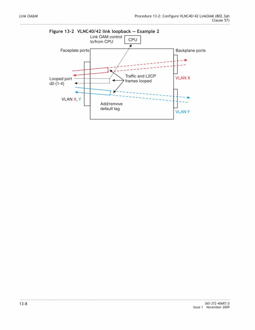
Figure 13-2 VLNC40/42 link loopback — Example 2
Faceplate ports Backplane ports
VLAN X
VLAN Y
VLAN ,X Y
Looped portd2-{1-4}
CPU
Add/removedefault tag
Link OAM controlto/from CPU
Traffic and L2CPframes looped
Link OA&M Procedure 13-2: Configure VLNC40/42 LinkOAM (802.3ah
Clause 57)
...................................................................................................................................................................................................................................
...................................................................................................................................................................................................................................
13-8 365-372-406R7.0
Issue 1 November 2009
14 14Service OA&M
Overview
Purpose
The service OA&M menu feature includes, but is not limited to:
• Connectivity Fault Management
• Maintenance Domain
• Maintenance Association
• Maintenance Association End Point
• Linktrace
• Loopback Request
• PM Administration
• Loss Measurement
• Delay Measurement
This section covers requirements pertaining to the service OA&M menu feature.
Contents
Before you begin 14-2
Procedure 14-1: Service OAM Place holder 14-3
Procedure 14-2: Configure Ethernet service OAM using CLI commands 14-4
Procedure 14-3: Y.1731 Service OAM for VL�C42 14-14
...................................................................................................................................................................................................................................
365-372-406R7.0
Issue 1 November 2009
14-1

Before you begin
Before you begin
Important! Command Line Interface (CLI) commands or the Web GUI is required to
interface with the VL�C40/42/42B Ethernet Aggregator, VL�C60/61/62 Circuit
Emulator, and VL�C64 Circuit Emulation Mini-Hub circuit packs.
Most of the procedures in this chapter use the Web GUI with corresponding reference to
the equivalent CLI commands. When using CLI commands, refer to the Alcatel-Lucent
1850 Transport Service Switch (TSS-5) Command Line Interface Guide.
Required equipment
All procedures in this chapter require a Personal Computer (PC).
Important! If additional equipment is required to perform a specific procedure, the
additional equipment is listed in the procedure.
Service OA&M Before you begin
...................................................................................................................................................................................................................................
...................................................................................................................................................................................................................................
14-2 365-372-406R7.0
Issue 1 November 2009
Procedure 14-1: Service OAM Place holder
Step
...................................................................................................................................................................................................
1 This is a place holder for service OA&M related Web GUI procedures to be supplied at a
later date.
E N D O F S T E P S
...................................................................................................................................................................................................
Service OA&M Procedure 14-1: Service OAM Place holder
...................................................................................................................................................................................................................................
...................................................................................................................................................................................................................................
365-372-406R7.0
Issue 1 November 2009
14-3

Procedure 14-2: Configure Ethernet service OAM using CLI
commands
Overview
Use this procedure to configure Ethernet service OAM on VL�C40/42 networks.
Refer to “Service OAM in VL�C40/42” (p. 14-10), and Figure 14-1, “Service OAM
reference model” (p. 14-10) for an example.
Refer to the Alcatel-Lucent 1850 Transport Service Switch (TSS-5) Command Line
Interface Guide, for help on using the Ethernet OAM CLI commands.
Service OAM provisioning consists of the following general order of steps:
1. Determine the VLA� tagging mode (VLA� ID) being used for this service.
2. Enabling Connectivity Fault Management (CFM) on each node in the network using
the ethoam cfm command.
3. Provision the Maintenance Domains (MDs) using the ethoam md command.
4. Provision the Maintenance Associations (MAs) using the ethoam ma command.
5. Provision the Maintenance association End Points (MEPs) to be used using the
ethoam mep and ethoam remote-mep commands.
This procedure uses Figure 14-1, “Service OAM reference model” (p. 14-10) as an
example for provisioning. Many other configurations are possible and must be
provisioned using local practices and procedures.
The steps in the following procedure are given in the logical order of configuring MDs
from the lowest level to the highest. Other ordering is possible, for instance configuring
successive ports, with all OAM entities on a port configured at once.
Although Figure 14-1, “Service OAM reference model” (p. 14-10) shows a Customer
level ME, this procedure is only used to provision the Provider network. Similar
provisioning may be performed between the customer and provider using these
procedures and coordination of the information that must be passed between the customer
and provider.
Refer to the Alcatel-Lucent 1850 Transport Service Switch (TSS-5) Command Line
Interface Guide, for the proper command syntax, parameters, and values for each of the
commands used in this procedure.
Before you begin
You must be familiar with the concepts of IEEE Std 802.1ag™ -2007 Connectivity Fault
Management and/or have detailed work instructions.
Service OA&M Procedure 14-2: Configure Ethernet service OAM using CLI
commands
...................................................................................................................................................................................................................................
...................................................................................................................................................................................................................................
14-4 365-372-406R7.0
Issue 1 November 2009
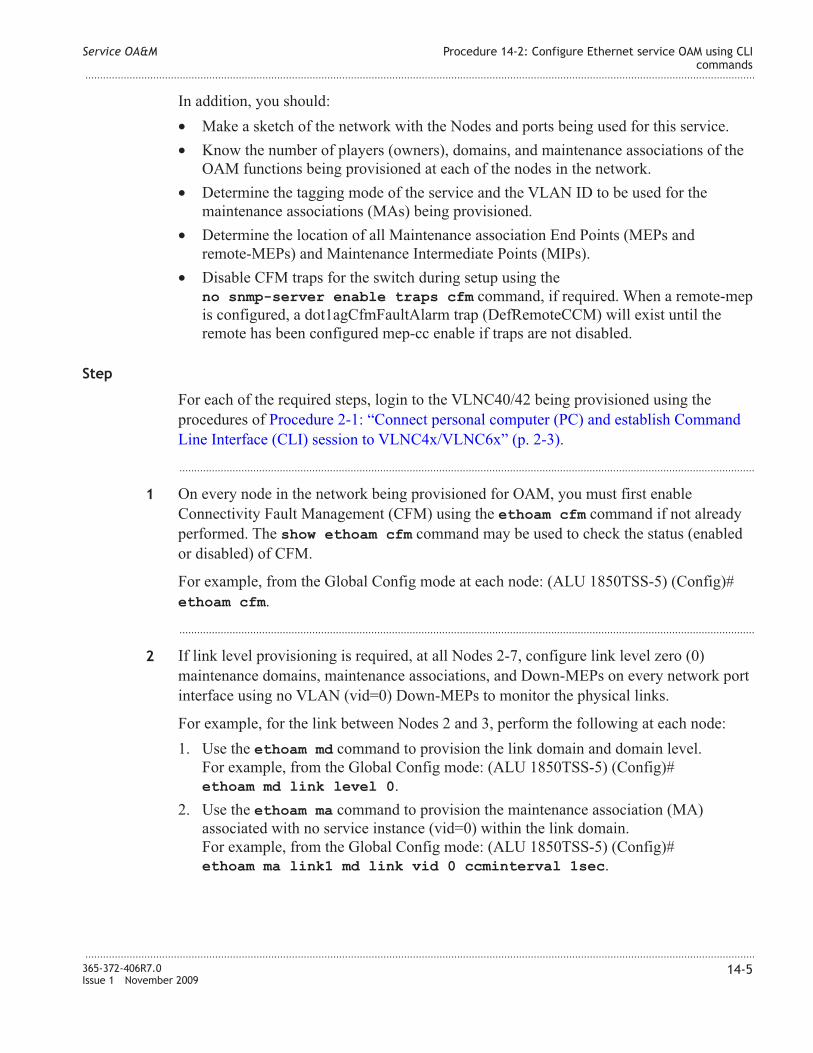
In addition, you should:
• Make a sketch of the network with the �odes and ports being used for this service.
• Know the number of players (owners), domains, and maintenance associations of the
OAM functions being provisioned at each of the nodes in the network.
• Determine the tagging mode of the service and the VLA� ID to be used for the
maintenance associations (MAs) being provisioned.
• Determine the location of all Maintenance association End Points (MEPs and
remote-MEPs) and Maintenance Intermediate Points (MIPs).
• Disable CFM traps for the switch during setup using the
no snmp-server enable traps cfm command, if required. When a remote-mep
is configured, a dot1agCfmFaultAlarm trap (DefRemoteCCM) will exist until the
remote has been configured mep-cc enable if traps are not disabled.
Step
For each of the required steps, login to the VL�C40/42 being provisioned using the
procedures of Procedure 2-1: “Connect personal computer (PC) and establish Command
Line Interface (CLI) session to VL�C4x/VL�C6x” (p. 2-3).
...................................................................................................................................................................................................
1 On every node in the network being provisioned for OAM, you must first enable
Connectivity Fault Management (CFM) using the ethoam cfm command if not already
performed. The show ethoam cfm command may be used to check the status (enabled
or disabled) of CFM.
For example, from the Global Config mode at each node: (ALU 1850TSS-5) (Config)#
ethoam cfm.
...................................................................................................................................................................................................
2 If link level provisioning is required, at all �odes 2-7, configure link level zero (0)
maintenance domains, maintenance associations, and Down-MEPs on every network port
interface using no VLA� (vid=0) Down-MEPs to monitor the physical links.
For example, for the link between �odes 2 and 3, perform the following at each node:
1. Use the ethoam md command to provision the link domain and domain level.
For example, from the Global Config mode: (ALU 1850TSS-5) (Config)#
ethoam md link level 0.
2. Use the ethoam ma command to provision the maintenance association (MA)
associated with no service instance (vid=0) within the link domain.
For example, from the Global Config mode: (ALU 1850TSS-5) (Config)#
ethoam ma link1 md link vid 0 ccminterval 1sec.
Service OA&M Procedure 14-2: Configure Ethernet service OAM using CLI
commands
...................................................................................................................................................................................................................................
...................................................................................................................................................................................................................................
365-372-406R7.0
Issue 1 November 2009
14-5

3. Use the ethoam mep command to configure each node interface at each end of the
link as a Maintenance association End Point (MEP) of the specific MA. At these
interfaces, configure the MEP as a Down-MEP. All MEPIDs in an MA must be
unique.
For example, from the Interface Config mode: (ALU 1850TSS-5) (Interface d2-1)#
ethoam mep 1 md link ma link1 direction down mep-cc enable
priority 7.
4. Use the ethoam remote-mep command to add remote Maintenance association End
Point (MEP) identifiers to the list of MEPIDs for this Maintenance Association (MA).
When the remote-mep is configured, a dot1agCfmFaultAlarm trap (DefRemoteCCM)
will exist until the remote has been configured mep-cc enable unless all CFM traps
are disabled during setup using the no snmp-server enable traps cfm
command.
For example, from the Global Config mode: (ALU 1850TSS-5) (Config)#
ethoam remote-mepid 2 md link ma link1.
Repeat this step for each of the links (between nodes 3 and 4, nodes 4 and 5, nodes 5 and
6, and nodes 6 and 7.
�ote that this step may also be used to provision link level zero (0) maintenance domains,
maintenance associations, and Down-MEPs at �odes 2 and 7 ports facing the customer
equipment (links between �odes 1 and 2 and �odes 7 and 8.)
...................................................................................................................................................................................................
3 At �odes 2 and 4, perform the following to provision OperatorA domains:
• Use the ethoam md command to provision the operator domain and domain level for
OperatorA.
For example, from the Global Config mode: (ALU 1850TSS-5) (Config)#
ethoam md operatorA level 2.
• Use the ethoam ma command to provision the maintenance association (MA)
associated with a single service instance within the operator domain.
For example, from the Global Config mode: (ALU 1850TSS-5) (Config)#
ethoam ma operator1 md operatorA vid 10 ccminterval 1sec ma-
mip enable.
�ote that the VLA� ID (vid) may not be the same in all cases depending on the
tagging mode.
Service OA&M Procedure 14-2: Configure Ethernet service OAM using CLI
commands
...................................................................................................................................................................................................................................
...................................................................................................................................................................................................................................
14-6 365-372-406R7.0
Issue 1 November 2009

• Use the ethoam mep command to configure the U�I-� and E-��I node interfaces
with a Maintenance Association End Point. At these interfaces, configure the MEP as
an Up-MEP. All MEPIDs in an MA must be unique.
For example, from the Interface Config mode at �ode 2: (ALU 1850TSS-5) (Interface
a-42)#
ethoam mep 1 md operatorA ma operator1 direction up mep-cc
enable priority 7.
• Use the ethoam remote-mep command to add remote Maintenance association End
Point (MEP) identifiers to the list of MEPIDs for this Maintenance Association (MA).
When the remote-mep is configured, a dot1agCfmFaultAlarm trap (DefRemoteCCM)
will exist until the remote has been configured mep-cc enable unless all CFM traps
are disabled during setup using the no snmp-server enable traps cfm
command.
For example, from the Global Config mode: (ALU 1850TSS-5) (Config)#
ethoam remote-mepid 2 md operatorA ma operator1.
...................................................................................................................................................................................................
4 At �ode 3, if required and the tagging mode allows, use the ethoam md and ethoam ma
commands to enable operatorA MIPs at this node.
For example, from the Global Config mode: (ALU 1850TSS-5) (Config)#
ethoam md operatorA level 2.
For example, from the Global Config mode: (ALU 1850TSS-5) (Config)#
ethoam ma operator1 md operatorA vid 10 ccminterval 1sec ma-mip
enable.
...................................................................................................................................................................................................
5 At �odes 5 and 7, perform the following to provision OperatorB domains:
• Use the ethoam md command to provision the operator domain and domain level for
OperatorB.
For example, from the Global Config mode: (ALU 1850TSS-5) (Config)#
ethoam md operatorB level 2.
• Use the ethoam ma command to provision the maintenance association (MA)
associated with a single service instance within the operator domain.
For example, from the Global Config mode: (ALU 1850TSS-5) (Config)#
ethoam ma operator2 md operatorB vid 10 ccminterval 1sec ma-
mip enable.
�ote that the VLA� ID (vid) may not be the same in all cases depending on the
tagging mode.
Service OA&M Procedure 14-2: Configure Ethernet service OAM using CLI
commands
...................................................................................................................................................................................................................................
...................................................................................................................................................................................................................................
365-372-406R7.0
Issue 1 November 2009
14-7

• Use the ethoam mep command to configure each node interface as a Maintenance
association End Point (MEP) of a specific MA. At these interfaces, configure the MEP
as an Up-MEP. All MEPIDs in an MA must be unique.
For example, from the Interface Config mode: (ALU 1850TSS-5) (Interface d2-1)#
ethoam mep 1 md operatorB ma operator2 direction up mep-cc
enable priority 7.
• Use the ethoam remote-mep command to add remote Maintenance association End
Point (MEP) identifiers to the list of MEPIDs for this Maintenance Association (MA).
When the remote-mep is configured, a dot1agCfmFaultAlarm trap (DefRemoteCCM)
will exist until the remote has been configured mep-cc enable unless all CFM traps
are disabled during setup using the no snmp-server enable traps cfm
command.
For example, from the Global Config mode: (ALU 1850TSS-5) (Config)#
ethoam remote-mepid 2 md operatorB ma operator2.
...................................................................................................................................................................................................
6 At �ode 6, if required and the tagging mode allows, use the ethoam md and ethoam ma
commands to enable operatorB MIPs at this node.
For example, from the Global Config mode: (ALU 1850TSS-5) (Config)#
ethoam md operatorB level 2.
For example, from the Global Config mode: (ALU 1850TSS-5) (Config)#
ethoam ma operator2 md operatorB vid 10 ccminterval 1sec ma-mip
enable.
...................................................................................................................................................................................................
7 At �odes 2 and 7, perform the following to provision the provider domain:
• Use the ethoam md command to provision the provider domain and domain level.
For example, from the Global Config mode: (ALU 1850TSS-5) (Config)#
ethoam md provider level 4.
• Use the ethoam ma command to provision the maintenance association (MA)
associated with a single service instance within the provider domain.
For example, from the Global Config mode: (ALU 1850TSS-5) (Config)#
ethoam ma providerXYZ md provider vid 10 ccminterval 1sec ma-
mip enable.
�ote that the VLA� ID (vid) may not be the same in all cases depending on the
tagging mode.
Service OA&M Procedure 14-2: Configure Ethernet service OAM using CLI
commands
...................................................................................................................................................................................................................................
...................................................................................................................................................................................................................................
14-8 365-372-406R7.0
Issue 1 November 2009
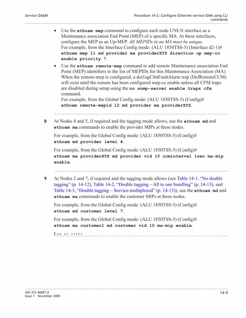
• Use the ethoam mep command to configure each node U�I-� interface as a
Maintenance association End Point (MEP) of a specific MA. At these interfaces,
configure the MEP as an Up-MEP. All MEPIDs in an MA must be unique.
For example, from the Interface Config mode: (ALU 1850TSS-5) (Interface d2-1)#
ethoam mep 11 md provider ma providerXYZ direction up mep-cc
enable priority 7.
• Use the ethoam remote-mep command to add remote Maintenance association End
Point (MEP) identifiers to the list of MEPIDs for this Maintenance Association (MA).
When the remote-mep is configured, a dot1agCfmFaultAlarm trap (DefRemoteCCM)
will exist until the remote has been configured mep-cc enable unless all CFM traps
are disabled during setup using the no snmp-server enable traps cfm
command.
For example, from the Global Config mode: (ALU 1850TSS-5) (Config)#
ethoam remote-mepid 12 md provider ma providerXYZ.
...................................................................................................................................................................................................
8 At �odes 4 and 5, if required and the tagging mode allows, use the ethoam md and
ethoam ma commands to enable the provider MIPs at these nodes.
For example, from the Global Config mode: (ALU 1850TSS-5) (Config)#
ethoam md provider level 4.
For example, from the Global Config mode: (ALU 1850TSS-5) (Config)#
ethoam ma providerXYZ md provider vid 10 ccminterval 1sec ma-mip
enable.
...................................................................................................................................................................................................
9 At �odes 2 and 7, if required and the tagging mode allows (see Table 14-1, “�o double
tagging” (p. 14-12), Table 14-2, “Double tagging – All to one bundling” (p. 14-13), and
Table 14-3, “Double tagging – Service-multiplexed” (p. 14-13)), use the ethoam md and
ethoam ma commands to enable the customer MIPs at these nodes.
For example, from the Global Config mode: (ALU 1850TSS-5) (Config)#
ethoam md customer level 7.
For example, from the Global Config mode: (ALU 1850TSS-5) (Config)#
ethoam ma customer1 md customer vid 10 ma-mip enable.
Service OA&M Procedure 14-2: Configure Ethernet service OAM using CLI
commands
...................................................................................................................................................................................................................................
...................................................................................................................................................................................................................................
365-372-406R7.0
Issue 1 November 2009
14-9
E N D O F S T E P S...................................................................................................................................................................................................

Service OAM in VLNC40/42
Ethernet service OAM (Operations, Administration, and Maintenance) provides
maintenance features for detecting, isolating, and reporting connectivity faults for
Ethernet services. This release implements IEEE Std 802.1ag™ -2007 Connectivity Fault
Management for the VL�C40/42 circuit packs. Three basic features are currently
specified: Continuity Check, Link Trace, and Loopback.
For each service, generally three types of players are involved: the customer, the service
provider, and operators. Each needs its own independent OAM functions, in its own
Maintenance Domain (MD). For this reason Service OAM is defined at multiple levels, as
shown in Figure 14-1, “Service OAM reference model” (p. 14-10).
Figure 14-1 Service OAM reference model
1 82 3 4 5 6 7
Service Provider
Operator A NEs Operator B NEs
Operator A ME(UNI-N to E-NNI)
Operator B ME(UNI-N to E-NNI)
Customerequipment
Customerequipment
Up MEP
Down MEP
MIP
Port
ETH
ME - Maintenance EntityETH - Ethernet framesTran/ETH - Physical transport layerE-NNI - External Network-to-Network InterfaceUNI - User-to-Network InterfaceUNI-C - User Network Interface, port on customer side of UNIUNI-N - User Network Interface, port on network side of UNI
Tran/EthPhysical
E-NNI
EVC (Provider) ME(UNI-N to UNI-N)
Customer ME(UNI-C to UNI-C)
Link Link Link Link Link
OAMservice
Link Link
Service OA&M Procedure 14-2: Configure Ethernet service OAM using CLI
commands
...................................................................................................................................................................................................................................
...................................................................................................................................................................................................................................
14-10 365-372-406R7.0
Issue 1 November 2009

CFM supports the following concepts to support multiple independent operators, services,
and customers:
• Maintenance Domains (MD) — A MD is a part of the network controlled by a single
player (owner) to support connectivity between maintenance end points (MEPs) that
bound the maintenance domain.
• Maintenance Domain Levels — Maintenance domain levels allow customers, service
providers, and operators to run independent OAMs on their own level. Up to eight
OAM levels are defined (0-7), with seven (7) being the highest. By convention,
customers are allocated up to three levels (5, 6, 7), service providers two levels (3, 4) ,
and operators three levels (0, 1, 2).
• Maintenance Associations (MA) — Maintenance Associations (MA) are associated
with a single service instance (identified by the service VLA� identifier) within a
maintenance domain (identified by the maintenance domain name). The combination
of the maintenance domain name (if MD name format is not null) and the
maintenance association name is called Maintenance Association Identifier (MAID).
• Maintenance End Points (MEPs) — Maintenance End Points (MEP) are established
on interfaces at each end of a maintenance domain. MEPs are configured for a
specific MA within a maintenance domain to generate and receive Connectivity Fault
Management (CFM) PDUs. Each individual MEP is configured with a MEPID that is
unique within its MA. MEPs may be configured as Up MEPs or Down MEPs. MEPs
may be addressed by the MEPID or by their port’s MAC address for Down-MEPs or
by the shared bridge CPU MAC address for Up-MEPs.
• Maintenance Intermediate Points (MIPs) — MIPs may also be created at intermediate
bridge ports between MEPs. When enabled, MIPs are automatically created on a port
at the MD level above the highest level MEP or in the lowest configured MD level if
there is no MEP on the port. In other words, MIPs can be created for the VID
(monitored by this MA) on any bridge port through which the VID can pass where
there are no lower MD levels, or where there is a MEP at the next lower MD level on
the port.
A MIP consists of two MIP Half Functions (MHFs) on a single bridge port, an Up
MHF and a Down MHF. MIPs may be addressed by their port’s MAC address for
Down-MHFs or by the shared bridge CPU MAC address for Up-MHFs.
Each player can establish their own Maintenance Associations (MA), consisting of
Maintenance Endpoints (MEP’s, shown as triangles), which allows them to exchange
OAM messages over their domain of the service. MEP’s can perform fault detection using
keep-alive messages called Continuity Check Messages (CCM). Maintenance
Intermediate Points (MIP’s, shown as circles) may be created to facilitate fault isolation.
They can respond to, but do not initiate, certain OAM functions. For example, loopbacks
may be initiated from a MEP which has detected a CC fault and targeted successively to
each MIP at its level. A provider can isolate a fault to one operator, and an operator can
isolate to a single �E.
Service OA&M Procedure 14-2: Configure Ethernet service OAM using CLI
commands
...................................................................................................................................................................................................................................
...................................................................................................................................................................................................................................
365-372-406R7.0
Issue 1 November 2009
14-11

Service OAM Configurations
An example application is a VL�C40/42 provider-owned demarcation point between
customers and the provider’s network. This is �ode 2 or �ode 7 in Figure 14-1, “Service
OAM reference model” (p. 14-10). Each customer port may be provisioned to support a
customer MIP and at least a provider Up-MEP, and if applicable an operator Up-MEP, for
each Ethernet Virtual Connection (EVC). A link-level Down-MEP may be configured on
both customer and network ports, with no VID, to monitor the entire link.
Provider bridging (double tagging) is typically used. In that case, a customer MIP can
only function if the customer supplies untagged Ethernet OAM frames (see “MIP
support” (p. 14-12)), which get tagged with the S-VLA�, otherwise the customer’s OAM
traffic is tunneled. See Table 14-2, “Double tagging – All to one bundling” (p. 14-13) and
Table 14-3, “Double tagging – Service-multiplexed” (p. 14-13). OAM for multiple EVC’s
(service-multiplexing) is supported. Similarly, in that case only one of the EVC’s on a
port can support a customer MIP, the one which includes untagged traffic (see Table 14-3,
“Double tagging – Service-multiplexed” (p. 14-13)).
If double tagging is not used, then a customer MIP may be supported in the default
VLA� if the customer supplies untagged Ethernet OAM frames, or by agreement with
the customer on a specific VLA� for OAM. See Table 14-1, “�o double tagging”
(p. 14-12). The provider’s OAM also uses that same VLA�, representing the “service.”
Service OAM also applies to more complex networks than is represented in this
procedure, including multipoint and ring networks.
MIP support
Whether and how a customer MIP can be supported depends on the tagging mode, and
whether the customer OAM frames (only levels 5, 6 and 7 are designated for customer
use) are tagged. Table 14-1, “�o double tagging” (p. 14-12) through Table 14-3, “Double
tagging – Service-multiplexed” (p. 14-13) show, for the provider edge, the relation
between customer OAM tagging and the Service VLA� to be used for configuring the
MA. For example, �ode 2 in Figure 14-1, “Service OAM reference model” (p. 14-10). A
customer MIP can only be supported (be accessible) in the provider’s equipment when the
customer’s OAM frames have a single tag when forwarded to the CPU. When double
tagged, they are tunneled.
Table 14-1 No double tagging
Customer OAM VLAN Customer MIP supported? Service VLAN ID
Untagged (untagged not
accepted)
�o �/A
Untagged (untagged
accepted)
Yes, in pvid pvid
Service OA&M Procedure 14-2: Configure Ethernet service OAM using CLI
commands
...................................................................................................................................................................................................................................
...................................................................................................................................................................................................................................
14-12 365-372-406R7.0
Issue 1 November 2009

Table 14-1 No double tagging (continued)
Customer OAM VLAN Customer MIP supported? Service VLAN ID
VLA�=X Yes X
�o OAM �o Any
Table 14-2 Double tagging – All to one bundling
Customer OAM VLAN Customer MIP supported? Service VLAN ID
Untagged Yes, in default VLA� (pvid) pvid
VID=X �o, tunneled pvid
Table 14-3 Double tagging – Service-multiplexed
Customer OAM VLAN Customer MIP supported? Service VLAN ID
Untagged Yes, in only one EVC As mapped with SVLA�
VID=X �o, tunneled As mapped with SVLA�
Service OA&M Procedure 14-2: Configure Ethernet service OAM using CLI
commands
...................................................................................................................................................................................................................................
...................................................................................................................................................................................................................................
365-372-406R7.0
Issue 1 November 2009
14-13

Procedure 14-3: Y.1731 Service OAM for VLNC42
Overview
Y.1731 service OAM in this release supports:
• Service OAM PM
Loss Measurement (LM)
– Dual-Ended (CCM-based Proactive)
– Single-Ended (LMM/LMR-based; On-Demand)
Delay Measurement (DM)
– Two-way (round trip) Delay Measurement
– One-way Delay Variation Measurement (no TOD clock needed)
• Ethernet AIS
• Y.1731/G.8021 CCM alarms
Before you begin
The OAM PM features, LM and DM, can be enabled when CFM is enabled. Parts of the
system configuration must be in place on the port(s) or LAG before OAM-PM is enabled,
and cannot be changed while OAM-PM is active. Disabling OAM-PM clears all
provisioning directly associated with it. The system configuration which must be
configured first includes “mode dvlan-tunnel”, spanning tree or ERP participation, LAG
membership on the OAM-PM ports, and mtu-size on all ports.
Step
...................................................................................................................................................................................................
1 Perform the following procedures, as required:
• Procedure 14-3.1: “Enable Ethernet OAM Performance Monitoring (PM)” (p. 14-16)
• Procedure 14-3.2: “OAM PM proactive loss measurement (LM)” (p. 14-18)
• Procedure 14-3.3: “Proactive LM Threshold Configuration” (p. 14-20)
• Procedure 14-3.4: “OAM PM on-demand loss measurement (LM)” (p. 14-23)
• Procedure 14-3.5: “OAM PM on-demand loss measurement (LM) responder”
(p. 14-26)
• Procedure 14-3.6: “OAM PM proactive delay measurement (DM)” (p. 14-28)
• Procedure 14-3.7: “Proactive DM Threshold Configuration” (p. 14-31)
• Procedure 14-3.8: “OAM PM on-demand delay measurement” (p. 14-33)
• Procedure 14-3.9: “OAM PM on-demand delay measurement (DM) responder”
(p. 14-36)
• Procedure 14-3.10: “Enable AIS generation on a MEP” (p. 14-38)
Service OA&M Procedure 14-3: Y.1731 Service OAM for VLNC42
...................................................................................................................................................................................................................................
...................................................................................................................................................................................................................................
14-14 365-372-406R7.0
Issue 1 November 2009

E N D O F S T E P S
...................................................................................................................................................................................................
Service OA&M Procedure 14-3: Y.1731 Service OAM for VLNC42
...................................................................................................................................................................................................................................
...................................................................................................................................................................................................................................
365-372-406R7.0
Issue 1 November 2009
14-15

Procedure 14-3.1: Enable Ethernet OAM Performance
Monitoring (PM)
Overview
Use this procedure to enable PM on d-group interface(s) or a LAG logical port containing
two d-group interfaces. The PM functions include Loss Measurement and Delay
Measurement, both proactive (continuous with 15-minute and 24-hour binning of results),
and on-demand. Up-MEPs which are configured for the PM measurements may exist on
any port, but the OAM PM traffic passes through the d-group interface(s). Down-MEPs
may be configured for PM measurements only on the interface(s) enabled for Ethernet
OAM PM. By default OAM PM is disabled.
You can only enable OAM PM on one or two d-group ports, or a LAG containing them,
and when ethoam cfm is enabled. Specified individual ports cannot be members of a
LAG. Once OAM PM is enabled, you cannot modify the port participation, nor can you
change the configuration of mode dvlan-tunnel, spanning tree or ERP participation, nor
LAG membership, on those ports, nor mtu-size on any port, without first disabling OAM
PM. You cannot change VLA� participation on a port enabled for OAM PM if a Loss or
Delay Measurement session is configured in that VLA�.
Step
...................................................................................................................................................................................................
1 From the �avigation menu, select Service OA&M → PM Admin.
Equivalent CLI command: ethoam pm <port1> [<port2>].
Result: The PM Admin window displays current settings.
...................................................................................................................................................................................................
2 Enable or Disable PM as required. See “PM Admin” (p. 14-17).
Service OA&M Procedure 14-3.1: Enable Ethernet OAM Performance
Monitoring (PM)
...................................................................................................................................................................................................................................
...................................................................................................................................................................................................................................
14-16 365-372-406R7.0
Issue 1 November 2009
E N D O F S T E P S....................................................................................................................................................................................................................................

PM Admin
Parameter Description CLI command
PM State This parameter enables Ethernet OA&M
Performance Monitoring (PM) on d-group
interface(s) or a LAG containing two d-group
interfaces. Valid values: Enable or Disable. The
default value is Disable. Use show ethoam pm
to get the system settings. If there is no output, it
means PM State is Disable. no ethoam pm
disables the PM State.
show ethoam pm,
ethoam pm,
no ethoam pm
Port 1 A d-group interface or LAG. A LAG must have
two d-group interfaces as members.
ethoam pm d2-1 d2-2
Port 2 A d-group interface. ethoam pm d2-1 d2-2
Service OA&M Procedure 14-3.1: Enable Ethernet OAM Performance
Monitoring (PM)
...................................................................................................................................................................................................................................
...................................................................................................................................................................................................................................
365-372-406R7.0
Issue 1 November 2009
14-17

Procedure 14-3.2: OAM PM proactive loss measurement (LM)
Overview
Use this procedure to request the MEP to begin a proactive Loss Measurement session for
a particular Class of Service, using CCM frames (ethoam mep mep-cc). The results are
minimum, maximum, and average, near end and far end, Frame Loss Ratio (FLR) per
15-minute and 24-hour intervals, reported via S�MP. In addition, SES and UAS PM are
augmented by per-second FLR calculations.
Loss Measurement provides an accurate accounting of frames received versus frames sent
for a service. A typical use is by a Service Provider who conducts the measurement
proactively (continuously) end-to-end for Service Level Agreement (SLA) verification.
Up-MEP’s at the service endpoints exchange frame count information to make the
calculation. The customer can do the same in their equipment for the same reason, using
Down-MEPs on their U�I ports. If the service crosses administrative boundaries, then the
responsible entities may measure performance on each leg, bounded by their MEPs.
Proactive LM is also used to monitor Severely Errored Second (SES) and UnAvailable
Second (UAS), also for SLA verification. An FLR is calculated each second, and if it
exceeds 75%, (or if the MEP detects a local fault) then the SES counter is incremented.
UAS is calculated in the same manner as in TDM. Both are implemented according to
ITU-T G.7710.
Proactive results are only available by S�MP. A TCA notification is provided for LM and
DM current maximum and average FLR bins, and for SES and UAS. The thresholds are
user configurable. See “Proactive LM Threshold parameters” (p. 14-21).
Before you begin
Refer to the following restrictions:
• Ethernet OAM pm (ethoam pm) must be enabled. See Procedure 14-3.1: “Enable
Ethernet OAM Performance Monitoring (PM)” (p. 14-16).
• Proactive LM can be configured on only one Up-MEP for a particular VID and
priority, and on only one Down-MEP for a particular VID, priority and port.
• You cannot enable a proactive LM session on both an Up and Down MEP having the
same VID and priority.
• You can enable proactive LM simultaneously with on-demand LM and an on-demand
LM responder, for the same VID and priority, but they must all be on the same MEP.
• The MEP must belong to a VLA� and have CCM enabled.
• The remote peer MEP should also have proactive LM enabled.
Step
Proactive Loss Measurement
Service OA&M Procedure 14-3.2: OAM PM proactive loss measurement
(LM)
...................................................................................................................................................................................................................................
...................................................................................................................................................................................................................................
14-18 365-372-406R7.0
Issue 1 November 2009

...................................................................................................................................................................................................
1 From the �avigation menu at each end of the service, select Service OA&M → Loss
Measurement → Proactive Configuration to configure proactive loss measurement.
Equivalent CLI command: ethoam proactive-lm.
Result: The Proactive LM Configuration window displays current settings.
...................................................................................................................................................................................................
2 Enter the parameters as required. See “Proactive loss measurement parameters” (p. 14-19)
. Click Submit to request the MEP to begin a proactive Loss Measurement session. Click
Delete to delete a proactive Loss Measurement session.
Proactive loss measurement parameters
Parameter Description CLI command
MD �ame Select the MD name from the drop-down list containing
all MDs on the bridge.
ethoam proactive-lm md
<MDname>
MA �ame Select the MA name from the drop-down list containing
all MAs on the bridge.
ethoam proactive-lm ma
<MAname>
SourceMEPID /
Create
MEPID of the MEP transmitting proactive LM. The
drop-down list contains "Create" plus all local MEPs,
which have the Proactive LM configured, in the
selected MA above.
ethoam proactive-lm
mep <sourceMEPID>
Proactive LM This is the MEP ID field. For "Create", the drop-down
list contains all local MEPs, which do not have
Proactive LM configured, in the selected MA above.
Otherwise, it is a display-only field containing the
above selected MEP ID.
ethoam proactive-lm
mep <sourceMEPID>
Service OA&M Procedure 14-3.2: OAM PM proactive loss measurement
(LM)
...................................................................................................................................................................................................................................
...................................................................................................................................................................................................................................
365-372-406R7.0
Issue 1 November 2009
14-19
E N D O F S T E P S...................................................................................................................................................................................................

Procedure 14-3.3: Proactive LM Threshold Configuration
Overview
Use this procedure to provision the LM/SES/AUS threshold values for a Proactive LM
session on a selected MEP or to delete the LM/SES/UAS Threshold values for the
Proactive LM session on a selected MEP.
LM/SES/UAS thresholds can be configured only when the associated proactive LM
session is enabled.
This procedure:
• Sets alarm thresholds for a proactive Loss Measurement session, for maximum or
average Frame Loss Ratio measurement, �ear-end or Far-end, 15-minute or 24-hour
intervals. Thresholds for average measurements are not crossed until the end of an
interval.
The alarm is raised when a measurement equals or exceeds the cross threshold, which
for maximum can occur anytime during a bin, and for average only at the end of a bin.
The alarm is cleared when the measurement at the end of a bin is equal or less than
the clear threshold.
• Sets alarm thresholds for Severely Errored Second monitoring, for Unidirectional
�ear-end or Far-end, Bidirectional �ear-end or Far-end, 15-minute or 24-hour
intervals.
The alarm is raised when a counter equals or exceeds the cross threshold, which can
occur anytime during a bin. The alarm is cleared when the counter at the end of a bin
is equal or less than the clear threshold.
• Sets alarm thresholds for Unavailable Seconds, for Unidirectional �ear-end or
Far-end, Bidirectional, 15-minute or 24-hour intervals.
The alarm is raised when a counter equals or exceeds the cross threshold, which can
occur anytime during a bin. The alarm is cleared when the counter at the end of a bin
is equal or less than the clear threshold.
Step
...................................................................................................................................................................................................
1 From the �avigation menu, select Service OA&M → Loss Measurement →Threshold Configuration to configure thresholds for the proactive loss measurement.
Equivalent CLI commands:
• ethoam lm-threshold
• ethoam ses-threshold
• ethoam uas-threshold
Service OA&M Procedure 14-3.3: Proactive LM Threshold Configuration
...................................................................................................................................................................................................................................
...................................................................................................................................................................................................................................
14-20 365-372-406R7.0
Issue 1 November 2009

Result: The Proactive LM Threshold Configuration window displays current settings.
...................................................................................................................................................................................................
2 Enter the parameters as required. See “Proactive LM Threshold parameters” (p. 14-21).
Click Submit to execute the commands. Click Delete to delete both Cross and Clear
Threshold values for the selected Monitoring Data in the selected Proactive LM session.
Proactive LM Threshold parameters
Parameter Description CLI command
Monitoring Data This is a drop-down list for the monitoring data type.
Valid values: LM, SES, UAS. The default value is
"LM".
ethoam lm-threshold
ethoam ses-threshold
ethoam uas-threshold
Measurement
Type
The type of measurement for the selected threshold
presented in a drop-down list:
• LM Range — a�15, x�15, aF15, xF15, a�24,
x�24, aF24, xF24 where: a = average, x =
maximum, � = near-end, F = far-end, 15 =
15-minute counter, 24 = 24-hour counter. For
example: a�15 is the Average �ear-end FLR for the
15-minute counter.
• SES Range — u�15, b�15, uF15, bF15, u�24,
b�24, uF24, bF24 where: u = unidirectional, b =
bidirectional, � = near-end, F = far-end, 15 =
15-minute counter, 24 = 24-hour counter. For
example: u�15 is the Unidirectional �ear-end SES
15-minute counter.
• UAS Range — u�15, uF15, b15, u�24, uF24, b24
where: u = unidirectional, b = bidirectional, � =
near-end, F = far-end, 15 = 15-minute counter, 24 =
24-hour counter. For example: u�15 is the
Unidirectional �ear-end UAS 15-minute counter.
For each Measurement Type, one set of threshold values
can be created per Proactive LM session. If the
Proactive LM does not have any threshold value set yet,
the default is the first one in the list. Otherwise, the
default value is the first measurement type set in the
system.
ethoam lm-threshold
<type>
ethoam ses-threshold
<type>
ethoam uas-threshold
<type>
Service OA&M Procedure 14-3.3: Proactive LM Threshold Configuration
...................................................................................................................................................................................................................................
...................................................................................................................................................................................................................................
365-372-406R7.0
Issue 1 November 2009
14-21
E N D O F S T E P S...................................................................................................................................................................................................

Parameter Description CLI command
Cross Threshold The threshold for generating a crossing alert.
• For LM: valid values: an integer in the range of 1 to
100000. The default value 30000.
• For SES and u�15, b�15, uF15, bF15, the valid
value is an integer in the range of 1-810. The
default value is 15.
• For SES and u�24, b�24, uF24, bF24, the valid
value is an integer in the range of 1-77760. The
default value is 20.
• For UAS and u�15, uF15, b15, the valid value is an
integer in the range of 1-900. The default value is
15.
• For UAS and u�24, uF24, b24, the valid value is an
integer in the range of 1-86400. The default value is
20.
ethoam lm-threshold
cross <value>
ethoam ses-threshold
cross <value>
ethoam uas-threshold
cross <value>
Clear Threshold The threshold for clearing a crossing alert. The Clear
Threshold must be lower than the Cross Threshold.
• For LM: valid values: an integer in the range of 1 to
100000. The default value is 25000.
• For SES and u�15, b�15, uF15, bF15, the valid
value is an integer in the range of 0-809. The
default value is 0.
• For SES and u�24, b�24, uF24, bF24, the valid
value is an integer in the range of 1-77759. The
default value is 0.
• For UAS and u�15, uF15, b15, the valid value is an
integer in the range of 0-899. The default value is 0.
• For UAS and u�24, uF24, b24, the valid value is an
integer in the range of 0-86399. The default value is
0.
ethoam lm-threshold
clear <value>
ethoam ses-threshold
clear <value>
ethoam uas-threshold
clear <value>
Proactive LM
(MD/MA/
MEPID)
This is a selectable field. The entry contains the comma
separated fields of MD name, MA name, and MEPID
for a Proactive LM. The drop-down list contains all
MEPs which have the Proactive LM configured and
enabled. The default display is for the first enabled
Proactive LM in the system. When the Proactive LM
selection is changed, the display data is updated
automatically.
Service OA&M Procedure 14-3.3: Proactive LM Threshold Configuration
...................................................................................................................................................................................................................................
...................................................................................................................................................................................................................................
14-22 365-372-406R7.0
Issue 1 November 2009

Procedure 14-3.4: OAM PM on-demand loss measurement (LM)
Overview
Use this procedure to request a MEP to begin a local on-demand Loss Measurement
session for a particular Class of Service (CoS). A single measurement is made, which can
be deferred using a start time. The results are retrievable via
show on-demand-lm-stats. When remote mc is configured, the class 1 multicast
address for the MEP’s level is used.
The on-demand loss measurement provides a troubleshooting tool by CLI. It consists of
frame loss ratio (FLR) measured over a specified interval at a specified time. On-demand
results per direction are reported at the end of the configured measurement interval.
On-Demand LM may be conducted on a MEP running Proactive LM, even for the same
CoS.
On-Demand LM may be enabled on a MEP regardless if CCM is enabled.
A single measurement is made for an On-Demand session, which can be deferred using a
start time. The measurement consists of a pair of Loss Measurement Messages (LMM)
and the received Loss Measurement Replies (LMR) from which the count differences
gives the number of frames sent and received during the period between them. That
period is configurable from 1 second up to 10 minutes.
Before you begin
Refer to the following restrictions:
• On-demand LM is available only when ethoam pm is enabled.
• On-demand LM can be configured on only one Up-MEP for a particular VID and
priority, and on only one Down-MEP for a particular VID and priority and port (and
only on a port which has ethoam pm enabled). You cannot enable an on-demand LM
session on both an Up and Down MEP having the same VID and priority.
• You can enable on-demand LM simultaneously with an on-demand LM responder and
proactive LM, for the same VID and priority, but they must all be on the same MEP.
• The command is rejected if remoteMEPID is specified, but the remote MEP MAC
address is not known (CCM are not received from the remote MEP).
• You should not use the multicast address when there is a possibility of more than one
reply.
• The remote peer MEP should also have either an overlapping on-demand LM session
or an LM responder enabled.
Service OA&M Procedure 14-3.4: OAM PM on-demand loss measurement
(LM)
...................................................................................................................................................................................................................................
...................................................................................................................................................................................................................................
365-372-406R7.0
Issue 1 November 2009
14-23

Step
...................................................................................................................................................................................................
1 From the �avigation menu, select Service OA&M → Loss Measurement →On-Demand Configuration to configure on-demand loss measurement.
Equivalent CLI command: ethoam on-demand-lm. Refer to the Alcatel-Lucent 1850
Transport Service Switch (TSS-5) Command Line Interface Guide for a complete
description of this command and related parameters.
When using CLI commands, use the show on-demand-lm-stats CLI command to
retrieve the results of an on-demand loss measurement.
Result: The On-Demand LM Configuration window displays current settings.
...................................................................................................................................................................................................
2 Enter the parameters as required. See “On-demand loss measurement parameters”
(p. 14-24). Click Submit to request the MEP to begin an on-demand Loss Measurement
session. Click Delete to delete an on-demand Loss Measurement session.
...................................................................................................................................................................................................
3 Both ends need to be configured for on-demand LM or an on-demand LM responder at
the other end (or a proactive LM session for the same class of service).
Reference: Procedure 14-3.5: “OAM PM on-demand loss measurement (LM)
responder” (p. 14-26)
...................................................................................................................................................................................................
4 From the �avigation menu, select ServiceOA&M → Loss Measurement →On-Demand Status command to retrieve the results of the measurement.
Equivalent CLI command: show ethoam on-demand-dm-stats.
On-demand loss measurement parameters
Parameter Description CLI command
MD �ame Select the MD name from the drop-down list containing
all MDs on the bridge.
ethoam on-demand-lm md
<MDname>
MA �ame Select the MA name from the drop-down list containing
all MAs on the bridge.
ethoam on-demand-lm ma
<MAname>
Service OA&M Procedure 14-3.4: OAM PM on-demand loss measurement
(LM)
...................................................................................................................................................................................................................................
...................................................................................................................................................................................................................................
14-24 365-372-406R7.0
Issue 1 November 2009
E N D O F S T E P S....................................................................................................................................................................................................................................

Parameter Description CLI command
SourceMEPID /
Create
MEPID of the MEP transmitting on-demand LM. The
drop-down list contains "Create" plus all local MEPs,
which have the on-demand LM configured, in the
selected MA above.
ethoam on-demand-lm
mep <sourceMEPID>
On-Demand LM This is the MEP ID field. For "Create", the drop-down
list contains all local MEPs, which do not have
On-demand LM configured, in the selected MA above.
Otherwise, it is a display-only field containing the
above selected MEP ID.
ethoam on-demand-lm
mep <sourceMEPID>
Priority The priority of the LMM frames carrying the LM
information, and the Class of Service being measured.
Valid values: an integer in the range of 0 to 7.
ethoam on-demand-lm
priority <priority-
value>
Remote MEP Valid values:
• The MAC Address of the Remote MEP
• The MEPID of the Remote MEP
• MC — When MC is selected for the Remote MEP,
the class 1 multicast address for the MEP’s level is
used.
ethoam on-demand-lm
remote {<remoteMAC> |
<remoteMEPID> | mc}
LMM Frame
�umber
The number of LMM frames sent during the
measurement. The valid value is 1 in this release.
ethoam on-demand-lm
nbr <meas-nbr>
Start Time The time to start a measurement. Valid values: an
integer in the format of YYYYMMDDHHMMSS. The
Start Time must be later than the current time.
ethoam on-demand-lm
start-time <s-time>
Period The period between LMM frames during the
measurement. Valid values: 1 Sec, 10 Sec (default), 1
Min, 10 Min
ethoam on-demand-lm
period {1sec | 10sec |
1min | 10min}
Service OA&M Procedure 14-3.4: OAM PM on-demand loss measurement
(LM)
...................................................................................................................................................................................................................................
...................................................................................................................................................................................................................................
365-372-406R7.0
Issue 1 November 2009
14-25

Procedure 14-3.5: OAM PM on-demand loss measurement (LM)
responder
Overview
Use this procedure to configure the local MEP to respond to a remote on-demand Loss
Measurement session for a particular Class of Service with measurement counts needed
by the remote MEP.
Generally a responder is needed for an on-demand LM session initiated by a remote MEP.
Configuring a responder allocates LM counter resources to this function. The same
resources are used by a local on-demand LM session so they only count once towards the
resource limit.
Before you begin
Refer to the following restrictions:
• On-demand LM is available only when ethoam pm is enabled.
• On-demand LM can be configured on only one Up-MEP for a particular VID and
priority, and on only one Down-MEP for a particular VID and priority and port (and
only on a port which has ethoam pm enabled). You cannot enable an on-demand LM
responder on both an Up and Down MEP having the same VID and priority.
• You can enable an on-demand LM responder simultaneously with on-demand LM and
proactive LM, for the same VID and priority, but they must all be on the same MEP.
Step
...................................................................................................................................................................................................
1 From the �avigation menu, select Service OA&M → Loss Measurement →On-Demand LM Responder Configuration to configure on-demand loss
measurement responder.
Equivalent CLI command: ethoam on-demand-lm-responder. Refer to the
Alcatel-Lucent 1850 Transport Service Switch (TSS-5) Command Line Interface Guide for
a complete description of this command and related parameters.
Result: The On-Demand LM Responder Configuration window displays current
settings.
...................................................................................................................................................................................................
2 Enter the parameters as required. See “On-demand loss measurement responder
parameters” (p. 14-27). Click Submit to execute the command. Click Delete to delete
the responder.
Service OA&M Procedure 14-3.5: OAM PM on-demand loss measurement
(LM) responder
...................................................................................................................................................................................................................................
...................................................................................................................................................................................................................................
14-26 365-372-406R7.0
Issue 1 November 2009
E N D O F S T E P S....................................................................................................................................................................................................................................

On-demand loss measurement responder parameters
Parameter Description CLI command
MD �ame The MD name of the Responder for a remote
On-Demand LM session.
ethoam on-demand-lm-
responder md <MDname>
MA �ame The MA name of the Responder for a remote
On-Demand LM session. This is a drop-down list
containing all MAs in the above selected MD.
ethoam on-demand-lm-
responder ma <MAname>
SourceMEPID /
Create
The MEP ID of the Responder for a remote On-Demand
LM session. This is a drop-down list containing all
MEPs in the above selected MD/MA.
ethoam on-demand-lm-
responder mep
<sourceMEPID>
Priority The priority of the LMM frames carrying the LM
information, and the Class of Service being measured.
Valid values: an integer in the range of 0 to 7.
ethoam on-demand-lm-
responder priority
<priority-value>
Service OA&M Procedure 14-3.5: OAM PM on-demand loss measurement
(LM) responder
...................................................................................................................................................................................................................................
...................................................................................................................................................................................................................................
365-372-406R7.0
Issue 1 November 2009
14-27

Procedure 14-3.6: OAM PM proactive delay measurement (DM)
Overview
Use this procedure to request the local MEP to begin a proactive Delay Measurement
session for a particular Class of Service. When remote “mc” is configured, the class 1
multicast address for the MEP’s level is used. The results are minimum, maximum, and
average, near end and far end, Delay and Delay Variation per 15 minute and 24 hour
intervals, reported via S�MP.
Round-trip (RT) delay is measured by sending timestamped DMM frames to the other
end which returns the frames to the originating node in DMR frames where they are again
timestamped. The difference between the timestamps is the RT delay, including the time it
takes the responder to reflect the message.
One-way Delay Variation is calculated by differences between subsequent “one-way
delay” measurements to minimize the error due to frequency offset between clocks used
by peers.
Proactive results are only available by S�MP. The minimum, average, and maximum
round-trip, and one-way delay variation per direction, are retrievable. A TCA is
configurable for Average and Maximum Round-trip Delay and One-way Delay Variation.
The thresholds are user configurable. See “Proactive DM Threshold parameters”
(p. 14-31).
When ethoam pm is enabled on a LAG, a DM session by default measures delay on the
lowest numbered member port. If that member port fails, the session switches to the good
member port, and back again when recovered.
Before you begin
Refer to the following restrictions:
• Ethernet OAM pm (ethoam pm) must be enabled. See Procedure 14-3.1: “Enable
Ethernet OAM Performance Monitoring (PM)” (p. 14-16).
• Proactive DM can be configured on only one Up-MEP for a particular VID, MD level,
and priority, and on only one Down-MEP for a particular VID, MD level, priority and
port (and only on a port which has ethoam pm enabled).
• Proactive DM is not availabe for MEPs with no VLA� (VID = 0).
• You cannot configure a proactive or on-demand DM session on both an Up and Down
MEP having the same VID, MD level, and priority.
• A DM responder may be configured simultaneously with either proactive or
on-demand DM, but it must be on the same MEP.
• The “fs-value” can be no greater than the mtu size configured for the port where the
MEP is configured (see show interface ethernet Max Frame Size).
Service OA&M Procedure 14-3.6: OAM PM proactive delay measurement
(DM)
...................................................................................................................................................................................................................................
...................................................................................................................................................................................................................................
14-28 365-372-406R7.0
Issue 1 November 2009

• The command is rejected if remoteMEPID is specified but the remote MEP MAC
address is not known (CCM are not received from the remote MEP).
• A configured responder is necessary to support a remote DM session (Proactive or
On-Demand) when there is not a DM session for the same VLA�, CoS and MD level
(and port, for a Down-MEP) enabled on the MEP.
Step
Proactive Delay Measurement
...................................................................................................................................................................................................
1 From the �avigation menu, select Service OA&M → Delay Measurement →Proactive Configuration to configure proactive delay measurement.
Equivalent CLI command: ethoam proactive-dm.
Result: The Proactive DM Configuration window displays current settings.
...................................................................................................................................................................................................
2 Enter the parameters as required. See “Proactive delay measurement parameters”
(p. 14-29). Click Submit to request the MEP to begin a proactive delay measurement
session. Click Delete to delete a proactive delay measurement session.
Proactive delay measurement parameters
Parameter Description CLI command
MD �ame Select the MD name from the drop-down list containing
all MDs on the bridge.
ethoam proactive-dm md
<MDname>
MA �ame Select the MA name from the drop-down list containing
all MAs on the bridge.
ethoam proactive-dm ma
<MAname>
Source MEPID MEPID of the MEP transmitting proactive DM. ethoam proactive-dm
mep <sourceMEPID>
Priority The priority of the DMM frames carrying the DM
information, and the Class of Service being measured.
Valid values: an integer in the range of 0 to 7.
ethoam proactive-dm
priority <priority-
value>
Remote MEP MAC Address or MEPID of the remote MEP.
Valid values:
• MAC Address of the Remote MEP
• MEPID of the Remote MEP
• MC
ethoam proactive-dm
remote {<remoteMAC> |
<remoteMEPID> | mc}
Service OA&M Procedure 14-3.6: OAM PM proactive delay measurement
(DM)
...................................................................................................................................................................................................................................
...................................................................................................................................................................................................................................
365-372-406R7.0
Issue 1 November 2009
14-29
E N D O F S T E P S...................................................................................................................................................................................................

Parameter Description CLI command
Period The period between DMM frames during the
measurement. This is an optional field.
Valid values:
• 1 Sec (default) and recommended.
• 10 Sec
• 1 Min
ethoam proactive-dm
period {1sec | 10sec |
1min}
Frame Size The size of the proactive DM frame. Valid values: 0 or
an integer in the range of 64 to 9216. This is an optional
field. 0 means a random frame size distributed between
64 and the port’s configured mtu size.
ethoam proactive-dm frame_
size <fs-value>
Service OA&M Procedure 14-3.6: OAM PM proactive delay measurement
(DM)
...................................................................................................................................................................................................................................
...................................................................................................................................................................................................................................
14-30 365-372-406R7.0
Issue 1 November 2009

Procedure 14-3.7: Proactive DM Threshold Configuration
Overview
Use this procedure to provision the threshold values for a proactive DM session on a
selected MEP. DM thresholds can be configured only when the associated proactive DM
session is enabled.
Alarm thresholds are set for a proactive Delay Measurement session, for maximum or
average measurement, Bidirectional (Round Trip) Delay or �ear-end or Far-end Delay
Variation, 15 minute or 24 hour intervals.
The clear threshold must be lower than the cross threshold. The alarm is raised when a
measurement equals or exceeds the cross threshold, which for maximum can occur
anytime during a bin, and for average only at the end of a bin. The alarm is cleared when
the measurement at the end of a bin is equal or less than the clear threshold. Because
delay typically is above zero, take care when setting the clear threshold so that the TCA
can clear under normal circumstances.
Step
...................................................................................................................................................................................................
1 From the �avigation menu, select Service OA&M → Delay Measurement →Threshold Configuration to configure thresholds for the proactive delay measurement.
Equivalent CLI command: ethoam dm-threshold
Result: The Proactive DM Threshold Configuration window displays current
settings.
...................................................................................................................................................................................................
2 Enter the parameters as required. See “Proactive DM Threshold parameters” (p. 14-31).
Click Submit to execute the command. Click Delete to delete the threshold values from
the selected Proactive DM session.
Proactive DM Threshold parameters
Parameter Description CLI command
Priority The Priority of the selected Proactive DM. It is the
priority of the DMM frames carrying the DM
information, and the Class of Service being measured.
Valid values: an integer in the range of 0 to 7.
ethoam dm-threshold
priority <priority-
value>
Service OA&M Procedure 14-3.7: Proactive DM Threshold Configuration
...................................................................................................................................................................................................................................
...................................................................................................................................................................................................................................
365-372-406R7.0
Issue 1 November 2009
14-31
E N D O F S T E P S...................................................................................................................................................................................................

Parameter Description CLI command
Measurement
Type
The type of measurement for the threshold.
Range: aB_FD15, xB_FD15, a�_FDV15, x�_FDV15,
aF_FDV15, xF_FDV15, aB_FD24, xB_FD24,
a�_FDV24, x�_FDV24, aF_FDV24, xF_FDV24,
where:
• a - average, x - maximum
• � - near end, F - far end
• B - bidirectional (round trip)
• FD - frame delay, FDV - frame delay variation
• 15 - 15-minute counter, 24 - 24-hour counter
For example: aB_FD15 - Average Round trip frame
delay, 15-minute counter.
ethoam dm-threshold
type <meas-type>
Cross Threshold The threshold for generating a crossing alert. Valid
values: an integer in the range of 1 to 100000 in units of
0.1 millisecond. Default: 10000.
ethoam dm-threshold
cross <cross-value>
Clear Threshold The threshold for clearing a crossing alert. Valid values:
an integer in the range of 0 to 99999 in units of 0.1
millisecond. The Clear Threshold must be lower than
the Cross Threshold. Default: 9000.
ethoam dm-threshold
clear <clear-value>
Proactive DM
(MD/MA/
MEPID)
A drop-down list containing all Proactive DM in the
system. It contains the comma separated fields of MD
name, MA name, and MEPID for a Proactive DM.
Service OA&M Procedure 14-3.7: Proactive DM Threshold Configuration
...................................................................................................................................................................................................................................
...................................................................................................................................................................................................................................
14-32 365-372-406R7.0
Issue 1 November 2009

Procedure 14-3.8: OAM PM on-demand delay measurement
Overview
Use this procedure to perform an on-demand round-trip delay measurement for a selected
MEP.
On-Demand DM has the same restrictions on instances as Proactive DM including not
sharing an instance with a Proactive session. See Procedure 14-3.6: “OAM PM proactive
delay measurement (DM)” (p. 14-28).
In release 6.0, only a single measurement is conducted for an On-Demand session,
consisting of a DMM and the received DMR from which the round-trip delay is
calculated.
The following results are retrievable using the show on-demand-dm-stats CLI
command or the Web GUI ServiceOAM → Delay Measurement → On-Demand
Status command:
• List of RT delays calculated at each period
• �umber of successful DMM/DMR transactions
• �umber of unsuccessful DMM/DMR transactions
Before you begin
Refer to the following restrictions:
• Ethernet OAM pm (ethoam pm) must be enabled. See Procedure 14-3.1: “Enable
Ethernet OAM Performance Monitoring (PM)” (p. 14-16).
• On-demand DM can be configured on only one Up-MEP for a particular VID, MD
level, and priority, and on only one Down-MEP for a particular VID, MD level,
priority and port (and only on a port which has ethoam pm enabled).
• You cannot configure a proactive or on-demand DM session on both an Up and Down
MEP having the same VID, MD level, and priority.
• On-demand DM is not available for MEPs with no VLA� (VID = 0).
• A DM responder may be configured simultaneously with either proactive or
on-demand DM, but it must be on the same MEP.
• The command is rejected if remoteMEPID is specified, but the remote MEP MAC
address is not known (CCM are not received from the remote MEP).
• A configured responder is necessary to support a remote DM session (Proactive or
On-Demand) when there is not a DM session for the same VLA�, CoS and MD level
(and port, for a Down-MEP) enabled on the MEP.
Service OA&M Procedure 14-3.8: OAM PM on-demand delay
measurement
...................................................................................................................................................................................................................................
...................................................................................................................................................................................................................................
365-372-406R7.0
Issue 1 November 2009
14-33

Step
...................................................................................................................................................................................................
1 From the �avigation menu, select Service OA&M → Delay Measurement →On-Demand Configuration to configure an on-demand delay measurement.
Equivalent CLI command: ethoam on-demand-dm
Result: The On-Demand DM Configuration window displays current settings.
...................................................................................................................................................................................................
2 Enter the parameters as required. See “On-demand delay measurement parameters”
(p. 14-34). Click Submit to execute the command. Click Delete to delete the selected
on-demand DM session.
...................................................................................................................................................................................................
3 From the �avigation menu, select ServiceOA&M → Delay Measurement →On-Demand Status command to retrieve the results of the measurement.
Equivalent CLI command: show ethoam on-demand-dm-stats.
On-demand delay measurement parameters
Parameter Description CLI command
MD �ame Select the MD name from the drop-down list containing
all MDs on the bridge.
ethoam on-demand-dm md
<MDname>
MA �ame Select the MA name from the drop-down list containing
all MAs on the bridge.
ethoam on-demand-dm ma
<MAname>
Source MEPID MEPID of the MEP transmitting proactive DM. ethoam on-demand-dm
mep <sourceMEPID>
Priority The priority of the DMM frames carrying the DM
information,, and the Class of Service being measured.
Valid values: an integer in the range of 0 to 7.
ethoam on-demand-dm
priority <priority-
value>
Remote MEP MAC Address or MEPID of the remote MEP.
Valid values:
• MAC Address of the Remote MEP
• MEPID of the Remote MEP
• MC
ethoam on-demand-dm
remote {<remoteMAC> |
<remoteMEPID> | mc}
DMM Frame
�umber
The number of DMM frames (delay measurements)
sent. The valid value in this release is 1.
ethoam on-demand-dm
nbr <meas-nbr>
Service OA&M Procedure 14-3.8: OAM PM on-demand delay
measurement
...................................................................................................................................................................................................................................
...................................................................................................................................................................................................................................
14-34 365-372-406R7.0
Issue 1 November 2009
E N D O F S T E P S....................................................................................................................................................................................................................................

Parameter Description CLI command
Start Time The time to start a measurement. The valid values: an
integer in the format of YYYYMMDDHHMMSS. The
Start Time must be later than the current time.
ethoam on-demand-dm
start-time <s-time>
Frame Size The size of the on-demand DM frame. Valid values: 0
or an integer in the range of 64 to 9216. This is an
optional field. 0 means a random frame size distributed
between 64 and the port’s configured mtu size.
ethoam on-demand-dm frame_
size <fs-value>
Service OA&M Procedure 14-3.8: OAM PM on-demand delay
measurement
...................................................................................................................................................................................................................................
...................................................................................................................................................................................................................................
365-372-406R7.0
Issue 1 November 2009
14-35

Procedure 14-3.9: OAM PM on-demand delay measurement
(DM) responder
Overview
Use this procedure to request the local MEP to respond to a remote Delay Measurement
session for a particular Class of Service with timestamps needed by the remote MEP. This
is independent of a local DM session for the same MEP and Class of Service.
Generally a responder is needed for a DM session initiated by a remote MEP when there
is not a local proactive DM session for the same MEP and priority. In that case,
configuring a responder allocates DM resources to this function.
Before you begin
Refer to the following restrictions:
• On-demand DM is available only when ethoam pm is enabled.
• On-demand DM can be configured on only one Up-MEP for a particular VID, MD
level, and priority, and on only one Down-MEP for a particular VID, MD level, and
priority and port (and only on a port which has ethoam pm enabled). You cannot
enable a DM responder on both an Up and Down MEP having the same VID, MD
level, and priority.
• A DM responder may be configured simultaneously with either proactive or
on-demand DM, but it must be on the same MEP.
Step
...................................................................................................................................................................................................
1 From the �avigation menu, select Service OA&M → Loss Measurement →On-Demand DM Responder Configuration to configure on-demand delay
measurement responder.
Equivalent CLI command: ethoam on-demand-dm-responder. Refer to the
Alcatel-Lucent 1850 Transport Service Switch (TSS-5) Command Line Interface Guide for
a complete description of this command and related parameters.
Result: The On-Demand DM Responder Configuration window displays current
settings.
...................................................................................................................................................................................................
2 Enter the parameters as required. See “On-demand delay measurement responder
parameters” (p. 14-37). Click Submit to execute the command. Click Delete to delete
the responder.
Service OA&M Procedure 14-3.9: OAM PM on-demand delay
measurement (DM) responder
...................................................................................................................................................................................................................................
...................................................................................................................................................................................................................................
14-36 365-372-406R7.0
Issue 1 November 2009
E N D O F S T E P S....................................................................................................................................................................................................................................
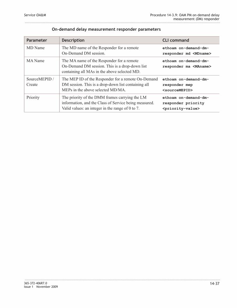
On-demand delay measurement responder parameters
Parameter Description CLI command
MD �ame The MD name of the Responder for a remote
On-Demand DM session.
ethoam on-demand-dm-
responder md <MDname>
MA �ame The MA name of the Responder for a remote
On-Demand DM session. This is a drop-down list
containing all MAs in the above selected MD.
ethoam on-demand-dm-
responder ma <MAname>
SourceMEPID /
Create
The MEP ID of the Responder for a remote On-Demand
DM session. This is a drop-down list containing all
MEPs in the above selected MD/MA.
ethoam on-demand-dm-
responder mep
<sourceMEPID>
Priority The priority of the DMM frames carrying the LM
information, and the Class of Service being measured.
Valid values: an integer in the range of 0 to 7.
ethoam on-demand-dm-
responder priority
<priority-value>
Service OA&M Procedure 14-3.9: OAM PM on-demand delay
measurement (DM) responder
...................................................................................................................................................................................................................................
...................................................................................................................................................................................................................................
365-372-406R7.0
Issue 1 November 2009
14-37

Procedure 14-3.10: Enable AIS generation on a MEP
Overview
Use this procedure to activate AIS generation on a MEP.
When an impairment is detected, the MEP sends AIS frames (immediately and then at 1
minute intervals) at the client MD level in the forward direction so that downstream
MEPs that would also detect the fault can suppress their alarms.
AIS insertion may be enabled on any MEP except, in R6.0, on a port which has spanning
tree or ERP enabled. The insertion takes place into a configured client MD level, in the
direction opposite of other MEP OAM transmission.
Step
...................................................................................................................................................................................................
1 From the �avigation menu, select Service OA&M → Maintenance association End
Point → AIS Generation.
Equivalent CLI command: ethoam ais. Refer to the Alcatel-Lucent 1850 Transport
Service Switch (TSS-5) Command Line Interface Guide for a complete description of this
command and related parameters.
Result: The AIS Generation Configuration window displays current settings.
...................................................................................................................................................................................................
2 Enter the parameters as required. See “AIS generation parameters” (p. 14-38). Click
Submit to execute the command. Click Delete to remove the AIS Generation from the
selected MEP ID.
AIS generation parameters
Parameter Description CLI command
MD �ame The MD name of the selected MEP ethoam ais md <MDname>
MA �ame The MA name of the selected MEP. This is a drop-down
list containing all MAs in the above selected MD.
ethoam ais ma <MAname>
SourceMEPID /
Create
The selected MEP ID. This is a drop-down list
containing all MEPs in the above selected MD/MA.
ethoam ais mep
<sourceMEPID>
Priority The priority of the AIS frames. Valid values: an integer
in the range of 0 to 7.
ethoam ais priority
<priority-value>
Service OA&M Procedure 14-3.10: Enable AIS generation on a MEP
...................................................................................................................................................................................................................................
...................................................................................................................................................................................................................................
14-38 365-372-406R7.0
Issue 1 November 2009
E N D O F S T E P S....................................................................................................................................................................................................................................

Parameter Description CLI command
Client Level MD level for the generated AIS frames. Typically this is
the next highest configured MD level, except for a
Down-MEP on a customer port where it is typically a
configured Customer MD level. Valid values: an integer
in the range of 0 to 7.
ethoam ais level
<clientMDlevel>
Maint CVLA� The VLA� ID of a maintenance CVLA�. The valid
values: an integer in the range of 0 to 4094. The default
value is 0 which means the AIS frames are untagged.
This is an optional field.
ethoam ais mnt-vlan
<vid>
Service OA&M Procedure 14-3.10: Enable AIS generation on a MEP
...................................................................................................................................................................................................................................
...................................................................................................................................................................................................................................
365-372-406R7.0
Issue 1 November 2009
14-39


15 15Circuit emulation service
(CES)
Overview
Purpose
The circuit emulation service (CES) menu feature includes, but is not limited to:
• CES Mode Configuration
• PS� Tunnel
• BFD (Bidirectional Forwarding Detection)
• Pseudowire
• Protection Mode Configuration
This section covers requirements pertaining to the circuit emulation service feature.
Contents
Before you begin 15-2
Procedure 15-1: Place holder 15-3
Procedure 15-2: Configure circuit emulation service on VL�C60/61/62/64 15-4
...................................................................................................................................................................................................................................
365-372-406R7.0
Issue 1 November 2009
15-1

Before you begin
Before you begin
Important! Command Line Interface (CLI) commands or the Web GUI is required to
interface with the VL�C40/42/42B Ethernet Aggregator, VL�C60/61/62 Circuit
Emulator, and VL�C64 Circuit Emulation Mini-Hub circuit packs.
The procedures in this chapter use the Web GUI with corresponding reference to the
equivalent CLI commands. When using CLI commands, refer to the Alcatel-Lucent 1850
Transport Service Switch (TSS-5) Command Line Interface Guide.
Required equipment
All procedures in this chapter require a Personal Computer (PC).
Important! If additional equipment is required to perform a specific procedure, the
additional equipment is listed in the procedure.
Circuit emulation service (CES) Before you begin
...................................................................................................................................................................................................................................
...................................................................................................................................................................................................................................
15-2 365-372-406R7.0
Issue 1 November 2009

Procedure 15-1: Place holder
Step
...................................................................................................................................................................................................
1 This is a place holder for circuit emulation service (CES) related Web GUI procedures to
be supplied at a later date.
E N D O F S T E P S
...................................................................................................................................................................................................
Circuit emulation service (CES) Procedure 15-1: Place holder
...................................................................................................................................................................................................................................
...................................................................................................................................................................................................................................
365-372-406R7.0
Issue 1 November 2009
15-3
Procedure 15-2: Configure circuit emulation service on
VLNC60/61/62/64
Overview
Use the procedures in this section to provision circuit emulation service (CES) on the
VL�C60/VL�C61/VL�C62/VL�C64 (VL�C6x).
The VL�C6x supports the following modes for Circuit Emulation Service, (CES):
• ethernet — In ethernet mode, the circuit pack supports Circuit Emulation
Service based on Metro Ethernet Forum - 8 (MEF-8) specification.
• mpls-php-enable — In mpls-php-enable mode, the circuit pack supports
Circuit Emulation Service based on RFC 4553 where the Penultimate Hop Popping
mode (PHP) is enabled. In this mode, the RFC 4553 encapsulated packets carry only
the Pseudowire header at the MPLS layer.
• mpls-php-disable — In mpls-php-disable mode, the circuit pack supports
Circuit Emulation Service based on RFC 4553 where the Penultimate Hop Popping
mode is disabled. In this mode, the RFC 4553 encapsulated packets carry both the
PS� Tunnel header and the Pseudowire header at the MPLS layer.
The procedures in this section cover the following configurations:
• Remote VL�C60/61/62 to Hub VL�C60/61/62.
• Remote VL�C60/61/62 to Hub VL�C64.
• Remote VL�C60/61/62 to two Hub VL�C64s.
A Remote site VL�C60/61/62 can be configured completely independent of a Hub site
VL�C6x.
Refer to Figure 15-1, “Circuit emulation service sample network (VL�C60s)” (p. 15-8)
and Figure 15-2, “Circuit emulation service sample network (VL�C60/61/62/64)”
(p. 15-8).
It is assumed the circuit packs have been installed and the interface mode has been set.
The interface-mode {t1 | e1} command configures the pack’s T1/E1 mode, and
SO�ET/SDH mode on the VL�C64. Refer to the Alcatel-Lucent 1850 Transport Service
Switch (TSS-5) Command Line Interface Guide, for help on using CLI commands.
Important! The example commands in these procedures use an arbitrary prompt
(ALU Switching) in illustrating the commands. The actual default prompt,
(ALU 1850TSS-5-xx), for the circuit pack you are logged into may appear or the
prompt you chose when setting up the system using the set prompt command.
Circuit emulation service (CES) Procedure 15-2: Configure circuit emulation service on
VLNC60/61/62/64
...................................................................................................................................................................................................................................
...................................................................................................................................................................................................................................
15-4 365-372-406R7.0
Issue 1 November 2009

Step
...................................................................................................................................................................................................
1 Login to the VL�C6x being provisioned.
Result: The User EXEC prompt [(ALU switching)>] displays.
Reference: Procedure 2-1: “Connect personal computer (PC) and establish Command
Line Interface (CLI) session to VL�C4x/VL�C6x” (p. 2-3)
...................................................................................................................................................................................................
2 Enter the Global Config mode:
1. From the User EXEC prompt, enter enable to enter the Privileged EXEC mode.
2. From the Privileged EXEC prompt, enter configure to enter the Global Config
mode.
...................................................................................................................................................................................................
3 Configure VL�C6x circuit emulation mode. From the Global Config mode, enter
ces-mode {ethernet | mpls-php-enable | mpls-php-disable} to set the
CES mode. Default is mpls-php-disable.
Example: (ALU Switching)(Config)# ces-mode mpls-php-enable.
If you change the mode from Ethernet to MPLS (MPLS PHP disable or MPLS PHP
enable) and vice versa, the system resets after clearing the configuration. If you
change the mode from MPLS PHP disable to MPLS PHP enable and vice versa, the
system resets, but without clearing the configuration.
...................................................................................................................................................................................................
4 If required, set the differential timestamp frequency for the system. From the Global
Config mode, enter
system-differential-timestamp-frequency {77.76 | 25}.
The values are specified in MHz. Default is 77.76 MHz.
You must ensure that the system at the other endpoint of the Circuit Emulation Service
has the same timestamp frequency that you set on this system.
On VL�C64 circuit packs, series S1:2 or later circuit packs are required to support the 25
MHz frequency.
Configuring this parameter will reset the circuit pack.
...................................................................................................................................................................................................
5 Configure VL�C64 OC3/STM1 interfaces, if required.
Circuit emulation service (CES) Procedure 15-2: Configure circuit emulation service on
VLNC60/61/62/64
...................................................................................................................................................................................................................................
...................................................................................................................................................................................................................................
365-372-406R7.0
Issue 1 November 2009
15-5

Reference: Procedure 15-2.1: “Configure VL�C64 OC3/STM1 interfaces” (p. 15-9)
...................................................................................................................................................................................................
6 Configure T1/E1 and Ethernet interfaces.
Reference: Procedure 15-2.2: “Configure T1/E1 and Ethernet interfaces” (p. 15-10)
...................................................................................................................................................................................................
7 Configure IP addresses and routes, if required. �ot required if ces-mode is set to
“ethernet”.
MEF-8 (ces-mode ethernet) is supported only on Ethernet switching networks. Therefore,
only a system level IP address is required (CLI commands: network parms, serviceport.)
Reference: Procedure 15-2.3: “Configure IP addresses and routes” (p. 15-13)
...................................................................................................................................................................................................
8 If required, configure VLA�s on which the Ethernet interface participates. The VLA�s
created will be used later in configuring the PS� Tunnel.
Reference: Procedure 15-2.4: “Configure VLA�s for Ethernet interface” (p. 15-15).
...................................................................................................................................................................................................
9 Configure Timing.
Reference: Procedure 15-2.5: “Configure timing for VL�C6x Circuit Emulation
Service (CES)” (p. 15-17)
...................................................................................................................................................................................................
10 Configure Tunnel 1 (Remote to Hub) and Tunnel 2 (Hub to Remote) incoming/outgoing
parameters.
Tunnel 1 outgoing parameters at Remote and Tunnel 1 incoming parameters at Hub.
Tunnel 2 outgoing parameters at Hub and Tunnel 2 incoming parameters at Remote.
If ces-mode is mpls-php-enable or mpls-php-disable,
• Destination for Tunnel 1 is configured to be “Pack IP address” of Hub. �ext hop for
Tunnel 1 is configured to be “Interface IP address” of Hub.
• Destination for Tunnel 2 is configured to be “Pack IP address” of Remote. �ext hop
for Tunnel 2 is configured to be interface IP address of Remote.
If ces-mode is Ethernet,
• Destination for Tunnel 1 is configured to be “System MAC address” of Hub. �ext
hop for Tunnel 1 is configured to be “Interface IP address” of Hub.
The System MAC address can be retrieved using the show network command.
• Destination for Tunnel 2 is configured to be “System MAC address” of Remote. �ext
hop for Tunnel 2 is configured to be interface IP address of Remote.
Circuit emulation service (CES) Procedure 15-2: Configure circuit emulation service on
VLNC60/61/62/64
...................................................................................................................................................................................................................................
...................................................................................................................................................................................................................................
15-6 365-372-406R7.0
Issue 1 November 2009
Reference: Procedure 15-2.7: “Configure Tunnel parameters” (p. 15-30).
...................................................................................................................................................................................................
11 Configure pseudowire (PWE) name and parameters.
Reference: Procedure 15-2.8: “Configure pseudowire (PWE)” (p. 15-35)
...................................................................................................................................................................................................
12 Connect the Pseudowire and the underlying PS� Tunnels in the incoming and outgoing
directions. The PS� Tunnels must already be configured (Step 10) on the circuit pack on
the same physical interface. �ote that outgoing-tunnel-name/incoming-tunnel-name at
one end is incoming-tunnel-name/outgoing-tunnel-name at the other end.
From the Pseudowire Config Mode, enter
connect-psntunnel <outgoing-tunnel-name> <incoming-tunnel-name>
where:
• outgoing-tunnel-name - specifies the tunnel in the outgoing direction. Range is a 1 to
31 alphanumeric character string.
• incoming-tunnel-name - specifies the tunnel in the incoming direction. Range is a 1 to
31 alphanumeric character string.
Example: (ALU Switching) (Config-tdmpwe1)#
connect-psntunnel Tunnel1 Tunnel2.
When the PWE to PS� Tunnel association must be changed, you must explicitly
remove the existing association with the no connect form of the command, and create
new associations using the connect form of the command.
...................................................................................................................................................................................................
13 Attach T1 interface to Pseudowire (PWE). This command associates a Pseudowire to an
interface. Once this association is done, the traffic on the interface is emulated through the
Pseudowire.
Important! Once an association is created it cannot be modified or removed. The
Pseudowire must be deleted and recreated.
From the Pseudowire Config Mode, enter
connect-interface <interface-number> where interface-number is a T1/E1 port
on the VL�C6x.
Example: (ALU Switching) (Config-tdmpwe1)# connect-interface a-1-1 or
connect-interface m1-1-1-1-1.
...................................................................................................................................................................................................
14 From the Pseudowire Config Mode, enter no shutdown to enable the Pseudowire
(PWE).
Circuit emulation service (CES) Procedure 15-2: Configure circuit emulation service on
VLNC60/61/62/64
...................................................................................................................................................................................................................................
...................................................................................................................................................................................................................................
365-372-406R7.0
Issue 1 November 2009
15-7

Example: (ALU Switching) (Config-tdmpwe1)# no shutdown.
Figure 15-1 Circuit emulation service sample network (VLNC60s)
Remote
VLNC60
Hub
VLNC60
TDMSource
T1/E1 T1/E1
EATN
Tunnel 1
Tunnel 2
Remote to Hub
Hub to Remote
Ethernet Ethernet
T1/E1 interface
Ethernet interface
VLNC60_CES
Figure 15-2 Circuit emulation service sample network (VLNC60/61/62/64)
Remote
VLNC60
Hub
VLNC64
TDMSource
T1/E1 DS1/E1
EATN
Tunnel 1
Tunnel 2
Remote to Hub
Hub to Remote
Ethernet Ethernet
T1/E1 interface
Ethernet interface
Channelized OC3/STM1 (DS1/E1>VT1.5/VC12>OC3/STM1)
VLNC64_CES
Circuit emulation service (CES) Procedure 15-2: Configure circuit emulation service on
VLNC60/61/62/64
...................................................................................................................................................................................................................................
...................................................................................................................................................................................................................................
15-8 365-372-406R7.0
Issue 1 November 2009
E N D O F S T E P S....................................................................................................................................................................................................................................

Procedure 15-2.1: Configure VLNC64 OC3/STM1 interfaces
Overview
Use this procedure to configure the VL�C64 OC3/STM1 interfaces used for circuit
emulation service.
Refer to the Alcatel-Lucent 1850 Transport Service Switch (TSS-5) Command Line
Interface Guide, for help on using CLI commands.
Step
...................................................................................................................................................................................................
1 Login to the VL�C64.
Result: The User EXEC prompt [(ALU switching)>] displays.
Reference: Procedure 2-1: “Connect personal computer (PC) and establish Command
Line Interface (CLI) session to VL�C4x/VL�C6x” (p. 2-3)
...................................................................................................................................................................................................
2 Enter the Global Config mode:
1. From the User EXEC prompt, enter enable to enter the Privileged EXEC mode.
2. From the Privileged EXEC prompt, enter configure to enter the Global Config
mode.
...................................................................................................................................................................................................
3 From the Global Config mode, enter interface <interface-number>, to enter the
Interface Config Mode where “interface-number” is a number in the range of
main-{1-2}-{1} for the port you are provisioning.
Example: (ALU Switching)(Config)# interface main-2-1.
...................................................................................................................................................................................................
4 Specify a description for the interface.
From the Interface Config Mode, enter interface <description> where description
is in a range of 1-32 alphanumeric character string.
Example: (ALU Switching) (Interface main-2-1 HubSiteSlot1Port1
...................................................................................................................................................................................................
5 Enter exit to return to the Global Config Mode.
E N D O F S T E P S
...................................................................................................................................................................................................
Circuit emulation service (CES) Procedure 15-2.1: Configure VLNC64 OC3/STM1 interfaces
...................................................................................................................................................................................................................................
...................................................................................................................................................................................................................................
365-372-406R7.0
Issue 1 November 2009
15-9

Procedure 15-2.2: Configure T1/E1 and Ethernet interfaces
Overview
Use this procedure to configure the T1/E1 and Ethernet interfaces used for circuit
emulation service.
This procedure assumes that the VL�C6x has been previously installed.
Refer to the Alcatel-Lucent 1850 Transport Service Switch (TSS-5) Command Line
Interface Guide, for help on using CLI commands.
Step
...................................................................................................................................................................................................
1 Login to the VL�C6x.
Result: The User EXEC prompt [(ALU switching)>] displays.
Reference: Procedure 2-1: “Connect personal computer (PC) and establish Command
Line Interface (CLI) session to VL�C4x/VL�C6x” (p. 2-3)
...................................................................................................................................................................................................
2 Enter the Global Config mode:
1. From the User EXEC prompt, enter enable to enter the Privileged EXEC mode.
2. From the Privileged EXEC prompt, enter configure to enter the Global Config
mode.
...................................................................................................................................................................................................
3 Configure T1/E1 interface.
From the Global Config mode, enter interface <interface-number>, to enter the
Interface Config Mode where “interface-number” is the address for the T1/E1 port you
are provisioning.
On the VL�C60/61/62, a T1/E1 port is addressed by "T1-Port"/"E1-Port" respectively.
On the VL�C64, T1/E1 ports are addressed by "VTDS1-Port"/"VCE1-Port" respectively.
See Addressable Entities in the Alcatel-Lucent 1850 Transport Service Switch (TSS-5)
Command Line Interface Guide for addresses.
Example: (ALU Switching)(Config)# interface a-1-1.
...................................................................................................................................................................................................
4 Specify a description for the T1/E1 interface.
From the Interface Config Mode, enter description <description> where
“description” is in a range of a 1-32 alphanumeric character string.
Circuit emulation service (CES) Procedure 15-2.2: Configure T1/E1 and Ethernet
interfaces
...................................................................................................................................................................................................................................
...................................................................................................................................................................................................................................
15-10 365-372-406R7.0
Issue 1 November 2009

Example: (ALU Switching) (Interface a-1-1)#
description RemoteSiteSlot1Port1
...................................................................................................................................................................................................
5 From the Interface Config Mode, enter the following commands one at a time:
• signalformat {sf | esf | uf} — (T1 only) Used to set the signal format of
the T1 interface. The supported formats are: Super Frame (SF), Extended Super
Frame (ESF), and Unframed, (UF). Default is esf for T1 port.
Example: (ALU Switching) (Interface a-1-1)# signalformat esf.
• signalformat {fas | crc4} — (E1 only) Used to set the signal format of the
E1 interface. The supported formats are: Frame Alignment Signal (FAS), and Cyclic
Redundancy Check-4 multiframe alignment (CRC4). Default is crc4 for E1 port.
Example: (ALU Switching) (Interface a-1-1)# signalformat fas.
• linecode {b8zs | ami} — (VL�C60/61/62 T1 only) Sets the linecode value on
the T1 interface. These are Alternate Mark Inversion (AMI), and Bipolar 8 Zero
Substitution (B8ZS). Default is b8zs for T1 port.
Example: (ALU Switching) (Interface a-1-1)# linecode b8zs.
• linebuildout {short} {{0-110 | 110-220 | 220-330 | 330-440 |
440-550 | 550-660} — (VL�C60/61/62 T1 only) Specifies the length of the
cable in feet that connects to the T1 interface on the other end of the VL�C60/61/62
T1 interface.
Example: (ALU Switching) (Interface a-1-1)# linebuildout short 110-220.
...................................................................................................................................................................................................
6 If required at this time, specify the type of service associated with the T1/E1 interface.
From the Interface Config Mode, enter encapsulation {ppp | satop}.
Example: (ALU Switching) (Interface a-1-1)# encapsulation satop.
Enter exit to exit the Interface Config Mode.
Important! If you are going to later provision “differential” as the timing source for
this interface using (Procedure 15-2.5: “Configure timing for VL�C6x Circuit
Emulation Service (CES)” (p. 15-17)) :
• Encapsulation may not be set to ppp.
• If you configure encapsulation now, you will have to remove the encapsulation
before you can configure the timing source to differential, then reconfigure
encapsulation.
• Alternatively, you can wait to configure encapsulation until after you have
provisioned the timing source.
...................................................................................................................................................................................................
7 Configure Ethernet interface.
Circuit emulation service (CES) Procedure 15-2.2: Configure T1/E1 and Ethernet
interfaces
...................................................................................................................................................................................................................................
...................................................................................................................................................................................................................................
365-372-406R7.0
Issue 1 November 2009
15-11

From the Global Config mode, enter interface <interface-number>, to enter the
Interface Config Mode where “interface-number” is a number in the range of
d{1-2}-{1-2} for the Ethernet port you are provisioning.
Example: (ALU Switching)(Config)# interface d1-1.
...................................................................................................................................................................................................
8 Specify a description for the Ethernet interface.
From the Interface Config Mode, enter interface <description> where description
is in a range of 1-32 alphanumeric character string.
Example: (ALU Switching) (Interface d1-1)# RemoteSiteSlot1Port1
...................................................................................................................................................................................................
9 If required, from the Interface Config Mode, enter auto-negotiate to enable
auto-negotiation. Default is disabled, except for 1000BASE-T ports which are always
enabled.
...................................................................................................................................................................................................
10 Enable the Ethernet interface.
From the Interface Config mode, enter no shutdown.
Example: (ALU Switching) (Interface d1-1)# no shutdown
...................................................................................................................................................................................................
11 Enter exit to return to the Global Config Mode.
E N D O F S T E P S
...................................................................................................................................................................................................
Circuit emulation service (CES) Procedure 15-2.2: Configure T1/E1 and Ethernet
interfaces
...................................................................................................................................................................................................................................
...................................................................................................................................................................................................................................
15-12 365-372-406R7.0
Issue 1 November 2009

Procedure 15-2.3: Configure IP addresses and routes
Overview
Use this procedure to configure the circuit pack IP address, interface IP address, and IP
routes used for circuit emulation service.
This procedure assumes that the VL�C6x has been previously installed.
Refer to the Alcatel-Lucent 1850 Transport Service Switch (TSS-5) Command Line
Interface Guide, for help on using CLI commands.
Step
...................................................................................................................................................................................................
1 Login to the VL�C6x.
Result: The User EXEC prompt [(ALU switching)>] displays.
Reference: Procedure 2-1: “Connect personal computer (PC) and establish Command
Line Interface (CLI) session to VL�C4x/VL�C6x” (p. 2-3)
...................................................................................................................................................................................................
2 From the User EXEC prompt, enter enable to enter the Privileged EXEC mode.
...................................................................................................................................................................................................
3 Configure network port (circuit pack) IP addresses. This command sets the IP address, the
netmask and the gateway of the network port. The network port is an internal port used
for in-band management access. The network port is accessible via any of the faceplate
and/or backplane Ethernet ports. The IP Address and gateway must be on the same
subnet.
From the Privileged EXEC mode, enter
network parms <ipaddr> <netmask> [<gateway>], where:
• ipaddr - IP Address of the network port. Range: IPv4 Address Range.
• netmask - Subnet Mask of the Address. Range: 0-255.0-255.0-255.0-255.
• gateway (optional) - IP Address of the Gateway. Range: IPv4 Address Range..
Example: (ALU Switching) # network parms 152.148.2.2 255.255.255.0.
Only one gateway may be defined for remote access, either on the network port or the
serviceport. The serviceport (see serviceport ip command) and network port must be on
different subnets.
...................................................................................................................................................................................................
4 Enable global IP routing. From the Privileged EXEC prompt, enter ip routing.
Example: (ALU Switching) # ip routing.
Circuit emulation service (CES) Procedure 15-2.3: Configure IP addresses and routes
...................................................................................................................................................................................................................................
...................................................................................................................................................................................................................................
365-372-406R7.0
Issue 1 November 2009
15-13

...................................................................................................................................................................................................
5 From the Privileged EXEC prompt, enter configure to enter the Global Config mode.
From the Global Config mode, enter interface <interface-number>, to enter the
Interface Config Mode where “interface-number” is a number in the range of
d{1-2}-{1-2} for the Ethernet port you are provisioning.
Example: (ALU Switching)(Config)# interface d1-1.
...................................................................................................................................................................................................
6 Enable routing on the Ethernet interface. From the Interface Config Mode, enter
routing.
Example: (ALU Switching) (Interface d1-1) # routing.
...................................................................................................................................................................................................
7 Specify the IP address of the Ethernet interface.
From the Interface Config Mode, enter ip address <ip-address> <mask>, where:
• ipaddr - IP Address of the interface port. Range: IPv4 Address Range.
• netmask - Subnet Mask of the Address. Range: 0-255.0-255.0-255.0-255.
Example: (ALU Switching) (Interface d1-1)#
ip address 1.1.1.20 255.255.255.0
...................................................................................................................................................................................................
8 Enter exit to exit the Interface Config Mode.
...................................................................................................................................................................................................
9 Configure IP static routes.
From the Global Config mode, enter
ip route <destination ip address> <mask> <nexthop ip address>
where:
• destination ip address - destination IP address of Hub/Remote
• mask - subnet mask address of Hub/Remote
• nexthop ip address - nexthop to Hub/Remote
Example: (ALU Switching)(Config)#
ip route 152.148.1.1 255.255.255.0 1.1.1.10 .
E N D O F S T E P S
...................................................................................................................................................................................................
Circuit emulation service (CES) Procedure 15-2.3: Configure IP addresses and routes
...................................................................................................................................................................................................................................
...................................................................................................................................................................................................................................
15-14 365-372-406R7.0
Issue 1 November 2009

Procedure 15-2.4: Configure VLANs for Ethernet interface
Overview
Use this procedure to configure the VLA�s in which the Ethernet interface participates.
VLA�s to be configured are:
• VLA� for PS� tunnel as specified in command service-vlan when configuring
the PS� tunnel.
• VLA� for 1588 traffic as specified in command ptp-1588 vlan when configuring
the timing source.
Refer to the Alcatel-Lucent 1850 Transport Service Switch (TSS-5) Command Line
Interface Guide, for help on using CLI commands.
Step
...................................................................................................................................................................................................
1 If required, login to the VL�C6x.
Result: The User EXEC prompt [(ALU switching)>] displays.
Reference: Procedure 2-1: “Connect personal computer (PC) and establish Command
Line Interface (CLI) session to VL�C4x/VL�C6x” (p. 2-3)
...................................................................................................................................................................................................
2 From the User EXEC prompt, enter enable to enter the Privileged EXEC mode.
Result: The Privileged EXEC prompt [(ALU switching)#] displays.
...................................................................................................................................................................................................
3 From the Privileged EXEC mode, enter vlan database to enter the VLA� Config
mode.
Example: (ALU Switching)# vlan database.
...................................................................................................................................................................................................
4 From the VLA� Config mode, enter vlan <vlanid> where vlanid is a value in the
range of 2-3965.
Example: (ALU Switching) (VLA�)# vlan 10
Enter exit to return to the Privileged EXEC mode.
...................................................................................................................................................................................................
5 From the Privileged EXEC mode, enter config to enter the Global Config Mode.
Example: (ALU Switching)# config.
Circuit emulation service (CES) Procedure 15-2.4: Configure VLANs for Ethernet interface
...................................................................................................................................................................................................................................
...................................................................................................................................................................................................................................
365-372-406R7.0
Issue 1 November 2009
15-15

...................................................................................................................................................................................................
6 From the Global Config mode, enter interface <interface-number>, to enter the
Interface Config Mode where “interface-number” is a number in the range of
d{1-2}-{1-2} for the Ethernet port you are provisioning.
Example: (ALU Switching)(Config)# interface d1-1.
...................................................................................................................................................................................................
7 From the Interface Config Mode, enter vlan participation include <vlanid>
where:
• include - The interface is always a member of this VLA�.
• vlanid - VLA� identification number. Range: 1-3965.
Example: (ALU Switching) (Interface d1-1)# vlan participation include 10.
...................................................................................................................................................................................................
8 Configure the tagging behavior for the specific interface in a VLA� to enabled. If tagging
is enabled, traffic is transmitted as tagged frames. If tagging is disabled, traffic is
transmitted as untagged frames.
From the Interface Config Mode, enter vlan tagging <vlanid> where vlanid is the
same as specified in the vlan participation command in the previous step.
Example: (ALU Switching) (Interface d1-1)# vlan tagging 10.
Enter exit to exit the Interface Config Mode.
E N D O F S T E P S
...................................................................................................................................................................................................
Circuit emulation service (CES) Procedure 15-2.4: Configure VLANs for Ethernet interface
...................................................................................................................................................................................................................................
...................................................................................................................................................................................................................................
15-16 365-372-406R7.0
Issue 1 November 2009

Procedure 15-2.5: Configure timing for VLNC6x Circuit
Emulation Service (CES)
Overview
Use this procedure to configure timing for the VL�C6x providing CES.
The system-timing-source
{bits [alternate-source-line]| ptp-1588 | free-running | line |
ge | backplane} command is used to specify a common timing source for all the
devices on the VL�C6x where:
• bits — Building Integrated Timing Supply This is a timing supply traceable to a
common Primary Reference Clock in the network. The shelf has a special T1/E1 input
interface associated with each main slot for receiving this timing.
• alternate-source-line — On the VL�C64, when the System Timing is BITS, an
alternate source of timing (Line) can be specified, which derives timing from the
OC3/STM1 interface on the pack. Specifying an alternate source for System Timing is
optional.
• ptp-1588 — Precision Timing Protocol-1588. This option specifies IEEE 1588 version
2, as a choice to drive the system timing. This is useful for remote locations where no
high-quality reference clock signal is available.
The IEEE 1588 protocol distributes time and frequency via Ethernet with expected
end-point time-alignment time precision measured in nanoseconds. The protocol is
designed to synchronize real-time clocks on the nodes of a distributed system that
communicate using a network. The protocol uses a master/slave relationship to
distribute timestamps from one device to the others.
• free-running — This option specifies that the System clock is in free-running mode.
This option is recommended to be used only on the VL�C60/61. The clock is derived
from a local SO�ET Stratum3 or SDH Type III (±4.6 ppm) oscillator in the
VL�C60/61.
This option is recommended to be used only when all T1/E1 interfaces offer MLPPP
service. By default, VL�C60/61 circuit packs have their System Timing source set as
Free Running.
• line — (VL�C64 circuit pack only). This option specifies that the System clock is
derived from the optical line (OC3/STM1 interface) on the VL�C64 pack.
• ge — This option specifies that the System clock is derived from SFP based GE
(Ethernet interface). This is also known as the SyncE Line timing.
• backplane — This option specifies that the System clock is derived from the
backplane 25 Mhz reference. In this mode timing is derived from the adjacent circuit
pack. This is also known as the Backplane timing.
Circuit emulation service (CES) Procedure 15-2.5: Configure timing for VLNC6x Circuit
Emulation Service (CES)
...................................................................................................................................................................................................................................
...................................................................................................................................................................................................................................
365-372-406R7.0
Issue 1 November 2009
15-17

The timing-source {system | loop | differential} command specifies the
timing source for the T1/E1 interfaces, where:
• system — The source of timing is derived from system timing configured using the
system-timing-source command.
• loop — The clocking information recovered from the received signal of the T1/E1
interface is used to drive the transmit side of the same T1/E1 interface.
• differential — The clock is recovered from the real time protocol (RTP) differential
timestamps on the incoming Pseudowire packet for the T1/E1. The reference timing
for recovery of this clock is System.
Refer to the Alcatel-Lucent 1850 Transport Service Switch (TSS-5) Command Line
Interface Guide, for help on using CLI commands.
Step
...................................................................................................................................................................................................
1 If ... Then ...
�etwork timing distribution for CES is using
BITS at both Hub and Remote,
continue with Step 2.
�etwork timing distribution for CES is using
IEEE 1588v2,
go to Step 6.
...................................................................................................................................................................................................
2 �etwork Timing Distribution for CES using BITS at both ends. See Figure 15-3,
“�etwork timing distribution for CES using BITS (VL�C60/61/62s)” (p. 15-21) and
Figure 15-4, “�etwork timing distribution for CES using BITS (VL�C6x)” (p. 15-21) for
reference.
Configure BITS Line Interface Unit (LIU) external timing reference (ref-1 or ref-2) at
both Remote and Hub ends. The interface <interface-number> command is used
to configure the BITS input. “Interface-number” is either ref-1 or ref-2 corresponding to
the BITS input for the Main slot equipped with the VL�C6x.
From the Global Config Mode at both the Remote end and Hub end, enter
interface ref-1 or ref-2 to enter the Interface Config Mode.
From the Interface Config Mode, enter the following commands one at a time:
• description <description> — Specifies a description for the interface where
“description” is in a range of a 1-32 alphanumeric character string.
Example: (ALU Switching) (Interface ref-2)# description bitsRef2.
• signalformat {sf | esf} (T1 only) — Used to set the signal format of the T1
interface. The supported formats are: Super Frame (SF) and Extended Super Frame
(ESF). Default is sf for BITS-LIU.
Example: (ALU Switching) (Interface ref-2)# signalformat esf.
Circuit emulation service (CES) Procedure 15-2.5: Configure timing for VLNC6x Circuit
Emulation Service (CES)
...................................................................................................................................................................................................................................
...................................................................................................................................................................................................................................
15-18 365-372-406R7.0
Issue 1 November 2009
• signalformat {fas | crc4} (E1 only) — Used to set the signal format of the
E1 interface. The supported formats are: Frame Alignment Signal (FAS), and Cyclic
Redundancy Check-4 multiframe alignment (CRC4). Default is crc4 for BITS-LIU.
Example: (ALU Switching) (Interface ref-2)# signalformat fas.
• linecode {b8zs | ami} (T1 only) — Sets the linecode value on the T1 interface.
These are Alternate Mark Inversion (AMI), and Bipolar 8 Zero Substitution (B8ZS).
Default is ami for BITS-LIU.
Example: (ALU Switching) (Interface ref-2)# linecode b8zs.
...................................................................................................................................................................................................
3 This command assumes that both the Remote end and Hub end have direct access to the
Primary Reference Source (PRS) or BITS.
Configure system timing source. The system-timing-source
{bits [alternate-source-line]| ptp-1588 | free-running | line |
ge | backplane} command is used to specify a common timing source for all the
devices on the VL�C6x.
From the Global Config Mode at both the Remote end and Hub end, enter
system-timing-source bits.
If required, at a VL�C64 Hub end, enter an alternate-source of line.
Example (VL�C64 only): (ALU 1850TSS-5) (Config)#
system-timing-source bits alternate-source line
Reference: Procedure 8-1: “Configure system timing for circuit pack” (p. 8-3)
...................................................................................................................................................................................................
4 Configure Remote end T1/E1 interface Timing source. The timing-source
{system | loop | differential} command specifies the timing source for the
VL�C60/61/62 T1/E1 interfaces.
From the Global Config mode, enter interface <interface-number> to enter the
Interface T1/E1 Config Mode. The interface-number specifies the specific T1/E1 interface
on the VL�C60/61/62. This command changes the context to the Interface Config Mode
and all subsequent configuration in this mode will be applicable to the interface identified
by the interface-number.
On the VL�C60/61/62, a T1/E1 port is addressed by "T1-Port"/"E1-Port" respectively.
On the VL�C64, T1/E1 ports are addressed by "VTDS1-Port"/"VCE1-Port" respectively.
See Addressable Entities in the Alcatel-Lucent 1850 Transport Service Switch (TSS-5)
Command Line Interface Guide for addresses.
If encapsulation has been configured on this interface and you are going to provision
“differential” as the timing source for this interface, you must first remove encapsulation
using no encapsulation {ppp | satop}.
Circuit emulation service (CES) Procedure 15-2.5: Configure timing for VLNC6x Circuit
Emulation Service (CES)
...................................................................................................................................................................................................................................
...................................................................................................................................................................................................................................
365-372-406R7.0
Issue 1 November 2009
15-19

From the Interface Config Mode at the Remote end, enter
timing-source differential.
If encapsulation has not been provisioned or was removed, enter
encapsulation {ppp | satop}.
Reference: Procedure 8-3: “Configure interface timing for DS1/E1 ports” (p. 8-15)
...................................................................................................................................................................................................
5 Configure Hub end T1/E1 interface Timing source. The timing-source
{system | loop | differential} command specifies the timing source for the
T1/E1 interfaces.
From the Global Config mode, enter interface <interface-number> to enter the
Interface Config Mode. The interface-number is the specific interface on the VL�C6x.
This command changes the context to the Interface Config Mode and all subsequent
configuration in this mode will be applicable to the interface identified by the
interface-number.
On the VL�C60/61/62, a T1/E1 port is addressed by "T1-Port"/"E1-Port" respectively.
On the VL�C64, T1/E1 ports are addressed by "VTDS1-Port"/"VCE1-Port" respectively.
See Addressable Entities in the Alcatel-Lucent 1850 Transport Service Switch (TSS-5)
Command Line Interface Guide for addresses.
If encapsulation has been configured on this interface and you are going to provision
“differential” as the timing source for this interface, you must first remove encapsulation
using no encapsulation {ppp | satop}.
From the Interface Config Mode at the Hub end, enter timing-source loop for
applications where there is one timing source traceable to a common reference clock for
the entire network. Enter timing-source differential for applications where the
timing source in each direction (Hub to Remote, Remote to Hub) can be asynchronous to
each other. For example: (ALU Switching) (Interface m2-1-1-1-1)#
timing-source loop (VL�C64), or (ALU Switching) (Interface a-1-1)#
timing-source loop (VL�C60/61/62).
For the VL�C64 at the Hub end, configure the differential timing domain for the T1/E1
interface. This command specifies the differential timing domain being used to generate
and recover the differential timestamps on the VL�C64. From the Interface Config Mode
at the Hub end VL�C64, enter differential-timing-domain <domain-value>
where domain-value is in the range 1-28. For example: (ALU Switching) (Interface
m2-1-1-1-1)# differential-timing-domain 1.
If encapsulation has not been provisioned or was removed, enter
encapsulation {ppp | satop}.
Circuit emulation service (CES) Procedure 15-2.5: Configure timing for VLNC6x Circuit
Emulation Service (CES)
...................................................................................................................................................................................................................................
...................................................................................................................................................................................................................................
15-20 365-372-406R7.0
Issue 1 November 2009

Figure 15-3 Network timing distribution for CES using BITS (VLNC60/61/62s)
Remote
VLNC60
Hub
VLNC60
TDMSource
T1/E1 T1/E1
EATN
Tunnel 1
Tunnel 2
Remote to Hub
Hub to Remote
Ethernet Ethernet
PRS
VLNC60 system-timing-source bitsT1/E1 interface “b” timing-source differentialT1/E1 interface “a” loop times from T1/E1 interface “b”
a b
VLNC60 system-timing-source bitsT1/E1 interface “g” timing-source loop or differential
g h
T1/E1 interface
Ethernet interface
CES_Timing_BITS
Figure 15-4 Network timing distribution for CES using BITS (VLNC6x)
Remote
VLNC60
Hub
VLNC64
TDMSource
T1/E1DS1/E1
EATN
Tunnel 1
Tunnel 2
Remote to Hub
Hub to Remote
Ethernet Ethernet
PRS
VLNC60 system-timing-source bitsT1/E1 interface “b” timing-source differentialT1/E1 interface “a” loop times from T1/E1 interface “b”
a b
VLNC64 system-timing-source bits (alternate-source Line)OC3/STM1interface “e” timing-source systemT1/E1 interface “g” timing-source loop or differential
differential-timing-domain <value>T1/E1 interface “g”
g h
e
T1/E1 interface
Ethernet interface
Channelized OC3/STM1 (DS1/E1>VT1.5/VC12>OC3/STM1)
CES_Timing_BITS_64
Circuit emulation service (CES) Procedure 15-2.5: Configure timing for VLNC6x Circuit
Emulation Service (CES)
...................................................................................................................................................................................................................................
...................................................................................................................................................................................................................................
365-372-406R7.0
Issue 1 November 2009
15-21

Reference: Procedure 8-3: “Configure interface timing for DS1/E1 ports” (p. 8-15)
...................................................................................................................................................................................................
6 Configure timing distribution using IEEE 1588v2. See Figure 15-5, “�etwork timing
distribution for CES using ptp-1588 (VL�C60/61/62)” (p. 15-24) and Figure 15-6,
“�etwork timing distribution for CES using ptp-1588 (VL�C6x)” (p. 15-25) for
reference.
Configure BITS Line Interface Unit (LIU) external timing reference (ref-1 or ref-2) at the
Hub ends. The interface <interface-number> command is used to configure the
BITS input. “Interface-number” is either ref-1 or ref-2 corresponding to the BITS input
for the Main slot equipped with the VL�C6x.
From the Global Config Mode at the Hub end, enter interface ref-1 or ref-2 to
enter the Interface Config Mode.
From the Interface Config Mode, enter the following commands one at a time:
• description <description> — Specifies a description for the interface where
“description” is in a range of a 1-32 alphanumeric character string.
Example: (ALU Switching) (Interface ref-2)# description bitsRef2.
• signalformat {sf | esf} (T1 only) — Used to set the signal format of the T1
interface. The supported formats are: Super Frame (SF) and Extended Super Frame
(ESF). Default is sf for BITS-LIU.
Example: (ALU Switching) (Interface ref-2)# signalformat esf.
• signalformat {fas | crc4} (E1 only) — Used to set the signal format of the
E1 interface. The supported formats are: Frame Alignment Signal (FAS), and Cyclic
Redundancy Check-4 multiframe alignment (CRC4). Default is crc4 for BITS-LIU.
Example: (ALU Switching) (Interface ref-2)# signalformat fas.
• linecode {b8zs | ami} (T1 only) — Sets the linecode value on the T1 interface.
These are Alternate Mark Inversion (AMI), and Bipolar 8 Zero Substitution (B8ZS).
Default is ami for BITS-LIU.
Example: (ALU Switching) (Interface ref-2)# linecode b8zs.
...................................................................................................................................................................................................
7 Configure system timing source. The system-timing-source
{bits [alternate-source-line]| ptp-1588 | free-running | line |
ge | backplane} command is used to specify a common timing source for all the
devices on the VL�C6x.
From the Global Config Mode at the Hub end, enter system-timing-source bits. If
required, at a VL�C64 Hub end, enter an alternate-source of line.
From the Global Config Mode at the Remote end, enter
system-timing-source ptp-1588.
Circuit emulation service (CES) Procedure 15-2.5: Configure timing for VLNC6x Circuit
Emulation Service (CES)
...................................................................................................................................................................................................................................
...................................................................................................................................................................................................................................
15-22 365-372-406R7.0
Issue 1 November 2009

Reference: Procedure 8-1: “Configure system timing for circuit pack” (p. 8-3)
...................................................................................................................................................................................................
8 Configure ptp-1588 parameters.
Reference: Procedure 15-2.6: “Configure Precision Timing Protocol - 1588ver2
parameters” (p. 15-27)
...................................................................................................................................................................................................
9 Configure Remote end T1/E1 interface Timing source. The timing-source
{system | loop | differential} command specifies the timing source for the
T1/E1 interfaces.
From the Global Config mode, enter interface <interface-number> to enter the
Interface T1/E1 Config Mode. The interface-number specifies the specific T1/E1 interface
on the VL�C60/61/62. This command changes the context to the Interface Config Mode
and all subsequent configuration in this mode will be applicable to the interface identified
by the interface-number.
On the VL�C60/61/62, a T1/E1 port is addressed by "T1-Port"/"E1-Port" respectively.
On the VL�C64, T1/E1 ports are addressed by "VTDS1-Port"/"VCE1-Port" respectively.
See Addressable Entities in the Alcatel-Lucent 1850 Transport Service Switch (TSS-5)
Command Line Interface Guide for addresses.
If encapsulation has been configured on this interface and you are going to provision
“differential” as the timing source for this interface, you must first remove encapsulation
using no encapsulation {ppp | satop}.
From the Interface Config Mode at the Remote end, enter
timing-source differential.
If encapsulation has not been provisioned or was removed, enter
encapsulation {ppp | satop}.
Reference: Procedure 8-3: “Configure interface timing for DS1/E1 ports” (p. 8-15)
...................................................................................................................................................................................................
10 Configure Hub end T1/E1 interface Timing source. The timing-source
{system | loop | differential} command specifies the timing source for the
T1/E1 interfaces.
From the Global Config mode, enter interface <interface-number> to enter the
Interface Config Mode. The interface-number is the specific interface on the VL�C6x.
This command changes the context to the Interface Config Mode and all subsequent
configuration in this mode will be applicable to the interface identified by the
interface-number.
Circuit emulation service (CES) Procedure 15-2.5: Configure timing for VLNC6x Circuit
Emulation Service (CES)
...................................................................................................................................................................................................................................
...................................................................................................................................................................................................................................
365-372-406R7.0
Issue 1 November 2009
15-23

On the VL�C60/61/62, a T1/E1 port is addressed by "T1-Port"/"E1-Port" respectively.
On the VL�C64, T1/E1 ports are addressed by "VTDS1-Port"/"VCE1-Port" respectively.
See Addressable Entities in the Alcatel-Lucent 1850 Transport Service Switch (TSS-5)
Command Line Interface Guide for addresses.
If encapsulation has been configured on this interface and you are going to provision
“differential” as the timing source for this interface, you must first remove encapsulation
using no encapsulation {ppp | satop}.
From the Interface Config Mode at the Hub end, enter timing-source loop for
applications where there is one timing source traceable to a common reference clock for
the entire network. Enter timing-source differential for applications where the
timing source in each direction (Hub to Remote, Remote to Hub) can be asynchronous to
each other. For example: (ALU Switching) (Interface m2-1-1-1-1)#
timing-source loop (VL�C64), or (ALU Switching) (Interface a-1-1)#
timing-source loop (VL�C60/61/62).
For the VL�C64 at the Hub end, configure the differential timing domain for the T1/E1
interface. This command specifies the differential timing domain being used to generate
and recover the differential timestamps on the VL�C64. From the Interface Config Mode
at the Hub end VL�C64, enter differential-timing-domain <domain-value>
where domain-value is in the range 1-28. For example: (ALU Switching) (Interface
m2-1-1-1-1)# differential-timing-domain 1.
If encapsulation has not been provisioned or was removed, enter
encapsulation {ppp | satop}.
Figure 15-5 Network timing distribution for CES using ptp-1588 (VLNC60/61/62)
Remote
VLNC60
Hub
VLNC60
TDMSource
T1/E1 T1/E1
EATN
Tunnel 1
Tunnel 2
Remote to Hub
Hub to Remote
Ethernet Ethernet
PRS
VLNC60 system-timing-source ptp-1588T1/E1 interface “b” timing-source differentialptp-1588 mode slave
T1/E1 interface “a” loop times from T1/E1 interface “b”
a b
VLNC60 system-timing-source bitsT1/E1 interface “g” timing-source loop or differentialptp-1588 mode master
g h
CES_Timing_1588
Circuit emulation service (CES) Procedure 15-2.5: Configure timing for VLNC6x Circuit
Emulation Service (CES)
...................................................................................................................................................................................................................................
...................................................................................................................................................................................................................................
15-24 365-372-406R7.0
Issue 1 November 2009

Figure 15-6 Network timing distribution for CES using ptp-1588 (VLNC6x)
Remote
VLNC60
Hub
VLNC64
TDMSource
T1/E1 DS1/E1
EATN
Tunnel 1
Tunnel 2
Remote to Hub
Hub to Remote
Ethernet Ethernet
PRS
VLNC60 system-timing-source ptp-1588T1/E1 interface “b” timing-source differentialptp-1588 mode slave
T1/E1 interface “a” loop times from T1/E1 interface “b”
a b
VLNC64 system-timing-source bits
T1/E1 interface “g” timing-source loop or differentialdifferential-timing-domain <value>
ptp-1588 mode master
(alternate-source Line)OC3/STM1interface “e” timing-source system
T1/E1 interface “g”
g h
e
T1/E1 interface
Ethernet interface
Channelized OC3/STM1 (DS1/E1>VT1.5/VC12>OC3/STM1)CES_Timing_1588_64
Circuit emulation service (CES) Procedure 15-2.5: Configure timing for VLNC6x Circuit
Emulation Service (CES)
...................................................................................................................................................................................................................................
...................................................................................................................................................................................................................................
365-372-406R7.0
Issue 1 November 2009
15-25

Reference: Procedure 8-3: “Configure interface timing for DS1/E1 ports” (p. 8-15)
E N D O F S T E P S
...................................................................................................................................................................................................
Figure 15-7 Network timing distribution for CES using ptp-1588 with two masters
Remote
VLNC60
Hub
VLNC64-a
TDMSource
T1/E1
T1/E1
EATNPRS
VLNC60 system-timing-source ptp-1588T1/E1 interfaces “b” and “j” timing-source differentialptp-1588 mode slave
Master source elected using priority, clock class
T1/E1 interface “a” and “i” loop timesfrom T1/E1 interface “b” and “j”
a
i
b
j
VLNC64s system-timing-source bits, m
T1/E1 interfaces “f, n” timing-source loop or differential
VLNC64-a: ptp-1588 mode master, priority 1b 2
(alternate-source Line)OC3/STM1interface “e ” timing-source system
T1/E1 interfaces “f, n” differential-timing-domain <value>
VLNC64- : ptp-1588 mode master, priority
f
n
g
h
o
e
m p
T1/E1 Interfaces a, b, i, j, f, g, n, o
OC3/STM1 Interfaces e, m, h, pPRS - Primary Reference Source (BITS)
1588 Master 1
1588 Master 2
1588 Slave
c
kVLNC64-b
Ethernet Interfaces c, k, d, l
d
l
CES2_Timing_1588_64
Circuit emulation service (CES) Procedure 15-2.5: Configure timing for VLNC6x Circuit
Emulation Service (CES)
...................................................................................................................................................................................................................................
...................................................................................................................................................................................................................................
15-26 365-372-406R7.0
Issue 1 November 2009

Procedure 15-2.6: Configure Precision Timing Protocol -
1588ver2 parameters
Overview
Use this procedure to configure Precision Timing Protocol (ptp) 1588ver2 parameters, if
required.
Refer to the Alcatel-Lucent 1850 Transport Service Switch (TSS-5) Command Line
Interface Guide, for help on using CLI commands.
Step
...................................................................................................................................................................................................
1 This command enables or disables the IEEE 1588 Precision Timing Protocol on the
system.
This protocol must be enabled on the system if clock synchronization across the network
is required for circuit emulation or if the application requires access to a high quality
clock, and one is not physically available.
From the Global Config Mode at both the Remote end and Hub end, enter
ptp-1588-protocol.
...................................................................................................................................................................................................
2 Configure the specified ptp-1588 mode, master or slave, on the system.. The
ptp-1588 mode {master | slave} command specifies the mode. The master mode
must be enabled on the system that has access to a high-precision clock. The 1588
component derives timing from the system clock that is configured in "timing-source
system" command. The slave mode should be used on a remote system that does not have
access to high-precision clock source.
From the Global Config Mode at the Hub end, enter ptp-1588 mode master.
From the Global Config Mode at the Remote end, enter ptp-1588 mode slave.
...................................................................................................................................................................................................
3 The primary and backup ports for 1588 must be configured to participate in the vlanid
specified in the command. This was configured earlier using the command vlan
participation. When this command is not specified, 1588 traffic is sent untagged.
Specify the VLA� id over which the 1588 protocol packets are transmitted.
From the Global Config Mode at both the Remote and Hub end, enter
ptp-1588 vlan <vlan id>, where vlan-id is in the range 1-3965.
Example: ptp-1588 vlan 10.
Circuit emulation service (CES) Procedure 15-2.6: Configure Precision Timing Protocol -
1588ver2 parameters
...................................................................................................................................................................................................................................
...................................................................................................................................................................................................................................
365-372-406R7.0
Issue 1 November 2009
15-27

...................................................................................................................................................................................................
4 Specify the port(s) over which 1588 protocol packets are transmitted and received. There
are 2 ports specified for the 1588 packet transmission/reception. These are the Primary
and Backup ports. When the primary port fails, the packets are transmitted/ received on
the Backup port. When the Primary port recovers after a failure, the 1588 protocol
packets transmission/reception is not reverted to the Primary port.
From the Global Config Mode at both the Remote and Hub end, enter
ptp-1588 port primary <primary port> backup <backup port> where
primary-port is the initial port used to send/receive 1588 packets and the backup port
is the backup to send/receive packets. The ports are Ethernet ports in the range
d{1-2}-{1-2}.
Example: ptp-1588 port primary d1-1 backup d1-1.
Important! This is a mandatory parameter. It must be configured in both directions
for the 1588 protocol messages to be exchanged. The primary-port and backup-port
may be the same port.
...................................................................................................................................................................................................
5 Important! Use this command only if two 1588 Masters are deployed at the Hub end.
Use this command only on a system which runs the 1588 protocol in Master mode.
Use this command to specify the Priority1 or Priority2 parameter of the 1588 protocol. It
is used only in the Master mode while sending the 1588 protocol messages. Change the
default only if two 1588 Masters are deployed.
From the Global Config Mode at one of the Hub end nodes, enter
ptp-1588 priority1 <priority> where priority is in the range of 0-255,
default 255.
From the Global Config Mode at the other Hub end node, enter
ptp-1588 priority2 <priority> where priority is in the range of 0-255,
default 255.
Example: ptp-1588 priority1 200.
...................................................................................................................................................................................................
6 The following is a list of optional commands that may be performed at the Hub end. For
more information on these commands, refer to the Alcatel-Lucent 1850 Transport Service
Switch (TSS-5) Command Line Interface Guide.
• ptp-1588 domain <domain-number> — Specifies the PTP domain value of the
1588 protocol.
Example: ptp-1588 domain 1
• ptp-1588 log-mean-sync-interval <mean-sync-interval-value> —
Specifies the log-mean-sync-interval parameter of the 1588 protocol.
Example: ptp-1588 log-mean-sync-interval 0
Circuit emulation service (CES) Procedure 15-2.6: Configure Precision Timing Protocol -
1588ver2 parameters
...................................................................................................................................................................................................................................
...................................................................................................................................................................................................................................
15-28 365-372-406R7.0
Issue 1 November 2009

• ptp-1588 log-mean-announce-interval <interval> — Specifies the
log-mean-announce-interval parameter of the 1588 protocol.
Example: ptp-1588 log-mean-announce-interval 1.
• ptp-1588 multicast <MAC-address> — Specifies the Multicast MAC address
on which to send the 1588 protocol messages.
...................................................................................................................................................................................................
7 The following is a list of optional commands that may be performed at the Remote end.
For more information on these commands, refer to the Alcatel-Lucent 1850 Transport
Service Switch (TSS-5) Command Line Interface Guide.
• ptp-1588 log-min-mean-delay-req-interval <interval> — Specifies
the log-min-mean-delay-req-interval parameter of the 1588 protocol.
Example: ptp-1588 log-min-mean-delay-req-interval 5
• ptp-1588 log-mean-announce-interval <interval> — Specifies the
log-mean-announce-interval parameter of the 1588 protocol.
Example: ptp-1588 log-mean-announce-interval 1
• ptp-1588 announce-receipt-timeout <timeout-value> — Specifies the
announce-receipt-timeout parameter of the 1588 protocol.
Example: ptp-1588 announce-receipt-timeout 2.
• ptp-1588 multicast <MAC-address> — Specifies the Multicast MAC address
on which to listen for the 1588 protocol messages.
E N D O F S T E P S
...................................................................................................................................................................................................
Circuit emulation service (CES) Procedure 15-2.6: Configure Precision Timing Protocol -
1588ver2 parameters
...................................................................................................................................................................................................................................
...................................................................................................................................................................................................................................
365-372-406R7.0
Issue 1 November 2009
15-29

Procedure 15-2.7: Configure Tunnel parameters
Overview
Use this procedure to configure the incoming and outgoing parameters for Tunnels being
provisioned at Remote and Hub ends.
This procedure only illustrates the provisioning of two tunnels. If more than two tunnels
are required, use the same procedure for the other tunnels.
Refer to the Alcatel-Lucent 1850 Transport Service Switch (TSS-5) Command Line
Interface Guide, for help on using CLI commands.
Step
...................................................................................................................................................................................................
1 If required, login to the VL�C6x.
Result: The User EXEC prompt [(ALU switching)>] displays.
Reference: Procedure 2-1: “Connect personal computer (PC) and establish Command
Line Interface (CLI) session to VL�C4x/VL�C6x” (p. 2-3)
...................................................................................................................................................................................................
2 Enter the Global Config mode:
1. From the User EXEC prompt, enter enable to enter the Privileged EXEC mode.
2. From the Privileged EXEC prompt, enter config to enter the Global Config mode.
...................................................................................................................................................................................................
3 Configure Tunnel 1 – outgoing parameters at Remote end and Tunnel 1 incoming
parameters at Hub end.
At both Remote or Hub, from the Global Config Mode, enter psntunnel <name>
command to enter the PS� Tunnel Config Mode. Parameter <name> is a 1 to 31
alphanumeric character string which creates the tunnel name if not already existing.
Example: (ALU Switching) (Config)# psntunnel Tunnel1
Circuit emulation service (CES) Procedure 15-2.7: Configure Tunnel parameters
...................................................................................................................................................................................................................................
...................................................................................................................................................................................................................................
15-30 365-372-406R7.0
Issue 1 November 2009

...................................................................................................................................................................................................
4 At Tunnel1 Hub end, from the PS� Tunnel Config Mode,
• If CES mode is “MPLS PHP enable” or “ethernet” — Enter
insegment [incoming-interface <in-interface], where in-interface
specifies the incoming Ethernet interface through which the PS� Tunnel’s packets can
be received.
For example, (ALU Switching) (Config-Tunnel1)#
insegment incoming-interface d1-1.
• If CES mode is “MPLS PHP disable” — Enter
insegment inlabel <label> [incoming-interface <in-interface],
where in-interface specifies the incoming Ethernet interface through which the
PS� Tunnel’s packets can be received and label specifies the incoming label of the
PS� Tunnel (Range: 16-1048575).
For example, (ALU Switching) (Config-Tunnel1)#
insegment in-label 300 incoming-interface d2-1.
...................................................................................................................................................................................................
5 At Tunnel1 Remote end, from the PS� Tunnel Config Mode,
• If CES mode is “MPLS PHP enable”,
Enter
outsegment destination <dst-addr> nexthop <nexthop-addr>
[outgoing-interface <out-interface>] where:
– dst-addr specifies the IP address of the destination node of the PS� Tunnel.
– nexthop-addr specifies the next hop address of the PS� Tunnel.
– out-interface specifies the output Ethernet interface through which the PS�
Tunnel’s destination can be reached.
Example: (ALU Switching) (Config-Tunnel1)#
outsegment destination 152.148.1.1 nexthop 1.1.1.10 outgoing-
interface d2-1.
• If CES mode is “MPLS PHP disable”,
Enter
outsegment destination <dst-addr> nexthop <nexthop-addr> out-
label <label> [outgoing-interface <out-interface>] where:
– dst-addr specifies the IP address of the destination node of the PS� Tunnel.
– nexthop-addr specifies the next hop address of the PS� Tunnel.
– label specifies the outgoing label of the PS� Tunnel, range 16-1048575.
– out-interface specifies the output Ethernet interface through which the PS�
Tunnel’s destination can be reached.
Example: (ALU Switching) (Config-Tunnel1)#
outsegment destination 152.148.1.1 nexthop 1.1.1.10 out-label
200 outgoing-interface d2-1.
Circuit emulation service (CES) Procedure 15-2.7: Configure Tunnel parameters
...................................................................................................................................................................................................................................
...................................................................................................................................................................................................................................
365-372-406R7.0
Issue 1 November 2009
15-31

• If CES mode is “ethernet”,
Enter
outsegment destination <MAC-addr> outgoing-interface <out-
interface> where:
– MAC-addr specifies the MAC address of the destination node of the PS� Tunnel.
– out-interface specifies the output Ethernet interface through which the PS�
Tunnel’s destination can be reached.
Example: (ALU Switching) (Config-Tunnel1)#
outsegment destination 00:60:10:20:30:40 outgoing-interface
d2-1.
...................................................................................................................................................................................................
6 At both Remote or Hub, from the PS� Tunnel Config Mode enter no shutdown to
enable Tunnel 1.
Example: (ALU Switching) (Config-Tunnel1)# no shutdown.
Enter exit to exit the PS� Tunnel Config Mode.
...................................................................................................................................................................................................
7 Configure Tunnel 2 – outgoing parameters at Hub end and Tunnel 2 incoming parameters
at Remote end.
At both Remote or Hub, from the Global Config Mode, enter psntunnel <name>
command to enter the PS� Tunnel Config Mode. Parameter <name> is a 1 to 31
alphanumeric character string which creates the tunnel name if not already existing.
Example: (ALU Switching) (Config)# psntunnel Tunnel2.
...................................................................................................................................................................................................
8 At Tunnel2 Remote end, from the PS� Tunnel Config Mode,
• If CES mode is “MPLS PHP enable” or “ethernet” — Enter
insegment [incoming-interface <in-interface], where in-interface
specifies the incoming Ethernet interface through which the PS� Tunnel’s packets can
be received.
For example, (ALU Switching) (Config-Tunnel2)#
insegment incoming-interface d1-1.
• If CES mode is “MPLS PHP disable” — Enter
insegment inlabel <label> [incoming-interface <in-interface],
where in-interface specifies the incoming Ethernet interface through which the
PS� Tunnel’s packets can be received and label specifies the incoming label of the
PS� Tunnel (Range: 16-1048575).
For example, (ALU Switching) (Config-Tunnel2)#
insegment in-label 300 incoming-interface d2-1.
Circuit emulation service (CES) Procedure 15-2.7: Configure Tunnel parameters
...................................................................................................................................................................................................................................
...................................................................................................................................................................................................................................
15-32 365-372-406R7.0
Issue 1 November 2009

...................................................................................................................................................................................................
9 At Tunnel2 Hub end, from the PS� Tunnel Config Mode,
• If CES mode is “MPLS PHP enable”,
Enter
outsegment destination <dst-addr> nexthop <nexthop-addr>
[outgoing-interface <out-interface>] where:
– dst-addr specifies the IP address of the destination node of the PS� Tunnel.
– nexthop-addr specifies the next hop address of the PS� Tunnel.
– out-interface specifies the output Ethernet interface through which the PS�
Tunnel’s destination can be reached.
Example: (ALU Switching) (Config-Tunnel2)#
outsegment destination 152.148.2.2 nexthop 1.1.1.20 outgoing-
interface d2-1.
• If CES mode is “MPLS PHP disable”,
Enter
outsegment destination <dst-addr> nexthop <nexthop-addr> out-
label <label> [outgoing-interface <out-interface>] where:
– dst-addr specifies the IP address of the destination node of the PS� Tunnel.
– nexthop-addr specifies the next hop address of the PS� Tunnel.
– label specifies the outgoing label of the PS� Tunnel, range 16-1048575.
– out-interface specifies the output Ethernet interface through which the PS�
Tunnel’s destination can be reached.
Example: (ALU Switching) (Config-Tunnel2)#
outsegment destination 152.148.2.2 nexthop 1.1.1.20 out-label
200 outgoing-interface d2-1.
• If CES mode is “ethernet”,
Enter
outsegment destination <MAC-addr> outgoing-interface <out-
interface> where:
– MAC-addr specifies the MAC address of the destination node of the PS� Tunnel.
– out-interface specifies the output Ethernet interface through which the PS�
Tunnel’s destination can be reached.
Example: (ALU Switching) (Config-Tunnel2)#
outsegment destination 00:60:1D:E8:08:50 outgoing-interface
d2-1.
Circuit emulation service (CES) Procedure 15-2.7: Configure Tunnel parameters
...................................................................................................................................................................................................................................
...................................................................................................................................................................................................................................
365-372-406R7.0
Issue 1 November 2009
15-33

...................................................................................................................................................................................................
10 If required, specify the VLA� tag to append to the outgoing/incoming tunnels at both
ends. From the PS� Tunnel Config Mode, enter
service-vlan <vlan id> [pbit <pbit-value>] where vlan id is in the range
of 1-3965. The pbit-value specifies the VLA� priority for the Ethernet frame. The
highest priority is indicated by 7 (Range 0-7, default 7).
Example: (ALU Switching) (Config-Tunnel2)# service-vlan 10 p-bit 6.
The VLA� specified in this command was configured earlier using the command
vlan participation.
...................................................................................................................................................................................................
11 At both Remote or Hub, from the PS� Tunnel Config Mode enter no shutdown to
enable Tunnel 2.
Example: (ALU Switching) (Config-Tunnel2)# no shutdown.
Enter exit to exit the PS� Tunnel Config Mode.
E N D O F S T E P S
...................................................................................................................................................................................................
Circuit emulation service (CES) Procedure 15-2.7: Configure Tunnel parameters
...................................................................................................................................................................................................................................
...................................................................................................................................................................................................................................
15-34 365-372-406R7.0
Issue 1 November 2009

Procedure 15-2.8: Configure pseudowire (PWE)
Overview
Use this procedure to configure the pseudowire name and parameters.
A minimum set of parameters must be configured to enable the Pseudowire:
• outlabel using command outlabel <label-value>.
• inlabel using command inlabel <label-value>.
Refer to the Alcatel-Lucent 1850 Transport Service Switch (TSS-5) Command Line
Interface Guide, for help on using CLI commands.
Step
...................................................................................................................................................................................................
1 If required, login to the VL�C6x.
Result: The User EXEC prompt [(ALU switching)>] displays.
Reference: Procedure 2-1: “Connect personal computer (PC) and establish Command
Line Interface (CLI) session to VL�C4x/VL�C6x” (p. 2-3)
...................................................................................................................................................................................................
2 Enter the Global Config mode:
1. From the User EXEC prompt, enter enable to enter the Privileged EXEC mode.
2. From the Privileged EXEC prompt, enter config to enter the Global Config mode.
...................................................................................................................................................................................................
3 From the Global Config Mode, enter the pseudowire <name> command to enter the
Pseudowire Config Mode where <name> is a 1 to 31 alphanumeric character string which
creates the pseudowire name if not already existing.
Example: (ALU Switching) (Config)# pseudowire tdmpwe1.
...................................................................................................................................................................................................
4 Specify an inlabel and outlabel with which incoming and outgoing Ethernet frames for
this Pseudowire are identified. �ote that the inlabel/outlabel at one end is the
outlabel/inlabel at the other end.
• From the Pseudowire Config Mode, enter inlabel <label-value> where
label-value is a value in the range of 16-1048575.
Example: (ALU Switching) (Config-tdmpwe1)# inlabel 20.
• From the Pseudowire Config Mode, enter outlabel <label-value> where
label-value is a value in the range of 16-1048575.
Example: (ALU Switching) (Config-tdmpwe1)# outlabel 10.
Circuit emulation service (CES) Procedure 15-2.8: Configure pseudowire (PWE)
...................................................................................................................................................................................................................................
...................................................................................................................................................................................................................................
365-372-406R7.0
Issue 1 November 2009
15-35

The inlabel/outlabel label-value cannot be the same as any label-value used for
another Pseudowire on the same circuit pack. The label values 0-15 are reserved by
the IETF standard.
E N D O F S T E P S
...................................................................................................................................................................................................
Circuit emulation service (CES) Procedure 15-2.8: Configure pseudowire (PWE)
...................................................................................................................................................................................................................................
...................................................................................................................................................................................................................................
15-36 365-372-406R7.0
Issue 1 November 2009

Procedure 15-2.9: Configure circuit emulation service with
pseudowire protection
Overview
Use this procedure to configure pseudowire protection when ces-mode is set to
“mpls-php-enable” or “mpls-php-disable”.
When ces-mode is set to “ethernet”, no bfd related commands are supported. Also, the
protectionmode command used to enable UPSR/S�CP protection is not supported.
When ces-mode is set the “ethernet”, basic protection for PWEs is supported using the
psn-tunnel-protect command. Refer to the Alcatel-Lucent 1850 Transport Service
Switch (TSS-5) Command Line Interface Guide, for help on using this command when
ces-mode is set to “ethernet”.
In addition to the general procedures used to configure circuit emulation service, other
procedures are required to configure CES with protection. See Figure 15-8, “Circuit
emulation service protection” (p. 15-43) and Figure 15-9, “Circuit emulation service
protection - UPSR/S�CP” (p. 15-44) for examples.
Configuring CES with protection consists of the following steps in addition to the general
CES configuration steps:
• Configuring two tunnels in the forward direction (for example, tunnels 1 and 3) and
two tunnels in the reverse direction (for example, tunnels 2 and 4).
• Associate forward and reverse tunnels as protection pairs.
• Configuring a pseudowire and associating it with a forward and reverse tunnel
(creating a tunnel aggregate), for example, tunnel 1 & 2.
• Configuring Bi-directional Forwarding Detection (BFD) on each Tunnel.
• Enabling protection mode on the Hub site if UPSR/S�CP protection is configured.
Refer to the Alcatel-Lucent 1850 Transport Service Switch (TSS-5) Command Line
Interface Guide, for help on using CLI commands.
Step
...................................................................................................................................................................................................
1 If required, login to the VL�C6x.
Circuit emulation service (CES) Procedure 15-2.9: Configure circuit emulation service
with pseudowire protection
...................................................................................................................................................................................................................................
...................................................................................................................................................................................................................................
365-372-406R7.0
Issue 1 November 2009
15-37

Result: The User EXEC prompt [(ALU switching)>] displays.
Reference: Procedure 2-1: “Connect personal computer (PC) and establish Command
Line Interface (CLI) session to VL�C4x/VL�C6x” (p. 2-3)
...................................................................................................................................................................................................
2 Enter the Global Config mode:
1. From the User EXEC prompt, enter enable to enter the Privileged EXEC mode.
2. From the Privileged EXEC prompt, enter config to enter the Global Config mode.
...................................................................................................................................................................................................
3 Configure VL�C6x circuit emulation mode. From the Global Config mode, enter
ces-mode {ethernet | mpls-php-enable | mpls-php-disable} to set the
CES mode. Default is mpls-php-disable.
Example: (ALU Switching)(Config)# ces-mode mpls-php-enable.
If you change the mode from Ethernet to MPLS (MPLS PHP disable or MPLS PHP
enable) and vice versa, the system resets after clearing the configuration. If you
change the mode from MPLS PHP disable to MPLS PHP enable and vice versa, the
system resets, but without clearing the configuration.
...................................................................................................................................................................................................
4 If required, set the differential timestamp frequency for the system. From the Global
Config mode, enter
system-differential-timestamp-frequency {77.76 | 25}.
The values are specified in MHz. Default is 77.76 MHz.
You must ensure that the system at the other endpoint of the Circuit Emulation Service
has the same timestamp frequency that you set on this system.
Configuring this parameter will reset the circuit pack.
...................................................................................................................................................................................................
5 Configure VL�C64 OC3/STM1 interfaces, as required.
Procedure 15-2.1: “Configure VL�C64 OC3/STM1 interfaces” (p. 15-9)
...................................................................................................................................................................................................
6 Configure T1/E1 and Ethernet interfaces at remote and hub ends.
Reference: Procedure 15-2.2: “Configure T1/E1 and Ethernet interfaces” (p. 15-10)
...................................................................................................................................................................................................
7 Configure IP addresses and routes, if required. �ot required if ces-mode is set to
“ethernet”.
Circuit emulation service (CES) Procedure 15-2.9: Configure circuit emulation service
with pseudowire protection
...................................................................................................................................................................................................................................
...................................................................................................................................................................................................................................
15-38 365-372-406R7.0
Issue 1 November 2009
MEF-8 (ces-mode ethernet) is supported only on Ethernet switching networks. Therefore,
only a system level IP address is required (CLI commands: network parms, serviceport.)
Reference: Procedure 15-2.3: “Configure IP addresses and routes” (p. 15-13)
...................................................................................................................................................................................................
8 If required, configure VLA�s on which the Ethernet interface(s) participates. The
VLA�s created will be used later in configuring the PS� tunnel.
Reference: Procedure 15-2.4: “Configure VLA�s for Ethernet interface” (p. 15-15).
...................................................................................................................................................................................................
9 Configure Timing.
Reference: Procedure 15-2.5: “Configure timing for VL�C6x Circuit Emulation
Service (CES)” (p. 15-17)
...................................................................................................................................................................................................
10 Configure Tunnel 1 and Tunnel 3 outgoing parameters at the Remote end, and Tunnel 1
and Tunnel 3 incoming parameters at Hub end.
Configure Tunnel 2 and Tunnel 4 incoming parameters at Remote end, and Tunnel 2 and
Tunnel 4 outgoing parameters at Hub end.
Reference: Procedure 15-2.7: “Configure Tunnel parameters” (p. 15-30)
...................................................................................................................................................................................................
11 Configure BFD sessions on all four of the tunnels.
From the Global Config mode, enter psntunnel <name>, where name is the name of
the tunnel you are configuring. For example: (ALU Switching) (Config)#
psntunnel Tunnel 1.
Refer to the Alcatel-Lucent 1850 Transport Service Switch (TSS-5) Command Line
Interface Guide, and configure the following:
• udp <udp-port-id> — enables udp port configuration on outgoing PS� Tunnels.
Example: udp 49152.
• local-discriminator <local-discriminator-value> — enables the local
discriminator configuration. Example: local-discriminator 10.
• remote-discriminator <local-discriminator-value> — enables the
remote discriminator configuration. Example: remote-discriminator 20.
• min-rx-interval <rx-interval-value> — minimum interval, in
milliseconds, between received BFD Control packets. Example:
min-rx-interval 100.
• min-tx-interval <tx-interval-value> — minimum interval, in
milliseconds, between transmitted BFD Control packets. Example:
min-tx-interval 100.
Circuit emulation service (CES) Procedure 15-2.9: Configure circuit emulation service
with pseudowire protection
...................................................................................................................................................................................................................................
...................................................................................................................................................................................................................................
365-372-406R7.0
Issue 1 November 2009
15-39

• multiplier <multiplier-value> — negotiated transmit interval, multiplied by
this value, provides the detection time for the transmitting pack in Asynchronous
mode. Example: multiplier 3
• bfd-flap-count <flap-count-value> — total number of flaps before the BFD
session enters dampening state. A flap is defined as a transition of the BFD session
from up to down state. Example: bfd-flap-count 15.
• bfd-flap-monitor-time <flap-monitor-time-value> — time interval (in
seconds) in which the flaps are detected for the BFD session. Example:
bfd-flap-monitor-time 15.
• bfd-max-dampening-time <max-dampening-time-value> — time interval
(in minutes) during which the BFD session will remain in dampening state. In the
dampening state, the pack will not monitor incoming BFD messages. This state
protects the pack from continuous transition between up and down state which could
be caused due to network events. Example: bfd-max-dampening-time 15.
Value 0 implies that the dampening mechanism is disabled for the session. 999
implies that once the BFD session enters dampening state it remains in it forever until
you explicitly enable the session.
From the PS� Tunnel Config Mode, enter bfd enable to enable BFD signalling on the
tunnel.
Repeat this step for all applicable tunnels.
...................................................................................................................................................................................................
12 Associate Tunnels 1 and 3, and Tunnels 2 and 4 as protection pairs.
From the Global Config mode, use the
psn-tunnel-protect <tunnel-name-1> <tunnel-name-2> command to specify
the protection pair.
For example: (ALU Switching) (Config)# psn-tunnel-protect Tunnel1 Tunnel3
or psn-tunnel-protect Tunnel2 Tunnel4
Tunnel-name-1 and tunnel-name-2 must be in the same direction, inbound or
outbound. The two Tunnels must be on two different interfaces. The command should
be run twice, for Tunnels in the inbound and outbound directions.
...................................................................................................................................................................................................
13 Configure pseudowire (PWE).
Reference: Procedure 15-2.8: “Configure pseudowire (PWE)” (p. 15-35)
...................................................................................................................................................................................................
14 Connect the Pseudowire with Tunnel1 and Tunnel2 in the outgoing and incoming
directions. The PS� Tunnels must already be configured on the circuit pack on the same
physical interface. �ote that outgoing-tunnel-name/incoming-tunnel-name at one end is
incoming-tunnel-name/outgoing-tunnel-name at the other end.
Circuit emulation service (CES) Procedure 15-2.9: Configure circuit emulation service
with pseudowire protection
...................................................................................................................................................................................................................................
...................................................................................................................................................................................................................................
15-40 365-372-406R7.0
Issue 1 November 2009

From the Pseudowire Config Mode, enter
connect-psntunnel <outgoing-tunnel-name> <incoming-tunnel-name>
where:
• outgoing-tunnel-name - specifies the tunnel in the outgoing direction. Range is a 1 to
31 alphanumeric character string.
• incoming-tunnel-name - specifies the tunnel in the incoming direction. Range is a 1 to
31 alphanumeric character string.
Example: (ALU Switching) (Config-tdmpwe1)#
connect-psntunnel Tunnel1 Tunnel2.
When the PWE to PS� Tunnel association must be changed, you must explicitly
remove the existing association with the no connect form of the command, and create
new associations using the connect form of the command.
...................................................................................................................................................................................................
15 Attach T1/E1 interface to Pseudowire (PWE). This command associates a Pseudowire to
an interface. Once this association is done, the traffic on the interface is emulated through
the Pseudowire.
From the Pseudowire Config Mode, enter
connect-interface <interface-number> where interface-number is a T1/E1 port
on the VL�C6x circuit pack.
Example: (ALU Switching) (Config-tdmpwe1)# connect-interface a-1-1 or
connect-interface m1-1-1-1-1.
...................................................................................................................................................................................................
16 From the Pseudowire Config Mode, enter no shutdown to enable the Pseudowire
(PWE).
Example: (ALU Switching) (Config-tdmpwe1)# no shutdown.
...................................................................................................................................................................................................
17 For configurations using UPSR/S�CP protection, the protection mode at the Hub end
VL�C64s must be enabled.
From the Global Config mode, use the protectionmode {enable | disable}
command at both VL�C64 Hub nodes to enable protection.
Example: (ALU Switching) (Config)# protectionmode enable.
...................................................................................................................................................................................................
18 For configurations on the VL�C64 using UPSR/S�CP protection, configure the PS�
Tunnel associated with the Pseudowire to be primary, secondary, or none.
Circuit emulation service (CES) Procedure 15-2.9: Configure circuit emulation service
with pseudowire protection
...................................................................................................................................................................................................................................
...................................................................................................................................................................................................................................
365-372-406R7.0
Issue 1 November 2009
15-41

From the Pseudowire Config Mode, enter
psntunnel-role {primary | secondary | none} where:
• primary — the Pseudowire is enabled for data transmission whenever the PS�
Tunnel is operationally up.
• secondary — the Pseudowire is disabled for data transmission. When the BFD
session associated with its PS� Tunnel receives a notification that the PS� Tunnel at
the other VL�C64 is down, it activates this Pseudowire for data transmission.
• none — the Pseudowire is enabled for data transmission only when it receives traffic
from the remote site.
Using the values primary and secondary enable end-to-end protection switchover
time of the about 50 milliseconds. The value none is supported for backward
compatibility of software up to Release 5.1. Using the value none will cause
protection switchover time to be about 5 seconds.
Example: (ALU Switching) (Config-tdmpwe1)# psntunnel-role primary.
This command is applicable only when protectionmode is enabled on the pack. This
parameter is required only when UPSR compatible protection is offered on the pack,
for example, it is one of the 2 VL�C64 packs connecting to a DACS node to offer
UPSR compatible protection. See figure below for a typical configuration.
Circuit emulation service (CES) Procedure 15-2.9: Configure circuit emulation service
with pseudowire protection
...................................................................................................................................................................................................................................
...................................................................................................................................................................................................................................
15-42 365-372-406R7.0
Issue 1 November 2009
E N D O F S T E P S....................................................................................................................................................................................................................................

Figure 15-8 Circuit emulation service protection
Remote
VLNC60
Hub
TDMSource
T1/E1
DS1/E1
EATN
Tunnel 1
Tunnel 3
Tunnel 4
Tunnel 2
T1/E1 interface
Ethernet interface
Channelized OC3/STM1 (DS1/E1>VT1.5/VC12>OC3/STM1)
main-1-1
m1-1-1-1-1
d1-1
d1-2
d1-1
d1-2
a-1-1
VLNC64VLNC60
Active PWEBackup PWE CES_Prot
Circuit emulation service (CES) Procedure 15-2.9: Configure circuit emulation service
with pseudowire protection
...................................................................................................................................................................................................................................
...................................................................................................................................................................................................................................
365-372-406R7.0
Issue 1 November 2009
15-43

Figure 15-9 Circuit emulation service protection - UPSR/SNCP
Remote
VLNC60
Hub
TDMSource
T1/E1
DS1/E1
EATN
Tunnel 1
Tunnel 3
Tunnel 4
Tunnel 2
main-1-1
m1-1-1-1-1
d1-1
d1-2
d1-1
d1-2
a-1-1
VLNC64aVLNC60
d1-1
VLNC64b
main-1-1 m1-1-1-1-1
Hub
T1/E1 interface
Ethernet interface
Channelized OC3/STM1 (DS1/E1>VT1.5/VC12>OC3/STM1)
Active PWEBackup PWE
DACS
DS1/E1
CES_Prot_upsr
Circuit emulation service (CES) Procedure 15-2.9: Configure circuit emulation service
with pseudowire protection
...................................................................................................................................................................................................................................
...................................................................................................................................................................................................................................
15-44 365-372-406R7.0
Issue 1 November 2009
16 16ML-PPP
Overview
Purpose
The MLL-PPP menu feature includes, but is not limited to:
• Multi Link Group
• PPP Link Member
This section covers requirements pertaining to the ML-PPP menu feature.
Contents
Before you begin 16-2
Procedure 16-1: Place holder 16-3
Procedure 16-2: Configure Multi-Link PPP (ML-PPP) Termination on
VL�C60/VL�C61/VL�C62
16-4
...................................................................................................................................................................................................................................
365-372-406R7.0
Issue 1 November 2009
16-1

Before you begin
Before you begin
Important! Command Line Interface (CLI) commands or the Web GUI is required to
interface with the VL�C40/42/42B Ethernet Aggregator, VL�C60/61/62 Circuit
Emulator, and VL�C64 Circuit Emulation Mini-Hub circuit packs.
The procedures in this chapter use the Web GUI with corresponding reference to the
equivalent CLI commands. When using CLI commands, refer to the Alcatel-Lucent 1850
Transport Service Switch (TSS-5) Command Line Interface Guide.
Required equipment
All procedures in this chapter require a Personal Computer (PC).
Important! If additional equipment is required to perform a specific procedure, the
additional equipment is listed in the procedure.
ML-PPP Before you begin
...................................................................................................................................................................................................................................
...................................................................................................................................................................................................................................
16-2 365-372-406R7.0
Issue 1 November 2009

Procedure 16-1: Place holder
Step
...................................................................................................................................................................................................
1 This is a place holder for ML-PPP Web GUI related procedures to be supplied at a later
date.
E N D O F S T E P S
...................................................................................................................................................................................................
ML-PPP Procedure 16-1: Place holder
...................................................................................................................................................................................................................................
...................................................................................................................................................................................................................................
365-372-406R7.0
Issue 1 November 2009
16-3

Procedure 16-2: Configure Multi-Link PPP (ML-PPP)
Termination on VLNC60/VLNC61/VLNC62
Overview
Use this procedure to provision Multi Link Point-to-Point Protocol (ML-PPP) termination
on the VL�C60/61/62 to provide an interworking between ML-PPP and Ethernet
interfaces for IP backhaul applications. The VL�C60/61/62 terminates the ML-PPP
session and transmits the IP traffic directly over the packet network using Ethernet 802.1q
encapsulation.
It is assumed the circuit packs have been installed and the interface mode has been set.
The interface-mode {t1 | e1} command configures the pack’s T1/E1 mode. Refer
to the Alcatel-Lucent 1850 Transport Service Switch (TSS-5) Command Line Interface
Guide, for help on using CLI commands.
Important! The example commands in these procedures use an arbitrary prompt
(ALU Switching) in illustrating the commands. The actual default prompt,
(ALU 1850TSS-5-60, 61, or 62), for the VL�C60/61/62 circuit pack you are
logged into may appear or the prompt you chose when setting up the system using the
set prompt command.
Step
...................................................................................................................................................................................................
1 Perform the following procedures :
1. Procedure 16-2.1: “Configure fragment map profiles” (p. 16-7)
2. If required, Procedure 16-2.2: “Configure VLA�s for multilink group (MLG)
interface” (p. 16-8). This is optional.
3. If required, Procedure 16-2.3: “Configure D�S server addresses” (p. 16-9). This is
optional.
4. Procedure 16-2.4: “Configure multi-link group interface” (p. 16-10).
5. Procedure 16-2.5: “Configure Ethernet interface for MLPPP” (p. 16-13)
6. Procedure 16-2.6: “Configure IP routing” (p. 16-15).
7. Procedure 16-2.7: “Configure T1/E1 interfaces and assign to MLG” (p. 16-17)
8. Procedure 16-2.8: “Configure timing for VL�C60/61/62 MLPPP service” (p. 16-20)
ML-PPP Procedure 16-2: Configure Multi-Link PPP (ML-PPP)
Termination on VLNC60/VLNC61/VLNC62
...................................................................................................................................................................................................................................
...................................................................................................................................................................................................................................
16-4 365-372-406R7.0
Issue 1 November 2009
E N D O F S T E P S....................................................................................................................................................................................................................................

Multi-Link PPP Termination on VLNC60/61/62
See Figure 16-1, “Multi-Link PPP termination on VL�C60/61/62” (p. 16-6) for reference.
On the T1/E1 interface side, the VL�C60/61/62 supports T1/E1 access ports (VL�C60 [8
T1/E1 ports], VL�C61/62 [16 T1/E1 ports]) and a logical interface, called a multilink
interface, for each MLPPP multilink group. The multilink interface coordinates the
configuration of the bundled link, and presents a single object for the aggregate links. For
the VL�C60, the maximum number of T1/E1s per MLG is eight (8), and the maximum
number of MLGs is eight (8). For the VL�C61/62, the maximum number of T1/E1s per
MLG is 16, and the maximum number of MLGs is 16 per VL�C61/62.
On the Ethernet side, the VL�C60/61/62 supports two SFPs for GbE or 100Mbps ports as
uplinks to the EAT� network or connected to a VL�C40/42 (on the same Alcatel-Lucent
1850 TSS-5, or a different Alcatel-Lucent 1850 TSS-5).
Up to 8 T1/E1s (VL�C60) or 16 T1/E1s (VL�C61/62) may be grouped into one or more
Multi-link Groups (MLGs). The application traffic is just treated as an IP packet payload
to the VL�C60/61/62. The VL�C60/61/62 terminates the ML-PPP, reassembling any
MLG fragments, and interworks the MLG with Ethernet. The VL�C60/61/62 performs a
layer 3 route lookup in a route table containing a configured default route and possibly
static routes to determine the layer 3 next hop, and then sends the IP packet encapsulated
in an 802.1q header over the appropriate port (using dynamic or static ARP to determine
the IP to MAC address mapping of the next hop). The Ethernet frames could (if
configured) be tagged with a VLA� that is mapped to a source IP address/port of the
MLG.
In the other direction, the traffic will be received by the VL�C60/61/62 as IP over
Ethernet, and then interworked to ML-PPP. The Ethernet header is stripped. Based on an
IP lookup of direct routes to the destination, the VL�C60/61/62 will bundle (and possibly
segment) nearly simultaneous traffic IP frames destined to the same MLG and send them
to the destination over the ML-PPP connection.
ML-PPP Procedure 16-2: Configure Multi-Link PPP (ML-PPP)
Termination on VLNC60/VLNC61/VLNC62
...................................................................................................................................................................................................................................
...................................................................................................................................................................................................................................
365-372-406R7.0
Issue 1 November 2009
16-5

Figure 16-1 Multi-Link PPP termination on VLNC60/61/62
VLNC60T1s
T1s
MLGs
VLNC60T1s
T1s
MLGs
VLNC60T1s
T1s
MLGs
VLNC40
EATN
IP over ML-PPP over TDM IP over Ethernet 802.1q
MLG - Multi-Link GroupML-PPP - Multi Link Point-to-Point Protocol
EATN - Ethernet Access Transport Network
VLNC60_MLPPP
ML-PPP Procedure 16-2: Configure Multi-Link PPP (ML-PPP)
Termination on VLNC60/VLNC61/VLNC62
...................................................................................................................................................................................................................................
...................................................................................................................................................................................................................................
16-6 365-372-406R7.0
Issue 1 November 2009

Procedure 16-2.1: Configure fragment map profiles
Overview
Use this procedure to specify the name of a fragment map profile. This profile is used to
configure the size of fragments per class of an multilink interface. A maximum of 8
profiles is allowed.
This procedure assumes that the VL�C60/61/62 has been previously installed.
Refer to the Alcatel-Lucent 1850 Transport Service Switch (TSS-5) Command Line
Interface Guide, for help on using CLI commands.
Step
...................................................................................................................................................................................................
1 Login to the VL�C60/61/62.
Result: The User EXEC prompt [(ALU switching)>] displays.
Reference: Procedure 2-1: “Connect personal computer (PC) and establish Command
Line Interface (CLI) session to VL�C4x/VL�C6x” (p. 2-3)
...................................................................................................................................................................................................
2 Enter the Global Config mode:
1. From the User EXEC prompt, enter enable to enter the Privileged EXEC mode.
2. From the Privileged EXEC prompt, enter configure to enter the Global Config
mode.
...................................................................................................................................................................................................
3 Create a fragment-map-profile to be assigned later to the multilink interface you create.
This command specifies the name of a fragment map profile. This profile is used to
configure the size of fragments per class of an multilink interface. If no multiclass is
configured, only fragment size 1 is applicable.
Refer to the fragment-map-profile <fragment-map-name> and
fragment-size{1-4} <fragment-size>commands in the Alcatel-Lucent 1850
Transport Service Switch (TSS-5) Command Line Interface Guide for details.
Example: (ALU Switching)(Config)# fragment-map-profile FMProfile1
Example: (ALU Switching)(Config - fragmentmap)# fragment-size1 128
E N D O F S T E P S
...................................................................................................................................................................................................
ML-PPP Procedure 16-2.1: Configure fragment map profiles
...................................................................................................................................................................................................................................
...................................................................................................................................................................................................................................
365-372-406R7.0
Issue 1 November 2009
16-7

Procedure 16-2.2: Configure VLANs for multilink group (MLG)
interface
Overview
If required, use this procedure to configure the service VLA�s to be pushed on traffic
towards Ethernet links. If it is not specified, there will be no VLA� pushed on the traffic
coming in from the multilink interface. This command is optional if no VLA�s are to be
assigned to the multilink group (MLG) interface.
The VL�C60/61/62 supports VLA� tagging based on each MLG when forwarding traffic
from the MLPPP interface over the IEEE 802.1q Ethernet interface. This allows
separation of traffic within the EAT�. The VL�C60/61/62 supports 32 VLA�s for
ML-PPP.
Refer to the Alcatel-Lucent 1850 Transport Service Switch (TSS-5) Command Line
Interface Guide, for help on using CLI commands.
Step
...................................................................................................................................................................................................
1 If required, login to the VL�C60/61/62.
Result: The User EXEC prompt [(ALU switching)>] displays.
Reference: Procedure 2-1: “Connect personal computer (PC) and establish Command
Line Interface (CLI) session to VL�C4x/VL�C6x” (p. 2-3)
...................................................................................................................................................................................................
2 From the User EXEC prompt, enter enable to enter the Privileged EXEC mode.
Result: The Privileged EXEC prompt [(ALU switching)#] displays.
...................................................................................................................................................................................................
3 From the Privileged EXEC mode, enter vlan database to enter the VLA� Config
mode.
Example: (ALU Switching)# vlan database.
...................................................................................................................................................................................................
4 From the VLA� Config mode, enter vlan <vlanid> where vlanid is a value in the
range of 2-3965.
Example: (ALU Switching) (VLA�)# vlan 10
Enter exit to return to the Privileged EXEC mode.
E N D O F S T E P S
...................................................................................................................................................................................................
ML-PPP Procedure 16-2.2: Configure VLANs for multilink group
(MLG) interface
...................................................................................................................................................................................................................................
...................................................................................................................................................................................................................................
16-8 365-372-406R7.0
Issue 1 November 2009

Procedure 16-2.3: Configure DNS server addresses
Overview
If required, use this procedure to configure D�S server addresses. This command is
optional if no D�S are required.
This command is used to provide D�S server addresses for the remote system connected
to the MLG interface. The address is provided through IPCP message.
Refer to the Alcatel-Lucent 1850 Transport Service Switch (TSS-5) Command Line
Interface Guide, for help on using CLI commands.
Step
...................................................................................................................................................................................................
1 If required, login to the VL�C60/61/62.
Result: The User EXEC prompt [(ALU switching)>] displays.
Reference: Procedure 2-1: “Connect personal computer (PC) and establish Command
Line Interface (CLI) session to VL�C4x/VL�C6x” (p. 2-3)
...................................................................................................................................................................................................
2 Enter the Global Config mode:
1. From the User EXEC prompt, enter enable to enter the Privileged EXEC mode.
2. From the Privileged EXEC prompt, enter configure to enter the Global Config
mode.
...................................................................................................................................................................................................
3 From the Global Config mode, enter ip dhcp pool <name> to enter IP DHCP Pool
Config mode, where name specifies the name of the DHCP pool.
...................................................................................................................................................................................................
4 From the IP DHCP Pool Config mode, enter
dns-server <primary ip address> <secondary ip address>, where
primary/secondary ip address is the IP address of the D�S servers being used.
The secondary IP address configuration is optional if only one IP address is to be
exchanged using IPCP.
E N D O F S T E P S
...................................................................................................................................................................................................
ML-PPP Procedure 16-2.3: Configure DNS server addresses
...................................................................................................................................................................................................................................
...................................................................................................................................................................................................................................
365-372-406R7.0
Issue 1 November 2009
16-9

Procedure 16-2.4: Configure multi-link group interface
Overview
A Multilink interface is a logical interface which represents a multilink PPP bundle. The
multilink interface serves to coordinate the configuration of the bundled link, and presents
a single object for the aggregate links. To enable Multilink PPP on multiple interfaces, the
multilink interface must first be configured, and the individual PPP links that are
aggregated together must be configured and added to the same multilink interface.
This procedure assumes that the VL�C60/61/62 has been previously installed.
Refer to the Alcatel-Lucent 1850 Transport Service Switch (TSS-5) Command Line
Interface Guide, for help on using CLI commands.
Step
...................................................................................................................................................................................................
1 Login to the VL�C60/61/62.
Result: The User EXEC prompt [(ALU switching)>] displays.
Reference: Procedure 2-1: “Connect personal computer (PC) and establish Command
Line Interface (CLI) session to VL�C4x/VL�C6x” (p. 2-3)
...................................................................................................................................................................................................
2 Enter the Global Config mode:
1. From the User EXEC prompt, enter enable to enter the Privileged EXEC mode.
2. From the Privileged EXEC prompt, enter configure to enter the Global Config
mode.
...................................................................................................................................................................................................
3 Create the multilink interface and enter the Multilink Interface Config mode.
From the Global Config mode, enter interface multilink <multilink-number>,
where multilink-number is a number in the range of 1-8. Default is none.
Example: (ALU Switching)(Config)# interface multilink 1.
...................................................................................................................................................................................................
4 Specify the IP address for the multilink interface.
From the Multilink Interface Config Mode, enter
ip address <ip-address> <mask>.
Where:
• ip-address - Specifies the IP address of the interface.
• mask - Specifies the subnet mask of the IP address.
ML-PPP Procedure 16-2.4: Configure multi-link group interface
...................................................................................................................................................................................................................................
...................................................................................................................................................................................................................................
16-10 365-372-406R7.0
Issue 1 November 2009

This is a mandatory parameter. The MLG cannot be enabled if this parameter is not
configured. To change this parameter, the multilink interface must be disabled so that
the new option information can be negotiated. The remote and local IP addresses must
be in the same subnet.
Example: (ALU Switching) (Interface multilink-1)#
ip address 152.148.10.10 255.255.255.0
...................................................................................................................................................................................................
5 An optional parameter may be used to specify offset and operation from the local IP
address/mask to be used to generate the remote IP address of the MLG to be assigned to
the remote end, via the IPCP Address Option.
From the Multilink Interface Config Mode, enter
remote-ip-address-offset [add | subtract] <ip-address-offset>
Where:
• {add | subtract} - The operation to perform with offset-value to calculate remote IP
address.
• ip-address-offset - Offset value to generate remote IP address of multilink interface.
Range is 0-255.0-255.0-255.0-255. Default is 0.0.0.1.
If this parameter is not configured, the default will be an operation of add with a value
of 1. Validation should check that the remote and local IP addresses are in the same
subnet. To change this parameter, the multilink interface must be disabled so that the
new option information can be negotiated from scratch.
Example: (ALU Switching) (Interface multilink-1)#
remote-ip-address-offset add 0.0.0.2
...................................................................................................................................................................................................
6 Enable routing on the multilink interface.
From the Multilink Interface Config Mode, enter routing.
Example: (ALU Switching) (Interface multilink-1)# routing
...................................................................................................................................................................................................
7 Important! The fragment-map specified in this command must already exist. See
Procedure 16-2.1: “Configure fragment map profiles” (p. 16-7).
Assign a pre-configured fragment-map which defines the maximum fragment size (per
class). If no multiclass is configured, only fragment size 1 is applicable.
From the Multilink Interface Config Mode, enter
assign-fragment-map <fragment-map-name> where fragment-map-name is in a
range of 1-31 case sensitive alphanumeric character string.
ML-PPP Procedure 16-2.4: Configure multi-link group interface
...................................................................................................................................................................................................................................
...................................................................................................................................................................................................................................
365-372-406R7.0
Issue 1 November 2009
16-11

This is a mandatory parameter. The MLG will not be allowed to be enabled if this
parameter is not configured.
Example: (ALU Switching) (Interface multilink-1)# assign-fragment-map
fragment-map-1
...................................................................................................................................................................................................
8 An optional command may be used to perform endpoint discriminator negotiation. �ote
that this command will only be accepted after a local IP address is configured on the
bundle. This parameter is optional. If it is not specified, all links join the same bundle.
Refer to the multilink bundle-name endpoint command in the Alcatel-Lucent
1850 Transport Service Switch (TSS-5) Command Line Interface Guide for details.
Example: (ALU Switching) (Interface multilink-1)# multilink bundle-name endpoint
...................................................................................................................................................................................................
9 Important! The VLA� specified in this command must already exist. See Procedure
16-2.2: “Configure VLA�s for multilink group (MLG) interface” (p. 16-8).
An optional command may be used to map a VLA� to be pushed on traffic towards
Ethernet links. If it is not specified, there will be no VLA� pushed on the traffic coming
in from the multilink interface.
Refer to the service vlan <vlan number> command in the Alcatel-Lucent 1850
Transport Service Switch (TSS-5) Command Line Interface Guide for details.
Example: (ALU Switching) (Interface multilink-1)# service-vlan 10
...................................................................................................................................................................................................
10 By default, the short-sequence option on the multilink interface is enabled. If you want to
disable it, from the Multilink Interface Config Mode, enter
no multilink short-sequence.
To enable the short-sequence option, enter multilink short-sequence.
...................................................................................................................................................................................................
11 From the Multilink Interface Config Mode, enter no shutdown to enable the interface.
Example: (ALU Switching) (Interface multilink-1)# no shutdown.
...................................................................................................................................................................................................
12 Enter exit to return to the Global Config Mode.
E N D O F S T E P S
...................................................................................................................................................................................................
ML-PPP Procedure 16-2.4: Configure multi-link group interface
...................................................................................................................................................................................................................................
...................................................................................................................................................................................................................................
16-12 365-372-406R7.0
Issue 1 November 2009

Procedure 16-2.5: Configure Ethernet interface for MLPPP
Overview
Use this procedure to configure the Ethernet interfaces used for MLPPP.
This procedure assumes that the VL�C60/61/62 has been previously installed.
Refer to the Alcatel-Lucent 1850 Transport Service Switch (TSS-5) Command Line
Interface Guide, for help on using CLI commands.
Step
...................................................................................................................................................................................................
1 If required, login to the VL�C60/61/62.
Result: The User EXEC prompt [(ALU switching)>] displays.
Reference: Procedure 2-1: “Connect personal computer (PC) and establish Command
Line Interface (CLI) session to VL�C4x/VL�C6x” (p. 2-3)
...................................................................................................................................................................................................
2 Enter the Global Config mode:
1. From the User EXEC prompt, enter enable to enter the Privileged EXEC mode.
2. From the Privileged EXEC prompt, enter configure to enter the Global Config
mode.
...................................................................................................................................................................................................
3 Configure the Ethernet interface port.
From the Global Config mode, enter interface <interface-number>, to enter the
Interface Config Mode where “interface-number” is a number in the range of
d{1-2}-{1-2} for the Ethernet port you are provisioning.
Example: (ALU Switching)(Config)# interface d2-1.
...................................................................................................................................................................................................
4 Specify a description for the Ethernet interface.
From the Interface Config Mode, enter interface <description> where description
is in a range of 1-32 alphanumeric character string.
Example: (ALU Switching) (Interface d2-1)# RemoteSiteSlot2Port1
...................................................................................................................................................................................................
5 If required, from the Interface Config Mode, enter auto-negotiate to enable
auto-negotiation. Default is disabled, except for 1000BASE-T ports which are always
enabled.
ML-PPP Procedure 16-2.5: Configure Ethernet interface for MLPPP
...................................................................................................................................................................................................................................
...................................................................................................................................................................................................................................
365-372-406R7.0
Issue 1 November 2009
16-13

...................................................................................................................................................................................................
6 Enable routing on the ethernet interface.
Example: Example: (ALU-Switching) (Interface d2-1) # routing
...................................................................................................................................................................................................
7 Configure IP address that is required for routing IP packets.
Example: Example: (ALU-Switching) (Interface d2-1) # ip address 100.100.100.1
255.255.255.0
...................................................................................................................................................................................................
8 Enable the Ethernet interface.
From the Interface Config mode, enter no shutdown.
Example: (ALU Switching) (Interface d2-1)# no shutdown
...................................................................................................................................................................................................
9 Enter exit to return to the Global Config Mode, if required.
E N D O F S T E P S
...................................................................................................................................................................................................
ML-PPP Procedure 16-2.5: Configure Ethernet interface for MLPPP
...................................................................................................................................................................................................................................
...................................................................................................................................................................................................................................
16-14 365-372-406R7.0
Issue 1 November 2009

Procedure 16-2.6: Configure IP routing
Overview
Use this procedure to configure default and/or static IP routes used for MLPPP.
The VL�C60/61/62 provides the ability to configure static IP routes, including a default
route. The default route can be used to forward all incoming packets to the gateway
router. Static routes could be used to forward specific IP destinations to nexthop IP
addresses.
This procedure assumes that the VL�C60/61/62 has been previously installed.
Refer to the Alcatel-Lucent 1850 Transport Service Switch (TSS-5) Command Line
Interface Guide, for help on using CLI commands.
Step
...................................................................................................................................................................................................
1 Login to the VL�C60/61/62.
Result: The User EXEC prompt [(ALU switching)>] displays.
Reference: Procedure 2-1: “Connect personal computer (PC) and establish Command
Line Interface (CLI) session to VL�C4x/VL�C6x” (p. 2-3)
...................................................................................................................................................................................................
2 From the User EXEC prompt, enter enable to enter the Privileged EXEC mode.
From the Privileged EXEC prompt, enter configure to enter the Global Config mode.
...................................................................................................................................................................................................
3 Configure IP static routes.
From the Global Config mode, enter
ip route <destination ip address> <mask> <nexthop ip address>
where:
• destination ip address - destination IP address
• mask - subnet mask address
• nexthop ip address - nexthop address
On an VL�C60/61/62 circuit pack, an explicit static IP route is required for destination
addresses on same subnet as the IP address on Ethernet port.
Example: (ALU Switching)(Config)#
ip route 152.148.1.1 255.255.255.0 1.1.1.10 .
...................................................................................................................................................................................................
4 Configure IP default routes.
ML-PPP Procedure 16-2.6: Configure IP routing
...................................................................................................................................................................................................................................
...................................................................................................................................................................................................................................
365-372-406R7.0
Issue 1 November 2009
16-15

From the Global Config mode, enter
ip route 0.0.0.0 0.0.0.0 <nexthop ip address> where
nexthop ip address is the nexthop IP address.
Example: (ALU Switching)(Config)#
ip route 0.0.0.0 0.0.0.0 255.255.255.0 1.1.1.10 .
...................................................................................................................................................................................................
5 Enable routing on the global level.
Example: (ALU Switching)(Config)# ip routing.
...................................................................................................................................................................................................
6 Configure static ARP, if required. This is optional since dynamic ARP exists.
Example: (ALU-Switching) (Config) # arp 100.100.100.1 00:11:22:33:44:55.
E N D O F S T E P S
...................................................................................................................................................................................................
ML-PPP Procedure 16-2.6: Configure IP routing
...................................................................................................................................................................................................................................
...................................................................................................................................................................................................................................
16-16 365-372-406R7.0
Issue 1 November 2009

Procedure 16-2.7: Configure T1/E1 interfaces and assign to
MLG
Overview
Use this procedure to assign member links into the multi-link group (MLG).
This procedure assumes that the VL�C60 has been previously installed.
Refer to the Alcatel-Lucent 1850 Transport Service Switch (TSS-5) Command Line
Interface Guide, for help on using CLI commands.
Step
...................................................................................................................................................................................................
1 Login to the VL�C60/61/62.
Result: The User EXEC prompt [(ALU switching)>] displays.
Reference: Procedure 2-1: “Connect personal computer (PC) and establish Command
Line Interface (CLI) session to VL�C4x/VL�C6x” (p. 2-3)
...................................................................................................................................................................................................
2 Enter the Global Config mode:
1. From the User EXEC prompt, enter enable to enter the Privileged EXEC mode.
2. From the Privileged EXEC prompt, enter configure to enter the Global Config
mode.
...................................................................................................................................................................................................
3 From the Global Config mode, enter interface <interface-number> to enter the
Interface T1/E1 Config Mode. The interface-number specifies the specific T1/E1 interface
on the VL�C60/61/62.
See Addressable Entities in the Alcatel-Lucent 1850 Transport Service Switch (TSS-5)
Command Line Interface Guide for addresses and ranges.
This command changes the context to Interface T1/E1 Config Mode and all subsequent
configuration in this mode will be applicable to the T1/E1 interface identified by
interface-number.
Example: (ALU Switching) (Config)# interface a-1-1
...................................................................................................................................................................................................
4 Specify a description for the T1/E1 interface.
From the Interface Config Mode, enter interface <description> where description
is in a range of 1-32 alphanumeric character string.
Example: (ALU Switching) (Interface a-1-1)# RemoteSiteSlot1Port1
ML-PPP Procedure 16-2.7: Configure T1/E1 interfaces and assign
to MLG
...................................................................................................................................................................................................................................
...................................................................................................................................................................................................................................
365-372-406R7.0
Issue 1 November 2009
16-17

...................................................................................................................................................................................................
5 From the Interface Config Mode, enter the following commands one at a time:
• signalformat {sf | esf | uf} — (T1 only) Used to set the signal format of
the T1 interface. The supported formats are: Super Frame (SF), Extended Super
Frame (ESF), and Unframed, (UF). Default is esf for T1 port.
Example: (ALU Switching) (Interface a-1-1)# signalformat esf.
• signalformat {fas | crc4} — (E1 only) Used to set the signal format of the
E1 interface. The supported formats are: Frame Alignment Signal (FAS), and Cyclic
Redundancy Check-4 multiframe alignment (CRC4). Default is crc4 for E1 port.
Example: (ALU Switching) (Interface a-1-1)# signalformat fas.
• linecode {b8zs | ami} — (T1 only) Sets the linecode value on the T1 interface.
These are Alternate Mark Inversion (AMI), and Bipolar 8 Zero Substitution (B8ZS).
Default is b8zs for T1 port.
Example: (ALU Switching) (Interface a-1-1)# linecode b8zs.
• linebuildout {short} {{0-110 | 110-220 | 220-330 | 330-440 |
440-550 | 550-660} — (VL�C60/61/62 [T1 only] only) Specifies the length of
the cable in feet that connects to the T1 interface on the other end of the
VL�C60/61/62 T1 interface.
Example: (ALU Switching) (Interface a-1-1)# linebuildout short 110-220.
...................................................................................................................................................................................................
6 From the Interface T1/E1 Config Mode, enter encapsulation ppp to configure PPP
encapsulation with HDLC framing specified.
Example: (ALU Switching) (Interface a-1-1)# encapsulation ppp
...................................................................................................................................................................................................
7 By default, the Protocol Field Compression (pfc) on the interface is enabled. If you want
to disable pfc, from the Interface T1/E1 Config Mode, enter no ppp pfc.
To enable pfc, enter ppp pfc.
...................................................................................................................................................................................................
8 By default, the Address and Control Field Compression (acfc) on the interface is enabled.
If you want to disable acfc, from the Interface T1/E1 Config Mode, enter no ppp acfc.
To enable acfc, enter ppp acfc.
...................................................................................................................................................................................................
9 The following are optional commands for ppp configuration.
ML-PPP Procedure 16-2.7: Configure T1/E1 interfaces and assign
to MLG
...................................................................................................................................................................................................................................
...................................................................................................................................................................................................................................
16-18 365-372-406R7.0
Issue 1 November 2009

Refer to the following commands in the Alcatel-Lucent 1850 Transport Service Switch
(TSS-5) Command Line Interface Guide for details:
• ppp restart-timer number-of-seconds — specifies the LCP restart-timer
which is the general timer used to time out transmissions of LCP Control packets.
Example: (ALU Switching) (Interface a-1-1)# ppp restart-timer 5
• ppp max-terminate <number of transmissions> — specifies the maximum
terminate value which indicates the number of Terminate-Request packets sent
without receiving a valid Terminate-Ack.
Example: (ALU Switching) (Interface a-1-1)# ppp max-terminate 5
• ppp max-configure <number of transmissions> — specifies the maximum
configure value which indicates the number of Configure-Request packets sent
without receiving a valid Config-Ack, Config-�ak, or Config-Reject.
Example: (ALU Switching) (Interface a-1-1)# ppp max-configure 5
• ppp max-failure <number of transmissions> — specifies the maximum
failure value which indicates the number of Configure-�AK packets sent without
receiving a valid Config-Ack.
Example: (ALU Switching) (Interface a-1-1)# ppp max-failure 5
...................................................................................................................................................................................................
10 From the Interface T1/E1 Config Mode, enter
assign-multilink-group <group-number> command to specify the multilink
interface that this interface is associated with. The group-number is in the range 1-8.
This is a mandatory parameter.
Example: (ALU Switching) (Interface a-1-1)# multilink-group 1
...................................................................................................................................................................................................
11 From the Interface T1/E1 Config Mode, enter no ppp shutdown to enable PPP on this
link.
When PPP is enabled, if the T1/E1 line is not connected or the link is in an alarm
state, the PPP protocol will try to send and retransmit PPP request packets at a default
rate of every three (3) seconds. If the physical link does not come up or the alarm does
not clear within 30 seconds (default), the PPP link state will transit to a stopped state
and will continue to be down even after the T1/E1 link comes up or after the alarm
clears.
If this occurs, you must enter no ppp shutdown again to enable PPP after the
physical link status is good.
The 30 second default transmit rate is derived from ppp configuration parameters, as
follows: (ppp restart-timer [default: 3] X ppp max-configure [default: 10]).
You can increase this interval by increasing the values of ppp restart-timer and
max-configure (See Step 9).
E N D O F S T E P S
...................................................................................................................................................................................................
ML-PPP Procedure 16-2.7: Configure T1/E1 interfaces and assign
to MLG
...................................................................................................................................................................................................................................
...................................................................................................................................................................................................................................
365-372-406R7.0
Issue 1 November 2009
16-19

Procedure 16-2.8: Configure timing for VLNC60/61/62 MLPPP
service
Overview
Use this procedure to configure timing for the VL�C60/61/62 providing ML-PPP service.
The system-timing-source
{bits | ptp-1588 | free-running | ge | backplane} command is used to
specify a common timing source for all the devices on the VL�C60/61/62 where:
• bits — Building Integrated Timing Supply. This is a timing supply traceable to a
common Primary Reference Clock in the network. The shelf has a special T1/E1 input
interface associated with each main slot for receiving this timing.
• ptp-1588 — Precision Timing Protocol-1588. This option specifies IEEE 1588 version
2 as a choice to drive the system timing. This is useful for remote locations where no
high-quality reference clock signal is available.
The IEEE 1588 protocol distributes time and frequency via Ethernet with expected
end-point time-alignment time precision measured in nanoseconds. The protocol is
designed to synchronize real-time clocks on the nodes of a distributed system that
communicate using a network. The protocol uses a master/slave relationship to
distribute timestamps from one device to the others.
• free-running — This option specifies that the System clock is in free-running mode.
This option is recommended to be used only on the VL�C60/61/62. The clock is
derived from a local SO�ET Stratum3 or SDH Type III (±4.6 ppm) oscillator in the
VL�C60/61/62.
This option is recommended to be used only when all T1/E1 interfaces offer MLPPP
service. By default, VL�C60/61/62 circuit packs have their System Timing source set
as Free Running.
• ge — This option specifies that the System clock is derived from SFP based GE
(Ethernet interface). This is also known as the SyncE Line timing.
• backplane — This option specifies that the System clock is derived from the
backplane 25 Mhz reference. In this mode timing is derived from the adjacent circuit
pack. This is also known as the Backplane timing.
The timing-source {system | loop | differential} command specifies the
timing source for the T1/E1 interfaces, where:
• system — The source of timing is derived from system timing configured using the
system-timing-source command.
• loop — The clocking information recovered from the received signal of the T1/E1
interface is used to drive the transmit side of the same T1/E1 interface.
• differential — The clock is recovered from the real time protocol (RTP) differential
timestamps on the incoming Pseudowire packet for the T1/E1. The reference timing
for recovery of this clock is System.
ML-PPP Procedure 16-2.8: Configure timing for VLNC60/61/62
MLPPP service
...................................................................................................................................................................................................................................
...................................................................................................................................................................................................................................
16-20 365-372-406R7.0
Issue 1 November 2009

Refer to the Alcatel-Lucent 1850 Transport Service Switch (TSS-5) Command Line
Interface Guide, for help on using CLI commands.
Refer to Figure 16-2, “Sample timing configurations for ML-PPP on VL�C60/61/62”
(p. 16-22) for an example.
Step
...................................................................................................................................................................................................
1 Configure system timing source, if required. The system-timing-source
{bits | ptp-1588 | free-running | ge | backplane} command is used to
specify a common timing source for all the devices on the VL�C60/61/62. The default is
free-running.
From the Global Config Mode, enter system-timing-source free-running, or
bits, ptp-1588, ge, or backplane.
The free-running option is recommended to be used only when all T1/E1 interfaces offer
MLPPP service. Figure 16-2, “Sample timing configurations for ML-PPP on
VL�C60/61/62” (p. 16-22).
Reference: Procedure 8-1: “Configure system timing for circuit pack” (p. 8-3)
...................................................................................................................................................................................................
2 Configure interface Timing source. The timing-source
{system | loop | differential} command specifies the timing source for the
T1/E1 interface.
From the Global Config mode, enter interface <interface-number> to enter the
Interface T1/E1 Config Mode. The interface-number specifies the specific T1/E1 interface
on the VL�C60/61/62.
This command changes the context to Interface T1/E1 Config Mode and all subsequent
configuration in this mode will be applicable to the T1/E1 interface identified by
interface-number. See Addressable Entities in the Alcatel-Lucent 1850 Transport Service
Switch (TSS-5) Command Line Interface Guide for addresses and ranges.
From the Interface T1/E1 Config Mode, enter timing-source system,
timing-source loop, or timing-source differential.
When two VL�C60/61/62s connect to the same source, the T1/E1s in first
VL�C60/61/62 would use system as the timing source. The T1/E1s on the second
VL�C60/61/62 would use loop as the timing source. Also, if all the MLGs from one
source terminate on the same VL�C60/61/62, the T1/E1s would use system timing.
Reference: Procedure 8-3: “Configure interface timing for DS1/E1 ports” (p. 8-15)
ML-PPP Procedure 16-2.8: Configure timing for VLNC60/61/62
MLPPP service
...................................................................................................................................................................................................................................
...................................................................................................................................................................................................................................
365-372-406R7.0
Issue 1 November 2009
16-21
E N D O F S T E P S...................................................................................................................................................................................................

Example of ML-PPP termination on VLNC60/61/62
Figure 16-2 Sample timing configurations for ML-PPP on VLNC60/61/62
VLNC60T1s
T1s
MLGs
EATN
IP over ML-PPP over TDM IP over Ethernet 802.1q
MLG - Multi-Link GroupML-PPP - Multi Link Point-to-Point Protocol
EATN - Ethernet Access Transport Network
VLNC60
VLNC60T1s
MLG
VLNC60T1s
MLGs
T1s
Node B
Node C
Node D
Node E
VLNC60T1s
MLGs
Node AT1s
Timing configurations:Nodes A, B, C and Esystem-timing-source free-runninginterface-timing-source system
NodeDsystem-timing-source free-runninginterface-timing-source loop
T1/E1 Source
T1/E1 Source
T1/E1 Source
T1/E1 Source
MLPPP_timing
ML-PPP Procedure 16-2.8: Configure timing for VLNC60/61/62
MLPPP service
...................................................................................................................................................................................................................................
...................................................................................................................................................................................................................................
16-22 365-372-406R7.0
Issue 1 November 2009

Glossary
...................................................................................................................................................................................................................................
Symbols
µ
Microns
µm
Micrometer
...................................................................................................................................................................................................................................
Numerics
1+1 (unidirectional)
The 1+1 optical line protection switching architecture protects against failures of the optical
transmit/receive equipment and their connecting fiber facility. One optical line (two fibers plus
associated OLIUs on each end) is designated "service," and the other optical line is designated
"protection." In the transmit direction at each end, identical signals are bridged on the service and
protection lines ("dual-fed"). At each end, the receiving equipment monitors the incoming service
and protection lines independently, and selects traffic from one line (the "active" line) based on
performance criteria and technician/OS control. In unidirectional 1+1 both service and protection
lines could be active at the same time (service in one direction, protection in the other).
1xN, 1x1
1x� protection switching pertains to circuit pack protection that provides a redundant signal path
through the system (it does not cover protection switching of an optical facility; see "1+1"). In
1x� switching, a group of � service circuit packs share a single spare protection circuit pack. 1x1
is a special case of 1x�, with �=1. In 1x1 only one is active at a time.
802.1Q Mode
In 802.1Q Mode, a circuit pack can be provisioned to use an incoming frame's VLA� tag, to add
a VLA� tag associated with the port for untagged frames, or to drop an incoming frame if its
VLA� tagging does not meet provisioned specifications. The priority bits in an incoming frame's
VLA� tag can also be used to affect the handling of the frame.
...................................................................................................................................................................................................................................
A ABN
Abnormal (status condition)
AC
Alternating Current
...................................................................................................................................................................................................................................
365-372-406R7.0
Issue 1 November 2009
GL-1

Active
Active identifies any protected entity which is currently selected by the receiver at either end as
the payload carrying signal that is currently carrying service. (See Standby).
Add/Drop Multiplexer (ADM)
The term for a synchronous network element capable of combining signals of different rates and
having those signals added to or dropped from the stream.
ADM
Add/Drop Multiplexer
Administrative Unit (AU)
An information structure which provides adaptation between the higher-order path layer and the
multiplexer section layer.
AGNE
Alarm Gateway �etwork Element
AIS
Alarm Indication Signal
Alarm
Visible or audible signal indicating that an equipment failure or significant event/condition has
occurred.
Alarm Cut-Off (ACO/TST)
A button on the SYSCTL used to silence audible alarms. Alarms can also be silenced using the
Fault → Alarm Cutoff command.
Alarm Gateway Network Element (AGNE)
A defined �E in an alarm group through which members of the alarm group exchange
information.
Alarm Indication Signal (AIS)
A code transmitted downstream in a digital network that shows that an upstream failure has been
detected and alarmed.
Alternate Mark Inversion (AMI)
A line code that employs a ternary signal to convey binary digits, in which successive binary ones
are represented by signal elements that are normally of alternating, positive and negative polarity
but equal in amplitude, and in which binary zeros are represented by signal elements that have
zero amplitude.
American Standard Code for Information Interchange (ASCII)
A standard 7-bit code that represents letters, numbers, punctuation marks, and special characters
in the interchange of data among computing and communications equipment.
Glossary
...................................................................................................................................................................................................................................
...................................................................................................................................................................................................................................
GL-2 365-372-406R7.0
Issue 1 November 2009

AMI
Alternate Mark Inversion
ANSI
American �ational Standards Institute
APS
Automatic Protection Switch
APS Channel
The signalling channel carried in the K1 and K2 bytes of the overhead on the protection line. It is
used to exchange requests and acknowledgments for protection switch actions.
ASCII
American Standard Code for Information Interchange
Asynchronous Transfer Mode (ATM)
A transmission technology characterized by high bandwidth and low delay. It utilizes a packet
switching and multiplexing technique which allocates bandwidth on demand.
ATM
Asynchronous Transfer Mode
AU
Administrative Unit
Auto
Automatic
Auto
One possible state of ports, lines, and channels. In this state, the port, line, or channel will
automatically be put in service if a good signal is detected coming from the DSX panel.
Automatic Protection Switch
A feature that allows another source to be automatically selected and reconfigured in the event of
a source failure or network change; for example, a fiber cut.
Autonomous Message
A message transmitted from the controlled �etwork Element to the ITM-SC which was not a
response to an ITM-SC originated command.
...................................................................................................................................................................................................................................
B B3ZS
Bipolar 3-Zero Substitution
B8ZS
Bipolar 8-Zero Substitution
Glossary
...................................................................................................................................................................................................................................
...................................................................................................................................................................................................................................
365-372-406R7.0
Issue 1 November 2009
GL-3

Backbone Ring
A host ring.
Backout
Refers to backing out of an upgrade in progress. A backout returns a node(s) to the pre-upgrade
state.
Backup
The backup and restoration features provide the capability to recover from loss of network
element data because of such factors as human error, power failure, and network element design
flaws.
Bandwidth
The difference in Hz between the highest and lowest frequencies in a transmission channel. The
data rate that can be carried by a given communications circuit.
Baud Rate
Transmission rate of data (bits per second) on a network link.
BDFB
Battery Distribution and Fuse Bay
BER
Bit Error Rate
BFD
Bidirectional Forwarding Detection
Bidirectional Forwarding Detection (BFD)
A protocol used to improve failure detection times on Ethernet links.
Bidirectional Line
A transmission path consisting of two fibers that handle traffic in both the transmit and receive
directions.
BIP
Bit Interleaved Parity
Bipolar 8-Zero Substitution (B8ZS)
A line coding technique that replaces eight consecutive zeros with a bit sequence having special
characteristics accomplishing two objectives: First, this bit sequence accommodates the density
requirements of the ones for digital T1 carrier; Second, the sequence is recognizable at the
destination (due to deliberate bipolar violations) and is removed to produce the original signal.
Bit
The smallest unit of information in a computer, with a value of either 0 or 1.
Glossary
...................................................................................................................................................................................................................................
...................................................................................................................................................................................................................................
GL-4 365-372-406R7.0
Issue 1 November 2009

Bit Error Rate (BER)
The ratio of error bits received to the total number of bits transmitted.
Bit Error Rate Threshold
The point at which an alarm is issued for bit errors.
Bit Interleaved Parity-N(BIP-N)
A method of error monitoring over a specified number of bits (BIP-3 or BIP-8).
BITS
Building Integrated Timing Supply
BITS clock
A BITS (Building Integrated Timing Source) clock is a clock within a central office that
distributes timing to all the equipment in that central office. The BITS clock is tied to an external,
stable timing source, such as a GPS (global positioning satellite).
Blocking
The state in which an Ethernet port does not participate in frame relay. The forwarding process
discards received frames.
BPDU
Bridge protocol data unit
Bridge Cross-Connection
Setting up a cross-connection leg with the same input tributary as that of an existing
cross-connection leg, forming a 1:2 bridge from an input tributary to two output tributaries.
Broadband
Any communications channel with greater bandwidth than a voice channel; sometimes used
synonomously with wideband.
BTS
Base Transceiver Station
Byte
Refers to a group of eight consecutive binary digits.
...................................................................................................................................................................................................................................
C C-Bit
A framing format used for DS3 signals produced by multiplexing 28 DS1s into a DS3. This
format provides for enhanced performance monitoring of both near-end and far-end entities.
CC
Clear Channel
Glossary
...................................................................................................................................................................................................................................
...................................................................................................................................................................................................................................
365-372-406R7.0
Issue 1 November 2009
GL-5

CCITT
Comité Consultatif International Télégrafique & Téléphonique
(International Telephone and Telegraph Consultative Committee)
CCITT - International Telephone and Telegraph Consultative Committee
An international advisory committee under United �ations' sponsorship that has composed and
recommended for adoption worldwide standards for international communications. Recently
changed to the International Telecommunications Union Telecommunications Standards Sector
(ITU-TSS).
CD-ROM
Compact Disk, Read-Only Memory
CESoP
Circuit Emulation Service over Packet
Channel
A logical signal within a port. For example, for an OC-3 port, there are three STS-1 channels. See
Port.
Channel State
The channel state is also referred to as the primary state of an STS-n, VT1.5, or VC� tributary.
The values may be AUTO, �MO�, or IS. The primary state parameter affects alarm reporting and
performance monitoring.
Channel State Provisioning
A feature that allows a user to suppress reporting of alarms and events during provisioning by
supporting multiple states (automatic, in-service and not monitored) for VT1.5, STS-n, VC�
channels. See Port State Provisioning.
Circuit
A set of transmission channels through one or more network elements that provides transmission
of signals between two points, to support a single communications path.
Circuit Emulation Service over Packet (CESoP)
Trunking TDM data between two points. This provides a method to transport T1/E1 or T3/E3
streams over an IP network.
CIT
Craft Interface Terminal
Clear Channel (CC)
A provisionable mode for the DS3 output that causes parity violations not to be monitored or
corrected before the DS3 signal is encoded.
CLEI
Common Language Equipment Identifier
Glossary
...................................................................................................................................................................................................................................
...................................................................................................................................................................................................................................
GL-6 365-372-406R7.0
Issue 1 November 2009

CLI
Command Line Interface
Client Signal Fail (CSF)
When a defect is detected in the incoming client signal, the Generic Framing Procedure uses the
Client Management Frame to report Client Signal Fail to the far-end customer equipment.
CO
Central Office
Coarse Wavelength Division Multiplexing (CWDM)
Coarse wavelength division multiplexing (CWDM) is a method of combining multiple signals on
laser beams at various wavelengths for transmission along fiber optic cables, such that the number
of channels is fewer than in dense wavelength division multiplexing (DWDM) but more than in
standard wavelength division multiplexing (WDM).
Coding Violation (CV)
A performance monitoring parameter indicating that bipolar violations of the signal have
occurred.
Collocated
System elements that are located in the same location.
Command Line Interface (CLI)
The Command Line Interface (CLI) commands use either telnet-sessions (not secure) or secure
shell (ssh) sessions to communicate with the VL�C40/42/42B Ethernet Aggregator,
VL�C60/61/62 Circuit Emulator, and VL�C64 Circuit Emulation Mini-Hub circuit packs.
CPE
Customer Premises Equipment
CR
Critical (alarm status)
Craft Interface Terminal (CIT)
The user interface terminal used by craft personnel to communicate with a network element.
Credit Interval
The provisioned interval for adding tokens to the token bucket used by the peak information rate
policer. This affects policing for all VLA�s (in 802.1Q mode), all port tags (in transparent mode),
and all Private line services (in Private Line or �o Tag mode).
Critical (CR)
Alarm that indicates a severe, service-affecting condition.
Cross-Connect Capacity
The total bandwidth of cross-connections as measured by the bandwidth of input and output
tributaries. A system with � STS-1 equivalent input tributaries and � STS-1 equivalent output
Glossary
...................................................................................................................................................................................................................................
...................................................................................................................................................................................................................................
365-372-406R7.0
Issue 1 November 2009
GL-7

tributaries (referred to as "�x�") provides a cross-connection capacity of � STS-1 equivalents.
This system could provide � one-way point-to-point cross-connections or �2
two-way
point-to-point cross-connections at the equivalent rate of STS-1.
Cross-Connection Rate
The attribute of a cross-connection that defines the constituent signal rates it can carry.
CSF
Client Signal Fail
CTS
Customer Technical Support; now known as Technical Support Services (TSS)
Cut-Through
Refers to a simple ASCII interface to an �E. It enables the user to send TL1 messages directly to
the �E with no interpretation or assistance provided by the WaveStar®
CIT.
CV
Coding Violation
CVFE
Coding Violation Far End
CWDM
Coarse Wavelength Division Multiplexing
...................................................................................................................................................................................................................................
D Data Communications Channel (DCC)
The embedded overhead communications channel in the synchronous line, used for end-to-end
communications and maintenance. The DCC carries alarm, control, and status information
between network elements in a synchronous network.
Data Communications Equipment (DCE)
The equipment that provides signal conversion and coding between the data terminating
equipment (DTE) and the line. The DCE may be separate equipment or an integral part of the
DTE or of intermediate equipment. A DCE may perform other functions usually performed at the
network end of the line.
Data Terminating Equipment (DTE)
The equipment that originates data for transmission and accepts transmitted data.
dB
Decibels
DC
Direct Current
Glossary
...................................................................................................................................................................................................................................
...................................................................................................................................................................................................................................
GL-8 365-372-406R7.0
Issue 1 November 2009

DCC
Data Communications Channel
DCE
Data Communications Equipment
Default Provisioning
The parameter values that are preprogrammed as shipped from the factory.
Demultiplexing
A process applied to a multiplexed signal for recovering signals combined within it and for
restoring the distinct individual channels of these signals.
DEMUX
Demultiplexer
DEMUX - Demultiplexer
The DEMUX direction is from the fiber toward the DSX.
DHCP
Dynamic Host Configuration Protocol
Digital Cross-Connect Panel (DSX)
A panel designed to interconnect to equipment that operates at a designated rate. For example, a
DSX-3 interconnects equipment operating at the DS3 rate.
Digital Multiplexer
Equipment that combines time-division multiplexing several digital signals into a single
composite digital signal.
Digital Signal Levels 0, 1, 3 (DS0, DS1, DS3)
An A�SI-defined signal or service level corresponding to the following: DS0 is 64 Kb/s, DS1 is
1.544 Mb/s (equivalent to T1), and DS3 is 44.736 Mb/s (equivalent to 28 T1 channels or T3).
Directory Services Network Element (DSNE)
A designated network element that is responsible for administering a database that maps network
element names (TIDs) to addresses (�SAPs - network service access points) in an OSI
subnetwork. There can be one DS�E per ring. Can also be a G�E.
Disable admin
An Ethernet port that does not participate in the spanning tree. The port is disabled by
management.
Disable failure
A port in this state does not participate in the spanning tree. The port is disabled due to a hardware
or software failure.
Glossary
...................................................................................................................................................................................................................................
...................................................................................................................................................................................................................................
365-372-406R7.0
Issue 1 November 2009
GL-9

DLC
Digital Loop Carrier
DS1
Digital Signal Level 1
DS3
Digital Signal Level 3
DS3 Format
Specifies the line format of a DS3 interface port, such as M23 or C-bit parity.
DSLAM
Digital Subscriber Line Access Multiplexer
DSNE
Directory Services �etwork Element
DSX
Digital Cross-Connect Panel
DTE
Data Terminating Equipment
...................................................................................................................................................................................................................................
E E1
E1 is an SDH/PDH (Synchronous Digital Hierarchy/Pleiseosynchronous Digital Hierarchy, the
European equivalent of SO�ET/DSx) electrical signal comparable to (but slightly faster than) a
DS1. E1 is also sometimes called CEPT-1 (Conference of European Posts and Telecommunica-
tions) and is at 2.048 Mbps.
EATN
Ethernet Access Transport �etwork
ECI
Equipment Catalog Item
EEPROM
Electrically-Erasable Programmable Read-Only Memory
EIA
Electronic Industries Association
EIU
Ethernet Interface Unit
Electromagnetic Compatibility (EMC)
A measure of equipment tolerance to external electromagnetic fields.
Glossary
...................................................................................................................................................................................................................................
...................................................................................................................................................................................................................................
GL-10 365-372-406R7.0
Issue 1 November 2009
Electromagnetic Interference (EMI)
High-energy, electrically induced magnetic fields that cause data corruption in cables passing
through the fields.
Electronic Industries Association (EIA)
A trade association of the electronic industry that establishes electrical and functional standards.
Electrostatic Discharge (ESD)
Static electrical energy potentially harmful to circuit packs and humans.
EMC
Electromagnetic Compatibility
EMI
Electromagnetic Interference
EOOF
Excessive Out of Frame
EPORT
Ethernet port
EPROM
Erasable Programmable Read-Only Memory
EQ
Equipped (memory administrative state)
EQPT
Equipment
Equipment Catalog Item (ECI)
The bar code number on the faceplate of each circuit pack used by some inventory systems.
ERP
Ethernet Ring Protection
Errored Seconds (ES)
A performance monitoring parameter.
ES
Errored Seconds
ESD
Electrostatic Discharge
ESF
Extended Super Frame
Glossary
...................................................................................................................................................................................................................................
...................................................................................................................................................................................................................................
365-372-406R7.0
Issue 1 November 2009
GL-11

EVC
Ethernet Virtual Connection
Event
A significant change. Events in controlled �etwork Elements include signal failures, equipment
failures, signals exceeding thresholds, and protection switch activity. When an event occurs in a
controlled �etwork Element, the controlled �etwork Element will generate an alarm or status
message and send it to the management system.
Extended Superframe Format (ESF)
A T1 format that uses the framing bit for non-intrusive signaling and control. A T1 frame is sent
8,000 times a second, with each frame consisting of a payload of 192 bits, and with each frame
preceeded by a framing bit. Because ESF only requires 2,000 framing bits for synchonization, the
remaining 6,000 framing bits can be used for error detection.
...................................................................................................................................................................................................................................
F Facility
A one- or two-way circuit that carries a transmission signal.
Facility Loopback
A facility loopback is where an entire line is looped back.
Facility Roll
The disconnection of the circuit cross-connecting input tributary to an output tributary followed,
within the required completion time, by a cross-connection of an input tributary to an output
tributary.
Failures in Time (FIT)
Circuit pack failure rates per 109
hours as calculated using the method described in Reliability
Prediction Procedure for Electronic Equipment, Telcordia®
Method I, Issue 5, September 1995.
Far End (FE)
Any other network element in a maintenance subnetwork other than the one the user is at or
working on. Also called remote.
Far End (FE)
Any other network element in a maintenance subnetwork other than the one the user is at or
working on. Also called remote.
Far End Alarm and Control (FEAC)
The FEAC data link is used by the channelized, cbit framed, b-3 DS3 port of the VL�C50/52
circuit pack to transmit a subset of FEAC codewords defined in A�SI T1.107. FEAC requested
DS1 and DS3 loopbacks requests may also be accepted for the DS3 line, individual constituent
DS1 signals, or all constituent DS1 signals simultaneously.
Glossary
...................................................................................................................................................................................................................................
...................................................................................................................................................................................................................................
GL-12 365-372-406R7.0
Issue 1 November 2009

Fault
Term used when a circuit pack has a hard (not temporary) fault and cannot perform its normal
function.
Fault Management
Collecting, processing, and forwarding of autonomous messages from network elements.
FCC
Federal Communications Commission
FE
Fast Ethernet
FE ACTY
Far End Activity
FEAC
Far End Alarm and Control
FEBE
Far End Block Error
FEPROM
Flash EPROM
File Transfer and Access Management (FTAM)
FTAM is the Open Systems Interconnection (OSI) standard for file transfer, file access, and file
management.
FIT
Failures in 109
hours of operation.
Flash EPROM
A technology that combines the nonvolatility of EPROM with the in-circuit reprogrammability of
EEPROM (electrically-erasable PROM).
Forced
Term used when a protected entity (either working or protection) has been locked into a
service-providing state by user command.
Forced Switch to Protection
The WaveStar®
CIT command that forces the protection group to be the "Active Unit." The clear
command is required to remove the Forced Switch state. While in the Forced Switch state the
system may not switch the active unit either automatically, by means of the WaveStar®
CIT
Forced Switch, or Manual Switch command.
Forwarding
The state in which an Ethernet port participates in frame relay.
Glossary
...................................................................................................................................................................................................................................
...................................................................................................................................................................................................................................
365-372-406R7.0
Issue 1 November 2009
GL-13

Free Running
An operating condition of a clock in which its local oscillator is not locked to an external
synchronization reference and is using no storage techniques to sustain its accuracy.
FTAM
File Transfer and Access Management
FTAM-FTP Gateway
This is also referred to as file transfer translation device (FTTD). The FTTD translates FTAM
over OSI presentation to FTP over TCP/IP.
...................................................................................................................................................................................................................................
G GARP
Generic Attribute Resolution Protocol
Gateway Network Element (GNE)
A network element that passes information between other network elements and management
systems through a data communication network.
GB
Gigabytes
Gb/s
Gigabits per second
GbE
Gigabit Ethernet
Generic Framing Procedure (GFP)
The Generic Framing Procedure, described in ITU-T G.7041/Y1303, provides a generic
mechanism to adapt traffic from higher-layer client signals over a SO�ET/SDH network.
GFP
Generic Framing Procedure
GHz
Gigahertz
GMRP
GARP Multicast Registration Protocol (based on GARP)
GNE
Gateway �etwork Element
GR-XXX
Telcordia®
General Requirement-XXX
Glossary
...................................................................................................................................................................................................................................
...................................................................................................................................................................................................................................
GL-14 365-372-406R7.0
Issue 1 November 2009

GUI
Graphical User Interface
...................................................................................................................................................................................................................................
H Hashed FTP
The hashed FTP (digital signature) capability prevents tampering with a downloadable software
image.
Holdover
An operating condition of a network element in which its local oscillator is not locked to any
synchronization reference but is using storage techniques to maintain its accuracy with respect to
the last known frequency comparison with a synchronization reference.
Hz
Hertz
...................................................................................................................................................................................................................................
I I/O
Input/Output
IAO LAN
Intraoffice Local Area �etwork
ID
Identifier
IEC
International Electrotechnical Commission
IEEE
Institute of Electrical and Electronics Engineers
In-Service (IS)
A memory administrative state for ports. IS refers to a port that is fully monitored and alarmed.
INC
Integrated �etwork Controller
Intermediate Reach (IR)
A term used to describe distances of 15 to 40 km between optical transmitter and receiver without
regeneration. See long reach.
IP
Internet Protocol
IP-BH
IP Backhaul
Glossary
...................................................................................................................................................................................................................................
...................................................................................................................................................................................................................................
365-372-406R7.0
Issue 1 November 2009
GL-15

IR
Intermediate Reach
IS
In Service
ISDN
Integrated Services Digital �etwork
ISO
International Standards Organization
ISP
Internet Service Provider
...................................................................................................................................................................................................................................
J Jitter
Timing jitter is defined as short-term variations of the significant instants of a digital signal from
their ideal positions in time.
Jumbo frame
Jumbo frames increase network efficiency by reducing the number of frames to be processed.
...................................................................................................................................................................................................................................
K Kb/s
Kilobits per second
...................................................................................................................................................................................................................................
L L2CP
Ethernet Layer 2 Control Protocol
LAN
Local Area �etwork
LAPD
Link Access Procedure "D"
LBC
Laser Bias Current
LBO
Lightguide Build Out
LCAS
Link Capacity Adjustment Scheme
Glossary
...................................................................................................................................................................................................................................
...................................................................................................................................................................................................................................
GL-16 365-372-406R7.0
Issue 1 November 2009

LCN
Local Communications �etwork
LCP
Link Control Protocol
LEC
Local Exchange Carrier
LED
Light-Emitting Diode
LFD
Loss of Frame Delineation
LGX
Lightguide Cross-Connect
Light Emitting Diode (LED)
Used on a circuit pack faceplate to show failure (red) or service state. It is also used to show the
alarm and status condition of the system.
Lightguide Build-Out (LBO)
An attenuating (signal-reducing) element used to keep an optical output signal strength within
desired limits.
Lightguide Cross-Connect (LGX)
A device that contains ports for optical fiber connections to an optical network element (�E). An
LGX is used to make and change connections to an �E without changing the cabling on the �E
itself.
Line
A transmission medium, together with the associated equipment, required to provide the means of
transporting information between two consecutive network elements. One network element
originates the line signal; the other terminates it.
Line Timing
The capability to directly derive clock timing from an incoming OC-� signal while providing the
user the capability to provision whether switching to an alternate OC-� from a different source
(as opposed to entering holdover) will occur if the OC-� currently used as the timing reference
for that �E becomes unsuitable as a reference.
Link Capacity Adjustment Scheme (LCAS)
LCAS is an enhancement to SO�ET/SDH Virtual Concatenation that allows adding or removing
Virtual Concatenation Group (VCG) members, to vary its bandwidth, by management command.
It also automatically removes and restores failed members.
Glossary
...................................................................................................................................................................................................................................
...................................................................................................................................................................................................................................
365-372-406R7.0
Issue 1 November 2009
GL-17

Listening
The state in which an Ethernet port is preparing to participate in frame relay. In the listening state,
frame relay is disabled. This is an interim state between blocking and learning.
LOA
Loss of Alignment
Local
See �ear-End.
Local Area Network (LAN)
A communications network that covers a limited geographic area, is privately owned and user
administered, is mostly used for internal transfer of information within a business, is normally
contained within a single building or adjacent group of buildings, and transmits data at a very
rapid speed.
LOF
Loss of Frame
Long Reach (LR)
A term used to describe distances of 40 km or more between optical transmitter and receiver
without regeneration. See Intermediate Reach.
Loopback
Type of diagnostic test used to compare an original transmitted signal with the resulting received
signal. A loopback is established when the received optical or electrical external transmission
signal is sent from a port or tributary input directly back toward the output.
LOP
Loss of Pointer
LOS
Loss of Signal
Loss of Alignment (LOA)
One or more STS-1s that compose a VCG are out of multiframe alignment because of excess
delay difference.
Loss of Frame (LOF)
A failure to synchronize to an incoming signal.
Loss of Frame Delineation (LFD)
Lack of sufficient bandwidth that is reported when there is a mismatch in the number of STS
tributaries.
Loss of Pointer (LOP)
A failure to extract good data from an STS-n/VC� payload.
Glossary
...................................................................................................................................................................................................................................
...................................................................................................................................................................................................................................
GL-18 365-372-406R7.0
Issue 1 November 2009

Loss of Signal (LOS)
The complete absence of an incoming signal.
LPBK
Loopback
LR
Long Reach
...................................................................................................................................................................................................................................
M Major
Indicates a service-affecting failure, main or unit controller failure, or power supply failure.
MB
Megabytes
Mb/s
Megabits per second
MEF
Metro Ethernet Forum (a standards body)
Minor (MN)
Indicates a non-service-affecting failure of equipment or facility.
Miscellaneous Discrete Interface
Allows an operations system to control and monitor equipment collocated within a set of input
and output contact closures.
MLG
Multilink Group
MLPPP
Multilink Point-to-Point Protocol
MM
Multimode
MN
Minor Alarm
MPLS
Multi-Protocol Label Switching
MS
Multiplex Section
Glossary
...................................................................................................................................................................................................................................
...................................................................................................................................................................................................................................
365-372-406R7.0
Issue 1 November 2009
GL-19

MSPP
Multi-Service Provisioning Platform
Mult
Multipling
Multi-link Point-to-Point Protocol (ML-PPP)
Multi-link Point-to-Point Protocol (ML-PPP) with Multi-class extension is a standards based layer
2 protocol used to transmit data over a group of serial point-to-point links which are treated as a
single aggregated pipe.
Multilink Group (MLG)
Multilink Group (MLG) interface is used to aggregate T1 bandwidth and provide a single routing
entity for the bundle in Multi-link Point-to-Point Protocol applications.
Multiplexer
A device (circuit pack) that combines two or more transmission signals into a combined signal on
a shared medium.
Multiplexing
The process of combining multiple signals into a larger signal at the transmitter by a multiplexer.
The large signal is then split into the original smaller signals at the receiver by a demultiplexer.
MUX
Multiplex
...................................................................................................................................................................................................................................
N NA
�ot Applicable
NE
�ear End
NE
�etwork Element
NE ACTY
�ear-End Activity
Near End
The network element the user is at or working on. Also called local.
NEBS
�etwork Equipment-Building System
Network Element (NE)
A node in a telecommunication network that supports network transport services and is directly
manageable by a management system.
Glossary
...................................................................................................................................................................................................................................
...................................................................................................................................................................................................................................
GL-20 365-372-406R7.0
Issue 1 November 2009

Network Element (NE)
The basic building block of a telecommunications equipment within a telecommunication
network that meets SO�ET/SDH standards. Typical internal attributes of a network element
include: one or more transmission ports, built-in intelligence, synchronization and timing
capability, and access interfaces for use by technicians and/or operation systems. In addition, a
network element may also include a timeslot interchanger.
Network Service Access Point (NSAP) Address
�etwork Service Access Point Address (used in the OSI network layer 3). An automatically
assigned number that uniquely identifies a �etwork Element for the purposes of routing DCC
messages.
Network Time Protocol
�etwork time protocol is an easy, accurate, and automatic method to get and synchronize
date/time.
nm
�anometer (10-9
meters)
NMA
�etwork Monitoring and Analysis
NMON
�ot Monitored (provisioning state)
NNI
�etwork-�etwork Interface
No Request State
This is the routine-operation quiet state in which no external command activities are occurring.
Node
A network element in a ring or, more generally, in any type of network. In a network element
supporting interfaces to more than one ring, node refers to an interface that is in a particular ring.
�ode is also defined as all equipment that is controlled by one system controller. A node is not
always directly manageable by a management system.
Non-Revertive Switching
In non-revertive switching, an active and standby line exist on the network. When a protection
switch occurs, the standby line is selected to support traffic, thereby becoming the active line. The
original active line then becomes the standby line. This status remains in effect even when the
fault clears. That is, there is no automatic switch back to the original status.
Non-Volatile Memory (NVM)
Memory that retains its stored data after power has been removed. An example of �VM would be
a hard disk.
Glossary
...................................................................................................................................................................................................................................
...................................................................................................................................................................................................................................
365-372-406R7.0
Issue 1 November 2009
GL-21

Not Monitored (NMON)
A provisioning state for equipment that is not monitored or alarmed.
NR
�ot Reported
NRZ
�onreturn to Zero
NSA
�ot Service Affecting
NSAP Address
�etwork Service Access Point Address (used in the OSI network layer 3)
NTF
�o Trouble Found
NTP
�etwork time protocol
NVM
�on-Volatile Memory
...................................................................................................................................................................................................................................
O OAM&P
Operations, Administration, Maintenance, and Provisioning
OAMPDU
Operations, Administration and Maintenance Protocol Data Unit
OC, OC-n - Optical Carrier
The optical signal that results from an optical inversion of an STS signal; that is, OC-1 from
STS-1 and OC-n from STS-n.
OC-12
Optical Carrier, Level 12 Signal (622.08 Mb/s)
OC-3
Optical Carrier, Level 3 Signal (155.52 Mb/s)
OC-48
Optical Carrier, Level 48 Signal (2488.32 Mb/s) (2.5 Gb/s)
OI
Operations Interworking
Glossary
...................................................................................................................................................................................................................................
...................................................................................................................................................................................................................................
GL-22 365-372-406R7.0
Issue 1 November 2009

OLIU
Optical Line Interface Unit
OMS
Optical Management System
OOF
Out of Frame
OOL
Out of Lock
OOS
Out-of-Service
Open Systems Interconnection (OSI)
Referring to the OSI reference model, a logical structure for network operations standardized by
the International Standards Organization (ISO).
Operations Interface
Any interface providing you with information on the system behavior or control. These include
the equipment LEDs, SYSCTL faceplate, WaveStar®
CIT, office alarms, and all telemetry
interfaces.
Operations Interworking (OI)
The capability to access, operate, provision, and administer remote systems through craft interface
access from any site in a SO�ET/SDH network or from a centralized operations system.
Operations System (OS)
A central computer-based system used to provide operations, administration, and maintenance
functions.
OPS/INE
Operations System/Intelligent �etwork Element
OS
Operations System
OSI
Open Systems Interconnection
OSMINE
Operations Systems Modifications for the Integration of �etwork Elements
OSP
Outside Plant
Glossary
...................................................................................................................................................................................................................................
...................................................................................................................................................................................................................................
365-372-406R7.0
Issue 1 November 2009
GL-23

...................................................................................................................................................................................................................................
P P-bit
Performance Bit
Pass Through
Paths that are cross-connected directly across an intermediate node in a ring network.
Path
A logical connection between the point at which a standard frame format for the signal at the
given rate is assembled, and the point at which the standard frame format for the signal is
disassembled.
Path Protection Group
The part of a cross-connection topology that is provisioned to provide path-level protection
switching for all the constituent signals carried by the cross-connection. A path protection group
can be identified as an entity by its logical output tributary and its cross-connection rate. A path
protection group consists of one or more constituent path selectors.
PC
Personal Computer
PCMCIA
Personal Computer Memory Card International Association
PDU
Protocol Data Unit
Peak Information Rate Policer
The peak information rate policer meters packet traffic leaving the internal packet switch and
going toward the SO�ET/SDH network. If the packets exceed the provisioned peak information
rate, the packets are dropped.
Performance Monitoring (PM)
Measures the quality of service and identifies degrading or marginally operating systems (before
an alarm would be generated).
PID
Program Identification
PJC
Pointer Justification Count
Plesiochronous Network
A network that contains multiple maintenance subnetworks, each internally synchronous and all
operating at the same nominal frequency, but whose timing may be slightly different at any
particular instant. For example, in SO�ET/SDH networks, each timing traceable to their own
Stratum 1 clock are considered plesiochronous with respect to each other
Glossary
...................................................................................................................................................................................................................................
...................................................................................................................................................................................................................................
GL-24 365-372-406R7.0
Issue 1 November 2009

PLL
Phase-Locked Loop
PM
Performance Monitoring
POP
Points of Presence
Port (also called Line)
The physical interface, consisting of both an input and output, where an electrical or optical
transmission interface is connected to the system and may be used to carry traffic between
network elements. The words "port" and "line" may often be used synonymously. "Port"
emphasizes the physical interface, and "line" emphasizes the interconnection. Either may be used
to identify the signal being carried.
Port Protection Group
A user provisioned association of protected optical interface ports. This association is used for line
protection. The group of ports represent both a protection switching entity and also a set of lines
that carry services to/from another network element. The port protection groups also determine
the set of logical tributaries from and to which cross-connections can be provisioned.
Port State Provisioning
A feature that allows a user to suppress alarm reporting and performance monitoring during
provisioning by supporting multiple states (automatic, in-service, and not monitored) for
transmission ports.
Proactive Maintenance
Refers to the process of detecting degrading conditions not severe enough to initiate protection
switching or alarming, but indicative of an impending signal fail or signal degrade defect (for
example, performance monitoring).
Protection
Extra capacity (channels, circuit packs) in transmission equipment that is not intended to be used
for service, but rather to serve as backup against failures.
Protection Group
A logical grouping of ports or circuit packs that share a common protection scheme, for example,
UPSR/S�CP switching or 1+1 line.
PROTN
Protection
Provisioning
The modification of certain programmable parameters that define how the node functions with
various installed entities. These modifications are initiated locally or remotely by either a CIT or
an OS. They may arrive at the node via the IAO LA�, CIT port, or any DCC channel. The
provisioned data is maintained in �VM and/or hardware registers.
Glossary
...................................................................................................................................................................................................................................
...................................................................................................................................................................................................................................
365-372-406R7.0
Issue 1 November 2009
GL-25

PSN
Packet Switched �etwork
PTM
Pluggable Transmission Module
PW
Pseudowire
PWR
Power
...................................................................................................................................................................................................................................
R RAI
Remote Alarm Indication
RAM
Random Access Memory
RDI
Remote Defect Indication
Reactive Maintenance
Refers to detecting defects/failures and clearing them.
Remote
See Far-End (FE).
Remote Defect Indication (RDI)
An indication returned to a transmitting terminal that the receiving terminal has detected an
incoming section failure. [Previously called far-end-receive failure (FERF).]
Remote Network Element
Any �etwork Element that is connected to the referenced �etwork Element through either an
electrical or optical link. It may be the adjacent node on a ring, or � nodes away from the
reference. It also may be at the same physical location but is usually at another (remote) site.
Revertive
A protection switching mode in which, after a protection switch occurs, the equipment returns to
the nominal configuration (that is, the service equipment is active, and the protection equipment is
standby) after the clearing of any failure conditions that caused a protection switch to occur or
after any external switch commands are reset. See �on-Revertive.
RFI
Remote Failure Indication
Glossary
...................................................................................................................................................................................................................................
...................................................................................................................................................................................................................................
GL-26 365-372-406R7.0
Issue 1 November 2009

Ring
A configuration of nodes comprised of network elements connected in a circular fashion. Under
normal conditions, each node is interconnected with its neighbor and includes capacity for
transmission in either direction between adjacent nodes. Path switched rings use a head-end
bridge and tail-end switch. Line switched rings actively reroute traffic over a protection line.
RPL
Ring Protection Link
RS
Regenerator Section
RSTP
Rapid Spanning Tree Protocol
RTP
Real-time Transport Protocol
RTRV
Retrieve
RU
Rack Unit
RZ
Return to Zero
...................................................................................................................................................................................................................................
S SA
Service Affecting
SAToP
Structure Agnostic Transport over Packet
SD
Signal Degrade
SDH
Synchronous Digital Hierarchy
SEC
SDH Equipment Clock, Option 2
SEFS
Severely Errored Frame Seconds
Glossary
...................................................................................................................................................................................................................................
...................................................................................................................................................................................................................................
365-372-406R7.0
Issue 1 November 2009
GL-27

Self-Healing
Ring architecture in which two or more fibers are used to provide route diversity. �ode failures
only affect traffic dropped at the failed node.
Service
The operational mode of a physical entity that indicates that the entity is providing service. This
designation will change with each switch action.
SES
Severely Errored Seconds
Severely Errored Seconds (SES)
This performance monitoring parameter is a second in which a signal failure occurs, or more than
a preset amount of coding violations (dependent on the type of signal) occur.
SF
Super Frame (format for DS1 signal)
SFP
Small Form-factor Pluggable
Shelf View
A graphical depiction of one shelf. Selectable objects in this view are the shelf, the slots/circuit
packs, and the ports.
SID
System Identification
Slot
A physical position in a shelf for holding a circuit pack and connecting it to the backplane. This
term is also used loosely to refer to the collection of ports or tributaries connected to a physical
circuit pack placed in a slot.
SM
Single Mode
SMC
SO�ET Minimum Clock
SNCP
Subnetwork Connection Protection
SNMP
Simple �etwork Management Protocol
Software Backup
The process of saving an image of the current network element's databases, which are contained
in its �VM, to a remote location. The remote location could be the WaveStar®
CIT or an OS.
Glossary
...................................................................................................................................................................................................................................
...................................................................................................................................................................................................................................
GL-28 365-372-406R7.0
Issue 1 November 2009

Software Download
The process of transferring a software generic from a remote entity to the target network element's
memory. The remote entity may be the WaveStar®
CIT or an OS. The download procedure uses
bulk transfer to move an uninterpreted binary file into the network element.
SONET
Synchronous Optical �ETwork
Spanning Tree Group
�odes can be provisioned to belong to a spanning tree group. Only the nodes within that group
participate in the spanning tree for the group.
SPE
Synchronous Payload Envelope
SRD
Software Release Description
Standby
Standby identifies a protected entity which is not currently selected by the receiver at either end as
the payload carrying signal hat is not currently carrying service. See Active.
Standing Condition
A standing condition (SC) is either an event (usually user initiated such as a switch request) or an
alarm that is provisioned �A (�ot Alarmed).
Status
The indication of a short-term change in the system.
STM
Synchronous Transport Module (SDH)
STM-1
Synchronous Transport Module Level 1 Signal (155 Mb/s).
STM-4
Synchronous Transport Module Level 4 Signal (622 Mb/s).
STM-n - Synchronous Transport Module Level n
The basic optical signal building block information structure that supports the SDH section layer
connections.
Stratum 3 Timing Generator
The timing generator circuit pack, located in an OLIU circuit pack, that generates clock signals
for distribution to the transmit circuits. It operates in the free-running, line-timing, externally
times, and holdover modes.
Glossary
...................................................................................................................................................................................................................................
...................................................................................................................................................................................................................................
365-372-406R7.0
Issue 1 November 2009
GL-29

STS, STS-n
Synchronous Transport Signal
STS-1 SPE
STS-1 Synchronous Payload Envelope
STS-1 SPE - STS-1 Synchronous Payload Envelope
A 125-microsecond frame structure composed of STS path overhead and the STS-1 payload.
STS-12c
Synchronous Transport Level 12 Concatenated Signal
STS-3c
Synchronous Transport Level 3 Concatenated Signal
STS-n - Synchronous Transport Signal
The basic building block signal with a rate of 51.840 Mb/s for an STS-1 signal and a rate of n
times 51.840 Mb/s for an STS-n signal.
STU
Synchronized - Traceability Unknown
Subnetwork
A group of interconnected/interrelated �etwork Elements. The most common connotation is a
synchronous network in which the �etwork Elements have data communications channel (DCC)
connectivity.
Superframe Format (SF)
A DS1 framing format in which 24 DS0 timeslots plus a coded framing bit are organized into a
frame which is repeated 12 times to form the superframe.
Suspend
Suspend refers to temporarily stopping an upgrade in progress.
Synchronization Messaging
SO�ET/SDH synchronization messaging is used to communicate the quality of network timing,
internal timing status, and timing states throughout a subnetwork.
Synchronous Digital Hierarchy (SDH)
The European standard for the rates and formats that defines optical signals and their constituents.
Synchronous Network
The synchronization of transmission systems with synchronous payloads to a master (network)
clock that can be traced to a reference clock.
Synchronous Optical Network (SONET)
The �orth American standard for the rates and formats that defines optical signals and their
constituents.
Glossary
...................................................................................................................................................................................................................................
...................................................................................................................................................................................................................................
GL-30 365-372-406R7.0
Issue 1 November 2009

Synchronous Payload
Payloads that can be derived from a network transmission signal by removing integral numbers of
bits from every frame. Therefore, no variable bit-stuffing rate adjustments are required to fit the
payload in the transmission signal.
Synchronous Payload Envelope (SPE)
The combined payload and path overhead of an STS-1, STS-3c, or VC� signal.
SYSCTL
System Controller (circuit pack)
SYSCTL - System Controller
The system controller circuit pack that provides overall administrative control of the terminal.
System View
A graphical depiction of the entire �etwork Element. Selectable objects in this view are the bays
and shelves.
...................................................................................................................................................................................................................................
T T-MPLS
Transport Multi-Protocol Label Switching
T1
A carrier system that transmits at the rate of 1.544 Mbps (a DS1 signal).
T1X1 and T1M1
The A�SI committees responsible for telecommunications standards
T2
A carrier system that transmits at the rate of 6.312 Mbps (a DS2 signal).
T3
A carrier system that transmits at the rate of 44.736 Mbps (a DS3 signal).
TA
Telcordia®
Technical Advisory
Target Identifier (TID)
A provisionable parameter that is used to identify a particular �etwork Element within a network.
It is a character string of up to 20 characters where the characters are letters, digits, or hyphens (-).
TARP
Target Identifiers Address Resolution Protocol
TBD
To Be Determined
Glossary
...................................................................................................................................................................................................................................
...................................................................................................................................................................................................................................
365-372-406R7.0
Issue 1 November 2009
GL-31

TCA
Threshold-Crossing Alert
TCP/IP
Transmission Control Protocol/Internet Protocol
TDC
TARP Data Cache
TDM
Time Division Multiplexing
Telcordia®
Telcordia®
(formerly Bellcore) is a well-recognized telecommunications standards organization.
TFTP
Trivial File Transport Protocol
Threshold-Crossing Alert (TCA)
A message type sent from a �etwork Element that indicates that a certain performance monitoring
parameter has exceeded a specified threshold.
Through (or Continue) Cross-Connection
A cross-connection within a ring, where the input and output tributaries have the same tributary
number but are in lines opposite each other.
THz
Terahertz (1012
Hz)
TID
Target Identifier
Time Division Multiplexing (TDM)
A technique for transmitting a number of separate data, voice, and/or video signals simultaneously
over one communications medium by interleaving a portion of each signal one after another.
Time Slot Assignment (TSA)
A capability that allows any tributary in a ring to be cross-connected to any tributary in any
lower-rate, non-ring interface or to the same-numbered tributary in the opposite side of the ring.
Time Slot Interchange (TSI)
A set of nodes configured as a ring with paths established in both directions of the ring. Switching
occurs per-path at the drop nodes.
TIRKS
Trunks Integrated Records Keeping System
Glossary
...................................................................................................................................................................................................................................
...................................................................................................................................................................................................................................
GL-32 365-372-406R7.0
Issue 1 November 2009

TIU
TDM Interface Unit
TL1
Transaction Language 1
TMUX
TransMultiplexer service
TR
Telcordia®
Technical Requirement
Transaction Language One (TL1)
The permission level associated with each user login that defines which commands the user can
execute.
Transparent Mode
In Transparent Mode, port tags (which are actually VLA� tags with a TPID value other than
8100hex) are used to separate traffic for different customers. A port tag is added to each incoming
frame at the ingress LA� port. The port tag contains a provisionable customer ID and priority
level.
Tributary
A path-level unit of bandwidth within a port, or the constituent signal(s) being carried in this unit
of bandwidth, for example, an STS-1 tributary within an OC-� port.
Trivial File Transport Protocol (TFTP)
SolarWinds Trivial File Transport Protocol (TFTP) server software.
TSA
Time Slot Assignment
TSI
Time Slot Interchange
TSO
Technical Support Organization
TU (Tributary Unit)
An information structure which provides adaptation between the lower order path layer and the
higher order path layer.
TUG
Tributary Unit Group
...................................................................................................................................................................................................................................
U UAS
Unavailable Seconds
Glossary
...................................................................................................................................................................................................................................
...................................................................................................................................................................................................................................
365-372-406R7.0
Issue 1 November 2009
GL-33

Unavailable Seconds (UAS)
In performance monitoring, the count of seconds in which a signal is declared failed or in which
10 consecutively severely errored seconds (SES) occurred, until the time when 10 consecutive
non-SES occur.
UNI
User-�etwork Interface
Unidirectional Path-Switched Ring (UPSR)
Path-Switched rings employ redundant fiber optic transmission facilities in a pair configuration,
with one fiber transmitting in one direction (for example, East) and the backup fiber transmitting
in the other direction (for example, West). If the primary ring fails, then the protection ring takes
over.
UPD/INIT
Update/Intialize
UPD/INIT
A push-button on the SYSCTL faceplate.
UPSR
Unidirectional Path Switched Rings
User Privilege
Permits a user must perform on the computer system on which the system software runs.
...................................................................................................................................................................................................................................
V VAC
Volts Alternating Current
VC
Virtual Container
VCG
Virtual Concatenation Group
VDC
Volts Direct Current
Virtual LAN (VLAN)
A virtual LA� (VLA�) is a subset of a LA�. A VLA� is created by putting VLA� IDs in
packets that indicate membership to a VLA� of that ID. A Local Area �etwork (LA�) can have
multiple VLA�s within it, up to the number of IDs available. Members (ports) of different
VLA�s do not see the traffic of VLA�s of which they are not members. A port may be a member
of many VLA�s (LA� ports in 802.1Q mode, WA� ports). In the Transparent mode, a LA� port
is typically assigned membership to a single VLA�.
In Transparent mode, VLA�s are assigned to ports using Port Tag (ed-eport and ed-vcg. In
Glossary
...................................................................................................................................................................................................................................
...................................................................................................................................................................................................................................
GL-34 365-372-406R7.0
Issue 1 November 2009

802.1Q mode, VLA�s are assigned to ports using VLA� IDs (ent-vlan/ed-vlan).
A VLA� tag is the specific field of information in a packet that carries the VLA� ID number.
Virtual Switch
A virtual switch is a grouping of ports on an Ethernet switch that results in partitioning of the
switch into multiple "logical" switches. A port may only be a member of one virtual switch.
Virtual Tributary (VT)
A structure designed for transport and switching of sub-STS-1 payloads. There are currently four
sizes: VT1.5 (1.728 Mb/s), VT2 (2.304 Mb/s), VT3 (3.456 Mb/s), and VT6 (6.912 Mb/s).
VLAN
Virtual Local Area �etwork
VM
Violation Monitor
VMR
Violation Monitor and Removal
VoIP
Voice over Internet Protocol
VT
Virtual Tributary
VT-G - Virtual Tributary Group
A 9-row by 12-column SO�ET structure (108 bytes) that carries one or more VTs of the same
size. Seven VT groups (756 bytes) are byte-interleaved within the VT-organized STS-1
synchronous payload envelope
VT1.5
Virtual Tributary 1.5 (1.728 Mb/s)
VT1.5 Tributary
A SO�ET logical signal with a data rate of 1.728 Mbps. In the 9-row structure of the STS-1 SPE,
a VT1.5 occupies three columns. VT-structured STS-1 SPEs are divided into seven VT groups.
Each VT group occupies twelve columns of the 9-row structure and, for VT1.5s, contains four
VTs per group.
...................................................................................................................................................................................................................................
W WAN
Wide Area �etwork
Wavelength Division Multiplexing (WDM)
A means of increasing the information-carrying capacity of an optical fiber by simultaneously
transmitting signals at different wavelengths.
Glossary
...................................................................................................................................................................................................................................
...................................................................................................................................................................................................................................
365-372-406R7.0
Issue 1 November 2009
GL-35

WDCS
Wideband Digital Cross-Connect System
WDM
Wavelength Division Multiplexing
Wide Area Network (WAN)
A communication network that uses common-carrier provided lines and covers an extended
geographical area.
Wizard
A form of user assistance that automates a procedure through a dialog with the user.
...................................................................................................................................................................................................................................
Z Zero Code Suppression
A technique used to reduce the number of consecutive zeros in a line-codes signal (B3ZS for DS3
signals and B8ZS for DS1 signals).
Glossary
...................................................................................................................................................................................................................................
...................................................................................................................................................................................................................................
GL-36 365-372-406R7.0
Issue 1 November 2009
Index
A ARP
display arp cache, 5-4
arp
routing, 10-3
audience, UOG, xvii
authentication
radius, 5-69
.............................................................
B barred-hand symbol, 1-19
.............................................................
C CES Service
vlnc60/61/62 ces, 15-4
vlnc64 ces, 15-4
Command Line Interface
backup configuration, 4-4
configure connection, 2-10,
2-12, 2-14, 2-16, 2-18, 2-20,
2-22
connect, 2-3, 2-5, 2-7, 2-9
copy image, 4-3
show software, 4-2
configuration
reset defaults, 5-46
save changes, 5-44
console port
configuration, 5-28
conventions used, xviii
copy, 5-48, 5-50
copy image, 5-56
.............................................................
D danger, potential sources of, 1-4
dhcp, 10-8
download
file, 5-48
download file, 5-43
dual image
configuration, 5-52
.............................................................
E electrostatic discharge, 1-4, 1-18,
1-18
ERP
vlnc40/42, 11-21
ESD, 1-18
establish
CLI session, 2-3, 2-7, 2-9,
2-10, 2-14, 2-16, 2-18, 2-20
local CLI session, 2-5, 2-12,
2-22
.............................................................
G ground strap, ESD, 1-18
.............................................................
H http
configuration, 5-22
.............................................................
I image
configuration, 5-52
configuration; copy, 5-43
copy, 5-56
inventory, 5-6
IP routing, 10-6
.............................................................
L lasers
classes, 1-13
eye damage, 1-13
safety, 1-6
warning labels, 1-17
logs
buffered, 5-36
command, 5-36
configuration, 5-36
console, 5-36
event, 5-36
.............................................................
M MGMT LA� port, 5-15
...................................................................................................................................................................................................................................
365-372-406R7.0
Issue 1 November 2009
IN-1
ML-PPP Termination
vlnc60 mlppp, 16-4
.............................................................
N network port
in-band connectivity, 5-18
.............................................................
O oam
performance monitoring, 14-14
.............................................................
P password
reset, 5-47
performance monitoring
oam, 14-14
ping, 5-54
potential sources of danger, 1-4
.............................................................
R radius server, 5-69
reset, 5-45
default configuration, 5-46
password, 5-47
router, 10-9
routing
dhcp, 10-8
IP, 10-6
router, 10-9
running configuration, 5-55
.............................................................
S safety instructions
general notes, 1-4
important, 1-21
laser, 1-6, 1-15
precautions (enclosed
systems), 1-15
special, 1-4
save, 5-44
secure shell
configuration, 5-72
serial port
configuration, 5-28
serviceport, 5-15
simple network time protocol,
5-59
Simple �etwork Time Protocol
configure sntp, 5-66
snmp
community configuration, 5-39
MIBs, 5-39
trap receiver configuration,
5-39
sntp, 5-66
configuration, 5-59
software
dual image status, 5-9
show version, 4-2
ssh, 5-72
supporting elements (SE), xx
system
configuration, 5-11
description, 5-12
network port connectivity, 5-18
reset, 5-43, 5-45
reset password, 5-43
reset to default, 5-43
save changes, 5-43, 5-43
serviceport, 5-15
utilities, 5-43
.............................................................
T telnet
configuration, 5-24
outbound configuration, 5-26
trap
manager, 5-57
.............................................................
U upload
file, 5-50
upload file, 5-43
user
accounts, 5-29
authentication, 5-29
logins, 5-29
.............................................................
V VL�C40/42
add node to erp, 11-28
configure erp, 11-23
delete node from erp, 11-35
Ethernet service OAM, 14-4
move rpl, 11-32
VL�C40/42/42B
L2CP tunneling, 11-3
VL�C40/VL�C42
linkoam 802.3ah, 13-4
service-multiplexing, 11-5
service-multiplexing nni, 11-8,
11-17
service-multiplexing uni, 11-9
service-multiplexing uni-nni,
11-10
service-multiplexing uni-uni,
11-14
Index
...................................................................................................................................................................................................................................
...................................................................................................................................................................................................................................
IN-2 365-372-406R7.0
Issue 1 November 2009

VL�C40/VL�C42/42B
service-multiplexing delete
mapping, 11-19
VL�C60
configure fragment map
profile, 16-7
VL�C60/61/62
configure dns, 16-9
configure Ethernet interface,
15-10, 16-13
configure IP addresses, 15-13,
16-15
configure IP routes, 15-13,
16-15
configure links, 16-17
configure mlg, 16-10
configure protection, 15-37
configure pseudowire, 15-35
configure t1 interface, 15-10
configure timing, 15-17, 16-20
configure tunnel, 15-30
configure VLA�, 15-15, 16-8
ptp 1588ver2, 15-27
VL�C64
configure Ethernet interface,
15-10
configure IP addresses, 15-13
configure IP routes, 15-13
configure OC3/STM1
interface, 15-9
configure protection, 15-37
configure t1 interface, 15-10
configure timing, 15-17
configure tunnel, 15-30
configure VLA�, 15-15
ptp 1588ver2, 15-27
.............................................................
W warning labels, laser, 1-17
WaveStar CIT
using, xix
Index
...................................................................................................................................................................................................................................
...................................................................................................................................................................................................................................
365-372-406R7.0
Issue 1 November 2009
IN-3