Embed Size (px)
Citation preview
ALISONIC srl
DELPHI Level Probe User manual
24/04/2018 EN rev. 1.0
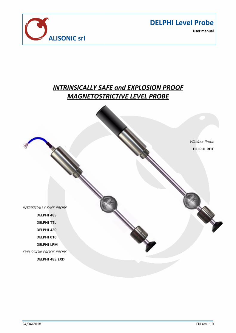
INTRINSICALLY SAFE and EXPLOSION PROOF MAGNETOSTRICTIVE LEVEL PROBE
Wireless Probe
DELPHI RDT
INTRISECALLY SAFE PROBE
DELPHI 485
DELPHI TTL
DELPHI 420
DELPHI 010
DELPHI LPM
EXPLOSION PROOF PROBE
DELPHI 485 EXD
SIBYLLA CONSOLE User Manual rev. 805c
ALISONIC S.r.l. This document, is the sole property of ALISONIC srl. and may not be used, copied
Pg. 2 / 31
SUMMARY
1 INSTRUCTION ................................................................................................................................................. 4
2 SAFETY INDICATION ..................................................................................................................................... 5
3 DEVICE DESCRIPTION .................................................................................................................................... 6
4 ELECTRICAL CHARACTERISTICS .................................................................................................................. 7
4.1.1 DELPHI RDT ................................................................................................................................................................... 7
4.1.2 DELPHI 485(RS 485 serial port for multipoint connection) .................................................................... 7
4.1.3 DELPHI 485 ExD(RS 485 serial port for multipoint connection) ........................................................... 8
4.1.4 DELPHI LPM (RS 485 serial port for multipoint connection) ................................................................. 8
4.1.5 DELPHI 420 .................................................................................................................................................................... 8
4.1.6 DELPHI 010 .................................................................................................................................................................... 9
4.1.7 COMMON CHARACTERISTICS FOR ALL TYPES ............................................................................................ 9
5 PRODUCT MARKING ................................................................................................................................... 10
5.1.1 DELPHI 485, DELPHI TTL, DELPHI 420, DELPHI 010, DELPHI LPM .....................................................10
5.1.2 DELPHI 485 ExD .........................................................................................................................................................10
5.1.3 DELPHI RDT .....................................................................................................................................................................10
6 INSTALLATION GUIDE ................................................................................................................................. 11
7 PROBE DIMENSIONS ................................................................................................................................... 12
7.1.1 DELPHI RDT (wireless) ..................................................................................................................................................12
7.1.2 DELPHI 485/420/010/TTL (RS485) ............................................................................................................................13
7.1.3 DELPHI 485PP (jacket pipe) ........................................................................................................................................14
7.1.4 DELPHI LPM ....................................................................................................................................................................15
8 ON TANK INSTALLATION ........................................................................................................................... 16
8.1.1 GENERAL RULES ............................................................................................................................................................16
8.1.2 SAFETY DISTANCE .........................................................................................................................................................17
8.1.3 INSTALLATION RULES .............................................................................................................................................18
8.1.4 ELECTRIC CONNECTION TO CONSOLE ......................................................................................................................19
8.1.5 VOLTAGE SURGE PROTECTION ..................................................................................................................................19
9 WIRED CONNECTIONS ................................................................................................................................ 20
10 WIRELESS CONNECTIONS ...................................................................................................................... 21
11 WIRELESS SETTING FEATURES AND OPERATIONS ........................................................................... 21
12 WIRELESS INSTALLATION ...................................................................................................................... 22
13 WIRELESS RECEIVER ................................................................................................................................ 23
14 MAINTENANCE ......................................................................................................................................... 24
SIBYLLA CONSOLE User Manual rev. 805c
ALISONIC S.r.l. This document, is the sole property of ALISONIC srl. and may not be used, copied
Pg. 3 / 31
15 DEVICE RETURN ....................................................................................................................................... 24
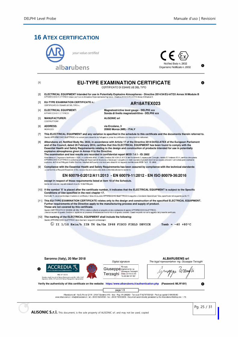
16 ATEX CERTIFICATION .............................................................................................................................. 25
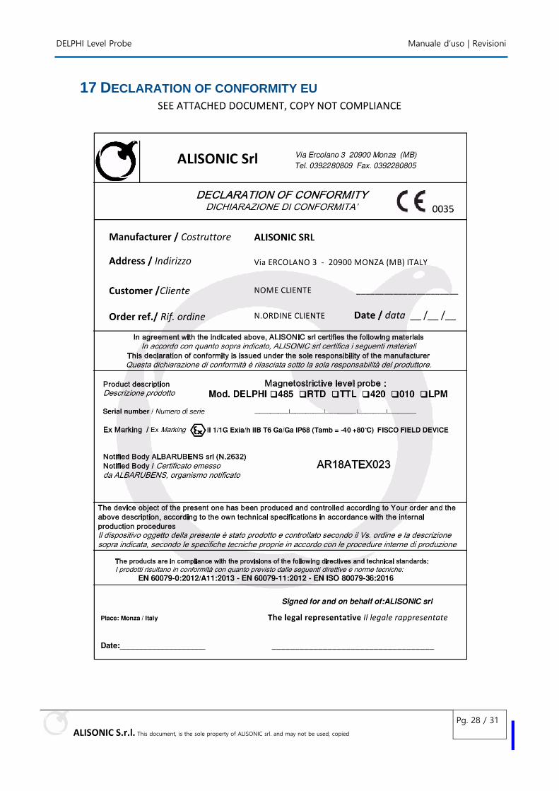
17 DECLARATION OF CONFORMITY EU ................................................................................................... 28
18 REVISION ................................................................................................................................................... 29
DELPHI Level Probe User Manual | rev 1.0
ALISONIC S.r.l. This document, is the sole property of ALISONIC srl. and may not be used, copied
Pg. 4 / 31
1 INSTRUCTION
This manual provides with all the necessary information about the installation operations of the DELPHI level probes family.
The family probes should only be installed by trained service engineers.
In the realization of this document, particular attention was paid to make it as complete and accurate as possible. Therefore, ALISONIC S.r.l. reserves the right to make unannounced upgrades aimed at improving the product, including management programs.
ALISONIC S.r.l. is not responsible for damages deriving from information contemplated in the following document.
This manual was written in the compliance with the IEC 82079-1 standard the ATEX DIRECTIVE 2014/34/ EU intended for the use of equipment and protective system used in potentially explosive atmospheres.
MANUFACTURER DATA:
Name ALISONIC S.r.l.
Address
Via ERCOLANO, 3
20900 MONZA (MB)
Italia
Telephone +39 0362-1547580
Website www.alisonic.it
e-Mail [email protected]
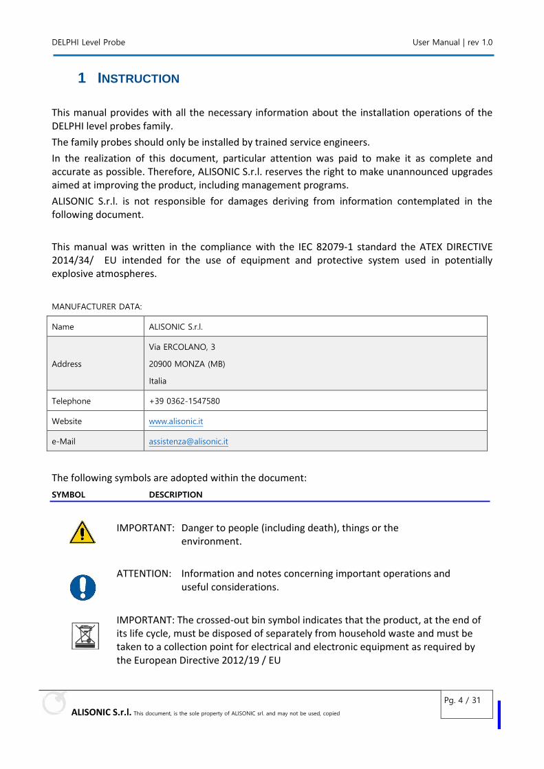
The following symbols are adopted within the document:
SYMBOL DESCRIPTION
IMPORTANT: Danger to people (including death), things or the environment.
ATTENTION: Information and notes concerning important operations and useful considerations.
IMPORTANT: The crossed-out bin symbol indicates that the product, at the end of its life cycle, must be disposed of separately from household waste and must be taken to a collection point for electrical and electronic equipment as required by the European Directive 2012/19 / EU
DELPHI Level Probe User Manual | rev 1.0
ALISONIC S.r.l. This document, is the sole property of ALISONIC srl. and may not be used, copied
Pg. 5 / 31
2 SAFETY INDICATION The level sensors have been developed, manufactured and tested in accordance with the latest
safety standards. Nevertheless, hazard may arise from their use.
The following safety precautions must be observed in order to reduce the risk of injury, electric
shocks, fire or damage to the equipment:
1. Before the installation and use of the equipment please carefully read the instructions
given into this manual.
2. The manufacturer is not responsible of any possible operation not mentioned into this
manual.
3. Any failure or faulty operation would occur to the equipment, please refer to the
authorized personnel for maintenance or directly to the manufacturer.
4. The manufacturer refuses all responsibility for any eventual injury and/or damage to things
caused to the non-observance of the safety regulations.
5. The assigned personnel is required to know all the safety regulations relative to the hereby
described equipment.
6. Any doubt may occur about the functioning of the equipment please refer to the
authorized personnel for maintenance or directly to the manufacturer.
7. Tampering releases, the manufacturer from any responsibility in front of the competent
authority.
8. This product is used in fuel tanks and in hazardous areas for risk of explosion and fire.
Subterranean leakages of the fuel tanks may cause serious damages to environment and
injury.
9. If mixed with air, the flammable vapours may cause explosion. Hazardous areas may be
originated therefore by the presence of gas or vapours.
10. · Explosions or fire may cause damages, even lethal.
11. · The magnetostrictive probe can be installed in hazardous areas.
12. The product may be powered only via the permissible auxiliary power supply.
13. The device must be powered and connected with a INTRINSICALLY SAFE BARRIER,
ALISONIC model: ISB-PC or ISB-PR or equivalent intrinsically safety device
DELPHI Level Probe User Manual | rev 1.0
ALISONIC S.r.l. This document, is the sole property of ALISONIC srl. and may not be used, copied
Pg. 6 / 31
3 DEVICE DESCRIPTION
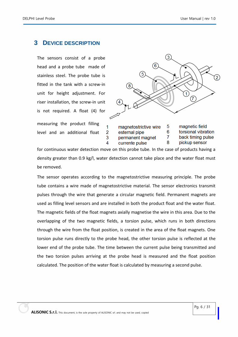
The sensors consist of a probe
head and a probe tube made of
stainless steel. The probe tube is
fitted in the tank with a screw-in
unit for height adjustment. For
riser installation, the screw-in unit
is not required. A float (4) for
measuring the product filling
level and an additional float
for continuous water detection move on this probe tube. In the case of products having a
density greater than 0.9 kg/l, water detection cannot take place and the water float must
be removed.
The sensor operates according to the magnetostrictive measuring principle. The probe
tube contains a wire made of magnetostrictive material. The sensor electronics transmit
pulses through the wire that generate a circular magnetic field. Permanent magnets are
used as filling level sensors and are installed in both the product float and the water float.
The magnetic fields of the float magnets axially magnetise the wire in this area. Due to the
overlapping of the two magnetic fields, a torsion pulse, which runs in both directions
through the wire from the float position, is created in the area of the float magnets. One
torsion pulse runs directly to the probe head, the other torsion pulse is reflected at the
lower end of the probe tube. The time between the current pulse being transmitted and
the two torsion pulses arriving at the probe head is measured and the float position
calculated. The position of the water float is calculated by measuring a second pulse.
DELPHI Level Probe User Manual | rev 1.0
ALISONIC S.r.l. This document, is the sole property of ALISONIC srl. and may not be used, copied
Pg. 7 / 31
4 ELECTRICAL CHARACTERISTICS
4.1.1 DELPHI RDT
Radiofrequency version connection with self-powered
1. · Power supply through intrinsically safe lithium battery 3.6Vdc, model SAFT LS33600 or EVE ER34615.
2. Battery life up to 3 years.(standard setting) 3. Consumption in transmission mode functioning <70 mA. 4. · Consumption in sleep mode < 200 uA. 5. Frequency transmission 169Mhz 6. ..Transmission power up to 200mW 7. Proprietary serial data protocol 8. The serial number is unique and corresponds to the probe address for the consequent
configuration into the electronics control.
4.1.2 DELPHI 485(RS 485 serial port for multipoint connection)
1. · Nominal power supply 12 Vdc (30Vmax) through an intrinsically safe barrier. 2. · Consumption in normal functioning <15 mA @ 12 Vdc 3. · Connection cable supplied by ALISONIC: FR2OR 300V- 4x0.25mm² CEI EN 50363 - ENI 00.181.00 4. · Maximum transmission distance: up to 2 Km based on standard of RS485 interface. 5. T= - 40°C + 80°C 6. Proprietary serial data protocol 7. The serial number is unique and corresponds to the probe address for the consequent
configuration into the electronics control 8. this probe needs intrinsically safe barrier to be connected to the system
Ui = 30V
Ii = 100mA
Ci = negligible
Li = negligible
DELPHI Level Probe User Manual | rev 1.0
ALISONIC S.r.l. This document, is the sole property of ALISONIC srl. and may not be used, copied
Pg. 8 / 31
4.1.3 DELPHI 485 ExD (RS 485 serial port for multipoint connection)
1. · Nominal power supply 12 Vdc (30Vmax) through an intrinsically safe barrier. 2. · Consumption in normal functioning <15 mA @ 12 Vdc 3. · Connection cable supplied by ALISONIC: FR2OR 300V- 4x0.25mm² CEI EN 50363 - ENI 00.181.00 4. · Maximum transmission distance: up to 2 Km based on standard of RS485 interface. 5. T= - 40°C + 80°C 6. Proprietary serial data protocol 7. The serial number is unique and corresponds to the probe address for the consequent
configuration into the electronics control 8. this probe can be connected directly to the system WITHOUT intrinsically safe barrier
Ui = 30V
Ii = 100mA
Ci = negligible
Li = negligible
4.1.4 DELPHI LPM (RS 485 serial port for multipoint connection)
1. · Nominal power supply 12 Vdc (30Vmax) through an intrinsically safe barrier. 2. · Consumption in normal functioning <25 mA @ 12 Vdc(25mA LPM) 3. · Connection cable supplied by ALISONIC: FR2OR 300V- 4x0.25mm² CEI EN 50363 - ENI 00.181.00 4. · Maximum transmission distance: up to 2 Km based on standard of RS485 interface. 5. T= - 40°C + 80°C 6. Proprietary serial data protocol 7. The serial number is unique and corresponds to the probe address for the consequent
configuration into the electronics control
Ui = 30V
Ii = 100mA
Ci = negligible
Li = negligible
4.1.5 DELPHI 420
Wired connection version and analogue output of standard 4-20mA current
1. · Power supply 30 Vdc through an intrinsically safe barrier. 2. · Signal 4 to 20 mA over 2 wires only 1 product float
DELPHI Level Probe User Manual | rev 1.0
ALISONIC S.r.l. This document, is the sole property of ALISONIC srl. and may not be used, copied
Pg. 9 / 31
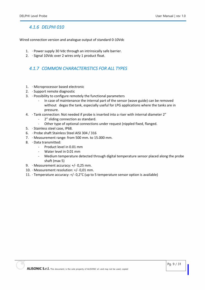
4.1.6 DELPHI 010
Wired connection version and analogue output of standard 0-10Vdc
1. · Power supply 30 Vdc through an intrinsically safe barrier. 2. · Signal 10Vdc over 2 wires only 1 product float.
4.1.7 COMMON CHARACTERISTICS FOR ALL TYPES
1. · Microprocessor based electronic 2. · Support remote diagnostic 3. · Possibility to configure remotely the functional parameters
- In case of maintenance the internal part of the sensor (wave guide) can be removed without degas the tank, especially useful for LPG applications where the tanks are in pressure.
4. · Tank connection: Not needed if probe is inserted into a riser with internal diameter 2” - 2” sliding connection as standard. - Other type of optional connections under request (nippled fixed, flanged.
5. · Stainless steel case, IP68. 6. · Probe shaft Stainless Steel AISI 304 / 316 7. · Measurement range: from 500 mm. to 15.000 mm. 8. · Data transmitted:
- Product level in 0.01 mm - Water level in 0.01 mm - Medium temperature detected through digital temperature sensor placed along the probe
shaft (max 5) 9. · Measurement accuracy: +/- 0,25 mm. 10. · Measurement resolution: +/- 0,01 mm. 11. · Temperature accuracy: +/- 0,2°C (up to 5 temperature sensor option is available)
DELPHI Level Probe User Manual | rev 1.0
ALISONIC S.r.l. This document, is the sole property of ALISONIC srl. and may not be used, copied
Pg. 10 / 31
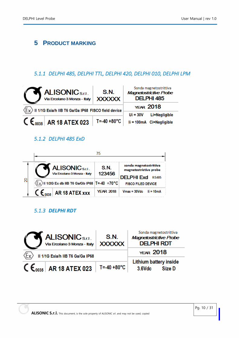
5 PRODUCT MARKING
5.1.1 DELPHI 485, DELPHI TTL, DELPHI 420, DELPHI 010, DELPHI LPM
5.1.2 DELPHI 485 ExD
5.1.3 DELPHI RDT
DELPHI Level Probe User´s manual
ALISONIC S.r.l. This document, is the sole property of ALISONIC srl. and may not be used, copied
Pg. 11 / 31
6 INSTALLATION GUIDE
IMPORTANT: For the installation and maintenance of the sensors, the requirements of the Explosion Protection Regulations, the Industrial Health and Safety Regulations and the Equipment Safety Regulations as well as generally accepted rules of engineering and this manual must be observed.
IMPORTANT: All applicable local safety and accident prevention regulations not included in this manual must also be observed.
ATTENTION: During the assembly, it is important to make sure that the probe tube is not bent. Protect the floats from knocks at all times. No moisture may enter the M12 connector.
Before installation move the supplied floats to the bottom end of the probe tube, otherwise they will slip down suddenly when you erect the sensors and could be damaged when striking the stop cap on bottom
ATTENTION: During the installation, following data of the Delphi sensors, tanks, and products are to be noted for configuring the Sybilla Console:
- Device numbers of the sensors,
- Tank assignments of the sensors,
- Tank assignments of the products,
- Terminal connection of the sensors in wired setting features
- Sensor distances from the central vertical axes of the tanks
DELPHI Level Probe User´s manual
ALISONIC S.r.l. This document, is the sole property of ALISONIC srl. and may not be used, copied
Pg. 12 / 31
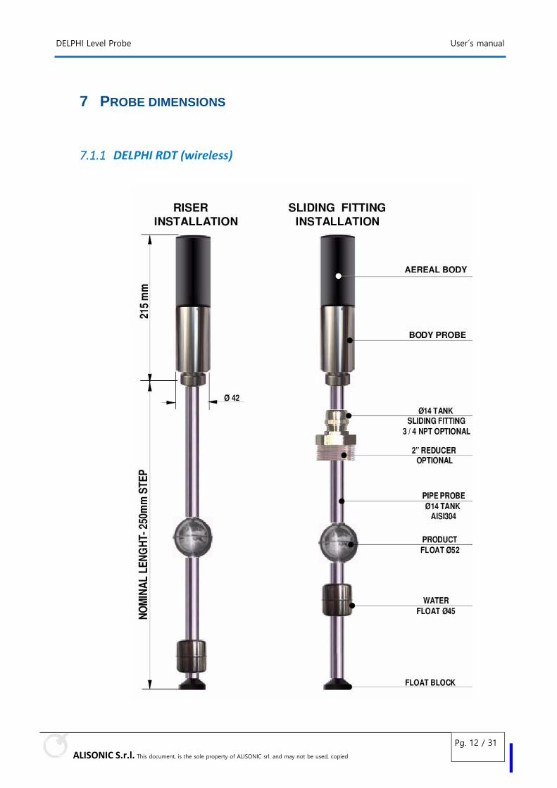
7 PROBE DIMENSIONS
7.1.1 DELPHI RDT (wireless)
DELPHI Level Probe User´s manual
ALISONIC S.r.l. This document, is the sole property of ALISONIC srl. and may not be used, copied
Pg. 13 / 31
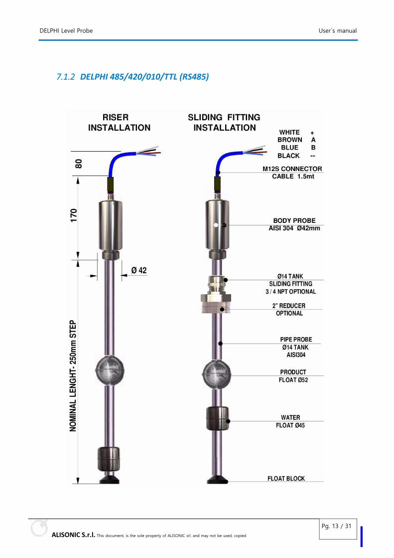
7.1.2 DELPHI 485/420/010/TTL (RS485)
DELPHI Level Probe User´s manual
ALISONIC S.r.l. This document, is the sole property of ALISONIC srl. and may not be used, copied
Pg. 14 / 31
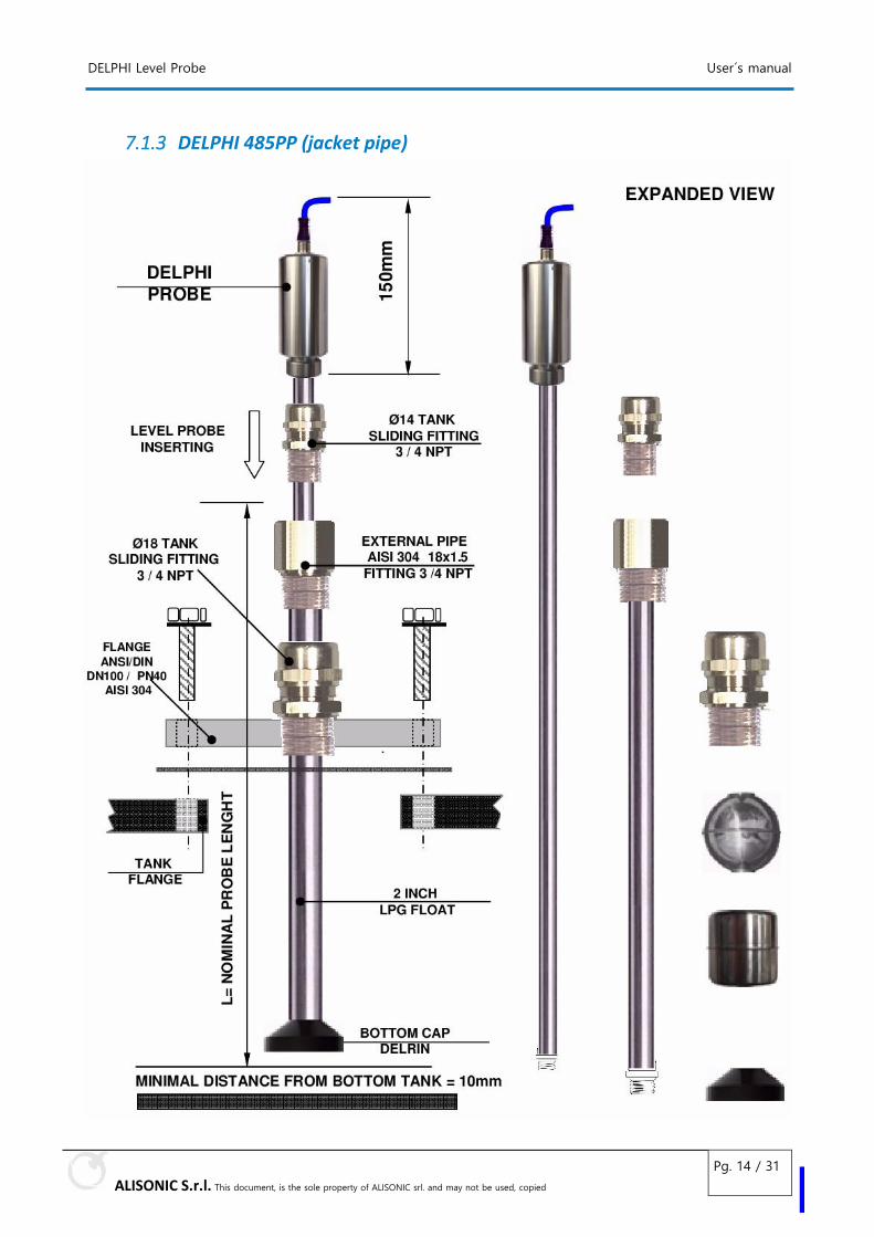
7.1.3 DELPHI 485PP (jacket pipe)
DELPHI Level Probe User´s manual
ALISONIC S.r.l. This document, is the sole property of ALISONIC srl. and may not be used, copied
Pg. 15 / 31
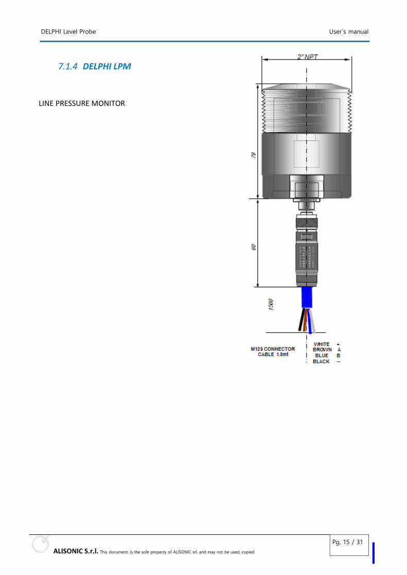
7.1.4 DELPHI LPM
LINE PRESSURE MONITOR
DELPHI Level Probe Manuale d’uso | Supporto
ALISONIC S.r.l. This document, is the sole property of ALISONIC srl. and may not be used, copied
Pg. 16 / 31
8 ON TANK INSTALLATION
8.1.1 GENERAL RULES
The DELPHI level probe is delivered in cardboard packaging per station or individually or up to a maximum of n.5 probes.
When you receive the device need to checking the integrity of the packaging.
In the removal phase from de original packaging please pay attention not to fold the steel pipe, the probe is an electronic tool!
The DELPHI sensor must be installed vertically inside the tanks as close as possible to the central vertical axis. Afterwards, it will be necessary to configure the respective positions of the sensors.
IMPORTANT: in case of hydrocarbon vapour please use anti-sparks tools.
REMEMBER
1 The installation must be realized by specialized people
2 Respect the safety rules
3 Read carefully the instructions provided into this manual
4 The manufacturer is not responsible for any damage and or supplementary cost due to the missing respect of the supplied instructions
DELPHI Level Probe Manuale d’uso | Supporto
ALISONIC S.r.l. This document, is the sole property of ALISONIC srl. and may not be used, copied
Pg. 17 / 31
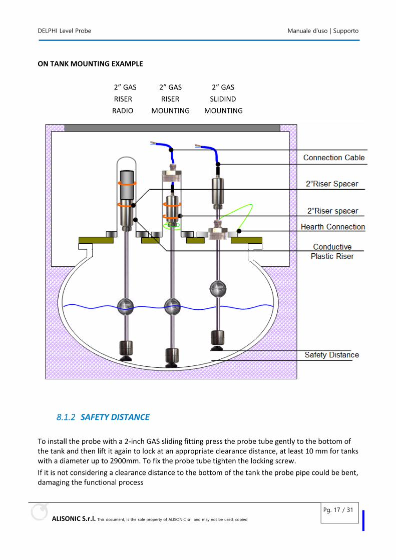
ON TANK MOUNTING EXAMPLE
2” GAS 2” GAS 2” GAS
RISER RISER SLIDIND
RADIO MOUNTING MOUNTING
8.1.2 SAFETY DISTANCE
To install the probe with a 2-inch GAS sliding fitting press the probe tube gently to the bottom of the tank and then lift it again to lock at an appropriate clearance distance, at least 10 mm for tanks with a diameter up to 2900mm. To fix the probe tube tighten the locking screw.
If it is not considering a clearance distance to the bottom of the tank the probe pipe could be bent, damaging the functional process
DELPHI Level Probe Manuale d’uso | Supporto
ALISONIC S.r.l. This document, is the sole property of ALISONIC srl. and may not be used, copied
Pg. 18 / 31
8.1.3 INSTALLATION RULES
1 The DELPHI level probe can supplied with a 2” male Gas sliding fitting or without a fitting in case of installation inside a safety riser
2 The 2” male Gas sliding connector and the floats mounted on it guarantee an easy passage inside 2”pipe connection used like riser. This simplifies the insertion of the probe inside the tank and therefore it is not necessary to disassemble any element.
3 The probe pipe inside the tank must not be bent or exposed to impact stresses.
The probe must be mounted keeping the head as high as possible to avoid immersion.
4 If a ground connection is required for the dispersion of electrostatic charges, this will be achieved by means of a metal band applied to the sensor pipe and an appropriate conductor connected to the equipotential metallic structure
5 The probe is supplied with a 1,5 meters of cable connected to M12 or SM12 connector at the probe head, this cable must be connected to the back bone using a junction box.
6 It is recommended to use a junction box IP68 for intrinsically safety connection.
7 In a typical RS485 serial connection all the probes are connected in parallel. Normally all the bus connections must be cascading to grant the lower transmission distance. In case of service stations distances are extremely reduced, branches no longer than 50 meters, in this case it is allowed to have a star type wiring.
8 The 4-wire connection cable has always red (or black), brown, blue and white colours.
9 Connect to the terminal box the cables with same colour: white-white, red-red, etc. At the console the shield from the cables have al to be connected in parallel as a one wire and connected to the earth into the office using a separated ground wire which must not be shared with the motors or power systems earth connections.
10 To connection and programming the console please refer to the manual provided together with every device.
11 The installation must be done in compliance with CEI 64-8 and EN 60079-14 standards.
DELPHI Level Probe Manuale d’uso | Supporto
ALISONIC S.r.l. This document, is the sole property of ALISONIC srl. and may not be used, copied
Pg. 19 / 31
8.1.4 ELECTRIC CONNECTION TO CONSOLE
After the junction with the probe cable the connection cable between the sensor and the Console must be have the following properties:
• Four unshielded wire cable, oil resistant and idrocarbure resistant.
• Cable conductor section (4 x 0.5mm² up to 100mt or 4 x 1mm² up to 200mt)
• Cable colour blue or printed blue (for a intrinsically safe circuits)
• Maximum external diameter from 6 to 10mm for reliable sealing by the cable gland
The equipotential bonding must be carried out by the installer in accordance with the nationally applicable installation regulations. For the purpose the equipotential connection at the probe pipe can be realized trough a metal tie.
8.1.5 VOLTAGE SURGE PROTECTION
To protect the level sensor from the voltage surges we recommend that you install a voltage surge protector directly upstream of the probe in the manhole.
Special EN regulations including EN 60079-14 and EN 60079-25 as well as local installation regulations must be observed.
DELPHI Level Probe Manuale d’uso | Supporto
ALISONIC S.r.l. This document, is the sole property of ALISONIC srl. and may not be used, copied
Pg. 20 / 31
9 WIRED CONNECTIONS
Always ensure that the power has been disconnected before you wire up the Delphi sensors to the Sibylla Console. For wiring, proceed as follows:
• If not already connected, plug the M12/SM12 flying connector supplied by Alisonic to the connector of the probe head.
Before to tighten the connector nut look for the correct coupling position as the connectors are provided with a polarization key, do not use excessive tightening torque should be between 100 … 150 Ncm.
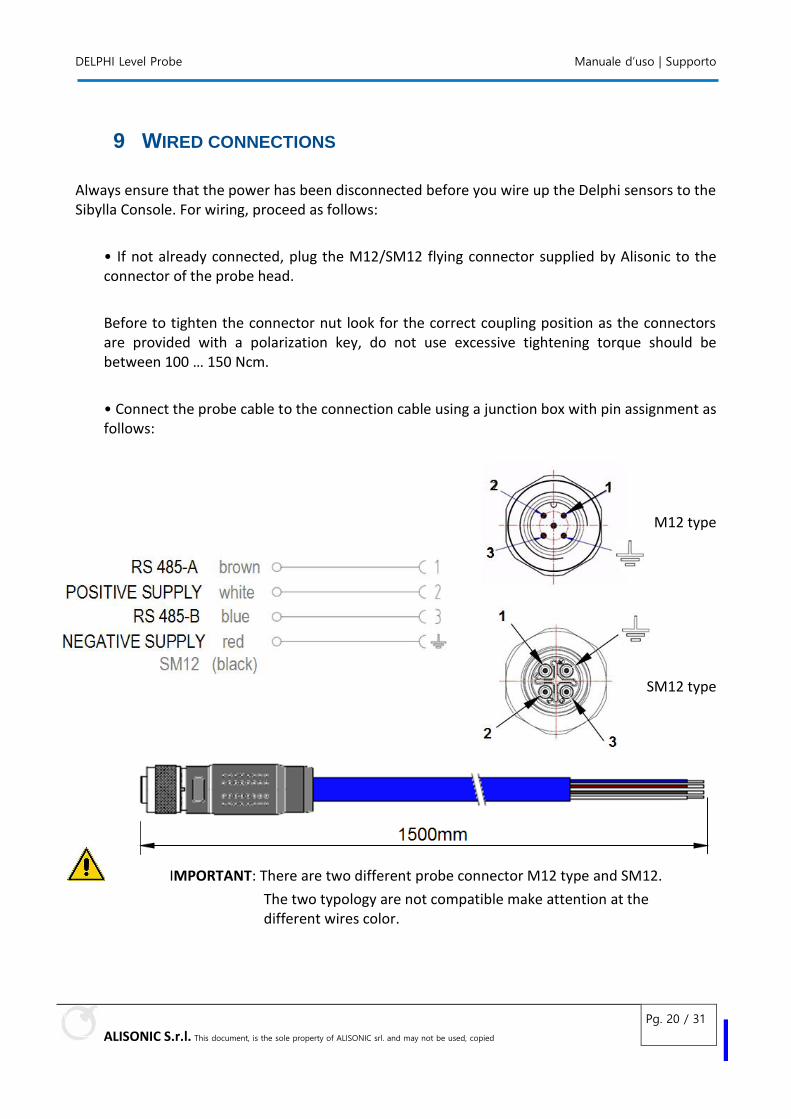
• Connect the probe cable to the connection cable using a junction box with pin assignment as follows:
M12 type
SM12 type
IMPORTANT: There are two different probe connector M12 type and SM12.
The two typology are not compatible make attention at the different wires color.
DELPHI Level Probe Manuale d’uso | Revisioni
ALISONIC S.r.l. This document, is the sole property of ALISONIC srl. and may not be used, copied
Pg. 21 / 31
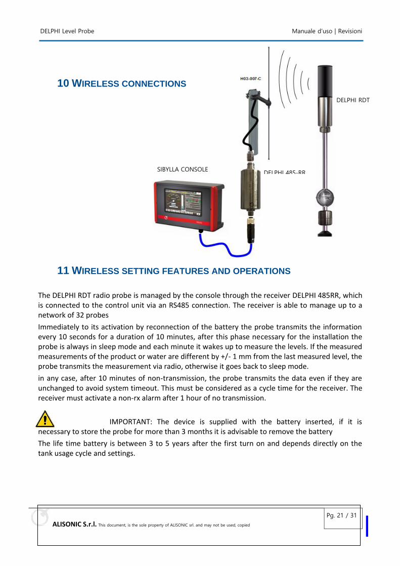
10 WIRELESS CONNECTIONS
11 WIRELESS SETTING FEATURES AND OPERATIONS
The DELPHI RDT radio probe is managed by the console through the receiver DELPHI 485RR, which is connected to the control unit via an RS485 connection. The receiver is able to manage up to a network of 32 probes
Immediately to its activation by reconnection of the battery the probe transmits the information every 10 seconds for a duration of 10 minutes, after this phase necessary for the installation the probe is always in sleep mode and each minute it wakes up to measure the levels. If the measured measurements of the product or water are different by +/- 1 mm from the last measured level, the probe transmits the measurement via radio, otherwise it goes back to sleep mode.
in any case, after 10 minutes of non-transmission, the probe transmits the data even if they are unchanged to avoid system timeout. This must be considered as a cycle time for the receiver. The receiver must activate a non-rx alarm after 1 hour of no transmission.
IMPORTANT: The device is supplied with the battery inserted, if it is necessary to store the probe for more than 3 months it is advisable to remove the battery
The life time battery is between 3 to 5 years after the first turn on and depends directly on the tank usage cycle and settings.
DELPHI 485-RR
DELPHI RDT
SIBYLLA CONSOLE
DELPHI Level Probe Manuale d’uso | Revisioni
ALISONIC S.r.l. This document, is the sole property of ALISONIC srl. and may not be used, copied
Pg. 22 / 31
IMPORTANT
The battery can only be changed in the field by qualified personnel, do not operate in the presence of flammable liquids or explosive atmospheres, following the manual instructions
Only intrinsally safe batteries can be used:
SAFT LS 33600 or equivalent
EVE 3,6 V 19 Ah D dimensione ER34615 farnel 1973584
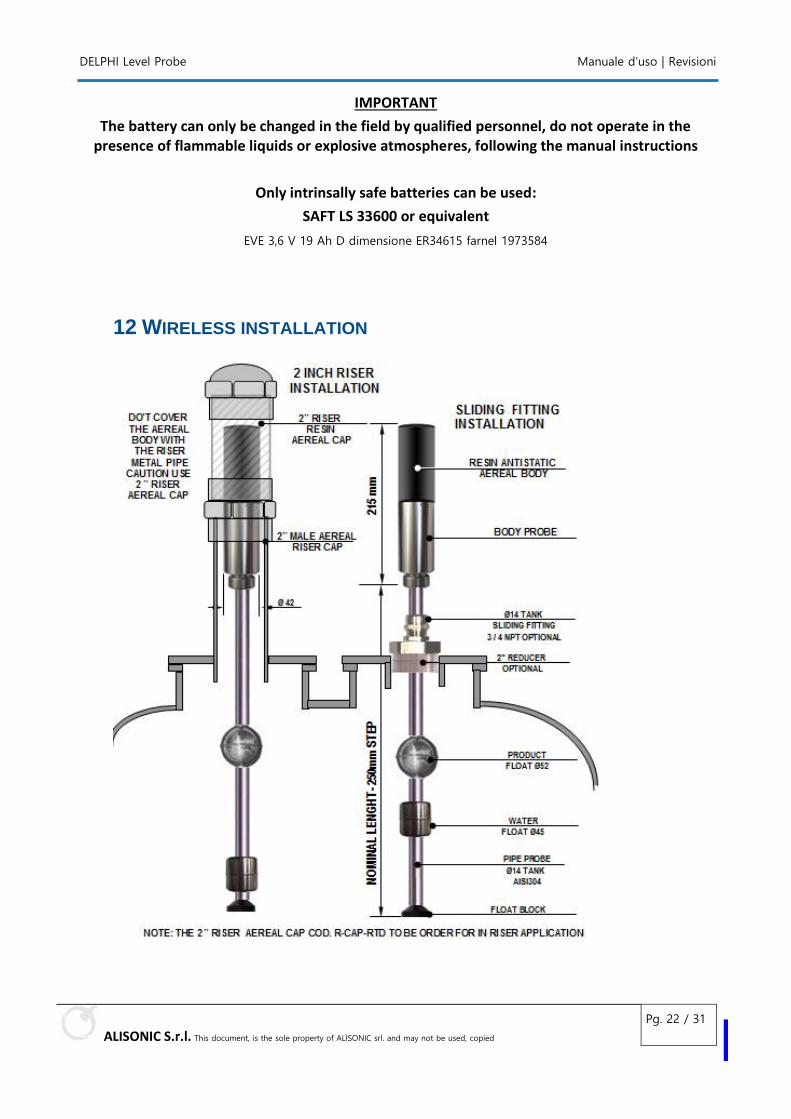
12 WIRELESS INSTALLATION
DELPHI Level Probe Manuale d’uso | Revisioni
ALISONIC S.r.l. This document, is the sole property of ALISONIC srl. and may not be used, copied
Pg. 23 / 31
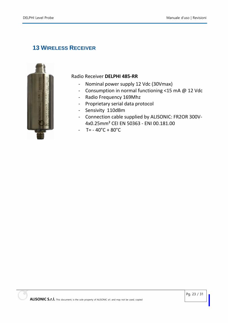
13 WIRELESS RECEIVER
Radio Receiver DELPHI 485-RR
- Nominal power supply 12 Vdc (30Vmax) - Consumption in normal functioning <15 mA @ 12 Vdc - Radio Frequency 169Mhz - Proprietary serial data protocol - Sensivity 110dBm - Connection cable supplied by ALISONIC: FR2OR 300V-
4x0.25mm² CEI EN 50363 - ENI 00.181.00 - T= - 40°C + 80°C
DELPHI Level Probe Manuale d’uso | Revisioni
ALISONIC S.r.l. This document, is the sole property of ALISONIC srl. and may not be used, copied
Pg. 24 / 31
14 MAINTENANCE
The sensor and associated floats are maintenance free, if they are operated according to the manufacturer’s specifications and not used to other applications.
15 DEVICE RETURN
Before returning any ALISONIC equipment request the (RMA) Return Material Authorization to
your account manager of ALISONIC for have the instructions on how to return goods.
DELPHI Level Probe Manuale d’uso | Revisioni
ALISONIC S.r.l. This document, is the sole property of ALISONIC srl. and may not be used, copied
Pg. 25 / 31
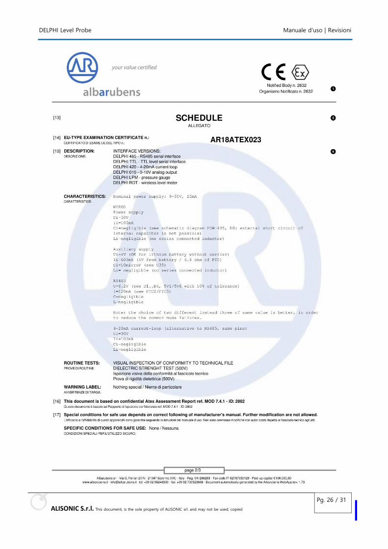
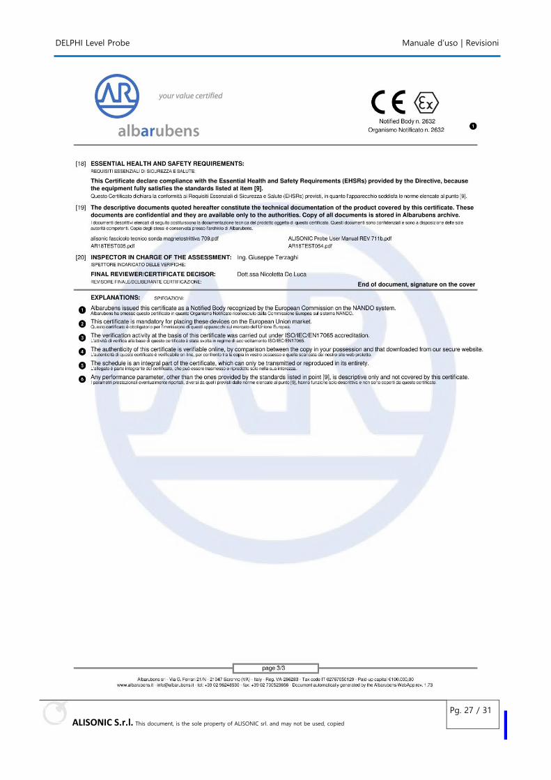
16 ATEX CERTIFICATION
DELPHI Level Probe Manuale d’uso | Revisioni
ALISONIC S.r.l. This document, is the sole property of ALISONIC srl. and may not be used, copied
Pg. 26 / 31
DELPHI Level Probe Manuale d’uso | Revisioni
ALISONIC S.r.l. This document, is the sole property of ALISONIC srl. and may not be used, copied
Pg. 27 / 31
DELPHI Level Probe Manuale d’uso | Revisioni
ALISONIC S.r.l. This document, is the sole property of ALISONIC srl. and may not be used, copied
Pg. 28 / 31
17 DECLARATION OF CONFORMITY EU SEE ATTACHED DOCUMENT, COPY NOT COMPLIANCE
DELPHI Level Probe Manuale d’uso | Revisioni
ALISONIC S.r.l. This document, is the sole property of ALISONIC srl. and may not be used, copied
Pg. 29 / 31
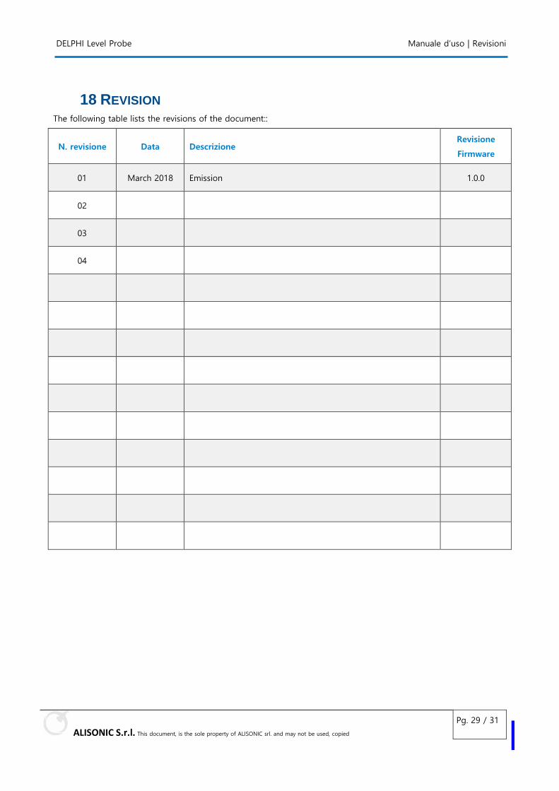
18 REVISION The following table lists the revisions of the document::
N. revisione Data Descrizione Revisione
Firmware
01 March 2018 Emission 1.0.0
02
03
04

Empty page
ALISONIC S.r.l.
Via Verona 18/20
20821 Meda (MB) - Italy
Tel. +39 0362 1547580
www.alisonic.it


