Embed Size (px)
Citation preview
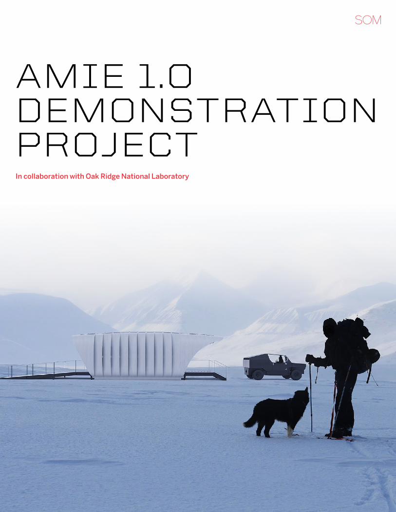
AMIE 1.0 DEMonstrAtIon projEct In collaboration with Oak Ridge National Laboratory
U.S. DOE UnvEilS SOM-DESignED 3D-PrintED BUilDing POwErED By a Car
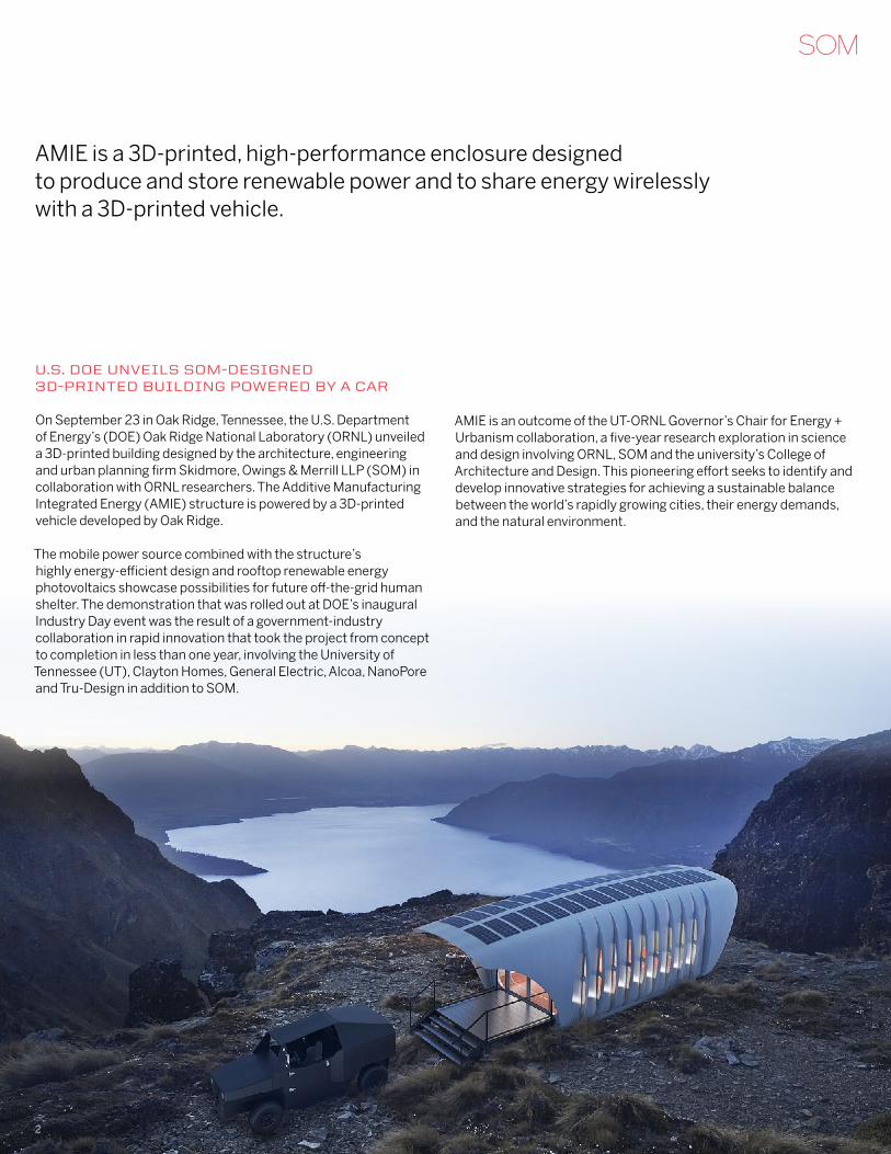
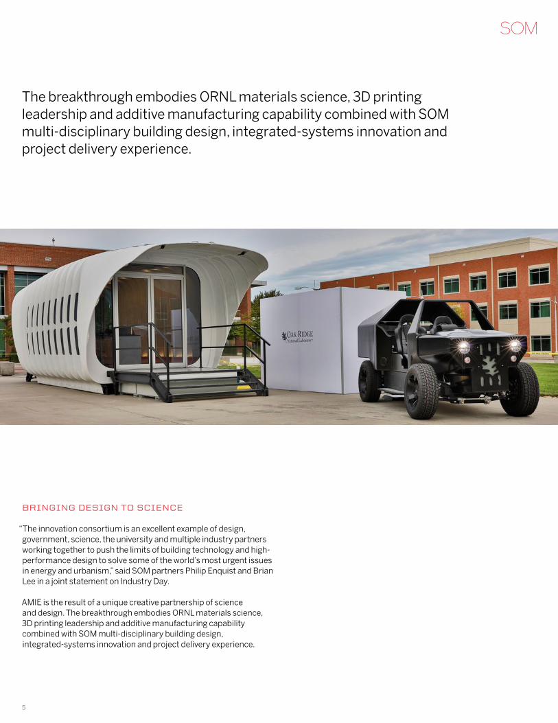
On September 23 in Oak Ridge, Tennessee, the U.S. Department of Energy’s (DOE) Oak Ridge National Laboratory (ORNL) unveiled a 3D-printed building designed by the architecture, engineering and urban planning firm Skidmore, Owings & Merrill LLP (SOM) in collaboration with ORNL researchers. The Additive Manufacturing Integrated Energy (AMIE) structure is powered by a 3D-printed vehicle developed by Oak Ridge.
The mobile power source combined with the structure’s highly energy-efficient design and rooftop renewable energy photovoltaics showcase possibilities for future off-the-grid human shelter. The demonstration that was rolled out at DOE’s inaugural Industry Day event was the result of a government-industry collaboration in rapid innovation that took the project from concept to completion in less than one year, involving the University of Tennessee (UT), Clayton Homes, General Electric, Alcoa, NanoPore and Tru-Design in addition to SOM.
AMIE is a 3D-printed, high-performance enclosure designed to produce and store renewable power and to share energy wirelessly with a 3D-printed vehicle.
AMIE is an outcome of the UT-ORNL Governor’s Chair for Energy + Urbanism collaboration, a five-year research exploration in science and design involving ORNL, SOM and the university’s College of Architecture and Design. This pioneering effort seeks to identify and develop innovative strategies for achieving a sustainable balance between the world’s rapidly growing cities, their energy demands, and the natural environment.
2
PUShing thE liMitS Of 3D Printing tO BUilDing SCalE
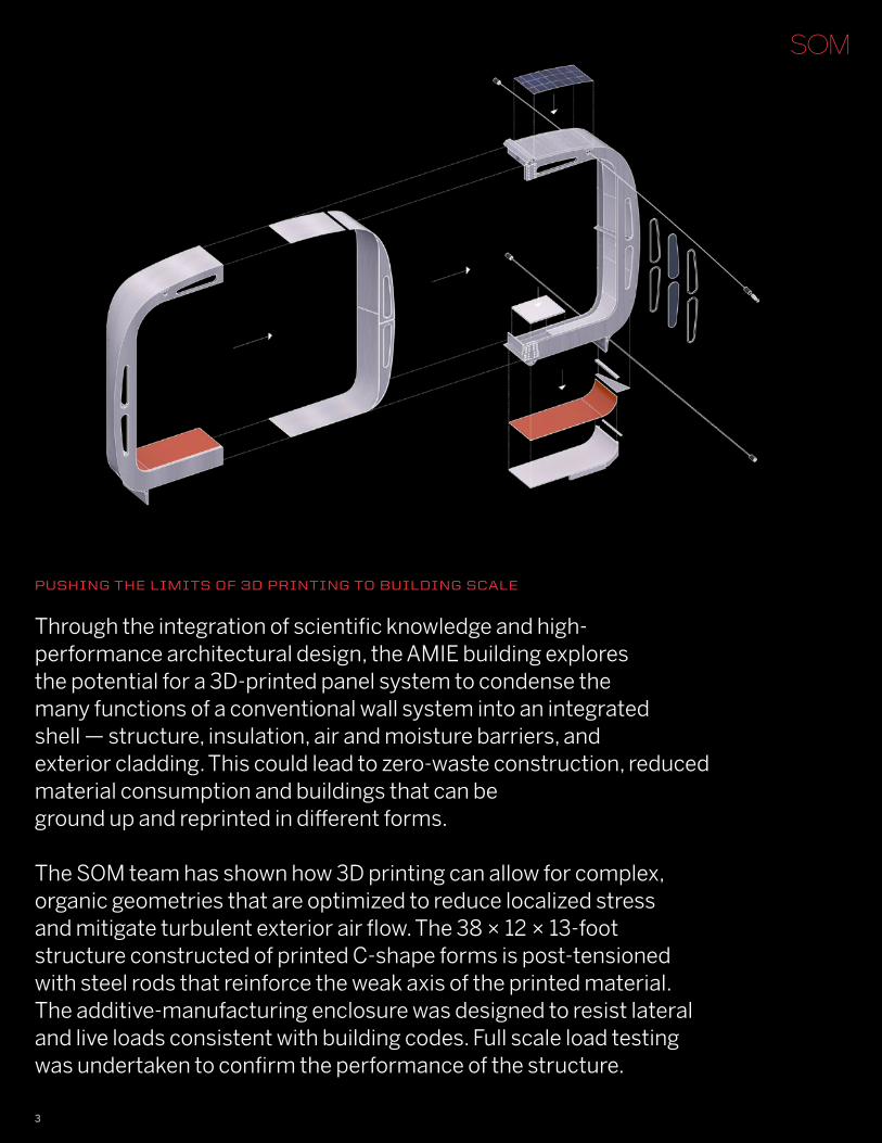
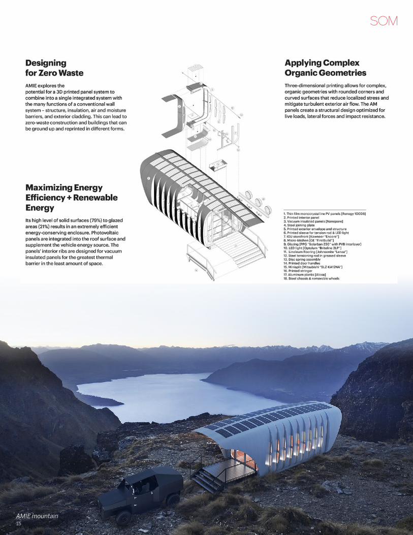
Through the integration of scientific knowledge and high-performance architectural design, the AMIE building explores the potential for a 3D-printed panel system to condense the many functions of a conventional wall system into an integrated shell — structure, insulation, air and moisture barriers, and exterior cladding. This could lead to zero-waste construction, reduced material consumption and buildings that can be ground up and reprinted in different forms.
The SOM team has shown how 3D printing can allow for complex, organic geometries that are optimized to reduce localized stress and mitigate turbulent exterior air flow. The 38 × 12 × 13-foot structure constructed of printed C-shape forms is post-tensioned with steel rods that reinforce the weak axis of the printed material. The additive-manufacturing enclosure was designed to resist lateral and live loads consistent with building codes. Full scale load testing was undertaken to confirm the performance of the structure.
3
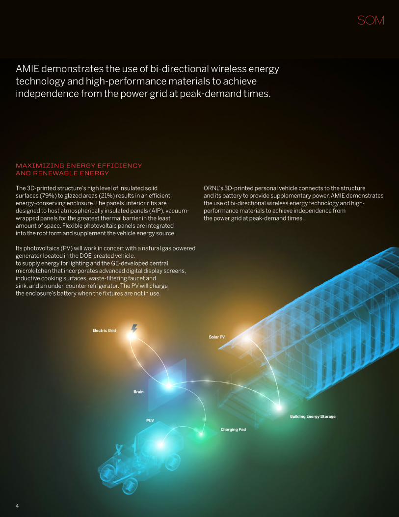
AMIE demonstrates the use of bi-directional wireless energy technology and high-performance materials to achieve independence from the power grid at peak-demand times.
MaxiMizing EnErgy EffiCiEnCy anD rEnEwaBlE EnErgy
The 3D-printed structure’s high level of insulated solid surfaces (79%) to glazed areas (21%) results in an efficient energy-conserving enclosure. The panels’ interior ribs are designed to host atmospherically insulated panels (AIP), vacuum-wrapped panels for the greatest thermal barrier in the least amount of space. Flexible photovoltaic panels are integrated into the roof form and supplement the vehicle energy source.
Its photovoltaics (PV) will work in concert with a natural gas powered generator located in the DOE-created vehicle, to supply energy for lighting and the GE-developed central microkitchen that incorporates advanced digital display screens, inductive cooking surfaces, waste-filtering faucet and sink, and an under-counter refrigerator. The PV will charge the enclosure’s battery when the fixtures are not in use.
ORNL’s 3D-printed personal vehicle connects to the structure and its battery to provide supplementary power. AMIE demonstrates the use of bi-directional wireless energy technology and high-performance materials to achieve independence from the power grid at peak-demand times.
4
Bringing DESign tO SCiEnCE
“The innovation consortium is an excellent example of design, government, science, the university and multiple industry partners working together to push the limits of building technology and high-performance design to solve some of the world’s most urgent issues in energy and urbanism,” said SOM partners Philip Enquist and Brian Lee in a joint statement on Industry Day.
AMIE is the result of a unique creative partnership of science and design. The breakthrough embodies ORNL materials science, 3D printing leadership and additive manufacturing capability combined with SOM multi-disciplinary building design, integrated-systems innovation and project delivery experience.
The breakthrough embodies ORNL materials science, 3D printing leadership and additive manufacturing capability combined with SOM multi-disciplinary building design, integrated-systems innovation and project delivery experience.
5
aBOUt SkiDMOrE, OwingS & MErrill llP
Skidmore, Owings & Merrill LLP (SOM) is one of the leading architecture, interior design, engineering, and urban planning firms in the world, with a nearly 80-year reputation for design excellence and a portfolio that includes some of the most important architectural accomplishments of the 20th and 21st centuries. Since its inception, SOM has been a leader in the research and development of specialized technologies, new processes and innovative ideas, many of which have had a palpable and lasting impact on the design profession and the physical environment. The firm’s longstanding leadership in design and building technology has been honored with more than 1,700 awards for quality, innovation, and management. The American Institute of Architects has recognized SOM twice with its highest honor, the Architecture Firm Award—in 1962 and again in 1996. The firm maintains offices in New York, Chicago, San Francisco, Los Angeles, Washington, D.C., London, Hong Kong, Shanghai, Mumbai, and Abu Dhabi.
For further information contact SOM Chicago’s PaUl O’COnnOr 312-360-4539 [email protected]
To learn more about AMIE, visit Ornl.gOv/aMiE
To learn more about the Governor’s Chair program, visit Utk.EDU/gOvChairS
To learn more about ORNL, visit Ornl.gOv
To learn more about the UT College of Architecture and Design, visitarChDESign.Utk.EDU
inDUStry PartnErS
Alcoa Cincinnati Inc Clayton Homes DowAksaU.S. Department of EnergyEPBGE AppliancesHexagon LincolnIACMI The Composites InstituteJohnson ControlsKawneer KUB Liberty UtilitiesLine-X Mach Fuels NanoPoreOak Ridge National Laboratory Skidmore, Owings & Merrill LLP Spiers New Technologies TechmerESTru-Design University of Tennessee
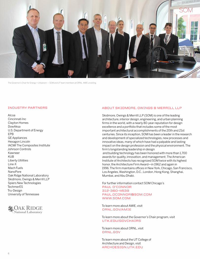
The Governor’s Chair for Energy + Urbanism — SOM and UT team members at ORNL AMIE unveiling.
6
DESign Of thE CarBOn fiBEr rEinfOrCED aBS StrUCtUrE
AMIE 1.0 is a demonstration project of a small building that uses Additive Manufacturing (3D printing) for the structure and enclosure along with Integrated Energy systems (AM+IE). The demonstration project was a joint effort by Oak Ridge National Laboratory (ORNL), Skidmore Owings & Merrill (SOM), Clayton Homes, General Electric, Alcoa, Nanopore, and Trudesign. The unique challenges presented by this project required each partner to share their knowledge and skillset, working together to find new solutions.
This paper discusses the challenges associated with the 3D printed structure designed by ORNL and SOM. The design process relied on the materials science, 3D printing knowledge, and 3D printing capabilities of ORNL along with the building application, systems innovation, and project delivery experience of SOM.
structurAl DEsIgn
7
MatErial PrOPErtiES
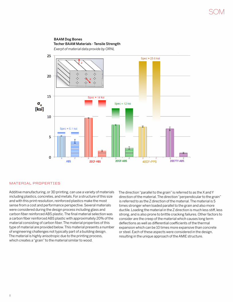
Additive manufacturing, or 3D printing, can use a variety of materials including plastics, concretes, and metals. For a structure of this size and with this print resolution, reinforced plastics make the most sense from a cost and performance perspective. Several materials were considered during the design process including glass and carbon fiber reinforced ABS plastic. The final material selection was a carbon fiber reinforced ABS plastic with approximately 20% of the material consisting of carbon fiber. The material properties of this type of material are provided below. This material presents a number of engineering challenges not typically part of a building design. The material is highly anisotropic due to the printing process, which creates a “grain” to the material similar to wood.
The direction “parallel to the grain” is referred to as the X and Y direction of the material. The direction “perpendicular to the grain” is referred to as the Z direction of the material. The material is 5 times stronger when loaded parallel to the grain and also more ductile. Loading the material in the Z direction is much less stiff, less strong, and is also prone to brittle cracking failures. Other factors to consider are the creep of the material which causes long term deflections as well as differential coefficients of the thermal expansion which can be 10 times more expansive than concrete or steel. Each of these aspects were considered in the design, resulting in the unique approach of the AMIE structure.
Material Properties
Additive manufacturing, or 3D printing, can use a variety of materials including plastics, concretes, and metals. For a structure of this size and with this print resolution, reinforced plastics make the most sense from a cost and performance perspective. Several materials were considered during the design process including glass and carbon fiber reinforced ABS plastic. The final material selection was a carbon fiber reinforced ABS plastic with approximately 20% of the material consisting of carbon fiber. The material properties of this type of material are provided below.
This material presents a number of engineering challenges not typically part of a building design. The material is highly anisotropic due to the printing process, which creates a “grain” to the material similar to wood. The direction “parallel to the grain” is referred to as the X and Y direction of the material. The direction “perpendicular to the grain” is referred to as the Z direction of the material. The material is 5 times stronger when loaded parallel to the grain and also more ductile. Loading the material in the Z direction is much less stiff, less strong, and is also prone to brittle cracking failures. Other factors to consider are the creep of the material which causes long term deflections as well as differential coefficients of the thermal expansion which can be 10 times more expansive than concrete or steel. Each of these aspects were considered in the design, resulting in the unique approach of the AMIE structure.
Figure 2: Excerpt of Material Data provided by ORNL
BAAM Dog BonesTecher BAAM Materials - Tensile Strength
Exerpt of material data provide by ORNL
8
StrUCtUral DESCriPtiOn
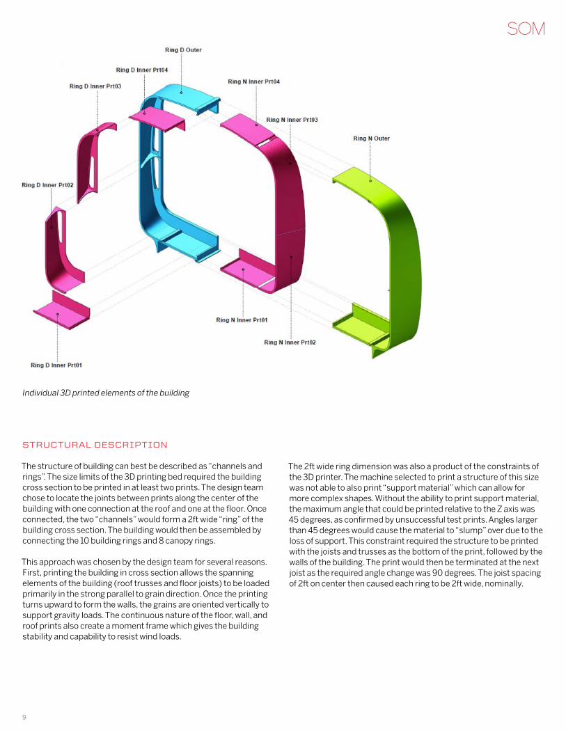
The structure of building can best be described as “channels and rings”. The size limits of the 3D printing bed required the building cross section to be printed in at least two prints. The design team chose to locate the joints between prints along the center of the building with one connection at the roof and one at the floor. Once connected, the two “channels” would form a 2ft wide “ring” of the building cross section. The building would then be assembled by connecting the 10 building rings and 8 canopy rings.
This approach was chosen by the design team for several reasons. First, printing the building in cross section allows the spanning elements of the building (roof trusses and floor joists) to be loaded primarily in the strong parallel to grain direction. Once the printing turns upward to form the walls, the grains are oriented vertically to support gravity loads. The continuous nature of the floor, wall, and roof prints also create a moment frame which gives the building stability and capability to resist wind loads.
The 2ft wide ring dimension was also a product of the constraints of the 3D printer. The machine selected to print a structure of this size was not able to also print “support material” which can allow for more complex shapes. Without the ability to print support material, the maximum angle that could be printed relative to the Z axis was 45 degrees, as confirmed by unsuccessful test prints. Angles larger than 45 degrees would cause the material to “slump” over due to the loss of support. This constraint required the structure to be printed with the joists and trusses as the bottom of the print, followed by the walls of the building. The print would then be terminated at the next joist as the required angle change was 90 degrees. The joist spacing of 2ft on center then caused each ring to be 2ft wide, nominally.
Individual 3D printed elements of the building
9
Main StrUCtUrE DESign
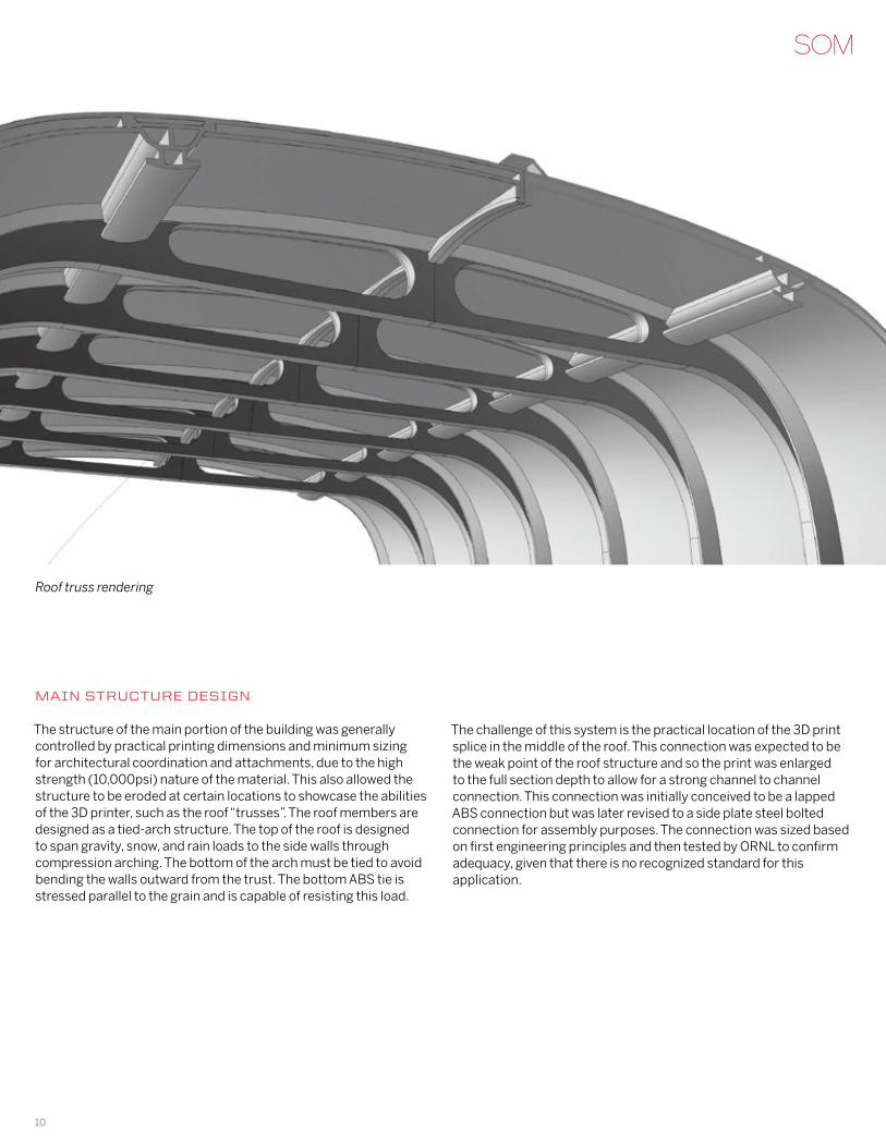
The structure of the main portion of the building was generally controlled by practical printing dimensions and minimum sizing for architectural coordination and attachments, due to the high strength (10,000psi) nature of the material. This also allowed the structure to be eroded at certain locations to showcase the abilities of the 3D printer, such as the roof “trusses”. The roof members are designed as a tied-arch structure. The top of the roof is designed to span gravity, snow, and rain loads to the side walls through compression arching. The bottom of the arch must be tied to avoid bending the walls outward from the trust. The bottom ABS tie is stressed parallel to the grain and is capable of resisting this load.
The challenge of this system is the practical location of the 3D print splice in the middle of the roof. This connection was expected to be the weak point of the roof structure and so the print was enlarged to the full section depth to allow for a strong channel to channel connection. This connection was initially conceived to be a lapped ABS connection but was later revised to a side plate steel bolted connection for assembly purposes. The connection was sized based on first engineering principles and then tested by ORNL to confirm adequacy, given that there is no recognized standard for this application.
Roof truss rendering
10
CanOPy DESign
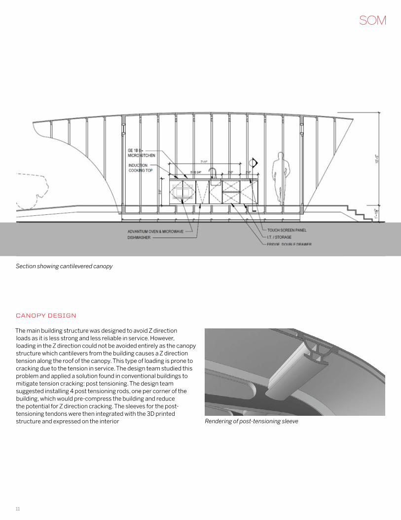
The main building structure was designed to avoid Z direction loads as it is less strong and less reliable in service. However, loading in the Z direction could not be avoided entirely as the canopy structure which cantilevers from the building causes a Z direction tension along the roof of the canopy. This type of loading is prone to cracking due to the tension in service. The design team studied this problem and applied a solution found in conventional buildings to mitigate tension cracking: post tensioning. The design team suggested installing 4 post tensioning rods, one per corner of the building, which would pre-compress the building and reduce the potential for Z direction cracking. The sleeves for the post-tensioning tendons were then integrated with the 3D printed structure and expressed on the interior
Section showing cantilevered canopy
Rendering of post-tensioning sleeve
11
thErMal lOaD DESign
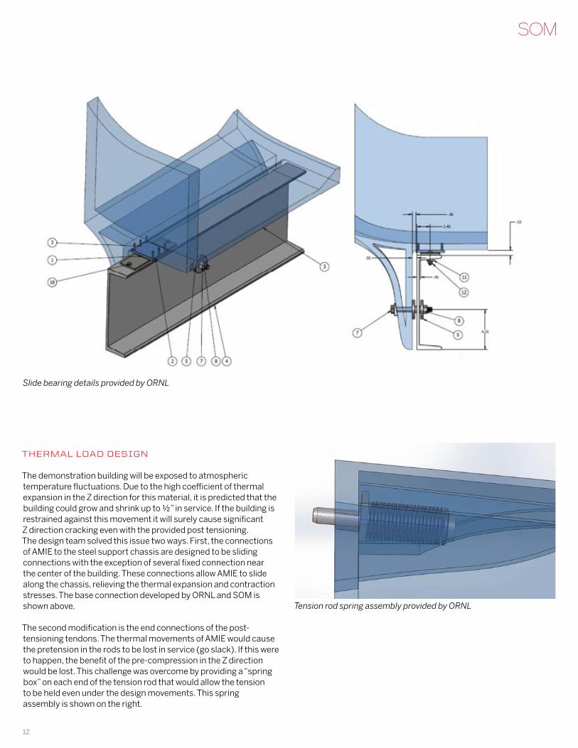
The demonstration building will be exposed to atmospheric temperature fluctuations. Due to the high coefficient of thermal expansion in the Z direction for this material, it is predicted that the building could grow and shrink up to ½” in service. If the building is restrained against this movement it will surely cause significant Z direction cracking even with the provided post tensioning. The design team solved this issue two ways. First, the connections of AMIE to the steel support chassis are designed to be sliding connections with the exception of several fixed connection near the center of the building. These connections allow AMIE to slide along the chassis, relieving the thermal expansion and contraction stresses. The base connection developed by ORNL and SOM is shown above.
The second modification is the end connections of the post-tensioning tendons. The thermal movements of AMIE would cause the pretension in the rods to be lost in service (go slack). If this were to happen, the benefit of the pre-compression in the Z direction would be lost. This challenge was overcome by providing a “spring box” on each end of the tension rod that would allow the tension to be held even under the design movements. This spring assembly is shown on the right.
Slide bearing details provided by ORNL
Tension rod spring assembly provided by ORNL
12
tESting anD vErifiCatiOn PrOgraM
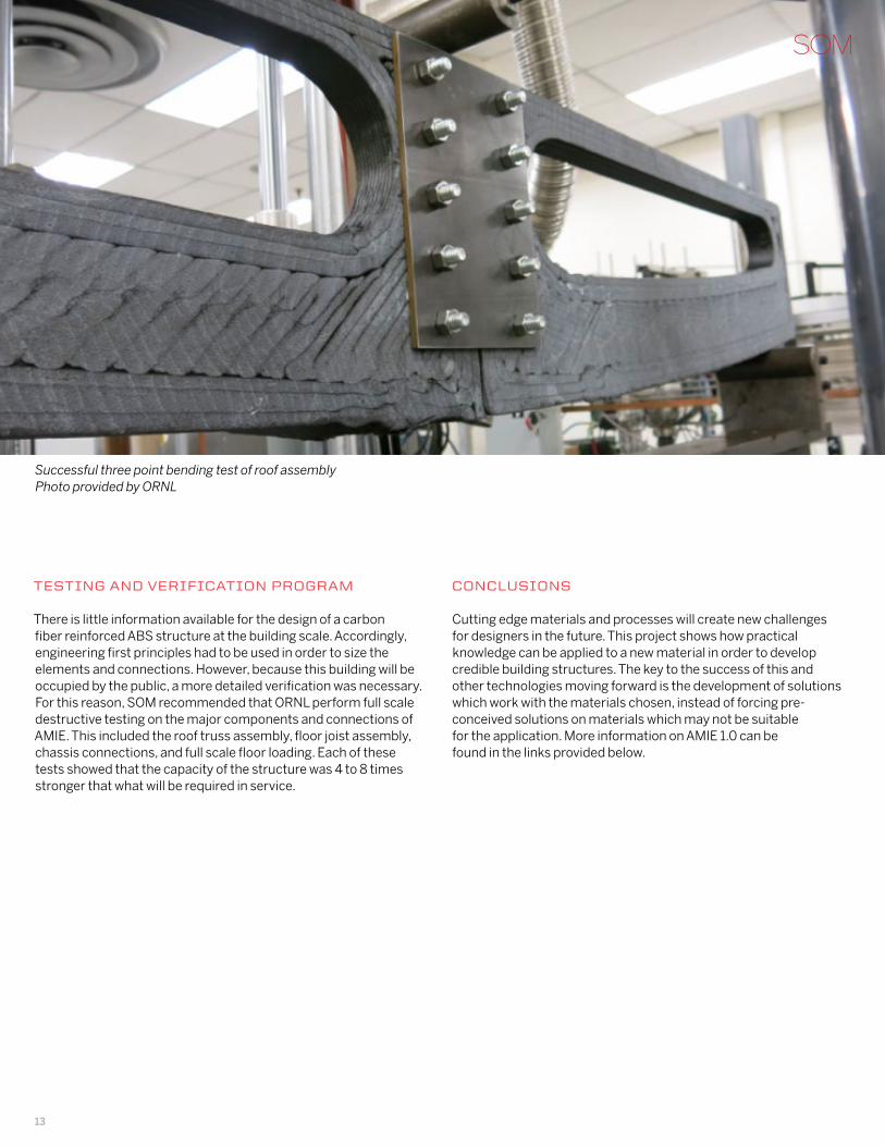
There is little information available for the design of a carbon fiber reinforced ABS structure at the building scale. Accordingly, engineering first principles had to be used in order to size the elements and connections. However, because this building will be occupied by the public, a more detailed verification was necessary. For this reason, SOM recommended that ORNL perform full scale destructive testing on the major components and connections of AMIE. This included the roof truss assembly, floor joist assembly, chassis connections, and full scale floor loading. Each of these tests showed that the capacity of the structure was 4 to 8 times stronger that what will be required in service.
Successful three point bending test of roof assemblyPhoto provided by ORNL
COnClUSiOnS
Cutting edge materials and processes will create new challenges for designers in the future. This project shows how practical knowledge can be applied to a new material in order to develop credible building structures. The key to the success of this and other technologies moving forward is the development of solutions which work with the materials chosen, instead of forcing pre-conceived solutions on materials which may not be suitable for the application. More information on AMIE 1.0 can be found in the links provided below.
13
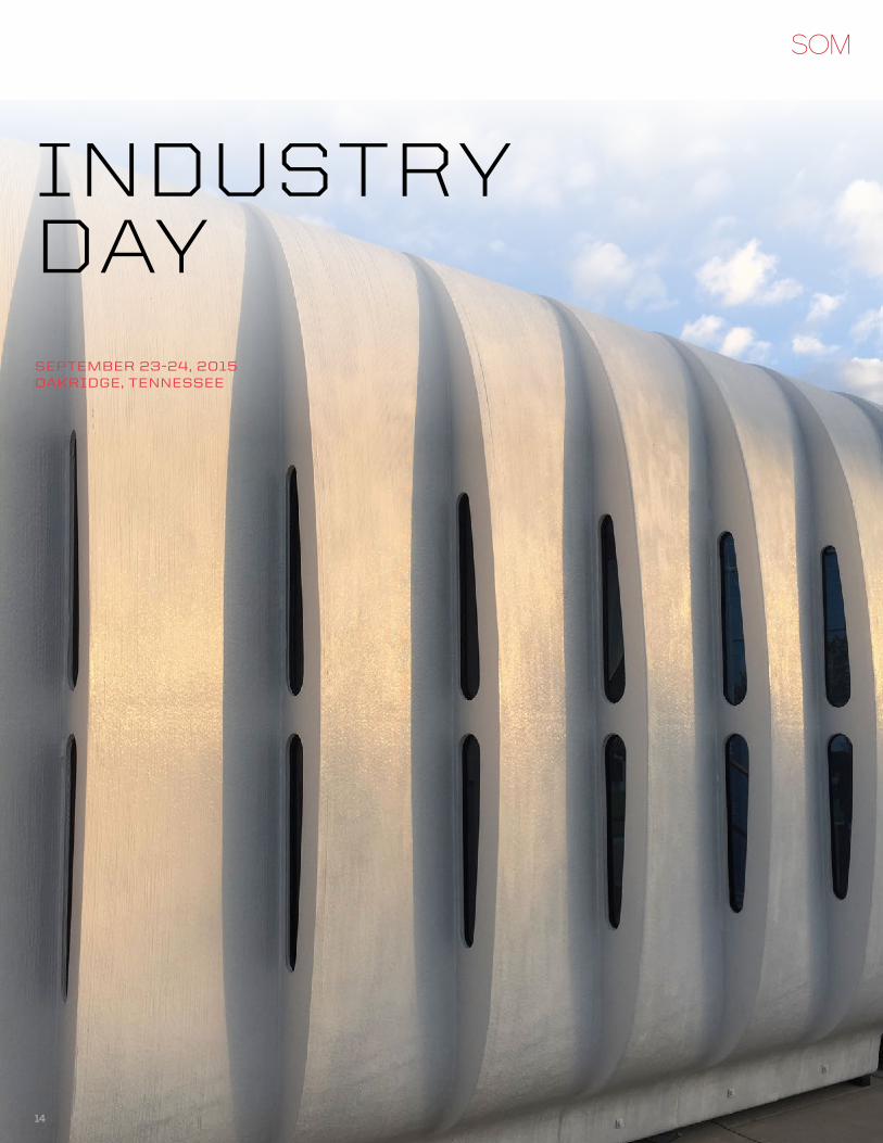
SEPtEMBEr 23-24, 2015OakriDgE, tEnnESSEE
InDustrY DAY
14
15
AMIE mountain
16
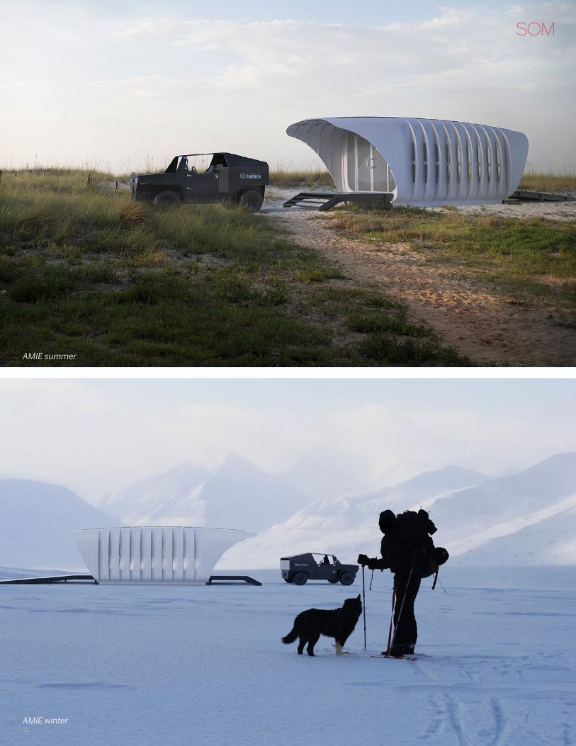
AMIE summer
AMIE winter
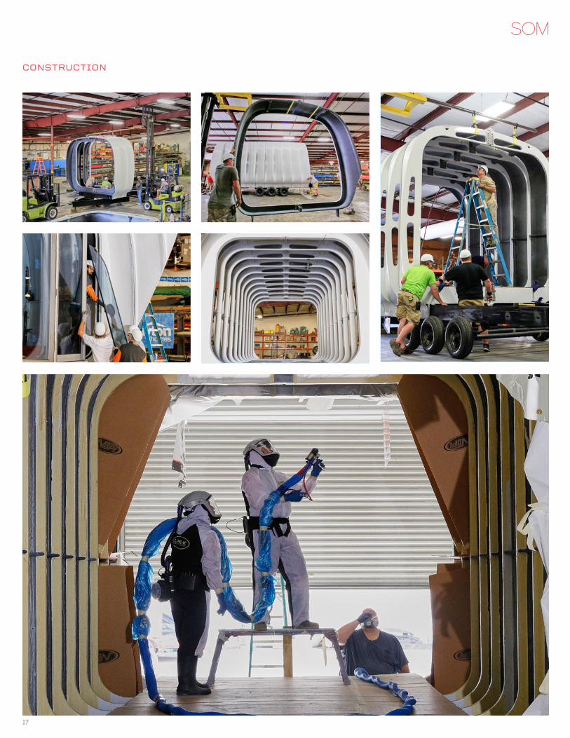
COnStrUCtiOn
17
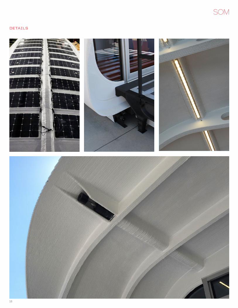
DEtailS
18
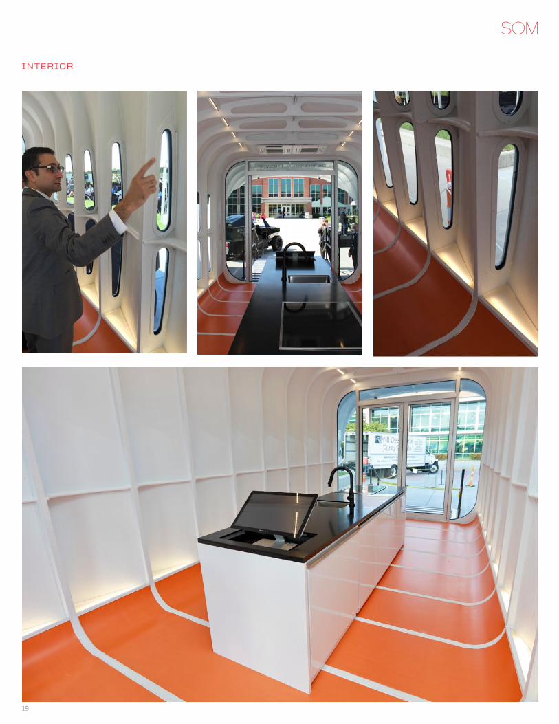
intEriOr
19
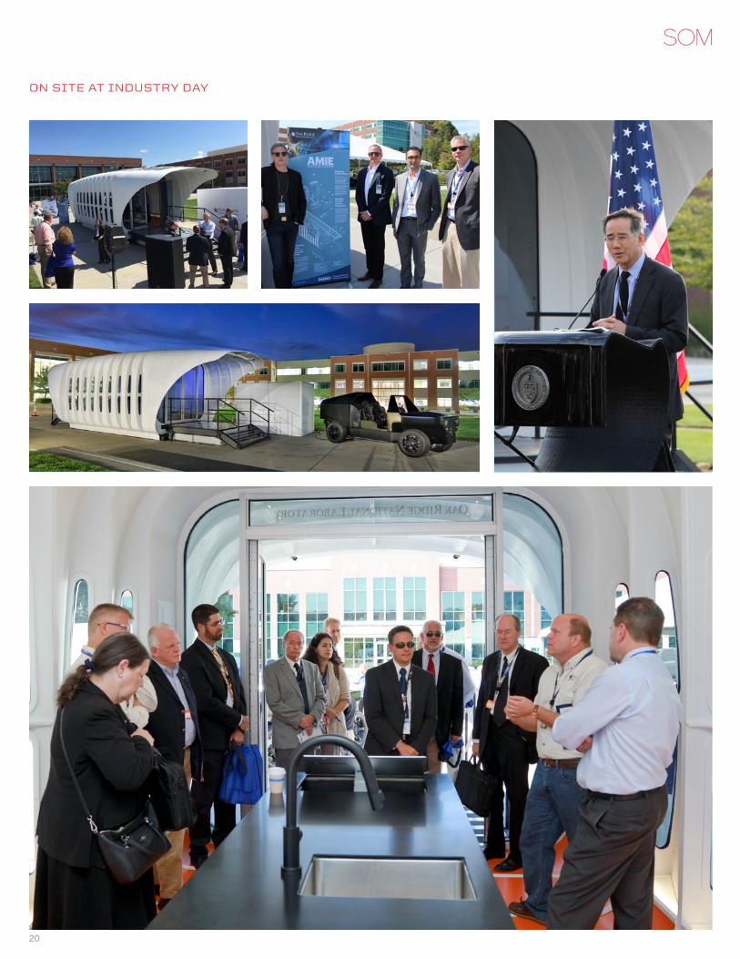
On SitE at inDUStry Day
20
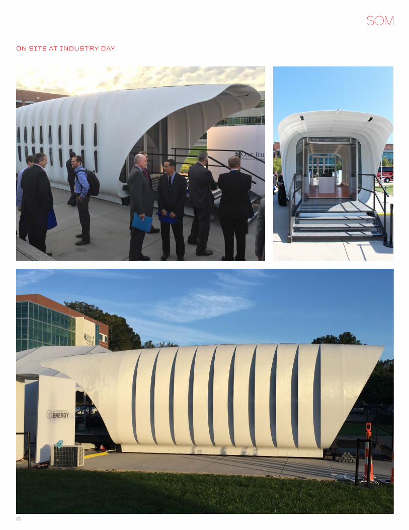
On SitE at inDUStry Day
21
MOrE On aMiE OnlinE
SOM Press Release
ORNL Press Release
SOM Press Page
SOM In the Press
ORNL AMIE Website
AMIE Fact Sheet
SOM Project Page
SOM Renderings
ORNL Photos
PrESS COvEragE
3dprint.com
3dprintingindustry.com
ArchDaily
Architectural Digest
Architect Magazine
BDC Network
BuiltWorlds
Curbed
DesignBoom
Fast Company
Free Press Journal
Gizmodo
Inhabitat
Lab Manager
MentalFloss
Phys.org
University of Tennessee Knoxville
WBIR.com
viDEOS
AMIE Demonstration Project – Vision
Additive Manufacturing Integrated Energy Demonstration
AMIE Electrical Energy Flow
@ORNL
@SOM_Design
#AMIE
#EEREIndustryDay
#MEETAMIE
22


