Embed Size (px)
Citation preview

IJRET: International Journal of Research in Engineering and Technology eISSN: 2319-1163 | pISSN: 2321-7308
_______________________________________________________________________________________
Volume: 04 Issue: 09 | September-2015, Available @ http://www.ijret.org 1
AN APPROACH TO EVALUATE THE HEAT EXCHANGER RETROFIT
FOR INSTALLED INDUSTRIAL GAS TURBINES: PART I –
TECHNICAL EVALUATION
Waleed Al-Busaidi1, Pericles Pilidis2
1Researcher in Cranfield University;School of Aerospace, Transport and Manufacturing; Bedfordshire; UK
2Head of Propulsion Engineering Centre, Cranfield University, Bedfordshire, UK
Abstract
This paper is the first part of a two-part study aiming to introduce a new integrated approach to evaluate the techno-economic
value of recuperator retrofit on existing gas turbine engines. The original gas turbines are designed for combined cycles so that
the pressure ratios are moderate to secure suitable exhaust temperatures. One way to enhance the thermal efficiency of some gas
turbines is by using recuperation to recover some of the exhaust heat. In this part, the developed model is described and
implemented for two gas turbine engines so the obtained characteristics are eva luated against the actual data. The new approach
will assist users to select the suitable gas turbine models with favorable recuperator characteristics based on a technical and
economic prospective. Besides, the performance results are used to design an ap propriate shell and tube heat exchanger.
Moreover, a new technique has been established to define the typical heat exchanger parameters in order to ensure the highest
possible improvements over the original cycles. One of the main features of this method is that it depends only on the velocity of
hot and cold heat exchanger streams from which the rest of the heat exchanger design and performance characteristics were
derived.
Key Words: integrated approach, techno-economic value, recuperation, shell and tube heat exchanger, velocity
--------------------------------------------------------------------***----------------------------------------------------------------------
1. INTRODUCTION
Many existing power generation installations are based on
moderate pressure ratio gas turbines where the exhaust gas
temperature (EGT) is greater than the compressor discharge
temperature(CDT). Th is makes the provision of a heat
transfer process attractive [1]. Besides, the low fuel
consumption has been one of the critical features to select a
gas turbine for power generation due to the gradual increase
in the fuel cost. One way to enhance this efficiency is by
using the recuperation to recover some of the exhausted heat
which normally exceeds 50% of the total produced energy
instead of injecting it into the atmosphere.
The main function of gas turbine heat exchangers is to
enable the heat transfer from the hot stream coming from the
turbine exhaust to the cold stream which is the discharge
compressor air. The actual amount of heat transfer between
the recuperator streams can be determined by the following
equation.
𝑄𝑎𝑐𝑡 = 𝑊𝐶𝑃, 𝑇1 − 𝑇2
= 𝑊𝑐𝐶𝑃,𝐶 𝑇𝑐2 − 𝑇𝑐1
(1)
The desired characteristics of a heat exchanger are: h igh
effectiveness, low pressure drop, low manufacturing and
operating costs and low physical weight and size. The
importance of each of these features depends on the type of
application [2]. Unfortunately, there is a conflict between
some of these design characteristics so to design a heat
exchanger with a higher effectiveness, a larger recuperator
size is required which should be considered in terms of the
available space and maximum allowed weight in some
applications. Furthermore, the price of the heat exchanger is
strongly influenced by its size so as recuperator size
increases, the price will also increase. Consequently, the
selected features of the heat exchanger have to be optimized
and a compromise has to be performed to select the
appropriate characteristics based on the application
requirements.
Unfortunately, there is no available systematic approach in
the open literature to define the optimum cycle parameters
and typical heat exchanger characteristics for higher techno-
economic value. Hence, this study aims to introduce a new
approach to determine the optimum heat exchanger
characteristics in order to attain the highest possible
technical and economical values. One of the unique features
of the developed method is that that it basically depends on
the flow velocity to derive the rest of parameters. This
model has been implemented with two installed gas turbine
models and an optimizat ion process is conducted to select
the design parameters of the heat exchanger.
This paper is organized into three main sections. The first
part presents some backgrounds for the developed method
followed by the detailed description of the used
methodology and empirical correlat ions. The second part
demonstrates the obtained heat exchanger and overall cycle
characteristics using the derived approach for both gas
turbines. Finally, a sensitivity study is performed to evaluate

IJRET: International Journal of Research in Engineering and Technology eISSN: 2319-1163 | pISSN: 2321-7308
_______________________________________________________________________________________
Volume: 04 Issue: 09 | September-2015, Available @ http://www.ijret.org 2
the suction parameters effects on the overall recuperative
gas turbine cycle.
2. HEAT EXCHANGER EVELUATION
METHODOLOGY
This part of the study describes the technical evaluation of
the heat exchanger features for gas turbine retrofit. This
example will be a useful illustration of how to optimize
recuperator characteristics for better cycle performance.
The performance of the gas turbines is simulated and the
isentropic efficiencies, pressure losses and bleed air are
assumed in order to match the performance of the simulated
models with the original specifications provided by the
supplier. The calculated discharge compressor conditions
and the turbine exhaust parameters are used as input features
of both cold and hot streams respectively.
The designed heat exchanger is from shell and tube type
which is used widely in process industry. In general, the
high-pressure stream is typically directed through the tubes
while the other stream flows in the space between the tubes
and the outer shell. The tube geometry parameters are
assumed at the beginning and then modified to obtain the
allowed pressure drop in the cold side. Besides, the required
duty is calculated using both Log Mean Temperature
Difference and Number of Transfer Units methods. The
overall heat transfer coefficient (U) is assumed and it is
iterated at the end until both values are equal.
The inside heat transfer coefficient is assumed and then it
will be calculated based on Reynolds number and tube
geometry. The assumed value is iterated to be equal to the
final calcu lated coefficient. Moreover, the shell geometry
dimensions are specified based on the recommended values
of the shell design parameters and the allowed pressure drop
in the hot side.There are different methods that have been
developed to calculate the heat transfer coefficient and
pressure drop of shell side, the Bell-Delaware method has
been used in this paper.
Figure 1: Basic Component of Shell and Tube Heat
Exchanger
Figure 2: Basic Component of Simulated Simple and
Recuperative Engine Cycles
Figure 3: A Strategy to Choose the Pressure Drop and Heat
Transfer
IJRET: International Journal of Research in Engineering and Technology eISSN: 2319-1163 | pISSN: 2321-7308
_______________________________________________________________________________________
Volume: 04 Issue: 09 | September-2015, Available @ http://www.ijret.org 3
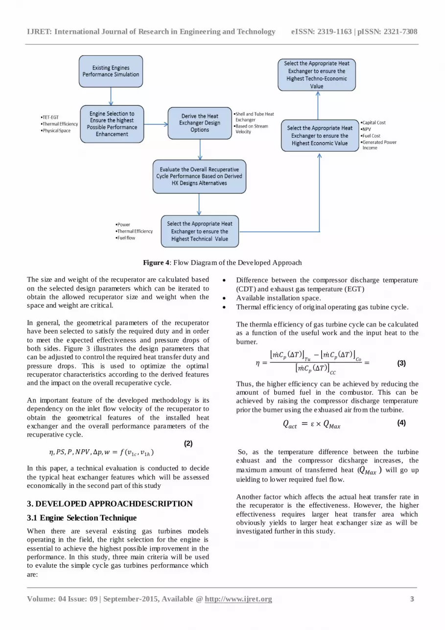
Figure 4: Flow Diagram of the Developed Approach
The size and weight of the recuperator are calculated based
on the selected design parameters which can be iterated to
obtain the allowed recuperator size and weight when the
space and weight are critical.
In general, the geometrical parameters of the recuperator
have been selected to satisfy the required duty and in order
to meet the expected effect iveness and pressure drops of
both sides. Figure 3 illustrates the design parameters that
can be adjusted to control the required heat transfer duty and
pressure drops. This is used to optimize the optimal
recuperator characteristics according to the derived features
and the impact on the overall recuperative cycle.
An important feature of the developed methodology is its
dependency on the inlet flow velocity of the recuperator to
obtain the geometrical features of the installed heat
exchanger and the overall performance parameters of the
recuperative cycle.
𝜂,𝑃𝑆,𝑃 ,𝑁𝑃𝑉 , ∆𝑝,𝑤 = 𝑓(𝑣1𝑐 , 𝑣1 )
(2)
In this paper, a technical evaluation is conducted to decide
the typical heat exchanger features which will be assessed
economically in the second part of this study
3. DEVELOPED APPROACHDESCRIPTION
3.1 Engine Selection Technique
When there are several existing gas turbines models
operating in the field, the right selection for the engine is
essential to achieve the highest possible improvement in the
performance. In this study, three main criteria will be used
to evalute the simple cycle gas turbines performance which
are:
Difference between the compressor discharge temperature
(CDT) and exhaust gas temperature (EGT)
Available installation space.
Thermal efficiency of orig inal operating gas tubine cycle.
The thermla efficiency of gas turbine cycle can be calculated
as a function of the useful work and the input heat to the
burner.
𝜂 = 𝑚 𝐶𝑝 ∆𝑇 𝑇𝑢
− 𝑚 𝐶𝑝 ∆𝑇 𝐶𝑜 𝑚 𝐶𝑝 ∆𝑇 𝐶𝐶
= (3)
Thus, the higher efficiency can be achieved by reducing the
amount of burned fuel in the combustor. This can be
achieved by raising the compressor discharge temperature
prior the burner using the exhuased air from the turbine.
𝑄𝑎𝑐𝑡 = ε × 𝑄𝑀𝑎𝑥 (4)
So, as the temperature difference between the turbine
exhuast and the compressor dicsharge increases, the
maximum amount of transferred heat (𝑄𝑀𝑎𝑥 ) will go up
uielding to lower required fuel flow.
Another factor which affects the actual heat transfer rate in
the recuperator is the effectiveness. However, the higher
effectiveness requires larger heat transfer area which
obviously yields to larger heat exchanger size as will be
investigated further in this study.

IJRET: International Journal of Research in Engineering and Technology eISSN: 2319-1163 | pISSN: 2321-7308
_______________________________________________________________________________________
Volume: 04 Issue: 09 | September-2015, Available @ http://www.ijret.org 4
3.2 Determination of Gas Properties at Recuperator
Sides
The outlet pressure and temperature from the shell and tube
can be determined by calculation from:
𝑃2 = 𝑃1 × 1 −∆𝑃 (%)
100
(5)
𝑇𝑐𝑜𝑙𝑑 ,𝑜𝑢𝑡 = 1 − 𝜀 × 𝑇𝑐𝑜𝑙𝑑 ,𝑖𝑛 + 𝜀 . 𝑇𝑜𝑡 ,𝑖𝑛 (6)
The dynamic viscosity can be calculated as a function of the
average temperature only using a correlat ion published by
Crane Company [3]. Th is equation is used for some
common gases and it was derived based on assumption that
the impact of pressure is minor (≤10% for the gases) and
can be neglected.
𝜇 𝐾𝑔
𝑚 . 𝑠 =
1.5105 × 10⁻⁶ × 𝑇𝑎𝑣𝑔1.5
𝑇𝑎𝑣𝑔 + 120
(7)
Where: 𝑇𝑎𝑣𝑔 is the average temperature in Kelvin (ºk)
The thermal conductivity (K) can be determined for hot and
cold streams using the correlation given by PasterAguilar
study [4]. This also has been developed assuming that the
thermal conductivity is a function of the average
temperature only.
𝐾 𝑊
𝑚.𝐾 = 1.5207 × 10⁻¹¹ × 𝑇𝑎𝑣𝑔
3 − 4.8574
× 10−8 × 𝑇𝑎𝑣𝑔2 + 1.0184
× 10−4 × 𝑇𝑎𝑣𝑔 − 3.9333
× 10−4
(8)
To calculate the specific heat, the correlation given by Ieradi
[5] is used. This equation has been derived experimentally
by plotting the variation of specific heat (𝐶𝑝) against
temperatures which has been done by. However, this
formula determines the specific heat (𝐶𝑝) in terms of the
average temperature only without a considering of the fuel
flow effect.
𝐶𝑝 𝐽
𝐾𝑔 .𝐾 = 1.9327 × 10⁻¹⁰ × 𝑇𝑎𝑣𝑔
4 − 7.9999
× 10−7 × 𝑇𝑎𝑣𝑔3 + 1.1407
× 10−3 × 𝑇𝑎𝑣𝑔2 − 4.4890
× 10−1 × 𝑇𝑎𝑣𝑔 + 1.0575 × 10³
(9)
3.3 Heat Exchanger Design Theory
Four input parameters can be selected to modify the tube
geometry; these are:
Tube outside diameter (Dt)
Tube wall thickness (tt)
Tube roughness
Tube length (lt)
The inlet tube diameter (𝑑𝑡 ) can be calculated based on the
specified tube outside diameter and its wall thickness.
Besides, the LMTD method is used to determine the
required tube area corresponding to the assumed overall heat
transfer coefficient (𝑈)by applying the following equation.
𝐴𝑡 =𝑄𝑎𝑐𝑡𝑢𝑎𝑙
𝑈 × 𝐿𝑀𝑇𝐷=
𝑄𝑎𝑐𝑡𝑢𝑎𝑙
𝑈 × 𝑇1−𝑡2 −(𝑇2−𝑡1)
𝑙𝑛 𝑇1−𝑡2
(𝑇2−𝑡1)
(10)
For higher effectiveness, the direction of flow is assumed to
be counter-flow so the correction value (F) is substituted by
one. Then, the number of required tubes can be calculated
using the formula below.
𝑁𝑡 =𝐴𝑡
𝜋 × 𝐷𝑡 × 𝑙𝑡
(11)
The cold air is coming from the compressor at high pressure
and velocity. So, it is necessary to ensure that the high
velocity will not cause a high pressure drop within the tubes.
The velocity throughout the tubes can be determined from
the obtained number of tubes per pass and by knowing the
total inlet flow rate of the discharge compressor air.
Numerically, the Darcy frict ion factor can be calculated
directly using Swamee and Jain's equation [6] without
iteration.
𝑓 = 0.25 𝑙𝑜𝑔 ε/dt
3.7+
5.74
𝑅𝑒𝑡0 .9
−2
(12)
The tubes are assumed to be straight so that the flow is
considered as fully developed. Thus, the frictional pressure
drop (∆𝑝𝑓 ) is derived from the equation of the fanning
friction factor. Besides, the combined header and tube
entrance losses (∆𝑝𝑒𝑛𝑡 ) can be estimated using the velocity
inside the tubes (𝑉𝑡 ). So, the total pressure drop of tube side
(∆𝑝𝑡 ) is calculated from:
∆𝑝𝑡 = 4 × 𝑓 𝑙𝑡dt ×
𝜌× 𝑉𝑡2
2 + 3
𝜌 × 𝑉𝑡2
2 × 𝑛
(13)

IJRET: International Journal of Research in Engineering and Technology eISSN: 2319-1163 | pISSN: 2321-7308
_______________________________________________________________________________________
Volume: 04 Issue: 09 | September-2015, Available @ http://www.ijret.org 5
Figure 5: Developed Methodology for Heat Exchanger
Design
The flow of the cold compressor discharge air is turbulent and the cross sectional area of the tubes is usually not large enough to allow laminar flow. So, the inside heat transfer coefficient for turbulent flow can be determined by equation (14).
𝑖 = 𝑎 𝑘𝑡
dt
× 𝑅𝑒0 .8 × 𝑃𝑟1 /3
(14)
Different sources offer various values for the formula
coefficient (a) ranging from 0.019 to 0.027 so the average
value is taken in this study.
In order to obtain realistic results, the outside heat transfer
coefficient (𝑠 ) will be calculated using Bell-Delaware
method [7]. Despite its relat ive complexity, th is technique
has been proven to provide more accurate and reliable
estimation and it is used frequently in the industry today.
Based on this method, the outside heat transfer coefficient
(𝑠 ) can be calculated using the following equation:
𝑠 = 𝑖 × 𝐽𝑐 × 𝐽𝑙 × 𝐽𝑏 × 𝐽𝑠 × 𝐽𝑟 (15)
The ideal heat transfer coefficient (𝑖 ) is determined by
applying correlation (16).
𝑖 = 𝑎1 1.33
𝑝𝑡/Dt
𝑎3
1+0.14 𝑅𝑒 𝑠 𝑎4
× 𝑅𝑒𝑠 𝑎2 × 𝐶𝑝𝑠 ×
𝑚 𝑠𝑆𝑚
× 𝐾𝑠
𝐶𝑝𝑠𝜇𝑠
2/3
(16)
The segmental baffle window correction factor ( 𝐽𝑐) and
baffle leakage correct ion factor (𝐽𝑙) is obtained from
equations (17) and (18).
𝐽𝑐 = 0.55 +×0.72
𝜋 𝜋 + 2
𝐷𝑠 −2𝐿𝑐𝐷𝑜𝑡𝑙
𝑠𝑖𝑛 cos−1 𝐷𝑠 − 2𝐿𝑐𝐷𝑜𝑡𝑙
− 2cos−1 𝐷𝑠 −2𝐿𝑐𝐷𝑜𝑡𝑙
(17)
𝐽𝑙 = 0.44 1 −𝑆𝑠𝑏
𝑆𝑠𝑏 + 𝑆𝑡𝑏
+ 1
−0.44 1−𝑆𝑠𝑏
𝑆𝑠𝑏 + 𝑆𝑡𝑏 exp −2.2
×𝑆𝑠𝑏 + 𝑆𝑡𝑏𝑆𝑚
(18)
The bypass correction factor (𝐽𝑏) is determined based on the
ratio of sealing strips to tubes crossings ( 𝑟𝑠𝑠 ) as following:
If 𝑟𝑠𝑠 < 0.5
𝐽𝑏 = 𝑒𝑥𝑝 −𝐶𝑏 ×𝑙𝑠 × 𝐷𝑠 − 𝐷𝑜𝑡𝑙 + 0.5𝐷𝑡 × 𝑁𝑝
𝑆𝑚
× 1 − 2 × 𝑟𝑠𝑠3
(19)
If 𝑟𝑠𝑠 ≥ 0.5
𝐽𝑏 = 1
(20)
The correction factor of unequal baffle spacing ( Js) is
calculated using below formula assuming an equal spacing
for the in let and outlet baffles (𝐿𝑖 = 𝐿𝑜 )
𝐽𝑠 = 𝑁𝑏 − 1 + 𝐿𝑖
∗ 1−𝑛 + 𝐿𝑜∗ 1−𝑛
𝑁𝑏 − 1 + 𝐿𝑖∗ + 𝐿𝑜
∗
(21)
Where:
𝑛: Formula exponent = 3
5for 𝑅𝑒𝑠 ≥100
1
3for 𝑅𝑒𝑠<100
The correction factor of adverse temperature g radient ( Jr) is
based on the shell flow Reynolds number (𝑅𝑒𝑠).
So, if 𝑅𝑒𝑠 < 20

IJRET: International Journal of Research in Engineering and Technology eISSN: 2319-1163 | pISSN: 2321-7308
_______________________________________________________________________________________
Volume: 04 Issue: 09 | September-2015, Available @ http://www.ijret.org 6
𝐽𝑟 = 𝐽𝑟 𝑟
= 10
𝐷𝑠−2𝐿𝑐
𝑋𝑙
+0.8
𝑋𝑙
𝐿𝑐 −𝐷𝑠−(𝐷𝑜𝑡𝑙 −𝐷𝑡)
2 ×(𝑁𝑏 + 1)
0.18
(22)
If 20 ≤ 𝑅𝑒𝑠 ≤ 100
𝐽𝑟 = 𝐽𝑟 𝑟 + 20−𝑅𝑒𝑠
80 × 𝐽𝑟 𝑟 − 1
(23)
If 𝑅𝑒𝑠 > 100
𝐽𝑟 = 1
(24)
The shell-side pressure drop (∆𝑃𝑠 ) is determined by
summing the pressure drops of three regions in the shell
which are the interior cross section (∆𝑃𝑐 ), shell window
(∆𝑃𝑤 ) and end zones (∆𝑃𝑒 ).
∆𝑃𝑠 = ∆𝑃𝑐 + ∆𝑃𝑤 + ∆𝑃𝑒 (25)
4. EXISTING GAS TURBINE MODELS
EVALUATION: CASE STUDY (1)
Five different models of gas turbines have been analyzed
and table 1 shows their calculated performance parameters
with less than 1% average deviation of each engine from the
OEM specificat ions. These engines will be called by: W6B,
W6FA, W9E, W7FA and W9FA respectively.
Figure 6 illustrates the difference between EGT and CDT of
these engines and how it varies with power setting at ISO
conditions (1atm, 15ºC). This is an important factor that
indicates the usefulness of the retrofit of a heat exchanger.
As this temperature difference increases, the amount of
transferred heat will increase with a consequent benefit on
thermal efficiency.
On the other hand, the negative value at low part load
operation would be detrimental to the overall efficiency of
the recuperative cycle. Based on this result, this kind of
cycles is not useful at less than 50% of the engine full load
capability.
When space for the heat exchanger installation is limited,
the engine with the lowest mass flow should be selected to
apply the recuperation retrofit. Co incidently, moderate
pressure ratio gas turbines also exh ibit h igh specific power.
Table 1: Specificat ions of the Modelled Gas Turbines at
ISO Conditions and Design Point Operation
Model Parameter Value
W6
B
ISO Rating Power (MW) 42.1
Pressure Ratio 12.2
Thermal Efficiency (%) 32.64
Exhaust Temperature (ºC ) 561
Flow Rate (kg/s ) 141.1
Firing Temperature (ºC ) 1140
W6
FA
ISO Rating Power (MW) 70
Pressure Ratio 14.9
Thermal Efficiency (%) 34.86
Exhaust Temperature (ºC ) 600.53
Flow Rate (kg/s ) 196
Firing Temperature (ºC ) 1288
W9
E
ISO Rating Power (MW) 126
Pressure Ratio 12.6
Thermal Efficiency (%) 33.68
Exhaust Temperature (ºC ) 548.44
Flow Rate (kg/s ) 418
Firing Temperature (ºC ) 1124
W7
FA
ISO Rating Power (MW) 168
Pressure Ratio 14.8
Thermal Efficiency (%) 36.89
Exhaust Temperature (ºC ) 596.22
Flow Rate (kg/s ) 432
Firing Temperature (ºC ) 1288
W9
FA
ISO Rating Power (MW) 227
Pressure Ratio 15
Exhaust Temperature (ºC ) 598.60
Mass Flow (kg/s) 602
Firing Temperature (ºC ) 1288
Figure 6: Predicted Temperature Difference of Simulated
Simple Cycle Gas Turbine Models at ISO Conditions

IJRET: International Journal of Research in Engineering and Technology eISSN: 2319-1163 | pISSN: 2321-7308
_______________________________________________________________________________________
Volume: 04 Issue: 09 | September-2015, Available @ http://www.ijret.org 7
Figure 7: Deviation of Specific Fuel Consumption from
ISO Fuel consumption
Heat exchangers are subjected to high thermal stresses
especially during start up. So these cycles are not
recommended for applications where the frequent starts are
required such as peak load electricity generation [8].So, two
hypothetical industrial gas turbines have been selected to
apply the recuperation retrofit: the W 6B and W7FA from
Table 1.
Figure 7 illustrates the specific fuel consumption of the
simulated engines at various operating temperature. It is
interesting to observe that when the high ambient
temperatures of the operating environment are dominant, the
recuperative cycle is expected to be a good solution to
recover some of the wasted heat to reduce the high fuel
consumption at high ambient temperatures.
5. NEW METHOD VALIDATION: CASE STUDY
(2)
Two single shaft heavy duty gas turbine models have been
used to evaluate the derived method. These engines are
selected based on the conducted optimization in the previous
section. The obtained performance parameters of the simple
cycle are compared with the measured data as shown in
table 2. The conducted compression revealed a good
matching with the actual parameters with the maximum
uncertainty of about ±2.3 in the exhaust temperature of the
frame 6B engine. This percentage is acceptable since it is
still below the maximum allowed deviation.
The performance results obtained from the simple cycle
simulation are used to determine the inlet conditions of both
recuperator streams as indicated in table 3. The terms
W6BRC and W7FARC donate the recuperative cycle of the
frames 6B and 7FA engines respectively. The stated
effectiveness and pressure drop values are for the proposed
design by the manufacture which will be evaluated and
compared with the other design options.
Table 2: Comparison between Predicted and Measured Gas
Turbine Cycle Parameters Model
Parameter Measure
d Predicte
d
Relative-Differences
%
Fra
me 6
B
ISO Rating Pow er (MW)
42.1 42.1 0
Pressure Ratio 12.2 12.2 0
Thermal Eff iciency (%)
32.1 32.64 1.68
Exhaust Temperature (ºC )
548 561 2.3
Flow Rate (kg/s ) 141.1 141.1 0
Firing Temperature (ºC )
1140 1140 0 F
ram
e 7F
A
ISO Rating Pow er (MW)
168 168 0
Pressure Ratio 14.8 14.8 0
Thermal Eff iciency (%)
36.2 36.89 1.9
Exhaust Temperature (C )
594 596.22 0.4
Flow Rate (Kg/s ) 432 432 0
Firing Temperature (C )
1288 1288 0
Table 3: Inlet and Outlet Conditions of Recuperator Streams
HX Side
W6BRC
W7FARC
Cold
Hot
Cold
Hot
Inlet temperature
(°k )
620
834
646
873
Inlet Pressure
(kpa ) 1223 103 1492 103
Mass Flow (kg/s) 130 143 386 440
2.33
Proposed Pressure Drop by
OEM (kpa)
18
2.33
22.38
ProposedEffectiv
eness by OEM
(%)
83
83
83
83
This study is focusing on the industrial heat exchangers
which can be classified according to several criteria
including: construction, surface compactness, flow
arrangements, number of passes, fluids phase and heat
transfer mechanism. In such applications , the high gas
turbine efficiency is the primary objective. Additionally, the
pressure ratios and mass flows of the gas turbines are
relatively high.

IJRET: International Journal of Research in Engineering and Technology eISSN: 2319-1163 | pISSN: 2321-7308
_______________________________________________________________________________________
Volume: 04 Issue: 09 | September-2015, Available @ http://www.ijret.org 8
So, the recuperative type of heat exchangers will be used
here to carry out the required heat transfer process . The shell
and tube heat exchanger with a counter-flow arrangement
will be considered here since it is the most effective among
the other types. The design methodology is set based on
some stated assumptions which are.
Steady state only will be considered in this study.
Recuperator is insulated from its surroundings so heat
losses to or from the surroundings are negligible.
No phase change - all fluids remain in gas phase.
Constant fluids properties and heat transfer coefficients
Inlet velocity and temperature of each stream are
uniform over the flow cross section.
Mass flow of each stream is assumed to be uniformly
distributed throughout the recuperator.
The flow velocity has a significant impact on the
performance characteristics of the heat exchanger and
overall cycle. Hence it has been used the key design
criterion to select the recuperator design features. The
dependence on the inlet flow velocity makes this
methodology quite unique and simple to fo llow by the user.
For simplicity, the design process will be carried assuming
an equal flow velocity of both streams. Figure 8 illustrates
the flow velocity influences on the heat transfer coefficient
and pressure drop of tube-side. It is clear that the tube heat
transfer coefficient is varying with approximately 0.8 power
of cold flow velocity, whereas the tube side pressure drop
varies with the flow velocity square.
Figure 8: Flow Velocity Effect on Heat Transfer Coefficient
and Pressure Drop of Tube-Side
The shell heat transfer coefficient increases with flow
velocity but with less sensitivity compared with that of tube
side (figure 9). Moreover, the increase in the inside and
outside heat transfer coefficients will enhance heat transfer
which will lead to a lower heat transfer area.
To allow for the flow velocity rise, the flow rate per tube
should be increased which can be achieved by reducing the
number of tubes and heat transfer area. Consequently, the
heat exchanger size is reduced with higher flow velocity.
However high flow velocity results in increased the pressure
drop; this is increasing faster than the heat transfer
coefficient. Thus, the rise in the overall pressure drops of
both sides is greater than the rise in heat transfer coefficient.
Additionally, with low flow velocity, the increase in heat
exchanger size and its heat transfer area allows for higher
amount of heat transfer from the hot stream to cold stream.
Hence the actual heat transfer will increase and the
recuperator effectiveness will be higher as shown in figures
10 and 11.
When the gas flows through the heat exchanger, the gas
velocity induces a fluid friction which leads to reduce the
gas pressure. As, the value of pressure drop increases, more
power will be required to move the fluid which will reduce
gas turbine power the thermal efficiency. At the same flow
velocity of both recuperator streams, the absolute pressure
drop in cold side is significantly greater than that of hot side
due to the higher inlet pressure of the cold stream. However,
the fractional pressure drop of both stream were relatively
closer as observed in figure 10 wherethe dotted line
indicates the estimated physical size of the proposed design
by the manufacture.
Although, the high flow velocity helps to reduce the
recuperator size, the resulting pressure drops will cause a
greater reduction in power output and thermal efficiency.

IJRET: International Journal of Research in Engineering and Technology eISSN: 2319-1163 | pISSN: 2321-7308
_______________________________________________________________________________________
Volume: 04 Issue: 09 | September-2015, Available @ http://www.ijret.org 9
Figure 10: Influence of Recuperator Size on the
Effectiveness and Pressure Drop of W6BRC
Figure 11: Influence of Recuperator Size on the
Effectiveness and Pressure Drop of W7FARC
Considering the recuperator effect iveness, a large
recuperator offers increased heat transfer area; hence the
actual heat transfer rate and the recuperator effectiveness
will increase. Moreover, the recuperator size is increasing as
the flow velocity reduces. For example: the recuperator size
has increased by 39% over the actual size when the flow
velocity of both streams reaches 15m/s comparing with the
size increase of 107.7% at 10m/s flow velocity.
Figure 11 indicates that the actual size of W7FARC heat
exchanger at the design point is located in the large size
region. This is needed to avoid the consequential high
pressure drop at the small size region of the curve. When the
flow velocity is reduced to 5m/s, the recuperator size
increases by 28.4% with pressure drops reached to 1.76%
and 0.358% of the hot and cold sides respectively and with
an effectiveness of 91.6%. On the other hand, in the case of
higher flow velocity and at 7.5m/s, the size has been
reduced by only 14% with an effectiveness of 87.25%. So,
technically, this point is accepted as design point to
compromise between the low pressure drop value and
smaller physical size.
These two figures can be used as a guide to select the
recuperator parameters based on the application
requirements and in order to meet the required improvement
in the overall cycle efficiency. Each value represents
different design point of the recuperator cycle and the
effects on the power output and overall efficiency of both
engines are shown in the figures 12 and 13.The power
output of both engines is increasing as the recuperator size
increases as a result of pressure drop reduction. Moreover
and as the flow velocity decreases, the high heat
effectiveness values at larger recuperator size result in a
lower fuel flow requirement. Furthermore, at very high flow
velocity and small recuperator size, there is a change in the
fuel flow trend in which it starts to decrease slightly. This is
basically due to the greater associated pressure drop in both
recuperator sides which in turn yields to higher reduction in
the rated power as illustrated in the same figures.
The significant drop in the rated power as the recuperator
flow velocity approaches 25m/s is affected by the low inlet
turbine pressure due to the high induced pressure drop
through the heat exchanger tubes. This leads to lower
turbine expansion rate and in consequence a higher
discharge turbine temperature. The inlet shell temperature is
increasing as the recuperator flow velocity and pressure
drop raise.
Figure 1: Influence of Recuperator Size on the Power
Output and Efficiency of W 6BRC

IJRET: International Journal of Research in Engineering and Technology eISSN: 2319-1163 | pISSN: 2321-7308
_______________________________________________________________________________________
Volume: 04 Issue: 09 | September-2015, Available @ http://www.ijret.org 10
Figure 2: Influence of Recuperator Size on the Power
Output and Efficiency of W 7FARC
However, the low heat transfer effectiveness between the
recuperator streams at high velocity region normally
overcomes the high inlet temperatures of the shell flow
yielding to lower tubes discharge temperatures and higher
required amount of fuel in the combustor.
On the other hand and as the recuperator flow velocity
increases further, the effect of high inlet hot-stream
temperature starts becoming the dominant factor against low
effectiveness values.Hence, the air enters the combustor at
relatively greater temperatures which accordingly reduces
the required fuel flow. Regarding to the rated power, the
lower turbine expansion rate as the inlet turbine pressure
decreases and the recuperator flow velocity increases
causing a continuous drop in the power output.
Figure 14: Influence of Flow Velocity of Recuperator
Streams on the Overall Cycle Fuel Flow at Full Load
Operation
Besides, the lower fuel flow at very high flow velocity leads
to relatively a lower in let turbine flow which can considered
as a contribution factor causing a further drop in the power
output. An interesting observation was that the thermal
efficiency is improving continuously with the recuperator
size increase despite the reduction in the fuel flow at high
flow reg ion. In fact, this can be exp lained by considering the
slope of the power change curve comparing with the fuel
flow variation trend which shows that the reduction in
power output is accelerating faster than the fuel flow drop.
6. EFFECT OF PART-LOAD OPERATION
By applying the recuperation, the fuel flow of W6B has
been reduced by 21.2% with 7.47% increase in its thermal
efficiency. Besides, the fuel flow of the engine W7FARC is
lower than that of the simple cycle by 19.42% with 7%
improvement in the thermal efficiency.
However, the power output of the engines W6B and W7FA
have been decreased by about 3.2% and 4.1% respectively
which in turn leads to reduce the specific work slightly.
Besides, although there is a drop in the rated power, the
thermal efficiency increased significantly due to the higher
reduction in fuel flow comparing with the power output
drop.
Based on the fuel flow, Figure 15demonstrates that the
reduction in the fuel flow due to the use of recuperation
began at 42%FL. However, the deviation between the fuel
flow of simple and recuperative cycles is increasing
significantly as the turbine load goes up.
Figure 15: Fuel Flow at Part-Load Conditions of
Recuperative and Simple Cycles using TET Control at ISO
Conditions

IJRET: International Journal of Research in Engineering and Technology eISSN: 2319-1163 | pISSN: 2321-7308
_______________________________________________________________________________________
Volume: 04 Issue: 09 | September-2015, Available @ http://www.ijret.org 11
Figure 16: Thermal Efficiency at Part-Load Condit ions of
Recuperative and Simple Cycles using TET Control at ISO
Conditions
Figure 16 illustrates the changes in the thermal efficiency of
the recuperative cycle at ISO conditions during part-load
operation. In the case of W6B gas turbine, the recuperative
cycle is not recommended at operating load lower than
42%FL. Operating the engine at part load lower than this
value will cause the recuperative cycle to be less efficient
than the simple cycle due to the reverse heat transfer from
the compressor discharge air to the turbine exhaust gas.
The difference in temperature between the two streams can
be identified from figure 6 in which the difference becomes
negative at lower than 42%FL operation. However,
W7FARC has a higher thermal efficiency than W7FA when
the turbine load exceeds 45% of its full load capability in
which the temperature of the exhaust gas will be greater
than that of compressor discharge air. As the compression
pressure ratio increases with the load rise, the use of
recuperation will be more efficient and useful as a result of
the increase in exhausted gas temperature so that more heat
can be absorbed to heat the compressor discharge air.
In the case W6BRC engine, the improvement in the thermal
efficiency due to the use of recuperation is reaching to 5%
and 7.47% at 85%FL and 100%FL, respectively.
Additionally, the difference in the thermal efficiency
between the recuperative and simple cycles of the engine
W7FA increased from 6% at 85%FL to 7% at full load
operation.
7. CONCLUSION
This paper introduces a new systematic analytical method
to:
Select an appropriate gas turbine among operating
units in the field for a recuperator retrofit.
Design a suitable recuperator
Evaluate the performance range of usefulness.
It was found that there isa trade-off between some of the
recuperator design features. A high effectiveness heat
exchanger is larger and affects the installation spacerequired
and the recuperator price. So, it is essential to find a
compromise between these features based on the specified
application and in order to satisfy the operation
requirements. The developed approach has been tested
using two gas turbines engines and the estimated cycle
parameters are compared with the actual values. One of the
unique features of the derived method is the fact that it
depends only on the flow velocity to derive the rest of
performance parameters. Besides, it can be used to evaluate
the existing operating gas turbines units for higher
performance achievement. However, it is important to
consider the economic viability of using the recuperative
cycle which will be covered in the second part of this
study.This is the topic of part II of this work.
ACKNOWLEDGMENTS
The first author would like to thank Petroleum Development
Oman Company and Cranfield University for supporting
this study.
NOMENCLATURE
𝑄 Amount of Heat Transfer
𝑉 Average Volumetric Flow Rate
𝐽𝑟 Correct ion Factor of Adverse Temperature
Gradient in Laminar Flow
𝐽𝑙 Correct ion Factor of Baffle Leakage Effects
𝐽𝑏 Correct ion Factor of Bundle Bypass Effects
𝐽𝑠 Correct ion Factor of Unequal Baffle Spacing at
Inlet and/or Outlet
𝑣
Flow Velocity
𝐶 ,𝑎1 , 𝑎2 , 𝑎3 , 𝑎4 Empirical Coefficients
𝐹𝑐 Fraction of Total Tubes in Cross-flow
𝑑𝑡 Inlet Tube Diameter
𝐹 Log-mean Temperature Difference Correct ion
Factor
𝑈𝑚 Overall Heat Transfer Coefficient
∆𝑃𝑒 Pressure Drop of End Zones
∆𝑃𝑐 Pressure Drop of Interior Shell Cross Section
∆𝑃𝑤 Pressure Drop of Shell Window
𝑤 Recuperator Weight
𝐽𝑐 Segmental Baffle W indow Correction Factor
𝑜 Shell Heat Transfer Coefficient
𝐶𝑃 Specific Heat
𝑘 Thermal Conductivity

IJRET: International Journal of Research in Engineering and Technology eISSN: 2319-1163 | pISSN: 2321-7308
_______________________________________________________________________________________
Volume: 04 Issue: 09 | September-2015, Available @ http://www.ijret.org 12
𝑖 Tube Heat Transfer Coefficient
𝑙𝑡 Tube Length
𝐷𝑡 Tube Outside Diameter
𝜇 Viscosity
𝜀 Effectiveness
ABBREVIATIONS
CDT Compressor Discharge Temperature
EGT Exhaust Gas Temperature
FL Full Load
GT Gas Turbine
HX Heat Exchanger
LMTD Log Mean Temperature Difference
NTU Number of Transfer Units
NPV Net Present Value
OEM Original Equipment Manufacture
PS Physical Size
P Power Output
PR Pressure Ratio
RC Recuperative Cycle
SC Simple Cycle
TET Turbine Entry Temperature
SUBSCRIPTS
c Cold Stream
h Hot Stream
1 Inlet of Recuperator Stream
2 Outlet of Recuperator Stream
s Shell Side
t Tube Side
Co Compressor
Tu Turbine
CC Combustion Chamber
act Actual
Max Maximum
REFERENCES
[1]. M. M. Rahman, Thamir K. Ibrahim, M. Y. Taib, M. M.
Noor and Rosli A. Bakar (2010), Thermal Analysis of
Open-Cycle Regenerator Gas- Turbine Power-Plant,
World Academy of Science, Engineering and
Technology.
[2]. B. Sunden and M. Faghri, (1998), Computer
Simulations in Compact Heat Exchangers,
Computational Mechanics Publications, Southampton.
[3]. Crane Company (1988), Flow of fluids through valves,
fittings and pipe, Technical Paper No. 410 (TP 410)
[4]. Pastor, F. A. (2007), Study and Development of an
Algorithm for the Transient Performance Response of
a Heat Exchanger Recuperator, MSc thesis, Cranfield
University.
[5]. Ierard i J. (2001), Physical and Thermal Properties of
Air and Water Vapour Dependent on Temperature,
Specific heat of air vs. temperature Plot.
[6]. Prabhata K. Swamee and Akalank K. Jain (1976),
Explicit Equations for Pipe-Flow Problems, Journal o f
the Hydraulics Division (ASCE), Vol.102, No.5,
pp.657-664, India.
[7]. K. J. Bell (1963), Final Report of the Cooperative
Research Program on Shell and TubeHeat Exchangers.
University of Delaware Eng. Exp . Sta. Bull, USA.
[8]. H. I. H. Saravanamuttoo, G.F.C. Rogers and H. Cohen
(2001), Gas Turbine Theory, 5th edition, England.


