Embed Size (px)
Citation preview
Sanjay Kumar Shukla
GEOSYNTHETICENGINEERING
An Introduction to
an informa business
Shukla
GEOSYNTHETIC ENGINEERINGAn Introduction to
The development of the use of polymeric materials in the form of geosynthetics has brought about major changes in the civil engineering industry. Geosynthetics are available in a wide range of compositions appropriate to different applications and environments. Over the past three to four decades, civil engineers have grown increasingly interested in geosynthetics and in understanding their correct use. Simultaneously, significant advances have been made in the use of geosynthetics in civil engineering applications as well as in the areas of aquaculture, agriculture and mining engineering. These developments have occurred because of the ongoing dialogue among leading engineers and researchers from several organizations and academic institutions.
This concise introductory textbook on geosynthetics deals with the basic concepts of the subject, especially for meeting the requirements of senior undergraduate/graduate students as well as of practising engineers who have not been exposed to geosynthetics thus far. It includes recently developed fundamental concepts and new applications covering the use of polymer and other fibres in soil improvement.
Shukla_def.indd 1 03-05-16 21:42
An Introduction to Geosynthetic Engineering
SHUKLA_Book.indb iSHUKLA_Book.indb i 4/6/2016 4:30:31 PM4/6/2016 4:30:31 PM

This page intentionally left blankThis page intentionally left blank
An Introduction to Geosynthetic Engineering
Sanjay Kumar ShuklaSchool of Engineering, Edith Cowan University, Joondalup, Perth, Australia
SHUKLA_Book.indb iiiSHUKLA_Book.indb iii 4/6/2016 4:30:31 PM4/6/2016 4:30:31 PM
CRC Press/Balkema is an imprint of the Taylor & Francis Group, an informa business
© 2016 Taylor & Francis Group, London, UK
Typeset by V Publishing Solutions Pvt Ltd., Chennai, IndiaPrinted and Bound by CPI Group (UK) Ltd, Croydon, CR0 4YY
All rights reserved. No part of this publication or the information contained herein may be reproduced, stored in a retrieval system, or transmitted in any form or by any means, electronic, mechanical, by photocopying, recording or otherwise, without prior permission in writing from the publisher. Innovations reported here may not be used without the approval of the authors.
Although all care is taken to ensure integrity and the quality of this publication and the information herein, no responsibility is assumed by the publishers nor the author for any damage to the property or persons as a result of operation or use of this publication and/or the information contained herein.
Published by: CRC Press/Balkema P.O. Box 11320, 2301 EH Leiden, The Netherlands e-mail: [email protected] www.crcpress.com – www.taylorandfrancis.com
Library of Congress Cataloging-in-Publication Data
Applied for
ISBN: 978-1-138-02774-9 (Hbk)ISBN: 978-1-4987-7809-1 (eBook PDF)
SHUKLA_Book.indb ivSHUKLA_Book.indb iv 4/6/2016 4:30:31 PM4/6/2016 4:30:31 PM
Table of contents
About the author xiPreface xiii
1 Basic description, functions and selection of geosynthetics 1
1.1 Introduction 11.2 Types of geosynthetics 21.3 Basic characteristics of geosynthetics 101.4 Raw materials for geosynthetics 111.5 Manufacturing processes for geosynthetics 161.6 Functions of geosynthetics 25
1.6.1 Reinforcement 251.6.2 Separation 301.6.3 Filtration 321.6.4 Drainage 331.6.5 Fluid barrier 341.6.6 Protection 341.6.7 Other functions 35
1.7 Selection 361.8 Historical developments of geosynthetic engineering 41Chapter summary 42Questions for practice 43References 47Answers to selected questions 49
2 Geosynthetics – properties, applications and design concepts 51
2.1 Introduction 512.2 Physical properties 51
2.2.1 Specific gravity 522.2.2 Unit mass 522.2.3 Thickness 522.2.4 Stiffness 54
SHUKLA_Book.indb vSHUKLA_Book.indb v 4/6/2016 4:30:31 PM4/6/2016 4:30:31 PM
vi Table of contents
2.3 Mechanical properties 552.3.1 Compressibility 552.3.2 Tensile properties 562.3.3 Survivability properties 662.3.4 Soil-geosynthetic interface properties 70
2.4 Hydraulic properties 752.4.1 Geosynthetic pore (or opening) characteristics 752.4.2 Percentage open area 762.4.3 Permeability 79
2.5 Endurance and degradation properties 862.5.1 Creep 862.5.2 Abrasion 882.5.3 Long-term flow characteristics 892.5.4 Durability 91
2.6 Test and allowable properties 972.7 Description of geosynthetics 1012.8 Application of geosynthetics 1022.9 Design concepts 102Chapter summary 109Questions for practice 111References 116Answers to selected questions 119
3 Geotechnical applications of geosynthetics 121
3.1 Introduction 1213.2 Retaining walls 121
3.2.1 Basic description 1213.2.2 Analysis and design concepts 1263.2.3 Application guidelines 1353.2.4 Case studies 137
3.3 Embankments 1403.3.1 Basic description 1403.3.2 Analysis and design concepts 1433.3.3 Application guidelines 1503.3.4 Case studies 153
3.4 Shallow foundations 1563.4.1 Basic description 1563.4.2 Analysis and design concepts 1583.4.3 Application guidelines 1673.4.4 Case studies 167
3.5 Slopes – stabilization 1693.5.1 Basic description 1693.5.2 Analysis and design concepts 174
SHUKLA_Book.indb viSHUKLA_Book.indb vi 4/6/2016 4:30:31 PM4/6/2016 4:30:31 PM
Table of contents vii
3.5.3 Application guidelines 1793.5.4 Case studies 186
Chapter summary 189Questions for practice 190References 195Answers to selected questions 199
4 Hydraulic and geoenvironmental applications of geosynthetics 201
4.1 Introduction 2014.2 Filters and drains 201
4.2.1 Basic description 2014.2.2 Analysis and design concepts 2064.2.3 Application guidelines 220
4.3 Slopes – erosion control 2234.3.1 Basic description 2234.3.2 Analysis and design concepts 2314.3.3 Application guidelines 2414.3.4 Case studies 244
4.4 Containment facilities 2464.4.1 Basic description 246
4.4.1.1 Landfills 2464.4.1.2 Ponds, reservoirs and canals 2504.4.1.3 Earth dams 251
4.4.2 Analysis and design concepts 2554.4.2.1 Landfills 2554.4.2.2 Ponds, reservoirs and canals 2654.4.2.3 Earth dams 268
4.4.3 Application guidelines 2704.4.4 Case studies 272
4.5 Tunnels 2764.5.1 Basic description 2764.5.2 Analysis and design concepts 2774.5.3 Application guidelines 2784.5.4 Case studies 279
Chapter summary 280Questions for practice 281References 286Answers to selected questions 290
5 Transportation applications of geosynthetics 291
5.1 Introduction 2915.2 Unpaved roads 291
SHUKLA_Book.indb viiSHUKLA_Book.indb vii 4/6/2016 4:30:31 PM4/6/2016 4:30:31 PM
viii Table of contents
5.2.1 Basic description 2915.2.2 Analysis and design concepts 293
5.2.2.1 Reinforcement function design method (RFDM) 293
5.2.2.2 Separation function design method (SFDM) 3025.2.2.3 Modified California bearing ratio (CBR)
design method 3055.2.3 Application guidelines 3065.2.4 Case studies 308
5.3 Paved roads 3095.3.1 Basic description 3095.3.2 Analysis and design concepts 3185.3.3 Application guidelines 3215.3.4 Case studies 323
5.4 Airfield pavements and parking lots 3265.5 Railway tracks 327
5.5.1 Basic description 3275.5.2 Analysis and design concepts 3305.5.3 Application guidelines 3345.5.4 Case studies 335
Chapter summary 337Questions for practice 338References 342Answers to selected questions 344
6 Mining, agricultural and aquacultural applications of geosynthetics 345
6.1 Introduction 3456.2 Mining applications 345
6.2.1 Areas of applications and types of geosynthetics 3456.2.2 Basic concepts of design, construction
and application guidelines 3486.3 Agricultural and aquacultural applications 3536.4 Geosynthetic deflection profiles and strain analysis 356Chapter summary 361Questions for practice 362References 364Answers to selected questions 366
7 Geosynthetic applications – general guidelines and installation survivability requirements 367
7.1 Introduction 3677.2 Care and consideration 367
SHUKLA_Book.indb viiiSHUKLA_Book.indb viii 4/6/2016 4:30:31 PM4/6/2016 4:30:31 PM
Table of contents ix
7.3 Geosynthetic selection 3687.4 Identification and inspection 3697.5 Sampling and test methods 3707.6 Protection before installation 3717.7 Site preparation 3727.8 Geosynthetic installation 3737.9 Joints/seams 3747.10 Cutting of geosynthetics 3807.11 Protection during construction and service life 3807.12 Damage assessment and correction 3837.13 Anchorage 3847.14 Prestressing 3857.15 Maintenance 3857.16 Certification 3867.17 Handling the refuse of geosynthetics 3867.18 Installation survivability requirements 386Chapter summary 395Questions for practice 396References 398Answers to selected questions 399
8 Quality, performance monitoring and economic evaluation 401
8.1 Introduction 4018.2 Quality and its evaluation 4018.3 Field performance monitoring 4068.4 Concepts of economic evaluation 4128.5 Experiences of cost analysis 414Chapter summary 418Questions for practice 419References 422Answers to selected questions 423
9 Fibre-reinforced soils 425
9.1 Introduction 4259.2 Basics of fibre-reinforced soil and phase concepts 4269.3 Behaviour of fibre-reinforced soils 4319.4 Basic reinforcement models 436
9.4.1 Waldron model 4369.4.2 Gray and Ohashi model 4379.4.3 Mahar and Gray model 4389.4.4 Shukla, Sivakugan and Singh (SSS) model 439
9.5 Field application areas and guidelines 443
SHUKLA_Book.indb ixSHUKLA_Book.indb ix 4/6/2016 4:30:31 PM4/6/2016 4:30:31 PM

x Table of contents
Chapter summary 445Questions for practice 445References 447Answers to selected questions 449
Subject index 451
SHUKLA_Book.indb xSHUKLA_Book.indb x 4/6/2016 4:30:31 PM4/6/2016 4:30:31 PM
About the author
Dr Sanjay Kumar Shukla is the Founding Editor-in-Chief of the International Journal of Geosynthetics and Ground Engi-neering (Springer International Publishing). He is an Associate Professor and Program Leader of Civil and Environmen-tal Engineering at the School of Engineering, Edith Cowan University, Perth, Australia. He is also a Distinguished Pro-fessor of Civil Engineering at the Institute of Engineering and Technology, Chitkara University, Himachal Pradesh, India. He graduated in 1988 with a first-class degree with distinction in Civil Engineering from BIT Sindri (Ranchi University, Ranchi), India, and earned his MTech in Civil Engineering (Engineering Geology) in 1992 and PhD in Civil Engineering (Geotechnical
Engineering) in 1995 from the Indian Institute of Technology Kanpur, India. He has over twenty years of teaching, research and consultancy experience in the field of Geo-technical and Geosynthetic engineering. He is the author of ICE textbooks entitled ‘Core Principles of Soil Mechanics’ and ‘Core Concepts of Geotechnical Engineer-ing’ published in 2014 and 2015, respectively, and has authored/co-authored/edited 5 other books and 12 book chapters. He is also the author/co-author of more than 150 research papers and technical articles, including over 100 refereed journal publica-tions. He is a fellow of Engineers Australia, Institution of Engineers (India) and the Indian Geotechnical Society, and a member of the American Society of Civil Engineers (ASCE), the International Geosynthetics Society and the Indian Roads Congress. He serves on the editorial boards of International Journal of Geotechnical Engineering, Ground Improvement, Geotechnical Research, Indian Geotechnical Journal and Cogent Engineering, and he is the Scientific Editor of Journal of Mountain Science.
SHUKLA_Book.indb xiSHUKLA_Book.indb xi 4/6/2016 4:30:31 PM4/6/2016 4:30:31 PM

This page intentionally left blankThis page intentionally left blank
Preface
Development and use of polymeric materials in the form of geosynthetics and fibres as a new class of construction materials have revolutionized the infrastructure and the environmental protection works in the construction industry during the past three to four decades. Geosynthetics are available in a wide range of compositions appropri-ate to different applications and environments. Engineers have grown increasingly interested in geosynthetics and their correct use because geosynthetics often provide efficient, cost-effective, environment-friendly and/or energy-efficient solutions to sev-eral problems. Simultaneously, significant advances have been made in the use of geosynthetics in civil (geotechnical, transportation, hydraulic and environmental) engineering applications as well as in some areas of mining, agricultural and aquacul-tural engineering. These developments have occurred because of the ongoing dialogue among leading engineers and researchers from industries and academic institutions.
Every four years since 1982, the engineering community holds the International Conference on Geosynthetics. There are currently three research journals, namely Geotextiles and Geomembranes, Geosynthetics International, and International Journal of Geosynthetics and Ground Engineering, dealing with different engineering aspects of geosynthetics and their applications, known as geosynthetic engineering. A few books dealing with geosynthetic engineering under different titles have been writ-ten in the past to cover the developments in this area. Each of them serves a purpose for students, researchers and practising engineers.
This textbook presents an introduction to geosynthetic engineering with up-to-date and in-depth coverage of the subject within nine chapters, which are primarily designed and developed for a one-semester course for senior undergraduate and postgraduate stu-dents as a part of a geotechnical/civil engineering program offered in the universities/insti-tutes/colleges worldwide. The material in all the chapters of this book is presented clearly in simple and plain English, and includes the optimum amount of text and number of illustrations, tables, examples and questions/problems for practice. The book covers the basic concepts, and explains the fundamentals of analysis and design of most geosynthetic applications, including use of fibre-reinforced soils. Each chapter includes many useful references, quoted in the text and listed at the end of the chapter, for further study. As the practical solution to an engineering problem often requires the application of engineering judgment and experience, which can be acquired by regular professional practice and self-study, an attempt has been made to provide practical experience, including field applica-tion guidelines and case studies, throughout the book. The chapter summary presented at the end may help readers master some key learning points easily. Since I have written this introductory textbook based on over 20 years of personal teaching, research and
SHUKLA_Book.indb xiiiSHUKLA_Book.indb xiii 4/6/2016 4:30:32 PM4/6/2016 4:30:32 PM
xiv Preface
consultancy experience in geotechnical and geosynthetic engineering as a student-centered learning resource, the students of civil, mining, agricultural and aquacultural engineering will find this textbook very useful for their needs in their study of geosynthetics and their applications and learning the fundamentals of the subject without any major assistance. In fact, some readers can learn the subject even by self-study. Apart from students, research-ers and teachers, this textbook will be a valuable resource for the practising engineers working in the areas of civil, mining, agricultural and aquacultural engineering to refresh their learning of the basic concepts of geosynthetic engineering while dealing with con-struction with geosynthetics in their projects.
As already mentioned, for the applications of geosynthetics, the details are described focusing on their basic description, analysis and design concepts, application guidelines, and some case studies. Chapter 1 provides a basic description of geosynthetics including their types, basic characteristics and manufacturing processes. The functions that can be per-formed by commercially available geosynthetics and several general aspects related to their selection are also described in this chapter. Chapter 2 deals with the properties of geosynthet-ics and highlights the basic concepts of their determination along with their importance in the design process and the performance in field applications. This chapter also presents the basic concepts of design methods for the geosynthetic-related structures or systems. Chap-ter 3 focuses on presenting the details of major geotechnical applications of geosynthetics, especially use of geosynthetics in retaining walls, embankments, shallow foundations and slopes. Chapter 4 covers the use of geosynthetics in hydraulic and geoenvironmental engi-neering, especially in filters and drains, erosion control for slopes, containment facilities and tunnel linings. Chapter 5 describes the applications of geosynthetics in transportation structures, especially in unpaved roads, paved roads and railway tracks. Chapter 6 intro-duces some applications of geosynthetics, which are implemented specifically in mining, agricultural and aquacultural projects in order to benefit from either improved produc-tivity or lower cost of operations in an environmentally friendly manner. For the success of the geosynthetic applications, the geosynthetics must be installed properly without any significant damages. In view of these requirements, to help the users of geosynthetics, Chap-ter 7 describes the general application guidelines and installation survivability requirements. Chapter 8 contains the details of quality evaluation, field performance monitoring, and the fundamentals of economic evaluation and related experiences from some completed geosynthetic-related projects and reported economic studies. Chapter 9 presents the funda-mental aspects of fibre-reinforced soils, including phase concepts, engineering behaviour, reinforcement models, and possible field application areas and guidelines.
I would like to thank Janjaap Blom, Senior Publisher, Alistair Bright, Acquisitions Editor, Lukas Goosen, Production Manager and other staff of CRC Press / Balkema, Taylor & Francis Group for their full support and cooperation at various stages of the preparation and production of this textbook.
I wish to extend sincere appreciation to my wife, Sharmila, for her encourage-ment and support throughout the preparation of the manuscript. I would also like to thank my daughter, Sakshi, and my son, Sarthak, for their patience during my work on this textbook at home.
Finally, I welcome suggestions from the readers and users of this textbook for improving its content in future editions.
Sanjay Kumar ShuklaPerth, 2016
SHUKLA_Book.indb xivSHUKLA_Book.indb xiv 4/6/2016 4:30:32 PM4/6/2016 4:30:32 PM
Chapter 1
Basic description, functions and selection of geosynthetics
1.1 INTRODUCTION
The term ‘geosynthetics’ has two parts: the prefix ‘geo’, referring to an end use asso-ciated with improving the performance of civil engineering works involving earth/ground/soil/rock, and the suffix ‘synthetics’, referring to the fact that the materials are almost exclusively from man-made products. The materials used in the manu-facture of geosynthetics are primarily synthetic polymers generally derived from the crude petroleum oils, although other materials such as rubber, fibreglass and bitumen are also sometimes used for manufacturing geosynthetics. Geosynthetics is, in fact, a generic name representing a broad range of planar products, such as geotextiles, geogrids, geonets, geomembranes, geocells, geofoams, geocomposites, etc., which are manufactured mainly from the polymeric materials and used in contact with soil, rock and/or any other civil engineering-related material as an integral part of a man-made project, structure, or system.
Over the past 35–40 years, civil engineers have shown an increasing interest in geosynthetics and their field applications, mainly because the use of geosynthetics offers technically efficient, cost-effective, environmentally friendly and/or energy-efficient alternative solutions to many civil engineering problems. Moreover, geosyn-thetics have now been added to the list of traditional construction materials such as soil, rock, brick, lime, cement, bitumen and steel in the relevant standards and codes of practice worldwide. Geosynthetics are also used in areas other than civil engineering, such as mining, agricultural and aquacultural engineering. Geosynthetics technology is basically a composite science involving the skills of polymer technolo-gists, chemists, production engineers and application engineers. The applications of geosynthetics mainly fall within the discipline of civil engineering, and the analysis and design of these applications, due to the use of geosynthetics with soils, rocks and other similar materials, are closely associated with geotechnical engineering. For a given application, the knowledge of geotechnical engineering only serves to define and enumerate the functions and properties of a geosynthetic (Ingold, 1994). Note that for any application of a geosynthetic, there can be one or more functions that the geosynthetic will be expected to serve during its performance life. The selection of a geosynthetic for any field application is highly governed by the function(s) to be performed by the geosynthetic in that specific application as discussed in Section 1.6 and Section. 1.7.
SHUKLA_Book.indb 1SHUKLA_Book.indb 1 4/6/2016 4:30:32 PM4/6/2016 4:30:32 PM
2 An introduction to geosynthetic engineering
The subject of geosynthetics and their applications is known as the ‘Geosynthetic engineering’, which is defined as follows (Shukla, 2013):
Geosynthetic engineering deals with the application of scientific principles and methods to the acquisition, interpretation and use of knowledge of geosynthetic products for the solution to the problems in geotechnical, transportation, envi-ronmental and hydraulic engineering, and also in some areas of agriculture, aqua-culture and mining engineering.
This book presents an introduction to geosynthetic engineering, focusing on its definition. This chapter provides a basic description of geosynthetics including their types, basic characteristics and manufacturing processes. The functions that can be performed by commercially available geosynthetics and several general aspects related to their selection are also described in this chapter.
1.2 TYPES OF GEOSYNTHETICS
Geosynthetics are commercially available in numerous types in the market with differ-ent product/brand names and descriptive numbers/codes, such as Tensar SS40, Secutex 301 GRK5, Terram W/20–4, Netlon CE131, etc. However, the most commonly avail-able geosynthetics are classified into the following major types (Figs. 1.1–1.6):
Geotextiles Geogrids Geonets Geomembranes Geocells Geofoams Geocomposites
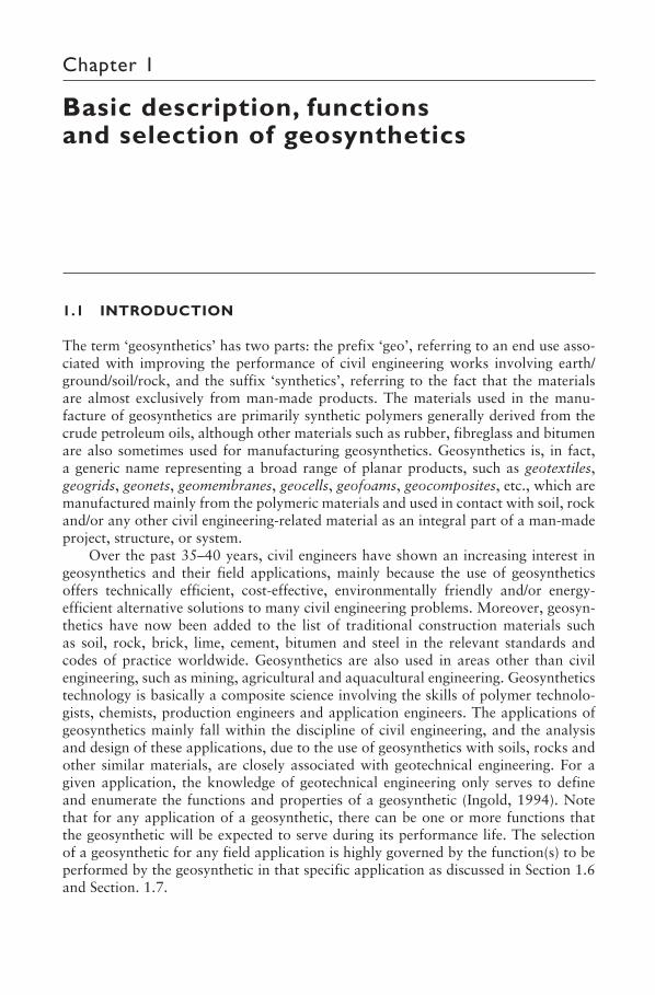
Geotextile: It is a planar, permeable, polymeric textile product in the form of a flexible sheet (Fig. 1.1). Currently available geotextiles are classified into the follow-ing categories based on the manufacturing process:
• Woven geotextile: A geotextile produced by interlacing, usually at right angles, two or more sets of yarns (made of one or several fibres) or other elements using a conventional weaving process with a weaving loom (Fig. 1.1(a)).
• Nonwoven geotextile: A geotextile produced from directionally or randomly ori-ented fibres into a loose web by bonding with partial melting, needle-punching, or chemical binding agents (glue, rubber, latex, cellulose derivative, etc.) (Fig. 1.1(b)).
• Knitted geotextile: A geotextile produced by interlooping one or more yarns (or other elements) together with a knitting machine, instead of a weaving loom (Fig. 1.1(c)).
• Stitched geotextile: A geotextile in which fibres or yarns or both are interlocked/bonded by stitching or sewing (Fig. 1.1(d)).
SHUKLA_Book.indb 2SHUKLA_Book.indb 2 4/6/2016 4:30:32 PM4/6/2016 4:30:32 PM
Basic description, functions and selection of geosynthetics 3
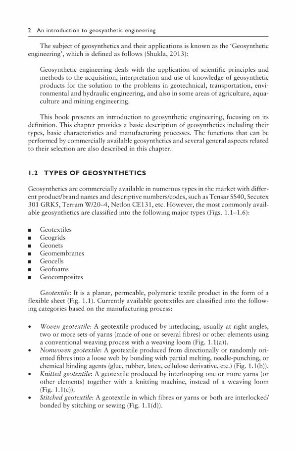
Geogrid: This is a planar, polymeric product consisting of a mesh or net-like regular open network of intersecting tensile-resistant elements, called the ribs, inte-grally connected at the junctions (Fig. 1.2). The ribs can be linked by extrusion, bond-ing or interlacing; the resulting geogrids are called extruded geogrid, bonded geogrid and woven geogrid, respectively. The extruded geogrids are classified into the fol-lowing three categories, principally based on the direction of stretching during their manufacture:
(a)
(b)
(c)
(d)
Figure 1.1 Typical geotextiles: (a) woven geotextile; (b) nonwoven geotextile; (c) knitted geotextile; (d) stitched geotextile.
SHUKLA_Book.indb 3SHUKLA_Book.indb 3 4/6/2016 4:30:32 PM4/6/2016 4:30:32 PM
4 An introduction to geosynthetic engineering
(a)-(i) (a)-(ii)
(a)-(iii)
(c)
(b)
Figure 1.2 Typical geogrids: (a) extruded geogrids – (i) uniaxial, (ii) biaxial, (iii) triaxial; (b) bonded geogrids; (c) woven geogrids.
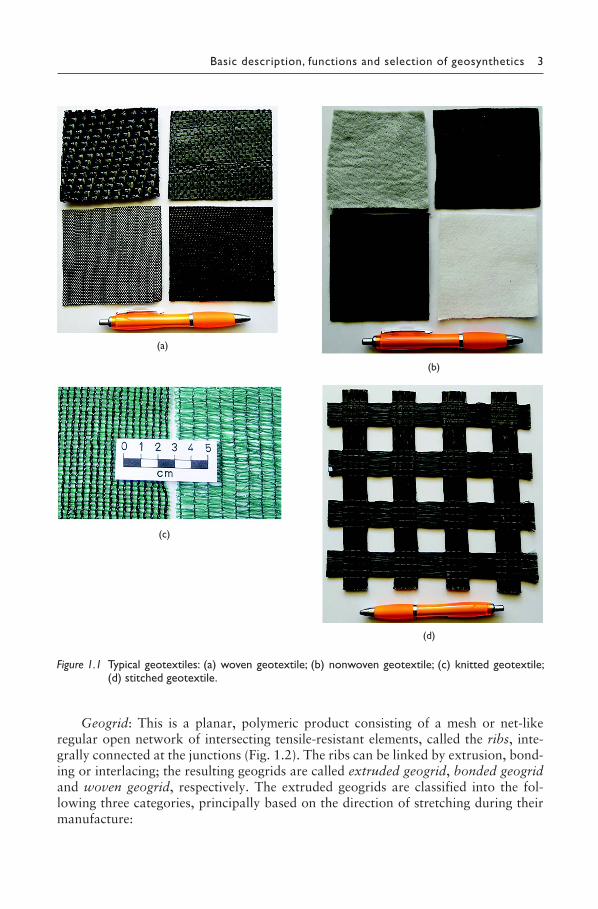
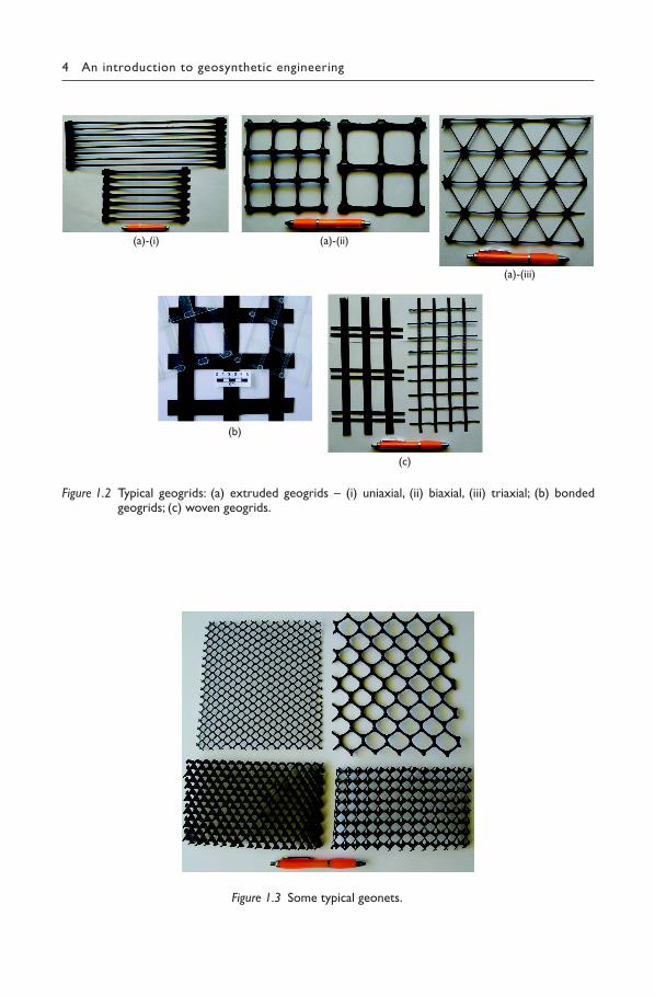
Figure 1.3 Some typical geonets.
SHUKLA_Book.indb 4SHUKLA_Book.indb 4 4/6/2016 4:30:36 PM4/6/2016 4:30:36 PM
Basic description, functions and selection of geosynthetics 5
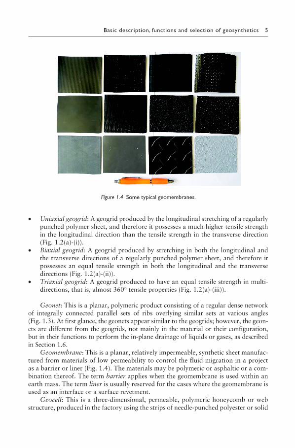
Figure 1.4 Some typical geomembranes.
• Uniaxial geogrid: A geogrid produced by the longitudinal stretching of a regularly punched polymer sheet, and therefore it possesses a much higher tensile strength in the longitudinal direction than the tensile strength in the transverse direction (Fig. 1.2(a)-(i)).
• Biaxial geogrid: A geogrid produced by stretching in both the longitudinal and the transverse directions of a regularly punched polymer sheet, and therefore it possesses an equal tensile strength in both the longitudinal and the transverse directions (Fig. 1.2(a)-(ii)).
• Triaxial geogrid: A geogrid produced to have an equal tensile strength in multi-directions, that is, almost 360° tensile properties (Fig. 1.2(a)-(iii)).
Geonet: This is a planar, polymeric product consisting of a regular dense network of integrally connected parallel sets of ribs overlying similar sets at various angles (Fig. 1.3). At first glance, the geonets appear similar to the geogrids; however, the geon-ets are different from the geogrids, not mainly in the material or their configuration, but in their functions to perform the in-plane drainage of liquids or gases, as described in Section 1.6.
Geomembrane: This is a planar, relatively impermeable, synthetic sheet manufac-tured from materials of low permeability to control the fluid migration in a project as a barrier or liner (Fig. 1.4). The materials may be polymeric or asphaltic or a com-bination thereof. The term barrier applies when the geomembrane is used within an earth mass. The term liner is usually reserved for the cases where the geomembrane is used as an interface or a surface revetment.
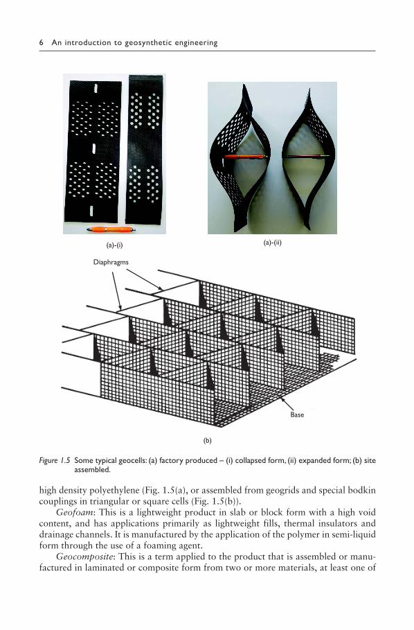
Geocell: This is a three-dimensional, permeable, polymeric honeycomb or web structure, produced in the factory using the strips of needle-punched polyester or solid
SHUKLA_Book.indb 5SHUKLA_Book.indb 5 4/6/2016 4:30:39 PM4/6/2016 4:30:39 PM
6 An introduction to geosynthetic engineering
Diaphragms
(a)-(i)
(b)
Base
(a)-(ii)
Figure 1.5 Some typical geocells: (a) factory produced – (i) collapsed form, (ii) expanded form; (b) site assembled.
high density polyethylene (Fig. 1.5(a), or assembled from geogrids and special bodkin couplings in triangular or square cells (Fig. 1.5(b)).
Geofoam: This is a lightweight product in slab or block form with a high void content, and has applications primarily as lightweight fills, thermal insulators and drainage channels. It is manufactured by the application of the polymer in semi-liquid form through the use of a foaming agent.
Geocomposite: This is a term applied to the product that is assembled or manu-factured in laminated or composite form from two or more materials, at least one of
SHUKLA_Book.indb 6SHUKLA_Book.indb 6 4/6/2016 4:30:41 PM4/6/2016 4:30:41 PM
Basic description, functions and selection of geosynthetics 7
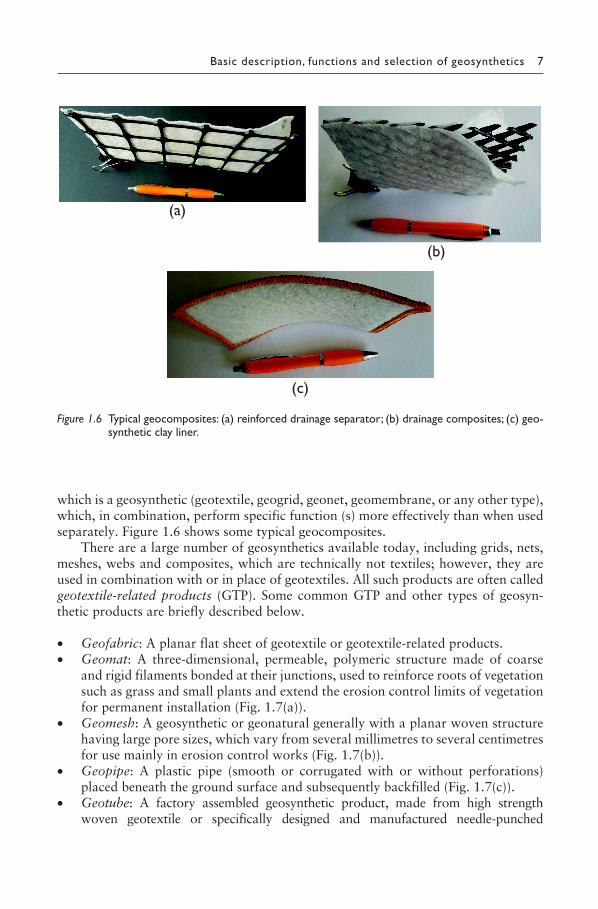
which is a geosynthetic (geotextile, geogrid, geonet, geomembrane, or any other type), which, in combination, perform specific function (s) more effectively than when used separately. Figure 1.6 shows some typical geocomposites.
There are a large number of geosynthetics available today, including grids, nets, meshes, webs and composites, which are technically not textiles; however, they are used in combination with or in place of geotextiles. All such products are often called geotextile-related products (GTP). Some common GTP and other types of geosyn-thetic products are briefly described below.
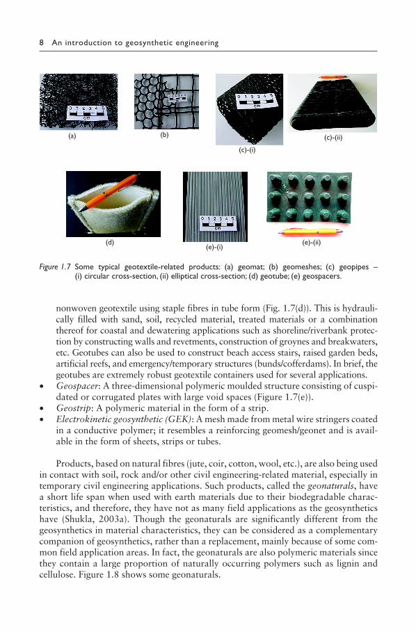
• Geofabric: A planar flat sheet of geotextile or geotextile-related products.• Geomat: A three-dimensional, permeable, polymeric structure made of coarse
and rigid filaments bonded at their junctions, used to reinforce roots of vegetation such as grass and small plants and extend the erosion control limits of vegetation for permanent installation (Fig. 1.7(a)).
• Geomesh: A geosynthetic or geonatural generally with a planar woven structure having large pore sizes, which vary from several millimetres to several centimetres for use mainly in erosion control works (Fig. 1.7(b)).
• Geopipe: A plastic pipe (smooth or corrugated with or without perforations) placed beneath the ground surface and subsequently backfilled (Fig. 1.7(c)).
• Geotube: A factory assembled geosynthetic product, made from high strength woven geotextile or specifically designed and manufactured needle-punched
(a)
(b)
(c)
Figure 1.6 Typical geocomposites: (a) reinforced drainage separator; (b) drainage composites; (c) geo-synthetic clay liner.
SHUKLA_Book.indb 7SHUKLA_Book.indb 7 4/6/2016 4:30:43 PM4/6/2016 4:30:43 PM
8 An introduction to geosynthetic engineering
nonwoven geotextile using staple fibres in tube form (Fig. 1.7(d)). This is hydrauli-cally filled with sand, soil, recycled material, treated materials or a combination thereof for coastal and dewatering applications such as shoreline/riverbank protec-tion by constructing walls and revetments, construction of groynes and breakwaters, etc. Geotubes can also be used to construct beach access stairs, raised garden beds, artificial reefs, and emergency/temporary structures (bunds/cofferdams). In brief, the geotubes are extremely robust geotextile containers used for several applications.
• Geospacer: A three-dimensional polymeric moulded structure consisting of cuspi-dated or corrugated plates with large void spaces (Figure 1.7(e)).
• Geostrip: A polymeric material in the form of a strip.• Electrokinetic geosynthetic (GEK): A mesh made from metal wire stringers coated
in a conductive polymer; it resembles a reinforcing geomesh/geonet and is avail-able in the form of sheets, strips or tubes.
Products, based on natural fibres (jute, coir, cotton, wool, etc.), are also being used in contact with soil, rock and/or other civil engineering-related material, especially in temporary civil engineering applications. Such products, called the geonaturals, have a short life span when used with earth materials due to their biodegradable charac-teristics, and therefore, they have not as many field applications as the geosynthetics have (Shukla, 2003a). Though the geonaturals are significantly different from the geosynthetics in material characteristics, they can be considered as a complementary companion of geosynthetics, rather than a replacement, mainly because of some com-mon field application areas. In fact, the geonaturals are also polymeric materials since they contain a large proportion of naturally occurring polymers such as lignin and cellulose. Figure 1.8 shows some geonaturals.
(a) (b)
(c)-(i)
(c)-(ii)
(d)(e)-(i)
(e)-(ii)
Figure 1.7 Some typical geotextile-related products: (a) geomat; (b) geomeshes; (c) geopipes – (i) circular cross-section, (ii) elliptical cross-section; (d) geotube; (e) geospacers.
SHUKLA_Book.indb 8SHUKLA_Book.indb 8 4/6/2016 4:30:45 PM4/6/2016 4:30:45 PM
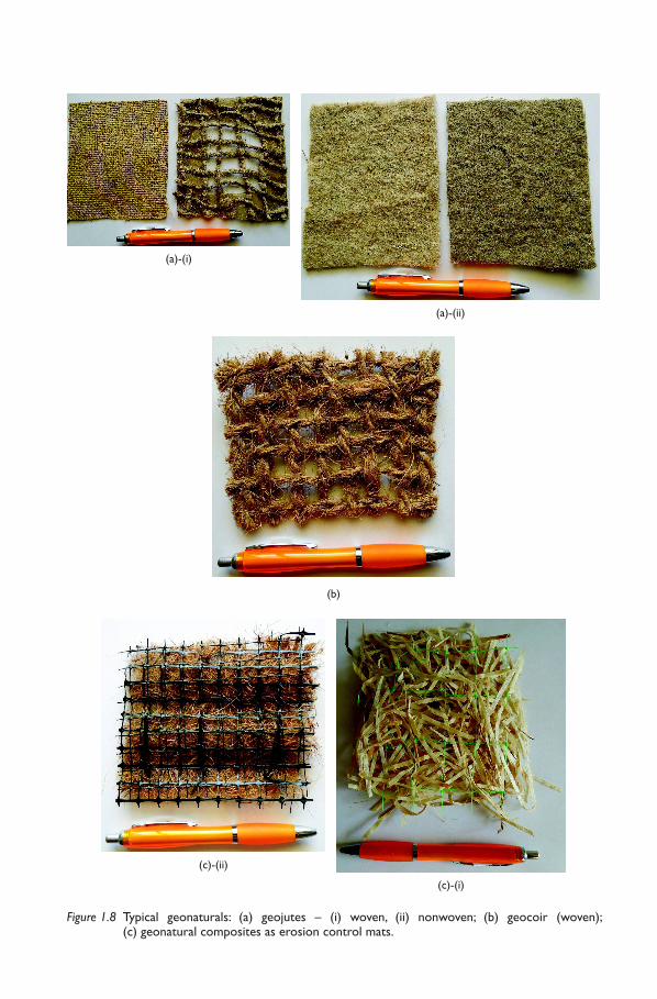
Figure 1.8 Typical geonaturals: (a) geojutes – (i) woven, (ii) nonwoven; (b) geocoir (woven); (c) geonatural composites as erosion control mats.
(c)-(ii)
(c)-(i)
(b)
(a)-(i)
(a)-(ii)
CH01.indd 9CH01.indd 9 4/15/2016 3:19:39 PM4/15/2016 3:19:39 PM
10 An introduction to geosynthetic engineering
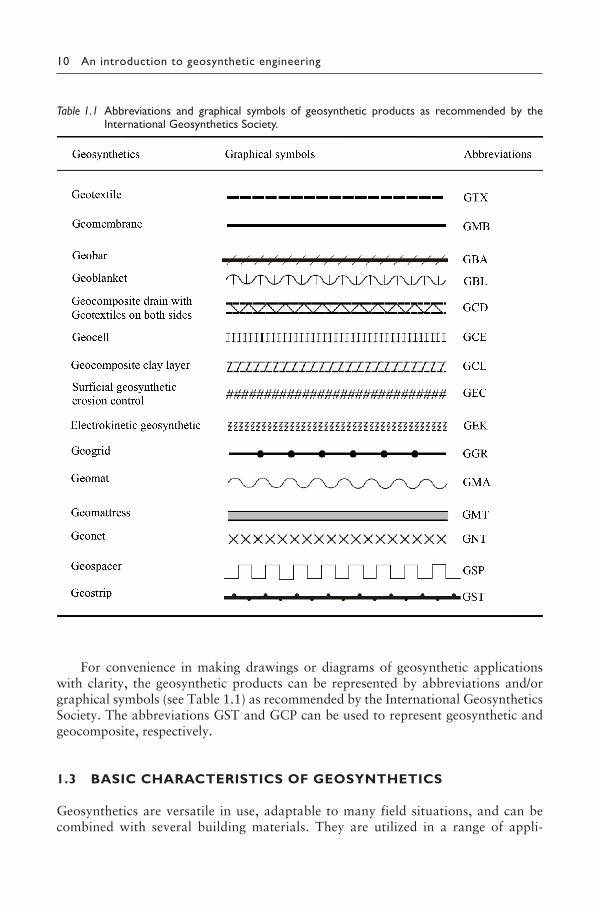
For convenience in making drawings or diagrams of geosynthetic applications with clarity, the geosynthetic products can be represented by abbreviations and/or graphical symbols (see Table 1.1) as recommended by the International Geosynthetics Society. The abbreviations GST and GCP can be used to represent geosynthetic and geocomposite, respectively.
1.3 BASIC CHARACTERISTICS OF GEOSYNTHETICS
Geosynthetics are versatile in use, adaptable to many field situations, and can be combined with several building materials. They are utilized in a range of appli-
Table 1.1 Abbreviations and graphical symbols of geosynthetic products as recommended by the International Geosynthetics Society.
SHUKLA_Book.indb 10SHUKLA_Book.indb 10 4/6/2016 4:30:57 PM4/6/2016 4:30:57 PM
Basic description, functions and selection of geosynthetics 11
cations in many areas of civil engineering, especially geotechnical, transportation, water resources, environmental, coastal, sediment and erosion control engineering, mining engineering, and agricultural and aquacultural engineering for achieving technical and/or economic benefits. The rapid growth in the past few decades all over the world is due mainly to the following favourable basic characteristics of geosynthetics:
• non-corrosiveness• highly resistant to biological and chemical degradation• long-term durability under soil cover up to 120 years• high flexibility• minimum volume• lightness• ease of storing and transportation• simplicity of installation• speeding the construction process• making economical and environment-friendly solutions• providing a good aesthetic look to structures.
The importance of geosynthetics can also be observed in their ability to partially or completely replace natural resources such as gravel, sand, clay, etc. In fact, the geosynthetics can be used for achieving better durability, aesthetics and environment of the civil engineering projects, and also of some projects in mining, agricultural and aquacultural engineering.
1.4 RAW MATERIALS FOR GEOSYNTHETICS
Almost exclusively, the raw materials from which the geosynthetics are produced are polymeric. Polymers are materials of very high molecular weight and are found to have multifarious applications in modern society. The polymers used to manufacture the geosynthetics are generally thermoplastics, which may be amorphous or semi-crystalline. Such materials melt on heating and solidify on cooling. The heating and cooling cycles can be applied several times without affecting the properties.
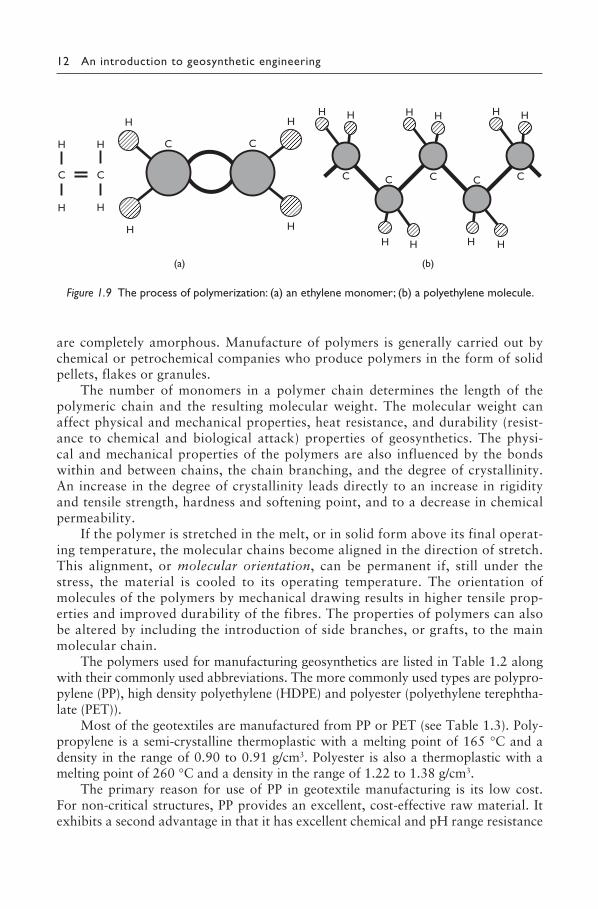
Any polymer, whether amorphous or semi-crystalline, consists of long chain molecules containing many identical chemical units bound together by covalent bonds. Each unit may be composed of one or more small molecular compounds called the monomers, which are most commonly hydrocarbon molecules. The pro-cess of joining monomers, end to end, to form long polymer chains is called the polymerization. In Figure 1.9, it is observed that that during the polymerization, the double carbon bond of the ethylene monomer forms a covalent bond with the carbon atoms of neighbouring monomers. The end result is a long polyethylene (PE) chain molecule in which one carbon atom is bonded to the next. If the chains are packed in a regular form and are highly ordered, the resulting configuration will have a crystalline structure, otherwise an amorphous structure. No polymers used for manufacturing the geosynthetics are completely crystalline, although the high density polyethylene (HDPE) can attain 90% or so crystallinity, but some
SHUKLA_Book.indb 11SHUKLA_Book.indb 11 4/6/2016 4:30:58 PM4/6/2016 4:30:58 PM
12 An introduction to geosynthetic engineering
are completely amorphous. Manufacture of polymers is generally carried out by chemical or petrochemical companies who produce polymers in the form of solid pellets, flakes or granules.
The number of monomers in a polymer chain determines the length of the polymeric chain and the resulting molecular weight. The molecular weight can affect physical and mechanical properties, heat resistance, and durability (resist-ance to chemical and biological attack) properties of geosynthetics. The physi-cal and mechanical properties of the polymers are also influenced by the bonds within and between chains, the chain branching, and the degree of crystallinity. An increase in the degree of crystallinity leads directly to an increase in rigidity and tensile strength, hardness and softening point, and to a decrease in chemical permeability.
If the polymer is stretched in the melt, or in solid form above its final operat-ing temperature, the molecular chains become aligned in the direction of stretch. This alignment, or molecular orientation, can be permanent if, still under the stress, the material is cooled to its operating temperature. The orientation of molecules of the polymers by mechanical drawing results in higher tensile prop-erties and improved durability of the fibres. The properties of polymers can also be altered by including the introduction of side branches, or grafts, to the main molecular chain.
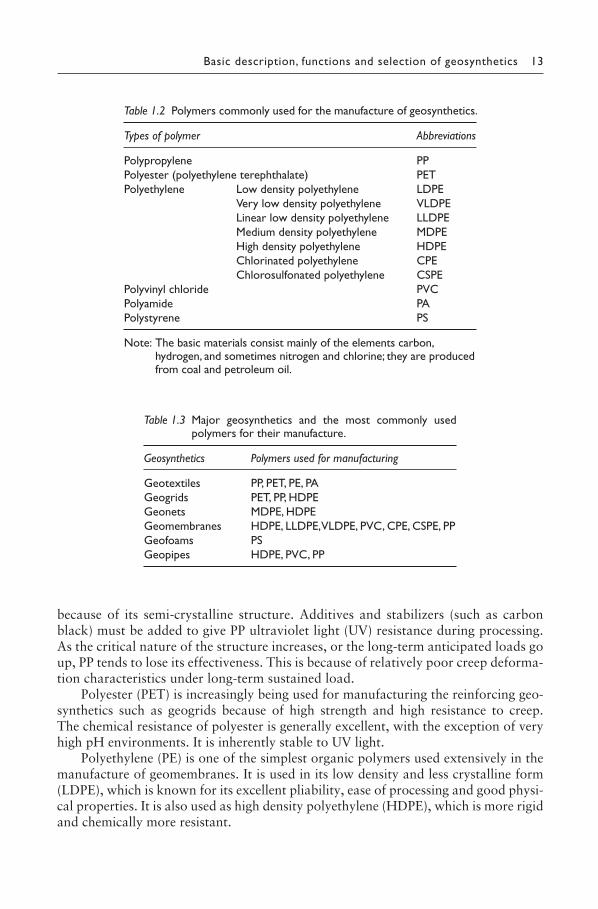
The polymers used for manufacturing geosynthetics are listed in Table 1.2 along with their commonly used abbreviations. The more commonly used types are polypro-pylene (PP), high density polyethylene (HDPE) and polyester (polyethylene terephtha-late (PET)).
Most of the geotextiles are manufactured from PP or PET (see Table 1.3). Poly-propylene is a semi-crystalline thermoplastic with a melting point of 165 °C and a density in the range of 0.90 to 0.91 g/cm3. Polyester is also a thermoplastic with a melting point of 260 °C and a density in the range of 1.22 to 1.38 g/cm3.
The primary reason for use of PP in geotextile manufacturing is its low cost. For non-critical structures, PP provides an excellent, cost-effective raw material. It exhibits a second advantage in that it has excellent chemical and pH range resistance
Figure 1.9 The process of polymerization: (a) an ethylene monomer; (b) a polyethylene molecule.
CC
H
H H
H C C
H H
H H
(a) (b)
C C
H H HH
C CC
H H
H H H H
SHUKLA_Book.indb 12SHUKLA_Book.indb 12 4/6/2016 4:30:58 PM4/6/2016 4:30:58 PM
Basic description, functions and selection of geosynthetics 13
because of its semi-crystalline structure. Additives and stabilizers (such as carbon black) must be added to give PP ultraviolet light (UV) resistance during processing. As the critical nature of the structure increases, or the long-term anticipated loads go up, PP tends to lose its effectiveness. This is because of relatively poor creep deforma-tion characteristics under long-term sustained load.
Polyester (PET) is increasingly being used for manufacturing the reinforcing geo-synthetics such as geogrids because of high strength and high resistance to creep. The chemical resistance of polyester is generally excellent, with the exception of very high pH environments. It is inherently stable to UV light.
Polyethylene (PE) is one of the simplest organic polymers used extensively in the manufacture of geomembranes. It is used in its low density and less crystalline form (LDPE), which is known for its excellent pliability, ease of processing and good physi-cal properties. It is also used as high density polyethylene (HDPE), which is more rigid and chemically more resistant.
Table 1.2 Polymers commonly used for the manufacture of geosynthetics.
Types of polymer Abbreviations
Polypropylene PPPolyester (polyethylene terephthalate) PETPolyethylene Low density polyethylene LDPE
Very low density polyethylene VLDPELinear low density polyethylene LLDPEMedium density polyethylene MDPEHigh density polyethylene HDPEChlorinated polyethylene CPEChlorosulfonated polyethylene CSPE
Polyvinyl chloride PVCPolyamide PAPolystyrene PS
Note: The basic materials consist mainly of the elements carbon, hydrogen, and sometimes nitrogen and chlorine; they are produced from coal and petroleum oil.
Table 1.3 Major geosynthetics and the most commonly used polymers for their manufacture.
Geosynthetics Polymers used for manufacturing
Geotextiles PP, PET, PE, PAGeogrids PET, PP, HDPEGeonets MDPE, HDPEGeomembranes HDPE, LLDPE, VLDPE, PVC, CPE, CSPE, PPGeofoams PSGeopipes HDPE, PVC, PP
SHUKLA_Book.indb 13SHUKLA_Book.indb 13 4/6/2016 4:30:58 PM4/6/2016 4:30:58 PM
14 An introduction to geosynthetic engineering
Polyvinyl chloride (PVC) is the most significant commercial member of the fam-ily of vinyl-based resins. With plasticizers and other additives, it takes up a great variety of forms. Unless PVC has suitable stabilizers, it tends to become brittle and darken when exposed to UV light over time, and can undergo heat-induced degradation.
Polyamides (PA), better known as nylons, are melt processable thermoplastics that contain an amide group as a recurring part of the chain. Polyamide offers a combination of properties including high strength at elevated temperatures, ductility, wear and abrasion resistance, low frictional properties, low permeability for gases and hydrocarbons, and good chemical resistance. Its limitations include a tendency to absorb moisture, with resulting changes in physical and mechanical properties, and limited resistance to acids and weathering.
The raw material for the manufacture of geofoams is polystyrene (PS), which is known as a packaging material and insulating material in everyday life. Its gen-esis is from ethylene and is available in two forms: expanded polystyrene (EPS), and extruded polystyrene (XPS).
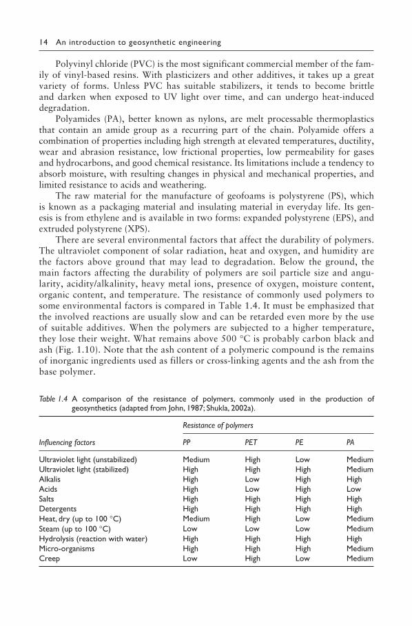
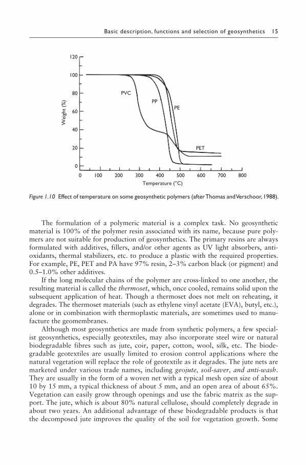
There are several environmental factors that affect the durability of polymers. The ultraviolet component of solar radiation, heat and oxygen, and humidity are the factors above ground that may lead to degradation. Below the ground, the main factors affecting the durability of polymers are soil particle size and angu-larity, acidity/alkalinity, heavy metal ions, presence of oxygen, moisture content, organic content, and temperature. The resistance of commonly used polymers to some environmental factors is compared in Table 1.4. It must be emphasized that the involved reactions are usually slow and can be retarded even more by the use of suitable additives. When the polymers are subjected to a higher temperature, they lose their weight. What remains above 500 °C is probably carbon black and ash (Fig. 1.10). Note that the ash content of a polymeric compound is the remains of inorganic ingredients used as fillers or cross-linking agents and the ash from the base polymer.
Table 1.4 A comparison of the resistance of polymers, commonly used in the production of geosynthetics (adapted from John, 1987; Shukla, 2002a).
Influencing factors
Resistance of polymers
PP PET PE PA
Ultraviolet light (unstabilized) Medium High Low MediumUltraviolet light (stabilized) High High High MediumAlkalis High Low High HighAcids High Low High LowSalts High High High HighDetergents High High High HighHeat, dry (up to 100 °C) Medium High Low MediumSteam (up to 100 °C) Low Low Low MediumHydrolysis (reaction with water) High High High HighMicro-organisms High High High MediumCreep Low High Low Medium
SHUKLA_Book.indb 14SHUKLA_Book.indb 14 4/6/2016 4:30:58 PM4/6/2016 4:30:58 PM
Basic description, functions and selection of geosynthetics 15
The formulation of a polymeric material is a complex task. No geosynthetic material is 100% of the polymer resin associated with its name, because pure poly-mers are not suitable for production of geosynthetics. The primary resins are always formulated with additives, fillers, and/or other agents as UV light absorbers, anti-oxidants, thermal stabilizers, etc. to produce a plastic with the required properties. For example, PE, PET and PA have 97% resin, 2–3% carbon black (or pigment) and 0.5–1.0% other additives.
If the long molecular chains of the polymer are cross-linked to one another, the resulting material is called the thermoset, which, once cooled, remains solid upon the subsequent application of heat. Though a thermoset does not melt on reheating, it degrades. The thermoset materials (such as ethylene vinyl acetate (EVA), butyl, etc.), alone or in combination with thermoplastic materials, are sometimes used to manu-facture the geomembranes.
Although most geosynthetics are made from synthetic polymers, a few special-ist geosynthetics, especially geotextiles, may also incorporate steel wire or natural biodegradable fibres such as jute, coir, paper, cotton, wool, silk, etc. The biode-gradable geotextiles are usually limited to erosion control applications where the natural vegetation will replace the role of geotextile as it degrades. The jute nets are marketed under various trade names, including geojute, soil-saver, and anti-wash. They are usually in the form of a woven net with a typical mesh open size of about 10 by 15 mm, a typical thickness of about 5 mm, and an open area of about 65%. Vegetation can easily grow through openings and use the fabric matrix as the sup-port. The jute, which is about 80% natural cellulose, should completely degrade in about two years. An additional advantage of these biodegradable products is that the decomposed jute improves the quality of the soil for vegetation growth. Some
Figure 1.10 Effect of temperature on some geosynthetic polymers (after Thomas and Verschoor, 1988).
Temperature (°C)
120
100
80
60
40
20
0
0 100 200 300 400 500 600 700 800
Wei
ght
(%)
PVC
PP PE
PET
SHUKLA_Book.indb 15SHUKLA_Book.indb 15 4/6/2016 4:30:58 PM4/6/2016 4:30:58 PM
16 An introduction to geosynthetic engineering
non-polymeric materials like sodium or calcium bentonite are also used to make a few geosynthetic products.
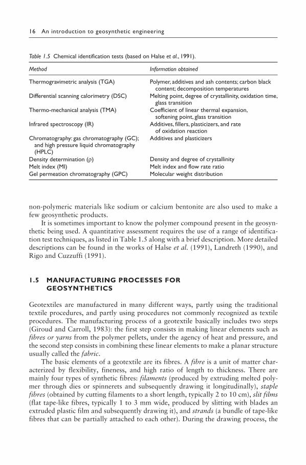
It is sometimes important to know the polymer compound present in the geosyn-thetic being used. A quantitative assessment requires the use of a range of identifica-tion test techniques, as listed in Table 1.5 along with a brief description. More detailed descriptions can be found in the works of Halse et al. (1991), Landreth (1990), and Rigo and Cuzzuffi (1991).
1.5 MANUFACTURING PROCESSES FOR GEOSYNTHETICS
Geotextiles are manufactured in many different ways, partly using the traditional textile procedures, and partly using procedures not commonly recognized as textile procedures. The manufacturing process of a geotextile basically includes two steps (Giroud and Carroll, 1983): the first step consists in making linear elements such as fibres or yarns from the polymer pellets, under the agency of heat and pressure, and the second step consists in combining these linear elements to make a planar structure usually called the fabric.
The basic elements of a geotextile are its fibres. A fibre is a unit of matter char-acterized by flexibility, fineness, and high ratio of length to thickness. There are mainly four types of synthetic fibres: filaments (produced by extruding melted poly-mer through dies or spinnerets and subsequently drawing it longitudinally), staple fibres (obtained by cutting filaments to a short length, typically 2 to 10 cm), slit films (flat tape-like fibres, typically 1 to 3 mm wide, produced by slitting with blades an extruded plastic film and subsequently drawing it), and strands (a bundle of tape-like fibres that can be partially attached to each other). During the drawing process, the
Table 1.5 Chemical identification tests (based on Halse et al., 1991).
Method Information obtained
Thermogravimetric analysis (TGA) Polymer, additives and ash contents; carbon black content; decomposition temperatures
Differential scanning calorimetry (DSC) Melting point, degree of crystallinity, oxidation time, glass transition
Thermo-mechanical analysis (TMA) Coefficient of linear thermal expansion, softening point, glass transition
Infrared spectroscopy (IR) Additives, fillers, plasticizers, and rate of oxidation reaction
Chromatography: gas chromatography (GC); and high pressure liquid chromatography (HPLC)
Additives and plasticizers
Density determination (ρ) Density and degree of crystallinityMelt index (MI) Melt index and flow rate ratioGel permeation chromatography (GPC) Molecular weight distribution
SHUKLA_Book.indb 16SHUKLA_Book.indb 16 4/6/2016 4:30:59 PM4/6/2016 4:30:59 PM
Basic description, functions and selection of geosynthetics 17
molecules become oriented in the same direction resulting in an increase of modulus of the fibres. A yarn consists of a number of fibres from the particular polymeric compound selected. Several types of yarn are used to construct woven geotextiles: monofilament yarn (made from a single filament), multifilament yarn (made from fine filaments aligned together), spun yarn (made from staple fibres interlaced or twisted together), slit film yarn (made from a single slit film fibre), and fibrillated yarn (made from strands). Note that the synthetic fibres are very efficient load-carrying elements, with tensile strengths equivalent to prestressing steel in some cases (e.g. in case of polyaramid fibres). Fibre technology in itself is a well-advanced science with an enor-mous database. It is in the fibre where control over physical and mechanical proper-ties first takes place in a well-prescribed and fully automated manner.
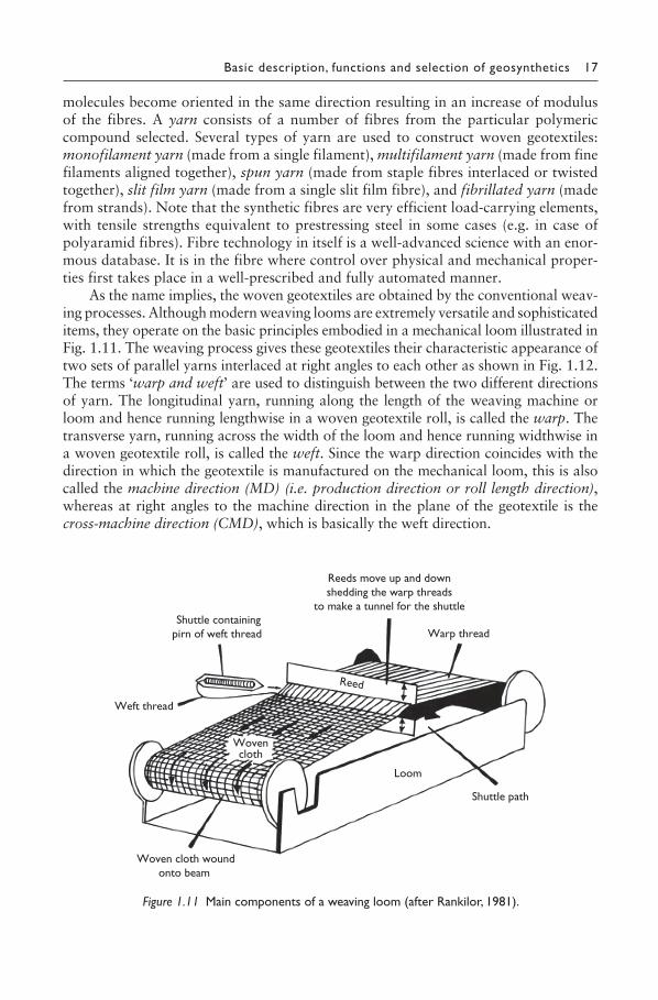
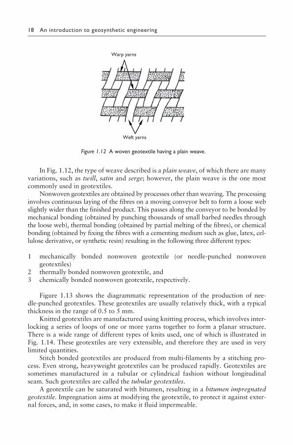
As the name implies, the woven geotextiles are obtained by the conventional weav-ing processes. Although modern weaving looms are extremely versatile and sophisticated items, they operate on the basic principles embodied in a mechanical loom illustrated in Fig. 1.11. The weaving process gives these geotextiles their characteristic appearance of two sets of parallel yarns interlaced at right angles to each other as shown in Fig. 1.12. The terms ‘warp and weft’ are used to distinguish between the two different directions of yarn. The longitudinal yarn, running along the length of the weaving machine or loom and hence running lengthwise in a woven geotextile roll, is called the warp. The transverse yarn, running across the width of the loom and hence running widthwise in a woven geotextile roll, is called the weft. Since the warp direction coincides with the direction in which the geotextile is manufactured on the mechanical loom, this is also called the machine direction (MD) (i.e. production direction or roll length direction), whereas at right angles to the machine direction in the plane of the geotextile is the cross-machine direction (CMD), which is basically the weft direction.
Figure 1.11 Main components of a weaving loom (after Rankilor, 1981).
Warp thread
Woven cloth woundonto beam
Weft thread
Reed
Loom
Shuttle containingpirn of weft thread
Reeds move up and downshedding the warp threads
to make a tunnel for the shuttle
Wovencloth
Shuttle path
SHUKLA_Book.indb 17SHUKLA_Book.indb 17 4/6/2016 4:30:59 PM4/6/2016 4:30:59 PM
18 An introduction to geosynthetic engineering
In Fig. 1.12, the type of weave described is a plain weave, of which there are many variations, such as twill, satin and serge; however, the plain weave is the one most commonly used in geotextiles.
Nonwoven geotextiles are obtained by processes other than weaving. The processing involves continuous laying of the fibres on a moving conveyor belt to form a loose web slightly wider than the finished product. This passes along the conveyor to be bonded by mechanical bonding (obtained by punching thousands of small barbed needles through the loose web), thermal bonding (obtained by partial melting of the fibres), or chemical bonding (obtained by fixing the fibres with a cementing medium such as glue, latex, cel-lulose derivative, or synthetic resin) resulting in the following three different types:
1 mechanically bonded nonwoven geotextile (or needle-punched nonwoven geotextiles)
2 thermally bonded nonwoven geotextile, and3 chemically bonded nonwoven geotextile, respectively.
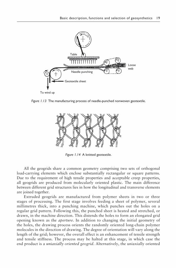
Figure 1.13 shows the diagrammatic representation of the production of nee-dle-punched geotextiles. These geotextiles are usually relatively thick, with a typical thickness in the range of 0.5 to 5 mm.
Knitted geotextiles are manufactured using knitting process, which involves inter-locking a series of loops of one or more yarns together to form a planar structure. There is a wide range of different types of knits used, one of which is illustrated in Fig. 1.14. These geotextiles are very extensible, and therefore they are used in very limited quantities.
Stitch bonded geotextiles are produced from multi-filaments by a stitching pro-cess. Even strong, heavyweight geotextiles can be produced rapidly. Geotextiles are sometimes manufactured in a tubular or cylindrical fashion without longitudinal seam. Such geotextiles are called the tubular geotextiles.
A geotextile can be saturated with bitumen, resulting in a bitumen impregnated geotextile. Impregnation aims at modifying the geotextile, to protect it against exter-nal forces, and, in some cases, to make it fluid impermeable.
Figure 1.12 A woven geotextile having a plain weave.
Warp yarns
Weft yarns
SHUKLA_Book.indb 18SHUKLA_Book.indb 18 4/6/2016 4:30:59 PM4/6/2016 4:30:59 PM
Basic description, functions and selection of geosynthetics 19
All the geogrids share a common geometry comprising two sets of orthogonal load-carrying elements which enclose substantially rectangular or square patterns. Due to the requirement of high tensile properties and acceptable creep properties, all geogrids are produced from molecularly oriented plastic. The main difference between different grid structures lies in how the longitudinal and transverse elements are joined together.
Extruded geogrids are manufactured from polymer sheets in two or three stages of processing. The first stage involves feeding a sheet of polymer, several millimetres thick, into a punching machine, which punches out the holes on a regular grid pattern. Following this, the punched sheet is heated and stretched, or drawn, in the machine direction. This distends the holes to form an elongated grid opening known as the aperture. In addition to changing the initial geometry of the holes, the drawing process orients the randomly oriented long-chain polymer molecules in the direction of drawing. The degree of orientation will vary along the length of the grid; however, the overall effect is an enhancement of tensile strength and tensile stiffness. The process may be halted at this stage, in which case the end product is a uniaxially oriented geogrid. Alternatively, the uniaxially oriented
Figure 1.13 The manufacturing process of needle-punched nonwoven geotextile.
To wind up
Geotextile sheet
Needle punching
Table
Loose web
Figure 1.14 A knitted geotextile.
SHUKLA_Book.indb 19SHUKLA_Book.indb 19 4/6/2016 4:31:00 PM4/6/2016 4:31:00 PM
20 An introduction to geosynthetic engineering
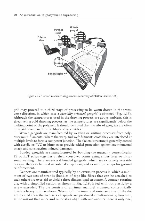
grid may proceed to a third stage of processing to be warm drawn in the trans-verse direction, in which case a biaxially oriented geogrid is obtained (Fig. 1.15). Although the temperatures used in the drawing process are above ambient, this is effectively a cold drawing process, as the temperatures are significantly below the melting point of the polymer. It should be noted that the ribs of geogrids are often quite stiff compared to the fibres of geotextiles.
Woven geogrids are manufactured by weaving or knitting processes from poly-ester multi-filaments. Where the warp and weft filaments cross they are interlaced at multiple levels to form a competent junction. The skeletal structure is generally coated with acrylic or PVC or bitumen to provide added protection against environmental attack and construction induced-damages.
Bonded geogrids are manufactured by bonding the mutually perpendicular PP or PET strips together at their crossover points using either laser or ultra-sonic welding. There are several bonded geogrids, which are extremely versatile because they can be used in isolated strip form, and as multiple strips for ground reinforcement.
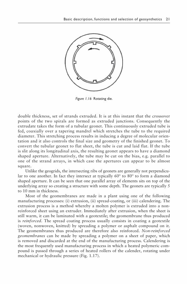
Geonets are manufactured typically by an extrusion process in which a mini-mum of two sets of strands (bundles of tape-like fibres that can be attached to each other) are overlaid to yield a three dimensional structure. A counter-rotating die, with a simplified section as shown in Fig. 1.16, is fed with hot plastic by a screw extruder. The die consists of an inner mandrel mounted concentrically inside a heavy tubular sleeve. When both the inner and outer sections of the die are rotated then the two sets of spirals are produced simultaneously; however, at the instant that inner and outer slots align with one another there is only one,
Figure 1.15 ‘Tensar’ manufacturing process (courtesy of Netlon Limited, UK).
Polymersheet
Punchedsheet
Uniaxialgeogrid
Biaxial geogrid
SHUKLA_Book.indb 20SHUKLA_Book.indb 20 4/6/2016 4:31:00 PM4/6/2016 4:31:00 PM
Basic description, functions and selection of geosynthetics 21
double thickness, set of strands extruded. It is at this instant that the crossover points of the two spirals are formed as extruded junctions. Consequently the extrudate takes the form of a tubular geonet. This continuously extruded tube is fed, coaxially over a tapering mandrel which stretches the tube to the required diameter. This stretching process results in inducing a degree of molecular orien-tation and it also controls the final size and geometry of the finished geonet. To convert the tubular geonet to flat sheet, the tube is cut and laid flat. If the tube is slit along its longitudinal axis, the resulting geonet appears to have a diamond shaped aperture. Alternatively, the tube may be cut on the bias, e.g. parallel to one of the strand arrays, in which case the apertures can appear to be almost square.
Unlike the geogrids, the intersecting ribs of geonets are generally not perpendicu-lar to one another. In fact they intersect at typically 60° to 80° to form a diamond shaped aperture. It can be seen that one parallel array of elements sits on top of the underlying array so creating a structure with some depth. The geonets are typically 5 to 10 mm in thickness.
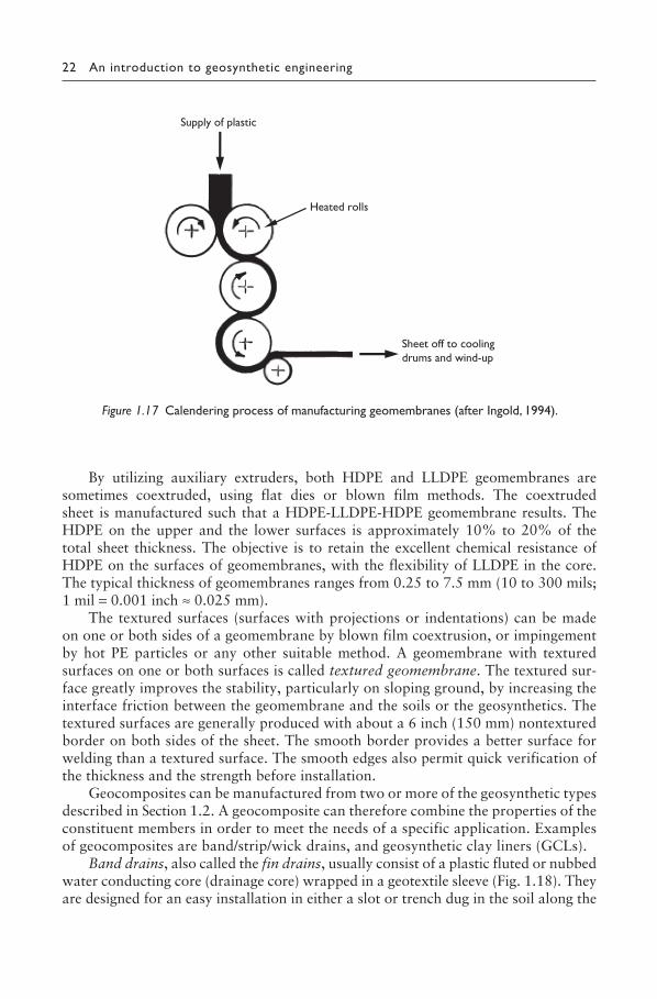
Most of the geomembranes are made in a plant using one of the following manufacturing processes: (i) extrusion, (ii) spread-coating, or (iii) calendering. The extrusion process is a method whereby a molten polymer is extruded into a non-reinforced sheet using an extruder. Immediately after extrusion, when the sheet is still warm, it can be laminated with a geotextile; the geomembrane thus produced is reinforced. The spread coating process usually consists in coating a geotextile (woven, nonwoven, knitted) by spreading a polymer or asphalt compound on it. The geomembranes thus produced are therefore also reinforced. Non-reinforced geomembranes can be made by spreading a polymer on a sheet of paper, which is removed and discarded at the end of the manufacturing process. Calendering is the most frequently used manufacturing process in which a heated polymeric com-pound is passed through a series of heated rollers of the calender, rotating under mechanical or hydraulic pressure (Fig. 1.17).
Figure 1.16 Rotating die.
SHUKLA_Book.indb 21SHUKLA_Book.indb 21 4/6/2016 4:31:01 PM4/6/2016 4:31:01 PM
22 An introduction to geosynthetic engineering
By utilizing auxiliary extruders, both HDPE and LLDPE geomembranes are sometimes coextruded, using flat dies or blown film methods. The coextruded sheet is manufactured such that a HDPE-LLDPE-HDPE geomembrane results. The HDPE on the upper and the lower surfaces is approximately 10% to 20% of the total sheet thickness. The objective is to retain the excellent chemical resistance of HDPE on the surfaces of geomembranes, with the flexibility of LLDPE in the core. The typical thickness of geomembranes ranges from 0.25 to 7.5 mm (10 to 300 mils; 1 mil = 0.001 inch ≈ 0.025 mm).
The textured surfaces (surfaces with projections or indentations) can be made on one or both sides of a geomembrane by blown film coextrusion, or impingement by hot PE particles or any other suitable method. A geomembrane with textured surfaces on one or both surfaces is called textured geomembrane. The textured sur-face greatly improves the stability, particularly on sloping ground, by increasing the interface friction between the geomembrane and the soils or the geosynthetics. The textured surfaces are generally produced with about a 6 inch (150 mm) nontextured border on both sides of the sheet. The smooth border provides a better surface for welding than a textured surface. The smooth edges also permit quick verification of the thickness and the strength before installation.
Geocomposites can be manufactured from two or more of the geosynthetic types described in Section 1.2. A geocomposite can therefore combine the properties of the constituent members in order to meet the needs of a specific application. Examples of geocomposites are band/strip/wick drains, and geosynthetic clay liners (GCLs).
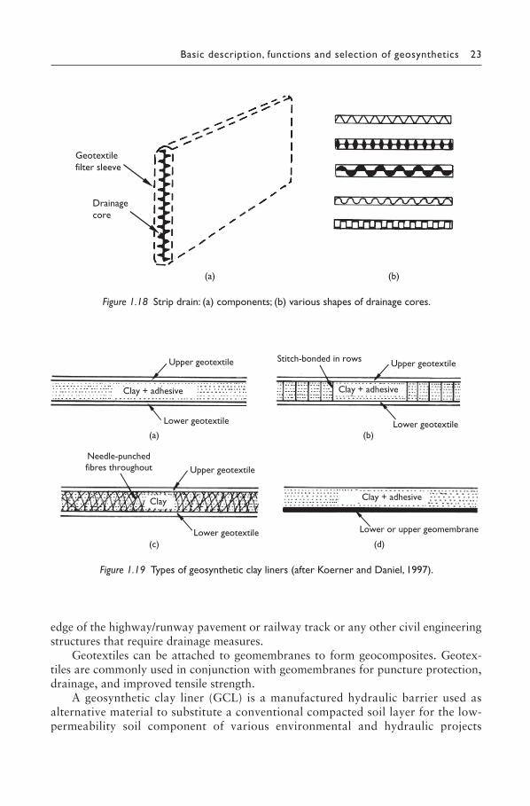
Band drains, also called the fin drains, usually consist of a plastic fluted or nubbed water conducting core (drainage core) wrapped in a geotextile sleeve (Fig. 1.18). They are designed for an easy installation in either a slot or trench dug in the soil along the
Figure 1.17 Calendering process of manufacturing geomembranes (after Ingold, 1994).
Supply of plastic
Heated rolls
Sheet off to coolingdrums and wind-up
SHUKLA_Book.indb 22SHUKLA_Book.indb 22 4/6/2016 4:31:01 PM4/6/2016 4:31:01 PM
Basic description, functions and selection of geosynthetics 23
edge of the highway/runway pavement or railway track or any other civil engineering structures that require drainage measures.
Geotextiles can be attached to geomembranes to form geocomposites. Geotex-tiles are commonly used in conjunction with geomembranes for puncture protection, drainage, and improved tensile strength.
A geosynthetic clay liner (GCL) is a manufactured hydraulic barrier used as alternative material to substitute a conventional compacted soil layer for the low-permeability soil component of various environmental and hydraulic projects
Figure 1.18 Strip drain: (a) components; (b) various shapes of drainage cores.
Geotextilefilter sleeve
Drainagecore
(b)(a)
Figure 1.19 Types of geosynthetic clay liners (after Koerner and Daniel, 1997).
Upper geotextile
Lower geotextile
Clay + adhesive
(a)
Stitch-bonded in rows Upper geotextile
Lower geotextile
Clay + adhesive
(b)
Lower or upper geomembrane
(d)
Clay + adhesive
Upper geotextile
Lower geotextile
Needle-punchedfibres throughout
Clay
(c)
SHUKLA_Book.indb 23SHUKLA_Book.indb 23 4/6/2016 4:31:01 PM4/6/2016 4:31:01 PM
24 An introduction to geosynthetic engineering
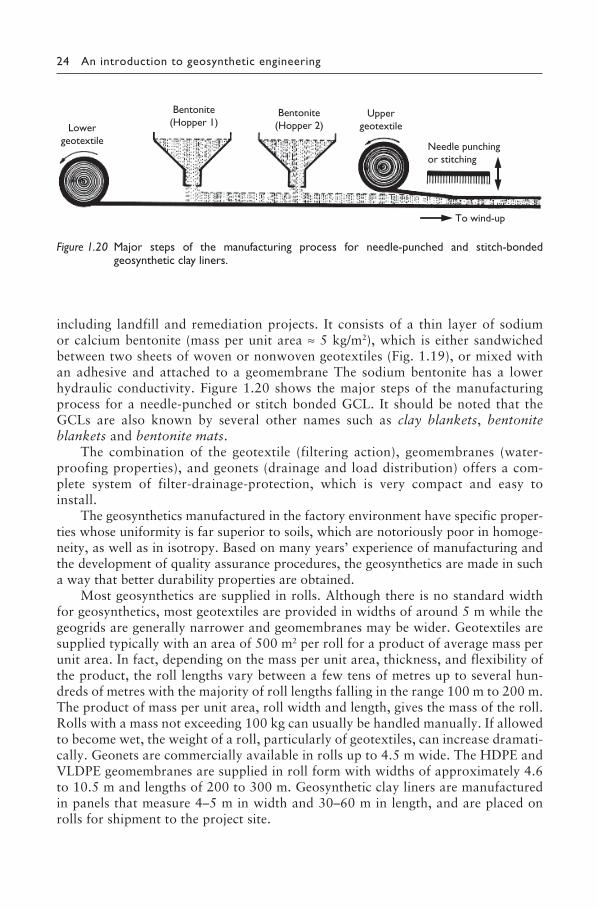
including landfill and remediation projects. It consists of a thin layer of sodium or calcium bentonite (mass per unit area ≈ 5 kg/m2), which is either sandwiched between two sheets of woven or nonwoven geotextiles (Fig. 1.19), or mixed with an adhesive and attached to a geomembrane The sodium bentonite has a lower hydraulic conductivity. Figure 1.20 shows the major steps of the manufacturing process for a needle-punched or stitch bonded GCL. It should be noted that the GCLs are also known by several other names such as clay blankets, bentonite blankets and bentonite mats.
The combination of the geotextile (filtering action), geomembranes (water-proofing properties), and geonets (drainage and load distribution) offers a com-plete system of filter-drainage-protection, which is very compact and easy to install.
The geosynthetics manufactured in the factory environment have specific proper-ties whose uniformity is far superior to soils, which are notoriously poor in homoge-neity, as well as in isotropy. Based on many years’ experience of manufacturing and the development of quality assurance procedures, the geosynthetics are made in such a way that better durability properties are obtained.
Most geosynthetics are supplied in rolls. Although there is no standard width for geosynthetics, most geotextiles are provided in widths of around 5 m while the geogrids are generally narrower and geomembranes may be wider. Geotextiles are supplied typically with an area of 500 m2 per roll for a product of average mass per unit area. In fact, depending on the mass per unit area, thickness, and flexibility of the product, the roll lengths vary between a few tens of metres up to several hun-dreds of metres with the majority of roll lengths falling in the range 100 m to 200 m. The product of mass per unit area, roll width and length, gives the mass of the roll. Rolls with a mass not exceeding 100 kg can usually be handled manually. If allowed to become wet, the weight of a roll, particularly of geotextiles, can increase dramati-cally. Geonets are commercially available in rolls up to 4.5 m wide. The HDPE and VLDPE geomembranes are supplied in roll form with widths of approximately 4.6 to 10.5 m and lengths of 200 to 300 m. Geosynthetic clay liners are manufactured in panels that measure 4–5 m in width and 30–60 m in length, and are placed on rolls for shipment to the project site.
Figure 1.20 Major steps of the manufacturing process for needle-punched and stitch-bonded geosynthetic clay liners.
To wind-up
Lowergeotextile
Uppergeotextile
Bentonite(Hopper 1)
Bentonite(Hopper 2)
Needle punchingor stitching
SHUKLA_Book.indb 24SHUKLA_Book.indb 24 4/6/2016 4:31:02 PM4/6/2016 4:31:02 PM
Basic description, functions and selection of geosynthetics 25
1.6 FUNCTIONS OF GEOSYNTHETICS
Geosynthetics have numerous application areas in civil engineering, and also in min-ing, agricultural and aquacultural engineering. They always perform one or more of the following basic functions when used in contact with soil, rock and/or any other civil engineering-related material:
• Reinforcement• Separation• Filtration• Drainage• Fluid Barrier• Protection
1.6.1 Reinforcement
A geosynthetic performs the reinforcement function by improving the mechanical properties of a soil mass as a result of its inclusion. When soil and geosynthetic rein-forcement are combined, a composite material, ‘reinforced soil’, possessing high compressive and tensile strengths (and similar, in principle, to the reinforced concrete)
EXAMPLE 1.1
Consider a roll of geotextile with the following details: Mass of the roll, M = 100 kg Width of the roll, B = 5 m, and Mass per unit area of the roll, m = 200 g/m2
Determine the roll length.
SOLUTION
Mass per unit area of the geotextile roll can be expressed as
mM
L B= (1.1)
where L is the roll length.
From Equation (1.1),
LM
m B= = =100
2 5( .0 )( )100 m
SHUKLA_Book.indb 25SHUKLA_Book.indb 25 4/6/2016 4:31:02 PM4/6/2016 4:31:02 PM
26 An introduction to geosynthetic engineering
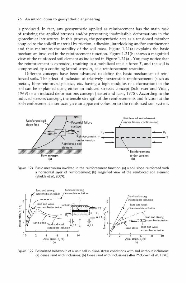
Figure 1.22 Postulated behaviour of a unit cell in plane strain conditions with and without inclusions: (a) dense sand with inclusions; (b) loose sand with inclusions (after McGown et al., 1978).
12
8
Stre
ss r
atio
, σ1 /
σ3
4
00 2 4 6 8 10
Sand and stronginextensible inclusion
Sand and strongextensible inclusion
Inclusion
Sand alone
Sand and weakinextensible inclusion
Sand and weakextensible inclusion
Axial strain, ε1 (%) (a)
σ1
σ1
σ3
σ3
δ1 / 2
δ1 / 2
δ3 / 2δ3 / 2
12
8
4
00 2 4 6 8 10
Sand and stronginextensible inclusion
Sand and strongextensible inclusion
Sand alone
Sand and weakinextensible inclusion
Sand and weakextensible inclusion
Stre
ss r
atio
, σ1 /
σ3
Axial strain, ε1 (%) (b)
Figure 1.21 Basic mechanism involved in the reinforcement function: (a) a soil slope reinforced with a horizontal layer of reinforcement; (b) magnified view of the reinforced soil element (Shukla et al., 2009).
Reinforced soilslope face
Potential failuresurface
Reinforcementunder tension
Firm stratum (a)
Reinforced soilelement
(b)
Reinforced soil elementunder lateral confinement
Reinforcementunder tension
TT
σRσR
is produced. In fact, any geosynthetic applied as reinforcement has the main task of resisting the applied stresses and/or preventing inadmissible deformations in the geotechnical structures. In this process, the geosynthetic acts as a tensioned member coupled to the soil/fill material by friction, adhesion, interlocking and/or confinement and thus maintains the stability of the soil mass. Figure 1.21(a) explains the basic mechanism involved in the reinforcement function. Figure 1.21(b) shows a magnified view of the reinforced soil element as indicated in Figure 1.21(a). You may notice that the reinforcement is extended, resulting in a mobilized tensile force T, and the soil is compressed by a confining lateral stress σR as a reinforcement restraint.
Different concepts have been advanced to define the basic mechanism of rein-forced soils. The effect of inclusion of relatively inextensible reinforcements (such as metals, fibre-reinforced plastics, etc. having a high modulus of deformation) in the soil can be explained using either an induced stresses concept (Schlosser and Vidal, 1969) or an induced deformations concept (Basset and Last, 1978). According to the induced stresses concept, the tensile strength of the reinforcements and friction at the soil-reinforcement interfaces give an apparent cohesion to the reinforced soil system.
SHUKLA_Book.indb 26SHUKLA_Book.indb 26 4/6/2016 4:31:02 PM4/6/2016 4:31:02 PM
Basic description, functions and selection of geosynthetics 27
The induced deformations concept considers that the tensile reinforcements involve anisotropic restraint of the soil deformations. The behaviour of the soil reinforced with extensible reinforcements, such as geosynthetics, does not fall completely within these concepts. The difference, between the influences of inextensible and extensible reinforcements, is significant in terms of the load-settlement behaviour of the rein-forced soil system (Fig. 1.22). The soil reinforced with an extensible reinforcement (termed ply-soil by McGown and Andrawes (1977)) has greater extensibility and smaller losses of post peak strength compared to soil alone or soil reinforced with inextensible reinforcement (termed reinforced earth by Vidal (1969)). However, some similarity between the ply-soil and the reinforced earth exists in that they inhibit the development of internal tensile strains in the soil and develop tensile strengths.
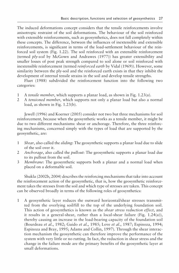
Fluet (1988) subdivided the reinforcement function into the following two categories:
1 A tensile member, which supports a planar load, as shown in Fig. 1.23(a).2 A tensioned member, which supports not only a planar load but also a normal
load, as shown in Fig. 1.23(b).
Jewell (1996) and Koerner (2005) consider not two but three mechanisms for soil reinforcement, because when the geosynthetic works as a tensile member, it might be due to two different mechanisms: shear or anchorage. Therefore, the three reinforc-ing mechanisms, concerned simply with the types of load that are supported by the geosynthetic, are:
1 Shear, also called the sliding: The geosynthetic supports a planar load due to slide of the soil over it.
2 Anchorage, also called the pullout: The geosynthetic supports a planar load due to its pullout from the soil.
3 Membrane: The geosynthetic supports both a planar and a normal load when placed on a deformable soil.
Shukla (2002b, 2004) describes the reinforcing mechanisms that take into account the reinforcement action of the geosynthetic, that is, how the geosynthetic reinforce-ment takes the stresses from the soil and which type of stresses are taken. This concept can be observed broadly in terms of the following roles of geosynthetics:
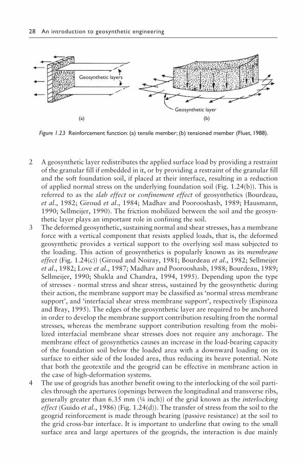
1 A geosynthetic layer reduces the outward horizontal/shear stresses transmit-ted from the overlying soil/fill to the top of the underlying foundation soil. This action of geosynthetics is known as the shear stress reduction effect, and it results in a general-shear, rather than a local-shear failure (Fig. 1.24(a)), thereby causing an increase in the load-bearing capacity of the foundation soil (Bourdeau et al., 1982; Guido et al., 1985; Love et al., 1987; Espinoza, 1994; Espinoza and Bray, 1995; Adams and Collin, 1997). Through the shear interac-tion mechanism the geosynthetic can therefore improve the performance of the system with very little or no rutting. In fact, the reduction in shear stress and the change in the failure mode are the primary benefits of the geosynthetic layer at small deformations.
SHUKLA_Book.indb 27SHUKLA_Book.indb 27 4/6/2016 4:31:03 PM4/6/2016 4:31:03 PM
28 An introduction to geosynthetic engineering
2 A geosynthetic layer redistributes the applied surface load by providing a restraint of the granular fill if embedded in it, or by providing a restraint of the granular fill and the soft foundation soil, if placed at their interface, resulting in a reduction of applied normal stress on the underlying foundation soil (Fig. 1.24(b)). This is referred to as the slab effect or confinement effect of geosynthetics (Bourdeau, et al., 1982; Giroud et al., 1984; Madhav and Poorooshasb, 1989; Hausmann, 1990; Sellmeijer, 1990). The friction mobilized between the soil and the geosyn-thetic layer plays an important role in confining the soil.
3 The deformed geosynthetic, sustaining normal and shear stresses, has a membrane force with a vertical component that resists applied loads, that is, the deformed geosynthetic provides a vertical support to the overlying soil mass subjected to the loading. This action of geosynthetics is popularly known as its membrane effect (Fig. 1.24(c)) (Giroud and Noiray, 1981; Bourdeau et al., 1982; Sellmeijer et al., 1982; Love et al., 1987; Madhav and Poorooshasb, 1988; Bourdeau, 1989; Sellmeijer, 1990; Shukla and Chandra, 1994, 1995). Depending upon the type of stresses - normal stress and shear stress, sustained by the geosynthetic during their action, the membrane support may be classified as ‘normal stress membrane support’, and ‘interfacial shear stress membrane support’, respectively (Espinoza and Bray, 1995). The edges of the geosynthetic layer are required to be anchored in order to develop the membrane support contribution resulting from the normal stresses, whereas the membrane support contribution resulting from the mobi-lized interfacial membrane shear stresses does not require any anchorage. The membrane effect of geosynthetics causes an increase in the load-bearing capacity of the foundation soil below the loaded area with a downward loading on its surface to either side of the loaded area, thus reducing its heave potential. Note that both the geotextile and the geogrid can be effective in membrane action in the case of high-deformation systems.
4 The use of geogrids has another benefit owing to the interlocking of the soil parti-cles through the apertures (openings between the longitudinal and transverse ribs, generally greater than 6.35 mm (¼ inch)) of the grid known as the interlocking effect (Guido et al., 1986) (Fig. 1.24(d)). The transfer of stress from the soil to the geogrid reinforcement is made through bearing (passive resistance) at the soil to the grid cross-bar interface. It is important to underline that owing to the small surface area and large apertures of the geogrids, the interaction is due mainly
Figure 1.23 Reinforcement function: (a) tensile member; (b) tensioned member (Fluet, 1988).
Geosynthetic layer
(b)
Geosynthetic layers
(a)
SHUKLA_Book.indb 28SHUKLA_Book.indb 28 4/6/2016 4:31:03 PM4/6/2016 4:31:03 PM
Basic description, functions and selection of geosynthetics 29
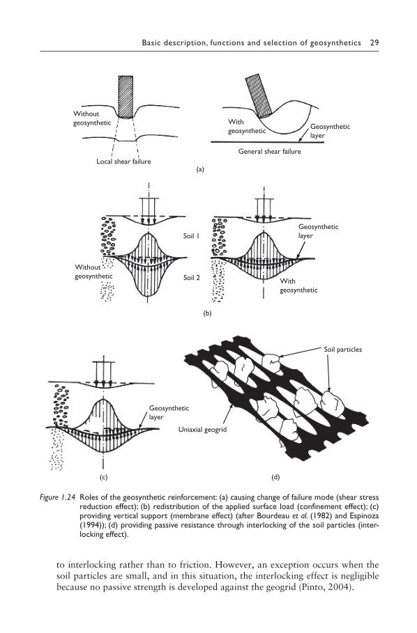
Figure 1.24 Roles of the geosynthetic reinforcement: (a) causing change of failure mode (shear stress reduction effect); (b) redistribution of the applied surface load (confinement effect); (c) providing vertical support (membrane effect) (after Bourdeau et al. (1982) and Espinoza (1994)); (d) providing passive resistance through interlocking of the soil particles (inter-locking effect).
Withoutgeosynthetic With
geosynthetic
Local shear failure (a)
General shear failure
Geosyntheticlayer
Without geosynthetic
With geosynthetic
Geosyntheticlayer
Soil 1
Soil 2
(b)
Soil particles
Uniaxial geogrid
(d)
Geosyntheticlayer
(c)
to interlocking rather than to friction. However, an exception occurs when the soil particles are small, and in this situation, the interlocking effect is negligible because no passive strength is developed against the geogrid (Pinto, 2004).
SHUKLA_Book.indb 29SHUKLA_Book.indb 29 4/6/2016 4:31:03 PM4/6/2016 4:31:03 PM
30 An introduction to geosynthetic engineering
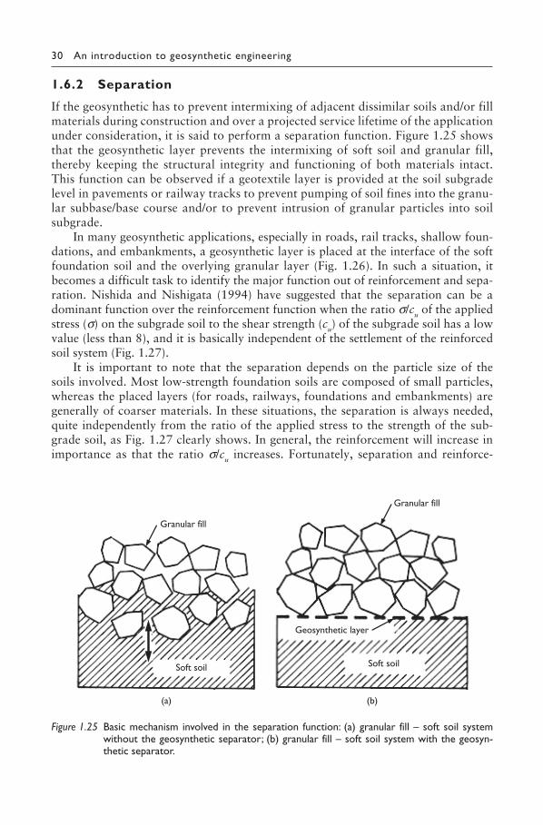
1.6.2 Separation
If the geosynthetic has to prevent intermixing of adjacent dissimilar soils and/or fill materials during construction and over a projected service lifetime of the application under consideration, it is said to perform a separation function. Figure 1.25 shows that the geosynthetic layer prevents the intermixing of soft soil and granular fill, thereby keeping the structural integrity and functioning of both materials intact. This function can be observed if a geotextile layer is provided at the soil subgrade level in pavements or railway tracks to prevent pumping of soil fines into the granu-lar subbase/base course and/or to prevent intrusion of granular particles into soil subgrade.
In many geosynthetic applications, especially in roads, rail tracks, shallow foun-dations, and embankments, a geosynthetic layer is placed at the interface of the soft foundation soil and the overlying granular layer (Fig. 1.26). In such a situation, it becomes a difficult task to identify the major function out of reinforcement and sepa-ration. Nishida and Nishigata (1994) have suggested that the separation can be a dominant function over the reinforcement function when the ratio σ/cu of the applied stress (σ) on the subgrade soil to the shear strength (cu) of the subgrade soil has a low value (less than 8), and it is basically independent of the settlement of the reinforced soil system (Fig. 1.27).
It is important to note that the separation depends on the particle size of the soils involved. Most low-strength foundation soils are composed of small particles, whereas the placed layers (for roads, railways, foundations and embankments) are generally of coarser materials. In these situations, the separation is always needed, quite independently from the ratio of the applied stress to the strength of the sub-grade soil, as Fig. 1.27 clearly shows. In general, the reinforcement will increase in importance as that the ratio σ/cu increases. Fortunately, separation and reinforce-
Figure 1.25 Basic mechanism involved in the separation function: (a) granular fill – soft soil system without the geosynthetic separator; (b) granular fill – soft soil system with the geosyn-thetic separator.
Granular fill
(a)
Granular fill
Soft soil Soft soil
(b)
Geosynthetic layer
SHUKLA_Book.indb 30SHUKLA_Book.indb 30 4/6/2016 4:31:04 PM4/6/2016 4:31:04 PM
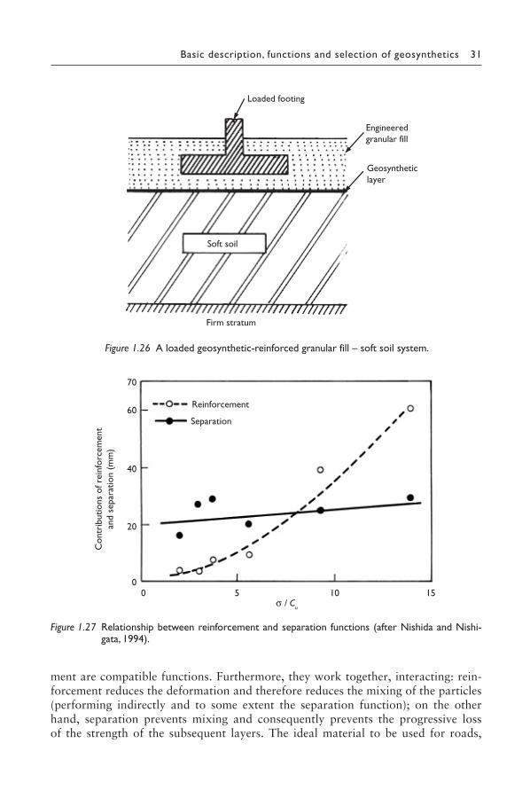
Basic description, functions and selection of geosynthetics 31
Figure 1.26 A loaded geosynthetic-reinforced granular fill – soft soil system.
Loaded footing
Engineeredgranular fill
Soft soil
Firm stratum
Geosyntheticlayer
Figure 1.27 Relationship between reinforcement and separation functions (after Nishida and Nishi-gata, 1994).
Reinforcement
Separation
00 5 10 15
20
40
60
70
σ / Cu
Con
trib
utio
ns o
f rei
nfor
cem
ent
and
sepa
ratio
n (m
m)
ment are compatible functions. Furthermore, they work together, interacting: rein-forcement reduces the deformation and therefore reduces the mixing of the particles (performing indirectly and to some extent the separation function); on the other hand, separation prevents mixing and consequently prevents the progressive loss of the strength of the subsequent layers. The ideal material to be used for roads,
SHUKLA_Book.indb 31SHUKLA_Book.indb 31 4/6/2016 4:31:04 PM4/6/2016 4:31:04 PM

32 An introduction to geosynthetic engineering
railways, foundations and embankments (i.e. when a coarse-grained soil is placed on top of a fine-grained soil with low strength) would be a continuous material such as a high-strength geotextile or a composite of a stiffer geogrid combined with a geotextile. In this way, the necessary separation and reinforcement functions can be performed simultaneously.
The selection of primary function out of reinforcement and separation can also be done on the basis of available empirical knowledge, if the California Bearing Ratio (CBR) of the subgrade soil is known. If the subgrade soil is soft, that is, the CBR of the subgrade soil is low, say its unsoaked value is less than 3 (or soaked value is less than 1), then the reinforcement can generally be taken as the primary function because of adequate tensile strength mobilization in the geosynthetic through large deformation, that is, deep ruts (say, greater than 75 mm) in the subgrade soil. Geosynthetics, used with subgrade soils with an unsoaked CBR higher than 8 (or soaked CBR higher than 3), will have a generally negligible amount of reinforcement role, and in such cases the primary function will uniquely be separation. For soils with intermediate unsoaked CBR values between 3 and 8 (or soaked CBR values between 1 and 3), the selection of the primary function is totally based on the site-specific situations.
1.6.3 Filtration
A geosynthetic may function as a filter that allows for adequate fluid flow with lim-ited migration of soil particles across its plane over a projected service lifetime of the application under consideration. Figure 1.28 shows that a geosynthetic allows passage of water from a soil mass while preventing the uncontrolled migration of soil particles.
When a geosynthetic filter is placed adjacent to a base soil (the soil to be fil-tered), a discontinuity arises between the original soil structure and the structure of
Geosyntheticlayer
Drainage stones
Water flow direction
Naturalsoil
Figure 1.28 Basic mechanism involved in the filtration function.
SHUKLA_Book.indb 32SHUKLA_Book.indb 32 4/6/2016 4:31:05 PM4/6/2016 4:31:05 PM
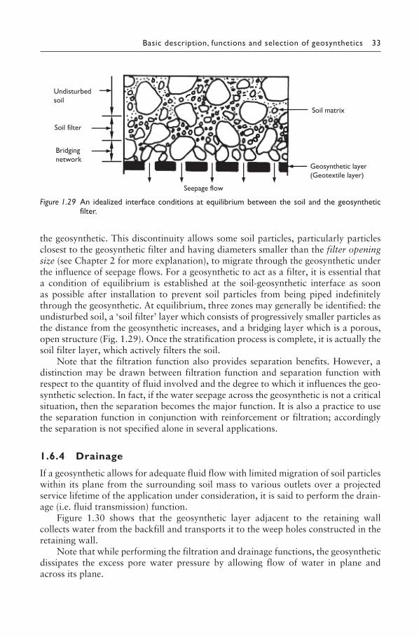
Basic description, functions and selection of geosynthetics 33
the geosynthetic. This discontinuity allows some soil particles, particularly particles closest to the geosynthetic filter and having diameters smaller than the filter opening size (see Chapter 2 for more explanation), to migrate through the geosynthetic under the influence of seepage flows. For a geosynthetic to act as a filter, it is essential that a condition of equilibrium is established at the soil-geosynthetic interface as soon as possible after installation to prevent soil particles from being piped indefinitely through the geosynthetic. At equilibrium, three zones may generally be identified: the undisturbed soil, a ‘soil filter’ layer which consists of progressively smaller particles as the distance from the geosynthetic increases, and a bridging layer which is a porous, open structure (Fig. 1.29). Once the stratification process is complete, it is actually the soil filter layer, which actively filters the soil.
Note that the filtration function also provides separation benefits. However, a distinction may be drawn between filtration function and separation function with respect to the quantity of fluid involved and the degree to which it influences the geo-synthetic selection. In fact, if the water seepage across the geosynthetic is not a critical situation, then the separation becomes the major function. It is also a practice to use the separation function in conjunction with reinforcement or filtration; accordingly the separation is not specified alone in several applications.
1.6.4 Drainage
If a geosynthetic allows for adequate fluid flow with limited migration of soil particles within its plane from the surrounding soil mass to various outlets over a projected service lifetime of the application under consideration, it is said to perform the drain-age (i.e. fluid transmission) function.
Figure 1.30 shows that the geosynthetic layer adjacent to the retaining wall collects water from the backfill and transports it to the weep holes constructed in the retaining wall.
Note that while performing the filtration and drainage functions, the geosynthetic dissipates the excess pore water pressure by allowing flow of water in plane and across its plane.
Undisturbedsoil
Soil filter
Bridgingnetwork
Seepage flow
Soil matrix
Geosynthetic layer(Geotextile layer)
Figure 1.29 An idealized interface conditions at equilibrium between the soil and the geosynthetic filter.
SHUKLA_Book.indb 33SHUKLA_Book.indb 33 4/6/2016 4:31:05 PM4/6/2016 4:31:05 PM
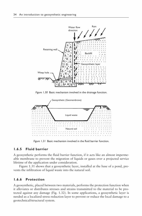
34 An introduction to geosynthetic engineering
1.6.5 Fluid barrier
A geosynthetic performs the fluid barrier function, if it acts like an almost imperme-able membrane to prevent the migration of liquids or gases over a projected service lifetime of the application under consideration.
Figure 1.31 shows that a geosynthetic layer, installed at the base of a pond, pre-vents the infiltration of liquid waste into the natural soil.
1.6.6 Protection
A geosynthetic, placed between two materials, performs the protection function when it alleviates or distributes stresses and strains transmitted to the material to be pro-tected against any damage (Fig. 1.32). In some applications, a geosynthetic layer is needed as a localized stress reduction layer to prevent or reduce the local damage to a geotechnical/structural system.
Rain Water flowdirection
Backfill
Geosynthetic layer
Weep hole
Retaining wall
Figure 1.30 Basic mechanism involved in the drainage function.
Geosynthetic (Geomembrane)
Liquid waste
Natural soil
Figure 1.31 Basic mechanism involved in the fluid barrier function.
SHUKLA_Book.indb 34SHUKLA_Book.indb 34 4/6/2016 4:31:05 PM4/6/2016 4:31:05 PM
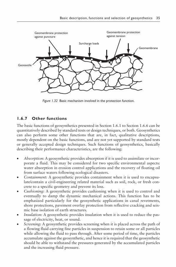
Basic description, functions and selection of geosynthetics 35
1.6.7 Other functions
The basic functions of geosynthetics presented in Section 1.6.1 to Section 1.6.6 can be quantitatively described by standard tests or design techniques, or both. Geosynthetics can also perform some other functions that are, in fact, qualitative descriptions, mostly dependent on the basic functions, and are not yet supported by standard tests or generally accepted design techniques. Such functions of geosynthetics, basically describing their performance characteristics, are the following:
• Absorption: A geosynthetic provides absorption if it is used to assimilate or incor-porate a fluid. This may be considered for two specific environmental aspects: water absorption in erosion control applications and the recovery of floating oil from surface waters following ecological disasters.
• Containment: A geosynthetic provides containment when it is used to encapsu-late/contain a civil-engineering related material such as soil, rock, or fresh con-crete to a specific geometry and prevent its loss.
• Cushioning: A geosynthetic provides cushioning when it is used to control and eventually to damp the dynamic mechanical actions. This function has to be emphasized particularly for the geosynthetic applications in canal revetments, shore protections, pavement overlay protection from reflective cracking and seis-mic base isolation of earth structures.
• Insulation: A geosynthetic provides insulation when it is used to reduce the pas-sage of electricity, heat, or sound.
• Screening: A geosynthetic provides screening when it is placed across the path of a flowing fluid carrying fine particles in suspension to retain some or all particles while allowing the fluid to pass through. After some period of time, the particles accumulate against the geosynthetic, and hence it is required that the geosynthetic should be able to withstand the pressures generated by the accumulated particles and the increasing fluid pressure.
Geomembrane protectionagainst tension
Geomembrane protectionagainst puncture
Geotextile
Surcharge loads
Geomembrane
Figure 1.32 Basic mechanism involved in the protection function.
SHUKLA_Book.indb 35SHUKLA_Book.indb 35 4/6/2016 4:31:06 PM4/6/2016 4:31:06 PM
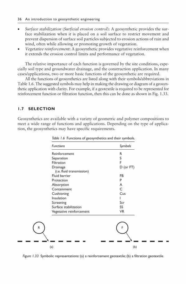
36 An introduction to geosynthetic engineering
• Surface stabilization (Surficial erosion control): A geosynthetic provides the sur-face stabilization when it is placed on a soil surface to restrict movement and prevent dispersion of surface soil particles subjected to erosion actions of rain and wind, often while allowing or promoting growth of vegetation.
• Vegetative reinforcement: A geosynthetic provides vegetative reinforcement when it extends the erosion control limits and performance of vegetation.
The relative importance of each function is governed by the site conditions, espe-cially soil type and groundwater drainage, and the construction application. In many cases/applications, two or more basic functions of the geosynthetic are required.
All the functions of geosynthetics are listed along with their symbols/abbreviations in Table 1.6. The suggested symbols may help in making the drawing or diagram of a geosyn-thetic application with clarity. For example, if a geotextile is required to be represented for reinforcement function or filtration function, then this can be done as shown in Fig. 1.33.
1.7 SELECTION
Geosynthetics are available with a variety of geometric and polymer compositions to meet a wide range of functions and applications. Depending on the type of applica-tion, the geosynthetics may have specific requirements.
R F
(a) (b)
Figure 1.33 Symbolic representations: (a) a reinforcement geotextile; (b) a filtration geotextile.
Table 1.6 Functions of geosynthetics and their symbols.
Functions Symbols
Reinforcement RSeparation SFiltration FDrainage
(i.e. fluid transmission)D (or FT)
Fluid barrier FBProtection PAbsorption AContainment CCushioning CusInsulation IScreening ScrSurface stabilization SSVegetative reinforcement VR
SHUKLA_Book.indb 36SHUKLA_Book.indb 36 4/6/2016 4:31:07 PM4/6/2016 4:31:07 PM
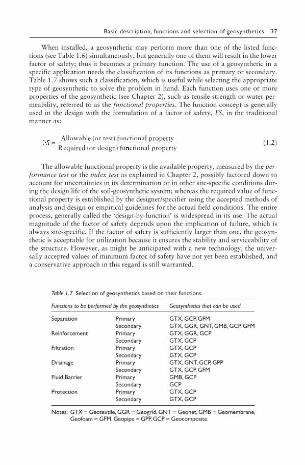
Basic description, functions and selection of geosynthetics 37
When installed, a geosynthetic may perform more than one of the listed func-tions (see Table 1.6) simultaneously, but generally one of them will result in the lower factor of safety; thus it becomes a primary function. The use of a geosynthetic in a specific application needs the classification of its functions as primary or secondary. Table 1.7 shows such a classification, which is useful while selecting the appropriate type of geosynthetic to solve the problem in hand. Each function uses one or more properties of the geosynthetic (see Chapter 2), such as tensile strength or water per-meability, referred to as the functional properties. The function concept is generally used in the design with the formulation of a factor of safety, FS, in the traditional manner as:
=Allowable (or test) functional property
Required (or design) funcnn tional property (1.2)
The allowable functional property is the available property, measured by the per-formance test or the index test as explained in Chapter 2, possibly factored down to account for uncertainties in its determination or in other site-specific conditions dur-ing the design life of the soil-geosynthetic system; whereas the required value of func-tional property is established by the designer/specifier using the accepted methods of analysis and design or empirical guidelines for the actual field conditions. The entire process, generally called the ‘design-by-function’ is widespread in its use. The actual magnitude of the factor of safety depends upon the implication of failure, which is always site-specific. If the factor of safety is sufficiently larger than one, the geosyn-thetic is acceptable for utilization because it ensures the stability and serviceability of the structure. However, as might be anticipated with a new technology, the univer-sally accepted values of minimum factor of safety have not yet been established, and a conservative approach in this regard is still warranted.
Table 1.7 Selection of geosynthetics based on their functions.
Functions to be performed by the geosynthetics Geosynthetics that can be used
Separation Primary GTX, GCP, GFMSecondary GTX, GGR, GNT, GMB, GCP, GFM
Reinforcement Primary GTX, GGR, GCPSecondary GTX, GCP
Filtration Primary GTX, GCPSecondary GTX, GCP
Drainage Primary GTX, GNT, GCP, GPPSecondary GTX, GCP, GFM
Fluid Barrier Primary GMB, GCPSecondary GCP
Protection Primary GTX, GCPSecondary GTX, GCP
Notes: GTX = Geotextile, GGR = Geogrid, GNT = Geonet, GMB = Geomembrane, Geofoam = GFM, Geopipe = GPP, GCP = Geocomposite.
SHUKLA_Book.indb 37SHUKLA_Book.indb 37 4/6/2016 4:31:07 PM4/6/2016 4:31:07 PM
38 An introduction to geosynthetic engineering
It is observed that only geotextiles and geocomposites perform most of the func-tions, and hence they are used in many applications. Geotextiles are porous to water flow across their manufactured planes and also within their planes. Thick, nonwoven needle-punched geotextiles have considerable void volume in their structure, and thus they can transmit fluid within the structure to a very high degree. The degree of poros-ity, which may vary widely, is used to determine the selection of specific geotextiles. Geotextiles can also be used as a fluid barrier on impregnation with materials like bitumen. The geotextiles vary with the type of polymer used, the type of fibre and the fabric style.
Geogrids are used to primarily function as reinforcement, and separation may be an occasional function, especially when soils having very large particle sizes are involved. The performance of the geogrid as reinforcement relies on its rigidity or high tensile modulus and on its open geometry, which accounts for its high capacity for interlocking with soil particles.
It has been observed that for the geotextiles to function properly as reinforce-ment, friction must develop between the soil and the reinforcement to prevent sliding, whereas for the geogrids, it is the interlocking of the soil particles through the apertures of the geogrid that achieves an efficient interlocking effect. In this respect, the geotextiles are frictional resistance-dependent reinforcement, whereas the geogrids are passive resistance-dependent reinforcement. The laboratory stud-ies have shown that the geogrids are a superior form of reinforcement owing to
EXAMPLE 1.2
A geogrid-reinforced soil structure is designed considering the tensile strength of the geogrid equal to 80 kN/m. If the factor of safety against the tensile failure is 1.5, what will be the allowable tensile strength of the geogrid?
SOLUTION
Given: Design tensile strength, σdesign = 80 kN/m and factor of safety, FS = 1.5If σall is the allowable tensile strength of the geogrid, then from Equation (1.2),
FS all
design
=σ a
σd
or
σall = (FS)(σdesign) = (1.5)(80) = 120 kN/m
Note: In Chapter 2, you will learn that the tensile strength of the geosynthetic is expressed in kN/m, not in kN/m2 as generally done for most other construction materials.
SHUKLA_Book.indb 38SHUKLA_Book.indb 38 4/6/2016 4:31:07 PM4/6/2016 4:31:07 PM
Basic description, functions and selection of geosynthetics 39
the interlocking of the soil particles within the grid apertures. Note that the use of triaxial geogrids in some applications such as pavements reduces the amount of aggregates, thus requiring less excavation below the ground level and hence pro-viding cost savings.
Geonets, unlike geotextiles, are relatively stiff, netlike materials with large open spaces between structural ribs. They are used exclusively as the fluid conducting cores in the prefabricated drainage geocomposites. Geonets play a major role in landfill leachate collection and leak detection systems in association with geomembranes or geotextiles. For a fair drainage function, the geonets should not be laid in contact with soils or waste materials, but used as the drainage cores with geotextile, geomembrane or other material on their upper and lower surfaces, thus avoiding the soil particles from obstructing the drainage net channels. Geonets as a drainage material generally fall intermediate in their flow capability between thick needle-punched nonwoven geotextiles and numerous drainage geocomposites.
Geomembranes are mostly used as a fluid barrier or liner. Sometimes, a geomem-brane is also known as the flexible membrane liner (FML), especially in landfill applications. The permeability of typical geomembranes ranges from 0.5 × 10⁻¹² to 0.5 × 10⁻¹⁵ m/s. Thus, the geomembranes are from 103 to 106 times lower in perme-ability than the compacted clay. In this context, we speak of geomembranes as being essentially impermeable. The recommended minimum thickness for all geomem-branes is 30 mil (0.75 mm), with the exception of HDPE (high-density polyethylene), which should be at least 60 mil (1.5 mm) to allow for the extrusion seaming (Qian et al., 2002). The most widely used geomembrane in the waste management industry is HDPE because this offers an excellent performance for landfill liners and covers, lagoon liners, wastewater treatment facilities, canal linings, floating covers, tank lin-ings and so on. If a greater flexibility than that of HDPE is required, then a linear low-density polyethylene (LLDPE) is used because it has a lower molecular weight resin that allows LLDPE to conform to non-uniform surfaces, making it suitable for landfill caps, pond liners, lagoon liners, potable water containment, tunnels and tank linings.
Geofoams are available in slab or block form. Since these geosynthetic products are very lightweight material with a unit weight ranging from 0.11 to 0.48 kN/m3, they can be selected as a highway fill over compressible subgrade soils and frost-sensitive soils, and as a backfill material for retaining walls to reduce the lateral earth pressure, thereby functioning basically as a separator. They can also function as a thermal insulator beneath buildings and as drainage channels beneath building slabs.
Geopipes are available in a wide range of diameters and wall dimensions for car-rying liquids and gases. For applications like subdrainage systems and leachate collec-tion systems, the geopipes should have perforations through the wall section to allow for the inflow of water and gas. The standard dimension ratio, defined as the ratio of outside pipe diameter to minimum pipe wall thickness, varies from a minimum of about 10 to a maximum of 40. This ratio can be related to the external strength and the internal pressure capability. Compared to steel pipes, they are cheap, light, and easy to install and join together along with a better durability.
It may happen that the geotextile, geogrid, geonet, geomembrane, geocell, geo-foam or geopipe chosen to meet the requirements of a particular function does not
SHUKLA_Book.indb 39SHUKLA_Book.indb 39 4/6/2016 4:31:07 PM4/6/2016 4:31:07 PM
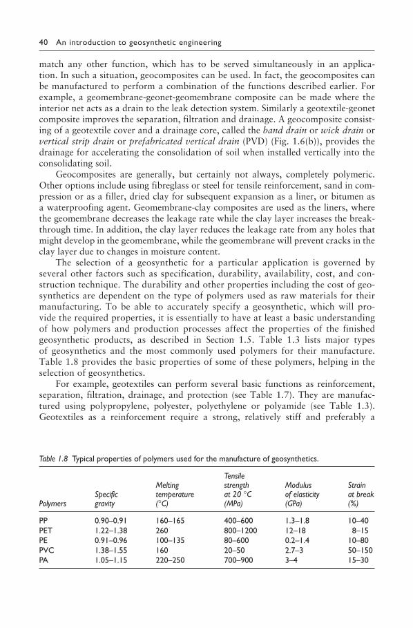
40 An introduction to geosynthetic engineering
match any other function, which has to be served simultaneously in an applica-tion. In such a situation, geocomposites can be used. In fact, the geocomposites can be manufactured to perform a combination of the functions described earlier. For example, a geomembrane-geonet-geomembrane composite can be made where the interior net acts as a drain to the leak detection system. Similarly a geotextile-geonet composite improves the separation, filtration and drainage. A geocomposite consist-ing of a geotextile cover and a drainage core, called the band drain or wick drain or vertical strip drain or prefabricated vertical drain (PVD) (Fig. 1.6(b)), provides the drainage for accelerating the consolidation of soil when installed vertically into the consolidating soil.
Geocomposites are generally, but certainly not always, completely polymeric. Other options include using fibreglass or steel for tensile reinforcement, sand in com-pression or as a filler, dried clay for subsequent expansion as a liner, or bitumen as a waterproofing agent. Geomembrane-clay composites are used as the liners, where the geomembrane decreases the leakage rate while the clay layer increases the break-through time. In addition, the clay layer reduces the leakage rate from any holes that might develop in the geomembrane, while the geomembrane will prevent cracks in the clay layer due to changes in moisture content.
The selection of a geosynthetic for a particular application is governed by several other factors such as specification, durability, availability, cost, and con-struction technique. The durability and other properties including the cost of geo-synthetics are dependent on the type of polymers used as raw materials for their manufacturing. To be able to accurately specify a geosynthetic, which will pro-vide the required properties, it is essentially to have at least a basic understanding of how polymers and production processes affect the properties of the finished geosynthetic products, as described in Section 1.5. Table 1.3 lists major types of geosynthetics and the most commonly used polymers for their manufacture. Table 1.8 provides the basic properties of some of these polymers, helping in the selection of geosynthetics.
For example, geotextiles can perform several basic functions as reinforcement, separation, filtration, drainage, and protection (see Table 1.7). They are manufac-tured using polypropylene, polyester, polyethylene or polyamide (see Table 1.3). Geotextiles as a reinforcement require a strong, relatively stiff and preferably a
Table 1.8 Typical properties of polymers used for the manufacture of geosynthetics.
PolymersSpecific gravity
Melting temperature (°C)
Tensile strength at 20 °C (MPa)
Modulus of elasticity (GPa)
Strain at break (%)
PP 0.90–0.91 160–165 400–600 1.3–1.8 10–40PET 1.22–1.38 260 800–1200 12–18 8–15PE 0.91–0.96 100–135 80–600 0.2–1.4 10–80PVC 1.38–1.55 160 20–50 2.7–3 50–150PA 1.05–1.15 220–250 700–900 3–4 15–30
SHUKLA_Book.indb 40SHUKLA_Book.indb 40 4/6/2016 4:31:07 PM4/6/2016 4:31:07 PM
Basic description, functions and selection of geosynthetics 41
water-permeable material. An inspection of Table 1.8 indicates that the polyester has a very high tensile strength at a relatively low strain. Thus a woven geotextile of poly-ester is a logical choice for the reinforcement applications. For separation/filtration applications, the geotextile has to be flexible, water-permeable, and soil-tight. A non-woven geotextile or a lightweight woven geotextile of polyethylene can be a logical choice for separation/filtration applications. Note that the environmental factors and the site conditions also greatly govern the selection of geosynthetics for a particular application (Shukla, 2003b).
Sometimes, during the selection process, you may find that several geosynthetics satisfy the minimum requirements for the particular application. In such a situation, the geosynthetic should be selected on the basis of cost-benefit ratio, including the value of field experience and product documentation.
The properties of geosynthetics can change unfavourably in several ways such as ageing, mechanical damage (particularly by installation stresses), creep, hydrolysis (reaction with water), chemical and biological attack, ultraviolet light exposure, etc., which have been discussed in detail in Chapter 2. These factors have to be taken into account when the geosynthetics are selected. In permanent installations, there must be proper care for maintaining the long-term satisfactory performance of the geosynthet-ics, that is, the durability.
Considering the risks and consequences of failure, especially for critical projects, great care is required in the selection of the appropriate geosynthetic. One should not try to economize by eliminating the soil-geosynthetic performance testing when such testing is required for the selection.
For some applications, the geosynthetics are selected on the basis of empirical guidelines. In these cases proper care should be taken to clearly define the required properties of the geosynthetic, in physical as well as in statistical terms.
1.8 HISTORICAL DEVELOPMENTS OF GEOSYNTHETIC ENGINEERING
The present form of geosynthetic engineering has been achieved because of ongo-ing efforts by researchers, practising engineers and polymer technologists dur-ing the past several decades. The following are some key stages of the historical developments:
1 The first use of fabrics in reinforcing roads was attempted by the South Carolina Highway Department in 1926 (Beckham and Mills, 1935).
2 The first geotextile used in a dam, in 1970, was a needle-punched nonwoven geo-textile used as a filter for the aggregate downstream drain in the Valcross Dam (17 m high), France (Giroud, 1992).
3 The first sample of Tensar grid was made in the Blackburn laboratories of Netlon Ltd, UK in July 1978.
4 Geofoam was originally applied as a lightweight fill in Norway in 1972.5 Soil confinement systems based on cellular geotextile nets were first developed
and evaluated in France during 1980.
SHUKLA_Book.indb 41SHUKLA_Book.indb 41 4/6/2016 4:31:07 PM4/6/2016 4:31:07 PM
42 An introduction to geosynthetic engineering
6 The first known environmental application of geonet was in 1984 for leak detection in a double-lined hazardous liquid-waste impoundment in Hopewell, Virginia.
7 The first conference on geosynthetics was held in Paris in 1977. 8 Koerner and Welsh wrote the first book on geosynthetics in 1980. 9 The International Geosynthetics Society was established in 1983.10 There are currently three geosynthetic-related international journals, namely
Geotextiles and Geomembranes, Geosynthetics International, and International Journal of Geosynthetics and Ground Engineering, which were first published in 1984, 1995 and 2015, respectively.
Note that the rapid and significant development of geosynthetic engineering worldwide is mainly based on the fact that the geosynthetics often provide cost-effec-tive, environmentally friendly, energy-efficient and sustainable solutions in the con-struction industry. Details of the sustainability aspects of geosynthetic applications can be found in Bouazza and Heerten (2012).
Chapter summary
1 Geosynthetics are planar products manufactured mainly from polymers (PP, PET, PE, PA, etc.) with some additives (e.g. carbon black), and their major types are geotextiles, geogrids, geonets, geomembranes, geocells, geofoams and geocom-posites. Geosynthetic clay liners and prefabricated vertical drains are most com-mon examples of geocomposites.
2 Geonaturals (geojutes, geocoirs, etc.) are similar to geosynthetics in physi-cal structure and some applications, but they are manufactured from natural fibres (jute, coir, etc.), which have a short life span due to their biodegradable characteristics.
3 Geotextiles are manufactured in many different ways, including the conventional weaving processes, resulting in the woven geotextiles. The manufacture of non-woven geotextiles from suitable fibres involves needle-punching, thermal bonding and chemical bonding processes. The geogrids share a common geometry com-prising load-carrying elements which enclose substantially rectangular, square or triangular patterns. Most geomembranes are made by extrusion, spread-coating, or calendaring process. Geocells are factory-manufactured products or they are assembled at the construction site. Geocomposites are generally, but certainly not always, completely polymeric.
4 Most geosynthetics are supplied in rolls having widths from 4 m to 10 m, and lengths from 30 to 300 m. Rolls with a mass not exceeding 100 kg can usually be handled manually.
5 In civil, mining, agricultural and aquacultural applications, the geosynthetics per-form several functions, including separation, reinforcement, filtration, drainage, fluid barrier and protection as the major functions. Geosynthetics are used mainly to achieve technical and/or economic benefits, and they also provide environmen-tal-friendly and energy-efficient solutions to several construction problems in a sustainable manner.
SHUKLA_Book.indb 42SHUKLA_Book.indb 42 4/6/2016 4:31:07 PM4/6/2016 4:31:07 PM
Basic description, functions and selection of geosynthetics 43
6 The geosynthetic reinforcement within a soil mass improves its strength character-istics through the following actions: shear stress reduction effect, slab/confinement effect, membrane effect and interlocking effect. The geosynthetic as a separator at the interface of two dissimilar soil layers prevents mixing and consequently pre-vents the progressive loss of the strength and functions of the soil layers.
7 When a geosynthetic filter is placed adjacent to a base soil, at the equilibrium, three zones may generally be identified: the undisturbed soil, a ‘soil filter’ layer which consists of progressively smaller particles as the distance from the geo-synthetic filter increases, and a bridging layer which is a porous, open structure. Once this stratification process is complete, it is actually the soil filter layer, which actively filters the soil. The geosynthetic layer as a drainage medium collects the water from the adjacent soil mass and conveys it to the drain pipe network or the disposal area.
8 A geosynthetic may act like an almost impermeable membrane to prevent the migration of fluids (liquids and gases) from one area to the other. This fluid barrier function is generally achieved through the use of geomembranes, which require a suitable protection in most field applications.
9 The use of a geosynthetic in a specific application needs the classification of its function as primary or secondary because the function concept is commonly used in the design with the formulation of a factor of safety, defined as the ratio of allowable/test functional property to the required or design functional property. If the factor of safety is sufficiently larger than one, the geosynthetic is acceptable for utilization because it ensures the stability and serviceability of the structure.
10 The selection of a geosynthetic for a particular application is governed by sev-eral factors such as specification, durability, availability, cost, and construction technique. Woven geotextiles, geogrids and some geocomposites are commonly used for reinforcement applications. Nonwoven geotextiles are commonly used in many separation, filtration, drainage and protection applications alone or in combination with others as geocomposites. Geonets are used exclusively as the fluid conducting cores in prefabricated drainage geocomposites. Geofoams are used as a very lightweight fill material, thermal insulator or drainage channel. Geopipes are used for carrying liquids and gases.
Questions for practice
(Select the most appropriate answer to the multiple-choice questions from Q 1.1 to Q 1.15.)
1.1 A planar, polymeric product consisting of a mesh or net-like regular open net-work of intersecting tensile-resistant elements, integrally connected at the junc-tions is called(a) geotextile(b) geogrid(c) geonet(d) geocell.
SHUKLA_Book.indb 43SHUKLA_Book.indb 43 4/6/2016 4:31:07 PM4/6/2016 4:31:07 PM
44 An introduction to geosynthetic engineering
1.2 The materials used in the manufacture of geosynthetics are primarily synthetic polymers generally derived from(a) rubber(b) fibre glass(c) crude petroleum oils(d) jute.
1.3 The most widely used polymers for manufacturing the reinforcing geosynthet-ics are(a) PP and PET(b) PP and PA(c) PP and PE(d) PET and PE.
1.4 The resistance to creep is high for(a) PP(b) PET(c) PE(d) PA.
1.5 The term ‘weft’ refers to(a) the longitudinal yarn of the geotextile(b) the yarn running in the roll length direction(c) the yarn running in the machine direction(d) all of the above.
1.6 Which one of the following geosynthetics is a geocomposite?(a) geofoam(b) geonet(c) geosynthetic clay liner(d) geocell
1.7 If geosynthetic allows for adequate fluid flow with limited migration of soil particles across its plane over a projected service lifetime of the application under consideration, then this function of geosynthetic is called(a) filtration(b) separation(c) drainage(d) fluid barrier.
1.8 The deformed geosynthetic provides a vertical support to the overlying soil mass subjected to a loading. This action of the geosynthetic is known as(a) shear stress reduction effect(b) membrane effect(c) confinement effect(d) interlocking effect.
1.9 For a geotextile, the separation can be a dominant function over the reinforce-ment function when the ratio of the applied normal stress on the subgrade soil to its undrained shear strength is generally
SHUKLA_Book.indb 44SHUKLA_Book.indb 44 4/6/2016 4:31:07 PM4/6/2016 4:31:07 PM
Basic description, functions and selection of geosynthetics 45
(a) equal to 8(b) greater than 8(c) lower than 8(d) none of the above.
1.10 In geosynthetic engineering, most of the functions are served by(a) GTX and GGR(b) GTX and GCP(c) GNT and GXT(d) GGR and GNT.
1.11 Which one of the following geosynthetics can serve the protection function?(a) GTX(b) GGR(c) GMB(d) GNT
1.12 The following geosynthetics are used as a drainage medium:(A) thick needle-punched nonwoven geotextiles(B) geonets(C) drainage geocomposites
The correct decreasing order of flow capability is generally(a) (A), (B), (C)(b) (B), (A), (C)(c) (C), (A), (B)(d) (C), (B), (A).
1.13 The specific gravity is smaller than one for(a) PP and PET(b) PET and PE(c) PE and PP(d) PA and PET.
1.14 The melting temperature of the polyester is(a) 130 °C(b) 165 °C(c) 220 °C(d) 260 °C
1.15 Which one of the following polymers has the highest modulus of elasticity?(a) PP(b) PET(c) PE(d) PVC.
1.16 What do you mean by geosynthetics and geonaturals? Explain these two terms making a point-wise comparison.
1.17 Explain the process of polymerization and its role in improving the characteris-tics of polymer fibres.
SHUKLA_Book.indb 45SHUKLA_Book.indb 45 4/6/2016 4:31:07 PM4/6/2016 4:31:07 PM
46 An introduction to geosynthetic engineering
1.18 What are the additives that are used to avoid ultraviolet light degradation of polymers?
1.19 What is the effect of temperature variation on the geosynthetic polymers? 1.20 What is the difference between thermoplastic and thermoset polymers? Why
are thermoset polymers rarely used? 1.21 Describe the major steps of manufacturing process for the following types of
geosynthetics:(a) woven geotextiles(b) nonwoven geotextile(c) extruded geogrids(d) geonets(e) geomembranes
1.22 Describe the major steps of the manufacturing process for the needle-punched and stitch-bonded geosynthetic clay liners with the help of a neat sketch.
1.23 What are the advantages of a textured geomembrane? Where should a textured geomembrane be used in field applications?
1.24 What would be the benefits of having a geotextile bonded directly to the geomembrane on its lower side?
1.25 What are the components of a strip drain? Draw a neat sketch in support of your answer.
1.26 Consider a roll of geotextile with the following details: Mass of the roll, M = 90 kg Length of the roll, L = 120 m, and Mass per unit area of the roll, m = 150 g/m2
Determine the roll width.
1.27 List the basic functions of geosynthetics. 1.28 Explain the basic mechanisms involved in the separation and filtration func-
tions with the help of neat sketches. 1.29 Explain the mechanism involved in drainage function comparing with the
mechanism involved in filtration function? 1.30 What are the performance characteristics of geosynthetics other than their basic
functions? How do they differ from the basic functions? 1.31 What are the characteristics of a soil reinforced with an extensible reinforce-
ment? Are these characteristics similar for the soil reinforced with an inextensi-ble reinforcement? Can you list the differences, if any?
1.32 What are the different mechanisms for soil reinforcement? Explain briefly. 1.33 How will you decide the primary function out of reinforcement and separation
in any field application? 1.34 Describe idealized interface conditions at equilibrium between the soil and geo-
synthetic filter. 1.35 What do you mean by functional properties? Explain with some examples. 1.36 Define the factor of safety required for the acceptance of a geosynthetic for a
specific application. 1.37 A geotextile-reinforced soil structure is designed considering the tensile strength
of the geotextile equal to 60 kN/m. If the allowable tensile strength of the geogrid is 80 kN/m, what will be the factor of safety against the tensile failure of the geotextile?
SHUKLA_Book.indb 46SHUKLA_Book.indb 46 4/6/2016 4:31:08 PM4/6/2016 4:31:08 PM
Basic description, functions and selection of geosynthetics 47
1.38 Which manufactured style of a geotextile is best suited to its application as a drainage medium?
1.39 How does a geonet differ from a geogrid in terms of functions? 1.40 If a geotextile is placed adjacent to a geonet, what function(s) does the geotextile
provide? How does the combination of geotextile and geonet accommodate the flow?
1.41 What are the advantages of geomembrane-clay composite liner? 1.42 List the major factors to be considered in the selection of a geosynthetic for field
applications. 1.43 What is the role of cost-benefit ratio in the selection of geosynthetics? 1.44 Give the symbolic representation for the reinforcement geotextile.
References
Adams, M.T. and Collin, J.G. (1997). Large model spread footing load tests on geosynthetic reinforced soil foundations. Journal of Geotechnical and Geoenvironmental Engineering, ASCE, 123, 1, pp. 66–72.
Bassett, R.H. and Last, N.C. (1978). Reinforcing earth below footings and embankments. Proceedings of the Symposium on Earth Reinforcement, ASCE, New York, pp. 202–231.
Beckham, W.K. and Mills, W.H. (1935). Cotton-fabric reinforced roads. Engineering News Record, pp. 453–455.
Bourdeau, P.L. (1989). Modeling of membrane action in a two-layer reinforced soil system. Computers and Geotechnics, 7, 1–2, pp. 19–36.
Bourdeau, P.L., Harr, M.E., and Holtz, R.D. (1982). Soil-fabric interaction – an analytical model. Proceedings of the 2nd International Conference on Geotextiles. Las Vegas, USA, pp. 387–391.
Bouazza, A. and Heerten, G. (2012). Geosynthetic applications – sustainability aspects. Chapter 18, Handbook of Geosynthetic Engineering, Shukla, S.K., Editor, ICE Publishing, London, pp. 387–396.
Espinoza, R.D. (1994). Soil-geotextile interaction: evaluation of membrane support. Geotextiles and Geomembranes, 13, 5, pp. 281–293.
Espinoza, R.D. and Bray, J.D. (1995). An integrated approach to evaluating single-layer reinforced soils. Geosynthetics International, 2, 4, 723–739.
Fluet, J.E. (1988). Geosynthetics for soil improvement: a general report and keynote address. Proceedings of the Symposium on Geosynthetics for Soil Improvement, Tennessee, USA, pp. 1–21.
Giroud, J.P. (1992). Geosynthetics in dams: Two decades of experience. Geotechnical Fabrics Report, 10, 5, pp. 6–9.
Giroud, J. P. and Noiray, L. (1981). Geotextile-reinforced unpaved road design. Journal of the Geotechnical Engineering Division, ASCE, 107, 9, pp. 1233–1254.
Giroud, J.P. and Carroll, R.G. (1983). Geotextile products. Geotechnical Fabrics Report, pp. 12–15.
Giroud, J.P., Ah-Line, A. and Bonaparte, R. (1984). Design of unpaved roads and trafficked areas with geogrids. Proceedings of the Symposium on Polymer Grid Reinforcement, London, pp. 116–127.
Guido, V.A., Biesiadecki, G.L. and Sullivan, M.J. (1985). Bearing capacity of a geotextile-reinforced foundation. Proceedings of the 11th International Conference on Soil Mechanics and Foundation Engineering. San Francisco, Calif. pp. 1777–1780.
Guido, V.A., Dong, K.G. and Sweeny, A. (1986). Comparison of geogrid and geotextile reinforced earth slabs. Canadian Geotechnical Journal, 23, 1, pp. 435–440.
SHUKLA_Book.indb 47SHUKLA_Book.indb 47 4/6/2016 4:31:08 PM4/6/2016 4:31:08 PM
48 An introduction to geosynthetic engineering
Halse, Y.H., Wiertz, J. and Rigo, J.M. (1991). Chemical identification methods used to characterize polymeric geomembranes. Chapter 15, Geomembranes Identification and Performance Testing, Chapman & Hall, London, pp. 316 – 336.
Hausmann, M.R. (1990). Engineering Principles of Ground Modification. McGraw-Hill, New York.
Ingold, T.S. (1994). The Geotextiles and Geomembranes Manual. Elsevier Advanced Technology, UK.
Jewell, R.A. (1996). Soil Reinforcement with Geotextiles. Construction Industry Research and Information Association, London, CIRIA, Special Publication 123.
John, N.W.M. (1987). Geotextiles. Blackie, London.Koerner, R. M. (2005). Designing with Geosynthetics. Fifth Edition, Prentice Hall, New Jersey,
USA.Koerner, R.M. and Daniel, D.E. (1997). Final covers for solid waste landfills and abandoned
dumps. ASCE Press, Reston, VA, and Thomas Telford, London, UK.Landreth, R.E. (1990). Chemical resistance evaluation of geosynthetics used in the waste man-
agement applications. Geosynthetics Testing for Waste Containment Applications, Special Technical Publication STP 1081, ASTM, Philadelphia, pp. 3–11.
Love, J.P., Burd, H.J., Milligan, G.W.E. and Houlsby (1987). Analytical and model studies of reinforcement of a layer of granular fill on soft clay subgrade. Canadian Geotechnical Journal, 24, 4, pp. 611–622.
Madhav, M.R. and Poorooshasb, H.B. (1988). A new model for geosynthetic-reinforced soil. Computers and Geotechnics, 6, 4, pp. 277–290.
Madhav, M.R. and Poorooshasb, H.B. (1989). Modified Paternak model for reinforced soil. Mathematical and Computational Modelling, an International Journal, 12, 12, pp. 1505–1509
McGown, A. and Andrawes, K.Z. (1977). The influence of nonwoven fabric inclusions on the stress-strain behaviour of a soil mass. Proceedings of the International Conference on the Use of Fabrics in Geotechnics, Paris, pp. 161–166.
McGown, A., Andrawes, K.Z. and Al-Hasani, M.M. (1978). Effect of inclusion properties on the behaviour of sand. Geotechnique, 28, 3, pp. 327–346.
Nishida, K. and Nishigata, T. (1994). The evaluation of separation function for geotextiles. Proceedings of the 5th Int. Conference on Geotextiles, Geomembranes and Related Prod-ucts. Singapore, 1994, pp. 139–142.
Pinto, M.I.M. (2004). Reply to the discussion of “Applications of geosynthetics for soil reinforcement’ by M.I.M. Pinto, Ground Improvement, 7, 2, 2003, pp. 61–72 by S.K. Shukla’. Ground Improvement, UK, 8, 4, pp. 181–182.
Qian, X, Koerner, R.M. and Gray, D.H. (2002). Geotechnical Aspects of Landfill Design and Construction. Prentice Hall, New Jersey.
Rankilor, P.R. (1981). Membranes in Ground Engineering. John Wiley & Sons, Chichester, England, 1981.
Rigo, J.M. and Cuzzuffi, D.A. (1991). Test standards and their classification. Geomembrane Identification and Performance Testing, Chapman and Hall, London, pp. 22–58.
Schlosser, F. and Vidal, H. (1969). Reinforced earth. Bulletin de Liaison des Laboratoires des Ponts et Chaussees, No. 41, France.
Sellmeijer, J.B. (1990). Design of geotextile reinforced unpaved roads and parking areas. Pro-ceedings of the 4th International Conference on Geotextiles, Geomembranes and Related Products. The Hague, Netherlands, pp. 177–182.
SHUKLA_Book.indb 48SHUKLA_Book.indb 48 4/6/2016 4:31:08 PM4/6/2016 4:31:08 PM
Basic description, functions and selection of geosynthetics 49
Sellmeijer, J.B., Kenter, C.J. and Van den Berg, C. (1982). Calculation method for fabric reinforced road. Proceedings of the 2nd International Conference on Geotextiles. Las Vegas, USA, pp. 393–398.
Shukla, S.K. (2002a). Fundamentals of geosynthetics. Chapter 1, Geosynthetics and Their Applications, Shukla, S.K., Editor, Thomas Telford, London, pp. 1–54.
Shukla, S.K. (2002b). Shallow foundations. Chapter 5, Geosynthetics and Their Applications, Shukla, S.K., Editor, Thomas Telford, London, pp. 123–163.
Shukla, S.K. (2003a). Geosynthetics in civil engineering constructions. Employment News, New Delhi, March 1–7, pp. 1–3.
Shukla (2003b). How to select geosynthetics for field applications. Geosynthetic Pulse, India, 1, 5, pp. 2–2.
Shukla, S.K. (2004). Discussion of “Applications of geosynthetics for soil reinforcement” by M.I.M. Pinto’ Ground Improvement, 8, 4, pp. 179–181.
Shukla, S.K. (2013). Articles of professional interest: editorial of the special issue on geosyn-thetic engineering, Indian Geotechnical Journal, 43, 4, pp. 281–282.
Shukla, S.K. and Chandra, S. (1994). A generalized mechanical model for geosynthetic-rein-forced foundation soil. Geotextiles and Geomembranes, 13, 12, pp. 813–825.
Shukla, S.K. and Chandra, S. (1995). Modelling of geosynthetic-reinforced engineered granular fill on soft soil”. Geosynthetics International, USA, 2, 3, pp. 603–618.
Shukla, S.K., Sivakugan, N. and Das, B.M. (2009). Fundamental concepts of soil reinforcement – an overview. International Journal of Geotechnical Engineering, 3, 3, pp. 329–342.
Thomas, R.W. and Verschoor, K.L. (1988). Thermal analysis of geosynthetics. Geotechnical Fabrics Report, 6, 3, pp. 24–30.
Vidal, H. (1969). The principle of reinforced earth. Highway Research Record, No. 282, pp. 1–16.
Answers to selected questions
1.1 (b)1.3 (a)1.5 (d)1.7 (a)1.9 (c)1.11 (a)1.13 (c)1.15 (b)1.26 5 m1.37 1.33
SHUKLA_Book.indb 49SHUKLA_Book.indb 49 4/6/2016 4:31:08 PM4/6/2016 4:31:08 PM

This page intentionally left blankThis page intentionally left blank
References
1 1. Basic description, functions andselection of geosynthetics
Adams, M.T. and Collin, J.G. (1997). Large model spreadfooting load tests on geosynthetic reinforced soilfoundations. Journal of Geotechnical and GeoenvironmentalEngineering, ASCE, 123, 1, pp. 66–72.
Bassett, R.H. and Last, N.C. (1978). Reinforcing earthbelow footings and embankments. Proceedings of theSymposium on Earth Reinforcement, ASCE, New York, pp.202–231.
Beckham, W.K. and Mills, W.H. (1935). Cotton-fabricreinforced roads. Engineering News Record, pp. 453–455.
Bourdeau, P.L. (1989). Modeling of membrane action in atwo-layer reinforced soil system. Computers andGeotechnics, 7, 1–2, pp. 19–36.
Bourdeau, P.L., Harr, M.E., and Holtz, R.D. (1982).Soil-fabric interaction – an analytical model. Proceedingsof the 2nd International Conference on Geotextiles. LasVegas, USA, pp. 387–391.
Bouazza, A. and Heerten, G. (2012). Geosyntheticapplications – sustainability aspects. Chapter 18,Handbook of Geosynthetic Engineering, Shukla, S.K., Editor,ICE Publishing, London, pp. 387–396.
Espinoza, R.D. (1994). Soil-geotextile interaction:evaluation of membrane support. Geotextiles andGeomembranes, 13, 5, pp. 281–293.
Espinoza, R.D. and Bray, J.D. (1995). An integratedapproach to evaluating single-layer reinforced soils.Geosynthetics International, 2, 4, 723–739.
Fluet, J.E. (1988). Geosynthetics for soil improvement: ageneral report and keynote address. Proceedings of theSymposium on Geosynthetics for Soil Improvement, Tennessee,USA, pp. 1–21.
Giroud, J.P. (1992). Geosynthetics in dams: Two decades ofexperience. Geotechnical Fabrics Report, 10, 5, pp. 6–9.
Giroud, J. P. and Noiray, L. (1981). Geotextile-reinforcedunpaved road design. Journal of the Geotechnical
Engineering Division, ASCE, 107, 9, pp. 1233–1254.
Giroud, J.P. and Carroll, R.G. (1983). Geotextile products.Geotechnical Fabrics Report, pp. 12–15.
Giroud, J.P., Ah-Line, A. and Bonaparte, R. (1984). Designof unpaved roads and trafficked areas with geogrids.Proceedings of the Symposium on Polymer Grid Reinforcement,London, pp. 116–127.
Guido, V.A., Biesiadecki, G.L. and Sullivan, M.J. (1985).Bearing capacity of a geotextilereinforced foundation.Proceedings of the 11th International Conference on SoilMechanics and Foundation Engineering. San Francisco,Calif. pp. 1777–1780.
Guido, V.A., Dong, K.G. and Sweeny, A. (1986). Comparisonof geogrid and geotextile reinforced earth slabs. CanadianGeotechnical Journal, 23, 1, pp. 435–440.
Halse, Y.H., Wiertz, J. and Rigo, J.M. (1991). Chemicalidentification methods used to characterize polymericgeomembranes. Chapter 15, Geomembranes Identification andPerformance Testing, Chapman & Hall, London, pp. 316 – 336.
Hausmann, M.R. (1990). Engineering Principles of GroundModification. McGraw-Hill, New York.
Ingold, T.S. (1994). The Geotextiles and GeomembranesManual. Elsevier Advanced Technology, UK.
Jewell, R.A. (1996). Soil Reinforcement with Geotextiles.Construction Industry Research and InformationAssociation, London, CIRIA, Special Publication 123.
John, N.W.M. (1987). Geotextiles. Blackie, London.
Koerner, R. M. (2005). Designing with Geosynthetics. FifthEdition, Prentice Hall, New Jersey, USA.
Koerner, R.M. and Daniel, D.E. (1997). Final covers forsolid waste landfills and abandoned dumps. ASCE Press,Reston, VA, and Thomas Telford, London, UK.
Landreth, R.E. (1990). Chemical resistance evaluation ofgeosynthetics used in the waste management applications.Geosynthetics Testing for Waste Containment Applications,Special Technical Publication STP 1081, ASTM,Philadelphia, pp. 3–11.
Love, J.P., Burd, H.J., Milligan, G.W.E. and Houlsby(1987). Analytical and model studies of reinforcement of alayer of granular fill on soft clay subgrade. CanadianGeotechnical Journal, 24, 4, pp. 611–622.
Madhav, M.R. and Poorooshasb, H.B. (1988). A new model forgeosynthetic-reinforced soil. Computers and Geotechnics,6, 4, pp. 277–290.
Madhav, M.R. and Poorooshasb, H.B. (1989). ModifiedPaternak model for reinforced soil. Mathematical andComputational Modelling, an International Journal, 12, 12,pp. 1505–1509
McGown, A. and Andrawes, K.Z. (1977). The influence ofnonwoven fabric inclusions on the stress-strain behaviourof a soil mass. Proceedings of the International Conferenceon the Use of Fabrics in Geotechnics, Paris, pp. 161–166.
McGown, A., Andrawes, K.Z. and Al-Hasani, M.M. (1978).Effect of inclusion properties on the behaviour of sand.Geotechnique, 28, 3, pp. 327–346.
Nishida, K. and Nishigata, T. (1994). The evaluation ofseparation function for geotextiles. Proceedings of the5th Int. Conference on Geotextiles, Geomembranes andRelated Products. Singapore, 1994, pp. 139–142.
Pinto, M.I.M. (2004). Reply to the discussion of“Applications of geosynthetics for soil reinforcement’ byM.I.M. Pinto, Ground Improvement, 7, 2, 2003, pp. 61–72 byS.K. Shukla’. Ground Improvement, UK, 8, 4, pp. 181–182.
Qian, X, Koerner, R.M. and Gray, D.H. (2002). GeotechnicalAspects of Landfill Design and Construction. PrenticeHall, New Jersey.
Rankilor, P.R. (1981). Membranes in Ground Engineering.John Wiley & Sons, Chichester, England, 1981.
Rigo, J.M. and Cuzzuffi, D.A. (1991). Test standards andtheir classification. Geomembrane Identification andPerformance Testing, Chapman and Hall, London, pp. 22–58.
Schlosser, F. and Vidal, H. (1969). Reinforced earth.Bulletin de Liaison des Laboratoires des Ponts etChaussees, No. 41, France.
Sellmeijer, J.B. (1990). Design of geotextile reinforcedunpaved roads and parking areas. Proceedings of the 4th
International Conference on Geotextiles, Geomembranes andRelated Products. The Hague, Netherlands, pp. 177–182.
Sellmeijer, J.B., Kenter, C.J. and Van den Berg, C. (1982).Calculation method for fabric reinforced road. Proceedingsof the 2nd International Conference on Geotextiles. LasVegas, USA, pp. 393–398.
Shukla, S.K. (2002a). Fundamentals of geosynthetics.Chapter 1, Geosynthetics and Their Applications, Shukla,S.K., Editor, Thomas Telford, London, pp. 1–54.
Shukla, S.K. (2002b). Shallow foundations. Chapter 5,Geosynthetics and Their Applications, Shukla, S.K.,Editor, Thomas Telford, London, pp. 123–163.
Shukla, S.K. (2003a). Geosynthetics in civil engineeringconstructions. Employment News, New Delhi, March 1–7, pp.1–3.
Shukla (2003b). How to select geosynthetics for fieldapplications. Geosynthetic Pulse, India, 1, 5, pp. 2–2.
Shukla, S.K. (2004). Discussion of “Applications ofgeosynthetics for soil reinforcement” by M.I.M. Pinto’Ground Improvement, 8, 4, pp. 179–181.
Shukla, S.K. (2013). Articles of professional interest:editorial of the special issue on geosynthetic engineering,Indian Geotechnical Journal, 43, 4, pp. 281–282.
Shukla, S.K. and Chandra, S. (1994). A generalizedmechanical model for geosynthetic-reinforced foundationsoil. Geotextiles and Geomembranes, 13, 12, pp. 813–825.
Shukla, S.K. and Chandra, S. (1995). Modelling ofgeosynthetic-reinforced engineered granular fill on softsoil”. Geosynthetics International, USA, 2, 3, pp. 603–618.
Shukla, S.K., Sivakugan, N. and Das, B.M. (2009).Fundamental concepts of soil reinforcement – an overview.International Journal of Geotechnical Engineering, 3, 3,pp. 329–342.
Thomas, R.W. and Verschoor, K.L. (1988). Thermal analysisof geosynthetics. Geotechnical Fabrics Report, 6, 3, pp.24–30.
Vidal, H. (1969). The principle of reinforced earth.Highway Research Record, No. 282, pp. 1–16.

Answers to selected questions
1.1 (b)
1.3 (a)
1.5 (d)
1.7 (a)
1.9 (c)
1.11 (a)
1.13 (c)
1.15 (b)
1.26 5 m
1.37 1.33 This page intentionally left blank
2 2. Geosynthetics – properties,applications and design concepts
AASHTO (American Association of State Highway andTransportation Officials) (2013). Geo
textile Specification for Highway Applications,Designation: M 288-06 (2011), Standard
Specifications for Transportation Materials and Methods ofSampling and Testing, Thirty
third Edition, Part 1B: Specifications M 280-R 63, AmericanAssociation of State Highway
and Transportation Officials, Washington, DC, USA.
Andrawes, K.Z., McGown, A. and Murray, R.T. (1986). Theload-strain-time-temperature
behaviour of geotextiles and geogrids. Proceedings of the3rd International Conference on
Geotextiles. Vienna, Austria, pp. 707–712.
ASTM (American Society for Testing and Materials) (2010).ASTM D5617-04, Standard
Test Method for Multi-Axial Tension Test for Geosynthetics.ASTM International, West
Conshohocken, PA, USA.
ASTM (2011a). ASTM D6364-06, Standard Test Method forDetermining Short-Term
Compression Behaviour of Geosynthetics. ASTM International,West Conshohocken,
PA, USA.
ASTM (2011b). ASTM D4595-11, Standard Test Method forTensile Properties of Geotex
tiles by the Wide-Width Strip Tensile Test. ASTMInternational, West Conshohocken,
PA, USA.
ASTM (2011c). ASTM D5886-95, Standard Guide for Selection
of Test Methods to Determine
Rate of Fluid Permeation through Geomembranes for SpecificApplications. ASTM Interna
tional, West Conshohocken, PA, USA.
ASTM (2011d). ASTM D5567-94, Standard Test Method forHydraulic Conductivity Ratio
(HCR) Testing of Soil/Geotextile Systems. ASTMInternational, West Conshohocken, PA,
USA.
ASTM (2012a). ASTM D5101-12, Standard Test Method forMeasuring the Filtration Com
patibility of Soil-Geotextile Systems. ASTM International,West Conshohocken, PA, USA.
ASTM (2012b). ASTM D1987-07, Standard Test Method forBiological Clogging of Geotex
tile or Soil/Geotextile Filters. ASTM International, WestConshohocken, PA, USA.
ASTM (2013). ASTM D4632/4632M-08, Standard Test Method forGrab Breaking Load and
Elongation of Geotextiles. ASTM International, WestConshohocken, PA, USA.
Bhatia, S.K., Smith, J.L. and Christopher, B.R. (1994).Interrelationship between pore openings
of geotextiles and methods of evaluation. Proceedings ofthe 5th International Conference
on Geotextiles, Geomembranes and Related Products.Singapore, pp. 705–710.
Bonaparte, R. and Berg, R. (1987). Long term allowabletension for geosynthetic reinforce
ment. Proceedings of the Geosynthetics ’87. New Orleans,Louisiana.
BSI (British Standards Institution) (2004a). BS EN ISO13738, Geotextiles and Geotextile
Related Products: Determination of Pullout Resistance inSoil. British Standards Institution,
London, UK.
BSI (2004b). BS EN ISO 13438, Geotextiles andGeotextile-Related Products: Screening Test
Method for Determining the Resistance to Oxidation. BritishStandards Institution, Lon
don, UK.
BSI (2008). DD ISO/TS 13434, Geosynthetics: Guidelines forthe Assessment of Durability.
British Standards Institution, London, UK.
BSI (2010). BS 8006-1, Code of Practice forStrengthened/Reinforced Soils and Fills. British
Standards Institution, London, UK.
Cassidy, P.E., Mores, M., Kerwick, D.J., Koeck, D.J.,Verschoor, K.L. and White, D.F. (1992).
Chemical resistance of geosynthetic materials. Geotextilesand Geomembranes, 11, 1,
pp. 61–98.
Chang, D.T.T., Chen, C.A. and Fu, Y.C. (1996). The creepbehaviour of geotextiles under
confined and unconfined conditions. Proceedings of theInternational Symposium on Earth
Reinforcement. Fukuoka, Japan, pp. 19–24.
den Hoedt, G. (1986). Creep and relaxation of geotextilesfabrics. Geotextiles and geomem
branes, 4, 2, pp. 83–92.
El-Fermaoui, A. and Nowatzki, E. (1982). Effect ofconfining pressure on performance of
geotextiles in soils. Proceedings of the 2nd InternationalConference on Geotextiles. Las
Veggas, USA, pp. 799–804.
Gray, C.G. (1982). Abrasion resistance of geotextilesfabrics. Proceedings of the 2nd Interna
tional Conference on Geotextiles. Las Vegas, USA, pp.817–821.
Giroud, J.P. (1980). Introduction to geotextiles and theirapplications. Proceedings of the 1st
Canadian Symposium on Geotextiles, pp. 3–31.
Giroud, J.P. (1984). Geotextiles and geomembranesdefinitions, properties and design, IFAI, St
Paul, Minnesota.
Giroud, J.P. (2004). Poisson’s ratio of unreinforcedgeomembranes and nonwoven geotextiles
subjected to large strains. Geotextiles and Geomembranes,22, 4, pp. 297–305.
Greenwood, J.H. and Myles, B. (1986). Creep and stressrelaxation of geotextiles. Proceedings
of the 3rd International Conference on Geotextiles. Vienna,Austria, pp. 821–826.
Greenwood, J.H., Trubiroha, P., Schroder, H.F., Frank, P.and Hufenus, R. (1996). Durability
standards for geosynthetics: the tests for weathering andbiological resistance. Proceedings
of the 1st European Geosynthetics Conference. Eurogeo 1,Maastricht, Netherlands, pp.
637–641.
Haliburton, T.A. and Wood, P.D. (1982). Evaluation of theU.S. Army Corps of Engineer gra
dient ratio test for geotextile performance. Proceedings ofthe 2nd International Conference
on Geotextiles. Las Vegas, USA, pp. 97–101.
Ingold, T.S. and Miller, K.S. (1988). Geotextiles Handbook.Thomas Telford Ltd., London,
U.K.
Jewell, R.A. (1986). Material properties for the design ofgeotextile reinforced slopes. Geotex
tiles and Geomembranes, 2, 2, pp. 83–109.
John, N.W.M. (1987). Geotextiles. Blackie, London.
Kabir, M.H. and Ahmed, K. (1994). Dynamic creep behaviourof geosynthetics. Proceedings
of the 5th International Conference on Geotextiles,Geomembranes and Related Products.
Singapore, pp. 1139–1144.
Kutay, M.E., Guler, M. and Aydilek, A.H. (2006). Analysisof factors affecting strain distribu
tion in geosynthetics. Journal of Geotechnical andGeoenvironmental Engineering, ASCE,
132, 1, pp. 1–11.
Lawson, C.R. and Kempton, G.T. (1995). Geosynthetics andtheir use in reinforced soil. Ter
ram Ltd., U.K.
Lopes, M.L. and Ladeira, M. (1996). Role of the specimengeometry, soil height, and sleeve
length on the pullout behaviour of geogrids. GeosyntheticsInternational, 3, 6, pp. 701–719.
McGown, A., Andrawes, K.Z. and Kabir, M.H. (1982).Load-extension testing of geotextiles
confined in soil. Proceedings of the 2nd InternationalConference on Geotextiles. Las Vegas,
USA, pp. 793–796.
Mikki, H., Hayashi, Y., Yamada, K., Takasago and Shido, H.(1990). Plane strain tensile
strength and creep of spun-bonded nonwovens. Proceedings ofthe 4th International Con
ference on Geotextiles, Geomembranes and Related Products.The Hague, pp. 667–672.
Myles, B. and Carswell, I.G. (1986). Tensile testing ofgeotextiles. Proceedings of the 3rd Inter
national Conference on Geotextiles. Vienna, Austria, pp.713–718.
Narejo, D., Hardin, K. and Ramsey, B. (2001). Geotextilespecifications: those vexing quali
fiers. Geotechnical Fabrics Report, pp. 24–27.
Perkins, S.W. (2000). Constitutive modeling ofgeosynthetics. Geotextiles and Geomembranes,
18, 5, pp. 273–292.
Richardson, G.N. and Christopher, B. (1997). Geotextiles indrainage systems. Geotechnical
Fabrics Report, April, pp. 17–28.
Shamsher, F.H. (1992). Ground Improvement with OrientedGeotextiles and Randomly Dis
tributed Geogrid Micro-Mesh. Ph.D. Thesis submitted toIndian Institute of Technology
Delhi, New Delhi.
Shukla, S.K. and Yin, J.H. (2006). Fundamentals ofGeosynthetic Engineering. Taylor and
Francis, London.
Shukla, S. K., Sivakugan, N. and Mahto, S. (2009). A simplemethod for estimating Pois
son’s ratio of geosynthetics at zero strain. GeotechnicalTesting Journal, ASTM, 32, 2,
pp. 181–185.
Standards Australia (2002). HB 154, Technical Handbook:Geosynthetics – Guidelines on
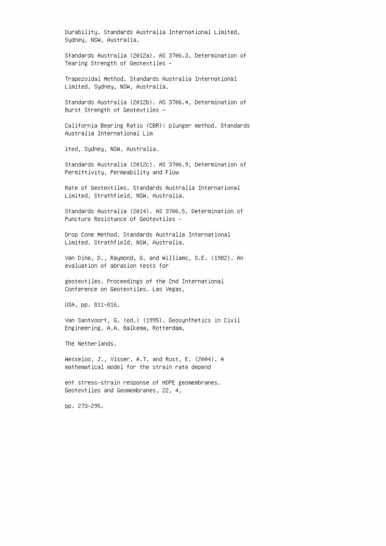
Durability. Standards Australia International Limited,Sydney, NSW, Australia.
Standards Australia (2012a). AS 3706.3, Determination ofTearing Strength of Geotextiles –
Trapezoidal Method. Standards Australia InternationalLimited, Sydney, NSW, Australia.
Standards Australia (2012b). AS 3706.4, Determination ofBurst Strength of Geotextiles –
California Bearing Ratio (CBR): plunger method. StandardsAustralia International Lim
ited, Sydney, NSW, Australia.
Standards Australia (2012c). AS 3706.9, Determination ofPermittivity, Permeability and Flow
Rate of Geotextiles. Standards Australia InternationalLimited, Strathfield, NSW, Australia.
Standards Australia (2014). AS 3706.5, Determination ofPuncture Resistance of Geotextiles –
Drop Cone Method. Standards Australia InternationalLimited, Strathfield, NSW, Australia.
Van Dine, D., Raymond, G. and Williams, S.E. (1982). Anevaluation of abrasion tests for
geotextiles. Proceedings of the 2nd InternationalConference on Geotextiles. Las Vegas,
USA, pp. 811–816.
Van Santvoort, G. (ed.) (1995). Geosynthetics in CivilEngineering. A.A. Balkema, Rotterdam,
The Netherlands.
Wesseloo, J., Visser, A.T. and Rust, E. (2004). Amathematical model for the strain rate depend
ent stress-strain response of HDPE geomembranes.Geotextiles and Geomembranes, 22, 4,
pp. 273–295.
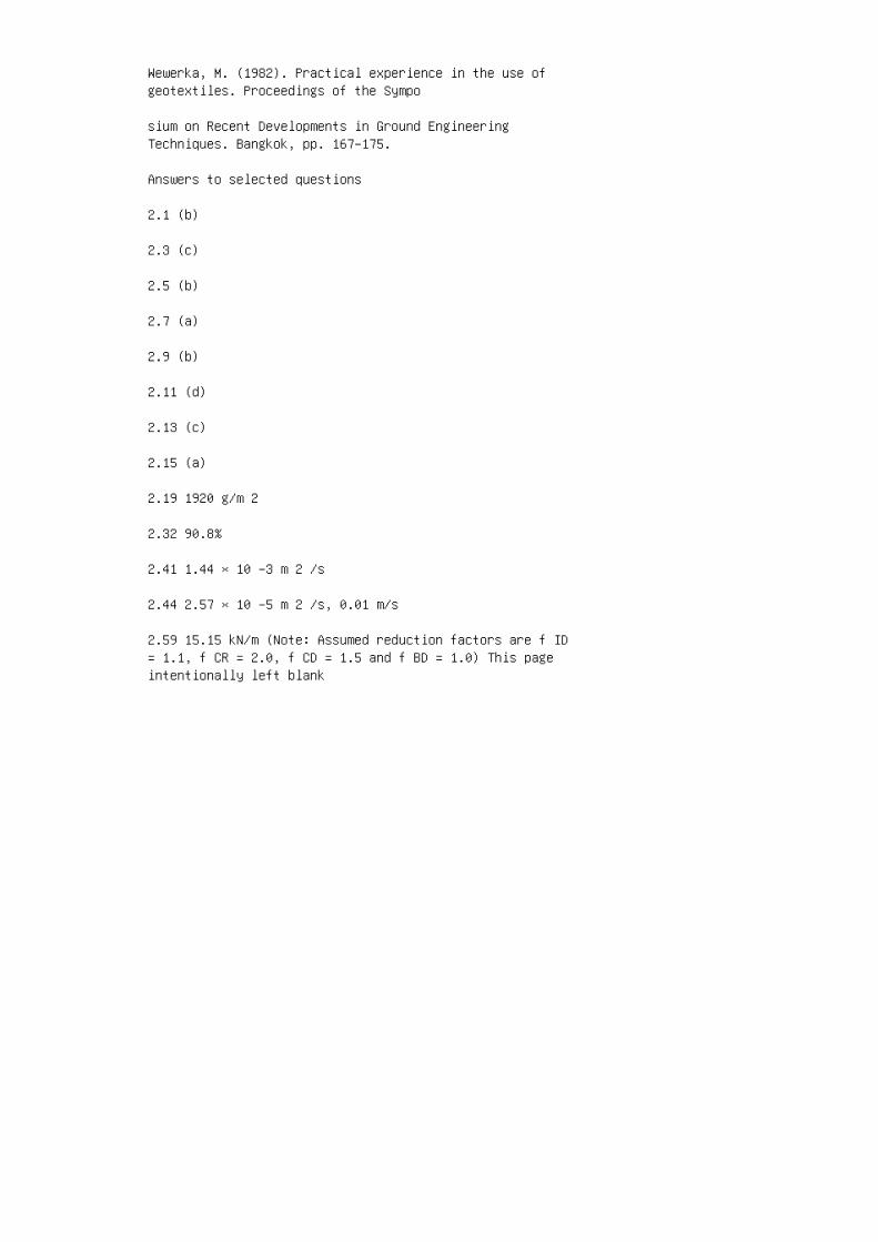
Wewerka, M. (1982). Practical experience in the use ofgeotextiles. Proceedings of the Sympo
sium on Recent Developments in Ground EngineeringTechniques. Bangkok, pp. 167–175.
Answers to selected questions
2.1 (b)
2.3 (c)
2.5 (b)
2.7 (a)
2.9 (b)
2.11 (d)
2.13 (c)
2.15 (a)
2.19 1920 g/m 2
2.32 90.8%
2.41 1.44 × 10 −3 m 2 /s
2.44 2.57 × 10 −5 m 2 /s, 0.01 m/s
2.59 15.15 kN/m (Note: Assumed reduction factors are f ID= 1.1, f CR = 2.0, f CD = 1.5 and f BD = 1.0) This pageintentionally left blank
3 3. Geotechnical applications ofgeosynthetics
AASHTO (American Association of State Highway andTransportation Officials) (2007). LRFD Bridge DesignSpecifications, SI Units, Fourth Edition, AmericanAssociation of State Highway and Transportation Officials,Washington, DC, USA.
Abramson, L.W., Lee, T.S., Sharma, S. and Boyce, G. (2002).Slope Stability and Stabilization Methods. John Wiley &Sons, Inc., New York.
Ali, F.H. and Tee, H.E. (1990). Reinforced slopes: fieldbehaviour and prediction. Proceedings of the 4thInternational Conference on Geotextiles, Geomembranes andRelated Products. The Hague, Netherlands, pp. 17–20.
Almeida, M.S.S., Britto, A.M. and Parry, R.H.G. (1986).Numerical modeling of a centrifuged embankment on softclay. Canadian Geotechnical Journal, 23, pp. 103–114.
Alston, C., Lowry, D.K. and Lister, A. (2015). Geogridreinforced granular pad resting on loose and soft soils,Hamilton Harbour, Ontario. International Journal ofGeosynthetics and Ground Engineering, 1, 3, 21, pp. 1–11.
Anthoine, A. (1989). Mixed modeling of reinforced soilswithin the framework of the yield design theory. Computersand Geotechnics, 7, 1 & 2, pp. 67–82.
Bassett, R.H. and Last, N.C. (1978). Reinforcing earthbelow footings and embankments. Proceedings of theSymposium on Earth Reinforcement, ASCE, New York, pp.202–231.
Bathurst, R.J., Hatami, K. and Alfaro, M.C. (2012).Geosynthetic-reinforced soil walls and slopes – seismicaspects. Chapter 16, Handbook of Geosynthetics Engineering,Second Edition, Shukla, S.K., Editor, ICE Publishing,London, pp. 317–363.
Binquet, J. and Lee, K.L. (1975a). Bearing capacityanalysis of reinforced earth slabs. Journal of theGeotechnical Engineering Division, ASCE, 101, 12, pp.1257–1276.
Binquet, J. and Lee, K.L. (1975b). Bearing capacity testson reinforced earth slabs. Journal of the GeotechnicalEngineering Division, ASCE, 101, 12, pp. 1241–1255.
Bonaparte, R. and Christopher, B.R. (1987). Design andconstruction of reinforced embankments over weakfoundations. Proceedings of the Symposium on ReinforcedLayered Systems. Transportation Research Record, 1153,Transportation Research Board, Washington, D.C., pp.26–39.
Broms, B.B. and Wong, I.H. (1986). Stabilization of slopesin residual soils with geofabric. Proceedings of the 3rdInternational Conference on Geotextiles. Vienna, Austria,pp. 295–300.
Broms, B.B. and Wong, K.S. (1990). Landslides. In:Foundation Engineering Handbook edited by H.Y. Fang, VanNostrand Reinhold, New York.
BS 8006-1 (2010). Code of Practice forStrengthened/Reinforced Soils and Fills. British StandardsInstitution, London, UK.
Bush, D.I., Jenner, C.G. and Bassett, R.H. (1990). Thedesign and construction of geocell foundation mattresssupporting embankments over soft ground. Geotextiles andGeomembranes, 9, 1, pp. 83–98.
CGS (Canadian Geotechnical Society) (2006). CanadianFoundation Engineering Manual. Fourth Edition, BiTech,Richmond, BC, Canada.
Chandaluri, V.K., Sawant, V.A. and Shukla, S.K. (2015).Seismic stability analysis of reinforced soil wall usinghorizontal slice method. International Journal ofGeosynthetics and Ground Engineering, 1, 3, pp.23:1–23.10.
Christopher, B.R. and Holtz, R.D. (1985). GeotextileEngineering Manual. Report No. FHWATS-86/203, FederalHighway Administration, Washington, D.C.
Christopher, B.R., Gill, S.A., Giroud, J.P., Juran, I.,Mitchell, J.K., Schlosser, F. and Dunnicliff, J.D. (1990).Reinforced Soil Structures, Volume I: Design andConstruction. Federal Highway Administration, Washington,DC, Report FHWA-RO-89-043.
Christopher, B.R. and Leschinsky, D. (1991). Design ofgeosynthetically reinforced slopes. Proceedings of theGeotechnical Engineering Congress, Boulder, Colorado, pp.988–1005.
Collin, J.G. (1996). Controlling surficial stabilityproblems on reinforced steepened slopes. GeotechnicalFabrics Report, pp. 26–29.
Das, B.M., Omar, M.T. and Singh, G. (1996). Stripfoundation on geogrid-reinforced clay. Proceedings of theFirst European Geosynthetics Conference. Eurogeo 1,Netherlands, pp. 419–426
de Buhan, P., Mangiavcchi, R., Nova, R., Pellegrini, G. andSalencon, J. (1989). Yield design of reinforced earthwalls by homogenization method. Geotechnique, 39, 2, pp.189–201.
Dikran, S.S. and Rimoldi, P. (1996). Hard facing for steepreinforced slopes: A case history from the UK. Proceedingsof the First European Geosynthetics Conference. Eurogeo 1,Netherlands, pp. 131–136.
Dixon, J.H. (1993). Geogrid reinforced soil repair of aslope failure in clay, North Circular Road, London, UnitedKingdom. In: Geosynthetics Case Histories edited by G.P.Raymond and J.P. Giroud on behalf of ISSMFE TechnicalCommittee TC9, Geotextiles and Geosynthetics, pp. 168–169.
Fowler, J. and Koerner, R.M. (1987). Stabilization of verysoft soils using geosynthetics. Proceedings of theGeosynthetics ’87, New Orleans, Louisiana, IFAI, St Paul,MN, pp. 289–300.
Ghiassian, H., Hryciw, R.D. and Gray, D.H. (1996).Laboratory testing apparatus for slopes stabilized byanchored geosynthetics. Geotechnical Testing Journal, 19,1, pp. 65–73.
Gill, K.S., Choudhary, A.K., Jha, J.N. and Shukla, S.K.(2013). Experimental and numerical studies of loaded stripfooting resting on reinforced fly ash slope. GeosyntheticsInternational, 20, 1, pp. 13–25.
Gourc J.P. and Risseeuw, P. (1993). Geotextile reinforcedwrap around faced wall, Prapoutel, France. GeosyntheticsCase Histories edited by G.P. Raymond and J.P. Giroud onbehalf of ISSMFE Technical Committee TC9, Geotextiles andGeosynthetics, pp. 272–273.
Guido, V.A., Biesiadecki, G.L. and Sullivan, M.J. (1985).Bearing capacity of a geotextilereinforced foundation.Proceedings of the 11th International Conference on Soil
Mechanics and Foundation Engineering. San Francisco,Calif. pp. 1777–1780.
Haliburton, T.A., Douglas, P.A. and Fowler, J. (1977).Feasibility of Pinto Island as a longterm dredged materialdisposal site. Miscellaneous Paper, D-77-3, U.S. ArmyWaterways Experiment Station.
Ingold, T.S. (1982). An analytical study of geosyntheticreinforced embankments. Proceedings of the 2ndInternational Conference on Geotextiles. Las Vegas, USA,pp. 683–688.
IRC (Indian Roads Congress) (2013). IRC: 113-2013,Guidelines for the Design and Construction of GeosyntheticReinforced Embankments on Soft Subsoils. Indian RoadsCongress, New Delhi, India.
IRC (2014). IRC:SP:102 (2014), Guidelines for Design andConstruction of Reinforced Soil Walls. Indian RoadsCongress, New Delhi, India.
Jewell, R.A. (1990). Revised design charts for steepreinforced slopes. Reinforced Embankments, Theory andPractice, Thomas Telford, London, pp. 1–30.
Jewell, R.A. and Woods, R.I. (1984). Simplified designcharts for steep reinforced slopes. Proceedings of theSymposium on Reinforced Soil, University of Mississipi.
Jewel, R.A., Paine, N. and Woods, R.I. (1984). Designmethods for steep reinforced embankments. Proceedings ofthe Symposium of Polymer grid reinforcement, Institute ofCivil Engineering, London, pp. 18–30.
Jha, J.N., Choudhary, A.K., Gill, K.S. and Shukla, S.K.(2013). Bearing capacity of a strip footing resting onreinforced fly ash slope: an analytical approach. IndianGeotechnical Journal, 43, 4, pp. 354–366.
Jiang, G.L. and Magnan, J.P. (1997). Stability analysis ofembankments: comparison of limit analysis with method ofslices. Geotechnique, 47, 4, pp. 857–872.
Kazi, M., Shukla, S.K. and Habibi, D. (2015). An improvedmethod to increase the load-bearing capacity of stripfooting resting on geotextile-reinforced sand bed. IndianGeotechnical Journal, India, 45, 1, pp. 98–109.
Kazi, M., Shukla, S.K. and Habibi, D. (2015). Behaviour of
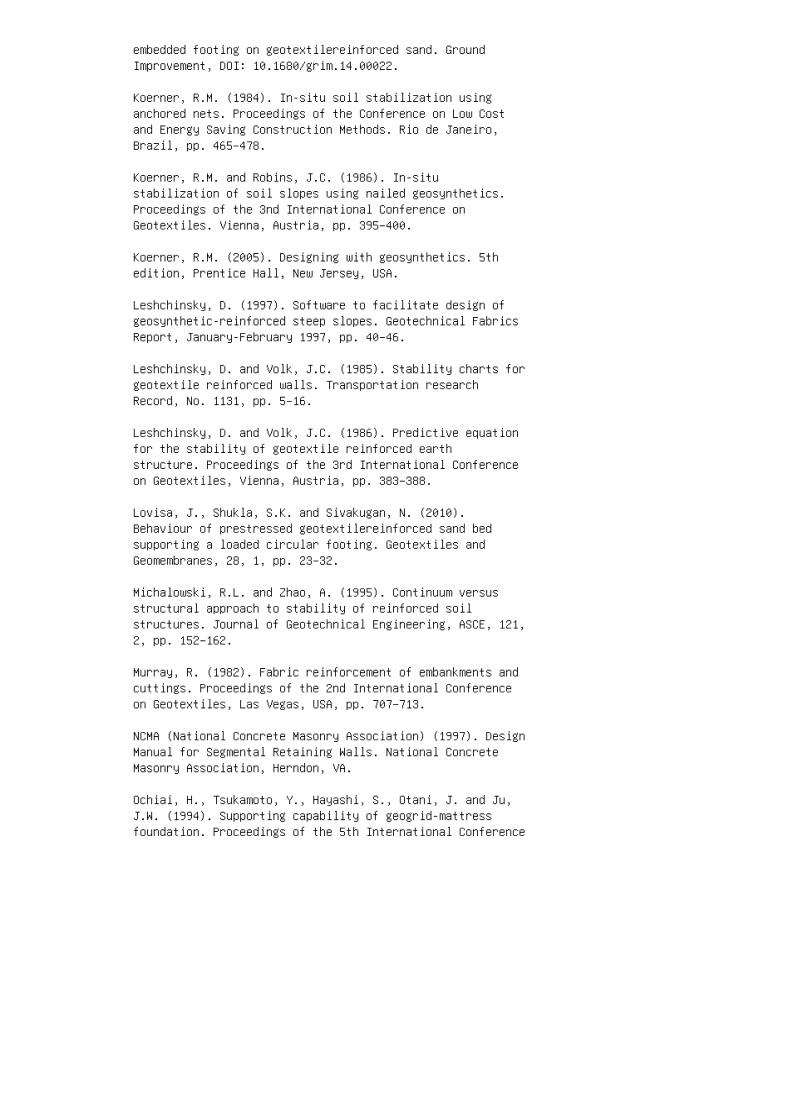
embedded footing on geotextilereinforced sand. GroundImprovement, DOI: 10.1680/grim.14.00022.
Koerner, R.M. (1984). In-situ soil stabilization usinganchored nets. Proceedings of the Conference on Low Costand Energy Saving Construction Methods. Rio de Janeiro,Brazil, pp. 465–478.
Koerner, R.M. and Robins, J.C. (1986). In-situstabilization of soil slopes using nailed geosynthetics.Proceedings of the 3nd International Conference onGeotextiles. Vienna, Austria, pp. 395–400.
Koerner, R.M. (2005). Designing with geosynthetics. 5thedition, Prentice Hall, New Jersey, USA.
Leshchinsky, D. (1997). Software to facilitate design ofgeosynthetic-reinforced steep slopes. Geotechnical FabricsReport, January-February 1997, pp. 40–46.
Leshchinsky, D. and Volk, J.C. (1985). Stability charts forgeotextile reinforced walls. Transportation researchRecord, No. 1131, pp. 5–16.
Leshchinsky, D. and Volk, J.C. (1986). Predictive equationfor the stability of geotextile reinforced earthstructure. Proceedings of the 3rd International Conferenceon Geotextiles, Vienna, Austria, pp. 383–388.
Lovisa, J., Shukla, S.K. and Sivakugan, N. (2010).Behaviour of prestressed geotextilereinforced sand bedsupporting a loaded circular footing. Geotextiles andGeomembranes, 28, 1, pp. 23–32.
Michalowski, R.L. and Zhao, A. (1995). Continuum versusstructural approach to stability of reinforced soilstructures. Journal of Geotechnical Engineering, ASCE, 121,2, pp. 152–162.
Murray, R. (1982). Fabric reinforcement of embankments andcuttings. Proceedings of the 2nd International Conferenceon Geotextiles, Las Vegas, USA, pp. 707–713.
NCMA (National Concrete Masonry Association) (1997). DesignManual for Segmental Retaining Walls. National ConcreteMasonry Association, Herndon, VA.
Ochiai, H., Tsukamoto, Y., Hayashi, S., Otani, J. and Ju,J.W. (1994). Supporting capability of geogrid-mattressfoundation. Proceedings of the 5th International Conference
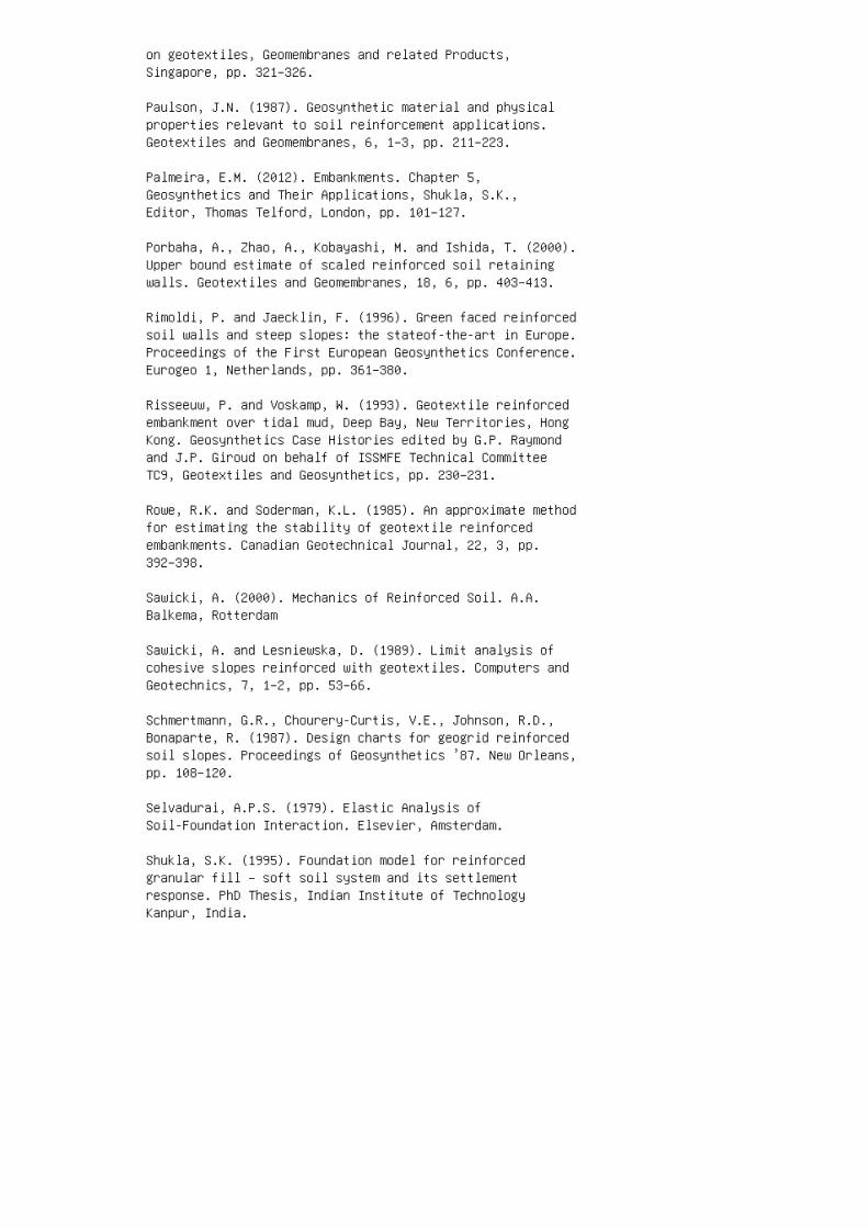
on geotextiles, Geomembranes and related Products,Singapore, pp. 321–326.
Paulson, J.N. (1987). Geosynthetic material and physicalproperties relevant to soil reinforcement applications.Geotextiles and Geomembranes, 6, 1–3, pp. 211–223.
Palmeira, E.M. (2012). Embankments. Chapter 5,Geosynthetics and Their Applications, Shukla, S.K.,Editor, Thomas Telford, London, pp. 101–127.
Porbaha, A., Zhao, A., Kobayashi, M. and Ishida, T. (2000).Upper bound estimate of scaled reinforced soil retainingwalls. Geotextiles and Geomembranes, 18, 6, pp. 403–413.
Rimoldi, P. and Jaecklin, F. (1996). Green faced reinforcedsoil walls and steep slopes: the stateof-the-art in Europe.Proceedings of the First European Geosynthetics Conference.Eurogeo 1, Netherlands, pp. 361–380.
Risseeuw, P. and Voskamp, W. (1993). Geotextile reinforcedembankment over tidal mud, Deep Bay, New Territories, HongKong. Geosynthetics Case Histories edited by G.P. Raymondand J.P. Giroud on behalf of ISSMFE Technical CommitteeTC9, Geotextiles and Geosynthetics, pp. 230–231.
Rowe, R.K. and Soderman, K.L. (1985). An approximate methodfor estimating the stability of geotextile reinforcedembankments. Canadian Geotechnical Journal, 22, 3, pp.392–398.
Sawicki, A. (2000). Mechanics of Reinforced Soil. A.A.Balkema, Rotterdam
Sawicki, A. and Lesniewska, D. (1989). Limit analysis ofcohesive slopes reinforced with geotextiles. Computers andGeotechnics, 7, 1–2, pp. 53–66.
Schmertmann, G.R., Chourery-Curtis, V.E., Johnson, R.D.,Bonaparte, R. (1987). Design charts for geogrid reinforcedsoil slopes. Proceedings of Geosynthetics ’87. New Orleans,pp. 108–120.
Selvadurai, A.P.S. (1979). Elastic Analysis ofSoil-Foundation Interaction. Elsevier, Amsterdam.
Shukla, S.K. (1995). Foundation model for reinforcedgranular fill – soft soil system and its settlementresponse. PhD Thesis, Indian Institute of TechnologyKanpur, India.
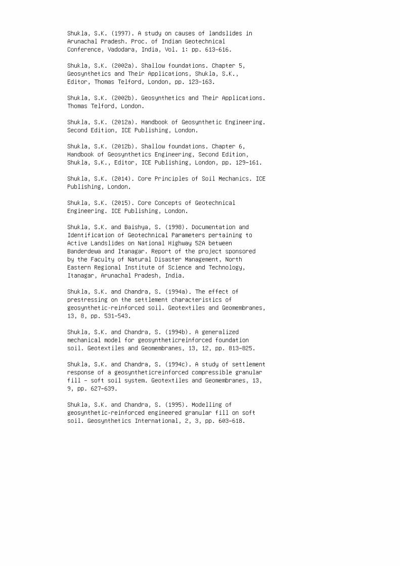
Shukla, S.K. (1997). A study on causes of landslides inArunachal Pradesh. Proc. of Indian GeotechnicalConference, Vadodara, India, Vol. 1: pp. 613–616.
Shukla, S.K. (2002a). Shallow foundations. Chapter 5,Geosynthetics and Their Applications, Shukla, S.K.,Editor, Thomas Telford, London, pp. 123–163.
Shukla, S.K. (2002b). Geosynthetics and Their Applications.Thomas Telford, London.
Shukla, S.K. (2012a). Handbook of Geosynthetic Engineering.Second Edition, ICE Publishing, London.
Shukla, S.K. (2012b). Shallow foundations. Chapter 6,Handbook of Geosynthetics Engineering, Second Edition,Shukla, S.K., Editor, ICE Publishing, London, pp. 129–161.
Shukla, S.K. (2014). Core Principles of Soil Mechanics. ICEPublishing, London.
Shukla, S.K. (2015). Core Concepts of GeotechnicalEngineering. ICE Publishing, London.
Shukla, S.K. and Baishya, S. (1998). Documentation andIdentification of Geotechnical Parameters pertaining toActive Landslides on National Highway 52A betweenBanderdewa and Itanagar. Report of the project sponsoredby the Faculty of Natural Disaster Management, NorthEastern Regional Institute of Science and Technology,Itanagar, Arunachal Pradesh, India.
Shukla, S.K. and Chandra, S. (1994a). The effect ofprestressing on the settlement characteristics ofgeosynthetic-reinforced soil. Geotextiles and Geomembranes,13, 8, pp. 531–543.
Shukla, S.K. and Chandra, S. (1994b). A generalizedmechanical model for geosyntheticreinforced foundationsoil. Geotextiles and Geomembranes, 13, 12, pp. 813–825.
Shukla, S.K. and Chandra, S. (1994c). A study of settlementresponse of a geosyntheticreinforced compressible granularfill – soft soil system. Geotextiles and Geomembranes, 13,9, pp. 627–639.
Shukla, S.K. and Chandra, S. (1995). Modelling ofgeosynthetic-reinforced engineered granular fill on softsoil. Geosynthetics International, 2, 3, pp. 603–618.
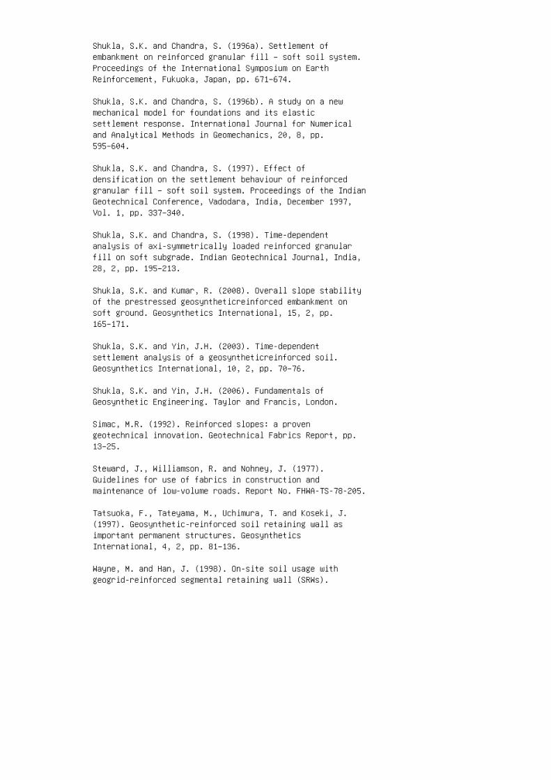
Shukla, S.K. and Chandra, S. (1996a). Settlement ofembankment on reinforced granular fill – soft soil system.Proceedings of the International Symposium on EarthReinforcement, Fukuoka, Japan, pp. 671–674.
Shukla, S.K. and Chandra, S. (1996b). A study on a newmechanical model for foundations and its elasticsettlement response. International Journal for Numericaland Analytical Methods in Geomechanics, 20, 8, pp.595–604.
Shukla, S.K. and Chandra, S. (1997). Effect ofdensification on the settlement behaviour of reinforcedgranular fill – soft soil system. Proceedings of the IndianGeotechnical Conference, Vadodara, India, December 1997,Vol. 1, pp. 337–340.
Shukla, S.K. and Chandra, S. (1998). Time-dependentanalysis of axi-symmetrically loaded reinforced granularfill on soft subgrade. Indian Geotechnical Journal, India,28, 2, pp. 195–213.
Shukla, S.K. and Kumar, R. (2008). Overall slope stabilityof the prestressed geosyntheticreinforced embankment onsoft ground. Geosynthetics International, 15, 2, pp.165–171.
Shukla, S.K. and Yin, J.H. (2003). Time-dependentsettlement analysis of a geosyntheticreinforced soil.Geosynthetics International, 10, 2, pp. 70–76.
Shukla, S.K. and Yin, J.H. (2006). Fundamentals ofGeosynthetic Engineering. Taylor and Francis, London.
Simac, M.R. (1992). Reinforced slopes: a provengeotechnical innovation. Geotechnical Fabrics Report, pp.13–25.
Steward, J., Williamson, R. and Nohney, J. (1977).Guidelines for use of fabrics in construction andmaintenance of low-volume roads. Report No. FHWA-TS-78-205.
Tatsuoka, F., Tateyama, M., Uchimura, T. and Koseki, J.(1997). Geosynthetic-reinforced soil retaining wall asimportant permanent structures. GeosyntheticsInternational, 4, 2, pp. 81–136.
Wayne, M. and Han, J. (1998). On-site soil usage withgeogrid-reinforced segmental retaining wall (SRWs).
Geotechnical Fabrics Report, pp. 20–25.
Wright, S.G. and Duncan, J.M. (1991). Limit equilibriumstability analyses for reinforced slopes. TransportationResearch Report, No. 1330, pp. 40–46.
Wrigley, N.E. (1987). Durability and long-term performanceof ‘Tensar’ polymer grids for soil reinforcement.Materials Science and Technology, Vol. 3, pp. 161–170.
Yin, J.H. (1997a). Modelling geosynthetic-reinforcedgranular fills over soft soil. GeosyntheticsInternational, 4, 2, pp. 165–185.
Yin, J.H. (1997b). A nonlinear model ofgeosynthetic-reinforced granular fill over soft soil.Geosynthetics International, 4, 5, pp. 523–537.
Zanzinger, H. and Gartung, E. (2002). Performance of ageogrid reinforced railway embankment on piles. Proceedingsof the Seventh International Conference on Geosynthetics,France, pp. 381–386.
Zhao, A. (1996). Limit analysis of geosynthetic-reinforcedslopes. Geosynthetics International, 3, 6, pp. 721–740.
Answers to selected questions
3.1 (b)
3.3 (d)
3.5 (b)
3.7 (c)
3.9 (b)
3.11 (c)
3.13 (a)
3.15 (d) This page intentionally left blank
4 4. Hydraulic and geoenvironmentalapplications of geosynthetics
AASHTO (American Association of State Highway andTransportation Officials) (2013). Geotextile Specificationfor Highway Applications, AASHTO Designation: M 288-06(2011), Standard Specifications for TransportationMaterials and Methods of Sampling and Testing,Thirty-third Edition, Part 1B: Specifications M 280-R 63,American Association of State Highway and TransportationOfficials, Washington, DC, USA.
ACZ (1990). Application and Execution Aspects of Sand TubeSystems. Internal Report of ACZ Marine Contractors B.V.,Gorinchem, The Netherlands.
Agnew, W. (1991). Erosion control product selection.Geotechnical Fabrics Report, April 1991, pp. 24–27.
Ahn, T.B., Cho, S.D. and Yang, S.C. (2002). Stabilizationof soil slope using geosynthetic mulching mat. Geotextilesand Geomembranes, 20, 2, pp. 135–46.
ASTM (American Society for Testing and Materials) (2011).ASTM D5567-94, Standard Test Method for HydraulicConductivity Ratio (HCR) Testing of Soil/GeotextileSystems. ASTM International, West Conshohocken, PA, USA.
ASTM (2012a). ASTM D5101-12. Standard Test Method forMeasuring the Filtration Compatibility of Soil-GeotextileSystems. ASTM International, West Conshohocken, PA, USA.
ASTM (2012b). ASTM D6102-12, Standard Guide forInstallation of Geosynthetic Clay Liners. ASTMInternational, West Conshohocken, PA, USA.
Bagchi, A. (1994). Design, Construction, and Monitoring ofLandfills. John Wiley & Son, Inc., New York.
Benneton, J.P., Mahuet, J.L. and Gourc, J.P. (1993).Geomembrane waterproofing of dry tunnel under two rivers,Lyon metro tunnel, France. In: Geosynthetics Case Historiesedited by G.P. Raymond and J.P. Giroud on behalf of ISSMFETechnical Committee TC9, Geotextiles and Geosynthetics,pp. 118–119.
Broms, B.B., Chu, J. and Chora, V. (1994). Measuring thedischarge capacity of band drains by a new drain tester.Proceedings of the 5th International Conference onGeotextiles, Geomembranes and Related Products. Singapore,
pp. 803–806.
Cancelli, A., Monti, R. and Rimoldi, P. (1990). Comparativestudy of geosynthetics for erosion control. Proceedings ofthe 4th International Conference on Geotextiles andGeomembranes. The Hague, The Netherlands.
Cazzuffi, D., Scuero, A. and Vaschetti, G. (2012).Hydraulic tunnels. Chapter 15, Handbook of GeosyntheticEngineering, Second Edition, Shukla, S.K., Editor, ICEPublishing, London, pp. 303–315.
Cedergren, H.R. (1989). Seepage, Drainage, and Flownets.Third Edition, John Wiley and Sons, New York.
Chen, Y.H. and Cotton, G.K. (1988). Design of roadsidechannels with flexible linings. Federal HighwayAdministration Report, HEC-15/FHWA-1P087-7, McLean, Va.,USA.
Christopher, B.R. (1998). The first step in geotextilefilter deign. Geotechnical Fabrics Report, March 1998, pp.36–38.
Christopher, B.R. and Holtz, R.D. (1985). GeotextileEngineering Manual. Report No. FHWATS-86/203, FederalHighway Administration, Washington, D.C.
Corbet, S.P. (1992). The design and specification ofgeotextiles and geocomposites for filtration and drainage.Proceedings of the Conference Geofad’ 92: Geotextiles infiltration and drainage, Cambridge, Thomas Telford, UK,pp. 29–40.
Daniel, D.E. (1993). ‘Landfill and Impoundments’, inGeotechnical Practice for Waste Disposal, Daniel, D.E.,Editor, Chapman & Hall, pp. 97–112.
Daniel, D.E., Koerner, R.M., Bonaparte, R., Landreth, R.E.,Carson, D.A. and Scranton, H.B. (1998). Slope stability ofgeosynthetic clay liner test plots. Journal of Geotechnicaland Geoenvironmental Engineering, ASCE, 124, 7, pp.628–637.
Davies. P.L. (1993). Geomembrane waterproofing of wethydroelectric tunnel, Drakensberg hydroelectric tunnel,South Africa. In: Geosynthetics Case Histories edited byG.P. Raymond and J.P. Giroud on behalf of ISSMFE TechnicalCommittee TC9, Geotextiles and Geosynthetics, pp. 114–115.
Duquennoi, C. (2002). Containment ponds, reservoirs andcanals. Chapter 13, Geosynthetics and Their Applications,Shukla, S.K., Editor, Thomas Telford, London, pp. 299–325.
Faure, Y. and Mlynarek, J. (1998). Geotextile filterhydraulic requirements. Geotechnical Fabrics Report, May1998, pp. 30–33.
Fourie, A. (1998). The determination of appropriatefiltration design parameters. Geotechnical Fabrics Report,April 1998, pp. 44–47.
Fox, P.J., Rowland, M.G. and Scheithe, J.R. (1998).Internal shear strength of three geosynthetic clay liners.Journal of Geotechnical and Geoenvironmental Engineering,ASCE, 124, 10, pp. 933–944.
Frobel, R.K. (1996). Geosynthetic clay liners, Part four:interface and internal shear strength determination.Geotechnical Fabrics Report, IFAI, Vol. 14, No. 8, pp.20–23.
Fuller, C. (1992). Concrete blocks gain acceptance aserosion control systems. Geotechnical Fabrics Report, pp.24–37.
Giroud, J.P. (1982). Filter criteria for geotextiles.Proceedings of the 2nd International Conference onGeotextiles. Las Vegas, pp. 103–108.
Giroud, J.P. (1984). Geotextiles and geomembranesdefinitions, properties and design, IFAI, St Paul,Minnesota.
Giroud, J.P. (1992). Geosynthetics in dams: Two decades ofexperience. Geotechnical Fabrics Report, pp. 22–28.
Giroud, J.P. (1994). Quantification of geosyntheticbehaviour. Proceedings of the 5th International Conferenceon Geotextiles, Geomembranes and Related Products.Singapore, pp. 1249–1273.
Giroud, J.P. (1996). Granular filters and geotextilefilters. Proceedings of GeoFilters ’96, Montreal, pp.565–680.
Giroud, J.P. and Bonaparte, R. (1989). Leakage throughliners constructed with geomembranes – Part I. Geomembraneliners. Geotextiles and Geomembranes, 8, 1, pp. 27–67.
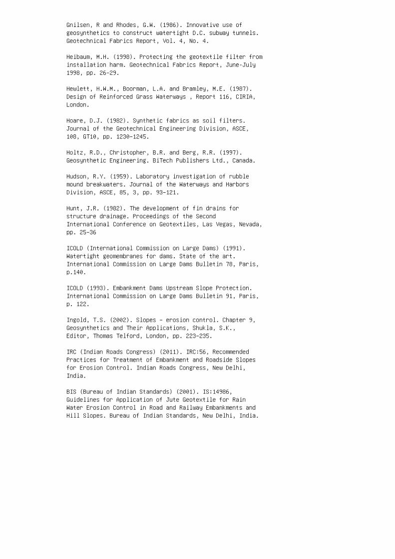
Gnilsen, R and Rhodes, G.W. (1986). Innovative use ofgeosynthetics to construct watertight D.C. subway tunnels.Geotechnical Fabrics Report, Vol. 4, No. 4.
Heibaum, M.H. (1998). Protecting the geotextile filter frominstallation harm. Geotechnical Fabrics Report, June-July1998, pp. 26–29.
Hewlett, H.W.M., Boorman, L.A. and Bramley, M.E. (1987).Design of Reinforced Grass Waterways , Report 116, CIRIA,London.
Hoare, D.J. (1982). Synthetic fabrics as soil filters.Journal of the Geotechnical Engineering Division, ASCE,108, GT10, pp. 1230–1245.
Holtz, R.D., Christopher, B.R. and Berg, R.R. (1997).Geosynthetic Engineering. BiTech Publishers Ltd., Canada.
Hudson, R.Y. (1959). Laboratory investigation of rubblemound breakwaters. Journal of the Waterways and HarborsDivision, ASCE, 85, 3, pp. 93–121.
Hunt, J.R. (1982). The development of fin drains forstructure drainage. Proceedings of the SecondInternational Conference on Geotextiles, Las Vegas, Nevada,pp. 25–36
ICOLD (International Commission on Large Dams) (1991).Watertight geomembranes for dams. State of the art.International Commission on Large Dams Bulletin 78, Paris,p.140.
ICOLD (1993). Embankment Dams Upstream Slope Protection.International Commission on Large Dams Bulletin 91, Paris,p. 122.
Ingold, T.S. (2002). Slopes – erosion control. Chapter 9,Geosynthetics and Their Applications, Shukla, S.K.,Editor, Thomas Telford, London, pp. 223–235.
IRC (Indian Roads Congress) (2011). IRC:56, RecommendedPractices for Treatment of Embankment and Roadside Slopesfor Erosion Control. Indian Roads Congress, New Delhi,India.
BIS (Bureau of Indian Standards) (2001). IS:14986,Guidelines for Application of Jute Geotextile for RainWater Erosion Control in Road and Railway Embankments andHill Slopes. Bureau of Indian Standards, New Delhi, India.
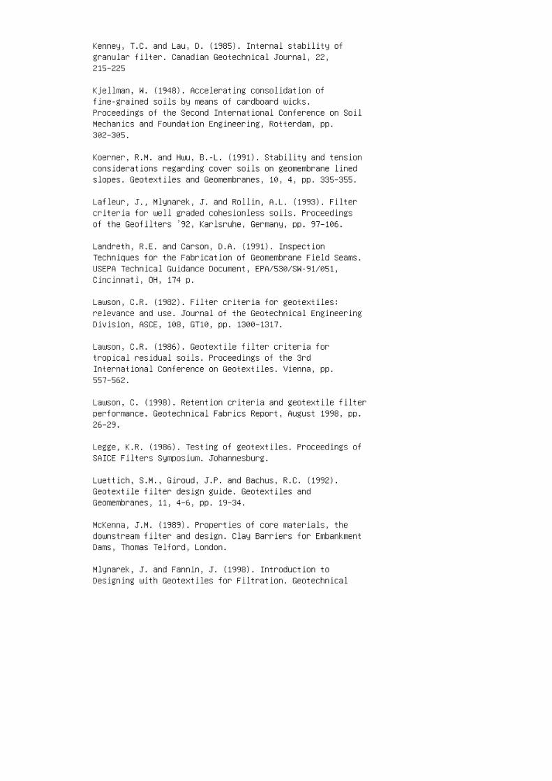
Kenney, T.C. and Lau, D. (1985). Internal stability ofgranular filter. Canadian Geotechnical Journal, 22,215–225
Kjellman, W. (1948). Accelerating consolidation offine-grained soils by means of cardboard wicks.Proceedings of the Second International Conference on SoilMechanics and Foundation Engineering, Rotterdam, pp.302–305.
Koerner, R.M. and Hwu, B.-L. (1991). Stability and tensionconsiderations regarding cover soils on geomembrane linedslopes. Geotextiles and Geomembranes, 10, 4, pp. 335–355.
Lafleur, J., Mlynarek, J. and Rollin, A.L. (1993). Filtercriteria for well graded cohesionless soils. Proceedingsof the Geofilters ’92, Karlsruhe, Germany, pp. 97–106.
Landreth, R.E. and Carson, D.A. (1991). InspectionTechniques for the Fabrication of Geomembrane Field Seams.USEPA Technical Guidance Document, EPA/530/SW-91/051,Cincinnati, OH, 174 p.
Lawson, C.R. (1982). Filter criteria for geotextiles:relevance and use. Journal of the Geotechnical EngineeringDivision, ASCE, 108, GT10, pp. 1300–1317.
Lawson, C.R. (1986). Geotextile filter criteria fortropical residual soils. Proceedings of the 3rdInternational Conference on Geotextiles. Vienna, pp.557–562.
Lawson, C. (1998). Retention criteria and geotextile filterperformance. Geotechnical Fabrics Report, August 1998, pp.26–29.
Legge, K.R. (1986). Testing of geotextiles. Proceedings ofSAICE Filters Symposium. Johannesburg.
Luettich, S.M., Giroud, J.P. and Bachus, R.C. (1992).Geotextile filter design guide. Geotextiles andGeomembranes, 11, 4–6, pp. 19–34.
McKenna, J.M. (1989). Properties of core materials, thedownstream filter and design. Clay Barriers for EmbankmentDams, Thomas Telford, London.
Mlynarek, J. and Fannin, J. (1998). Introduction toDesigning with Geotextiles for Filtration. Geotechnical
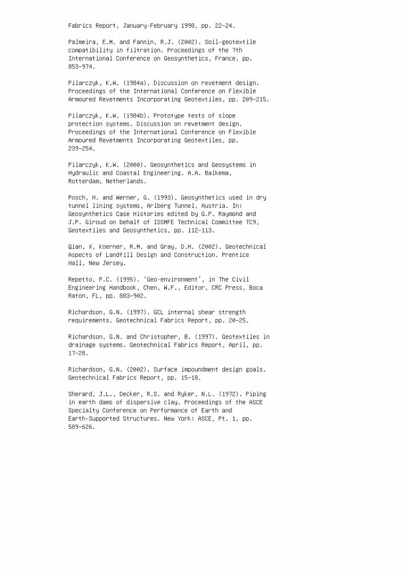
Fabrics Report, January-February 1998, pp. 22–24.
Palmeira, E.M. and Fannin, R.J. (2002). Soil-geotextilecompatibility in filtration. Proceedings of the 7thInternational Conference on Geosynthetics, France, pp.853–974.
Pilarczyk, K.W. (1984a). Discussion on revetment design.Proceedings of the International Conference on FlexibleArmoured Revetments Incorporating Geotextiles, pp. 209–215.
Pilarczyk, K.W. (1984b). Prototype tests of slopeprotection systems. Discussion on revetment design.Proceedings of the International Conference on FlexibleArmoured Revetments Incorporating Geotextiles, pp.239–254.
Pilarczyk, K.W. (2000). Geosynthetics and Geosystems inHydraulic and Coastal Engineering. A.A. Balkema,Rotterdam, Netherlands.
Posch, H. and Werner, G. (1993). Geosynthetics used in drytunnel lining systems, Arlberg Tunnel, Austria. In:Geosynthetics Case Histories edited by G.P. Raymond andJ.P. Giroud on behalf of ISSMFE Technical Committee TC9,Geotextiles and Geosynthetics, pp. 112–113.
Qian, X, Koerner, R.M. and Gray, D.H. (2002). GeotechnicalAspects of Landfill Design and Construction. PrenticeHall, New Jersey.
Repetto, P.C. (1995). ‘Geo-environment’, in The CivilEngineering Handbook, Chen, W.F., Editor, CRC Press, BocaRaton, FL, pp. 883–902.
Richardson, G.N. (1997). GCL internal shear strengthrequirements. Geotechnical Fabrics Report, pp. 20–25.
Richardson, G.N. and Christopher, B. (1997). Geotextiles indrainage systems. Geotechnical Fabrics Report, April, pp.17–28.
Richardson, G.N. (2002). Surface impoundment design goals.Geotechnical Fabrics Report, pp. 15–18.
Sherard, J.L., Decker, R.S. and Ryker, N.L. (1972). Pipingin earth dams of dispersive clay. Proceedings of the ASCESpecialty Conference on Performance of Earth andEarth-Supported Structures. New York: ASCE, Pt. 1, pp.589–626.
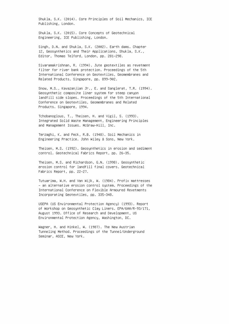
Shukla, S.K. (2014). Core Principles of Soil Mechanics, ICEPublishing, London.
Shukla, S.K. (2015). Core Concepts of GeotechnicalEngineering, ICE Publishing, London.
Singh, D.N. and Shukla, S.K. (2002). Earth dams. Chapter12, Geosynthetics and Their Applications, Shukla, S.K.,Editor, Thomas Telford, London, pp. 281–298.
Sivaramakrishnan, R. (1994). Jute geotextiles as revetmentfilter for river bank protection. Proceedings of the 5thInternational Conference on Geotextiles, Geomembranes andRelated Products. Singapore, pp. 899–902.
Snow, M.S., Kavazanjian Jr., E. and Sanglerat, T.R. (1994).Geosynthetic composite liner system for steep canyonlandfill side slopes. Proceedings of the 5th InternationalConference on Geotextiles, Geomembranes and RelatedProducts. Singapore, 1994.
Tchobanoglous, T., Theisen, H. and Vigil, S. (1993).Integrated Solid Waste Management, Engineering Principlesand Management Issues. McGraw-Hill, Inc.
Terzaghi, K. and Peck, R.B. (1948). Soil Mechanics inEngineering Practice. John Wiley & Sons, New York.
Theisen, M.S. (1992). Geosynthetics in erosion and sedimentcontrol. Geotechnical Fabrics Report, pp. 26–35.
Theisen, M.S. and Richardson, G.N. (1998). Geosyntheticerosion control for landfill final covers. GeotechnicalFabrics Report, pp. 22–27.
Tutuarima, W.H. and Van Wijk, W. (1984). Profix mattresses– an alternative erosion control system. Proceedings of theInternational Conference on Flexible Armoured RevetmentsIncorporating Geotextiles, pp. 335–348.
USEPA (US Environmental Protection Agency) (1993). Reportof Workshop on Geosynthetic Clay Liners. EPA/600/R-93/171,August 1993. Office of Research and Development, USEnvironmental Protection Agency, Washington, DC.
Wagner, H. and Hinkel, W. (1987). The New AustrianTunneling Method. Proceedings of the Tunnel/UndergroundSeminar, ASCE, New York.
Wang, D.W. (1994). Filter criteria of woven geotextiles forprotective works. Proceedings of the 5th InternationalConference on Geotextiles, Geomembranes and RelatedProducts. Singapore, pp. 763–766.
Werner, G., Puhringer, G. and Frobel, R.K. (1990).Multiaxial stress rupture and puncture testing ofgeotextiles. In the Proceedings of the Fourth InternationalConference on Geotextiles, Geomembranes, and RelatedProducts. The Hague, Vol. 2, pp. 765–770.
Wilson, C.B. (1992). Repair to Reeves lake dam, CobbCounty, Georgia. Proceedings of the 1992 Annual Conferenceof the Association of State Dam Safety Officials,Baltimore, pp. 77–81.
Wooten, R.L., Powledge, G.R. and Whiteside, S.L. (1990).CCM overtopping protection on three Park way dams.Proceedings of Hydraulic Engineering National Conference,ASCE. San Diego, pp. 1152–1157.
Wu, K.J. and Austin, D.N. (1992). Three dimensionalpolyethylene geocells for erosion control and channellinings. Geotextiles and Geomembranes, pp. 611–620.
Zanzinger, H. and Gartung, E. (2002). Landfills. Chapter11, Geosynthetics and Their Applications, Shukla, S.K.,Editor, Thomas Telford, London, pp. 259–279.
Answers to selected questions
4.1 (b)
4.3 (d)
4.5 (a)
4.7 (c)
4.9 (b)
4.11 (b)
4.13 (c)
4.15 (c)
4.17 (a)
5 5. Transportation applications ofgeosynthetics
AASHTO (American Association of State Highway andTransportation Officials) (1993). Guide for Design ofPavement Structures. American Association of State Highwayand Transportation Officials (AASHTO), Washington, DC,USA.
AASHTO (2008). Mechanistic-Empirical Pavement Design Guide– A Manual of Practice. American Association of StateHighway and Transportation Officials (AASHTO), Washington,DC, USA.
AASHTO (2013). Geotextile Specification for HighwayApplications, AASHTO Designation: M 288-06 (2011),Standard Specifications for Transportation Materials andMethods of Sampling and Testing. Thirty-third Edition,Part 1B: Specifications M 280-R 63, American Associationof State Highway and Transportation Officials, Washington,DC, USA.
AREA (American Railway Engineering Association) (1985).American Railway Engineering Manual, Lanham, MD, USA.
ASTM (American Society for Testing and Materials) (2013a).ASTM D4632/4632M-08, Standard Test Method for Grab BreakingLoad and Elongation of Geotextiles. ASTM International,West Conshohocken, PA, USA.
ASTM (2013b). ASTM D3884-09, Standard Guide for AbrasionResistance of Textile Fabrics (Rotary Platform,Double-Head Method). ASTM International, West Conshohocken,PA, USA.
ASTM (2014). ASTM D6140–00, Standard Test Method toDetermine Asphalt Retention of Paving Fabrics Used inAsphalt Paving for Full-Width Applications. ASTMInternational, West Conshohocken, PA, USA.
Baker, T. (1998). The most overlooked factor inpaving-fabric installation. Geotechnical Fabrics Report,April 1998, pp. 48–52.
Barazone, M. (2000). Installing paving synthetics –overview of correct installation procedures. GeotechnicalFabrics Report, May 2000, pp. 17–20.
Bourdeau, P.L. and Ashmawy, A.K. (2002). Unpaved roads.Chapter 6, Geosynthetics and Their Applications, Shukla,
S.K., Editor, Thomas Telford, London, pp. 165–183.
Cedergren, H.R. (1987). Drainage of Highway and AirfieldPavements. Krieger.
Chaddock, B.C.J. (1988). Deformation of road foundationswith geogrid reinforcement. Research Report 140,Department of Transportation, TRRL, Crowthorne, Berkshire,U.K.
Chan, F., Barksdale, R.D. and Brown, S.F. (1989). Aggregatebase reinforcement of surfaced pavements. Geotextiles andGeomembranes, 8, 3, pp. 165–189.
De Garidel, R. and Javor, E. (1986). Mechanicalreinforcement of low-volume roads by geotextiles.Proceedings of the 3rd International Conference onGeotextiles. Vienna, Austria, pp. 147–152.
Fernandes, G., Palmeira, E.M. and Gomes, R.C. (2008).Performance of geosynthetic- reinforced alternativesub-ballast material in a railway track. GeosyntheticsInternational, 15, 5, pp. 311–321.
Giroud, J.P., Ah-Line, A. and Bonaparte, R. (1984). Designof unpaved roads and trafficked areas with geogrids.Proceedings of the Symposium on Polymer Grid Reinforcement,London, pp. 116–127.
Giroud, J.P. and Han, J. (2004a). Design method forgeogrid-reinforced unpaved roads. I. development of designmethod. Journal of Geotechnical and GeoenvironmentalEngineering, ASCE, 130, 8, pp. 775–786.
Giroud, J.P. and Han, J. (2004b). Design method forgeogrid-reinforced unpaved roads. II. calibration andapplications. Journal of Geotechnical and GeoenvironmentalEngineering, ASCE, 130, 8, pp. 787–797.
Giroud, J.P. and Noiray, L. (1981). Geotextile-ReinforcedUnpaved Road Design. Journal of the GeotechnicalEngineering Division, ASCE, 107, 9, pp. 1233–1254.
Fannin, R.J. and Sigurdsson, O. (1996). Field observationson stabilization of unpaved roads with geosynthetics.Journal of Geotechnical Engineering, ASCE, 122, 7, pp.544–553.
Hirano, I., Itoh, M., Kawahara, S., Shirasawa, M. andShimizu, H. (1990). Test on trafficability of a low
embankment on soft ground reinforced with geotextiles.Proceedings of the 4th International Conference onGeotextiles, Geomembranes and Related Products. The Hague,The Netherlands, pp. 227–232
Holtz, R.D., Christopher, B.R. and Berg, R.R. (1997).Geosynthetic Engineering. BiTech Publishers Ltd., Canada.
IFAI (Industrial Fabrics Association International) (1992).A Design Primer: Geotextiles and Related Materials.Section 13 Asphalt Overlay. Industrial Fabrics AssociationInternational, St. Paul, USA.
IRC (Indian Roads Congress) (2002). IRC:SP:59, Guidelinesfor Use of Geotextiles in Road Pavements and AssociatedWorks. Indian Roads Congress, New Delhi, India.
IRC (2011). IRC:58, Guidelines for the Design of PlainJointed Rigid Pavements for Highways. Indian RoadsCongress. Indian Roads Congress, New Delhi, India.
IRC (2012). IRC:37, Tentative Guidelines for the Design ofFlexible Pavements. Indian Roads Congress, New Delhi,India.
Jay, T. (2002). Improving the performance of geosyntheticmaterials. International Railway Journal, March 2002, pp.34–36.
Kazarnovsky, V.D. and Brantman, B.P. (1993). Geotextilereinforcement of a temporary road, Smolenskaya region,USSR. In: Geosynthetics Case Histories edited by G.P.Raymond and J.P. Giroud on behalf of ISSMFE TechnicalCommittee TC9, Geotextiles and Geosynthetics, pp. 194–195.
Koerner, R.M. (1994). Designing with Geosynthetics. ThirdEdition, Prentice Hall, New Jersey, USA.
Marienfeld, M.L. and Baker, T. (1998). Paving fabricinterlayer system as a pavement moisture barrier. 77thAnnual Meeting, Transportation Research Board, DC, NationalAcademy of Sciences.
Marienfeld, M.L. and Smiley, D. (1994). Paving fabrics: thewhy and the how-to. Geotechnical Fabrics Report,June/July, pp. 24–29.
Milligan, G.W.E., Fanin, R.J. and Farrar, D.M. (1986).Model and full-scale tests of granular layers reinforcedwith a geogrid. Proceedings of the 3rd International
Conference on Geotextiles. Vienna, pp. 61–66.
Perkins, S.W., Berg, R.R. and Christopher, B.R. (2002).Paved roads. Chapter 7, Geosynthetics and TheirApplications, Shukla, S.K., Editor, Thomas Telford, London,pp. 185–201.
Rankilor, P.R. (1981). Membranes in Ground Engineering.John Wiley & Sons, Chichester, England, 1981.
Raymond, G.P. (1982). Geotextiles for railroad bedrehabilitation. Proceedings of the 2nd InternationalConference on Geotextiles, Las Vegas, USA, pp. 479–484.
Raymond, G.P. (1983a). Geotextile for railroad branch lineupgrading. Proceedings on Geosynthetics Case Histories,ISSMFE, TC9. pp. 122–123.
Raymond, G.P. (1983b). Geotextiles for railway switch andgrade crossing rehabilitation maritime provinces, Canada.Proceedings on Geosynthetics Case Histories, ISSMFE, TC9.pp. 124–125.
Raymond, G.P. (1986a). Performance assessment of a railwayturnout geotextile. Canadian Geotechnical Journal, 23, 4,pp. 472–480.
Raymond, G.P. (1986b). Installation factors affectingperformance of railroad geotextiles. TransportationResearch Record, 1071, TRB, National Research Council ofUSA, pp. 64–71.
Raymond, G.P. (1999). Railway rehabilitation geotextiles.Geotextiles and Geomembranes, 17, 4, pp. 213–230.
Raymond, G.P. and Bathurst, R.J. (1990). Tests results onexhumed railway track geotextiles. Proceedings of 4thInternational Conference on Geotextiles, Geomembranes andRelated Products. The Hague, Netherlands, pp. 197–202.
Richardson, G.N. (1997). Swamp roads and ramblings.Geotechnical Fabrics Report, May, pp. 17–28.
Shukla, S.K. (2006). Geosynthetic at subgrade level inpaved roadways – design practice and installation. CivilEngineering and Construction Review, New Delhi, 19, 3, pp.78–84.
Shukla, S.K. and Chandra, S. (1994). The effect ofprestressing on the settlement characteristics of
geosynthetic-reinforced soil. Geotextiles and Geomembranes,13, 8, pp. 531–543.
Shukla, S.K., Chauhan, H.K. and Sharma, A.K. (2004).Engineering aspects of geotextilereinforced roadway of theNational Highway, NH-2, Varanasi zone. Civil Engineeringand Construction Review, New Delhi, 17, 12, pp. 56–61.
Shukla, S.K. and Yin, J.H. (2004). Functions andinstallation of paving geosynthetics. Proceedings of theAsian Regional Conference on Geosynthetics, GeoAsia 2004,Seoul, Korea, pp. 314–321.
Steward, J., Williamson, R. and Nohney, J. (1977).Guidelines for use of fabrics in construction andmaintenance of low-volume roads. Report No. FHWA-TS-78–205.
Tan, S.A. and Shukla, S.K. (2012). Railway tracks. Chapter9, Handbook of Geosynthetic Engineering, Shukla, S.K.,Editor, ICE Publishing, London, pp. 193–208.
Walls, J.C. and Newby, J.E. (1993). Geosynthetics forrailroad track rehabilitation, Alabama, USA. Proceedingson Geosynthetics Case Histories, ISSMFE, TC9. pp. 126–127.
Answers to selected questions
5.1 (b)
5.3 (c)
5.5 (a)
5.7 (d)
5.9 (b)
5.11 (c)
5.13 (c)
5.15 (a)
6 6. Mining, agricultural andaquacultural applications ofgeosynthetics
Adams, D.N., Muindi, T. and Selig, E.T. (1988). Performanceof high density polyethylene pipe under high fill.Geotechnical Report No. ADS88-51F, Department of CivilEngineering, University MA, Amherst.
ASTM (American Society for Testing and Materials) (2010).ASTM D5617-04, Standard test method for multi-axialtension test for geosynthetics. ASTM International, WestConshohocken, PA, USA.
ASTM (2014a). ASTM D5514/5514M-14 (2014a). Standard testmethod for large scale hydrostatic puncture testing ofgeosynthetics. ASTM International, West Conshohocken, PA,USA.
ASTM (2014b). ASTM D5321/5321M-14, Standard test method fordetermining the coefficient of soil and geosynthetic orgeosynthetic and geosynthetic friction by the direct shearmethod. ASTM International, West Conshohocken, PA, USA.
Barrington, S.F., Prasher, S.O. and Raimondo, R.J. (1990).Geotextiles as sealing liners for earthen manurereservoirs: Part 1, geotextile porosity. Journal ofAgricultural Engineering Research, 46, pp. 93–103.
Casagrande, L. (1949). Electro-osmosis in soils.Geotechnique, 1, 3, pp. 159–177.
Cantrell, K.B., Chastain, J.P. and Mooore, K.P. (2008).Geotextiles filtration performance for lagoon sludges andliquid animal manures dewatering. Transactions of theASABE, 51, 3, pp. 1067–1076.
DeGarie, C.J., Crapper, T., Howe, B.M., Burke, B.F. andMcCarthy, P.J. (2000). Floating geomembrane covers forodour control and biogas collection and utilisation inmunicipal lagoons. Water Science and Technology, 42,10–11, pp. 291–298.
Dierickx, W. and Berghe, P.V.D. (2004). Natural weatheringof textiles used in agricultural applications. Geotextilesand Geomembranes, 22, 4, pp. 255–272.
Fourie, A.B. and Jones, C.J.F.P. (2010). Improved estimatesof power consumption during dewatering of mine tailingsusing electrokinetic geosynthetics (EKGs). Geotextiles and
Geomembranes, 28, 2, pp. 181–190.
Giroud, J.P. (1995). Determination of geosynthetic straindue to deflection. Geosynthetics International, 2, 3, pp.635–641.
Giroud, J.P. (2009). An explicit expression for strain ingeomembrane uplifted by wind. Geosynthetics International,16, 6, pp. 500–503.
Giroud, J.P. and Noiray, L. (1981). Geotextile-reinforcedunpaved road design. Journal of the Geotechnical Division,ASCE, 107, 9, pp. 1233–1254.
Giroud, J.P., Badu-Tweneboah, K. and Soderman, K.L. (1995).Theoretical analysis of geomembrane puncture. GeosyntheticsInternational, 2, 6, pp. 1019–1048.
Guerdat, T.C., Losordo, T.M., DeLong, D.P. and Jones, R.D.(2013). An evaluation of solid waste capture fromrecirculating aquaculture systems using a geotextile bagsystem with a flocculant-aid. Aquacultural Engineering,54, 5 pp. 1–8.
Hamir, R.B., Jones, C.J.F.P. and Clarke, B.G. (2001).Electrically conductive geosynthetics for consolidation andreinforced soil. Geotextiles and Geomembranes, 19, 8, pp.455–482.
Hornsey, W.P., Scheirs, J., Gates, W.P. and Bouazza, A.(2010). The impact of mining solutions/liquors ongeosynthetics. Geotextiles and Geomembranes, 28, 2, pp.191–198.
Jarret, P.M. (1986). Load tests on geogrid reinforcedgravel fills constructed on peat subgrades. Proceedings ofthe Third International Conference on Geotextiles, Vienna,Austria, pp. 87–92
Lange, K. Rowe, R.K. and Jamieson, H. (2010). The potentialrole of geosynthetic clay liners in mine water treatmentsystems. Geotextiles and Geomembranes, 28, 2, pp. 199–205.
Lupo J.F. (2010). Liner system design for heap leach pads.Geotextiles and Geomembranes, 28, 2, pp. 163–173.
Lupo, J.F. and Morrison, K.F. (2007). Geosynthetic designand construction approaches in the mining industry.Geotextiles and Geomembranes, 25, 2, pp. 96–108.
Lamont-Black, J. (2001). EKG: the next generation ofgeosynthetics. Ground Engineering, pp. 22–23.
Miura, N., Sakai, A., Taesiri, Y. Yamanouchi, T. andYasuhara, K. (1990). Polymer grid reinforced pavement onsoft clay grounds. Geotextiles and Geomembranes, 9, 1, pp.99–123.
Mukhtar, S., Lazenby, L.A. and Rajman, S. (2007).Evaluation of a synthetic tube dewatering system for animalwaste pollution. Applied Engineering in Agriculture, 23, 5,pp. 669–675.
Neukirchner, R.J. and Lord, G.G. (1998). Covering of softmine tailings. Tensar Earth Technologies Inc., Spring Lake,NJ.
Peggs, I.D., Schmucker, B. and Carey, P. (2005). Assessmentof maximum allowable strains in polyethylene andpolypropylene geomembranes. Proceedings of theGeo-Frontiers 2005 Congress, ASCE, Austin, TX, pp. 1–16.
Renken, K., Mchaina, D.M. and Yanful, E.K. (2006).Geosynthetics research and applications in the mining andmineral processing environment. Proceedings of NAGS, GRI-19Cooperative Conference, pp. 1–20.
Rigden, P. (2008). To net or not to net, Third edition,Department of Primary Industries and Fisheries, QueenslandGovernment, Australia.
Shukla, S.K. (1996). Discussion of “Determination ofgeosynthetic strain due to deflection” by J.P. Giroud’, 3,1, pp. 141–144.
Shukla, S.K. and Chandra, S. (1995). Modelling ofgeosynthetic-reinforced engineered granular fill on softsoil. Geosynthetics International, 2, 3, pp. 603–618.
Shukla, S.K. and Sivakugan, N. (2009). A general expressionfor geosynthetic strain due to deflection. GeosyntheticsInternational, 16, 5, pp. 402–407.
Shukla, S.K., Gaurav and Sivakugan, N. (2009). A simplifiedextension of the conventional theory of arching in soils.International Journal of Geotechnical Engineering, 3, 3,pp. 353–359.
Shukla, S.K. and Sivakugan, N. (2013). Load coefficient forditch conduits covered with geosynthetic-reinforced
granular fill. International Journal of Geomechanics, ASCE,13, 1, pp. 76–82.
Terzaghi, K. (1943). Theoretical Soil Mechanics, John Wileyand Sons, Inc., New York.
Thiel, R. and Smith, M.E. (2004). State of practice reviewof heap leach pad design issues. Geotextiles andGeomembranes, 22, 6, pp. 555–568.
Veal, C., Johnston, B. and Miller, S. (2000). TheElectro-osmotic dewatering (EOD) of mine tailings.Proceedings of the American Filtration Society Conference,p. 10.
Worley, J.W., Bass, T.M. and Vendrell, P.F. (2004). Fieldtest of geotextile tube for dewatering dairy lagoonsludge. ASAE Paper No. 044078, ASAE, St. Joseph, Mich.
Answers to selected questions
6.1 (c)
6.3 (d)
6.5 (c)
6.7 (c)
6.12 2.22 MPa, No
6.21 0.053, 1.59 kN/m
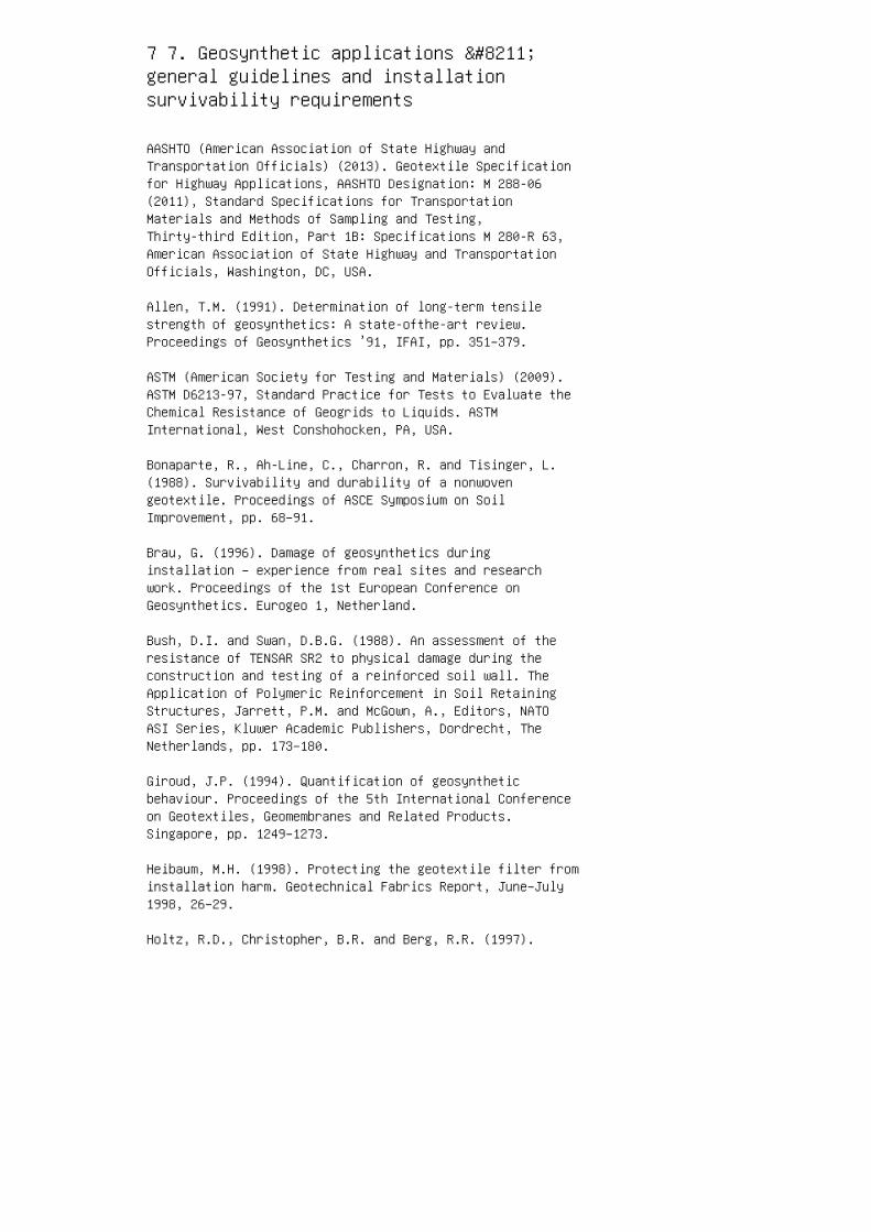
7 7. Geosynthetic applications –general guidelines and installationsurvivability requirements
AASHTO (American Association of State Highway andTransportation Officials) (2013). Geotextile Specificationfor Highway Applications, AASHTO Designation: M 288-06(2011), Standard Specifications for TransportationMaterials and Methods of Sampling and Testing,Thirty-third Edition, Part 1B: Specifications M 280-R 63,American Association of State Highway and TransportationOfficials, Washington, DC, USA.
Allen, T.M. (1991). Determination of long-term tensilestrength of geosynthetics: A state-ofthe-art review.Proceedings of Geosynthetics ’91, IFAI, pp. 351–379.
ASTM (American Society for Testing and Materials) (2009).ASTM D6213-97, Standard Practice for Tests to Evaluate theChemical Resistance of Geogrids to Liquids. ASTMInternational, West Conshohocken, PA, USA.
Bonaparte, R., Ah-Line, C., Charron, R. and Tisinger, L.(1988). Survivability and durability of a nonwovengeotextile. Proceedings of ASCE Symposium on SoilImprovement, pp. 68–91.
Brau, G. (1996). Damage of geosynthetics duringinstallation – experience from real sites and researchwork. Proceedings of the 1st European Conference onGeosynthetics. Eurogeo 1, Netherland.
Bush, D.I. and Swan, D.B.G. (1988). An assessment of theresistance of TENSAR SR2 to physical damage during theconstruction and testing of a reinforced soil wall. TheApplication of Polymeric Reinforcement in Soil RetainingStructures, Jarrett, P.M. and McGown, A., Editors, NATOASI Series, Kluwer Academic Publishers, Dordrecht, TheNetherlands, pp. 173–180.
Giroud, J.P. (1994). Quantification of geosyntheticbehaviour. Proceedings of the 5th International Conferenceon Geotextiles, Geomembranes and Related Products.Singapore, pp. 1249–1273.
Heibaum, M.H. (1998). Protecting the geotextile filter frominstallation harm. Geotechnical Fabrics Report, June–July1998, 26–29.
Holtz, R.D., Christopher, B.R. and Berg, R.R. (1997).
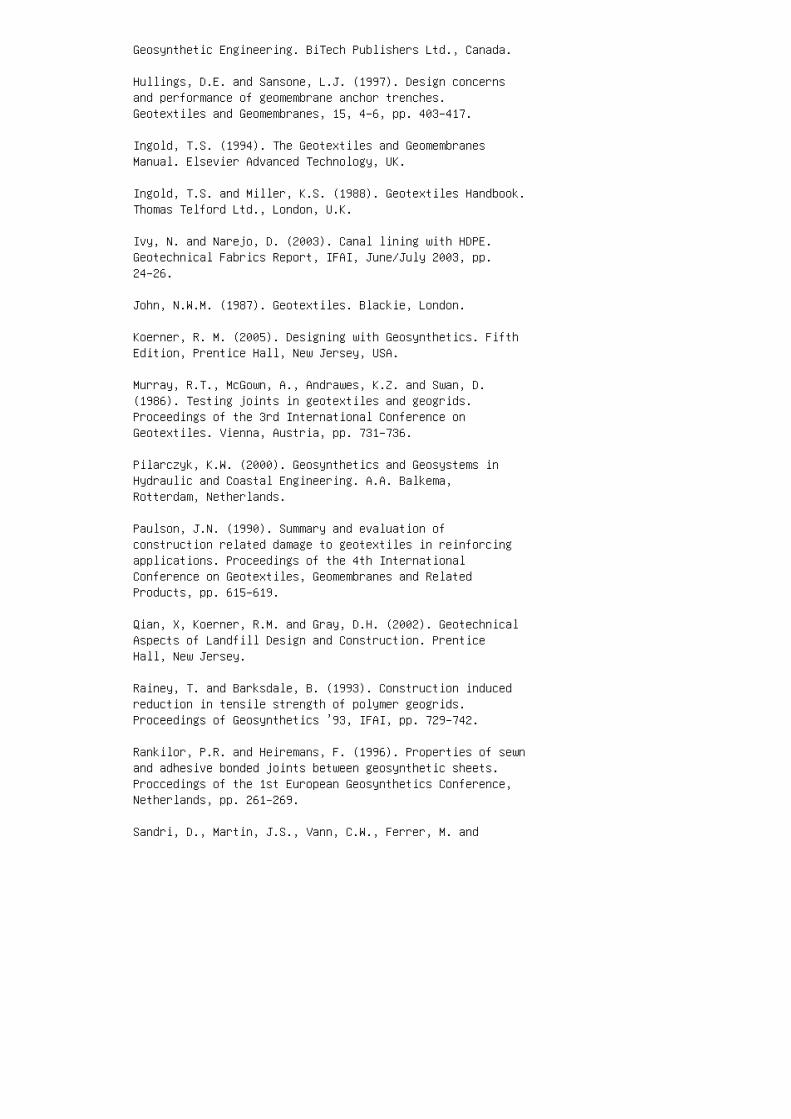
Geosynthetic Engineering. BiTech Publishers Ltd., Canada.
Hullings, D.E. and Sansone, L.J. (1997). Design concernsand performance of geomembrane anchor trenches.Geotextiles and Geomembranes, 15, 4–6, pp. 403–417.
Ingold, T.S. (1994). The Geotextiles and GeomembranesManual. Elsevier Advanced Technology, UK.
Ingold, T.S. and Miller, K.S. (1988). Geotextiles Handbook.Thomas Telford Ltd., London, U.K.
Ivy, N. and Narejo, D. (2003). Canal lining with HDPE.Geotechnical Fabrics Report, IFAI, June/July 2003, pp.24–26.
John, N.W.M. (1987). Geotextiles. Blackie, London.
Koerner, R. M. (2005). Designing with Geosynthetics. FifthEdition, Prentice Hall, New Jersey, USA.
Murray, R.T., McGown, A., Andrawes, K.Z. and Swan, D.(1986). Testing joints in geotextiles and geogrids.Proceedings of the 3rd International Conference onGeotextiles. Vienna, Austria, pp. 731–736.
Pilarczyk, K.W. (2000). Geosynthetics and Geosystems inHydraulic and Coastal Engineering. A.A. Balkema,Rotterdam, Netherlands.
Paulson, J.N. (1990). Summary and evaluation ofconstruction related damage to geotextiles in reinforcingapplications. Proceedings of the 4th InternationalConference on Geotextiles, Geomembranes and RelatedProducts, pp. 615–619.
Qian, X, Koerner, R.M. and Gray, D.H. (2002). GeotechnicalAspects of Landfill Design and Construction. PrenticeHall, New Jersey.
Rainey, T. and Barksdale, B. (1993). Construction inducedreduction in tensile strength of polymer geogrids.Proceedings of Geosynthetics ’93, IFAI, pp. 729–742.
Rankilor, P.R. and Heiremans, F. (1996). Properties of sewnand adhesive bonded joints between geosynthetic sheets.Proccedings of the 1st European Geosynthetics Conference,Netherlands, pp. 261–269.
Sandri, D., Martin, J.S., Vann, C.W., Ferrer, M. and
Zeppenfeldt, I. (1993). Installation damage testing of fourpolyester geogrids in three soil types. Proceedings ofGeosynthetics ’93, AFAI, pp. 743–755.
Shukla (2003). How to select geosynthetics for fieldapplications. Geosynthetic Pulse, India, 1, 5, p. 2.
Shukla, S.K. (2002). Geosynthetics and Their Applications.Thomas Telford, London.
Shukla, S.K. (2012). Handbook of Geosynthetic Engineering,Second Edition, Thomas Telford, London.
Shukla, S.K and Yin, J.H. (2006). Fundamentals ofGeosynthetic Engineering, Taylor and Francis, London.
USDI (US Department of the Interior) (1992). DesignStandards # 13: Embankment Dams. US Department of theInterior, Bureau of Reclamation , Denver.
Van Santvoort, G.) (1994). Geotextiles and Geomembranes inCivil Engineering. A.A. Balkema, Rotterdam, TheNetherlands.
Van Santvoort, G. (1995). Geosynthetics in CivilEngineering. A.A. Balkema, Rotterdam, The Netherlands.
Voskamp, W., Wichern, H.A.M. and Wijk, W. van (1990).Installation problems with geotextiles, an overview ofproducer’s experience with designers and contractors.Proceedings of the 4th International Conference onGeotextiles, Geomembranes and Related Products, The Hague,pp. 627–630.
Answers to selected questions
7.1 (d)
7.3 (b)
7.5 (c)
7.7 (a)
7.9 (b) This page intentionally left blank
8 8. Quality, performance monitoring andeconomic evaluation
Anon. (1979). Reinforced Earth and Other CompositeTechniques. Supplementary Report No. 457. Transportationand Roads Research Laboratory, London, UK.
ASTM (American Society for Testing and Materials) (2012).ASTM D6737–12, Standard Guide for Selection of Techniquesfor Electrical Detection of Leaks in Geomembranes. ASTMInternational, West Conshohocken, PA, USA.
Bagchi, A. (1994). Design, Construction, and Monitoring ofLandfills. John Wiley & Son, Inc., New York.
Barenberg, E.J. (1992). Subgrade stabilization. In A DesignPrimer: Geotextiles and Related Materials. IndustrialFabric Association International, Minnesota, USA, pp.10–20.
Bell, J.R., Barrett, R.K. and Ruckmann, A.C. (1984).Geotextile earth-reinforced retaining wall tests.Transportaion Research Record, No. 916, pp. 59–69.
Bouazza, A., Zornberg, J.G. and Adam, D. (2002).Geosynthetics in waste containment facilities. Proceedingsof the 7th International Conference on Geosynthetics,France, pp. 445–514.
Christie, I.F. (1982). Economic and technical aspects ofembankments reinforced with fabric. Proceedings of the 2ndInternational Conference on Geotextiles. La Vegas, USA, pp.659–664.
Dunnicliff, J. (1988). Geotechnical Instrumentation forMonitoring Field Performance. J. Wiley & Sons, New York.
Durukan, Z. and Tezcan, S.S. (1992). Cost analysis ofreinforced soil walls. Geotextiles and Geomembranes, 11,1, pp. 29–43.
Ghoshal, A. and Som N. (1993). Geotextiles and geomembranesin India – state of usage and economic evaluation.Geotextiles and Geomembranes, 12, 3, pp. 193–213.
Giroud, J.P. (2000). Lessons learned from successes andfailures associated with geosynthetics. Proceedings of the2nd European Geosynthetics Conference, Bologna, pp. 77–118.
IFAI (Industrial Fabrics Association International) (1992).
A Design Primer: Geotextiles and Related Materials.Section 13 Asphalt Overlay. Industrial Fabrics AssociationInternational, St. Paul, USA.
Ingold, T.S. (1982). Reinforced Earth. Thomas Telford Ltd.,London, UK.
Ivy, N. and Narejo, D. (2003). Canal lining with HDPE.Geotechnical Fabrics Report, IFAI, June/July 2003, pp.24–26.
Koerner, G. (2001). In situ temperature monitoring ofgeosynthetics used in a landfill. Geotechnical FabricsReport, pp. 12–14.
Koerner, R.M. and Daniel, D.E. (1993). Manufacturing andconstruction quality control and quality assurance ofgeosynthetics. Proceedings of the MQC/MQA and CQC/CQA ofGeosynthetics Seminar, Philadelphia, Pennsylvania, USA, pp.1–14.
Koerner, R.M. (1996). The state-of-the-practice regardingin-situ monitoring of geosynthetics. Proceedings of the1st European geosynthetics Conference. Eurogeo 1,Maastricht, Netherlands, pp. 71–86.
Menoff, S.D. and Eith, A.W. (1990). Quality assurance as ameans to minimize long-term liability. Geotextiles andGeomembranes, pp. 461–465.
Murray, R. (1982). Fabric reinforcement of embankments andcuttings. Proceedings of the 2nd International Conferenceon Geotextiles. Las Vegas, USA, pp. 707–713.
Nosko, V. and Touze-Foltz, N. (2000). Geomembrane linerfailure: modeling of its influence on containmenttransfer. Proceedings of the 2nd European GeosyntheticsConference, Bologna, pp. 557–560.
Paul, J. (1984). Economics and construction of blastembankments using Tensar geogrids. Proceedings of theConference on Polymer Grid Reinforcement, London, UK, pp.191–197.
Qian, X, Koerner, R.M. and Gray, D.H. (2002). GeotechnicalAspects of Landfill Design and Construction. PrenticeHall, New Jersey.
Simac, M.R. (1992). Reinforced slopes: a provengeotechnical innovation. Geotechnical Fabrics Report, pp.
13–25.
Swihart, J. and Haynes, J. (2002). Canal-LiningDemonstration Project Year 10 Final Report. United StatesDepartment of Interior, Bureau of Reclamation, USA.
Thiel, R.S. and Stewart, M.G. (1993). Field constructionquality assurance of geotextile installations. Proceedingsof the MQC/MQA and CQC/CQA of Geosynthetics Seminar,Philadelphia, Pennsylvania, USA, pp. 126–137.
Answers to selected questions
8.1 (d)
8.3 (b)
8.5 (d)
8.7 (a)
8.9 (b)
8.11 (c)
8.13 (c) This page intentionally left blank
9 9. Fibre-reinforced soils
Al-Refeai, T. and Al-Suhaibani, A. (1998). Dynamic andstatic characterization of polypropylene fibre-reinforceddune sand. Geosynthetics International, 5, 5, pp. 443–458.
Babu, G.L.S., Vasudevan, A.K. and Sayida, M.K. (2008). Useof coir fibres for improving the engineering properties ofexpansive soils. Journal of Natural Fibers, 5, 1, pp.61–75.
Consoli, N.C., Montardo, J.P., Prietto, P.D.M. and Pasa,G.S. (2002). Engineering behaviour of a sand reinforcedwith plastic waste. Journal of Geotechnical andGeoenvironmental Engineering, ASCE, 128, 6, pp. 462–472.
Consoli, N.C., Casagrande, M.D.T., Prietto, P.D.M. andThome, A. (2003a). Plate load test on fibre-reinforcedsoil. Journal of Geotechnical and GeoenvironmentalEngineering, ASCE, 129, 10, pp. 951–955.
Consoli, N.C., Vendruscolo, M.R.A. and Prietto, P.D.M.(2003b). Behaviour of plate load tests on soil layersimproved with cement and fibre. Journal of Geotechnical andGeoenvironmental Engineering, ASCE, 129, 1, pp. 96–101.
Consoli, N.C., Casagrande, M.D.T., Thome, A., Rosa, F.D.and Fahey, M. (2009). Effect of relative density on plateloading tests on fibre-reinforced sand. Geotechnique, 59,5, pp. 471–476.
Diambra, A., Ibraim, E., Wood, D.M. and Russell, A.R.(2010). Fibre reinforced sands: experiments and modelling.Geotextiles and Geomembranes, 28, 3, pp. 238–250.
Edincliler, A. and Cagatay, A. (2013). Weak subgradeimprovement with rubber fibre inclusions. GeosyntheticsInternational, 20, 1, pp. 39–46.
Fletcher, C.S. and Humphries, W.K. (1991). Californiabearing ratio improvement of remoulded soils by theaddition of polypropylene fibre reinforcement. Proceedingsof the 7th Annual Meeting, Transportation Research Board,Washington, DC, USA, pp. 80–86.
Gill, K.S., Choudhary, A.K., Jha, J.N. and Shukla, S.K.(2014). Utilization of fly ash and waste recycled productreinforced with plastic wastes as construction materials inflexible pavements. Proceedings of the GeoCongress onGeo-Characterization and Modelling for Sustainability,
ASCE, Atlanta, Georgia, USA, GSP 234, pp. 3890–3902.
Gray, D.H. and Ohashi, H. (1983). Mechanics of fibrereinforcement in sand. Journal of Geotechnical Engineering,ASCE, 109, 3, pp. 335–353.
Gray, D.H. and Al-Refeai, T. (1986). Behaviour of fabricversus fiber reinforced sand. Journal of GeotechnicalEngineering, ASCE, 112, 8, pp. 804–820.
Ibraim, E., Diambra, A., Wood, D.M. and Russell, A.R.(2010). Static liquefaction of fibre reinforced sand undermonotonic loading. Geotextiles and Geomembranes, 28, 4, pp.374–385.
Ibraim, E., Diambra, A., Russell, A.R. and Wood, D.M. and(2012). Assessment of laboratory sample preparation forfibre reinforced sands. Geotextiles and Geomembranes, 34,pp. 69–79.
Jha, J.N., Choudhary, J.N., Gill, K.S. and Shukla, S.K.(2014). Behaviour of plastic waste fibrereinforcedindustrial wastes in pavement applications. InternationalJournal of Geotechnical Engineering, 8, 3, pp. 277–286.
Jha, J.N., Gill, K.S., Choudhary, A.K. and Shukla, S.K.(2015). Stress-strain Characteristics of fiber-reinforcedrice husk ash. Proceedings of the Geosynthetics 2015,Portland, Oregon, USA, pp. 134–141.
Kumar, P. and Singh, S.P. (2008). Fibre-reinforced fly ashsubbases in rural roads. Journal of TransportationEngineering, ASCE, 134, 4, pp. 171–180.
Lovisa, J., Shukla, S.K. and Sivakugan, N. (2010). Shearstrength of randomly distributed moist fiber-reinforcedsand. Geosynthetics International, 17, 2, pp. 100–106.
Maher, M.H. and Gray, D.H. (1990). Static response of sandsreinforced with randomly distributed fibres. Journal ofGeotechnical Engineering, ASCE, 116, 11, pp. 1661–1677.
Mirzababaei, M., Miraftab, M., Mohamed, M. and McMahon, M.(2013). Unconfined compression strength of reinforced clayswith carpet waste fibres. Journal of Geotechnical andGeoenvironmental Engineering, ASCE, 139, 3, pp. 483–493.
Ranjan, G., Vasan, R.M. and Charan, H.D. (1994). Behaviourof plastic-fibre reinforced sand. Geotextiles andGeomembranes, 13, 8, pp. 555–565.
Ranjan, G. Vasan, R.M. and Charan, H.D. (1996).Probabilistic analysis of randomly distributedfibre-reinforced soil. Journal of Geotechnical Engineering,ASCE, 122, 6, pp. 419–426.
Shukla, S.K., Sivakugan, N. and Das, B.M. (2009).Fundamental concepts of soil reinforcement – an overview.International Journal of Geotechnical Engineering, 3, 3,pp. 329–343.
Shukla, S.K. and Sivakugan, N. (2010). Discussion of“Fiber-reinforced fly ash subbases in rural roads’ by P.Kumar and S.P. Singh”. Journal of TransportationEngineering, ASCE, 136, 4, pp. 400–401.
Shukla, S.K., Sivakugan, N. and Singh, A.K. (2010).Analytical model for fiber-reinforced granular soils underhigh confining stresses. Journal of Materials in CivilEngineering, ASCE, 22, 9, pp. 935–942.
Shukla, S.K., Shahin, M.A. and Abu-Taleb, H. (2015). A noteon void ratio of fibre-reinforced soils. InternationalJournal of Geosynthetics and Ground Engineering,Switzerland, 1, 3, pp. 1–5.
Tingle, J.S., Santoni, R.L. and Webster, S.L. (2002).Full-scale field tests of discrete fibre-reinforced sand.Journal of Transportation Engineering, ASCE, 128, 1, pp.9–16.
Santoni, R.L., Tingle, J.S. and Webster, S.L. (2001).Engineering properties of sand –fibre mixtures for roadconstruction. Journal of Geotechnical and GeoenvironmentalEngineering, ASCE, 127, 3, pp. 258–268.
Santoni, R.L. and Webster, S.L. (2001). Airfields and roadsconstruction using fibre stabilization of sands. Journal ofTransportation Engineering, ASCE, 127, 2, pp. 96–104.
Shewbridge, S.E. and Sitar, N. (1989). Deformationcharacteristics of reinforced sand in direct shear.Journal of Geotechnical Engineering, ASCE, 115, 8, pp.1134–1147.
Shewbridge, S.E. and Sitar, N. (1990). Deformation basedmodel for reinforced sand. Journal of GeotechnicalEngineering, ASCE, 116 , 7, pp. 1153–1170.
Yetimoglu, T. and Salbas, O. (2003). A study on shear

strength of sands reinforced with randomly distributeddiscrete fibres. Geotextiles and Geomembranes, 21, 2, pp.103–110.
Yetimoglu, T., Inanir, M. and Inanir, O.E. (2005). A studyon bearing capacity of randomly distributedfibre-reinforced sand fills overlying soft clay.Geotextiles and Geomembranes, 23, 2, pp. 174–183.
Waldron, L.J. (1977). Shear resistance of root-permeatedhomogeneous and stratified soil. Proceedings of the SoilScience Society of America, 41, 5, pp. 843–849.
Answers to selected questions
9.1 (a)
9.3 (d)
9.5 (c)
9.8 2.60 This page intentionally left blank


