Embed Size (px)
Citation preview
ANALYSIS OF FREQUENCY HOPPING SYSTEM WITH 2-ARY
FSK AND BPSK MODULATION AND AN IMPLEMENTATION
OF A COHERENT 2-ARY FSK/FH MODEM :
A Thesis Presented t o
The Faculty of t h e College of Engineering and Technology
Ohio Univers i ty
I n P a r t i a l Fu l f i l lmen t
o f t h e Requirements f o r t h e Degree of
Master of Science
b Y
Yaim B. Zaxawi
March 1983
OHIO UNIVERSITY LIBRARY ATHENS, OHIO
Acknowledgment
I am indebted t o my adv i so r , D r . Joseph E . Essman, f o r h i s
encouragement, va luable suggest ions and guidance during t h e course
of t h i s work. Also t h e author wishes t o express h i s thanks t o
D r . M. Jameel f o r h i s he lp , p a r t i c u l a r l y i n t h e r e a l t ime s imula t ion .
Specia l apprec ia t ion and a f f e c t i o n is recorded t o my paren t s
f o r t h e i r support and understanding during t h e course of t h i s work.
TABLE OF CONTENTS
Page
ACKNOWLEDGMENT . . . . . . . . . . . . . . . . . . . . . . . . . i
. . . . . . . . . . . . . . . . . . . . . . . . LISTOFTABLES i v
. . . . . . . . . . . . . . . . . . . . . . . . LISTOFFIGURES v
Chapter
INTRODUCTION . . . . . . . . . . . . . . . . . . . . . . . 2 SPECTRAL ANALYSIS . . . . . . . . . . . . . . . . . . . 4
In t roduct ion
2.2 Analysis of Frequency S h i f t Keying/Frequency Hopping (FSK/FH) . . . . . . . . . . . . . . . . . 4
2.2.a Analysis of Frequency Hopping Signal Using a PN-Code Sequence . . . . . . . . . . 4
2.2.b Analysis of Frequency S h i f t Keying (FSK) Signal . . . . . . . . . . . . . . . . . . . 8
2.2.c Spectrum Analysis . . . . . . . . . . . . . 11
2.3 Spectrum Analysis of Binary Phase S h i f t Keying/ Frequency Hopping (BPSK/FH) . . . . . . . . . . . . 27
. . . . . . . . . . . . . . 2.4 Summaryand Conclusions 34
3 . PERFORMANCE OF THE FREQUENCY HOPPING SYSTEE.1 . . . . . . 39
3.1 In t roduct ion . . . . . . . . . . . . . . . . . . . 39
3.2.a Partial-Band Noise Jan?ming Model . . . . . . 39
3 . 2 . b Partial-Band k l t i t o n e J a m i n g Model . . . . 4 0
3 . 3 Probab i l i ty of Er ro r Calcula t ions i n t h e Presence of Part ial-Band Noise Jamming . . . . . . 40
3.3.a Detection of Yon-Coherent Binary Frequency S h i f t Keying i n Frequency Hopping . . . . . . . . . Environment (2-ary FSK/FH) 40
i i
3.3.b Worst Case Jamming S t r a t e g y Against Non-Cherent FSK/FH . . . . . . . . . . . . . 43
3.3 . c Detect ion of Coherent Frequency S h i f t Keying i n Frequency Hopping Environment (Coherent FSK/FH) . . . . . . . . . . . . . 46
3.3.d Binary D i f f e r e n t i a l Phase S h i f t Keying i n Frequency Hopping Environment (BDPSK/FH) . . . . . . . . . . . . . . . . . 49
3.4 Ca lcu la t ions of t h e P r o b a b i l i t y of Er ro r i n t h e Presence of Part ial-Band Mul t i tone Jamming . . 52
3.4.a 2-ary Non-Coherent FSK/FH with Jam Tone Spacing Equal t o t h e B i t Rate . . . . . 55
3.4.b 2-ary Non-Coherent FSK/FH with Jam Tone Spacing Equal t o Twice B i t Rate . . . . 57
3.4.c P r o b a b i l i t y of Er ro r of t h e BDPSK/FH with Jam Tone Spacing Equal t o t h e B i t Rate . . . . . . . . . . . . . . . . . . . . 57
3.5 C o n c l u s i o n s . . . . . . . . . . . . . . . . . . . . 60
4 . REALTIMESIMULATION. . . . . . . . . . . . . . . . . . 62
4 . 1 In t roduc t ion . . . . . . . . . . . . . . . . . . . 62
4.2 Design and Descr ip t ion of t h e Coherent FSK/FH Modem 62
4 .3 Resul t s andcomments . . . . . . . . . . . . . . . 72
4 . 3 Summary and Conclusions . . . . . . . . . . . . . . 54
BIBLIOGRAPHY.. . . . . . . . . . . . . . . . . . . . . . . . . 91
APPENDIX
A. COMPUTER LISTINGS
LIST OF FIGURES
Figure Page
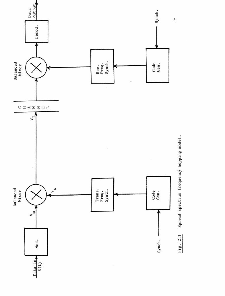
2 . 1 Spread Spectrum Frequency Hopping Model . . . . . . . . . 5
2 . 2 C a r r i e r Frequency Versus Time f o r t h e FH Signal Using a PN-Code Sequence . . . . . . . . . . . . . . . . . . . 7
2.3 The Pe r iod ic Rectangular Function Used i n t h e Expression of t h e FH Signal . . . . . . . . . . . . . . . 7
2 - 4 Frequency S y n t h e s i z e r ' s Waveforms wi th B = 2 . . . . . . 9 a ) Code Sequence b ) C a r r i e r Frequency Versus Time c ) The Pe r iod ic Rectangular Funct ion d) Output Waveform
2.5 The FSK Modulator Waveforms . . . . . . . . . . . . . . . 10 a ) Baseband S igna l ( Inpu t ) b ) Output Waveform c ) Frequency Versus Time
2.6 Frequency Versus Time Re la t ionsh ip f o r t h e FSK/FH S igna l Assuming T~ = 2~~ f o r B = 2 . . . . . . . . . . . . . . . 13
2 . 7 The General Pe r iod ic Gate Function Used i n t h e FSK/FH Analys is . . . . . . . . . . . . . . . . . . . . . . . . 13
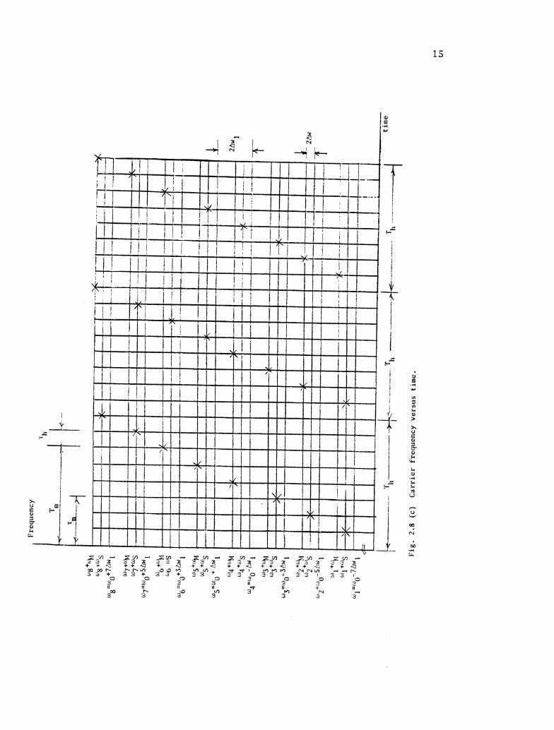
2.3 Frequency Versus Time f o r t h e FSK/FH Signal wi th B = 3 and T~ = ~ , / 3 . . . . . . . . . . . . . . . . . . . . . 14 a ) Code Sequence b) Rectangular Funct ions f o r t h e FSK and FH Signal c ) C a r r i e r Frequency Versus Time
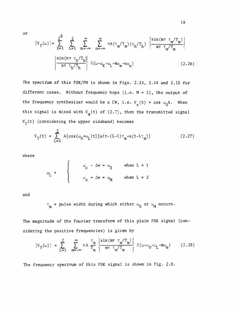
2.9 Magnitude Line Spec t r a f o r t h e P l a i n FSK S igna l Considering t h e Second Zero Crossing ( P o s i t i v e Frequencies Only) . . . . . . . . . . . . . . . . . . . . 20
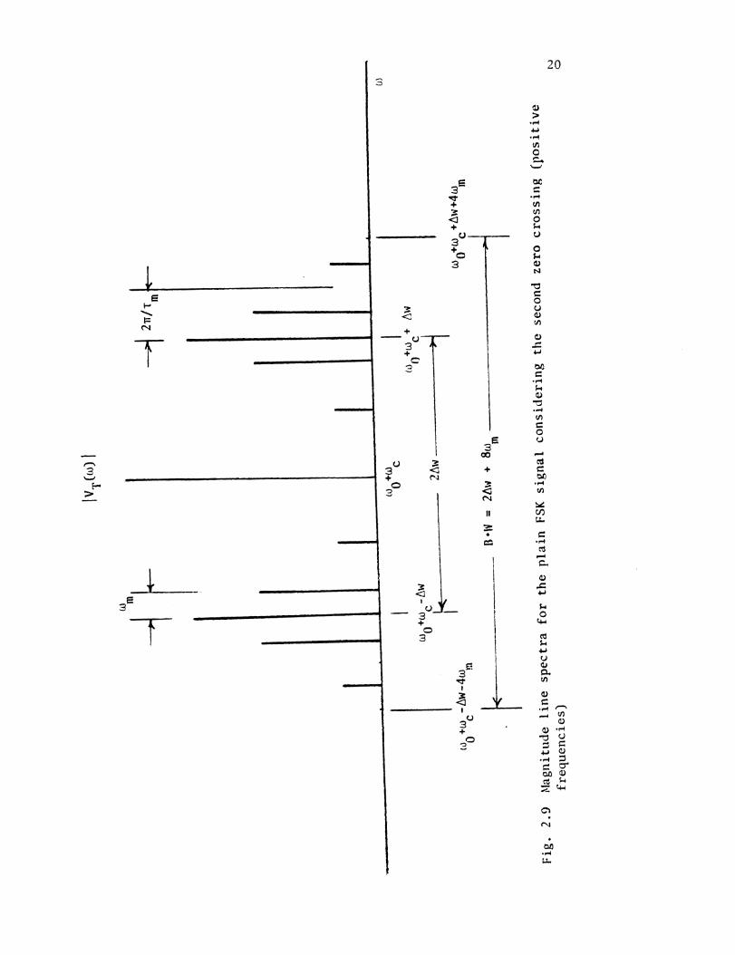
2.10 Magnitude Line Spec t r a f o r t h e P l a i n FH S ignal wi th B = 2 Considering t h e Second Zero Crossing ( P o s i t i v e Frequencies Only) . . . . . . . . . . . . . . . 21
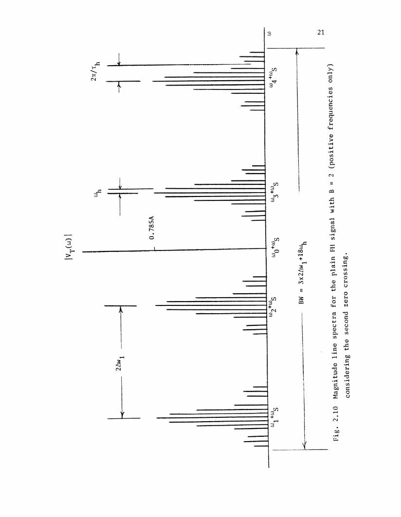
2 . 1 1 Magnitude Line Spec t r a f o r t h e P l a i n FH S i g c a l with B = 3 Considering t h e First Zero Crossing ( P o s i t i v e Frequencies Only! . . . . . . . . . . . . . . . 2 2
Figure Page
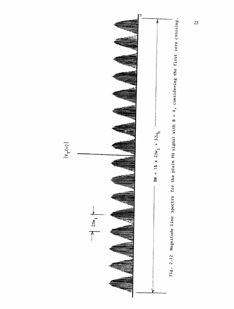
Magnitude Line Spec t r a f o r t h e P l a i n FH Signal with B = 4 Considering t h e F i r s t Zero Cross ing . . . . . . . . 23
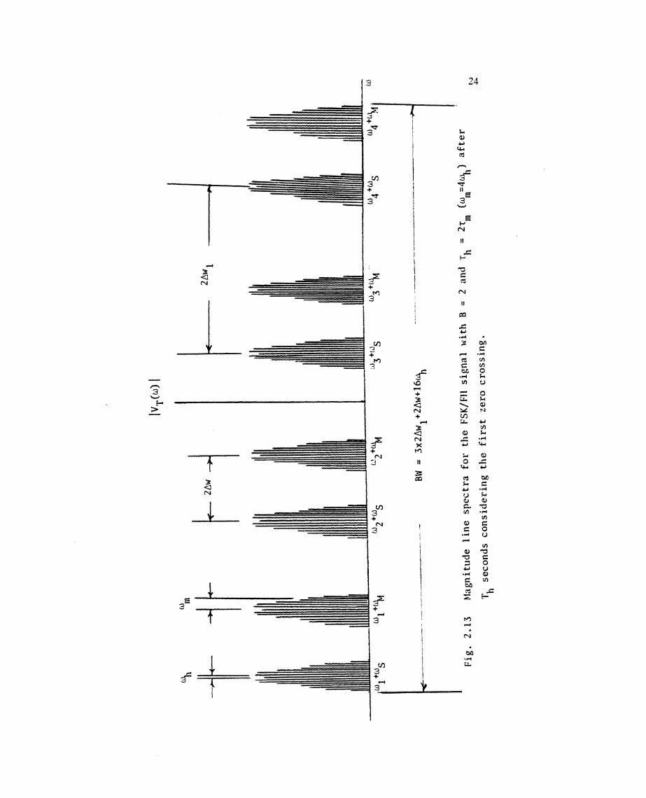
Magnitude Line Spec t r a f o r t h e FSK/FH Signal with B = 2 and rh = 2rm (urn = 4%) A f t e r Th Seconds,
Considering t h e F i r s t Zero Crossing . . . . . . . . . . . 24
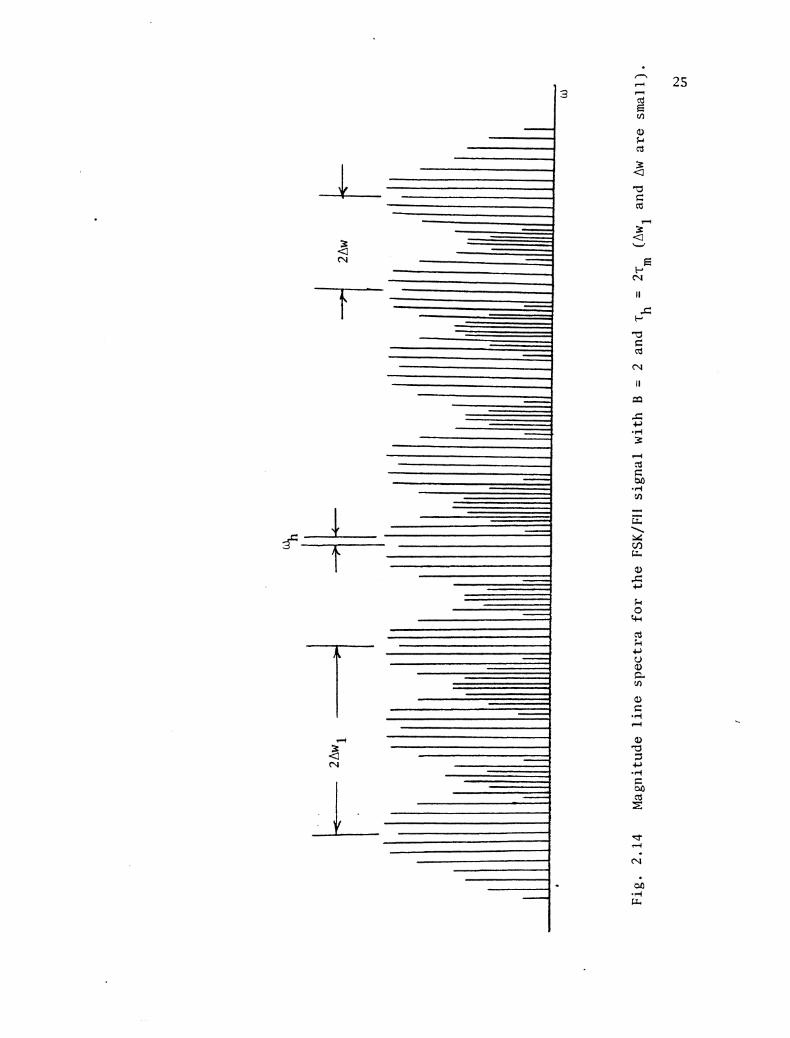
Magnitude Line Spectrum f o r t h e FSK/FH S igna l wi th B = 2 and -rh = 2 r f o r t h e Spec ia l Case Where Awl m
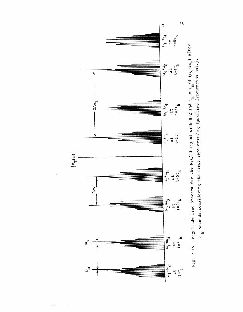
Magnitude Line Spec t r a f o r t h e FSK/FH Signal with B = 2 and rh = r,/4 (b+, = 2um) A f t e r 2Th Seconds,
Cons ider ing t h e F i r s t Zero Crossing ( P o s i t i v e . . . . . . . . . . . . . . . . . . . . Frequencies Only) 26
. . . . . . . . . . . . . . . . . . . . . BPSKWaveforms 28 a ) Baseband S igna l b) Output S igna l
C a r r i e r Frequency Versus Time f o r t h e BPSK/FH S igna l wi th B = 2 and rh = 2rm . . . . . . . . . . . . . 30
Magnitude Line Spec t r a f o r t h e BPSK Signal . . . . . . . 32
Magnitude Line Spec t r a f o r t h e BPSK/FH Signal wi th B = 2 and r = 2rm . . . . . . . . . . . . . . 33 h
. . . . . . . . . . . . Par t ia l -Band Noise Jamming Model 41
. . . . . . . . . . Par t ia l -Band Mul t i t one Jamming Model 4 1
B i t P r o b a b i l i t y o f E r r o r Versus B i t Energy t o Jam Noise f o r t h e Non-Coherent FSK/FH i n t h e Presence . . . . . . . . . . . of Par t ia l -Band Noise with a = 1 .0 44
The Product XPB(x) Versus E/NJ f o r t h e Coherent
and Non-Coherent FSK/FH i n t h e Presence of P a r t i a l - . . . . . . . . . . . . . . . . . . B a n d N o i s e J a ~ m i n g . 3 5
B i t P r o b a b i l i t y of E r r o r Versus t h e B i t Energy o f Jam Noise Densi ty i n t h e Presence of Pa r t i a l -Sand Noise wi th a = 1.0 f o r t h e Coherent and Non- . . . . . . . . . . . . . . . . . . . . . Coherent FSK/FH 47
Figure Page
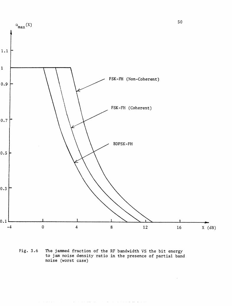
3.6 The Jammed Frac t ion of t h e RF Bandwidth v s t h e B i t Energy t o Jam Noise Densi ty Rat io i n t h e Presence o f P a r t i a l Band Noise (Worst Case) f o r t h e FSK/FH (Coherent ) , FSK-FH (Non-Coherent) , and BDPSK/FH Waveforms . . . . . . . . . . . . . . . . . . . . . . . 50
3.7 Maximum B i t P r o b a b i l i t y of E r r o r v s B i t Energy t o Jam Noise Densi ty i n t h e Presence o f Par t ia l -Band Noise f o r t h e Coherent and Non-Coherent FSK/FH Waveforms (Worst Case) . . . . 51
3.8 The Product XPB(x) Versus (E/NJ) f o r t h e BPSK/FH
Waveform i n t h e Presence of Par t ia l -Band Noise Jamming. . . . . . . . . . . . . . . . . . . . . . . . . 53
3.9 B i t P r o b a b i l i t y o f E r r o r v s t h e B i t Energy t o Jam Noise i n t h e Presence o f Par t ia l -Band Noise Jamming f o r t h e BFSK/FH and BDPSK/FH (Worst Case) . 54
3.10 B i t P r o b a b i l i t y of E r r o r Versus t h e B i t Energy t o Jam Noise Densi ty i n t h e Presence of P a r t i a l - Band Mul t i tone Jamming (Worst Case) f o r t h e
. . . . Non-Coherent FSK/FH and f o r t h e BPSK-FH Waveforms 58
3.11 B i t P r o b a b i l i t y o f E r r o r Versus t h e B i t Energy t o Jam Noise Dens i ty (Worst Case) f o r A l l t h e
. . . . . . . . . . . . . D i f f e r e n t Waveforms Considered 59
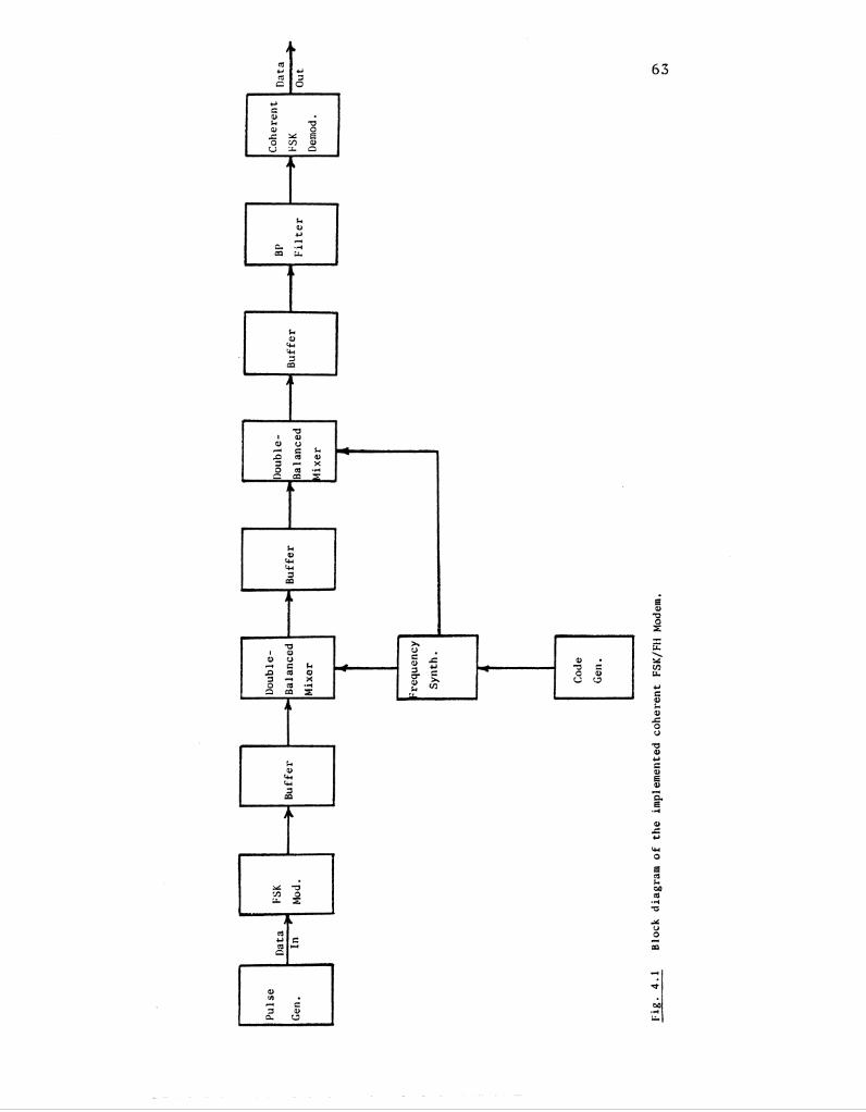
4.1 Block Diagram o f t h e Implemented Coherent FSK/FH Modem. . . . . . . . . . . . . . . . . . . . . . . . . . 63
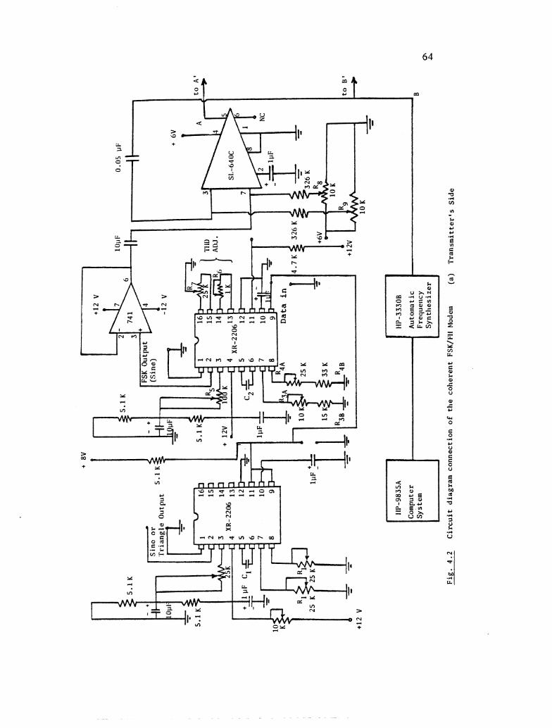
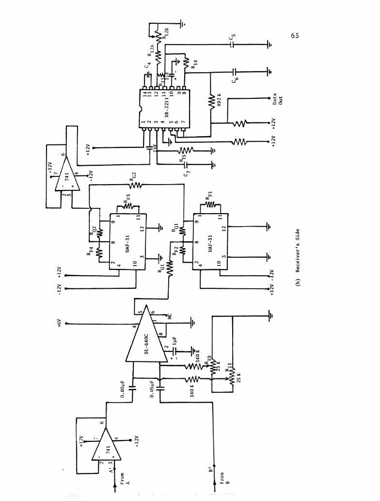
4 . 2 C i r c u i t Diagram Connection f o r t h e Coherent FSK/FH Modem. . . . . . . . . . . . . . . . . . . . . . . . . . 64 a ) T r a n s m i t t e r ' s S ide b) Rece ive r ' s S ide
4 . 3 Input Waveforms t o t h e FSK/FH Modem . . . . . . . . . . . 74 a ) Input Data (A Stream of Square Wave Pu l se s wi th
r = 15 msec and duty c y c l e = 50%) m b) The Spreading Frequency Hopping S igna l with a
Center Frequency = 150 KHz, Number of Output Frequencies = 11, and Hopping S tep S i z e = 5 KHz
4 . 4 Output Waveforms from t h e FSK Modulator . . . . . . . . . 75 a ) The Mark Frequency f = 2 KHz M b ) The Space Frequency f S = 1 KHz
c ) The FSK S igna l
Figure Page
Amplitude Response of t h e Receiver ' s 4-Pole Butterworth Band Pass F i l t e r with Center Frequency f = 1.5 KHz and Qual i ty Factor =
C Q B p = 2 . . . . . . . . . . . . . . . . . . . . . . . . 7 6
The Complete Transmitted FSK/FH Signal Waveform (Output of the Transmi t t e r ' s Mixer) . . . . . . . . . . . 77
Output Waveform of t h e Receiver 's BPF . . . . . . . . . . 77
Output Data (Output of t h e FSK Demodulator) . . . . . . . 77
Frequency Spectrum f o r t h e FH Signal Coming from t h e Synthes izer with a Center Frequency = 150 KHz, Number of Output Frequencies = 11, Hopping Step S ize = 5 KHz and Time/Hopping Step -rh = 30 msec . . . . . . . . . . . . . . . . . . . 78
Frequency Spectrum f o r t h e FSK Signal with t h e Mark Frequency f = 2 KHz, Space Frequency f S = 1 KHz M and Pulse Width rm = 15 msec . . . . . . . . . . . . . 78
Frequency Spectrum f o r t h e Frequency Hopping . . . . . . . . . . . . . . . . . . . Signal of Fig . 4.9 79 a ) When Mixed with t h e Mark Frequency Only b) When Mixed with t h e Space Frequency Only
Frequency Spectrum f o r t h e FSK/FH Signal with a Center Frequency = 150 KHz, Number of Output Frequencies = 11, Hopping Step S ize (Awi) =
5 KHz, ;h = 30 msec and -rm = 15 msec (Slow
. . . . . . . . . . . . . . . . . . Frequency Hopping) . 8 0
Frequency Spectrum f o r t h e De-spread Signal . . . . . . . . . . . Afte r Being Passed Through t h e BPF 80
Frequency Spectrum f o r t h e FH Signal with a Center Frequency = 500 KHz, Number o f Output Frequencies = 101, Hopping Step S ize = 5 KHz and Time/Step = . . . . . . . . . . . . . . . . . . . . . . . . 30 m s e c . S1
Frequency Spectrum f o r t h e FH Signal (Whose Spectrum is Shown i n Fig. 4.14) When Mixed with . . . . . . . . . . . . t h e FSK Signal with - r m = 15 msec 81
Por t ion of t h e Spectrum of t h e Signal Whose Spectrum i s Shown i n Fig. 4.15. [Horizontal . . . . . . . . . . . . . . . Scale i s Set t o 10 KHz/cm.] 82
Figure Page
4.17 Frequency Spectrum f o r the FSK/FH Signal with a Center Frequency = 150 KHz, Number of Output Frequencies = 11, Hopping Step Size = 0.5 KHz, T~ = 30 msec and T~ = 15 msec . . . . . . . . . . . . . . 82
4.18 Frequency Spectrum f o r t he FSK/FH Signal with a Center Frequency = 150 KHz, Number of Output Frequencies = 11, Hopping Step Size = 5 KHz and T~ = ~ , / 2 = 30 msec (Fast Frequency Hopping) . . . . . . 83
a ) After t < 3Th
b) After t > 3Th
Chapter 1
INTRODUCTION
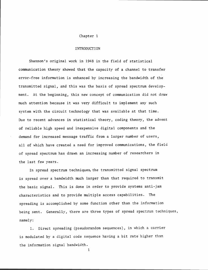
Shannon's o r i g i n a l work i n 1948 i n t h e f i e l d of s t a t i s t i c a l
communication theory showed t h a t t h e capaci ty of a channel t o t r a n s f e r
e r r o r - f r e e information i s enhanced by inc reas ing t h e bandwidth of t h e
t ransmit ted s i g n a l , and t h i s was t h e b a s i s of spread spectrum develop-
ment. A t t h e beginning, t h i s new concept of communication d id not draw
much a t t e n t i o n because it was very d i f f i c u l t t o implement any such
system with t h e c i r c u i t technology t h a t was a v a i l a b l e a t t h a t time.
Due t o recent advances i n s t a t i s t i c a l theory , coding theory, t h e advent
of r e l i a b l e high speed and inexpensive d i g i t a l components and t h e
demand f o r increased message t r a f f i c from a l a r g e r number of u s e r s ,
a l l of which have c rea ted a need f o r improved communications, t h e f i e l d
of spread spectrum has drawn an increas ing number of r esea rchers i n
t h e l a s t few years .
I n spread spectrum techniques, the t ransmit ted s igna l spectrum
i s spread over a bandwidth much l a r g e r than t h a t required t o t ransmit
t h e bas ic s i g n a l . This i s done i n order t o provide systems ant i - jam
c h a r a c t e r i s t i c s and t o provide mul t ip le access c a p a b i l i t i e s . The
spreading i s accomplished by some funct ion o t h e r than t h e information
being sen t . Generally, t h e r e a r e t h r e e types of spread spectrum techniques,
namely:
1. Direct spreading (pseudorandom sequences), i n which a c a r r i e r
i s modulated by a d i g i t a l code sequence having a b i t r a t e h igher than
t h e information s igna l bandwidth. 1
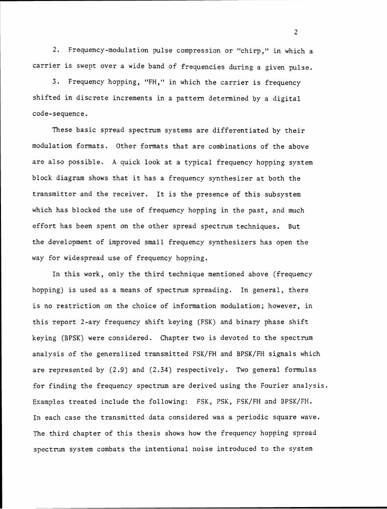
2 . Frequency-modulation pu l se compression o r "ch i rp ," i n which a
c a r r i e r i s swept over a wide band of f r equenc ie s du r ing a given pu l se .
3 . Frequency hopping, "FH," i n which t h e c a r r i e r i s frequency
s h i f t e d i n d i s c r e t e increments i n a p a t t e r n determined by a d i g i t a l
code-sequence . These b a s i c spread spectrum systems a r e d i f f e r e n t i a t e d by t h e i r
modulation formats . Other formats t h a t a r e combinations of t h e above
a r e a l s o p o s s i b l e . A quick look a t a t y p i c a l f requency hopping system
block diagram shows t h a t it has a f requency s y n t h e s i z e r a t bo th t h e
t r a n s m i t t e r and t h e r e c e i v e r . I t i s t h e presence of t h i s subsystem
which has blocked t h e u s e of f requency hopping i n t h e p a s t , and much
e f f o r t has been spen t on t h e o t h e r spread spectrum techniques . But
t h e development of improved small f requency s y n t h e s i z e r s h a s open t h e
way f o r widespread u s e o f f requency hopping.
In t h i s work, only t h e t h i r d technique mentioned above (frequency
hopping) is used a s a means of spectrum sp read ing . In g e n e r a l , t h e r e
i s no r e s t r i c t i o n on t h e cho ice of in format ion modulation; however, i n
t h i s r e p o r t 2-ary frequency s h i f t keying (FSK) and b ina ry phase s h i f t
keying (BPSK) were cons idered . Chapter two i s devoted t o t h e spectrum
a n a l y s i s of t h e gene ra l i zed t r a n s m i t t e d FSK/FH and BPSK/FH s i g n a l s which
a r e r ep re sen ted by (2 .9) and ( 2 . 3 4 ) r e s p e c t i v e l y . Two gene ra l formulas
f o r f i n d i n g t h e frequency spectrum a r e de r ived us ing t h e Four i e r a n a l y s i s .
Examples t r e a t e d inc lude t h e fo l lowing: FSK, PSK, FSK/FH and BPSK/FH.
In each case t h e t r a n s m i t t e d d a t a cons idered was a p e r i o d i c square wave.
The t h i r d c h a p t e r of t h i s t h e s i s shows how t h e frequency hopping spread
spectrum system combats t h e i n t e n t i o n a l n o i s e in t roduced t o t h e s y s t e n
3
by t h e jammer. Two common models were cons idered: p a r t i a l - b a n d n o i s e
jamming and p a r t i a l - b a n d mul t i t one jamming. For each model t h e p e r -
formance c h a r a c t e r i s t i c s of t h e BFSK/FH and BDPSK/FH a r e p re sen ted . The
maximum p r o b a b i l i t y of e r r o r corresponding t o t h e worst c a s e jamming
s t r a t e g y , which c o n s i s t s of s p e c i f y i n g t h e worst p a r t i a l - b a n d f r a c t i o n ,
is determined. F i n a l l y a coherent FSK/FH modem was implemented and
Fig. 4.2a,b shows t h e c i r c u i t diagram o f t h i s system. I t i s t o b e noted
t h a t i n t h i s system t h e frequency synthes izer ,which i s c o n t r o l l e d by a
computer, i s used t o gene ra t e t h e frequency hopping s i g n a l . Th i s s i g n a l
is used f o r spectrum sp read ing a t t h e t r a n s m i t t e r ' s s i d e and spectrum
de-spreading a t t h e r e c e i v e r ' s s i d e t o a s s u r e frequency and phase coherence.
The t r a n s m i t t e d d a t a which i s a s t ream of squa re wave p u l s e s i s f i n a l l y
recovered us ing a coherent FSK demodulator. A frequency spectrum a n a l y z e r
was used t o o b t a i n t h e frequency spectrum f o r t h e FSK/FH s i g n a l . The
des ign and d e t a i l s of t h e modem a r e d i scussed i n c h a p t e r f o u r fol lowed
by summary and conc lus ions .
Chapter 2
SPECTRAL ANALYSIS
2 . 1 In t roduc t ion
In communication s y s t e m s , i t i s important t o know t h e s p e c t r a l
occupancy of t h e t r a n s m i t t e d s i g n a l i n o r d e r t o e f f i c i e n t l y des ign t h e
modem. Th i s c h a p t e r i s devoted t o t h e bandwidth BW a n a l y s i s of a
s i m p l i f i e d frequency hopping model shown i n F ig . 2 . 1 i n which t h e
c e n t r a l f e a t u r e of t h e system i s t h e code gene ra to r a t both t h e t r a n s -
m i t t e r and r e c e i v e r . The genera ted code sequence i s used t o g i v e com-
mands t o t h e frequency s y n t h e s i z e r t o switch i t s ou tpu t f requency i n a
p a t t e r n determined by t h e used code sequence. The baseband s i g n a l i s
modulated then mixed wi th t h e s y n t h e s i z e r ou tput s i g n a l , t o form t h e
complete t r a n s m i t t e d frequency hopping s i g n a l . A t t h e r e c e i v e r , t h e
rece ived s i g n a l i s mixed wi th a synchronized r e p l i c a of t h e t r a n s m i t t e r ' s
f requency hopping s i g n a l t o remove t h e frequency hops. Assuming no
t iming ' and o t h e r e r r o r s , t h e r e s u l t w i l l be t h e o r i g i n a l modulated
s i g n a l which can be demodulated i n a convent iona l manner. I n t h i s
a n a l y s i s , two types o f modulations a r e cons ide red , namely:
1. 2-ary frequency s h i f t keying (FSK), and
2 . b i n a r y phase s h i f t keying (BPSK).
Analysis of Frequency S h i f t Keying/Frequency Hopping (FSKIFH)
2.2.a Analysis of Frequency Hopping Signal Using a PN-Code Sequence
"Frequency Hopping," o r more a c c u r a t e l y termed "mul t ip ie
frequency code - se l ec t ed , f requency s h i f t keying," i s no th ing more than
a
6
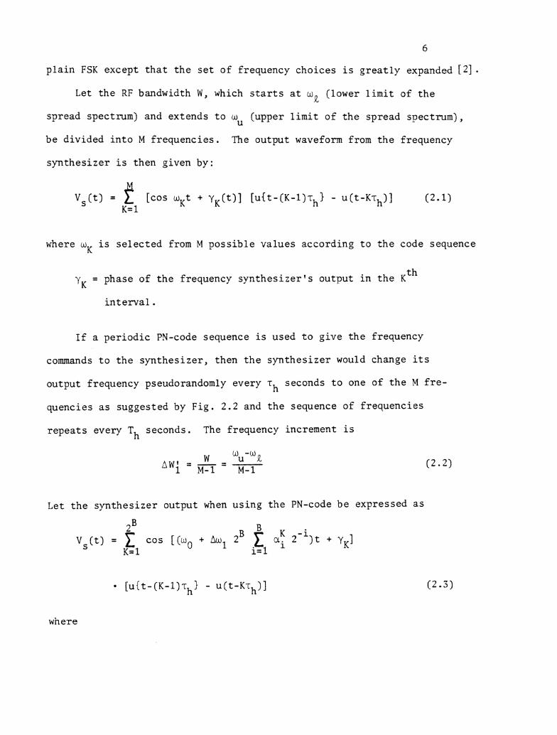
p l a i n FSK except t h a t t h e s e t of frequency choices i s g r e a t l y expanded [ 2 ] .
Let t h e RF bandwidth W, which s t a r t s a t we (lower l i m i t of t h e
spread spectrum) and extends t o w (upper l i m i t of t h e spread spectrum), u
be d iv ided i n t o M f requencies . The output waveform from t h e frequency
syn thes ize r i s then given by:
( t ) = f [COS w K t + y K ( t ) ] [ u ( t - ( ~ - l ) \ ~ - ~ ( t - K r h ) ] K= 1
(2.1)
where s i s s e l e c t e d from M p o s s i b l e va lues according t o t h e code sequence K
= phase of t h e frequency s y n t h e s i z e r ' s output i n t h e K t h ' K
i n t e r v a l .
I f a p e r i o d i c PN-code sequence i s used t o g ive t h e frequency
commands t o t h e s y n t h e s i z e r , then t h e syn thes ize r would change i t s
output frequency pseudorandomly every rh seconds t o one of t h e ?4 f r e -
quencies a s suggested by Fig . 2.2 and t h e sequence of freq.uencies
r e p e a t s every T seconds. The frequency increment i s h
Let t h e syn thes ize r output when us ing t h e PN-code be expressed a s
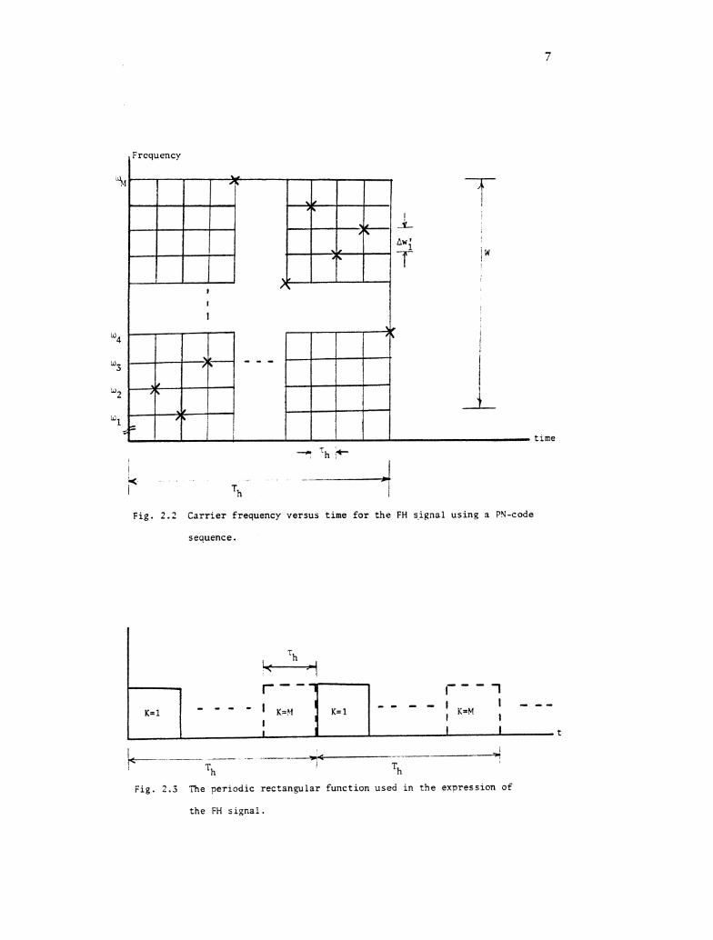
Fig. 2 . 2 C a r r i e r frequency versus time f o r t h e FH s-ignal using a PN-code
sequence.
Fig. 2.3 The periodic rectangular funct ion used in t h e e x ~ r e s s i o n of
the FH s ignal
8
B = number of b i t s f o r t h e code word spec i fy ing t h e frequency hop.
id = s y n t h e s i z e r ' s c e n t e r frequency around which t h e M f requencies 0
a r e t o be suppl ied .
Owl = hopping s t e p s i z e / 2 .
The [ u { t - ( ~ - l ) r ~ ) - u(t-KT ) ] r ec tangu la r func t ion is i l l u s t r a t e d i n h
Fig. 2.3. Each s p e c i f i c output frequency i s given by [2] a s
and t h e code word spec i fy ing t h e hop i s given by
The c t fs i n (2.3) and (2.4) a r e given by
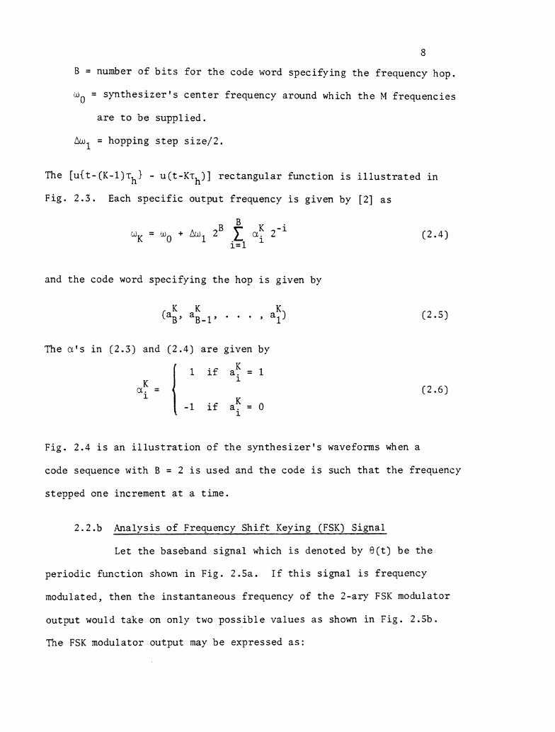
Fig. 2.4 i s an i l l u s t r a t i o n of t h e s y n t h e s i z e r ' s waveforms when a
code sequence with B = 2 i s used and t h e code i s such t h a t t h e frequency
stepped one increment a t a t ime.
2.2 .b Analysis of Frequency S h i f t Keying (FSK) Signal
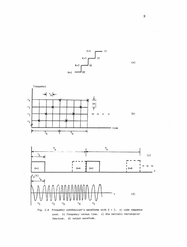
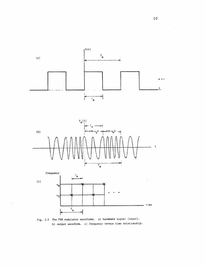
Let t h e baseband s i g n a l which i s denoted by a ( t ) be t h e
pe r iod ic func t ion shown i n Fig . 2.5a. If t h i s s i g n a l i s frequency
modulated, then t h e ins tantaneous frequency of t h e 2-ary FSK modulator
output would t a k e on only two p o s s i b l e va lues a s shown i n Fig . 2.5b.
The FSK modulator output may be expressed a s :
Frequency
t i n e
F i g . 2 .4 Frequency s y n t h e s i z e r ' s waveforms wi th 3 = 2 . a ) code sequence
used. b ) f requency v e r s u s zime. c ) t h e q e r i o d i c r e c t a n g u l a r
f u n c t i o n . d) o u t r u t waveform.
t c o s o t 7 0 s %t 4 I
Frequency
I 'm -
Fig. 2.5 The FSK modulator waveforms. a) baseband s i ~ n a l ( i n p u t ) .
b) output waveform. c ) frequency ve r sus t ime r e l a t i o n s h i p .
(c)
94
us'
Tm 1
w
7 -
P.
time
L
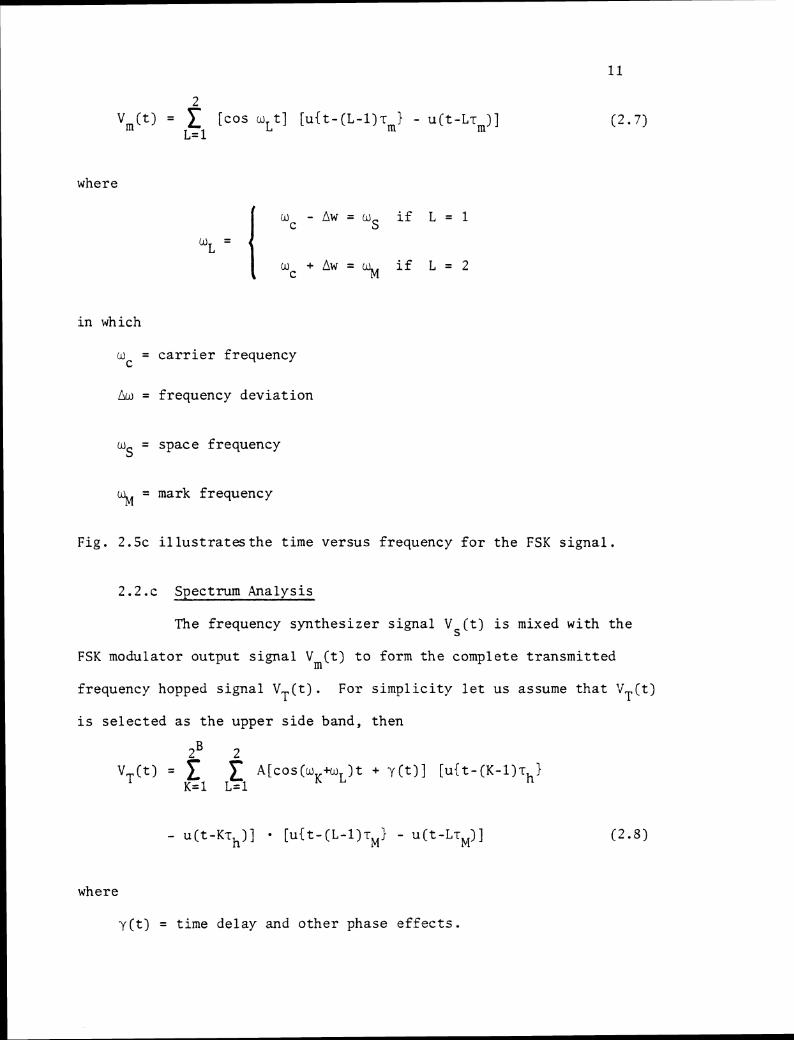
Vm(t) = [cos wLt] [ u { t - ( L - l ) r m i - ~ ( t - L T , ) ] L= 1
where
i n which
w = c a r r i e r f requency C
Gw = frequency d e v i a t i o n
us = space frequency
% = mark frequency
F i g . 2 . 5 ~ i l l u s t r a t e s t h e t ime ve r sus frequency f o r t h e FSK s i g n a l .
2.2.c Spectrum Analys is
The frequency s y n t h e s i z e r s i g n a l Vs( t ) i s mixed wi th t h e
FSK modulator ou tput s i g n a l Vm(t) t o form t h e complete t r a n s m i t t e d
frequency hopped s i g n a l VT( t ) . For s i m p l i c i t y l e t u s assume t h a t 'J ( t ) T
is s e l e c t e d a s t h e upper s i d e band, then
2B 2 v T ( t ) = ~ [ c o s ( w ~ + u ~ ) t + y ( t ) l [ u i t - ( ~ - l ) ~ ~ i
K = l L = l
where
y ( t ) = t ime de lay and o t h e r phase e f f e c t s .
12
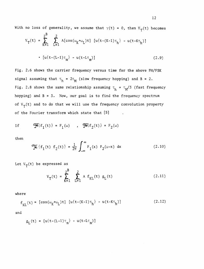
With no l o s s o f g e n e r a l i t y , we assume t h a t y ( t ) = 0, then V,(t) becomes
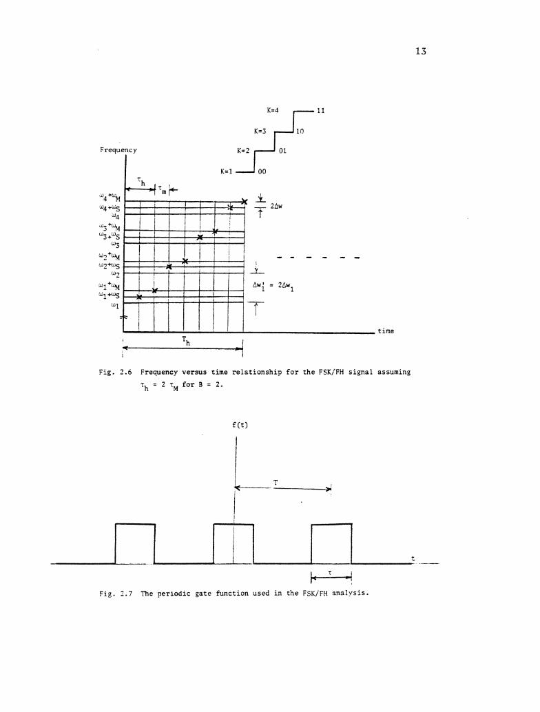
Fig. 2.6 shows t h e c a r r i e r f requency v e r s u s t ime f o r t h e above FH/FSK
s i g n a l assuming t h a t rh = 2r (slow frequency hopping) and B = 2 . M
Fig . 2.8 shows t h e same r e l a t i o n s h i p assuming r = rM/3 ( f a s t f requency h
hopping) and B = 3 . Yow, o u r goa l is t o f i n d t h e frequency spectrum
of V ( t ) and t o do t h a t we w i l l u s e t h e frequency convolu t ion p r o p e r t y T
of t h e F o u r i e r t ransform which s t a t e t h a t [5]
then
Let VT(t) be expressed a s
where
f ( t ) = [cos(wK+wL)t] [ u { ~ - ( K - I ) T ~ ~ - u ( ~ - K T ~ ) ] KL
and
g L ( t ) = [ ~ { t - ( L - I ) ? , } - ~ ( t - L r , ) ]
Th 7
1
I -
I
F i g . 2.6 Frequency v e r s u s t ime r e l a t i o n s h i p f o r t h e FSK/FH s i g n a l
T~ = 2 T~ f o r B = 2 .
t ime
assuming
Fig. 2 . 7 The p e r i o d i c g a t e f u n c t i o n a s e d i n t h e FSK/FH a n a l y s i s .
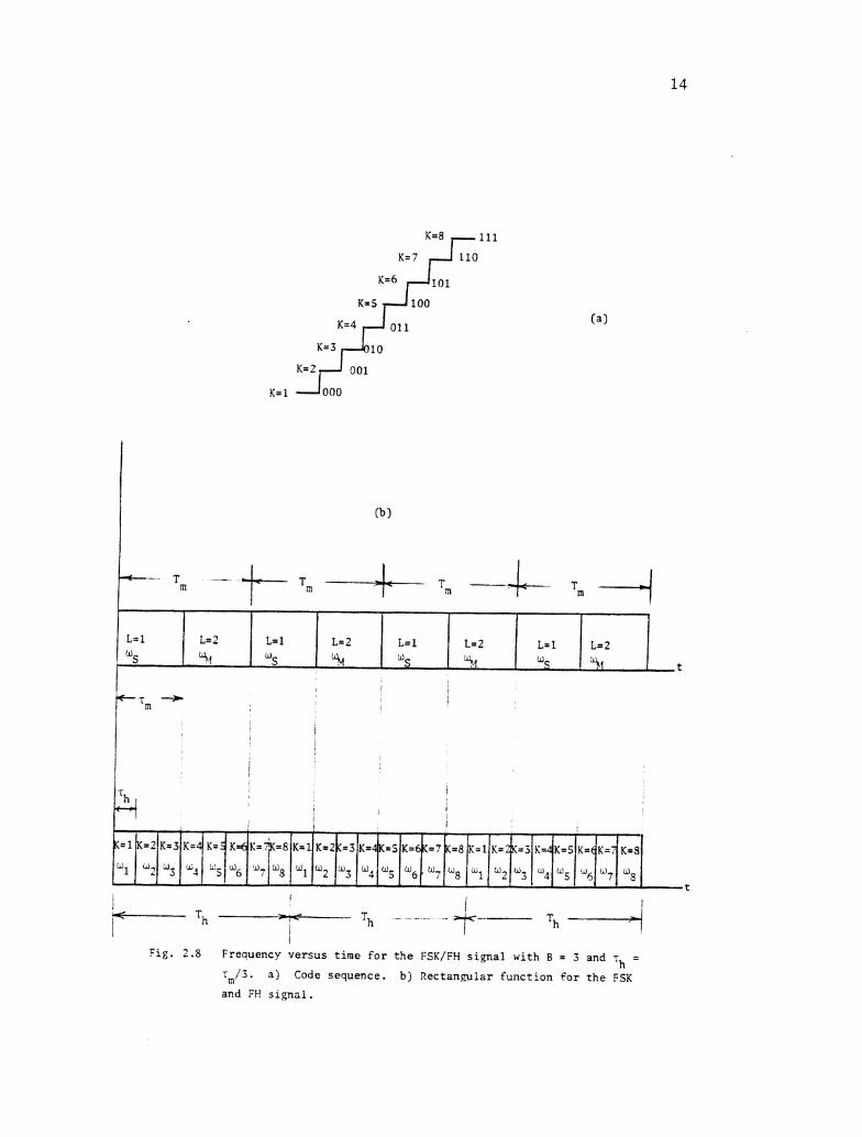
Fig. 2.8 Frequency v e r s u s t ime f o r t h e FSK/FH s i . p a l w i th B = 3 and - - 'I, -
?,/3. a j Code sequence. b ) R e c t a n w i a r f u n c t i o n f o r t h e FSK
and FR s l g n a l .
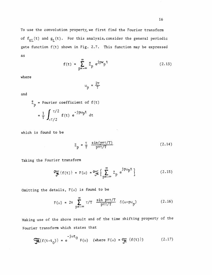
To u s e t h e convolu t ion property,we f i r s t f i n d t h e Four i e r t r ans fo rm
of f K L ( t ) and g L ( t ) . For t h i s a n a l y s i s , cons ide r t h e genera l p e r i o d i c
g a t e f u n c t i o n f ( t ) shown i n F ig . 2 .7 . This func t ion may be expressed
where
and
2 = Four i e r c o e f f i c i e n t of f ( t ) P
which i s found t o b e
Taking t h e F o u r i e r t r ans fo rm
Omit t ing t h e d e t a i l s , F(w) i s found t o b e
s i n p n ~ / T (u-pwp)
p=-co
Waking u s e o f t h e above r e s u l t and of t h e t ime s h i f t i n g p rope r ty of t h e
Four i e r t ransform which s t a t e s t h a t
- j u t 0 F { f ( t - t o ) } = e F(o) (where F(o) = G j S { f ( t ) } )
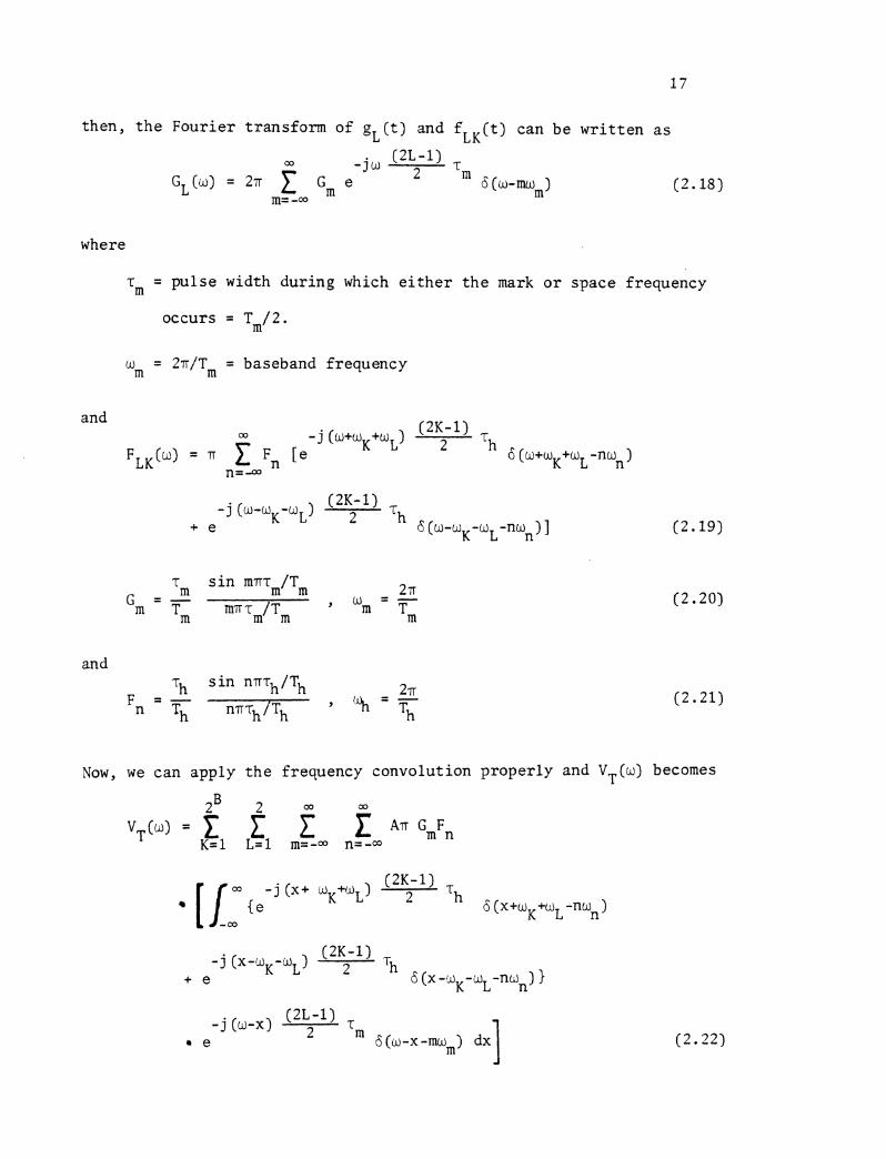
then , t h e Four ier t ransform of g L ( t ) and f ( t ) can be w r i t t e n a s L K
where
'm = pulse width dur ing which e i t h e r t h e mark o r space frequency
occurs = Tm/ 2.
'm = 27/Tm = baseband frequency
- j (w-w -w ) (2K- 1)
+ e K L 2 Th 6 (w-wK-uL-non) ]
r s i n mn~,/T, - m 2 7 ~
Gm - 7 , w = - Inn 'm/Tm " Tm
and
Now, we can apply t h e frequency convolution proper ly and V (w) becomes T
- j (w-x) (2L-1)
e 2 ' m 6 (w -x - m m ) dxl
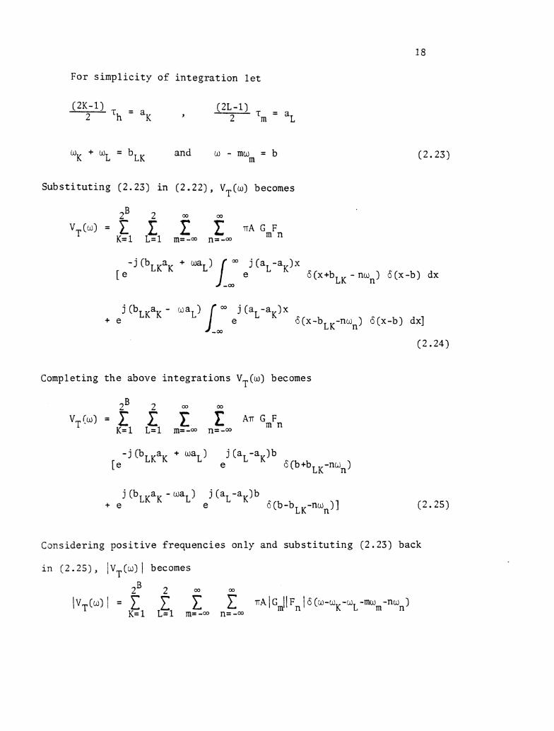
For simplicity of integration let
"K + "L = b~~ and w - mu = b
m
Substituting (2.23) in (2.22), VT(w) becomes
- j (bLKaK + uaL) [ 8 (x+bLK - nun) 6 (x-b) dx
j (bLKaK - maL) Jam ej (a L -a K 1' + e 6(x-bLK-nun) 6(x-b) dx]
Completing the above integrations V (w) becomes T
Csnsidering positive frequencies only and substituting (2.23) back
in (2.25) , I V (w) 1 becomes T
2B 2 a a 1 s i n (mv T ~ / T ~ ) I v T ( ~ ) I = 1 1 T ~ ( ~ ~ / ~ ~ ) (rh/Th)
~ = l ~ = l m=-w n=-oo m.rr rm/Trn
The spectrum of t h i s FSK/FH i s shown i n F igs . 2.13, 2.14 and 2.15 f o r
s i n (nn rh/Tk,)
nn rh/Th
d i f f e r e n t c a s e s . Without f requency hops ( i . e . M = 1 ) . t h e ou tpu t of
B(w-w -w -mw -nw ) K L m n
t h e frequency s y n t h e s i z e r would be a CW, i . e . V ( t ) = cos w t . When S 0
t h i s s i g n a l i s mixed wi th V ( t ) o f (2 .7) , then t h e t r a n s m i t t e d s i g n a l m
V ( t ) ( cons ide r ing t h e upper s ideband) becomes T
where
W - A w = w C S
when L = 1
14 + A W = c % w h e n L = 2
and
r = p u l s e width dur ing which e i t h e r us o r /A occur s . m M
The magnitude of t h e F o u r i e r t ransform of t h i s p l a i n FSK s i g n a l (con-
s i d e r i n g t h e p o s i t i v e f r equenc ie s ) i s given by
The frequency spectrum of t h i s FSK s i g n a l i s shown i n F ig . 2 .9 .
2 7
S i m i l a r l y , i f one frequency (space o r mark) i s considered, then
t h e output of t h e modulator Vm(t) becomes:
Vm(t) = cos w s t y w = space frequency S
When t h i s s i g n a l i s mixed with VS(t) o f (Z.3), then VT(t) becomes
2 VT(t) = 1 A [ c o s ( ~ ~ + w ~ ) ~ ] [u{t - (K-l ) rh} - u(t-Krh)] (2.29)
K= 1
where
r = hop i n t e r v a l h
The magnitude of t h e Four ier t ransform of t h i s p l a i n FH s igna l (considering
p o s i t i v e f requencies only) i s given by
The spectrum i s shown i n Figs. 2.10, 2.11 and 2.12 f o r d i f f e r e n t cases .
2B T~ s i n (nrr T ~ / T ~ )
2 . 3 Spectrum Analysis of Binary Phase S h i f t Keying/Frequency Hopping
~ ~ ~ ( ~ ) l = 1 1 "Aq / nrr \/Th K = l n=-a
(BPSK/ FH)
6(w-w K -w S -nw,) (2.30)
Let t h e pe r iod ic baseband s i g n a l shown i n Fig. 2.16a b e phase
modulated, then t h e output of t h e modulator would change i t s phase every
T seconds t o one of two p o s s i b l e va lues (0 o r T) according t o t h e b inary m
stream a s shohn i n Fig. 2.16b. This waveform may b e expressed as:
where
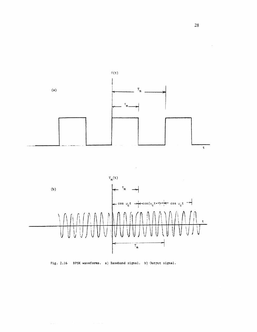
Fig. 2.16 BPSK waveforms. a) Baseband signal. b) Output signal .
0 when L = 1 -
O L - TT when L = 2
V ( t ) may b e a l s o w r i t t e n a s m
where w e g e t t h e p o s i t i v e s ign when L = 1 and t h e nega t ive s ign when
L = 2 . The p l a i n frequency hopping s i g n a l coming from t h e frequency
syn thes ize r was given be fo re a s
This s i g n a l is mixed with Vm(t) (output of t h e BPSK modulator) t o
form t h e complete t r ansmi t t ed BPSK/FH s igna l which would b e denoted
a s VT(t) . Assuming t h a t VT(t) i s s e l e c t e d a s t h e upper sideband and any
time delay i s neglec ted , then
2B 2 VT(t) = 1 1 t A[cos(wK+wc)t] [ u i t - ( ~ - l ) ? ~ } - U ( ~ - K T ~ ) ]
K = l L = l
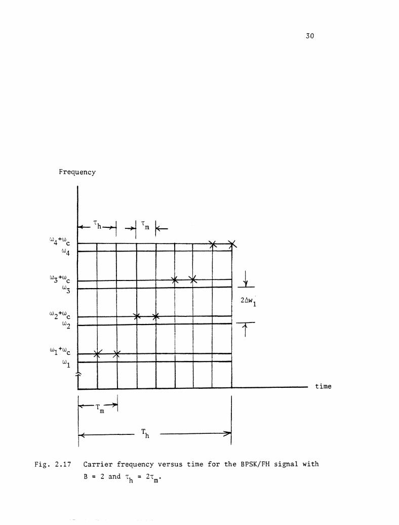
The c a r r i e r frequency versus time f o r t h i s BPSK/FH s i g n a l i s shown i n
Fig. 2 .17 f o r B = 2 and T~ = 2 ~ ~ .
To ob ta in t h e frequency spectrum of t h e above s i g n a l , we need t o
t ake i t s Four ier t ransform. Using t h e same method a s t h a t used t o f i n d
t h e Four ier t ransform of t h e FSK/FH s i g n a l represented by (2.9) and
omit t ing t h e d e t a i l s , we ge t
Frequency
Fig. 2.17 Carrier frequency versus time for the BPSK/FH signal with
B = 2 and rh = Z;,.
where
r s i n mn rm/Tm - m Gm - < 2 Tr
9 W = -
mTr T ~ / T ~ Tm
b = w-mu m and bcK = w +w c K
Considering the p o s i t i v e f r equenc ie s only , V (w) becomes T
zB 2 a3 a j (bcKaK-waL) V T ( w ) = 1 k i r A G m F n [ e
K = l L = l m=-w n=-oo
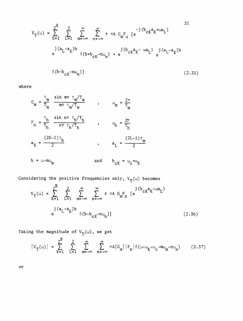
Taking t h e magnitude o f VT(w), we g e t
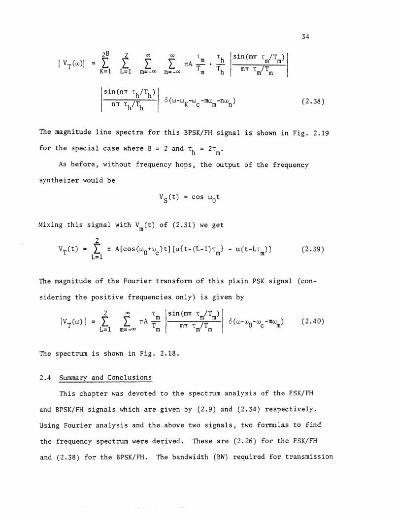
'I I s i n (mn 'I~/T,)
K = l L = l m=-co n=-a mT './Tm 1 I
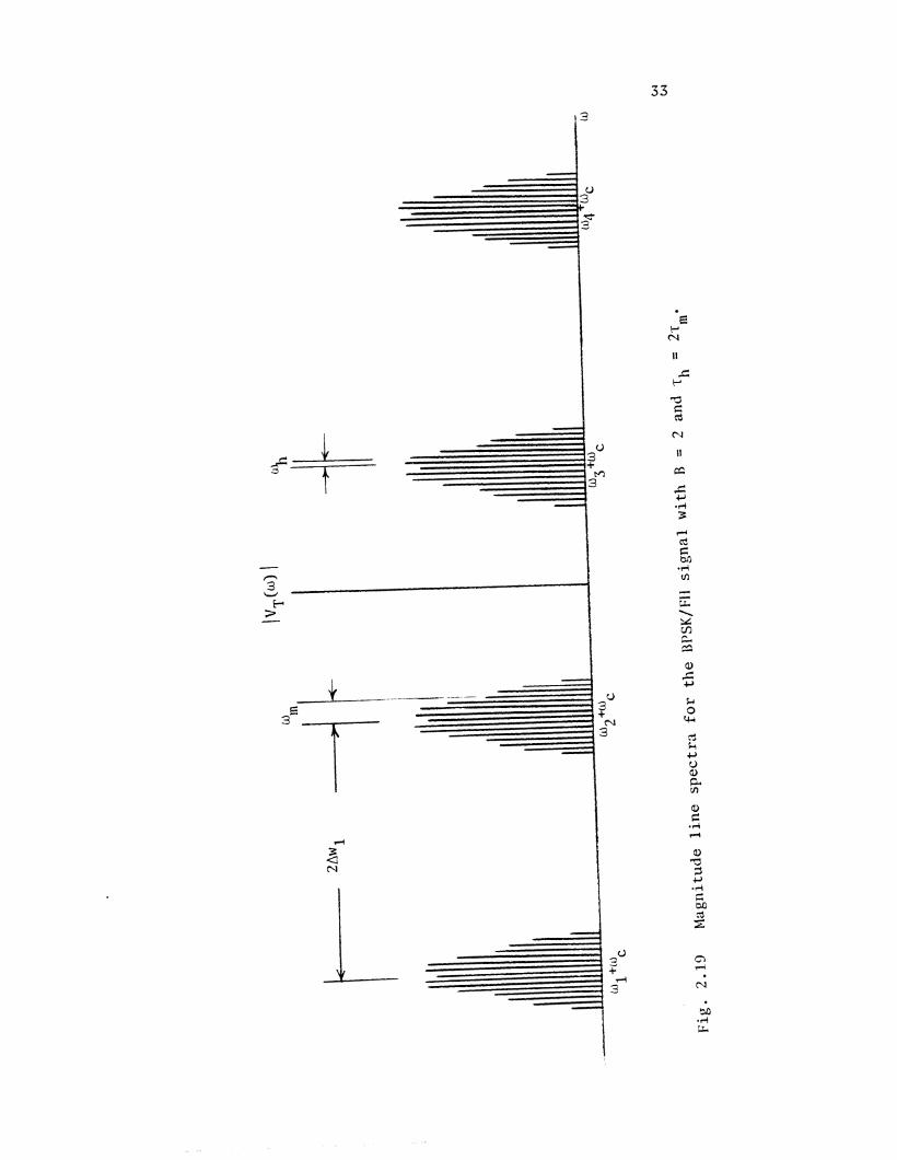
The magnitude l i n e s p e c t r a f o r t h i s BPSK/FH s i g n a l i s shown i n Fig. 2.19
s i n (nn rh/Th)
nn 'Ih/Th
f o r t h e s p e c i a l c a s e where B = 2 and r = 2rm. h
A s be fo re , without frequency hops, t h e output of t h e frequency
syn the ize r would be
6 (u-oK-oc -mum-nun) (2.38)
VS(t) = cos w t 0
Mixing t h i s s i g n a l with Vm(t) of (2.31) we g e t
2 v T ( t ) = 1 t 4[cos(uo+wc)t] [ u { t - ( ~ - l ) r ~ j - u( t -Lrm)] (2.39)
L= 1
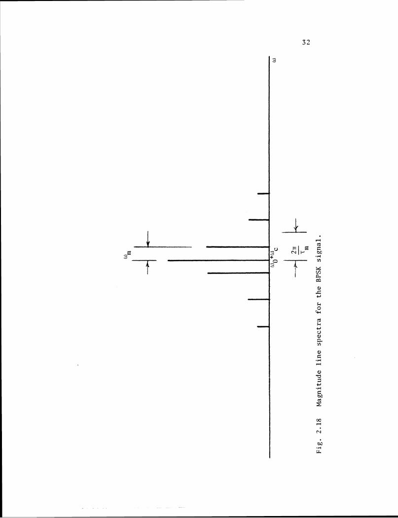
The magnitude of t h e Four i e r t ransform of t h i s p l a i n PSK s i g n a l (con-
s i d e r i n g t h e p o s i t i v e f requencies only) is given by
The spectrum i s shown i n Fig. 2.18.
2.4 Summary and Conclusions
This chap te r was devoted t o t h e spectrum a n a l y s i s of t h e FSK/FH
and BPSK/FH s i g n a l s which a r e given by (2.9) and (2.34) r e s p e c t i v e l y .
Using Four ier a n a l y s i s and t h e above two s i g n a l s , two formulas t o f i n d
t h e frequency spectrum were der ived . These a r e (2.25) f o r t h e FSK/FH
and (2.38) f o r t h e BPSK/FH. The bandwidth (BW) r equ i red f o r trarlsmission
f o r each of t h e d i f f e r e n t modulations cons ide red could be found from
t h e magnitude l i n e s p e c t r a corresponding t o t h a t modulation a s fo l lows :
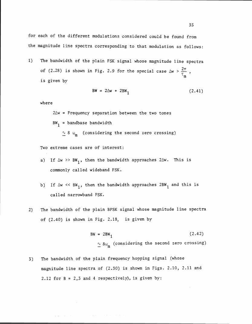
1 ) The bandwidth of t h e p l a i n FSK s i g n a l whose magnitude l i n e s p e c t r a
2 .rr of (2.28) i s shown i n Fig. 2.9 f o r t h e s p e c i a l c a s e Aw > - , Tm
i s given by
where
2Lw = Frequency s e p a r a t i o n between t h e two tones
BW1 = bandbase bandwidth
n., 8 wm - ( cons ide r ing t h e second zero c r o s s i n g )
Two extreme c a s e s a r e of i n t e r e s t :
a ) I f Aw >> BW then t h e bandwidth approaches 2Aw. This i s 1 ' commonly c a l l e d wideband FSK.
b) I f Aw << BW then t h e bandwidth approaches 2BW1 and t h i s i s 1 ' c a l l e d narrowband FSK.
2) The bandwidth of t h e p l a i n BPSK s i g n a l whose magnitude l i n e s p e c t r a
o f (2.40) i s shown i n F ig . 2.18, i s g iven by
n., 8wm (cons ide r ing t h e second zero c r o s s i n g ) -
3 ) The bandwidth of t h e p l a i n frequency hopping s i g n a l (whose
magnitude l i n e s p e c t r a of (2.30) i s shown i n F igs . 2.10, 2 . 1 1 and
2.12 f o r B = 2,3 and 4 r e spec t ive ly ) , i s given by:
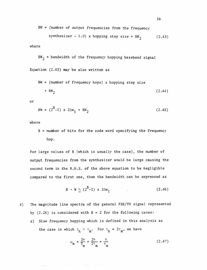
3 6
BW = (number of ou tpu t f r equenc ie s from t h e f requency
s y n t h e s i z e r - 1.0) x hopping s t e p s i z e + BW2 ( 2 . 4 3 )
where
BW2 = bandwidth of t h e frequency hopping baseband s i g n a l
Equation (2.43) may b e a l s o w r i t t e n a s
BW = (number o f f requency hops) x hopping s t e p s i z e
+ BW, L.
where
B = number of b i t s f o r t h e code word s p e c i f y i n g t h e frequency
hop.
For l a r g e v a l u e s of B (which is u s u a l l y t h e c a s e ) , t h e number o f
ou tput f r equenc ie s from t h e s y n t h e s i z e r would b e l a r g e caus ing t h e
second term i n t h e R . H . S . o f t h e above equat ion t o b e n e g l i g i b l e
compared t o t h e f i r s t one, then t h e bandwidth can be expressed a s
4) The magnitude l i n e s p e c t r a o f t h e gene ra l FSK/FH s i g n a l r ep re sen ted
by (2.26) i s cons idered with B = 2 f o r t h e fo l lowing c a s e s :
a ) Slow frequency hopping which i s de f ined i n t h i s a n a l y s i s a s
t h e c a s e i n which -ch > T . For T - 2~ , , we have m h -
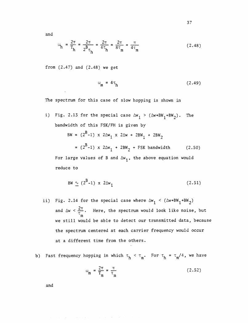
and
from (2.47) and (2.48) we g e t
The spectrum f o r t h i s c a s e of slow hopping is shown in
i ) F ig . 2.13 f o r t h e s p e c i a l c a s e Awl > (Aw+BW1+BW2). The
bandwidth o f t h i s FSK/FH is given by
B BW = (2 -1) x 2Awl x 20w + 2BW1 + 2BW2
= (zB-1) x 2Awl + 2BW2 + FSK bandwidth (2.50)
For l a r g e v a l u e s of B and Awl , t h e above equat ion would
reduce t o
i i ) F ig . 2.14 f o r t h e s p e c i a l c a s e where Awl < (Aw+BWl+BW2)
and Aw < 2. Here, t h e spectrum would look l i k e n o i s e , b u t 'm
we s t i l l would be a b l e t o d e t e c t ou r t r a n s m i t t e d d a t a , because
t h e spectrum cen te red a t each c a r r i e r f requency would occur
a t a d i f f e r e n t t ime from t h e o t h e r s .
b ) Fas t f requency hopping i n which T~ < For T~ = ~ ~ / 4 , we have
and
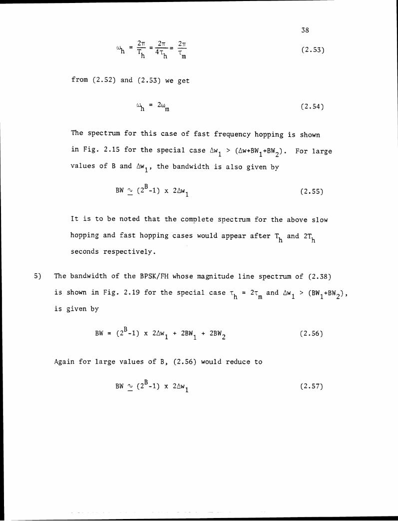
from (2.52) and (2.53) we g e t
The spectrum f o r t h i s case of f a s t frequency hopping i s shown
i n Fig. 2.15 f o r t h e s p e c i a l case Awl > (Aw+BWl+BW2). For l a r g e
values of B and Awl , t he bandwidth i s a l s o given by
I t is t o be noted t h a t t h e complete spectrum f o r the above slow
hopping and f a s t hopping cases would appear a f t e r T and 2Th h
seconds r e s p e c t i v e l y .
5) The bandwidth of t h e BPSK/FH whose magnitude l i n e spectrum of (2.38)
i s shown i n Fig . 2.19 f o r t h e s p e c i a l c a s e T = 2% and Awl > (BW1+BW2), h
i s given by
Again f o r l a r g e values of B , (2.56) would reduce t o
Chapter 3
PERFORMANCE OF THE FH SYSTEM
3.1 In t roduct ion
Noise reduct ion i s probably t h e most important s i n g l e considera t ion
i n transmission of s i g n a l s i n noisy and/or h o s t i l e channels. This can
be a major f a c t o r i n t h e system design and performance. In t h e case o f
d i g i t a l t ransmiss ion, the no i se can r e s u l t i n mistaken d i g i t s , and t h e
performance of t h e system is evaluated i n terms of p r o b a b i l i t y o f b i t
e r r o r .
I n t h i s chapter we w i l l show how t h e spread spectrum technique
( i n our case frequency hopping) is used t o p r o t e c t t h e system from
d e l i b e r a t e in te r fe rence (jamming). The p r o b a b i l i t y of e r r o r i s evalu-
a ted f o r t h e BFSK/FH and BDPSK/FH i n t h e presence of two very common
jamming models, namely:
a) par t ia l -band no i se jamming model, and
b) par t ia l -band mult i tone jamming model.
Then t h e worst case jamming s t r a t e g y i s determined f o r each case.
3 . 2 Jamming Models
While many poss ib le jammer models can be proposed, only t h e two
most common models a r e considered i n t h i s work, and these are :
3 .2 . a P a r t i a l -Band Noise Jamming Model
By d e f i n i t i o n , n o i s e jamming c o n s i s t s of f i l t e r e d white Gaussian
noise with t h e f i l t e r i n g r e s t r i c t i n g t h e no i se t o some o r a l l t h e RF
band. I t w i l l be assumed t h a t t h e jammer has a t o t a l power J which i s
3 9
40
uniformly spread ac ross a f r a c t i o n a o f t h e t o t a l RF band-width W ,
then t h e jammer appears a s an a d d i t i v e Gaussian no i se with one-sided
power s p e c t r a l d e n s i t y given by
The p a r t i a l band jamming model is shown i n Fig. 3.1.
3.2.b Part ial-BandMulti toneJammingModel
blul t i tone jamming c o n s i s t s of a s e r i e s of equal amplitude
tones coincident with t h e c e n t e r frequencies of t h e frequency hopping
channels. I f t h e jammer evenly d iv ides h i s t o t a l power J among q tones ,
then t h e power i n each tone would be J / q . I f t h e spacing between any
two success ive tones i s denoted by Rc, then t h e f r a c t i o n o f band which
is jammed is given by:
The mult i tone jamming model i s shown i n Fig. 3 . 2 .
I n t h e following p r o b a b i l i t y o f e r r o r ' s a n a l y s i s t h e white Gaussian
no i se background i s neglec ted s i n c e i t s con t r ibu t ion t o e r r o r is small
compared with t h e d e l i b e r a t e in te r fe rence , and i n genera l , could be
considered a s p a r t of t h a t system.
P robab i l i ty of Error Calcula t ions i n t h e Presence of P a r t i a l -
Band Noise Jamming
3.3. a Detect ion of Non-Coherent Binary Frequency S h i f t Keying i n
Frequency Hopping Environment (2-ary FSK-FH)
I t was mentioned before t h a t t h e par t ia l -band no i se jamming
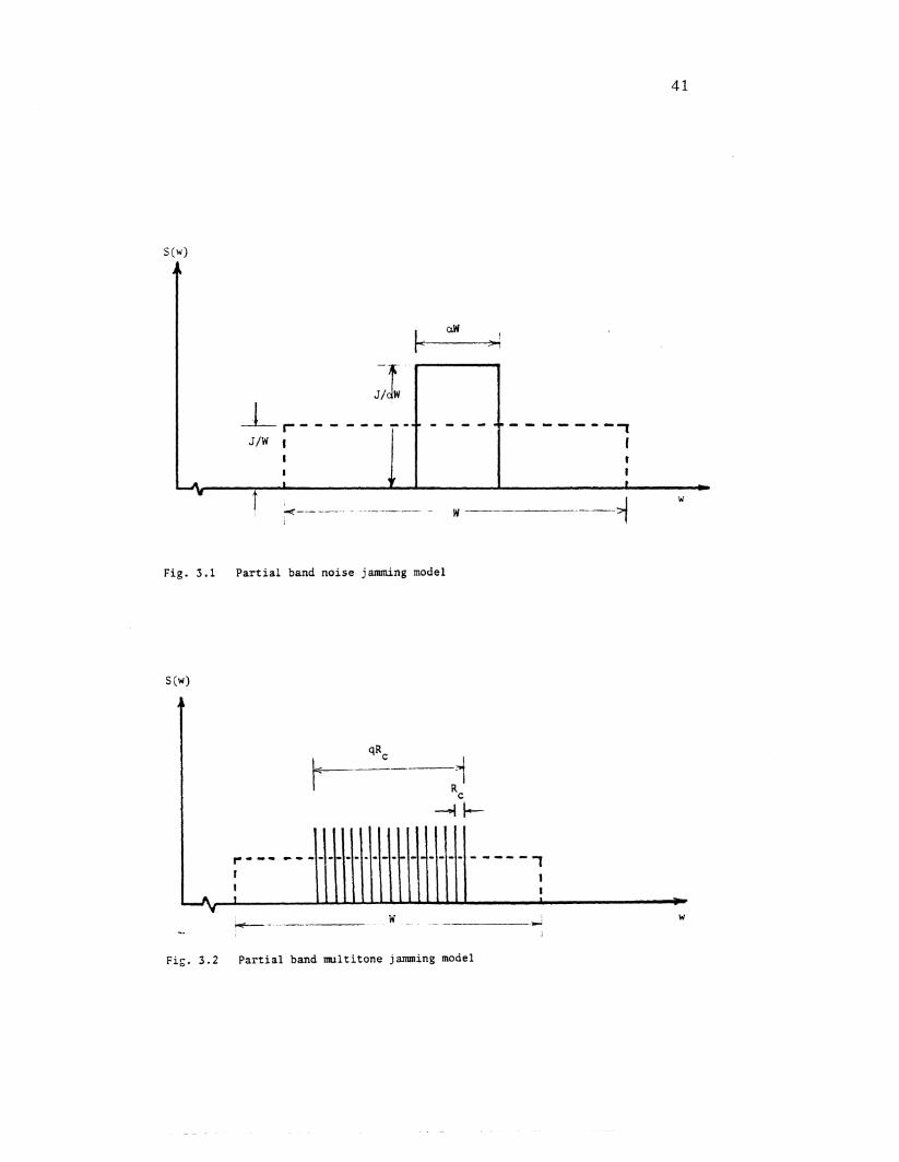
Fig. 3.1 P a r t i a l band n o i s e jamming model
Fig. 3 .2 P a r t i a l band mul t i t one jamming model
appears a s an a d d i t i v e Gaussian no i se with one-sided power s p e c t r a l
dens i ty N = J/aW. Therefore t h e p r o b a b i l i t y of e r r o r f o r t h e non- J
coherent FSK/FH recep t ion i s obtained d i r e c t l y from t h e r e s u l t s obtained
by Schwartz [3] f o r t h e ordinary non-coherent FSK, by rep lac ing n 0
(one-sided power s p e c t r a l d e n s i t y o f Gaussian noise) by our N a s done J
by Sam Houston [ g ] and Marvin Simon [16] . Thus t h e b i t p r o b a b i l i t y o f
e r r o r f o r t h e non-coherent FSK/FH i s given by:
where
E = b i t energy
a = f r a c t i o n of t h e t o t a l RF band which is jammed
NJ = one-sided power s p e c t r a l d e n s i t y
= J/aW
E/N can be expressed a s follows: J
where
X = E/J/W = b i t energy t o jam n o i s e d e n s i t y r a t i o .
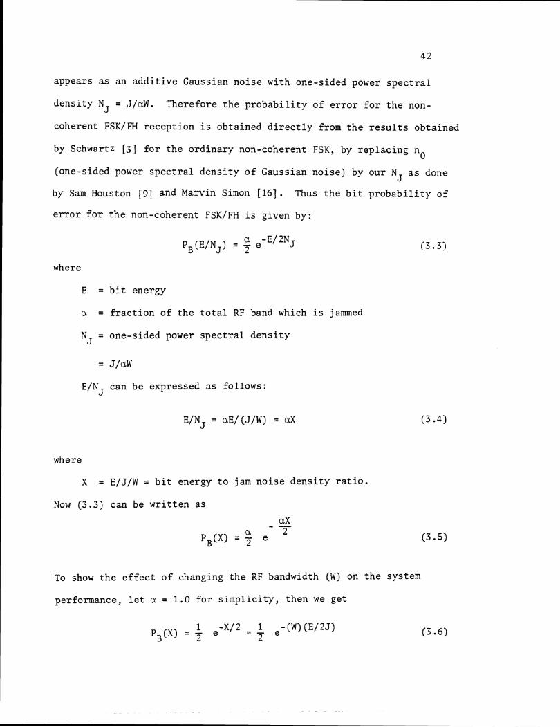
Now (3.3) can be w r i t t e n a s
To show t h e e f f e c t o f changing t h e RF bandwidth (W) on t h e system
performance, l e t a = 1.0 f o r s i m p l i c i t y , then we ge t
We can see t h a t by inc reas ing W , t h e e f f e c t i v e b i t energy t o jam
no i se r a t i o would inc rease . Fig. 3 .3 shows t h e b i t p r o b a b i l i t y o f
e r r o r f o r two d i f f e r e n t RF-bandwidths with a = 1.
3.3.b Worst Case Jamming S t r a t e g y Against Non-Coherent FSK/FH
The purpose of t h e jammer i s t o degrade t h e system performance
by inc reas ing t h e p r o b a b i l i t y of b i t e r r o r . Since we a r e assuming t h a t
t h e jammer has an a v a i l a b l e power J , t h e on ly parameter l e f t t o him
t o vary i s a, which i s r e s t r i c t e d t o t h e range 0 < o - < 1. The b i t
p r o b a b i l i t y o f e r r o r was given by (3.5) a s
mul t ip ly ing both s i d e s by X and s u b s t i t u t i n g f o r ax, E/NJ we ge t
1
1 - 7 (E/NJ) X P, (X) = (E/NJ) e
Fig. 3.4 i s a p l o t of t h e product X PB(X) versus (E/NJ). This curve
has a maximum value of 0.3679 a t (E/N ) = 2 = a X J max max
. . a = 2/X max
This va lue is optimum only i f it i s l e s s than u n i t y ( i . e . X > 2 ) .
Using (3.8) i n (3.5) we g e t PB (X) f o r X > 2. For X - < 2 we s e t max
ci = 1 i n (3.5) t o g e t P (X) . Now f o r t h e non-coherent FSK/FH, t h e ,max
p r o b a b i l i t y of b i t e r r o r corresponding t o t h e worst case pa r t i a l -band
jamming can be w r i t t e n a s :
X (db)
Fig. 3.3 Bit probability of error versus bit energy to jam noise ratio for the non-coherent FSK/FH in the presence of partial-band noise with a = 1.0
This i s shown i n Fig. 3.5. The optimum (which causes maximum b i t
e r r o r ) jammed f r a c t i o n of t h e t o t a l RF bandwidth W is expressed a s
follows :
u (X) = max
This is shown i n Fig. 3 . 6 .
3.3.c Detect ion of Coherent Frequency S h i f t Keying i n Frequency
Hopping Environment (Coherent FSK-FH)
A t t h e receiving end of t h e FSK/FH system, a FH-signal i d e n t i c a l
t o t h e spreading one appl ied a t t h e t r a n s m i t t e r , is used t o de-spread
t h e incoming s i g n a l , and a conventional coherent FSK de tec t ion i s used
t o decode t h e t ransmit ted da ta . The b i t p r o b a b i l i t y of e r r o r f o r t h e
ordinary coherent FSK i s given by Schwartz [3] a s
where
1 PB = Z e r f c
E = b i t energy
n = one-sided power s p e c t r a l dens i ty of Gaussian no i se 0
Since t h e par t ia l -band noise jamming is considered a s an a d d i t i v e
Gaussian noise , then b i t p r o b a b i l i t y of e r r o r f o r t h e coherent FSK/FH
may be expressed a s :
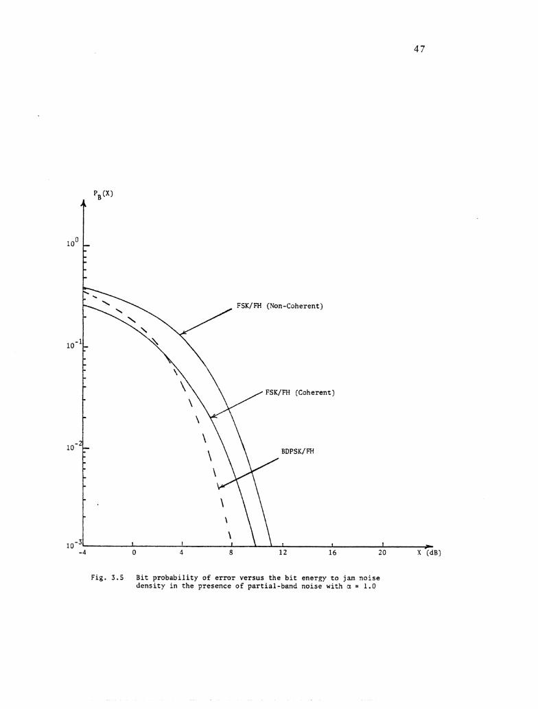
Fig. 3.5 Bit probability of error versus the bit energy to jam noise density in the presence of partial-band noise with a = 1.0
a PB(E/NJ) = 7 e r f c
where E , NJ and a a r e def ined a s before . Equation (3.12) can be
a l s o w r i t t e n as :
a pB(x) = ;r e r f c @ (3.13)
The b i t p r o b a b i l i t y o f e r r o r i s shown i n Fig. 3.5 f o r both t h e coherent
and non-coherent cases , with a = 1.0 f o r t h e purpose of comparison.
A s before , t o f i n d t h e worst case jamming s t r a t e g y a g a i n s t
coherent FSK/FH, w e mul t ip ly both s i d e s o f (3.9) by X t o o b t a i n
This product has a maximum value o f 0.16574 a t (E/N ) = 1.425 a s J rnax
shown i n Fig. 3.4 from which
1.425 = - a max x
This va lue is optimum ( i n t h e sense o f g iv ing maximum b i t e r r o r ) i f
i t i s l e s s than u n i t y ( i .e . X > 1.425). Using (3.15) i n (3.13), t h e
r e s u l t would be PB (X) f o r X > 1.425. For X < 1.425 w e set a = 1.0 - max
i n (3.13) . Omitting t h e d e t a i l s , t h e f i n a l form of %ax (X) and PB (X) rnax
(worst case) f o r t h e coherent FSK/FH case would be given by:
and
PB ( X I = rnax ( 0.5 e r f c X < 1.425 -
Fig. 3 . 6 shows a (X) versus X f o r t h e coherent and non-coherent rnax
FSK/FH cases , while Fig. 3 . 7 shows PB (X) versus X f o r both cases . max
3.3.d Binary D i f f e r e n t i a l Phase S h i f t Keying i n Frequency Hopping
Environment (BDPSK/FH)
The p r o b a b i l i t y of b i t e r r o r f o r t h e o rd ina ry BDPSK i n which
t h e change i n t h e c a r r i e r phase c a r r i e s t h e information ( i . e . a one
d i c t a t e s a change i n t h e phase o f t h e t r ansmi t t ed s i g n a l , and a zero
d i c t a t e s no change), i s given by Seymour S t e i n [6] a s :
where
n = one-sided power s p e c t r a l d e n s i t y o f Gaussian noise . 0
Now t o determine an expression f o r t h e p r o b a b i l i t y of e r r o r f o r t h e
BDPSK/FH i n t h e presence of pa r t i a l -band n o i s e jamming, t h e same agru-
ment a s t h a t used i n t h e case of FSK/FH is used and w e ge t :
where 2, E , and N a r e defined as before . Equation (3.19) can be J
a l s o w r i t t e n a s
a (XI max
Fig. 3.6 The jammed f r a c t i o n of the RF bandwidth VS t h e b i t energy t o jam no i se d e n s i t y r a t i o i n t h e presence of p a r t i a l band no i se (worst case)
FSK-FH (Non-Coherent)
/
FSK-FH (Coherent)
X [dB)
Fig. 3.7 Max bit probability of error VS the bit energy to jam noise density in the presence of partial-band noise (worst-case)
The b i t p r o b a b i l i t y of e r r o r f o r t h e BDPSK/FH which corresponds
t o t h e worst case par t ia l -band jamming s t r a t e g y may be found a s before
using Fig. 3 and equation (3-20). Omitting t h e d e t a i l s c i & X ) and
PB (X) can be f i n a l l y w r i t t e n as : max
a (X) = rnax
and
0.18394/X X > 1.0
PB (XI = (3.22) max 1 -X
7 e X < 1.0 -
Figs. 3- 9 and 3- 6 show P (X) versus X(dB) and gax a g a i n s t X(dB) Bmax
r e spec t ive ly f o r both cases FSK/FH and BDPSK/FH f o r t h e purpose of
comparison.
3.4 Calcula t ions of t h e Probab i l i ty o f Error i n t h e Presence of
Partial-Band Mult i tone Jamming
I n t h i s s e c t i o q t h e second type o f i n t e r f e r e n c e which i s t h e
par t ia l -band mul t i tone jamming i s considered. The mul t i tone jammer
is assumed t o have p e r f e c t knowledge o f t h e system opera t ion except
f o r t h e frequency hopping code sequence, and t h a t he has an a v a i l a b l e
power J. The b e s t s t r a t e g y f o r him i s t o d i s t r i b u t e h i s power equal ly
among q contiguous tones and vary t h i s number t o maximize t h e p r o b a b i l i t y
of e r r o r of t h e system [g]
Fig. 3.9 Bit probability of error versus the bit energy to jam noise in the presence of partial-band noise jamming (worst case)
3.4.a 2-ary Ncn-Coherent FSK/FH with Jam Tone Spacing Equal t o
t h e B i t Rate
1 Let Rc = - denote t h e b i t r a t e , then t h e t o t a l number o f T-
frequency b ins i n t h e spread spectrum bandwidth (W) i s given by
The p r o b a b i l i t y t h a t t h e jammer w i l l h i t a keyed tone i s
where q = number of jamming tones.
The b i t p r o b a b i l i t y of e r r o r f o r t h e M-ary non-coherent FSK/FH
was given by Sam Houston [9] a s
For t h e 2-ary case we s e t M = 2 i n t h e above equation t o g e t
This equation can be expressed a s
ap* ( X I To determine t h e value o f q which maximizes PB(X) we s e t
aq = 0,
t o ob ta in
W = - "ma, 2Rc
It is usually more convenient to express P in terms of the ratio h
of the signal power (S) to the jamming power per tone (J/q), and let this
ratio be denoted by a, i.e.
Now (3.24) can be written as
Substituting (3 -30) in (3.26) we get
aPB(x) We now maximize PB(X) with respect to a, setting aa = 0, to obtain
a - X max - 7
This value of a is optimum (gives maximum probability of error) if it
is less than unity (i.e. X < 2). Using (3.32) in (3.31) we get
P~ (X) for X < 2. For X - > 2 we set a = 1 in (3.31). Omitting the max
details amm (X) and PB (X) can be expressed as : max
and
PB (XI = max
Fig. 3.10 shows t h e worst-case performance represented by (3.34).
3.4.b 2-ary FSK/FH with Jam Tone Spacing Equals t o Twice t h e B i t
Rate
I n t h i s s t r a t e g y , t h e mult i tone jammer seeks t o h i t only one
of t h e two t ransmit ted symbols. The b i t p r o b a b i l i t y of e r r o r i n t h i s
case was given by Sam Houston [9] a s
The b i t p r o b a b i l i t y of e r r o r (worst case) can be found t o be:
1 - X X > 2.0 -
P (X) = Bmax
0.5 X < 2.0
This is shown i n Fig. 3.10.
3.4.c P robab i l i ty o f Error o f t h e BDPSK/FH with Jam Tone Spacing
Eaual t o t h e B i t Rate
The b i t p r o b a b i l i t y of e r r o r (worst-case) f o r t h e BDPSK/FH
with tone spacing = Rc was given by Sam Houston [9] a s
PB (XI = max
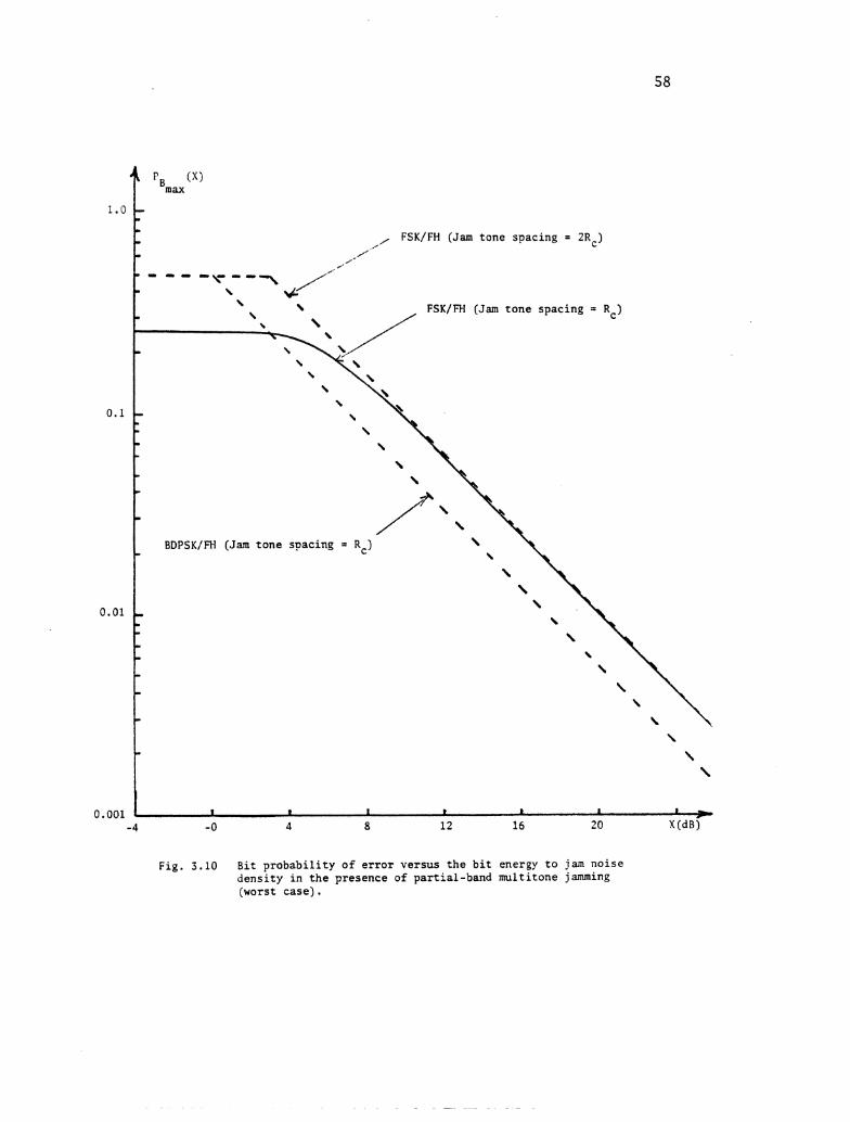
Fig . 3.10 B i t p r o b a b i l i t y o f e r r o r ve r sus t h e b i t energy t o jam no i se d e n s i t y i n t h e presence of pa r t i a l -band mul t i tone jamming (worst c a s e ) .
a 1.0
0.1
0.01
0.001 -4
Bmax
- - - , FSK/FH (Jam t one spacing = 2Rc) - 0 , ' /'
I' - - - - . -r---, \ /- \
4 \ - \
FSK/FH (Jam t o n e spacing = Rc) \
-
- - . P
- BDPSK/FH (Jam t one spacing = Rc) -
- . - - 0
- - -
\ - \ \
x I 1 I * a I I - - 0 4 8 12 16 20 X (dB)
(XI
- ,BDPSK/FH (jam t one spacing = Rc)
Non-Coherent FSK/FH (Jam t one spacing = R )
C
Son-Coherent FSK/FH (partial-band no l se )
. Coherent FSK/FH ( p a r t i a l -band no i se )
*
- 4 0 3 8 12 16 2 0 X(dB)
Fig. 3.11 B i t p r o b a b i l i t y o f e r r o r ve r sus t h e b i t energy t o jam n o i s e d e n s i t y (worst c a s e ) .
60
This i s shown i n Fig. 3.10.
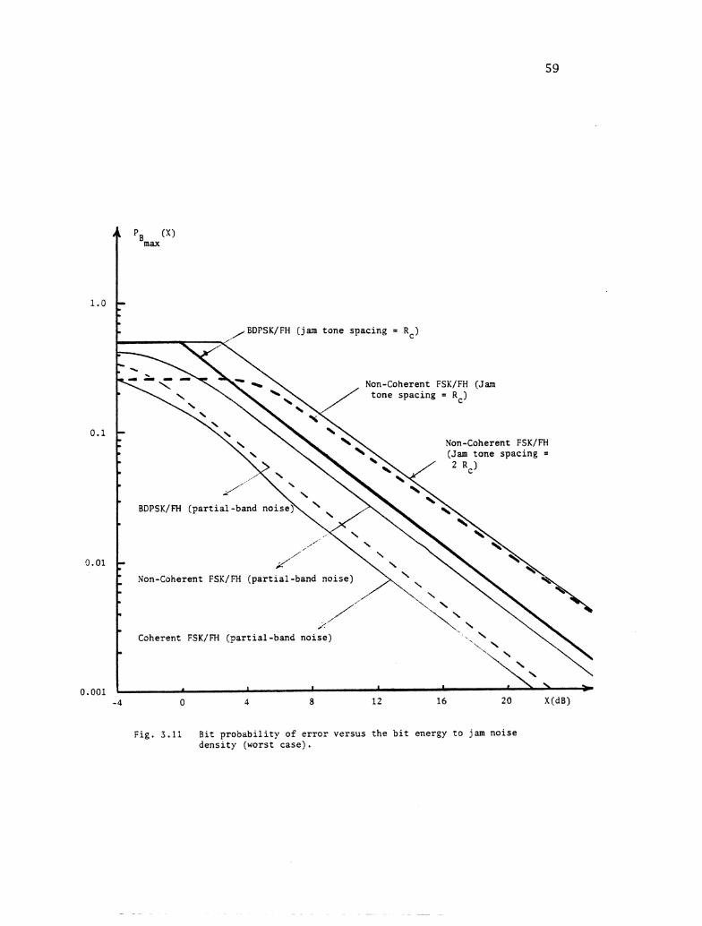
Fig. 3.11 shows the performance (worst-case) of t h e d i f f e r e n t
types of modulation considered, i n t he presence of t h e part ial-band
noise jamming and p a r t i a l -band multi tone jamming f o r t he purpose of
comparison.
3 .5 Conclusions
In t h i s chapter, we have seen how the FH technique could be used
t o p ro tec t t he communication system against t he in ten t iona l i n t e r -
ference introduced t o t h e system.
Following t he previous ana lys i s , we reach t o t he following
conclusions:
1) Fig. 3 . 3 t e l l s us t h a t t he b i t p robab i l i ty of e r r o r can be
minimized by increas ing t h e t o t a l RF bandwidth of t he t r ans -
mitted spread spectrum s igna l .
2) In t h e presence of part ial-band noise jamming we not ice: i
a) From Figs. 3.5 and 3 . 7 , we can see t h a t t he non-coherent
FSK/FH system requires more s ignal power f o r t he same prob-
a b i l i t y of e r r o r ( i . e . the re i s a penalty paid f o r not
maintaining phase coherence i n t h e non-coherent case) .
b) From Fig. 3 . 6 , it i s seen t h a t t o o b t a i n optimum r e s u l t s
(from t h e point of view of t he jammer), t h e t o t a l RF-bandwidth
(W) should be jammed f o r small values of X ( b i t energy t o jam
noise densi ty r a t i o ) , while f o r l a r g e r values of X, jamming
a f rac t ion of W would be more e f f ec t i ve .
(c) Referring t o Fig. 3 . 5 , one observes t h a t when the t o t a l RF band-
width is j ammed ( i .e. a = 1) and when X i s small (X < 3 dB) ,
t h e coherent FSK/FH i s t he most e f f e c t i v e technique agains t
t h e par t ia l -band noise jamming. For l a rge r values of X
(X > 3 dB), t h e BDPSK/FH system is t he most e f f e c t i v e one.
d) Considering t he worst-case jamming s t r a t egy ( i n which t he
b i t p robab i l i ty of e r r o r i s maxirmun), t h e most e f f e c t i v e
system agains t t h e par t ia l -band noise jamming i s t he coherent
FSK/FH followed by BDPSK/FH. This i s shown c l e a r l y i n Fig. 3.9.
3 ) Fig. 3.10 shows t h a t i n t he presence of p a r t i a l -band
noise jamming (worst-case) and when t he values of X a r e small
( X < 3 dB), t he most e f f e c t i v e system agains t t he tone jamming
i s t h e FSK/FH (jam tone spacing = Rc), while f o r l a r g e r values
of X (X > 3 dB), t h e most e f f e c t i v e system i s t h e BDPSK/FH (jam
tone spacing = Rc)
4) Fig. 3 . 1 1 shows t h a t
a) The most e f f e c t i v e in te r fe rence (higher b i t e r ro r ) aga ins t
our frequency hopping system is t he par t ia l -band mult i tone
j amrning with t he jam tone spacing = 2 Rc and t h e non-coherent
FSK i s considered.
b) The l e a s t e f f e c t i v e in te r fe rence (lower b i t e r ro r ) aga ins t our
system i s t he par t ia l -band no i se jamming when t h e coherent
FSK is considered.
5) Although t he worst case b i t p robab i l i ty of e r r o r i n our cases is
- 1 r e l a t i v e l y high, (approximately 10 - f o r X ( 0 - 20 dB),
it i s considered good and reasonable, because without t he spread
spectrum technique which we a r e us ing, the p robab i l i t y of e r r o r
would be much higher and we would c e r t a i n l y l o se our t ransmit ted
data .
Chapter 4
REAL TIME SIMULATION
4.1 In t roduct ion
Most of t h e concepts of spread spectrum have been known f o r many
yea r s , but t h e components and techniques f o r implementing r e l i a b l e
systems have only been a v a i l a b l e r e c e n t l y . The primary reason f o r t h i s
i s t h a t only r e c e n t l y has t h e technology i n i n t e g r a t e d c i r c u i t r y a r e a
come t o t h e po in t of making smal l , high speed and r e l i a b l e e l e c t r o n i c
components a v a i l a b l e a t a reasonable c o s t .
Fig. 4.1 shows t h e block diagram of t h e spread spectrum system
implemented i n t h i s i n v e s t i g a t i o n . The input d a t a i s a square wave and
t h e modulation assumed is frequency s h i f t keying (FSK). The spread
spectrum technique used i s frequency hopping. I t can be seen t h a t t h e
same s i g n a l i s used f o r spectrum spreading a t t h e t r a n s m i t t i n g
s i d e , and f o r spectrum de-spreading a t t h e rece iv ing end t o a s s u r e f r e -
quency and phase coherence. A coherent FSK demodulator is f i n a l l y used
t o recover t h e t r ansmi t t ed d a t a . The design and d e t a i l s of t h i s system
i s discussed i n t h e next s e c t i o n followed by conclusions.
4 . 2 Design and Descript ion of t h e Coherent FSK/FH Modem
A FSK/FH Modemwas implemented and Fig. 4-2a,b shows t h e c i r c u i t
diagram of t h i s system. The input da ta t o t h e system (Fig. 4-3a) is a
stream of square wave pulses produced by t h e f i r s t I.C. (XR-2206). The
pulse width and t h e duty cyc le can be adjus ted by t h e choice of R1 and
R 2 , and a r e given by:
Fig
. 4
.1
Blo
ck d
iagr
am o
f th
e im
plem
erit
ed c
oher
ent
FSK
/FIi
Mod
em.
Pu
lse
Gen
.
u u u
';-
Bu
ffer
na
t a
In ' - FS
K
Mod
.
u
J, u
i i
a =
i
-
1 "e
quen
cy
Syn
th.
=I
Ilou
b 1 e
-
Bal
ance
d
Mix
er
u u
.
A
Cod
e
Gen
.
i
Bu
ffer
n
ot~
b 1 e -
PB
ala
nced
Yix
er
- Buffer
L -
BP
Fil
ter
* C
oher
ent
t:SK
Den
~od .
Da
ta u
Out
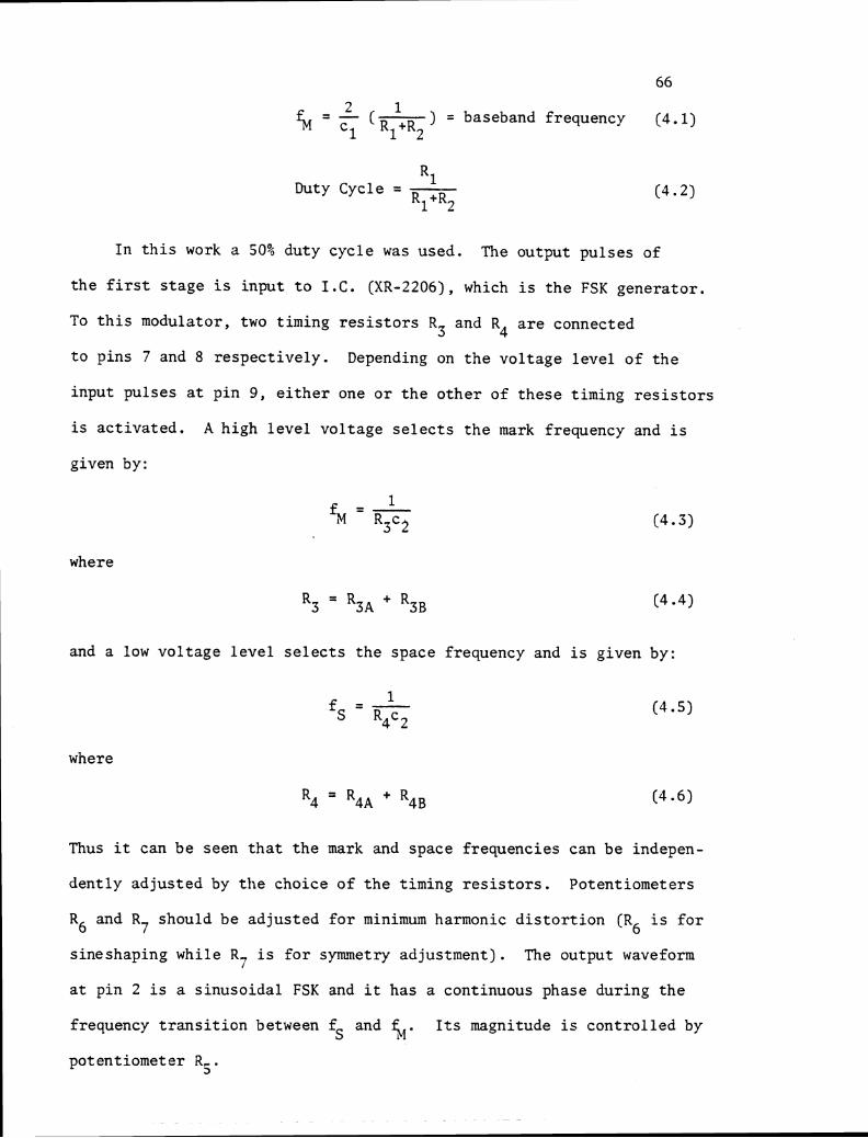
2 1 (-) = baseband frequency (4.1) % = R1+R2
L Duty Cycle = -
R1+R2
In t h i s work a 50% duty cyc le was used. The output pu l ses of
t h e f i r s t s t a g e i s input t o I . C . (XR-2206), which is t h e FSK genera tor .
To t h i s modulator, two timing r e s i s t o r s R3 and R4 a r e connected
t o p ins 7 and 8 r e spec t ive ly . Depending on t h e vo l t age l e v e l of t h e
input pulses a t p in 9 , e i t h e r one o r t h e o t h e r of t h e s e t iming r e s i s t o r s
i s ac t iva ted . A high l e v e l vol tage s e l e c t s t h e mark frequency and i s
given by:
where
and a low vo l t age l e v e l s e l e c t s t h e space frequency and is given by:
where
Thus it can b e seen t h a t t h e mark and space f requencies can be indepen-
den t ly ad jus ted by t h e choice of t h e t iming r e s i s t o r s . Potentiometers
R6 and R should be adjus ted f o r minimum harmonic d i s t o r t i o n (R i s f o r 7 6
sineshaping while R7 i s f o r symmetry adjustment) . The output waveform
a t pin 2 is a s inuso ida l FSK and it has a continuous phase during t h e
frequency t r a n s i t i o n between f and %. I t s magnitude is c o n t r o l l e d by S
potentiometer R,. 3
A frequency counter can be used t o measure t h e mark and space
frequencies separate ly a s follows:
(a) When pin 9 of t he FSK modulator i s disconnected o r connected t o a
pos i t ive voltage, a sinusoidal waveform with frequency equal t o
% i s obtained a t t h e output (pin 2) and may be measured.
(b) When pin 9 i s grounded, t h e frequency of t he output s inusoidal
waveform a t pin 2 , would be fM, and may be measured using t he
frequency counter.
The f i r s t two 741 operational ampl i f iers shown i n Fig. 4.2a,b
a c t s as buf fe rs , one between t he FSK modulator and t h e t r ansmi t t e r ' s
mixer, while t h e o ther one between t h e t ransmi t te r and r ece ive r ' s
mixer. Each mixer is a doubly balanced one, and employs SL-640C. Pin 2
of each mixer must be decoupled t o ea r th v i a a capaci tor which represents
the lower poss ible impedance a t both t h e c a r r i e r and s igna l frequencies.
A t t he t r ansmi t t e r ' s mixer t he sinusoidal FSK s igna l (fed t o pin 7) i s
mixed with t he frequency hopping s ignal (fed t o pin 3 of t h e mixer).
The output s ignal (obtained a t pin 5) contains t h e sum and d i f fe rence
frequencies of t he two mixed s igna l s . A t t h e r ece ive r ' s mixer t h e
incoming s igna l (fed t o pin 3 ) i s mixed with t h e same frequency hopping
s ignal t h a t was used a t t h e t r ansmi t t e r ' s s i de t o assure phase coherence.
Rg and Rg of t h e t r ansmi t t e r ' s mixer a r e t h e c a r r i e r and s igna l n u l l
potentiometers. I t is necessary t o ad jus t these controls a l t e r n a t e l y .
F i r s t with t he c a r r i e r but no FSK signal potentiometer Rg i s adjusted
f o r minimum output. Conversely, with t h e FSK signal and no c a r r i e r ,
potentiometer Rg i s s e t f o r minimum leakage t o the output. The same i s
sa id about potentiometers R10 and RI1 of t he r ece ive r ' s mixer.
6 8
The frequency hopping signal, which i s used a t both t h e t ransmi t te r
and receiver, is provided by t he HP-3330B Automatic Synthesizer which
could be programmed manually by using t he f ron t panel keyboards, o r
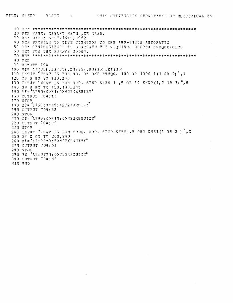
remotely by using a seven-bit p a r a l l e l ASCII code. The remote control
is accomplished by t h e HP-9835A computer system. An i n t e r ac t i ve BASIC
program "SWEEP" was wr i t t en and when executed, gives commands t o t h e
synthesizer t o generate the required hopped frequencies. The de-spread
signal which i s taken from pin 5 of t he r ece ive r ' s mixer, i s fed t o t he
rece iver ' s band pass f i l t e r (BPF). Two Burr-Brown UAF-31 1.C.s a r e
used t o implement a two s tages , 4-pole Butterworth BPF. The cen te r
frequency of t h i s f i l t e r is chosen t o f a l l mid-way between t he mark and
space frequencies and a low qua l i t y f ac to r i s chosen t o enable t h e f i l t e r
t o pass both frequencies. The following s teps a r e considered i n designing
the two s tages BPF [12] :
(1) Low pass f i l t e r parameters (qua l i ty f ac to r Q and normalized na tura l
frequency f ) a r e given by Burr-Brown f o r d i f f e r e n t number of poles. n
Xow, f o r t he required number of poles, f n and Q a r e se lec ted .
( 2 ) A computer FORTRAN program "ZAFILTER" i s used t o transform t h e low
pass design t o t h e equivalent band pass design and t he required
component values t o be connected t o t h e UAF-31 a r e calcula ted.
The input data t o t h i s program a r e Q, f n (se lected i n s t e p I ) ,
ABP (band pass gain) and Q (qua l i ty f ac to r f o r t h e BPF). The BP
amplitude response f o r the implemented BPF with cen te r frequency =
1.5 KHz and QBp = 2 is shown in Fig. 4 .5 .
The f i l t e r e d s i g n a l (Fig. 4.7) i s fed t o t h e l a s t I . C . (XR-2211)
a t p in 2. This I . C . is an FSK demodulator which opera tes on t h e phase-
locked loop (PLL) p r i n c i p l e . The fol lowing s t e p s a r e taken i n designing
t h e FSK demodulator [13]:
(1) The c e n t e r frequency of t h e PLL should be c a l c u l a t e d t o f a l l midway
between t h e mark and space f requencies , i .e.
f i s a l s o given by C
where
A s u i t a b l e va lue f o r R12 i s chosen, then c4 is c a l c u l a t e d us ing
(4.8).
(2) The t r ack ing range ( 2 Aft) which i s t h e range of f requencies over
which t h e PLL can r e t a i n lock with a swept input s i g n a l i s ca lcu la ted
us ing
I t i s a l s o given by
- R12fc A f , - - R13
Using (4.10) and (4.11), RI3 is determined.
(3) The PLL damping f a c t o r (p) determines t h e amount of overshoot,
undershoot o r r i n g i n g present i n t h e phase-locked loop 's response
t o a s t e p change i n frequency and i s given by:
For most Modem app l i ca t ion p i s s e t equal t o 0.5, then
Knowing c ( f o r s t e p 1) c5 can be determined. 4
(4) The FSK output f i l t e r time constant ( T ~ ) i s given by
T F = R c = 0.3 1 4 6 BaudRate
Choosing a s u i t a b l e va lue f o r RI4, and knowing t h e baud r a t e , c 6
can b e ca lcu la ted .
(5) c7 can be determined using t h e formula
16 - 16 - - C7("Ff 2 Capture range i n H Z 2*fc
where t h e cap tu re range (+ Afc) is t h e range of f requencies over
which t h e phase locked loop can acqu i re lock. In most Modem a p p l i -
c a t i o n s
A f c = (80% - 99%) A f t (4.16)
F ina l ly t h e output d a t a a r e obtained a t p in 7 of t h e FSK demodulator,
Table 4 . 1 shows t h e i n t e g r a t e d c i r c u i t s and t h e component va lues
used f o r t h e design of t h e Modem.
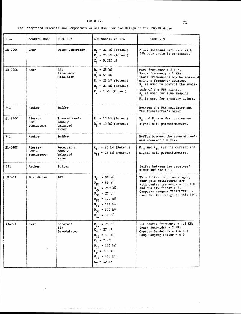
Table 4.1 7 1 The Integrated C i r c u i t s and Components Values Used f o r t h e Design of t h e FSK/FH Modem
I.C.
XR-2206
XR-2206
COMMENTS
A 1.2 kilobaud data r a t e with 50% duty cyc le i s generated.
Mark frequency = 2 KHz. Space frequency = 1 KHz. These frequencies may be measure1 using a frequency counter . R is used t o control t h e ampli- 5
.WFACTURER
Exar
Exar
tude of t h e FSK s igna l . R i s used f o r s i n e shaping. 6 R7 is used f o r symmetry ad jus t .
Between t h e FSK modulator and t h e t r a n s m i t t e r ' s mixer.
R and R a r e t h e c a r r i e r and 8 9
s igna l n u l l potentiometers.
Buffer between t h e t r a n s m i t t e r ' s and r e c e i v e r ' s mixer.
R10 and Rl l a r e the c a r r i e r and
s igna l nu l l potentiometers.
Buffer between the r e c e i v e r ' s mixer and t h e BPF.
This f i l t e r is n two stages, four pole Butterworth BPF with cen te r frequency = 1.5 KHz and q u a l i t y f a c t o r = 2 . Computer program "ZAFILTER" is used f o r t h e design of t h i s RPl:.
I R7 = 1 kR (Poten.)
FUNCTION
Pulse Generator
FSK Sinusoidal Modulator
COMWNENTS VALUES
Rl = 25 kR (Poten.)
R2 = 25 kli (Poten.i
C1 = 0.022 uF
R3 = 25 kQ
R4 = 58 kR
R5 = 25 kR (Poten.)
R6 = 25 kQ (Poten.)
I
R8 = 10 kn (Poten.)
Rg = 10 kc (Poten.)
R10 = 25 kR (Poten.)
Rll * 25 kj2 (Poten.)
RF1 = 89 kn
RF2 = 89 kn
R = 250 kc Q1
RG1 = 27 ki?.
RF3 = 127 kc
RF4 = 127 kQ
i 1
R = 370 kg Q2
RG2 = 39 k c
RI2 = 25 kR XR-221 PLL c e n t e r frequency = 1.5 KHz Exar Coherent
Buffer
Transmit ter 's doubly balanced mixer
Buffer
I
74 1
SL-640C
Track Bandwidth = 2 KHz Capture Bandwidth = 1.6 M z Loop Damping Factor = 0.5
1 ~ ~ ~ o d u l a t o r
Archer
Plessey
R15 = 470 kQ
C7 = 10 nF I
C4 = 27 nF
R13 = 39 k c
C5 = 7 nF
R14 = 102 kc?
C6 = 2.5 nF
SL-640C Plessey Receiver's Semi- doub 1 y conductors
mixer
74 1
1 741 i Archer
I I Buffer j 1
i UAF-31 / ~ u r r - ~ r o w n i BPF j 1
I i i
i
Semi- conductors
Archer
7 2
4.3 Resul ts and Comments
The inpu t s i g n a l s t o our coherent FSK/FH modem, which a r e t h e
spreading FH s i g n a l coming from t h e syn thes ize r and t h e t r ansmi t t ed da ta
(stream of b ina ry pulses) a r e shown i n Fig. 4.3. The b ina ry pu l ses a r e
frequency modulated and t h e output of t h e modulator which i s shown i n
Fig. 4.4, i s mixed with t h e FH s i g n a l t o form t h e FSK/FH s i g n a l . This
s igna l i s shown i n Fig . 4.6. A t t h e r e c e i v e r ' s s i d e , t h e rece ived
s i g n a l i s m u l t i p l i e d with t h e same FH s i g n a l a s t h a t used a t t h e t r a n s -
m i t t e r ' s s i d e . F ig . 4.7 shows t h e de-spread s i g n a l a f t e r being passed
through t h e BPF whose amplitude response i s shown i n Fig. 4.5. The
output of t h e BPF i s FSK de-modulated and t h e output of t h e demodulator
i s shown i n Fig. 4.8.
A frequency spectrum analyzer was used t o obta in t h e frequency
spectrum f o r each of t h e waveforms of i n t e r e s t . Fig. 4.9 shows t h e
frequency spectrum f o r t h e FH s i g n a l with a c e n t e r frequency f o =
150 KHz, number of output f requencies M = 11, frequency increment Afi =
5 KHz and hopping i n t e r v a l rh = 30 msec, while Fig. 4.10 shows t h e
spectrum f o r t h e FSK s i g n a l with t h e mark frequency f M = 2 KHz, t h e
space frequency f = 1 KHz and t h e b ina ry pu l se width rm = 15 msec. S
When t h e above two s i g n a l s a r e mixed toge the r , we ge t t h e FSK/FH s i g n a l
(slow hopping case) and t h e spectrum of t h i s s i g n a l i s shown i n Fig. 4.12
from which t h e bandwidth is measured and found t o be BW = 54 KHz.
Recall ing t h a t t h e BW f o r FSK/FH s i g n a l was given a s
BW = (number of output f requencies - 1 . O ) x hopping s t e p
s i z e + bandwidth of t h e FSK s i g n a l + 2 BW2
where
BW2 = bandwidth of t h e frequency hopping baseband s i g n a l
In our case BW2 i s small and can be neglec ted because T i s l a rge . Then h
t h e bandwidth i s given by
BW 'L (M-1) x A f i + bandwidth of t h e FSK s i g n a l -
= (11-1) x 5 KHz + 4 KHz = 54 KHz
which agrees wi th t h e measured bandwidth.
Fig. 4.17 shows t h e frequency spectrum f o r t h e above FSK/FH s i g n a l
with Afi = 0.5 KHz. The spectrum looks l i k e no i se , bu t our t r ansmi t t ed
d a t a s t i l l could be de tec ted a s expected be fo re . F ig . 4.13 shows t h e
spectrum f o r t h e de-spread s i g n a l a f t e r being passed through t h e BPF.
The mark frequency component (2 KHz) i s shown t o be smal ler than t h e
space frequency (1 KHz) because t h e BPF i s not exac t ly symmetrical about
t h e c e n t e r frequency (1.5 KHz) a s shown i n Fig. 4.5. Fig. 4.15 shows the
frequency spectrum f o r t h e FSK/FH s i g n a l when us ing a FH s i g n a l with
f o = 500 KHz, M = 101 and Afi = 5 KHz. The bandwidth of t h i s s i g n a l
i s measured and found t o b e
BW = 500 KHz
Again, r e c a l l i n g t h a t f o r l a r g e number of f requencies from t h e
syn thes ize r , t h e bandwidth f o r t h e FSK/FH s i g n a l was given by
BW a (M-1) x Afi -
Applying t h i s t o our case we g e t
BW = (101-1) x 5 KHz = 500 KHz
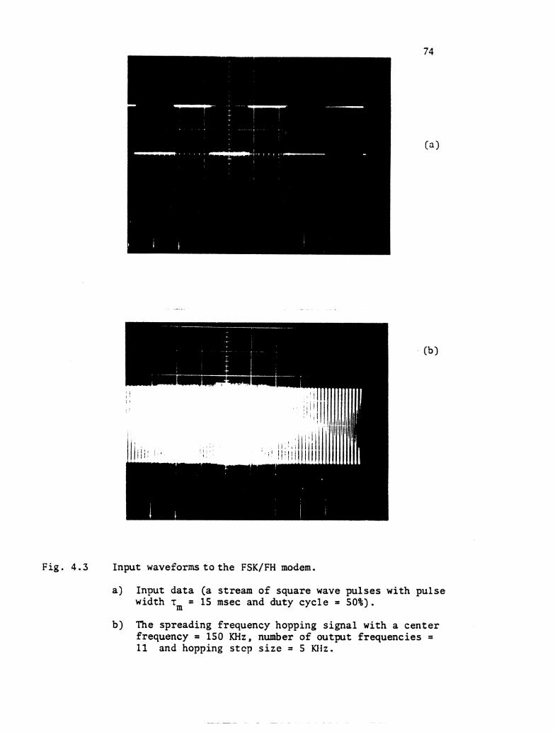
F i g . 4 . 3 Input waveforms t o t h e FSK/FH modem.
a) Input da ta (a stream of square wave pulses with pulse width rm = 15 msec and duty cycle = 50%).
b) The spreading frequency hopping s ignal with a cen te r frequency = 150 KHz, number of output frequencies = 11 and hopping s t c p s i z e = 5 KHz.
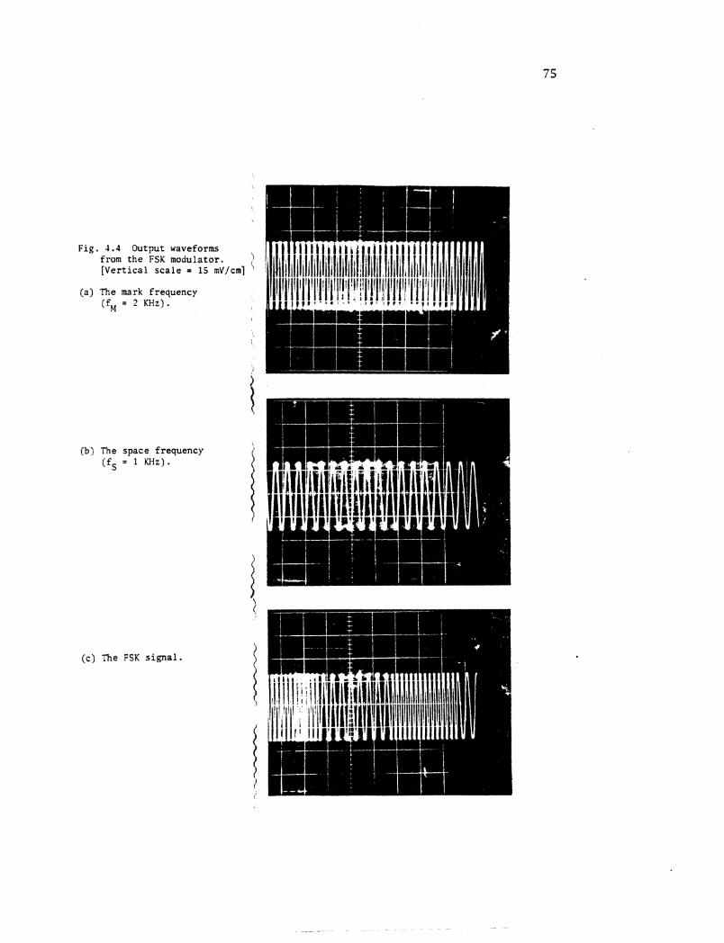
Fig. 4.4 Output waveforms from t h e FSK modulator. \ [ V e r t i c a l s c a l e = 15 mV/cm] '
(a) The mark f requency (fM = 2 KHz).
i (b) The space f requency
( f S = 1 KHz).
i
(c) The FSK s i g n a l .
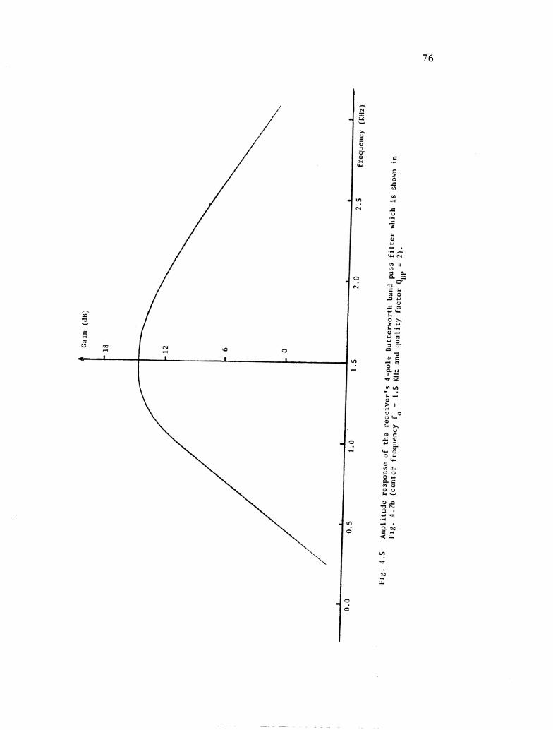
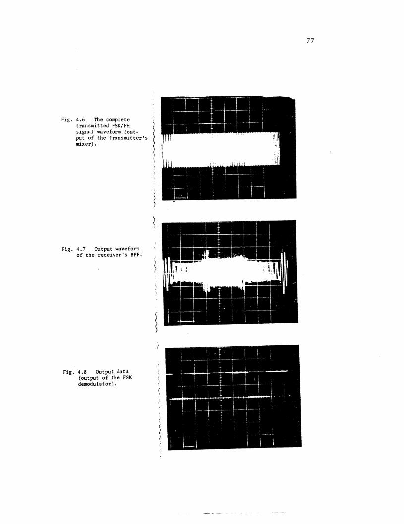
Fig.
Fig.
4.6 The complete transmitted FSK/FH signal waveform (out- put of the transmitter's mixer).
4.7 Output waveform of the receiver's BPF.
Fig. 4.8 Output data (output of the FSK demodulator1 .
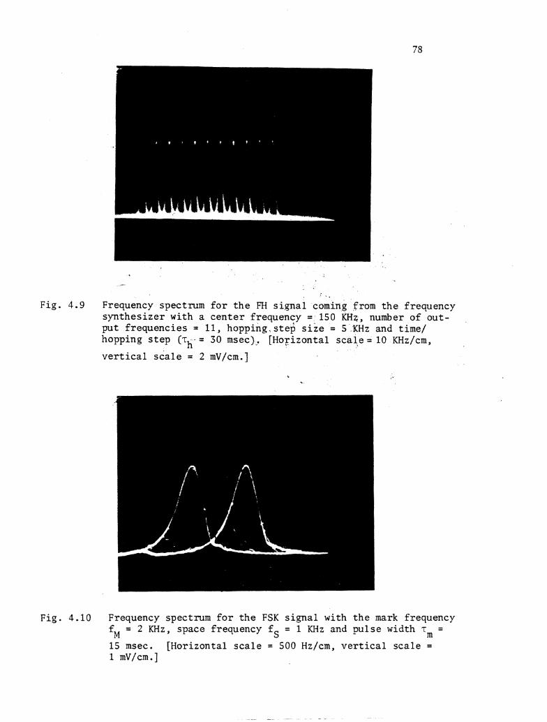
Fig. 4 .9 Frequency spectrum f o r t h e F'H s i g n a l coming from t h e frequency s y n t h e s i z e r with a c e n t e r f requency = 150 KHq, number of ou t - p u t f r equenc ie s = 11, hopp ing . s t ep s i z e = 5 KHz and time/ hopping s t e p (r = 30 msec). [Horizontal s c a l e = 10 KHz/cm. h v e r t i c a l s c a l e = 2 mV/cm.]
Fig. 4.10 Frequency spectrum f o r t h e FSK s i g n a l with t h e mark frequency fM = 2 KHz, space frequency fS = 1 KHz and p u l s e width T~ =
15 msec. [Horizontal s c a l e = 500 Hz/cm, v e r t i c a l s c a l e = 1 mV/cm.]
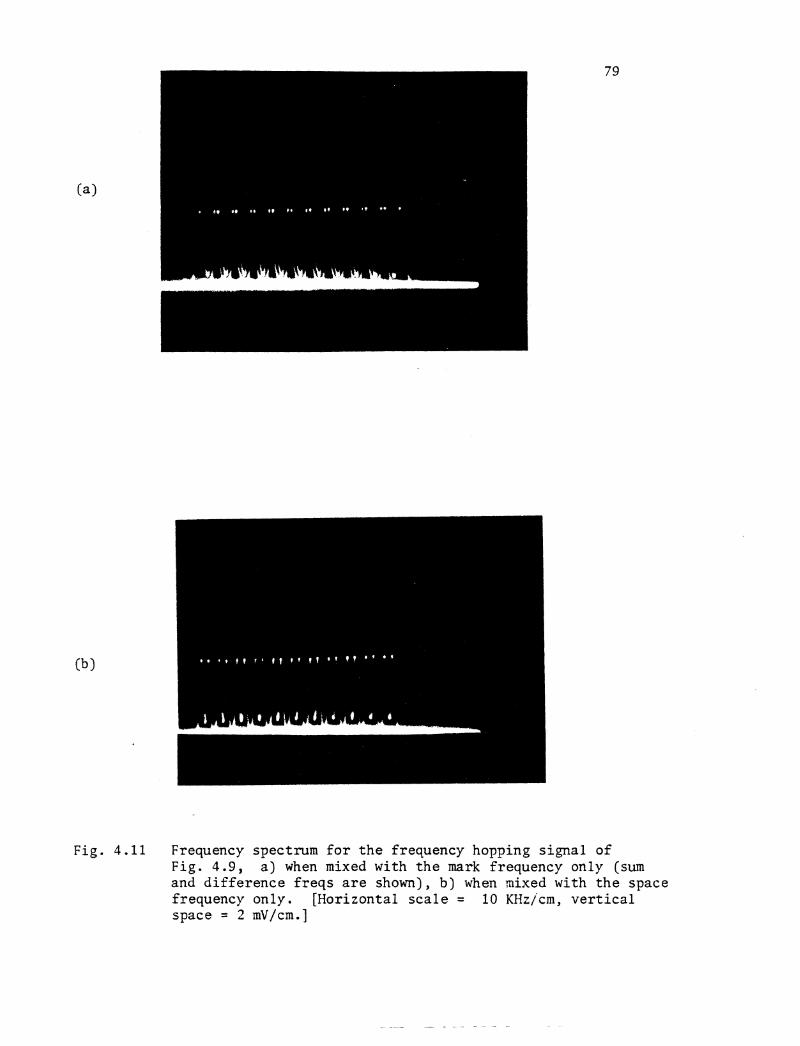
Fig. 4 . 1 1 Frequency spectrum f o r t h e frequency hopping s i g n a l of Fig . 4.9, a ) when mixed with t h e mark frequency only (sum and d i f f e r e n c e f r e q s a r e shown), b) when mixed with t h e space frequency only. [Horizontal s c a l e = 10 KHzjcm, v e r t i c a l space = 2 mV/cm.]
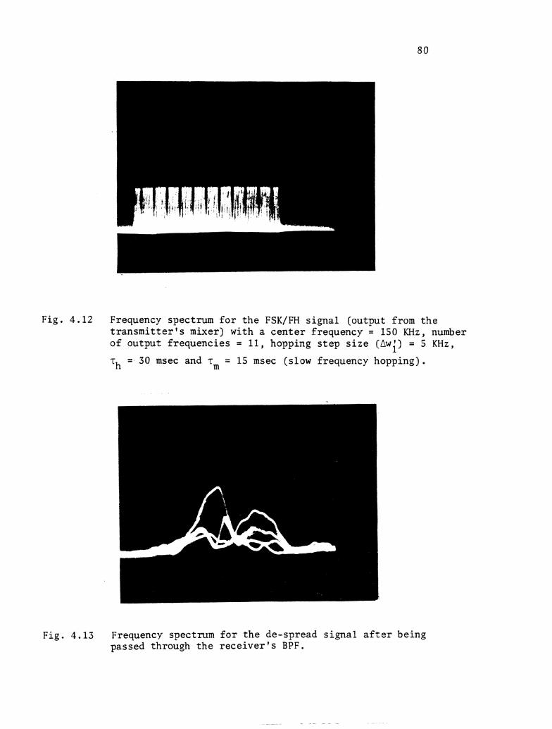
Fig. 4 . 1 2 Frequency spectrum f o r t h e FSK/FH s i g n a l (output from t h e t r a n s m i t t e r f s mixer) with a c e n t e r frequency = 150 KHz, number of output f requencies = 11 , hopping s t e p s i z e (Awi) = 5 KHz,
T~ = 30 msec and rm = 15 msec (slow frequency hopping) .
Fig. 4 . 1 3 Frequency spectrum f o r t h e de-spread s i g n a l a f t e r being passed through t h e r e c e i v e r ' s BPF.
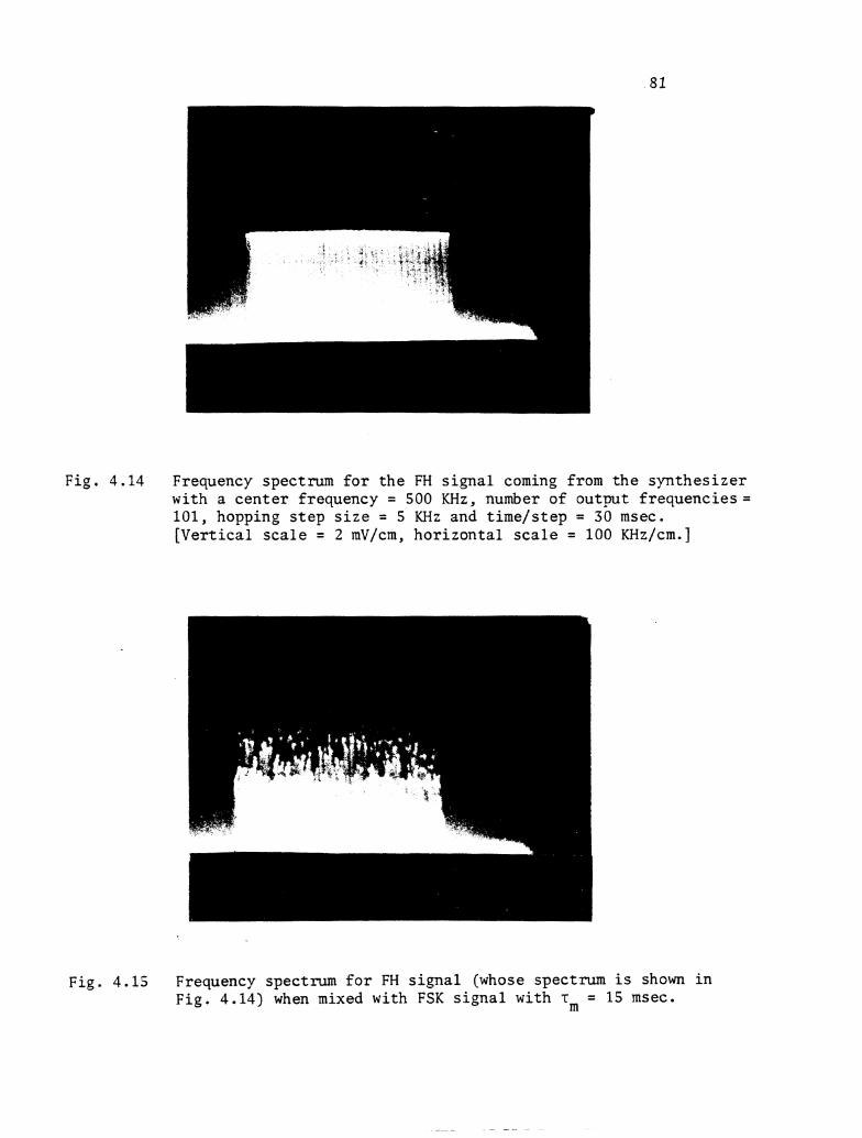
Fig. 4.14 Frequency spectrum f o r t h e FH s i g n a l coming from t h e syn thes ize r with a c e n t e r frequency = 500 KHz, number of output f r equenc ies ; 101, hopping s t e p s i z e = 5 KHz and t ime/s tep = 30 msec. [Ver t i ca l s c a l e = 2 mV/cm, hor izon ta l s c a l e = 100 KHz/cm.]
Fig. 4.15 Frequency spectrum f o r FH s i g n a l (whose spectrum i s shown i n Fig. 4.14) when mixed with FSK s i g n a l with T~ = 15 msec.
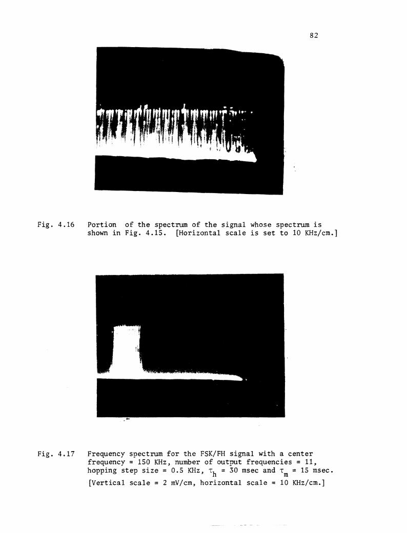
Fig . 4.16 Por t ion of t h e spectrum o f t h e s i g n a l whose spectrum is shown i n Fig. 4.15. [Horizontal s c a l e i s s e t t o 10 KHz/cm.]
Fig. 4.17 Frequency spectrum f o r t h e FSK/FH s i g n a l with a c e n t e r f requency = 150 KHz, number o f ou tpu t f r equenc ie s = 11, hopping s t e p s i z e = 0.5 KHz, rh = 30 msec and -rm = 15 msec.
[ V e r t i c a l s c a l e = 2 mV/cm, h o r i z o n t a l s c a l e = 10 KHz/cm.]
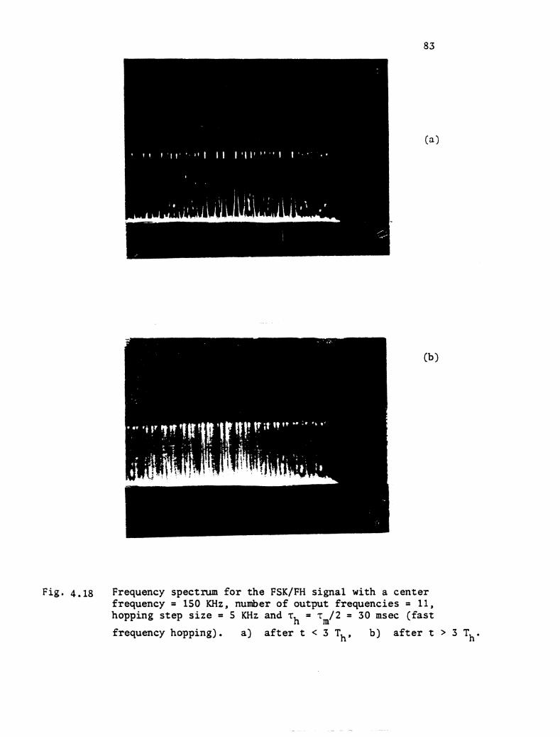
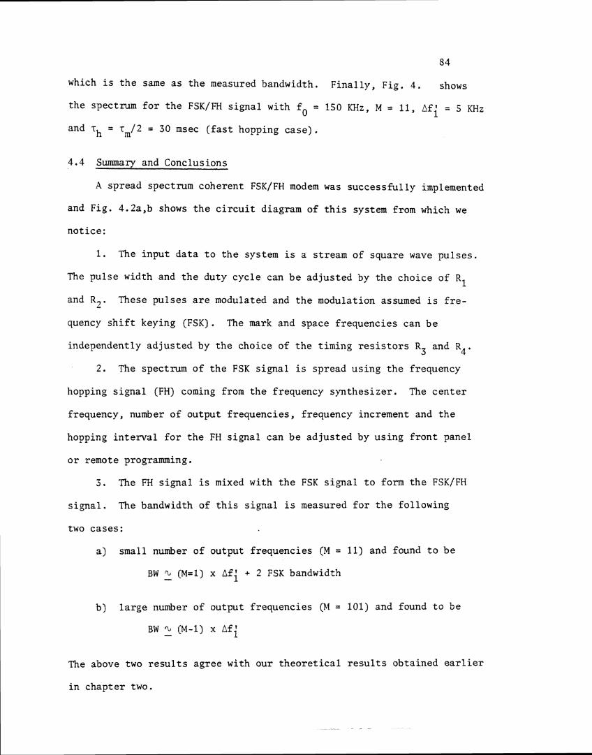
Fig. 4.18 Frequency s p e c t m f o r t he FSK/FH signal with a cen te r frequency = 150 KHz, number of output frequencies = 11, hopping s t e p s i z e = 5 KHz and rh = T*/Z = 30 msec ( f a s t
frequency hopping) . a) a f t e r t < 3 Th, b) a f t e r t > 3 Th .
84
which i s t h e same a s t h e measured bandwidth. F i n a l l y , F ig . 4 . shows
the spectrum f o r t h e FSK/FH s i g n a l with fo = 150 KHz, M = 11, Afi = 5 KHz
and rh = r,/2 = 30 msec ( f a s t hopping c a s e ) .
4 .4 Summary and Conclusions
A spread spectrum coherent FSK/FH modem was success fu l ly implemented
and Fig. 4.2a,b shows t h e c i r c u i t diagram of t h i s system from which we
no t i ce :
1. The input d a t a t o t h e system i s a stream of square wave p u l s e s .
The pu l se width and t h e duty cyc le can b e ad jus ted by t h e choice of R1
and R 2 . These pu l ses a r e modulated and t h e modulation assumed i s f r e -
quency s h i f t keying (FSK). The mark and space f requencies can b e
independently ad jus ted by t h e choice of t h e t iming r e s i s t o r s R3 and R4.
2 . The spectrum of t h e FSK s igna l i s spread us ing t h e frequency
hopping s i g n a l (FH) coming from t h e frequency syn thes ize r . The c e n t e r
frequency, number of output f requencies , frequency increment and t h e
hopping i n t e r v a l f o r t h e FH s i g n a l can be ad jus ted by us ing f r o n t panel
o r remote programming.
3. The FH s i g n a l i s mixed with t h e FSK s i g n a l t o form t h e FSK/FH
s i g n a l . The bandwidth of t h i s s i g n a l is measured f o r t h e fol lowing
two cases :
a ) small number of output f requencies (M = 11) and found t o b e
BW Q (M=1) x A f i + 2 FSK bandwidth -
b) l a r g e number of output f requencies (M = 101) and found t o be
BW - .̂ (bl-1) x Afi
The above two r e s u l t s agree with our t h e o r e t i c a l r e s u l t s obtained e a r l i e r
i n chap te r two.
4 . A t t h e receiving end of t h e modem, spectrum de-spreading i s
accomplished by c o r r e l a t i n g t h e received s igna l with t h e same frequency
hopping s igna l a s t h a t used f o r spectrum spreading a t t h e t r a n s m i t t e r ' s
s i d e , t o a s s u r e frequency and phase coherence. In t h e same process i n
which t h e des i red s igna l i s de-spread any undesired incoming s i g n a l i s
spread by being mul t ip l i ed with t h e same FH s i g n a l . Therefore, by
passing t h e r e s u l t i n g s i g n a l s through t h e BPF, which i s designed t o pass
t h e mark and space f requencies , any undesired s igna l would be r e j e c t e d .
F ina l ly , a coherent FSK demodulator i s used t o recover t h e t r ansmi t t ed
da ta .
Chapter 5
SUMMARY AND CONCLUSIONS
A new a n a l y t i c a l technique i s developed which provides t h e
communications engineer a means f o r i n v e s t i g a t i n g var ious t r a d e - o f f s
i n spread spectrum s i g n a l s and t h e i r e f f e c t s on performance. The
techniques developed a r e genera l and can be used t o i n v e s t i g a t e both slow
and f a s t hopping. Performance c h a r a c t e r i s t i c s a r e determined and v e r i f i e d .
General ly, t h e r e is no r e s t r i c t i o n on t h e choice of information
modulation; however, i n t h i s work two types of modulations were con-
s ide red , namely: i ) FSK and i i ) BPSK. The genera l ized t r ansmi t t ed
FSK/FH and BPSK/FH s i g n a l s were represented by (2.9) and (2.34)
r e spec t ive ly . S t a r t i n g with t h e above two equations and us ing Four ie r
a n a l y s i s , two general formulas t o f i n d t h e frequency spectrum were
derived. These a r e (2.26) f o r t h e FSK/FH and (2.38) f o r t h e BPSK/FH.
Using a code sequence such t h a t t h e frequency stepped one increment
a t a time, t h e magnitude l i n e s p e c t r a was shown f o r t h e fol lowing
cases: a ) slow frequency hopping (which i s considered h e r e a s t h e
case when rh > r m ) , b) f a s t frequency hopping ( T ~ < T,), and c ) d i f f e r e n t
number of output f requencies . I t was found t h a t when us ing a l a r g e
number o f output f requencies from t h e frequency syn thes ize r , which i s
usua l ly t h e case , t h e bandwidth (BW) requ i red f o r t ransmiss ion of t h e
complete frequency hopping s i g n a l would b e approximated by
BW - % (number of output f requencies - 1) x hopping s t e p s i z e
8 7
In Chapter Three, two common jamming models were introduced t o
t h e system and these a r e par t ia l -band no i se jamming and par t ia l -band
mult i tone jamming. For each model, t h e performance of t h e BFSK/FH and
DBPSK/FH i s presented and t h e maximum p r o b a b i l i t y of e r r o r corresponding
t o t h e worst case jamming s t r a t e g y (from t h e point of view of t h e
system des igner) i s determined. Fig. 3.11 shows t h e system performance
(worst case) f o r t h e d i f f e r e n t types of modulation considered from which
one observes t h a t t h e coherent FSK/FH system is t h e most e f f e c t i v e (lower
p r o b a b i l i t y of e r r o r ) aga ins t t h e par t ia l -band no i se jamming while t h e
BDPSK/FH i s t h e most e f f e c t i v e a g a i n s t t h e mul t i tone jamming.
F ina l ly , a coherent FSK/FH modem was implemented and Fig. 4.2a,b
shows t h e c i r c u i t diagram of t h i s system. The input d a t a t o t h e modem
is a stream of square wave pulses and t h e modulation assumed is FSK.
I t i s t o be noted t h a t a t t h e receiving end of t h e modem, spectrum
de-spreading i s accomplished by mul t ip ly ing t h e received s igna l with
t h e same frequency hopping s igna l t h a t was used f o r spectrum spreading
a t t h e t r a n s m i t t e r ' s s i d e t o assure frequency and phase coherence.
The t ransmit ted da ta i s f i n a l l y recovered using a coherent FSK demodu-
l a t o r . A frequency spectrum analyzer was used t o obta in t h e frequency
spectrum of t h e FSK/FH s igna l f o r d i f f e r e n t cases and it was found t h a t
t h e bandwidth required f o r t ransmission i s a funct ion of t h e number of
frequency hops and t h e hopping s t e p s i z e which agrees with t h e r e s u l t s
obtained i n Chapter Two.

REFERENCES
REFERENCES
1. R.C. Dixon, "Spread Spectrum Systems," Wiley Interscience Publication,
1976.
2 . Joseph E. Essman and Paul R. Blasche, "WPAFB O.U. Communication
Simulator," Vol. 1, June, 1980.
3 . Robert C. Dixon, !'Spread Spectrum Techni,ques," IEEE Press, 1976.
4 . Mischa Schwartz, Information Transmission, Modulation and Noise,
Third Edition, McGraw-Hill Book Company, 1980.
5 . Ferrel G. Stremler, Introduction to Communication Systems, Second
Printing, Addison-Wesley Publishing Company, 1979.
6. Mischa Schwartz, William R. Bennett and Seymour Stein, Communication
Systems and Techniques, McGraw-Hill Book Company, 1966.
7. Heinz H. Schriber, "Self-Noise of Frequency Hopping SignalsYM IEEE - Transactions on Communication Technology, October 1969.
8. William F. Utlant, "Spectrum Principles and Possible Applications to
Spectrum Utilization and Allocati~n,~ IEEE Communication Society
Magazine, Sept. 1978.
9. Sam W. Houston, "Modulation Techniques for Communication, Part I:
Tone and Noise Jaming Performance of Spread Spectrum M-ary FSK and
2,4-ary DPSK Waveforms," Proceedings of the IEEE National Aeorspace
and Electronics Conference, Dayton, Ohio, June 10-12, 1975, pp. 51-58.
10. Marvin K. Simon, !?The Performance of M-ary, FH-DPSK in the Presence
of Partial-Band Multitone Jamming,ll IEEE Transaction on Communications,
May 1982, Special Issue on Spread Spectrum Communication.
11. Edward M. Noll, Linear IC Principles, Experiments and Projects,
Howard W. Sams and Company, Inc., 1974.
1 2 . Burr-Brown Research Coruoration General Catalog. 1981.
13. Exar Complete Data Books, 1981.
14. The Radio Amateur's Handbook, 1982, ( f i f t y -n in th ed i t i on ) .
15. "Plessy semiconductor^,^^ Linear I C Handbook, May, 1982.
16. Marvin K . Simon, "Different ia l Coherent Detection of QASK f o r Frequency
Hopping Systems, Par t 11. Performance i n t h e Presence of Jamming,"
IEEE Transaction on Communications, January 1982.

BIBLIOGRAPHY
BIBLIOGRAPHY
Digi ta l Methods Synthesize Frequency Elect ronic Design, May 23, 1968.
Golomb, Baumert, Eas te r l ing , S t i f f l e r and V i t e rb i , Digi ta l Communica- t i ons with Space Applications. Prentice-Hall , Inc.: Englewood C l i f f s , N . J .
Hekimiam, N.C. Digi ta l Frequency Synthesizers. Washington, D.C.: Page Communications Engineers, Inc.
Huth, G . K . Detai led Frequency-Hopper Analysis. Magnavox Technical Library.
IEEE Transaction on Communication. Special I s sue on Spread Spectrum Communications. August, 1977.
Kendall Webster Sessions. I . C . Schematic Source Master. John Wiley and Sons.
Noordanus, J. Frequency Synthesizers: A Survey o f Techniques. IEEE Transactions on Communication Technology, Apri l , 1969.
Nossen, Edward J. Fast Frequency Hopping Synthesizer. Camden, New Jersey: RCA/Communications System Division.
Pawula, R.F. and R.F. Mathis. A Spread Spectrum System with Frequency Hopping and Sequent ia l ly Balanced Modulation: Pa r t s I E 11. IEEE Transaction on Communication, May, 1980.
Powers, Thomas R. The Master Handbook of I . C . C i rcu i t s . Tab Books, Inc . , 1982.
Renschler, Ed and Brent Welling. An In tegrated Ci rcu i t Phase-Locked Loop Dig i ta l Frequency Synthesizer. Motorola Semiconductor Products, Inc.
Schmidt H. and P.L. McAdam. "Anti-Jam Performance of Spread Spectrum Coded System." Proceedings of IEEE National Aerospace and Elect ronics Conference, Dayton, Ohio, June 10-12, 1975.
Simon, Marvin K . and Gaylord K. Huth. D i f f e r en t i a l l y Coherent Detection o f QASK f o r Frequency Hopping System. Par t I : Perfor- mance i n t h e Presence of a Gaussian Noise Environment. Par t 11: Performance i n t he Presence of Jamming. IEEE Transaction on Communication, Vol. Com. 30, No. 1, January, 1982.
Vi te rb i , Andrew J. Pr inc ip les of Coherent Communications. EIcGravi-Hill Book Company.
Appendix A
Computer List ings
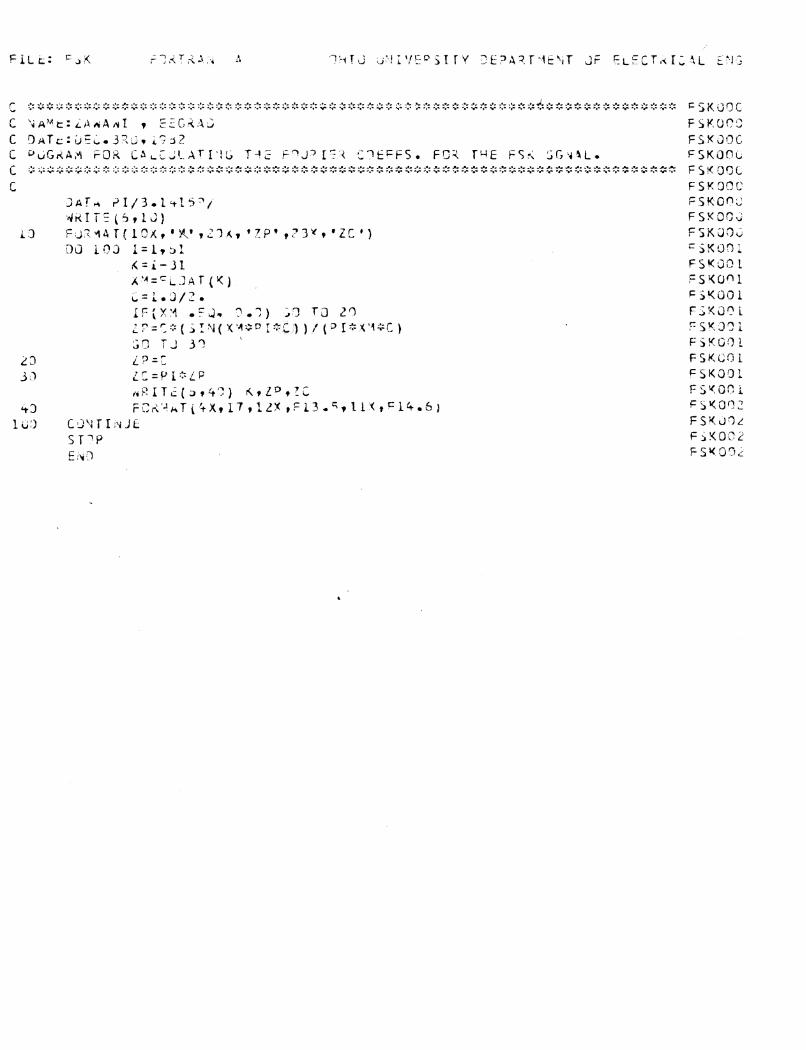
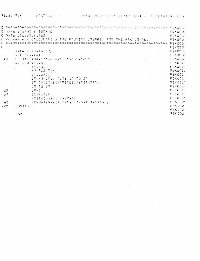
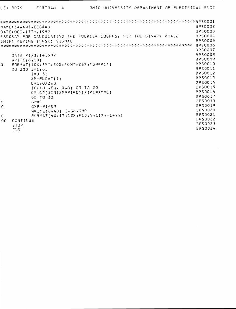
' LE : E P j K F'7RTRA:4 A 3 H I O U ! j T V E ? S I T Y 3 E P a K T M E N T JF E L E C T R I C A L E p l G I
2'; :: + -;::I: s + g <: g :: ;? -$ :> :> % :: 3 <: :> :; % :: ,* :; ;: ::: -;: :> -;: 8 2% :;: <: :: :: :: ::: := 2 $ <: + :: ~t ;:::: ::: :: :> 5 :: ::: :: ::: .$ ::: ::: 2: :> ::: :> :;: :> ;:: ::: <: -2 r 3 P S O O a L X A l Y E : Z A 5 A d I , E E G R 4 3 3 P 5 0 0 0 2 3 A T E : D E C . L 7 T F , 1 9 9 2 9 P 5 0 0 0 3 PFICIG?.AY F O R C A L C U L A T I t G TctE F 9 U R I E R C O E F F S * THE: O I Y A R Y ? " A 5 5 U P S O ~ I O ~ S H I F T K E Y I f 4 G ( C I P S K ) S I C r . l A L 8PSOCC)S $3$9$+<:$$4:::$<:-$:::3$$ :>f $Q~:;t$:>$$<:<:$~$+';r~$<::>:::~~;>:;:::::';~:<r$.~Q?;::::::$<:~::::';;%:::$~::<::>~<:;%r': ~ P ' 5 C ) o ~ 6
3 P S 0 0 0 7 3 A T A P 1 / 3 * 1 4 1 5 9 / 3 P S G 0 0 3 N R I T E ( 6 t l O ) P S 0 0 0 9
0 F C ~ R ' ~ A T ( ~ O X I ' ~ ' ~ ~ ~ X ? ' C - F J * ~ 2 3 X t ' G Y 3 P I ' ) 3 P S O O L O 30 200 J = l ? S l 3 P S 3 0 1 1
I = J - 3 1 F P S O O L Z X M = F L O A T ( I ) &PSSOL:! c= l.o/r.o ? P S O O L + I F ( X I 4 *EQ. 0 . 0 ) G 3 T 3 2 0 E i P S 3 0 15 G ~ = C ; % ( j I N ( x y : : P l % C ) ) / [OI: :XM+C) 9 2 ' 5 3 0 1 5 G O TO 3 0 3 P S O O 17
0 G!?=C 3 P S 3 0 2 3 (3 s,vp= p ~ : > r ~ , y 3 P S 3 0 1 9
A ? I T E ( 6 ? 4 0 ) I ~ G ? + I , S M P 3P53320 0 F ~ Q ! ~ A T ( ~ X T 1 7 ~ 1 2 X ? F 1 3 ~ 5 ~ 1 L X ~ = 1 4 . b ) i ? P S 0 0 2 1 0 0 C t ? 4 T I ' i U f ? P S O C 2 2
S T C P ljPS0023 E?i 3 33350024
- 1 L E : K A E A R FORTRAN 4 3HIO UNIVESS l T Y O E D A R T Y E N T OF E L E C T Z I C A L E M C I
. *.~***II.*********_C*6*..Lhh****rL..-****J-&**.L***d.*I********C-&**********&I***A . P . ~ ~ ~ ~ ~ ~ ~ ~ . C . I ~ P I I ^ C I I I . ~ ~ ~ C ~ ~ - ~ ~ ~ P I I I ~ - ~ - C Y I . ~ ~ - ~ - C T ~ ~ - C I - ~ I I I - ~ F ~ - - ~ ~ I ~ - * . Z ~ - C - C - ~ ~ ~ ~ - ~ ~ ~ ~ ~ - ~ - ~ ~ ) < A H ~ ~ ~ ~
: Y A Y E r 2 4 H A W I T E E G R A D K A M O O O Z ; 0 A T E : N O V e 18THv 1982 K A P 0 0 0 3
PROGRAM FOR CAACCtJLATfhlG THE FOUQXER COEFF* F0Q THE FH SIGYAL * C - * * * ~ ~ * ~ * C - * * * - L * A * - L * ~ * * * * * & * * + * * * * * * - - L * ~ * * * * ~ * L - * * * * ~ * * ~ ~ ~ . * * ~ * ~ * C - _ . - ~ ~ ~ * K A P 0 0 0 4 . Y I ~ ~ I - C I ~ ~ ~ - ~ - . C Z I I * ~ - . ~ Z ~ I ~ ~ Y ~ ~ - . F I - ~ ~ ~ ~ ~ - ~ . ~ ~ . C . Y ~ ~ ' C - C T - ~ - ~ - ~ ~ ~ - ~ - ~ ~ ~ . ~ . ~ - . ~ - ~ ~ - ~ ~ - C ~ - C ~ Y ~ . ~ - ~ - C ~ - ~ K A M 0 0 0 5
K A Y 0 0 0 6 DATA P I / 3 . 1 4 1 5 9 / KAY0007 W R I T E ( 6 t l O ) K A Y O O O F
10 FORMAT(BXI*~'~L~K,'P'~ZI?X~'ZP' v 2 O X t ' Z C ' ) Y A M 0 0 0 4 8=COOE WO2O LENGTH K A H O O L C
00 2 0 0 J = l r 6 KAMOOI 1 L=J YAM0012 C = L e O / F L C l A T ( Z = * L ) K A H O O 1 3 00 100 I=lr61 K A M 0 0 1 4
K-1-31 K A U 0 0 1 5 A=FLQAT ( K ) K A W 0 0 1 6 I F ( A mEQe 0.0) GO TO 20 K A N 0 0 1 7 LP=C~(SIN(A+PI*C))/(?I~A*C) K A M 0 0 1 8 'Jo T O 3 0 K A M 0 0 1 9
2 0 z P=C K A l r 0 0 2 C 30 ZC=PI*ZP K A Y 0 0 2 1
W R I T E ( 6 9 4 0 ) L T K T Z P I Z C K A M O Q 2 2 40 F O S ~ ~ A T ( ~ X ~ ~ ( I S ~ ~ Z X ) T F ~ ~ ~ ~ I ~ L X ~ F ~ ~ . ~ ) K A V 0 0 2 : L 0 0 CONT IFIUE K A M O O Z 4 200 C O N T I h 4 U E K A H O O 2 5
S T O P K A H O O Z C END K A M O O Z ?
1 L t : + - H t - b K - l ~ J-;!Kl?AN A GHI2 U'l 5 T T Y DEPAPTUEhJT OF ELZCTH I C A L Er<GI
-.. -.- 2. J- -.- -. --.- -C .C J- ... * J- ... -.- -.. -.. ... J. -.. 2- ..- ..- -.- ... ... a. * ..- * ..- 2. ..- .._ ..-_.- -.- ... ..- ..- J. .._ C- .., J- -5 -.-..I ... ..- ..- 2. * _.- -.-_.- ..- ..- .._ .._ ... * -.- _._ _.- _.- ... * >. -.- -.--.- ...... -.---.-.. .-.-.---........-...v-.~2....-.-..-..-.-.-.- . . . . . -.-.,-..-I-.--.. . * .---.-.-- , . . . .--.--.-I.--.- -.- - .-..- -,. -..- ---.--- -..--.- -.--.. .,. ..- .,. ... ... ... .,--.-.,- .,. ....,-.- *. . . . . , . a Fiifooor NAKE:Z , Id$%I E E G R A 3 . F H F 0 0 0 7 ?ATE:',4!3V. 1 B T t i 1 9 8 2 F H F 0 0 0 3 PROGQ.A' I FOR CALCULATING THE P 2 3 ! j C T ' = I'::ZPc5*4 * FO!? THC COfdPLETE TRPih!S . FHFQOC4 FH/FSK ( F A S T FF!E.3UENCY HOPPI' IG) F H F 3 0 0 5 ***A **** *-.- ** 4-* -.- ..-a*..- 2- -C -.. -L- * .C * *-.- -C * * *..-a- .C ..-..- ..- .C A-.* .....- ..- ..- *..- 4 ..--.. * J -..- * _._ -%_C .._ .._ -.- _C -.. ..-_ .. -.- * .C -. ..- T Y .- -,. ..- -.- ,.-.- 7 -.- -.- -.- -C -.- *.- -.- -.- -.. -C Z ..- ..- -.- -*- ..- -.- ..- ..- .- -.- ..- -.. -.. ..- ..- - . - - -.- -.- -.- ..- -.. ..- ... . . ..- - . . - -.. -.. ..- ... -.- - - . . - - -.- -C .*. .- -.- .C ... .. . . -,. -- ..- - - . . . . . . . . . . . . FHFOOOLi
FHF00Q7 F H F 0 0 0 9
2 A T A P1/3 .1459 / F H F i l 0 0 Q B I S THE RAT13 OF THE 2 I J L S E , 41074 T 3 TYE PERIOD SF THE F S K F h F C Q L C C I S T H E 3 P T I i 3 9 F THE PULSE i i I O T H r13 TIJE PER133 :IF THE FP FHF 00 1 ! !3=1o3/2..3 FHF OC 1 2 W R I T f ( 6 r l 3 ) F H F 0 0 1 3
0 F i l R V A T ( 6 X r ' C 0 3 E ' J O Q D L E N G T Y ' r B X t ' N ' t l b X I ' Y * ~ Z L X ~ * Z C ' ) F H F 0 0 1 4 CO 300 N = l r 5 FHFGO 15
C=1.'3/FLOsT( Z:=::N) F H F 0 0 1 6 03 200 I = l r 3 L FHFC017
Y = I - l S F HFQO 1 F! k..V
XP=FLO.AT(F) FHFOOL3 I F ( K P ~ E 3 ~ 5 . 0 ) G O T 3 L O FHF002'Y Zp=C<:(Sfhd( tp::p[:::C))/ (XP%PI<:C) FHFOO2 1 GO T 0 3 0 FHFOOZZ Z P=C FHFOC23 DO LC9 J = 1 ~ 3 1 F HFC1024
K = J - 1 6 F H F 0 0 2 5 XU=FLUAT(K) FHFOD25 IF(XM .EQ. 9.0) ~3 TCI 4 0 FHFOOZ? Z C = P I ~ Z P ~ ~ S ( S I N ( X Y % P I * ~ ) ) / (x~"!*PI:FD) FYFOOZ!! GO T O 5 3 F!4FOQ2?
:O z;=p 1::: zp3': F H F 0 0 3 Q
50 d R I T E ( b r 6 0 ) f i t r>q*KrZG cHF0031 3 0 F O 2 Y A T ( 4 X ~ i 6 r L 5 Y ~ 2 ( I b r l 2 X ) ~ F 1 5 * 6 ) FHF i l03Z .OO C O N T I N U E F H F 0 0 3 3
1 0 0 CCI?:Tl?.iUE FHF0034
300 C 3 X T T h U E F H F 0 0 3 5
STOP F H F 0 0 3 5 E NC FHF3C37
F I L E : ALI F O R T R A N A O H I O UNIVERSITY DEPABTYENT OF ELECTBICAL ENC
C *+***************$***t,*t***t*t,*t**#*****************************************A~Iooc C N A f l E l Z B H A H I NAId A L X O O ( C DATE! JULY 27T3, 1982 ALIOOC C PROGBAII FOR CALCULATIHG A L P A - H A X - FOR TEE PSK-FH CASE I N THE ALIOOC C PRESENCE OF PARTIAL-BAND Y O I S E J A 8 f l I N G ALIOOC C * * * * * t * * * * * $ * * * * * * * * * * * * * ~ * * * * * * * A L I O O C C B L I O O ~
#RITE ( 6 , 1 0 ) A L I O O C 10 P O R f f R T ( 1 3 X , r X * , 15X, ' X (DB) ', 19X,*ALPA-SAX, * ) A L I O O C
DO 200 K=1,150 ALI001 h=0,25+0,25*FLOAT fK- 1 ) B L I O O 7 B = IO,OO*ALOG 1 0 ( A ) A L I O O ! I? {A, GT, 1,425) GO TO 20 ALIOOJ ALFA=1.0 ALI 00 l G O TO 30 ALIOO 1
20 ALFA=1,425/A ALIOO 1 30 WaITE (6,40) A,B, ALFB A L I O O f 4 0 F c ) R H A T ( 5 X p 2 ( F 1 2 - 5 , 9 X ) , S X , E l 5 - 5 ) ALIOOS 200 CONTINUE hLIOOl
S T3 P A L I O 0 2 END ALI 002
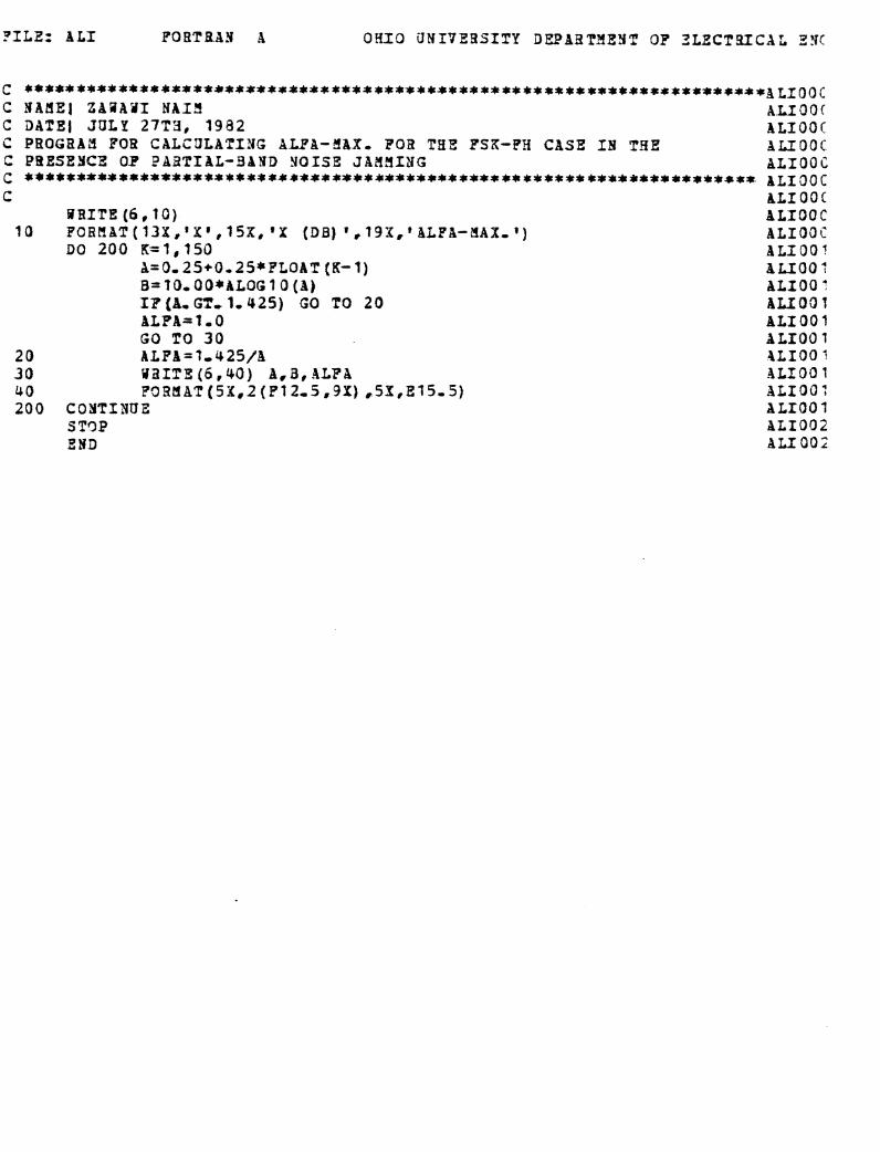
P I L E : A L I POBTBB?I A O H I O dNI7EBSfTY DIEAST3EHT OP 2LECT2XCXL SYC
C * * * * * * * * * * * * * * * * * * * * * * * * * * * * * * * * * * * * * * * * * * * * * * * * * * * * * * * * * * * * * * * * * * * * * *~~~~~c C BAMEJ Z B B A i i I N A I 3 A L I O O f C DATE1 JULY 27T3, 1982 ALIOOr C PROGBAY FOR CALZULATIYG B U A - 5 B X - FOR TEE FSK-PH CASE IN THE A L I O O f C PRESEYCE OF P A a T I B L - B A N D Y O I S E JAdflI3G ALI 00 C C **********************$************************************** &LxgOC C hLf OOC
B R I T E (6.10) A L I O O C 10 PORffAT(13X,'Xg,15X,'X ( O B ) * , 1 9 3 , t A L P A - 3 A X - 8 ) A L I O O C
DO 200 K = l , I S O B L I 0 O 7 A=0.25+O125*PLOAT [K- 1) A L T O 0 7 B=?O.O0*8LOG10 (A) B L X O O : IF(A,GT, 1,425) GO TO 20 A L I O O 1 BLFA=I * O ALIOO 1 GO TO 30 A L I O O 7
20 ALFB=?,42f/B PLIOO 7 30 UilITE(6.40) A.3,ALFA B L I O O 1 40 P ~ B M A T ( ~ X , ~ ( P ? ~ , ~ , ~ X ) .5S,E15-5) ALf 00 7 200 C O I T I Y U E A L I O O f
S TC3P ALI002 END ALI002
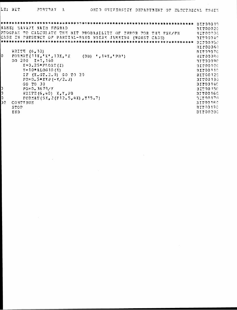
* * * * * 6 * * * * t * t * f t C * * * k t r P f * t I r b - L * , Z * * * * f * * * * * * * * * * * * 4 * * * * * * * * * B I r f ) q Q 1 q N A M E ] 34'iA;'T N A I M FEGRPD 31T0002C ??OGDA:: T(? C X L C U I A X ? T 4 ? b I T T'R6B.131LTT'1 ' OF P A R q S ?OR T.19 FSS/FH S I T ? ? " 3 C C A S E I N "BESENC? 017 P A B T I I L - 9 2 N G ?6313? J IM' l . I l J i ; (BC3ST C A S T ) 3IT3C0-1" * * * * t a ~ * t ~ * * * * * * * * * * # * t * 9 ~ * 4 4 ~ I t * * * * ~ ~ t * ~ * * 3 1 ~ 3 0 ' 3 5 ~
2 1 r o o 3 ~ i r URITF: ( 6 , 1 3 ) R I T ? 3 3 7 C
0 FO~Y~lT{11X,'X',13X,yX {QB) ' , 1 3 ~ ~ ' ? a T ) 2iTi333511 DO 200 I=1,1-50 S T T 3 0 r ) 9 P
X=3.25*7T O A T (I) 1 3 ~ ~ o o l c r Y = I O * A L O G 1 0 ( 4 ) 3IT0011" r n L.C ( X r G T r Z . i 2 ) GiJ Ti> 2 3 3 I T C C 12: PI3=3.5*EY 2 ( - Y / 2 , 3 ) 31T00 1 3 3 G O TO 3 0 3IT0313f
3 P3=3. 3679,'Y 3 ; 3 0 15( 3 WcITE ( 6 , 4 0 1 X , K , i?B 3TT00 16: (3 PCR,'IRT(5X,2 ( F ? 2 - 5 , 4 ' X ) , 5 1 5 - 7 ) 3,Tr)n77{1 1 COYTTITUE 3 ~ ~ g f ~ l a . '
STOP STT*?O?' ; i l E t: n l3TPO9 '>Oi
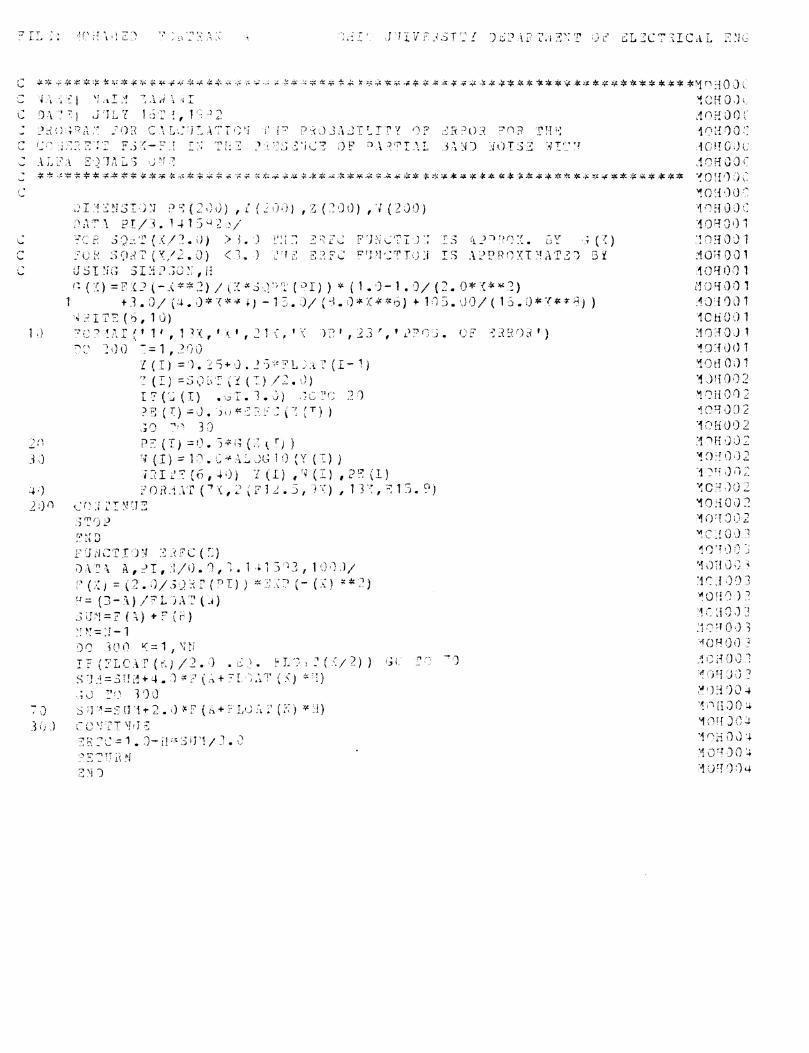
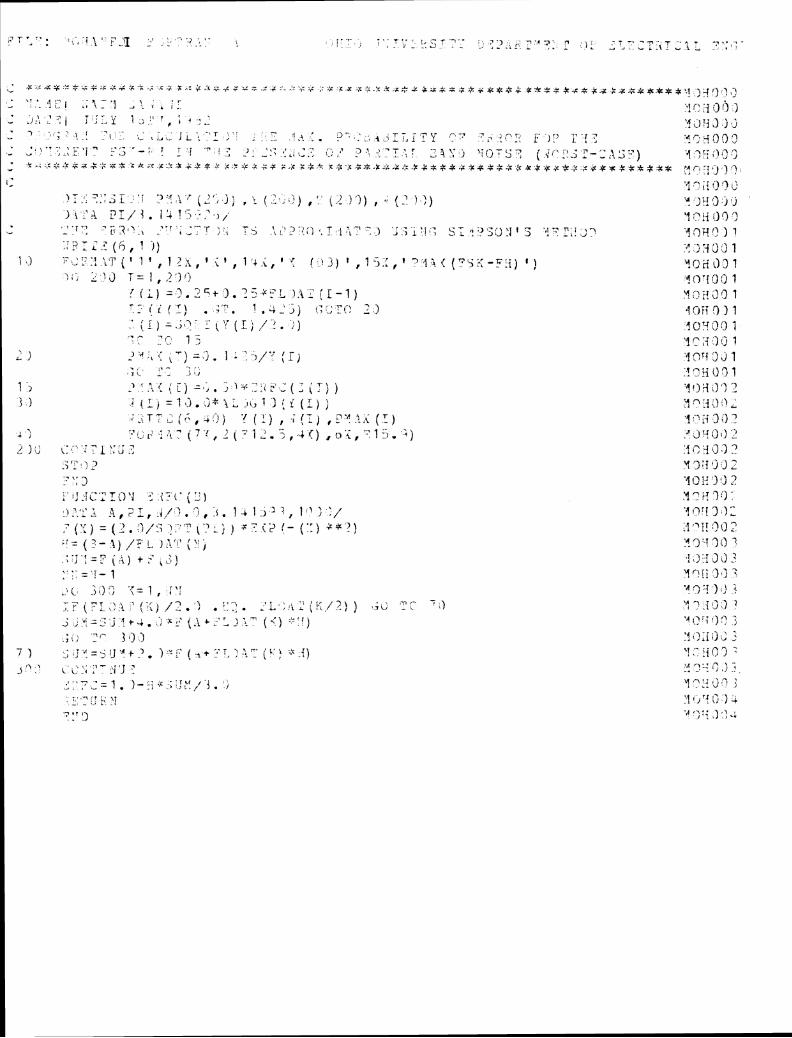
8- ' . x , ; x q ~ ' ? ~ i : g . 6 , , : 6 : K - i . , : z : :,::;:c<.\:<.z:A.: <..-:.,<.; , : A x * , , : k . x , * z : F * ***=.:;:+**** *****.&*++ ;$+*** **.,! .:{, j > , 3
. '.. ~l ' .- l . , ? - ,. ..1:.1 ' , , . '"I :'\ <) A ril
L J?. .' -: 1 7 j:.Y 1 .I ' i .:.I '.!\):j ,) j ,J ...
1 . I ' : . 4-2, 1 - >.--.\ ,,,-. T > i T y :--7 ?,.::-:: ,;> 7 - r ; '9 5 t? 2 . .,,;,:. - - , 5.3 - 7 . . . , 7 ! .. > . . -. ' i t : , . - 2 . . . . . . . , , L q \ ; j \T(;Tz7 ( ? ; * - > : _ L.J ? - ; , , P y ) A '1 ?ti ;I :,: .; - t .: .:;:,':.*z *.;: =-$ 'LA T C . 6 . k .i .,L* * ;: ,;.: ;;: !Z * * S,$ *,$ 4: ,c *$+,$:,:;~,:: 8 & r , f . ~ . % + j L ; ~ . : : : c * ~ * * + * 6 : : . z ~ * ~ j : $ * * * * * .- . A , - , : : , w ..
i: .:I " i i I:! '1 $3 >;.,- 7 , . , - > L - - - :- ' , ; . 3 ' * ; , - , " - . \ & , J ) %: [ -. ; , ) ) , . '. ( : 2 )'I) , .. {.? ) 2 ) 'f j V [ ) , j , j
) 1 :'>A ?I/ 3 . 13 ?':I $4 1 .-, ,. A g . (.I I2 '1 , > . I 7 , - .
" A . . ,,>:I , ; ; - r ;, * , .> , j , - . ; > , ? . : . ] .&T l ; , 7 ) ,;-;.i-!,; .., < y .,:>;;;:jl . 7 ,,i>. n.1 >-I i -'.,2. + r J f l / ? 1 1 . . ?. , 6 y Z C . ? (6, 1 J ) . .J i ;;.3 3 1
i , j 1.7 - , ~ : . ~ ' , ~ ( ! - . + l t , I ? , \ , t , ; t p + , I t (.'! 3 ) 1 7 "J,:, 1 7 4 { (? ' ;<-?t i) ' ! ,,! 2 2 ? I), \ J T z 1 , .? ' ) ! ; I To7{9:1 I
{ { L ) = ? . " t ). -"*::L ]:\.: (1-7) !l >'.? :: 3 9 1 - - . -' , ; i - ) , 1 ,;-,,) : : , , ? , - \ . , . \ , 2 1 .13ii31 7 .' ( 1 ) =,;<;- : { l r (1; ,/.'). ; ) 18!i?'3 1 ..C 7," 1; ;< :I (j 1
- , L 1 A > d :, : . \ - 1 1 = , > * 1 : ;:)/:: (1, ,'I sri 2 \) 1
., ,.- - , , 1 . 8 % ) :!"Y i!3 1
1 , z , ; . \.+ ; : { : : ( - ' - ' ) -. \ - i !I ? 2 3 1 ; { L j = 1 3 . > ; 4 ; ? L . i t r l ) ( r ' f L ) ) rt . ?'I . :)
, , ' - , T - ! . , ( f : , + , - ! ) 'f [ : I , ; ( : I ,F.?"'..<(:) y 2 ,') .l 9 ,
1, , . - . - i ~ - , r . ; , i . ( ? ' ~ , ~ ~ 7 ~ : - ~ , ~ 4 < ) , ~ ' < ~ - ' l f i . 2 ) .¶ ~ y d ! ) 2 j ) ; (::..;?,,...-
A * 0 :, :",: ;3 .? .3 ? , r - , . . .) L ,, 2 Y 3 :I 'j ,.) :
t 7 - 9 J .'I02 2 , ; 2
j',;-!<;,:Ic)'! < ;: ( * ( y ) 1: 7 ; j .
\ . . - . . - , I ' ; ~ , ? I , . i , / ~ . ' > , . < . ' ~ l : > ' 2 , 1 ' ' > ~ / '.!<?'! 3 f f
7 . ( 1 , T ,, \ = ( 2 . ;>/:; - I . - , " [-.>:; ) $;I->> !- (::) 2 s (3 T! ;J I,] 2 ::= { ;- ,I) / ? ,- ) $',.'.' ( > ! , :? .-I 7 (> 7 . .: ., ' \ i f J . = 3 ( 4 ) t: ,..', 1 ;:?J,).?
\ . .. - - - ! - 1 . . . yni; 1.3 7
.:i ;,I,; ',;= 1 , [ ' r 'A!3:! 1 ,.! 3 U 7 1.'.
, .I 5 1 1
y ,,: : i , ) ; , - 4 1 , , 1 * i . ; 3 ..! ;- ;. < ; ~
. i . J - ,,,$ 9 :: ,; ,) : .. - . .. y n r T , ^ :
4 . > : $ J .! , '1 i jr ! 2, ) .<! I,.. ,-I .? :.r
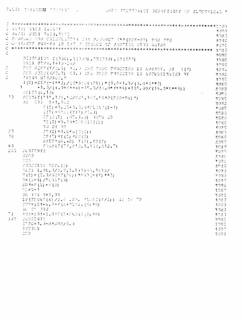
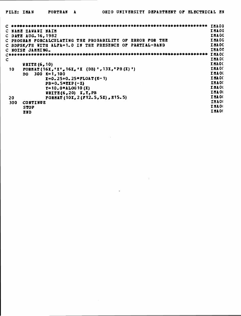
FILE: ILIAN F O R T R A N A O H I O U N I V E B S I T Y D B P A B P U E I T OP ELECTRICAL Ell
C * * + * * * * + * + * * * * ~ * * ~ ~ * * * * * * * * ~ * * * * ~ ~ * * ~ ~ * * IHAQO C H b H E ZAYAUI Ma18 r nroG C DATE AUG. 1 6 , 1 9 8 2 I H A O C C PROGRAB FOBCALCULATING THE PROBABILITY OF BEBOB FOB THE I P l A O C C BDPSK/PH VITX ALPB=l,O I N THE PRESEICB OF P A B T X U - B A H D I H A O C C HOISE JAHMIW- I M A O C ~**************+**t***+r****.++*t***~r***l)i**t************-~rt+ rnaoc c znsot
RPITE ( 6 . 1 0 ) I R A Q I 10 P O R H A T ( t 6 X . ' X ' , 1 6 X , * X (DB) ' , 1 3 X , ' P B ( X ) ') I H A O I
DO 300 K=I,IOO rnaoc X=0,25+0,25*PLOAT (K- 1 ) IMOC PB=O. 5 * E X P ( - X I XMAOt Y= 1O,O*ALOG 10 (X) I M A O t VBLTE(6.20) X , P . P B I ~ A O ~
20 PORHAT ( l O X . 2 (P12.5,51) ,B15.5) I U l l O ( 300 COBTIIBE I f l A O t
STOP z naoc EBD I H A O t
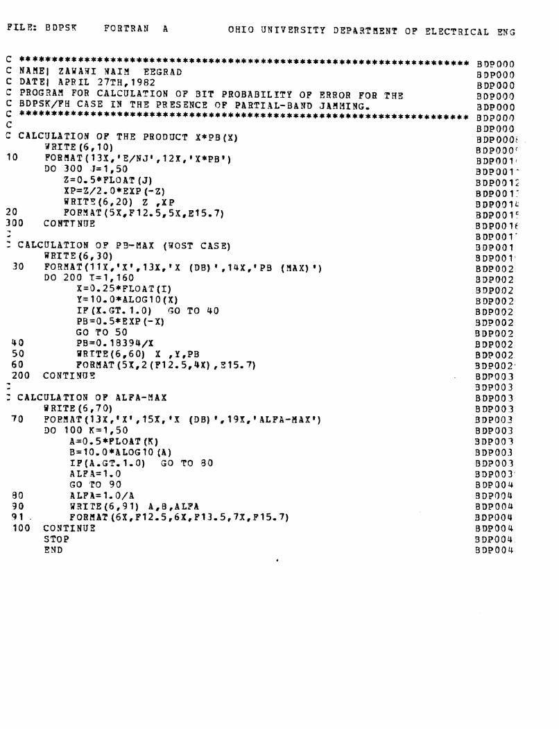
FILE: BDPSY F O R T R A N R OHIO U N I V E R S I T Y DEPASTUENT OF ELECTRICAL ENG
C * * * * * t * * * * * * * * * * * * * * * ~ * * * * * * * * * * * * * * * * * * BDPOf)O C N A H E J Z A U A B I MAX?!! EEGRAD BDPOOO C DATE1 APRIL 27TH, 1982 BDPOOO C PROGRAR FOR CALCULATION OF B I T PROBABILITY OF ERROR FOB THE BDP00.3 C BDPSK/FH CASE I W THE PRESENCE OF PARTIAL-BAND J A f l M I N G , BDPOOO C ***********************~*********+**t****** BDPOOo n t
C CALCULATION OP THE PRODUCT X * P B ( X ) BRITE ( 6 , 1 0 )
1 0 PO%!lAT(13X,'E/NJt , 1 2 X , ' X * P B t ) DO 3 0 0 5=1 ,50
Z=0,5*FLOAT (J) XP=Z/2- O*EXP (-2) URIT5(6 ,20) Z ,XP
20 FORYAT (5X,F12,5,5X,El5,7) 300 C O H T f N U E - 4
: CALCULATION OF' PS-MAX (UOST CASE) WRITE ( 6 , 3 0 )
30 FORBAT(IlX,'X'.13X,'X (DB) ' ,14X, 'PB ( Y A X ) ' ) DO 2 0 0 T=1,160
X=0.25*FLOAT (I) Y=10,0*BLOGlO(X) IF (X. GT. 1.0) GO TO 40 PB=O. 5*EXP (-X) GO 'PO 50
4 0 PB=O. 18394/X 5 0 U R f T X ( 6 , 6 0 ) X ,Y,PB 60 FORPIAT (5X,2 (P l2 .5 ,4X) , 315.7) 200 CONTINUS
1 - : CALCULATTOR OF ALFA-MAX
P RITE ( 6 , 7 0) 7 0 F O E M A T ( 1 3 X , ' X t , 15X, 'X (DB) '. 19X,'ALFA-HhXt)
DO 1 0 0 K=1,50 A=OW5*FLOAT ( K ) B=lO,O*ALOG10 ( A ) IP(A,GT,1,0) G O TO 9 0 ALFA=1,0 GO TO 9 0
8 0 ALFA= 1.O/A '30 S i 4 I f E ( 6 , 9 1 ) A,B,ALPA 91 . FORflAT(6X,F12,5,6X,F?3~5,7X,F15,7) 100 CONTINUE
STOP E N D
*
BDPOOO BDPOOOt BDPOOOi BDPOO 1 1 BDP001- BDPOO1; BDP00 1 ' B DPOO 1 BDP00 1' BDP00 16 BDPOOl* BDPOOl BDP001 BDP002 BDP002 BDPOOZ BDP002 BDP002 BDP002 BDP002 BDP002 BDPO02 BDP002 BDP003 9DP003 BDP003 BDP003 BDPO03 BDP003 3DP003 BDP003 BDP003 BDP003 BDPOOY BDPO34 BDPOO4 BDP004 BDPOOY BDP004 B D P O O Y
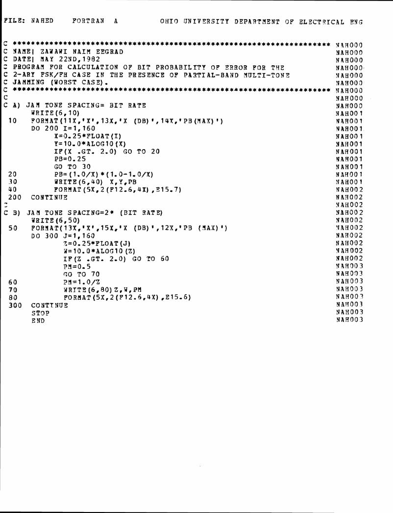
PILE: HABED FORTRAN A O H I O U N I V E R S I T Y DEPARTAENT OF ZLECTQIC4L E N G
C ********************************************************************* C YAME] ZA2AUI N A I H EEGBAD C DATE] M A Y 22ND,1982 2 PBOGRAPl FOR CALCULATION OF BIT PROBABILITY OF ERROR F O R TYE C 2-ABP FSK/FH CASE I 8 THE PRESENCE OF P83TIAL-BAND MULTI-TONE C J A H M I N G (VORST CAS E) , c ********************************************************************* C c A ) J A B T O N E SPACING= arr RATE
W R I T E ( 6 , l O ) 1 0 ?OREIAT(lIX,'Xr , l3X, 'X ( D B ) l , 14X,'PB(flAX) ' )
DO 2 0 0 I = I , 1 6 0 X=0,25*FLOAT (I) Y=10,O*ALOG10 (X) IF(X ,GT. 2-01 GO TO 20 P B = 0 , 2 5 GD TO 30
20 PB= (1,O/X) * ( I . 0-I,O/X) -3 0 URITE(6.40) X,Y,PB 40 F O R H A T (5X.2 (F12.6,4X) ,E15.7)
?.
200 C O H T I N D E - - C 3) JAM TONE S P A C I N G = 2 * (BIT !?ATE)
%RITE ( 6 , 5 0 ) 5 0 FOB3AT(13Xf1X',15X,'X (DB) ' , 1 2 8 , ' P S ( Y A X ) ' )
DO 3 0 0 J = 1 , 1 6 3 ?=0. 25*f LOAT (J) 3= 10*O*BLOG t o ( 2 ) I P ( Z .GT. 2.0) G O TO 60 Pil=O- 5 GO TO 70
6 0 P ~ = I , O / Z 7 0 URTTE (6,801 Z,W,PH 80 POR1IAT(5X,2(F12-6.4X) ,E:l5-6) 3 0 0 COHTTYUE
STQP E ND
!J91700(1 H A H O O D N A A O O O N A H O O O N A H O O O YAHOO3 ??AH000 N A H O O O N A H O O O H A H O O 1 Y A H O O ? Y A H O O ? N A H O O 1 YAHOO1 NAB001 YAHOO1 N A H O O l N B H O O 1 Y AH09 1 NAH002 N A 3 O O Z Y A H O O 2 NAH00 2 YAHOO2 '?AH002 NAHO32 NXHOO2 V AH 002 NAH002 YhR303 WAAOD7 NBH003 %A803 3 N AH00 7 NAB00 3 NAH003 NAB00 3
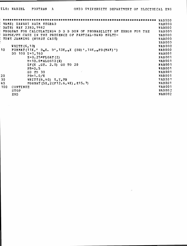
?ILE: WABEEL FOZTRAM X O H I O U T I V S R S I T Y DEPARTYENT OF E L E C T S I C A L EYG
* * * * 9 * * * * * ~ * t * ~ * * * 9 * * ~ * * * * ~ * * ~ * * ~ * * * * * * * * * * * 3 A 9 3 9 3 3 N A ? l E 1 Z B W A Y T Y B T Z EEGRAD NAB000 I DATE1 YAP 23RD,1982 NA9000
P R O G R A Y FOR C A L C U L A T I N Z U D 9 D DON OF PROBABILITY OF ERROR f09 THE LJABOOF) J i3DPSK/F;S CASE IY T H E PRESENCE OF PABTTAL-BAWi) HULTT- Y A B O O O : TOPE J A f i F I I N G (V9RST CASS) NAB000 .. - Y A B 0 0 ~
V R I T E ( 6 , 1 0 ) NAB000 1 0 FOBiYAT(IlX,' DgX- D',13X,,X (DB) 't1YX,,P!3(MAX) ' ) H A B O O O
DO 100 1 = 1 , 1 6 0 NAB001 X=0,25*FLOAT (I) NAB001 Y=lO.O*ALOGlO ( X ) Y B B O O l I F ( X ,GT, 2.0) G O TO 20 W ABOO 1 PB=G. 5 Y ABOO 1 G O TO 3 0 YABOO?
20 P9= 1 , O / X X A B 0 0 1 3 0 P R I T 3 ( 6 , 4 0 ) X,P,PB 'TABOO 7 4 0 POH3AT ( 5 X , 2 ( F l 2 , 6 , r ) X ) , E15-7) N A B 0 0 1 1GO C O N T I N U X VAB001
STOP H A B O O 2 E N D VAB002
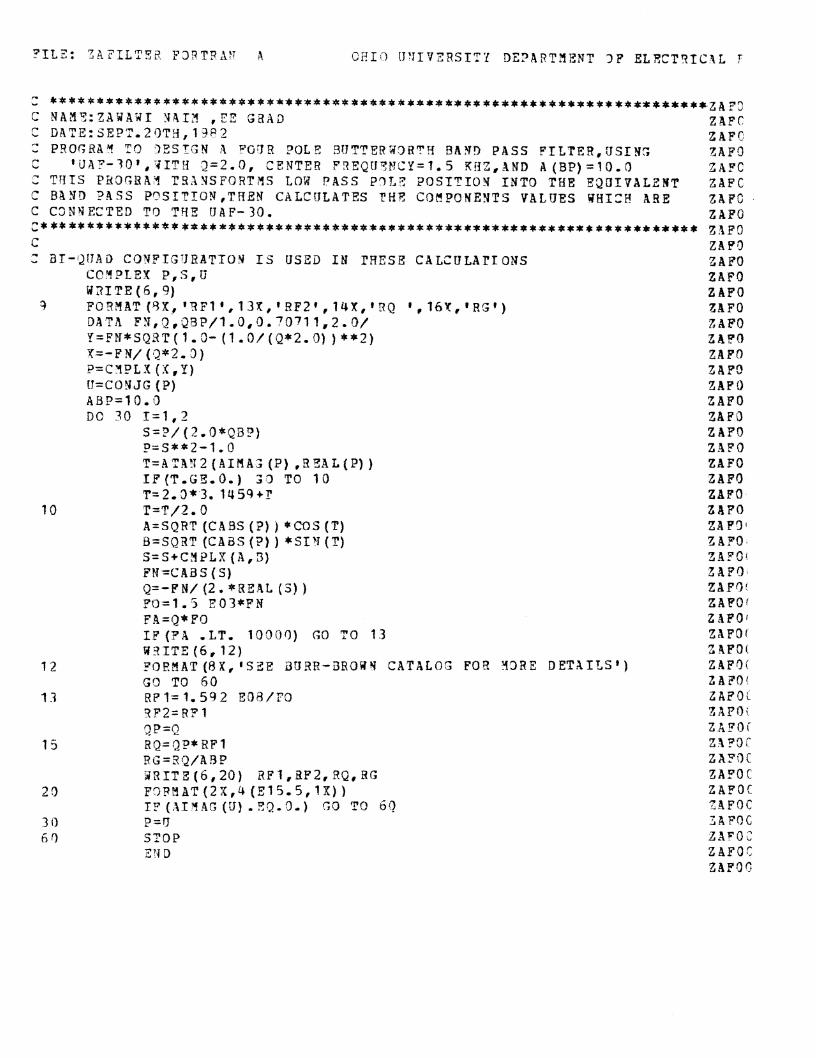
z *************++*+*****************************************************~~~~ C NAM9:ZAUBWI Y913 , EE S Z A D ZAFC C DATE:3ETZ ' .2OT8 ,13P2 ZAFC Z PSOGRbY TQ 7 E S T G N 1 P G r J R ?OL? 3!rTTER73BTY B A Y ? PASS F I L T E R , U S I N S 'ZAP9 C ' U A P - 3 0 * , 4IT!i 2 ~ 2 . 0 , CENTER FREQU?ML'Y=?. 5 K B Z , A N D A (BP) =10.0 Z A FC Z T H I S Fa3GBAY TSXNSFORT3S Log P A S S ??I,? POSTTIOY 13TO THE E g O I V A L Z R T ZAPC C B a N D ? R S S P?SIT ' ION,THEY CALCULATES THT COflPOHENTS V A L U E S WIIIZE! ABE ZAPG C C3N"IECTED T3 TYE IJAF-30, Z A f O ~********** t**** t******************************************** ZIPS C Z A f 9 2 B I - 1 J I J A D C O Y F f G i J R A T T O N 15 USED fit THESE: CALCULATrONS ZAFO
CCYPLEX P , S , U ZAFO W 3 I T E ( 6 , 4 ) ZAP0
9 FO9?IAT(SX,"FiF?',13X,*BF2',14X,9RQ ',16Y,*RGq) ZbFO DATA FN, 2, aBP/1.0,0. 7071 1,2.13/ Z AFO Y=F?J*SQ2T(l .3- ( 1 .3/(Q*2.01 f * * 2 ) Z A P 0 Y=-FN/ {2*2 .3 ) 2AFO P=CYPLX f X , Y ) Z R PD I J = C O N J G (P) ZAP0 ABP=10,0 ZAP0 DO 30 I=1,3 ZAP0
S=?/f?.O*QB?) ZAFO P=S**2-1.0 Z3FO T - A T ~ N ~ AXH HA^ (P ) , ~ ~ A L I P ) ) ZAFO IF(T,CS.O.J 3 3 TO 10 ZAP0 T = 2 , 3 * 3 . 1459+f Z A F O T=T/2.0 ZAP0 A=SQRT (CABS ( 2 ) f *COS (T) ZA F g 3 B = S Q R T (CABS (?) ) *SIU (T) Z B f Q S=S+C?!PLX {A,3) Z A P O ! F?i=L'Ai3S ( S ) Z AFQ Q=-FN/ (2. *RE44L ( 3 ) ) ZAFf?' FO=1.5 E 0 3 + P Y ZAFO' FA=Q*PO Z B F O I IF (FA .LT, 10309) GO TO 1 3 ZXFO( U 9 I T E ( 6 , 1 2 ) 1,.9FO( FI~EEIAT ( R X , 'SZE d U R R - i 3 R O H Y CATALOS FOB Y3 R E D E T A I L S 9 ) ZAFO; G3 TO 63 ZAFO' RPI- t , 592 o o a / r o z AF o L ?F2=R21 ZAPt); ~ P = Q Z A R O i
BQ=QP*RF1 Z \PDT I7 G = l?Q/A ?3 P Z A ? O f B R I T E ( 6 , 2 O ) RFJ,BF2vRQ,RG ZAFO C F ? F Y A T ( ~ ' X , ~ [E15.5,1X) ) ZAPOC
I? ( X I Y A G {U) . XQ.3.) GO TO 6? TAFOC
P=fJ Z A F Q C
STOP L A P 0 2 9" D Z A F O C
Z A F ' 3 C