Embed Size (px)
Citation preview
Građevinar 6/2013
GRAĐEVINAR 65 (2013) 6, 1-10 537
UDK 634.057.012.45:666.97.033.14
Seyed Jamal Aldin Hosseini, MSc. CEUniversiti Teknologi MalaysiaFaculty of Civil [email protected]
Assoc.Prof. Ahmad Baharuddin Abd. Rahman, PhD. CEUniversiti Teknologi MalaysiaFaculty of Civil [email protected]
Subject reviewSeyed Jamal Aldin Hosseini, Ahmad Baharuddin Abd. Rahman
Analysis of spiral reinforcement in grouted pipe splice connectors
Tensile resistance of a grouted splice connector depends on the interaction between reinforcement bars, sleeve and grout. Results for 21 grouted splice connectors which were tested until failure under an increasing axial load are presented in the paper. Each splice connector consisted of a steel pipe, steel spiral with vertical bars, and cement grout. The effects of spiral pitch distance of 15, 25 and 35 mm on the bond stress to slip relationship were evaluated. The best performance of grouted pipe splice connectors was obtained at the spiral pitch distance of 15mm, combined with the use of four vertical bars as shear keys.
Key words:grouted pipe splice, spiral reinforcement, bond stress, slip
Pregledni radSeyed Jamal Aldin Hosseini, Ahmad Baharuddin Abd. Rahman
Analiza spiralne armature u injektiranim cjevastim spojevima
Vlačni otpor injektiranog cjevastog spoja ovisi o interakciji spoja između armaturnih šipaka, cjevastog naglavka i injekcijske smjese. U radu su prikazani rezultati dobiveni ispitivanjem 21 uzorka injektiranih spojeva koji su opterećeni rastućim osnim opterećenjem sve do sloma. Svaki cjevasti spoj sastojao se od čelične cijevi, spiralne armature s vertikalnim šipkama i cementne injekcijske smjese. Analiziran je utjecaj koraka spiralne armature od 15, 25 i 35 mm na odnos naprezanja prianjanja i proklizavanja. Najbolji rezultati injektiranih cjevastih spojeva postignuti su kod koraka spiralne armature od 15 mm te četiri vertikalne šipke koje djeluju kao posmični klinovi.
Ključne riječi:injektirani cjevasti spoj, spiralna armatura, naprezanje prianjanja, proklizavanje
ÜbersichtsarbeitSeyed Jamal Aldin Hosseini, Ahmad Baharuddin Abd. Rahman
Analyse von Spiralarmierungen in injizierten Rohrverbindungen
Die Zugfestigkeit injizierter Verknüpfungen hängt von der Interaktion der Verbindung zwischen den Bewehrungsstäben, der Rohrhülse und dem Injektionsmittel ab. In dieser Arbeit sind Ergebnisse von Versuchen an 21 Proben eingespritzter Rohrverbindungen, die zunehmender axialer Belastung bis zum Versagen ausgesetzt sind, dargestellt. Jede Verbindung war aus einem Stahlrohr, einer Spiralarmierung mit vertikalen Stabelementen und Injektionsmittel aus Zement zusammengesetzt. Der Einfluss des Spiralenschrittes von 15, 25 i 35 mm auf das Verhältnis von Haftspannungen und Abrutschen ist untersucht worden. Die besten Resultate sind für injizierte Rohrverbindungen mit einem Spiralenschritt von 15 mm und vier vertikalen Stabelementen, die als Abscherbolzen dienen, erzielt worden.
Schlüsselwörter:eingespritzte Rohrverbindung, Spiralarmierungen, Haftspannungen, Abrutschen
Analysis of spiral reinforcement in grouted pipe splice connectors
Primljen / Received: 10.2.2013.
Ispravljen / Corrected: 23.5.2013.
Prihvaćen / Accepted: 29.5.2013.
Dostupno online / Available online: 10.7.2013.
Authors:
Građevinar 6/2013
GRAĐEVINAR 65 (2013) 6, 1-10538
Seyed Jamal Aldin Hosseini, Ahmad Baharuddin Abd. Rahman
1. Introduction
Precast concrete structures have considerable advantages over cast-in-place structures, particularly in their capacity to reduce time demanded for construction, and thus decrease an overall cost of structures. One of the major concerns that commonly arise with regard to the use of prefabricated elements is how to develop the quality of connections [1]. The main function of connection is to transmit forces among precast elements and provide the strength and ductility. The connection system of the precast concrete structure can be designed in such way that its structural performance is equivalent to that of a monolithic concrete structure [2]. In this respect, the America Concrete Institute (ACI) published Emulating Cast-in-Place Detailing in Precast Construction [3]. Although most technical details related to precast connections have been invented by private individuals and are difficult to obtain due to the proprietorship rights, this publication does provide some insights into the use of mechanical splices for connecting precast elements. Exceptions are some recently published basic feasibility evaluation reports by Tokyo Steel Corp [4], Jansson [5] and Coogler et al. [6]. For the grouted pipe splice connector, the interaction between the grout and reinforcement is strongly reliant on bond development. In fact, the mechanism of stress transfer under different types of loading is dependent on the quality of an adequate bond [7]. So, the bond quality improvement is always a critical aspect of structural behavior, in addition to the type of confinement.Significant anchor bond improvements, which have resulted in reduction of the required embedment length, are attributed to the governing factor known as confinement [8, 9, 10, 11]. Because of the lack of well-established standards, a wide variety of methods such as the use of transverse reinforcements surrounding the anchor bar zone [12], spirals [13, 14], aluminum tubes [15, 16], cylindrical pipes [8, 17, 18] square hollow sections [19] and fiber reinforced polymer (FRP) [1], have been used to gauge the effects of confinement. Obviously, all these types of confinement differ in their geometrical and mechanical properties, which has resulted in significant differences with regard to bond behavior.
2. Research significance
The bond stress and slippage behavior of connections in precast systems has a significant effect on the rigidity and stability of structures. This paper evaluates the behavior and application of the steel pipe sleeve with spiral confinement by changing the pitch distance. Characteristics and properties of spirals can be applied in Industrial Building Systems (IBS) to optimize the mechanical splice sleeve connector. It guarantees a higher quality of construction and provides an alternative for the conventional lapping reinforcement bar.
2.1. Experimental program
2.1.1. Design of test specimens
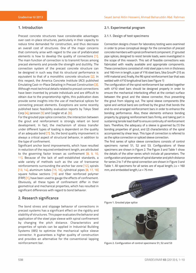
Connection designs chosen for laboratory testing were examined in order to prove conceptual design for the connection of precast concrete members with spiral confinement component. 21 grouted pipe splices, designed to resist tensile loads, were investigated in the scope of this research. This set of feasible connections was fabricated with readily available and appropriate components. These connections consisted of: mild steel pipe 4 mm in thickness and 160 mm in length, a pair of Y16 steel bars, Sika Grout®-215 as infill material and, finally, the R6 spiral reinforcement bar that was welded with 4Y10 longitudinal bars (see Figure 1)The configuration of the spiral reinforcement bar welded together with 4Y10 steel bars should be designed properly in order to ensure the mechanical interlocking effect at the contact surface between the grout and the sleeve connector, thus preventing the grout from slipping out. The spiral sleeve components (the spiral and vertical bars) are confined by the grout that bonds the end-to-end arranged reinforcement bars in order to enhance the bonding performance. Also, these elements enhance bonding property by gripping reinforcement bars firmly, and taking part in sustaining tensile load itself to ensure continuity of reinforcement bars. Therefore, the adequacy of a sleeve is governed by (1) the bonding properties of grout, and (2) characteristics of the spiral accompanied by shear keys. This type of connection is referred to as the splice connection or spliced sleeve connection.The first series of splice sleeve connections consists of control specimens named S1, S2 and S3. Configurations of these specimens are shown in Figure 2. The Figure 3 and Table 1 show the details of the other series which include all parameters. The configuration and parameters of spiral diameter and pitch distance for series 2 to 7 of the spiral connection are shown in Figure 3 and Table 1. All specimens for all series are of equal length, Ls = 160 mm, and embedded length, Le = 75 mm
Figure 1. Grouted pipe splice
Figure 2. Configuration of control specimens S1, S2 and S3
Građevinar 6/2013
GRAĐEVINAR 65 (2013) 6, 1-10 539
Analysis of spiral reinforcement in grouted pipe splice connectors
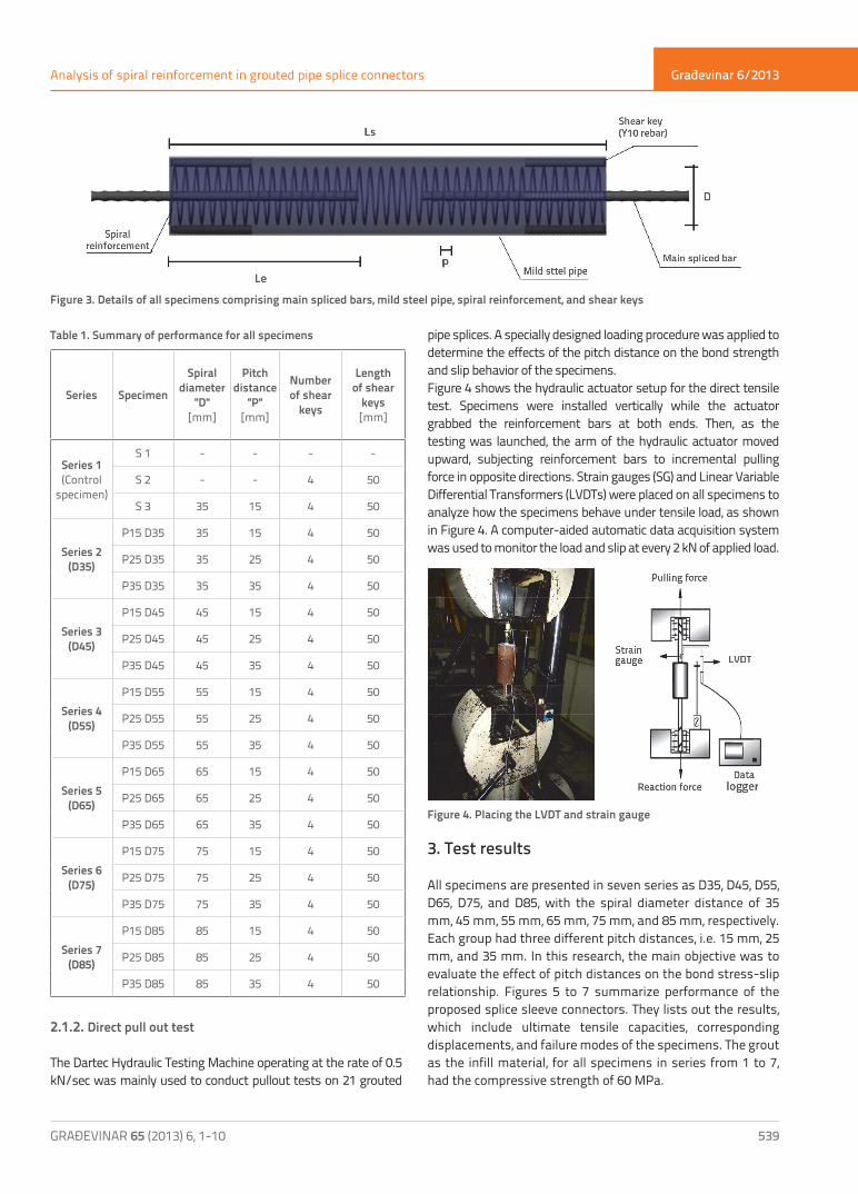
Table 1. Summary of performance for all specimens
2.1.2. Direct pull out test
The Dartec Hydraulic Testing Machine operating at the rate of 0.5 kN/sec was mainly used to conduct pullout tests on 21 grouted
pipe splices. A specially designed loading procedure was applied to determine the effects of the pitch distance on the bond strength and slip behavior of the specimens.Figure 4 shows the hydraulic actuator setup for the direct tensile test. Specimens were installed vertically while the actuator grabbed the reinforcement bars at both ends. Then, as the testing was launched, the arm of the hydraulic actuator moved upward, subjecting reinforcement bars to incremental pulling force in opposite directions. Strain gauges (SG) and Linear Variable Differential Transformers (LVDTs) were placed on all specimens to analyze how the specimens behave under tensile load, as shown in Figure 4. A computer-aided automatic data acquisition system was used to monitor the load and slip at every 2 kN of applied load.
Figure 4. Placing the LVDT and strain gauge
3. Test results
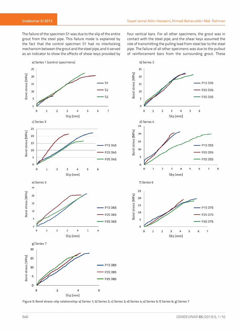
All specimens are presented in seven series as D35, D45, D55, D65, D75, and D85, with the spiral diameter distance of 35 mm, 45 mm, 55 mm, 65 mm, 75 mm, and 85 mm, respectively. Each group had three different pitch distances, i.e. 15 mm, 25 mm, and 35 mm. In this research, the main objective was to evaluate the effect of pitch distances on the bond stress-slip relationship. Figures 5 to 7 summarize performance of the proposed splice sleeve connectors. They lists out the results, which include ultimate tensile capacities, corresponding displacements, and failure modes of the specimens. The grout as the infill material, for all specimens in series from 1 to 7, had the compressive strength of 60 MPa.
Figure 3. Details of all specimens comprising main spliced bars, mild steel pipe, spiral reinforcement, and shear keys
Series Specimen
Spiral diameter
"D" [mm]
Pitch distance
"P" [mm]
Number of shear
keys
Length of shear
keys[mm]
Series 1(Control
specimen)
S 1 - - - -
S 2 - - 4 50
S 3 35 15 4 50
Series 2(D35)
P15 D35 35 15 4 50
P25 D35 35 25 4 50
P35 D35 35 35 4 50
Series 3(D45)
P15 D45 45 15 4 50
P25 D45 45 25 4 50
P35 D45 45 35 4 50
Series 4(D55)
P15 D55 55 15 4 50
P25 D55 55 25 4 50
P35 D55 55 35 4 50
Series 5(D65)
P15 D65 65 15 4 50
P25 D65 65 25 4 50
P35 D65 65 35 4 50
Series 6(D75)
P15 D75 75 15 4 50
P25 D75 75 25 4 50
P35 D75 75 35 4 50
Series 7(D85)
P15 D85 85 15 4 50
P25 D85 85 25 4 50
P35 D85 85 35 4 50
Građevinar 6/2013
GRAĐEVINAR 65 (2013) 6, 1-10540
Seyed Jamal Aldin Hosseini, Ahmad Baharuddin Abd. Rahman
The failure of the specimen S1 was due to the slip of the entire grout from the steel pipe. This failure mode is explained by the fact that the control specimen S1 had no interlocking mechanism between the grout and the steel pipe, and it served as an indicator to show the effects of shear keys provided by
four vertical bars. For all other specimens, the grout was in contact with the steel pipe, and the shear keys assumed the role of transmitting the pulling load from steel bar to the steel pipe. The failure of all other specimens was due to the pullout of reinforcement bars from the surrounding grout. These
Figure 5: Bond stress-slip relationship: a) Series 1; b) Series 2; c) Series 3; d) Series 4; e) Series 5; f) Series 6; g) Series 7
Građevinar 6/2013
GRAĐEVINAR 65 (2013) 6, 1-10 541
Analysis of spiral reinforcement in grouted pipe splice connectors
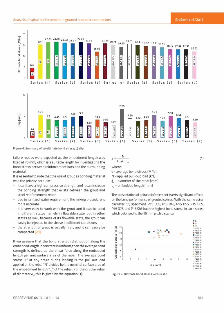
failure modes were expected as the embedment length was fixed at 75 mm, which is a suitable length for investigating the bond stress between reinforcement bars and the surrounding material.It is essential to note that the use of grout as bonding material was the priority because: - It can have a high compressive strength and it can increase
the bonding strength that exists between the grout and steel reinforcement rebar
- due to its fixed water requirement, the mixing procedure is more accurate
- it is very easy to work with the grout and it can be used in different states namely in flowable state, but in other states as well; because of its flowable state, the grout can easily be injected in the sleeve in different conditions
- the strength of grout is usually high, and it can easily be compacted [20].
If we assume that the bond strength distribution along the embedded length in concrete is uniform, then the average bond strength is defined as the shear force along the embedded length per unit surface area of the rebar. The average bond stress "t" at any stage during loading is the pull-out load applied on the rebar "N" divided by the nominal surface area of the embedment length "Le" of the rebar. For the circular rebar of diameter fe, this is given by the equation (1).
τφ
=⋅ ⋅
NP Leε
(1)
where:t - average bond stress [MPa]N - applied pull-out load [kN]fe - diameter of the rebar [mm]Le - embedded length [mm]
The presentation of spiral reinforcement exerts significant effects on the bond performance of grouted splices. With the same spiral diameter "S", specimens P15 D35, P15 D45, P15 D55, P15 D65, P15 D75, and P15 S85 had the highest bond stress in each series which belonged to the 15 mm pitch distance.
Figure 7. Ultimate bond stress versus slip
Figure 6. Summary of: a) ultimate bond stress; b) slip
Građevinar 6/2013
GRAĐEVINAR 65 (2013) 6, 1-10542
Seyed Jamal Aldin Hosseini, Ahmad Baharuddin Abd. Rahman
4. Behavior of grouted splice
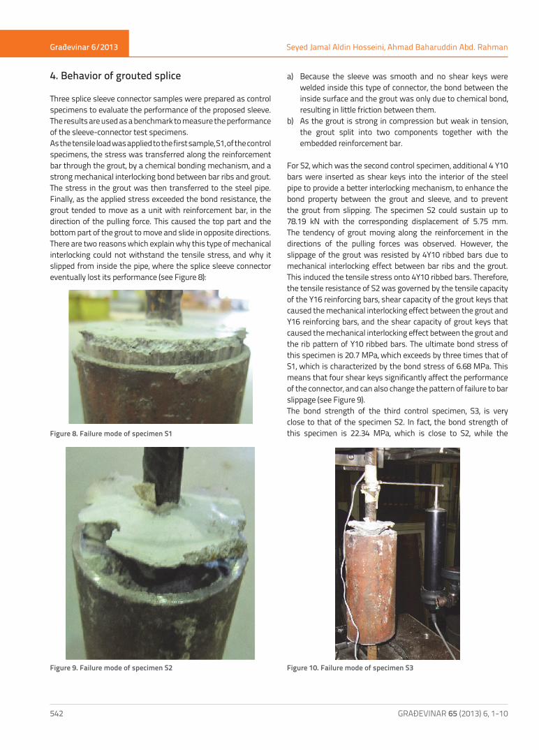
Three splice sleeve connector samples were prepared as control specimens to evaluate the performance of the proposed sleeve. The results are used as a benchmark to measure the performance of the sleeve-connector test specimens.As the tensile load was applied to the first sample, S1, of the control specimens, the stress was transferred along the reinforcement bar through the grout, by a chemical bonding mechanism, and a strong mechanical interlocking bond between bar ribs and grout. The stress in the grout was then transferred to the steel pipe. Finally, as the applied stress exceeded the bond resistance, the grout tended to move as a unit with reinforcement bar, in the direction of the pulling force. This caused the top part and the bottom part of the grout to move and slide in opposite directions.There are two reasons which explain why this type of mechanical interlocking could not withstand the tensile stress, and why it slipped from inside the pipe, where the splice sleeve connector eventually lost its performance (see Figure 8):
a) Because the sleeve was smooth and no shear keys were welded inside this type of connector, the bond between the inside surface and the grout was only due to chemical bond, resulting in little friction between them.
b) As the grout is strong in compression but weak in tension, the grout split into two components together with the embedded reinforcement bar.
For S2, which was the second control specimen, additional 4 Y10 bars were inserted as shear keys into the interior of the steel pipe to provide a better interlocking mechanism, to enhance the bond property between the grout and sleeve, and to prevent the grout from slipping. The specimen S2 could sustain up to 78.19 kN with the corresponding displacement of 5.75 mm. The tendency of grout moving along the reinforcement in the directions of the pulling forces was observed. However, the slippage of the grout was resisted by 4Y10 ribbed bars due to mechanical interlocking effect between bar ribs and the grout. This induced the tensile stress onto 4Y10 ribbed bars. Therefore, the tensile resistance of S2 was governed by the tensile capacity of the Y16 reinforcing bars, shear capacity of the grout keys that caused the mechanical interlocking effect between the grout and Y16 reinforcing bars, and the shear capacity of grout keys that caused the mechanical interlocking effect between the grout and the rib pattern of Y10 ribbed bars. The ultimate bond stress of this specimen is 20.7 MPa, which exceeds by three times that of S1, which is characterized by the bond stress of 6.68 MPa. This means that four shear keys significantly affect the performance of the connector, and can also change the pattern of failure to bar slippage (see Figure 9). The bond strength of the third control specimen, S3, is very close to that of the specimen S2. In fact, the bond strength of this specimen is 22.34 MPa, which is close to S2, while the
Figure 10. Failure mode of specimen S3Figure 9. Failure mode of specimen S2
Figure 8. Failure mode of specimen S1
Građevinar 6/2013
GRAĐEVINAR 65 (2013) 6, 1-10 543
Analysis of spiral reinforcement in grouted pipe splice connectors
ultimate bond stress amounts to 20.7 MPa. This indicates that the spiral did not significantly enhance the performance of the splice sleeve connector in terms of ultimate bond stress, but the spiral was somehow effective in controlling the splitting cracks in the splice, in restraining the movement, and in preventing deterioration of the joint. However, the results show that slip was reduced from 5.75 mm for the second specimen to 4.70 mm for the third specimen which is equipped with spiral confinement. Hence, the spirals have the potential to control movement and prevent sudden deterioration of the connector. The failure mode of specimen S3 is shown in Figure 10.As shown in Figures 5 to 7, the mechanism of bond failure tended to be ductile and bar pull outs prevailed. As the tensile force was applied at both ends of the splice sleeve connector, the reinforcement bars were inclined to slip along with pulling load in the opposite direction to one another. The mechanical interlocking between the spiral confinement and grout caused the bonding property to configure between surrounding reinforcement bars and the grout. The bars resisted slipping out of the splice sleeve connector, and remained in their position. The compressive stress applied as an incremental force was increased until it reached radial cracks at both ends of the specimens. As the incremental load increased even further, the grout keys between the lugs were crushed and shearing occurred. When the pull out force exceeded the bonding capacity, the reinforcement bars slipped out of the sleeve. The failure mode typical for Series 2 is shown in Figure 11.
Figure 11. Bar slippage from left to right: P15 D35, P25 D35 and P35 D35
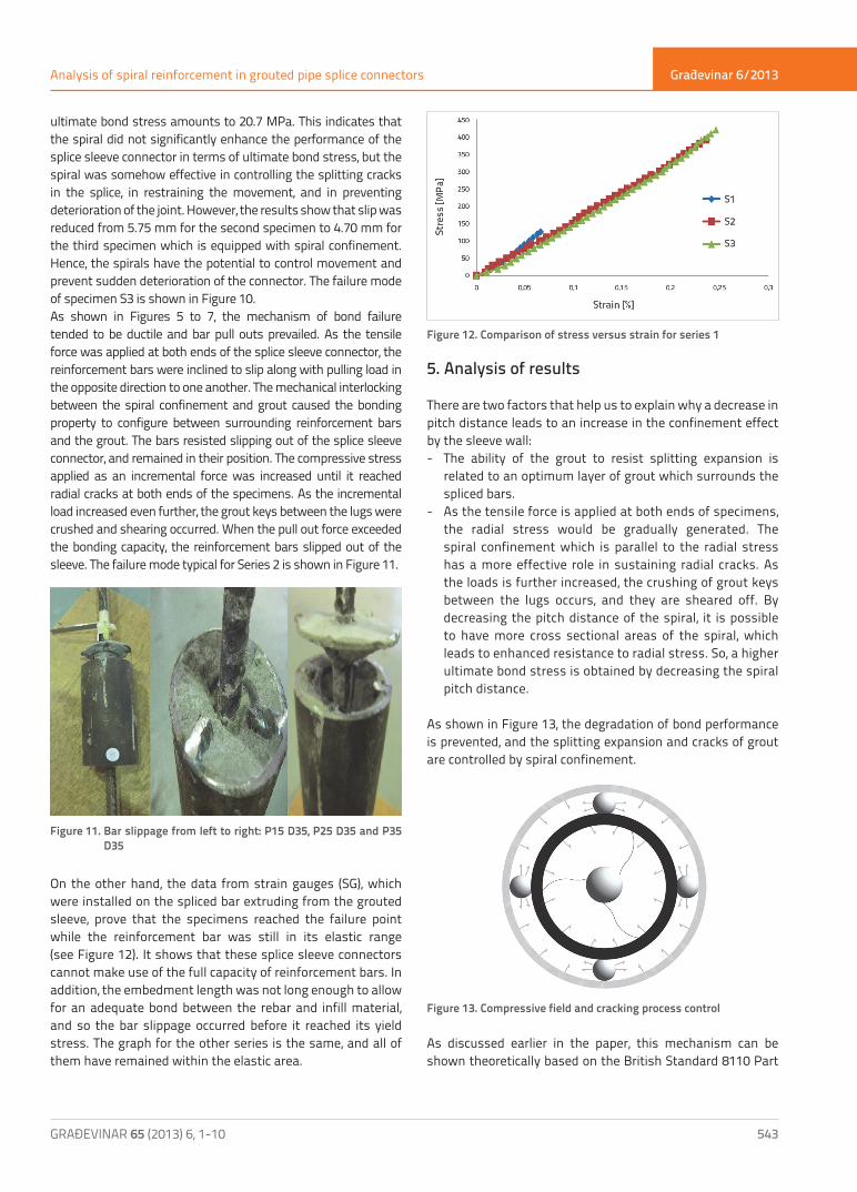
On the other hand, the data from strain gauges (SG), which were installed on the spliced bar extruding from the grouted sleeve, prove that the specimens reached the failure point while the reinforcement bar was still in its elastic range (see Figure 12). It shows that these splice sleeve connectors cannot make use of the full capacity of reinforcement bars. In addition, the embedment length was not long enough to allow for an adequate bond between the rebar and infill material, and so the bar slippage occurred before it reached its yield stress. The graph for the other series is the same, and all of them have remained within the elastic area.
Figure 12. Comparison of stress versus strain for series 1
5. Analysis of results
There are two factors that help us to explain why a decrease in pitch distance leads to an increase in the confinement effect by the sleeve wall: - The ability of the grout to resist splitting expansion is
related to an optimum layer of grout which surrounds the spliced bars.
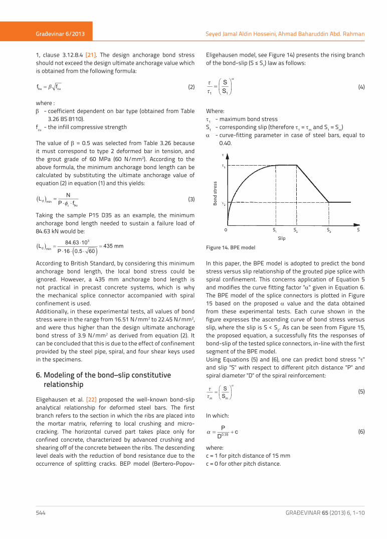
- As the tensile force is applied at both ends of specimens, the radial stress would be gradually generated. The spiral confinement which is parallel to the radial stress has a more effective role in sustaining radial cracks. As the loads is further increased, the crushing of grout keys between the lugs occurs, and they are sheared off. By decreasing the pitch distance of the spiral, it is possible to have more cross sectional areas of the spiral, which leads to enhanced resistance to radial stress. So, a higher ultimate bond stress is obtained by decreasing the spiral pitch distance.
As shown in Figure 13, the degradation of bond performance is prevented, and the splitting expansion and cracks of grout are controlled by spiral confinement.
Figure 13. Compressive field and cracking process control
As discussed earlier in the paper, this mechanism can be shown theoretically based on the British Standard 8110 Part
Građevinar 6/2013
GRAĐEVINAR 65 (2013) 6, 1-10544
Seyed Jamal Aldin Hosseini, Ahmad Baharuddin Abd. Rahman
1, clause 3.12.8.4 [21]. The design anchorage bond stress should not exceed the design ultimate anchorage value which is obtained from the following formula:
f fbu cu= β (2)
where :β - coefficient dependent on bar type (obtained from Table
3.26 BS 8110).fcu - the infill compressive strength
The value of β = 0.5 was selected from Table 3.26 because it must correspond to type 2 deformed bar in tension, and the grout grade of 60 MPa (60 N/mm2). According to the above formula, the minimum anchorage bond length can be calculated by substituting the ultimate anchorage value of equation (2) in equation (1) and this yields:
Ld min( ) =⋅ ⋅
NP fbuφε
(3)
Taking the sample P15 D35 as an example, the minimum anchorage bond length needed to sustain a failure load of 84.63 kN would be:
L16
435 mmd min( ) =⋅
⋅ ⋅ ⋅( )=
84.63 10P 0.5 60
3
According to British Standard, by considering this minimum anchorage bond length, the local bond stress could be ignored. However, a 435 mm anchorage bond length is not practical in precast concrete systems, which is why the mechanical splice connector accompanied with spiral confinement is used.Additionally, in these experimental tests, all values of bond stress were in the range from 16.51 N/mm2 to 22.45 N/mm2, and were thus higher than the design ultimate anchorage bond stress of 3.9 N/mm2 as derived from equation (2). It can be concluded that this is due to the effect of confinement provided by the steel pipe, spiral, and four shear keys used in the specimens.
6. Modeling of the bond–slip constitutive relationship
Eligehausen et al. [22] proposed the well-known bond-slip analytical relationship for deformed steel bars. The first branch refers to the section in which the ribs are placed into the mortar matrix, referring to local crushing and micro-cracking. The horizontal curved part takes place only for confined concrete, characterized by advanced crushing and shearing off of the concrete between the ribs. The descending level deals with the reduction of bond resistance due to the occurrence of splitting cracks. BEP model (Bertero-Popov-
Eligehausen model, see Figure 14) presents the rising branch of the bond-slip (S ≤ S1) law as follows:
ττ
α
1
=
SS1
(4)
Where:t1 - maximum bond stressS1 - corresponding slip (therefore t1 = tm and S1 = Sm)a - curve-fitting parameter in case of steel bars, equal to
0.40.
Figure 14. BPE model
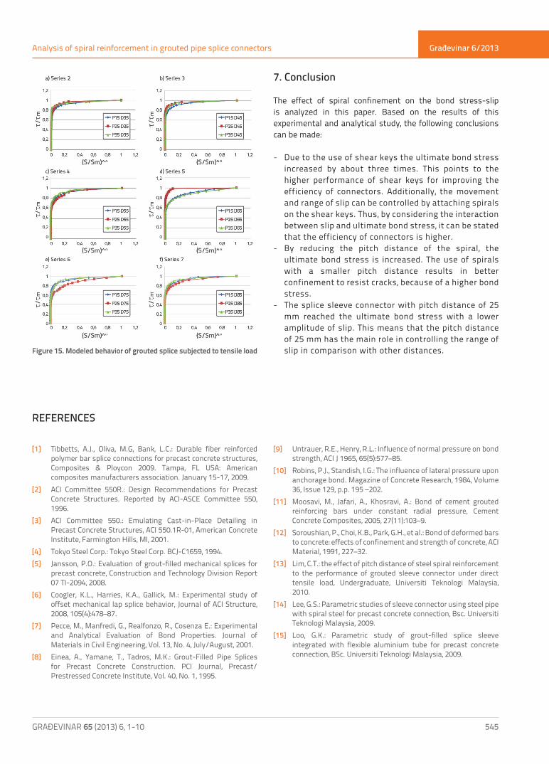
In this paper, the BPE model is adopted to predict the bond stress versus slip relationship of the grouted pipe splice with spiral confinement. This concerns application of Equation 5 and modifies the curve fitting factor "a" given in Equation 6. The BPE model of the splice connectors is plotted in Figure 15 based on the proposed a value and the data obtained from these experimental tests. Each curve shown in the figure expresses the ascending curve of bond stress versus slip, where the slip is S < S2. As can be seen from Figure 15, the proposed equation, a successfully fits the responses of bond-slip of the tested splice connectors, in-line with the first segment of the BPE model.Using Equations (5) and (6), one can predict bond stress "t" and slip "S" with respect to different pitch distance "P" and spiral diameter "D" of the spiral reinforcement:
ττ
α
m
=
SSm
(5)
In which:
α = +P
Dc0.35 (6)
where:c = 1 for pitch distance of 15 mmc = 0 for other pitch distance.
Građevinar 6/2013
GRAĐEVINAR 65 (2013) 6, 1-10 545
Analysis of spiral reinforcement in grouted pipe splice connectors
Figure 15. Modeled behavior of grouted splice subjected to tensile load
7. Conclusion
The effect of spiral confinement on the bond stress-slip is analyzed in this paper. Based on the results of this experimental and analytical study, the following conclusions can be made:
- Due to the use of shear keys the ultimate bond stress increased by about three times. This points to the higher performance of shear keys for improving the efficiency of connectors. Additionally, the movement and range of slip can be controlled by attaching spirals on the shear keys. Thus, by considering the interaction between slip and ultimate bond stress, it can be stated that the efficiency of connectors is higher.
- By reducing the pitch distance of the spiral, the ultimate bond stress is increased. The use of spirals with a smaller pitch distance results in better confinement to resist cracks, because of a higher bond stress.
- The splice sleeve connector with pitch distance of 25 mm reached the ultimate bond stress with a lower amplitude of slip. This means that the pitch distance of 25 mm has the main role in controlling the range of slip in comparison with other distances.
REFERENCES
[1] Tibbetts, A.J., Oliva, M.G, Bank, L.C.: Durable fiber reinforced polymer bar splice connections for precast concrete structures, Composites & Ploycon 2009. Tampa, FL USA: American composites manufacturers association. January 15-17, 2009.
[2] ACI Committee 550R.: Design Recommendations for Precast Concrete Structures. Reported by ACI-ASCE Committee 550, 1996.
[3] ACI Committee 550.: Emulating Cast-in-Place Detailing in Precast Concrete Structures, ACI 550.1R-01, American Concrete Institute, Farmington Hills, MI, 2001.
[4] Tokyo Steel Corp.: Tokyo Steel Corp. BCJ-C1659, 1994.[5] Jansson, P.O.: Evaluation of grout-filled mechanical splices for
precast concrete, Construction and Technology Division Report 07 TI-2094, 2008.
[6] Coogler, K.L., Harries, K.A., Gallick, M.: Experimental study of offset mechanical lap splice behavior, Journal of ACI Structure, 2008, 105(4):478–87.
[7] Pecce, M., Manfredi, G., Realfonzo, R., Cosenza E.: Experimental and Analytical Evaluation of Bond Properties. Journal of Materials in Civil Engineering, Vol. 13, No. 4, July/August, 2001.
[8] Einea, A., Yamane, T., Tadros, M.K.: Grout-Filled Pipe Splices for Precast Concrete Construction. PCI Journal, Precast/Prestressed Concrete Institute, Vol. 40, No. 1, 1995.
[9] Untrauer, R.E., Henry, R.L.: Influence of normal pressure on bond strength, ACI J 1965, 65(5):577–85.
[10] Robins, P.J., Standish, I.G.: The influence of lateral pressure upon anchorage bond. Magazine of Concrete Research, 1984, Volume 36, Issue 129, p.p. 195 –202.
[11] Moosavi, M., Jafari, A., Khosravi, A.: Bond of cement grouted reinforcing bars under constant radial pressure, Cement Concrete Composites, 2005, 27(11):103–9.
[12] Soroushian, P., Choi, K.B., Park, G.H., et al.: Bond of deformed bars to concrete: effects of confinement and strength of concrete, ACI Material, 1991, 227–32.
[13] Lim, C.T.: the effect of pitch distance of steel spiral reinforcement to the performance of grouted sleeve connector under direct tensile load, Undergraduate, Universiti Teknologi Malaysia, 2010.
[14] Lee, G.S.: Parametric studies of sleeve connector using steel pipe with spiral steel for precast concrete connection, Bsc. Universiti Teknologi Malaysia, 2009.
[15] Loo, G.K.: Parametric study of grout-filled splice sleeve integrated with flexible aluminium tube for precast concrete connection, BSc. Universiti Teknologi Malaysia, 2009.
Građevinar 6/2013
GRAĐEVINAR 65 (2013) 6, 1-10546
Seyed Jamal Aldin Hosseini, Ahmad Baharuddin Abd. Rahman
[16] Ling, J.H., Abd. Rahman, A.B., Abd. Hamid, Z.: Performance of corrugated aluminium sleeve connector under direct tensile load, 2nd engineering conference on sustainable engineering (ENCON 08). Kuching, Sarawak, Malaysia: University Malaysia Sarawak (UNIMAS), 2008.
[17] Loh, H.Y.: Development of grouted splice sleeve and its performance under axial tension, Msc. Universiti Teknologi Malaysia, 2008.
[18] Ling, J.H., Abd. Rahman, A.B., Abd. Hamad, Z., et al.: Structural performance of splice connector for precast concrete structures, Joint conference 7th Asia Pacific Structural Engineering & Construction Conference & 2nd European Asian Civil Engineering Forum. Pulau Langkawi, Malaysia: Universiti Teknologi Malaysia (UTM), Universitas Pelita Harapan (UPH), 2009.
[19] Ling, J.H., Abd. Rahman, A.B., Ibrahim, I.S., et al.: Tensile performance of ribbed hollow section splice sleeve connector under direct tensile load. 2nd construction industry research achievement international conference, Kuala Lumpur, Malaysia: Construction research institute of Malaysia (CREAM), Construction industry development board (CIDB), 2009.
[20] Ling, J.H., Abd Rahman, A.B., Mirasa, A.K., et al.: Performance of CS-sleeve under direct tensile load: Part II – Structural performance, Malaysian Journal of Civil Engineering, 2008.
[21] British Standard Institution. Structural Use of Concrete BS8110: Part 1: 1997: London, Clause 3.12.8.4
[22] Eligehausen, R., Popov, E.P., Bertero, V.V.: Local bond stress-slip relationships of deformed bars under generalized excitations, Report No. 83r23, EERC, University of California, Berkeley, 1983.


