Embed Size (px)
Citation preview
Analysis of Stall Onset in a Multistage Axial Flow
Compressor in Response to Engine Icing
Reema Kundu and J. V. R. Prasad
School of Aerospace Engineering, Georgia Institute of Technology, Atlanta, GA 30332-0150
Swati Saxena and Rajkeshar Singh
GE Global Research Center,Niskayuna, NY 12309
Andy Breeze-Stringfellow and Tsuguji Nakano
GE Aviation, Cincinnati, OH 45215
Propulsion system instabilities such as compressor surge and stall can arise due to iceingested by an aircraft engine flying through high ice water content regions. Performanceand operability are affected by ice ingestion into a gas turbine engine compression system.Since the 1980’s ingestion of ice particles into engines have caused over one hundred en-gine power loss events. This paper presents an analysis of a multistage compressor systemresponse to ice ingestion. Towards this, an aero-thermodynamic model of the discrete par-ticles that captures mass and heat balances with air, is constructed. The computationalmethodology integrates it with a quasi-one-dimensional unsteady flow model with addi-tional source terms from the discrete phase. From numerical simulations of the coupledcontinuous-discrete phase flow model, it is observed that a re-matching of the stages acrossthe compressor occurs with increasing ice flow rates to accommodate loss of energy to theice flow. The axial flow and pressure oscillations with increasing ice flow rates results inan eventual irretrievable unsteady compressor operating point excursion to stall side. Theflow solver simulates the onset of a surge-stall event and identifies the stalling stage ofthe compressor. The numerical simulations correlate the magnitude of ice flow rates topressure disturbances ultimately causing compressor instability.
Nomenclature
m mass flow rateMp total mass flow rate of ice crystalsws shaft power per unit volumeT temperaturehm mass transfer coefficienth heat transfer coefficientk thermal conductivityLmelt latent heat of fusionLvap latent heat of evaporationRH relative humidityφ flow coefficient, u/Uψf body force coefficientρ densityρv,s saturated vapor density at droplet surfaceρv free-stream vapor densityA flow-path areaAp projected area of the discrete particle in the
direction of it’s relative velocity
CD drag coefficientCP constant pressure specific heat capacityD discrete particle diametere internal energyf body force per unit volumeH total enthalpyL compressor lengthmp mass of single ice crystal or water dropletN number of discrete elementsp static pressureq specific humidityrm pitch-line radiussE discrete phase energy source termsM discrete phase momentum source termsV discrete phase mass source termt time instantU pitch-line blade rotational speed, ωru axial component of flow velocity
1 of 11
American Institute of Aeronautics and Astronautics
up discrete particle velocityvθ circumferential component of flow velocity
Subscripts
θ circumferential componentc continuous phasex axial component
0 stagnation conditionsDRY dry air flow conditionsb bleedp discrete element: ice crystals and water
dropletss static conditionsv water vapor
I. Introduction
Ice ingestion in engines is a serious safety and performance concern for modern aircraft. Extensive researchhas been undertaken to identify engine icing events through the development of experimental facilities.1
Additionally researchers have attempted to numerically simulate ice accretion in the engine core due toatmospheric ice ingestion and quantify its effect on the complete engine system.2–4 Ice shed inside thecompressor from the accreted ice is believed to be a direct cause of engine instability.5,6 McDonald7 presentedthe transient response of hail ingestion in an engine under flight idle power conditions. The simulated modelcompressor discharge pressure and temperature in presence of hail were compared to experimental data andan eventual engine roll-back was recorded. AGARD8 discussed the influence of rain, snow and hail on theperformance and operability of gas turbine engines. According to the report the compressor undergoes aloss in surge margin due to the increased operating line in presence of hail or snow. The stable operation ofa compressor is limited by the surge line. Rain ingestion in adverse weather conditions has a performancedegradation effect due to aerodynamic and mechanical effects.9 Studies related to inlet fogging and wetcompression have shown its wide applicability in power and efficiency augmentation of gas turbine enginesattributed to thermodynamic effects.10–12 However, literature indicates that the compressor will have atendency to operate considerable off design in presence of water vapor. Re-matching of the stages lead to thefront stages moving towards choke and rear stages towards stall .13 Due to operability concerns, a similaranalysis is required for ice shed into the compressor to capture aero-thermodynamic and mechanical effectsresulting in a redistribution of the stage load.
Kundu et al.14 reviewed the effect of a steady flow rate of ice on the performance characteristics of a tenstage compressor at engine ground idling conditions. The authors quantify the impact of ice intake on thecompressor flow dynamics. A coupled generic one-dimensional model for flow in a multistage compressoralong with a discrete phase model is used. The developed reduced order model simulates the two-wayinteraction between the discrete phase and the multistage compressor flow field.
Further, in this paper the onset of stall in the compressor is precipitated by increasing ice flow into theairflow of a ten stage compressor operating at nominal take-off conditions. The inertial and heat energy lostby the air to the discrete phase and the mass of vapor added in the continuous phase causes the operatingpoint to migrate away from the design value to a different pressure ratio. The analysis indicates a loadingof the back stages and unloading of the front stages. The stage characteristics of the compressor models canbe separately evaluated. This makes it suitable for detecting the stage where stall gets initiated due to iceingestion. Observed industry trends are used for comparison against the numerical results.
II. Numerical model
A. Geometrical configuration
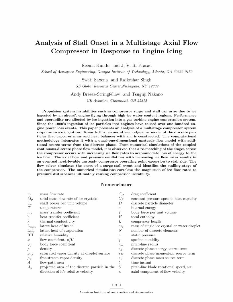
Figure 1 shows the schematic of the compression system that is representative of a typical laboratory orrig-test setup.15 The compressor is assumed to be externally driven and hence operating at a constantrotational speed. A throttle valve downstream of the plenum, modeled as a variable area choked orifice, setsthe nominal operating point of the system. The basic unit of the compressor is the blade row consisting of arotor and a stator. The simulation tool is based on the compressor geometry of a ten stage compressor anda set of steady state characteristic maps representing the blade forces on the fluid.
2 of 11
American Institute of Aeronautics and Astronautics
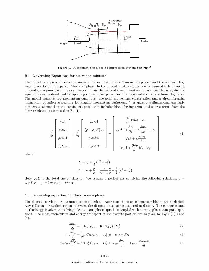
Figure 1. A schematic of a basic compression system test rig.15
B. Governing Equations for air-vapor mixture
The modeling approach treats the air-water vapor mixture as a “continuous phase” and the ice particles/water droplets form a separate “discrete” phase. In the present treatment, the flow is assumed to be inviscid,unsteady, compressible and axisymmetric. Thus the reduced one-dimensional quasi-linear Euler system ofequations can be developed by applying conservation principles to an elemental control volume (figure 2).The model contains two momentum equations: the axial momentum conservation and a circumferentialmomentum equation accounting for angular momentum variations.16 A quasi-one-dimensional unsteadymathematical model of the continuous phase that includes blade forcing terms and source terms from thediscrete phase, is expressed in Eq.(1).
∂
∂t
ρcA
ρcuA
ρcvθA
ρcEA
+
∂
∂x
ρcuA(p+ ρcu
2)A
ρcuAvθ
ρcuAH
=
∂
∂x(mb) + sV
fxA+ p∂A
∂x+ u
∂mb
∂x+ sM
fθA+ vθ∂mb
∂x
wsA+∂mb
∂xHc + sE
(1)
where,
E = ec +1
2
(u2 + v2θ
)Hc = E +
p
ρ=
γ
γ − 1
p
ρ+
1
2
(u2 + v2θ
)Here, ρcE is the total energy density. We assume a perfect gas satisfying the following relations, p =ρcRT, p = (γ − 1)ρcec, γ = cP /cV .
C. Governing equation for the discrete phase
The discrete particles are assumed to be spherical. Accretion of ice on compressor blades are neglected.Any collisions or agglomerations between the discrete phase are considered negligible. The computationalmethodology involves the solving of continuous phase equations coupled with discrete phase transport equa-tions. The mass, momentum and energy transport of the discrete particle are as given by Eqs.(2),(3) and(4).
dmv
dt= − hm (ρv,s − RH %ρv)πD
2p (2)
mpdupdt
=1
2ρcCDAp|u− up| (u− up) = FD (3)
mpcP,pdTpdt
= hπD2p (Tair − Tp) + Lvap
dmv
dt+ Lmelt
dmmelt
dt(4)
3 of 11
American Institute of Aeronautics and Astronautics
up
mv
dx
mb
fx + fθ + ws
u1 u2
p1 p2
1 2
Figure 2. Elemental control volume withdispersed phase elements adapted fromCrowe17
Specific humidity ratio (q) is expressed as a ratio of massof water vapor (mv) per unit mass of dry air (ma) and can beexpressed in terms of relative humidity. Relative humidity isupdated at the end of every time step and plays an importantrole in the mass transport equation. The specific humidity, q,is useful in tracking the vapor formed during phase transitions.The conservation of vapor gives rise to an unsteady speciesequation in terms of q, given by,
∂
∂t(ρcqA) +
∂
∂x(ρcuqA) =
dmv
dx(5)
The equations that govern the compressor flow field andthe icing physics are coupled as the phase changes in ice andwater molecules modify the characteristics of the surroundingair phase. The vapor produced by the droplets is a mass sourcefor the fluid, moreover the vaporization process generates modifications in the momentum and energy bal-ances between both phases.18 These modify the temperature and pressure variation through the compressor,which are input terms to the governing equations for the discrete phase. Thus a two-way coupling betweencontinuous and discrete phase, is achieved.
D. Source terms
A control volume in a typical compressor illustrated in figure 2 is acted upon by a body force, fx perunit volume in the axial direction. The circumferential momentum exchange is fθ and the shaft work wscommunicates the change in total enthalpy of the fluid due to the blades. A set of quasi-steady stagecharacteristics provides these stage forces and shaft work inputs to the momentum and energy equations.
The body force terms are functions of the mass flow rate calculated at blade leading edges and respondinstantaneously to changes in the flow. In reality any flow changes cause a gradual response of the bodyforces on the blades. Time-lag models are commonly used to simulate this delay in response.
τdF
dt+ F = FSS(φ) (6)
where, τ is a time scale associated with blade response. φ is the local, unsteady axial velocity coefficient ofthe compressor. FSS is the steady performance of the blade row and F is the instantaneous value of thebody force to which the first order lag model is applied.
In the present work, the ten stage compressor flow model has bleed mass flux mb, after the 4th stagecontrol volume and again after the 7th stage control volume. The bleed mass flow rate is calculated as afunction of pressure and temperature to account for transient effect on the amount of bleed.
Evaporation of the discrete phase will result in mass flow into the continuous phase (influx). Thus, thedispersed phase mass flux term becomes,
sV = − 1
dx
∑p
N mv (7)
where, mv is the water vapor flux from all p discrete particles. The negative sign indicates that a waterdroplet losing mass is adding mass to the carrier phase.
The air does work in driving the discrete phase particles through the compressor and is evident as dragforce FD seen as the momentum transport term in Eq.(3). The energy exchange with airflow, Qp is sumof the sensible heat for raising the temperature of the discrete particles and the latent work done in phasechanges. The momentum and energy source terms contributed by the discrete phase can be expressed in thefollowing form:
sM = upsV − fD (u− up) (8)
sE = sVHp +∂Qp∂x− fD (u− up)up (9)
where, fD = 1dx (NFD)/(u− up) and Hp = hp + 1
2u2p.
4 of 11
American Institute of Aeronautics and Astronautics
III. Numerical Results and Conclusions
The numerical results presented in this paper is for a ten stage compressor operating at a constantrotational speed representing a compressor rig behavior and operating at nominal take off conditions. Theguide vane angle and stagnation conditions at the inlet are specified. A choked nozzle condition is assumed atthe exit of the compressor and the exit ambient pressure is specified. A non-uniform grid of 3212 elements isused to discretize the one-dimensional computational domain. Equation 1 is discretized with a second-ordercentral difference Kurganov-Tadmor (KT) scheme. The resulting ODEs are solved with an explicit secondorder Runge-Kutta solver.
The equations and associated boundary conditions for the continuous and discrete phases are resolved ina two-step process that lead to a coupled formulation. The first step involves solving the governing equationsfor the continuous phase given by Eq.(1) along with the steady state blade characteristics is used to calculatethe conservative flow variables. Additionally the species equation in Eq.(5) is solved to update the relativehumidity in the compressor. In the second step, the flow conditions of the air-vapor are then passed as inputsto solve Eqs.(2) - (4) for the discrete phase. The mass, momentum and energy source/sink terms are thenupdated and applied in the next time step. The time steps are first run in dry conditions until the initialtransients decay and the compressor reaches a steady state operating point. Then a steady ice flow rate isintroduced in the compressor airflow.
A recent parametric study on this model focussed on the influence of humidity, incoming ice crystal sizes,percentage ice bleed, ice crystal temperatures etc.19 In this work, the dynamic response of the compressorto increasing amount of ice inflow rates is investigated. Towards this, a ten bin Rosin-Rammler ice crystaldistribution with 175 µm mean value diameter is selected. The incoming temperature of ice crystal is 256K.The ingested ice causes a slow drift of the compressor performance from the design steady state operatingpoint eventually causing compressor instability. A correlation is sought of the quantity of ice ingested intothe compressor that leads to compressor instability.
A. Transient variation of discrete phase through the compressor
0 50 100 150 200 250 300 350 400Time (milliseconds)
mIC
E
R1R2
R3R4
R5R6
R7R8
R9R10
{
!m ICE= 0 .26%mDRYAIR
(a) Time traces of ice flow across rotors
0 50 100 150 200 250 300 350 4000
0.005
0.01
0.015
0.02
0.025
0.03
Time (milliseconds)
Specifi
chum
idit
y
R1R2
R3R4
R5R6
R7R8
R9R10
(b) Time traces of specific humidity across rotors
Figure 3. Ice to vapor phase transitions
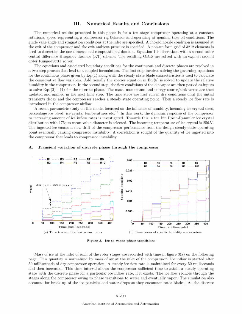
Mass of ice at the inlet of each of the rotor stages are recorded with time in figure 3(a) on the followingpage. This quantity is normalized by mass of air at the inlet of the compressor. Ice inflow is started after50 milliseconds of dry compressor operation. A steady ice flow rate is maintained for every 50 millisecondsand then increased. This time interval allows the compressor sufficient time to attain a steady operatingstate with the discrete phase for a particular ice inflow rate, if it exists. The ice flow reduces through thestages along the compressor owing to phase transitions to water and eventually vapor. The simulation alsoaccounts for break up of the ice particles and water drops as they encounter rotor blades. As the discrete
5 of 11
American Institute of Aeronautics and Astronautics
phase particles travel through the compressor, both heat and mass exchanges occur with air. This causesproperties like gas constant and the specific heat at constant pressure of the air-vapor mixture to alter.These effects also play a key role in the dynamic behavior of the airflow in presence of ice.19,20
The corresponding increase in the specific humidity (mass flow rate of vapor to that of dry air) inducedby vaporization of the discrete phase, is evident in figure 3(b) on the next page. The increasing temperatureprofile from the front to the rear stages contribute to a higher phase transition to vapor at the rear stages.This appears as a source term sV in the Eq.(1).
B. Transient response of the air-vapor mixture to increasing ice flow preceding stall
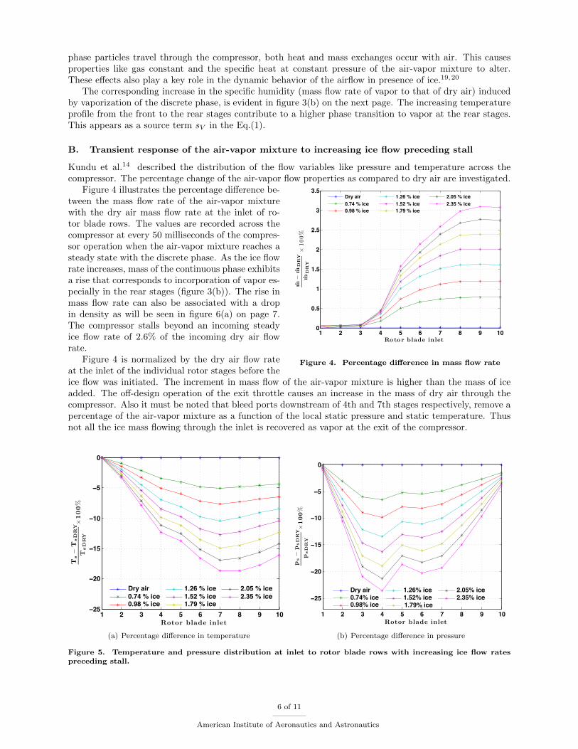
Kundu et al.14 described the distribution of the flow variables like pressure and temperature across thecompressor. The percentage change of the air-vapor flow properties as compared to dry air are investigated.
1 2 3 4 5 6 7 8 9 100
0.5
1
1.5
2
2.5
3
3.5
Roto r blade inlet
m!
mD
RY
mD
RY
"100%
Dry air0.74 % ice0.98 % ice
1.26 % ice1.52 % ice1.79 % ice
2.05 % ice2.35 % ice
Figure 4. Percentage difference in mass flow rate
Figure 4 illustrates the percentage difference be-tween the mass flow rate of the air-vapor mixturewith the dry air mass flow rate at the inlet of ro-tor blade rows. The values are recorded across thecompressor at every 50 milliseconds of the compres-sor operation when the air-vapor mixture reaches asteady state with the discrete phase. As the ice flowrate increases, mass of the continuous phase exhibitsa rise that corresponds to incorporation of vapor es-pecially in the rear stages (figure 3(b)). The rise inmass flow rate can also be associated with a dropin density as will be seen in figure 6(a) on page 7.The compressor stalls beyond an incoming steadyice flow rate of 2.6% of the incoming dry air flowrate.
Figure 4 is normalized by the dry air flow rateat the inlet of the individual rotor stages before theice flow was initiated. The increment in mass flow of the air-vapor mixture is higher than the mass of iceadded. The off-design operation of the exit throttle causes an increase in the mass of dry air through thecompressor. Also it must be noted that bleed ports downstream of 4th and 7th stages respectively, remove apercentage of the air-vapor mixture as a function of the local static pressure and static temperature. Thusnot all the ice mass flowing through the inlet is recovered as vapor at the exit of the compressor.
1 2 3 4 5 6 7 8 9 10−25
−20
−15
−10
−5
0
Rotor blade inlet
Ts
!T
sD
RY
TsD
RY
"100
%
Dry air0.74 % ice0.98 % ice
1.26 % ice1.52 % ice1.79 % ice
2.05 % ice2.35 % ice
(a) Percentage difference in temperature
1 2 3 4 5 6 7 8 9 10
−25
−20
−15
−10
−5
0
Rotor blade inlet
ps
!p
sD
RY
psD
RY
"100
%
Dry air0.74% ice0.98% ice
1.26% ice1.52% ice1.79% ice
2.05% ice2.35% ice
(b) Percentage difference in pressure
Figure 5. Temperature and pressure distribution at inlet to rotor blade rows with increasing ice flow ratespreceding stall.
6 of 11
American Institute of Aeronautics and Astronautics
A comparison with the temperature of the air-vapor mixture at rotor blade inlets in figure 5(a) signifiesa reduction in the heating capacity of the air with increasing ice flow. The temperature drops at eachconsecutive stage in response to the ice flowing through the inlet of the compressor. Front stages havegreater concentration of ice that cause a small drop in temperature mainly due the drag force on particles andmelting of ice. The rear stages have a higher water content that evaporate resulting in a higher temperaturedrop due to large latent heat of vaporization absorbed from the air-vapor mixture.
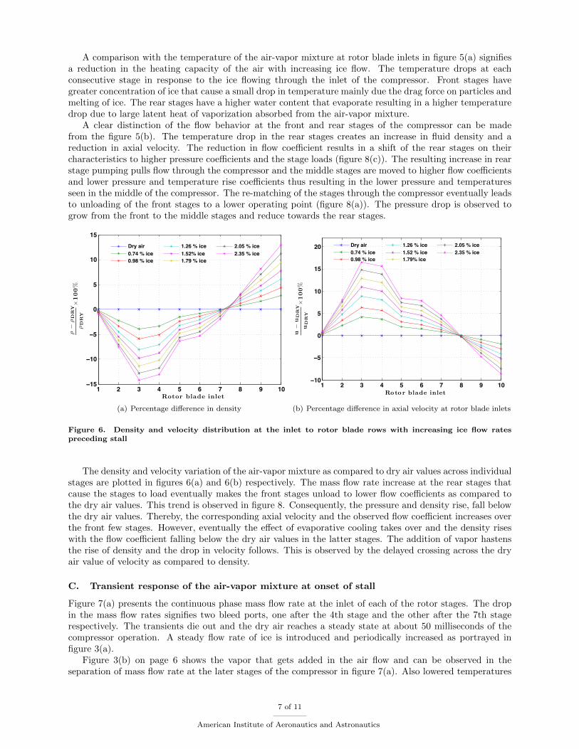
A clear distinction of the flow behavior at the front and rear stages of the compressor can be madefrom the figure 5(b). The temperature drop in the rear stages creates an increase in fluid density and areduction in axial velocity. The reduction in flow coefficient results in a shift of the rear stages on theircharacteristics to higher pressure coefficients and the stage loads (figure 8(c)). The resulting increase in rearstage pumping pulls flow through the compressor and the middle stages are moved to higher flow coefficientsand lower pressure and temperature rise coefficients thus resulting in the lower pressure and temperaturesseen in the middle of the compressor. The re-matching of the stages through the compressor eventually leadsto unloading of the front stages to a lower operating point (figure 8(a)). The pressure drop is observed togrow from the front to the middle stages and reduce towards the rear stages.
1 2 3 4 5 6 7 8 9 10−15
−10
−5
0
5
10
15
Rotor blade inlet
!!
!D
RY
!D
RY
"100
%
Dry air0.74 % ice0.98 % ice
1.26 % ice1.52% ice1.79 % ice
2.05 % ice2.35 % ice
(a) Percentage difference in density
1 2 3 4 5 6 7 8 9 10−10
−5
0
5
10
15
20
Roto r blade inlet
u!
uD
RY
uD
RY
"100
%
Dry air0.74 % ice0.98 % ice
1.26 % ice1.52 % ice1.79% ice
2.05 % ice2.35 % ice
(b) Percentage difference in axial velocity at rotor blade inlets
Figure 6. Density and velocity distribution at the inlet to rotor blade rows with increasing ice flow ratespreceding stall
The density and velocity variation of the air-vapor mixture as compared to dry air values across individualstages are plotted in figures 6(a) and 6(b) respectively. The mass flow rate increase at the rear stages thatcause the stages to load eventually makes the front stages unload to lower flow coefficients as compared tothe dry air values. This trend is observed in figure 8. Consequently, the pressure and density rise, fall belowthe dry air values. Thereby, the corresponding axial velocity and the observed flow coefficient increases overthe front few stages. However, eventually the effect of evaporative cooling takes over and the density riseswith the flow coefficient falling below the dry air values in the latter stages. The addition of vapor hastensthe rise of density and the drop in velocity follows. This is observed by the delayed crossing across the dryair value of velocity as compared to density.
C. Transient response of the air-vapor mixture at onset of stall
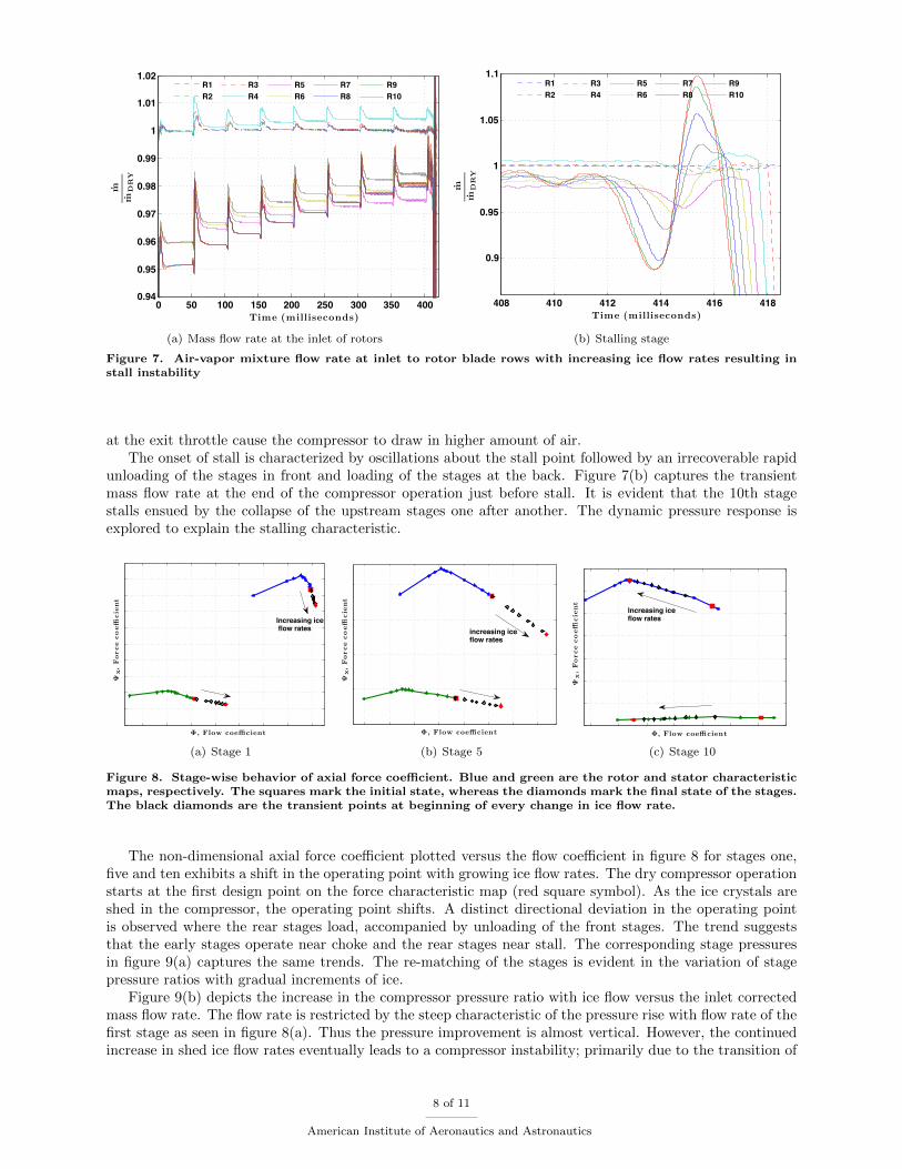
Figure 7(a) presents the continuous phase mass flow rate at the inlet of each of the rotor stages. The dropin the mass flow rates signifies two bleed ports, one after the 4th stage and the other after the 7th stagerespectively. The transients die out and the dry air reaches a steady state at about 50 milliseconds of thecompressor operation. A steady flow rate of ice is introduced and periodically increased as portrayed infigure 3(a).
Figure 3(b) on page 6 shows the vapor that gets added in the air flow and can be observed in theseparation of mass flow rate at the later stages of the compressor in figure 7(a). Also lowered temperatures
7 of 11
American Institute of Aeronautics and Astronautics
0 50 100 150 200 250 300 350 4000.94
0.95
0.96
0.97
0.98
0.99
1
1.01
1.02
Time (milliseconds)
m
mD
RY
R1R2
R3R4
R5R6
R7R8
R9R10
(a) Mass flow rate at the inlet of rotors
408 410 412 414 416 418
0.9
0.95
1
1.05
1.1
Time (milliseconds)
m
mD
RY
R1R2
R3R4
R5R6
R7R8
R9R10
(b) Stalling stage
Figure 7. Air-vapor mixture flow rate at inlet to rotor blade rows with increasing ice flow rates resulting install instability
at the exit throttle cause the compressor to draw in higher amount of air.The onset of stall is characterized by oscillations about the stall point followed by an irrecoverable rapid
unloading of the stages in front and loading of the stages at the back. Figure 7(b) captures the transientmass flow rate at the end of the compressor operation just before stall. It is evident that the 10th stagestalls ensued by the collapse of the upstream stages one after another. The dynamic pressure response isexplored to explain the stalling characteristic.
! , Flow coe"cient
#x,
Force
coe"
cie
nt
Increasing ice flow rates
(a) Stage 1
! , Flow coe"cient
#x,
Force
coe"
cie
nt
increasing ice flow rates
(b) Stage 5
!, Flow coe"cient
#x,
Force
coe"
cie
nt
Increasing ice flow rates
(c) Stage 10
Figure 8. Stage-wise behavior of axial force coefficient. Blue and green are the rotor and stator characteristicmaps, respectively. The squares mark the initial state, whereas the diamonds mark the final state of the stages.The black diamonds are the transient points at beginning of every change in ice flow rate.
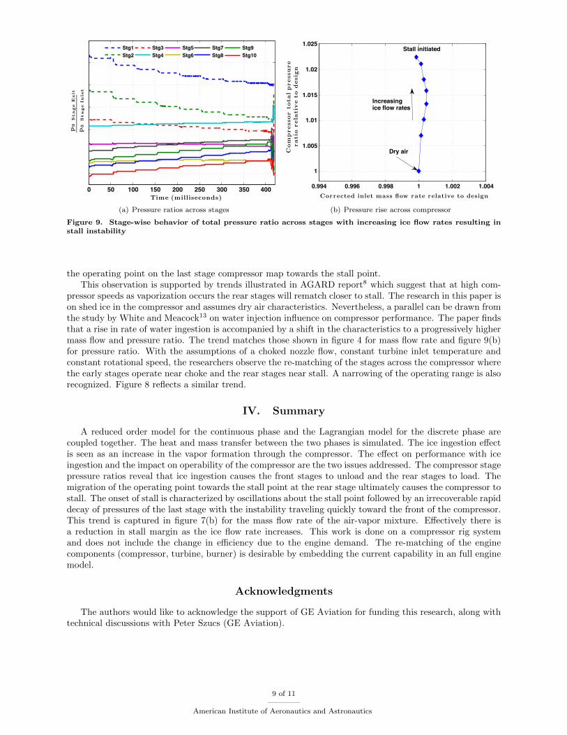
The non-dimensional axial force coefficient plotted versus the flow coefficient in figure 8 for stages one,five and ten exhibits a shift in the operating point with growing ice flow rates. The dry compressor operationstarts at the first design point on the force characteristic map (red square symbol). As the ice crystals areshed in the compressor, the operating point shifts. A distinct directional deviation in the operating pointis observed where the rear stages load, accompanied by unloading of the front stages. The trend suggeststhat the early stages operate near choke and the rear stages near stall. The corresponding stage pressuresin figure 9(a) captures the same trends. The re-matching of the stages is evident in the variation of stagepressure ratios with gradual increments of ice.
Figure 9(b) depicts the increase in the compressor pressure ratio with ice flow versus the inlet correctedmass flow rate. The flow rate is restricted by the steep characteristic of the pressure rise with flow rate of thefirst stage as seen in figure 8(a). Thus the pressure improvement is almost vertical. However, the continuedincrease in shed ice flow rates eventually leads to a compressor instability; primarily due to the transition of
8 of 11
American Institute of Aeronautics and Astronautics
0 50 100 150 200 250 300 350 400Time (milliseconds)
p0
Stage
Exit
p0
Stage
Inle
t
Stg1Stg2
Stg3Stg4
Stg5Stg6
Stg7Stg8
Stg9Stg10
(a) Pressure ratios across stages
0.994 0.996 0.998 1 1.002 1.004
1
1.005
1.01
1.015
1.02
1.025
Corrected inlet mass flow rate relative to design
Com
pressor
totalpressure
ratio
rela
tiv
eto
desig
n
Stall initiated
Increasing ice flow rates
Dry air
(b) Pressure rise across compressor
Figure 9. Stage-wise behavior of total pressure ratio across stages with increasing ice flow rates resulting install instability
the operating point on the last stage compressor map towards the stall point.This observation is supported by trends illustrated in AGARD report8 which suggest that at high com-
pressor speeds as vaporization occurs the rear stages will rematch closer to stall. The research in this paper ison shed ice in the compressor and assumes dry air characteristics. Nevertheless, a parallel can be drawn fromthe study by White and Meacock13 on water injection influence on compressor performance. The paper findsthat a rise in rate of water ingestion is accompanied by a shift in the characteristics to a progressively highermass flow and pressure ratio. The trend matches those shown in figure 4 for mass flow rate and figure 9(b)for pressure ratio. With the assumptions of a choked nozzle flow, constant turbine inlet temperature andconstant rotational speed, the researchers observe the re-matching of the stages across the compressor wherethe early stages operate near choke and the rear stages near stall. A narrowing of the operating range is alsorecognized. Figure 8 reflects a similar trend.
IV. Summary
A reduced order model for the continuous phase and the Lagrangian model for the discrete phase arecoupled together. The heat and mass transfer between the two phases is simulated. The ice ingestion effectis seen as an increase in the vapor formation through the compressor. The effect on performance with iceingestion and the impact on operability of the compressor are the two issues addressed. The compressor stagepressure ratios reveal that ice ingestion causes the front stages to unload and the rear stages to load. Themigration of the operating point towards the stall point at the rear stage ultimately causes the compressor tostall. The onset of stall is characterized by oscillations about the stall point followed by an irrecoverable rapiddecay of pressures of the last stage with the instability traveling quickly toward the front of the compressor.This trend is captured in figure 7(b) for the mass flow rate of the air-vapor mixture. Effectively there isa reduction in stall margin as the ice flow rate increases. This work is done on a compressor rig systemand does not include the change in efficiency due to the engine demand. The re-matching of the enginecomponents (compressor, turbine, burner) is desirable by embedding the current capability in an full enginemodel.
Acknowledgments
The authors would like to acknowledge the support of GE Aviation for funding this research, along withtechnical discussions with Peter Szucs (GE Aviation).
9 of 11
American Institute of Aeronautics and Astronautics
References
1Mason, J. G., Fuleki, D. M., and Chow, P., “Understanding Ice Crystal Accretion and Shedding Phenomenon in JetEngines Using a Rig Test,” Journal of Engineering for Gas Turbines and Power , Vol. 133, No. 4, 2011, pp. 041201.
2Veres, J., Jorgenson, P., Wright, W., and Struk, P., “A Model to Assess the Risk of Ice Accretion due to Ice CrystalIngestion in a Turbofan Engine and its Effects on Performance,” 4th AIAA Atmospheric and Space Environments Conference,2012.
3Veillard, X., Habashi, W., Aube, M., and Baruzzi, G., “FENSAP-ICE: Ice Accretion in Multi-stage Jet Engines,” 1stAtmospheric and Space Environments Conference, AIAA Paper , Vol. 4158, 2009.
4Jorgenson, P. C., Veres, J. P., May, R., and Wright, W., “Engine Icing Modeling and Simulation (Part I): Ice CrystalAccretion on Compression System Components and Modeling its Effects on Engine Performance,” SAE International Conferenceon Aircraft and Engine Icing and Ground Deicing, Chicago, IL, Jun 13–17 2011.
5Mason, J., Grzych, M., and Chow, P., “Current Perspectives on Jet Engine Power Loss in Ice Crystal Conditions: EngineIcing,” AIAA Atmospheric and Space Environments, June 23 2009.
6Mason, J. G., Strapp, J. W., and Chow, P., “The Ice Particle Threat to Engines in Flight,” 44th AIAA AerospaceSciences Meeting and Exhibit , Reno, NV., Jan. 2006.
7McDonald, P. W., “Transient Model Applications. 3: Transient Engine Simulation and Analysis of an Ice Ingestion Test,”VKI Gas Turbine Engine Transient Behavior , Vol. 1, 1993.
8Garwood, K. R., “Recommended Practices for the Assessment of the Effects of Atmospheric Water Ingestion on thePerformance and Operability of Gas Turbine Engines,” AGARD Advisory Report AGARD AR-332 , 1995.
9Day, I., Williams, J., and Freeman, C., “Rain Ingestion in Axial Flow Compressors at Part Speed,” Journal of Turboma-chinery, Vol. 130, No. 1, 2008, pp. 011024.
10Sun, L., Bhargava, R., Zheng, Q., and Li, Y., “Understanding Effects of Wet Compression on Separated Flow Behaviorin an Axial Compressor Stage Using CFD Analysis,” Journal of Turbomachinery, Vol. 133, No. 3, 2011, pp. 031026.
11Bianchi, M., Melino, F., Peretto, A., Spina, P., and Ingistov, S., “Influence of Water Droplet Size and Temperature onWet Compression,” ASME Turbo Expo 2007: Power for Land, Sea, and Air , American Society of Mechanical Engineers, 2007,pp. 651–662.
12Chaker, M., Meher-Homji, C. B., and Mee, T., “Inlet Fogging of Gas Turbine Engines: Part AFog Droplet Thermo-dynamics, Heat Transfer and Practical Considerations,” ASME Turbo Expo 2002: Power for Land, Sea, and Air , AmericanSociety of Mechanical Engineers, 2002, pp. 413–428.
13White, A. and Meacock, A., “An Evaluation of the Effects of Water Injection on Compressor Performance,” ASMETurbo Expo 2003, collocated with the 2003 International Joint Power Generation Conference, American Society of MechanicalEngineers, 2003, pp. 181–189.
14Kundu, R., Prasad, J. V. R., Tiwari, P., Breeze-Stringfellow, A., Szucs, P., Nakano, T., and Pritchard, B., “Impactof Engine Icing on Jet Engine Compressor Flow Dynamics,” 48th AIAA/ASME/SAE/ASEE Joint Propulsion Conference &Exhibit , 2012.
15Dhingra, M., Prasad, J. V. R., Tiwari, P., Nakano, T., and Breeze-Stringfellow, A., “Impact of Inter-Stage Dynamics onStalling Stage Identification,” ASME TurboExpo: Turbine Technical Conference and Exposition, Reno, NV., June 2011, pp.1799–1808.
16Leonward, O. and Adam, O., “A Quasi-One-Dimensional CFD model for Multistage Turbomachines,” Journal of ThermalScience, Vol. 17, No. 1, 2008, pp. 7–20.
17Crowe, C., Sommerfeld, M., and Tsuji, Y., Multiphase Flows with Droplets and Particles, CRC Press LLC, 1998.18Berlemont, A., Grancher, M. S., and Gouesbet, G., “Heat and Mass Transfer Coupling Between Vaporizing Droplets and
Turbulence Using a Lagrangian Approach,” Interbnational Journal of Heat Mass Transfer , Vol. 38, No. 16, 1995, pp. 3023–3034.19Kundu, R., Prasad, J. V. R., Saxena, S., Singh, R., Breeze-Stringfellow, A., and Nakano, T., “Modeling and Analysis
of Ice Shed in Multistage Compressor of Jet Engines,” 6th AIAA Atmospheric and Space Environments Conference, Atlanta,GA, June 2014.
20Klepper, J., Hale, A., Davis, M., and Hurwitz, W., “A Numerical Investigation of the Effects of Steam Ingestion onCompression System Performance,” ASME Turbo Expo 2004: Power for Land, Sea, and Air , American Society of MechanicalEngineers, 2004, pp. 295–303.
21Li, X. and Wang, T., “Effects of Various Modeling Schemes on Mist Film Cooling Simulation,” Journal of Heat Transfer ,Vol. 129, 2007, pp. 472–482.
22Walsh, P. P. and Fletcher, P., Gas Turbine Performance, second edition, Blackwell Science, Limited, 2004.
10 of 11
American Institute of Aeronautics and Astronautics


