Embed Size (px)
Citation preview

Pergamon Computers Elect. Engng Vol. 20, No. 4, pp. 335-345, 1994
Copyright ~) 1994 Elsevier Science Ltd 0045-7906(93)Elgg~M Printed in Great Britain. All rights reserved
0045-7906/94 $7.00 + 0.00
O N A F A U L T - T O L E R A N T M U L T I S T A G E
I N T E R C O N N E C T I O N N E T W O R K
P. K. BANSAL,2~ " R. C. Josm and KULDIP Sn~oI-I ~ tDepartment of Electronics and Computer Engineering, University of Roorkee, Roorkee-247 667 and 2Department of Electrical and Electronics Engineering, Thapar Institute of Engineering and Technology,
Patiala-147 001, India
(Received for publication 5 November 1993)
Abstract--This paper introduces a class of fault-tolerant multistage interconnection networks (MINs) named as Augmented Baseline Networks (ABNs). A technique is described for making MINs more reliable and cost-effective. The proposed technique results in a reduced number of stages in a network. Performance and reliability studies show that ABNs achieve a significant improvement over unique-path MINs and compare favorably with other multiple path MINs.
Key words: Fault-tolerance, multistage interconnection networks, reliability, performance evaluation, baseline network.
1. I N T R O D U C T I O N
A number of techniques have been proposed to increase the reliability and fault-tolerance of MINs, a survey of the fault-tolerance attributes of these networks is found in [1]. The modest cost of unique-path MINs makes them attractive for large multiprocessor systems, but their lack of fault-tolerance is a major drawback. To mitigate this problem, three hardware options are available: replicate the entire network, add extra stages, and/or add additional links.
The general goals for the design of fault-tolerant MINs are high reliability, good performance even in the presence of faults, low cost, and simple control. However, most fault-tolerant MINs proposed in the literature cannot achieve all of these goals at the same time. Some of the networks fail to tolerate faults in the first and/or last stages. Some others can tolerate faults in any stage, but they are, in general, too costly.
In this paper, we present methods of augmenting unique-path MINs to create redundant paths between every source-destination pair, to achieve fault-tolerance. The proposed Augmented Baseline Networks (ABNs) consists of two copies of a subnetwork, each consisting of a modified baseline network. The modified baseline network is a baseline network [2] with one less stage and feature links among switches belonging to the same stage and forming loops of switches. As we will see, ABNs can achieve general goals for the design of fault-tolerant networks, i.e. high reliability, good performance even in the presence of faults, simple control, and low cost.
In the following section, the way of constructing ABNs is described. The routing scheme of ABNs is given in Section 3. The fault-tolerance aspects and reliability analysis are presented in Sections 4 and 5 respectively. Cost-effectiveness of ABNs is analyzed in Section 6. Performance improvement is discussed in Section 7. Finally, some concluding remarks are given in Section 8.
2. C O N S T R U C T I O N OF ABNS
An Augmented Baseline Network (ABN) is a baseline network with two less stages, additional intrastage links known as auxiliary links, multiplexers, demultiplexers, and slightly more complex switches. To construct an ABN of size N, i.e. with N sources and N destinations, two identical groups of N/2 sources and N/2 destinations need to be formed first. Each group consists of a multiple path modified baseline network of size N/2. The modified baseline network is a baseline
tAuthor for correspondence.
335
336 P.K. BANSAL et al.
network with one less stage, and features links among switches belonging to the same stage and forming several loops of switches. The switches in the last stage are of size 2 x 2 and the remaining switches in stages 1 through n - 3 (n = log2N) are of size 3 × 3. In each stage, the switches can be grouped into conjugate pairs, i.e. each switch in such a pair has the same successor switches in the next stage. These conjugate pairs can then be grouped into conjugate subsets, where a conjugate subset is composed of all switches in a particular stage that lead to the same subset of destinations. The modified baseline network achieves the multiple path property by permitting two switches in the same conjugate subset that are not a conjugate pair to communicate through auxiliary links. The switches which communicate through the use of auxiliary links are called a conjugate loop. The conjugate loops are formed in such a way that the two switches which form a loop have their respective conjugate switches in a different loop. These pairs of loops are called conjugate loops.
Each source is linked to both the groups via multiplexers. There is one 4 x 1 MUX for each input link of a switch in stage 1 and one 1 x 2 DEMUX for each output link of a switch in stage n - 2. Each group consisting of a modified baseline network of size N/2 plus its associated multiplexers and demultiplexers is called a subnetwork. Thus an ABN consists of two identical subnetworks which are denoted by G ;. The switches in a stage of a subnetwork are being numbered from top to bottom as 0, 1 . . . . . (N/4 - 1). For example, in Fig. 2, switches 0, 1, 2, 3 belonging to stage 1 of a subnetwork (G i) form a conjugate subset; within that subset, switches 0 and 1 form a conjugate pair; and switches 0 and 2 form a conjugate loop.
A source selects a particular subnetwork (G ~) based upon the most significant bit of the destination. As there are two paths between a source--destination pair, so each source is connected to two switches (primary and secondary) in a subnetwork. The sources are connected to the switches of stage 1 as follows:
Let the source S and destination D be represented in binary code as:
S =so, s~,.. . ,s~_2,s~_t
D = a o , Cl, . . . . . d~_2, d~_,.
(i) Source S is connected to the (st . . . . , sn_2) primary switch in both the subnetworks through the multiplexers.
(ii) Source S is also connected to the [{(st . . . . , sn_2) + 1} rood N/4] secondary switch in both the subnetworks through the multiplexers.
Thus an ABN of size N consists of N 4 x 1 multiplexers, N 1 x 2 demultiplexers, and n - 2 stages of N/2 switches each (the last stage has 2 x 2 switches and the remaining stages have 3 x 3 switches). Observe that this construction procedure has two benefits. First, the network can tolerate the failure of any switch in the network. And, secondly it provides a topology which lends itself to on-line repair and maintainability, as a loop can be removed from any stage of the ABN without disrupting the operation of the network. Since the subnetworks are identical, so VLSI implemen- tation of the network becomes simple. The construction procedure given in this section can be applied to a broad class of unique-path networks which are topologically equivalent [2]. A baseline network of size 16 is shown in Fig. 1. An ABN of size 16 along with its redundancy graph is illustrated in Fig. 2. The multiple paths between S = 0000 and D = 0100, and between S = 0000 and D = 1001 of an ABN are highlighted in Fig. 3. For connections between S = 0000 and D = 0100, switch 0 and switch 1 of stage 1 belonging to subnetwork G 0 act as the primary and the secondary switches respectively. The paths connecting, source and the primary switch is named as the primary path and source and the secondary switch is named as the secondary path.
3. R O U T I N G S C H E M E
In this section, we consider the routing scheme of ABNs in the case that each source-destination pair tries to utilize only one path at a time. The non-backtracking scheme given below is easy to implement and performs quite well. This scheme assumes that sources and switches have the ability to detect faults in the switches to which they are connected. Several techniques of detecting faults

On a fault-tolerant multistage interconnection network 337
in MINs have been reported [1]. The ABNs are self routing. A request from any source S to a given destination D is routed through the ABN as:
(i) The source S selects one of the subnetwork G ~ based on the most significant bit of the destination D (i = do).
(ii) There are two paths, i.e. primary and secondary, between each source-destination pair. Each source attempts entry into the ABN via its primary path. If the primary path is faulty (i.e. either MUX or primary switch or both are faulty), then the request is routed to the secondary path. I f the secondary path is also faulty, then the ABN is failed.
(iii) After the multiplexer, the routing of the request in the intermediate stages of the subnetwork depends upon (n - 2) tag bits. The routing tag of the ABN is the destination address with its most significant bit being trimmed (i.e. routing tag = d~ . . . . . d , _ 2' d , _ 1 ). For each switch in stage i (i < n - 2), use tag bit dj and route the request through the usual output link, if it is busy or if the successor switch (in the next stage) is faulty, route the request via the auxiliary output link to the other switch in the loop with the same tag bit d , If the auxiliary link is also unusable because it is busy or because of a fault, then drop the request. A faulty DEMUX at the output of the ABN is regarded as a failure of its associated switch in stage n - 2. This strategy essentially enables a switch to detect a failure of its successor switch and reroutes the request whenever possible.
(iv) For a request at a switch in stage n - 2, use bit d,_ 2 of the routing tag and route the request accordingly to one of the output links. If the required output link is busy, drop the request.
(v) For routing a request through a DEMUX, use bit d,_ i of the routing tag.
Since there are two choices to route at each step, except in stage n - 2 (where it is assumed that a fault in a DEMUX at the output of a switch is a fault in that switch and that the destinations are fault free), it is clear that the routing procedure delivers a request from a source to any required destination in the presence of single switch failure. We can easily see that the routing algorithm of ABNs is simple and routing complexity is comparable to that of the unique-path networks of the same size.
4. F A U L T - T O L E R A N C E O F A B N S
There are two types of fault models adopted to the reliability analysis of networks; 'switch-fault model' and 'link-fault model'. In the former, a switch is considered to be totally unusable if it becomes faulty. But in the latter, a switch can be partially operational even if it contains some faulty
2 3
Stage
0 7 7 : 1
2 3
4 r -E 5
° 77= 7
s 9 ~
10 - - [ ~ 1 1 ~
12 - - ~ 1 3 - -
14 ~ [ ~ J
1
o
4
Fig. 1. Baseline of network size 16.
0 1
- - 2 - - 3
~ 4 5
- - 6 - - 7
- - 8 - - 9
10 11
12 13
14 15
o
e~

338
(a)
G O
G 1
0000
0001
0010
0011
0100
0101
0110
0111
1000
1001
1010
1011
1100
1101
1110
1111
Source
P. K. BANSAL et al.
1 2
Stage
Fig. 2. (a) An ABN of size 16. (b) The redundancy graph.
Des t ina t ion 0000
0001
0010
0011
0100
0101
0110
0111
1000
1001
1010
1011
1100
1101
1110
1111
links. In this paper, the switch-fault model is used for the analysis of ABNs. We assume that any of the switching components, i.e. crossbar switches, multiplexers or demultiplexers, in an ABNs can fail. We also assume that faults are independent of each other.
Under the criterion of full access, the reliability of a network can be measured in terms of Mean Time To Failure (MTTF). Before we are involved in the analysis of MTTF, the number of faults that ABNs can tolerate is worth being mentioned. A network is said to be k-fault tolerant, if it can still provide a connection for any source-destination pair in the presence of any instance of up to k faults in the network. Since ABNs provides two disjoint paths for each source--destination pair, so ABNs are single switch fault-tolerant. But one can find combination of two switches, which when simultaneously faulty, can disconnect a source from a destination. For instance, if both the switches to which a source or a destination is connected become faulty, then that source or destination is disconnected from the rest of the network. However, if such critical combinations of switches are not present in a fault pattern, several multiple faults can be tolerated.

On a fault-tolerant multistage interconnection network 339
5. R E L I A B I L I T Y A N A L Y S I S O F A B N S - M E A N T I M E TO F A I L U R E
In this section the reliability of ABNs in terms of MTTF is analyzed, To make the analysis of MTTF tractable, we need to have some assumptions. We use the assumptions similar to the ones that have been made previously in the other studies of fault-tolerant networks. The two assumptions used in our analysis on the failure rates of components are given below.
(i) Switch failures occur independently in a network with a failure rate of 4 for 2 x 2 crossbar switches (a reasonable estimate for 4 is about 10 -6 per h).
(ii) Failures of multiplexers and demultiplexers also occur independently with failure rates of 4m and '[d respectively, which can be different from 4. In general, more complicated components lead to higher failure rates. Assuming that the hardware complexity of a component is directly proportional to the gate counts of it, one can derive a failure rate of the component.
Based on the gate counts of crossbar switches [3], the number of gates in a 2 x 2 crossbar switch is approximately equal to that in a 4 x 1 M U X or an 1 x 4 D E M U X . Thus, to simplify the analysis, we can assume that 4,~ = m4/4 fo r a m x 1 M U X o r 4d (=4m) fo r a 1 x m D E M U X .
5.1. Augmented baseline network The adaptive routing scheme described in Sec t ion 3 cons ide r s a 2 x 2 switch in the last stage and
its associated demultiplexers as a series system, so we consider these three elements as a single component (SE2a), and based on gate count, a failure rate of 42a = 24 can be assigned to this group
Source Destination
G o
G 1
0000
0001
0010
0011
0100
0101
0110
0111
1000
1001
1010
1011
1100
1101
1110
1111
1 2
Stage
Fig. 3. An ABN of size 16, highlighting the multiple paths between S - D pair.

340
(a)
N/2 copies
P. K. BANSAL et aL
NI4 ( n - 3) copies
N/4 copies
(b)
S E ~ m e s ~ N / 8 copies N/8 (n - 4)
copies N/4
copies
Fig. 4. (a) Reliability block diagram of ABN for the evaluation of MTTF upper bound. (b) Reliability block diagram of ABN for the evaluation of MTFF lower bound.
of elements. Also let 23 be the failure rate for the 3 x 3 switch (SEa), then based on gate count, 23 = 2.252.
5. L I. Upper bound. To obtain an upper bound for the ABN, we observe that each source is connected to two multiplexers in each subnetwork, and each switch has a conjugate. So if we assume that the ABN is operational as long as one of the two multiplexers attached to a source (in a particular subnetwork) is operational and as long as a conjugate pair (loop or switch) is not faulty, then we will permit as many as one half of the components to fail and the ABN may still be operational. This permits a simple reliability block diagram of the optimistic (upper) bound as shown in Fig. 4(a).
MTTF
6 / ~ • B Line + ABN UB * ABN_LB
1
3 -
2 I I 1 I I I 4 5 6 7 8 9 10
Log N
Fig. 5. MTTF vs log N.
On a fault-tolerant multistage intereonneetion network 341
R
1.5 F • ASEN_UB + ABN_UB * ASEN LB [] ABN_LB
0.5 ' ~
o I I I I I I 4 5 6 7 8 9 10
Log N
Fig. 6. Ratio of MTTF/cost w.r.t, baseline network.
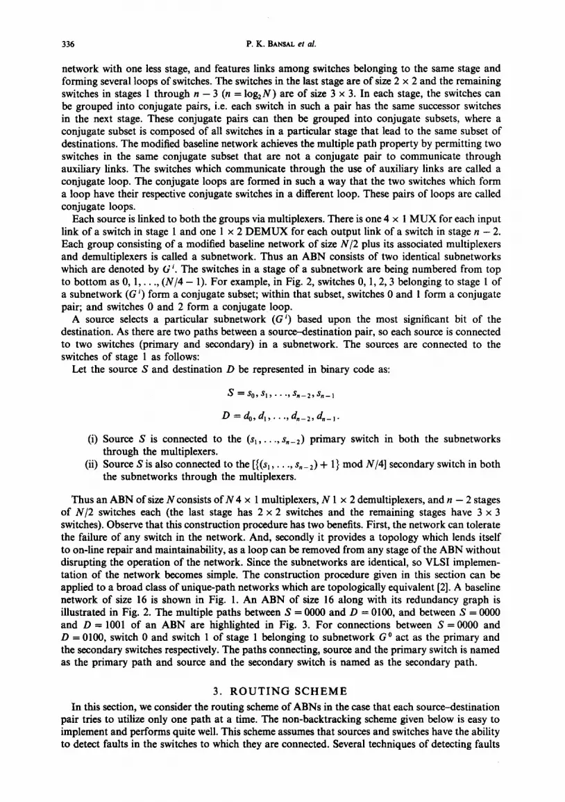
The expression for the upper bound of the ABN reliability is:
RABN - ub(t ) = [1 -- (1 -- e -'tM . ,)2]N/2 . I1 -- ( l - - e -23 -t)2]N/4. (n- 3).
[1 - (1 - e -2~'t)2]N]4
MTTFABN_ ub ---- f : RABN - ub (t)" dt.
5.1.2. Lower bound. At the input side of the ABN, the routing scheme does not consider the multiplexers to be an integral part of a 3 x 3 switch. For example, as long as at least one of the two multiplexers attached to a particular switch is operational, the switch can still be used for routing. Hence, if we group two multiplexers with each switch in the input side and consider them as a series system (SE3m), then we will have a conservative estimate of the reliability of these components. Their aggregated failure rate will be 23m = 4.252. Finally these aggregated components and the switches in the intermediate stages can be arranged in pairs of conjugate loops. To obtain the pessimistic (lower) bound on the reliability of ABN, we assume that the network is failed whenever more than one conjugate loop has a faulty element or more than one conjugate switch in the last stage fails. The reliability block diagram is shown in Fig. 4(b). The expression for lower bound of the ABN is:
RAB N _ ib(t ) = [1 -- (1 -- e -2a~' ,)2]N/S. [1 -- (1 -- e-2"~3t)2] N/s(n-4).
[1 -- (1 -- e-~ut)2] N/4
- Ib = f : RABN - Ib ( t ) " MTTFAeN dt.
5.2. Unique-path baseline network
Although unique-path baseline network is not a fault-tolerant network, we use it as a yardstick to measure the reliability improvement of ABNs. As any single fault leads to a network failure, MTTF for baseline network can be easily calculated as:
MTWFbaseline = f : [e-2t] N/2"n " dt.
The reliability improvement of ABNs over unique-path baseline network, for various network sizes is illustrated by the graph shown in Fig. 5.

342 P .K . BANSAL et al.
6. C O S T - E F F E C T I V E N E S S
We can observe that ABNs can provide higher or at least equal reliability compared to some other fault-tolerant networks. However, if such high reliability comes at the expense of high cost, it may have little value in practice. This section concerns the cost-effectiveness of ABNs.
To estimate the cost of a network, one common method is to calculate the switch complexity with an assumption that the cost of a switch is proportional to the number of gates involved, which is roughly proportional to the number of 'crosspoints' within a switch [3,4]. For example, a 2 x 2 switch has four units of hardware cost, whereas a 3 x 3 switch has nine units. For the multiplexers and demultiplexers, we roughly assume that each of m x 1 multiplexers or 1 x m demultiplexers has m units of cost. Thus an ABN has the cost of N/2(9n - 11).
Now, a simple measure of the cost-effectiveness for reliability can be given by comparing MTTF and the cost of the network. Let the cost-effectiveness, r/, of a network for reliability be the ratio of M T T F to its cost. To highlight the cost-effectiveness of ABNs, the cost-effectiveness of the ABNs and ASEN - 2 [5] relative to that of baseline network (for both upper and lower bounds) are evaluated and compared, and the improvement in results are shown in Fig. 6. From the results, we can observe that ABNs are more cost-effective than most of the other fault-tolerant networks.
Realizing different sizes of switches increases the cost and complexity of an interconnection network in a VLSI environment. But this problem can be solved in ABN, by designing uniform switches (i.e. 3 x 3 switches) for all stages. At first, the switches in the final stage appear to be different in terms of the number of links and also because they are required to report faults in the demultiplexers at their outputs to the switches in the previous stage. However, designing all the
1.0
0.8
0 . 6
Po
Po
0.4
0.2
(a) - - • ABN + Baseline * Crossbar
~.~-- -~ ~ , .
~ + - . _ . . _ ~ O
+
0 I I I I I I 4 5 6 7 8 9 10
Log N
(b) 1.0 -- • ABN + Baseline • Crossbar
+ ~
0 . 8 q,"~
0.6
0.4 --
0.2 --
0 4
I I I I I I 5 6 7 8 9 10
Log N
Fig. 7. (a) Probability of acceptance vs log N-- reques t generation probability of 1.0. (b) Probability of acceptance vs log N - - a request generation probability of 0.5.

On a fault-tolerant multistage intereonneetion network 343
Pa
Pa
1.0
0.8
0.6
0.4
0.2
(a) , • ABN + Baseline * Crossbar
- ~ + ~ + ~ ° ~ . ~ o ~ . ~ - * ~ * + ~ + _ _ ~ e ~ o
0 I I I I I I I I I 0.1 0.2 0.3 0.4 0.5 0.6 0.7 0.8 0.9 1.0
Req u es t gene ra t i on p r o b a b i l i t y
(b) 1.0 ~ , ~ , ~ ,
08L ~ . ~ , ~ , ~ + ~ o ~ ~ °6I
0.4 + ~
• ABN + Baseline * Crossbar o 2
0 0.1
I I I I I I I I I 0.2 0.3 0.4 0.5 0.6 0.7 0.8 0.9 1.0
Reques t g e n e r a t i o n p r o b a b i l i t y
Fig. 8. (a) Probability of acceptance vs request generation probability for N = 256. (b) Probability of acceptance vs request generation probability for N = 1024.
switches in such a way that they report themselves to be faulty whenever their auxiliary link and at least one other output link leads to faulty switches, and then permanently assuming the auxiliary output links of the switches used in the final stage to the faulty stage, solves the uniformity problem.
7. P E R F O R M A N C E O F A B N S
The improvement in the performance of ABNs due to the presence of multiple paths is discussed in this section. The measure of the performance of a MIN is the probability of acceptance (Pa) of a request submitted by a source, i.e. the probability that a request submitted by a source reaches the required destination without getting blocked in the network, given that each source generates a request with a certain probability and aims at the destinations with equal probability.
The results of the performance improvement of ABNs over unique-path baseline networks are shown in Figs 7 and 8. Figure 7(a) and (b) shows the variation ofpa with network size for request generation probabilities of 1.0 and 0.5 respectively. Figure 8(a) and (b) shows the variation Ofpa with the traffic routed through the network for network sizes of 256 and 1024 respectively. The figures for the crossbar networks is also included for comparison.
8. C O N C L U S I O N S
The general goals in designing fault-tolerant multistage interconnection networks are high reliability, good performance even in the presence of faults, low cost, and simple control. In this paper, we proposed and analyzed a class of fault-tolerant multistage interconnection networks,
CAEE 20/4--E

344 P.K. BANSAL et al.
named as Augmented Baseline Networks (ABNs), which can achieve significant tolerance to faults and good performance with relatively low cost and simple control scheme.
The switch-fault model is used to analyze the reliability of ABNs. In our analysis, any switch, any multiplexer, and any demultiplexer in ABNs are assumed to have a possibility to fail. The analysis of the lower and upper bounds of MTTF showed that ABNs perform, in general, more reliably than other fault-tolerant networks. However, if such high reliability comes at the expense of high cost, it may have little value in practice. Our analysis on the cost of networks showed that ABNs are, in general, more cost-effective than other fault-tolerant multistage interconnection networks. Performance study has also been carried out. The figures show that ABNs provide a higher probability of acceptance than those of its counterpart unique-path networks of same size and compare favorably with other fault-tolerant MINs. Obviously, as the number of faults increases, the performance of ABNs decreases. However, for 'light' traffic, such performance degradation is not significant.
R E F E R E N C E S 1. G. B. Adams III, D. P. Agrawal and H. J. Siegel, A survey and comparison of fault-tolerant multistage interconnection
networks. Computer 20, 14-27 (1987). 2. C. Wu and T. Feng, On a class of multistage interconnection networks. IEEE Trans. Comp. 696-702 (1980). 3. J. H. Patel, Performance of processor-memory interconnections for multiprocessors. IEEE Trans. Comp. 30, 771-780
(1981). 4. N. Tzeng, P. Yew and C. Zhu, A fault-tolerant scheme for multistage interconnection networks. 12th Int. Symp.
Computer Architect. 368-375 (1985). 5. V. P. Kumar and S. M. Reddy, Augmented shuffle-exchange multistage interconnection networks. Computer 20, 30-40
(1987).
A U T H O R S ' B I O G R A P H I E S
Dr P. K. Bansal--Dr P. K. Bansal obtained his B.E. degree in Electronics & Communication Engineering from Punjab Engineering College, Chandigarh (Punjab University, Chandigarh) in 1972. He obtained his M.E. and Ph.D. degrees from Electronics and Computer Engineering Department, University of Roorkee, Roorkee in 1979 and 1992 respectively. Presently he is working as Assistant Professor in the Department of Electrical and Electronics Engineering, Thapar Institute of Engineering and Technology, Patiala. He has many research publications to his credit. His research interests include interconnection networks, parallel processing, computer architecture and fault-toleranee.
Dr R. C. Joshi---Dr R. C. Joshi graduated in Electrical Engineering from AUahabad University in 1967. He did his M.E. (Honours) and Ph.D. from Electronics and Computer Engineering Department, University of Roorkee, Roorkee. He joined as a faculty member in Electronics and Computer Engineering Department, University of Roorkee, Roorkee in 1970. Presently he is working as Professor and Head of Department. His fields of interest are artificial intelligence, experts systems, distributed processing and database management systems.
On a fault-tolerant multistage interconnection network 345
Dr Knldip Singh--Dr K. Singh obtained his B.E., M.E. and Ph.D. degrees from the Department of Electronics and Computer Engineering, University of Roorkee, Roorkee. He joined University of Roorkee as Lecturer in the Department of Electronics and Communication Engineering in 1973. He is currently Professor in the Department of Continuing Education and is organizing short term courses on advance topics of current interest for in-service Engineers. He has worked on various projects sponsored by Ministry of Defence and Human Resource Development, Government of India. Dr Singh has many research publications to his credit in National and International journals. His research interests include interconnection network and parallel processing. Presently he is working on the Natural Language Processing Project sponsored by the Department of Electronics.