Embed Size (px)
Citation preview
Epilogue: Some Ideas for Performance- andDisplacement-Based Seismic Design of NewBuildings
We thus have come to the end of a long development on current-generation seismicdesign, assessment and retrofitting of concrete buildings. Its emphasis has been onEN-Eurocode 8, scheduled to become the exclusive standard for earthquake resis-tance in Europe after March 2010. To this point we have focused on the presentsituation, with the aim to help designers apply the relevant parts of EN-Eurocode 8correctly and cost-effectively and to familiarise them with their background.
Part 3 of Eurocode 8, and other international codes for seismic assessment andretrofitting of existing buildings, do reflect the current State-of-the-Art and providea firm basis for codified practice in the foreseeable future. However, this cannotbe claimed with much confidence by seismic design standards for new concretebuildings, including Part 1 of Eurocode 8. Indeed, Section 6.4 noted at its closingthat, once the new ideas for codified seismic assessment and retrofitting becomeestablished through successful application in practice, they are expected to infil-trate codes for seismic design of new buildings as well, marking a reversal of pasttraditions.
Readers who have followed the long development in this book to its conclusionare invited now to follow it one step further, namely to some ideas for a possiblefuture performance- and deformation-based seismic design of new concrete build-ings. Far from being a revolution in the design of concrete buildings for earthquakeresistance, these ideas just aspire to introduce there the current State-of-the-Art, asreflected already in codified seismic assessment and retrofitting of existing buildingsand in Part 3 of Eurocode 8 in particular. As a matter of fact, it is proposed to venturethis in the form of a few measured steps, which preserve or emulate to the largestpossible extent current codified design practice.
The ideas presented below have evolved from the early work of Fardis and Pana-giotakos (1997c) and Panagiotakos and Fardis (1999, 2001c). According to the newproposal buildings are designed to meet all three performance levels:
– Immediate Occupancy,– Life Safety and– Near Collapse
each at the appropriate seismic hazard level, defined through its own 5%-dampedelastic spectrum. The proposed compliance criteria for the three performance levelsare:
695
696 Epilogue
1. Brittle (i.e., shear) failures of members, primary or secondary, and of their con-nections, should be prevented at all three performance levels.
2. At the Immediate Occupancy level, nominal yielding at potential plastic hingesmay be exceeded by a factor with a value around 2, which reflects a presumedoverstrength factor of at least 1.5 in materials and members and certain toleranceof flexural yielding at some sections.
3. At the Life Safety level, a safety margin against the ultimate chord rotation atmember ends should be provided.
4. At the Near Collapse performance level, member ends should stay below theirultimate chord rotations; indeed primary ones should have a margin for modeluncertainty.
The similarity with the Eurocode 8-Part 3 criteria in Table 6.1 for the three LimitStates is clear. The safety elements for the checks in 1 above may be those in Table6.1 for brittle members, primary or secondary. The safety margins in 3 and 4 againstultimate conditions in flexure may also be chosen the same as those in Table 6.1for primary or secondary ductile members at the Significant Damage and the NearCollapse Limit State, respectively. According to the reasoning in the last paragraphof Section 6.5.3, a constant ratio between the chord rotation limits for Life Safetyand Near Collapse (as in Table 6.1) implies that checking them at both these levelsis normally redundant. The Near Collapse level will govern, if the spectral valuesof its own seismic action at the important natural periods of the elastic structure(as determined in Step 5 below with the final effective stiffness values from Step4) clearly exceed those of the Life Safety seismic action by more than the inverseof the constant ratio of chord rotation limits at these levels. Conversely, if they areclearly less. Besides, the shear verifications are carried out only once. So, in the endthe three-tier design normally reduces to single-tier design for shear and a two-tierone for flexure.
The design procedure may comprise the following steps:
Step 1 – Conceptual design and sizing of members: Select the structurallayout following as closely as possible the guidance in Sections 2.1.3–2.1.13.Make sure that there is sufficient torsional stiffness to meet Eq. (2.4) in Sec-tion 2.1.6, and indeed with a margin. Size the members according to thefollowing, for fruition of Step 7:
– In each one of the two horizontal directions vertical members of the samefamily (i.e., walls or columns) should have as uniform a cross-sectionaldepth as possible. If the rotational restraint of members by others in theconsidered horizontal direction varies among members of the same family,those restrained more by others may be chosen with smaller depth than therest.
– The beam depth should be uniform all-along any plane frame, but may besmaller in frames with shorter spans than in others with longer ones.
Epilogue 697
– The beam depth should be gradually reduced from the base to the roof ofthe building.
Column sections should accommodate the intended beam bar sizes accordingto the relevant bond criteria, such as Eqs. (5.10) in Section 5.4.1.
Step 2 – Design for non-seismic actions: Dimension the reinforcement of allmembers on the basis of the Ultimate and the Serviceability Limit Statesfor all pertinent non-seismic actions (gravity loads, wind, etc.), taking intoaccount the minimum reinforcement requirements for structures withoutearthquake resistance. Redistribute beam ULS moments from supports tomid-span(s) or vice-versa, as appropriate and optimal in design for non-seismic actions.
Step 3 – Capacity Design against storey-sway mechanisms. Unless the wallsin a horizontal direction of the building are considered sufficient to precludea storey-sway mechanism, determine the vertical reinforcement of columnsto satisfy Eq. (1.4) in that direction, using there the beam moment resistancesresulting from earlier steps.1 Base this calculation on the axial force due togravity loads concurrent with the seismic action.
Step 4 – Member effective stiffness: Estimate the member effective stiffness(secant to yield-point) for the seismic action, (EI)eff:
– If this is the first time this step is carried out (see Step 8 for the itera-tions), use empirical expressions independent of the amount and layoutof longitudinal reinforcement (e.g., Eq. (3.69) in Section 3.2.3.3). Checkthe result against the outcome of Eq. (3.68), averaged at the (two) end(s)where a plastic hinge might form and for both directions of bending, usingthe longitudinal reinforcement from Steps 2 and 3. Adopt the larger of thetwo (EI)eff-values: from Eq. (3.68) or (3.69). In these calculations use avalue for the shear span at member ends according to the guidance inSection 4.10.1.4 (summarised also at point 2 of Section 4.10.5.1 and inSection 6.5.4.2). Use judgement to revise upwards the estimates from Eq.(3.69) in those vertical members (especially walls) which are expected tocome out of Step 7 with heavy longitudinal reinforcement.
– If the present step is carried out after Step 7 in the context of iterationstowards convergence of the stiffness values, calculate (EI)eff only from Eq.(3.68). To accelerate convergence, especially if different walls or columnshave different cross-sectional depth, use as shear span, Ls , in Eqs. (3.66),(3.68) the value of the moment-to-shear ratio from the seismic analysis inStep 5 at the end of the member where the moment is largest. Adopt thebeam effective flange width suggested in Section 4.10.5.1 and count itsbars into the beam top reinforcement.
1 This step may be revisited in the framework of iterations involving Steps 3–7 (see Step 8).
698 Epilogue
Use throughout the step the axial force values due to the gravity loads con-current with the seismic action, as well as mean values of material propertiesestimated from nominal strengths.
Step 5 – Linear analysis for the Immediate Occupancy seismic action:Carry out a modal response spectrum analysis for the seismic action forwhich Immediate Occupancy performance is desired, using its 5%-dampedelastic spectrum and the estimates of effective stiffness from Step 4. Combinemodal contributions through the CQC rule (Eq. (4.11) in Section 4.4.3) andthe effects of individual seismic action components through Eq. (4.24) inSection 4.7.1.
Step 6 - Demand-capacity ratios for the Immediate Occupancy seismicaction: Calculate the ratio of:
– the elastic moment demand, D, taken equal to the seismic moment fromStep 5 plus the one due to the concurrent gravity loads, to
– the corresponding design resistance, C,
at any section where a primary member is connected to another one havingstiffness in a plane of bending normal to the vector of the moment in question.Use design values of material strengths (nominal ones divided by the partialfactor for the material) for the design value of moment resistance.
Step 7 - Tailoring of flexural capacities to demands for uniformly dis-tributed inelasticity: Increase the longitudinal reinforcement at all locationswhere plastic hinges are intended to develop, so that their D/C ratios are asuniform as possible:
– within families of such locations, notably:
� the wall base sections in wall and dual systems,� the column base sections in frame and dual systems,� the end sections of primary beams connected to stronger columns (i.e.,
whose sum of moment resistances above and below a joint exceeds thecorresponding sum in the beams framing into the joint), and
� the end sections of primary columns connected to stronger beams (i.e.,whose sum of moment resistances across the joint exceeds that of thecolumns above and below the same joint), as well as
– between different families, as relevant.
According to the compliance criterion for the Immediate Occupancy per-formance level (criterion no. 2 above), the target D/C-value in each familyis (around) 2. However, important plastic hinge locations may have comeout of Step 5 with D/C values markedly below this target. If the C-value atsuch a location is governed by Step 2, it cannot be reduced to increase D/Ctowards the target value of 2.0. Unless such low D/C values are sporadic anddo not cast doubt about the prevailing plastic mechanism, we may go ahead to
Epilogue 699
achieve the target D/C-value at these locations by raising the seismic actionfor Immediate Occupancy performance (and of course the capacities at allother locations, so that D/C ≈ 2 there under the increased seismic hazardlevel).
Step 8 – Iterations with updated stiffness values. Repeat Steps 3–7, usingeverywhere the longitudinal reinforcement from Step 7. The change in stiff-ness may change the demands and partly undo the harmonisation achievedin Step 8. So iterations may be needed through Steps 3–7 until satisfactoryconvergence. Depending on the progress towards convergence, we may haveto overshoot in Step 7 (i.e., increase the low C-values more than required forthe target D/C-value), in order to harmonise in the end the D/C values overall potential plastic hinges.
Step 9 – Capacity Design of force-controlled mechanisms: Derive throughcapacity design calculations (as in Section 6.5.5) the shear force demandsin all members or joints, the seismic internal forces in the foundation sys-tem and the forces transferred to the ground, using the final longitudinalreinforcement in all relevant members. Verify shear force demands againstcapacities derived according to the pertinent parts of Chapter 5 (Sections5.4.2, 5.5, 5.7.2.3, 5.7.3.4 and 5.7.4.2, as relevant), using design values ofmaterial properties (nominal strengths divided by partial factor for the mate-rial) for primary members and mean values for secondary ones (cf. Table6.1). Verify the entire foundation system and the ground at the UltimateLimit State (ULS) for the forces derived in this step via capacity design.Increase member dimensions that turn out to be insufficient (including plandimensions of foundation elements) and repeat Steps 2–9 as necessary.
Step 10 – Analysis for the Life Safety or/and the Near Collapse seismicactions. Determine the chord rotation demands at all member ends due tosimultaneous horizontal components of the Life Safety or the Near Collapseseismic action, whichever seems most critical according to the criteria in thelast paragraph before the description of Step 1 above. Thanks to Steps 3, 7and 9, modal response spectrum analysis may well be used, with the 5%-damped elastic spectrum of the seismic action in question. If this spectrum isproportional to that of the Immediate Occupancy action over the range of nat-ural periods considered, seismic action effects from Step 5 are scaled-up bythat proportionality constant and added to those due to the concurrent gravityloads. Alternatively, nonlinear dynamic (response-history) analysis may becarried out both for the Life Safety and the Near Collapse seismic actions,following the guidance in Sections 4.6.2, 4.10.1 and 6.5.4.2, using in themodel mean values of material properties estimated from nominal strengths.
Step 11 – Member detailing for the required chord rotation capacities:Upgrade the chord rotation capacities of members to meet the correspondingcriteria of Table 6.1. To this end, wherever these criteria are violated:
a. increase the bottom reinforcement, if the member is a beam (see term ω′
in Eqs. (3.78)); and/or
700 Epilogue
b. increase the confining reinforcement ratio, ρsx , over an appropriate lengthnear the end in question (see exponent of the 2nd term before the last onein Eqs. (3.78)); and/or
c. replace part of any “web“ reinforcement distributed between the tensionand the compression one with a smaller total amount of tension pluscompression reinforcement, to increase ω2 in Eqs. (3.78) and reduce ω1
(which is the sum of the tension and “web“ reinforcement) while keepingthe yield moment, My , and the stiffness to yield-point, (EI)eff, unchanged;and/or
d. if the member is a column which is squat in a single plane of bending, ora short beam, add diagonal reinforcement (preferably by replacing part ofthe longitudinal one, to avoid increasing My and (EI)eff); and/or
e. increase the width of the web, bw, if it is small compared to the sectiondepth, h (see term involving h/bw in Eq. (3.78c)); in rectangular sectionsthis will also increase the width of the compression zone, b, and reducethe axial load ratio, ν, which is based on normalisation by bh.
Measures (a) and (e) above unavoidably increase My and (EI)eff. Normallythe increase is minor and does not warrant re-visiting any previous steps, pro-vided that Eq. (1.4) has been met in Step 3 with a margin. The same applies toany other measure involving the longitudinal reinforcement, if care has beentaken not to increase My and (EI)eff. Anyway, such an increase is safe-sided,thanks to co-lateral reductions of the seismic chord rotation demands fromStep 10.Implementation of measures (a)–(e) can best be served by Eqs. (3.78), whichreflect in an uncoupled and multiplicative fashion each one of the designparameters that may be changed (ω2, ω1, ρsx , ρd , h/bw), as well as anyparameter that varies during the response (notably, the shear span and theaxial load, Ls and N). Recall that a nonlinear dynamic analysis carried outfor the purposes of Step 10 gives the average and the maximum – acrossthe suite of time-histories – of the largest value of the ratio of chord rota-tion demand to capacity, as both vary during each response-history at themember end in question (flexural damage ratio).2 Note also that the termsinvolving any design parameter to be changed in the framework of measures(a)–(e) above appear separately and multiplicatively in the denominator ofthe flexural damage ratios and have the same value at the considered memberend across the response-histories. By contrast, the terms involving N and Ls
have different values in each response-history, namely the ones they assumedwhen the flexural damage ratio was at its largest. But as the flexural damageratio includes in the denominator these latter terms also separately and mul-tiplicatively, its average and maximum value in the suite of time-histories
2 For convenience, demand and capacity may be expressed in terms of the plastic part of chordrotation if Eqs. (3.78b) or (3.78c) are used, or in terms of total chord rotations if Eq. (3.78a) isapplied instead.
Epilogue 701
can be reduced to the desired level by (a combination of) measures (a)–(e)above, without affecting at all the variable terms (those involving N and Ls).So, Step 11 may successfully conclude without re-doing any analysis.
Although it may produce very different designs, the procedure itself differs onlyat few points from that of today’s force-based design with a behaviour factor, q:
1. In conceptual design it includes two explicit goals:
� The requirement to meet Eq. (2.4), as there is no q-factor anymore to penalisethe structural system for torsional sensitivity.
� The goal of uniform cross-sections among walls or columns and of smoothreduction of beam depths with decreasing average span of the frame and fromthe base to the roof. This is to promote the most important feature of thedesign procedure, notably the effort to prevent overstrengths and promoteuniform inelastic deformation demands in potential plastic hinges (see point3 below).
2. In order to realistically estimate seismic displacements and deformations, theanalysis uses a secant to yield-point stiffness (from Steps 5 and 8), which ismuch more representative than the default value of current codified force-baseddesign.
3. Although Steps 5–7 may look like blind force-based design with a force-reductionfactor of 2 for the Immediate Occupancy seismic action (i.e. with a q-factor of2 times the ratio of Life Safety to Immediate Occupancy seismic actions, or,in Eurocode 8 terminology, times the ratio of the design seismic action to thedamage limitation one), in reality their goal is to prevent overstrength at potentialplastic hinges and ensure uniform distribution of inelastic deformation demandsthere at all seismic action levels of interest. Steps 5–7 are repeated until thisgoal is met to a satisfactory degree. Note also that what appears as an effectiveq-factor of 2 on the Immediate Occupancy seismic action is applied on the sumof its effects to those of the concurrent gravity loads, and not on the ImmediateOccupancy action alone.
4. In current force-based seismic design any member end section is dimensionedat the ULS in bending once, for the most adverse effect between those producedfrom the factored non-seismic actions or from the combination of the design seis-mic action and the concurrent gravity loads.3 By contrast, in the above procedureULS dimensioning in bending is first carried out in Step 2 for the non-seismicactions and then re-visited in Step 7 for the Immediate Occupancy seismic action.
5. Detailing of members for ductility is based not on opaque prescriptions, but on atransparent explicit verification of inelastic deformation demands against capac-ity limits.
3 Provided that the same partial factors for materials are used in ULS design for non-seismic andfor seismic actions.
References
Aboutaha RS, Engelhardt MD, Jirsa JO, Kreger ME (1996a) Retrofit of concrete columns withinadequate lap splices by the use of rectangular steel jackets. Earthquake Spectra 12(4):693–714
Aboutaha RS, Engelhardt MD, Jirsa JO, Kreger ME (1996b) Seismic retrofit of R/C columnsusing steel jackets. In: Sabnis GM et al. (ed) Seismic Rehabilitation of Concrete Structures.ACI-SP160, American Concrete Institute, Detroit, MI, pp. 59–72
Aboutaha RS, Engelhardt MD, Jirsa JO, Kreger ME (1999) Rehabilitation of shear critical concretecolumns by use of rectangular steel jackets. ACI Struct J 96(1): 68–78
Abrahamson NA, Litehiser JJ (1989) Attenuation of peak vertical acceleration. Bull SeismologSoc Am 79: 549–580
Abrams D (1987) Influence of axial force variation on flexural behavior of reinforced concretecolumns. ACI Struct J 84(3): 246–254
ACI (2003) ACI 440.IR-03 – Guide for the design and construction of concrete reinforced withFRP bars. ACI Committee 440, American Concrete Institute, Farmington Hills, MI
ACI (2008) Building code requirements for structural concrete and commentary. American Con-crete Institute, Farmington Hills, MI
ACI Committee 408 (2001) Splice and development length of high relative rib area reinforcingbars. American Concrete Institute, Farmington Hills, MI
ACI Committee 440 (2002) Guide for the design and construction of externally bonded FRP sys-tems for strengthening concrete structures. American Concrete Institute, Farmington Hills,MI
ACI-ASCE Committee 352 (1988) Recommendations for design of slab-column connections inmonotonic reinforced concrete structures. ACI Struct J 85(6): 675–696
AIJ (1992) AIJ standard for structural calculation of reinforced concrete structures, ArchitecturalInstitute of Japan, Tokyo
AIJ (1994) AIJ structural design guidelines for reinforced concrete buildings, Architectural Insti-tute of Japan, Tokyo
Aktan A, Pecknold D, Sozen MA (1974) R/C column earthquake response in two dimensions.ASCE J Struct Div 100(ST10): 1999–2015
Alca N, Alexander SDB, MacGregor JG (1997) Effect of size on flexural behavior of high-strengthconcrete beams. ACI Struct J 94(1): 59–66
Alcocer SM (1992) Rehabilitation of RC frame connections using jacketing. 10th World Confer-ence on Earthquake Engineering, Madrid, Balkema, Rottterdam, pp. 5235–5240
Alcocer SM, Jirsa JO (1993) Strength of reinforced concrete frame connections rehabilitated byjacketing. ACI Struct J 90(3): 249–261
Ambraseys NN, Simpson KA (1996) Prediction of vertical response spectra in Europe. EarthquakeEng Struct Dyn 25(4): 401–412
Anagnostopoulos SA (1972) Nonlinear dynamic response and ductility requirements of buildingstructures subjected to earthquakes. Res. Report R72-54, Department of Civil Engineering,Massachusetts Institute of Technology, Cambridge, MA
703
704 References
ASCE (2003) ASCE/SEI Standard 31-03, Seismic evaluation of existing buildings. AmericanSociety of Civil Engineers, Reston, VA
ASCE (2007) ASCE/SEI Standard 41-06, Seismic rehabilitation of existing buildings (includingSupplement 1). American Society of Civil Engineers, Reston, VA
Ascheim MA, Moehle JP (1992) Shear strength and deformability of RC bridge columns subjectedto inelastic cyclic displacements. Rep. UCB/EERC-92/04, Earthquake Engineering ResearchCenter, University of California, Berkeley, CA
ATC (1988) Rapid visual screening of buildings for potential seismic hazards: A manual. ATC-21Applied Technology Council for the Federal Emergency Management Agency (FEMA Report154), Washington, DC
ATC (1997) NEHRP Guidelines for the seismic rehabilitation of buildings. Applied TechnologyCouncil for the Building Seismic Safety Council and the Federal Emergency ManagementAgency (FEMA Reports 273, 274), Washington, DC
ATC (1998) Evaluation of earthquake damaged concrete and masonry wall buildings. AppliedTechnology Council for the Federal Emergency Management Agency (FEMA Reports 306,307), Washington, DC
Aziz TS (1976) Inelastic dynamic analysis of building frames. Res. Report R76-37, Departmentof Civil Engineering, Massachusetts Institute of Technology, Cambridge, MA
Balazs GL (1989) Bond softening under reversed load cycles. Studi e Ricerche, Politecnico diMilano, No. 11, Milano, pp. 503–524
Balazs GL (1991) Fatigue of bond. ACI Mater J 88(6): 620–629Benjamin JR, Cornell CA (1970) Probability, Statistics and Decision for Civil Engineers. McGraw
Hill, New YorkBigaj A, Walraven JC (1993) Size effect on rotational capacity of plastic hinges in reinforced
concrete beams. Ductility-Reinforcement, CEB Bulletin d’ Information No. 218, pp. 7–23Biskinis DE (2007) Resistance and deformation capacity of concrete members with or without
retrofitting. Doctoral Thesis, Civil Engineering Department, University of Patras, Patras, GRBiskinis DE, Fardis MN (2004) Cyclic strength and deformation capacity of RC members, includ-
ing members retrofitted for earthquake resistance. In: Walraven J et al. (ed) 5th InternationalPh.D Symposium in Civil Engineering, Balkema, Rotterdam, pp. 1125–1133
Biskinis DE, Fardis MN (2007) Effect of lap splices on flexural resistance and cyclic deformationcapacity of members. Beton- und Stahlbetonbau, Sonderheft Englisch 102: 51–59
Biskinis DE, Fardis MN (2009) Upgrading of resistance and cyclic deformation capacity of defi-cient concrete columns. In: Ilki A et al. (ed) Seismic Risk Assessment and Retrofitting, withSpecial Emphasis on Existing Low Rise Structures, Springer Verlag, Heidelberg
Biskinis DE, Roupakias G, Fardis MN (2004) Degradation of shear strength of RC members withinelastic cyclic displacements. ACI Struct J 101(6): 773–783
Bommer JJ, Elnashai AS (1999) Displacement spectra for seismic design. J Earthquake Eng 3(1):1–32
Bosco C, Debernardi PG (1993) Influence of some basic parameters on the plastic rotation ofreinforced concrete elements. Ductility-Reinforcement, CEB Bulletin d’ Information No. 218,pp. 25–44
Bousias SN (1993) Experimental and analytical study of RC columns in cyclic biaxial bendingwith axial force. Doctoral thesis, Civil Engineering Department, University of Patras, Patras,GR
Bousias SN, Fardis MN (1994) Inelastic R.C. section and member model for general biaxial bend-ing with axial force. In: Mang H et al. (ed) EURO-C 1994, Pineridge Press, Swansea, UK, pp.795–804
Bousias SN, Panagiotakos TB, Fardis MN (2002) Modelling of RC members under cyclic biaxialflexure and axial force. J Earthquake Eng 6(3): 213–238
Bousias SN, Fardis MN, Biskinis DE (2005a) Retrofitting of RC columns with deficient lap-splices. In: Balazs GL, Borosnyoi A (eds) fib Symposium: Keep concrete attractive, Budapest,pp. 885–890
Bousias SN, Spathis L-A, Fardis MN (2007a) Seismic retrofitting of columns with lap-splicedsmooth bars through FRP or concrete jackets. J Earthquake Eng 11(5): 653–674
References 705
Bousias SN, Verzeletti G, Fardis MN, Magonette G (1992) Reinforced concrete columns in cyclicbiaxial bending and axial load. 10th World Conference on Earthquake Engineering, Balkema,Rotterdam, pp. 3041–3049
Bousias SN, Verzeletti G, Fardis MN, Gutierrez E (1995) Load-path effects on column biaxialbending with axial force. ASCE Eng Mech J 121(5): 596–605
Bousias SN, Fardis MN, Spathis L-A, Biskinis DE (2005b) Shotcrete or FRP jacketing of con-crete columns for seismic retrofitting. In: Wasti ST, Ozcebe G (eds) Advances in EarthquakeEngineering for Urban Risk Reduction, Springer, Dordrecht, NL, pp. 33–46
Bousias SN, Biskinis DE, Fardis MN, Spathis L-A (2007b) Strength, stiffness and cyclic defor-mation capacity of concrete jacketed members. ACI Struct J 104(5): 521–531
Bousias SN, Spathis L-A, Fardis MN, Papanicolaou CG, Triantafillou TC (2007c) Pseudodynamictests of non-seismically designed RC structures retrofitted with textile-reinforced mortar. In:Triantafillou TC (ed) 8th International Symposium on Fiber Reinforced Polymer Reinforce-ment for Concrete Structures (FRPRCS-8), Patras, GR, paper 17-12
Bracci JM, Kunnath SK, Reinhorn AM (1997) Seismic performance and retrofit evaluation forreinforced concrete structures. ASCE J Struct Eng 123(1): 3–10
BSSC (2003) NEHRP recommended provisions for seismic regulations for new buildings andother structures. Building Seismic Safety Council for the Federal Emergency ManagementAgency (FEMA Rep. 368, 369), Washington, DC
Cairns J (2006) Proposals of fib TG4.5 for bond anchorage in the new fib Model code. federationinternationale du beton, Lausanne
Calvi GM, Grossi V, Magenes G (1994) First report on the characteristics of reinforcing steelavailable in Italy. Univ. di Pavia contribution to 1st PREC8 Topic 1 annual report, Universitadi Pavia, Pavia, IT
Carvalho EC (1995) Prenormative research in support of Eurocode 8. In: Elnashai A (ed)5th SECED Conference: European Seismic Design Practice – Research and Application,Balkema, Rotterdam, pp. 43–50
Carvalho E, Pipa M (1994) Short note on the characteristics of B400 and B500 Tempcorebars produced in Europe and its comparison with Eurocode 8 requirements – Mechani-cal characteristics of reinforced steel bars manufactured in Portugal. LNEC contributionto 1st PREC8 Topic 1 annual report, Laboratorio Nacional de Engenharia Civil (LNEC),Lisbon
Carvalho EC, Coelho E (1997) Numerical investigations on the seismic response of R.C. framesdesigned in accordance with Eurocode 8. ECOEST-PREC8 Rep. 7. Laboratorio Nacional deEngenharia Civil (LNEC), Lisbon
CEB (1970) CEB-FIP International Recommendations for the design and construction of concretestructures: 1 Principles and Recommendations, Bulletin No. 72. Comite Euro-international duBeton, Paris
CEB (1985) CEB Model Code for seismic design of concrete structures, Bulletin No. 165. ComiteEuro-International du Beton, Lausanne
CEB (1988a) Concrete structures under impact and impulsive loading, Bull. d’ Information No.187. Comite Euro-International du Beton, Lausanne
CEB (1988b) General principles on reliability of structures: A commentary on ISO 2394, BulletinNo. 191. Comite Euro-International du Beton, Lausanne
CEB (1991) CEB-FIP Model Code 1990, Bull. d’ Information No. 203/204/205. Comite Euro-International du Beton, Lausanne
CEB (1996a) RC frames under earthquake loading, T. Telford, London, for Comite Euro-international du Beton, Lausanne
CEB (1996b) RC elements under earthquake loading, T. Telford, London, for Comite Euro-international du Beton, Lausanne
CEN (1996) European prestandard ENV 1998-1-4: Eurocode 8: Design provisions for earthquakeresistance of structures, Part 1-4: Strengthening and repair of buildings. Comite Europeen deNormalisation, Brusells
CEN (2002) European Standard EN 1990:2002 Eurocode: Basis of structural design. ComiteEuropeen de Normalisation, Brusells
706 References
CEN (2003) European Standard EN 1997-1:2003 Eurocode 7: Geotechnical design – Part 1: Gen-eral rules. Comite Europeen de Normalisation, Brusells
CEN (2004a) European Standard EN 1998-1:2004 Eurocode 8: Design of structures for earthquakeresistance, Part 1: General rules, seismic actions and rules for buildings. Comite Europeen deNormalisation, Brusells
CEN (2004b) European Standard EN 1992-1-1:2004 Eurocode 2: Design of concrete structures,Part 1-1: General rules and rules for buildings. Comite Europeen de Normalisation, Brusells
CEN (2004c) European Standard EN 1998-5:2004 Eurocode 8: Design of structures for earthquakeresistance, Part 5: Foundations, retaining structures, geotechnical aspects. Comite Europeende Normalisation, Brusells
CEN (2005a) European Standard EN 1998-3:2005 Eurocode 8: Design of structures for earthquakeresistance, Part 3: Assessment and retrofitting of buildings. Comite Europeen de Normalisa-tion, Brusells
CEN (2005b). European Standard EN 1998-2:2005 Eurocode 8: Design of structures for earth-quake resistance, Part 2: Bridges. Comite Europeen de Normalisation, Brusells
Cheung VW, Tso WK (1986) Eccentricity in irregular multistory buildings. Canadian J Civil Eng13(1): 46–52
Chopra A (2007) Dynamics of structures. Theory and applications to earthquake engineering.Prentice Hall, Englewood Cliffs, NJ
Chopra AK, Goel RK (2002) A modal pushover analysis procedure for estimating seismicdemands for buildings. Earthquake Eng Struct Dyn 31(3): 561–582
Chopra AK, Goel RK (2004) A modal pushover analysis procedure to estimate seismic demandsof unsymmetric plan buildings. Earthquake Eng Struct Dyn 33(8): 903–927
Chopra AK, Goel RK, Chintanapakdee C (2004) Evaluation of a modified MPA procedure assum-ing higher modes as elastic to estimate seismic demands. Earthquake Spectra 20(3): 757–778
Clough R, Johnston S (1966) Effect of stiffness degradation on earthquake ductility requirements.Transactions of Japan Earthquake Engineering Symposium, Tokyo, pp. 195–198
Clough RW, Benuska KL, Wilson EL (1965) Inelastic earthquake response of tall buildings. 3rdWorld Conference on Earthquake Engineering, Auckland, NZ, V 11
Coelho E, Carvalho EC (1990) Nonlinear seismic behaviour of reinforced concrete structures. 9thEuropean Conference on Earthquake Engineering, Moscow
Costa AC, Costa AG (1987). Hysteretic model of force-displacement relationships for seismicanalysis of structures. Res. Report, Laboratorio Nacional de Engenharia Civil, Lisbon
Cremer C (2001) Modelisation du comportement nonlineaire des fondations superficiellessous seisme. Macro-element d’interaction sol-structure. These de doctorat, Laboratoire deMecanique et de Technologie de Cachan. ENS Cachan, Paris
Darwin D, Zuo J, McCabe SL (2002a) Descriptive equations for development and splice strengthof straight reinforcing bars. In: Balazs GL et al. (ed) 3rd International Symposium: Bond inConcrete – from Research to Standards, Budapest, pp. 501–508
Darwin D, McCabe SL, Browning J-A, Matamoros A, Zuo J (2002b) Evaluation of developmentlength design expressions. In: Balazs GL et al. (ed) 3rd International Symposium: Bond inConcrete – from Research to Standards, Budapest, pp. 747–754
De Lorenzis L, Tepfers R (2001) A comparative study of models on confinement of concrete cylin-ders with FRP composites. Publ. No. 01/04, Dept. of Building Materials, Chalmers Universityof Technology, Goteborg
Der Kiureghian A (1981) A response spectrum method for random vibration analysis of MDFsystems. Earthquake Eng Struct Dyn 9: 419–435
Dritsos S, Pilakoutas K (1992) Composite technique for repair-strengthening of RC members. 2ndInternational Symposium on Composite Materials and Structures, Beijing University Press,Beijing, pp. 958–963
Eibl J, Keintzel E (1988) Seismic shear forces in cantilever shear walls. 9th World Conference inEarthquake Engineering, Tokyo/Kyoto
Eligehausen R, Lettow S (2007) Formulation of Application Rules for Lap Splices in the New fibModel Code, federation internationale du beton, Stuttgart
References 707
Elnashai AS (1994) Characteristics of reinforcing steel in the United Kingdom. Imperial Collegecontribution to 1st PREC8 Topic 1 annual report, Imperial College of Science, Technologyand Medicine, London, UK
Elnashai AS (2001) Advanced inelastic static (pushover) analysis for earthquake applications.Struct Eng Mech 12(1): 51–69
Elnashai AS, Papazoglou AJ (1997) Procedure and spectra for analysis of RC structures subjectedto strong vertical earthquake loads. J Earthquake Eng 1(1): 121–155
Elsabee G, Kausel E, Roesset JM (1977) Dynamic stiffness of embedded foundations. ASCE 2ndAnnual Engineering Mechanics Division Specialty Conference, pp. 40–43
Elwi AA, Murray DW (1979) A 3D hypoelastic concrete constitutive relationship. ASCE J EngMech Div 105(EM4): 623–641
Elwood KJ, Moehle JP (2001) Shake-table tests on the gravity load collapse of reinforced concreteframes. In: Kabeyasawa T, Moehle JP (eds) 3rd US-Japan Workshop on Performance-BasedEarthquake Engineering Methodology for Reinforced Concrete Building Structures, PEER-2002/02, Pacific Earthquake Engineering Research Center, University of California, Berkeley,CA
Faccioli E, Vanini M, Frassine L (2002) Complex site effects in earthquake ground motion, includ-ing topography. 12th European Conference on Earthquake Engineering, London, paper 844
Fajfar P (2000) A nonlinear analysis method for performance-based seismic design. EarthquakeSpectra 16(3): 573–593
Fajfar P, Marusic D, Perus I (2005) Torsional effects in the pushover-based seismic analysis ofbuildings. J Earthquake Eng 9: 831–854
Fajfar P, Dolsek M, Marusic D, Perus I (2004) Extensions of the N2 method – asymmetric build-ings, infilled frames and incremental N2. In: Fajfar P, Krawinkler H (eds) Performance-BasedSeismic Design Concepts and Implementation, PEER Rep. 2004/05, PEER, University ofCalifornia, Berkeley, CA, pp. 357–368
Fardis MN (1991) Member-type models for the nonlinear seismic response analysis of reinforcedconcrete structures. In: Donea J, Jones PM (eds) Experimental and Numerical Methods inEarthquake Engineering, Kluwer Academic Publishers, Dordrecht, NL, pp. 247–280
Fardis MN (1997) Chaper 9: Reinforced concrete structures. In: Beskos D, Anagnostopoulos SA(eds) Computer Analysis and Design of Earthquake Resistant Structures – A Handbook. Com-putational Mechanics Publications, Southampton, pp. 441–532
Fardis MN (1998) Seismic assessment and retrofit of RC structures. In: Bisch P et al. (ed) InvitedLectures, 11th European Conference on Earthquake Engineering, Paris, Balkema, Rottterdam,pp. 131–150
Fardis MN (2000) Design provisions for masonry-infilled RC frames. 12th World Conference onEarthquake Engineering, Auckland, NZ, paper 2553
Fardis MN (2001) Displacement-based seismic assessment and retrofit of reinforced concretebuildings. In: Bosch K et al. (ed) Seismic Assessment and Upgrading of Existing Structures,20th European Regional Earthquake Engineering Seminar, European Association of Earth-quake Engineering, pp. 67–86
Fardis MN (2004) A European Perspective for Performance-Based Seismic Design, In: Fajfar P,Krawinkler H (eds) Performance-Based Seismic Design Concepts and Implementation, PEERRep. 2004/05, PEER, University of California, Berkeley, CA, pp. 1–13
Fardis MN, Buyukozturk O (1979) A shear transfer model for reinforced concrete. ASCE J EngMech Div 105(EM2): 255-275
Fardis MN, Khalili HH (1981) Concrete encased in fiberglass-reinforced plastic. ACI J 78(6):440–446
Fardis MN, Khalili HH (1982). FRP-encased concrete as a structural material, Mag Concr Res34(121): 191–202
Fardis MN, Kosmopoulos A (2007) Practical implementation of seismic assessment method inEurocode 8 – Part 3, with linear or nonlinear analysis and deformation-based verificationusing empirical chord rotation capacity expressions. 6th National Conference on EarthquakeEngineering, Istanbul, Vol. 3, pp. 69–101
708 References
Fardis MN, Panagiotakos TB (1996) Hysteretic damping of reinforced concrete elements, 11thWorld Conference on Earthquake Engineering, Acapulco, MX, paper 464
Fardis MN, Panagiotakos TB (1997a) Seismic design and response of bare and infilled reinforcedconcrete buildings – Part I: Bare structures. J Earthquake Eng 1(1): 219–256
Fardis MN, Panagiotakos TB (1997b) Seismic design and response of bare and infilled reinforcedconcrete buildings – Part II: Infilled structures. J Earthquake Eng 1(3): 473–503
Fardis MN, Panagiotakos TB (1997c) Displacement-based design of RC buildings: Proposedapproach and application. In: Fajfar P and Krawinkler H (eds) Seismic Design Methodologiesfor the Next Generation of Codes, Balkema, Rotterdam, pp. 195–206
Fardis MN, Skouteropoulou A-M, Bousias SN (1987) Stiffness matrix of free-standing helicalstairs. ASCE J Struct Eng 113(1): 74–87
Fardis MN, Bousias SN, Franchioni G, Panagiotakos TB (1999a) Seismic response and design ofRC structures with plan-eccentric masonry infills. Earthquake Eng Struct Dyn 28: 173–191
Fardis MN, Negro P, Bousias SN, Colombo A (1999b) Seismic design of open-story infilled RCbuildings. J Earthquake Eng 3(1): 173–198
Fardis MN, Panagiotakos TB, Biskinis DE, Kosmopoulos A (2003) Seismic assessment of exist-ing RC buildings. In: Wasti ST, Ozcebe G (eds) Seismic Assessment and Rehabilitation ofExisting RC Buildings, Kluwer Academic Publishers, Dordrecht, NL, pp. 215–244
Fardis MN, Biskinis DE, Kosmopoulos AJ, Bousias SN, Spathis L-A (2005) Seismic retrofittingtechniques for concrete buildings. In: Fardis MN, Negro P (eds) SPEAR Workshop – An Eventto Honour the Memory of J Donea. EUR 21768 EN, European Commission, JRC, Ispra, IT,pp. 229–240
fib (2001) Externally bonded FRP reinforcement for RC structures, fib Bulletin 14, Lausannefib (2003) Seismic assessment and retrofit of RC buildings, fib Bulletin 24, Federation Interna-
tionale du Beton, Lausannefib (2006) Retrofitting of concrete structures through externally bonded FRPs, with emphasis on
seismic applications, fib Bulletin 35, Federation Internationale du Beton, Lausannefib (2007) FRP Reinforcement in RC Structures, fib Bulletin 40, Federation Internationale du
Beton, Lausannefib (2008) A practitioner’s guide to computer-based modelling of structural concrete. Bulletin No.
45, Federation Internationale du Beton, LausanneFilippou FC, Issa A (1988) Nonlinear analysis of reinforced concrete frames under cyclic load
reversals. Rep. UCB/EERC 88-12, Earthquake Engineering Research Center, University ofCalifornia, Berkeley, CA
Frankel A, Mueller C, Barnhard T, Perkins D, Leyendecker EV, Dickman N, Hanson S, HapperM (1996) National seismic hazard maps: Documentation, USGS Open-file Report 96–532,Denver, CO
Frankel A, Mueller C, Barnhard T, Perkins D, Leyendecker EV, Dickman N, Hanson S, HapperM (1997) Seismic hazard maps for the conterminus United States, USGS Open-file Report97–131, Denver, CO
French CW, Schultz AE (1991) Minimum available deformation capacity of reinforced concretebeams. In: Ghosh SK (ed) ACI Special Publication SP127, American Concrete Institute,Detroit, MI, pp. 363–410
Fujikake K, Mindess S, Xu H (2004) Analytical model for concrete confined with fiber-reinforcedpolymer composite. ASCE J Composite Construct 3(3): 143–150
Garstka B (1993) Untersuchungen zum Trag- und Schadigungsverhalten StabformigerStahlbetonbauteile mit Berucksichtigung des Schubeinflusses bei Zyklischer NichtlinearerBeanspruchung. Dissertation, Ruhr-Universitat Bochum, Bochum, DE
Gasparini DA, Vanmarcke EH (1976) Simulated earthquake motions compatible with prescribedresponse spectra. Res. Report R76-4, Department of Civil Engineering, Massachusetts Insti-tute of Technology, Cambridge, MA
Gazetas G, Anastasopoulos I (2007) Overturning of buildings in Adapazari during the 1999Kocaeli earthquake. 6th National Earthquake Engineering Conference, Istanbul, Vol. 3, pp.43–49
References 709
Ghobarah A, Biddah A, Mahgoub M (1997) Rehabilitation of reinforced concrete columns usingcorrugated steel jacketing. J Earthquake Eng 1(4): 651–673
Giannakas A, Patronis D, Fardis MN (1987) Influence of location and size of openings on elasticstiffness of infill walls. 8th Greek Concrete Conference, Kavala, Greece, Vol. II, pp. 49–56
Giberson MF (1967) The response of nonlinear multi-story structures subjected to earthquakeexcitation. Ph.D. Thesis, California Institute of Technology, Pasadena, CA
Gupta AK, Singh MP (1977) Design of column sections subjected to three components of earth-quake. Nucl Eng Des 41: 129–133
Gupta B, Kunnath SK (2000) Adaptive spectra-based pushover procedure for seismic evaluationof structures. Earthquake Spectra 16(2): 367–392
Horvath JS (1983) Modulus of subgrade reaction: new perspective. ASCE J Geotech Eng Div109(GT12): 1567–1587
Huang Z, Engstrom B, Magnusson J (1996) Experimental and analytical studies of the bondbehaviour of deformed bars in high strength concrete. 4th International Symposium on theUtilization of High Strength/High Performance Concrete, Vol. 3. Laboratories des Ponts etChaussees, Paris.
ICBO (1997) Uniform Building Code. International Conference of Building Officials, Whitier, CAICC (2006) International Building Code. International Code Council, Falls Church, VAImai K, Korenaga T, Takiguchi K (2005) Compressive properties of concrete and flexural strength
around critical section of reinforced concrete members. AIJ J Struct Construct Eng 587: 189–196
Inoue S, Tanabe A (2006) Seismic performance improvement of reinforced concrete columns bypartial prestressing, 2nd fib Congress, Napoli, paper 9–35
Izzuddin BA, Elnashai AS (1989) ADAPTIC: A program for the adaptive dynamic analysis ofspace frames. Rep. ESEE-89/7, Imperial College Imperial College of Science, Technologyand Medicine, London, UK
JBDPA (1977) Standard for evaluation of seismic capacity and guidelines for seismic retrofitdesign of existing reinforced concrete buildings. Japan Building Disaster Prevention Asso-ciation (revised 1990), Tokyo
JBDPA (1999) Seismic retrofit design and construction guidelines for existing reinforced concreteand steel encased reinforced concrete buildings using continuous fibre reinforcing materials.Japan Building Disaster Prevention Association, Tokyo.
JCI (2007) Seismic rehabilitation of concrete structures. In: Sugano S (ed) International Publica-tion Series IPS-2, American Concrete Institute, Farmington Hills, MI
JPCEA (2002) Seismic design code for prestressed concrete structures. Japan Prestressed ConcreteEngineering Association, Tokyo
JSCE (1997) Recommendation for design and construction of concrete structures using continuousfibre reinforcing materials. Research Committee on Continuous Fiber Reinforcing Materials,Japan Society of Civil Engineers, Tokyo
JSCE (2001). Recommendations for upgrading of concrete structures with use of continuous fibersheets. In: Maruyama K (ed), JSCE 292 Committee on Concrete Structures with ExternallyBonded Continuous Fiber Reinforcing Materials, Japan Society of Civil Engineers, Tokyo
Kaba S, Mahin SA (1984) Refined modeling of reinforced concrete columns for seismic analysis.Rep. UCB/EERC 84-3, Earthquake Engineering Research Center, University of California,Berkeley, CA
Kakaletsis DJ, Karayannis CG (2008) Influence of masonry strength and openings on infilled RCframes under cyclic loading. J Earthquake Eng 12(2): 197–221
Kaku T, Asakusa H (1991) Bond and anchorage of bars in reinforced concrete beam-column joints.ACI Special Publication SP123, American Concrete Institute, Detroit, MI pp. 401–424
Karbhari VM, Chin JW, Dunston D, Benmokrane B, Juska T, Morgan R, Lesko JJ, Sorathia U,Reynaud D (2003) Durability gap analysis for fiber-reinforced polymer composites in civilinfrastructure. ASCE J Composite Construct 7(3): 238–247
Karsan DI (1968) Behavior of plain concrete under variable load histories. Ph.D. Thesis, RiceUniversity, Houston, TX
710 References
Kausel E, Roesset JM (1975) Dynamic stiffness of circular foundations, ASCE J Eng Mech Divi-sion l01(EM6): 771–785
Keintzel E (1990) Seismic design shear forces in reinforced concrete cantilever shear wall struc-tures. European J Earthquake Eng 3(1): 7–16
Kitayama K, Otani S, Aoyama H (1991) Development of design criteria for RC interior beam-column joints. ACI Special Publication SP123, American Concrete Institute, Detroit, MI, pp.97–124.
Kosmopoulos AJ, Fardis MN (2004) Seismic testing of 3-storey full-scale torsionally unbalancedRC structure: Pre-test predictions, design and analyses of retrofitting. In: Walraven J et al. (ed)5th International Ph.D Symposium in Civil Engineering, Balkema, Rotterdam, pp. 1115–1123
Kosmopoulos AJ, Fardis MN (2006) Seismic evaluation of strongly irregular and torsionallyunbalanced concrete buildings, 2nd fib Congress, Napoli, paper 9–14
Kosmopoulos AJ, Fardis MN (2007) Estimation of inelastic seismic deformations in asymmetricmultistory RC buildings. Earthquake Eng Struct Dyn 36(9): 1209–1234
Kosmopoulos AJ, Fardis MN (2008) Simple models for inelastic seismic analysis of asymmetricmultistory RC buildings, J Earthquake Eng, 12(5): 704–727
Kosmopoulos A, Bousias SN, Fardis MN (2003) Design and pre-test assessment of 3-storeytorsionally-unbalanced RC test structure, fib 2003 Symposium: Concrete Structures in SeismicRegions, Athens, GR, paper 123
Kosmopoulos A, Bousias SN, Fardis MN (2007) Seismic Rehabilitation of a Theater Facilityaccording to Eurocode 8 using CFRPs. In: Triantafillou TC (ed) 8th International Symposiumon Fiber Reinforced Polymer Reinforcement for Concrete Structures (FRPRCS-8), Patras,GR, paper 15-8
Kowalsky MJ, Priestley MJN (2000) Improved analytical model for shear strength of circularreinforced concrete columns in seismic regions. ACI Struct J 97(3): 388–396
Kwan AK (1993) Improved wide-column-frame analogy for shear/core wall analysis. ASCE JStruct Eng 119(2): 420–439
Lam L, Teng JG (2003a) Design-oriented stress-strain model for FRP-confined concrete. ConstructBuild Mater 17(6&7): 471–489
Lam L, Teng JG (2003b) Design-oriented stress-strain model for FRP-confined concrete in rect-angular columns. J Reinforc Plast Compos 22(13): 1149–1186
Litton RW (1975) A contribution to the analysis of concrete structures under cyclic loading. Ph.D.Thesis, Department of Civil Engineering, University of California, Berkeley, CA
Ma SM, Bertero VV, Popov EP (1976) Experimental and analytical studies on hysteretic behaviorof reinforced concrete rectangular and T-beams. Rep. EERC 76-2, Earthquake EngineeringResearch Center, University of California, Berkeley, CA
Mahasuverachai M, Powell GH (1982) Inelastic analysis of piping and tubular structures, Rep.UCB/EERC 82-27, Earthquake Engineering Research Center, University of California, Berke-ley, CA
Mainstone RJ (1971) On the stiffnesses and strengths of infilled frames. Proceedings of Institutionof Civil Engineers v 7360s
Mander JB, Priestley MJN, Park R (1988) Theoretical stress-strain model for confined concrete.ASCE J Struct Eng 114(8): 1804–1826
Mark K (1976) Nonlinear dynamic response of reinforced concrete frames. Res. Report R76-38,Department of Civil Engineering, Massachusetts Institute of Technology, Cambridge, MA
Marusic D, Fajfar P (2005) On the inelastic seismic response of asymmetric buildings under bi-axial excitation. Earthquake Eng Struct Dyn 34(8): 943–963
Menegotto M, Pinto PE (1973) Method of analysis for cyclically loaded RC plane frames includingchanges in geometry and non-elastic behaviour of elements under combined normal force andbending. Preliminary Report, International Association of Bridge and Structural Engineering,Vol. 13, pp. 15–22
Millard A (1993) CASTEM 2000 Manuel d’ utilisation. Rapp. CEA-LAMS No. 93/007, Saclay,FR
References 711
Moehle JP (1996) Seismic design considerations for flat-plate construction. ACI Special Publica-tion SP-162, American Concrete Institute, Farmington Hills, MI pp. 1–34
Moehle JP, Kreger ME, Leon R (1988) Background to recommendations for design of reinforcedconcrete slab-column connections. ACI Struct J 85(6): 636–644
Moehle JP, Lynn A, Elwood K, Sezen H (2001) Gravity load collapse of building frames duringearthquakes. PEER Report: 2nd US-Japan Workshop on Performance-based Design Method-ology for Reinforced Concrete Building Structures. PEER Center, Richmond, CA
Mola E, Negro P (2005) Full-scale PsD testing of the torsionally unbalanced SPEAR structure inthe as-built and retrofitted configurations. In: Fardis MN, Negro P (eds) SPEAR Workshop –An event to honour the memory of J Donea. EUR 21768 EN, European Commission, JRC,Ispra, IT, pp. 139–154
Molina FJ, Buchet P, Magonette GE, Hubert O, Negro P (2005) Full-scale bidirectional PsD testingof the torsionally unbalanced SPEAR structure: Method, algorithm and experimental setup,In: Fardis MN, Negro P (eds) SPEAR Workshop – An event to honour the memory of J Donea.EUR 21768 EN, European Commission, JRC, Ispra, IT, pp. 155–172.
Mondkar DP, Powel GH (1975) ANSR-I General Purpose Program for Analysis of StructuralResponse. Rep. UCB/EERC 75-37, Earthquake Engineering Research Center, University ofCalifornia, Berkeley, CA
Monti G, Nuti C (1991) Analytical model of cyclic behaviour of reinforcing bars with inelasticbuckling. Rapp. No. 91/06, Universita di Roma La Sapienza, Roma
Monti G, Liotta MA (2005) FRP-strengthening in shear: tests and design equations. 7th Interna-tional Symposium on Fibre-Reinforced Polymer (FRP) Reinforcement for Concrete Struc-tures (FRPRCS-7), Kansas City, MO
Nakano Y (1995) Damage to buildings due to 1994 Sanriku-harukaoki earthquake. Building Dis-aster 211, Japan Building Disaster Prevention Association, pp. 6–15
Newman K, Newman JB (1971) Failure theories and design criteria for plain concrete. In: Te’eni(ed) Structure, Solid Mechanics and Engineering Design, J. Wiley-Interscience, New York
Newmark NM (1959) A method of computation for structural dynamics, ASCE J Eng Mech Div85: 67–94
Oh BH, Kim SH (2007) Realistic models for local bond stress-slip of reinforced concrete underrepeated loading. ASCE J Struct Eng 133(2): 216–224
Ohta Y, Goto N (1976) Estimation of S-wave velocity in terms of characteristic indices of soil.Butsuri-Tanko 29(4): 34–41
Otani S (1974) Inelastic analysis of R/C frame structures. ASCE J Struct Div 100(ST7):1433–1449
Pan A, Moehle JP (1989) Lateral displacement ductility of reinforced concrete flat plates. ACIStruct J 86(3): 250–271
Panagiotakos TB, Fardis MN (1994) Proposed nonlinear strut models for infill panels. 1st yearprogress report of PREC8 project. University of Patras, Patras, GR
Panagiotakos TB, Fardis MN (1998) Effect of column capacity design on earthquake response ofreinforced concrete buildings. J Earthquake Eng 2(1): 113–145
Panagiotakos TB, Fardis MN (1999a) Estimation of inelastic deformation demands in multistoreyRC buildings. Earthquake Eng Struct Dyn 28: 501–528
Panagiotakos TB, Fardis MN (1999b) Deformation-controlled earthquake resistant design of RCbuildings. J Earthquake Eng 3(4): 495–518
Panagiotakos TB, Fardis MN (2001a) Deformations of RC members at yielding and ultimate. ACIStruct J 98(2): 135–148
Panagiotakos TB, Fardis MN (2001b) Nonlinear modelling of wall uplift and rocking. Report toSAFERR project, University of Patras, GR
Panagiotakos TB, Fardis MN (2001c) A displacement-based seismic design procedure of RCbuildings and comparison with EC8. Earthquake Eng Struct Dyn 30: 1439–1462
Panagiotakos TB, Fardis MN (2003) Performance of RC frame buildings designed for alternativeDuctility Classes according to Eurocode 8 (Final Version, 2003). 5th US-Japan Workshop
712 References
on performance-based earthquake engineering methodology for reinforced concrete buildingstructures. Hakone, Japan
Panagiotakos TB, Fardis MN (2004) Seismic performance of RC frame buildings designed to thethree Ductility Classes of EN1998 (Eurocode 8) or the Greek Codes 2000. Bull EarthquakeEng 2(2): 221–259
Pantazopoulou SJ (1995) Role of expansion on mechanical behavior of concrete. ASCE J StructEng 121(12): 1795–1805
Pantazopoulou SJ (1998) Detailing for reinforcement stability in RC members. ASCE J Struct Eng124(6): 623–632
Pantazopoulou SJ, Bonacci JF (1994) On earthquake resistant RC frame connections. Canadian JCivil Eng 21(2): 307–328
Paolluci R (2002) Amplification of earthquake ground motion by steep topographic irregularities.Earthquake Eng Struct Dyn 31: 1831–1853
Paolluci R (2006) Numerical investigation of 3D seismic amplification by steep topographic pro-files and check of the EC8 topographic amplification coefficients. In: Bouckovalas G (ed)General Report Proceedings of the Athens Workshop, ETC12. Geotechnical Evaluation andApplication of the Seismic Eurocode EC8, National Technical University of Athens, pp.187–191
Park R, Paulay T (1975) Reinforced concrete structures. J. Wiley, New YorkPark YJ, Reinhorn AM, Kunnath SK (1987) IDARC: Inelastic damage analysis of reinforced
concrete frame-shear-wall structures. Technical Report NCEER-87-0008, National Center forEarthquake Engineering Research, State University of New York, Buffalo, NY
Paulay T, Priestley MJN (1992) Seismic design of reinforced concrete and masonry buildings, J.Wiley, New York
Perdikaris P (1980) Stiffness and strength of biaxially tensioned orthogonally reinforced concretepanels subjected to membrane shear. Ph.D Thesis, Civil Engineering Department, CornellUniversity, Ithaca, NY
Perus I, Fajfar P (2005) On the inelastic torsional response of single-storey structures under bi-axial excitation. Earthquake Eng Struct Dyn 34(8): 931–941
Pipa M, Carvalho EC (1994) Reinforcing steel characteristics for earthquake resistant structures.In: Duma G (ed) 10th European Conference on Earthquake Engineering, Balkema, Rotterdam,pp. 2887–2892
Pires FMG (1990) Influencia das paredes de alvbenaria no comportamento de estruturas retic-uladas de betao armado sueitas a accoes horizontais. Res. Report, Laboratorio Nacional deEngenharia Civil, Lisbon
Plumier A, Vangelatou O (1995) Synthesis of the statistical data on reinforcing steel collectedin Europe and comparison to the Eurocode 8 requirements. Internal PREC8 report No. 4,Universite de Liege, Liege, BE
Priestley MJN (1997) Displacement-based seismic assessment of reinforced concrete buildings. JEarthquake Eng, 1(1): 157–192
Reinhorn AM, Kunnath SK, Panahshahi N (1988) Modelling of RC building structures with flex-ible floor diaphragms (IDARC 2). Technical Report NCEER-88-0035, National Center forEarthquake Engineering Research, State University of New York, Buffalo, NY
Restrepo-Posada JI, Park R, Buchanan AH (1993) Seismic behaviour of connections betweenprecast concrete elements. Res. Report 93-3, Department of Civil Engineering, University ofCanterbury, Christchurch, NZ
Rey J, Faccioli E, Bommer JJ (2002) Derivation of design soil coefficients (S) and response spec-tral shapes for Eurocode 8 using the European Strong-Motion Database. J Seismology 6(4):547–555
Richart FE, Brandtzaeg A, Brown RL (1928) A study of the failure of concrete under combinedcompressive stresses, Bulletin 185. University of Illinois Engineering Experimental Station,Champaign, IL
Rosenblueth E (1951) A basis for aseismic design. Ph.D. Thesis, Department of Civil Engineering,University of Illinois, Urbana, IL
References 713
Rosenblueth E, Elorduy J (1969) Response of linear systems to certain transient disturbances, 4thWorld Conference on Earthquake Engineering, Santiago, Chile, A-1 pp. 185–196
Roufaiel MSL, Meyer C (1987) Analytical modeling of hysteretic behaviour of R/C frames. ASCEJ Struct Eng 113(ST3): 429–444
Rowe RE (1970) Current European views on structural safety. ASCE J Struct Div 96(ST3): 461–467
Rutenberg A (1982) Simplified P-Delta analyses for asymmetric structures. ASCE J Struct Div108(ST9): 1995–2013
Rutenberg A, Shtarkaman M, Eisenberger M (1986) Torsional analysis methods for perforatedcores, ASCE J Struct Eng 112(6): 1207–1226
Saadatmanesh H, Ehsani MR, Li MW (1994) Strength and ductility of concrete columns externallyreinforced with fiber composite straps. ACI Struct J 91(4): 434–447
Saatcioglou M (1991) Deformability of reinforced concrete columns. In: Ghosh SK (ed) ACISpecial Publication SP127, American Concrete Institute, Detroit, MI, pp. 421–452
Saiidi M, Sozen MA (1979) Simple and complex models for nonlinear seismic response of R/Cstructures. Civil Engineering Studies, Structural Research Series No. 465, University of Illi-nois, Urbana, IL
Sakai J, Jeong H, Mahin SA (2006) Reinforced concrete bridge columns that re-center followingearthquakes. 8th U.S. National Conference on Earthquake Engineering, San Francisco, CA,paper 1421
SEAOC (1995) Performance based seismic engineering of buildings: Vision 2000. Structural Engi-neers Association of California, Sacramento, CA
SEAOC (1999) Recommended lateral force requirements and commentary. Seismology Commit-tee. Structural Engineers Association of California, Sacramento, CA
Sfakianakis MG, Fardis MN (1991a) Nonlinear finite element for modeling reinforced concretecolumns in three-dimensional analysis. Comput Struct 40(6): 1405–1419
Sfakianakis MG, Fardis MN (1991b) RC column model for inelastic seismic response analysis in3D, ASCE J Eng Mech 117(12): 2770–2787
Sheikh SA, Uzumeri SM (1982) Analytical model for concrete confinement in tied columns.ASCE J Struct Eng 108(ST12): 2703–2722
Shohara R, Kato B (1981) Ultimate strength of reinforced concrete members under combinedloading. IABSE Colloquium – Advanced Mechanics of Reinforced Concrete, Delft, NL, pp.701–716
Skouteropoulou A-M, Bousias SN, Fardis MN (1986) Contribution of curved-in-space free-standing staircases to the lateral stiffness of structures. 8th European Conference on Earth-quake Engineering, Lisbon, Vol. 3, 6.6, pp. 41–48
Skouteropoulou A-M, Bousias SN, Fardis MN (1987) Stiffness of free-standing stairs with 180o
turn. ASCE J Struct Eng 113(12): 2415–2438Smebby W, Der Kiureghian A (1985) Modal combination rules for multicomponent earthquake
excitation. Earthquake Eng Struct Dyn 13(1): pp. 1–12Spoelstra MR, Monti G (1999) FRP-confined concrete model. ASCE J Composite Construct 3(3):
143–150Stafford-Smith B, Girgis AM (1986) Deficiencies in the wide column analogy for shear wall core
analysis. Concr Int 8(4): 58–61Stanescu D, Plumier A (1993) Types of steel available in Belgium – Statistical data, National
Standards. University de Liege contribution to 1st PREC8 Topic 1 annual report, Liege, BEStoppenhagen DR, Jirsa JO, Wyllie LA (1995). Seismic repair and strengthening of a severely
damaged concrete frame. ACI Struct J 92(2): 177–187Stylianidis KC (1985) Experimental investigation of the behaviour of the single-storey infilled
RC frames under cyclic quasi-static horizontal loading (parametric analysis). Ph.D. Thesis,Department of Civil Engineering, Aristotle University of Thessaloniki, Thessaloniki, GR
Suda K, Murayama Y, Ichinomiya T, Shimbo H (1996) Buckling behavior of longitudinal rein-forcing bars in concrete column subjected to reverse lateral loading. 11th World Conferenceon Earthquake Engineering, Acapulco, paper 1753
714 References
Tabbara M, Karam G (2007) Modeling the strength of concrete cylinders with FRP wraps usingthe Hoek-Brown strength criterion. In: Triantafillou TC (ed) 8th International Symposium onFiber Reinforced Polymer Reinforcement for Concrete Structures (FRPRCS-8), Patras, GR,paper 6–12
Takeda T, Sozen MA, Nielsen NN (1970) R/C response to simulated earthquakes. ASCE J StructDiv 96(ST12): 2557–2573
Takiguchi K, Imai K, Mizobuchi T (1997) Compressive strength of concrete around critical sectionof RC column under compression-bending-shear. AIJ J Struct Construct Eng 496: 83–90
Tamuzs V, Tepfers R, Valdmanis V, Sparnins E, Zıle E, Ladnova O (2007). Tests and predictionof the mechanical behaviour of cylindrical concrete specimens confined by composite wrap-ping. In: Triantafillou TC (ed) 8th International Symposium on Fiber Reinforced PolymerReinforcement for Concrete Structures (FRPRCS-8), Patras, GR, paper 6-6
Tassios TP (1984) Masonry infill and R/C walls under cyclic actions. CIB Symposium on WallStructures, Warsaw
Taucer F, Spacone E, Filippou FC (1991) A fiber beam-column element for seismic responseanalysis of reinforced concrete structures. Rep. UCB/EERC 91-17, Earthquake EngineeringResearch Center, University of California, Berkeley, CA
Teng JG, Lam L (2004) Behavior and modelling of Fiber Reinforced Polymer-confined concrete.ASCE J Struct Eng 130(11): 1713–1723
Thermou GE, Elnashai AS (2006) Seismic retrofit schemes for RC structures and local-globalconsequences. J Progr Struct Eng Mater 8(1): 1–15
Thermou GE, Pantazopoulou SJ, Elnashai AS (2007a) Flexural behavior of brittle RC membersrehabilitated with concrete jacketing. ASCE J Struct Eng 133(10): 1373–1384
Thermou GE, Pantazopoulou SJ, Elnashai AS (2007b) Design metholodology for seismic upgrad-ing of substandard RC structures. J Earthquake Eng 11(4): 582–606
Toutanji HA, Han M, Matthys S (2007) Axial load behaviour of rectangular concrete columnsconfined with FRP composites. In: Triantafillou TC (ed) 8th International Symposium onFiber Reinforced Polymer Reinforcement for Concrete Structures (FRPRCS-8), Patras, GR,paper 6–13
Triantafillou TC (1998) Shear strengthening of reinforced concrete beams using epoxy-bondedFRP composites. ACI Struct J 95(2): 107–115
Triantafillou TC, Antonopoulos CP (2000) Design of concrete flexural members strengthened inshear with FRP. ASCE J Composite Construct 4(4): 198–205
Triantafillou TC, Papanicolaou CG (2006) Shear strengthening of RC members with Textile Rein-forced Mortar (TRM) jackets. Mater Struct 39(1): 85–93
Triantafillou TC, Papanicolaou CG, Zisimopoulos P, Laourdekis T (2006) Concrete confinementwith Textile Reinforced Mortar (TRM) jackets. ACI Struct J 103(1): 28–37
Tsiknias T, Pittas M (1992) Strengthening of buildings with shotcrete braces. 1st National Con-ference on Earthquake Engineering and Engineering Seismology, Athens, GR, Vol. B, pp.349–362
Tso WK (1990) Static eccentricity concept for torsional moment estimations. ASCE J Struct Eng116(ST5): 1199–1212
Vidic T, Fajfar P, Fischinger M (1994) Consistent inelastic design spectra: strength and displace-ment. Earthquake Eng Struct Dyn 23: 502–521
Vintzeleou EN (1984) Mechanisms of load transfer along reinforced concrete interfaces undermonotonic and cyclic actions. Doctoral Thesis, Civil Engineering Department, National Tech-nical University, Athens, GR
Vintzileou E, Panagiotidou E (2007) An empirical model for predicting the mechanical propertiesof FRP-confined concrete. In: Triantafillou TC (ed) 8th International Symposium on FiberReinforced Polymer Reinforcement for Concrete Structures (FRPRCS-8), Patras, GR, paper6-4
Viwathanatepa S, Popov E, Bertero VV (1979) Seismic behavior of reinforced concrete beam-column subassemblages. Rep. UCB/EERC-79/14, Earthquake Engineering Research Center,University of California, Berkeley, CA
References 715
Walraven JC (2002) Background document for EN 1992-1-1: Eurocode 2: Design of ConcreteStructures – Chapter 6.2: Shear, Delft University of Technology, Delft, NL
Wang TY, Bertero VV, Popov EP (1975) Hysteretic behavior of reinforced concrete framed walls.Rep. EERC 75-23, Earthquake Engineering Research Center, University of California, Berke-ley, CA
Wilson EL, Der Kiureghian A, Bayo EP (1981) A replacement for the SRSS method in seismicanalysis. Earthquake Eng Struct Dyn 9: 187–194
Xenidis E, Athanatopoulou A, Avramidis IE (1993). Modelling of shear wall cores under earth-quake loading using equivalent frames. In: Moan T et al. (ed) Structural Dynamics – EURO-DYN ’93, Balkema, Rotterdam, pp. 901–910
Yamamoto Y (1993) Strength and ductility of frames strengthened with steel bracing. In OkadaT (ed) Earthquake Resistance of Reinforced Concrete Structures – A Volume Honoring H.Aoyama, Department of Architecture, University of Tokyo, pp. 467–476
Yan Z, Pantelides CP (2006) Fiber-Reinforced Polymer jacketed and shape-modified compressionmembers: II – model. ACI Struct J 103(6): 894–903
Yan Z, Pantelides CP (2007) Design-oriented model for concrete columns confined with bondedFRP jackets or post-tensioned FRP shells. In: Triantafillou TC (ed) 8th International Sym-posium on Fiber Reinforced Polymer Reinforcement for Concrete Structures (FRPRCS-8),Patras, GR, paper 6-1
Yettram AL, Husain HM (1966) Plain-framework method for plates in extension. ASCE J EngMech Div 92(EM1): 157–168
Yoshimura M, Takaine Y, Nakamura T (2004) Collapse drift of R/C columns. In: KabeyasawaT (ed) Development of Performance-Based Design Methodologies, US-Japan Co-operativeResearch on Urban Earthquake Disaster Mitigation, Tokyo, pp. 231–242
Zaharia R, Taucer F, Pinto A, Molina J, Vidal V, Coelho E, Candeias P (2004) Earthquake testingof a full-scale RC flat slab building structure. European Laboratory for Structural Assessment(ELSA), Institute for the Protection and Security of the Citizen, JRC, Ispra, IT
Zarnic R, Tomazevic M (1985) Study of the behaviour of masonry infilled reinforced concreteframes subjected to seismic loading – Part II. Rep. ZRMK/lKPl-85/02, Ljubljana, SI
Zeris CA, Mahin SA (1984) Analysis of reinforced concrete beam-columns under uniaxial excita-tion. ASCE J Struct Eng 114(4): 804–820
Colour Plates
(a) (b)
(c)
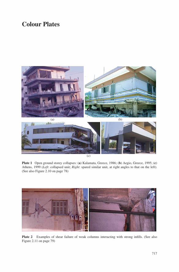
Plate 1 Open ground storey collapses: (a) Kalamata, Greece, 1986; (b) Aegio, Greece, 1995; (c)Athens, 1999 (Left: collapsed unit; Right: spared similar unit, at right angles to that on the left).(See also Figure 2.10 on page 78)
Plate 2 Examples of shear failure of weak columns interacting with strong infills. (See alsoFigure 2.11 on page 79)
717
718 Colour Plates
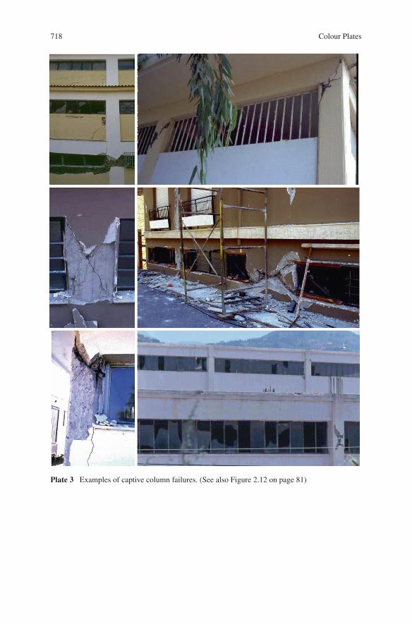
Plate 3 Examples of captive column failures. (See also Figure 2.12 on page 81)
Colour Plates 719
(a) (b) (c)
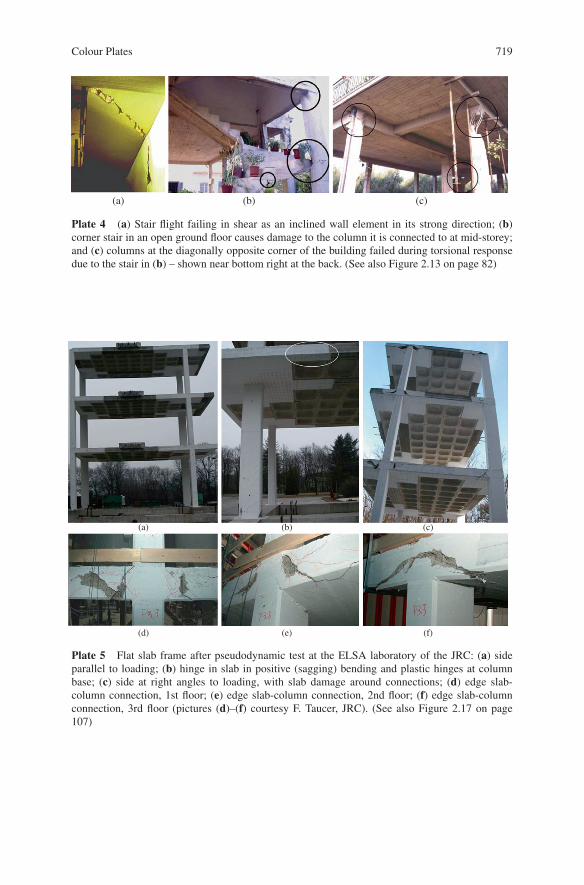
Plate 4 (a) Stair flight failing in shear as an inclined wall element in its strong direction; (b)corner stair in an open ground floor causes damage to the column it is connected to at mid-storey;and (c) columns at the diagonally opposite corner of the building failed during torsional responsedue to the stair in (b) – shown near bottom right at the back. (See also Figure 2.13 on page 82)
(a) (b) (c)
(d) (e) (f)
Plate 5 Flat slab frame after pseudodynamic test at the ELSA laboratory of the JRC: (a) sideparallel to loading; (b) hinge in slab in positive (sagging) bending and plastic hinges at columnbase; (c) side at right angles to loading, with slab damage around connections; (d) edge slab-column connection, 1st floor; (e) edge slab-column connection, 2nd floor; (f) edge slab-columnconnection, 3rd floor (pictures (d)–(f) courtesy F. Taucer, JRC). (See also Figure 2.17 on page107)
720 Colour Plates
(a)
(b)
(c)
(d)
(e)
(f)
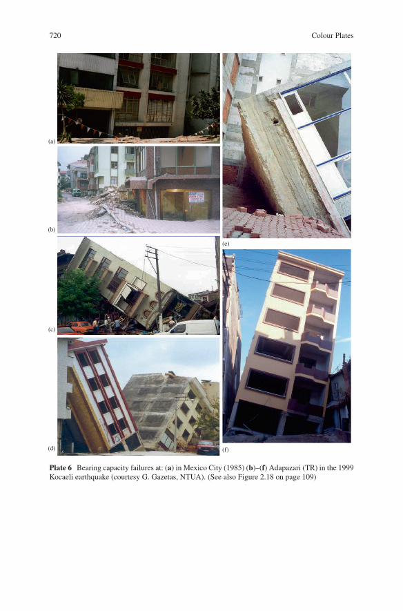
Plate 6 Bearing capacity failures at: (a) in Mexico City (1985) (b)–(f) Adapazari (TR) in the 1999Kocaeli earthquake (courtesy G. Gazetas, NTUA). (See also Figure 2.18 on page 109)
Colour Plates 721
(a) (b) (c)
(d) (e) (f)
(g) (h) (i)
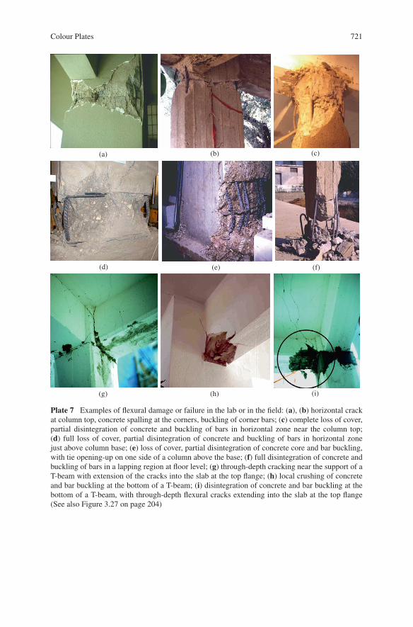
Plate 7 Examples of flexural damage or failure in the lab or in the field: (a), (b) horizontal crackat column top, concrete spalling at the corners, buckling of corner bars; (c) complete loss of cover,partial disintegration of concrete and buckling of bars in horizontal zone near the column top;(d) full loss of cover, partial disintegration of concrete and buckling of bars in horizontal zonejust above column base; (e) loss of cover, partial disintegration of concrete core and bar buckling,with tie opening-up on one side of a column above the base; (f) full disintegration of concrete andbuckling of bars in a lapping region at floor level; (g) through-depth cracking near the support of aT-beam with extension of the cracks into the slab at the top flange; (h) local crushing of concreteand bar buckling at the bottom of a T-beam; (i) disintegration of concrete and bar buckling at thebottom of a T-beam, with through-depth flexural cracks extending into the slab at the top flange(See also Figure 3.27 on page 204)
722 Colour Plates
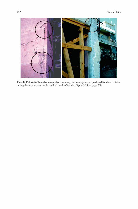
Plate 8 Pull-out of beam bars from short anchorage in corner joint has produced fixed-end rotationduring the response and wide residual cracks (See also Figure 3.29 on page 208)

Colour Plates 723
Plate 9 Shear failures of columns or walls (See also Figure 3.35 on page 252)

724 Colour Plates
(a) (b) (c)
Plate 10 Shear failure of exterior joints. (a) reinforced joint; (b), (c): unreinforced joints (See alsoFigure 3.47 on page 288)
Colour Plates 725
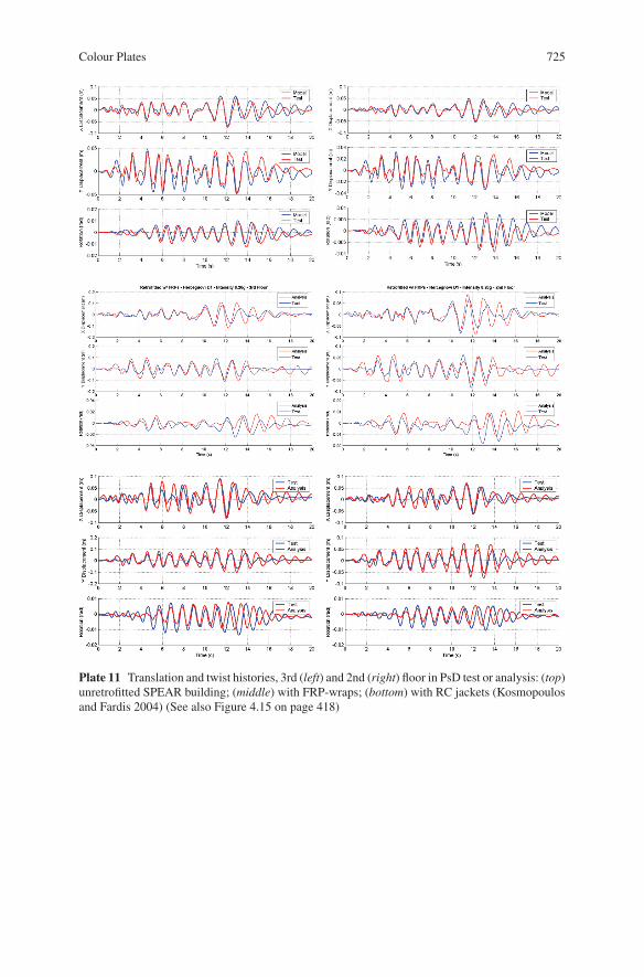
Plate 11 Translation and twist histories, 3rd (left) and 2nd (right) floor in PsD test or analysis: (top)unretrofitted SPEAR building; (middle) with FRP-wraps; (bottom) with RC jackets (Kosmopoulosand Fardis 2004) (See also Figure 4.15 on page 418)
726 Colour Plates
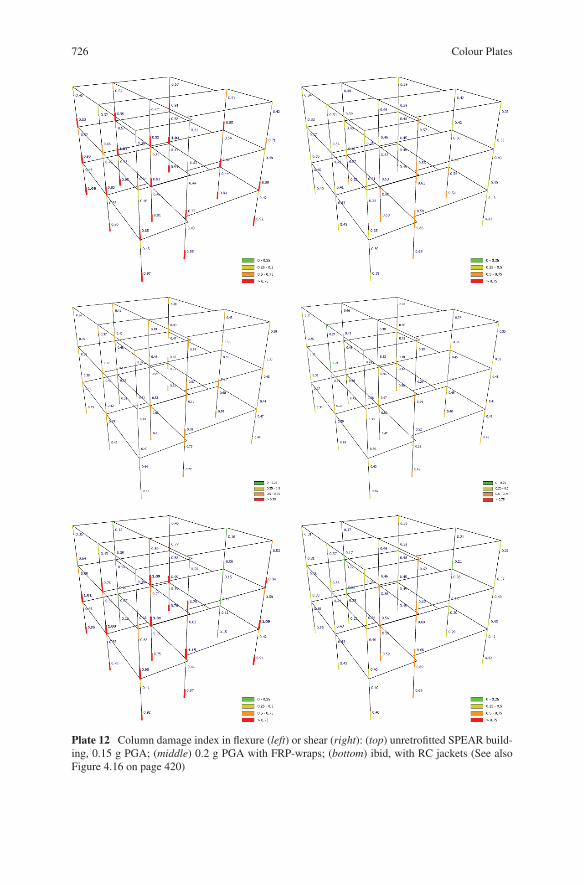
Plate 12 Column damage index in flexure (left) or shear (right): (top) unretrofitted SPEAR build-ing, 0.15 g PGA; (middle) 0.2 g PGA with FRP-wraps; (bottom) ibid, with RC jackets (See alsoFigure 4.16 on page 420)
Colour Plates 727
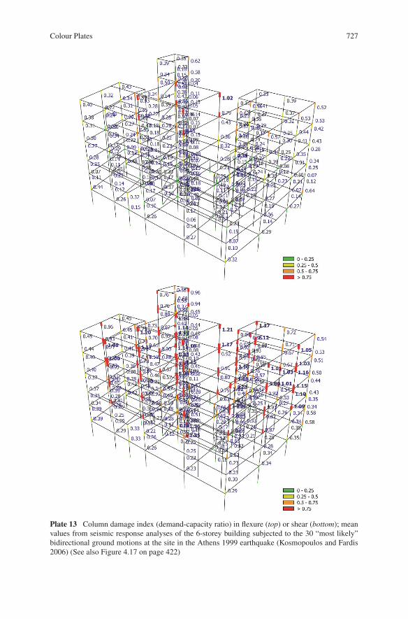
Plate 13 Column damage index (demand-capacity ratio) in flexure (top) or shear (bottom); meanvalues from seismic response analyses of the 6-storey building subjected to the 30 “most likely”bidirectional ground motions at the site in the Athens 1999 earthquake (Kosmopoulos and Fardis2006) (See also Figure 4.17 on page 422)
728 Colour Plates
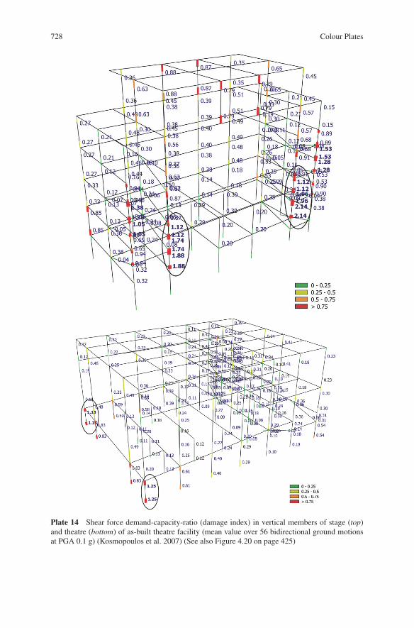
Plate 14 Shear force demand-capacity-ratio (damage index) in vertical members of stage (top)and theatre (bottom) of as-built theatre facility (mean value over 56 bidirectional ground motionsat PGA 0.1 g) (Kosmopoulos et al. 2007) (See also Figure 4.20 on page 425)
Colour Plates 729
(a) (b) (c)
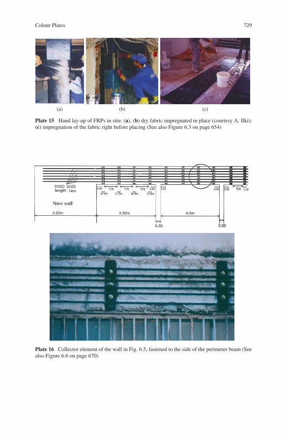
Plate 15 Hand lay-up of FRPs in situ: (a), (b) dry fabric impregnated in place (courtesy A. Ilki);(c) impregnation of the fabric right before placing (See also Figure 6.3 on page 654)
Plate 16 Collector element of the wall in Fig. 6.5, fastened to the side of the perimeter beam (Seealso Figure 6.6 on page 670)
730 Colour Plates
(a)
(b)
(c)
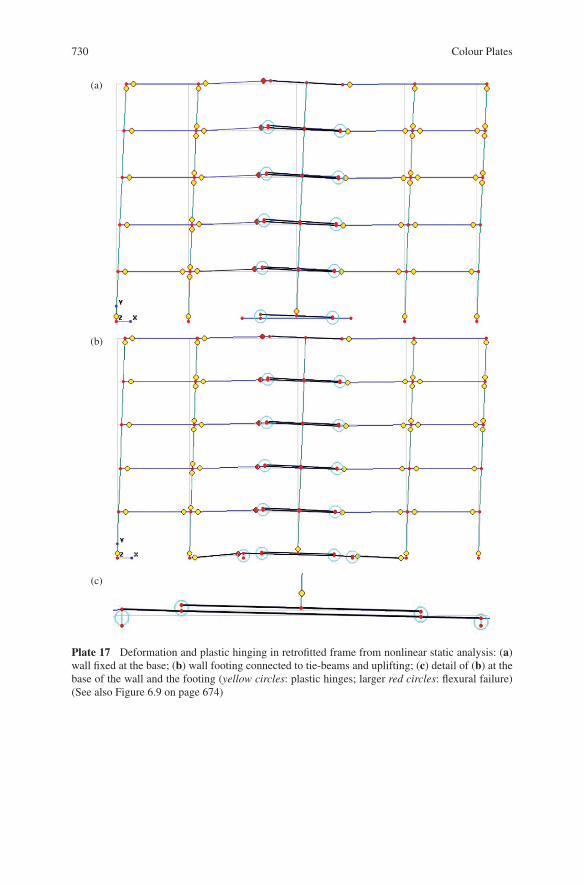
Plate 17 Deformation and plastic hinging in retrofitted frame from nonlinear static analysis: (a)wall fixed at the base; (b) wall footing connected to tie-beams and uplifting; (c) detail of (b) at thebase of the wall and the footing (yellow circles: plastic hinges; larger red circles: flexural failure)(See also Figure 6.9 on page 674)
Colour Plates 731
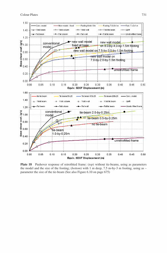
Plate 18 Pushover response of retrofitted frame: (top) without tie-beams, using as parametersthe model and the size of the footing; (bottom) with 1 m deep, 7.5 m-by-3 m footing, using as –parameter the size of the tie-beam (See also Figure 6.10 on page 675)
732 Colour Plates
(a) (b)
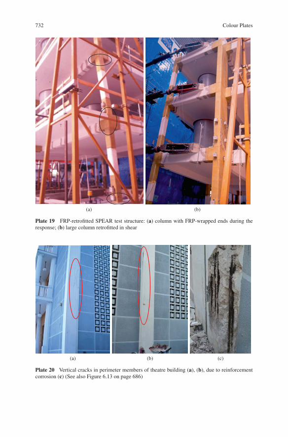
Plate 19 FRP-retrofitted SPEAR test structure: (a) column with FRP-wrapped ends during theresponse; (b) large column retrofitted in shear
(a) (b) (c)
Plate 20 Vertical cracks in perimeter members of theatre building (a), (b), due to reinforcementcorrosion (c) (See also Figure 6.13 on page 686)
Colour Plates 733
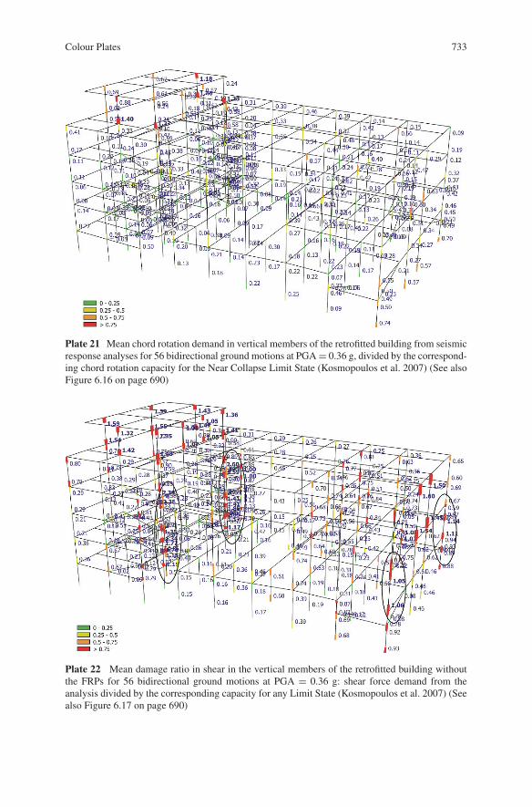
Plate 21 Mean chord rotation demand in vertical members of the retrofitted building from seismicresponse analyses for 56 bidirectional ground motions at PGA = 0.36 g, divided by the correspond-ing chord rotation capacity for the Near Collapse Limit State (Kosmopoulos et al. 2007) (See alsoFigure 6.16 on page 690)
Plate 22 Mean damage ratio in shear in the vertical members of the retrofitted building withoutthe FRPs for 56 bidirectional ground motions at PGA = 0.36 g: shear force demand from theanalysis divided by the corresponding capacity for any Limit State (Kosmopoulos et al. 2007) (Seealso Figure 6.17 on page 690)
Index
AAccidental actions, 14Accidental eccentricity, see Accidental torsionAccidental torsion, 57, 75, 337, 347–351, 482,
515–518, 560, 582, 609, 624ACI, xvi, 20, 21, 26, 30, 32, 41, 45, 106, 159,
160, 172, 220, 263, 442, 580, 655,659
Added walls, 667–671, 673–676, 686–689Aggregate interlock, 164–166AIJ, 259, 262–264, 273, 315Anchorage
by bend, 174, 284, 292, 466, 569, 570of FRP, 654, 692in joints, 89, 92, 208, 281–287, 443,
463–466, 522, 599, 697of reinforcement, 90–92, 443, 463–466,
469–574Axial deformations, 230, 231, 387Axial force
calculation, 93, 94, 517, 519–521in capacity design of columns in bending,
495–499, 520, 521, 525–528effect on cyclic flexure, 205–207, 230, 231,
233, 236effect on shear resistance, 259–263,
265–269, 271, 278, 293–296, 446for verification of columns in shear,
496–499, 533–537Axial stiffness, see Stiffness, axial
BBase shear, 42, 43, 111, 301, 312–316, 319,
326, 557–560, 583, 587Beams
capacity design in shear, 27–30, 481, 489,529–531
coupling, 43, 280deep, 280
dimensioning in bending, 481–484,522–524
dimensioning in shear, 27–30, 444,469–471, 481, 489, 528–531
effective flange width, 21, 22, 84, 85, 355,413
moment redistribution, 483, 484–489, 697retrofitting of, 633sizing of, 89–92, 696
Behaviour factor qbasic value, 43, 44, 444, 446, 450, 452,
453, 460, 514, 559dual systems, 43, 65, 103for force-based assessment or retrofitting,
625–627, 680frame systems, 43, 65, 103heightwise irregular buildings, 44, 79general, 9, 10, 18, 36, 39, 41–44, 65, 213,
219, 299, 301, 303, 310, 434, 437,438, 451, 453, 516, 559, 560, 566
inverted pendulum systems, 43, 44systems of large lightly reinforced walls,
473–475torsionally flexible systems, 43, 44, 453wall systems, 43, 44, 65, 100
Biaxialbending, 86, 101, 232, 234–237, 339–345,
380, 381, 386, 387, 414, 445, 490,492–494, 505, 525, 526, 620, 621,623
failure, 232, 235, 237loading, 75, 116, 232, 234–237, 414,
417–422yielding, 232, 236, 237
Bondin beam-column joints, 89, 92, 281–287,
291–294, 443, 463–466, 481, 522in cyclic loading, 169–171, 175, 282
735
736 Index
general, 166–175, 177, 184, 208, 386, 395strength, 167–171, 287
Boundary elementsin ductile walls, 447, 448, 450, 459–463,
482, 504, 565, 574–577, 640,667–669
in Eurocode 2 walls, 447, 575, 577in large lightly reinforced walls, 478, 479
Bracing system in steel, 476–478, 522–529Brittle
materials, 26, 174mode of behaviour, 11–13, 26–27, 275,
276, 396, 454, 612, 613, 618, 619,681
shear, 27, 251–253, 258–265Buckling of reinforcement, 131–136, 138, 634,
635, 640
CCapacity curve, 425–429, 496, 497, 521Capacity design
of columns in flexure, 20–24, 445,493–495, 524–528, 696
of foundation, 20, 115–118, 497, 538–541,547–552, 583, 591, 699
general, 15–20, 41, 45, 84, 88, 481, 699Capacity design forces for linear analysis
in the foundation, 617, 618, 699general, 613–615, 617, 618, 699shears in beams, 27–30, 614, 699shears in columns, 31, 32, 613, 699shears in joints, 287–290, 615, 699shears in walls, 33, 615, 699
Capacity design in shearbeams, 27–30, 444, 481, 489, 529–531,
699columns, 31, 32, 446, 481, 496, 533, 535,
699ductile walls, 33, 449, 482, 699general, 26, 27, 481, 699joints, 481, 489, 699
Centre of mass, 53, 56, 57, 59, 121, 122, 314,315, 317, 326, 329, 346, 347, 360,363, 364, 416, 417, 424, 426, 685
Centre of resistance, 53, 56, 121, 122, 416,417, 424, 426, 685
Centre of rigidity, 53–56, 59, 121, 122, 346,347, 416, 417, 424, 426, 685
Centre of stiffness, see Centre of rigidityCentre of strength, see Centre of resistanceCentre of twist, 55, 121, 122, 416, 417,
424, 426
Chord rotationcalculation, 214, 317, 318, 383, 387, 392,
395, 429–432, 611, 612, 619, 620definition, 16, 17ductility factor, 16, 18, 383, 393, 433, 436,
439, 605ultimate, 138, 139, 222–224, 227–230, 237,
240–247, 250, 393, 396, 397, 414,610, 612, 620–622, 636, 645–649,656–658, 697, 699
at yielding, 216–219, 221, 224, 228, 230,236–242, 245, 249, 250, 267, 493,494, 612, 636, 645–649, 657, 658
Collapse examples, 53, 60, 61, 67, 69, 78, 109,119–128
Collapse prevention, see Near CollapseColumns
capacity design in flexure, 20–24, 445,493–495, 524–528, 697
capacity design in shear, 31, 32, 446, 481,496, 533, 535, 699
circular, 150–152, 160, 161, 173, 255–268,661
confining reinforcement, 150–157, 228,229, 246, 445, 446, 456–460, 481,532, 533, 644
detailing, 151–155, 445, 446dimensioning in shear, 446, 481retrofitting with concrete jackets, 558–560,
562, 637–649, 685with lap-spliced bars, 238–241, 244–247retrofitting with FRP, 557, 559, 560, 562,
649, 654–661, 655, 684, 685retrofitting with steel jackets, 661–667sizing of, 92–94, 696
Combinationof actions, 13, 90, 482, 490, 510of factored gravity loads, 90, 91, 482,
490, 510CQC, 320, 321, 330, 331, 345, 698of modal contributions, 319–321of seismic action components, 332,
338–345, 350, 498, 519, 520, 525,539, 698
SRSS, 320, 321, 332, 338, 342–345, 348,415, 430, 431, 498, 520, 525, 539
Complete Quadratic Combination (CQC), 320,321, 330, 331, 345, 698
Compression zone, 133–136, 143, 147–150,156, 157, 162, 179–181, 186–198,203, 228, 238, 240, 258, 273,291, 455, 461, 462, 478, 575–577,645, 648
Index 737
Conceptual designof dual systems, 103–105of foundation, 108–115of frame systems, 83–94general, xiv, 47–50, 696of wall systems, 94–103
Concreteconfined, 143–163cyclic stress-strain behaviour, 142, 143minumum requirements in Eurocode 8,
163, 164ultimate strain, 147–149
Concrete jacketsconfinement, 644detailing, 639–643moment resistance, 644–648shear strengthening, 646, 649stiffness, 644–648ultimate deformation, 644–648
Confidence factor, 607, 608, 610, 613–617,620–623, 626, 649, 658
Confinementeffectiveness factor, 145, 150–153,
155–157, 161–163, 243, 405, 450,532, 533, 575–577, 663
by FRP wrapping, 157–163, 174, 242–247,656, 657
of lap splices, 167, 172–174, 238–241,244–247
models, 144–150of circular sections, 150–152, 160, 161of rectangular sections, 151, 153–157, 162,
457, 459by steel jackets, 663, 664by transverse reinforcement, 150–157,
175, 228, 229, 246, 294, 445–447,456–473, 481, 482, 532, 533,575–577, 644, 700
of wall boundary elements, 459–463,574–577
Coupled walls, see Walls coupledCoupling axial-flexural, 99, 100, 205–207,
230, 231, 233, 234, 386–388Critical regions, 139, 140, 441–449, 452,
453, 455–463, 469–472, 481, 482,528–538, 566–567, 575–577
Curvaturedefinition, 178ductility factor, 213, 223, 443–461, 515,
523, 533, 575–577at yielding, 139, 179–183, 185, 213,
216–218, 222–224, 238–241, 389,390, 455, 461, 610, 621, 644
ultimate, 139, 148, 149, 185–195, 210–213,222–224, 240, 242, 244, 247, 389,396, 397, 455, 457, 461, 610, 621,622, 656
DDamage
examples, 79, 81, 82, 107, 168, 204, 208,252, 288
limitation, 6–8, 19, 305, 439, 626, 627Damage limitation (LS), 7, 603, 604, 612, 618,
624–626, 681Damping
hysteretic, 235, 401–403, 406, 409, 410Rayleigh, 333, 334, 414viscous, 304, 305, 307, 320, 333, 334,
414, 431Demand-to-capacity ratio D/C, 428, 429, 431,
609, 698, 699Design seismic action, 1, 2, 6–9, 13–15, 37,
42, 305, 331, 332, 366, 432, 434,437, 439, 626, 627, 701
Design situationpersistent and transient, 14, 64, 86, 90, 508,
697seismic, 13, 14, 64, 88
Detailingof beam-column joints, 463–466, 468,
469of beams, 443, 444, 454–456, 529–531of columns, 445, 446, 459, 460, 532–538of ductile walls, 447–450, 459–463, 565,
574–577for ductility, 11, 13, 20, 174, 175in Eurocode 8, 442–450, 454–466, 468,
469, 478–480, 529–538, 565,574–577
of large lightly reinforced walls, 478–480Diagonal strut
in infill panels, 366, 367, 404, 408, 409,499, 540, 624
in shear resistance, 261–264, 273, 274,282, 290–292
Diaphragmsflexible, 57, 67–70, 120–123, 125–128,
349, 355, 360–362, 414, 421,483
general, 57, 67–71, 103, 104, 113,120–123, 125–128, 444, 478, 480
modelling, 359–362, 414, 421, 483rigid, 70, 103, 104, 314, 317, 349, 355,
359, 360, 364verification, 577–582
738 Index
Displacement-basedassessment and retrofitting, 220, 221,
302–304, 427, 608design, 220, 694–701
Displacement calculation, 58, 302, 303, 329,330, 363, 418, 419, 426–432,434, 437
Dissipative zones, 13, 14, 19, 20, 442Dowel
action, 164–166, 202, 251, 254, 263, 265epoxy grouted, 641, 648, 668, 683,
687, 689Dual systems
definition, 43frame-equivalent, 43wall-equivalent, 43
Ductile shear, 251, 253–257, 265–269Ductile walls
design in flexure, 25, 26, 449, 482,502–506, 564, 565, 567, 569–574
detailing, 447–450, 459–463, 465, 574–577dimensioning in shear, 33–36, 449, 471,
472, 482, 506, 507, 566–568Ductility
definition, 11design for, 9–11, 36–38, 117, 118, 451–453detailing for, 11, 13, 20, 174, 175,
442–450, 454–466, 468, 469,478–480, 529–538, 565, 574–577
global, 9–11, 19–20local, 19–20, 138, 175, 451–463of materials, 137–141, 454, 455
Ductility Class (DC)H (high), 29, 31, 34–36, 39, 40, 43, 68, 74,
78, 79, 106, 118, 140, 141, 153,164, 209, 269, 271, 442–450
L (low), 39, 41, 74, 78, 106, 140, 141, 248,436, 443–450, 454
M (medium), 29, 31, 35, 36, 39, 40, 42–44,68, 74, 78, 79, 106, 140, 141, 153,164, 269, 442–450, 453
Ductility Classes (DCs) in Eurocode 8, 38–40Ductility factor
of chord rotation, 16, 18, 213, 223, 263,266, 269, 451
of curvature, 213, 223, 443–461, 515, 523,533, 575–577
of displacement, 10, 11, 18, 36, 213, 451
EEffective footing area, 540–542, 548, 549,
585, 586Effective stiffness, see Stiffness
Epoxy resins, 652, 653Equal displacement rule, 10, 37, 302, 328, 363,
427, 429, 434, 437Equivalent SDOF system, 9, 10, 426–430Eurocode 2, 14, 39, 140, 146, 147, 167, 168,
172, 187, 212, 218, 220, 226, 258,261, 263, 269, 271, 355, 412, 436,441, 444, 451–453, 455–457, 459,462, 464, 466, 469–472, 474–478,480, 486, 495, 506, 511, 528–532,534, 542, 544, 552, 562–564,566, 567, 569, 570, 575–577, 580,581, 591
Eurocode 6, 366, 367Eurocode 7, 108, 540, 584Eurocode 8
Part 1, xvi, 1, 2, 6, 7, 10, 13, 14, 19–23, 27,29–36, 39–44, 52, 53, 56–58, 60,61, 65, 68, 74–76, 78, 79, 81, 90,103, 108, 117, 118, 163, 167, 209,247, 248, 271, 280, 281, 294–296,300–303, 305, 312–313, 318, 320,324–329, 331, 332, 337, 339, 347,353, 354, 359, 363–366, 368, 412,413, 427, 430, 432–436, 441–455,458–470, 472–479, 486, 488,492–494, 499–506, 526, 528, 529,532, 555, 556, 558, 560, 575–578,583, 584, 586
Part 3, xvi, 7, 144, 146, 149, 162, 212, 218,219, 221, 226, 229, 230, 238–240,243, 245–247, 267, 271, 279, 303,306, 324, 325, 328, 330, 366, 396,413, 421, 426, 430–434, 436, 439,451, 452, 602–626, 648, 649, 656,681, 686, 689
Part 5, 306, 374, 376
FFailure
in brittle shear, 252, 253in ductile shear, 256, 257examples, 53, 60, 61, 67, 69, 78, 109,
119–128, 204, 208, 252, 288in flexure, 12, 82, 204, 253in shear, 79, 81, 82, 252, 288
Fibre models, 380–387, 395, 404Fibre Reinforced Polymers, see FRPsFixed-end rotation
general, 184, 185, 282–284, 385,386, 390, 393, 395, 401, 414,616
at ultimate, 208–211, 224at yielding, 185, 217–219
Index 739
Flat-slab framesbehaviour, 105–108in Eurocode 8, 106, 435, 555, 558modelling, 555, 558verification, 561–564
Flexure-shear interaction, 272–278Floor diaphragms, see DiaphragmsFootings
capacity design, 115–118, 480–482, 497,538–541, 547–552
modelling, 374–376, 410–412, 673–675rigid, 374, 376verification of bearing capacity, 497,
540–542, 548, 584–587verification in bending, 545–547, 553verification in shear, 543–545, 551, 552
Force-basedassessment and retrofitting, 600, 601,
625–627, 630, 682seismic design, 9, 19, 20, 65, 219, 299,
310, 426, 427, 701Force path
continuity, 67, 68, 633, 634, 668redundancy, 65, 85, 97, 102
Force-reduction factor R, 45, 299Foundation beams
design in flexure, 493, 494design in shear, 492, 493general, 97, 108, 112, 113, 117, 118, 426,
616, 618, 672, 689modelling, 370–373, 410verification of bearing capacity, 584–587
Foundation systembox-type, 97, 113, 114, 554, 582–593selection, 113–115shallow, 108
Foundation of walls, 97–99, 671–676Frames, 83–92, 103, 104, 480, 481, 507–538Frame systems definition, 43FRP anchorage, 654, 692FRP materials, 650–654FRPs, 157–163, 174, 241–247, 557, 559,
560, 562, 565, 650, 651, 684, 685,690–693
FRP-wrapped membersconfinement, 157–163, 174, 242–247, 656,
657, 684, 685moment resistance, 241, 245, 656, 657shear strengthening, 658–661, 690–693stiffness, 242, 245, 656, 657ultimate deformations, 242–247, 656, 657yielding, 241, 242, 245, 656, 657
Fundamental period, see Period, fundamental
HHorizontal components
combination of, 332, 338–345, 349, 350,498, 519, 520, 525, 539, 698
design spectrum, 310directions, 316, 338elastic response spectrum, 306, 307
Hysteresis rules, 334, 397–401, 413, 439
IImmediate Occupancy, 3, 4, 7, 8, 366, 695,
696, 698, 699, 701Importance Class, 2, 508, 516, 554, 560Importance factor, 2, 8, 39, 305, 508, 554Inelastic spectrum, 9–11, 36, 37, 328, 427,
451, 452Infilling of frames with RC, 666–671, 688, 689Infills, see Masonry infillsInput motions
artificial, 331conformity with spectrum, 331, 332minimum number, 333recorded, 331, 332simulated, 331, 332
Interfaceof concrete jacket to old member, 639,
641–643, 646–648, 668, 669of steel bracing to old frame, 683
Interstorey driftcalculation, 513, 516, 560, 561contributions to, 215limit (or verification), 6, 87, 88, 513, 516,
560, 561sensitivity coefficient, 363, 364, 516, 561
Inverted pendulum systems, 43, 44Irregularity in elevation
effects of, 60, 61, 76–78, 120–124of infills, 64, 76–78, 124
Irregularity in planeffects of, 52, 53, 75, 120–128of infills, 74, 75
JJoint(s)
beam-column, 280–297, 463–469bond and anchorage in, 89, 92, 281–283,
291–294, 443, 463–466, 481,522
shear force, 281–283, 287–290, 466, 481shear verification, 466–468, 699seismic, 57, 58, 629, 630, 687
LLap length, 72, 239, 240, 245, 246
740 Index
Lap-splicesand concrete jackets, 645, 646effect on stiffness, 238, 244, 245effect on ultimate deformation, 239–241,
245–247effect on yield moment, 238, 244, 245and FRP wrapping, 244–247, 649, 657of smooth bars, 241and steel jacket, 665, 666
Large lightly reinforced wallsin bending, 474, 475definition, 473in shear, 475–478system of, 472–474
Large wallsbehaviour, 99–101in Eurocode 8, 472–480
Lateral force patternin linear static analysis, 314, 315, 508,
566in nonlinear static analysis, 324, 325
Liability in retrofitting, 627, 628Life Safety, 3, 4, 7, 8, 366, 367, 426, 604, 686,
689, 695, 696, 699, 701Limit States (LS), 5–8, 603, 604, 618, 619,
623, 624, 626, 628, 681, 686, 689,696
Linear analysis applicability conditions, 428,429, 609
Linear modellingbeams and columns, 354–356floor diaphragms, 359–362, 414, 421footings, 474–476foundation beams, 370–373foundation elements, 369–376infill panels, 365–369soil compliance, 369–376staircases, 362walls (U-shaped), 357–359
Linear static analysisapplicability conditions, 311, 312force pattern, 314, 315, 508, 566
Load-path, see Force pathLow seismicity, 39, 106Lumped inelasticity models, 390–395,
404, 413
MMasonry infills
adverse local effects, 79–81, 499–502effects of, 72–81in existing buildings, 599, 602, 605–608,
624, 625, 627, 631
general, 6, 36irregularity in elevation, 74, 76–78, 124irregularity in plan, 74, 75modelling, 365–369, 404–410shear resistance, 408, 409, 500
Mean return period, 1, 2, 4, 7, 8, 14, 405,406, 604
Modal response spectrum analysis, 300, 301,303, 315–321, 329, 338, 341–345,347, 350, 367, 430, 431, 498, 608,698, 699
Model Code 90, 146, 147, 169, 258, 259,261–263, 270
Modellingin assessment and retrofitting, 609–612for linear analysis, 352–379for nonlinear analysis, 379–412
Modes, normal, see Normal modesMoment-curvature, 183–203, 256, 257, 389,
390, 397–401Moment frames
intermediate, 30, 41, 45ordinary, 41, 45special, 23, 24, 30, 32, 41, 45
NNear Collapse, 3, 4, 7, 8, 306, 366, 426, 603,
604, 612, 619, 623, 624, 681, 689,690, 695, 696, 699
NEHRP, xvi, 8, 20, 26, 30, 40, 45, 46, 63,65, 66, 115, 130, 142–145, 147,161, 162, 168, 177, 183, 193, 257,263, 442
Neutral axis depth, 138, 149, 157, 177–181,184, 186–194, 196–198, 230–232,248, 261, 265, 266, 268, 273,291, 455, 458, 461–463, 484, 495,504, 648
Nonlinear dynamic analysisapplication examples, 415–426, 685,
689, 690input motions, 331–333modelling, 380–412numerical integration, 334, 335
Nonlinear modellingin Eurocode 8, 412of foundation uplift, 410–412, 673–675of infill panels, 404–410
Nonlinear response-history analysis, seeNonlinear dynamic analysis
Nonlinear static analysisadaptive schemes, 325in Eurocode 8, 324–329
Index 741
higher mode effects, 330torsional effects, 329
Non-structural elements (infills, etc.), 4, 6, 36,630, 667
Normal modescombination, 319–321minimum number, 318, 319in pushover analysis, 330
Numerical integration, 334, 335
OOverstrength
factor, 20, 28–34, 41–46, 116, 451, 453,455, 459, 464, 467, 475, 476, 478
of materials, 20, 28–34, 39–41, 44–46, 116,451, 453, 455, 459, 464, 467, 475,476, 506, 578
of system, 42–46, 451Overturning moment, 83, 86, 93, 105, 111,
115, 315, 370, 378, 509, 519,582, 583
PP-Δ effects, see Second-order effectsPeak ground acceleration (PGA), 10, 40, 305,
306, 332, 374, 431, 623Performance
levels, 3–8, 305, 306, 366, 603, 604, 626,628, 695, 696
requirements, 1–8, 48, 306, 336, 596, 601,603, 604
Performance-basedassessment and retrofitting, 2–5, 7, 306,
336, 601, 630design, 2–5, 8, 695
Periodcorner (or transition), 10, 34, 304, 305, 307,
311–313, 326, 328, 429, 450, 615fundamental
horizontal, 9, 10, 34, 58, 59, 71, 111,301, 305, 311–314, 326–328, 332,370, 377, 378, 414, 427, 429, 450,473, 514, 559, 615
vertical, 321, 322, 332, 379natural (or modal), 306, 307, 309, 310, 316,
317, 319, 320Pile foundations, 108, 371, 376, 377Pinching, 184, 201–203, 206, 386, 398–403Plastic hinge
general, 11, 13, 16–18, 20, 23, 25–31,33, 34, 42, 51, 52, 78, 86, 88, 95,116, 138, 139, 222–224, 233, 241,242, 248, 254, 264, 393, 394, 442,
451–453, 455–463, 494, 501, 636,649, 656, 660, 674
length, 224–227, 240, 241, 247, 250, 621,622, 645–647
Plastic mechanismbeam-sway, 16–20, 64, 95, 324general, 16–18, 42, 65, 301, 324, 326, 327soft-storey, 16–20, 23–26, 64, 76–78, 86,
102, 103, 325Point-hinge models, see Lumped inelasticity
modelsPolyesters, 652, 653Pounding, 57, 58, 75, 629, 630, 686Prestressed members
ultimate deformation, 250yielding, 249, 250
Prestressing in Eurocode 8, 247, 248, 321, 435Primary members
in assessment and retrofitting, 433, 434,436, 437, 606, 609, 610, 618,624–627, 631, 633, 649, 681, 682
definition, 432in design of new buildings, 433–436,
442–556, 559–561, 564–593, 699Pseudodynamic test, 415, 417, 418, 685Pushover analysis, see Nonlinear static analysis
Qq-factor, see Behaviour factor q
RRadius of gyration, 58, 59, 511, 512, 556, 557Raft foundations, 108, 109, 111, 113, 115, 117,
371, 373, 410, 618Rapid screening, 597Rayleigh damping, see Damping, RayleighRayleigh quotient, 313, 514Redundancy, 42–44, 46, 52, 59, 64–66, 84, 85,
102, 103, 473Regularity in elevation criteria, 61–63Regularity in plan criteria, 53, 56–59Reinforcement
compression, 177, 179–181, 190–194,196–198, 201, 228, 229, 238, 240,275, 277, 279, 455, 503–505, 644,657, 700
confining, 150–157, 175, 228, 229, 246,294, 445–447, 456–463, 481, 482,532, 533, 575–577, 644, 700
inclined, 229, 279–281, 443, 444, 470, 471,481, 482, 700
slippage of, 184, 185, 208–211, 217–219,224, 281–287, 385, 386, 390, 393,395, 401, 414, 616
742 Index
tension, 138, 177, 179–181, 184, 186,190–194, 196–198, 199, 210–212,216–218, 228, 229, 249, 259, 260,275, 455, 503–505, 700
web (longitudinal), 179–181, 190–194,196–198, 228, 229, 472, 478,503–505, 700
Reinforcement ratiomaximum, 443–450, 455, 456mechanical, 156, 187, 190–194, 196–198,
228, 229, 260, 275, 277, 458–460,503–505
minimum, 443–450, 454volumetric, 146, 151, 154–156, 458, 459,
461Reinforcing bars
anchorage, 90–92, 443, 463–466, 569–574bending diameter, 569, 570bond, 166–175, 177, 184, 208buckling, 131–136, 138, 157, 174, 175,
203–205, 280, 382, 395, 634,635, 640
curtailment, 569–574dowel action, 164–166, 202, 251, 254,
263, 265lap-spliced, 238–241, 244–247, 645, 646,
649, 657, 665, 666ribbed (deformed), 166–174, 182, 219,
221, 228–230, 238–241, 244–247smooth (plain), 648, 685, 687, 696, 707
Reinforcing steelclass, 140, 212, 453–455, 484cyclic stress-strain behaviour, 129–133requirements in Eurocode 8, 137–141strain at ultimate strength, 130, 135, 137,
139, 140, 147, 148, 186, 210–212time effects, 136, 137ultimate strain in cyclic loading, 210, 241ultimate strain in monotonic loading, 210,
211, 241ultimate strength, 130, 138–141yield stress, 129, 130, 140, 141
Repaired membersstiffness, 242, 636, 637ultimate deformation, 243, 244, 636, 637yielding, 242, 636, 637
Repair techniques, 634–636Response-history analysis, see Time-history
analysisResponse spectrum
design, 310elastic, 306, 307, 309horizontal, 306, 307, 310
inelastic, 9–11, 36, 37, 328, 427, 451, 452vertical, 309, 310
Retrofitting strategies, 628–634
SSafety factor
partial for actions, 91, 482, 490, 510partial for materials, 14, 21, 456, 464, 469,
543, 584, 622, 623, 655, 656, 664SEAOC, xvi, 2, 8, 20, 26, 30, 40, 45, 46,
63, 65, 66, 115, 130, 131, 138,142–145, 148, 149, 161, 162, 168,177, 183, 193, 199, 257, 263, 442
Secondary membersin assessment or retrofitting, 433, 434, 436,
437, 439, 602, 606, 609, 612, 618,626, 627, 630, 682
definition, 432modelling, 437–439, 609, 610, 612in new buildings, 433–436, 437–439, 443,
445, 501, 556–558, 561–564, 699Second-order effects, 87, 96, 220, 349, 363,
364, 474, 516, 561Seismic hazard, 2–5, 7, 8, 14, 305, 306, 601,
603, 604, 626, 695, 699Seismic joint, see Joint(s), seismicShear
in joints, 281–283, 287–290sliding, 280, 449, 450, 470, 471, 477,
482, 578Shear resistance
cyclic loading, 253–257, 265–269in diagonal compression, 270, 271in diagonal tension, 265–269of joints, 290–297monotonic loading, 258–264of short (squat) columns, 278, 279of walls, 270, 271, 448–450
Shear span, 80, 94, 96, 138, 176, 177, 184,214–216, 221, 223, 224, 393, 394,396, 413, 414, 472, 502, 611, 619,623, 700
Shear span ratio, 11, 12, 44, 84, 89, 91, 94, 96,100, 176, 225, 228, 229, 264–268,270–279, 403
Shift rule, 216, 217, 448, 483, 564, 593Short columns
design, 24, 272–280vulnerability, 79–81, 112, 598
Significant Damage (LS), 7, 603, 604, 612,619, 623, 624, 626, 681, 682,686, 689
Soil bearing capacity, 540–542, 548, 584–587
Index 743
Soil compliance, 370–376SPEAR test-building, 415–421, 429, 684, 685Spectral displacement, 304, 305, 317, 326, 328Spectral pseudoacceleration, 8, 10, 34, 40,
304–307, 309, 615Spectral pseudovelocity, 10, 98, 304, 305,
311–313Spread inelasticity models, 387–390Square Root of the Sum of Squares (SRSS),
see Combination, SRSSSquat columns, see Short columnsStaircases
effects of, 82, 83modelling, 362, 414stiffness, 362, 598
Steel jacketed membersconfinement, 663lap splices, 665, 666moment resistance, 666, 667shear strengthening, 664, 665stiffness, 666, 667ultimate deformations, 666, 667yielding, 666, 667
Stiffnessaxial, 354, 390, 394in biaxial loading, 237cracked, 19, 220, 456, 460of floor diaphragms, 359–362secant to yield point, 219–222, 237–239,
242–245, 250, 393, 395–397, 413,417, 610, 611, 636, 645, 648,656, 657, 697, 699, 700
torsional, 354, 357, 359Stiffness degradation, 201, 233, 391, 399,
439, 613Strength degradation, 186, 203, 234, 251, 254,
255, 270, 271, 278, 401, 405, 409,419, 439, 613
Strong column-weak beam design, 16–20, 445,493–495, 524–528, 697
Strut-and-Tie models, 279, 476, 477, 578–582
TTarget displacement, 326, 328–330, 396Tension shift, see Shift ruleTension stiffening, 216Tie-beams, 7, 97, 108, 111–112, 116–118, 480,
617, 671–676
Time-history analysis, 301, 330–335, 337, 397,398, 417–419, 429, 430
T-, L-, U-compression zone, 181–183, 218,222, 225–227, 228, 229
Torsional effectsin linear analysis, 348, 349, 351in pushover analysis, 329
Torsionally flexible systems, 12, 13, 43, 44Torsional radius, 53–56, 58, 59, 511, 512,
556, 557
UUltimate chord rotation, see Chord rotation,
ultimateUltimate curvature, see Curvature, ultimateUltimate deformation definition, 135, 203, 205Uplift
of footings, 98, 99, 374–376, 410–412,475, 673–676
of walls, 99, 100US standards, xvi, 8, 20, 23, 26, 30, 33, 40, 45,
46, 63, 65, 66, 115, 130, 142–145,148, 161, 162, 168, 177, 183, 193,257, 263, 442
VVertical component
combination of components, 321, 332,338–345, 350
design for, 321–323design spectrum, 310elastic response spectrum, 309linear static analysis, 322, 323
WWall definition, 94Walls
coupled, 35, 43, 503, 504, 507design in flexure, 25, 26, 449, 482,
502–506, 564, 565, 567, 569–574design in shear, 33–36, 449, 471, 472, 482,
506, 507, 566–568foundation of, 97, 99, 671–676redistribution of design internal forces,
482, 502, 503, 507Wall systems
behaviour factor, 43, 44, 65, 100definition, 43


