Embed Size (px)
Citation preview
Seismic Rotational Displacement of Gravity Walls byPseudodynamic Method
Deepankar Choudhury, M.ASCE1; and Sanjay S. Nimbalkar, S.M.ASCE2
Abstract: Prediction of the rotational displacements, induced by earthquake is a key aspect of the seismic design of retaining walls. Inthis paper, the pseudodynamic method is used to compute rotational displacements of the retaining wall supporting cohesionless backfillunder seismic loading. The proposed method considers time, phase difference, and effect of amplification in shear and primary wavespropagating through the backfill and the retaining wall. The influence of ground motion characteristics on rotational displacement of thewall is evaluated. Also the effects of variation of parameters like wall friction angle, soil friction angle, amplification factor, shear wavevelocity, primary wave velocity, period of lateral shaking, horizontal, and vertical seismic accelerations on the rotational displacements arestudied. Results are provided in graphical form with a comparison to the available pseudostatic result to validate the proposed theory.Present results give higher values of rotational displacements of the wall when compared with the available results by pseudostaticanalysis.
DOI: 10.1061/�ASCE�1532-3641�2008�8:3�169�
CE Database subject headings: Displacement; Earth pressure; Time dependence; Soil-structure interaction; Retaining walls; Seismiceffects.
Introduction
Earthquakes have caused severe damage to the earth retainingstructures during many previous earthquakes all over the world.Many researchers have developed several methods to determinesliding and rotational displacements of retaining structures due toearthquake loading. Newmark �1965� proposed a sliding blockmethod to calculate the displacement of slopes of embankments.Using the concept of a yield or threshold acceleration, relativedisplacement between a rigid block and the ground beneath willaccumulate when the instant ground acceleration exceeds thethreshold acceleration until the block and the ground have thesame velocity again. Franklin and Chang �1977� developed thisapproach further, analyzing a number of historic earthquakerecords to develop “standardized” sliding displacements as afunction of the ratio of threshold to peak acceleration. The slidingblock approach was modified and extended by Richards and Elms�1979� for the design of gravity retaining walls. Nadim and Whit-man �1983� have further proposed a new seismic design methodfor gravity retaining walls, based on the earthquake induced per-manent displacement of the wall considering effects of groundmotion amplification. Whitman and Liao �1985� identified severalmodeling errors in the sliding block method proposed by Richards
1Associate Professor, Dept. of Civil Engineering, Indian Institute ofTechnology Bombay, Powai, Mumbai 400 076, India �correspondingauthor�. E-mail: [email protected]
2Lecturer, Dept. of Civil Engineering, Government College of Engi-neering, Karad 415 124, India.
Note. Discussion open until November 1, 2008. Separate discussionsmust be submitted for individual papers. To extend the closing date byone month, a written request must be filed with the ASCE ManagingEditor. The manuscript for this paper was submitted for review and pos-sible publication on July 6, 2006; approved on September 4, 2007. Thispaper is part of the International Journal of Geomechanics, Vol. 8, No.
3, June 1, 2008. ©ASCE, ISSN 1532-3641/2008/3-169–175/$25.00.INTERNATION
Downloaded 08 Mar 2011 to 130.130.37.12. Redistribu
and Elms �1979� such as: neglect of the dynamic response of thebackfill, neglect of kinematic factors, neglect of tilting mecha-nisms, and neglect of vertical accelerations, and had shown thatthe permanent displacements were larger when the effect of ver-tical acceleration was considered and that the tilting mechanismsgenerally increase wall displacements over those produced bysliding-only models of Richards and Elms �1979�. Steedman�1998� suggested the use of a displacement-based approach forseismic design of a retaining walls as the behavior of a retainingwall during earthquakes was dominated by displacements ratherthan by stresses. But all these pseudostatic based analyses didn’tgive the clear dynamic behavior of the rotational movement of theretaining wall during an earthquake.
Zeng and Steedman �2000� have used the rotating blockmethod for seismic displacement of gravity retaining walls. Thismethod considers the conventional pseudostatic method of analy-sis, which had several drawbacks by considering equivalent staticloading instead of any dynamic loading. Also the effect of verticalseismic acceleration was not considered in their analysis. But abetter pseudodynamic method originally proposed by Steedmanand Zeng �1990� and further modified by Choudhury and Nim-balkar �2006b� for computation of seismic active earth pressureby considering dynamic effects over the conventional pseudo-static method is now available. Further, the more realistic natureof pseudodynamic analysis over the conventional pseudostaticmethod was discussed by Choudhury and Nimbalkar �2006b� forthe computation of seismic active earth pressure and byChoudhury and Nimbalkar �2005, 2006a� for the seismic passiveearth pressure.
The rotating block method originally developed by Zeng andSteedman �2000� for the pseudostatic active case of earth pressurehas been extended by Choudhury and Nimbalkar �2007b� for thecase of passive earth pressure. However, the same method for theactive case of earth pressure using the pseudodynamic approach is
still scarce. Hence, in the present study, the pseudodynamicAL JOURNAL OF GEOMECHANICS © ASCE / MAY/JUNE 2008 / 169
tion subject to ASCE license or copyright. Visithttp://www.ascelibrary.org
method is used to compute the rotational displacement of the wallunder an active case of earth pressure by including the amplifica-tion effect with both soil and wall inertia, in addition to timeeffect and phase change effect in both shear waves and primarywaves propagating through the backfill and the wall. Apart fromusing a better pseudodynamic method of analysis, and as an im-provement over Zeng and Steedman �2000� analysis, the effect ofvariation of different parameters like soil friction angle ���, wallfriction angle ���, period of lateral shaking �T�, time of inputmotion �t�, both horizontal and vertical seismic acceleration coef-ficients for soil �khs ,kvs� and for wall �khw,kvw�, shear wave ve-locities in the soil �Vss� and in the wall �Vsw�, primary wavevelocities in the soil �Vps�, and in the wall �Vpw�, etc., are consid-ered in the present analysis.
Method of Analysis
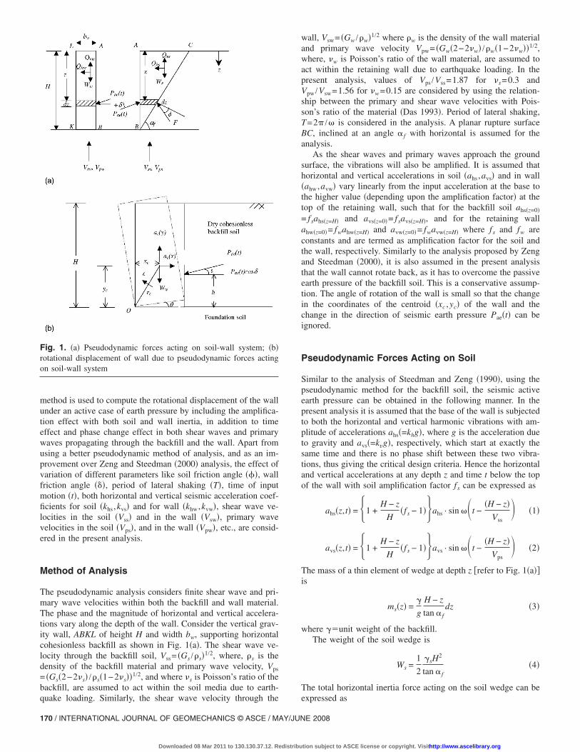
The pseudodynamic analysis considers finite shear wave and pri-mary wave velocities within both the backfill and wall material.The phase and the magnitude of horizontal and vertical accelera-tions vary along the depth of the wall. Consider the vertical grav-ity wall, ABKL of height H and width bw, supporting horizontalcohesionless backfill as shown in Fig. 1�a�. The shear wave ve-locity through the backfill soil, Vss= �Gs /�s�1/2, where, �s is thedensity of the backfill material and primary wave velocity, Vps
= �Gs�2−2�s� /�s�1−2�s��1/2, and where �s is Poisson’s ratio of thebackfill, are assumed to act within the soil media due to earth-
Fig. 1. �a� Pseudodynamic forces acting on soil-wall system; �b�rotational displacement of wall due to pseudodynamic forces actingon soil-wall system
quake loading. Similarly, the shear wave velocity through the
170 / INTERNATIONAL JOURNAL OF GEOMECHANICS © ASCE / MAY/JUN
Downloaded 08 Mar 2011 to 130.130.37.12. Redistribu
wall, Vsw= �Gw /�w�1/2 where �w is the density of the wall materialand primary wave velocity Vpw= �Gw�2−2�w� /�w�1−2�w��1/2,where, �w is Poisson’s ratio of the wall material, are assumed toact within the retaining wall due to earthquake loading. In thepresent analysis, values of Vps /Vss=1.87 for �s=0.3 andVpw /Vsw=1.56 for �w=0.15 are considered by using the relation-ship between the primary and shear wave velocities with Pois-son’s ratio of the material �Das 1993�. Period of lateral shaking,T=2� /� is considered in the analysis. A planar rupture surfaceBC, inclined at an angle � f with horizontal is assumed for theanalysis.
As the shear waves and primary waves approach the groundsurface, the vibrations will also be amplified. It is assumed thathorizontal and vertical accelerations in soil �ahs ,avs� and in wall�ahw,avw� vary linearly from the input acceleration at the base tothe higher value �depending upon the amplification factor� at thetop of the retaining wall, such that for the backfill soil ahs�z=0�= fsahs�z=H� and avs�z=0�= fsavs�z=H�, and for the retaining wallahw�z=0�= fwahw�z=H� and avw�z=0�= fwavw�z=H� where fs and fw areconstants and are termed as amplification factor for the soil andthe wall, respectively. Similarly to the analysis proposed by Zengand Steedman �2000�, it is also assumed in the present analysisthat the wall cannot rotate back, as it has to overcome the passiveearth pressure of the backfill soil. This is a conservative assump-tion. The angle of rotation of the wall is small so that the changein the coordinates of the centroid �xc ,yc� of the wall and thechange in the direction of seismic earth pressure Pae�t� can beignored.
Pseudodynamic Forces Acting on Soil
Similar to the analysis of Steedman and Zeng �1990�, using thepseudodynamic method for the backfill soil, the seismic activeearth pressure can be obtained in the following manner. In thepresent analysis it is assumed that the base of the wall is subjectedto both the horizontal and vertical harmonic vibrations with am-plitude of accelerations ahs�=khg�, where g is the acceleration dueto gravity and avs�=kvg�, respectively, which start at exactly thesame time and there is no phase shift between these two vibra-tions, thus giving the critical design criteria. Hence the horizontaland vertical accelerations at any depth z and time t below the topof the wall with soil amplification factor fs can be expressed as
ahs�z,t� = �1 +H − z
H�fs − 1��ahs · sin ��t −
�H − z�Vss
� �1�
avs�z,t� = �1 +H − z
H�fs − 1��avs · sin ��t −
�H − z�Vps
� �2�
The mass of a thin element of wedge at depth z �refer to Fig. 1�a��is
ms�z� =�
g
H − z
tan � fdz �3�
where �unit weight of the backfill.The weight of the soil wedge is
Ws =1
2
�sH2
tan � f�4�
The total horizontal inertia force acting on the soil wedge can be
expressed asE 2008
tion subject to ASCE license or copyright. Visithttp://www.ascelibrary.org
Qhs =�0
H
ms�z�ahs�z,t�dz �5�
Qhs =�sahs
4�2g tan � f�2�H cos w� + �sin w� − sin wt�
+�sahs�fs − 1�4�3gH tan � f
�2�H��H cos w� + sin w��
+ 2�cos wt − cos w�� �6�
and total vertical inertial force acting on the soil wedge can beexpressed as
Qvs =�0
H
ms�z�avs�z,t�dz �7�
Qvs =��savs
4�2g tan � f�2�H cos � + ��sin � − sin �t�
+��savs�fs − 1�4�3gH tan � f
�2�H��H cos � + � sin � �
+ �2�cos �t − cos w � �8�
where =TVsswavelength of the vertically propagating shearwave; �=TVpswavelength of the vertically propagating primarywave through the soil; and �= t−H /Vss and = t−H /Vps.
The total �static+seismic� active thrust, Pae�t� can be obtainedby resolving the forces on the wedge and considering the equilib-rium of the forces and hence Pae�t� can be expressed by Eq. �9� asfollows
Pae�t� =Ws sin�� f − �� + Qhs cos�� f − �� − Qvs sin�� f − ��
cos�� + � − � f�
�9�
where Wsweight of the failure zone; �soil friction angle; and�wall friction angle.
The detail methodology to calculate Pae�t� and hence the seis-mic active earth pressure coefficient �Kae� is already discussed byChoudhury and Nimbalkar �2006a� and the height of the point ofapplication �h� of total seismic active thrust from the base of thewall can be obtained from Choudhury and Nimbalkar �2007a�.
Pseudodynamic Forces Acting on Wall
Similar to the case mentioned for soil inertia, if the wall is sub-jected to both the harmonic horizontal and vertical accelerationsof amplitudes ahw and avw, the accelerations at depth z, and timet, below the top of the wall can be expressed as
ahw�z,t� = �1 +H − z
H�fa − 1��ahw · sin ��t −
�H − z�Vsw
� �10�
avw�z,t� = �1 +H − z
H�fa − 1��avw · sin ��t −
�H − z�Vpw
� �11�
The total horizontal inertia force acting on the wall can be ex-pressed as
Qhw =�H
mw · ahw�z,t�dz �12�
0INTERNATION
Downloaded 08 Mar 2011 to 130.130.37.12. Redistribu
Qhw =��wbwahw
4�2gH2 �2�H cos w� + ��sin w� − sin wt�
+��wbwahw�fw − 1�
4�2gH3 �2�H��H cos w� + � sin w��
+ �2�cos wt − cos w�� �13�
Again, total vertical inertial force acting on the wall can be ex-pressed as
Qvw =�0
H
mw · avw�z,t�dz �14�
Qvw =��wbwavw
4�2gH2 �2�H cos �� + ��sin �� − sin �t�
+��wbwavw�fw − 1�
4�2gH3 �2�H��H cos �� + � sin ���
+ �2�cos �t − cos w�� �15�
where �=TVswwavelength of the vertically propagating shearwave; �=TVpwwavelength of the vertically propagating pri-mary wave through the wall; and �= t−H /Vsw and �= t−H /Vpw.
The weight of the gravity retaining wall is
Ww = �w · bw · H �16�
Determination of Threshold Acceleration Coefficient„ktr…
If the peak ground acceleration exceeds the threshold acceleration�=ktrg� for rotation, then tilting/rotational displacement of the walloccurs.
Total vertical inertia force Qvw and total horizontal inertiaforce Qhw act at distance xc and yc, respectively, from the toe ofthe retaining wall which is also defined as rotation center O. Thepoints of applications of these forces are obtained by differentiat-ing these forces with the depth of the retaining wall and findingthe centroids of pressure distributions.
For the gravity retaining wall shown in Fig. 1�b�, subjected topure rotation, at the instant when tilting is yet to start
�ktr�W · yc� + Pae�t�cos �� · h = �Ww − Qvw · xc + Pae�t�sin �� · bw
�17�
where W= �Qhw /ktr�.Hence, the coefficient of the threshold acceleration for rotation
�ktr� can be obtained by performing iterative analysis using Eqs.�13� and �17�. If the maximum ground acceleration exceeds thethreshold acceleration �atr=ktrg� for rotation, then only rotationaldisplacement will occur.
Determination of Rotational Displacement of Wall
Similar to the assumptions made by Richards and Elms �1979�and Zeng and Steedman �2000� by using the pseudostatic ap-proach, rigidity of the wall is considered for obtaining rotationaldisplacement of the wall for the present study using the pseudo-dynamic approach. Tobita and Sawada �2006� had also consideredthe rigidity of the rectangular foundation for obtaining the rota-
tional movement under earthquake excitation. In the presentAL JOURNAL OF GEOMECHANICS © ASCE / MAY/JUNE 2008 / 171
tion subject to ASCE license or copyright. Visithttp://www.ascelibrary.org
study, referring to Fig. 1�b�, the equation of motion when rotationhas started about the toe �O� of the wall can be written as
� Mo = − yc�Ww/g��ac�x + xc�Ww/g��ac�y + Ic · � �18�
and the acceleration at the centroid �ac� is the sum of three com-ponents, viz.
ac = ag + � � rc − �2rc �19�
From Fig. 1�b�, horizontal and vertical accelerations at the cen-troid are
�a � = a − �y − �2x
c x g c cVps=187 m /s; Vpw=2,500 m /s; Vsw=3,900 m /s.
172 / INTERNATIONAL JOURNAL OF GEOMECHANICS © ASCE / MAY/JUN
Downloaded 08 Mar 2011 to 130.130.37.12. Redistribu
�ac�y = �xc − �2yc �20�
Substituting from Eq. �20� into Eq. �18�
� Mo = �Ww/g�rc2� − �Ww/g�agyc + Ic� �21�
Again
� Mo = Qhw · yc + Pae�t�cos �� · h − �Ww − Qvw� · xc
− Pae�t�sin �� · bw �22�
From Eqs. �21� and �22�, the rotational acceleration ��� can be
expressed as� =�Pae�t�cos �� · h + �Ww/g�ag · yc − Ww · xc + Qhw · yc + Qvw · xc − Pae�t�sin �� · bw
Ic +Ww
g· rc
2� �23�
where Pae�t�pseudodynamic active earth pressure calculatedusing ground acceleration; ah �=khg� rather than using the thresh-old acceleration atr �=ktrg� as proposed by Zeng and Steedman�2000� since in the rotating block method, the threshold accelera-tion for rotating does not represent the true acceleration of anyparticular points in the system. For example, at the toe, the soilwill have the same acceleration as the ground while above thebase, the soil will have the same acceleration as the wall at thesame height.
The velocity of rotation �angular velocity� can be derived as
� =�0
t
� · dt when � � 0 �24a�
� = 0 when Eq. �24a� gives � � 0 �24b�
Eq. �19b� is the direct result of assumption, which considers thatthe wall cannot rotate back.
The tilting angle or rotational displacement ��� can be ob-tained as
� =�0
t
� dt �25�
The above procedure is repeated for each cycle of vibration wherethe threshold acceleration for rotation is exceeded. The final tilt-ing angle or rotational displacement is the summation of indi-vidual tilting angles during the entire earthquake motion.
Results and Discussion
Typical results are presented by graphs for rotational displace-ment ��� of the wall with respect to the horizontal seismic accel-eration coefficient �kh�. Variations of parameters considered in thepresent analysis are as follows: �=20, 30, 40, and 50°; � /�=−1.0, 0.0, 0.5, and 1.0; T=0.2, 0.3, 0.4, and 0.5 s; t=0.1, 0.2,0.3, 0.4, and 0.5 s; khs=khw=kh=0.1, 0.2, and 0.3; kvs=kvw=kv=0.0, 0.5kh and 1.0kh; fs= fw= f =1.0, 1.2, and 1.4; Vss=100 m /s;
Effect of Amplification Factor „f… on RotationalDisplacement
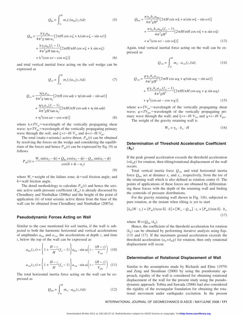
Fig. 2 shows the effect of amplification factor �f� on the rotationaldisplacement ��� of the wall for different values of kh with kv
=0.5kh, �=30°, �=�, H /=0.3, H /�=0.16, H /�=0.012, H /�
=0.0077, H=10 m, bw=5 m, and t=0.5 s. From the plot, it maybe seen that the rotational displacement of the wall increases withincrease in amplification factor and the rate of increase is morefor higher values of horizontal seismic acceleration coefficient�kh�. For kh=0.2, the rotational displacement of the wall increasesby 398.6% when f changes from 1 to 1.2 and 208.86% when fchanges from 1.2 to 1.4. Thus, the present study reveals the sig-nificant influence of amplification factor on the rotational dis-placement of the wall.
Fig. 2. Effect of amplification factor �f� on rotational displacement��� for different values of kh with kv=0.5kh, �=30°, �=�, H /=0.3, H /�=0.16, H /�=0.012, H /�=0.0077, H=10 m, bw=5 m, andt=0.5 s
E 2008
tion subject to ASCE license or copyright. Visithttp://www.ascelibrary.org
Effect of Soil Friction Angle „�… on RotationalDisplacement
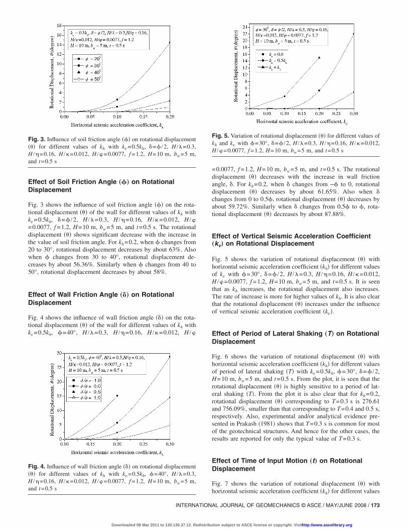
Fig. 3 shows the influence of soil friction angle ��� on the rota-tional displacement ��� of the wall for different values of kh withkv=0.5kh, �=� /2, H /=0.3, H /�=0.16, H /�=0.012, H /�=0.0077, f =1.2, H=10 m, bw=5 m, and t=0.5 s. The rotationaldisplacement ��� shows significant decrease with the increase inthe value of soil friction angle. For kh=0.2, when � changes from20 to 30°, rotational displacement decreases by about 63%. Alsowhen � changes from 30 to 40°, rotational displacement de-creases by about 56.36%. Similarly when � changes from 40 to50°, rotational displacement decreases by about 58%.
Effect of Wall Friction Angle „�… on RotationalDisplacement
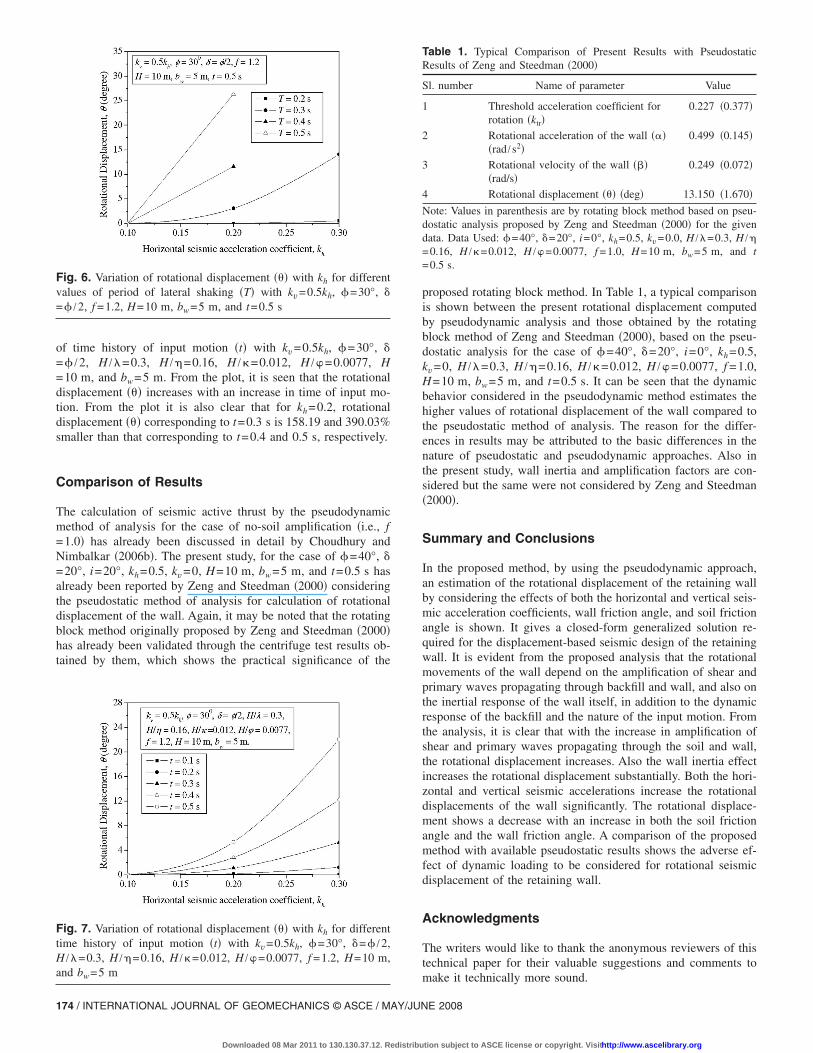
Fig. 4 shows the influence of wall friction angle ��� on the rota-tional displacement ��� of the wall for different values of kh withkv=0.5kh, �=40°, H /=0.3, H /�=0.16, H /�=0.012, H /�
Fig. 3. Influence of soil friction angle ��� on rotational displacement��� for different values of kh with kv=0.5kh, �=� /2, H /=0.3,H /�=0.16, H /�=0.012, H /�=0.0077, f =1.2, H=10 m, bw=5 m,and t=0.5 s
Fig. 4. Influence of wall friction angle ��� on rotational displacement��� for different values of kh with kv=0.5kh, �=40°, H /=0.3,H /�=0.16, H /�=0.012, H /�=0.0077, f =1.2, H=10 m, bw=5 m,and t=0.5 s
INTERNATION
Downloaded 08 Mar 2011 to 130.130.37.12. Redistribu
=0.0077, f =1.2, H=10 m, bw=5 m, and t=0.5 s. The rotationaldisplacement ��� decreases with the increase in wall frictionangle, �. For kh=0.2, when � changes from −� to 0, rotationaldisplacement ��� decreases by about 61.65%. Also when �changes from 0 to 0.5�, rotational displacement ��� decreases byabout 59.72%. Similarly when � changes from 0.5� to �, rota-tional displacement ��� decreases by about 87.88%.
Effect of Vertical Seismic Acceleration Coefficient„kv… on Rotational Displacement
Fig. 5 shows the variation of rotational displacement ��� withhorizontal seismic acceleration coefficient �kh� for different valuesof kv with �=30°, �=� /2, H /=0.3, H /�=0.16, H /�=0.012,H /�=0.0077, f =1.2, H=10 m, bw=5 m, and t=0.5 s. It is seenthat as kh increases, the rotational displacement also increases.The rate of increase is more for higher values of kh. It is also clearthat the rotational displacement ��� increases under the influenceof vertical seismic acceleration coefficient �kv�.
Effect of Period of Lateral Shaking „T… on RotationalDisplacement
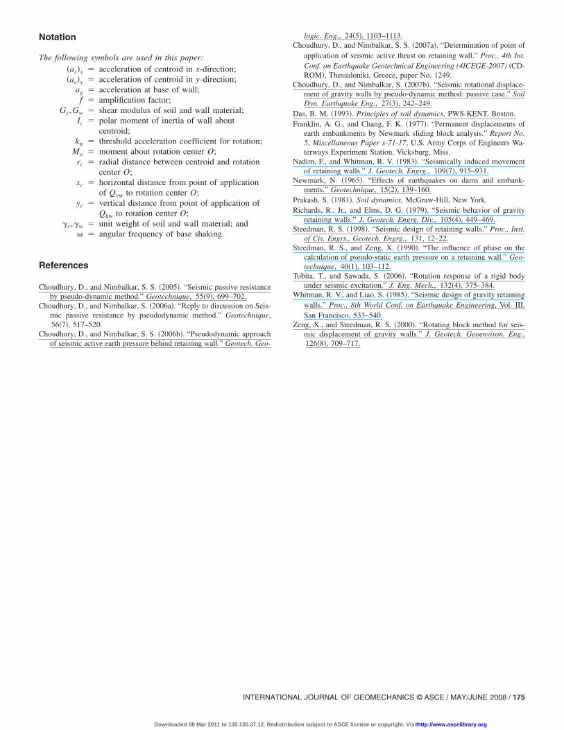
Fig. 6 shows the variation of rotational displacement ��� withhorizontal seismic acceleration coefficient �kh� for different valuesof period of lateral shaking �T� with kv=0.5kh, �=30°, �=� /2,H=10 m, bw=5 m, and t=0.5 s. From the plot, it is seen that therotational displacement ��� is highly sensitive to a period of lat-eral shaking �T�. From the plot it is also clear that for kh=0.2,rotational displacement ��� corresponding to T=0.3 s is 276.61and 756.09%, smaller than that corresponding to T=0.4 and 0.5 s,respectively. Also, experimental and/or analytical evidence pre-sented in Prakash �1981� shows that T=0.3 s is common for mostof the geotechnical structures. And hence for the other cases, theresults are reported for only the typical value of T=0.3 s.
Effect of Time of Input Motion „t… on RotationalDisplacement
Fig. 7 shows the variation of rotational displacement ��� with
Fig. 5. Variation of rotational displacement ��� for different values ofkh and kv with �=30°, �=� /2, H /=0.3, H /�=0.16, H /�=0.012,H /�=0.0077, f =1.2, H=10 m, bw=5 m, and t=0.5 s
horizontal seismic acceleration coefficient �kh� for different values
AL JOURNAL OF GEOMECHANICS © ASCE / MAY/JUNE 2008 / 173
tion subject to ASCE license or copyright. Visithttp://www.ascelibrary.org
of time history of input motion �t� with kv=0.5kh, �=30°, �=� /2, H /=0.3, H /�=0.16, H /�=0.012, H /�=0.0077, H=10 m, and bw=5 m. From the plot, it is seen that the rotationaldisplacement ��� increases with an increase in time of input mo-tion. From the plot it is also clear that for kh=0.2, rotationaldisplacement ��� corresponding to t=0.3 s is 158.19 and 390.03%smaller than that corresponding to t=0.4 and 0.5 s, respectively.
Comparison of Results
The calculation of seismic active thrust by the pseudodynamicmethod of analysis for the case of no-soil amplification �i.e., f=1.0� has already been discussed in detail by Choudhury andNimbalkar �2006b�. The present study, for the case of �=40°, �=20°, i=20°, kh=0.5, kv=0, H=10 m, bw=5 m, and t=0.5 s hasalready been reported by Zeng and Steedman �2000� consideringthe pseudostatic method of analysis for calculation of rotationaldisplacement of the wall. Again, it may be noted that the rotatingblock method originally proposed by Zeng and Steedman �2000�has already been validated through the centrifuge test results ob-tained by them, which shows the practical significance of the
Fig. 6. Variation of rotational displacement ��� with kh for differentvalues of period of lateral shaking �T� with kv=0.5kh, �=30°, �=� /2, f =1.2, H=10 m, bw=5 m, and t=0.5 s
Fig. 7. Variation of rotational displacement ��� with kh for differenttime history of input motion �t� with kv=0.5kh, �=30°, �=� /2,H /=0.3, H /�=0.16, H /�=0.012, H /�=0.0077, f =1.2, H=10 m,and bw=5 m
174 / INTERNATIONAL JOURNAL OF GEOMECHANICS © ASCE / MAY/JUN
Downloaded 08 Mar 2011 to 130.130.37.12. Redistribu
proposed rotating block method. In Table 1, a typical comparisonis shown between the present rotational displacement computedby pseudodynamic analysis and those obtained by the rotatingblock method of Zeng and Steedman �2000�, based on the pseu-dostatic analysis for the case of �=40°, �=20°, i=0°, kh=0.5,kv=0, H /=0.3, H /�=0.16, H /�=0.012, H /�=0.0077, f =1.0,H=10 m, bw=5 m, and t=0.5 s. It can be seen that the dynamicbehavior considered in the pseudodynamic method estimates thehigher values of rotational displacement of the wall compared tothe pseudostatic method of analysis. The reason for the differ-ences in results may be attributed to the basic differences in thenature of pseudostatic and pseudodynamic approaches. Also inthe present study, wall inertia and amplification factors are con-sidered but the same were not considered by Zeng and Steedman�2000�.
Summary and Conclusions
In the proposed method, by using the pseudodynamic approach,an estimation of the rotational displacement of the retaining wallby considering the effects of both the horizontal and vertical seis-mic acceleration coefficients, wall friction angle, and soil frictionangle is shown. It gives a closed-form generalized solution re-quired for the displacement-based seismic design of the retainingwall. It is evident from the proposed analysis that the rotationalmovements of the wall depend on the amplification of shear andprimary waves propagating through backfill and wall, and also onthe inertial response of the wall itself, in addition to the dynamicresponse of the backfill and the nature of the input motion. Fromthe analysis, it is clear that with the increase in amplification ofshear and primary waves propagating through the soil and wall,the rotational displacement increases. Also the wall inertia effectincreases the rotational displacement substantially. Both the hori-zontal and vertical seismic accelerations increase the rotationaldisplacements of the wall significantly. The rotational displace-ment shows a decrease with an increase in both the soil frictionangle and the wall friction angle. A comparison of the proposedmethod with available pseudostatic results shows the adverse ef-fect of dynamic loading to be considered for rotational seismicdisplacement of the retaining wall.
Acknowledgments
The writers would like to thank the anonymous reviewers of thistechnical paper for their valuable suggestions and comments to
Table 1. Typical Comparison of Present Results with PseudostaticResults of Zeng and Steedman �2000�
Sl. number Name of parameter Value
1 Threshold acceleration coefficient forrotation �ktr�
0.227 �0.377�
2 Rotational acceleration of the wall ����rad /s2�
0.499 �0.145�
3 Rotational velocity of the wall ����rad/s�
0.249 �0.072�
4 Rotational displacement ��� �deg� 13.150 �1.670�
Note: Values in parenthesis are by rotating block method based on pseu-dostatic analysis proposed by Zeng and Steedman �2000� for the givendata. Data Used: �=40°, �=20°, i=0°, kh=0.5, kv=0.0, H /=0.3, H /�=0.16, H /�=0.012, H /�=0.0077, f =1.0, H=10 m, bw=5 m, and t=0.5 s.
make it technically more sound.
E 2008
tion subject to ASCE license or copyright. Visithttp://www.ascelibrary.org
Notation
The following symbols are used in this paper:�ac�x acceleration of centroid in x-direction;�ac�y acceleration of centroid in y-direction;
ag acceleration at base of wall;f amplification factor;
Gs ,Gw shear modulus of soil and wall material;Ic polar moment of inertia of wall about
centroid;ktr threshold acceleration coefficient for rotation;
Mo moment about rotation center O;rc radial distance between centroid and rotation
center O;xc horizontal distance from point of application
of Qvw to rotation center O;yc vertical distance from point of application of
Qhw to rotation center O;�s ,�w unit weight of soil and wall material; and
� angular frequency of base shaking.
References
Choudhury, D., and Nimbalkar, S. S. �2005�. “Seismic passive resistanceby pseudo-dynamic method.” Geotechnique, 55�9�, 699–702.
Choudhury, D., and Nimbalkar, S. �2006a�. “Reply to discussion on Seis-mic passive resistance by pseudodynamic method.” Geotechnique,56�7�, 517–520.
Choudhury, D., and Nimbalkar, S. S. �2006b�. “Pseudodynamic approach
of seismic active earth pressure behind retaining wall.” Geotech. Geo-INTERNATION
Downloaded 08 Mar 2011 to 130.130.37.12. Redistribu
logic. Eng., 24�5�, 1103–1113.Choudhury, D., and Nimbalkar, S. S. �2007a�. “Determination of point of
application of seismic active thrust on retaining wall.” Proc., 4th Int.Conf. on Earthquake Geotechnical Engineering (4ICEGE-2007) �CD-ROM�, Thessaloniki, Greece, paper No. 1249.
Choudhury, D., and Nimbalkar, S. �2007b�. “Seismic rotational displace-ment of gravity walls by pseudo-dynamic method: passive case.” SoilDyn. Earthquake Eng., 27�3�, 242–249.
Das, B. M. �1993�. Principles of soil dynamics, PWS-KENT, Boston.Franklin, A. G., and Chang, F. K. �1977�. “Permanent displacements of
earth embankments by Newmark sliding block analysis.” Report No.5, Miscellaneous Paper s-71-17, U.S. Army Corps of Engineers Wa-terways Experiment Station, Vicksburg, Miss.
Nadim, F., and Whitman, R. V. �1983�. “Seismically induced movementof retaining walls.” J. Geotech. Engrg., 109�7�, 915–931.
Newmark, N. �1965�. “Effects of earthquakes on dams and embank-ments.” Geotechnique, 15�2�, 139–160.
Prakash, S. �1981�. Soil dynamics, McGraw-Hill, New York.Richards, R., Jr., and Elms, D. G. �1979�. “Seismic behavior of gravity
retaining walls.” J. Geotech. Engrg. Div., 105�4�, 449–469.Steedman, R. S. �1998�. “Seismic design of retaining walls.” Proc., Inst.
of Civ. Engrs., Geotech. Engrg., 131, 12–22.Steedman, R. S., and Zeng, X. �1990�. “The influence of phase on the
calculation of pseudo-static earth pressure on a retaining wall.” Geo-technique, 40�1�, 103–112.
Tobita, T., and Sawada, S. �2006�. “Rotation response of a rigid bodyunder seismic excitation.” J. Eng. Mech., 132�4�, 375–384.
Whitman, R. V., and Liao, S. �1985�. “Seismic design of gravity retainingwalls.” Proc., 8th World Conf. on Earthquake Engineering, Vol. III,San Francisco, 533–540.
Zeng, X., and Steedman, R. S. �2000�. “Rotating block method for seis-mic displacement of gravity walls.” J. Geotech. Geoenviron. Eng.,
126�8�, 709–717.AL JOURNAL OF GEOMECHANICS © ASCE / MAY/JUNE 2008 / 175
tion subject to ASCE license or copyright. Visithttp://www.ascelibrary.org


