Embed Size (px)
Citation preview
June 2014
Angle encoders
Without Integral Bearing
2
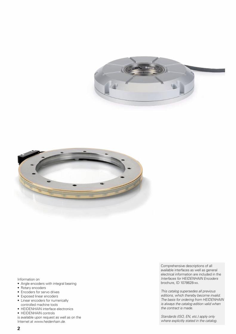
Information on• Angle encoders with integral bearing• Rotary encoders• Encoders for servo drives• Exposed linear encoders• Linear encoders for numerically
controlled machine tools• HEIDENHAIN interface electronics• HEIDENHAIN controlsis available upon request as well as on the Internet at www.heidenhain.de.
Comprehensive descriptions of all available interfaces as well as general electrical information are included in the Interfaces for HEIDENHAIN Encoders brochure, ID 1078628-xx.
This catalog supersedes all previous editions, which thereby become invalid.The basis for ordering from HEIDENHAIN is always the catalog edition valid when the contract is made.
Standards (ISO, EN, etc.) apply only where explicitly stated in the catalog.
Contents
Overview
Rotary encoders from HEIDENHAIN 4
Selection guide Angle encoders and modular encoders without integral bearing
6
Absolute angle encoders with integral bearing
10
Incremental angle encoders with integral bearing
12
Technical features and mounting information
Measuring principles Measuring standard, incremental measuring principle
14
Scanning the measuring standard 16
Measuring accuracy 18
Reliability 22
Mechanical design types and mounting 24
General mechanical information 32
Specifi cations Series or model Graduation accuracy
Angle encoders without integral bearing
ERP 880 ± 0.9” 34
ERP 4080/ERP 8080 To ± 1.0” 36
ERO 6000 series To ± 2.0” 38
ERO 6180 ± 10” 40
ERA 4000 series To ± 1.7” 42
ERA 7000 Series To ± 1.6” 48
ERA 8000 series To ± 1.9” 52
Electrical connection
Interfaces and
pin layouts
Incremental signals 1VPP 56
TTL 57
Cables and connecting elements 58
HEIDENHAIN testing equipment 61
Interface electronics 64
Evaluation electronics units 66
4
Rotary encoders from HEIDENHAIN
The term angle encoder is typically used to describe encoders that have an accuracy of better than ± 5” and a line count above 10 000.
These angle encoders are found in applications that require the highly
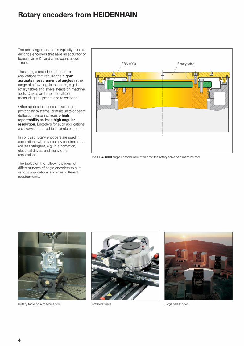
accurate measurement of angles in the range of a few angular seconds, e.g. in rotary tables and swivel heads on machine tools, C axes on lathes, but also in measuring equipment and telescopes.
Other applications, such as scanners, positioning systems, printing units or beam defl ection systems, require high
repeatability and/or a high angular
resolution. Encoders for such applications are likewise referred to as angle encoders.
In contrast, rotary encoders are used in applications where accuracy requirements are less stringent, e.g. in automation, electrical drives, and many other applications.
The tables on the following pages list different types of angle encoders to suit various applications and meet different requirements.
The ERA 4000 angle encoder mounted onto the rotary table of a machine tool
Rotary tableERA 4000
Rotary table on a machine tool X-Y-theta table Large telescopes
5
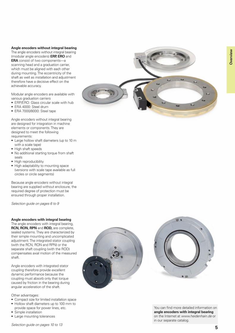
Angle encoders without integral bearing
The angle encoders without integral bearing (modular angle encoders) ERP, ERO and ERA consist of two components—a scanning head and a graduation carrier, which must be aligned with each other during mounting. The eccentricity of the shaft as well as installation and adjustment therefore have a decisive effect on the achievable accuracy.
Modular angle encoders are available with various graduation carriers• ERP/ERO: Glass circular scale with hub• ERA 4000: Steel drum• ERA 7000/8000: Steel tape
Angle encoders without integral bearing are designed for integration in machine elements or components. They are designed to meet the following requirements:• Large hollow shaft diameters (up to 10 m
with a scale tape)• High shaft speeds• No additional starting torque from shaft
seals• High reproducibility• High adaptability to mounting space
(versions with scale tape available as full circles or circle segments)
Because angle encoders without integral bearing are supplied without enclosure, the required degree of protection must be ensured through proper installation.
Selection guide on pages 6 to 9
Angle encoders with integral bearing
The angle encoders with integral bearing, RCN, RON, RPN and ROD, are complete, sealed systems. They are characterized by their simple mounting and uncomplicated adjustment. The integrated stator coupling (with the RCN, RON and RPN) or the separate shaft coupling (with the ROD) compensates axial motion of the measured shaft.
Angle encoders with integrated stator coupling therefore provide excellent dynamic performance because the coupling must absorb only that torque caused by friction in the bearing during angular acceleration of the shaft.
Other advantages:• Compact size for limited installation space• Hollow shaft diameters up to 100 mm to
provide space for power lines, etc.• Simple installation• Large mounting tolerances
Selection guide on pages 10 to 13
You can fi nd more detailed information on angle encoders with integral bearing on the Internet at www.heidenhain.de or in our separate catalog.
Overv
iew
6
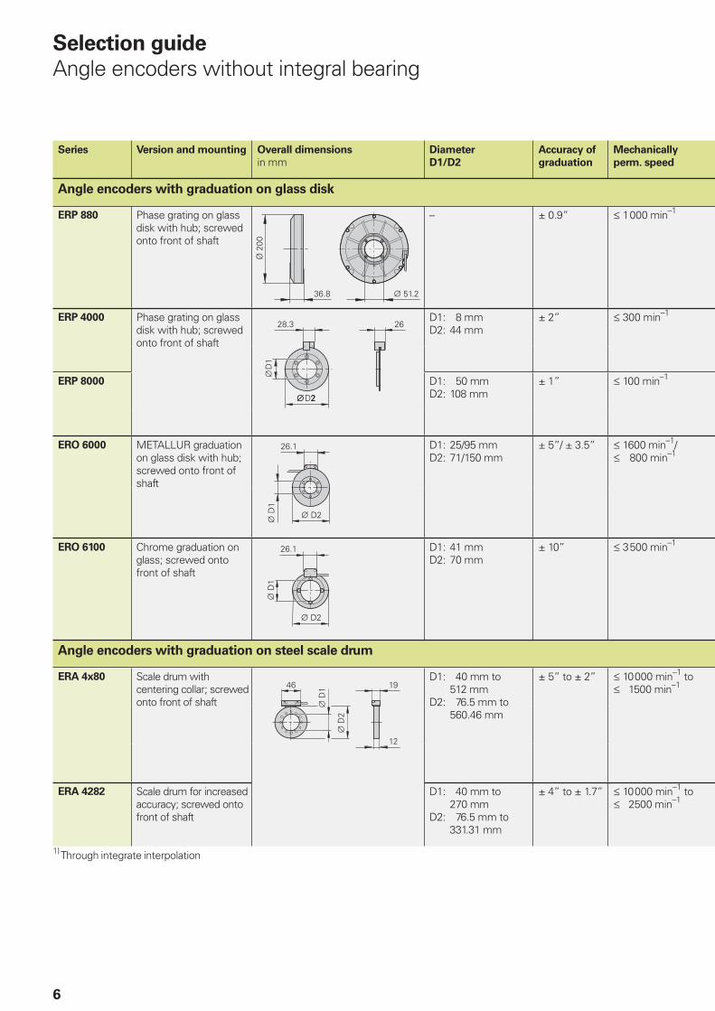
Selection guide
Angle encoders without integral bearing
Series Version and mounting Overall dimensions
in mmDiameter
D1/D2
Accuracy of
graduation
Mechanically
perm. speed
Angle encoders with graduation on glass disk
ERP 880 Phase grating on glass disk with hub; screwed onto front of shaft
– ± 0.9” 1 000 min–1
ERP 4000 Phase grating on glass disk with hub; screwed onto front of shaft
D1: 8 mmD2: 44 mm
± 2” 300 min–1
ERP 8000 D1: 50 mmD2: 108 mm
± 1” 100 min–1
ERO 6000 METALLUR graduation on glass disk with hub; screwed onto front of shaft
D1: 25/95 mmD2: 71/150 mm
± 5”/ ± 3.5” 1600 min–1/ 800 min–1
ERO 6100 Chrome graduation on glass; screwed onto front of shaft
D1: 41 mmD2: 70 mm
± 10” 3 500 min–1
Angle encoders with graduation on steel scale drum
ERA 4x80 Scale drum with centering collar; screwed onto front of shaft
D1: 40 mm to 512 mm
D2: 76.5 mm to 560.46 mm
± 5” to ± 2” 10 000 min–1 to 1500 min–1
ERA 4282 Scale drum for increased accuracy; screwed onto front of shaft
D1: 40 mm to 270 mm
D2: 76.5 mm to 331.31 mm
± 4” to ± 1.7” 10 000 min–1 to 2500 min–1
1) Through integrate interpolation
ERP 880
ERP 4080
ERO 6080
ERA 4000
7
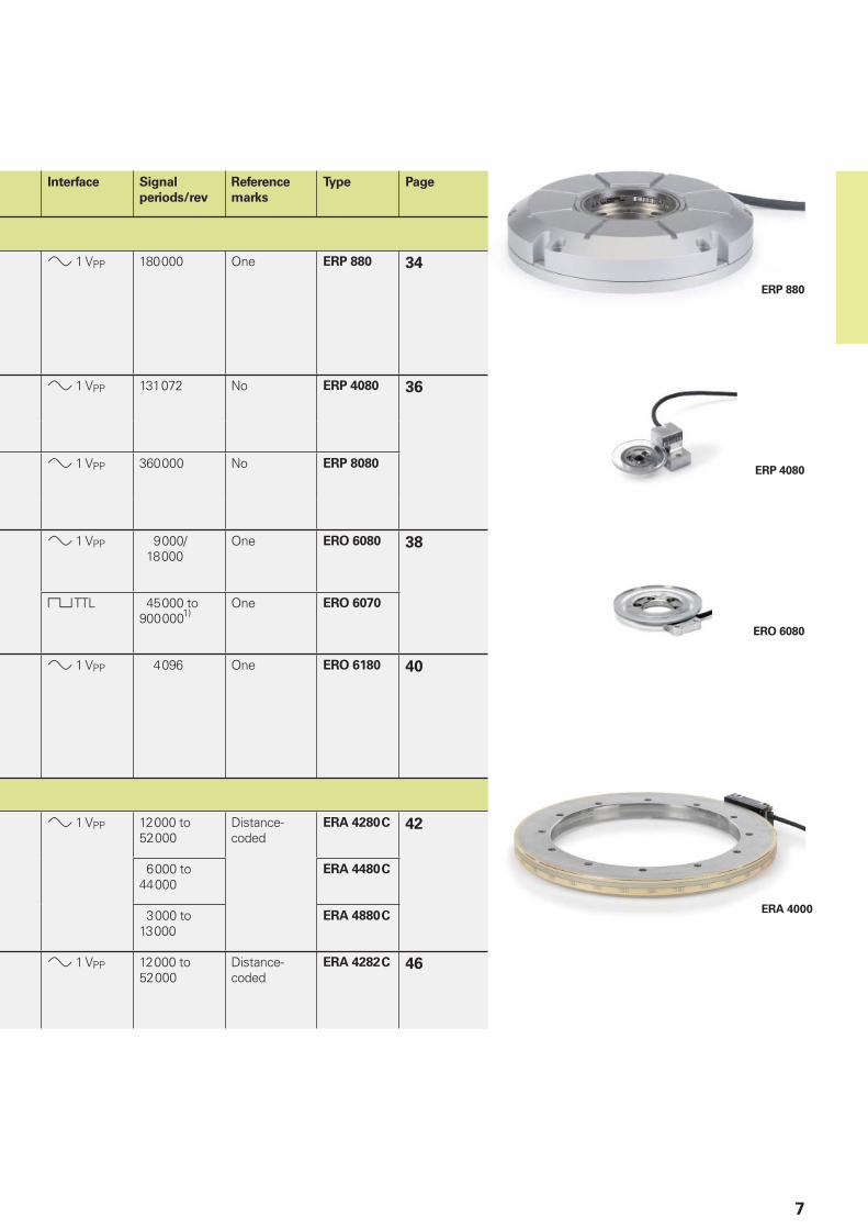
Interface Signal
periods/rev
Reference
marks
Type Page
1 VPP 180 000 One ERP 880 34
1 VPP 131 072 No ERP 4080 36
1 VPP 360 000 No ERP 8080
1 VPP 9 000/ 18 000
One ERO 6080 38
TTL 45 000 to 900 0001)
One ERO 6070
1 VPP 4 096 One ERO 6180 40
1 VPP 12 000 to 52 000
Distance-coded
ERA 4280 C 42
6 000 to 44 000
ERA 4480 C
3 000 to 13 000
ERA 4880 C
1 VPP 12 000 to 52 000
Distance-coded
ERA 4282 C 46
8
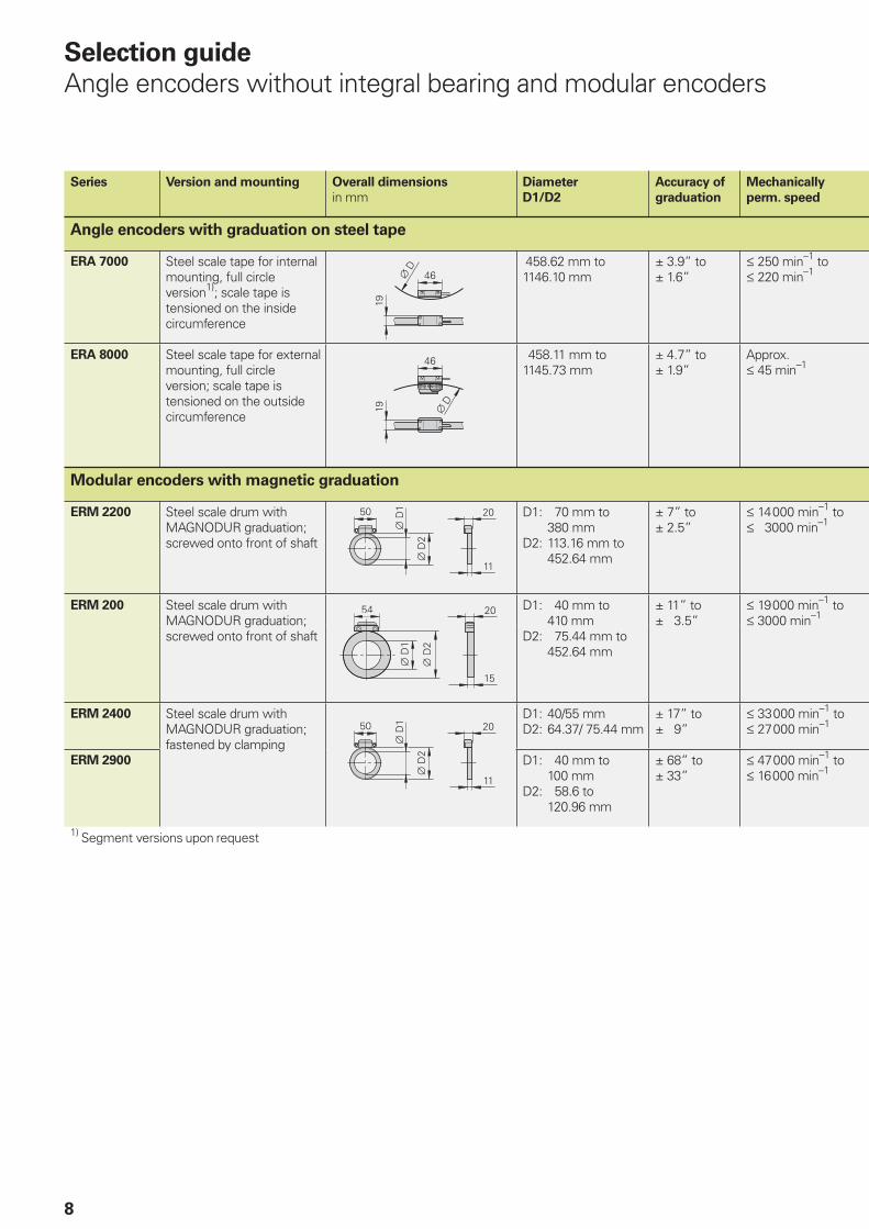
Selection guide
Angle encoders without integral bearing and modular encoders
Series Version and mounting Overall dimensions
in mmDiameter
D1/D2
Accuracy of
graduation
Mechanically
perm. speed
Angle encoders with graduation on steel tape
ERA 7000 Steel scale tape for internal mounting, full circle version1); scale tape is tensioned on the inside circumference
458.62 mm to 1146.10 mm
± 3.9” to ± 1.6”
250 min–1 to 220 min–1
ERA 8000 Steel scale tape for external mounting, full circle version; scale tape is tensioned on the outside circumference
458.11 mm to 1145.73 mm
± 4.7” to ± 1.9”
Approx. 45 min–1
Modular encoders with magnetic graduation
ERM 2200 Steel scale drum with MAGNODUR graduation; screwed onto front of shaft
D1: 70 mm to 380 mm
D2: 113.16 mm to 452.64 mm
± 7” to ± 2.5”
14 000 min–1 to 3000min–1
ERM 200 Steel scale drum with MAGNODUR graduation; screwed onto front of shaft
D1: 40 mm to 410 mm
D2: 75.44 mm to 452.64 mm
± 11” to ± 3.5”
19 000 min–1 to 3000min–1
ERM 2400 Steel scale drum with MAGNODUR graduation; fastened by clamping
D1: 40/55 mmD2: 64.37/ 75.44 mm
± 17” to ± 9”
33 000 min–1to 27 000 min–1
ERM 2900 D1: 40 mm to 100 mm
D2: 58.6 to 120.96 mm
± 68” to ± 33”
47 000 min–1 to 16 000 min–1
1) Segment versions upon request
ERA 7480
ERA 8480
ERM 280
ERM 2200
9
Interface Signal
periods/rev
Reference
marks
Type Page
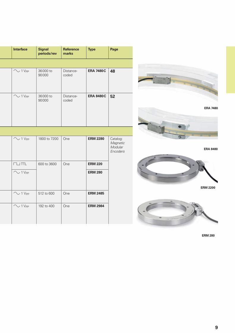
1 VPP 36 000 to 90 000
Distance-coded
ERA 7480 C 48
1 VPP 36 000 to 90 000
Distance-coded
ERA 8480 C 52
1VPP 1800 to 7200 One ERM 2280 Catalog: Magnetic Modular Encoders
TTL 600 to 3600 One ERM 220
1 VPP ERM 280
1VPP 512 to 600 One ERM 2485
1 VPP 192 to 400 One ERM 2984
10
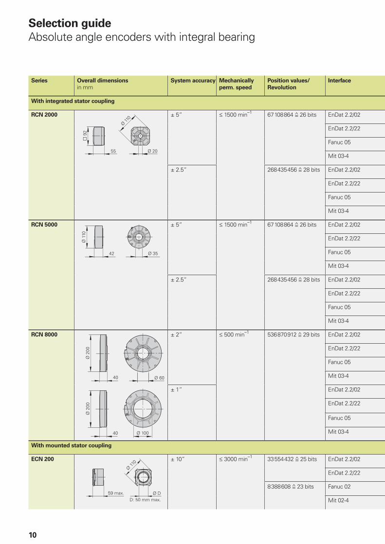
Selection guide
Absolute angle encoders with integral bearing
Series Overall dimensions
in mmSystem accuracy Mechanically
perm. speed
Position values/
Revolution
Interface
With integrated stator coupling
RCN 2000 ± 5” 1500 min–1 67 108 864 26 bits EnDat 2.2/02
EnDat 2.2/22
Fanuc 05
Mit 03-4
± 2.5” 268 435 456 28 bits EnDat 2.2/02
EnDat 2.2/22
Fanuc 05
Mit 03-4
RCN 5000 ± 5” 1500 min–1 67 108 864 26 bits EnDat 2.2/02
EnDat 2.2/22
Fanuc 05
Mit 03-4
± 2.5” 268 435 456 28 bits EnDat 2.2/02
EnDat 2.2/22
Fanuc 05
Mit 03-4
RCN 8000 ± 2” 500 min–1 536 870 912 29 bits EnDat 2.2/02
EnDat 2.2/22
Fanuc 05
Mit 03-4
± 1” EnDat 2.2/02
EnDat 2.2/22
Fanuc 05
Mit 03-4
With mounted stator coupling
ECN 200 ± 10” 3000 min–1 33 554 432 25 bits EnDat 2.2/02
EnDat 2.2/22
8 388 608 23 bits Fanuc 02
Mit 02-4
60
RCN 2000
RCN 5000
RCN 8000
60 mm
RCN 8000
100 mm
ECN 200
50 mm
11
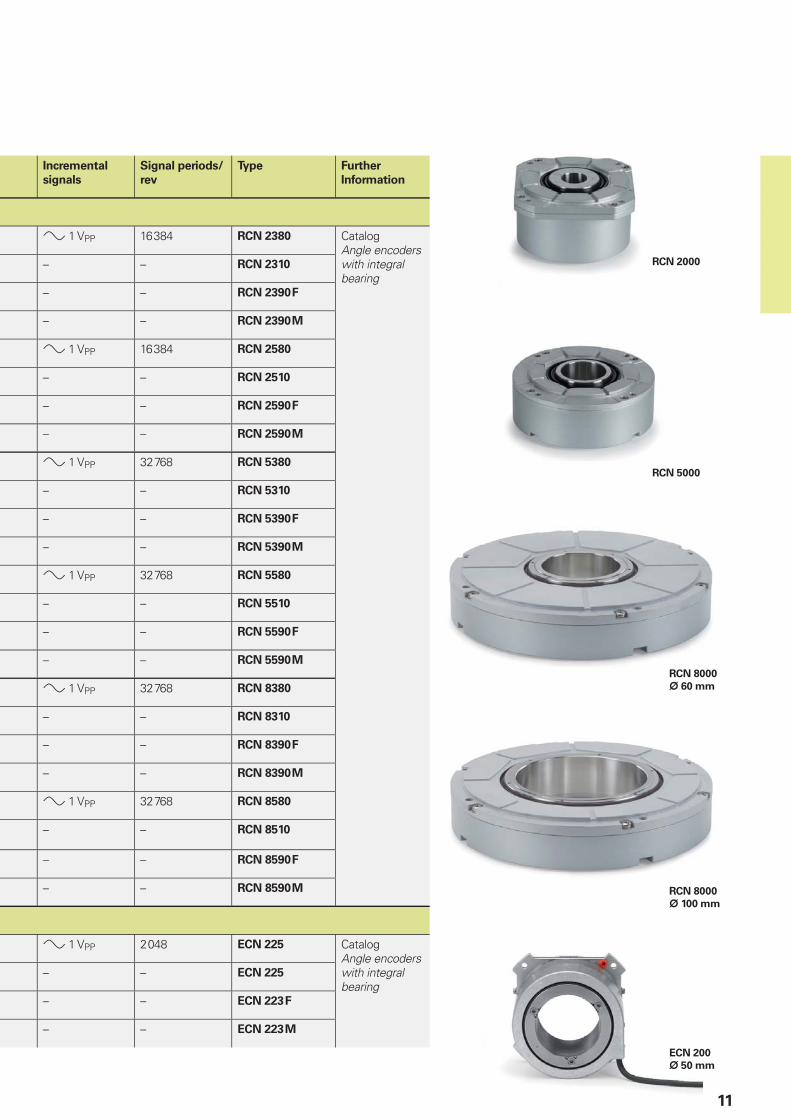
Incremental
signals
Signal periods/
rev
Type Further
Information
1 VPP 16 384 RCN 2380 CatalogAngle encoders with integral bearing
– – RCN 2310
– – RCN 2390 F
– – RCN 2390 M
1 VPP 16 384 RCN 2580
– – RCN 2510
– – RCN 2590 F
– – RCN 2590 M
1 VPP 32 768 RCN 5380
– – RCN 5310
– – RCN 5390 F
– – RCN 5390 M
1 VPP 32 768 RCN 5580
– – RCN 5510
– – RCN 5590 F
– – RCN 5590 M
1 VPP 32 768 RCN 8380
– – RCN 8310
– – RCN 8390 F
– – RCN 8390 M
1 VPP 32 768 RCN 8580
– – RCN 8510
– – RCN 8590 F
– – RCN 8590 M
1 VPP 2 048 ECN 225 CatalogAngle encoders with integral bearing
– – ECN 225
– – ECN 223 F
– – ECN 223 M
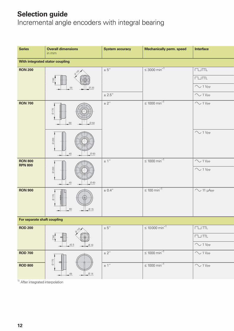
12
Series Overall dimensions
in mmSystem accuracy Mechanically perm. speed Interface
With integrated stator coupling
RON 200 ± 5” 3000min–1 TTL
TTL
1VPP
± 2.5” 1 VPP
RON 700 ± 2” 1000min–1 1 VPP
1VPP
RON 800
RPN 800
± 1” 1000 min–1 1 VPP
1VPP
RON 900 ± 0.4” 100min–1 11µAPP
For separate shaft coupling
ROD 200 ± 5” 10 000min–1 TTL
TTL
1VPP
ROD 700 ± 2” 1000min–1 1 VPP
ROD 800 ± 1” 1000min–1 1 VPP
1) After integrated interpolation
Selection guide
Incremental angle encoders with integral bearing
ROD 780
RON 285
RON 786
RON 905
ROD 280
13
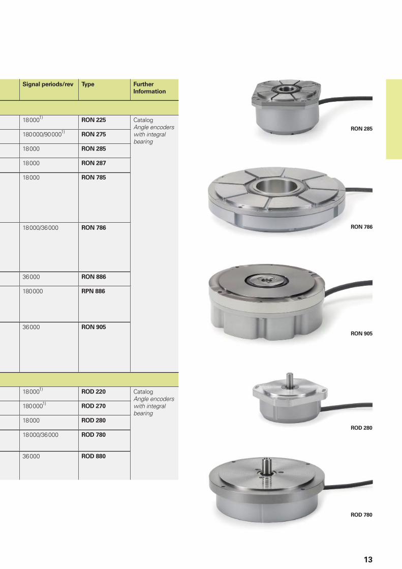
Signal periods/rev Type Further
Information
18 0001)RON 225 Catalog
Angle encoders with integral bearing
180 000/90 0001)RON 275
18 000 RON 285
18 000 RON 287
18 000 RON 785
18 000/36 000 RON 786
36 000 RON 886
180 000 RPN 886
36 000 RON 905
18 0001)ROD 220 Catalog
Angle encoders with integral bearing
180 0001)ROD 270
18 000 ROD 280
18 000/36 000 ROD 780
36 000 ROD 880
14
Measuring
principles
Measuring standard
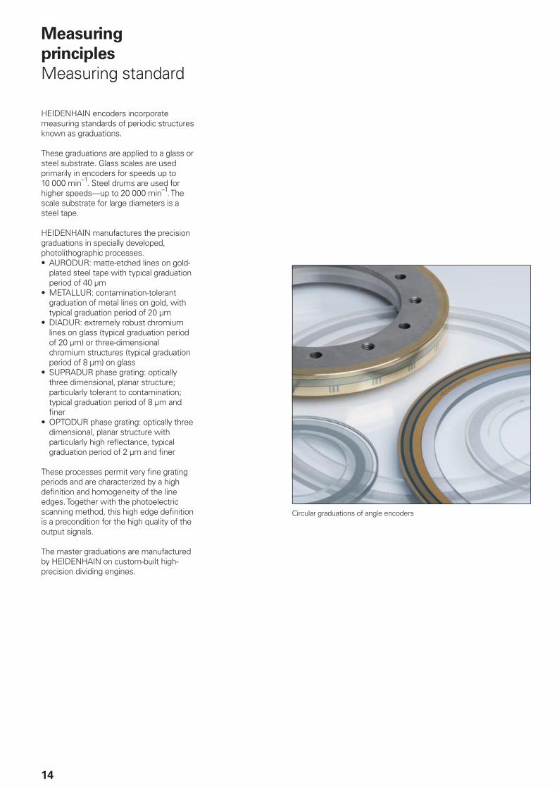
Circular graduations of angle encoders
HEIDENHAIN encoders incorporate measuring standards of periodic structures known as graduations.
These graduations are applied to a glass or steel substrate. Glass scales are used primarily in encoders for speeds up to 10 000 min–1. Steel drums are used for higher speeds—up to 20 000 min–1. The scale substrate for large diameters is a steel tape.
HEIDENHAIN manufactures the precision graduations in specially developed, photolithographic processes. • AURODUR: matte-etched lines on gold-
plated steel tape with typical graduation period of 40 µm
• METALLUR: contamination-tolerant graduation of metal lines on gold, with typical graduation period of 20 µm
• DIADUR: extremely robust chromium lines on glass (typical graduation period of 20 µm) or three-dimensional chromium structures (typical graduation period of 8 µm) on glass
• SUPRADUR phase grating: optically three dimensional, planar structure; particularly tolerant to contamination; typical graduation period of 8 µm and fi ner
• OPTODUR phase grating: optically three dimensional, planar structure with particularly high refl ectance, typical graduation period of 2 µm and fi ner
These processes permit very fi ne grating periods and are characterized by a high defi nition and homogeneity of the line edges. Together with the photoelectric scanning method, this high edge defi nition is a precondition for the high quality of the output signals.
The master graduations are manufactured by HEIDENHAIN on custom-built high-precision dividing engines.
15
1 = (abs A–sgn A–1) x I + (sgn A–sgn D) x abs MRR
where:
A = 2 x abs MRR–I
Incremental measuring method
With the incremental measuring
method, the graduation consists of a periodic grating structure. The position information is obtained by counting the individual increments (measuring steps) from some point of origin. Since an absolute reference is required to ascertain positions, the measuring standard is provided with an additional track that bears a reference mark. The absolute position on the scale, established by the reference mark, is gated with exactly one measuring step.
The reference mark must therefore be scanned to establish an absolute reference or to fi nd the last selected datum.
In some cases, this may require rotation by up to nearly 360°. To speed and simplify such “reference runs,” many HEIDENHAIN encoders feature distance-coded
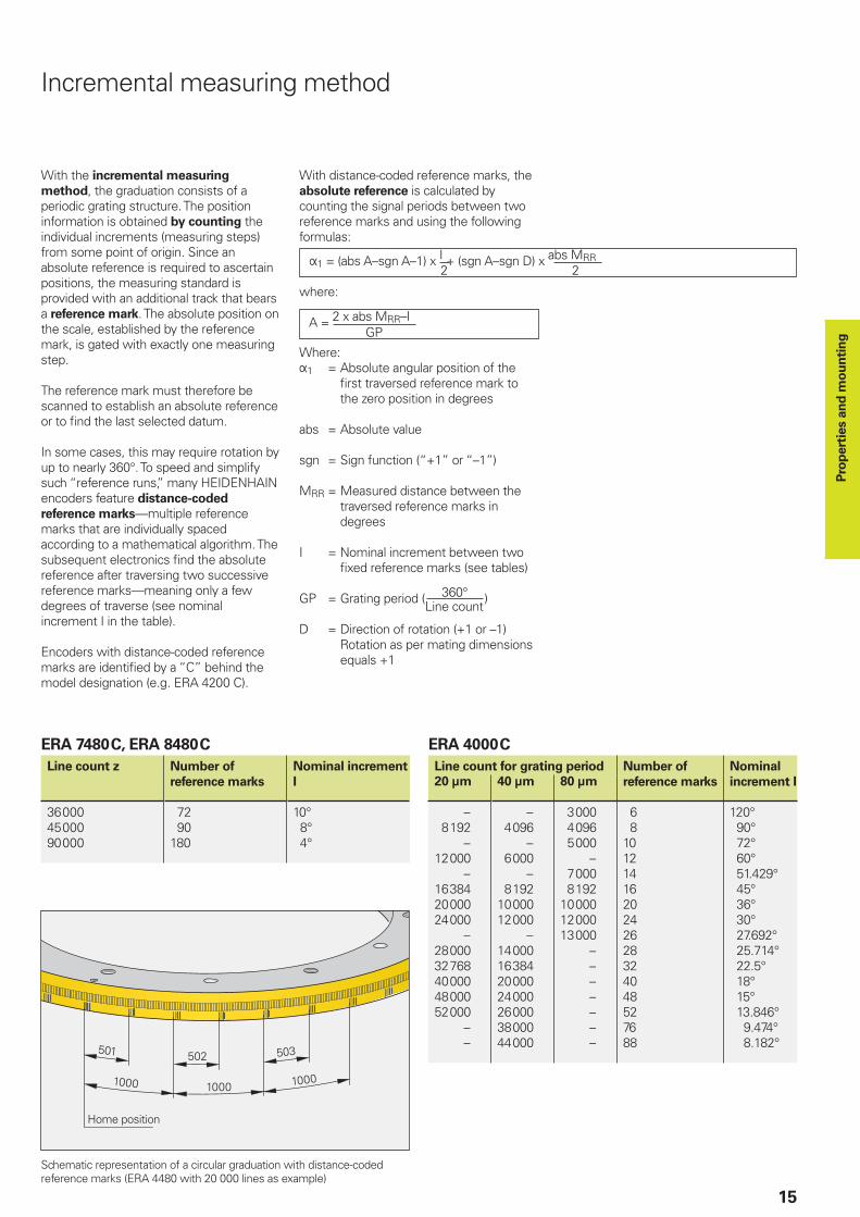
reference marks—multiple reference marks that are individually spaced according to a mathematical algorithm. The subsequent electronics fi nd the absolute reference after traversing two successive reference marks—meaning only a few degrees of traverse (see nominal increment I in the table).
Encoders with distance-coded reference marks are identifi ed by a “C” behind the model designation (e.g. ERA 4200 C).
With distance-coded reference marks, the absolute reference is calculated by counting the signal periods between two reference marks and using the following formulas:
2 2
Where:1 = Absolute angular position of the
fi rst traversed reference mark to the zero position in degrees
abs = Absolute value
sgn = Sign function (“+1” or “–1”)
MRR = Measured distance between the traversed reference marks in degrees
I = Nominal increment between two fi xed reference marks (see tables)
GP = Grating period (360° )
D = Direction of rotation (+1 or –1)Rotation as per mating dimensions equals +1
Line count
ERA 7480 C, ERA 8480 C
Line count z Number of
reference marks
Nominal increment
I
36 00045 00090 000
72 90180
10° 8° 4°
GP
Schematic representation of a circular graduation with distance-coded reference marks (ERA 4480 with 20 000 lines as example)
Pro
pert
ies a
nd
mo
un
tin
g
ERA 4000 C
Line count for grating period Number of
reference marks
Nominal
increment I20 µm 40 µm 80 µm
– 8 192 –12 000 –16 38420 00024 000 –28 00032 76840 00048 00052 000 – –
– 4 096 – 6 000 – 8 19210 00012 000 –14 00016 38420 00024 00026 00038 00044 000
3 000 4 096 5 000 – 7 000 8 19210 00012 00013 000 – – – – – – –
6 81012141620242628324048527688
120° 90° 72° 60° 51.429° 45° 36° 30° 27.692° 25.714° 22.5° 18° 15° 13.846° 9.474° 8.182°
Home position
16
Most HEIDENHAIN encoders operate using the principle of photoelectric scanning. Photoelectric scanning of a measuring standard is contact-free, and as such, free of wear. This method detects even very fi ne lines, no more than a few microns wide, and generates output signals with very small signal periods.
The fi ner the grating period of a measuring standard is, the greater the effect of diffraction on photoelectric scanning. HEIDENHAIN uses two scanning principles with angle encoders:
• The imaging scanning principle for grating periods from 10 µm to approx. 70 µm.
• The interferential scanning principle for very fi ne graduations with grating periods of 4 µm and fi ner.
Scanning the measuring standard
Photoelectric scanning
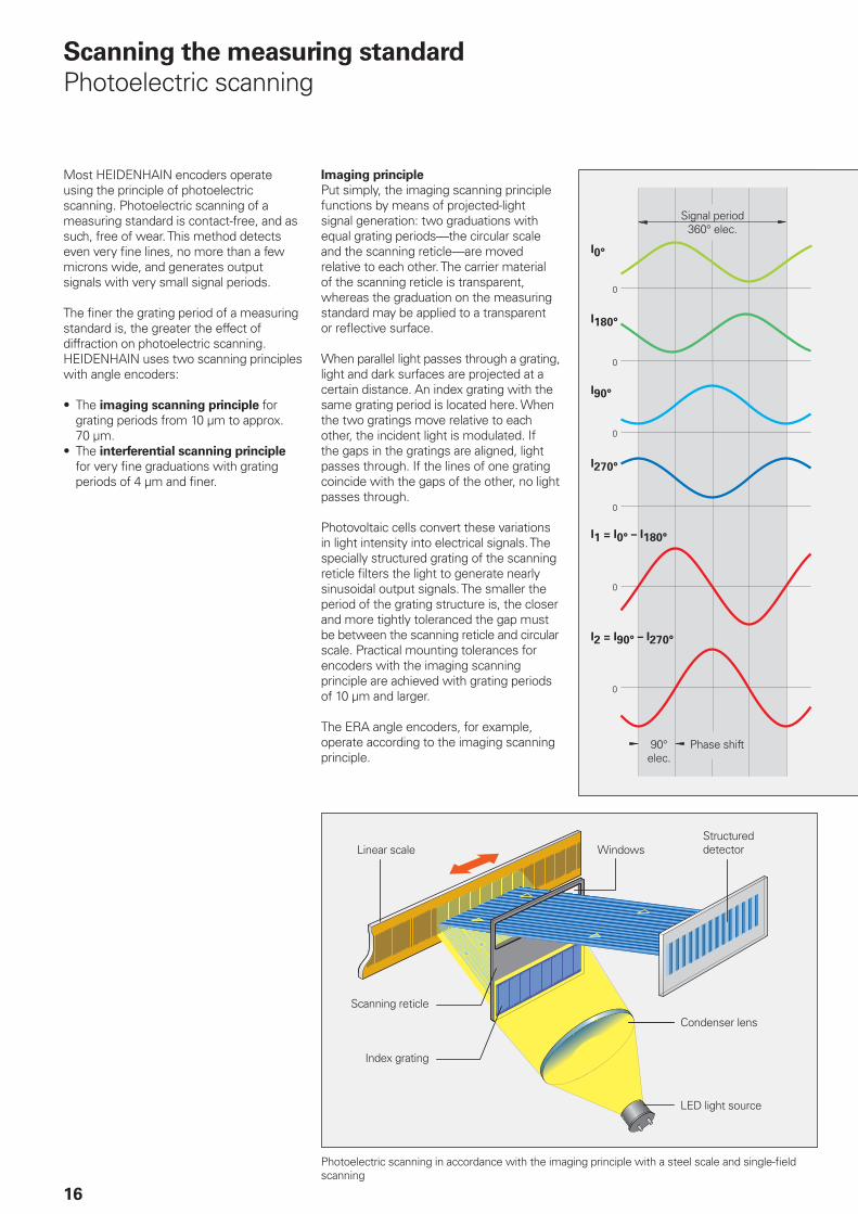
Imaging principle
Put simply, the imaging scanning principle functions by means of projected-light signal generation: two graduations with equal grating periods—the circular scale and the scanning reticle—are moved relative to each other. The carrier material of the scanning reticle is transparent, whereas the graduation on the measuring standard may be applied to a transparent or refl ective surface.
When parallel light passes through a grating, light and dark surfaces are projected at a certain distance. An index grating with the same grating period is located here. When the two gratings move relative to each other, the incident light is modulated. If the gaps in the gratings are aligned, light passes through. If the lines of one grating coincide with the gaps of the other, no light passes through.
Photovoltaic cells convert these variations in light intensity into electrical signals. The specially structured grating of the scanning reticle fi lters the light to generate nearly sinusoidal output signals. The smaller the period of the grating structure is, the closer and more tightly toleranced the gap must be between the scanning reticle and circular scale. Practical mounting tolerances for encoders with the imaging scanning principle are achieved with grating periods of 10 µm and larger.
The ERA angle encoders, for example, operate according to the imaging scanning principle.
Linear scale WindowsStructured detector
Scanning reticle
Index grating
Condenser lens
LED light source
Photoelectric scanning in accordance with the imaging principle with a steel scale and single-fi eld scanning
Signal period360° elec.
90° elec.
Phase shift
17
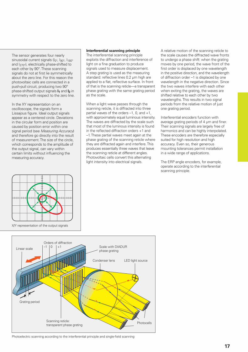
Interferential scanning principle
The interferential scanning principle exploits the diffraction and interference of light on a fi ne graduation to produce signals used to measure displacement.A step grating is used as the measuring standard: refl ective lines 0.2 µm high are applied to a fl at, refl ective surface. In front of that is the scanning reticle—a transparent phase grating with the same grating period as the scale.
When a light wave passes through the scanning reticle, it is diffracted into three partial waves of the orders –1, 0, and +1, with approximately equal luminous intensity. The waves are diffracted by the scale such that most of the luminous intensity is found in the refl ected diffraction orders +1 and –1. These partial waves meet again at the phase grating of the scanning reticle where they are diffracted again and interfere. This produces essentially three waves that leave the scanning reticle at different angles. Photovoltaic cells convert this alternating light intensity into electrical signals.
A relative motion of the scanning reticle to the scale causes the diffracted wave fronts to undergo a phase shift: when the grating moves by one period, the wave front of the fi rst order is displaced by one wavelength in the positive direction, and the wavelength of diffraction order –1 is displaced by one wavelength in the negative direction. Since the two waves interfere with each other when exiting the grating, the waves are shifted relative to each other by two wavelengths. This results in two signal periods from the relative motion of just one grating period.
Interferential encoders function with average grating periods of 4 µm and fi ner. Their scanning signals are largely free of harmonics and can be highly interpolated. These encoders are therefore especially suited for high resolution and high accuracy. Even so, their generous mounting tolerances permit installation in a wide range of applications.
The ERP angle encoders, for example, operate according to the interferential scanning principle.
Photoelectric scanning according to the interferential principle and single-fi eld scanning
Linear scale
Orders of diffraction–1 0 +1 Scale with DIADUR
phase grating
Grating period
Scanning reticle:transparent phase grating
Photocells
LED light sourceCondenser lens
The sensor generates four nearly sinusoidal current signals (I0°, I90°, I180° and I270°), electrically phase-shifted to each other by 90°. These scanning signals do not at fi rst lie symmetrically about the zero line. For this reason the photovoltaic cells are connected in a push-pull circuit, producing two 90° phase-shifted output signals I1 and I2 in symmetry with respect to the zero line.
In the XY representation on an oscilloscope, the signals form a Lissajous fi gure. Ideal output signals appear as a centered circle. Deviations in the circular form and position are caused by position error within one signal period (see Measuring Accuracy) and therefore go directly into the result of measurement. The size of the circle, which corresponds to the amplitude of the output signal, can vary within certain limits without infl uencing the measuring accuracy.
X/Y representation of the output signals
18
Measuring accuracy
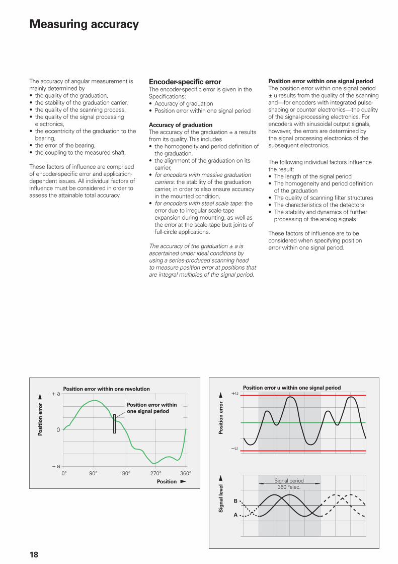
Position error within one revolution
Position error within
one signal period
Position error u within one signal period
Signal period360 °elec.
Po
sit
ion
err
or
Position
Po
sit
ion
err
or
Sig
nal le
vel
The accuracy of angular measurement is mainly determined by• the quality of the graduation,• the stability of the graduation carrier,• the quality of the scanning process,• the quality of the signal processing
electronics,• the eccentricity of the graduation to the
bearing,• the error of the bearing,• the coupling to the measured shaft.
These factors of infl uence are comprised of encoder-specifi c error and application-dependent issues. All individual factors of infl uence must be considered in order to assess the attainable total accuracy.
Encoder-specifi c errorThe encoder-specifi c error is given in the Specifi cations: • Accuracy of graduation• Position error within one signal period
Accuracy of graduation
The accuracy of the graduation ± a results from its quality. This includes• the homogeneity and period defi nition of
the graduation,• the alignment of the graduation on its
carrier,• for encoders with massive graduation
carriers: the stability of the graduation carrier, in order to also ensure accuracy in the mounted condition,
• for encoders with steel scale tape: the error due to irregular scale-tape expansion during mounting, as well as the error at the scale-tape butt joints of full-circle applications.
The accuracy of the graduation ± a is ascertained under ideal conditions by using a series-produced scanning head to measure position error at positions that are integral multiples of the signal period.
Position error within one signal period
The position error within one signal period ± u results from the quality of the scanning and—for encoders with integrated pulse-shaping or counter electronics—the quality of the signal-processing electronics. For encoders with sinusoidal output signals, however, the errors are determined by the signal processing electronics of the subsequent electronics.
The following individual factors infl uence the result:• The length of the signal period• The homogeneity and period defi nition
of the graduation• The quality of scanning fi lter structures• The characteristics of the detectors• The stability and dynamics of further
processing of the analog signals
These factors of infl uence are to be considered when specifying position error within one signal period.
19
Position error within one signal period ± u is specifi ed in percent of the signal period. For modular angle encoders without integral bearing the value is typically better than ± 1 % of the signal period (ERP 880: ± 1.5 %). You will fi nd the specifi ed values in the Specifi cations.
Position errors within one signal period already become apparent in very small angular motions and in repeated meas-urements. They especially lead to speed ripples in the speed control loop.
Application-dependent errorThe mounting and adjustment of the scanning head, in addition to the given encoder-specifi c error, normally have a signifi cant effect on the accuracy that can be achieved by encoders without integral
bearings. Of particular importance are the mounting eccentricity of the graduation and the radial runout of the measured shaft. The application-dependent error values must be measured and calculated individually in order to evaluate the total accuracy.
In contrast, the specifi ed system accuracy for encoders with integral bearing already includes the error of the bearing and the shaft coupling (see catalog Angle Encoders with Integral Bearing).
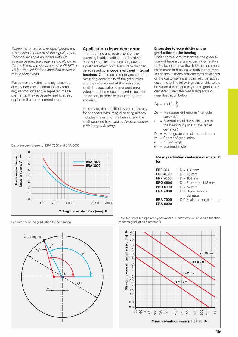
Errors due to eccentricity of the
graduation to the bearing
Under normal circumstances, the gradua-tion will have a certain eccentricity relative to the bearing once the disk/hub assembly, scale drum or steel scale tape is mounted. In addition, dimensional and form deviations of the customer’s shaft can result in added eccentricity. The following relationship exists between the eccentricity e, the graduation diameter D and the measuring error (see illustration below):
= ± 412 · De
= Measurement error in ” (angular seconds)
e = Eccentricity of the scale drum to the bearing in µm (1/2 the radial deviation)
D = Mean graduation diameter in mmM = Center of graduation = “True” angle‘ = Scanned angle
Eccentricity of the graduation to the bearing
Scanning unit
Resultant measuring error for various eccentricity values e as a function of mean graduation diameter D
Measu
rin
g e
rro
r
[an
gu
lar
seco
nd
s]
Mean graduation diameter D [mm]
Mean graduation centerline diameter D
for:
ERP 880
ERP 4000
ERP 8000
ERO 6000
ERO 6100
ERA 4000
ERA 7000
ERA 8000
D = 126 mmD = 40 mmD = 104 mmD = 64 mm or 142 mmD = 64 mmD Drum outside
diameterD Scale mating diameter
En
co
der-
sp
ecifi c
err
or
[an
gu
lar
seco
nd
s]
Mating surface diameter [mm]
Encoder-specifi c error of ERA 7000 and ERA 8000
20
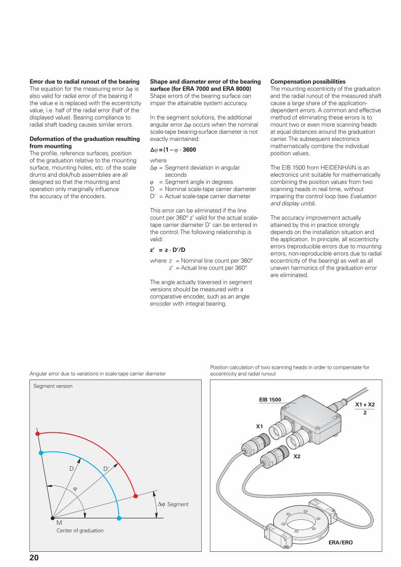
Angular error due to variations in scale-tape carrier diameterPosition calculation of two scanning heads in order to compensate for eccentricity and radial runout
Segment version
Center of graduation
Segment
Error due to radial runout of the bearing
The equation for the measuring error is also valid for radial error of the bearing if the value e is replaced with the eccentricity value, i.e. half of the radial error (half of the displayed value). Bearing compliance to radial shaft loading causes similar errors.
Deformation of the graduation resulting
from mounting
The profi le, reference surfaces, position of the graduation relative to the mounting surface, mounting holes, etc. of the scale drums and disk/hub assemblies are all designed so that the mounting and operation only marginally infl uence the accuracy of the encoders.
Shape and diameter error of the bearing
surface (for ERA 7000 and ERA 8000)
Shape errors of the bearing surface can impair the attainable system accuracy.
In the segment solutions, the additional angular error occurs when the nominal scale-tape bearing-surface diameter is not exactly maintained:
= (1 – · 3600
where = Segment deviation in angular
seconds = Segment angle in degreesD = Nominal scale-tape carrier diameterD‘ = Actual scale-tape carrier diameter
This error can be eliminated if the line count per 360° z’ valid for the actual scale-tape carrier diameter D’ can be entered in the control. The following relationship is valid:
z‘ = z · D‘/D
where z = Nominal line count per 360°z‘ = Actual line count per 360°
The angle actually traversed in segment versions should be measured with a comparative encoder, such as an angle encoder with integral bearing.
Compensation possibilities
The mounting eccentricity of the graduation and the radial runout of the measured shaft cause a large share of the application-dependent errors. A common and effective method of eliminating these errors is to mount two or even more scanning heads at equal distances around the graduation carrier. The subsequent electronics mathematically combine the individual position values.
The EIB 1500 from HEIDENHAIN is an electronics unit suitable for mathematically combining the position values from two scanning heads in real time, without impairing the control loop (see Evaluation and display units).
The accuracy improvement actually attained by this in practice strongly depends on the installation situation and the application. In principle, all eccentricity errors (reproducible errors due to mounting errors, non-reproducible errors due to radial eccentricity of the bearing) as well as all uneven harmonics of the graduation error are eliminated.
2
1
21
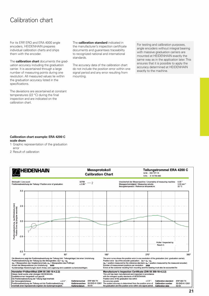
Calibration chart example: ERA 4200 C
scale drum
1 Graphic representation of the graduation error
2 Result of calibration
For its ERP, ERO and ERA 4000 angle encoders, HEIDENHAIN prepares individual calibration charts and ships them with the encoder.
The calibration chart documents the grad-uation accuracy including the graduation carrier. It is ascertained through a large number of measuring points during one revolution. All measured values lie within the graduation accuracy listed in the specifi cations.
The deviations are ascertained at constant temperatures (22 °C) during the fi nal inspection and are indicated on the calibration chart.
The calibration standard indicated in the manufacturer’s inspection certifi cate documents and guarantees traceability to recognized national and international standards.
The accuracy data of the calibration chart do not include the position error within one signal period and any error resulting from mounting.
Calibration chart
For testing and calibration purposes, angle encoders without integral bearing with massive graduation carriers are mounted at HEIDENHAIN exactly the same way as in the application later. This ensures that it is possible to apply the accuracy determined at HEIDENHAIN exactly to the machine.
2
2.5
2
2.5
2
2.5
22
Reliability
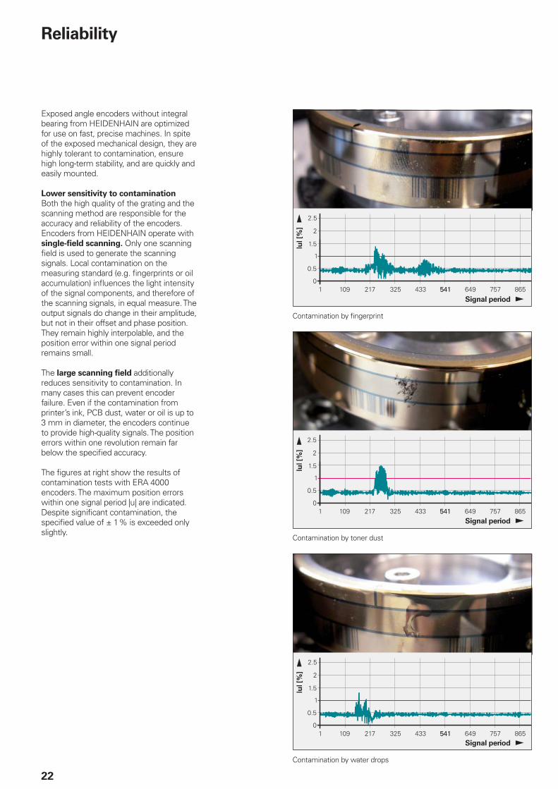
Exposed angle encoders without integral bearing from HEIDENHAIN are optimized for use on fast, precise machines. In spite of the exposed mechanical design, they are highly tolerant to contamination, ensure high long-term stability, and are quickly and easily mounted.
Lower sensitivity to contamination
Both the high quality of the grating and the scanning method are responsible for the accuracy and reliability of the encoders. Encoders from HEIDENHAIN operate with single-fi eld scanning. Only one scanning fi eld is used to generate the scanning signals. Local contamination on the measuring standard (e.g. fi ngerprints or oil accumulation) infl uences the light intensity of the signal components, and therefore of the scanning signals, in equal measure. The output signals do change in their amplitude, but not in their offset and phase position. They remain highly interpolable, and the position error within one signal period remains small.
The large scanning fi eld additionally reduces sensitivity to contamination. In many cases this can prevent encoder failure. Even if the contamination from printer’s ink, PCB dust, water or oil is up to 3 mm in diameter, the encoders continue to provide high-quality signals. The position errors within one revolution remain far below the specifi ed accuracy.
The fi gures at right show the results of contamination tests with ERA 4000 encoders. The maximum position errors within one signal period |u| are indicated. Despite signifi cant contamination, the specifi ed value of ± 1 % is exceeded only slightly.
Signal period
Signal period
Signal period
Contamination by fi ngerprint
Contamination by toner dust
Contamination by water drops
23
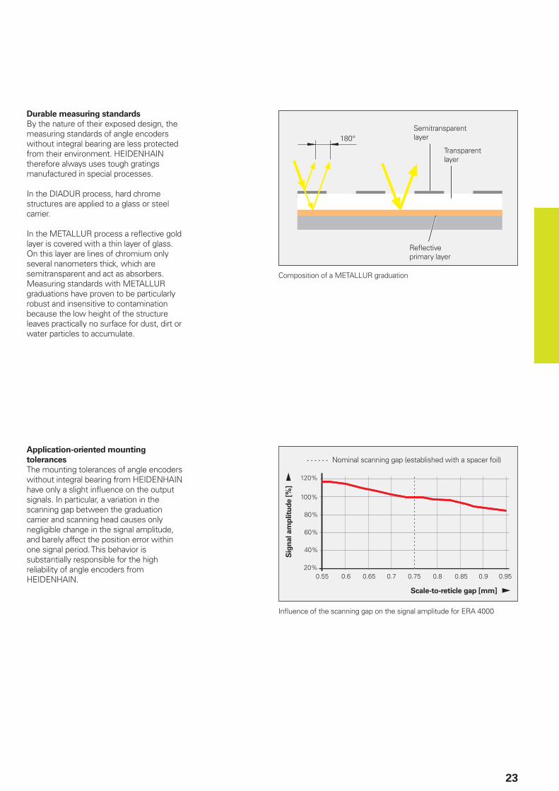
Durable measuring standards
By the nature of their exposed design, the measuring standards of angle encoders without integral bearing are less protected from their environment. HEIDENHAIN therefore always uses tough gratings manufactured in special processes.
In the DIADUR process, hard chrome structures are applied to a glass or steel carrier.
In the METALLUR process a refl ective gold layer is covered with a thin layer of glass. On this layer are lines of chromium only several nanometers thick, which are semitransparent and act as absorbers. Measuring standards with METALLUR graduations have proven to be particularly robust and insensitive to contamination because the low height of the structure leaves practically no surface for dust, dirt or water particles to accumulate.
Composition of a METALLUR graduation
Transparent layer
Refl ective primary layer
Semitransparent layer
Nominal scanning gap (established with a spacer foil)
Scale-to-reticle gap [mm]
Sig
nal am
plitu
de [
%]
Application-oriented mounting
tolerances
The mounting tolerances of angle encoders without integral bearing from HEIDENHAIN have only a slight infl uence on the output signals. In particular, a variation in the scanning gap between the graduation carrier and scanning head causes only negligible change in the signal amplitude, and barely affect the position error within one signal period. This behavior is substantially responsible for the high reliability of angle encoders from HEIDENHAIN.
Infl uence of the scanning gap on the signal amplitude for ERA 4000
24
Angle encoders without integral bearing consist of a scanning head and a graduation carrier. The graduation carrier can either be a scale tape or a massive component, such as a scale drum or disk/hub assembly. The motion of the scanning head and graduation relative to each other is determined solely via the machine bearing. For this reason the machine must be designed from the very beginning to meet the following prerequisites:• The bearing must be so designed that
the mounting tolerances of the encoders are maintained and the accuracy requirements expected for the axis are fulfi lled (see Specifi cations) during mounting as well as operation.
• The mounting surface for the graduation carrier must meet the demands of the respective encoder regarding fl atness, roundness, eccentricity and the diameter.
• To facilitate adjustment of the scanning head to the graduation, the scanning head should be fastened to a bracket or by using appropriate fi xed stops.
All angle encoders without integral bearing with massive graduation carriers are designed so that the specifi ed accuracy can actually be achieved in the application. The mounting methods and alignment strategies ensure the highest possible reproducibility.
Mechanical design types and mounting
General information
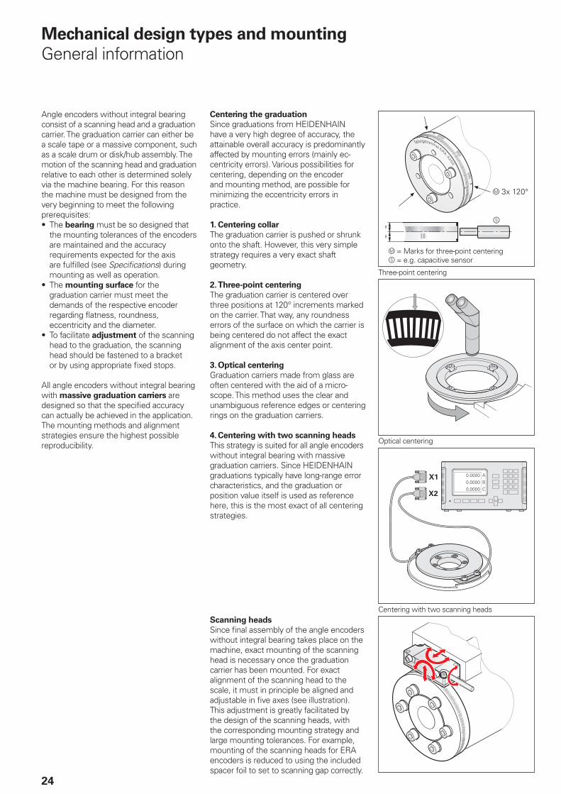
Centering the graduation
Since graduations from HEIDENHAIN have a very high degree of accuracy, the attainable overall accuracy is predominantly affected by mounting errors (mainly ec-centricity errors). Various possibilities for centering, depending on the encoder and mounting method, are possible for minimizing the eccentricity errors in practice.
1. Centering collar
The graduation carrier is pushed or shrunk onto the shaft. However, this very simple strategy requires a very exact shaft geometry.
2. Three-point centering
The graduation carrier is centered over three positions at 120° increments marked on the carrier. That way, any roundness errors of the surface on which the carrier is being centered do not affect the exact alignment of the axis center point.
3. Optical centering
Graduation carriers made from glass are often centered with the aid of a micro-scope. This method uses the clear and unambiguous reference edges or centering rings on the graduation carriers.
4. Centering with two scanning heads
This strategy is suited for all angle encoders without integral bearing with massive graduation carriers. Since HEIDENHAIN graduations typically have long-range error characteristics, and the graduation or position value itself is used as reference here, this is the most exact of all centering strategies.
Scanning heads
Since fi nal assembly of the angle encoders without integral bearing takes place on the machine, exact mounting of the scanning head is necessary once the graduation carrier has been mounted. For exact alignment of the scanning head to the scale, it must in principle be aligned and adjustable in fi ve axes (see illustration). This adjustment is greatly facilitated by the design of the scanning heads, with the corresponding mounting strategy and large mounting tolerances. For example, mounting of the scanning heads for ERA encoders is reduced to using the included spacer foil to set to scanning gap correctly.
Three-point centering
Optical centering
Centering with two scanning heads
= Marks for three-point centering = e.g. capacitive sensor
25
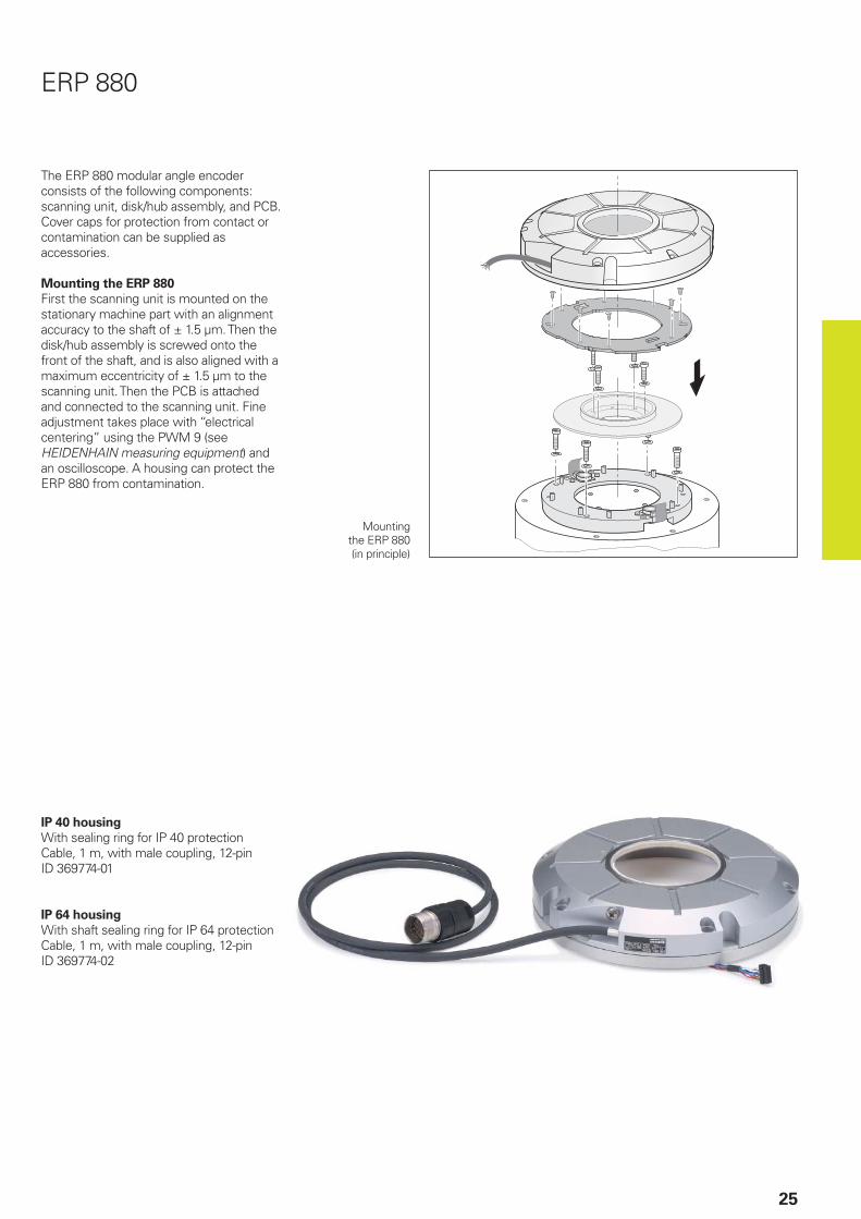
The ERP 880 modular angle encoder consists of the following components: scanning unit, disk/hub assembly, and PCB. Cover caps for protection from contact or contamination can be supplied as accessories.
Mounting the ERP 880
First the scanning unit is mounted on the stationary machine part with an alignment accuracy to the shaft of ± 1.5 µm. Then the disk/hub assembly is screwed onto the front of the shaft, and is also aligned with a maximum eccentricity of ± 1.5 µm to the scanning unit. Then the PCB is attached and connected to the scanning unit. Fine adjustment takes place with “electrical centering” using the PWM 9 (see HEIDENHAIN measuring equipment) and an oscilloscope. A housing can protect the ERP 880 from contamination.
Mounting the ERP 880 (in principle)
IP 40 housing
With sealing ring for IP 40 protectionCable, 1 m, with male coupling, 12-pinID 369774-01
IP 64 housing
With shaft sealing ring for IP 64 protectionCable, 1 m, with male coupling, 12-pinID 369774-02
ERP 880
26
Mechanical design types and mounting
ERP 4080/ERP 8080
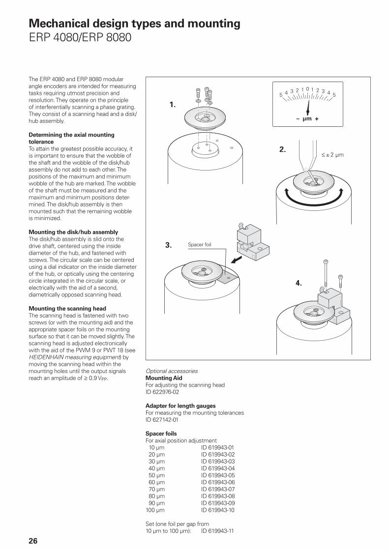
The ERP 4080 and ERP 8080 modular angle encoders are intended for measuring tasks requiring utmost precision and resolution. They operate on the principle of interferentially scanning a phase grating. They consist of a scanning head and a disk/hub assembly.
Determining the axial mounting
tolerance
To attain the greatest possible accuracy, it is important to ensure that the wobble of the shaft and the wobble of the disk/hub assembly do not add to each other. The positions of the maximum and minimum wobble of the hub are marked. The wobble of the shaft must be measured and the maximum and minimum positions deter-mined. The disk/hub assembly is then mounted such that the remaining wobble is minimized.
Mounting the disk/hub assembly
The disk/hub assembly is slid onto the drive shaft, centered using the inside diameter of the hub, and fastened with screws. The circular scale can be centered using a dial indicator on the inside diameter of the hub, or optically using the centering circle integrated in the circular scale, or electrically with the aid of a second, diametrically opposed scanning head.
Mounting the scanning head
The scanning head is fastened with two screws (or with the mounting aid) and the appropriate spacer foils on the mounting surface so that it can be moved slightly. The scanning head is adjusted electronically with the aid of the PWM 9 or PWT 18 (see HEIDENHAIN measuring equipment) by moving the scanning head within the mounting holes until the output signals reach an amplitude of 0.9 VPP.
Optional accessoriesMounting Aid
For adjusting the scanning headID 622976-02
Adapter for length gauges
For measuring the mounting tolerancesID 627142-01
Spacer foils
For axial position adjustment 10 µm ID 619943-01 20 µm ID 619943-02 30 µm ID 619943-03 40 µm ID 619943-04 50 µm ID 619943-05 60 µm ID 619943-06 70 µm ID 619943-07 80 µm ID 619943-08 90 µm ID 619943-09100 µm ID 619943-10
Set (one foil per gap from10 µm to 100 µm): ID 619943-11
Spacer foil
27
ERO 6000, ERO 6100
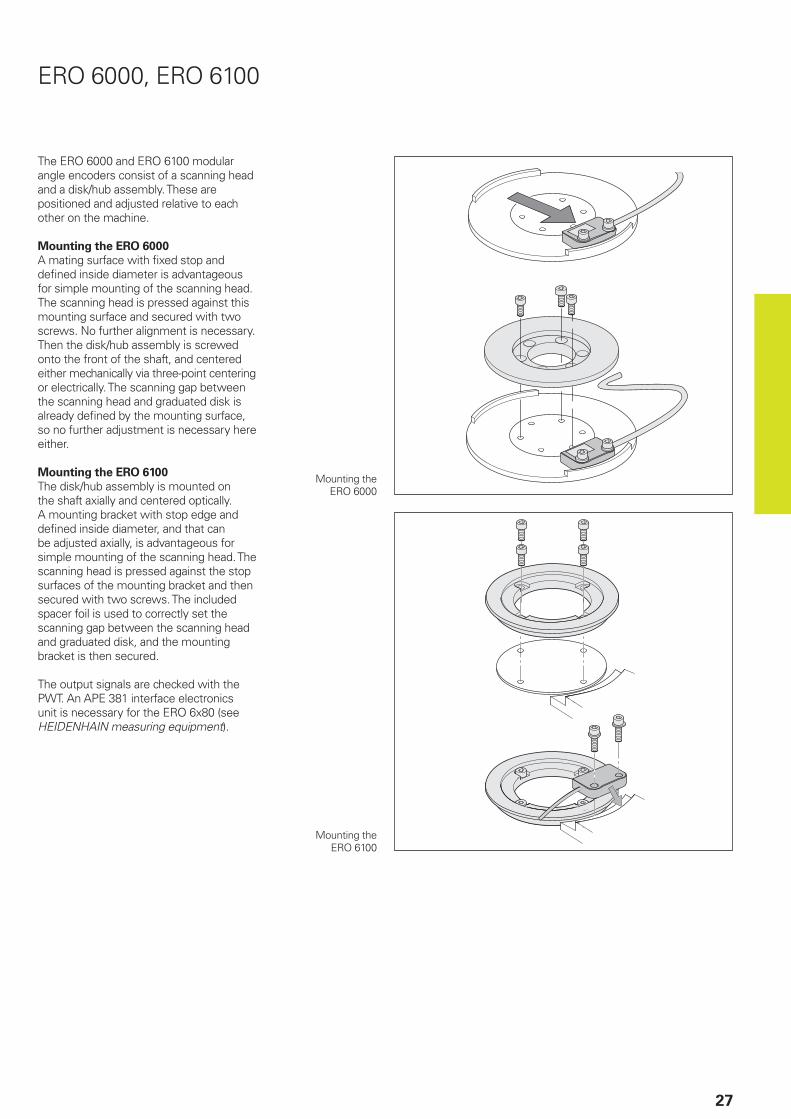
The ERO 6000 and ERO 6100 modular angle encoders consist of a scanning head and a disk/hub assembly. These are positioned and adjusted relative to each other on the machine.
Mounting the ERO 6000
A mating surface with fi xed stop and defi ned inside diameter is advantageous for simple mounting of the scanning head. The scanning head is pressed against this mounting surface and secured with two screws. No further alignment is necessary. Then the disk/hub assembly is screwed onto the front of the shaft, and centered either mechanically via three-point centering or electrically. The scanning gap between the scanning head and graduated disk is already defi ned by the mounting surface, so no further adjustment is necessary here either.
Mounting the ERO 6100
The disk/hub assembly is mounted on the shaft axially and centered optically. A mounting bracket with stop edge and defi ned inside diameter, and that can be adjusted axially, is advantageous for simple mounting of the scanning head. The scanning head is pressed against the stop surfaces of the mounting bracket and then secured with two screws. The included spacer foil is used to correctly set the scanning gap between the scanning head and graduated disk, and the mounting bracket is then secured.
The output signals are checked with the PWT. An APE 381 interface electronics unit is necessary for the ERO 6x80 (see HEIDENHAIN measuring equipment).
Mounting the ERO 6000
Mounting the ERO 6100
28
Mechanical design types and mounting
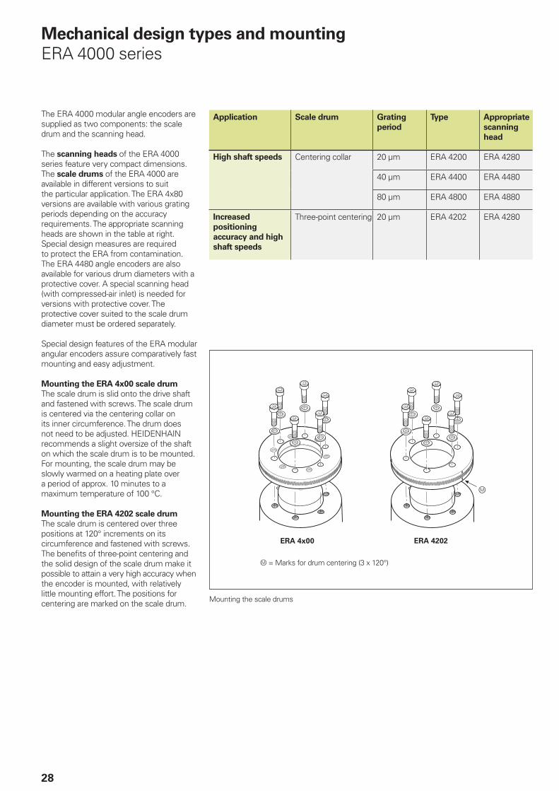
ERA 4000 series
Application Scale drum Grating
period
Type Appropriate
scanning
head
High shaft speeds Centering collar 20 µm ERA 4200 ERA 4280
40 µm ERA 4400 ERA 4480
80 µm ERA 4800 ERA 4880
Increased
positioning
accuracy and high
shaft speeds
Three-point centering 20 µm ERA 4202 ERA 4280
= Marks for drum centering (3 x 120°)
Mounting the scale drums
The ERA 4000 modular angle encoders are supplied as two components: the scale drum and the scanning head.
The scanning heads of the ERA 4000 series feature very compact dimensions. The scale drums of the ERA 4000 are available in different versions to suit the particular application. The ERA 4x80 versions are available with various grating periods depending on the accuracy requirements. The appropriate scanning heads are shown in the table at right. Special design measures are required to protect the ERA from contamination. The ERA 4480 angle encoders are also available for various drum diameters with a protective cover. A special scanning head (with compressed-air inlet) is needed for versions with protective cover. The protective cover suited to the scale drum diameter must be ordered separately.
Special design features of the ERA modular angular encoders assure comparatively fast mounting and easy adjustment.
Mounting the ERA 4x00 scale drum
The scale drum is slid onto the drive shaft and fastened with screws. The scale drum is centered via the centering collar on its inner circumference. The drum does not need to be adjusted. HEIDENHAIN recommends a slight oversize of the shaft on which the scale drum is to be mounted. For mounting, the scale drum may be slowly warmed on a heating plate over a period of approx. 10 minutes to a maximum temperature of 100 °C.
Mounting the ERA 4202 scale drum
The scale drum is centered over three positions at 120° increments on its circumference and fastened with screws. The benefi ts of three-point centering and the solid design of the scale drum make it possible to attain a very high accuracy when the encoder is mounted, with relatively little mounting effort. The positions for centering are marked on the scale drum.
29
Mounting the Scanning Head
Eccentric bushing for fi ne adjustment
Spacer foil
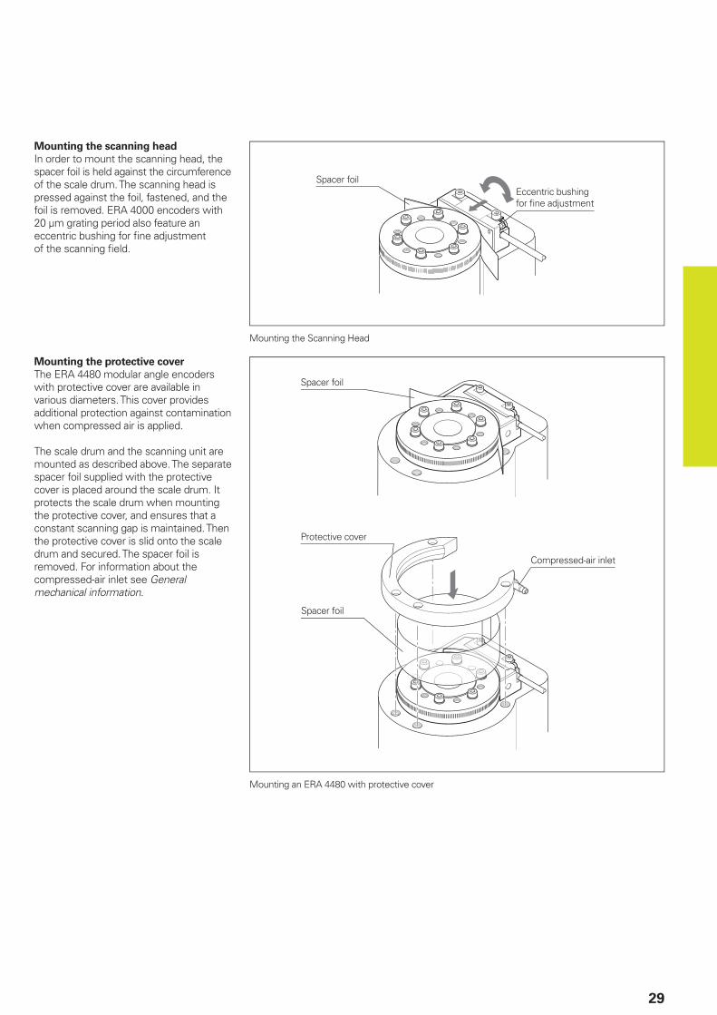
Mounting the scanning head
In order to mount the scanning head, the spacer foil is held against the circumference of the scale drum. The scanning head is pressed against the foil, fastened, and the foil is removed. ERA 4000 encoders with 20 µm grating period also feature an eccentric bushing for fi ne adjustment of the scanning fi eld.
Mounting the protective cover
The ERA 4480 modular angle encoders with protective cover are available in various diameters. This cover provides additional protection against contamination when compressed air is applied.
The scale drum and the scanning unit are mounted as described above. The separate spacer foil supplied with the protective cover is placed around the scale drum. It protects the scale drum when mounting the protective cover, and ensures that a constant scanning gap is maintained. Then the protective cover is slid onto the scale drum and secured. The spacer foil is removed. For information about the compressed-air inlet see General mechanical information.
Protective cover
Compressed-air inlet
Spacer foil
Mounting an ERA 4480 with protective cover
Spacer foil
30
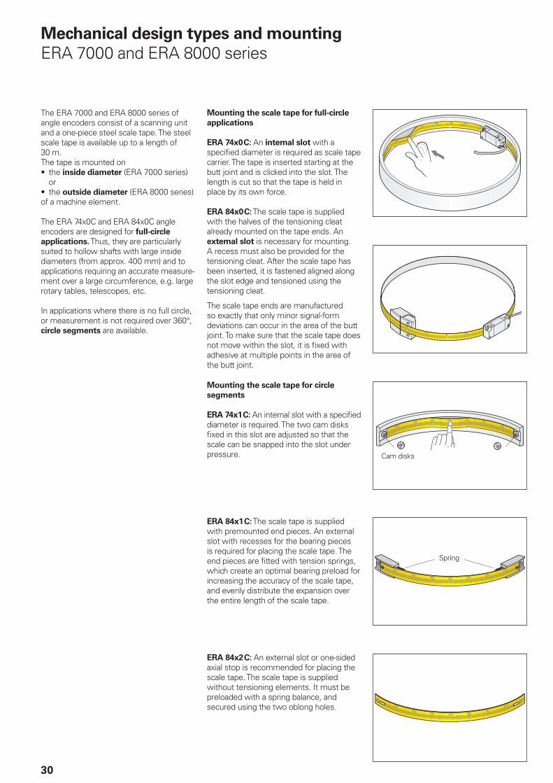
The ERA 7000 and ERA 8000 series of angle encoders consist of a scanning unit and a one-piece steel scale tape. The steel scale tape is available up to a length of 30 m.The tape is mounted on• the inside diameter (ERA 7000 series)
or• the outside diameter (ERA 8000 series)of a machine element.
The ERA 74x0C and ERA 84x0C angle encoders are designed for full-circle
applications. Thus, they are particularly suited to hollow shafts with large inside diameters (from approx. 400 mm) and to applications requiring an accurate measure-ment over a large circumference, e.g. large rotary tables, telescopes, etc.
In applications where there is no full circle, or measurement is not required over 360°, circle segments are available.
Mechanical design types and mounting
ERA 7000 and ERA 8000 series
Mounting the scale tape for full-circle
applications
ERA 74x0 C: An internal slot with a specifi ed diameter is required as scale tape carrier. The tape is inserted starting at the butt joint and is clicked into the slot. The length is cut so that the tape is held in place by its own force.
ERA 84x0 C: The scale tape is supplied with the halves of the tensioning cleat already mounted on the tape ends. An external slot is necessary for mounting. A recess must also be provided for the tensioning cleat. After the scale tape has been inserted, it is fastened aligned along the slot edge and tensioned using the tensioning cleat.
The scale tape ends are manufactured so exactly that only minor signal-form deviations can occur in the area of the butt joint. To make sure that the scale tape does not move within the slot, it is fi xed with adhesive at multiple points in the area of the butt joint.
Mounting the scale tape for circle
segments
ERA 74x1 C: An internal slot with a specifi ed diameter is required. The two cam disks fi xed in this slot are adjusted so that the scale can be snapped into the slot under pressure.
ERA 84x1 C: The scale tape is supplied with premounted end pieces. An external slot with recesses for the bearing pieces is required for placing the scale tape. The end pieces are fi tted with tension springs, which create an optimal bearing preload for increasing the accuracy of the scale tape, and evenly distribute the expansion over the entire length of the scale tape.
ERA 84x2 C: An external slot or one-sided axial stop is recommended for placing the scale tape. The scale tape is supplied without tensioning elements. It must be preloaded with a spring balance, and secured using the two oblong holes.
Cam disks
Spring
PWT
31
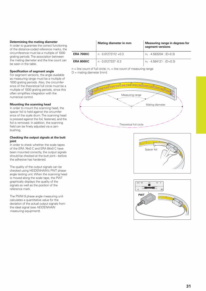
Determining the mating diameter
In order to guarantee the correct functioning of the distance-coded reference marks, the circumference must be a multiple of 1000 grating periods. The association between the mating diameter and the line count can be seen in the table.
Specifi cation of segment angle
For segment versions, the angle available as measuring range must be a multiple of 1000 grating periods. Also, the circumfer-ence of the theoretical full circle must be a multiple of 1000 grating periods, since this often simplifi es integration with the numerical control.
Mounting the scanning head
In order to mount the scanning head, the spacer foil is held against the circumfer-ence of the scale drum. The scanning head is pressed against the foil, fastened, and the foil is removed. In addition, the scanning fi eld can be fi nely adjusted via a cam bushing.
Checking the output signals at the butt
joint
In order to check whether the scale tapes of the ERA 74x0 C and ERA 84x0 C have been mounted correctly, the output signals should be checked at the butt joint—before the adhesive has hardened.
The quality of the output signals can be checked using HEIDENHAIN’s PWT phase-angle testing unit. When the scanning head is moved along the scale tape, the PWT graphically displays the quality of the signals as well as the position of the reference mark.
The PWM 9 phase angle measuring unit calculates a quantitative value for the deviation of the actual output signals from the ideal signal (see HEIDENHAIN measuring equipment).
Spacer foil
Mating diameter in mm Measuring range in degrees for
segment versions
ERA 7000 C n · 0.01273112 +0.3 n1 · 4.583204 : (D–0.3)
ERA 8000 C n · 0.0127337 -0.3 n1 · 4.584121 : (D+0.3)
n = line count of full circle; n1 = line count of measuring rangeD = mating diameter [mm]
Theoretical full circle
Mating diameter
Measuring range
32
General mechanical information
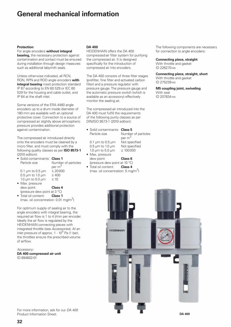
DA 400
Protection
For angle encoders without integral
bearing, the necessary protection against contamination and contact must be ensured during installation through design measures such as additional labyrinth seals.
Unless otherwise indicated, all RCN, RON, RPN and ROD angle encoders with
integral bearing meet protection standard IP 67 according to EN 60 529 or IEC 60 529 for the housing and cable outlet, and IP 64 at the shaft inlet.
Some versions of the ERA 4480 angle encoders up to a drum inside diameter of 180 mm are available with an optional protective cover. Connection to a source of compressed air slightly above atmospheric pressure provides additional protection against contamination.
The compressed air introduced directly onto the encoders must be cleaned by a micro fi lter, and must comply with the following quality classes as per ISO 8573-1 (2010 edition):• Solid contaminants: Class 1
Particle size Number of particles per m3
0.1 µm to 0.5 µm 20 0000.5 µm to 1.0 µm 4001.0 µm to 5.0 µm 10
• Max. pressure dew point: Class 4
(pressure dew point at 3 °C)• Total oil content: Class 1
(max. oil concentration: 0.01 mg/m3)
For optimum supply of sealing air to the angle encoders with integral bearing, the required air fl ow is 1 to 4 l/min per encoder. Ideally the air fl ow is regulated by the HEIDENHAIN connecting pieces with integrated throttle (see Accessories). At an inlet pressure of approx. 1 · 105 Pa (1 bar), the throttles ensure the prescribed volume of airfl ow.
Accessory:DA 400 compressed air unit
ID 894602-01
For more information, ask for our DA 400 Product Information Sheet.
DA 400
HEIDENHAIN offers the DA 400 compressed-air fi lter system for purifying the compressed air. It is designed specifi cally for the introduction of compressed air into encoders.
The DA 400 consists of three fi lter stages (prefi lter, fi ne fi lter and activated carbon fi lter) and a pressure regulator with pressure gauge. The pressure gauge and the automatic pressure switch (which is available as an accessory) effectively monitor the sealing air.
The compressed air introduced into the DA 400 must fulfi ll the requirements of the following purity classes as per DIN/ISO 8573-1 (2010 edition):
• Solid contaminants: Class 5
Particle size Number of particles per m3
0.1 µm to 0.5 µm Not specifi ed0.5 µm to 1.0 µm Not specifi ed1.0 µm to 5.0 µm 100 000
• Max. pressure dew point: Class 6
(pressure dew point at 10 °C)• Total oil content: Class 4
(max. oil concentration: 5 mg/m3)
The following components are necessary for connection to angle encoders:
Connecting piece, straight
With throttle and gasketID 226270-xx
Connecting piece, straight, short
With throttle and gasketID 275239-xx
M5 coupling joint, swiveling
With sealID 207834-xx
33
System tests
Encoders from HEIDENHAIN are usually integrated as components in larger systems. Such applications require comprehensive tests of the entire
system regardless of the specifi cations of the encoder.
The specifi cations shown in this brochure apply to the specifi c encoder, not to the complete system. Any operation of the encoder outside of the specifi ed range or for any other than the intended applications is at the user’s own risk.
Assembly
Work steps to be performed and dimensions to be maintained during mounting are specifi ed solely in the mounting instructions supplied with the unit. All data in this catalog regarding mounting are therefore provisional and not binding; they do not become terms of a contract.
DIADUR, AURODUR and METALLUR are registered trademarks of DR. JOHANNES HEIDENHAIN GmbH, Traunreut.
Temperature range
The angle encoders are inspected at a reference temperature of 22 °C. The system accuracy given in the calibration chart applies at this temperature.
The operating temperature range indicates the ambient temperature limits between which the angle encoders will function properly.
The storage temperature range of –30 °C to +80 °C is valid as long as the unit remains in its packaging (ERP 4080/ERP 8080: 0 °C to 60 °C).
Protection against contact
After encoder installation, all rotating parts must be protected against accidental contact during operation.
Acceleration
Angle encoders are subject to various types of acceleration during operation and mounting.• The indicated maximum values for
vibration resistance are valid according to EN 60 068-2-6.
• The maximum permissible acceleration values (semi-sinusoidal shock) for shock
and impact are valid for 6 ms (EN 60 068-2-27).
Under no circumstances should a hammer or similar implement be used to adjust or position the encoder.
Shaft speeds
The maximum permissible shaft speeds for the ERA 4000 angle encoders series were determined according to the FKM guideline. This guideline serves as mathematical attestation of component strength with re-gard to all relevant infl uences and it refl ects the latest state of the art. The requirements for fatigue strength (107 million reversals of load) were considered in the calculation of the permissible shaft speeds. Because installation has a signifi cant infl uence, all requirements and directions in the specifi -cations and mounting instructions must be followed for the shaft-speed data to be valid.
Expendable parts
Encoders from HEIDENHAIN are designed for a long service life. Preventive mainte-nance is not required. However, they contain components that are subject to wear, depending on the application and manipulation. These include in particular cables with frequent fl exing.
Other such components are the bearings of encoders with integral bearing, shaft sealing rings on rotary and angle encoders, and sealing lips on sealed linear encoders.
34
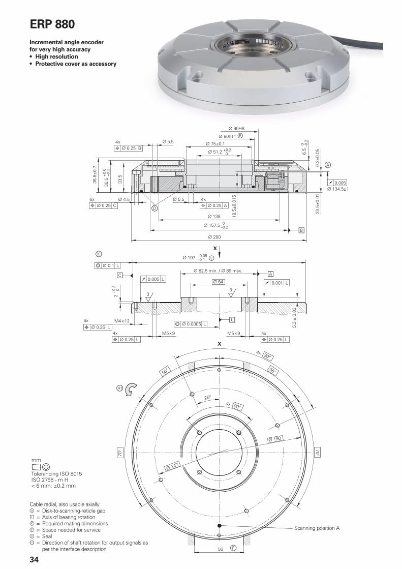
ERP 880
Incremental angle encoder
for very high accuracy
• High resolution
• Protective cover as accessory
Scanning position A
Cable radial, also usable axially = Disk-to-scanning-reticle gap = Axis of bearing rotation = Required mating dimensions = Space needed for service = Seal = Direction of shaft rotation for output signals as
per the interface description
35
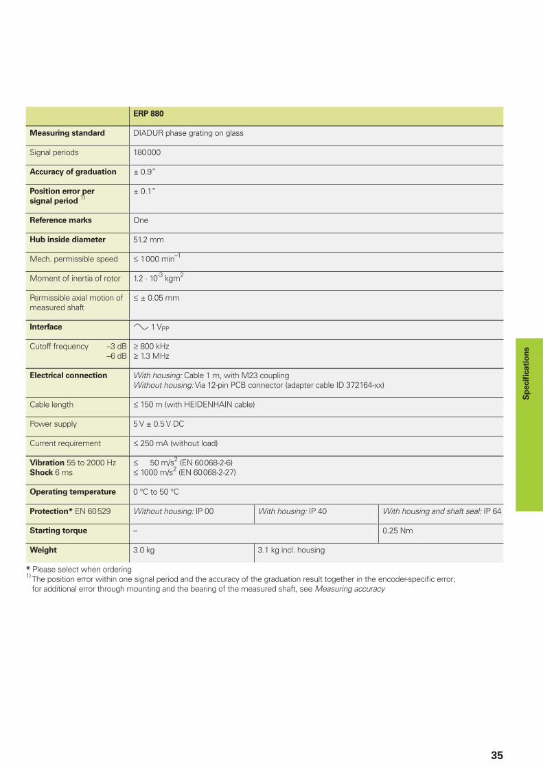
ERP 880
Measuring standard DIADUR phase grating on glass
Signal periods 180 000
Accuracy of graduation ± 0.9”
Position error per
signal period 1)
± 0.1”
Reference marks One
Hub inside diameter 51.2 mm
Mech. permissible speed 1 000 min–1
Moment of inertia of rotor 1.2 · 10-3 kgm2
Permissible axial motion of measured shaft
± 0.05 mm
Interface 1 VPP
Cutoff frequency –3 dB –6 dB
800 kHz 1.3 MHz
Electrical connection With housing: Cable 1 m, with M23 couplingWithout housing: Via 12-pin PCB connector (adapter cable ID 372164-xx)
Cable length 150 m (with HEIDENHAIN cable)
Power supply 5 V ± 0.5 V DC
Current requirement 250 mA (without load)
Vibration 55 to 2000 HzShock 6 ms
50 m/s2 (EN 60 068-2-6) 1000 m/s2 (EN 60 068-2-27)
Operating temperature 0 °C to 50 °C
Protection* EN 60 529 Without housing: IP 00 With housing: IP 40 With housing and shaft seal: IP 64
Starting torque – 0.25 Nm
Weight 3.0 kg 3.1 kg incl. housing
* Please select when ordering1) The position error within one signal period and the accuracy of the graduation result together in the encoder-specifi c error;
for additional error through mounting and the bearing of the measured shaft, see Measuring accuracy
Sp
ecifi c
ati
on
s
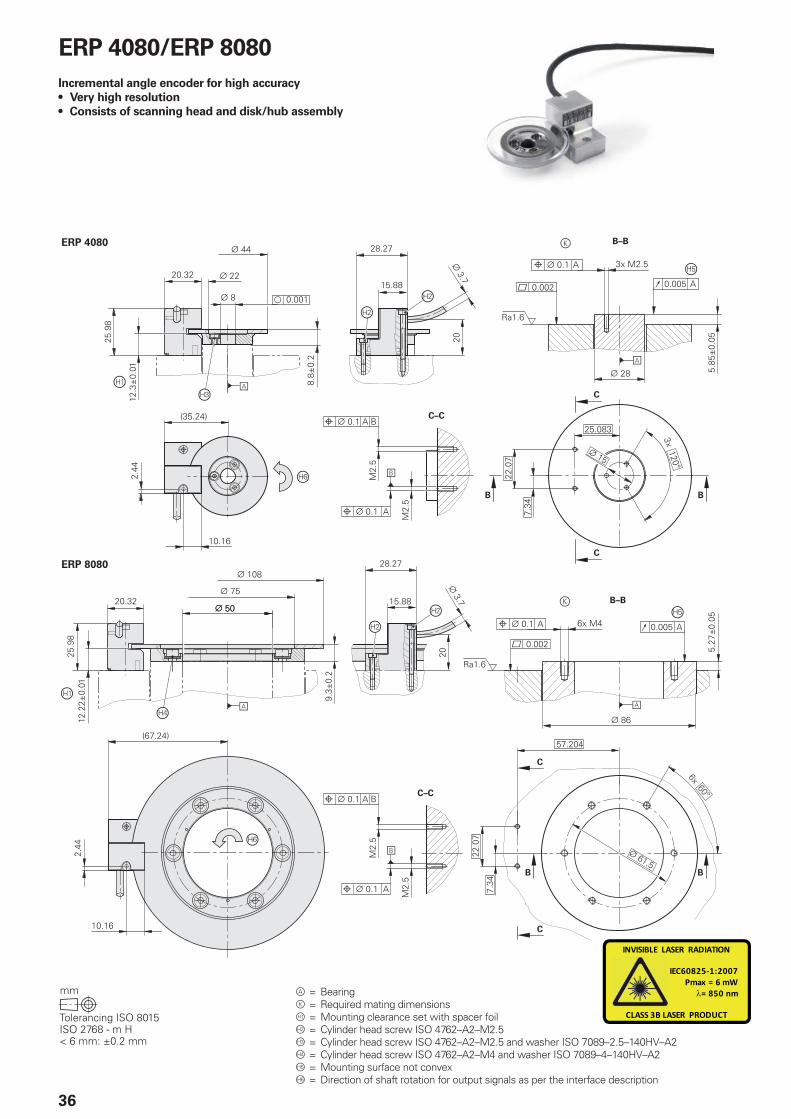
ERP 4080
ERP 8080
INVISIBLE LASER RADIATION
IEC60825-1:2007Pmax = 6 mW
= 850 nm
CLASS 3B LASER PRODUCT
36
= Bearing = Required mating dimensions = Mounting clearance set with spacer foil = Cylinder head screw ISO 4762–A2–M2.5 = Cylinder head screw ISO 4762–A2–M2.5 and washer ISO 7089–2.5–140HV–A2 = Cylinder head screw ISO 4762–A2–M4 and washer ISO 7089–4–140HV–A2 = Mounting surface not convex = Direction of shaft rotation for output signals as per the interface description
ERP 4080/ERP 8080
Incremental angle encoder for high accuracy
• Very high resolution
• Consists of scanning head and disk/hub assembly
37
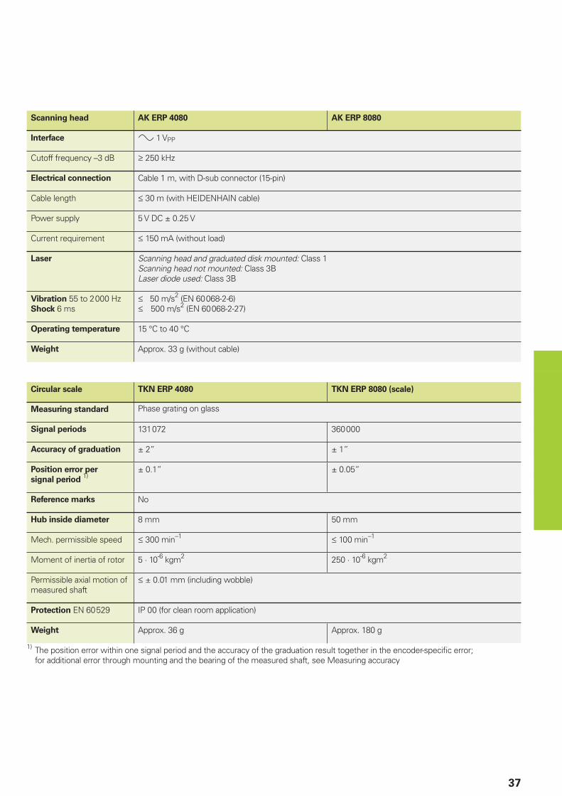
Scanning head AK ERP 4080 AK ERP 8080
Interface 1 VPP
Cutoff frequency –3 dB 250 kHz
Electrical connection Cable 1 m, with D-sub connector (15-pin)
Cable length 30 m (with HEIDENHAIN cable)
Power supply 5 V DC ± 0.25 V
Current requirement 150 mA (without load)
Laser Scanning head and graduated disk mounted: Class 1Scanning head not mounted: Class 3BLaser diode used: Class 3B
Vibration 55 to 2 000 HzShock 6 ms
50 m/s2 (EN 60 068-2-6) 500 m/s2 (EN 60 068-2-27)
Operating temperature 15 °C to 40 °C
Weight Approx. 33 g (without cable)
Circular scale TKN ERP 4080 TKN ERP 8080 (scale)
Measuring standard
Signal periods 131 072 360 000
Accuracy of graduation ± 2” ± 1”
Position error per
signal period 1)
± 0.1” ± 0.05”
Reference marks No
Hub inside diameter 8 mm 50 mm
Mech. permissible speed 300 min–1 100 min–1
Moment of inertia of rotor 5 · 10-6 kgm2 250 · 10-6 kgm2
Permissible axial motion of measured shaft
± 0.01 mm (including wobble)
Protection EN 60 529 IP 00 (for clean room application)
Weight Approx. 36 g Approx. 180 g
1) The position error within one signal period and the accuracy of the graduation result together in the encoder-specifi c error; for additional error through mounting and the bearing of the measured shaft, see Measuring accuracy
38
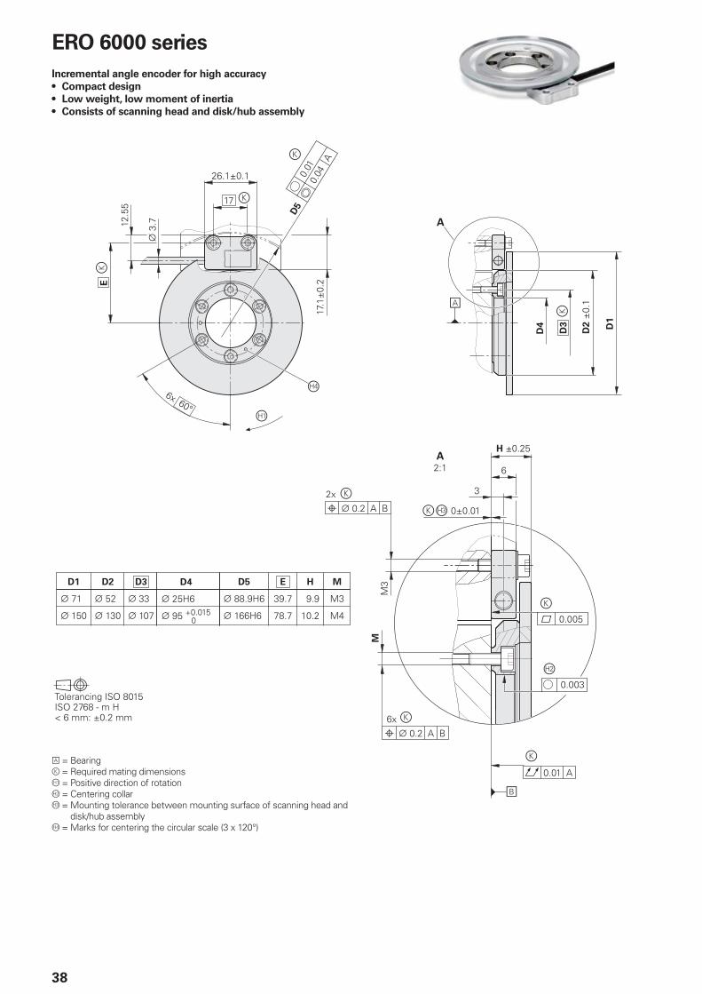
ERO 6000 series
Incremental angle encoder for high accuracy
• Compact design
• Low weight, low moment of inertia
• Consists of scanning head and disk/hub assembly
= Bearing = Required mating dimensions = Positive direction of rotation = Centering collar = Mounting tolerance between mounting surface of scanning head and
disk/hub assembly = Marks for centering the circular scale (3 x 120°)
39
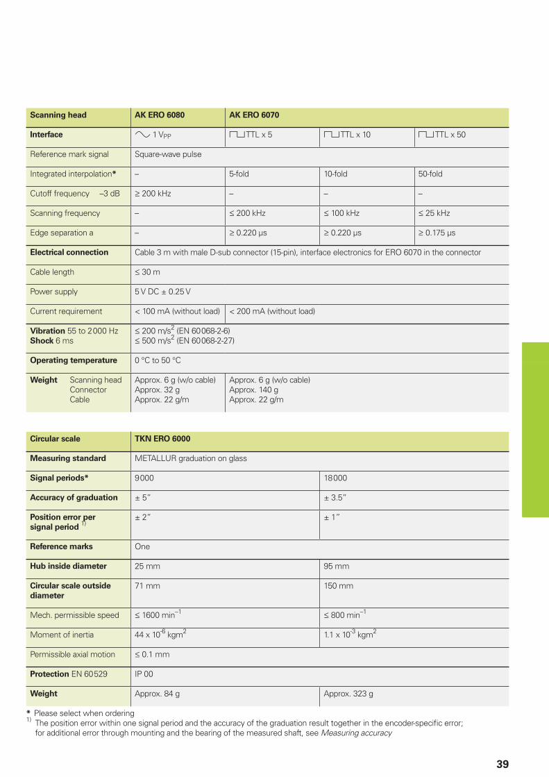
Scanning head AK ERO 6080 AK ERO 6070
Interface 1 VPP TTL x 5 TTL x 10 TTL x 50
Reference mark signal Square-wave pulse
Integrated interpolation* – 5-fold 10-fold 50-fold
Cutoff frequency –3 dB 200 kHz – – –
Scanning frequency – 200 kHz 100 kHz 25 kHz
Edge separation a – 0.220 µs 0.220 µs 0.175 µs
Electrical connection Cable 3 m with male D-sub connector (15-pin), interface electronics for ERO 6070 in the connector
Cable length 30 m
Power supply 5 V DC ± 0.25 V
Current requirement < 100 mA (without load) < 200 mA (without load)
Vibration 55 to 2 000 HzShock 6 ms
200 m/s2 (EN 60 068-2-6) 500 m/s2 (EN 60 068-2-27)
Operating temperature 0 °C to 50 °C
Weight Scanning head Connector Cable
Approx. 6 g (w/o cable)Approx. 32 gApprox. 22 g/m
Approx. 6 g (w/o cable)Approx. 140 gApprox. 22 g/m
Circular scale TKN ERO 6000
Measuring standard METALLUR graduation on glass
Signal periods* 9 000 18 000
Accuracy of graduation ± 5” ± 3.5”
Position error per
signal period 1)
± 2” ± 1”
Reference marks One
Hub inside diameter 25 mm 95 mm
Circular scale outside
diameter
71 mm 150 mm
Mech. permissible speed 1600 min–1 800 min–1
Moment of inertia 44 x 10-6 kgm2 1.1 x 10⁻³ kgm2
Permissible axial motion 0.1 mm
Protection EN 60 529 IP 00
Weight Approx. 84 g Approx. 323 g
* Please select when ordering1) The position error within one signal period and the accuracy of the graduation result together in the encoder-specifi c error;
for additional error through mounting and the bearing of the measured shaft, see Measuring accuracy
40
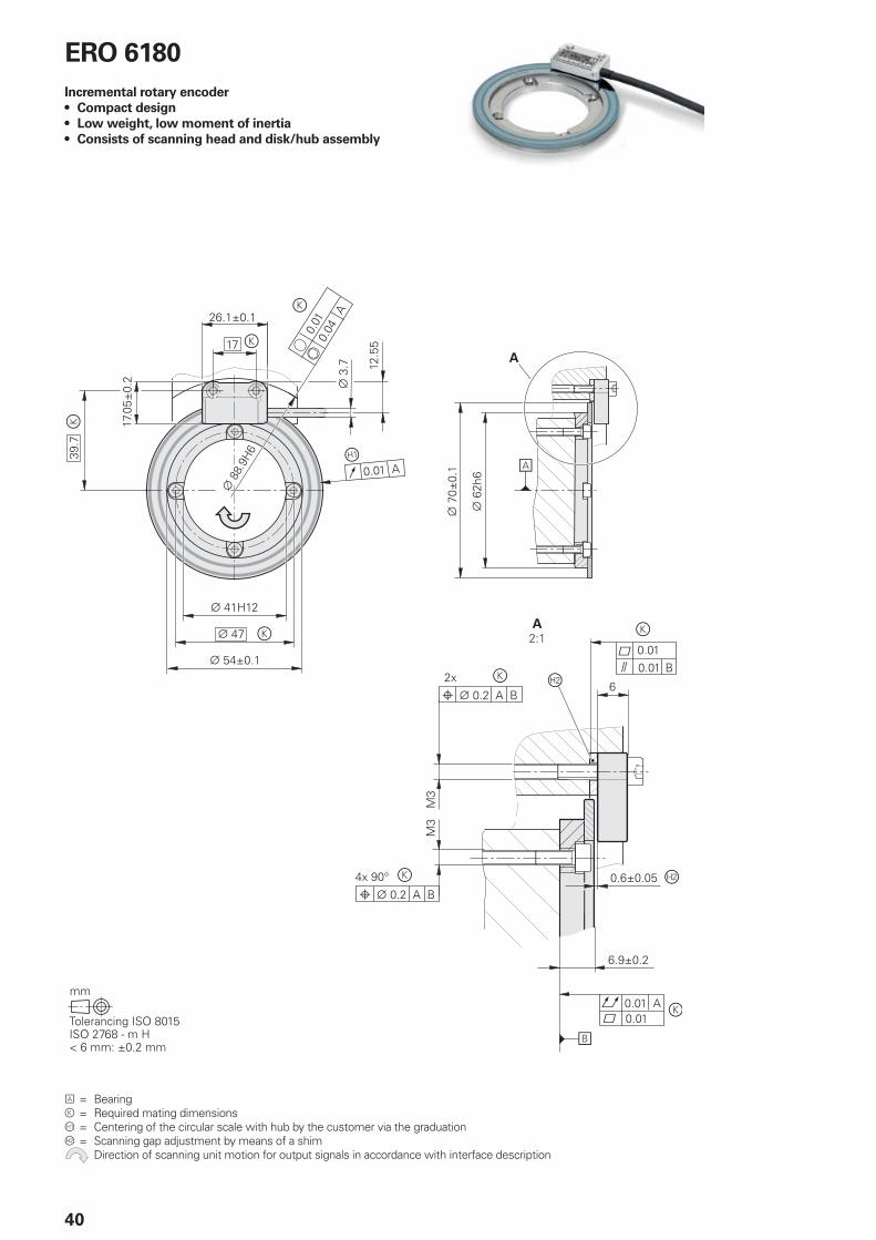
ERO 6180
Incremental rotary encoder
• Compact design
• Low weight, low moment of inertia
• Consists of scanning head and disk/hub assembly
= Bearing = Required mating dimensions = Centering of the circular scale with hub by the customer via the graduation = Scanning gap adjustment by means of a shim Direction of scanning unit motion for output signals in accordance with interface description
41
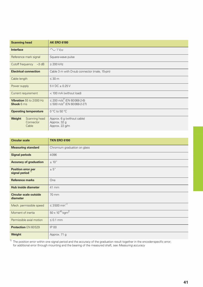
Scanning head AK ERO 6180
Interface 1 VPP
Reference mark signal Square-wave pulse
Cutoff frequency –3 dB 200 kHz
Electrical connection Cable 3 m with D-sub connector (male, 15-pin)
Cable length 30 m
Power supply 5 V DC ± 0.25 V
Current requirement < 100 mA (without load)
Vibration 55 to 2 000 HzShock 6 ms
200 m/s2 (EN 60 068-2-6) 500 m/s2 (EN 60 068-2-27)
Operating temperature 0 °C to 50 °C
Weight Scanning head Connector Cable
Approx. 6 g (without cable)Approx. 32 gApprox. 22 g/m
Circular scale TKN ERO 6100
Measuring standard Chromium graduation on glass
Signal periods 4 096
Accuracy of graduation ± 10”
Position error per
signal period 1)
± 5”
Reference marks One
Hub inside diameter 41 mm
Circular scale outside
diameter
70 mm
Mech. permissible speed 3 500 min–1
Moment of inertia 50 x 10–6 kgm2
Permissible axial motion 0.1 mm
Protection EN 60 529 IP 00
Weight Approx. 71 g
1) The position error within one signal period and the accuracy of the graduation result together in the encoder-specifi c error; for additional error through mounting and the bearing of the measured shaft, see Measuring accuracy
42
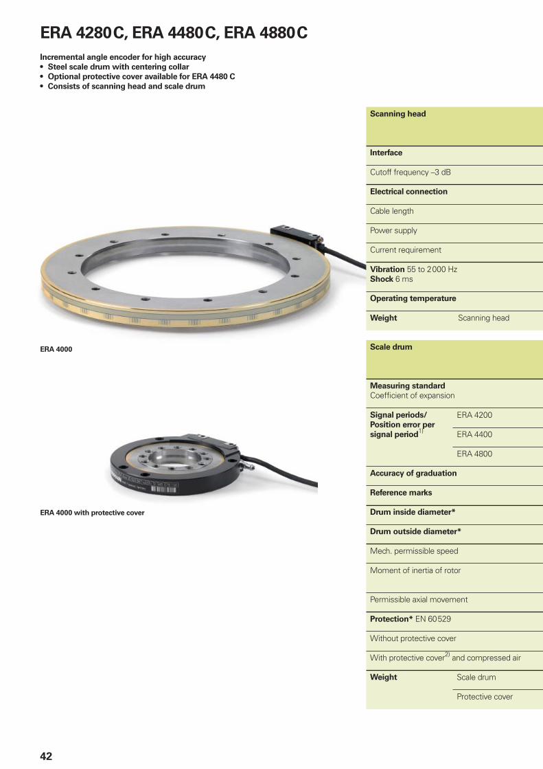
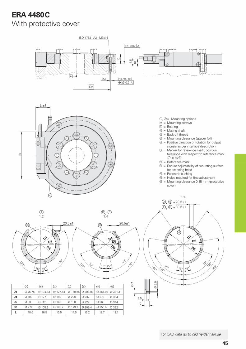
ERA 4280 C, ERA 4480 C, ERA 4880 C
Incremental angle encoder for high accuracy
• Steel scale drum with centering collar
• Optional protective cover available for ERA 4480 C
• Consists of scanning head and scale drum
ERA 4000
ERA 4000 with protective cover
Scanning head
Interface
Cutoff frequency –3 dB
Electrical connection
Cable length
Power supply
Current requirement
Vibration 55 to 2 000 HzShock 6 ms
Operating temperature
Weight Scanning head
Scale drum
Measuring standard
Coeffi cient of expansion
Signal periods/
Position error per
signal period1)
ERA 4200
ERA 4400
ERA 4800
Accuracy of graduation
Reference marks
Drum inside diameter*
Drum outside diameter*
Mech. permissible speed
Moment of inertia of rotor
Permissible axial movement
Protection* EN 60 529
Without protective cover
With protective cover2) and compressed air
Weight Scale drum
Protective cover
43
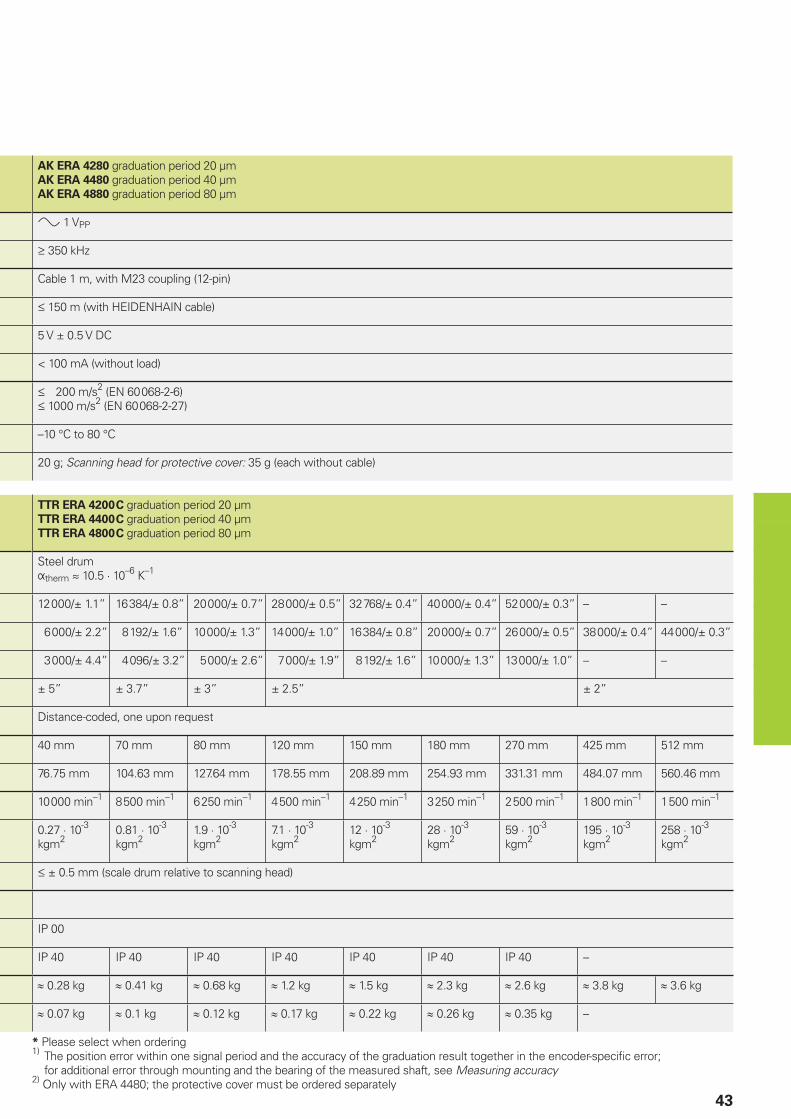
AK ERA 4280 graduation period 20 µmAK ERA 4480 graduation period 40 µmAK ERA 4880 graduation period 80 µm
1 VPP
350 kHz
Cable 1 m, with M23 coupling (12-pin)
150 m (with HEIDENHAIN cable)
5 V ± 0.5 V DC
< 100 mA (without load)
200 m/s2 (EN 60 068-2-6) 1000 m/s2 (EN 60 068-2-27)
–10 °C to 80 °C
20 g; Scanning head for protective cover: 35 g (each without cable)
TTR ERA 4200 C graduation period 20 µmTTR ERA 4400 C graduation period 40 µmTTR ERA 4800 C graduation period 80 µm
Steel drumtherm 10.5 · 10–6 K–1
12 000/± 1.1” 16 384/± 0.8” 20 000/± 0.7” 28 000/± 0.5” 32 768/± 0.4” 40 000/± 0.4” 52 000/± 0.3” – –
6 000/± 2.2” 8 192/± 1.6” 10 000/± 1.3” 14 000/± 1.0” 16 384/± 0.8” 20 000/± 0.7” 26 000/± 0.5” 38 000/± 0.4” 44 000/± 0.3”
3 000/± 4.4” 4 096/± 3.2” 5 000/± 2.6” 7 000/± 1.9” 8 192/± 1.6” 10 000/± 1.3” 13 000/± 1.0” – –
± 5” ± 3.7” ± 3” ± 2.5” ± 2”
Distance-coded, one upon request
40 mm 70 mm 80 mm 120 mm 150 mm 180 mm 270 mm 425 mm 512 mm
76.75 mm 104.63 mm 127.64 mm 178.55 mm 208.89 mm 254.93 mm 331.31 mm 484.07 mm 560.46 mm
10 000 min–1 8 500 min–1 6 250 min–1 4 500 min–1 4 250 min–1 3 250 min–1 2 500 min–1 1 800 min–1 1 500 min–1
0.27 · 10-3 kgm2
0.81 · 10-3 kgm2
1.9 · 10-3 kgm2
7.1 · 10-3 kgm2
12 · 10-3 kgm2
28 · 10-3 kgm2
59 · 10-3 kgm2
195 · 10-3 kgm2
258 · 10-3 kgm2
± 0.5 mm (scale drum relative to scanning head)
IP 00
IP 40 IP 40 IP 40 IP 40 IP 40 IP 40 IP 40 –
0.28 kg 0.41 kg 0.68 kg 1.2 kg 1.5 kg 2.3 kg 2.6 kg 3.8 kg 3.6 kg
0.07 kg 0.1 kg 0.12 kg 0.17 kg 0.22 kg 0.26 kg 0.35 kg –
* Please select when ordering1) The position error within one signal period and the accuracy of the graduation result together in the encoder-specifi c error;
for additional error through mounting and the bearing of the measured shaft, see Measuring accuracy2) Only with ERA 4480; the protective cover must be ordered separately
44
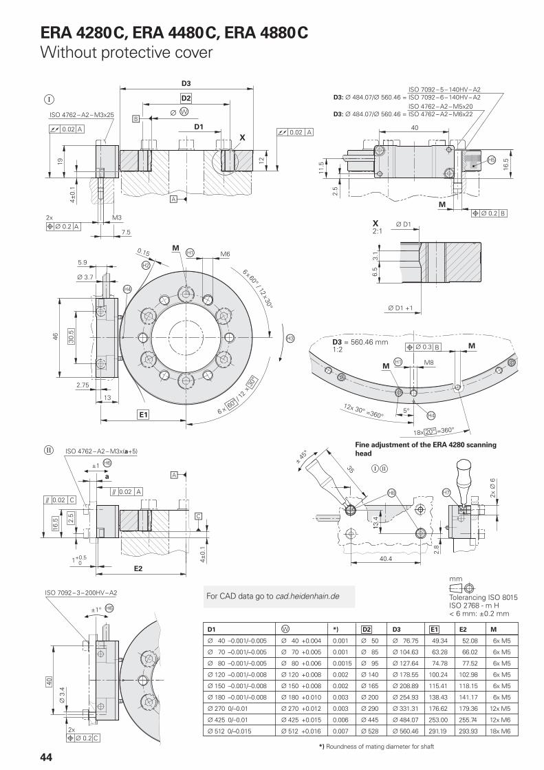
Fine adjustment of the ERA 4280 scanning
head
ERA 4280 C, ERA 4480 C, ERA 4880 C
Without protective cover
*) Roundness of mating diameter for shaft
For CAD data go to cad.heidenhain.de
45
= Mounting optionsM = Mounting screws = Bearing = Mating shaft = Back-off thread = Mounting clearance (spacer foil) = Positive direction of rotation for output
signals as per interface description= Marker for reference mark, position
tolerance with respect to reference mark ± 1.0 mm
= Reference mark = Ensure adjustability of mounting surface
for scanning head = Eccentric bushing = Holes required for fi ne adjustment = Mounting clearance 0.15 mm (protective
cover)
ERA 4480 C
With protective cover
For CAD data go to cad.heidenhain.de
46
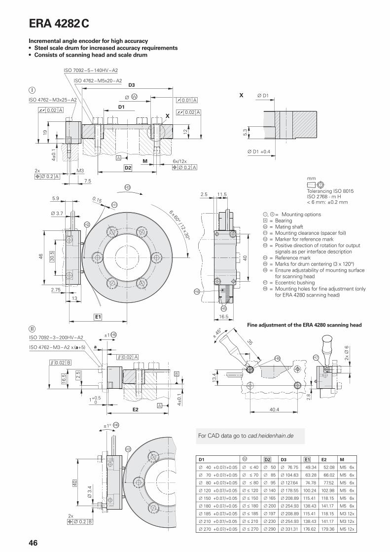
ERA 4282 C
Incremental angle encoder for high accuracy
• Steel scale drum for increased accuracy requirements
• Consists of scanning head and scale drum
Fine adjustment of the ERA 4280 scanning head
= Mounting options = Bearing = Mating shaft = Mounting clearance (spacer foil) = Marker for reference mark = Positive direction of rotation for output
signals as per interface description = Reference mark= Marks for drum centering (3 x 120°) = Ensure adjustability of mounting surface
for scanning head= Eccentric bushing = Mounting holes for fi ne adjustment (only
for ERA 4280 scanning head)
For CAD data go to cad.heidenhain.de
47
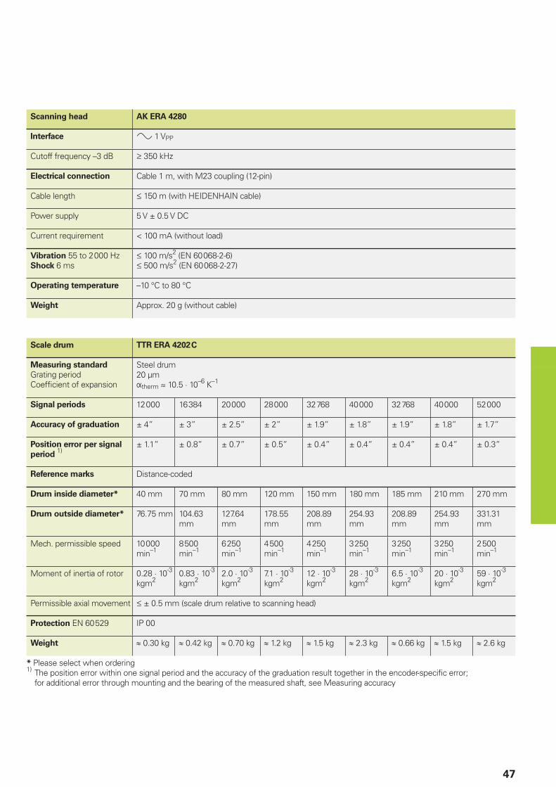
Scanning head AK ERA 4280
Interface 1 VPP
Cutoff frequency –3 dB 350 kHz
Electrical connection Cable 1 m, with M23 coupling (12-pin)
Cable length 150 m (with HEIDENHAIN cable)
Power supply 5 V ± 0.5 V DC
Current requirement < 100 mA (without load)
Vibration 55 to 2 000 HzShock 6 ms
100 m/s2 (EN 60 068-2-6) 500 m/s2 (EN 60 068-2-27)
Operating temperature –10 °C to 80 °C
Weight Approx. 20 g (without cable)
Scale drum TTR ERA 4202 C
Measuring standard
Grating periodCoeffi cient of expansion
Steel drum20 µmtherm 10.5 · 10–6 K–1
Signal periods 12 000 16 384 20 000 28 000 32 768 40 000 32 768 40 000 52 000
Accuracy of graduation ± 4” ± 3” ± 2.5” ± 2” ± 1.9” ± 1.8” ± 1.9” ± 1.8” ± 1.7”
Position error per signal
period 1)
± 1.1” ± 0.8” ± 0.7” ± 0.5” ± 0.4” ± 0.4” ± 0.4” ± 0.4” ± 0.3”
Reference marks Distance-coded
Drum inside diameter* 40 mm 70 mm 80 mm 120 mm 150 mm 180 mm 185 mm 210 mm 270 mm
Drum outside diameter* 76.75 mm 104.63 mm
127.64 mm
178.55 mm
208.89 mm
254.93 mm
208.89 mm
254.93 mm
331.31 mm
Mech. permissible speed 10 000 min–1
8 500 min–1
6 250 min–1
4 500 min–1
4 250 min–1
3 250 min–1
3 250 min–1
3 250 min–1
2 500 min–1
Moment of inertia of rotor 0.28 · 10-3 kgm2
0.83 · 10-3 kgm2
2.0 · 10-3 kgm2
7.1 · 10-3 kgm2
12 · 10-3 kgm2
28 · 10-3 kgm2
6.5 · 10-3 kgm2
20 · 10-3 kgm2
59 · 10-3 kgm2
Permissible axial movement ± 0.5 mm (scale drum relative to scanning head)
Protection EN 60 529 IP 00
Weight 0.30 kg 0.42 kg 0.70 kg 1.2 kg 1.5 kg 2.3 kg 0.66 kg 1.5 kg 2.6 kg
* Please select when ordering1) The position error within one signal period and the accuracy of the graduation result together in the encoder-specifi c error;
for additional error through mounting and the bearing of the measured shaft, see Measuring accuracy
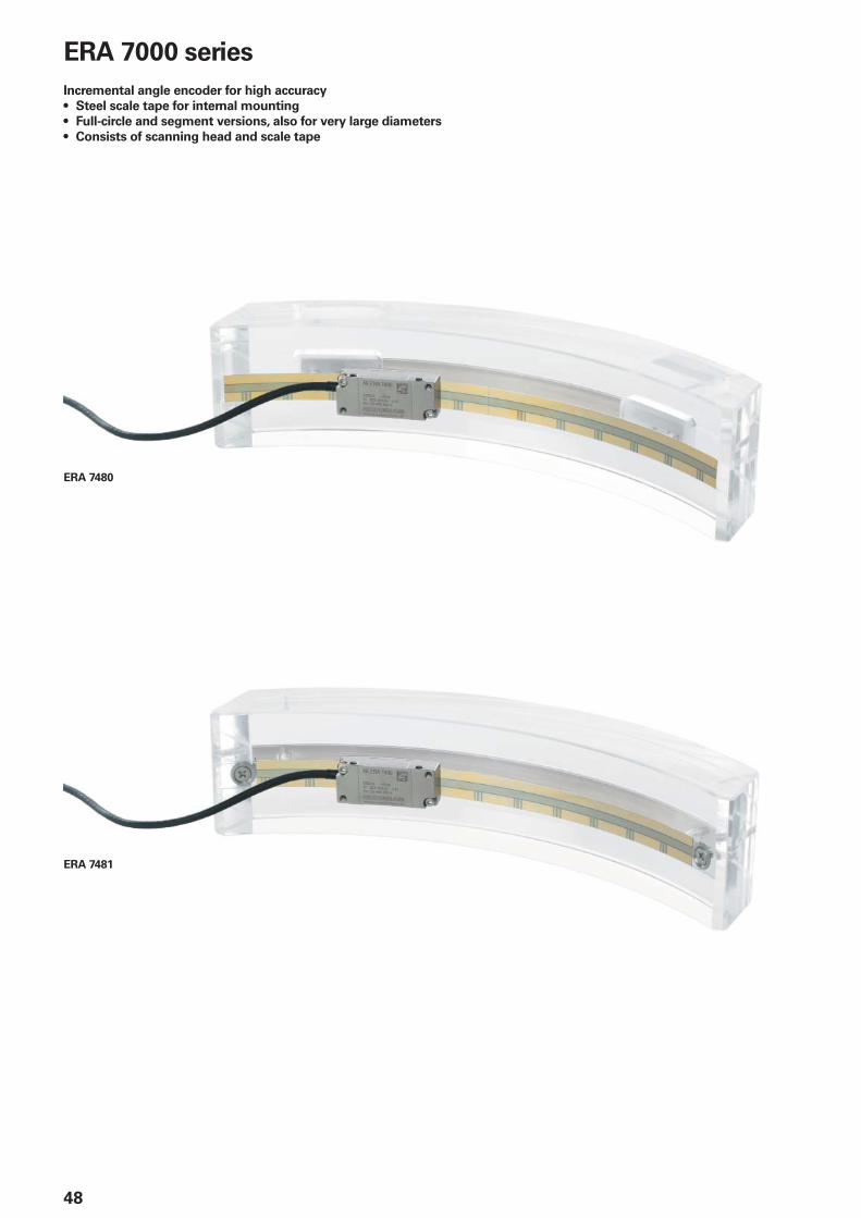
ERA 7480
ERA 7481
48
ERA 7000 series
Incremental angle encoder for high accuracy
• Steel scale tape for internal mounting
• Full-circle and segment versions, also for very large diameters
• Consists of scanning head and scale tape
49
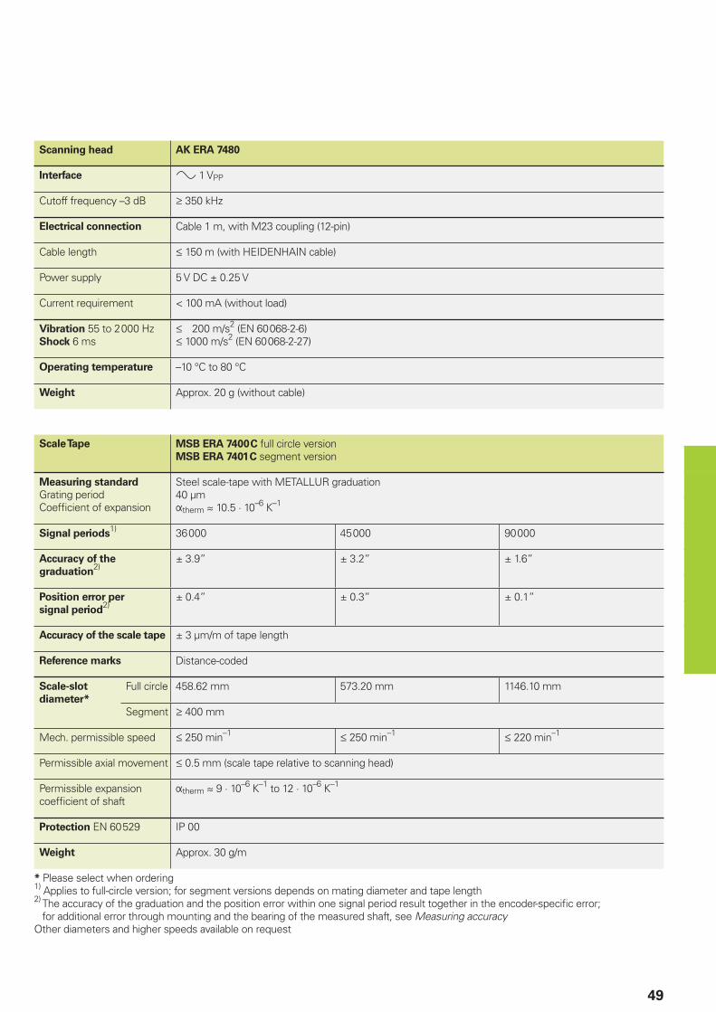
Scanning head AK ERA 7480
Interface 1 VPP
Cutoff frequency –3 dB 350 kHz
Electrical connection Cable 1 m, with M23 coupling (12-pin)
Cable length 150 m (with HEIDENHAIN cable)
Power supply 5 V DC ± 0.25 V
Current requirement < 100 mA (without load)
Vibration 55 to 2 000 HzShock 6 ms
200 m/s2 (EN 60 068-2-6) 1000 m/s2 (EN 60 068-2-27)
Operating temperature –10 °C to 80 °C
Weight Approx. 20 g (without cable)
Scale Tape MSB ERA 7400 C full circle versionMSB ERA 7401 C segment version
Measuring standard
Grating periodCoeffi cient of expansion
Steel scale-tape with METALLUR graduation40 µmtherm 10.5 · 10–6 K–1
Signal periods1) 36 000 45 000 90 000
Accuracy of the
graduation2)
± 3.9” ± 3.2” ± 1.6”
Position error per
signal period2)
± 0.4” ± 0.3” ± 0.1”
Accuracy of the scale tape ± 3 µm/m of tape length
Reference marks Distance-coded
Scale-slot
diameter*
Full circle 458.62 mm 573.20 mm 1146.10 mm
Segment 400 mm
Mech. permissible speed 250 min–1 250 min–1 220 min–1
Permissible axial movement 0.5 mm (scale tape relative to scanning head)
Permissible expansion coeffi cient of shaft
therm9 · 10–6 K–1 to 12 · 10–6 K–1
Protection EN 60 529 IP 00
Weight Approx. 30 g/m
* Please select when ordering1) Applies to full-circle version; for segment versions depends on mating diameter and tape length2) The accuracy of the graduation and the position error within one signal period result together in the encoder-specifi c error;
for additional error through mounting and the bearing of the measured shaft, see Measuring accuracyOther diameters and higher speeds available on request
50
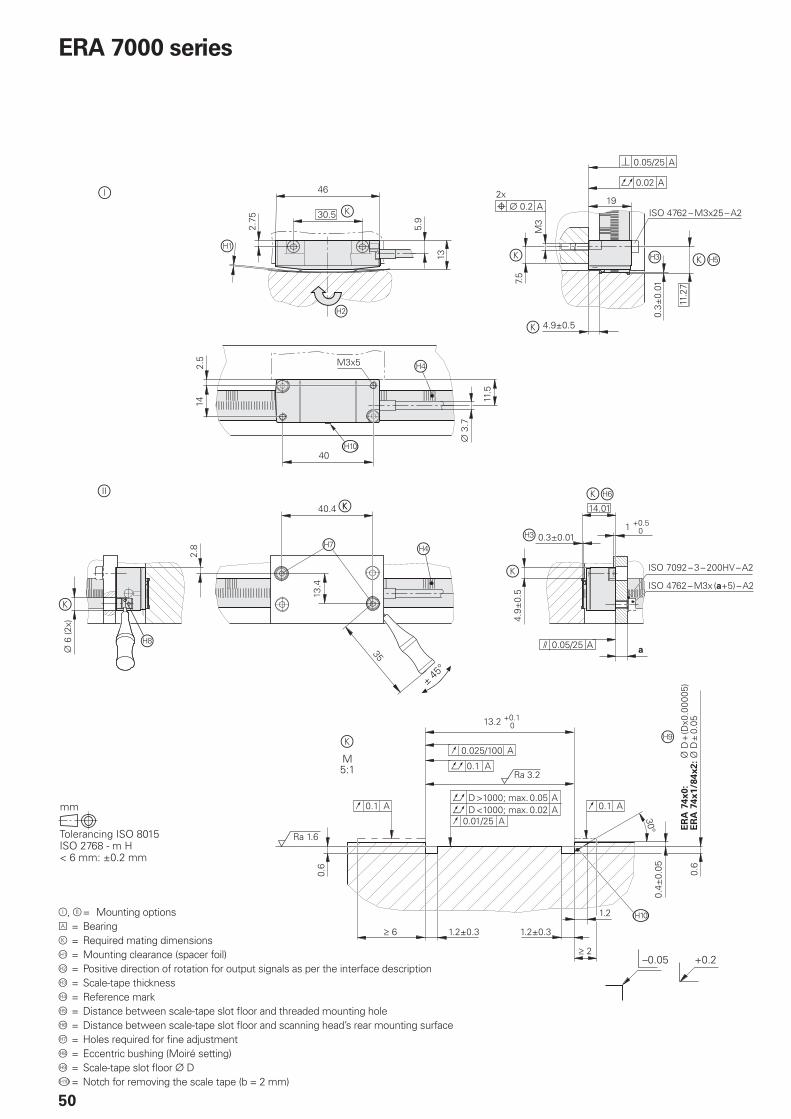
= Mounting options = Bearing= Required mating dimensions = Mounting clearance (spacer foil) = Positive direction of rotation for output signals as per the interface description = Scale-tape thickness = Reference mark = Distance between scale-tape slot fl oor and threaded mounting hole = Distance between scale-tape slot fl oor and scanning head’s rear mounting surface = Holes required for fi ne adjustment = Eccentric bushing (Moiré setting) = Scale-tape slot fl oor D = Notch for removing the scale tape (b = 2 mm)
ERA 7000 series
51
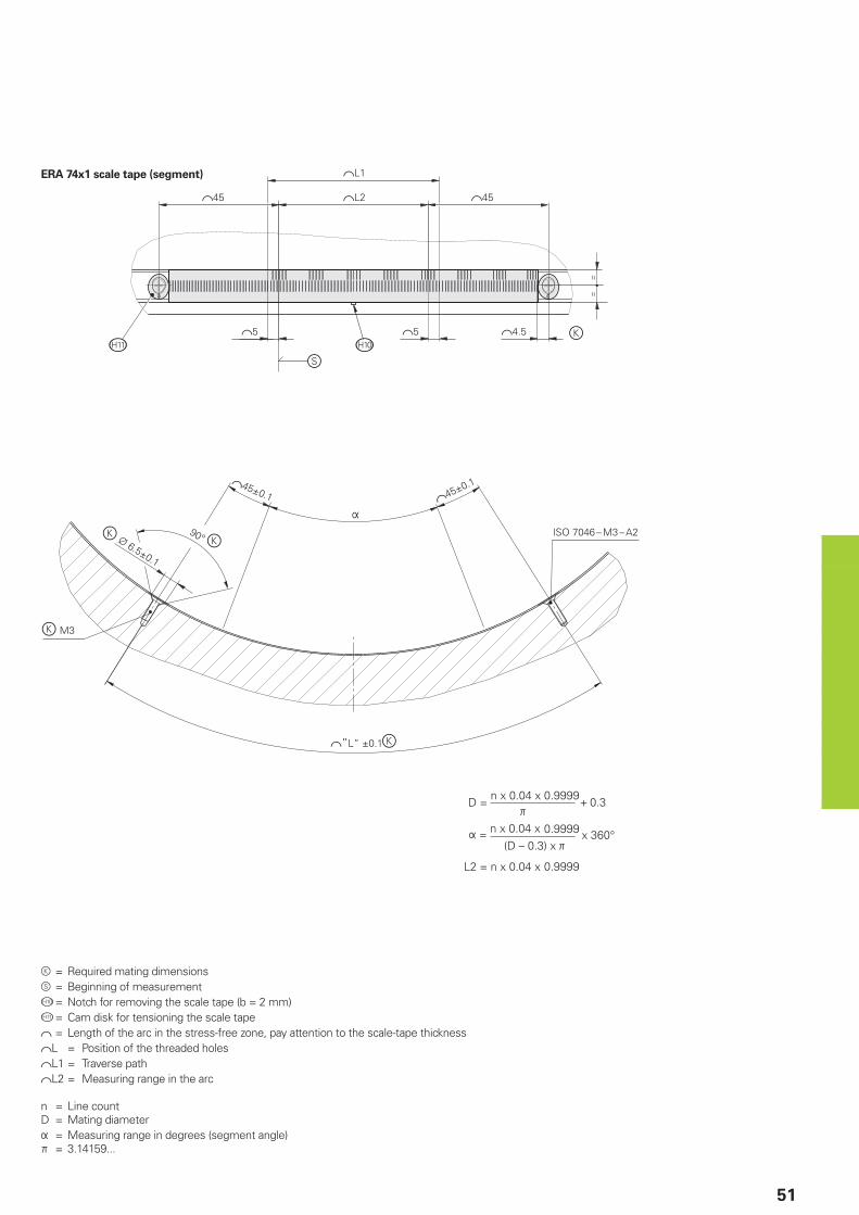
= Required mating dimensions = Beginning of measurement = Notch for removing the scale tape (b = 2 mm) = Cam disk for tensioning the scale tape = Length of the arc in the stress-free zone, pay attention to the scale-tape thicknessL = Position of the threaded holesL1 = Traverse pathL2 = Measuring range in the arc
n = Line countD = Mating diameter = Measuring range in degrees (segment angle) = 3.14159...
ERA 74x1 scale tape (segment)
52
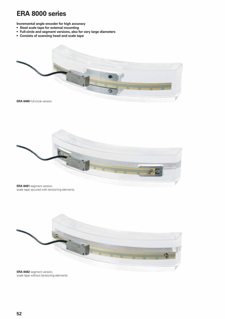
ERA 8000 series
Incremental angle encoder for high accuracy
• Steel scale tape for external mounting
• Full-circle and segment versions, also for very large diameters
• Consists of scanning head and scale tape
ERA 8480 full-circle version
ERA 8481 segment version, scale tape secured with tensioning elements
ERA 8482 segment version, scale tape without tensioning elements
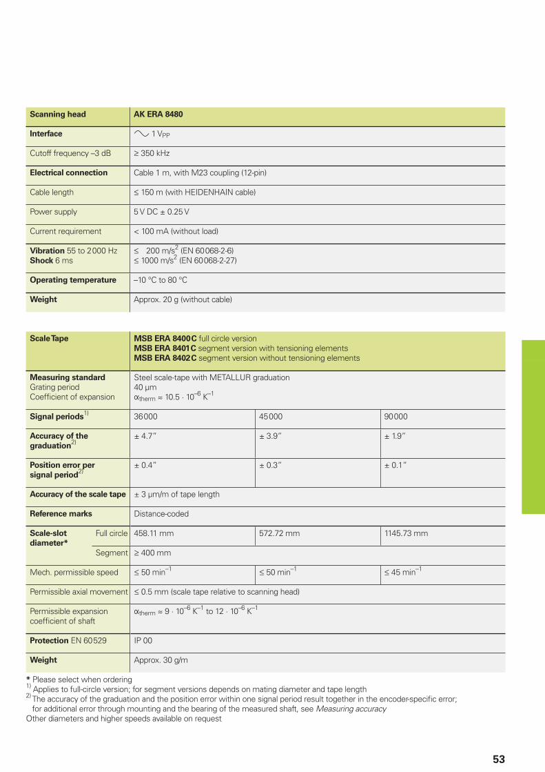
53
Scanning head AK ERA 8480
Interface 1 VPP
Cutoff frequency –3 dB 350 kHz
Electrical connection Cable 1 m, with M23 coupling (12-pin)
Cable length 150 m (with HEIDENHAIN cable)
Power supply 5 V DC ± 0.25 V
Current requirement < 100 mA (without load)
Vibration 55 to 2 000 HzShock 6 ms
200 m/s2 (EN 60 068-2-6) 1000 m/s2 (EN 60 068-2-27)
Operating temperature –10 °C to 80 °C
Weight Approx. 20 g (without cable)
Scale Tape MSB ERA 8400 C full circle versionMSB ERA 8401 C segment version with tensioning elementsMSB ERA 8402 C segment version without tensioning elements
Measuring standard
Grating periodCoeffi cient of expansion
Steel scale-tape with METALLUR graduation40 µmtherm 10.5 · 10–6 K–1
Signal periods1) 36 000 45 000 90 000
Accuracy of the
graduation2)
± 4.7” ± 3.9” ± 1.9”
Position error per
signal period2)
± 0.4” ± 0.3” ± 0.1”
Accuracy of the scale tape ± 3 µm/m of tape length
Reference marks Distance-coded
Scale-slot
diameter*
Full circle 458.11 mm 572.72 mm 1145.73 mm
Segment 400 mm
Mech. permissible speed 50 min–1 50 min–1 45 min–1
Permissible axial movement 0.5 mm (scale tape relative to scanning head)
Permissible expansion coeffi cient of shaft
therm9 · 10–6 K–1 to 12 · 10–6 K–1
Protection EN 60 529 IP 00
Weight Approx. 30 g/m
* Please select when ordering1) Applies to full-circle version; for segment versions depends on mating diameter and tape length2) The accuracy of the graduation and the position error within one signal period result together in the encoder-specifi c error;
for additional error through mounting and the bearing of the measured shaft, see Measuring accuracyOther diameters and higher speeds available on request
54
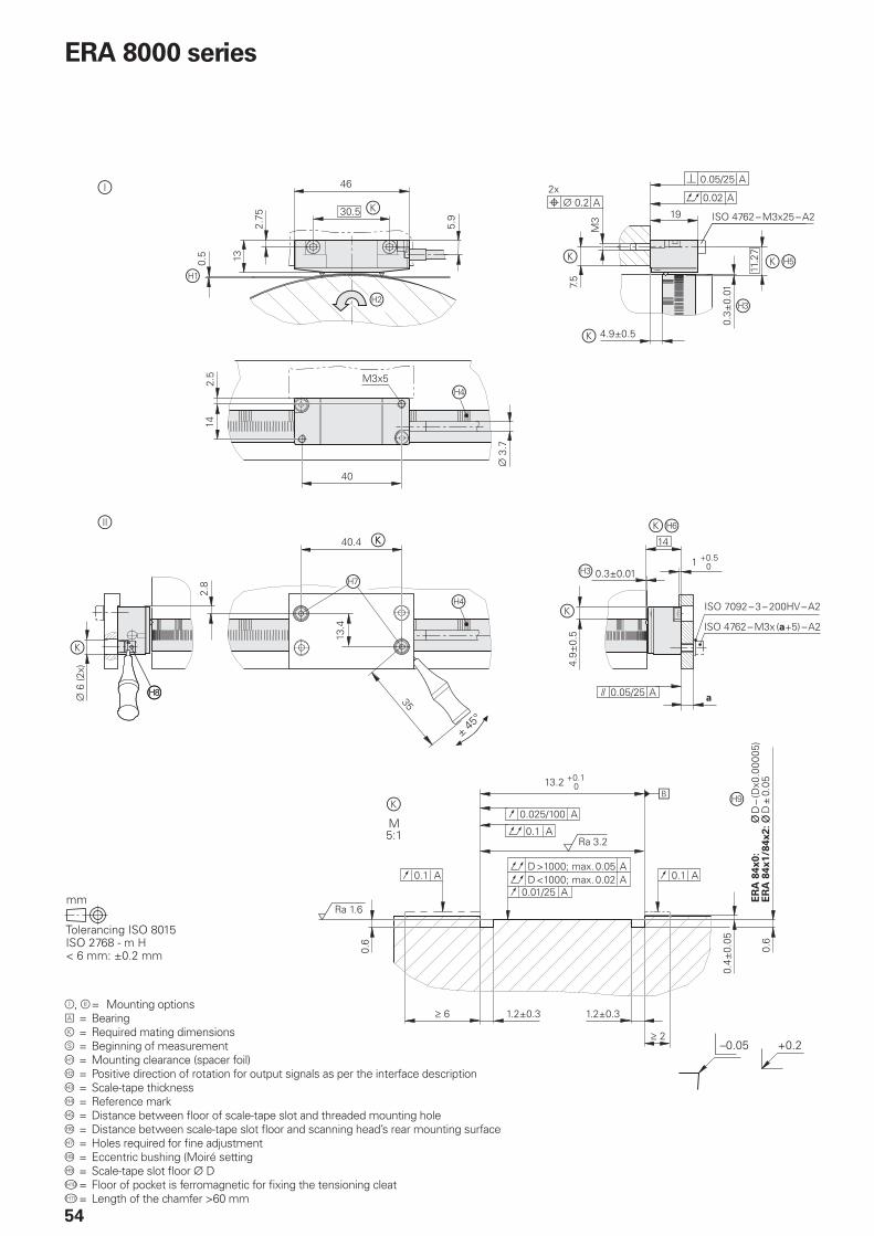
ERA 8000 series
= Mounting options = Bearing = Required mating dimensions = Beginning of measurement = Mounting clearance (spacer foil) = Positive direction of rotation for output signals as per the interface description = Scale-tape thickness = Reference mark = Distance between fl oor of scale-tape slot and threaded mounting hole = Distance between scale-tape slot fl oor and scanning head’s rear mounting surface = Holes required for fi ne adjustment = Eccentric bushing (Moiré setting = Scale-tape slot fl oor D = Floor of pocket is ferromagnetic for fi xing the tensioning cleat = Length of the chamfer >60 mm
55
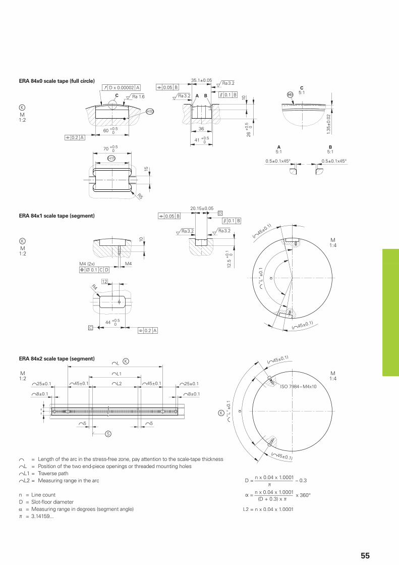
ERA 84x0 scale tape (full circle)
ERA 84x1 scale tape (segment)
= Length of the arc in the stress-free zone, pay attention to the scale-tape thicknessL = Position of the two end-piece openings or threaded mounting holesL1 = Traverse pathL2 = Measuring range in the arc
n = Line countD = Slot-fl oor diameter = Measuring range in degrees (segment angle) = 3.14159...
ERA 84x2 scale tape (segment)
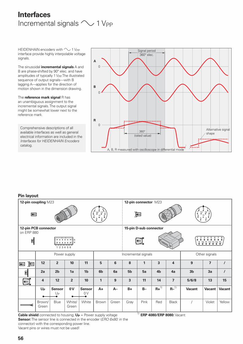
56
Pin layout
12-pin coupling M23 12-pin connector M23
12-pin PCB connector
on ERP 88015-pin D-sub connector
Power supply Incremental signals Other signals
12 2 10 11 5 6 8 1 3 4 9 7 /
2a 2b 1a 1b 6b 6a 5b 5a 4b 4a 3b 3a /
4 12 2 10 1 9 3 11 14 7 5/6/8 13 15
UP Sensor
UP
0 V Sensor
0 VA+ A– B+ B– R+
1)R–
1)Vacant Vacant Vacant
Brown/Green
Blue White/Green
White Brown Green Gray Pink Red Black / Violet Yellow
Cable shield connected to housing; UP = Power supply voltageSensor: The sensor line is connected in the encoder (ERO 6x80: in the connector) with the corresponding power line.Vacant pins or wires must not be used!
1) ERP 4080/ERP 8080: Vacant
Interfaces
Incremental signals 1 VPP
Signal period360° elec.
(rated value)
A, B, R measured with oscilloscope in differential mode
HEIDENHAIN encoders with 1 VPP interface provide highly interpolable voltage signals.
The sinusoidal incremental signals A and B are phase-shifted by 90° elec. and have amplitudes of typically 1 VPP. The illustrated sequence of output signals—with B lagging A—applies for the direction of motion shown in the dimension drawing.
The reference mark signal R has an unambiguous assignment to the incremental signals. The output signal might be somewhat lower next to the reference mark.
Alternative signal shape
Comprehensive descriptions of all available interfaces as well as general electrical information are included in the Interfaces for HEIDENHAIN Encoders catalog.
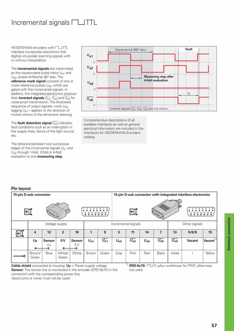
57
Ele
ctr
ical co
nn
ecti
on
Pin layout
15-pin D-sub connector 15-pin D-sub connector with integrated interface electronics
Voltage supply Incremental signals Other signals
4 12 2 10 1 9 3 11 14 7 13 5/6/8 15
UP Sensor
UP
0 V Sensor
0 VUa1 Ua2 Ua0 Vacant Vacant
1)
Brown/Green
Blue White/Green
White Brown Green Gray Pink Red Black Violet / Yellow
Cable shield connected to housing; UP = Power supply voltageSensor: The sensor line is connected in the encoder (ERO 6x70: in the connector) with the corresponding power line.Vacant pins or wires must not be used!
1) ERO 6x70:
TTL/11 µAPP switchover for PWT, otherwise not used
Incremental signals TTL
HEIDENHAIN encoders with TTL interface incorporate electronics that digitize sinusoidal scanning signals with or without interpolation.
The incremental signals are transmitted as the square-wave pulse trains Ua1 and Ua2, phase-shifted by 90° elec. The reference mark signal consists of one or more reference pulses Ua0, which are gated with the incremental signals. In addition, the integrated electronics produce their inverted signals , and for noise-proof transmission. The illustrated sequence of output signals—with Ua2 lagging Ua1—applies to the direction of motion shown in the dimension drawing.
The fault detection signal indicates fault conditions such as an interruption in the supply lines, failure of the light source, etc.
The distance between two successive edges of the incremental signals Ua1 and Ua2 through 1-fold, 2-fold or 4-fold evaluation is one measuring step.
Signal period 360° elec. Fault
Measuring step after
4-fold evaluation
Inverse signals , , are not shown
Comprehensive descriptions of all available interfaces as well as general electrical information are included in the Interfaces for HEIDENHAIN Encoders catalog.
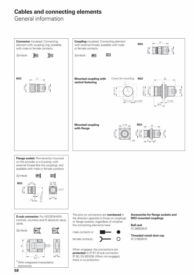
M23
M23
M23
M23
58
Cables and connecting elements
General information
Connector insulated: Connecting element with coupling ring; available with male or female contacts.
Symbols
Coupling insulated: Connecting element with external thread; available with male or female contacts.
Symbols
The pins on connectors are numbered in the direction opposite to those on couplings or fl ange sockets, regardless of whether the connecting elements have
male contacts or
female contacts.
When engaged, the connections are protected to IP 67 (D-sub connector: IP 50; EN 60 529). When not engaged, there is no protection.
D-sub connector: For HEIDENHAIN controls, counters and IK absolute value cards.
Symbols
Accessories for fl ange sockets and
M23 mounted couplings
Bell seal
ID 266526-01
Threaded metal dust cap
ID 219926-01
Flange socket: Permanently mounted on the encoder or a housing, with external thread (like the coupling), and available with male or female contacts.
Symbols
Mounted coupling with
central fastening
Mounted coupling
with fl ange
Cutout for mounting
1) With integrated interpolation electronics
M23
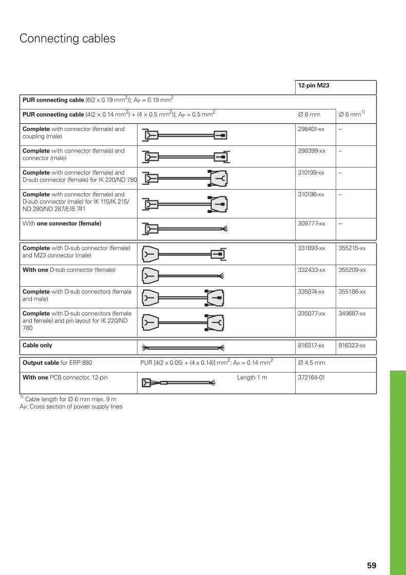
59
Connecting cables
12-pin M23
PUR connecting cable [6(2 x 0.19 mm2)]; AP = 0.19 mm2
PUR connecting cable [4(2 × 0.14 mm2) + (4 × 0.5 mm2)]; AP = 0.5 mm2 8 mm 6 mm1)
Complete with connector (female) and coupling (male)
298401-xx –
Complete with connector (female) and connector (male)
298399-xx –
Complete with connector (female) and D-sub connector (female) for IK 220/ND 780
310199-xx –
Complete with connector (female) and D-sub connector (male) for IK 115/IK 215/ND 280/ND 287/EIB 741
310196-xx –
With one connector (female) 309777-xx –
Complete with D-sub connector (female) and M23 connector (male)
331693-xx 355215-xx
With one D-sub connector (female) 332433-xx 355209-xx
Complete with D-sub connectors (female and male)
335074-xx 355186-xx
Complete with D-sub connectors (female and female) and pin layout for IK 220/ND 780
335077-xx 349687-xx
Cable only 816317-xx 816323-xx
Output cable for ERP 880 PUR [4(2 x 0.05) + (4 x 0.14)] mm2; AP = 0.14 mm2 4.5 mm
With one PCB connector, 12-pin Length 1 m 372164-01
1) Cable length for 6 mm max. 9 mAP: Cross section of power supply lines
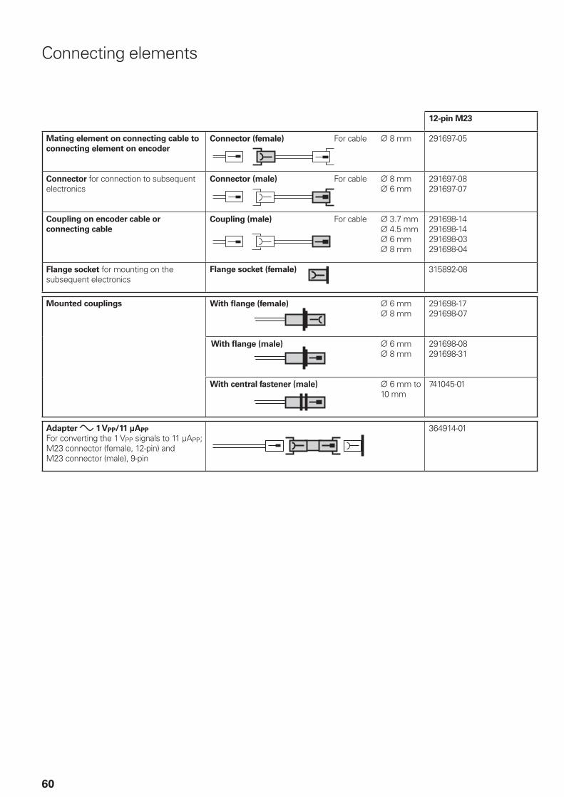
60
12-pin M23
Mating element on connecting cable to
connecting element on encoder
Connector (female) For cable 8 mm 291697-05
Connector for connection to subsequent electronics
Connector (male) For cable 8 mm 6 mm
291697-08291697-07
Coupling on encoder cable or
connecting cable
Coupling (male) For cable 3.7 mm 4.5 mm 6 mm 8 mm
291698-14291698-14291698-03291698-04
Flange socket for mounting on the subsequent electronics
Flange socket (female) 315892-08
Mounted couplings With fl ange (female) 6 mm 8 mm
291698-17291698-07
With fl ange (male) 6 mm 8 mm
291698-08291698-31
With central fastener (male) 6 mm to 10 mm
741045-01
Adapter 1 VPP/11 µAPP
For converting the 1 VPP signals to 11 µAPP; M23 connector (female, 12-pin) and M23 connector (male), 9-pin
364914-01
Connecting elements
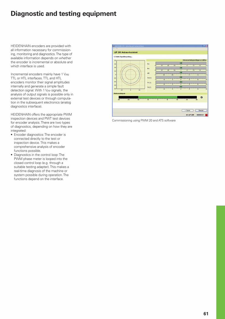
61
Diagnostic and testing equipment
Commissioning using PWM 20 and ATS software
HEIDENHAIN encoders are provided with all information necessary for commission-ing, monitoring and diagnostics. The type of available information depends on whether the encoder is incremental or absolute and which interface is used.
Incremental encoders mainly have 1 VPP, TTL or HTL interfaces. TTL and HTL encoders monitor their signal amplitudes internally and generate a simple fault detection signal. With 1 VPP signals, the analysis of output signals is possible only in external test devices or through computa-tion in the subsequent electronics (analog diagnostics interface).
HEIDENHAIN offers the appropriate PWM inspection devices and PWT test devices for encoder analysis. There are two types of diagnostics, depending on how they are integrated:• Encoder diagnostics: The encoder is
connected directly to the test or inspection device. This makes a comprehensive analysis of encoder functions possible.
• Diagnostics in the control loop: The PWM phase meter is looped into the closed control loop (e.g. through a suitable testing adapter). This makes a real-time diagnosis of the machine or system possible during operation. The functions depend on the interface.
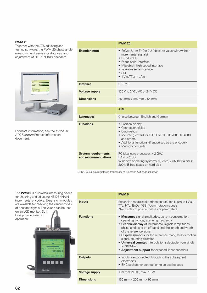
62
PWM 20
Together with the ATS adjusting and testing software, the PWM 20 phase angle measuring unit serves for diagnosis and adjustment of HEIDENHAIN encoders.
PWM 20
Encoder input • EnDat 2.1 or EnDat 2.2 (absolute value with/without incremental signals)
• DRIVE-CLiQ• Fanuc serial interface• Mitsubishi high speed interface• Yaskawa serial interface• SSI• 1 VPP/TTL/11 µAPP
Interface USB 2.0
Voltage supply 100 V to 240 V AC or 24 V DC
Dimensions 258 mm x 154 mm x 55 mm
ATS
Languages Choice between English and German
Functions • Position display• Connection dialog• Diagnostics• Mounting wizard for EBI/ECI/EQI, LIP 200, LIC 4000
and others• Additional functions (if supported by the encoder)• Memory contents
System requirements
and recommendations
PC (dual-core processor, > 2 GHz)RAM > 2 GBWindows operating systems XP, Vista, 7 (32-bit/64-bit), 8200 MB free space on hard disk
DRIVE-CLiQ is a registered trademark of Siemens Aktiengesellschaft
The PWM 9 is a universal measuring device for checking and adjusting HEIDENHAIN incremental encoders. Expansion modules are available for checking the various types of encoder signals. The values can be read on an LCD monitor. Soft keys provide ease of operation.
PWM 9
Inputs Expansion modules (interface boards) for 11 µAPP; 1 VPP; TTL; HTL; EnDat*/SSI*/commutation signals*No display of position values or parameters
Functions • Measures signal amplitudes, current consumption, operating voltage, scanning frequency
• Graphic display of incremental signals (amplitudes, phase angle and on-off ratio) and the length and width of the reference signal
• Display symbols for the reference mark, fault detection signal, counting direction
• Universal counter, interpolation selectable from single to 1024-fold
• Adjustment support for exposed linear encoders
Outputs • Inputs are connected through to the subsequent electronics
• BNC sockets for connection to an oscilloscope
Voltage supply 10 V to 30 V DC, max. 15 W
Dimensions 150 mm × 205 mm × 96 mm
For more information, see the PWM 20, ATS Software Product Information document.
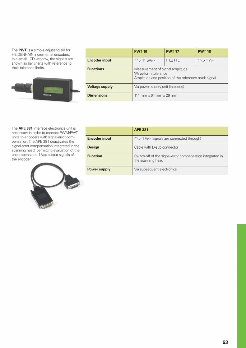
63
The PWT is a simple adjusting aid for HEIDENHAIN incremental encoders. In a small LCD window, the signals are shown as bar charts with reference to their tolerance limits.
PWT 10 PWT 17 PWT 18
Encoder input 11 µAPP TTL 1 VPP
Functions Measurement of signal amplitudeWave-form toleranceAmplitude and position of the reference mark signal
Voltage supply Via power supply unit (included)
Dimensions 114 mm x 64 mm x 29 mm
APE 381
Encoder input 1 VPP (signals are connected through)
Design Cable with D-sub connector
Function Switch-off of the signal-error compensation integrated in the scanning head
Power supply Via subsequent electronics
The APE 381 interface electronics unit is necessary in order to connect PWM/PWT units to encoders with signal-error com-pensation. The APE 381 deactivates the signal-error compensation integrated in the scanning head, permitting evaluation of the uncompensated 1 VPP output signals of the encoder.
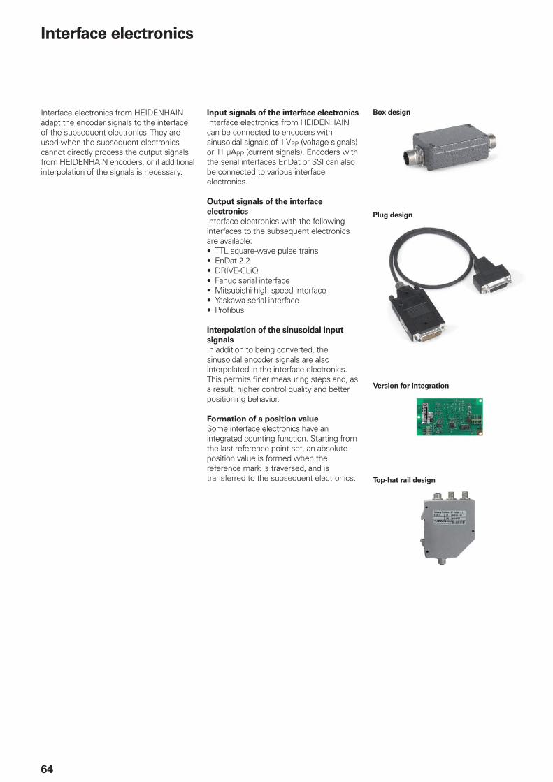
64
Interface electronics
Interface electronics from HEIDENHAIN adapt the encoder signals to the interface of the subsequent electronics. They are used when the subsequent electronics cannot directly process the output signals from HEIDENHAIN encoders, or if additional interpolation of the signals is necessary.
Box design
Plug design
Version for integration
Top-hat rail design
Input signals of the interface electronics
Interface electronics from HEIDENHAIN can be connected to encoders with sinusoidal signals of 1 VPP (voltage signals) or 11 µAPP (current signals). Encoders with the serial interfaces EnDat or SSI can also be connected to various interface electronics.
Output signals of the interface
electronics
Interface electronics with the following interfaces to the subsequent electronics are available:• TTL square-wave pulse trains• EnDat 2.2• DRIVE-CLiQ• Fanuc serial interface• Mitsubishi high speed interface• Yaskawa serial interface• Profi bus
Interpolation of the sinusoidal input
signals
In addition to being converted, the sinusoidal encoder signals are also interpolated in the interface electronics. This permits fi ner measuring steps and, as a result, higher control quality and better positioning behavior.
Formation of a position value
Some interface electronics have an integrated counting function. Starting from the last reference point set, an absolute position value is formed when the reference mark is traversed, and is transferred to the subsequent electronics.
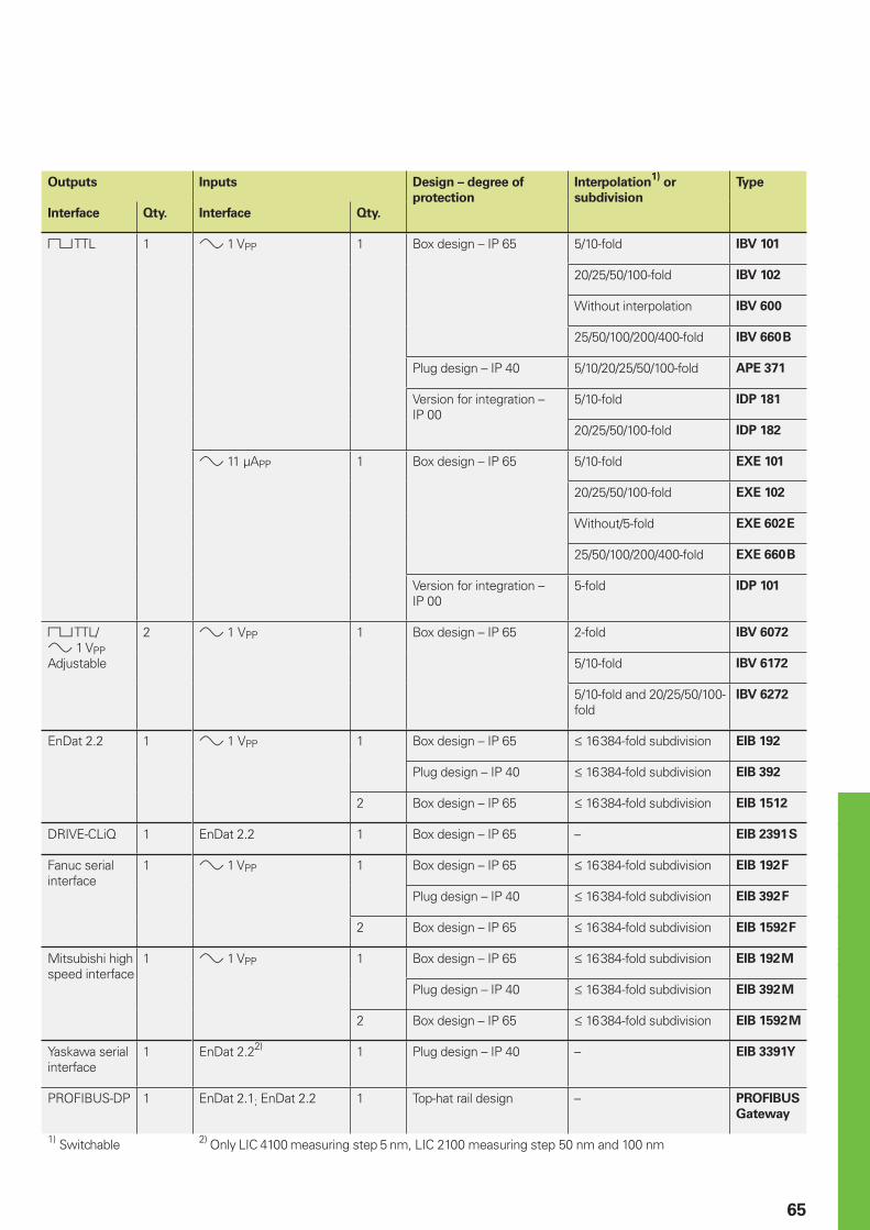
65
Outputs Inputs Design – degree of
protection
Interpolation1)
or
subdivision
Type
Interface Qty. Interface Qty.
TTL 1 1 VPP 1 Box design – IP 65 5/10-fold IBV 101
20/25/50/100-fold IBV 102
Without interpolation IBV 600
25/50/100/200/400-fold IBV 660 B
Plug design – IP 40 5/10/20/25/50/100-fold APE 371
Version for integration – IP 00
5/10-fold IDP 181
20/25/50/100-fold IDP 182
11µAPP 1 Box design – IP 65 5/10-fold EXE 101
20/25/50/100-fold EXE 102
Without/5-fold EXE 602 E
25/50/100/200/400-fold EXE 660 B
Version for integration – IP 00
5-fold IDP 101
TTL/ 1 VPPAdjustable
2 1VPP 1 Box design – IP 65 2-fold IBV 6072
5/10-fold IBV 6172
5/10-fold and 20/25/50/100-fold
IBV 6272
EnDat 2.2 1 1VPP 1 Box design – IP 65 16 384-fold subdivision EIB 192
Plug design – IP 40 16 384-fold subdivision EIB 392
2 Box design – IP 65 16 384-fold subdivision EIB 1512
DRIVE-CLiQ 1 EnDat 2.2 1 Box design – IP 65 – EIB 2391 S
Fanuc serial interface
1 1 VPP 1 Box design – IP 65 16 384-fold subdivision EIB 192 F
Plug design – IP 40 16 384-fold subdivision EIB 392 F
2 Box design – IP 65 16 384-fold subdivision EIB 1592 F
Mitsubishi high speed interface
1 1 VPP 1 Box design – IP 65 16 384-fold subdivision EIB 192 M
Plug design – IP 40 16 384-fold subdivision EIB 392 M
2 Box design – IP 65 16 384-fold subdivision EIB 1592 M
Yaskawa serial interface
1 EnDat 2.22) 1 Plug design – IP 40 – EIB 3391 Y
PROFIBUS-DP 1 EnDat 2.1; EnDat 2.2 1 Top-hat rail design – PROFIBUS
Gateway
1) Switchable 2) Only LIC 4100 measuring step 5 nm, LIC 2100 measuring step 50 nm and 100 nm
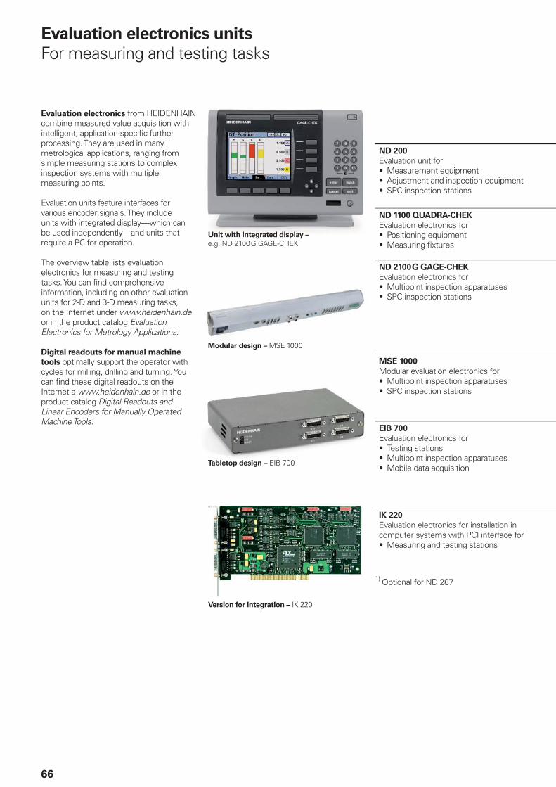
66
Evaluation electronics units
For measuring and testing tasks
ND 200
Evaluation unit for• Measurement equipment• Adjustment and inspection equipment• SPC inspection stations
ND 1100 QUADRA-CHEK
Evaluation electronics for• Positioning equipment• Measuring fi xtures
ND 2100 G GAGE-CHEK
Evaluation electronics for• Multipoint inspection apparatuses• SPC inspection stations
MSE 1000
Modular evaluation electronics for• Multipoint inspection apparatuses• SPC inspection stations
EIB 700
Evaluation electronics for• Testing stations• Multipoint inspection apparatuses• Mobile data acquisition
IK 220
Evaluation electronics for installation in computer systems with PCI interface for• Measuring and testing stations
1) Optional for ND 287
Unit with integrated display – e.g. ND 2100 G GAGE-CHEK
Modular design – MSE 1000
Tabletop design – EIB 700
Version for integration – IK 220
Evaluation electronics from HEIDENHAIN combine measured value acquisition with intelligent, application-specifi c further processing. They are used in many metrological applications, ranging from simple measuring stations to complex inspection systems with multiple measuring points.
Evaluation units feature interfaces for various encoder signals. They include units with integrated display—which can be used independently—and units that require a PC for operation.
The overview table lists evaluation electronics for measuring and testing tasks. You can fi nd comprehensive information, including on other evaluation units for 2-D and 3-D measuring tasks, on the Internet under www.heidenhain.de or in the product catalog Evaluation Electronics for Metrology Applications.
Digital readouts for manual machine
tools optimally support the operator with cycles for milling, drilling and turning. You can fi nd these digital readouts on the Internet a www.heidenhain.de or in the product catalog Digital Readouts and Linear Encoders for Manually Operated Machine Tools.
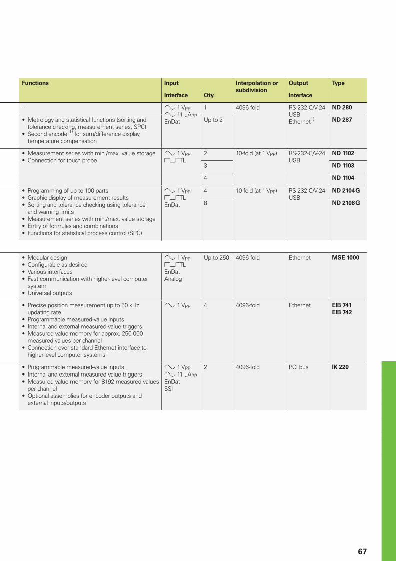
67
Functions Input Interpolation or
subdivision
Output Type
Interface Qty. Interface
– 1 VPP 11 µAPPEnDat
1 4096-fold RS-232-C/V-24USBEthernet1)
ND 280
• Metrology and statistical functions (sorting and tolerance checking, measurement series, SPC)
• Second encoder1) for sum/difference display, temperature compensation
Up to 2 ND 287
• Measurement series with min./max. value storage• Connection for touch probe
1 VPP TTL
2 10-fold (at 1 VPP) RS-232-C/V-24USB
ND 1102
3 ND 1103
4 ND 1104
• Programming of up to 100 parts• Graphic display of measurement results• Sorting and tolerance checking using tolerance
and warning limits• Measurement series with min./max. value storage• Entry of formulas and combinations• Functions for statistical process control (SPC)
1 VPP TTLEnDat
4 10-fold (at 1 VPP) RS-232-C/V-24USB
ND 2104 G
8 ND 2108 G
• Modular design• Confi gurable as desired• Various interfaces• Fast communication with higher-level computer
system• Universal outputs
1 VPP TTLEnDatAnalog
Up to 250 4096-fold Ethernet MSE 1000
• Precise position measurement up to 50 kHz updating rate
• Programmable measured-value inputs• Internal and external measured-value triggers• Measured-value memory for approx. 250 000
measured values per channel• Connection over standard Ethernet interface to
higher-level computer systems
1 VPP 4 4096-fold Ethernet EIB 741
EIB 742
• Programmable measured-value inputs• Internal and external measured-value triggers• Measured-value memory for 8192 measured values
per channel• Optional assemblies for encoder outputs and
external inputs/outputs
1 VPP 11 µAPPEnDatSSI
2 4096-fold PCI bus IK 220
PL APS02-384 Warszawa, Polandwww.heidenhain.pl
PT FARRESA ELECTRÓNICA, LDA.4470 - 177 Maia, Portugalwww.farresa.pt
RO HEIDENHAIN Reprezentanta RomaniaBrasov, 500407, Romaniawww.heidenhain.ro
RS Serbia BG
RU OOO HEIDENHAIN115172 Moscow, Russiawww.heidenhain.ru
SE HEIDENHAIN Scandinavia AB12739 Skärholmen, Swedenwww.heidenhain.se
SG HEIDENHAIN PACIFIC PTE LTD.Singapore 408593www.heidenhain.com.sg
SK KOPRETINA TN s.r.o.91101 Trencin, Slovakiawww.kopretina.sk
SL NAVO d.o.o.2000 Maribor, Sloveniawww.heidenhain.si
TH HEIDENHAIN (THAILAND) LTDBangkok 10250, Thailandwww.heidenhain.co.th
TR T&M Mühendislik San. ve Tic. LTD. STI·.
34728 Ümraniye-Istanbul, Turkeywww.heidenhain.com.tr
TW HEIDENHAIN Co., Ltd.Taichung 40768, Taiwan R.O.C.www.heidenhain.com.tw
UA Gertner Service GmbH Büro Kiev 01133 Kiev, Ukrainewww.heidenhain.ua
US HEIDENHAIN CORPORATIONSchaumburg, IL 60173-5337, USAwww.heidenhain.com
VE Maquinaria Diekmann S.A. Caracas, 1040-A, VenezuelaE-mail: [email protected]
VN AMS Co. LtdHCM City, VietnamE-mail: [email protected]
ZA MAFEMA SALES SERVICES C.C.Midrand 1685, South Africawww.heidenhain.co.za
ES FARRESA ELECTRONICA S.A.08028 Barcelona, Spainwww.farresa.es
FI HEIDENHAIN Scandinavia AB02770 Espoo, Finlandwww.heidenhain.fi
FR HEIDENHAIN FRANCE sarl92310 Sèvres, Francewww.heidenhain.fr
GB HEIDENHAIN (G.B.) LimitedBurgess Hill RH15 9RD, United Kingdomwww.heidenhain.co.uk
GR MB Milionis Vassilis17341 Athens, Greecewww.heidenhain.gr
HK HEIDENHAIN LTDKowloon, Hong KongE-mail: [email protected]
HR Croatia SL
HU HEIDENHAIN Kereskedelmi Képviselet1239 Budapest, Hungarywww.heidenhain.hu
ID PT Servitama Era ToolsindoJakarta 13930, IndonesiaE-mail: [email protected]
IL NEUMO VARGUS MARKETING LTD.Tel Aviv 61570, IsraelE-mail: [email protected]
IN HEIDENHAIN Optics & ElectronicsIndia Private LimitedChetpet, Chennai 600 031, Indiawww.heidenhain.in
IT HEIDENHAIN ITALIANA S.r.l.20128 Milano, Italywww.heidenhain.it
JP HEIDENHAIN K.K.Tokyo 102-0083, Japanwww.heidenhain.co.jp
KR HEIDENHAIN Korea LTD.Gasan-Dong, Seoul, Korea 153-782www.heidenhain.co.kr
MX HEIDENHAIN CORPORATION MEXICO20235 Aguascalientes, Ags., MexicoE-mail: [email protected]
MY ISOSERVE SDN. BHD.43200 Balakong, SelangorE-mail: [email protected]
NL HEIDENHAIN NEDERLAND B.V.6716 BM Ede, Netherlandswww.heidenhain.nl
NO HEIDENHAIN Scandinavia AB7300 Orkanger, Norwaywww.heidenhain.no
PH Machinebanks` CorporationQuezon City, Philippines 1113E-mail: [email protected]
AR NAKASE SRL.B1653AOX Villa Ballester, Argentinawww.heidenhain.com.ar
AT HEIDENHAIN Techn. Büro Österreich83301 Traunreut, Germanywww.heidenhain.de
AU FCR Motion Technology Pty. LtdLaverton North 3026, AustraliaE-mail: [email protected]
BE HEIDENHAIN NV/SA1760 Roosdaal, Belgiumwww.heidenhain.be
BG ESD Bulgaria Ltd.Sofi a 1172, Bulgariawww.esd.bg
BR DIADUR Indústria e Comércio Ltda.04763-070 – São Paulo – SP, Brazilwww.heidenhain.com.br
BY GERTNER Service GmbH220026 Minsk, Belaruswww.heidenhain.by
CA HEIDENHAIN CORPORATIONMississauga, OntarioL5T2N2, Canadawww.heidenhain.com
CH HEIDENHAIN (SCHWEIZ) AG8603 Schwerzenbach, Switzerlandwww.heidenhain.ch
CN DR. JOHANNES HEIDENHAIN (CHINA) Co., Ltd.Beijing 101312, Chinawww.heidenhain.com.cn
CZ HEIDENHAIN s.r.o.102 00 Praha 10, Czech Republicwww.heidenhain.cz
DK TP TEKNIK A/S2670 Greve, Denmarkwww.tp-gruppen.dk
DE HEIDENHAIN Vertrieb Deutschland83301 Traunreut, Deutschland 08669 31-3132 08669 32-3132E-Mail: [email protected]
HEIDENHAIN Technisches Büro Nord12681 Berlin, Deutschland 030 54705-240
HEIDENHAIN Technisches Büro Mitte07751 Jena, Deutschland 03641 4728-250
HEIDENHAIN Technisches Büro West44379 Dortmund, Deutschland 0231 618083-0
HEIDENHAIN Technisches Büro Südwest70771 Leinfelden-Echterdingen, Deutschland 0711 993395-0
HEIDENHAIN Technisches Büro Südost83301 Traunreut, Deutschland 08669 31-1345
Vollständige und weitere Adressen siehe www.heidenhain.deFor complete and further addresses see www.heidenhain.de
Zu
m A
bh
eft
en
hie
r fa
lzen
! /
Fo
ld h
ere
fo
r fi
lin
g!
������������ ��� ��������������� ��������������������������������������� �������������� ������������������ ��!�"����������
������ !���� ��!�
606136-25 · 10 · 6/2014 · H · Printed in Germany


