Embed Size (px)
Citation preview
Page 1 of 26
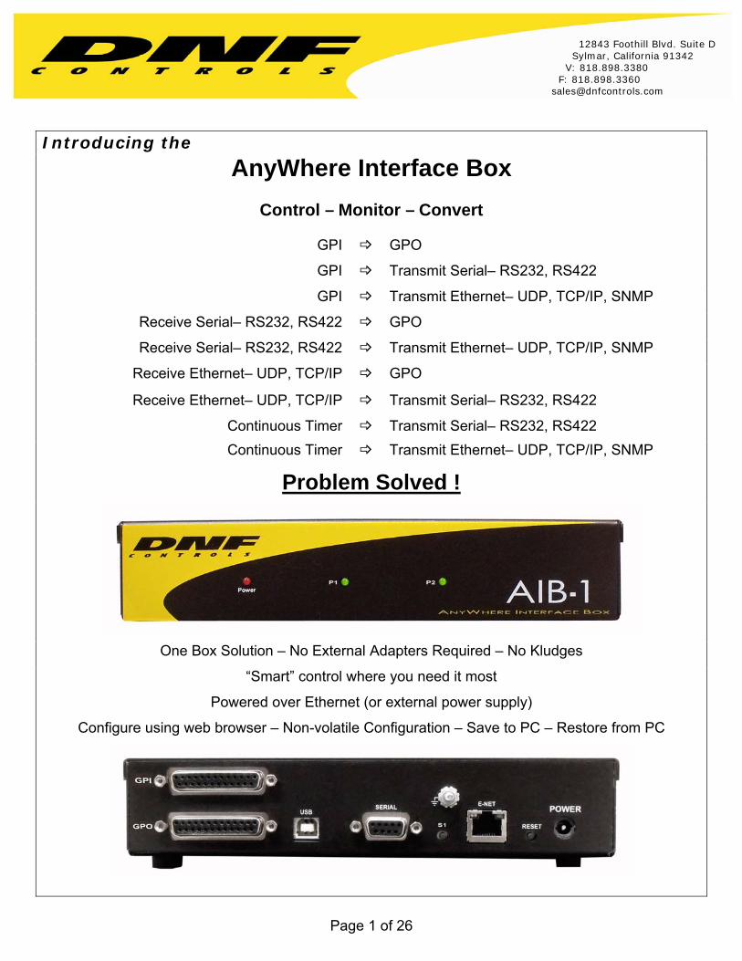
Introducing the
AnyWhere Interface Box
Control – Monitor – Convert
GPI GPO
GPI Transmit Serial– RS232, RS422
GPI Transmit Ethernet– UDP, TCP/IP, SNMP
Receive Serial– RS232, RS422 GPO
Receive Serial– RS232, RS422 Transmit Ethernet– UDP, TCP/IP, SNMP
Receive Ethernet– UDP, TCP/IP GPO
Receive Ethernet– UDP, TCP/IP Transmit Serial– RS232, RS422
Continuous Timer Transmit Serial– RS232, RS422
Continuous Timer Transmit Ethernet– UDP, TCP/IP, SNMP
Problem Solved !
One Box Solution – No External Adapters Required – No Kludges
“Smart” control where you need it most
Powered over Ethernet (or external power supply)
Configure using web browser – Non-volatile Configuration – Save to PC – Restore from PC
12843 Foothill Blvd. Suite D Sylmar, California 91342 V: 818.898.3380 F: 818.898.3360 [email protected]
Page 2 of 26
TABLE OF CONTENTS
1. OVERVIEW ........................................................................................................... 3
2. INSTALLATION & CONFIGURATION ............................................................ 5
3. GPI EVENTS Configuration Web Page ......................................................... 7
4. GPO ACTIONS Configuration Web Page ..................................................... 8
5. SERIAL PORT CONFIGURATION Web Page............................................... 9
6. SERIAL RECEIVE EVENTS Configuration Web Page............................. 10
7. SERIAL TRANSMIT ACTIONS Configuration Web Page ....................... 11
8. REMOTE DEVICE ASSIGNMENT Configuration Web Page .................. 12
9. ETHERNET RECEIVE EVENTS Configuration Web Page...................... 14
10. ETHERNET TRANSMIT ACTIONS Configuration Web Page................. 15
11. SNMP TRANSMIT ACTIONS Configuration Web Page........................... 16
12. EVENT ACTION TABLE Configuration Web Page................................... 17
13. REAR PANEL CONNECTORS ....................................................................... 19
14. GPIs, WET/ DRY Configuration .................................................................... 21
15. GPOs, WET/ DRY Configuration ................................................................. 22
16. EXAMPLES......................................................................................................... 23
17. DNF CONTROLS LIMITED WARRANTY ..................................................... 26
Revision History
Version 1.0 Original
Version 1.1 Added Installation and Configuration section
Page 3 of 26
AnyWhere Interface Box
SPECIFICATIONS
GPI Inputs 8- Opto-isolated Inputs
GPO Outputs 8- Isolated Relay contact closures
Serial Port Configurable: RS422 Controller or Device RS232 DTE
Ethernet Port RJ45 10baseT
Power Power over Ethernet or optional external power supply (12W)
Size 8.25” W x 4.125” D x 1.5” H
1. OVERVIEW The AnyWhere Interface Box (AIB) maps an EVENT input to an ACTION output.
EVENT Inputs- GPI Input, Serial Receive, Ethernet Receive, and Periodic Timer
ACTION Outputs- GPO Output, Serial Transmit, Ethernet Transmit, and SNMP Transmit Any EVENT can trigger any ACTION. One EVENT can trigger one ACTION. One EVENT can trigger multiple ACTIONs. GPI events trigger an ON ACTION and an OFF ACTION. Serial Receive, Ethernet Receive and Periodic Timer events trigger only ON ACTIONs. Use the EVENT ACTION TABLE web page to map an EVENT to an ACTION. EVENTS
A GPI ON event triggers an ON ACTION when the GPI turns on. A GPI OFF event triggers an OFF ACTION when it turns OFF. Use the “Do Nothing” action to ignore the GPI ON or OFF event. Use the GPI EVENTS web page to configure the individual operation of the 8 GPIs. A Serial Receive and Ethernet Receive event turns ON, when received data matches the assigned, user entered data pattern, and then triggers an ON ACTION. Receive events do not trigger OFF ACTIONs. The Ethernet Receive data must come from the assigned IP address and Port number. Serial and Ethernet Receive data pattern matching supports simple and complex pattern matching. Match a single received ASCII (ie: ‘A’) character or match a group of received characters (ie: ‘control_on‘). Match ASCII, binary and hexadecimal characters. Match the whole received character, the first half, the second half, specific bits, or ignore the whole character. Refer to the USAGE instructions on the serial and Ethernet receive event web pages. Use the SERIAL RECEIVE EVENTS web page to enter serial data patterns. Use the ETHERNET RECEIVE EVENTS web page to enter Ethernet data patterns. Use the REMOTE DEVICE ASSIGNMENT web page to configure the remote device’s IP address and Port number.

Page 4 of 26
The Periodic Timer is a continuously running timer with a user assigned time period, 100 milliseconds to 1500 milliseconds (1.5 seconds). When the Timer time period expires, the Timer triggers an ON ACTION, and then automatically restarts itself. Use the EVENT ACTION TABLE web page to configure periodic timers ACTIONS
GPO ON and GPO OFF actions are individually configurable for the 8 GPOs– Latch, Momentary, and Toggle. Specify the momentary on time. Also, configure GPOs to operate as a radio group (turning one on automatically turns the other members of the group off) or flip flop (a radio group of just two GPOs). Use the GPO ACTIONS web page to configure GPOs. The Serial Transmit action transmits a user entered group of characters out the serial port. Configure the serial port’s Transmit/ Receive baud rate and parity. 8-data bits. 1 Stop and Start bit. BREAK character (18 bits times), %BR, is supported.
The Ethernet Transmit action transmits a user entered group of characters to the user assigned IP Address and Port Number. UDP, TCP/IP (client and server), and SNMP are supported.
The Transmit action transmits ASCII and HEX characters, up to 256 in length. Add a %WT, WAIT, to delay transmission of characters, 1 to 999 milliseconds. The characters preceding %WT are sent immediately. The characters after %WT are sent when the wait timer expires. More than one WAIT can be included in a transmit action.
Use the SERIAL PORT CONFIGURATION web page to configure the serial port. Use the SERIAL TRANSMIT ACTIONS web page to enter serial transmit data. Use the ETHERNET TRANSMIT ACTIONS web page to enter Ethernet transmit data. Use the REMOTE DEVICE ASSIGNMENT web page to enter the remote device’s IP address and Port number.
Page 5 of 26
2. INSTALLATION & CONFIGURATION INSTALLATION
Refer to the REAR PANEL CONNECTORS section for GPI, GPO, and serial connector pin out information.
Refer to the GPIs, WET/ DRY Configuration and GPOs, WET/ DRY Configuration sections for GPI and GPO Wet/ Dry configuration information.
Use the GPI Events web page to configure GPI operation.
Use the GPO Actions web page to configure GPO operation.
Use the Serial Port Configuration web page to configure the serial port.
Use the Remote Device Assignment web page to configure Ethernet connections.
POWER
The AnyWhere Interface Box is powered from an Ethernet switcher/ router that supports Power Over Ethernet (POE), or from an optional external power supply. The AIB requires 12 volts DC at 2 amps from an external power supply and 13 Watts from POE switch. An external power supply may be purchased from DNF Controls. DEFAULT ETHERNET CONFIGURATION
IP Address: 192.168.10.217 Subnet Mask: 255.255.255.0
Gateway: 192.168.10.1 RESET
Press the RESET switch on the rear of the AIB to reboot it.
Press and hold the RESET switch for 10 seconds to reset the IP address, subnet mask, Gateway, and configuration to factory defaults.
CONFIGURATION
The AnyWhere Interface Box is configured using a standard web browser (Internet Explorer, Firefox, and Chrome). Enter the AIB’s IP address in the Address/ URL bar, typically located at the top of the web browser page, to access the AIB’s Home Page. Use the links on the left side of the Home Page to access the desired configuration web page.
All configuration settings are saved in non-volatile memory in the AIB. Settings are retained when power is removed from the AIB.
Settings may be uploaded to a computer as a configuration file (.dnf) for storage. Configuration files may be downloaded from a computer into the AIB to restore a saved configuration. A configuration file contains all of the AIB’s configurations except IP address, subnet mask, and gateway address. The AIB does not support partial configuration upload or download. The configuration file is a not a text formatted file. It can not be viewed or modified with a text editor.
Page 6 of 26
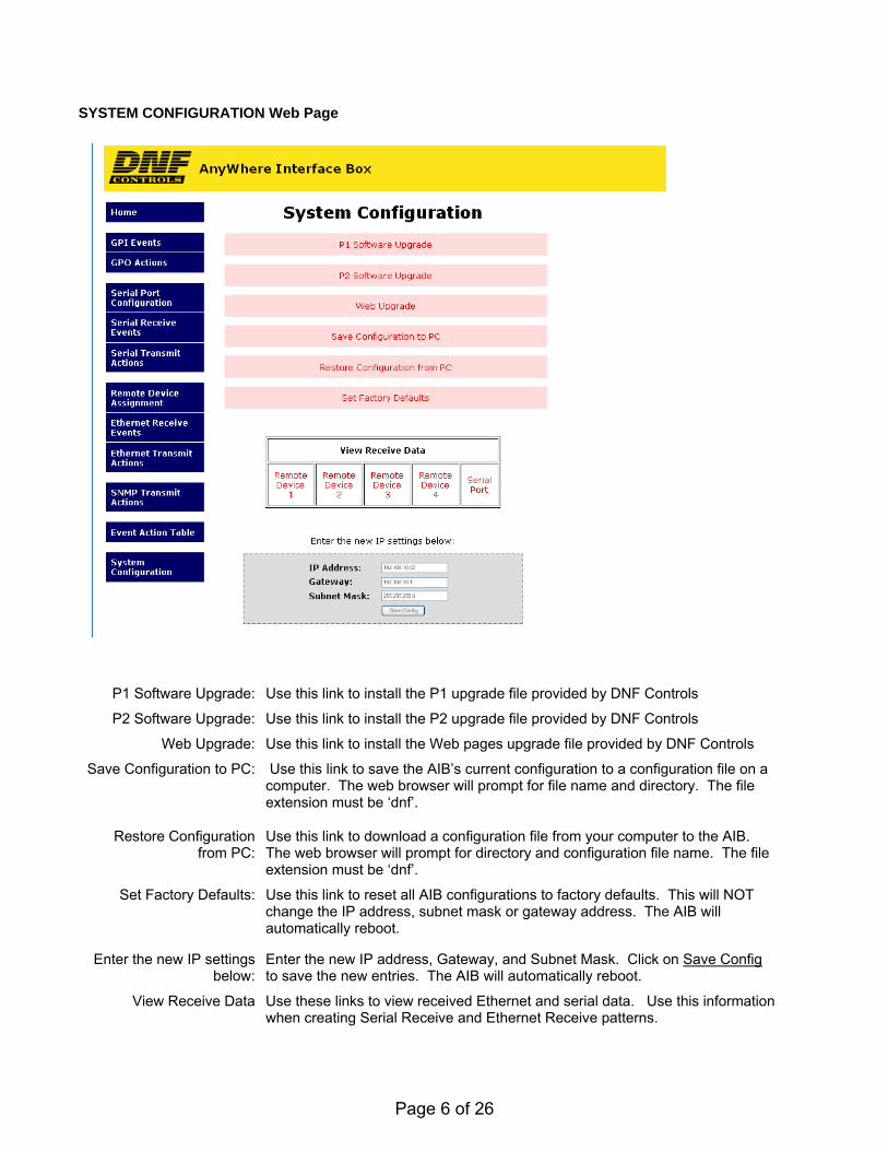
SYSTEM CONFIGURATION Web Page
P1 Software Upgrade: Use this link to install the P1 upgrade file provided by DNF Controls
P2 Software Upgrade: Use this link to install the P2 upgrade file provided by DNF Controls
Web Upgrade: Use this link to install the Web pages upgrade file provided by DNF Controls
Save Configuration to PC: Use this link to save the AIB’s current configuration to a configuration file on a computer. The web browser will prompt for file name and directory. The file extension must be ‘dnf’.
Restore Configuration from PC:
Use this link to download a configuration file from your computer to the AIB. The web browser will prompt for directory and configuration file name. The file extension must be ‘dnf’.
Set Factory Defaults: Use this link to reset all AIB configurations to factory defaults. This will NOT change the IP address, subnet mask or gateway address. The AIB will automatically reboot.
Enter the new IP settings below:
Enter the new IP address, Gateway, and Subnet Mask. Click on Save Config to save the new entries. The AIB will automatically reboot.
View Receive Data Use these links to view received Ethernet and serial data. Use this information when creating Serial Receive and Ethernet Receive patterns.
Page 7 of 26
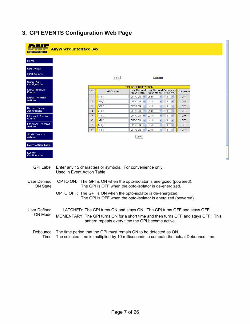
3. GPI EVENTS Configuration Web Page
GPI Label Enter any 15 characters or symbols. For convenience only.
Used in Event Action Table
User Defined ON State
OPTO ON: The GPI is ON when the opto-isolator is energized (powered). The GPI is OFF when the opto-isolator is de-energized.
OPTO OFF: The GPI is ON when the opto-isolator is de-energized. The GPI is OFF when the opto-isolator is energized (powered).
User Defined
ON Mode LATCHED: The GPI turns ON and stays ON. The GPI turns OFF and stays OFF.
MOMENTARY: The GPI turns ON for a short time and then turns OFF and stays OFF. This pattern repeats every time the GPI become active.
Debounce
Time The time period that the GPI must remain ON to be detected as ON. The selected time is multiplied by 10 milliseconds to compute the actual Debounce time.
Page 8 of 26
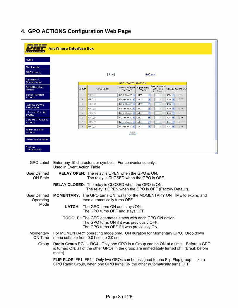
4. GPO ACTIONS Configuration Web Page
GPO Label Enter any 15 characters or symbols. For convenience only. Used in Event Action Table
User Defined ON State
RELAY OPEN: The relay is OPEN when the GPO is ON. The relay is CLOSED when the GPO is OFF.
RELAY CLOSED: The relay is CLOSED when the GPO is ON. The relay is OPEN when the GPO is OFF (Factory Default).
User Defined Operating
Mode
MOMENTARY: The GPO turns ON, waits for the MOMENTARY ON TIME to expire, and then automatically turns OFF.
LATCH: The GPO turns ON and stays ON. The GPO turns OFF and stays OFF.
TOGGLE: The GPO alternates states with each GPO ON action. The GPO turns ON if it was previously OFF. The GPO turns OFF if it was previously ON.
Momentary ON Time
For MOMENTARY operating mode only. ON duration for Momentary GPO. Drop down menu settable from 0.01 sec to 2.0 sec.
Group Radio Group RG1 – RG4: Only one GPO in a Group can be ON at a time. Before a GPO is turned ON, all of the other GPOs in the group are immediately turned off. (Break before make)
FLIP-FLOP FF1–FF4: Only two GPOs can be assigned to one Flip-Flop group. Like a GPO Radio Group, when one GPO turns ON the other automatically turns OFF.
Page 9 of 26
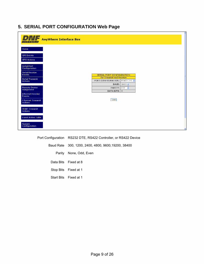
5. SERIAL PORT CONFIGURATION Web Page
Port Configuration RS232 DTE, RS422 Controller, or RS422 Device
Baud Rate 300, 1200, 2400, 4800, 9600,19200, 38400
Parity None, Odd, Even
Data Bits Fixed at 8
Stop Bits Fixed at 1
Start Bits Fixed at 1
Page 10 of 26
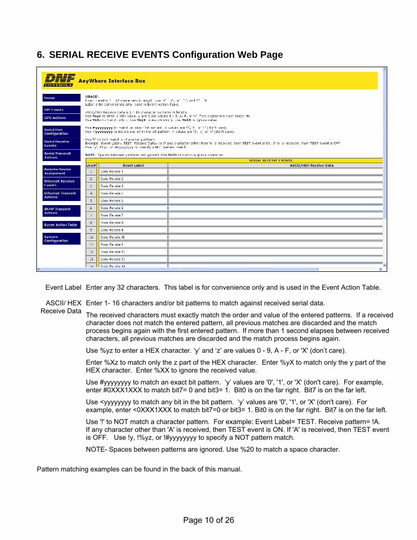
6. SERIAL RECEIVE EVENTS Configuration Web Page
Pattern matching examples can be found in the back of this manual.
Event Label Enter any 32 characters. This label is for convenience only and is used in the Event Action Table.
ASCII/ HEX Receive Data
Enter 1- 16 characters and/or bit patterns to match against received serial data.
The received characters must exactly match the order and value of the entered patterns. If a received character does not match the entered pattern, all previous matches are discarded and the match process begins again with the first entered pattern. If more than 1 second elapses between received characters, all previous matches are discarded and the match process begins again.
Use %yz to enter a HEX character. ‘y’ and ‘z’ are values 0 - 9, A - F, or 'X' (don’t care).
Enter %Xz to match only the z part of the HEX character. Enter %yX to match only the y part of the HEX character. Enter %XX to ignore the received value.
Use #yyyyyyyy to match an exact bit pattern. ‘y’ values are '0', '1', or 'X' (don't care). For example, enter #0XXX1XXX to match bit7= 0 and bit3= 1. Bit0 is on the far right. Bit7 is on the far left.
Use <yyyyyyyy to match any bit in the bit pattern. ‘y’ values are '0', '1', or 'X' (don't care). For example, enter <0XXX1XXX to match bit7=0 or bit3= 1. Bit0 is on the far right. Bit7 is on the far left.
Use '!' to NOT match a character pattern. For example: Event Label= TEST. Receive pattern= !A. If any character other than 'A' is received, then TEST event is ON. If 'A' is received, then TEST event is OFF. Use !y, !%yz, or !#yyyyyyyy to specify a NOT pattern match.
NOTE- Spaces between patterns are ignored. Use %20 to match a space character.
Page 11 of 26
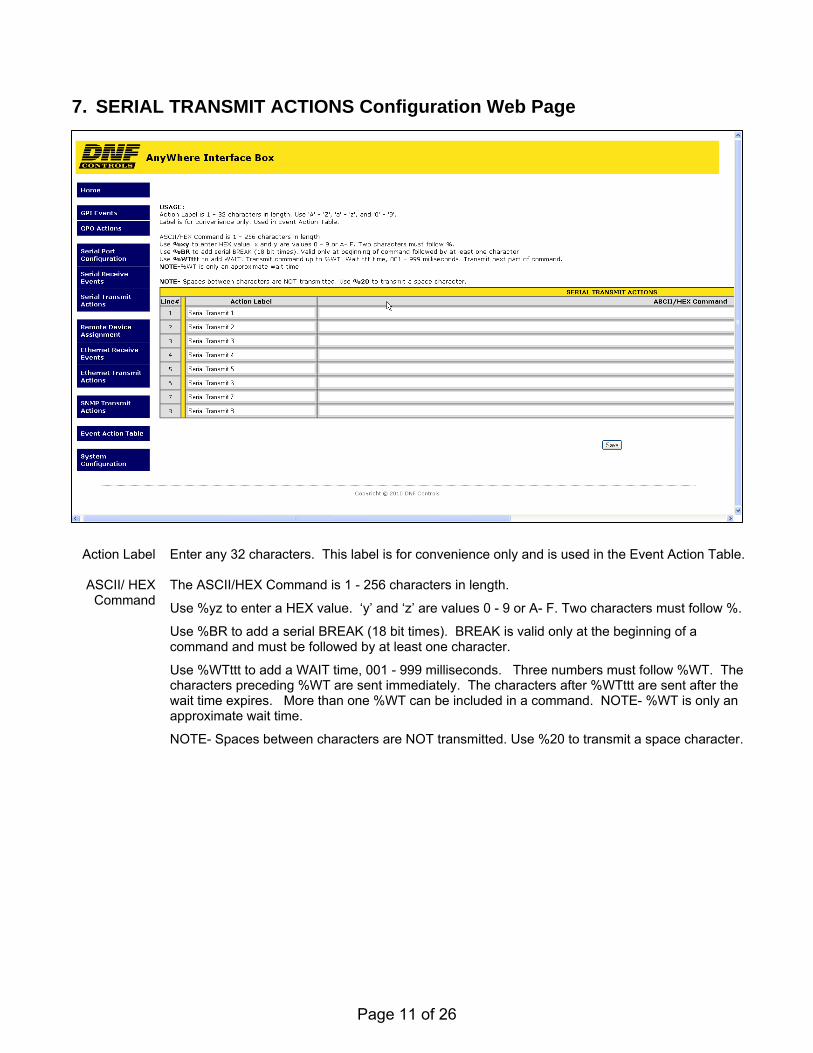
7. SERIAL TRANSMIT ACTIONS Configuration Web Page
Action Label Enter any 32 characters. This label is for convenience only and is used in the Event Action Table. ASCII/ HEX
Command The ASCII/HEX Command is 1 - 256 characters in length.
Use %yz to enter a HEX value. ‘y’ and ‘z’ are values 0 - 9 or A- F. Two characters must follow %.
Use %BR to add a serial BREAK (18 bit times). BREAK is valid only at the beginning of a command and must be followed by at least one character.
Use %WTttt to add a WAIT time, 001 - 999 milliseconds. Three numbers must follow %WT. The characters preceding %WT are sent immediately. The characters after %WTttt are sent after the wait time expires. More than one %WT can be included in a command. NOTE- %WT is only an approximate wait time.
NOTE- Spaces between characters are NOT transmitted. Use %20 to transmit a space character.
Page 12 of 26
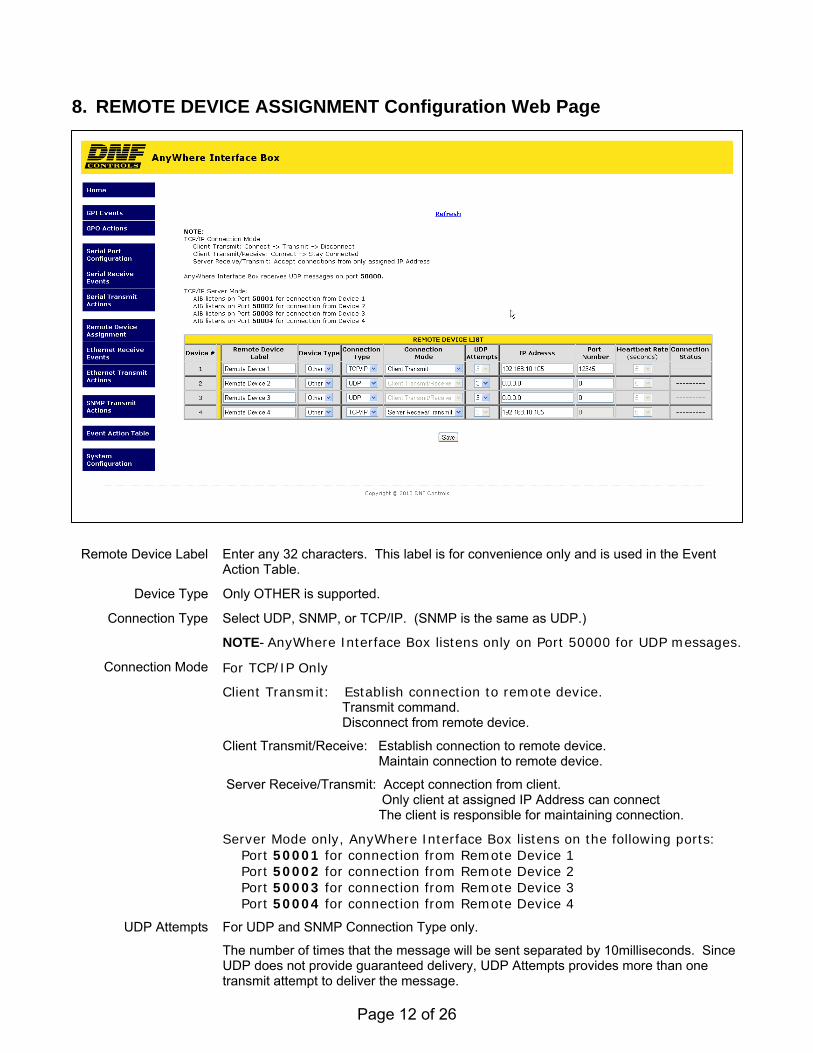
8. REMOTE DEVICE ASSIGNMENT Configuration Web Page
Remote Device Label Enter any 32 characters. This label is for convenience only and is used in the Event
Action Table.
Device Type Only OTHER is supported.
Connection Type Select UDP, SNMP, or TCP/IP. (SNMP is the same as UDP.)
NOTE- AnyWhere Interface Box listens only on Port 50000 for UDP messages.
Connection Mode For TCP/IP Only
Client Transmit: Establish connection to remote device. Transmit command. Disconnect from remote device.
Client Transmit/Receive: Establish connection to remote device. Maintain connection to remote device.
Server Receive/Transmit: Accept connection from client. Only client at assigned IP Address can connect The client is responsible for maintaining connection.
Server Mode only, AnyWhere Interface Box listens on the following ports: Port 50001 for connection from Remote Device 1 Port 50002 for connection from Remote Device 2 Port 50003 for connection from Remote Device 3 Port 50004 for connection from Remote Device 4
UDP Attempts For UDP and SNMP Connection Type only.
The number of times that the message will be sent separated by 10milliseconds. Since UDP does not provide guaranteed delivery, UDP Attempts provides more than one transmit attempt to deliver the message.

Page 13 of 26
IP Address Client or Destination IP address
Port Number Destination port number
Heartbeat Rate Currently, not supported.
Connection Status For TCP/IP Connection Types only.
Page 14 of 26
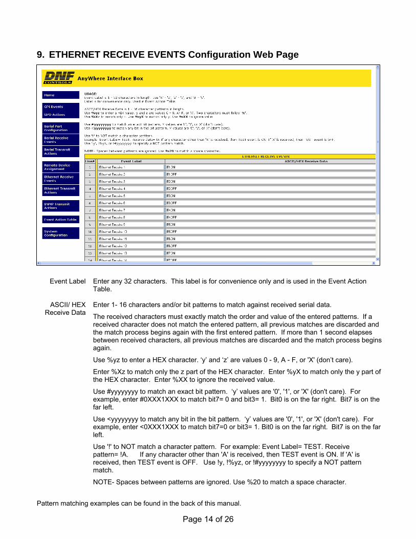
9. ETHERNET RECEIVE EVENTS Configuration Web Page
Pattern matching examples can be found in the back of this manual.
Event Label Enter any 32 characters. This label is for convenience only and is used in the Event Action Table.
ASCII/ HEX
Receive Data Enter 1- 16 characters and/or bit patterns to match against received serial data.
The received characters must exactly match the order and value of the entered patterns. If a received character does not match the entered pattern, all previous matches are discarded and the match process begins again with the first entered pattern. If more than 1 second elapses between received characters, all previous matches are discarded and the match process begins again.
Use %yz to enter a HEX character. ‘y’ and ‘z’ are values 0 - 9, A - F, or 'X' (don’t care).
Enter %Xz to match only the z part of the HEX character. Enter %yX to match only the y part of the HEX character. Enter %XX to ignore the received value.
Use #yyyyyyyy to match an exact bit pattern. ‘y’ values are '0', '1', or 'X' (don't care). For example, enter #0XXX1XXX to match bit7= 0 and bit3= 1. Bit0 is on the far right. Bit7 is on the far left.
Use <yyyyyyyy to match any bit in the bit pattern. ‘y’ values are '0', '1', or 'X' (don't care). For example, enter <0XXX1XXX to match bit7=0 or bit3= 1. Bit0 is on the far right. Bit7 is on the far left.
Use '!' to NOT match a character pattern. For example: Event Label= TEST. Receive pattern= !A. If any character other than 'A' is received, then TEST event is ON. If 'A' is received, then TEST event is OFF. Use !y, !%yz, or !#yyyyyyyy to specify a NOT pattern match.
NOTE- Spaces between patterns are ignored. Use %20 to match a space character.
Page 15 of 26
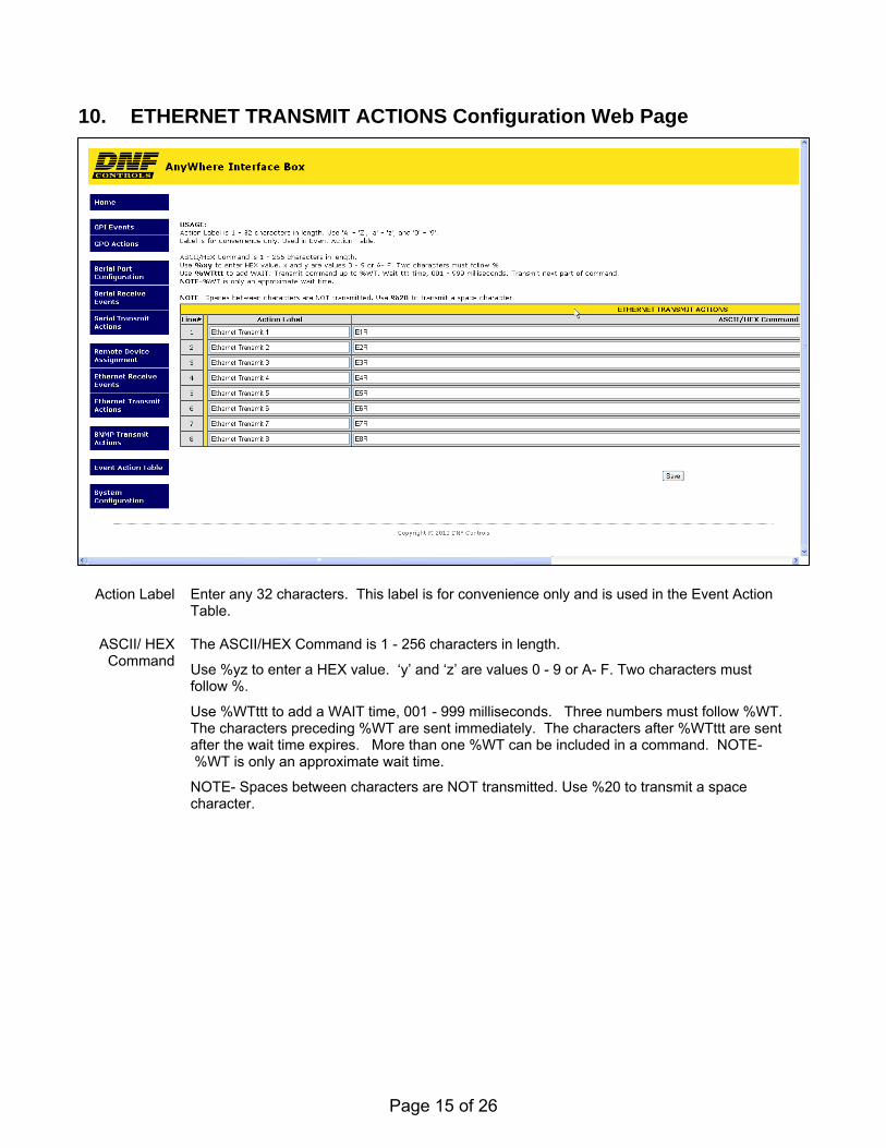
10. ETHERNET TRANSMIT ACTIONS Configuration Web Page
Action Label Enter any 32 characters. This label is for convenience only and is used in the Event Action
Table.
ASCII/ HEX Command
The ASCII/HEX Command is 1 - 256 characters in length.
Use %yz to enter a HEX value. ‘y’ and ‘z’ are values 0 - 9 or A- F. Two characters must follow %.
Use %WTttt to add a WAIT time, 001 - 999 milliseconds. Three numbers must follow %WT. The characters preceding %WT are sent immediately. The characters after %WTttt are sent after the wait time expires. More than one %WT can be included in a command. NOTE- %WT is only an approximate wait time.
NOTE- Spaces between characters are NOT transmitted. Use %20 to transmit a space character.

Page 16 of 26
11. SNMP TRANSMIT ACTIONS Configuration Web Page
Action Label Enter any 32 characters. This label is for convenience only and is used in the Event Action Table.
Community Community string is 1 - 32 characters in length. Typical value is 'public'.
Command SET- Control remote device
GET- Monitor remote device
Object Identifier
(OID)
The OID is 8 - 256 decimal values in length entered in dot notation. Only decimal values are accepted. ie: 1.22.333.4.55.666.7.88. Maximum entered decimal value is 99999999.
Value Type OID Value Type:
Integer: decimal value 0 127
Octet String: 1 – 16 decimal values in length, entered in dot notation. Only decimal values are accepted. ie: 1.22.333.4.55.666.7.88 Maximum decimal value is 255.
NULL: Set to NULL when no OID value is entered.
Page 17 of 26
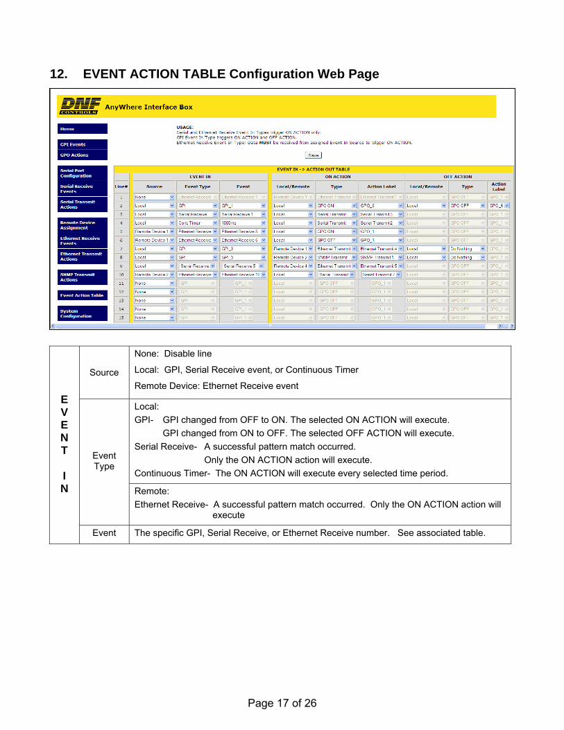
12. EVENT ACTION TABLE Configuration Web Page
Source
None: Disable line
Local: GPI, Serial Receive event, or Continuous Timer
Remote Device: Ethernet Receive event
Local:
GPI- GPI changed from OFF to ON. The selected ON ACTION will execute.
GPI changed from ON to OFF. The selected OFF ACTION will execute.
Serial Receive- A successful pattern match occurred.
Only the ON ACTION action will execute.
Continuous Timer- The ON ACTION will execute every selected time period.
Event Type
Remote:
Ethernet Receive- A successful pattern match occurred. Only the ON ACTION action will execute
E V E N T I N
Event The specific GPI, Serial Receive, or Ethernet Receive number. See associated table.
Page 18 of 26
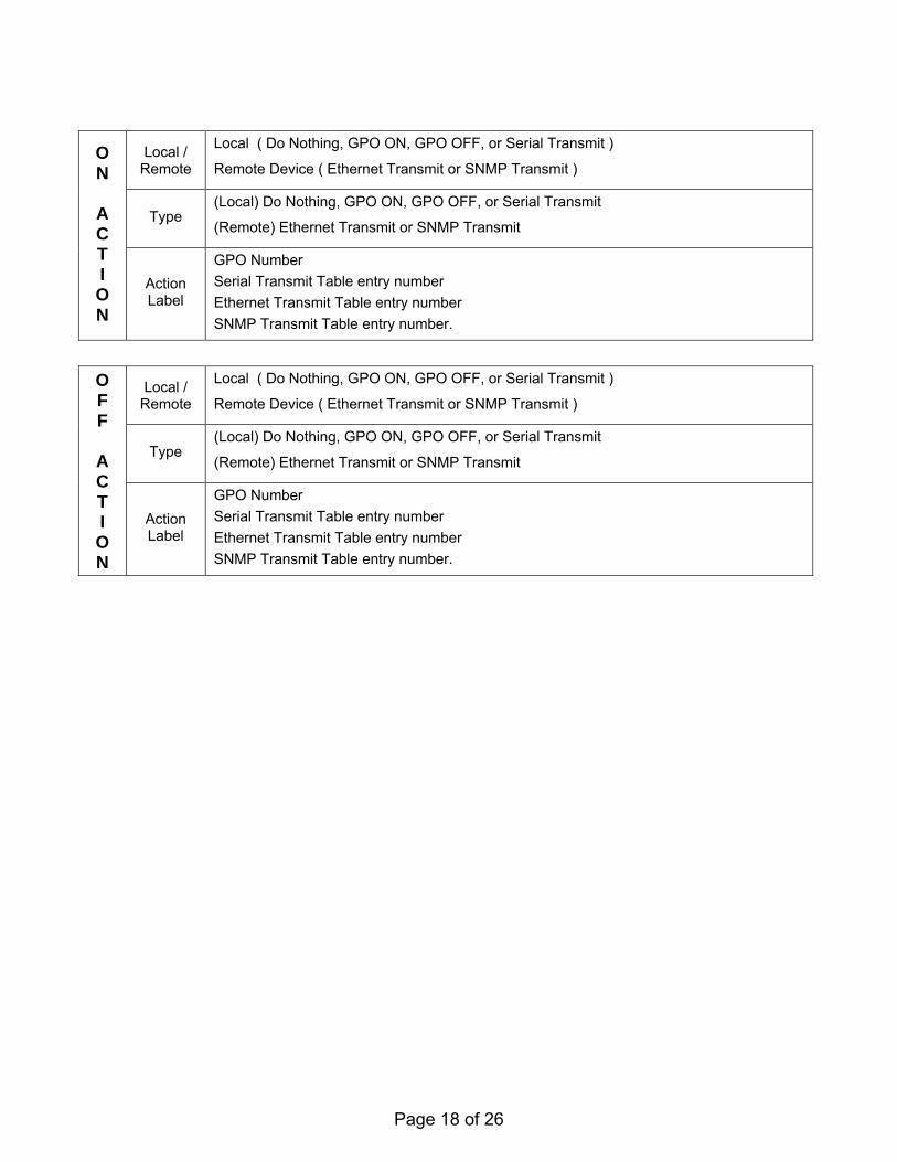
Local / Remote
Local ( Do Nothing, GPO ON, GPO OFF, or Serial Transmit )
Remote Device ( Ethernet Transmit or SNMP Transmit )
Type (Local) Do Nothing, GPO ON, GPO OFF, or Serial Transmit
(Remote) Ethernet Transmit or SNMP Transmit
O N
A C T I O N
Action Label
GPO Number
Serial Transmit Table entry number
Ethernet Transmit Table entry number
SNMP Transmit Table entry number.
Local / Remote
Local ( Do Nothing, GPO ON, GPO OFF, or Serial Transmit )
Remote Device ( Ethernet Transmit or SNMP Transmit )
Type (Local) Do Nothing, GPO ON, GPO OFF, or Serial Transmit
(Remote) Ethernet Transmit or SNMP Transmit
O F F
A C T I O N
Action Label
GPO Number
Serial Transmit Table entry number
Ethernet Transmit Table entry number
SNMP Transmit Table entry number.

Page 19 of 26
13. REAR PANEL CONNECTORS
Physical size: 8.25” W x 4.125” D x 1.5” H
GPO CONNECTOR 8 Isolated Relay Contact Closure Outputs
Pin # Description Pin # Description
1 Ground 14 GP0 8 N.O
2 GPO 8 Com 15 Common Bus
3 +V 16 GPO 7 N.O.
4 GPO 7 Com 17 GPO 6 N.O.
5 GPO 6 Com 18 Common Bus
6 Common Bus 19 GPO 5 N.O.
7 GPO 5 Com 20 GPO 4 N.O.
8 GPO 4 Com 21 Common Bus
9 Common Bus 22 GPIO 3 N.O.
10 GPO 3 Com 23 GPO 2 N.O.
11 GPO 2 Com 24 Common Bus
12 Common Bus 25 GPO 1 N.O.
13 GPO 1 Com
GPI CONNECTOR 8 Isolated Opto-Isolator Inputs
Pin # Description Pin # Description
1 Ground 14 GPI 8 +
2 GPI 8 ─ 15 +V
3 +V 16 GPI 7 ─
4 GPI 7 + 17 GPI 6 +
5 GPI 6 ─ 18 +V
6 +V 19 GPI 5 ─
7 GPI 5 + 20 GPI 4 +
8 GPI 4 ─ 21 +V
9 +V 22 GPI 3 ─
10 GPI 3 + 23 GPI 2 +
11 GPI 2 ─ 24 +V
12 +V 25 GPI 1 ─
13 GPI 1 +
ETHERNET CONNECTOR
1- 10baseT
Supports Power Over Ethernet
S1 Switch
Press and hold 10 seconds to reset:
IP address to 192.168.10.217
Configuration to default
POWER CONNECTOR
12V DC, 2.0Amps
USB CONNECTOR
Not Used
Page 20 of 26
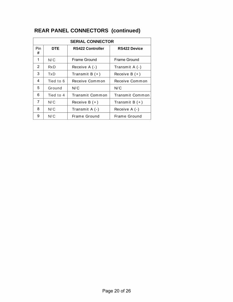
REAR PANEL CONNECTORS (continued)
SERIAL CONNECTOR
Pin #
DTE RS422 Controller RS422 Device
1 N/C Frame Ground Frame Ground
2 RxD Receive A (-) Transmit A (-)
3 TxD Transmit B (+) Receive B (+)
4 Tied to 6 Receive Common Receive Common
5 Ground N/C N/C
6 Tied to 4 Transmit Common Transmit Common
7 N/C Receive B (+) Transmit B (+)
8 N/C Transmit A (-) Receive A (-)
9 N/C Frame Ground Frame Ground
Page 21 of 26
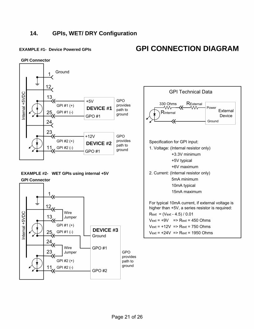
14. GPIs, WET/ DRY Configuration
EXAMPLE #1- Device Powered GPIs
EXAMPLE #2- WET GPIs using internal +5V
1
13
23
25
11
Inte
rnal
+5V
DC
GPI Connector
12
24
GPI #1 (+)
GPI #1 (-)
GPI #2 (+)
GPI #2 (-)DEVICE #2
+12V
GPO #1
DEVICE #1
+5V
GPO #1
Ground
GPO provides path to ground
GPO provides path to ground
1
13
23
25
11
Inte
rna
l +5V
DC
12
24
GPI #1 (+)
GPI #1 (-)
GPI #2 (+)
GPI #2 (-)
Wire Jumper
Wire Jumper
DEVICE #3
GPO #1
GPO #2
Ground
GPO provides path to ground
GPI Connector
Specification for GPI input:
1. Voltage: (Internal resistor only)
+3.3V minimum
+5V typical
+6V maximum
2. Current: (Internal resistor only)
5mA minimum
10mA typical
15mA maximum
For typical 10mA current, if external voltage is higher than +5V, a series resistor is required:
Rext = (Vext - 4.5) / 0.01
Vext = +9V => Rext = 450 Ohms
Vext = +12V => Rext = 750 Ohms
Vext = +24V => Rext = 1950 Ohms
GPI Technical Data
RInternal
330 Ohms RExternal
External Device
Ground
Power
GPI CONNECTION DIAGRAM
Page 22 of 26
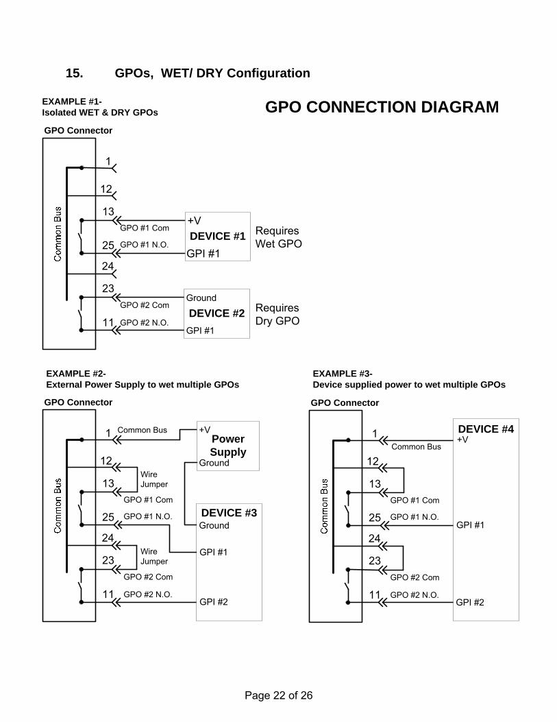
15. GPOs, WET/ DRY Configuration
Common Bus
GPO #1 Com
GPO #1 N.O.
EXAMPLE #1-Isolated WET & DRY GPOs
RequiresDry GPO
RequiresWet GPO
EXAMPLE #3-Device supplied power to wet multiple GPOs
1
13
23
25
11
GPO Connector
12
24
GPO #2 Com
GPO #2 N.O.
DEVICE #4+V
GPI #1
GPI #2
Common Bus
GPO #1 Com
GPO #1 N.O.
1
13
23
25
11
GPO Connector
12
24
GPO #2 Com
GPO #2 N.O.
WireJumper
WireJumper
PowerSupply
Ground
+V
DEVICE #3
GPI #1
GPI #2
Ground
EXAMPLE #2-External Power Supply to wet multiple GPOs
1
13
23
25
11
GPO Connector
12
24
GPO #1 Com
GPO #1 N.O.
GPO #2 Com
GPO #2 N.O.DEVICE #2
Ground
GPI #1
DEVICE #1
+V
GPI #1
GPO CONNECTION DIAGRAM
Page 23 of 26
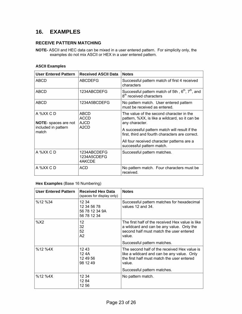
16. EXAMPLES RECEIVE PATTERN MATCHING
NOTE- ASCII and HEC data can be mixed in a user entered pattern. For simplicity only, the examples do not mix ASCII or HEX in a user entered pattern.
ASCII Examples
User Entered Pattern Received ASCII Data Notes
ABCD ABCDEFG
Successful pattern match of first 4 received characters
ABCD 1234ABCDEFG Successful pattern match of 5th , 6th, 7th, and 8th received characters
ABCD 1234A5BCDEFG No pattern match. User entered pattern must be received as entered.
A %XX C D NOTE- spaces are not included in pattern match
ABCD ACCD AJCD A2CD
The value of the second character in the pattern, %XX, is like a wildcard, so it can be any character.
A successful pattern match will result if the first, third and fourth characters are correct.
All four received character patterns are a successful pattern match.
A %XX C D 1234ABCDEFG 1234A5CDEFG 4AKCDE
Successful pattern matches.
A %XX C D ACD No pattern match. Four characters must be received.
Hex Examples (Base 16 Numbering)
User Entered Pattern Received Hex Data (spaces for display only)
Notes
%12 %34 12 34 12 34 56 78 56 78 12 34 9A 56 78 12 34
Successful pattern matches for hexadecimal values 12 and 34.
%X2 12 32 52 A2
The first half of the received Hex value is like a wildcard and can be any value. Only the second half must match the user entered value.
Successful pattern matches.
%12 %4X 12 43 12 4A 12 49 56 98 12 49
The second half of the received Hex value is like a wildcard and can be any value. Only the first half must match the user entered value.
Successful pattern matches.
%12 %4X 12 34 12 84 12 56
No pattern match.
Page 24 of 26
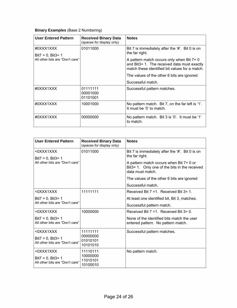
Binary Examples (Base 2 Numbering)
User Entered Pattern Received Binary Data (spaces for display only)
Notes
#0XXX1XXX
Bit7 = 0, Bit3= 1 All other bits are “Don’t care”
01011000 Bit 7 is immediately after the ‘#’. Bit 0 is on the far right.
A pattern match occurs only when Bit 7= 0 and Bit3= 1. The received data must exactly match these identified bit values for a match.
The values of the other 6 bits are ignored.
Successful match.
#0XXX1XXX
01111111 00001000 01101001
Successful pattern matches.
#0XXX1XXX
10001000 No pattern match. Bit 7, on the far left is ‘1’. It must be ‘0’ to match.
#0XXX1XXX
00000000 No pattern match. Bit 3 is ‘0’. It must be ‘1’ to match.
User Entered Pattern Received Binary Data
(spaces for display only) Notes
<0XXX1XXX
Bit7 = 0, Bit3= 1 All other bits are “Don’t care”
01011000 Bit 7 is immediately after the ‘#’. Bit 0 is on the far right.
A pattern match occurs when Bit 7= 0 or Bit3= 1. Only one of the bits in the received data must match.
The values of the other 6 bits are ignored
Successful match.
<0XXX1XXX
Bit7 = 0, Bit3= 1 All other bits are “Don’t care”
11111111 Received Bit 7 =1. Received Bit 3= 1.
At least one identified bit, Bit 3, matches.
Successful pattern match.
<0XXX1XXX
Bit7 = 0, Bit3= 1 All other bits are “Don’t care”
10000000 Received Bit 7 =1. Received Bit 3= 0.
None of the identified bits match the user entered pattern. No pattern match.
<0XXX1XXX
Bit7 = 0, Bit3= 1 All other bits are “Don’t care”
11111111 00000000 01010101 10101010
Successful pattern matches.
<0XXX1XXX
Bit7 = 0, Bit3= 1 All other bits are “Don’t care”
11110111 10000000 11010101 10100010
No pattern match.

Page 25 of 26
ASCII Examples
User Entered Pattern Received ASCII Data Notes
!A B
A pattern match is successful when the received character is any character except ‘A’.
!A AAAAAA All of the received characters are ‘A’. No pattern match.
!A AB The second character is not an ‘A’. The received data is a successful pattern match.
!A BA The first character is not an ‘A’ and is a successful pattern match. The received data is a successful pattern match.
!A BC No character is an ‘A’. Successful pattern match.
!AB AB The first character can be any character except ‘A’. The second character must be ‘B’.
No pattern match
!AB CB DB ZB
The first character can be any character except ‘A’. The second character must be ‘B’.
Successful pattern match
!AB CD The first character can be any character except ‘A’. The second character must be ‘B’.
No pattern match
Hex Examples (Base 16 Numbering)
User Entered Pattern Received Hex Data Notes
!%12 12
A pattern match is successful when any value is received except 12.
No pattern match.
!%12 34 22 34
A pattern match is successful when any value is received except 12, immediately followed by 34
Successful pattern match.
!%12 34 11 34 21 34 9F 34 87 34
Successful pattern matches.
!%12 34 11 12 34 No pattern match
!%12 34 11 22 34 11 45 34 56
Successful pattern matches

Page 26 of 26
17. DNF CONTROLS LIMITED WARRANTY
DNF Controls warrants its product to be free from defects in material and workmanship for a period of one (1) year from the date of sale to the original purchaser from DNF Controls. In order to enforce the rights under this warranty, the customer must first contact DNF’s Customer Support Department to afford the opportunity of identifying and fixing the problem without sending the unit in for repair. If DNF’s Customer Support Department cannot fix the problem, the customer will be issued a Returned Merchandise Authorization number (RMA). The customer will then ship the defective product prepaid to DNF Controls with the RMA number clearly indicated on the customer’s shipping document. The merchandise is to be shipped to: DNF Controls 12843 Foothill Blvd., Suite D Sylmar, CA 91342 USA Failure to obtain a proper RMA number prior to returning the product may result in the return not being accepted, or in a charge for the required repair. DNF Controls, at its option, will repair or replace the defective unit. DNF Controls will return the unit prepaid to the customer. The method of shipment is at the discretion of DNF Controls, principally UPS Ground for shipments within the United States of America. Shipments to international customers will be sent via air. Should a customer require the product to be returned in a more expeditious manner, the return shipment will be billed to their freight account. This warranty will be considered null and void if accident, misuse, abuse, improper line voltage, fire, water, lightning or other acts of God damaged the product. All repair parts are to be supplied by DNF Controls, either directly or through its authorized dealer network. Similarly, any repair work not performed by either DNF Controls or its authorized dealer may void the warranty. After the warranty period has expired, DNF Controls offers repair services at prices listed in the DNF Controls Price List. DNF Controls reserves the right to refuse repair of any unit outside the warranty period that is deemed non-repairable. DNF Controls shall not be liable for direct, indirect, incidental, consequential or other types of damage resulting from the use of the product.


