Embed Size (px)
Citation preview

©2020 ANSYS, Inc. Unauthorized use, distribution, or duplication is prohibited.
HFSS Getting Started WS5.3
HFSS Getting Started
Release 2020 R2
Workshop 5.3: Assigning Finite Conductivity Boundary Band Pass Filter
©2020 ANSYS, Inc. Unauthorized use, distribution, or duplication is prohibited.
Overview - Band Pass Filter Finite Conductivity Union
This workshop changes the default PEC boundary on the HFSS band pass filter example to finite conductivity with aluminum properties.
The three learning objectives of the workshop are:
1. Understand how to perform the Unite (union) command in the 3D Modeler.
2. Understand why the Unite command is used before the finite conductivity boundary assignment.
3. Copy and paste signal data for comparison to updated simulations.
Input File: Bp_filter1.aedtz
Based on the HFSS example. This is also the project simulated in WS1.1.
2
©2020 ANSYS, Inc. Unauthorized use, distribution, or duplication is prohibited.
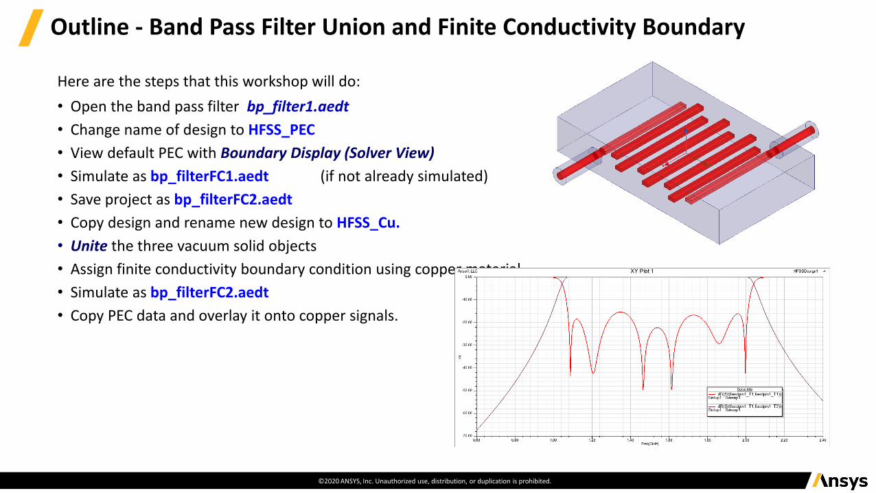
Outline - Band Pass Filter Union and Finite Conductivity Boundary
Here are the steps that this workshop will do:
• Open the band pass filter bp_filter1.aedt
• Change name of design to HFSS_PEC
• View default PEC with Boundary Display (Solver View)
• Simulate as bp_filterFC1.aedt (if not already simulated)
• Save project as bp_filterFC2.aedt
• Copy design and rename new design to HFSS_Cu.
• Unite the three vacuum solid objects
• Assign finite conductivity boundary condition using copper material.
• Simulate as bp_filterFC2.aedt
• Copy PEC data and overlay it onto copper signals.
©2020 ANSYS, Inc. Unauthorized use, distribution, or duplication is prohibited.
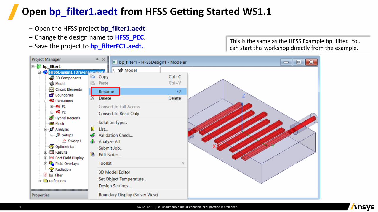
Open bp_filter1.aedt from HFSS Getting Started WS1.1
This is the same as the HFSS Example bp_filter. You can start this workshop directly from the example.
4
– Open the HFSS project bp_filter1.aedt– Change the design name to HFSS_PEC. – Save the project to bp_filterFC1.aedt.
©2020 ANSYS, Inc. Unauthorized use, distribution, or duplication is prohibited.
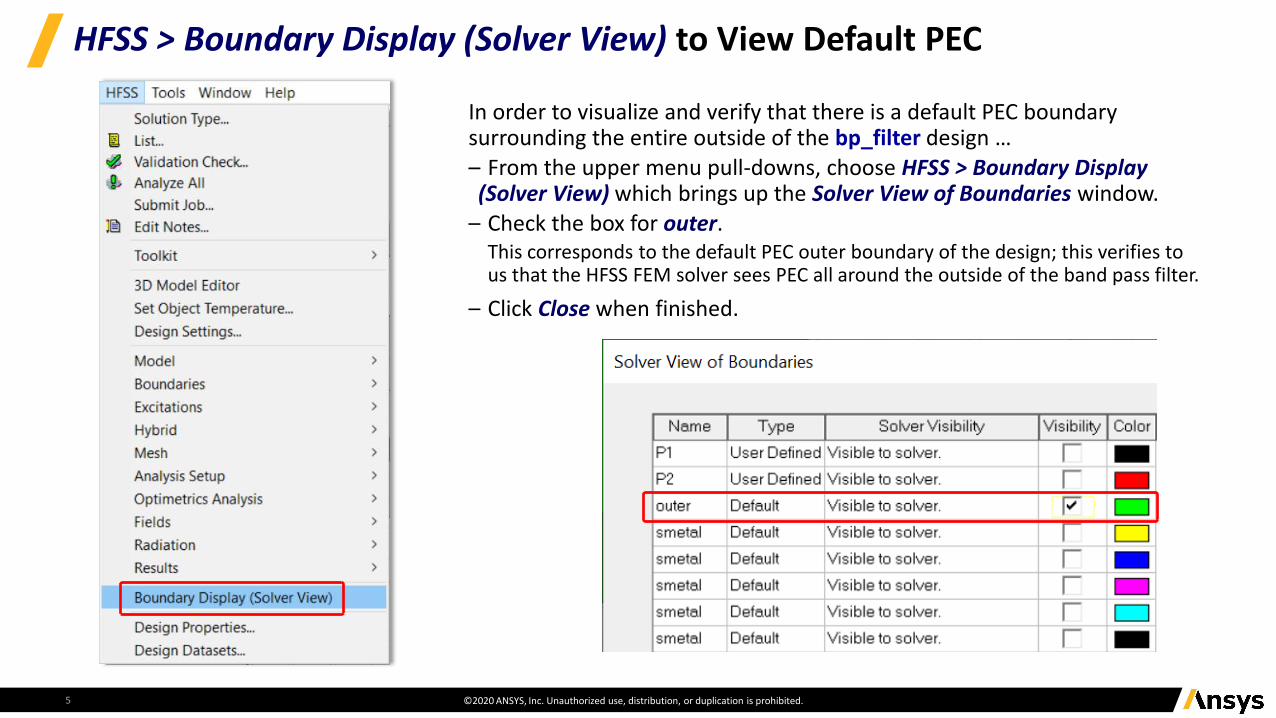
HFSS > Boundary Display (Solver View) to View Default PEC
5
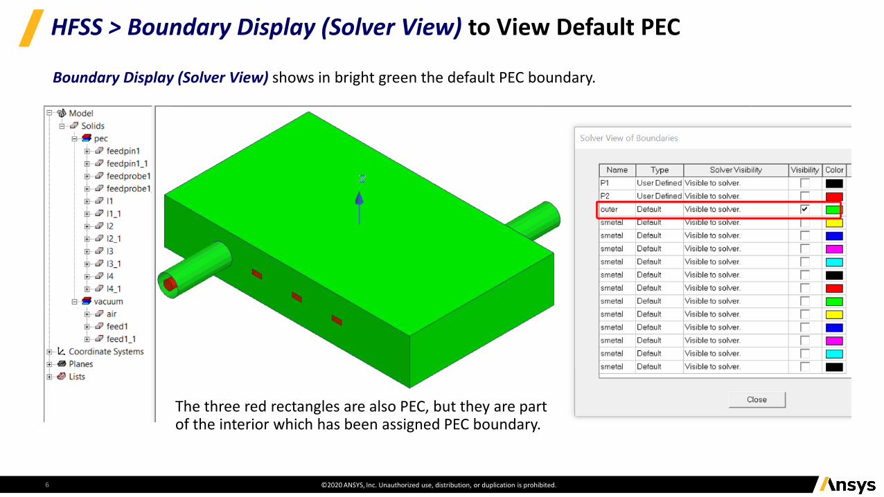
In order to visualize and verify that there is a default PEC boundary surrounding the entire outside of the bp_filter design … – From the upper menu pull-downs, choose HFSS > Boundary Display (Solver View) which brings up the Solver View of Boundaries window.
– Check the box for outer. This corresponds to the default PEC outer boundary of the design; this verifies to us that the HFSS FEM solver sees PEC all around the outside of the band pass filter.
– Click Close when finished.
©2020 ANSYS, Inc. Unauthorized use, distribution, or duplication is prohibited.
HFSS > Boundary Display (Solver View) to View Default PEC
6
Boundary Display (Solver View) shows in bright green the default PEC boundary.
The three red rectangles are also PEC, but they are part of the interior which has been assigned PEC boundary.
©2020 ANSYS, Inc. Unauthorized use, distribution, or duplication is prohibited.
Validate and Analyze HFSS Project bp_filterFC1 - Simulation #1
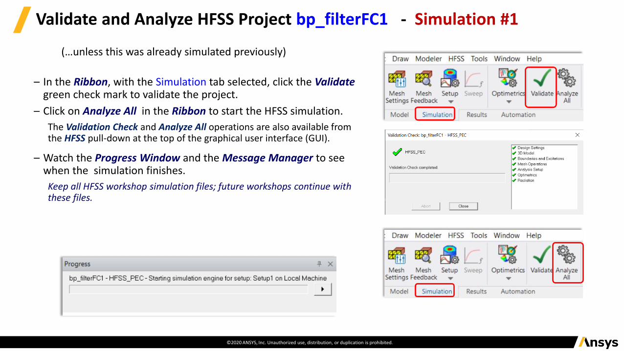
– In the Ribbon, with the Simulation tab selected, click the Validategreen check mark to validate the project.
– Click on Analyze All in the Ribbon to start the HFSS simulation.
The Validation Check and Analyze All operations are also available from the HFSS pull-down at the top of the graphical user interface (GUI).
– Watch the Progress Window and the Message Manager to see when the simulation finishes.
Keep all HFSS workshop simulation files; future workshops continue with these files.
(…unless this was already simulated previously)
©2020 ANSYS, Inc. Unauthorized use, distribution, or duplication is prohibited.
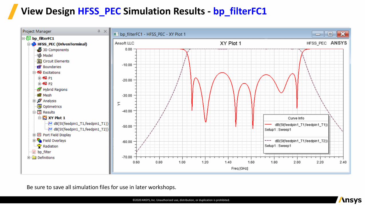
View Design HFSS_PEC Simulation Results - bp_filterFC1
Be sure to save all simulation files for use in later workshops.
©2020 ANSYS, Inc. Unauthorized use, distribution, or duplication is prohibited.
Select the Three Outer Objects Made of Vacuum - bp_filterFC2
9
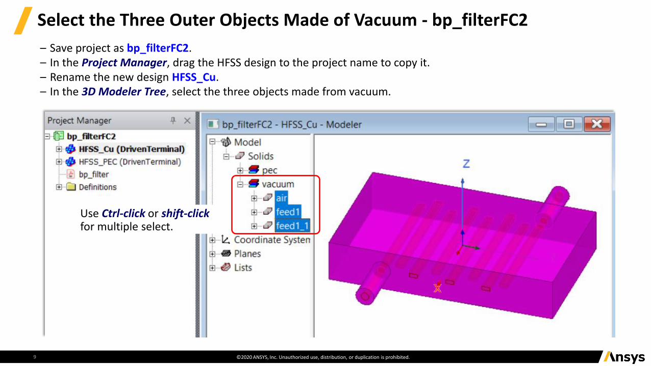
– Save project as bp_filterFC2. – In the Project Manager, drag the HFSS design to the project name to copy it. – Rename the new design HFSS_Cu. – In the 3D Modeler Tree, select the three objects made from vacuum.
Use Ctrl-click or shift-clickfor multiple select.
©2020 ANSYS, Inc. Unauthorized use, distribution, or duplication is prohibited.
Unite the Three Outer Objects Made of Vacuum
10
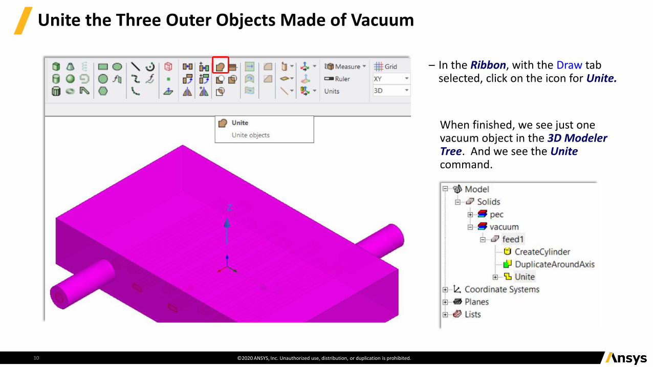
– In the Ribbon, with the Draw tab selected, click on the icon for Unite.
When finished, we see just one vacuum object in the 3D Modeler Tree. And we see the Unitecommand.
©2020 ANSYS, Inc. Unauthorized use, distribution, or duplication is prohibited.
Assign Finite Conductivity… to Single United Vacuum Object
11
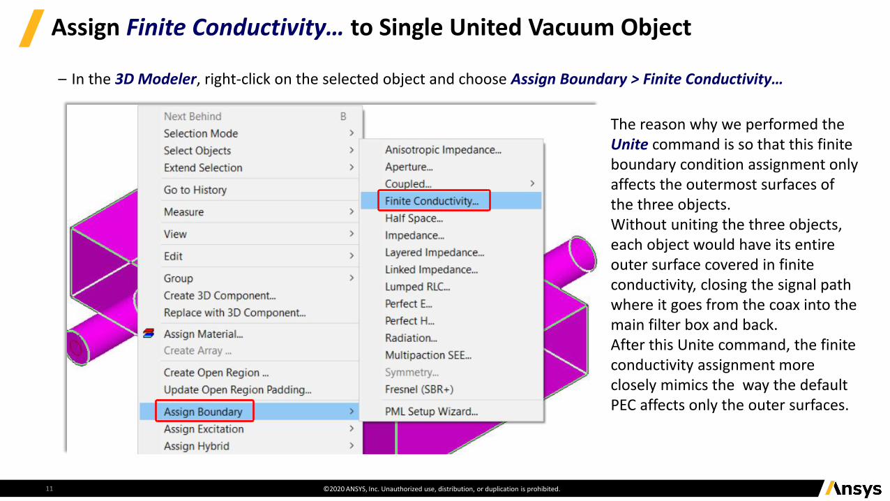
– In the 3D Modeler, right-click on the selected object and choose Assign Boundary > Finite Conductivity…
The reason why we performed the Unite command is so that this finite boundary condition assignment only affects the outermost surfaces of the three objects. Without uniting the three objects, each object would have its entire outer surface covered in finite conductivity, closing the signal path where it goes from the coax into the main filter box and back. After this Unite command, the finite conductivity assignment more closely mimics the way the default PEC affects only the outer surfaces.
©2020 ANSYS, Inc. Unauthorized use, distribution, or duplication is prohibited.
Assign Copper Material to Finite Conductivity Boundary
12
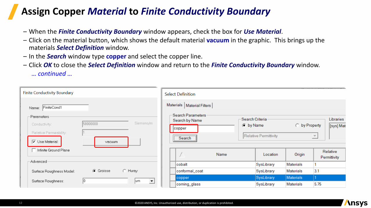
– When the Finite Conductivity Boundary window appears, check the box for Use Material.– Click on the material button, which shows the default material vacuum in the graphic. This brings up the
materials Select Definition window. – In the Search window type copper and select the copper line. – Click OK to close the Select Definition window and return to the Finite Conductivity Boundary window.
… continued …
©2020 ANSYS, Inc. Unauthorized use, distribution, or duplication is prohibited.
Finish Copper Material Selection for Finite Conductivity Boundary
13
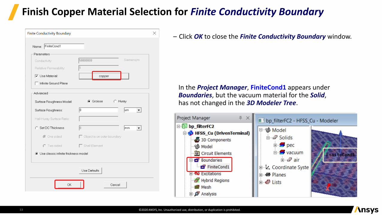
– Click OK to close the Finite Conductivity Boundary window.
In the Project Manager, FiniteCond1 appears under Boundaries, but the vacuum material for the Solid, has not changed in the 3D Modeler Tree.
©2020 ANSYS, Inc. Unauthorized use, distribution, or duplication is prohibited.
Validate and Analyze HFSS Project bp_filterFC2 - Simulation #2
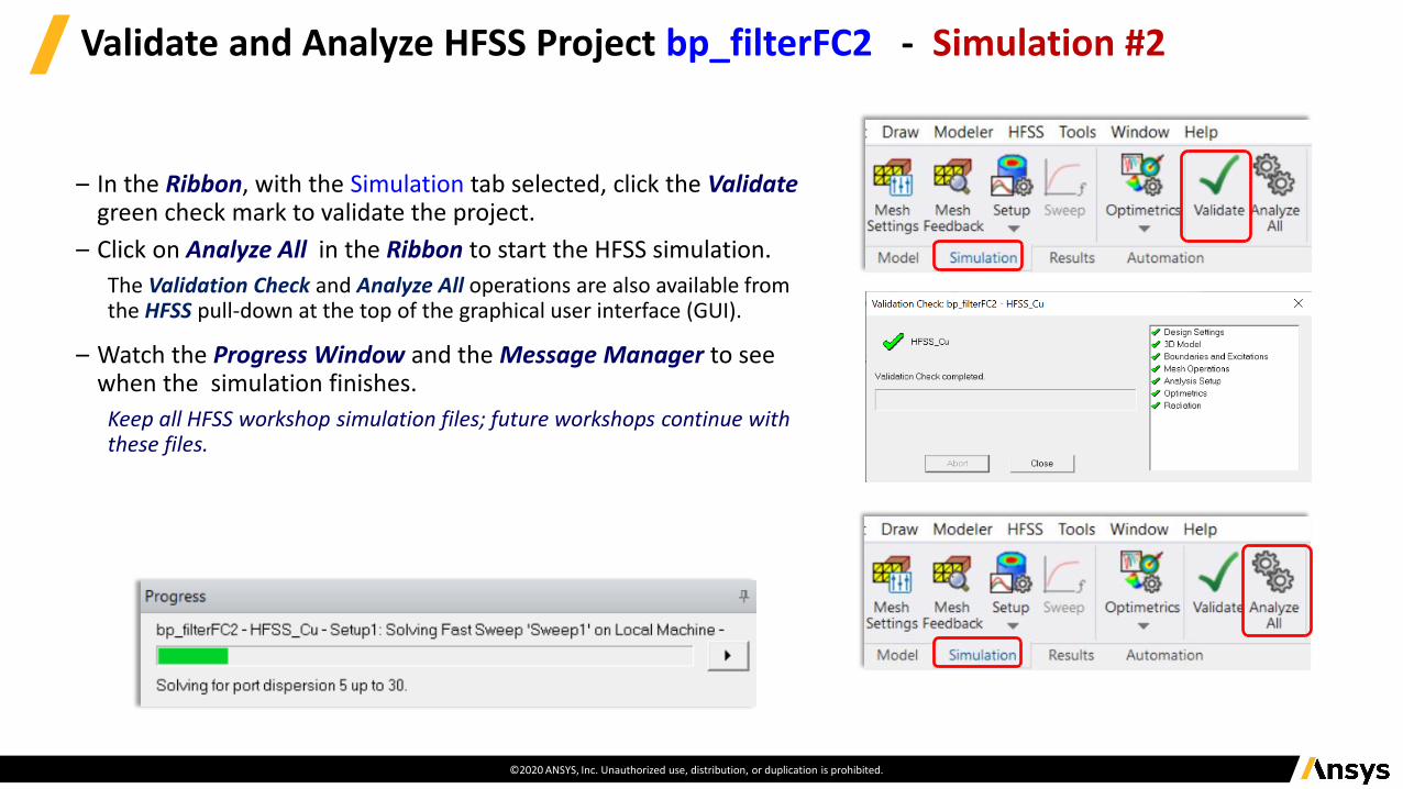
– In the Ribbon, with the Simulation tab selected, click the Validategreen check mark to validate the project.
– Click on Analyze All in the Ribbon to start the HFSS simulation.
The Validation Check and Analyze All operations are also available from the HFSS pull-down at the top of the graphical user interface (GUI).
– Watch the Progress Window and the Message Manager to see when the simulation finishes.
Keep all HFSS workshop simulation files; future workshops continue with these files.
©2020 ANSYS, Inc. Unauthorized use, distribution, or duplication is prohibited.
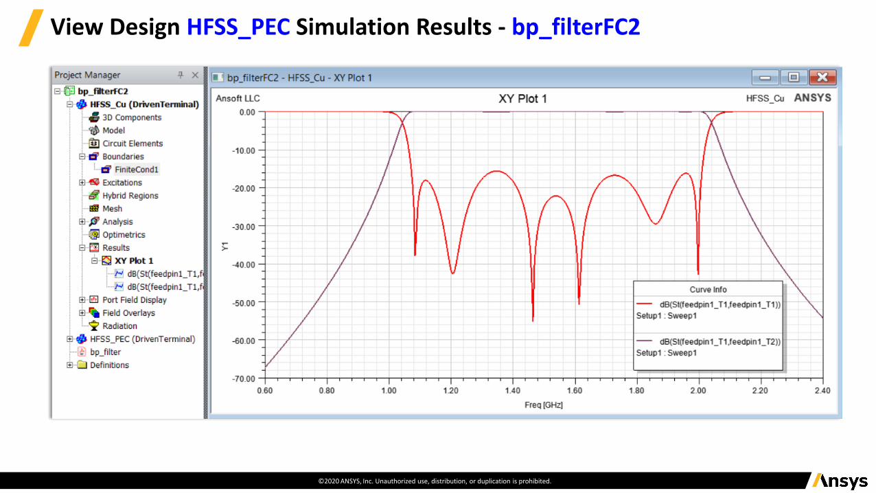
View Design HFSS_PEC Simulation Results - bp_filterFC2
©2020 ANSYS, Inc. Unauthorized use, distribution, or duplication is prohibited.
Overlay HFSS_PEC Simulation Results on HFSS_Cu - bp_filterFC2
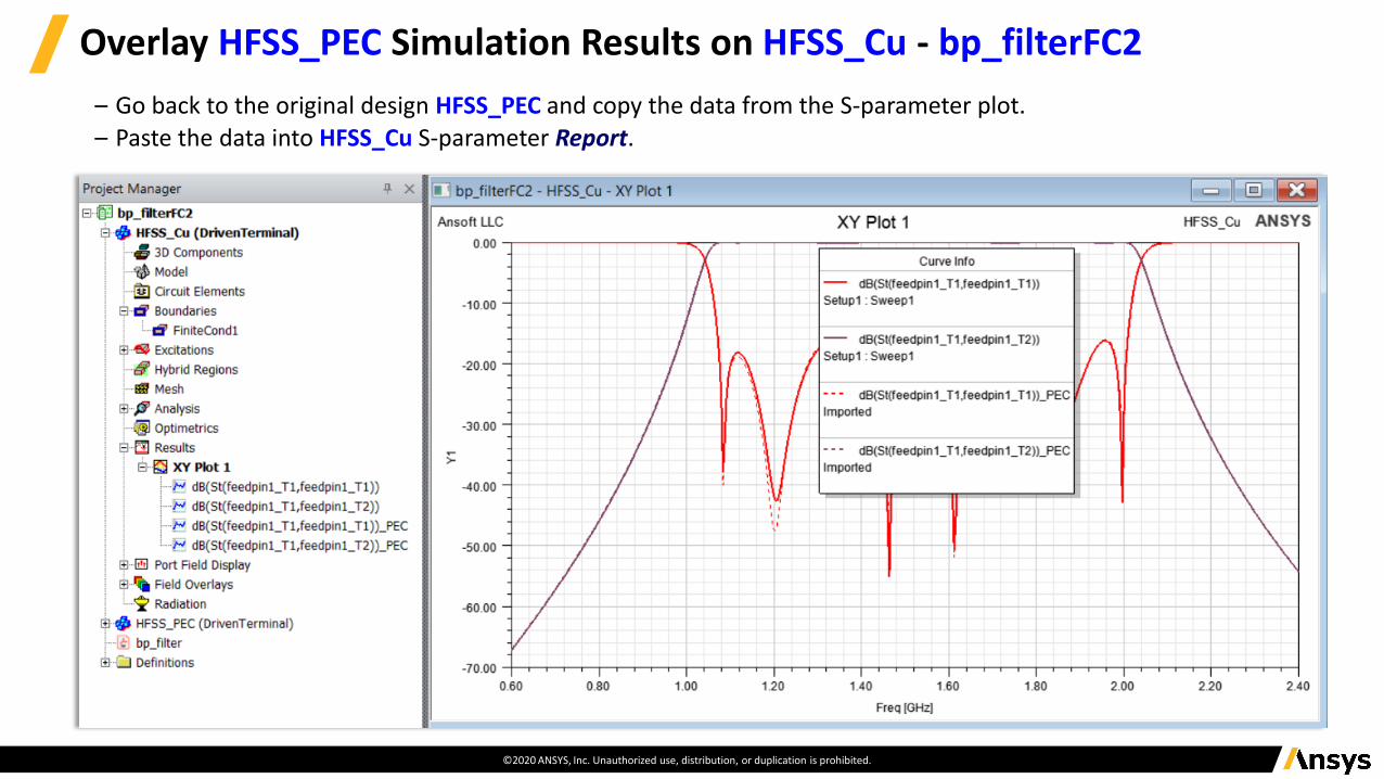
– Go back to the original design HFSS_PEC and copy the data from the S-parameter plot. – Paste the data into HFSS_Cu S-parameter Report.
©2020 ANSYS, Inc. Unauthorized use, distribution, or duplication is prohibited.
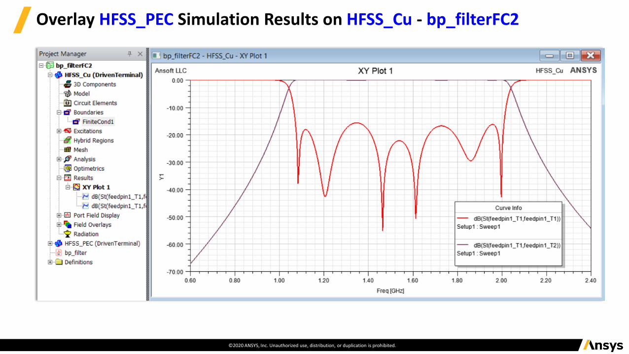
Overlay HFSS_PEC Simulation Results on HFSS_Cu - bp_filterFC2

End of Presentation