Embed Size (px)
Citation preview
Autodesk Inventor: Part 3 Creating a Drawing
Once a part has been finalized and fitted into the
assembly, a Drawing needs to be made, so a
diagram of the part can be printed to show how the
part should be made.
PowerPoint by: Danica Chang
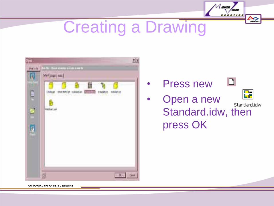
Creating a Drawing
• Press new
• Open a new
Standard.idw, then
press OK

Formatting
3. Under model, in the lower left part of the screen, right-click “Sheet:1”
4. Then press “Edit Sheet…”
5. Change size to A, then press OK
6. Next, delete by right-clicking and pressing delete
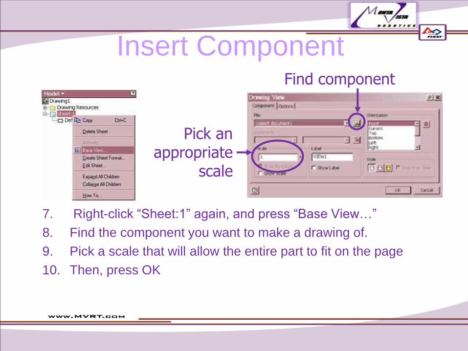
Insert Component
7. Right-click “Sheet:1” again, and press “Base View…”
8. Find the component you want to make a drawing of.
9. Pick a scale that will allow the entire part to fit on the page
10. Then, press OK
Find component
Pick an appropriate
scale
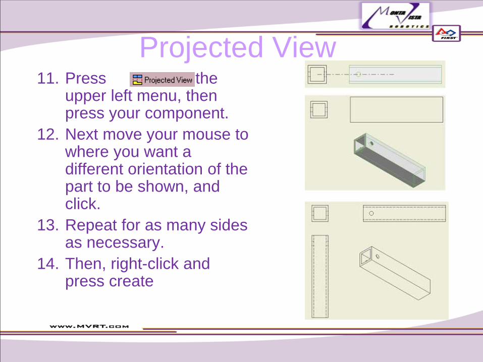
Projected View 11. Press on the
upper left menu, then press your component.
12. Next move your mouse to where you want a different orientation of the part to be shown, and click.
13. Repeat for as many sides as necessary.
14. Then, right-click and press create
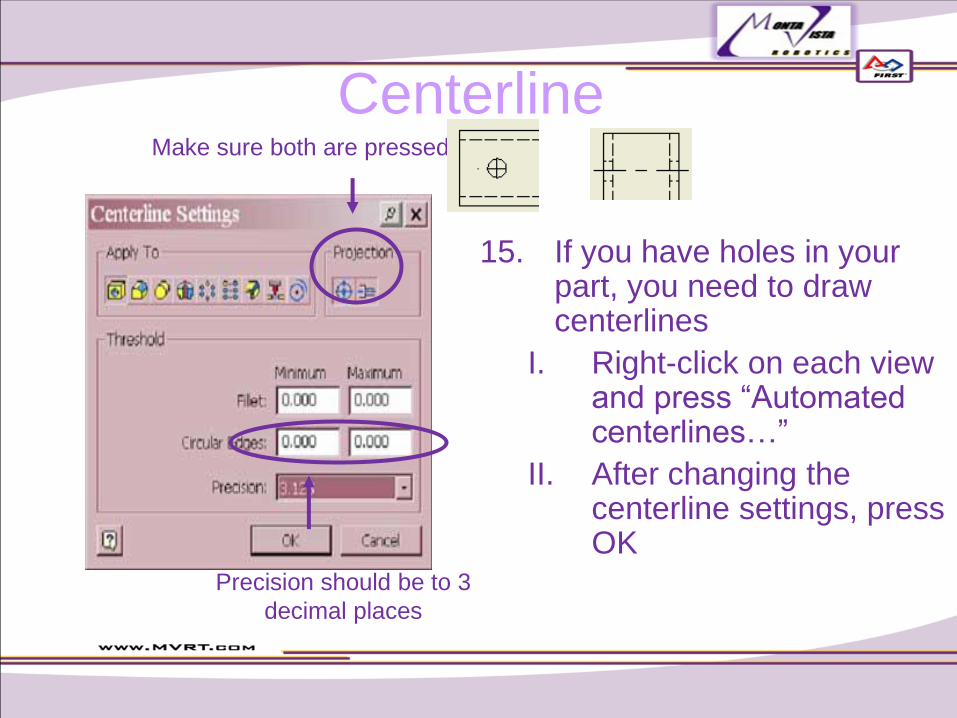
Centerline
15. If you have holes in your part, you need to draw centerlines
I. Right-click on each view and press “Automated centerlines…”
II. After changing the centerline settings, press OK
Make sure both are pressed
Precision should be to 3
decimal places
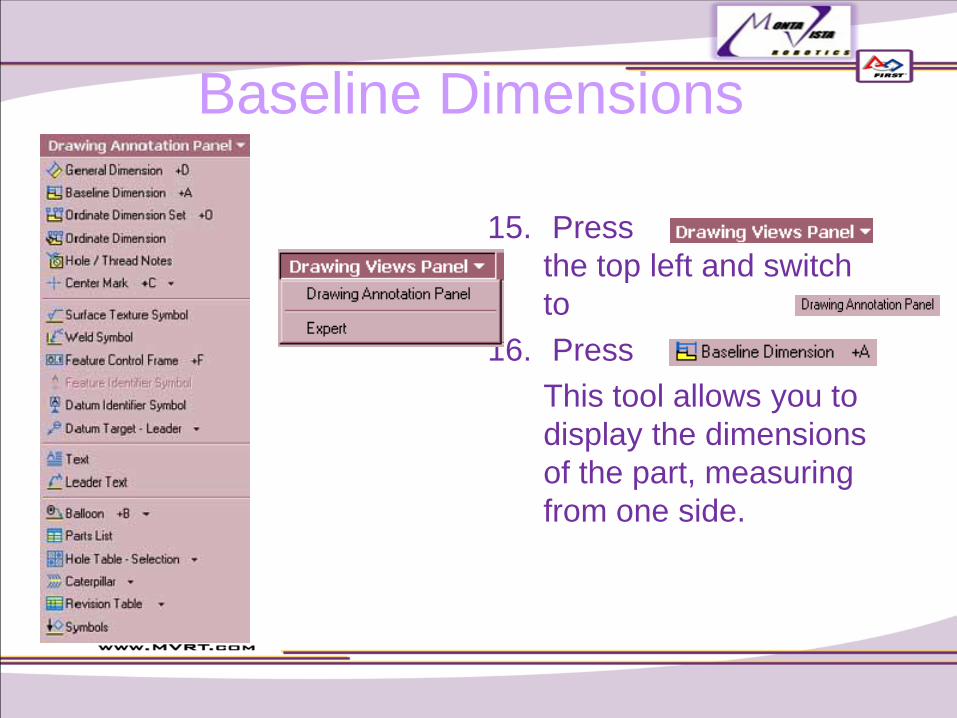
Baseline Dimensions
15. Press on
the top left and switch
to
16. Press
This tool allows you to
display the dimensions
of the part, measuring
from one side.
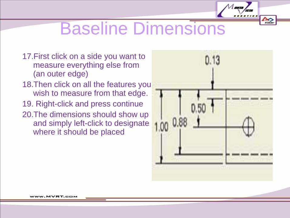
Baseline Dimensions
17.First click on a side you want to measure everything else from (an outer edge)
18.Then click on all the features you wish to measure from that edge.
19. Right-click and press continue
20.The dimensions should show up and simply left-click to designate where it should be placed
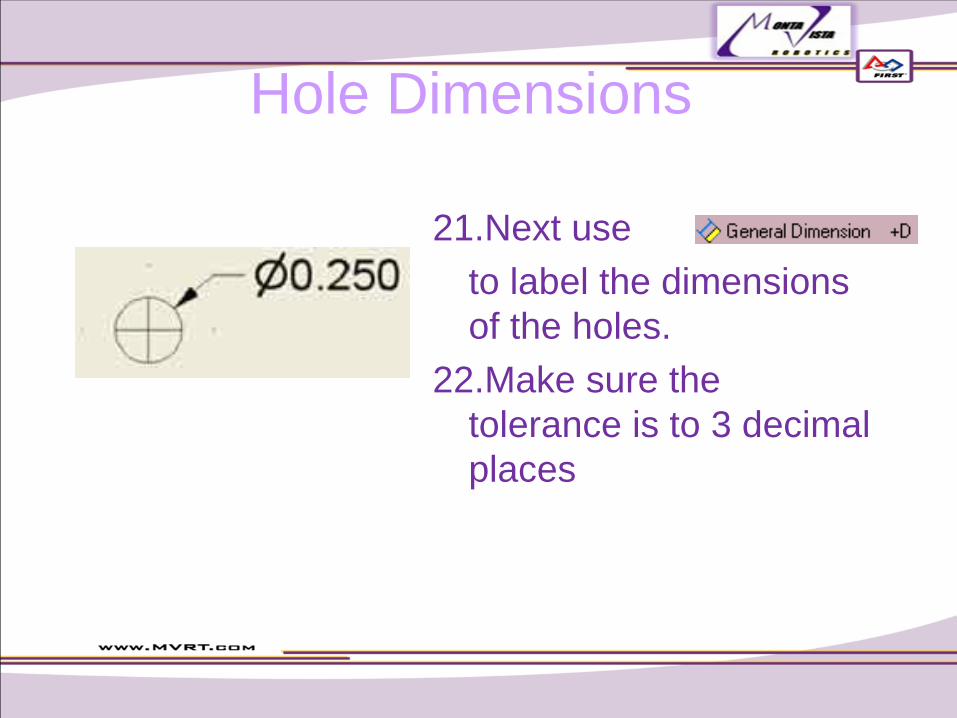
Hole Dimensions
21.Next use
to label the dimensions
of the holes.
22.Make sure the
tolerance is to 3 decimal
places
Description
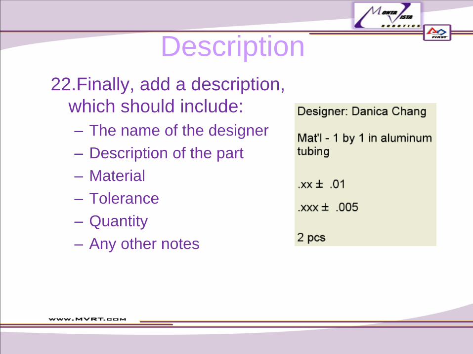
22.Finally, add a description,
which should include:
– The name of the designer
– Description of the part
– Material
– Tolerance
– Quantity
– Any other notes
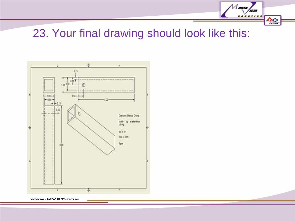
23. Your final drawing should look like this:


