Embed Size (px)
Citation preview
Automatic handshake expansion and reshu�ingusing concurrency reductionJordi Cortadella1, Michael Kishinevsky2, Alex Kondratyev3, LucianoLavagno4, and Alex Yakovlev51 Univ. Polit�ecnica de Catalunya, Barcelona, Spain, email: [email protected] Intel Corp., Hillsboro, OR, USA, email: [email protected] The Univ. of Aizu, Japan, email: [email protected] Politecnico di Torino, Italy, email: [email protected] Univ. of Newcastle upon Tyne, U.K., email:[email protected]. We present an automatic technique for handshake expansionand reshu�ing in asynchronous control circuit design. A designer cande�ne the behavior of a control circuit using a CSP-like or STG-likenotation. This de�nition may be partial , i.e. involve only some of theactual events.The method solves handshake expansion by inserting reset events withmaximal concurrency and then automatically explores reshu�ing of eventsunder interface and concurrency constraints using a single basic opera-tion { concurrency reduction. The algorithm trades o� the number ofrequired state signals and logic complexity.Experimental results show that this approach provides more exibility inthe design process than completely speci�ed CSP or STG. It signi�cantlyincreases the solution space for logic synthesis compared to existing CSP-based or STG-based synthesis tools.1 Introduction[11] and [1] proposed two techniques for compilation of CSP-like speci�cationsinto asynchronous circuits. Those techniques, in principle, assume that two de-sign steps should precede logic synthesis:{ handshake expansion: replacement of each communication action of a CSPprogram with its implementation as signal transitions on the two wires thatconstitute the channel,{ reshu�ing : selecting the order of actions (reset signal transitions in fourphase expansion of the channels) for optimizing area, performance or power.This paper presents an automatic technique for solving these steps by usingconcurrency reduction as a basic operation (�rst introduced in [21, 23], where itwas used to solve the state encoding problem).We apply the same method also in a more general context of Signal TransitionGraph-based (STG) synthesis as follows. Starting from a partial speci�cationof the control, which speci�es only some signal transitions important for thedesigner, insert reset signal transitions such that:
{ consistency of the speci�cation is maintained automatically (i.e., rising andfalling transitions for each signal alternate);{ speed-independence of the speci�cation is preserved;{ interface behavior of the speci�cation is preserved;{ speci�ed constraints on concurrency of events are satis�ed for performanceoptimization.The technique that we propose can be used in several applications in asyn-chronous circuit design. The �rst case, that we illustrate by example in thissection, is the implementation at the gate level of high-level components, suchas those used in some Delay Insensitive compilation techniques [1]. This is use-ful, for example, to re-target the compiler to use a new technology by exploitinga synchronous (perhaps slightly enhanced with a few asynchronous elements)standard cell library. A second case is the optimization of several componentsgenerated by compilation. This optimization can be performed either by com-bining complete STG speci�cations [17], or (potentially with better results) bycombining only the active transitions, and then adding return-to-zero transitionsby the techniques illustrated in this paper. A third case, obviously, is to helpmanual designers in concentrating on the most signi�cant functional aspects(e.g., the relations between the active transitions in four phase handshaking andlatch control), leaving to a tool the most repetitive aspects such as reshu�ingand concurrency reduction.The idea of using the concurrency reduction as an e�cient tool in the opti-mization loop was �rst proposed in [22]. According to the heuristic strategy usedin that paper, a speci�cation is simpli�ed by the iterative application of a basicoperation that reduces the concurrency for a certain pair of transitions. Theforward reduction mechanism suggested in Section 4 is a generalization of thisbasic operation, in that it satis�es several new correctness requirements. Themethod of concurrency reduction was further developed in [10] in the frame-work of the satis�ability approach to State Graph-based asynchronous circuitsynthesis, where several reductions of concurrency by pairs of transitions wereperformed by solving an instance of the satis�ability problem. The satis�abilityapproach is attractive due to its generality (every combinatorial optimizationproblem can be formulated in that way), but it su�ers from performance prob-lems, and o�ers little control over the quality of the �nal solution. In particular,due to the need to reduce the solution space, the approach of [10] was limitedto a smaller set of transformations than those originally described in [22].The main distinctive features of our approach with respect to [22, 10] are:1. We use a �ner reduction, by removal of State Graph arcs, than their tech-nique based on removal of states.2. Not every form of concurrency reduction can be modeled by a sequence ofpairwise reductions. Hence in Section 5.1 we develop a more general (albeitexpensive) technique.3. The reduction procedures presented in our paper are aimed at the generalminimization of logic, while in [22, 10] they were aimed only at the solutionof the CSC problem.
l?
r!
r?
l!
li+
ro+
ri+
lo+
�����
�����
�����
�����
�����
�����
�����
�����
�����
�����
�����
�����
(f)
li+
ro+
ri+
lo+
li-
ro-
ri-
lo-
li+
ro+
ri+
lo+
li-
lo- ri-
ro-
���������� ������
������
������ ������
������
LR LRl rli
lo ro
ri
(a) (b)
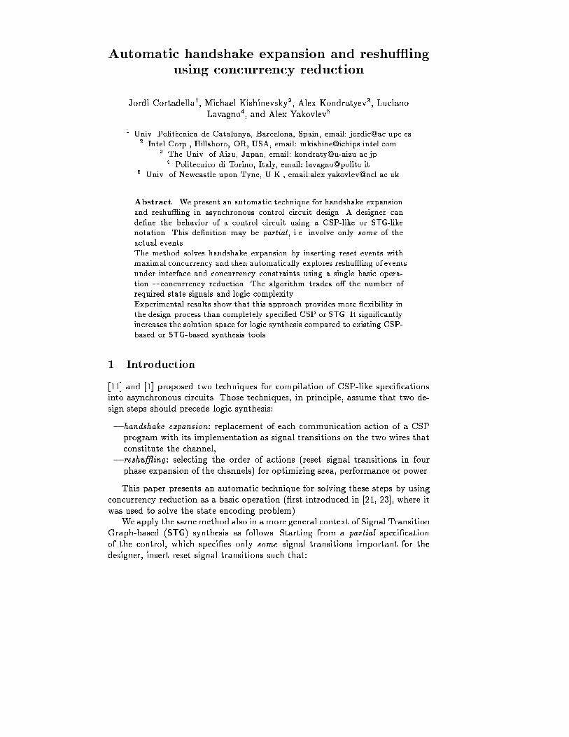
(c) (d) (e)Fig. 1. Speci�cation of the LR-process1.1 A motivating exampleFigure 1,a shows the structure of an LR-process [11] using the \handshake com-ponent" notation [1]. The process has a passive port l and an active port r andshould transfer control from the left port to the right port. Figure 1,b showsexpansion of each channel with two wires such that l = fli; log and r = fri; rog.Figure 1,c gives a speci�cation of this process using CSP-like actions for events,where l?; l! (r?; r!) stand for the input and output actions at channel l (r). Assum-ing four-phase implementation of the channel and positive encoding of channelactions, Figure 1,d presents a handshake expansion of the previous speci�cation.It is obtained by relabeling channel actions l? and l! to rising transitions on theinput and output wires of the ports, li+ and lo+, correspondingly (the same forchannel r).The latter speci�cation is viewed as a partial four phase STG. It cannotbe directly implemented by existing STG-based synthesis tools since the falling(reset) transitions of the signals are not speci�ed. There are many di�erent solu-tions for inserting falling signal transitions. Among them there are two extremesolutions: with maximum and minimum concurrency for falling transitions. Thesolution with minimum concurrency is not unique and depends upon the actualchosen reshu�ing for falling transitions. Starting from the solution with max-imum concurrency one can derive any other valid reshu�ing of transitions byconcurrency reduction. Figure 1,e shows an STG with maximal concurrency forall falling transitions assuming that all signals li; lo; ri; ro are independent andno interface constraints are given.This handshake expansion however is not valid for the LR-process. Indeed,we should obey additional ordering constraints for the channels: never resetthe requesting signal before receiving the acknowledgment. For example, for apassive port l one should satisfy the following interleaving of signal transitions:�[li+; lo+; li�; lo�]. Similarly for the active channel. Figure 1,f presents a validmaximal concurrency handshake expansion for the LR-process taking interfaceconstraints into account.
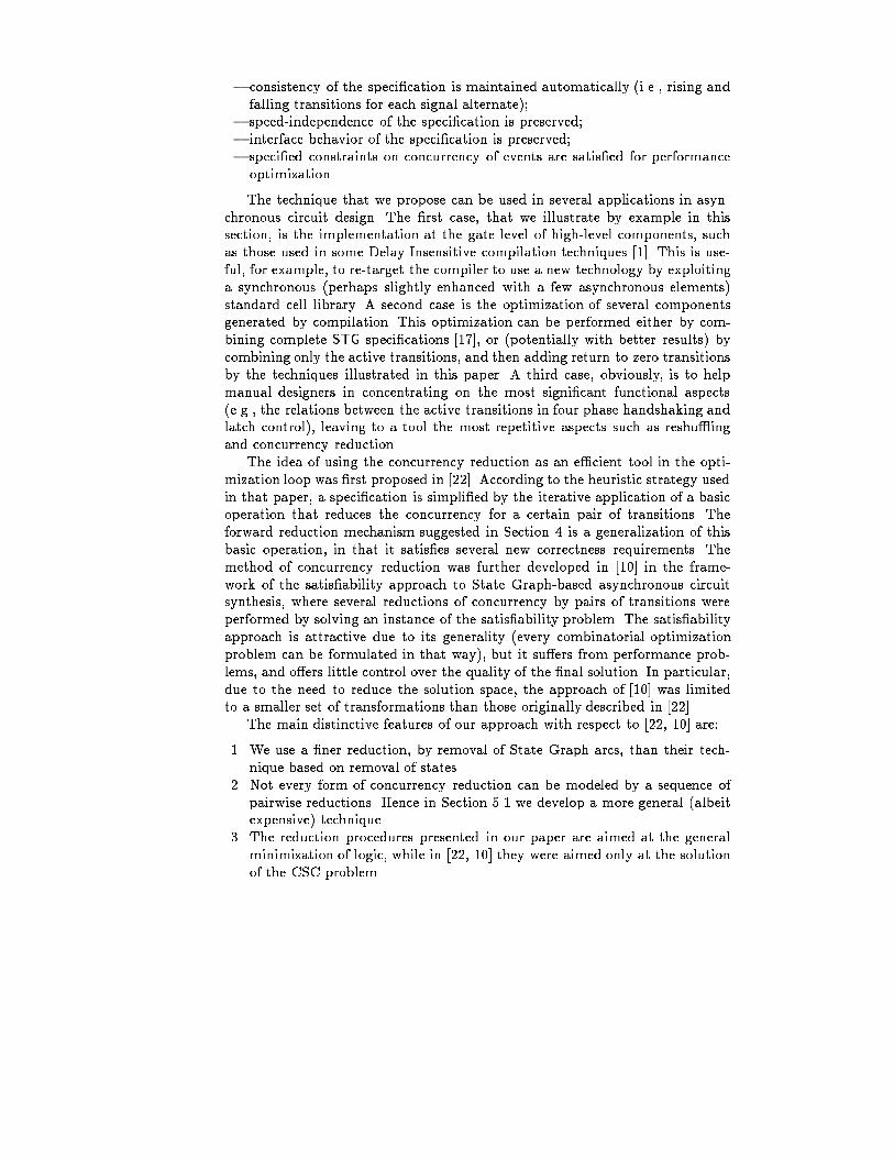
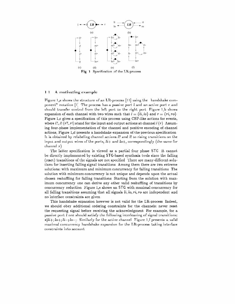
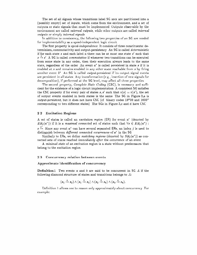
The corresponding State Graph (SG) is presented in Figure 3,a. This spec-i�cation can be implemented with the current STG based synthesis tools. Twostate signals are inserted in this example for resolving the Complete State Cod-ing (CSC) con icts. I.e., a pair of states labeled with the same binary code (e.g.,10*00, 1000*) require di�erent next values for output signals lo and ro and hencemust be distinguished by means of state signals (see Section 2.1).Table 1 presents the area and performance results for di�erent implemen-tations of the LR-process. The row corresponding to the \Max. concurrency"corresponds to the implementation of the STG with maximum concurrency ofthe reset signal transition. The circuit area is 168 units, and two state signalshave been inserted for resolving CSC con icts. Assuming that all internal andoutput events have a delay of 1 time unit, and that all input events have a delayof 2 time units, the critical cycle is 13 units and contains 3 input events.The well-known implementation of the LR-process is a Q-module [11] (alsocalled a S-element [1]). It corresponds to the SG in Figure 3,b and STG in Fig-ure 4,a. Its area is 104 units, while the critical cycle under the same assumptionsis longer. This solution can be automatically obtained by our tool by reducingconcurrency of signal transitions under the assumption that signal transition lo+is late with respect to ri�. This assumption, if violated, a�ects only the perfor-mance, not the correctness of the implementation, since the circuit is synthesizedto be speed-independent.The cost function for concurrency reduction strives to minimize the numberof CSC con icts and to reduce the estimated complexity of the logic (cf. Sec-tion 6.2). Therefore, a complete reduction of concurrency under no constraintswill give another solution { two wires, which is the best in terms of area (seeFigures 3,c and 4,b). This solution however does not allow to decouple the leftand the right neighbors of the LR-process, and hence would not be accepted asan e�cient implementation in the four-phase expansion of the process, due tothe increase in latency [18].To get other solutions we perform concurrency reduction under concurrencyconstraints. We do not allow to reduce concurrency for any pair of events (a; b)which are declared to be maintained concurrent (a k b) (This de�nition can benaturally extended to signals, i.e. to any pair of events of the involved signals.)The results are reported in the last four lines of Table 1. The two best solutions,for li k ri and lo k ri, corresponding to the SGs in Figure 3,d and c are reportedin Figure 4,c and d. All the circuits have been obtained automatically with thetool petrify, by technology mapping into a library of two-input gates.1.2 Algorithm overviewThe overall algorithm for handshake expansion and reshu�ing used in this ex-ample is shown in Figure 2. Line 1 of the algorithm corresponds to handshakeexpansion, line 4 corresponds to reshu�ing.A number of questions arise from this informal example.We will try to answerthem in the rest of the paper.
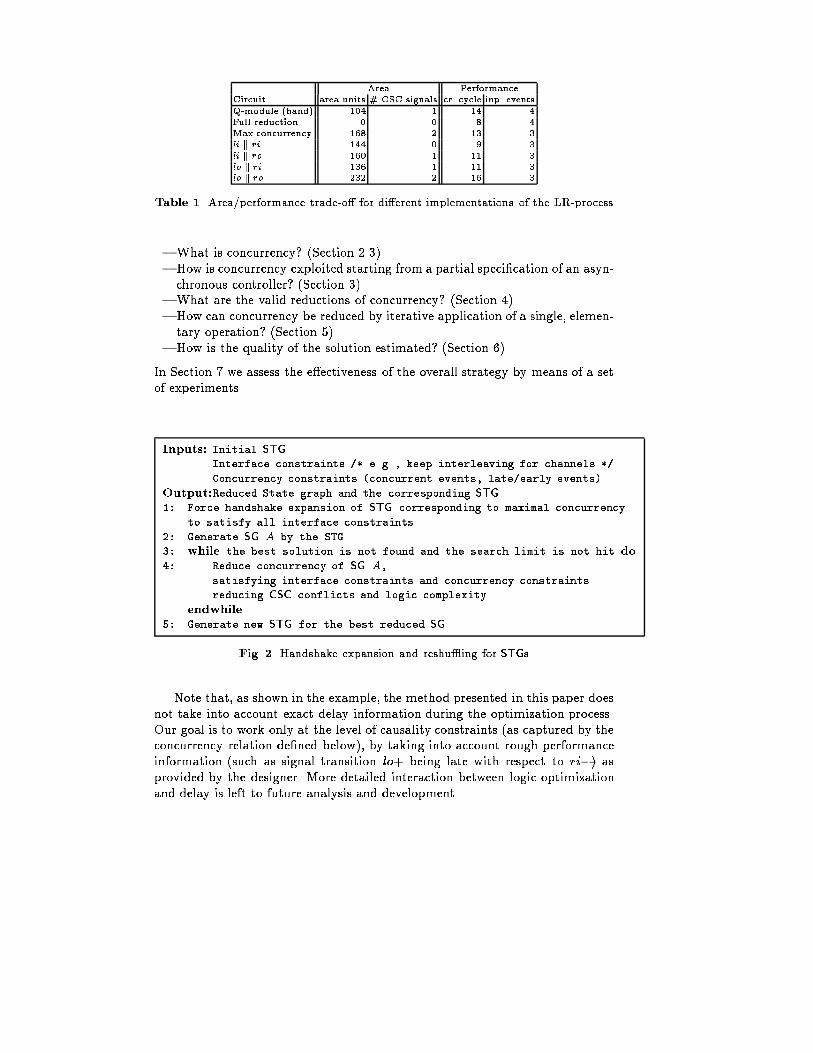
Area PerformanceCircuit area units # CSC signals cr. cycle inp. eventsQ-module (hand) 104 1 14 4Full reduction 0 0 8 4Max.concurrency 168 2 13 3li k ri 144 0 9 3li k ro 160 1 11 3lo k ri 136 1 11 3lo k ro 232 2 16 3Table 1. Area/performance trade-o� for di�erent implementations of the LR-process{ What is concurrency? (Section 2.3){ How is concurrency exploited starting from a partial speci�cation of an asyn-chronous controller? (Section 3){ What are the valid reductions of concurrency? (Section 4){ How can concurrency be reduced by iterative application of a single, elemen-tary operation? (Section 5){ How is the quality of the solution estimated? (Section 6)In Section 7 we assess the e�ectiveness of the overall strategy by means of a setof experiments.Inputs: Initial STGInterface constraints /* e.g., keep interleaving for channels */Concurrency constraints (concurrent events, late/early events)Output:Reduced State graph and the corresponding STG1: Force handshake expansion of STG corresponding to maximal concurrencyto satisfy all interface constraints2: Generate SG A by the STG3: while the best solution is not found and the search limit is not hit do4: Reduce concurrency of SG A,satisfying interface constraints and concurrency constraintsreducing CSC conflicts and logic complexityendwhile5: Generate new STG for the best reduced SGFig. 2. Handshake expansion and reshu�ing for STGsNote that, as shown in the example, the method presented in this paper doesnot take into account exact delay information during the optimization process.Our goal is to work only at the level of causality constraints (as captured by theconcurrency relation de�ned below), by taking into account rough performanceinformation (such as signal transition lo+ being late with respect to ri�) asprovided by the designer. More detailed interaction between logic optimizationand delay is left to future analysis and development.
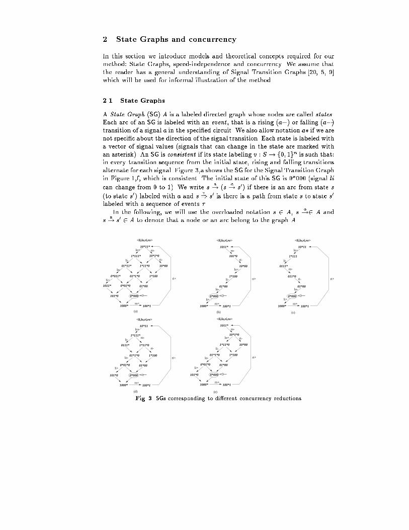
2 State Graphs and concurrencyIn this section we introduce models and theoretical concepts required for ourmethod: State Graphs, speed-independence and concurrency. We assume thatthe reader has a general understanding of Signal Transition Graphs [20, 5, 9]which will be used for informal illustration of the method.2.1 State GraphsA State Graph (SG) A is a labeled directed graph whose nodes are called states.Each arc of an SG is labeled with an event , that is a rising (a+) or falling (a�)transition of a signal a in the speci�ed circuit. We also allow notation a� if we arenot speci�c about the direction of the signal transition. Each state is labeled witha vector of signal values (signals that can change in the state are marked withan asterisk). An SG is consistent if its state labeling v : S ! f0; 1gn is such that:in every transition sequence from the initial state, rising and falling transitionsalternate for each signal. Figure 3,a shows the SG for the Signal Transition Graphin Figure 1,f, which is consistent. The initial state of this SG is 0*000 (signal lican change from 0 to 1). We write s a! (s a! s0) if there is an arc from state s(to state s0) labeled with a and s �) s0 is there is a path from state s to state s0labeled with a sequence of events � .In the following, we will use the overloaded notation s 2 A, s a!2 A ands a! s0 2 A to denote that a node or an arc belong to the graph A.01*11* 1*11*0 10*00
10*1*0
10*11*
1*111*
0*011* 01*1*0 1*100
1011* 0*01*0 01*00
101*0 0*000
1000* 100*1
<li,lo,ri,ro>
lo+ ro-
ri-li-
lo-
li+
ro+
ri+
li+
0111* 1*11*0
10*11
1*111*
01*1*0 1*100
0*01*0 01*00
101*0 0*000
1000* 100*1
<li,lo,ri,ro>
lo+
li-
ro+
ri+
1*11*0 10*00
10*1*0
1011*
01*1*0 1*100
0*01*0 01*00
101*0 0*000
1000* 100*1
<li,lo,ri,ro>
ro-
ri-
ro+
ri+
10*00
101*0
1011*
1*100
01*00
0*000
1000* 100*1
<li,lo,ri,ro>
ro-
ri-
ro+
ri+
0111*
10*11
1*111
011*0
01*00
0*000
1000* 100*1
<li,lo,ri,ro>
lo+
li-
ro+
ri+
li+
lo-
li-
lo+ ro-
ri-
lo-
li+
(a) (b) (c)
(e)(d)
lo+
li-
lo-
li+
ro-
ri-
lo- Fig. 3. SGs corresponding to di�erent concurrency reductions
The set of all signals whose transitions label SG arcs are partitioned into a(possibly empty) set of inputs, which come from the environment, and a set ofoutputs or state signals that must be implemented. Outputs observable by theenvironment are called external outputs, while other outputs are called internaloutputs or simply internal signals.In addition to consistency, the following two properties of an SG are neededfor implementability as a speed-independent logic circuit.The �rst property is speed-independence. It consists of three constituents: de-terminism, commutativity and output-persistency. An SG is called deterministicif for each state s and each label a there can be at most one state s0 such thats a! s0. A SG is called commutative if whenever two transitions can be executedfrom some state in any order, then their execution always leads to the samestate, regardless of the order. An event a� is called persistent in state s if it isenabled at s and remains enabled in any other state reachable from s by �ringanother event b�. An SG is called output-persistent if its output signal eventsare persistent in all states. Any transformation (e.g., insertion of new signals fordecomposition), if performed at the SG level, may a�ect all three properties.The second property, Complete State Coding (CSC), is necessary and su�-cient for the existence of a logic circuit implementation. A consistent SG satis�esthe CSC property if for every pair of states s; s0 such that v(s) = v(s0), the setof output events enabled in both states is the same. The SG in Figure 3,a isoutput-persistent, but it does not have CSC (cf. binary codes 10*00 and 1000*corresponding to two di�erent states). The SGs in Figure 3,c and d have CSC.2.2 Excitation RegionsA set of states is called an excitation region (ER) for event a� (denoted byERj(a�)) if it is a maximal connected set of states such that 8s 2 ERj(a�) :s a�!. Since any event a� can have several separated ERs, an index j is used todistinguish between di�erent connected occurrences of a� in the SG.Similarly to ERs, we de�ne switching regions (denoted by SRj(a�)) as con-nected sets of states reached immediately after the occurrence of an event.A minimal state of an excitation region is a state without predecessors thatbelong to the excitation region.2.3 Concurrency relation between eventsApproximate identi�cation of concurrencyDe�nition1. Two events a and b are said to be concurrent in SG A if thefollowing diamond structure of states and transitions belongs to A:(s1 a! s2) ^ (s1 b! s3) ^ (s2 b! s4) ^ (s3 a! s4):De�nition 1 allows one to reason only approximately about concurrency. Forexample:
C
liro
rilo
li+
ro+
ri+
lo-
lo+li-
ro-
ri-li ro
rilo
ro-ri-
li+
ro+
ri+
lo+
ri-
li- ro-
lo-
C
(b)
S
RRs
lo ri
roli
(c)
C
Cli
lo
ri
ro
lo-
li-
csc-
li+
ro+
ri+csc+
ro-
ri-lo+
(d)
li+
ro+
lo-
ri+
csc+lo+
li-
csc-
(a)
Fig. 4. Implementations of the LR-process{ it approximates concurrency for sets of events by using only pairwise con-currency. E.g., if the SG is not persistent, then (ajjb) ^ (bjjc) ^ (ajjc) doesnot necessarily imply jj(a; b; c). Consider, for example, an arbiter with threerequesting inputs a; b; c and two available resources that can be granted con-currently, but not to all three requesters.{ instead of de�ning concurrency at the level of event occurrences (i.e., withinan acyclic in�nite structure, as discussed below), it de�nes it for all occur-rences due to the same SG events. The distinction, although required intheory due to pathological examples, seems to be seldom necessary in prac-tice.If the SG is known to be speed-independent and a; b are output events, andhence output persistent and commutative, then concurrency of a and b can bechecked just as intersection of their ERs:ajjb, ER(a) \ER(b) 6= ;:In this paper we have chosen the approximate de�nition, because in ourexperience it works well in practice and is easily implementable. Moreover, con-currency reduction at the level of individual occurrences of events, as discussedin the next section, is much more expensive to implement, and hence can misspotentially useful optimizations due to excessive complexity.Exact identi�cation of concurrency Each event is represented by a singleER in an SG. However, not all states of this ER are potentially reachable in a
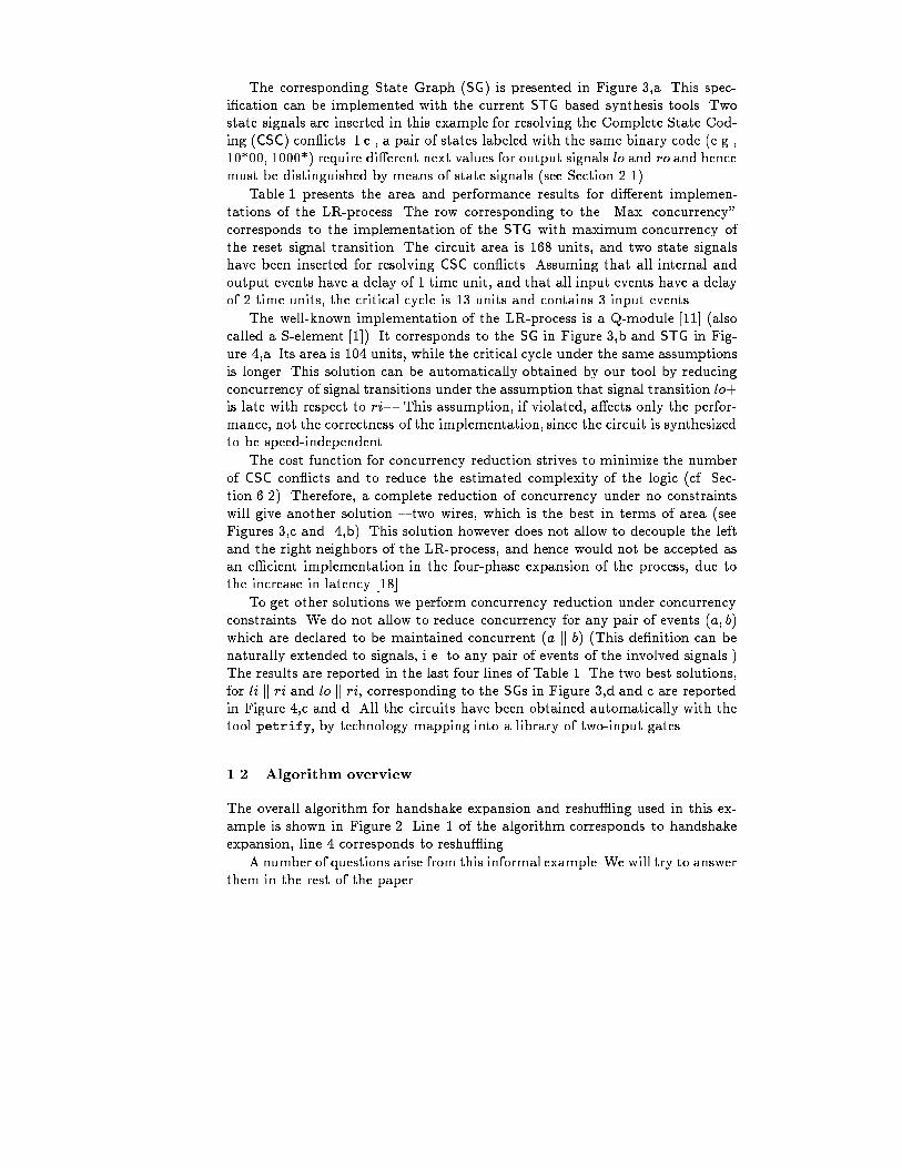
single run of the process. The subset of reachable states can di�er depending onthe initial state of the system, on the path that is followed in the SG, and henceon which particular state is selected for entering the ER. Di�erent occurrences ofthe same event are characterized by sub-regions of the ER reachable in a singlerun of the process. The concurrency relation can be therefore precisely capturedonly in terms of occurrences of events.The theory of unfoldings for SGs [14, 7, 16] and for Petri Nets and STGs [13,6, 8] has been developed for this purpose. An unfolding of an STG is an equiva-lent acyclic STG where di�erent occurrences of an event are split and thereforerepresented by di�erent ERs in the corresponding unfolding of an SG. Orderingrelations for occurrences of events, including concurrency, can be easily derivedby unfoldings [8].Hence, we can precisely reason about concurrency reduction for occurrencesof events in terms of unfoldings by comparing concurrent runs [19] (also knownas Mazurkiewicz's traces [12]) of the initial speci�cations with interleaved tracesof a reduced system.Using unfoldings in a synthesis tool is feasible, but in this case it is moreexpensive and complex than using the SG. Even though the STG unfolding canbe much more compact than a corresponding SG, performing operations such asreduction of concurrency on the set of occurrences of a pair of events simultane-ously and consistently is much more complicated than performing them at theSG level.3 Handshake expansionThis section explains how handshake expansion is performed. The syntax of ourspeci�cations allows to describe the behavior of channels and partially speci-�ed signals. In both cases, the speci�cation only contains the active transitions,whereas the handshake expansion method transforms the speci�cation accordingto the re�nement chosen by the designer: 2-phase re�nement, with no distinc-tion between up and down transitions or 4-phase re�nement, with return-to-zerosignaling for each handshake.3.1 ChannelsIn this section we use a notation similar to the one proposed for handshakeprocesses [1]. Two types of events can occur in channel a: input events (a?) andoutput events (a!). The terminals of a channel are called ports. A channel a isimplemented by two signals: ai (input) and ao (output).The expansion from channel to signal events can be done by manipulating thestructure of the underlying Petri net. For 2-phase re�nement, the transformationsimply requires relabeling the STG transitions from a? to ai~and a! to ao~, wherethe su�x~denotes a toggle transition of the signal. The process of determining thebinary encoding for each state will �nally deduce whether the actual transitionis rising or falling.
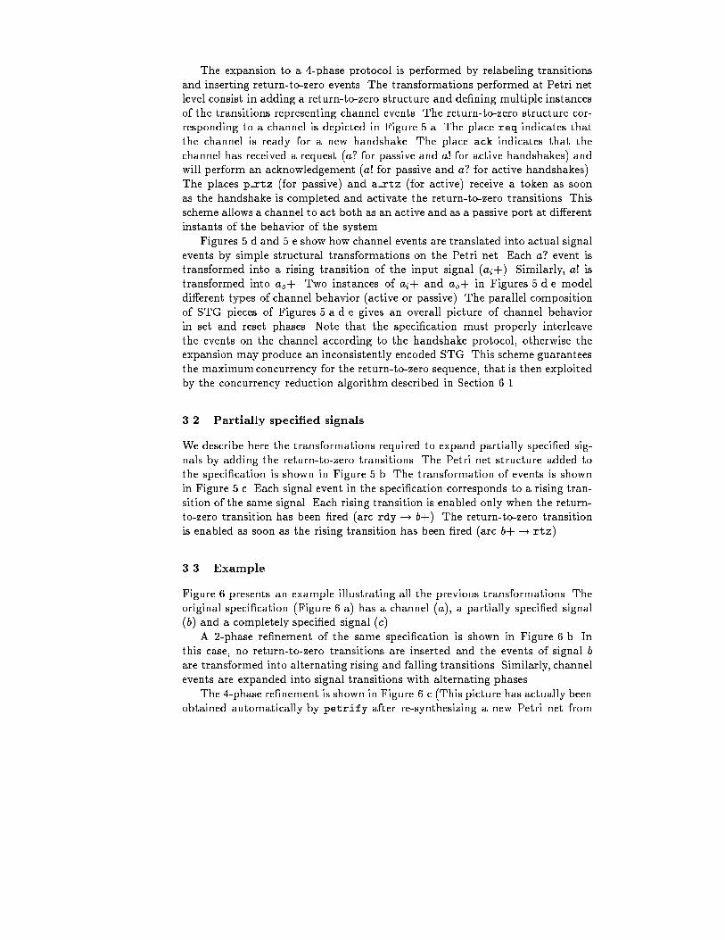
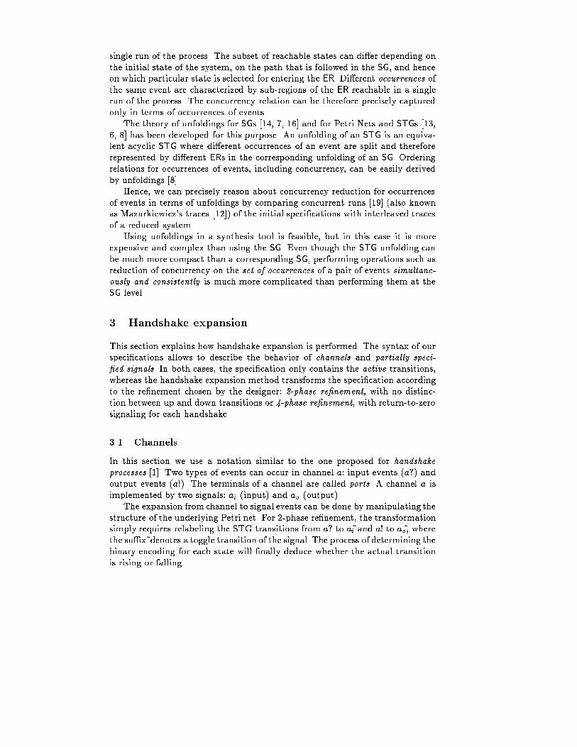
The expansion to a 4-phase protocol is performed by relabeling transitionsand inserting return-to-zero events. The transformations performed at Petri netlevel consist in adding a return-to-zero structure and de�ning multiple instancesof the transitions representing channel events. The return-to-zero structure cor-responding to a channel is depicted in Figure 5.a. The place req indicates thatthe channel is ready for a new handshake. The place ack indicates that thechannel has received a request (a? for passive and a! for active handshakes) andwill perform an acknowledgement (a! for passive and a? for active handshakes).The places p rtz (for passive) and a rtz (for active) receive a token as soonas the handshake is completed and activate the return-to-zero transitions. Thisscheme allows a channel to act both as an active and as a passive port at di�erentinstants of the behavior of the system.Figures 5.d and 5.e show how channel events are translated into actual signalevents by simple structural transformations on the Petri net. Each a? event istransformed into a rising transition of the input signal (ai+). Similarly, a! istransformed into ao+. Two instances of ai+ and ao+ in Figures 5.d.e modeldi�erent types of channel behavior (active or passive). The parallel compositionof STG pieces of Figures 5.a.d.e gives an overall picture of channel behaviorin set and reset phases. Note that the speci�cation must properly interleavethe events on the channel according to the handshake protocol, otherwise theexpansion may produce an inconsistently encoded STG. This scheme guaranteesthe maximumconcurrency for the return-to-zero sequence, that is then exploitedby the concurrency reduction algorithm described in Section 6.1.3.2 Partially speci�ed signalsWe describe here the transformations required to expand partially speci�ed sig-nals by adding the return-to-zero transitions. The Petri net structure added tothe speci�cation is shown in Figure 5.b. The transformation of events is shownin Figure 5.c. Each signal event in the speci�cation corresponds to a rising tran-sition of the same signal. Each rising transition is enabled only when the return-to-zero transition has been �red (arc rdy! b+). The return-to-zero transitionis enabled as soon as the rising transition has been �red (arc b+! rtz).3.3 ExampleFigure 6 presents an example illustrating all the previous transformations. Theoriginal speci�cation (Figure 6.a) has a channel (a), a partially speci�ed signal(b) and a completely speci�ed signal (c).A 2-phase re�nement of the same speci�cation is shown in Figure 6.b. Inthis case, no return-to-zero transitions are inserted and the events of signal bare transformed into alternating rising and falling transitions. Similarly, channelevents are expanded into signal transitions with alternating phases.The 4-phase re�nement is shown in Figure 6.c (This picture has actually beenobtained automatically by petrify after re-synthesizing a new Petri net from
ai-
ao- ai-
ao-
a_rtzp_rtz
req
ack rdy
b-
rtz
p1 p2
p3
b
p1 p2
p3
b+
rdy
rtz
(a) (b) (c)
(d) (e)
p1 p2
p3
p1 p2
p3
req
ack
a_rtz
a? ai+ ai+
p1 p2
p3
req
ack
p_rtz
ao+ ao+
p1 p2
p3
a!Fig. 5. Petri net structures for return-to-zero transitions in 4-phase re�nement: (a) forchannels and (b) for partially speci�ed signals. Event transformations: (c) for partiallyspeci�ed signals, (d) for input channel events and (e) for output channel events.a!
a?
b
c+
a!
b
c-
a?(a) ao+ b-
ai+ ao-
c+ c-
b+ ai-(b) b+
b-
ao+
b-
b+
ai+
c-
c+
ao+
ai-
ai-
ao-
ao-
ai+(c)Fig. 6. (a) Original speci�cation (state graph), (b) 2-phase re�nement (state graph),(c) 4-phase re�nement (Petri net).the one derived by applying the structural transformations for 4-phase re�ne-ment [2].) All the events of signal b are now transformed into rising transitionswith an automatic insertion of return-to-zero transitions. Events of channel a arealso transformed into rising transitions of signals ai and ao. All return-to-zerotransitions are incorporated with maximum concurrency.
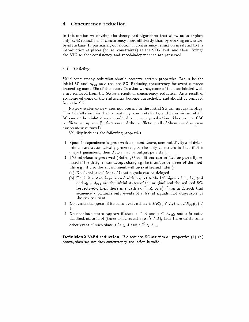
4 Concurrency reductionIn this section we develop the theory and algorithms that allow us to exploreonly valid reductions of concurrency more e�ciently than by working on a state-by-state base. In particular, our notion of concurrency reduction is related to theintroduction of places (causal constraints) at the STG level, and then \�xing"the STG so that consistency and speed-independence are preserved.4.1 ValidityValid concurrency reduction should preserve certain properties. Let A be theinitial SG and Ared be a reduced SG. Reducing concurrency for event e meanstruncating some ERs of this event. In other words, some of the arcs labeled withe are removed from the SG as a result of concurrency reduction. As a result ofarc removal some of the states may become unreachable and should be removedfrom the SG.No new states or new arcs not present in the initial SG can appear in Ared.This trivially implies that consistency, commutativity, and determinism of theSG cannot be violated as a result of concurrency reduction. Also no new CSCcon icts can appear (in fact some of the con icts or all of them can disappeardue to state removal).Validity includes the following properties:1. Speed-independence is preserved: as noted above, commutativity and deter-minism are automatically preserved, so the only constraint is that if A isoutput persistent, then Ared must be output persistent.2. I/O interface is preserved (Both I/O conditions can in fact be partially re-laxed if the designer can accept changing the interface behavior of the mod-ule, e.g., if also the environment will be synthesized later.):(a) No signal transitions of input signals can be delayed.(b) The initial state is preserved with respect to the I/O signals, i.e., if s0 2 Aand s00 2 Ared are the initial states of the original and the reduced SGsrespectively, then there is a path s0 �) s00 or s00 �) s0 in A such thatsequence � contains only events of internal signals, not observable bythe environment.3. No events disappear: if for some event e there isER(e) 2 A, then ERred(e) 6=;.4. No deadlock states appear: if state s 2 A and s 2 Ared, and s is not adeadlock state in A (there exists event e: s e! 2 A), then there exists someother event e0 such that: s e0! 2 A and s e0! 2 Ared.De�nition2 Valid reduction. If a reduced SG satis�es all properties (1){(4)above, then we say that concurrency reduction is valid.
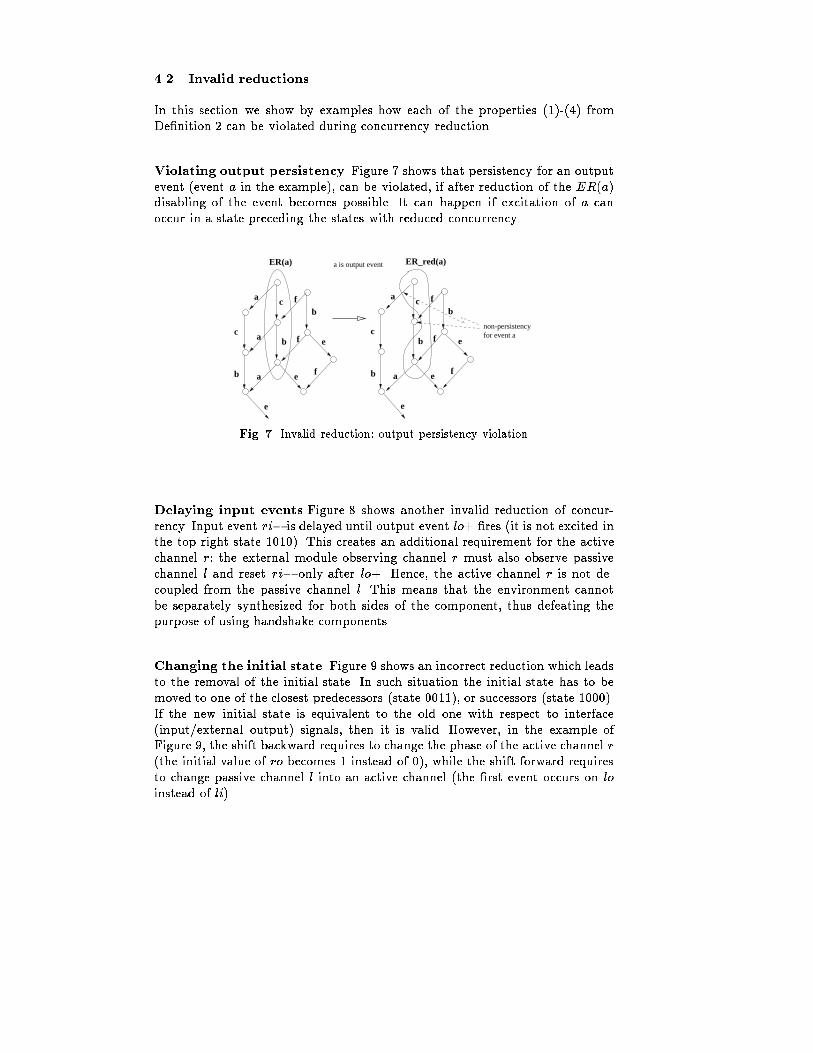
4.2 Invalid reductionsIn this section we show by examples how each of the properties (1)-(4) fromDe�nition 2 can be violated during concurrency reduction.Violating output persistency Figure 7 shows that persistency for an outputevent (event a in the example), can be violated, if after reduction of the ER(a)disabling of the event becomes possible. It can happen if excitation of a canoccur in a state preceding the states with reduced concurrency.a
a
a
c
b
b
c
ER(a)
bf
f
f
e
e
e
a is output event
a
a
c
b
b
c
ER_red(a)
bf
f
f
e
e
e
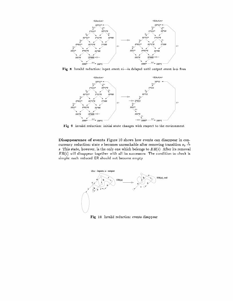
non-persistency for event aFig. 7. Invalid reduction: output persistency violationDelaying input events Figure 8 shows another invalid reduction of concur-rency. Input event ri� is delayed until output event lo+ �res (it is not excited inthe top right state 1010). This creates an additional requirement for the activechannel r: the external module observing channel r must also observe passivechannel l and reset ri� only after lo+. Hence, the active channel r is not de-coupled from the passive channel l. This means that the environment cannotbe separately synthesized for both sides of the component, thus defeating thepurpose of using handshake components.Changing the initial state Figure 9 shows an incorrect reduction which leadsto the removal of the initial state. In such situation the initial state has to bemoved to one of the closest predecessors (state 0011), or successors (state 1000).If the new initial state is equivalent to the old one with respect to interface(input/external output) signals, then it is valid. However, in the example ofFigure 9, the shift backward requires to change the phase of the active channel r(the initial value of ro becomes 1 instead of 0), while the shift forward requiresto change passive channel l into an active channel (the �rst event occurs on loinstead of li).
01*11* 1*11*0 10*00
10*1*0
10*11*
1*111*
0*011* 01*1*0 1*100
1011* 0*01*0 01*00
101*0 0*000
1000* 100*1
<li,lo,ri,ro>
lo+ ro-
ri-li-
lo-
li+
ro+
ri+
10*10
01*11* 1*11*0
10*11*
1*111*
0*011* 01*1*0 1*100
1011* 0*01*0 01*00
101*0 0*000
1000* 100*1
<li,lo,ri,ro>
lo+ ro-
li-
lo-
li+
ro+
ri+
ri-Fig. 8. Invalid reduction: input event ri� is delayed until output event lo+ �res.01*11* 1*11*0 10*00
10*1*0
10*11*
1*111*
0*011* 01*1*0 1*100
1011* 0*01*0 01*00
101*0 0*000
1000*
ri-
100*1
<li,lo,ri,ro>
lo+ ro-
ri-li-
lo-
li+
ro+
ri+
01*11
10*11
1*111
0*011
1011*
101*0
1000* 100*1
<li,lo,ri,ro>
lo+
li-
lo-
li+
ro+
ri+
ro-Fig. 9. Invalid reduction: initial state changes with respect to the environment.Disappearance of events Figure 10 shows how events can disappear in con-currency reduction: state s becomes unreachable after removing transition s0 a!s. This state, however, is the only one which belongs to ER(i). After its removalER(i) will disappear together with all its successors. The condition to check issimple: each reduced ER should not become empty.b
c
cER(a)_red
a aa
i,b,c - inputs; a - output
a b
b c
c
i
ER(a)s
aFig. 10. Invalid reduction: events disappear.
01*11* 1*11*0 10*00
10*1*0
10*11*
1*111*
0*011* 01*1*0 1*100
1011* 0*01*0 01*00
101*0 0*000
1000* 100*1
<li,lo,ri,ro>
lo+ ro-
ri-li-
lo-
li+
ro+
ri+
deadlock
01*11* 1*11*0 10*00
10*1*0
10*11*
1*111*
0*011* 01*1*0 1*100
1011* 0*01*0 01*00
1010 0*000
1000* 100*1
<li,lo,ri,ro>
lo+ ro-
ri-li-
lo-
li+
ro+
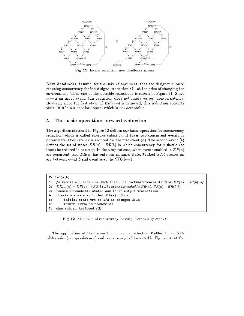
ri+Fig. 11. Invalid reduction: new deadlocks appear.New deadlocks Assume, for the sake of argument, that the designer allowedreducing concurrency for input signal transition ri� at the price of changing theenvironment. Then one of the possible reductions is shown in Figure 11. Sinceri� is an input event, this reduction does not imply output non-persistency.However, since the last state of ER(ri�) is removed, this reduction convertsstate 1010 into a deadlock state, which is not acceptable.5 The basic operation: forward reductionThe algorithm sketched in Figure 12 de�nes our basic operation for concurrencyreduction which is called forward reduction. It takes two concurrent events asparameters. Concurrency is reduced for the �rst event (a). The second event (b)de�nes the set of states ER(a) \ ER(b) in which concurrency for a should (atleast) be reduced in one step. In the simplest case, when events enabled in ER(a)are persistent, and ER(a) has only one minimal state, FwdRed(a,b) creates anarc between event b and event a at the STG level.FwdRed(a,b)1: /* remove all arcs s a! such that s is backward reachable from ER(a) \ER(b) */2: ERred(a) = ER(a)� (ER(b) [ backward reachable(ER(a); ER(a) \ ER(b)))3: remove unreachable states and their output transitions4: if exists some e such that ER(e) = ; or5: initial state wrt to I/O is changed then6: return (invalid reduction)7: else return (reduced SG)Fig. 12. Reduction of concurrency for output event a by event b.The application of the forward concurrency reduction FwdRed to an STGwith choice (non-persistency) and concurrency is illustrated in Figure 13. At the
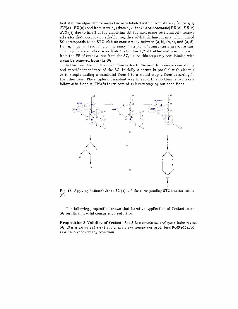
�rst step the algorithm removes two arcs labeled with a from state s2 (since s2 2ER(a)\ER(b)) and from state s1 (since s1 2 backward reachable(ER(a); ER(a)\ER(b))) due to line 2 of the algorithm. At the next stage we iteratively removeall states that become unreachable, together with their fan-out arcs. The reducedSG corresponds to an STG with no concurrency between (a; b), (a; e), and (a; d).Hence, in general reducing concurrency for a pair of events can also reduce con-currency for some other pairs. Note that in line 1,2 of FwdRed states are removedfrom the ER of event a, not from the SG, i.e. at this step only arcs labeled witha can be removed from the SG.In this case, the multiple reduction is due to the need to preserve consistencyand speed-independence of the SG. Initially a occurs in parallel with either dor b. Simply adding a constraint from b to a would stop a from occurring inthe other case. The simplest, persistent way to avoid this problem is to make afollow both b and d. This is taken care of automatically by our conditions.c
a
ed
b(b)
(a)
c
a
ab
b
d
e
de
s0
s1
s6
s7
s8
s2
s3
s5
s4
c
a
ab
d
e
s0
s1
s8
s2
s3
s5
s4
c
a
a
a
ab
b
d
e
de
s0
s1
s6
s7
s8
s2
s3
s5
s4
ER(a)
ER_red(a)
c
d e
b
aFig. 13. Applying FwdRed(a,b) to SG (a) and the corresponding STG transformation(b).The following proposition shows that iterative application of FwdRed to anSG results in a valid concurrency reduction.Proposition3 Validity of FwdRed. Let A be a consistent and speed-independentSG. If a is an output event and a and b are concurrent in A, then FwdRed(a,b)is a valid concurrency reduction.
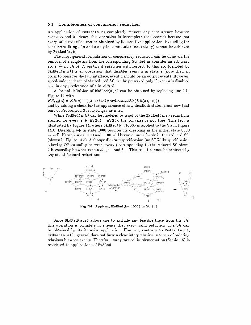
5.1 Completeness of concurrency reductionAn application of FwdRed(a,b) completely reduces any concurrency betweenevents a and b. Hence this operation is incomplete (too coarse) because notevery valid reduction can be obtained by its iterative application. Excluding theconcurrent �ring of a and b only in some states (not totally) cannot be achievedby FwdRed(a,b).The most general formulation of concurrency reduction can be done via theremoval of a single arc from the corresponding SG. Let us consider an arbitraryarc s a! in SG A. A backward reduction with respect to this arc (denoted byBkdRed(a,s)) is an operation that disables event a in state s (note that, inorder to preserve the I/O interface, event a should be an output event). However,speed-independence of the reduced SG can be preserved only if event a is disabledalso in any predecessor of s in ER(a).A formal de�nition of BkdRed(a,s) can be obtained by replacing line 2 inFigure 12 withERred(a) = ER(a) � (fsg [ backward reachable(ER(a); fsg))and by adding a check for the appearance of new deadlock states, since now thatpart of Proposition 3 is no longer satis�ed.While FwdRed(a,b) can be modeled by a set of the BkdRed(a,s) reductionsapplied for every s 2 ER(a) \ ER(b), the converse is not true. This fact isillustrated by Figure 14, where BkdRed(b+,1000) is applied to the SG in Figure14,b. Disabling b+ in state 1000 requires its disabling in the initial state 0000as well. Hence states 0100 and 1100 will become unreachable in the reduced SG(shown in Figure 14,c). A change diagram speci�cation (an STG-like speci�cationallowing OR-causality between events) corresponding to the reduced SG showsOR-causality between events d+; c+ and b+. This result cannot be achieved byany set of forward reductions.a+
d+
b+ c+
a-...
... ...
a b c d
0*00*0
100*0* 0*0*10
0*110 10*10*
1110*
10*0*1
110*1 10*11
1*111
ER(b+) a+ c+
d+
b+
a-
OR
d)
a)
b)
a b c d
0*0*0*0
10*0*0* 0*10*0 0*0*10
110*0* 0*110 10*10*
1110*
10*0*1
110*1 10*11
1*111
b+
delaying b+in 10*0*0*
c)Fig. 14. Applying BkdRed(b+,1000) to SG (b)Since BkdRed(a,s) allows one to exclude any feasible trace from the SG,this operation is complete in a sense that every valid reduction of a SG canbe obtained by its iterative application. However, contrary to FwdRed(a,b),BkdRed(a,s) in general does not have a clear interpretation in terms of orderingrelations between events. Therefore, our practical implementation (Section 6) isrestricted to applications of FwdRed.
6 ImplementationThis section describes the actual strategy implemented for concurrency reductionin the tool petrify.As we mentioned in Section 1 and we will experimentally illustrate in Sec-tion 7, concurrency reduction can reduce the logic complexity of the circuit intwo ways. First of all, the number of CSC con icts is reduced, and hence thecomplexity of the logic implementing the state signals is reduced (or totally elim-inated, if the reduced SG has CSC). Secondly, the number of reachable states isreduced, and hence the don't care set that can be exploited by logic minimizationis increased. However, in this case one must also consider the potential increasein the number of \trigger" signals for each output. (Loosely speaking, these arethe signals that directly enable a transition of the output, and that must be partof any speed-independent implementation.) For this reason, we use a heuristiccost function that estimates changes in logic complexity at each step, since exactcomputation by state signal insertion, decomposition and technology mappingwould be too expensive.6.1 Concurrency reductionThe algorithm in Figure 15 describes how concurrency reduction is performed.The designer initially provides a list of pairs of events whose concurrency cannotbe reduced, e.g., because they are crucial for overall system performance. Thiswill prevent the algorithm from adding causality relations between these pairsof events.The exploration is done by a strategy similar to the ��� pruning commonlyused in game-playing algorithms. At each level of the exploration and from agiven con�guration, a set of neighbor con�gurations is generated by performinga basic transformation (forward concurrency reduction between two events). Foreach level of the exploration, only a few candidates, with the best estimatedcost, survive to the next level. These candidates are kept in the list frontier.The width of the exploration is controlled by the parameter size frontier.Note that at each level of the exploration the obtained state graphs are lessconcurrent than their predecessors. This monotonous behavior guarantees thatthe algorithm will terminate when no more concurrency can be reduced in anyof the con�gurations in frontier.6.2 Cost functionThe cost function to select the best con�gurations at each level aims at reducingthe complexity of the resulting circuit. Unfortunately, the estimation of the com-plexity of the logic for output signals with CSC con icts can be inaccurate dueto the impossibility to derive correct equations. For this reason, the cost func-tion combines the information of CSC con icts with the estimated complexity
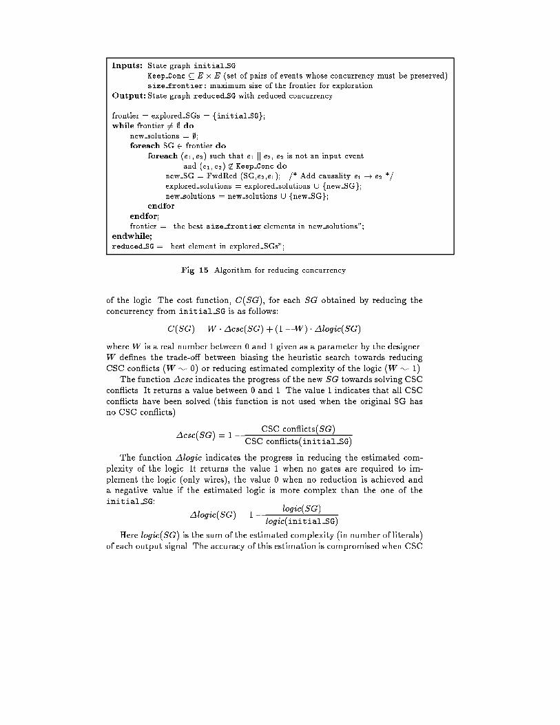
Inputs: State graph initial SGKeep Conc � E �E (set of pairs of events whose concurrency must be preserved)size frontier: maximum size of the frontier for explorationOutput: State graph reduced SG with reduced concurrencyfrontier = explored SGs = finitial SGg;while frontier 6= ; donew solutions = ;;foreach SG 2 frontier doforeach (e1; e2) such that e1 k e2, e2 is not an input eventand (e1; e2) 62 Keep Conc donew SG = FwdRed (SG,e2,e1); /* Add causality e1 ! e2 */explored solutions = explored solutions [ fnew SGg;new solutions = new solutions [ fnew SGg;endforendfor;frontier = \the best size frontier elements in new solutions";endwhile;reduced SG = \best element in explored SGs";Fig. 15. Algorithm for reducing concurrency.of the logic. The cost function, C(SG), for each SG obtained by reducing theconcurrency from initial SG is as follows:C(SG) = W ��csc(SG) + (1�W ) ��logic(SG)where W is a real number between 0 and 1 given as a parameter by the designer.W de�nes the trade-o� between biasing the heuristic search towards reducingCSC con icts (W ; 0) or reducing estimated complexity of the logic (W ; 1).The function �csc indicates the progress of the new SG towards solving CSCcon icts. It returns a value between 0 and 1. The value 1 indicates that all CSCcon icts have been solved (this function is not used when the original SG hasno CSC con icts).�csc(SG) = 1� CSC con icts(SG)CSC con icts(initial SG)The function �logic indicates the progress in reducing the estimated com-plexity of the logic. It returns the value 1 when no gates are required to im-plement the logic (only wires), the value 0 when no reduction is achieved anda negative value if the estimated logic is more complex than the one of theinitial SG: �logic(SG) = 1� logic(SG)logic(initial SG)Here logic(SG) is the sum of the estimated complexity (in number of literals)of each output signal. The accuracy of this estimation is compromised when CSC
con icts still remain in the SG due to the improper de�nition of the on-set ando�-set of the signals. Improving this estimation is one of the aspects that requirefurther investigation in the future.7 Experimental results7.1 First case study: the PAR componentThis section presents a case study considering the handshake expansion andconcurrency reduction of the PAR component used in VLSI programming [1].Figure 16.a shows an STG speci�cation in terms of channel events. This spec-i�cation may yield di�erent implementations depending on the selected phasere�nement and concurrency among events. The purpose of our CAD strategy isto assist the designer in the selection of the best implementation according tothe requirements of the application.Figure 16.e depicts a 2-phase re�nement of the speci�cation, obtained bymerely considering each event of the original speci�cation as a transition on thecorresponding wire. An implementation of such behavior is shown in Figure 16.i.The most challenging problem arises when a 4-phase re�nement is desired.The freedom to schedule the return-to-zero transitions opens a spectrum of dif-ferent implementations. Figures 16.c [1] and 16.d [18] (corresponding to imple-mentations in Figures 16.g and 16.h respectively) have been obtained manually.The latter is the one actually used by the current Tangram compiler.Our tool can automatically perform a 4-phase expansion by using the struc-tural Petri net techniques discussed in Section 3, and derive the speci�cationshown in Figure 16.b. After this transformation, the return-to-zero signalling isperformed with maximum concurrency with regard to the rest of events. How-ever, a direct implementation of this behavior may result in a complex circuitdue to the need of inserting extra logic for state encoding and logic decomposi-tion. An actual implementation for maximum concurrency has more than twicethe complexity of any of the circuits shown in Figure 16.Figures 16.f and 16.j depict the solution automatically obtained by reducingthe concurrency of the 4-phase re�nement in Figure 16.b. The reduction has beenperformed by preserving the concurrency between the events b? and c?, thusmaintaining the parallel execution of both processes. Interestingly, the circuitmanifests an asymmetric behavior that can be bene�cial to implement PARcomponents in which the process at channel b is known to be slower than c.The circuit is slightly smaller (by 12% in our standard cell library) than thoseobtained by manual design, although its estimated performance may be worsethan that of Figure 16.h, if b and c have balanced delays (the critical cycle islonger by 11% under the assumption: delay of a combinational gate { 1 timeunit, delay of a sequential gate { 1.5 time units, and delay of an input event { 3time units).
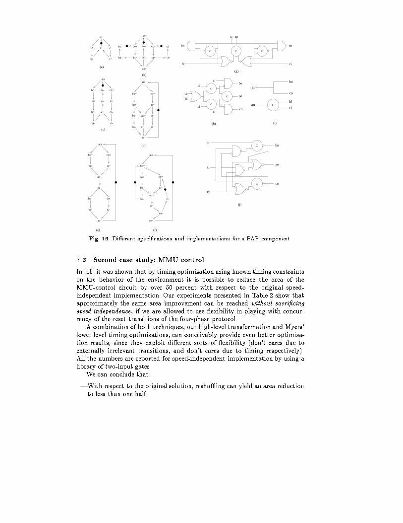
ai+
bo+
bi+
bo-
bi-
co+
ci+
ao+
ai-
co-
ao-
ci-
ai+
bo+ co+
bi+ ci+
ao+
ai-
bo- co-
bi- ci-
ao-
CCC
ai ao
bi
bo
ci
co
C
ai
bi
ciao
co
bo
C
C
(d)
ao
bo
co
bi
ai
ci
a?
b!
b?
c!
c?
a!
C
C
C
ai
ai
ai
bi
bi
ci
ao
bo
cobi+
bo+
bo-
bi-
co+
ci+
co-
ci-
ao+
ai-
ao-
ai+
bi+
bo+
bo-
bi-
co+
ci+
co-
ci-
ao+
ai-
ao-
ai+
ai+
bo+ co+
bi+ ci+
ao+
bo-
bi-
co-
ci-
ai-
ao-
(c)
(e) (f)
(g)
(h) (i)
(j)
(b)
(a)
Fig. 16. Di�erent speci�cations and implementations for a PAR component.7.2 Second case study: MMU controlIn [15] it was shown that by timing optimization using known timing constraintson the behavior of the environment it is possible to reduce the area of theMMU-control circuit by over 50 percent with respect to the original speed-independent implementation. Our experiments presented in Table 2 show thatapproximately the same area improvement can be reached without sacri�cingspeed-independence, if we are allowed to use exibility in playing with concur-rency of the reset transitions of the four-phase protocol.A combination of both techniques, our high-level transformation and Myers'lower level timing optimizations, can conceivably provide even better optimiza-tion results, since they exploit di�erent sorts of exibility (don't cares due toexternally irrelevant transitions, and don't cares due to timing respectively).All the numbers are reported for speed-independent implementation by using alibrary of two-input gates.We can conclude that{ With respect to the original solution, reshu�ing can yield an area reductionto less than one half.
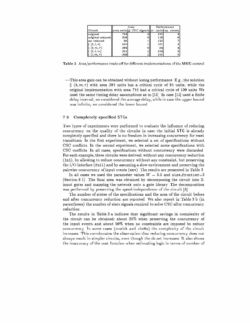
Area PerformanceCircuit area units # CSC signals cr. cycle inp. eventsoriginal 744 2 100 4original reduced 208 0 118 6csc reduced 96 1 123 7k (b; l; r) 440 1 101 4k (b;m; r) 384 0 94 4k (b; l; m) 352 1 104 5k (l; m; r) 368 1 105 5Table 2. Area/performance trade-o� for di�erent implementations of the MMU-control{ This area gain can be obtained without losing performance. E.g., the solutionk (b;m; r) with area 384 units has a critical cycle of 94 units, while theoriginal implementation with area 744 had a critical cycle of 100 units Weused the same timing delay assumptions as in [15]. In case [15] used a �nitedelay interval, we considered the average delay, while in case the upper boundwas in�nite, we considered the lower bound.7.3 Completely speci�ed STGsTwo types of experiments were performed to evaluate the in uence of reducingconcurrency on the quality of the circuits in case the initial STG is alreadycompletely speci�ed and there is no freedom in increasing concurrency for resettransitions. In the �rst experiment, we selected a set of speci�cations withoutCSC con icts. In the second experiment, we selected some speci�cations withCSC con icts. In all cases, speci�cations without concurrency were discarded.For each example, three circuits were derived: without any concurrency reduction(ini), by allowing to reduce concurrency without any constraint, but preservingthe I/O interface (full) and by assuming a slow environment and preserving thepairwise concurrency of input events (env). The results are presented in Table 3.In all cases we used the parameter values W = 0:5 and size frontier=3(Section 6.1). The �nal area was obtained by decomposing the circuit into 2-input gates and mapping the network onto a gate library. The decompositionwas performed by preserving the speed-independence of the circuit [3].The number of states of the speci�cations and the area of the circuit beforeand after concurrency reduction are reported. We also report in Table 3.b (inparentheses) the number of state signals required to solve CSC after concurrencyreduction.The results in Table 3.a indicate that signi�cant savings in complexity ofthe circuit can be obtained: about 20% when preserving the concurrency ofthe input events and about 50% when no constraints are imposed to reduceconcurrency. In some cases (nowick and vbe6a) the complexity of the circuitincreases. This corroborates the observation that reducing concurrency does notalways result in simpler circuits, even though the dc-set increases. It also showsthe inaccuracy of the cost function when estimating logic in terms of number of
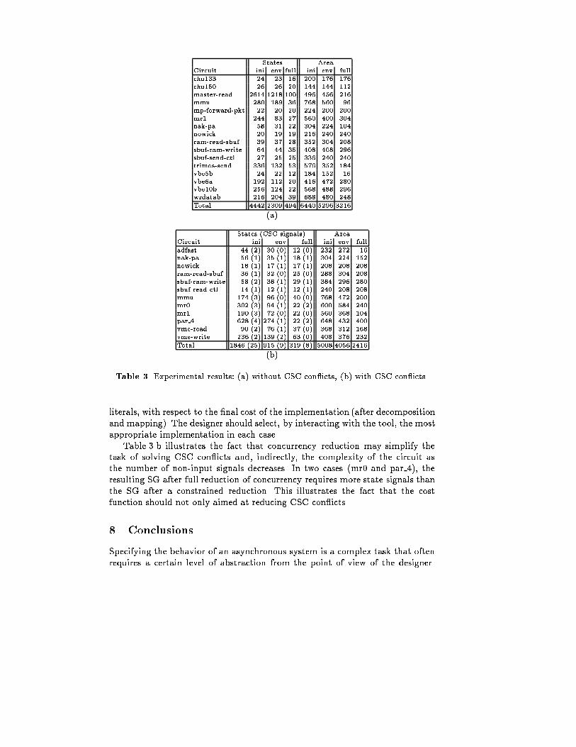
States AreaCircuit ini env full ini env fullchu133 24 23 16 200 176 176chu150 26 26 20 144 144 112master-read 2614 1218 100 496 456 216mmu 280 189 36 768 560 96mp-forward-pkt 22 20 20 224 200 200mr1 244 83 27 560 400 304nak-pa 58 31 22 304 224 104nowick 20 19 19 216 240 240ram-read-sbuf 39 37 28 352 304 208sbuf-ram-write 64 44 35 408 408 296sbuf-send-ctl 27 25 25 336 240 240trimos-send 336 132 53 576 352 184vbe5b 24 22 12 184 152 16vbe6a 192 112 20 416 472 280vbe10b 256 124 22 568 488 296wrdatab 216 204 39 688 480 248Total 4442 2309 494 6440 5296 3216(a)States (CSC signals) AreaCircuit ini env full ini env fulladfast 44 (2) 30 (0) 12 (0) 232 272 16nak-pa 56 (1) 35 (1) 18 (1) 304 224 152nowick 18 (1) 17 (1) 17 (1) 208 208 208ram-read-sbuf 36 (1) 32 (0) 25 (0) 288 304 208sbuf-ram-write 58 (2) 38 (1) 29 (1) 384 296 280sbuf-read-ctl 14 (1) 12 (1) 12 (1) 240 208 208mmu 174 (3) 96 (0) 40 (0) 768 472 200mr0 302 (3) 94 (1) 22 (2) 600 584 240mr1 190 (3) 72 (0) 22 (0) 560 368 104par 4 628 (4) 274 (1) 22 (2) 648 432 400vme-read 90 (2) 76 (1) 37 (0) 368 312 168vme-write 236 (2) 139 (2) 63 (0) 408 376 232Total 1846 (25) 915 (9) 319 (8) 5008 4056 2416(b)Table 3. Experimental results: (a) without CSC con icts, (b) with CSC con icts.literals, with respect to the �nal cost of the implementation (after decompositionand mapping). The designer should select, by interacting with the tool, the mostappropriate implementation in each case.Table 3.b illustrates the fact that concurrency reduction may simplify thetask of solving CSC con icts and, indirectly, the complexity of the circuit asthe number of non-input signals decreases. In two cases (mr0 and par 4), theresulting SG after full reduction of concurrency requires more state signals thanthe SG after a constrained reduction. This illustrates the fact that the costfunction should not only aimed at reducing CSC con icts.8 ConclusionsSpecifying the behavior of an asynchronous system is a complex task that oftenrequires a certain level of abstraction from the point of view of the designer.
Reasoning in terms of actions (or events) and communication channels allowsthe designer to describe a behavior without worrying about the implementationdetails.This paper has presented a method to automate the decisions taken at thelowest levels of the circuit synthesis, concerning phase re�nements and eventreshu�ing. Thus, the designer is only left the intellectually challenging task ofde�ning the causality among actions and specifying the desired concurrency inthe system. The tedious task of translating actions into signals transitions isautomatically handled by CAD tools.Some aspects still require further research. In particular, better logic estima-tion strategies when the speci�cation has CSC con icts must be sought. On theother hand, simple but accurate methods for performance estimation should bedevised to increase the degree of automation and provide a wider exploration ofthe solution space.Acknowledgements. We thank Steve Furber for emphasizing the need to tacklethe problem of automatic handshake expansion and concurrency reduction. Thiswork was supported by the following grants: ESPRIT ACiD-WG (21949), Min-istry of Education of Spain (CICYT TIC 95-0419), UK EPSRC GR/K70175and GR/L24038, and British Council (Spain) Acciones Integradas Programme(MDR/1998/99/2463).References1. Kees van Berkel. HandshakeCircuits: an AsynchronousArchitecture for VLSI Pro-gramming, volume 5 of International Series on Parallel Computation. CambridgeUniversity Press, 1993.2. J. Cortadella, M. Kishinevsky, L. Lavagno, and A. Yakovlev. Synthesizing Petrinets from state-based models. In Proc. of ICCAD'95, pages 164{171, November1995.3. J. Cortadella, M. Kishinevsky, A. Kondratyev, L. Lavagno, E. Pastor, andA. Yakovlev. Decomposition and technology mapping of speed-independent cir-cuits using boolean relations. In Proceedings of the International Conference onComputer-Aided Design, November 1997.4. J. Cortadella, M. Kishinevsky, A. Kondratyev, L. Lavagno, and A. Yakovlev. Pet-rify: a tool for manipulating concurrent speci�cations and synthesis of asyn-chronous controllers. IEICE Trans. Inf. and Syst., E80-D(3):315{325, March 1997.Petrify can be downloaded from URL: http://www.ac.upc.es/vlsi/5. T.-A. Chu. On the Models for Designing VLSI Asynchronous Digital SystemsIntegration: the VLSI journal, 4: 99{113 (1986).6. J. Esparza, S. R�omer, and W. Vogler. An improvement of McMillan's unfoldingalgorithm. Lecture Notes in Computer Science, 1055:87{106, 1996.7. J. Gunawardena. On the causal structure of the Muller unfolding. Technical Re-port STAN-CS-93-1466, Dept. of Comp. Sci., Stanford University, March 1993.8. A. Kondratyev, M. Kishinevsky, A. Taubin, and S. Ten. A structural approach forthe analysis of Petri nets by reduced unfoldings. In International Conference onApplication and Theory of Petri Nets, Proc. 17th Int. Conference, volume 1091
of Lecture Notes in Computer Science, pages 346{365, Osaka, Japan, June 1996.Springer-Verlag.9. L. Lavagno and A. Sangiovanni-Vincentelli. Algorithms for synthesis and testingof asynchronous circuits. Kluwer AP, Boston, 1993.10. Bill Lin, Chantal Ykman-Couvreur, and Peter Vanbekbergen. A general stategraph transformation framework for asynchronous synthesis. In Proc. EuropeanDesign Automation Conference (EURO-DAC), pages 448{453. IEEE ComputerSociety Press, September 1994.11. Alain J. Martin. Synthesis of asynchronous VLSI circuits. In J. Straunstrup, ed-itor, Formal Methods for VLSI Design, chapter 6, pages 237{283. North-Holland,1990.12. A. Mazurkiewicz. Concurrency, modularity and synchronization. In Lecture Notesin Computer Science, Vol. 379. Springer-Verlag, 1989.13. K. L. McMillan. A technique of state space search based on unfolding. FormalMethods in System Design, 6(1):45{65, 1995.14. D. E. Muller and W. C. Bartky. A theory of asynchronous circuits. In Annals ofComputing Laboratory of Harvard University, pages 204{243, 1959.15. Chris J. Myers and Teresa H.-Y. Meng. Synthesis of timed asynchronous circuits.IEEE Transactions on VLSI Systems, 1(2):106{119, June 1993.16. M. Nielsen, G. Plotkin, and G. Winskel. Petri nets, event structures and domains,part I. Theoretical Computer Science, 13:85{108, 1981.17. M. A. Pe~na and J. Cortadella. Combining process algebras and Petri nets forthe speci�cation and synthesis of asynchronous circuits. In Proc. InternationalSymposium on Advanced Research in Asynchronous Circuits and Systems. IEEEComputer Society Press, March 1996.18. Ad Peeters. Implementation of a parallel component in tangram. Personal com-munication, 1997.19. W. Reisig. Formal methods for concurrent systems design: A survey. In Proceed-ings of the Conference on Programming Models for Massively Parallel Computers,pages 12{23. December 1993.20. L.Y. Rosenblum and A.V. Yakovlev. Signal graphs: from self-timed to timed ones.In Proceedings of InternationalWorkshop on Timed Petri Nets, Torino, Italy, pages199{207, July 1985.21. P. Vanbekbergen. Optimized synthesis of asynchronous control circuits fromgraph-theoretic speci�cations. In Proceedings of the International Conference onComputer-Aided Design, pages 184{187, November 1990.22. C. Ykman-Couvreur, P. Vanbekbergen, and B. Lin. Concurrency reduction trans-formations on state graphs for asynchronous circuit synthesis. In Proceedings ofthe International Workshop on Logic Synthesis, May 1993.23. Ch. Ykman-Couvreur, P. Vanbekbergen, and B. Lin. Concurrency reduction trans-formations on state graphs for asynchronous circuit synthesis. In Proceedings ofthe International Workshop on Logic Synthesis, May 1993.


