Embed Size (px)
Citation preview

Computers & Graphics 36 (2012) 101–110
Contents lists available at SciVerse ScienceDirect
Computers & Graphics
0097-84
doi:10.1
$Thisn Corr
E-m
xshi@de1 Pa
Technol
journal homepage: www.elsevier.com/locate/cag
Technical Section
Automatic hole-filling of CAD models with feature-preserving$
Xiaochao Wang a, Xiuping Liu a,n, Linfa Lu c,d, Baojun Li e, Junjie Cao a,b, Baocai Yin f,n, Xiquan Shi g,1,n
a School of Mathematical Sciences, Dalian University of Technology, Dalian, Chinab Department of Engineering Mechanics, State Key Laboratory of Structural Analysis for Industrial Equipment, Dalian University of Technology, Dalian, Chinac School of Information Science & Technology, Sun Yat-sen University, Guangzhou 510006, Chinad National Engineering Research Center of Digital Life, Guangzhou 510006, Chinae School of Automotive Engineering, Faculty of Vehicle Engineering and Mechanics, State Key Laboratory of Structural Analysis for Industrial Equipment,
Dalian University of Technology, Dalian, Chinaf Beijing Municipal Key Lab of Multimedia and Intelligent Software Technology, College of Computer Science and Technology, Beijing University of Technology, Beijing 100124, Chinag Department of Mathematical Sciences, Delaware State University, Dover, DE 19901, USA
a r t i c l e i n f o
Article history:
Received 21 June 2011
Received in revised form
28 November 2011
Accepted 12 December 2011Available online 23 December 2011
Keywords:
Hole-filling
Feature-preserving
Feature set matching
Corner recovery
93/$ - see front matter & 2011 Elsevier Ltd. A
016/j.cag.2011.12.007
article was recommended for publication by
esponding authors.
ail addresses: [email protected] (X. Liu), ybc@
su.edu (X. Shi).
rt of Xiquan Shi’s work is finished when he
ogy.
a b s t r a c t
In this paper, we propose an automatic hole-filling method, particularly for recovering missing feature
curves and corners. We first extract the feature vertices around a hole of a CAD model and classify them
into different feature sets. These feature sets are then automatically paired, using ordered double
normals, Gaussian mapping and convex/concave analysis, to produce missing feature curves.
Additionally, by minimizing a newly defined energy, the missing corners can be efficiently recovered
as well. The hole is consequently divided into simple sub-holes according to the produced feature
curves and recovered corners. Finally, each sub-hole is filled by a modified advancing front method
individually. The experiments show that our approach is simple, efficient, and suitable for CAD systems.
& 2011 Elsevier Ltd. All rights reserved.
1. Introduction
Triangular meshes are widely used to represent 3D models.However, for many reasons, such as occlusion, limitation ofscanners and the damaging of original models, triangular meshesmay contain holes. These holes make it difficult for manysubsequent operations, such as model rebuilding, rapid prototyp-ing and finite element analysis. So, it is necessary to fill holes in areasonable manner. In addition, hole-filling also plays importantroles in other applications, such as feature suppression [1], meshmerging [2] and mesh parametrization [3].
A large number of hole-filling methods have been proposed inthe current literatures. Most of them work well for small holeslocated on smooth regions; however, it is still a challenge to filllarger and complex holes with missing sharp features. Due to thediversity and complexity of the holes, none of the existing methodsworks for all holes. In this paper, we focus on the hole-fillingproblem of incomplete piecewise smooth meshes that may haveholes locating on feature regions. In addition, holes may also contain
ll rights reserved.
A. Tal.
bjut.edu.cn (B. Yin),
visited Dalian University of
missing corners. Inspired by the idea of divide-and-conquer, wepropose an automatic feature-preserving hole-filling framework forrestoring the missing corners and sharp edges. Besides recoveringthe feature structures, our results are of high quality in approximat-ing the original meshes. On top of that, we also present a newenergy function to recover the missing corners.
To recover the missing sharp features, three main steps areinvolved. First, feature vertices around the hole are extracted andclassified into different feature sets. Then, we automatically matchthe feature sets to construct the missing feature curves to dividethe original hole into some simple sub-holes. A simple sub-hole is ahole of containing not any feature boundary vertex except those ofsharing as common boundary vertices with other sub-holes.Finally, the sub-holes are filled by the modified advancing frontmethod (MAFM) [4]. In this process, the reconstructed featurecurves are preserved unchanging once they are constructed. Ifthere are missing corners in the hole, they can also be efficientlyrecovered by minimizing a newly defined energy.
The main contributions of this paper can be summarized asfollows:
�
The extracted feature vertices are automatically paired torecover the missing sharp features, which can avoid tedioususer interactions and thus improve the algorithm’s efficiency. � The missing feature curves are explicitly reconstructed bycubic splines, which interpolate the corresponding feature

X. Wang et al. / Computers & Graphics 36 (2012) 101–110102
vertices and guarantee the accuracy of the recovered featurestructures.
� Significantly different from previous works, the missing cor-ners can be recovered by minimizing a newly presentedenergy before the hole is filled.
The rest of the paper is organized as follows. The related workis briefly reviewed in Section 2. Section 3 gives the outline of ourmethod and the details are described in Section 4. Experimentalresults are presented in Section 5, and Section 6 concludesthe paper.
2. Related work
Numerous hole-filling methods have been proposed. Generallyspeaking, they can be classified into two categories: volume-based methods and mesh-based methods [5].
Volume-based methods. The input model is first converted intoan intermediate volumetric grid. After hole-filling, the volumepresentation is again converted to a triangular mesh by differentiso-surface extraction methods [6–12]. Davis et al. [7] defined asigned distance function in the vicinity of observed surfaces. Thena diffusion process was applied to extend this function throughthe volume until its zero set bridged all holes. A voxel-basedmethod [8] was proposed to simplify and repair polygonal modelsby adopting open and close morphological operators. Bischoffet al. removed typical mesh artifacts by using volumetric geome-try representation in [10,11]. Hetroy et al. [13] extracted a validtwo-manifold surface from a voxel set in geometrical and topo-logical defect regions in a user-friendly manner.
Volume-based methods excel in robustness in filling complexholes. However, as stated in [5], most volume-based methods usethe Marching Cubes algorithm for reconstruction, which gener-ates blobby surfaces to result in losing the sharp corners andedges of the input model. Although feature-preserving contouringalgorithm [14] has been proposed and used in [9,10], it stillcannot efficiently reproduce all geometric features, especially themissing sharp features.
Mesh-based methods. Unlike volume-based method, mesh-based methods fill holes locally with the rest of the surfaceunchanged. Barequet and Sharir [15] combined matched borderstitching and minimum area triangulation to fill holes. Instead ofa simple step hole-filling, Liepa [16] used refinement and fairingto refine the obtained patch mesh, so that the triangle densityagrees to that of the surrounding mesh. This method is furtherused in [17]. Zhao et al. [18] first got an initial patch mesh byadvancing front method (AFM), then optimized vertex’s positionby solving the Poisson equation. Pernot et al. [19] filled holes byminimizing the curvature variant between the surrounding andinserted meshes. However, for some complex cases, stiffener lineshave to be created manually. This method was further improvedin [20].
Jun [21] presented a piecewise hole-filling algorithm forcomplex holes. The algorithm incrementally splits a complex holeinto simple sub-holes with respect to the 3D shape of the holeboundary, and then consecutively fills each sub-hole.
Different from filling holes directly on 3D meshes [22,23],triangulated holes on 2D parametric domain and embedded thetriangulation into 3D meshes by minimizing some energy func-tions. The hole-filling patches can also be obtained by adaptingscattered data fitting techniques, such as radial basis function(RBF) [24–26] and moving least squares [27].
Although the methods mentioned above work well for holeslocated on smooth regions, most of them cannot propagatefeature structures therein. The features involved in hole-filling
can be divided into two categories. One is geometric detail ortexture structure, such as the geometric details of a golf or thehair region on a head. The other is sharp features, such as sharpedges or corners in CAD models, on which is what this workfocusing.
Handling geometric details. For reconstructing geometric detailsof the missing holes, a variety of methodologies have beenproposed. In the example-based methods [28–30] or context-based methods [31,32], holes are iteratively filled by copyingsimilar matching patches from the input model itself or fromsome existing models. Kraevoy et al. [33] first computed amapping between the incomplete mesh and a template model,then employed this mapping to glue together the components ofthe input mesh and to fill the holes simultaneously. Nguyen et al.[34] reconstructed 3D geometric information of holes fromsynthesizing local gradient images on 2D parametric domain.Xiao et al. [35] presented a texture synthesis and context basedmethod for appearance and geometric completion of point setsurfaces. Recently, Li et al. [36] developed a skull completionmethod by combining symmetric detection and template-basedmethod.
Handling sharp features. Comparing to handling geometricdetails, a few methods exist for processing sharp features. Chenet al. [25,26] reconstructed sharp features via sharpness depen-dent filter [37]. Two processes are involved in this approach:producing an initial repaired model by using RBF based inter-polation method and then recovering the sharp features by asharpness dependent filter.
Although [25,26] can recover sharp features, there are twopotential problems. First, RBF cannot provide well-shaped initialpatch meshes for sharpness dependent filtering when the hole isbig or complex. Second, the sharpness dependent filter has animportant parameter that should be carefully selected to preventthe positions of the features unexpectable. These two drawbacksmay very easily prevent the method from recovering the missingsharp features of the input models.
Following the piecewise scheme of [21], a feature-preservinghole-filling method was presented in [38] by using polynomialblending technique. Polynomial blending curves are constructedbased on the detected feature vertices around the hole tocomplete the missing parts of the feature curves. Generallyspeaking, this method has two limitations. One is that the featurecurve segments around the hole are matched interactively. Theother is that the method cannot recover missing corners. Toovercome these limitations, an automatic hole-filling method isproposed in this paper, which can not only reconstruct themissing feature curves, but also recover the missing corners.
3. Method overview
Following most mesh-based methods [16,18–20], we assumethat all meshes are triangular, oriented, manifold and connected,with boundary is allowed. That is, two separate holes will have novertices in common and any hole contains no islands (otherwisethe mesh cannot be connected). A triangular mesh is representedby M¼ ðV ,E,FÞ, where V ¼ fv1,v2, . . . ,vng denotes the set ofvertices, E denotes the set of edges and F ¼ ff 1,f 2, . . . ,f mg denotesthe set of faces.
The flowchart of our framework is shown in Fig. 1. At thebeginning, the method described in [18] is adopted to detect allholes of the input mesh. To this end, we first identify all boundaryvertices based on the property that the numbers of a boundaryvertex’s 1-ring triangles and 1-ring edges are not equal. Then,starting from any boundary vertex, a set of connected boundaryedges are traced until getting a closed loop. This loop should be

Fig. 1. Overall flowchart of the hole-filling framework.
Fig. 2. Feature recovery. (a) Boundary vertices are marked in red and the vertices of
the local mesh are marked in green. (b) Selected feature vertices are marked in colors
and the boundary feature vertices are marked in green. (c) Reconstructed feature
curves marked in red and the sampled vertices on feature curves located in the hole
are marked in blue. (d) The obtained patch mesh is marked in green and the
reconstructed feature lines are shown in red. (For interpretation of the references to
color in this figure legend, the reader is referred to the web version of this article.)
X. Wang et al. / Computers & Graphics 36 (2012) 101–110 103
the boundary of a hole. All holes can be identified in the samemanner.
If there are degenerated triangles along holes, an optionalcleaning process will be applied. More details can be found in[19]. For each hole, a local mesh, usually up to five or six rings ofvertices and triangles near to the hole boundary, is used in hole-filling (see Fig. 2(a)).
To determine whether the feature recovery process is neces-sary or not, the feature vertices around the hole are detectedbased on normal tensor voting [39]. According to [39], all verticescan be classified into three types, that is, face type, sharp edgetype and corner type. Both sharp edge type and corner typevertices are called feature vertices.
As mentioned above, a hole is called simple if it contains nofeature vertices except those of sharing as common boundaryvertices with other holes. A simple hole will be directly filled byAFM or MAFM. Otherwise, the missing feature curves and cornersare explicitly recovered to divide the original hole into simplesub-holes. During the hole filling process, the reconstructedfeatures are effectively preserved. We demonstrate a number ofexperiments to illustrate the applicability and effectiveness of ourmethod. In the following sections, we focus on recovering themissing sharp features.
4. Feature recovery
Denote all detected feature vertices around a hole by Fh. Someof them will be removed out and the rests are grouped intodifferent feature sets to construct the missing features.
4.1. Feature sets
A boundary feature vertex is a feature vertex locating exactly onthe hole’s boundary. For each hole, all boundary feature vertices Fb areordered in the oriented way of agreeing with the orientation of theinput mesh and are denoted by Fb ¼ fv1,v2, � � � ,vmg (see Fig. 2(b)).
The feature sets can be constructed as follows. For each vertex vi
of Fb, a feature set Fviis created by putting vi as the first element of
Fviand vi is re-denoted by v0
i . The rest elements of Fviare
recursively defined by vji (jZ1) will be the j-th element of Fvi
if vji
is the only feature vertex in Fh\fvj�1i g, such that ½vj�1
i ,vji� is an edge of
M. That is, vki
i should be the end element of Fviif there is no feature
vertices or there are more than one feature vertices in Fh\fvki�1i g to
co-edge with vki
i . The vertices of feature set Fvi¼ fv0
i ,v1i ,v2
i , . . . ,vki
i g
are connected one by one and each set contains one and only oneboundary feature vertex v0
i as its representative element (see alsoFig. 2(b)). The feature vertices in Fh that are not selected into anyfeature set should be removed out.
4.2. Feature sets matching
In order to obtain pleasing results for big or complex holes withmissing sharp features, a reasonable choice is to divide the originalhole into some simple sub-holes. To this end, the feature sets shouldbe correctly matched to construct the missing feature curves. In thissection, we first consider the case that holes do not contain anymissing corners and thus each missing feature curve has to intersectthe hole to two boundary feature vertices. We postpone discussingholes with missing corners in Section 4.4. Hence only even numberof feature sets will be handled in this section.
In practice, to match two feature sets we only need to matchtheir representative elements, i.e., the boundary feature vertices.Our matching method is based on the fact that there is at leastone matching pair of Fb which is comprised of two adjacentfeature vertices. This matching pair determines all other matchingpairs of Fb. As shown in Fig. 2(b), if fv3,v4g is a matching pair, thenfv2,v5g and fv1,v6g should also be matching pairs.
In fact, if the number of boundary feature vertices is more thantwo, in Fb there should be two pairs of comprised of two adjacentfeature vertices. If one pair is fv1,vmg, then its corresponding pairshould be fvm=2,v1þm=2g. For example, in Fig. 2(b), two such pairsare fv1,v6g and fv3,v4g. Therefore, we will focus on finding twomatching pairs of adjacent boundary feature vertices.
Ordered double normals. Normal is one of the importantdifferential geometric properties. The behavior of normal reflectslocal shape of the surface, which can be accurately expressed byGaussian mapping. Usually, the normal of a vertex is computed byweighted average of its one ring triangles’ normals, not distin-guishing it is a feature vertex or not. To fully use the properties ofedge type feature vertices, we introduce ordered double normalsfor each boundary feature vertex. Namely, the ordered doublenormals Nvi
¼ fN1vi
,N2vig of the boundary feature vertex vi are
defined by the normals of two adjacent triangles associated tothe oriented edge ½vi,v
1i � and ½v1
i ,vi� (see Fig. 3(a)).At this point, to pair two adjacent boundary feature vertices,
the following energy is constructed:
EðiÞ ¼ JN1vi�N2
viþ 1JþJN2
vi�N1
viþ 1JþJN1
viþm=2�N2
vjJþJN2
viþm=2�N1
vjJ,
ð1Þ

Fig. 3. Boundary feature vertices matching. (a) and (c) The ordered double
normals of boundary feature vertices. The first one is marked in green and the
second one is marked in blue. (b) and (d) The matching result of (a) and (c).
The matched vertices are marked in same color. (For interpretation of the
references to color in this figure legend, the reader is referred to the web version
of this article.)
Fig. 4. Further checking. (a) The boundary feature vertices are marked in green
and the edge type vertices directly connected to them are marked in red. The dash
red vectors composed by v1i and vi point to hole region. For a matching pair
{v1, v2}, two vectors pointing to each other are shown in green. (b) A hole with
boundary marked in green. (c) Filling result of (b). (For interpretation of the
references to color in this figure legend, the reader is referred to the web version of
this article.)
X. Wang et al. / Computers & Graphics 36 (2012) 101–110104
where 1r irm=2 and j¼ iþ1þm=2ðmod mÞ. In fact, the termJN1
vi�N2
viþ 1J reflects the normal clustering of Gaussian mapping
on the unit Gaussian sphere.Then, two pairs fv
i,v
iþ1g and fv
iþm=2,v
iþ1þm=2ðmod mÞg are what
we want if
EðiÞ ¼ min1r jrm=2
EðjÞ: ð2Þ
Fig. 3 (b) shows a matching result obtained by minimizing E.Convex/concave analysis. Convexity/concavity is another
important geometric property of a vertex, but the energy E doesnot take it into account. This may lead to mismatching (seeFig. 3(c)). In general, the matched boundary feature verticesshould have the same convexity/concavity. Therefore, a pair,together with its corresponding pair, should be filtered out inadvance, if the two adjacent boundary feature vertices containedin this pair have different convexity/concavity.
Convexity/concavity of a vertex can be determined by itsnormal ni and Laplacian coordinate di,
BoolðviÞ ¼convex if ni � dir0,
concave if ni � di40,
(ð3Þ
where [40]
di ¼X
vj ANðviÞ
oijvj
0@
1A�vi, ð4Þ
with the default weights oij ¼ 1=di and di is the valence of vi.Combining with convexity/concavity, correct matching pairs canbe obtained (see Fig. 3(d)).
Further checking. To enhance the robust of feature sets match-ing, we further check the matching pairs according to thefollowing observation. For a correct matching pair fvi vjg, two
vectors vi vj��!
and vj vi��!
should both point to the hole region.
Otherwise, the pair is considered as false matched. This can be
easily checked with the help of vectors v1i vi
��!and v1
j vj
��!, which both
point to the hole region as well. For each correct matching pair
fvi vjg, it should hold both vi vj��!� v1
i vi
��!40 and vj vi
��!� v1
j vj
��!40 (see
Fig. 4(a)).It is worth to point out that it could exist several potential
matching results for a hole whose feature boundary vertices areall on a same feature curve, as shown in Fig. 4(b). The matchingstrategy for Fig. 4(b) may give two potential matching results.One is {v1, v2} and {v3, v4} (see Fig. 4(a)), which generate twosmall feature segments to fill the missing part of the featurecurve. The other is {v1, v4} and {v2, v3}, which will generate a longand a short segments that overlap with each other. The latter casewill cause serious problems in hole-filling, such as self-intersec-tion. Fortunately, this mismatching can be eliminated by the fact
that the correct matching should satisfy the conditions vi vj��!�
v1i vi
��!40 and vj vi
��!� v1
j vj
��!40, as mentioned above. By eliminating
such false matchings, the correct matching is obtained and thefilling result is shown in Fig. 4(c).
Due to the diversity and complexity of holes, some specialcases may be encountered. For instance, if a feature curveintersects with a hole in only one vertex, there is nothing toreconstruct with this feature there. In this case, the separatefeature vertex will be treated as an outlier in the set of thedetected feature vertices.
4.3. Feature curves reconstruction
For each matching pair fvi,vjg, the vertices of Fviand Fvj
will beput together as the interpolation knots to reconstruct the poten-tial feature curve. For flexibility and efficiency, a parametric cubicspline of cumulative chord length is adopted to fit the potentialfeature curve.

Fig. 5. More results of feature curves reconstruction. (a) Octa-flower. (b) Twirl.
(c) Twist. (d) Part of the Fandisk.
X. Wang et al. / Computers & Graphics 36 (2012) 101–110 105
Given nþ1 vector values Piðxi,yi,ziÞ, i¼ 0;1, . . . ,n, denote thechord length of two adjacent vectors by
li ¼
ffiffiffiffiffiffiffiffiffiffiffiffiffiffiffiffiffiffiffiffiffiffiffiffiffiffiffiffiffiffiffiffiffiffiffiffiffiffiffiffiffiffiffiffiffiffiffiffiffiffiffiffiffiffiffiffiffiffiffiffiffiffiffiffiffiffiffiffiffiffiffiffiffiðxi�xi�1Þ
2þðyi�yi�1Þ
2þðzi�zi�1Þ
2q
, ð5Þ
where i¼ 1;2, . . . ,n. Then, D : 0¼ t0ot1o � � �otn, is a partitionof the parameter interval ½t0,tn�, where ti ¼
Pij ¼ 1 lj, i¼ 1;2, . . . ,n.
Based on the partition D, we construct C2 cubic spline functionsxðtÞ,yðtÞ and z(t) to interpolate data fxig, fyig and fzig, respectively.PðtÞ ¼ ðxðtÞ,yðtÞ,zðtÞÞ is called the parametric cubic splines ofcumulative chord length with respect to data Piðxi,yi,ziÞ,i¼ 0;1, . . . ,n.
The constructed feature curves and the new sampled vertices areshown in Figs. 2(c) and 5. These feature curves divide the originalhole into several simple sub-holes. The boundary vertices of eachsub-hole are composed of the sampled vertices obtained fromfeature curves and the original boundary vertices.
4.4. Corner recovery
In this section, we propose a novel energy to recover thepotential missing corners. By minimizing the energy, it generatesa vertex of the potential missing corner. Furthermore, if theminimized energy is relative small, the potential missing cornerobtained should be a missing corner. It is also clear that the vertexof a missing corner should be the intersection of multiple (at leastthree) smooth surfaces. For a missing corner, its vertex is used,together with the boundary feature vertices, to reconstruct themissing feature curves by using cubic spline curves. In thefollowing, we take Fig. 6(a) as an example to illustrate the processof recovering the missing corner.
If c¼ ðx,y,zÞ is a potential missing corner, we can obtaina virtual filling patch by connecting it to all boundary vertices(see Fig. 6(b)). To determine the position of the missingcorner, the following energy is constructed. For each boundaryedge ½vi,vj�, there are two faces. One is the existing facef ijk ¼ ½vi,vj,vk� and the other is the virtual face f jic ¼ ½vj,vi,c�.Consider the volume Tij of the tetrahedron composed of verticesvi,vj,vk,c,
Tij ¼1
6
1 1 1 1
vix vjx vkx x
viy vjx vkx y
viz vjx vkx z
0BBBB@
1CCCCA, ð6Þ
where ðvix,viy,vizÞ is the coordinates of vi. Summing the squares ofTijs over all boundary edges, we get
TB ¼X
½vi ,vj �AEB
T2ij, ð7Þ
where EB is the set of all boundary edges. If c¼ ðx,y,zÞ is not apotential missing corner, i.e., does not lie on the intersection ofmultiple piecewise surfaces, the minimum of TB will be relevantlarge. If it does, the minimum of TB must be a very small number.Thus, we can recover the missing corner by minimizing TB, whichis the intersection of multiple piecewise surfaces.
Additionally, to obtain a more evenly distributed virtual patchmesh, the tetrahedron’s volume associating to each inner edge ofthe virtual patch mesh is also considered. That is,
TI ¼X
T2ic , ð8Þ
where ½vi,c� is the inner edge of the virtual patch mesh with theexception that vi belongs to the boundary feature vertex set Fb.
Then, the total energy for recovering the missing corner can bewritten as
T ¼ TBþTI : ð9Þ
After restoring the missing corner by minimizing T, themissing feature curves are reconstructed, as stated above. Thesereconstructed missing feature curves divide the original hole intosimple sub-holes (see Fig. 6(c)). Fig. 6(d) shows the final fillingresult.
4.5. Sub-hole filling
At this point, all feature structures are recovered and theoriginal hole has been divided into simple sub-holes. Severalmethods can be used to fill the sub-holes, such as the methodused in [16], planar triangulation used in [21,23,41] or AFM usedin [18].
It is well known that AFM works well for planar holes.However, due to each new vertex is created on the planedetermined by the adjacent boundary edges, AFM does not workwell for curved holes. To address this issue, a modified advancingfront method [4] is adopted. The main idea of MAFM is tocompute an optimal inserting direction to improve filling results.More details are referred to [4].
Additionally, an optional mean filter can be applied to theinner part of each newly created patch mesh. By applying themean filter, the newly created vertices will be distributed moreevenly and the quality of the patch mesh can be further improved.
4.6. Corner detection
After sub-hole filling, we turn back to discuss two problems.One is how to judge whether there are missing corners in a hole.The other is how to decide which parts of the boundary edges andboundary feature vertices should be used to recover each missingcorner.
For each hole with the detected boundary feature vertices Fb,we define K ¼ ðFbÞ, the number of elements of Fb. If K¼0 or 1, fillthe hole directly by MAFM. If K¼2, maybe there is a missingfeature curve and the feature set matching is applied. If KZ3, wefirst assume that there are missing corners and use all boundaryfeature vertices and all boundary edges to compute the energy T
according to Eq. (9). If T is smaller than a specified threshold e, wesay that there is a potential missing corner. Otherwise, we have toconsider all the combinations of the vertices of Fb to determine ifthere are missing corners contained in the hole or not. Thus, thecomputational complexity could be the exponential in K.

Fig. 6. Corner recovery. (a) Part of a cube model with a missing corner. (b) A victual filled patch mesh. (c) The reconstructed corner and feature structures. (d) Filling result of (a).
X. Wang et al. / Computers & Graphics 36 (2012) 101–110106
Algorithm 1. Corner detection.
1: Fb ¼ fv1,v2, . . . ,vKg,KZ3 // boundary feature vertices2: #ðFbÞ the number of element in Fb
3: e // threshold4: IFb // involved boundary feature vertices5: T // the energy for IFb
6: i’#ðFbÞ : �1 : 3 do7: if i¼ ¼#ðFbÞ then8: IFb’Fb
9: compute T for IFb
10: if Toe then11: compute corner12: BREAK13: end if14: else15: for j’1 : #ðFbÞ do16: IFb’i adjacent boundary feature vertices of Fb
17: compute T for IFb
18: if Toe then19: compute corner20: Fb’Fb�IFb
21: go to Step 622: end if23: end for24: end if25: end for
To reduce the computational complexity, two important assump-tions are taken into account. First, only the combinations composedof consecutive boundary feature vertices are considered, and second,
the number of the feature vertices contained in each combination isnot too large, at most B (a number to define later), for example. Infact, in geometry, it is reasonable only to use consecutive featurevertices to obtain a missing corner. It is also reasonable to furtherassume that B is not too large, since it is not common that a largenumber of feature curves meeting to one point. In our experiment,we set B equals five.
After first assumption, we only need to check a total number ofnot more than ð#ðFbÞ�3Þ#ðFbÞ combinations whose sizes run from3 to #ðFbÞ�1. After second assumption, there are only total numberof not more than ðB�2Þ#ðFbÞ combinations to check.
For each combination, boundary edges lying among the adjacentboundary feature vertices are also used in determining the missingcorner. Additionally, to enhance the robust of this scheme, a fewboundary edges exceeding the scope of the combination could beused as well. As shown in Fig. 7, for each missing corner, the verticesof the used boundary edges are marked in red. If there is a case withthe energy smaller than the specified threshold, then a potentialmissing corner is detected. After one corner is found, the involvedboundary feature vertices of this corner are removed from Fb. If thenumber of the remaining boundary feature vertices is not smallerthan three, repeating the above process until all three adjacentboundary feature vertices are considered. In this way, all potentialmissing corners can be searched. The details of the method areshown in Algorithm 1.
If the hole contains missing corners, then there exists at leastone combination such that its energy is small enough, smallerthan a carefully selected threshold. Otherwise, we believe thatthere is no missing corner. In our implementation, the threshold eis taken as 0.001 times of the regular tetrahedron’s volume (theedge length of this regular tetrahedron equals to the average of all

Fig. 7. For recovering each corner, the information of the used boundary vertices
are shown in red. (For interpretation of the references to color in this figure
legend, the reader is referred to the web version of this article.)
X. Wang et al. / Computers & Graphics 36 (2012) 101–110 107
edges in the mesh), which always results ideal results. For a holewith n boundary edges and K (KZ3) boundary feature vertices,there are at most OðnnK2
Þ operations. In practice, the number ofboundary feature vertices of each hole is usually small. Therefore,we can find all potential missing corners in O(n) operations.
Fig. 8. (a and b) An example from [41] and the result. (c and d) An example from
[38] and the result. (e) A similar model to (a). (f) Our result. (g) The same model of
(c). (h) Our result.
Fig. 9. (a) Fandisk with two holes. (b–d) The filling results obtained by the
methods of Ju [9], Attene [17] and ours, respectively.
5. Experiments and results
In this section, we first demonstrate a number of experimentsand comparisons with other state-of-art methods to illustrate theeffectiveness of our approach. The limitations of our method arediscussed at the end of this section.
5.1. Feature curves recovery
Let us first test our method on a box model (similar to themodel used in [41]) and the Fandisk model (the same one used in[38]) to recover the missing sharp features. From Fig. 8(a–d) wecan see that the methods [38,41] work well for recovering themissing sharp features. In fact, for these simple cases we can alsoaccomplish perfect reconstructions, which can be easily observedfrom Fig. 8(f) and (h).
To further show the advantages of our method, we compare ourmethod with that of Ju [9], Attene [17], and Chen [26] in fouraspects: the shape recovery, the quality of the recovered meshes, theability to handle noisy data, and the efficiency of filling big holes.
The first advantage of our method is that the missing shapecan be effectively recovered. In Fig. 9, for the small hole locates ona relative smooth area, all methods can achieve acceptableresults, and the results of Attene and ours are slightly better.But for the hole with missing sharp features, both Ju and Attene’smethods could not nicely recover the missing sharp features.On the contrary, our method achieves an almost perfect result(see Fig. 9(d)).
Another comparison between our approach and Chen et al.[26] is carried out in Fig. 10. Due to the sharpness dependent filterbeing sensitive to the quality of the initial patch mesh, themethod presented in [26] may produce unexpected result whenseveral feature curves missed simultaneously (see Fig. 10(a). Theresults used in Figs. 10–12 are provided by Cheng [26]). As shownin Fig. 10(b), our method generates a more pleasing result withthe missing sharp features well reconstructed.
The second advantage of our method is that our results canwell match the original feature parts. In Fig. 11, it can be seen thatboth methods are able to reconstruct the missing sharp features.However, from the zoom-in views, we can see that the featurecurve constructed by [26] could not smoothly match to its
surrounding feature curve, while the feature curve constructedby our method is much better due to the nice fitting property ofthe cubic spline curves.
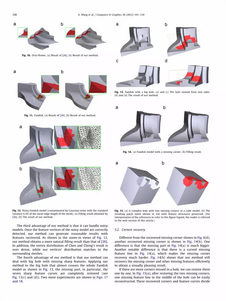
Fig. 10. Octa-flower. (a) Result of [26]. (b) Result of our method.
Fig. 11. Fandisk. (a) Result of [26]. (b) Result of our method.
Fig. 12. Noisy Fandisk model (contaminated by Gaussian noise with the standard
variance is 6% of the mean edge length of the mesh). (a) Filling result obtained by
[26]. (b) The result of our method.
Fig. 13. Fandisk with a big hole. (a) and (c) The hole viewed from two sides.
(b) and (d) The result of our method.
Fig. 14. (a) Fandisk model with a missing corner. (b) Filling result.
Fig. 15. (a) A complex hole with two missing corners in a cube model. (b) The
resulting patch mesh shown in red with feature structures preserved. (For
interpretation of the references to color in this figure legend, the reader is referred
to the web version of this article.)
X. Wang et al. / Computers & Graphics 36 (2012) 101–110108
The third advantage of our method is that it can handle noisymodels. Once the feature vertices of the noisy model are correctlydetected, our method can generate reasonable results withfeatures recovered. As shown in the zoom-in views of Fig. 12,our method obtains a more natural filling result than that of [26].In addition, the vertex distribution of Chen and Cheng’s result isover dense, while our vertices’ distribution matches to thesurrounding meshes.
The fourth advantage of our method is that our method candeal with big hole with missing sharp features. Applying ourmethod to the big hole that almost crosses the whole Fandiskmodel as shown in Fig. 13, the missing part, in particular, theseven sharp feature curves are completely restored (seeFig. 13(c) and (d)). Two more experiments are shown in Figs. 17and 18.
5.2. Corners recovery
Different from the recovered missing corner shown in Fig. 6(d),another recovered missing corner is shown in Fig. 14(b). Onedifference is that the missing part in Fig. 14(a) is much bigger.Another notable difference is that there is a curved missingfeature line in Fig. 14(a), which makes the missing cornerrecovery much harder. Fig. 14(b) shows that our method stillrecovers the missing corner and other missing features efficientlyto obtain a visually pleasing result.
If there are more corners missed in a hole, we can restore themone by one. In Fig. 15(a), after restoring the two missing corners,one missing feature line in the middle of the hole can be easilyreconstructed. These recovered corners and feature curves divide

X. Wang et al. / Computers & Graphics 36 (2012) 101–110 109
the original hole into simple sub-holes, which are effectively filledby AFM (see Fig. 15(b)).
5.3. Limitations
Our method mainly focuses on feature-preserving hole-fillingfor piecewise smooth meshes. The complex case considered in [7]or the geometry details considered in [31] are not considered andthey will be our future works. In addition, if there are no sufficientinformation available, it is difficult to restore the missing featuresautomatically (see Fig. 16(a) and (b)).
It should be also noted that we only focus on the holes withoutislands. In practice, this problem could be solved if we considerthe solution proposed in [16,38], where line segments (eitherautomatically or manually) are used to create bridges betweendisconnected boundaries. Following this scheme, if there arefeature vertices detected in island, we can heuristically matchfeature vertices between island and the hole’s boundary toconstruct sharp features. Since dealing the hole with island isnot the main contribution of the current work, it will also beconsidered in our future work.
Fig. 16. Difficult to recover missing corners without enough information.
Fig. 17. Twirl model. (a) Twirl model with a hole. (c) Filling result. (b) and (d) are
the zoom-in views of the result from different view points.
Fig. 18. Twist model. (a) Twist model with a hole. (c) Filling result. (b) and (d) are
the zoom-in views of the result from different view points.
6. Conclusions
In this paper, we propose a feature-preserving hole-fillingmethod to automatically recover the missing sharp features andcorners from piecewise smooth surfaces. Based on a sequence ofprocesses including feature detection, feature sets matching,corner recovery, feature curves reconstruction and sub-holefilling, we can restore the potential sharp features hidden inincomplete meshes, not only the missing feature curves, but alsothe missing corners, in an automatic way. Experimental resultsdemonstrated that our results are much closer to reality andoutperform that of obtained by previous methods.
Acknowledgements
The authors are grateful to the anonymous reviewers for theirextensive help in improving this work. We also express our thanksto Prof. Kuo-Yong Cheng and his assistant Sean, Prof. Kobbelt andMarcel Campen for providing the comparison data. We thank Prof.Ligang Liu and Prof. Zhong Li for their helpful discussions. Inaddition, we would like to thank Prof. Tao Ju and Prof. Marco Attenefor their softwares Polymender and Meshfix, respectively. This workis partially funded by the National Natural Science Foundation ofChina (No. U0935004, 60873181, 61173102, 61033004, 60825203,U0935004), the National Basic Research Program of China (973Program) (No. 2011CB302703), ARO (P-54412-CI-ISP) and DEPSCoR(W911NF-07-1-0422, W911NF-08-1-0506).
References
[1] Gao S-M, Zhao W, Lin H-W, Yang F-Q, Chen X. Feature suppression based CADmesh model simplification. Comput Aided Des 2010;42(12):1178–88.
[2] Lou R-D, Pernot J-P, Mikchevitch A, Veron P. Merging enriched finite elementtriangle meshes for fast prototyping of alternate solutions in the context ofindustrial maintenance. Comput Aided Des 2010;42(8):670–81.
[3] Li B-J, Zhang X-K, Zhou P, Hu P. Mesh parameterization based on one-stepinverse forming. Comput Aided Des 2010;42(7):633–40.
[4] Wang X-C, Cao J-J, Liu X-P, Li B-J. Advancing front method in triangularmeshes hole-filling application. J Comput Aided Des Comput Graph2011;23(6):1048–54.

X. Wang et al. / Computers & Graphics 36 (2012) 101–110110
[5] Ju T. Fixing geometric errors on polygonal models: a survey. J Comput SciTechnol 2009;24(1):19–29.
[6] Curless B, Levoy M. A volumetric method for building complex models fromrange images. In: Proceedings of the 23rd annual conference on computergraphics and interactive techniques; 1996. p. 303–12.
[7] Davis J, Marschner S, Carr M, Levoy M. Filling holes in complex surfaces usingvolumetric diffusion. In: First international symposium on 3D data proces-sing, visualization, and transmission; 2002. p. 428–38.
[8] Nooruddin FS, Turk G. Simplification and repair of polygonal models usingvolumetric techniques. IEEE Trans Vis Comput Graph 2003;9(2):191–205.
[9] Ju T. Robust repair of polygonal models. ACM Trans Graph 2004;23(3):888–95.
[10] Bischoff S, Kobbelt L. Structure preserving CAD model repair. Comput GraphForum 2005;24(3):527–36.
[11] Bischoff S, Pavic D, Kobbelt L. Automatic restoration of polygon models. ACMTrans Graph 2005;24(4):1332–52.
[12] Podolak J, Rusinkiewicz S. Atomic volumes for mesh completion. In: SGP ’05:proceedings of the third eurographics symposium on geometry processing;2005. p. 31–41.
[13] Hetroy F, Rey S, Andujar C, Brunet P, Vinacua ı. Mesh repair with user-friendly topology control. Comput Aided Des 2011;43(1):101–13.
[14] Ju T, Losasso F, Schaefer S, Warren J. Dual contouring of hermite data. In:SIGGRAPH ’02: proceedings of the 29th annual conference on computergraphics and interactive techniques; 2002. p. 339–46.
[15] Barequet G, Sharir M. Filling gaps in the boundary of a polyhedron. ComputAided Geom Des 1995;12(2):207–29.
[16] Liepa P. Filling holes in meshes. In: SGP ’03: proceedings of the 2003eurographics/ACM SIGGRAPH symposium on geometry processing; 2003.p. 200–5.
[17] Attene M. A lightweight approach to repairing digitized polygon meshes. VisComput 2010;26(11):1393–406.
[18] Zhao W, Gao S-M, Lin H-W. A robust hole-filling algorithm for triangularmesh. Vis Comput 2007;23(12):987–97.
[19] Pernot J-P, Moraru G, Veron P. Filling holes in meshes using a mechanicalmodel to simulate the curvature variation minimization. Comput Graph2006;30(6):892–902.
[20] Panchetti M, Pernot J-P, Veron P. Towards recovery of complex shapes inmeshes using digital images for reverse engineering applications. ComputAided Des 2010;42(8):693–707.
[21] Jun Y. A piecewise hole filling algorithm in reverse engineering. ComputAided Des 2005;37(2):263–70.
[22] Levy B. Dual domain extrapolation. ACM Trans Graph 2003;22(3):364–9.[23] Brunton A, Wuhrer S, Shu C, Bose P, Demaine ED. Filling holes in triangular
meshes by curve unfolding. In: IEEE international conference on shapemodeling and applications (SMI); 2009. p. 66–72.
[24] Carr JC, Beatson RK, Cherrie JB, Mitchell TJ, Fright WR, McCallum BC.Reconstruction and representation of 3D objects with radial basis functions.
In: SIGGRAPH ’01: proceedings of the 28th annual conference on computergraphics and interactive techniques; 2001. p. 67–76.
[25] Chen C-Y, Cheng K-Y, Liao HYM. A sharpness dependent approach to 3d
polygon mesh hole filling. In: Proceedings of the eurographics 05’, vol. 29;2005. p. 13–6.
[26] Chen C-Y, Cheng K-Y. A sharpness-dependent filter for recovering sharpfeatures in repaired 3D mesh models. IEEE Trans Vis Comput Graph
2008;14(1):200–12.[27] Wang J-N, Oliveira MM. Filling holes on locally smooth surfaces recon-
structed from point clouds. Image Vis Comput 2007;25(1):103–13.[28] Podolak J, Rusinkiewicz S. Example-based 3D scan completion. In: SGP ’05:
proceedings of the third eurographics symposium on geometry processing;
2005. p. 23–32.[29] Bendels GH, Schnabel R, Klein R. Detail-preserving surface in painting. In: The
6th international symposium on virtual reality. Archaeology and CulturalHeritage (VAST); 2005. p. 41–8.
[30] Breckon TP, Fisher RB. Three-dimensional surface relief completion vianonparametric techniques. IEEE Trans Pattern Anal Mach Intell 2008;30(12):2249–55.
[31] Sharf A, Alexa M, Cohen-Or D. Context-based surface completion. ACM TransGraph 2004;23:878–87.
[32] Park S, Guo X-H, Shin H, Qin H. Surface completion for shape and appearance.Vis Comput 2006;22:168–80.
[33] Kraevoy V, Sheffer A. Template-based mesh completion. In: SGP ’05:proceedings of the third eurographics symposium on geometry processing;
2005. p. 13–22.[34] Nguyen MX, Yuan X-R, Chen B-Q. Geometry completion and detail generation
by texture synthesis. Vis Comput 2005;21(9–10):669–78.[35] Xiao C-X, Zheng W-T, Miao Y-W, Zhao Y, Peng Q-S. A unified method for
appearance and geometry completion of point set surfaces. Vis Comput2007;23:433–43.
[36] Li X, Yin Z, Wei L, Wan S-H, Yu W, Li M-Q. Symmetry and template guidedcompletion of damaged skulls. Comput Graph 2011;35(4):885–93.
[37] Chen C-Y, Cheng K-Y. A sharpness dependent filter for mesh smoothing.Comput Aided Geom Des 2005;22(5):376–91.
[38] Li Z, Meek DS, Walton DJ. Polynomial blending in a mesh hole-filling
application. Comput Aided Des 2010;42(4):340–9.[39] Kim HS, Choi HK, Lee KH. Feature detection of triangular meshes based on
tensor voting theory. Comput Aided Des 2009;41(1):47–58.[40] Nealen A, Igarashi T, Sorkine O, Alexa M. Laplacian mesh optimization. In:
GRAPHITE ’06: proceedings of the 4th international conference on computergraphics and interactive techniques in Australasia and Southeast Asia; 2006.p. 381–9.
[41] Li G, Ye X-Z, Zhang S-Y. An algorithm for filling complex holes in reverseengineering. Eng Comput 2008;24(2):119–25.