Embed Size (px)
Citation preview
Automatic Valve & Accessories
www.automa.co.kr
VER0214.08
We, AUTOMA Co.,Ltd (AUTOMA) was established in 1992 as a specialized manufacturer to produce all kinds of control & shut-off valves using control process system such as Gas, Oil, Refinery, Chemical, Steel & Power Plants.
AUTOMA’s Quality Management Goal is that, Firstly advanced control & shut- off valve engineering technologies have been accumulated to improve the high quality assurance system and reduce production cost for competitive price, Secondly the best products have been delivered on time to our customers.
We promise to meet the needs and expectations of our valuable customers through the control & shut-off valves technology services products of the high quality.
Automatic Valve & Accessories
CONT
ENTS
3
2AUTOMATIC VALVE1622262831323435363738
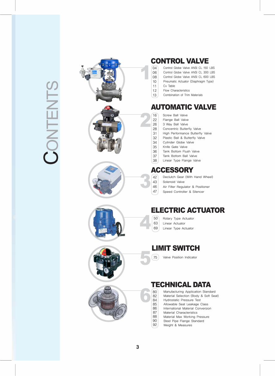
Screw Ball Valve
Flange Ball Valve
3 Way Ball Valve
Concentric Butterfly Valve
High Performance Butterfly Valve
Plastic Ball & Butterfly Valve
Cylinder Globe Valve
Knife Gate Valve
Tank Bottom Flush Valve
Tank Bottom Ball Valve
Linear Type Flange Valve
3ACCESSORY42
43
46
47
Declutch Gear (With Hand Wheel)
Solenoid Valve
Air Filter Regulator & Positioner
Speed Controller & Silencer
4ELECTRIC ACTUATOR50
63
69
Rotary Type Actuator
Linear Actuator
Linear Type Actuator
1 04060810111213
CONTROL VALVEControl Globe Valve ANSI CL 150 LBS
Control Globe Valve ANSI CL 300 LBS
Control Globe Valve ANSI CL 600 LBS
Pneumatic Actuator (Diaphragm Type)
Cv Table
Flow Characteristics
Combination of Trim Materials
5LIMIT SWITCH
Valve Position Indicator75
6TECHNICAL DATA808284858687889092
Manufacturing Application Standard
Material Selection (Body & Soft Seat)
Hydrostatic Pressure Test
Allowable Seat Leakage Class
International Material Conversion
Material Characteristics
Material Max Working Pressure
Steel Pipe Flange Standard
Weight & Measures
Automatic Valve & Accessories

4
Control Valve
Control ValveControl Globe Valve ANSI CL 150 LBS Control Globe Valve ANSI CL 300 LBS Control Globe Valve ANSI CL 600 LBS Pneumatic Actuator (Diaphragm Type)Cv TableFlow CharacteristicsCombination of Trim Materials
5

Control Globe Valve
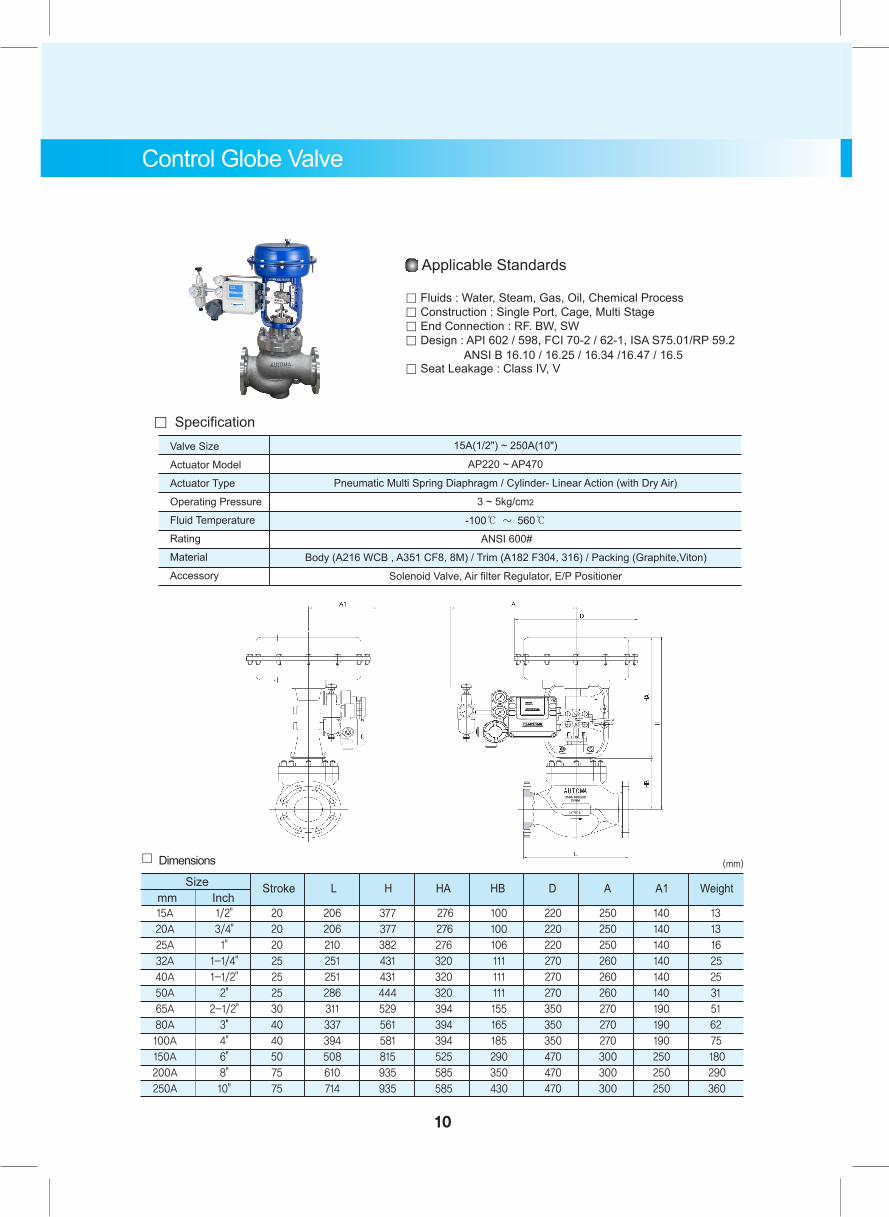
Pneumatic Multi Spring Diaphragm / Cylinder- Linear Action (with Dry Air)
3 ~ 5kg/cm2
-100℃ ~ 560℃
ANSI 150#
Solenoid Valve, Air filter Regulator, E/P Positioner
Applicable Standards
。 Fluids : Water, Steam, Gas, Oil, Chemical Process。 Construction : Single Port, Cage, Multi Stage 。 End Connection : RF. BW, SW。 Design : API 602 / 598, FCI 70-2 / 62-1, ISA S75.01 / RP 59.2 ANSI B 16.10 / 16.25 / 16.34 / 16.47 / 16.5。 Seat Leakage : Class IV, V, VI
Valve Size
Actuator Model
Actuator Type
Operating Pressure
Fluid Temperature
Rating
Material
Accessory
AP220 ~ AP470
。 Specification
Body (A216 WCB , A351 CF8, 8M) / Trim (A182 F304, 316) / Packing (Graphite,Viton)
15A(1/2") ~ 250A(10")
15A 1/2" 20 184 377 276 100 220 250 140 13 20A 3/4" 20 184 377 276 100 220 250 140 13 25A 1" 20 184 382 276 106 220 250 140 16 32A 1-1/4" 25 222 431 320 111 270 260 140 22 40A 1-1/2" 25 222 431 320 111 270 260 140 22 50A 2" 25 254 444 320 111 270 260 140 28 65A 2-1/2" 30 276 529 394 155 350 270 190 48 80A 3" 40 298 561 394 165 350 270 190 61 100A 4" 40 352 581 394 185 350 270 190 176 125A 5" 50 403 805 525 280 350 270 190 155 150A 6" 50 451 815 525 290 470 300 250 175 200A 8" 75 543 935 585 350 470 300 250 280 250A 10" 75 673 935 585 430 470 300 250 350
。 DimensionsSize Stroke L H HA HB D A A1 Weight
(mm)
mm Inch
6
7
Control Globe Valve
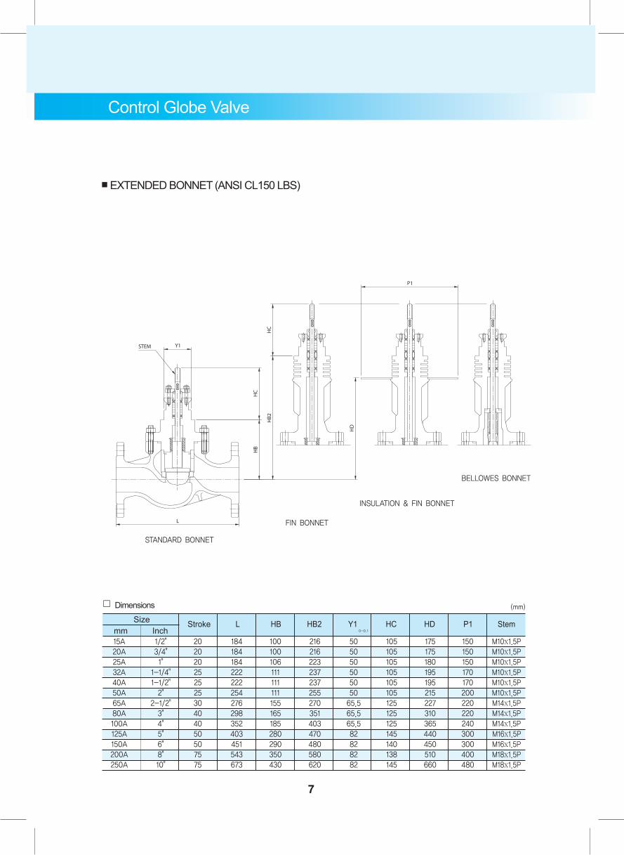
■ EXTENDED BONNET (ANSI CL150 LBS)
INSULATION & FIN BONNET
BELLOWES BONNET
FIN BONNET
STANDARD BONNET
15A 1/2" 20 184 100 216 50 105 175 150 M10x1.5P 20A 3/4" 20 184 100 216 50 105 175 150 M10x1.5P 25A 1" 20 184 106 223 50 105 180 150 M10x1.5P 32A 1-1/4" 25 222 111 237 50 105 195 170 M10x1.5P 40A 1-1/2" 25 222 111 237 50 105 195 170 M10x1.5P 50A 2" 25 254 111 255 50 105 215 200 M10x1.5P 65A 2-1/2" 30 276 155 270 65.5 125 227 220 M14x1.5P 80A 3" 40 298 165 351 65.5 125 310 220 M14x1.5P 100A 4" 40 352 185 403 65.5 125 365 240 M14x1.5P 125A 5" 50 403 280 470 82 145 440 300 M16x1.5P 150A 6" 50 451 290 480 82 140 450 300 M16x1.5P 200A 8" 75 543 350 580 82 138 510 400 M18x1.5P 250A 10" 75 673 430 620 82 145 660 480 M18x1.5P
。 DimensionsSize Stroke L HB HB2 Y1 HC HD P1 Stem
(mm)
mm Inch 0-0.1

Pneumatic Multi Spring Diaphragm / Cylinder- Linear Action (with Dry Air)
3 ~ 5kg/cm2
-100℃ ~ 560℃
ANSI 300#
Solenoid Valve, Air filter Regulator, E/P Positioner
Applicable Standards
。 Fluids : Water, Steam, Gas, Oil, Chemical Process。 Construction : Single Port, Cage, Multi Stage 。 End Connection : RF. BW, SW。 Design : API 602 / 598, FCI 70-2 / 62-1, ISA S75.01 / RP 59.2 ANSI B 16.10 / 16.25 / 16.34 / 16.47 / 16.5。 Seat Leakage : Class IV, V, VI
Valve Size
Actuator Model
Actuator Type
Operating Pressure
Fluid Temperature
Rating
Material
Accessory
AP220 ~ AP470
。 Specification
Body (A216 WCB , A351 CF8, 8M) / Trim (A182 F304, 316) / Packing (Graphite,Viton)
15A(1/2") ~ 250A(10")
15A 1/2" 20 194 377 276 100 220 250 140 13
20A 3/4" 20 194 377 276 100 220 250 140 13
25A 1" 20 194 382 276 106 220 250 140 16
32A 1-1/4" 25 235 431 320 111 270 260 140 25
40A 1-1/2" 25 235 431 320 111 270 260 140 25
50A 2" 25 267 444 320 111 270 260 140 31
65A 2-1/2" 30 292 529 394 155 350 270 190 51
80A 3" 40 318 561 394 165 350 270 190 62
100A 4" 40 368 581 394 185 350 270 190 75
150A 6" 50 473 815 525 290 470 300 250 180
200A 8" 75 568 935 585 350 470 300 250 290
250A 10" 75 708 935 585 430 470 300 250 360
。 DimensionsSize Stroke L H HA HB D A A1 Weight
(mm)
Inch
Control Globe Valve
8
mm
Control Globe Valve
9
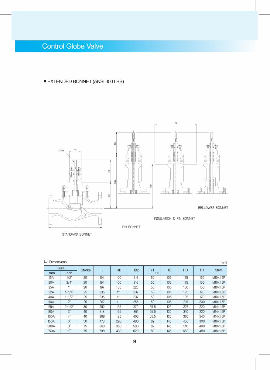
■ EXTENDED BONNET (ANSI 300 LBS)
INSULATION & FIN BONNET
BELLOWES BONNET
FIN BONNET
STANDARD BONNET
15A 1/2" 20 194 100 216 50 105 175 150 M10x1.5P
20A 3/4" 20 194 100 216 50 105 175 150 M10x1.5P
25A 1" 20 197 106 223 50 105 180 150 M10x1.5P
32A 1-1/4" 25 235 111 237 50 105 195 170 M10x1.5P
40A 1-1/2" 25 235 111 237 50 105 195 170 M10x1.5P
50A 2" 25 267 111 255 50 105 215 200 M10x1.5P
65A 2-1/2" 30 292 155 270 65.5 125 227 220 M14x1.5P
80A 3" 40 318 165 351 65.5 125 310 220 M14x1.5P
100A 4" 40 368 185 403 65.5 125 365 240 M14x1.5P
150A 6" 50 473 290 480 82 145 450 300 M16x1.5P
200A 8" 75 568 350 580 82 145 510 400 M18x1.5P
250A 10" 75 708 430 620 82 145 660 480 M18x1.5P
。 DimensionsSize Stroke L HB HB2 Y1 HC
(mm)
mm Inch 0-0.1
HD P1 Stem
Pneumatic Multi Spring Diaphragm / Cylinder- Linear Action (with Dry Air)
3 ~ 5kg/cm2
-100℃ ~ 560℃
ANSI 600#
Solenoid Valve, Air filter Regulator, E/P Positioner
Applicable Standards
。 Fluids : Water, Steam, Gas, Oil, Chemical Process。 Construction : Single Port, Cage, Multi Stage 。 End Connection : RF. BW, SW。 Design : API 602 / 598, FCI 70-2 / 62-1, ISA S75.01/RP 59.2 ANSI B 16.10 / 16.25 / 16.34 /16.47 / 16.5。 Seat Leakage : Class IV, V
Valve Size
Actuator Model
Actuator Type
Operating Pressure
Fluid Temperature
Rating
Material
Accessory
AP220 ~ AP470
。 Specification
Body (A216 WCB , A351 CF8, 8M) / Trim (A182 F304, 316) / Packing (Graphite,Viton)
15A(1/2") ~ 250A(10")
Control Globe Valve
15A 1/2" 20 206 377 276 100 220 250 140 13
20A 3/4" 20 206 377 276 100 220 250 140 13
25A 1" 20 210 382 276 106 220 250 140 16
32A 1-1/4" 25 251 431 320 111 270 260 140 25
40A 1-1/2" 25 251 431 320 111 270 260 140 25
50A 2" 25 286 444 320 111 270 260 140 31
65A 2-1/2" 30 311 529 394 155 350 270 190 51
80A 3" 40 337 561 394 165 350 270 190 62
100A 4" 40 394 581 394 185 350 270 190 75
150A 6" 50 508 815 525 290 470 300 250 180
200A 8" 75 610 935 585 350 470 300 250 290
250A 10" 75 714 935 585 430 470 300 250 360
。 Dimensions
Size Stroke L H HA HB D A A1 Weight
(mm)
mm Inch
10
Control Globe Valve
11
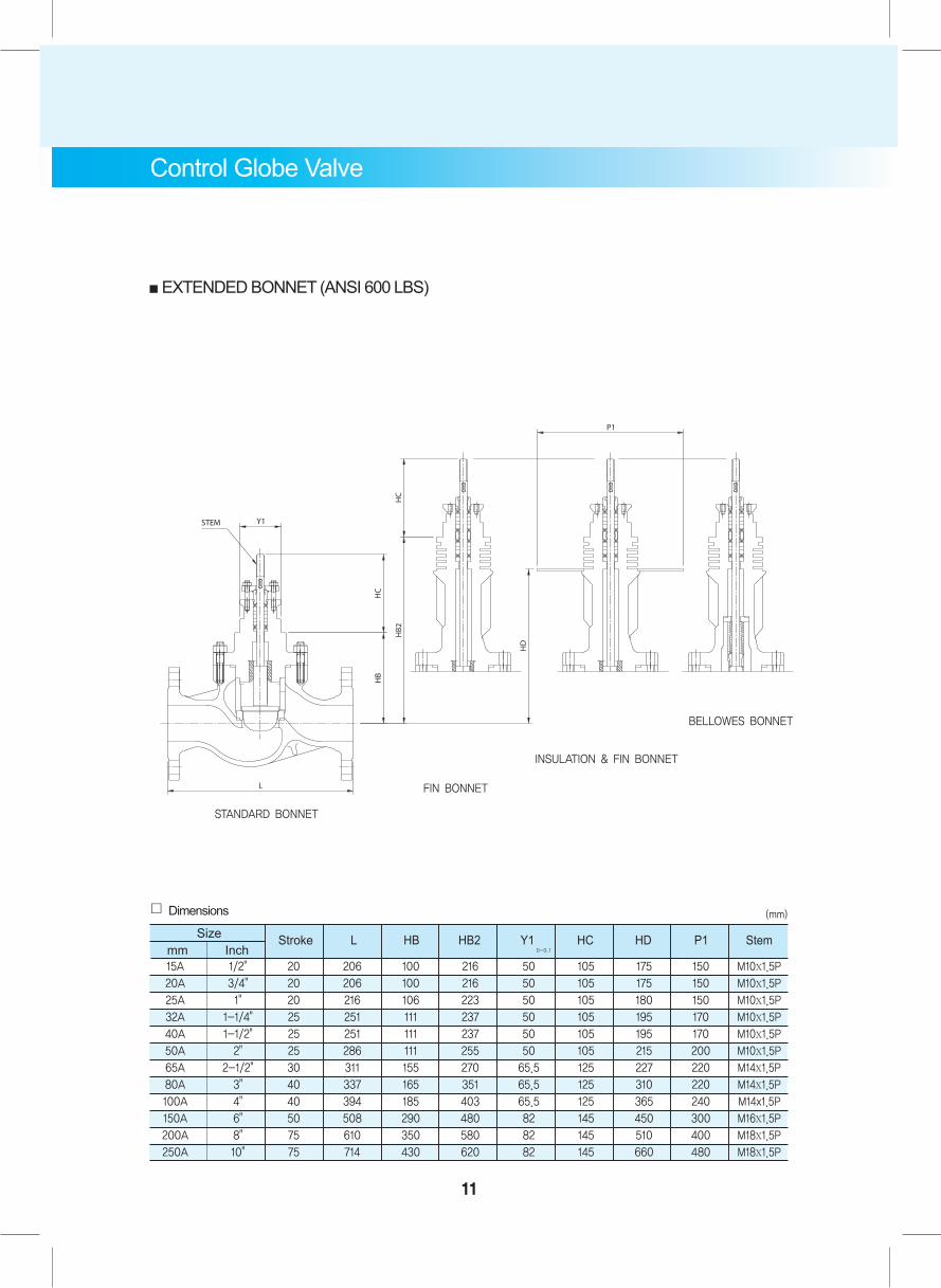
■ EXTENDED BONNET (ANSI 600 LBS)
INSULATION & FIN BONNET
BELLOWES BONNET
FIN BONNET
STANDARD BONNET
15A 1/2" 20 206 100 216 50 105 175 150 M10x1.5P
20A 3/4" 20 206 100 216 50 105 175 150 M10x1.5P
25A 1" 20 216 106 223 50 105 180 150 M10x1.5P
32A 1-1/4" 25 251 111 237 50 105 195 170 M10x1.5P
40A 1-1/2" 25 251 111 237 50 105 195 170 M10x1.5P
50A 2" 25 286 111 255 50 105 215 200 M10x1.5P
65A 2-1/2" 30 311 155 270 65.5 125 227 220 M14x1.5P
80A 3" 40 337 165 351 65.5 125 310 220 M14x1.5P
100A 4" 40 394 185 403 65.5 125 365 240 M14x1.5P
150A 6" 50 508 290 480 82 145 450 300 M16x1.5P
200A 8" 75 610 350 580 82 145 510 400 M18x1.5P
250A 10" 75 714 430 620 82 145 660 480 M18x1.5P
。 Dimensions
Size Stroke L HB HB2 Y1 HC HD P1 Stem
(mm)
mm Inch 0-0.1
220
270
350
470
190
320
550
1100
155
198
268
370
190
320
550
1100
20
25
40(30)
50,75
M8xDP20
M8xDP20
M8xDP20
M8xDP20
M4x0.7P
M4x0.7P
M4x0.7P
M4x0.7P
Ø16xM14x1.5P
Ø16xM14x1.5P
Ø25xM20x1.5P
Ø30xM24x1.5P
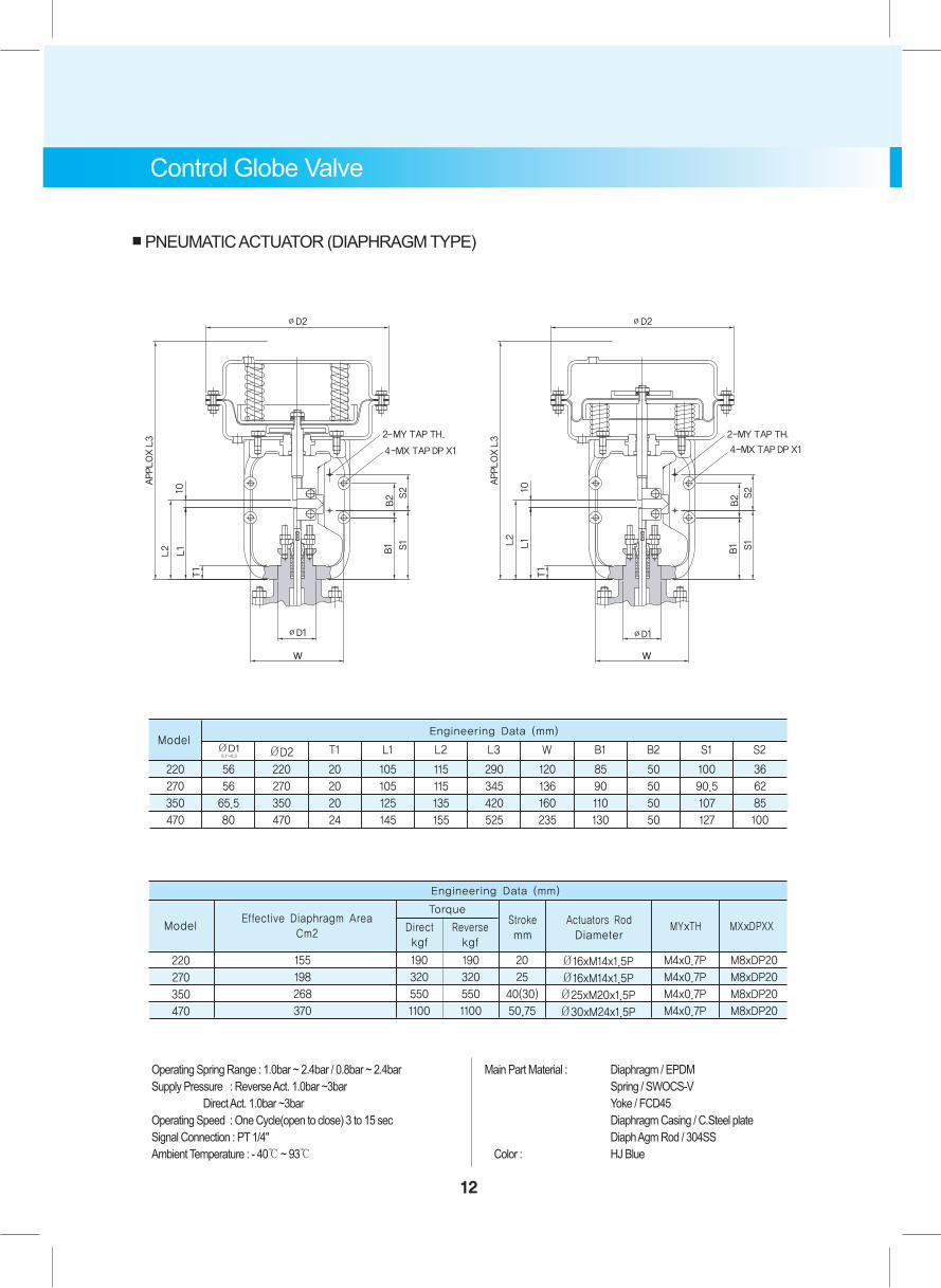
Model
Torque
Engineering Data (mm)
Effective Diaphragm AreaCm2 Direct
kgfReversekgf
Strokemm
Actuators RodDiameter
MYxTH MXxDPXX
Operating Spring Range : 1.0bar ~ 2.4bar / 0.8bar ~ 2.4bar Main Part Material : Diaphragm / EPDMSupply Pressure : Reverse Act. 1.0bar ~3bar Spring / SWOCS-V Direct Act. 1.0bar ~3bar Yoke / FCD45Operating Speed : One Cycle(open to close) 3 to 15 sec Diaphragm Casing / C.Steel plateSignal Connection : PT 1/4" Diaph Agm Rod / 304SSAmbient Temperature : - 40℃ ~ 93℃ Color : HJ Blue
■ PNEUMATIC ACTUATOR (DIAPHRAGM TYPE)
Control Globe Valve
12
220
270
350
470
56
56
65.5
80
220
270
350
470
20
20
20
24
105
105
125
145
115
115
135
155
290
345
420
525
120
136
160
235
85
90
110
130
50
50
50
50
100
90.5
107
127
36
62
85
100
ModelØD2ØD1
0.1~0.3T1 L1 L2 L3 W B1 B2 S1 S2
Engineering Data (mm)
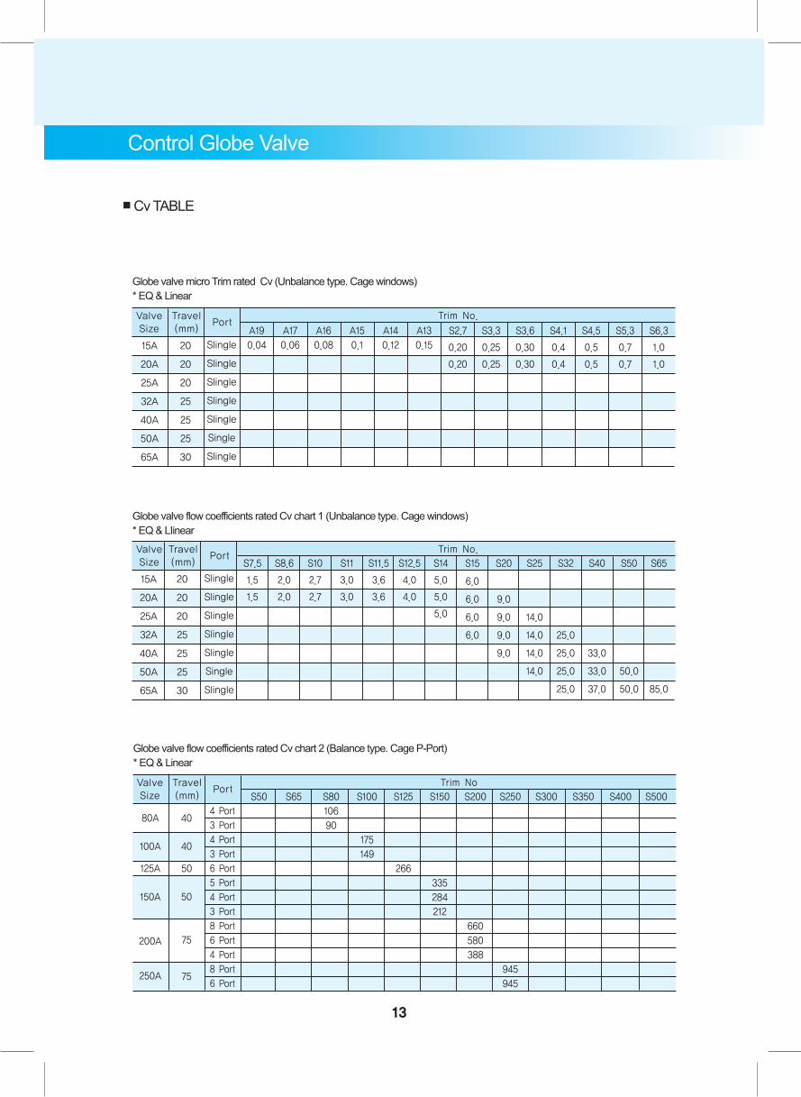
Globe valve micro Trim rated Cv (Unbalance type. Cage windows) * EQ & Linear
15A
20A
25A
32A
40A
50A
65A
20
20
20
25
25
25
30
SIingle
SIingle
SIingle
SIingle
SIingle
Single
SIingle
ValveSize
Travel(mm)
PortTrim No.
S2.7
0.20
0.20
S3.3
0.25
0.25
S3.6
0.30
0.30
S4.1
0.4
0.4
S4.5
0.5
0.5
S5.3
0.7
0.7
S6.3
1.0
1.0
A19
0.04
A17
0.06
A16
0.08
A15
0.1
A14
0.12
A13
0.15
Globe valve flow coefficients rated Cv chart 2 (Balance type. Cage P-Port) * EQ & Linear
80A
100A
150A
200A
125A 50
250A
40
40
50
75
75
4 Port
3 Port
4 Port
3 Port
6 Port
5 Port
4 Port
3 Port
8 Port
6 Port
4 Port
8 Port
6 Port
ValveSize
Travel(mm)
PortTrim No
S50 S65 S80
106
90
S100
175
149
S125
266
S150
335
284
212
S200
660
580
388
S250
945
945
S300 S350 S400 S500
■ Cv TABLE
Control Globe Valve
13
Globe valve flow coefficients rated Cv chart 1 (Unbalance type. Cage windows)* EQ & LIinear
15A
20A
25A
32A
40A
50A
65A
20
20
20
25
25
25
30
SIingle
SIingle
SIingle
SIingle
SIingle
Single
SIingle
ValveSize
Travel(mm)
PortTrim No.
S14
5.0
5.0
5.0
S15
6.0
6.0
6.0
6.0
S20
9.0
9.0
9.0
9.0
S25
14.0
14.0
14.0
14.0
S32
25.0
25.0
25.0
25.0
S40
33.0
33.0
37.0
S50
50.0
50.0
S7.5
1.5
1.5
S8.6
2.0
2.0
S10
2.7
2.7
S11
3.0
3.0
S11.5
3.6
3.6
S12.5
4.0
4.0
S65
85.0
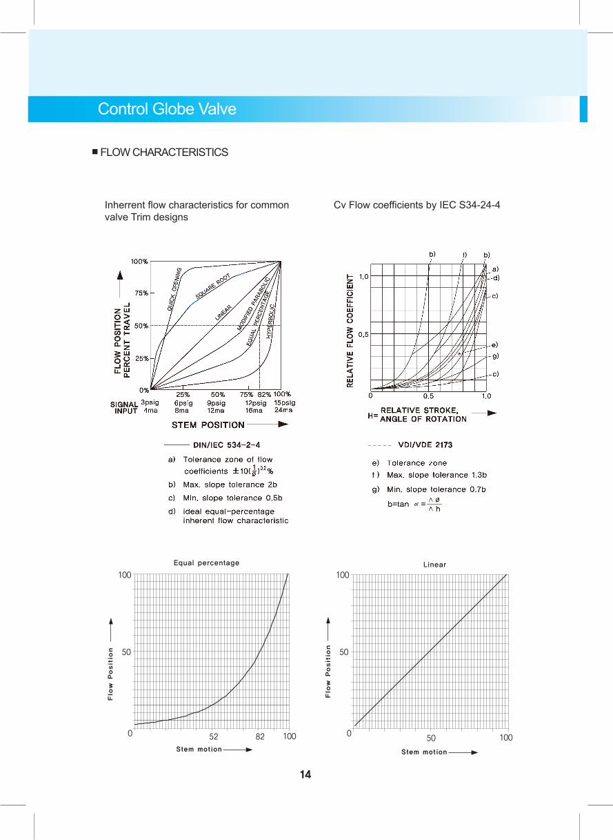
Inherrent flow characteristics for common valve Trim designs
Cv Flow coefficients by IEC S34-24-4
■ FLOW CHARACTERISTICS
Control Globe Valve
14
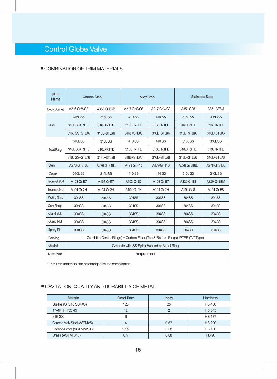
Material Stellite #6 (316 SS+#6) 17-4PH HRC 45 316 SS Chrome Moly Steel (ASTM c5) Carbon Steel (ASTM WCB) Brass (ASTM B16)
Dead Time1201264
2.250.5
Index2021
0.670.380.08
HardnessHB 400HB 375HB 187HB 200HB 150HB 90
■ CAVITATION, QUALITY AND DURABILITY OF METAL
A216 Gr WCB
316L SS
316L SS+RTFE
316L SS+STL#6
316L SS
316L SS+RTFE
316L SS+STL#6
A276 Gr 316L
316L SS
A193 Gr B7
A194 Gr 2H
304SS
304SS
304SS
304SS
304SS
A352 Gr LCB
316L SS
316L+RTFE
316L+STL#6
316L SS
316L+RTFE
316L+STL#6
A276 Gr 316L
316L SS
A193 Gr B7
A194 Gr 2H
304SS
304SS
304SS
304SS
304SS
A217 Gr WC6
410 SS
316L+RTFE
316L+STL#6
410 SS
316L+RTFE
316L+STL#6
A479 Gr 410
410 SS
A193 Gr B7
A194 Gr 2H
304SS
304SS
304SS
304SS
304SS
A217 Gr WC9
410 SS
316L+RTFE
316L+STL#6
410 SS
316L+RTFE
316L+STL#6
A479 Gr 410
410 SS
A193 Gr B7
A194 Gr 2H
304SS
304SS
304SS
304SS
304SS
A351 CF8
316L SS
316L+RTFE
316L+STL#6
316L SS
316L+RTFE
316L+STL#6
A276 Gr 316L
316L SS
A320 Gr B8
A194 Gr 8
304SS
304SS
304SS
304SS
304SS
A351 CF8M
316L SS
316L+RTFE
316L+STL#6
316L SS
316L+RTFE
316L+STL#6
A276 Gr 316L
316L SS
A320 Gr B8M
A194 Gr B8
304SS
304SS
304SS
304SS
304SS
Part Name Carbon Steel Alloy Steel Stainless Steel
Stem
Cage
Bonnet Bolt
Bonnet Nut
Packing Gland
Gland Flange
Gland Bolt
Gland Nut
Spring Pin
Packing
Gasket
Name Plate
Seat Ring
Plug
Body, Bonnet
Graphite (Center Rings) + Carbon Fiber (Top & Bottom Rings), PTFE ("V" Type)
Graphite with SS Spiral Wound or Metal Ring
Requirement
* Trim Part materials can be changed by the combination.
■ COMBINATION OF TRIM MATERIALS
Control Globe Valve
15

16
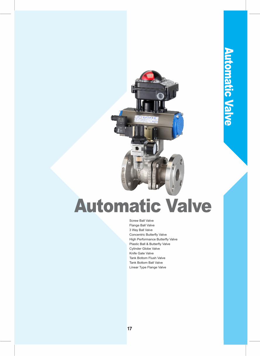
Automatic Valve
Automatic ValveScrew Ball ValveFlange Ball Valve3 Way Ball ValveConcentric Butterfly Valve High Performance Butterfly ValvePlastic Ball & Butterfly ValveCylinder Globe ValveKnife Gate ValveTank Bottom Flush Valve Tank Bottom Ball ValveLinear Type Flange Valve
17
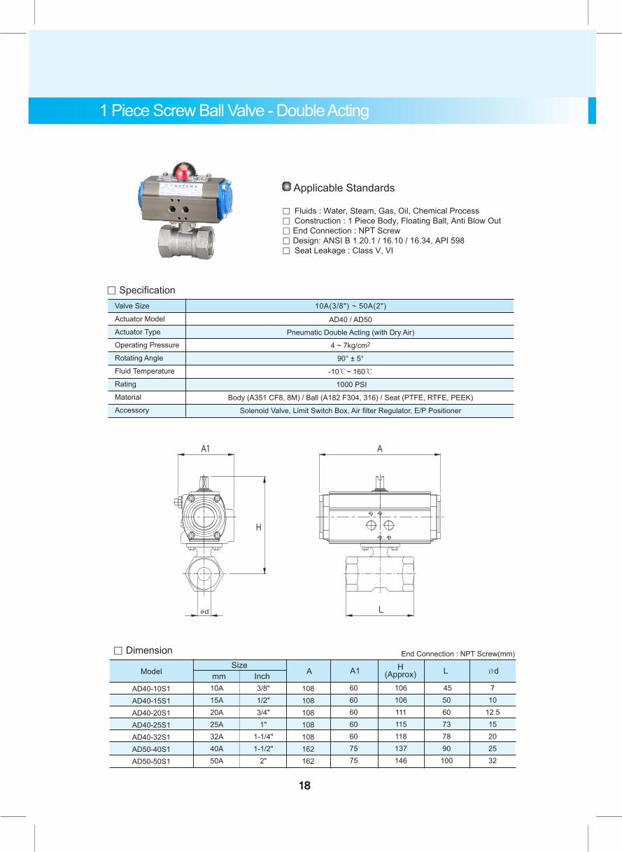
Pneumatic Double Acting (with Dry Air)
4 ~ 7kg/cm2
90° ± 5°
-10℃~ 160℃
1000 PSI
Body (A351 CF8, 8M) / Ball (A182 F304, 316) / Seat (PTFE, RTFE, PEEK)
Solenoid Valve, Limit Switch Box, Air filter Regulator, E/P Positioner
。 Dimension
AD40-10S1AD40-15S1AD40-20S1AD40-25S1AD40-32S1AD50-40S1AD50-50S1
10A15A20A25A32A40A50A
Sizemm Inch
3/8"1/2"3/4"1"
1-1/4"1-1/2"
2"
108108108108108162162
A
60606060607575
106106111115118137146
455060737890
100
710
12.515202532
A1 LH(Approx) Ød
End Connection : NPT Screw(mm)
Model
Applicable Standards
。 Fluids : Water, Steam, Gas, Oil, Chemical Process。 Construction : 1 Piece Body, Floating Ball, Anti Blow Out。 End Connection : NPT Screw 。 Design: ANSI B 1.20.1 / 16.10 / 16.34, API 598。 Seat Leakage : Class V, VI
1 Piece Screw Ball Valve - Double Acting
。 SpecificationValve Size
Actuator Model
Actuator Type
Operating Pressure
Rotating Angle
Fluid Temperature
Rating
Material
Accessory
AD40 / AD50
10A(3/8") ~ 50A(2")
18
19
。 Dimension
AS40-10S1AS40-15S1AS50-20S1AS50-25S1AS50-32S1AS50-40S1AS65-50S1
10A15A20A25A32A40A50A
3/8"1/2"3/4"1"
1-1/4"1-1/2"
2"
108108257257257257314
60607575757589
106106127131135137163
455060737890
100
710
12.515202532
End Connection : NPT Screw (mm)
ModelSize
mm Inch A A1 LH(Approx) Ød
。 SpecificationValve Size
Actuator Model
Actuator Type
Operating Pressure
Rotating Angle
Fluid Temperature
Rating
Material
Accessory
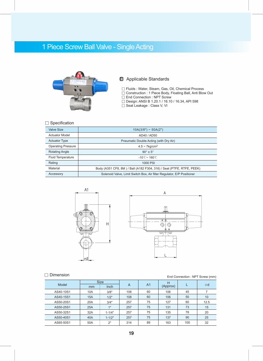
Pneumatic Double Acting (with Dry Air)
4.5 ~ 7kg/cm2
90° ± 5°
-10℃~ 160℃
1000 PSI
Body (A351 CF8, 8M ) / Ball (A182 F304, 316) / Seat (PTFE, RTFE, PEEK)
Solenoid Valve, Limit Switch Box, Air filter Regulator, E/P Positioner
AD40 / AD50
10A(3/8") ~ 50A(2")
Applicable Standards
。 Fluids : Water, Steam, Gas, Oil, Chemical Process。 Construction : 1 Piece Body, Floating Ball, Anti Blow Out。 End Connection : NPT Screw 。 Design: ANSI B 1.20.1 / 16.10 / 16.34, API 598。 Seat Leakage : Class V, VI
1 Piece Screw Ball Valve - Single Acting
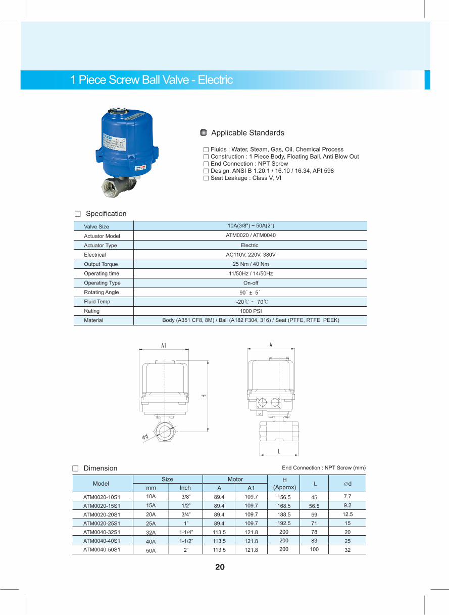
1 Piece Screw Ball Valve - Electric
。 Dimension
ATM0020-10S1ATM0020-15S1ATM0020-20S1ATM0020-25S1ATM0040-32S1ATM0040-40S1ATM0040-50S1
10A15A20A25A32A40A50A
SizeModel
3/8"1/2"3/4"1"
1-1/4"1-1/2"
2"
89.489.489.489.4113.5113.5113.5
A109.7109.7109.7109.7121.8121.8121.8
A1156.5168.5188.5192.5200200200
H(Approx)
4556.559717883
100
L
7.79.2
12.515202532
ØdMotor
。 Specification
Valve Size
Actuator Model
Actuator Type
Electrical
Output Torque
Operating time
Operating Type
Rotating Angle
Fluid Temp
Rating
Material
Electric
AC110V, 220V, 380V
On-off
1000 PSI
10A(3/8") ~ 50A(2")
ATM0020 / ATM0040
25 Nm / 40 Nm
11/50Hz / 14/50Hz
90̊ ± 5̊
-20℃ ~ 70℃
Body (A351 CF8, 8M) / Ball (A182 F304, 316) / Seat (PTFE, RTFE, PEEK)
Applicable Standards
。 Fluids : Water, Steam, Gas, Oil, Chemical Process。 Construction : 1 Piece Body, Floating Ball, Anti Blow Out。 End Connection : NPT Screw 。 Design: ANSI B 1.20.1 / 16.10 / 16.34, API 598。 Seat Leakage : Class V, VI
mm Inch
20
End Connection : NPT Screw (mm)
。 Dimension
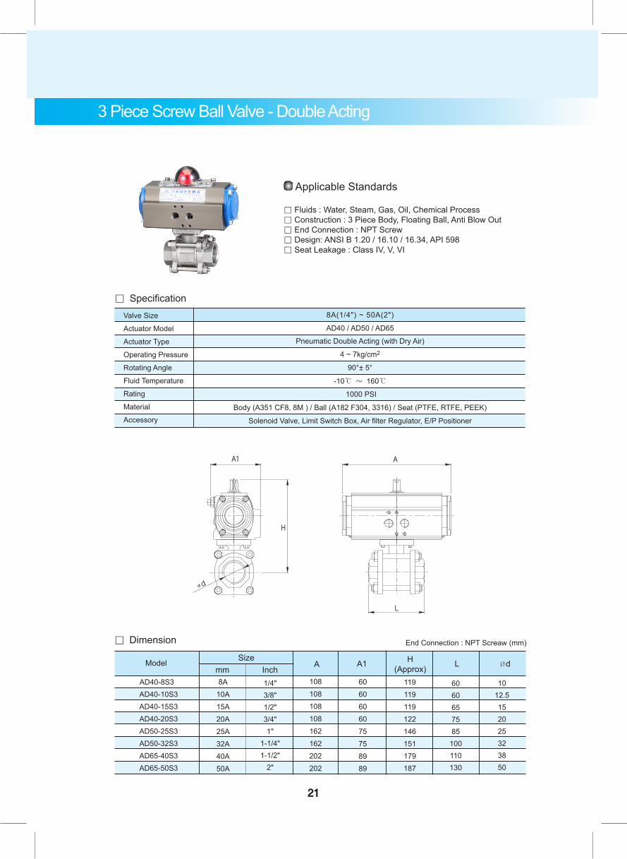
AD40-8S3
AD40-10S3 AD40-15S3 AD40-20S3 AD50-25S3 AD50-32S3 AD65-40S3 AD65-50S3
8A10A15A20A25A32A40A50A
1/4"3/8"1/2"3/4"1"
1-1/4"1-1/2"
2"
108108108108162162202202
6060606075758989
119119119122146151179187
6060657585
100110130
1012.5152025323850
End Connection : NPT Screaw (mm)
Sizemm Inch
A A1 LH(Approx) ØdModel
Valve Size
Actuator Model
Actuator Type
Operating Pressure
Rotating Angle
Fluid Temperature
Rating
Material
Accessory
Pneumatic Double Acting (with Dry Air)
4 ~ 7kg/cm2
90°± 5°
-10℃ ~ 160℃
1000 PSI
Body (A351 CF8, 8M ) / Ball (A182 F304, 3316) / Seat (PTFE, RTFE, PEEK)
Solenoid Valve, Limit Switch Box, Air filter Regulator, E/P Positioner
AD40 / AD50 / AD65
。 Specification8A(1/4") ~ 50A(2")
Applicable Standards
。 Fluids : Water, Steam, Gas, Oil, Chemical Process。 Construction : 3 Piece Body, Floating Ball, Anti Blow Out。 End Connection : NPT Screw 。 Design: ANSI B 1.20 / 16.10 / 16.34, API 598。 Seat Leakage : Class IV, V, VI
3 Piece Screw Ball Valve - Double Acting
21

3 Piece Screw Ball Valve - Single Acting
。 Dimension
AS40-8S3
AS40-10S3 AS50-15S3 AS50-20S3 AS50-25S3 AS65-32S3 AS65-40S3 AS65-50S3
8A10A15A20A25A32A40A50A
1/4"3/8"1/2"3/4"1"
1-1/4"1-1/2"
2"
108108257257257314314314
6060757575898989
119119135138146168179187
6060657585
101110130
1012.5152025323850
End Connection : NPT Screaw (mm)
Sizemm Inch A A1 LH
(Approx) ØdModel
Valve Size
Actuator Model
Actuator Type
Operating Pressure
Rotating Angle
Fluid Temperature
Rating
Material
Accessory
Pneumatic Single Acting / Spring Return (with Dry Air)
4.5 ~ 7kg/cm2
90°± 5°
-10℃ ~ 150℃
1000 PSI
Solenoid Valve, Limit Switch Box, Air filter Regulator, E/P Positioner
AD40 / AD50 / AD65
。 Specification
Body (A351 CF8, 8M ) / Ball (A182 F304, 316) / Seat (PTFE, RTFE, PEEK)
8A(1/4") ~ 50A(2")
Applicable Standards
。 Fluids : Water, Steam, Gas, Oil, Chemical Process。 Construction : 3 Piece Body, Floating Ball, Anti Blow Out 。 End Connection : NPT Screw 。 Design: ANSI B 1.20.1 / 16.10 / 16.34. API 598。 Seat Leakage : Class V, VI
22
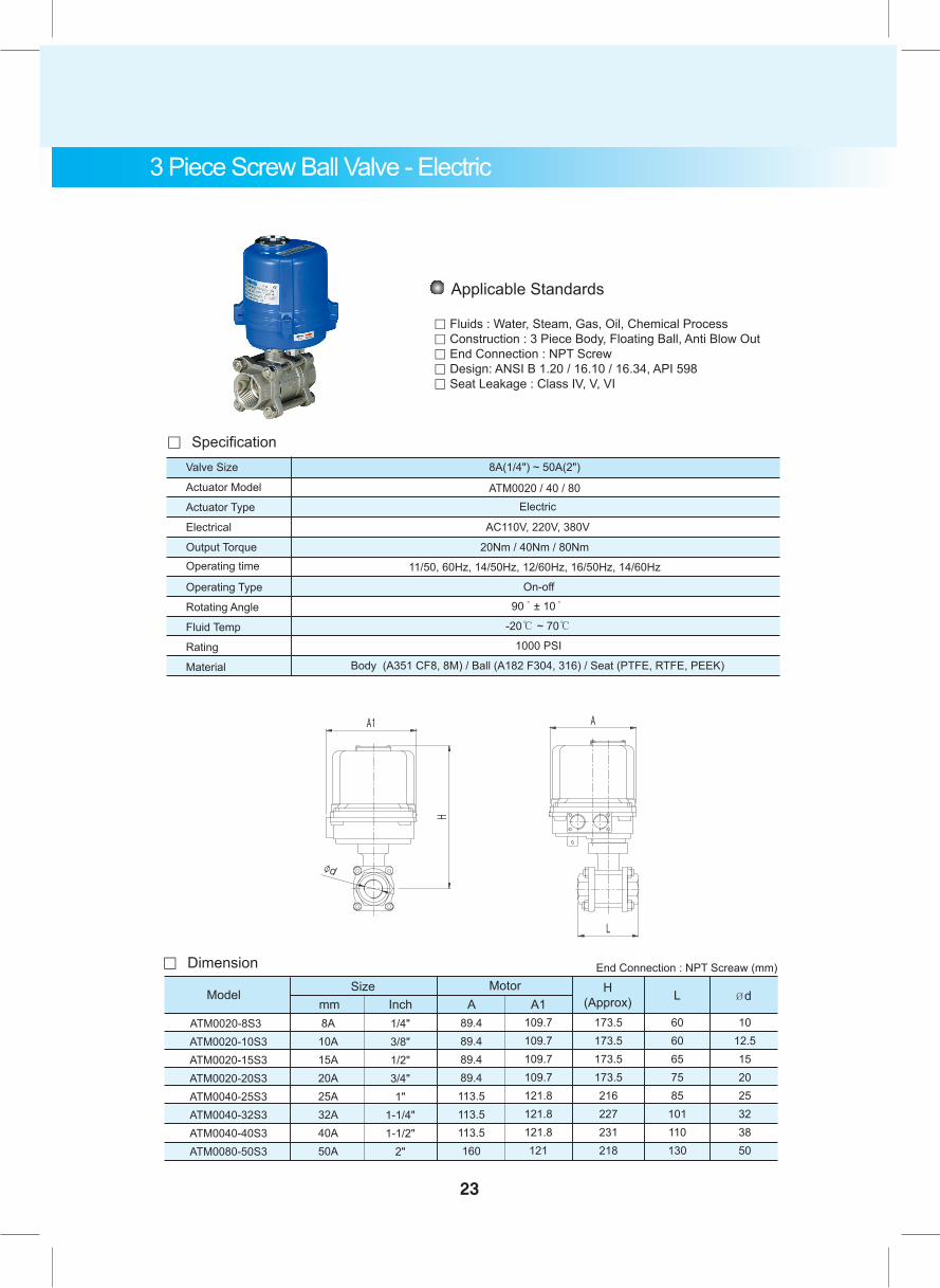
3 Piece Screw Ball Valve - Electric
End Connection : NPT Screaw (mm)。 Dimension
ATM0020-8S3 ATM0020-10S3 ATM0020-15S3 ATM0020-20S3 ATM0040-25S3 ATM0040-32S3 ATM0040-40S3 ATM0080-50S3
8A10A15A20A25A32A40A50A
Size MotorModel
1/4"3/8"1/2"3/4"1"
1-1/4"1-1/2"
2"
89.489.489.489.4113.5113.5113.5160
A109.7109.7109.7109.7121.8121.8121.8121
A1173.5173.5173.5173.5216227231218
H(Approx)
6060657585
101110130
L
1012.5152025323850
Ød
Applicable Standards
。 Fluids : Water, Steam, Gas, Oil, Chemical Process。 Construction : 3 Piece Body, Floating Ball, Anti Blow Out。 End Connection : NPT Screw 。 Design: ANSI B 1.20 / 16.10 / 16.34, API 598。 Seat Leakage : Class IV, V, VI
mm Inch
23
。 SpecificationValve Size
Actuator Model
Actuator Type
Electrical
Output Torque
Operating Type
Rotating Angle
Fluid Temp
Rating
Material
Operating time 11/50, 60Hz, 14/50Hz, 12/60Hz, 16/50Hz, 14/60Hz
ATM0020 / 40 / 80
20Nm / 40Nm / 80Nm
-20℃ ~ 70℃
1000 PSI
Body (A351 CF8, 8M) / Ball (A182 F304, 316) / Seat (PTFE, RTFE, PEEK)
On-off
90̊ ± 10̊
8A(1/4") ~ 50A(2")
AC110V, 220V, 380V
Electric
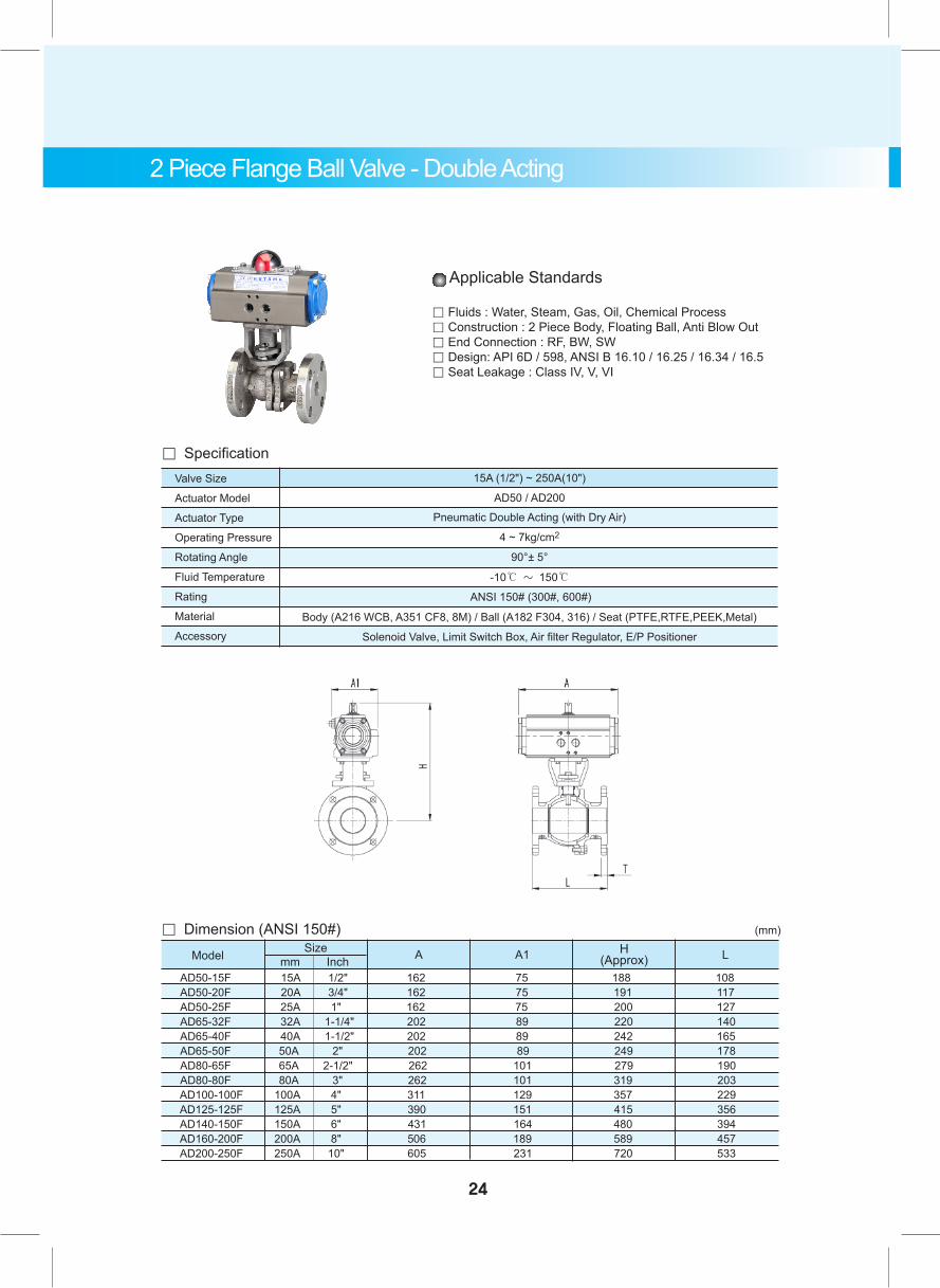
2 Piece Flange Ball Valve - Double Acting
Valve Size
Actuator Model
Actuator Type
Operating Pressure
Rotating Angle
Fluid Temperature
Rating
Material
Accessory
Pneumatic Double Acting (with Dry Air)
4 ~ 7kg/cm2
90°± 5°
-10℃ ~ 150℃
ANSI 150# (300#, 600#)
Solenoid Valve, Limit Switch Box, Air filter Regulator, E/P Positioner
AD50 / AD200
。 Specification
Body (A216 WCB, A351 CF8, 8M) / Ball (A182 F304, 316) / Seat (PTFE,RTFE,PEEK,Metal)
15A (1/2") ~ 250A(10")
Applicable Standards
。 Fluids : Water, Steam, Gas, Oil, Chemical Process。 Construction : 2 Piece Body, Floating Ball, Anti Blow Out。 End Connection : RF, BW, SW 。 Design: API 6D / 598, ANSI B 16.10 / 16.25 / 16.34 / 16.5。 Seat Leakage : Class IV, V, VI
。 Dimension (ANSI 150#) Model mm Inch A A1 H
(Approx)Size L
AD50-15F 15A 1/2" 162 75 188 108 AD50-20F 20A 3/4" 162 75 191 117 AD50-25F 25A 1" 162 75 200 127 AD65-32F 32A 1-1/4" 202 89 220 140 AD65-40F 40A 1-1/2" 202 89 242 165 AD65-50F 50A 2" 202 89 249 178 AD80-65F 65A 2-1/2" 262 101 279 190 AD80-80F 80A 3" 262 101 319 203 AD100-100F 100A 4" 311 129 357 229 AD125-125F 125A 5" 390 151 415 356 AD140-150F 150A 6" 431 164 480 394 AD160-200F 200A 8" 506 189 589 457 AD200-250F 250A 10" 605 231 720 533
(mm)
24
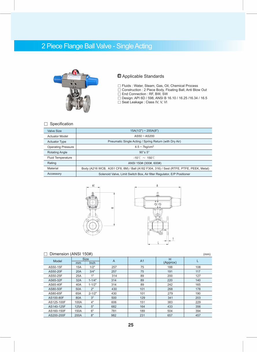
AS50-15F 15A 1/2" 257 75 188 108 AS50-20F 20A 3/4" 257 75 191 117 AS50-25F 25A 1" 314 89 200 127 AS65-32F 32A 1-1/4" 314 89 220 140 AS65-40F 40A 1-1/2" 314 89 242 165 AS80-50F 50A 2" 430 101 268 178 AS80-65F 65A 2-1/2" 430 101 279 190 AS100-80F 80A 3" 500 129 341 203 AS125-100F 100A 4" 606 151 383 229 AS140-125F 125A 5" 682 164 433 356 AS160-150F 150A 6" 781 189 504 394 AS200-200F 200A 8" 982 231 657 457
。 Dimension (ANSI 150#)Model mm Inch A A1 H
(Approx)Size L
25
Valve Size
Actuator Model
Actuator Type
Operating Pressure
Rotating Angle
Fluid Temperature
Rating
Material
Accessory
Pneumatic Single Acting / Spring Return (with Dry Air)
4.5 ~ 7kg/cm2
90°± 5°
-10℃ ~ 150℃
ANSI 150# (300#, 600#)
Solenoid Valve, Limit Switch Box, Air filter Regulator, E/P Positioner
AS50 ~ AS200
。 Specification
Body (A216 WCB, A351 CF8, 8M) / Ball (A182 F304, 316) / Sest (RTFE, PTFE, PEEK, Metal)
15A(1/2") ~ 200A(8")
Applicable Standards
。 Fluids : Water, Steam, Gas, Oil, Chemical Process。 Construction : 2 Piece Body, Floating Ball, Anti Blow Out。 End Connection : RF, BW, SW 。 Design: API 6D / 598, ANSI B 16.10 / 16.25 /16.34 / 16.5。 Seat Leakage : Class IV, V, VI
(mm)
2 Piece Flange Ball Valve - Single Acting
Valve Size
Actuator Model
Actuator Type
Operating Pressure
Rotating Angle
Fluid Temperature
Rating
Material
Accessory
Pneumatic Duble Acting (with Dry Air)
4 ~ 7kg/cm2
90°± 5°
-10℃ ~ 150℃
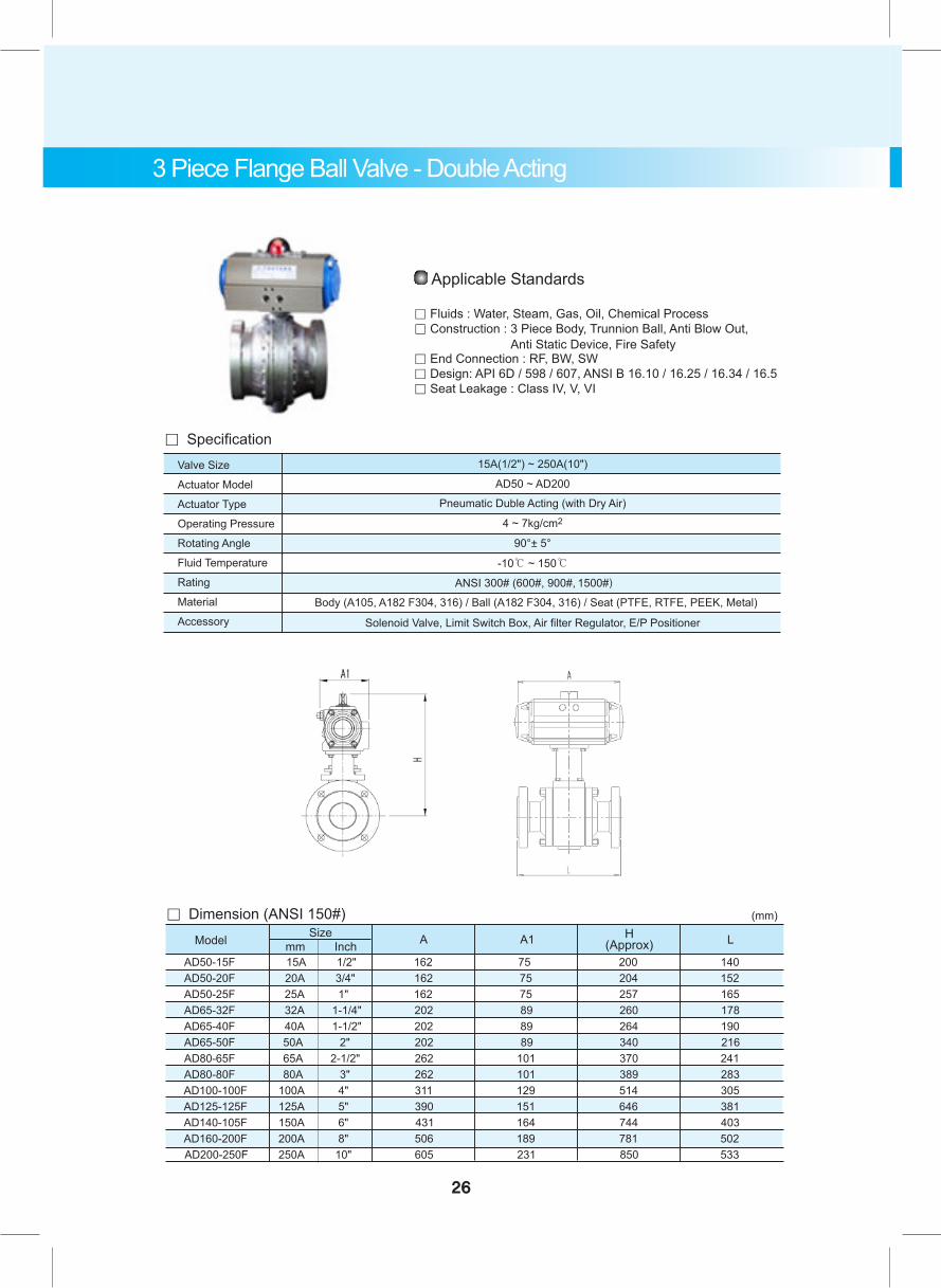
ANSI 300# (600#, 900#, 1500#)
Solenoid Valve, Limit Switch Box, Air filter Regulator, E/P Positioner
AD50 ~ AD200
。 Specification
Body (A105, A182 F304, 316) / Ball (A182 F304, 316) / Seat (PTFE, RTFE, PEEK, Metal)
15A(1/2") ~ 250A(10")
Applicable Standards
。 Fluids : Water, Steam, Gas, Oil, Chemical Process。 Construction : 3 Piece Body, Trunnion Ball, Anti Blow Out, Anti Static Device, Fire Safety。 End Connection : RF, BW, SW。 Design: API 6D / 598 / 607, ANSI B 16.10 / 16.25 / 16.34 / 16.5。 Seat Leakage : Class IV, V, VI
AD50-15F 15A 1/2" 162 75 200 140 AD50-20F 20A 3/4" 162 75 204 152 AD50-25F 25A 1" 162 75 257 165 AD65-32F 32A 1-1/4" 202 89 260 178 AD65-40F 40A 1-1/2" 202 89 264 190 AD65-50F 50A 2" 202 89 340 216 AD80-65F 65A 2-1/2" 262 101 370 241 AD80-80F 80A 3" 262 101 389 283 AD100-100F 100A 4" 311 129 514 305 AD125-125F 125A 5" 390 151 646 381 AD140-105F 150A 6" 431 164 744 403 AD160-200F 200A 8" 506 189 781 502 AD200-250F 250A 10" 605 231 850 533
。 Dimension (ANSI 150#)Model mm Inch A A1 H
(Approx)Size L
(mm)
3 Piece Flange Ball Valve - Double Acting
26
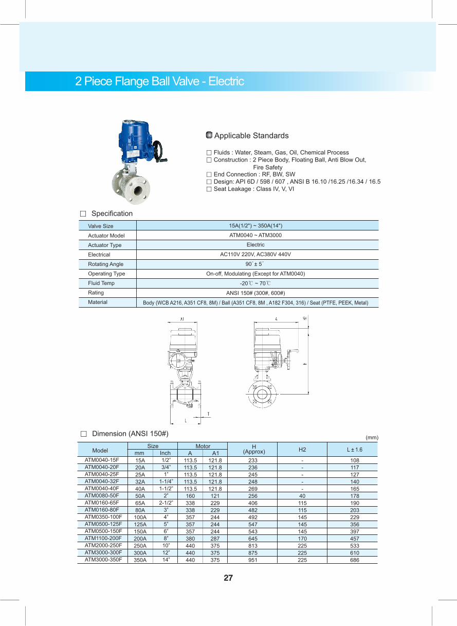
2 Piece Flange Ball Valve - Electric
Valve Size
Actuator Model
Actuator Type
Electrical
Rotating Angle
Operating Type
Fluid Temp
Rating
Material
Electric
AC110V 220V, AC380V 440V
90̊ ± 5̊
On-off, Modulating (Except for ATM0040)
-20℃ ~ 70℃
ANSI 150# (300#, 600#)
Body (WCB A216, A351 CF8, 8M) / Ball (A351 CF8, 8M , A182 F304, 316) / Seat (PTFE, PEEK, Metal)
15A(1/2") ~ 350A(14")
ATM0040 ~ ATM3000
。 Specification
。 Dimension (ANSI 150#)
Model
(mm)Size
ATM0040-15FATM0040-20FATM0040-25FATM0040-32FATM0040-40FATM0080-50FATM0160-65FATM0160-80FATM0350-100FATM0500-125FATM0500-150FATM1100-200FATM2000-250FATM3000-300FATM3000-350F
15A20A25A32A40A50A65A80A
100A125A150A200A250A300A350A
113.5113.5113.5113.5113.5160338338357357357380440440440
121.8121.8121.8121.8121.8121229229244244244287375375375
233236245248269256406482492547543645813875951
-----
40115115145145145170225225225
108117127140165178190203229356397457533610686
1/2"3/4"1"
1-1/4"1-1/2"
2"2-1/2"
3"4"5"6"8"
10"12"14"
A A1Motor H
(Approx) H2 L ± 1.6
Applicable Standards
。 Fluids : Water, Steam, Gas, Oil, Chemical Process。 Construction : 2 Piece Body, Floating Ball, Anti Blow Out, Fire Safety。 End Connection : RF, BW, SW 。 Design: API 6D / 598 / 607 , ANSI B 16.10 /16.25 /16.34 / 16.5。 Seat Leakage : Class IV, V, VI
mm Inch
27

28
3 Way Screw Ball Valve- Double Acting
。 Dimension
AD40-8S3WAD40-10S3WAD40-15S3WAD50-20S3WAD50-25S3WAD65-32S3WAD65-40S3WAD65-50S3W
8A10A15A20A25A32A40A50A
SizeA A1 H
(Approx) L L/2Modelmm Inch
1/4"3/8"1/2"3/4"1"
1-1/4"1-1/2"
2"
108108108162162202202202
6060607575898989
130130130149157180186197
73737385
100113127150
3636364250566375
1111121520253238
1/4"3/8"1/2"3/4"1"
1-1/4"1-1/2"
2"
End Connection : NPT Screaw (mm)
Ød Ød1
Valve Size
Actuator Model
Actuator Type
Operating Pressure
Rotating Angle
Fluid Temperature
Rating
Material
Accessory
Pneumatic Double Acting (with Dry Air)
4 ~ 7kg/cm2
90°± 5°
-10℃ ~ 90℃
1000 PSI
Solenoid Valve, Limit Switch Box, Air filter Regulator, E/P Positioner
AD40 / AD50 / AD65
。 Specification
Body (A351 CF8M ) / Ball (A182 F304, 316) / Seat (PTTE)
8A(1/4") ~ 50A(2")
Applicable Standards
。 Fluids : Water, Steam, Gas, Oil, Chemical Process。 Construction : 1 Piece 3 Way Body, Floating Ball, Anti Blow Out。 End Connection : NPT Screw 。 Design: ANSI B 1.20.1 / 16.34 / 16.5, API 598。 Seat Leakage : Class V, VI
29
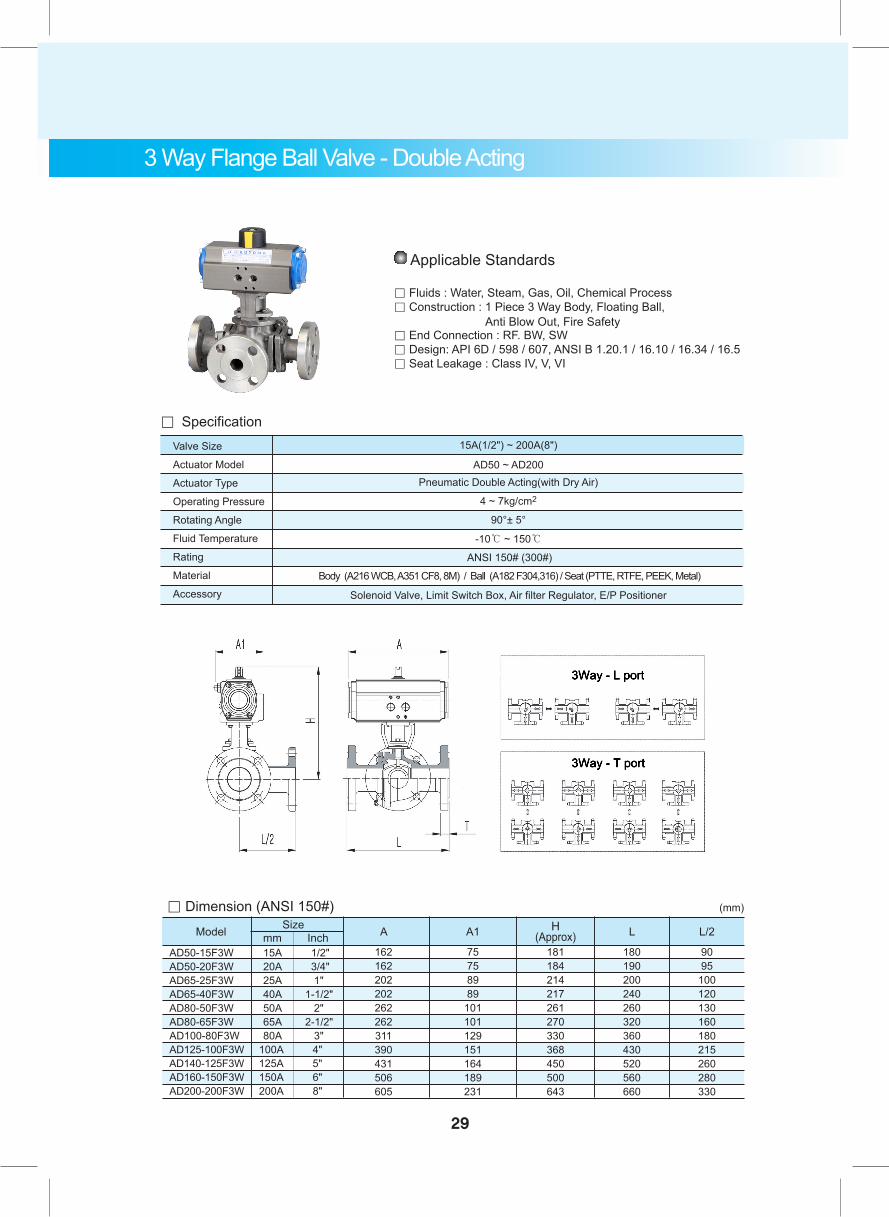
3 Way Flange Ball Valve - Double Acting
。 Dimension (ANSI 150#)
Model mm Inch A
162162202202262262311390431506605
A1
75758989
101101129151164189231
H(Approx)
181184214217261270330368450500643
L
180190200240260320360430520560660
L/2
9095
100120130160180215260280330
(mm)Size
AD50-15F3W 15A 1/2" AD50-20F3W 20A 3/4" AD65-25F3W 25A 1" AD65-40F3W 40A 1-1/2" AD80-50F3W 50A 2" AD80-65F3W 65A 2-1/2" AD100-80F3W 80A 3" AD125-100F3W 100A 4" AD140-125F3W 125A 5" AD160-150F3W 150A 6" AD200-200F3W 200A 8"
Valve Size
Actuator Model
Actuator Type
Operating Pressure
Rotating Angle
Fluid Temperature
Rating
Material
Accessory
Pneumatic Double Acting(with Dry Air)
4 ~ 7kg/cm2
90°± 5°
-10℃ ~ 150℃
ANSI 150# (300#)
Solenoid Valve, Limit Switch Box, Air filter Regulator, E/P Positioner
AD50 ~ AD200
。 Specification
Body (A216 WCB, A351 CF8, 8M) / Ball (A182 F304,316) / Seat (PTTE, RTFE, PEEK, Metal)
15A(1/2") ~ 200A(8")
Applicable Standards
。 Fluids : Water, Steam, Gas, Oil, Chemical Process。 Construction : 1 Piece 3 Way Body, Floating Ball, Anti Blow Out, Fire Safety。 End Connection : RF. BW, SW。 Design: API 6D / 598 / 607, ANSI B 1.20.1 / 16.10 / 16.34 / 16.5。 Seat Leakage : Class IV, V, VI
Valve Size
Actuator Model
Actuator Type
Operating Pressure
Rotating Angle
Fluid Temperature
Rating
Material
Accessory
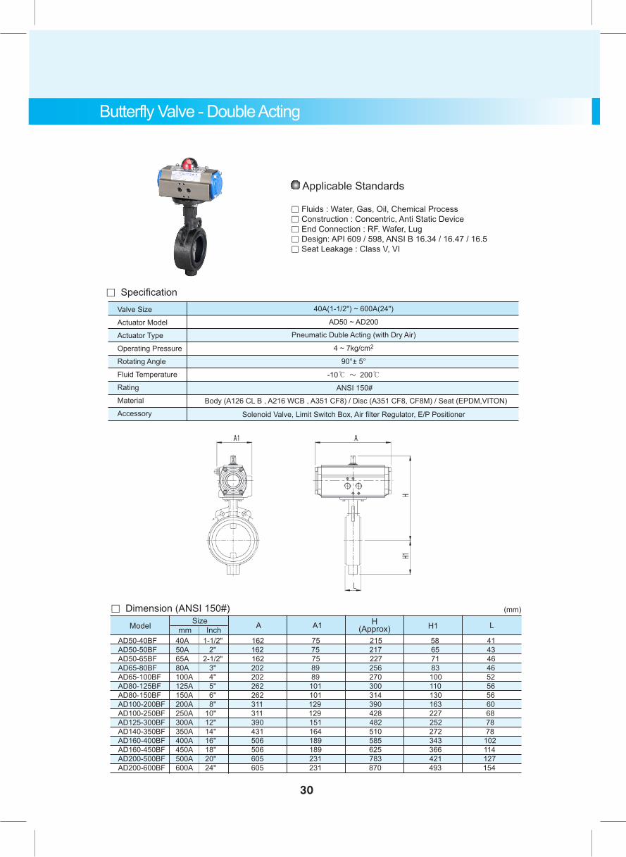
Pneumatic Duble Acting (with Dry Air)
4 ~ 7kg/cm2
90°± 5°
-10℃ ~ 200℃
ANSI 150#
Solenoid Valve, Limit Switch Box, Air filter Regulator, E/P Positioner
AD50 ~ AD200
。 Specification
Body (A126 CL B , A216 WCB , A351 CF8) / Disc (A351 CF8, CF8M) / Seat (EPDM,VITON)
40A(1-1/2") ~ 600A(24")
Applicable Standards
。 Fluids : Water, Gas, Oil, Chemical Process。 Construction : Concentric, Anti Static Device。 End Connection : RF. Wafer, Lug。 Design: API 609 / 598, ANSI B 16.34 / 16.47 / 16.5。 Seat Leakage : Class V, VI
AD50-40BF 40A 1-1/2" 162 75 215 58 41 AD50-50BF 50A 2" 162 75 217 65 43 AD50-65BF 65A 2-1/2" 162 75 227 71 46 AD65-80BF 80A 3" 202 89 256 83 46 AD65-100BF 100A 4" 202 89 270 100 52 AD80-125BF 125A 5" 262 101 300 110 56 AD80-150BF 150A 6" 262 101 314 130 56 AD100-200BF 200A 8" 311 129 390 163 60 AD100-250BF 250A 10" 311 129 428 227 68 AD125-300BF 300A 12" 390 151 482 252 78 AD140-350BF 350A 14" 431 164 510 272 78 AD160-400BF 400A 16" 506 189 585 343 102 AD160-450BF 450A 18" 506 189 625 366 114 AD200-500BF 500A 20" 605 231 783 421 127 AD200-600BF 600A 24" 605 231 870 493 154
。 Dimension (ANSI 150#)Model A A1 H
(Approx)mm InchSize LH1
(mm)
Butterfly Valve - Double Acting
30
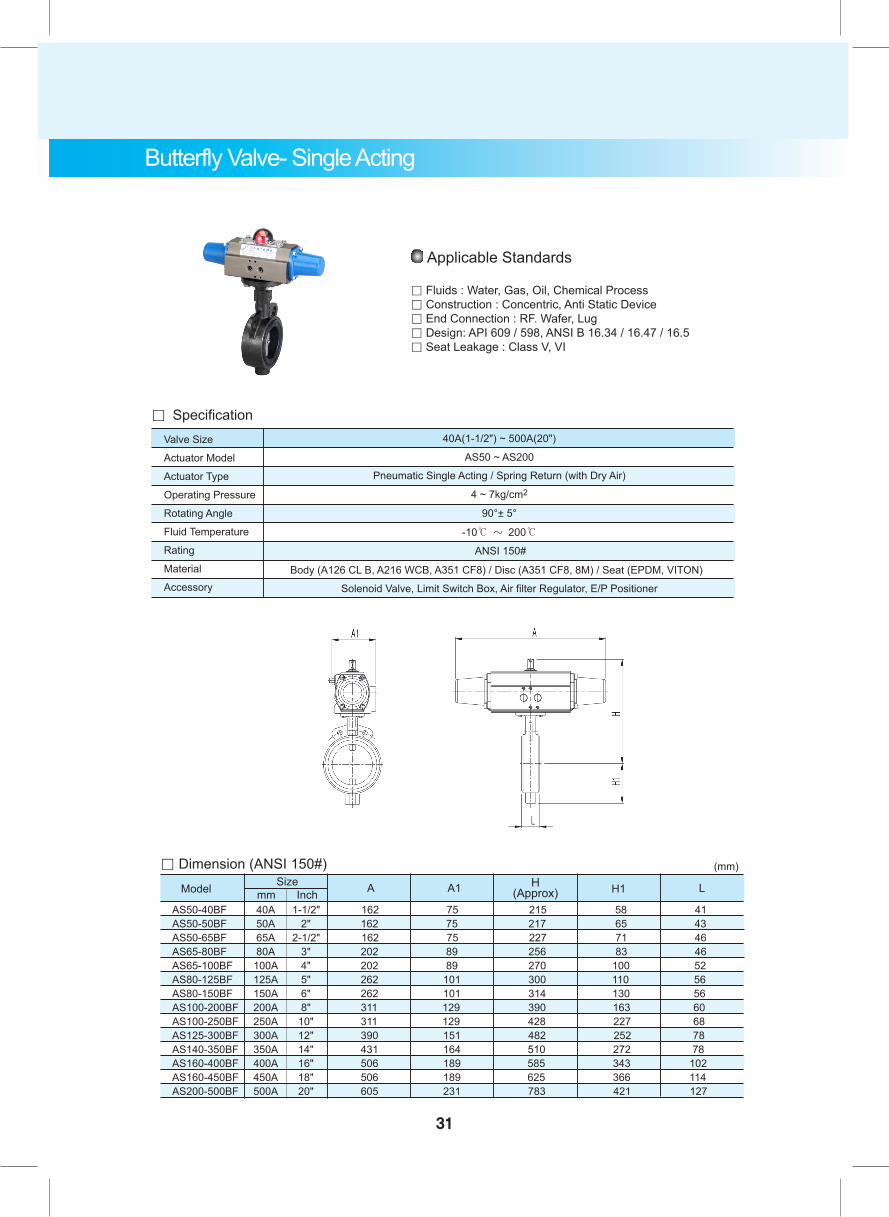
Butterfly Valve- Single Acting
Valve Size
Actuator Model
Actuator Type
Operating Pressure
Rotating Angle
Fluid Temperature
Rating
Material
Accessory
Pneumatic Single Acting / Spring Return (with Dry Air)
4 ~ 7kg/cm2
90°± 5°
-10℃ ~ 200℃
ANSI 150#
Solenoid Valve, Limit Switch Box, Air filter Regulator, E/P Positioner
AS50 ~ AS200
。 Specification
Body (A126 CL B, A216 WCB, A351 CF8) / Disc (A351 CF8, 8M) / Seat (EPDM, VITON)
40A(1-1/2") ~ 500A(20")
Applicable Standards
。 Fluids : Water, Gas, Oil, Chemical Process。 Construction : Concentric, Anti Static Device。 End Connection : RF. Wafer, Lug。 Design: API 609 / 598, ANSI B 16.34 / 16.47 / 16.5。 Seat Leakage : Class V, VI
AS50-40BF 40A 1-1/2" 162 75 215 58 41 AS50-50BF 50A 2" 162 75 217 65 43 AS50-65BF 65A 2-1/2" 162 75 227 71 46 AS65-80BF 80A 3" 202 89 256 83 46 AS65-100BF 100A 4" 202 89 270 100 52 AS80-125BF 125A 5" 262 101 300 110 56 AS80-150BF 150A 6" 262 101 314 130 56 AS100-200BF 200A 8" 311 129 390 163 60 AS100-250BF 250A 10" 311 129 428 227 68 AS125-300BF 300A 12" 390 151 482 252 78 AS140-350BF 350A 14" 431 164 510 272 78 AS160-400BF 400A 16" 506 189 585 343 102 AS160-450BF 450A 18" 506 189 625 366 114 AS200-500BF 500A 20" 605 231 783 421 127
。 Dimension (ANSI 150#)Model A A1 H
(Approx)mm InchSize LH1
(mm)
31
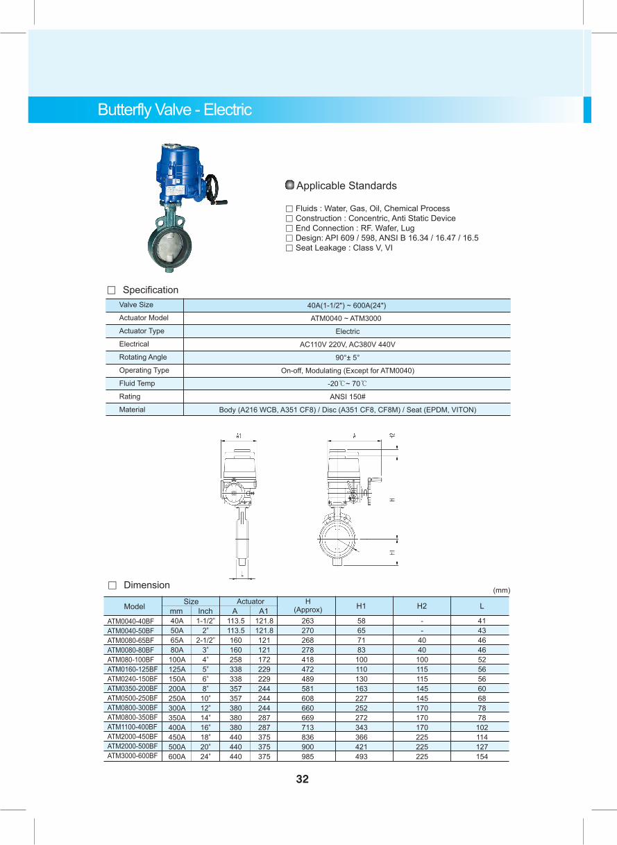
Butterfly Valve - Electric
Valve Size
Actuator Model
Actuator Type
Electrical
Rotating Angle
Operating Type
Fluid Temp
Rating
Material
Electric
AC110V 220V, AC380V 440V
90°± 5°
On-off, Modulating (Except for ATM0040)
-20℃~ 70℃
ANSI 150#
Body (A216 WCB, A351 CF8) / Disc (A351 CF8, CF8M) / Seat (EPDM, VITON)
40A(1-1/2") ~ 600A(24")
ATM0040 ~ ATM3000
。 Specification
。 Dimension
Model SizeA A1 H1 H2 LH
(Approx)
(mm)
ATM0040-40BFATM0040-50BFATM0080-65BFATM0080-80BFATM080-100BFATM0160-125BFATM0240-150BFATM0350-200BFATM0500-250BFATM0800-300BFATM0800-350BFATM1100-400BFATM2000-450BFATM2000-500BFATM3000-600BF
40A50A65A80A
100A125A150A200A250A300A350A400A450A500A600A
113.5113.5160160258338338357357380380380440440440
121.8121.8121121172229229244244244287287375375375
263270268278418472489581608660669713836900985
58657183
100110130163227252272343366421493
--
4040
100115115145145170170170225225225
4143464652565660687878
102114127154
Actuator
1-1/2"2"
2-1/2"3"4"5"6"8"
10"12"14"16"18"20"24"
Applicable Standards
。 Fluids : Water, Gas, Oil, Chemical Process。 Construction : Concentric, Anti Static Device。 End Connection : RF. Wafer, Lug。 Design: API 609 / 598, ANSI B 16.34 / 16.47 / 16.5。 Seat Leakage : Class V, VI
mm Inch
32
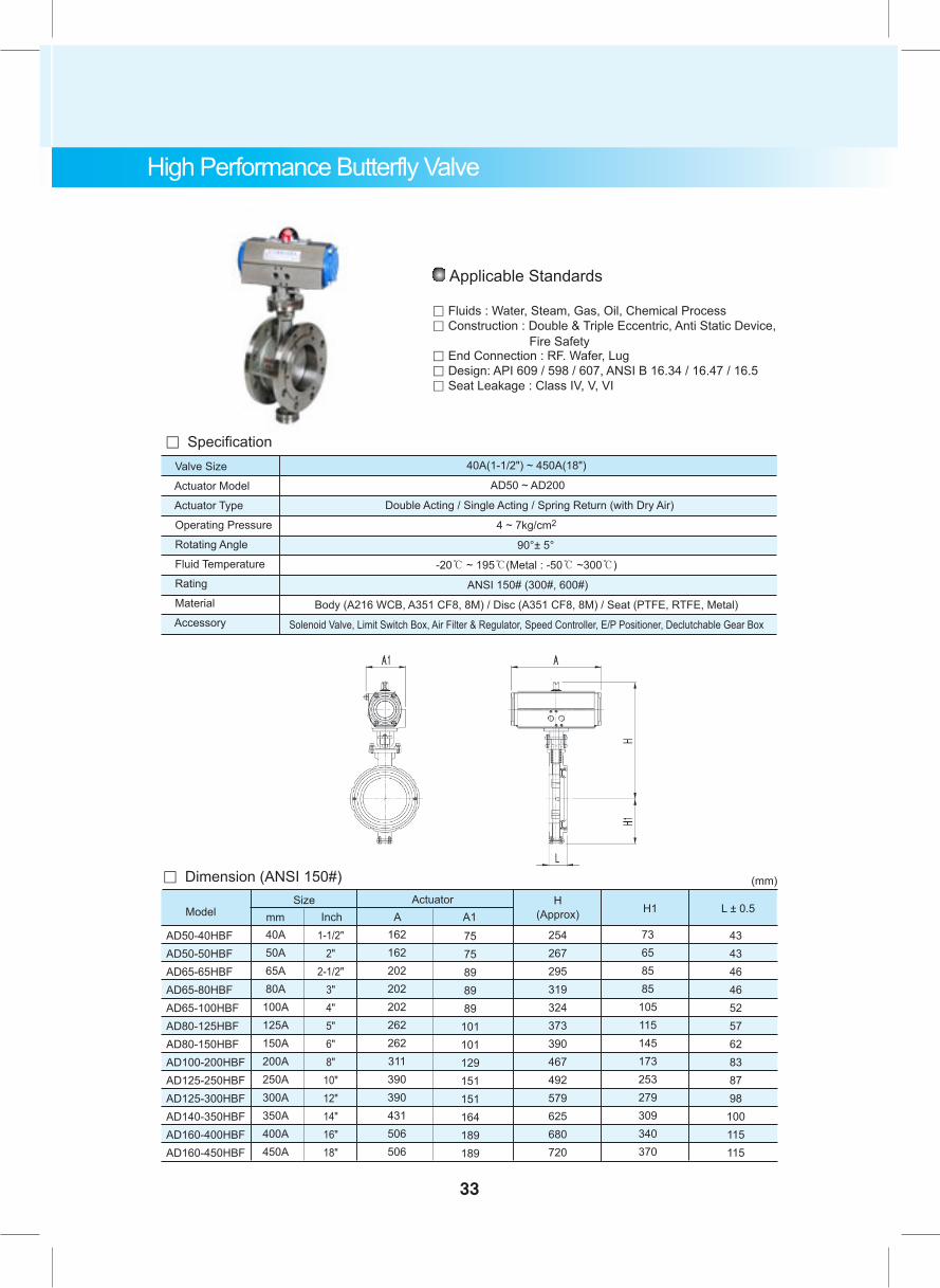
High Performance Butterfly Valve
Valve Size
Actuator Model
Actuator Type
Operating Pressure
Rotating Angle
Fluid Temperature
Rating
Material
Accessory
40A(1-1/2") ~ 450A(18")
AD50 ~ AD200
Double Acting / Single Acting / Spring Return (with Dry Air)
4 ~ 7kg/cm2
90°± 5°
-20℃ ~ 195℃(Metal : -50℃ ~300℃)
ANSI 150# (300#, 600#)
Body (A216 WCB, A351 CF8, 8M) / Disc (A351 CF8, 8M) / Seat (PTFE, RTFE, Metal)
Solenoid Valve, Limit Switch Box, Air Filter & Regulator, Speed Controller, E/P Positioner, Declutchable Gear Box
。 Specification
1-1/2"2"
2-1/2"3"4"5"6"8"
10"12"14"16"18"
Size
40A50A65A80A
100A125A150A200A250A300A350A400A450A
Inchmm162162202202202262262311390390431506506
7575898989
101101129151151164189189
ActuatorA A1
H(Approx)
254267295319324373390467492579625680720
H1
73658585
105115145173253279309340370
L ± 0.5
43434646525762838798
100115115
。 Dimension (ANSI 150#)
AD50-40HBFAD50-50HBFAD65-65HBFAD65-80HBFAD65-100HBFAD80-125HBFAD80-150HBFAD100-200HBFAD125-250HBFAD125-300HBFAD140-350HBFAD160-400HBFAD160-450HBF
Model
(mm)
Applicable Standards
。 Fluids : Water, Steam, Gas, Oil, Chemical Process。 Construction : Double & Triple Eccentric, Anti Static Device, Fire Safety。 End Connection : RF. Wafer, Lug。 Design: API 609 / 598 / 607, ANSI B 16.34 / 16.47 / 16.5。 Seat Leakage : Class IV, V, VI
33

34
Plastic Ball Valve - Double Acting
。 Dimension
Model mm Inch A
162162162162202202202262262311390
15A20A25A30A40A50A65A80A
100A125A150A
1/2"3/4"1"
1-1/4"1-1/2"
2"2-1/2"
3"4"5"6"
AD50-15FAD50-20FAD50-25FAD50-30FAD65-40FAD65-50FAD65-65FAD80-80F
AD80-100F AD100-125F AD125-150F
A1
75757575898989
101101129151
H(Approx)
168177190200212227247276301358414
L
145150170175190210260265300360360
(mm)Size
Valve Size
Actuator Model
Actuator Type
Operating Pressure
Rotating Angle
Fluid Temperature
Rating
Material
Accessory
Pneumatic Duble Acting (with Dry Air)
4 ~ 7kg/cm2
90°± 5°
-10℃ ~ 140℃
ANSI 150#
Solenoid Valve, Limit Switch Box, Air filter Regulator, E/P Positioner
AD50 ~ AD125
。 Specification
PP, C-PVC, PVDF
15A(1/2") ~ 150A(6")
Applicable Standards
。 Fluids : Water, Steam, Oil, Chemical Process。 Construction : Floating Ball, Anti Blow Out, Anti Static Device。 End Connection : FF. SW 。 Design: API 6D / 598, ANSI B 16.10 / 16.25 / 16.34 / 16.5。 Seat Leakage : Class V, VI
Pneumatic Duble Acting(with Dry Air)
4 ~ 7kg/cm2
90°± 5°
-10℃ ~ 140℃
ANSI 150#
Solenoid Valve, Limit Switch Box, Air filter Regulator, E/P Positioner
35
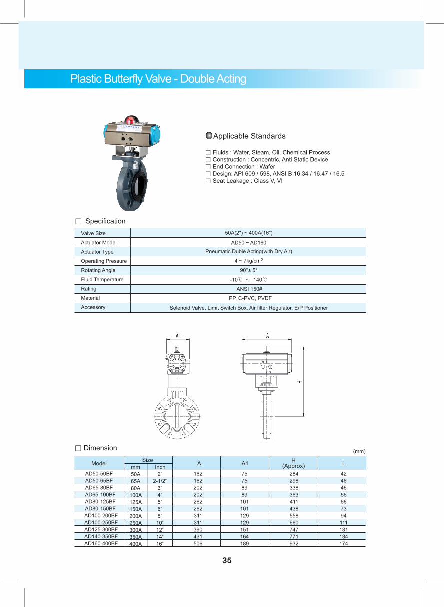
Plastic Butterfly Valve - Double Acting
。 Dimension
Model A
50A65A80A
100A125A150A200A250A300A350A400A
162162202202262262311311390431506
75758989
101101129129151164189
284298338363411438558660747771932
42464656667394111131134174
2"2-1/2"
3"4"5"6"8"
10"12"14"16"
AD50-50BFAD50-65BFAD65-80BF
AD65-100BF AD80-125BF AD80-150BF
AD100-200BF AD100-250BF AD125-300BF AD140-350BF AD160-400BF
A1 H(Approx) L
(mm)Size
mm Inch
Valve Size
Actuator Model
Actuator Type
Operating Pressure
Rotating Angle
Fluid Temperature
Rating
Material
Accessory
AD50 ~ AD160
。 Specification
PP, C-PVC, PVDF
50A(2") ~ 400A(16")
Applicable Standards
。 Fluids : Water, Steam, Oil, Chemical Process。 Construction : Concentric, Anti Static Device。 End Connection : Wafer 。 Design: API 609 / 598, ANSI B 16.34 / 16.47 / 16.5。 Seat Leakage : Class V, VI
36
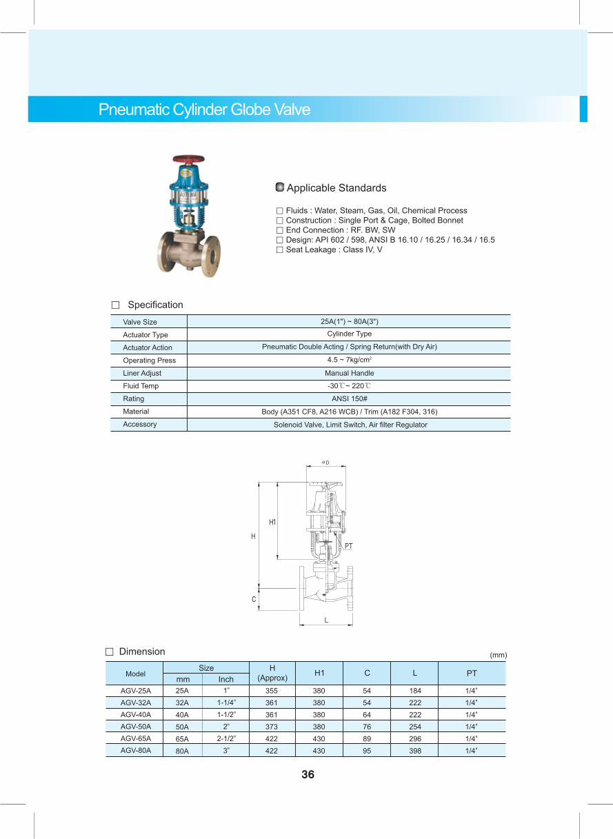
Pneumatic Cylinder Globe Valve
。 Dimension
AGV-25AAGV-32AAGV-40AAGV-50AAGV-65AAGV-80A
25A32A40A50A65A80A
SizeInchmm
1"1-1/4"1-1/2"
2"2-1/2"
3"
355361361373422422
380380380380430430
545464768995
184222222254296398
1/4"1/4"1/4"1/4"1/4"1/4"
H(Approx) H1 C L
(mm)
Model PT
。 SpecificationValve Size
Actuator Type
Actuator Action
Operating Press
Liner Adjust
Fluid Temp
Rating
Material
Accessory
Cylinder Type
Pneumatic Double Acting / Spring Return(with Dry Air)
4.5 ~ 7kg/cm2
-30℃~ 220℃
ANSI 150#
Body (A351 CF8, A216 WCB) / Trim (A182 F304, 316)
Solenoid Valve, Limit Switch, Air filter Regulator
Manual Handle
25A(1") ~ 80A(3")
Applicable Standards
。 Fluids : Water, Steam, Gas, Oil, Chemical Process。 Construction : Single Port & Cage, Bolted Bonnet。 End Connection : RF. BW, SW 。 Design: API 602 / 598, ANSI B 16.10 / 16.25 / 16.34 / 16.5。 Seat Leakage : Class IV, V
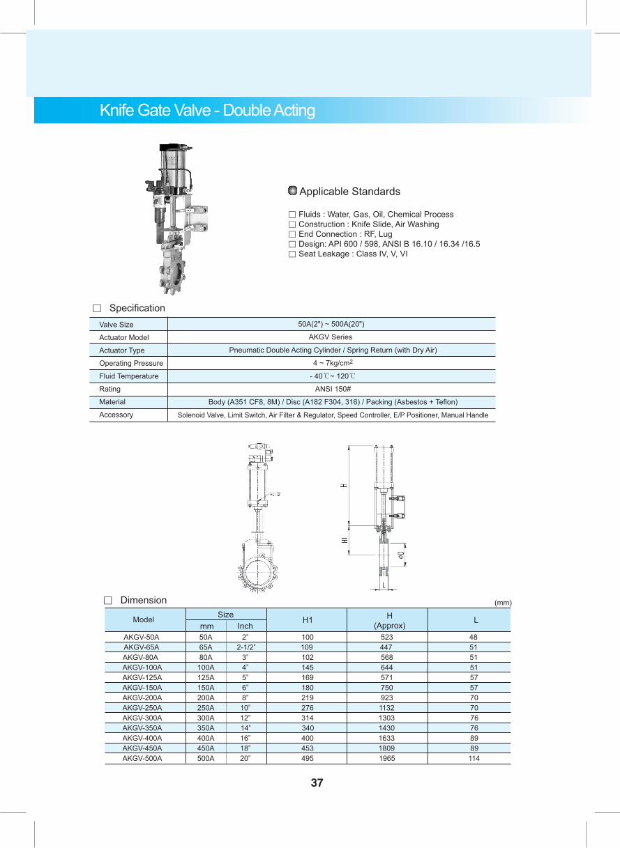
AKGV-50A 50A 2" 100 523 48 AKGV-65A 65A 2-1/2" 109 447 51 AKGV-80A 80A 3" 102 568 51 AKGV-100A 100A 4" 145 644 51 AKGV-125A 125A 5" 169 571 57 AKGV-150A 150A 6" 180 750 57 AKGV-200A 200A 8" 219 923 70 AKGV-250A 250A 10" 276 1132 70 AKGV-300A 300A 12" 314 1303 76 AKGV-350A 350A 14" 340 1430 76 AKGV-400A 400A 16" 400 1633 89 AKGV-450A 450A 18" 453 1809 89 AKGV-500A 500A 20" 495 1965 114
37
Knife Gate Valve - Double Acting
Applicable Standards
。 Fluids : Water, Gas, Oil, Chemical Process。 Construction : Knife Slide, Air Washing。 End Connection : RF, Lug。 Design: API 600 / 598, ANSI B 16.10 / 16.34 /16.5。 Seat Leakage : Class IV, V, VI
Valve Size
Actuator Model
Actuator Type
Operating Pressure
Fluid Temperature
Rating
Material
Accessory
Pneumatic Double Acting Cylinder / Spring Return (with Dry Air)
4 ~ 7kg/cm2
- 40℃~ 120℃
ANSI 150#
Body (A351 CF8, 8M) / Disc (A182 F304, 316) / Packing (Asbestos + Teflon)
Solenoid Valve, Limit Switch, Air Filter & Regulator, Speed Controller, E/P Positioner, Manual Handle
50A(2") ~ 500A(20")
AKGV Series
。 Specification
。 Dimension
Model Sizemm Inch
H1 H(Approx) L
(mm)
10"x12"
1150120400318
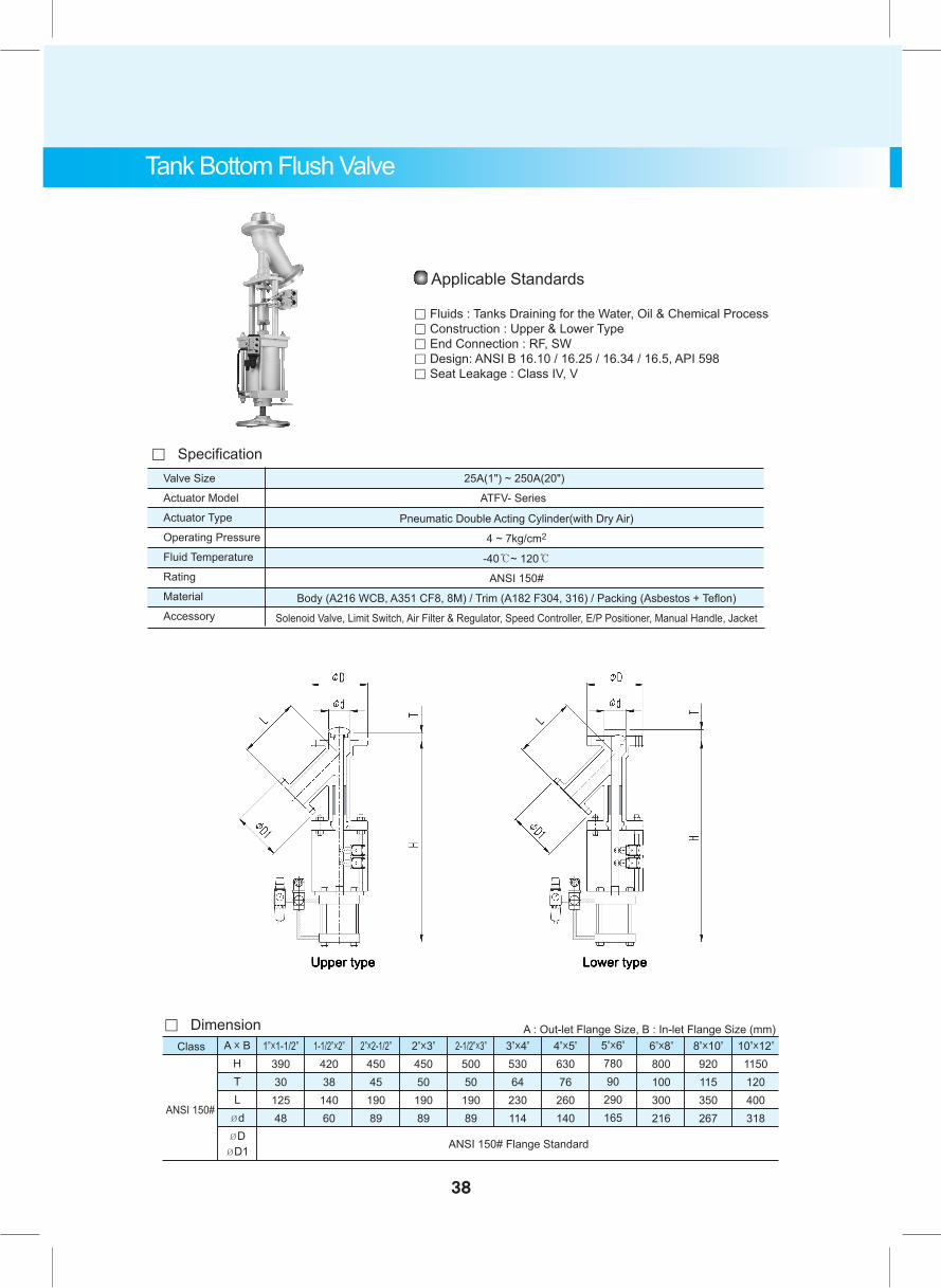
Tank Bottom Flush Valve
Applicable Standards
。 Fluids : Tanks Draining for the Water, Oil & Chemical Process。 Construction : Upper & Lower Type。 End Connection : RF, SW。 Design: ANSI B 16.10 / 16.25 / 16.34 / 16.5, API 598。 Seat Leakage : Class IV, V
Valve Size
Actuator Model
Actuator Type
Operating Pressure
Fluid Temperature
Rating
Material
Accessory
Pneumatic Double Acting Cylinder(with Dry Air)
4 ~ 7kg/cm2
-40℃~ 120℃
ANSI 150#
Body (A216 WCB, A351 CF8, 8M) / Trim (A182 F304, 316) / Packing (Asbestos + Teflon)
Solenoid Valve, Limit Switch, Air Filter & Regulator, Speed Controller, E/P Positioner, Manual Handle, Jacket
25A(1") ~ 250A(20")
ATFV- Series
。 Specification
A x BHTL
ØdØD
ØD1
1"x1-1/2"39030
12548
1-1/2"x2"42038
14060
2"x2-1/2"45045
19089
2"x3"
45050
19089
2-1/2"x3"50050
19089
3"x4"
53064
230114
4"x5"
63076
260140
5"x6"
78090
290165
6"x8"
800100300216
8"x10"
920115350267
ANSI 150# Flange Standard
ANSI 150#
Class
。 Dimension A : Out-let Flange Size, B : In-let Flange Size (mm)
38
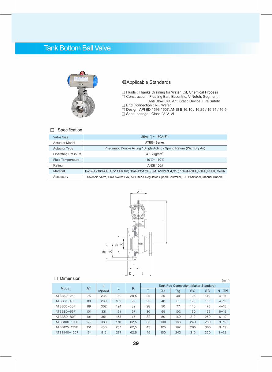
Applicable Standards
。 Fluids : Thanks Draining for Water, Oil, Chemical Process。 Construction : Floating Ball, Eccentric, V-Notch, Segment, Anti Blow Out, Anti Static Device, Fire Safety。 End Connection : RF, Wafer。 Design: API 6D / 598 / 607, ANSI B 16.10 / 16.25 / 16.34 / 16.5。 Seat Leakage : Class IV, V, VI
Valve Size
Actuator Model
Actuator Type
Operating Pressure
Fluid Temperature
Rating
Material
Accessory
25A(1") ~ 150A(6")
ATBB- Series
Pneumatic Double Acting / Single Acting / Spring Return (With Dry Air)
4 ~ 7kg/cm2
-10℃~ 110℃
ANSI 150#
Body (A 216 WCB, A351 CF8, 8M) / Ball (A351 CF8, 8M / A182 F304, 316) / Seat (RTFE, RTFE, PEEK, Metal)
Solenoid Valve, Limit Switch Box, Air Filter & Regulator, Speed Controller, E/P Positioner, Manual Handle
。 Specification
ATBB50-25F
ATBB65-40F
ATBB65-50F
ATBB80-65F
ATBB80-80F
ATBB100-100F
ATBB125-125F
ATBB140-150F
75
89
89
101
101
129
151
164
Model A1 H(Approx) L K
TTank Pad Connection (Maker Standard)Ød Øg ØC ØD N-ØH
235
289
302
331
351
383
450
516
93
109
124
131
153
170
254
277
28.5
29
32
37
45
62.5
62.5
62.5
25
25
28
30
32
35
43
45
25
40
50
65
80
100
125
150
49
61
77
102
140
166
192
243
105
120
140
160
210
240
265
310
140
155
175
195
250
280
305
350
4-15
4-15
4-15
6-15
6-19
8-19
8-19
8-23
。 Dimension (mm)
Tank Bottom Ball Valve
39
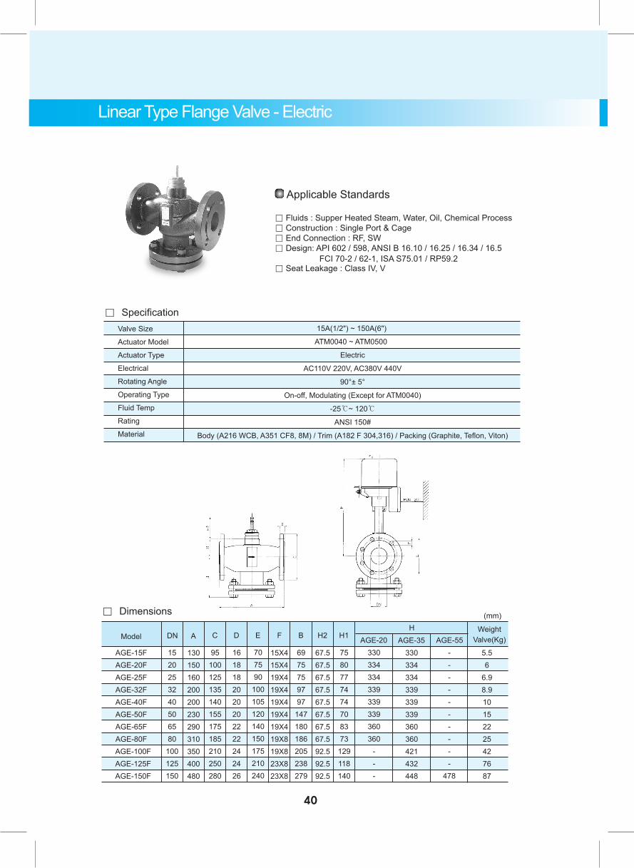
Applicable Standards
。 Fluids : Supper Heated Steam, Water, Oil, Chemical Process。 Construction : Single Port & Cage。 End Connection : RF, SW。 Design: API 602 / 598, ANSI B 16.10 / 16.25 / 16.34 / 16.5 FCI 70-2 / 62-1, ISA S75.01 / RP59.2。 Seat Leakage : Class IV, V
Valve Size
Actuator Model
Actuator Type
Electrical
Rotating Angle
Operating Type
Fluid Temp
Rating
Material
Electric
AC110V 220V, AC380V 440V
90°± 5°
On-off, Modulating (Except for ATM0040)
-25℃~ 120℃
ANSI 150#
Body (A216 WCB, A351 CF8, 8M) / Trim (A182 F 304,316) / Packing (Graphite, Teflon, Viton)
15A(1/2") ~ 150A(6")
ATM0040 ~ ATM0500
。 Specification
AGE-15FAGE-20FAGE-25FAGE-32FAGE-40FAGE-50FAGE-65FAGE-80F
AGE-100F AGE-125F AGE-150F
Model A C D E F B H2 H1
330334334339339339360360
---
330334334339339339360360421432448
----------
478
5.56
6.98.910152225427687
DNH
AGE-20 AGE-35 AGE-55Weight
Valve(Kg)
。 Dimensions
1520253240506580
100125150
130150160200200230290310350400480
95100125135140155175185210250280
1618182020202222242426
707590
100105120140150175210240
15X415X419X419X419X419X419X419X819X823X823X8
6975759797
147180186205238279
67.567.567.567.567.567.567.567.592.592.592.5
7580777474708373
129118140
(mm)
Linear Type Flange Valve - Electric
40
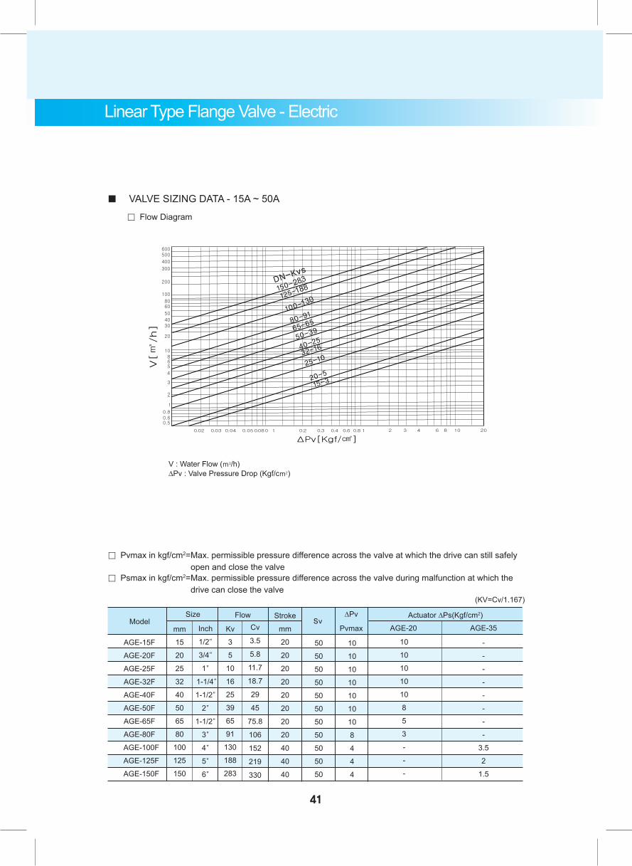
■ VALVE SIZING DATA - 15A ~ 50A
。 Flow Diagram
V : Water Flow (m3/h) ∆Pv : Valve Pressure Drop (Kgf/cm2)
。 Pvmax in kgf/cm2= Max. permissible pressure difference across the valve at which the drive can still safely open and close the valve
。 Psmax in kgf/cm2= Max. permissible pressure difference across the valve during malfunction at which the drive can close the valve
(KV=Cv/1.167)
AGE-15F
AGE-20F
AGE-25F
AGE-32F
AGE-40F
AGE-50F
AGE-65F
AGE-80F
AGE-100F
AGE-125F
AGE-150F
SizeModel
mm
15
20
25
32
40
50
65
80
100
125
150
Inch
1/2"
3/4"
1"
1-1/4"
1-1/2"
2"
1-1/2"
3"
4"
5"
6"
Kv
3
5
10
16
25
39
65
91
130
188
283
Cv
3.5
5.8
11.7
18.7
29
45
75.8
106
152
219
330
Flow Stroke
mm
20
20
20
20
20
20
20
20
40
40
40
50
50
50
50
50
50
50
50
50
50
50
∆Pv
PvmaxSv
AGE-35AGE-20
10
10
10
10
10
10
10
8
4
4
4
10
10
10
10
10
8
5
3
-
-
-
-
-
-
-
-
-
-
-
3.5
2
1.5
Actuator ∆Ps(Kgf/cm2)
Linear Type Flange Valve - Electric
41

42
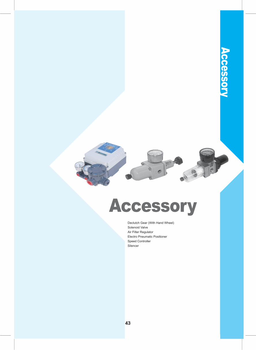
Accessory
AccessoryDeclutch Gear (With Hand Wheel)Solenoid ValveAir Filter Regulator Electro Pneumatic PositionerSpeed ControllerSilencer
43
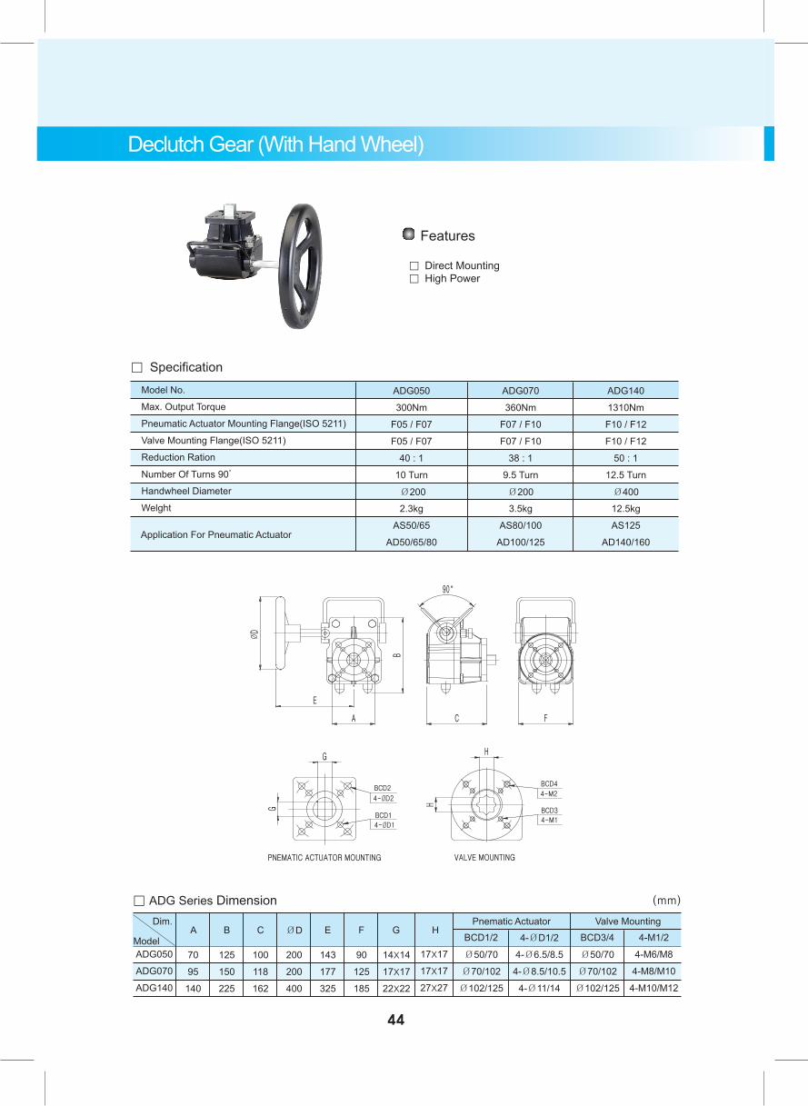
Declutch Gear (With Hand Wheel)
Features
。 Direct Mounting 。 High Power
。 Specification Model No.
Max. Output Torque
Pneumatic Actuator Mounting Flange(ISO 5211)
Valve Mounting Flange(ISO 5211)
Reduction Ration
Number Of Turns 90̊
Handwheel Diameter
Welght
ADG050
300Nm
F05 / F07
F05 / F07
40 : 1
10 Turn
Ø200
2.3kg
AS50/65
AD50/65/80
ADG070
360Nm
F07 / F10
F07 / F10
38 : 1
9.5 Turn
Ø200
3.5kg
AS80/100
AD100/125
ADG140
1310Nm
F10 / F12
F10 / F12
50 : 1
12.5 Turn
Ø400
12.5kg
AS125
AD140/160 Application For Pneumatic Actuator
。 ADG Series Dimension (mm)
BCD1/2
Ø50/70
Ø70/102
Ø102/125
ADG050
ADG070
ADG140
70
95
140
125
150
225
100
118
162
200
200
400
143
177
325
90
125
185
14X14
17X17
22X22
17X17
17X17
27X27
BCD3/4
Ø50/70
Ø70/102
Ø102/125
4-ØD1/2
4-Ø6.5/8.5
4-Ø8.5/10.5
4-Ø11/14
4-M1/2
4-M6/M8
4-M8/M10
4-M10/M12
A B C ØD E F G HPnematic ActuatorDim.
Model
Valve Mounting
44
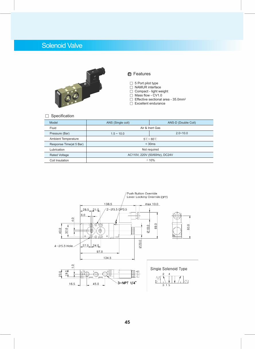
Solenoid Valve
Fluid
Pressure (Bar)
Ambient Temperature
Response Time(at 5 Bar)
Lubrication
Rated Voltage
Coil Insulation
Air & Inert Gas
5℃~ 60℃
Not required
AC110V, 220V (50/60Hz), DC24V
±10%
Model ANS (Single coil) ANS-D (Double Coil)
1.5 ~ 10.0 2.0~10.0
< 30ms
。 Specification
Features
。 5 Port pilot type 。 NAMUR interface。 Compact - light weight。 Mass flow - CV1.0。 Effective sectional area - 35.0mm2
。 Excellent endurance
45
ANS Series(Weather Proof)
ASV Series(Explosion Proof)
ANS Series(Weather Proof)
ASV Series(Explosion Proof)
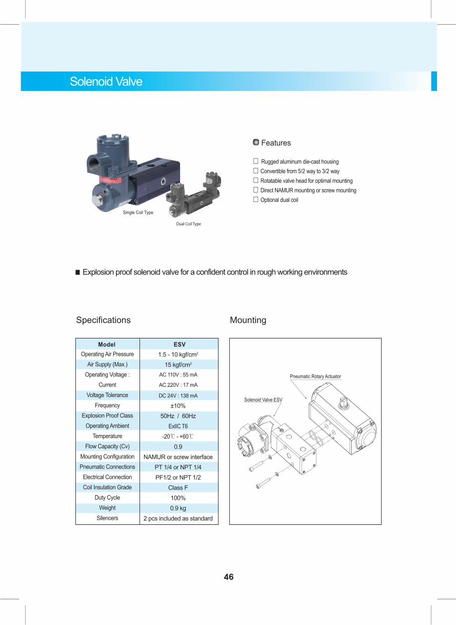
Model ESVOperating Air Pressure
Air Supply (Max.)Operating Voltage :
CurrentVoltage Tolerance
FrequencyExplosion Proof Class
Operating Ambient Temperature
Flow Capacity (Cv)Mounting ConfigurationPneumatic Connections
Electrical ConnectionCoil Insulation Grade
Duty CycleWeight
Silencers
1.5 - 10 kgf/cm2
15 kgf/cm2
AC 110V : 55 mA
AC 220V : 17 mA
DC 24V : 138 mA
±10%50Hz / 60Hz
ExIIC T6-20℃ - +60℃
0.9NAMUR or screw interface
PT 1/4 or NPT 1/4PF1/2 or NPT 1/2
Class F100%0.9 kg
2 pcs included as standard
■ Explosion proof solenoid valve for a confident control in rough working environments
Features
「 Rugged aluminum die-cast housing 「 Convertible from 5/2 way to 3/2 way「 Rotatable valve head for optimal mounting「 Direct NAMUR mounting or screw mounting「 Optional dual coil
Single Coil Type
46
Specifications Mounting
Solenoid Valve
Dual Coil Type
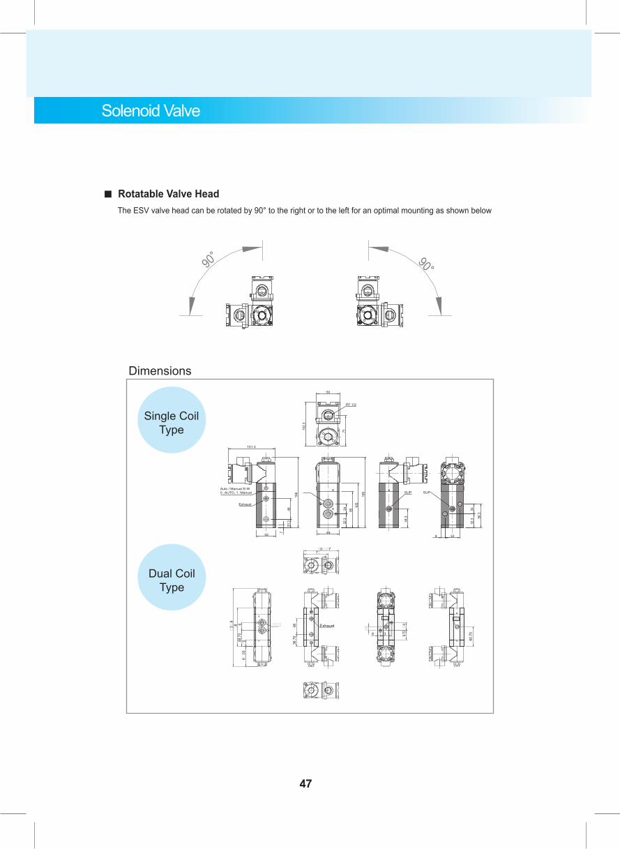
Dimensions
36.7
048
Exhaust �4
3�
��
�8
.70
8
���
�0�.�77�
�3�
.6
��8
�04
8.7
0�
4
6�
.03
���
60.7
0
���
Dual Coil Type
Single Coil Type
101.3
Auto / Manual S/W
0 : AUTO, 1 : Manual SUP SUP
8 32
24
32.3
56.3
44.3
48
32.3
24
85
105
166
Exhaust
166
42
48
20.3
7
50
PF 1/2
102.3
71
■ Rotatable Valve Head The ESV valve head can be rotated by 90° to the right or to the left for an optimal mounting as shown below
47
Solenoid Valve
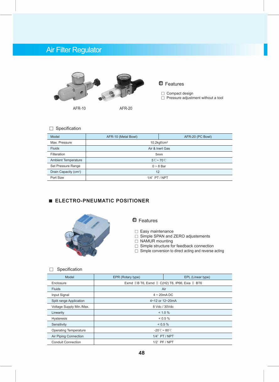
Air Filter Regulator
■ ELECTRO-PNEUMATIC POSITIONER
Features
。 Easy maintenance 。 Simple SPAN and ZERO adjustements。 NAMUR mounting 。 Simple structure for feedback connection。 Simple conversion to direct acting and reverse acting
Enclosure Exmd ⅡB T6, Exmd Ⅱ C(H2) T6, IP66, Exia Ⅱ BT6
Fluids Air
Input Signal 4 ~ 20mA DC
Split range Application 4~12 or 12~20mA
Voltage Supply Min./Max. 8 Vdc / 30Vdc
Linearity < 1.0 %
Hysteresis < 0.5 %
Sensitivity < 0.5 %
Operating Temperature -20℃~ 80℃
Air Piping Connection 1/4" PT / NPT
Conduit Connection 1/2' PF / NPT
Model EPR (Rotary type) EPL (Linear type)
。 Specification
Model AFR-10 (Metal Bowl) AFR-20 (PC Bowl)
Max. Pressure
Fluids
Filteration
Ambient Temperature
Set Pressure Range
Drain Capacity (cm2)
Port Size
10.2kgf/cm2
Air & lnert Gas
5mm
5℃~ 70℃
0 ~ 8 Bar
。 Specification
12
1/4" PT / NPT
Features
。 Compact design 。 Pressure adjustment without a tool
AFR-10 AFR-20
48
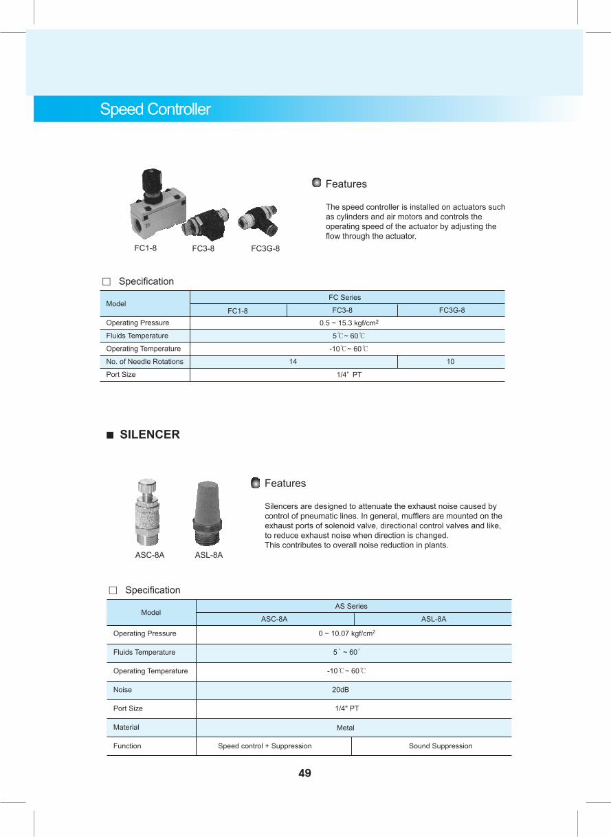
0.5 ~ 15.3 kgf/cm2
5℃~ 60℃
-10℃~ 60℃
1/4" PT
ModelFC Series
FC3-8 FC3G-8FC1-8
。 Specification
14 10
Operating Pressure 0 ~ 10.07 kgf/cm2
Fluids Temperature 5̊ ~ 60̊
Operating Temperature -10℃~ 60℃
Noise 20dB
Port Size 1/4" PT
Material
Function Speed control + Suppression Sound Suppression
ModelAS Series
ASC-8A ASL-8A
。 Specification
Metal
Features
The speed controller is installed on actuators such as cylinders and air motors and controls the operating speed of the actuator by adjusting the flow through the actuator.
FC1-8 FC3-8 FC3G-8
Features
Silencers are designed to attenuate the exhaust noise caused by control of pneumatic lines. In general, mufflers are mounted on the exhaust ports of solenoid valve, directional control valves and like, to reduce exhaust noise when direction is changed. This contributes to overall noise reduction in plants.
ASC-8A ASL-8A
■ SILENCER
49
Speed Controller
Operating Pressure
Fluids Temperature
Operating Temperature
No. of Needle Rotations
Port Size

50
Electric Aatuator
Electric Actuator
Rotary Type ActuatorLinear ActuatorLinear Type Actuator
51
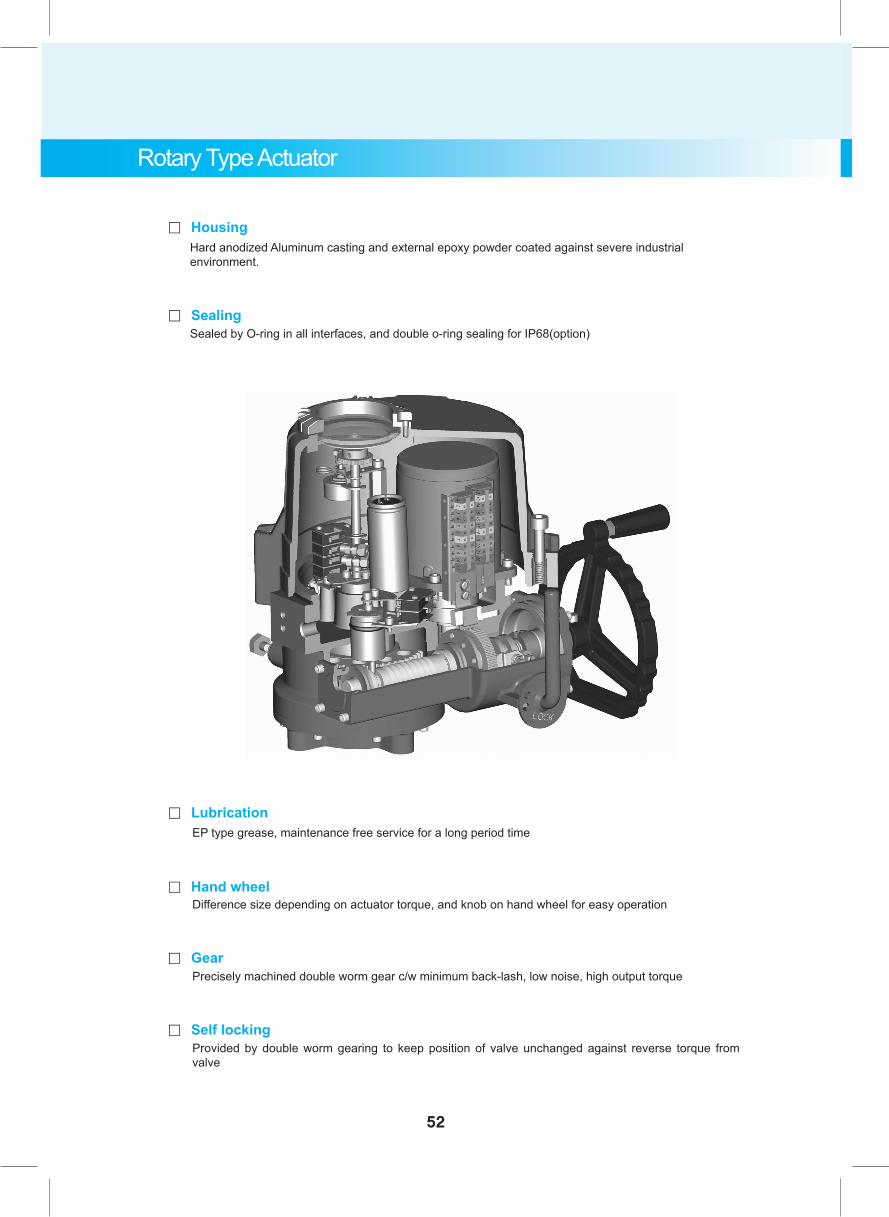
Rotary Type Actuator
Hard anodized Aluminum casting and external epoxy powder coated against severe industrial environment.
Sealed by O-ring in all interfaces, and double o-ring sealing for IP68(option)
。 Housing
。 Sealing
EP type grease, maintenance free service for a long period time
Difference size depending on actuator torque, and knob on hand wheel for easy operation
Precisely machined double worm gear c/w minimum back-lash, low noise, high output torque
Provided by double worm gearing to keep position of valve unchanged against reverse torque from valve
。 Lubrication
。 Hand wheel
。 Gear
。 Self locking
52
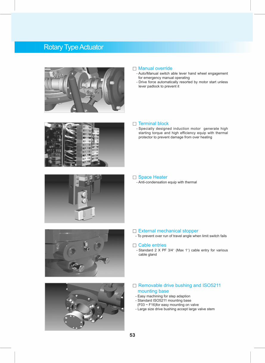
。 External mechanical stopper - To prevent over run of travel angle when limit switch fails
。 Cable entries - Standard 2 X PF 3/4" (Max 1") cable entry for various
cable gland
。 Manual override - Auto/Manual switch able lever hand wheel engagement
for emergency manual operating - Drive force automatically resorted by motor start unless
lever padlock to prevent it
。 Removable drive bushing and ISO5211 mounting base - Easy machining for step adaption - Standard ISO5211 mounting base (F03 ~ F16)for easy mounting on valve - Large size drive bushing accept large valve stem
。 Terminal block - Specially designed induction motor generate high
starting torque and high efficiency equip with thermal protector to prevent damage from over heating
。 Space Heater - Anti-condensation equip with thermal
Rotary Type Actuator
53
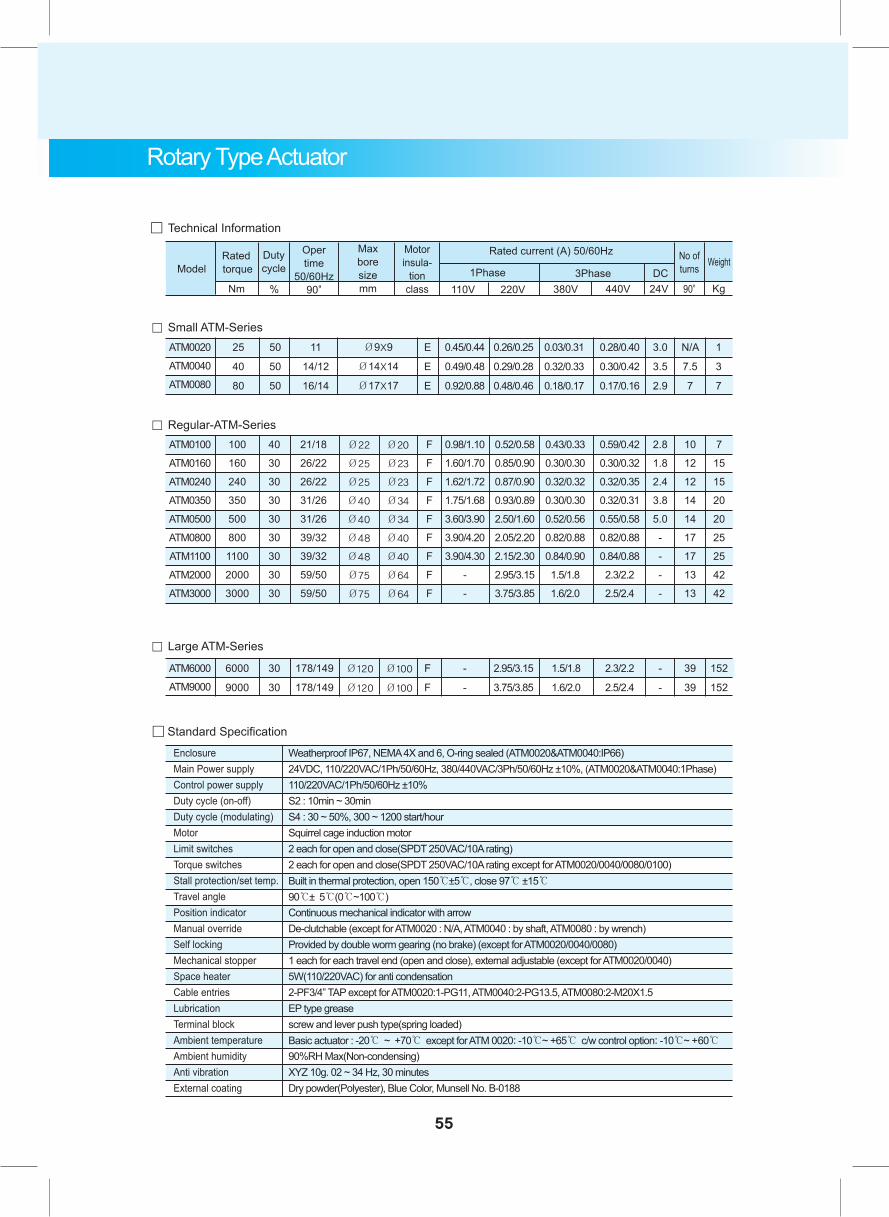
。 Captive cover bolt - Cover bolts are captive type designed to prevent loosing
during maintenance or installation
- All external bolts are stainless steel for rust prevention
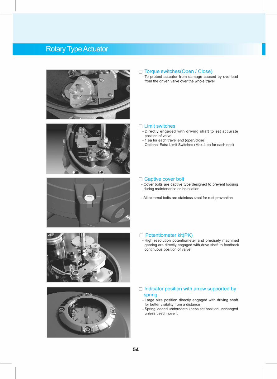
。 Torque switches(Open / Close) - To protect actuator from damage caused by overload
from the driven valve over the whole travel
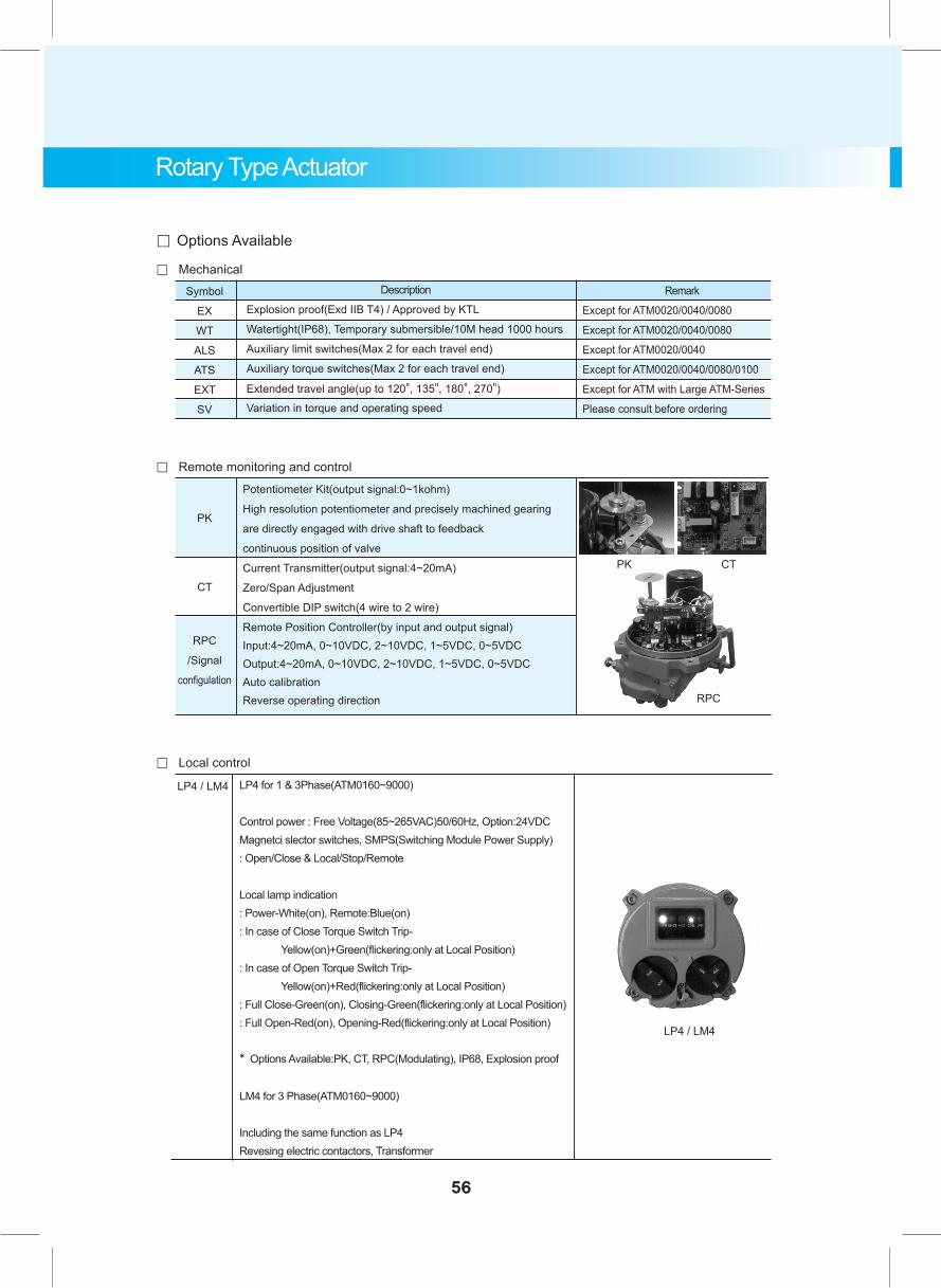
。 Potentiometer kit(PK) - High resolution potentiometer and precisely machined
gearing are directly engaged with drive shaft to feedback continuous position of valve
。 Limit switches - Directly engaged with driving shaft to set accurate
position of valve - 1 ea for each travel end (open/close) - Optional Extra Limit Switches (Max 4 ea for each end)
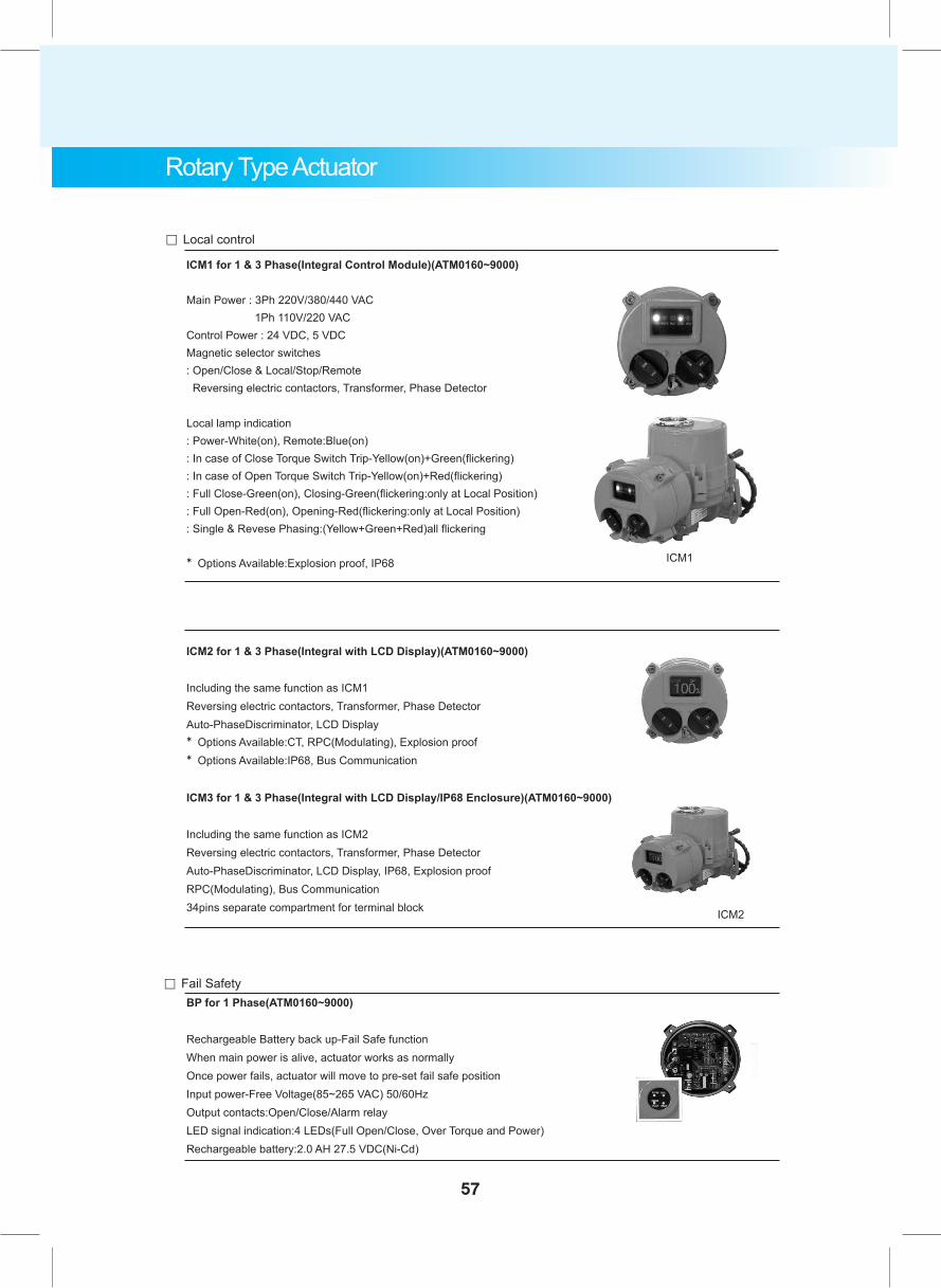
。 Indicator position with arrow supported by spring - Large size position directly engaged with driving shaft
for better visibility from a distance - Spring loaded underneath keeps set position unchanged
unless used move it
Rotary Type Actuator
54
。 Technical Information
ModelRated torque
Nm %
Oper time
50/60Hz90"
Dutycycle
Max boresizemm
Motor insula-
tion class
Rated current (A) 50/60Hz
1Phase 3Phase DC110V 220V 380V 440V 24V Kg90"
No of turns Weight
。 Small ATM-SeriesATM0020
ATM0040
ATM0080
25
40
80
50
50
50
1
3
7
N/A
7.5
7
3.0
3.5
2.9
E
E
E
Ø9X9
Ø14X14
Ø17X17
11
14/12
16/14
0.28/0.40
0.30/0.42
0.17/0.16
0.03/0.31
0.32/0.33
0.18/0.17
0.26/0.25
0.29/0.28
0.48/0.46
0.45/0.44
0.49/0.48
0.92/0.88
。 Large ATM-Series
ATM6000
ATM9000
6000
9000
30
30
152
152
39
39
-
-
F
F
Ø120
Ø120
Ø100
Ø100
178/149
178/149
2.3/2.2
2.5/2.4
1.5/1.8
1.6/2.0
2.95/3.15
3.75/3.85
-
-
。 Regular-ATM-SeriesATM0100
ATM0160
ATM0240
ATM0350
ATM0500
ATM0800
ATM1100
ATM2000
ATM3000
100
160
240
350
500
800
1100
2000
3000
40
30
30
30
30
30
30
30
30
7
15
15
20
20
25
25
42
42
10
12
12
14
14
17
17
13
13
2.8
1.8
2.4
3.8
5.0
-
-
-
-
F
F
F
F
F
F
F
F
F
Ø22
Ø25
Ø25
Ø40
Ø40
Ø48
Ø48
Ø75
Ø75
Ø20
Ø23
Ø23
Ø34
Ø34
Ø40
Ø40
Ø64
Ø64
21/18
26/22
26/22
31/26
31/26
39/32
39/32
59/50
59/50
0.59/0.42
0.30/0.32
0.32/0.35
0.32/0.31
0.55/0.58
0.82/0.88
0.84/0.88
2.3/2.2
2.5/2.4
0.43/0.33
0.30/0.30
0.32/0.32
0.30/0.30
0.52/0.56
0.82/0.88
0.84/0.90
1.5/1.8
1.6/2.0
0.52/0.58
0.85/0.90
0.87/0.90
0.93/0.89
2.50/1.60
2.05/2.20
2.15/2.30
2.95/3.15
3.75/3.85
0.98/1.10
1.60/1.70
1.62/1.72
1.75/1.68
3.60/3.90
3.90/4.20
3.90/4.30
-
-
。 Standard Specification
EnclosureMain Power supplyControl power supplyDuty cycle (on-off)Duty cycle (modulating)MotorLimit switchesTorque switchesStall protection/set temp.Travel anglePosition indicatorManual overrideSelf lockingMechanical stopperSpace heaterCable entriesLubricationTerminal blockAmbient temperatureAmbient humidityAnti vibrationExternal coating
Weatherproof IP67, NEMA 4X and 6, O-ring sealed (ATM0020&ATM0040:IP66)24VDC, 110/220VAC/1Ph/50/60Hz, 380/440VAC/3Ph/50/60Hz ±10%, (ATM0020&ATM0040:1Phase)110/220VAC/1Ph/50/60Hz ±10%S2 : 10min ~ 30minS4 : 30 ~ 50%, 300 ~ 1200 start/hourSquirrel cage induction motor2 each for open and close(SPDT 250VAC/10A rating)2 each for open and close(SPDT 250VAC/10A rating except for ATM0020/0040/0080/0100)Built in thermal protection, open 150℃±5℃, close 97℃ ±15℃
90℃± 5℃(0℃~100℃)Continuous mechanical indicator with arrowDe-clutchable (except for ATM0020 : N/A, ATM0040 : by shaft, ATM0080 : by wrench)Provided by double worm gearing (no brake) (except for ATM0020/0040/0080)1 each for each travel end (open and close), external adjustable (except for ATM0020/0040)5W(110/220VAC) for anti condensation2-PF3/4” TAP except for ATM0020:1-PG11, ATM0040:2-PG13.5, ATM0080:2-M20X1.5EP type greasescrew and lever push type(spring loaded)Basic actuator : -20℃ ~ +70℃ except for ATM 0020: -10℃~ +65℃ c/w control option: -10℃~ +60℃
90%RH Max(Non-condensing)XYZ 10g. 02 ~ 34 Hz, 30 minutesDry powder(Polyester), Blue Color, Munsell No. B-0188
Rotary Type Actuator
55
。 Options Available
Symbol
EX
WT
ALS
ATS
EXT
SV
Description
Explosion proof(Exd IIB T4) / Approved by KTL
Watertight(IP68), Temporary submersible/10M head 1000 hours
Auxiliary limit switches(Max 2 for each travel end)
Auxiliary torque switches(Max 2 for each travel end)
Extended travel angle(up to 120", 135", 180", 270")
Variation in torque and operating speed
Remark
Except for ATM0020/0040/0080
Except for ATM0020/0040/0080
Except for ATM0020/0040
Except for ATM0020/0040/0080/0100
Except for ATM with Large ATM-Series
Please consult before ordering
。 Mechanical
。 Remote monitoring and control
。 Local control
Potentiometer Kit(output signal:0~1kohm)
High resolution potentiometer and precisely machined gearing
are directly engaged with drive shaft to feedback
continuous position of valve
Current Transmitter(output signal:4~20mA)
Zero/Span Adjustment
Convertible DIP switch(4 wire to 2 wire)
Remote Position Controller(by input and output signal)Input:4~20mA, 0~10VDC, 2~10VDC, 1~5VDC, 0~5VDCOutput:4~20mA, 0~10VDC, 2~10VDC, 1~5VDC, 0~5VDCAuto calibrationReverse operating direction
PK
CT
RPC
/Signal
configulation
PK CT
RPC
LP4 / LM4 LP4 for 1 & 3Phase(ATM0160~9000)
Control power : Free Voltage(85~265VAC)50/60Hz, Option:24VDCMagnetci slector switches, SMPS(Switching Module Power Supply): Open/Close & Local/Stop/Remote
Local lamp indication: Power-White(on), Remote:Blue(on): In case of Close Torque Switch Trip- Yellow(on)+Green(flickering:only at Local Position): In case of Open Torque Switch Trip- Yellow(on)+Red(flickering:only at Local Position): Full Close-Green(on), Closing-Green(flickering:only at Local Position): Full Open-Red(on), Opening-Red(flickering:only at Local Position)
* Options Available:PK, CT, RPC(Modulating), IP68, Explosion proof
LM4 for 3 Phase(ATM0160~9000)
Including the same function as LP4Revesing electric contactors, Transformer
LP4 / LM4
Rotary Type Actuator
56
ICM1 for 1 & 3 Phase(Integral Control Module)(ATM0160~9000)
Main Power : 3Ph 220V/380/440 VAC 1Ph 110V/220 VACControl Power : 24 VDC, 5 VDCMagnetic selector switches: Open/Close & Local/Stop/Remote Reversing electric contactors, Transformer, Phase Detector
Local lamp indication: Power-White(on), Remote:Blue(on): In case of Close Torque Switch Trip-Yellow(on)+Green(flickering): In case of Open Torque Switch Trip-Yellow(on)+Red(flickering): Full Close-Green(on), Closing-Green(flickering:only at Local Position): Full Open-Red(on), Opening-Red(flickering:only at Local Position): Single & Revese Phasing:(Yellow+Green+Red)all flickering
* Options Available:Explosion proof, IP68
ICM2 for 1 & 3 Phase(Integral with LCD Display)(ATM0160~9000)
Including the same function as ICM1Reversing electric contactors, Transformer, Phase DetectorAuto-PhaseDiscriminator, LCD Display* Options Available:CT, RPC(Modulating), Explosion proof* Options Available:IP68, Bus Communication
ICM3 for 1 & 3 Phase(Integral with LCD Display/IP68 Enclosure)(ATM0160~9000)
Including the same function as ICM2Reversing electric contactors, Transformer, Phase DetectorAuto-PhaseDiscriminator, LCD Display, IP68, Explosion proofRPC(Modulating), Bus Communication34pins separate compartment for terminal block
。 Local control
ICM1
ICM2
。 Fail SafetyBP for 1 Phase(ATM0160~9000)
Rechargeable Battery back up-Fail Safe functionWhen main power is alive, actuator works as normallyOnce power fails, actuator will move to pre-set fail safe positionInput power-Free Voltage(85~265 VAC) 50/60HzOutput contacts:Open/Close/Alarm relayLED signal indication:4 LEDs(Full Open/Close, Over Torque and Power)Rechargeable battery:2.0 AH 27.5 VDC(Ni-Cd)
Rotary Type Actuator
57
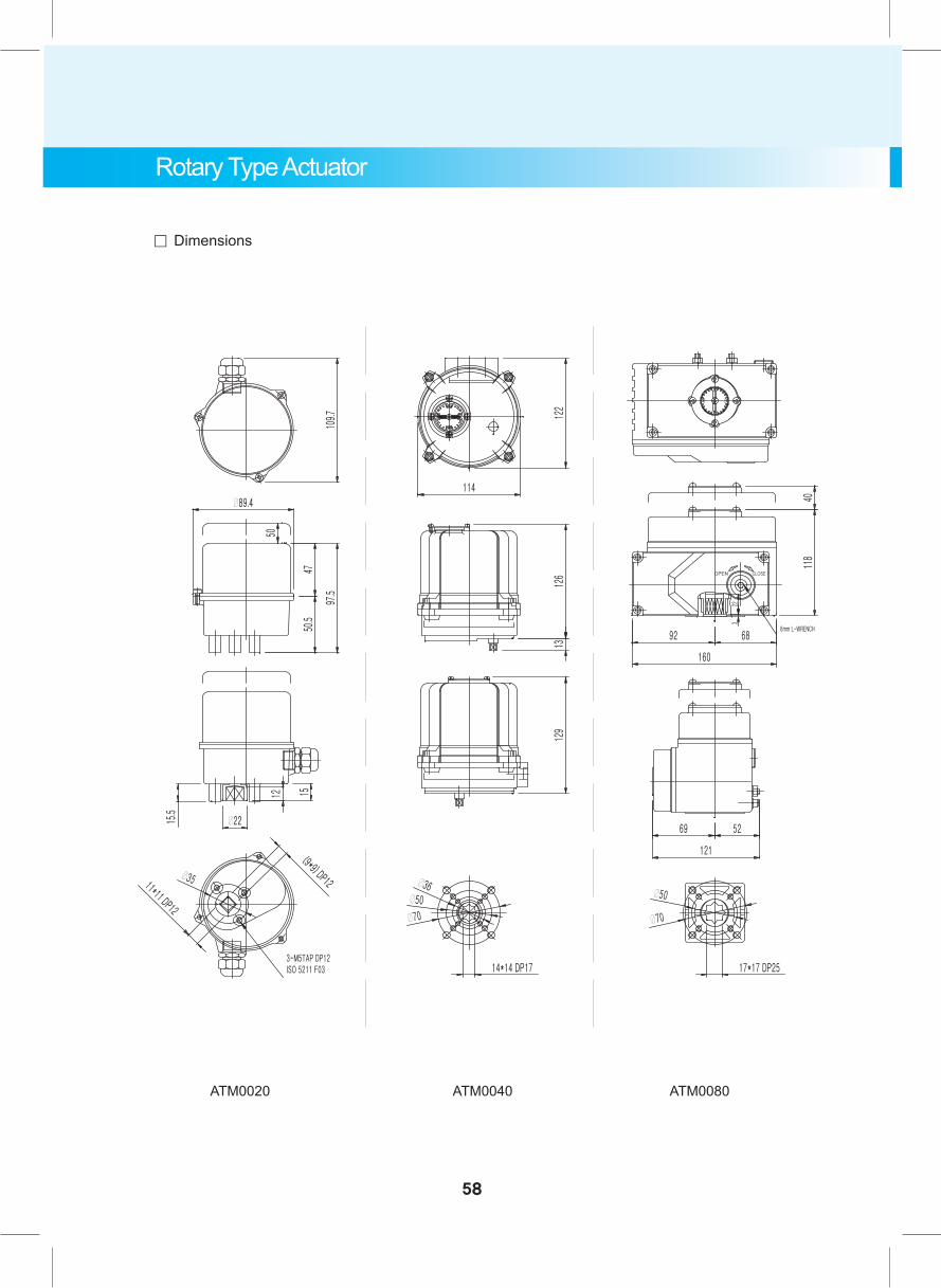
。 Dimensions
ATM0020 ATM0040 ATM0080
58
Rotary Type Actuator
59
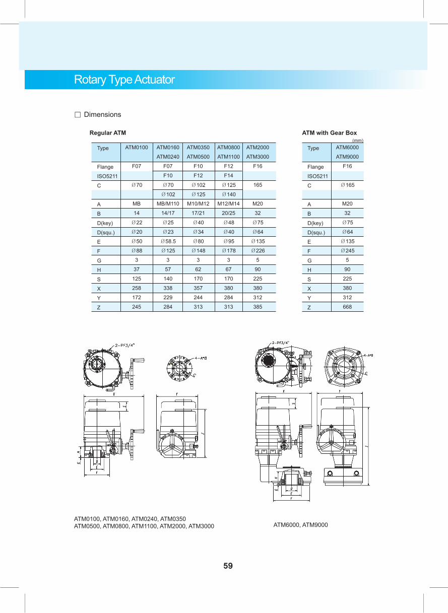
。 Dimensions
ATM0100, ATM0160, ATM0240, ATM0350 ATM0500, ATM0800, ATM1100, ATM2000, ATM3000 ATM6000, ATM9000
Rotary Type Actuator
Type
Flange
ISO5211
C
A
B
D(key)
D(squ.)
E
F
G
H
S
X
Y
Z
ATM0100
F07
Ø70
MB
14
Ø22
Ø20
Ø50
Ø88
3
37
125
258
172
245
Regular ATM
ATM0160
ATM0240
F07
F10
Ø70
Ø102
MB/M110
14/17
Ø25
Ø23
Ø58.5
Ø125
3
57
140
338
229
284
ATM0350
ATM0500
F10
F12
Ø102
Ø125
M10/M12
17/21
Ø40
Ø34
Ø80
Ø148
3
62
170
357
244
313
ATM0800
ATM1100
F12
F14
Ø125
Ø140
M12/M14
20/25
Ø48
Ø40
Ø95
Ø178
3
67
170
380
284
313
ATM2000
ATM3000
F16
165
M20
32
Ø75
Ø64
Ø135
Ø226
5
90
225
380
312
385
Type
Flange
ISO5211
C
A
B
D(key)
D(squ.)
E
F
G
H
S
X
Y
Z
ATM6000
ATM9000
F16
Ø165
M20
32
Ø75
Ø64
Ø135
Ø245
5
90
225
380
312
668
ATM with Gear Box (mm)
60
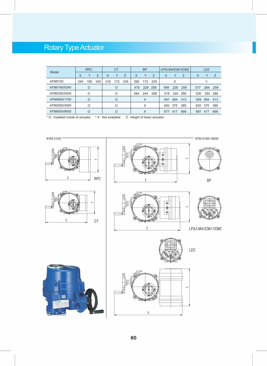
ATM0100
ATM0160/0240
ATM0350/0500
ATM0800/1100
ATM2000/3000
ATM6000/9000
RPC
X Y Z
340 190 245
O
O
O
O
O
CT
X Y Z
316 172 245
O
O
O
O
O
BP
X Y Z
396 172 245
475 229 259
494 244 288
X
X
X
LP4/LM4/ICM1/ICM2
X Y Z
X
499 229 259
518 244 288
541 284 313
600 375 385
677 417 668
LD2
X Y Z
X
517 284 259
536 284 288
559 284 313
620 375 385
697 417 668
* O : Installed inside of actuator * X : Not available Z : Height of basic actuator
ATM 0100 ATM 0160~9000
Rotary Type Actuator
Model
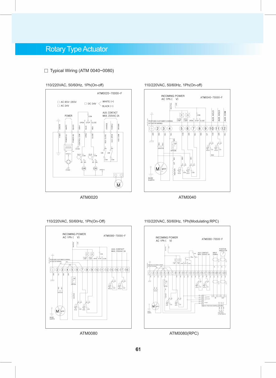
。 Typical Wiring (ATM 0040~0080)
110/220VAC, 50/60Hz, 1Ph(On-off)
110/220VAC, 50/60Hz, 1Ph(On-Off) 110/220VAC, 50/60Hz, 1Ph(Modulating:RPC)
ATM0020 ATM0040
ATM0080 ATM0080(RPC)
110/220VAC, 50/60Hz, 1Ph(On-off)
61
Rotary Type Actuator

110/220VAC, 50/60Hz, 1Ph(On-Off)
110/220VAC, 50/60Hz, 1Ph(Modulating:RPC)
ATM0100 ATM0100(3Ph)
ATM0100(RPC)
380/440VAC, 50/60Hz, 3Ph(On-Off)
。 Typical Wiring (ATM 0100)
CLS : Close Limit Switch (250VAC 10A)OLS : Open Limit Switch (250VAC 10A)ACLS : Aux. Close Limit Switch (250VAC 10A)AOLS : Aux. Open Limit Switch (250VAC 10A)ACTS : Aux. Close Torque Switch (250VAC 10A)AOTS : Aux. Open Torque Switch (250VAC 10A) TP : Thermal Protector (250VAC 15A OPTION)
* Each actuator should be powered through its own individual switch or relay contacts to prevent cross feed between two or more actuators.
62
Rotary Type Actuator
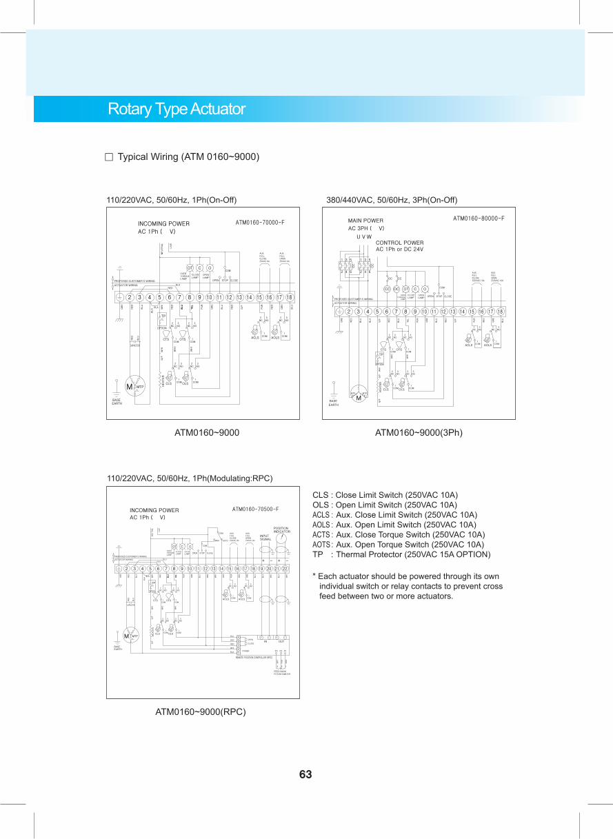
。 Typical Wiring (ATM 0160~9000)
110/220VAC, 50/60Hz, 1Ph(On-Off)
110/220VAC, 50/60Hz, 1Ph(Modulating:RPC)
ATM0160~9000 ATM0160~9000(3Ph)
ATM0160~9000(RPC)
380/440VAC, 50/60Hz, 3Ph(On-Off)
CLS : Close Limit Switch (250VAC 10A)OLS : Open Limit Switch (250VAC 10A)ACLS : Aux. Close Limit Switch (250VAC 10A)AOLS : Aux. Open Limit Switch (250VAC 10A)ACTS : Aux. Close Torque Switch (250VAC 10A)AOTS : Aux. Open Torque Switch (250VAC 10A) TP : Thermal Protector (250VAC 15A OPTION)
* Each actuator should be powered through its own individual switch or relay contacts to prevent cross feed between two or more actuators.
63
Rotary Type Actuator
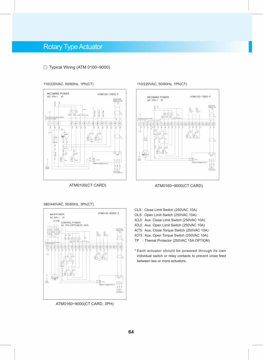
。 Typical Wiring (ATM 0100~9000)
110/220VAC, 50/60Hz, 1Ph(CT)
380/440VAC, 50/60Hz, 3Ph(CT)
ATM0100(CT CARD)
ATM0160~9000(CT CARD, 3PH)
ATM0160~9000(CT CARD)
110/220VAC, 50/60Hz, 1Ph(CT)
CLS : Close Limit Switch (250VAC 10A)OLS : Open Limit Switch (250VAC 10A)ACLS : Aux. Close Limit Switch (250VAC 10A)AOLS : Aux. Open Limit Switch (250VAC 10A)ACTS : Aux. Close Torque Switch (250VAC 10A)AOTS : Aux. Open Torque Switch (250VAC 10A) TP : Themal Protector (250VAC 15A OPTION)
* Each actuator should be powered through its own individual switch or relay contacts to prevent cross feed between two or more actuators.
64
Rotary Type Actuator
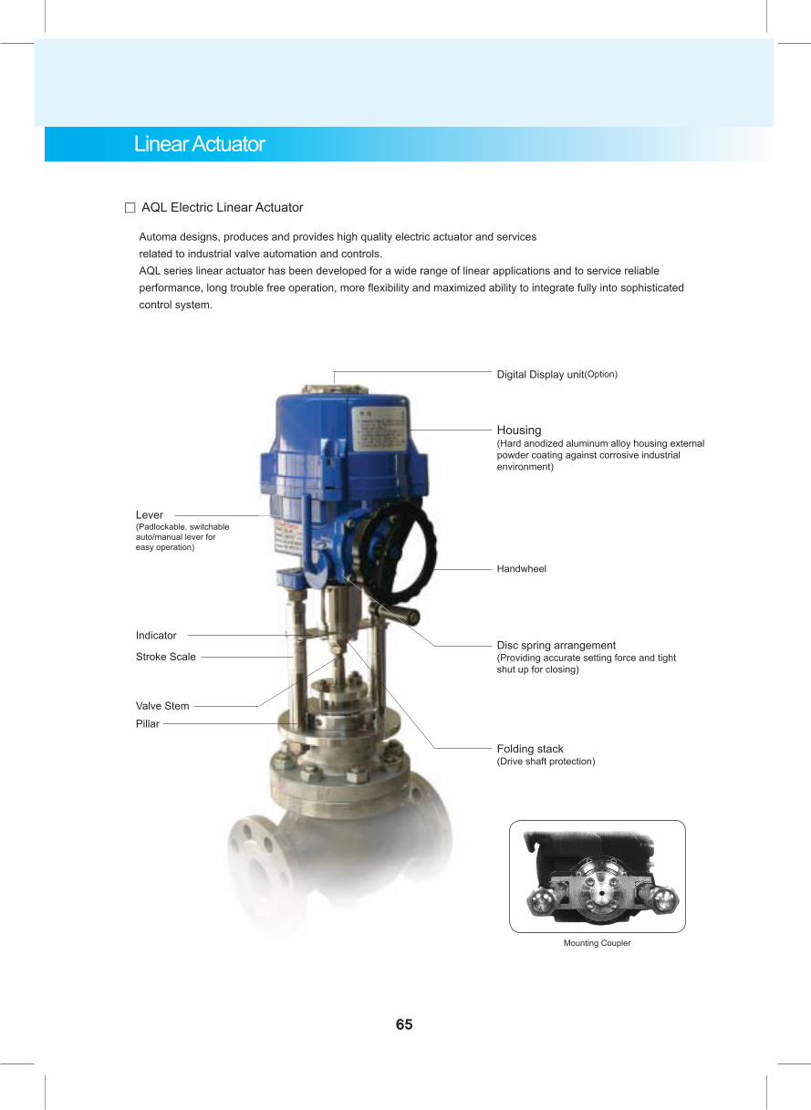
。 AQL Electric Linear Actuator
Lever(Padlockable, switchable auto/manual lever for easy operation)
Stroke Scale
Indicator
Handwheel
Folding stack(Drive shaft protection)
Mounting Coupler
PillarValve Stem
Digital Display unit(Option)
Disc spring arrangement(Providing accurate setting force and tight shut up for closing)
Automa designs, produces and provides high quality electric actuator and servicesrelated to industrial valve automation and controls.AQL series linear actuator has been developed for a wide range of linear applications and to service reliable performance, long trouble free operation, more flexibility and maximized ability to integrate fully into sophisticated control system.
65
Linear Actuator
Housing(Hard anodized aluminum alloy housing external powder coating against corrosive industrial environment)
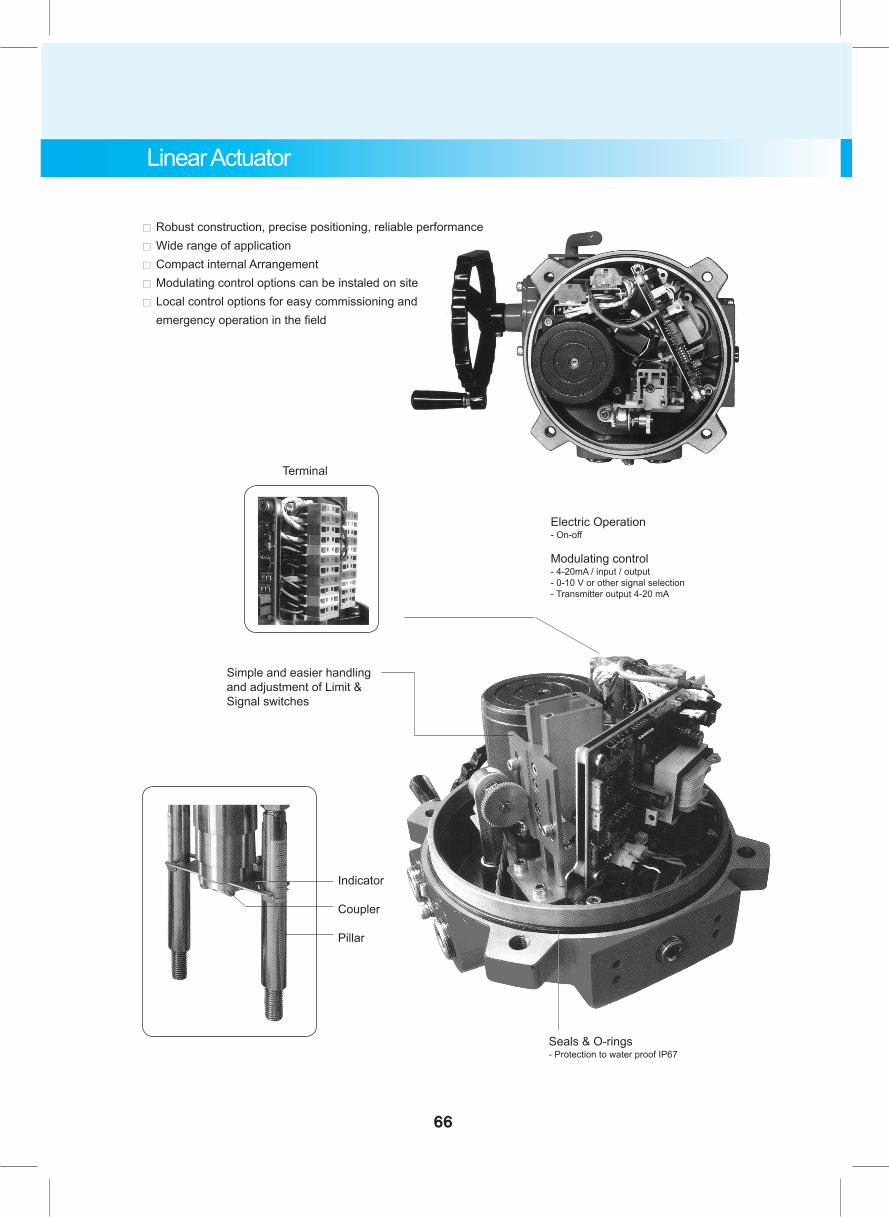
。 Robust construction, precise positioning, reliable performance。 Wide range of application。 Compact internal Arrangement。 Modulating control options can be instaled on site。 Local control options for easy commissioning and
emergency operation in the field
Electric Operation- On-off
Modulating control- 4-20mA / input / output- 0-10 V or other signal selection- Transmitter output 4-20 mA
Seals & O-rings- Protection to water proof IP67
Terminal
Simple and easier handling and adjustment of Limit &Signal switches
Indicator
Coupler
Pillar
66
Linear Actuator
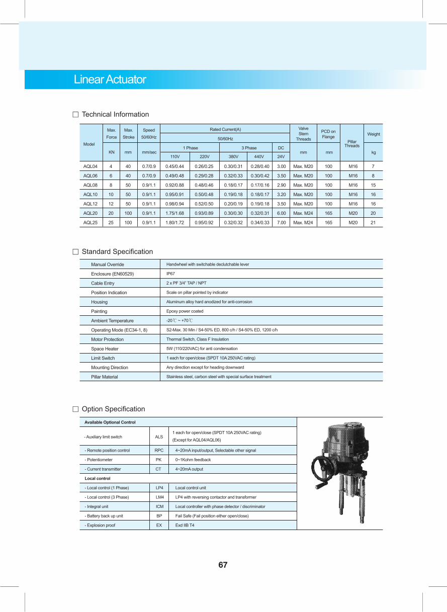
AQL04 4 40 0.7/0.9 0.45/0.44 0.26/0.25 0.30/0.31 0.28/0.40 3.00 Max. M20 100 M16 7
AQL06 6 40 0.7/0.9 0.49/0.48 0.29/0.28 0.32/0.33 0.30/0.42 3.50 Max. M20 100 M16 8
AQL08 8 50 0.9/1.1 0.92/0.88 0.48/0.46 0.18/0.17 0.17/0.16 2.90 Max. M20 100 M16 15
AQL10 10 50 0.9/1.1 0.95/0.91 0.50/0.48 0.19/0.18 0.18/0.17 3.20 Max. M20 100 M16 16
AQL12 12 50 0.9/1.1 0.98/0.94 0.52/0.50 0.20/0.19 0.19/0.18 3.50 Max. M20 100 M16 16
AQL20 20 100 0.9/1.1 1.75/1.68 0.93/0.89 0.30/0.30 0.32/0.31 6.00 Max. M24 165 M20 20
AQL25 25 100 0.9/1.1 1.80/1.72 0.95/0.92 0.32/0.32 0.34/0.33 7.00 Max. M24 165 M20 21
。 Technical Information
。 Standard Specification
。 Option Specification
Model
Max.Force
Max.Stroke
Speed50/60Hz
ValveStem
Threads
PCD onFlange Weight
Rated Current(A)
50/60Hz
KN mm mm/sec1 Phase
110V 220V 380V 440V 24V
DCmm mm kg
3 PhasePillar
Threads
67
Linear Actuator
Available Optional Control
- Remote position control RPC 4~20mA input/output, Selectable other signal
- Potentiometer PK 0~1Kohm feedback
- Current transmitter CT 4~20mA output
Local control
- Local control (1 Phase) LP4 Local control unit
- Local control (3 Phase) LM4 LP4 with reversing contactor and transformer
- Integral unit ICM Local controller with phase detector / discriminator
- Battery back up unit BP Fail Safe (Fail position either open/close)
- Explosion proof EX Exd IIB T4
ALS1 each for open/close (SPDT 10A 250VAC rating)
(Except for AQL04/AQL06) - Auxiliary limit switch
Manual Override
Enclosure (EN60529)
Cable Entry
Position Indication
Housing
Painting
Ambient Temperature
Operating Mode (EC34-1, 8)
Motor Protection
Space Heater
Limit Switch
Mounting Direction
Pillar Material
Handwheel with switchable declutchable lever
IP67
2 x PF 3/4” TAP / NPT
Scale on pillar pointed by indicator
Aluminum alloy hard anodized for anti-corrosion
Epoxy power coated
-20℃ ~ +70℃
S2-Max. 30 Min / S4-50% ED, 800 c/h / S4-50% ED, 1200 c/h
Thermal Switch, Class F Insulation
5W (110/220VAC) for anti condensation
1 each for open/close (SPDT 10A 250VAC rating)
Any direction except for heading downward
Stainless steel, carbon steel with special surface treatment
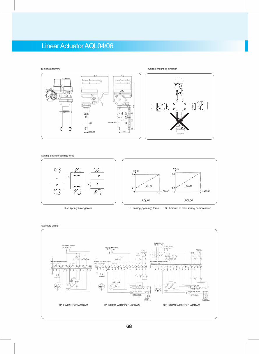
Linear Actuator AQL04/06
Dimensions(mm)
Setting closing(opening) force
Standard wiring
F : Closing(opening) force S : Amount of disc spring compression
1PH WIRING DIAGRAM 1PH+RPC WIRING DIAGRAM 3PH+RPC WIRING DIAGRAM
AQL04 AQL06
Disc spring arrangement
Correct mounting direction
68
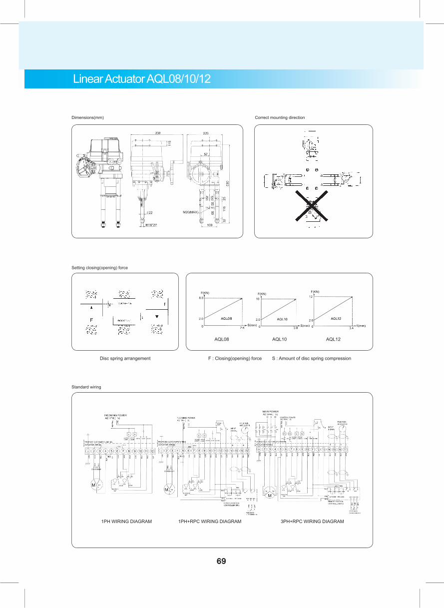
Linear Actuator AQL08/10/12
Dimensions(mm)
Setting closing(opening) force
Standard wiring
F : Closing(opening) force S : Amount of disc spring compression
1PH WIRING DIAGRAM 1PH+RPC WIRING DIAGRAM 3PH+RPC WIRING DIAGRAM
AQL08 AQL10 AQL12
Disc spring arrangement
Correct mounting direction
69
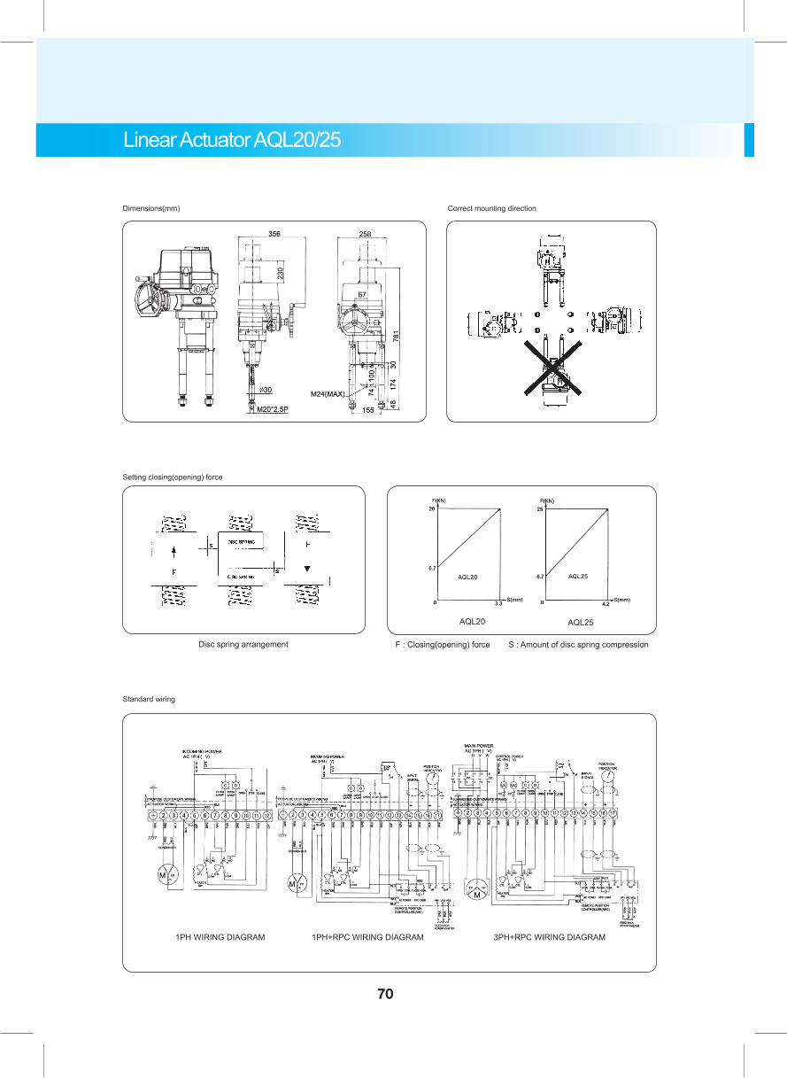
Linear Actuator AQL20/25
Dimensions(mm)
Setting closing(opening) force
Standard wiring
F : Closing(opening) force S : Amount of disc spring compression
1PH WIRING DIAGRAM 1PH+RPC WIRING DIAGRAM 3PH+RPC WIRING DIAGRAM
AQL20 AQL25
Disc spring arrangement
Correct mounting direction
70
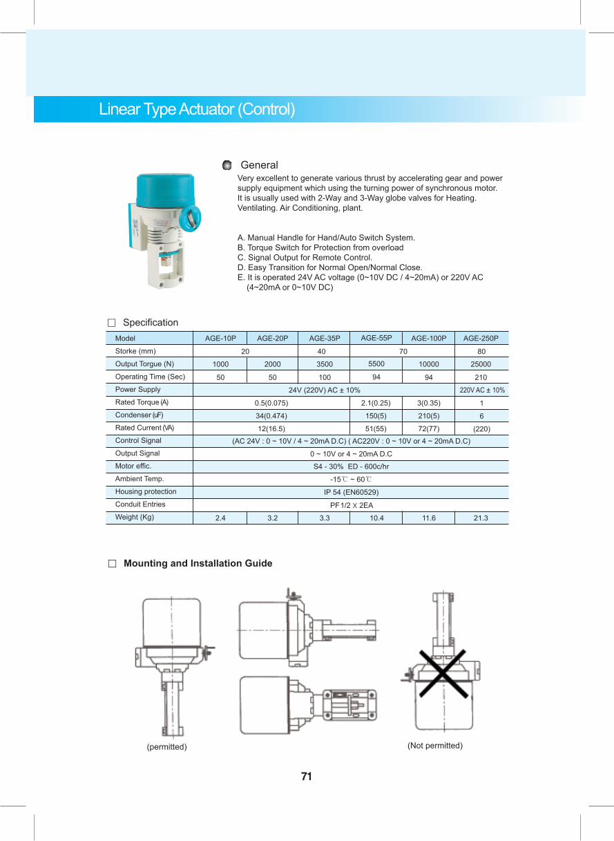
Very excellent to generate various thrust by accelerating gear and power supply equipment which using the turning power of synchronous motor.It is usually used with 2-Way and 3-Way globe valves for Heating.Ventilating. Air Conditioning, plant.
A. Manual Handle for Hand/Auto Switch System.B. Torque Switch for Protection from overloadC. Signal Output for Remote Control.D. Easy Transition for Normal Open/Normal Close.E. It is operated 24V AC voltage (0~10V DC / 4~20mA) or 220V AC (4~20mA or 0~10V DC)
General
Model
Storke (mm)
Output Torgue (N)
Operating Time (Sec)
Power Supply
Rated Torque (A)
Condenser (uF)
Rated Current (VA)
Control Signal
Output Signal
Motor effic.
Ambient Temp.
Housing protection
Conduit Entries
Weight (Kg)
0.5(0.075)
34(0.474)
12(16.5)
2.1(0.25)
150(5)
51(55)
20 40 70 80
。 Specification
3(0.35)
210(5)
72(77)
1
6
(220)
2.4 3.2 3.3 10.4 11.6 21.3
AGE-10P AGE-20P AGE-35P AGE-55P AGE-100P AGE-250P
1000 2000 3500 5500 10000 25000
50 50
24V (220V) AC ± 10%
(AC 24V : 0 ~ 10V / 4 ~ 20mA D.C) ( AC220V : 0 ~ 10V or 4 ~ 20mA D.C)
0 ~ 10V or 4 ~ 20mA D.C
S4 - 30% ED - 600c/hr
-15℃ ~ 60℃
IP 54 (EN60529)
220V AC ± 10%
100 94 94 210
PF1/2 X 2EA
。 Mounting and Installation Guide
(permitted) (Not permitted)
Linear Type Actuator (Control)
71
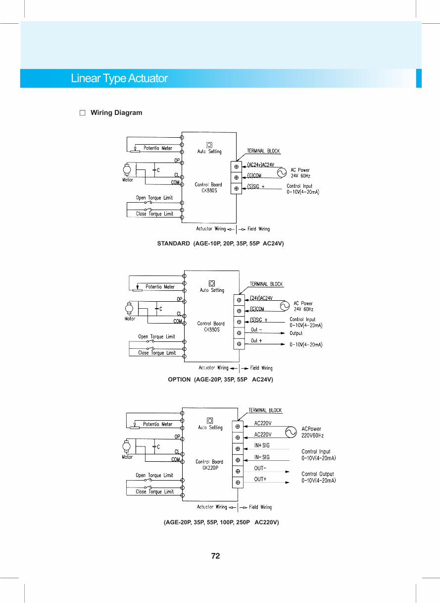
STANDARD (AGE-10P, 20P, 35P, 55P AC24V)
OPTION (AGE-20P, 35P, 55P AC24V)
(AGE-20P, 35P, 55P, 100P, 250P AC220V)
。 Wiring Diagram
Linear Type Actuator
72
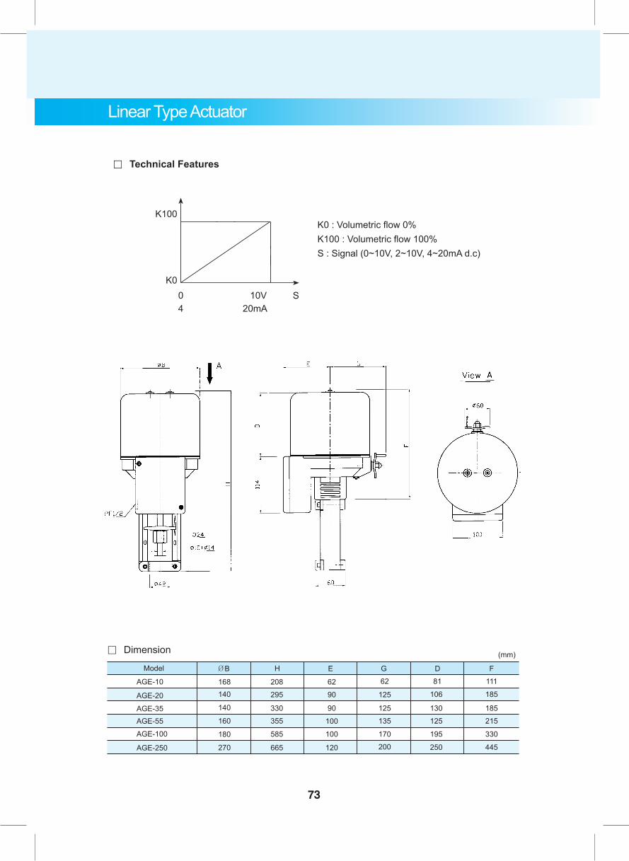
K0 : Volumetric flow 0%K100 : Volumetric flow 100%S : Signal ( 0~10V, 2~10V, 4~20mA d.c)
K100
K004
10V20mA
S
。 Technical Features
Linear Type Actuator
111
185
185215
330
445
F
(mm)
AGE-10
ØB
AGE-20
AGE-35AGE-55
AGE-100
AGE-250
Model
208295
330355
585
665
H
6290
90
100
100
120
E62
125
125135
170200
G81
106
130125
195
250
D
168140
140
160
180
270
。 Dimension
73
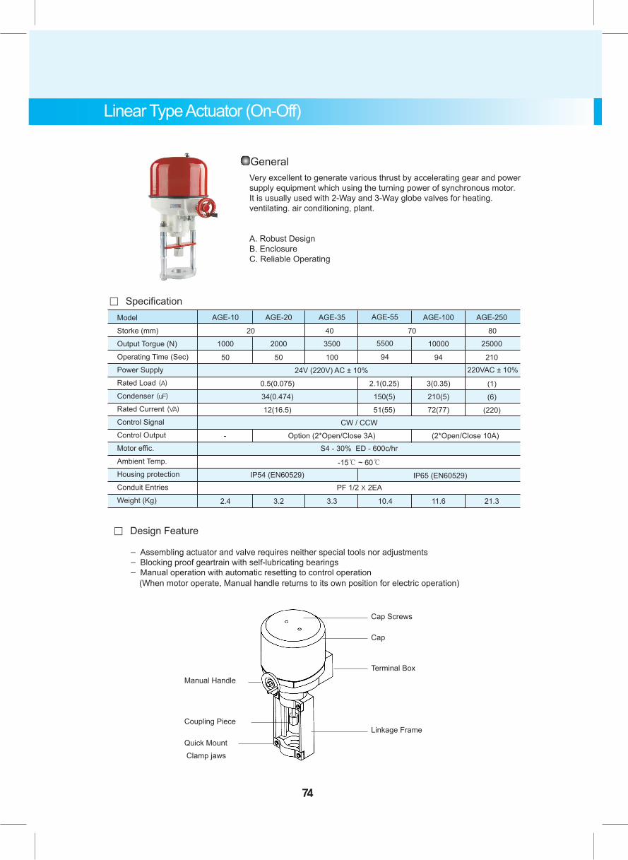
220V (110V)AC
Linear Type Actuator (On-Off)
Cap Screws
Cap
Terminal Box
Linkage Frame
Manual Handle
Coupling Piece
Quick Mount Clamp jaws
Model
Storke (mm)
Output Torgue (N)
Operating Time (Sec)
Power Supply
Rated Load (A)
Condenser (uF)
Rated Current (VA)
Control Signal
Control Output
Motor effic.
Ambient Temp.
Housing protection
Conduit Entries
Weight (Kg)
0.5(0.075)
34(0.474)
12(16.5)
2.1(0.25)
150(5)
51(55)
20 40 70 80
。 Specification
3(0.35)
210(5)
72(77)
(1)
(6)
(220)
2.4 3.2 3.3 10.4 11.6 21.3
AGE-10 AGE-20 AGE-35 AGE-55 AGE-100 AGE-250
1000 2000 3500 5500 10000 25000
50 50
24V (220V) AC ± 10%
CW / CCW
- Option (2*Open/Close 3A) (2*Open/Close 10A)S4 - 30% ED - 600c/hr
-15℃ ~ 60℃
100 94 94 210
IP54 (EN60529)PF 1/2 X 2EA
IP65 (EN60529)
。 Design Feature
- Assembling actuator and valve requires neither special tools nor adjustments - Blocking proof geartrain with self-lubricating bearings - Manual operation with automatic resetting to control operation (When motor operate, Manual handle returns to its own position for electric operation)
Very excellent to generate various thrust by accelerating gear and power supply equipment which using the turning power of synchronous motor.It is usually used with 2-Way and 3-Way globe valves for heating.ventilating. air conditioning, plant.
A. Robust DesignB. EnclosureC. Reliable Operating
General
74
220VAC ± 10%
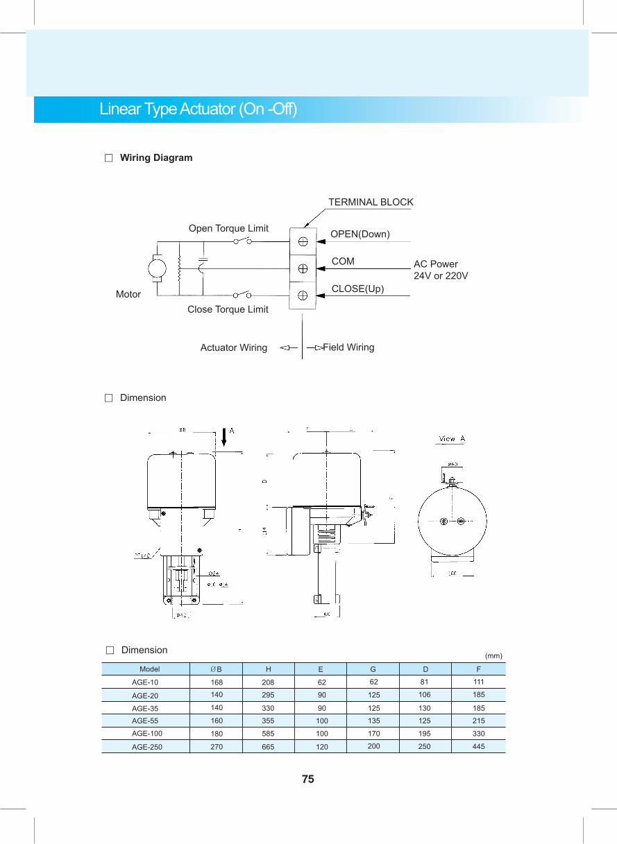
185
215
445
F
。 Dimension
。 Wiring Diagram
AGE-10
ØB
AGE-20
AGE-35AGE-55
AGE-100
AGE-250
Model
208295
330355
585
665
H
6290
90
100
100
120
E62
125
125135
170200
G81
106
130125
195
250
D111
185
330
168140
140
160
180
270
(mm)
TERMINAL BLOCK
OPEN(Down)
COM
CLOSE(Up)
Field Wiring
AC Power24V or 220V
Actuator Wiring
Close Torque LimitMotor
Open Torque Limit
Linear Type Actuator (On -Off)
。 Dimension
75

76
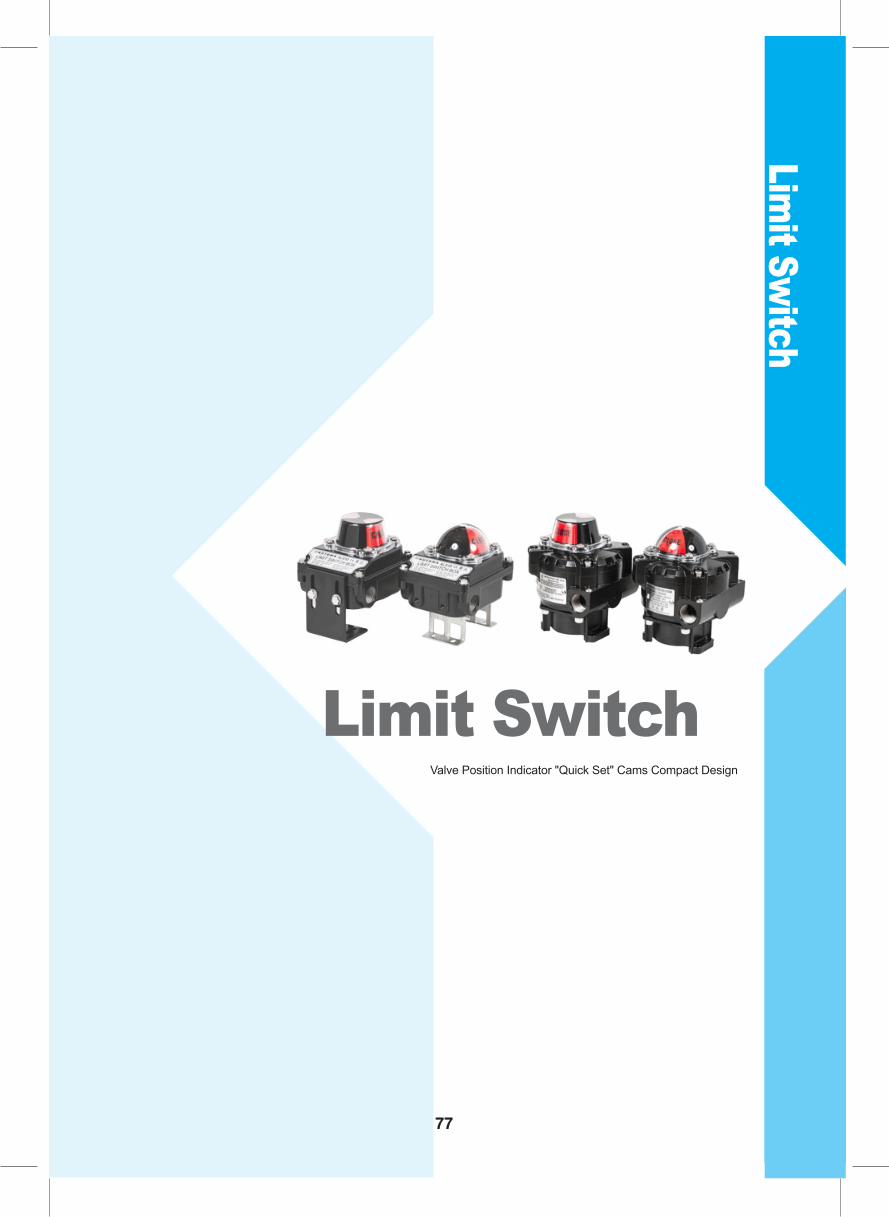
Limit Sw
itch
Limit Switch Valve Position Indicator "Quick Set" Cams Compact Design
77
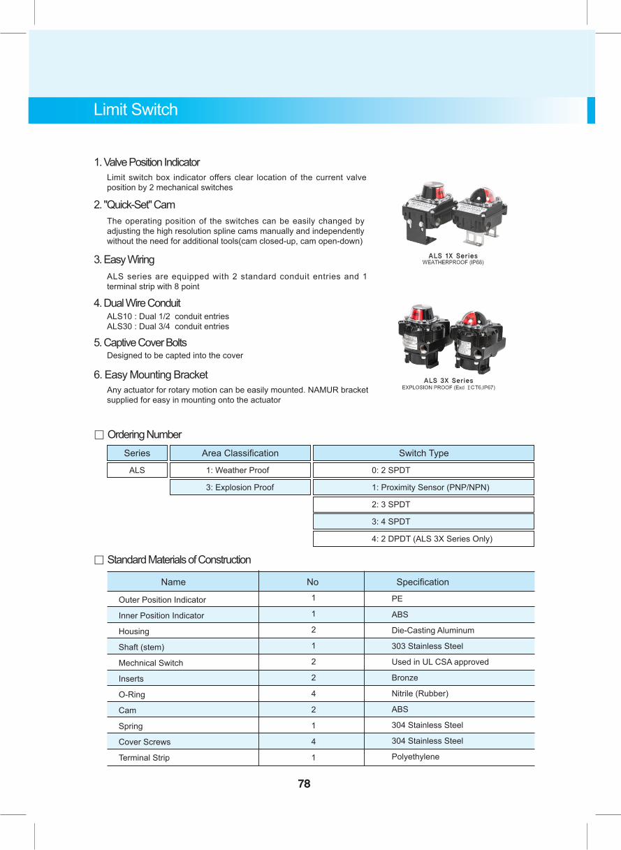
。 Standard Materials of Construction
1. Valve Position IndicatorLimit switch box indicator offers clear location of the current valve position by 2 mechanical switches
2. "Quick-Set" CamThe operating position of the switches can be easily changed by adjusting the high resolution spline cams manually and independently without the need for additional tools(cam closed-up, cam open-down)
3. Easy WiringALS series are equipped with 2 standard conduit entries and 1 terminal strip with 8 point
4. Dual Wire ConduitALS10 : Dual 1/2 conduit entriesALS30 : Dual 3/4 conduit entries
5. Captive Cover BoltsDesigned to be capted into the cover
6. Easy Mounting BracketAny actuator for rotary motion can be easily mounted. NAMUR bracket supplied for easy in mounting onto the actuator
。 Ordering NumberSeries Area Classification Switch Type
ALS 1: Weather Proof 0: 2 SPDT
3: Explosion Proof 1: Proximity Sensor (PNP/NPN)
2: 3 SPDT
3: 4 SPDT
4: 2 DPDT (ALS 3X Series Only)
Limit Switch
78
Outer Position Indicator
Inner Position Indicator
Housing
Shaft (stem)
Mechnical Switch
Inserts
O-Ring
Cam
Spring
Cover Screws
Terminal Strip
Name No Specification1
1
2
1
2
2
4
2
1
4
1
PE
ABS
Die-Casting Aluminum
303 Stainless Steel
Used in UL CSA approved
Bronze
Nitrile (Rubber)
ABS
304 Stainless Steel
304 Stainless Steel
Polyethylene
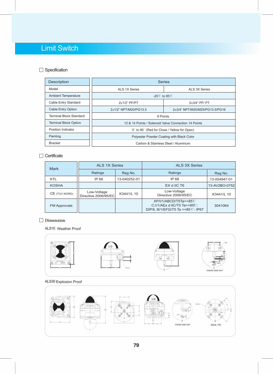
。 Dimension
ALS10 Weather Proof
ALS30 Explosion Proof
。 Specification
。 Certificate
Mark
CE (TUV NORD)
KOSHA
FM Approvals
Ratings Reg No.
K3441/L 10
Ratings
EX d IIC T6
Reg No.
13-AV2BO-0752
XP/I/1/ABCD/T5Ta=+85℃C;I/1/AEx d llC/T5 Ta=+85℃:
DIP/ll, lll/1/EFG/T5 Ta =+85℃: IP67
Low-Voltage Directive 2006/95/EC
IP 68KTL IP 6813-040252-01 13-054947-01
Low-Voltage Directive 2006/95/EC
ALS 1X Series ALS 3X Series
3041064
K3441/L 10
-20℃ to 85℃
8 Points
12 & 14 Points / Solenoid Valve Connection 14 Points
0̊ to 90̊ (Red for Close / Yellow for Open)
Polyester Powder Coating with Black Color
Carbon & Stainless Steel / Aluminium
Description
Model
Ambient Temperature
Cable Entry Standard
Cable Entry Option
Terminal Block Standard
Terminal Block Option
Position Indicator
Painting
Bracket
Series
ALS 1X Series
2x1/2" PF/PT
2x1/2" NPT/M20/PG13.5
ALS 3X Series
2x3/4" PF/ PT
2x3/4" NPT/M20/M25/PG13.5/PG16
Limit Switch
79
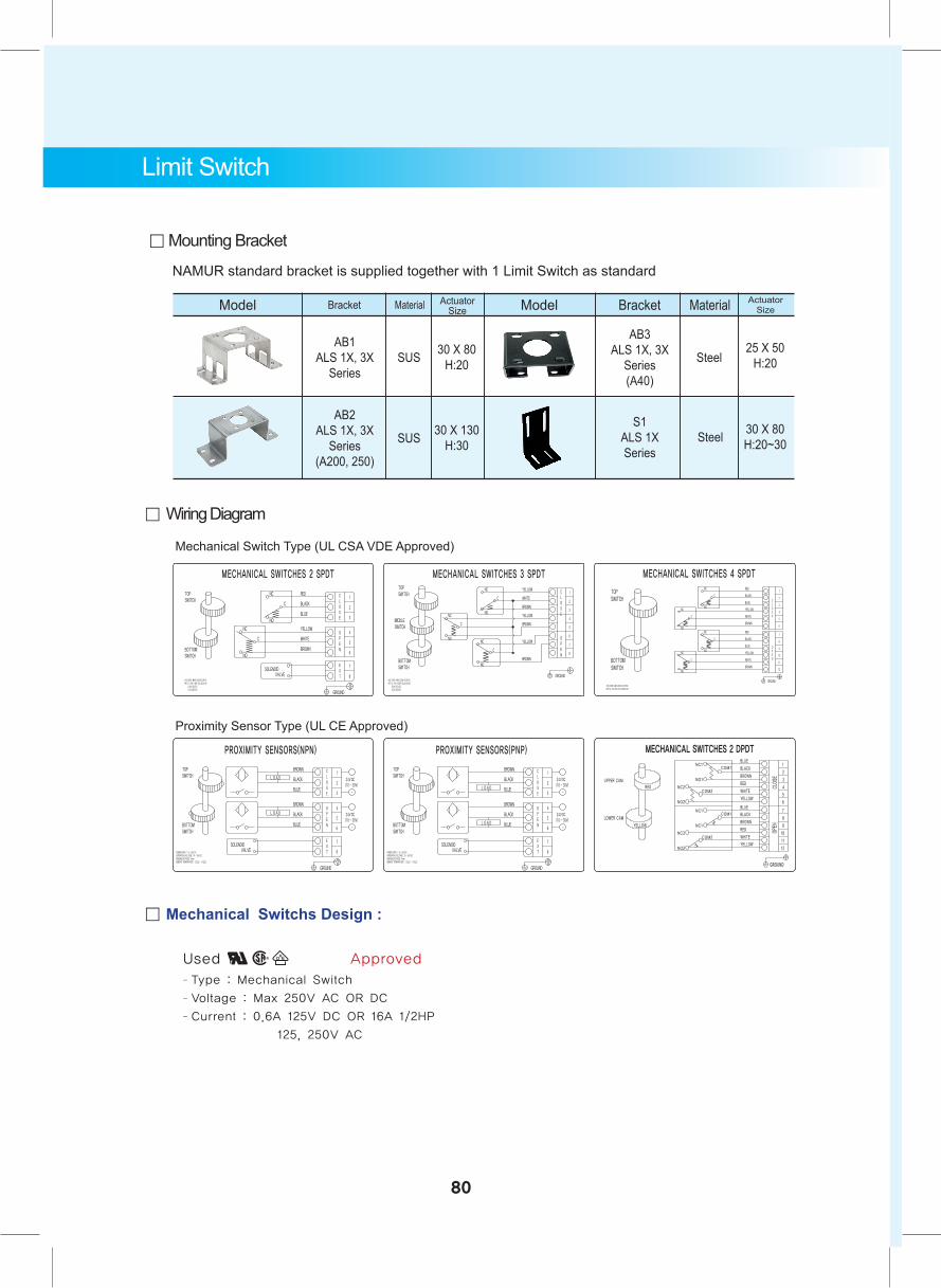
。 Mechanical Switchs Design :
Used in Approved - Type : Mechanical Switch
- Voltage : Max 250V AC OR DC
- Current : 0.6A 125V DC OR 16A 1/2HP
125, 250V AC
。 Mounting Bracket
NAMUR standard bracket is supplied together with 1 Limit Switch as standard
Model Bracket ModelMaterial ActuatorSize
AB1ALS 1X, 3X
Series
AB3ALS 1X, 3X
Series(A40)
SUS Steel30 X 80 H:20
AB2ALS 1X, 3X
Series(A200, 250)
SUS 30 X 130 H:30
Bracket Material ActuatorSize
S1ALS 1XSeries
Steel 30 X 80 H:20~30
25 X 50 H:20
Limit Switch
80
。 Wiring Diagram
Proximity Sensor Type (UL CE Approved)
Mechanical Switch Type (UL CSA VDE Approved)
Technical Data
Technical DataManufacturing Application StandardMaterial Selection (Body & Soft Seat)Hydrostatic Pressure Test Allowable Seat Leakage ClassInternational Material ConversionMaterial CharacteristicsMaterial Max Working PressureSteel Pipe Flange StandardWeight & Measures
81
Technical Data
。 MANUFACTURING APPLICATION STANDARDS
AUTOMA Valves are designed to operate under the serve conditions in accordance
with the following Standards & Codes.
ANSI(American National Standard Institute)
B 16.1 (Cast iron pipe flanges and flanged fittings)
B 1.20.1 (Pipe threads for general purpose)
B 16.1 (Cast iron pipe flanges and flanged fittings)
B 16.10 (Face to face and end to end dimension of valve)
B 16.25 (Butt welding Ends)
B 16.34 (Valves-flanged and butt welding end)
B 16.37 (Hydrostatic test of control valve
B 16.47 (Large diameter dteel flanges)
B 16.5 (Steel pipe flange and flange fittings)
ASTM (American Society for Testing and Materials)
A 105 (Standard specification for forging, carbon steel)
A 182 (Standard specification for forging, stainless steel)
A 216/7(Standard specifications, for casting, for carbon steel)
A 350 (Standard specification for castings (low temperature), carbon steel)
API (American Petroleum Institute)
6D (Specification for pipeline valves)
598 (Valve inspection and test)
600 (Steel gate valves-flange and butt welding ends)
602 (Compact design carbon steel gate valves)
607 (Fire test for soft-seated ball valves)
608 (Metal ball valves-flanged and but-welding ends)
609 (Specification for butterfly valves)
BSI (British Standards Institute)
5146 (Inspection and test of steel valves for the petroleum industries)
5351 (Steel ball valves for the petroleum, petrochemical and allied industries)
5353 (Specification for gate, check, globe and plug valves)
5417 (Inspection for the industrial valves)
6364 (Valve for cryogenic service)
6755 Part 1 (Specification for production pressure testing requirements)
6755 Part 2 (Testing of valves, specification for fire type testing requirements)
82
Technical Data
MSS (Manufacturers Standardization Society of the valve and fittings industry) SP-6 (Standard finishes system for valves) SP-25 (Standard marking system for valves) SP-55 (Quality standard for steel casting for valves, flanges and fittings and other piping components visual method) SP-61 (Pressure testing of steel valves)
SSPC (Steel structure painting council) 1-10 (Surface preparation specifications)
AWWA (American water and wastewater works association) C 111 (Mechanical joints ends) C 504 (Rubber seated butterfly valves) C 606 (Grooved joints ends)
DIN (Germany Standards) 3230 (Test conditions of delivery for valves), 3339 (Component of the valves parts), 3840 (Bodies of valves, calculation), 50049.2.2/3.1B (Certificates on materials tests)
ISO (International Standards Organization) 5203 (Part-turn valve actuator attachment-top flange dimension) 5208 (Industrial valves - pressure testing for valves) 5209 (Marking for the industrial valves) 5211 (Part-turn valve actuator attachment)
FCI (Fluid Control Institute, Inc) 62-1 (Recommend volume tray standards formulas for sizing control valves) 70-2-2 (Control valve seat leakage)
ISA (Instrument Society of America) RP 59.2 (Field measurements of air borne sound level generated by control valves) S75.19 (Hydrostatic Testing of control valve)
EN (European National Standards) 1626 (Cryogenic vessels-Valves for cryogenic services) 10204 (Type of inspection documents)
IEC (International Electro technical Commission) PUP 534-1 (Industrial process valve part 1 : general considerations)
NACE (National Association of Corrosion Engineers) MR 0175 (Sulfide stress cracking resistant materials)
83
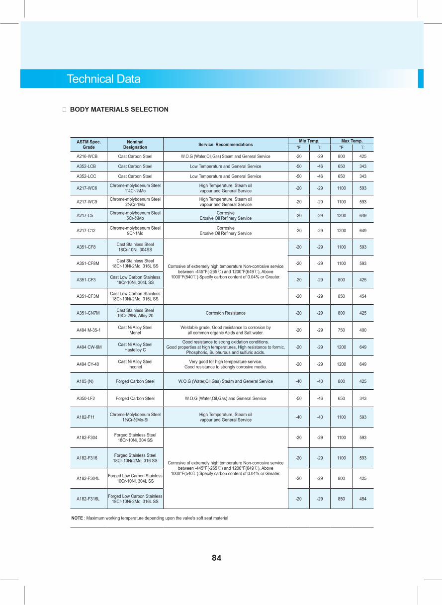
ASTM Spec. Grade
Nominal Designation Service Recommendations
Min Temp. Max Temp.°F ℃ °F ℃
A216-WCB Cast Carbon Steel W.O.G (Water,Oil,Gas) Steam and General Service -20 -29 800 425
A352-LCB Cast Carbon Steel Low Temperature and General Service -50 -46 650 343
A352-LCC Cast Carbon Steel Low Temperature and General Service -50 -46 650 343
A217-WC6 Chrome-molybdenum Steel 1¼Cr-½Mo
High Temperature, Steam oil vapour and General Service -20 -29 1100 593
A217-WC9 Chrome-molybdenum Steel 2¼Cr-1Mo
High Temperature, Steam oil vapour and General Service -20 -29 1100 593
A217-C5 Chrome-molybdenum Steel 5Cr-½Mo
Corrosive Erosive Oil Refinery Service -20 -29 1200 649
A217-C12 Chrome-molybdenum Steel 9Cr-1Mo
Corrosive Erosive Oil Refinery Service -20 -29 1200 649
A351-CF8 Cast Stainless Steel 18Cr-10Ni, 304SS
Corrosive of extremely high temperature Non-corrosive service between -445°F(-265℃) and 1200°F(649℃), Above
1000°F(540℃) Specify carbon content of 0.04% or Greater.
-20 -29 1100 593
A351-CF8M Cast Stainless Steel 18Cr-10Ni-2Mo, 316L SS -20 -29 1100 593
A351-CF3 Cast Low Carbon Stainless 18Cr-10Ni, 304L SS -20 -29 800 425
A351-CF3M Cast Low Carbon Stainless 18Cr-10Ni-2Mo, 316L SS -20 -29 850 454
A351-CN7M Cast Stainless Steel 19Cr-29Ni, Alloy-20 Corrosion Resistance -20 -29 800 425
A494 M-35-1 Cast Ni Alloy Steel Monel
Weldable grade, Good resistance to corrosion by all common organic Acids and Salt water. -20 -29 750 400
A494 CW-6M Cast Ni Alloy Steel Hastelloy C
Good resistance to strong oxidation conditions. Good properties at high temperatures, High resistance to formic,
Phosphoric, Sulphurous and sulfuric acids.-20 -29 1200 649
A494 CY-40 Cast Ni Alloy Steel Inconel
Very good for high temperature service. Good resistance to strongly corrosive media. -20 -29 1200 649
A105 (N) Forged Carbon Steel W.O.G (Water,Oil,Gas) Steam and General Service -40 -40 800 425
A350-LF2 Forged Carbon Steel W.O.G (Water,Oil,Gas) and General Service -50 -46 650 343
A182-F11 Chrome-Molybdenum Steel 1¼Cr-½Mo-Si
High Temperature, Steam oil vapour and General Service -40 -40 1100 593
A182-F304 Forged Stainless Steel 18Cr-10Ni, 304 SS
Corrosive of extremely high temperature Non-corrosive service between -445°F(-265℃) and 1200°F(649℃), Above
1000°F(540℃) Specify carbon content of 0.04% or Greater.
-20 -29 1100 593
A182-F316 Forged Stainless Steel 18Cr-10Ni-2Mo, 316 SS -20 -29 1100 593
A182-F304L Forged Low Carbon Stainless 10Cr-10Ni, 304L SS -20 -29 800 425
A182-F316L Forged Low Carbon Stainless 18Cr-10Ni-2Mo, 316L SS -20 -29 850 454
NOTE : Maximum working temperature depending upon the valve's soft seat material
Technical Data
。 BODY MATERIALS SELECTION
84
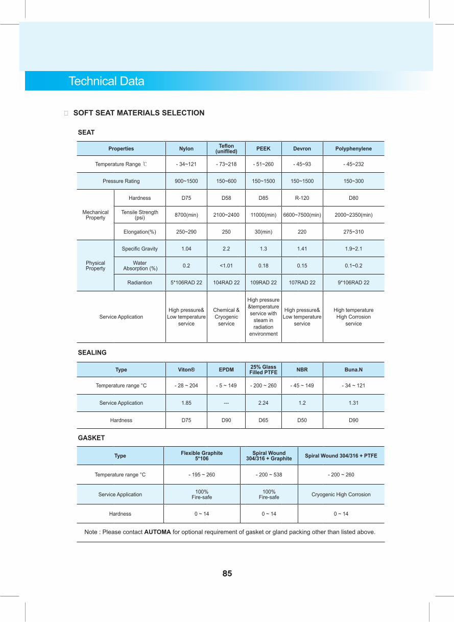
85
SEAT
Properties Nylon Teflon (uniflled) PEEK Devron Polyphenylene
Temperature Range ℃ - 34~121 - 73~218 - 51~260 - 45~93 - 45~232
Pressure Rating 900~1500 150~600 150~1500 150~1500 150~300
Mechanical Property
Hardness D75 D58 D85 R-120 D80
Tensile Strength (psi) 8700(min) 2100~2400 11000(min) 6600~7500(min) 2000~2350(min)
Elongation(%) 250~290 250 30(min) 220 275~310
Physical Property
Specific Gravity 1.04 2.2 1.3 1.41 1.9~2.1
Water Absorption (%) 0.2 <1.01 0.18 0.15 0.1~0.2
Radiantion 5*106RAD 22 104RAD 22 109RAD 22 107RAD 22 9*106RAD 22
Service ApplicationHigh pressure&
Low temperature service
Chemical & Cryogenic
service
High pressure &temperature service with
steam in radiation
environment
High pressure& Low temperature
service
High temperature High Corrosion
service
SEALING
Type Viton® EPDM 25% Glass Filled PTFE NBR Buna.N
Temperature range °C - 28 ~ 204 - 5 ~ 149 - 200 ~ 260 - 45 ~ 149 - 34 ~ 121
Service Application 1.85 --- 2.24 1.2 1.31
Hardness D75 D90 D65 D50 D90
GASKET
Type Flexible Graphite5*106
Spiral Wound 304/316 + Graphite Spiral Wound 304/316 + PTFE
Temperature range °C - 195 ~ 260 - 200 ~ 538 - 200 ~ 260
Service Application 100% Fire-safe
100% Fire-safe Cryogenic High Corrosion
Hardness 0 ~ 14 0 ~ 14 0 ~ 14
Technical Data
。 SOFT SEAT MATERIALS SELECTION
Note : Please contact AUTOMA for optional requirement of gasket or gland packing other than listed above.
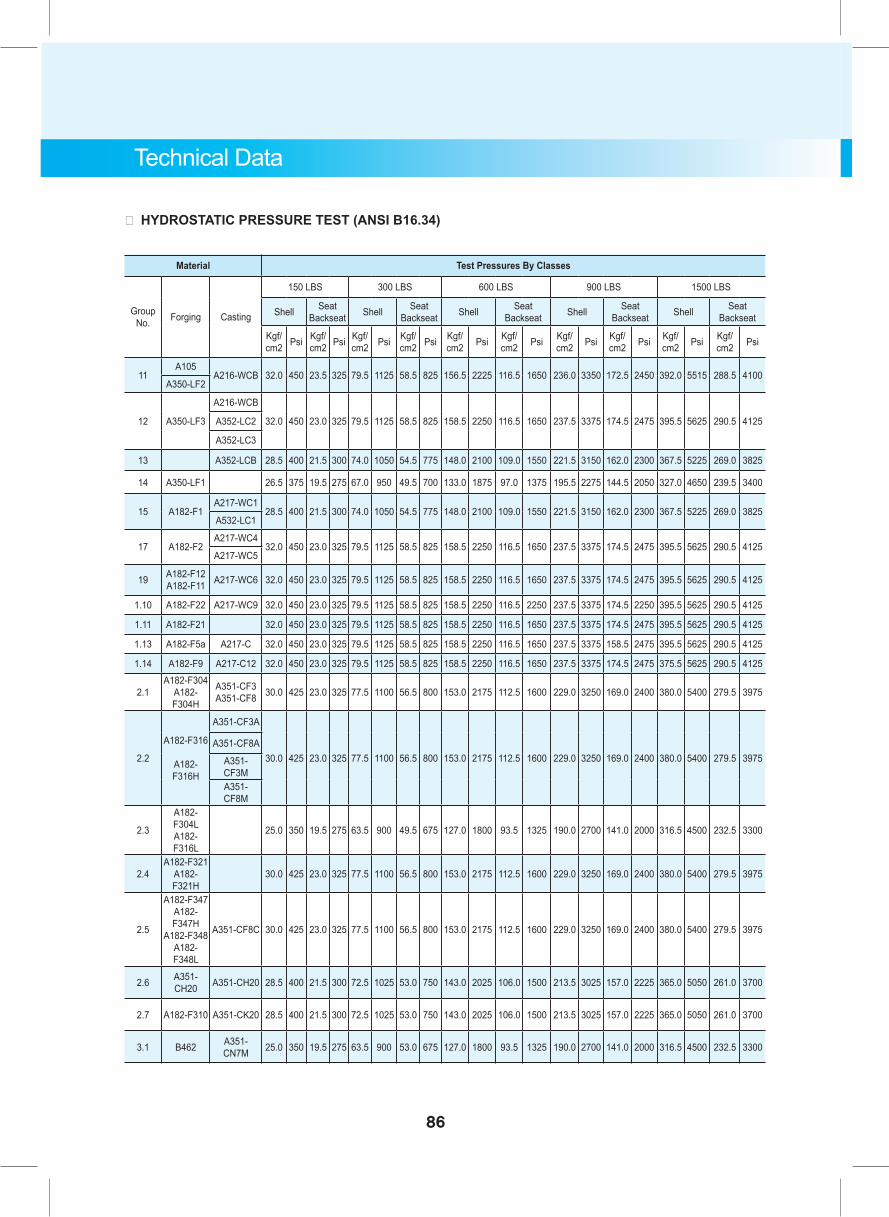
86
Technical Data
。 HYDROSTATIC PRESSURE TEST (ANSI B16.34)
Material Test Pressures By Classes
Group No. Forging Casting
150 LBS 300 LBS 600 LBS 900 LBS 1500 LBS
Shell Seat Backseat Shell Seat
Backseat Shell Seat Backseat Shell Seat
Backseat Shell Seat Backseat
Kgf/cm2 Psi Kgf/
cm2 Psi Kgf/cm2 Psi Kgf/
cm2 Psi Kgf/cm2 Psi Kgf/
cm2 Psi Kgf/cm2 Psi Kgf/
cm2 Psi Kgf/cm2 Psi Kgf/
cm2 Psi
11A105
A216-WCB 32.0 450 23.5 325 79.5 1125 58.5 825 156.5 2225 116.5 1650 236.0 3350 172.5 2450 392.0 5515 288.5 4100A350-LF2
12 A350-LF3
A216-WCB
32.0 450 23.0 325 79.5 1125 58.5 825 158.5 2250 116.5 1650 237.5 3375 174.5 2475 395.5 5625 290.5 4125A352-LC2
A352-LC3
13 A352-LCB 28.5 400 21.5 300 74.0 1050 54.5 775 148.0 2100 109.0 1550 221.5 3150 162.0 2300 367.5 5225 269.0 3825
14 A350-LF1 26.5 375 19.5 275 67.0 950 49.5 700 133.0 1875 97.0 1375 195.5 2275 144.5 2050 327.0 4650 239.5 3400
15 A182-F1A217-WC1
28.5 400 21.5 300 74.0 1050 54.5 775 148.0 2100 109.0 1550 221.5 3150 162.0 2300 367.5 5225 269.0 3825A532-LC1
17 A182-F2A217-WC4
32.0 450 23.0 325 79.5 1125 58.5 825 158.5 2250 116.5 1650 237.5 3375 174.5 2475 395.5 5625 290.5 4125A217-WC5
19 A182-F12 A182-F11 A217-WC6 32.0 450 23.0 325 79.5 1125 58.5 825 158.5 2250 116.5 1650 237.5 3375 174.5 2475 395.5 5625 290.5 4125
1.10 A182-F22 A217-WC9 32.0 450 23.0 325 79.5 1125 58.5 825 158.5 2250 116.5 2250 237.5 3375 174.5 2250 395.5 5625 290.5 4125
1.11 A182-F21 32.0 450 23.0 325 79.5 1125 58.5 825 158.5 2250 116.5 1650 237.5 3375 174.5 2475 395.5 5625 290.5 4125
1.13 A182-F5a A217-C 32.0 450 23.0 325 79.5 1125 58.5 825 158.5 2250 116.5 1650 237.5 3375 158.5 2475 395.5 5625 290.5 4125
1.14 A182-F9 A217-C12 32.0 450 23.0 325 79.5 1125 58.5 825 158.5 2250 116.5 1650 237.5 3375 174.5 2475 375.5 5625 290.5 4125
2.1A182-F304
A182-F304H
A351-CF3 A351-CF8 30.0 425 23.0 325 77.5 1100 56.5 800 153.0 2175 112.5 1600 229.0 3250 169.0 2400 380.0 5400 279.5 3975
2.2
A182-F316
A182-F316H
A351-CF3A
30.0 425 23.0 325 77.5 1100 56.5 800 153.0 2175 112.5 1600 229.0 3250 169.0 2400 380.0 5400 279.5 3975A351-CF8A
A351-CF3MA351-CF8M
2.3
A182-F304L A182-F316L
25.0 350 19.5 275 63.5 900 49.5 675 127.0 1800 93.5 1325 190.0 2700 141.0 2000 316.5 4500 232.5 3300
2.4A182-F321
A182-F321H
30.0 425 23.0 325 77.5 1100 56.5 800 153.0 2175 112.5 1600 229.0 3250 169.0 2400 380.0 5400 279.5 3975
2.5
A182-F347 A182-F347H
A182-F348 A182-F348L
A351-CF8C 30.0 425 23.0 325 77.5 1100 56.5 800 153.0 2175 112.5 1600 229.0 3250 169.0 2400 380.0 5400 279.5 3975
2.6 A351-CH20 A351-CH20 28.5 400 21.5 300 72.5 1025 53.0 750 143.0 2025 106.0 1500 213.5 3025 157.0 2225 365.0 5050 261.0 3700
2.7 A182-F310 A351-CK20 28.5 400 21.5 300 72.5 1025 53.0 750 143.0 2025 106.0 1500 213.5 3025 157.0 2225 365.0 5050 261.0 3700
3.1 B462 A351-CN7M 25.0 350 19.5 275 63.5 900 53.0 675 127.0 1800 93.5 1325 190.0 2700 141.0 2000 316.5 4500 232.5 3300
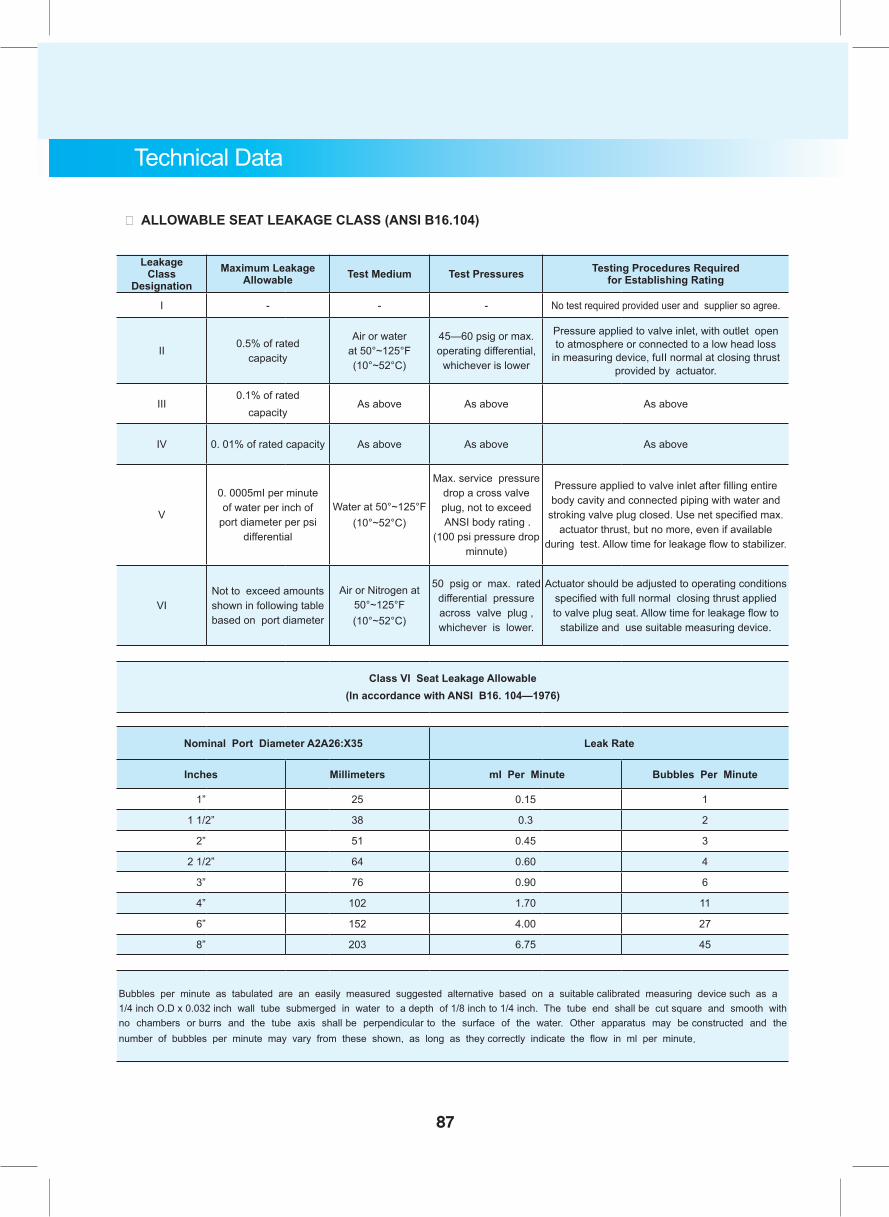
87
Technical Data
。 ALLOWABLE SEAT LEAKAGE CLASS (ANSI B16.104)
Leakage Class
DesignationMaximum Leakage
Allowable Test Medium Test Pressures Testing Procedures Required for Establishing Rating
Ι - - - No test required provided user and supplier so agree.
II0.5% of rated
capacity
Air or water at 50°~125°F (10°~52°C)
45—60 psig or max. operating differential,
whichever is lower
Pressure applied to valve inlet, with outlet open to atmosphere or connected to a low head loss
in measuring device, fuII normal at closing thrust provided by actuator.
III0.1% of rated
capacityAs above As above As above
IV 0. 01% of rated capacity As above As above As above
V
0. 0005mI per minute of water per inch of
port diameter per psi differential
Water at 50°~125°F (10°~52°C)
Max. service pressure drop a cross valve plug, not to exceed ANSI body rating .
(100 psi pressure drop minnute)
Pressure applied to valve inlet after filling entire body cavity and connected piping with water and
stroking valve plug closed. Use net specified max. actuator thrust, but no more, even if available
during test. Allow time for leakage flow to stabilizer.
VINot to exceed amounts shown in following table based on port diameter
Air or Nitrogen at 50°~125°F (10°~52°C)
50 psig or max. rated differential pressure across valve plug , whichever is lower.
Actuator should be adjusted to operating conditions specified with full normal closing thrust applied to valve plug seat. Allow time for leakage flow to
stabilize and use suitable measuring device.
Class VI Seat Leakage Allowable (ln accordance with ANSI B16. 104—1976)
Nominal Port Diameter A2A26:X35 Leak Rate
Inches Millimeters mI Per Minute Bubbles Per Minute
1” 25 0.15 1
1 1/2” 38 0.3 2
2” 51 0.45 3
2 1/2” 64 0.60 4
3” 76 0.90 6
4” 102 1.70 11
6” 152 4.00 27
8” 203 6.75 45
Bubbles per minute as tabulated are an easily measured suggested alternative based on a suitable calibrated measuring device such as a 1/4 inch O.D x 0.032 inch wall tube submerged in water to a depth of 1/8 inch to 1/4 inch. The tube end shall be cut square and smooth with no chambers or burrs and the tube axis shall be perpendicular to the surface of the water. Other apparatus may be constructed and the number of bubbles per minute may vary from these shown, as long as they correctly indicate the flow in ml per minute.
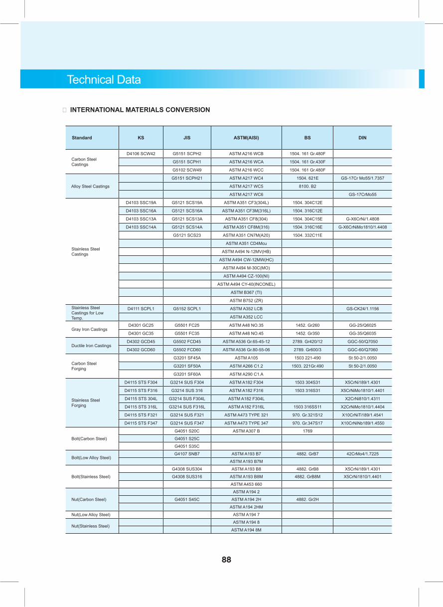
Technical Data
。 INTERNATIONAL MATERIALS CONVERSION
Standard KS JIS ASTM(AISI) BS DIN
Carbon Steel Castings
D4106 SCW42 G5151 SCPH2 ASTM A216 WCB 1504. 161 Gr.480F
G5151 SCPH1 ASTM A216 WCA 1504. 161 Gr.430F
G5102 SCW49 ASTM A216 WCC 1504. 161 Gr.480F
Alloy Steel Castings
G5151 SCPH21 ASTM A217 WC4 1504. 621E GS-17Cr Mo55/1.7357
ASTM A217 WC5 8100. B2
ASTM A217 WC6 GS-17CrMo55
Stainless Steel Castings
D4103 SSC19A G5121 SCS19A ASTM A351 CF3(304L) 1504. 304C12E
D4103 SSC16A G5121 SCS16A ASTM A351 CF3M(316L) 1504. 316C12E
D4103 SSC13A G5121 SCS13A ASTM A351 CF8(304) 1504. 304C15E G-X6CrNi/1.4808
D4103 SSC14A G5121 SCS14A ASTM A351 CF8M(316) 1504. 316C16E G-X6CrNiMo1810/1.4408
G5121 SCS23 ASTM A351 CN7M(A20) 1504. 332C11E
ASTM A351 CD4Mcu
ASTM A494 N-12MV(HB)
ASTM A494 CW-12MW(HC)
ASTM A494 M-30C(MO)
ASTM A494 CZ-100(NI)
ASTM A494 CY-40(INCONEL)
ASTM B367 (TI)
ASTM B752 (ZR) Stainless Steel Castings for Low Temp.
D4111 SCPL1 G5152 SCPL1 ASTM A352 LCB GS-CK24/1.1156
ASTM A352 LCC
Gray Iron CastingsD4301 GC25 G5501 FC25 ASTM A48 NO.35 1452. Gr260 GG-25/Q6025
D4301 GC35 G5501 FC35 ASTM A48 NO.45 1452. Gr350 GG-35/Q6035
Ductile Iron CastingsD4302 GCD45 G5502 FCD45 ASTM A536 Gr.65-45-12 2789. Gr420/12 GGC-50/Q7050
D4302 GCD60 G5502 FCD60 ASTM A536 Gr.80-55-06 2789. Gr600/3 GGC-60/Q7060
Carbon Steel Forging
G3201 SF45A ASTM A105 1503 221-490 St 50-2/1.0050
G3201 SF50A ASTM A266 C1.2 1503. 221Gr.490 St 50-2/1.0050
G3201 SF60A ASTM A290 C1.A
Stainless Steel Forging
D4115 STS F304 G3214 SUS F304 ASTM A182 F304 1503 304S31 X5CrNi189/1.4301
D4115 STS F316 G3214 SUS 316 ASTM A182 F316 1503 316S31 X5CrNiMo1810/1.4401
D4115 STS 304L G3214 SUS F304L ASTM A182 F304L X2CrNi810/1.4311
D4115 STS 316L G3214 SUS F316L ASTM A182 F316L 1503 316SS11 X2CrNiMo1810/1.4404
D4115 STS F321 G3214 SUS F321 ASTM A473 TYPE 321 970. Gr.321S12 X10CrNiTi189/1.4541
D4115 STS F347 G3214 SUS F347 ASTM A473 TYPE 347 970. Gr.347S17 X10CrNiNb189/1.4550
Bolt(Carbon Steel)
G4051 S20C ASTM A307 B 1769
G4051 S25C
G4051 S35C
Bolt(Low Alloy Steel)G4107 SNB7 ASTM A193 B7 4882. GrB7 42CrMo4/1.7225
ASTM A193 B7M
Bolt(Stainless Steel)
G4308 SUS304 ASTM A193 B8 4882. GrB8 X5CrNi189/1.4301
G4308 SUS316 ASTM A193 B8M 4882. GrB8M X5CrNi1810/1.4401
ASTM A453 660
Nut(Carbon Steel)
ASTM A194 2
G4051 S45C ASTM A194 2H 4882. Gr2H
ASTM A194 2HM
Nut(Low Alloy Steel) ASTM A194 7
Nut(Stainless Steel)ASTM A194 8
ASTM A194 8M
88
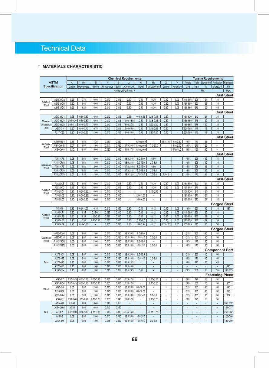
Technical Data
。 MATERIALS CHARACTERISTIC
ASTM Specification
Chemical Requirements Tensile RequirementsC Mn Si P S Cr Ni Mo Cu V Tensile Yield Elongation Reduction Hardness
Carbon Manganese Silicon Phosphorus Sulfur Chromium Nickel Molybdenum Copper Vanadium Mpa Mpa % of area, % HBNminal or Maximum, % Min. Max.
Cast Steel
Carbon Steel
A216-WCA 0.25 0.70 0.60 0.040 0.045 0.50 0.50 0.20 0.30 0.03 415-585 205 24 35 A216-WCB 0.30 1.00 0.60 0.040 0.045 0.50 0.50 0.20 0.30 0.03 485-655 250 22 35 A216-WCC 0.25 1.20 0.60 0.040 0.045 0.50 0.50 0.20 0.30 0.03 485-655 275 22 35
Cast Steel
Chrome-Molybdenum
Steel
A217-WC1 0.25 0.50-0.80 0.60 0.040 0.045 0.35 0.45-0.65 0.45-0.65 0.50 - 450-620 240 24 35 A217-WC6 0.05-0.20 0.50-0.80 0.60 0.040 0.045 1.00-1.50 0.50 0.45-0.65 0.50 - 485-655 275 20 35 A217-WC9 0.05-0.18 0.40-0.70 0.60 0.040 0.045 2.00-2.75 0.50 0.90-1.20 0.50 - 485-655 275 20 35 A217-C5 0.20 0.40-0.70 0.75 0.040 0.045 4.00-6.50 0.50 0.45-0.65 0.50 - 620-795 415 18 35
A217-C12 0.20 0.35-0.65 1.00 0.040 0.045 8.00-10.0 0.50 0.90-1.20 0.50 - 620-795 415 18 35 Cast Steel
Ni Alloy Steel
A494M35-1 0.35 1.50 1.25 0.030 0.030 - Allowance - 26.0-33.0 Fe≤3.50 450 170 25 -A494CW-6M 0.07 1.00 1.00 0.040 0.030 17.0-20.0 Allowance 17.0-20.0 - Fe≤3.00 495 275 25 -A494CY40 0.40 1.50 3.00 0.030 0.030 14.0-17.0 Allowance - - Fe≤11.0 185 195 30 -
Cast Steel
Stainless Steel
A351-CF8 0.08 1.50 2.00 0.040 0.040 18.0-21.0 8.0-11.0 0.50 - - 485 205 35 35 A351-CF8M 0.08 1.50 1.50 0.040 0.040 18.0-21.0 9.0-12.0 2.0-3.0 - - 485 205 30 30 A351-CF3 0.03 1.50 2.00 0.040 0.040 17.0-21.0 8.0-12.0 0.50 - - 485 205 35 35
A351-CF3M 0.03 1.50 1.50 0.040 0.040 17.0-21.0 9.0-13.0 2.0-3.0 - - 485 205 30 30 A351-CF7M 0.07 1.50 1.50 0.040 0.040 19.0-22.0 27.5-30.5 2.0-3.0 3.0-4.0 - 450 170 35 35
Cast Steel
Carbon Steel
A352-LCB 0.30 1.00 0.60 0.040 0.045 0.50 0.50 0.20 0.30 0.03 450-650 240 24 35 A352-LCC 0.25 1.20 0.60 0.040 0.045 0.50 0.50 0.20 0.30 0.03 485-655 275 22 35 A352-LC1 0.25 0.50-0.80 0.60 0.040 0.045 - - 0.45-0.65 - - 450-620 240 24 35 A352-LC2 0.25 0.50-0.80 0.60 0.040 0.045 - 2.00-3.00 - - - 485-655 275 24 35 A352-LC3 0.15 0.50-0.80 0.60 0.040 0.045 - 3.00-4.00 - - - 485-655 275 24 35
Forged Steel
Carbon Steel
A105(N) 0.35 0.60-1.05 0.35 0.040 0.050 0.30 0.40 0.12 0.40 0.03 485 250 30 30 187 A350-LF1 0.30 1.35 0.15-0.3 0.035 0.040 0.30 0.40 0.12 0.40 0.03 415-585 205 25 38 A350-LF2 0.30 1.35 1.15-0.30 0.035 0.040 0.30 0.40 0.12 0.40 0.03 485-655 250 22 30 A350-LF3 0.20 0.90 0.20-0.35 0.035 0.040 0.30 3.25-3.7 0.12 0.40 0.03 485-655 260 22 35 A350-LF9 0.20 0.40-1.06 - 0.035 0.040 0.30 1.60-2.24 0.12 0.75-1.25 0.03 435-605 315 25 38
Forged Steel
Stainless Steel
A182-F304 0.08 2.00 1.00 0.040 0.030 18.0-20.0 8.0-11.0 - - - 515 205 30 50 A182-F316 0.08 2.00 1.00 0.040 0.030 16.0-18.0 10.0-14.0 2.0-3.0 - - 515 205 30 50 A182-F304L 0.03 2.00 1.00 0.045 0.030 18.0-20.0 8.0-13.0 - - - 485 170 30 50 A182-F316L 0.03 2.00 1.00 0.045 0.030 16.0-18.0 10.0-15.0 2.0-3.0 - - 485 170 30 50
Component Part
Trim
A276-304 0.08 2.00 1.00 0.045 0.030 18.0-20.0 8.0-10.5 - - - 515 205 40 50 A276-316 0.08 2.00 1.00 0.045 0.030 16.0-18.0 10.0-14.0 2.0-3.0 - - 485 170 40 50 A276-410 0.15 1.00 1.00 0.040 0.030 11.5-13.5 - - - - 480 275 20 45 A276-420 0.15 1.00 1.00 0.040 0.030 12.0-14.0 - - - - - - - - 241 A182-F6a 0.15 1.00 1.00 0.040 0.030 11.5-13.5 0.50 - - - 585 380 18 35 167~229
Fastening Piece
Stud
A193-B7 0.37-0.49 0.65-1.10 0.15-0.35 0.035 0.040 0.75-1.20 - 0.15-0.25 - - 860 720 16 50 A193-B7M 0.37-0.49 0.65-1.10 0.15-0.35 0.035 0.040 0.75-1.20 - 0.15-0.25 - - 690 550 18 50 235 A193-B8 0.08 2.00 1.00 0.045 0.030 18.0-20.0 8.0-10.50 - - - 515 205 30 50 223
A193-B8A 0.08 2.00 1.00 0.045 0.030 18.0-20.0 8.0-10.50 - - - 515 205 30 50 223 A193-B8M 0.08 2.00 1.00 0.045 0.030 16.0-18.0 10.0-14.0 2.0-3.0 - - 515 205 30 50 192 A320-L7 0.38-0.48 075-1.00 0.15-0.35 0.035 0.040 0.80-1.10 - 0.15-0.25 - - 860 725 16 50
Nut
A194-2H ≥0.40 1.00 0.40 0.040 0.050 - - - - - - - - - 248~352A194-2HM ≥0.40 1.00 0.40 0.040 0.050 - - - - - - - - - 159~237
A194-7 0.37-0.49 0.65-1.10 0.15-0.35 0.040 0.040 0.75-1.20 - 0.15-0.25 - - - - - - 248~352A194-8 0.08 2.00 1.00 0.045 0.030 18.0-20.0 18.0-20.0 - - - - - - - 126~300
A194-8M 0.08 2.00 1.00 0.045 0.030 16.0-18.0 16.0-18.0 2.0-3.0 - - - - - - 126~300
89
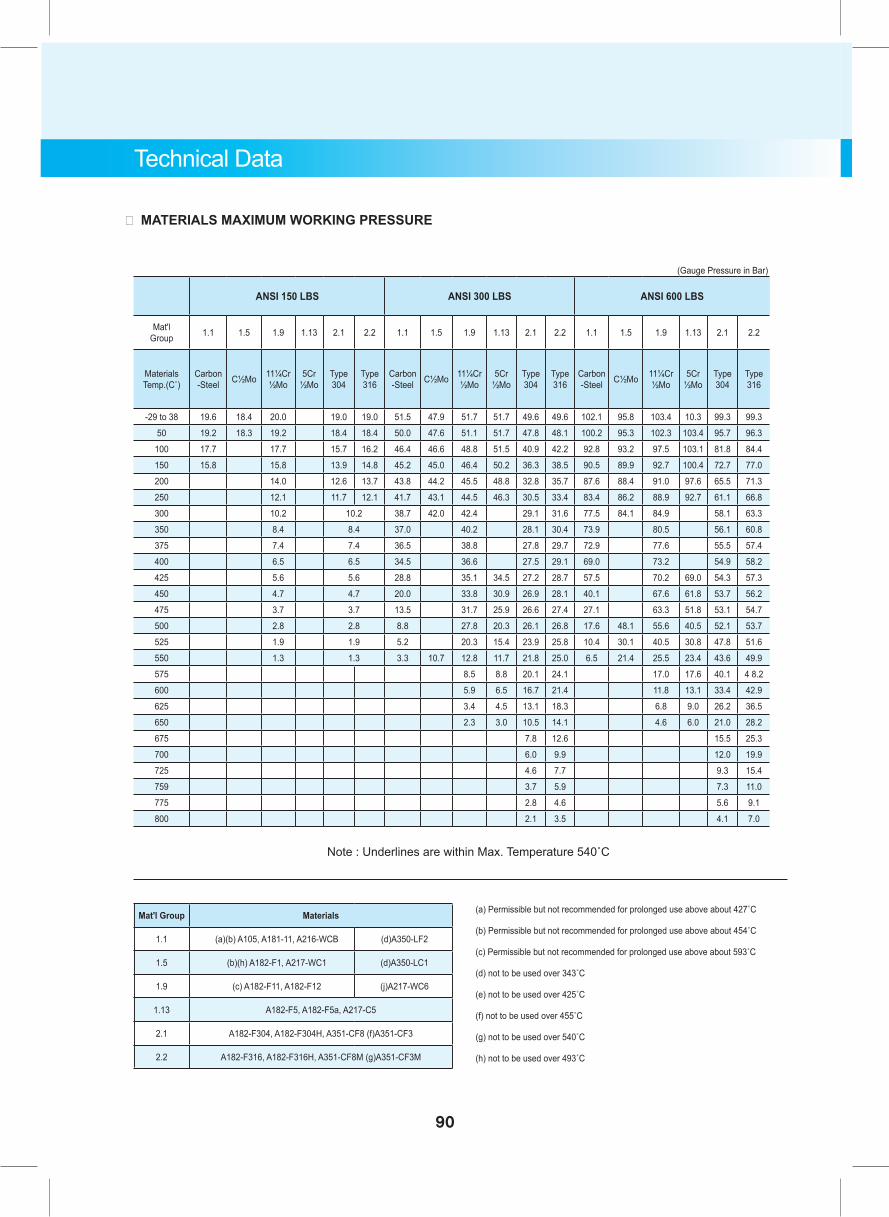
Technical Data
。 MATERIALS MAXIMUM WORKING PRESSURE
(Gauge Pressure in Bar)
ANSI 150 LBS ANSI 300 LBS ANSI 600 LBS
Mat'l Group 1.1 1.5 1.9 1.13 2.1 2.2 1.1 1.5 1.9 1.13 2.1 2.2 1.1 1.5 1.9 1.13 2.1 2.2
Materials Temp.(C˚)
Carbon -Steel C½Mo 11¼Cr
½Mo5Cr
½MoType 304
Type 316
Carbon -Steel C½Mo 11¼Cr
½Mo5Cr
½MoType 304
Type 316
Carbon -Steel C½Mo 11¼Cr
½Mo5Cr
½MoType 304
Type 316
-29 to 38 19.6 18.4 20.0 19.0 19.0 51.5 47.9 51.7 51.7 49.6 49.6 102.1 95.8 103.4 10.3 99.3 99.3
50 19.2 18.3 19.2 18.4 18.4 50.0 47.6 51.1 51.7 47.8 48.1 100.2 95.3 102.3 103.4 95.7 96.3
100 17.7 17.7 15.7 16.2 46.4 46.6 48.8 51.5 40.9 42.2 92.8 93.2 97.5 103.1 81.8 84.4
150 15.8 15.8 13.9 14.8 45.2 45.0 46.4 50.2 36.3 38.5 90.5 89.9 92.7 100.4 72.7 77.0
200 14.0 12.6 13.7 43.8 44.2 45.5 48.8 32.8 35.7 87.6 88.4 91.0 97.6 65.5 71.3
250 12.1 11.7 12.1 41.7 43.1 44.5 46.3 30.5 33.4 83.4 86.2 88.9 92.7 61.1 66.8
300 10.2 10.2 38.7 42.0 42.4 29.1 31.6 77.5 84.1 84.9 58.1 63.3
350 8.4 8.4 37.0 40.2 28.1 30.4 73.9 80.5 56.1 60.8
375 7.4 7.4 36.5 38.8 27.8 29.7 72.9 77.6 55.5 57.4
400 6.5 6.5 34.5 36.6 27.5 29.1 69.0 73.2 54.9 58.2
425 5.6 5.6 28.8 35.1 34.5 27.2 28.7 57.5 70.2 69.0 54.3 57.3
450 4.7 4.7 20.0 33.8 30.9 26.9 28.1 40.1 67.6 61.8 53.7 56.2
475 3.7 3.7 13.5 31.7 25.9 26.6 27.4 27.1 63.3 51.8 53.1 54.7
500 2.8 2.8 8.8 27.8 20.3 26.1 26.8 17.6 48.1 55.6 40.5 52.1 53.7
525 1.9 1.9 5.2 20.3 15.4 23.9 25.8 10.4 30.1 40.5 30.8 47.8 51.6
550 1.3 1.3 3.3 10.7 12.8 11.7 21.8 25.0 6.5 21.4 25.5 23.4 43.6 49.9
575 8.5 8.8 20.1 24.1 17.0 17.6 40.1 4 8.2
600 5.9 6.5 16.7 21.4 11.8 13.1 33.4 42.9
625 3.4 4.5 13.1 18.3 6.8 9.0 26.2 36.5
650 2.3 3.0 10.5 14.1 4.6 6.0 21.0 28.2
675 7.8 12.6 15.5 25.3
700 6.0 9.9 12.0 19.9
725 4.6 7.7 9.3 15.4
759 3.7 5.9 7.3 11.0
775 2.8 4.6 5.6 9.1
800 2.1 3.5 4.1 7.0
Note : Underlines are within Max. Temperature 540˚C
(a) Permissible but not recommended for prolonged use above about 427˚C
(b) Permissible but not recommended for prolonged use above about 454˚C
(c) Permissible but not recommended for prolonged use above about 593˚C
(d) not to be used over 343˚C
(e) not to be used over 425˚C
(f) not to be used over 455˚C
(g) not to be used over 540˚C
(h) not to be used over 493˚C
Mat'l Group Materials
1.1 (a)(b) A105, A181-11, A216-WCB (d)A350-LF2
1.5 (b)(h) A182-F1, A217-WC1 (d)A350-LC1
1.9 (c) A182-F11, A182-F12 (j)A217-WC6
1.13 A182-F5, A182-F5a, A217-C5
2.1 A182-F304, A182-F304H, A351-CF8 (f)A351-CF3
2.2 A182-F316, A182-F316H, A351-CF8M (g)A351-CF3M
90
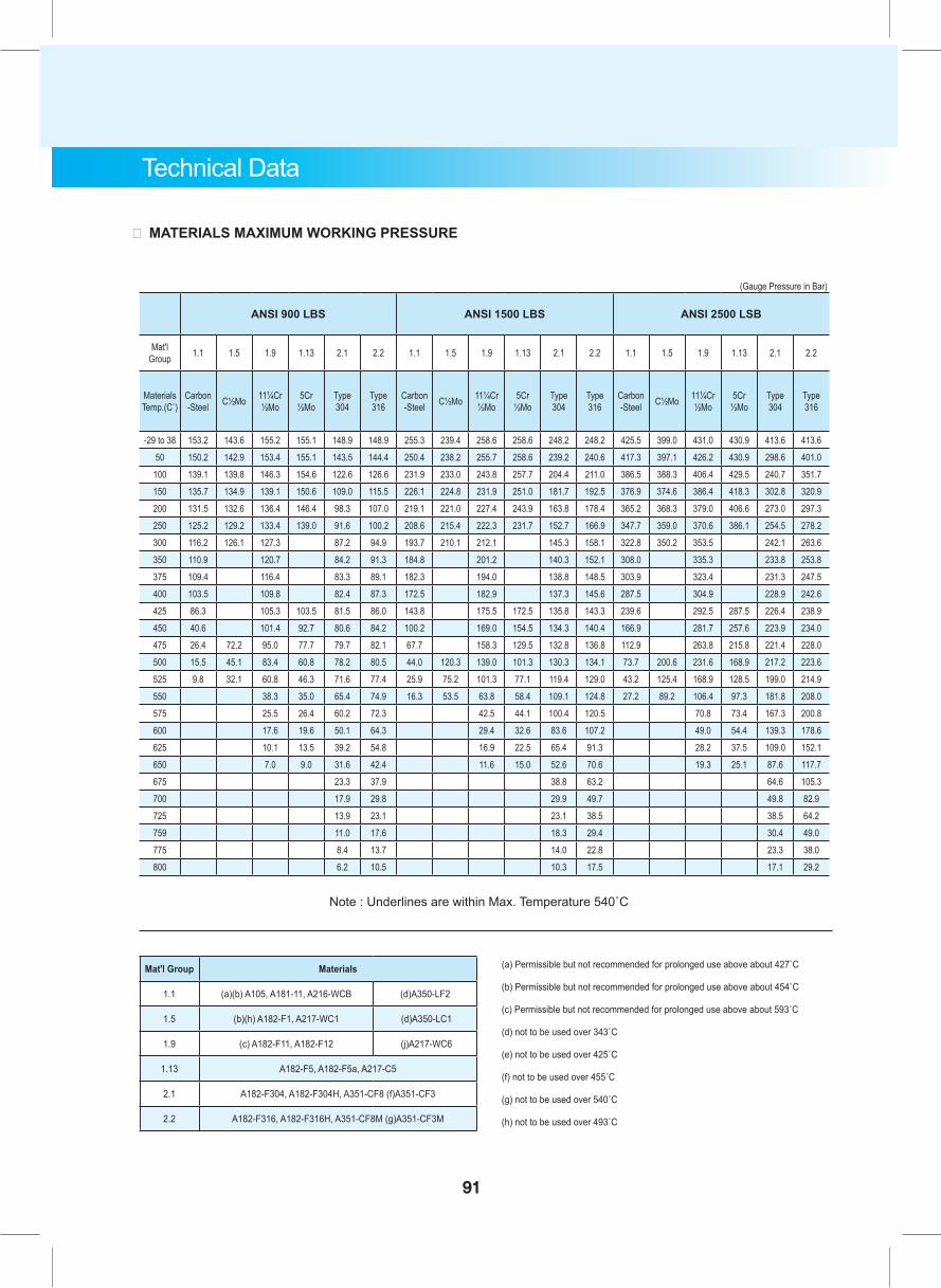
Technical Data
。 MATERIALS MAXIMUM WORKING PRESSURE
(Gauge Pressure in Bar)
ANSI 900 LBS ANSI 1500 LBS ANSI 2500 LSB
Mat'l Group 1.1 1.5 1.9 1.13 2.1 2.2 1.1 1.5 1.9 1.13 2.1 2.2 1.1 1.5 1.9 1.13 2.1 2.2
Materials Temp.(C˚)
Carbon -Steel C½Mo 11¼Cr
½Mo5Cr
½MoType 304
Type 316
Carbon -Steel C½Mo 11¼Cr
½Mo5Cr
½MoType 304
Type 316
Carbon -Steel C½Mo 11¼Cr
½Mo5Cr
½MoType 304
Type 316
-29 to 38 153.2 143.6 155.2 155.1 148.9 148.9 255.3 239.4 258.6 258.6 248.2 248.2 425.5 399.0 431.0 430.9 413.6 413.650 150.2 142.9 153.4 155.1 143.5 144.4 250.4 238.2 255.7 258.6 239.2 240.6 417.3 397.1 426.2 430.9 298.6 401.0
100 139.1 139.8 146.3 154.6 122.6 126.6 231.9 233.0 243.8 257.7 204.4 211.0 386.5 388.3 406.4 429.5 240.7 351.7150 135.7 134.9 139.1 150.6 109.0 115.5 226.1 224.8 231.9 251.0 181.7 192.5 376.9 374.6 386.4 418.3 302.8 320.9200 131.5 132.6 136.4 146.4 98.3 107.0 219.1 221.0 227.4 243.9 163.8 178.4 365.2 368.3 379.0 406.6 273.0 297.3250 125.2 129.2 133.4 139.0 91.6 100.2 208.6 215.4 222.3 231.7 152.7 166.9 347.7 359.0 370.6 386.1 254.5 278.2300 116.2 126.1 127.3 87.2 94.9 193.7 210.1 212.1 145.3 158.1 322.8 350.2 353.5 242.1 263.6350 110.9 120.7 84.2 91.3 184.8 201.2 140.3 152.1 308.0 335.3 233.8 253.8375 109.4 116.4 83.3 89.1 182.3 194.0 138.8 148.5 303.9 323.4 231.3 247.5400 103.5 109.8 82.4 87.3 172.5 182.9 137.3 145.6 287.5 304.9 228.9 242.6425 86.3 105.3 103.5 81.5 86.0 143.8 175.5 172.5 135.8 143.3 239.6 292.5 287.5 226.4 238.9450 40.6 101.4 92.7 80.6 84.2 100.2 169.0 154.5 134.3 140.4 166.9 281.7 257.6 223.9 234.0475 26.4 72.2 95.0 77.7 79.7 82.1 67.7 158.3 129.5 132.8 136.8 112.9 263.8 215.8 221.4 228.0500 15.5 45.1 83.4 60.8 78.2 80.5 44.0 120.3 139.0 101.3 130.3 134.1 73.7 200.6 231.6 168.9 217.2 223.6525 9.8 32.1 60.8 46.3 71.6 77.4 25.9 75.2 101.3 77.1 119.4 129.0 43.2 125.4 168.9 128.5 199.0 214.9550 38.3 35.0 65.4 74.9 16.3 53.5 63.8 58.4 109.1 124.8 27.2 89.2 106.4 97.3 181.8 208.0575 25.5 26.4 60.2 72.3 42.5 44.1 100.4 120.5 70.8 73.4 167.3 200.8600 17.6 19.6 50.1 64.3 29.4 32.6 83.6 107.2 49.0 54.4 139.3 178.6625 10.1 13.5 39.2 54.8 16.9 22.5 65.4 91.3 28.2 37.5 109.0 152.1650 7.0 9.0 31.6 42.4 11.6 15.0 52.6 70.6 19.3 25.1 87.6 117.7675 23.3 37.9 38.8 63.2 64.6 105.3700 17.9 29.8 29.9 49.7 49.8 82.9725 13.9 23.1 23.1 38.5 38.5 64.2759 11.0 17.6 18.3 29.4 30.4 49.0775 8.4 13.7 14.0 22.8 23.3 38.0800 6.2 10.5 10.3 17.5 17.1 29.2
(a) Permissible but not recommended for prolonged use above about 427˚C
(b) Permissible but not recommended for prolonged use above about 454˚C
(c) Permissible but not recommended for prolonged use above about 593˚C
(d) not to be used over 343˚C
(e) not to be used over 425˚C
(f) not to be used over 455˚C
(g) not to be used over 540˚C
(h) not to be used over 493˚C
Note : Underlines are within Max. Temperature 540˚C
(a) Permissible but not recommended for prolonged use above about 427˚C
(b) Permissible but not recommended for prolonged use above about 454˚C
(c) Permissible but not recommended for prolonged use above about 593˚C
(d) not to be used over 343˚C
(e) not to be used over 425˚C
(f) not to be used over 455˚C
(g) not to be used over 540˚C
(h) not to be used over 493˚C
Mat'l Group Materials
1.1 (a)(b) A105, A181-11, A216-WCB (d)A350-LF2
1.5 (b)(h) A182-F1, A217-WC1 (d)A350-LC1
1.9 (c) A182-F11, A182-F12 (j)A217-WC6
1.13 A182-F5, A182-F5a, A217-C5
2.1 A182-F304, A182-F304H, A351-CF8 (f)A351-CF3
2.2 A182-F316, A182-F316H, A351-CF8M (g)A351-CF3M
91
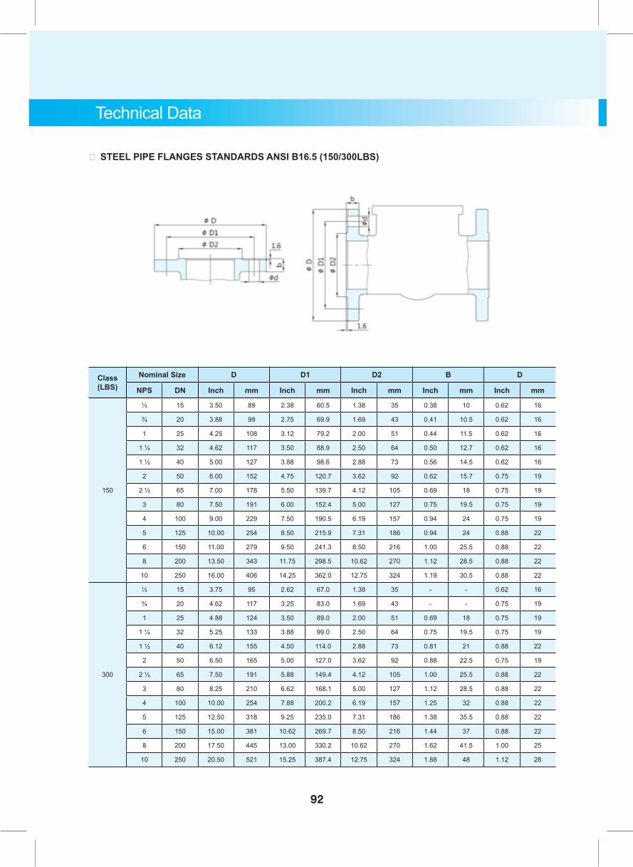
Class (LBS)
Nominal Size D D1 D2 B D
NPS DN Inch mm Inch mm Inch mm Inch mm Inch mm
150
½ 15 3.50 89 2.38 60.5 1.38 35 0.38 10 0.62 16
¾ 20 3.88 99 2.75 69.9 1.69 43 0.41 10.5 0.62 16
1 25 4.25 108 3.12 79.2 2.00 51 0.44 11.5 0.62 16
1 ¼ 32 4.62 117 3.50 88.9 2.50 64 0.50 12.7 0.62 16
1 ½ 40 5.00 127 3.88 98.6 2.88 73 0.56 14.5 0.62 16
2 50 6.00 152 4.75 120.7 3.62 92 0.62 15.7 0.75 19
2 ½ 65 7.00 178 5.50 139.7 4.12 105 0.69 18 0.75 19
3 80 7.50 191 6.00 152.4 5.00 127 0.75 19.5 0.75 19
4 100 9.00 229 7.50 190.5 6.19 157 0.94 24 0.75 19
5 125 10.00 254 8.50 215.9 7.31 186 0.94 24 0.88 22
6 150 11.00 279 9.50 241.3 8.50 216 1.00 25.5 0.88 22
8 200 13.50 343 11.75 298.5 10.62 270 1.12 28.5 0.88 22
10 250 16.00 406 14.25 362.0 12.75 324 1.19 30.5 0.88 22
300
½ 15 3.75 95 2.62 67.0 1.38 35 - - 0.62 16
¾ 20 4.62 117 3.25 83.0 1.69 43 - - 0.75 19
1 25 4.88 124 3.50 89.0 2.00 51 0.69 18 0.75 19
1 ¼ 32 5.25 133 3.88 99.0 2.50 64 0.75 19.5 0.75 19
1 ½ 40 6.12 155 4.50 114.0 2.88 73 0.81 21 0.88 22
2 50 6.50 165 5.00 127.0 3.62 92 0.88 22.5 0.75 19
2 ½ 65 7.50 191 5.88 149.4 4.12 105 1.00 25.5 0.88 22
3 80 8.25 210 6.62 168.1 5.00 127 1.12 28.5 0.88 22
4 100 10.00 254 7.88 200.2 6.19 157 1.25 32 0.88 22
5 125 12.50 318 9.25 235.0 7.31 186 1.38 35.5 0.88 22
6 150 15.00 381 10.62 269.7 8.50 216 1.44 37 0.88 22
8 200 17.50 445 13.00 330.2 10.62 270 1.62 41.5 1.00 25
10 250 20.50 521 15.25 387.4 12.75 324 1.88 48 1.12 28
Technical Data
。 STEEL PIPE FLANGES STANDARDS ANSI B16.5 (150/300LBS)
92
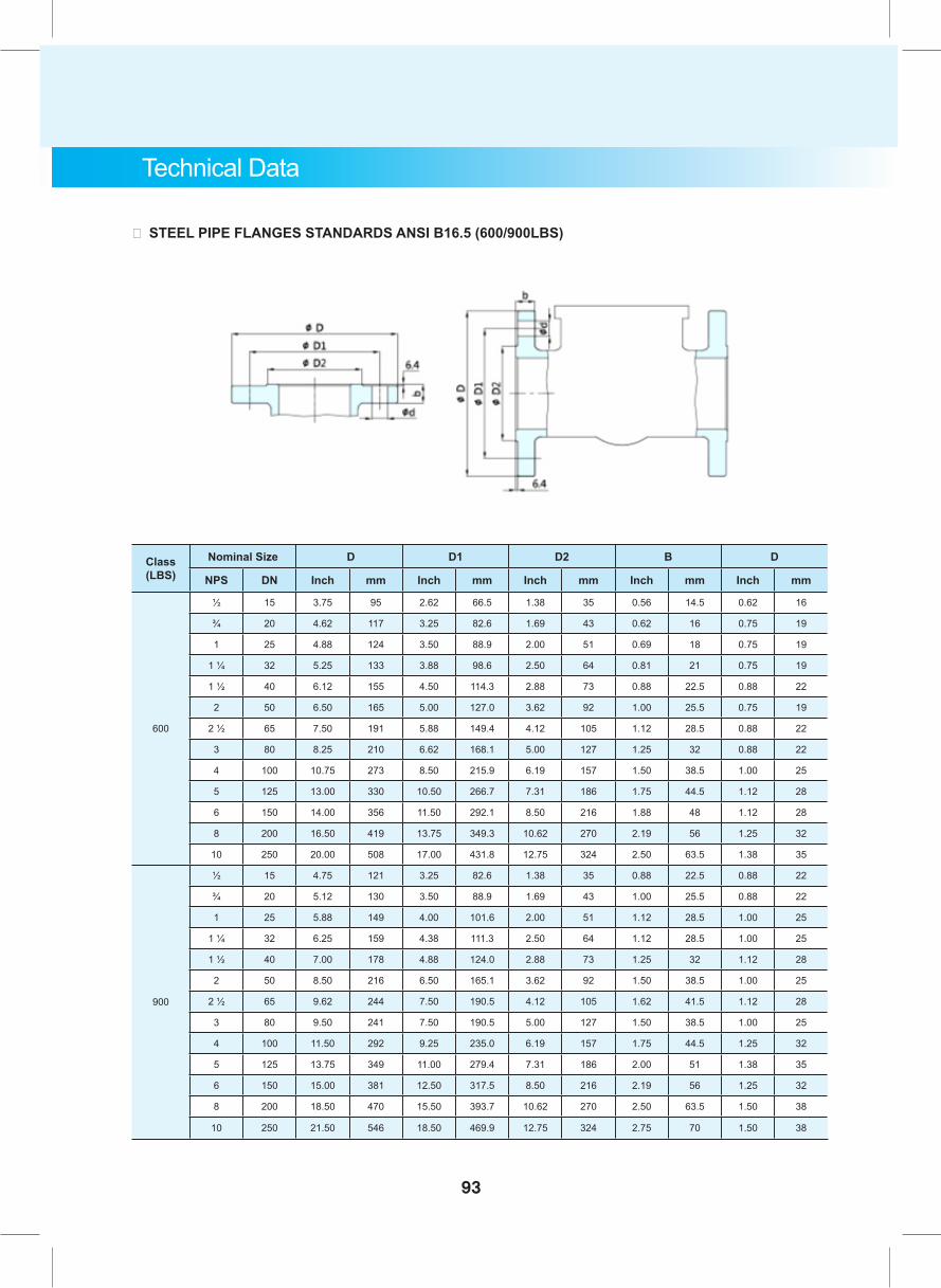
Technical Data
。 STEEL PIPE FLANGES STANDARDS ANSI B16.5 (600/900LBS)
Class (LBS)
Nominal Size D D1 D2 B D
NPS DN Inch mm Inch mm Inch mm Inch mm Inch mm
600
½ 15 3.75 95 2.62 66.5 1.38 35 0.56 14.5 0.62 16
¾ 20 4.62 117 3.25 82.6 1.69 43 0.62 16 0.75 19
1 25 4.88 124 3.50 88.9 2.00 51 0.69 18 0.75 19
1 ¼ 32 5.25 133 3.88 98.6 2.50 64 0.81 21 0.75 19
1 ½ 40 6.12 155 4.50 114.3 2.88 73 0.88 22.5 0.88 22
2 50 6.50 165 5.00 127.0 3.62 92 1.00 25.5 0.75 19
2 ½ 65 7.50 191 5.88 149.4 4.12 105 1.12 28.5 0.88 22
3 80 8.25 210 6.62 168.1 5.00 127 1.25 32 0.88 22
4 100 10.75 273 8.50 215.9 6.19 157 1.50 38.5 1.00 25
5 125 13.00 330 10.50 266.7 7.31 186 1.75 44.5 1.12 28
6 150 14.00 356 11.50 292.1 8.50 216 1.88 48 1.12 28
8 200 16.50 419 13.75 349.3 10.62 270 2.19 56 1.25 32
10 250 20.00 508 17.00 431.8 12.75 324 2.50 63.5 1.38 35
900
½ 15 4.75 121 3.25 82.6 1.38 35 0.88 22.5 0.88 22
¾ 20 5.12 130 3.50 88.9 1.69 43 1.00 25.5 0.88 22
1 25 5.88 149 4.00 101.6 2.00 51 1.12 28.5 1.00 25
1 ¼ 32 6.25 159 4.38 111.3 2.50 64 1.12 28.5 1.00 25
1 ½ 40 7.00 178 4.88 124.0 2.88 73 1.25 32 1.12 28
2 50 8.50 216 6.50 165.1 3.62 92 1.50 38.5 1.00 25
2 ½ 65 9.62 244 7.50 190.5 4.12 105 1.62 41.5 1.12 28
3 80 9.50 241 7.50 190.5 5.00 127 1.50 38.5 1.00 25
4 100 11.50 292 9.25 235.0 6.19 157 1.75 44.5 1.25 32
5 125 13.75 349 11.00 279.4 7.31 186 2.00 51 1.38 35
6 150 15.00 381 12.50 317.5 8.50 216 2.19 56 1.25 32
8 200 18.50 470 15.50 393.7 10.62 270 2.50 63.5 1.50 38
10 250 21.50 546 18.50 469.9 12.75 324 2.75 70 1.50 38
93
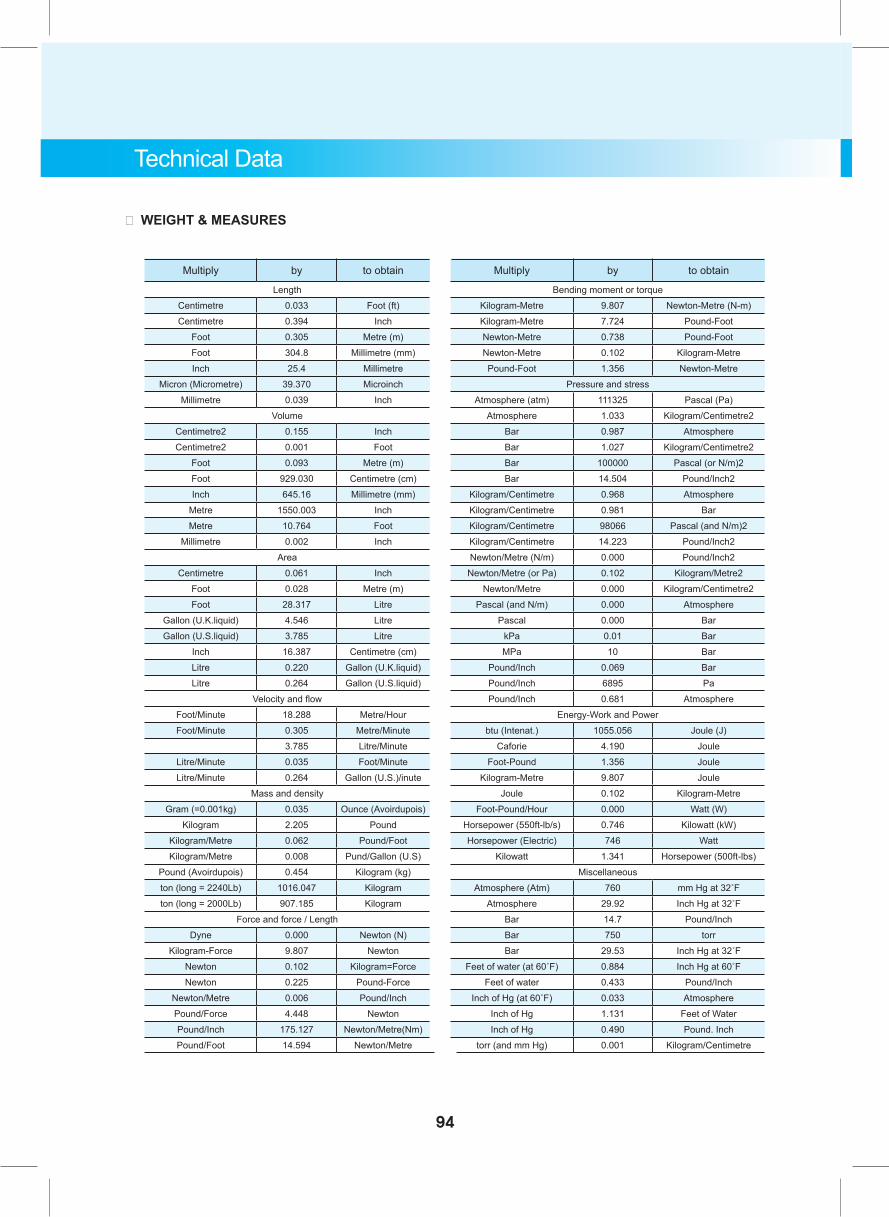
Multiply by to obtain Multiply by to obtain
Length Bending moment or torqueCentimetre 0.033 Foot (ft) Kilogram-Metre 9.807 Newton-Metre (N-m)Centimetre 0.394 Inch Kilogram-Metre 7.724 Pound-Foot
Foot 0.305 Metre (m) Newton-Metre 0.738 Pound-FootFoot 304.8 Millimetre (mm) Newton-Metre 0.102 Kilogram-MetreInch 25.4 Millimetre Pound-Foot 1.356 Newton-Metre
Micron (Micrometre) 39.370 Microinch Pressure and stressMillimetre 0.039 Inch Atmosphere (atm) 111325 Pascal (Pa)
Volume Atmosphere 1.033 Kilogram/Centimetre2Centimetre2 0.155 Inch Bar 0.987 AtmosphereCentimetre2 0.001 Foot Bar 1.027 Kilogram/Centimetre2
Foot 0.093 Metre (m) Bar 100000 Pascal (or N/m)2Foot 929.030 Centimetre (cm) Bar 14.504 Pound/Inch2Inch 645.16 Millimetre (mm) Kilogram/Centimetre 0.968 Atmosphere
Metre 1550.003 Inch Kilogram/Centimetre 0.981 BarMetre 10.764 Foot Kilogram/Centimetre 98066 Pascal (and N/m)2
Millimetre 0.002 Inch Kilogram/Centimetre 14.223 Pound/Inch2Area Newton/Metre (N/m) 0.000 Pound/Inch2
Centimetre 0.061 Inch Newton/Metre (or Pa) 0.102 Kilogram/Metre2Foot 0.028 Metre (m) Newton/Metre 0.000 Kilogram/Centimetre2Foot 28.317 Litre Pascal (and N/m) 0.000 Atmosphere
Gallon (U.K.liquid) 4.546 Litre Pascal 0.000 BarGallon (U.S.liquid) 3.785 Litre kPa 0.01 Bar
Inch 16.387 Centimetre (cm) MPa 10 BarLitre 0.220 Gallon (U.K.liquid) Pound/Inch 0.069 BarLitre 0.264 Gallon (U.S.liquid) Pound/Inch 6895 Pa
Velocity and flow Pound/Inch 0.681 AtmosphereFoot/Minute 18.288 Metre/Hour Energy-Work and PowerFoot/Minute 0.305 Metre/Minute btu (Intenat.) 1055.056 Joule (J)
3.785 Litre/Minute Caforie 4.190 JouleLitre/Minute 0.035 Foot/Minute Foot-Pound 1.356 JouleLitre/Minute 0.264 Gallon (U.S.)/inute Kilogram-Metre 9.807 Joule
Mass and density Joule 0.102 Kilogram-MetreGram (=0.001kg) 0.035 Ounce (Avoirdupois) Foot-Pound/Hour 0.000 Watt (W)
Kilogram 2.205 Pound Horsepower (550ft-lb/s) 0.746 Kilowatt (kW)Kilogram/Metre 0.062 Pound/Foot Horsepower (Electric) 746 WattKilogram/Metre 0.008 Pund/Gallon (U.S) Kilowatt 1.341 Horsepower (500ft-lbs)
Pound (Avoirdupois) 0.454 Kilogram (kg) Miscellaneouston (long = 2240Lb) 1016.047 Kilogram Atmosphere (Atm) 760 mm Hg at 32˚Fton (long = 2000Lb) 907.185 Kilogram Atmosphere 29.92 Inch Hg at 32˚F
Force and force / Length Bar 14.7 Pound/InchDyne 0.000 Newton (N) Bar 750 torr
Kilogram-Force 9.807 Newton Bar 29.53 Inch Hg at 32˚FNewton 0.102 Kilogram=Force Feet of water (at 60˚F) 0.884 Inch Hg at 60˚FNewton 0.225 Pound-Force Feet of water 0.433 Pound/Inch
Newton/Metre 0.006 Pound/Inch Inch of Hg (at 60˚F) 0.033 AtmospherePound/Force 4.448 Newton Inch of Hg 1.131 Feet of WaterPound/Inch 175.127 Newton/Metre(Nm) Inch of Hg 0.490 Pound. InchPound/Foot 14.594 Newton/Metre torr (and mm Hg) 0.001 Kilogram/Centimetre
Technical Data
。 WEIGHT & MEASURES
94
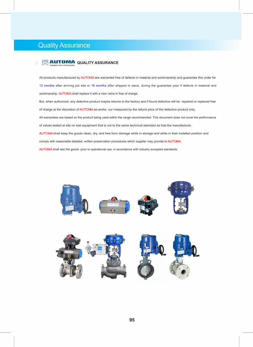
Quality Assurance
。 QUALITY ASSURANCE
All products manufactured by AUTOMA are warranted free of defects in material and workmanship and guarantee this order for
12 months after arriving job site or 18 months after shipped in wave, during the guarantee year if defects in material and
workmanship, AUTOMA shall replace it with a new valve in free of charge.
But, when authorized, any defective product maybe returne to the factory and if found defective will be repaired or replaced free
of charge at the discretion of AUTOMA ex-works our measured by the refund price of the defective product only.
All warrantees are based on the product being used within the range recommended. This document dose not cover the performance
of valves tested at site on test equipment that is not to the same technical standard as that the manufacturer.
AUTOMA shall keep the goods clean, dry, and free form damage while in storage and while in their installed position and
comply with reasonable detailed, written preservation procedures which supplier may provide to AUTOMA.
AUTOMA shall test the goods prior to operational use, in accordance with industry accepted standards.
95
2014
.08 (JB
0211)
Automa Bldg. #48, Jomaru-ro 385 beon-gil, Wonmi-gu, Bucheon-city, Gyeonggi-do, Korea Phone : 82-32-653-6477 Fax : 82-32-653-6478www.automa.co.kr / E-mail : [email protected]
AUTOMA CO., LTD.