Embed Size (px)
Citation preview

High Performance Compact Inverters
Options & Accessories
• Braking Accessories• Option Boards• Reactors & Remote Keypad• External Cooling Adapter
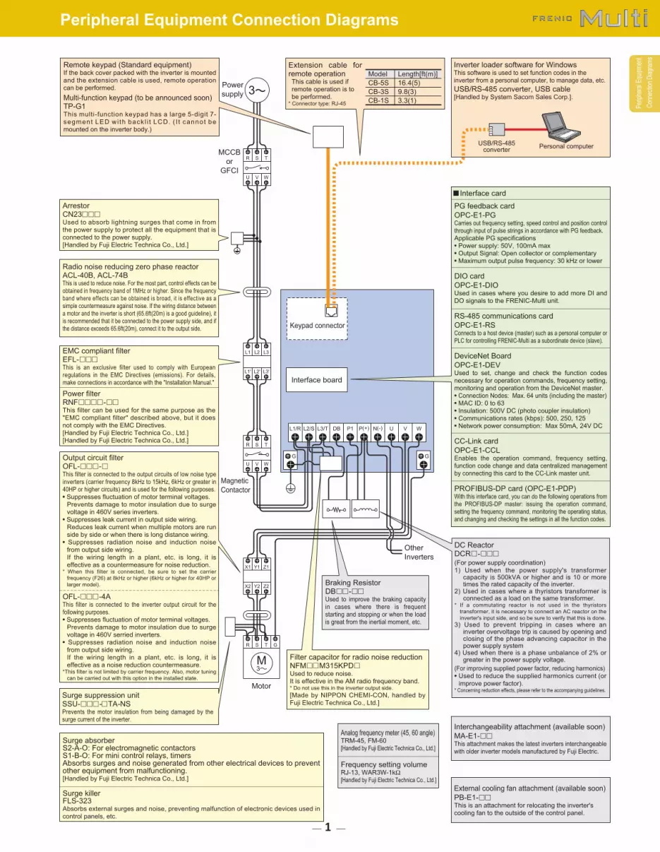
Braking ResistorDB�� -��
Used to improve the braking capacity
in cases where there is frequent
starting and stopping or when the load
is great from the inertial moment, etc.
MCCB
or
GFCI
Power
supply
Magnetic
Contactor
Motor
GG
L1/R L2/S L3/T P1DB P(+) N(-) U V W
Interface board
Other
Inverters
Keypad connector
V WU
S TR
L2' L3'L1'
L2 L3L1
Y2 Z2X2
Y1 Z1X1
S TR G
V WU
S TR
■ Interface card
PG feedback card
OPC-E1-PGCarries out frequency setting, speed control and position control
through input of pulse strings in accordance with PG feedback.
Applicable PG specifications
• Power supply: 50V, 100mA max
• Output Signal: Open collector or complementary
• Maximum output pulse frequency: 30 kHz or lower
DIO card
OPC-E1-DIOUsed in cases where you desire to add more DI and
DO signals to the FRENIC-Multi unit.
RS-485 communications card
OPC-E1-RSConnects to a host device (master) such as a personal computer or
PLC for controlling FRENIC-Multi as a subordinate device (slave).
DeviceNet Board
OPC-E1-DEVUsed to set, change and check the function codes
necessary for operation commands, frequency setting,
monitoring and operation from the DeviceNet master.
• Connection Nodes: Max. 64 units (including the master)
• MAC ID: 0 to 63
• Insulation: 500V DC (photo coupler insulation)
• Communications rates (kbps): 500, 250, 125
• Network power consumption: Max 50mA, 24V DC
CC-Link card
OPC-E1-CCLEnables the operation command, frequency setting,
function code change and data centralized management
by connecting this card to the CC-Link master unit.
PROFIBUS-DP card (OPC-E1-PDP)With this interface card, you can do the following operations from
the PROFIBUS-DP master: issuing the operation command,
setting the frequency command, monitoring the operating status,
and changing and checking the settings in all the function codes.
Model
CB-5S
CB-3S
CB-1S
Length[ft(m)]
16.4(5)
9.8(3)
3.3(1)
ArrestorCN23���
Used to absorb lightning surges that come in from
the power supply to protect all the equipment that is
connected to the power supply.
[Handled by Fuji Electric Technica Co., Ltd.]
Radio noise reducing zero phase reactorACL-40B, ACL-74BThis is used to reduce noise. For the most part, control effects can be
obtained in frequency band of 1MHz or higher. Since the frequency
band where effects can be obtained is broad, it is effective as a
simple countermeasure against noise. If the wiring distance between
a motor and the inverter is short (65.6ft(20m) is a good guideline), it
is recommended that it be connected to the power supply side, and if
the distance exceeds 65.6ft(20m), connect it to the output side.
EMC compliant filterEFL-���
This is an exclusive filter used to comply with European
regulations in the EMC Directives (emissions). For details,
make connections in accordance with the "Installation Manual."
Filter capacitor for radio noise reductionNFM��M315KPD�
Used to reduce noise.
It is effective in the AM radio frequency band.* Do not use this in the inverter output side.
[Made by NIPPON CHEMI-CON, handled by
Fuji Electric Technica Co., Ltd.]
Power filterRNF���� -��
This filter can be used for the same purpose as the
"EMC compliant filter" described above, but it does
not comply with the EMC Directives.
[Handled by Fuji Electric Technica Co., Ltd.]
[Handled by Fuji Electric Technica Co., Ltd.]
DC ReactorDCR� -���
(For power supply coordination)
1) Used when the power supply's transformercapacity is 500kVA or higher and is 10 or moretimes the rated capacity of the inverter.
2) Used in cases where a thyristors transformer isconnected as a load on the same transformer.
* If a commutating reactor is not used in the thyristors
transformer, it is necessary to connect an AC reactor on the
inverter's input side, and so be sure to verify that this is done.
3) Used to prevent tripping in cases where aninverter overvoltage trip is caused by opening and closing of the phase advancing capacitor in thepower supply system
4) Used when there is a phase unbalance of 2% orgreater in the power supply voltage.
(For improving supplied power factor, reducing harmonics)
• Used to reduce the supplied harmonics current (or
improve power factor).* Concerning reduction effects, please refer to the accompanying guidelines.
Output circuit filterOFL-��� -�This filter is connected to the output circuits of low noise type
inverters (carrier frequency 8kHz to 15kHz, 6kHz or greater in
40HP or higher circuits) and is used for the following purposes.
• Suppresses fluctuation of motor terminal voltages.
Prevents damage to motor insulation due to surge
voltage in 460V series inverters.
• Suppresses leak current in output side wiring.
Reduces leak current when multiple motors are run
side by side or when there is long distance wiring.
• Suppresses radiation noise and induction noise
from output side wiring.
If the wiring length in a plant, etc. is long, it is
effective as a countermeasure for noise reduction.* When this filter is connected, be sure to set the carrier
frequency (F26) at 8kHz or higher (6kHz or higher for 40HP or
larger model).
OFL-��� -4AThis filter is connected to the inverter output circuit for the
following purposes.
• Suppresses fluctuation of motor terminal voltages.
Prevents damage to motor insulation due to surge
voltage in 460V serried inverters.
• Suppresses radiation noise and induction noise
from output side wiring.
If the wiring length in a plant, etc. is long, it is
effective as a noise reduction countermeasure.*This filter is not limited by carrier frequency. Also, motor tuning
can be carried out with this option in the installed state.
Surge absorberS2-A-O: For electromagnetic contactorsS1-B-O: For mini control relays, timersAbsorbs surges and noise generated from other electrical devices to prevent other equipment from malfunctioning.[Handled by Fuji Electric Technica Co., Ltd.]
Surge killerFLS-323Absorbs external surges and noise, preventing malfunction of electronic devices used in
control panels, etc.
Analog frequency meter (45, 60 angle)TRM-45, FM-60
[Handled by Fuji Electric Technica Co., Ltd.]
Frequency setting volumeRJ-13, WAR3W-1kΩ[Handled by Fuji Electric Technica Co., Ltd.]
Inverter loader software for WindowsThis software is used to set function codes in the
inverter from a personal computer, to manage data, etc.
USB/RS-485 converter, USB cable[Handled by System Sacom Sales Corp.].
Extension cable for remote operationThis cable is used if
remote operation is to
be performed.* Connector type: RJ-45
USB/RS-485converter
Personal computer
External cooling fan attachment (available soon)
PB-E1-��
This is an attachment for relocating the inverter's
cooling fan to the outside of the control panel.
Interchangeability attachment (available soon)
MA-E1-��
This attachment makes the latest inverters interchangeable
with older inverter models manufactured by Fuji Electric.
M3
3
Remote keypad (Standard equipment)If the back cover packed with the inverter is mounted
and the extension cable is used, remote operation
can be performed.
Multi-function keypad (to be announced soon)TP-G1This multi-function keypad has a large 5-digit 7-
segment LED wi th back l i t LCD. ( I t cannot be
mounted on the inverter body.)
Surge suppression unitSSU-��� -�TA-NSPrevents the motor insulation from being damaged by the
surge current of the inverter.
Per
iphe
ral E
quip
men
t
Con
nect
ion
Dia
gram
s
Peripheral Equipment Connection Diagrams
1

Type, specifications and external dimensions [Unit: inch(mm)]
[Standard type] (DB��� -2) (DB��� -4)
[10% ED type] (DB��� -2C) (DB��� -4C)
[Compact type] (TK80W120Ω)
Braking resistor
Mass [lbs(kg)]230V series 460V series W H H1 D
DB0.75-2
DB2.2-2
-
DB3.7-2
-
DB5.5-2
-
DB7.5-2
-
DB11-2
-
DB15-2
-
DB0.75-2C
DB2.2-2C
DB3.7-2C
DB5.5-2C
DB7.5-2C
DB11-2C
DB15-2C
DB0.75-4
-
DB2.2-4
-
DB3.7-4
-
DB5.5-4
-
DB7.5-4
-
DB11-4
-
DB15-4
DB0.75-4C
DB2.2-4C
DB3.7-4C
DB5.5-4C
DB7.5-4C
DB11-4C
DB15-4C
A
A
A
A
A
B
B
B
B
C
C
C
C
D
E
E
E
E
F
F
2.52(64)
2.99(76)
2.52(64)
2.99(76)
2.52(64)
3.54(90)
2.91(74)
3.54(90)
2.91(74)
5.59(142)
5.59(142)
5.59(142)
5.59(142)
1.69(43)
2.64(67)
2.64(67)
-
-
3.15(80)
3.15(80)
12.20(310)
13.58(345)
18.50(470)
13.58(345)
18.50(470)
17.72(450)
18.50(470)
15.35(390)
20.47(520)
16.93(430)
16.93(430)
16.93(430)
16.93(430)
8.70(221)
7.40(188)
12.91(328)
14.88(378)
16.46(418)
18.11(460)
22.83(580)
W1
-
-
-
-
-
3.54(90)
2.91(74)
3.54(90)
2.91(74)
2.91(74)
2.91(74)
2.91(74)
2.91(74)
-
-
-
-
-
1.97(50)
1.97(50)
11.61(295)
13.07(332)
17.91(455)
13.07(332)
17.91(455)
16.93(430)
17.91(455)
14.57(370)
19.49(495)
16.34(415)
16.34(415)
16.34(415)
16.34(415)
8.46(215)
6.77(172)
12.28(312)
14.25(362)
15.83(402)
17.32(440)
17.32(440)
2.64(67)
3.70(94)
2.64(67)
3.70(94)
2.64(67)
2.66(67.5)
2.64(67)
3.54(90)
2.64(67)
6.30(160)
6.30(160)
6.30(160)
6.30(160)
1.20(30.5)
2.17(55)
2.17(55)
3.07(78)
3.07(78)
5.51(140)
5.51(140)
2.9(1.3)
4.4(2.0)
4.4(2.0)
4.4(2.0)
3.7(1.7)
9.9(4.5)
9.9(4.5)
11(5.0)
11(5.0)
15(6.9)
15(6.9)
15(6.9)
15(6.9)
1.1(0.5)
1.8(0.8)
3.5(1.6)
6.4(2.9)
7.3(3.3)
9.5(4.3)
12(5.6)
Standard
type
10%ED
type
VoltageFig
Dimensions [Unit: inch (mm)]
19.69(500)
15.75
(400)
4.92±0.06(125±1.5)
5.51±0.06(140±1.5)
5.91±0.06(50±1.5)
1.3
4±
0.0
4
(34
±1
)
0.1
8
(4.5
)
φ 0.1
8
(φ4
.5)
Protection tube
0.05-0.16
(1.25-4)
0.7
9±
0.0
4
(20
±1
)
0.0
4
(1)
Three-phase230V
Power source voltage
Resistance
Applicable inverter
Applied motor output [HP]
Average braking torque [%]
Allowable limits
Type TK80W120Ω0.11
120
FRNF50
E1□-2U
1/2
150
15
15s
FRN001
E1□-2U
1
130
5
15s
FRN002
E1□-2U
2
100
5
10s
FRN003
E1□-2U
3
65
5
10s
FRN005
E1□-2U
5
45
5
10s
Capacity [HP]
Resistance [Ω]
Allowable duty cycle [%]
Continuous allowable braking time
NOTE: This resistor is not applicable to three-phase 460V series and single-phase 230V series.
DB0.75-2 1 100
150
29.4(3.32)
55.3(6.25)
110(12.4)
161(18.2)
270(30.5)
358(40.5)
545(61.6)
792(89.5)
1080(122)
29.4(3.32)
55.3(6.25)
110(12.4)
161(18.2)
270(30.5)
398(45.0)
545(61.6)
792(89.5)
1080(122)
29.4(3.32)
55.3(6.25)
110(12.4)
161(18.2)
29.4(3.32)
55.3(6.25)
110(12.4)
161(18.2)
270(30.5)
359(40.5)
545(61.6)
792(89.5)
1080(122)
29.4(3.32)
55.3(6.25)
110(12.4)
161(18.2)
270(30.5)
398(45.0)
545(61.6)
792(89.5)
1080(122)
29.4(3.32)
55.3(6.25)
110(12.4)
161(18.2)
9
17
34
33
37
55
37
55
75
9
17
34
33
37
55
38
55
75
9
17
34
33
50
55
140
55
37
55
75
50
55
140
55
38
55
75
50
55
45
30
20
20
10
45
30
20
20
10
45
30
250
133
73
50
75
20
10
250
133
73
50
75
20
10
250
133
73
50
0.06(0.044)
0.09(0.068)
0.10(0.075)
0.10(0.077)
0.12(0.093)
0.19(0.138)
0.25(0.188)
0.37(0.275)
0.50(0.375)
0.06(0.044)
0.09(0.068)
0.10(0.075)
0.10(0.077)
0.12(0.093)
1.53(1.138)
0.25(0.188)
0.37(0.275)
0.50(0.375)
0.06(0.044)
0.09(0.068)
0.10(0.075)
0.10(0.077)
0.1(0.075)
0.15(0.110)
0.25(0.185)
0.37(0.275)
0.50(0.375)
0.74(0.55)
1.01(0.75)
6.71(5)
0.15(0.110)
0.25(0.185)
0.37(0.275)
0.50(0.375)
0.74(0.55)
1.01(0.75)
0.10(0.075)
0.15(0.110)
22
18
10
7
5
5
5
5
5
22
18
10
7
5
5
5
5
5
22
18
10
7
37
20
14
10
10
10
10
10
10
37
20
14
10
10
10
10
10
10
37
20
14
10
FRNF50E1□-2U
FRN001E1□-2U
FRN002E1□-2U
FRN003E1□-2U
FRN005E1□-2U
FRN007E1□-2U
FRN010E1□-2U
FRN015E1□-2U
FRN020E1□-2U
FRNF50E1□-4U
FRN001E1□-4U
FRN002E1□-4U
FRN003E1□-4U
FRN005E1□-4U
FRN007E1□-4U
FRN010E1□-4U
FRN015E1□-4U
FRN020E1□-4U
FRNF50E1□-7U
FRN001E1□-7U
FRN002E1□-7U
FRN003E1□-7U
FRNF50E1□-2U
FRN001E1□-2U
FRN002E1□-2U
FRN003E1□-2U
FRN005E1□-2U
FRN007E1□-2U
FRN010E1□-2U
FRN015E1□-2U
FRN020E1□-2U
FRNF50E1□-4U
FRN001E1□-4U
FRN002E1□-4U
FRN003E1□-4U
FRN005E1□-4U
FRN007E1□-4U
FRN010E1□-4U
FRN015E1□-4U
FRN020E1□-4U
FRNF50E1□-7U
FRN001E1□-7U
FRN002E1□-7U
FRN003E1□-7U
35.6(4.02)
67.0(7.57)
133(15.0)
195(22.0)
328(37.1)
481(54.3)
658(74.4)
956(108)
1301(147)
35.6(4.02)
67.0(7.57)
133(15.0)
195(22.0)
328(37.1)
481(54.3)
651(73.6)
956(108)
1301(147)
35.6(4.02)
67.0(7.57)
133(15.0)
195(22.0)
35.6(4.02)
67.0(7.57)
133(15.0)
195(22.0)
328(37.1)
481(54.3)
659(74.4)
956(108)
1301(147)
35.6(4.02)
67.0(7.57)
133(15.0)
195(22.0)
328(37.1)
481(54.3)
651(73.5)
956(108)
1301(147)
35.6(4.02)
67.0(7.57)
133(15.0)
195(22.0)
Three-
phase
230V
Three-
phase
460V
Single-
phase
230V
Single-
phase
230V
Three-
phase
230V
Three-
phase
460V
DB2.2-2 1 40
DB3.7-2
DB5.5-2
DB7.5-2
DB11-2
DB15-2
DB5.5-2C
DB7.5-2C
DB11-2C
DB15-2C
DB5.5-4
DB7.5-4
DB11-4
DB15-4
DB5.5-4C
DB7.5-4C
DB11-4C
DB15-4C
1
1
1
1
1
20
15
10
8.6
80
60
40
34.4
20
15
10
8.6
80
60
40
34.4
1
1
1
1
1
1
1
1
1
1
1
1
33
DB0.75-4 1 200Standard
typeDB2.2-4 1 160
150
150
150
DB3.7-4 1 130
DB0.75-2 1 100
150
DB2.2-2 1 40
DB0.75-2C 1 100
150DB2.2-2C 1 40
DB3.7-2C 1 33
DB0.75-4C 110%ED
typeDB2.2-4C 1 160 150
150
150
DB3.7-4C 1 130
200
DB0.75-2C 1 100
150
DB2.2-2C 1 40
Braking
resistor
type
Power
supply
voltageInverter type Type
Qty. Resistance
[Ω]
Max braking torque [%] Continuous braking
(100% torque conversion value)50 [Hz] 60 [Hz]
[lb-in (N •m)] [lb-in (N •m)]Discharging
capacity [HPs]
Braking time
[s]
Repetitive braking
[Each cycle is less than 100[s].]
Average allowable
loss [HP]
Duty cycle
[%ED]
■ Options
W
HH1
0.28(7)
W
HH1
0.20(5)
W
W1
0.28(7)
HH1
D
0.0
6
(1.6
)
D
0.0
6
(1.6
)
D
0.0
5
(1.2
)
W
HH1
0.28(7)
D
0.0
6
(1.6
)
Fig. A Fig. B Fig. D Fig. EFig. C Fig. F
0.28(7)
H1 H
W1
W
D
0.0
6(1
.6)
0.28(7)
W
W1
R0.14
(R3.5)
φ0.59
(φ15)
0.0
6
(1.6
) DHH1
□: S or E S: standard E: EMC filter built-in type
Options
Opt
ions
Braking Accessories

DC REACTOR
D2
D1
D
W1
W
H
4xG mounting hole
Powersupplyvoltage
Applicablemotor rating
[HP]
Three-phase230V
Three-phase460V
Single-phase230V
1/8
1/4
1/2
1
2
3
5
7.5
10
15
20
1/2
1
2
3
5
7.5
10
15
20
1/8
1/4
1/2
1
2
3
W
Dimensions Unit: inch (mm)
2.60(66)
2.60(66)
2.60(66)
3.39(86)
3.39(86)
4.37(111)
4.37(111)
4.37(111)
5.75(146)
2.60(66)
2.60(66)
2.60(66)
2.60(66)
3.39(86)
3.39(86)
4.37(111)
4.37(111)
5.75(146)
2.60(66)
2.60(66)
2.60(66)
2.60(66)
3.39(86)
3.39(86)
W1
2.20(56)
2.20(56)
2.20(56)
2.80(71)
2.80(71)
3.74(95)
3.74(95)
3.74(95)
4.88(124)
2.20(56)
2.20(56)
2.20(56)
2.80(71)
2.80(71)
2.80(71)
3.74(95)
3.74(95)
4.88(124)
2.20(56)
2.20(56)
2.20(56)
2.20(56)
2.80(71)
2.80(71)
D
3.54(90)
3.54(90)
3.54(90)
3.94(100)
3.94(100)
3.94(100)
3.94(100)
3.94(100)
4.72(120)
3.54(90)
3.54(90)
3.54(90)
3.94(100)
3.94(100)
3.94(100)
3.94(100)
3.94(100)
4.72(120)
3.54(90)
3.54(90)
3.54(90)
3.54(90)
3.94(100)
3.94(100)
D1
2.83(72)
2.83(72)
2.83(72)
3.15(80)
3.15(80)
3.15(80)
3.15(80)
3.15(80)
3.78(96)
2.83(72)
2.83(72)
2.83(72)
3.15(80)
3.15(80)
3.15(80)
3.15(80)
3.15(80)
3.78(96)
2.83(72)
2.83(72)
2.83(72)
2.83(72)
3.15(80)
3.15(80)
D2
0.59(15)
0.79(20)
0.79(20)
0.39(10)
0.79(20)
0.79(20)
0.91(23)
0.94(24)
0.59(15)
0.59(15)
0.79(20)
0.79(20)
0.59(15)
0.79(20)
0.79(20)
0.94(24)
0.94(24)
0.59(15)
0.20(5)
0.59(15)
0.79(20)
0.79(20)
0.39(10)
0.79(20)
H
3.70(94)
3.70(94)
3.70(94)
4.33(110)
4.33(110)
5.12(130)
5.12(130)
5.39(137)
7.09(180)
3.70(94)
3.70(94)
3.70(94)
4.33(110)
4.33(110)
4.33(110)
5.12(130)
5.12(130)
6.73(171)
3.70(94)
3.70(94)
3.70(94)
3.70(94)
4.33(110)
4.33(110)
Terminalhole
M4
M4
M4
M4
M4
M5
M5
M6
M6
M4
M4
M4
M4
M4
M4
M5
M5
M5
M4
M4
M4
M4
M4
M4
Mass[lbs (kg)]
2.2(1.0)
3.1(1.4)
3.5(1.6)
4.0(1.8)
5.7(2.6)
7.9(3.6)
8.4(3.8)
9.5(4.3)
13(5.9)
2.2(1.0)
3.1(1.4)
3.5(1.6)
4.4(2.0)
5.7(2.6)
5.7(2.6)
9.3(4.2)
9.5(4.3)
13(5.9)
1.8(0.8)
2.2(1.0)
3.1(1.4)
3.5(1.6)
4.0(1.8)
5.7(2.6)
Mounting hole
0.20x0.31(5.2x8)
0.20x0.31(5.2x8)
0.20x0.31(5.2x8)
0.24x0.43(6x11)
0.24x0.43(6x11)
0.24x0.43(6x11)
0.28x0.43(7x11)
0.28x0.43(7x11)
0.28x0.43(7x11)
0.20x0.31(5.2x8)
0.20x0.31(5.2x8)
0.20x0.31(5.2x8)
0.24x0.35(6x9)
0.24x0.35(6x9)
0.24x0.35(6x9)
0.28x0.43(7x11)
0.28x0.43(7x11)
0.28x0.43(7x11)
0.20x0.31(5.2x8)
0.20x0.31(5.2x8)
0.20x0.31(5.2x8)
0.20x0.31(5.2x8)
0.24x0.43(6x11)
0.24x0.43(6x11)
Inverter type
FRNF12E1□-2U
FRNF25E1□-2U
FRNF50E1□-2U
FRN001E1□-2U
FRN002E1□-2U
FRN003E1S-2U
FRN005E1□-2U
FRN007E1□-2U
FRN010E1□-2U
FRN015E1□-2U
FRN020E1□-2U
FRNF50E1□-4U
FRN001E1□-4U
FRN002E1□-4U
FRN003E1□-4U
FRN005E1□-4U
FRN007E1□-4U
FRN010E1□-4U
FRN015E1□-4U
FRN020E1□-4U
FRNF12E1□-7U
FRNF25E1□-7U
FRNF50E1□-7U
FRN001E1□-7U
FRN002E1□-7U
FRN003E1□-7U
REACTORtype
DCR2-0.4
DCR2-0.75
DCR2-1.5
DCR2-2.2
DCR2-3.7
DCR2-5.5
DCR2-7.5
DCR2-11
DCR2-15
DCR4-0.4
DCR4-0.75
DCR4-1.5
DCR4-2.2
DCR4-3.7
DCR4-5.5
DCR4-7.5
DCR4-11
DCR4-15
DCR2-0.2
DCR2-0.4
DCR2-0.75
DCR2-1.5
DCR2-2.2
DCR2-3.7
DCR2-0.2 2.60(66) 2.20(56) 3.54(90) 2.83(72) 0.20(5) 3.70(94)0.20x0.31
(5.2x8)M4 1.8(0.8)
L
0.32(8)0.04(1)
Optional type
CB-5S
CB-3S
CB-1S
Length [ft(m)]
16.4(5)
9.8(3)
3.3(1)
Connector type: RJ-45
0.72
(18.2)
2.40(61) 0.37
(9.5)2×M3
0.54
(13
.77
5)
0.3
2
(8.1
7)
0.4
1
(10
.5)
4.1
2(1
04
.6)
Backside view
0.5
9
(15
.08
)
0.58
(14
.61
5)
Panel cut part
0.4
1
(10.5
)
5.0
6(1
28.5
)
(23)
(1)
4.1
2(1
04.6
)
0.18
(4.5)
2.28(58)
3.15(80)
0.37
(9.5)
2.40(61)
2 4
3.15(80)
5.0
6(1
28
.5)
0.67
(16.98)
0.3
2
(8.1
)
0.46
(11.68)
2.12(53.8)
0.06
(15.24)
0.4
5
(11
.4)
[Unit: inch(mm)]
■ Multi-function keypad (TP-G1) ■ Extension cable for remote operation(CB-□S)
This is used to connect the inverter and the remote keypad.Connection with FRENIC-Multi using an extension cable for remoteoperation (optional) enables remote operation, function code datasetting, monitoring, etc. from the keypad keys and panel.The keypad is equipped with an LCD panel (with backlight) and thecopy function (for three inverter data).
Dimensions of panel cutting
(viewed from "A")
A
Inside panel
The code in □ represents followings; S: standard model, E: EMC filter built-in type
Opt
ions
Options DC Reactror & Keypad
3

[Unit: inch(mm)]
■ Interface card
■ Front installation type External dimensions●OPC-E1-CCL,OPC-E1-DEV ●OPC-E1-DIO
0.3
3
(8.4
)
5.0
(12
7)
3.13(79.6) 1.87(47.5) 0.43
(11)
0.16
( 4) 5
.0(1
27
)
3.13(79.6) 1.87(47.5) 0.43
(11)
PG interface card (OPC-E1-PG) for 5V
When this card is built in the inverter, positioning accuracy will improve, resulting in reduced positioning time and improved measuring accuracy by the measuring instrument.
DeviceNet card (OPC-E1-DEV)
Connection with the DeviceNet master unit permits application to the system that requires operation commands and frequency settings.
Note1) An external power supply of 24V is needed to use a separately sold option card.
Note2) The inverter that can be used with the SY card includes special specifications. When ordering the SY card, please order together with the inverter in a set.
DIO card (OPC-E1-DIO)
This card allows frequency setting or status monitoring by exchanging digital signal data with the host controller.
SY card (synchronized operation) NOTE2)
Using this card allows synchronized operation of the two motors having a pulse generator (PG).
RS-485 communication card (OPC-F1-RS)
Connection with a host (master) device such as PC or PLC allows youto control FRENIC-Multi as a subordinate (slave) device. (The card isadded to the RS-485 communication devices for FRENIC-Multi.)NOTE: This option card cannot be connected with the keypad or asupport loader.
●Number of connectable devices: 1 host device and 31 inverters●Number of ports: 2 ports●Electric specifications: EIA RS-485●Synchronization method: Start/stop●Communication method: Half-duplex●Transmission speed (bps): 2400, 4800, 9600, 19200 and 38400●Maximum communication distance: 1600ft(500m)●Terminating resistor: Built-in
Built-in type Front installation type
Front installation type
Built-in type
PROFIBUS-DP card (OPC-E1-PDP)
Connection with the PROFIBUS-DP card permits application to the system that requires operation commands and frequency settings.
Built-in type
PG interface card (OPC-E1-PG3) for 12V
Incorporating the interface card in the inverter permits accurate speed control and position control.The interface card can be used simultaneously with the communication bus for FRENIC-Multi series, optional DeviceNet card (OPC-E1-DEV), CC-Link card (OPC-E1-CCL), and PROFIBUS-DP card (OPC-E1-PDP).
Built-in type
0.16
( 4)
Front installation type
Options
Opt
ions
Interface Cards
4

■ External cooling attachment
4×M5
2x 0.24(2x 6)
2x 0.39(2x 10)
2xM5
6.85(174)
5.94(151)
9.1
9(2
33
.5)
9.9
0(2
51
.5)
1.8
7(4
7.5
)
1.2
4
(31
.5)
0.2
8(7
)
9.3
1(2
36
.5)
7.6
4(1
94
)0
.41
(10
.5)
0.2
0(5
)
1.14(2
9)
6.46(164)
7.17(182)
9.3
1(2
36
.5)
6.46(164)
7.56(192) 3.19(81)
(1.2)
3.00(76.3)
0.55(14) 0.55(14)
Panel installation surface
4×M88.43(214)
6.85(174)
10
.75
(27
3)
8.3
9(2
13
)0
.83
(21
)1.54
(3
9)
10
.83
(27
5)
0.3
0(7
.5)
7.72(196)
8.74(222)
3.88(98.5)
0.08(2)
3.80(96.5)
2xM8
10
.83
(27
5)
7.72(196)
10.31(262)
1.3(33)
1.3(33)
11
.65
(29
6)
2.3
8(6
0.5
)
1.4
6(3
7)
0.3
9(1
0)
Panel installation surface
Optional type
PB-E1-7.5
Applicable inverter type
FRN007E1S-2/4U
FRN010E1S-2/4U
Optional type
PB-F1-15
Applicable inverter type
FRN015E1S-2/4U
FRN020E1S-2/4UPanel machining drawing
Panel machining drawing
External cooling attachment (PB-E1-7.5/PB-F1-15)
This attachment allows installation of the inverter heat sink outside the panel. With this attachment, it is possible to improve the cooling
effect and to make the panel more compact.
0.44(11.3)
0.31(7.8)
29.5(75)
5.0
4(1
28
)
7.0
9(1
80
)0.2
8(7
)6.69(170)
Optional type Applicable inverter type Previous inverter type
FRNF12E1S-2U
FRNF25E1S-2U
FRNF50E1S-2U
FRN001E1S-2U
FRNF12E1S-7U
FRNF25E1S-7U
FRNF50E1S-7U
FRN005E1S-2U
FRN005E1S-4U
FRN003E1S-7U
・MA-E1-0.75
・MA-E1-3.7
FVR0.1E11S-2
FVR0.2E11S-2
FVR0.4E11S-2
FVR0.75E11S-2
FVR0.1E11S-7
FVR0.2E11S-7
FVR0.4E11S-7
FVR3.7E11S-2
FVR3.7E11S-4
FVR2.2E11S-7
*The table below shows the previous and new inverters with are compatible and do not need attachment for replacement.
Applicable inverter type Previous inverter type
FRN002E1S-2U
FRN003E1S-2U
FRNF50E1S-4U
FRN001E1S-4U
FRN002E1S-4U
FRN003E1S-4U
FRN002E1S-7U
FRN003E1S-7U
FRN007E1S-2U
FRN007E1S-4U
FRN010E1S-2U
FRN010E1S-4U
FVR1.5E11S-2
FVR2.2E11S-2
FVR0.4E11S-4
FVR0.75E11S-4
FVR1.5E11S-4
FVR2.2E11S-4
FVR1.5E11S-7
FVR2.2E11S-7
FVR5.5E11S-2
FVR5.5E11S-4
FVR7.5E11S-2
FVR7.5E11S-4
MA-E1-0.75 MA-E1-3.7
Compatible attachment (MA-E1-□□)
This attachment allows replacing our previous model with the new one without machining.
■ Compatible attachment
Op
tio
ns
Options External Cooling
5

Warranty
To all our customers who purchaseFuji Electric products included in this catalog:
Please take the following items into consideration when placing your order.
(1) The product warranty period is '' Three years from shipment'' (2) However, in cases where the use environment, conditions of use, use frequency and times used, etc., have an effect on
product life, this warranty period may not apply.(3) Furthermore, the warranty period for parts restored by Fuji Electric's Service Department is ''6 months from the date that
repairs are completed.''
As a rule, the customer is requested to carry out a preliminary trouble diagnosis. However, at the customer's request, this company or its service network can perform the trouble diagnosis on a chargeable basis. In this case, the customer is asked to assume the burden for charges levied in accordance with this company's fee schedule.
Regardless of whether a breakdown occurs during or after the free of charge warranty period, this company shall not beliable for any loss of opportunity, loss of profits, or damages arising from special circumstances, secondary damages,accident compensation to another company, or damages to products other than this company's products, whether foreseenor not by this company, which this company is not be responsible for causing.
When requesting an estimate and placing your orders for the products included in these materials, please be aware that any items such as specifications which are not specifically mentioned in the contract, catalog, specifications or other materials will be as mentioned below.In addition, the products included in these materials are limited in the use they are put to and the place where they can be used, etc., and may require periodic inspection. Please confirm these points with your sales representative or directly with this company.Furthermore, regarding purchased products and delivered products, we request that you take adequate consideration of the necessity of rapid receiving inspections and of product management and maintenance even before receiving your products.1. Free of Charge Warranty Period and Warranty Range
2. Exclusion of Liability for Loss of Opportunity, etc.
Concerning models (products) which have gone out of production, this company will perform repairs for a period of 7 yearsafter production stop, counting from the month and year when the production stop occurs. In addition, we will continue tosupply the spare parts required for repairs for a period of 7 years, counting from the month and year when the productionstop occurs. However, if it is estimated that the life cycle of certain electronic and other parts is short and it will be difficult toprocure or produce those parts, there may be cases where it is difficult to provide repairs or supply spare parts even withinthis 7-year period. For details, please confirm at our company's business office or our service office.
3. Repair Period after Production Stop, Spare Parts Supply Period (Holding Period)
In the case of standard products which do not include settings or adjustments in an application program, the products shallbe transported to and transferred to the customer and this company shall not be responsible for local adjustments or trialoperation.
4. Transfer Rights
The cost of purchased and delivered products does not include the cost of dispatching engineers or service costs. Dependingon the request, these can be discussed separately.
5. Service Contents
Above contents shall be assumed to apply to transactions and use of the country where you purchased the products.Consult the local supplier or Fuji for the detail separately.
6. Applicable Scope of Service
1-1 Free of charge warranty period
(1) In the event that breakdown occurs during the product's warranty period which is the responsibility of Fuji Electric, FujiElectric will replace or repair the part of the product that has broken down free of charge at the place where the productwas purchased or where it was delivered. However, if the following cases are applicable, the terms of this warranty maynot apply.1) The breakdown was caused by inappropriate conditions, environment, handling or use methods, etc. which are not
specified in the catalog, operation manual, specifications or other relevant documents.2) The breakdown was caused by the product other than the purchased or delivered Fuji's product.3) The breakdown was caused by the product other than Fuji's product, such as the customer's equipment or software
design, etc.4) Concerning the Fuji's programmable products, the breakdown was caused by a program other than a program
supplied by this company, or the results from using such a program.5) The breakdown was caused by modifications or repairs affected by a party other than Fuji Electric.6) The breakdown was caused by improper maintenance or replacement using consumables, etc. specified in the
operation manual or catalog, etc.7) The breakdown was caused by a chemical or technical problem that was not foreseen when making practical
application of the product at the time it was purchased or delivered.8) The product was not used in the manner the product was originally intended to be used.9) The breakdown was caused by a reason which is not this company's responsibility, such as lightning or other disaster.
(2) Furthermore, the warranty specified herein shall be limited to the purchased or delivered product alone.(3) The upper limit for the warranty range shall be as specified in item (1) above and any damages (damage to or loss of
machinery or equipment, or lost profits from the same, etc.) consequent to or resulting from breakdown of the purchasedor delivered product shall be excluded from coverage by this warranty.
1-2 Warranty range
1-3. Trouble diagnosis
N