Embed Size (px)
Citation preview
Edition 2016-08
AutomotiveBL-DC Fans for Commercial Vehicles
Automotive_2016_16_08_2016_AE_Final_.indd 1 16.08.2016 08:47:59
Our automotive products BL-DC axial fans and BL-DC dual centrifugal fans with housing are ground breakers in the fieldof commercial vehicle air conditioning.
They not only meet the increased demands for comfort, e.g. inbuses but also work wear-free for over 40.000 operating hours as they are brushless.No additional maintenance, no additional servicing.
This corresponds to the usual reliability expected from ebm-papst.
Data is subject to change without notice at ebm-papst discretion.
Benefits and characteristics at a glance- over 40.000 operating hours
- variable speed control
- high efficiency
- low sound emission thanks to aerodynamically optimized impellers
- increased reliability due to the electronics’ high integration density
- can be retrofitted into existing systems
- compliance with the most stringent EMC requirements
- configurable control curve
- optimized voltage independence
- extended temperature range
- long-life ball bearings
2
AutomotiveBL-DC Fans for Commercial Vehicles
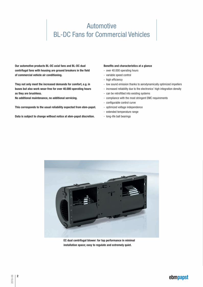
EC dual centrifugal blower: for top performance in minimalinstallation space; easy to regulate and extremely quiet.
2016-08
Automotive_2016_16_08_2016_AE_Final_.indd 2 16.08.2016 08:48:00
Our automotive products ..... 2About ebm-papst 4Ideas for changing technology in commercial vehicles 6EC dual centrifugal fan with housing "Premium" 8EC dual centrifugal fan with housing "Basic" 21EC axial fans "Premium & Power" 27EC axial fans "Basic" 51
EC centrifugal fan, forward curved 57EC centrifugal fans - RadiCal, backward curved 61Technology:
- Cables 70 - Accessories 72 - Conn. diagrams 74 - Technical parameters & scope 86ebm-papst agents 90
3
Contents
2016-08
EC c
entr
ifuga
l fan
s fo
rwar
d-cu
rved
Inf
orm
atio
nEC
cen
trifu
gal f
ans
- Ra
diCa
lba
ckw
ard-
curv
edTe
chno
logy
Age
nts
EC a
xial
fans
"Bas
ic"
EC a
xial
fans
"Pre
miu
m &
Pow
er"
EC d
ual c
entr
ifuga
l fan
sw
ith h
ousi
ng "
Basi
c"EC
dua
l cen
trifu
gal f
ans
with
hou
sing
"Pr
emiu
m"
Automotive_2016_16_08_2016_AE_Final_.indd 3 16.08.2016 08:48:02
4
2016-08
About ebm-papst
As a leader in technologies for ventilation and drive engineering, ebm-papst is in demand as an engineering partner in many sectors. With over 15,000 different products, we provide the right solution for just about any challenge. Our fans and drives are reliable, quiet and energy-efficient.
Six reasons that make us the ideal partner:
Our systems expertise.You want the best solution for every project. The inter relationships
between ventilation and drive engineering must thus be considered
as a whole. And that’s what we do – with motor technology that sets
standards, sophisticated electronics and aerodynamic designs –
all from a single source and perfectly matched. These system solutions
release unique synergies worldwide. And in particular – they relieve you
of a lot of work, so that you can concentrate on your core competency.
The ebm-papst spirit of invention.In addition to our wide range of products, we are always able to develop
customized solutions for you. A diversified team of 600 engineers and
technicians works at our three locations in Germany: Mulfingen, Landshut
and St. Georgen. Contact us to discuss your next project.
Our lead in technology.As pioneer and trail-blazer for developing highly efficient EC tech nology,
we are way ahead of other motor manufacturers. Almost our entire product
range is also available with GreenTech EC technology. The list of benefits is
long: higher efficiency, main tenance-free, longer service life, sound reduc-
tion, intelligent control characteristics and incomparable energy efficiency
with savings of up to 80 % compared to conventional AC technology. Let
our technology be your competitive advantage as you lead in your industry.
Proximity to our customers.ebm-papst owns 57 sales offices worldwide, of which 47 are sub sidiaries
with an extensive network of sales representatives and distributors. You
will always have a local contact, someone who speaks your language and
knows your market.
Our standard of quality.Of course you can rely on the highest standards of quality with our pro-
ducts. Our quality management is uncompromising, at every step in every
process. This is underscored by our certification according to international
standards including DIN EN ISO 9001, ISO/TS 16949-2 and DIN EN ISO
14001.
Our sustainable approach.Assuming responsibility for the environment, for our employees and for
society is an integral part of our corporate philosophy. We develop
products with an eye to maximum environmental compatibility, in particu-
lar resource-preserving production methods. We promote environmental
awareness among our young staff and are actively involved in sporting,
cultural activities and education. That’s what makes us a leading company
– and an ideal partner for you.
Automotive_2016_16_08_2016_AE_Final_.indd 4 16.08.2016 08:48:02
5
2016-08
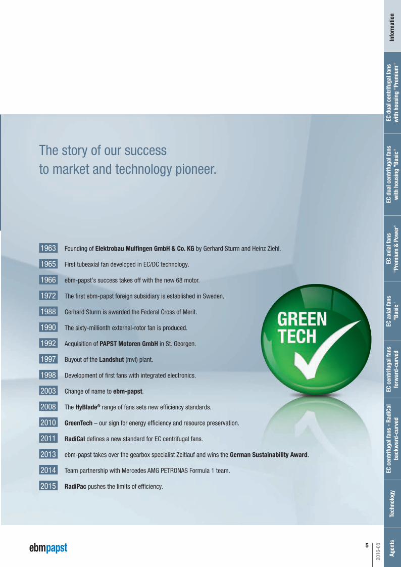
The story of our success to market and technology pioneer.
EC c
entr
ifuga
l fan
s fo
rwar
d-cu
rved
Inf
orm
atio
nEC
cen
trifu
gal f
ans
- Ra
diCa
lba
ckw
ard-
curv
edTe
chno
logy
Age
nts
EC a
xial
fans
"Bas
ic"
EC a
xial
fans
"Pre
miu
m &
Pow
er"
EC d
ual c
entr
ifuga
l fan
sw
ith h
ousi
ng "
Basi
c"EC
dua
l cen
trifu
gal f
ans
with
hou
sing
"Pr
emiu
m"
1963 Founding of Elektrobau Mulfingen GmbH & Co. KG by Gerhard Sturm and Heinz Ziehl.
1965 First tubeaxial fan developed in EC/DC technology.
1966 ebm-papst’s success takes off with the new 68 motor.
1972 The first ebm-papst foreign subsidiary is established in Sweden.
1988 Gerhard Sturm is awarded the Federal Cross of Merit.
1990 The sixty-millionth external-rotor fan is produced.
1992 Acquisition of PAPST Motoren GmbH in St. Georgen.
1997 Buyout of the Landshut (mvl) plant.
1998 Development of first fans with integrated electronics.
2003 Change of name to ebm-papst.
2008 The HyBlade® range of fans sets new efficiency standards.
2010 GreenTech – our sign for energy efficiency and resource preservation.
2011 RadiCal defines a new standard for EC centrifugal fans.
2013 ebm-papst takes over the gearbox specialist Zeitlauf and wins the German Sustainability Award.
2014 Team partnership with Mercedes AMG PETRONAS Formula 1 team.
2015 RadiPac pushes the limits of efficiency.
Automotive_2016_16_08_2016_AE_Final_.indd 5 16.08.2016 08:48:05

6
Ideas for changing technologyin commercial vehicles
Climate comfort in a commercial vehicle is anything but a question of
convenience. Both the transportation of people in buses and coaches,
as well truck journeys which are as stress and fatigue-free as possible,
place high demands on vehicle technology; predominantly air conditioning,
ventilation, and heating.
For many years, major bus manufacturers have been installing air condi-
tioners with brushless and wear-free centrifugal blowers and axial fans
from ebm-papst. In the mean time, these products are also now widely
used in the air conditioning and ventilation systems for the cabs in trucks,
tractors and construction machinery, as well as in transport refrigeration
systems.
A number of air conditioning manufacturers rely on our experience and
outstanding expertise in the core competencies of engine development,
aerodynamics, and electronics.
Counteracting high demands with new technologies:In modern commercial vehicles, EC technology has now become
standard. Our new EC axial fans and EC dual centrifugal fans with second
generation housing set a precedent in global commercial vehicle air
conditioning. Our EC fans have even been able to demonstrate their clear
superiority in hot countries and tropical regions, where they have also
proven their worth.
But it is not just in the fi eld of air conditioning products where customers
are relying on ebm-papst products: EC fans are increasingly being used
for cooling heat exchangers in the engine compartment of vehicles.
Fans and blowers:for commercial vehicle air conditioning and cooling of individual compo-
nents.
However, ebm-papst has even more to offer:If you are unable to fi nd a solution amongst our products, speak to us.
As a competent consultant and practical implementer, we will certainly
be able to fi nd you a solution thanks to our in-depth knowledge from
many applications.
2016-08
Automotive_2016_16_08_2016_AE_Final_.indd 6 16.08.2016 08:48:06

7
In comparison:In brush motors from various manufacturers, the commutator
assumes the role of current distribution to the coils. The commutator
consists of copper fins embedded in an insulating compound. Mechani-
cal springs push the integrated carbon brushes to the commutator. These
two rubbing mechanical components are the weak spot of conventional
DC motors. After around 5,000 operating hours, the carbon brushes are
run down and the commutator is worn. As a result, the entire blower must
be replaced. In addition, it is only possible to regulate speed via external
electronics.
The brushless DC motors from ebm-papst are completely different. Here,
an electronic controller directly integrated in the motor has the task of
distributing current. No brushes means no wearing parts. This increases
the service life of these motors to more than 40,000 hours. The user not
only saves money in terms of replacement parts and repair costs, he also
avoids unproductive downtimes and a possible loss of image.
EC motors are energy efficient, because the integrated electronics with
variable speed control only draw the energy actually required from the
on-board network. In the commercial vehicle sector, it is also crucial that
fans withstand constantly changing environmental influences. Standard
products would only provide unsatisfactory results here. For this reason,
automotive products from ebm-papst are also reliably protected against
load dumping, reverse polarity, shock and vibration, as well as damage
from moisture and dirt penetration across a wide temperature range.
This also requires special efforts in terms of the selection of materials and
testing of products. With the help of real-world extreme tests that we have
defined in collaboration with leading OEMs (e.g., salt spray, vibration and
temperature cycling tests), we are able to ensure the performance of the
fans.
Apart from the considerably longer service life, our intelligent EC fans
provide advanced control and regulation possibilities. The functionality of
the fans can be checked via a diagnostic output at any time. Furthermore,
these display excellent electromagnetic compatibility traits and operate
extremely quietly.
2016-08
EC c
entr
ifuga
l fan
s fo
rwar
d-cu
rved
Inf
orm
atio
nEC
cen
trifu
gal f
ans
- Ra
diCa
lba
ckw
ard-
curv
edTe
chno
logy
Age
nts
EC a
xial
fans
"Bas
ic"
EC a
xial
fans
"Pre
miu
m &
Pow
er"
EC d
ual c
entr
ifuga
l fan
sw
ith h
ousi
ng "
Basi
c"EC
dua
l cen
trifu
gal f
ans
with
hou
sing
"Pr
emiu
m"
Automotive_2016_16_08_2016_AE_Final_.indd 7 16.08.2016 08:48:08

8
2016-08
Automotive_2016_16_08_2016_AE_Final_.indd 8 16.08.2016 08:48:09
9
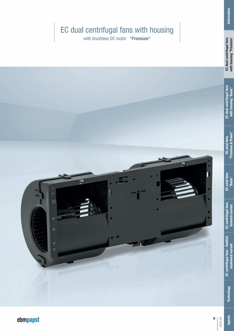
EC dual centrifugal fans with housingwith brushless DC motor "Premium"
2016-08
EC c
entr
ifuga
l fan
s fo
rwar
d-cu
rved
Inf
orm
atio
nEC
cen
trifu
gal f
ans
- Ra
diCa
lba
ckw
ard-
curv
edTe
chno
logy
Age
nts
EC a
xial
fans
"Bas
ic"
EC a
xial
fans
"Pre
miu
m &
Pow
er"
EC d
ual c
entr
ifuga
l fan
sw
ith h
ousi
ng "
Basi
c"EC
dua
l cen
trifu
gal f
ans
with
hou
sing
"Pr
emiu
m"
Automotive_2016_16_08_2016_AE_Final_.indd 9 16.08.2016 08:48:09

10
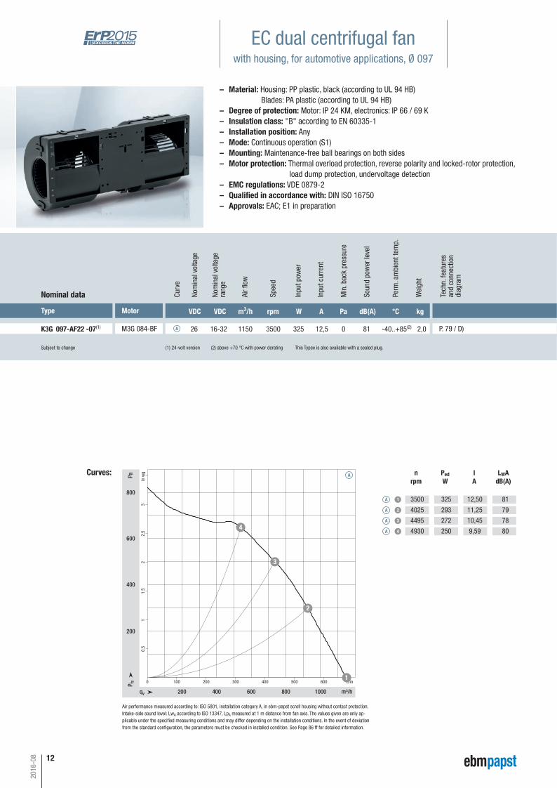
EC dual centrifugal fanwith housing, for automotive applications, Ø 097
Subject to change (1) 24-volt version (2) above +70 °C with power derating
Type Motor VDC VDC m3/h rpm W A Pa dB(A) °C kg
K3G 097-AF22 -02(1) M3G 084-BF 26 16-32 1150 3500 325 12,5 0 81 -40..+85(2) 2,0 P. 79 / D)
Nominal data Curv
e
A
Nom
inal
vol
tage
rang
e
Nom
inal
vol
tage
Spee
d
Inpu
t pow
er
Inpu
t cur
rent
Soun
d po
wer
leve
l
Perm
. am
bien
t tem
p.
Wei
ght
Curves:
qv m³/h
cfmP fs
Pa
in w
g
200 400 600 800 1000
0 100 200 300 400 500 600
200
400
600
800
0.5
11.
52
2.5
3
1
2
3
4
A
Air fl
ow
nrpm
PedW
IA
LWAdB(A)
A 1
A 2
A 3
A 4
3500
4025
4495
4930
325
293
272
250
12,50
11,25
10,45
9,59
81
79
78
80
Min
. bac
k pr
essu
re
Air performance measured according to: ISO 5801, installation category A, in ebm-papst scroll housing without contact protection. Intake-side sound level: LwA according to ISO 13347, LpA measured at 1 m distance from fan axis. The values given are only ap-plicable under the specifi ed measuring conditions and may differ depending on the installation conditions. In the event of deviation from the standard confi guration, the parameters must be checked in installed condition. See Page 86 ff for detailed information.
– Material: Housing: PP plastic, black (according to UL 94 HB) Blades: PA plastic (according to UL 94 HB)– Degree of protection: IP 24 KM– Insulation class: "B" according to EN 60335-1– Installation position: Any– Mode: Continuous operation (S1)– Mounting: Maintenance-free ball bearings on both sides– Motor protection: Thermal overload protection, reverse polarity and locked-rotor protection, load dump protection, undervoltage detection– EMC regulations: VDE 0879-2– Approvals: EAC; E1 in preparation
2016-08
Tech
n. fe
atur
esan
d co
nnec
tion
diag
ram
Automotive_2016_16_08_2016_AE_Final_.indd 10 16.08.2016 08:48:10
11
P. 79 / D)
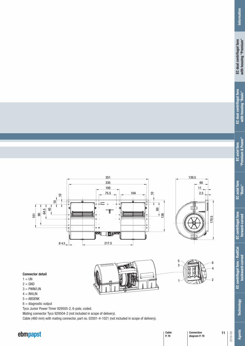
Connection diagram P. 79
Ø 4.5
75.5
100
335
351
217.5
18
10
45
64.5
90
101
10
60
136
170.
5
11
60
139.5
2.5104
1
35
2
4
6
CableP. 70
Connector detail1 = UN2 = GND3 = PWM/LIN4 = INVLIN 5 = ABSENK6 = diagnostic outputTyco Junior Power Timer 929505-2, 6-pole, coded.Mating connector Tyco 929504-2 (not included in scope of delivery).Cable (460 mm) with mating connector, part no. 02001-4-1021 (not included in scope of delivery).
2016-08
EC c
entr
ifuga
l fan
s fo
rwar
d-cu
rved
Inf
orm
atio
nEC
cen
trifu
gal f
ans
- Ra
diCa
lba
ckw
ard-
curv
edTe
chno
logy
Age
nts
EC a
xial
fans
"Bas
ic"
EC a
xial
fans
"Pre
miu
m &
Pow
er"
EC d
ual c
entr
ifuga
l fan
sw
ith h
ousi
ng "
Basi
c"EC
dua
l cen
trifu
gal f
ans
with
hou
sing
"Pr
emiu
m"
Automotive_2016_16_08_2016_AE_Final_.indd 11 16.08.2016 08:48:11
12
EC dual centrifugal fanwith housing, for automotive applications, Ø 097
Subject to change (1) 24-volt version (2) above +70 °C with power derating This Typee is also available with a sealed plug.
Type Motor VDC VDC m3/h rpm W A Pa dB(A) °C kg
K3G 097-AF22 -07(1) M3G 084-BF 26 16-32 1150 3500 325 12,5 0 81 -40..+85(2) 2,0 P. 79 / D)
Nominal data Curv
e
A
Nom
inal
vol
tage
rang
e
Nom
inal
vol
tage
Spee
d
Inpu
t pow
er
Inpu
t cur
rent
Soun
d po
wer
leve
l
Perm
. am
bien
t tem
p.
Wei
ght
Curves:
Air fl
ow
nrpm
PedW
IA
LWAdB(A)
A 1
A 2
A 3
A 4
3500
4025
4495
4930
325
293
272
250
12,50
11,25
10,45
9,59
81
79
78
80
Min
. bac
k pr
essu
re
qv m³/h
cfmP fs
Pa
in w
g
200 400 600 800 1000
0 100 200 300 400 500 600
200
400
600
800
0.5
11.
52
2.5
3
1
2
3
4
A
Air performance measured according to: ISO 5801, installation category A, in ebm-papst scroll housing without contact protection. Intake-side sound level: LwA according to ISO 13347, LpA measured at 1 m distance from fan axis. The values given are only ap-plicable under the specifi ed measuring conditions and may differ depending on the installation conditions. In the event of deviation from the standard confi guration, the parameters must be checked in installed condition. See Page 86 ff for detailed information.
– Material: Housing: PP plastic, black (according to UL 94 HB) Blades: PA plastic (according to UL 94 HB)– Degree of protection: Motor: IP 24 KM, electronics: IP 66 / 69 K– Insulation class: "B" according to EN 60335-1– Installation position: Any– Mode: Continuous operation (S1)– Mounting: Maintenance-free ball bearings on both sides– Motor protection: Thermal overload protection, reverse polarity and locked-rotor protection, load dump protection, undervoltage detection– EMC regulations: VDE 0879-2– Qualifi ed in accordance with: DIN ISO 16750– Approvals: EAC; E1 in preparation
2016-08
Tech
n. fe
atur
esan
d co
nnec
tion
diag
ram
Automotive_2016_16_08_2016_AE_Final_.indd 12 16.08.2016 08:48:12
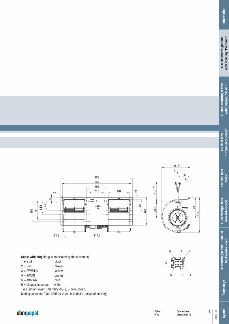
13Connection diagram P. 79
CableP. 70
Ø 4.5
75.5
100
335
351
217.5
18
10
45
64.5
90
101
10
60
136
104
79.5
1160
139.5
170.
599
415
X
+20
X
6 4 2
5 3 1
Cable with plug (Plug is not sealed by the customer)1 = +UB black2 = GND brown3 = PWM/LIN yellow4 = INVLIN orange5 = ABSENK blue6 = diagnostic output whiteTyco Junior Power Timer 929505-2, 6-pole, coded.Mating connector Tyco 929504-2 (not included in scope of delivery).
P. 79 / D)
2016-08
EC c
entr
ifuga
l fan
s fo
rwar
d-cu
rved
Inf
orm
atio
nEC
cen
trifu
gal f
ans
- Ra
diCa
lba
ckw
ard-
curv
edTe
chno
logy
Age
nts
EC a
xial
fans
"Bas
ic"
EC a
xial
fans
"Pre
miu
m &
Pow
er"
EC d
ual c
entr
ifuga
l fan
sw
ith h
ousi
ng "
Basi
c"EC
dua
l cen
trifu
gal f
ans
with
hou
sing
"Pr
emiu
m"
Automotive_2016_16_08_2016_AE_Final_.indd 13 16.08.2016 08:48:12
14
EC dual centrifugal fanwith housing, for automotive applications, Ø 097
Subject to change (1) 24-volt version (2) above +70 °C with power derating
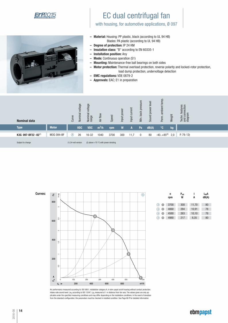
Type Motor VDC VDC m3/h rpm W A Pa dB(A) °C kg
K3G 097-BF22 -02(1) M3G 084-BF 26 16-32 1040 3700 300 11,7 0 80 -40..+85(2) 2,0 P. 79 / D)
Nominal data Curv
e
A
Nom
inal
vol
tage
rang
e
Nom
inal
vol
tage
Spee
d
Inpu
t pow
er
Inpu
t cur
rent
Soun
d po
wer
leve
l
Perm
. am
bien
t tem
p.
Wei
ght
Curves:
qv m³/h
cfmP fs
Pa
in w
g
200 400 600 800
0 100 200 300 400 500
200
400
600
800
0.5
11.
52
2.5
3
1
2
3
4
A
Air fl
ow
nrpm
PedW
IA
LWAdB(A)
A 1
A 2
A 3
A 4
3700
4060
4580
4980
300
284
263
217
11,70
10,91
10,10
8,35
80
78
78
80
Min
. bac
k pr
essu
re
Air performance measured according to: ISO 5801, installation category A, in ebm-papst scroll housing without contact protection. Intake-side sound level: LwA according to ISO 13347, LpA measured at 1 m distance from fan axis. The values given are only ap-plicable under the specifi ed measuring conditions and may differ depending on the installation conditions. In the event of deviation from the standard confi guration, the parameters must be checked in installed condition. See Page 86 ff for detailed information.
– Material: Housing: PP plastic, black (according to UL 94 HB) Blades: PA plastic (according to UL 94 HB)– Degree of protection: IP 24 KM– Insulation class: "B" according to EN 60335-1– Installation position: Any– Mode: Continuous operation (S1)– Mounting: Maintenance-free ball bearings on both sides– Motor protection: Thermal overload protection, reverse polarity and locked-rotor protection, load dump protection, undervoltage detection– EMC regulations: VDE 0879-2– Approvals: EAC; E1 in preparation
2016-08
Tech
n. fe
atur
esan
d co
nnec
tion
diag
ram
Automotive_2016_16_08_2016_AE_Final_.indd 14 16.08.2016 08:48:13
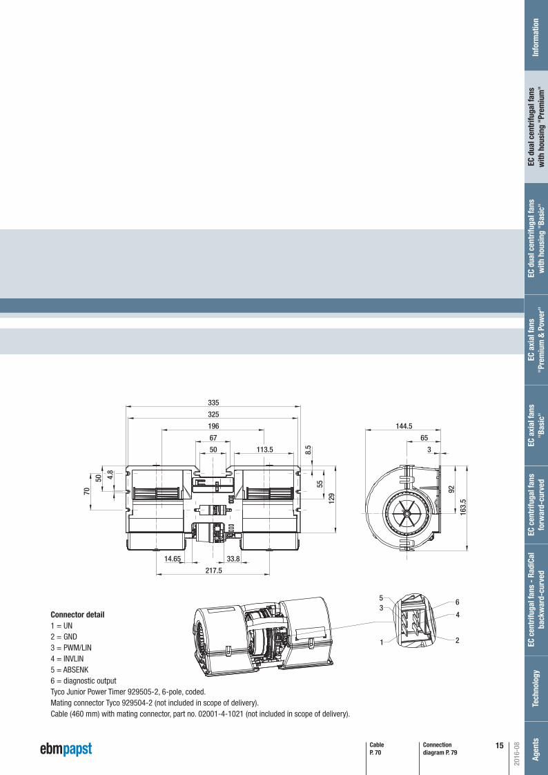
15
P. 79 / D)
Connection diagram P. 79
144.5
163.5
392
6567
50
33.814.65
113.5 8.5
55
129
4.8
50
70
325
335
196
217.5
1
35
2
4
6
CableP. 70
Connector detail1 = UN2 = GND3 = PWM/LIN4 = INVLIN 5 = ABSENK6 = diagnostic outputTyco Junior Power Timer 929505-2, 6-pole, coded.Mating connector Tyco 929504-2 (not included in scope of delivery).Cable (460 mm) with mating connector, part no. 02001-4-1021 (not included in scope of delivery).
2016-08
EC c
entr
ifuga
l fan
s fo
rwar
d-cu
rved
Inf
orm
atio
nEC
cen
trifu
gal f
ans
- Ra
diCa
lba
ckw
ard-
curv
edTe
chno
logy
Age
nts
EC a
xial
fans
"Bas
ic"
EC a
xial
fans
"Pre
miu
m &
Pow
er"
EC d
ual c
entr
ifuga
l fan
sw
ith h
ousi
ng "
Basi
c"EC
dua
l cen
trifu
gal f
ans
with
hou
sing
"Pr
emiu
m"
Automotive_2016_16_08_2016_AE_Final_.indd 15 16.08.2016 08:48:14
16
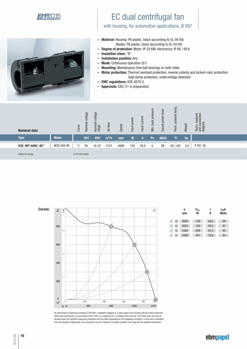
EC dual centrifugal fanwith housing, for automotive applications, Ø 097
– Material: Housing: PA plastic, black (according to UL 94 V0) Blades: PA plastic, black (according to UL 94 V0)– Degree of protection: Motor: IP 24 KM, electronics: IP 66 / 69 K– Insulation class: "B"– Installation position: Any– Mode: Continuous operation (S1)– Mounting: Maintenance-free ball bearings on both sides– Motor protection: Thermal overload protection, reverse polarity and locked-rotor protection, load dump protection, undervoltage detection– EMC regulations: VDE 0879-2– Approvals: EAC; E1 in preparation
Subject to change (1) 24-volt version
Type Motor
K3G 097-AS82 -82(1) M3G 084-BF
Nominal data
Curves: nrpm
PedW
IA
LWAdB(A)
A 1
A 2
A 3
A 4
VDC VDC m3/h rpm W A Pa dB(A) °C kg
26 16-32 1574 4680 740 28,0 0 88 -40..+60 2,0 P. 83 / Q)
Curv
e
A
Nom
inal
vol
tage
rang
e
Nom
inal
vol
tage
Spee
d
Inpu
t pow
er
Inpu
t cur
rent
Soun
d po
wer
leve
l
Perm
. am
bien
t tem
p.
Wei
ght
Air fl
ow
Min
. bac
k pr
essu
re
Air performance measured according to: ISO 5801, installation category A, in ebm-papst scroll housing without contact protection. Intake-side sound level: LwA according to ISO 13347, LpA measured at 1 m distance from fan axis. The values given are only ap-plicable under the specifi ed measuring conditions and may differ depending on the installation conditions. In the event of deviation from the standard confi guration, the parameters must be checked in installed condition. See Page 86 ff for detailed information.
qv m³/h
cfmP fs
Pa
in w
g
400 800 1200
0 200 400 600 800
200
400
600
800
12
3
1
2
3
4
A
4680
5025
5380
5500
740
740
659
441
28,0
28,0
25,3
16,9
88
87
85
84
2016-08
Tech
n. fe
atur
esan
d co
nnec
tion
diag
ram
Automotive_2016_16_08_2016_AE_Final_.indd 16 16.08.2016 08:48:15
17
79.5
1000
11
60139.5
170.
5
35133510075.5
217.5Ø 4.5
136
6010
1810
4564
.590
101
10499
875
+20
±10
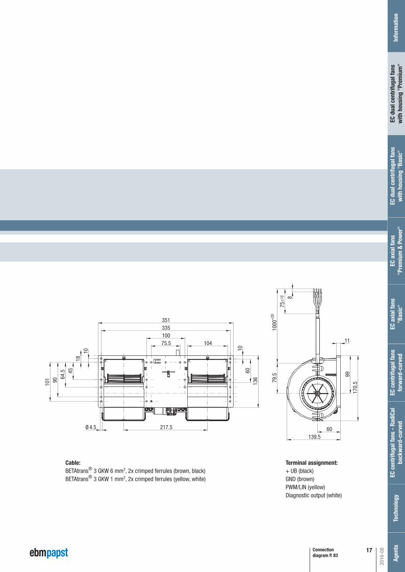
P. 83 / Q)
Connection diagram P. 83
2016-08
Cable:BETAtrans® 3 GKW 6 mm2, 2x crimped ferrules (brown, black)BETAtrans® 3 GKW 1 mm2, 2x crimped ferrules (yellow, white)
Terminal assignment:+ UB (black)GND (brown)PWM/LIN (yellow)Diagnostic output (white)
EC c
entr
ifuga
l fan
s fo
rwar
d-cu
rved
Inf
orm
atio
nEC
cen
trifu
gal f
ans
- Ra
diCa
lba
ckw
ard-
curv
edTe
chno
logy
Age
nts
EC a
xial
fans
"Bas
ic"
EC a
xial
fans
"Pre
miu
m &
Pow
er"
EC d
ual c
entr
ifuga
l fan
sw
ith h
ousi
ng "
Basi
c"EC
dua
l cen
trifu
gal f
ans
with
hou
sing
"Pr
emiu
m"
Automotive_2016_16_08_2016_AE_Final_.indd 17 16.08.2016 08:48:16
18
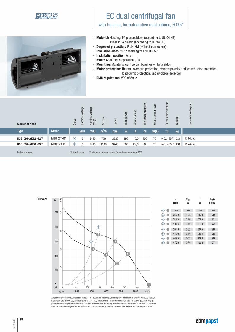
EC dual centrifugal fanwith housing, for automotive applications, Ø 097
Subject to change (1) 12-volt version (2) wide open, not recommended for continuous operation at 85°C
Type Motor VDC VDC m3/h rpm W A Pa dB(A) °C kg
K3G 097-AK32 -42(1) M3G 074-BF 13 9-15 750 3630 195 15,0 300 70 -40..+85(2) 2,3 P. 74 / A)
Nominal data Curv
e
A
Nom
inal
vol
tage
rang
e
Nom
inal
vol
tage
Spee
d
Inpu
t pow
er
Inpu
t cur
rent
Soun
d po
wer
leve
l
Perm
. am
bien
t tem
p.
Wei
ght
Curves:
0 100 200 300 400 500 600
1,0
200
2,0
400
600
3,0
800
1000 4,0
200 400 600 800 1000qv m³/h
cfmP fs
Pa
in w
g
1
2
3
4
2
3
4
Air fl
ow
nrpm
PedW
IA
LWAdB(A)
A 1
A 2
A 3
A 4
---
3630
3875
4135
---
195
177
143
---
15,0
13,5
11,0
---
70
71
72
B 1
B 2
B 3
B 4
3740
4400
4775
4970
385
344
309
234
29,5
26,4
23,8
18,0
76
75
76
77
K3G 097-AK36 -55(1) M3G 074-BF 13 9-15 1180 3740 385 29,5 0 76 -40..+85(2) 2,6 P. 74 / A)BM
in. b
ack
pres
sure
A
B
Air performance measured according to: ISO 5801, installation category A, in ebm-papst scroll housing without contact protection. Intake-side sound level: LwA according to ISO 13347, LpA measured at 1 m distance from fan axis. The values given are only ap-plicable under the specifi ed measuring conditions and may differ depending on the installation conditions. In the event of deviation from the standard confi guration, the parameters must be checked in installed condition. See Page 86 ff for detailed information.
– Material: Housing: PP plastic, black (according to UL 94 HB) Blades: PA plastic (according to UL 94 HB)– Degree of protection: IP 24 KM (without connectors)– Insulation class: "B" according to EN 60335-1– Installation position: Any– Mode: Continuous operation (S1)– Mounting: Maintenance-free ball bearings on both sides– Motor protection: Thermal overload protection, reverse polarity and locked-rotor protection, load dump protection, undervoltage detection– EMC regulations: VDE 0879-2
2016-08
Conn
ectio
n di
agra
m
Automotive_2016_16_08_2016_AE_Final_.indd 18 16.08.2016 08:48:16
19
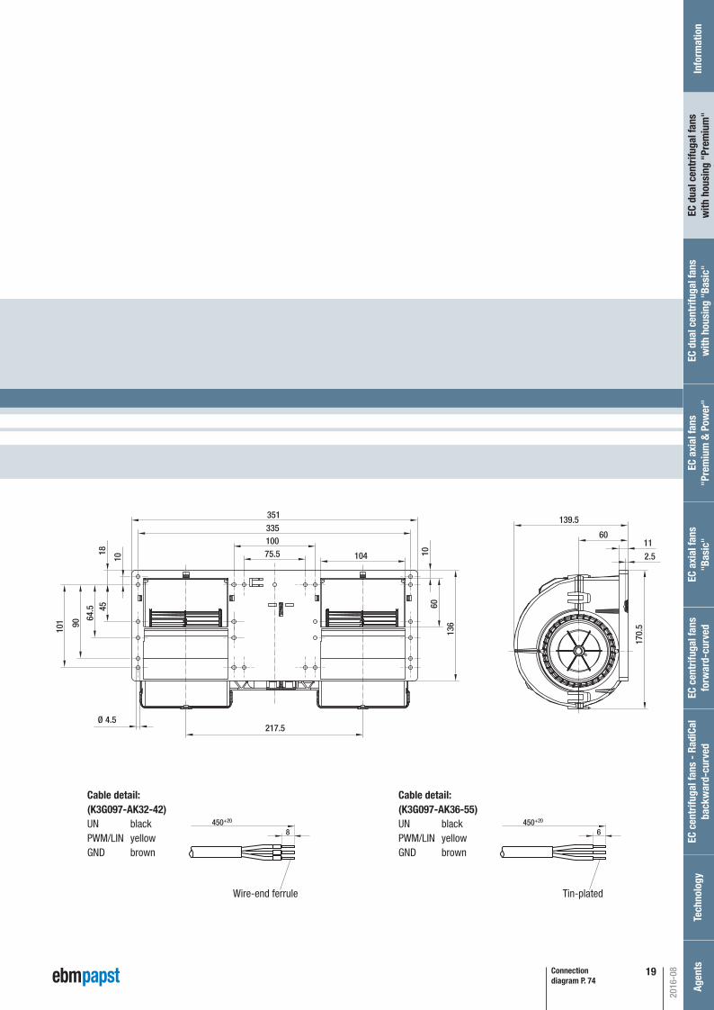
P. 74 / A)
Connection diagram P. 74
75.5100
104
335351
18
10
4564
.5
90
101
217.5
60
136
10 2.5
1160
139.5
170.
5
Ø 4.5
Cable detail:(K3G097-AK32-42)UN blackPWM/LIN yellowGND brown
P. 74 / A)
Cable detail:(K3G097-AK36-55)UN blackPWM/LIN yellowGND brown
Wire-end ferrule Tin-plated
450+20
8450+20
6
2016-08
EC c
entr
ifuga
l fan
s fo
rwar
d-cu
rved
Inf
orm
atio
nEC
cen
trifu
gal f
ans
- Ra
diCa
lba
ckw
ard-
curv
edTe
chno
logy
Age
nts
EC a
xial
fans
"Bas
ic"
EC a
xial
fans
"Pre
miu
m &
Pow
er"
EC d
ual c
entr
ifuga
l fan
sw
ith h
ousi
ng "
Basi
c"EC
dua
l cen
trifu
gal f
ans
with
hou
sing
"Pr
emiu
m"
Automotive_2016_16_08_2016_AE_Final_.indd 19 16.08.2016 08:48:17

20
2016-08
Automotive_2016_16_08_2016_AE_Final_.indd 20 16.08.2016 08:48:17
21
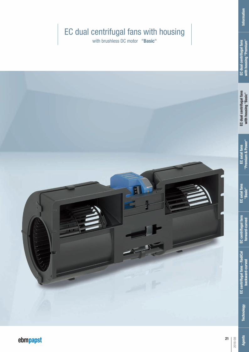
EC dual centrifugal fans with housingwith brushless DC motor "Basic"
2016-08
EC c
entr
ifuga
l fan
s fo
rwar
d-cu
rved
Inf
orm
atio
nEC
cen
trifu
gal f
ans
- Ra
diCa
lba
ckw
ard-
curv
edTe
chno
logy
Age
nts
EC a
xial
fans
"Bas
ic"
EC a
xial
fans
"Pre
miu
m &
Pow
er"
EC d
ual c
entr
ifuga
l fan
sw
ith h
ousi
ng "
Basi
c"EC
dua
l cen
trifu
gal f
ans
with
hou
sing
"Pr
emiu
m"
Automotive_2016_16_08_2016_AE_Final_.indd 21 16.08.2016 08:48:18
22
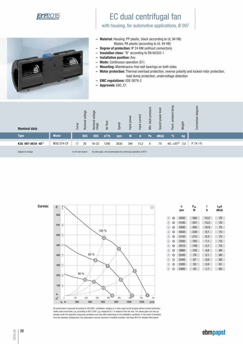
EC dual centrifugal fanwith housing, for automotive applications, Ø 097
Subject to change (1) 24-volt version (2) wide open, not recommended for continuous operation at 85°C
Type Motor VDC VDC m3/h rpm W A Pa dB(A) °C kg
K3G 097-AK34 -65(1) M3G 074-CF 26 16-32 1290 3830 394 15,2 0 79 -40..+85(2) 2,0 P. 74 / F)
Nominal data Curv
e
A
Nom
inal
vol
tage
rang
e
Nom
inal
vol
tage
Spee
d
Inpu
t pow
er
Inpu
t cur
rent
Soun
d po
wer
leve
l
Perm
. am
bien
t tem
p.
Wei
ght
Curves:
0,8
1,2
1,6
2,0
2,4
2,8
0,4
0 100 200 300 400 500 600 700
200 400 600 800 1000 1200
100
200
300
400
500
600
700
800
qv m³/h
cfmP fs
Pa
in w
g
1
2
3
4
5
6
7
8
9
10
1112
Air fl
ow
nrpm
PedW
IA
LWAdB(A)
A 1
A 2
A 3
A 4
3830
4100
4380
4630
394
347
285
238
15,2
13,3
10,9
9,1
79
76
75
75
Min
. bac
k pr
essu
re
A 5
A 6
A 7
A 8
3150
3330
3510
3660
215
185
149
120
8,3
7,1
5,7
4,6
75
72
70
69A 9
A 10
A 11
A 12
2240
2340
2430
2460
79
67
53
43
3,1
2,6
2,0
1,7
66
66
61
60
A
100 %
80 %
60 %
Air performance measured according to: ISO 5801, installation category A, in ebm-papst scroll housing without contact protection. Intake-side sound level: LwA according to ISO 13347, LpA measured at 1 m distance from fan axis. The values given are only ap-plicable under the specifi ed measuring conditions and may differ depending on the installation conditions. In the event of deviation from the standard confi guration, the parameters must be checked in installed condition. See Page 86 ff for detailed information.
– Material: Housing: PP plastic, black (according to UL 94 HB) Blades: PA plastic (according to UL 94 HB)– Degree of protection: IP 24 KM (without connectors)– Insulation class: "B" according to EN 60335-1– Installation position: Any– Mode: Continuous operation (S1)– Mounting: Maintenance-free ball bearings on both sides– Motor protection: Thermal overload protection, reverse polarity and locked-rotor protection, load dump protection, undervoltage detection– EMC regulations: VDE 0879-2– Approvals: EAC, E1
2016-08
Conn
ectio
n di
agra
m
Automotive_2016_16_08_2016_AE_Final_.indd 22 16.08.2016 08:48:19
23
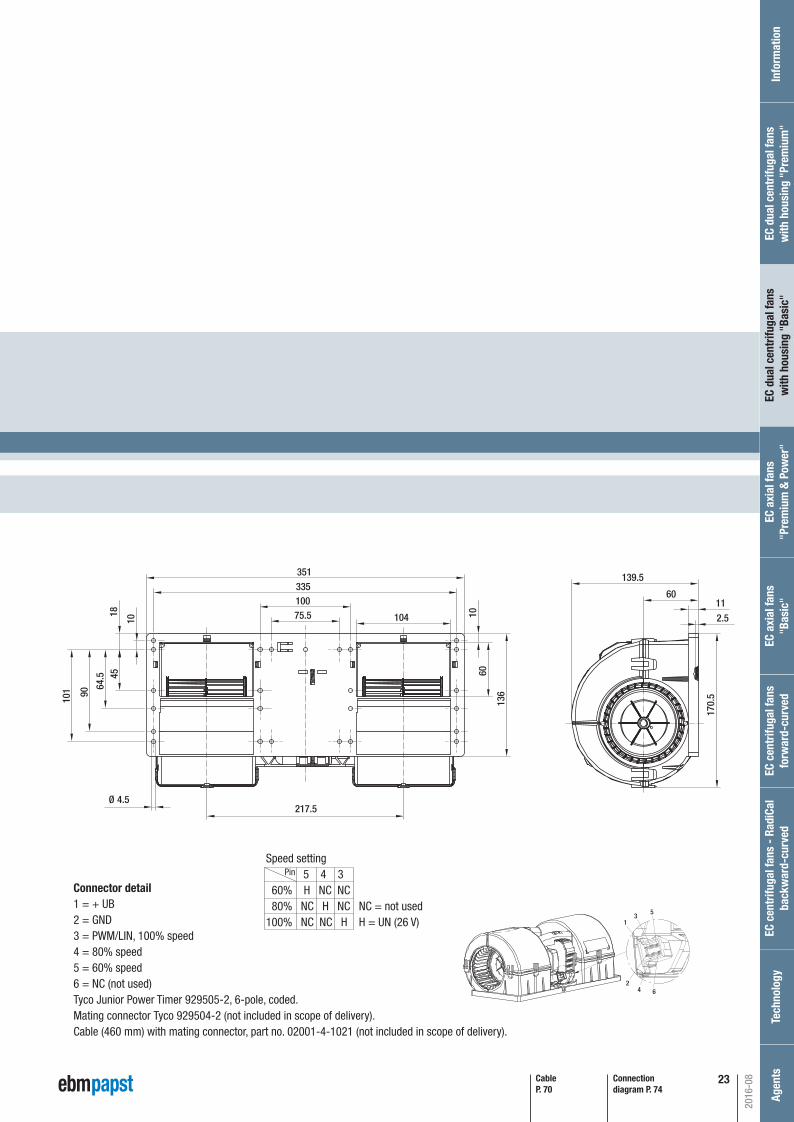
P. 74 / F)
Connection diagram P. 74
CableP. 70
75.5100
104
335351
18
10
4564
.5
90
101
217.5
60
136
10 2.5
1160
139.5
170.
5
Ø 4.5
5
2
1
4
3
6
Connector detail1 = + UB2 = GND3 = PWM/LIN, 100% speed4 = 80% speed5 = 60% speed6 = NC (not used)Tyco Junior Power Timer 929505-2, 6-pole, coded.Mating connector Tyco 929504-2 (not included in scope of delivery).Cable (460 mm) with mating connector, part no. 02001-4-1021 (not included in scope of delivery).
Speed setting 5 4 3 60% H NC NC 80% NC H NC NC = not used100% NC NC H H = UN (26 V)
Pin
2016-08
EC c
entr
ifuga
l fan
s fo
rwar
d-cu
rved
Inf
orm
atio
nEC
cen
trifu
gal f
ans
- Ra
diCa
lba
ckw
ard-
curv
edTe
chno
logy
Age
nts
EC a
xial
fans
"Bas
ic"
EC a
xial
fans
"Pre
miu
m &
Pow
er"
EC d
ual c
entr
ifuga
l fan
sw
ith h
ousi
ng "
Basi
c"EC
dua
l cen
trifu
gal f
ans
with
hou
sing
"Pr
emiu
m"
Automotive_2016_16_08_2016_AE_Final_.indd 23 16.08.2016 08:48:19

24
EC dual centrifugal fanwith housing, for automotive applications, Ø 097
Subject to change (1) 24-volt version (2) wide open, not recommended for continuous operation at 85°C
Type Motor VDC VDC m3/h rpm W A Pa dB(A) °C kg
K3G 097-BK34 -65(1) M3G 074-CF 26 16-32 1110 4040 344 13,3 0 77 -40..+85(2) 2,0 P. 74 / F)
Nominal data Curv
e
A
Nom
inal
vol
tage
rang
e
Nom
inal
vol
tage
Spee
d
Inpu
t pow
er
Inpu
t cur
rent
Soun
d po
wer
leve
l
Perm
. am
bien
t tem
p.
Wei
ght
Curves:
0,8
1,2
1,6
2,0
2,4
2,8
0,4
0 100 200 300 400 500 600
200 400 600 800 1000
100
200
300
400
500
600
700
3,2800
3,6900
qv m³/h
cfmP fs
Pa
in w
g
1
2
3
4
5
6
7
8
9
10
1112
Air fl
ow
nrpm
PedW
IA
LWAdB(A)
A 1
A 2
A 3
A 4
4040
4210
4380
4630
344
325
279
242
13,3
12,5
10,6
9,2
77
76
75
75
Min
. bac
k pr
essu
re
A 5
A 6
A 7
A 8
3310
3390
3520
3650
186
171
145
121
7,2
6,6
5,5
4,6
73
71
70
69A 9
A 10
A 11
A 12
2330
2360
2410
2480
67
62
53
42
2,6
2,4
2,0
1,6
64
62
61
60
A
100 %
80 %
60 %
Air performance measured according to: ISO 5801, installation category A, in ebm-papst scroll housing without contact protection. Intake-side sound level: LwA according to ISO 13347, LpA measured at 1 m distance from fan axis. The values given are only ap-plicable under the specifi ed measuring conditions and may differ depending on the installation conditions. In the event of deviation from the standard confi guration, the parameters must be checked in installed condition. See Page 86 ff for detailed information.
– Material: Housing: PP plastic, black (according to UL 94 HB) Blades: PA plastic (according to UL 94 HB)– Degree of protection: IP 24 KM (without connectors)– Insulation class: "B" according to EN 60335-1– Installation position: Any– Mode: Continuous operation (S1)– Mounting: Maintenance-free ball bearings on both sides– Motor protection: Thermal overload protection, reverse polarity and locked-rotor protection, load dump protection, undervoltage detection– EMC regulations: VDE 0879-2– Approvals: EAC, E1
2016-08
Conn
ectio
n di
agra
m
Automotive_2016_16_08_2016_AE_Final_.indd 24 16.08.2016 08:48:20
25
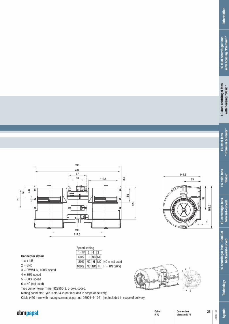
P. 74 / F)
Connection diagram P. 74
196
217.5
8.5
55
129
113.55067
325
70
4.8
50
65
144.5
92
3
163.
5
335
CableP. 70
5
2
1
4
3
6
Connector detail1 = + UB2 = GND3 = PWM/LIN, 100% speed4 = 80% speed5 = 60% speed6 = NC (not used)Tyco Junior Power Timer 929505-2, 6-pole, coded.Mating connector Tyco 929504-2 (not included in scope of delivery).Cable (460 mm) with mating connector, part no. 02001-4-1021 (not included in scope of delivery).
Speed setting 5 4 3 60% H NC NC 80% NC H NC NC = not used100% NC NC H H = UN (26 V)
Pin
2016-08
EC c
entr
ifuga
l fan
s fo
rwar
d-cu
rved
Inf
orm
atio
nEC
cen
trifu
gal f
ans
- Ra
diCa
lba
ckw
ard-
curv
edTe
chno
logy
Age
nts
EC a
xial
fans
"Bas
ic"
EC a
xial
fans
"Pre
miu
m &
Pow
er"
EC d
ual c
entr
ifuga
l fan
sw
ith h
ousi
ng "
Basi
c"EC
dua
l cen
trifu
gal f
ans
with
hou
sing
"Pr
emiu
m"
Automotive_2016_16_08_2016_AE_Final_.indd 25 16.08.2016 08:48:21

26
2016-08
Automotive_2016_16_08_2016_AE_Final_.indd 26 16.08.2016 08:48:21
27
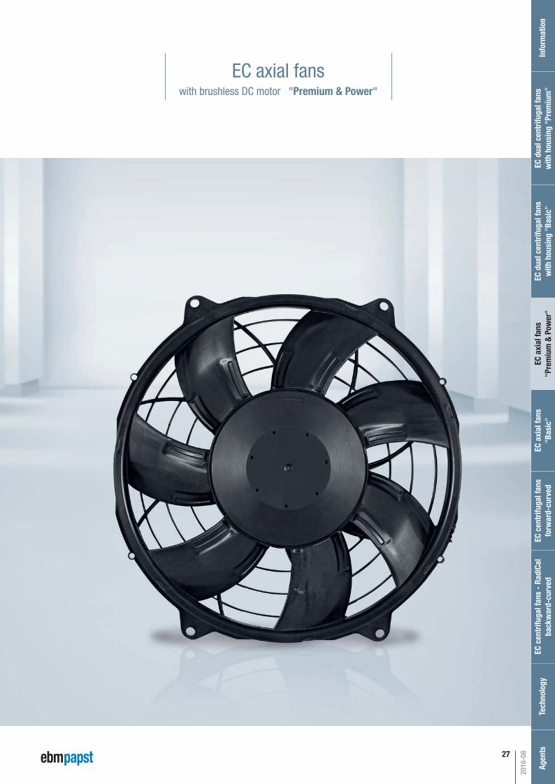
EC axial fanswith brushless DC motor "Premium & Power"
2016-08
EC c
entr
ifuga
l fan
s fo
rwar
d-cu
rved
Inf
orm
atio
nEC
cen
trifu
gal f
ans
- Ra
diCa
lba
ckw
ard-
curv
edTe
chno
logy
Age
nts
EC a
xial
fans
"Bas
ic"
EC a
xial
fans
"Pre
miu
m &
Pow
er"
EC d
ual c
entr
ifuga
l fan
sw
ith h
ousi
ng "
Basi
c"EC
dua
l cen
trifu
gal f
ans
with
hou
sing
"Pr
emiu
m"
Automotive_2016_16_08_2016_AE_Final_.indd 27 16.08.2016 08:48:22
28
2016-08
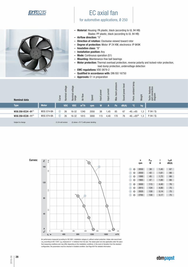
W3G 250-EC24 -01(1) M3G 074-BA 26 16-32 1240 2050 38 1,45 85 67 -40..+85 1,3 P. 84 / S)A
qv m³/h
cfmP fs
Pa
in w
g
400 800 1200 1600
0 200 400 600 800 1000
40
80
120
160
0.2
0.4
0.6
1
2
3
4
1
23
4
A 1
A 2
A 3
A 4
2050
2050
1990
1965
38
42
45
47
1,45
1,61
1,72
1,80
67
66
66
66
W3G 250-EC28 -11(1) M3G 074-BA 26 16-32 1815 3000 115 4,40 170 76 -40..+85(2) 1,3 P. 84 / S)B
B 1
B 2
B 3
B 4
3000
2915
2835
2765
115
124
130
130
4,40
4,80
5,14
5,17
76
75
75
75A
B
(1) 24-volt version (2) above +70 °C with power derating
Curves:
Air performance measured according to: ISO 5801, installation category A, without contact protection. Intake-side sound level:LwA according to ISO 13347, LpA measured at 1 m distance from fan axis. The values given are only applicable under the speci-fi ed measuring conditions and may differ depending on the installation conditions. In the event of deviation from the standard confi guration, the parameters must be checked in installed condition. See Page 86 ff for detailed information.
nrpm
PedW
IA
LWAdB(A)
EC axial fanfor automotive applications, Ø 250
Type Motor VDC VDC m3/h rpm W A Pa dB(A) °C kg
Nominal data Curv
e
Nom
inal
vol
tage
rang
e
Nom
inal
vol
tage
Spee
d
Inpu
t pow
er
Inpu
t cur
rent
Soun
d po
wer
leve
l
Perm
. am
bien
t tem
p.
Wei
ght
Air fl
ow
Max
. bac
k pr
essu
re
– Material: Housing: PA plastic, black (according to UL 94 HB) Blades: PP plastic, black (according to UL 94 HB)
– Direction of rotation: Clockwise viewed toward rotor– Degree of protection: Motor: IP 24 KM, electronics: IP 6K9K– Insulation class: "B"– Installation position: Any– Mode: Continuous operation (S1)– Mounting: Maintenance-free ball bearings– Motor protection: Thermal overload protection, reverse polarity and locked-rotor protection, load dump protection, undervoltage detection– EMC regulations: VDE 0879-2– Qualifi ed in accordance with: DIN ISO 16750– Approvals: E1 in preparation
– Airfl ow direction: "V"
Subject to change
Tech
n. fe
atur
esan
d co
nnec
tion
diag
ram
Automotive_2016_16_08_2016_AE_Final_.indd 28 16.08.2016 08:48:23
EC c
entr
ifuga
l fan
s fo
rwar
d-cu
rved
Inf
orm
atio
nEC
cen
trifu
gal f
ans
- Ra
diCa
lba
ckw
ard-
curv
edTe
chno
logy
Age
nts
EC a
xial
fans
"Bas
ic"
EC a
xial
fans
"Pre
miu
m &
Pow
er"
EC d
ual c
entr
ifuga
l fan
sw
ith h
ousi
ng "
Basi
c"EC
dua
l cen
trifu
gal f
ans
with
hou
sing
"Pr
emiu
m"
2016-08
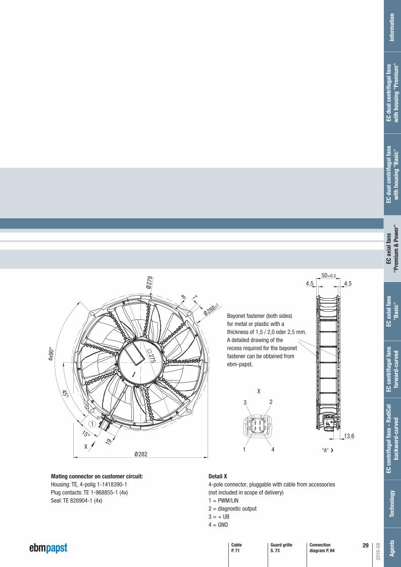
P. 84 / S)
X
±1
X
2
4
3
1
1
19
275
Ø27
8
4x90
°
15°
45°
Ø282
Ø288
8 7
13.6
4.550+0.5
4.5
P. 84 / S)
Detail X4-pole connector, pluggable with cable from accessories(not included in scope of delivery)1 = PWM/LIN2 = diagnostic output3 = + UB4 = GND
Mating connector on customer circuit:Housing: TE, 4-polig 1-1418390-1Plug contacts: TE 1-968855-1 (4x)Seal: TE 828904-1 (4x)
"A"
❮
Bayonet fastener (both sides)for metal or plastic with athickness of 1,5 / 2,0 oder 2,5 mm.A detailed drawing of the recess required for the bayonetfastener can be obtained fromebm-papst.
Connection diagram P. 84
Guard grilleS. 73
CableP. 71
29
Automotive_2016_16_08_2016_AE_Final_.indd 29 16.08.2016 08:48:24
30
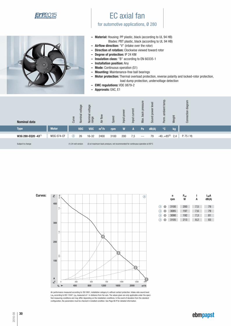
EC axial fanfor automotive applications, Ø 280
– Material: Housing: PP plastic, black (according to UL 94 HB) Blades: PBT plastic, black (according to UL 94 HB)
– Direction of rotation: Clockwise viewed toward rotor– Degree of protection: IP 24 KM– Insulation class: "B" according to EN 60335-1– Installation position: Any– Mode: Continuous operation (S1)– Mounting: Maintenance-free ball bearings– Motor protection: Thermal overload protection, reverse polarity and locked-rotor protection, load dump protection, undervoltage detection– EMC regulations: VDE 0879-2– Approvals: EAC, E1
Subject to change (1) 24-volt version (2) at maximum back pressure, not recommended for continuous operation at 85°C
Type Motor VDC VDC m3/h rpm W A Pa dB(A) °C kg
W3G 280-EQ20 -43(1) M3G 074-CF 26 16-32 2400 3100 200 7,5 --- 79 -40..+85(2) 2,4 P. 75 / H)
Nominal data Curv
e
A
Nom
inal
vol
tage
rang
e
Nom
inal
vol
tage
Spee
d
Inpu
t pow
er
Inpu
t cur
rent
Soun
d po
wer
leve
l
Perm
. am
bien
t tem
p.
Wei
ght
Curves:
1,0
1,5
0,5
0 250 500 750 12501000
400 800 1200 1600 2000
100
200
300
400
qv m³/h
cfmP fs
Pa
in w
g
1
2
3
4
Air fl
ow
nrpm
PedW
IA
LWAdB(A)
A 1
A 2
A 3
A 4
3100
3085
3090
3105
200
197
192
213
7,5
7,6
7,3
8,2
79
79
81
83
Max
. bac
k pr
essu
re
A
– Airfl ow direction: "V" (intake over the rotor)
Air performance measured according to: ISO 5801, installation category A, without contact protection. Intake-side sound level:LwA according to ISO 13347, LpA measured at 1 m distance from fan axis. The values given are only applicable under the speci-fi ed measuring conditions and may differ depending on the installation conditions. In the event of deviation from the standard confi guration, the parameters must be checked in installed condition. See Page 86 ff for detailed information.
2016-08
Conn
ectio
n di
agra
m
Automotive_2016_16_08_2016_AE_Final_.indd 30 16.08.2016 08:48:25
31
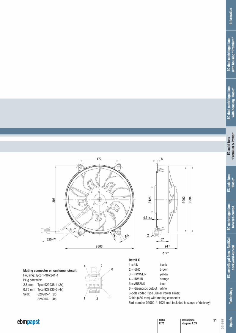
P. 75 / H)
Connection diagram P. 75
Ø303
298
325+20
18
8.5 X
172
57
94+2
Ø29
4
Ø12
5
Ø29
2
8
21.7˚
4.3 1.5
CableP. 70
4
1
6
2
5
3
Detail X1 = UN black2 = GND brown3 = PWM/LIN yellow4 = INVLIN orange5 = ABSENK blue6 = diagnostic output white6-pole coded Tyco Junior Power Timer; Cable (460 mm) with mating connector Part number 02002-4-1021 (not included in scope of delivery)
❮ "V"
Mating connector on customer circuit:Housing: Tyco 1-967241-1Plug contacts:2.5 mm Tyco 929938-1 (2x)0.75 mm Tyco 929930-3 (4x)Seal: 828905-1 (2x) 828904-1 (4x)
2016-08
EC c
entr
ifuga
l fan
s fo
rwar
d-cu
rved
Inf
orm
atio
nEC
cen
trifu
gal f
ans
- Ra
diCa
lba
ckw
ard-
curv
edTe
chno
logy
Age
nts
EC a
xial
fans
"Bas
ic"
EC a
xial
fans
"Pre
miu
m &
Pow
er"
EC d
ual c
entr
ifuga
l fan
sw
ith h
ousi
ng "
Basi
c"EC
dua
l cen
trifu
gal f
ans
with
hou
sing
"Pr
emiu
m"
Automotive_2016_16_08_2016_AE_Final_.indd 31 16.08.2016 08:48:25

32
Subject to change (1) 12-volt version (2) above +85 °C with power derating
Type Motor VDC VDC m3/h rpm W A Pa dB(A) °C kg
W3G 300-BV12 -41(1) M3G 084-BF 13 9-16 2610 3200 220 16,7 --- 83 -40..+105(2) 2,0 P. 77 / K)
Nominal data Curv
e
A
Nom
inal
vol
tage
rang
e
Nom
inal
vol
tage
Spee
d
Inpu
t pow
er
Inpu
t cur
rent
Soun
d po
wer
leve
l
Perm
. am
bien
t tem
p.
Wei
ght
Curves:
1,0
1,2
0,8
0,6
0,2
0,4
0 250 500 750 1250 15001000
400 800 1200 1600 2000 2400
50
100
150
200
250
300
350
qv m³/h
cfmP fs
Pa
in w
g
1
2
3
4
Air fl
ow
nrpm
PedW
IA
LWAdB(A)
A 1
A 2
A 3
A 4
3200
3140
2960
2840
220
235
247
248
16,7
18,1
18,9
19,0
83
82
80
82
Max
. bac
k pr
essu
re
A
EC axial fanfor automotive applications, Ø 300
Air performance measured according to: ISO 5801, installation category A, without contact protection. Intake-side sound level:LwA according to ISO 13347, LpA measured at 1 m distance from fan axis. The values given are only applicable under the speci-fi ed measuring conditions and may differ depending on the installation conditions. In the event of deviation from the standard confi guration, the parameters must be checked in installed condition. See Page 86 ff for detailed information.
– Material: Housing: PA plastic, black (according to UL 94 HB) Blades: PA plastic, black (according to UL 94 HB)
– Direction of rotation: Clockwise viewed toward rotor– Degree of protection: Motor: IP 24 KM, electronics: IP 66 / 69 K– Insulation class: "B" according to EN 60335-1– Installation position: Any– Mode: Continuous operation (S1)– Mounting: Maintenance-free ball bearings– Motor protection: Thermal overload protection, reverse polarity and locked-rotor protection, load dump protection, undervoltage detection– EMC regulations: VDE 0879-2– Qualifi ed in accordance with: DIN ISO 16750– Approvals: EAC, E1
– Airfl ow direction: "V" (intake over the rotor)
2016-08
Tech
n. fe
atur
esan
d co
nnec
tion
diag
ram
Automotive_2016_16_08_2016_AE_Final_.indd 32 16.08.2016 08:48:26

33
P. 77 / K)
Connection diagram P. 77
X
300+20 0
54
76.5+2 0
+2
+2
+2
+3 0
16
Ø318
+1
0
Ø340Ø337
24°
9.5
7.5
4x90
°
330
CableP. 70
4
1
6
2
5
3
Detail X1 = +UB black2 = GND brown3 = PWM/LIN* yellow *optional LIN-BUS4 = NC (not used)5 = ABSENK blue6 = diagnostic output white6-pole coded Tyco Junior Power Timer; Cable (460 mm) with mating connector Part number 02002-4-1021 (not included in scope of delivery)
❮ "V"
Mating connector on customer circuit:Housing: Tyco 1-967241-1Plug contacts:2.5 mm Tyco 929938-1 (2x)0.75 mm Tyco 929930-3 (4x)Seal: 828905-1 (2x) 828904-1 (4x)
2016-08
EC c
entr
ifuga
l fan
s fo
rwar
d-cu
rved
Inf
orm
atio
nEC
cen
trifu
gal f
ans
- Ra
diCa
lba
ckw
ard-
curv
edTe
chno
logy
Age
nts
EC a
xial
fans
"Bas
ic"
EC a
xial
fans
"Pre
miu
m &
Pow
er"
EC d
ual c
entr
ifuga
l fan
sw
ith h
ousi
ng "
Basi
c"EC
dua
l cen
trifu
gal f
ans
with
hou
sing
"Pr
emiu
m"
Automotive_2016_16_08_2016_AE_Final_.indd 33 16.08.2016 08:48:27
34
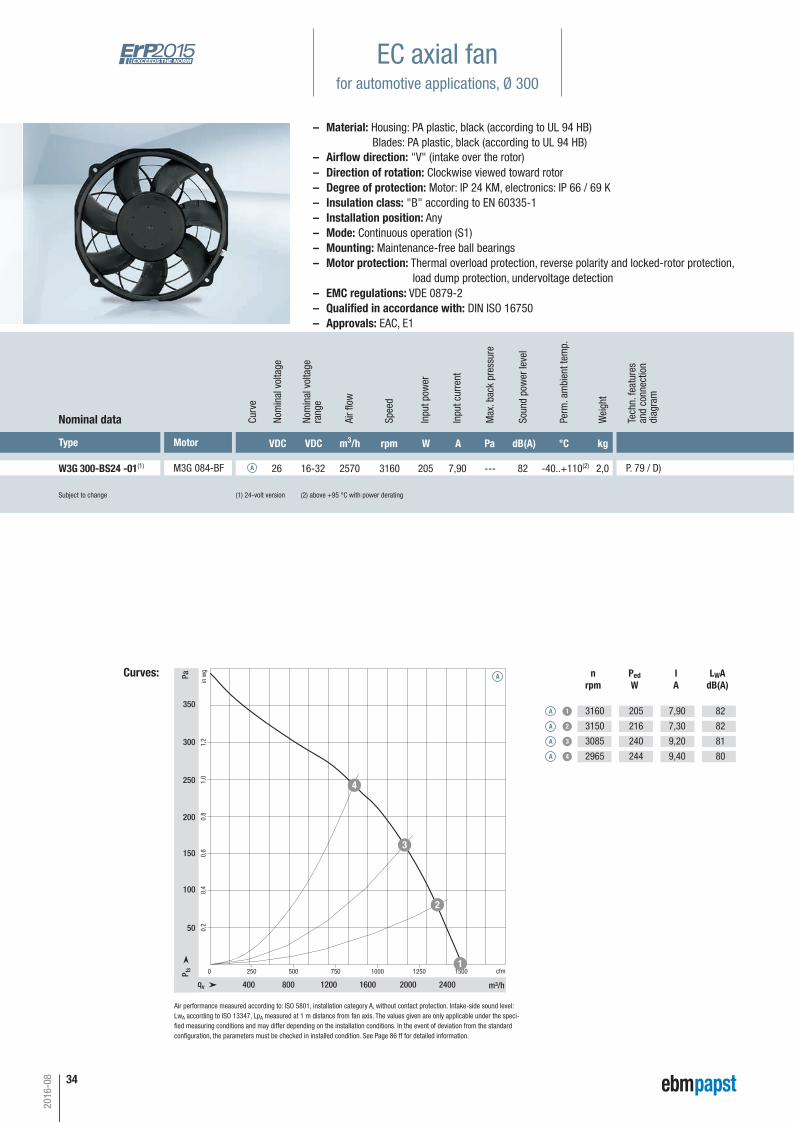
Subject to change (1) 24-volt version (2) above +95 °C with power derating
Type Motor VDC VDC m3/h rpm W A Pa dB(A) °C kg
W3G 300-BS24 -01(1) M3G 084-BF 26 16-32 2570 3160 205 7,90 --- 82 -40..+110(2) 2,0 P. 79 / D)
Nominal data Curv
e
A
Nom
inal
vol
tage
rang
e
Nom
inal
vol
tage
Spee
d
Inpu
t pow
er
Inpu
t cur
rent
Soun
d po
wer
leve
l
Perm
. am
bien
t tem
p.
Wei
ght
Curves:
1,0
1,2
0,8
0,6
0,2
0,4
0 250 500 750 1250 15001000
400 800 1200 1600 2000 2400
50
100
150
200
250
300
350
qv m³/h
cfmP fs
Pa
in w
g
1
2
3
4
A
Air fl
ow
nrpm
PedW
IA
LWAdB(A)
A 1
A 2
A 3
A 4
3160
3150
3085
2965
205
216
240
244
7,90
7,30
9,20
9,40
82
82
81
80
Max
. bac
k pr
essu
re
EC axial fanfor automotive applications, Ø 300
Air performance measured according to: ISO 5801, installation category A, without contact protection. Intake-side sound level:LwA according to ISO 13347, LpA measured at 1 m distance from fan axis. The values given are only applicable under the speci-fi ed measuring conditions and may differ depending on the installation conditions. In the event of deviation from the standard confi guration, the parameters must be checked in installed condition. See Page 86 ff for detailed information.
– Material: Housing: PA plastic, black (according to UL 94 HB) Blades: PA plastic, black (according to UL 94 HB)
– Direction of rotation: Clockwise viewed toward rotor– Degree of protection: Motor: IP 24 KM, electronics: IP 66 / 69 K– Insulation class: "B" according to EN 60335-1– Installation position: Any– Mode: Continuous operation (S1)– Mounting: Maintenance-free ball bearings– Motor protection: Thermal overload protection, reverse polarity and locked-rotor protection, load dump protection, undervoltage detection– EMC regulations: VDE 0879-2– Qualifi ed in accordance with: DIN ISO 16750– Approvals: EAC, E1
– Airfl ow direction: "V" (intake over the rotor)
2016-08
Tech
n. fe
atur
esan
d co
nnec
tion
diag
ram
Automotive_2016_16_08_2016_AE_Final_.indd 34 16.08.2016 08:48:28
3535
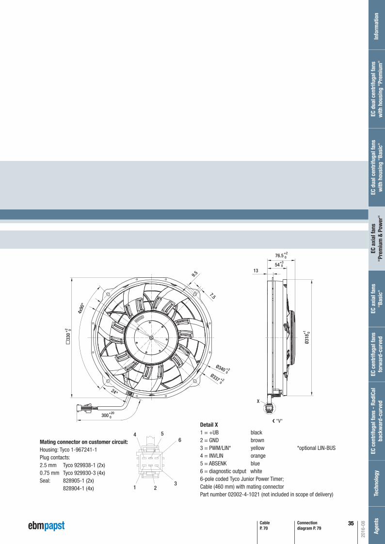
P. 79 / D)
Connection diagram P. 79
CableP. 70
X
300+20 0
54
76.5+2 0
+3 0
13
Ø318
+1
0
Ø340Ø337
24°
9.5
7.5
4x90
°
330
+2 0
+2 0
+2 0
4
1
6
2
5
3
Detail X1 = +UB black2 = GND brown3 = PWM/LIN* yellow *optional LIN-BUS4 = INVLIN orange5 = ABSENK blue6 = diagnostic output white6-pole coded Tyco Junior Power Timer; Cable (460 mm) with mating connector Part number 02002-4-1021 (not included in scope of delivery)
❮ "V"
Mating connector on customer circuit:Housing: Tyco 1-967241-1Plug contacts:2.5 mm Tyco 929938-1 (2x)0.75 mm Tyco 929930-3 (4x)Seal: 828905-1 (2x) 828904-1 (4x)
2016-08
EC c
entr
ifuga
l fan
s fo
rwar
d-cu
rved
Inf
orm
atio
nEC
cen
trifu
gal f
ans
- Ra
diCa
lba
ckw
ard-
curv
edTe
chno
logy
Age
nts
EC a
xial
fans
"Bas
ic"
EC a
xial
fans
"Pre
miu
m &
Pow
er"
EC d
ual c
entr
ifuga
l fan
sw
ith h
ousi
ng "
Basi
c"EC
dua
l cen
trifu
gal f
ans
with
hou
sing
"Pr
emiu
m"
Automotive_2016_16_08_2016_AE_Final_.indd 35 16.08.2016 08:48:28
36
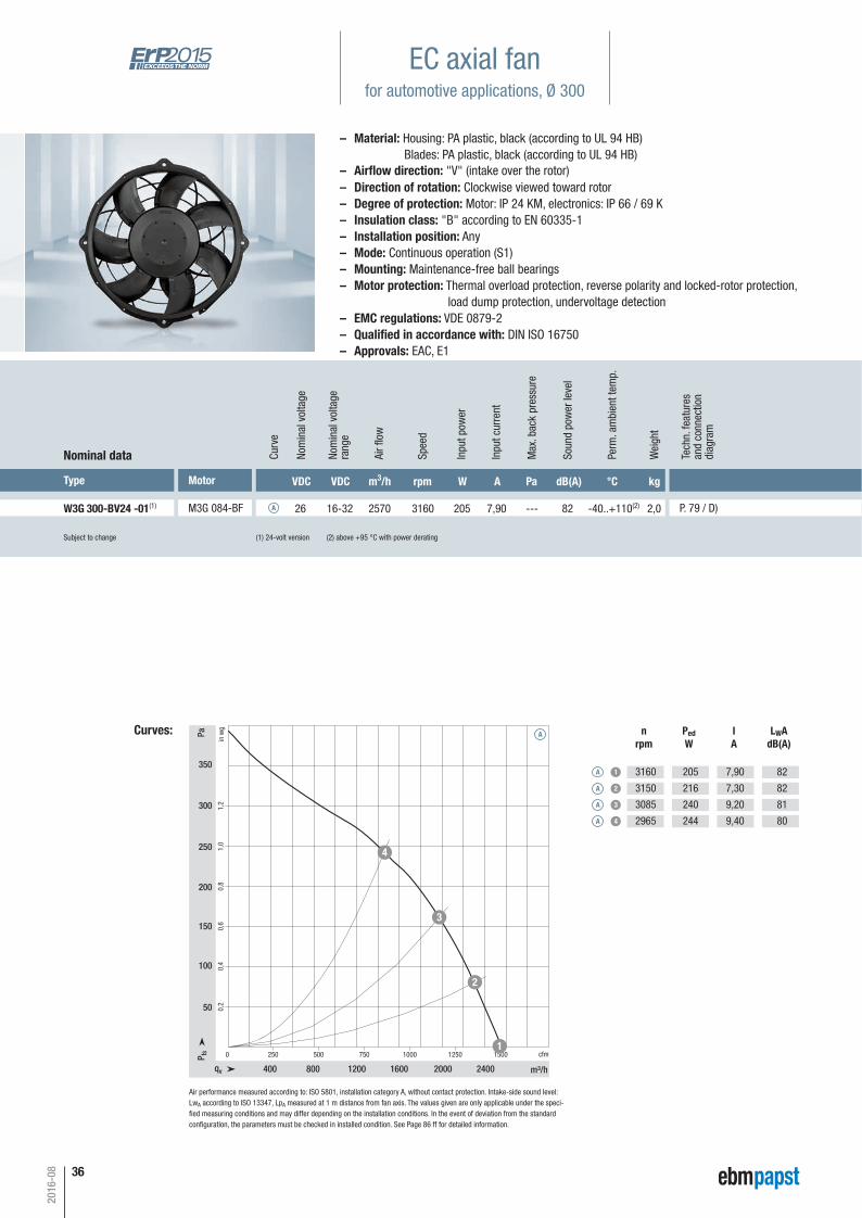
Subject to change (1) 24-volt version (2) above +95 °C with power derating
Type Motor VDC VDC m3/h rpm W A Pa dB(A) °C kg
W3G 300-BV24 -01(1) M3G 084-BF 26 16-32 2570 3160 205 7,90 --- 82 -40..+110(2) 2,0 P. 79 / D)
Nominal data Curv
e
A
Nom
inal
vol
tage
rang
e
Nom
inal
vol
tage
Spee
d
Inpu
t pow
er
Inpu
t cur
rent
Soun
d po
wer
leve
l
Perm
. am
bien
t tem
p.
Wei
ght
Curves:
1,0
1,2
0,8
0,6
0,2
0,4
0 250 500 750 1250 15001000
400 800 1200 1600 2000 2400
50
100
150
200
250
300
350
qv m³/h
cfmP fs
Pa
in w
g
1
2
3
4
A
Air fl
ow
nrpm
PedW
IA
LWAdB(A)
A 1
A 2
A 3
A 4
3160
3150
3085
2965
205
216
240
244
7,90
7,30
9,20
9,40
82
82
81
80
Max
. bac
k pr
essu
re
EC axial fanfor automotive applications, Ø 300
Air performance measured according to: ISO 5801, installation category A, without contact protection. Intake-side sound level:LwA according to ISO 13347, LpA measured at 1 m distance from fan axis. The values given are only applicable under the speci-fi ed measuring conditions and may differ depending on the installation conditions. In the event of deviation from the standard confi guration, the parameters must be checked in installed condition. See Page 86 ff for detailed information.
– Material: Housing: PA plastic, black (according to UL 94 HB) Blades: PA plastic, black (according to UL 94 HB)
– Direction of rotation: Clockwise viewed toward rotor– Degree of protection: Motor: IP 24 KM, electronics: IP 66 / 69 K– Insulation class: "B" according to EN 60335-1– Installation position: Any– Mode: Continuous operation (S1)– Mounting: Maintenance-free ball bearings– Motor protection: Thermal overload protection, reverse polarity and locked-rotor protection, load dump protection, undervoltage detection– EMC regulations: VDE 0879-2– Qualifi ed in accordance with: DIN ISO 16750– Approvals: EAC, E1
– Airfl ow direction: "V" (intake over the rotor)
2016-08
Tech
n. fe
atur
esan
d co
nnec
tion
diag
ram
Automotive_2016_16_08_2016_AE_Final_.indd 36 16.08.2016 08:48:29
37
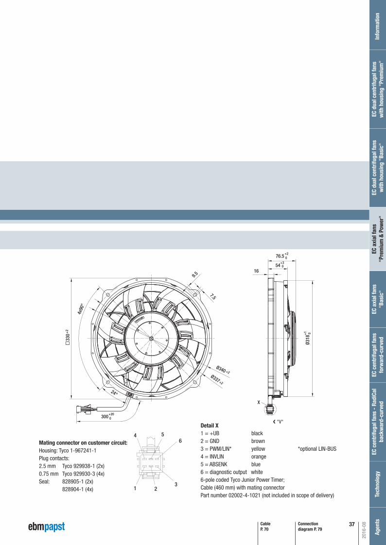
P. 79 / D)
Connection diagram P. 79
CableP. 70
X
300+20 0
54
76.5+2 0
+2
+2
+2
+3 0
16
Ø318
+1
0
Ø340Ø337
24°
9.5
7.5
4x90
°
330
4
1
6
2
5
3
Detail X1 = +UB black2 = GND brown3 = PWM/LIN* yellow *optional LIN-BUS4 = INVLIN orange5 = ABSENK blue6 = diagnostic output white6-pole coded Tyco Junior Power Timer; Cable (460 mm) with mating connector Part number 02002-4-1021 (not included in scope of delivery)
❮ "V"
Mating connector on customer circuit:Housing: Tyco 1-967241-1Plug contacts:2.5 mm Tyco 929938-1 (2x)0.75 mm Tyco 929930-3 (4x)Seal: 828905-1 (2x) 828904-1 (4x)
2016-08
EC c
entr
ifuga
l fan
s fo
rwar
d-cu
rved
Inf
orm
atio
nEC
cen
trifu
gal f
ans
- Ra
diCa
lba
ckw
ard-
curv
edTe
chno
logy
Age
nts
EC a
xial
fans
"Bas
ic"
EC a
xial
fans
"Pre
miu
m &
Pow
er"
EC d
ual c
entr
ifuga
l fan
sw
ith h
ousi
ng "
Basi
c"EC
dua
l cen
trifu
gal f
ans
with
hou
sing
"Pr
emiu
m"
Automotive_2016_16_08_2016_AE_Final_.indd 37 16.08.2016 08:48:29
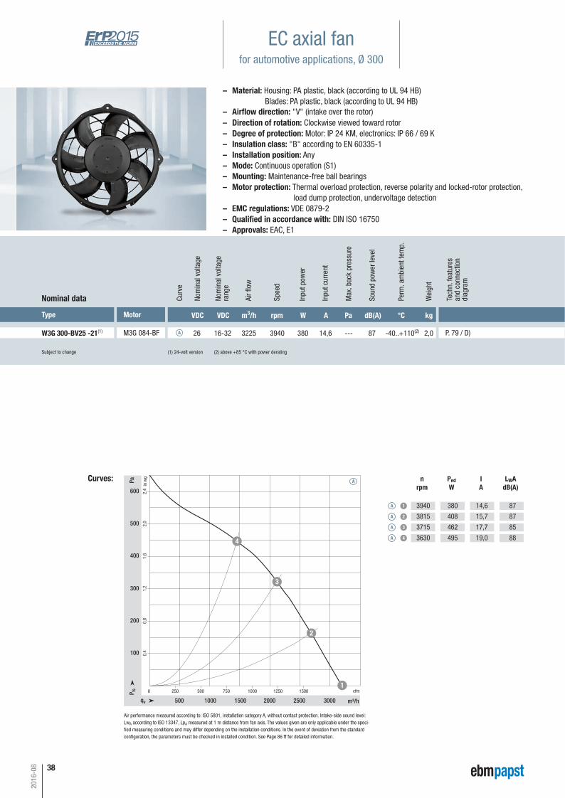
38
Subject to change (1) 24-volt version (2) above +85 °C with power derating
Type Motor VDC VDC m3/h rpm W A Pa dB(A) °C kg
W3G 300-BV25 -21(1) M3G 084-BF 26 16-32 3225 3940 380 14,6 --- 87 -40..+110(2) 2,0 P. 79 / D)
Nominal data Curv
e
A
Nom
inal
vol
tage
rang
e
Nom
inal
vol
tage
Spee
d
Inpu
t pow
er
Inpu
t cur
rent
Soun
d po
wer
leve
l
Perm
. am
bien
t tem
p.
Wei
ght
Curves:
1,6
1,2
0,8
0,4
0 250 500 750 1250 15001000
500 1000 1500 2000 2500 3000
100
200
300
400
2,0500
2,4600
qv m³/h
cfmP fs
Pa
in w
g
1
2
3
4
Air fl
ow
nrpm
PedW
IA
LWAdB(A)
A 1
A 2
A 3
A 4
3940
3815
3715
3630
380
408
462
495
14,6
15,7
17,7
19,0
87
87
85
88
Max
. bac
k pr
essu
re
A
EC axial fanfor automotive applications, Ø 300
Air performance measured according to: ISO 5801, installation category A, without contact protection. Intake-side sound level:LwA according to ISO 13347, LpA measured at 1 m distance from fan axis. The values given are only applicable under the speci-fi ed measuring conditions and may differ depending on the installation conditions. In the event of deviation from the standard confi guration, the parameters must be checked in installed condition. See Page 86 ff for detailed information.
– Material: Housing: PA plastic, black (according to UL 94 HB) Blades: PA plastic, black (according to UL 94 HB)
– Direction of rotation: Clockwise viewed toward rotor– Degree of protection: Motor: IP 24 KM, electronics: IP 66 / 69 K– Insulation class: "B" according to EN 60335-1– Installation position: Any– Mode: Continuous operation (S1)– Mounting: Maintenance-free ball bearings– Motor protection: Thermal overload protection, reverse polarity and locked-rotor protection, load dump protection, undervoltage detection– EMC regulations: VDE 0879-2– Qualifi ed in accordance with: DIN ISO 16750– Approvals: EAC, E1
– Airfl ow direction: "V" (intake over the rotor)
2016-08
Tech
n. fe
atur
esan
d co
nnec
tion
diag
ram
Automotive_2016_16_08_2016_AE_Final_.indd 38 16.08.2016 08:48:30

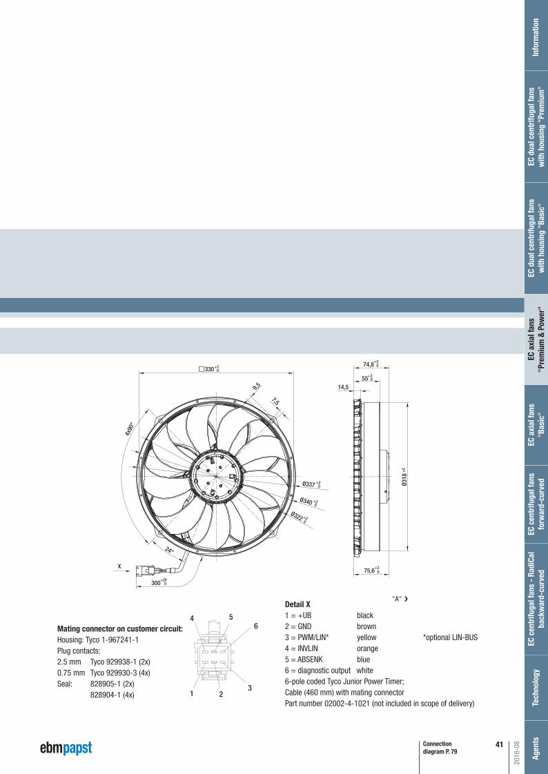
39
P. 79 / D)
Connection diagram P. 79
CableP. 70
X
300+20 0
54
76.5+2 0
+2
+2
+2
+3 0
16
Ø318
+1
0
Ø340Ø337
24°
9.5
7.5
4x90
°
330
4
1
6
2
5
3
Detail X1 = +UB black2 = GND brown3 = PWM/LIN* yellow *optional LIN-BUS4 = INVLIN orange5 = ABSENK blue6 = diagnostic output white6-pole coded Tyco Junior Power Timer; Cable (460 mm) with mating connector Part number 02002-4-1021 (not included in scope of delivery)
❮ "V"
Mating connector on customer circuit:Housing: Tyco 1-967241-1Plug contacts:2.5 mm Tyco 929938-1 (2x)0.75 mm Tyco 929930-3 (4x)Seal: 828905-1 (2x) 828904-1 (4x)
2016-08
EC c
entr
ifuga
l fan
s fo
rwar
d-cu
rved
Inf
orm
atio
nEC
cen
trifu
gal f
ans
- Ra
diCa
lba
ckw
ard-
curv
edTe
chno
logy
Age
nts
EC a
xial
fans
"Bas
ic"
EC a
xial
fans
"Pre
miu
m &
Pow
er"
EC d
ual c
entr
ifuga
l fan
sw
ith h
ousi
ng "
Basi
c"EC
dua
l cen
trifu
gal f
ans
with
hou
sing
"Pr
emiu
m"
Automotive_2016_16_08_2016_AE_Final_.indd 39 16.08.2016 08:48:30
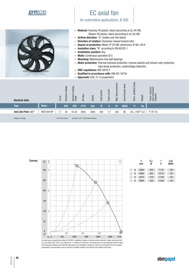
40
Subject to change (1) 24-volt version (2) above +85 °C with power derating
Type Motor VDC VDC m3/h rpm W A Pa dB(A) °C kg
W3G 300-PW24 -01(1) M3G 084-BF 26 16-32 2955 3000 200 7,7 320 86 -40..+105(2) 2,0 P. 79 / D)
Nominal data Curv
e
A
Nom
inal
vol
tage
rang
e
Nom
inal
vol
tage
Spee
d
Inpu
t pow
er
Inpu
t cur
rent
Soun
d po
wer
leve
l
Perm
. am
bien
t tem
p.
Wei
ght
Curves:
qv m³/h
cfmP fs
Pa
in w
g
500 1000 1500 2000 2500
0 400 800 1200
50
100
150
200
250
300
0.4
0.8
1.2
1
2
3
4
Air fl
ow
Max
. bac
k pr
essu
re
A nrpm
PedW
IA
LWAdB(A)
A 1
A 2
A 3
A 4
3000
2980
3010
2950
200
263
310
333
7,70
10,10
11,93
12,80
86
85
83
84
EC axial fanfor automotive applications, Ø 300
Air performance measured according to: ISO 5801, installation category A, without contact protection. Intake-side sound level:LwA according to ISO 13347, LpA measured at 1 m distance from fan axis. The values given are only applicable under the speci-fi ed measuring conditions and may differ depending on the installation conditions. In the event of deviation from the standard confi guration, the parameters must be checked in installed condition. See Page 86 ff for detailed information.
– Material: Housing: PA plastic, black (according to UL 94 HB) Blades: PA plastic, black (according to UL 94 HB)
– Direction of rotation: Clockwise viewed toward rotor– Degree of protection: Motor: IP 24 KM, electronics: IP 66 / 69 K– Insulation class: "B" according to EN 60335-1– Installation position: Any– Mode: Continuous operation (S1)– Mounting: Maintenance-free ball bearings– Motor protection: Thermal overload protection, reverse polarity and locked-rotor protection, load dump protection, undervoltage detection– EMC regulations: VDE 0879-2– Qualifi ed in accordance with: DIN ISO 16750– Approvals: EAC; E1 in preparation
– Airfl ow direction: "A" (intake over the stator)
2016-08
Tech
n. fe
atur
esan
d co
nnec
tion
diag
ram
Automotive_2016_16_08_2016_AE_Final_.indd 40 16.08.2016 08:48:31
41
P. 79 / D)
Connection diagram P. 79
Ø322 +2 0
9,5
300+20
0
7,5
330+2 0
Ø340 +2 0
Ø337 +2 0
4x90
°
24°
Ø318
±2
14,555+3 0
74,8+2 0
75,6+2 0
X
4
1
6
2
5
3
Detail X1 = +UB black2 = GND brown3 = PWM/LIN* yellow *optional LIN-BUS4 = INVLIN orange5 = ABSENK blue6 = diagnostic output white6-pole coded Tyco Junior Power Timer; Cable (460 mm) with mating connector Part number 02002-4-1021 (not included in scope of delivery)
Mating connector on customer circuit:Housing: Tyco 1-967241-1Plug contacts:2.5 mm Tyco 929938-1 (2x)0.75 mm Tyco 929930-3 (4x)Seal: 828905-1 (2x) 828904-1 (4x)
"A"
❮
2016-08
EC c
entr
ifuga
l fan
s fo
rwar
d-cu
rved
Inf
orm
atio
nEC
cen
trifu
gal f
ans
- Ra
diCa
lba
ckw
ard-
curv
edTe
chno
logy
Age
nts
EC a
xial
fans
"Bas
ic"
EC a
xial
fans
"Pre
miu
m &
Pow
er"
EC d
ual c
entr
ifuga
l fan
sw
ith h
ousi
ng "
Basi
c"EC
dua
l cen
trifu
gal f
ans
with
hou
sing
"Pr
emiu
m"
Automotive_2016_16_08_2016_AE_Final_.indd 41 16.08.2016 08:48:31

42
Subject to change (1) 12-volt version (2) above +70 °C with power derating
Type Motor VDC VDC m3/h rpm W A Pa dB(A) °C kg
W3G 385-CT53 -61(1) M3G 084-CF 13 9-16 4110 3100 445 34,0 --- 89 -40..+105(2) 3,1 P. 78 / L)
Nominal data Curv
e
A
Nom
inal
vol
tage
rang
e
Nom
inal
vol
tage
Spee
d
Inpu
t pow
er
Inpu
t cur
rent
Soun
d po
wer
leve
l
Perm
. am
bien
t tem
p.
Wei
ght
Curves:
0,8
0,4
0 500 1500 20001000
500 1000 1500 2000 2500 3000 3500 4000
100
200
1,2300
2,0500
1,6400
qv m³/h
cfmP fs
Pa
in w
g
1
2
3
4
Air fl
ow
nrpm
PedW
IA
LWAdB(A)
A 1
A 2
A 3
A 4
3100
3000
2930
2815
445
487
544
590
34,0
37,6
41,9
45,6
89
89
87
89
Max
. bac
k pr
essu
re
A
EC axial fanfor automotive applications, Ø 385
Air performance measured according to: ISO 5801, installation category A, without contact protection. Intake-side sound level:LwA according to ISO 13347, LpA measured at 1 m distance from fan axis. The values given are only applicable under the speci-fi ed measuring conditions and may differ depending on the installation conditions. In the event of deviation from the standard confi guration, the parameters must be checked in installed condition. See Page 86 ff for detailed information.
– Material: Housing: PA plastic, black (according to UL 94 HB) Blades: PA plastic, black (according to UL 94 HB)
– Direction of rotation: Clockwise viewed toward rotor– Degree of protection: Motor: IP 24 KM, electronics: IP 66 / 69 K– Insulation class: "B" according to EN 60335-1– Installation position: Any– Mode: Continuous operation (S1)– Mounting: Maintenance-free ball bearings– Motor protection: Thermal overload protection, reverse polarity and locked-rotor protection, load dump protection, undervoltage detection– EMC regulations: VDE 0879-2– Qualifi ed in accordance with: DIN ISO 16750– Approvals: EAC, E1
– Airfl ow direction: "V" (intake over the rotor)
2016-08
Tech
n. fe
atur
esan
d co
nnec
tion
diag
ram
Automotive_2016_16_08_2016_AE_Final_.indd 42 16.08.2016 08:48:33
43
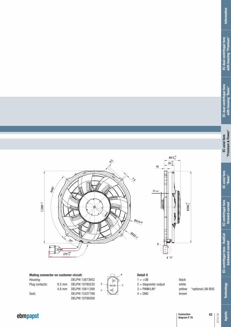
P. 78 / L)
Connection diagram P. 78
X
9.5
7.5
Ø422
Ø414
270 +20
0
399
24°
4x90
°
55
89.5+2 0
+3 0
16
17Ø3
96+
2 0
±1
+3
+2
+2+2
32
4
1
❮ "V"
Detail X1 = +UB black2 = diagnostic output white 3 = PWM/LIN* yellow *optional LIN-BUS4 = GND brown
Mating connector on customer circuit:Housing: DELPHI 13873952Plug contacts: 9.5 mm DELPHI 10780235 4.8 mm DELPHI 10811289Seal: DELPHI 15327788 DELPHI 10788269
2016-08
EC c
entr
ifuga
l fan
s fo
rwar
d-cu
rved
Inf
orm
atio
nEC
cen
trifu
gal f
ans
- Ra
diCa
lba
ckw
ard-
curv
edTe
chno
logy
Age
nts
EC a
xial
fans
"Bas
ic"
EC a
xial
fans
"Pre
miu
m &
Pow
er"
EC d
ual c
entr
ifuga
l fan
sw
ith h
ousi
ng "
Basi
c"EC
dua
l cen
trifu
gal f
ans
with
hou
sing
"Pr
emiu
m"
Automotive_2016_16_08_2016_AE_Final_.indd 43 16.08.2016 08:48:33

44
Subject to change (1) 24-volt version (2) above +95 °C with power derating
Type Motor VDC VDC m3/h rpm W A Pa dB(A) °C kg
W3G 385-BV44 -01(1) M3G 084-BF 26 16-32 3425 2600 260 10,0 --- 84 -40..+110(2) 2,7 P. 79 / D)
Nominal data Curv
e
A
Nom
inal
vol
tage
rang
e
Nom
inal
vol
tage
Spee
d
Inpu
t pow
er
Inpu
t cur
rent
Soun
d po
wer
leve
l
Perm
. am
bien
t tem
p.
Wei
ght
Curves:
0,8
0,6
0,4
0,2
0 250 500 750 1250 15001000
500 1000 1500 2000 2500 3000
50
100
150
200
1,0250
1,2300
1,4350
qv m³/h
cfmP fs
Pa
in w
g
1
2
3
4
Air fl
ow
nrpm
PedW
IA
LWAdB(A)
A 1
A 2
A 3
A 4
2600
2505
2325
2215
260
272
273
274
10,0
10,5
10,5
10,5
84
83
81
82
Max
. bac
k pr
essu
re
A
EC axial fanfor automotive applications, Ø 385
Air performance measured according to: ISO 5801, installation category A, without contact protection. Intake-side sound level:LwA according to ISO 13347, LpA measured at 1 m distance from fan axis. The values given are only applicable under the speci-fi ed measuring conditions and may differ depending on the installation conditions. In the event of deviation from the standard confi guration, the parameters must be checked in installed condition. See Page 86 ff for detailed information.
– Material: Housing: PA plastic, black (according to UL 94 HB) Blades: PA plastic, black (according to UL 94 HB)
– Direction of rotation: Clockwise viewed toward rotor– Degree of protection: Motor: IP 24 KM, electronics: IP 66 / 69 K– Insulation class: "B" according to EN 60335-1– Installation position: Any– Mode: Continuous operation (S1)– Mounting: Maintenance-free ball bearings– Motor protection: Thermal overload protection, reverse polarity and locked-rotor protection, load dump protection, undervoltage detection– EMC regulations: VDE 0879-2– Qualifi ed in accordance with: DIN ISO 16750– Approvals: EAC, E1
– Airfl ow direction: "V" (intake over the rotor)
2016-08
Tech
n. fe
atur
esan
d co
nnec
tion
diag
ram
Automotive_2016_16_08_2016_AE_Final_.indd 44 16.08.2016 08:48:34
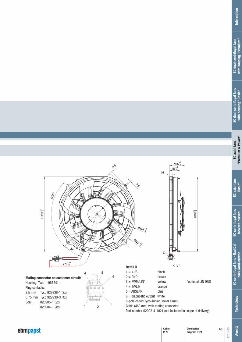
45
P. 79 / D)
Connection diagram P. 79
9.5
7.5
Ø422
Ø414
270 +20
0
399
24°
4x90
°
55
79.5+2 0
+3 0
+2 0
+2 0
+3 0
16
Ø396
+2 0
X
CableP. 70
4
1
6
2
5
3
Detail X1 = +UB black2 = GND brown3 = PWM/LIN* yellow *optional LIN-BUS4 = INVLIN orange5 = ABSENK blue6 = diagnostic output white6-pole coded Tyco Junior Power Timer; Cable (460 mm) with mating connector Part number 02002-4-1021 (not included in scope of delivery)
❮ "V"
Mating connector on customer circuit:Housing: Tyco 1-967241-1Plug contacts:2.5 mm Tyco 929938-1 (2x)0.75 mm Tyco 929930-3 (4x)Seal: 828905-1 (2x) 828904-1 (4x)
2016-08
EC c
entr
ifuga
l fan
s fo
rwar
d-cu
rved
Inf
orm
atio
nEC
cen
trifu
gal f
ans
- Ra
diCa
lba
ckw
ard-
curv
edTe
chno
logy
Age
nts
EC a
xial
fans
"Bas
ic"
EC a
xial
fans
"Pre
miu
m &
Pow
er"
EC d
ual c
entr
ifuga
l fan
sw
ith h
ousi
ng "
Basi
c"EC
dua
l cen
trifu
gal f
ans
with
hou
sing
"Pr
emiu
m"
Automotive_2016_16_08_2016_AE_Final_.indd 45 16.08.2016 08:48:35

46
Subject to change (1) 24-volt version (2) above +95 °C with power derating
Type Motor VDC VDC m3/h rpm W A Pa dB(A) °C kg
W3G 385-BS44 -01(1) M3G 084-BF 26 16-32 3425 2600 260 10,0 --- 84 -40..+110(2) 2,7 P. 79 / D)
Nominal data Curv
e
A
Nom
inal
vol
tage
rang
e
Nom
inal
vol
tage
Spee
d
Inpu
t pow
er
Inpu
t cur
rent
Soun
d po
wer
leve
l
Perm
. am
bien
t tem
p.
Wei
ght
Curves:
0,8
0,6
0,4
0,2
0 250 500 750 1250 15001000
500 1000 1500 2000 2500 3000
50
100
150
200
1,0250
1,2300
1,4350
qv m³/h
cfmP fs
Pa
in w
g
1
2
3
4
Air fl
ow
nrpm
PedW
IA
LWAdB(A)
A 1
A 2
A 3
A 4
2600
2505
2325
2215
260
272
273
274
10,0
10,5
10,5
10,5
84
83
81
82
Max
. bac
k pr
essu
re
A
EC axial fanfor automotive applications, Ø 385
Air performance measured according to: ISO 5801, installation category A, without contact protection. Intake-side sound level:LwA according to ISO 13347, LpA measured at 1 m distance from fan axis. The values given are only applicable under the speci-fi ed measuring conditions and may differ depending on the installation conditions. In the event of deviation from the standard confi guration, the parameters must be checked in installed condition. See Page 86 ff for detailed information.
– Material: Housing: PA plastic, black (according to UL 94 HB) Blades: PA plastic, black (according to UL 94 HB)
– Direction of rotation: Clockwise viewed toward rotor– Degree of protection: Motor: IP 24 KM, electronics: IP 66 / 69 K– Insulation class: "B" according to EN 60335-1– Installation position: Any– Mode: Continuous operation (S1)– Mounting: Maintenance-free ball bearings– Motor protection: Thermal overload protection, reverse polarity and locked-rotor protection, load dump protection, undervoltage detection– EMC regulations: VDE 0879-2– Qualifi ed in accordance with: DIN ISO 16750– Approvals: EAC, E1
– Airfl ow direction: "V" (intake over the rotor)
2016-08
Tech
n. fe
atur
esan
d co
nnec
tion
diag
ram
Automotive_2016_16_08_2016_AE_Final_.indd 46 16.08.2016 08:48:35

47
P. 79 / D)
Connection diagram P. 79
9.5
7.5
Ø422
Ø414
270 +20
0
399
24°
4x90
°
55
79.5+2 0
+3 0
+2 0
+2 0
+3 0
16
Ø396
+2 0
X
CableP. 70
4
1
6
2
5
3
Detail X1 = +UB black2 = GND brown3 = PWM/LIN* yellow *optional LIN-BUS4 = INVLIN orange5 = ABSENK blue6 = diagnostic output white6-pole coded Tyco Junior Power Timer; Cable (460 mm) with mating connector Part number 02002-4-1021 (not included in scope of delivery)
❮ "V"
Mating connector on customer circuit:Housing: Tyco 1-967241-1Plug contacts:2.5 mm Tyco 929938-1 (2x)0.75 mm Tyco 929930-3 (4x)Seal: 828905-1 (2x) 828904-1 (4x)
2016-08
EC c
entr
ifuga
l fan
s fo
rwar
d-cu
rved
Inf
orm
atio
nEC
cen
trifu
gal f
ans
- Ra
diCa
lba
ckw
ard-
curv
edTe
chno
logy
Age
nts
EC a
xial
fans
"Bas
ic"
EC a
xial
fans
"Pre
miu
m &
Pow
er"
EC d
ual c
entr
ifuga
l fan
sw
ith h
ousi
ng "
Basi
c"EC
dua
l cen
trifu
gal f
ans
with
hou
sing
"Pr
emiu
m"
Automotive_2016_16_08_2016_AE_Final_.indd 47 16.08.2016 08:48:36
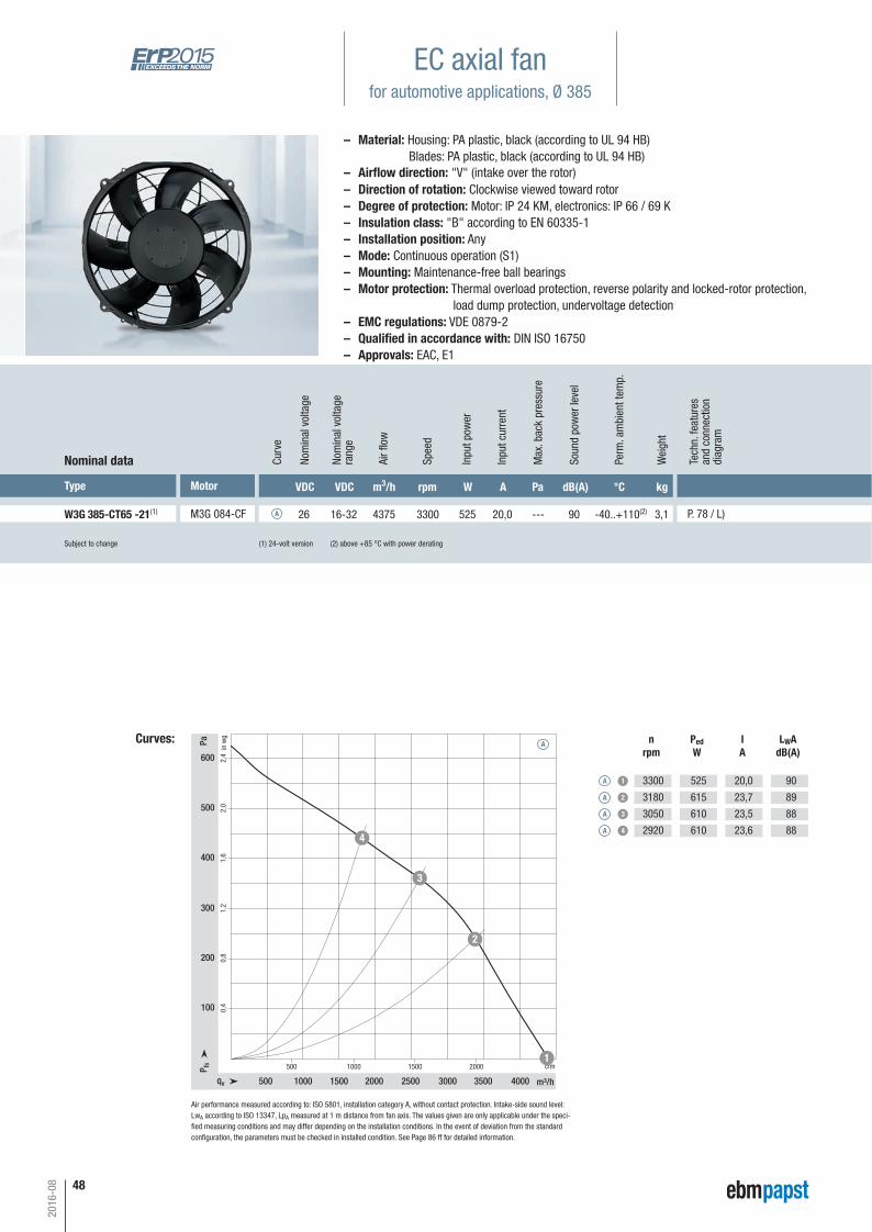
48
Subject to change (1) 24-volt version (2) above +85 °C with power derating
Type Motor VDC VDC m3/h rpm W A Pa dB(A) °C kg
W3G 385-CT65 -21(1) M3G 084-CF 26 16-32 4375 3300 525 20,0 --- 90 -40..+110(2) 3,1 P. 78 / L)
Nominal data Curv
e
A
Nom
inal
vol
tage
rang
e
Nom
inal
vol
tage
Spee
d
Inpu
t pow
er
Inpu
t cur
rent
Soun
d po
wer
leve
l
Perm
. am
bien
t tem
p.
Wei
ght
Curves:
1,6
1,2
0,8
0,4100
200
300
400
2,0500
2,4600
500 1500 20001000
500 1000 1500 2000 2500 3000 3500 4000qv m³/h
cfmP fs
Pa
in w
g
1
2
3
4
Air fl
ow
nrpm
PedW
IA
LWAdB(A)
A 1
A 2
A 3
A 4
3300
3180
3050
2920
525
615
610
610
20,0
23,7
23,5
23,6
90
89
88
88
Max
. bac
k pr
essu
re
A
EC axial fanfor automotive applications, Ø 385
Air performance measured according to: ISO 5801, installation category A, without contact protection. Intake-side sound level:LwA according to ISO 13347, LpA measured at 1 m distance from fan axis. The values given are only applicable under the speci-fi ed measuring conditions and may differ depending on the installation conditions. In the event of deviation from the standard confi guration, the parameters must be checked in installed condition. See Page 86 ff for detailed information.
– Material: Housing: PA plastic, black (according to UL 94 HB) Blades: PA plastic, black (according to UL 94 HB)
– Direction of rotation: Clockwise viewed toward rotor– Degree of protection: Motor: IP 24 KM, electronics: IP 66 / 69 K– Insulation class: "B" according to EN 60335-1– Installation position: Any– Mode: Continuous operation (S1)– Mounting: Maintenance-free ball bearings– Motor protection: Thermal overload protection, reverse polarity and locked-rotor protection, load dump protection, undervoltage detection– EMC regulations: VDE 0879-2– Qualifi ed in accordance with: DIN ISO 16750– Approvals: EAC, E1
– Airfl ow direction: "V" (intake over the rotor)
2016-08
Tech
n. fe
atur
esan
d co
nnec
tion
diag
ram
Automotive_2016_16_08_2016_AE_Final_.indd 48 16.08.2016 08:48:37

49
P. 78 / L)
Connection diagram P. 78
X
9.5
7.5
Ø422
Ø414
270 +20
0
399
24°
4x90
°
55
89.5+2 0
+3 0
16
17Ø3
96+
2 0
±1
+3
+2
+2+2
❮ "V"
32
4
1
Detail X1 = +UB black2 = diagnostic output white 3 = PWM/LIN* yellow *optional LIN-BUS4 = GND brown
Mating connector on customer circuit:Housing: DELPHI 13873952Plug contacts: 9.5 mm DELPHI 10780235 4.8 mm DELPHI 10811289Seal: DELPHI 15327788 DELPHI 10788269
2016-08
EC c
entr
ifuga
l fan
s fo
rwar
d-cu
rved
Inf
orm
atio
nEC
cen
trifu
gal f
ans
- Ra
diCa
lba
ckw
ard-
curv
edTe
chno
logy
Age
nts
EC a
xial
fans
"Bas
ic"
EC a
xial
fans
"Pre
miu
m &
Pow
er"
EC d
ual c
entr
ifuga
l fan
sw
ith h
ousi
ng "
Basi
c"EC
dua
l cen
trifu
gal f
ans
with
hou
sing
"Pr
emiu
m"
Automotive_2016_16_08_2016_AE_Final_.indd 49 16.08.2016 08:48:37

50
2016-08
Automotive_2016_16_08_2016_AE_Final_.indd 50 16.08.2016 08:48:38
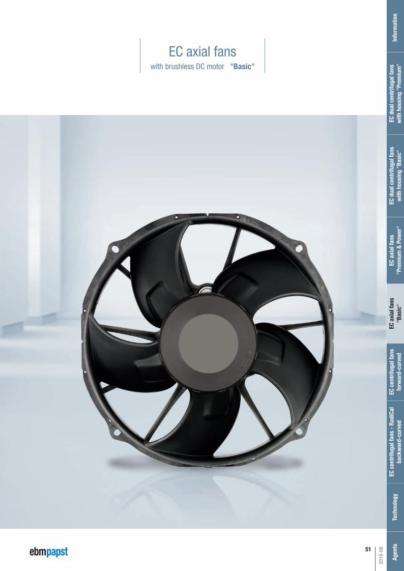
51
EC axial fanswith brushless DC motor "Basic"
2016-08
EC c
entr
ifuga
l fan
s fo
rwar
d-cu
rved
Inf
orm
atio
nEC
cen
trifu
gal f
ans
- Ra
diCa
lba
ckw
ard-
curv
edTe
chno
logy
Age
nts
EC a
xial
fans
"Bas
ic"
EC a
xial
fans
"Pre
miu
m &
Pow
er"
EC d
ual c
entr
ifuga
l fan
sw
ith h
ousi
ng "
Basi
c"EC
dua
l cen
trifu
gal f
ans
with
hou
sing
"Pr
emiu
m"
Automotive_2016_16_08_2016_AE_Final_.indd 51 16.08.2016 08:48:38
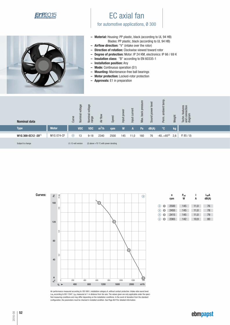
52
2016-08
W1G 300-EC12 -20(1) M1G 074-CF 13 9-18 2340 2500 145 11,0 160 76 -40..+85(2) 2,6 P. 85 / U)A
qv m³/h
cfmP fs
Pa
in w
g
400 800 1200 1600 2000
0 200 400 600 800 1000 1200
40
80
120
160
0.2
0.4
0.6
1
2
3
4A 1
A 2
A 3
A 4
2500
2455
2415
2365
145
145
145
142
11,0
11,0
11,0
10,9
76
78
79
80
A
(1) 12-volt version (2) above +70 °C with power derating
Curves: nrpm
PedW
IA
LWAdB(A)
Air performance measured according to: ISO 5801, installation category A, without contact protection. Intake-side sound level:LwA according to ISO 13347, LpA measured at 1 m distance from fan axis. The values given are only applicable under the speci-fi ed measuring conditions and may differ depending on the installation conditions. In the event of deviation from the standard confi guration, the parameters must be checked in installed condition. See Page 86 ff for detailed information.
Subject to change
Type Motor VDC VDC m3/h rpm W A Pa dB(A) °C kg
Nominal data Curv
e
Nom
inal
vol
tage
rang
e
Nom
inal
vol
tage
Spee
d
Inpu
t pow
er
Inpu
t cur
rent
Soun
d po
wer
leve
l
Perm
. am
bien
t tem
p.
Wei
ght
Air fl
ow
Max
. bac
k pr
essu
re
EC axial fanfor automotive applications, Ø 300
– Material: Housing: PP plastic, black (according to UL 94 HB) Blades: PP plastic, black (according to UL 94 HB)
– Direction of rotation: Clockwise viewed toward rotor– Degree of protection: Motor: IP 24 KM, electronics: IP 66 / 69 K– Insulation class: "B" according to EN 60335-1– Installation position: Any– Mode: Continuous operation (S1)– Mounting: Maintenance-free ball bearings– Motor protection: Locked-rotor protection– Approvals: E1 in preparation
– Airfl ow direction: "V" (intake over the rotor)
Tech
n. fe
atur
esan
d co
nnec
tion
diag
ram
Automotive_2016_16_08_2016_AE_Final_.indd 52 16.08.2016 08:48:39

EC c
entr
ifuga
l fan
s fo
rwar
d-cu
rved
Inf
orm
atio
nEC
cen
trifu
gal f
ans
- Ra
diCa
lba
ckw
ard-
curv
edTe
chno
logy
Age
nts
EC a
xial
fans
"Bas
ic"
EC a
xial
fans
"Pre
miu
m &
Pow
er"
EC d
ual c
entr
ifuga
l fan
sw
ith h
ousi
ng "
Basi
c"EC
dua
l cen
trifu
gal f
ans
with
hou
sing
"Pr
emiu
m"
53
2016-08
P. 85 / U)
X
X
+2
+1
+1
321
45°
Ø337
Ø31
8
91
Ø2.7/2.87.5
62
Ø330
28°
Ø340
5411
9.5
4x90
°
330
❮ "V"
Connection diagram P. 85
Guard grilleP. 72
CableP. 70
Detail X1 = + UB2 = 0–10 V3 = GND
Mating connector on customer circuit:Housing: TE MCP 2.8, 3-pole 1-1718627-1Plug contacts: 2x 1-968857-1 1x 1-968855-1Seal: 2x 828905-1 1x 828904-1Cable with mating connector not included in scope of delivery.
On both sides for screws for fastening plastics, Ø 3.5 mm
Automotive_2016_16_08_2016_AE_Final_.indd 53 16.08.2016 08:48:41
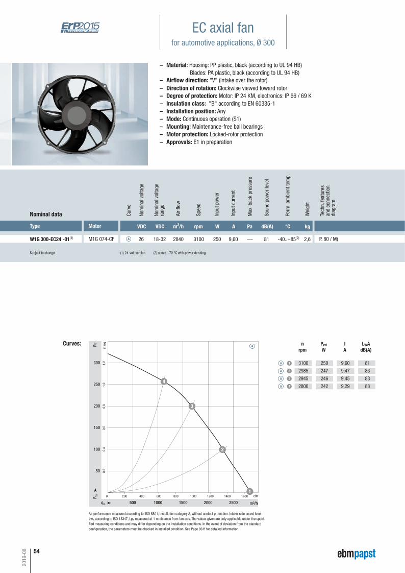
54
– Material: Housing: PP plastic, black (according to UL 94 HB) Blades: PA plastic, black (according to UL 94 HB)
– Direction of rotation: Clockwise viewed toward rotor– Degree of protection: Motor: IP 24 KM, electronics: IP 66 / 69 K– Insulation class: "B" according to EN 60335-1– Installation position: Any– Mode: Continuous operation (S1)– Mounting: Maintenance-free ball bearings– Motor protection: Locked-rotor protection– Approvals: E1 in preparation
Subject to change (1) 24-volt version (2) above +70 °C with power derating
Type Motor VDC VDC m3/h rpm W A Pa dB(A) °C kg
W1G 300-EC24 -01(1) M1G 074-CF 26 18-32 2840 3100 250 9,60 --- 81 -40..+85(2) 2,6 P. 80 / M)
Nominal data Curv
e
A
Nom
inal
vol
tage
rang
e
Nom
inal
vol
tage
Spee
d
Inpu
t pow
er
Inpu
t cur
rent
Soun
d po
wer
leve
l
Perm
. am
bien
t tem
p.
Wei
ght
Air fl
ow
Max
. bac
k pr
essu
re
Curves:
500 1000 1500 2000 2500
0
50
0,4100
0,2
0,8
0,6
200 400 800600 1600140012001000
200
1,0250
1,2300
150
qv m³/h
cfmP fs
Pa
in w
g
1
2
3
4
nrpm
PedW
IA
LWAdB(A)
A 1
A 2
A 3
A 4
3100
2985
2945
2800
250
247
246
242
9,60
9,47
9,45
9,29
81
83
83
83
A
EC axial fanfor automotive applications, Ø 300
Air performance measured according to: ISO 5801, installation category A, without contact protection. Intake-side sound level:LwA according to ISO 13347, LpA measured at 1 m distance from fan axis. The values given are only applicable under the speci-fi ed measuring conditions and may differ depending on the installation conditions. In the event of deviation from the standard confi guration, the parameters must be checked in installed condition. See Page 86 ff for detailed information.
– Airfl ow direction: "V" (intake over the rotor)
2016-08
Tech
n. fe
atur
esan
d co
nnec
tion
diag
ram
Automotive_2016_16_08_2016_AE_Final_.indd 54 16.08.2016 08:48:42
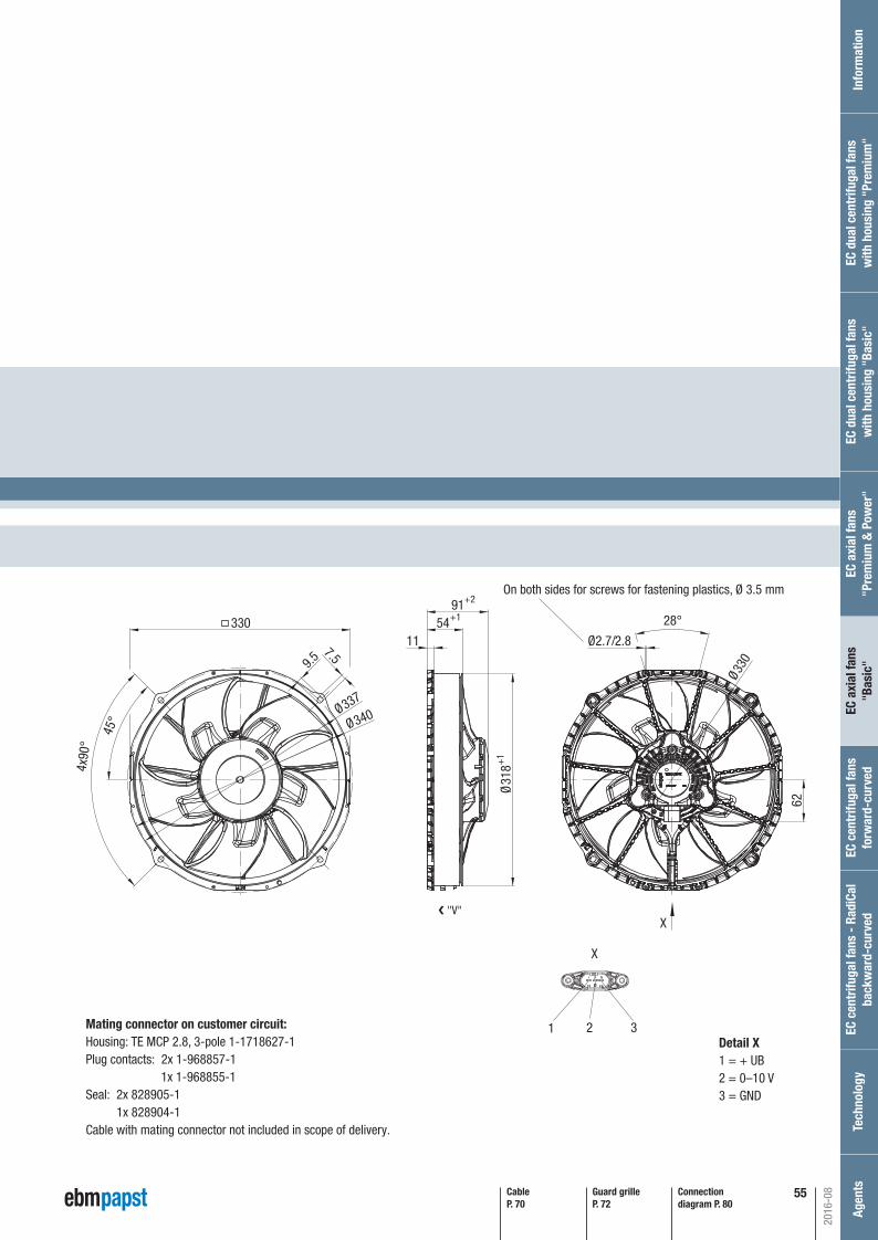
55
P. 80 / M)
Connection diagram P. 80
Guard grilleP. 72
CableP. 70
2016-08
EC c
entr
ifuga
l fan
s fo
rwar
d-cu
rved
Inf
orm
atio
nEC
cen
trifu
gal f
ans
- Ra
diCa
lba
ckw
ard-
curv
edTe
chno
logy
Age
nts
EC a
xial
fans
"Bas
ic"
EC a
xial
fans
"Pre
miu
m &
Pow
er"
EC d
ual c
entr
ifuga
l fan
sw
ith h
ousi
ng "
Basi
c"EC
dua
l cen
trifu
gal f
ans
with
hou
sing
"Pr
emiu
m"
X
X
+2
+1
+1
321
45°
Ø337
Ø31
8
91
Ø2.7/2.87.5
62
Ø330
28°
Ø340
5411
9.5
4x90
°
330
❮ "V"
Detail X1 = + UB2 = 0–10 V3 = GND
Mating connector on customer circuit:Housing: TE MCP 2.8, 3-pole 1-1718627-1Plug contacts: 2x 1-968857-1 1x 1-968855-1Seal: 2x 828905-1 1x 828904-1Cable with mating connector not included in scope of delivery.
On both sides for screws for fastening plastics, Ø 3.5 mm
Automotive_2016_16_08_2016_AE_Final_.indd 55 16.08.2016 08:48:42

56
2016-08
Automotive_2016_16_08_2016_AE_Final_.indd 56 16.08.2016 08:48:44
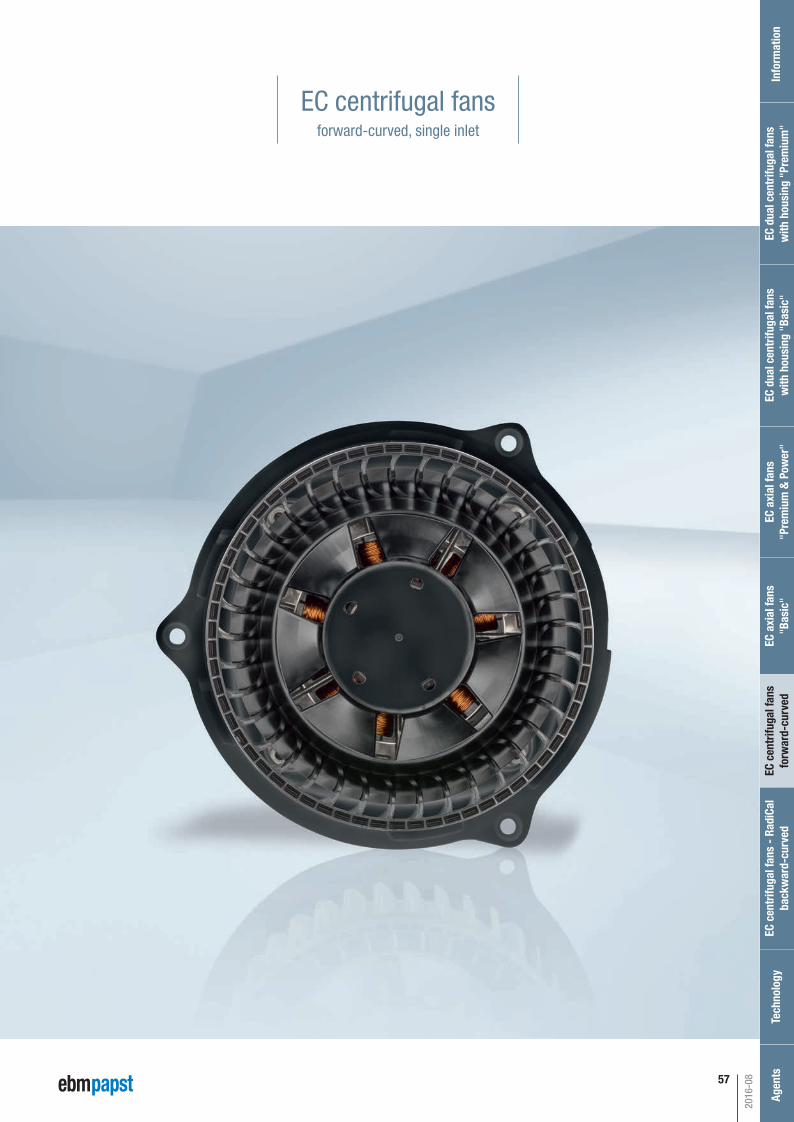
EC c
entr
ifuga
l fan
s fo
rwar
d-cu
rved
Inf
orm
atio
nEC
cen
trifu
gal f
ans
- Ra
diCa
lba
ckw
ard-
curv
edTe
chno
logy
Age
nts
EC a
xial
fans
"Bas
ic"
EC a
xial
fans
"Pre
miu
m &
Pow
er"
EC d
ual c
entr
ifuga
l fan
sw
ith h
ousi
ng "
Basi
c"EC
dua
l cen
trifu
gal f
ans
with
hou
sing
"Pr
emiu
m"
57
EC centrifugal fansforward-curved, single inlet
2016-08
Automotive_2016_16_08_2016_AE_Final_.indd 57 16.08.2016 08:48:44
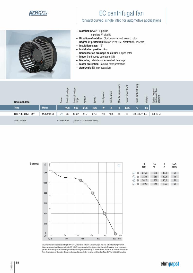
58
2016-08
R3G 146-EC50 -01(1) M3G 084-BF 26 16-32 815 2750 280 10,8 0 79 -40..+85(2) 1,5 P. 84 / S)A
EC centrifugal fanforward curved, single inlet, for automotive applications
qv m³/h
cfmP fs
Pa
in w
g
200 400 600 800
0 100 200 300 400
200
600
400
800
1200
12
34
5
1
2
3
41000
A 1
A 2
A 3
A 4
2750
3245
3815
4225
280
280
280
245
10,8
10,8
10,8
9,55
79
78
78
79
ACurves: n
rpmPedW
IA
LWAdB(A)
Air performance measured according to: ISO 5801, installation category A, in ebm-papst inlet ring without contact protection.Intake-side sound level: LwA according to ISO 13347, LpA measured at 1 m distance from fan axis. The values given are only ap-plicable under the specifi ed measuring conditions and may differ depending on the installation conditions. In the event of deviation from the standard confi guration, the parameters must be checked in installed condition. See Page 86 ff for detailed information.
Type Motor VDC VDC m3/h rpm W A Pa dB(A) °C kg
Nominal data Curv
e
Nom
inal
vol
tage
rang
e
Nom
inal
vol
tage
Spee
d
Inpu
t pow
er
Inpu
t cur
rent
Soun
d po
wer
leve
l
Perm
. am
bien
t tem
p.
Wei
ght
Air fl
ow
Max
. bac
k pr
essu
reSubject to change (1) 24-volt version (2) above +75 °C with power derating
– Material: Cover: PP plastic Impeller: PA plastic– Direction of rotation: Clockwise viewed toward rotor– Degree of protection: Motor: IP 24 KM, electronics: IP 6K9K– Insulation class: "B"– Installation position: Any– Condensation drainage holes: None, open rotor– Mode: Continuous operation (S1)– Mounting: Maintenance-free ball bearings– Motor protection: Locked-rotor protection– Approvals: E1 in preparation
Tech
n. fe
atur
esan
d co
nnec
tion
diag
ram
Automotive_2016_16_08_2016_AE_Final_.indd 58 16.08.2016 08:48:45
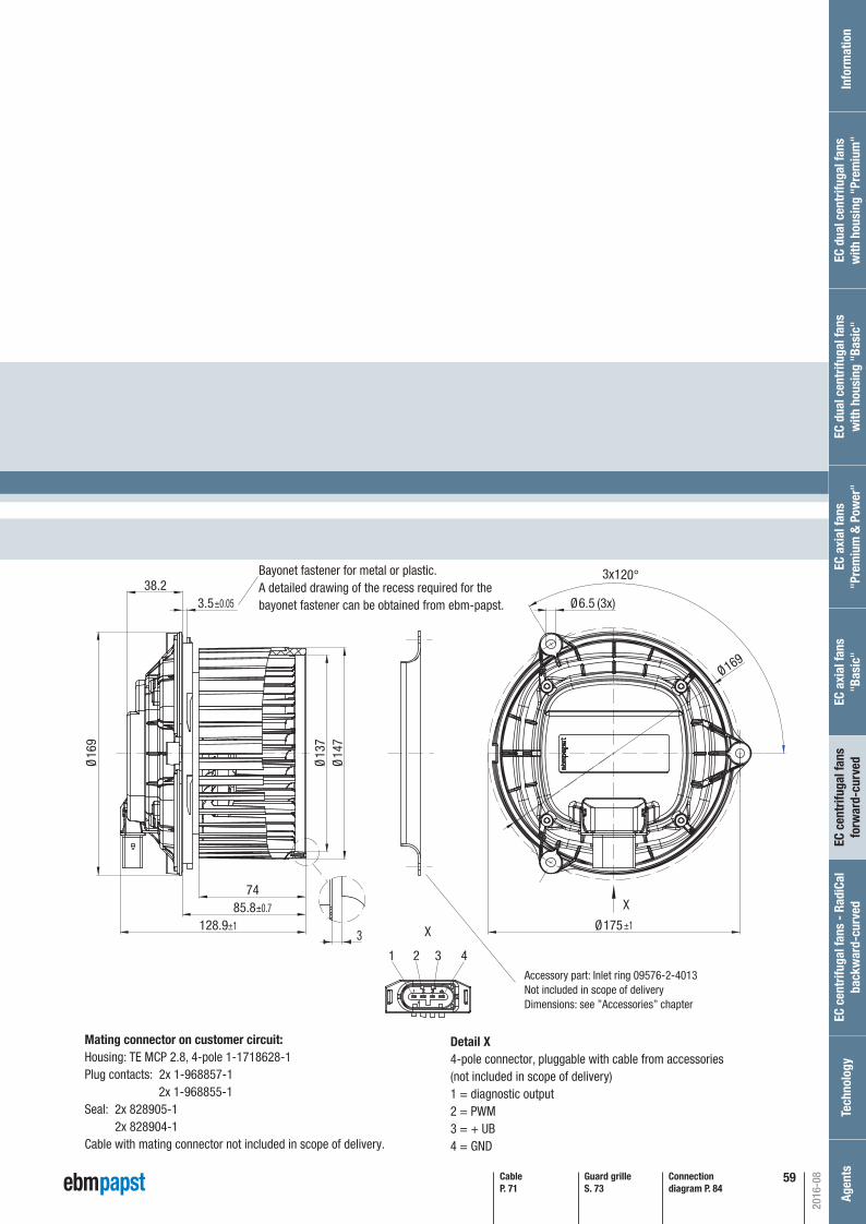
Inf
orm
atio
nEC
cen
trifu
gal f
ans
- Ra
diCa
lba
ckw
ard-
curv
edTe
chno
logy
Age
nts
EC a
xial
fans
"Pre
miu
m &
Pow
er"
EC d
ual c
entr
ifuga
l fan
sw
ith h
ousi
ng "
Basi
c"EC
dua
l cen
trifu
gal f
ans
with
hou
sing
"Pr
emiu
m"
EC c
entr
ifuga
l fan
s fo
rwar
d-cu
rved
EC a
xial
fans
"Bas
ic"
59
2016-08
P. 84 / S)
X±0.7
±1 ±1
±0.05
X
4321
3
3.5
Ø16
9
38.23x120°
Ø6.5 (3x)
Ø175
Ø169
128.985.8
74
Ø14
7Ø
137
Bayonet fastener for metal or plastic.A detailed drawing of the recess required for thebayonet fastener can be obtained from ebm-papst.
Accessory part: Inlet ring 09576-2-4013Not included in scope of deliveryDimensions: see ”Accessories” chapter
Detail X4-pole connector, pluggable with cable from accessories(not included in scope of delivery)1 = diagnostic output2 = PWM3 = + UB4 = GND
Connection diagram P. 84
Guard grilleS. 73
CableP. 71
Mating connector on customer circuit:Housing: TE MCP 2.8, 4-pole 1-1718628-1Plug contacts: 2x 1-968857-1 2x 1-968855-1Seal: 2x 828905-1 2x 828904-1Cable with mating connector not included in scope of delivery.
Automotive_2016_16_08_2016_AE_Final_.indd 59 16.08.2016 08:48:46

60
2016-08
Automotive_2016_16_08_2016_AE_Final_.indd 60 16.08.2016 08:48:47
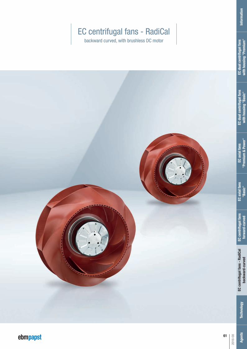
61
EC centrifugal fans - RadiCalbackward curved, with brushless DC motor
2016-08
Inf
orm
atio
nEC
cen
trifu
gal f
ans
- Ra
diCa
lba
ckw
ard-
curv
edTe
chno
logy
Age
nts
EC a
xial
fans
"Pre
miu
m &
Pow
er"
EC d
ual c
entr
ifuga
l fan
sw
ith h
ousi
ng "
Basi
c"EC
dua
l cen
trifu
gal f
ans
with
hou
sing
"Pr
emiu
m"
EC c
entr
ifuga
l fan
s fo
rwar
d-cu
rved
EC a
xial
fans
"Bas
ic"
Automotive_2016_16_08_2016_AE_Final_.indd 61 16.08.2016 08:48:48
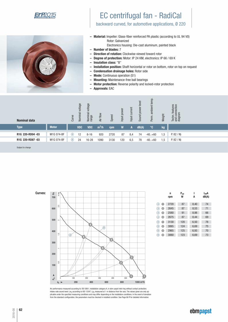
62
EC centrifugal fan - RadiCalbackward curved, for automotive applications, Ø 220
Subject to change
Type Motor VDC VDC m3/h rpm W A dB(A) °C kg
R1G 220-RD04 -03 M1G 074-BF 12 8-16 920 2720 87 8,4 74 -40..+60 1,5 P. 82 / N)
Nominal data Curv
e
A
Nom
inal
vol
tage
rang
e
Nom
inal
vol
tage
Spee
d
Inpu
t pow
er
Inpu
t cur
rent
Soun
d po
wer
leve
l
Perm
. am
bien
t tem
p.
Wei
ght
Curves:
qv m³/h
cfmP fs
Pa
in w
g
200 400 600 800 1000
0 100 200 300 400 500
100
200
300
400
500
600
700
0.5
11.
52
2.5
11
2
2
3
3
4
4
Air fl
ow
nrpm
PedW
IA
LWAdB(A)
A 1
A 2
A 3
A 4
2720
2645
2580
2675
87
87
91
87
8,40
8,53
8,98
8,44
74
71
66
69
– Material: Impeller: Glass-fi ber reinforced PA plastic (according to UL 94 V0) Rotor: Galvanized Electronics housing: Die-cast aluminum, painted black – Number of blades: 7– Direction of rotation: Clockwise viewed toward rotor– Degree of protection: Motor: IP 24 KM, electronics: IP 66 / 69 K– Insulation class: "B"– Installation position: Shaft horizontal or rotor on bottom, rotor on top on request– Condensation drainage holes: Rotor side– Mode: Continuous operation (S1)– Mounting: Maintenance-free ball bearings– Motor protection: Reverse polarity and locked-rotor protection– Approvals: EAC
R1G 220-RD87 -03 M1G 074-BF 24 16-28 1090 3130 120 6,5 78 -40..+60 1,5 P. 82 / N)B
B 1
B 2
B 3
B 4
3130
3065
2965
3060
120
124
125
123
6,50
6,69
6,93
6,69
78
75
70
73A
B
Air performance measured according to: ISO 5801, installation category A, in ebm-papst inlet ring without contact protection.Intake-side sound level: LwA according to ISO 13347, LpA measured at 1 m distance from fan axis. The values given are only ap-plicable under the specifi ed measuring conditions and may differ depending on the installation conditions. In the event of deviation from the standard confi guration, the parameters must be checked in installed condition. See Page 86 ff for detailed information.
2016-08
Tech
n. fe
atur
esan
d co
nnec
tion
diag
ram
Automotive_2016_16_08_2016_AE_Final_.indd 62 16.08.2016 08:48:48

63
Ø22
0
Ø16
1
71
73.7
Ø58
45°
450
856
M4 (4x)
4x90°
0.8
R21.8
Ø88
63.7
Ø25
2
21
Ø15
5
±10
±0.15
+20
-0.5
+0.
3
±1
2
Connection diagram P. 82
Inlet ringP. 72
P. 82 / N)
P. 82 / N)
Max. clearance for screw 6 mm
Accessory part:inlet ring 09609-2-4013,not included in scope of delivery.
Cable:FLRYW 4x 0.75 mm2, 4x crimped splices
Terminal assignmentUN redPWM/LIN yellowDUE whiteGND blue
2016-08
Inf
orm
atio
nEC
cen
trifu
gal f
ans
- Ra
diCa
lba
ckw
ard-
curv
edTe
chno
logy
Age
nts
EC a
xial
fans
"Pre
miu
m &
Pow
er"
EC d
ual c
entr
ifuga
l fan
sw
ith h
ousi
ng "
Basi
c"EC
dua
l cen
trifu
gal f
ans
with
hou
sing
"Pr
emiu
m"
EC c
entr
ifuga
l fan
s fo
rwar
d-cu
rved
EC a
xial
fans
"Bas
ic"
Automotive_2016_16_08_2016_AE_Final_.indd 63 16.08.2016 08:48:49
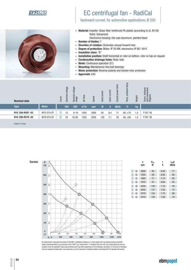
64
Subject to change
Type Motor VDC VDC m3/h rpm W A dB(A) °C kg
R1G 250-RC67 -03 M1G 074-CF 12 8-16 1030 2000 65 6,4 71 -40..+70 1,5
Nominal data Curv
e
A
Nom
inal
vol
tage
rang
e
Nom
inal
vol
tage
Spee
d
Inpu
t pow
er
Inpu
t cur
rent
Soun
d po
wer
leve
l
Perm
. am
bien
t tem
p.
Wei
ght
Curves:
qv m³/h
cfmP fs
Pa
in w
g
200 400 600 800 1000 1200
0 100 200 300 400 500 600
100
200
300
400
500
600
700
0.4
0.8
1.2
1.6
2.0
2.4
2.8
1
2
2
3
4
7001
3
4
Air fl
ow
nrpm
PedW
IA
LWAdB(A)
A 1
A 2
A 3
A 4
2000
1935
1900
1975
65
69
71
67
6,40
6,85
7,14
6,60
71
66
62
65
P. 82 / N)
B 1
B 2
B 3
B 4
2550
2445
2370
2410
130
131
134
132
7,10
7,45
7,73
7,59
76
72
69
70
R1G 250-RC75 -03 M1G 074-CF 24 16-28 1325 2550 130 7,1 76 -40..+60 1,5B P. 82 / N)
B
A
EC centrifugal fan - RadiCalbackward curved, for automotive applications, Ø 250
Air performance measured according to: ISO 5801, installation category A, in ebm-papst inlet ring without contact protection.Intake-side sound level: LwA according to ISO 13347, LpA measured at 1 m distance from fan axis. The values given are only ap-plicable under the specifi ed measuring conditions and may differ depending on the installation conditions. In the event of deviation from the standard confi guration, the parameters must be checked in installed condition. See Page 86 ff for detailed information.
– Material: Impeller: Glass-fi ber reinforced PA plastic (according to UL 94 V0) Rotor: Galvanized Electronics housing: Die-cast aluminum, painted black – Number of blades: 7– Direction of rotation: Clockwise viewed toward rotor– Degree of protection: Motor: IP 24 KM, electronics: IP 66 / 69 K– Insulation class: "B"– Installation position: Shaft horizontal or rotor on bottom, rotor on top on request– Condensation drainage holes: Rotor side– Mode: Continuous operation (S1)– Mounting: Maintenance-free ball bearings– Motor protection: Reverse polarity and locked-rotor protection– Approvals: EAC
2016-08
Tech
n. fe
atur
esan
d co
nnec
tion
diag
ram
Automotive_2016_16_08_2016_AE_Final_.indd 64 16.08.2016 08:48:50
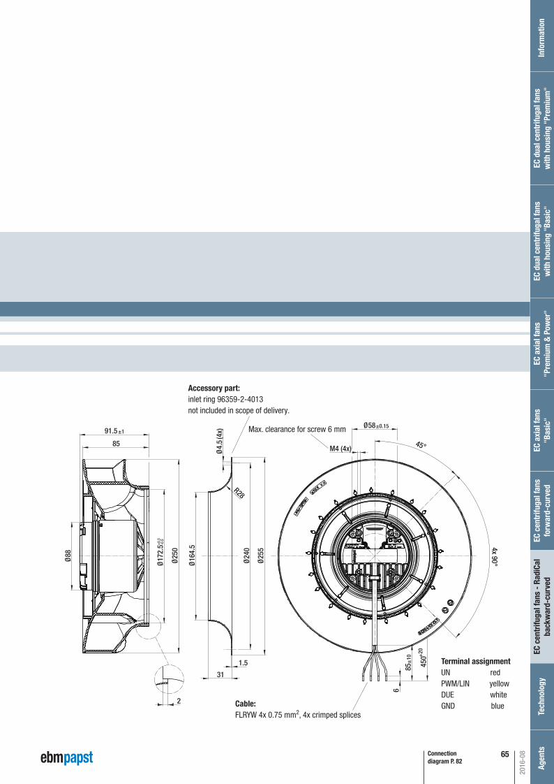
65
91.5
Ø25
0
Ø25
5
Ø24
0
Ø16
4.5
31
Ø17
2.5
6
85 450
45°
Ø58
M4 (4x)
R28
4x 90°
Ø4.
5(4
x)
1.5
Ø88
85
±0.15+
20
±10
±1
+0.
3-0
.5
2
Connection diagram P. 82
P. 82 / N)
P. 82 / N)
Max. clearance for screw 6 mm
Accessory part:inlet ring 96359-2-4013not included in scope of delivery.
Cable:FLRYW 4x 0.75 mm2, 4x crimped splices
Terminal assignmentUN redPWM/LIN yellowDUE whiteGND blue
2016-08
Inf
orm
atio
nEC
cen
trifu
gal f
ans
- Ra
diCa
lba
ckw
ard-
curv
edTe
chno
logy
Age
nts
EC a
xial
fans
"Pre
miu
m &
Pow
er"
EC d
ual c
entr
ifuga
l fan
sw
ith h
ousi
ng "
Basi
c"EC
dua
l cen
trifu
gal f
ans
with
hou
sing
"Pr
emiu
m"
EC c
entr
ifuga
l fan
s fo
rwar
d-cu
rved
EC a
xial
fans
"Bas
ic"
Automotive_2016_16_08_2016_AE_Final_.indd 65 16.08.2016 08:48:51

66
– Material: Impeller: Glass-fi ber reinforced PA plastic (according to UL 94 V0, EN 45545-2 / HL3) Rotor: Painted black Electronics housing: Die-cast aluminum, painted black – Number of blades: 5– Direction of rotation: Clockwise viewed toward rotor– Degree of protection: Motor: IP 24 KM, electronics: IP 66 / 69 K– Insulation class: "B"– Installation position: Any– Condensation drainage holes: Rotor side– Mode: Continuous operation (S1)– Mounting: Maintenance-free ball bearings
Subject to change (1) 24-volt version (also available as a 12-volt version)
Type Motor VDC VDC m3/h rpm W A dB(A) °C kg
R3G 280-RU26 -81(1) M3G 084-CF 26 16-32 2740 2350 252 10,5 80 -40..+60 3,0
Nominal data Curv
e
A
Nom
inal
vol
tage
rang
e
Nom
inal
vol
tage
Spee
d
Inpu
t pow
er
Inpu
t cur
rent
Soun
d po
wer
leve
l
Perm
. am
bien
t tem
p.
Wei
ght
Curves:
500 1000 1500 2000 2500
0
100
200
0,4
1,2300
0,8
2,0
1,6
200 400 600 800 1200 14001000 cfm
500
2,4600
400
qv m³/h
P fs
Pa
in w
g
1
2
3
4
A
Air fl
ow
nrpm
PedW
IA
LWAdB(A)
A 1
A 2
A 3
A 4
2350
2280
2265
2305
252
298
309
278
10,5
12,4
12,9
11,6
80
75
73
74
P. 81 / P)
EC centrifugal fan - RadiCalbackward curved, for automotive applications, Ø 280
Air performance measured according to: ISO 5801, installation category A, in ebm-papst inlet ring without contact protection.Intake-side sound level: LwA according to ISO 13347, LpA measured at 1 m distance from fan axis. The values given are only ap-plicable under the specifi ed measuring conditions and may differ depending on the installation conditions. In the event of deviation from the standard confi guration, the parameters must be checked in installed condition. See Page 86 ff for detailed information.
2016-08
Tech
n. fe
atur
esan
d co
nnec
tion
diag
ram
Automotive_2016_16_08_2016_AE_Final_.indd 66 16.08.2016 08:48:52

67
– Technical features: See connection diagram P. 81– Cable exit: To the side– Protection class: III– Approvals: EAC, E1
Connection diagram P. 81
Ø17
6.7
Ø17
9.6
Ø26
0Ø
280
Ø4.
5 (4
x)
R17R53R33
1.2546
Ø18
7.5
Ø29
4
127148.5
31°4x90° 45°
4x90°
(4x) (4x) (4x)
Ø144
112
87510
00
Ø115Ø75Ø58
±0.2
±0.2
±0.2
+20
±10
±1
8
P. 81 / P)
Max. clearance for screw 10 mm, tapping hole ready for self-tapping M5 screw.
Cable:2x 2.5 mm2, 4x 1.0 mm2, 6x crimped ferrules
Max. clearance for screw 8 mm, tapping hole ready for self-tapping M4 screw.
Max. clearance for screw 12 mm,tapping hole ready for self-tappingM6 screw.
Accessory part:inlet ring 28000-2-4013not included in scope of delivery.
Terminal assignmentUN +26 VDC blackGND brownPWM/LIN yellowINVLIN orangeABSENK blueDU white
2016-08
Inf
orm
atio
nEC
cen
trifu
gal f
ans
- Ra
diCa
lba
ckw
ard-
curv
edTe
chno
logy
Age
nts
EC a
xial
fans
"Pre
miu
m &
Pow
er"
EC d
ual c
entr
ifuga
l fan
sw
ith h
ousi
ng "
Basi
c"EC
dua
l cen
trifu
gal f
ans
with
hou
sing
"Pr
emiu
m"
EC c
entr
ifuga
l fan
s fo
rwar
d-cu
rved
EC a
xial
fans
"Bas
ic"
Automotive_2016_16_08_2016_AE_Final_.indd 67 16.08.2016 08:48:53
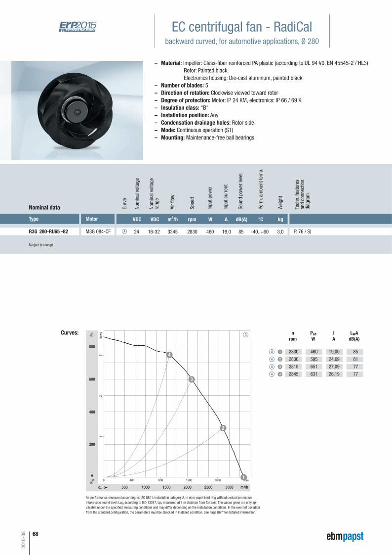
68
Subject to change
Type Motor VDC VDC m3/h rpm W A dB(A) °C kg
R3G 280-RU65 -82 M3G 084-CF 24 16-32 3345 2830 460 19,0 85 -40..+60 3,0
Nominal data Curv
e
A
Nom
inal
vol
tage
rang
e
Nom
inal
vol
tage
Spee
d
Inpu
t pow
er
Inpu
t cur
rent
Soun
d po
wer
leve
l
Perm
. am
bien
t tem
p.
Wei
ght
Curves:
qv m³/h
cfmP fs
Pa
in w
g
500 1000 1500 2000 2500 3000
0 400 800 1200 1600
200
400
600
800
12
3
1
2
3
4
A
Air fl
ow
nrpm
PedW
IA
LWAdB(A)
A 1
A 2
A 3
A 4
2830
2830
2815
2845
460
595
651
631
19,00
24,69
27,09
26,19
85
81
77
77
P. 76 / S)
EC centrifugal fan - RadiCalbackward curved, for automotive applications, Ø 280
Air performance measured according to: ISO 5801, installation category A, in ebm-papst inlet ring without contact protection.Intake-side sound level: LwA according to ISO 13347, LpA measured at 1 m distance from fan axis. The values given are only ap-plicable under the specifi ed measuring conditions and may differ depending on the installation conditions. In the event of deviation from the standard confi guration, the parameters must be checked in installed condition. See Page 86 ff for detailed information.
Tech
n. fe
atur
esan
d co
nnec
tion
diag
ram
– Material: Impeller: Glass-fi ber reinforced PA plastic (according to UL 94 V0, EN 45545-2 / HL3) Rotor: Painted black Electronics housing: Die-cast aluminum, painted black – Number of blades: 5– Direction of rotation: Clockwise viewed toward rotor– Degree of protection: Motor: IP 24 KM, electronics: IP 66 / 69 K– Insulation class: "B"– Installation position: Any– Condensation drainage holes: Rotor side– Mode: Continuous operation (S1)– Mounting: Maintenance-free ball bearings
2016-08
Automotive_2016_16_08_2016_AE_Final_.indd 68 16.08.2016 08:48:54
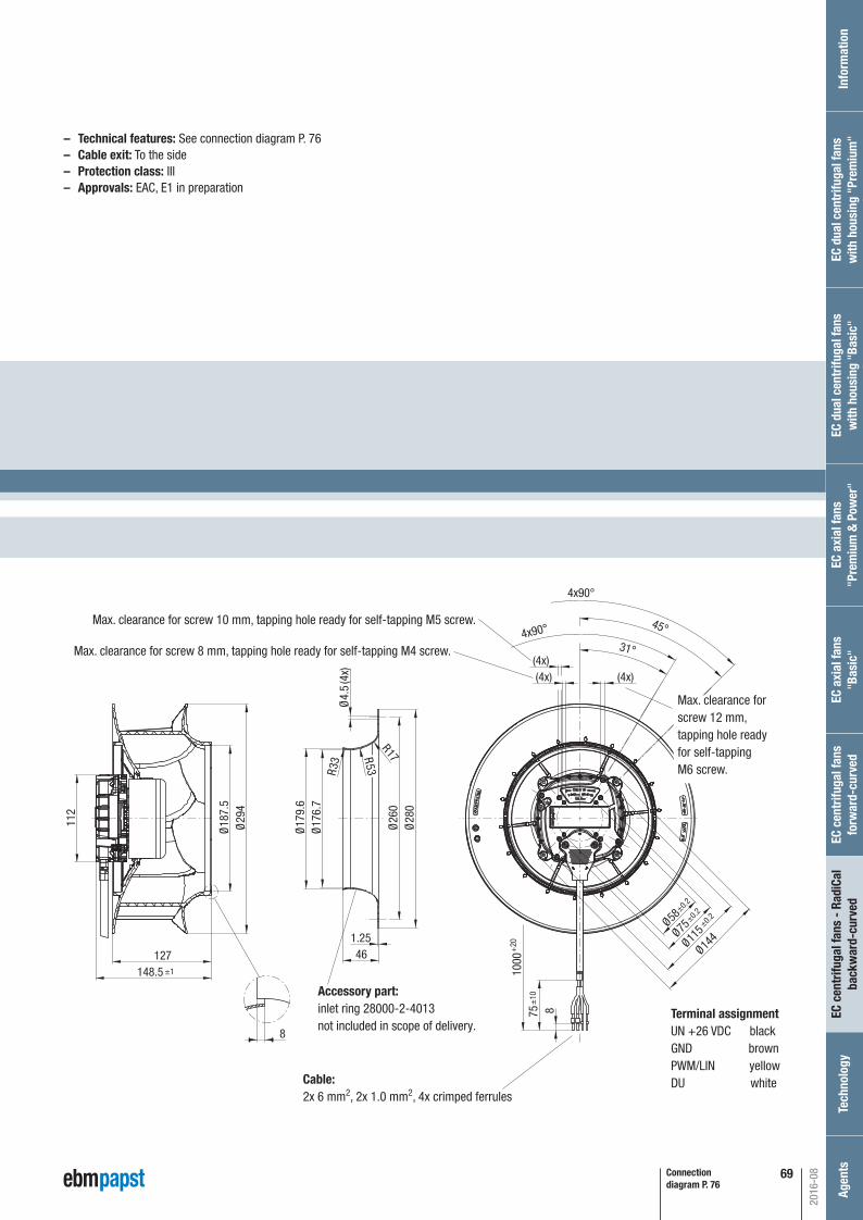
69
– Technical features: See connection diagram P. 76– Cable exit: To the side– Protection class: III– Approvals: EAC, E1 in preparation
Connection diagram P. 76
Ø17
6.7
Ø17
9.6
Ø26
0Ø
280
Ø4.
5 (4
x)
R17R53R33
1.2546
Ø18
7.5
Ø29
4
127148.5
31°4x90° 45°
4x90°
(4x) (4x) (4x)
Ø144
112
87510
00
Ø115Ø75Ø58
±0.2
±0.2
±0.2
+20
±10
±1
8
P. 76 / S)
Max. clearance for screw 10 mm, tapping hole ready for self-tapping M5 screw.
Cable:2x 6 mm2, 2x 1.0 mm2, 4x crimped ferrules
Max. clearance for screw 8 mm, tapping hole ready for self-tapping M4 screw.
Max. clearance for screw 12 mm,tapping hole ready for self-tappingM6 screw.
Accessory part:inlet ring 28000-2-4013not included in scope of delivery.
Terminal assignmentUN +26 VDC blackGND brownPWM/LIN yellowDU white
2016-08
Inf
orm
atio
nEC
cen
trifu
gal f
ans
- Ra
diCa
lba
ckw
ard-
curv
edTe
chno
logy
Age
nts
EC a
xial
fans
"Pre
miu
m &
Pow
er"
EC d
ual c
entr
ifuga
l fan
sw
ith h
ousi
ng "
Basi
c"EC
dua
l cen
trifu
gal f
ans
with
hou
sing
"Pr
emiu
m"
EC c
entr
ifuga
l fan
s fo
rwar
d-cu
rved
EC a
xial
fans
"Bas
ic"
Automotive_2016_16_08_2016_AE_Final_.indd 69 16.08.2016 08:48:55
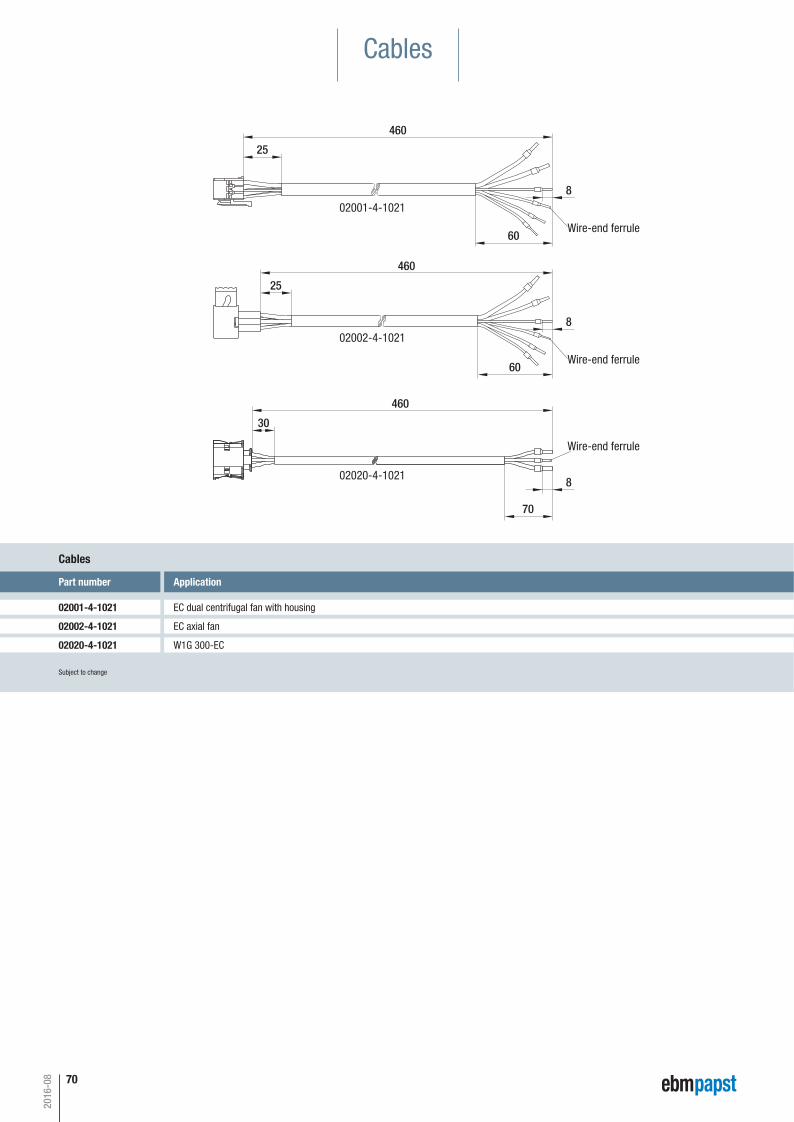
Cables
Subject to change
Part number Application
02001-4-1021 EC dual centrifugal fan with housing
Cables
02002-4-1021 EC axial fan
02020-4-1021 W1G 300-EC
460
25
60
8
460
25
60
8
460
30
70
8
02001-4-1021
02002-4-1021
02020-4-1021
Wire-end ferrule
Wire-end ferrule
Wire-end ferrule
Part number
02025-4-1021
02040-4-1021
70
2016-08
Automotive_2016_16_08_2016_AE_Final_.indd 70 16.08.2016 08:48:55
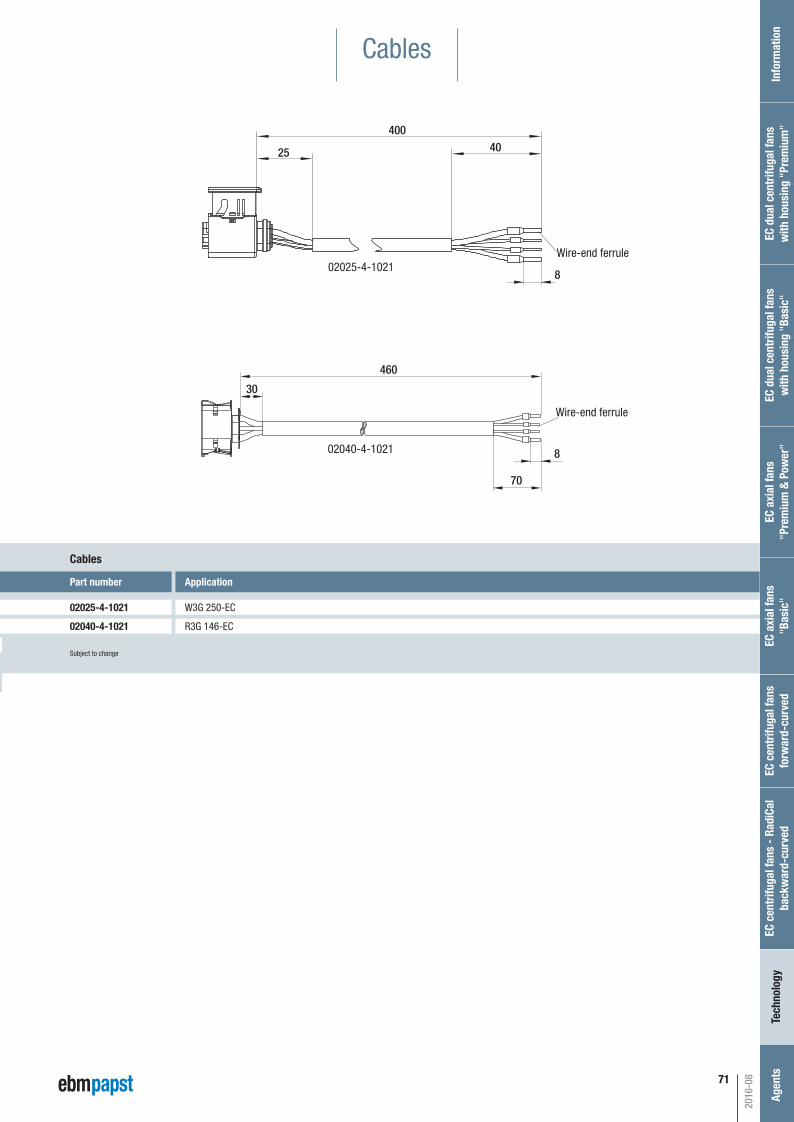
460
30
70
8
Application
W3G 250-EC
R3G 146-EC
Application
EC dual centrifugal fan with housing
EC axial fan
W1G 300-ECSubject to change
Part number
02025-4-1021
Cables
02040-4-1021
400
25 40
802025-4-1021
Wire-end ferrule
02040-4-1021
Wire-end ferrule
71
2016-08
Inf
orm
atio
nEC
cen
trifu
gal f
ans
- Ra
diCa
lba
ckw
ard-
curv
edTe
chno
logy
Age
nts
EC a
xial
fans
"Pre
miu
m &
Pow
er"
EC d
ual c
entr
ifuga
l fan
sw
ith h
ousi
ng "
Basi
c"EC
dua
l cen
trifu
gal f
ans
with
hou
sing
"Pr
emiu
m"
EC c
entr
ifuga
l fan
s fo
rwar
d-cu
rved
EC a
xial
fans
"Bas
ic"
Cables
Automotive_2016_16_08_2016_AE_Final_.indd 71 16.08.2016 08:48:56
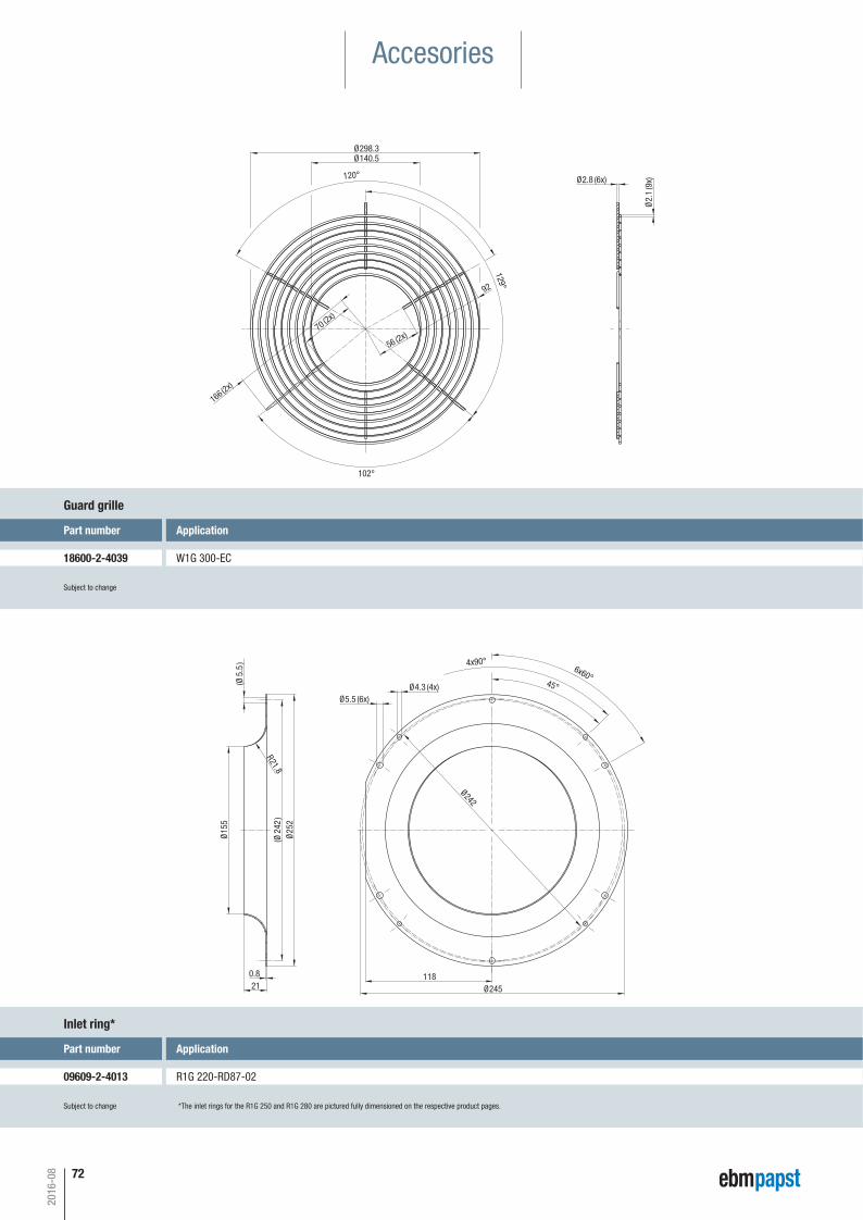
Part number
18605-2-4039
Part number
09576-2-4013
Accesories
129°
102°
Ø2.8 (6x)
Ø2.
1 (9
x)120°
Ø140.5Ø298.3
56 (2x)
70 (2x)
166 (2x)
92
Ø15
5
(Ø24
2)
Ø25
2
0.821
(Ø5.
5)
R21.8
118Ø245
Ø5.5 (6x)Ø4.3 (4x)
Ø242
45°
6x60°
4x90°
Subject to change
Part number Application
18600-2-4039 W1G 300-EC
Guard grille
Subject to change
Part number Application
09609-2-4013 R1G 220-RD87-02
Inlet ring*
*The inlet rings for the R1G 250 and R1G 280 are pictured fully dimensioned on the respective product pages.
72
2016-08
Automotive_2016_16_08_2016_AE_Final_.indd 72 16.08.2016 08:48:56
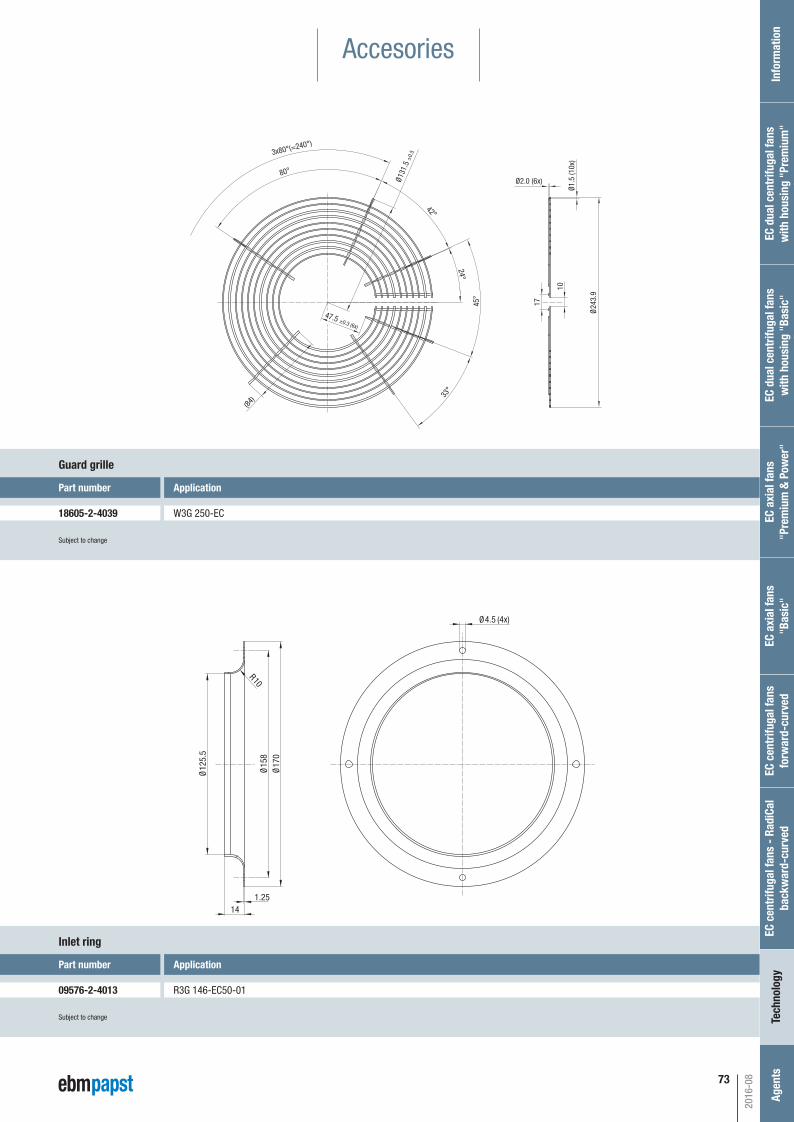
3x80°(=240°)
80°
(84)
Ø24
3.9
10
17
33°
45°
24°
42°
Ø131
.5 ±
0.5
Ø1.5
(10x
)
Ø2.0 (6x)
47.5 ±0.3 (6x)
Ø4.5 (4x)
Ø15
8Ø
170
Ø12
5.5
1.2514
R10Subject to change
Part number Application
18605-2-4039 W3G 250-EC
Guard grille
Subject to change
Part number Application
09576-2-4013 R3G 146-EC50-01
Inlet ring
Application
W1G 300-EC
Application
R1G 220-RD87-02
Inf
orm
atio
nEC
cen
trifu
gal f
ans
- Ra
diCa
lba
ckw
ard-
curv
edTe
chno
logy
Age
nts
EC a
xial
fans
"Pre
miu
m &
Pow
er"
EC d
ual c
entr
ifuga
l fan
sw
ith h
ousi
ng "
Basi
c"EC
dua
l cen
trifu
gal f
ans
with
hou
sing
"Pr
emiu
m"
EC c
entr
ifuga
l fan
s fo
rwar
d-cu
rved
EC a
xial
fans
"Bas
ic"
73
2016-08
Accesories
Automotive_2016_16_08_2016_AE_Final_.indd 73 16.08.2016 08:48:56
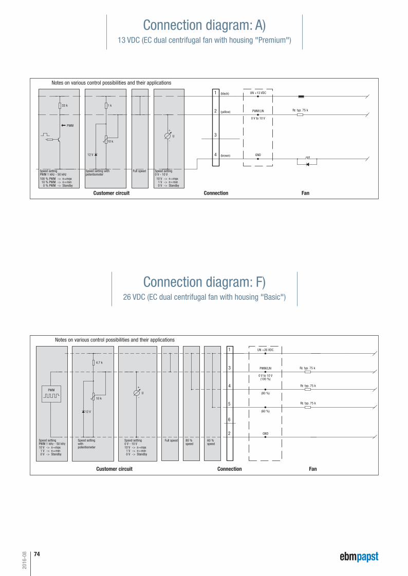
7453
Electrical connections
Customer circuit
Notes on various control possibilities and their applications
Connection Fan
Speed settingPWM 1 kHz - 50 kHz
Speed setting with potentiometer
Full speed
100 % PWM -> n=max10 % PWM -> n=min
0 % PWM -> Standby
Speed setting0 V - 10 V10 V -> n=max1 V -> n=min0 V -> Standby
1 k33 k
10 k
12 V
U
(black) UN +13 VDC
PWM/LIN
0 V to 10 V
GND
(yellow)
(brown)
RE typ. 75 k
4
3
2
1
PWM+
-
A) 13 VDC electrical connection (EC dual centrifugal blowers “Premium”)
Customer circuit
Notes on various control possibilities and their applications
Connection Fan
L) 13 VDC electrical connection (EC axial fans „Power“)
Speed settingPWM 5 Hz - 100 kHz
Speed setting with potentiometer
Full speed
100 % PWM -> n=max15 % PWM -> n=min
0 % PWM -> Standby
Speed setting0 V - 10 V10 V -> n=max
1,5 V -> n=min0 V -> Standby
1 k
10 k
12 V
(black) UB +13 VDC
PWM/LIN
0 V to 10 V
Diagnostic output
GND
(yellow)
(white)
(brown)
RE typ. 22 k
Diagnostic outputOperation:output level low (U = 0 V)Rotor locked orovervoltage/undervoltage:output level high (U = UB - 2 V)Imax = 50 mACollective fault signal possible
4
2
3
1
0.05 k
PWMU
+
-
Automotive__EN__120816___Automotive_deutsch 07.10.2014 09:27 Seite 53
55
Customer circuit
Notes on various control possibilities and their applications
Connection Fan
Speed settingPWM 1 kHz - 50 kHz
Speed setting with potentiometer
Fullspeed
100 % PWM->n=max10 % PWM->n=min0 % PWM->Standby
Speed setting0 V - 10 V
10 V -> n=max1 V -> n=min0 V -> Standby
4,7 k
10 k
12 V
U
(black) UN +26 VDC
PWM/LIN
0 V .. 10 V
GND
(yellow)
(brown)
RE typ 75 k
4
3
2
1
PWM+
-
G) 26 VDC electrical connection (EC dual centrifugal blowers „Premium/Power“)
Temperature control module
50002-1-017450003-1-0174
(white) DU
3 k Imax=10mA
Diagnostic outputOperation: output levelhigh (U = UB - 2 V)Rotor locked or overtemp-erature: output levellow (U = 0 V)Imax = 10 mACollective fault signalpossible
22 k
E) 24 VDC electrical connection
Temperature control module
50002-1-017450003-1-0174
Speed setting
PWM 1 kHz - 50 kHz
Speed settingwith potentiometer
Full speed
100% PWM -> n=maxapprox. 10% PWM -> n=min
< 10% PWM -> n=0
Safe start atUNom -30 % from 40 % PWM
Speed setting
1 V - 10 V
10 V -> n=maxapprox. 1 V -> n=min
< 1 V -> n=0
Safe start atUNom -30 % from 4 V Ucontr
33 K 4.7 K
10 KPWM
12 V
U
Speed display
Alarm
Controller
Counter
red
white
blue
Maximum ripple±3.5%
Tach outputpulses per revolution
GND
RE> 100 k
Isink max. 10 mA
680 Ω
47 V
Customer circuit
Notes on various control possibilities and their applications
Connection Fan
yellow
Lin/PWM control input0-10 VDC / PWM
F) 26 VDC electrical connection (EC dual centrifugal blowers “Basic”)
Customer circuit
Notes on various control possibilities and their applications
Connection Fan
Speed settingPWM 1 kHz - 50 kHz
Speed settingwith potentiometer
Full speedSpeed setting0 V - 10 V10 V -> n=max1 V -> n=min0 V -> Standby
4.7 k
10 k
12 V
UN +26 VDC
PWM/LIN
0 V to 10 V(100 %)
GND
RE typ. 75 k3
1
PWMU
+
-
10 V -> n=max1 V -> n=min0 V -> Standby
80 %speed
60 %speed
4
5
6
2
(60 %)
(80 %)
RE typ. 75 k
RE typ. 75 k
Automotive__EN__120816___Automotive_deutsch 07.10.2014 09:27 Seite 55
Connection diagram: A)13 VDC (EC dual centrifugal fan with housing "Premium")
Connection diagram: F)26 VDC (EC dual centrifugal fan with housing "Basic")
2016-08
Automotive_2016_16_08_2016_AE_Final_.indd 74 16.08.2016 08:48:57
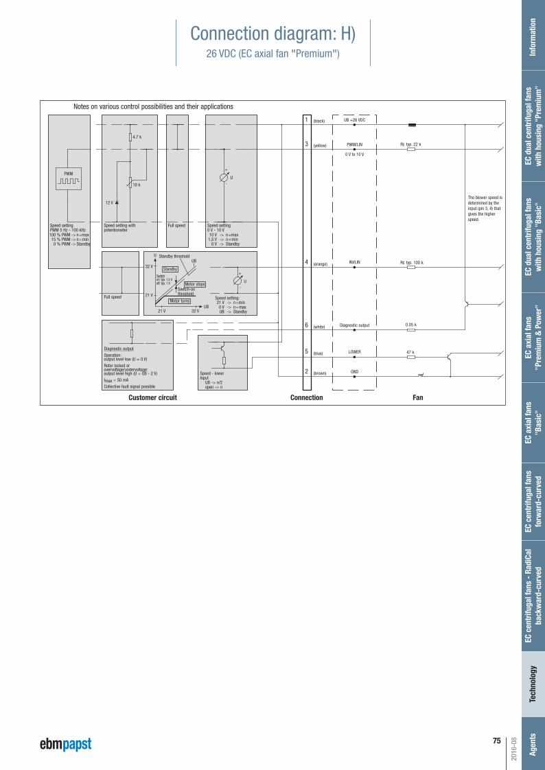
75
56
Electrical connections
Customer circuit
Notes on various control possibilities and their applications
Connection Fan
K) 13 VDC electrical connection (EC axial fans „Premium“)
4
The blower speed isdetermined by theinput (pin 3, 4) thatgives the higherspeed.
Speed settingPWM 5 Hz - 100 kHz
Speed setting with potentiometer
Full speed
100 % PWM -> n=max15 % PWM -> n=min
0 % PWM -> Standby
Speed setting0 V - 10 V10 V -> n=max
1,5 V -> n=min0 V -> Standby
10 k
12 V
(black) UB +13 VDC
PWM/LIN
0 V to 10 V
Diagnostic output
LOWER
GND
(yellow)
(white)
(blue)
(brown)
RE typ. 22 k
Diagnostic outputOperation:output level low (U = 0 V)Rotor locked orovervoltage/undervoltage:output level high (U = UB - 2 V)Imax = 50 mACollective fault signal possible
Speed - lowerInput
UB -> n/2open -> n
2
5
6
3
1
47 k
0.05 k
PWMU
+
-
Customer circuit
Notes on various control possibilities and their applications
Connection Fan
H) 26 VDC electrical connection (EC axial fans „Premium/Power“)
INVLIN RE typ. 100 k(orange)4
The blower speed isdetermined by theinput (pin 3, 4) thatgives the higherspeed.
Full speed
Standby thresholdUB
Standby
Motor stops
Motor turns
Switchon: typ. 1.5 Voff: typ. 1 V
Switch-on threshold
32 V
U
21 V
21 V 32 VUB
Speed setting:21 V -> n=min0 V -> n=maxUB -> Standby
Speed settingPWM 5 Hz - 100 kHz
Speed setting with potentiometer
Full speed
100 % PWM -> n=max15 % PWM -> n=min
0 % PWM -> Standby
Speed setting0 V - 10 V10 V -> n=max
1,5 V -> n=min0 V -> Standby
4.7 k
10 k
12 V
(black) UB +26 VDC
PWM/LIN
0 V to 10 V
Diagnostic output
LOWER
GND
(yellow)
(white)
(blue)
(brown)
RE typ. 22 k
Diagnostic outputOperation:output level low (U = 0 V)Rotor locked orovervoltage/undervoltage:output level high (U = UB - 2 V)Imax = 50 mACollective fault signal possible
Speed - lowerInput
UB -> n/2open -> n
2
5
6
3
1
47 k
0.05 k
PWMU
+
-
U
+
-
1 k
NC
Automotive__EN__120816___Automotive_deutsch 07.10.2014 09:27 Seite 56
Connection diagram: H)26 VDC (EC axial fan "Premium")
2016-08
Inf
orm
atio
nEC
cen
trifu
gal f
ans
- Ra
diCa
lba
ckw
ard-
curv
edTe
chno
logy
Age
nts
EC a
xial
fans
"Pre
miu
m &
Pow
er"
EC d
ual c
entr
ifuga
l fan
sw
ith h
ousi
ng "
Basi
c"EC
dua
l cen
trifu
gal f
ans
with
hou
sing
"Pr
emiu
m"
EC c
entr
ifuga
l fan
s fo
rwar
d-cu
rved
EC a
xial
fans
"Bas
ic"
Automotive_2016_16_08_2016_AE_Final_.indd 75 16.08.2016 08:48:58
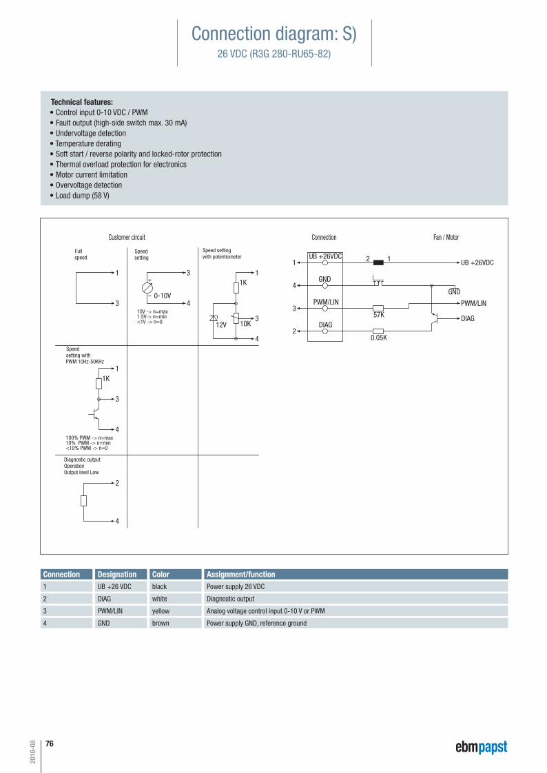
76
0-10V
Fan / MotorConnectionCustomer circuit
UB +26VDC1 1
1
1
4
4
4
4
4
3
3
33
3
2
2
UB +26VDC
DIAG
PWM/LIN
GND
12
DIAG
GND
PWM/LIN
57K
0.05K
10K
1K
1K
12V
10V -> n=max
<1V -> n=0
100% PWM -> n=max10% PWM -> n=min<10% PWM -> n=0
PWM 10Hz-50KHz
1.5V-> n=min
Speed settingwith potentiometer
Speedsetting
Fullspeed
Speed setting with
Diagnostic outputOperationOutput level Low
Technical features: • Control input 0-10 VDC / PWM • Fault output (high-side switch max. 30 mA) • Undervoltage detection • Temperature derating • Soft start / reverse polarity and locked-rotor protection • Thermal overload protection for electronics • Motor current limitation • Overvoltage detection • Load dump (58 V)
Connection diagram: S)26 VDC (R3G 280-RU65-82)
Connection DesignationUB +26 VDC
DIAG
PWM/LIN
Assignment/functionPower supply 26 VDC
Diagnostic output
Analog voltage control input 0-10 V or PWM
1
2
3
GND Power supply GND, reference ground 4
Colorblack
white
yellow
brown
2016-08
Automotive_2016_16_08_2016_AE_Final_.indd 76 16.08.2016 08:48:58
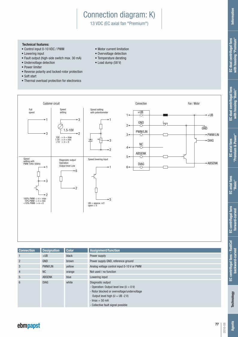
77
1 11
1 1
2
2
2
2
2
5
5
3
3
3
3
3
66
4
+UB
DIAG
ABSENK
PWM/LIN
GND
NC
1.5-10V
Customer circuit
UB-> approx. n/2open-> n
100% PWM -> n = max10% PWM -> n = min
<10% PWM -> n = 0
Connection Fan / Motor
Speed lowering input
1.5V -> n = min10V -> n = max
<1V -> n = 0
PWM 10Hz-50kHz
+UB
ABSENK
DIAG
GND
PWM/LIN
Speed settingwith potentiometer
Speedsetting
Fullspeed
Speed setting with Diagnostic output
OperationOutput level Low
Technical features: • Control input 0-10 VDC / PWM • Lowering input • Fault output (high-side switch max. 30 mA) • Undervoltage detection • Power limiter • Reverse polarity and locked-rotor protection • Soft start • Thermal overload protection for electronics
• Motor current limitation • Overvoltage detection • Temperature derating • Load dump (58 V)
Connection diagram: K)13 VDC (EC axial fan "Premium")
Connection Designation+UB
GND
PWM/LIN
Assignment/functionPower supply
Power supply GND, reference ground
Analog voltage control input 0-10 V or PWM
1
2
3
NC Not used / no function4
ABSENK Lowering input5
DIAG Diagnostic output- Operation: Output level low (U = 0 V)- Rotor blocked or overvoltage/undervoltage Output level high (U = UB -2 V)- Imax = 50 mA- Collective fault signal possible
6
Colorblack
brown
yellow
orange
blue
white
2016-08
Inf
orm
atio
nEC
cen
trifu
gal f
ans
- Ra
diCa
lba
ckw
ard-
curv
edTe
chno
logy
Age
nts
EC a
xial
fans
"Pre
miu
m &
Pow
er"
EC d
ual c
entr
ifuga
l fan
sw
ith h
ousi
ng "
Basi
c"EC
dua
l cen
trifu
gal f
ans
with
hou
sing
"Pr
emiu
m"
EC c
entr
ifuga
l fan
s fo
rwar
d-cu
rved
EC a
xial
fans
"Bas
ic"
Automotive_2016_16_08_2016_AE_Final_.indd 77 16.08.2016 08:48:58
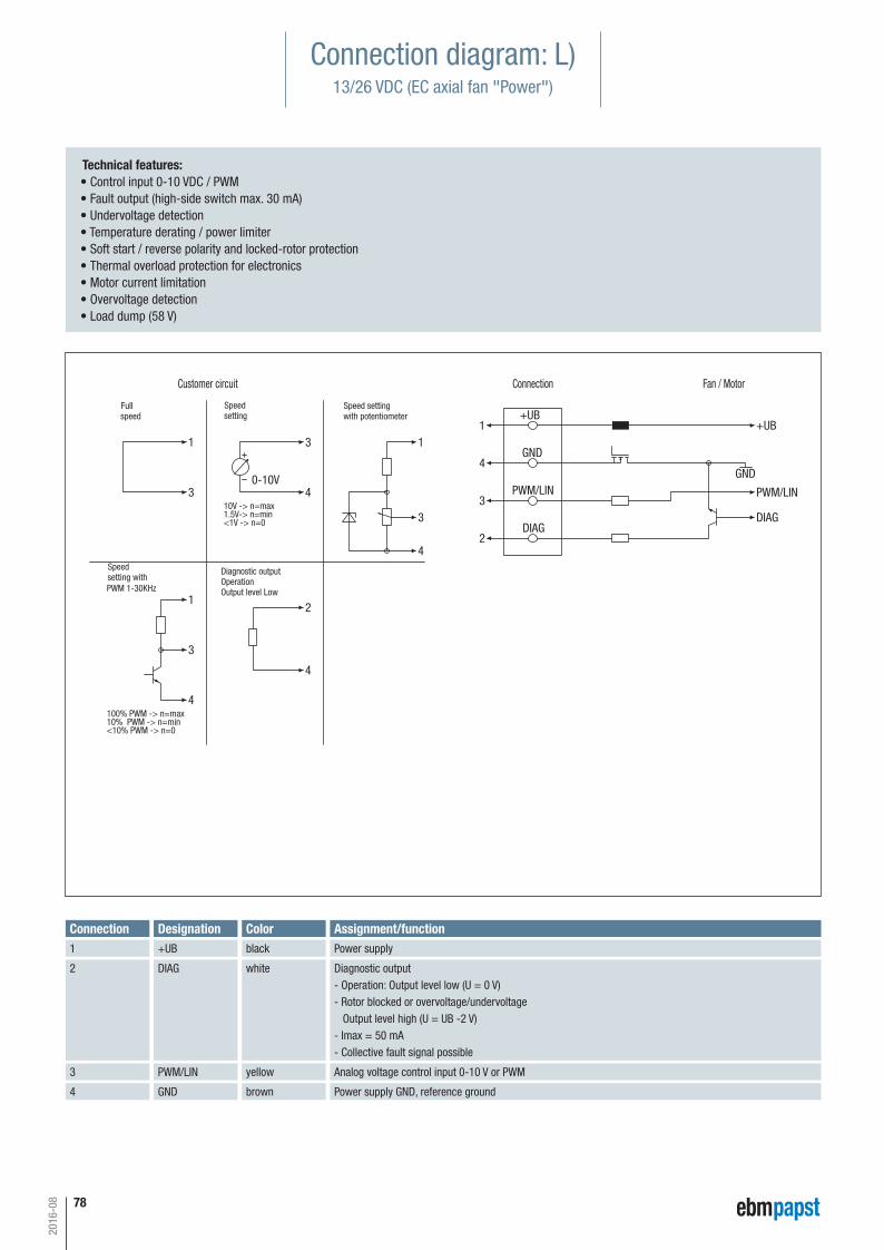
78
0-10V
+UB1 1
1
1
4
4
4
4
4
3
3
33
3
2
2
+UB
DIAG
PWM/LIN
GND
DIAG
GND
PWM/LIN10V -> n=max
<1V -> n=0
100% PWM -> n=max10% PWM -> n=min<10% PWM -> n=0
PWM 1-30KHz
1.5V-> n=min
Customer circuit Connection Fan / Motor
Speed settingwith potentiometer
Speedsetting
Fullspeed
Speed setting with
Diagnostic outputOperationOutput level Low
Technical features: • Control input 0-10 VDC / PWM • Fault output (high-side switch max. 30 mA) • Undervoltage detection • Temperature derating / power limiter • Soft start / reverse polarity and locked-rotor protection • Thermal overload protection for electronics • Motor current limitation • Overvoltage detection • Load dump (58 V)
Connection diagram: L)13/26 VDC (EC axial fan "Power")
Connection Designation+UB
DIAG
PWM/LIN
Assignment/functionPower supply
Diagnostic output- Operation: Output level low (U = 0 V)- Rotor blocked or overvoltage/undervoltage Output level high (U = UB -2 V)- Imax = 50 mA- Collective fault signal possible
Analog voltage control input 0-10 V or PWM
1
2
3
GND Power supply GND, reference ground 4
Colorblack
white
yellow
brown
2016-08
Automotive_2016_16_08_2016_AE_Final_.indd 78 16.08.2016 08:48:58
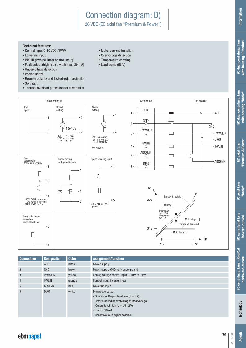
79
1
1
1
1
1
1
2
2
2
2
2
5
5
3
3
3
3
3
6
6
4
4
+UB
DIAG
ABSENK
PWM/LIN
GND
INVLIN
1.5-10V
UB-> approx. n/2open-> n
21V -> n = min0V -> n = maxUB -> standby
100% PWM -> n = max10% PWM -> n = min
<10% PWM -> n = 0
Standby threshold
standby
Switch-on threshold
Motor turns
Motor stops
Switch ontyp. 1.5VSwitch offtyp. 1V
UBU
32V
21V
21V 32VUB
A:
see curve A
1.5V -> n = min10V -> n = max
<1V -> n = 0
PWM 10Hz-50kHz
+UB
ABSENK
DIAG
GND
INVLIN
PWM/LIN
Customer circuit Connection Fan / Motor
Speed lowering inputSpeed settingwith potentiometer
Speedsetting
Speedsetting
Fullspeed
Speed setting with
Diagnostic outputOperationOutput level Low
Connection diagram: D)26 VDC (EC axial fan "Premium & Power")
Technical features: • Control input 0-10 VDC / PWM • Lowering input • INVLIN (inverse linear control input) • Fault output (high-side switch max. 30 mA) • Undervoltage detection • Power limiter • Reverse polarity and locked-rotor protection • Soft start • Thermal overload protection for electronics
• Motor current limitation • Overvoltage detection • Temperature derating • Load dump (58 V)
Connection Designation+UB
GND
PWM/LIN
Assignment/functionPower supply
Power supply GND, reference ground
Analog voltage control input 0-10 V or PWM
1
2
3
INVLIN Control input, inverse linear4
ABSENK Lowering input5
DIAG Diagnostic output- Operation: Output level low (U = 0 V)- Rotor blocked or overvoltage/undervoltage Output level high (U = UB -2 V)- Imax = 50 mA- Collective fault signal possible
6
Colorblack
brown
yellow
orange
blue
white
2016-08
Inf
orm
atio
nEC
cen
trifu
gal f
ans
- Ra
diCa
lba
ckw
ard-
curv
edTe
chno
logy
Age
nts
EC a
xial
fans
"Pre
miu
m &
Pow
er"
EC d
ual c
entr
ifuga
l fan
sw
ith h
ousi
ng "
Basi
c"EC
dua
l cen
trifu
gal f
ans
with
hou
sing
"Pr
emiu
m"
EC c
entr
ifuga
l fan
s fo
rwar
d-cu
rved
EC a
xial
fans
"Bas
ic"
Automotive_2016_16_08_2016_AE_Final_.indd 79 16.08.2016 08:48:59
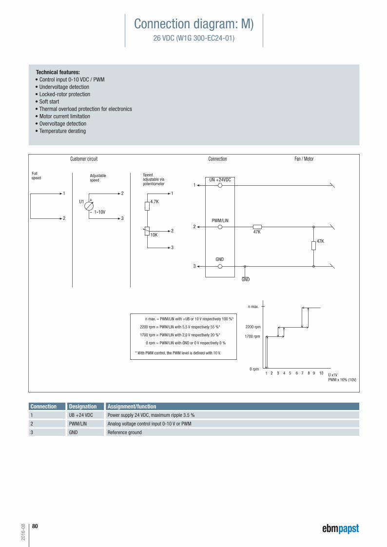
80
11
1
2
2
2
2
3
3
3
UN +24VDC
PWM/LIN
GND
GND
47K
47K10K
4.7KU1
1-10V
1 10
2200 rpm
0 rpm
n max.
U x1VPWM x 10% (10V)
3 42 5 6 7 8 9
1700 rpm
n max. = PWM/LIN with +UB or 10 V respectively 100 %*
1700 rpm = PWM/LIN with 2,0 V respectively 20 %*
0 rpm = PWM/LIN with GND or 0 V respectively 0 %
* With PWM control, the PWM level is defined with 10 V.
2200 rpm = PWM/LIN with 5,5 V respectively 55 %*
Customer circuit Connection Fan / Motor
Fullspeed Adjustable
speedSpeedadjustable viapotentiometer
Connection diagram: M)26 VDC (W1G 300-EC24-01)
Technical features: • Control input 0-10 VDC / PWM • Undervoltage detection • Locked-rotor protection • Soft start • Thermal overload protection for electronics • Motor current limitation • Overvoltage detection • Temperature derating
Connection DesignationUB +24 VDC
PWM/LIN
GND
Assignment/functionPower supply 24 VDC, maximum ripple 3.5 %
Analog voltage control input 0-10 V or PWM
Reference ground
1
2
3
2016-08
Automotive_2016_16_08_2016_AE_Final_.indd 80 16.08.2016 08:48:59
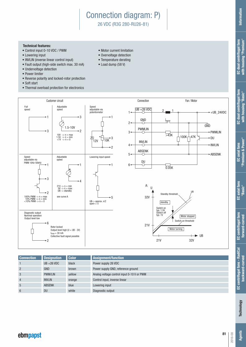
81
1 11
1 1 1
2
2
2
2
2
5
5
3
3
3
3
3
6
6
4
4
UB +26 VDC
DU
ABSENK
PWMLIN
GND
INVLIN10K
1.5-10V
12V
Customer circuit
UB-> approx. n/2open-> n
21V -> n = min0V -> n = maxUB -> standby
100% PWM -> n = max10% PWM -> n = min
<10% PWM -> n = 0
Standby threshold
standby
Switch-on threshold
Motor turning
Motor stopped
Switch ontyp. 1.5VSwitch offtyp. 1V
UBU
32V
21V
21V 32VUB
A:
see curve A
Connection Fan / Motor
Lowering input speed
1.5V -> n = min10V -> n = max
<1V -> n = 0
Fullspeed
Adjustablespeed
Speedadjustable viapotentiometer
Adjustablespeed
Speed adjustable viaPWM 10Hz-50kHz
Diagnostic output
Rotor lockedOutput level high (U = UB - 2V)I = 30 mACollective fault signal possiblemax
Nominal operationOutput level low
+UB_24VDC
ABSENK
12
DU
GND
INVLIN
PWMLIN>43K 100K 47K
0.05K
Connection diagram: P)26 VDC (R3G 280-RU26-81)
Technical features: • Control input 0-10 VDC / PWM • Lowering input • INVLIN (inverse linear control input) • Fault output (high-side switch max. 30 mA) • Undervoltage detection • Power limiter • Reverse polarity and locked-rotor protection • Soft start • Thermal overload protection for electronics
• Motor current limitation • Overvoltage detection • Temperature derating • Load dump (58 V)
Connection DesignationUB +26 VDC
GND
PWM/LIN
Assignment/functionPower supply 26 VDC
Power supply GND, reference ground
Analog voltage control input 0-10 V or PWM
1
2
3
INVLIN Control input, inverse linear4
ABSENK Lowering input5
DU Diagnostic output6
Colorblack
brown
yellow
orange
blue
white
2016-08
Inf
orm
atio
nEC
cen
trifu
gal f
ans
- Ra
diCa
lba
ckw
ard-
curv
edTe
chno
logy
Age
nts
EC a
xial
fans
"Pre
miu
m &
Pow
er"
EC d
ual c
entr
ifuga
l fan
sw
ith h
ousi
ng "
Basi
c"EC
dua
l cen
trifu
gal f
ans
with
hou
sing
"Pr
emiu
m"
EC c
entr
ifuga
l fan
s fo
rwar
d-cu
rved
EC a
xial
fans
"Bas
ic"
Automotive_2016_16_08_2016_AE_Final_.indd 81 16.08.2016 08:48:59
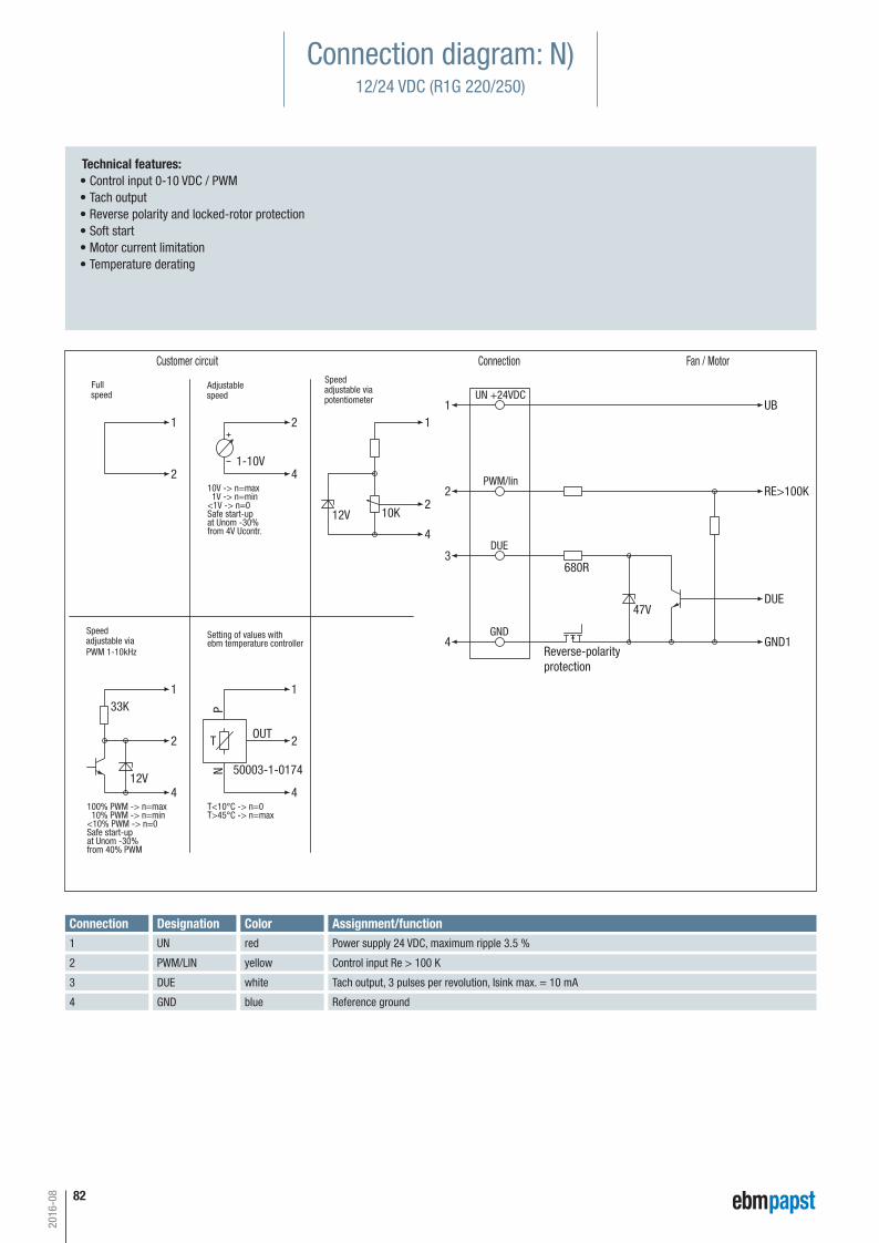
82
11
1 1
1
2
2
2
2 2
2
3
4
4
4 4
4
UN +24VDC
PWM/lin
DUE
GND
DUE
GND1
N
OUT
P
50003-1-0174
T
680R
10K
33K
RE>100K
Reverse-polarityprotection
1-10V
UB
47V
12V
12VSafe start-upat Unom -30%
T<10°C -> n=0T>45°C -> n=max
10V -> n=max 1V -> n=min<1V -> n=0
from 4V Ucontr.
100% PWM -> n=max 10% PWM -> n=min<10% PWM -> n=0Safe start-upat Unom -30%from 40% PWM
PWM 1-10kHz
Setting of values withebm temperature controller
Customer circuit Connection Fan / Motor
Fullspeed
Adjustablespeed
Speedadjustable viapotentiometer
Speed adjustable via
Connection diagram: N)12/24 VDC (R1G 220/250)
Technical features: • Control input 0-10 VDC / PWM • Tach output • Reverse polarity and locked-rotor protection • Soft start • Motor current limitation • Temperature derating
Connection DesignationUN
PWM/LIN
DUE
Assignment/functionPower supply 24 VDC, maximum ripple 3.5 %
Control input Re > 100 K
Tach output, 3 pulses per revolution, Isink max. = 10 mA
1
2
3
GND Reference ground4
Colorred
yellow
white
blue
2016-08
Automotive_2016_16_08_2016_AE_Final_.indd 82 16.08.2016 08:48:59
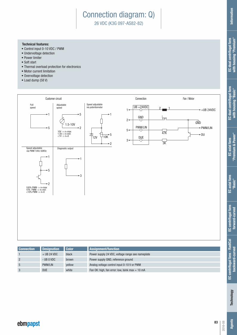
83
1.5-10V
Fan / MotorConnectionCustomer circuit
+UB 24VDC1 1
1
1
2
2
2
2
3
5
5
55
5
1
3
UB +24VDC
DUE
PWM/LIN
GND
12
DU
GND
PWM/LIN
47K
3K
10K12V
10V -> n=max
<1V -> n=0
100% PWM -> n=max15% PWM -> n=min<10% PWM -> n=0
via PWM 10Hz-50KHz
1.5V-> n=min
Speed adjustablevia potentiometer
Adjustablespeed
Fullspeed
Speed adjustable Diagnostic output
Connection diagram: Q)26 VDC (K3G 097-AS82-82)
Technical features: • Control input 0-10 VDC / PWM • Undervoltage detection • Power limiter • Soft start • Thermal overload protection for electronics • Motor current limitation • Overvoltage detection • Load dump (58 V)
Connection Designation Assignment/functionPower supply 24 VDC, voltage range see nameplate
Power supply GND, reference ground
Analog voltage control input 0-10 V or PWM
Fan OK: high, fan error: low, Isink max = 10 mA
Colorblack
brown
yellow
white
2016-08
+ UB 24 VDC
- UB 0 VDC
PWM/LIN
1
2
5
DUE3
Inf
orm
atio
nEC
cen
trifu
gal f
ans
- Ra
diCa
lba
ckw
ard-
curv
edTe
chno
logy
Age
nts
EC a
xial
fans
"Pre
miu
m &
Pow
er"
EC d
ual c
entr
ifuga
l fan
sw
ith h
ousi
ng "
Basi
c"EC
dua
l cen
trifu
gal f
ans
with
hou
sing
"Pr
emiu
m"
EC c
entr
ifuga
l fan
s fo
rwar
d-cu
rved
EC a
xial
fans
"Bas
ic"
Automotive_2016_16_08_2016_AE_Final_.indd 83 16.08.2016 08:49:00
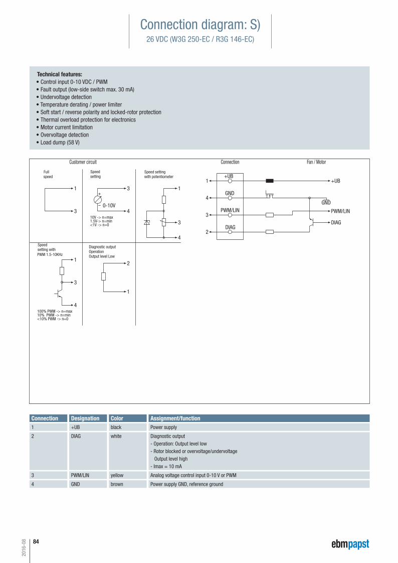
84
2016-08
0-10V
+UB1 1
1
1
4
4
4
4
1
3
3
33
3
2
2
+UB
DIAG
PWM/LIN
GND
DIAG
GND
PWM/LIN10V -> n=max
<1V -> n=0
100% PWM -> n=max10% PWM -> n=min<10% PWM -> n=0
PWM 1.5-10KHz
1.5V-> n=min
Customer circuit Connection Fan / Motor
Speed settingwith potentiometer
Speedsetting
Fullspeed
Speed setting with
Diagnostic outputOperationOutput level Low
Technical features: • Control input 0-10 VDC / PWM • Fault output (low-side switch max. 30 mA) • Undervoltage detection • Temperature derating / power limiter • Soft start / reverse polarity and locked-rotor protection • Thermal overload protection for electronics • Motor current limitation • Overvoltage detection • Load dump (58 V)
Connection Designation+UB
DIAG
PWM/LIN
Assignment/functionPower supply
Diagnostic output- Operation: Output level low- Rotor blocked or overvoltage/undervoltage Output level high- Imax = 10 mA
Analog voltage control input 0-10 V or PWM
1
2
3
GND Power supply GND, reference ground 4
Colorblack
white
yellow
brown
Connection diagram: S)26 VDC (W3G 250-EC / R3G 146-EC)
Automotive_2016_16_08_2016_AE_Final_.indd 84 16.08.2016 08:49:00
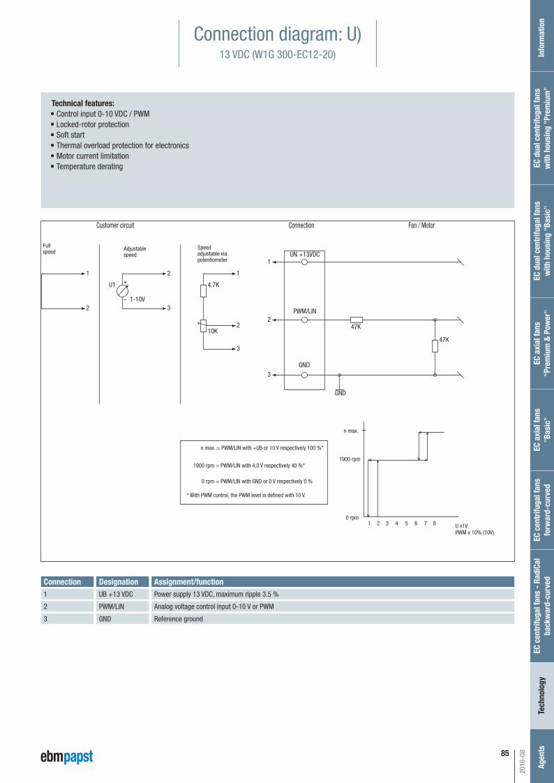
Inf
orm
atio
nEC
cen
trifu
gal f
ans
- Ra
diCa
lba
ckw
ard-
curv
edTe
chno
logy
Age
nts
EC a
xial
fans
"Pre
miu
m &
Pow
er"
EC d
ual c
entr
ifuga
l fan
sw
ith h
ousi
ng "
Basi
c"EC
dua
l cen
trifu
gal f
ans
with
hou
sing
"Pr
emiu
m"
EC c
entr
ifuga
l fan
s fo
rwar
d-cu
rved
EC a
xial
fans
"Bas
ic"
85
2016-08
Connection diagram: U)13 VDC (W1G 300-EC12-20)
11
1
2
2
2
2
3
3
3
UN +13VDC
PWM/LIN
GND
GND
47K
47K10K
4.7KU1
1-10V
n max. = PWM/LIN with +UB or 10 V respectively 100 %*
1900 rpm = PWM/LIN with 4,0 V respectively 40 %*
0 rpm = PWM/LIN with GND or 0 V respectively 0 %
* With PWM control, the PWM level is defined with 10 V.
10 rpm
n max.
U x1VPWM x 10% (10V)
3 42 5 6 7 8
1900 rpm
Customer circuit Connection Fan / Motor
Fullspeed Adjustable
speedSpeedadjustable viapotentiometer
Technical features: • Control input 0-10 VDC / PWM • Locked-rotor protection • Soft start • Thermal overload protection for electronics • Motor current limitation • Temperature derating
Connection DesignationUB +13 VDC
PWM/LIN
GND
Assignment/functionPower supply 13 VDC, maximum ripple 3.5 %
Analog voltage control input 0-10 V or PWM
Reference ground
1
2
3
Automotive_2016_16_08_2016_AE_Final_.indd 85 16.08.2016 08:49:00
86
Technical parameters and scope
High standards for all ebm-papst productsAt ebm-papst we are always looking to improve our products to be able to offer customers just what they need for their particular requirements.Careful monitoring of the market enables us to constantly incorporate enhancements into our products.As shown by the technical parameters listed below, you can always be sure of fi nding the right solution from ebm-papst for whatever applicationyou may have in mind.
General performance parameters
Any deviations from the technical data and technical parameters described
here are given in the product-specifi c data sheet.
Degree of protection
The degree of protection is specifi ed in the product-specifi c data sheets.
Insulation class
The insulation class is specifi ed in the product-specifi c data sheets.
Installation position
The installation position is specifi ed in the product-specifi c data sheets.
Condensation drainage holes
Information on condensation drainage holes is provided in the product-
specifi c data sheets.
Mode of operation
The mode of operation is specifi ed in the product-specifi c data sheets.
Protection class
The protection class is specifi ed in the product-specifi c data sheets.
Service life
The service life of ebm-papst automotive products depends on:
– The service life of the bearing system
The service life of the bearing system is primarily governed by the thermal
load on the bearings.
For the majority of our products we use maintenance-free ball bearings
which can be installed in any installation position.
As a rough guide (depending on the general conditions), the ball bearings
have a life expectancy L10 of approx. 40,000 hours of operation at an
ambient temperature of 40 °C.
We will gladly provide you with a life expectancy calculation based on your
specifi c usage conditions.
Motor protection/thermal protection
Information on motor protection and thermal protection is provided in the
product-specifi c data sheets.
The following protection methods are provided depending on the typee of
motor and area of application:
– Thermal overload protector, in-circuit
– PTC/NTC with electronic diagnostics
– Current limitation via electronics
2016-08
Automotive_2016_16_08_2016_AE_Final_.indd 86 16.08.2016 08:49:00
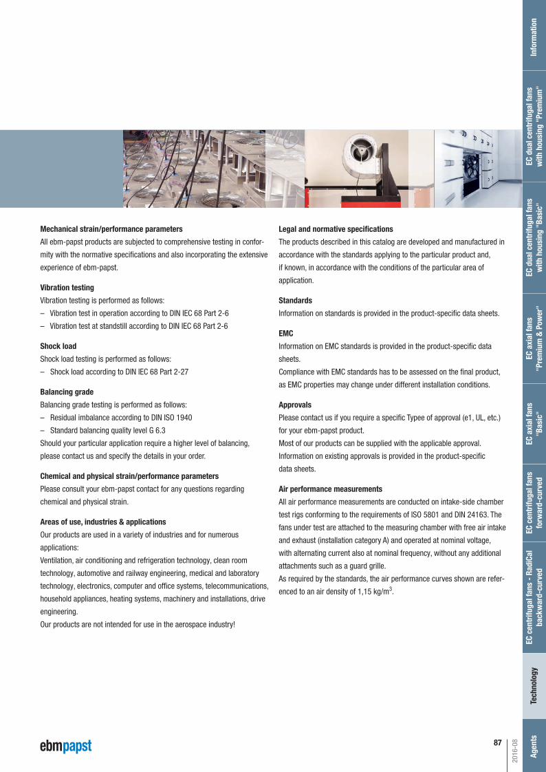
87
Mechanical strain/performance parameters
All ebm-papst products are subjected to comprehensive testing in confor-
mity with the normative specifi cations and also incorporating the extensive
experience of ebm-papst.
Vibration testing
Vibration testing is performed as follows:
– Vibration test in operation according to DIN IEC 68 Part 2-6
– Vibration test at standstill according to DIN IEC 68 Part 2-6
Shock load
Shock load testing is performed as follows:
– Shock load according to DIN IEC 68 Part 2-27
Balancing grade
Balancing grade testing is performed as follows:
– Residual imbalance according to DIN ISO 1940
– Standard balancing quality level G 6.3
Should your particular application require a higher level of balancing,
please contact us and specify the details in your order.
Chemical and physical strain/performance parameters
Please consult your ebm-papst contact for any questions regarding
chemical and physical strain.
Areas of use, industries & applications
Our products are used in a variety of industries and for numerous
applications:
Ventilation, air conditioning and refrigeration technology, clean room
technology, automotive and railway engineering, medical and laboratory
technology, electronics, computer and offi ce systems, telecommunications,
household appliances, heating systems, machinery and installations, drive
engineering.
Our products are not intended for use in the aerospace industry!
Legal and normative specifi cations
The products described in this catalog are developed and manufactured in
accordance with the standards applying to the particular product and,
if known, in accordance with the conditions of the particular area of
application.
Standards
Information on standards is provided in the product-specifi c data sheets.
EMC
Information on EMC standards is provided in the product-specifi c data
sheets.
Compliance with EMC standards has to be assessed on the fi nal product,
as EMC properties may change under different installation conditions.
Approvals
Please contact us if you require a specifi c Typee of approval (e1, UL, etc.)
for your ebm-papst product.
Most of our products can be supplied with the applicable approval.
Information on existing approvals is provided in the product-specifi c
data sheets.
Air performance measurements
All air performance measurements are conducted on intake-side chamber
test rigs conforming to the requirements of ISO 5801 and DIN 24163. The
fans under test are attached to the measuring chamber with free air intake
and exhaust (installation category A) and operated at nominal voltage,
with alternating current also at nominal frequency, without any additional
attachments such as a guard grille.
As required by the standards, the air performance curves shown are refer-
enced to an air density of 1,15 kg/m3.
2016-08
Inf
orm
atio
nEC
cen
trifu
gal f
ans
- Ra
diCa
lba
ckw
ard-
curv
edTe
chno
logy
Age
nts
EC a
xial
fans
"Pre
miu
m &
Pow
er"
EC d
ual c
entr
ifuga
l fan
sw
ith h
ousi
ng "
Basi
c"EC
dua
l cen
trifu
gal f
ans
with
hou
sing
"Pr
emiu
m"
EC c
entr
ifuga
l fan
sfo
rwar
d-cu
rved
EC a
xial
fans
"Bas
ic"
Automotive_2016_16_08_2016_AE_Final_.indd 87 16.08.2016 08:49:03
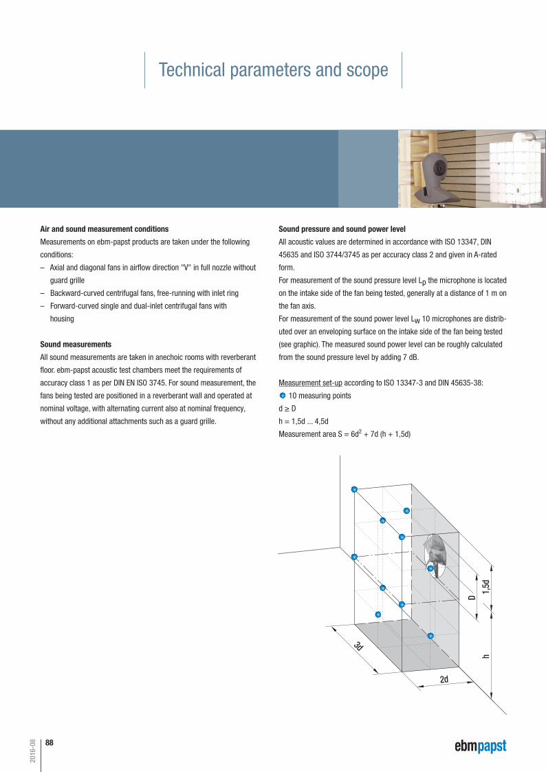
88
Sound pressure and sound power level
All acoustic values are determined in accordance with ISO 13347, DIN
45635 and ISO 3744/3745 as per accuracy class 2 and given in A-rated
form.
For measurement of the sound pressure level Lp the microphone is located
on the intake side of the fan being tested, generally at a distance of 1 m on
the fan axis.
For measurement of the sound power level Lw 10 microphones are distrib-
uted over an enveloping surface on the intake side of the fan being tested
(see graphic). The measured sound power level can be roughly calculated
from the sound pressure level by adding 7 dB.
Measurement set-up according to ISO 13347-3 and DIN 45635-38:
10 measuring points
d ≥ D
h = 1,5d ... 4,5d
Measurement area S = 6d2 + 7d (h + 1,5d)
3d
2d
h
D
1,5d
Technical parameters and scope
Air and sound measurement conditions
Measurements on ebm-papst products are taken under the following
conditions:
– Axial and diagonal fans in airfl ow direction "V" in full nozzle without
guard grille
– Backward-curved centrifugal fans, free-running with inlet ring
– Forward-curved single and dual-inlet centrifugal fans with
housing
Sound measurements
All sound measurements are taken in anechoic rooms with reverberant
fl oor. ebm-papst acoustic test chambers meet the requirements of
accuracy class 1 as per DIN EN ISO 3745. For sound measurement, the
fans being tested are positioned in a reverberant wall and operated at
nominal voltage, with alternating current also at nominal frequency,
without any additional attachments such as a guard grille.
2016-08
Automotive_2016_16_08_2016_AE_Final_.indd 88 16.08.2016 08:49:04
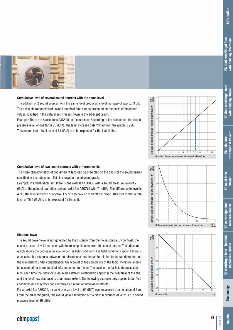
89
Cumulative level of several sound sources with the same level
The addition of 2 sound sources with the same level produces a level increase of approx. 3 dB.
The noise characteristics of several identical fans can be predicted on the basis of the sound
values specifi ed in the data sheet. This is shown in the adjacent graph.
Example: There are 8 axial fans A3G800 on a condenser. According to the data sheet, the sound
pressure level of one fan is 75 dB(A). The level increase determined from the graph is 9 dB.
This means that a total level of 84 dB(A) is to be expected for the installation.
Cumulative level of two sound sources with different levels
The noise characteristics of two different fans can be predicted on the basis of the sound values
specifi ed in the data sheet. This is shown in the adjacent graph.
Example: In a ventilation unit, there is one axial fan A3G800 with a sound pressure level of 75
dB(A) at the point of operation and one axial fan A3G710 with 71 dB(A). The difference in level is
4 dB. The level increase of approx. 1.5 dB can now be read off the graph. This means that a total
level of 76.5 dB(A) is to be expected for the unit.
Distance laws
The sound power level is not governed by the distance from the noise source. By contrast, the
sound pressure level decreases with increasing distance from the sound source. The adjacent
graph shows the decrease in level under far fi eld conditions. Far fi eld conditions apply if there is
a considerable distance between the microphone and the fan in relation to the fan diameter and
the wavelength under consideration. On account of the complexity of the topic, literature should
be consulted for more detailed information on far fi elds. The level in the far fi eld decreases by
6 dB each time the distance is doubled. Different relationships apply in the near fi eld of the fan
and the level may decrease to a far lesser extent. The following example only applies to far fi eld
conditions and may vary considerably as a result of installation effects:
For an axial fan A3G300, a sound pressure level of 65 dB(A) was measured at a distance of 1 m.
From the adjacent graph, this would yield a reduction of 26 dB at a distance of 20 m, i.e. a sound
pressure level of 39 dB(A).
15
10 15 20 255 82 3
105
90
1
Number of sources of sound with identical level
Incr
ease
in s
ound
pre
ssur
e / s
ound
pow
er le
vel
4 6 7 9[d
B][d
B(A)
]
3
12 16 20 2484
21
1,5
0
0
Difference in level with two sources of sound
Incr
ease
in s
ound
pre
ssur
e / s
ound
pow
er le
vel
[dB]
[dB(
A)]
[dB][dB(A)]
0
10 20 50 10052
-10
-26
-20
-30
-40
1
[m] Distance
Decr
ease
in s
ound
pre
ssur
e le
vel
[dB]
[dB(
A)]
2016-08
Inf
orm
atio
nEC
cen
trifu
gal f
ans
- Ra
diCa
lba
ckw
ard-
curv
edTe
chno
logy
Age
nts
EC a
xial
fans
"Pre
miu
m &
Pow
er"
EC d
ual c
entr
ifuga
l fan
sw
ith h
ousi
ng "
Basi
c"EC
dua
l cen
trifu
gal f
ans
with
hou
sing
"Pr
emiu
m"
EC c
entr
ifuga
l fan
sfo
rwar
d-cu
rved
EC a
xial
fans
"Bas
ic"
Automotive_2016_16_08_2016_AE_Final_.indd 89 16.08.2016 08:49:06
90 fan agent compact fan agent motor specialist motor agent
ebm-papst in Germany
ebm-papst Mulfi ngen GmbH & Co. KGBachmühle 274673 Mulfi ngenGERMANYPhone +49 7938 81-0Fax +49 7938 [email protected]
ebm-papst St. Georgen GmbH & Co. KGHermann-Papst-Straße 178112 St. GeorgenGERMANYPhone +49 7724 81-0Fax +49 7724 [email protected]
ebm-papst Landshut GmbHHofmark-Aich-Straße 2584030 LandshutGERMANYPhone +49 871 707-0Fax +49 871 [email protected]
2016-08
BerlinDipl.-Ing. (TH) Jens DuchowHändelstraße 716341 PanketalGERMANYPhone +49 30 944149-62Fax +49 30 [email protected]
BielefeldDipl.-Ing. (FH) Wolf-Jürgen WeberNiehausweg 1333739 BielefeldGERMANYPhone +49 5206 91732-31Fax +49 5206 [email protected]
DortmundDipl.-Ing. (FH) Hans-Joachim PundtAuf den Steinern 359519 Möhnesee-VöllinghausenGERMANYPhone +49 2925 800-407Fax +49 2925 [email protected]
FrankfurtDipl.-Ing. Christian KleffmannDr.-Hermann-Krause-Straße 2363452 HanauGERMANYPhone +49 6181 1898-12Fax +49 6181 [email protected]
HalleDipl.-Ing. (TU) Michael HanningLercheneck 406198 Salzatal / OT LieskauGERMANYPhone +49 345 55124-56Fax +49 345 [email protected]
HamburgIngenieurbüro Breuell GmbHIng. Dirk KahlElektroingenieurOststraße 9622844 NorderstedtGERMANYPhone +49 40 538092-19Fax +49 40 [email protected]
Heilbronn / HeidelbergDipl.-Ing. Mark GartnerGehrweg 1274199 UnterheinrietGERMANYPhone +49 7130 404569-1Fax +49 7130 [email protected]
KasselDipl.-Ing. (FH) Ralph BrückHoherainstraße 3 b35075 GladenbachGERMANYPhone +49 6462 4071-10Fax +49 6462 [email protected]
KoblenzWinfried SchaeferHinter der Kirch 1056767 UersfeldGERMANYPhone +49 2657 16-96Fax +49 2657 [email protected]
MunichDipl.-Wirt.-Ing. (FH) Jens PeterLandsbergerstraße 1486932 PürgenGERMANYPhone +49 8196 99877-54Fax +49 8196 [email protected]
NurembergDipl.-Wirt.-Ing. (FH) Axel ReschDr.-August-Koch-Str. 191639 Wolframs-EschenbachGERMANYPhone +49 9875 9783-170Fax +49 9875 [email protected]
OffenburgDipl.-Ing. (FH) Ralf BraunHubeneck 2177704 OberkirchGERMANYPhone +49 7802 9822-52Fax +49 7802 [email protected]
StuttgartDipl.-Ing. (FH) Rudi WeinmannHindenburgstraße 100/173207 PlochingenGERMANYPhone +49 7153 9289-80Fax +49 7153 [email protected]
UlmM.Sc. Reinhard SommerreißerAm Germanenring 1386674 Baar / SchwabenGERMANYPhone +49 8276 5899-775Fax +49 8276 [email protected]
Distributors
FrankfurtR.E.D. Handelsgesellschaft mbHGutenbergstraße 363110 Rodgau - JügesheimGERMANYPhone +49 6106 841-0Fax +49 6106 [email protected]
HamburgBreuell + Hilgenfeldt GmbHOststraße 9622844 NorderstedtGERMANYPhone +49 40 538092-20Fax +49 40 [email protected]
MunichA. Schweiger GmbHOhmstraße 182054 SauerlachGERMANYPhone +49 8104 897-0Fax +49 8104 [email protected]
(1 to 5 pieces)
NorthBreuell + Hilgenfeldt GmbHOststraße 9622844 NorderstedtGERMANYPhone +49 40 538092-20Fax +49 40 [email protected]
SouthHDS Ventilatoren Vertriebs GmbHGlaswiesenstraße 174677 DörzbachGERMANYPhone +49 7937 80355-20Fax +49 7937 [email protected]
Automotive_2016_16_08_2016_AE_Final_.indd 90 16.08.2016 08:49:06
91fan agent compact fan agent motor specialist motor agent
ebm-papst in Europe
2016-08
Europe
Austriaebm-papst Motoren & Ventilatoren GmbHStraubingstraße 174030 LinzAUSTRIAPhone +43 732 321150-0Fax +43 732 [email protected]
Belarusebm-papst Bel AgmbHLipkovskaya Gasse 34Offi ce No.6, Room 106,107223010 MinskBELARUSPhone +375 17 3851556Fax +375 17 [email protected]
Belgiumebm-papst Benelux B.V.Sales offi ce Belgium-LuxemburgRomeinsestraat 6/0101Research Park Haasrode3001 Heverlee-LeuvenBELGIUMPhone +32 16 396-200Fax +32 16 [email protected]
Bulgariaebm-papst Romania S.R.L.Str. Tarnavei No. 20500327 BrasovROMANIAPhone +40 268 331859Fax +40 268 [email protected]
Croatiaebm-papst Industries Kft.Ezred u. 2.1044 BudapestHUNGARYPhone +36 1 8722-190Fax +36 1 8722-194offi [email protected]
CyprusHelcomaE. Rota and Co. OEDavaki 6517672 Kallithea-AttikiGREECEPhone +30 210 9513-705Fax +30 210 [email protected]
Czech Republic / Slovakiaebm-papst CZ s.r.o.Kaštanová 34a620 00 BrnoCZECH REPUBLICPhone +420 544 502-411Fax +420 547 [email protected]
Denmarkebm-papst Denmark ApSVallensbækvej 212605 BrøndbyDENMARKPhone +45 43 631111Fax +45 43 [email protected]
Estoniaebm-papst Oy, Eesti FiliaalKesk tee 21Aaviku küla, Jüri Tehnopark75301 Rae Vald, HarjumaaESTONIAPhone +372 65569-78www.ebmpapst.ee
Finlandebm-papst OyPuistotie 102760 EspooFINLANDPhone +358 9 887022-0Fax +358 9 [email protected] www.ebmpapst.fi
Franceebm-papst sarlParc d’Activités Nord1 rue Mohler – BP 6267212 Obernai CedexFRANCEPhone +33 3 88 66 88 [email protected]
GreeceHelcomaE. Rota and Co. OEDavaki 6517672 Kallithea-AttikiGREECEPhone +30 210 9513-705Fax +30 210 [email protected]
Hungaryebm-papst Industries Kft.Ezred u. 2.1044 BudapestHUNGARYPhone +36 1 8722-190Fax +36 1 8722-194offi [email protected]
IcelandRJ EngineersStangarhyl 1a110 ReykjavikICELANDPhone +354 567 8030Fax +354 567 [email protected]
Irelandebm-papst UK Ltd.Chelmsford Business ParkChelmsford Essex CM2 5EZUNITED KINGDOMPhone +44 1245 468555Fax +44 1245 [email protected]
AuBren LimitedPortlaoise Business & Technology ParkMountrath RoadPortlaoise, Co. LaoisIRELANDPhone +353 57 8664343Fax +353 57 [email protected]
Italyebm-papst SrlVia Cornaggia 10822076 Mozzate (Co)ITALYPhone +39 0331 836201Fax +39 0331 [email protected]
Inf
orm
atio
nEC
cen
trifu
gal f
ans
- Ra
diCa
lba
ckw
ard-
curv
edTe
chno
logy
Age
nts
EC a
xial
fans
"Pre
miu
m &
Pow
er"
EC d
ual c
entr
ifuga
l fan
sw
ith h
ousi
ng "
Basi
c"EC
dua
l cen
trifu
gal f
ans
with
hou
sing
"Pr
emiu
m"
EC c
entr
ifuga
l fan
sfo
rwar
d-cu
rved
EC a
xial
fans
"Bas
ic"
Automotive_2016_16_08_2016_AE_Final_.indd 91 16.08.2016 08:49:07
92 fan agent compact fan agent motor specialist motor agent
ebm-papst in Europe
2016-08
Macedoniaebm-papst Industries Kft.Ezred u. 2.1044 BudapestHUNGARYPhone +36 1 8722-190Fax +36 1 8722-194offi [email protected]
Netherlandsebm-papst Benelux B.V.Polbeemd 7 - 5741 TP Beek en DonkP.O. Box 140 - 5740 AC Beek en DonkNETHERLANDSPhone +31 492 502-900Fax +31 492 [email protected]
ebm-papst Heating Systems B.V.Van Veldekekade 360 5216 KT ‘s-Hertogenbosch NETHERLANDSPhone +31 73 648 89 00Fax +31 73 648 89 [email protected]
Norwayebm-papst ASP.B. 173 Holmlia1203 OsloNORWAYPhone +47 22 763340Fax +47 22 [email protected]
Polandebm-papst Polska Sp. z o.o.ul. Annopol 4A03236 WarszawaPOLANDPhone +48 22 6757819Fax +48 22 6769587offi [email protected]
Portugalebm-papst (Portugal), Lda.Centro Empresarial de AlvercaRua de Adarse, Vale D’ErvasCorpo D / Fracção 32615-178 Alverca do RibatejoPORTUGALPhone +351 218 394 880Fax +351 218 394 [email protected]
Romaniaebm-papst Romania S.R.L.Str. Tarnavei Nr. 20500327 BrasovROMANIAPhone +40 268 331859Fax +40 268 [email protected]
Russiaebm-papst Rus GmbHOlimpiyskiy prospect 29A, offi ce 418141006 Mytistschi, Oblast MoskauRUSSIAPhone +7 495 9807524Fax +7 495 [email protected]
ebm-papst Ural GmbHPosadskaja-Strasse, 23(E), 3620102 EkaterinburgRUSSIAPhone +7 343 2338000Fax +7 343 [email protected]
Serbia & Montenegroebm-papst Industries Kft.Ezred u. 2.1044 BudapestHUNGARYPhone +36 1 8722-190Fax +36 1 8722-194offi [email protected]
Spainebm-papst Ibérica S.L.Avda. del Sistema Solar, 2928830 San Fernando de Henares (Madrid)SPAINPhone +34 91 6780894Fax +34 91 [email protected]
Swedenebm-papst ABÄggelundavägen 217562 JärfällaSWEDENPhone +46 10 4544400Fax +46 8 [email protected]
Switzerlandebm-papst AGRütisbergstrasse 18156 OberhasliSWITZERLANDPhone +41 44 73220-70Fax +41 44 [email protected]
TurkeyAkantel Elektronik San. Tic. LTD. Sti.Atatürk Organize SanayiBölgesi 10007 SK. No.:635620 Cigli-IzmirTURKEYPhone +90 232 3282090Fax +90 232 [email protected]
Ukraineebm-papst Ukraine LLCLepse Boulevard, 4, Building 2103067 KievUKRAINEPhone +38 044 2063091Fax +38 044 2063091 [email protected]
United Kingdomebm-papst UK Ltd.Chelmsford Business ParkChelmsford Essex CM2 5EZUNITED KINGDOMPhone +44 1245 468555Fax +44 1245 [email protected]
ebm-papst Automotive & Drives (UK) Ltd.The SmithyFidlers LaneEast Ilsley, Berkshire RG20 7LGUNITED KINGDOMPhone +44 1635 2811-11Fax +44 1635 2811-61A&[email protected]
Automotive_2016_16_08_2016_AE_Final_.indd 92 16.08.2016 08:49:08
93fan agent compact fan agent motor specialist motor agent
ebm-papst in America and Africa
2016-08
America
Argentinaebm-papst de Argentina S.A.Hernandarias 148 Lomas del MiradorPcia. de Buenos Aires (1752)ARGENTINAPhone +54 11 46576135Fax +54 11 [email protected]
Brazilebm-papst Motores Ventiladores Ltda.Av. José Giorgi, 301 Galpões B6+B7Condominio Logical Center06707-100 Cotia - São PauloBRAZILPhone +55 11 4613-8700Fax +55 11 [email protected]
Canadaebm-papst Canada Inc.1800 Ironstone Manor, Unit 2Pickering, Ontario, L1W3J9CANADAPhone +1 905 420-3533Fax +1 905 [email protected]
Mexicoebm Industrial S. de R.L. de C.V.Paseo de Tamarindos 400-A-5to PisoCol. Bosques de las LomasMexico 05120, D.F.MEXICOPhone +52 55 3300-5144Fax +52 55 [email protected]
USAebm-papst Inc.P.O. Box 4009100 Hyde RoadFarmington, CT 06034UNITED STATESPhone +1 860 674-1515Fax +1 860 [email protected]
ebm-papst Automotive & Drives, Inc.3200 Greenfi eld, Suite 130Dearborn, MI 48120UNITED STATESPhone +1 313 406-8080Fax +1 313 [email protected]
Africa
South Africaebm-papst South Africa (Pty) Ltd.P.O. Box 31241119 Yacht Avenue2040 HoneydewSOUTH AFRICAPhone +27 11 794-3434Fax +27 11 [email protected]
Inf
orm
atio
nEC
cen
trifu
gal f
ans
- Ra
diCa
lba
ckw
ard-
curv
edTe
chno
logy
Age
nts
EC a
xial
fans
"Pre
miu
m &
Pow
er"
EC d
ual c
entr
ifuga
l fan
sw
ith h
ousi
ng "
Basi
c"EC
dua
l cen
trifu
gal f
ans
with
hou
sing
"Pr
emiu
m"
EC c
entr
ifuga
l fan
sfo
rwar
d-cu
rved
EC a
xial
fans
"Bas
ic"
Automotive_2016_16_08_2016_AE_Final_.indd 93 16.08.2016 08:49:09
fan agent compact fan agent motor specialist motor agent
ebm-papst in Asia
2016-08
Asia
Chinaebm-papst Ventilator (Shanghai) Co., Ltd.No. 418, Huajing RoadWaiGaoQiao Free Trade ZoneNo. 2001, Yang Gao (N) Road200131 ShanghaiP.R. of CHINAPhone +86 21 5046-0183Fax +86 21 [email protected]
Hong Kongebm-papst Hong Kong Ltd.Room 17E, MG Tower133 Hoi Bun Road, Kwun TongHong KongP.R. of CHINAPhone +852 2145-8678Fax +852 [email protected]
Indiaebm-papst India Pvt. Ltd.26/3, G.N.T. Road, ErukkencherryChennai-600118INDIAPhone +91 44 25372556Fax +91 44 [email protected]
Indonesiaebm-papst IndonesiaRepresentative Offi ceGerman Centre, 4th Floor, Suite 4470Jl. Kapt. Subijono Dj. Bumi Serpong Damai15321 TangerangINDONESIAPhone +62 21 5376250Fax +62 21 [email protected]
IsraelPolak Bros. Import Agencies Ltd.9 Hamefalsim StreetKiryat Arie, Petach-Tikva 49514ISRAELPhone +972 3 9100300Fax +972 3 [email protected]
Japanebm-papst Japan K.K.Attend on Tower 13FShinyokohama 2-8-12, Kohoku-ku222-0033 Yokohama-City, KanagawaJAPANPhone +81 45 47057-51Fax +81 45 [email protected]
Koreaebm-papst Korea Co. Ltd.6F, Trutec Bldg.12, WorldCupbuk-ro 56-gilMapo-Gu Seoul 03924KOREAPhone +82 2 366213-24Fax +82 2 [email protected] www.ebmpapst.co.kr
Malaysiaebm-papst MalaysiaRepresentative Offi ceUnit 12-2, Jalan USJ Sentral 3Persiaran Subang, Selangor Darul Ehsan47600 Subang JayaMALAYSIAPhone +60 3 8024-1680Fax +60 3 [email protected]
Philippinesebm-papst SEA Pte. Ltd.Representative Offi ce (Philippines)ALPAP II BuildingTrade Street Corner Investment DriveUnit 1101 Madrigal Business Park1799 Ayala Alabang / Muntinlupa CityTelefon: +63 02 8042747Telefax: +63 02 [email protected]
Singaporeebm-papst SEA Pte. Ltd.No. 23 Ubi Road 4#06-00 Olympia Industrial BuildingSingapore 408620SINGAPOREPhone +65 65513789Fax +65 [email protected]
TaiwanETECO Engineering & Trading Corp.10F-I, No. 92, Teh-Wei Str.Tsow-Inn District, KaohsiungTAIWANPhone +886 7 557-4268Fax +886 7 [email protected]
Thailandebm-papst Thailand Co., Ltd.99/9 Moo 2, Central Chaengwattana Tower14th Floor, Room 1402Chaengwattana Road Bangtarad, Pakkret11120 NonthaburiTHAILANDPhone +66 2 8353785-7Fax +66 2 [email protected]
United Arab Emiratesebm-papst Middle East FZEPO Box 17755Jebel Ali Free Zone / FZS1 / AP05DubaiUNITED ARAB EMIRATESPhone +971 4 88608-26Fax +971 4 [email protected]
Vietnamebm-papst SEA Pte. Ltd.Representative Offi ceRoom 402, 4th Floor, Saigon 3 Building140 Nguyen Van Thu StreetDakao Ward, District 1Ho Chi Minh CityVIETNAMPhone +848 3910 4099Fax +848 3910 [email protected]
94
Automotive_2016_16_08_2016_AE_Final_.indd 94 16.08.2016 08:49:10
95fan agent compact fan agent motor specialist motor agent
ebm-papst in Oceania
2016-08
Oceania
Australiaebm-papst A&NZ Pty Ltd.10 Oxford RoadLaverton North, Victoria, 3026AUSTRALIAPhone +61 3 9360-6400Fax +61 3 [email protected]
New Zealandebm-papst A&NZ Pty Ltd.61 Hugo Johnston Drive, Unit HPenrose 1061, AucklandNEW ZEALANDPO Box 112278,Penrose 1642, AucklandPhone +64 9 525-0245Fax +64 9 [email protected]
Inf
orm
atio
nEC
cen
trifu
gal f
ans
- Ra
diCa
lba
ckw
ard-
curv
edTe
chno
logy
Age
nts
EC a
xial
fans
"Pre
miu
m &
Pow
er"
EC d
ual c
entr
ifuga
l fan
sw
ith h
ousi
ng "
Basi
c"EC
dua
l cen
trifu
gal f
ans
with
hou
sing
"Pr
emiu
m"
EC c
entr
ifuga
l fan
sfo
rwar
d-cu
rved
EC a
xial
fans
"Bas
ic"
Automotive_2016_16_08_2016_AE_Final_.indd 95 16.08.2016 08:49:11
www.ebmpapst.com
ebm-papst
Mulfingen GmbH & Co. KG
Bachmühle 2
74673 Mulfingen
Germany
Phone +49 7938 81-0
Fax +49 7938 81-110
37659-7-8811 · 2016-08 · KD-3’Printed in Germany
Automotive_2016_16_08_2016_AE_Final_.indd 96 16.08.2016 08:49:12


