Embed Size (px)
Citation preview
1
[email protected]@CalypsoControl.com
Product ManualCB-5000
Calypso Control Systems, LLC 944 O'Keefe Road Hudson,Wisconsin 54016 USA
(888)381-9646
Chapter 1: Introduction to the CB-5000 31.1 CB-5000 Overview 3
1.2 CB-5000 Wiring 3
1.2.1 CB-5000 Physical Connections 3
1.2.2 Powering the CB-5000 4
1.2.3 TB-8 Adapter 4
1.3 Programming the CB-5000 5
1.3.1 User Interface Programming 5
1.3.2 Control Logic Programming 8
1.3.3 Control Logic Interface Basics 9
1.3.4 “Configuration” Administration Pages 11
1.3.5 “Command Line” and “IR Learn” 16
1.3.6 “Event Database” Administration Pages 19
1.4 Using the Controller to Serve a Custom Web Page 23
1.4.1 Custom Files 24
1.4.2 Custom File Loading and Deleting 24
1.4.3 Custom Page Viewing 24
1.4.4 Custom Page Example 25
Chapter 2 - CB-5000 Advanced Functions 262.1 Accessing Setup Function 26
2.1.1 Entering Setup Mode 26
2.1.2 IP Reset 26
2.1.3 Home Set 26
2.1.4 LCD Set 26
2.1.5 Diag Test 27
2.1.6 Calib Touch 27
2.1.7 Misc 27
Appendices 28
Appendix A. -- Calypso Action Control Language 28
Appendix B. -- Supported Graphic Formats 36
2
Chapter 1: Introduction to the CB-50001.1 CB-5000 Overview
The CB-5000 touch controller delivers fully integrated device control with a 3” monochrome touch panel in a cost-effective 2-gang, wall-mount package. The CB-5000 features 4 on-board RS-232 serial ports, 2 on-board IR outputs and a standard RJ-45 network connection. In addition, an optional series of “Smart Block” RJ-45 adapters provide a variety of I/O expansion options, using a wired IR bus to the CB-5000, for additional serial, IR and relay connections.
This all-in-one networked controller combines the power and simplicity of our flagship ION-LT2 controller with the flexibility of touch-screen graphics. The CB-5000 touch screen supports up to 8 pages of buttons and a total of 64 buttons across all pages. The unitʼs off-line configuration utility is used to conveniently assign button graphics from Calypsoʼs design library and to link buttons to control actions.
1.2 CB-5000 Wiring
1.2.1 CB-5000 Physical Connections
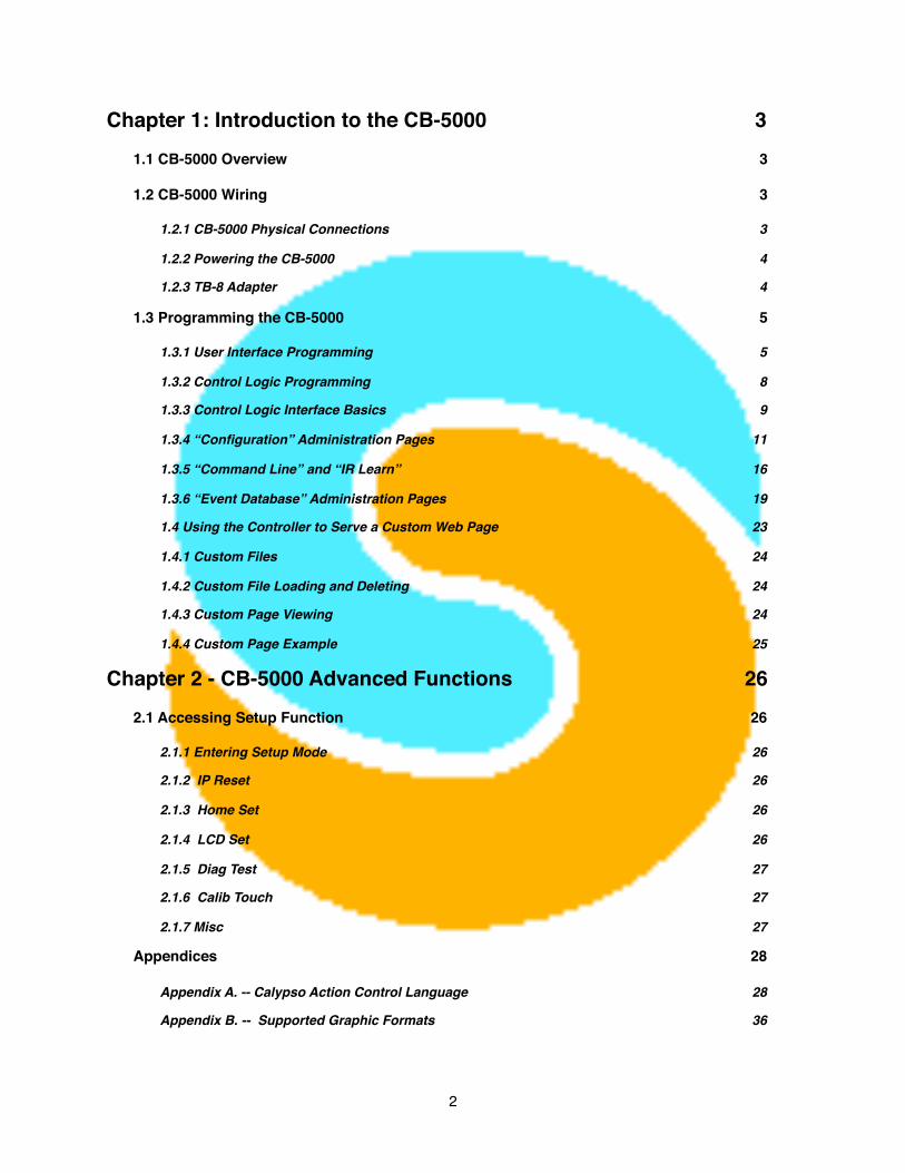
Connectivity to the CB-5000 is supplied by 3 RJ-45 ports -- AUX Ports 1 & 2 for Serial, IR and Power and a LAN Port for network connectivity. Pictured below is the back of the unit -- the pin-outs are clearly designated.
3
Note: Using an additional TB-8 connector (included) to terminate the “Aux 2” port of the CB-5000 provides 2 additional Serial ports and one additional IR port.
Ancillary TB-8 for additionalconnectivity
1.2.2 Powering the CB-5000
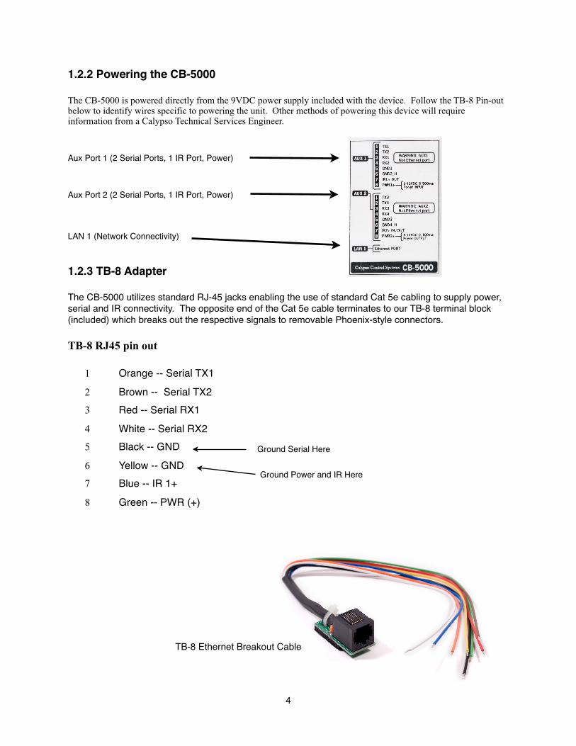
The CB-5000 is powered directly from the 9VDC power supply included with the device. Follow the TB-8 Pin-out below to identify wires specific to powering the unit. Other methods of powering this device will require information from a Calypso Technical Services Engineer.
Aux Port 1 (2 Serial Ports, 1 IR Port, Power)
Aux Port 2 (2 Serial Ports, 1 IR Port, Power)
LAN 1 (Network Connectivity)
1.2.3 TB-8 Adapter
The CB-5000 utilizes standard RJ-45 jacks enabling the use of standard Cat 5e cabling to supply power, serial and IR connectivity. The opposite end of the Cat 5e cable terminates to our TB-8 terminal block (included) which breaks out the respective signals to removable Phoenix-style connectors.
TB-8 RJ45 pin out
1 Orange -- Serial TX1
2 Brown -- Serial TX23 Red -- Serial RX1
4 White -- Serial RX25 Black -- GND
6 Yellow -- GND 7 Blue -- IR 1+
8 Green -- PWR (+)
4
Ground Power and IR Here
Ground Serial Here
TB-8 Ethernet Breakout Cable
1.3 Programming the CB-5000
There are two distinct phases of programming the CB-5000. User Interface Programming relates to button design and other touch-screen related programming. Control Logic Programming relates to the programming of the Calypso Event Database. The Event Database is where all the serial and IR command strings and triggers can be assigned and manipulated.
1.3.1 User Interface Programming
User Interface Programming will utilize the CB-5000 Utility included with your device. This utility creates a file that is saved on your computer and then uploaded to the device when complete. When using the utility you should use the following workflow:
• Create Pages -- 8 pages are available + 2 special pages• Create Buttons -- 8 buttons per page (Maximum of 64)• Assign Actions -- CIRT (Calypso IR Triggers) triggers sent to fire actions from the Calypso Event
Database (See Pg. 18 for further information on CIRT Codes)
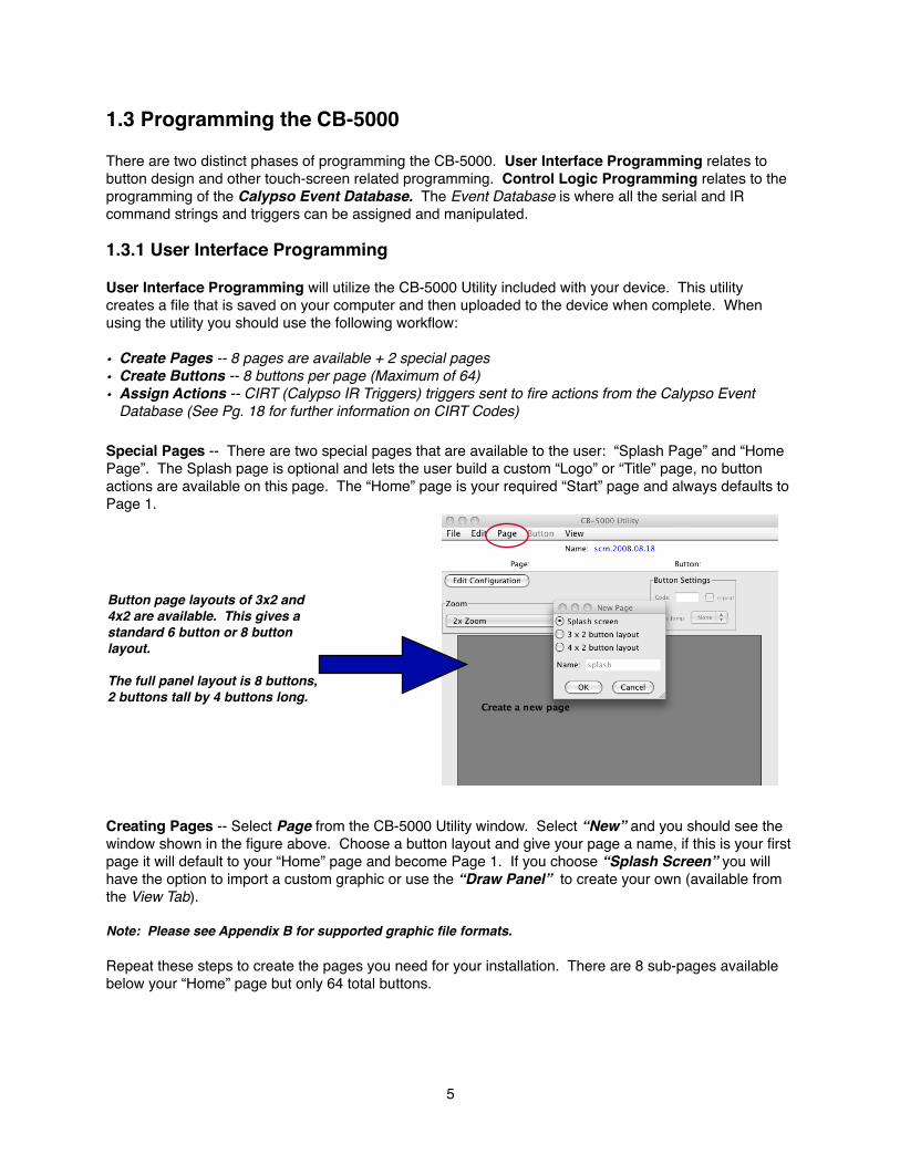
Special Pages -- There are two special pages that are available to the user: “Splash Page” and “Home Page”. The Splash page is optional and lets the user build a custom “Logo” or “Title” page, no button actions are available on this page. The “Home” page is your required “Start” page and always defaults to Page 1.
Creating Pages -- Select Page from the CB-5000 Utility window. Select “New” and you should see the window shown in the figure above. Choose a button layout and give your page a name, if this is your first page it will default to your “Home” page and become Page 1. If you choose “Splash Screen” you will have the option to import a custom graphic or use the “Draw Panel” to create your own (available from the View Tab).
Note: Please see Appendix B for supported graphic file formats.
Repeat these steps to create the pages you need for your installation. There are 8 sub-pages available below your “Home” page but only 64 total buttons.
5
Button page layouts of 3x2 and 4x2 are available. This gives a standard 6 button or 8 button layout.
The full panel layout is 8 buttons, 2 buttons tall by 4 buttons long.
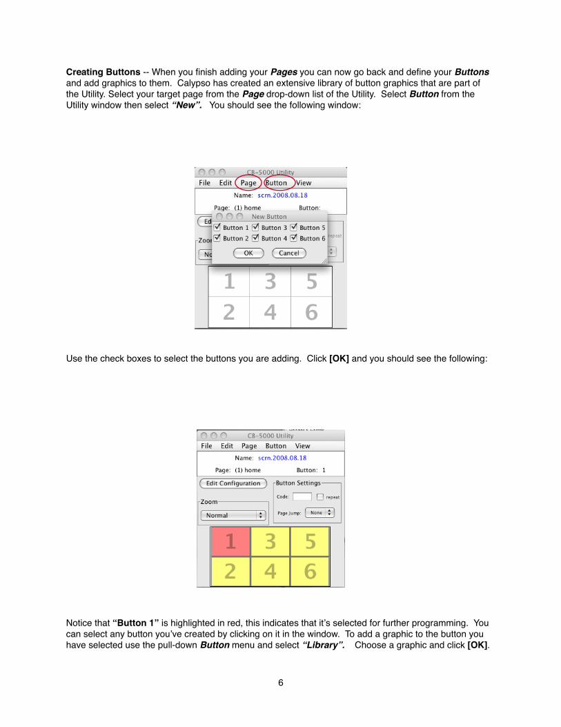
Creating Buttons -- When you finish adding your Pages you can now go back and define your Buttons and add graphics to them. Calypso has created an extensive library of button graphics that are part of the Utility. Select your target page from the Page drop-down list of the Utility. Select Button from the Utility window then select “New”. You should see the following window:
Use the check boxes to select the buttons you are adding. Click [OK] and you should see the following:
Notice that “Button 1” is highlighted in red, this indicates that itʼs selected for further programming. You can select any button youʼve created by clicking on it in the window. To add a graphic to the button you have selected use the pull-down Button menu and select “Library”. Choose a graphic and click [OK].
6
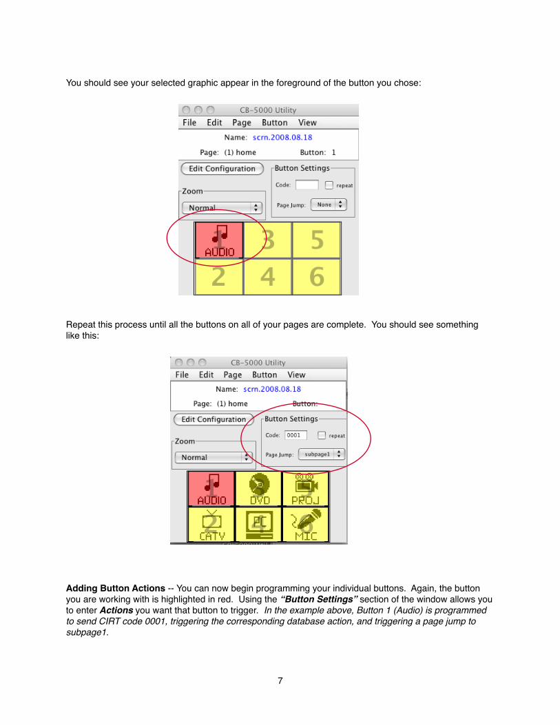
You should see your selected graphic appear in the foreground of the button you chose:
Repeat this process until all the buttons on all of your pages are complete. You should see something like this:
Adding Button Actions -- You can now begin programming your individual buttons. Again, the button you are working with is highlighted in red. Using the “Button Settings” section of the window allows you to enter Actions you want that button to trigger. In the example above, Button 1 (Audio) is programmed to send CIRT code 0001, triggering the corresponding database action, and triggering a page jump to subpage1.
7
1.3.2 Control Logic Programming
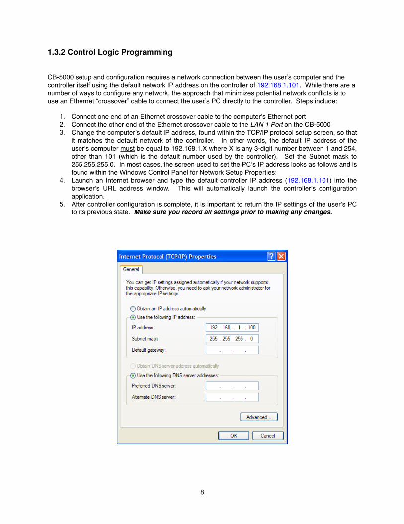
CB-5000 setup and configuration requires a network connection between the userʼs computer and the controller itself using the default network IP address on the controller of 192.168.1.101. While there are a number of ways to configure any network, the approach that minimizes potential network conflicts is to use an Ethernet “crossover” cable to connect the userʼs PC directly to the controller. Steps include:
1. Connect one end of an Ethernet crossover cable to the computerʼs Ethernet port2. Connect the other end of the Ethernet crossover cable to the LAN 1 Port on the CB-50003. Change the computerʼs default IP address, found within the TCP/IP protocol setup screen, so that
it matches the default network of the controller. In other words, the default IP address of the userʼs computer must be equal to 192.168.1.X where X is any 3-digit number between 1 and 254, other than 101 (which is the default number used by the controller). Set the Subnet mask to 255.255.255.0. In most cases, the screen used to set the PCʼs IP address looks as follows and is found within the Windows Control Panel for Network Setup Properties:
4. Launch an Internet browser and type the default controller IP address (192.168.1.101) into the browserʼs URL address window. This will automatically launch the controllerʼs configuration application.
5. After controller configuration is complete, it is important to return the IP settings of the userʼs PC to its previous state. Make sure you record all settings prior to making any changes.
8
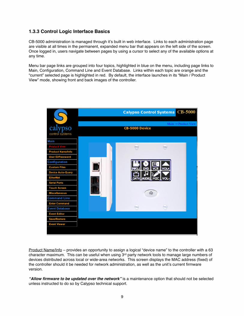
1.3.3 Control Logic Interface Basics
CB-5000 administration is managed through itʼs built in web interface. Links to each administration page are visible at all times in the permanent, expanded menu bar that appears on the left side of the screen. Once logged in, users navigate between pages by using a cursor to select any of the available options at any time.
Menu bar page links are grouped into four topics, highlighted in blue on the menu, including page links to Main, Configuration, Command Line and Event Database. Links within each topic are orange and the “current” selected page is highlighted in red. By default, the interface launches in its “Main / Product View” mode, showing front and back images of the controller.
Product Name/Info – provides an opportunity to assign a logical “device name” to the controller with a 63 character maximum. This can be useful when using 3rd party network tools to manage large numbers of devices distributed across local or wide-area networks. This screen displays the MAC address (fixed) of the controller should it be needed for network administration, as well as the unitʼs current firmware version.
“Allow firmware to be updated over the network” is a maintenance option that should not be selected unless instructed to do so by Calypso technical support.
9
“Enable diagnostic mode” is also a maintenance option used at Calypso before shipping each controller. Enabling diagnostics shuts down the event database. This can be helpful when making changes to an existing complex event database. An event that is executing while simultaneously being saved with changes can cause the controller to lock up. Please contact Calypso Control before placing the controller in this mode.
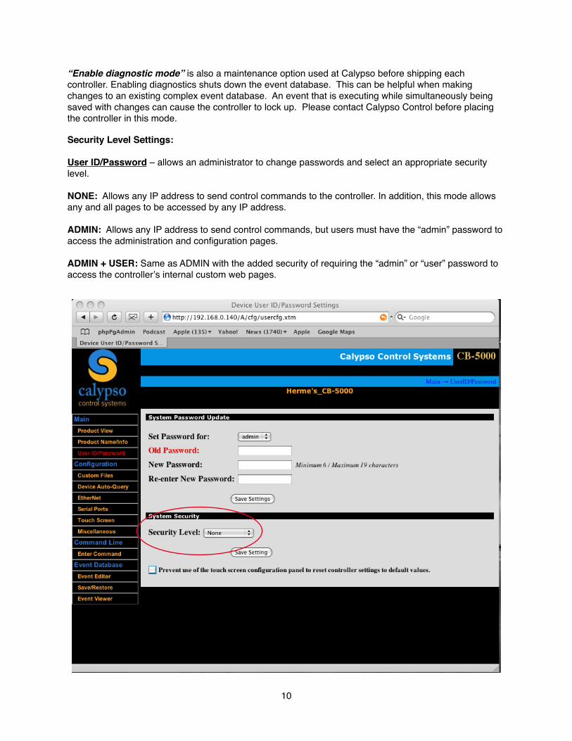
Security Level Settings:
User ID/Password – allows an administrator to change passwords and select an appropriate security level.
NONE: Allows any IP address to send control commands to the controller. In addition, this mode allows any and all pages to be accessed by any IP address.
ADMIN: Allows any IP address to send control commands, but users must have the “admin” password to access the administration and configuration pages.
ADMIN + USER: Same as ADMIN with the added security of requiring the “admin” or “user” password to access the controllerʼs internal custom web pages.
10
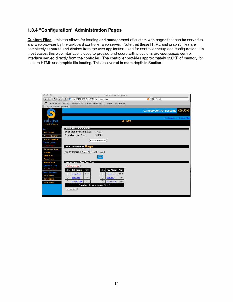
1.3.4 “Configuration” Administration Pages
Custom Files – this tab allows for loading and management of custom web pages that can be served to any web browser by the on-board controller web server. Note that these HTML and graphic files are completely separate and distinct from the web application used for controller setup and configuration. In most cases, this web interface is used to provide end-users with a custom, browser-based control interface served directly from the controller. The controller provides approximately 350KB of memory for custom HTML and graphic file loading. This is covered in more depth in Section
11
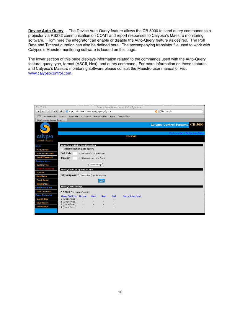
Device Auto-Query – The Device Auto-Query feature allows the CB-5000 to send query commands to a projector via RS232 communication on COM1 and report responses to Calypsoʼs Maestro monitoring software. From here the integrator can enable or disable the Auto-Query feature as desired. The Poll Rate and Timeout duration can also be defined here. The accompanying translator file used to work with Calypsoʼs Maestro monitoring software is loaded on this page.
The lower section of this page displays information related to the commands used with the Auto-Query feature: query type, format (ASCII, Hex), and query command. For more information on these features and Calypsoʼs Maestro monitoring software please consult the Maestro user manual or visit www.calypsocontrol.com.
12
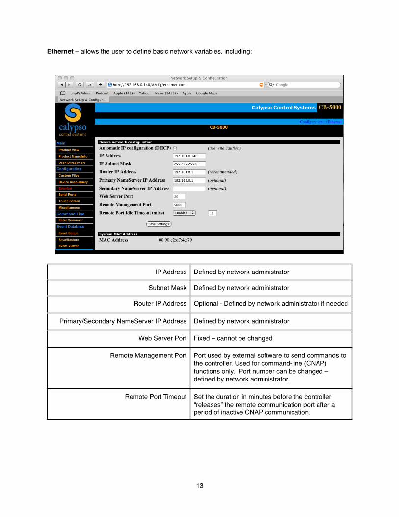
Ethernet – allows the user to define basic network variables, including:
IP Address Defined by network administrator
Subnet Mask Defined by network administrator
Router IP Address Optional - Defined by network administrator if needed
Primary/Secondary NameServer IP Address Defined by network administrator
Web Server Port Fixed – cannot be changed
Remote Management Port Port used by external software to send commands to the controller. Used for command-line (CNAP) functions only. Port number can be changed – defined by network administrator.
Remote Port Timeout Set the duration in minutes before the controller “releases” the remote communication port after a period of inactive CNAP communication.
13
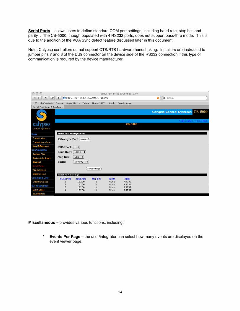
Serial Ports – allows users to define standard COM port settings, including baud rate, stop bits and parity. . The CB-5000, though populated with 4 RS232 ports, does not support pass-thru mode. This is due to the addition of the VGA Sync detect feature discussed later in this document.
Note: Calypso controllers do not support CTS/RTS hardware handshaking. Installers are instructed to jumper pins 7 and 8 of the DB9 connector on the device side of the RS232 connection if this type of communication is required by the device manufacturer.
Miscellaneous – provides various functions, including:
• Events Per Page – the user/integrator can select how many events are displayed on the event viewer page.
14
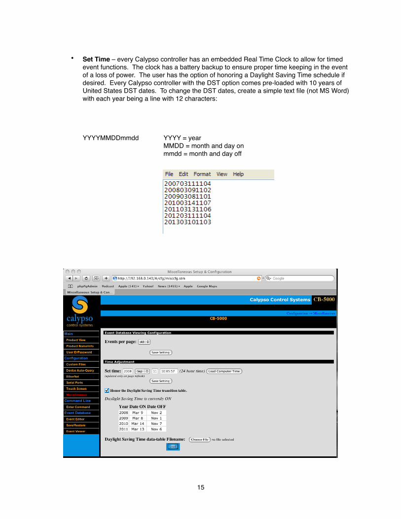
• Set Time – every Calypso controller has an embedded Real Time Clock to allow for timed event functions. The clock has a battery backup to ensure proper time keeping in the event of a loss of power. The user has the option of honoring a Daylight Saving Time schedule if desired. Every Calypso controller with the DST option comes pre-loaded with 10 years of United States DST dates. To change the DST dates, create a simple text file (not MS Word) with each year being a line with 12 characters:
YYYYMMDDmmdd YYYY = year MMDD = month and day on mmdd = month and day off
15
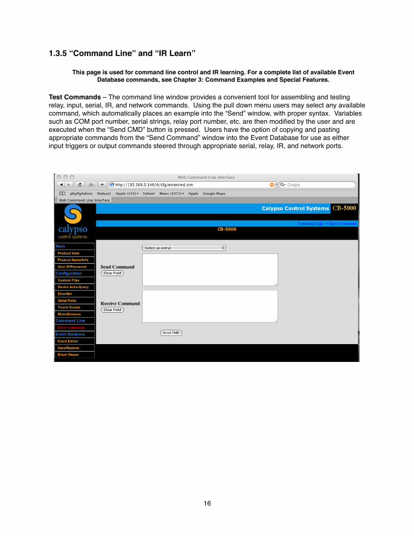
1.3.5 “Command Line” and “IR Learn”
This page is used for command line control and IR learning. For a complete list of available Event Database commands, see Chapter 3: Command Examples and Special Features.
Test Commands – The command line window provides a convenient tool for assembling and testing relay, input, serial, IR, and network commands. Using the pull down menu users may select any available command, which automatically places an example into the “Send” window, with proper syntax. Variables such as COM port number, serial strings, relay port number, etc. are then modified by the user and are executed when the “Send CMD” button is pressed. Users have the option of copying and pasting appropriate commands from the “Send Command” window into the Event Database for use as either input triggers or output commands steered through appropriate serial, relay, IR, and network ports.
16
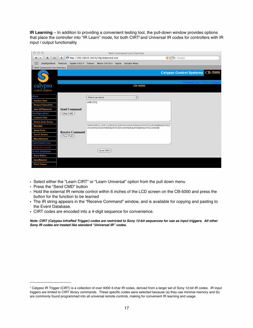
IR Learning – In addition to providing a convenient testing tool, the pull-down window provides options that place the controller into “IR Learn” mode, for both CIRT1and Universal IR codes for controllers with IR input / output functionality.
• Select either the “Learn CIRT” or “Learn Universal” option from the pull down menu• Press the “Send CMD” button• Hold the external IR remote control within 6 inches of the LCD screen on the CB-5000 and press the
button for the function to be learned• The IR string appears in the “Receive Command” window, and is available for copying and pasting to
the Event Database.• CIRT codes are encoded into a 4-digit sequence for convenience.
Note: CIRT (Calypso InfraRed Trigger) codes are restricted to Sony 12-bit sequences for use as input triggers. All other Sony IR codes are treated like standard “Universal IR” codes.
17
1 Calypso IR Trigger (CIRT) is a collection of over 4000 4-char IR codes, derived from a larger set of Sony 12-bit IR codes. IR input triggers are limited to CIRT library commands. These specific codes were selected because (a) they use minimal memory and (b) are commonly found programmed into all universal remote controls, making for convenient IR learning and usage.
CIRT codes (Calypso InfraRed Triggers): Special usage for database event triggers
Calypso controllers with IR functionality have a unique feature used to receive and decode Sony 12-bit IR commands. This feature allows these codes to act as event triggers, making it possible to use standard off-the-shelf universal remote controls to control sophisticated “non-IR” systems. While operating in CIRT mode, if the Sony IR code bit structure is something other than 12-bit the controller will display an “invalid code” message. Once the appropriate Sony code is learned it is automatically encoded into a convenient 4-digit sequence. This new 4-digit code can now be copied and pasted into an Event and used as an IR trigger.
IR Event Trigger Inputs:
Controllers with IR functionality respond to CIRT codes from the front panel IR window and/or each of the back panel IR connectors. The Pro I/O and ION-e controllers have the option of turning this function on or off from the Miscellaneous page.
Universal IR Command Header:
When an IR command is learned the controller inserts an “IR Header” onto the front of the command. Each Hex byte of this header contains information pertaining to certain IR parameters of a learned code. It is not retransmitted with the IR code. It tells the controller what to do with the code string that follows. It is helpful to understand the first 6 bytes of this header when dealing with difficult IR devices.
Example IR header: 40 00 03 00 01 54
BYTE 1: Carrier frequency of the IR command: 28Khz, 30Khz, 32khz, 36khz, 38khz, 40khz and 56khz. This byte should not be changed unless there is a need to strip the carrier from the IR signal. This can be accomplished by changing the byte to 00.
BYTE 2: Idle/Delay time – a user adjustable time to override the existing idle gap between IR bursts when the IR command is sent more than once, or to add a delay time after the last IR command burst. Allowable timing increments are 04h – 7Fh for an idle gap override, and 80h - FFh for an added delay time. Each hex unit is equal to 10ms delay. For example, a value of 0Ah (decimal 10) would insert a delay of 100ms between the IR bursts. Default is 00h, which means that the controller will use the idle time that is part of the learned IR code. A value of 90h (decimal 144) would add a 1.44 second delay after the last IR command sent.
BYTE 3: Repeat - selects how many times the IR command is to be repeated. Allowable values are from 01h to FFh (must be in Hex form!). Default is 03h and 00h is invalid.
BYTE 4: Repeat Mode - three selections: 00h = repeat the entire IR command, 01 = repeat the IR header only once, 02h = repeat the IR command with an offset. Default is 00h.
BYTE 5: Offset – displays which section of the IR burst was learned. 01 = Learn Universal code 02 = Learn Universal code w/1 skip 03 = Learn Universal code w/2 skips
BYTE 6: Data Length – displays the size of the data string in Hex form including the header.
18
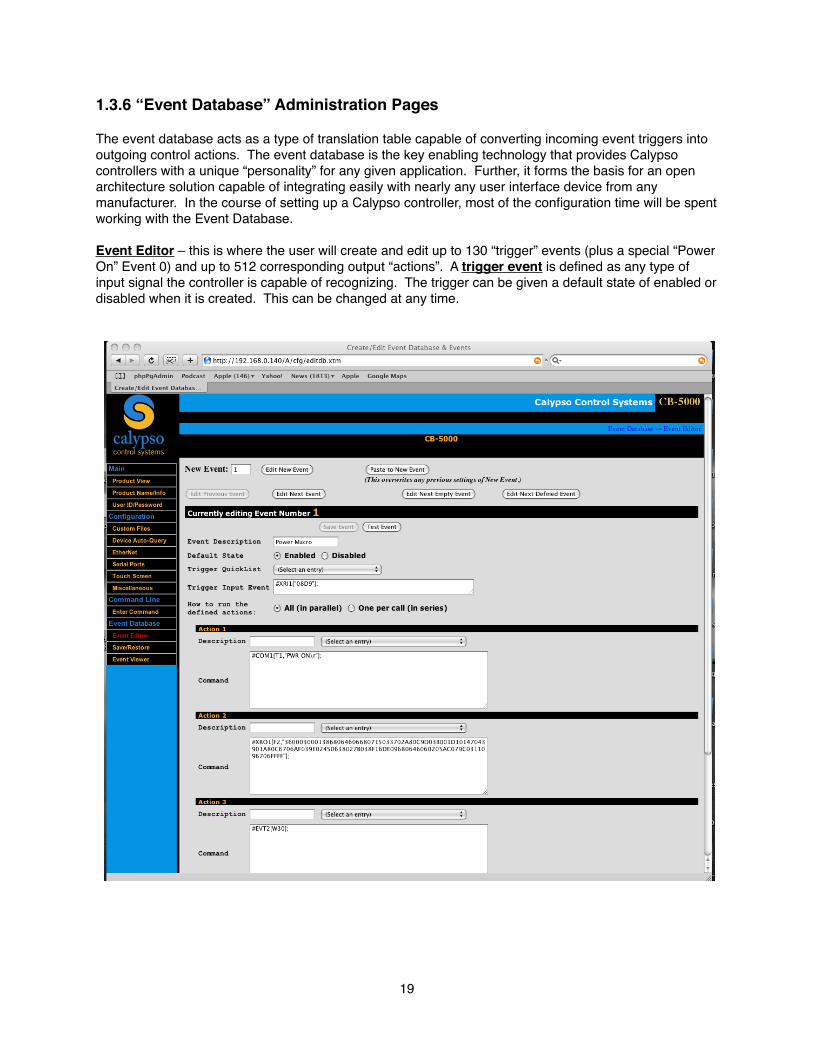
1.3.6 “Event Database” Administration Pages
The event database acts as a type of translation table capable of converting incoming event triggers into outgoing control actions. The event database is the key enabling technology that provides Calypso controllers with a unique “personality” for any given application. Further, it forms the basis for an open architecture solution capable of integrating easily with nearly any user interface device from any manufacturer. In the course of setting up a Calypso controller, most of the configuration time will be spent working with the Event Database.
Event Editor – this is where the user will create and edit up to 130 “trigger” events (plus a special “Power On” Event 0) and up to 512 corresponding output “actions”. A trigger event is defined as any type of input signal the controller is capable of recognizing. The trigger can be given a default state of enabled or disabled when it is created. This can be changed at any time.
19

Likewise, output actions are defined as any output signal the controller is capable of generating through its unique collection of output ports and the Ethernet connection. A summary list of available event database actions includes:
WHAT HOW RESTRICTIONCIRT infrared code IR “remote” detector or IR wired
connectorsCIRT code (12-bit Sony IR code)
Input (open/close) General purpose input connectors (dry contact)
None
Serial String Serial compare COM1 only; max 8 character length match, ASCII or HEX
Direct IP port data string NET compare – Ethernet connection
Max 8 character length match,ASCII or HEX
Time of Day or defined time interval
Internal clock Smallest unit of measure is minutes
VGA Sync Sync detect connectors VGA vertical sync signal
Test value command Compare value using <, >, =, not equal, or range
Up to 50 unique value placeholders: range 0-65535
For example, the user may define the “trigger” for event number 1 as a particular CIRT code and the corresponding output actions as a sequence of two serial commands followed by a network command sent to a second controller in a different location. Once defined within the event editor, the controller constantly “scans” all inputs, searching for an event that matches pre-defined “triggers”. When a matching event is recognized, the corresponding output actions are executed in rapid succession.
It is permissible to have events with no defined input trigger. Events that are executed using hyperlinks or direct event calls using the Remote (CNAP) port do not require an external trigger to be defined unless they are also executed using another type of user input (e.g. CIRT code).
It is also permissible to have multiple events with the same input trigger. When that defined trigger is detected by the controller all the matching events will be executed in no particular number order. Correspondingly, the output actions within a given event will execute in no particular order. When Event 1 is executed, for example, the controller will attempt to fire all 4 Actions (if applicable) simultaneously. In newer firmware versions the integrator has the option of placing the Event Actions is one of two modes:
All (in parallel) or One Per Call (in series).
All – the controller will attempt to execute all actions for that event simultaneously.
One Per Call – the controller will execute Action 1 on the first call, Action 2 on the second call, etc. until it reaches Action 4 or an empty Action (whichever comes first) then back to Action 1.
It is often useful to include a simple description of each event within the appropriate description fields. Event descriptions are used within the “Event Viewer” to simplify the process of visually scanning through the entire list of events.
Autostart Event. It is important to note that event number 0 (zero) is reserved for a control sequence triggered automatically upon system startup. Event number 0 otherwise functions the same as any other event as defined within the event database.
20
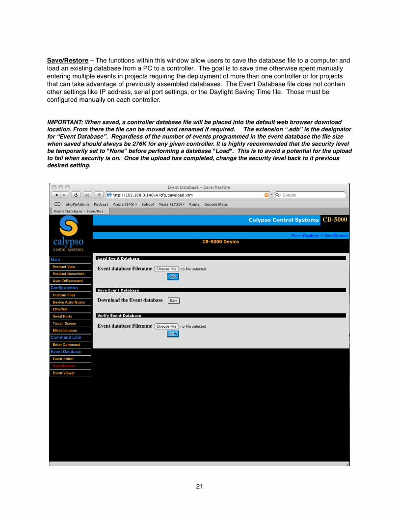
Save/Restore – The functions within this window allow users to save the database file to a computer and load an existing database from a PC to a controller. The goal is to save time otherwise spent manually entering multiple events in projects requiring the deployment of more than one controller or for projects that can take advantage of previously assembled databases. The Event Database file does not contain other settings like IP address, serial port settings, or the Daylight Saving Time file. Those must be configured manually on each controller.
IMPORTANT: When saved, a controller database file will be placed into the default web browser download location. From there the file can be moved and renamed if required. The extension “.edb” is the designator for “Event Database”. Regardless of the number of events programmed in the event database the file size when saved should always be 276K for any given controller. It is highly recommended that the security level be temporarily set to "None" before performing a database "Load". This is to avoid a potential for the upload to fail when security is on. Once the upload has completed, change the security level back to it previous desired setting.
21
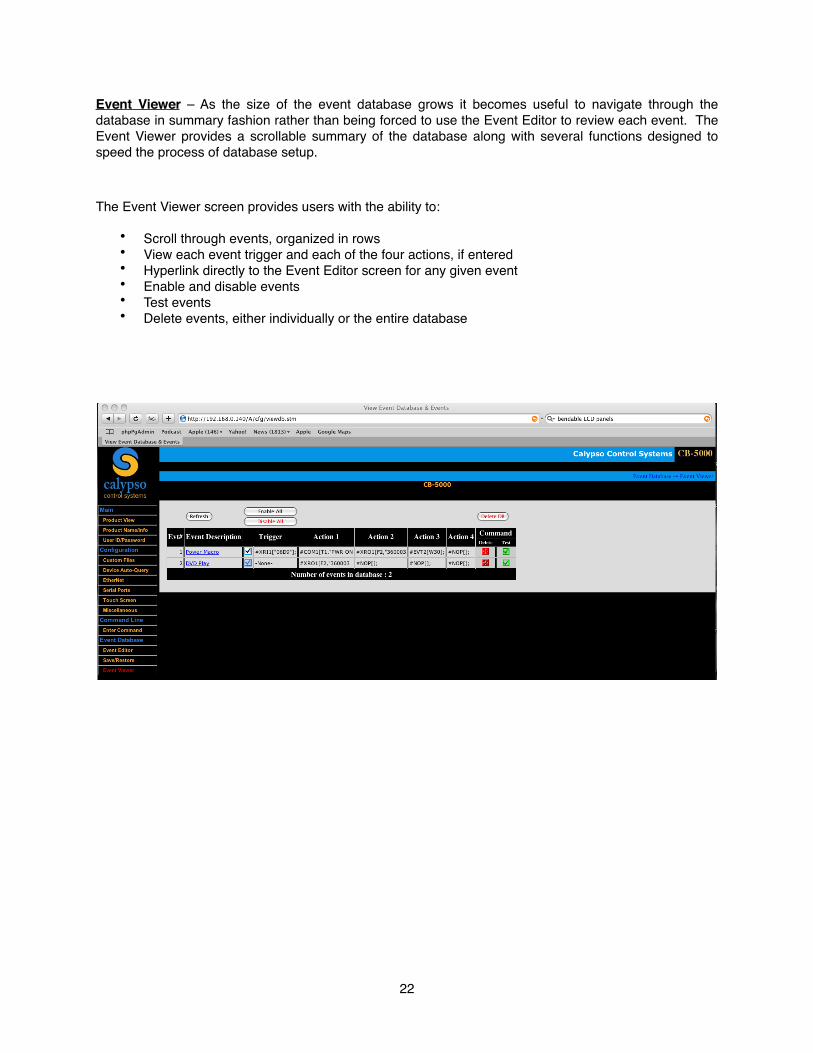
Event Viewer – As the size of the event database grows it becomes useful to navigate through the database in summary fashion rather than being forced to use the Event Editor to review each event. The Event Viewer provides a scrollable summary of the database along with several functions designed to speed the process of database setup.
The Event Viewer screen provides users with the ability to:
• Scroll through events, organized in rows• View each event trigger and each of the four actions, if entered• Hyperlink directly to the Event Editor screen for any given event• Enable and disable events• Test events• Delete events, either individually or the entire database
22
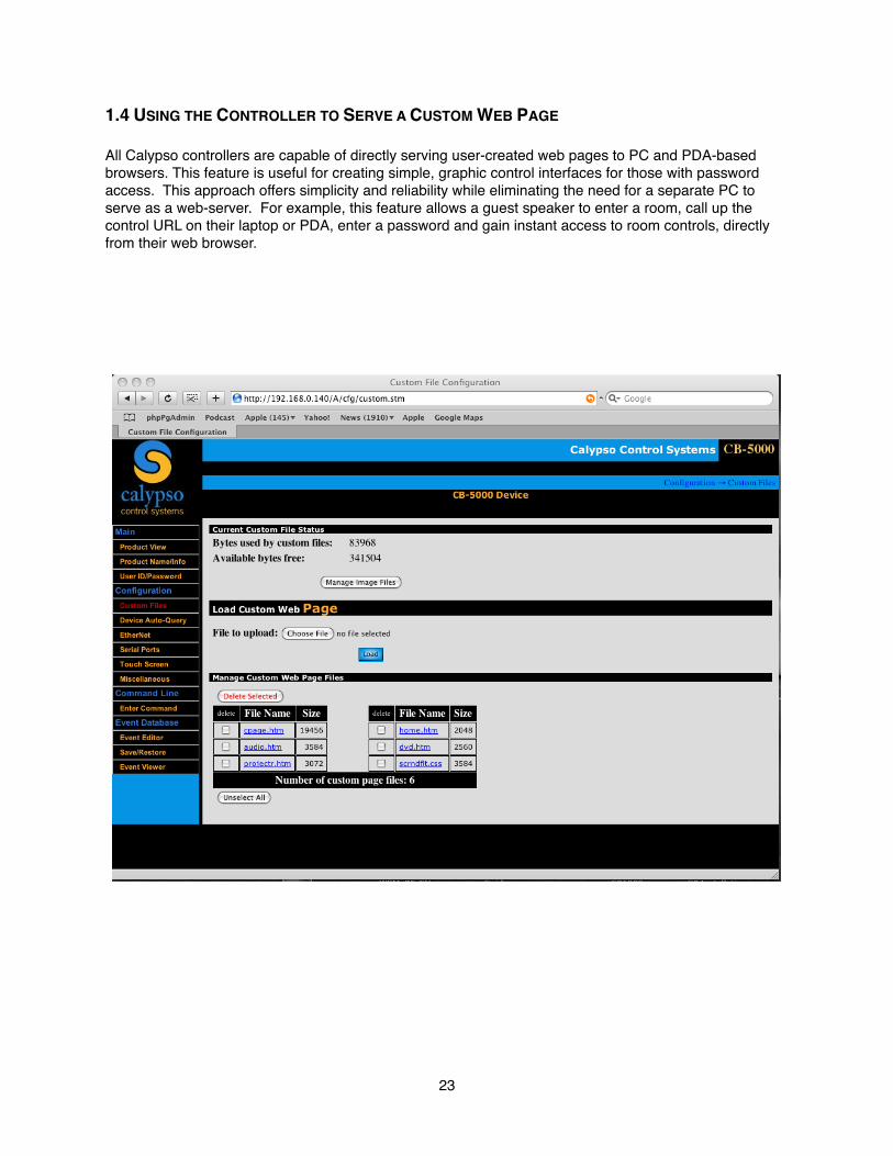
1.4 USING THE CONTROLLER TO SERVE A CUSTOM WEB PAGE
All Calypso controllers are capable of directly serving user-created web pages to PC and PDA-based browsers. This feature is useful for creating simple, graphic control interfaces for those with password access. This approach offers simplicity and reliability while eliminating the need for a separate PC to serve as a web-server. For example, this feature allows a guest speaker to enter a room, call up the control URL on their laptop or PDA, enter a password and gain instant access to room controls, directly from their web browser.
23
1.4.1 Custom Files
Custom HTML pages and images are developed “off-line” and are then loaded onto the controller, limited to approximately 512KB worth of files. Control applications using as many as 25 pages have been implemented. The actual number of pages possible depends on the HTML layout and images used.
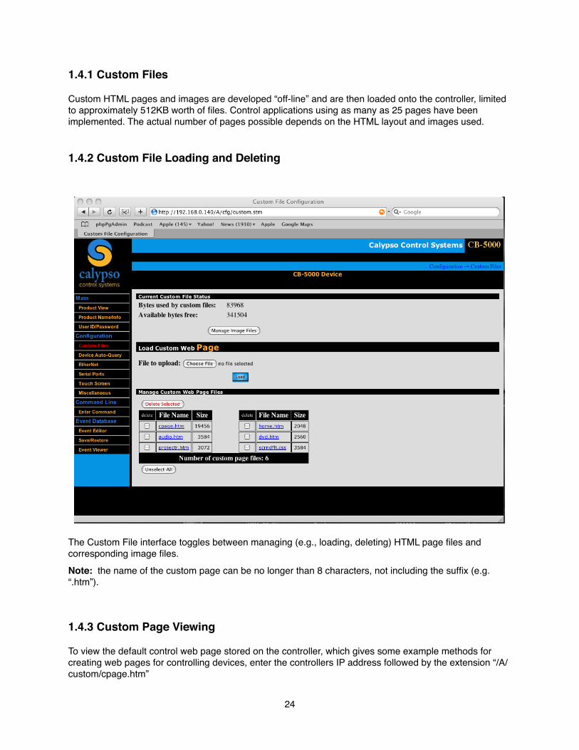
1.4.2 Custom File Loading and Deleting
The Custom File interface toggles between managing (e.g., loading, deleting) HTML page files and corresponding image files.Note: the name of the custom page can be no longer than 8 characters, not including the suffix (e.g. “.htm”).
1.4.3 Custom Page Viewing
To view the default control web page stored on the controller, which gives some example methods for creating web pages for controlling devices, enter the controllers IP address followed by the extension “/A/custom/cpage.htm”
24
Example: http://192.168.1.101/A/custom/cpage.htm
Note that the custom page does not need to be named “cpage”, but does require the “htm” extension. If the custom page name is anything other than cpage.htm be sure to record the name of the page for later viewing through a web browser.
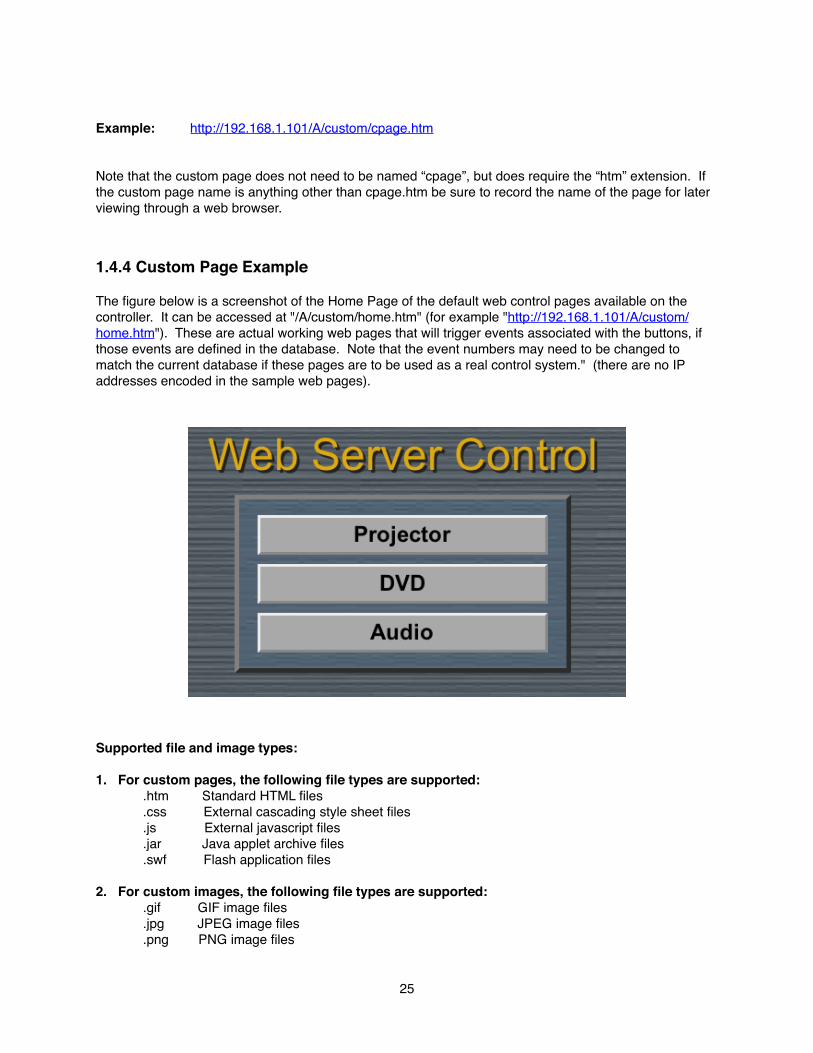
1.4.4 Custom Page Example
The figure below is a screenshot of the Home Page of the default web control pages available on the controller. It can be accessed at "/A/custom/home.htm" (for example "http://192.168.1.101/A/custom/home.htm"). These are actual working web pages that will trigger events associated with the buttons, if those events are defined in the database. Note that the event numbers may need to be changed to match the current database if these pages are to be used as a real control system." (there are no IP addresses encoded in the sample web pages).
Supported file and image types:
1. For custom pages, the following file types are supported: .htm Standard HTML files .css External cascading style sheet files .js External javascript files .jar Java applet archive files .swf Flash application files
2. For custom images, the following file types are supported: .gif GIF image files .jpg JPEG image files .png PNG image files
25
Chapter 2 - CB-5000 Advanced Functions2.1 Accessing Setup FunctionThe CB-5000 has several advanced functions available for controlling system defaults such as:
• Access Passwords• IP Address• Touch Screen Functions• Performing Diagnostic Tests
These functions should only need to be accessed during initial setup or when an IP Reset needs to initiated.
2.1.1 Entering Setup Mode
The Advanced Function Menu can be accessed by pressing and holding the [Home] button for 3 seconds -- you will see the Password screen when you release the button. At the password screen enter 1426 on the touch-panel and press [ENT].
2.1.2 IP Reset
The IP Reset function resets the device to the factory default IP Address of 192.168.1.101. If the address you set up in your administrative ethernet settings is ever forgotten, lost or deemed irretrievable this “reset option” will let you communicate with the device.
Note: This reset option also resets other preferences to their factory default. Use only when necessary.
2.1.3 Home Set
The Home Set menu allows configuration of access options to the device interface. We recommend that these settings be adjusted only from the CB-5000 Configuration Utility. Options are located in the Edit Configuration area of the Utility. See Fig.
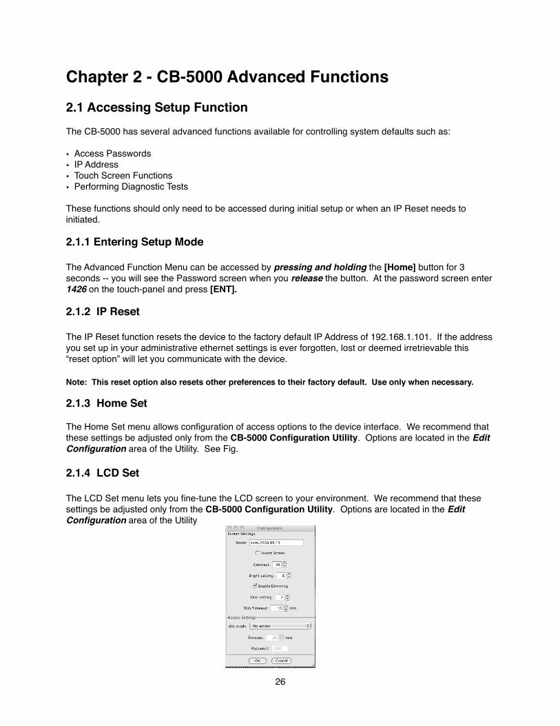
2.1.4 LCD Set
The LCD Set menu lets you fine-tune the LCD screen to your environment. We recommend that these settings be adjusted only from the CB-5000 Configuration Utility. Options are located in the Edit Configuration area of the Utility
26

2.1.5 Diag Test
The Diag Test button will run an internal test of the device. This would only be required during a troubleshooting session with a Calypso Technical Services Engineer.
2.1.6 Calib Touch
This feature allows a re-calibration of the basic touch-screen X,Y Axis settings. This would only be required during a troubleshooting session with a Calypso Technical Services Engineer.
2.1.7 Misc
The Misc menu should only be accessed when instructed by a Calypso Technical Services Engineer.
27

Appendices
Appendix A. -- Calypso Action Control Language
Formatted strings:Special characters, which may be used in the "string" portion of COM, CMP, NET, and NCM commands below.
Command Descriptionccc..\ esc..ccc non-hex mode formatted string (character sequence)
Escape sequences: \a insert character 07 (the bell character) into the string character sequence.
\b insert character 08 (the backspace character) into the string character sequence.
\f insert character 0C (the form-feed character) into the string character sequence.
\n insert character 0A (the line feed character) into the string character sequence.
\r insert character 0D (the carriage return character) into the string character sequence.
\vn insert a base-10 string representation of stored value n (VALx[];) into the string character sequence; this escape sequence can result in multiple characters being inserted.
\vxn insert a base-16 string representation of stored value n into the string character sequence; this escape sequence results in 4 characters being inserted.
\xnn insert character 0xnn into the string character sequence (allows for a single hexadecimal-value character to be inserted).
\xvn.0 insert the low-order byte of stored value n into the string character sequence.
\xvn.1 insert the high
\c insert the character c into the string character sequence; e.g. "\\"; this is the result if c is not one of the characters listed above.
28
Control Language Syntax
A control language is used to define event triggers (trigger context), event actions (action context), and commands delivered over the network or commands entered from a controllers “Enter Command” web page (command context). Not all commands can be used in every context, as noted below. Commands are not case sensitive and there are no spaces or leading zeros.

GPO (relays):
Command Description#GPOn[Fn]; command context only
#GPOn[string, Dn]; action or command context
n a decimal value between 1 and maxGPO, which targets a specific relay connection.
string a sequence of printable characters delimited by double quotes; the sequence should be either "OPEN" or "CLOSE" (case insensitive).
Dn duration of pulse; causes the relay to temporarily change to the given state for a period of n units of time, and then change to the opposite state.
Fn flag setting; n indicates the error return mode.
IR Input:
Command Description#XRIn[Fn]; command context only
#XRIn[F1, string]; trigger context only
n a decimal value between 1 and maxIRin, which targets a specific IR input line (most products have only a single IR input line with multiple connection points).
string a sequence of printable characters delimited by quotes; either single or double quotes may be used, as long as they are matched. The sequence must be a valid CIRT code (two hexadecimal pairs, case insensitive).
Fn
flag for type; n indicates the type of IR data returned or expected: 1 = CIRT data, which is the default and is the only setting allowed for triggers 2 = Universal data (grab first or only burst) 4 = Noise data 6 = Universal data, skip first burst (grab second burst) 7 = Universal data, skip first 2 bursts (grab third burst) Only the F1 setting may be used for triggers, and may be omitted entirely since it is the default. The other settings may be used in learn command context.
29
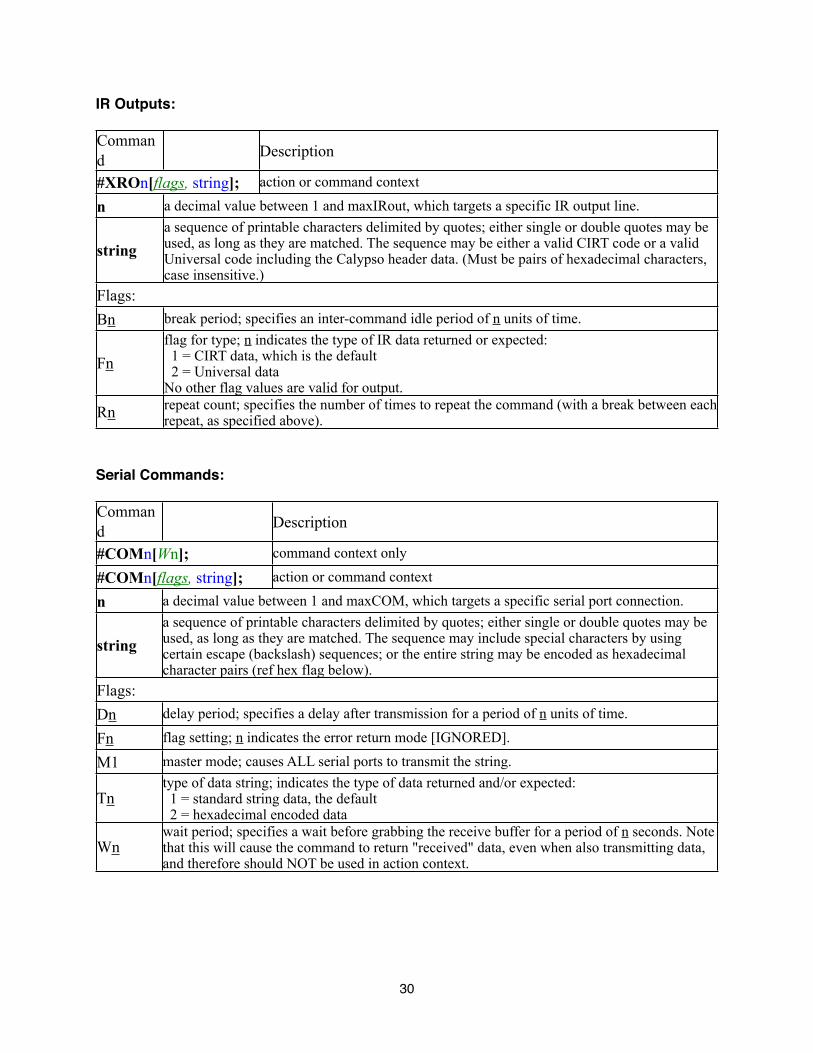
IR Outputs:
Command Description
#XROn[flags, string]; action or command context
n a decimal value between 1 and maxIRout, which targets a specific IR output line.
string a sequence of printable characters delimited by quotes; either single or double quotes may be used, as long as they are matched. The sequence may be either a valid CIRT code or a valid Universal code including the Calypso header data. (Must be pairs of hexadecimal characters, case insensitive.)
Flags: Bn break period; specifies an inter-command idle period of n units of time.
Fn flag for type; n indicates the type of IR data returned or expected: 1 = CIRT data, which is the default 2 = Universal data No other flag values are valid for output.
Rn repeat count; specifies the number of times to repeat the command (with a break between each repeat, as specified above).
Serial Commands:
Command Description
#COMn[Wn]; command context only
#COMn[flags, string]; action or command context
n a decimal value between 1 and maxCOM, which targets a specific serial port connection.
string a sequence of printable characters delimited by quotes; either single or double quotes may be used, as long as they are matched. The sequence may include special characters by using certain escape (backslash) sequences; or the entire string may be encoded as hexadecimal character pairs (ref hex flag below).
Flags: Dn delay period; specifies a delay after transmission for a period of n units of time.
Fn flag setting; n indicates the error return mode [IGNORED].
M1 master mode; causes ALL serial ports to transmit the string.
Tn type of data string; indicates the type of data returned and/or expected: 1 = standard string data, the default 2 = hexadecimal encoded data
Wn wait period; specifies a wait before grabbing the receive buffer for a period of n seconds. Note that this will cause the command to return "received" data, even when also transmitting data, and therefore should NOT be used in action context.
30
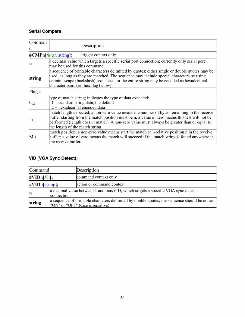
Serial Compare:
Command Description
#CMPn[flags, string]; trigger context only
n a decimal value which targets a specific serial port connection; currently only serial port 1 may be used for this command.
string a sequence of printable characters delimited by quotes; either single or double quotes may be used, as long as they are matched. The sequence may include special characters by using certain escape (backslash) sequences; or the entire string may be encoded as hexadecimal character pairs (ref hex flag below).
Flags:
Cn type of match string; indicates the type of data expected: 1 = standard string data, the default 2 = hexadecimal encoded data
Ln match length expected; a non-zero value means the number of bytes remaining in the receive buffer starting from the match position must be n; a value of zero means this test will not be performed (length doesn't matter). A non-zero value must always be greater than or equal to the length of the match string.
Mn match position; a non-zero value means start the match at 1-relative position n in the receive buffer; a value of zero means the match will succeed if the match string is found anywhere in the receive buffer.
VID (VGA Sync Detect):
Command Description#VIDn[Fn]; command context only
#VIDn[string]; action or command context
n a decimal value between 1 and maxVID, which targets a specific VGA sync detect connection.
string a sequence of printable characters delimited by double quotes; the sequence should be either "ON" or "OFF" (case insensitive).
31
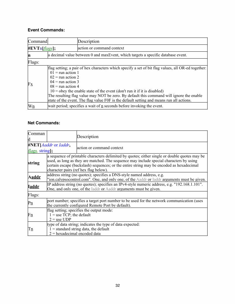
Event Commands:
Command Description#EVTn[flags]; action or command context
n a decimal value between 0 and maxEvent, which targets a specific database event.
Flags:
Fx
flag setting; a pair of hex characters which specify a set of bit flag values, all OR-ed together: 01 = run action 1 02 = run action 2 04 = run action 3 08 = run action 4 10 = obey the enable state of the event (don't run it if it is disabled) The resulting flag value may NOT be zero. By default this command will ignore the enable state of the event. The flag value F0F is the default setting and means run all actions.
Wn wait period; specifies a wait of n seconds before invoking the event.
Net Commands:
Command Description
#NET[Aaddr or Iaddr, flags, string];
action or command context
string a sequence of printable characters delimited by quotes; either single or double quotes may be used, as long as they are matched. The sequence may include special characters by using certain escape (backslash) sequences; or the entire string may be encoded as hexadecimal character pairs (ref hex flag below).
Aaddr address string (no quotes); specifies a DNS-style named address, e.g. "ion.calypsocontrol.com". One, and only one, of the Aaddr or Iaddr arguments must be given.
Iaddr IP address string (no quotes); specifies an IPv4-style numeric address, e.g. "192.168.1.101". One, and only one, of the Iaddr or Aaddr arguments must be given.
Flags:
Pn port number; specifies a target port number to be used for the network communication (uses the currently configured Remote Port by default).
Fn flag setting; specifies the output mode: 1 = use TCP; the default 2 = use UDP
Tn type of data string; indicates the type of data expected: 1 = standard string data, the default 2 = hexadecimal encoded data
32
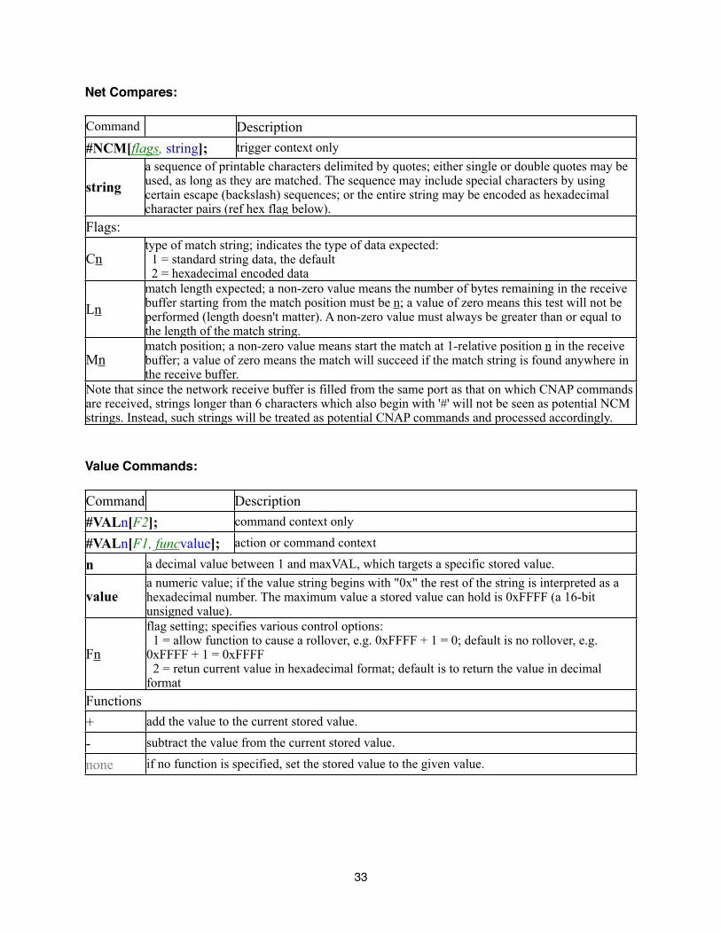
Net Compares:
Command Description#NCM[flags, string]; trigger context only
string a sequence of printable characters delimited by quotes; either single or double quotes may be used, as long as they are matched. The sequence may include special characters by using certain escape (backslash) sequences; or the entire string may be encoded as hexadecimal character pairs (ref hex flag below).
Flags:
Cn type of match string; indicates the type of data expected: 1 = standard string data, the default 2 = hexadecimal encoded data
Ln match length expected; a non-zero value means the number of bytes remaining in the receive buffer starting from the match position must be n; a value of zero means this test will not be performed (length doesn't matter). A non-zero value must always be greater than or equal to the length of the match string.
Mn match position; a non-zero value means start the match at 1-relative position n in the receive buffer; a value of zero means the match will succeed if the match string is found anywhere in the receive buffer.
Note that since the network receive buffer is filled from the same port as that on which CNAP commands are received, strings longer than 6 characters which also begin with '#' will not be seen as potential NCM strings. Instead, such strings will be treated as potential CNAP commands and processed accordingly.
Value Commands:
Command Description#VALn[F2]; command context only
#VALn[F1, funcvalue]; action or command context
n a decimal value between 1 and maxVAL, which targets a specific stored value.
value a numeric value; if the value string begins with "0x" the rest of the string is interpreted as a hexadecimal number. The maximum value a stored value can hold is 0xFFFF (a 16-bit unsigned value).
Fn
flag setting; specifies various control options: 1 = allow function to cause a rollover, e.g. 0xFFFF + 1 = 0; default is no rollover, e.g. 0xFFFF + 1 = 0xFFFF 2 = retun current value in hexadecimal format; default is to return the value in decimal format
Functions + add the value to the current stored value.
- subtract the value from the current stored value.
none if no function is specified, set the stored value to the given value.
33
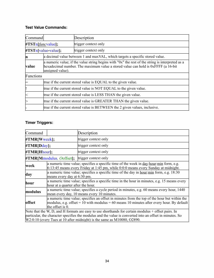
Test Value Commands:
Command Description#TSTn[funcvalue]; trigger context only
#TSTn[value-value]; trigger context only
n a decimal value between 1 and maxVAL, which targets a specific stored value.
value a numeric value; if the value string begins with "0x" the rest of the string is interpreted as a hexadecimal number. The maximum value a stored value can hold is 0xFFFF (a 16-bit unsigned value).
Functions = true if the current stored value is EQUAL to the given value.
! true if the current stored value is NOT EQUAL to the given value.
< true if the current stored value is LESS THAN the given value.
> true if the current stored value is GREATER THAN the given value.
- true if the current stored value is BETWEEN the 2 given values, inclusive.
Timer Triggers:
Command Description#TMR[Wweek]; trigger context only
#TMR[Dday]; trigger context only
#TMR[Hhour]; trigger context only
#TMR[Mmodulus, Ooffset]; trigger context only
week a numeric time value; specifies a specific time of the week in day:hour:min form, e.g. 6:13:45 means every Friday at 1:45 pm, while 0:0:0 means every Sunday at midnight.
day a numeric time value; specifies a specific time of the day in hour:min form, e.g. 18:30 means every day at 6:30 pm.
hour a numeric time value; specifies a specific time in the hour in minutes, e.g. 15 means every hour at a quarter after the hour.
modulus a numeric time value; specifies a cycle period in minutes, e.g. 60 means every hour, 1440 mean every day, 10 means every 10 minutes.
offset a numeric time value; specifies an offset in minutes from the top of the hour but within the modulus, e.g. offset = 10 with modulus = 60 means 10 minutes after every hour. By default the offset is 0.
Note that the W, D, and H formats are easy to use shorthands for certain modulus + offset pairs. In particular, the character specifies the modulus and the value is converted into an offset in minutes. So W2:0:10 (every Tues at 10 after midnight) is the same as M10080, O2890.
34
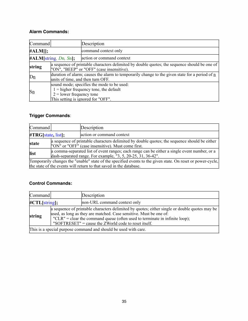
Alarm Commands:
Command Description#ALM[]; command context only
#ALM[string, Dn, Sn]; action or command context
string a sequence of printable characters delimited by double quotes; the sequence should be one of "ON", "BEEP" or "OFF" (case insensitive).
Dn duration of alarm; causes the alarm to temporarily change to the given state for a period of n units of time, and then turn OFF.
Sn sound mode; specifies the mode to be used: 1 = higher frequency tone, the default 2 = lower frequency tone This setting is ignored for "OFF".
Trigger Commands:
Command Description#TRG[state, list]; action or command context
state a sequence of printable characters delimited by double quotes; the sequence should be either "ON" or "OFF" (case insensitive). Must come first.
list a comma-separated list of event ranges; each range can be either a single event number, or a dash-separated range. For example, "3, 5, 20-25, 31, 36-42".
Temporarily changes the "enable" state of the specified events to the given state. On reset or power-cycle, the state of the events will return to that saved in the database.
Control Commands:
Command Description#CTL[string]; non-URL command context only
string a sequence of printable characters delimited by quotes; either single or double quotes may be used, as long as they are matched. Case sensitive. Must be one of: "CLR" = clear the command queue (often used to terminate in infinite loop); "SOFTRESET" = cause the ZWorld code to reset itself.
This is a special purpose command and should be used with care.
35

Appendix B. -- Supported Graphic Formats
The guidelines for importing graphics on the CB-5000 Utility are currently as follows:
• The known supported formats are: PNG, GIF, JPEG, and BMP. Other formats may work (based on support of the Java libraries employed), but have not been tested.
• Any size and bit depth are "allowed", but the import mechanism is very simple and so if the size is too far off or the bit depth is more than 1 the results are generally not very useful (often simply all white or all black).
• For best results, the image should be monochrome (B&W) and close to the end size (128x64 for full pages, or 42x32 or 32x32 for the 2 button sizes).
• Experimentation is not a problem, but don't expect great results if the above guidelines are not followed.
36
Calypso Control Systems 3-year Product Warranty Statement
This Non-Transferable warranty is provided to original purchasing end user, herein referred as “customer”, of Calypso Control Systems product line defined as: Pro I/O, ION-e, ION-LT1, ION-LT2, UT-500, ION-4s, ION-8r, ION-16i, CB-1000, CR-1200R, CA-500, CA-1000, and CA-1050, herein referred as “product”.
This warranty is applicable to product sold or distributed to customer by an authorized Calypso Control Systems Dealer, OEM, Value Added Reseller or sold directly to the end user by Calypso Control Systems, LLC. This warranty becomes effective from the moment the end user completes purchase and receives product. This warranty shall remain in effect for 3 years from the moment of purchase as long as the original customer of the product continues to own and use the product. This warranty does not apply to accessories such as power supplies and cables, which carry standard 12-month manufacturer warranties.
Terms
Calypso Control Systems warrants that product shall be materially free of defects in material and workmanship under normal use and service during the warranty period. In the event that Calypso Control Systems receives notice from the customer during the warranty period that product does not conform to this warranty, Calypso Control Systems shall, at its sole option, either repair or replace the non-conforming product. The warranty on the replacement or repaired product shall continue for the duration of the original warranty. All returned product becomes the property of Calypso Control Systems.
Procedures
A product may only be returned with the prior written approval of Calypso Control Systems. Such approval shall reference a Return Material Authorization number (RMA) issued by authorized Calypso Control Systems technical support personnel. Transportation costs, if any, incurred in connection with the return of a defective item to Calypso Control Systems shall be borne by the Customer. Transportation costs incurred in connection with the re-delivery of a repaired or replaced item to the Customer shall be borne by Calypso Control Systems. However, such costs shall be borne by the Customer if Calypso Control Systems, reasonably determines that the product is not defective. If Calypso Control Systems determines, in its sole discretion, that the allegedly defective product is not covered by the terms of the warranty provided hereunder, or that a warranty claim is made after the warranty period, the cost of repair by Calypso Control Systems, including all shipping expenses, shall be reimbursed by the Customer. Calypso Control Systems shall have no liability with respect to data contained in any system returned to Calypso Control Systems.
Exclusions
The foregoing warranties and remedies are for the Customerʼs exclusive benefit and are non-transferable. Any and all warranties shall be void regarding System components that are damaged or rendered unserviceable by: (1) acts or omissions of non-Calypso Control Systems personnel; (2) misuse, theft, vandalism, fire, water, or other peril; (3) alterations of or additions to the System or any element thereof performed by personnel not certified by Calypso Control Systems to perform such alterations and additions or (4) the Customerʼs failure to operate the product in conformance with Calypso Control Systems published operating parameters, including environmental specifications.
37

Disclaimer of Warranty
TO THE EXTENT ALLOWED BY APPLICABLE LAW, THE LIMITED WARRANTIES REFERRED TO IN THE PARAGRAPHS ABOVE SHALL BE IN LIEU OF ALL OTHER WARRANTIES WHETHER EXPRESSED, IMPLIED, STATUTORY, OR OTHERWISE. Calypso Control Systems, LLC SPECIFICALLY DISCLAIMS ANY IMPLIED WARRANTIES OF MERCHANTABILITY OR FITNESS FOR A PARTICULAR PURPOSE.
Limitation of Liability
TO THE EXTENT ALLOWED BY APPLICABLE LAW, Calypso Control Systems, LLC AND ITS SUPPLIERS EXCLUDE THEMSELVES FROM ANY LIABILITY FOR ANY LOST REVENUE OR PROFIT, LOSS OF BUSINESS, LOSS OF INFORMATION OR DATA, OR FOR SPECIAL, INDIRECT, CONSEQUENTIAL, INCIDENTAL, OR PUNITIVE DAMAGES OF ANY KIND CAUSED OUT OF OR IN CONNECTION WITH THE SALE, INSTALLATION, MAINTENANCE, USE, PERFORMANCE, FAILURE, OR INTERRUPTION OF ITS PRODUCTS, EVEN IF Calypso Control Systems, LLC AND ITS AUTHORIZED RESELLERS HAVE BEEN ADVISED OF THE POSSIBILITY OF SUCH DAMAGES. IN NO EVENT SHALL Calypso Control Systems, LLC OR ITS SUPPLIERʼS TOTAL LIABILITY TO THE CUSTOMER, WHETHER IN CONTRACT NEGLIGENCE, STRICT LIABILITY, TORT OR OTHERWISE, EXCEED THE PRICE PAID BY THE CUSTOMER. THE FOREGOING LIMITATIONS SHALL APPLY EVEN IF ANY REMEDY PROVIDED HEREIN SHALL FAIL ITS ESSENTIAL PURPOSE. THIS LIMITATION OF LIABILITY, HOWEVER, WILL NOT APPLY TO ANY CLAIMS FOR PERSONAL INJURY.
38