Embed Size (px)
Citation preview

Toyota Supports ASE Certification Page 1 of 2
BO
030-01
Title:
WINDSHIELD WIPER BLADE
MAINTENANCE AND CLEANINGModels:
All Models & All Years Through Current
Technical ServiceBULLETIN
December 7, 2001
TSB REVISION NOTICE:July 13, 2004: The Applicable Vehicles has been changed to all models and all yearsthrough current.All previous versions of this TSB should be discarded.
The following procedures are recommended to maintain windshield wiper blade performance.
� All models and model years through current.
OP CODE DESCRIPTION TIME OFP T1 T2
N/A Not Applicable to Warranty – – – –
Recommendations for Windshield Wiper Maintenance, Cleaning and Use:
1. Scheduled Maintenance
� Check wiper rubber blades every 4 – 6 months or 7,500 miles for wear, crackingand contamination.
� Clean glass and rubber wiper blades if blades are not clearing glass adequately.If this does not correct the problem, then replace the rubber elements.
2. Cleaning Procedure
� Wiper Rubber: Bugs, dirt, sap and road grime on blades will cause streaking.Clean wiper rubber of road and environmental debris using cloth or paper towelsoaked with windshield washer fluid or mild detergent.
� DO NOT USE fuel, kerosene, or petroleum based products to clean rubber wiperblades.
� Windshield: Bugs, road grime, sap and car wash wax treatments decrease wiperperformance.
� Rinse windshield with water and apply non–abrasive cleaner, such as Bon–Ami(www.faultless.com), with a sponge.
NOTE:Make sure to use plenty of water with all powder based cleaners so the glass is not scratched.
BO
DY
Introduction
ApplicableVehicles
WarrantyInformation
Maintenance,Cleaningand Use
WINDSHIELD WIPER BLADE MAINTENANCE AND CLEANING – BO030-01 Revised December 7, 2001
Page 2 of 2
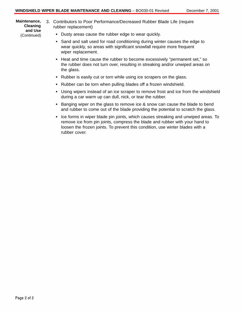
3. Contributors to Poor Performance/Decreased Rubber Blade Life (require rubber replacement)
� Dusty areas cause the rubber edge to wear quickly.
� Sand and salt used for road conditioning during winter causes the edge to wear quickly, so areas with significant snowfall require more frequent wiper replacement.
� Heat and time cause the rubber to become excessively “permanent set,” so the rubber does not turn over, resulting in streaking and/or unwiped areas on the glass.
� Rubber is easily cut or torn while using ice scrapers on the glass.
� Rubber can be torn when pulling blades off a frozen windshield.
� Using wipers instead of an ice scraper to remove frost and ice from the windshieldduring a car warm up can dull, nick, or tear the rubber.
� Banging wiper on the glass to remove ice & snow can cause the blade to bendand rubber to come out of the blade providing the potential to scratch the glass.
� Ice forms in wiper blade pin joints, which causes streaking and unwiped areas. Toremove ice from pin joints, compress the blade and rubber with your hand toloosen the frozen joints. To prevent this condition, use winter blades with a rubber cover.
Maintenance,Cleaningand Use
(Continued)

Toyota Supports ASE Certification Page 1 of 2
PG
004–00
Title:
FRONT LICENSE PLATE BRACKET
INSTALLATIONModels:
’00 MR2 Spyder
Technical ServiceBULLETIN
February 4, 2000
The 2000 model year MR2 Spyder front license plate bracket and three attaching screwsare placed in the glovebox of the vehicle at the assembly plant. For states that require afront license plate, install the bracket on the front bumper cover during Pre–DeliveryService (PDS) according to the following procedures.
� 2000 model year MR2 Spyder
OP CODE DESCRIPTION TIME OPN T1 T2
N/A Not Applicable to Warranty – – – –
PR
OD
UC
T G
EN
ER
AL IN
FO
RM
AT
ION
Introduction
ApplicableVehicle
WarrantyInformation

FRONT LICENSE PLATE BRACKET INSTALLATION – PG004–00 February 4, 2000
Page 2 of 2
1. Drill two holes, 2 mm (0.078 in.)diameter, at dimples “A” on the frontbumper.
NOTE:Do NOT drill holes oversize.
2. Using two self–tapping screws, installthe front license plate bracket on thefront bumper.
NOTE:Screw the driver’s side self–tappingscrew in first.
3. Drill one hole, 2 mm (0.078 in.)diameter, on the front bumper at hole“B” of the bracket.
NOTE:Do NOT drill hole oversize.
4. Screw the self–tapping screw intohole “B” to retain the bracket.
NOTE:Do NOT overtighten the screw becausethere is no sleeve behind the bumpercover at “B”.
5. Install the front license plate to thebracket using self–tapping screws of anon–corroding type having thefollowing size:
Length (L):18.0 – 25.0 mm (0.71 – 0.98 in.)
Diameter (D):6.0 mm (0.24 in.)
Pitch:2.5 mm (0.098 in.).
Cross Section of “A”
Front LicensePlate Bracket
Self–Tapping Screws
Sleeve2 mm
AInstallationProcedure
Self–Tapping Screw
B
Self–TappingScrews
FrontLicensePlate
D
L

Toyota Supports ASE Certification Page 1 of 1
PG
005–00
Title:
ECU-B1 FUSE INSTALLATION DURING
PDSModels:
’00 MR2 Spyder
Technical ServiceBULLETIN
February 18, 2000
To minimize battery discharge during transportation and storage, the ECU–B1 fuse hasbeen removed at the assembly plant.
� 2000 model year MR2 Spyder
The ECU–B1 fuse provides power to the DOME, Radio1, and ECU–B circuits. Removalof the ECU–B1 fuse will affect the following systems:
� Clock � Interior Light
� Key Reminder Buzzer � Light Reminder Buzzer
� Day Time Running Light System � Radio Antenna Motor
� Radio and CD Player � Open Door Warning Light (with Ignition OFF)
1. The ECU–B1 fuse (25 A) is stored inthe blank space of the Relay Block inthe engine compartment.
2. During Pre–Delivery Service (PDS),install the ECU–B1 fuse in the RelayBlock as shown.
NOTE:If the vehicle is stored at thedealership for a long period of timeafter PDS, disconnect the negativebattery terminal to prevent batterydischarge. Refer to TSB EL001–96 forbattery maintenance information.
OP CODE DESCRIPTION TIME OPN T1 T2
N/A Not Applicable to Warranty – – – –
PR
OD
UC
T G
EN
ER
AL IN
FO
RM
AT
ION
Introduction
ApplicableVehicles
AffectedSystems
Engine Compartment
Relay Block
InstallFuse Here
Relay Block
RemoveFuse from Here
WarrantyInformation
Toyota Supports ASE Certification Page 1 of 1
PG
001–00
Title:
2000 TECHNICAL SERVICE BULLETIN
INFORMATIONModels:
All Models
Technical ServiceBULLETIN
January 7, 2000
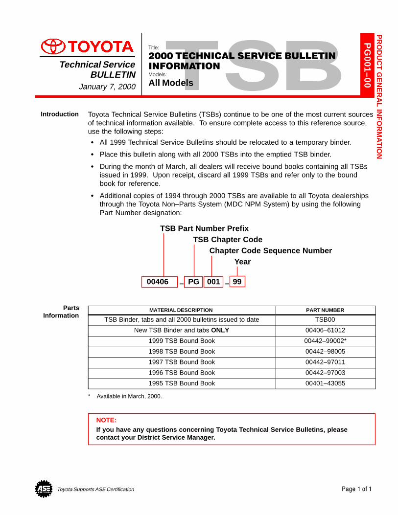
Toyota Technical Service Bulletins (TSBs) continue to be one of the most current sourcesof technical information available. To ensure complete access to this reference source,use the following steps:
� All 1999 Technical Service Bulletins should be relocated to a temporary binder.
� Place this bulletin along with all 2000 TSBs into the emptied TSB binder.
� During the month of March, all dealers will receive bound books containing all TSBsissued in 1999. Upon receipt, discard all 1999 TSBs and refer only to the boundbook for reference.
� Additional copies of 1994 through 2000 TSBs are available to all Toyota dealershipsthrough the Toyota Non–Parts System (MDC NPM System) by using the followingPart Number designation:
00406 PG 001 99
TSB Part Number PrefixTSB Chapter Code
Chapter Code Sequence NumberYear
– –
MATERIAL DESCRIPTION PART NUMBER
TSB Binder, tabs and all 2000 bulletins issued to date TSB00
New TSB Binder and tabs ONLY 00406–61012
1999 TSB Bound Book 00442–99002*
1998 TSB Bound Book 00442–98005
1997 TSB Bound Book 00442–97011
1996 TSB Bound Book 00442–97003
1995 TSB Bound Book 00401–43055
* Available in March, 2000.
NOTE:If you have any questions concerning Toyota Technical Service Bulletins, pleasecontact your District Service Manager.
PR
OD
UC
T G
EN
ER
AL IN
FO
RM
AT
ION
Introduction
PartsInformation
Toyota Supports ASE Certification Page 1 of 4
PG
001-03
Title:
REPAIR MANUAL CORRECTIONS INDEXModels:
All ModelsTechnical Service
BULLETINFebruary 28, 2003
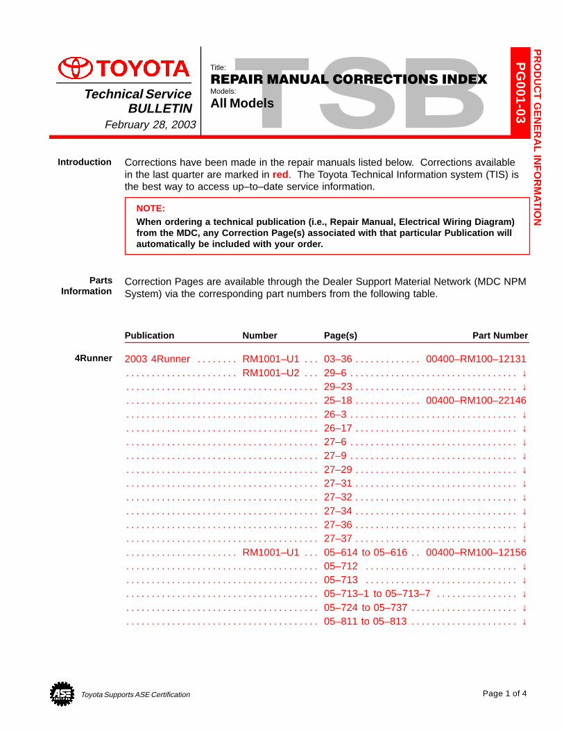
Corrections have been made in the repair manuals listed below. Corrections available in the last quarter are marked in red . The Toyota Technical Information system (TIS) isthe best way to access up–to–date service information.
NOTE:When ordering a technical publication (i.e., Repair Manual, Electrical Wiring Diagram)from the MDC, any Correction Page(s) associated with that particular Publication willautomatically be included with your order.
Correction Pages are available through the Dealer Support Material Network (MDC NPMSystem) via the corresponding part numbers from the following table.
Publication Number Page(s) Part Number
2003 4Runner RM1001–U1 03–36 00400–RM100–12131. . . . . . . . . . . . . . . . . . . . . . . . RM1001–U2 29–6 ↓. . . . . . . . . . . . . . . . . . . . . . . . . . . . . . . . . . . . . . . . . . . . . . . . . . . . . . . . . .
29–23 ↓. . . . . . . . . . . . . . . . . . . . . . . . . . . . . . . . . . . . . . . . . . . . . . . . . . . . . . . . . . . . . . . . . . . . . . 25–18 00400–RM100–22146. . . . . . . . . . . . . . . . . . . . . . . . . . . . . . . . . . . . . . . . . . . . . . . . . . . 26–3 ↓. . . . . . . . . . . . . . . . . . . . . . . . . . . . . . . . . . . . . . . . . . . . . . . . . . . . . . . . . . . . . . . . . . . . . . . 26–17 ↓. . . . . . . . . . . . . . . . . . . . . . . . . . . . . . . . . . . . . . . . . . . . . . . . . . . . . . . . . . . . . . . . . . . . . . 27–6 ↓. . . . . . . . . . . . . . . . . . . . . . . . . . . . . . . . . . . . . . . . . . . . . . . . . . . . . . . . . . . . . . . . . . . . . . . 27–9 ↓. . . . . . . . . . . . . . . . . . . . . . . . . . . . . . . . . . . . . . . . . . . . . . . . . . . . . . . . . . . . . . . . . . . . . . . 27–29 ↓. . . . . . . . . . . . . . . . . . . . . . . . . . . . . . . . . . . . . . . . . . . . . . . . . . . . . . . . . . . . . . . . . . . . . . 27–31 ↓. . . . . . . . . . . . . . . . . . . . . . . . . . . . . . . . . . . . . . . . . . . . . . . . . . . . . . . . . . . . . . . . . . . . . . 27–32 ↓. . . . . . . . . . . . . . . . . . . . . . . . . . . . . . . . . . . . . . . . . . . . . . . . . . . . . . . . . . . . . . . . . . . . . . 27–34 ↓. . . . . . . . . . . . . . . . . . . . . . . . . . . . . . . . . . . . . . . . . . . . . . . . . . . . . . . . . . . . . . . . . . . . . . 27–36 ↓. . . . . . . . . . . . . . . . . . . . . . . . . . . . . . . . . . . . . . . . . . . . . . . . . . . . . . . . . . . . . . . . . . . . . . 27–37 ↓. . . . . . . . . . . . . . . . . . . . . . . . . . . . . . . . . . . . . . . . . . . . . . . . . . . . . . . . . . . . . . . . . . . . . .
RM1001–U1 05–614 to 05–616 00400–RM100–12156. . . . . . . . . . . . . . . . . . . . . . . . . . . 05–712 ↓. . . . . . . . . . . . . . . . . . . . . . . . . . . . . . . . . . . . . . . . . . . . . . . . . . . . . . . . . . . . . . . . . . . . 05–713 ↓. . . . . . . . . . . . . . . . . . . . . . . . . . . . . . . . . . . . . . . . . . . . . . . . . . . . . . . . . . . . . . . . . . . . 05–713–1 to 05–713–7 ↓. . . . . . . . . . . . . . . . . . . . . . . . . . . . . . . . . . . . . . . . . . . . . . . . . . . . . . 05–724 to 05–737 ↓. . . . . . . . . . . . . . . . . . . . . . . . . . . . . . . . . . . . . . . . . . . . . . . . . . . . . . . . . . . 05–811 to 05–813 ↓. . . . . . . . . . . . . . . . . . . . . . . . . . . . . . . . . . . . . . . . . . . . . . . . . . . . . . . . . . .
PR
OD
UC
T G
EN
ER
AL IN
FO
RM
AT
ION
Introduction
PartsInformation
4Runner
REPAIR MANUAL CORRECTIONS INDEX – PG001-03 February 28, 2003
Page 2 of 4
Publication Number Page(s) Part Number
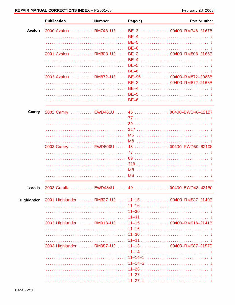
2000 Avalon RM746–U2 BE–3 00400–RM746–2167B. . . . . . . . . . . . . . . . . . . . . . . . . . . BE–4 ↓. . . . . . . . . . . . . . . . . . . . . . . . . . . . . . . . . . . . . . . . . . . . . . . . . . . . . . . . . . . . . . . . . . . . . . BE–5 ↓. . . . . . . . . . . . . . . . . . . . . . . . . . . . . . . . . . . . . . . . . . . . . . . . . . . . . . . . . . . . . . . . . . . . . . BE–6 ↓. . . . . . . . . . . . . . . . . . . . . . . . . . . . . . . . . . . . . . . . . . . . . . . . . . . . . . . . . . . . . . . . . . . . . .
2001 Avalon RM808–U2 BE–3 00400–RM808–2166B. . . . . . . . . . . . . . . . . . . . . . . . . . . BE–4 ↓. . . . . . . . . . . . . . . . . . . . . . . . . . . . . . . . . . . . . . . . . . . . . . . . . . . . . . . . . . . . . . . . . . . . . . BE–5 ↓. . . . . . . . . . . . . . . . . . . . . . . . . . . . . . . . . . . . . . . . . . . . . . . . . . . . . . . . . . . . . . . . . . . . . . BE–6 ↓. . . . . . . . . . . . . . . . . . . . . . . . . . . . . . . . . . . . . . . . . . . . . . . . . . . . . . . . . . . . . . . . . . . . . .
2002 Avalon RM872–U2 BE–96 00400–RM872–2088B. . . . . . . . . . . . . . . . . . . . . . . . . . BE–3 00400–RM872–2165B. . . . . . . . . . . . . . . . . . . . . . . . . . . . . . . . . . . . . . . . . . . . . . . . . . . BE–4 ↓. . . . . . . . . . . . . . . . . . . . . . . . . . . . . . . . . . . . . . . . . . . . . . . . . . . . . . . . . . . . . . . . . . . . . . BE–5 ↓. . . . . . . . . . . . . . . . . . . . . . . . . . . . . . . . . . . . . . . . . . . . . . . . . . . . . . . . . . . . . . . . . . . . . . BE–6 ↓. . . . . . . . . . . . . . . . . . . . . . . . . . . . . . . . . . . . . . . . . . . . . . . . . . . . . . . . . . . . . . . . . . . . . .
2002 Camry EWD461U 45 00400–EWD46–12107. . . . . . . . . . . . . . . . . . . . . . . . . . . . . . . 77 ↓. . . . . . . . . . . . . . . . . . . . . . . . . . . . . . . . . . . . . . . . . . . . . . . . . . . . . . . . . . . . . . . . . . . . . . . . . 89 ↓. . . . . . . . . . . . . . . . . . . . . . . . . . . . . . . . . . . . . . . . . . . . . . . . . . . . . . . . . . . . . . . . . . . . . . . . . 317 ↓. . . . . . . . . . . . . . . . . . . . . . . . . . . . . . . . . . . . . . . . . . . . . . . . . . . . . . . . . . . . . . . . . . . . . . . . M5 ↓. . . . . . . . . . . . . . . . . . . . . . . . . . . . . . . . . . . . . . . . . . . . . . . . . . . . . . . . . . . . . . . . . . . . . . . . M6 ↓. . . . . . . . . . . . . . . . . . . . . . . . . . . . . . . . . . . . . . . . . . . . . . . . . . . . . . . . . . . . . . . . . . . . . . . .
2003 Camry EWD506U 45 00400–EWD50–62108. . . . . . . . . . . . . . . . . . . . . . . . . . . . . . . 77 ↓. . . . . . . . . . . . . . . . . . . . . . . . . . . . . . . . . . . . . . . . . . . . . . . . . . . . . . . . . . . . . . . . . . . . . . . . . 89 ↓. . . . . . . . . . . . . . . . . . . . . . . . . . . . . . . . . . . . . . . . . . . . . . . . . . . . . . . . . . . . . . . . . . . . . . . . . 319 ↓. . . . . . . . . . . . . . . . . . . . . . . . . . . . . . . . . . . . . . . . . . . . . . . . . . . . . . . . . . . . . . . . . . . . . . . . M5 ↓. . . . . . . . . . . . . . . . . . . . . . . . . . . . . . . . . . . . . . . . . . . . . . . . . . . . . . . . . . . . . . . . . . . . . . . . M6 ↓. . . . . . . . . . . . . . . . . . . . . . . . . . . . . . . . . . . . . . . . . . . . . . . . . . . . . . . . . . . . . . . . . . . . . . . .
2003 Corolla EWD484U 49 00400–EWD48–42150. . . . . . . . . . . . . . . . . . . . . . . . . . . . . . .
2001 Highlander RM837–U2 11–15 00400–RM837–2140B. . . . . . . . . . . . . . . . . . . . . . . 11–16 ↓. . . . . . . . . . . . . . . . . . . . . . . . . . . . . . . . . . . . . . . . . . . . . . . . . . . . . . . . . . . . . . . . . . . . . . 11–30 ↓. . . . . . . . . . . . . . . . . . . . . . . . . . . . . . . . . . . . . . . . . . . . . . . . . . . . . . . . . . . . . . . . . . . . . . 11–31 ↓. . . . . . . . . . . . . . . . . . . . . . . . . . . . . . . . . . . . . . . . . . . . . . . . . . . . . . . . . . . . . . . . . . . . . .
2002 Highlander RM918–U2 11–15 00400–RM918–2141B. . . . . . . . . . . . . . . . . . . . . . . 11–16 ↓. . . . . . . . . . . . . . . . . . . . . . . . . . . . . . . . . . . . . . . . . . . . . . . . . . . . . . . . . . . . . . . . . . . . . . 11–30 ↓. . . . . . . . . . . . . . . . . . . . . . . . . . . . . . . . . . . . . . . . . . . . . . . . . . . . . . . . . . . . . . . . . . . . . . 11–31 ↓. . . . . . . . . . . . . . . . . . . . . . . . . . . . . . . . . . . . . . . . . . . . . . . . . . . . . . . . . . . . . . . . . . . . . .
2003 Highlander RM987–U2 11–13 00400–RM987–2157B. . . . . . . . . . . . . . . . . . . . . . . 11–14 ↓. . . . . . . . . . . . . . . . . . . . . . . . . . . . . . . . . . . . . . . . . . . . . . . . . . . . . . . . . . . . . . . . . . . . . . 11–14–1 ↓. . . . . . . . . . . . . . . . . . . . . . . . . . . . . . . . . . . . . . . . . . . . . . . . . . . . . . . . . . . . . . . . . . . 11–14–2 ↓. . . . . . . . . . . . . . . . . . . . . . . . . . . . . . . . . . . . . . . . . . . . . . . . . . . . . . . . . . . . . . . . . . . 11–26 ↓. . . . . . . . . . . . . . . . . . . . . . . . . . . . . . . . . . . . . . . . . . . . . . . . . . . . . . . . . . . . . . . . . . . . . . 11–27 ↓. . . . . . . . . . . . . . . . . . . . . . . . . . . . . . . . . . . . . . . . . . . . . . . . . . . . . . . . . . . . . . . . . . . . . . 11–27–1 ↓. . . . . . . . . . . . . . . . . . . . . . . . . . . . . . . . . . . . . . . . . . . . . . . . . . . . . . . . . . . . . . . . . . .
Avalon
Camry
Corolla
Highlander
REPAIR MANUAL CORRECTIONS INDEX – PG001-03 February 28, 2003
Page 3 of 4
Publication Number Page(s) Part Number
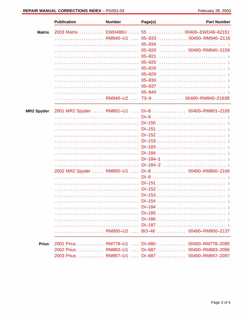
2003 Matrix EWD486U 55 00400–EWD48–62151. . . . . . . . . . . . . . . . . . . . . . . . . . . . . . . . RM940–U1 05–833 00400–RM940–2116. . . . . . . . . . . . . . . . . . . . . . . . . . . . . . . . . . . . . . .
05–834 ↓. . . . . . . . . . . . . . . . . . . . . . . . . . . . . . . . . . . . . . . . . . . . . . . . . . . . . . . . . . . . . . . . . . . . 05–820 00400–RM940–2159. . . . . . . . . . . . . . . . . . . . . . . . . . . . . . . . . . . . . . . . . . . . . . . . . . 05–821 ↓. . . . . . . . . . . . . . . . . . . . . . . . . . . . . . . . . . . . . . . . . . . . . . . . . . . . . . . . . . . . . . . . . . . . 05–825 ↓. . . . . . . . . . . . . . . . . . . . . . . . . . . . . . . . . . . . . . . . . . . . . . . . . . . . . . . . . . . . . . . . . . . . 05–826 ↓. . . . . . . . . . . . . . . . . . . . . . . . . . . . . . . . . . . . . . . . . . . . . . . . . . . . . . . . . . . . . . . . . . . . 05–829 ↓. . . . . . . . . . . . . . . . . . . . . . . . . . . . . . . . . . . . . . . . . . . . . . . . . . . . . . . . . . . . . . . . . . . . 05–830 ↓. . . . . . . . . . . . . . . . . . . . . . . . . . . . . . . . . . . . . . . . . . . . . . . . . . . . . . . . . . . . . . . . . . . . 05–837 ↓. . . . . . . . . . . . . . . . . . . . . . . . . . . . . . . . . . . . . . . . . . . . . . . . . . . . . . . . . . . . . . . . . . . . 05–840 ↓. . . . . . . . . . . . . . . . . . . . . . . . . . . . . . . . . . . . . . . . . . . . . . . . . . . . . . . . . . . . . . . . . . . .
RM940–U2 73–9 00400–RM940–2163B. . . . . . . . . . . . . . . . . . . . . . . . . . . . . . . . . . . . . . . .
2001 MR2 Spyder RM801–U1 DI–8 00400–RM801–2105. . . . . . . . . . . . . . . . . . . . . . . . DI–9 ↓. . . . . . . . . . . . . . . . . . . . . . . . . . . . . . . . . . . . . . . . . . . . . . . . . . . . . . . . . . . . . . . . . . . . . . . DI–150 ↓. . . . . . . . . . . . . . . . . . . . . . . . . . . . . . . . . . . . . . . . . . . . . . . . . . . . . . . . . . . . . . . . . . . . . DI–151 ↓. . . . . . . . . . . . . . . . . . . . . . . . . . . . . . . . . . . . . . . . . . . . . . . . . . . . . . . . . . . . . . . . . . . . . DI–152 ↓. . . . . . . . . . . . . . . . . . . . . . . . . . . . . . . . . . . . . . . . . . . . . . . . . . . . . . . . . . . . . . . . . . . . . DI–153 ↓. . . . . . . . . . . . . . . . . . . . . . . . . . . . . . . . . . . . . . . . . . . . . . . . . . . . . . . . . . . . . . . . . . . . . DI–183 ↓. . . . . . . . . . . . . . . . . . . . . . . . . . . . . . . . . . . . . . . . . . . . . . . . . . . . . . . . . . . . . . . . . . . . . DI–184 ↓. . . . . . . . . . . . . . . . . . . . . . . . . . . . . . . . . . . . . . . . . . . . . . . . . . . . . . . . . . . . . . . . . . . . . DI–184–1 ↓. . . . . . . . . . . . . . . . . . . . . . . . . . . . . . . . . . . . . . . . . . . . . . . . . . . . . . . . . . . . . . . . . . DI–184–2 ↓. . . . . . . . . . . . . . . . . . . . . . . . . . . . . . . . . . . . . . . . . . . . . . . . . . . . . . . . . . . . . . . . . .
2002 MR2 Spyder RM900–U1 DI–8 00400–RM900–2106. . . . . . . . . . . . . . . . . . . . . . . . DI–9 ↓. . . . . . . . . . . . . . . . . . . . . . . . . . . . . . . . . . . . . . . . . . . . . . . . . . . . . . . . . . . . . . . . . . . . . . . DI–151 ↓. . . . . . . . . . . . . . . . . . . . . . . . . . . . . . . . . . . . . . . . . . . . . . . . . . . . . . . . . . . . . . . . . . . . . DI–152 ↓. . . . . . . . . . . . . . . . . . . . . . . . . . . . . . . . . . . . . . . . . . . . . . . . . . . . . . . . . . . . . . . . . . . . . DI–153 ↓. . . . . . . . . . . . . . . . . . . . . . . . . . . . . . . . . . . . . . . . . . . . . . . . . . . . . . . . . . . . . . . . . . . . . DI–154 ↓. . . . . . . . . . . . . . . . . . . . . . . . . . . . . . . . . . . . . . . . . . . . . . . . . . . . . . . . . . . . . . . . . . . . . DI–184 ↓. . . . . . . . . . . . . . . . . . . . . . . . . . . . . . . . . . . . . . . . . . . . . . . . . . . . . . . . . . . . . . . . . . . . . DI–185 ↓. . . . . . . . . . . . . . . . . . . . . . . . . . . . . . . . . . . . . . . . . . . . . . . . . . . . . . . . . . . . . . . . . . . . . DI–186 ↓. . . . . . . . . . . . . . . . . . . . . . . . . . . . . . . . . . . . . . . . . . . . . . . . . . . . . . . . . . . . . . . . . . . . . DI–187 ↓. . . . . . . . . . . . . . . . . . . . . . . . . . . . . . . . . . . . . . . . . . . . . . . . . . . . . . . . . . . . . . . . . . . . .
RM900–U2 BO–46 00400–RM900–2137. . . . . . . . . . . . . . . . . . . . . . . . . . . . . . . . . . . . . . .
2001 Prius RM778–U1 DI–680 00400–RM778–2095. . . . . . . . . . . . . . . . . . . . . . . . . . . . . 2002 Prius RM883–U1 DI–687 00400–RM883–2096. . . . . . . . . . . . . . . . . . . . . . . . . . . . . 2003 Prius RM957–U1 DI–687 00400–RM957–2097. . . . . . . . . . . . . . . . . . . . . . . . . . . . .
Matrix
MR2 Spyder
Prius
REPAIR MANUAL CORRECTIONS INDEX – PG001-03 February 28, 2003
Page 4 of 4
Publication Number Page(s) Part Number
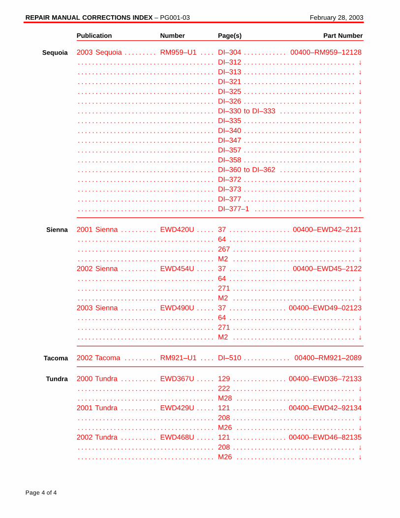
2003 Sequoia RM959–U1 DI–304 00400–RM959–12128. . . . . . . . . . . . . . . . . . . . . . . . . DI–312 ↓. . . . . . . . . . . . . . . . . . . . . . . . . . . . . . . . . . . . . . . . . . . . . . . . . . . . . . . . . . . . . . . . . . . . . DI–313 ↓. . . . . . . . . . . . . . . . . . . . . . . . . . . . . . . . . . . . . . . . . . . . . . . . . . . . . . . . . . . . . . . . . . . . . DI–321 ↓. . . . . . . . . . . . . . . . . . . . . . . . . . . . . . . . . . . . . . . . . . . . . . . . . . . . . . . . . . . . . . . . . . . . . DI–325 ↓. . . . . . . . . . . . . . . . . . . . . . . . . . . . . . . . . . . . . . . . . . . . . . . . . . . . . . . . . . . . . . . . . . . . . DI–326 ↓. . . . . . . . . . . . . . . . . . . . . . . . . . . . . . . . . . . . . . . . . . . . . . . . . . . . . . . . . . . . . . . . . . . . . DI–330 to DI–333 ↓. . . . . . . . . . . . . . . . . . . . . . . . . . . . . . . . . . . . . . . . . . . . . . . . . . . . . . . . . . . DI–335 ↓. . . . . . . . . . . . . . . . . . . . . . . . . . . . . . . . . . . . . . . . . . . . . . . . . . . . . . . . . . . . . . . . . . . . . DI–340 ↓. . . . . . . . . . . . . . . . . . . . . . . . . . . . . . . . . . . . . . . . . . . . . . . . . . . . . . . . . . . . . . . . . . . . . DI–347 ↓. . . . . . . . . . . . . . . . . . . . . . . . . . . . . . . . . . . . . . . . . . . . . . . . . . . . . . . . . . . . . . . . . . . . . DI–357 ↓. . . . . . . . . . . . . . . . . . . . . . . . . . . . . . . . . . . . . . . . . . . . . . . . . . . . . . . . . . . . . . . . . . . . . DI–358 ↓. . . . . . . . . . . . . . . . . . . . . . . . . . . . . . . . . . . . . . . . . . . . . . . . . . . . . . . . . . . . . . . . . . . . . DI–360 to DI–362 ↓. . . . . . . . . . . . . . . . . . . . . . . . . . . . . . . . . . . . . . . . . . . . . . . . . . . . . . . . . . . DI–372 ↓. . . . . . . . . . . . . . . . . . . . . . . . . . . . . . . . . . . . . . . . . . . . . . . . . . . . . . . . . . . . . . . . . . . . . DI–373 ↓. . . . . . . . . . . . . . . . . . . . . . . . . . . . . . . . . . . . . . . . . . . . . . . . . . . . . . . . . . . . . . . . . . . . . DI–377 ↓. . . . . . . . . . . . . . . . . . . . . . . . . . . . . . . . . . . . . . . . . . . . . . . . . . . . . . . . . . . . . . . . . . . . . DI–377–1 ↓. . . . . . . . . . . . . . . . . . . . . . . . . . . . . . . . . . . . . . . . . . . . . . . . . . . . . . . . . . . . . . . . . .
2001 Sienna EWD420U 37 00400–EWD42–2121. . . . . . . . . . . . . . . . . . . . . . . . . . . . . . . . 64 ↓. . . . . . . . . . . . . . . . . . . . . . . . . . . . . . . . . . . . . . . . . . . . . . . . . . . . . . . . . . . . . . . . . . . . . . . . . 267 ↓. . . . . . . . . . . . . . . . . . . . . . . . . . . . . . . . . . . . . . . . . . . . . . . . . . . . . . . . . . . . . . . . . . . . . . . . M2 ↓. . . . . . . . . . . . . . . . . . . . . . . . . . . . . . . . . . . . . . . . . . . . . . . . . . . . . . . . . . . . . . . . . . . . . . . .
2002 Sienna EWD454U 37 00400–EWD45–2122. . . . . . . . . . . . . . . . . . . . . . . . . . . . . . . . 64 ↓. . . . . . . . . . . . . . . . . . . . . . . . . . . . . . . . . . . . . . . . . . . . . . . . . . . . . . . . . . . . . . . . . . . . . . . . . 271 ↓. . . . . . . . . . . . . . . . . . . . . . . . . . . . . . . . . . . . . . . . . . . . . . . . . . . . . . . . . . . . . . . . . . . . . . . . M2 ↓. . . . . . . . . . . . . . . . . . . . . . . . . . . . . . . . . . . . . . . . . . . . . . . . . . . . . . . . . . . . . . . . . . . . . . . .
2003 Sienna EWD490U 37 00400–EWD49–02123. . . . . . . . . . . . . . . . . . . . . . . . . . . . . . . 64 ↓. . . . . . . . . . . . . . . . . . . . . . . . . . . . . . . . . . . . . . . . . . . . . . . . . . . . . . . . . . . . . . . . . . . . . . . . . 271 ↓. . . . . . . . . . . . . . . . . . . . . . . . . . . . . . . . . . . . . . . . . . . . . . . . . . . . . . . . . . . . . . . . . . . . . . . . M2 ↓. . . . . . . . . . . . . . . . . . . . . . . . . . . . . . . . . . . . . . . . . . . . . . . . . . . . . . . . . . . . . . . . . . . . . . . .
2002 Tacoma RM921–U1 DI–510 00400–RM921–2089. . . . . . . . . . . . . . . . . . . . . . . . . .
2000 Tundra EWD367U 129 00400–EWD36–72133. . . . . . . . . . . . . . . . . . . . . . . . . . . . . . 222 ↓. . . . . . . . . . . . . . . . . . . . . . . . . . . . . . . . . . . . . . . . . . . . . . . . . . . . . . . . . . . . . . . . . . . . . . . . M28 ↓. . . . . . . . . . . . . . . . . . . . . . . . . . . . . . . . . . . . . . . . . . . . . . . . . . . . . . . . . . . . . . . . . . . . . . .
2001 Tundra EWD429U 121 00400–EWD42–92134. . . . . . . . . . . . . . . . . . . . . . . . . . . . . . 208 ↓. . . . . . . . . . . . . . . . . . . . . . . . . . . . . . . . . . . . . . . . . . . . . . . . . . . . . . . . . . . . . . . . . . . . . . . . M26 ↓. . . . . . . . . . . . . . . . . . . . . . . . . . . . . . . . . . . . . . . . . . . . . . . . . . . . . . . . . . . . . . . . . . . . . . .
2002 Tundra EWD468U 121 00400–EWD46–82135. . . . . . . . . . . . . . . . . . . . . . . . . . . . . . 208 ↓. . . . . . . . . . . . . . . . . . . . . . . . . . . . . . . . . . . . . . . . . . . . . . . . . . . . . . . . . . . . . . . . . . . . . . . . M26 ↓. . . . . . . . . . . . . . . . . . . . . . . . . . . . . . . . . . . . . . . . . . . . . . . . . . . . . . . . . . . . . . . . . . . . . . .
Sequoia
Sienna
Tacoma
Tundra
Toyota Supports ASE Certification Page 1 of 4
PG
002–00
Title:
REPAIR MANUAL CORRECTIONS INDEXModels:
All ModelsTechnical Service
BULLETINDecember 31, 2000
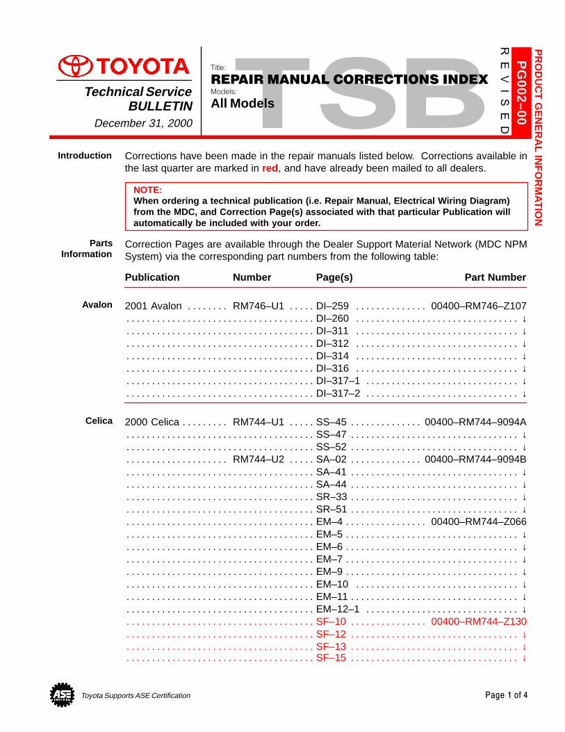
Corrections have been made in the repair manuals listed below. Corrections available inthe last quarter are marked in red , and have already been mailed to all dealers.
NOTE:When ordering a technical publication (i.e. Repair Manual, Electrical Wiring Diagram)from the MDC, and Correction Page(s) associated with that particular Publication willautomatically be included with your order.
Correction Pages are available through the Dealer Support Material Network (MDC NPMSystem) via the corresponding part numbers from the following table:
Publication Number Page(s) Part Number
2001 Avalon RM746–U1 DI–259 00400–RM746–Z107. . . . . . . . . . . . . . . . . . . . . . . . . . . DI–260 ↓. . . . . . . . . . . . . . . . . . . . . . . . . . . . . . . . . . . . . . . . . . . . . . . . . . . . . . . . . . . . . . . . . . . . . DI–311 ↓. . . . . . . . . . . . . . . . . . . . . . . . . . . . . . . . . . . . . . . . . . . . . . . . . . . . . . . . . . . . . . . . . . . . . DI–312 ↓. . . . . . . . . . . . . . . . . . . . . . . . . . . . . . . . . . . . . . . . . . . . . . . . . . . . . . . . . . . . . . . . . . . . . DI–314 ↓. . . . . . . . . . . . . . . . . . . . . . . . . . . . . . . . . . . . . . . . . . . . . . . . . . . . . . . . . . . . . . . . . . . . . DI–316 ↓. . . . . . . . . . . . . . . . . . . . . . . . . . . . . . . . . . . . . . . . . . . . . . . . . . . . . . . . . . . . . . . . . . . . . DI–317–1 ↓. . . . . . . . . . . . . . . . . . . . . . . . . . . . . . . . . . . . . . . . . . . . . . . . . . . . . . . . . . . . . . . . . . . DI–317–2 ↓. . . . . . . . . . . . . . . . . . . . . . . . . . . . . . . . . . . . . . . . . . . . . . . . . . . . . . . . . . . . . . . . . . .
2000 Celica RM744–U1 SS–45 00400–RM744–9094A. . . . . . . . . . . . . . . . . . . . . . . . . . . . SS–47 ↓. . . . . . . . . . . . . . . . . . . . . . . . . . . . . . . . . . . . . . . . . . . . . . . . . . . . . . . . . . . . . . . . . . . . . . SS–52 ↓. . . . . . . . . . . . . . . . . . . . . . . . . . . . . . . . . . . . . . . . . . . . . . . . . . . . . . . . . . . . . . . . . . . . . .
RM744–U2 SA–02 00400–RM744–9094B. . . . . . . . . . . . . . . . . . . . . . . . . . . . . . . . . . . . . . . SA–41 ↓. . . . . . . . . . . . . . . . . . . . . . . . . . . . . . . . . . . . . . . . . . . . . . . . . . . . . . . . . . . . . . . . . . . . . . SA–44 ↓. . . . . . . . . . . . . . . . . . . . . . . . . . . . . . . . . . . . . . . . . . . . . . . . . . . . . . . . . . . . . . . . . . . . . . SR–33 ↓. . . . . . . . . . . . . . . . . . . . . . . . . . . . . . . . . . . . . . . . . . . . . . . . . . . . . . . . . . . . . . . . . . . . . . SR–51 ↓. . . . . . . . . . . . . . . . . . . . . . . . . . . . . . . . . . . . . . . . . . . . . . . . . . . . . . . . . . . . . . . . . . . . . . EM–4 00400–RM744–Z066. . . . . . . . . . . . . . . . . . . . . . . . . . . . . . . . . . . . . . . . . . . . . . . . . . . . . EM–5 ↓. . . . . . . . . . . . . . . . . . . . . . . . . . . . . . . . . . . . . . . . . . . . . . . . . . . . . . . . . . . . . . . . . . . . . . . EM–6 ↓. . . . . . . . . . . . . . . . . . . . . . . . . . . . . . . . . . . . . . . . . . . . . . . . . . . . . . . . . . . . . . . . . . . . . . . EM–7 ↓. . . . . . . . . . . . . . . . . . . . . . . . . . . . . . . . . . . . . . . . . . . . . . . . . . . . . . . . . . . . . . . . . . . . . . . EM–9 ↓. . . . . . . . . . . . . . . . . . . . . . . . . . . . . . . . . . . . . . . . . . . . . . . . . . . . . . . . . . . . . . . . . . . . . . . EM–10 ↓. . . . . . . . . . . . . . . . . . . . . . . . . . . . . . . . . . . . . . . . . . . . . . . . . . . . . . . . . . . . . . . . . . . . . EM–11 ↓. . . . . . . . . . . . . . . . . . . . . . . . . . . . . . . . . . . . . . . . . . . . . . . . . . . . . . . . . . . . . . . . . . . . . . EM–12–1 ↓. . . . . . . . . . . . . . . . . . . . . . . . . . . . . . . . . . . . . . . . . . . . . . . . . . . . . . . . . . . . . . . . . . . SF–10 00400–RM744–Z130. . . . . . . . . . . . . . . . . . . . . . . . . . . . . . . . . . . . . . . . . . . . . . . . . . . . SF–12 ↓. . . . . . . . . . . . . . . . . . . . . . . . . . . . . . . . . . . . . . . . . . . . . . . . . . . . . . . . . . . . . . . . . . . . . . SF–13 ↓. . . . . . . . . . . . . . . . . . . . . . . . . . . . . . . . . . . . . . . . . . . . . . . . . . . . . . . . . . . . . . . . . . . . . . SF–15 ↓. . . . . . . . . . . . . . . . . . . . . . . . . . . . . . . . . . . . . . . . . . . . . . . . . . . . . . . . . . . . . . . . . . . . . .
PR
OD
UC
T G
EN
ER
AL IN
FO
RM
AT
ION
Introduction
PartsInformation
Avalon
Celica
REPAIR MANUAL CORRECTIONS INDEX – PG002-00 Revised December 31, 2000
Page 2 of 4
Publication Number Page(s) Part Number
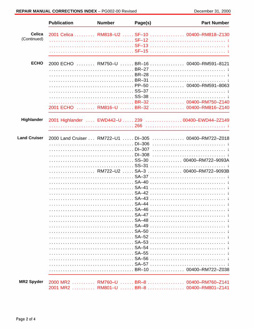
2001 Celica RM818–U2 SF–10 00400–RM818–Z130. . . . . . . . . . . . . . . . . . . . . . . . . . . . . SF–12 ↓. . . . . . . . . . . . . . . . . . . . . . . . . . . . . . . . . . . . . . . . . . . . . . . . . . . . . . . . . . . . . . . . . . . . . . SF–13 ↓. . . . . . . . . . . . . . . . . . . . . . . . . . . . . . . . . . . . . . . . . . . . . . . . . . . . . . . . . . . . . . . . . . . . . . SF–15 ↓. . . . . . . . . . . . . . . . . . . . . . . . . . . . . . . . . . . . . . . . . . . . . . . . . . . . . . . . . . . . . . . . . . . . . .
2000 ECHO RM750–U BR–16 00400–RM591–8121. . . . . . . . . . . . . . . . . . . . . . . . . . . . . BR–27 ↓. . . . . . . . . . . . . . . . . . . . . . . . . . . . . . . . . . . . . . . . . . . . . . . . . . . . . . . . . . . . . . . . . . . . . . BR–28 ↓. . . . . . . . . . . . . . . . . . . . . . . . . . . . . . . . . . . . . . . . . . . . . . . . . . . . . . . . . . . . . . . . . . . . . . BR–31 ↓. . . . . . . . . . . . . . . . . . . . . . . . . . . . . . . . . . . . . . . . . . . . . . . . . . . . . . . . . . . . . . . . . . . . . . PP–50 00400–RM591–8063. . . . . . . . . . . . . . . . . . . . . . . . . . . . . . . . . . . . . . . . . . . . . . . . . . . . SS–37 ↓. . . . . . . . . . . . . . . . . . . . . . . . . . . . . . . . . . . . . . . . . . . . . . . . . . . . . . . . . . . . . . . . . . . . . . SS–38 ↓. . . . . . . . . . . . . . . . . . . . . . . . . . . . . . . . . . . . . . . . . . . . . . . . . . . . . . . . . . . . . . . . . . . . . . BR–32 00400–RM750–Z140. . . . . . . . . . . . . . . . . . . . . . . . . . . . . . . . . . . . . . . . . . . . . . . . . . . .
2001 ECHO RM816–U BR–32 00400–RM816–Z140. . . . . . . . . . . . . . . . . . . . . . . . . . . . .
2001 Highlander EWD442–U 239 00400–EWD44–2Z149. . . . . . . . . . . . . . . . . . . . . . . . . 266 ↓. . . . . . . . . . . . . . . . . . . . . . . . . . . . . . . . . . . . . . . . . . . . . . . . . . . . . . . . . . . . . . . . . . . . . . . .
2000 Land Cruiser RM722–U1 DI–305 00400–RM722–Z018. . . . . . . . . . . . . . . . . . . . . . DI–306 ↓. . . . . . . . . . . . . . . . . . . . . . . . . . . . . . . . . . . . . . . . . . . . . . . . . . . . . . . . . . . . . . . . . . . . . DI–307 ↓. . . . . . . . . . . . . . . . . . . . . . . . . . . . . . . . . . . . . . . . . . . . . . . . . . . . . . . . . . . . . . . . . . . . . DI–308 ↓. . . . . . . . . . . . . . . . . . . . . . . . . . . . . . . . . . . . . . . . . . . . . . . . . . . . . . . . . . . . . . . . . . . . . SS–30 00400–RM722–9093A. . . . . . . . . . . . . . . . . . . . . . . . . . . . . . . . . . . . . . . . . . . . . . . . . . . SS–31 ↓. . . . . . . . . . . . . . . . . . . . . . . . . . . . . . . . . . . . . . . . . . . . . . . . . . . . . . . . . . . . . . . . . . . . . .
RM722–U2 SA–3 00400–RM722–9093B. . . . . . . . . . . . . . . . . . . . . . . . . . . . . . . . . . . . . . . . SA–37 ↓. . . . . . . . . . . . . . . . . . . . . . . . . . . . . . . . . . . . . . . . . . . . . . . . . . . . . . . . . . . . . . . . . . . . . . SA–40 ↓. . . . . . . . . . . . . . . . . . . . . . . . . . . . . . . . . . . . . . . . . . . . . . . . . . . . . . . . . . . . . . . . . . . . . . SA–41 ↓. . . . . . . . . . . . . . . . . . . . . . . . . . . . . . . . . . . . . . . . . . . . . . . . . . . . . . . . . . . . . . . . . . . . . . SA–42 ↓. . . . . . . . . . . . . . . . . . . . . . . . . . . . . . . . . . . . . . . . . . . . . . . . . . . . . . . . . . . . . . . . . . . . . . SA–43 ↓. . . . . . . . . . . . . . . . . . . . . . . . . . . . . . . . . . . . . . . . . . . . . . . . . . . . . . . . . . . . . . . . . . . . . . SA–44 ↓. . . . . . . . . . . . . . . . . . . . . . . . . . . . . . . . . . . . . . . . . . . . . . . . . . . . . . . . . . . . . . . . . . . . . . SA–46 ↓. . . . . . . . . . . . . . . . . . . . . . . . . . . . . . . . . . . . . . . . . . . . . . . . . . . . . . . . . . . . . . . . . . . . . . SA–47 ↓. . . . . . . . . . . . . . . . . . . . . . . . . . . . . . . . . . . . . . . . . . . . . . . . . . . . . . . . . . . . . . . . . . . . . . SA–48 ↓. . . . . . . . . . . . . . . . . . . . . . . . . . . . . . . . . . . . . . . . . . . . . . . . . . . . . . . . . . . . . . . . . . . . . . SA–49 ↓. . . . . . . . . . . . . . . . . . . . . . . . . . . . . . . . . . . . . . . . . . . . . . . . . . . . . . . . . . . . . . . . . . . . . . SA–50 ↓. . . . . . . . . . . . . . . . . . . . . . . . . . . . . . . . . . . . . . . . . . . . . . . . . . . . . . . . . . . . . . . . . . . . . . SA–52 ↓. . . . . . . . . . . . . . . . . . . . . . . . . . . . . . . . . . . . . . . . . . . . . . . . . . . . . . . . . . . . . . . . . . . . . . SA–53 ↓. . . . . . . . . . . . . . . . . . . . . . . . . . . . . . . . . . . . . . . . . . . . . . . . . . . . . . . . . . . . . . . . . . . . . . SA–54 ↓. . . . . . . . . . . . . . . . . . . . . . . . . . . . . . . . . . . . . . . . . . . . . . . . . . . . . . . . . . . . . . . . . . . . . . SA–55 ↓. . . . . . . . . . . . . . . . . . . . . . . . . . . . . . . . . . . . . . . . . . . . . . . . . . . . . . . . . . . . . . . . . . . . . . SA–56 ↓. . . . . . . . . . . . . . . . . . . . . . . . . . . . . . . . . . . . . . . . . . . . . . . . . . . . . . . . . . . . . . . . . . . . . . SA–57 ↓. . . . . . . . . . . . . . . . . . . . . . . . . . . . . . . . . . . . . . . . . . . . . . . . . . . . . . . . . . . . . . . . . . . . . . BR–10 00400–RM722–Z038. . . . . . . . . . . . . . . . . . . . . . . . . . . . . . . . . . . . . . . . . . . . . . . . . . . .
2000 MR2 RM760–U BR–8 00400–RM760–Z141. . . . . . . . . . . . . . . . . . . . . . . . . . . . . . . . 2001 MR2 RM801–U BR–8 00400–RM801–Z141. . . . . . . . . . . . . . . . . . . . . . . . . . . . . . . .
Celica(Continued)
ECHO
Highlander
Land Cruiser
MR2 Spyder
REPAIR MANUAL CORRECTIONS INDEX – PG002-00 Revised December 31, 2000
Page 3 of 4
Publication Number Page(s) Part Number
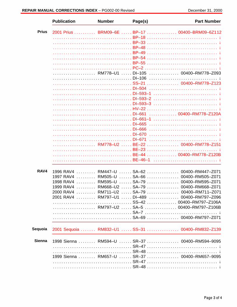
2001 Prius BRM09–6E BP–17 00400–BRM09–6Z112. . . . . . . . . . . . . . . . . . . . . . . . . . . . . BP–18 ↓. . . . . . . . . . . . . . . . . . . . . . . . . . . . . . . . . . . . . . . . . . . . . . . . . . . . . . . . . . . . . . . . . . . . . . BP–33 ↓. . . . . . . . . . . . . . . . . . . . . . . . . . . . . . . . . . . . . . . . . . . . . . . . . . . . . . . . . . . . . . . . . . . . . . BP–48 ↓. . . . . . . . . . . . . . . . . . . . . . . . . . . . . . . . . . . . . . . . . . . . . . . . . . . . . . . . . . . . . . . . . . . . . . BP–49 ↓. . . . . . . . . . . . . . . . . . . . . . . . . . . . . . . . . . . . . . . . . . . . . . . . . . . . . . . . . . . . . . . . . . . . . . BP–54 ↓. . . . . . . . . . . . . . . . . . . . . . . . . . . . . . . . . . . . . . . . . . . . . . . . . . . . . . . . . . . . . . . . . . . . . . BP–55 ↓. . . . . . . . . . . . . . . . . . . . . . . . . . . . . . . . . . . . . . . . . . . . . . . . . . . . . . . . . . . . . . . . . . . . . . PC–2 ↓. . . . . . . . . . . . . . . . . . . . . . . . . . . . . . . . . . . . . . . . . . . . . . . . . . . . . . . . . . . . . . . . . . . . . . .
RM778–U1 DI–105 00400–RM778–Z093. . . . . . . . . . . . . . . . . . . . . . . . . . . . . . . . . . . . . . . DI–106 ↓. . . . . . . . . . . . . . . . . . . . . . . . . . . . . . . . . . . . . . . . . . . . . . . . . . . . . . . . . . . . . . . . . . . . . SS–21 00400–RM778–Z123. . . . . . . . . . . . . . . . . . . . . . . . . . . . . . . . . . . . . . . . . . . . . . . . . . . . DI–504 ↓. . . . . . . . . . . . . . . . . . . . . . . . . . . . . . . . . . . . . . . . . . . . . . . . . . . . . . . . . . . . . . . . . . . . . DI–593–1 ↓. . . . . . . . . . . . . . . . . . . . . . . . . . . . . . . . . . . . . . . . . . . . . . . . . . . . . . . . . . . . . . . . . . . DI–593–2 ↓. . . . . . . . . . . . . . . . . . . . . . . . . . . . . . . . . . . . . . . . . . . . . . . . . . . . . . . . . . . . . . . . . . . DI–593–3 ↓. . . . . . . . . . . . . . . . . . . . . . . . . . . . . . . . . . . . . . . . . . . . . . . . . . . . . . . . . . . . . . . . . . . HV–22 ↓. . . . . . . . . . . . . . . . . . . . . . . . . . . . . . . . . . . . . . . . . . . . . . . . . . . . . . . . . . . . . . . . . . . . . . DI–661 00400–RM778–Z120A. . . . . . . . . . . . . . . . . . . . . . . . . . . . . . . . . . . . . . . . . . . . . . . . . . DI–661–1 ↓. . . . . . . . . . . . . . . . . . . . . . . . . . . . . . . . . . . . . . . . . . . . . . . . . . . . . . . . . . . . . . . . . . . DI–665 ↓. . . . . . . . . . . . . . . . . . . . . . . . . . . . . . . . . . . . . . . . . . . . . . . . . . . . . . . . . . . . . . . . . . . . . DI–666 ↓. . . . . . . . . . . . . . . . . . . . . . . . . . . . . . . . . . . . . . . . . . . . . . . . . . . . . . . . . . . . . . . . . . . . . DI–670 ↓. . . . . . . . . . . . . . . . . . . . . . . . . . . . . . . . . . . . . . . . . . . . . . . . . . . . . . . . . . . . . . . . . . . . . DI–671 ↓. . . . . . . . . . . . . . . . . . . . . . . . . . . . . . . . . . . . . . . . . . . . . . . . . . . . . . . . . . . . . . . . . . . . .
RM778–U2 BE–22 00400–RM778–Z151. . . . . . . . . . . . . . . . . . . . . . . . . . . . . . . . . . . . . . . . BE–23 ↓. . . . . . . . . . . . . . . . . . . . . . . . . . . . . . . . . . . . . . . . . . . . . . . . . . . . . . . . . . . . . . . . . . . . . . BE–44 00400–RM778–Z120B. . . . . . . . . . . . . . . . . . . . . . . . . . . . . . . . . . . . . . . . . . . . . . . . . . . BE–46–1 ↓. . . . . . . . . . . . . . . . . . . . . . . . . . . . . . . . . . . . . . . . . . . . . . . . . . . . . . . . . . . . . . . . . . .
1996 RAV4 RM447–U SA–62 00400–RM447–Z071. . . . . . . . . . . . . . . . . . . . . . . . . . . . . . 1997 RAV4 RM505–U SA–66 00400–RM505–Z071. . . . . . . . . . . . . . . . . . . . . . . . . . . . . . 1998 RAV4 RM595–U SA–79 00400–RM595–Z071. . . . . . . . . . . . . . . . . . . . . . . . . . . . . . 1999 RAV4 RM668–U2 SA–79 00400–RM668–Z071. . . . . . . . . . . . . . . . . . . . . . . . . . . . . 2000 RAV4 RM711–U2 SA–79 00400–RM711–Z071. . . . . . . . . . . . . . . . . . . . . . . . . . . . . 2001 RAV4 RM797–U1 DI–489 00400–RM797–Z096. . . . . . . . . . . . . . . . . . . . . . . . . . . .
SS–42 00400–RM797–Z106A. . . . . . . . . . . . . . . . . . . . . . . . . . . . . . . . . . . . . . . . . . . . . . . . . . . RM797–U2 SA–5 00400–RM797–Z106B. . . . . . . . . . . . . . . . . . . . . . . . . . . . . . . . . . . . . . . .
SA–7 ↓. . . . . . . . . . . . . . . . . . . . . . . . . . . . . . . . . . . . . . . . . . . . . . . . . . . . . . . . . . . . . . . . . . . . . . . SA–69 00400–RM797–Z071. . . . . . . . . . . . . . . . . . . . . . . . . . . . . . . . . . . . . . . . . . . . . . . . . . . .
2001 Sequoia RM832–U1 SS–31 00400–RM832–Z139. . . . . . . . . . . . . . . . . . . . . . . . . . .
1998 Sienna RM594–U SR–37 00400–RM594–9095. . . . . . . . . . . . . . . . . . . . . . . . . . . . . SR–47 ↓. . . . . . . . . . . . . . . . . . . . . . . . . . . . . . . . . . . . . . . . . . . . . . . . . . . . . . . . . . . . . . . . . . . . . . SR–48 ↓. . . . . . . . . . . . . . . . . . . . . . . . . . . . . . . . . . . . . . . . . . . . . . . . . . . . . . . . . . . . . . . . . . . . . .
1999 Sienna RM657–U SR–37 00400–RM657–9095. . . . . . . . . . . . . . . . . . . . . . . . . . . . . SR–47 ↓. . . . . . . . . . . . . . . . . . . . . . . . . . . . . . . . . . . . . . . . . . . . . . . . . . . . . . . . . . . . . . . . . . . . . . SR–48 ↓. . . . . . . . . . . . . . . . . . . . . . . . . . . . . . . . . . . . . . . . . . . . . . . . . . . . . . . . . . . . . . . . . . . . . .
Prius
RAV4
Sequoia
Sienna
REPAIR MANUAL CORRECTIONS INDEX – PG002-00 Revised December 31, 2000
Page 4 of 4
Publication Number Page(s) Part Number
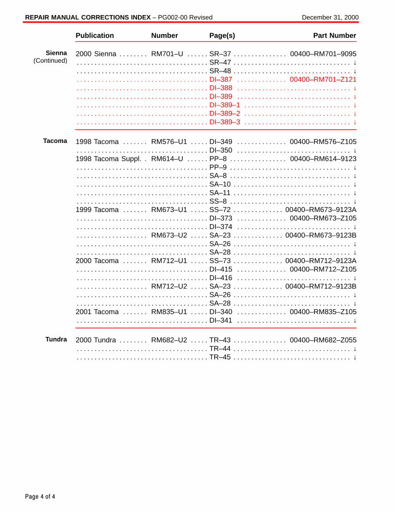
2000 Sienna RM701–U SR–37 00400–RM701–9095. . . . . . . . . . . . . . . . . . . . . . . . . . . . . SR–47 ↓. . . . . . . . . . . . . . . . . . . . . . . . . . . . . . . . . . . . . . . . . . . . . . . . . . . . . . . . . . . . . . . . . . . . . . SR–48 ↓. . . . . . . . . . . . . . . . . . . . . . . . . . . . . . . . . . . . . . . . . . . . . . . . . . . . . . . . . . . . . . . . . . . . . . DI–387 00400–RM701–Z121. . . . . . . . . . . . . . . . . . . . . . . . . . . . . . . . . . . . . . . . . . . . . . . . . . . DI–388 ↓. . . . . . . . . . . . . . . . . . . . . . . . . . . . . . . . . . . . . . . . . . . . . . . . . . . . . . . . . . . . . . . . . . . . . DI–389 ↓. . . . . . . . . . . . . . . . . . . . . . . . . . . . . . . . . . . . . . . . . . . . . . . . . . . . . . . . . . . . . . . . . . . . . DI–389–1 ↓. . . . . . . . . . . . . . . . . . . . . . . . . . . . . . . . . . . . . . . . . . . . . . . . . . . . . . . . . . . . . . . . . . . DI–389–2 ↓. . . . . . . . . . . . . . . . . . . . . . . . . . . . . . . . . . . . . . . . . . . . . . . . . . . . . . . . . . . . . . . . . . . DI–389–3 ↓. . . . . . . . . . . . . . . . . . . . . . . . . . . . . . . . . . . . . . . . . . . . . . . . . . . . . . . . . . . . . . . . . . .
1998 Tacoma RM576–U1 DI–349 00400–RM576–Z105. . . . . . . . . . . . . . . . . . . . . . . . . . DI–350 ↓. . . . . . . . . . . . . . . . . . . . . . . . . . . . . . . . . . . . . . . . . . . . . . . . . . . . . . . . . . . . . . . . . . . . .
1998 Tacoma Suppl. RM614–U PP–8 00400–RM614–9123. . . . . . . . . . . . . . . . . . . . . . . PP–9 ↓. . . . . . . . . . . . . . . . . . . . . . . . . . . . . . . . . . . . . . . . . . . . . . . . . . . . . . . . . . . . . . . . . . . . . . . SA–8 ↓. . . . . . . . . . . . . . . . . . . . . . . . . . . . . . . . . . . . . . . . . . . . . . . . . . . . . . . . . . . . . . . . . . . . . . . SA–10 ↓. . . . . . . . . . . . . . . . . . . . . . . . . . . . . . . . . . . . . . . . . . . . . . . . . . . . . . . . . . . . . . . . . . . . . . SA–11 ↓. . . . . . . . . . . . . . . . . . . . . . . . . . . . . . . . . . . . . . . . . . . . . . . . . . . . . . . . . . . . . . . . . . . . . . SS–8 ↓. . . . . . . . . . . . . . . . . . . . . . . . . . . . . . . . . . . . . . . . . . . . . . . . . . . . . . . . . . . . . . . . . . . . . . .
1999 Tacoma RM673–U1 SS–72 00400–RM673–9123A. . . . . . . . . . . . . . . . . . . . . . . . . . DI–373 00400–RM673–Z105. . . . . . . . . . . . . . . . . . . . . . . . . . . . . . . . . . . . . . . . . . . . . . . . . . . DI–374 ↓. . . . . . . . . . . . . . . . . . . . . . . . . . . . . . . . . . . . . . . . . . . . . . . . . . . . . . . . . . . . . . . . . . . . .
RM673–U2 SA–23 00400–RM673–9123B. . . . . . . . . . . . . . . . . . . . . . . . . . . . . . . . . . . . . . . SA–26 ↓. . . . . . . . . . . . . . . . . . . . . . . . . . . . . . . . . . . . . . . . . . . . . . . . . . . . . . . . . . . . . . . . . . . . . . SA–28 ↓. . . . . . . . . . . . . . . . . . . . . . . . . . . . . . . . . . . . . . . . . . . . . . . . . . . . . . . . . . . . . . . . . . . . . .
2000 Tacoma RM712–U1 SS–73 00400–RM712–9123A. . . . . . . . . . . . . . . . . . . . . . . . . . DI–415 00400–RM712–Z105. . . . . . . . . . . . . . . . . . . . . . . . . . . . . . . . . . . . . . . . . . . . . . . . . . . DI–416 ↓. . . . . . . . . . . . . . . . . . . . . . . . . . . . . . . . . . . . . . . . . . . . . . . . . . . . . . . . . . . . . . . . . . . . .
RM712–U2 SA–23 00400–RM712–9123B. . . . . . . . . . . . . . . . . . . . . . . . . . . . . . . . . . . . . . . SA–26 ↓. . . . . . . . . . . . . . . . . . . . . . . . . . . . . . . . . . . . . . . . . . . . . . . . . . . . . . . . . . . . . . . . . . . . . . SA–28 ↓. . . . . . . . . . . . . . . . . . . . . . . . . . . . . . . . . . . . . . . . . . . . . . . . . . . . . . . . . . . . . . . . . . . . . .
2001 Tacoma RM835–U1 DI–340 00400–RM835–Z105. . . . . . . . . . . . . . . . . . . . . . . . . . DI–341 ↓. . . . . . . . . . . . . . . . . . . . . . . . . . . . . . . . . . . . . . . . . . . . . . . . . . . . . . . . . . . . . . . . . . . . .
2000 Tundra RM682–U2 TR–43 00400–RM682–Z055. . . . . . . . . . . . . . . . . . . . . . . . . . . . TR–44 ↓. . . . . . . . . . . . . . . . . . . . . . . . . . . . . . . . . . . . . . . . . . . . . . . . . . . . . . . . . . . . . . . . . . . . . . TR–45 ↓. . . . . . . . . . . . . . . . . . . . . . . . . . . . . . . . . . . . . . . . . . . . . . . . . . . . . . . . . . . . . . . . . . . . . .
Sienna(Continued)
Tacoma
Tundra
Toyota Supports ASE Certification Page 1 of 3
PG
002-02
Title:
REPAIR MANUAL CORRECTIONS INDEXModels:
All ModelsTechnical Service
BULLETINSeptember 30, 2002
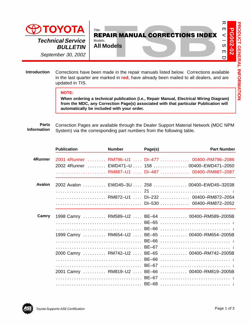
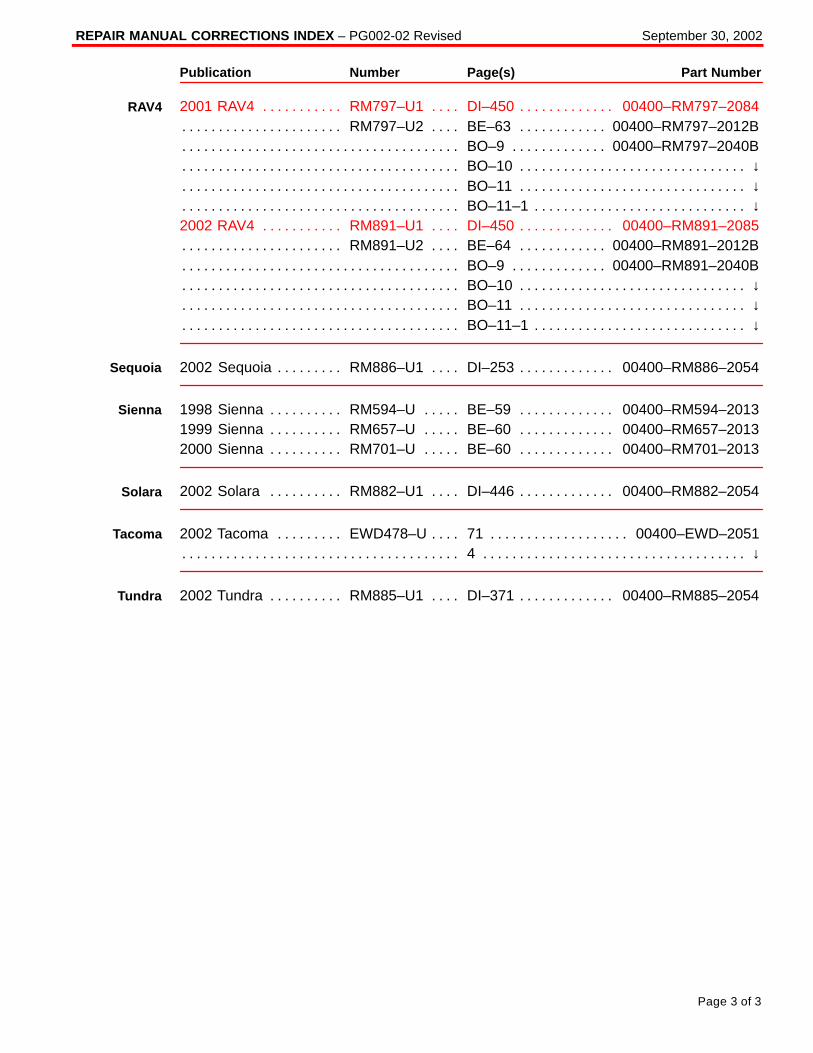
Corrections have been made in the repair manuals listed below. Corrections available in the last quarter are marked in red , have already been mailed to all dealers, and areupdated in TIS.
NOTE:When ordering a technical publication (i.e., Repair Manual, Electrical Wiring Diagram)from the MDC, any Correction Page(s) associated with that particular Publication willautomatically be included with your order.
Correction Pages are available through the Dealer Support Material Network (MDC NPMSystem) via the corresponding part numbers from the following table.
Publication Number Page(s) Part Number
2001 4Runner RM796–U1 DI–477 00400–RM796–2086. . . . . . . . . . . . . . . . . . . . . . . . . 2002 4Runner EWD471–U 158 00400–EWD471–2050. . . . . . . . . . . . . . . . . . . . . . . . . . .
RM887–U1 DI–487 00400–RM887–2087. . . . . . . . . . . . . . . . . . . . . . . . . . . . . . . . . . . . . . .
2002 Avalon EWD45–3U 258 00400–EWD45–32038. . . . . . . . . . . . . . . . . . . . . . . . . . . . . 21 ↓. . . . . . . . . . . . . . . . . . . . . . . . . . . . . . . . . . . . . . . . . . . . . . . . . . . . . . . . . . . . . . . . . . . . . . . . .
RM872–U1 DI–232 00400–RM872–2054. . . . . . . . . . . . . . . . . . . . . . . . . . . . . . . . . . . . . . . DI–530 00400–RM872–2052. . . . . . . . . . . . . . . . . . . . . . . . . . . . . . . . . . . . . . . . . . . . . . . . . . .
1998 Camry RM589–U2 BE–64 00400–RM589–2005B. . . . . . . . . . . . . . . . . . . . . . . . . . BE–65 ↓. . . . . . . . . . . . . . . . . . . . . . . . . . . . . . . . . . . . . . . . . . . . . . . . . . . . . . . . . . . . . . . . . . . . . BE–66 ↓. . . . . . . . . . . . . . . . . . . . . . . . . . . . . . . . . . . . . . . . . . . . . . . . . . . . . . . . . . . . . . . . . . . . .
1999 Camry RM654–U2 BE–65 00400–RM654–2005B. . . . . . . . . . . . . . . . . . . . . . . . . . BE–66 ↓. . . . . . . . . . . . . . . . . . . . . . . . . . . . . . . . . . . . . . . . . . . . . . . . . . . . . . . . . . . . . . . . . . . . . BE–67 ↓. . . . . . . . . . . . . . . . . . . . . . . . . . . . . . . . . . . . . . . . . . . . . . . . . . . . . . . . . . . . . . . . . . . . .
2000 Camry RM742–U2 BE–65 00400–RM742–2005B. . . . . . . . . . . . . . . . . . . . . . . . . . BE–66 ↓. . . . . . . . . . . . . . . . . . . . . . . . . . . . . . . . . . . . . . . . . . . . . . . . . . . . . . . . . . . . . . . . . . . . . BE–67 ↓. . . . . . . . . . . . . . . . . . . . . . . . . . . . . . . . . . . . . . . . . . . . . . . . . . . . . . . . . . . . . . . . . . . . .
2001 Camry RM819–U2 BE–66 00400–RM819–2005B. . . . . . . . . . . . . . . . . . . . . . . . . . BE–67 ↓. . . . . . . . . . . . . . . . . . . . . . . . . . . . . . . . . . . . . . . . . . . . . . . . . . . . . . . . . . . . . . . . . . . . . BE–68 ↓. . . . . . . . . . . . . . . . . . . . . . . . . . . . . . . . . . . . . . . . . . . . . . . . . . . . . . . . . . . . . . . . . . . . .
PR
OD
UC
T G
EN
ER
AL IN
FO
RM
AT
ION
Introduction
PartsInformation
4Runner
Avalon
Camry
REPAIR MANUAL CORRECTIONS INDEX – PG002-02 Revised September 30, 2002
Page 2 of 3
Publication Number Page(s) Part Number
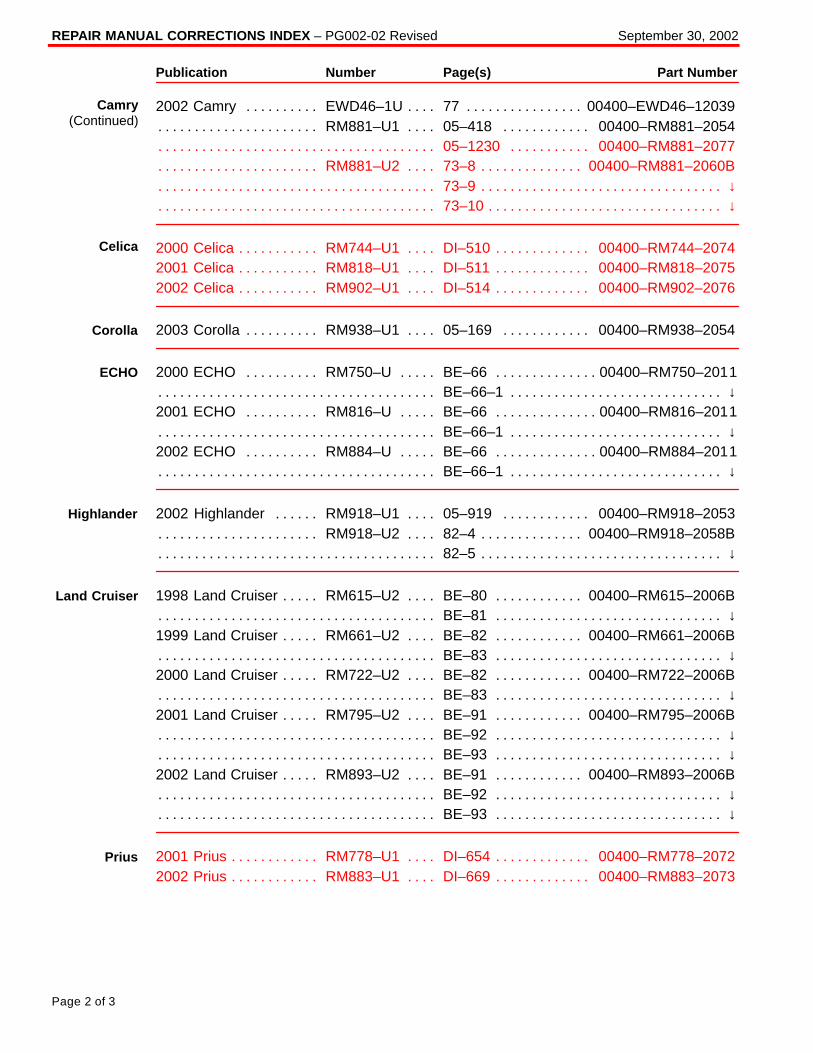
2002 Camry EWD46–1U 77 00400–EWD46–12039. . . . . . . . . . . . . . . . . . . . . . . . . . . . . . RM881–U1 05–418 00400–RM881–2054. . . . . . . . . . . . . . . . . . . . . . . . . . . . . . . . . . . . . .
05–1230 00400–RM881–2077. . . . . . . . . . . . . . . . . . . . . . . . . . . . . . . . . . . . . . . . . . . . . . . . . RM881–U2 73–8 00400–RM881–2060B. . . . . . . . . . . . . . . . . . . . . . . . . . . . . . . . . . . . . . . .
73–9 ↓. . . . . . . . . . . . . . . . . . . . . . . . . . . . . . . . . . . . . . . . . . . . . . . . . . . . . . . . . . . . . . . . . . . . . . . 73–10 ↓. . . . . . . . . . . . . . . . . . . . . . . . . . . . . . . . . . . . . . . . . . . . . . . . . . . . . . . . . . . . . . . . . . . . . .
2000 Celica RM744–U1 DI–510 00400–RM744–2074. . . . . . . . . . . . . . . . . . . . . . . . . . . . 2001 Celica RM818–U1 DI–511 00400–RM818–2075. . . . . . . . . . . . . . . . . . . . . . . . . . . . 2002 Celica RM902–U1 DI–514 00400–RM902–2076. . . . . . . . . . . . . . . . . . . . . . . . . . . .
2003 Corolla RM938–U1 05–169 00400–RM938–2054. . . . . . . . . . . . . . . . . . . . . . . . . .
2000 ECHO RM750–U BE–66 00400–RM750–2011. . . . . . . . . . . . . . . . . . . . . . . . . . . . . BE–66–1 ↓. . . . . . . . . . . . . . . . . . . . . . . . . . . . . . . . . . . . . . . . . . . . . . . . . . . . . . . . . . . . . . . . . . .
2001 ECHO RM816–U BE–66 00400–RM816–2011. . . . . . . . . . . . . . . . . . . . . . . . . . . . . BE–66–1 ↓. . . . . . . . . . . . . . . . . . . . . . . . . . . . . . . . . . . . . . . . . . . . . . . . . . . . . . . . . . . . . . . . . . .
2002 ECHO RM884–U BE–66 00400–RM884–2011. . . . . . . . . . . . . . . . . . . . . . . . . . . . . BE–66–1 ↓. . . . . . . . . . . . . . . . . . . . . . . . . . . . . . . . . . . . . . . . . . . . . . . . . . . . . . . . . . . . . . . . . . .
2002 Highlander RM918–U1 05–919 00400–RM918–2053. . . . . . . . . . . . . . . . . . . . . . RM918–U2 82–4 00400–RM918–2058B. . . . . . . . . . . . . . . . . . . . . . . . . . . . . . . . . . . . . . . .
82–5 ↓. . . . . . . . . . . . . . . . . . . . . . . . . . . . . . . . . . . . . . . . . . . . . . . . . . . . . . . . . . . . . . . . . . . . . . .
1998 Land Cruiser RM615–U2 BE–80 00400–RM615–2006B. . . . . . . . . . . . . . . . . . . . . BE–81 ↓. . . . . . . . . . . . . . . . . . . . . . . . . . . . . . . . . . . . . . . . . . . . . . . . . . . . . . . . . . . . . . . . . . . . .
1999 Land Cruiser RM661–U2 BE–82 00400–RM661–2006B. . . . . . . . . . . . . . . . . . . . . BE–83 ↓. . . . . . . . . . . . . . . . . . . . . . . . . . . . . . . . . . . . . . . . . . . . . . . . . . . . . . . . . . . . . . . . . . . . .
2000 Land Cruiser RM722–U2 BE–82 00400–RM722–2006B. . . . . . . . . . . . . . . . . . . . . BE–83 ↓. . . . . . . . . . . . . . . . . . . . . . . . . . . . . . . . . . . . . . . . . . . . . . . . . . . . . . . . . . . . . . . . . . . . .
2001 Land Cruiser RM795–U2 BE–91 00400–RM795–2006B. . . . . . . . . . . . . . . . . . . . . BE–92 ↓. . . . . . . . . . . . . . . . . . . . . . . . . . . . . . . . . . . . . . . . . . . . . . . . . . . . . . . . . . . . . . . . . . . . . BE–93 ↓. . . . . . . . . . . . . . . . . . . . . . . . . . . . . . . . . . . . . . . . . . . . . . . . . . . . . . . . . . . . . . . . . . . . .
2002 Land Cruiser RM893–U2 BE–91 00400–RM893–2006B. . . . . . . . . . . . . . . . . . . . . BE–92 ↓. . . . . . . . . . . . . . . . . . . . . . . . . . . . . . . . . . . . . . . . . . . . . . . . . . . . . . . . . . . . . . . . . . . . . BE–93 ↓. . . . . . . . . . . . . . . . . . . . . . . . . . . . . . . . . . . . . . . . . . . . . . . . . . . . . . . . . . . . . . . . . . . . .
2001 Prius RM778–U1 DI–654 00400–RM778–2072. . . . . . . . . . . . . . . . . . . . . . . . . . . . . 2002 Prius RM883–U1 DI–669 00400–RM883–2073. . . . . . . . . . . . . . . . . . . . . . . . . . . . .
Camry(Continued)
Celica
Corolla
ECHO
Highlander
Land Cruiser
Prius
REPAIR MANUAL CORRECTIONS INDEX – PG002-02 Revised September 30, 2002
Page 3 of 3
Publication Number Page(s) Part Number
2001 RAV4 RM797–U1 DI–450 00400–RM797–2084. . . . . . . . . . . . . . . . . . . . . . . . . . . . RM797–U2 BE–63 00400–RM797–2012B. . . . . . . . . . . . . . . . . . . . . . . . . . . . . . . . . . . . . .
BO–9 00400–RM797–2040B. . . . . . . . . . . . . . . . . . . . . . . . . . . . . . . . . . . . . . . . . . . . . . . . . . . BO–10 ↓. . . . . . . . . . . . . . . . . . . . . . . . . . . . . . . . . . . . . . . . . . . . . . . . . . . . . . . . . . . . . . . . . . . . . BO–11 ↓. . . . . . . . . . . . . . . . . . . . . . . . . . . . . . . . . . . . . . . . . . . . . . . . . . . . . . . . . . . . . . . . . . . . . BO–11–1 ↓. . . . . . . . . . . . . . . . . . . . . . . . . . . . . . . . . . . . . . . . . . . . . . . . . . . . . . . . . . . . . . . . . . .
2002 RAV4 RM891–U1 DI–450 00400–RM891–2085. . . . . . . . . . . . . . . . . . . . . . . . . . . . RM891–U2 BE–64 00400–RM891–2012B. . . . . . . . . . . . . . . . . . . . . . . . . . . . . . . . . . . . . .
BO–9 00400–RM891–2040B. . . . . . . . . . . . . . . . . . . . . . . . . . . . . . . . . . . . . . . . . . . . . . . . . . . BO–10 ↓. . . . . . . . . . . . . . . . . . . . . . . . . . . . . . . . . . . . . . . . . . . . . . . . . . . . . . . . . . . . . . . . . . . . . BO–11 ↓. . . . . . . . . . . . . . . . . . . . . . . . . . . . . . . . . . . . . . . . . . . . . . . . . . . . . . . . . . . . . . . . . . . . . BO–11–1 ↓. . . . . . . . . . . . . . . . . . . . . . . . . . . . . . . . . . . . . . . . . . . . . . . . . . . . . . . . . . . . . . . . . . .
2002 Sequoia RM886–U1 DI–253 00400–RM886–2054. . . . . . . . . . . . . . . . . . . . . . . . . .
1998 Sienna RM594–U BE–59 00400–RM594–2013. . . . . . . . . . . . . . . . . . . . . . . . . . . . 1999 Sienna RM657–U BE–60 00400–RM657–2013. . . . . . . . . . . . . . . . . . . . . . . . . . . . 2000 Sienna RM701–U BE–60 00400–RM701–2013. . . . . . . . . . . . . . . . . . . . . . . . . . . .
2002 Solara RM882–U1 DI–446 00400–RM882–2054. . . . . . . . . . . . . . . . . . . . . . . . . . .
2002 Tacoma EWD478–U 71 00400–EWD–2051. . . . . . . . . . . . . . . . . . . . . . . . . . . . . . . . 4 ↓. . . . . . . . . . . . . . . . . . . . . . . . . . . . . . . . . . . . . . . . . . . . . . . . . . . . . . . . . . . . . . . . . . . . . . . . . .
2002 Tundra RM885–U1 DI–371 00400–RM885–2054. . . . . . . . . . . . . . . . . . . . . . . . . . .
RAV4
Sequoia
Sienna
Solara
Tacoma
Tundra
TOYOTA
TSBTechnicalServiceBULL ETIN
December 28, 2001
PG003-01
Toyota Supports ASE Certification
PRODUCT GENERAL IN
FORMATION
Title:
REP AIR MA NU AL CORRECT IONS INDEXM odels:
All Mod els
Page 1 of 5
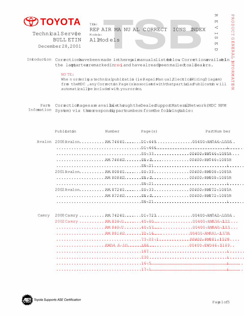
Corrections have been made in the repair manuals listed below. Corrections available inthe last quarter are marked in red, and have already been mailed to all dealers.
Introduction
NO TE:Whe n ordering a technical publication (i.e. Repair Man ual, Electrical Wiring Diagram)from the MDC , any Correction Page(s) associated with that particular Publication w illautomatically be included with your order.
Correction Pages are available through the Dealer Support Material Network (MDC NPMSystem) via the corresponding part numbers from the following table:
PartsInformation
Avalon 2000 Avalon......................RM 746-U1 ............DI-449................................00400-RM746-1008
.........................................................................DI-466....................................↓
.........................................................................SS-33..............................00400-RM746-1085A
..........................................RM 746-U2 ............SR-11 ..............................00400-RM746-1085B
.........................................................................SR-21....................................↓2001 Avalon......................RM 808-U1 ............SS-33..............................00400-RM808-1085A
..........................................RM 808-U2 ............SR-11 ..............................00400-RM808-1085B
.........................................................................SR-21....................................↓2002 Avalon......................RM 872-U1 ............SS-33..............................00400-RM872-1085A
..........................................RM 872-U2 ............SR-11 ..............................00400-RM872-1085B
.........................................................................SR-21....................................↓
RE
VIS
ED
Publication Number Page(s) Part Num ber
Camry 2000 Camry ......................RM 742-U1 ............DI-723................................00400-RM742-1006
2002 Camry ......................RM 836-U..............40-60..................................00400-RM836-1122
..........................................RM 840-U..............40-57..................................00400-RM840-1123
..........................................RM 881-U2 ............32-16...............................00400-RM881-1137B
.........................................................................73-22-1............................00400-RM881-1152B
..........................................EWD4 6-1U...........186..................................00400-EWD46-11169
.........................................................................187......................................↓
.........................................................................230......................................↓
.........................................................................16-5......................................↓
.........................................................................17-1......................................↓
REP AIR MANUA L COR RECT IONS INDEX - PG003-01 Revised December 28, 2001
Page 2 of 5
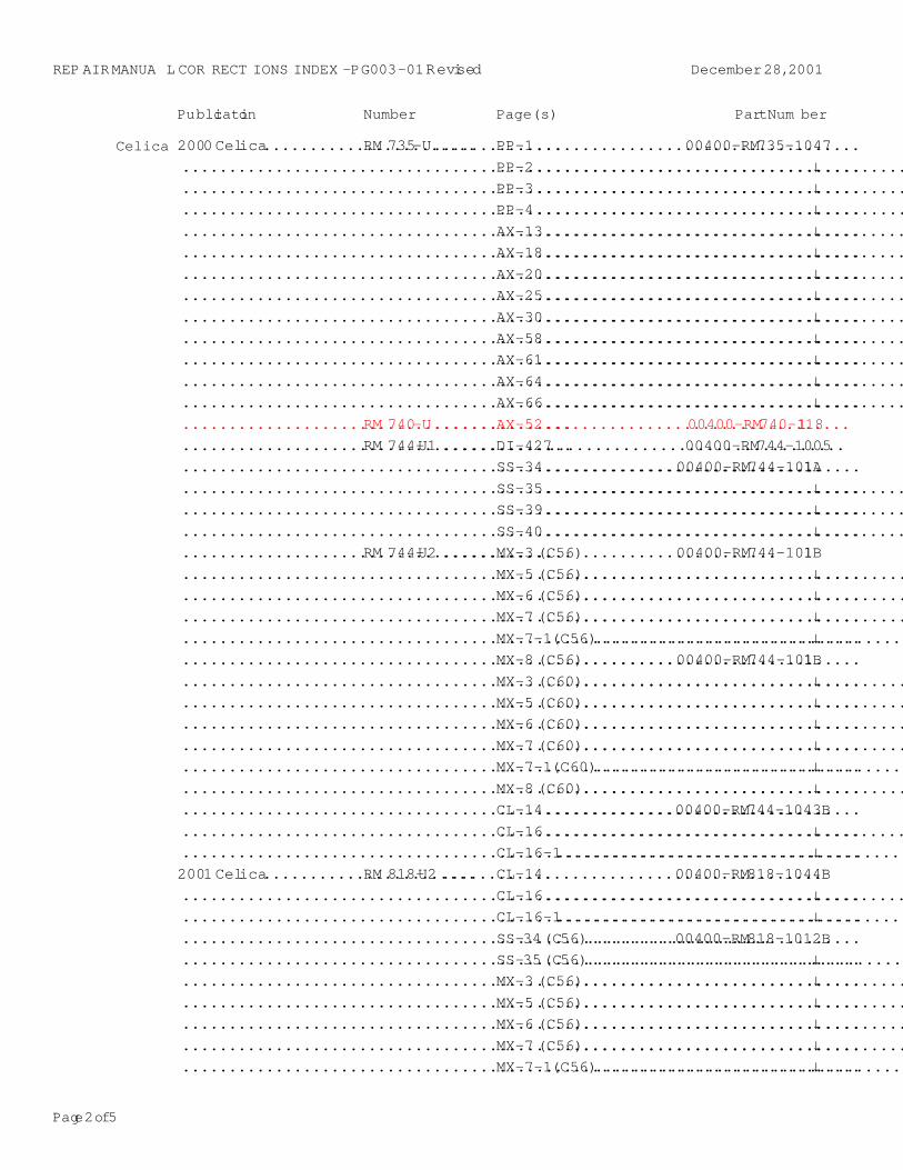
Celica 2000 Celica.......................RM 735-U..............PP-1...................................00400-RM735-1047
.........................................................................PP-2........................................↓
.........................................................................PP-3........................................↓
.........................................................................PP-4........................................↓
.........................................................................AX-13.......................................↓
.........................................................................AX-18.......................................↓
.........................................................................AX-20.......................................↓
.........................................................................AX-25.......................................↓
.........................................................................AX-30.......................................↓
.........................................................................AX-58.......................................↓
.........................................................................AX-61.......................................↓
.........................................................................AX-64.......................................↓
.........................................................................AX-66.......................................↓
..........................................RM 740-U..............AX-52.................................00400-RM740-1118
..........................................RM 744-U1 ............DI-427................................00400-RM744-1005
.........................................................................SS-34..............................00400-RM744-1011A
.........................................................................SS-35.......................................↓
.........................................................................SS-39.......................................↓
.........................................................................SS-40.......................................↓
..........................................RM 744-U2 ............MX-3 (C56).....................00400-RM744-1011B
.........................................................................MX-5 (C56)...................................↓
.........................................................................MX-6 (C56)...................................↓
.........................................................................MX-7 (C56)...................................↓
.........................................................................MX-7-1 (C56).................................↓
.........................................................................MX-8 (C56).....................00400-RM744-1011B
.........................................................................MX-3 (C60)...................................↓
.........................................................................MX-5 (C60)...................................↓
.........................................................................MX-6 (C60)...................................↓
.........................................................................MX-7 (C60)...................................↓
.........................................................................MX-7-1 (C60).................................↓
.........................................................................MX-8 (C60)...................................↓
.........................................................................CL-14..............................00400-RM744-1043B
.........................................................................CL-16.......................................↓
.........................................................................CL-16-1......................................↓2001 Celica.......................RM 818-U2 ............CL-14..............................00400-RM818-1044B
.........................................................................CL-16.......................................↓
.........................................................................CL-16-1......................................↓
.........................................................................SS-34 (C56)....................00400-RM818-1012B
.........................................................................SS-35 (C56)..................................↓
.........................................................................MX-3 (C56)...................................↓
.........................................................................MX-5 (C56)...................................↓
.........................................................................MX-6 (C56)...................................↓
.........................................................................MX-7 (C56)...................................↓
.........................................................................MX-7-1 (C56).................................↓
Publication Number Page(s) Part Num ber
Page 3 of 5
REP AIR MANUA L COR RECT IONS INDEX - PG003-01 Revised December 28, 2001
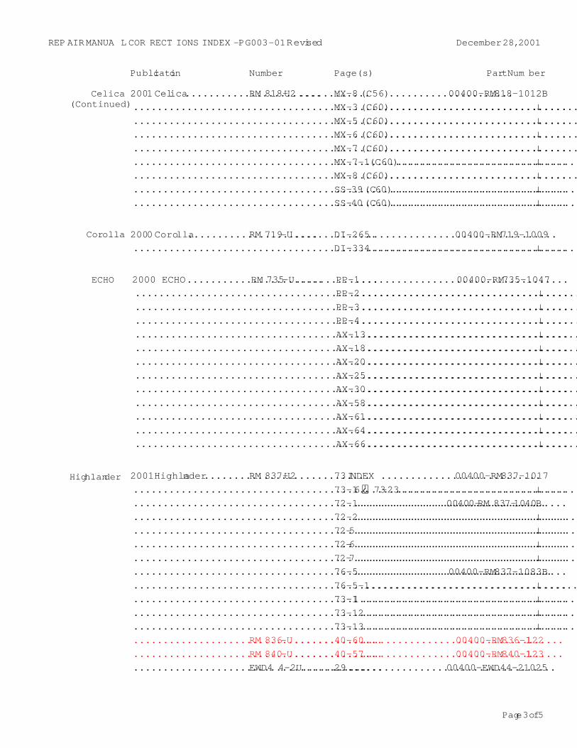
Highlander 2001 Highlander................RM 837-U2 ............73 INDEX ...........................00400-RM837-1017
.........................................................................73-16 73-23...............................↓
.........................................................................72-1................................00400-RM 837-1040B
.........................................................................72-2.....................................↓
.........................................................................72-5.....................................↓
.........................................................................72-6.....................................↓
.........................................................................72-7.....................................↓
.........................................................................76-5.................................00400-RM837-1083B
.........................................................................76-5-1....................................↓
.........................................................................73-11 .....................................↓
.........................................................................73-12.....................................↓
.........................................................................73-13.....................................↓
..........................................RM 836-U..............40-60..................................00400-RM836-1122
..........................................RM 840-U..............40-57..................................00400-RM840-1123
..........................................EWD4 4-2U...........29...................................00400-EWD44-21025
Publication Number Page(s) Part Num ber
ECHO 2000 ECHO.......................RM 735-U..............PP-1...................................00400-RM735-1047
.........................................................................PP-2.....................................↓
.........................................................................PP-3.....................................↓
.........................................................................PP-4.....................................↓
.........................................................................AX-13....................................↓
.........................................................................AX-18....................................↓
.........................................................................AX-20....................................↓
.........................................................................AX-25....................................↓
.........................................................................AX-30....................................↓
.........................................................................AX-58....................................↓
.........................................................................AX-61....................................↓
.........................................................................AX-64....................................↓
.........................................................................AX-66....................................↓
Celica(Continued)
2001 Celica.......................RM 818-U2 ............MX-8 (C56).....................00400-RM818-1012B
.........................................................................MX-3 (C60)................................↓
.........................................................................MX-5 (C60)................................↓
.........................................................................MX-6 (C60)................................↓
.........................................................................MX-7 (C60)................................↓
.........................................................................MX-7-1 (C60)...............................↓
.........................................................................MX-8 (C60)................................↓
.........................................................................SS-39 (C60)...............................↓
.........................................................................SS-40 (C60)...............................↓
Corolla 2000 Corolla......................RM 719-U..............DI-265................................00400-RM719-1009
.........................................................................DI-334....................................↓
REP AIR MANUA L COR RECT IONS INDEX - PG003-01 Revised December 28, 2001
Page 4 of 5
Publication Number Page(s) Part Num ber
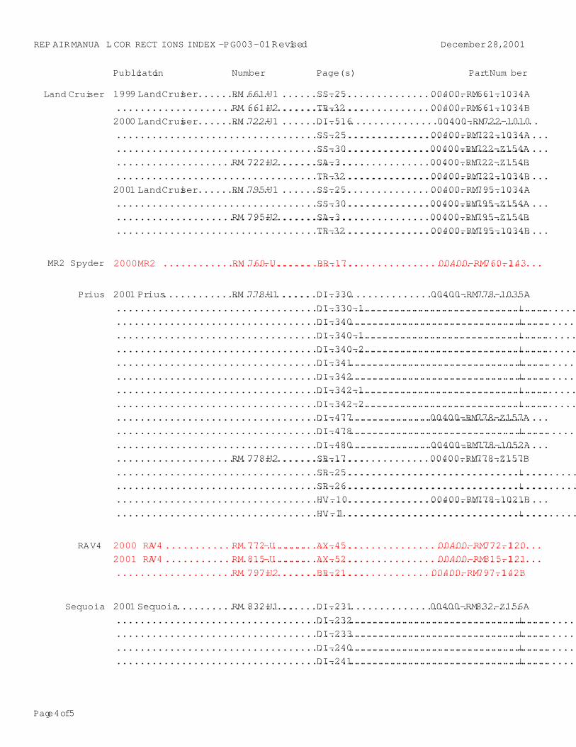
Prius 2001 Prius.........................RM 778-U1 ............DI-330.............................00400-RM778-1035A
.........................................................................DI-330-1.....................................↓
.........................................................................DI-340......................................↓
.........................................................................DI-340-1.....................................↓
.........................................................................DI-340-2.....................................↓
.........................................................................DI-341......................................↓
.........................................................................DI-342......................................↓
.........................................................................DI-342-1.....................................↓
.........................................................................DI-342-2.....................................↓
.........................................................................DI-477.............................00400-RM778-Z157A
.........................................................................DI-478......................................↓
.........................................................................DI-480.............................00400-RM778-1052A
..........................................RM 778-U2 ............SR-17..............................00400-RM778-Z157B
.........................................................................SR-25.......................................↓
.........................................................................SR-26.......................................↓
.........................................................................HV-10..............................00400-RM778-1021B
.........................................................................HV-11 .......................................↓
RAV4 2000 RAV4 ........................RM 772-U..............AX-45.................................00400-RM772-1120
2001 RAV4 ........................RM 815-U..............AX-52.................................00400-RM815-1121
..........................................RM 797-U2 ............BR-21..............................00400-RM797-1142B
Land Cruiser 1999 Land Cruiser............RM 661-U1 ............SS-25..............................00400-RM661-1034A
..........................................RM 661-U2 ............TR-32..............................00400-RM661-1034B
2000 Land Cruiser............RM 722-U1 ............DI-516................................00400-RM722-1010
.........................................................................SS-25..............................00400-RM722-1034A
.........................................................................SS-30..............................00400-RM722-Z154A
..........................................RM 722-U2 ............SA-3................................00400-RM722-Z154B
.........................................................................TR-32..............................00400-RM722-1034B
2001 Land Cruiser............RM 795-U1 ............SS-25..............................00400-RM795-1034A
.........................................................................SS-30..............................00400-RM795-Z154A
..........................................RM 795-U2 ............SA-3................................00400-RM795-Z154B
.........................................................................TR-32..............................00400-RM795-1034B
MR2 Spyder 2000 MR2 .........................RM 760-U..............BR-17.................................00400-RM760-1143
Sequoia 2001 Sequoia....................RM 832-U1 ............DI-231.............................00400-RM832-Z156A
.........................................................................DI-232......................................↓
.........................................................................DI-233......................................↓
.........................................................................DI-240......................................↓
.........................................................................DI-241......................................↓
Page 5 of 5
REP AIR MANUA L COR RECT IONS INDEX - PG003-01 Revised December 28, 2001
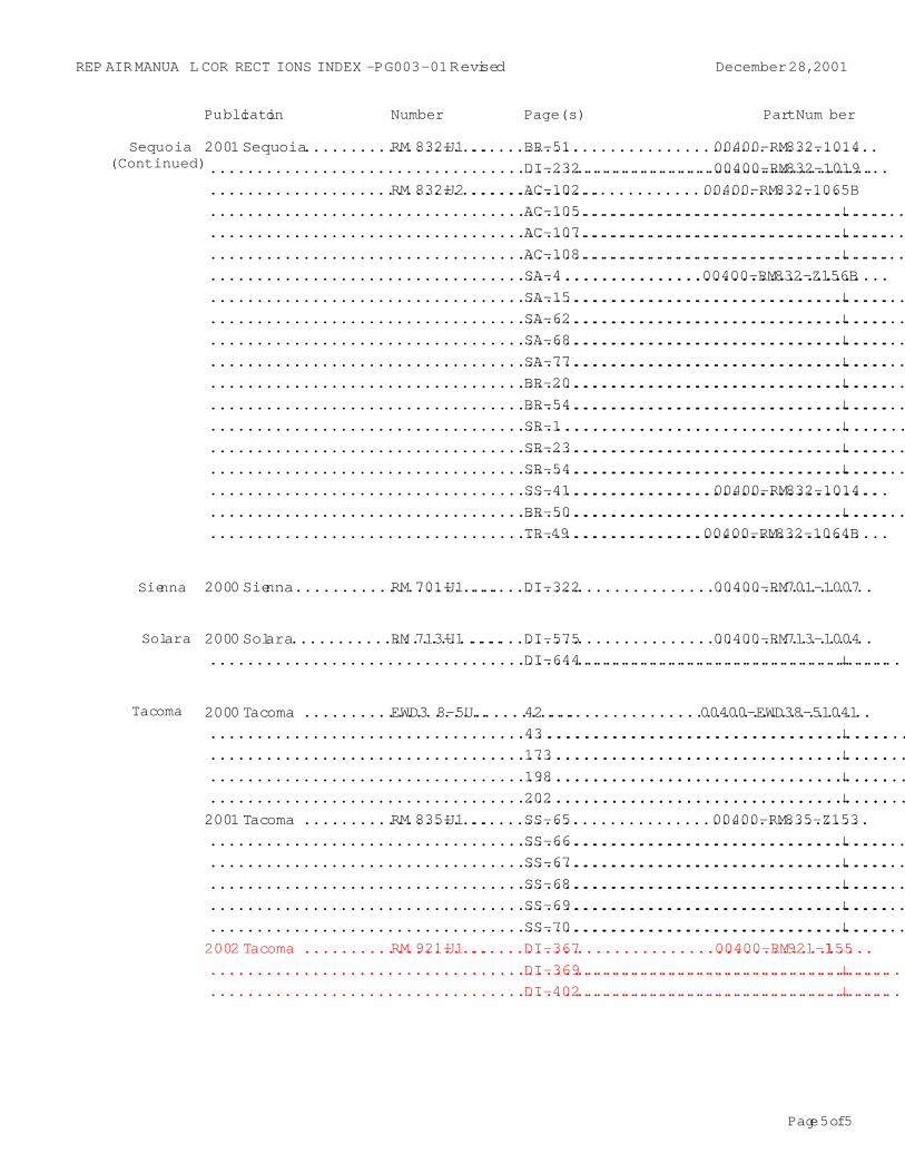
Sienna 2000 Sienna......................RM 701-U1 ............DI-322................................00400-RM701-1007
Solara 2000 Solara.......................RM 713-U1 ............DI-575................................00400-RM713-1004
.........................................................................DI-644....................................↓
Sequoia(Continued)
2001 Sequoia....................RM 832-U1 ............BR-51.................................00400-RM832-1014
.........................................................................DI-232................................00400-RM832-1019
..........................................RM 832-U2 ............AC-102............................00400-RM832-1065B
.........................................................................AC-105...................................↓
.........................................................................AC-107...................................↓
.........................................................................AC-108...................................↓
.........................................................................SA-4................................00400-RM832-Z156B
.........................................................................SA-15....................................↓
.........................................................................SA-62....................................↓
.........................................................................SA-68....................................↓
.........................................................................SA-77....................................↓
.........................................................................BR-20....................................↓
.........................................................................BR-54....................................↓
.........................................................................SR-1.....................................↓
.........................................................................SR-23....................................↓
.........................................................................SR-54....................................↓
.........................................................................SS-41.................................00400-RM832-1014
.........................................................................BR-50....................................↓
.........................................................................TR-49..............................00400-RM832-1064B
Publication Number Page(s) Part Num ber
Tacoma 2000 Tacoma ....................EWD3 8-5U...........42...................................00400-EWD38-51041
.........................................................................43.......................................↓
.........................................................................173......................................↓
.........................................................................198......................................↓
.........................................................................202......................................↓2001 Tacoma ....................RM 835-U1 ............SS-65................................00400-RM835-Z153
.........................................................................SS-66....................................↓
.........................................................................SS-67....................................↓
.........................................................................SS-68....................................↓
.........................................................................SS-69....................................↓
.........................................................................SS-70....................................↓2002 Tacoma ....................RM 921-U1 ............DI-367................................00400-RM921-1155
.........................................................................DI-369....................................↓
.........................................................................DI-402....................................↓
Toyota Supports ASE Certification Page 1 of 6
PG
006–00Title:
CA/50 STATE CERTIFIED EMISSION
CONTROL UNDERHOOD LABEL
ORDERINGModels:
All Models
Technical ServiceBULLETIN
March 31, 2000
It is no longer necessary to fax the CA/50 State Emission Label Order Form to TMS.California (CA) and 50 State Certified underhood emission control labels (emissionlabels) may now be obtained through your dealership Parts Department utilizing standardreplacement parts ordering procedures via the TDN. Follow the guidelines outlined inthis TSB to ensure proper label application.
� All model year Toyota Vehicles.We have included tables reflecting 1997 – 2000 MY CA and 50 State Emission Labelpart number information for your convenience. Please continue to consult theElectronic Parts Catalog (EPC) or the parts microfiche for information regarding othermodel years as well as Federal Emission label part numbers.
NOTE:Although the California Smog Impact Fee has been discontinued, dealers are stillrequired by regulation to verify the correct emission label is installed on the correctvehicle.
REGULATIONS:The United States Clean Air Act, Title II, Sections 202, 203, 205, and 207 mandates thatthe emission control label must correctly match the emissions equipment on thevehicle. Any person violating this requirement is subject to applicable State penaltiesand a Federal civil penalty of no more than $25,000 for each instance.
Personnel at franchised dealerships are authorized to affix such labels to vehicles andare, therefore, subject to this regulation and the attendant penalties.
� Do not sell the labels over the counter. Always install the label on the vehicle.
� Never install a California and/or 50 State Label on a vehicle that is not a California/50 State Emission Certified Vehicle.
� Do not install Federal Emission labels on vehicles that are not FederalEmissions Certified.
OP CODE DESCRIPTION TIME OPN T1 T2
N/A Not Applicable to Warranty – – – –
PR
OD
UC
T G
EN
ER
AL IN
FO
RM
AT
ION
Introduction
ApplicableVehicles
WarrantyInformation
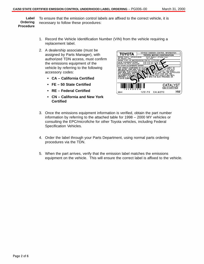
CA/50 STATE CERTIFIED EMISSION CONTROL UNDERHOOD LABEL ORDERING – PG006–00 March 31, 2000
Page 2 of 6
To ensure that the emission control labels are affixed to the correct vehicle, it isnecessary to follow these procedures:
1. Record the Vehicle Identification Number (VIN) from the vehicle requiring areplacement label.
2. A dealership associate (must beassigned by Parts Manager), withauthorized TDN access, must confirmthe emissions equipment of thevehicle by referring to the followingaccessory codes:
� CA – California Certified
� FE – 50 State Certified
� RE – Federal Certified
� CN – California and New YorkCertified
3. Once the emissions equipment information is verified, obtain the part numberinformation by referring to the attached table for 1998 – 2000 MY vehicles orconsulting the EPC/microfiche for other Toyota vehicles, including FederalSpecification Vehicles.
4. Order the label through your Parts Department, using normal parts orderingprocedures via the TDN.
5. When the part arrives, verify that the emission label matches the emissionsequipment on the vehicle. This will ensure the correct label is affixed to the vehicle.
LabelOrdering
Procedure
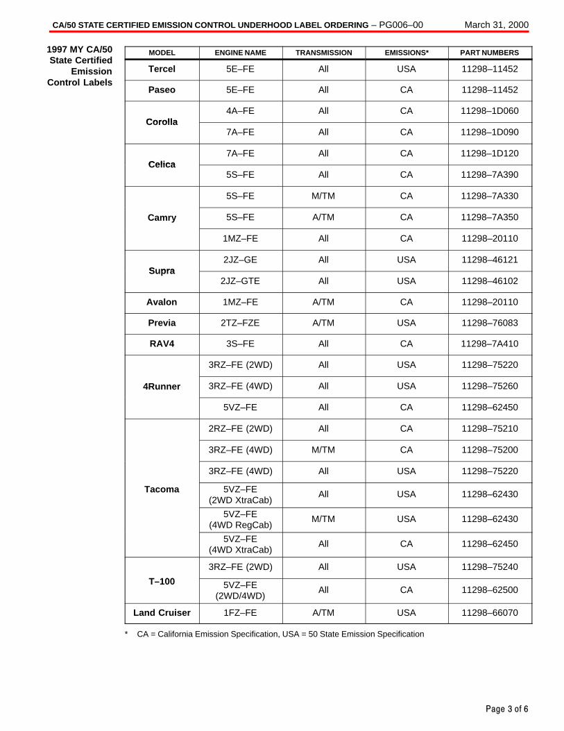
CA/50 STATE CERTIFIED EMISSION CONTROL UNDERHOOD LABEL ORDERING – PG006–00 March 31, 2000
Page 3 of 6
MODEL ENGINE NAME TRANSMISSION EMISSIONS* PART NUMBERS
Tercel 5E–FE All USA 11298–11452
Paseo 5E–FE All CA 11298–11452
Corolla4A–FE All CA 11298–1D060
Coro lla7A–FE All CA 11298–1D090
Celica7A–FE All CA 11298–1D120
Celica5S–FE All CA 11298–7A390
5S–FE M/TM CA 11298–7A330
Camry 5S–FE A/TM CA 11298–7A350
1MZ–FE All CA 11298–20110
S pra2JZ–GE All USA 11298–46121
Supra2JZ–GTE All USA 11298–46102
Avalon 1MZ–FE A/TM CA 11298–20110
Previa 2TZ–FZE A/TM USA 11298–76083
RAV4 3S–FE All CA 11298–7A410
3RZ–FE (2WD) All USA 11298–75220
4Runner 3RZ–FE (4WD) All USA 11298–75260
5VZ–FE All CA 11298–62450
2RZ–FE (2WD) All CA 11298–75210
3RZ–FE (4WD) M/TM CA 11298–75200
3RZ–FE (4WD) All USA 11298–75220
Tacoma 5VZ–FE(2WD XtraCab)
All USA 11298–62430
5VZ–FE(4WD RegCab)
M/TM USA 11298–62430
5VZ–FE(4WD XtraCab)
All CA 11298–62450
T 100
3RZ–FE (2WD) All USA 11298–75240
T–100 5VZ–FE(2WD/4WD)
All CA 11298–62500
Land Cruiser 1FZ–FE A/TM USA 11298–66070
* CA = California Emission Specification, USA = 50 State Emission Specification
1997 MY CA/50State Certified
EmissionControl Labels
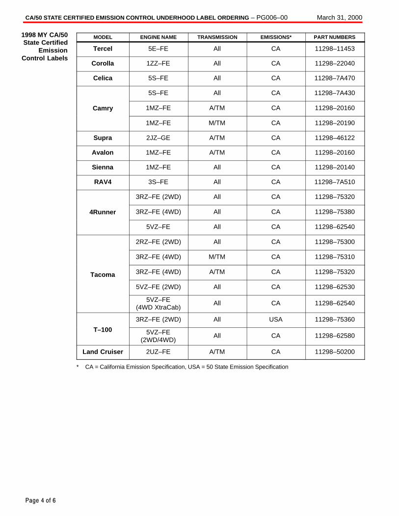
CA/50 STATE CERTIFIED EMISSION CONTROL UNDERHOOD LABEL ORDERING – PG006–00 March 31, 2000
Page 4 of 6
MODEL ENGINE NAME TRANSMISSION EMISSIONS* PART NUMBERS
Tercel 5E–FE All CA 11298–11453
Corolla 1ZZ–FE All CA 11298–22040
Celica 5S–FE All CA 11298–7A470
5S–FE All CA 11298–7A430
Camry 1MZ–FE A/TM CA 11298–20160
1MZ–FE M/TM CA 11298–20190
Supra 2JZ–GE A/TM CA 11298–46122
Avalon 1MZ–FE A/TM CA 11298–20160
Sienna 1MZ–FE All CA 11298–20140
RAV4 3S–FE All CA 11298–7A510
3RZ–FE (2WD) All CA 11298–75320
4Runner 3RZ–FE (4WD) All CA 11298–75380
5VZ–FE All CA 11298–62540
2RZ–FE (2WD) All CA 11298–75300
3RZ–FE (4WD) M/TM CA 11298–75310
Tacoma 3RZ–FE (4WD) A/TM CA 11298–75320
5VZ–FE (2WD) All CA 11298–62530
5VZ–FE(4WD XtraCab)
All CA 11298–62540
T 100
3RZ–FE (2WD) All USA 11298–75360
T–100 5VZ–FE(2WD/4WD)
All CA 11298–62580
Land Cruiser 2UZ–FE A/TM CA 11298–50200
* CA = California Emission Specification, USA = 50 State Emission Specification
1998 MY CA/50State Certified
EmissionControl Labels
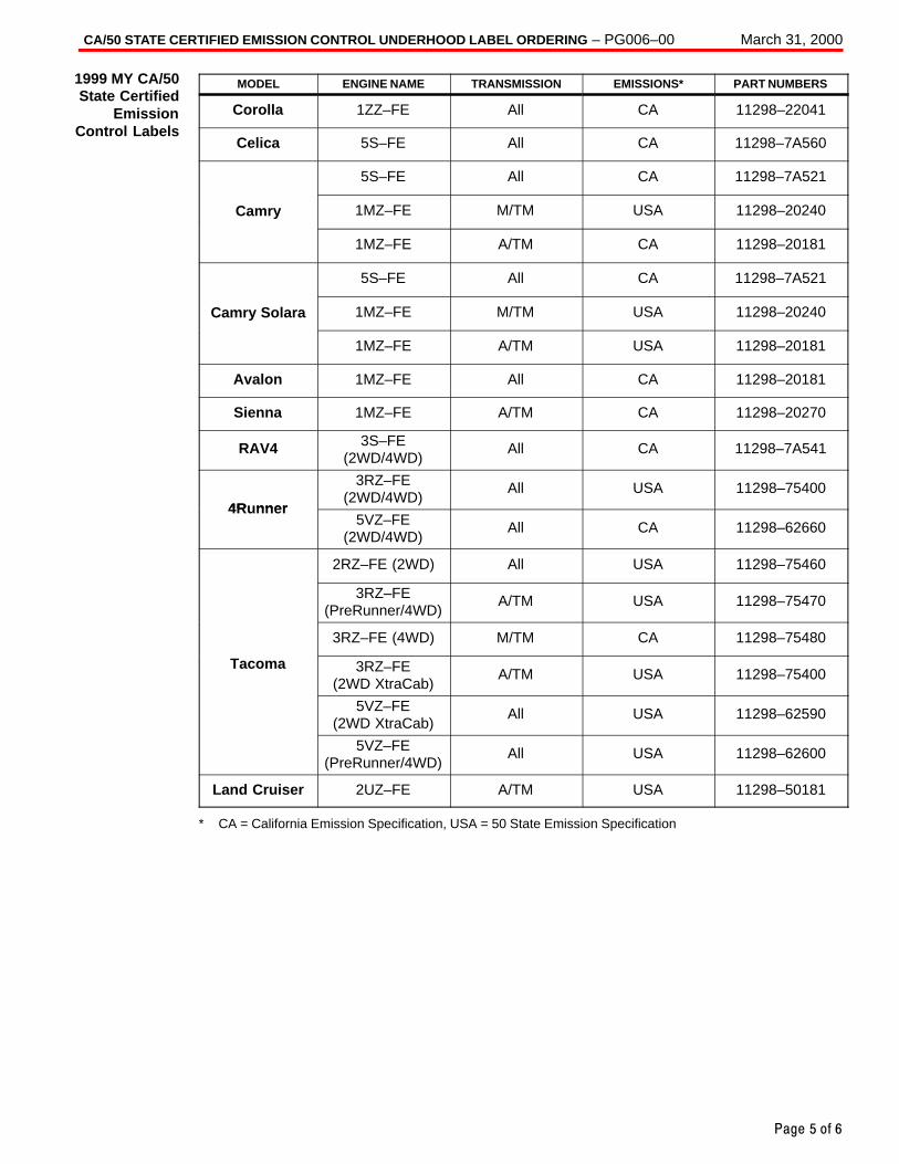
CA/50 STATE CERTIFIED EMISSION CONTROL UNDERHOOD LABEL ORDERING – PG006–00 March 31, 2000
Page 5 of 6
MODEL ENGINE NAME TRANSMISSION EMISSIONS* PART NUMBERS
Corolla 1ZZ–FE All CA 11298–22041
Celica 5S–FE All CA 11298–7A560
5S–FE All CA 11298–7A521
Camry 1MZ–FE M/TM USA 11298–20240
1MZ–FE A/TM CA 11298–20181
5S–FE All CA 11298–7A521
Camry Solara 1MZ–FE M/TM USA 11298–20240
1MZ–FE A/TM USA 11298–20181
Avalon 1MZ–FE All CA 11298–20181
Sienna 1MZ–FE A/TM CA 11298–20270
RAV4 3S–FE(2WD/4WD)
All CA 11298–7A541
4R nner
3RZ–FE(2WD/4WD)
All USA 11298–754004Runner
5VZ–FE(2WD/4WD)
All CA 11298–62660
2RZ–FE (2WD) All USA 11298–75460
3RZ–FE(PreRunner/4WD)
A/TM USA 11298–75470
3RZ–FE (4WD) M/TM CA 11298–75480
Tacoma 3RZ–FE(2WD XtraCab)
A/TM USA 11298–75400
5VZ–FE(2WD XtraCab)
All USA 11298–62590
5VZ–FE(PreRunner/4WD)
All USA 11298–62600
Land Cruiser 2UZ–FE A/TM USA 11298–50181
* CA = California Emission Specification, USA = 50 State Emission Specification
1999 MY CA/50State Certified
EmissionControl Labels
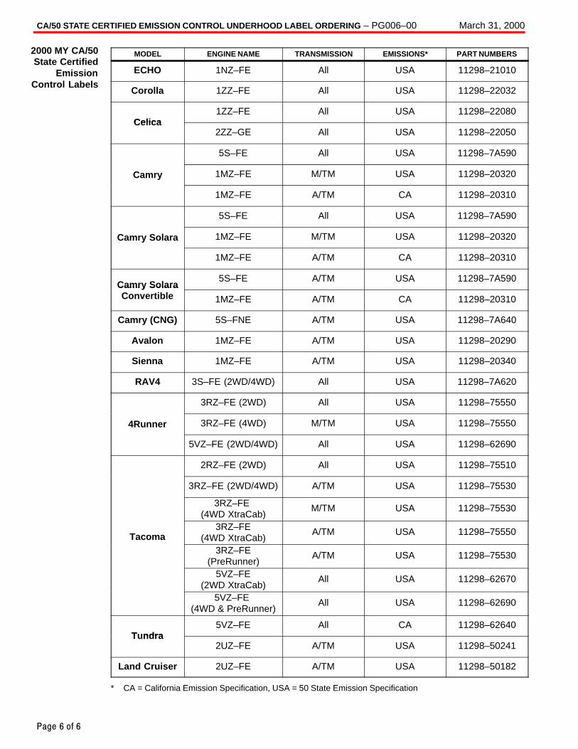
CA/50 STATE CERTIFIED EMISSION CONTROL UNDERHOOD LABEL ORDERING – PG006–00 March 31, 2000
Page 6 of 6
MODEL ENGINE NAME TRANSMISSION EMISSIONS* PART NUMBERS
ECHO 1NZ–FE All USA 11298–21010
Corolla 1ZZ–FE All USA 11298–22032
Celica1ZZ–FE All USA 11298–22080
Celica2ZZ–GE All USA 11298–22050
5S–FE All USA 11298–7A590
Camry 1MZ–FE M/TM USA 11298–20320
1MZ–FE A/TM CA 11298–20310
5S–FE All USA 11298–7A590
Camry Solara 1MZ–FE M/TM USA 11298–20320
1MZ–FE A/TM CA 11298–20310
Camry Solara5S–FE A/TM USA 11298–7A590
Camry SolaraConvertible 1MZ–FE A/TM CA 11298–20310
Camry (CNG) 5S–FNE A/TM USA 11298–7A640
Avalon 1MZ–FE A/TM USA 11298–20290
Sienna 1MZ–FE A/TM USA 11298–20340
RAV4 3S–FE (2WD/4WD) All USA 11298–7A620
3RZ–FE (2WD) All USA 11298–75550
4Runner 3RZ–FE (4WD) M/TM USA 11298–75550
5VZ–FE (2WD/4WD) All USA 11298–62690
2RZ–FE (2WD) All USA 11298–75510
3RZ–FE (2WD/4WD) A/TM USA 11298–75530
3RZ–FE (4WD XtraCab)
M/TM USA 11298–75530
Tacoma3RZ–FE
(4WD XtraCab)A/TM USA 11298–75550
3RZ–FE(PreRunner)
A/TM USA 11298–75530
5VZ–FE(2WD XtraCab)
All USA 11298–62670
5VZ–FE (4WD & PreRunner)
All USA 11298–62690
T ndra5VZ–FE All CA 11298–62640
Tundra2UZ–FE A/TM USA 11298–50241
Land Cruiser 2UZ–FE A/TM USA 11298–50182
* CA = California Emission Specification, USA = 50 State Emission Specification
2000 MY CA/50State Certified
EmissionControl Labels
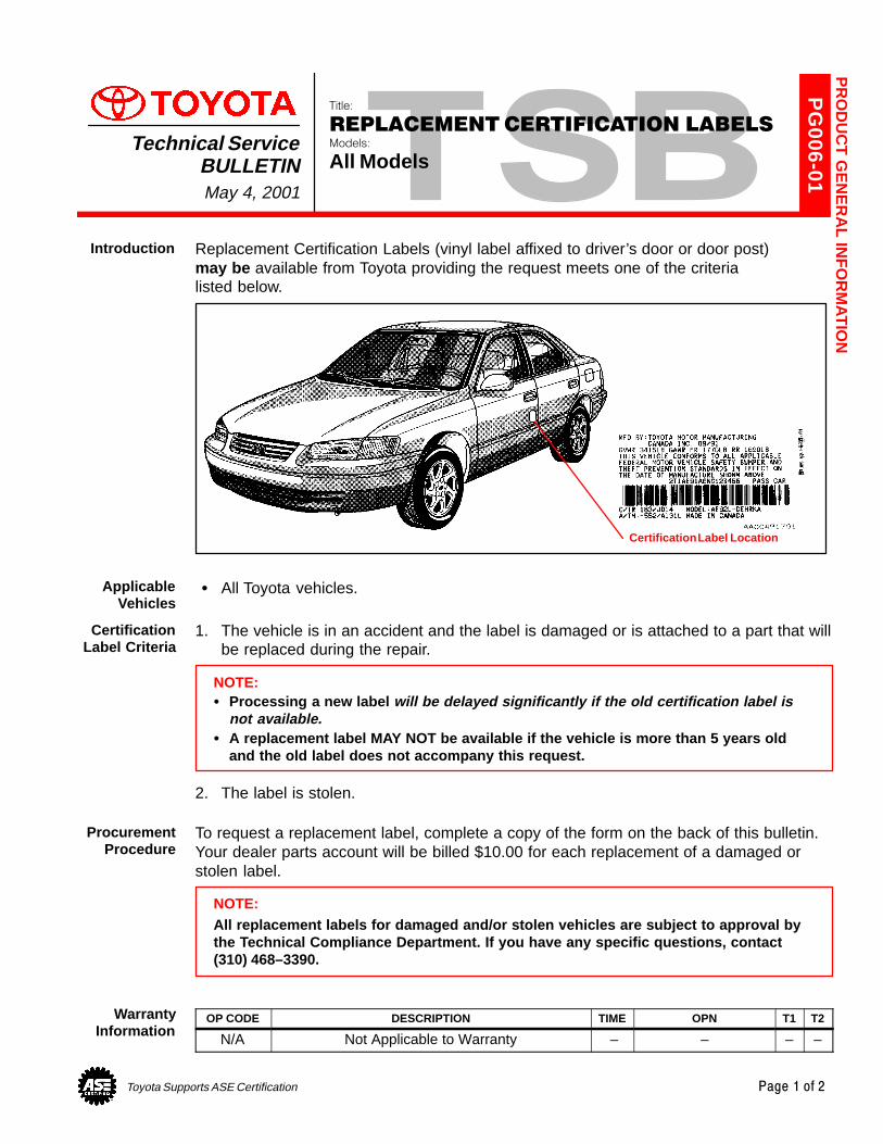
Toyota Supports ASE Certification Page 1 of 2
PG
006-01
Title:
REPLACEMENT CERTIFICATION LABELSModels:
All ModelsTechnical Service
BULLETINMay 4, 2001
Replacement Certification Labels (vinyl label affixed to driver’s door or door post) may be available from Toyota providing the request meets one of the criteria listed below.
Certification Label Location
� All Toyota vehicles.
1. The vehicle is in an accident and the label is damaged or is attached to a part that willbe replaced during the repair.
NOTE:� Processing a new label will be delayed significantly if the old certification label is
not available.� A replacement label MAY NOT be available if the vehicle is more than 5 years old
and the old label does not accompany this request.
2. The label is stolen.
To request a replacement label, complete a copy of the form on the back of this bulletin.Your dealer parts account will be billed $10.00 for each replacement of a damaged orstolen label.
NOTE:All replacement labels for damaged and/or stolen vehicles are subject to approval bythe Technical Compliance Department. If you have any specific questions, contact(310) 468–3390.
OP CODE DESCRIPTION TIME OPN T1 T2
N/A Not Applicable to Warranty – – – –
PR
OD
UC
T G
EN
ER
AL IN
FO
RM
AT
ION
Introduction
ApplicableVehicles
CertificationLabel Criteria
ProcurementProcedure
WarrantyInformation
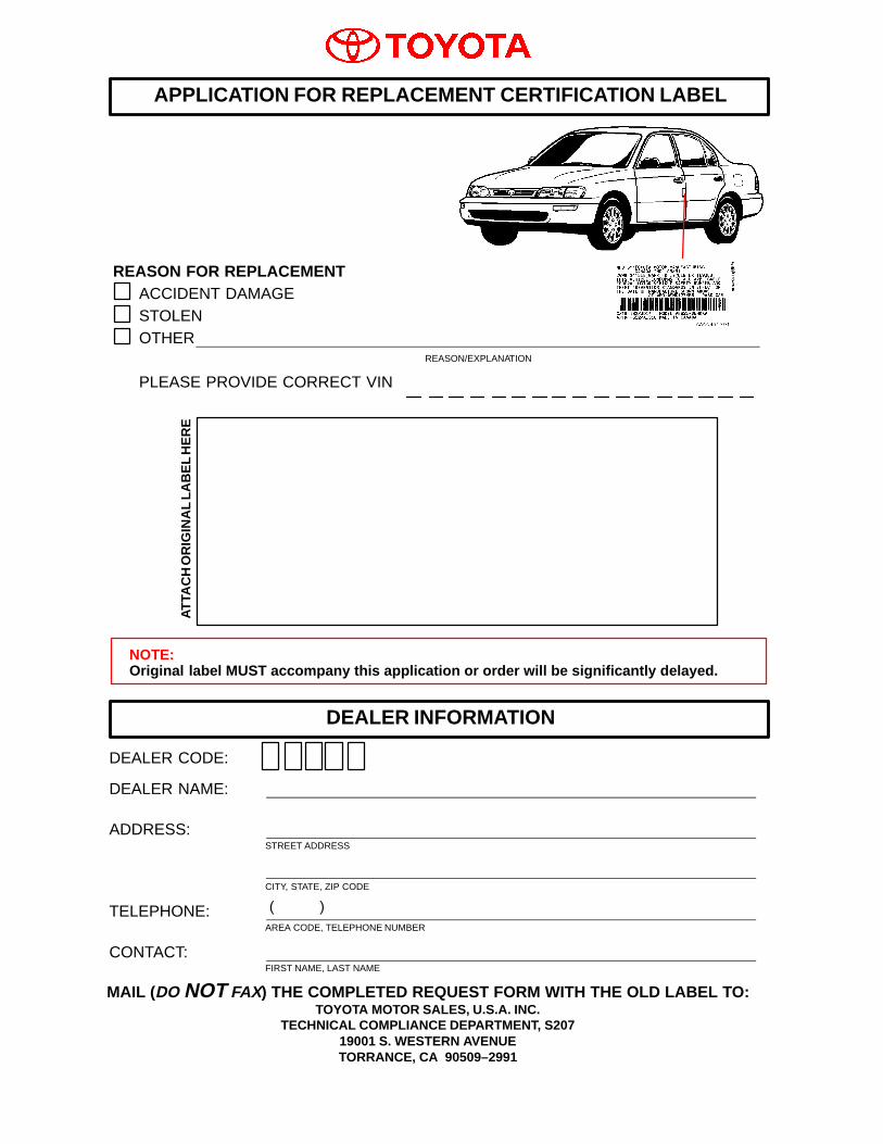
DEALER CODE:
DEALER NAME:
ADDRESS:STREET ADDRESS
CITY, STATE, ZIP CODE
TELEPHONE:AREA CODE, TELEPHONE NUMBER
CONTACT:FIRST NAME, LAST NAME
REASON FOR REPLACEMENTACCIDENT DAMAGESTOLENOTHER
REASON/EXPLANATION
PLEASE PROVIDE CORRECT VIN
APPLICATION FOR REPLACEMENT CERTIFICATION LABEL
ATTA
CH
OR
IGIN
AL
LAB
EL
HE
RE
DEALER INFORMATION
NOTE:Original label MUST accompany this application or order will be significantly delayed.
MAIL (DO NOT FAX) THE COMPLETED REQUEST FORM WITH THE OLD LABEL TO:TOYOTA MOTOR SALES, U.S.A. INC.
TECHNICAL COMPLIANCE DEPARTMENT, S20719001 S. WESTERN AVENUETORRANCE, CA 90509–2991
( )
Toyota Supports ASE Certification Page 1 of 3
PG
006–03
Title:
WARRANTY PARTS
MARKING PROCEDUREModels:
All Models
Technical ServiceBULLETIN
September 26, 2003
Effective September 1, 2003, all warranty parts (as indicated on the next page) must bemarked in the area or location of the failure. The technician should complete thisprocedure after the failed part has been removed from the vehicle and before the part isplaced in the 10–bin storage. (Exchanged parts and remanufactured parts are notincluded in this procedure.)
Failed parts marking will be beneficial in detecting and resolving product and parts qualityissues. This will also offer additional opportunities to make future enhancements to ourparts and products.
Parts are subject to random inspection in the dealership by field representatives toensure compliance with this new policy.
Failure to comply with this policy may result in a debit of the correspondingwarranty claim(s).
� All models.
All technicians must follow these procedures to ensure proper parts marking:
� Wipe the part clean (no excess fluid should be present).
� Indicate area of defect or failure by marking the specific part(s) with a waterresistant permanent marker. Use a color that can be easily seen against thebackground of the part being marked. For dark surfaces the color yellow is highlyrecommended as well as the color black for light surfaces.
� Mark the area of failure or defect by drawing a circle, a square, pointing an arrowor adhering tape with an indication of the failed or defect location.
� Attach a completed Warranty Parts Tag (M/N 00404–PRETN–TAGS) to themarked part.
All other parts recovery/shipping policies and procedures apply.
OP CODE DESCRIPTION TIME OFP T1 T2
N/A Not Applicable to Warranty – – – –
PR
OD
UC
T G
EN
ER
AL IN
FO
RM
AT
ION
Introduction
ApplicableVehicles
PartsMarking
Procedure
WarrantyInformation
WARRANTY PARTS MARKING PROCEDURE – PG006-03 September 26, 2003
Page 2 of 3
Dealers are requested to mark the location of the failure of all warranty parts that arelisted below. This list is not inclusive. There may be other components that can bemarked in the area of failure. All other parts that can be marked should be marked.
assist grip assy headlamps
audio (blemish) headliner
back door garnish hoses
bumper covers instrument panel safety pad sub–assy
cargo cover (retractable) Interior light assemblies and covers
carpet knobs, levers, handles
clutch disc l/pulley pump assy
clutch flywheel mirrors (side and rearview)
combination meter glass navigation or VES screens
console and components pillar garnish
cowl assy rack and pinion/power steering gear assy
cowl side trim sub–assy radiator
cupholders room partition board
cylinder head cover sub–assy rotors (mark where min. runout is exceeded or warped)
dash panel insulator assy seat covers/cushions
dashboard and trim seat tracks
disc wheel soft trim
display panels spare tire cover
door handle assy steering column cover
door moulding steering wheel
door trim panel & molding tail lamps and covers
emblems transmission oil pan
engine oil pan visor
exhaust manifold washer jar
floor and cargo mats wheel cap
gear shift knob wheels
grills
PartsMarking
Requirement
PartsMarking
List
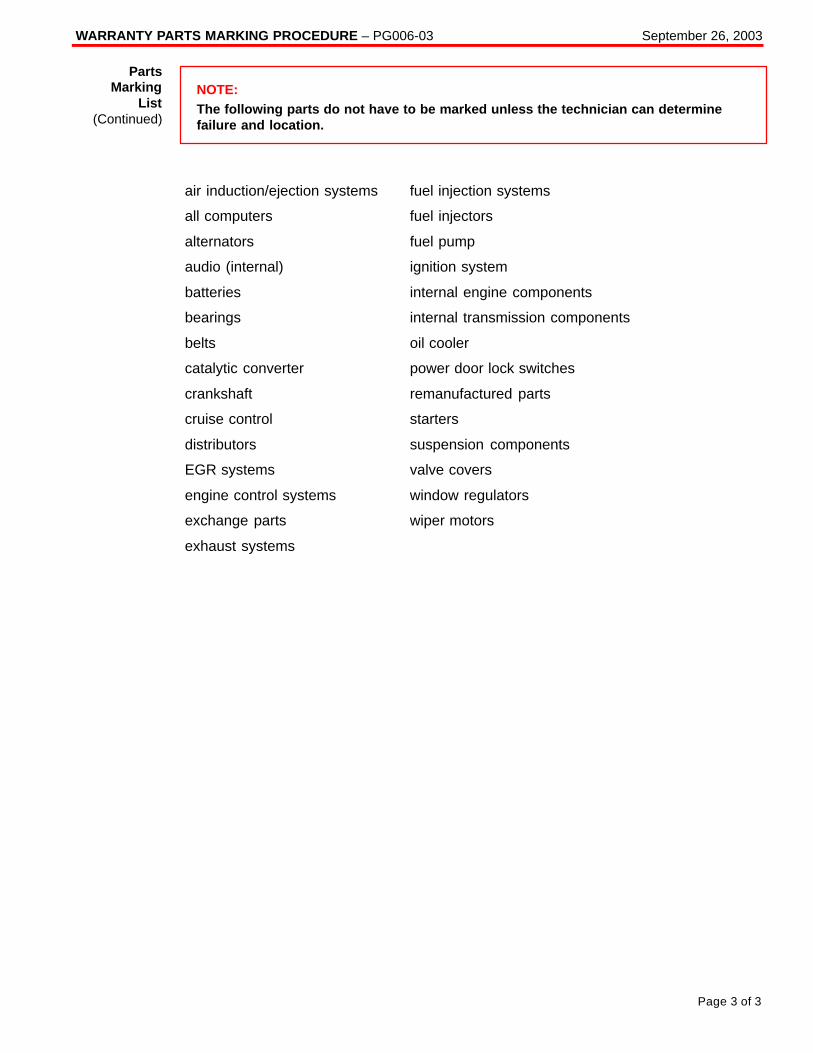
WARRANTY PARTS MARKING PROCEDURE – PG006-03 September 26, 2003
Page 3 of 3
NOTE:The following parts do not have to be marked unless the technician can determinefailure and location.
air induction/ejection systems fuel injection systems
all computers fuel injectors
alternators fuel pump
audio (internal) ignition system
batteries internal engine components
bearings internal transmission components
belts oil cooler
catalytic converter power door lock switches
crankshaft remanufactured parts
cruise control starters
distributors suspension components
EGR systems valve covers
engine control systems window regulators
exchange parts wiper motors
exhaust systems
PartsMarking
List(Continued)
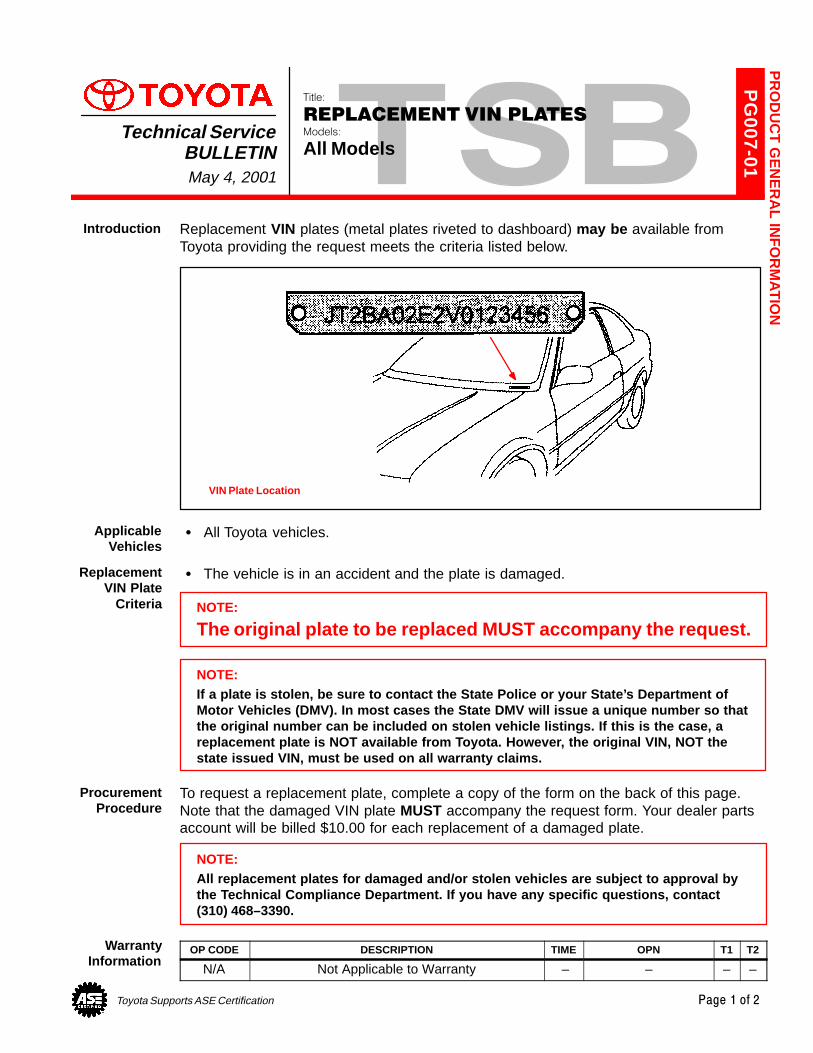
Toyota Supports ASE Certification Page 1 of 2
PG
007-01
Title:
REPLACEMENT VIN PLATESModels:
All ModelsTechnical Service
BULLETINMay 4, 2001
Replacement VIN plates (metal plates riveted to dashboard) may be available fromToyota providing the request meets the criteria listed below.
VIN Plate Location
� All Toyota vehicles.
� The vehicle is in an accident and the plate is damaged.
NOTE:
The original plate to be replaced MUST accompany the request.
NOTE:If a plate is stolen, be sure to contact the State Police or your State’s Department ofMotor Vehicles (DMV). In most cases the State DMV will issue a unique number so thatthe original number can be included on stolen vehicle listings. If this is the case, areplacement plate is NOT available from Toyota. However, the original VIN, NOT thestate issued VIN, must be used on all warranty claims.
To request a replacement plate, complete a copy of the form on the back of this page.Note that the damaged VIN plate MUST accompany the request form. Your dealer partsaccount will be billed $10.00 for each replacement of a damaged plate.
NOTE:All replacement plates for damaged and/or stolen vehicles are subject to approval bythe Technical Compliance Department. If you have any specific questions, contact(310) 468–3390.
OP CODE DESCRIPTION TIME OPN T1 T2
N/A Not Applicable to Warranty – – – –
PR
OD
UC
T G
EN
ER
AL IN
FO
RM
AT
ION
Introduction
ApplicableVehicles
ReplacementVIN Plate
Criteria
ProcurementProcedure
WarrantyInformation
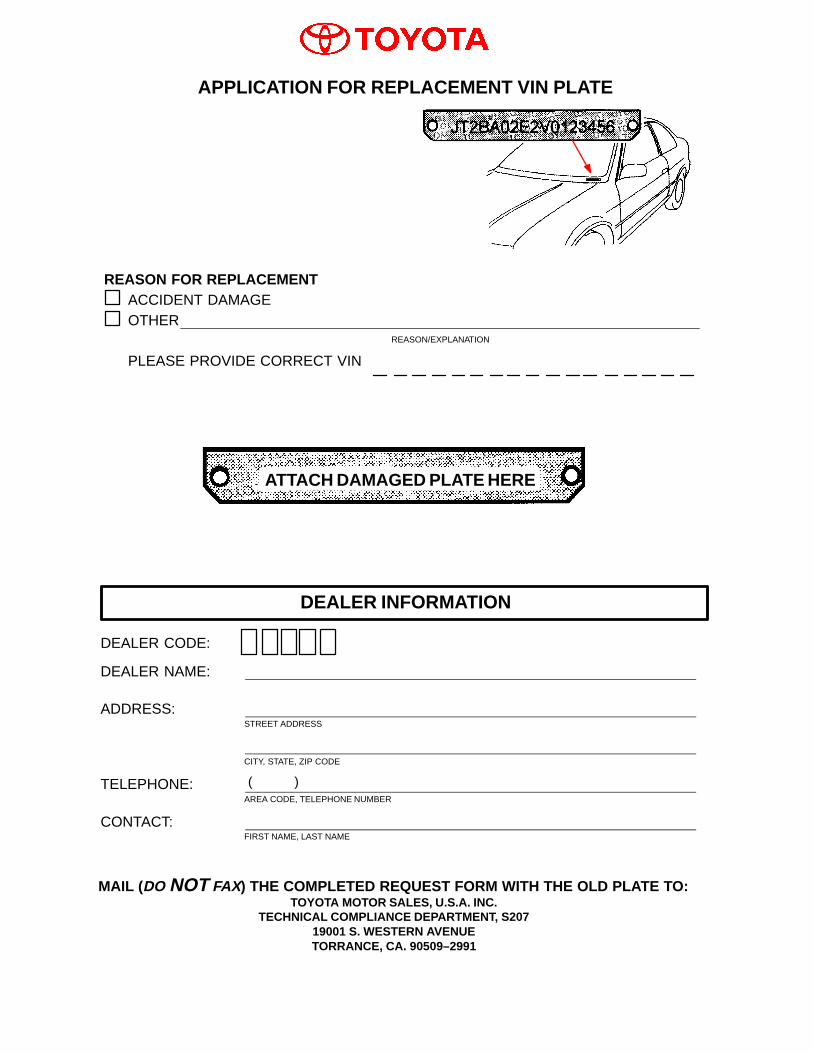
DEALER CODE:
DEALER NAME:
ADDRESS:STREET ADDRESS
CITY, STATE, ZIP CODE
TELEPHONE:AREA CODE, TELEPHONE NUMBER
CONTACT:FIRST NAME, LAST NAME
REASON FOR REPLACEMENTACCIDENT DAMAGEOTHER
REASON/EXPLANATION
PLEASE PROVIDE CORRECT VIN
APPLICATION FOR REPLACEMENT VIN PLATE
DEALER INFORMATION
MAIL (DO NOT FAX) THE COMPLETED REQUEST FORM WITH THE OLD PLATE TO:TOYOTA MOTOR SALES, U.S.A. INC.
TECHNICAL COMPLIANCE DEPARTMENT, S20719001 S. WESTERN AVENUETORRANCE, CA. 90509–2991
( )
ATTACH DAMAGED PLATE HERE
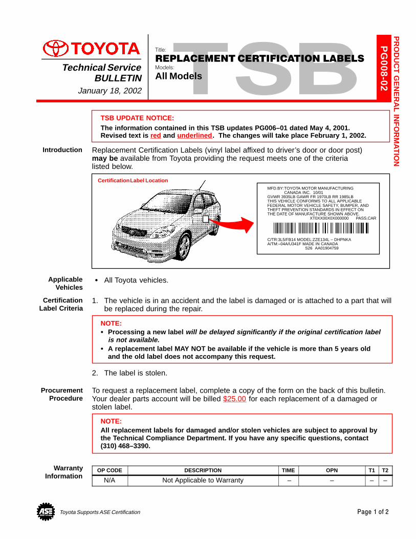
Toyota Supports ASE Certification Page 1 of 2
PG
008-02
Title:
REPLACEMENT CERTIFICATION LABELSModels:
All ModelsTechnical Service
BULLETINJanuary 18, 2002
TSB UPDATE NOTICE:The information contained in this TSB updates PG006–01 dated May 4, 2001.Revised text is red and underlined . The changes will take place February 1, 2002.
Replacement Certification Labels (vinyl label affixed to driver’s door or door post) may be available from Toyota providing the request meets one of the criteria listed below.
Certification Label LocationMFD.BY:TOYOTA MOTOR MANUFACTURING
CANADA INC. 10/01GVWR 3935LB GAWR FR 1970LB RR 1985LBTHIS VEHICLE CONFORMS TO ALL APPLICABLEFEDERAL MOTOR VEHICLE SAFETY, BUMPER, ANDTHEFT PREVENTION STANDARDS IN EFFECT ONTHE DATE OF MANUFACTURE SHOWN ABOVE.
XT0XX00X0X000000 PASS.CAR
C/TR:3L5/FB14 MODEL:ZZE134L – DHPNKAA/TM:–04A/U341F MADE IN CANADA
S26 AA01904759
� All Toyota vehicles.
1. The vehicle is in an accident and the label is damaged or is attached to a part that willbe replaced during the repair.
NOTE:� Processing a new label will be delayed significantly if the original certification label
is not available.� A replacement label MAY NOT be available if the vehicle is more than 5 years old
and the old label does not accompany this request.
2. The label is stolen.
To request a replacement label, complete a copy of the form on the back of this bulletin.Your dealer parts account will be billed $25.00 for each replacement of a damaged orstolen label.
NOTE:All replacement labels for damaged and/or stolen vehicles are subject to approval bythe Technical Compliance Department. If you have any specific questions, contact(310) 468–3390.
OP CODE DESCRIPTION TIME OPN T1 T2
N/A Not Applicable to Warranty – – – –
PR
OD
UC
T G
EN
ER
AL IN
FO
RM
AT
ION
Introduction
ApplicableVehicles
CertificationLabel Criteria
ProcurementProcedure
WarrantyInformation
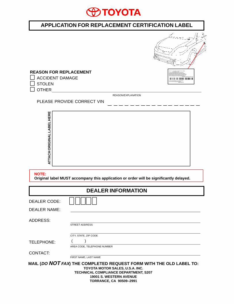
DEALER CODE:
DEALER NAME:
ADDRESS:STREET ADDRESS
CITY, STATE, ZIP CODE
TELEPHONE:AREA CODE, TELEPHONE NUMBER
CONTACT:FIRST NAME, LAST NAME
REASON FOR REPLACEMENTACCIDENT DAMAGESTOLENOTHER
REASON/EXPLANATION
PLEASE PROVIDE CORRECT VIN
APPLICATION FOR REPLACEMENT CERTIFICATION LABEL
ATTA
CH
OR
IGIN
AL
LAB
EL
HE
RE
DEALER INFORMATION
NOTE:Original label MUST accompany this application or order will be significantly delayed.
MAIL (DO NOT FAX) THE COMPLETED REQUEST FORM WITH THE OLD LABEL TO:TOYOTA MOTOR SALES, U.S.A. INC.
TECHNICAL COMPLIANCE DEPARTMENT, S20719001 S. WESTERN AVENUETORRANCE, CA 90509–2991
( )
MFD.BY: TOYOTA MOTOR MANUFACTURINGCANADA INC. 10/01
GVWR 3935LB GAWR FR 1970LB RR 1985LBTHIS VEHICLE CONFORMS TO ALL APPLICABLEFEDERAL MOTOR VEHICLE SAFETY, BUMPER, ANDTHEFT PREVENTION STANDARDS IN EFFECT ONTHE DATE OF MANUFACTURE SHOWN ABOVE.
XT0XX00X0X000000 PASS.CAR
C/TR:3L5/FB14 MODEL:ZZE134L – DHPNKAA/TM:–04A/U341F MADE IN CANADA
S26 AA01904759
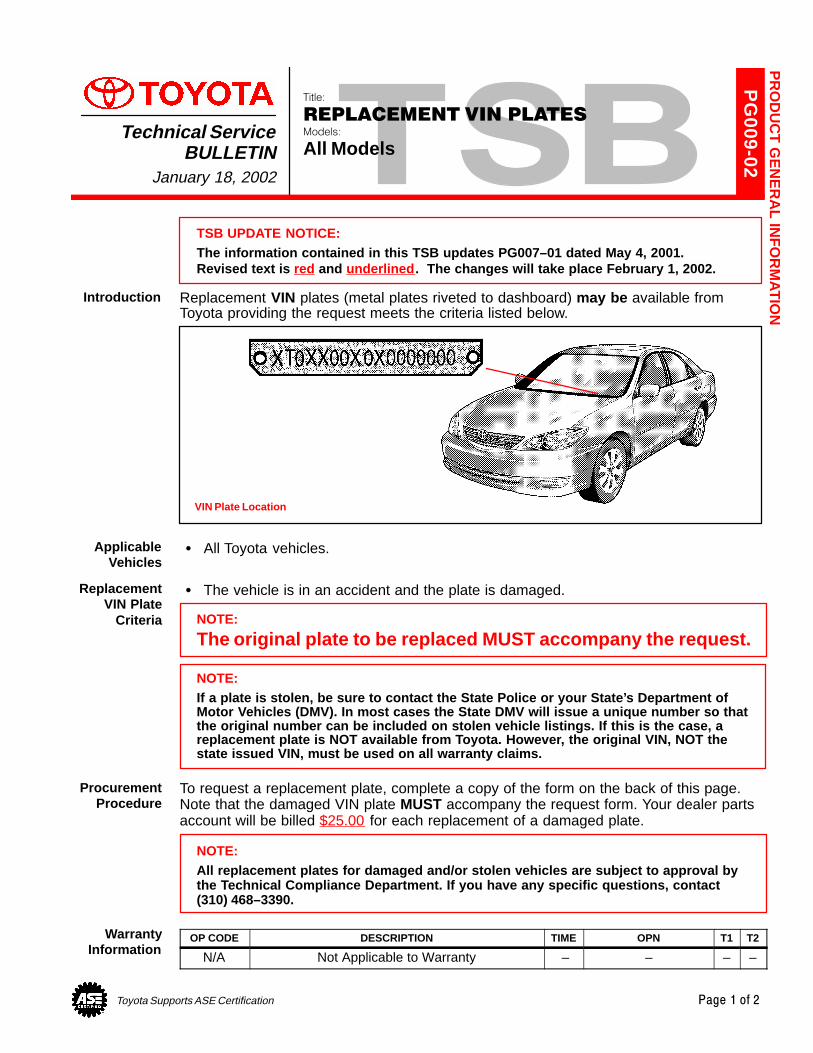
Toyota Supports ASE Certification Page 1 of 2
PG
009-02
Title:
REPLACEMENT VIN PLATESModels:
All ModelsTechnical Service
BULLETINJanuary 18, 2002
TSB UPDATE NOTICE:The information contained in this TSB updates PG007–01 dated May 4, 2001.Revised text is red and underlined . The changes will take place February 1, 2002.
Replacement VIN plates (metal plates riveted to dashboard) may be available fromToyota providing the request meets the criteria listed below.
VIN Plate Location
� All Toyota vehicles.
� The vehicle is in an accident and the plate is damaged.
NOTE:
The original plate to be replaced MUST accompany the request.
NOTE:If a plate is stolen, be sure to contact the State Police or your State’s Department ofMotor Vehicles (DMV). In most cases the State DMV will issue a unique number so thatthe original number can be included on stolen vehicle listings. If this is the case, areplacement plate is NOT available from Toyota. However, the original VIN, NOT thestate issued VIN, must be used on all warranty claims.
To request a replacement plate, complete a copy of the form on the back of this page.Note that the damaged VIN plate MUST accompany the request form. Your dealer partsaccount will be billed $25.00 for each replacement of a damaged plate.
NOTE:All replacement plates for damaged and/or stolen vehicles are subject to approval bythe Technical Compliance Department. If you have any specific questions, contact(310) 468–3390.
OP CODE DESCRIPTION TIME OPN T1 T2
N/A Not Applicable to Warranty – – – –
PR
OD
UC
T G
EN
ER
AL IN
FO
RM
AT
ION
Introduction
ApplicableVehicles
ReplacementVIN Plate
Criteria
ProcurementProcedure
WarrantyInformation
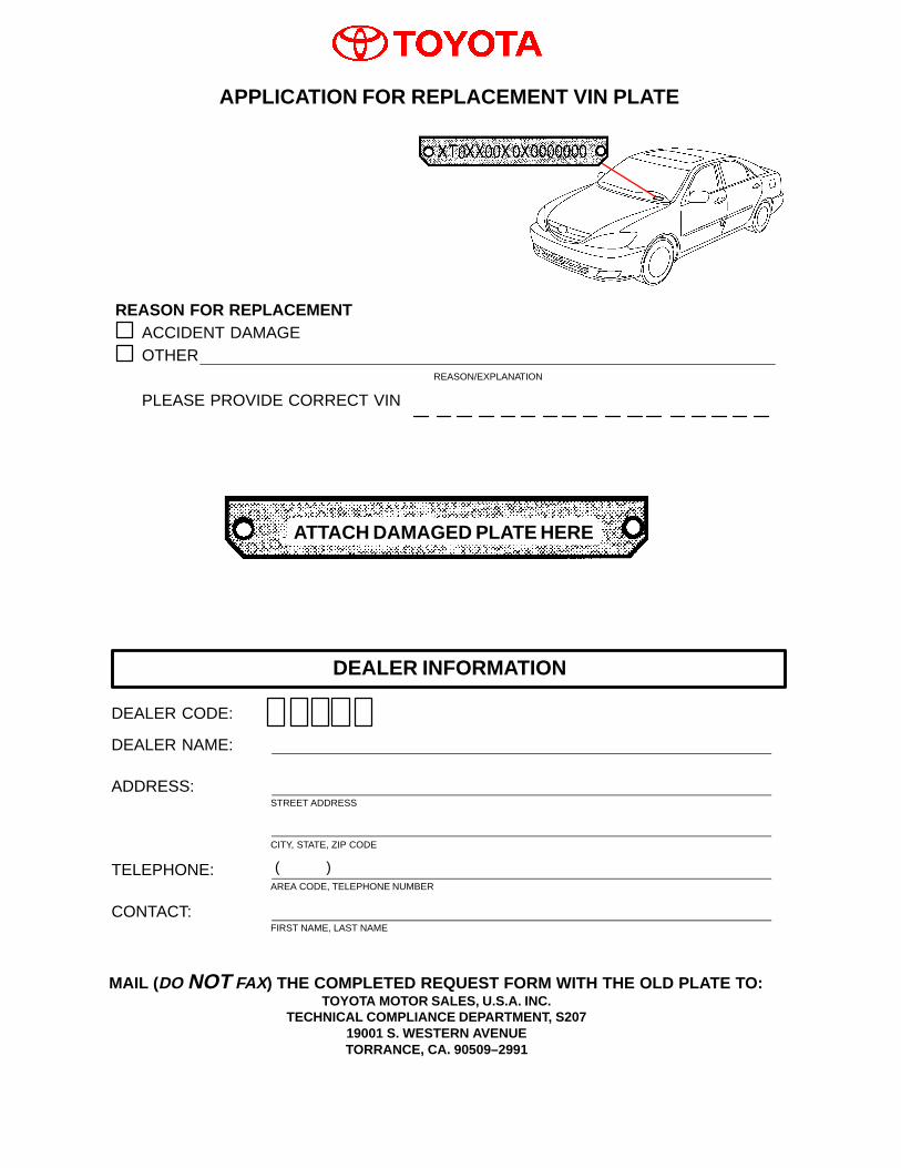
DEALER CODE:
DEALER NAME:
ADDRESS:STREET ADDRESS
CITY, STATE, ZIP CODE
TELEPHONE:AREA CODE, TELEPHONE NUMBER
CONTACT:FIRST NAME, LAST NAME
REASON FOR REPLACEMENTACCIDENT DAMAGEOTHER
REASON/EXPLANATION
PLEASE PROVIDE CORRECT VIN
APPLICATION FOR REPLACEMENT VIN PLATE
DEALER INFORMATION
MAIL (DO NOT FAX) THE COMPLETED REQUEST FORM WITH THE OLD PLATE TO:TOYOTA MOTOR SALES, U.S.A. INC.
TECHNICAL COMPLIANCE DEPARTMENT, S20719001 S. WESTERN AVENUETORRANCE, CA. 90509–2991
( )
ATTACH DAMAGED PLATE HERE
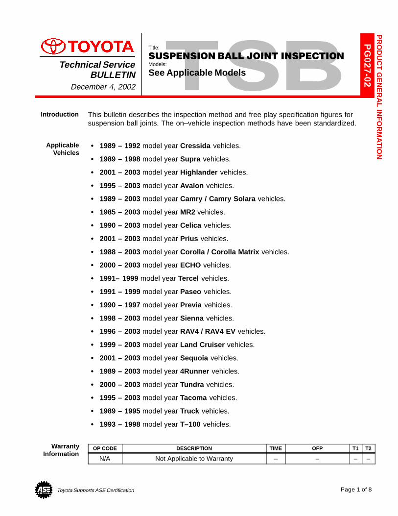
Toyota Supports ASE Certification Page 1 of 8
PG
027-02
Title:
SUSPENSION BALL JOINT INSPECTIONModels:
See Applicable ModelsTechnical Service
BULLETINDecember 4, 2002
This bulletin describes the inspection method and free play specification figures forsuspension ball joints. The on–vehicle inspection methods have been standardized.
� 1989 – 1992 model year Cressida vehicles.
� 1989 – 1998 model year Supra vehicles.
� 2001 – 2003 model year Highlander vehicles.
� 1995 – 2003 model year Avalon vehicles.
� 1989 – 2003 model year Camry / Camry Solara vehicles.
� 1985 – 2003 model year MR2 vehicles.
� 1990 – 2003 model year Celica vehicles.
� 2001 – 2003 model year Prius vehicles.
� 1988 – 2003 model year Corolla / Corolla Matrix vehicles.
� 2000 – 2003 model year ECHO vehicles.
� 1991– 1999 model year Tercel vehicles.
� 1991 – 1999 model year Paseo vehicles.
� 1990 – 1997 model year Previa vehicles.
� 1998 – 2003 model year Sienna vehicles.
� 1996 – 2003 model year RAV4 / RAV4 EV vehicles.
� 1999 – 2003 model year Land Cruiser vehicles.
� 2001 – 2003 model year Sequoia vehicles.
� 1989 – 2003 model year 4Runner vehicles.
� 2000 – 2003 model year Tundra vehicles.
� 1995 – 2003 model year Tacoma vehicles.
� 1989 – 1995 model year Truck vehicles.
� 1993 – 1998 model year T–100 vehicles.
OP CODE DESCRIPTION TIME OFP T1 T2
N/A Not Applicable to Warranty – – – –
PR
OD
UC
T G
EN
ER
AL IN
FO
RM
AT
ION
Introduction
ApplicableVehicles
WarrantyInformation
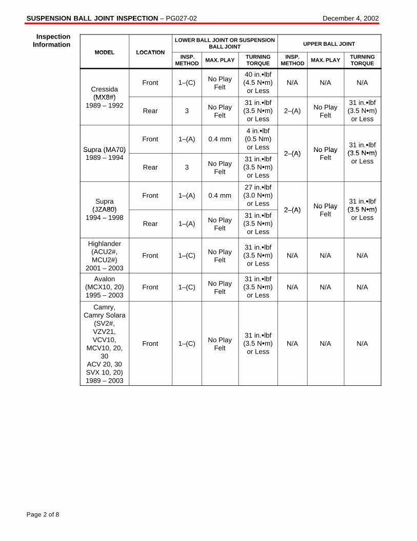
SUSPENSION BALL JOINT INSPECTION – PG027-02 December 4, 2002
Page 2 of 8
MODEL LOCATION
LOWER BALL JOINT OR SUSPENSIONBALL JOINT UPPER BALL JOINT
MODEL LOCATION INSP.
METHODMAX. PLAY
TURNINGTORQUE
INSP.METHOD
MAX. PLAYTURNINGTORQUE
Cressida(MX8#)
Front 1–(C) No PlayFelt
40 in.�lbf(4.5 N�m)or Less
N/A N/A N/A
(MX8#)1989 – 1992
Rear 3 No PlayFelt
31 in.�lbf(3.5 N�m)or Less
2–(A) No PlayFelt
31 in.�lbf(3.5 N�m)or Less
Supra (MA70)
Front 1–(A) 0.4 mm4 in.�lbf(0.5 Nm)or Less
2 (A) No Play31 in.�lbf(3 5 N�m)Su ra (MA70)
1989 – 1994Rear 3 No Play
Felt
31 in.�lbf(3.5 N�m)or Less
2–(A) No PlayFelt
(3.5 N�m)or Less
Supra(JZA80)
Front 1–(A) 0.4 mm27 in.�lbf(3.0 N�m)or Less
2 (A) No Play31 in.�lbf(3 5 N�m)(JZA80)
1994 – 1998Rear 1–(A) No Play
Felt
31 in.�lbf(3.5 N�m)or Less
2–(A) No PlayFelt
(3.5 N�m)or Less
Highlander(ACU2#,MCU2#)
2001 – 2003
Front 1–(C) No PlayFelt
31 in.�lbf(3.5 N�m)or Less
N/A N/A N/A
Avalon(MCX10, 20)1995 – 2003
Front 1–(C) No PlayFelt
31 in.�lbf(3.5 N�m)or Less
N/A N/A N/A
Camry,Camry Solara
(SV2#,VZV21,VCV10,
MCV10, 20,30
ACV 20, 30SVX 10, 20)1989 – 2003
Front 1–(C) No PlayFelt
31 in.�lbf(3.5 N�m)or Less
N/A N/A N/A
InspectionInformation
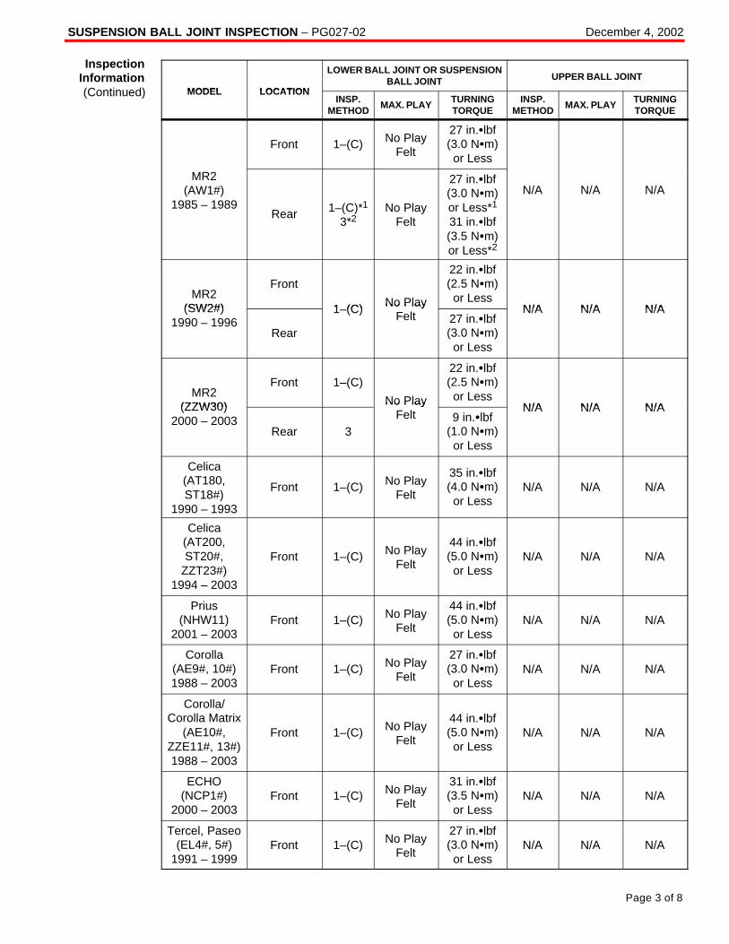
SUSPENSION BALL JOINT INSPECTION – PG027-02 December 4, 2002
Page 3 of 8
MODEL LOCATION
LOWER BALL JOINT OR SUSPENSIONBALL JOINT UPPER BALL JOINT
MODEL LOCATIONINSP.
METHODMAX. PLAY
TURNINGTORQUE
INSP.METHOD
MAX. PLAYTURNINGTORQUE
Front 1–(C) No PlayFelt
27 in.�lbf(3.0 N�m)or Less
MR2(AW1#)
1985 – 1989Rear 1–(C)*1
3*2No Play
Felt
27 in.�lbf(3.0 N�m)or Less*1
31 in.�lbf(3.5 N�m)or Less*2
N/A N/A N/A
MR2(SW2#)
Front
1 (C) No Play
22 in.�lbf(2.5 N�m)or Less
N/A N/A N/A(SW2#)1990 – 1996
Rear
1–(C) No PlayFelt 27 in.�lbf
(3.0 N�m)or Less
N/A N/A N/A
MR2(ZZW30)
Front 1–(C)
No Play
22 in.�lbf(2.5 N�m)or Less
N/A N/A N/A(ZZW30)2000 – 2003
Rear 3
No PlayFelt 9 in.�lbf
(1.0 N�m)or Less
N/A N/A N/A
Celica(AT180,ST18#)
1990 – 1993
Front 1–(C) No PlayFelt
35 in.�lbf(4.0 N�m)or Less
N/A N/A N/A
Celica(AT200,ST20#,
ZZT23#)1994 – 2003
Front 1–(C) No PlayFelt
44 in.�lbf(5.0 N�m)or Less
N/A N/A N/A
Prius(NHW11)
2001 – 2003Front 1–(C) No Play
Felt
44 in.�lbf(5.0 N�m)or Less
N/A N/A N/A
Corolla(AE9#, 10#)1988 – 2003
Front 1–(C) No PlayFelt
27 in.�lbf(3.0 N�m)or Less
N/A N/A N/A
Corolla/Corolla Matrix
(AE10#,ZZE11#, 13#)1988 – 2003
Front 1–(C) No PlayFelt
44 in.�lbf(5.0 N�m)or Less
N/A N/A N/A
ECHO(NCP1#)
2000 – 2003Front 1–(C) No Play
Felt
31 in.�lbf(3.5 N�m)or Less
N/A N/A N/A
Tercel, Paseo(EL4#, 5#)
1991 – 1999Front 1–(C) No Play
Felt
27 in.�lbf(3.0 N�m)or Less
N/A N/A N/A
InspectionInformation(Continued)
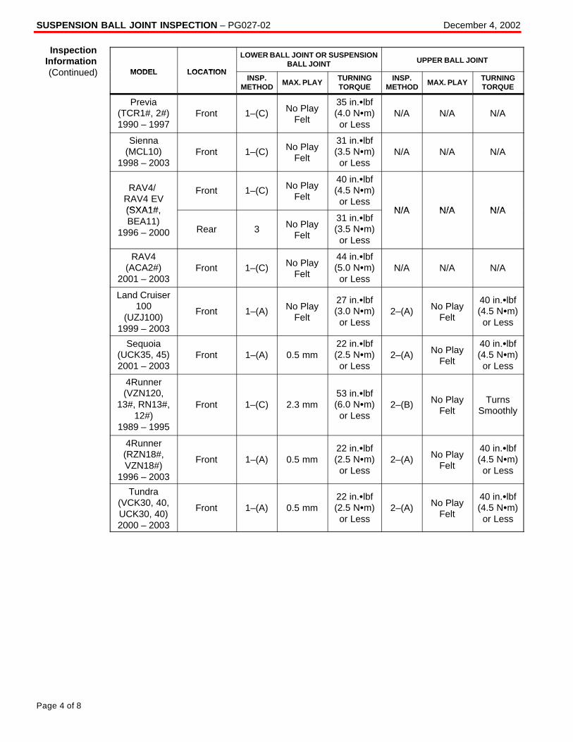
SUSPENSION BALL JOINT INSPECTION – PG027-02 December 4, 2002
Page 4 of 8
MODEL LOCATION
LOWER BALL JOINT OR SUSPENSIONBALL JOINT UPPER BALL JOINT
MODEL LOCATIONINSP.
METHODMAX. PLAY
TURNINGTORQUE
INSP.METHOD
MAX. PLAYTURNINGTORQUE
Previa(TCR1#, 2#)1990 – 1997
Front 1–(C) No PlayFelt
35 in.�lbf(4.0 N�m)or Less
N/A N/A N/A
Sienna(MCL10)
1998 – 2003Front 1–(C) No Play
Felt
31 in.�lbf(3.5 N�m)or Less
N/A N/A N/A
RAV4/ RAV4 EV(SXA1#
Front 1–(C) No PlayFelt
40 in.�lbf(4.5 N�m)or Less
N/A N/A N/A(SXA1#,BEA11)
1996 – 2000 Rear 3 No PlayFelt
31 in.�lbf(3.5 N�m)or Less
N/A N/A N/A
RAV4(ACA2#)
2001 – 2003Front 1–(C) No Play
Felt
44 in.�lbf(5.0 N�m)or Less
N/A N/A N/A
Land Cruiser100
(UZJ100)1999 – 2003
Front 1–(A) No PlayFelt
27 in.�lbf(3.0 N�m)or Less
2–(A) No PlayFelt
40 in.�lbf(4.5 N�m)or Less
Sequoia(UCK35, 45)2001 – 2003
Front 1–(A) 0.5 mm22 in.�lbf(2.5 N�m)or Less
2–(A) No PlayFelt
40 in.�lbf(4.5 N�m)or Less
4Runner(VZN120,
13#, RN13#,12#)
1989 – 1995
Front 1–(C) 2.3 mm53 in.�lbf(6.0 N�m)or Less
2–(B) No PlayFelt
TurnsSmoothly
4Runner(RZN18#,VZN18#)
1996 – 2003
Front 1–(A) 0.5 mm22 in.�lbf(2.5 N�m)or Less
2–(A) No PlayFelt
40 in.�lbf(4.5 N�m)or Less
Tundra(VCK30, 40,UCK30, 40)2000 – 2003
Front 1–(A) 0.5 mm22 in.�lbf(2.5 N�m)or Less
2–(A) No PlayFelt
40 in.�lbf(4.5 N�m)or Less
InspectionInformation(Continued)
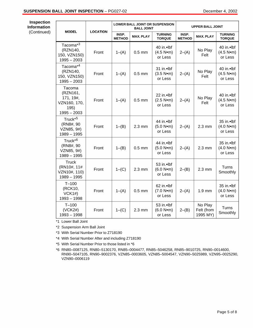
SUSPENSION BALL JOINT INSPECTION – PG027-02 December 4, 2002
Page 5 of 8
MODEL LOCATION
LOWER BALL JOINT OR SUSPENSIONBALL JOINT UPPER BALL JOINT
MODEL LOCATIONINSP.
METHODMAX. PLAY
TURNINGTORQUE
INSP.METHOD
MAX. PLAYTURNINGTORQUE
Tacoma*3
(RZN140,150, VZN150)1995 – 2003
Front 1–(A) 0.5 mm40 in.�lbf(4.5 N�m)or Less
2–(A) No PlayFelt
40 in.�lbf(4.5 N�m)or Less
Tacoma*4
(RZN140,150, VZN150)1995 – 2003
Front 1–(A) 0.5 mm31 in.�lbf(3.5 N�m)or Less
2–(A) No PlayFelt
40 in.�lbf(4.5 N�m)or Less
Tacoma(RZN161,171, 19#,
VZN160, 170,195)
1995 – 2003
Front 1–(A) 0.5 mm22 in.�lbf(2.5 N�m)or Less
2–(A) No PlayFelt
40 in.�lbf(4.5 N�m)or Less
Truck*5
(RN8#, 90VZN85, 9#)1989 – 1995
Front 1–(B) 2.3 mm44 in.�lbf(5.0 N�m)or Less
2–(A) 2.3 mm35 in.�lbf(4.0 N�m)or Less
Truck*6
(RN8#, 90VZN85, 9#)1989 – 1995
Front 1–(B) 0.5 mm44 in.�lbf(5.0 N�m)or Less
2–(A) 2.3 mm35 in.�lbf(4.0 N�m)or Less
Truck(RN10#, 11#
VZN10#, 110)1989 – 1995
Front 1–(C) 2.3 mm53 in.�lbf(6.0 N�m)or Less
2–(B) 2.3 mm TurnsSmoothly
T–100(RCK10,VCK1#)
1993 – 1998
Front 1–(A) 0.5 mm62 in.�lbf(7.0 N�m)or Less
2–(A) 1.9 mm35 in.�lbf(4.0 N�m)or Less
T–100(VCK2#)
1993 – 1998Front 1–(C) 2.3 mm
53 in.�lbf(6.0 N�m)or Less
2–(B)No Play
Felt (from1995 MY)
TurnsSmoothly
*1 Lower Ball Joint
*2 Suspension Arm Ball Joint
*3 With Serial Number Prior to Z718190
*4 With Serial Number After and including Z718190
*5 With Serial Number Prior to those listed in *6
*6 RN80–0087125, RN80–5130170, RN85–0004477, RN85–5046258, RN85–9010725, RN90–0014600,RN90–5047105, RN90–9002376, VZN85–0003605, VZN85–5004547, VZN90–5025989, VZN95–0025290,VZN90–0006119
InspectionInformation(Continued)
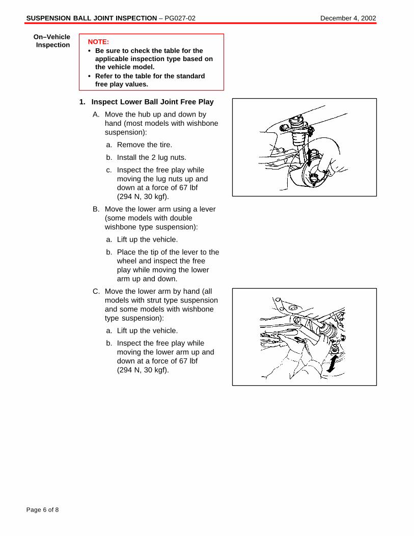
SUSPENSION BALL JOINT INSPECTION – PG027-02 December 4, 2002
Page 6 of 8
NOTE:� Be sure to check the table for the
applicable inspection type based onthe vehicle model.
� Refer to the table for the standardfree play values.
1. Inspect Lower Ball Joint Free Play
A. Move the hub up and down byhand (most models with wishbonesuspension):
a. Remove the tire.
b. Install the 2 lug nuts.
c. Inspect the free play whilemoving the lug nuts up anddown at a force of 67 lbf (294 N, 30 kgf).
B. Move the lower arm using a lever(some models with doublewishbone type suspension):
a. Lift up the vehicle.
b. Place the tip of the lever to thewheel and inspect the freeplay while moving the lowerarm up and down.
C. Move the lower arm by hand (allmodels with strut type suspensionand some models with wishbonetype suspension):
a. Lift up the vehicle.
b. Inspect the free play whilemoving the lower arm up anddown at a force of 67 lbf (294 N, 30 kgf).
On–VehicleInspection
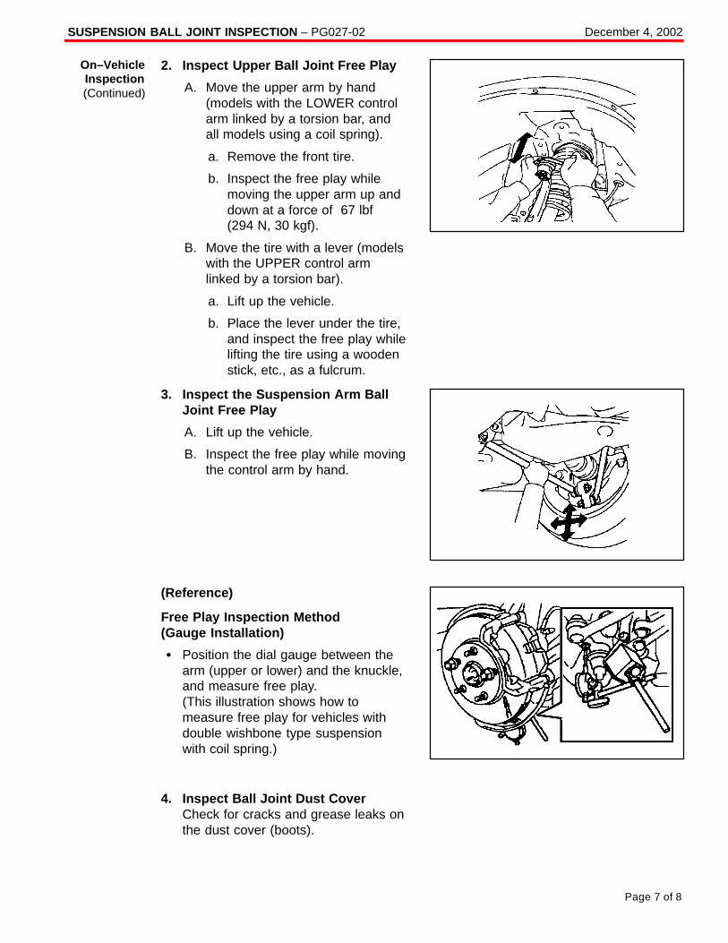
SUSPENSION BALL JOINT INSPECTION – PG027-02 December 4, 2002
Page 7 of 8
2. Inspect Upper Ball Joint Free Play
A. Move the upper arm by hand(models with the LOWER controlarm linked by a torsion bar, andall models using a coil spring).
a. Remove the front tire.
b. Inspect the free play whilemoving the upper arm up anddown at a force of 67 lbf(294 N, 30 kgf).
B. Move the tire with a lever (modelswith the UPPER control armlinked by a torsion bar).
a. Lift up the vehicle.
b. Place the lever under the tire,and inspect the free play whilelifting the tire using a woodenstick, etc., as a fulcrum.
3. Inspect the Suspension Arm BallJoint Free Play
A. Lift up the vehicle.
B. Inspect the free play while movingthe control arm by hand.
(Reference)
Free Play Inspection Method(Gauge Installation)
� Position the dial gauge between thearm (upper or lower) and the knuckle,and measure free play.(This illustration shows how tomeasure free play for vehicles withdouble wishbone type suspensionwith coil spring.)
4. Inspect Ball Joint Dust CoverCheck for cracks and grease leaks onthe dust cover (boots).
On–VehicleInspection(Continued)
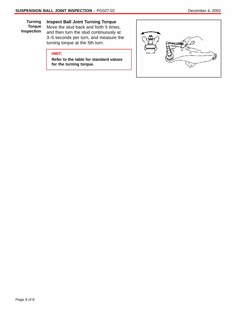
SUSPENSION BALL JOINT INSPECTION – PG027-02 December 4, 2002
Page 8 of 8
Inspect Ball Joint Turning TorqueMove the stud back and forth 5 times,and then turn the stud continuously at3–5 seconds per turn, and measure theturning torque at the 5th turn.
HINT:Refer to the table for standard valuesfor the turning torque.
TurningTorque
Inspection
Toyota Supports ASE Certification Page 1 of 2
PG
032–99
Title:
YEAR 2000 READINESS DISCLOSUREModels:
All ModelsTechnical Service
BULLETINDecember 24, 1999
Based upon information we have obtained from our suppliers,1 all factory–installedsystems in Toyota cars, sports utility vehicles and trucks distributed and/or sold by Toyota(“Vehicles”)2 will not be affected by the change of date from 1999 to the year 2000.
Toyota anticipates no problems with past, current or future Toyota brand vehicles orGenuine Toyota parts and accessories regarding year 2000 readiness. We hope thefollowing information is helpful to you.
Please contact our Customer Service Department at 1–800–331–4331 should you haveany other questions.
� All Models
WARRANTY STATEMENT WITH RESPECT TO TOYOTA BRAND VEHICLES
Toyota is pleased to confirm that the manufacturer’s limited express warranty andToyota’s powertrain warranty warrant that all factory–installed systems in new Vehiclesand Toyota Certified Used Vehicles shall be free of any defect arising solely due to achange in date from the year 1999 to the year 2000.3
With respect to Vehicles no longer covered under such Toyota limited express warranty,Toyota is not aware of any operational safety or functional impact the year 2000 datechange would have upon any factory–installed system in Toyota Vehicles. Should Toyotabecome aware of any material impact to the operational safety or functionality of suchsystems, Toyota shall publish such information promptly.
WARRANTY STATEMENT WITH RESPECT TO GENUINE TOYOTA PARTS ANDACCESSORIES
Toyota is pleased to confirm that the manufacturer’s limited express warranty warrantsthat all new Toyota Genuine Parts and Accessories shall be free of any defect arisingsolely due to a change in date from the year 1999 to the year 2000. 3
With respect to products no longer covered under a Toyota limited express warranty,Toyota is not aware of any operational safety or functional impact the year 2000 datechange would have upon such products. Should Toyota become aware of any materialimpact to the operational safety or functionality of such a product, Toyota shall publishsuch information promptly.
1 Toyota relies on the statements made by its suppliers and has not independently verified such information.2 Vehicles includes alternative fuel vehicles.3 Please refer to terms of limited express warranty for disclaimers, limitations and restrictions.
PR
OD
UC
T G
EN
ER
AL IN
FO
RM
AT
ION
Introduction
ApplicableVehicles
Warranty
YEAR 2000 READINESS DISCLOSURE – PG032-99 December 24, 1999
Page 2 of 2
GENUINE TOYOTA PARTS AND ACCESSORIES
Based upon information we have obtained from our suppliers,1 all new Genuine ToyotaParts and Accessories will not be affected by the change of date from 1999 to the year2000.
DEALER–INSTALLED AND OTHER THIRD PARTY–INSTALLED SYSTEMS/PRODUCTS
Our dealers and distributors may sell and/or install products that are not Genuine ToyotaParts and Accessories. Toyota can only determine the Year 2000 readiness status ofGenuine Toyota Parts and Accessories. Therefore, the above statements do not apply toproducts that are not Genuine Toyota Parts and Accessories or were not installed by thefactory. We encourage you to contact your dealer or other relevant third party regardingproducts installed on your Toyota vehicle(s) that are not Genuine Toyota Parts andAccessories and/or were not installed by the factory to determine any Year 2000 issuesassociated with those products.
1 Toyota relies on the statements made by its suppliers and has not independently verified such information.
Parts &Accessories
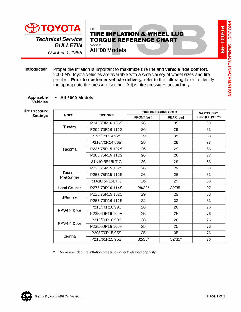
Toyota Supports ASE Certification Page 1 of 2
PG
031–99
Title:
TIRE INFLATION & WHEEL LUG
TORQUE REFERENCE CHARTModels:
All ’00 Models
Technical ServiceBULLETIN
October 1, 1999
Proper tire inflation is important to maximize tire life and vehicle ride comfort.2000 MY Toyota vehicles are available with a wide variety of wheel sizes and tireprofiles. Prior to customer vehicle delivery, refer to the following table to identifythe appropriate tire pressure setting. Adjust tire pressures accordingly.
� All 2000 Models
MODEL TIRE SIZETIRE PRESSURE COLD WHEEL NUT
MODEL TIRE SIZEFRONT (psi) REAR (psi)
WHEEL NUTTORQUE (ft�lbf)
TundraP245/70R16 106S 26 35 83
TundraP265/70R16 111S 26 29 83
P195/75R14 92S 29 35 83
P215/70R14 96S 29 29 83
Tacoma P225/75R15 102S 26 29 83
P265/75R15 112S 26 26 83
31X10.5R15LT C 26 29 83
TP225/75R15 102S 26 29 83
TacomaPreRunner
P265/75R15 112S 26 26 83PreRunner
31X10.5R15LT C 26 29 83
Land Cruiser P275/70R16 114S 29/29* 32/35* 97Land Cruiser P275/70R16 114S 29/29* 32/35* 97
4RunnerP225/75R15 102S 29 29 83
4RunnerP265/70R16 111S 32 32 83
RAV4 2 DoorP215/70R16 99S 26 26 76
RAV4 2 DoorP235/60R16 100H 25 25 76
RAV4 4 DoorP215/70R16 99S 28 26 76
RAV4 4 DoorP235/60R16 100H 25 25 76
SiennaP205/70R15 95S 35 35 76
SiennaP215/65R15 95S 32/35* 32/35* 76
* Recommended tire inflation pressure under high load capacity.
PR
OD
UC
T G
EN
ER
AL IN
FO
RM
AT
ION
Introduction
ApplicableVehicles
Tire PressureSettings
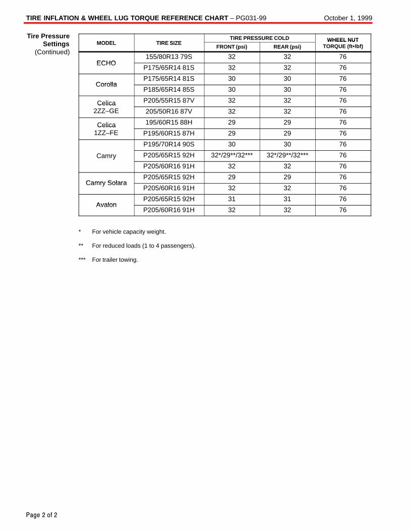
TIRE INFLATION & WHEEL LUG TORQUE REFERENCE CHART – PG031-99 October 1, 1999
Page 2 of 2
MODEL TIRE SIZETIRE PRESSURE COLD WHEEL NUT
MODEL TIRE SIZEFRONT (psi) REAR (psi)
WHEEL NUTTORQUE (ft�lbf)
ECHO155/80R13 79S 32 32 76
ECHOP175/65R14 81S 32 32 76
CorollaP175/65R14 81S 30 30 76
CorollaP185/65R14 85S 30 30 76
Celica P205/55R15 87V 32 32 76Celica2ZZ–GE 205/50R16 87V 32 32 76
Celica 195/60R15 88H 29 29 76Celica1ZZ–FE P195/60R15 87H 29 29 76
P195/70R14 90S 30 30 76
Camry P205/65R15 92H 32*/29**/32*** 32*/29**/32*** 76y
P205/60R16 91H 32 32 76
Camry SolaraP205/65R15 92H 29 29 76
Camry SolaraP205/60R16 91H 32 32 76
AvalonP205/65R15 92H 31 31 76
AvalonP205/60R16 91H 32 32 76
* For vehicle capacity weight.
** For reduced loads (1 to 4 passengers).
*** For trailer towing.
Tire PressureSettings
(Continued)
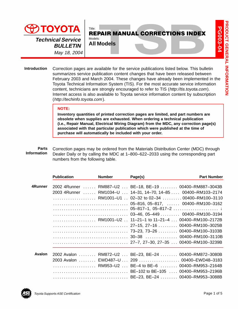
Toyota Supports ASE Certification Page 1 of 5
PG
003-04
Title:
REPAIR MANUAL CORRECTIONS INDEXModels:
All ModelsTechnical Service
BULLETINMay 18, 2004
Correction pages are available for the service publications listed below. This bulletinsummarizes service publication content changes that have been released betweenFebruary 2003 and March 2004. These changes have already been implemented in theToyota Technical Information System (TIS). For the most accurate service informationcontent, technicians are strongly encouraged to refer to TIS (http://tis.toyota.com).Internet access is also available to Toyota service information content by subscription(http://techinfo.toyota.com ).
NOTE:Inventory quantities of printed correction pages are limited, and part numbers areobsolete when supplies are exhausted. When ordering a technical publication(i.e., Repair Manual, Electrical Wiring Diagram) from the MDC, any correction page(s)associated with that particular publication which were published at the time ofpurchase will automatically be included with your order.
Correction pages may be ordered from the Materials Distribution Center (MDC) throughDealer Daily or by calling the MDC at 1–800–622–2033 using the corresponding partnumbers from the following table.
Publication Number Page(s) Part Number
2002 4Runner RM887–U2 BE–18, BE–19 00400–RM887–3043B. . . . . . . . . . . . . . . . . 2003 4Runner RM1034–U 14–31, 14–70, 14–85 00400–RM103–2174. . . . . . . . . . . . .
RM1001–U1 02–32 to 02–34 00400–RM100–3110. . . . . . . . . . . . . . . . . . . . . . . . . . . . . . . 05–816, 05–817, 00400–RM100–3162. . . . . . . . . . . . . . . . . . . . . . . . . . . . . . . . . . . . . . . . . 05–817–1, 05–817–2 ↓. . . . . . . . . . . . . . . . . . . . . . . . . . . . . . . . . . . . . . . . . . . . . . . . . . . . . . . . 03–46, 05–449 00400–RM100–3194. . . . . . . . . . . . . . . . . . . . . . . . . . . . . . . . . . . . . . . . . . . .
RM1001–U2 11–21–1 to 11–21–4 00400–RM100–2172B. . . . . . . . . . . . . . . . . . . . . . . . . 27–15, 27–16 00400–RM100–3025B. . . . . . . . . . . . . . . . . . . . . . . . . . . . . . . . . . . . . . . . . . . . 73–23, 73–26 00400–RM100–3103B. . . . . . . . . . . . . . . . . . . . . . . . . . . . . . . . . . . . . . . . . . . . 30–38 00400–RM100–3110B. . . . . . . . . . . . . . . . . . . . . . . . . . . . . . . . . . . . . . . . . . . . . . . . . . 27–7, 27–30, 27–35 00400–RM100–3239B. . . . . . . . . . . . . . . . . . . . . . . . . . . . . . . . . . . . . .
2002 Avalon RM872–U2 BE–23, BE–24 00400–RM872–3080B. . . . . . . . . . . . . . . . . . . 2003 Avalon EWD487–U 209 00400–EWD48–3183. . . . . . . . . . . . . . . . . . . . . . . . . . . . . .
RM953–U2 BE–4 to BE–6 00400–RM953–2164B. . . . . . . . . . . . . . . . . . . . . . . . . . . . . . . BE–102 to BE–105 00400–RM953–2196B. . . . . . . . . . . . . . . . . . . . . . . . . . . . . . . . . . . . . . . BE–23, BE–24 00400–RM953–3088B. . . . . . . . . . . . . . . . . . . . . . . . . . . . . . . . . . . . . . . . . . .
PR
OD
UC
T G
EN
ER
AL IN
FO
RM
AT
ION
Introduction
PartsInformation
4Runner
Avalon
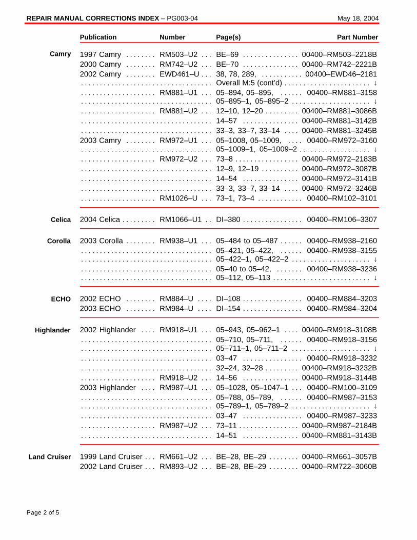
REPAIR MANUAL CORRECTIONS INDEX – PG003-04 May 18, 2004
Page 2 of 5
Publication Number Page(s) Part Number
1997 Camry RM503–U2 BE–69 00400–RM503–2218B. . . . . . . . . . . . . . . . . . . . . . . . . . 2000 Camry RM742–U2 BE–70 00400–RM742–2221B. . . . . . . . . . . . . . . . . . . . . . . . . . 2002 Camry EWD461–U 38, 78, 289, 00400–EWD46–2181. . . . . . . . . . . . . . . . . . . . . .
Overall M:5 (cont’d) ↓. . . . . . . . . . . . . . . . . . . . . . . . . . . . . . . . . . . . . . . . . . . . . . . . . . . . . . . . . . RM881–U1 05–894, 05–895, 00400–RM881–3158. . . . . . . . . . . . . . . . . . . . . . . . . . . . .
05–895–1, 05–895–2 ↓. . . . . . . . . . . . . . . . . . . . . . . . . . . . . . . . . . . . . . . . . . . . . . . . . . . . . . . . RM881–U2 12–10, 12–20 00400–RM881–3086B. . . . . . . . . . . . . . . . . . . . . . . . . . . . . . . .
14–57 00400–RM881–3142B. . . . . . . . . . . . . . . . . . . . . . . . . . . . . . . . . . . . . . . . . . . . . . . . . . 33–3, 33–7, 33–14 00400–RM881–3245B. . . . . . . . . . . . . . . . . . . . . . . . . . . . . . . . . . . . . . .
2003 Camry RM972–U1 05–1008, 05–1009, 00400–RM972–3160. . . . . . . . . . . . . . . 05–1009–1, 05–1009–2 ↓. . . . . . . . . . . . . . . . . . . . . . . . . . . . . . . . . . . . . . . . . . . . . . . . . . . . . .
RM972–U2 73–8 00400–RM972–2183B. . . . . . . . . . . . . . . . . . . . . . . . . . . . . . . . . . . . . . . . 12–9, 12–19 00400–RM972–3087B. . . . . . . . . . . . . . . . . . . . . . . . . . . . . . . . . . . . . . . . . . . . . 14–54 00400–RM972–3141B. . . . . . . . . . . . . . . . . . . . . . . . . . . . . . . . . . . . . . . . . . . . . . . . . . 33–3, 33–7, 33–14 00400–RM972–3246B. . . . . . . . . . . . . . . . . . . . . . . . . . . . . . . . . . . . . . .
RM1026–U 73–1, 73–4 00400–RM102–3101. . . . . . . . . . . . . . . . . . . . . . . . . . . . . . . . . . .
2004 Celica RM1066–U1 DI–380 00400–RM106–3307. . . . . . . . . . . . . . . . . . . . . . . . . . .
2003 Corolla RM938–U1 05–484 to 05–487 00400–RM938–2160. . . . . . . . . . . . . . . . . 05–421, 05–422, 00400–RM938–3155. . . . . . . . . . . . . . . . . . . . . . . . . . . . . . . . . . . . . . . . . 05–422–1, 05–422–2 ↓. . . . . . . . . . . . . . . . . . . . . . . . . . . . . . . . . . . . . . . . . . . . . . . . . . . . . . . . 05–40 to 05–42, 00400–RM938–3236. . . . . . . . . . . . . . . . . . . . . . . . . . . . . . . . . . . . . . . . . . 05–112, 05–113 ↓. . . . . . . . . . . . . . . . . . . . . . . . . . . . . . . . . . . . . . . . . . . . . . . . . . . . . . . . . . . . .
2002 ECHO RM884–U DI–108 00400–RM884–3203. . . . . . . . . . . . . . . . . . . . . . . . . . . . 2003 ECHO RM984–U DI–154 00400–RM984–3204. . . . . . . . . . . . . . . . . . . . . . . . . . . .
2002 Highlander RM918–U1 05–943, 05–962–1 00400–RM918–3108B. . . . . . . . . . . 05–710, 05–711, 00400–RM918–3156. . . . . . . . . . . . . . . . . . . . . . . . . . . . . . . . . . . . . . . . . 05–711–1, 05–711–2 ↓. . . . . . . . . . . . . . . . . . . . . . . . . . . . . . . . . . . . . . . . . . . . . . . . . . . . . . . . 03–47 00400–RM918–3232. . . . . . . . . . . . . . . . . . . . . . . . . . . . . . . . . . . . . . . . . . . . . . . . . . . 32–24, 32–28 00400–RM918–3232B. . . . . . . . . . . . . . . . . . . . . . . . . . . . . . . . . . . . . . . . . . . .
RM918–U2 14–56 00400–RM918–3144B. . . . . . . . . . . . . . . . . . . . . . . . . . . . . . . . . . . . . . 2003 Highlander RM987–U1 05–1028, 05–1047–1 00400–RM100–3109. . . . . . . . . .
05–788, 05–789, 00400–RM987–3153. . . . . . . . . . . . . . . . . . . . . . . . . . . . . . . . . . . . . . . . . 05–789–1, 05–789–2 ↓. . . . . . . . . . . . . . . . . . . . . . . . . . . . . . . . . . . . . . . . . . . . . . . . . . . . . . . . 03–47 00400–RM987–3233. . . . . . . . . . . . . . . . . . . . . . . . . . . . . . . . . . . . . . . . . . . . . . . . . . .
RM987–U2 73–11 00400–RM987–2184B. . . . . . . . . . . . . . . . . . . . . . . . . . . . . . . . . . . . . . . 14–51 00400–RM881–3143B. . . . . . . . . . . . . . . . . . . . . . . . . . . . . . . . . . . . . . . . . . . . . . . . . .
1999 Land Cruiser RM661–U2 BE–28, BE–29 00400–RM661–3057B. . . . . . . . . . . . . . 2002 Land Cruiser RM893–U2 BE–28, BE–29 00400–RM722–3060B. . . . . . . . . . . . . .
Camry
Celica
Corolla
ECHO
Highlander
Land Cruiser
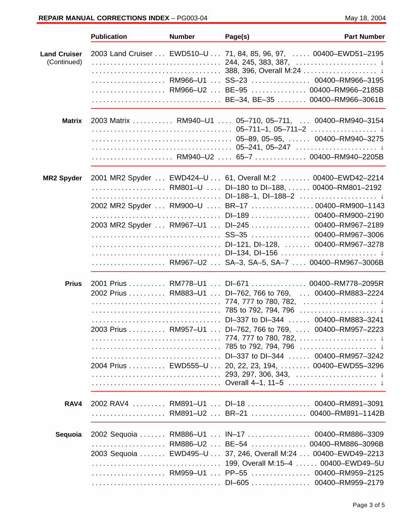
REPAIR MANUAL CORRECTIONS INDEX – PG003-04 May 18, 2004
Page 3 of 5
Publication Number Page(s) Part Number
2003 Land Cruiser EWD510–U 71, 84, 85, 96, 97, 00400–EWD51–2195. . . . . . . . . . . 244, 245, 383, 387, ↓. . . . . . . . . . . . . . . . . . . . . . . . . . . . . . . . . . . . . . . . . . . . . . . . . . . . . . . . . 388, 396, Overall M:24 ↓. . . . . . . . . . . . . . . . . . . . . . . . . . . . . . . . . . . . . . . . . . . . . . . . . . . . . . .
RM966–U1 SS–23 00400–RM966–3195. . . . . . . . . . . . . . . . . . . . . . . . . . . . . . . . . . . . . . . RM966–U2 BE–95 00400–RM966–2185B. . . . . . . . . . . . . . . . . . . . . . . . . . . . . . . . . . . . . .
BE–34, BE–35 00400–RM966–3061B. . . . . . . . . . . . . . . . . . . . . . . . . . . . . . . . . . . . . . . . . . .
2003 Matrix RM940–U1 05–710, 05–711, 00400–RM940–3154. . . . . . . . . . . . . . . . . . 05–711–1, 05–711–2 ↓. . . . . . . . . . . . . . . . . . . . . . . . . . . . . . . . . . . . . . . . . . . . . . . . . . . . . . . . 05–89, 05–95, 00400–RM940–3275. . . . . . . . . . . . . . . . . . . . . . . . . . . . . . . . . . . . . . . . . . . . 05–241, 05–247 ↓. . . . . . . . . . . . . . . . . . . . . . . . . . . . . . . . . . . . . . . . . . . . . . . . . . . . . . . . . . . .
RM940–U2 65–7 00400–RM940–2205B. . . . . . . . . . . . . . . . . . . . . . . . . . . . . . . . . . . . . . . .
2001 MR2 Spyder EWD424–U 61, Overall M:2 00400–EWD42–2214. . . . . . . . . . . . . . RM801–U DI–180 to DI–188, 00400–RM801–2192 . . . . . . . . . . . . . . . . . . . . . . . . . . . . . .
DI–188–1, DI–188–2 ↓. . . . . . . . . . . . . . . . . . . . . . . . . . . . . . . . . . . . . . . . . . . . . . . . . . . . . . . . 2002 MR2 Spyder RM900–U BR–17 00400–RM900–1143. . . . . . . . . . . . . . . . . . . . . . . .
DI–189 00400–RM900–2190. . . . . . . . . . . . . . . . . . . . . . . . . . . . . . . . . . . . . . . . . . . . . . . . . . . 2003 MR2 Spyder RM967–U1 DI–245 00400–RM967–2189. . . . . . . . . . . . . . . . . . . . . .
SS–35 00400–RM967–3006. . . . . . . . . . . . . . . . . . . . . . . . . . . . . . . . . . . . . . . . . . . . . . . . . . . DI–121, DI–128, 00400–RM967–3278. . . . . . . . . . . . . . . . . . . . . . . . . . . . . . . . . . . . . . . . . . DI–134, DI–156 ↓. . . . . . . . . . . . . . . . . . . . . . . . . . . . . . . . . . . . . . . . . . . . . . . . . . . . . . . . . . . . .
RM967–U2 SA–3, SA–5, SA–7 00400–RM967–3006B. . . . . . . . . . . . . . . . . . . . . . . . . . .
2001 Prius RM778–U1 DI–671 00400–RM778–2095R. . . . . . . . . . . . . . . . . . . . . . . . . . . . 2002 Prius RM883–U1 DI–762, 766 to 769, 00400–RM883–2224. . . . . . . . . . . . . . . .
774, 777 to 780, 782, ↓. . . . . . . . . . . . . . . . . . . . . . . . . . . . . . . . . . . . . . . . . . . . . . . . . . . . . . . 785 to 792, 794, 796 ↓. . . . . . . . . . . . . . . . . . . . . . . . . . . . . . . . . . . . . . . . . . . . . . . . . . . . . . . . DI–337 to DI–344 00400–RM883–3241. . . . . . . . . . . . . . . . . . . . . . . . . . . . . . . . . . . . . . . . .
2003 Prius RM957–U1 DI–762, 766 to 769, 00400–RM957–2223. . . . . . . . . . . . . . . . . 774, 777 to 780, 782, ↓. . . . . . . . . . . . . . . . . . . . . . . . . . . . . . . . . . . . . . . . . . . . . . . . . . . . . . . . 785 to 792, 794, 796 ↓. . . . . . . . . . . . . . . . . . . . . . . . . . . . . . . . . . . . . . . . . . . . . . . . . . . . . . . . DI–337 to DI–344 00400–RM957–3242. . . . . . . . . . . . . . . . . . . . . . . . . . . . . . . . . . . . . . . . .
2004 Prius EWD555–U 20, 22, 23, 194, 00400–EWD55–3296. . . . . . . . . . . . . . . . . . . . . 293, 297, 306, 343, ↓. . . . . . . . . . . . . . . . . . . . . . . . . . . . . . . . . . . . . . . . . . . . . . . . . . . . . . . . . Overall 4–1, 11–5 ↓. . . . . . . . . . . . . . . . . . . . . . . . . . . . . . . . . . . . . . . . . . . . . . . . . . . . . . . . . . .
2002 RAV4 RM891–U1 DI–18 00400–RM891–3091. . . . . . . . . . . . . . . . . . . . . . . . . . . . . RM891–U2 BR–21 00400–RM891–1142B. . . . . . . . . . . . . . . . . . . . . . . . . . . . . . . . . . . . . .
2002 Sequoia RM886–U1 IN–17 00400–RM886–3309. . . . . . . . . . . . . . . . . . . . . . . . . . . RM886–U2 BE–54 00400–RM886–3096B. . . . . . . . . . . . . . . . . . . . . . . . . . . . . . . . . . . . . .
2003 Sequoia EWD495–U 37, 246, Overall M:24 00400–EWD49–2213. . . . . . . . . . . . . 199, Overall M:15–4 00400–EWD49–5U. . . . . . . . . . . . . . . . . . . . . . . . . . . . . . . . . . . . . . . . .
RM959–U1 PP–55 00400–RM959–2125. . . . . . . . . . . . . . . . . . . . . . . . . . . . . . . . . . . . . . . DI–605 00400–RM959–2179. . . . . . . . . . . . . . . . . . . . . . . . . . . . . . . . . . . . . . . . . . . . . . . . . . .
Land Cruiser(Continued)
Matrix
MR2 Spyder
Prius
RAV4
Sequoia
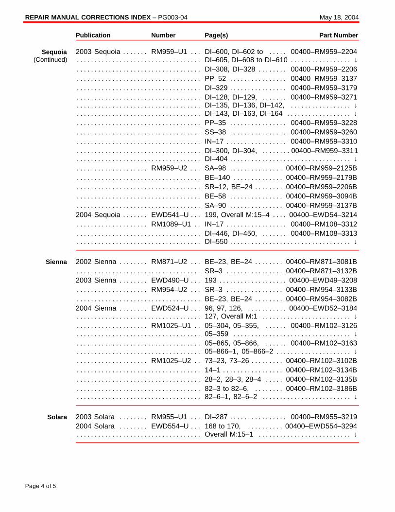
REPAIR MANUAL CORRECTIONS INDEX – PG003-04 May 18, 2004
Page 4 of 5
Publication Number Page(s) Part Number
2003 Sequoia RM959–U1 DI–600, DI–602 to 00400–RM959–2204. . . . . . . . . . . . . . . DI–605, DI–608 to DI–610 ↓. . . . . . . . . . . . . . . . . . . . . . . . . . . . . . . . . . . . . . . . . . . . . . . . . . . . DI–308, DI–328 00400–RM959–2206. . . . . . . . . . . . . . . . . . . . . . . . . . . . . . . . . . . . . . . . . . . PP–52 00400–RM959–3137. . . . . . . . . . . . . . . . . . . . . . . . . . . . . . . . . . . . . . . . . . . . . . . . . . . DI–329 00400–RM959–3179. . . . . . . . . . . . . . . . . . . . . . . . . . . . . . . . . . . . . . . . . . . . . . . . . . . DI–128, DI–129, 00400–RM959–3271. . . . . . . . . . . . . . . . . . . . . . . . . . . . . . . . . . . . . . . . . . DI–135, DI–136, DI–142, ↓. . . . . . . . . . . . . . . . . . . . . . . . . . . . . . . . . . . . . . . . . . . . . . . . . . . . DI–143, DI–163, DI–164 ↓. . . . . . . . . . . . . . . . . . . . . . . . . . . . . . . . . . . . . . . . . . . . . . . . . . . . . PP–35 00400–RM959–3228. . . . . . . . . . . . . . . . . . . . . . . . . . . . . . . . . . . . . . . . . . . . . . . . . . . SS–38 00400–RM959–3260. . . . . . . . . . . . . . . . . . . . . . . . . . . . . . . . . . . . . . . . . . . . . . . . . . . IN–17 00400–RM959–3310. . . . . . . . . . . . . . . . . . . . . . . . . . . . . . . . . . . . . . . . . . . . . . . . . . . . DI–300, DI–304, 00400–RM959–3311. . . . . . . . . . . . . . . . . . . . . . . . . . . . . . . . . . . . . . . . . . . DI–404 ↓. . . . . . . . . . . . . . . . . . . . . . . . . . . . . . . . . . . . . . . . . . . . . . . . . . . . . . . . . . . . . . . . . . . . .
RM959–U2 SA–98 00400–RM959–2125B. . . . . . . . . . . . . . . . . . . . . . . . . . . . . . . . . . . . . . BE–140 00400–RM959–2179B. . . . . . . . . . . . . . . . . . . . . . . . . . . . . . . . . . . . . . . . . . . . . . . . . SR–12, BE–24 00400–RM959–2206B. . . . . . . . . . . . . . . . . . . . . . . . . . . . . . . . . . . . . . . . . . . BE–58 00400–RM959–3094B. . . . . . . . . . . . . . . . . . . . . . . . . . . . . . . . . . . . . . . . . . . . . . . . . . SA–90 00400–RM959–3137B. . . . . . . . . . . . . . . . . . . . . . . . . . . . . . . . . . . . . . . . . . . . . . . . . .
2004 Sequoia EWD541–U 199, Overall M:15–4 00400–EWD54–3214. . . . . . . . . . . . . . RM1089–U1 IN–17 00400–RM108–3312. . . . . . . . . . . . . . . . . . . . . . . . . . . . . . . . . . . . . . .
DI–446, DI–450, 00400–RM108–3313. . . . . . . . . . . . . . . . . . . . . . . . . . . . . . . . . . . . . . . . . . DI–550 ↓. . . . . . . . . . . . . . . . . . . . . . . . . . . . . . . . . . . . . . . . . . . . . . . . . . . . . . . . . . . . . . . . . . . . .
2002 Sienna RM871–U2 BE–23, BE–24 00400–RM871–3081B. . . . . . . . . . . . . . . . . . . SR–3 00400–RM871–3132B. . . . . . . . . . . . . . . . . . . . . . . . . . . . . . . . . . . . . . . . . . . . . . . . . . .
2003 Sienna EWD490–U 193 00400–EWD49–3208. . . . . . . . . . . . . . . . . . . . . . . . . . . . . . RM954–U2 SR–3 00400–RM954–3133B. . . . . . . . . . . . . . . . . . . . . . . . . . . . . . . . . . . . . . .
BE–23, BE–24 00400–RM954–3082B. . . . . . . . . . . . . . . . . . . . . . . . . . . . . . . . . . . . . . . . . . . 2004 Sienna EWD524–U 96, 97, 126, 00400–EWD52–3184. . . . . . . . . . . . . . . . . . . . . .
127, Overall M:1 ↓. . . . . . . . . . . . . . . . . . . . . . . . . . . . . . . . . . . . . . . . . . . . . . . . . . . . . . . . . . . . RM1025–U1 05–304, 05–355, 00400–RM102–3126. . . . . . . . . . . . . . . . . . . . . . . . . . . .
05–359 ↓. . . . . . . . . . . . . . . . . . . . . . . . . . . . . . . . . . . . . . . . . . . . . . . . . . . . . . . . . . . . . . . . . . . . 05–865, 05–866, 00400–RM102–3163. . . . . . . . . . . . . . . . . . . . . . . . . . . . . . . . . . . . . . . . . 05–866–1, 05–866–2 ↓. . . . . . . . . . . . . . . . . . . . . . . . . . . . . . . . . . . . . . . . . . . . . . . . . . . . . . . .
RM1025–U2 73–23, 73–26 00400–RM102–3102B. . . . . . . . . . . . . . . . . . . . . . . . . . . . . . . 14–1 00400–RM102–3134B. . . . . . . . . . . . . . . . . . . . . . . . . . . . . . . . . . . . . . . . . . . . . . . . . . . . 28–2, 28–3, 28–4 00400–RM102–3135B. . . . . . . . . . . . . . . . . . . . . . . . . . . . . . . . . . . . . . . . 82–3 to 82–6, 00400–RM102–3186B. . . . . . . . . . . . . . . . . . . . . . . . . . . . . . . . . . . . . . . . . . . 82–6–1, 82–6–2 ↓. . . . . . . . . . . . . . . . . . . . . . . . . . . . . . . . . . . . . . . . . . . . . . . . . . . . . . . . . . . .
2003 Solara RM955–U1 DI–287 00400–RM955–3219. . . . . . . . . . . . . . . . . . . . . . . . . . . 2004 Solara EWD554–U 168 to 170, 00400–EWD554–3294. . . . . . . . . . . . . . . . . . . . .
Overall M:15–1 ↓. . . . . . . . . . . . . . . . . . . . . . . . . . . . . . . . . . . . . . . . . . . . . . . . . . . . . . . . . . . . .
Sequoia(Continued)
Sienna
Solara
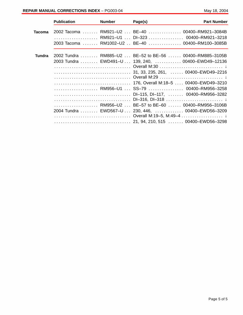
REPAIR MANUAL CORRECTIONS INDEX – PG003-04 May 18, 2004
Page 5 of 5
Publication Number Page(s) Part Number
2002 Tacoma RM921–U2 BE–40 00400–RM921–3084B. . . . . . . . . . . . . . . . . . . . . . . . . RM921–U1 DI–323 00400–RM921–3218. . . . . . . . . . . . . . . . . . . . . . . . . . . . . . . . . . . . . . .
2003 Tacoma RM1002–U2 BE–40 00400–RM100–3085B. . . . . . . . . . . . . . . . . . . . . . . .
2002 Tundra RM885–U2 BE–52 to BE–56 00400–RM885–3105B. . . . . . . . . . . . . . . . . 2003 Tundra EWD491–U 139, 240, 00400–EWD49–12136. . . . . . . . . . . . . . . . . . . . . . .
Overall M:30 ↓. . . . . . . . . . . . . . . . . . . . . . . . . . . . . . . . . . . . . . . . . . . . . . . . . . . . . . . . . . . . . . . . 31, 33, 235, 261, 00400–EWD49–2216. . . . . . . . . . . . . . . . . . . . . . . . . . . . . . . . . . . . . . . . . Overall M:29 ↓. . . . . . . . . . . . . . . . . . . . . . . . . . . . . . . . . . . . . . . . . . . . . . . . . . . . . . . . . . . . . . . . 176, Overall M:18–5 00400–EWD49–3210. . . . . . . . . . . . . . . . . . . . . . . . . . . . . . . . . . . . . . .
RM956–U1 SS–79 00400–RM956–3258. . . . . . . . . . . . . . . . . . . . . . . . . . . . . . . . . . . . . . . DI–115, DI–117, 00400–RM956–3282. . . . . . . . . . . . . . . . . . . . . . . . . . . . . . . . . . . . . . . . . . DI–316, DI–318 ↓. . . . . . . . . . . . . . . . . . . . . . . . . . . . . . . . . . . . . . . . . . . . . . . . . . . . . . . . . . . . .
RM956–U2 BE–57 to BE–60 00400–RM956–3106B. . . . . . . . . . . . . . . . . . . . . . . . . . . . . 2004 Tundra EWD567–U 230, 446, 00400–EWD56–3209. . . . . . . . . . . . . . . . . . . . . . . .
Overall M:19–5, M:49–4 ↓. . . . . . . . . . . . . . . . . . . . . . . . . . . . . . . . . . . . . . . . . . . . . . . . . . . . . . 21, 94, 210, 515 00400–EWD56–3298. . . . . . . . . . . . . . . . . . . . . . . . . . . . . . . . . . . . . . . . . .
Tacoma
Tundra
Toyota Supports ASE Certification Page 1 of 2
PG
004–00
Title:
FRONT LICENSE PLATE BRACKET
INSTALLATIONModels:
’00 MR2 Spyder
Technical ServiceBULLETIN
February 4, 2000
The 2000 model year MR2 Spyder front license plate bracket and three attaching screwsare placed in the glovebox of the vehicle at the assembly plant. For states that require afront license plate, install the bracket on the front bumper cover during Pre–DeliveryService (PDS) according to the following procedures.
� 2000 model year MR2 Spyder
OP CODE DESCRIPTION TIME OPN T1 T2
N/A Not Applicable to Warranty – – – –
PR
OD
UC
T G
EN
ER
AL IN
FO
RM
AT
ION
Introduction
ApplicableVehicle
WarrantyInformation
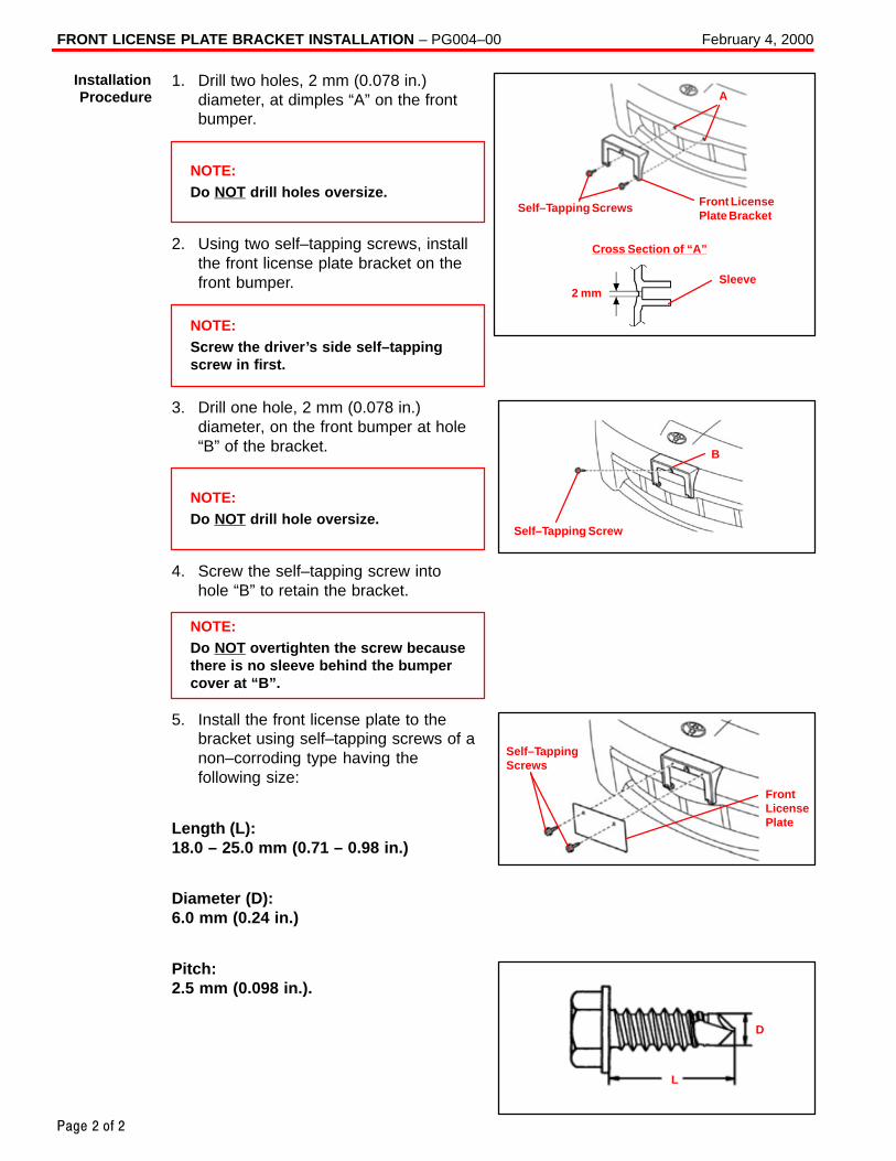
FRONT LICENSE PLATE BRACKET INSTALLATION – PG004–00 February 4, 2000
Page 2 of 2
1. Drill two holes, 2 mm (0.078 in.)diameter, at dimples “A” on the frontbumper.
NOTE:Do NOT drill holes oversize.
2. Using two self–tapping screws, installthe front license plate bracket on thefront bumper.
NOTE:Screw the driver’s side self–tappingscrew in first.
3. Drill one hole, 2 mm (0.078 in.)diameter, on the front bumper at hole“B” of the bracket.
NOTE:Do NOT drill hole oversize.
4. Screw the self–tapping screw intohole “B” to retain the bracket.
NOTE:Do NOT overtighten the screw becausethere is no sleeve behind the bumpercover at “B”.
5. Install the front license plate to thebracket using self–tapping screws of anon–corroding type having thefollowing size:
Length (L):18.0 – 25.0 mm (0.71 – 0.98 in.)
Diameter (D):6.0 mm (0.24 in.)
Pitch:2.5 mm (0.098 in.).
Cross Section of “A”
Front LicensePlate Bracket
Self–Tapping Screws
Sleeve2 mm
AInstallationProcedure
Self–Tapping Screw
B
Self–TappingScrews
FrontLicensePlate
D
L
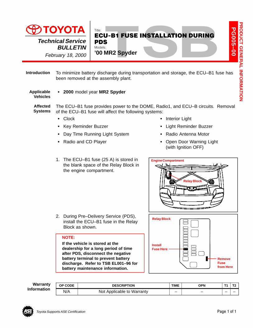
Toyota Supports ASE Certification Page 1 of 1
PG
005–00
Title:
ECU-B1 FUSE INSTALLATION DURING
PDSModels:
’00 MR2 Spyder
Technical ServiceBULLETIN
February 18, 2000
To minimize battery discharge during transportation and storage, the ECU–B1 fuse hasbeen removed at the assembly plant.
� 2000 model year MR2 Spyder
The ECU–B1 fuse provides power to the DOME, Radio1, and ECU–B circuits. Removalof the ECU–B1 fuse will affect the following systems:
� Clock � Interior Light
� Key Reminder Buzzer � Light Reminder Buzzer
� Day Time Running Light System � Radio Antenna Motor
� Radio and CD Player � Open Door Warning Light (with Ignition OFF)
1. The ECU–B1 fuse (25 A) is stored inthe blank space of the Relay Block inthe engine compartment.
2. During Pre–Delivery Service (PDS),install the ECU–B1 fuse in the RelayBlock as shown.
NOTE:If the vehicle is stored at thedealership for a long period of timeafter PDS, disconnect the negativebattery terminal to prevent batterydischarge. Refer to TSB EL001–96 forbattery maintenance information.
OP CODE DESCRIPTION TIME OPN T1 T2
N/A Not Applicable to Warranty – – – –
PR
OD
UC
T G
EN
ER
AL IN
FO
RM
AT
ION
Introduction
ApplicableVehicles
AffectedSystems
Engine Compartment
Relay Block
InstallFuse Here
Relay Block
RemoveFuse from Here
WarrantyInformation
Toyota Supports ASE Certification Page 1 of 7
PG
021–99
Title:
2000 MODEL YEAR PRE-DELIVERY
SERVICE (PDS)Models:
All Models
Technical ServiceBULLETIN
September 1, 1999
Pre–Delivery Service is a critical step in satisfying your dealership’s new car customers.Customer feedback indicates the following areas deserve special attention whenperforming PDS:
� Careful inspection for Paint Chips/Scratches and Body Dents/Dings
� Proper Operation of Electrical Accessories (including interior light, clock and radioreset).
� Interior Cleanliness
� Proper Function of Mechanical Systems
Periodic in–dealership training for technicians, both new and experienced, is arequirement to ensure that PDS is performed correctly. A number of training resourcesare available in your dealership.
� Pre–Delivery Service – The Final Touch video (P/N 00401–43067)
� Pre–Delivery Service Technician’s Handbook (P/N 00401–43068)
The “Service Manager’s Guide to Technician Orientation and Training” is included in theDealer Delivery Quality Operations Guide (P/N 00116–DDQOG–98) and provides asample training agenda to conduct a successful session in your dealership. (Thesetraining materials have been distributed to dealers. Additional copies are availablethrough the TDN system – Dealer Support Materials.)
A new PDS form has been developed for the 2000 model year. Some check points havebeen added, expanded or clarified. For improved customer satisfaction, please payparticular attention to the Fuse Installation and Electrical Operation areas indicated inbold red type.
An initial distribution of PDS forms will be mailed to each dealership. Additional PDSforms (P/N 00406–PDS00) may be ordered via TDN – Dealer Support Materials or fromthe Material Distribution Center utilizing form 1450.
If the need for additional repairs or adjustments is noted during the Pre–Delivery Service,required service should be performed under warranty. Reimbursement should berequested via regular warranty channels.
The Warranty Policy and Procedures Manual requires that you maintain thecompleted PDS check sheet in the customer file. If you cannot produce a completedform for each retailed vehicle upon TMS and/or Region/Distributor audit, the PDSpayment amount will be subject to debit.
An additional Repair Order completed in conjunction with normal PDS must have timepunch/flags for service. If multiple repairs are performed, separate time flags must bepunched for each repair.
See Page 7, Warranty Information section for Opcode information.
PR
OD
UC
T G
EN
ER
AL IN
FO
RM
AT
ION
Introduction
PDS FormOrdering
Information
WarrantyPolicy
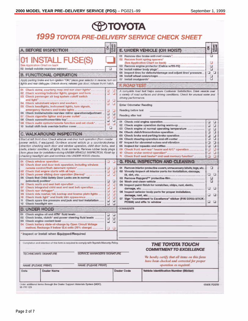
2000 MODEL YEAR PRE–DELIVERY SERVICE (PDS) – PG021–99 September 1, 1999
Page 2 of 7
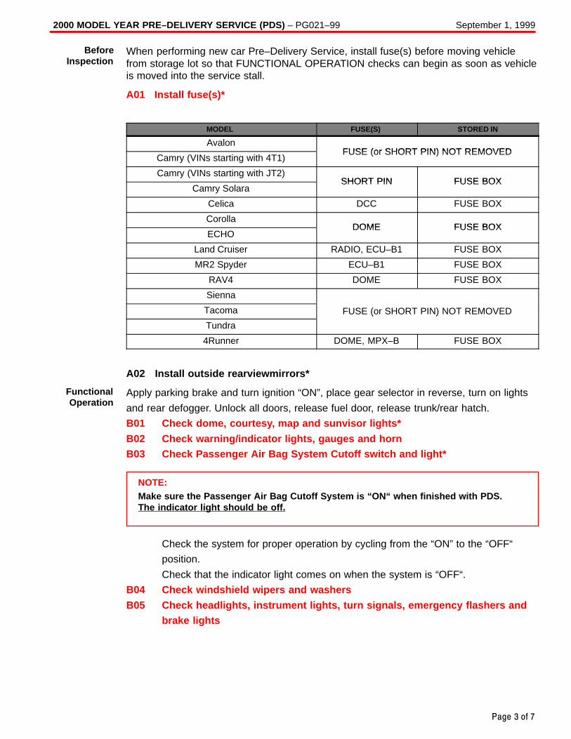
2000 MODEL YEAR PRE–DELIVERY SERVICE (PDS) – PG021–99 September 1, 1999
Page 3 of 7
When performing new car Pre–Delivery Service, install fuse(s) before moving vehiclefrom storage lot so that FUNCTIONAL OPERATION checks can begin as soon as vehicleis moved into the service stall.
A01 Install fuse(s)*
MODEL FUSE(S) STORED IN
AvalonFUSE (or SHORT PIN) NOT REMOVED
Camry (VINs starting with 4T1)FUSE (or SHORT PIN) NOT REMOVED
Camry (VINs starting with JT2)SHORT PIN FUSE BOX
Camry SolaraSHORT PIN FUSE BOX
Celica DCC FUSE BOX
CorollaDOME FUSE BOX
ECHODOME FUSE BOX
Land Cruiser RADIO, ECU–B1 FUSE BOX
MR2 Spyder ECU–B1 FUSE BOX
RAV4 DOME FUSE BOX
Sienna
Tacoma FUSE (or SHORT PIN) NOT REMOVED
Tundra
( )
4Runner DOME, MPX–B FUSE BOX
A02 Install outside rearviewmirrors*
Apply parking brake and turn ignition “ON”, place gear selector in reverse, turn on lights
and rear defogger. Unlock all doors, release fuel door, release trunk/rear hatch.
B01 Check dome, courtesy, map and sunvisor lights*
B02 Check warning/indicator lights, gauges and hornB03 Check Passenger Air Bag System Cutoff switch and light*
NOTE:Make sure the Passenger Air Bag Cutoff System is “ON“ when finished with PDS.The indicator light should be off.
Check the system for proper operation by cycling from the “ON” to the “OFF“
position.
Check that the indicator light comes on when the system is “OFF“.
B04 Check windshield wipers and washers
B05 Check headlights, instrument lights, turn signals, emergency flashers andbrake lights
BeforeInspection
FunctionalOperation
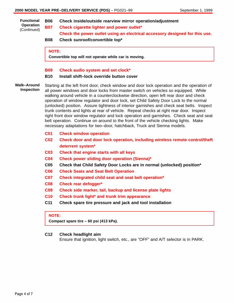
2000 MODEL YEAR PRE–DELIVERY SERVICE (PDS) – PG021–99 September 1, 1999
Page 4 of 7
B06 Check inside/outside rearview mirror operation/adjustmentB07 Check cigarette lighter and power outlet*
Check the power outlet using an electrical accessory designed for this use.B08 Check sunroof/convertible top*
NOTE:Convertible top will not operate while car is moving.
B09 Check audio system and set clock*B10 Install shift–lock override button cover
Starting at the left front door, check window and door lock operation and the operation ofall power windows and door locks from master switch on vehicles so equipped. Whilewalking around vehicle in a counterclockwise direction, open left rear door and checkoperation of window regulator and door lock, set Child Safety Door Lock to the normal(unlocked) position. Assure tightness of interior garnishes and check seat belts. Inspecttrunk contents and lights at rear of vehicle. Repeat checks at right rear door. Inspectright front door window regulator and lock operation and garnishes. Check seat and seatbelt operation. Continue on around to the front of the vehicle checking lights. Makenecessary adaptations for two–door, hatchback, Truck and Sienna models.
C01 Check window operationC02 Check door and door lock operation, including wireless remote control/theft
deterrent system*C03 Check that engine starts with all keys
C04 Check power sliding door operation (Sienna)*C05 Check that Child Safety Door Locks are in normal (unlocked) position*
C06 Check Seats and Seat Belt OperationC07 Check integrated child seat and seat belt operation*
C08 Check rear defogger*C09 Check side marker, tail, backup and license plate lights
C10 Check trunk light* and trunk trim appearanceC11 Check spare tire pressure and jack and tool installation
NOTE:Compact spare tire – 60 psi (413 kPa).
C12 Check headlight aimEnsure that ignition, light switch, etc., are ”OFF” and A/T selector is in PARK.
FunctionalOperation
(Continued)
Walk–AroundInspection
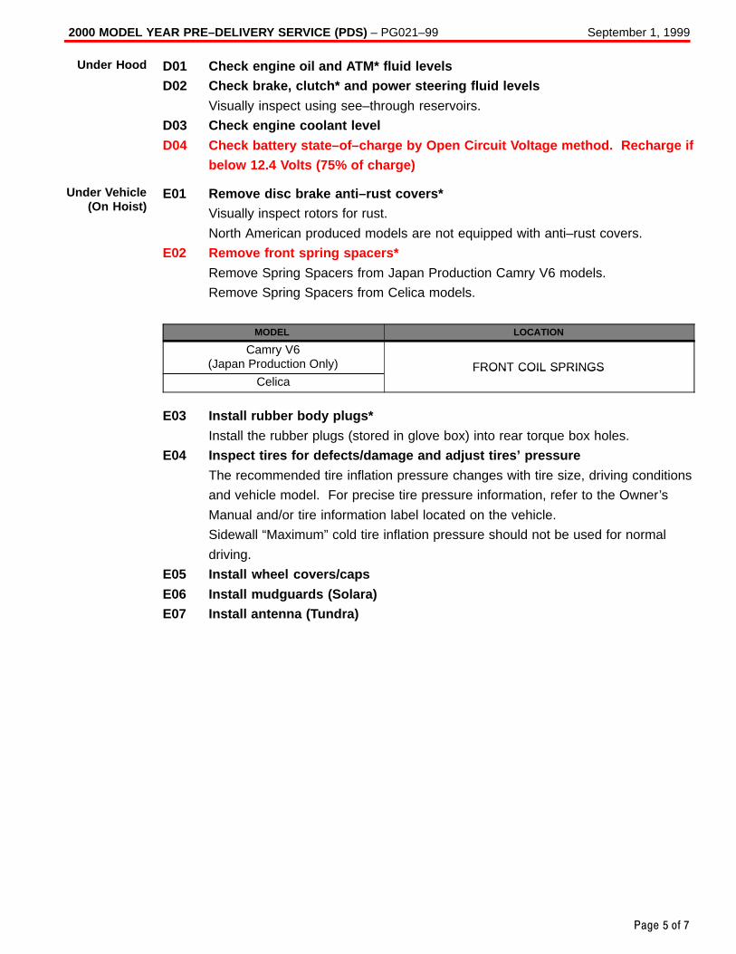
2000 MODEL YEAR PRE–DELIVERY SERVICE (PDS) – PG021–99 September 1, 1999
Page 5 of 7
D01 Check engine oil and ATM* fluid levelsD02 Check brake, clutch* and power steering fluid levels
Visually inspect using see–through reservoirs.
D03 Check engine coolant level
D04 Check battery state–of–charge by Open Circuit Voltage method. Recharge ifbelow 12.4 Volts (75% of charge)
E01 Remove disc brake anti–rust covers*Visually inspect rotors for rust.
North American produced models are not equipped with anti–rust covers.
E02 Remove front spring spacers*
Remove Spring Spacers from Japan Production Camry V6 models.
Remove Spring Spacers from Celica models.
MODEL LOCATION
Camry V6(Japan Production Only) FRONT COIL SPRINGS
CelicaFRONT COIL SPRINGS
E03 Install rubber body plugs*
Install the rubber plugs (stored in glove box) into rear torque box holes.
E04 Inspect tires for defects/damage and adjust tires’ pressure
The recommended tire inflation pressure changes with tire size, driving conditions
and vehicle model. For precise tire pressure information, refer to the Owner’s
Manual and/or tire information label located on the vehicle.
Sidewall “Maximum” cold tire inflation pressure should not be used for normal
driving.
E05 Install wheel covers/caps
E06 Install mudguards (Solara)E07 Install antenna (Tundra)
Under Hood
Under Vehicle(On Hoist)
2000 MODEL YEAR PRE–DELIVERY SERVICE (PDS) – PG021–99 September 1, 1999
Page 6 of 7
A complete road test helps assure Customer Satisfaction. Drive vehicle over a variety of
road surfaces and driving conditions. Check for unusual noise and driving performance.
F01 Check cold engine operationCheck starting and fast idle operation performance.
F02 Check engine operation during warm–upCheck that engine operates smoothly during warm–up.Check for unusual noise, engine vibration, rough idle, etc.
F03 Check engine at normal operating temperatureCheck engine performance over a broad range of driving conditions, includingidle quality, acceleration, cruise and deceleration.
F04 Check clutch/transmission operationCheck clutch operation, including: engagement, disengagement, chattering andunusual noise.Check manual transmission operation, including shift lever/linkage and unusualnoise.Check automatic transmission operation, including operation in each range,neutral start switch and shift lock system.
F05 Check brake and parking brake operationCheck brake function, including unusual noise, parking brake performance and allrelated brake system indicator lights.
F06 Check steering operation and off–centerCheck steering function and steering wheel centering.Check for suspension noise.
F07 Inspect for abnormal noises and vibration
F08 Inspect for squeaks and rattles
F09 Check front and rear* heater and A/C* operation
F10 Check cruise control operation*Check cruise control, including On–Off switch, “SET/COAST”,“RESUME/ACCEL”, and “CANCEL” functions.
F11 Check front seat heater* and seat memory function*
F12 Set/Calibrate compass (Avalon XLS)
Road Test
2000 MODEL YEAR PRE–DELIVERY SERVICE (PDS) – PG021–99 September 1, 1999
Page 7 of 7
G01 Remove interior protective covers, unnecessary labels, tags, etc.(Remove protective covers just before delivery to customer).
� Remove plastic covers from door panels, seats, head restraints and sunvisors, asrequired.
� Remove labels, tags and stickers (except those containing owner information).
NOTE:Consumer Information Label such as Air Bag Information Warning and BumperInformation Labels must be left on the vehicle until delivery to a retail customer.
G02 Visually inspect all interior parts for installation, damage, fit, dirt, etc.
G03 Remove RapgardTM protective film
G04 Wash and clean vehicle
G05 Inspect paint finish for scratches, chips, rust, dents, damage, etc.
G06 Inspect exterior body parts for proper installation, damage, rust, etc.
G07 Sign “Commitment To Excellence“ sticker (P/N 00405–STICK–PDS98) and
affix to window
OP CODE DESCRIPTION TIME OPN T1 T2
001013 Pre Delivery Service * N/A N/A N/A
* Variable by model.
Road Test
WarrantyInformation
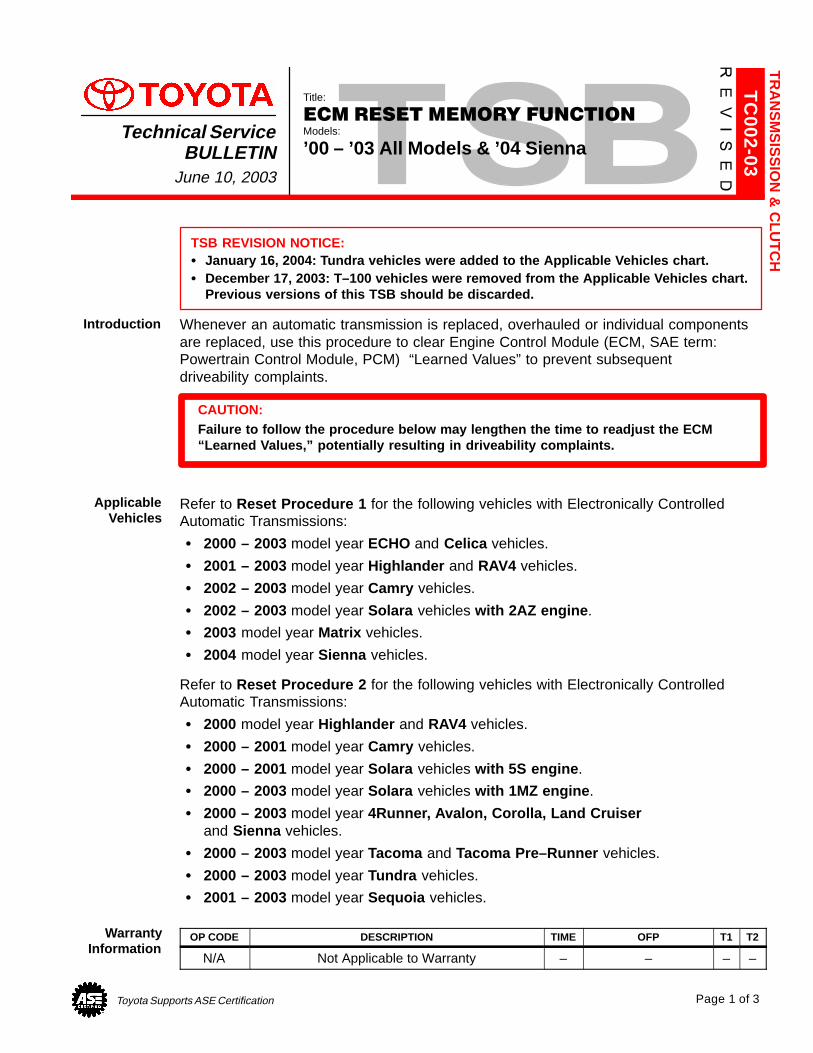
Toyota Supports ASE Certification Page 1 of 3
TC
002-03
Title:
ECM RESET MEMORY FUNCTIONModels:
’00 – ’03 All Models & ’04 SiennaTechnical Service
BULLETINJune 10, 2003
TSB REVISION NOTICE:� January 16, 2004: Tundra vehicles were added to the Applicable Vehicles chart.� December 17, 2003: T–100 vehicles were removed from the Applicable Vehicles chart.
Previous versions of this TSB should be discarded.
Whenever an automatic transmission is replaced, overhauled or individual componentsare replaced, use this procedure to clear Engine Control Module (ECM, SAE term:Powertrain Control Module, PCM) “Learned Values” to prevent subsequent driveability complaints.
CAUTION:Failure to follow the procedure below may lengthen the time to readjust the ECM“Learned Values,” potentially resulting in driveability complaints.
Refer to Reset Procedure 1 for the following vehicles with Electronically ControlledAutomatic Transmissions:
� 2000 – 2003 model year ECHO and Celica vehicles.
� 2001 – 2003 model year Highlander and RAV4 vehicles.
� 2002 – 2003 model year Camry vehicles.
� 2002 – 2003 model year Solara vehicles with 2AZ engine .
� 2003 model year Matrix vehicles.
� 2004 model year Sienna vehicles.
Refer to Reset Procedure 2 for the following vehicles with Electronically ControlledAutomatic Transmissions:
� 2000 model year Highlander and RAV4 vehicles.
� 2000 – 2001 model year Camry vehicles.
� 2000 – 2001 model year Solara vehicles with 5S engine .
� 2000 – 2003 model year Solara vehicles with 1MZ engine .
� 2000 – 2003 model year 4Runner, Avalon, Corolla, Land Cruiser and Sienna vehicles.
� 2000 – 2003 model year Tacoma and Tacoma Pre–Runner vehicles.
� 2000 – 2003 model year Tundra vehicles.
� 2001 – 2003 model year Sequoia vehicles.
OP CODE DESCRIPTION TIME OFP T1 T2
N/A Not Applicable to Warranty – – – –
TR
AN
SM
SIS
SIO
N &
CLU
TC
H
Introduction
ApplicableVehicles
WarrantyInformation

ECM RESET MEMORY FUNCTION – TC002-03 Revised June 10, 2003
Page 2 of 3
SPECIAL SERVICE TOOLS (SSTs) PART NUMBER QUANTITY
Toyota Diagnostic Tester Kit*
01001271 1
12 Megabyte Diagnostic Tester Program Cardwith version 10.0a Software (or later)* 01002593-005 1
* Essential SSTs.
NOTE:Additional Diagnostic Tester Kits, Program Cards or SSTs may be ordered by callingSPX/OTC at 1-800-933-8335.
1. Connect the Toyota Diagnostic Tester to the vehicle.
2. Reset the ECM (PCM). Refer to the procedures below.
DO YOU WISH TO RESET THE ECM?
[YES] to CONTINUE[NO] to EXIT
2: CUSTOMIZE3: ECU REPROGRAM
FUNCTION SELECT FORNORTH AMERICA
B*APPLICATION SELECT*
A
1: DIAGNOSIS
DIAGNOSTIC MENUENGINE
C
DO NOT USE THISFUNCTION UNLESSINSTRUCTED BYREPAIR MANUAL.
RESET MEMORY
ERESET MEMORY
NOTICE
D
[YES]
F
1: OBD/MOBD
3: CARB OBD II4: BREAK–OUT BOX5: NVH6: AUTOPROBE7: 02 RPM CHECK8: SNAPSHOT REVIEW9: SETUP0: GAS ANALYSIS
2: ENHANCED OBD II 1: DATA LIST2: DTC INFO3: ACTIVE TEST4: SNAPSHOT5: SYSTEM CHECK6: RESET MEMORY7: MONITOR STATUS8: CHECK MODE
6: RESET MEMORY
ONLY USE AFTER REPLACING THE ENGINE,AUTO TRANS, OR ECMON CERTAIN VEHICLES.
EXECUTING THIS FUNCTION WILL RESETTHE LEARNED VALUES IN THE ECM.
RESET MEMORY
RESETTING COMPLETE
PRESS [ENTER]
3. Start the engine and warm it up to normal operating temperatures before test–driving.
4. Perform a thorough test drive with several accelerations from a stop with “lightthrottle” application until proper transmission shifting is verified.
RequiredSSTs
ResetProcedure 1

ECM RESET MEMORY FUNCTION – TC002-03 Revised June 10, 2003
Page 3 of 3
1. Record radio station presets and No. 1 driver’s seat memory position.
2. Disconnect the negative battery cable for 5 minutes.
NOTE:Record presets before disconnecting battery cable.
3. Reconnect battery cable and reset radio presets and No. 1 driving position seatmemory.
4. If necessary, perform the following operations:
� Initialize moon roof� Initialize power windows� Calibrate compass
For more detailed information on performing these operations, refer to TIS for theapplicable TSB and/or repair procedures.
5. Start the engine and warm it up to normal operating temperatures before test–driving.
6. Perform a thorough test drive with several accelerations from a stop with “lightthrottle” application until proper transmission shifting is verified.
ResetProcedure 2
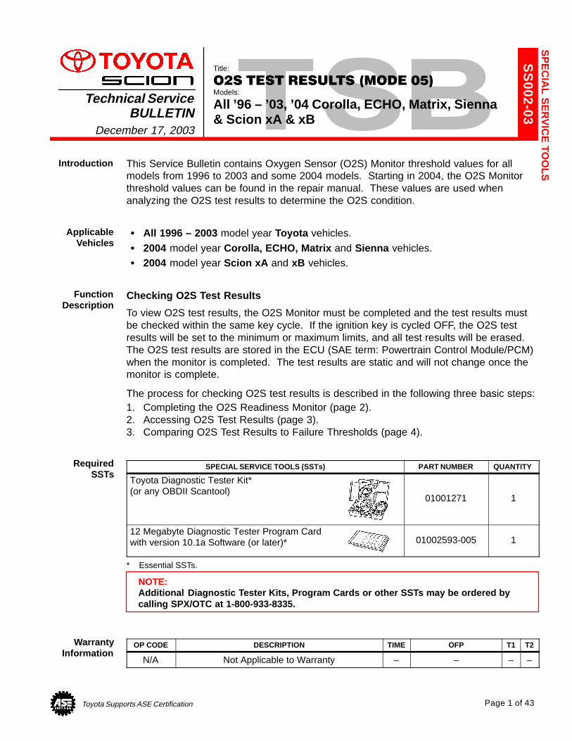
Toyota Supports ASE Certification Page 1 of 43
SS
002-03
Title:
O2S TEST RESULTS (MODE 05)Models:
All ’96 – ’03, ’04 Corolla, ECHO, Matrix, Sienna& Scion xA & xB
Technical ServiceBULLETIN
December 17, 2003
This Service Bulletin contains Oxygen Sensor (O2S) Monitor threshold values for allmodels from 1996 to 2003 and some 2004 models. Starting in 2004, the O2S Monitorthreshold values can be found in the repair manual. These values are used whenanalyzing the O2S test results to determine the O2S condition.
� All 1996 – 2003 model year Toyota vehicles.
� 2004 model year Corolla, ECHO, Matrix and Sienna vehicles.� 2004 model year Scion xA and xB vehicles.
Checking O2S Test Results
To view O2S test results, the O2S Monitor must be completed and the test results mustbe checked within the same key cycle. If the ignition key is cycled OFF, the O2S testresults will be set to the minimum or maximum limits, and all test results will be erased.The O2S test results are stored in the ECU (SAE term: Powertrain Control Module/PCM)when the monitor is completed. The test results are static and will not change once themonitor is complete.
The process for checking O2S test results is described in the following three basic steps:1. Completing the O2S Readiness Monitor (page 2).2. Accessing O2S Test Results (page 3).3. Comparing O2S Test Results to Failure Thresholds (page 4).
SPECIAL SERVICE TOOLS (SSTs) PART NUMBER QUANTITY
Toyota Diagnostic Tester Kit*(or any OBDII Scantool)
01001271 1
12 Megabyte Diagnostic Tester Program Cardwith version 10.1a Software (or later)* 01002593-005 1
* Essential SSTs.
NOTE:Additional Diagnostic Tester Kits, Program Cards or other SSTs may be ordered bycalling SPX/OTC at 1-800-933-8335.
OP CODE DESCRIPTION TIME OFP T1 T2
N/A Not Applicable to Warranty – – – –
SP
EC
IAL S
ER
VIC
E TO
OLSIntroduction
ApplicableVehicles
FunctionDescription
RequiredSSTs
WarrantyInformation

O2S TEST RESULTS (MODE 05) – SS002-03 December 17, 2003
Page 2 of 43
1. Clear any stored Diagnostic Trouble Codes (DTCs) using the Toyota Diagnostic Tester.
2. Start the engine.3. Perform the drive pattern below to run and complete the Oxygen Sensor (O2S) Monitor.
O2S Monitor Drive PatternECT: 167�F (75�C) or more
Vehicle Speed At Least 8 Times
48 km/h (30 mph)
Idling
At Least Twice
Accelerator PedalDepressing
Accelerator PedalReleasing (Fuel–Cut)
6 mph (10 km/h)
Time2 min.
or more40 sec
or more20 sec
or more10 sec
or more10 sec
or more
HINT:The O2S Monitor is completed when the following conditions are met:� Two (2) minutes or more passed after the engine start.� The Engine Coolant Temperature (ECT) is 167 �F (75�C) or more.� Cumulative running time at 30 mph (48 km/h) or more exceeds 6 minutes.� Vehicle is in closed loop.� The fuel–cut is operated for 8 seconds or more (for Rear O2S Monitor).
A. Allow the engine to idle for two minutes.
B. Warm up the engine until the Engine Coolant Temperature (ECT) reaches 167�F(75�C).
C. Drive the vehicle over 30 mph (48 km/h) for more than 40 seconds.
D. Stop the vehicle and allow the engine to idle for more than 20 seconds.
E. Repeat steps C and D at least 8 times in one driving cycle. (Do not cycle the ignition key.)
In addition, perform the following steps for the Rear O2S Readiness Monitor:
A. Select second gear.
B. Allow the vehicle to run at 30 mph (48 km/h) or more.
C. Keep the accelerator pedal “off–idle” for more than 10 seconds.
D. Immediately after step C, release the accelerator pedal for at least 10 secondswithout depressing the brake pedal (to execute the fuel–cut).
E. Decelerate the vehicle until the vehicle speed reaches less than 6 mph (10 km/h).
F. Repeat steps B – E at least twice in one driving cycle.
CompletingO2S
ReadinessMonitor

O2S TEST RESULTS (MODE 05) – SS002-03 December 17, 2003
Page 3 of 43
1. On the Diagnostic Tester* screen,select the following menus:
� DIAGNOSTICS� CARB OBD II� O2S TEST RESULTS
A list of the available oxygen sensorswill be displayed.
2. Select the desired oxygen sensor andpress Enter.
NOTE:The monitor result of the A/F sensor willnot be displayed. If you select“Bank 1–Sensor 1” or Bank 2–Sensor 1”for a vehicle equipped with an A/Fsensor, the Diagnostic Tester willdisplay “No parameter to display.”
3. Compare the test results with thevalues listed in the Failure Threshold Chart.
* Although this procedure references the Toyota Diagnostic Tester, the O2S test results can be checked using a generic OBDII scantool. Refer to your OBDII scantool operator’s manual for specific procedures.
AccessingO2S Test
Results
O2S TEST RESULT Screen
01 BANK 1 – SENSOR 1
01 BANK 1 – SENSOR 2
01 BANK 2 – SENSOR 1
01 BANK 2 – SENSOR 2
TEST DATA Screen
LOW SW V � � � � 0.400 V
HIGH SW V � � � � 0.550 V
MIN O2S V � � � � 0.100 V
MAX O2S V � � � � 0.900 V
TIME $81 � � � � � 17

NOTE:Before the O2S Monitor completes or after the ignition switch is turned OFF, theDiagnostic Tester displays the viewable upper limit or a lower limit of the test value(example: 0 V, 1.275 V, 0 s [seconds], 10.2 s, 0 and 255).
O2S TEST RESULTS (MODE 05) – SS002-03 December 17, 2003
Page 4 of 43
1. Determine the correct O2S Failure Threshold Chart for your vehicle by looking in the“O2S Application Table,” pages 5 – 9 in this bulletin.
2. Select appropriate year, model, and engine for specified O2S Failure Threshold Chart.
3. Compare O2S test results with the specified O2S Failure Threshold Chart. It may benecessary to convert O2S test results to a specific measurement unit using theconversion factor that is supplied in the specified table. See example below:
Example:
A. The Diagnostic Tester displays“17” as a value of the “Time $81”(see illustration).
B. Find the Conversion Factor valueof “Time $81” in the O2S FailureThreshold chart below. 0.3906 is specified for Time $81 in this chart.
C. Multiply “17” in step “A” by 0.3906(Conversion Factor) in step “B.”17 x 0.3906 = 6.6 %
D. If the answer is within theStandard Value of TEST LIMIT,the “Time $81” can be confirmedto be normal.
Example of O2S Failure Threshold Chart:
TEST ID DESCRIPTION OF TEST DATACONVERSION
FACTORUNIT
STANDARD VALUEOF TEST LIMIT
Time$81
Percentage of monitoring timewhere Oxygen Sensor voltage isless than 0.05V
Multiply 0.3906 % Within 60%
ComparingO2S Test
Results toFailure
Thresholds
Example
LOW SW V � � � � 0.400 VHIGH SW V � � � � 0.550 VMIN O2S V � � � � 0.035 VMAX O2S V � � � � 0.835 VTime $81 17Time $84 84Time $85 79
NOTE:� “LOW SW V” indicates the O2S
voltage when the O2S status changesfrom rich to lean.
� “HIGH SW V” indicates the O2Svoltage when the O2S status changesfrom lean to rich.
� If the O2S voltage is lower than“LOW SW V,” the O2S status is lean.
� If the O2S voltage is higher than“HIGH SW V,” the O2S status is rich.
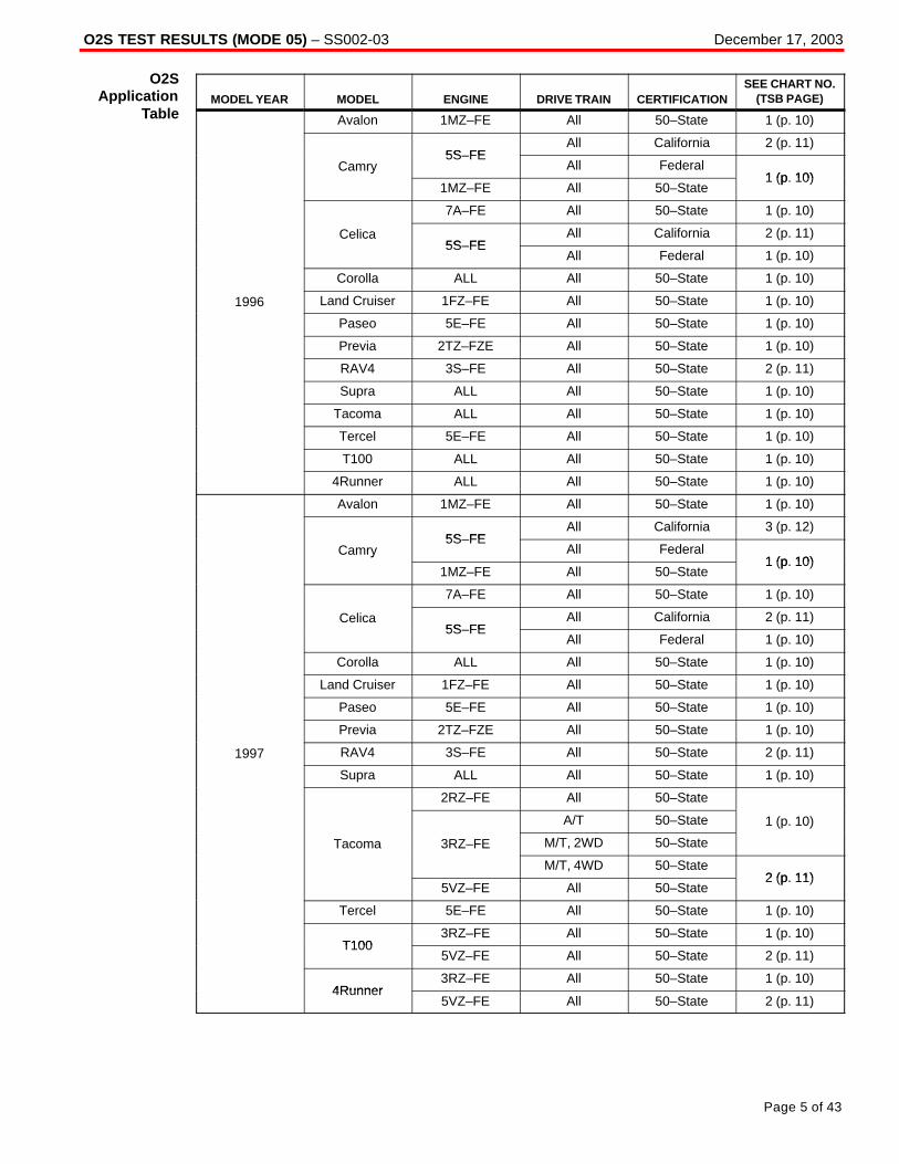
O2S TEST RESULTS (MODE 05) – SS002-03 December 17, 2003
Page 5 of 43
MODEL YEAR MODEL ENGINE DRIVE TRAIN CERTIFICATIONSEE CHART NO.
(TSB PAGE)
Avalon 1MZ–FE All 50–State 1 (p. 10)
5S FEAll California 2 (p. 11)
Camry5S–FE
All Federal1 (p 10)
y
1MZ–FE All 50–State1 (p. 10)
7A–FE All 50–State 1 (p. 10)
Celica5S FE
All California 2 (p. 11)5S–FE
All Federal 1 (p. 10)
Corolla ALL All 50–State 1 (p. 10)
1996 Land Cruiser 1FZ–FE All 50–State 1 (p. 10)
Paseo 5E–FE All 50–State 1 (p. 10)
Previa 2TZ–FZE All 50–State 1 (p. 10)
RAV4 3S–FE All 50–State 2 (p. 11)
Supra ALL All 50–State 1 (p. 10)
Tacoma ALL All 50–State 1 (p. 10)
Tercel 5E–FE All 50–State 1 (p. 10)
T100 ALL All 50–State 1 (p. 10)
4Runner ALL All 50–State 1 (p. 10)
Avalon 1MZ–FE All 50–State 1 (p. 10)
5S FEAll California 3 (p. 12)
Camry5S–FE
All Federal1 (p 10)
y
1MZ–FE All 50–State1 (p. 10)
7A–FE All 50–State 1 (p. 10)
Celica5S FE
All California 2 (p. 11)5S–FE
All Federal 1 (p. 10)
Corolla ALL All 50–State 1 (p. 10)
Land Cruiser 1FZ–FE All 50–State 1 (p. 10)
Paseo 5E–FE All 50–State 1 (p. 10)
Previa 2TZ–FZE All 50–State 1 (p. 10)
1997 RAV4 3S–FE All 50–State 2 (p. 11)
Supra ALL All 50–State 1 (p. 10)
2RZ–FE All 50–State
A/T 50–State 1 (p. 10)
Tacoma 3RZ–FE M/T, 2WD 50–State
( )
M/T, 4WD 50–State2 (p 11)
5VZ–FE All 50–State2 (p. 11)
Tercel 5E–FE All 50–State 1 (p. 10)
T1003RZ–FE All 50–State 1 (p. 10)
T1005VZ–FE All 50–State 2 (p. 11)
4Runner3RZ–FE All 50–State 1 (p. 10)
4Runner5VZ–FE All 50–State 2 (p. 11)
O2SApplication
Table

O2S TEST RESULTS (MODE 05) – SS002-03 December 17, 2003
Page 6 of 43
MODEL YEAR MODEL ENGINE DRIVE TRAIN CERTIFICATIONSEE CHART NO.
(TSB PAGE)
Avalon 1MZ FEAll California 4 (p. 12)
Avalon 1MZ–FEAll Federal 1 (p. 10)
5S FEAll California 3 (p. 12)
5S–FEAll Federal 2 (p. 11)
CamryA/T
California 4 (p. 12)y
1MZ–FEA/T
Federal1 (p 10)
M/T 50–State1 (p. 10)
Celica 5S FEAll California 2 (p. 11)
Celica 5S–FEAll Federal 1 (p. 10)
Corolla 1ZZ–FE All 50–State 2 (p. 11)
1998 Land Cruiser 2UZ–FE All 50–State 2 (p. 11)
Paseo 5E–FE All 50–State 1 (p. 10)
RAV4 3S FEAll California 3 (p. 12)
RAV4 3S–FEAll Federal 2 (p. 11)
Sienna 1MZ–FE All 50–State 1 (p. 10)
Supra2JZ–GE All 50–State 2 (p. 11)
Supra2JZ–GTE All 50–State 1 (p. 10)
Tacoma ALL All 50–State 2 (p. 11)
Tercel 5E–FE All 50–State 1 (p. 10)
T100 ALL All 50–State 2 (p. 11)
4Runner ALL All 50–State 2 (p. 11)
Avalon 1MZ FEAll California 4 (p. 12)
Avalon 1MZ–FEAll Federal 5 (p. 13)
Camry CNG 5S–FNE All 50–State 6 (p. 13)
Celica 5S–FE All 50–State 5 (p. 13)
Corolla 1ZZ–FE All 50–State 2 (p. 11)
Land Cruiser 2UZ–FE All 50–State 2 (p. 11)
Paseo 5E–FE All 50–State 1 (p. 10)
RAV4 3S FEAll California 3 (p. 12)
RAV4 3S–FEAll Federal 2 (p. 11)
Sienna 1MZ FEAll California 4 (p. 12)
1999Sienna 1MZ–FE
All Federal 5 (p. 13)
5S FEAll California 3 (p. 12)
5S–FEAll Federal 5 (p. 13)
SolaraA/T
California 4 (p. 12)
1MZ–FEA/T
Federal5 (p 13)
M/T 50–State5 (p. 13)
Tacoma ALL All 50–State 2 (p. 11)
Tercel 5E–FE All 50–State 1 (p. 10)
3RZ–FE All 50–State 2 (p. 11)
4Runner5VZ FE
All California 4 (p. 12)5VZ–FE
All Federal 2 (p. 11)
O2SApplication
Table(Continued)
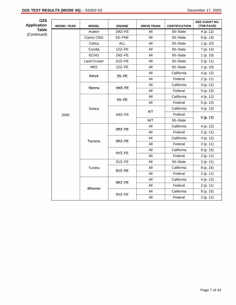
O2S TEST RESULTS (MODE 05) – SS002-03 December 17, 2003
Page 7 of 43
MODEL YEAR MODEL ENGINE DRIVE TRAIN CERTIFICATIONSEE CHART NO.
(TSB PAGE)
Avalon 1MZ–FE All 50–State 4 (p. 12)
Camry CNG 5S–FNE All 50–State 6 (p. 13)
Celica ALL All 50–State 1 (p. 10)
Corolla 1ZZ–FE All 50–State 7 (p. 14)
ECHO 1NZ–FE All 50–State 1 (p. 10)
Land Cruiser 2UZ–FE All 50–State 2 (p. 11)
MR2 1ZZ–FE All 50–State 1 (p. 10)
RAV4 3S FEAll California 4 (p. 12)
RAV4 3S–FEAll Federal 2 (p. 11)
Sienna 1MZ FEAll California 4 (p. 12)
Sienna 1MZ–FEAll Federal 5 (p. 13)
5S FEAll California 4 (p. 12)
5S–FEAll Federal 5 (p. 13)
SolaraA/T
California 4 (p. 12)
2000 1MZ–FEA/T
Federal5 (p 13)
M/T 50–State5 (p. 13)
2RZ FEAll California 4 (p. 12)
2RZ–FEAll Federal 2 (p. 11)
Tacoma 3RZ FEAll California 4 (p. 12)
Tacoma 3RZ–FEAll Federal 2 (p. 11)
5VZ FEAll California 8 (p. 15)
5VZ–FEAll Federal 2 (p. 11)
2UZ–FE All 50–State 2 (p. 11)
Tundra5VZ FE
All California 8 (p. 15)5VZ–FE
All Federal 2 (p. 11)
3RZ FEAll California 4 (p. 12)
4Runner
3RZ–FEAll Federal 2 (p. 11)
4Runner
5VZ FEAll California 8 (p. 15)
5VZ–FEAll Federal 2 (p. 11)
O2SApplication
Table(Continued)
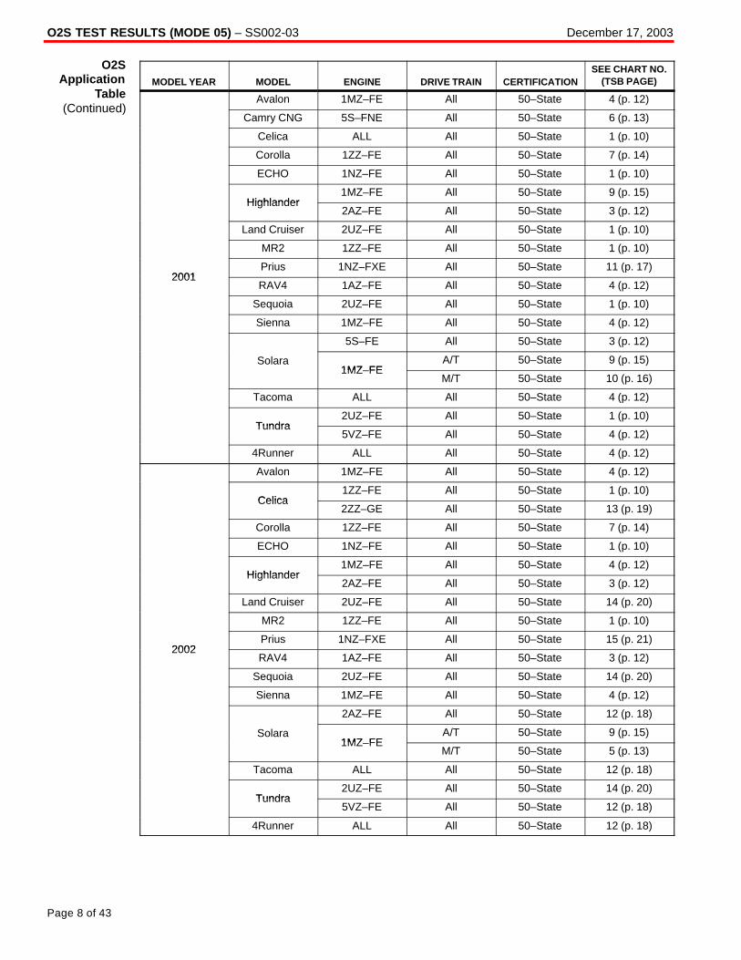
O2S TEST RESULTS (MODE 05) – SS002-03 December 17, 2003
Page 8 of 43
MODEL YEAR MODEL ENGINE DRIVE TRAIN CERTIFICATIONSEE CHART NO.
(TSB PAGE)
Avalon 1MZ–FE All 50–State 4 (p. 12)
Camry CNG 5S–FNE All 50–State 6 (p. 13)
Celica ALL All 50–State 1 (p. 10)
Corolla 1ZZ–FE All 50–State 7 (p. 14)
ECHO 1NZ–FE All 50–State 1 (p. 10)
Highlander1MZ–FE All 50–State 9 (p. 15)
Highlander2AZ–FE All 50–State 3 (p. 12)
Land Cruiser 2UZ–FE All 50–State 1 (p. 10)
MR2 1ZZ–FE All 50–State 1 (p. 10)
2001Prius 1NZ–FXE All 50–State 11 (p. 17)
2001RAV4 1AZ–FE All 50–State 4 (p. 12)
Sequoia 2UZ–FE All 50–State 1 (p. 10)
Sienna 1MZ–FE All 50–State 4 (p. 12)
5S–FE All 50–State 3 (p. 12)
Solara1MZ FE
A/T 50–State 9 (p. 15)1MZ–FE
M/T 50–State 10 (p. 16)
Tacoma ALL All 50–State 4 (p. 12)
Tundra2UZ–FE All 50–State 1 (p. 10)
Tundra5VZ–FE All 50–State 4 (p. 12)
4Runner ALL All 50–State 4 (p. 12)
Avalon 1MZ–FE All 50–State 4 (p. 12)
Celica1ZZ–FE All 50–State 1 (p. 10)
Celica2ZZ–GE All 50–State 13 (p. 19)
Corolla 1ZZ–FE All 50–State 7 (p. 14)
ECHO 1NZ–FE All 50–State 1 (p. 10)
Highlander1MZ–FE All 50–State 4 (p. 12)
Highlander2AZ–FE All 50–State 3 (p. 12)
Land Cruiser 2UZ–FE All 50–State 14 (p. 20)
MR2 1ZZ–FE All 50–State 1 (p. 10)
2002Prius 1NZ–FXE All 50–State 15 (p. 21)
2002RAV4 1AZ–FE All 50–State 3 (p. 12)
Sequoia 2UZ–FE All 50–State 14 (p. 20)
Sienna 1MZ–FE All 50–State 4 (p. 12)
2AZ–FE All 50–State 12 (p. 18)
Solara1MZ FE
A/T 50–State 9 (p. 15)1MZ–FE
M/T 50–State 5 (p. 13)
Tacoma ALL All 50–State 12 (p. 18)
Tundra2UZ–FE All 50–State 14 (p. 20)
Tundra5VZ–FE All 50–State 12 (p. 18)
4Runner ALL All 50–State 12 (p. 18)
O2SApplication
Table(Continued)
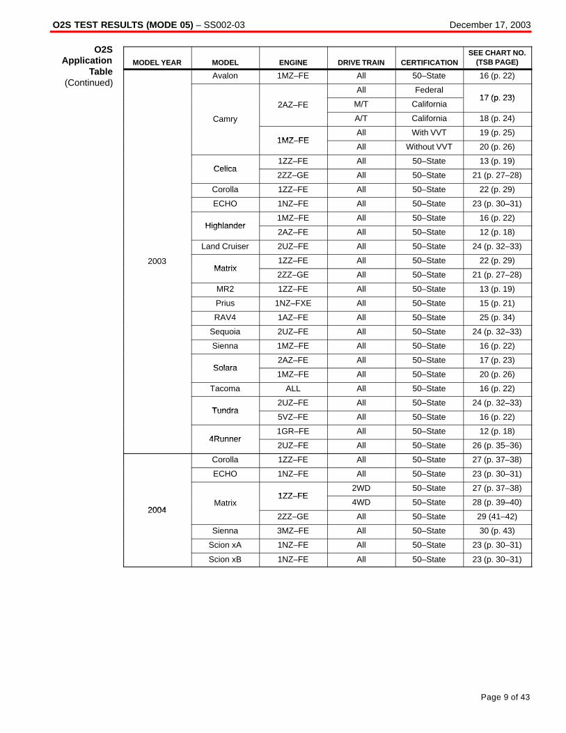
O2S TEST RESULTS (MODE 05) – SS002-03 December 17, 2003
Page 9 of 43
MODEL YEAR MODEL ENGINE DRIVE TRAIN CERTIFICATIONSEE CHART NO.
(TSB PAGE)
Avalon 1MZ–FE All 50–State 16 (p. 22)
All Federal17 (p 23)
2AZ–FE M/T California17 (p. 23)
Camry A/T California 18 (p. 24)y
1MZ FEAll With VVT 19 (p. 25)
1MZ–FEAll Without VVT 20 (p. 26)
Celica1ZZ–FE All 50–State 13 (p. 19)
Celica2ZZ–GE All 50–State 21 (p. 27–28)
Corolla 1ZZ–FE All 50–State 22 (p. 29)
ECHO 1NZ–FE All 50–State 23 (p. 30–31)
Highlander1MZ–FE All 50–State 16 (p. 22)
Highlander2AZ–FE All 50–State 12 (p. 18)
Land Cruiser 2UZ–FE All 50–State 24 (p. 32–33)
2003Matrix
1ZZ–FE All 50–State 22 (p. 29)Matrix
2ZZ–GE All 50–State 21 (p. 27–28)
MR2 1ZZ–FE All 50–State 13 (p. 19)
Prius 1NZ–FXE All 50–State 15 (p. 21)
RAV4 1AZ–FE All 50–State 25 (p. 34)
Sequoia 2UZ–FE All 50–State 24 (p. 32–33)
Sienna 1MZ–FE All 50–State 16 (p. 22)
Solara2AZ–FE All 50–State 17 (p. 23)
Solara1MZ–FE All 50–State 20 (p. 26)
Tacoma ALL All 50–State 16 (p. 22)
Tundra2UZ–FE All 50–State 24 (p. 32–33)
Tundra5VZ–FE All 50–State 16 (p. 22)
4Runner1GR–FE All 50–State 12 (p. 18)
4Runner2UZ–FE All 50–State 26 (p. 35–36)
Corolla 1ZZ–FE All 50–State 27 (p. 37–38)
ECHO 1NZ–FE All 50–State 23 (p. 30–31)
1ZZ FE2WD 50–State 27 (p. 37–38)
2004Matrix
1ZZ–FE4WD 50–State 28 (p. 39–40)
20042ZZ–GE All 50–State 29 (41–42)
Sienna 3MZ–FE All 50–State 30 (p. 43)
Scion xA 1NZ–FE All 50–State 23 (p. 30–31)
Scion xB 1NZ–FE All 50–State 23 (p. 30–31)
O2SApplication
Table(Continued)

O2S TEST RESULTS (MODE 05) – SS002-03 December 17, 2003
Page 10 of 43
CHART 1:
Front O2S (Bank 1 Sensor 1 and Bank 2 Sensor 1) Voltage MonitorRelated DTCs: P0130, P0150, P2195, P2196, P2197 and P2198
TEST ID DESCRIPTION OF TEST DATACONVERSION
FACTORUNIT
STANDARD VALUEOF TEST LIMIT
Time$07
The minimum voltage during O2Smonitoring
N/A V Between 0 and 0.4 V
Time$08
The maximum voltage duringO2S monitoring
N/A V Between 0.55 and1.275 V
If the sensor voltage is out of the standard value, the ECM interprets this as a malfunction.
Front O2S (Bank 1 Sensor 1 and Bank 2 Sensor 1) Response MonitorRelated DTCs: P0133 and P0153
TEST ID DESCRIPTION OF TEST DATACONVERSION
FACTORUNIT
STANDARD VALUEOF TEST LIMIT
Time$31
Time to change from Lean(≤0.4 V) to Rich (≥0.55 V)
N/A Second Between 0 and1 second
Time$32
Time to change from Rich(≥0.55 V) to Lean (≥0.4 V)
N/A Second Between 0 and1 second
If the time required to change is out of the standard value, the ECM interprets this as a malfunction.
Rear O2S (Bank 1 Sensor 2 and Bank 2 Sensor 2) Voltage MonitorRelated DTCs: P0136 and P0156
TEST ID DESCRIPTION OF TEST DATACONVERSION
FACTORUNIT
STANDARD VALUEOF TEST LIMIT
Time$07
The minimum voltage during O2Smonitoring
N/A V Between 0 and 0.4 V
Time$08
The maximum voltage duringO2S monitoring
N/A V Between 0.5 and1.275 V
If the sensor voltage is out of the standard value, the ECM interprets this as a malfunction.
O2SFailure
ThresholdCharts
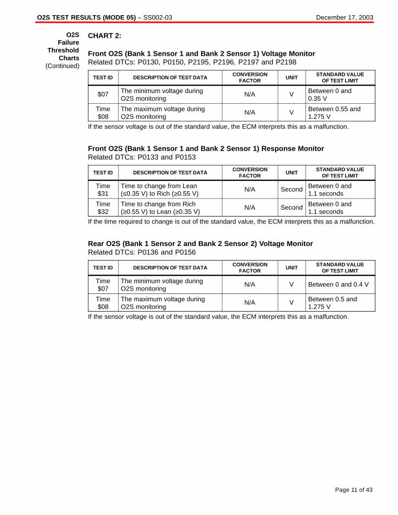
O2S TEST RESULTS (MODE 05) – SS002-03 December 17, 2003
Page 11 of 43
CHART 2:
Front O2S (Bank 1 Sensor 1 and Bank 2 Sensor 1) Voltage MonitorRelated DTCs: P0130, P0150, P2195, P2196, P2197 and P2198
TEST ID DESCRIPTION OF TEST DATACONVERSION
FACTORUNIT
STANDARD VALUEOF TEST LIMIT
$07 The minimum voltage duringO2S monitoring
N/A V Between 0 and0.35 V
Time$08
The maximum voltage duringO2S monitoring
N/A V Between 0.55 and1.275 V
If the sensor voltage is out of the standard value, the ECM interprets this as a malfunction.
Front O2S (Bank 1 Sensor 1 and Bank 2 Sensor 1) Response MonitorRelated DTCs: P0133 and P0153
TEST ID DESCRIPTION OF TEST DATACONVERSION
FACTORUNIT
STANDARD VALUEOF TEST LIMIT
Time$31
Time to change from Lean(≤0.35 V) to Rich (≥0.55 V)
N/A Second Between 0 and1.1 seconds
Time$32
Time to change from Rich(≥0.55 V) to Lean (≥0.35 V)
N/A Second Between 0 and1.1 seconds
If the time required to change is out of the standard value, the ECM interprets this as a malfunction.
Rear O2S (Bank 1 Sensor 2 and Bank 2 Sensor 2) Voltage MonitorRelated DTCs: P0136 and P0156
TEST ID DESCRIPTION OF TEST DATACONVERSION
FACTORUNIT
STANDARD VALUEOF TEST LIMIT
Time$07
The minimum voltage duringO2S monitoring
N/A V Between 0 and 0.4 V
Time$08
The maximum voltage duringO2S monitoring
N/A V Between 0.5 and1.275 V
If the sensor voltage is out of the standard value, the ECM interprets this as a malfunction.
O2SFailure
ThresholdCharts
(Continued)

O2S TEST RESULTS (MODE 05) – SS002-03 December 17, 2003
Page 12 of 43
CHART 3:
Rear O2S (Bank 1 Sensor 2 and Bank 2 Sensor 2) Voltage MonitorRelated DTCs: P0136 and P0156
TEST ID DESCRIPTION OF TEST DATACONVERSION
FACTORUNIT
STANDARD VALUEOF TEST LIMIT
Time$07
The minimum voltage duringO2S monitoring
N/A V Between 0 and0.45 V
Time$08
The maximum voltage duringO2S monitoring
N/A V Between 0.6 and1.275 V
If the sensor voltage is out of the standard value, the ECM interprets this as a malfunction.
CHART 4:
Rear O2S (Bank 1 Sensor 2 and Bank 2 Sensor 2) Voltage MonitorRelated DTCs: P0136 and P0156
TEST ID DESCRIPTION OF TEST DATACONVERSION
FACTORUNIT
STANDARD VALUEOF TEST LIMIT
Time$07
The minimum voltage duringO2S monitoring
N/A V Between 0 and 0.4 V
Time$08
The maximum voltage duringO2S monitoring
N/A V Between 0.6 and1.275 V
If the sensor voltage is out of the standard value, the ECM interprets this as a malfunction.
O2SFailure
ThresholdCharts
(Continued)
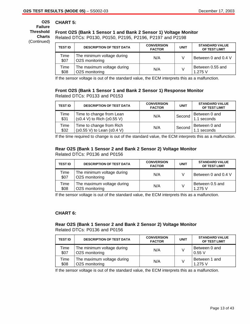
O2S TEST RESULTS (MODE 05) – SS002-03 December 17, 2003
Page 13 of 43
CHART 5:
Front O2S (Bank 1 Sensor 1 and Bank 2 Sensor 1) Voltage MonitorRelated DTCs: P0130, P0150, P2195, P2196, P2197 and P2198
TEST ID DESCRIPTION OF TEST DATACONVERSION
FACTORUNIT
STANDARD VALUEOF TEST LIMIT
Time$07
The minimum voltage duringO2S monitoring
N/A V Between 0 and 0.4 V
Time$08
The maximum voltage duringO2S monitoring
N/A V Between 0.55 and1.275 V
If the sensor voltage is out of the standard value, the ECM interprets this as a malfunction.
Front O2S (Bank 1 Sensor 1 and Bank 2 Sensor 1) Response MonitorRelated DTCs: P0133 and P0153
TEST ID DESCRIPTION OF TEST DATACONVERSION
FACTORUNIT
STANDARD VALUEOF TEST LIMIT
Time$31
Time to change from Lean(≤0.4 V) to Rich (≥0.55 V)
N/A Second Between 0 and1.1 seconds
Time$32
Time to change from Rich(≥0.55 V) to Lean (≤0.4 V)
N/A Second Between 0 and1.1 seconds
If the time required to change is out of the standard value, the ECM interprets this as a malfunction.
Rear O2S (Bank 1 Sensor 2 and Bank 2 Sensor 2) Voltage MonitorRelated DTCs: P0136 and P0156
TEST ID DESCRIPTION OF TEST DATACONVERSION
FACTORUNIT
STANDARD VALUEOF TEST LIMIT
Time$07
The minimum voltage duringO2S monitoring
N/A V Between 0 and 0.4 V
Time$08
The maximum voltage duringO2S monitoring
N/A V Between 0.5 and1.275 V
If the sensor voltage is out of the standard value, the ECM interprets this as a malfunction.
CHART 6:
Rear O2S (Bank 1 Sensor 2 and Bank 2 Sensor 2) Voltage MonitorRelated DTCs: P0136 and P0156
TEST ID DESCRIPTION OF TEST DATACONVERSION
FACTORUNIT
STANDARD VALUEOF TEST LIMIT
Time$07
The minimum voltage duringO2S monitoring
N/A V Between 0 and0.55 V
Time$08
The maximum voltage duringO2S monitoring
N/A V Between 1 and1.275 V
If the sensor voltage is out of the standard value, the ECM interprets this as a malfunction.
O2SFailure
ThresholdCharts
(Continued)
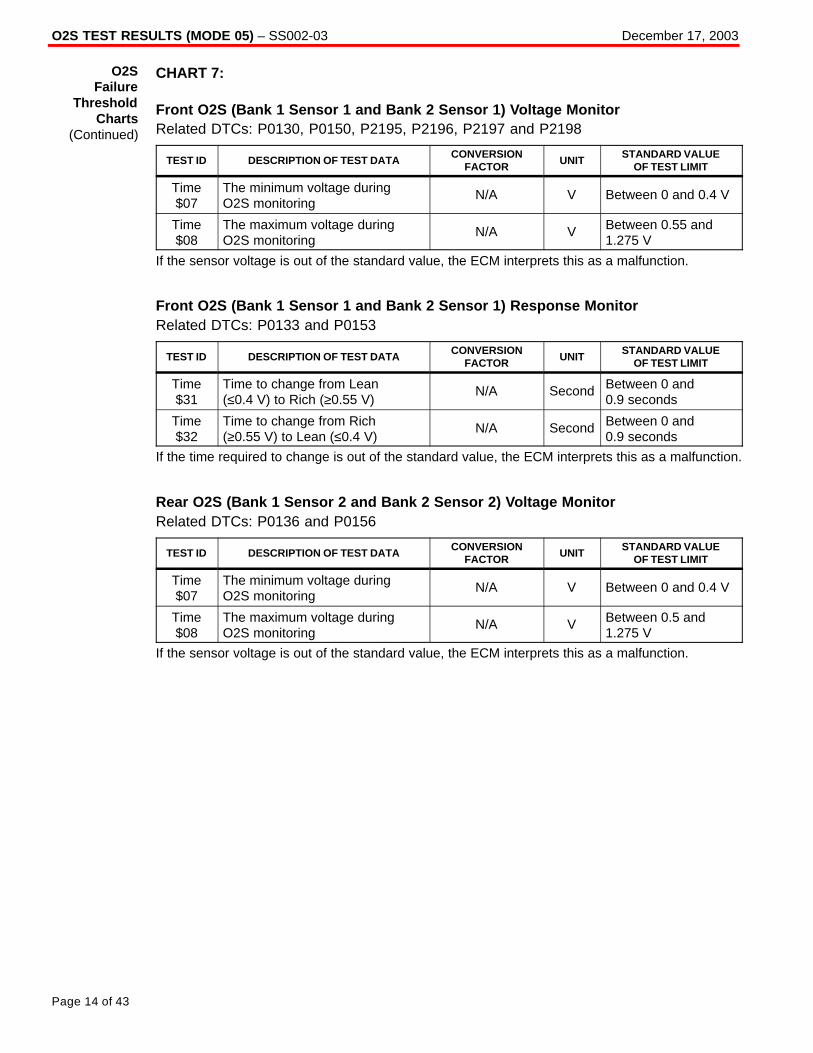
O2S TEST RESULTS (MODE 05) – SS002-03 December 17, 2003
Page 14 of 43
CHART 7:
Front O2S (Bank 1 Sensor 1 and Bank 2 Sensor 1) Voltage MonitorRelated DTCs: P0130, P0150, P2195, P2196, P2197 and P2198
TEST ID DESCRIPTION OF TEST DATACONVERSION
FACTORUNIT
STANDARD VALUEOF TEST LIMIT
Time$07
The minimum voltage duringO2S monitoring
N/A V Between 0 and 0.4 V
Time$08
The maximum voltage duringO2S monitoring
N/A V Between 0.55 and1.275 V
If the sensor voltage is out of the standard value, the ECM interprets this as a malfunction.
Front O2S (Bank 1 Sensor 1 and Bank 2 Sensor 1) Response MonitorRelated DTCs: P0133 and P0153
TEST ID DESCRIPTION OF TEST DATACONVERSION
FACTORUNIT
STANDARD VALUEOF TEST LIMIT
Time$31
Time to change from Lean(≤0.4 V) to Rich (≥0.55 V)
N/A Second Between 0 and0.9 seconds
Time$32
Time to change from Rich(≥0.55 V) to Lean (≤0.4 V)
N/A Second Between 0 and0.9 seconds
If the time required to change is out of the standard value, the ECM interprets this as a malfunction.
Rear O2S (Bank 1 Sensor 2 and Bank 2 Sensor 2) Voltage MonitorRelated DTCs: P0136 and P0156
TEST ID DESCRIPTION OF TEST DATACONVERSION
FACTORUNIT
STANDARD VALUEOF TEST LIMIT
Time$07
The minimum voltage duringO2S monitoring
N/A V Between 0 and 0.4 V
Time$08
The maximum voltage duringO2S monitoring
N/A V Between 0.5 and1.275 V
If the sensor voltage is out of the standard value, the ECM interprets this as a malfunction.
O2SFailure
ThresholdCharts
(Continued)
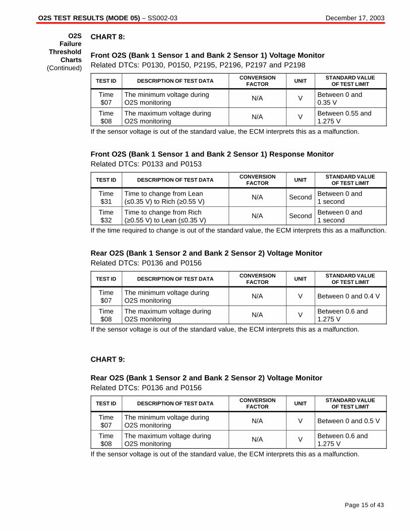
O2S TEST RESULTS (MODE 05) – SS002-03 December 17, 2003
Page 15 of 43
CHART 8:
Front O2S (Bank 1 Sensor 1 and Bank 2 Sensor 1) Voltage MonitorRelated DTCs: P0130, P0150, P2195, P2196, P2197 and P2198
TEST ID DESCRIPTION OF TEST DATACONVERSION
FACTORUNIT
STANDARD VALUEOF TEST LIMIT
Time$07
The minimum voltage duringO2S monitoring
N/A V Between 0 and0.35 V
Time$08
The maximum voltage duringO2S monitoring
N/A V Between 0.55 and1.275 V
If the sensor voltage is out of the standard value, the ECM interprets this as a malfunction.
Front O2S (Bank 1 Sensor 1 and Bank 2 Sensor 1) Response MonitorRelated DTCs: P0133 and P0153
TEST ID DESCRIPTION OF TEST DATACONVERSION
FACTORUNIT
STANDARD VALUEOF TEST LIMIT
Time$31
Time to change from Lean(≤0.35 V) to Rich (≥0.55 V)
N/A Second Between 0 and1 second
Time$32
Time to change from Rich(≥0.55 V) to Lean (≤0.35 V)
N/A Second Between 0 and1 second
If the time required to change is out of the standard value, the ECM interprets this as a malfunction.
Rear O2S (Bank 1 Sensor 2 and Bank 2 Sensor 2) Voltage MonitorRelated DTCs: P0136 and P0156
TEST ID DESCRIPTION OF TEST DATACONVERSION
FACTORUNIT
STANDARD VALUEOF TEST LIMIT
Time$07
The minimum voltage duringO2S monitoring
N/A V Between 0 and 0.4 V
Time$08
The maximum voltage duringO2S monitoring
N/A V Between 0.6 and1.275 V
If the sensor voltage is out of the standard value, the ECM interprets this as a malfunction.
CHART 9:
Rear O2S (Bank 1 Sensor 2 and Bank 2 Sensor 2) Voltage MonitorRelated DTCs: P0136 and P0156
TEST ID DESCRIPTION OF TEST DATACONVERSION
FACTORUNIT
STANDARD VALUEOF TEST LIMIT
Time$07
The minimum voltage duringO2S monitoring
N/A V Between 0 and 0.5 V
Time$08
The maximum voltage duringO2S monitoring
N/A V Between 0.6 and1.275 V
If the sensor voltage is out of the standard value, the ECM interprets this as a malfunction.
O2SFailure
ThresholdCharts
(Continued)

O2S TEST RESULTS (MODE 05) – SS002-03 December 17, 2003
Page 16 of 43
CHART 10:
Front O2S (Bank 1 Sensor 1 and Bank 2 Sensor 1) Voltage MonitorRelated DTCs: P0130, P0150, P2195, P2196, P2197 and P2198
TEST ID DESCRIPTION OF TEST DATACONVERSION
FACTORUNIT
STANDARD VALUEOF TEST LIMIT
Time$07
The minimum voltage duringO2S monitoring
N/A V Between 0 and 0.4 V
Time$08
The maximum voltage duringO2S monitoring
N/A V Between 0.55 and1.275 V
If the sensor voltage is out of the standard value, the ECM interprets this as a malfunction.
Front O2S (Bank 1 Sensor 1 and Bank 2 Sensor 1) Response MonitorRelated DTCs: P0133 and P0153
TEST ID DESCRIPTION OF TEST DATACONVERSION
FACTORUNIT
STANDARD VALUEOF TEST LIMIT
Time$31
Time to change from Lean(≤0.4 V) to Rich (≥0.55 V)
N/A Second Between 0 and1.1 seconds
Time$32
Time to change from Rich(≥0.55 V) to Lean (≤0.4 V)
N/A Second Between 0 and1.1 seconds
If the time required to change is out of the standard value, the ECM interprets this as a malfunction.
Rear O2S (Bank 1 Sensor 2 and Bank 2 Sensor 2) Voltage MonitorRelated DTCs: P0136 and P0156
TEST ID DESCRIPTION OF TEST DATACONVERSION
FACTORUNIT
STANDARD VALUEOF TEST LIMIT
Time$07
The minimum voltage duringO2S monitoring
N/A V Between 0 and 0.5 V
Time$08
The maximum voltage duringO2S monitoring
N/A V Between 0.6 and1.275 V
If the sensor voltage is out of the standard value, the ECM interprets this as a malfunction.
O2SFailure
ThresholdCharts
(Continued)

O2S TEST RESULTS (MODE 05) – SS002-03 December 17, 2003
Page 17 of 43
CHART 11:
Front O2S (Bank 1 Sensor 1 and Bank 2 Sensor 1) Voltage MonitorRelated DTCs: P0130, P0150, P2195, P2196, P2197 and P2198
TEST ID DESCRIPTION OF TEST DATACONVERSION
FACTORUNIT
STANDARD VALUEOF TEST LIMIT
Time$07
The minimum voltage duringO2S monitoring
N/A V Between 0 and0.42 V
Time$08
The maximum voltage duringO2S monitoring
N/A V Between 0.48 and1.275 V
If the sensor voltage is out of the standard value, the ECM interprets this as a malfunction.
Front O2S (Bank 1 Sensor 1 and Bank 2 Sensor 1) Response MonitorRelated DTCs: P0133 and P0153
TEST ID DESCRIPTION OF TEST DATACONVERSION
FACTORUNIT
STANDARD VALUEOF TEST LIMIT
Time$31
Time to change from Lean(≤0.42 V) to Rich (≥0.48 V)
N/A Second Between 0 and 0.4 seconds
Time$32
Time to change from Rich(≥0.48 V) to Lean (≤0.42 V)
N/A Second Between 0 and 0.4 seconds
If the time required to change is out of the standard value, the ECM interprets this as a malfunction.
Rear O2S (Bank 1 Sensor 2 and Bank 2 Sensor 2) Voltage MonitorRelated DTCs: P0136 and P0156
TEST ID DESCRIPTION OF TEST DATACONVERSION
FACTORUNIT
STANDARD VALUEOF TEST LIMIT
Time$07
The minimum voltage duringO2S monitoring
N/A V Between 0 and0.45 V
Time$08
The maximum voltage duringO2S monitoring
N/A V Between 0.55 and1.275 V
If the sensor voltage is out of the standard value, the ECM interprets this as a malfunction.
O2SFailure
ThresholdCharts
(Continued)

O2S TEST RESULTS (MODE 05) – SS002-03 December 17, 2003
Page 18 of 43
CHART 12:
Rear O2S (Bank 1 Sensor 2 and Bank 2 Sensor 2) Voltage MonitorRelated DTCs: P0136 and P0156
TEST ID DESCRIPTION OF TEST DATACONVERSION
FACTORUNIT
STANDARD VALUEOF TEST LIMIT
Time$07
The minimum voltage duringO2S monitoring
N/A V Between 0 and0.45 V
Time$08
The maximum voltage duringO2S monitoring
N/A V Between 0.6 and1.275 V
If the sensor voltage is out of the standard value, the ECM interprets this as a malfunction.
Rear O2S (Bank 1 Sensor 2 and Bank 2 Sensor 2) Element MonitorRelated DTCs: P0136 and P0156
TEST ID DESCRIPTION OF TEST DATACONVERSION
FACTORUNIT
STANDARD VALUEOF TEST LIMIT
Time$81
Percentage of monitoring timewhere Oxygen Sensor voltage isless than 0.05 V
Multiply 0.3906 % Between 0 and 60%
Time$84
Percentage of monitoring timewhere Oxygen Sensor voltage is0.70 V or more
Multiply 0.3906 % Between 20 and100%
Time$85
Maximum Rich (≤0.45 V) time Multiply 0.2621 Second Between 20 and 66.8 seconds
If all the values (Time $81, Time $84 and Time $85) are out of the standard values, the ECMinterprets this as a malfunction.
O2SFailure
ThresholdCharts
(Continued)

O2S TEST RESULTS (MODE 05) – SS002-03 December 17, 2003
Page 19 of 43
CHART 13:
Front O2S (Bank 1 Sensor 1 and Bank 2 Sensor 1) Voltage MonitorRelated DTCs: P0130, P0150, P2195, P2196, P2197 and P2198
TEST ID DESCRIPTION OF TEST DATACONVERSION
FACTORUNIT
STANDARD VALUEOF TEST LIMIT
Time$07
The minimum voltage duringO2S monitoring
N/A V Between 0 and 0.4 V
Time$08
The maximum voltage duringO2S monitoring
N/A V Between 0.55 and1.275 V
If the sensor voltage is out of the standard value, the ECM interprets this as a malfunction.
Front O2S (Bank 1 Sensor 1 and Bank 2 Sensor 1) Response MonitorRelated DTCs: P0133 and P0153
TEST ID DESCRIPTION OF TEST DATACONVERSION
FACTORUNIT
STANDARD VALUEOF TEST LIMIT
Time$31
Time to change from Lean(≤0.4 V) to Rich (≥0.55 V)
N/A Second Between 0 and 1 seconds
Time$32
Time to change from Rich(≥0.55 V) to Lean (≤0.4 V)
N/A Second Between 0 and 1 seconds
If the time required to change is out of the standard value, the ECM interprets this as a malfunction.
Rear O2S (Bank 1 Sensor 2 and Bank 2 Sensor 2) Voltage MonitorRelated DTCs: P0136 and P0156
TEST ID DESCRIPTION OF TEST DATACONVERSION
FACTORUNIT
STANDARD VALUEOF TEST LIMIT
Time$07
The minimum voltage duringO2S monitoring
N/A V Between 0 and 0.4 V
Time$08
The maximum voltage duringO2S monitoring
N/A V Between 0.5 and1.275 V
If the sensor voltage is out of the standard value, the ECM interprets this as a malfunction.
Rear O2S (Bank 1 Sensor 2 and Bank 2 Sensor 2) Element MonitorRelated DTCs: P0136 and P0156
TEST ID DESCRIPTION OF TEST DATACONVERSION
FACTORUNIT
STANDARD VALUEOF TEST LIMIT
Time$81
Percentage of monitoring timewhere Oxygen Sensor voltage isless than 0.5 V
Multiply 0.3906 % Between 0 and 60%
Time$84
Percentage of monitoring timewhere Oxygen Sensor voltage is0.70 V or more
Multiply 0.3906 % Between 20 and100%
Time$85
Maximum Rich (≥0.45 V) time Multiply 0.2621 Second Between 20 and 66.8 seconds
If all the values (Time $81, Time $84 and Time $85) are out of the standard values, the ECMinterprets this as a malfunction.
O2SFailure
ThresholdCharts
(Continued)

O2S TEST RESULTS (MODE 05) – SS002-03 December 17, 2003
Page 20 of 43
CHART 14:
Front O2S (Bank 1 Sensor 1 and Bank 2 Sensor 1) Voltage MonitorRelated DTCs: P0130, P0150, P2195, P2196, P2197 and P2198
TEST ID DESCRIPTION OF TEST DATACONVERSION
FACTORUNIT
STANDARD VALUEOF TEST LIMIT
Time$07
The minimum voltage duringO2S monitoring
N/A V Between 0 and 0.4 V
Time$08
The maximum voltage duringO2S monitoring
N/A V Between 0.55 and1.275 V
If the sensor voltage is out of the standard value, the ECM interprets this as a malfunction.
Front O2S (Bank 1 Sensor 1 and Bank 2 Sensor 1) Response MonitorRelated DTCs: P0133 and P0153
TEST ID DESCRIPTION OF TEST DATACONVERSION
FACTORUNIT
STANDARD VALUEOF TEST LIMIT
Time$31
Time to change from Lean(≤0.4 V) to Rich (≥0.55 V)
N/A Second Between 0 and 0.9 seconds
Time$32
Time to change from Rich(≥0.55 V) to Lean (≤0.4 V)
N/A Second Between 0 and 0.9 seconds
If the time required to change is out of the standard value, the ECM interprets this as a malfunction.
Rear O2S (Bank 1 Sensor 2 and Bank 2 Sensor 2) Voltage MonitorRelated DTCs: P0136 and P0156
TEST ID DESCRIPTION OF TEST DATACONVERSION
FACTORUNIT
STANDARD VALUEOF TEST LIMIT
Time$07
The minimum voltage duringO2S monitoring
N/A V Between 0 and 0.4 V
Time$08
The maximum voltage duringO2S monitoring
N/A V Between 0.5 and1.275 V
If the sensor voltage is out of the standard value, the ECM interprets this as a malfunction.
Rear O2S (Bank 1 Sensor 2 and Bank 2 Sensor 2) Element MonitorRelated DTCs: P0136 and P0156
TEST ID DESCRIPTION OF TEST DATACONVERSION
FACTORUNIT
STANDARD VALUEOF TEST LIMIT
Time$81
Percentage of monitoring timewhere Oxygen Sensor voltage isless than 0.5 V
Multiply 0.3906 % Between 0 and 90%
Time$84
Percentage of monitoring timewhere Oxygen Sensor voltage is0.70 V or more
Multiply 0.3906 % Between 20 and100%
Time$85
Maximum Rich (≥0.45 V) time Multiply 0.2621 Second Between 20 and 66.8 seconds
If all the values (Time $81, Time $84 and Time $85) are out of the standard values, the ECMinterprets this as a malfunction.
O2SFailure
ThresholdCharts
(Continued)

O2S TEST RESULTS (MODE 05) – SS002-03 December 17, 2003
Page 21 of 43
CHART 15:
Front O2S (Bank 1 Sensor 1 and Bank 2 Sensor 1) Voltage MonitorRelated DTCs: P0130, P0150, P2195, P2196, P2197 and P2198
TEST ID DESCRIPTION OF TEST DATACONVERSION
FACTORUNIT
STANDARD VALUEOF TEST LIMIT
Time$07
The minimum voltage duringO2S monitoring
N/A V Between 0 and0.42 V
Time$08
The maximum voltage duringO2S monitoring
N/A V Between 0.48 and1.275 V
If the sensor voltage is out of the standard value, the ECM interprets this as a malfunction.
Front O2S (Bank 1 Sensor 1 and Bank 2 Sensor 1) Response MonitorRelated DTCs: P0133 and P0153
TEST ID DESCRIPTION OF TEST DATACONVERSION
FACTORUNIT
STANDARD VALUEOF TEST LIMIT
Time$31
Time to change from Lean(≤0.42 V) to Rich (≥0.48 V)
N/A Second Between 0 and 0.4 seconds
Time$32
Time to change from Rich(≥0.48 V) to Lean (≤0.42 V)
N/A Second Between 0 and 0.4 seconds
If the time required to change is out of the standard value, the ECM interprets this as a malfunction.
Rear O2S (Bank 1 Sensor 2 and Bank 2 Sensor 2) Voltage MonitorRelated DTCs: P0136 and P0156
TEST ID DESCRIPTION OF TEST DATACONVERSION
FACTORUNIT
STANDARD VALUEOF TEST LIMIT
Time$07
The minimum voltage duringO2S monitoring
N/A V Between 0 and0.45 V
Time$08
The maximum voltage duringO2S monitoring
N/A V Between 0.55 and1.275 V
If the sensor voltage is out of the standard value, the ECM interprets this as a malfunction.
Rear O2S (Bank 1 Sensor 2 and Bank 2 Sensor 2) Element MonitorRelated DTCs: P0136 and P0156
TEST ID DESCRIPTION OF TEST DATACONVERSION
FACTORUNIT
STANDARD VALUEOF TEST LIMIT
Time$81
Percentage of monitoring timewhere Oxygen Sensor voltage isless than 0.5 V
Multiply 0.3906 % Between 0 and 80%
Time$84
Percentage of monitoring timewhere Oxygen Sensor voltage is0.70 V or more
Multiply 0.3906 % Between 20 and100%
Time$85
Maximum Rich (≥0.45 V) time Multiply 0.2621 Second Between 10 and 66.8 seconds
If all the values (Time $81, Time $84 and Time $85) are out of the standard values, the ECMinterprets this as a malfunction.
O2SFailure
ThresholdCharts
(Continued)

O2S TEST RESULTS (MODE 05) – SS002-03 December 17, 2003
Page 22 of 43
CHART 16:
Front O2S (Bank 1 Sensor 1 and Bank 2 Sensor 1) Voltage MonitorRelated DTCs: P0136 and P0156
TEST ID DESCRIPTION OF TEST DATACONVERSION
FACTORUNIT
STANDARD VALUEOF TEST LIMIT
Time$07
The minimum voltage duringO2S monitoring
N/A V Between 0 and 0.4 V
Time$08
The maximum voltage duringO2S monitoring
N/A V Between 0.6 and1.275 V
If the sensor voltage is out of the standard value, the ECM interprets this as a malfunction.
Rear O2S (Bank 1 Sensor 2 and Bank 2 Sensor 2) Element MonitorRelated DTCs: P0136 and P0156
TEST ID DESCRIPTION OF TEST DATACONVERSION
FACTORUNIT
STANDARD VALUEOF TEST LIMIT
Time$81
Percentage of monitoring timewhere Oxygen Sensor voltage isless than 0.5 V
Multiply 0.3906 % Between 0 and 60%
Time$84
Percentage of monitoring timewhere Oxygen Sensor voltage is0.70 V or more
Multiply 0.3906 % Between 20 and100%
Time$85
Maximum Rich (≥0.45 V) time Multiply 0.2621 Second Between 20 and 66.8 seconds
If all the values (Time $81, Time $84 and Time $85) are out of the standard values, the ECMinterprets this as a malfunction.
O2SFailure
ThresholdCharts
(Continued)

O2S TEST RESULTS (MODE 05) – SS002-03 December 17, 2003
Page 23 of 43
CHART 17:
Rear O2S (Bank 1 Sensor 2 and Bank 2 Sensor 2) Voltage MonitorRelated DTCs: P0136 and P0156
TEST ID DESCRIPTION OF TEST DATACONVERSION
FACTORUNIT
STANDARD VALUEOF TEST LIMIT
Time$07
The minimum voltage duringO2S monitoring
N/A V Between 0 and0.45 V
Time$08
The maximum voltage duringO2S monitoring
N/A V Between 0.6 and1.275 V
If the sensor voltage is out of the standard value, the ECM interprets this as a malfunction.
Rear O2S (Bank 1 Sensor 2 and Bank 2 Sensor 2) Element MonitorRelated DTCs: P0136 and P0156
TEST ID DESCRIPTION OF TEST DATACONVERSION
FACTORUNIT
STANDARD VALUEOF TEST LIMIT
Time$81
Percentage of monitoring timewhere Oxygen Sensor voltage isless than 0.05 V
Multiply 0.3906 % Between 0 and 55%
Time$84
Percentage of monitoring timewhere Oxygen Sensor voltage is0.70 V or more
Multiply 0.3906 % Between 20 and100%
Time$85
Maximum Rich (≥0.45 V) time Multiply 0.2621 Second Between 20 and 66.8 seconds
If all the values (Time $81, Time $84 and Time $85) are out of the standard values, the ECMinterprets this as a malfunction.
O2SFailure
ThresholdCharts
(Continued)
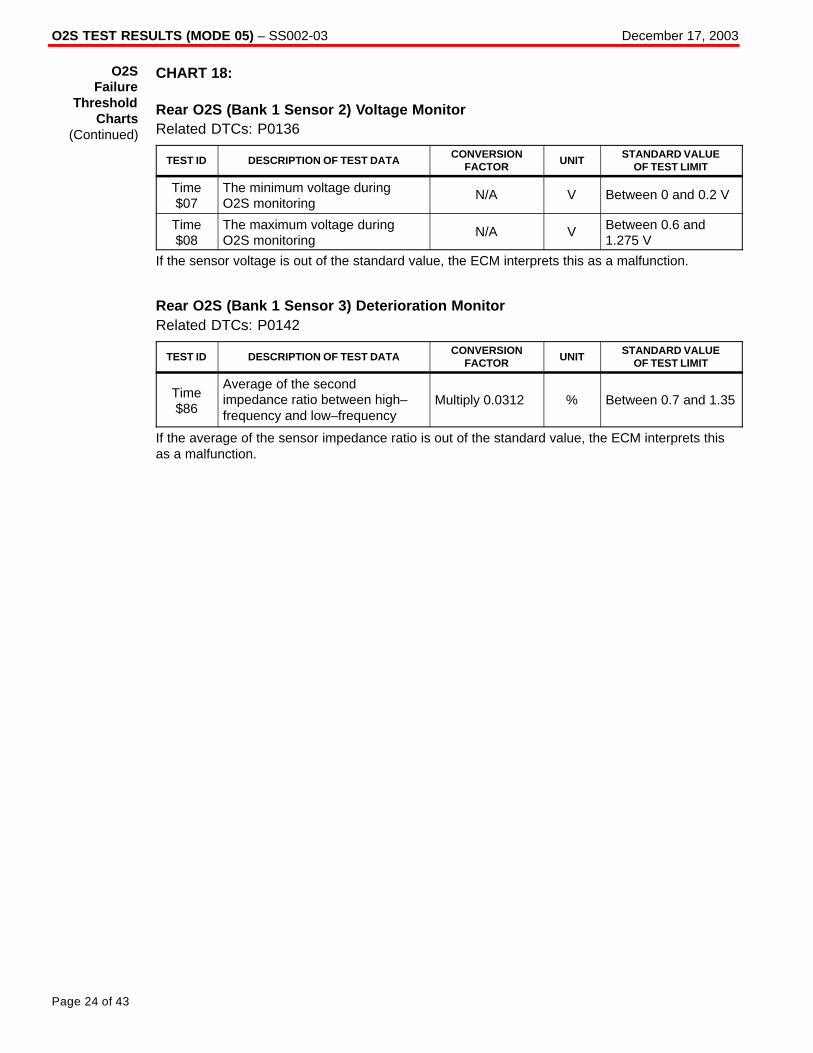
O2S TEST RESULTS (MODE 05) – SS002-03 December 17, 2003
Page 24 of 43
CHART 18:
Rear O2S (Bank 1 Sensor 2) Voltage MonitorRelated DTCs: P0136
TEST ID DESCRIPTION OF TEST DATACONVERSION
FACTORUNIT
STANDARD VALUEOF TEST LIMIT
Time$07
The minimum voltage duringO2S monitoring
N/A V Between 0 and 0.2 V
Time$08
The maximum voltage duringO2S monitoring
N/A V Between 0.6 and1.275 V
If the sensor voltage is out of the standard value, the ECM interprets this as a malfunction.
Rear O2S (Bank 1 Sensor 3) Deterioration MonitorRelated DTCs: P0142
TEST ID DESCRIPTION OF TEST DATACONVERSION
FACTORUNIT
STANDARD VALUEOF TEST LIMIT
Time$86
Average of the secondimpedance ratio between high– frequency and low–frequency
Multiply 0.0312 % Between 0.7 and 1.35
If the average of the sensor impedance ratio is out of the standard value, the ECM interprets thisas a malfunction.
O2SFailure
ThresholdCharts
(Continued)
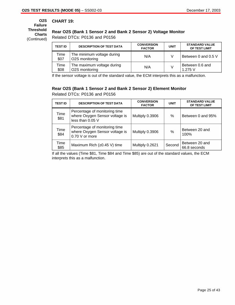
O2S TEST RESULTS (MODE 05) – SS002-03 December 17, 2003
Page 25 of 43
CHART 19:
Rear O2S (Bank 1 Sensor 2 and Bank 2 Sensor 2) Voltage MonitorRelated DTCs: P0136 and P0156
TEST ID DESCRIPTION OF TEST DATACONVERSION
FACTORUNIT
STANDARD VALUEOF TEST LIMIT
Time$07
The minimum voltage duringO2S monitoring
N/A V Between 0 and 0.5 V
Time$08
The maximum voltage duringO2S monitoring
N/A V Between 0.6 and1.275 V
If the sensor voltage is out of the standard value, the ECM interprets this as a malfunction.
Rear O2S (Bank 1 Sensor 2 and Bank 2 Sensor 2) Element MonitorRelated DTCs: P0136 and P0156
TEST ID DESCRIPTION OF TEST DATACONVERSION
FACTORUNIT
STANDARD VALUEOF TEST LIMIT
Time$81
Percentage of monitoring timewhere Oxygen Sensor voltage isless than 0.05 V
Multiply 0.3906 % Between 0 and 95%
Time$84
Percentage of monitoring timewhere Oxygen Sensor voltage is0.70 V or more
Multiply 0.3906 % Between 20 and100%
Time$85
Maximum Rich (≥0.45 V) time Multiply 0.2621 Second Between 20 and 66.8 seconds
If all the values (Time $81, Time $84 and Time $85) are out of the standard values, the ECMinterprets this as a malfunction.
O2SFailure
ThresholdCharts
(Continued)

O2S TEST RESULTS (MODE 05) – SS002-03 December 17, 2003
Page 26 of 43
CHART 20:
Rear O2S (Bank 1 Sensor 2 and Bank 2 Sensor 2) Voltage MonitorRelated DTCs: P0136 and P0156
TEST ID DESCRIPTION OF TEST DATACONVERSION
FACTORUNIT
STANDARD VALUEOF TEST LIMIT
Time$07
The minimum voltage duringO2S monitoring
N/A V Between 0 and 0.5 V
Time$08
The maximum voltage duringO2S monitoring
N/A V Between 0.6 and1.275 V
If the sensor voltage is out of the standard value, the ECM interprets this as a malfunction.
Rear O2S (Bank 1 Sensor 2 and Bank 2 Sensor 2) Element MonitorRelated DTCs: P0136 and P0156
TEST ID DESCRIPTION OF TEST DATACONVERSION
FACTORUNIT
STANDARD VALUEOF TEST LIMIT
Time$81
Percentage of monitoring timewhere Oxygen Sensor voltage isless than 0.05 V
Multiply 0.3906 % Between 0 and 80%
Time$84
Percentage of monitoring timewhere Oxygen Sensor voltage is0.70 V or more
Multiply 0.3906 % Between 20 and100%
Time$85
Maximum Rich (≥0.45 V) time Multiply 0.2621 Second Between 20 and 66.8 seconds
If all the values (Time $81, Time $84 and Time $85) are out of the standard values, the ECMinterprets this as a malfunction.
O2SFailure
ThresholdCharts
(Continued)
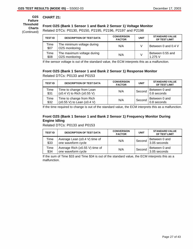
O2S TEST RESULTS (MODE 05) – SS002-03 December 17, 2003
Page 27 of 43
CHART 21:
Front O2S (Bank 1 Sensor 1 and Bank 2 Sensor 1) Voltage MonitorRelated DTCs: P0130, P0150, P2195, P2196, P2197 and P2198
TEST ID DESCRIPTION OF TEST DATACONVERSION
FACTORUNIT
STANDARD VALUEOF TEST LIMIT
Time$07
The minimum voltage duringO2S monitoring
N/A V Between 0 and 0.4 V
Time$08
The maximum voltage duringO2S monitoring
N/A V Between 0.55 and1.275 V
If the sensor voltage is out of the standard value, the ECM interprets this as a malfunction.
Front O2S (Bank 1 Sensor 1 and Bank 2 Sensor 1) Response MonitorRelated DTCs: P0133 and P0153
TEST ID DESCRIPTION OF TEST DATACONVERSION
FACTORUNIT
STANDARD VALUEOF TEST LIMIT
Time$31
Time to change from Lean(≤0.4 V) to Rich (≥0.55 V)
N/A Second Between 0 and 0.8 seconds
Time$32
Time to change from Rich(≥0.55 V) to Lean (≤0.4 V)
N/A Second Between 0 and 0.8 seconds
If the time required to change is out of the standard value, the ECM interprets this as a malfunction.
Front O2S (Bank 1 Sensor 1 and Bank 2 Sensor 1) Frequency Monitor DuringEngine IdlingRelated DTCs: P0133 and P0153
TEST ID DESCRIPTION OF TEST DATACONVERSION
FACTORUNIT
STANDARD VALUEOF TEST LIMIT
Time$33
Average Lean (≤0.4 V) time ofone waveform cycle
N/A Second Between 0 and 3.05 seconds
Time$34
Average Rich (≥0.55 V) time ofone waveform cycle
N/A Second Between 0 and 3.05 seconds
If the sum of Time $33 and Time $34 is out of the standard value, the ECM interprets this as amalfunction.
O2SFailure
ThresholdCharts
(Continued)

O2S TEST RESULTS (MODE 05) – SS002-03 December 17, 2003
Page 28 of 43
CHART 21 (Continued):
Front O2S (Bank 1 Sensor 1 and Bank 2 Sensor 1) Frequency Monitor DuringVehicle RunningRelated DTCs: P0133 and P0153
TEST ID DESCRIPTION OF TEST DATACONVERSION
FACTORUNIT
STANDARD VALUEOF TEST LIMIT
Time$35
Average Lean (≤0.4 V) time ofone waveform cycle
N/A Second
Between 0 and 0.95 seconds (varies depending on feedbackcompensation factor)
Time$36
Average Rich (≤0.55 V) time ofone waveform cycle
N/A Second
Between 0 and 0.95seconds (varies depending on feedbackcompensation factor)
If the sum of Time $35 and Time $36 is out of the standard value, the ECM interprets this as amalfunction.
Rear O2S (Bank 1 Sensor 2 and Bank 2 Sensor 2) Voltage MonitorRelated DTCs: P0136 and P0156
TEST ID DESCRIPTION OF TEST DATACONVERSION
FACTORUNIT
STANDARD VALUEOF TEST LIMIT
Time$07
The minimum voltage duringO2S monitoring
N/A V Between 0 and 0.4 V
Time$08
The maximum voltage duringO2S monitoring
N/A V Between 0.5 and1.275 V
If the sensor voltage is out of the standard value, the ECM interprets this as a malfunction.
Rear O2S (Bank 1 Sensor 2 and Bank 2 Sensor 2) Element MonitorRelated DTCs: P0136 and P0156
TEST ID DESCRIPTION OF TEST DATACONVERSION
FACTORUNIT
STANDARD VALUEOF TEST LIMIT
Time$81
Percentage of monitoring timewhere Oxygen Sensor voltage isless than 0.05 V
Multiply 0.3906 % Between 0 and 60%
Time$84
Percentage of monitoring timewhere Oxygen Sensor voltage is0.70 V or more
Multiply 0.3906 % Between 20 and100%
Time$85
Maximum Rich (≥0.45 V) time Multiply 0.2621 Second Between 20 and 66.8 seconds
If all the values (Time $81, Time $84 and Time $85) are out of the standard values, the ECMinterprets this as a malfunction.
O2SFailure
ThresholdCharts
(Continued)

O2S TEST RESULTS (MODE 05) – SS002-03 December 17, 2003
Page 29 of 43
CHART 22:
Front O2S (Bank 1 Sensor 1 and Bank 2 Sensor 1) Voltage MonitorRelated DTCs: P0130, P0150, P2195, P2196, P2197 and P2198
TEST ID DESCRIPTION OF TEST DATACONVERSION
FACTORUNIT
STANDARD VALUEOF TEST LIMIT
Time$07
The minimum voltage duringO2S monitoring
N/A V Between 0 and 0.4 V
Time$08
The maximum voltage duringO2S monitoring
N/A V Between 0.55 and1.275 V
If the sensor voltage is out of the standard value, the ECM interprets this as a malfunction.
Front O2S (Bank 1 Sensor 1 and Bank 2 Sensor 1) Response MonitorRelated DTCs: P0133 and P0153
TEST ID DESCRIPTION OF TEST DATACONVERSION
FACTORUNIT
STANDARD VALUEOF TEST LIMIT
Time$31
Time to change from Lean(≤0.4 V) to Rich (≥0.55 V)
N/A Second Between 0 and 0.9 seconds
Time$32
Time to change from Rich(≥0.55 V) to Lean (≤0.4 V)
N/A Second Between 0 and 0.9 seconds
If the time required to change is out of the standard value, the ECM interprets this as a malfunction.
Rear O2S (Bank 1 Sensor 2 and Bank 2 Sensor 2) Voltage MonitorRelated DTCs: P0136 and P0156
TEST ID DESCRIPTION OF TEST DATACONVERSION
FACTORUNIT
STANDARD VALUEOF TEST LIMIT
Time$07
The minimum voltage duringO2S monitoring
N/A V Between 0 and 0.4 V
Time$08
The maximum voltage duringO2S monitoring
N/A V Between 0.5 and1.275 V
If the sensor voltage is out of the standard value, the ECM interprets this as a malfunction.
Rear O2S (Bank 1 Sensor 2 and Bank 2 Sensor 2) Element MonitorRelated DTCs: P0136 and P0156
TEST ID DESCRIPTION OF TEST DATACONVERSION
FACTORUNIT
STANDARD VALUEOF TEST LIMIT
Time$81
Percentage of monitoring timewhere Oxygen Sensor voltage isless than 0.5 V
Multiply 0.3906 % Between 0 and 60%
Time$84
Percentage of monitoring timewhere Oxygen Sensor voltage is0.70 V or more
Multiply 0.3906 % Between 20 and100%
Time$85
Maximum Rich (≥0.45 V) time Multiply 0.2621 Second Between 20 and 66.8 seconds
If all the values (Time $81, Time $84 and Time $85) are out of the standard values, the ECMinterprets this as a malfunction.
O2SFailure
ThresholdCharts
(Continued)
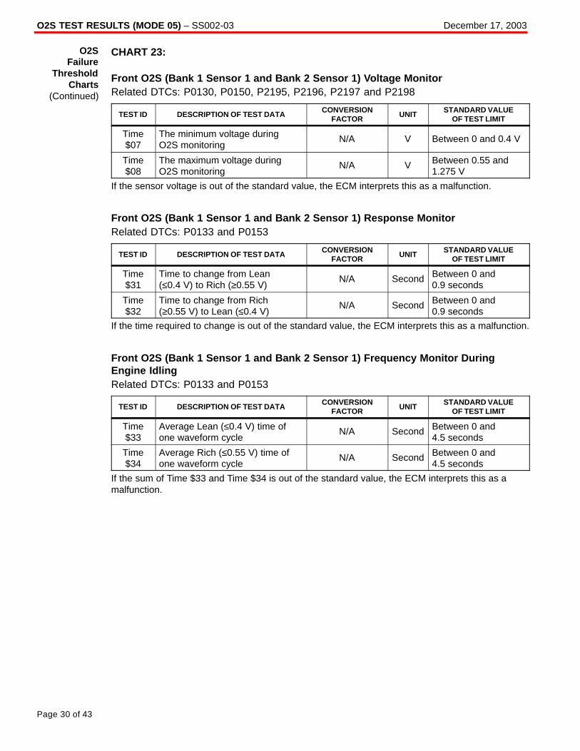
O2S TEST RESULTS (MODE 05) – SS002-03 December 17, 2003
Page 30 of 43
CHART 23:
Front O2S (Bank 1 Sensor 1 and Bank 2 Sensor 1) Voltage MonitorRelated DTCs: P0130, P0150, P2195, P2196, P2197 and P2198
TEST ID DESCRIPTION OF TEST DATACONVERSION
FACTORUNIT
STANDARD VALUEOF TEST LIMIT
Time$07
The minimum voltage duringO2S monitoring
N/A V Between 0 and 0.4 V
Time$08
The maximum voltage duringO2S monitoring
N/A V Between 0.55 and1.275 V
If the sensor voltage is out of the standard value, the ECM interprets this as a malfunction.
Front O2S (Bank 1 Sensor 1 and Bank 2 Sensor 1) Response MonitorRelated DTCs: P0133 and P0153
TEST ID DESCRIPTION OF TEST DATACONVERSION
FACTORUNIT
STANDARD VALUEOF TEST LIMIT
Time$31
Time to change from Lean(≤0.4 V) to Rich (≥0.55 V)
N/A Second Between 0 and 0.9 seconds
Time$32
Time to change from Rich(≥0.55 V) to Lean (≤0.4 V)
N/A Second Between 0 and 0.9 seconds
If the time required to change is out of the standard value, the ECM interprets this as a malfunction.
Front O2S (Bank 1 Sensor 1 and Bank 2 Sensor 1) Frequency Monitor DuringEngine IdlingRelated DTCs: P0133 and P0153
TEST ID DESCRIPTION OF TEST DATACONVERSION
FACTORUNIT
STANDARD VALUEOF TEST LIMIT
Time$33
Average Lean (≤0.4 V) time ofone waveform cycle
N/A Second Between 0 and 4.5 seconds
Time$34
Average Rich (≤0.55 V) time ofone waveform cycle
N/A Second Between 0 and 4.5 seconds
If the sum of Time $33 and Time $34 is out of the standard value, the ECM interprets this as amalfunction.
O2SFailure
ThresholdCharts
(Continued)

O2S TEST RESULTS (MODE 05) – SS002-03 December 17, 2003
Page 31 of 43
CHART 23 (Continued):
Front O2S (Bank 1 Sensor 1 and Bank 2 Sensor 1) Frequency Monitor DuringVehicle RunningRelated DTCs: P0133 and P0153
TEST ID DESCRIPTION OF TEST DATACONVERSION
FACTORUNIT
STANDARD VALUEOF TEST LIMIT
Time$35
Average Lean (≤0.4 V) time ofone waveform cycle
N/A Second
Between 0 and 0.9 seconds (varies depending on feedbackcompensation factor)
Time$36
Average Rich (≤0.55 V) time ofone waveform cycle
N/A Second
Between 0 and 0.9 seconds (varies depending on feedbackcompensation factor)
If the sum of Time $35 and Time $36 is out of the standard value, the ECM interprets this as amalfunction.
Rear O2S (Bank 1 Sensor 2 and Bank 2 Sensor 2) Voltage MonitorRelated DTCs: P0136 and P0156
TEST ID DESCRIPTION OF TEST DATACONVERSION
FACTORUNIT
STANDARD VALUEOF TEST LIMIT
Time$07
The minimum voltage duringO2S monitoring
N/A V Between 0 and 0.4 V
Time$08
The maximum voltage duringO2S monitoring
N/A V Between 0.5 and1.275 V
If the sensor voltage is out of the standard value, the ECM interprets this as a malfunction.
Rear O2S (Bank 1 Sensor 2 and Bank 2 Sensor 2) Element MonitorRelated DTCs: P0136 and P0156
TEST ID DESCRIPTION OF TEST DATACONVERSION
FACTORUNIT
STANDARD VALUEOF TEST LIMIT
Time$81
Percentage of monitoring timewhere Oxygen Sensor voltage isless than 0.05 V
Multiply 0.3906 % Between 0 and 60%
Time$84
Percentage of monitoring timewhere Oxygen Sensor voltage is0.70 V or more
Multiply 0.3906 % Between 20 and100%
Time$85
Maximum Rich (≥0.45 V) time Multiply 0.2621 Second Between 20 and 66.8 seconds
If all the values (Time $81, Time $84 and Time $85) are out of the standard values, the ECMinterprets this as a malfunction.
O2SFailure
ThresholdCharts
(Continued)
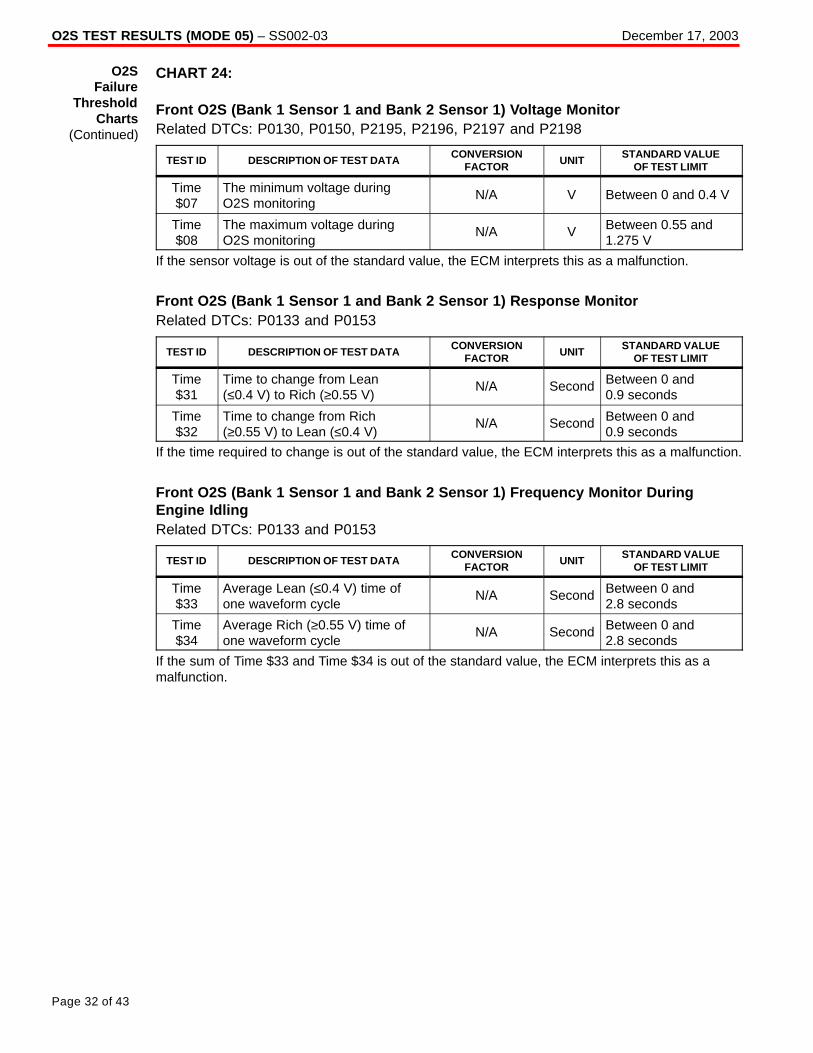
O2S TEST RESULTS (MODE 05) – SS002-03 December 17, 2003
Page 32 of 43
CHART 24:
Front O2S (Bank 1 Sensor 1 and Bank 2 Sensor 1) Voltage MonitorRelated DTCs: P0130, P0150, P2195, P2196, P2197 and P2198
TEST ID DESCRIPTION OF TEST DATACONVERSION
FACTORUNIT
STANDARD VALUEOF TEST LIMIT
Time$07
The minimum voltage duringO2S monitoring
N/A V Between 0 and 0.4 V
Time$08
The maximum voltage duringO2S monitoring
N/A V Between 0.55 and1.275 V
If the sensor voltage is out of the standard value, the ECM interprets this as a malfunction.
Front O2S (Bank 1 Sensor 1 and Bank 2 Sensor 1) Response MonitorRelated DTCs: P0133 and P0153
TEST ID DESCRIPTION OF TEST DATACONVERSION
FACTORUNIT
STANDARD VALUEOF TEST LIMIT
Time$31
Time to change from Lean(≤0.4 V) to Rich (≥0.55 V)
N/A Second Between 0 and 0.9 seconds
Time$32
Time to change from Rich(≥0.55 V) to Lean (≤0.4 V)
N/A Second Between 0 and 0.9 seconds
If the time required to change is out of the standard value, the ECM interprets this as a malfunction.
Front O2S (Bank 1 Sensor 1 and Bank 2 Sensor 1) Frequency Monitor DuringEngine IdlingRelated DTCs: P0133 and P0153
TEST ID DESCRIPTION OF TEST DATACONVERSION
FACTORUNIT
STANDARD VALUEOF TEST LIMIT
Time$33
Average Lean (≤0.4 V) time ofone waveform cycle
N/A Second Between 0 and 2.8 seconds
Time$34
Average Rich (≥0.55 V) time ofone waveform cycle
N/A Second Between 0 and 2.8 seconds
If the sum of Time $33 and Time $34 is out of the standard value, the ECM interprets this as amalfunction.
O2SFailure
ThresholdCharts
(Continued)
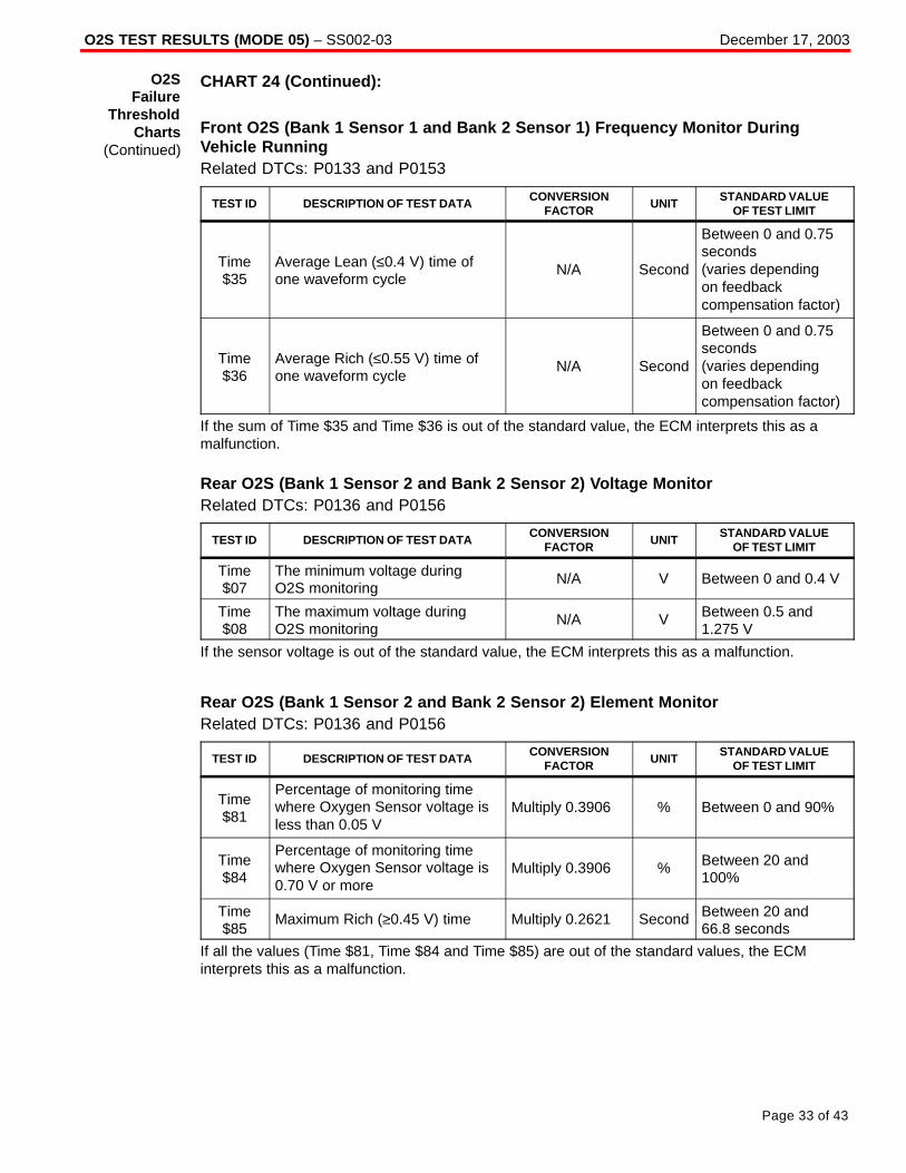
O2S TEST RESULTS (MODE 05) – SS002-03 December 17, 2003
Page 33 of 43
CHART 24 (Continued):
Front O2S (Bank 1 Sensor 1 and Bank 2 Sensor 1) Frequency Monitor DuringVehicle RunningRelated DTCs: P0133 and P0153
TEST ID DESCRIPTION OF TEST DATACONVERSION
FACTORUNIT
STANDARD VALUEOF TEST LIMIT
Time$35
Average Lean (≤0.4 V) time ofone waveform cycle
N/A Second
Between 0 and 0.75seconds (varies depending on feedbackcompensation factor)
Time$36
Average Rich (≤0.55 V) time ofone waveform cycle
N/A Second
Between 0 and 0.75seconds (varies depending on feedbackcompensation factor)
If the sum of Time $35 and Time $36 is out of the standard value, the ECM interprets this as amalfunction.
Rear O2S (Bank 1 Sensor 2 and Bank 2 Sensor 2) Voltage MonitorRelated DTCs: P0136 and P0156
TEST ID DESCRIPTION OF TEST DATACONVERSION
FACTORUNIT
STANDARD VALUEOF TEST LIMIT
Time$07
The minimum voltage duringO2S monitoring
N/A V Between 0 and 0.4 V
Time$08
The maximum voltage duringO2S monitoring
N/A V Between 0.5 and1.275 V
If the sensor voltage is out of the standard value, the ECM interprets this as a malfunction.
Rear O2S (Bank 1 Sensor 2 and Bank 2 Sensor 2) Element MonitorRelated DTCs: P0136 and P0156
TEST ID DESCRIPTION OF TEST DATACONVERSION
FACTORUNIT
STANDARD VALUEOF TEST LIMIT
Time$81
Percentage of monitoring timewhere Oxygen Sensor voltage isless than 0.05 V
Multiply 0.3906 % Between 0 and 90%
Time$84
Percentage of monitoring timewhere Oxygen Sensor voltage is0.70 V or more
Multiply 0.3906 % Between 20 and100%
Time$85
Maximum Rich (≥0.45 V) time Multiply 0.2621 Second Between 20 and 66.8 seconds
If all the values (Time $81, Time $84 and Time $85) are out of the standard values, the ECMinterprets this as a malfunction.
O2SFailure
ThresholdCharts
(Continued)

O2S TEST RESULTS (MODE 05) – SS002-03 December 17, 2003
Page 34 of 43
CHART 25:
Rear O2S (Bank 1 Sensor 2 and Bank 2 Sensor 2) Voltage MonitorRelated DTCs: P0136 and P0156
TEST ID DESCRIPTION OF TEST DATACONVERSION
FACTORUNIT
STANDARD VALUEOF TEST LIMIT
Time$07
The minimum voltage duringO2S monitoring
N/A V Between 0 and0.45 V
Time$08
The maximum voltage duringO2S monitoring
N/A V Between 0.6 and1.275 V
If the sensor voltage is out of the standard value, the ECM interprets this as a malfunction.
Rear O2S (Bank 1 Sensor 2 and Bank 2 Sensor 2) Element MonitorRelated DTCs: P0136 and P0156
TEST ID DESCRIPTION OF TEST DATACONVERSION
FACTORUNIT
STANDARD VALUEOF TEST LIMIT
Time$81
Percentage of monitoring timewhere Oxygen Sensor voltage isless than 0.05 V
Multiply 0.3906 % Between 0 and 80%
Time$84
Percentage of monitoring timewhere Oxygen Sensor voltage is0.70 V or more
Multiply 0.3906 % Between 20 and100%
Time$85
Maximum Rich (≥0.45 V) time Multiply 0.2621 Second Between 20 and 66.8 seconds
If all the values (Time $81, Time $84 and Time $85) are out of the standard values, the ECMinterprets this as a malfunction.
O2SFailure
ThresholdCharts
(Continued)

O2S TEST RESULTS (MODE 05) – SS002-03 December 17, 2003
Page 35 of 43
CHART 26:
Front O2S (Bank 1 Sensor 1 and Bank 2 Sensor 1) Voltage MonitorRelated DTCs: P0130, P0150, P2195, P2196, P2197 and P2198
TEST ID DESCRIPTION OF TEST DATACONVERSION
FACTORUNIT
STANDARD VALUEOF TEST LIMIT
Time$07
The minimum voltage duringO2S monitoring
N/A V Between 0 and 0.4 V
Time$08
The maximum voltage duringO2S monitoring
N/A V Between 0.55 and1.275 V
If the sensor voltage is out of the standard value, the ECM interprets this as a malfunction.
Front O2S (Bank 1 Sensor 1 and Bank 2 Sensor 1) Response MonitorRelated DTCs: P0133 and P0153
TEST ID DESCRIPTION OF TEST DATACONVERSION
FACTORUNIT
STANDARD VALUEOF TEST LIMIT
Time$31
Time to change from Lean(≤0.4 V) to Rich (≥0.55 V)
N/A Second Between 0 and 0.9 seconds
Time$32
Time to change from Rich(≥0.55 V) to Lean (≤0.4 V)
N/A Second Between 0 and 0.9 seconds
If the time required to change is out of the standard value, the ECM interprets this as a malfunction.
Front O2S (Bank 1 Sensor 1 and Bank 2 Sensor 1) Frequency Monitor DuringEngine IdlingRelated DTCs: P0133 and P0153
TEST ID DESCRIPTION OF TEST DATACONVERSION
FACTORUNIT
STANDARD VALUEOF TEST LIMIT
Time$33
Average Lean (≤0.4 V) time ofone waveform cycle
N/A Second Between 0 and 2.8 seconds
Time$34
Average Rich (≥0.55 V) time ofone waveform cycle
N/A Second Between 0 and 2.8 seconds
If the sum of Time $33 and Time $34 is out of the standard value, the ECM interprets this as amalfunction.
O2SFailure
ThresholdCharts
(Continued)

O2S TEST RESULTS (MODE 05) – SS002-03 December 17, 2003
Page 36 of 43
CHART 26 (Continued):
Front O2S (Bank 1 Sensor 1 and Bank 2 Sensor 1) Frequency Monitor DuringVehicle RunningRelated DTCs: P0133 and P0153
TEST ID DESCRIPTION OF TEST DATACONVERSION
FACTORUNIT
STANDARD VALUEOF TEST LIMIT
Time$35
Average Lean (≤0.4 V) time ofone waveform cycle
N/A Second
Between 0 and 0.75 seconds (varies depending on feedbackcompensation factor)
Time$36
Average Rich (≤0.55 V) time ofone waveform cycle
N/A Second
Between 0 and 0.75 seconds (varies depending on feedbackcompensation factor)
If the sum of Time $35 and Time $36 is out of the standard value, the ECM interprets this as amalfunction.
Rear O2S (Bank 1 Sensor 2 and Bank 2 Sensor 2) Voltage MonitorRelated DTCs: P0136 and P0156
TEST ID DESCRIPTION OF TEST DATACONVERSION
FACTORUNIT
STANDARD VALUEOF TEST LIMIT
Time$07
The minimum voltage duringO2S monitoring
N/A V Between 0 and 0.4 V
Time$08
The maximum voltage duringO2S monitoring
N/A V Between 0.5 and1.275 V
If the sensor voltage is out of the standard value, the ECM interprets this as a malfunction.
Rear O2S (Bank 1 Sensor 2 and Bank 2 Sensor 2) Element MonitorRelated DTCs: P0136 and P0156
TEST ID DESCRIPTION OF TEST DATACONVERSION
FACTORUNIT
STANDARD VALUEOF TEST LIMIT
Time$81
Percentage of monitoring timewhere Oxygen Sensor voltage isless than 0.05 V
Multiply 0.3906 % Between 0 and 60%
Time$84
Percentage of monitoring timewhere Oxygen Sensor voltage is0.70 V or more
Multiply 0.3906 % Between 20 and100%
Time$85
Maximum Rich (≥0.45 V) time Multiply 0.2621 Second Between 20 and 66.8 seconds
If all the values (Time $81, Time $84 and Time $85) are out of the standard values, the ECMinterprets this as a malfunction.
O2SFailure
ThresholdCharts
(Continued)

O2S TEST RESULTS (MODE 05) – SS002-03 December 17, 2003
Page 37 of 43
CHART 27:
Front O2S (Bank 1 Sensor 1 and Bank 2 Sensor 1) Voltage MonitorRelated DTCs: P0130, P0150, P2195, P2196, P2197 and P2198
TEST ID DESCRIPTION OF TEST DATACONVERSION
FACTORUNIT
STANDARD VALUEOF TEST LIMIT
Time$07
The minimum voltage duringO2S monitoring
N/A V Between 0 and0.35 V
Time$08
The maximum voltage duringO2S monitoring
N/A V Between 0.45 and1.275 V
If the sensor voltage is out of the standard value, the ECM interprets this as a malfunction.
Front O2S (Bank 1 Sensor 1 and Bank 2 Sensor 1) Response MonitorRelated DTCs: P0133 and P0153
TEST ID DESCRIPTION OF TEST DATACONVERSION
FACTORUNIT
STANDARD VALUEOF TEST LIMIT
Time$31
Time to change from Lean(≤0.35 V) to Rich (≥0.45 V)
N/A Second Between 0 and 0.6 seconds
Time$32
Time to change from Rich(≥0.45 V) to Lean (≤0.35 V)
N/A Second Between 0 and 0.6 seconds
If the time required to change is out of the standard value, the ECM interprets this as a malfunction.
Front O2S (Bank 1 Sensor 1 and Bank 2 Sensor 1) Frequency Monitor DuringEngine IdlingRelated DTCs: P0133 and P0153
TEST ID DESCRIPTION OF TEST DATACONVERSION
FACTORUNIT
STANDARD VALUEOF TEST LIMIT
Time$33
Average Lean (≤0.35 V) time ofone waveform cycle
N/A Second Between 0 and 3 seconds
Time$34
Average Rich (≥0.45 V) time ofone waveform cycle
N/A Second Between 0 and 3 seconds
If the sum of Time $33 and Time $34 is out of the standard value, the ECM interprets this as amalfunction.
O2SFailure
ThresholdCharts
(Continued)

O2S TEST RESULTS (MODE 05) – SS002-03 December 17, 2003
Page 38 of 43
CHART 27 (Continued):
Front O2S (Bank 1 Sensor 1 and Bank 2 Sensor 1) Frequency Monitor DuringVehicle RunningRelated DTCs: P0133 and P0153
TEST ID DESCRIPTION OF TEST DATACONVERSION
FACTORUNIT
STANDARD VALUEOF TEST LIMIT
Time$35
Average Lean (≤0.35 V) time ofone waveform cycle
N/A Second
Between 0 and 0.55seconds (varies depending on feedbackcompensation factor)
Time$36
Average Rich (≤0.45 V) time ofone waveform cycle
N/A Second
Between 0 and 0.55seconds (varies depending on feedbackcompensation factor)
If the sum of Time $35 and Time $36 is out of the standard value, the ECM interprets this as amalfunction.
Rear O2S (Bank 1 Sensor 2 and Bank 2 Sensor 2) Voltage MonitorRelated DTCs: P0136 and P0156
TEST ID DESCRIPTION OF TEST DATACONVERSION
FACTORUNIT
STANDARD VALUEOF TEST LIMIT
Time$07
The minimum voltage duringO2S monitoring
N/A V Between 0 and 0.4 V
Time$08
The maximum voltage duringO2S monitoring
N/A V Between 0.5 and1.275 V
If the sensor voltage is out of the standard value, the ECM interprets this as a malfunction.
Rear O2S (Bank 1 Sensor 2 and Bank 2 Sensor 2) Element MonitorRelated DTCs: P0136 and P0156
TEST ID DESCRIPTION OF TEST DATACONVERSION
FACTORUNIT
STANDARD VALUEOF TEST LIMIT
Time$81
Percentage of monitoring timewhere Oxygen Sensor voltage isless than 0.05 V
Multiply 0.3906 % Between 0 and 60%
Time$84
Percentage of monitoring timewhere Oxygen Sensor voltage is0.70 V or more
Multiply 0.3906 % Between 20 and100%
Time$85
Maximum Rich (≥0.45 V) time Multiply 0.2621 Second Between 20 and 66.8 seconds
If all the values (Time $81, Time $84 and Time $85) are out of the standard values, the ECMinterprets this as a malfunction.
O2SFailure
ThresholdCharts
(Continued)

O2S TEST RESULTS (MODE 05) – SS002-03 December 17, 2003
Page 39 of 43
CHART 28:
Front O2S (Bank 1 Sensor 1 and Bank 2 Sensor 1) Voltage MonitorRelated DTCs: P0130, P0150, P2195, P2196, P2197 and P2198
TEST ID DESCRIPTION OF TEST DATACONVERSION
FACTORUNIT
STANDARD VALUEOF TEST LIMIT
Time$07
The minimum voltage duringO2S monitoring
N/A V Between 0 and0.35 V
Time$08
The maximum voltage duringO2S monitoring
N/A V Between 0.45 and1.275 V
If the sensor voltage is out of the standard value, the ECM interprets this as a malfunction.
Front O2S (Bank 1 Sensor 1 and Bank 2 Sensor 1) Response MonitorRelated DTCs: P0133 and P0153
TEST ID DESCRIPTION OF TEST DATACONVERSION
FACTORUNIT
STANDARD VALUEOF TEST LIMIT
Time$31
Time to change from Lean(≤0.35 V) to Rich (≥0.45 V)
N/A Second Between 0 and 0.6 seconds
Time$32
Time to change from Rich(≥0.45 V) to Lean (≤0.35 V)
N/A Second Between 0 and 0.6 seconds
If the time required to change is out of the standard value, the ECM interprets this as a malfunction.
Front O2S (Bank 1 Sensor 1 and Bank 2 Sensor 1) Frequency Monitor DuringEngine IdlingRelated DTCs: P0133 and P0153
TEST ID DESCRIPTION OF TEST DATACONVERSION
FACTORUNIT
STANDARD VALUEOF TEST LIMIT
Time$33
Average Lean (≤0.35 V) time ofone waveform cycle
N/A Second Between 0 and 2 seconds
Time$34
Average Rich (≥0.45 V) time ofone waveform cycle
N/A Second Between 0 and 2 seconds
If the sum of Time $33 and Time $34 is out of the standard value, the ECM interprets this as amalfunction.
O2SFailure
ThresholdCharts
(Continued)

O2S TEST RESULTS (MODE 05) – SS002-03 December 17, 2003
Page 40 of 43
CHART 28 (Continued):
Front O2S (Bank 1 Sensor 1 and Bank 2 Sensor 1) Frequency Monitor DuringVehicle RunningRelated DTCs: P0133 and P0153
TEST ID DESCRIPTION OF TEST DATACONVERSION
FACTORUNIT
STANDARD VALUEOF TEST LIMIT
Time$35
Average Lean (≤0.35 V) time ofone waveform cycle
N/A Second
Between 0 and 0.5seconds (varies depending on feedbackcompensation factor)
Time$36
Average Rich (≤0.45 V) time ofone waveform cycle
N/A Second
Between 0 and 0.5seconds (varies depending on feedbackcompensation factor)
If the sum of Time $35 and Time $36 is out of the standard value, the ECM interprets this as amalfunction.
Rear O2S (Bank 1 Sensor 2 and Bank 2 Sensor 2) Voltage MonitorRelated DTCs: P0136 and P0156
TEST ID DESCRIPTION OF TEST DATACONVERSION
FACTORUNIT
STANDARD VALUEOF TEST LIMIT
Time$07
The minimum voltage duringO2S monitoring
N/A V Between 0 and 0.4 V
Time$08
The maximum voltage duringO2S monitoring
N/A V Between 0.5 and1.275 V
If the sensor voltage is out of the standard value, the ECM interprets this as a malfunction.
Rear O2S (Bank 1 Sensor 2 and Bank 2 Sensor 2) Element MonitorRelated DTCs: P0136 and P0156
TEST ID DESCRIPTION OF TEST DATACONVERSION
FACTORUNIT
STANDARD VALUEOF TEST LIMIT
Time$81
Percentage of monitoring timewhere Oxygen Sensor voltage isless than 0.05 V
Multiply 0.3906 % Between 0 and 60%
Time$84
Percentage of monitoring timewhere Oxygen Sensor voltage is0.70 V or more
Multiply 0.3906 % Between 20 and100%
Time$85
Maximum Rich (≥0.45 V) time Multiply 0.2621 Second Between 20 and 66.8 seconds
If all the values (Time $81, Time $84 and Time $85) are out of the standard values, the ECMinterprets this as a malfunction.
O2SFailure
ThresholdCharts
(Continued)

O2S TEST RESULTS (MODE 05) – SS002-03 December 17, 2003
Page 41 of 43
CHART 29:
Front O2S (Bank 1 Sensor 1 and Bank 2 Sensor 1) Frequency Monitor DuringEngine IdlingRelated DTCs: P0133 and P0153
TEST ID DESCRIPTION OF TEST DATACONVERSION
FACTORUNIT
STANDARD VALUEOF TEST LIMIT
Time$33
Average Lean (≤0.4 V) time ofone waveform cycle
N/A Second Between 0 and 4 seconds
Time$34
Average Rich (≥0.55 V) time ofone waveform cycle
N/A Second Between 0 and 4 seconds
If the sum of Time $33 and Time $34 is out of the standard value, the ECM interprets this as amalfunction.
Front O2S (Bank 1 Sensor 1 and Bank 2 Sensor 1) Frequency Monitor DuringVehicle RunningRelated DTCs: P0133 and P0153
TEST ID DESCRIPTION OF TEST DATACONVERSION
FACTORUNIT
STANDARD VALUEOF TEST LIMIT
Time$35
Average Lean (≤0.4 V) time ofone waveform cycle
N/A Second
Between 0 and 1.08seconds (varies depending on feedbackcompensation factor)
Time$36
Average Rich (≥0.55 V) time ofone waveform cycle
N/A Second
Between 0 and 1.08seconds (varies depending on feedbackcompensation factor)
If the sum of Time $35 and Time $36 is out of the standard value, the ECM interprets this as amalfunction.
O2SFailure
ThresholdCharts
(Continued)
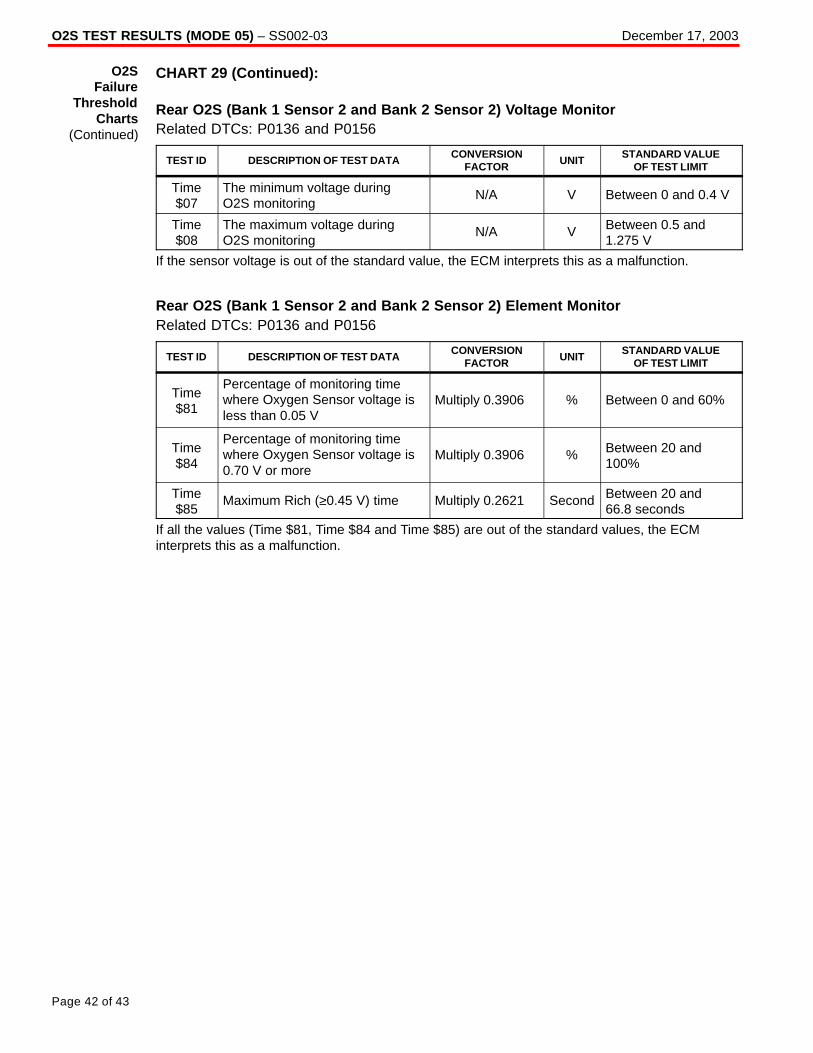
O2S TEST RESULTS (MODE 05) – SS002-03 December 17, 2003
Page 42 of 43
CHART 29 (Continued):
Rear O2S (Bank 1 Sensor 2 and Bank 2 Sensor 2) Voltage MonitorRelated DTCs: P0136 and P0156
TEST ID DESCRIPTION OF TEST DATACONVERSION
FACTORUNIT
STANDARD VALUEOF TEST LIMIT
Time$07
The minimum voltage duringO2S monitoring
N/A V Between 0 and 0.4 V
Time$08
The maximum voltage duringO2S monitoring
N/A V Between 0.5 and1.275 V
If the sensor voltage is out of the standard value, the ECM interprets this as a malfunction.
Rear O2S (Bank 1 Sensor 2 and Bank 2 Sensor 2) Element MonitorRelated DTCs: P0136 and P0156
TEST ID DESCRIPTION OF TEST DATACONVERSION
FACTORUNIT
STANDARD VALUEOF TEST LIMIT
Time$81
Percentage of monitoring timewhere Oxygen Sensor voltage isless than 0.05 V
Multiply 0.3906 % Between 0 and 60%
Time$84
Percentage of monitoring timewhere Oxygen Sensor voltage is0.70 V or more
Multiply 0.3906 % Between 20 and100%
Time$85
Maximum Rich (≥0.45 V) time Multiply 0.2621 Second Between 20 and 66.8 seconds
If all the values (Time $81, Time $84 and Time $85) are out of the standard values, the ECMinterprets this as a malfunction.
O2SFailure
ThresholdCharts
(Continued)

O2S TEST RESULTS (MODE 05) – SS002-03 December 17, 2003
Page 43 of 43
CHART 30:
Rear O2S (Bank 1 Sensor 2 and Bank 2 Sensor 2) Voltage MonitorRelated DTCs: P0136 and P0156
TEST ID DESCRIPTION OF TEST DATACONVERSION
FACTORUNIT
STANDARD VALUEOF TEST LIMIT
Time$07
The minimum voltage duringO2S monitoring
N/A V Between 0 and0.45 V
Time$08
The maximum voltage duringO2S monitoring
N/A V Between 0.5 and1.275 V
If the sensor voltage is out of the standard value, the ECM interprets this as a malfunction.
Rear O2S (Bank 1 Sensor 2 and Bank 2 Sensor 2) Element MonitorRelated DTCs: P0136 and P0156
TEST ID DESCRIPTION OF TEST DATACONVERSION
FACTORUNIT
STANDARD VALUEOF TEST LIMIT
Time$81
Percentage of monitoring timewhere Oxygen Sensor voltage isless than 0.05 V
Multiply 0.3906 % Between 0 and 80%
Time$84
Percentage of monitoring timewhere Oxygen Sensor voltage is0.70 V or more
Multiply 0.3906 % Between 20 and100%
Time$85
Maximum Rich (≥0.45 V) time Multiply 0.2621 Second Between 20 and 66.8 seconds
If all the values (Time $81, Time $84 and Time $85) are out of the standard values, the ECMinterprets this as a malfunction.
O2SFailure
ThresholdCharts
(Continued)
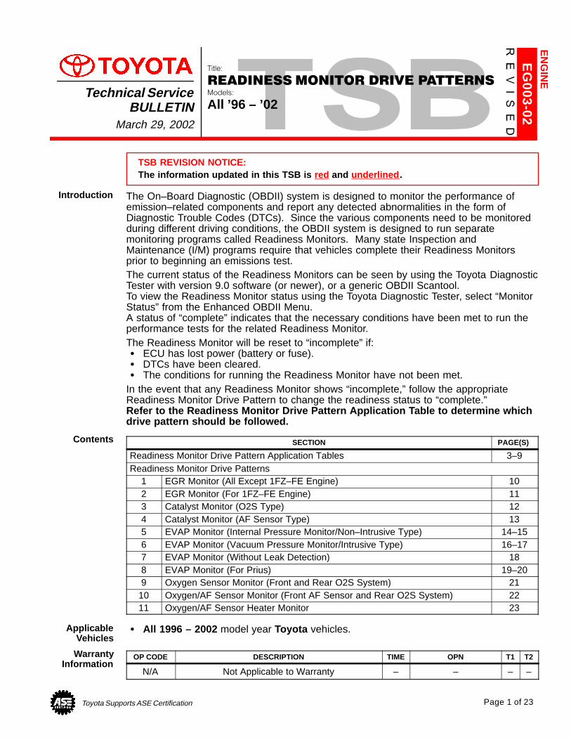
Toyota Supports ASE Certification Page 1 of 23
EG
003-02
Title:
READINESS MONITOR DRIVE PATTERNSModels:
All ’96 – ’02Technical Service
BULLETINMarch 29, 2002
TSB REVISION NOTICE:The information updated in this TSB is red and underlined .
The On–Board Diagnostic (OBDII) system is designed to monitor the performance ofemission–related components and report any detected abnormalities in the form ofDiagnostic Trouble Codes (DTCs). Since the various components need to be monitoredduring different driving conditions, the OBDII system is designed to run separatemonitoring programs called Readiness Monitors. Many state Inspection andMaintenance (I/M) programs require that vehicles complete their Readiness Monitorsprior to beginning an emissions test.The current status of the Readiness Monitors can be seen by using the Toyota DiagnosticTester with version 9.0 software (or newer), or a generic OBDII Scantool. To view the Readiness Monitor status using the Toyota Diagnostic Tester, select “MonitorStatus” from the Enhanced OBDII Menu. A status of “complete” indicates that the necessary conditions have been met to run theperformance tests for the related Readiness Monitor.The Readiness Monitor will be reset to “incomplete” if:� ECU has lost power (battery or fuse).� DTCs have been cleared.� The conditions for running the Readiness Monitor have not been met.
In the event that any Readiness Monitor shows “incomplete,” follow the appropriateReadiness Monitor Drive Pattern to change the readiness status to “complete.” Refer to the Readiness Monitor Drive Pattern Application Table to determine which drive pattern should be followed.
SECTION PAGE(S)
Readiness Monitor Drive Pattern Application Tables 3–9Readiness Monitor Drive Patterns
1 EGR Monitor (All Except 1FZ–FE Engine) 102 EGR Monitor (For 1FZ–FE Engine) 113 Catalyst Monitor (O2S Type) 124 Catalyst Monitor (AF Sensor Type) 135 EVAP Monitor (Internal Pressure Monitor/Non–Intrusive Type) 14–156 EVAP Monitor (Vacuum Pressure Monitor/Intrusive Type) 16–177 EVAP Monitor (Without Leak Detection) 188 EVAP Monitor (For Prius) 19–209 Oxygen Sensor Monitor (Front and Rear O2S System) 21
10 Oxygen/AF Sensor Monitor (Front AF Sensor and Rear O2S System) 2211 Oxygen/AF Sensor Heater Monitor 23
� All 1996 – 2002 model year Toyota vehicles.
OP CODE DESCRIPTION TIME OPN T1 T2
N/A Not Applicable to Warranty – – – –
EN
GIN
E
Introduction
Contents
ApplicableVehicles
WarrantyInformation
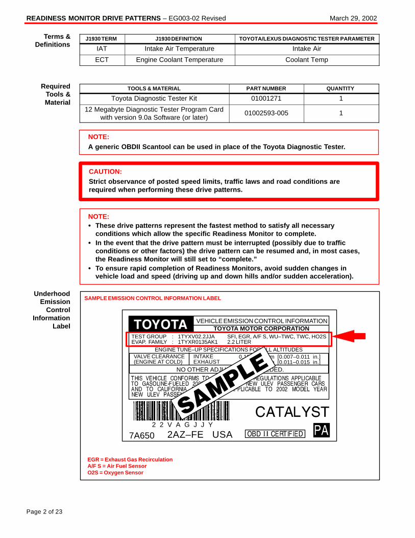
READINESS MONITOR DRIVE PATTERNS – EG003-02 Revised March 29, 2002
Page 2 of 23
J1930 TERM J1930 DEFINITION TOYOTA/LEXUS DIAGNOSTIC TESTER PARAMETER
IAT Intake Air Temperature Intake Air
ECT Engine Coolant Temperature Coolant Temp
TOOLS & MATERIAL PART NUMBER QUANTITY
Toyota Diagnostic Tester Kit 01001271 1
12 Megabyte Diagnostic Tester Program Cardwith version 9.0a Software (or later)
01002593-005 1
NOTE:A generic OBDII Scantool can be used in place of the Toyota Diagnostic Tester.
CAUTION:Strict observance of posted speed limits, traffic laws and road conditions arerequired when performing these drive patterns.
NOTE:� These drive patterns represent the fastest method to satisfy all necessary
conditions which allow the specific Readiness Monitor to complete.� In the event that the drive pattern must be interrupted (possibly due to traffic
conditions or other factors) the drive pattern can be resumed and, in most cases,the Readiness Monitor will still set to “complete.”
� To ensure rapid completion of Readiness Monitors, avoid sudden changes invehicle load and speed (driving up and down hills and/or sudden acceleration).
SAMPLE EMISSION CONTROL INFORMATION LABEL
EGR = Exhaust Gas RecirculationA/F S = Air Fuel SensorO2S = Oxygen Sensor
0.19–0.29 mm [0.007–0.011 in.]0.28–0.38 mm [0.011–0.015 in.]
INTAKEEXHAUST
VALVE CLEARANCE(ENGINE AT COLD)
NO OTHER ADJUSTMENTS NEEDED.
ENGINE TUNE–UP SPECIFICATIONS FOR ALL ALTITUDES
7A6502 2 V A G J J Y
2AZ–FE USA
SFI, EGR, A/F S, WU–TWC, TWC, HO2S2.2 LITER
TEST GROUP : 1TYXV02.2JJAEVAP. FAMILY : 1TYXR0135AK1
TOYOTA MOTOR CORPORATIONVEHICLE EMISSION CONTROL INFORMATION
Terms &Definitions
RequiredTools &Material
UnderhoodEmission
ControlInformation
Label
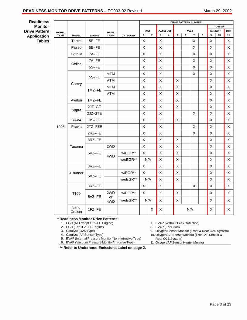
READINESS MONITOR DRIVE PATTERNS – EG003-02 Revised March 29, 2002
Page 3 of 23
DRIVE PATTERN NUMBER*
O2S/AF
MODEL DRIVE EGR CATALYST EVAP SENSOR HTRMODELYEAR MODEL ENGINE
DRIVETRAIN CATEGORY 1 2 3 4 5 6 7 8 9 10 11
Tercel 5E–FE X X X X X
Paseo 5E–FE X X X X X
Corolla 7A–FE X X X X X
Celica7A–FE X X X X X
Celica5S–FE X X X X X
5S FEMTM X X X X X
Camry
5S–FEATM X X X X X
Camry
1MZ FEMTM X X X X X
1MZ–FEATM X X X X X
Avalon 1MZ–FE X X X X X
Supra2JZ–GE X X X X X
Supra2JZ-GTE X X X X X
RAV4 3S–FE X X X X X
1996 Previa 2TZ–FZE X X X X X
2RZ–FE X X X X X
3RZ–FE X X X X X
Tacoma 2WD X X X X X
5VZ–FE4WD
w/EGR** X X X X X4WD
w/oEGR** N/A X X X X
3RZ–FE X X X X X
4Runner5VZ FE
w/EGR** X X X X X5VZ–FE
w/oEGR** N/A X X X X
3RZ–FE X X X X X
T1005VZ FE
2WDor
w/EGR** X X X X X5VZ–FE or
4WD w/oEGR** N/A X X X X
LandCruiser
1FZ–FE X X N/A X X
* Readiness Monitor Drive Patterns:1. EGR (All Except 1FZ–FE Engine)2. EGR (For 1FZ–FE Engine)3. Catalyst (O2S Type)4. Catalyst (AF Sensor Type)5. EVAP (Internal Pressure Monitor/Non–Intrusive Type)6. EVAP (Vacuum Pressure Monitor/Intrusive Type)
7. EVAP (Without Leak Detection)8. EVAP (For Prius)9. Oxygen Sensor Monitor (Front & Rear O2S System)10. Oxygen/AF Sensor Monitor (Front AF Sensor & Rear O2S System)11. Oxygen/AF Sensor Heater Monitor
** Refer to Underhood Emissions Label on page 2.
ReadinessMonitor
Drive PatternApplication
Tables
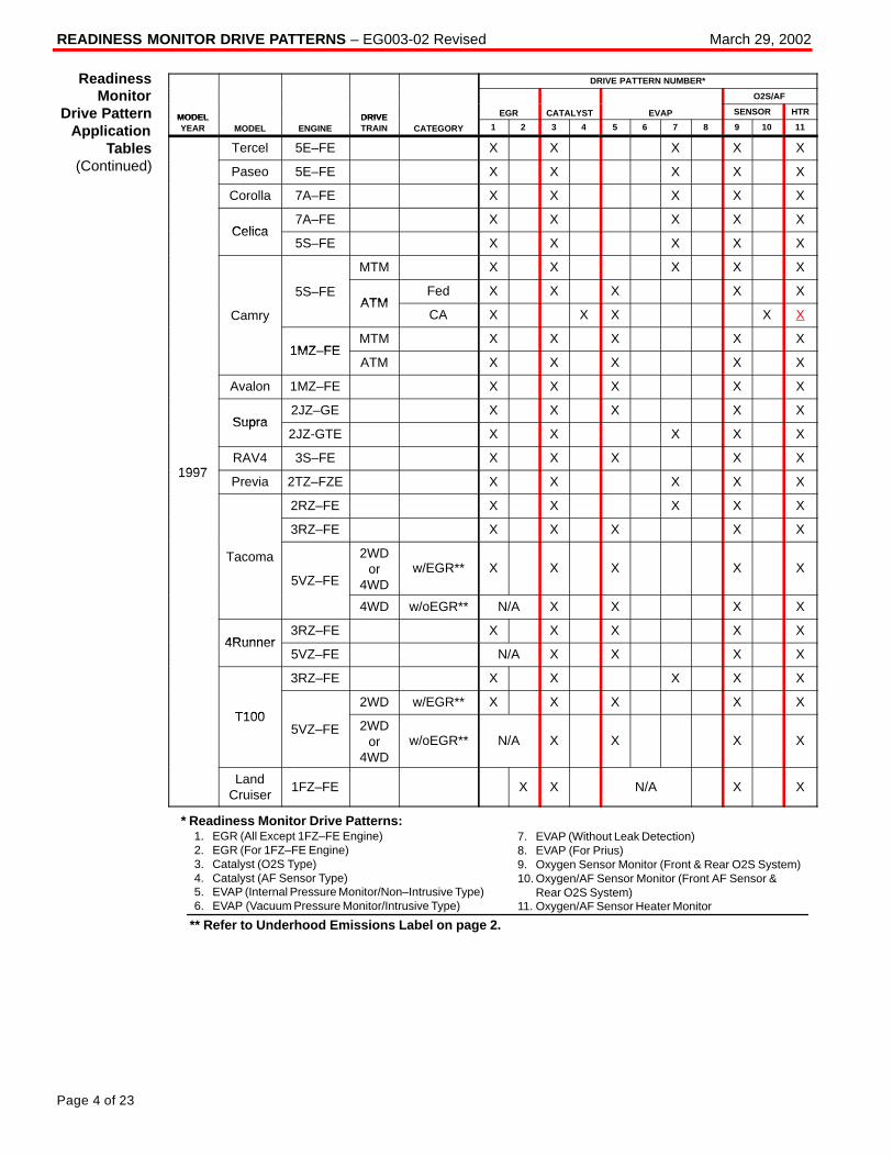
READINESS MONITOR DRIVE PATTERNS – EG003-02 Revised March 29, 2002
Page 4 of 23
DRIVE PATTERN NUMBER*
O2S/AF
MODEL DRIVE EGR CATALYST EVAP SENSOR HTRMODELYEAR MODEL ENGINE
DRIVETRAIN CATEGORY 1 2 3 4 5 6 7 8 9 10 11
Tercel 5E–FE X X X X X
Paseo 5E–FE X X X X X
Corolla 7A–FE X X X X X
Celica7A–FE X X X X X
Celica5S–FE X X X X X
MTM X X X X X
5S–FEATM
Fed X X X X X
CamryATM
CA X X X X Xy
1MZ FEMTM X X X X X
1MZ–FEATM X X X X X
Avalon 1MZ–FE X X X X X
Supra2JZ–GE X X X X X
Supra2JZ-GTE X X X X X
1997RAV4 3S–FE X X X X X
1997Previa 2TZ–FZE X X X X X
2RZ–FE X X X X X
3RZ–FE X X X X X
Tacoma
5VZ–FE
2WDor
4WDw/EGR** X X X X X
4WD w/oEGR** N/A X X X X
4Runner3RZ–FE X X X X X
4Runner5VZ–FE N/A X X X X
3RZ–FE X X X X X
T1002WD w/EGR** X X X X X
T1005VZ–FE 2WD
or4WD
w/oEGR** N/A X X X X
LandCruiser
1FZ–FE X X N/A X X
* Readiness Monitor Drive Patterns:1. EGR (All Except 1FZ–FE Engine)2. EGR (For 1FZ–FE Engine)3. Catalyst (O2S Type)4. Catalyst (AF Sensor Type)5. EVAP (Internal Pressure Monitor/Non–Intrusive Type)6. EVAP (Vacuum Pressure Monitor/Intrusive Type)
7. EVAP (Without Leak Detection)8. EVAP (For Prius)9. Oxygen Sensor Monitor (Front & Rear O2S System)10. Oxygen/AF Sensor Monitor (Front AF Sensor & Rear O2S System)11. Oxygen/AF Sensor Heater Monitor
** Refer to Underhood Emissions Label on page 2.
ReadinessMonitor
Drive PatternApplication
Tables(Continued)
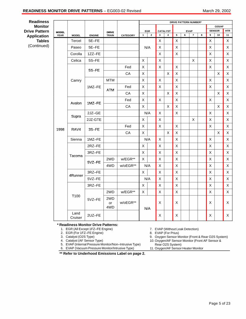
READINESS MONITOR DRIVE PATTERNS – EG003-02 Revised March 29, 2002
Page 5 of 23
DRIVE PATTERN NUMBER*
O2S/AF
MODEL DRIVE EGR CATALYST EVAP SENSOR HTRMODELYEAR MODEL ENGINE
DRIVETRAIN CATEGORY 1 2 3 4 5 6 7 8 9 10 11
Tercel 5E–FE X X X X
Paseo 5E–FE N/A X X X X
Corolla 1ZZ–FE X X X X
Celica 5S–FE X X X X X
5S FEFed X X X X X
5S–FECA X X X X X
Camry MTM X X X X Xy
1MZ–FEATM
Fed X X X X XATM
CA X X X X X
Avalon 1MZ FEFed X X X X X
Avalon 1MZ–FECA X X X X X
Supra2JZ–GE N/A X X X X
Supra2JZ-GTE X X X X X
1998 RAV4 3S FEFed X X X X X
1998 RAV4 3S–FECA X X X X X
Sienna 1MZ–FE N/A X X X X
2RZ–FE X X X X X
Tacoma3RZ–FE X X X X X
Tacoma
5VZ FE2WD w/EGR** X X X X X
5VZ–FE4WD w/oEGR** N/A X X X X
4Runner3RZ–FE X X X X X
4Runner5VZ–FE N/A X X X X
3RZ–FE X X X X X
T1002WD w/EGR** X X X X X
T1005VZ–FE 2WD
or4WD
w/oEGR**
N/A
X X X X
LandCruiser
2UZ–FE
N/A
X X X X
* Readiness Monitor Drive Patterns:1. EGR (All Except 1FZ–FE Engine)2. EGR (For 1FZ–FE Engine)3. Catalyst (O2S Type)4. Catalyst (AF Sensor Type)5. EVAP (Internal Pressure Monitor/Non–Intrusive Type)6. EVAP (Vacuum Pressure Monitor/Intrusive Type)
7. EVAP (Without Leak Detection)8. EVAP (For Prius)9. Oxygen Sensor Monitor (Front & Rear O2S System)10. Oxygen/AF Sensor Monitor (Front AF Sensor & Rear O2S System)11. Oxygen/AF Sensor Heater Monitor
** Refer to Underhood Emissions Label on page 2.
ReadinessMonitor
Drive PatternApplication
Tables(Continued)
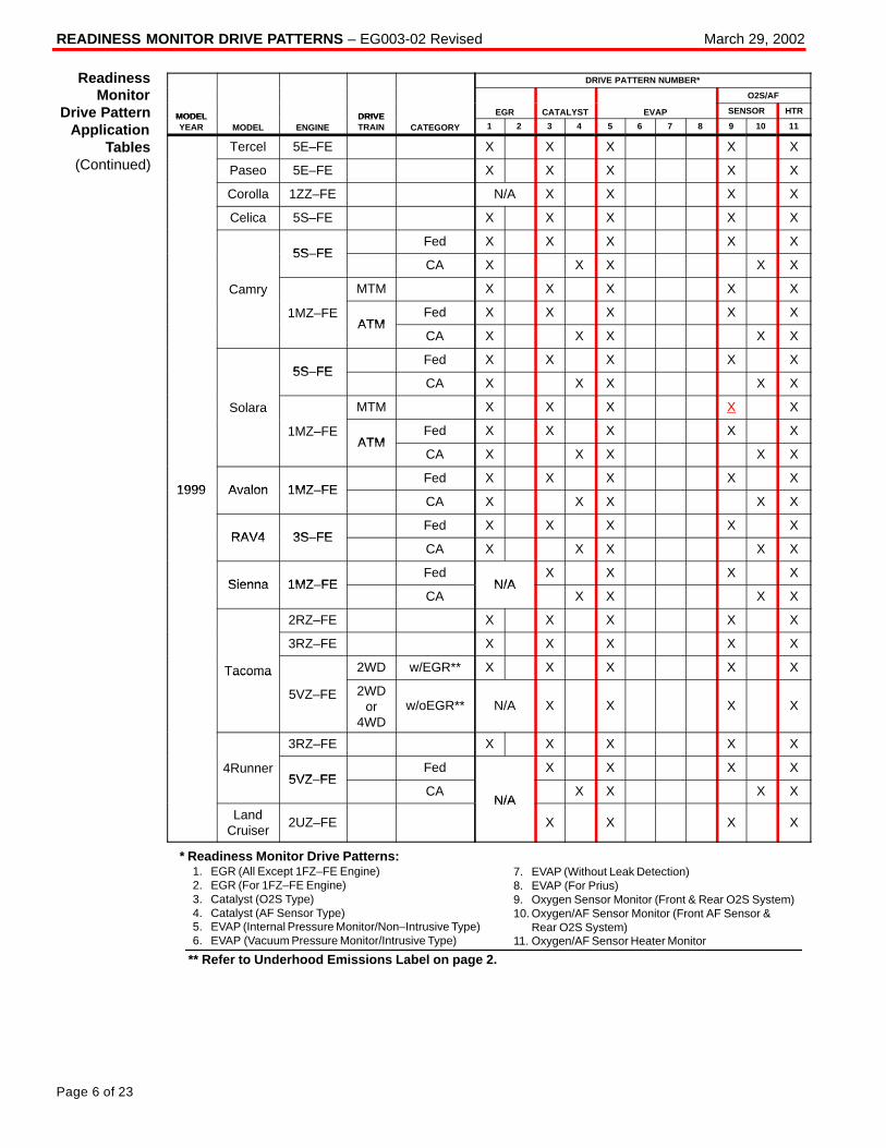
READINESS MONITOR DRIVE PATTERNS – EG003-02 Revised March 29, 2002
Page 6 of 23
DRIVE PATTERN NUMBER*
O2S/AF
MODEL DRIVE EGR CATALYST EVAP SENSOR HTRMODELYEAR MODEL ENGINE
DRIVETRAIN CATEGORY 1 2 3 4 5 6 7 8 9 10 11
Tercel 5E–FE X X X X X
Paseo 5E–FE X X X X X
Corolla 1ZZ–FE N/A X X X X
Celica 5S–FE X X X X X
5S FEFed X X X X X
5S–FECA X X X X X
Camry MTM X X X X Xy
1MZ–FEATM
Fed X X X X XATM
CA X X X X X
5S FEFed X X X X X
5S–FECA X X X X X
Solara MTM X X X X X
1MZ–FEATM
Fed X X X X XATM
CA X X X X X
1999 Avalon 1MZ FEFed X X X X X
1999 Avalon 1MZ–FECA X X X X X
RAV4 3S FEFed X X X X X
RAV4 3S–FECA X X X X X
Sienna 1MZ FEFed
N/AX X X X
Sienna 1MZ–FECA
N/AX X X X
2RZ–FE X X X X X
3RZ–FE X X X X X
Tacoma 2WD w/EGR** X X X X XTacoma
5VZ–FE 2WDor
4WDw/oEGR** N/A X X X X
3RZ–FE X X X X X
4Runner5VZ FE
Fed X X X X5VZ–FE
CAN/A
X X X X
LandCruiser
2UZ–FE
N/A
X X X X
* Readiness Monitor Drive Patterns:1. EGR (All Except 1FZ–FE Engine)2. EGR (For 1FZ–FE Engine)3. Catalyst (O2S Type)4. Catalyst (AF Sensor Type)5. EVAP (Internal Pressure Monitor/Non–Intrusive Type)6. EVAP (Vacuum Pressure Monitor/Intrusive Type)
7. EVAP (Without Leak Detection)8. EVAP (For Prius)9. Oxygen Sensor Monitor (Front & Rear O2S System)10. Oxygen/AF Sensor Monitor (Front AF Sensor & Rear O2S System)11. Oxygen/AF Sensor Heater Monitor
** Refer to Underhood Emissions Label on page 2.
ReadinessMonitor
Drive PatternApplication
Tables(Continued)
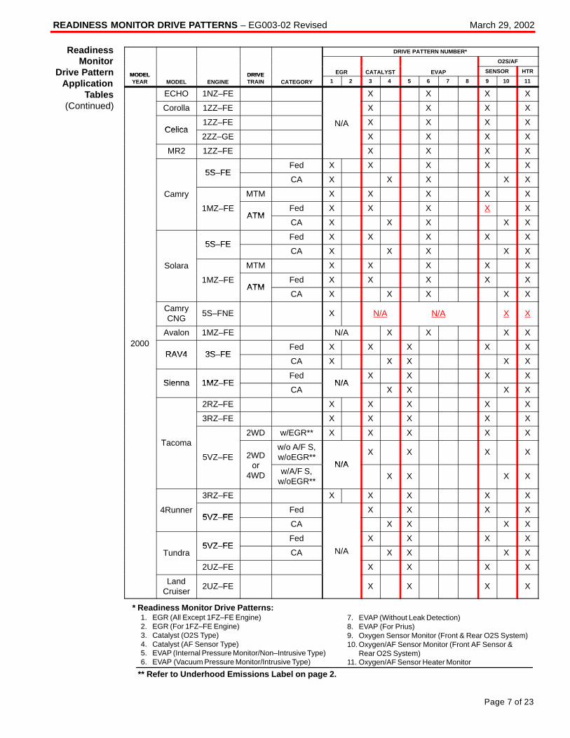
READINESS MONITOR DRIVE PATTERNS – EG003-02 Revised March 29, 2002
Page 7 of 23
DRIVE PATTERN NUMBER*
O2S/AF
MODEL DRIVE EGR CATALYST EVAP SENSOR HTRMODELYEAR MODEL ENGINE
DRIVETRAIN CATEGORY 1 2 3 4 5 6 7 8 9 10 11
ECHO 1NZ–FE X X X X
Corolla 1ZZ–FE X X X X
Celica1ZZ–FE N/A X X X X
Celica2ZZ–GE X X X X
MR2 1ZZ–FE X X X X
5S FEFed X X X X X
5S–FECA X X X X X
Camry MTM X X X X Xy
1MZ–FEATM
Fed X X X X XATM
CA X X X X X
5S FEFed X X X X X
5S–FECA X X X X X
Solara MTM X X X X X
1MZ–FEATM
Fed X X X X XATM
CA X X X X X
CamryCNG
5S–FNE X N/A N/A X X
Avalon 1MZ–FE N/A X X X X2000
RAV4 3S FEFed X X X X X
RAV4 3S–FECA X X X X X
Sienna 1MZ FEFed
N/AX X X X
Sienna 1MZ–FECA
N/AX X X X
2RZ–FE X X X X X
3RZ–FE X X X X X
T2WD w/EGR** X X X X X
Tacoma
5VZ–FE 2WDor
w/o A/F S,w/oEGR**
N/A
X X X X
or4WD w/A/F S,
w/oEGR**
N/AX X X X
3RZ–FE X X X X X
4Runner5VZ FE
Fed X X X X5VZ–FE
CA X X X X
5VZ FEFed X X X X
Tundra5VZ–FE
CA N/A X X X X
2UZ–FE X X X X
LandCruiser
2UZ–FE X X X X
* Readiness Monitor Drive Patterns:1. EGR (All Except 1FZ–FE Engine)2. EGR (For 1FZ–FE Engine)3. Catalyst (O2S Type)4. Catalyst (AF Sensor Type)5. EVAP (Internal Pressure Monitor/Non–Intrusive Type)6. EVAP (Vacuum Pressure Monitor/Intrusive Type)
7. EVAP (Without Leak Detection)8. EVAP (For Prius)9. Oxygen Sensor Monitor (Front & Rear O2S System)10. Oxygen/AF Sensor Monitor (Front AF Sensor & Rear O2S System)11. Oxygen/AF Sensor Heater Monitor
** Refer to Underhood Emissions Label on page 2.
ReadinessMonitor
Drive PatternApplication
Tables(Continued)
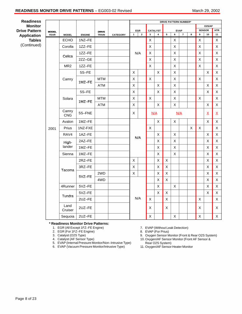
READINESS MONITOR DRIVE PATTERNS – EG003-02 Revised March 29, 2002
Page 8 of 23
DRIVE PATTERN NUMBER*
O2S/AF
MODEL DRIVE EGR CATALYST EVAP SENSOR HTRMODELYEAR MODEL ENGINE
DRIVETRAIN CATEGORY 1 2 3 4 5 6 7 8 9 10 11
ECHO 1NZ–FE X X X X
Corolla 1ZZ–FE X X X X
Celica1ZZ–FE N/A X X X X
Celica2ZZ–GE X X X X
MR2 1ZZ–FE X X X X
5S–FE X X X X X
Camry1MZ FE
MTM X X X X Xy1MZ–FE
ATM X X X X X
5S–FE X X X X X
Solara1MZ FE
MTM X X X X X1MZ–FE
ATM X X X X X
CamryCNG
5S–FNE X N/A N/A X X
Avalon 1MZ–FE X X X X
2001 Prius 1NZ-FXE X X X X
RAV4 1AZ–FEN/A
X X X X
High- 2AZ–FEN/A
X X X XHighlander 1MZ–FE X X X X
Sienna 1MZ–FE X X X X
2RZ–FE X X X X X
Tacoma3RZ–FE X X X X X
Tacoma
5VZ FE2WD X X X X X
5VZ–FE4WD X X X X
4Runner 5VZ–FE X X X X
Tundra5VZ–FE X X X X
Tundra2UZ–FE N/A X X X X
LandCruiser
2UZ–FE X X X X
Sequoia 2UZ–FE X X X X
* Readiness Monitor Drive Patterns:1. EGR (All Except 1FZ–FE Engine)2. EGR (For 1FZ–FE Engine)3. Catalyst (O2S Type)4. Catalyst (AF Sensor Type)5. EVAP (Internal Pressure Monitor/Non–Intrusive Type)6. EVAP (Vacuum Pressure Monitor/Intrusive Type)
7. EVAP (Without Leak Detection)8. EVAP (For Prius)9. Oxygen Sensor Monitor (Front & Rear O2S System)10. Oxygen/AF Sensor Monitor (Front AF Sensor & Rear O2S System)11. Oxygen/AF Sensor Heater Monitor
ReadinessMonitor
Drive PatternApplication
Tables(Continued)
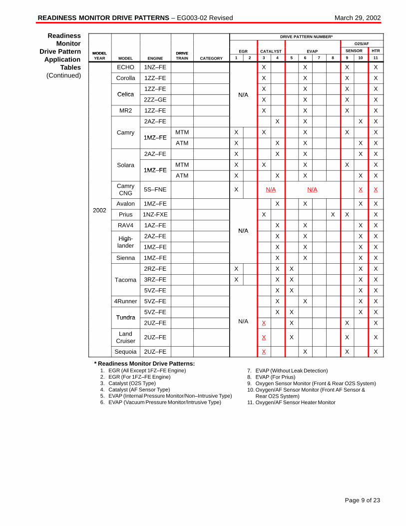
READINESS MONITOR DRIVE PATTERNS – EG003-02 Revised March 29, 2002
Page 9 of 23
DRIVE PATTERN NUMBER*
O2S/AF
MODEL DRIVE EGR CATALYST EVAP SENSOR HTRMODELYEAR MODEL ENGINE
DRIVETRAIN CATEGORY 1 2 3 4 5 6 7 8 9 10 11
ECHO 1NZ–FE X X X X
Corolla 1ZZ–FE X X X X
Celica1ZZ–FE
N/AX X X X
Celica2ZZ–GE
N/AX X X X
MR2 1ZZ–FE X X X X
2AZ–FE X X X X
Camry1MZ FE
MTM X X X X Xy1MZ–FE
ATM X X X X X
2AZ–FE X X X X X
Solara1MZ FE
MTM X X X X X1MZ–FE
ATM X X X X X
CamryCNG
5S–FNE X N/A N/A X X
2002Avalon 1MZ–FE X X X X
2002Prius 1NZ-FXE X X X X
RAV4 1AZ–FEN/A
X X X X
High- 2AZ–FEN/A
X X X XHighlander 1MZ–FE X X X X
Sienna 1MZ–FE X X X X
2RZ–FE X X X X X
Tacoma 3RZ–FE X X X X X
5VZ–FE X X X X
4Runner 5VZ–FE X X X X
Tundra5VZ–FE X X X X
Tundra2UZ–FE N/A X X X X
LandCruiser
2UZ–FE X X X X
Sequoia 2UZ–FE X X X X
* Readiness Monitor Drive Patterns:1. EGR (All Except 1FZ–FE Engine)2. EGR (For 1FZ–FE Engine)3. Catalyst (O2S Type)4. Catalyst (AF Sensor Type)5. EVAP (Internal Pressure Monitor/Non–Intrusive Type)6. EVAP (Vacuum Pressure Monitor/Intrusive Type)
7. EVAP (Without Leak Detection)8. EVAP (For Prius)9. Oxygen Sensor Monitor (Front & Rear O2S System)10. Oxygen/AF Sensor Monitor (Front AF Sensor & Rear O2S System)11. Oxygen/AF Sensor Heater Monitor
ReadinessMonitor
Drive PatternApplication
Tables(Continued)
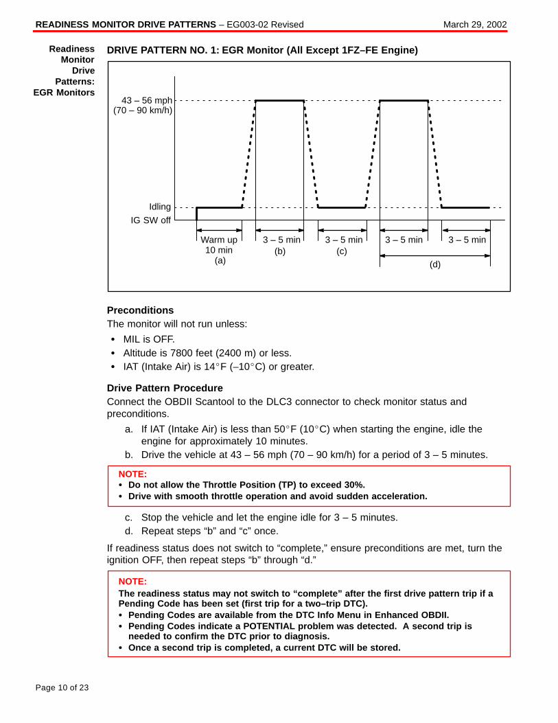
READINESS MONITOR DRIVE PATTERNS – EG003-02 Revised March 29, 2002
Page 10 of 23
DRIVE PATTERN NO. 1: EGR Monitor (All Except 1FZ–FE Engine)
Warm up10 min
43 – 56 mph(70 – 90 km/h)
Idling
IG SW off
3 – 5 min 3 – 5 min3 – 5 min(b)
3 – 5 min(c)
(d)(a)
PreconditionsThe monitor will not run unless:
� MIL is OFF.� Altitude is 7800 feet (2400 m) or less.� IAT (Intake Air) is 14�F (–10�C) or greater.
Drive Pattern ProcedureConnect the OBDII Scantool to the DLC3 connector to check monitor status andpreconditions.
a. If IAT (Intake Air) is less than 50�F (10�C) when starting the engine, idle theengine for approximately 10 minutes.
b. Drive the vehicle at 43 – 56 mph (70 – 90 km/h) for a period of 3 – 5 minutes.
NOTE:� Do not allow the Throttle Position (TP) to exceed 30%.� Drive with smooth throttle operation and avoid sudden acceleration.
c. Stop the vehicle and let the engine idle for 3 – 5 minutes.d. Repeat steps “b” and “c” once.
If readiness status does not switch to “complete,” ensure preconditions are met, turn theignition OFF, then repeat steps “b” through “d.”
NOTE:The readiness status may not switch to “complete” after the first drive pattern trip if aPending Code has been set (first trip for a two–trip DTC).� Pending Codes are available from the DTC Info Menu in Enhanced OBDII.� Pending Codes indicate a POTENTIAL problem was detected. A second trip is
needed to confirm the DTC prior to diagnosis.� Once a second trip is completed, a current DTC will be stored.
ReadinessMonitor
DrivePatterns:
EGR Monitors
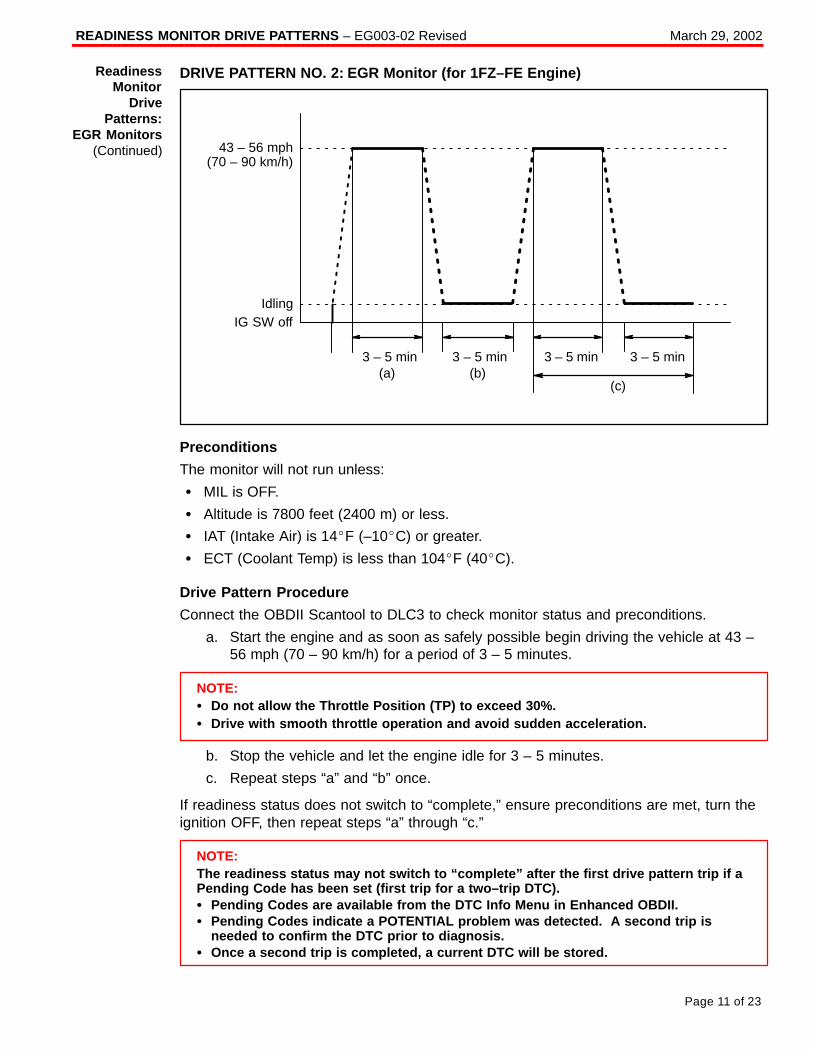
READINESS MONITOR DRIVE PATTERNS – EG003-02 Revised March 29, 2002
Page 11 of 23
DRIVE PATTERN NO. 2: EGR Monitor (for 1FZ–FE Engine)
43 – 56 mph(70 – 90 km/h)
IdlingIG SW off
3 – 5 min 3 – 5 min3 – 5 min(b)
3 – 5 min
(c)(a)
Preconditions
The monitor will not run unless:
� MIL is OFF.
� Altitude is 7800 feet (2400 m) or less.
� IAT (Intake Air) is 14�F (–10�C) or greater.
� ECT (Coolant Temp) is less than 104�F (40�C).
Drive Pattern Procedure
Connect the OBDII Scantool to DLC3 to check monitor status and preconditions.
a. Start the engine and as soon as safely possible begin driving the vehicle at 43 –56 mph (70 – 90 km/h) for a period of 3 – 5 minutes.
NOTE:� Do not allow the Throttle Position (TP) to exceed 30%.� Drive with smooth throttle operation and avoid sudden acceleration.
b. Stop the vehicle and let the engine idle for 3 – 5 minutes.
c. Repeat steps “a” and “b” once.
If readiness status does not switch to “complete,” ensure preconditions are met, turn theignition OFF, then repeat steps “a” through “c.”
NOTE:The readiness status may not switch to “complete” after the first drive pattern trip if aPending Code has been set (first trip for a two–trip DTC).� Pending Codes are available from the DTC Info Menu in Enhanced OBDII.� Pending Codes indicate a POTENTIAL problem was detected. A second trip is
needed to confirm the DTC prior to diagnosis.� Once a second trip is completed, a current DTC will be stored.
ReadinessMonitor
DrivePatterns:
EGR Monitors(Continued)
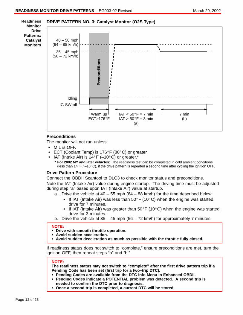
READINESS MONITOR DRIVE PATTERNS – EG003-02 Revised March 29, 2002
Page 12 of 23
DRIVE PATTERN NO. 3: Catalyst Monitor (O2S Type)
40 – 50 mph(64 – 88 km/h)
35 – 45 mph(56 – 72 km/h)
Idling
IG SW off
Warm upECT≥176�F
IAT < 50�F = 7 minIAT > 50�F = 3 min
(a)
7 min(b)
PreconditionsThe monitor will not run unless:� MIL is OFF.� ECT (Coolant Temp) is 176�F (80�C) or greater.� IAT (Intake Air) is 14�F (–10�C) or greater.*
* For 2002 MY and later vehicles: The readiness test can be completed in cold ambient conditions (less than 14�F / –10�C), if the drive pattern is repeated a second time after cycling the ignition OFF.
Drive Pattern ProcedureConnect the OBDII Scantool to DLC3 to check monitor status and preconditions.Note the IAT (Intake Air) value during engine startup. The driving time must be adjustedduring step “a” based upon IAT (Intake Air) value at startup.
a. Drive the vehicle at 40 – 55 mph (64 – 88 km/h) for the time described below:� If IAT (Intake Air) was less than 50�F (10�C) when the engine was started,
drive for 7 minutes.� If IAT (Intake Air) was greater than 50�F (10�C) when the engine was started,
drive for 3 minutes.b. Drive the vehicle at 35 – 45 mph (56 – 72 km/h) for approximately 7 minutes.
NOTE:� Drive with smooth throttle operation.� Avoid sudden acceleration.� Avoid sudden deceleration as much as possible with the throttle fully closed.
If readiness status does not switch to “complete,” ensure preconditions are met, turn theignition OFF, then repeat steps “a” and “b.”
NOTE:The readiness status may not switch to “complete” after the first drive pattern trip if aPending Code has been set (first trip for a two–trip DTC).� Pending Codes are available from the DTC Info Menu in Enhanced OBDII.� Pending Codes indicate a POTENTIAL problem was detected. A second trip is
needed to confirm the DTC prior to diagnosis.� Once a second trip is completed, a current DTC will be stored.
ReadinessMonitor
DrivePatterns:Catalyst
Monitors
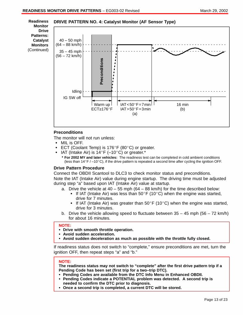
READINESS MONITOR DRIVE PATTERNS – EG003-02 Revised March 29, 2002
Page 13 of 23
DRIVE PATTERN NO. 4: Catalyst Monitor (AF Sensor Type)
IAT<50�F=7minIAT>50�F=3min
(a)
40 – 50 mph(64 – 88 km/h)
Idling
IG SW off
16 min(b)
35 – 45 mph(56 – 72 km/h)
Warm upECT≥176�F
PreconditionsThe monitor will not run unless:� MIL is OFF.� ECT (Coolant Temp) is 176�F (80�C) or greater.� IAT (Intake Air) is 14�F (–10�C) or greater.*
* For 2002 MY and later vehicles: The readiness test can be completed in cold ambient conditions (less than 14�F / –10�C), if the drive pattern is repeated a second time after cycling the ignition OFF.
Drive Pattern ProcedureConnect the OBDII Scantool to DLC3 to check monitor status and preconditions.Note the IAT (Intake Air) value during engine startup. The driving time must be adjustedduring step “a” based upon IAT (Intake Air) value at startup.
a. Drive the vehicle at 40 – 55 mph (64 – 88 km/h) for the time described below:� If IAT (Intake Air) was less than 50�F (10�C) when the engine was started,
drive for 7 minutes.� If IAT (Intake Air) was greater than 50�F (10�C) when the engine was started,
drive for 3 minutes.b. Drive the vehicle allowing speed to fluctuate between 35 – 45 mph (56 – 72 km/h)
for about 16 minutes.
NOTE:� Drive with smooth throttle operation.� Avoid sudden acceleration.� Avoid sudden deceleration as much as possible with the throttle fully closed.
If readiness status does not switch to “complete,” ensure preconditions are met, turn theignition OFF, then repeat steps “a” and “b.”
NOTE:The readiness status may not switch to “complete” after the first drive pattern trip if aPending Code has been set (first trip for a two–trip DTC).� Pending Codes are available from the DTC Info Menu in Enhanced OBDII.� Pending Codes indicate a POTENTIAL problem was detected. A second trip is
needed to confirm the DTC prior to diagnosis.� Once a second trip is completed, a current DTC will be stored.
ReadinessMonitor
DrivePatterns:Catalyst
Monitors(Continued)
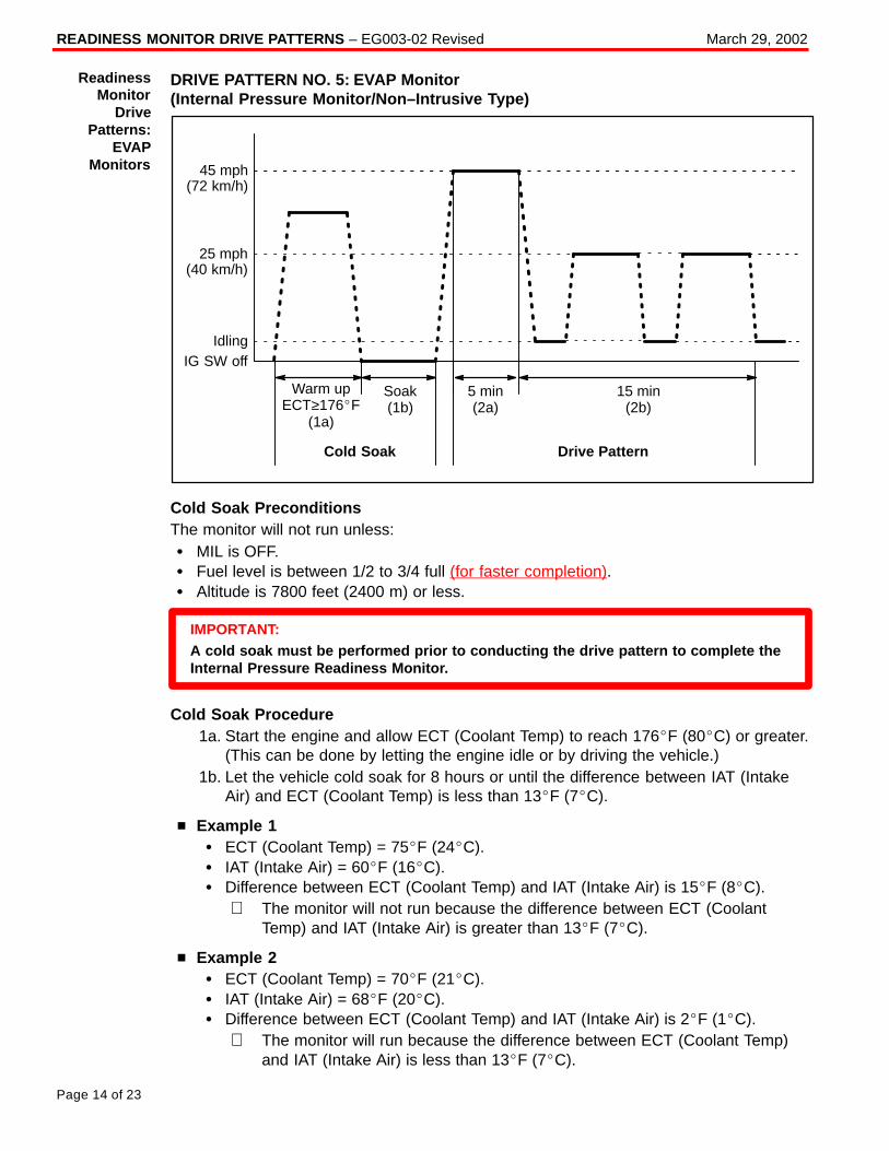
READINESS MONITOR DRIVE PATTERNS – EG003-02 Revised March 29, 2002
Page 14 of 23
DRIVE PATTERN NO. 5: EVAP Monitor (Internal Pressure Monitor/Non–Intrusive Type)
45 mph(72 km/h)
25 mph(40 km/h)
IdlingIG SW off
Soak(1b)
5 min(2a)
15 min(2b)
Warm upECT≥176�F
(1a)
Cold Soak Drive Pattern
Cold Soak PreconditionsThe monitor will not run unless:� MIL is OFF.� Fuel level is between 1/2 to 3/4 full (for faster completion).� Altitude is 7800 feet (2400 m) or less.
IMPORTANT:A cold soak must be performed prior to conducting the drive pattern to complete theInternal Pressure Readiness Monitor.
Cold Soak Procedure1a. Start the engine and allow ECT (Coolant Temp) to reach 176�F (80�C) or greater.
(This can be done by letting the engine idle or by driving the vehicle.)1b. Let the vehicle cold soak for 8 hours or until the difference between IAT (Intake
Air) and ECT (Coolant Temp) is less than 13�F (7�C).
� Example 1� ECT (Coolant Temp) = 75�F (24�C).� IAT (Intake Air) = 60�F (16�C).� Difference between ECT (Coolant Temp) and IAT (Intake Air) is 15�F (8�C).
⇒ The monitor will not run because the difference between ECT (CoolantTemp) and IAT (Intake Air) is greater than 13�F (7�C).
� Example 2� ECT (Coolant Temp) = 70�F (21�C).� IAT (Intake Air) = 68�F (20�C).� Difference between ECT (Coolant Temp) and IAT (Intake Air) is 2�F (1�C).
⇒ The monitor will run because the difference between ECT (Coolant Temp)and IAT (Intake Air) is less than 13�F (7�C).
ReadinessMonitor
DrivePatterns:
EVAPMonitors
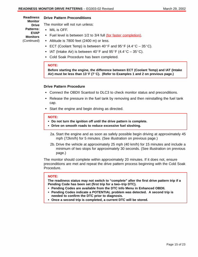
READINESS MONITOR DRIVE PATTERNS – EG003-02 Revised March 29, 2002
Page 15 of 23
Drive Pattern Preconditions
The monitor will not run unless:
� MIL is OFF.
� Fuel level is between 1/2 to 3/4 full (for faster completion).
� Altitude is 7800 feet (2400 m) or less.
� ECT (Coolant Temp) is between 40�F and 95�F (4.4�C – 35�C).
� IAT (Intake Air) is between 40�F and 95�F (4.4�C – 35�C).
� Cold Soak Procedure has been completed.
NOTE:Before starting the engine, the difference between ECT (Coolant Temp) and IAT (IntakeAir) must be less than 13 �F (7�C). (Refer to Examples 1 and 2 on previous page.)
Drive Pattern Procedure
� Connect the OBDII Scantool to DLC3 to check monitor status and preconditions.
� Release the pressure in the fuel tank by removing and then reinstalling the fuel tankcap.
� Start the engine and begin driving as directed.
NOTE:� Do not turn the ignition off until the drive pattern is complete.� Drive on smooth roads to reduce excessive fuel sloshing.
2a. Start the engine and as soon as safely possible begin driving at approximately 45mph (72km/h) for 5 minutes. (See illustration on previous page.)
2b. Drive the vehicle at approximately 25 mph (40 km/h) for 15 minutes and include aminimum of two stops for approximately 30 seconds. (See illustration on previouspage.)
The monitor should complete within approximately 20 minutes. If it does not, ensurepreconditions are met and repeat the drive pattern process beginning with the Cold SoakProcedure.
NOTE:The readiness status may not switch to “complete” after the first drive pattern trip if aPending Code has been set (first trip for a two–trip DTC).� Pending Codes are available from the DTC Info Menu in Enhanced OBDII.� Pending Codes indicate a POTENTIAL problem was detected. A second trip is
needed to confirm the DTC prior to diagnosis.� Once a second trip is completed, a current DTC will be stored.
ReadinessMonitor
DrivePatterns:
EVAPMonitors
(Continued)
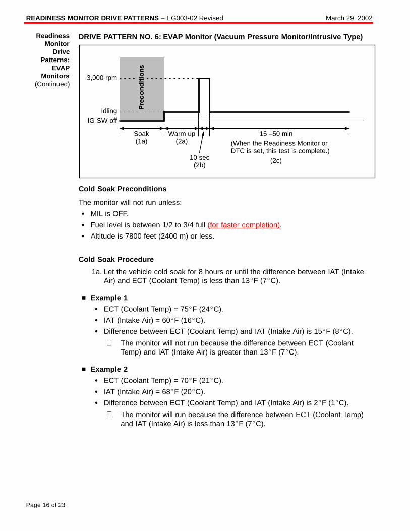
READINESS MONITOR DRIVE PATTERNS – EG003-02 Revised March 29, 2002
Page 16 of 23
DRIVE PATTERN NO. 6: EVAP Monitor (Vacuum Pressure Monitor/Intrusive Type)
IdlingIG SW off
Warm up(2a)
Soak(1a)
15 –50 min(When the Readiness Monitor orDTC is set, this test is complete.)
(2c)10 sec(2b)
3,000 rpm
Cold Soak Preconditions
The monitor will not run unless:
� MIL is OFF.
� Fuel level is between 1/2 to 3/4 full (for faster completion).
� Altitude is 7800 feet (2400 m) or less.
Cold Soak Procedure
1a. Let the vehicle cold soak for 8 hours or until the difference between IAT (IntakeAir) and ECT (Coolant Temp) is less than 13�F (7�C).
� Example 1
� ECT (Coolant Temp) = 75�F (24�C).
� IAT (Intake Air) = 60�F (16�C).
� Difference between ECT (Coolant Temp) and IAT (Intake Air) is 15�F (8�C).
⇒ The monitor will not run because the difference between ECT (CoolantTemp) and IAT (Intake Air) is greater than 13�F (7�C).
� Example 2
� ECT (Coolant Temp) = 70�F (21�C).
� IAT (Intake Air) = 68�F (20�C).
� Difference between ECT (Coolant Temp) and IAT (Intake Air) is 2�F (1�C).
⇒ The monitor will run because the difference between ECT (Coolant Temp)and IAT (Intake Air) is less than 13�F (7�C).
ReadinessMonitor
DrivePatterns:
EVAPMonitors
(Continued)
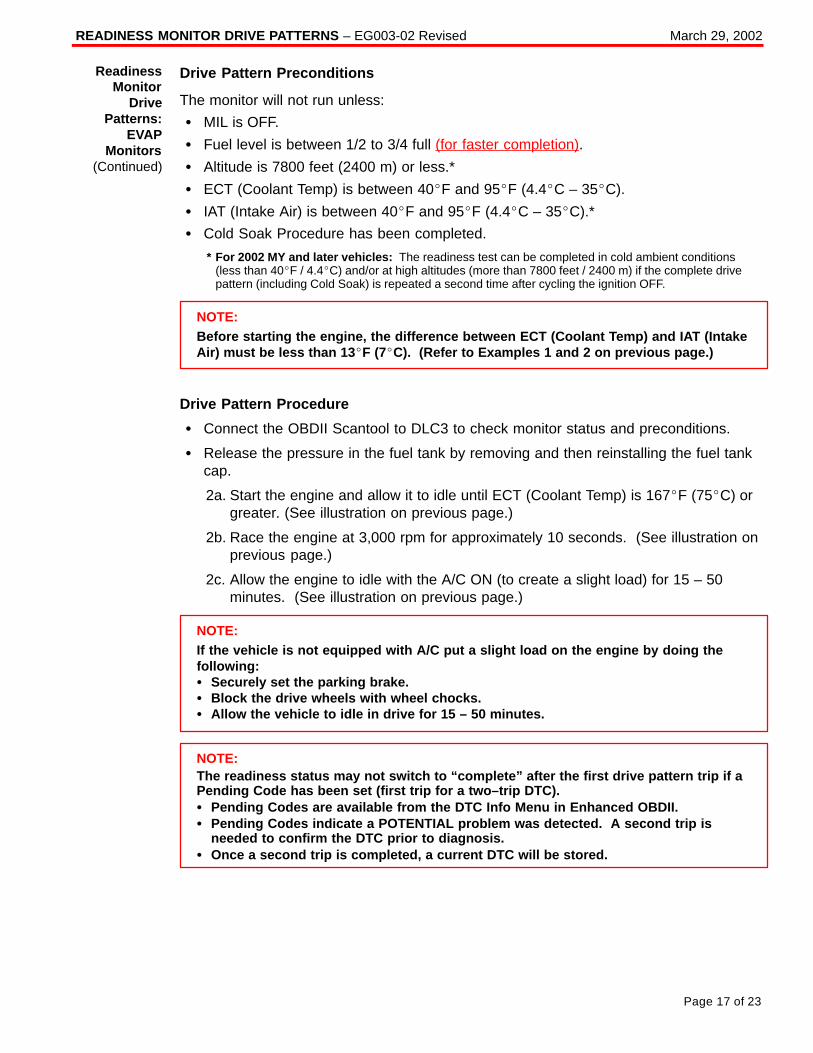
READINESS MONITOR DRIVE PATTERNS – EG003-02 Revised March 29, 2002
Page 17 of 23
Drive Pattern Preconditions
The monitor will not run unless:
� MIL is OFF.
� Fuel level is between 1/2 to 3/4 full (for faster completion).
� Altitude is 7800 feet (2400 m) or less.*
� ECT (Coolant Temp) is between 40�F and 95�F (4.4�C – 35�C).
� IAT (Intake Air) is between 40�F and 95�F (4.4�C – 35�C).*
� Cold Soak Procedure has been completed.
* For 2002 MY and later vehicles: The readiness test can be completed in cold ambient conditions (less than 40�F / 4.4�C) and/or at high altitudes (more than 7800 feet / 2400 m) if the complete drivepattern (including Cold Soak) is repeated a second time after cycling the ignition OFF.
NOTE:Before starting the engine, the difference between ECT (Coolant Temp) and IAT (IntakeAir) must be less than 13 �F (7�C). (Refer to Examples 1 and 2 on previous page.)
Drive Pattern Procedure
� Connect the OBDII Scantool to DLC3 to check monitor status and preconditions.
� Release the pressure in the fuel tank by removing and then reinstalling the fuel tankcap.
2a. Start the engine and allow it to idle until ECT (Coolant Temp) is 167�F (75�C) orgreater. (See illustration on previous page.)
2b. Race the engine at 3,000 rpm for approximately 10 seconds. (See illustration onprevious page.)
2c. Allow the engine to idle with the A/C ON (to create a slight load) for 15 – 50minutes. (See illustration on previous page.)
NOTE:If the vehicle is not equipped with A/C put a slight load on the engine by doing thefollowing:� Securely set the parking brake.� Block the drive wheels with wheel chocks.� Allow the vehicle to idle in drive for 15 – 50 minutes.
NOTE:The readiness status may not switch to “complete” after the first drive pattern trip if aPending Code has been set (first trip for a two–trip DTC).� Pending Codes are available from the DTC Info Menu in Enhanced OBDII.� Pending Codes indicate a POTENTIAL problem was detected. A second trip is
needed to confirm the DTC prior to diagnosis.� Once a second trip is completed, a current DTC will be stored.
ReadinessMonitor
DrivePatterns:
EVAPMonitors
(Continued)
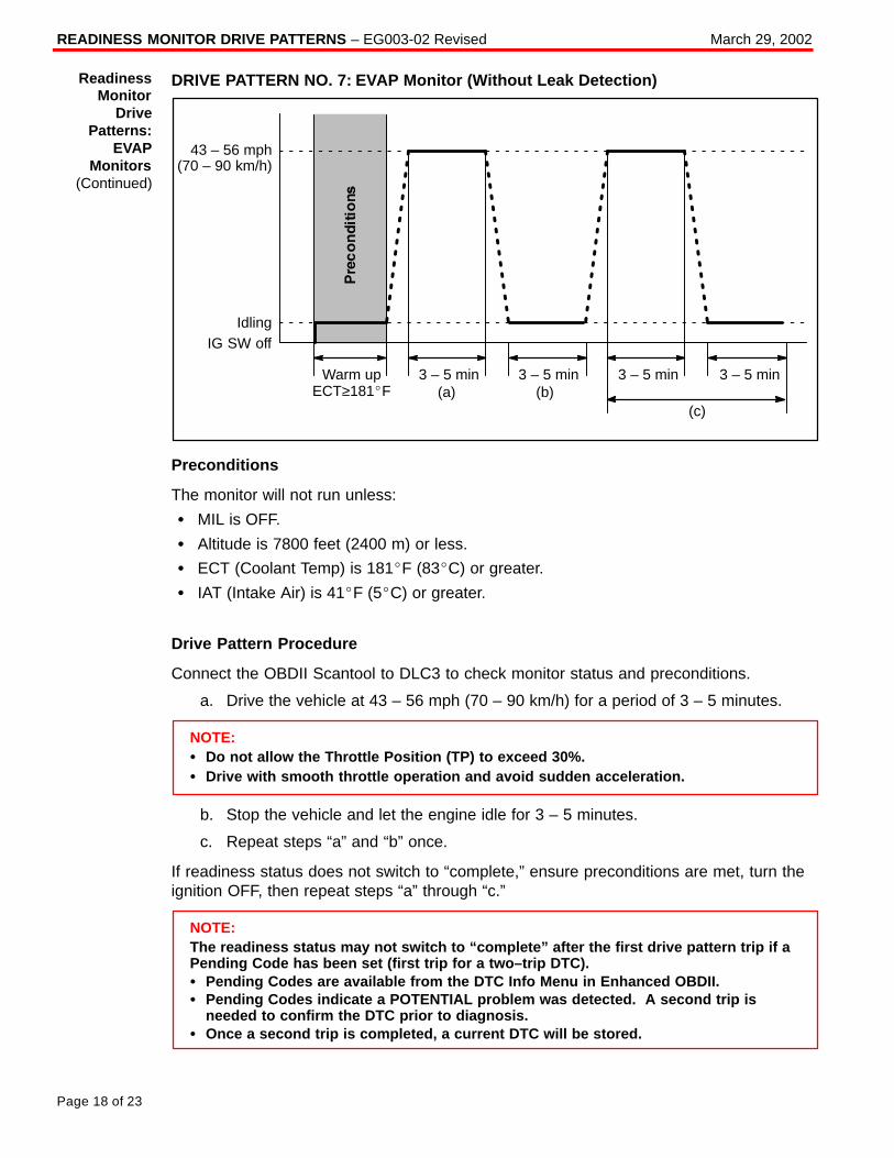
READINESS MONITOR DRIVE PATTERNS – EG003-02 Revised March 29, 2002
Page 18 of 23
DRIVE PATTERN NO. 7: EVAP Monitor (Without Leak Detection)
43 – 56 mph(70 – 90 km/h)
IdlingIG SW off
3 – 5 min 3 – 5 min3 – 5 min(a) (b)
3 – 5 min
(c)
Warm upECT≥181�F
Preconditions
The monitor will not run unless:
� MIL is OFF.
� Altitude is 7800 feet (2400 m) or less.
� ECT (Coolant Temp) is 181�F (83�C) or greater.
� IAT (Intake Air) is 41�F (5�C) or greater.
Drive Pattern Procedure
Connect the OBDII Scantool to DLC3 to check monitor status and preconditions.
a. Drive the vehicle at 43 – 56 mph (70 – 90 km/h) for a period of 3 – 5 minutes.
NOTE:� Do not allow the Throttle Position (TP) to exceed 30%.� Drive with smooth throttle operation and avoid sudden acceleration.
b. Stop the vehicle and let the engine idle for 3 – 5 minutes.
c. Repeat steps “a” and “b” once.
If readiness status does not switch to “complete,” ensure preconditions are met, turn theignition OFF, then repeat steps “a” through “c.”
NOTE:The readiness status may not switch to “complete” after the first drive pattern trip if aPending Code has been set (first trip for a two–trip DTC).� Pending Codes are available from the DTC Info Menu in Enhanced OBDII.� Pending Codes indicate a POTENTIAL problem was detected. A second trip is
needed to confirm the DTC prior to diagnosis.� Once a second trip is completed, a current DTC will be stored.
ReadinessMonitor
DrivePatterns:
EVAPMonitors
(Continued)
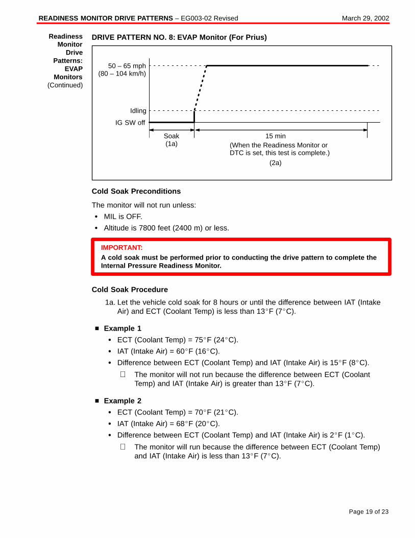
READINESS MONITOR DRIVE PATTERNS – EG003-02 Revised March 29, 2002
Page 19 of 23
DRIVE PATTERN NO. 8: EVAP Monitor (For Prius)
Idling
IG SW off
Soak(1a)
15 min(When the Readiness Monitor orDTC is set, this test is complete.)
(2a)
50 – 65 mph(80 – 104 km/h)
Cold Soak Preconditions
The monitor will not run unless:
� MIL is OFF.
� Altitude is 7800 feet (2400 m) or less.
IMPORTANT:A cold soak must be performed prior to conducting the drive pattern to complete theInternal Pressure Readiness Monitor.
Cold Soak Procedure
1a. Let the vehicle cold soak for 8 hours or until the difference between IAT (IntakeAir) and ECT (Coolant Temp) is less than 13�F (7�C).
� Example 1
� ECT (Coolant Temp) = 75�F (24�C).
� IAT (Intake Air) = 60�F (16�C).
� Difference between ECT (Coolant Temp) and IAT (Intake Air) is 15�F (8�C).
⇒ The monitor will not run because the difference between ECT (CoolantTemp) and IAT (Intake Air) is greater than 13�F (7�C).
� Example 2
� ECT (Coolant Temp) = 70�F (21�C).
� IAT (Intake Air) = 68�F (20�C).
� Difference between ECT (Coolant Temp) and IAT (Intake Air) is 2�F (1�C).
⇒ The monitor will run because the difference between ECT (Coolant Temp)and IAT (Intake Air) is less than 13�F (7�C).
ReadinessMonitor
DrivePatterns:
EVAPMonitors
(Continued)
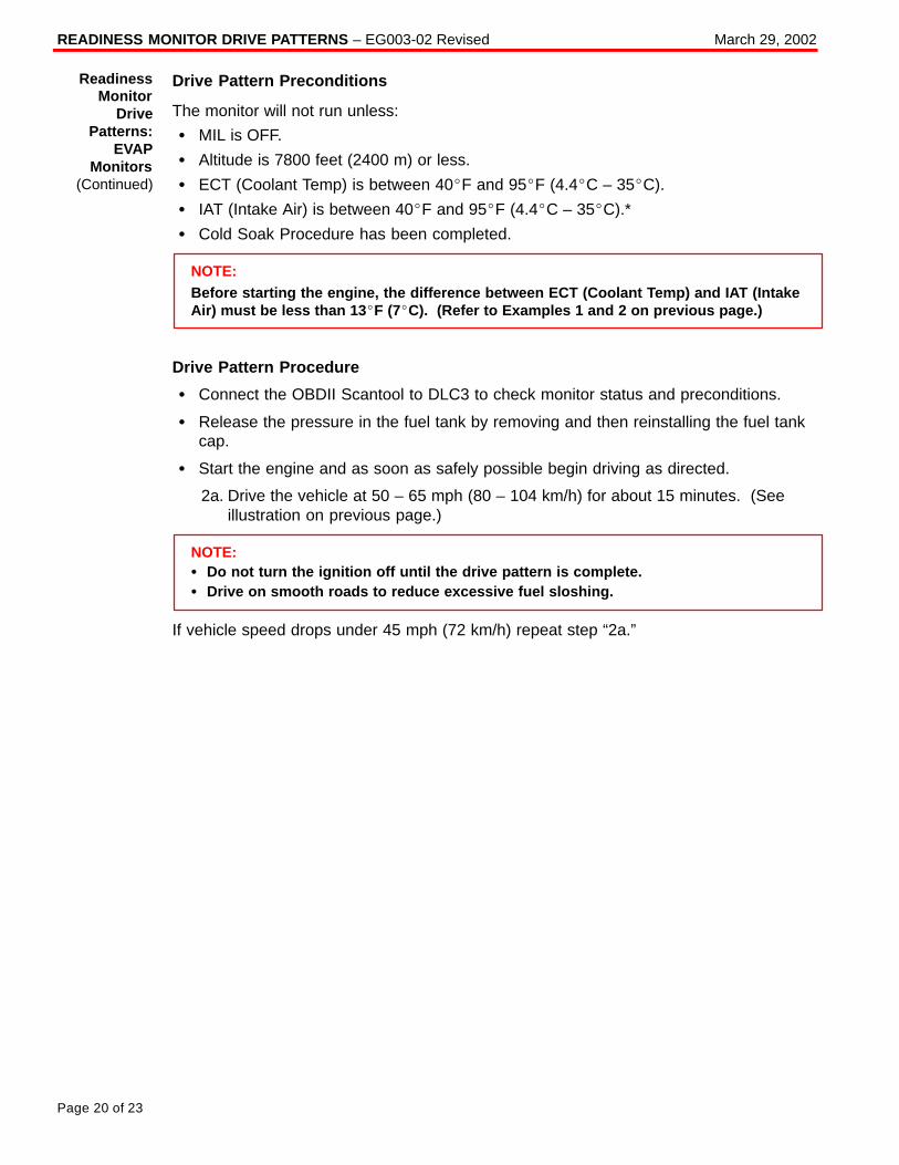
READINESS MONITOR DRIVE PATTERNS – EG003-02 Revised March 29, 2002
Page 20 of 23
Drive Pattern Preconditions
The monitor will not run unless:
� MIL is OFF.
� Altitude is 7800 feet (2400 m) or less.
� ECT (Coolant Temp) is between 40�F and 95�F (4.4�C – 35�C).
� IAT (Intake Air) is between 40�F and 95�F (4.4�C – 35�C).*
� Cold Soak Procedure has been completed.
NOTE:Before starting the engine, the difference between ECT (Coolant Temp) and IAT (IntakeAir) must be less than 13 �F (7�C). (Refer to Examples 1 and 2 on previous page.)
Drive Pattern Procedure
� Connect the OBDII Scantool to DLC3 to check monitor status and preconditions.
� Release the pressure in the fuel tank by removing and then reinstalling the fuel tankcap.
� Start the engine and as soon as safely possible begin driving as directed.
2a. Drive the vehicle at 50 – 65 mph (80 – 104 km/h) for about 15 minutes. (Seeillustration on previous page.)
NOTE:� Do not turn the ignition off until the drive pattern is complete.� Drive on smooth roads to reduce excessive fuel sloshing.
If vehicle speed drops under 45 mph (72 km/h) repeat step “2a.”
ReadinessMonitor
DrivePatterns:
EVAPMonitors
(Continued)
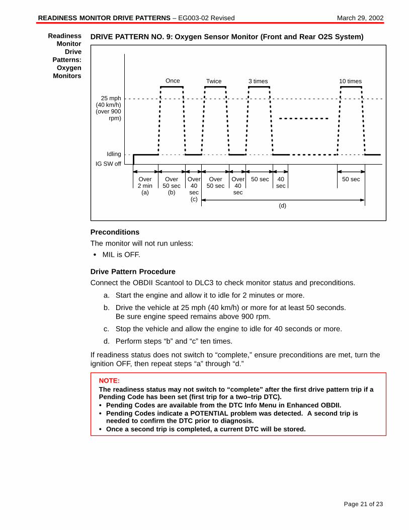
READINESS MONITOR DRIVE PATTERNS – EG003-02 Revised March 29, 2002
Page 21 of 23
DRIVE PATTERN NO. 9: Oxygen Sensor Monitor (Front and Rear O2S System)
Once Twice 3 times 10 times
25 mph(40 km/h)(over 900
rpm)
Idling
IG SW off
Over2 min
(a)
Over50 sec
Over50 sec
(b)
50 sec 50 secOver40sec(c)
Over40sec
40sec
(d)
Preconditions
The monitor will not run unless:
� MIL is OFF.
Drive Pattern Procedure
Connect the OBDII Scantool to DLC3 to check monitor status and preconditions.
a. Start the engine and allow it to idle for 2 minutes or more.
b. Drive the vehicle at 25 mph (40 km/h) or more for at least 50 seconds. Be sure engine speed remains above 900 rpm.
c. Stop the vehicle and allow the engine to idle for 40 seconds or more.
d. Perform steps “b” and “c” ten times.
If readiness status does not switch to “complete,” ensure preconditions are met, turn theignition OFF, then repeat steps “a” through “d.”
NOTE:The readiness status may not switch to “complete” after the first drive pattern trip if aPending Code has been set (first trip for a two–trip DTC).� Pending Codes are available from the DTC Info Menu in Enhanced OBDII.� Pending Codes indicate a POTENTIAL problem was detected. A second trip is
needed to confirm the DTC prior to diagnosis.� Once a second trip is completed, a current DTC will be stored.
ReadinessMonitor
DrivePatterns:
OxygenMonitors
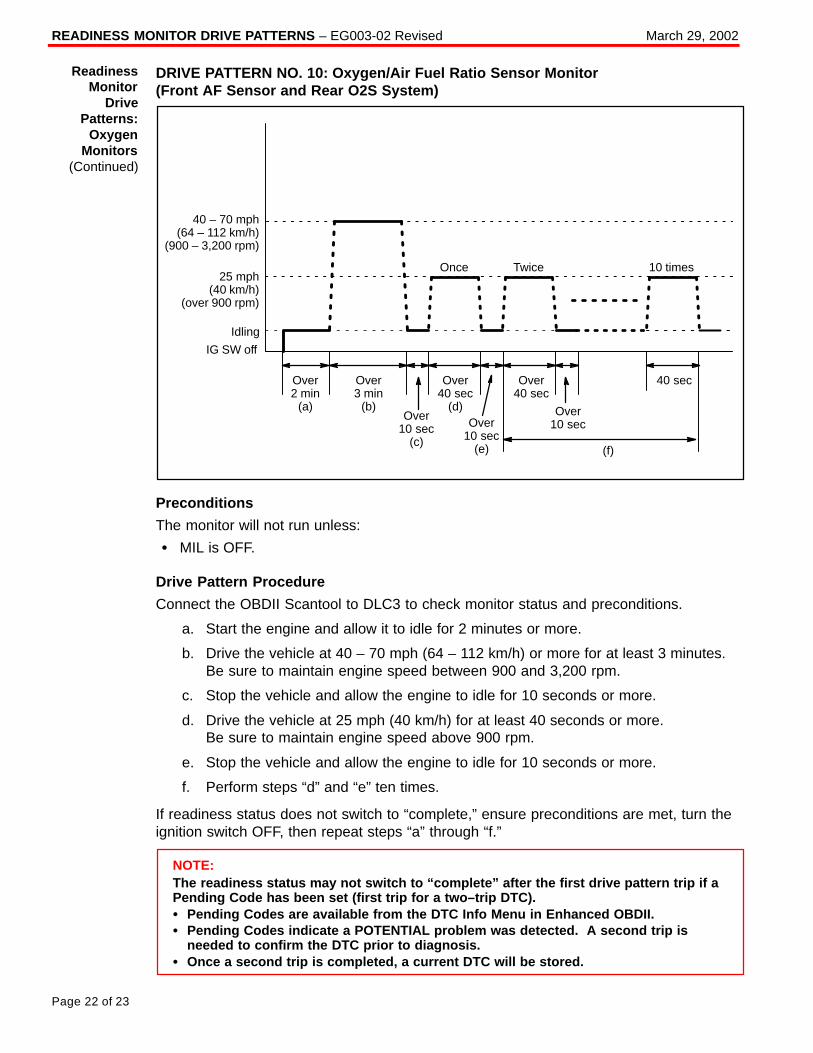
READINESS MONITOR DRIVE PATTERNS – EG003-02 Revised March 29, 2002
Page 22 of 23
DRIVE PATTERN NO. 10: Oxygen/Air Fuel Ratio Sensor Monitor (Front AF Sensor and Rear O2S System)
40 – 70 mph(64 – 112 km/h)
(900 – 3,200 rpm)
Idling
IG SW off
Once Twice 10 times
Over2 min
(a)
Over40 sec
(d)
25 mph(40 km/h)
(over 900 rpm)
Over3 min
(b)Over
10 sec(c)
Over10 sec
(e)
Over40 sec
Over10 sec
40 sec
(f)
Preconditions
The monitor will not run unless:
� MIL is OFF.
Drive Pattern Procedure
Connect the OBDII Scantool to DLC3 to check monitor status and preconditions.
a. Start the engine and allow it to idle for 2 minutes or more.
b. Drive the vehicle at 40 – 70 mph (64 – 112 km/h) or more for at least 3 minutes. Be sure to maintain engine speed between 900 and 3,200 rpm.
c. Stop the vehicle and allow the engine to idle for 10 seconds or more.
d. Drive the vehicle at 25 mph (40 km/h) for at least 40 seconds or more. Be sure to maintain engine speed above 900 rpm.
e. Stop the vehicle and allow the engine to idle for 10 seconds or more.
f. Perform steps “d” and “e” ten times.
If readiness status does not switch to “complete,” ensure preconditions are met, turn theignition switch OFF, then repeat steps “a” through “f.”
NOTE:The readiness status may not switch to “complete” after the first drive pattern trip if aPending Code has been set (first trip for a two–trip DTC).� Pending Codes are available from the DTC Info Menu in Enhanced OBDII.� Pending Codes indicate a POTENTIAL problem was detected. A second trip is
needed to confirm the DTC prior to diagnosis.� Once a second trip is completed, a current DTC will be stored.
ReadinessMonitor
DrivePatterns:
OxygenMonitors
(Continued)
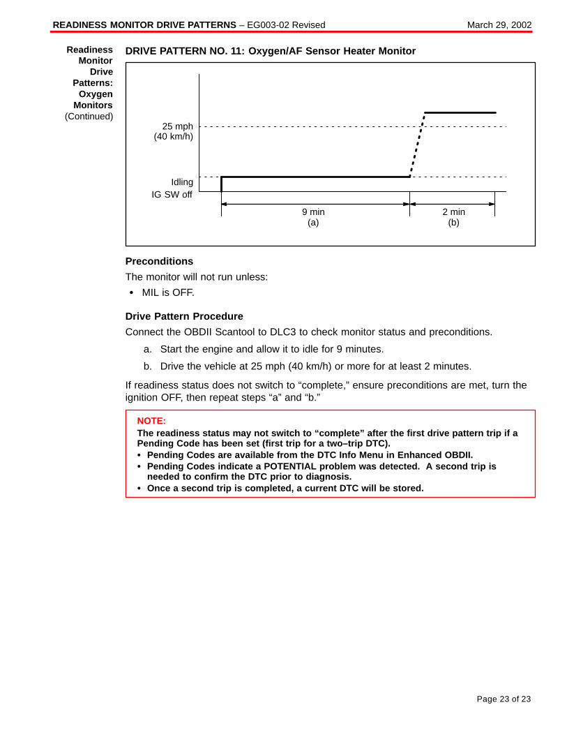
READINESS MONITOR DRIVE PATTERNS – EG003-02 Revised March 29, 2002
Page 23 of 23
DRIVE PATTERN NO. 11: Oxygen/AF Sensor Heater Monitor
IdlingIG SW off
2 min(b)
9 min(a)
25 mph(40 km/h)
Preconditions
The monitor will not run unless:
� MIL is OFF.
Drive Pattern Procedure
Connect the OBDII Scantool to DLC3 to check monitor status and preconditions.
a. Start the engine and allow it to idle for 9 minutes.
b. Drive the vehicle at 25 mph (40 km/h) or more for at least 2 minutes.
If readiness status does not switch to “complete,” ensure preconditions are met, turn theignition OFF, then repeat steps “a” and “b.”
NOTE:The readiness status may not switch to “complete” after the first drive pattern trip if aPending Code has been set (first trip for a two–trip DTC).� Pending Codes are available from the DTC Info Menu in Enhanced OBDII.� Pending Codes indicate a POTENTIAL problem was detected. A second trip is
needed to confirm the DTC prior to diagnosis.� Once a second trip is completed, a current DTC will be stored.
ReadinessMonitor
DrivePatterns:
OxygenMonitors
(Continued)
Toyota Supports ASE Certification Page 1 of 1
EG
003-03
Title:
SULFUR ODOR FROM EXHAUSTModels:
All ModelsTechnical Service
BULLETINFebruary 24, 2003
Some owners of Toyota vehicles may experience a sulfur–like or “rotten egg” odor fromthe exhaust system. Sulfur is a natural component of crude oil from which gasoline isrefined and the amount of sulfur can be decreased through the refining process. Theamount of sulfur in fuel sold in California is regulated, however gasoline sold in otherstates can have substantially higher sulfur content. Sulfur content also variesconsiderably between gasoline brands and locations.
� All Models .
A sulfur odor emitted from the vehicle’s tailpipe does not necessarily indicate that there isan issue with the engine’s running condition, but is most likely directly related to the fuel.If the vehicle is exhibiting an excessive sulfur odor, the following checks should beperformed:
� If the MIL light is ON, check for DTCs and repair as necessary.
If no trouble is found after performing the above check, recommend the customer try adifferent source of fuel.
Replacement of oxygen sensors, air/fuel ratio sensors or catalytic converters will notreduce the odor and will therefore not be considered warrantable.
OP CODE DESCRIPTION TIME OFP T1 T2
N/A Not Applicable to Warranty – – – –
EN
GIN
E
Introduction
ApplicableVehicles
RepairProcedure
WarrantyInformation
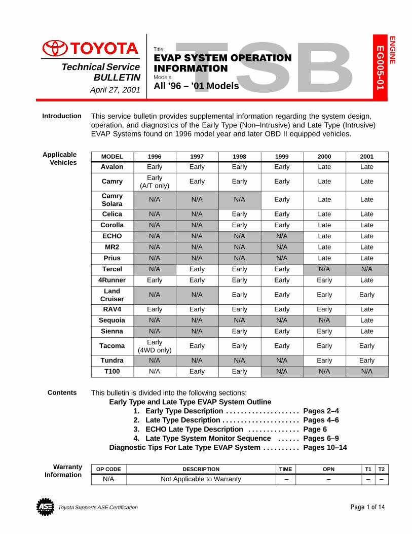
Toyota Supports ASE Certification Page 1 of 14
EG
005-01
Title:
EVAP SYSTEM OPERATION
INFORMATIONModels:
All ’96 – ’01 Models
Technical ServiceBULLETIN
April 27, 2001
This service bulletin provides supplemental information regarding the system design,operation, and diagnostics of the Early Type (Non–Intrusive) and Late Type (Intrusive)EVAP Systems found on 1996 model year and later OBD II equipped vehicles.
MODEL 1996 1997 1998 1999 2000 2001
Avalon Early Early Early Early Late Late
Camry Early(A/T only)
Early Early Early Late Late
CamrySolara
N/A N/A N/A Early Late Late
Celica N/A N/A Early Early Late Late
Corolla N/A N/A Early Early Late Late
ECHO N/A N/A N/A N/A Late Late
MR2 N/A N/A N/A N/A Late Late
Prius N/A N/A N/A N/A Late Late
Tercel N/A Early Early Early N/A N/A
4Runner Early Early Early Early Early Late
LandCruiser
N/A N/A Early Early Early Early
RAV4 Early Early Early Early Early Late
Sequoia N/A N/A N/A N/A N/A Late
Sienna N/A N/A Early Early Early Late
Tacoma Early(4WD only)
Early Early Early Early Early
Tundra N/A N/A N/A N/A Early Early
T100 N/A Early Early N/A N/A N/A
This bulletin is divided into the following sections:Early Type and Late Type EVAP System Outline
1. Early Type Description Pages 2–4. . . . . . . . . . . . . . . . . . . . 2. Late Type Description Pages 4–6. . . . . . . . . . . . . . . . . . . . . 3. ECHO Late Type Description Page 6. . . . . . . . . . . . . . 4. Late Type System Monitor Sequence Pages 6–9. . . . . .
Diagnostic Tips For Late Type EVAP System Pages 10–14. . . . . . . . . .
OP CODE DESCRIPTION TIME OPN T1 T2
N/A Not Applicable to Warranty – – – –
EN
GIN
E
Introduction
ApplicableVehicles
Contents
WarrantyInformation
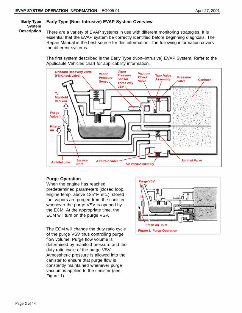
EVAP SYSTEM OPERATION INFORMATION – EG005-01 April 27, 2001
Page 2 of 14
Early Type (Non–Intrusive) EVAP System Overview
There are a variety of EVAP systems in use with different monitoring strategies. It isessential that the EVAP system be correctly identified before beginning diagnosis. TheRepair Manual is the best source for this information. The following information coversthe different systems.
The first system described is the Early Type (Non–Intrusive) EVAP System. Refer to theApplicable Vehicles chart for applicability information.
Onboard Recovery Valve(Fill Check Valve) Vapor
PressureSensor
VaporPressureSensorThree WayVSV
VacuumCheckValve
Tank ValveAssembly
PressureValve Canister
ToManifoldVacuum
PurgeValve
FilteredAir
Air Drain ValveAir Valve Assembly
Air Inlet ValveAir Inlet Line
ServicePort
Purge OperationWhen the engine has reachedpredetermined parameters (closed loop,engine temp. above 125�F, etc.), storedfuel vapors are purged from the canisterwhenever the purge VSV is opened bythe ECM. At the appropriate time, theECM will turn on the purge VSV.
The ECM will change the duty ratio cycleof the purge VSV thus controlling purgeflow volume. Purge flow volume isdetermined by manifold pressure and theduty ratio cycle of the purge VSV.Atmospheric pressure is allowed into thecanister to ensure that purge flow isconstantly maintained whenever purgevacuum is applied to the canister (seeFigure 1).
Early TypeSystem
Description
Figure 1. Purge Operation
Fresh Air Inlet
Purge VSV
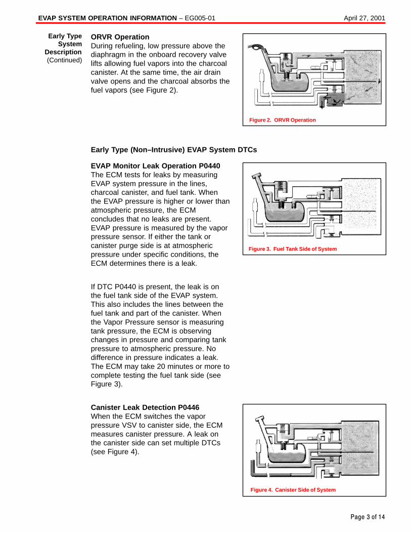
EVAP SYSTEM OPERATION INFORMATION – EG005-01 April 27, 2001
Page 3 of 14
ORVR OperationDuring refueling, low pressure above thediaphragm in the onboard recovery valvelifts allowing fuel vapors into the charcoalcanister. At the same time, the air drainvalve opens and the charcoal absorbs thefuel vapors (see Figure 2).
Early Type (Non–Intrusive) EVAP System DTCs
EVAP Monitor Leak Operation P0440The ECM tests for leaks by measuringEVAP system pressure in the lines,charcoal canister, and fuel tank. Whenthe EVAP pressure is higher or lower thanatmospheric pressure, the ECMconcludes that no leaks are present.EVAP pressure is measured by the vaporpressure sensor. If either the tank orcanister purge side is at atmosphericpressure under specific conditions, theECM determines there is a leak.
If DTC P0440 is present, the leak is onthe fuel tank side of the EVAP system.This also includes the lines between thefuel tank and part of the canister. Whenthe Vapor Pressure sensor is measuringtank pressure, the ECM is observingchanges in pressure and comparing tankpressure to atmospheric pressure. Nodifference in pressure indicates a leak.The ECM may take 20 minutes or more tocomplete testing the fuel tank side (seeFigure 3).
Canister Leak Detection P0446When the ECM switches the vaporpressure VSV to canister side, the ECMmeasures canister pressure. A leak onthe canister side can set multiple DTCs(see Figure 4).
Early TypeSystem
Description(Continued)
Figure 2. ORVR Operation
Figure 3. Fuel Tank Side of System
Figure 4. Canister Side of System
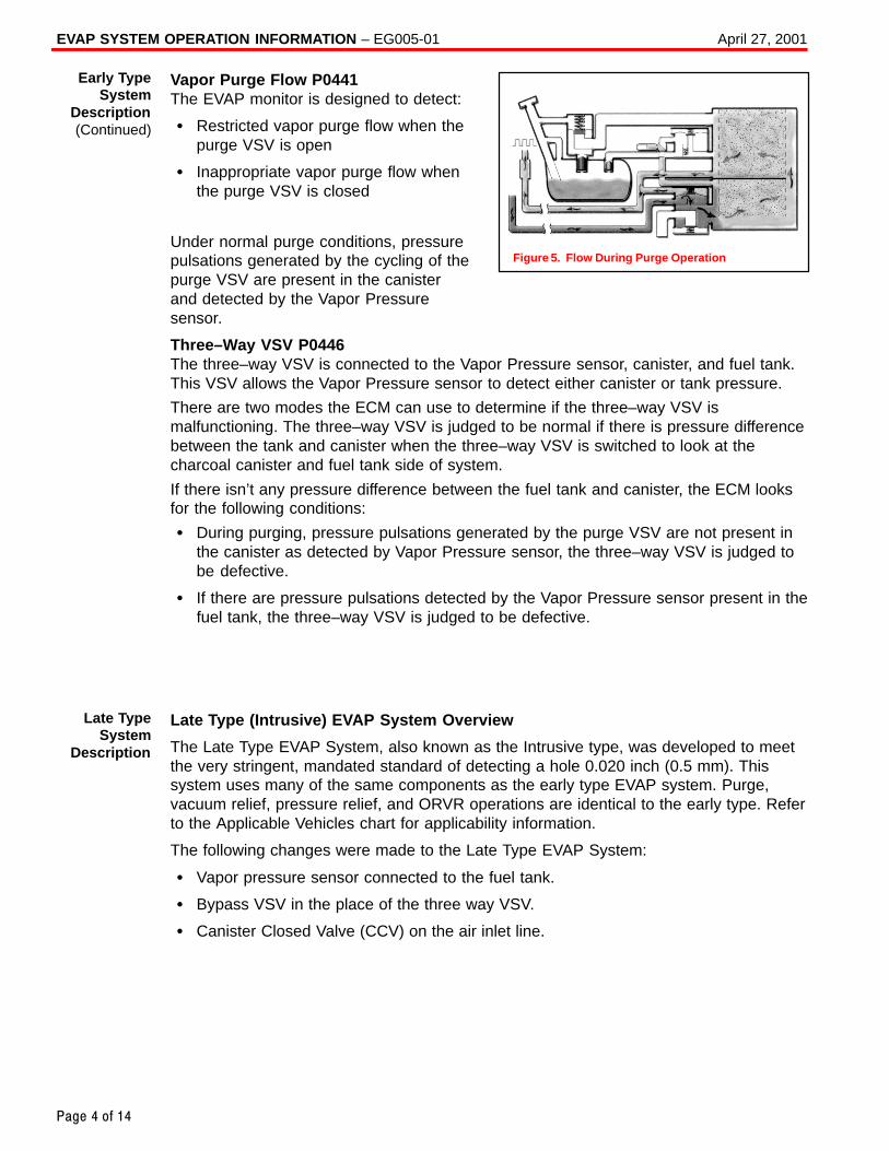
EVAP SYSTEM OPERATION INFORMATION – EG005-01 April 27, 2001
Page 4 of 14
Vapor Purge Flow P0441The EVAP monitor is designed to detect:
� Restricted vapor purge flow when thepurge VSV is open
� Inappropriate vapor purge flow whenthe purge VSV is closed
Under normal purge conditions, pressurepulsations generated by the cycling of thepurge VSV are present in the canisterand detected by the Vapor Pressuresensor.
Three–Way VSV P0446The three–way VSV is connected to the Vapor Pressure sensor, canister, and fuel tank.This VSV allows the Vapor Pressure sensor to detect either canister or tank pressure.
There are two modes the ECM can use to determine if the three–way VSV ismalfunctioning. The three–way VSV is judged to be normal if there is pressure differencebetween the tank and canister when the three–way VSV is switched to look at thecharcoal canister and fuel tank side of system.
If there isn’t any pressure difference between the fuel tank and canister, the ECM looksfor the following conditions:
� During purging, pressure pulsations generated by the purge VSV are not present inthe canister as detected by Vapor Pressure sensor, the three–way VSV is judged tobe defective.
� If there are pressure pulsations detected by the Vapor Pressure sensor present in thefuel tank, the three–way VSV is judged to be defective.
Late Type (Intrusive) EVAP System Overview
The Late Type EVAP System, also known as the Intrusive type, was developed to meetthe very stringent, mandated standard of detecting a hole 0.020 inch (0.5 mm). Thissystem uses many of the same components as the early type EVAP system. Purge,vacuum relief, pressure relief, and ORVR operations are identical to the early type. Referto the Applicable Vehicles chart for applicability information.
The following changes were made to the Late Type EVAP System:
� Vapor pressure sensor connected to the fuel tank.
� Bypass VSV in the place of the three way VSV.
� Canister Closed Valve (CCV) on the air inlet line.
Early TypeSystem
Description(Continued)
Figure 5. Flow During Purge Operation
Late TypeSystem
Description
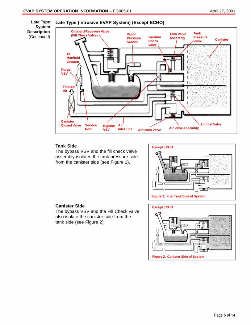
EVAP SYSTEM OPERATION INFORMATION – EG005-01 April 27, 2001
Page 5 of 14
Late Type (Intrusive EVAP System) (Except ECHO)
Onboard Recovery Valve(Fill Check Valve) Vapor
PressureSensor
VacuumCheckValve
Tank ValveAssembly
TankPressureValve Canister
ToManifoldVacuum
PurgeVSV
FilteredAir
Air Drain Valve Air Valve AssemblyAir Inlet Valve
CanisterClosed Valve Bypass
VSVAir Inlet Line
ServicePort
Tank SideThe bypass VSV and the fill check valveassembly isolates the tank pressure sidefrom the canister side (see Figure 1).
Canister SideThe bypass VSV and the Fill Check valvealso isolate the canister side from thetank side (see Figure 2).
Late TypeSystem
Description(Continued)
Except ECHO
Figure 1. Fuel Tank Side of System
Except ECHO
Figure 2. Canister Side of System
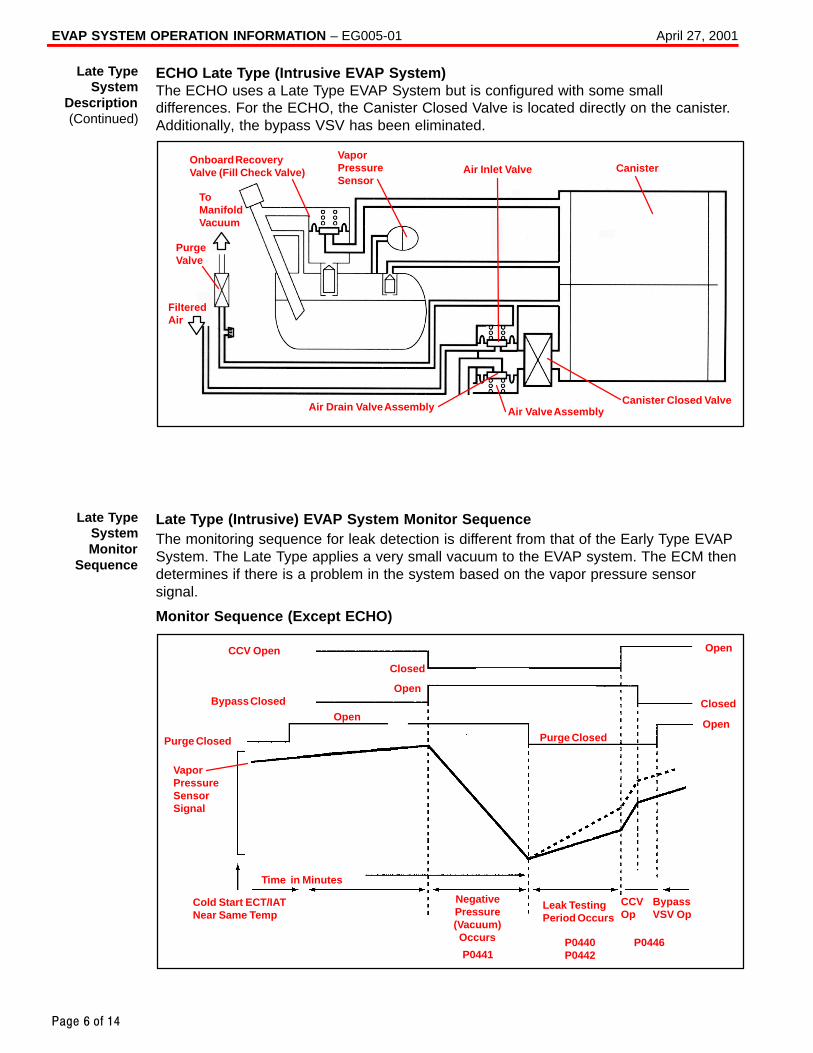
EVAP SYSTEM OPERATION INFORMATION – EG005-01 April 27, 2001
Page 6 of 14
ECHO Late Type (Intrusive EVAP System)The ECHO uses a Late Type EVAP System but is configured with some smalldifferences. For the ECHO, the Canister Closed Valve is located directly on the canister.Additionally, the bypass VSV has been eliminated.
Onboard RecoveryValve (Fill Check Valve)
VaporPressureSensor
Air Inlet Valve Canister
Canister Closed ValveAir Valve AssemblyAir Drain Valve Assembly
ToManifoldVacuum
PurgeValve
FilteredAir
Late Type (Intrusive) EVAP System Monitor SequenceThe monitoring sequence for leak detection is different from that of the Early Type EVAPSystem. The Late Type applies a very small vacuum to the EVAP system. The ECM thendetermines if there is a problem in the system based on the vapor pressure sensorsignal.
Monitor Sequence (Except ECHO)
CCV Open
Purge Closed
Open
Closed
Purge ClosedOpen
Open
Cold Start ECT/IATNear Same Temp
NegativePressure(Vacuum)Occurs
Leak TestingPeriod Occurs
CCVOp
Open
Time in Minutes
Bypass Closed Closed
BypassVSV Op
VaporPressureSensor Signal
P0441P0440P0442
P0446
Late TypeSystem
Description(Continued)
Late TypeSystemMonitor
Sequence
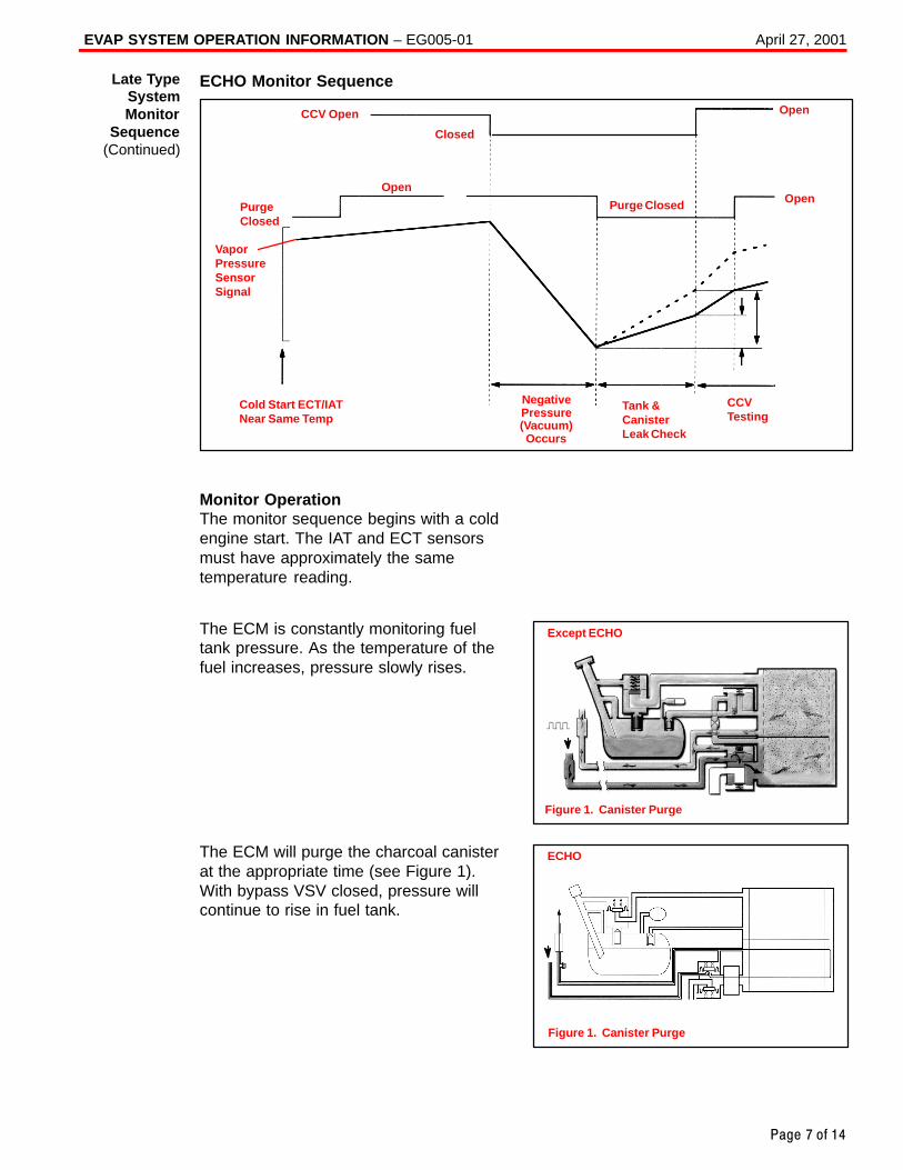
EVAP SYSTEM OPERATION INFORMATION – EG005-01 April 27, 2001
Page 7 of 14
ECHO Monitor Sequence
CCV Open
PurgeClosed
Open
Closed
Purge Closed Open
Open
Cold Start ECT/IATNear Same Temp
NegativePressure(Vacuum)Occurs
Tank &CanisterLeak Check
CCVTesting
VaporPressureSensor Signal
Monitor Operation The monitor sequence begins with a coldengine start. The IAT and ECT sensorsmust have approximately the sametemperature reading.
The ECM is constantly monitoring fueltank pressure. As the temperature of thefuel increases, pressure slowly rises.
The ECM will purge the charcoal canisterat the appropriate time (see Figure 1).With bypass VSV closed, pressure willcontinue to rise in fuel tank.
Late TypeSystemMonitor
Sequence(Continued)
Except ECHO
Figure 1. Canister Purge
ECHO
Figure 1. Canister Purge
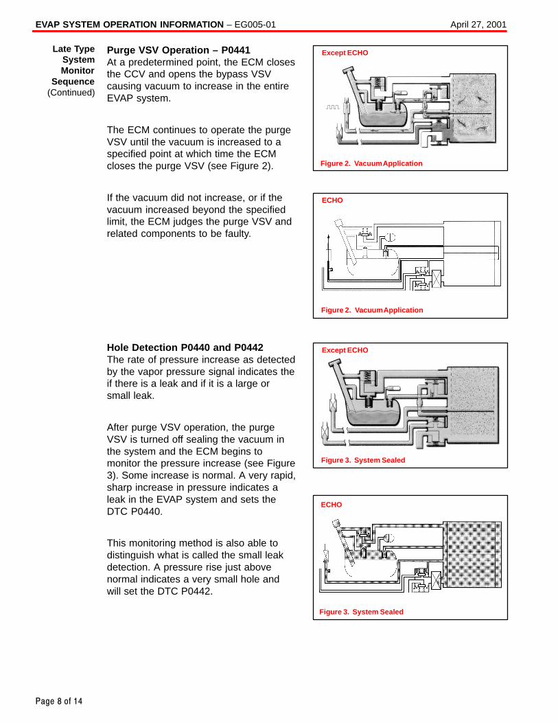
EVAP SYSTEM OPERATION INFORMATION – EG005-01 April 27, 2001
Page 8 of 14
Purge VSV Operation – P0441At a predetermined point, the ECM closesthe CCV and opens the bypass VSVcausing vacuum to increase in the entireEVAP system.
The ECM continues to operate the purgeVSV until the vacuum is increased to aspecified point at which time the ECMcloses the purge VSV (see Figure 2).
If the vacuum did not increase, or if thevacuum increased beyond the specifiedlimit, the ECM judges the purge VSV andrelated components to be faulty.
Hole Detection P0440 and P0442The rate of pressure increase as detectedby the vapor pressure signal indicates theif there is a leak and if it is a large orsmall leak.
After purge VSV operation, the purgeVSV is turned off sealing the vacuum inthe system and the ECM begins tomonitor the pressure increase (see Figure3). Some increase is normal. A very rapid,sharp increase in pressure indicates aleak in the EVAP system and sets theDTC P0440.
This monitoring method is also able todistinguish what is called the small leakdetection. A pressure rise just abovenormal indicates a very small hole andwill set the DTC P0442.
Except ECHO
Figure 2. Vacuum Application
Late TypeSystemMonitor
Sequence(Continued)
ECHO
Figure 2. Vacuum Application
Except ECHO
Figure 3. System Sealed
ECHO
Figure 3. System Sealed
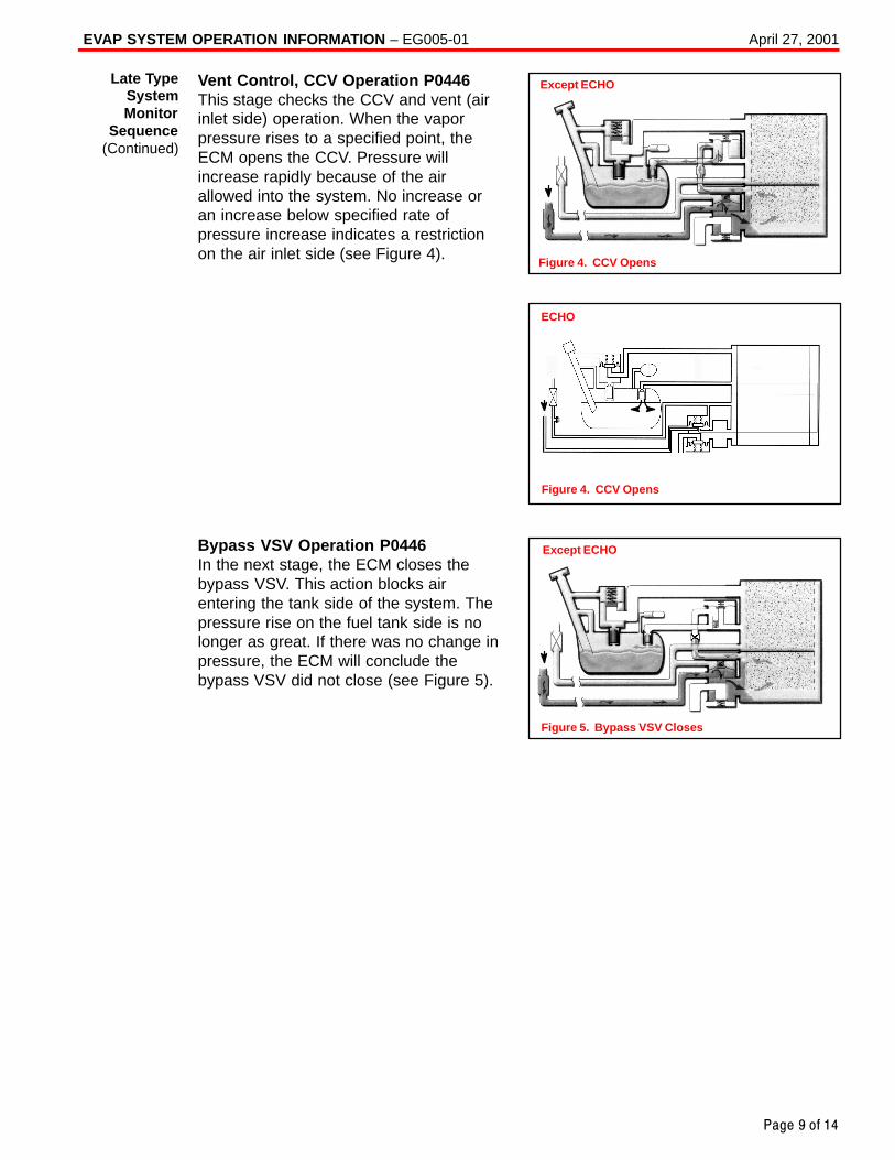
EVAP SYSTEM OPERATION INFORMATION – EG005-01 April 27, 2001
Page 9 of 14
Vent Control, CCV Operation P0446This stage checks the CCV and vent (airinlet side) operation. When the vaporpressure rises to a specified point, theECM opens the CCV. Pressure willincrease rapidly because of the airallowed into the system. No increase oran increase below specified rate ofpressure increase indicates a restrictionon the air inlet side (see Figure 4).
Bypass VSV Operation P0446In the next stage, the ECM closes thebypass VSV. This action blocks airentering the tank side of the system. Thepressure rise on the fuel tank side is nolonger as great. If there was no change inpressure, the ECM will conclude thebypass VSV did not close (see Figure 5).
Late TypeSystemMonitor
Sequence(Continued)
Except ECHO
Figure 4. CCV Opens
ECHO
Figure 4. CCV Opens
Except ECHO
Figure 5. Bypass VSV Closes
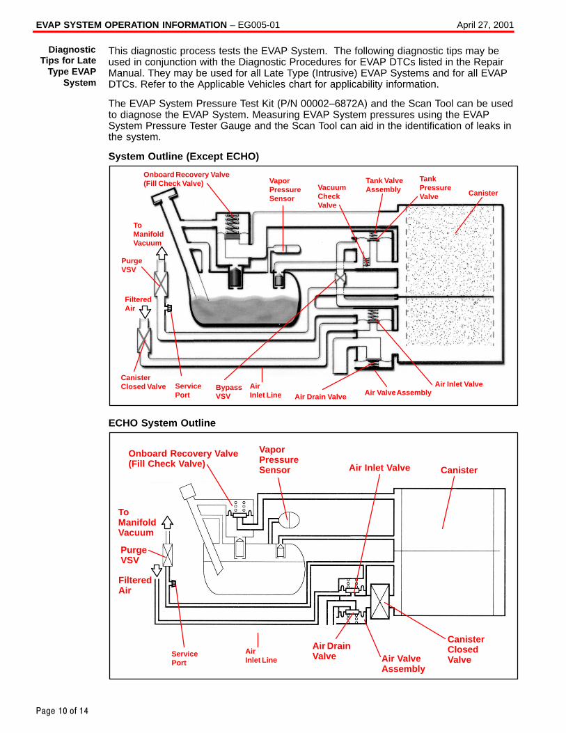
EVAP SYSTEM OPERATION INFORMATION – EG005-01 April 27, 2001
Page 10 of 14
This diagnostic process tests the EVAP System. The following diagnostic tips may beused in conjunction with the Diagnostic Procedures for EVAP DTCs listed in the RepairManual. They may be used for all Late Type (Intrusive) EVAP Systems and for all EVAPDTCs. Refer to the Applicable Vehicles chart for applicability information.
The EVAP System Pressure Test Kit (P/N 00002–6872A) and the Scan Tool can be usedto diagnose the EVAP System. Measuring EVAP System pressures using the EVAPSystem Pressure Tester Gauge and the Scan Tool can aid in the identification of leaks inthe system.
System Outline (Except ECHO)
Onboard Recovery Valve(Fill Check Valve) Vapor
PressureSensor
VacuumCheckValve
Tank ValveAssembly
TankPressureValve Canister
ToManifoldVacuum
PurgeVSV
FilteredAir
Air Drain Valve Air Valve AssemblyAir Inlet Valve
CanisterClosed Valve Bypass
VSVAir Inlet Line
ServicePort
ECHO System Outline
Onboard Recovery Valve(Fill Check Valve)
ToManifoldVacuum
FilteredAir
PurgeVSV
Air DrainValve Air Valve
Assembly
CanisterClosedValve
Canister
VaporPressureSensor Air Inlet Valve
Air Inlet Line
ServicePort
DiagnosticTips for Late
Type EVAPSystem
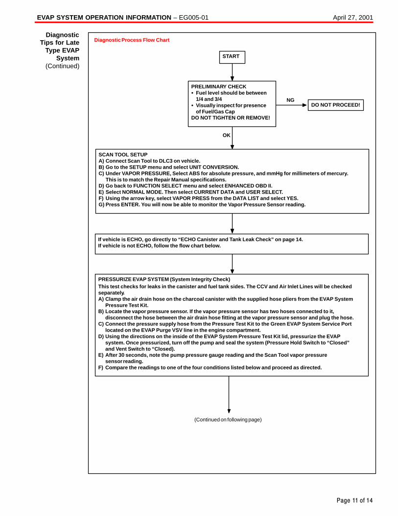
EVAP SYSTEM OPERATION INFORMATION – EG005-01 April 27, 2001
Page 11 of 14
Diagnostic Process Flow Chart
(Continued on following page)
PRELIMINARY CHECK� Fuel level should be between
1/4 and 3/4� Visually inspect for presence
of Fuel/Gas CapDO NOT TIGHTEN OR REMOVE!
PRESSURIZE EVAP SYSTEM (System Integrity Check)This test checks for leaks in the canister and fuel tank sides. The CCV and Air Inlet Lines will be checkedseparately.A) Clamp the air drain hose on the charcoal canister with the supplied hose pliers from the EVAP System
Pressure Test Kit.B) Locate the vapor pressure sensor. If the vapor pressure sensor has two hoses connected to it,
disconnect the hose between the air drain hose fitting at the vapor pressure sensor and plug the hose.C) Connect the pressure supply hose from the Pressure Test Kit to the Green EVAP System Service Port
located on the EVAP Purge VSV line in the engine compartment.D) Using the directions on the inside of the EVAP System Pressure Test Kit lid, pressurize the EVAP
system. Once pressurized, turn off the pump and seal the system (Pressure Hold Switch to “Closed” and Vent Switch to “Closed).
E) After 30 seconds, note the pump pressure gauge reading and the Scan Tool vapor pressure sensor reading.
F) Compare the readings to one of the four conditions listed below and proceed as directed.
DO NOT PROCEED!NG
OK
SCAN TOOL SETUPA) Connect Scan Tool to DLC3 on vehicle.B) Go to the SETUP menu and select UNIT CONVERSION.C) Under VAPOR PRESSURE, Select ABS for absolute pressure, and mmHg for millimeters of mercury.
This is to match the Repair Manual specifications.D) Go back to FUNCTION SELECT menu and select ENHANCED OBD II.E) Select NORMAL MODE. Then select CURRENT DATA and USER SELECT.F) Using the arrow key, select VAPOR PRESS from the DATA LIST and select YES.G) Press ENTER. You will now be able to monitor the Vapor Pressure Sensor reading.
START
If vehicle is ECHO, go directly to “ECHO Canister and Tank Leak Check” on page 14. If vehicle is not ECHO, follow the flow chart below.
DiagnosticTips for Late
Type EVAPSystem
(Continued)
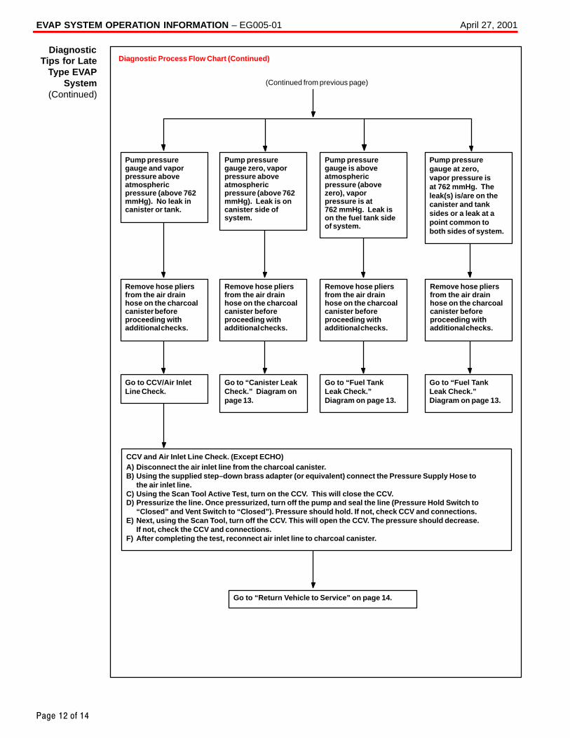
EVAP SYSTEM OPERATION INFORMATION – EG005-01 April 27, 2001
Page 12 of 14
Pump pressure gauge and vapor pressure above atmospheric pressure (above 762 mmHg). No leak in canister or tank.
Pump pressure gauge zero, vaporpressure above atmosphericpressure (above 762mmHg). Leak is on canister side of system.
Pump pressure gauge is above atmospheric pressure (above zero), vapor pressure is at 762 mmHg. Leak is on the fuel tank side of system.
Pump pressure gauge at zero, vapor pressure is at 762 mmHg. The leak(s) is/are on the canister and tank sides or a leak at a point common to both sides of system.
Remove hose pliers from the air drain hose on the charcoalcanister beforeproceeding with additional checks.
Remove hose pliers from the air drain hose on the charcoalcanister before proceeding with additional checks.
Remove hose pliers from the air drain hose on the charcoalcanister before proceeding with additional checks.
Go to CCV/Air Inlet Line Check.
Go to “Canister LeakCheck.” Diagram on page 13.
Go to “Fuel Tank Leak Check.” Diagram on page 13.
Go to “Fuel Tank Leak Check.” Diagram on page 13.
Remove hose pliers from the air drain hose on the charcoalcanister before proceeding with additional checks.
Go to “Return Vehicle to Service” on page 14.
CCV and Air Inlet Line Check. (Except ECHO)A) Disconnect the air inlet line from the charcoal canister.B) Using the supplied step–down brass adapter (or equivalent) connect the Pressure Supply Hose to
the air inlet line.C) Using the Scan Tool Active Test, turn on the CCV. This will close the CCV.D) Pressurize the line. Once pressurized, turn off the pump and seal the line (Pressure Hold Switch to
“Closed” and Vent Switch to “Closed”). Pressure should hold. If not, check CCV and connections.E) Next, using the Scan Tool, turn off the CCV. This will open the CCV. The pressure should decrease.
If not, check the CCV and connections.F) After completing the test, reconnect air inlet line to charcoal canister.
Diagnostic Process Flow Chart (Continued)
(Continued from previous page)
DiagnosticTips for Late
Type EVAPSystem
(Continued)
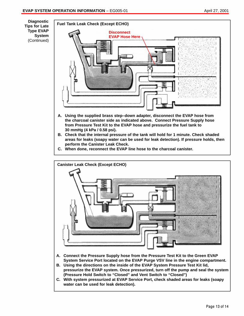
EVAP SYSTEM OPERATION INFORMATION – EG005-01 April 27, 2001
Page 13 of 14
DisconnectEVAP Hose Here
A. Using the supplied brass step–down adapter, disconnect the EVAP hose from the charcoal canister side as indicated above. Connect Pressure Supply hose from Pressure Test Kit to the EVAP hose and pressurize the fuel tank to 30 mmHg (4 kPa / 0.58 psi).
B. Check that the internal pressure of the tank will hold for 1 minute. Check shadedareas for leaks (soapy water can be used for leak detection). If pressure holds, thenperform the Canister Leak Check.
C. When done, reconnect the EVAP line hose to the charcoal canister.
Fuel Tank Leak Check (Except ECHO)
Canister Leak Check (Except ECHO)
A. Connect the Pressure Supply hose from the Pressure Test Kit to the Green EVAPSystem Service Port located on the EVAP Purge VSV line in the engine compartment.
B. Using the directions on the inside of the EVAP System Pressure Test Kit lid, pressurize the EVAP system. Once pressurized, turn off the pump and seal the system(Pressure Hold Switch to “Closed” and Vent Switch to “Closed”)
C. With system pressurized at EVAP Service Port, check shaded areas for leaks (soapywater can be used for leak detection).
DiagnosticTips for Late
Type EVAPSystem
(Continued)
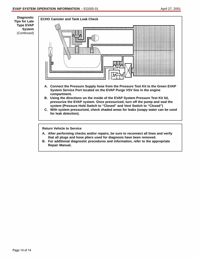
EVAP SYSTEM OPERATION INFORMATION – EG005-01 April 27, 2001
Page 14 of 14
ECHO Canister and Tank Leak Check
A. Connect the Pressure Supply hose from the Pressure Test Kit to the Green EVAPSystem Service Port located on the EVAP Purge VSV line in the enginecompartment.
B. Using the directions on the inside of the EVAP System Pressure Test Kit lid,pressurize the EVAP system. Once pressurized, turn off the pump and seal thesystem (Pressure Hold Switch to “Closed” and Vent Switch to “Closed”)
C. With system pressurized, check shaded areas for leaks (soapy water can be usedfor leak detection).
Return Vehicle to Service
A. After performing checks and/or repairs, be sure to reconnect all lines and verifythat all plugs and hose pliers used for diagnosis have been removed.
B. For additional diagnostic procedures and information, refer to the appropriateRepair Manual.
DiagnosticTips for Late
Type EVAPSystem
(Continued)
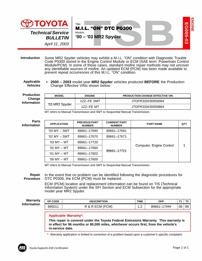
Toyota Supports ASE Certification Page 1 of 1
EG
005-03
Title:
M.I.L. �ON" DTC P0300Models:
’00 – ’03 MR2 SpyderTechnical Service
BULLETINApril 11, 2003
Some MR2 Spyder vehicles may exhibit a M.I.L. “ON” condition with Diagnostic TroubleCode P0300 stored in the Engine Control Module or ECM (SAE term: Powertrain ControlModule/PCM). In some of these cases, standard misfire repair methods may not uncoverany identifiable sources of misfire. An updated ECM (PCM) has been made available toprevent repeat occurrences of this M.I.L. “ON” condition.
� 2000 – 2003 model year MR2 Spyder vehicles produced BEFORE the ProductionChange Effective VINs shown below.
MODEL ENGINE PRODUCTION CHANGE EFFECTIVE VIN
’03 MR2 Spyder1ZZ–FE SMT JTDFR320#30059064
’03 MR2 Spyder1ZZ–FE MT JTDFR320#30059864
MT refers to Manual Transmission and SMT to Sequential Manual Transmission.
APPLICATIONPREVIOUS PART
NUMBERCURRENT PART
NUMBERPART NAME QTY
’03 MY – SMT 89661–17690 89661–17691
’02 MY – SMT 89661–17670 89661–17671
’03 MY – MT 89661–17720Computer Engine Control 1
’02 MY – MT 89661–1766089661 17721
Computer, Engine Control 1
’01 MY – MT 89661–1760289661–17721
’00 MY – MT 89661–17600
MT refers to Manual Transmission and SMT to Sequential Manual Transmission.
In the event that no problem can be identified following the diagnostic procedures forDTC P0300, the ECM (PCM) must be replaced.
ECM (PCM) location and replacement information can be found on TIS (TechnicalInformation System) under the SFI Section and ECM Subsection for the appropriatemodel year MR2 Spyder.
OP CODE DESCRIPTION TIME OFP T1 T2
895011 R & R ECM (PCM) 1.2 89661–17### 08 99
Applicable Warranty*:This repair is covered under the Toyota Federal Emissions Warranty. This warranty isin effect for 96 months or 80,000 miles, whichever occurs first, from the vehicle’sin-service date.
* Warranty application is limited to correction of a problem based upon a customer’s specific complaint.
EN
GIN
E
Introduction
ApplicableVehicles
ProductionChange
Information
PartsInformation
RepairProcedure
WarrantyInformation
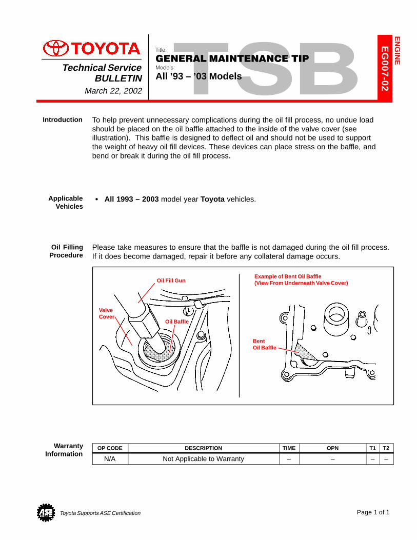
Toyota Supports ASE Certification Page 1 of 1
EG
007-02
Title:
GENERAL MAINTENANCE TIPModels:
All ’93 – ’03 ModelsTechnical Service
BULLETINMarch 22, 2002
To help prevent unnecessary complications during the oil fill process, no undue loadshould be placed on the oil baffle attached to the inside of the valve cover (seeillustration). This baffle is designed to deflect oil and should not be used to supportthe weight of heavy oil fill devices. These devices can place stress on the baffle, andbend or break it during the oil fill process.
� All 1993 – 2003 model year Toyota vehicles.
Please take measures to ensure that the baffle is not damaged during the oil fill process.If it does become damaged, repair it before any collateral damage occurs.
Oil Fill Gun
Oil Baffle
Example of Bent Oil Baffle(View From Underneath Valve Cover)
BentOil Baffle
ValveCover
OP CODE DESCRIPTION TIME OPN T1 T2
N/A Not Applicable to Warranty – – – –
EN
GIN
E
Introduction
ApplicableVehicles
Oil FillingProcedure
WarrantyInformation
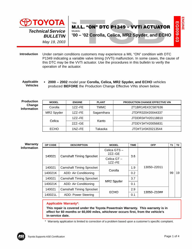
Toyota Supports ASE Certification Page 1 of 4
EG
009-03
Title:
M.I.L. �ON" DTC P1349 - VVTi ACTUATORModels:
’00 – ’02 Corolla, Celica, MR2 Spyder, and ECHOTechnical Service
BULLETINMay 19, 2003
Under certain conditions customers may experience a MIL “ON” condition with DTCP1349 indicating a variable valve timing (VVTi) malfunction. In some cases, the cause ofthis DTC may be the VVTi actuator. Use the procedures in this bulletin to verify theoperation of the actuator.
� 2000 – 2002 model year Corolla, Celica, MR2 Spyder, and ECHO vehiclesproduced BEFORE the Production Change Effective VINs shown below.
MODEL ENGINE PLANT PRODUCTION CHANGE EFFECTIVE VIN
Corolla 1ZZ–FE TMMC 2T1BR1#E#2C587636
MR2 Spyder 1ZZ–FE Sagamihara JTDFR320#20044337
Celica1ZZ–FE
KantoJTDDR3#T#20118810
Celica2ZZ–GE
KantoJTDDY3#T#20056831
ECHO 1NZ–FE Takaoka JTD#T1#3#20213544
OP CODE DESCRIPTION MODEL TIME OFP T1 T2
140021 Camshaft Timing Sprocket
Celica GTS –2ZZ–GE
3 6140021 Camshaft Timing SprocketCelica GT –
1ZZ–FE
3.6
140021 Camshaft Timing SprocketCorolla
1.9 13050–22011
140021K ADD: Air ConditioningCorolla
0.2 99 19
140021 Camshaft Timing SprocketMR2 Spyder
3.7
140021K ADD: Air ConditioningMR2 Spyder
0.1
140021 Camshaft Timing SprocketECHO
2.913050 210##
140021L ADD: Power SteeringECHO
0.113050–210##
Applicable Warranty*:This repair is covered under the Toyota Powertrain Warranty. This warranty is in effect for 60 months or 60,000 miles, whichever occurs first, from the vehicle’sin-service date.
* Warranty application is limited to correction of a problem based upon a customer’s specific complaint.
EN
GIN
E
Introduction
ApplicableVehicles
ProductionChange
Information
WarrantyInformation
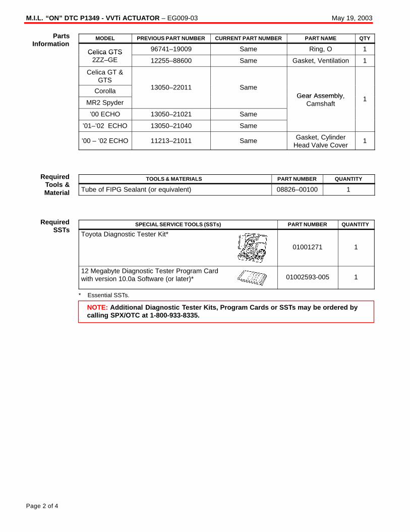
M.I.L. “ON” DTC P1349 - VVTi ACTUATOR – EG009-03 May 19, 2003
Page 2 of 4
MODEL PREVIOUS PART NUMBER CURRENT PART NUMBER PART NAME QTY
Celica GTS 96741–19009 Same Ring, O 1Celica GTS2ZZ–GE 12255–88600 Same Gasket, Ventilation 1
Celica GT >S
13050 22011 SCorolla 13050–22011 SameGear Assembly 1MR2 SpyderGear Assembly,
Camshaft1
’00 ECHO 13050–21021 Same
C
’01–’02 ECHO 13050–21040 Same
’00 – ’02 ECHO 11213–21011 Same Gasket, CylinderHead Valve Cover
1
TOOLS & MATERIALS PART NUMBER QUANTITY
Tube of FIPG Sealant (or equivalent) 08826–00100 1
SPECIAL SERVICE TOOLS (SSTs) PART NUMBER QUANTITY
Toyota Diagnostic Tester Kit*
01001271 1
12 Megabyte Diagnostic Tester Program Cardwith version 10.0a Software (or later)* 01002593-005 1
* Essential SSTs.
NOTE: Additional Diagnostic Tester Kits, Program Cards or SSTs may be ordered bycalling SPX/OTC at 1-800-933-8335.
PartsInformation
RequiredTools &Material
RequiredSSTs
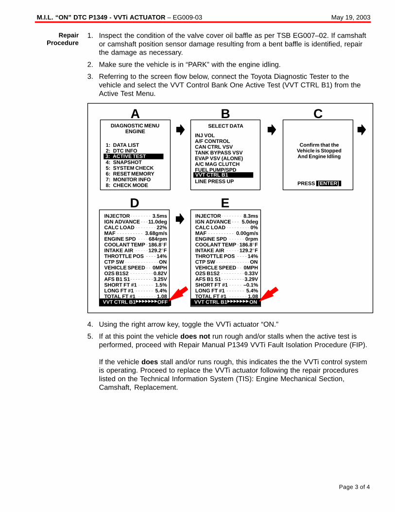
M.I.L. “ON” DTC P1349 - VVTi ACTUATOR – EG009-03 May 19, 2003
Page 3 of 4
1. Inspect the condition of the valve cover oil baffle as per TSB EG007–02. If camshaftor camshaft position sensor damage resulting from a bent baffle is identified, repairthe damage as necessary.
2. Make sure the vehicle is in “PARK” with the engine idling.
3. Referring to the screen flow below, connect the Toyota Diagnostic Tester to thevehicle and select the VVT Control Bank One Active Test (VVT CTRL B1) from theActive Test Menu.
1: DATA LIST2: DTC INFO3:4: SNAPSHOT5: SYSTEM CHECK6: RESET MEMORY7: MONITOR INFO8: CHECK MODE
SELECT DATA
BDIAGNOSTIC MENU
ENGINE
A CINJ VOLA/F CONTROLCAN CTRL VSVTANK BYPASS VSVEVAP VSV (ALONE)A/C MAG CLUTCHFUEL PUMP/SPD
LINE PRESS UPVVT CTRL B1
Confirm that theVehicle is StoppedAnd Engine Idling3: ACTIVE TEST
PRESS [ENTER]
INJECTOR 3.5msIGN ADVANCE 11.0degCALC LOAD 22%MAF 3.68gm/sENGINE SPD 684rpmCOOLANT TEMP 186.8�FINTAKE AIR 129.2�FTHROTTLE POS 14%CTP SW ONVEHICLE SPEED 0MPHO2S B1S2 0.82VAFS B1 S1 3.25VSHORT FT #1 1.5%LONG FT #1 5.4%TOTAL FT #1 1.08
ED
VVT CTRL B1�������OFF
INJECTOR 8.3msIGN ADVANCE 5.0degCALC LOAD 0%MAF 0.00gm/sENGINE SPD 0rpmCOOLANT TEMP 186.8�FINTAKE AIR 129.2�FTHROTTLE POS 14%CTP SW ONVEHICLE SPEED 0MPHO2S B1S2 0.33VAFS B1 S1 3.29VSHORT FT #1 –0.1%LONG FT #1 5.4%TOTAL FT #1 1.08VVT CTRL B1�������ON
4. Using the right arrow key, toggle the VVTi actuator “ON.”
5. If at this point the vehicle does not run rough and/or stalls when the active test isperformed, proceed with Repair Manual P1349 VVTi Fault Isolation Procedure (FIP).
If the vehicle does stall and/or runs rough, this indicates the the VVTi control systemis operating. Proceed to replace the VVTi actuator following the repair procedureslisted on the Technical Information System (TIS): Engine Mechanical Section,Camshaft, Replacement.
RepairProcedure
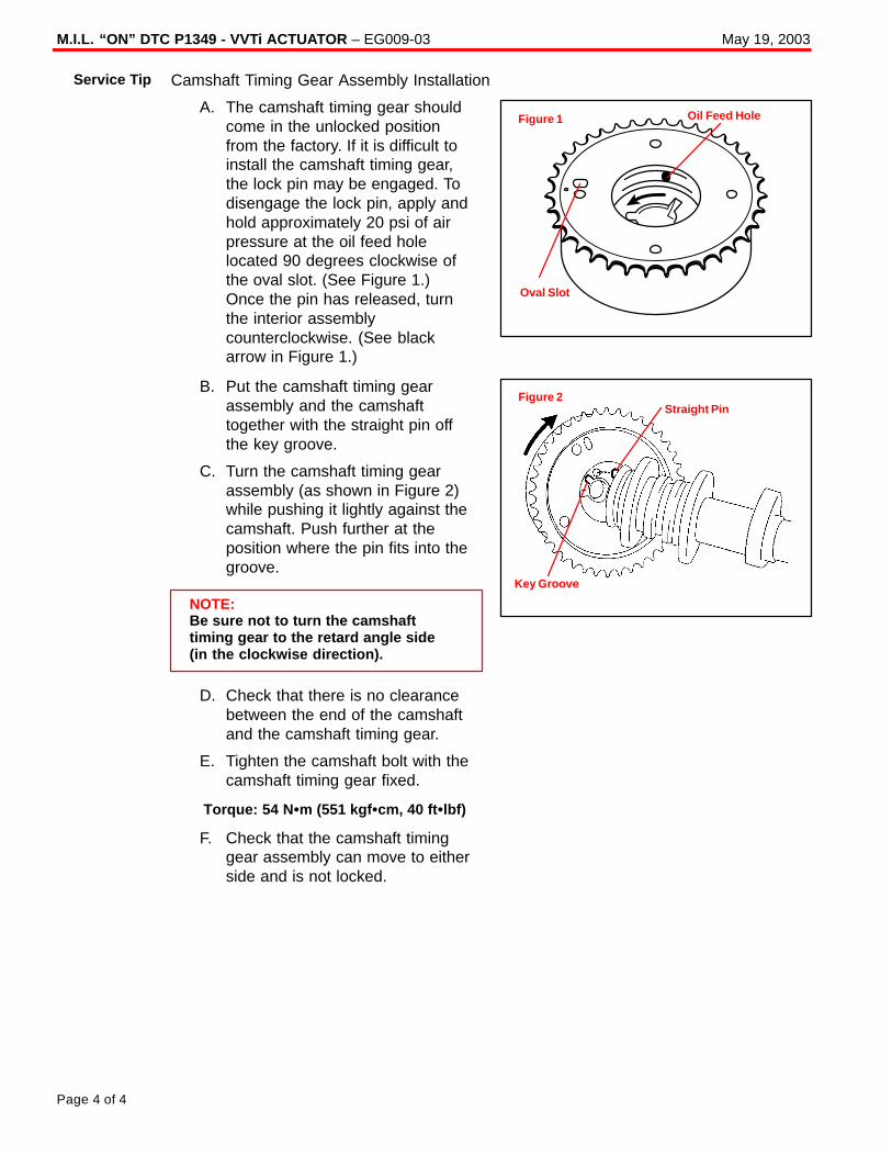
M.I.L. “ON” DTC P1349 - VVTi ACTUATOR – EG009-03 May 19, 2003
Page 4 of 4
Camshaft Timing Gear Assembly Installation
A. The camshaft timing gear shouldcome in the unlocked positionfrom the factory. If it is difficult toinstall the camshaft timing gear,the lock pin may be engaged. Todisengage the lock pin, apply andhold approximately 20 psi of airpressure at the oil feed holelocated 90 degrees clockwise ofthe oval slot. (See Figure 1.)Once the pin has released, turnthe interior assemblycounterclockwise. (See blackarrow in Figure 1.)
B. Put the camshaft timing gearassembly and the camshafttogether with the straight pin offthe key groove.
C. Turn the camshaft timing gearassembly (as shown in Figure 2)while pushing it lightly against thecamshaft. Push further at theposition where the pin fits into thegroove.
NOTE:Be sure not to turn the camshafttiming gear to the retard angle side (in the clockwise direction).
D. Check that there is no clearancebetween the end of the camshaftand the camshaft timing gear.
E. Tighten the camshaft bolt with thecamshaft timing gear fixed.
Torque: 54 N �m (551 kgf �cm, 40 ft �lbf)
F. Check that the camshaft timinggear assembly can move to eitherside and is not locked.
Service Tip
Oval Slot
Oil Feed HoleFigure 1
Key Groove
Straight PinFigure 2
Toyota Supports ASE Certification Page 1 of 2
EG
014-01
Title:
ACCESSORY DRIVE BELT/
BELT TENSIONER ASSEMBLY NOISEModels:
’00 – ’01 Celica & MR2 Spyder
Technical ServiceBULLETIN
December 7, 2001
Some 1ZZ–FE and 2ZZ–GE engines may exhibit squealing and/or rattling noisesemanating from the engine compartment during vehicle operation, especially duringdeceleration at slow speeds after cold soak. The Accessory Drive Belt and BeltTensioner have been improved to correct this condition.
� 2000 – 2001 model year Celica GT/GTS and MR2 Spyder vehicles producedBEFORE the Production Change Effective VINs listed below.
MODEL PRODUCTION CHANGE EFFECTIVE VIN
Celica GT JTDDR32T#10106005
Celica GTS JTDDY38T#10049473
MR2 Spyder JTDFR320#10039271
VEHICLE PREVIOUS PART NUMBER CURRENT PART NUMBER PART NAME
Celica GT w/ AC 90916–02432 90916–02534
Celica GT w/o AC 90916–02468 90916–02535Accessory Drive Belt
Celica GTS 90916–02310 90916–02540Accessory Drive Belt
MR2 Spyder 90916–02486 90916–02537
Celica GTCelica GTSMR2 Spyder
16601–22010 16601–22011Belt TensionerSub–Assembly
(Hydraulic Cylinder)MR2 Spyder
N/A 90105–08415 Bolt, Flange
Celica GTMR2 Spyder
16620–22010 16620–22011 Belt TensionerAssembly, Complete
Celica GTS 16620–22030 16620–22031 Belt TensionerAssembly, Complete
OP CODE DESCRIPTION TIME OPN T1 T2
EG8001 R & R Accessory Belt Tensioner 0.6 16620–22010 91 99
Applicable Warranty*:This repair is covered under the Toyota Comprehensive Warranty. This warranty is ineffect for 36 months or 36,000 miles, whichever occurs first, from the vehicle’sin-service date.
* Warranty application is limited to correction of a problem based upon a customer’s specific complaint.
EN
GIN
E
Introduction
ApplicableVehicles
ProductionChange
Information
PartsInformation
WarrantyInformation
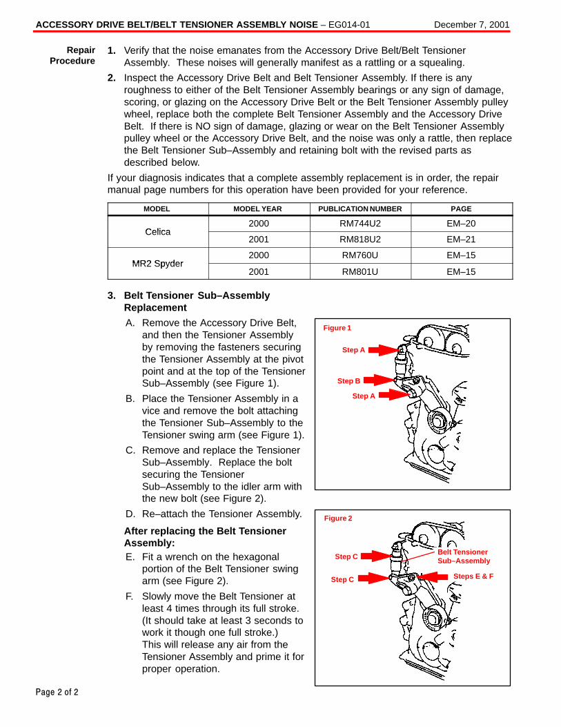
ACCESSORY DRIVE BELT/BELT TENSIONER ASSEMBLY NOISE – EG014-01 December 7, 2001
Page 2 of 2
1. Verify that the noise emanates from the Accessory Drive Belt/Belt TensionerAssembly. These noises will generally manifest as a rattling or a squealing.
2. Inspect the Accessory Drive Belt and Belt Tensioner Assembly. If there is anyroughness to either of the Belt Tensioner Assembly bearings or any sign of damage,scoring, or glazing on the Accessory Drive Belt or the Belt Tensioner Assembly pulleywheel, replace both the complete Belt Tensioner Assembly and the Accessory DriveBelt. If there is NO sign of damage, glazing or wear on the Belt Tensioner Assemblypulley wheel or the Accessory Drive Belt, and the noise was only a rattle, then replacethe Belt Tensioner Sub–Assembly and retaining bolt with the revised parts asdescribed below.
If your diagnosis indicates that a complete assembly replacement is in order, the repairmanual page numbers for this operation have been provided for your reference.
MODEL MODEL YEAR PUBLICATION NUMBER PAGE
Celica2000 RM744U2 EM–20
Celica2001 RM818U2 EM–21
MR2 Spyder2000 RM760U EM–15
MR2 Spyder2001 RM801U EM–15
3. Belt Tensioner Sub–AssemblyReplacement
A. Remove the Accessory Drive Belt,and then the Tensioner Assemblyby removing the fasteners securingthe Tensioner Assembly at the pivotpoint and at the top of the TensionerSub–Assembly (see Figure 1).
B. Place the Tensioner Assembly in avice and remove the bolt attachingthe Tensioner Sub–Assembly to theTensioner swing arm (see Figure 1).
C. Remove and replace the TensionerSub–Assembly. Replace the boltsecuring the TensionerSub–Assembly to the idler arm withthe new bolt (see Figure 2).
D. Re–attach the Tensioner Assembly.
After replacing the Belt TensionerAssembly:E. Fit a wrench on the hexagonal
portion of the Belt Tensioner swingarm (see Figure 2).
F. Slowly move the Belt Tensioner atleast 4 times through its full stroke.(It should take at least 3 seconds towork it though one full stroke.) This will release any air from theTensioner Assembly and prime it forproper operation.
RepairProcedure
Figure 1
Step A
Step A
Step B
Figure 2
Step C
Step C
Steps E & F
Belt TensionerSub–Assembly
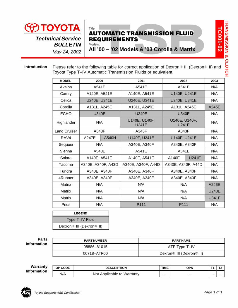
Toyota Supports ASE Certification Page 1 of 1
TC
001-02
Title:
AUTOMATIC TRANSMISSION FLUID
REQUIREMENTSModels:
All ’00 – ’02 Models & ’03 Corolla & Matrix
Technical ServiceBULLETIN
May 24, 2002
Please refer to the following table for correct application of Dexron� III (Dexron� II) andToyota Type T–IV Automatic Transmission Fluids or equivalent.
MODEL 2000 2001 2002 2003
Avalon A541E A541E A541E N/A
Camry A140E, A541E A140E, A541E U140E, U241E N/A
Celica U240E, U341E U240E, U341E U240E, U341E N/A
Corolla A131L, A245E A131L, A245E A131L, A245E A245E
ECHO U340E U340E U340E N/A
Highlander N/A U140E, U140F,U241E
U140E, U140F,U241E
N/A
Land Cruiser A343F A343F A343F N/A
RAV4 A247E A540H U140F, U241E U140F, U241E N/A
Sequoia N/A A340E, A340F A340E, A340F N/A
Sienna A540E A541E A541E N/A
Solara A140E, A541E A140E, A541E A140E U241E N/A
Tacoma A340E, A340F, A43D A340E, A340F, A44D A340E, A340F, A44D N/A
Tundra A340E, A340F A340E, A340F A340E, A340F N/A
4Runner A340E, A340F A340E, A340F A340E, A340F N/A
Matrix N/A N/A N/A A246E
Matrix N/A N/A N/A U240E
Matrix N/A N/A N/A U341F
Prius N/A P111 P111 N/A
LEGEND
Type T–IV Fluid
Dexron� III (Dexron� II)
PART NUMBER PART NAME
08886–81015 ATF Type T–IV
00718–ATF00 Dexron� III (Dexron� II)
OP CODE DESCRIPTION TIME OPN T1 T2
N/A Not Applicable to Warranty – – – –
TR
AN
SM
ISS
ION
& C
LUT
CH
Introduction
PartsInformation
WarrantyInformation

Toyota Supports ASE Certification Page 1 of 3
TC
002-03
Title:
ECM RESET MEMORY FUNCTIONModels:
’00 – ’03 All Models & ’04 SiennaTechnical Service
BULLETINJune 10, 2003
TSB REVISION NOTICE:� January 16, 2004: Tundra vehicles were added to the Applicable Vehicles chart.� December 17, 2003: T–100 vehicles were removed from the Applicable Vehicles chart.
Previous versions of this TSB should be discarded.
Whenever an automatic transmission is replaced, overhauled or individual componentsare replaced, use this procedure to clear Engine Control Module (ECM, SAE term:Powertrain Control Module, PCM) “Learned Values” to prevent subsequent driveability complaints.
CAUTION:Failure to follow the procedure below may lengthen the time to readjust the ECM“Learned Values,” potentially resulting in driveability complaints.
Refer to Reset Procedure 1 for the following vehicles with Electronically ControlledAutomatic Transmissions:
� 2000 – 2003 model year ECHO and Celica vehicles.
� 2001 – 2003 model year Highlander and RAV4 vehicles.
� 2002 – 2003 model year Camry vehicles.
� 2002 – 2003 model year Solara vehicles with 2AZ engine .
� 2003 model year Matrix vehicles.
� 2004 model year Sienna vehicles.
Refer to Reset Procedure 2 for the following vehicles with Electronically ControlledAutomatic Transmissions:
� 2000 model year Highlander and RAV4 vehicles.
� 2000 – 2001 model year Camry vehicles.
� 2000 – 2001 model year Solara vehicles with 5S engine .
� 2000 – 2003 model year Solara vehicles with 1MZ engine .
� 2000 – 2003 model year 4Runner, Avalon, Corolla, Land Cruiser and Sienna vehicles.
� 2000 – 2003 model year Tacoma and Tacoma Pre–Runner vehicles.
� 2000 – 2003 model year Tundra vehicles.
� 2001 – 2003 model year Sequoia vehicles.
OP CODE DESCRIPTION TIME OFP T1 T2
N/A Not Applicable to Warranty – – – –
TR
AN
SM
SIS
SIO
N &
CLU
TC
H
Introduction
ApplicableVehicles
WarrantyInformation
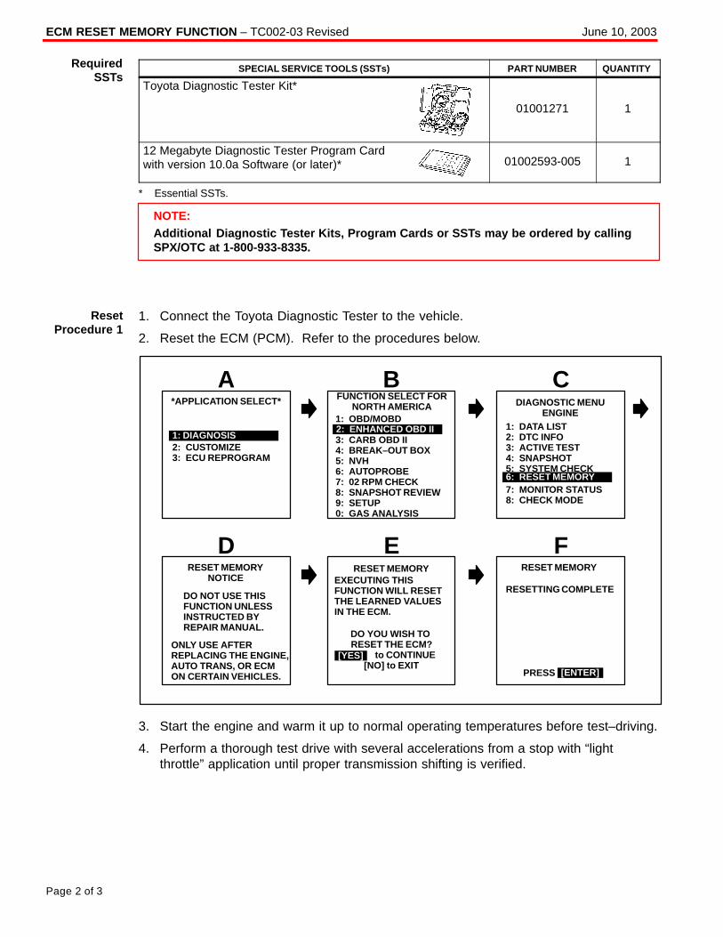
ECM RESET MEMORY FUNCTION – TC002-03 Revised June 10, 2003
Page 2 of 3
SPECIAL SERVICE TOOLS (SSTs) PART NUMBER QUANTITY
Toyota Diagnostic Tester Kit*
01001271 1
12 Megabyte Diagnostic Tester Program Cardwith version 10.0a Software (or later)* 01002593-005 1
* Essential SSTs.
NOTE:Additional Diagnostic Tester Kits, Program Cards or SSTs may be ordered by callingSPX/OTC at 1-800-933-8335.
1. Connect the Toyota Diagnostic Tester to the vehicle.
2. Reset the ECM (PCM). Refer to the procedures below.
DO YOU WISH TO RESET THE ECM?
[YES] to CONTINUE[NO] to EXIT
2: CUSTOMIZE3: ECU REPROGRAM
FUNCTION SELECT FORNORTH AMERICA
B*APPLICATION SELECT*
A
1: DIAGNOSIS
DIAGNOSTIC MENUENGINE
C
DO NOT USE THISFUNCTION UNLESSINSTRUCTED BYREPAIR MANUAL.
RESET MEMORY
ERESET MEMORY
NOTICE
D
[YES]
F
1: OBD/MOBD
3: CARB OBD II4: BREAK–OUT BOX5: NVH6: AUTOPROBE7: 02 RPM CHECK8: SNAPSHOT REVIEW9: SETUP0: GAS ANALYSIS
2: ENHANCED OBD II 1: DATA LIST2: DTC INFO3: ACTIVE TEST4: SNAPSHOT5: SYSTEM CHECK6: RESET MEMORY7: MONITOR STATUS8: CHECK MODE
6: RESET MEMORY
ONLY USE AFTER REPLACING THE ENGINE,AUTO TRANS, OR ECMON CERTAIN VEHICLES.
EXECUTING THIS FUNCTION WILL RESETTHE LEARNED VALUES IN THE ECM.
RESET MEMORY
RESETTING COMPLETE
PRESS [ENTER]
3. Start the engine and warm it up to normal operating temperatures before test–driving.
4. Perform a thorough test drive with several accelerations from a stop with “lightthrottle” application until proper transmission shifting is verified.
RequiredSSTs
ResetProcedure 1
ECM RESET MEMORY FUNCTION – TC002-03 Revised June 10, 2003
Page 3 of 3
1. Record radio station presets and No. 1 driver’s seat memory position.
2. Disconnect the negative battery cable for 5 minutes.
NOTE:Record presets before disconnecting battery cable.
3. Reconnect battery cable and reset radio presets and No. 1 driving position seatmemory.
4. If necessary, perform the following operations:
� Initialize moon roof� Initialize power windows� Calibrate compass
For more detailed information on performing these operations, refer to TIS for theapplicable TSB and/or repair procedures.
5. Start the engine and warm it up to normal operating temperatures before test–driving.
6. Perform a thorough test drive with several accelerations from a stop with “lightthrottle” application until proper transmission shifting is verified.
ResetProcedure 2
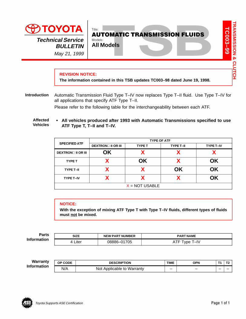
Toyota Supports ASE Certification Page 1 of 1
TC
003–99
Title:
AUTOMATIC TRANSMISSION FLUIDSModels:
All ModelsTechnical Service
BULLETINMay 21, 1999
REVISION NOTICE:The information contained in this TSB updates TC003–98 dated June 19, 1998.
Automatic Transmission Fluid Type T–IV now replaces Type T–II fluid. Use Type T–IV forall applications that specify ATF Type T–II.
Please refer to the following table for the interchangeability between each ATF.
� All vehicles produced after 1993 with Automatic Transmissions specified to useATF Type T, T–II and T–IV.
SPECIFIED ATFTYPE OF ATF
SPECIFIED ATFDEXTRON II OR III TYPE T TYPE T–II TYPE T–IV
DEXTRON II OR III OK X X XTYPE T X OK X OK
TYPE T–II X X OK OKTYPE T–IV X X X OK
X = NOT USABLE
NOTICE:With the exception of mixing ATF Type T with Type T–IV fluids, different types of fluidsmust not be mixed.
SIZE NEW PART NUMBER PART NAME
4 Liter 08886–01705 ATF Type T–IV
OP CODE DESCRIPTION TIME OPN T1 T2
N/A Not Applicable to Warranty – – – –
TR
AN
SM
ISS
ION
& C
LUT
CH
Introduction
AffectedVehicles
PartsInformation
WarrantyInformation
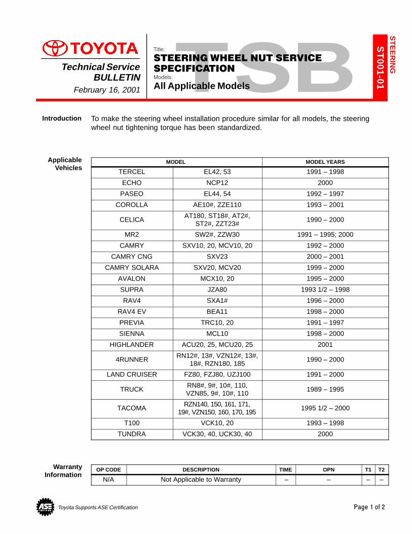
Toyota Supports ASE Certification Page 1 of 2
ST
001-01
Title:
STEERING WHEEL NUT SERVICE
SPECIFICATIONModels:
All Applicable Models
Technical ServiceBULLETIN
February 16, 2001
To make the steering wheel installation procedure similar for all models, the steeringwheel nut tightening torque has been standardized.
MODEL MODEL YEARS
TERCEL EL42, 53 1991 – 1998
ECHO NCP12 2000
PASEO EL44, 54 1992 – 1997
COROLLA AE10#, ZZE110 1993 – 2001
CELICA AT180, ST18#, AT2#,ST2#, ZZT23#
1990 – 2000
MR2 SW2#, ZZW30 1991 – 1995; 2000
CAMRY SXV10, 20, MCV10, 20 1992 – 2000
CAMRY CNG SXV23 2000 – 2001
CAMRY SOLARA SXV20, MCV20 1999 – 2000
AVALON MCX10, 20 1995 – 2000
SUPRA JZA80 1993 1/2 – 1998
RAV4 SXA1# 1996 – 2000
RAV4 EV BEA11 1998 – 2000
PREVIA TRC10, 20 1991 – 1997
SIENNA MCL10 1998 – 2000
HIGHLANDER ACU20, 25, MCU20, 25 2001
4RUNNER RN12#, 13#, VZN12#, 13#,18#, RZN180, 185
1990 – 2000
LAND CRUISER FZ80, FZJ80, UZJ100 1991 – 2000
TRUCK RN8#, 9#, 10#, 110,VZN85, 9#, 10#, 110
1989 – 1995
TACOMA RZN140, 150, 161, 171,19#, VZN150, 160, 170, 195
1995 1/2 – 2000
T100 VCK10, 20 1993 – 1998
TUNDRA VCK30, 40, UCK30, 40 2000
OP CODE DESCRIPTION TIME OPN T1 T2
N/A Not Applicable to Warranty – – – –
ST
EE
RIN
G
Introduction
ApplicableVehicles
WarrantyInformation

STEERING WHEEL NUT SERVICE SPECIFICATION – ST001-01 February 16, 2001
Page 2 of 2
50 N�m (510 kgf �cm, 37 ft �lbf)
35 N�m (360 kgf �cm, 26 ft �lbf)
Steering WheelInstallation Nut
Steering WheelLowerNo. 2 Cover
Steering WheelLowerNo. 3 Cover
Steering Wheel Pad
Steering Wheel
Steering Column
ServiceInformation
Toyota Supports ASE Certification Page 1 of 3
SU
004–99
Title:
WHEEL BALANCE ADJUSTMENT
PROCEDUREModels:
’00 MR2 Spyder
Technical ServiceBULLETIN
December 17, 1999
MR2 Spyder alloy wheels have a decorative outer wheel flange which does not acceptstandard Toyota clip–on type wheel weights. To properly adjust wheel balance, stick–ontype wheel weights must be used. Some wheel balancers do not have a “hidden weight”function which is used to measure the tire/wheel assembly imbalance in the location ofthe stick–on type wheel weights. The procedure included in this bulletin can be used tobalance MR2 Spyder tire/wheel assemblies on wheel balancers that do not have a“hidden weight“ function.
� 2000 model year MR2 Spyder
OP CODE DESCRIPTION TIME OPN T1 T2
N/A Not Applicable to Warranty – – – –
SU
SP
EN
SIO
N
Introduction
ApplicableVehicles
WarrantyInformation
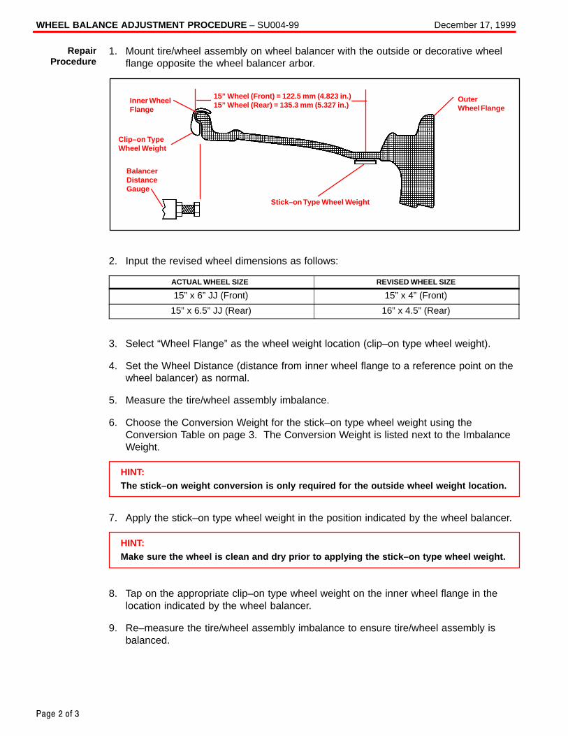
WHEEL BALANCE ADJUSTMENT PROCEDURE – SU004-99 December 17, 1999
Page 2 of 3
1. Mount tire/wheel assembly on wheel balancer with the outside or decorative wheelflange opposite the wheel balancer arbor.
Inner WheelFlange
BalancerDistanceGauge
Clip–on TypeWheel Weight
15” Wheel (Front) = 122.5 mm (4.823 in.)15” Wheel (Rear) = 135.3 mm (5.327 in.)
OuterWheel Flange
Stick–on Type Wheel Weight
2. Input the revised wheel dimensions as follows:
ACTUAL WHEEL SIZE REVISED WHEEL SIZE
15” x 6” JJ (Front) 15” x 4” (Front)
15” x 6.5” JJ (Rear) 16” x 4.5” (Rear)
3. Select “Wheel Flange” as the wheel weight location (clip–on type wheel weight).
4. Set the Wheel Distance (distance from inner wheel flange to a reference point on thewheel balancer) as normal.
5. Measure the tire/wheel assembly imbalance.
6. Choose the Conversion Weight for the stick–on type wheel weight using theConversion Table on page 3. The Conversion Weight is listed next to the ImbalanceWeight.
HINT:The stick–on weight conversion is only required for the outside wheel weight location.
7. Apply the stick–on type wheel weight in the position indicated by the wheel balancer.
HINT:Make sure the wheel is clean and dry prior to applying the stick–on type wheel weight.
8. Tap on the appropriate clip–on type wheel weight on the inner wheel flange in thelocation indicated by the wheel balancer.
9. Re–measure the tire/wheel assembly imbalance to ensure tire/wheel assembly isbalanced.
RepairProcedure
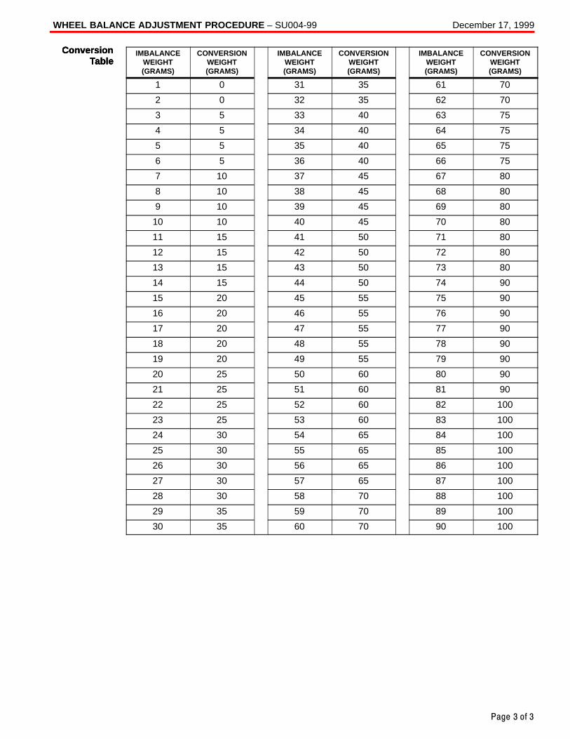
WHEEL BALANCE ADJUSTMENT PROCEDURE – SU004-99 December 17, 1999
Page 3 of 3
IMBALANCEWEIGHT(GRAMS)
CONVERSIONWEIGHT(GRAMS)
IMBALANCEWEIGHT(GRAMS)
CONVERSIONWEIGHT(GRAMS)
IMBALANCEWEIGHT(GRAMS)
CONVERSIONWEIGHT(GRAMS)
1 0 31 35 61 70
2 0 32 35 62 70
3 5 33 40 63 75
4 5 34 40 64 75
5 5 35 40 65 75
6 5 36 40 66 75
7 10 37 45 67 80
8 10 38 45 68 80
9 10 39 45 69 80
10 10 40 45 70 80
11 15 41 50 71 80
12 15 42 50 72 80
13 15 43 50 73 80
14 15 44 50 74 90
15 20 45 55 75 90
16 20 46 55 76 90
17 20 47 55 77 90
18 20 48 55 78 90
19 20 49 55 79 90
20 25 50 60 80 90
21 25 51 60 81 90
22 25 52 60 82 100
23 25 53 60 83 100
24 30 54 65 84 100
25 30 55 65 85 100
26 30 56 65 86 100
27 30 57 65 87 100
28 30 58 70 88 100
29 35 59 70 89 100
30 35 60 70 90 100
ConversionTable
ConversionTable
ConversionTable
Toyota Supports ASE Certification Page 1 of 4
BR
004–00
Title:
BRAKE PAD CLICKING NOISEModels:
’90 – ’00 All ModelsTechnical Service
BULLETINOctober 20, 2000
A clicking type noise may be noticed when first applying the brakes after changingvehicle travel direction (Drive/Forward to Reverse, Reverse to Drive/Forward). This is anormal noise caused by the required brake pad–to–caliper clearances. When thedirection of travel is changed, the brake pads may “shift” towards the new direction oftravel. When the brake pad contacts the caliper, a clicking noise may be heard.
To minimize this clicking noise, a disc brake caliper grease has been made available foruse during brake service/maintenance operations. Under normal usage conditions thisgrease should be effective for a period of 6 months to 1 year.
� 1990 – 2000 model year Toyota vehicles, all models.
PREVIOUS PART NUMBER CURRENT PART NUMBER PART NAME
N/A 08887–80609 Disc Brake Caliper Grease (50 g tube)
OP CODE DESCRIPTION TIME OPN T1 T2
N/A Not Applicable to Warranty – – – –
BR
AK
ES
Introduction
ApplicableVehicles
PartsInformation
WarrantyInformation
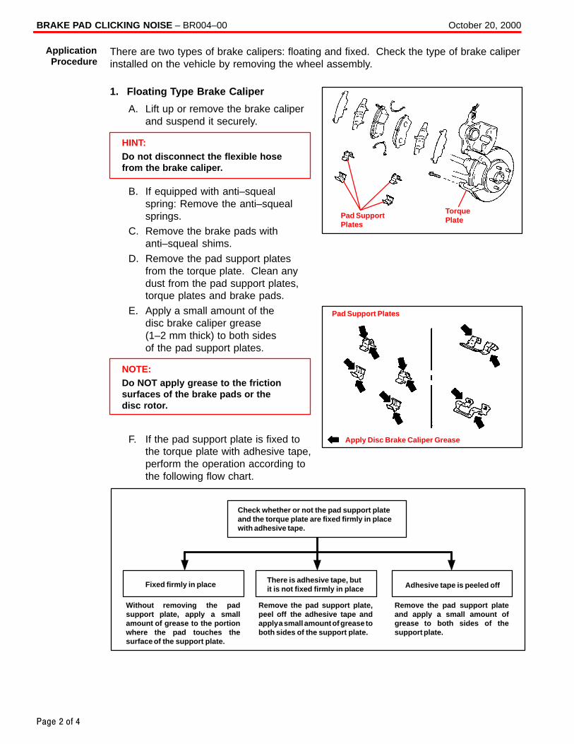
BRAKE PAD CLICKING NOISE – BR004–00 October 20, 2000
Page 2 of 4
There are two types of brake calipers: floating and fixed. Check the type of brake caliperinstalled on the vehicle by removing the wheel assembly.
1. Floating Type Brake Caliper
A. Lift up or remove the brake caliperand suspend it securely.
HINT:Do not disconnect the flexible hosefrom the brake caliper.
B. If equipped with anti–squealspring: Remove the anti–squealsprings.
C. Remove the brake pads withanti–squeal shims.
D. Remove the pad support platesfrom the torque plate. Clean anydust from the pad support plates,torque plates and brake pads.
E. Apply a small amount of the disc brake caliper grease (1–2 mm thick) to both sides of the pad support plates.
NOTE:Do NOT apply grease to the frictionsurfaces of the brake pads or thedisc rotor.
F. If the pad support plate is fixed tothe torque plate with adhesive tape,perform the operation according tothe following flow chart.
Without removing the padsupport plate, apply a smallamount of grease to the portionwhere the pad touches thesurface of the support plate.
Fixed firmly in placeThere is adhesive tape, butit is not fixed firmly in place Adhesive tape is peeled off
Remove the pad support plate,peel off the adhesive tape andapply a small amount of grease toboth sides of the support plate.
Remove the pad support plateand apply a small amount ofgrease to both sides of thesupport plate.
Check whether or not the pad support plateand the torque plate are fixed firmly in placewith adhesive tape.
ApplicationProcedure
Pad SupportPlates
TorquePlate
Apply Disc Brake Caliper Grease
Pad Support Plates
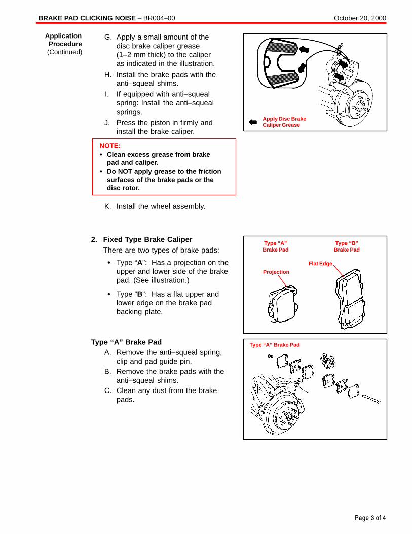
BRAKE PAD CLICKING NOISE – BR004–00 October 20, 2000
Page 3 of 4
G. Apply a small amount of the disc brake caliper grease(1–2 mm thick) to the caliper as indicated in the illustration.
H. Install the brake pads with theanti–squeal shims.
I. If equipped with anti–squealspring: Install the anti–squealsprings.
J. Press the piston in firmly andinstall the brake caliper.
NOTE:� Clean excess grease from brake
pad and caliper.� Do NOT apply grease to the friction
surfaces of the brake pads or thedisc rotor.
K. Install the wheel assembly.
2. Fixed Type Brake CaliperThere are two types of brake pads:
� Type “A”: Has a projection on theupper and lower side of the brakepad. (See illustration.)
� Type “B”: Has a flat upper andlower edge on the brake padbacking plate.
Type “A” Brake PadA. Remove the anti–squeal spring,
clip and pad guide pin.B. Remove the brake pads with the
anti–squeal shims.C. Clean any dust from the brake
pads.
ApplicationProcedure(Continued)
Apply Disc BrakeCaliper Grease
Type “A”Brake Pad
Type “B”Brake Pad
Projection
Flat Edge
Type “A” Brake Pad
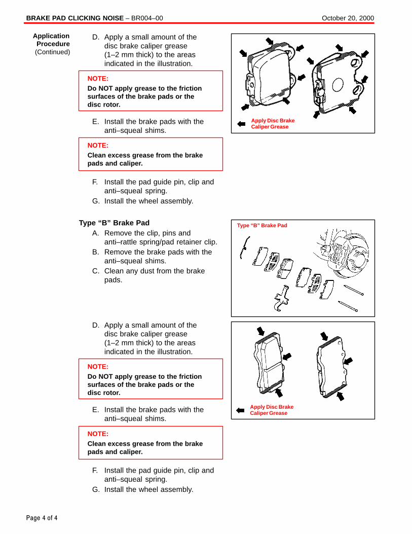
BRAKE PAD CLICKING NOISE – BR004–00 October 20, 2000
Page 4 of 4
D. Apply a small amount of the disc brake caliper grease (1–2 mm thick) to the areasindicated in the illustration.
NOTE:Do NOT apply grease to the frictionsurfaces of the brake pads or thedisc rotor.
E. Install the brake pads with theanti–squeal shims.
NOTE:Clean excess grease from the brakepads and caliper.
F. Install the pad guide pin, clip andanti–squeal spring.
G. Install the wheel assembly.
Type “B” Brake PadA. Remove the clip, pins and
anti–rattle spring/pad retainer clip.B. Remove the brake pads with the
anti–squeal shims.C. Clean any dust from the brake
pads.
D. Apply a small amount of the disc brake caliper grease (1–2 mm thick) to the areasindicated in the illustration.
NOTE:Do NOT apply grease to the frictionsurfaces of the brake pads or thedisc rotor.
E. Install the brake pads with theanti–squeal shims.
NOTE:Clean excess grease from the brakepads and caliper.
F. Install the pad guide pin, clip andanti–squeal spring.
G. Install the wheel assembly.
ApplicationProcedure(Continued)
Apply Disc BrakeCaliper Grease
Type “B” Brake Pad
Apply Disc BrakeCaliper Grease
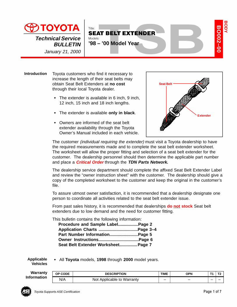
Toyota Supports ASE Certification Page 1 of 7
BO
002–00
Title:
SEAT BELT EXTENDERModels:
’98 – ’00 Model YearTechnical Service
BULLETINJanuary 21, 2000
Toyota customers who find it necessary toincrease the length of their seat belts mayobtain Seat Belt Extenders at no costthrough their local Toyota dealer.
� The extender is available in 6 inch, 9 inch,12 inch, 15 inch and 18 inch lengths.
� The extender is available only in black .
� Owners are informed of the seat beltextender availability through the ToyotaOwner’s Manual included in each vehicle.
The customer (individual requiring the extender) must visit a Toyota dealership to havethe required measurements made and to complete the seat belt extender worksheet.The worksheet will allow the proper fitting and selection of a seat belt extender for thecustomer. The dealership personnel should then determine the applicable part numberand place a Critical Order through the TDN Parts Network.
The dealership service department should complete the affixed Seat Belt Extender Labeland review the “owner instruction sheet” with the customer. The dealership should give acopy of the completed worksheet to the customer and keep the original in the customer’sfile.
To assure utmost owner satisfaction, it is recommended that a dealership designate oneperson to coordinate all activities related to the seat belt extender issue.
From past sales history, it is recommended that dealerships do not stock Seat beltextenders due to low demand and the need for customer fitting.
This bulletin contains the following information:Procedure and Sample Label.................Page 2Application Charts .................................Page 3–4Part Number Information........................Page 5Owner Instructions..................................Page 6Seat Belt Extender Worksheet...............Page 7
� All Toyota models, 1998 through 2000 model years.
OP CODE DESCRIPTION TIME OPN T1 T2
N/A Not Applicable to Warranty – – – –
BO
DY
Introduction
Extender
Seat Belt
ApplicableVehicles
WarrantyInformation
SEAT BELT EXTENDER: ’98 – ’00 – BO002–00 January 21, 2000
Page 2 of 7
1. Owner requests a seat belt extender from dealer.
2. Dealer verifies the need for a seat belt extender and obtains a current copy of thisTSB and copies the worksheet.
3. Dealer measures the customer and completes the worksheet. Dealer determines thecorrect part number and places a Critical Order for the part through the TDN PartsNetwork.
4. Dealer receives seat belt extender and calls the customer in to check fit of the part.
5. If the seat belt extender fit is good, dealership personnel completes the customerinformation label on the part, explains usage of the part, and gives the customer acopy of the completed worksheet.
6. Dealer places a copy of the completed worksheet in the customer’s records.
DEALER
MEASURECUSTOMER
&COMPLETE
WORKSHEET
PLACECRITICALORDER
THROUGHTDN
SHIP SEATBELT
EXTENDERTO
DEALER
TEST FITCUSTOMERWITH PART
COMPLETELABEL AND
ADVISEOWNER
RECEIVECOPY OF
WORKSHEET& USE
EXTENDER
FILEWORKSHEET
INCUSTOMERRECORDS
PARTSSUPPLY
DEALER OWNER
CAUTION
Procedure
Sample SeatBelt Extender
CustomerInformation
Label
SEAT BELT EXTENDER: ’98 – ’00 – BO002–00 January 21, 2000
Page 3 of 7
FRONT SEAT – EXTENDER APPLICATION
MODEL TYPE ’00 ’99 ’98
RAV4 — R–5 R–5 R–5
RAV4 EV — R–5 R–5 R–5
TERCELRH
— R–5 R–5TERCELLH
— R–5 R–5
COUPE (RH)— R–5 R–5
PASEO COUPE (LH)— R–5 R–5
CONVERTIBLE — N–6 N–6
ECHO — K–5 — —
COROLLATMMC PRODUCTION
Q–4 Q–4 Q–4COROLLANUMMI PRODUCTION
Q–4 Q–4 Q–4
MR2 — N–6 — —
CELICALIFTBACK & COUPE N–6
N–6 N–6CELICACONVERTIBLE —
N–6 N–6
CAMRYTMC PRODUCTION
Q–4 Q–4 Q–4CAMRYTMMK PRODUCTION
Q–4 Q–4 Q–4
CAMRY COUPE Q–4 Q–4 —CAMRYSOLARA COVERTIBLE Q–4 — —
SUPRA — — — R–3
AVALON *1 — T–1 Q–2 Q–2
SIENNA — Q–4 Q–4 Q–4
TACOMA *1 — S–1 S–1 S–1
4RUNNER — K–5 K–5 K–5
LAND CRUISER — K–5 K–5 K–5
T100 *1 — — — R–5
TUNDRA *1 — Q–4 — —
*1 The extender must not be used for the center seat belt of Avalon, Tacoma, T100 and Tundra which havebench seats.
Front Seat BeltExtender
Applications
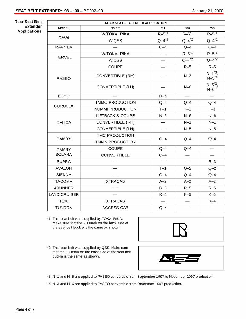
SEAT BELT EXTENDER: ’98 – ’00 – BO002–00 January 21, 2000
Page 4 of 7
REAR SEAT – EXTENDER APPLICATION
MODEL TYPE ’01 ’00 ’99
RAV4W/TOKAI RIKA R–5*1 R–5*1 R–5*1
RAV4W/QSS Q–4*2 Q–4*2 Q–4*2
RAV4 EV — Q–4 Q–4 Q–4
TERCELW/TOKAI RIKA — R–5*1 R–5*1
TERCELW/QSS — Q–4*2 Q–4*2
COUPE — R–5 R–5
PASEOCONVERTIBLE (RH) — N–3 N–1*3,
N–3*4
CONVERTIBLE (LH) — N–6 N–5*3,N–6*4
ECHO — R–5 — —
COROLLATMMC PRODUCTION Q–4 Q–4 Q–4
COROLLANUMMI PRODUCTION T–1 T–1 T–1
LIFTBACK & COUPE N–6 N–6 N–6
CELICA CONVERTIBLE (RH) — N–1 N–1
CONVERTIBLE (LH) — N–5 N–5
CAMRYTMC PRODUCTION
Q–4 Q–4 Q–4CAMRYTMMK PRODUCTION
Q–4 Q–4 Q–4
CAMRY COUPE Q–4 Q–4 —CAMRYSOLARA CONVERTIBLE Q–4 — —
SUPRA — — — R–3
AVALON — T–1 Q–2 Q–2
SIENNA — Q–4 Q–4 Q–4
TACOMA XTRACAB A–2 A–2 A–2
4RUNNER — R–5 R–5 R–5
LAND CRUISER — K–5 K–5 K–5
T100 XTRACAB — — K–4
TUNDRA ACCESS CAB Q–4 — —
*1 This seat belt was supplied by TOKAI RIKA.Make sure that the I/D mark on the back side ofthe seat belt buckle is the same as shown.
*2 This seat belt was supplied by QSS. Make surethat the I/D mark on the back side of the seat beltbuckle is the same as shown.
*3 N–1 and N–5 are applied to PASEO convertible from September 1997 to November 1997 production.
*4 N–3 and N–6 are applied to PASEO convertible from December 1997 production.
Rear Seat BeltExtender
Applications
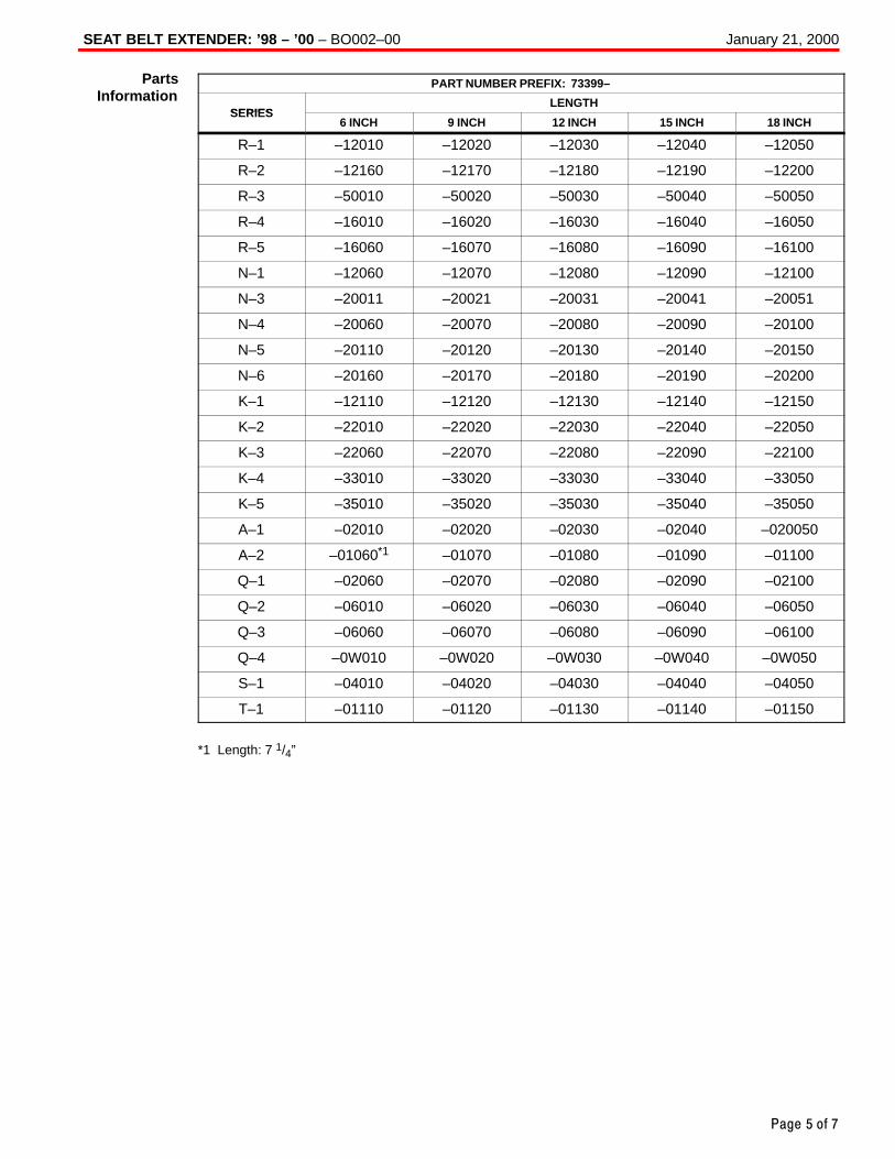
SEAT BELT EXTENDER: ’98 – ’00 – BO002–00 January 21, 2000
Page 5 of 7
PART NUMBER PREFIX: 73399–
SERIESLENGTH
SERIES6 INCH 9 INCH 12 INCH 15 INCH 18 INCH
R–1 –12010 –12020 –12030 –12040 –12050
R–2 –12160 –12170 –12180 –12190 –12200
R–3 –50010 –50020 –50030 –50040 –50050
R–4 –16010 –16020 –16030 –16040 –16050
R–5 –16060 –16070 –16080 –16090 –16100
N–1 –12060 –12070 –12080 –12090 –12100
N–3 –20011 –20021 –20031 –20041 –20051
N–4 –20060 –20070 –20080 –20090 –20100
N–5 –20110 –20120 –20130 –20140 –20150
N–6 –20160 –20170 –20180 –20190 –20200
K–1 –12110 –12120 –12130 –12140 –12150
K–2 –22010 –22020 –22030 –22040 –22050
K–3 –22060 –22070 –22080 –22090 –22100
K–4 –33010 –33020 –33030 –33040 –33050
K–5 –35010 –35020 –35030 –35040 –35050
A–1 –02010 –02020 –02030 –02040 –020050
A–2 –01060*1 –01070 –01080 –01090 –01100
Q–1 –02060 –02070 –02080 –02090 –02100
Q–2 –06010 –06020 –06030 –06040 –06050
Q–3 –06060 –06070 –06080 –06090 –06100
Q–4 –0W010 –0W020 –0W030 –0W040 –0W050
S–1 –04010 –04020 –04030 –04040 –04050
T–1 –01110 –01120 –01130 –01140 –01150
*1 Length: 7 1/4”
PartsInformation
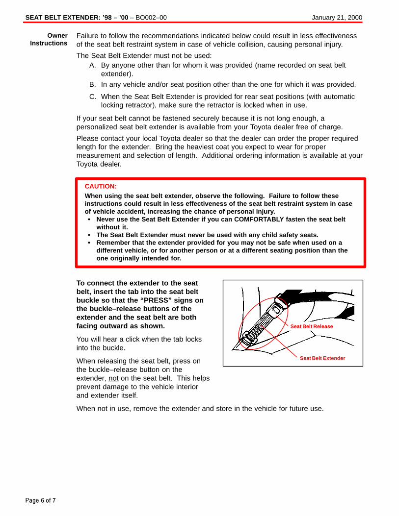
SEAT BELT EXTENDER: ’98 – ’00 – BO002–00 January 21, 2000
Page 6 of 7
Failure to follow the recommendations indicated below could result in less effectivenessof the seat belt restraint system in case of vehicle collision, causing personal injury.
The Seat Belt Extender must not be used:A. By anyone other than for whom it was provided (name recorded on seat belt
extender).
B. In any vehicle and/or seat position other than the one for which it was provided.
C. When the Seat Belt Extender is provided for rear seat positions (with automaticlocking retractor), make sure the retractor is locked when in use.
If your seat belt cannot be fastened securely because it is not long enough, apersonalized seat belt extender is available from your Toyota dealer free of charge.
Please contact your local Toyota dealer so that the dealer can order the proper requiredlength for the extender. Bring the heaviest coat you expect to wear for propermeasurement and selection of length. Additional ordering information is available at yourToyota dealer.
CAUTION:When using the seat belt extender, observe the following. Failure to follow theseinstructions could result in less effectiveness of the seat belt restraint system in caseof vehicle accident, increasing the chance of personal injury.� Never use the Seat Belt Extender if you can COMFORTABLY fasten the seat belt
without it.� The Seat Belt Extender must never be used with any child safety seats.� Remember that the extender provided for you may not be safe when used on a
different vehicle, or for another person or at a different seating position than theone originally intended for.
To connect the extender to the seatbelt, insert the tab into the seat beltbuckle so that the “PRESS” signs onthe buckle–release buttons of theextender and the seat belt are bothfacing outward as shown.
You will hear a click when the tab locksinto the buckle.
When releasing the seat belt, press onthe buckle–release button on theextender, not on the seat belt. This helpsprevent damage to the vehicle interiorand extender itself.
When not in use, remove the extender and store in the vehicle for future use.
OwnerInstructions
Seat Belt Extender
Seat Belt Release
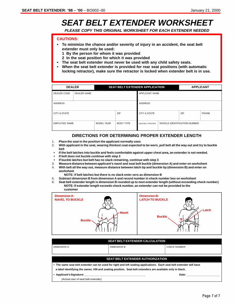
SEAT BELT EXTENDER: ’98 – ’00 – BO002–00 January 21, 2000
Page 7 of 7
SEAT BELT EXTENDER WORKSHEETPLEASE COPY THIS ORIGINAL WORKSHEET FOR EACH EXTENDER NEEDED
CAUTIONS:� To minimize the chance and/or severity of injury in an accident, the seat belt
extender must only be used:1 By the person for whom it was provided2 In the seat position for which it was provided
� The seat belt extender must never be used with any child safety seats.� When the seat belt extender is provided for rear seat positions (with automatic
locking retractor), make sure the retractor is locked when extender belt is in use.
DEALER SEAT BELT EXTENDER APPLICATION APPLICANT
DEALER CODE DEALER NAME APPLICANT NAME
ADDRESS ADDRESS
CITY & STATE ZIP CITY & STATE ZIP PHONE
EMPLOYEE NAME MODEL YEAR BODY TYPE SEATING POSITION VEHICLE IDENTIFICATION NUMBER
DIRECTIONS FOR DETERMINING PROPER EXTENDER LENGTH1. Place the seat in the position the applicant normally uses2. With applicant in the seat, wearing thickest coat expected to be worn, pull belt all the way out and try to buckle
belt� If the belt latches into buckle and feels comfortable against upper chest area, an extender is not needed.� If belt does not buckle continue with step 3� If buckle latches but belt has no slack remaining, continue with step 3
3. Measure distance between applicant’s navel and seat belt buckle (dimension A) and enter on worksheet4. With belt all the way out, measure distance between latch tip and buckle tip (dimension B) and enter on
worksheetNOTE: If belt latches but there is no slack enter zero as dimension B
5. Subtract dimension B from dimension A and record number in check number box on worksheet6. Seat belt extender length is dimension B rounded up to next extender length (without exceeding check number)
NOTE: If extender length exceeds check number, an extender can not be provided to thecustomer
Dimension A:NAVEL TO BUCKLE
Dimension B:LATCH TO BUCKLE
BuckleBuckle
NavelLatch
A B
SEAT BELT EXTENDER CALCULATION
DIMENSION A: DIMENSION B: CHECK NUMBER:
SEAT BELT EXTENDER AUTHORIZATION
� The same seat belt extender can be used for right and left seating applications. Each seat belt extender will have
a label identifying the owner, VIN and seating position. Seat belt extenders are available only in black.
� Applicant’s Signature: _________________________________________ Date: ______________________
(Actual user of seat belt extender)
Toyota Supports ASE Certification Page 1 of 7
BO
002-01
Title:
SEAT BELT EXTENDERModels:
’99 – ’01 Model YearTechnical Service
BULLETINJanuary 26, 2001
TSB UPDATE NOTICE:The information contained in this TSB updates BO020–00 dated August 11, 2000.Revised text is red and underlined .
Toyota customers who find it necessary toincrease the length of their seat belts may obtainSeat Belt Extenders at no cost through their localToyota dealer.
� The extender is available in 6 inch,9 inch, 12 inch, 15 inch and 18 inch lengths.
� The extender is available only in black.
� Owners are informed of the Seat Belt Extenderavailability through the Toyota Owner’s Manualincluded in each vehicle.
The customer (individual requiring the extender) must visit a Toyota dealership to havethe required measurements made and to complete the Seat Belt Extender worksheet.The worksheet will allow the proper fitting and selection of a Seat Belt Extender for thecustomer. The dealership personnel should then determine the applicable part numberand place a Critical Order through the TDN Parts Network.
The dealership service department should complete the affixed Seat Belt ExtenderCustomer Information Label and review the “Owner Instruction Sheet” with the customer.The dealership should give a copy of the completed worksheet to the customer and keepthe original in the customer’s file.
To assure utmost owner satisfaction, it is recommended that a dealership designate oneperson to coordinate all activities related to the Seat Belt Extender issue.
It is recommended that dealerships do not stock Seat Belt Extenders due to the needfor proper fitting to individual customers.
This bulletin contains the following information:Procedure and Sample Label Page 2. . . . . . . . . . Application Charts Pages 3–4. . . . . . . . . . . . . . . . . . . . Part Number Information Page 5. . . . . . . . . . . . . . Owner Instructions Page 6. . . . . . . . . . . . . . . . . . . Seat Belt Extender Worksheet Page 7. . . . . . . . .
� 1999 through 2001 model year Toyota vehicles.
OP CODE DESCRIPTION TIME OPN T1 T2
N/A Not Applicable to Warranty – – – –
BO
DY
Introduction
Seat Belt
Extender
ApplicableVehicles
WarrantyInformation
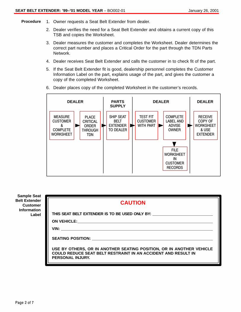
SEAT BELT EXTENDER: ’99–’01 MODEL YEAR – BO002-01 January 26, 2001
Page 2 of 7
1. Owner requests a Seat Belt Extender from dealer.
2. Dealer verifies the need for a Seat Belt Extender and obtains a current copy of thisTSB and copies the Worksheet.
3. Dealer measures the customer and completes the Worksheet. Dealer determines thecorrect part number and places a Critical Order for the part through the TDN PartsNetwork.
4. Dealer receives Seat Belt Extender and calls the customer in to check fit of the part.
5. If the Seat Belt Extender fit is good, dealership personnel completes the CustomerInformation Label on the part, explains usage of the part, and gives the customer acopy of the completed Worksheet.
6. Dealer places copy of the completed Worksheet in the customer’s records.
DEALER PARTSSUPPLY
DEALERDEALER
MEASURECUSTOMER
&COMPLETE
WORKSHEET
PLACECRITICALORDER
THROUGHTDN
SHIP SEATBELT
EXTENDERTO DEALER
TEST FITCUSTOMERWITH PART
COMPLETELABEL AND
ADVISEOWNER
RECEIVECOPY OF
WORKSHEET& USE
EXTENDER
FILEWORKSHEET
INCUSTOMERRECORDS
CAUTION
THIS SEAT BELT EXTENDER IS TO BE USED ONLY BY :
ON VEHICLE:
SEATING POSITION:
VIN:
USE BY OTHERS, OR IN ANOTHER SEATING POSITION, OR IN ANOTHER VEHICLECOULD REDUCE SEAT BELT RESTRAINT IN AN ACCIDENT AND RESULT INPERSONAL INJURY.
Procedure
Sample SeatBelt Extender
CustomerInformation
Label
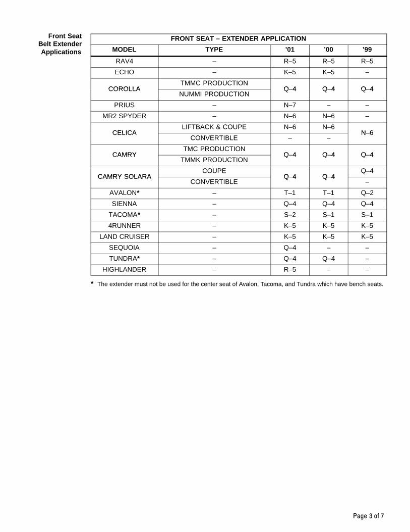
Page 3 of 7
FRONT SEAT – EXTENDER APPLICATION
MODEL TYPE ’01 ’00 ’99
RAV4 – R–5 R–5 R–5
ECHO – K–5 K–5 –
COROLLATMMC PRODUCTION
Q–4 Q–4 Q–4COROLLANUMMI PRODUCTION
Q–4 Q–4 Q–4
PRIUS – N–7 – –
MR2 SPYDER – N–6 N–6 –
CELICALIFTBACK & COUPE N–6 N–6
N–6CELICACONVERTIBLE – –
N–6
CAMRYTMC PRODUCTION
Q–4 Q–4 Q–4CAMRYTMMK PRODUCTION
Q–4 Q–4 Q–4
CAMRY SOLARACOUPE
Q–4 Q–4Q–4
CAMRY SOLARACONVERTIBLE
Q–4 Q–4–
AVALON* – T–1 T–1 Q–2
SIENNA – Q–4 Q–4 Q–4
TACOMA* – S–2 S–1 S–1
4RUNNER – K–5 K–5 K–5
LAND CRUISER – K–5 K–5 K–5
SEQUOIA – Q–4 – –
TUNDRA* – Q–4 Q–4 –
HIGHLANDER – R–5 – –
* The extender must not be used for the center seat of Avalon, Tacoma, and Tundra which have bench seats.
Front SeatBelt ExtenderApplications
SEAT BELT EXTENDER: ’99–’01 MODEL YEAR – BO002-01 January 26, 2001
Page 4 of 7
REAR SEAT – EXTENDER APPLICATION
MODEL TYPE ’01 ’00 ’99
RAV4W/TOKAI RIKA R–5 R–5*1 R–5*1
RAV4W/QSS – Q–4*2 Q–4*2
ECHO – R–5 R–5 –
COROLLATMMC PRODUCTION Q–4 Q–4 Q–4
COROLLANUMMI PRODUCTION T–1 T–1 T–1
PRIUS – N–7 – –
LIFTBACK & COUPE N–6 N–6 N–6
CELICA CONVERTIBLE (RH)– –
N–1
CONVERTIBLE (LH)– –
N–5
CAMRYTMC PRODUCTION
Q–4 Q–4 Q–4CAMRYTMMK PRODUCTION
Q–4 Q–4 Q–4
CAMRY SOLARACOUPE
Q–4 Q–4Q–4
CAMRY SOLARACONVERTIBLE
Q–4 Q–4–
AVALON – T–1 T–1 Q–2
SIENNA – Q–4 Q–4 Q–4
TACOMA XTRACAB A–2 A–2 A–2
4RUNNER – R–5 R–5 R–5
LAND CRUISER – K–5 K–5 K–5
SEQUOIAREAR SEAT #1 T–1
– –SEQUOIAREAR SEAT #2 Q–4
– –
TUNDRA ACCESS CAB Q–4 Q–4 –
HIGHLANDER – R–5 – –
*1 This seat belt was supplied by TOKAIRIKA. Make sure that the I/D mark onthe back side of the seat belt buckleis the same as shown.
*2 This seat belt was supplied by QSS.Make sure that the I/D mark on theback side of the seat belt buckle isthe same as shown.
NOTE:The seat belt extender must not beused for the center rear seat belt.
Rear SeatBelt ExtenderApplications
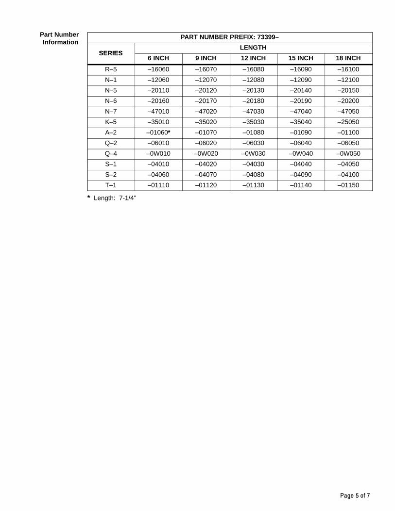
Page 5 of 7
PART NUMBER PREFIX: 73399–
SERIESLENGTH
SERIES6 INCH 9 INCH 12 INCH 15 INCH 18 INCH
R–5 –16060 –16070 –16080 –16090 –16100
N–1 –12060 –12070 –12080 –12090 –12100
N–5 –20110 –20120 –20130 –20140 –20150
N–6 –20160 –20170 –20180 –20190 –20200
N–7 –47010 –47020 –47030 –47040 –47050
K–5 –35010 –35020 –35030 –35040 –25050
A–2 –01060* –01070 –01080 –01090 –01100
Q–2 –06010 –06020 –06030 –06040 –06050
Q–4 –0W010 –0W020 –0W030 –0W040 –0W050
S–1 –04010 –04020 –04030 –04040 –04050
S–2 –04060 –04070 –04080 –04090 –04100
T–1 –01110 –01120 –01130 –01140 –01150
* Length: 7-1/4”
Part NumberInformation
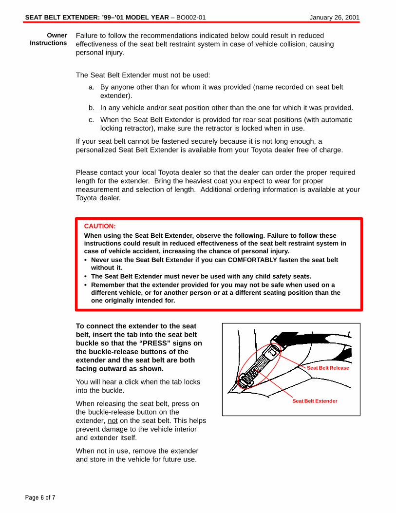
SEAT BELT EXTENDER: ’99–’01 MODEL YEAR – BO002-01 January 26, 2001
Page 6 of 7
Failure to follow the recommendations indicated below could result in reducedeffectiveness of the seat belt restraint system in case of vehicle collision, causingpersonal injury.
The Seat Belt Extender must not be used:
a. By anyone other than for whom it was provided (name recorded on seat beltextender).
b. In any vehicle and/or seat position other than the one for which it was provided.
c. When the Seat Belt Extender is provided for rear seat positions (with automaticlocking retractor), make sure the retractor is locked when in use.
If your seat belt cannot be fastened securely because it is not long enough, apersonalized Seat Belt Extender is available from your Toyota dealer free of charge.
Please contact your local Toyota dealer so that the dealer can order the proper requiredlength for the extender. Bring the heaviest coat you expect to wear for propermeasurement and selection of length. Additional ordering information is available at yourToyota dealer.
CAUTION:When using the Seat Belt Extender, observe the following. Failure to follow theseinstructions could result in reduced effectiveness of the seat belt restraint system incase of vehicle accident, increasing the chance of personal injury.� Never use the Seat Belt Extender if you can COMFORTABLY fasten the seat belt
without it.� The Seat Belt Extender must never be used with any child safety seats.� Remember that the extender provided for you may not be safe when used on a
different vehicle, or for another person or at a different seating position than theone originally intended for.
To connect the extender to the seatbelt, insert the tab into the seat beltbuckle so that the “PRESS” signs onthe buckle-release buttons of theextender and the seat belt are bothfacing outward as shown.
You will hear a click when the tab locksinto the buckle.
When releasing the seat belt, press onthe buckle-release button on theextender, not on the seat belt. This helpsprevent damage to the vehicle interiorand extender itself.
When not in use, remove the extenderand store in the vehicle for future use.
OwnerInstructions
Seat Belt Extender
Seat Belt Release
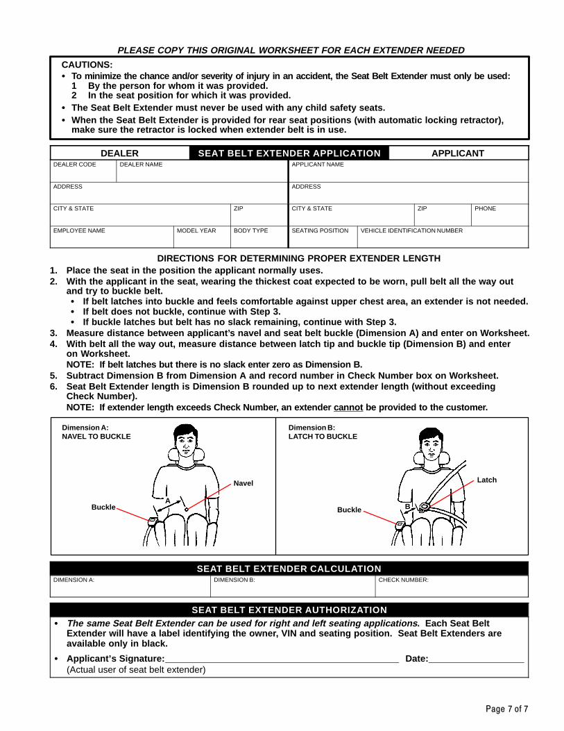
Page 7 of 7
PLEASE COPY THIS ORIGINAL WORKSHEET FOR EACH EXTENDER NEEDED
CAUTIONS:� To minimize the chance and/or severity of injury in an accident, the Seat Belt Extender must only be used:
1 By the person for whom it was provided.2 In the seat position for which it was provided.
� The Seat Belt Extender must never be used with any child safety seats.� When the Seat Belt Extender is provided for rear seat positions (with automatic locking retractor),
make sure the retractor is locked when extender belt is in use.
DEALER SEAT BELT EXTENDER APPLICATION APPLICANTDEALER CODE DEALER NAME APPLICANT NAME
ADDRESS ADDRESS
CITY & STATE ZIP CITY & STATE ZIP PHONE
EMPLOYEE NAME MODEL YEAR BODY TYPE SEATING POSITION VEHICLE IDENTIFICATION NUMBER
DIRECTIONS FOR DETERMINING PROPER EXTENDER LENGTH1. Place the seat in the position the applicant normally uses.2. With the applicant in the seat, wearing the thickest coat expected to be worn, pull belt all the way out
and try to buckle belt.� If belt latches into buckle and feels comfortable against upper chest area, an extender is not needed.� If belt does not buckle, continue with Step 3.� If buckle latches but belt has no slack remaining, continue with Step 3.
3. Measure distance between applicant’s navel and seat belt buckle (Dimension A) and enter on Worksheet.4. With belt all the way out, measure distance between latch tip and buckle tip (Dimension B) and enter
on Worksheet.NOTE: If belt latches but there is no slack enter zero as Dimension B.
5. Subtract Dimension B from Dimension A and record number in Check Number box on Worksheet.6. Seat Belt Extender length is Dimension B rounded up to next extender length (without exceeding
Check Number).NOTE: If extender length exceeds Check Number, an extender ca nnot be provided to the customer.
Dimension A:NAVEL TO BUCKLE
Dimension B:LATCH TO BUCKLE
Buckle
Navel
ABuckle
Latch
B
SEAT BELT EXTENDER CALCULATIONDIMENSION A: DIMENSION B: CHECK NUMBER:
SEAT BELT EXTENDER AUTHORIZATION� The same Seat Belt Extender can be used for right and left seating applications . Each Seat Belt
Extender will have a label identifying the owner, VIN and seating position. Seat Belt Extenders areavailable only in black.
� Applicant’s Signature: Date: (Actual user of seat belt extender)
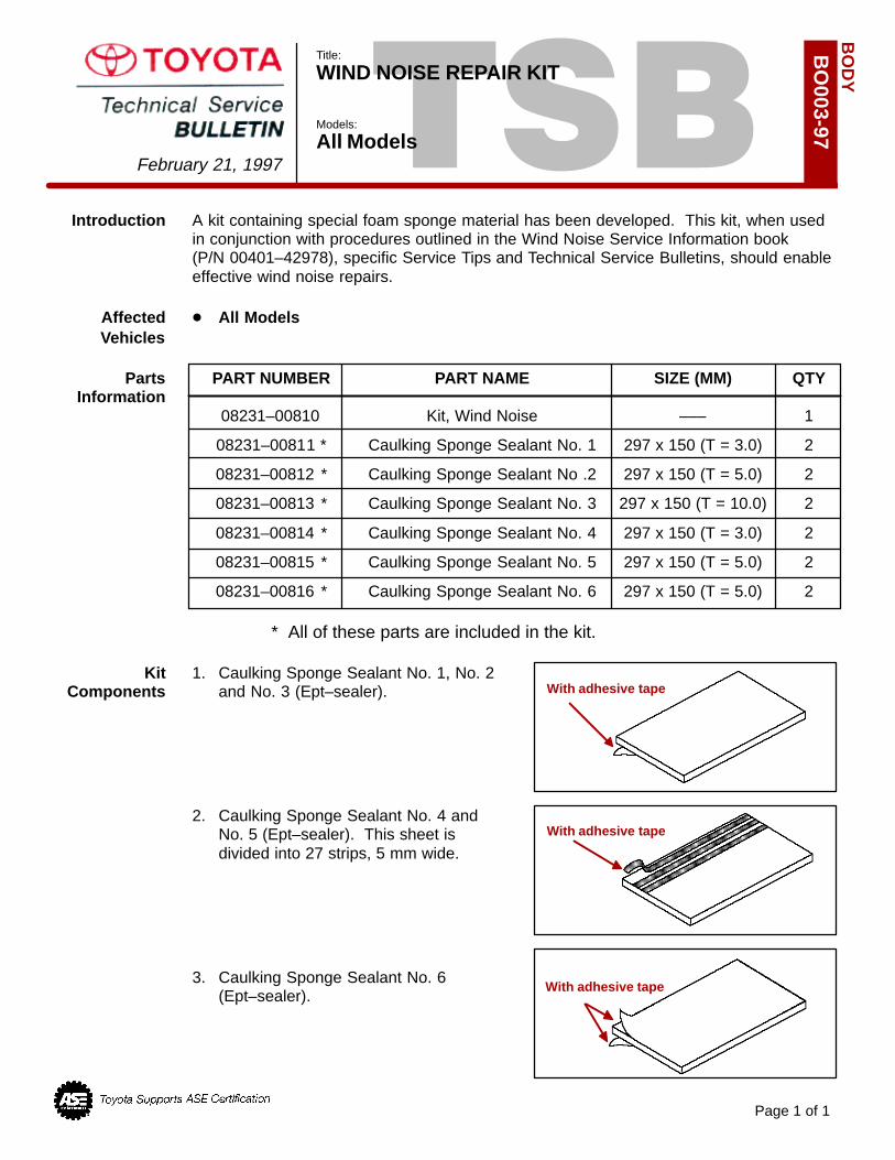
TSBIntroduction A kit containing special foam sponge material has been developed. This kit, when used
in conjunction with procedures outlined in the Wind Noise Service Information book (P/N 00401–42978), specific Service Tips and Technical Service Bulletins, should enableeffective wind noise repairs.
Affected � All ModelsVehicles
Parts PART NUMBER PART NAME SIZE (MM) QTYInformation
08231–00810 Kit, Wind Noise ––– 1
08231–00811 * Caulking Sponge Sealant No. 1 297 x 150 (T = 3.0) 2
08231–00812 * Caulking Sponge Sealant No .2 297 x 150 (T = 5.0) 2
08231–00813 * Caulking Sponge Sealant No. 3 297 x 150 (T = 10.0) 2
08231–00814 * Caulking Sponge Sealant No. 4 297 x 150 (T = 3.0) 2
08231–00815 * Caulking Sponge Sealant No. 5 297 x 150 (T = 5.0) 2
08231–00816 * Caulking Sponge Sealant No. 6 297 x 150 (T = 5.0) 2
* All of these parts are included in the kit.
Kit 1. Caulking Sponge Sealant No. 1, No. 2 Components and No. 3 (Ept–sealer).
2. Caulking Sponge Sealant No. 4 and No. 5 (Ept–sealer). This sheet is divided into 27 strips, 5 mm wide.
3. Caulking Sponge Sealant No. 6 (Ept–sealer).
BO
DY
February 21, 1997
Page 1 of 1
BO
003-97
With adhesive tape
With adhesive tape
Title:
WIND NOISE REPAIR KIT
Models:
All Models
With adhesive tape
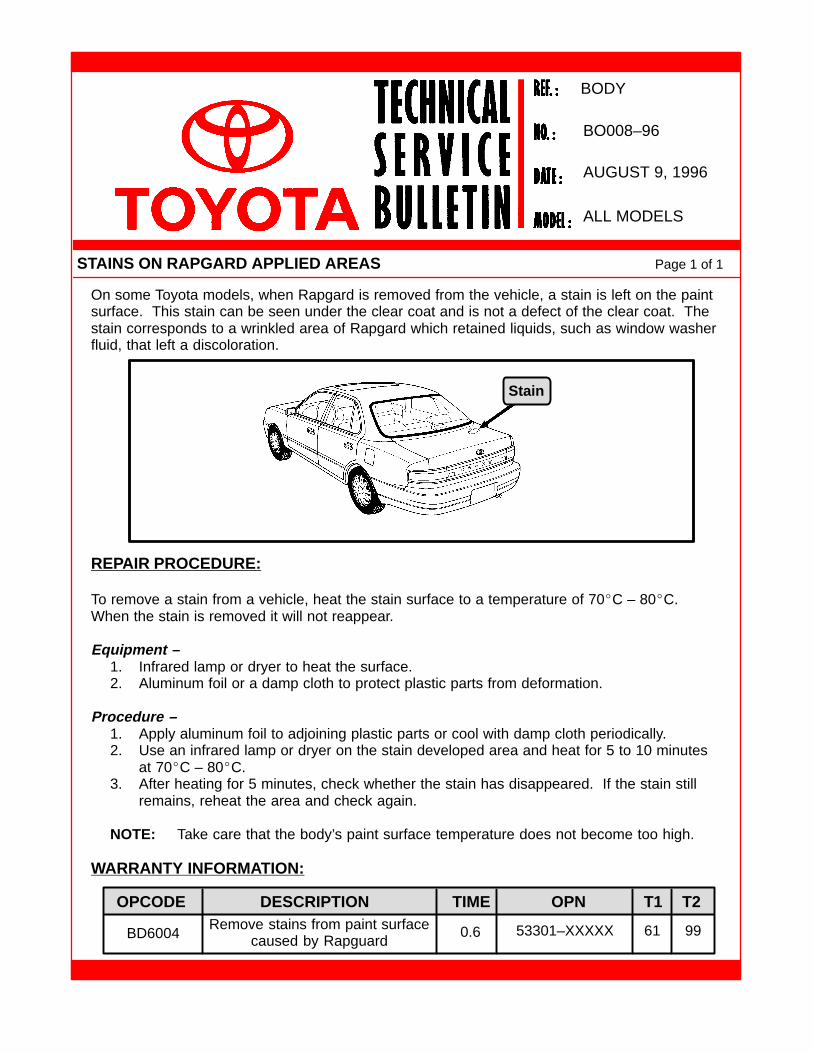
On some Toyota models, when Rapgard is removed from the vehicle, a stain is left on the paintsurface. This stain can be seen under the clear coat and is not a defect of the clear coat. Thestain corresponds to a wrinkled area of Rapgard which retained liquids, such as window washerfluid, that left a discoloration.
REPAIR PROCEDURE:
To remove a stain from a vehicle, heat the stain surface to a temperature of 70�C – 80�C.When the stain is removed it will not reappear.
Equipment –1. Infrared lamp or dryer to heat the surface.2. Aluminum foil or a damp cloth to protect plastic parts from deformation.
Procedure –1. Apply aluminum foil to adjoining plastic parts or cool with damp cloth periodically.2. Use an infrared lamp or dryer on the stain developed area and heat for 5 to 10 minutes
at 70�C – 80�C.3. After heating for 5 minutes, check whether the stain has disappeared. If the stain still
remains, reheat the area and check again.
NOTE: Take care that the body’s paint surface temperature does not become too high.
WARRANTY INFORMATION:
STAINS ON RAPGARD APPLIED AREAS Page 1 of 1
AUGUST 9, 1996
BODY
BO008–96
ALL MODELS
OPCODE DESCRIPTION TIME OPN T1 T2
BD6004Remove stains from paint surface
caused by Rapguard0.6 53301–XXXXX 61 99
Stain
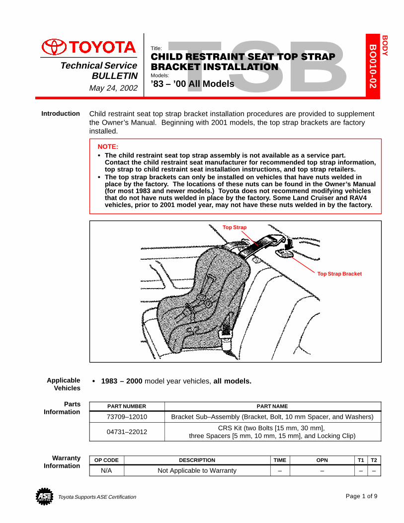
Toyota Supports ASE Certification Page 1 of 9
BO
010-02
Title:
CHILD RESTRAINT SEAT TOP STRAP
BRACKET INSTALLATIONModels:
’83 – ’00 All Models
Technical ServiceBULLETIN
May 24, 2002
Child restraint seat top strap bracket installation procedures are provided to supplementthe Owner’s Manual. Beginning with 2001 models, the top strap brackets are factoryinstalled.
NOTE:� The child restraint seat top strap assembly is not available as a service part.
Contact the child restraint seat manufacturer for recommended top strap information,top strap to child restraint seat installation instructions, and top strap retailers.
� The top strap brackets can only be installed on vehicles that have nuts welded inplace by the factory. The locations of these nuts can be found in the Owner’s Manual(for most 1983 and newer models.) Toyota does not recommend modifying vehiclesthat do not have nuts welded in place by the factory. Some Land Cruiser and RAV4vehicles, prior to 2001 model year, may not have these nuts welded in by the factory.
Top Strap
Top Strap Bracket
� 1983 – 2000 model year vehicles, all models.
PART NUMBER PART NAME
73709–12010 Bracket Sub–Assembly (Bracket, Bolt, 10 mm Spacer, and Washers)
04731–22012 CRS Kit (two Bolts [15 mm, 30 mm], three Spacers [5 mm, 10 mm, 15 mm], and Locking Clip)
OP CODE DESCRIPTION TIME OPN T1 T2
N/A Not Applicable to Warranty – – – –
BO
DY
Introduction
ApplicableVehicles
PartsInformation
WarrantyInformation
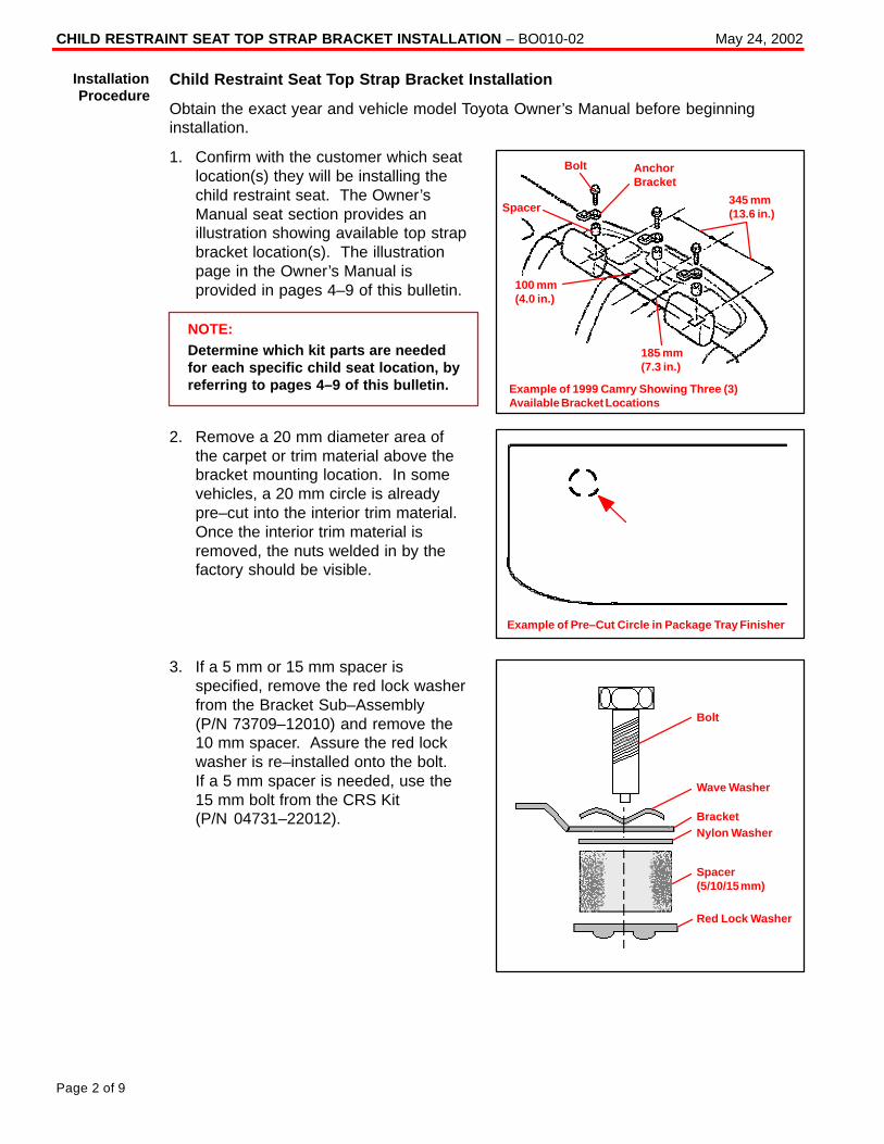
CHILD RESTRAINT SEAT TOP STRAP BRACKET INSTALLATION – BO010-02 May 24, 2002
Page 2 of 9
Child Restraint Seat Top Strap Bracket Installation
Obtain the exact year and vehicle model Toyota Owner’s Manual before beginninginstallation.
1. Confirm with the customer which seatlocation(s) they will be installing thechild restraint seat. The Owner’sManual seat section provides anillustration showing available top strapbracket location(s). The illustrationpage in the Owner’s Manual isprovided in pages 4–9 of this bulletin.
NOTE:Determine which kit parts are neededfor each specific child seat location, byreferring to pages 4–9 of this bulletin.
2. Remove a 20 mm diameter area ofthe carpet or trim material above thebracket mounting location. In somevehicles, a 20 mm circle is alreadypre–cut into the interior trim material.Once the interior trim material isremoved, the nuts welded in by thefactory should be visible.
3. If a 5 mm or 15 mm spacer isspecified, remove the red lock washerfrom the Bracket Sub–Assembly (P/N 73709–12010) and remove the10 mm spacer. Assure the red lockwasher is re–installed onto the bolt. If a 5 mm spacer is needed, use the15 mm bolt from the CRS Kit (P/N 04731–22012).
InstallationProcedure
Bolt
Spacer
100 mm(4.0 in.)
AnchorBracket
185 mm(7.3 in.)
345 mm(13.6 in.)
Example of 1999 Camry Showing Three (3)Available Bracket Locations
Example of Pre–Cut Circle in Package Tray Finisher
Red Lock Washer
Bolt
Wave Washer
BracketNylon Washer
Spacer(5/10/15 mm)
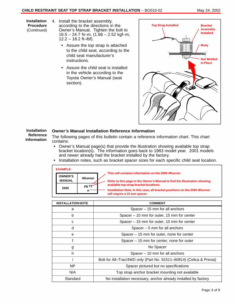
CHILD RESTRAINT SEAT TOP STRAP BRACKET INSTALLATION – BO010-02 May 24, 2002
Page 3 of 9
4. Install the bracket assembly,according to the directions in theOwner’s Manual. Tighten the bolt to16.5 – 24.7 N–m, (1.68 – 2.52 kgf–m,12.2 – 18.2 ft–lbf).
� Assure the top strap is attachedto the child seat, according to thechild seat manufacturer’sinstructions.
� Assure the child seat is installedin the vehicle according to theToyota Owner’s Manual (seatsection).
Owner’s Manual Installation Reference InformationThe following pages of this bulletin contain a reference information chart. This chartcontains:� Owner’s Manual page(s) that provide the illustration showing available top strap
bracket location(s). The information goes back to 1983 model year. 2001 modelsand newer already had the bracket installed by the factory.
� Installation notes, such as bracket spacer sizes for each specific child seat location.
OWNER’SMANUAL
4Runner
pg 73a
2000
This cell contains information on the 2000 4Runner
Refer to this page in the Owner’s Manual to find the illustration showingavailable top strap bracket locations.
Installation Note. In this case, all bracket positions on the 2000 4Runnerwill require a 15 mm spacer.
EXAMPLE:
INSTALLATION NOTE COMMENT
a Spacer – 15 mm for all anchors
b Spacer – 10 mm for outer, 15 mm for center
c Spacer – 15 mm for outer, 10 mm for center
d Spacer – 5 mm for all anchors
e Spacer – 15 mm for outer, none for center
f Spacer – 15 mm for center, none for outer
g No Spacer
h Spacer – 10 mm for all anchors
i Bolt for All–Trac/4WD only (Part No. 91511–60814) (Celica & Previa)
NP Spacer pictured but no specifications
N/A Top strap anchor bracket mounting not available
Standard No installation necessary, anchor already installed by factory
Bracket AssemblyInstalled
Top Strap Installed
Nut Weldedin Place
Body
InstallationProcedure(Continued)
InstallationReference
Information
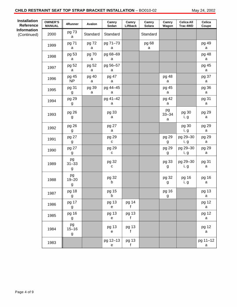
CHILD RESTRAINT SEAT TOP STRAP BRACKET INSTALLATION – BO010-02 May 24, 2002
Page 4 of 9
OWNER’SMANUAL
4Runner AvalonCamrySedan
CamryLiftback
CamrySolara
CamryWagon
Celica AllTrac 4WD
CelicaCoupe
2000 pg 73a
Standard Standard Standard
1999 pg 71a
pg 72a
pg 71–73a
pg 68a
pg 49a
1998 pg 53a
pg 70a
pg 68–69a
pg 48a
1997 pg 52a
pg 52a
pg 56–57a
pg 45a
1996 pg 45NP
pg 40a
pg 47a
pg 48a
pg 37a
1995 pg 31g
pg 39a
pg 44–45a
pg 45a
pg 36a
1994 pg 29g
pg 41–42a
pg 42a
pg 31a
1993 pg 26g
pg 33a
pg33–34
a
pg 30i, g
pg 29a
1992 pg 26g
pg 27a
pg 30i, g
pg 29a
1991 pg 27g
pg 29c
pg 29g
pg 29–30i, g
pg 29a
1990 pg 27g
pg 29c
pg 29g
pg 29–30i, g
pg 29a
1989pg
31–33g
pg 32c
pg 33g
pg 29–30i, g
pg 31a
1988pg
19–20g
pg 32b
pg 32g
pg 16i, g
pg 16a
1987 pg 18g
pg 15b
pg 16g
pg 13a
1986 pg 17g
pg 13e
pg 14f
pg 12a
1985 pg 16g
pg 13e
pg 13f
pg 12a
1984pg
15–16g
pg 13e
pg 13f
pg 12a
1983 pg 12–13e
pg 13f
pg 11–12a
InstallationReference
Information(Continued)
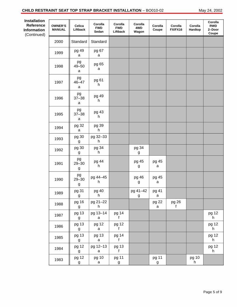
CHILD RESTRAINT SEAT TOP STRAP BRACKET INSTALLATION – BO010-02 May 24, 2002
Page 5 of 9
OWNER’SMANUAL
CelicaLiftback
CorollaFWD
Sedan
CorollaFWD
Liftback
Corolla4WD
Wagon
CorollaCoupe
CorollaFX/FX16
CorollaHardtop
CorollaRWD
2–DoorCoupe
2000 Standard Standard
1999 pg 49a
pg 67a
1998pg
49–50a
pg 65a
1997pg
46–47a
pg 61h
1996pg
37–38a
pg 49h
1995pg
37–38a
pg 43h
1994 pg 32a
pg 39h
1993 pg 30g
pg 32–33h
1992 pg 30g
pg 34h
pg 34g
1991pg
29–30g
pg 44h
pg 45g
pg 45a
1990pg
29–30g
pg 44–45h
pg 46g
pg 45a
1989 pg 31g
pg 40h
pg 41–42g
pg 41a
1988 pg 16g
pg 21–22h
pg 22a
pg 26f
1987 pg 13g
pg 13–14a
pg 14f
pg 12h
1986 pg 13g
pg 12a
pg 12f
pg 12h
1985 pg 13g
pg 13a
pg 14f
pg 12h
1984 pg 12g
pg 12–13a
pg 13f
pg 12h
1983 pg 12g
pg 10a
pg 11g
pg 11g
pg 10h
InstallationReference
Information(Continued)
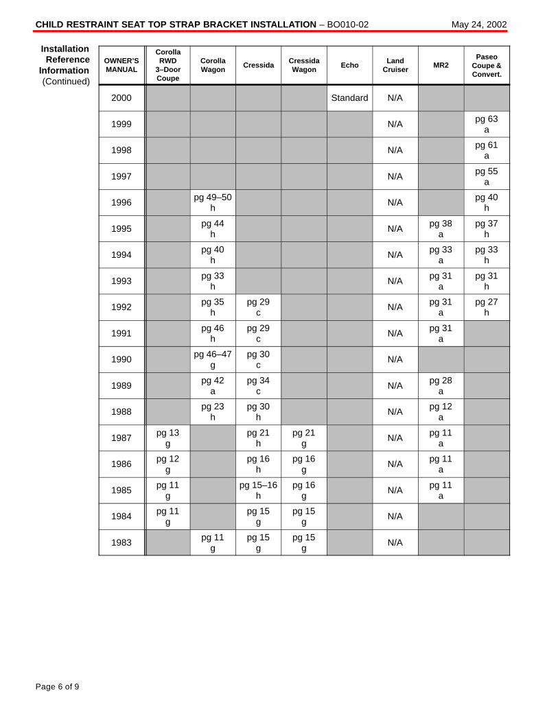
CHILD RESTRAINT SEAT TOP STRAP BRACKET INSTALLATION – BO010-02 May 24, 2002
Page 6 of 9
OWNER’SMANUAL
CorollaRWD
3–DoorCoupe
CorollaWagon
CressidaCressidaWagon
EchoLand
CruiserMR2
PaseoCoupe &Convert.
2000 Standard N/A
1999 N/A pg 63a
1998 N/A pg 61a
1997 N/A pg 55a
1996 pg 49–50h
N/A pg 40h
1995 pg 44h
N/A pg 38a
pg 37h
1994 pg 40h
N/A pg 33a
pg 33h
1993 pg 33h
N/A pg 31a
pg 31h
1992 pg 35h
pg 29c
N/A pg 31a
pg 27h
1991 pg 46h
pg 29c
N/A pg 31a
1990 pg 46–47g
pg 30c
N/A
1989 pg 42a
pg 34c
N/A pg 28a
1988 pg 23h
pg 30h
N/A pg 12a
1987 pg 13g
pg 21h
pg 21g
N/A pg 11a
1986 pg 12g
pg 16h
pg 16g
N/A pg 11a
1985 pg 11g
pg 15–16h
pg 16g
N/A pg 11a
1984 pg 11g
pg 15g
pg 15g
N/A
1983 pg 11g
pg 15g
pg 15g
N/A
InstallationReference
Information(Continued)
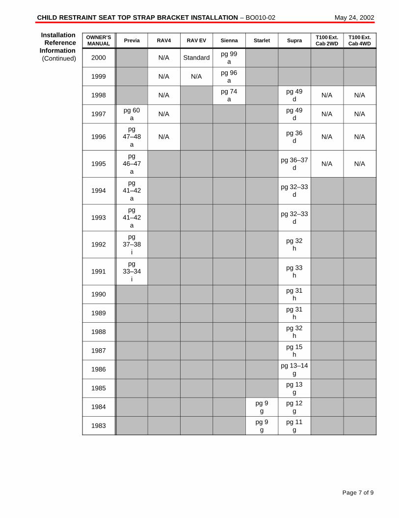
CHILD RESTRAINT SEAT TOP STRAP BRACKET INSTALLATION – BO010-02 May 24, 2002
Page 7 of 9
OWNER’SMANUAL
Previa RAV4 RAV EV Sienna Starlet SupraT100 Ext.Cab 2WD
T100 Ext.Cab 4WD
2000 N/A Standard pg 99a
1999 N/A N/A pg 96a
1998 N/A pg 74a
pg 49d
N/A N/A
1997 pg 60a
N/A pg 49d
N/A N/A
1996pg
47–48a
N/A pg 36d
N/A N/A
1995pg
46–47a
pg 36–37d
N/A N/A
1994pg
41–42a
pg 32–33d
1993pg
41–42a
pg 32–33d
1992pg
37–38i
pg 32h
1991pg
33–34i
pg 33h
1990 pg 31h
1989 pg 31h
1988 pg 32h
1987 pg 15h
1986 pg 13–14g
1985 pg 13g
1984 pg 9g
pg 12g
1983 pg 9g
pg 11g
InstallationReference
Information(Continued)
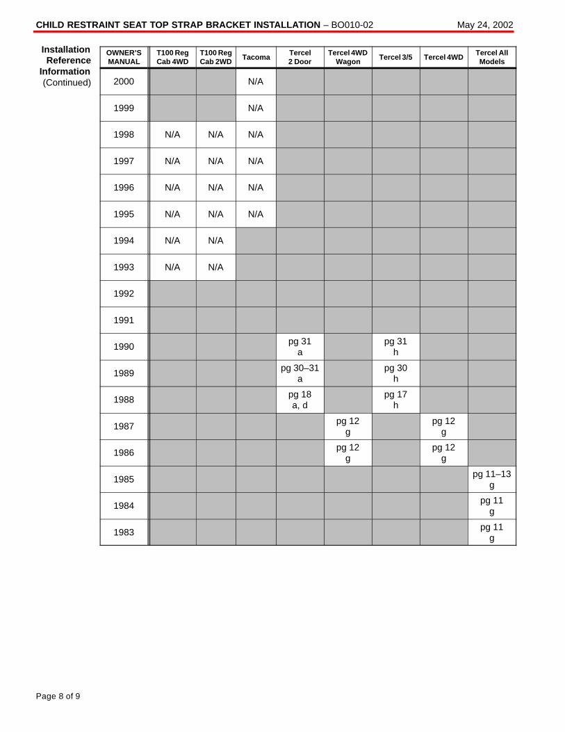
CHILD RESTRAINT SEAT TOP STRAP BRACKET INSTALLATION – BO010-02 May 24, 2002
Page 8 of 9
OWNER’SMANUAL
T100 RegCab 4WD
T100 RegCab 2WD
TacomaTercel2 Door
Tercel 4WDWagon
Tercel 3/5 Tercel 4WDTercel AllModels
2000 N/A
1999 N/A
1998 N/A N/A N/A
1997 N/A N/A N/A
1996 N/A N/A N/A
1995 N/A N/A N/A
1994 N/A N/A
1993 N/A N/A
1992
1991
1990 pg 31a
pg 31h
1989 pg 30–31a
pg 30h
1988 pg 18a, d
pg 17h
1987 pg 12g
pg 12g
1986 pg 12g
pg 12g
1985 pg 11–13g
1984 pg 11g
1983 pg 11g
InstallationReference
Information(Continued)
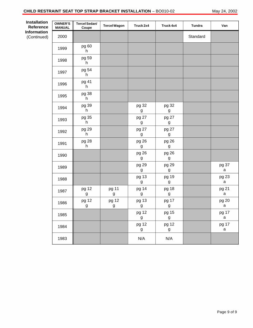
CHILD RESTRAINT SEAT TOP STRAP BRACKET INSTALLATION – BO010-02 May 24, 2002
Page 9 of 9
OWNER’SMANUAL
Tercel Sedan/Coupe
Tercel Wagon Truck 2x4 Truck 4x4 Tundra Van
2000 Standard
1999 pg 60h
1998 pg 59h
1997 pg 54h
1996 pg 41h
1995 pg 38h
1994 pg 39h
pg 32g
pg 32g
1993 pg 35h
pg 27g
pg 27g
1992 pg 29h
pg 27g
pg 27g
1991 pg 28h
pg 26g
pg 26g
1990 pg 26g
pg 26g
1989 pg 29g
pg 29g
pg 37a
1988 pg 13g
pg 19g
pg 23a
1987 pg 12g
pg 11g
pg 14g
pg 18g
pg 21a
1986 pg 12g
pg 12g
pg 13g
pg 17g
pg 20a
1985 pg 12g
pg 15g
pg 17a
1984 pg 12g
pg 12g
pg 17a
1983 N/A N/A
InstallationReference
Information(Continued)
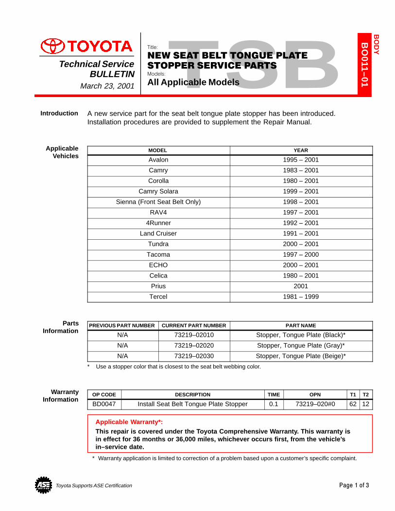
Toyota Supports ASE Certification Page 1 of 3
BO
011–01
Title:
NEW SEAT BELT TONGUE PLATE
STOPPER SERVICE PARTSModels:
All Applicable Models
Technical ServiceBULLETIN
March 23, 2001
A new service part for the seat belt tongue plate stopper has been introduced.Installation procedures are provided to supplement the Repair Manual.
MODEL YEAR
Avalon 1995 – 2001
Camry 1983 – 2001
Corolla 1980 – 2001
Camry Solara 1999 – 2001
Sienna (Front Seat Belt Only) 1998 – 2001
RAV4 1997 – 2001
4Runner 1992 – 2001
Land Cruiser 1991 – 2001
Tundra 2000 – 2001
Tacoma 1997 – 2000
ECHO 2000 – 2001
Celica 1980 – 2001
Prius 2001
Tercel 1981 – 1999
PREVIOUS PART NUMBER CURRENT PART NUMBER PART NAME
N/A 73219–02010 Stopper, Tongue Plate (Black)*
N/A 73219–02020 Stopper, Tongue Plate (Gray)*
N/A 73219–02030 Stopper, Tongue Plate (Beige)*
* Use a stopper color that is closest to the seat belt webbing color.
OP CODE DESCRIPTION TIME OPN T1 T2
BD0047 Install Seat Belt Tongue Plate Stopper 0.1 73219–020#0 62 12
Applicable Warranty*:This repair is covered under the Toyota Comprehensive Warranty. This warranty isin effect for 36 months or 36,000 miles, whichever occurs first, from the vehicle’sin–service date.
* Warranty application is limited to correction of a problem based upon a customer’s specific complaint.
BO
DY
Introduction
ApplicableVehicles
PartsInformation
WarrantyInformation
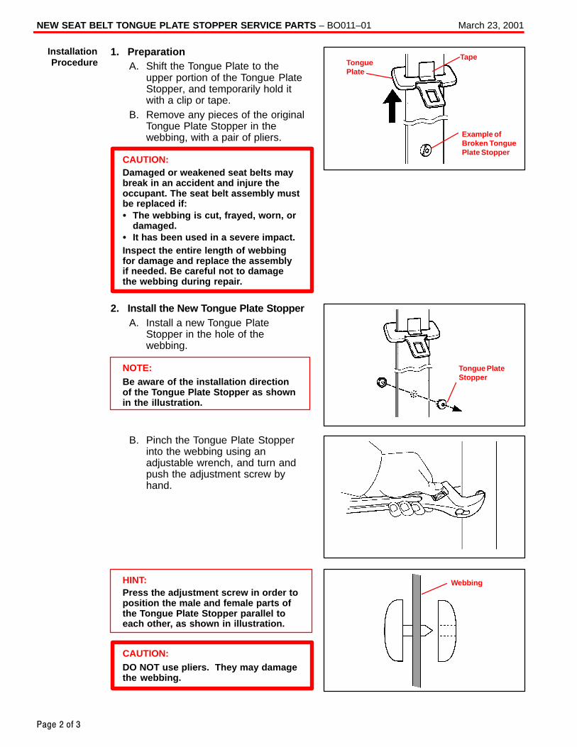
NEW SEAT BELT TONGUE PLATE STOPPER SERVICE PARTS – BO011–01 March 23, 2001
Page 2 of 3
1. PreparationA. Shift the Tongue Plate to the
upper portion of the Tongue PlateStopper, and temporarily hold itwith a clip or tape.
B. Remove any pieces of the originalTongue Plate Stopper in thewebbing, with a pair of pliers.
CAUTION:Damaged or weakened seat belts maybreak in an accident and injure theoccupant. The seat belt assembly mustbe replaced if:� The webbing is cut, frayed, worn, or
damaged.� It has been used in a severe impact.Inspect the entire length of webbingfor damage and replace the assemblyif needed. Be careful not to damagethe webbing during repair.
2. Install the New Tongue Plate StopperA. Install a new Tongue Plate
Stopper in the hole of thewebbing.
NOTE:Be aware of the installation directionof the Tongue Plate Stopper as shownin the illustration.
B. Pinch the Tongue Plate Stopperinto the webbing using anadjustable wrench, and turn andpush the adjustment screw byhand.
HINT:Press the adjustment screw in order toposition the male and female parts ofthe Tongue Plate Stopper parallel toeach other, as shown in illustration.
CAUTION:DO NOT use pliers. They may damagethe webbing.
InstallationProcedure Tongue
Plate
Tape
Example ofBroken TonguePlate Stopper
Tongue PlateStopper
Webbing
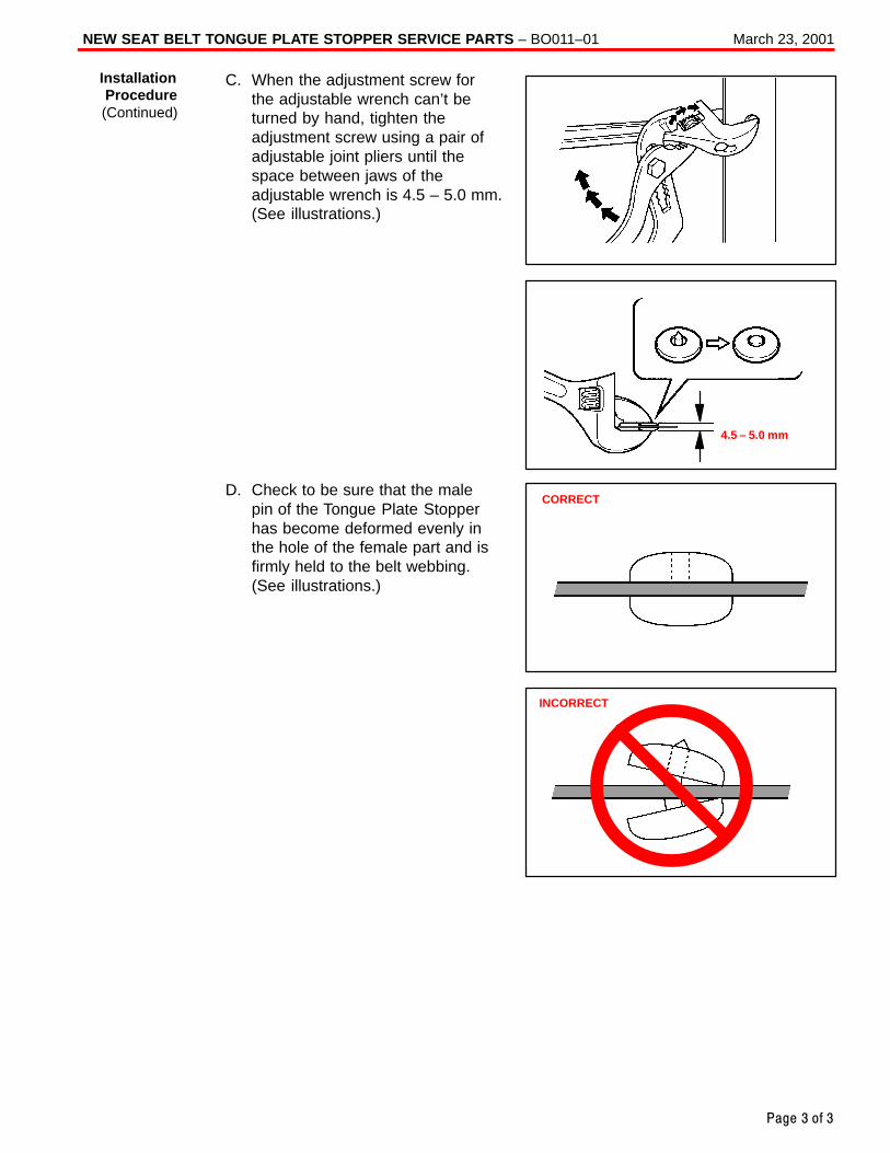
NEW SEAT BELT TONGUE PLATE STOPPER SERVICE PARTS – BO011–01 March 23, 2001
Page 3 of 3
C. When the adjustment screw forthe adjustable wrench can’t beturned by hand, tighten theadjustment screw using a pair ofadjustable joint pliers until thespace between jaws of theadjustable wrench is 4.5 – 5.0 mm.(See illustrations.)
D. Check to be sure that the malepin of the Tongue Plate Stopperhas become deformed evenly inthe hole of the female part and isfirmly held to the belt webbing. (See illustrations.)
4.5 – 5.0 mm
InstallationProcedure(Continued)
CORRECT
INCORRECT
Toyota Supports ASE Certification Page 1 of 1
BO
017-03
Title:
TRIM GARNISH LOOSEModels:
All ModelsTechnical Service
BULLETINSeptember 9, 2003
TSB REVISION NOTICE:March 3, 2004: The TSB has been changed to include new inspection and replacement instructions.Previous versions of this TSB should be discarded.
Customers may experience an interior trim panel either loose or fitting poorly due to adeformed or missing panel attachment clips. When a trim garnish (A, B, C or D pillargarnish, door trim panel, etc.) is removed and reinstalled using the old clips, there is apossibility that the garnish may exhibit a loose condition. To prevent this condition fromoccurring, please use the following procedures.
All Models – All trim panel attachment clips must be inspected prior to reassembly andreplaced if any damage or wear is detected. If no damage is visible, the clip may bereused. Always check to make sure that the garnish is properly attached afterreinstallation of all interior trim panels.
2002 – 2004 model year Camry and 2004 model year Solara – When removing theA–pillar garnish panels, replace the white plastic attachment clips (P/N 90467–A0025).
� All models.
OP CODE DESCRIPTION TIME OFP T1 T2
N/A Not Applicable to Warranty – – – –
BO
DY
Introduction
Inspection/Replacement
Procedure
ApplicableVehicles
WarrantyInformation

Toyota Supports ASE Certification Page 1 of 7
BO
020–00
Title:
SEAT BELT EXTENDERModels:
’99 – ’01 Model YearTechnical Service
BULLETINAugust 11, 2000
Toyota customers who find it necessary toincrease the length of their seat belts mayobtain Seat Belt Extenders at no costthrough their local Toyota dealer.
� The extender is available in 6 inch, 9 inch,12 inch, 15 inch and 18 inch lengths.
� The extender is available only in black .
� Owners are informed of the seat beltextender availability through the ToyotaOwner’s Manual included in each vehicle.
The customer (individual requiring the extender) must visit a Toyota dealership to havethe required measurements made and to complete the seat belt extender worksheet.The worksheet will allow the proper fitting and selection of a seat belt extender for thecustomer. The dealership personnel should then determine the applicable part numberand place a Critical Order through the TDN Parts Network.
The dealership service department should complete the affixed Seat Belt Extender Labeland review the “owner instruction sheet” with the customer. The dealership should give acopy of the completed worksheet to the customer and keep the original in the customer’sfile.
To assure utmost owner satisfaction, it is recommended that a dealership designate oneperson to coordinate all activities related to the seat belt extender issue.
From past sales history, it is recommended that dealerships do not stock Seat beltextenders due to low demand and the need for customer fitting.
This bulletin contains the following information:Procedure and Sample Label.................Page 2Application Charts .................................Page 3–4Part Number Information........................Page 5Owner Instructions..................................Page 6Seat Belt Extender Worksheet...............Page 7
� 1999 through 2001 model year Toyota vehicles.
OP CODE DESCRIPTION TIME OPN T1 T2
N/A Not Applicable to Warranty – – – –
BO
DY
Introduction
Extender
Seat Belt
ApplicableVehicles
WarrantyInformation
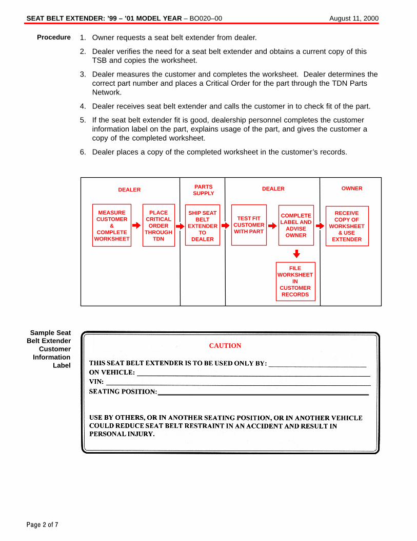
SEAT BELT EXTENDER: ’99 – ’01 MODEL YEAR – BO020–00 August 11, 2000
Page 2 of 7
1. Owner requests a seat belt extender from dealer.
2. Dealer verifies the need for a seat belt extender and obtains a current copy of thisTSB and copies the worksheet.
3. Dealer measures the customer and completes the worksheet. Dealer determines thecorrect part number and places a Critical Order for the part through the TDN PartsNetwork.
4. Dealer receives seat belt extender and calls the customer in to check fit of the part.
5. If the seat belt extender fit is good, dealership personnel completes the customerinformation label on the part, explains usage of the part, and gives the customer acopy of the completed worksheet.
6. Dealer places a copy of the completed worksheet in the customer’s records.
DEALER
MEASURECUSTOMER
&COMPLETE
WORKSHEET
PLACECRITICALORDER
THROUGHTDN
SHIP SEATBELT
EXTENDERTO
DEALER
TEST FITCUSTOMERWITH PART
COMPLETELABEL AND
ADVISEOWNER
RECEIVECOPY OF
WORKSHEET& USE
EXTENDER
FILEWORKSHEET
INCUSTOMERRECORDS
PARTSSUPPLY
DEALER OWNER
CAUTION
Procedure
Sample SeatBelt Extender
CustomerInformation
Label
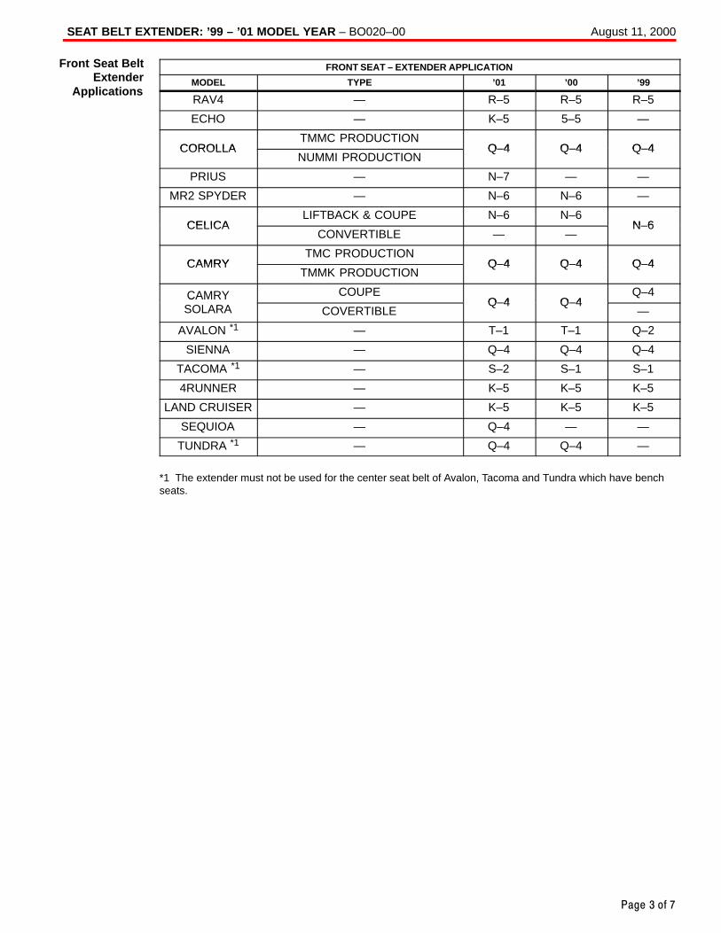
SEAT BELT EXTENDER: ’99 – ’01 MODEL YEAR – BO020–00 August 11, 2000
Page 3 of 7
FRONT SEAT – EXTENDER APPLICATION
MODEL TYPE ’01 ’00 ’99
RAV4 — R–5 R–5 R–5
ECHO — K–5 5–5 —
COROLLATMMC PRODUCTION
Q–4 Q–4 Q–4COROLLANUMMI PRODUCTION
Q–4 Q–4 Q–4
PRIUS — N–7 — —
MR2 SPYDER — N–6 N–6 —
CELICALIFTBACK & COUPE N–6 N–6
N–6CELICACONVERTIBLE — —
N–6
CAMRYTMC PRODUCTION
Q–4 Q–4 Q–4CAMRYTMMK PRODUCTION
Q–4 Q–4 Q–4
CAMRY COUPEQ–4 Q–4
Q–4CAMRYSOLARA COVERTIBLE
Q–4 Q–4—
AVALON *1 — T–1 T–1 Q–2
SIENNA — Q–4 Q–4 Q–4
TACOMA *1 — S–2 S–1 S–1
4RUNNER — K–5 K–5 K–5
LAND CRUISER — K–5 K–5 K–5
SEQUIOA — Q–4 — —
TUNDRA *1 — Q–4 Q–4 —
*1 The extender must not be used for the center seat belt of Avalon, Tacoma and Tundra which have benchseats.
Front Seat BeltExtender
Applications
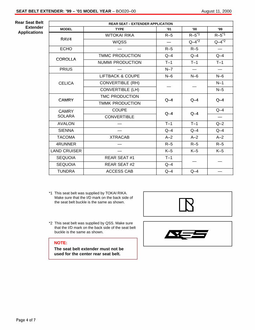
SEAT BELT EXTENDER: ’99 – ’01 MODEL YEAR – BO020–00 August 11, 2000
Page 4 of 7
REAR SEAT – EXTENDER APPLICATION
MODEL TYPE ’01 ’00 ’99
RAV4W/TOKAI RIKA R–5 R–5*1 R–5*1
RAV4W/QSS — Q–4*2 Q–4*2
ECHO — R–5 R–5 —
COROLLATMMC PRODUCTION Q–4 Q–4 Q–4
COROLLANUMMI PRODUCTION T–1 T–1 T–1
PRIUS — N–7 — —
LIFTBACK & COUPE N–6 N–6 N–6
CELICA CONVERTIBLE (RH)— —
N–1
CONVERTIBLE (LH)— —
N–5
CAMRYTMC PRODUCTION
Q–4 Q–4 Q–4CAMRYTMMK PRODUCTION
Q–4 Q–4 Q–4
CAMRY COUPEQ–4 Q–4
Q–4CAMRYSOLARA CONVERTIBLE
Q–4 Q–4—
AVALON — T–1 T–1 Q–2
SIENNA — Q–4 Q–4 Q–4
TACOMA XTRACAB A–2 A–2 A–2
4RUNNER — R–5 R–5 R–5
LAND CRUISER — K–5 K–5 K–5
SEQUOIA REAR SEAT #1 T–1— —
SEQUOIA REAR SEAT #2 Q–4— —
TUNDRA ACCESS CAB Q–4 Q–4 —
*1 This seat belt was supplied by TOKAI RIKA.Make sure that the I/D mark on the back side ofthe seat belt buckle is the same as shown.
*2 This seat belt was supplied by QSS. Make surethat the I/D mark on the back side of the seat beltbuckle is the same as shown.
NOTE:The seat belt extender must not beused for the center rear seat belt.
Rear Seat BeltExtender
Applications
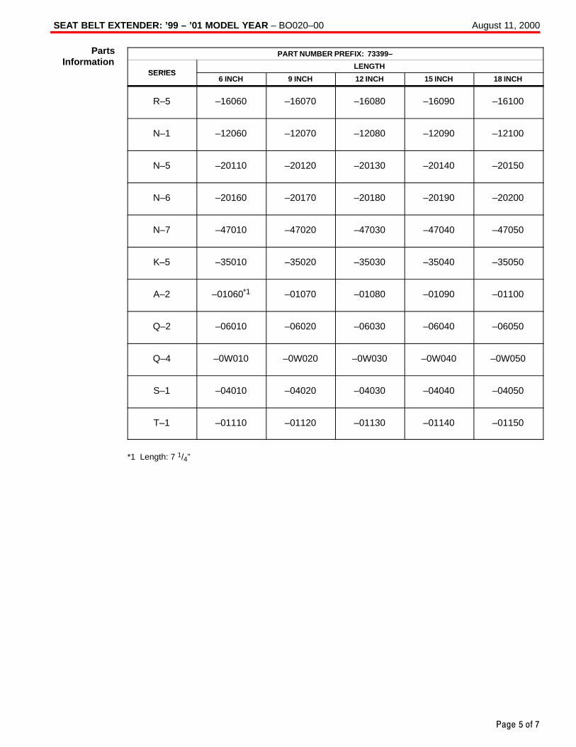
SEAT BELT EXTENDER: ’99 – ’01 MODEL YEAR – BO020–00 August 11, 2000
Page 5 of 7
PART NUMBER PREFIX: 73399–
SERIESLENGTH
SERIES6 INCH 9 INCH 12 INCH 15 INCH 18 INCH
R–5 –16060 –16070 –16080 –16090 –16100
N–1 –12060 –12070 –12080 –12090 –12100
N–5 –20110 –20120 –20130 –20140 –20150
N–6 –20160 –20170 –20180 –20190 –20200
N–7 –47010 –47020 –47030 –47040 –47050
K–5 –35010 –35020 –35030 –35040 –35050
A–2 –01060*1 –01070 –01080 –01090 –01100
Q–2 –06010 –06020 –06030 –06040 –06050
Q–4 –0W010 –0W020 –0W030 –0W040 –0W050
S–1 –04010 –04020 –04030 –04040 –04050
T–1 –01110 –01120 –01130 –01140 –01150
*1 Length: 7 1/4”
PartsInformation
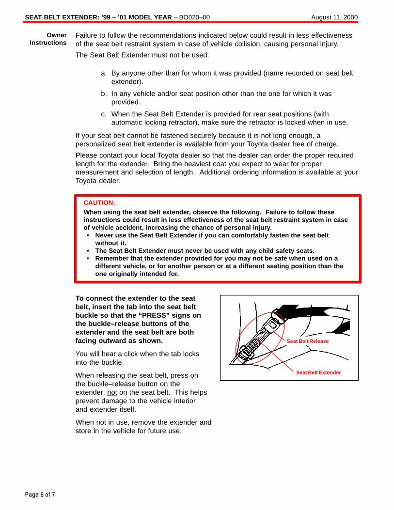
SEAT BELT EXTENDER: ’99 – ’01 MODEL YEAR – BO020–00 August 11, 2000
Page 6 of 7
Failure to follow the recommendations indicated below could result in less effectivenessof the seat belt restraint system in case of vehicle collision, causing personal injury.
The Seat Belt Extender must not be used:
a. By anyone other than for whom it was provided (name recorded on seat beltextender).
b. In any vehicle and/or seat position other than the one for which it wasprovided.
c. When the Seat Belt Extender is provided for rear seat positions (withautomatic locking retractor), make sure the retractor is locked when in use.
If your seat belt cannot be fastened securely because it is not long enough, apersonalized seat belt extender is available from your Toyota dealer free of charge.
Please contact your local Toyota dealer so that the dealer can order the proper requiredlength for the extender. Bring the heaviest coat you expect to wear for propermeasurement and selection of length. Additional ordering information is available at yourToyota dealer.
CAUTION:When using the seat belt extender, observe the following. Failure to follow theseinstructions could result in less effectiveness of the seat belt restraint system in caseof vehicle accident, increasing the chance of personal injury.� Never use the Seat Belt Extender if you can comfortably fasten the seat belt
without it.� The Seat Belt Extender must never be used with any child safety seats.� Remember that the extender provided for you may not be safe when used on a
different vehicle, or for another person or at a different seating position than theone originally intended for.
To connect the extender to the seatbelt, insert the tab into the seat beltbuckle so that the “PRESS” signs onthe buckle–release buttons of theextender and the seat belt are bothfacing outward as shown.
You will hear a click when the tab locksinto the buckle.
When releasing the seat belt, press onthe buckle–release button on theextender, not on the seat belt. This helpsprevent damage to the vehicle interiorand extender itself.
When not in use, remove the extender andstore in the vehicle for future use.
OwnerInstructions
Seat Belt Extender
Seat Belt Release
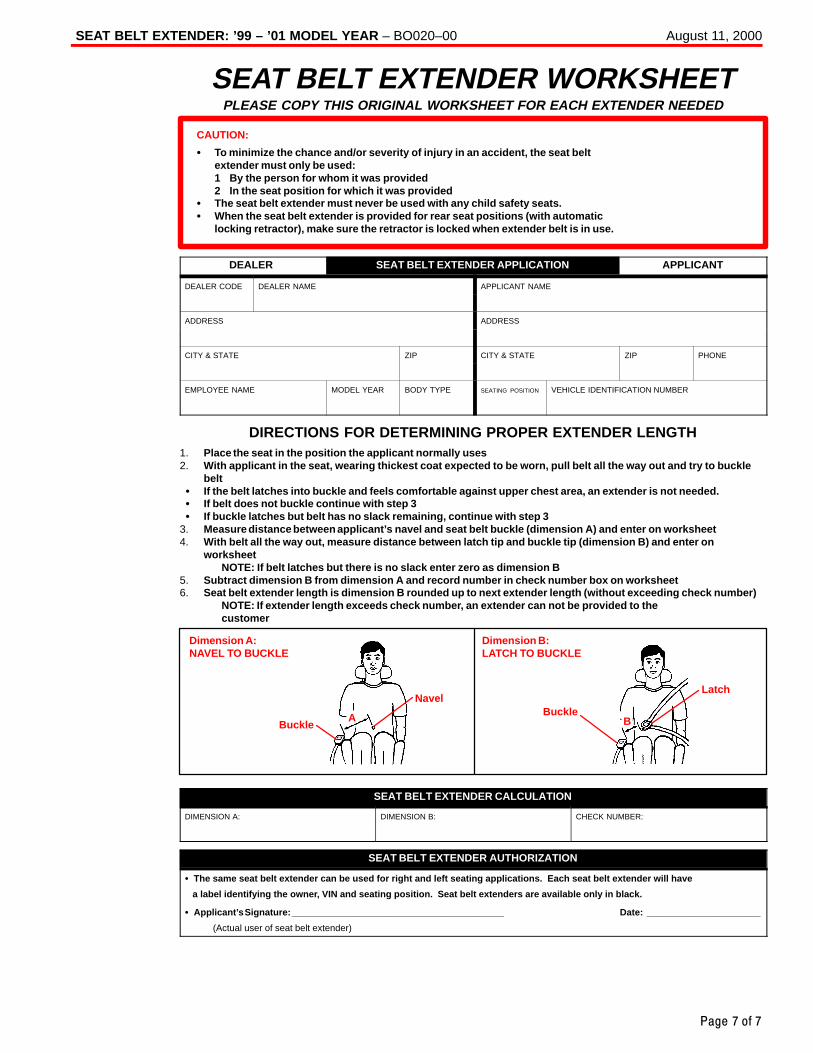
SEAT BELT EXTENDER: ’99 – ’01 MODEL YEAR – BO020–00 August 11, 2000
Page 7 of 7
SEAT BELT EXTENDER WORKSHEETPLEASE COPY THIS ORIGINAL WORKSHEET FOR EACH EXTENDER NEEDED
CAUTION:
� To minimize the chance and/or severity of injury in an accident, the seat beltextender must only be used:1 By the person for whom it was provided2 In the seat position for which it was provided
� The seat belt extender must never be used with any child safety seats.� When the seat belt extender is provided for rear seat positions (with automatic
locking retractor), make sure the retractor is locked when extender belt is in use.
DEALER SEAT BELT EXTENDER APPLICATION APPLICANT
DEALER CODE DEALER NAME APPLICANT NAME
ADDRESS ADDRESS
CITY & STATE ZIP CITY & STATE ZIP PHONE
EMPLOYEE NAME MODEL YEAR BODY TYPE SEATING POSITION VEHICLE IDENTIFICATION NUMBER
DIRECTIONS FOR DETERMINING PROPER EXTENDER LENGTH1. Place the seat in the position the applicant normally uses2. With applicant in the seat, wearing thickest coat expected to be worn, pull belt all the way out and try to buckle
belt� If the belt latches into buckle and feels comfortable against upper chest area, an extender is not needed.� If belt does not buckle continue with step 3� If buckle latches but belt has no slack remaining, continue with step 3
3. Measure distance between applicant’s navel and seat belt buckle (dimension A) and enter on worksheet4. With belt all the way out, measure distance between latch tip and buckle tip (dimension B) and enter on
worksheetNOTE: If belt latches but there is no slack enter zero as dimension B
5. Subtract dimension B from dimension A and record number in check number box on worksheet6. Seat belt extender length is dimension B rounded up to next extender length (without exceeding check number)
NOTE: If extender length exceeds check number, an extender can not be provided to thecustomer
Dimension A:NAVEL TO BUCKLE
Dimension B:LATCH TO BUCKLE
BuckleBuckle
NavelLatch
A B
SEAT BELT EXTENDER CALCULATION
DIMENSION A: DIMENSION B: CHECK NUMBER:
SEAT BELT EXTENDER AUTHORIZATION
� The same seat belt extender can be used for right and left seating applications. Each seat belt extender will have
a label identifying the owner, VIN and seating position. Seat belt extenders are available only in black.
� Applicant’s Signature: _________________________________________ Date: ______________________
(Actual user of seat belt extender)
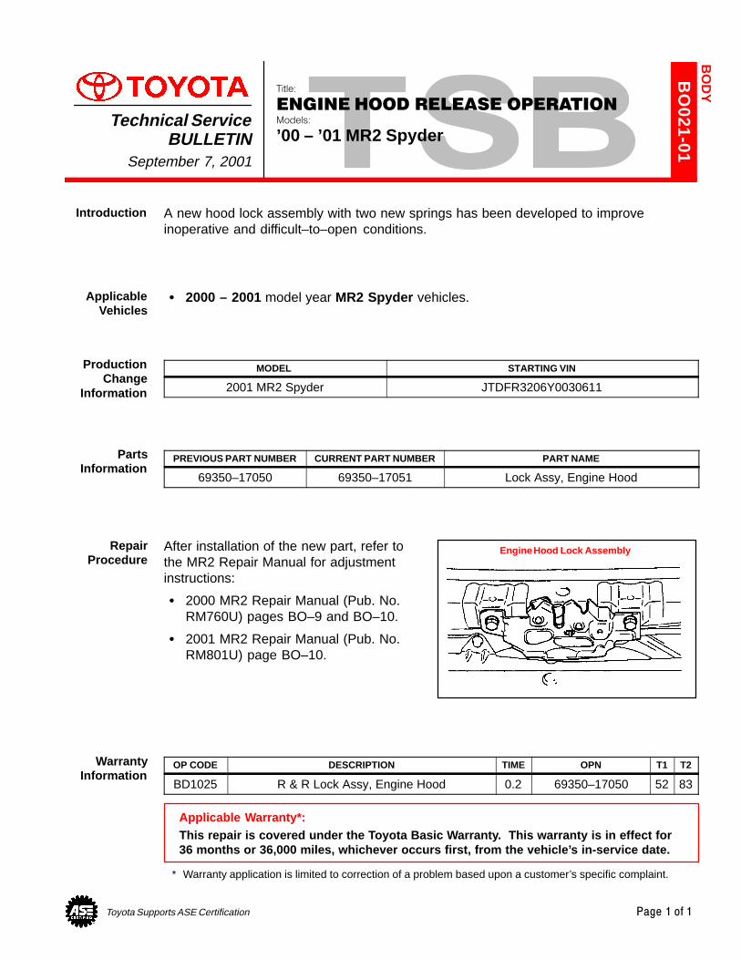
Toyota Supports ASE Certification Page 1 of 1
BO
021-01
Title:
ENGINE HOOD RELEASE OPERATIONModels:
’00 – ’01 MR2 SpyderTechnical Service
BULLETINSeptember 7, 2001
A new hood lock assembly with two new springs has been developed to improveinoperative and difficult–to–open conditions.
� 2000 – 2001 model year MR2 Spyder vehicles.
MODEL STARTING VIN
2001 MR2 Spyder JTDFR3206Y0030611
PREVIOUS PART NUMBER CURRENT PART NUMBER PART NAME
69350–17050 69350–17051 Lock Assy, Engine Hood
After installation of the new part, refer tothe MR2 Repair Manual for adjustmentinstructions:
� 2000 MR2 Repair Manual (Pub. No.RM760U) pages BO–9 and BO–10.
� 2001 MR2 Repair Manual (Pub. No.RM801U) page BO–10.
OP CODE DESCRIPTION TIME OPN T1 T2
BD1025 R & R Lock Assy, Engine Hood 0.2 69350–17050 52 83
Applicable Warranty*:This repair is covered under the Toyota Basic Warranty. This warranty is in effect for36 months or 36,000 miles, whichever occurs first, from the vehicle’s in-service date.
* Warranty application is limited to correction of a problem based upon a customer’s specific complaint.
BO
DY
Introduction
ApplicableVehicles
ProductionChange
Information
PartsInformation
RepairProcedure
Engine Hood Lock Assembly
WarrantyInformation
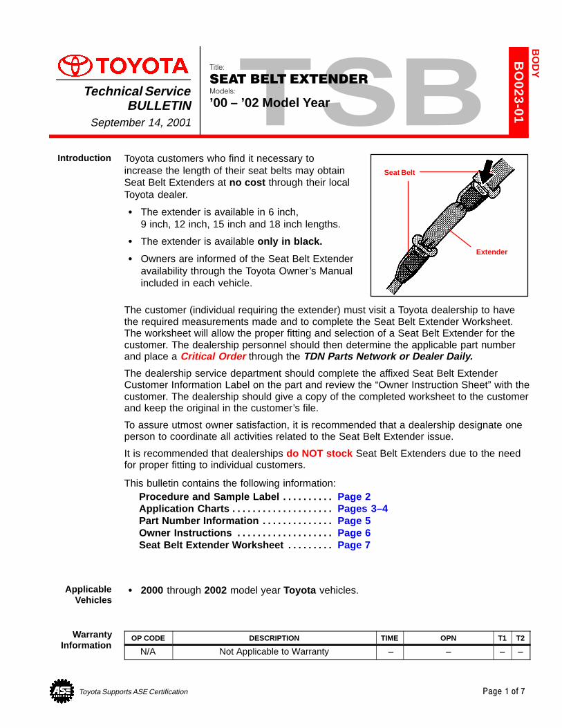
Toyota Supports ASE Certification Page 1 of 7
BO
023-01
Title:
SEAT BELT EXTENDERModels:
’00 – ’02 Model YearTechnical Service
BULLETINSeptember 14, 2001
Toyota customers who find it necessary toincrease the length of their seat belts may obtainSeat Belt Extenders at no cost through their localToyota dealer.
� The extender is available in 6 inch,9 inch, 12 inch, 15 inch and 18 inch lengths.
� The extender is available only in black.
� Owners are informed of the Seat Belt Extenderavailability through the Toyota Owner’s Manualincluded in each vehicle.
The customer (individual requiring the extender) must visit a Toyota dealership to havethe required measurements made and to complete the Seat Belt Extender Worksheet.The worksheet will allow the proper fitting and selection of a Seat Belt Extender for thecustomer. The dealership personnel should then determine the applicable part numberand place a Critical Order through the TDN Parts Network or Dealer Daily.
The dealership service department should complete the affixed Seat Belt ExtenderCustomer Information Label on the part and review the “Owner Instruction Sheet” with thecustomer. The dealership should give a copy of the completed worksheet to the customerand keep the original in the customer’s file.
To assure utmost owner satisfaction, it is recommended that a dealership designate oneperson to coordinate all activities related to the Seat Belt Extender issue.
It is recommended that dealerships do NOT stock Seat Belt Extenders due to the needfor proper fitting to individual customers.
This bulletin contains the following information:Procedure and Sample Label Page 2. . . . . . . . . . Application Charts Pages 3–4. . . . . . . . . . . . . . . . . . . . Part Number Information Page 5. . . . . . . . . . . . . . Owner Instructions Page 6. . . . . . . . . . . . . . . . . . . Seat Belt Extender Worksheet Page 7 . . . . . . . . .
� 2000 through 2002 model year Toyota vehicles.
OP CODE DESCRIPTION TIME OPN T1 T2
N/A Not Applicable to Warranty – – – –
BO
DY
Introduction
Seat Belt
Extender
ApplicableVehicles
WarrantyInformation

SEAT BELT EXTENDER: ’00–’02 MODEL YEAR – BO023-01 September 14, 2001
Page 2 of 7
1. Owner requests a Seat Belt Extender from dealer.
2. Dealer verifies the need for a Seat Belt Extender and obtains a current copy of thisTSB and copies the Worksheet.
3. Dealer measures the customer and completes the Worksheet. Dealer determines thecorrect part number and places a Critical Order for the part through the TDN PartsNetwork or Dealer Daily.
4. Dealer receives Seat Belt Extender and calls the customer in to check fit of the part.
5. If the Seat Belt Extender fit is good, dealership personnel completes the CustomerInformation Label on the part, explains usage of the part, and gives the customer acopy of the completed Worksheet.
6. Dealer places copy of the completed Worksheet in the customer’s records.
DEALER PARTSSUPPLY
OWNERDEALER
MEASURECUSTOMER
&COMPLETE
WORKSHEET
PLACECRITICALORDER
THROUGHTDNOR
DEALERDAILY
SHIP SEATBELT
EXTENDERTO DEALER
TEST FITCUSTOMERWITH PART
COMPLETELABEL AND
ADVISEOWNER
RECEIVECOPY OF
WORKSHEET& USE
EXTENDER
FILEWORKSHEET
INCUSTOMERRECORDS
CAUTION
THIS SEAT BELT EXTENDER IS TO BE USED ONLY BY :
ON VEHICLE:
SEATING POSITION:
VIN:
USE BY OTHERS, OR IN ANOTHER SEATING POSITION, OR IN ANOTHER VEHICLECOULD REDUCE SEAT BELT RESTRAINT IN AN ACCIDENT AND RESULT INPERSONAL INJURY.
Procedure
Sample SeatBelt Extender
CustomerInformation
Label
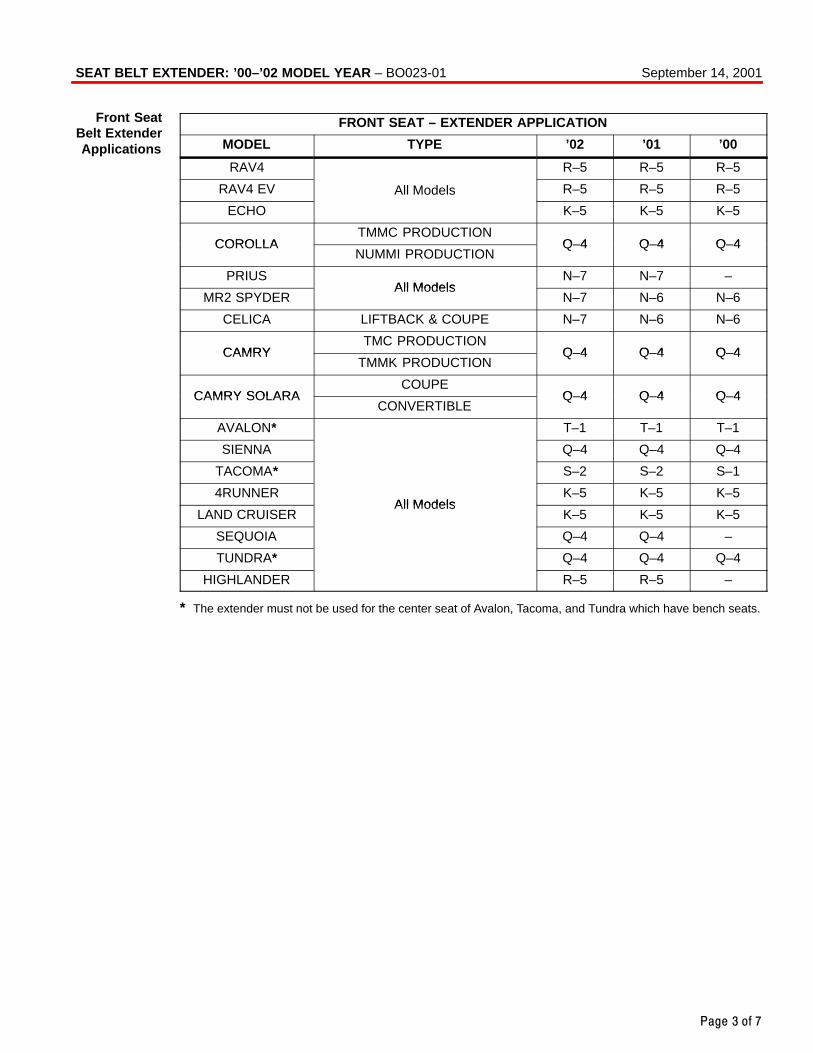
Page 3 of 7
FRONT SEAT – EXTENDER APPLICATION
MODEL TYPE ’02 ’01 ’00
RAV4 R–5 R–5 R–5
RAV4 EV All Models R–5 R–5 R–5
ECHO K–5 K–5 K–5
COROLLATMMC PRODUCTION
Q–4 Q–4 Q–4COROLLANUMMI PRODUCTION
Q–4 Q–4 Q–4
PRIUSAll Models
N–7 N–7 –
MR2 SPYDERAll Models
N–7 N–6 N–6
CELICA LIFTBACK & COUPE N–7 N–6 N–6
CAMRYTMC PRODUCTION
Q–4 Q–4 Q–4CAMRYTMMK PRODUCTION
Q–4 Q–4 Q–4
CAMRY SOLARACOUPE
Q–4 Q–4 Q–4CAMRY SOLARACONVERTIBLE
Q–4 Q–4 Q–4
AVALON* T–1 T–1 T–1
SIENNA Q–4 Q–4 Q–4
TACOMA* S–2 S–2 S–1
4RUNNERAll Models
K–5 K–5 K–5
LAND CRUISERAll Models
K–5 K–5 K–5
SEQUOIA Q–4 Q–4 –
TUNDRA* Q–4 Q–4 Q–4
HIGHLANDER R–5 R–5 –
* The extender must not be used for the center seat of Avalon, Tacoma, and Tundra which have bench seats.
SEAT BELT EXTENDER: ’00–’02 MODEL YEAR – BO023-01 September 14, 2001
Front SeatBelt ExtenderApplications
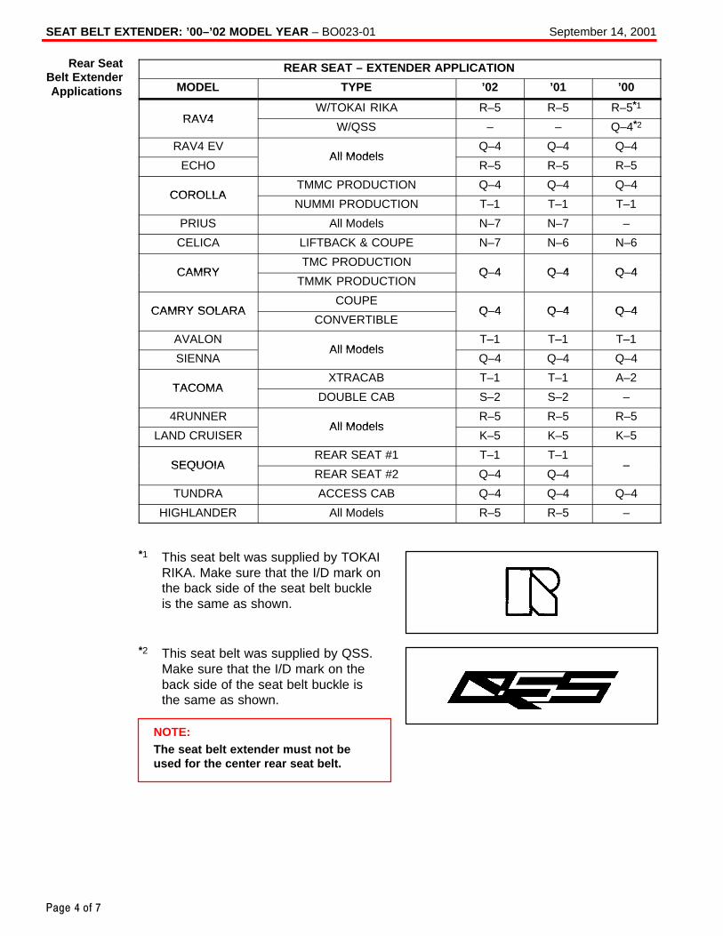
SEAT BELT EXTENDER: ’00–’02 MODEL YEAR – BO023-01 September 14, 2001
Page 4 of 7
REAR SEAT – EXTENDER APPLICATION
MODEL TYPE ’02 ’01 ’00
RAV4W/TOKAI RIKA R–5 R–5 R–5*1
RAV4W/QSS – – Q–4*2
RAV4 EVAll Models
Q–4 Q–4 Q–4
ECHOAll Models
R–5 R–5 R–5
COROLLATMMC PRODUCTION Q–4 Q–4 Q–4
COROLLANUMMI PRODUCTION T–1 T–1 T–1
PRIUS All Models N–7 N–7 –
CELICA LIFTBACK & COUPE N–7 N–6 N–6
CAMRYTMC PRODUCTION
Q–4 Q–4 Q–4CAMRYTMMK PRODUCTION
Q–4 Q–4 Q–4
CAMRY SOLARACOUPE
Q–4 Q–4 Q–4CAMRY SOLARACONVERTIBLE
Q–4 Q–4 Q–4
AVALONAll Models
T–1 T–1 T–1
SIENNAAll Models
Q–4 Q–4 Q–4
TACOMAXTRACAB T–1 T–1 A–2
TACOMADOUBLE CAB S–2 S–2 –
4RUNNERAll Models
R–5 R–5 R–5
LAND CRUISERAll Models
K–5 K–5 K–5
SEQUOIAREAR SEAT #1 T–1 T–1
–SEQUOIAREAR SEAT #2 Q–4 Q–4
–
TUNDRA ACCESS CAB Q–4 Q–4 Q–4
HIGHLANDER All Models R–5 R–5 –
*1 This seat belt was supplied by TOKAIRIKA. Make sure that the I/D mark onthe back side of the seat belt buckleis the same as shown.
*2 This seat belt was supplied by QSS.Make sure that the I/D mark on theback side of the seat belt buckle isthe same as shown.
NOTE:The seat belt extender must not beused for the center rear seat belt.
Rear SeatBelt ExtenderApplications
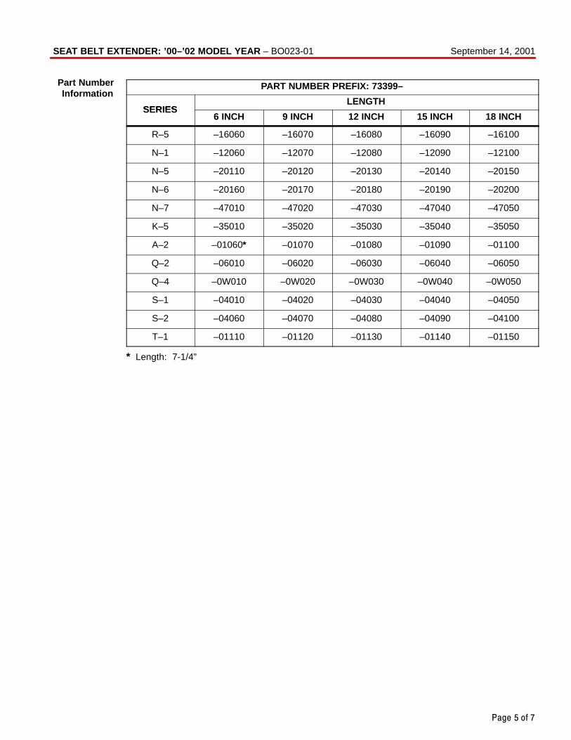
Page 5 of 7
PART NUMBER PREFIX: 73399–
SERIESLENGTH
SERIES6 INCH 9 INCH 12 INCH 15 INCH 18 INCH
R–5 –16060 –16070 –16080 –16090 –16100
N–1 –12060 –12070 –12080 –12090 –12100
N–5 –20110 –20120 –20130 –20140 –20150
N–6 –20160 –20170 –20180 –20190 –20200
N–7 –47010 –47020 –47030 –47040 –47050
K–5 –35010 –35020 –35030 –35040 –35050
A–2 –01060* –01070 –01080 –01090 –01100
Q–2 –06010 –06020 –06030 –06040 –06050
Q–4 –0W010 –0W020 –0W030 –0W040 –0W050
S–1 –04010 –04020 –04030 –04040 –04050
S–2 –04060 –04070 –04080 –04090 –04100
T–1 –01110 –01120 –01130 –01140 –01150
* Length: 7-1/4”
SEAT BELT EXTENDER: ’00–’02 MODEL YEAR – BO023-01 September 14, 2001
Part NumberInformation
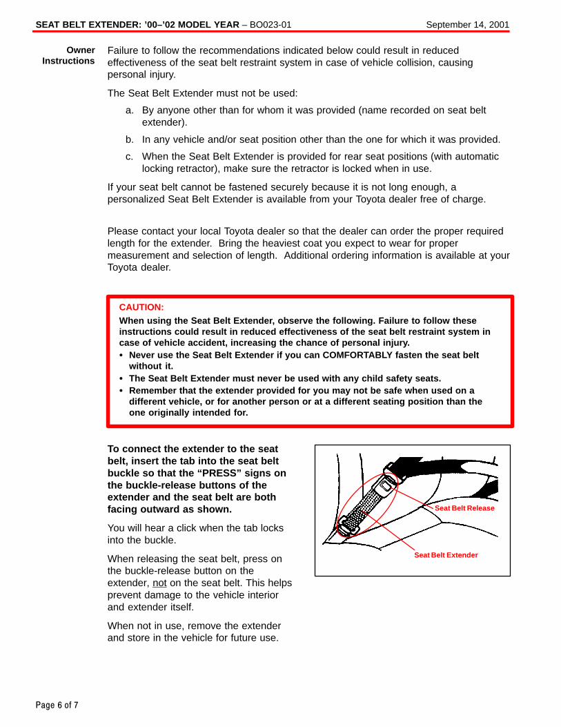
SEAT BELT EXTENDER: ’00–’02 MODEL YEAR – BO023-01 September 14, 2001
Page 6 of 7
Failure to follow the recommendations indicated below could result in reducedeffectiveness of the seat belt restraint system in case of vehicle collision, causingpersonal injury.
The Seat Belt Extender must not be used:
a. By anyone other than for whom it was provided (name recorded on seat beltextender).
b. In any vehicle and/or seat position other than the one for which it was provided.
c. When the Seat Belt Extender is provided for rear seat positions (with automaticlocking retractor), make sure the retractor is locked when in use.
If your seat belt cannot be fastened securely because it is not long enough, apersonalized Seat Belt Extender is available from your Toyota dealer free of charge.
Please contact your local Toyota dealer so that the dealer can order the proper requiredlength for the extender. Bring the heaviest coat you expect to wear for propermeasurement and selection of length. Additional ordering information is available at yourToyota dealer.
CAUTION:When using the Seat Belt Extender, observe the following. Failure to follow theseinstructions could result in reduced effectiveness of the seat belt restraint system incase of vehicle accident, increasing the chance of personal injury.� Never use the Seat Belt Extender if you can COMFORTABLY fasten the seat belt
without it.� The Seat Belt Extender must never be used with any child safety seats.� Remember that the extender provided for you may not be safe when used on a
different vehicle, or for another person or at a different seating position than theone originally intended for.
To connect the extender to the seatbelt, insert the tab into the seat beltbuckle so that the “PRESS” signs onthe buckle-release buttons of theextender and the seat belt are bothfacing outward as shown.
You will hear a click when the tab locksinto the buckle.
When releasing the seat belt, press onthe buckle-release button on theextender, not on the seat belt. This helpsprevent damage to the vehicle interiorand extender itself.
When not in use, remove the extenderand store in the vehicle for future use.
OwnerInstructions
Seat Belt Extender
Seat Belt Release
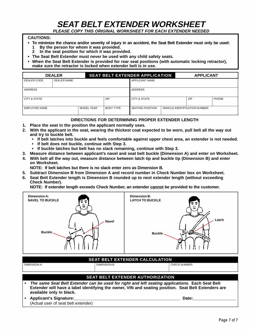
Page 7 of 7
SEAT BELT EXTENDER WORKSHEETPLEASE COPY THIS ORIGINAL WORKSHEET FOR EACH EXTENDER NEEDED
CAUTIONS:� To minimize the chance and/or severity of injury in an accident, the Seat Belt Extender must only be used:
1 By the person for whom it was provided.2 In the seat position for which it was provided.
� The Seat Belt Extender must never be used with any child safety seats.� When the Seat Belt Extender is provided for rear seat positions (with automatic locking retractor),
make sure the retractor is locked when extender belt is in use.
DEALER SEAT BELT EXTENDER APPLICATION APPLICANTDEALER CODE DEALER NAME APPLICANT NAME
ADDRESS ADDRESS
CITY & STATE ZIP CITY & STATE ZIP PHONE
EMPLOYEE NAME MODEL YEAR BODY TYPE SEATING POSITION VEHICLE IDENTIFICATION NUMBER
DIRECTIONS FOR DETERMINING PROPER EXTENDER LENGTH1. Place the seat in the position the applicant normally uses.2. With the applicant in the seat, wearing the thickest coat expected to be worn, pull belt all the way out
and try to buckle belt.� If belt latches into buckle and feels comfortable against upper chest area, an extender is not needed.� If belt does not buckle, continue with Step 3.� If buckle latches but belt has no slack remaining, continue with Step 3.
3. Measure distance between applicant’s navel and seat belt buckle (Dimension A) and enter on Worksheet.4. With belt all the way out, measure distance between latch tip and buckle tip (Dimension B) and enter
on Worksheet.NOTE: If belt latches but there is no slack enter zero as Dimension B.
5. Subtract Dimension B from Dimension A and record number in Check Number box on Worksheet.6. Seat Belt Extender length is Dimension B rounded up to next extender length (without exceeding
Check Number).NOTE: If extender length exceeds Check Number, an extender ca nnot be provided to the customer.
Dimension A:NAVEL TO BUCKLE
Dimension B:LATCH TO BUCKLE
Buckle
Navel
ABuckle
Latch
B
SEAT BELT EXTENDER CALCULATIONDIMENSION A: DIMENSION B: CHECK NUMBER:
SEAT BELT EXTENDER AUTHORIZATION� The same Seat Belt Extender can be used for right and left seating applications . Each Seat Belt
Extender will have a label identifying the owner, VIN and seating position. Seat Belt Extenders areavailable only in black.
� Applicant’s Signature: Date: (Actual user of seat belt extender)
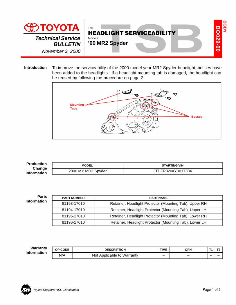
Toyota Supports ASE Certification Page 1 of 2
BO
029-00
Title:
HEADLIGHT SERVICEABILITYModels:
’00 MR2 SpyderTechnical Service
BULLETINNovember 3, 2000
To improve the serviceability of the 2000 model year MR2 Spyder headlight, bosses havebeen added to the headlights. If a headlight mounting tab is damaged, the headlight canbe reused by following the procedure on page 2.
Bosses
MountingTabs
MODEL STARTING VIN
2000 MY MR2 Spyder JTDFR320#Y0017384
PART NUMBER PART NAME
81193-17010 Retainer, Headlight Protector (Mounting Tab), Upper RH
81194-17010 Retainer, Headlight Protector (Mounting Tab), Upper LH
81195-17010 Retainer, Headlight Protector (Mounting Tab), Lower RH
81196-17010 Retainer, Headlight Protector (Mounting Tab), Lower LH
OP CODE DESCRIPTION TIME OPN T1 T2
N/A Not Applicable to Warranty – – – –
BO
DY
Introduction
ProductionChange
Information
PartsInformation
WarrantyInformation
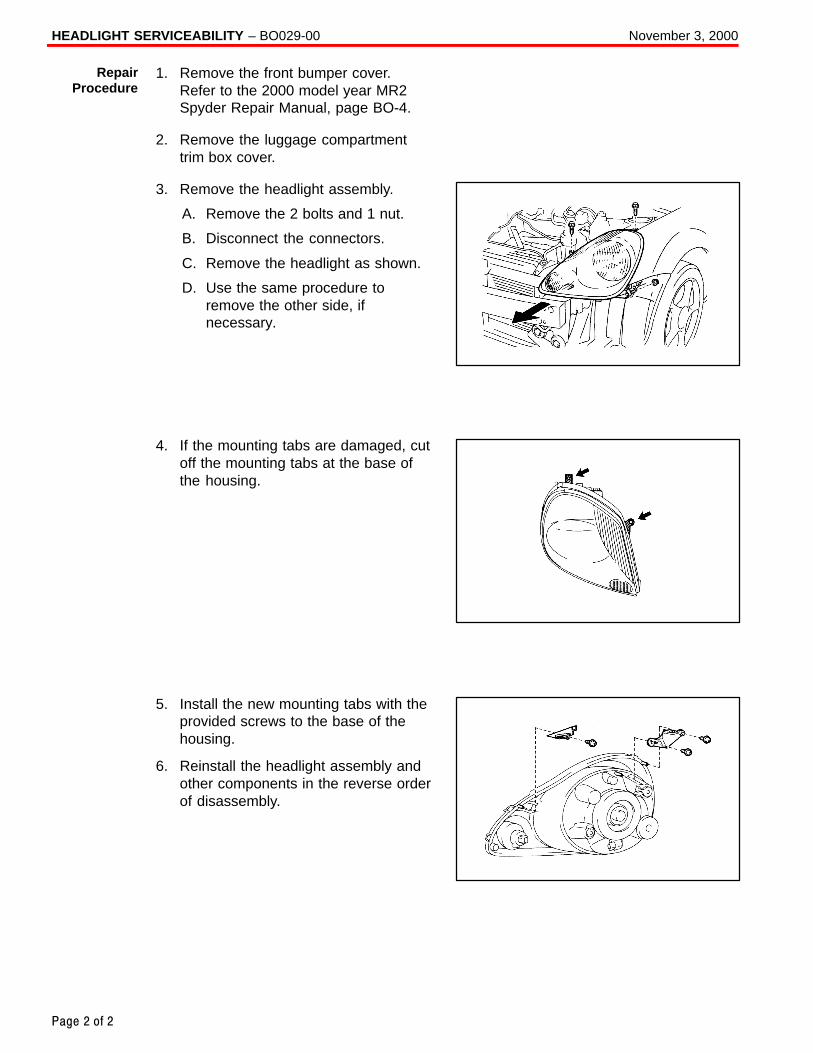
HEADLIGHT SERVICEABILITY – BO029-00 November 3, 2000
Page 2 of 2
1. Remove the front bumper cover.Refer to the 2000 model year MR2Spyder Repair Manual, page BO-4.
2. Remove the luggage compartmenttrim box cover.
3. Remove the headlight assembly.
A. Remove the 2 bolts and 1 nut.
B. Disconnect the connectors.
C. Remove the headlight as shown.
D. Use the same procedure toremove the other side, ifnecessary.
4. If the mounting tabs are damaged, cutoff the mounting tabs at the base ofthe housing.
5. Install the new mounting tabs with theprovided screws to the base of thehousing.
6. Reinstall the headlight assembly andother components in the reverse orderof disassembly.
RepairProcedure
Toyota Supports ASE Certification Page 1 of 2
BO
030-01
Title:
WINDSHIELD WIPER BLADE
MAINTENANCE AND CLEANINGModels:
All Models & All Years Through Current
Technical ServiceBULLETIN
December 7, 2001
TSB REVISION NOTICE:July 13, 2004: The Applicable Vehicles has been changed to all models and all yearsthrough current.All previous versions of this TSB should be discarded.
The following procedures are recommended to maintain windshield wiper blade performance.
� All models and model years through current.
OP CODE DESCRIPTION TIME OFP T1 T2
N/A Not Applicable to Warranty – – – –
Recommendations for Windshield Wiper Maintenance, Cleaning and Use:
1. Scheduled Maintenance
� Check wiper rubber blades every 4 – 6 months or 7,500 miles for wear, crackingand contamination.
� Clean glass and rubber wiper blades if blades are not clearing glass adequately.If this does not correct the problem, then replace the rubber elements.
2. Cleaning Procedure
� Wiper Rubber: Bugs, dirt, sap and road grime on blades will cause streaking.Clean wiper rubber of road and environmental debris using cloth or paper towelsoaked with windshield washer fluid or mild detergent.
� DO NOT USE fuel, kerosene, or petroleum based products to clean rubber wiperblades.
� Windshield: Bugs, road grime, sap and car wash wax treatments decrease wiperperformance.
� Rinse windshield with water and apply non–abrasive cleaner, such as Bon–Ami(www.faultless.com), with a sponge.
NOTE:Make sure to use plenty of water with all powder based cleaners so the glass is not scratched.
BO
DY
Introduction
ApplicableVehicles
WarrantyInformation
Maintenance,Cleaningand Use

WINDSHIELD WIPER BLADE MAINTENANCE AND CLEANING – BO030-01 Revised December 7, 2001
Page 2 of 2
3. Contributors to Poor Performance/Decreased Rubber Blade Life (require rubber replacement)
� Dusty areas cause the rubber edge to wear quickly.
� Sand and salt used for road conditioning during winter causes the edge to wear quickly, so areas with significant snowfall require more frequent wiper replacement.
� Heat and time cause the rubber to become excessively “permanent set,” so the rubber does not turn over, resulting in streaking and/or unwiped areas on the glass.
� Rubber is easily cut or torn while using ice scrapers on the glass.
� Rubber can be torn when pulling blades off a frozen windshield.
� Using wipers instead of an ice scraper to remove frost and ice from the windshieldduring a car warm up can dull, nick, or tear the rubber.
� Banging wiper on the glass to remove ice & snow can cause the blade to bendand rubber to come out of the blade providing the potential to scratch the glass.
� Ice forms in wiper blade pin joints, which causes streaking and unwiped areas. Toremove ice from pin joints, compress the blade and rubber with your hand toloosen the frozen joints. To prevent this condition, use winter blades with a rubber cover.
Maintenance,Cleaningand Use
(Continued)
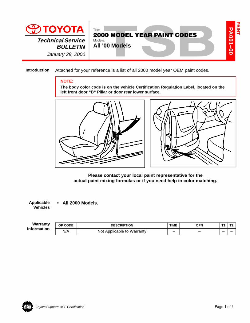
Toyota Supports ASE Certification Page 1 of 4
PA
001–00
Title:
2000 MODEL YEAR PAINT CODESModels:
All ’00 ModelsTechnical Service
BULLETINJanuary 28, 2000
Attached for your reference is a list of all 2000 model year OEM paint codes.
NOTE:The body color code is on the vehicle Certification Regulation Label, located on theleft front door “B“ Pillar or door rear lower surface.
Please contact your local paint representative for theactual paint mixing formulas or if you need help in color matching.
� All 2000 Models.
OP CODE DESCRIPTION TIME OPN T1 T2
N/A Not Applicable to Warranty – – – –
PA
INT
Introduction
ApplicableVehicles
WarrantyInformation
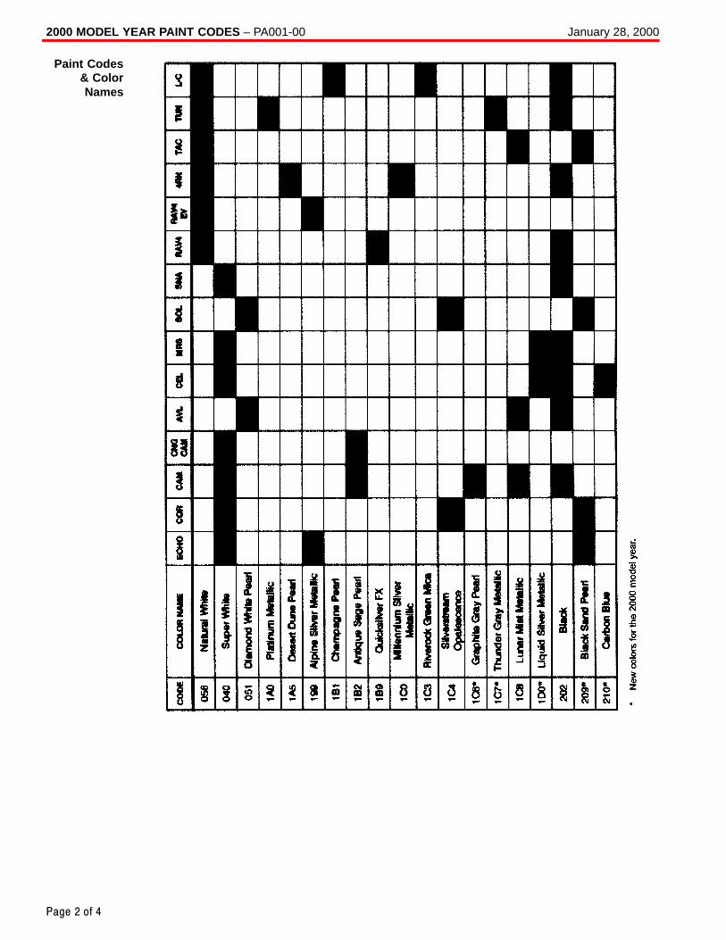
2000 MODEL YEAR PAINT CODES – PA001-00 January 28, 2000
Page 2 of 4
Paint Codes& ColorNames
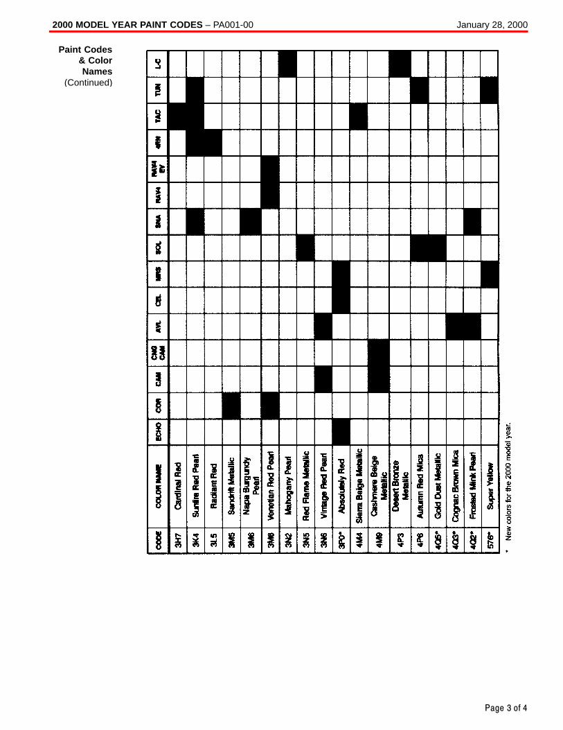
2000 MODEL YEAR PAINT CODES – PA001-00 January 28, 2000
Page 3 of 4
Paint Codes& ColorNames
(Continued)
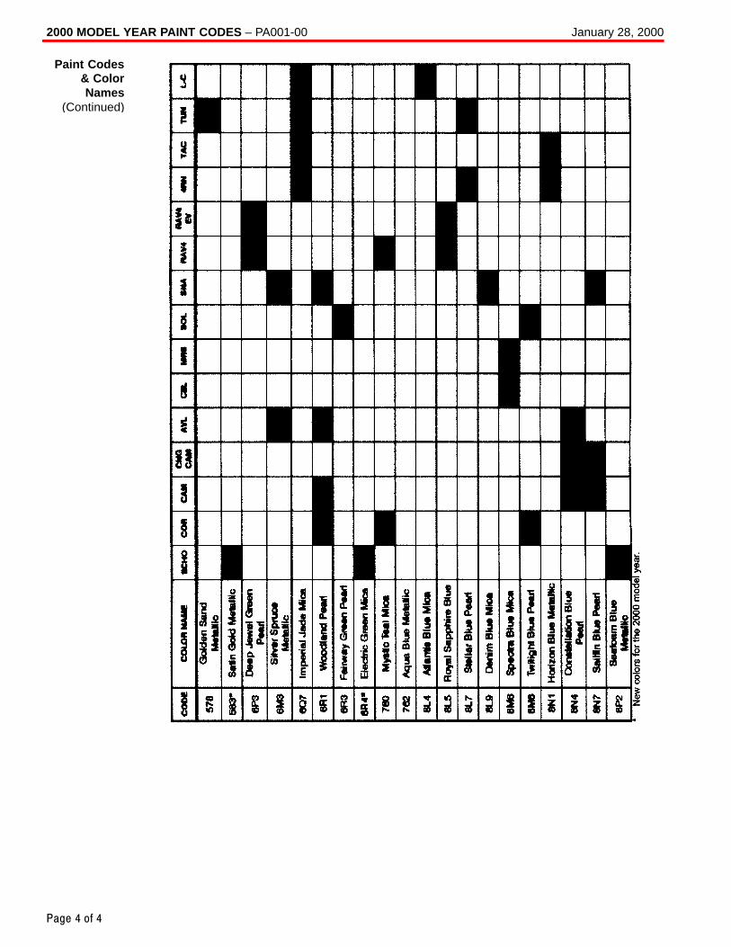
2000 MODEL YEAR PAINT CODES – PA001-00 January 28, 2000
Page 4 of 4
Paint Codes& ColorNames
(Continued)
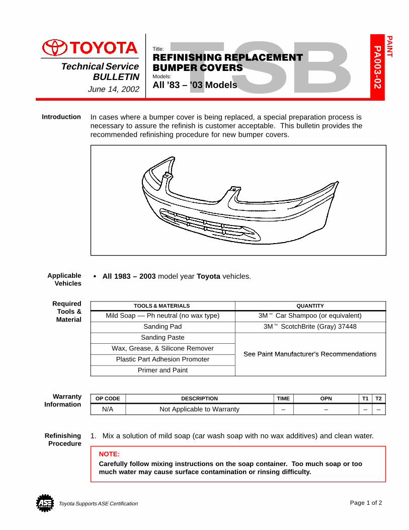
Toyota Supports ASE Certification Page 1 of 2
PA
003-02
Title:
REFINISHING REPLACEMENT
BUMPER COVERSModels:
All ’83 – ’03 Models
Technical ServiceBULLETIN
June 14, 2002
In cases where a bumper cover is being replaced, a special preparation process isnecessary to assure the refinish is customer acceptable. This bulletin provides therecommended refinishing procedure for new bumper covers.
� All 1983 – 2003 model year Toyota vehicles.
TOOLS & MATERIALS QUANTITY
Mild Soap –– Ph neutral (no wax type) 3M� Car Shampoo (or equivalent)
Sanding Pad 3M� ScotchBrite (Gray) 37448
Sanding Paste
Wax, Grease, & Silicone RemoverSee Paint Manufacturer’s Recommendations
Plastic Part Adhesion PromoterSee Paint Manufacturer’s Recommendations
Primer and Paint
OP CODE DESCRIPTION TIME OPN T1 T2
N/A Not Applicable to Warranty – – – –
1. Mix a solution of mild soap (car wash soap with no wax additives) and clean water.
NOTE:Carefully follow mixing instructions on the soap container. Too much soap or toomuch water may cause surface contamination or rinsing difficulty.
PA
INT
Introduction
ApplicableVehicles
RequiredTools &Material
WarrantyInformation
RefinishingProcedure
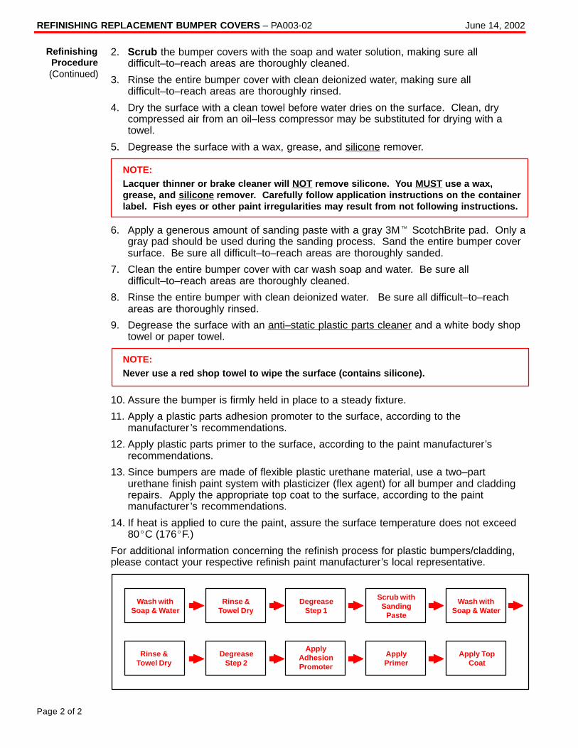
REFINISHING REPLACEMENT BUMPER COVERS – PA003-02 June 14, 2002
Page 2 of 2
2. Scrub the bumper covers with the soap and water solution, making sure alldifficult–to–reach areas are thoroughly cleaned.
3. Rinse the entire bumper cover with clean deionized water, making sure alldifficult–to–reach areas are thoroughly rinsed.
4. Dry the surface with a clean towel before water dries on the surface. Clean, drycompressed air from an oil–less compressor may be substituted for drying with atowel.
5. Degrease the surface with a wax, grease, and silicone remover.
NOTE:Lacquer thinner or brake cleaner will NOT remove silicone. You MUST use a wax,grease, and silicone remover. Carefully follow application instructions on the containerlabel. Fish eyes or other paint irregularities may result from not following instructions.
6. Apply a generous amount of sanding paste with a gray 3M� ScotchBrite pad. Only agray pad should be used during the sanding process. Sand the entire bumper coversurface. Be sure all difficult–to–reach areas are thoroughly sanded.
7. Clean the entire bumper cover with car wash soap and water. Be sure alldifficult–to–reach areas are thoroughly cleaned.
8. Rinse the entire bumper with clean deionized water. Be sure all difficult–to–reachareas are thoroughly rinsed.
9. Degrease the surface with an anti–static plastic parts cleaner and a white body shoptowel or paper towel.
NOTE:Never use a red shop towel to wipe the surface (contains silicone).
10. Assure the bumper is firmly held in place to a steady fixture.
11. Apply a plastic parts adhesion promoter to the surface, according to themanufacturer ’s recommendations.
12. Apply plastic parts primer to the surface, according to the paint manufacturer’srecommendations.
13. Since bumpers are made of flexible plastic urethane material, use a two–parturethane finish paint system with plasticizer (flex agent) for all bumper and claddingrepairs. Apply the appropriate top coat to the surface, according to the paintmanufacturer ’s recommendations.
14. If heat is applied to cure the paint, assure the surface temperature does not exceed80�C (176�F.)
For additional information concerning the refinish process for plastic bumpers/cladding,please contact your respective refinish paint manufacturer’s local representative.
ApplyPrimer
Wash withSoap & Water
Scrub withSanding
Paste
Wash withSoap & Water
Rinse &Towel Dry
DegreaseStep 1
ApplyAdhesionPromoter
Apply TopCoat
Rinse &Towel Dry
DegreaseStep 2
RefinishingProcedure(Continued)
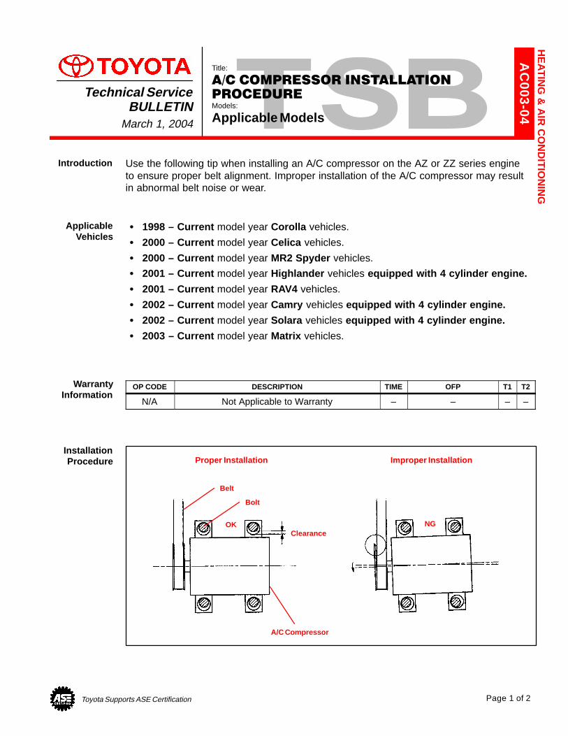
Toyota Supports ASE Certification Page 1 of 2
AC
003-04
Title:
A/C COMPRESSOR INSTALLATION
PROCEDUREModels:
Applicable Models
Technical ServiceBULLETIN
March 1, 2004
Use the following tip when installing an A/C compressor on the AZ or ZZ series engineto ensure proper belt alignment. Improper installation of the A/C compressor may result in abnormal belt noise or wear.
� 1998 – Current model year Corolla vehicles.
� 2000 – Current model year Celica vehicles.
� 2000 – Current model year MR2 Spyder vehicles.
� 2001 – Current model year Highlander vehicles equipped with 4 cylinder engine.
� 2001 – Current model year RAV4 vehicles.
� 2002 – Current model year Camry vehicles equipped with 4 cylinder engine.
� 2002 – Current model year Solara vehicles equipped with 4 cylinder engine.
� 2003 – Current model year Matrix vehicles.
OP CODE DESCRIPTION TIME OFP T1 T2
N/A Not Applicable to Warranty – – – –
Belt
Bolt
Clearance
A/C Compressor
OK NG
Proper Installation Improper Installation
HE
AT
ING
& A
IR C
ON
DIT
ION
ING
Introduction
ApplicableVehicles
WarrantyInformation
InstallationProcedure
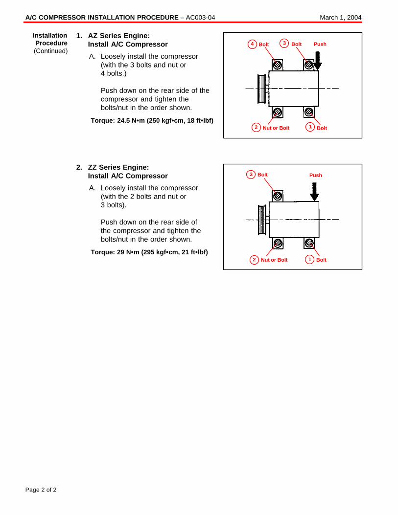
A/C COMPRESSOR INSTALLATION PROCEDURE – AC003-04 March 1, 2004
Page 2 of 2
1. AZ Series Engine:Install A/C Compressor
A. Loosely install the compressor(with the 3 bolts and nut or 4 bolts.)
Push down on the rear side of thecompressor and tighten thebolts/nut in the order shown.
Torque: 24.5 N �m (250 kgf �cm, 18 ft �lbf)
2. ZZ Series Engine:Install A/C Compressor
A. Loosely install the compressor(with the 2 bolts and nut or 3 bolts).
Push down on the rear side of the compressor and tighten thebolts/nut in the order shown.
Torque: 29 N �m (295 kgf �cm, 21 ft �lbf)
InstallationProcedure(Continued)
Bolt Bolt Push
Nut or Bolt Bolt12
34
Bolt Push
Nut or Bolt Bolt12
3
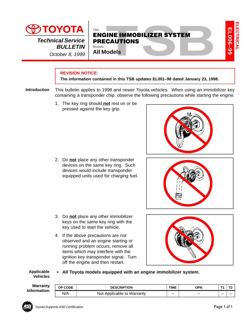
Toyota Supports ASE Certification Page 1 of 1
EL006–99
Title:
ENGINE IMMOBILIZER SYSTEM
PRECAUTIONSModels:
All Models
Technical ServiceBULLETIN
October 8, 1999
REVISION NOTICE:The information contained in this TSB updates EL001–98 dated January 23, 1998.
This bulletin applies to 1998 and newer Toyota vehicles. When using an immobilizer keycontaining a transponder chip, observe the following precautions while starting the engine.
1. The key ring should not rest on or bepressed against the key grip.
2. Do not place any other transponderdevices on the same key ring. Suchdevices would include transponderequipped units used for charging fuel.
3. Do not place any other immobilizerkeys on the same key ring with thekey used to start the vehicle.
4. If the above precautions are notobserved and an engine starting orrunning problem occurs, remove allitems which may interfere with theignition key transponder signal. Turnoff the engine and then restart.
� All Toyota models equipped with an engine immobilizer system.
OP CODE DESCRIPTION TIME OPN T1 T2
N/A Not Applicable to Warranty – – – –
ELE
CT
RIC
AL
Introduction
ApplicableVehicles
WarrantyInformation
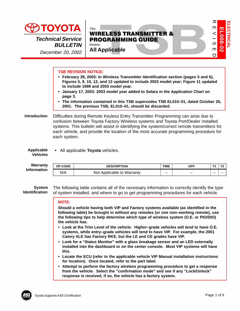
Toyota Supports ASE Certification Page 1 of 6
EL008-02
Title:
WIRELESS TRANSMITTER &
PROGRAMMING GUIDEModels:
All Applicable
Technical ServiceBULLETIN
December 20, 2002
TSB REVISION NOTICE:� February 28, 2003: In Wireless Transmitter Identification section (pages 5 and 6),
Figures 5, 9, 10, 12, and 13 updated to include 2003 model year; Figure 11 updatedto include 1999 and 2003 model year.
� January 17, 2003: 2003 model year added to Solara in the Application Chart onpage 3.
� The information contained in this TSB supercedes TSB EL010–01, dated October 26,2001. The previous TSB, EL010–01, should be discarded.
Difficulties during Remote Keyless Entry Transmitter Programming can arise due toconfusion between Toyota Factory Wireless systems and Toyota Port/Dealer installedsystems. This bulletin will assist in identifying the system/correct remote transmitters foreach vehicle, and provide the location of the most accurate programming procedure foreach system.
� All applicable Toyota vehicles.
OP CODE DESCRIPTION TIME OFP T1 T2
N/A Not Applicable to Warranty – – – –
The following table contains all of the necessary information to correctly identify the typeof system installed, and where to go to get programming procedures for each vehicle.
NOTE:Should a vehicle having both VIP and Factory systems available (as identified in thefollowing table) be brought in without any remotes (or one non–working remote), usethe following tips to help determine which type of wireless system (O.E. or PIO/DIO)the vehicle has.� Look at the Trim Level of the vehicle. Higher–grade vehicles will tend to have O.E.
systems, while entry–grade vehicles will tend to have VIP. For example, the 2001Camry XLE has Factory RKE, but the LE and CE grades have VIP.
� Look for a “Status Monitor” with a glass breakage sensor and an LED externallyinstalled into the dashboard or on the center console. Most VIP systems will havethis.
� Locate the ECU (refer to the applicable vehicle VIP Manual installation instructionsfor location). Once located, refer to the part label.
� Attempt to perform the factory wireless programming procedure to get a responsefrom the vehicle. Select the “confirmation mode” and see if any “Lock/Unlock”response is received, if so, the vehicle has a factory system.
ELE
CT
RIC
AL
Introduction
ApplicableVehicles
WarrantyInformation
SystemIdentification
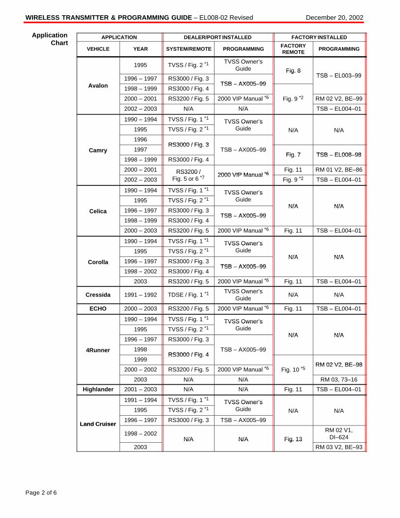
WIRELESS TRANSMITTER & PROGRAMMING GUIDE – EL008-02 Revised December 20, 2002
Page 2 of 6
APPLICATION DEALER/PORT INSTALLED FACTORY INSTALLED
VEHICLE YEAR SYSTEM/REMOTE PROGRAMMINGFACTORYREMOTE
PROGRAMMING
1995 TVSS / Fig. 2 *1TVSS Owner’s
Guide Fig. 8TSB EL003 99
A l1996 – 1997 RS3000 / Fig. 3
TSB AX005 99
Fig. 8TSB – EL003–99
Avalon 1998 – 1999 RS3000 / Fig. 4TSB – AX005–99
2000 – 2001 RS3200 / Fig. 5 2000 VIP Manual *6 Fig. 9 *2 RM 02 V2, BE–99
2002 – 2003 N/A N/A
g
TSB – EL004–01
1990 – 1994 TVSS / Fig. 1 *1 TVSS Owner’s1995 TVSS / Fig. 2 *1
TVSS Owner sGuide N/A N/A
1996RS3000 / Fig 3
Camry 1997RS3000 / Fig. 3
TSB – AX005–99Fig 7 TSB EL008 98
y
1998 – 1999 RS3000 / Fig. 4Fig. 7 TSB – EL008–98
2000 – 2001 RS3200 / 2000 VIP Manual *6Fig. 11 RM 01 V2, BE–86
2002 – 2003RS3200 /
Fig. 5 or 6 *72000 VIP Manual *6
Fig. 9 *2 TSB – EL004–01
1990 – 1994 TVSS / Fig. 1 *1 TVSS Owner’s1995 TVSS / Fig. 2 *1
TVSS Owner sGuide
N/A N/ACelica 1996 – 1997 RS3000 / Fig. 3
TSB AX005 99
N/A N/A
1998 – 1999 RS3000 / Fig. 4TSB – AX005–99
2000 – 2003 RS3200 / Fig. 5 2000 VIP Manual *6 Fig. 11 TSB – EL004–01
1990 – 1994 TVSS / Fig. 1 *1 TVSS Owner’s1995 TVSS / Fig. 2 *1
TVSS Owner sGuide
N/A N/ACorolla 1996 – 1997 RS3000 / Fig. 3
TSB AX005 99
N/A N/A
1998 – 2002 RS3000 / Fig. 4TSB – AX005–99
2003 RS3200 / Fig. 5 2000 VIP Manual *6 Fig. 11 TSB – EL004–01
Cressida 1991 – 1992 TDSE / Fig. 1 *1TVSS Owner’s
GuideN/A N/A
ECHO 2000 – 2003 RS3200 / Fig. 5 2000 VIP Manual *6 Fig. 11 TSB – EL004–01
1990 – 1994 TVSS / Fig. 1 *1 TVSS Owner’s1995 TVSS / Fig. 2 *1
TVSS Owner sGuide
N/A N/A1996 – 1997 RS3000 / Fig. 3
N/A N/A
4Runner 1998RS3000 / Fig 4
TSB – AX005–99
1999RS3000 / Fig. 4
RM 02 V2 BE 982000 – 2002 RS3200 / Fig. 5 2000 VIP Manual *6 Fig. 10 *5
RM 02 V2, BE–98
2003 N/A N/A
g
RM 03, 73–16
Highlander 2001 – 2003 N/A N/A Fig. 11 TSB – EL004–01
1991 – 1994 TVSS / Fig. 1 *1 TVSS Owner’s1995 TVSS / Fig. 2 *1
TVSS Owner sGuide N/A N/A
Land Cruiser1996 – 1997 RS3000 / Fig. 3 TSB – AX005–99
Land Cruiser
1998 – 2002N/A N/A Fig. 13
RM 02 V1,DI–624
2003N/A N/A Fig. 13
RM 03 V2, BE–93
ApplicationChart
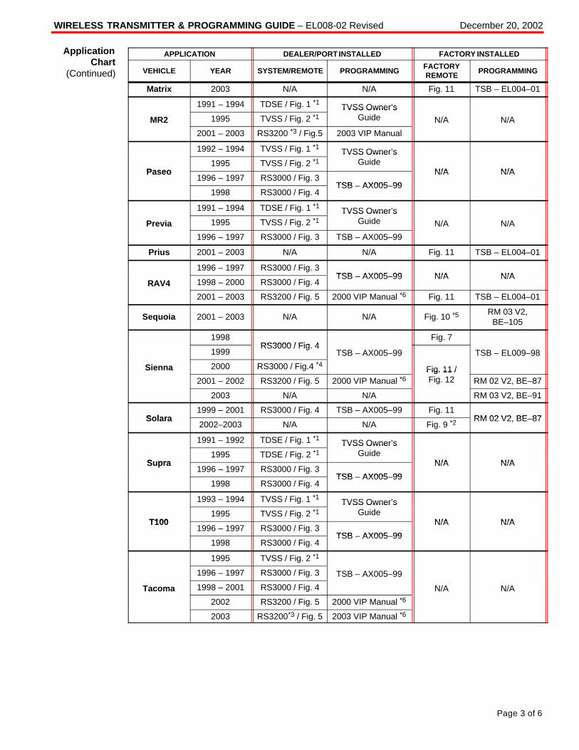
WIRELESS TRANSMITTER & PROGRAMMING GUIDE – EL008-02 Revised December 20, 2002
Page 3 of 6
APPLICATION DEALER/PORT INSTALLED FACTORY INSTALLED
VEHICLE YEAR SYSTEM/REMOTE PROGRAMMINGFACTORYREMOTE
PROGRAMMING
Matrix 2003 N/A N/A Fig. 11 TSB – EL004–01
1991 – 1994 TDSE / Fig. 1 *1 TVSS Owner’s
MR2 1995 TVSS / Fig. 2 *1TVSS Owner s
Guide N/A N/A
2001 – 2003 RS3200 *3 / Fig.5 2003 VIP Manual
1992 – 1994 TVSS / Fig. 1 *1 TVSS Owner’s
Paseo1995 TVSS / Fig. 2 *1
TVSS Owner sGuide
N/A N/APaseo1996 – 1997 RS3000 / Fig. 3
TSB AX005 99
N/A N/A
1998 RS3000 / Fig. 4TSB – AX005–99
1991 – 1994 TDSE / Fig. 1 *1 TVSS Owner’s
Previa 1995 TVSS / Fig. 2 *1TVSS Owner s
Guide N/A N/A
1996 – 1997 RS3000 / Fig. 3 TSB – AX005–99
Prius 2001 – 2003 N/A N/A Fig. 11 TSB – EL004–01
1996 – 1997 RS3000 / Fig. 3TSB AX005 99 N/A N/A
RAV4 1998 – 2000 RS3000 / Fig. 4TSB – AX005–99 N/A N/A
2001 – 2003 RS3200 / Fig. 5 2000 VIP Manual *6 Fig. 11 TSB – EL004–01
Sequoia 2001 – 2003 N/A N/A Fig. 10 *5RM 03 V2,
BE–105
1998RS3000 / Fig 4
Fig. 7
1999RS3000 / Fig. 4
TSB – AX005–99 TSB – EL009–98
Sienna 2000 RS3000 / Fig.4 *4 Fig. 11 /2001 – 2002 RS3200 / Fig. 5 2000 VIP Manual *6
Fig. 11 /Fig. 12 RM 02 V2, BE–87
2003 N/A N/A RM 03 V2, BE–91
Solara1999 – 2001 RS3000 / Fig. 4 TSB – AX005–99 Fig. 11
RM 02 V2 BE 87Solara2002–2003 N/A N/A Fig. 9 *2
RM 02 V2, BE–87
1991 – 1992 TDSE / Fig. 1 *1 TVSS Owner’s
S pra1995 TDSE / Fig. 2 *1
TVSS Owner sGuide
N/A N/ASupra1996 – 1997 RS3000 / Fig. 3
TSB AX005 99
N/A N/A
1998 RS3000 / Fig. 4TSB – AX005–99
1993 – 1994 TVSS / Fig. 1 *1 TVSS Owner’s
T1001995 TVSS / Fig. 2 *1
TVSS Owner sGuide
N/A N/AT1001996 – 1997 RS3000 / Fig. 3
TSB AX005 99
N/A N/A
1998 RS3000 / Fig. 4TSB – AX005–99
1995 TVSS / Fig. 2 *1
1996 – 1997 RS3000 / Fig. 3 TSB – AX005–99
Tacoma 1998 – 2001 RS3000 / Fig. 4 N/A N/A
2002 RS3200 / Fig. 5 2000 VIP Manual *6
2003 RS3200*3 / Fig. 5 2003 VIP Manual *6
ApplicationChart
(Continued)
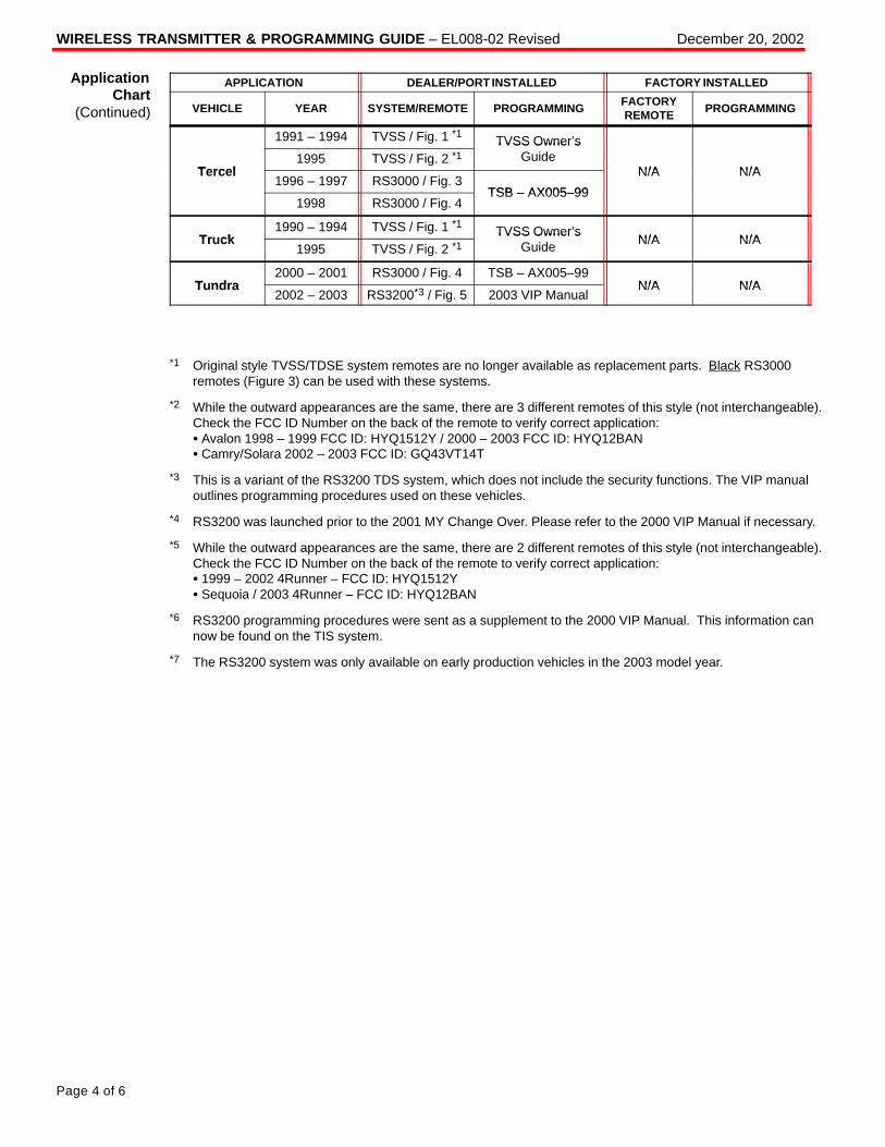
WIRELESS TRANSMITTER & PROGRAMMING GUIDE – EL008-02 Revised December 20, 2002
Page 4 of 6
APPLICATION DEALER/PORT INSTALLED FACTORY INSTALLED
VEHICLE YEAR SYSTEM/REMOTE PROGRAMMINGFACTORYREMOTE
PROGRAMMING
1991 – 1994 TVSS / Fig. 1 *1 TVSS Owner’s
Tercel1995 TVSS / Fig. 2 *1
TVSS Owner sGuide
N/A N/ATercel1996 – 1997 RS3000 / Fig. 3
TSB AX005 99
N/A N/A
1998 RS3000 / Fig. 4TSB – AX005–99
Tr ck1990 – 1994 TVSS / Fig. 1 *1 TVSS Owner’s
N/A N/ATruck1995 TVSS / Fig. 2 *1
TVSS Owner sGuide N/A N/A
T ndra2000 – 2001 RS3000 / Fig. 4 TSB – AX005–99
N/A N/ATundra2002 – 2003 RS3200*3 / Fig. 5 2003 VIP Manual
N/A N/A
*1 Original style TVSS/TDSE system remotes are no longer available as replacement parts. Black RS3000remotes (Figure 3) can be used with these systems.
*2 While the outward appearances are the same, there are 3 different remotes of this style (not interchangeable).Check the FCC ID Number on the back of the remote to verify correct application: � Avalon 1998 – 1999 FCC ID: HYQ1512Y / 2000 – 2003 FCC ID: HYQ12BAN� Camry/Solara 2002 – 2003 FCC ID: GQ43VT14T
*3 This is a variant of the RS3200 TDS system, which does not include the security functions. The VIP manualoutlines programming procedures used on these vehicles.
*4 RS3200 was launched prior to the 2001 MY Change Over. Please refer to the 2000 VIP Manual if necessary.
*5 While the outward appearances are the same, there are 2 different remotes of this style (not interchangeable).Check the FCC ID Number on the back of the remote to verify correct application: � 1999 – 2002 4Runner – FCC ID: HYQ1512Y � Sequoia / 2003 4Runner – FCC ID: HYQ12BAN
*6 RS3200 programming procedures were sent as a supplement to the 2000 VIP Manual. This information cannow be found on the TIS system.
*7 The RS3200 system was only available on early production vehicles in the 2003 model year.
ApplicationChart
(Continued)
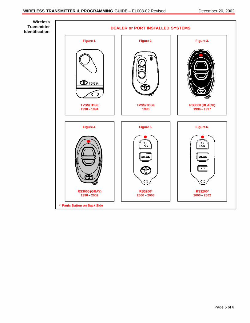
WIRELESS TRANSMITTER & PROGRAMMING GUIDE – EL008-02 Revised December 20, 2002
Page 5 of 6
DEALER or PORT INSTALLED SYSTEMS
Figure 1.
TVSS/TDSE1990 – 1994
Figure 2.
TVSS/TDSE1995
Figure 3.
RS3000 (BLACK)1996 – 1997
Figure 4.
RS3000 (GRAY)1998 – 2002
Figure 5.
RS3200*2000 – 2003
Figure 6.
RS3200*2000 – 2002
* Panic Button on Back Side
WirelessTransmitter
Identification
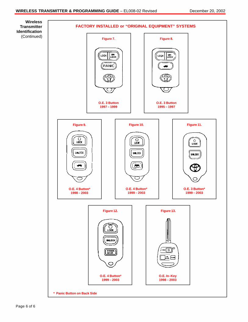
WIRELESS TRANSMITTER & PROGRAMMING GUIDE – EL008-02 Revised December 20, 2002
Page 6 of 6
FACTORY INSTALLED or “ORIGINAL EQUIPMENT” SYSTEMS
Figure 7.
O.E. 3 Button1997 – 1999
Figure 8.
O.E. 3 Button1995 – 1997
Figure 9.
O.E. 4 Button*1998 – 2003
Figure 10.
O.E. 4 Button*1999 – 2003
Figure 11.
O.E. 3 Button*1999 – 2003
Figure 12. Figure 13.
* Panic Button on Back Side
O.E. 4 Button*1999 – 2003
O.E. In–Key1998 – 2003
WirelessTransmitter
Identification(Continued)
OBSOLETEPLEASE SEE EL008–02
Toyota Supports ASE Certification Page 1 of 5
EL010-01
Title:
WIRELESS TRANSMITTER &
PROGRAMMING GUIDEModels:
All Applicable
Technical ServiceBULLETIN
October 26, 2001
Difficulties during Remote Keyless Entry Transmitter Programming can arise due toconfusion between Toyota Factory Wireless systems and Toyota Port/Dealer installedsystems. This bulletin will assist in identifying the system/correct remote transmitters foreach vehicle, and provide the location of the most accurate programming procedure foreach system.
� All applicable Toyota vehicles.
OP CODE DESCRIPTION TIME OPN T1 T2
N/A Not Applicable to Warranty – – – –
The following table contains all of the necessary information to correctly identify the typeof system installed, and where to go to get programming procedures for each vehicle.
NOTE:Should a vehicle having both VIP and Factory systems available (as identified in thefollowing table) be brought in without any remotes (or one non–working remote), usethe following tips to help determine which type of wireless system (O.E. or PIO/DIO)the vehicle has.� Look at the Trim Level of the vehicle. Higher–grade vehicles will tend to have O.E.
systems, while entry–grade vehicles will tend to have VIP. For example, the 2001Camry XLE has Factory RKE, but the LE and CE grades have VIP.
� Look for a “Status Monitor” with a glass breakage sensor and an LED externallyinstalled into the dashboard or on the center console. Most VIP systems will havethis.
� Locate the ECU (refer to the applicable vehicle VIP Manual installation instructionsfor location). Once located, refer to the part label.
� Attempt to perform the factory wireless programming procedure to get a responsefrom the vehicle. Select the “confirmation mode” and see if any “Lock/Unlock”response is received, if so, the vehicle has a factory system.
ELE
CT
RIC
AL
Introduction
ApplicableVehicles
WarrantyInformation
SystemIdentification
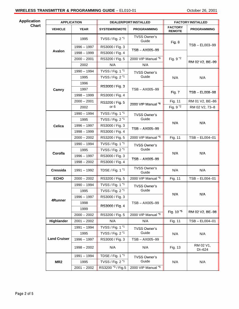
October 26, 2001WIRELESS TRANSMITTER & PROGRAMMING GUIDE – EL010-01
Page 2 of 5
APPLICATION DEALER/PORT INSTALLED FACTORY INSTALLED
VEHICLE YEAR SYSTEM/REMOTE PROGRAMMINGFACTORYREMOTE
PROGRAMMING
1995 TVSS / Fig. 2 *1TVSS Owner’s
Guide Fig. 8TSB EL003 99
A l1996 – 1997 RS3000 / Fig. 3
TSB AX005 99
Fig. 8TSB – EL003–99
Avalon 1998 – 1999 RS3000 / Fig. 4TSB – AX005–99
2000 – 2001 RS3200 / Fig. 5 2000 VIP Manual *6 Fig. 9 *2RM 02 V2 BE 99
2002 N/A N/A
gRM 02 V2, BE–99
1990 – 1994 TVSS / Fig. 1 *1 TVSS Owner’s1995 TVSS / Fig. 2 *1
TVSS Owner sGuide N/A N/A
1996RS3000 / Fig 3
Camry 1997RS3000 / Fig. 3
TSB – AX005–99Fig 7 TSB EL008 98
y
1998 – 1999 RS3000 / Fig. 4Fig. 7 TSB – EL008–98
2000 – 2001 RS3200 / Fig. 5 2000 VIP Manual *6Fig. 11 RM 01 V2, BE–86
2002RS3200 / Fig. 5
or 62000 VIP Manual *6
Fig. 9 *2 RM 02 V2, 73–8
1990 – 1994 TVSS / Fig. 1 *1 TVSS Owner’s1995 TVSS / Fig. 2 *1
TVSS Owner sGuide
N/A N/ACelica 1996 – 1997 RS3000 / Fig. 3
TSB AX005 99
N/A N/A
1998 – 1999 RS3000 / Fig. 4TSB – AX005–99
2000 – 2002 RS3200 / Fig. 5 2000 VIP Manual *6 Fig. 11 TSB – EL004–01
1990 – 1994 TVSS / Fig. 1 *1 TVSS Owner’s
Corolla1995 TVSS / Fig. 2 *1
TVSS Owner sGuide
N/A N/ACorolla1996 – 1997 RS3000 / Fig. 3
TSB AX005 99
N/A N/A
1998 – 2002 RS3000 / Fig. 4TSB – AX005–99
Cressida 1991 – 1992 TDSE / Fig. 1 *1TVSS Owner’s
GuideN/A N/A
ECHO 2000 – 2002 RS3200 / Fig. 5 2000 VIP Manual *6 Fig. 11 TSB – EL004–01
1990 – 1994 TVSS / Fig. 1 *1 TVSS Owner’s1995 TVSS / Fig. 2 *1
TVSS Owner sGuide
N/A N/A
4R nner1996 – 1997 RS3000 / Fig. 3
N/A N/A
4Runner1998
RS3000 / Fig 4TSB – AX005–99
1999RS3000 / Fig. 4
Fig 10 *5 RM 02 V2 BE 982000 – 2002 RS3200 / Fig. 5 2000 VIP Manual *6
Fig. 10 *5 RM 02 V2, BE–98
Highlander 2001 – 2002 N/A N/A Fig. 11 TSB – EL004–01
1991 – 1994 TVSS / Fig. 1 *1 TVSS Owner’s1995 TVSS / Fig. 2 *1
TVSS Owner sGuide N/A N/A
Land Cruiser 1996 – 1997 RS3000 / Fig. 3 TSB – AX005–99
1998 – 2002 N/A N/A Fig. 13RM 02 V1,
DI–624
1991 – 1994 TDSE / Fig. 1 *1 TVSS Owner’sMR2 1995 TVSS / Fig. 2 *1
TVSS Owner sGuide N/A N/A
2001 – 2002 RS3200 *3 / Fig.5 2000 VIP Manual *6
ApplicationChart
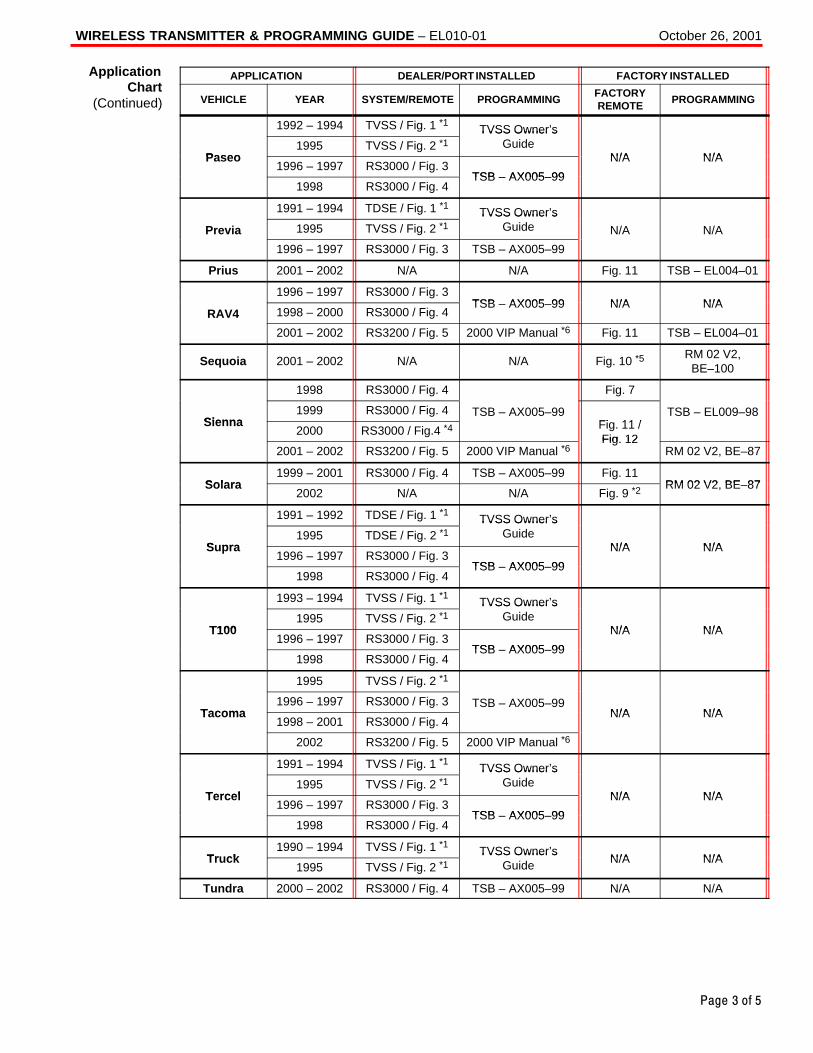
October 26, 2001WIRELESS TRANSMITTER & PROGRAMMING GUIDE – EL010-01
Page 3 of 5
APPLICATION DEALER/PORT INSTALLED FACTORY INSTALLED
VEHICLE YEAR SYSTEM/REMOTE PROGRAMMINGFACTORYREMOTE
PROGRAMMING
1992 – 1994 TVSS / Fig. 1 *1 TVSS Owner’s
Paseo1995 TVSS / Fig. 2 *1
TVSS Owner sGuide
N/A N/APaseo1996 – 1997 RS3000 / Fig. 3
TSB AX005 99
N/A N/A
1998 RS3000 / Fig. 4TSB – AX005–99
1991 – 1994 TDSE / Fig. 1 *1 TVSS Owner’s
Previa 1995 TVSS / Fig. 2 *1TVSS Owner s
Guide N/A N/A
1996 – 1997 RS3000 / Fig. 3 TSB – AX005–99
Prius 2001 – 2002 N/A N/A Fig. 11 TSB – EL004–01
1996 – 1997 RS3000 / Fig. 3TSB AX005 99 N/A N/A
RAV4 1998 – 2000 RS3000 / Fig. 4TSB – AX005–99 N/A N/A
2001 – 2002 RS3200 / Fig. 5 2000 VIP Manual *6 Fig. 11 TSB – EL004–01
Sequoia 2001 – 2002 N/A N/A Fig. 10 *5RM 02 V2,
BE–100
1998 RS3000 / Fig. 4 Fig. 7
Sienna1999 RS3000 / Fig. 4 TSB – AX005–99
Fi 11 /TSB – EL009–98
Sienna2000 RS3000 / Fig.4 *4 Fig. 11 /
Fig 122001 – 2002 RS3200 / Fig. 5 2000 VIP Manual *6
Fig. 12RM 02 V2, BE–87
Solara1999 – 2001 RS3000 / Fig. 4 TSB – AX005–99 Fig. 11
RM 02 V2 BE 87Solara2002 N/A N/A Fig. 9 *2
RM 02 V2, BE–87
1991 – 1992 TDSE / Fig. 1 *1 TVSS Owner’s
S pra1995 TDSE / Fig. 2 *1
TVSS Owner sGuide
N/A N/ASupra1996 – 1997 RS3000 / Fig. 3
TSB AX005 99
N/A N/A
1998 RS3000 / Fig. 4TSB – AX005–99
1993 – 1994 TVSS / Fig. 1 *1 TVSS Owner’s
T1001995 TVSS / Fig. 2 *1
TVSS Owner sGuide
N/A N/AT1001996 – 1997 RS3000 / Fig. 3
TSB AX005 99
N/A N/A
1998 RS3000 / Fig. 4TSB – AX005–99
1995 TVSS / Fig. 2 *1
Tacoma1996 – 1997 RS3000 / Fig. 3 TSB – AX005–99
N/A N/ATacoma1998 – 2001 RS3000 / Fig. 4
N/A N/A
2002 RS3200 / Fig. 5 2000 VIP Manual *6
1991 – 1994 TVSS / Fig. 1 *1 TVSS Owner’s
Tercel1995 TVSS / Fig. 2 *1
TVSS Owner sGuide
N/A N/ATercel1996 – 1997 RS3000 / Fig. 3
TSB AX005 99
N/A N/A
1998 RS3000 / Fig. 4TSB – AX005–99
Tr ck1990 – 1994 TVSS / Fig. 1 *1 TVSS Owner’s
N/A N/ATruck1995 TVSS / Fig. 2 *1
TVSS Owner sGuide N/A N/A
Tundra 2000 – 2002 RS3000 / Fig. 4 TSB – AX005–99 N/A N/A
ApplicationChart
(Continued)
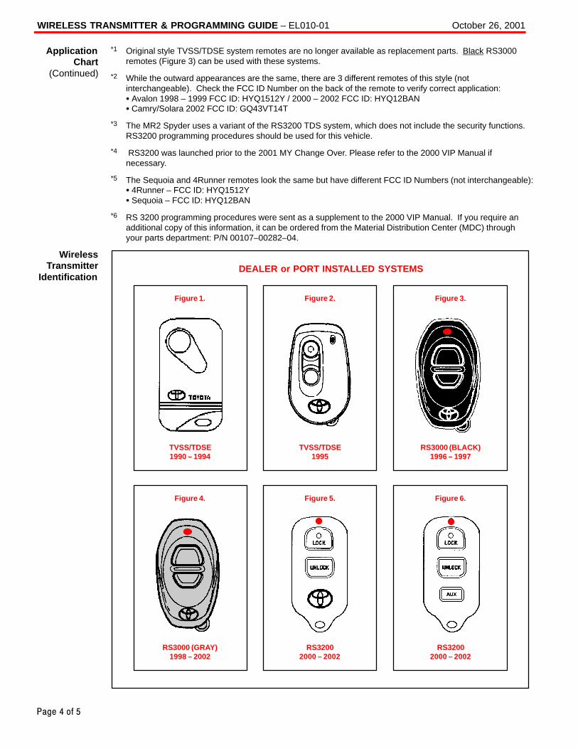
October 26, 2001WIRELESS TRANSMITTER & PROGRAMMING GUIDE – EL010-01
Page 4 of 5
*1 Original style TVSS/TDSE system remotes are no longer available as replacement parts. Black RS3000remotes (Figure 3) can be used with these systems.
*2 While the outward appearances are the same, there are 3 different remotes of this style (notinterchangeable). Check the FCC ID Number on the back of the remote to verify correct application: � Avalon 1998 – 1999 FCC ID: HYQ1512Y / 2000 – 2002 FCC ID: HYQ12BAN� Camry/Solara 2002 FCC ID: GQ43VT14T
*3 The MR2 Spyder uses a variant of the RS3200 TDS system, which does not include the security functions.RS3200 programming procedures should be used for this vehicle.
*4 RS3200 was launched prior to the 2001 MY Change Over. Please refer to the 2000 VIP Manual ifnecessary.
*5 The Sequoia and 4Runner remotes look the same but have different FCC ID Numbers (not interchangeable): � 4Runner – FCC ID: HYQ1512Y � Sequoia – FCC ID: HYQ12BAN
*6 RS 3200 programming procedures were sent as a supplement to the 2000 VIP Manual. If you require anadditional copy of this information, it can be ordered from the Material Distribution Center (MDC) throughyour parts department: P/N 00107–00282–04.
DEALER or PORT INSTALLED SYSTEMS
Figure 1.
TVSS/TDSE1990 – 1994
Figure 2.
TVSS/TDSE1995
Figure 3.
RS3000 (BLACK)1996 – 1997
Figure 4.
RS3000 (GRAY)1998 – 2002
Figure 5.
RS32002000 – 2002
Figure 6.
RS32002000 – 2002
ApplicationChart
(Continued)
WirelessTransmitter
Identification
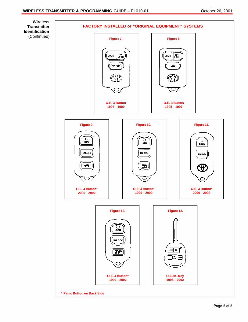
October 26, 2001WIRELESS TRANSMITTER & PROGRAMMING GUIDE – EL010-01
Page 5 of 5
FACTORY INSTALLED or “ORIGINAL EQUIPMENT” SYSTEMS
Figure 7.
O.E. 3 Button1997 – 1999
Figure 8.
O.E. 3 Button1995 – 1997
Figure 9.
O.E. 4 Button*2000 – 2002
Figure 10.
O.E. 4 Button*1999 – 2002
Figure 11.
O.E. 3 Button*2000 – 2002
Figure 12. Figure 13.
* Panic Button on Back Side
O.E. 4 Button*1999 – 2002
O.E. In–Key1998 – 2002
WirelessTransmitter
Identification(Continued)
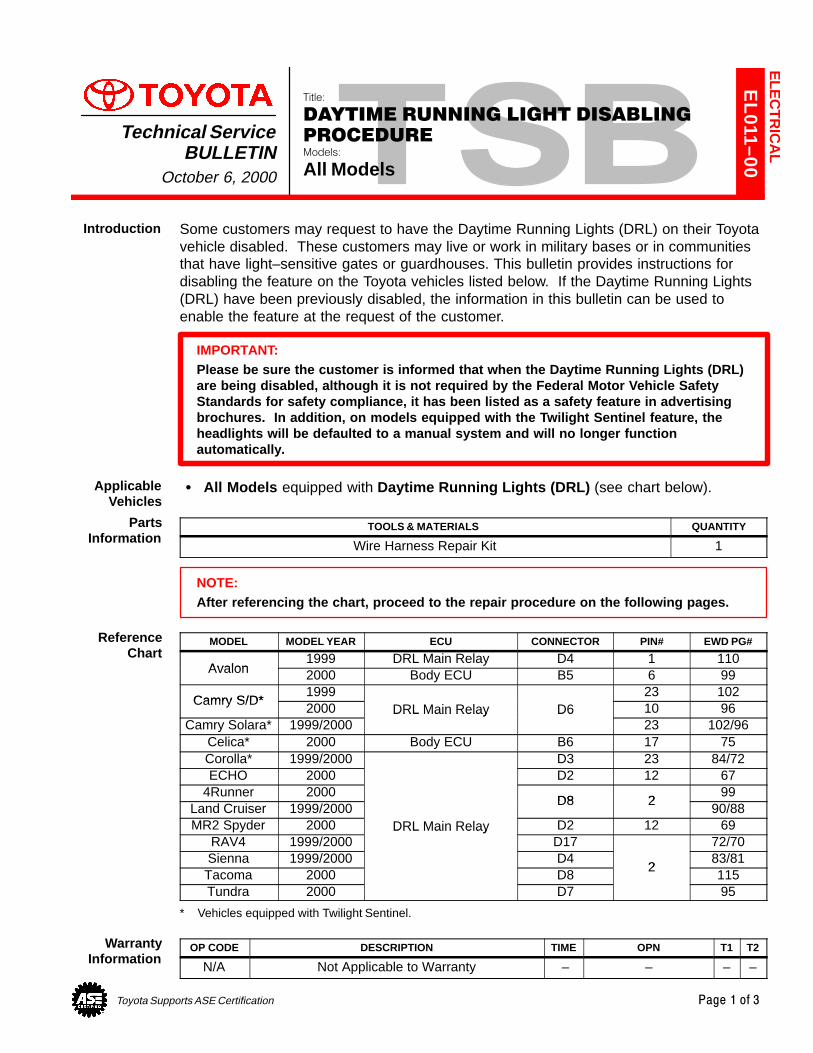
Toyota Supports ASE Certification Page 1 of 3
EL011–00
Title:
DAYTIME RUNNING LIGHT DISABLING
PROCEDUREModels:
All Models
Technical ServiceBULLETIN
October 6, 2000
Some customers may request to have the Daytime Running Lights (DRL) on their Toyotavehicle disabled. These customers may live or work in military bases or in communitiesthat have light–sensitive gates or guardhouses. This bulletin provides instructions fordisabling the feature on the Toyota vehicles listed below. If the Daytime Running Lights(DRL) have been previously disabled, the information in this bulletin can be used toenable the feature at the request of the customer.
IMPORTANT:Please be sure the customer is informed that when the Daytime Running Lights (DRL)are being disabled, although it is not required by the Federal Motor Vehicle SafetyStandards for safety compliance, it has been listed as a safety feature in advertisingbrochures. In addition, on models equipped with the Twilight Sentinel feature, theheadlights will be defaulted to a manual system and will no longer functionautomatically.
� All Models equipped with Daytime Running Lights (DRL) (see chart below).
TOOLS & MATERIALS QUANTITY
Wire Harness Repair Kit 1
NOTE:After referencing the chart, proceed to the repair procedure on the following pages.
MODEL MODEL YEAR ECU CONNECTOR PIN# EWD PG#
Avalon1999 DRL Main Relay D4 1 110
Avalon 2000 Body ECU B5 6 99
Camry S/D*1999 23 102
Camry S/D*2000 DRL Main Relay D6 10 96
Camry Solara* 1999/2000DRL Main Relay D6
23 102/96Celica* 2000 Body ECU B6 17 75Corolla* 1999/2000 D3 23 84/72ECHO 2000 D2 12 67
4Runner 2000D8 2
99Land Cruiser 1999/2000
D8 290/88
MR2 Spyder 2000 DRL Main Relay D2 12 69RAV4 1999/2000
DRL Main RelayD17 72/70
Sienna 1999/2000 D42
83/81Tacoma 2000 D8
2115
Tundra 2000 D7 95
* Vehicles equipped with Twilight Sentinel.
OP CODE DESCRIPTION TIME OPN T1 T2
N/A Not Applicable to Warranty – – – –
ELE
CT
RIC
AL
Introduction
ApplicableVehicles
PartsInformation
ReferenceChart
WarrantyInformation
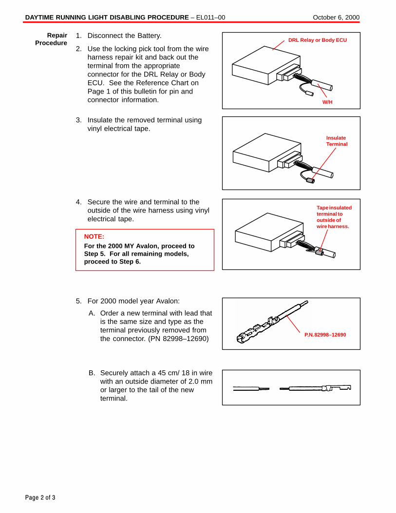
DAYTIME RUNNING LIGHT DISABLING PROCEDURE – EL011–00 October 6, 2000
Page 2 of 3
1. Disconnect the Battery.
2. Use the locking pick tool from the wireharness repair kit and back out theterminal from the appropriateconnector for the DRL Relay or BodyECU. See the Reference Chart onPage 1 of this bulletin for pin andconnector information.
3. Insulate the removed terminal usingvinyl electrical tape.
4. Secure the wire and terminal to theoutside of the wire harness using vinylelectrical tape.
NOTE:For the 2000 MY Avalon, proceed toStep 5. For all remaining models,proceed to Step 6.
5. For 2000 model year Avalon:
A. Order a new terminal with lead thatis the same size and type as theterminal previously removed fromthe connector. (PN 82998–12690)
B. Securely attach a 45 cm/ 18 in wirewith an outside diameter of 2.0 mmor larger to the tail of the newterminal.
RepairProcedure DRL Relay or Body ECU
W/H
InsulateTerminal
Tape insulatedterminal tooutside ofwire harness.
P.N. 82998–12690
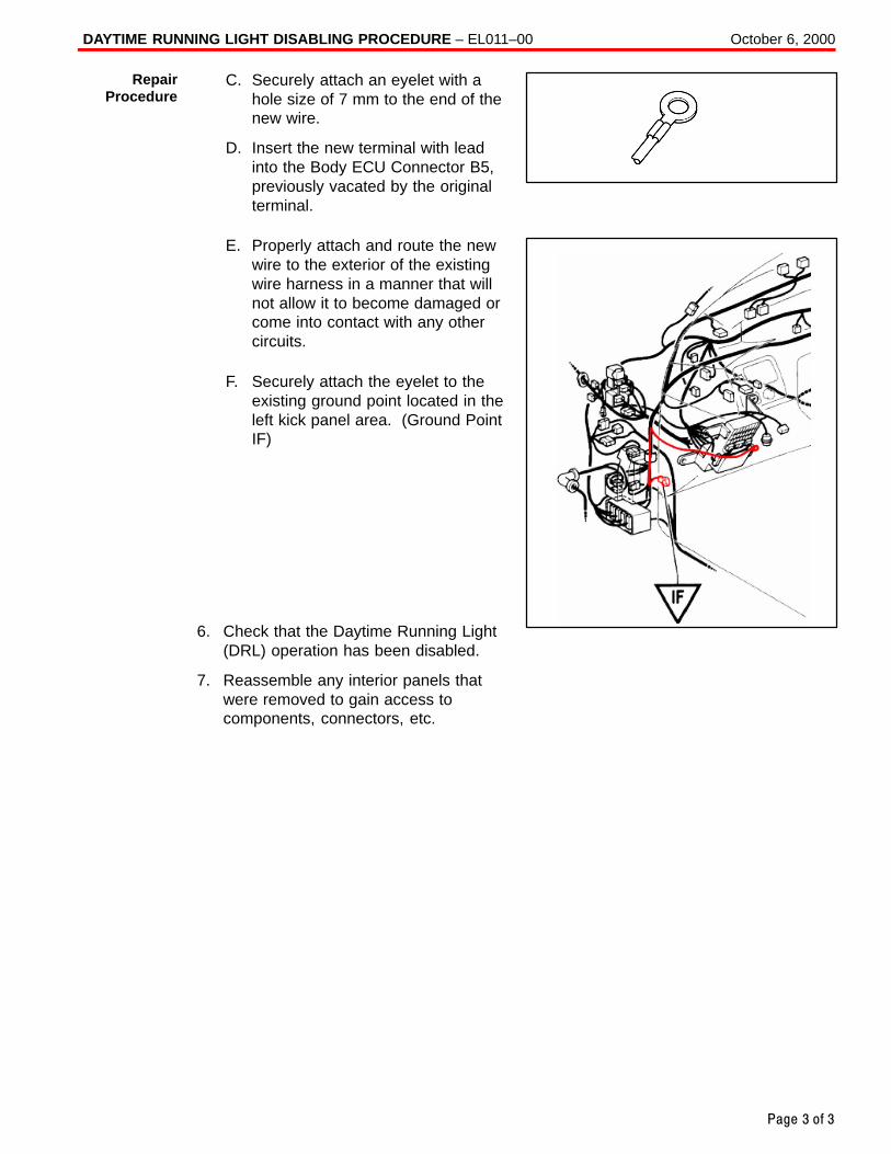
DAYTIME RUNNING LIGHT DISABLING PROCEDURE – EL011–00 October 6, 2000
Page 3 of 3
C. Securely attach an eyelet with ahole size of 7 mm to the end of thenew wire.
D. Insert the new terminal with leadinto the Body ECU Connector B5,previously vacated by the originalterminal.
E. Properly attach and route the newwire to the exterior of the existingwire harness in a manner that willnot allow it to become damaged orcome into contact with any othercircuits.
F. Securely attach the eyelet to theexisting ground point located in theleft kick panel area. (Ground PointIF)
6. Check that the Daytime Running Light(DRL) operation has been disabled.
7. Reassemble any interior panels thatwere removed to gain access tocomponents, connectors, etc.
RepairProcedure
Toyota Supports ASE Certification Page 1 of 1
AC
002–00
Title:
A/C COMPRESSOR MAINTENANCE FOR
STORED VEHICLESModels:
All Models
Technical ServiceBULLETINJuly 21, 2000
When a vehicle is stored for a long period (more than one month), the volume of oilin the A/C compressor may decrease due to oil flow into the condenser, pipes, etc.
If the A/C system is turned on at high engine RPM after a long storage period, A/Ccompressor damage may result.
To minimize the possibility of damage to the A/C compressor while storing a vehicle,perform the following recommended maintenance procedure at least once a month tolubricate the compressor.
Recommended Maintenance Procedure For A/C Compressor Lubrication :
1. Turn off A/C and blower switches prior to starting engine.
2. Start and warm–up engine until engine speed drops below 1,000 RPM.
3. Turn on the A/C system (including the rear A/C) using the following settings:
� A/C switch: On
� Blower Speed: High
� Engine Speed: Below 1,000 RPM
4. Keep A/C on with engine idling for at least 30 seconds.
5. Turn off A/C system and stop engine.
OP CODE DESCRIPTION TIME OPN T1 T2
N/A Not Applicable to Warranty – – – –
HE
AT
ING
& A
IR C
ON
DIT
ION
ING
Introduction
MaintenanceProcedure
WarrantyInformation

Toyota Supports ASE Certification Page 1 of 2
AC
003-04
Title:
A/C COMPRESSOR INSTALLATION
PROCEDUREModels:
Applicable Models
Technical ServiceBULLETIN
March 1, 2004
Use the following tip when installing an A/C compressor on the AZ or ZZ series engineto ensure proper belt alignment. Improper installation of the A/C compressor may result in abnormal belt noise or wear.
� 1998 – Current model year Corolla vehicles.
� 2000 – Current model year Celica vehicles.
� 2000 – Current model year MR2 Spyder vehicles.
� 2001 – Current model year Highlander vehicles equipped with 4 cylinder engine.
� 2001 – Current model year RAV4 vehicles.
� 2002 – Current model year Camry vehicles equipped with 4 cylinder engine.
� 2002 – Current model year Solara vehicles equipped with 4 cylinder engine.
� 2003 – Current model year Matrix vehicles.
OP CODE DESCRIPTION TIME OFP T1 T2
N/A Not Applicable to Warranty – – – –
Belt
Bolt
Clearance
A/C Compressor
OK NG
Proper Installation Improper Installation
HE
AT
ING
& A
IR C
ON
DIT
ION
ING
Introduction
ApplicableVehicles
WarrantyInformation
InstallationProcedure

A/C COMPRESSOR INSTALLATION PROCEDURE – AC003-04 March 1, 2004
Page 2 of 2
1. AZ Series Engine:Install A/C Compressor
A. Loosely install the compressor(with the 3 bolts and nut or 4 bolts.)
Push down on the rear side of thecompressor and tighten thebolts/nut in the order shown.
Torque: 24.5 N �m (250 kgf �cm, 18 ft �lbf)
2. ZZ Series Engine:Install A/C Compressor
A. Loosely install the compressor(with the 2 bolts and nut or 3 bolts).
Push down on the rear side of the compressor and tighten thebolts/nut in the order shown.
Torque: 29 N �m (295 kgf �cm, 21 ft �lbf)
InstallationProcedure(Continued)
Bolt Bolt Push
Nut or Bolt Bolt12
34
Bolt Push
Nut or Bolt Bolt12
3
Toyota Supports ASE Certification Page 1 of 2
AX
001–00
Title:
TOYOTA �DINGHY" TOWING GUIDEModels:
All ModelsTechnical Service
BULLETINMarch 17, 2000
The chart on the next page indicates which Toyota vehicles can be Dinghy towed (towedwith four wheels on the ground) behind a Motorhome.
CAUTION:Dinghy towing a vehicle behind a Motorhome requires special towing equipmentand accessories. Please see your Motorhome Manufacturer / Service Outlet forrecommended towing equipment.
OP CODE DESCRIPTION TIME OPN T1 T2
N/A Not Applicable to Warranty – – – –
AC
CE
SS
OR
IES
Introduction
WarrantyInformation
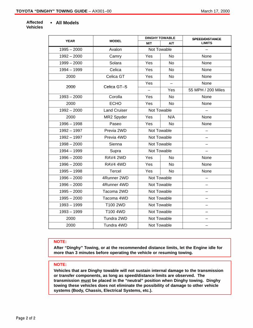
TOYOTA “DINGHY” TOWING GUIDE – AX001–00 March 17, 2000
Page 2 of 2
� All Models
YEAR MODELDINGHY TOWABLE SPEED/DISTANCE
YEAR MODELM/T A/T
SPEED/DISTANCELIMITS
1995 – 2000 Avalon Not Towable –
1992 – 2000 Camry Yes No None
1999 – 2000 Solara Yes No None
1994 – 1999 Celica Yes No None
2000 Celica GT Yes No None
2000 Celica GT–SYes – None
2000 Celica GT–S– Yes 55 MPH / 200 Miles
1993 – 2000 Corolla Yes No None
2000 ECHO Yes No None
1992 – 2000 Land Cruiser Not Towable –
2000 MR2 Spyder Yes N/A None
1996 – 1998 Paseo Yes No None
1992 – 1997 Previa 2WD Not Towable –
1992 – 1997 Previa 4WD Not Towable –
1998 – 2000 Sienna Not Towable –
1994 – 1999 Supra Not Towable –
1996 – 2000 RAV4 2WD Yes No None
1996 – 2000 RAV4 4WD Yes No None
1995 – 1998 Tercel Yes No None
1996 – 2000 4Runner 2WD Not Towable –
1996 – 2000 4Runner 4WD Not Towable –
1995 – 2000 Tacoma 2WD Not Towable –
1995 – 2000 Tacoma 4WD Not Towable –
1993 – 1999 T100 2WD Not Towable –
1993 – 1999 T100 4WD Not Towable –
2000 Tundra 2WD Not Towable –
2000 Tundra 4WD Not Towable –
NOTE:After “Dinghy” Towing, or at the recommended distance limits, let the Engine idle formore than 3 minutes before operating the vehicle or resuming towing.
NOTE:Vehicles that are Dinghy towable will not sustain internal damage to the transmissionor transfer components, as long as speed/distance limits are observed. Thetransmission must be placed in the “neutral” position when Dinghy towing. Dinghytowing these vehicles does not eliminate the possibility of damage to other vehiclesystems (Body, Chassis, Electrical Systems, etc.).
AffectedVehicles
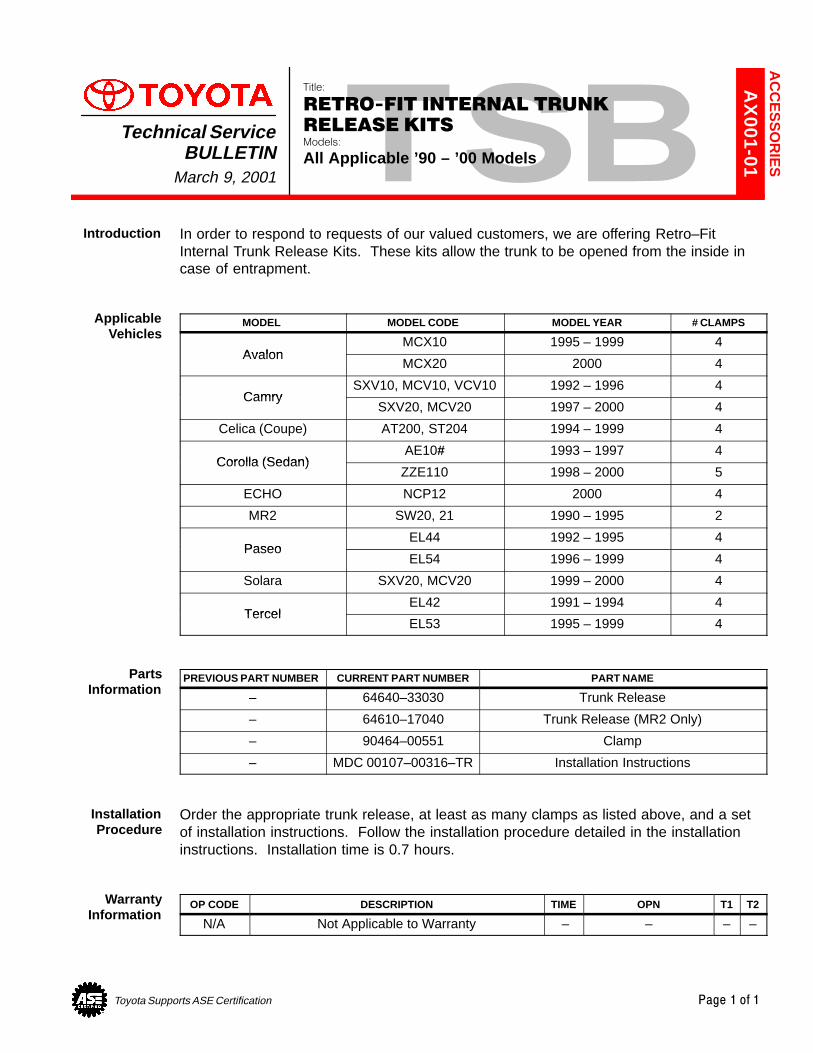
Toyota Supports ASE Certification Page 1 of 1
AX
001-01Title:
RETRO-FIT INTERNAL TRUNK
RELEASE KITSModels:
All Applicable ’90 – ’00 Models
Technical ServiceBULLETIN
March 9, 2001
In order to respond to requests of our valued customers, we are offering Retro–FitInternal Trunk Release Kits. These kits allow the trunk to be opened from the inside incase of entrapment.
MODEL MODEL CODE MODEL YEAR # CLAMPS
AvalonMCX10 1995 – 1999 4
AvalonMCX20 2000 4
CamrySXV10, MCV10, VCV10 1992 – 1996 4
CamrySXV20, MCV20 1997 – 2000 4
Celica (Coupe) AT200, ST204 1994 – 1999 4
Corolla (Sedan)AE10# 1993 – 1997 4
Corolla (Sedan)ZZE110 1998 – 2000 5
ECHO NCP12 2000 4
MR2 SW20, 21 1990 – 1995 2
PaseoEL44 1992 – 1995 4
PaseoEL54 1996 – 1999 4
Solara SXV20, MCV20 1999 – 2000 4
TercelEL42 1991 – 1994 4
TercelEL53 1995 – 1999 4
PREVIOUS PART NUMBER CURRENT PART NUMBER PART NAME
– 64640–33030 Trunk Release
– 64610–17040 Trunk Release (MR2 Only)
– 90464–00551 Clamp
– MDC 00107–00316–TR Installation Instructions
Order the appropriate trunk release, at least as many clamps as listed above, and a setof installation instructions. Follow the installation procedure detailed in the installationinstructions. Installation time is 0.7 hours.
OP CODE DESCRIPTION TIME OPN T1 T2
N/A Not Applicable to Warranty – – – –
AC
CE
SS
OR
IES
Introduction
ApplicableVehicles
PartsInformation
Installation Procedure
WarrantyInformation
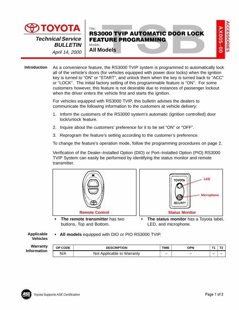
Toyota Supports ASE Certification Page 1 of 2
AX
005–00
Title:
RS3000 TVIP AUTOMATIC DOOR LOCK
FEATURE PROGRAMMINGModels:
All Models
Technical ServiceBULLETIN
April 14, 2000
As a convenience feature, the RS3000 TVIP system is programmed to automatically lockall of the vehicle’s doors (for vehicles equipped with power door locks) when the ignitionkey is turned to “ON” or “START”, and unlock them when the key is turned back to “ACC”or “LOCK”. The initial factory setting of this programmable feature is “ON”. For somecustomers however, this feature is not desirable due to instances of passenger lockoutwhen the driver enters the vehicle first and starts the ignition.
For vehicles equipped with RS3000 TVIP, this bulletin advises the dealers tocommunicate the following information to the customers at vehicle delivery:
1. Inform the customers of the RS3000 system’s automatic (ignition controlled) doorlock/unlock feature.
2. Inquire about the customers’ preference for it to be set “ON” or “OFF”.
3. Reprogram the feature’s setting according to the customer’s preference.
To change the feature’s operation mode, follow the programming procedures on page 2.
Verification of the Dealer–Installed Option (DIO) or Port–Installed Option (PIO) RS3000TVIP System can easily be performed by identifying the status monitor and remotetransmitter.
� The remote transmitter has twobuttons, Top and Bottom.
� The status monitor has a Toyota label,LED, and microphone.
Remote Control
LED
Status Monitor
Microphone
� All models equipped with DIO or PIO RS3000 TVIP.
OP CODE DESCRIPTION TIME OPN T1 T2
N/A Not Applicable to Warranty – – – –
AC
CE
SS
OR
IES
Introduction
ApplicableVehicles
WarrantyInformation
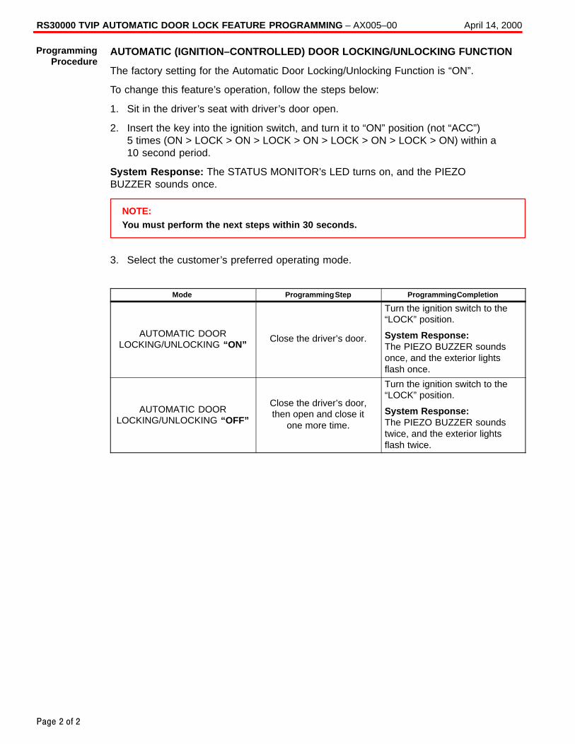
RS30000 TVIP AUTOMATIC DOOR LOCK FEATURE PROGRAMMING – AX005–00 April 14, 2000
Page 2 of 2
AUTOMATIC (IGNITION–CONTROLLED) DOOR LOCKING/UNLOCKING FUNCTION
The factory setting for the Automatic Door Locking/Unlocking Function is “ON”.
To change this feature’s operation, follow the steps below:
1. Sit in the driver’s seat with driver’s door open.
2. Insert the key into the ignition switch, and turn it to “ON” position (not “ACC”)5 times (ON > LOCK > ON > LOCK > ON > LOCK > ON > LOCK > ON) within a10 second period.
System Response: The STATUS MONITOR’s LED turns on, and the PIEZOBUZZER sounds once.
NOTE:You must perform the next steps within 30 seconds.
3. Select the customer’s preferred operating mode.
Mode Programming Step Programming Completion
AUTOMATIC DOORLOCKING/UNLOCKING “ON”
Close the driver’s door.
Turn the ignition switch to the“LOCK” position.
System Response:The PIEZO BUZZER soundsonce, and the exterior lightsflash once.
AUTOMATIC DOORLOCKING/UNLOCKING “OFF”
Close the driver’s door,then open and close it
one more time.
Turn the ignition switch to the“LOCK” position.
System Response:The PIEZO BUZZER soundstwice, and the exterior lightsflash twice.
ProgrammingProcedure
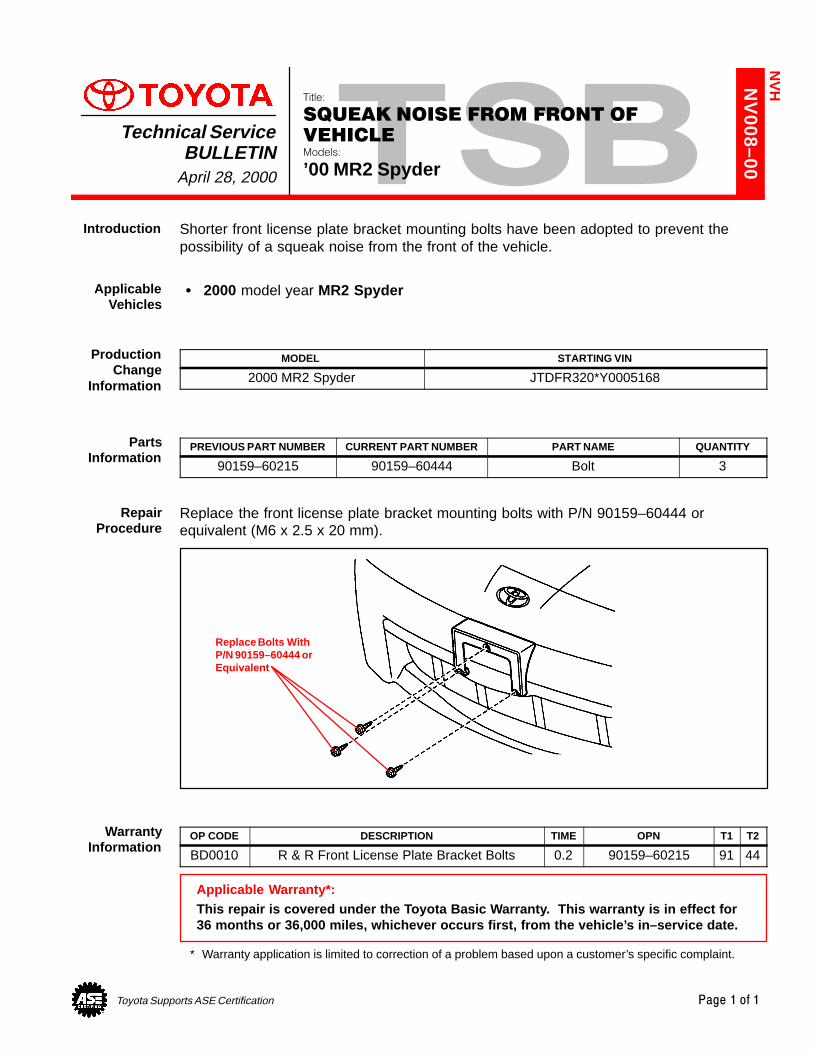
Toyota Supports ASE Certification Page 1 of 1
NV
008–00
Title:
SQUEAK NOISE FROM FRONT OF
VEHICLEModels:
’00 MR2 Spyder
Technical ServiceBULLETIN
April 28, 2000
Shorter front license plate bracket mounting bolts have been adopted to prevent thepossibility of a squeak noise from the front of the vehicle.
� 2000 model year MR2 Spyder
MODEL STARTING VIN
2000 MR2 Spyder JTDFR320*Y0005168
PREVIOUS PART NUMBER CURRENT PART NUMBER PART NAME QUANTITY
90159–60215 90159–60444 Bolt 3
Replace the front license plate bracket mounting bolts with P/N 90159–60444 orequivalent (M6 x 2.5 x 20 mm).
Replace Bolts WithP/N 90159–60444 orEquivalent
OP CODE DESCRIPTION TIME OPN T1 T2
BD0010 R & R Front License Plate Bracket Bolts 0.2 90159–60215 91 44
Applicable Warranty*:This repair is covered under the Toyota Basic Warranty. This warranty is in effect for36 months or 36,000 miles, whichever occurs first, from the vehicle’s in–service date.
* Warranty application is limited to correction of a problem based upon a customer’s specific complaint.
NV
H
Introduction
ApplicableVehicles
ProductionChange
Information
PartsInformation
RepairProcedure
WarrantyInformation
Toyota Supports ASE Certification Page 1 of 6
NV
011–00
Title:
SQUEAK & RATTLE SERVICE TIPSModels:
’00 MR2 SpyderTechnical Service
BULLETINJune 2, 2000
To reduce interior squeaks and rattles on the 2000 model year MR2 Spyder, material hasbeen added between parts at several locations. The following repair procedures havebeen adopted.
� 2000 model year MR2 Spyder
TOOLS & MATERIALS PART NUMBER
Interior Noise Kit 08231–00801
High Performance Penetrating Lubricant (or equivalent) 00530–1PL00
Kent� Acrysol (or equivalent) Kent� P/N 60170
OP CODE DESCRIPTION TIME OPN T1 T2
BD0017 Push Instrument Panel Forward & Retighten Bolt 0.1 55311–17070–C0
EL0002 Add Felt to Passenger Airbag Brackets 0.2 55313–17010
BD0018 Add EPT Sealer to Convertible Top 0.4 65911–17010
BD0019 Apply Lubricant to Convertible Top B–Link 0.1 65950–17010
BD0020 Bend Luggage Compartment Lid Striker 0.1 6441X–17XX0–C091 44
BD0021 Add Felt to Luggage Compartment Box 0.2 64270–1721091 44
BD0022 Reposition Cup Holder Bracket 0.3 55604–17010–C0
BD0023 Add EPT Sealer to Instrument PanelLower Finish Panel
0.2 55046–17010–C0
BD0024 Add EPT Sealer to Power Door Lock Connector 0.4 690X0–17130
Applicable Warranty*:This repair is covered under the Toyota Basic Warranty. This warranty is in effect for36 months or 36,000 miles, whichever occurs first, from the vehicle’s in–service date.
* Warranty application is limited to correction of a problem based upon a customer’s specific complaint.
NV
H
Introduction
ApplicableVehicles
Tools &Material
WarrantyInformation
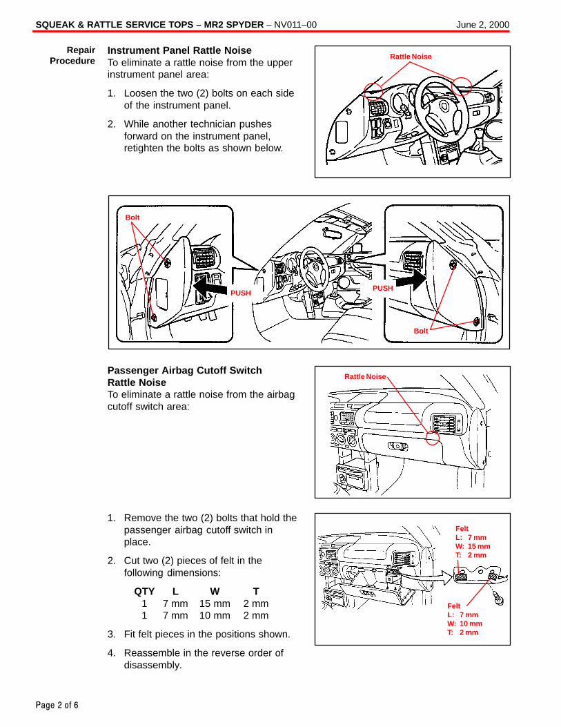
SQUEAK & RATTLE SERVICE TOPS – MR2 SPYDER – NV011–00 June 2, 2000
Page 2 of 6
Instrument Panel Rattle NoiseTo eliminate a rattle noise from the upperinstrument panel area:
1. Loosen the two (2) bolts on each sideof the instrument panel.
2. While another technician pushesforward on the instrument panel,retighten the bolts as shown below.
Bolt
PUSHPUSH
Bolt
Passenger Airbag Cutoff Switch Rattle NoiseTo eliminate a rattle noise from the airbagcutoff switch area:
1. Remove the two (2) bolts that hold thepassenger airbag cutoff switch inplace.
2. Cut two (2) pieces of felt in thefollowing dimensions:
QTY L W T1 7 mm 15 mm 2 mm1 7 mm 10 mm 2 mm
3. Fit felt pieces in the positions shown.
4. Reassemble in the reverse order ofdisassembly.
RepairProcedure Rattle Noise
Rattle Noise
FeltL: 7 mmW: 10 mmT: 2 mm
FeltL: 7 mmW: 15 mmT: 2 mm
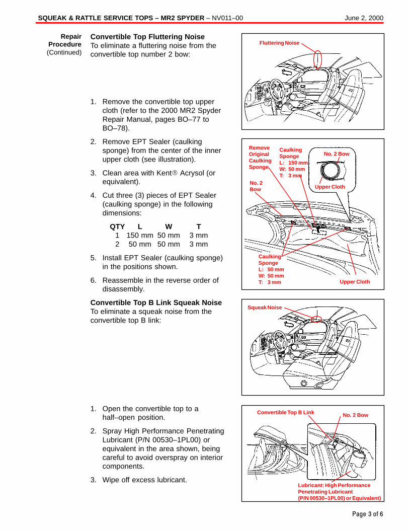
SQUEAK & RATTLE SERVICE TOPS – MR2 SPYDER – NV011–00 June 2, 2000
Page 3 of 6
Convertible Top Fluttering NoiseTo eliminate a fluttering noise from theconvertible top number 2 bow:
1. Remove the convertible top uppercloth (refer to the 2000 MR2 SpyderRepair Manual, pages BO–77 toBO–78).
2. Remove EPT Sealer (caulkingsponge) from the center of the innerupper cloth (see illustration).
3. Clean area with Kent� Acrysol (orequivalent).
4. Cut three (3) pieces of EPT Sealer(caulking sponge) in the followingdimensions:
QTY L W T1 150 mm 50 mm 3 mm2 50 mm 50 mm 3 mm
5. Install EPT Sealer (caulking sponge)in the positions shown.
6. Reassemble in the reverse order ofdisassembly.
Convertible Top B Link Squeak NoiseTo eliminate a squeak noise from theconvertible top B link:
1. Open the convertible top to ahalf–open position.
2. Spray High Performance PenetratingLubricant (P/N 00530–1PL00) orequivalent in the area shown, beingcareful to avoid overspray on interiorcomponents.
3. Wipe off excess lubricant.
RepairProcedure(Continued)
Fluttering Noise
RemoveOriginalCaulkingSponge
No. 2Bow
No. 2 Bow
Upper Cloth
CaulkingSpongeL: 150 mmW: 50 mmT: 3 mm
CaulkingSpongeL: 50 mmW: 50 mmT: 3 mm Upper Cloth
Squeak Noise
Convertible Top B Link No. 2 Bow
Lubricant: High PerformancePenetrating Lubricant (P/N 00530–1PL00) or Equivalent)
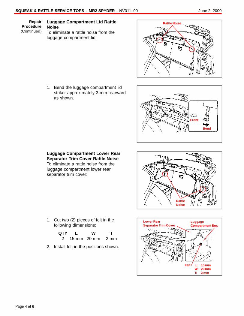
SQUEAK & RATTLE SERVICE TOPS – MR2 SPYDER – NV011–00 June 2, 2000
Page 4 of 6
Luggage Compartment Lid RattleNoiseTo eliminate a rattle noise from theluggage compartment lid:
1. Bend the luggage compartment lidstriker approximately 3 mm rearwardas shown.
Luggage Compartment Lower RearSeparator Trim Cover Rattle NoiseTo eliminate a rattle noise from theluggage compartment lower rearseparator trim cover:
1. Cut two (2) pieces of felt in thefollowing dimensions:
QTY L W T2 15 mm 20 mm 2 mm
2. Install felt in the positions shown.
RepairProcedure(Continued)
Rattle Noise
Front
Bend
RattleNoise
Lower RearSeparator Trim Cover
LuggageCompartment Box
Felt L: 15 mm W: 20 mm T: 2 mm
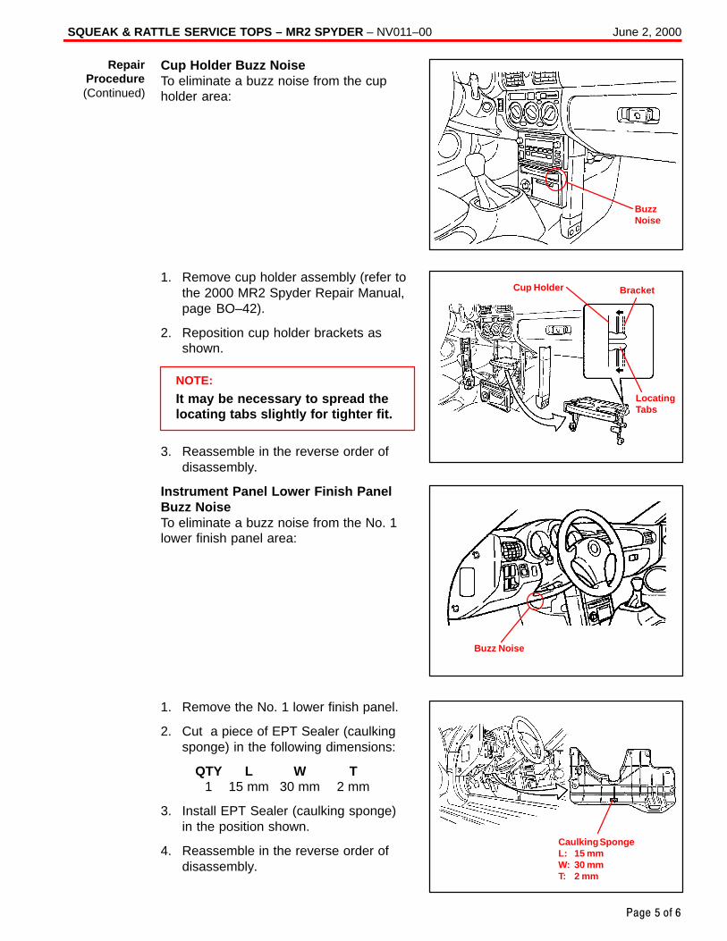
SQUEAK & RATTLE SERVICE TOPS – MR2 SPYDER – NV011–00 June 2, 2000
Page 5 of 6
Cup Holder Buzz NoiseTo eliminate a buzz noise from the cupholder area:
1. Remove cup holder assembly (refer tothe 2000 MR2 Spyder Repair Manual,page BO–42).
2. Reposition cup holder brackets asshown.
NOTE:
It may be necessary to spread thelocating tabs slightly for tighter fit.
3. Reassemble in the reverse order ofdisassembly.
Instrument Panel Lower Finish PanelBuzz NoiseTo eliminate a buzz noise from the No. 1lower finish panel area:
1. Remove the No. 1 lower finish panel.
2. Cut a piece of EPT Sealer (caulkingsponge) in the following dimensions:
QTY L W T1 15 mm 30 mm 2 mm
3. Install EPT Sealer (caulking sponge)in the position shown.
4. Reassemble in the reverse order ofdisassembly.
RepairProcedure(Continued)
BuzzNoise
Cup Holder Bracket
LocatingTabs
Buzz Noise
Caulking SpongeL: 15 mmW: 30 mmT: 2 mm
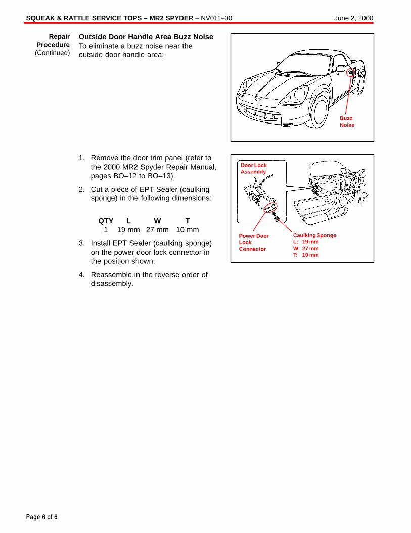
SQUEAK & RATTLE SERVICE TOPS – MR2 SPYDER – NV011–00 June 2, 2000
Page 6 of 6
Outside Door Handle Area Buzz NoiseTo eliminate a buzz noise near theoutside door handle area:
1. Remove the door trim panel (refer tothe 2000 MR2 Spyder Repair Manual,pages BO–12 to BO–13).
2. Cut a piece of EPT Sealer (caulkingsponge) in the following dimensions:
QTY L W T1 19 mm 27 mm 10 mm
3. Install EPT Sealer (caulking sponge)on the power door lock connector inthe position shown.
4. Reassemble in the reverse order ofdisassembly.
RepairProcedure(Continued)
BuzzNoise
Caulking SpongeL: 19 mmW: 27 mmT: 10 mm
Power DoorLockConnector
Door LockAssembly
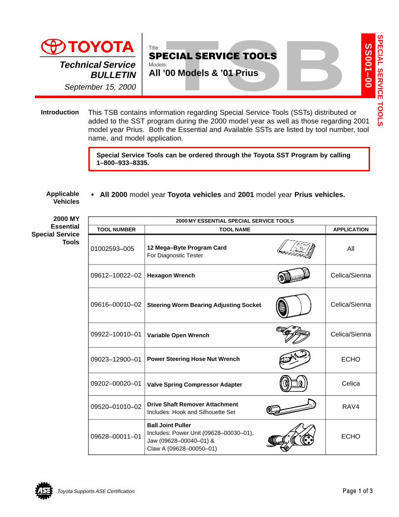
Toyota Supports ASE Certification Page 1 of 3
SS
001–00
Title:
SPECIAL SERVICE TOOLSModels:
All ’00 Models & ’01 PriusTechnical Service
BULLETINSeptember 15, 2000
This TSB contains information regarding Special Service Tools (SSTs) distributed oradded to the SST program during the 2000 model year as well as those regarding 2001model year Prius. Both the Essential and Available SSTs are listed by tool number, toolname, and model application.
Special Service Tools can be ordered through the Toyota SST Program by calling1–800–933–8335.
� All 2000 model year Toyota vehicles and 2001 model year Prius vehicles.
2000 MY ESSENTIAL SPECIAL SERVICE TOOLS
TOOL NUMBER TOOL NAME APPLICATION
01002593–005 12 Mega–Byte Program CardFor Diagnostic Tester
All
09612–10022–02 Hexagon Wrench Celica/Sienna
09616–00010–02 Steering Worm Bearing Adjusting Socket Celica/Sienna
09922–10010–01 Variable Open Wrench Celica/Sienna
09023–12900–01 Power Steering Hose Nut Wrench ECHO
09202–00020–01 Valve Spring Compressor Adapter Celica
09520–01010–02 Drive Shaft Remover AttachmentIncludes: Hook and Silhouette Set
RAV4
09628–00011–01
Ball Joint PullerIncludes: Power Unit (09628–00030–01),Jaw (09628–00040–01) & Claw A (09628–00050–01)
ECHO
SP
EC
IAL S
ER
VIC
E TO
OLS
Introduction
ApplicableVehicles
2000 MYEssential
Special ServiceTools
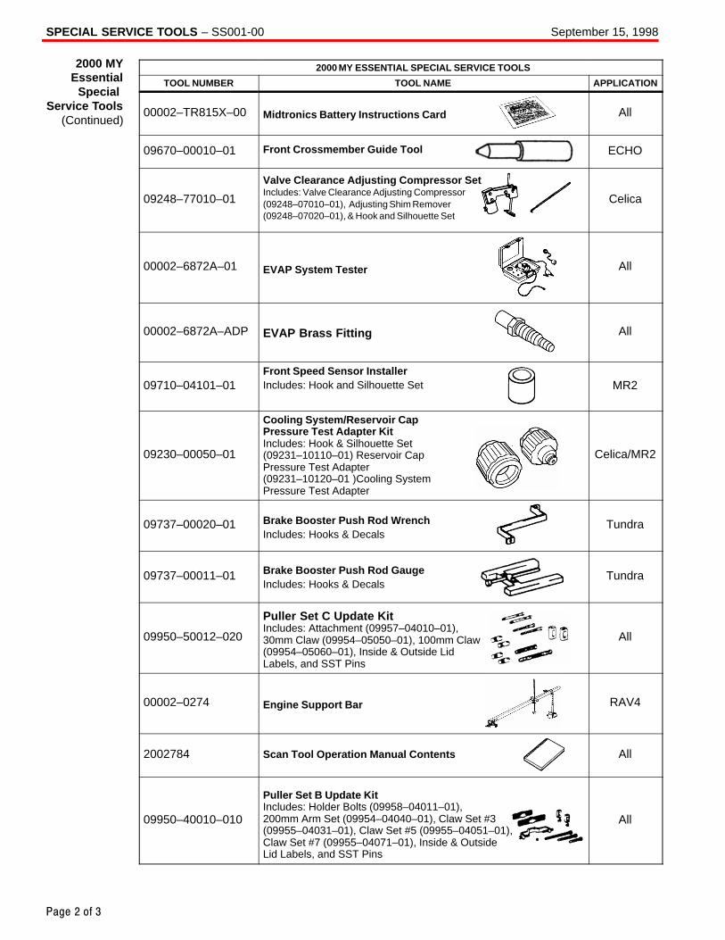
SPECIAL SERVICE TOOLS – SS001-00 September 15, 1998
Page 2 of 3
2000 MY ESSENTIAL SPECIAL SERVICE TOOLS
TOOL NUMBER TOOL NAME APPLICATION
00002–TR815X–00 Midtronics Battery Instructions Card All
09670–00010–01 Front Crossmember Guide Tool ECHO
09248–77010–01
Valve Clearance Adjusting Compressor SetIncludes: Valve Clearance Adjusting Compressor(09248–07010–01), Adjusting Shim Remover(09248–07020–01), & Hook and Silhouette Set
Celica
00002–6872A–01 EVAP System Tester All
00002–6872A–ADP EVAP Brass Fitting All
09710–04101–01Front Speed Sensor InstallerIncludes: Hook and Silhouette Set MR2
09230–00050–01
Cooling System/Reservoir Cap Pressure Test Adapter KitIncludes: Hook & Silhouette Set(09231–10110–01) Reservoir Cap Pressure Test Adapter(09231–10120–01 )Cooling System Pressure Test Adapter
Celica/MR2
09737–00020–01 Brake Booster Push Rod WrenchIncludes: Hooks & Decals
Tundra
09737–00011–01 Brake Booster Push Rod GaugeIncludes: Hooks & Decals
Tundra
09950–50012–020
Puller Set C Update KitIncludes: Attachment (09957–04010–01), 30mm Claw (09954–05050–01), 100mm Claw(09954–05060–01), Inside & Outside Lid Labels, and SST Pins
All
00002–0274 Engine Support Bar RAV4
2002784 Scan Tool Operation Manual Contents All
09950–40010–010
Puller Set B Update KitIncludes: Holder Bolts (09958–04011–01),200mm Arm Set (09954–04040–01), Claw Set #3(09955–04031–01), Claw Set #5 (09955–04051–01),Claw Set #7 (09955–04071–01), Inside & OutsideLid Labels, and SST Pins
All
2000 MYEssential
Special Service Tools
(Continued)
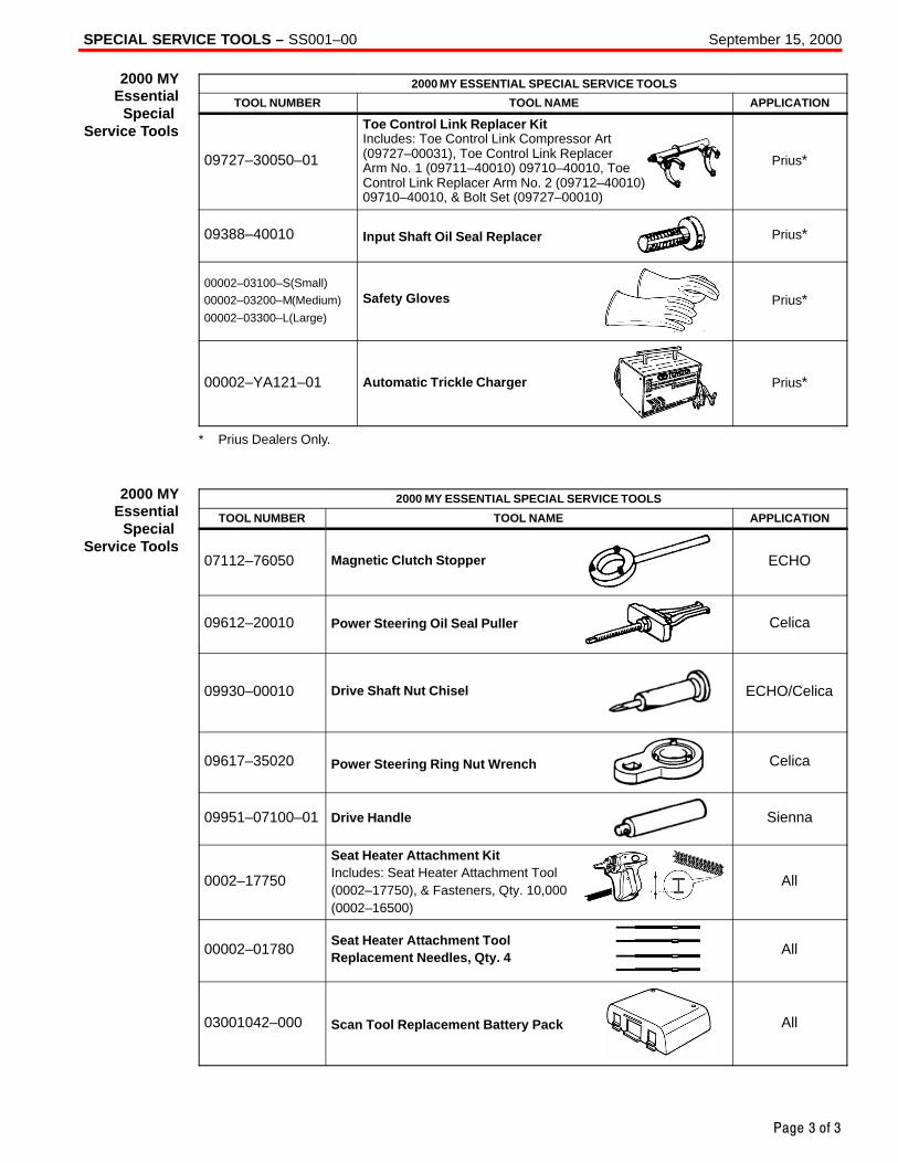
SPECIAL SERVICE TOOLS – SS001–00 September 15, 2000
Page 3 of 3
2000 MY ESSENTIAL SPECIAL SERVICE TOOLS
TOOL NUMBER TOOL NAME APPLICATION
09727–30050–01
Toe Control Link Replacer KitIncludes: Toe Control Link Compressor Art(09727–00031), Toe Control Link ReplacerArm No. 1 (09711–40010) 09710–40010, ToeControl Link Replacer Arm No. 2 (09712–40010)09710–40010, & Bolt Set (09727–00010)
Prius*
09388–40010 Input Shaft Oil Seal Replacer Prius*
00002–03100–S (Small)
00002–03200–M (Medium)
00002–03300–L (Large)
Safety Gloves Prius*
00002–YA121–01 Automatic Trickle Charger Prius*
* Prius Dealers Only.
2000 MY ESSENTIAL SPECIAL SERVICE TOOLS
TOOL NUMBER TOOL NAME APPLICATION
07112–76050 Magnetic Clutch Stopper ECHO
09612–20010 Power Steering Oil Seal Puller Celica
09930–00010 Drive Shaft Nut Chisel ECHO/Celica
09617–35020 Power Steering Ring Nut Wrench Celica
09951–07100–01 Drive Handle Sienna
0002–17750
Seat Heater Attachment KitIncludes: Seat Heater Attachment Tool (0002–17750), & Fasteners, Qty. 10,000(0002–16500)
All
00002–01780Seat Heater Attachment ToolReplacement Needles, Qty. 4
All
03001042–000 Scan Tool Replacement Battery Pack All
2000 MYEssential
Special Service Tools
2000 MYEssential
Special Service Tools
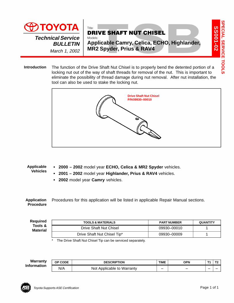
Toyota Supports ASE Certification Page 1 of 1
SS
001-02
Title:
DRIVE SHAFT NUT CHISELModels:
Applicable Camry, Celica, ECHO, Highlander,MR2 Spyder, Prius & RAV4
Technical ServiceBULLETIN
March 1, 2002
The function of the Drive Shaft Nut Chisel is to properly bend the detented portion of alocking nut out of the way of shaft threads for removal of the nut. This is important toeliminate the possibility of thread damage during nut removal. After nut installation, thetool can also be used to stake the locking nut.
Drive Shaft Nut ChiselP/N 09930–00010
� 2000 – 2002 model year ECHO, Celica & MR2 Spyder vehicles.
� 2001 – 2002 model year Highlander, Prius & RAV4 vehicles.
� 2002 model year Camry vehicles.
Procedures for this application will be listed in applicable Repair Manual sections.
TOOLS & MATERIALS PART NUMBER QUANTITY
Drive Shaft Nut Chisel 09930–00010 1
Drive Shaft Nut Chisel Tip* 09930–00009 1
* The Drive Shaft Nut Chisel Tip can be serviced separately.
OP CODE DESCRIPTION TIME OPN T1 T2
N/A Not Applicable to Warranty – – – –
SP
EC
IAL S
ER
VIC
E TO
OLSIntroduction
ApplicableVehicles
ApplicationProcedure
RequiredTools &Material
WarrantyInformation
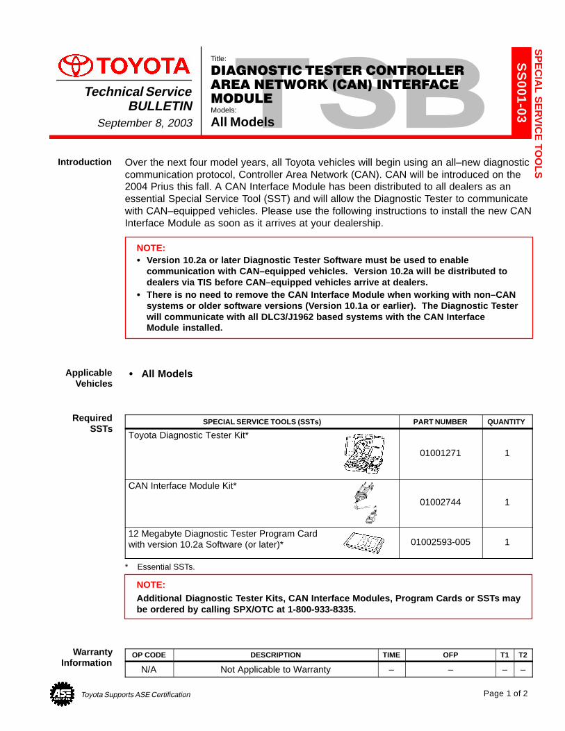
Toyota Supports ASE Certification Page 1 of 2
SS
001-03Title:
DIAGNOSTIC TESTER CONTROLLER
AREA NETWORK (CAN) INTERFACE
MODULEModels:
All Models
Technical ServiceBULLETIN
September 8, 2003
Over the next four model years, all Toyota vehicles will begin using an all–new diagnosticcommunication protocol, Controller Area Network (CAN). CAN will be introduced on the2004 Prius this fall. A CAN Interface Module has been distributed to all dealers as anessential Special Service Tool (SST) and will allow the Diagnostic Tester to communicatewith CAN–equipped vehicles. Please use the following instructions to install the new CANInterface Module as soon as it arrives at your dealership.
NOTE:� Version 10.2a or later Diagnostic Tester Software must be used to enable
communication with CAN–equipped vehicles. Version 10.2a will be distributed todealers via TIS before CAN–equipped vehicles arrive at dealers.
� There is no need to remove the CAN Interface Module when working with non–CANsystems or older software versions (Version 10.1a or earlier). The Diagnostic Testerwill communicate with all DLC3/J1962 based systems with the CAN Interface Module installed.
� All Models
SPECIAL SERVICE TOOLS (SSTs) PART NUMBER QUANTITY
Toyota Diagnostic Tester Kit*
01001271 1
CAN Interface Module Kit*
01002744 1
12 Megabyte Diagnostic Tester Program Cardwith version 10.2a Software (or later)* 01002593-005 1
* Essential SSTs.
NOTE:Additional Diagnostic Tester Kits, CAN Interface Modules, Program Cards or SSTs maybe ordered by calling SPX/OTC at 1-800-933-8335.
OP CODE DESCRIPTION TIME OFP T1 T2
N/A Not Applicable to Warranty – – – –
SP
EC
IAL S
ER
VIC
E TO
OLSIntroduction
ApplicableVehicles
RequiredSSTs
WarrantyInformation
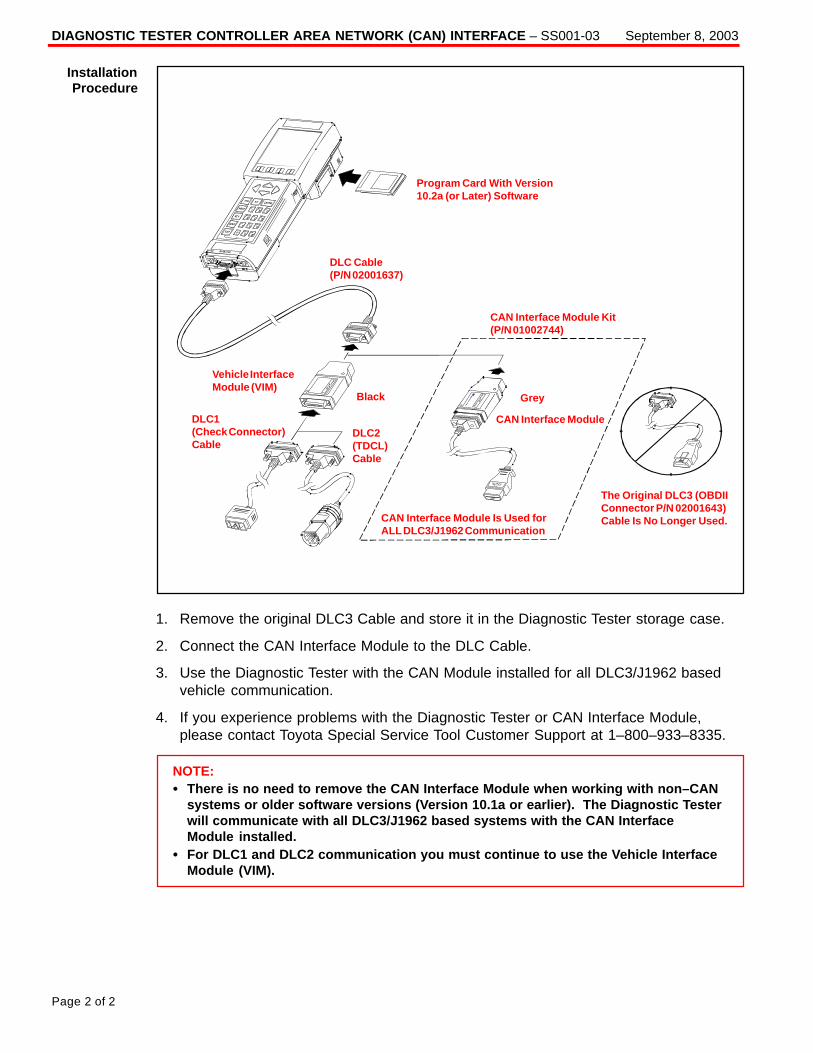
DIAGNOSTIC TESTER CONTROLLER AREA NETWORK (CAN) INTERFACE – SS001-03 September 8, 2003
Page 2 of 2
Program Card With Version10.2a (or Later) Software
CAN Interface Module Kit(P/N 01002744)
Grey
CAN Interface Module
CAN Interface Module Is Used forALL DLC3/J1962 Communication
The Original DLC3 (OBDIIConnector P/N 02001643)Cable Is No Longer Used.
Black
DLC Cable(P/N 02001637)
Vehicle InterfaceModule (VIM)
DLC1(Check Connector)Cable
DLC2(TDCL)Cable
1. Remove the original DLC3 Cable and store it in the Diagnostic Tester storage case.
2. Connect the CAN Interface Module to the DLC Cable.
3. Use the Diagnostic Tester with the CAN Module installed for all DLC3/J1962 basedvehicle communication.
4. If you experience problems with the Diagnostic Tester or CAN Interface Module,please contact Toyota Special Service Tool Customer Support at 1–800–933–8335.
NOTE:� There is no need to remove the CAN Interface Module when working with non–CAN
systems or older software versions (Version 10.1a or earlier). The Diagnostic Testerwill communicate with all DLC3/J1962 based systems with the CAN Interface Module installed.
� For DLC1 and DLC2 communication you must continue to use the Vehicle InterfaceModule (VIM).
InstallationProcedure
Toyota Supports ASE Certification Page 1 of 10
SS
002-02
Title:
MIDTRONICS BATTERY TESTER
SOFTWARE UPDATEModels:
All Models & Model Years Through Current
Technical ServiceBULLETINJune 7, 2002
The internal software of the Midtronics Battery Tester can now be periodically updated tosupport future models. New updates will include new battery warranty codes and testinginformation.
The Technical Information System (TIS) will be the primary distribution method for batterytester software updates. Utilizing the new Midtronics Update Wizard (MUW) and the newessential SST (Midtronics Battery Tester Adapter), you will be able to quickly and easilyupdate your Midtronics Battery Tester.
This bulletin will show you how to use and install the Midtronics Update Wizard to updatethe Midtronics tester software.
� All models and model years through current.
SPECIAL SERVICE TOOLS (SSTs) PART NUMBER QUANTITY
Midtronics Battery Tester* 00002–MP815–T 1
Midtronics Battery Tester Adapter* 00002–DMPUC 1
* Essential SSTs.
OP CODE DESCRIPTION TIME OPN T1 T2
N/A Not Applicable to Warranty – – – –
The Midtronics Battery Tester Software Update is a 2-step process:
1. Installing the Midtronics Update Wizard (MUW).The Midtronics Update Wizard (MUW) is an application that only needs to be installedon the PC one time. This bulletin will provide the steps to install the MUW.
2. Using the Midtronics Update Wizard (MUW).The Midtronics Update Wizard (MUW) will be used with each battery tester softwareupdate. The Update Wizard will walk you through each step to connect the PC to thetester and perform the update.
SP
EC
IAL S
ER
VIC
E TO
OLSIntroduction
ApplicableVehicles
RequiredTools &Material
WarrantyInformation
ProcessOverview
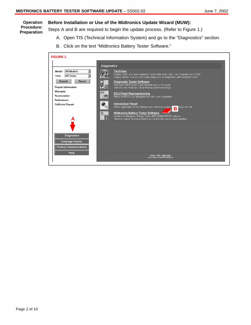
MIDTRONICS BATTERY TESTER SOFTWARE UPDATE – SS002-02 June 7, 2002
Page 2 of 10
Before Installation or Use of the Midtronics Update Wizard (MUW):
Steps A and B are required to begin the update process. (Refer to Figure 1.)
A. Open TIS (Technical Information System) and go to the “Diagnostics” section.
B. Click on the text “Midtronics Battery Tester Software.”
A
FIGURE 1.
B
OperationProcedure:
Preparation
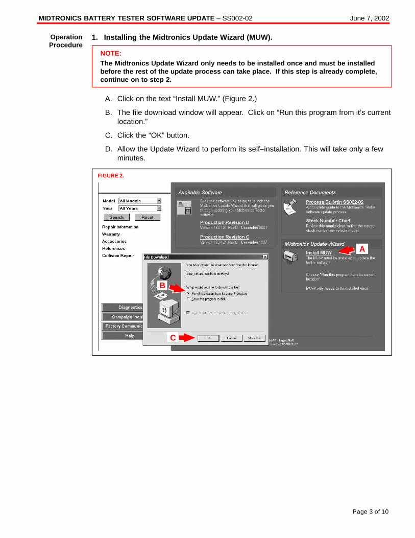
MIDTRONICS BATTERY TESTER SOFTWARE UPDATE – SS002-02 June 7, 2002
Page 3 of 10
1. Installing the Midtronics Update Wizard (MUW).
NOTE:The Midtronics Update Wizard only needs to be installed once and must be installedbefore the rest of the update process can take place. If this step is already complete,continue on to step 2.
A. Click on the text “Install MUW.” (Figure 2.)
B. The file download window will appear. Click on “Run this program from it’s currentlocation.”
C. Click the “OK” button.
D. Allow the Update Wizard to perform its self–installation. This will take only a fewminutes.
B
C
FIGURE 2.
A
OperationProcedure
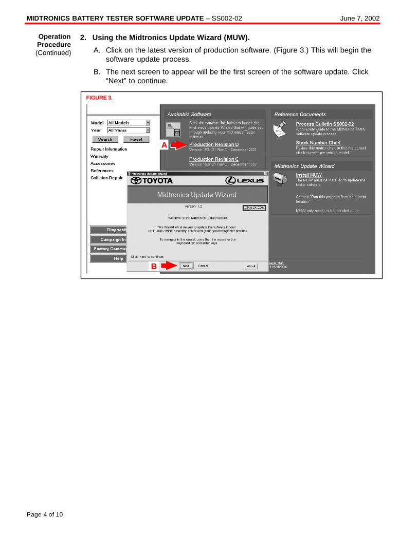
MIDTRONICS BATTERY TESTER SOFTWARE UPDATE – SS002-02 June 7, 2002
Page 4 of 10
2. Using the Midtronics Update Wizard (MUW).
A. Click on the latest version of production software. (Figure 3.) This will begin thesoftware update process.
B. The next screen to appear will be the first screen of the software update. Click“Next” to continue.
A
FIGURE 3.
B
OperationProcedure(Continued)
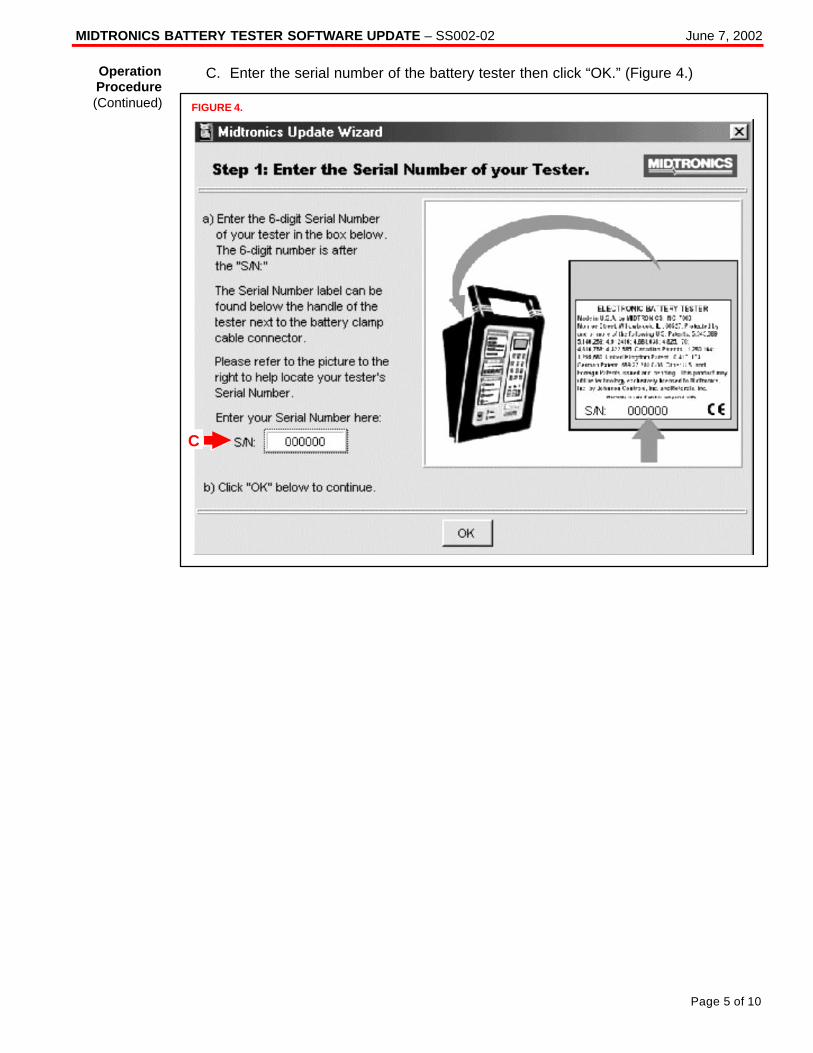
MIDTRONICS BATTERY TESTER SOFTWARE UPDATE – SS002-02 June 7, 2002
Page 5 of 10
C. Enter the serial number of the battery tester then click “OK.” (Figure 4.)
FIGURE 4.
C
OperationProcedure(Continued)
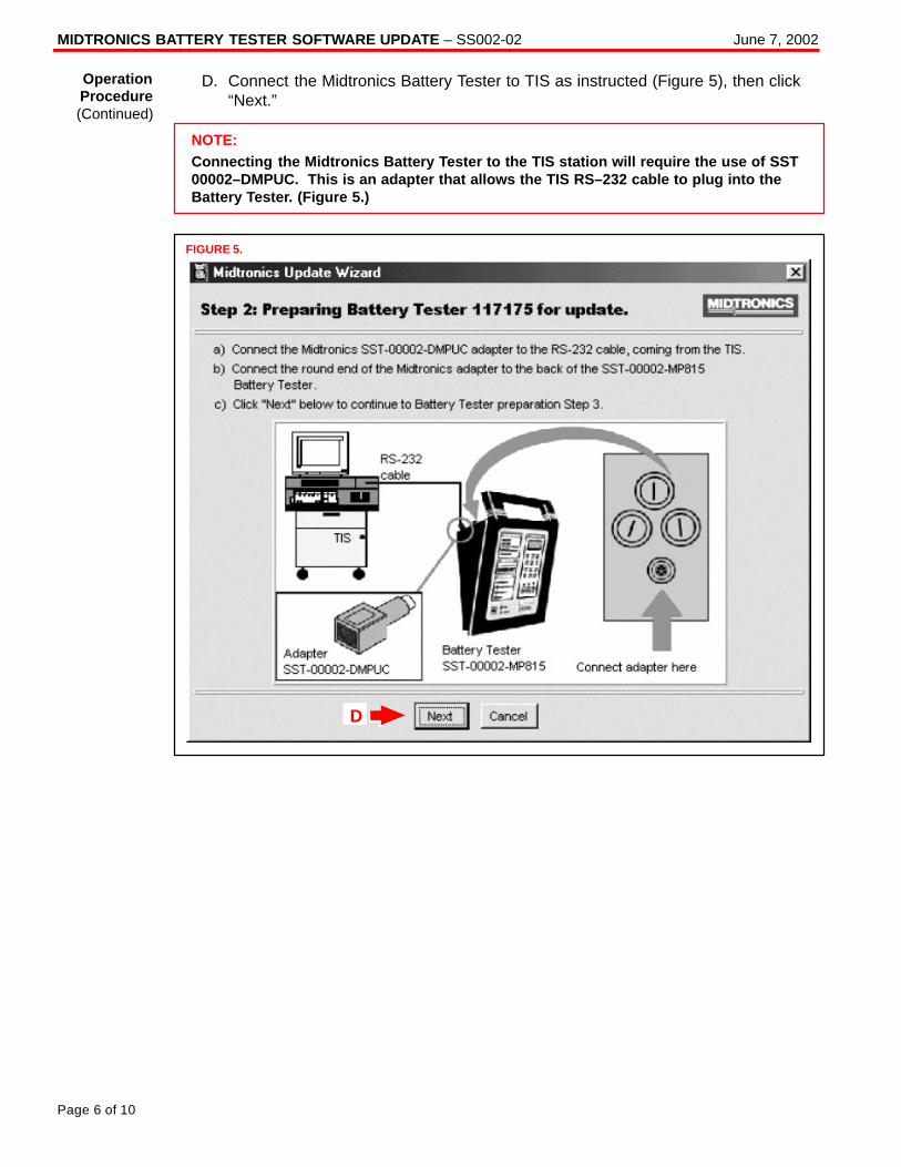
MIDTRONICS BATTERY TESTER SOFTWARE UPDATE – SS002-02 June 7, 2002
Page 6 of 10
D. Connect the Midtronics Battery Tester to TIS as instructed (Figure 5), then click“Next.”
NOTE:Connecting the Midtronics Battery Tester to the TIS station will require the use of SST00002–DMPUC. This is an adapter that allows the TIS RS–232 cable to plug into theBattery Tester. (Figure 5.)
FIGURE 5.
D
OperationProcedure(Continued)
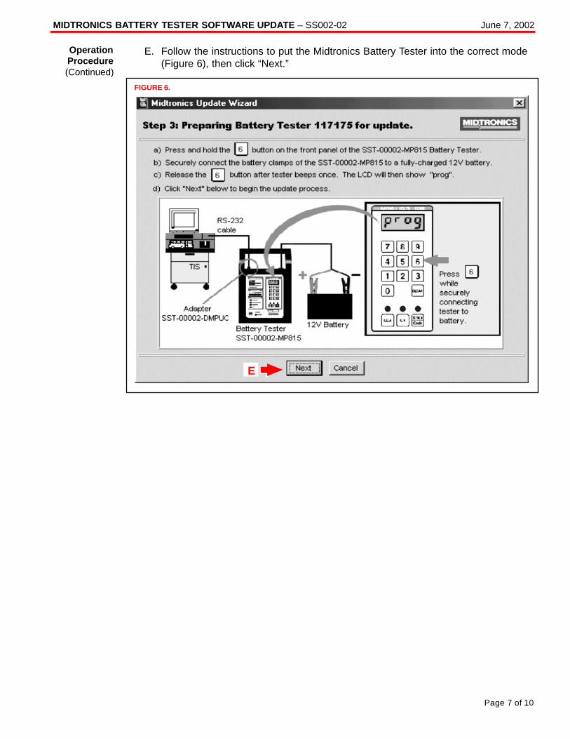
MIDTRONICS BATTERY TESTER SOFTWARE UPDATE – SS002-02 June 7, 2002
Page 7 of 10
E. Follow the instructions to put the Midtronics Battery Tester into the correct mode(Figure 6), then click “Next.”
FIGURE 6.
E
OperationProcedure(Continued)
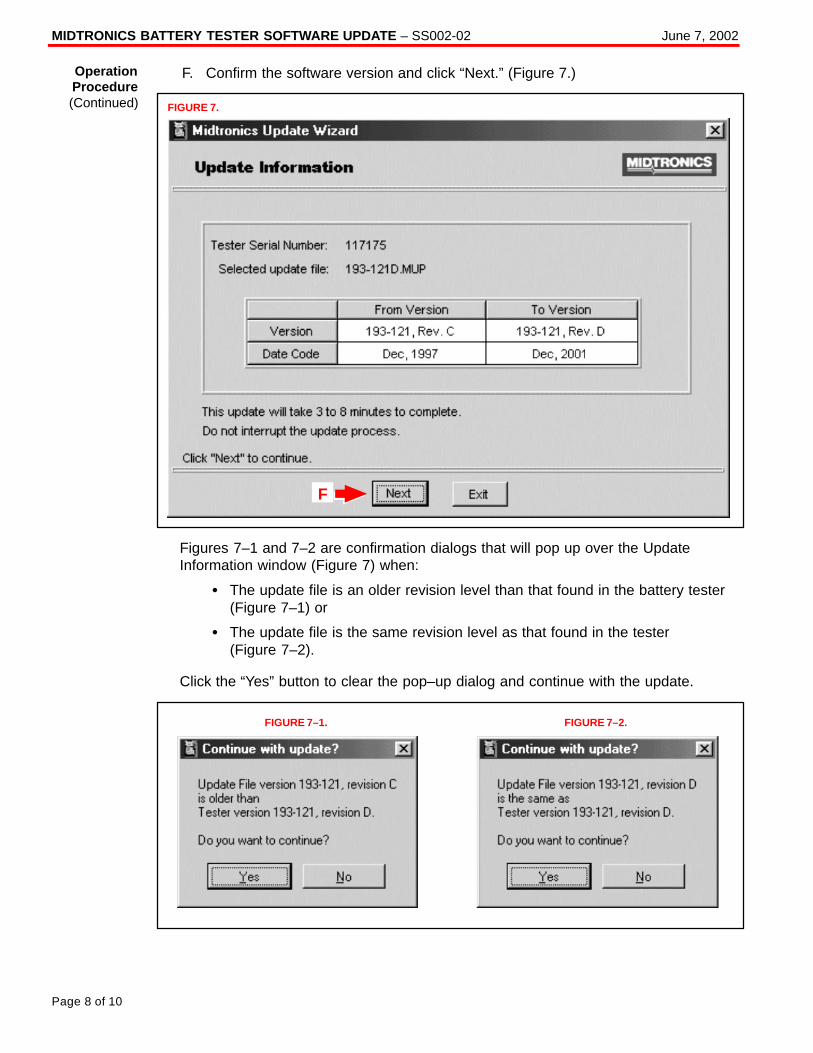
MIDTRONICS BATTERY TESTER SOFTWARE UPDATE – SS002-02 June 7, 2002
Page 8 of 10
F. Confirm the software version and click “Next.” (Figure 7.)
FIGURE 7.
F
Figures 7–1 and 7–2 are confirmation dialogs that will pop up over the UpdateInformation window (Figure 7) when:
� The update file is an older revision level than that found in the battery tester(Figure 7–1) or
� The update file is the same revision level as that found in the tester(Figure 7–2).
Click the “Yes” button to clear the pop–up dialog and continue with the update.
FIGURE 7–1. FIGURE 7–2.
OperationProcedure(Continued)
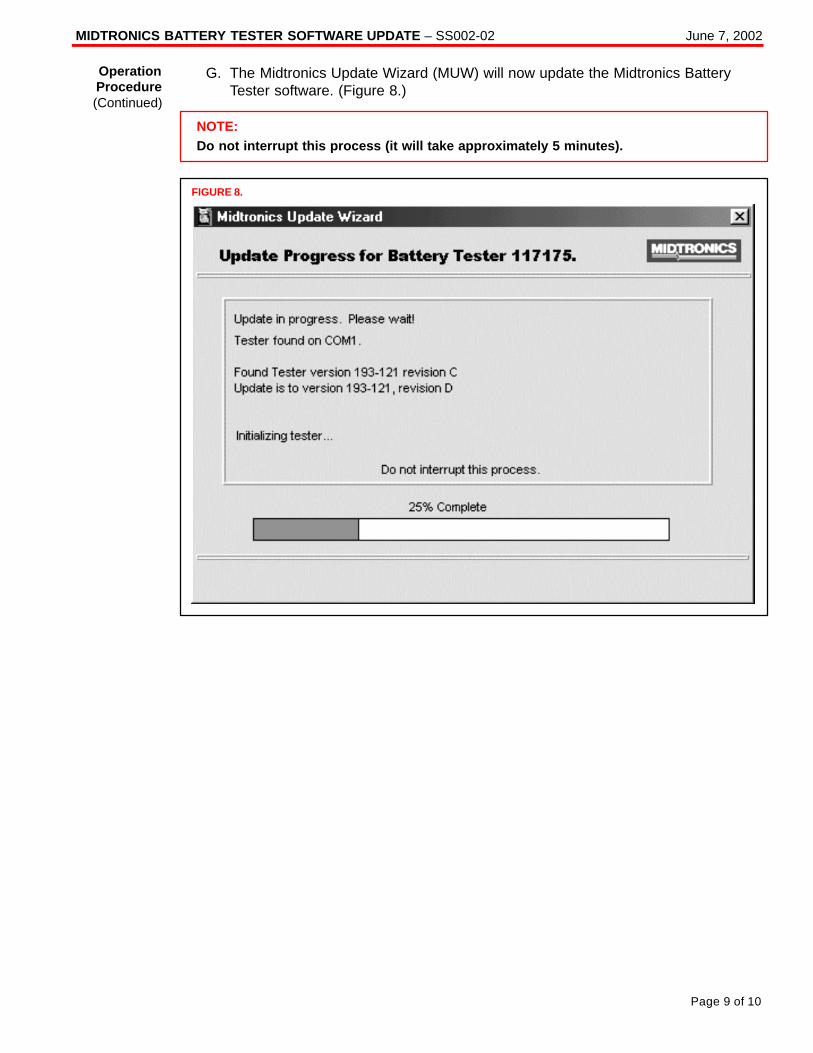
MIDTRONICS BATTERY TESTER SOFTWARE UPDATE – SS002-02 June 7, 2002
Page 9 of 10
G. The Midtronics Update Wizard (MUW) will now update the Midtronics BatteryTester software. (Figure 8.)
NOTE:Do not interrupt this process (it will take approximately 5 minutes).
FIGURE 8.
OperationProcedure(Continued)
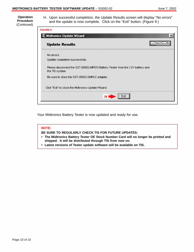
MIDTRONICS BATTERY TESTER SOFTWARE UPDATE – SS002-02 June 7, 2002
Page 10 of 10
H. Upon successful completion, the Update Results screen will display “No errors”and the update is now complete. Click on the “Exit” button. (Figure 9.)
FIGURE 9.
H
Your Midtronics Battery Tester is now updated and ready for use.
NOTE:BE SURE TO REGULARLY CHECK TIS FOR FUTURE UPDATES:� The Midtronics Battery Tester OE Stock Number Card will no longer be printed and
shipped. It will be distributed through TIS from now on.� Latest versions of Tester update software will be available on TIS.
OperationProcedure(Continued)
Toyota Supports ASE Certification Page 1 of 3
SS
003–00
Title:
EVAP SYSTEM PRESSURE TESTER
IMPROVEMENTModels:
All ’00 Models
Technical ServiceBULLETIN
October 6, 2000
In an effort to expand the diagnostic capabilities of the EVAP System Pressure Testerand prevent inadvertent misuse of the tester pressure pump, the EVAP System PressureTester Kit, P/N 00002–6872A has been upgraded with the following components:� New EVAP Lid Instructions� Pump Outlet Hose Tie Wrap� EVAP Brass Adapter
The information contained in this bulletin will provide you with a detailed outline for theprocedures to upgrade the EVAP System Pressure Tester Kit.
� 2000 model year Toyota vehicles, all models.
PREVIOUS PART NUMBER CURRENT PART NUMBER PART NAME
00002–6872A–DEC EVAP System Tester Kit Lid Instructions Decal
N/A 00002–6872A–TIE Pump Outlet Hose Tie Wrap
00002–6872A–ADP EVAP Brass Adapter
NOTE:
The upgraded EVAP components will be distributed to all Toyota dealers by OTC. ReplacementEVAP System Tester parts may be ordered by calling OTC at: 1 (800) 933–8335.
TOOLS & MATERIALS QUANTITY
Side Cutting Pliers 1
OP CODE DESCRIPTION TIME OPN T1 T2
N/A Not Applicable to Toyota Warranty* – – – –
*Applicable Warranty:With the LIFETIME MARATHON � WARRANTY, all SPX OTC products and parts arewarranted against defects in materials and workmanship for the life of the product orpart. For service on this or any other Toyota SST, call 1 (800) 933–8335.
SP
EC
IAL S
ER
VIC
E TO
OLSIntroduction
ApplicableVehicles
PartsInformation
Required Tools& Materials
WarrantyInformation
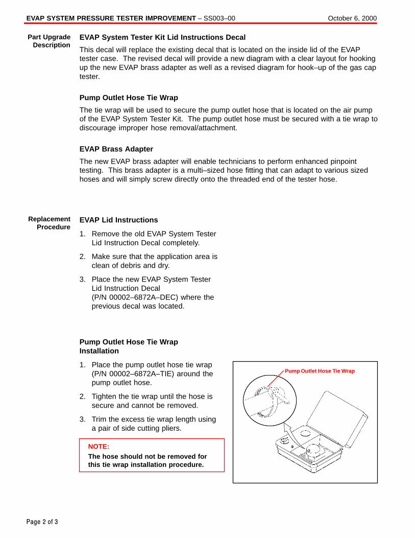
EVAP SYSTEM PRESSURE TESTER IMPROVEMENT – SS003–00 October 6, 2000
Page 2 of 3
EVAP System Tester Kit Lid Instructions Decal
This decal will replace the existing decal that is located on the inside lid of the EVAPtester case. The revised decal will provide a new diagram with a clear layout for hookingup the new EVAP brass adapter as well as a revised diagram for hook–up of the gas captester.
Pump Outlet Hose Tie Wrap
The tie wrap will be used to secure the pump outlet hose that is located on the air pumpof the EVAP System Tester Kit. The pump outlet hose must be secured with a tie wrap todiscourage improper hose removal/attachment.
EVAP Brass Adapter
The new EVAP brass adapter will enable technicians to perform enhanced pinpointtesting. This brass adapter is a multi–sized hose fitting that can adapt to various sizedhoses and will simply screw directly onto the threaded end of the tester hose.
EVAP Lid Instructions
1. Remove the old EVAP System TesterLid Instruction Decal completely.
2. Make sure that the application area isclean of debris and dry.
3. Place the new EVAP System TesterLid Instruction Decal(P/N 00002–6872A–DEC) where theprevious decal was located.
Pump Outlet Hose Tie WrapInstallation
1. Place the pump outlet hose tie wrap(P/N 00002–6872A–TIE) around thepump outlet hose.
2. Tighten the tie wrap until the hose issecure and cannot be removed.
3. Trim the excess tie wrap length usinga pair of side cutting pliers.
NOTE:The hose should not be removed forthis tie wrap installation procedure.
Part UpgradeDescription
ReplacementProcedure
Pump Outlet Hose Tie Wrap
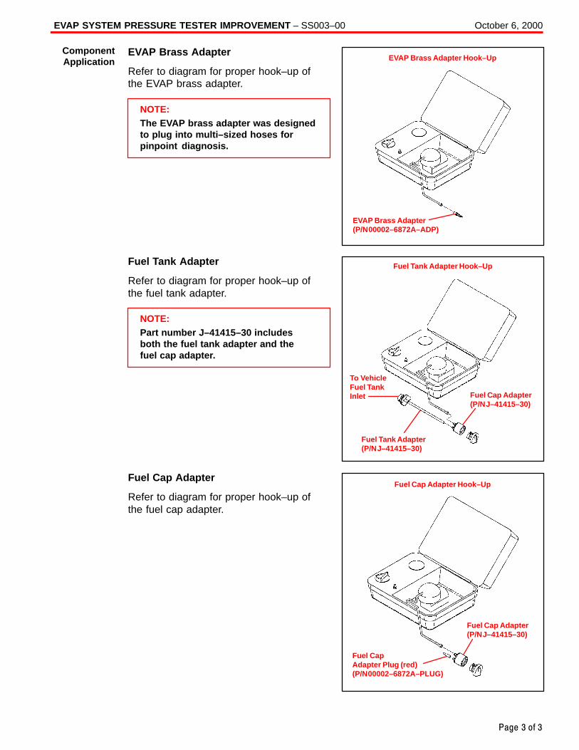
EVAP SYSTEM PRESSURE TESTER IMPROVEMENT – SS003–00 October 6, 2000
Page 3 of 3
EVAP Brass Adapter
Refer to diagram for proper hook–up ofthe EVAP brass adapter.
NOTE:The EVAP brass adapter was designedto plug into multi–sized hoses forpinpoint diagnosis.
Fuel Tank Adapter
Refer to diagram for proper hook–up ofthe fuel tank adapter.
NOTE:Part number J–41415–30 includesboth the fuel tank adapter and thefuel cap adapter.
Fuel Cap Adapter
Refer to diagram for proper hook–up ofthe fuel cap adapter.
ComponentApplication
EVAP Brass Adapter(P/N 00002–6872A–ADP)
EVAP Brass Adapter Hook–Up
To VehicleFuel TankInlet
Fuel Tank Adapter Hook–Up
Fuel Tank Adapter(P/N J–41415–30)
Fuel Cap Adapter(P/N J–41415–30)
Fuel Cap Adapter Plug (red)(P/N 00002–6872A–PLUG)
Fuel Cap Adapter Hook–Up
Fuel Cap Adapter(P/N J–41415–30)
Toyota Supports ASE Certification Page 1 of 7
SS
003-01Title:
IMMOBILIZER KEY CODE RESETModels:
Applicable 4Runner, Camry, Highlander,Land Cruiser, MR2 Spyder, RAV4, Sequoia,& Solara
Technical ServiceBULLETIN
August 30, 2002
TSB REVISION NOTICE:� June 25, 2003: Preparation procedure on page 3 now applies to all model years of
MR2 Spyder.� January 20, 2003: Updated terminals in Figure 1 on page 3.� August 30, 2002: The information contained in this TSB supercedes the original
SS003–01. Previous TSBs should be discarded.
Immobilizer Reset is a new feature that allows the registration of a new Master Key evenif all original Master Keys are lost. Once the Immobilizer system is reset, all previouslyregistered keys will be erased.
MODEL YEAR MODEL ENGINE MODEL
2000 & Later MR2 Spyder* 1ZZ
2001 RAV4* 1AZ
4Runner 5VZ
2001 & Later Highlander 2AZ
Land Cruiser 2UZ
2001 & 2002 Sequoia 2UZ
Camry 1MZ & 2AZ
2002 & Later RAV4 1AZ
Solara 2AZ
* Refer to special preparation procedure in this bulletin.
NOTE:Refer to TIS (Technical Information System) for the most current applicable vehicleinformation.
PREVIOUS PART NUMBER CURRENT PART NUMBER PART NAME
N/A Model Specific Replacement Key (Master or Sub)
OP CODE DESCRIPTION TIME OFP T1 T2
N/A Not Applicable to Warranty – – – –
SP
EC
IAL S
ER
VIC
E TO
OLS
Introduction
ApplicableVehicles
PartsInformation
WarrantyInformation
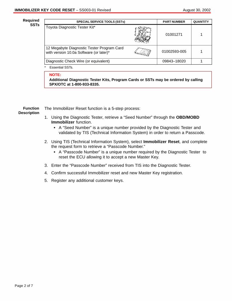
IMMOBILIZER KEY CODE RESET – SS003-01 Revised August 30, 2002
Page 2 of 7
SPECIAL SERVICE TOOLS (SSTs) PART NUMBER QUANTITY
Toyota Diagnostic Tester Kit*
01001271 1
12 Megabyte Diagnostic Tester Program Cardwith version 10.0a Software (or later)* 01002593-005 1
Diagnostic Check Wire (or equivalent) 09843–18020 1
* Essential SSTs.
NOTE:Additional Diagnostic Tester Kits, Program Cards or SSTs may be ordered by callingSPX/OTC at 1-800-933-8335.
The Immobilizer Reset function is a 5-step process:
1. Using the Diagnostic Tester, retrieve a “Seed Number” through the OBD/MOBDImmobilizer function.� A “Seed Number” is a unique number provided by the Diagnostic Tester and
validated by TIS (Technical Information System) in order to return a Passcode.
2. Using TIS (Technical Information System), select Immobilizer Reset , and completethe request form to retrieve a “Passcode Number.”� A “Passcode Number” is a unique number required by the Diagnostic Tester to
reset the ECU allowing it to accept a new Master Key.
3. Enter the “Passcode Number” received from TIS into the Diagnostic Tester.
4. Confirm successful Immobilizer reset and new Master Key registration.
5. Register any additional customer keys.
RequiredSSTs
FunctionDescription
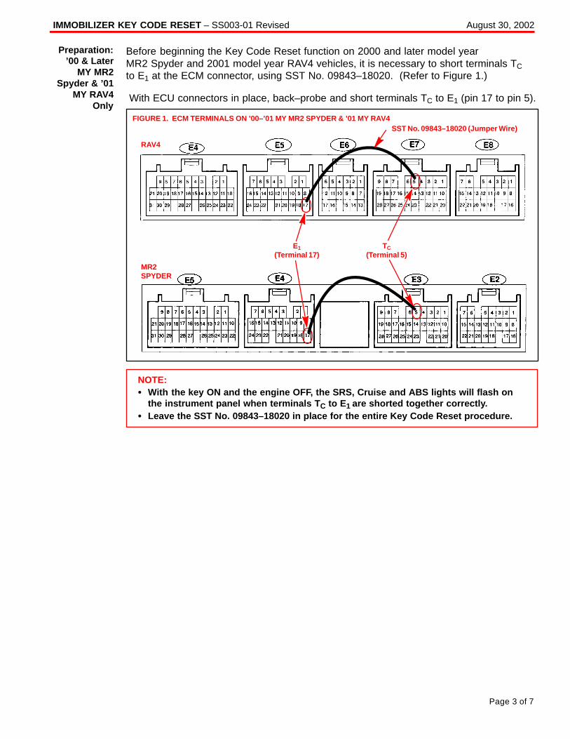
IMMOBILIZER KEY CODE RESET – SS003-01 Revised August 30, 2002
Page 3 of 7
Before beginning the Key Code Reset function on 2000 and later model yearMR2 Spyder and 2001 model year RAV4 vehicles, it is necessary to short terminals TC to E1 at the ECM connector, using SST No. 09843–18020. (Refer to Figure 1.)
With ECU connectors in place, back–probe and short terminals TC to E1 (pin 17 to pin 5).
FIGURE 1. ECM TERMINALS ON ’00–’01 MY MR2 SPYDER & ’01 MY RAV4
RAV4
MR2SPYDER
E1(Terminal 17)
TC(Terminal 5)
SST No. 09843–18020 (Jumper Wire)
NOTE:� With the key ON and the engine OFF, the SRS, Cruise and ABS lights will flash on
the instrument panel when terminals T C to E1 are shorted together correctly.� Leave the SST No. 09843–18020 in place for the entire Key Code Reset procedure.
Preparation:’00 & Later
MY MR2Spyder & ’01
MY RAV4Only
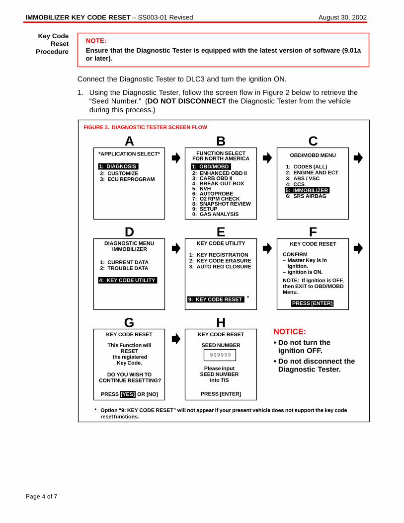
IMMOBILIZER KEY CODE RESET – SS003-01 Revised August 30, 2002
Page 4 of 7
NOTE:Ensure that the Diagnostic Tester is equipped with the latest version of software (9.01aor later).
Connect the Diagnostic Tester to DLC3 and turn the ignition ON.
1. Using the Diagnostic Tester, follow the screen flow in Figure 2 below to retrieve the“Seed Number.” (DO NOT DISCONNECT the Diagnostic Tester from the vehicleduring this process.)
1: CODES (ALL)2: ENGINE AND ECT3: ABS / VSC4: CCS
6: SRS AIRBAG
PRESS OR [NO]
1: KEY REGISTRATION2: KEY CODE ERASURE3: AUTO REG CLOSURE
*APPLICATION SELECT*
1: DIAGNOSIS2: CUSTOMIZE3: ECU REPROGRAM
AFUNCTION SELECT
FOR NORTH AMERICA
B C
1: OBD/MOBD2: ENHANCED OBD II3: CARB OBD II4: BREAK-OUT BOX5: NVH6: AUTOPROBE7: O2 RPM CHECK8: SNAPSHOT REVIEW9: SETUP0: GAS ANALYSIS
OBD/MOBD MENU
5: IMMOBILIZER
DIAGNOSTIC MENUIMMOBILIZER
4: KEY CODE UTILITY
1: CURRENT DATA2: TROUBLE DATA
DKEY CODE UTILITY
E F
9: KEY CODE RESET
KEY CODE RESET
CONFIRM– Master Key is in
ignition.– ignition is ON.
NOTE: If ignition is OFF,then EXIT to OBD/MOBDMenu.
PRESS [ENTER]
G HKEY CODE RESET
This Function willRESET
the registeredKey Code.
DO YOU WISH TO CONTINUE RESETTING?
[YES] PRESS [ENTER]
KEY CODE RESET
SEED NUMBER
999999
FIGURE 2. DIAGNOSTIC TESTER SCREEN FLOW
Please inputSEED NUMBER
into TIS
NOTICE:� Do not turn the
ignition OFF.� Do not disconnect the
Diagnostic Tester.
*
* Option “9: KEY CODE RESET” will not appear if your present vehicle does not support the key codereset functions.
Key CodeReset
Procedure
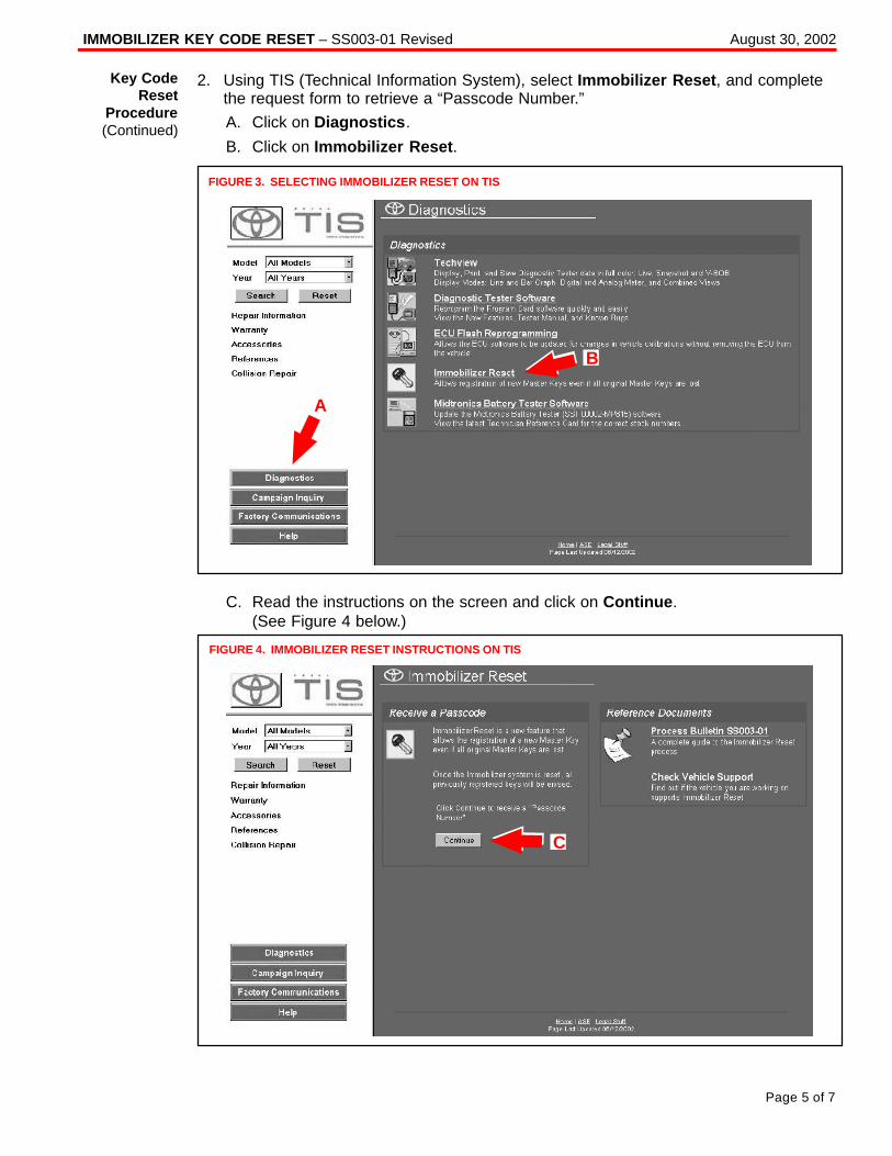
IMMOBILIZER KEY CODE RESET – SS003-01 Revised August 30, 2002
Page 5 of 7
2. Using TIS (Technical Information System), select Immobilizer Reset , and completethe request form to retrieve a “Passcode Number.”
A. Click on Diagnostics .
B. Click on Immobilizer Reset .
B
FIGURE 3. SELECTING IMMOBILIZER RESET ON TIS
A
C. Read the instructions on the screen and click on Continue .(See Figure 4 below.)
FIGURE 4. IMMOBILIZER RESET INSTRUCTIONS ON TIS
C
Key CodeReset
Procedure(Continued)
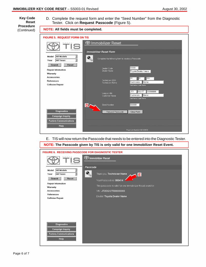
IMMOBILIZER KEY CODE RESET – SS003-01 Revised August 30, 2002
Page 6 of 7
D. Complete the request form and enter the “Seed Number” from the DiagnosticTester. Click on Request Passcode (Figure 5).
FIGURE 5. REQUEST FORM ON TIS
NOTE: All fields must be completed.
D
E. TIS will now return the Passcode that needs to be entered into the Diagnostic Tester.
FIGURE 6. RECEIVING PASSCODE FOR DIAGNOSTIC TESTER
NOTE: The Passcode given by TIS is only valid for one Immobilizer Reset Event.
E
Key CodeReset
Procedure(Continued)
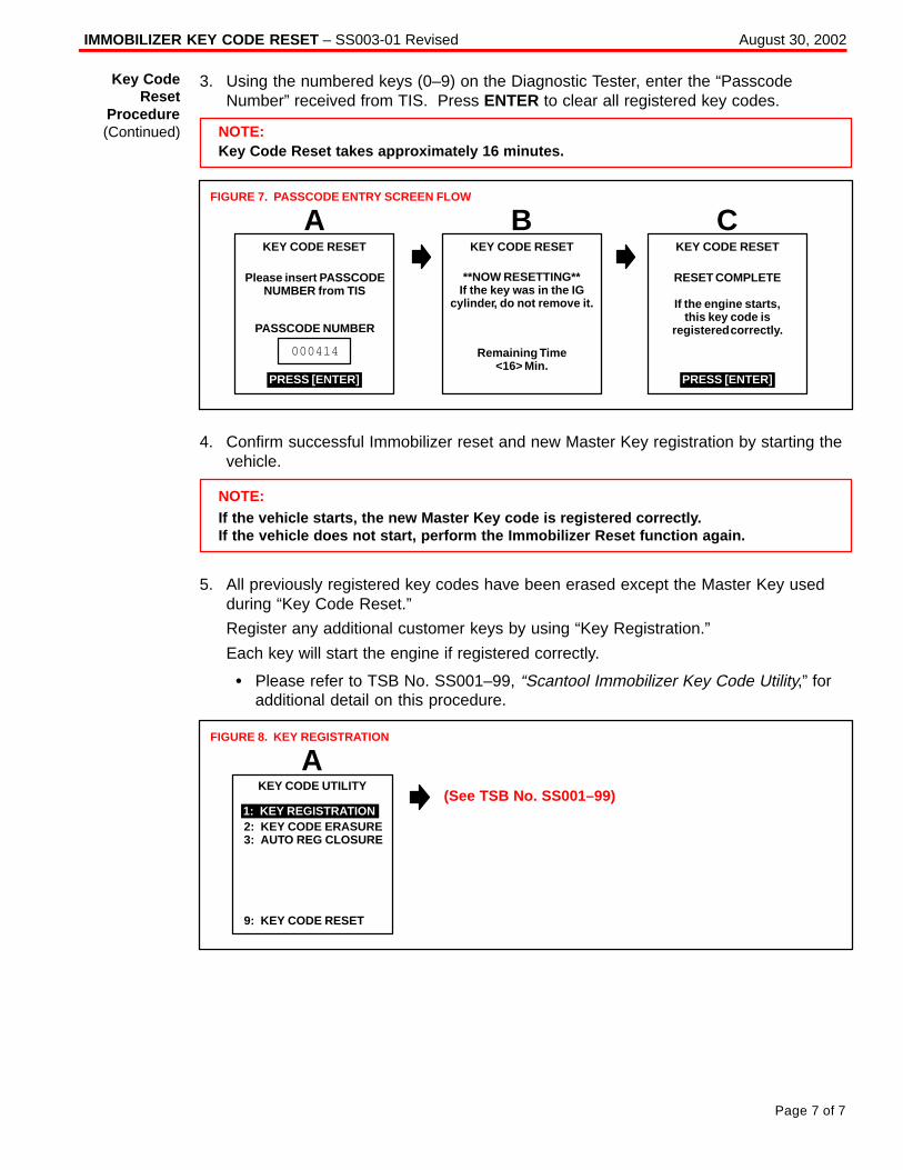
IMMOBILIZER KEY CODE RESET – SS003-01 Revised August 30, 2002
Page 7 of 7
3. Using the numbered keys (0–9) on the Diagnostic Tester, enter the “PasscodeNumber” received from TIS. Press ENTER to clear all registered key codes.
NOTE:Key Code Reset takes approximately 16 minutes.
A B C
RESET COMPLETE
If the engine starts,this key code is
registered correctly.
KEY CODE RESET
Please insert PASSCODENUMBER from TIS
PASSCODE NUMBER
KEY CODE RESETKEY CODE RESET
Remaining Time<16> Min.
PRESS [ENTER]
000414
PRESS [ENTER]
FIGURE 7. PASSCODE ENTRY SCREEN FLOW
**NOW RESETTING**If the key was in the IG
cylinder, do not remove it.
4. Confirm successful Immobilizer reset and new Master Key registration by starting thevehicle.
NOTE:If the vehicle starts, the new Master Key code is registered correctly.If the vehicle does not start, perform the Immobilizer Reset function again.
5. All previously registered key codes have been erased except the Master Key usedduring “Key Code Reset.”
Register any additional customer keys by using “Key Registration.”
Each key will start the engine if registered correctly.
� Please refer to TSB No. SS001–99, “Scantool Immobilizer Key Code Utility,” foradditional detail on this procedure.
2: KEY CODE ERASURE3: AUTO REG CLOSURE
KEY CODE UTILITY
1: KEY REGISTRATION
AFIGURE 8. KEY REGISTRATION
9: KEY CODE RESET
(See TSB No. SS001–99)
Key CodeReset
Procedure(Continued)
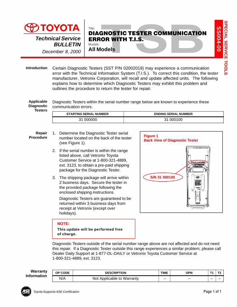
Toyota Supports ASE Certification Page 1 of 1
SS
004-00
Title:
DIAGNOSTIC TESTER COMMUNICATION
ERROR WITH T.I.S.Models:
All Models
Technical ServiceBULLETIN
December 8, 2000
Certain Diagnostic Testers (SST P/N 02002019) may experience a communication error with the Technical Information System (T.I.S.). To correct this condition, the testermanufacturer, Vetronix Corporation, will recall and update affected units. The followingexplains how to determine which Diagnostic Testers may exhibit this problem and outlines the procedure to return the tester for repair.
Diagnostic Testers within the serial number range below are known to experience thesecommunication errors.
STARTING SERIAL NUMBER ENDING SERIAL NUMBER
31 000000 31 000100
1. Determine the Diagnostic Tester serialnumber located on the back of the tester(see Figure 1).
2. If the serial number is within the rangelisted above, call Vetronix ToyotaCustomer Service at 1-800-321-4889,ext. 3123, to obtain a pre-paid shippingpackage for the Diagnostic Tester.
3. The shipping package will arrive within2 business days. Secure the tester inthe provided package following theenclosed shipping instructions.
Diagnostic Testers are guaranteed to bereturned within 3 business days fromreceipt at Vetronix (except overholidays).
NOTE:This update will be performed freeof charge.
Diagnostic Testers outside of the serial number range above are not affected and do not needthis repair. If a Diagnostic Tester outside this range experiences a similar problem, please callDealer Daily Support at 1-877-DL-DAILY or Vetronix Toyota Customer Service at1-800-321-4889, ext. 3123.
OP CODE DESCRIPTION TIME OPN T1 T2
N/A Not Applicable to Warranty – – – –
SP
EC
IAL S
ER
VIC
E TO
OLSIntroduction
ApplicableDiagnostic
Testers
RepairProcedure Figure 1
Back View of Diagnostic Tester
S/N 31 000100
WarrantyInformation

Toyota Supports ASE Certification Page 1 of 43
SS
002-03
Title:
O2S TEST RESULTS (MODE 05)Models:
All ’96 – ’03, ’04 Corolla, ECHO, Matrix, Sienna& Scion xA & xB
Technical ServiceBULLETIN
December 17, 2003
This Service Bulletin contains Oxygen Sensor (O2S) Monitor threshold values for allmodels from 1996 to 2003 and some 2004 models. Starting in 2004, the O2S Monitorthreshold values can be found in the repair manual. These values are used whenanalyzing the O2S test results to determine the O2S condition.
� All 1996 – 2003 model year Toyota vehicles.
� 2004 model year Corolla, ECHO, Matrix and Sienna vehicles.� 2004 model year Scion xA and xB vehicles.
Checking O2S Test Results
To view O2S test results, the O2S Monitor must be completed and the test results mustbe checked within the same key cycle. If the ignition key is cycled OFF, the O2S testresults will be set to the minimum or maximum limits, and all test results will be erased.The O2S test results are stored in the ECU (SAE term: Powertrain Control Module/PCM)when the monitor is completed. The test results are static and will not change once themonitor is complete.
The process for checking O2S test results is described in the following three basic steps:1. Completing the O2S Readiness Monitor (page 2).2. Accessing O2S Test Results (page 3).3. Comparing O2S Test Results to Failure Thresholds (page 4).
SPECIAL SERVICE TOOLS (SSTs) PART NUMBER QUANTITY
Toyota Diagnostic Tester Kit*(or any OBDII Scantool)
01001271 1
12 Megabyte Diagnostic Tester Program Cardwith version 10.1a Software (or later)* 01002593-005 1
* Essential SSTs.
NOTE:Additional Diagnostic Tester Kits, Program Cards or other SSTs may be ordered bycalling SPX/OTC at 1-800-933-8335.
OP CODE DESCRIPTION TIME OFP T1 T2
N/A Not Applicable to Warranty – – – –
SP
EC
IAL S
ER
VIC
E TO
OLSIntroduction
ApplicableVehicles
FunctionDescription
RequiredSSTs
WarrantyInformation
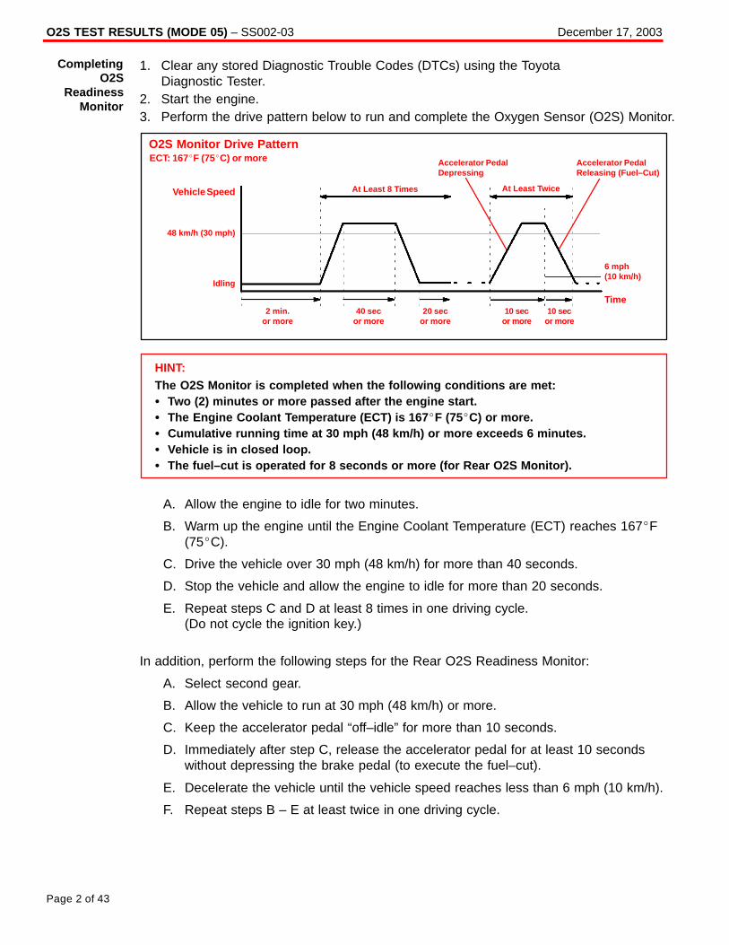
O2S TEST RESULTS (MODE 05) – SS002-03 December 17, 2003
Page 2 of 43
1. Clear any stored Diagnostic Trouble Codes (DTCs) using the Toyota Diagnostic Tester.
2. Start the engine.3. Perform the drive pattern below to run and complete the Oxygen Sensor (O2S) Monitor.
O2S Monitor Drive PatternECT: 167�F (75�C) or more
Vehicle Speed At Least 8 Times
48 km/h (30 mph)
Idling
At Least Twice
Accelerator PedalDepressing
Accelerator PedalReleasing (Fuel–Cut)
6 mph (10 km/h)
Time2 min.
or more40 sec
or more20 sec
or more10 sec
or more10 sec
or more
HINT:The O2S Monitor is completed when the following conditions are met:� Two (2) minutes or more passed after the engine start.� The Engine Coolant Temperature (ECT) is 167 �F (75�C) or more.� Cumulative running time at 30 mph (48 km/h) or more exceeds 6 minutes.� Vehicle is in closed loop.� The fuel–cut is operated for 8 seconds or more (for Rear O2S Monitor).
A. Allow the engine to idle for two minutes.
B. Warm up the engine until the Engine Coolant Temperature (ECT) reaches 167�F(75�C).
C. Drive the vehicle over 30 mph (48 km/h) for more than 40 seconds.
D. Stop the vehicle and allow the engine to idle for more than 20 seconds.
E. Repeat steps C and D at least 8 times in one driving cycle. (Do not cycle the ignition key.)
In addition, perform the following steps for the Rear O2S Readiness Monitor:
A. Select second gear.
B. Allow the vehicle to run at 30 mph (48 km/h) or more.
C. Keep the accelerator pedal “off–idle” for more than 10 seconds.
D. Immediately after step C, release the accelerator pedal for at least 10 secondswithout depressing the brake pedal (to execute the fuel–cut).
E. Decelerate the vehicle until the vehicle speed reaches less than 6 mph (10 km/h).
F. Repeat steps B – E at least twice in one driving cycle.
CompletingO2S
ReadinessMonitor
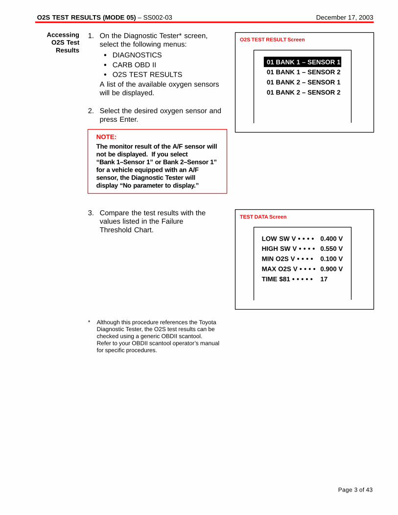
O2S TEST RESULTS (MODE 05) – SS002-03 December 17, 2003
Page 3 of 43
1. On the Diagnostic Tester* screen,select the following menus:
� DIAGNOSTICS� CARB OBD II� O2S TEST RESULTS
A list of the available oxygen sensorswill be displayed.
2. Select the desired oxygen sensor andpress Enter.
NOTE:The monitor result of the A/F sensor willnot be displayed. If you select“Bank 1–Sensor 1” or Bank 2–Sensor 1”for a vehicle equipped with an A/Fsensor, the Diagnostic Tester willdisplay “No parameter to display.”
3. Compare the test results with thevalues listed in the Failure Threshold Chart.
* Although this procedure references the Toyota Diagnostic Tester, the O2S test results can be checked using a generic OBDII scantool. Refer to your OBDII scantool operator’s manual for specific procedures.
AccessingO2S Test
Results
O2S TEST RESULT Screen
01 BANK 1 – SENSOR 1
01 BANK 1 – SENSOR 2
01 BANK 2 – SENSOR 1
01 BANK 2 – SENSOR 2
TEST DATA Screen
LOW SW V � � � � 0.400 V
HIGH SW V � � � � 0.550 V
MIN O2S V � � � � 0.100 V
MAX O2S V � � � � 0.900 V
TIME $81 � � � � � 17
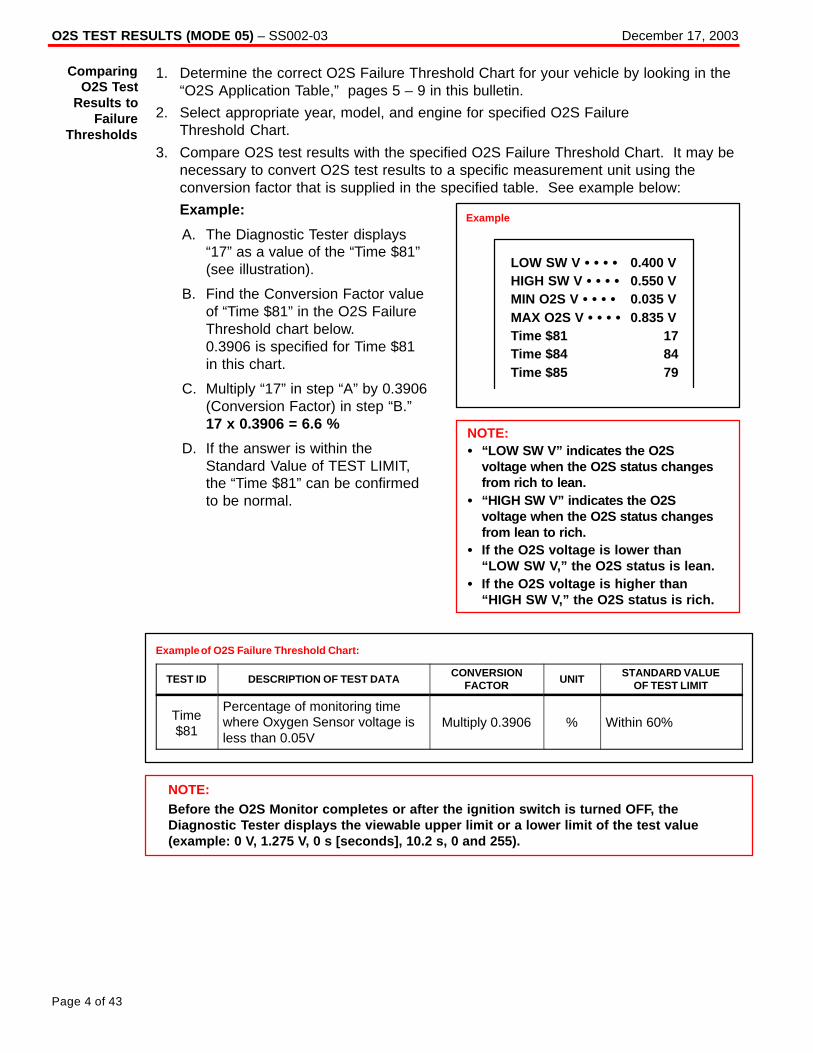
NOTE:Before the O2S Monitor completes or after the ignition switch is turned OFF, theDiagnostic Tester displays the viewable upper limit or a lower limit of the test value(example: 0 V, 1.275 V, 0 s [seconds], 10.2 s, 0 and 255).
O2S TEST RESULTS (MODE 05) – SS002-03 December 17, 2003
Page 4 of 43
1. Determine the correct O2S Failure Threshold Chart for your vehicle by looking in the“O2S Application Table,” pages 5 – 9 in this bulletin.
2. Select appropriate year, model, and engine for specified O2S Failure Threshold Chart.
3. Compare O2S test results with the specified O2S Failure Threshold Chart. It may benecessary to convert O2S test results to a specific measurement unit using theconversion factor that is supplied in the specified table. See example below:
Example:
A. The Diagnostic Tester displays“17” as a value of the “Time $81”(see illustration).
B. Find the Conversion Factor valueof “Time $81” in the O2S FailureThreshold chart below. 0.3906 is specified for Time $81 in this chart.
C. Multiply “17” in step “A” by 0.3906(Conversion Factor) in step “B.”17 x 0.3906 = 6.6 %
D. If the answer is within theStandard Value of TEST LIMIT,the “Time $81” can be confirmedto be normal.
Example of O2S Failure Threshold Chart:
TEST ID DESCRIPTION OF TEST DATACONVERSION
FACTORUNIT
STANDARD VALUEOF TEST LIMIT
Time$81
Percentage of monitoring timewhere Oxygen Sensor voltage isless than 0.05V
Multiply 0.3906 % Within 60%
ComparingO2S Test
Results toFailure
Thresholds
Example
LOW SW V � � � � 0.400 VHIGH SW V � � � � 0.550 VMIN O2S V � � � � 0.035 VMAX O2S V � � � � 0.835 VTime $81 17Time $84 84Time $85 79
NOTE:� “LOW SW V” indicates the O2S
voltage when the O2S status changesfrom rich to lean.
� “HIGH SW V” indicates the O2Svoltage when the O2S status changesfrom lean to rich.
� If the O2S voltage is lower than“LOW SW V,” the O2S status is lean.
� If the O2S voltage is higher than“HIGH SW V,” the O2S status is rich.

O2S TEST RESULTS (MODE 05) – SS002-03 December 17, 2003
Page 5 of 43
MODEL YEAR MODEL ENGINE DRIVE TRAIN CERTIFICATIONSEE CHART NO.
(TSB PAGE)
Avalon 1MZ–FE All 50–State 1 (p. 10)
5S FEAll California 2 (p. 11)
Camry5S–FE
All Federal1 (p 10)
y
1MZ–FE All 50–State1 (p. 10)
7A–FE All 50–State 1 (p. 10)
Celica5S FE
All California 2 (p. 11)5S–FE
All Federal 1 (p. 10)
Corolla ALL All 50–State 1 (p. 10)
1996 Land Cruiser 1FZ–FE All 50–State 1 (p. 10)
Paseo 5E–FE All 50–State 1 (p. 10)
Previa 2TZ–FZE All 50–State 1 (p. 10)
RAV4 3S–FE All 50–State 2 (p. 11)
Supra ALL All 50–State 1 (p. 10)
Tacoma ALL All 50–State 1 (p. 10)
Tercel 5E–FE All 50–State 1 (p. 10)
T100 ALL All 50–State 1 (p. 10)
4Runner ALL All 50–State 1 (p. 10)
Avalon 1MZ–FE All 50–State 1 (p. 10)
5S FEAll California 3 (p. 12)
Camry5S–FE
All Federal1 (p 10)
y
1MZ–FE All 50–State1 (p. 10)
7A–FE All 50–State 1 (p. 10)
Celica5S FE
All California 2 (p. 11)5S–FE
All Federal 1 (p. 10)
Corolla ALL All 50–State 1 (p. 10)
Land Cruiser 1FZ–FE All 50–State 1 (p. 10)
Paseo 5E–FE All 50–State 1 (p. 10)
Previa 2TZ–FZE All 50–State 1 (p. 10)
1997 RAV4 3S–FE All 50–State 2 (p. 11)
Supra ALL All 50–State 1 (p. 10)
2RZ–FE All 50–State
A/T 50–State 1 (p. 10)
Tacoma 3RZ–FE M/T, 2WD 50–State
( )
M/T, 4WD 50–State2 (p 11)
5VZ–FE All 50–State2 (p. 11)
Tercel 5E–FE All 50–State 1 (p. 10)
T1003RZ–FE All 50–State 1 (p. 10)
T1005VZ–FE All 50–State 2 (p. 11)
4Runner3RZ–FE All 50–State 1 (p. 10)
4Runner5VZ–FE All 50–State 2 (p. 11)
O2SApplication
Table
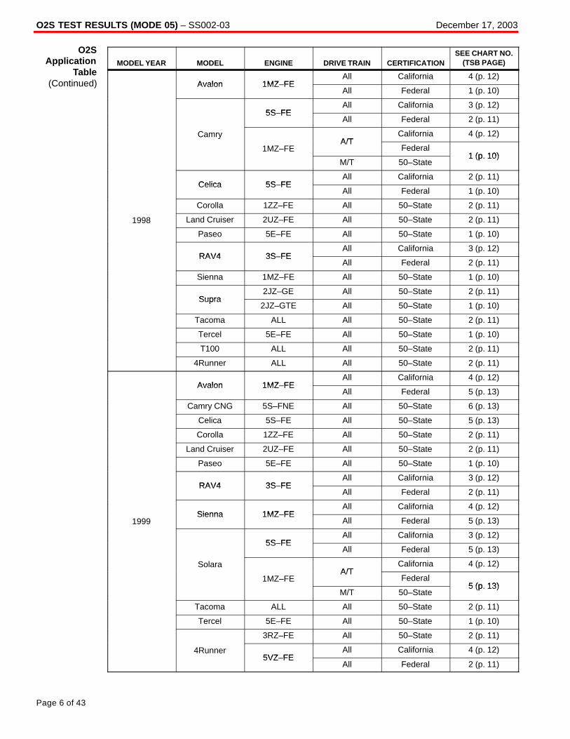
O2S TEST RESULTS (MODE 05) – SS002-03 December 17, 2003
Page 6 of 43
MODEL YEAR MODEL ENGINE DRIVE TRAIN CERTIFICATIONSEE CHART NO.
(TSB PAGE)
Avalon 1MZ FEAll California 4 (p. 12)
Avalon 1MZ–FEAll Federal 1 (p. 10)
5S FEAll California 3 (p. 12)
5S–FEAll Federal 2 (p. 11)
CamryA/T
California 4 (p. 12)y
1MZ–FEA/T
Federal1 (p 10)
M/T 50–State1 (p. 10)
Celica 5S FEAll California 2 (p. 11)
Celica 5S–FEAll Federal 1 (p. 10)
Corolla 1ZZ–FE All 50–State 2 (p. 11)
1998 Land Cruiser 2UZ–FE All 50–State 2 (p. 11)
Paseo 5E–FE All 50–State 1 (p. 10)
RAV4 3S FEAll California 3 (p. 12)
RAV4 3S–FEAll Federal 2 (p. 11)
Sienna 1MZ–FE All 50–State 1 (p. 10)
Supra2JZ–GE All 50–State 2 (p. 11)
Supra2JZ–GTE All 50–State 1 (p. 10)
Tacoma ALL All 50–State 2 (p. 11)
Tercel 5E–FE All 50–State 1 (p. 10)
T100 ALL All 50–State 2 (p. 11)
4Runner ALL All 50–State 2 (p. 11)
Avalon 1MZ FEAll California 4 (p. 12)
Avalon 1MZ–FEAll Federal 5 (p. 13)
Camry CNG 5S–FNE All 50–State 6 (p. 13)
Celica 5S–FE All 50–State 5 (p. 13)
Corolla 1ZZ–FE All 50–State 2 (p. 11)
Land Cruiser 2UZ–FE All 50–State 2 (p. 11)
Paseo 5E–FE All 50–State 1 (p. 10)
RAV4 3S FEAll California 3 (p. 12)
RAV4 3S–FEAll Federal 2 (p. 11)
Sienna 1MZ FEAll California 4 (p. 12)
1999Sienna 1MZ–FE
All Federal 5 (p. 13)
5S FEAll California 3 (p. 12)
5S–FEAll Federal 5 (p. 13)
SolaraA/T
California 4 (p. 12)
1MZ–FEA/T
Federal5 (p 13)
M/T 50–State5 (p. 13)
Tacoma ALL All 50–State 2 (p. 11)
Tercel 5E–FE All 50–State 1 (p. 10)
3RZ–FE All 50–State 2 (p. 11)
4Runner5VZ FE
All California 4 (p. 12)5VZ–FE
All Federal 2 (p. 11)
O2SApplication
Table(Continued)

O2S TEST RESULTS (MODE 05) – SS002-03 December 17, 2003
Page 7 of 43
MODEL YEAR MODEL ENGINE DRIVE TRAIN CERTIFICATIONSEE CHART NO.
(TSB PAGE)
Avalon 1MZ–FE All 50–State 4 (p. 12)
Camry CNG 5S–FNE All 50–State 6 (p. 13)
Celica ALL All 50–State 1 (p. 10)
Corolla 1ZZ–FE All 50–State 7 (p. 14)
ECHO 1NZ–FE All 50–State 1 (p. 10)
Land Cruiser 2UZ–FE All 50–State 2 (p. 11)
MR2 1ZZ–FE All 50–State 1 (p. 10)
RAV4 3S FEAll California 4 (p. 12)
RAV4 3S–FEAll Federal 2 (p. 11)
Sienna 1MZ FEAll California 4 (p. 12)
Sienna 1MZ–FEAll Federal 5 (p. 13)
5S FEAll California 4 (p. 12)
5S–FEAll Federal 5 (p. 13)
SolaraA/T
California 4 (p. 12)
2000 1MZ–FEA/T
Federal5 (p 13)
M/T 50–State5 (p. 13)
2RZ FEAll California 4 (p. 12)
2RZ–FEAll Federal 2 (p. 11)
Tacoma 3RZ FEAll California 4 (p. 12)
Tacoma 3RZ–FEAll Federal 2 (p. 11)
5VZ FEAll California 8 (p. 15)
5VZ–FEAll Federal 2 (p. 11)
2UZ–FE All 50–State 2 (p. 11)
Tundra5VZ FE
All California 8 (p. 15)5VZ–FE
All Federal 2 (p. 11)
3RZ FEAll California 4 (p. 12)
4Runner
3RZ–FEAll Federal 2 (p. 11)
4Runner
5VZ FEAll California 8 (p. 15)
5VZ–FEAll Federal 2 (p. 11)
O2SApplication
Table(Continued)

O2S TEST RESULTS (MODE 05) – SS002-03 December 17, 2003
Page 8 of 43
MODEL YEAR MODEL ENGINE DRIVE TRAIN CERTIFICATIONSEE CHART NO.
(TSB PAGE)
Avalon 1MZ–FE All 50–State 4 (p. 12)
Camry CNG 5S–FNE All 50–State 6 (p. 13)
Celica ALL All 50–State 1 (p. 10)
Corolla 1ZZ–FE All 50–State 7 (p. 14)
ECHO 1NZ–FE All 50–State 1 (p. 10)
Highlander1MZ–FE All 50–State 9 (p. 15)
Highlander2AZ–FE All 50–State 3 (p. 12)
Land Cruiser 2UZ–FE All 50–State 1 (p. 10)
MR2 1ZZ–FE All 50–State 1 (p. 10)
2001Prius 1NZ–FXE All 50–State 11 (p. 17)
2001RAV4 1AZ–FE All 50–State 4 (p. 12)
Sequoia 2UZ–FE All 50–State 1 (p. 10)
Sienna 1MZ–FE All 50–State 4 (p. 12)
5S–FE All 50–State 3 (p. 12)
Solara1MZ FE
A/T 50–State 9 (p. 15)1MZ–FE
M/T 50–State 10 (p. 16)
Tacoma ALL All 50–State 4 (p. 12)
Tundra2UZ–FE All 50–State 1 (p. 10)
Tundra5VZ–FE All 50–State 4 (p. 12)
4Runner ALL All 50–State 4 (p. 12)
Avalon 1MZ–FE All 50–State 4 (p. 12)
Celica1ZZ–FE All 50–State 1 (p. 10)
Celica2ZZ–GE All 50–State 13 (p. 19)
Corolla 1ZZ–FE All 50–State 7 (p. 14)
ECHO 1NZ–FE All 50–State 1 (p. 10)
Highlander1MZ–FE All 50–State 4 (p. 12)
Highlander2AZ–FE All 50–State 3 (p. 12)
Land Cruiser 2UZ–FE All 50–State 14 (p. 20)
MR2 1ZZ–FE All 50–State 1 (p. 10)
2002Prius 1NZ–FXE All 50–State 15 (p. 21)
2002RAV4 1AZ–FE All 50–State 3 (p. 12)
Sequoia 2UZ–FE All 50–State 14 (p. 20)
Sienna 1MZ–FE All 50–State 4 (p. 12)
2AZ–FE All 50–State 12 (p. 18)
Solara1MZ FE
A/T 50–State 9 (p. 15)1MZ–FE
M/T 50–State 5 (p. 13)
Tacoma ALL All 50–State 12 (p. 18)
Tundra2UZ–FE All 50–State 14 (p. 20)
Tundra5VZ–FE All 50–State 12 (p. 18)
4Runner ALL All 50–State 12 (p. 18)
O2SApplication
Table(Continued)

O2S TEST RESULTS (MODE 05) – SS002-03 December 17, 2003
Page 9 of 43
MODEL YEAR MODEL ENGINE DRIVE TRAIN CERTIFICATIONSEE CHART NO.
(TSB PAGE)
Avalon 1MZ–FE All 50–State 16 (p. 22)
All Federal17 (p 23)
2AZ–FE M/T California17 (p. 23)
Camry A/T California 18 (p. 24)y
1MZ FEAll With VVT 19 (p. 25)
1MZ–FEAll Without VVT 20 (p. 26)
Celica1ZZ–FE All 50–State 13 (p. 19)
Celica2ZZ–GE All 50–State 21 (p. 27–28)
Corolla 1ZZ–FE All 50–State 22 (p. 29)
ECHO 1NZ–FE All 50–State 23 (p. 30–31)
Highlander1MZ–FE All 50–State 16 (p. 22)
Highlander2AZ–FE All 50–State 12 (p. 18)
Land Cruiser 2UZ–FE All 50–State 24 (p. 32–33)
2003Matrix
1ZZ–FE All 50–State 22 (p. 29)Matrix
2ZZ–GE All 50–State 21 (p. 27–28)
MR2 1ZZ–FE All 50–State 13 (p. 19)
Prius 1NZ–FXE All 50–State 15 (p. 21)
RAV4 1AZ–FE All 50–State 25 (p. 34)
Sequoia 2UZ–FE All 50–State 24 (p. 32–33)
Sienna 1MZ–FE All 50–State 16 (p. 22)
Solara2AZ–FE All 50–State 17 (p. 23)
Solara1MZ–FE All 50–State 20 (p. 26)
Tacoma ALL All 50–State 16 (p. 22)
Tundra2UZ–FE All 50–State 24 (p. 32–33)
Tundra5VZ–FE All 50–State 16 (p. 22)
4Runner1GR–FE All 50–State 12 (p. 18)
4Runner2UZ–FE All 50–State 26 (p. 35–36)
Corolla 1ZZ–FE All 50–State 27 (p. 37–38)
ECHO 1NZ–FE All 50–State 23 (p. 30–31)
1ZZ FE2WD 50–State 27 (p. 37–38)
2004Matrix
1ZZ–FE4WD 50–State 28 (p. 39–40)
20042ZZ–GE All 50–State 29 (41–42)
Sienna 3MZ–FE All 50–State 30 (p. 43)
Scion xA 1NZ–FE All 50–State 23 (p. 30–31)
Scion xB 1NZ–FE All 50–State 23 (p. 30–31)
O2SApplication
Table(Continued)
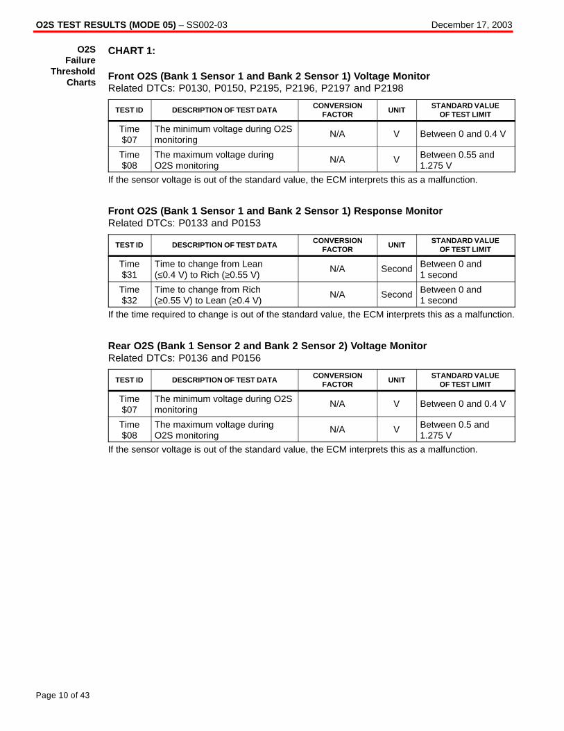
O2S TEST RESULTS (MODE 05) – SS002-03 December 17, 2003
Page 10 of 43
CHART 1:
Front O2S (Bank 1 Sensor 1 and Bank 2 Sensor 1) Voltage MonitorRelated DTCs: P0130, P0150, P2195, P2196, P2197 and P2198
TEST ID DESCRIPTION OF TEST DATACONVERSION
FACTORUNIT
STANDARD VALUEOF TEST LIMIT
Time$07
The minimum voltage during O2Smonitoring
N/A V Between 0 and 0.4 V
Time$08
The maximum voltage duringO2S monitoring
N/A V Between 0.55 and1.275 V
If the sensor voltage is out of the standard value, the ECM interprets this as a malfunction.
Front O2S (Bank 1 Sensor 1 and Bank 2 Sensor 1) Response MonitorRelated DTCs: P0133 and P0153
TEST ID DESCRIPTION OF TEST DATACONVERSION
FACTORUNIT
STANDARD VALUEOF TEST LIMIT
Time$31
Time to change from Lean(≤0.4 V) to Rich (≥0.55 V)
N/A Second Between 0 and1 second
Time$32
Time to change from Rich(≥0.55 V) to Lean (≥0.4 V)
N/A Second Between 0 and1 second
If the time required to change is out of the standard value, the ECM interprets this as a malfunction.
Rear O2S (Bank 1 Sensor 2 and Bank 2 Sensor 2) Voltage MonitorRelated DTCs: P0136 and P0156
TEST ID DESCRIPTION OF TEST DATACONVERSION
FACTORUNIT
STANDARD VALUEOF TEST LIMIT
Time$07
The minimum voltage during O2Smonitoring
N/A V Between 0 and 0.4 V
Time$08
The maximum voltage duringO2S monitoring
N/A V Between 0.5 and1.275 V
If the sensor voltage is out of the standard value, the ECM interprets this as a malfunction.
O2SFailure
ThresholdCharts

O2S TEST RESULTS (MODE 05) – SS002-03 December 17, 2003
Page 11 of 43
CHART 2:
Front O2S (Bank 1 Sensor 1 and Bank 2 Sensor 1) Voltage MonitorRelated DTCs: P0130, P0150, P2195, P2196, P2197 and P2198
TEST ID DESCRIPTION OF TEST DATACONVERSION
FACTORUNIT
STANDARD VALUEOF TEST LIMIT
$07 The minimum voltage duringO2S monitoring
N/A V Between 0 and0.35 V
Time$08
The maximum voltage duringO2S monitoring
N/A V Between 0.55 and1.275 V
If the sensor voltage is out of the standard value, the ECM interprets this as a malfunction.
Front O2S (Bank 1 Sensor 1 and Bank 2 Sensor 1) Response MonitorRelated DTCs: P0133 and P0153
TEST ID DESCRIPTION OF TEST DATACONVERSION
FACTORUNIT
STANDARD VALUEOF TEST LIMIT
Time$31
Time to change from Lean(≤0.35 V) to Rich (≥0.55 V)
N/A Second Between 0 and1.1 seconds
Time$32
Time to change from Rich(≥0.55 V) to Lean (≥0.35 V)
N/A Second Between 0 and1.1 seconds
If the time required to change is out of the standard value, the ECM interprets this as a malfunction.
Rear O2S (Bank 1 Sensor 2 and Bank 2 Sensor 2) Voltage MonitorRelated DTCs: P0136 and P0156
TEST ID DESCRIPTION OF TEST DATACONVERSION
FACTORUNIT
STANDARD VALUEOF TEST LIMIT
Time$07
The minimum voltage duringO2S monitoring
N/A V Between 0 and 0.4 V
Time$08
The maximum voltage duringO2S monitoring
N/A V Between 0.5 and1.275 V
If the sensor voltage is out of the standard value, the ECM interprets this as a malfunction.
O2SFailure
ThresholdCharts
(Continued)
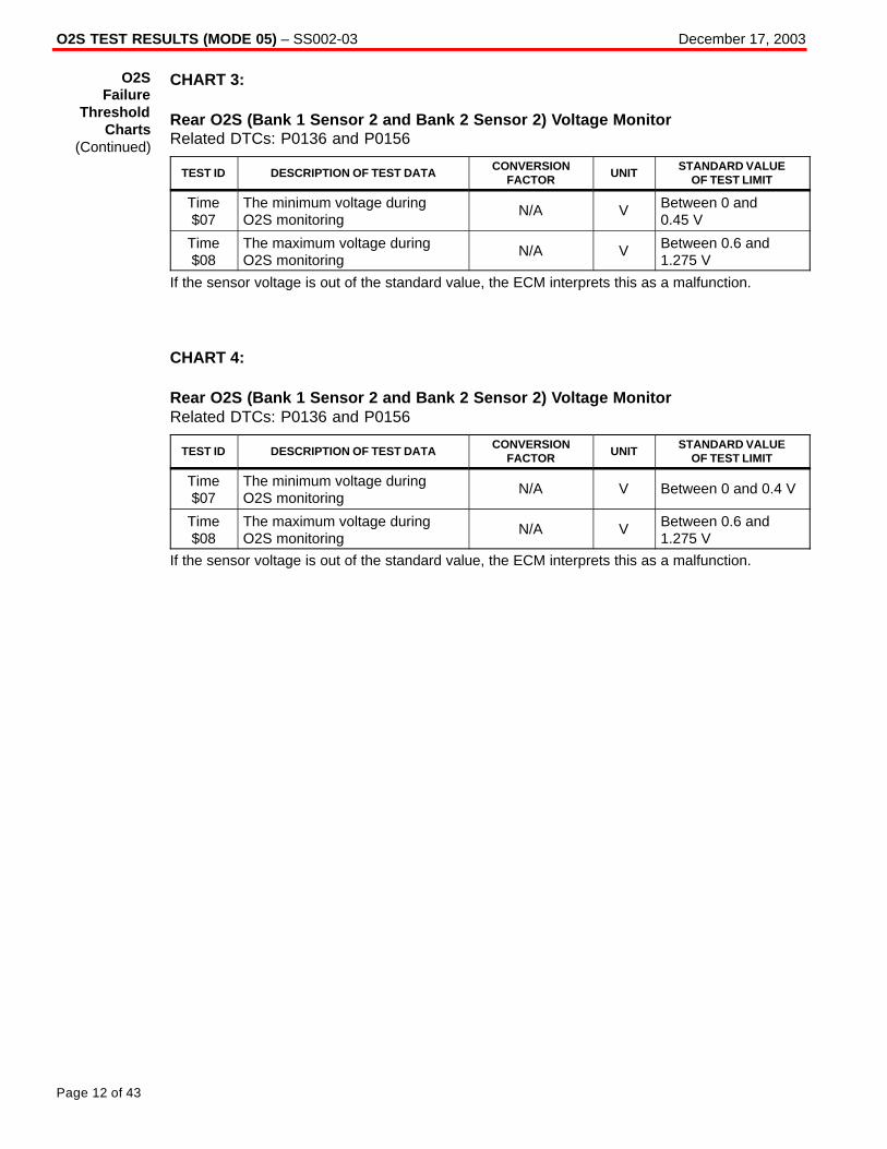
O2S TEST RESULTS (MODE 05) – SS002-03 December 17, 2003
Page 12 of 43
CHART 3:
Rear O2S (Bank 1 Sensor 2 and Bank 2 Sensor 2) Voltage MonitorRelated DTCs: P0136 and P0156
TEST ID DESCRIPTION OF TEST DATACONVERSION
FACTORUNIT
STANDARD VALUEOF TEST LIMIT
Time$07
The minimum voltage duringO2S monitoring
N/A V Between 0 and0.45 V
Time$08
The maximum voltage duringO2S monitoring
N/A V Between 0.6 and1.275 V
If the sensor voltage is out of the standard value, the ECM interprets this as a malfunction.
CHART 4:
Rear O2S (Bank 1 Sensor 2 and Bank 2 Sensor 2) Voltage MonitorRelated DTCs: P0136 and P0156
TEST ID DESCRIPTION OF TEST DATACONVERSION
FACTORUNIT
STANDARD VALUEOF TEST LIMIT
Time$07
The minimum voltage duringO2S monitoring
N/A V Between 0 and 0.4 V
Time$08
The maximum voltage duringO2S monitoring
N/A V Between 0.6 and1.275 V
If the sensor voltage is out of the standard value, the ECM interprets this as a malfunction.
O2SFailure
ThresholdCharts
(Continued)

O2S TEST RESULTS (MODE 05) – SS002-03 December 17, 2003
Page 13 of 43
CHART 5:
Front O2S (Bank 1 Sensor 1 and Bank 2 Sensor 1) Voltage MonitorRelated DTCs: P0130, P0150, P2195, P2196, P2197 and P2198
TEST ID DESCRIPTION OF TEST DATACONVERSION
FACTORUNIT
STANDARD VALUEOF TEST LIMIT
Time$07
The minimum voltage duringO2S monitoring
N/A V Between 0 and 0.4 V
Time$08
The maximum voltage duringO2S monitoring
N/A V Between 0.55 and1.275 V
If the sensor voltage is out of the standard value, the ECM interprets this as a malfunction.
Front O2S (Bank 1 Sensor 1 and Bank 2 Sensor 1) Response MonitorRelated DTCs: P0133 and P0153
TEST ID DESCRIPTION OF TEST DATACONVERSION
FACTORUNIT
STANDARD VALUEOF TEST LIMIT
Time$31
Time to change from Lean(≤0.4 V) to Rich (≥0.55 V)
N/A Second Between 0 and1.1 seconds
Time$32
Time to change from Rich(≥0.55 V) to Lean (≤0.4 V)
N/A Second Between 0 and1.1 seconds
If the time required to change is out of the standard value, the ECM interprets this as a malfunction.
Rear O2S (Bank 1 Sensor 2 and Bank 2 Sensor 2) Voltage MonitorRelated DTCs: P0136 and P0156
TEST ID DESCRIPTION OF TEST DATACONVERSION
FACTORUNIT
STANDARD VALUEOF TEST LIMIT
Time$07
The minimum voltage duringO2S monitoring
N/A V Between 0 and 0.4 V
Time$08
The maximum voltage duringO2S monitoring
N/A V Between 0.5 and1.275 V
If the sensor voltage is out of the standard value, the ECM interprets this as a malfunction.
CHART 6:
Rear O2S (Bank 1 Sensor 2 and Bank 2 Sensor 2) Voltage MonitorRelated DTCs: P0136 and P0156
TEST ID DESCRIPTION OF TEST DATACONVERSION
FACTORUNIT
STANDARD VALUEOF TEST LIMIT
Time$07
The minimum voltage duringO2S monitoring
N/A V Between 0 and0.55 V
Time$08
The maximum voltage duringO2S monitoring
N/A V Between 1 and1.275 V
If the sensor voltage is out of the standard value, the ECM interprets this as a malfunction.
O2SFailure
ThresholdCharts
(Continued)

O2S TEST RESULTS (MODE 05) – SS002-03 December 17, 2003
Page 14 of 43
CHART 7:
Front O2S (Bank 1 Sensor 1 and Bank 2 Sensor 1) Voltage MonitorRelated DTCs: P0130, P0150, P2195, P2196, P2197 and P2198
TEST ID DESCRIPTION OF TEST DATACONVERSION
FACTORUNIT
STANDARD VALUEOF TEST LIMIT
Time$07
The minimum voltage duringO2S monitoring
N/A V Between 0 and 0.4 V
Time$08
The maximum voltage duringO2S monitoring
N/A V Between 0.55 and1.275 V
If the sensor voltage is out of the standard value, the ECM interprets this as a malfunction.
Front O2S (Bank 1 Sensor 1 and Bank 2 Sensor 1) Response MonitorRelated DTCs: P0133 and P0153
TEST ID DESCRIPTION OF TEST DATACONVERSION
FACTORUNIT
STANDARD VALUEOF TEST LIMIT
Time$31
Time to change from Lean(≤0.4 V) to Rich (≥0.55 V)
N/A Second Between 0 and0.9 seconds
Time$32
Time to change from Rich(≥0.55 V) to Lean (≤0.4 V)
N/A Second Between 0 and0.9 seconds
If the time required to change is out of the standard value, the ECM interprets this as a malfunction.
Rear O2S (Bank 1 Sensor 2 and Bank 2 Sensor 2) Voltage MonitorRelated DTCs: P0136 and P0156
TEST ID DESCRIPTION OF TEST DATACONVERSION
FACTORUNIT
STANDARD VALUEOF TEST LIMIT
Time$07
The minimum voltage duringO2S monitoring
N/A V Between 0 and 0.4 V
Time$08
The maximum voltage duringO2S monitoring
N/A V Between 0.5 and1.275 V
If the sensor voltage is out of the standard value, the ECM interprets this as a malfunction.
O2SFailure
ThresholdCharts
(Continued)

O2S TEST RESULTS (MODE 05) – SS002-03 December 17, 2003
Page 15 of 43
CHART 8:
Front O2S (Bank 1 Sensor 1 and Bank 2 Sensor 1) Voltage MonitorRelated DTCs: P0130, P0150, P2195, P2196, P2197 and P2198
TEST ID DESCRIPTION OF TEST DATACONVERSION
FACTORUNIT
STANDARD VALUEOF TEST LIMIT
Time$07
The minimum voltage duringO2S monitoring
N/A V Between 0 and0.35 V
Time$08
The maximum voltage duringO2S monitoring
N/A V Between 0.55 and1.275 V
If the sensor voltage is out of the standard value, the ECM interprets this as a malfunction.
Front O2S (Bank 1 Sensor 1 and Bank 2 Sensor 1) Response MonitorRelated DTCs: P0133 and P0153
TEST ID DESCRIPTION OF TEST DATACONVERSION
FACTORUNIT
STANDARD VALUEOF TEST LIMIT
Time$31
Time to change from Lean(≤0.35 V) to Rich (≥0.55 V)
N/A Second Between 0 and1 second
Time$32
Time to change from Rich(≥0.55 V) to Lean (≤0.35 V)
N/A Second Between 0 and1 second
If the time required to change is out of the standard value, the ECM interprets this as a malfunction.
Rear O2S (Bank 1 Sensor 2 and Bank 2 Sensor 2) Voltage MonitorRelated DTCs: P0136 and P0156
TEST ID DESCRIPTION OF TEST DATACONVERSION
FACTORUNIT
STANDARD VALUEOF TEST LIMIT
Time$07
The minimum voltage duringO2S monitoring
N/A V Between 0 and 0.4 V
Time$08
The maximum voltage duringO2S monitoring
N/A V Between 0.6 and1.275 V
If the sensor voltage is out of the standard value, the ECM interprets this as a malfunction.
CHART 9:
Rear O2S (Bank 1 Sensor 2 and Bank 2 Sensor 2) Voltage MonitorRelated DTCs: P0136 and P0156
TEST ID DESCRIPTION OF TEST DATACONVERSION
FACTORUNIT
STANDARD VALUEOF TEST LIMIT
Time$07
The minimum voltage duringO2S monitoring
N/A V Between 0 and 0.5 V
Time$08
The maximum voltage duringO2S monitoring
N/A V Between 0.6 and1.275 V
If the sensor voltage is out of the standard value, the ECM interprets this as a malfunction.
O2SFailure
ThresholdCharts
(Continued)

O2S TEST RESULTS (MODE 05) – SS002-03 December 17, 2003
Page 16 of 43
CHART 10:
Front O2S (Bank 1 Sensor 1 and Bank 2 Sensor 1) Voltage MonitorRelated DTCs: P0130, P0150, P2195, P2196, P2197 and P2198
TEST ID DESCRIPTION OF TEST DATACONVERSION
FACTORUNIT
STANDARD VALUEOF TEST LIMIT
Time$07
The minimum voltage duringO2S monitoring
N/A V Between 0 and 0.4 V
Time$08
The maximum voltage duringO2S monitoring
N/A V Between 0.55 and1.275 V
If the sensor voltage is out of the standard value, the ECM interprets this as a malfunction.
Front O2S (Bank 1 Sensor 1 and Bank 2 Sensor 1) Response MonitorRelated DTCs: P0133 and P0153
TEST ID DESCRIPTION OF TEST DATACONVERSION
FACTORUNIT
STANDARD VALUEOF TEST LIMIT
Time$31
Time to change from Lean(≤0.4 V) to Rich (≥0.55 V)
N/A Second Between 0 and1.1 seconds
Time$32
Time to change from Rich(≥0.55 V) to Lean (≤0.4 V)
N/A Second Between 0 and1.1 seconds
If the time required to change is out of the standard value, the ECM interprets this as a malfunction.
Rear O2S (Bank 1 Sensor 2 and Bank 2 Sensor 2) Voltage MonitorRelated DTCs: P0136 and P0156
TEST ID DESCRIPTION OF TEST DATACONVERSION
FACTORUNIT
STANDARD VALUEOF TEST LIMIT
Time$07
The minimum voltage duringO2S monitoring
N/A V Between 0 and 0.5 V
Time$08
The maximum voltage duringO2S monitoring
N/A V Between 0.6 and1.275 V
If the sensor voltage is out of the standard value, the ECM interprets this as a malfunction.
O2SFailure
ThresholdCharts
(Continued)

O2S TEST RESULTS (MODE 05) – SS002-03 December 17, 2003
Page 17 of 43
CHART 11:
Front O2S (Bank 1 Sensor 1 and Bank 2 Sensor 1) Voltage MonitorRelated DTCs: P0130, P0150, P2195, P2196, P2197 and P2198
TEST ID DESCRIPTION OF TEST DATACONVERSION
FACTORUNIT
STANDARD VALUEOF TEST LIMIT
Time$07
The minimum voltage duringO2S monitoring
N/A V Between 0 and0.42 V
Time$08
The maximum voltage duringO2S monitoring
N/A V Between 0.48 and1.275 V
If the sensor voltage is out of the standard value, the ECM interprets this as a malfunction.
Front O2S (Bank 1 Sensor 1 and Bank 2 Sensor 1) Response MonitorRelated DTCs: P0133 and P0153
TEST ID DESCRIPTION OF TEST DATACONVERSION
FACTORUNIT
STANDARD VALUEOF TEST LIMIT
Time$31
Time to change from Lean(≤0.42 V) to Rich (≥0.48 V)
N/A Second Between 0 and 0.4 seconds
Time$32
Time to change from Rich(≥0.48 V) to Lean (≤0.42 V)
N/A Second Between 0 and 0.4 seconds
If the time required to change is out of the standard value, the ECM interprets this as a malfunction.
Rear O2S (Bank 1 Sensor 2 and Bank 2 Sensor 2) Voltage MonitorRelated DTCs: P0136 and P0156
TEST ID DESCRIPTION OF TEST DATACONVERSION
FACTORUNIT
STANDARD VALUEOF TEST LIMIT
Time$07
The minimum voltage duringO2S monitoring
N/A V Between 0 and0.45 V
Time$08
The maximum voltage duringO2S monitoring
N/A V Between 0.55 and1.275 V
If the sensor voltage is out of the standard value, the ECM interprets this as a malfunction.
O2SFailure
ThresholdCharts
(Continued)
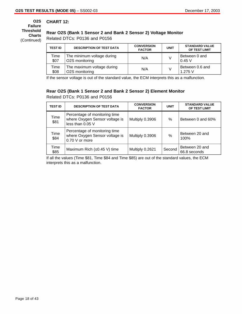
O2S TEST RESULTS (MODE 05) – SS002-03 December 17, 2003
Page 18 of 43
CHART 12:
Rear O2S (Bank 1 Sensor 2 and Bank 2 Sensor 2) Voltage MonitorRelated DTCs: P0136 and P0156
TEST ID DESCRIPTION OF TEST DATACONVERSION
FACTORUNIT
STANDARD VALUEOF TEST LIMIT
Time$07
The minimum voltage duringO2S monitoring
N/A V Between 0 and0.45 V
Time$08
The maximum voltage duringO2S monitoring
N/A V Between 0.6 and1.275 V
If the sensor voltage is out of the standard value, the ECM interprets this as a malfunction.
Rear O2S (Bank 1 Sensor 2 and Bank 2 Sensor 2) Element MonitorRelated DTCs: P0136 and P0156
TEST ID DESCRIPTION OF TEST DATACONVERSION
FACTORUNIT
STANDARD VALUEOF TEST LIMIT
Time$81
Percentage of monitoring timewhere Oxygen Sensor voltage isless than 0.05 V
Multiply 0.3906 % Between 0 and 60%
Time$84
Percentage of monitoring timewhere Oxygen Sensor voltage is0.70 V or more
Multiply 0.3906 % Between 20 and100%
Time$85
Maximum Rich (≤0.45 V) time Multiply 0.2621 Second Between 20 and 66.8 seconds
If all the values (Time $81, Time $84 and Time $85) are out of the standard values, the ECMinterprets this as a malfunction.
O2SFailure
ThresholdCharts
(Continued)
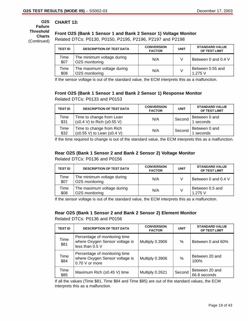
O2S TEST RESULTS (MODE 05) – SS002-03 December 17, 2003
Page 19 of 43
CHART 13:
Front O2S (Bank 1 Sensor 1 and Bank 2 Sensor 1) Voltage MonitorRelated DTCs: P0130, P0150, P2195, P2196, P2197 and P2198
TEST ID DESCRIPTION OF TEST DATACONVERSION
FACTORUNIT
STANDARD VALUEOF TEST LIMIT
Time$07
The minimum voltage duringO2S monitoring
N/A V Between 0 and 0.4 V
Time$08
The maximum voltage duringO2S monitoring
N/A V Between 0.55 and1.275 V
If the sensor voltage is out of the standard value, the ECM interprets this as a malfunction.
Front O2S (Bank 1 Sensor 1 and Bank 2 Sensor 1) Response MonitorRelated DTCs: P0133 and P0153
TEST ID DESCRIPTION OF TEST DATACONVERSION
FACTORUNIT
STANDARD VALUEOF TEST LIMIT
Time$31
Time to change from Lean(≤0.4 V) to Rich (≥0.55 V)
N/A Second Between 0 and 1 seconds
Time$32
Time to change from Rich(≥0.55 V) to Lean (≤0.4 V)
N/A Second Between 0 and 1 seconds
If the time required to change is out of the standard value, the ECM interprets this as a malfunction.
Rear O2S (Bank 1 Sensor 2 and Bank 2 Sensor 2) Voltage MonitorRelated DTCs: P0136 and P0156
TEST ID DESCRIPTION OF TEST DATACONVERSION
FACTORUNIT
STANDARD VALUEOF TEST LIMIT
Time$07
The minimum voltage duringO2S monitoring
N/A V Between 0 and 0.4 V
Time$08
The maximum voltage duringO2S monitoring
N/A V Between 0.5 and1.275 V
If the sensor voltage is out of the standard value, the ECM interprets this as a malfunction.
Rear O2S (Bank 1 Sensor 2 and Bank 2 Sensor 2) Element MonitorRelated DTCs: P0136 and P0156
TEST ID DESCRIPTION OF TEST DATACONVERSION
FACTORUNIT
STANDARD VALUEOF TEST LIMIT
Time$81
Percentage of monitoring timewhere Oxygen Sensor voltage isless than 0.5 V
Multiply 0.3906 % Between 0 and 60%
Time$84
Percentage of monitoring timewhere Oxygen Sensor voltage is0.70 V or more
Multiply 0.3906 % Between 20 and100%
Time$85
Maximum Rich (≥0.45 V) time Multiply 0.2621 Second Between 20 and 66.8 seconds
If all the values (Time $81, Time $84 and Time $85) are out of the standard values, the ECMinterprets this as a malfunction.
O2SFailure
ThresholdCharts
(Continued)
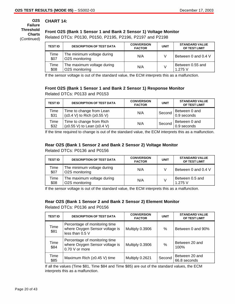
O2S TEST RESULTS (MODE 05) – SS002-03 December 17, 2003
Page 20 of 43
CHART 14:
Front O2S (Bank 1 Sensor 1 and Bank 2 Sensor 1) Voltage MonitorRelated DTCs: P0130, P0150, P2195, P2196, P2197 and P2198
TEST ID DESCRIPTION OF TEST DATACONVERSION
FACTORUNIT
STANDARD VALUEOF TEST LIMIT
Time$07
The minimum voltage duringO2S monitoring
N/A V Between 0 and 0.4 V
Time$08
The maximum voltage duringO2S monitoring
N/A V Between 0.55 and1.275 V
If the sensor voltage is out of the standard value, the ECM interprets this as a malfunction.
Front O2S (Bank 1 Sensor 1 and Bank 2 Sensor 1) Response MonitorRelated DTCs: P0133 and P0153
TEST ID DESCRIPTION OF TEST DATACONVERSION
FACTORUNIT
STANDARD VALUEOF TEST LIMIT
Time$31
Time to change from Lean(≤0.4 V) to Rich (≥0.55 V)
N/A Second Between 0 and 0.9 seconds
Time$32
Time to change from Rich(≥0.55 V) to Lean (≤0.4 V)
N/A Second Between 0 and 0.9 seconds
If the time required to change is out of the standard value, the ECM interprets this as a malfunction.
Rear O2S (Bank 1 Sensor 2 and Bank 2 Sensor 2) Voltage MonitorRelated DTCs: P0136 and P0156
TEST ID DESCRIPTION OF TEST DATACONVERSION
FACTORUNIT
STANDARD VALUEOF TEST LIMIT
Time$07
The minimum voltage duringO2S monitoring
N/A V Between 0 and 0.4 V
Time$08
The maximum voltage duringO2S monitoring
N/A V Between 0.5 and1.275 V
If the sensor voltage is out of the standard value, the ECM interprets this as a malfunction.
Rear O2S (Bank 1 Sensor 2 and Bank 2 Sensor 2) Element MonitorRelated DTCs: P0136 and P0156
TEST ID DESCRIPTION OF TEST DATACONVERSION
FACTORUNIT
STANDARD VALUEOF TEST LIMIT
Time$81
Percentage of monitoring timewhere Oxygen Sensor voltage isless than 0.5 V
Multiply 0.3906 % Between 0 and 90%
Time$84
Percentage of monitoring timewhere Oxygen Sensor voltage is0.70 V or more
Multiply 0.3906 % Between 20 and100%
Time$85
Maximum Rich (≥0.45 V) time Multiply 0.2621 Second Between 20 and 66.8 seconds
If all the values (Time $81, Time $84 and Time $85) are out of the standard values, the ECMinterprets this as a malfunction.
O2SFailure
ThresholdCharts
(Continued)

O2S TEST RESULTS (MODE 05) – SS002-03 December 17, 2003
Page 21 of 43
CHART 15:
Front O2S (Bank 1 Sensor 1 and Bank 2 Sensor 1) Voltage MonitorRelated DTCs: P0130, P0150, P2195, P2196, P2197 and P2198
TEST ID DESCRIPTION OF TEST DATACONVERSION
FACTORUNIT
STANDARD VALUEOF TEST LIMIT
Time$07
The minimum voltage duringO2S monitoring
N/A V Between 0 and0.42 V
Time$08
The maximum voltage duringO2S monitoring
N/A V Between 0.48 and1.275 V
If the sensor voltage is out of the standard value, the ECM interprets this as a malfunction.
Front O2S (Bank 1 Sensor 1 and Bank 2 Sensor 1) Response MonitorRelated DTCs: P0133 and P0153
TEST ID DESCRIPTION OF TEST DATACONVERSION
FACTORUNIT
STANDARD VALUEOF TEST LIMIT
Time$31
Time to change from Lean(≤0.42 V) to Rich (≥0.48 V)
N/A Second Between 0 and 0.4 seconds
Time$32
Time to change from Rich(≥0.48 V) to Lean (≤0.42 V)
N/A Second Between 0 and 0.4 seconds
If the time required to change is out of the standard value, the ECM interprets this as a malfunction.
Rear O2S (Bank 1 Sensor 2 and Bank 2 Sensor 2) Voltage MonitorRelated DTCs: P0136 and P0156
TEST ID DESCRIPTION OF TEST DATACONVERSION
FACTORUNIT
STANDARD VALUEOF TEST LIMIT
Time$07
The minimum voltage duringO2S monitoring
N/A V Between 0 and0.45 V
Time$08
The maximum voltage duringO2S monitoring
N/A V Between 0.55 and1.275 V
If the sensor voltage is out of the standard value, the ECM interprets this as a malfunction.
Rear O2S (Bank 1 Sensor 2 and Bank 2 Sensor 2) Element MonitorRelated DTCs: P0136 and P0156
TEST ID DESCRIPTION OF TEST DATACONVERSION
FACTORUNIT
STANDARD VALUEOF TEST LIMIT
Time$81
Percentage of monitoring timewhere Oxygen Sensor voltage isless than 0.5 V
Multiply 0.3906 % Between 0 and 80%
Time$84
Percentage of monitoring timewhere Oxygen Sensor voltage is0.70 V or more
Multiply 0.3906 % Between 20 and100%
Time$85
Maximum Rich (≥0.45 V) time Multiply 0.2621 Second Between 10 and 66.8 seconds
If all the values (Time $81, Time $84 and Time $85) are out of the standard values, the ECMinterprets this as a malfunction.
O2SFailure
ThresholdCharts
(Continued)

O2S TEST RESULTS (MODE 05) – SS002-03 December 17, 2003
Page 22 of 43
CHART 16:
Front O2S (Bank 1 Sensor 1 and Bank 2 Sensor 1) Voltage MonitorRelated DTCs: P0136 and P0156
TEST ID DESCRIPTION OF TEST DATACONVERSION
FACTORUNIT
STANDARD VALUEOF TEST LIMIT
Time$07
The minimum voltage duringO2S monitoring
N/A V Between 0 and 0.4 V
Time$08
The maximum voltage duringO2S monitoring
N/A V Between 0.6 and1.275 V
If the sensor voltage is out of the standard value, the ECM interprets this as a malfunction.
Rear O2S (Bank 1 Sensor 2 and Bank 2 Sensor 2) Element MonitorRelated DTCs: P0136 and P0156
TEST ID DESCRIPTION OF TEST DATACONVERSION
FACTORUNIT
STANDARD VALUEOF TEST LIMIT
Time$81
Percentage of monitoring timewhere Oxygen Sensor voltage isless than 0.5 V
Multiply 0.3906 % Between 0 and 60%
Time$84
Percentage of monitoring timewhere Oxygen Sensor voltage is0.70 V or more
Multiply 0.3906 % Between 20 and100%
Time$85
Maximum Rich (≥0.45 V) time Multiply 0.2621 Second Between 20 and 66.8 seconds
If all the values (Time $81, Time $84 and Time $85) are out of the standard values, the ECMinterprets this as a malfunction.
O2SFailure
ThresholdCharts
(Continued)

O2S TEST RESULTS (MODE 05) – SS002-03 December 17, 2003
Page 23 of 43
CHART 17:
Rear O2S (Bank 1 Sensor 2 and Bank 2 Sensor 2) Voltage MonitorRelated DTCs: P0136 and P0156
TEST ID DESCRIPTION OF TEST DATACONVERSION
FACTORUNIT
STANDARD VALUEOF TEST LIMIT
Time$07
The minimum voltage duringO2S monitoring
N/A V Between 0 and0.45 V
Time$08
The maximum voltage duringO2S monitoring
N/A V Between 0.6 and1.275 V
If the sensor voltage is out of the standard value, the ECM interprets this as a malfunction.
Rear O2S (Bank 1 Sensor 2 and Bank 2 Sensor 2) Element MonitorRelated DTCs: P0136 and P0156
TEST ID DESCRIPTION OF TEST DATACONVERSION
FACTORUNIT
STANDARD VALUEOF TEST LIMIT
Time$81
Percentage of monitoring timewhere Oxygen Sensor voltage isless than 0.05 V
Multiply 0.3906 % Between 0 and 55%
Time$84
Percentage of monitoring timewhere Oxygen Sensor voltage is0.70 V or more
Multiply 0.3906 % Between 20 and100%
Time$85
Maximum Rich (≥0.45 V) time Multiply 0.2621 Second Between 20 and 66.8 seconds
If all the values (Time $81, Time $84 and Time $85) are out of the standard values, the ECMinterprets this as a malfunction.
O2SFailure
ThresholdCharts
(Continued)

O2S TEST RESULTS (MODE 05) – SS002-03 December 17, 2003
Page 24 of 43
CHART 18:
Rear O2S (Bank 1 Sensor 2) Voltage MonitorRelated DTCs: P0136
TEST ID DESCRIPTION OF TEST DATACONVERSION
FACTORUNIT
STANDARD VALUEOF TEST LIMIT
Time$07
The minimum voltage duringO2S monitoring
N/A V Between 0 and 0.2 V
Time$08
The maximum voltage duringO2S monitoring
N/A V Between 0.6 and1.275 V
If the sensor voltage is out of the standard value, the ECM interprets this as a malfunction.
Rear O2S (Bank 1 Sensor 3) Deterioration MonitorRelated DTCs: P0142
TEST ID DESCRIPTION OF TEST DATACONVERSION
FACTORUNIT
STANDARD VALUEOF TEST LIMIT
Time$86
Average of the secondimpedance ratio between high– frequency and low–frequency
Multiply 0.0312 % Between 0.7 and 1.35
If the average of the sensor impedance ratio is out of the standard value, the ECM interprets thisas a malfunction.
O2SFailure
ThresholdCharts
(Continued)

O2S TEST RESULTS (MODE 05) – SS002-03 December 17, 2003
Page 25 of 43
CHART 19:
Rear O2S (Bank 1 Sensor 2 and Bank 2 Sensor 2) Voltage MonitorRelated DTCs: P0136 and P0156
TEST ID DESCRIPTION OF TEST DATACONVERSION
FACTORUNIT
STANDARD VALUEOF TEST LIMIT
Time$07
The minimum voltage duringO2S monitoring
N/A V Between 0 and 0.5 V
Time$08
The maximum voltage duringO2S monitoring
N/A V Between 0.6 and1.275 V
If the sensor voltage is out of the standard value, the ECM interprets this as a malfunction.
Rear O2S (Bank 1 Sensor 2 and Bank 2 Sensor 2) Element MonitorRelated DTCs: P0136 and P0156
TEST ID DESCRIPTION OF TEST DATACONVERSION
FACTORUNIT
STANDARD VALUEOF TEST LIMIT
Time$81
Percentage of monitoring timewhere Oxygen Sensor voltage isless than 0.05 V
Multiply 0.3906 % Between 0 and 95%
Time$84
Percentage of monitoring timewhere Oxygen Sensor voltage is0.70 V or more
Multiply 0.3906 % Between 20 and100%
Time$85
Maximum Rich (≥0.45 V) time Multiply 0.2621 Second Between 20 and 66.8 seconds
If all the values (Time $81, Time $84 and Time $85) are out of the standard values, the ECMinterprets this as a malfunction.
O2SFailure
ThresholdCharts
(Continued)

O2S TEST RESULTS (MODE 05) – SS002-03 December 17, 2003
Page 26 of 43
CHART 20:
Rear O2S (Bank 1 Sensor 2 and Bank 2 Sensor 2) Voltage MonitorRelated DTCs: P0136 and P0156
TEST ID DESCRIPTION OF TEST DATACONVERSION
FACTORUNIT
STANDARD VALUEOF TEST LIMIT
Time$07
The minimum voltage duringO2S monitoring
N/A V Between 0 and 0.5 V
Time$08
The maximum voltage duringO2S monitoring
N/A V Between 0.6 and1.275 V
If the sensor voltage is out of the standard value, the ECM interprets this as a malfunction.
Rear O2S (Bank 1 Sensor 2 and Bank 2 Sensor 2) Element MonitorRelated DTCs: P0136 and P0156
TEST ID DESCRIPTION OF TEST DATACONVERSION
FACTORUNIT
STANDARD VALUEOF TEST LIMIT
Time$81
Percentage of monitoring timewhere Oxygen Sensor voltage isless than 0.05 V
Multiply 0.3906 % Between 0 and 80%
Time$84
Percentage of monitoring timewhere Oxygen Sensor voltage is0.70 V or more
Multiply 0.3906 % Between 20 and100%
Time$85
Maximum Rich (≥0.45 V) time Multiply 0.2621 Second Between 20 and 66.8 seconds
If all the values (Time $81, Time $84 and Time $85) are out of the standard values, the ECMinterprets this as a malfunction.
O2SFailure
ThresholdCharts
(Continued)

O2S TEST RESULTS (MODE 05) – SS002-03 December 17, 2003
Page 27 of 43
CHART 21:
Front O2S (Bank 1 Sensor 1 and Bank 2 Sensor 1) Voltage MonitorRelated DTCs: P0130, P0150, P2195, P2196, P2197 and P2198
TEST ID DESCRIPTION OF TEST DATACONVERSION
FACTORUNIT
STANDARD VALUEOF TEST LIMIT
Time$07
The minimum voltage duringO2S monitoring
N/A V Between 0 and 0.4 V
Time$08
The maximum voltage duringO2S monitoring
N/A V Between 0.55 and1.275 V
If the sensor voltage is out of the standard value, the ECM interprets this as a malfunction.
Front O2S (Bank 1 Sensor 1 and Bank 2 Sensor 1) Response MonitorRelated DTCs: P0133 and P0153
TEST ID DESCRIPTION OF TEST DATACONVERSION
FACTORUNIT
STANDARD VALUEOF TEST LIMIT
Time$31
Time to change from Lean(≤0.4 V) to Rich (≥0.55 V)
N/A Second Between 0 and 0.8 seconds
Time$32
Time to change from Rich(≥0.55 V) to Lean (≤0.4 V)
N/A Second Between 0 and 0.8 seconds
If the time required to change is out of the standard value, the ECM interprets this as a malfunction.
Front O2S (Bank 1 Sensor 1 and Bank 2 Sensor 1) Frequency Monitor DuringEngine IdlingRelated DTCs: P0133 and P0153
TEST ID DESCRIPTION OF TEST DATACONVERSION
FACTORUNIT
STANDARD VALUEOF TEST LIMIT
Time$33
Average Lean (≤0.4 V) time ofone waveform cycle
N/A Second Between 0 and 3.05 seconds
Time$34
Average Rich (≥0.55 V) time ofone waveform cycle
N/A Second Between 0 and 3.05 seconds
If the sum of Time $33 and Time $34 is out of the standard value, the ECM interprets this as amalfunction.
O2SFailure
ThresholdCharts
(Continued)

O2S TEST RESULTS (MODE 05) – SS002-03 December 17, 2003
Page 28 of 43
CHART 21 (Continued):
Front O2S (Bank 1 Sensor 1 and Bank 2 Sensor 1) Frequency Monitor DuringVehicle RunningRelated DTCs: P0133 and P0153
TEST ID DESCRIPTION OF TEST DATACONVERSION
FACTORUNIT
STANDARD VALUEOF TEST LIMIT
Time$35
Average Lean (≤0.4 V) time ofone waveform cycle
N/A Second
Between 0 and 0.95 seconds (varies depending on feedbackcompensation factor)
Time$36
Average Rich (≤0.55 V) time ofone waveform cycle
N/A Second
Between 0 and 0.95seconds (varies depending on feedbackcompensation factor)
If the sum of Time $35 and Time $36 is out of the standard value, the ECM interprets this as amalfunction.
Rear O2S (Bank 1 Sensor 2 and Bank 2 Sensor 2) Voltage MonitorRelated DTCs: P0136 and P0156
TEST ID DESCRIPTION OF TEST DATACONVERSION
FACTORUNIT
STANDARD VALUEOF TEST LIMIT
Time$07
The minimum voltage duringO2S monitoring
N/A V Between 0 and 0.4 V
Time$08
The maximum voltage duringO2S monitoring
N/A V Between 0.5 and1.275 V
If the sensor voltage is out of the standard value, the ECM interprets this as a malfunction.
Rear O2S (Bank 1 Sensor 2 and Bank 2 Sensor 2) Element MonitorRelated DTCs: P0136 and P0156
TEST ID DESCRIPTION OF TEST DATACONVERSION
FACTORUNIT
STANDARD VALUEOF TEST LIMIT
Time$81
Percentage of monitoring timewhere Oxygen Sensor voltage isless than 0.05 V
Multiply 0.3906 % Between 0 and 60%
Time$84
Percentage of monitoring timewhere Oxygen Sensor voltage is0.70 V or more
Multiply 0.3906 % Between 20 and100%
Time$85
Maximum Rich (≥0.45 V) time Multiply 0.2621 Second Between 20 and 66.8 seconds
If all the values (Time $81, Time $84 and Time $85) are out of the standard values, the ECMinterprets this as a malfunction.
O2SFailure
ThresholdCharts
(Continued)

O2S TEST RESULTS (MODE 05) – SS002-03 December 17, 2003
Page 29 of 43
CHART 22:
Front O2S (Bank 1 Sensor 1 and Bank 2 Sensor 1) Voltage MonitorRelated DTCs: P0130, P0150, P2195, P2196, P2197 and P2198
TEST ID DESCRIPTION OF TEST DATACONVERSION
FACTORUNIT
STANDARD VALUEOF TEST LIMIT
Time$07
The minimum voltage duringO2S monitoring
N/A V Between 0 and 0.4 V
Time$08
The maximum voltage duringO2S monitoring
N/A V Between 0.55 and1.275 V
If the sensor voltage is out of the standard value, the ECM interprets this as a malfunction.
Front O2S (Bank 1 Sensor 1 and Bank 2 Sensor 1) Response MonitorRelated DTCs: P0133 and P0153
TEST ID DESCRIPTION OF TEST DATACONVERSION
FACTORUNIT
STANDARD VALUEOF TEST LIMIT
Time$31
Time to change from Lean(≤0.4 V) to Rich (≥0.55 V)
N/A Second Between 0 and 0.9 seconds
Time$32
Time to change from Rich(≥0.55 V) to Lean (≤0.4 V)
N/A Second Between 0 and 0.9 seconds
If the time required to change is out of the standard value, the ECM interprets this as a malfunction.
Rear O2S (Bank 1 Sensor 2 and Bank 2 Sensor 2) Voltage MonitorRelated DTCs: P0136 and P0156
TEST ID DESCRIPTION OF TEST DATACONVERSION
FACTORUNIT
STANDARD VALUEOF TEST LIMIT
Time$07
The minimum voltage duringO2S monitoring
N/A V Between 0 and 0.4 V
Time$08
The maximum voltage duringO2S monitoring
N/A V Between 0.5 and1.275 V
If the sensor voltage is out of the standard value, the ECM interprets this as a malfunction.
Rear O2S (Bank 1 Sensor 2 and Bank 2 Sensor 2) Element MonitorRelated DTCs: P0136 and P0156
TEST ID DESCRIPTION OF TEST DATACONVERSION
FACTORUNIT
STANDARD VALUEOF TEST LIMIT
Time$81
Percentage of monitoring timewhere Oxygen Sensor voltage isless than 0.5 V
Multiply 0.3906 % Between 0 and 60%
Time$84
Percentage of monitoring timewhere Oxygen Sensor voltage is0.70 V or more
Multiply 0.3906 % Between 20 and100%
Time$85
Maximum Rich (≥0.45 V) time Multiply 0.2621 Second Between 20 and 66.8 seconds
If all the values (Time $81, Time $84 and Time $85) are out of the standard values, the ECMinterprets this as a malfunction.
O2SFailure
ThresholdCharts
(Continued)

O2S TEST RESULTS (MODE 05) – SS002-03 December 17, 2003
Page 30 of 43
CHART 23:
Front O2S (Bank 1 Sensor 1 and Bank 2 Sensor 1) Voltage MonitorRelated DTCs: P0130, P0150, P2195, P2196, P2197 and P2198
TEST ID DESCRIPTION OF TEST DATACONVERSION
FACTORUNIT
STANDARD VALUEOF TEST LIMIT
Time$07
The minimum voltage duringO2S monitoring
N/A V Between 0 and 0.4 V
Time$08
The maximum voltage duringO2S monitoring
N/A V Between 0.55 and1.275 V
If the sensor voltage is out of the standard value, the ECM interprets this as a malfunction.
Front O2S (Bank 1 Sensor 1 and Bank 2 Sensor 1) Response MonitorRelated DTCs: P0133 and P0153
TEST ID DESCRIPTION OF TEST DATACONVERSION
FACTORUNIT
STANDARD VALUEOF TEST LIMIT
Time$31
Time to change from Lean(≤0.4 V) to Rich (≥0.55 V)
N/A Second Between 0 and 0.9 seconds
Time$32
Time to change from Rich(≥0.55 V) to Lean (≤0.4 V)
N/A Second Between 0 and 0.9 seconds
If the time required to change is out of the standard value, the ECM interprets this as a malfunction.
Front O2S (Bank 1 Sensor 1 and Bank 2 Sensor 1) Frequency Monitor DuringEngine IdlingRelated DTCs: P0133 and P0153
TEST ID DESCRIPTION OF TEST DATACONVERSION
FACTORUNIT
STANDARD VALUEOF TEST LIMIT
Time$33
Average Lean (≤0.4 V) time ofone waveform cycle
N/A Second Between 0 and 4.5 seconds
Time$34
Average Rich (≤0.55 V) time ofone waveform cycle
N/A Second Between 0 and 4.5 seconds
If the sum of Time $33 and Time $34 is out of the standard value, the ECM interprets this as amalfunction.
O2SFailure
ThresholdCharts
(Continued)
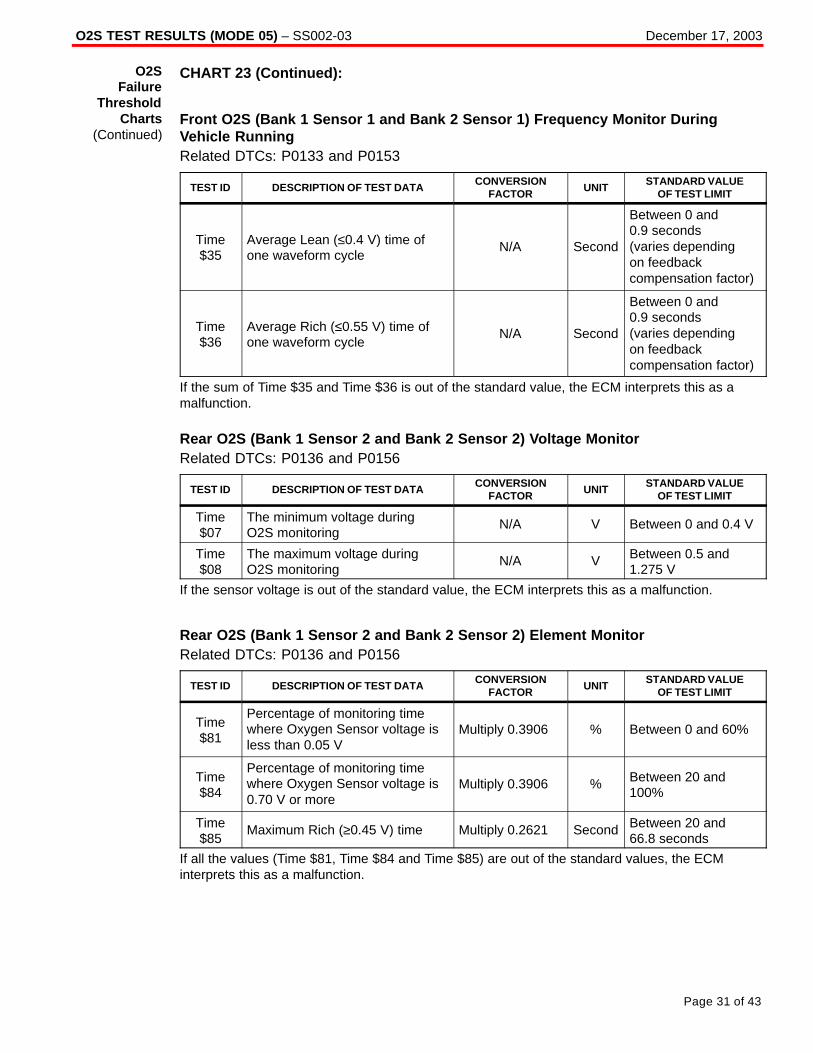
O2S TEST RESULTS (MODE 05) – SS002-03 December 17, 2003
Page 31 of 43
CHART 23 (Continued):
Front O2S (Bank 1 Sensor 1 and Bank 2 Sensor 1) Frequency Monitor DuringVehicle RunningRelated DTCs: P0133 and P0153
TEST ID DESCRIPTION OF TEST DATACONVERSION
FACTORUNIT
STANDARD VALUEOF TEST LIMIT
Time$35
Average Lean (≤0.4 V) time ofone waveform cycle
N/A Second
Between 0 and 0.9 seconds (varies depending on feedbackcompensation factor)
Time$36
Average Rich (≤0.55 V) time ofone waveform cycle
N/A Second
Between 0 and 0.9 seconds (varies depending on feedbackcompensation factor)
If the sum of Time $35 and Time $36 is out of the standard value, the ECM interprets this as amalfunction.
Rear O2S (Bank 1 Sensor 2 and Bank 2 Sensor 2) Voltage MonitorRelated DTCs: P0136 and P0156
TEST ID DESCRIPTION OF TEST DATACONVERSION
FACTORUNIT
STANDARD VALUEOF TEST LIMIT
Time$07
The minimum voltage duringO2S monitoring
N/A V Between 0 and 0.4 V
Time$08
The maximum voltage duringO2S monitoring
N/A V Between 0.5 and1.275 V
If the sensor voltage is out of the standard value, the ECM interprets this as a malfunction.
Rear O2S (Bank 1 Sensor 2 and Bank 2 Sensor 2) Element MonitorRelated DTCs: P0136 and P0156
TEST ID DESCRIPTION OF TEST DATACONVERSION
FACTORUNIT
STANDARD VALUEOF TEST LIMIT
Time$81
Percentage of monitoring timewhere Oxygen Sensor voltage isless than 0.05 V
Multiply 0.3906 % Between 0 and 60%
Time$84
Percentage of monitoring timewhere Oxygen Sensor voltage is0.70 V or more
Multiply 0.3906 % Between 20 and100%
Time$85
Maximum Rich (≥0.45 V) time Multiply 0.2621 Second Between 20 and 66.8 seconds
If all the values (Time $81, Time $84 and Time $85) are out of the standard values, the ECMinterprets this as a malfunction.
O2SFailure
ThresholdCharts
(Continued)

O2S TEST RESULTS (MODE 05) – SS002-03 December 17, 2003
Page 32 of 43
CHART 24:
Front O2S (Bank 1 Sensor 1 and Bank 2 Sensor 1) Voltage MonitorRelated DTCs: P0130, P0150, P2195, P2196, P2197 and P2198
TEST ID DESCRIPTION OF TEST DATACONVERSION
FACTORUNIT
STANDARD VALUEOF TEST LIMIT
Time$07
The minimum voltage duringO2S monitoring
N/A V Between 0 and 0.4 V
Time$08
The maximum voltage duringO2S monitoring
N/A V Between 0.55 and1.275 V
If the sensor voltage is out of the standard value, the ECM interprets this as a malfunction.
Front O2S (Bank 1 Sensor 1 and Bank 2 Sensor 1) Response MonitorRelated DTCs: P0133 and P0153
TEST ID DESCRIPTION OF TEST DATACONVERSION
FACTORUNIT
STANDARD VALUEOF TEST LIMIT
Time$31
Time to change from Lean(≤0.4 V) to Rich (≥0.55 V)
N/A Second Between 0 and 0.9 seconds
Time$32
Time to change from Rich(≥0.55 V) to Lean (≤0.4 V)
N/A Second Between 0 and 0.9 seconds
If the time required to change is out of the standard value, the ECM interprets this as a malfunction.
Front O2S (Bank 1 Sensor 1 and Bank 2 Sensor 1) Frequency Monitor DuringEngine IdlingRelated DTCs: P0133 and P0153
TEST ID DESCRIPTION OF TEST DATACONVERSION
FACTORUNIT
STANDARD VALUEOF TEST LIMIT
Time$33
Average Lean (≤0.4 V) time ofone waveform cycle
N/A Second Between 0 and 2.8 seconds
Time$34
Average Rich (≥0.55 V) time ofone waveform cycle
N/A Second Between 0 and 2.8 seconds
If the sum of Time $33 and Time $34 is out of the standard value, the ECM interprets this as amalfunction.
O2SFailure
ThresholdCharts
(Continued)

O2S TEST RESULTS (MODE 05) – SS002-03 December 17, 2003
Page 33 of 43
CHART 24 (Continued):
Front O2S (Bank 1 Sensor 1 and Bank 2 Sensor 1) Frequency Monitor DuringVehicle RunningRelated DTCs: P0133 and P0153
TEST ID DESCRIPTION OF TEST DATACONVERSION
FACTORUNIT
STANDARD VALUEOF TEST LIMIT
Time$35
Average Lean (≤0.4 V) time ofone waveform cycle
N/A Second
Between 0 and 0.75seconds (varies depending on feedbackcompensation factor)
Time$36
Average Rich (≤0.55 V) time ofone waveform cycle
N/A Second
Between 0 and 0.75seconds (varies depending on feedbackcompensation factor)
If the sum of Time $35 and Time $36 is out of the standard value, the ECM interprets this as amalfunction.
Rear O2S (Bank 1 Sensor 2 and Bank 2 Sensor 2) Voltage MonitorRelated DTCs: P0136 and P0156
TEST ID DESCRIPTION OF TEST DATACONVERSION
FACTORUNIT
STANDARD VALUEOF TEST LIMIT
Time$07
The minimum voltage duringO2S monitoring
N/A V Between 0 and 0.4 V
Time$08
The maximum voltage duringO2S monitoring
N/A V Between 0.5 and1.275 V
If the sensor voltage is out of the standard value, the ECM interprets this as a malfunction.
Rear O2S (Bank 1 Sensor 2 and Bank 2 Sensor 2) Element MonitorRelated DTCs: P0136 and P0156
TEST ID DESCRIPTION OF TEST DATACONVERSION
FACTORUNIT
STANDARD VALUEOF TEST LIMIT
Time$81
Percentage of monitoring timewhere Oxygen Sensor voltage isless than 0.05 V
Multiply 0.3906 % Between 0 and 90%
Time$84
Percentage of monitoring timewhere Oxygen Sensor voltage is0.70 V or more
Multiply 0.3906 % Between 20 and100%
Time$85
Maximum Rich (≥0.45 V) time Multiply 0.2621 Second Between 20 and 66.8 seconds
If all the values (Time $81, Time $84 and Time $85) are out of the standard values, the ECMinterprets this as a malfunction.
O2SFailure
ThresholdCharts
(Continued)

O2S TEST RESULTS (MODE 05) – SS002-03 December 17, 2003
Page 34 of 43
CHART 25:
Rear O2S (Bank 1 Sensor 2 and Bank 2 Sensor 2) Voltage MonitorRelated DTCs: P0136 and P0156
TEST ID DESCRIPTION OF TEST DATACONVERSION
FACTORUNIT
STANDARD VALUEOF TEST LIMIT
Time$07
The minimum voltage duringO2S monitoring
N/A V Between 0 and0.45 V
Time$08
The maximum voltage duringO2S monitoring
N/A V Between 0.6 and1.275 V
If the sensor voltage is out of the standard value, the ECM interprets this as a malfunction.
Rear O2S (Bank 1 Sensor 2 and Bank 2 Sensor 2) Element MonitorRelated DTCs: P0136 and P0156
TEST ID DESCRIPTION OF TEST DATACONVERSION
FACTORUNIT
STANDARD VALUEOF TEST LIMIT
Time$81
Percentage of monitoring timewhere Oxygen Sensor voltage isless than 0.05 V
Multiply 0.3906 % Between 0 and 80%
Time$84
Percentage of monitoring timewhere Oxygen Sensor voltage is0.70 V or more
Multiply 0.3906 % Between 20 and100%
Time$85
Maximum Rich (≥0.45 V) time Multiply 0.2621 Second Between 20 and 66.8 seconds
If all the values (Time $81, Time $84 and Time $85) are out of the standard values, the ECMinterprets this as a malfunction.
O2SFailure
ThresholdCharts
(Continued)

O2S TEST RESULTS (MODE 05) – SS002-03 December 17, 2003
Page 35 of 43
CHART 26:
Front O2S (Bank 1 Sensor 1 and Bank 2 Sensor 1) Voltage MonitorRelated DTCs: P0130, P0150, P2195, P2196, P2197 and P2198
TEST ID DESCRIPTION OF TEST DATACONVERSION
FACTORUNIT
STANDARD VALUEOF TEST LIMIT
Time$07
The minimum voltage duringO2S monitoring
N/A V Between 0 and 0.4 V
Time$08
The maximum voltage duringO2S monitoring
N/A V Between 0.55 and1.275 V
If the sensor voltage is out of the standard value, the ECM interprets this as a malfunction.
Front O2S (Bank 1 Sensor 1 and Bank 2 Sensor 1) Response MonitorRelated DTCs: P0133 and P0153
TEST ID DESCRIPTION OF TEST DATACONVERSION
FACTORUNIT
STANDARD VALUEOF TEST LIMIT
Time$31
Time to change from Lean(≤0.4 V) to Rich (≥0.55 V)
N/A Second Between 0 and 0.9 seconds
Time$32
Time to change from Rich(≥0.55 V) to Lean (≤0.4 V)
N/A Second Between 0 and 0.9 seconds
If the time required to change is out of the standard value, the ECM interprets this as a malfunction.
Front O2S (Bank 1 Sensor 1 and Bank 2 Sensor 1) Frequency Monitor DuringEngine IdlingRelated DTCs: P0133 and P0153
TEST ID DESCRIPTION OF TEST DATACONVERSION
FACTORUNIT
STANDARD VALUEOF TEST LIMIT
Time$33
Average Lean (≤0.4 V) time ofone waveform cycle
N/A Second Between 0 and 2.8 seconds
Time$34
Average Rich (≥0.55 V) time ofone waveform cycle
N/A Second Between 0 and 2.8 seconds
If the sum of Time $33 and Time $34 is out of the standard value, the ECM interprets this as amalfunction.
O2SFailure
ThresholdCharts
(Continued)

O2S TEST RESULTS (MODE 05) – SS002-03 December 17, 2003
Page 36 of 43
CHART 26 (Continued):
Front O2S (Bank 1 Sensor 1 and Bank 2 Sensor 1) Frequency Monitor DuringVehicle RunningRelated DTCs: P0133 and P0153
TEST ID DESCRIPTION OF TEST DATACONVERSION
FACTORUNIT
STANDARD VALUEOF TEST LIMIT
Time$35
Average Lean (≤0.4 V) time ofone waveform cycle
N/A Second
Between 0 and 0.75 seconds (varies depending on feedbackcompensation factor)
Time$36
Average Rich (≤0.55 V) time ofone waveform cycle
N/A Second
Between 0 and 0.75 seconds (varies depending on feedbackcompensation factor)
If the sum of Time $35 and Time $36 is out of the standard value, the ECM interprets this as amalfunction.
Rear O2S (Bank 1 Sensor 2 and Bank 2 Sensor 2) Voltage MonitorRelated DTCs: P0136 and P0156
TEST ID DESCRIPTION OF TEST DATACONVERSION
FACTORUNIT
STANDARD VALUEOF TEST LIMIT
Time$07
The minimum voltage duringO2S monitoring
N/A V Between 0 and 0.4 V
Time$08
The maximum voltage duringO2S monitoring
N/A V Between 0.5 and1.275 V
If the sensor voltage is out of the standard value, the ECM interprets this as a malfunction.
Rear O2S (Bank 1 Sensor 2 and Bank 2 Sensor 2) Element MonitorRelated DTCs: P0136 and P0156
TEST ID DESCRIPTION OF TEST DATACONVERSION
FACTORUNIT
STANDARD VALUEOF TEST LIMIT
Time$81
Percentage of monitoring timewhere Oxygen Sensor voltage isless than 0.05 V
Multiply 0.3906 % Between 0 and 60%
Time$84
Percentage of monitoring timewhere Oxygen Sensor voltage is0.70 V or more
Multiply 0.3906 % Between 20 and100%
Time$85
Maximum Rich (≥0.45 V) time Multiply 0.2621 Second Between 20 and 66.8 seconds
If all the values (Time $81, Time $84 and Time $85) are out of the standard values, the ECMinterprets this as a malfunction.
O2SFailure
ThresholdCharts
(Continued)

O2S TEST RESULTS (MODE 05) – SS002-03 December 17, 2003
Page 37 of 43
CHART 27:
Front O2S (Bank 1 Sensor 1 and Bank 2 Sensor 1) Voltage MonitorRelated DTCs: P0130, P0150, P2195, P2196, P2197 and P2198
TEST ID DESCRIPTION OF TEST DATACONVERSION
FACTORUNIT
STANDARD VALUEOF TEST LIMIT
Time$07
The minimum voltage duringO2S monitoring
N/A V Between 0 and0.35 V
Time$08
The maximum voltage duringO2S monitoring
N/A V Between 0.45 and1.275 V
If the sensor voltage is out of the standard value, the ECM interprets this as a malfunction.
Front O2S (Bank 1 Sensor 1 and Bank 2 Sensor 1) Response MonitorRelated DTCs: P0133 and P0153
TEST ID DESCRIPTION OF TEST DATACONVERSION
FACTORUNIT
STANDARD VALUEOF TEST LIMIT
Time$31
Time to change from Lean(≤0.35 V) to Rich (≥0.45 V)
N/A Second Between 0 and 0.6 seconds
Time$32
Time to change from Rich(≥0.45 V) to Lean (≤0.35 V)
N/A Second Between 0 and 0.6 seconds
If the time required to change is out of the standard value, the ECM interprets this as a malfunction.
Front O2S (Bank 1 Sensor 1 and Bank 2 Sensor 1) Frequency Monitor DuringEngine IdlingRelated DTCs: P0133 and P0153
TEST ID DESCRIPTION OF TEST DATACONVERSION
FACTORUNIT
STANDARD VALUEOF TEST LIMIT
Time$33
Average Lean (≤0.35 V) time ofone waveform cycle
N/A Second Between 0 and 3 seconds
Time$34
Average Rich (≥0.45 V) time ofone waveform cycle
N/A Second Between 0 and 3 seconds
If the sum of Time $33 and Time $34 is out of the standard value, the ECM interprets this as amalfunction.
O2SFailure
ThresholdCharts
(Continued)
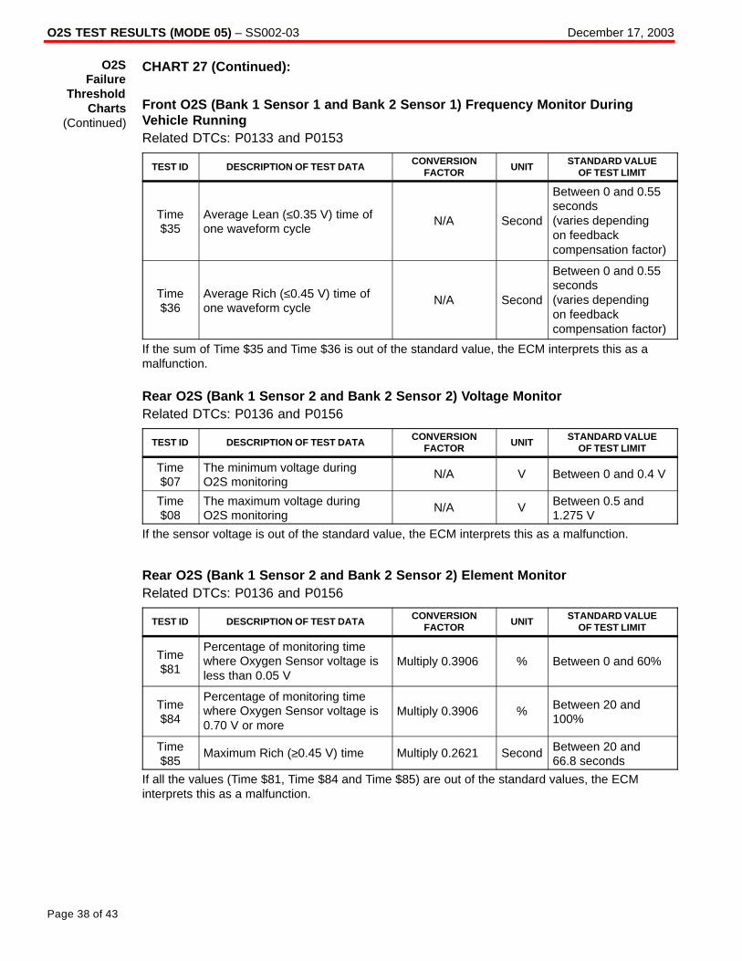
O2S TEST RESULTS (MODE 05) – SS002-03 December 17, 2003
Page 38 of 43
CHART 27 (Continued):
Front O2S (Bank 1 Sensor 1 and Bank 2 Sensor 1) Frequency Monitor DuringVehicle RunningRelated DTCs: P0133 and P0153
TEST ID DESCRIPTION OF TEST DATACONVERSION
FACTORUNIT
STANDARD VALUEOF TEST LIMIT
Time$35
Average Lean (≤0.35 V) time ofone waveform cycle
N/A Second
Between 0 and 0.55seconds (varies depending on feedbackcompensation factor)
Time$36
Average Rich (≤0.45 V) time ofone waveform cycle
N/A Second
Between 0 and 0.55seconds (varies depending on feedbackcompensation factor)
If the sum of Time $35 and Time $36 is out of the standard value, the ECM interprets this as amalfunction.
Rear O2S (Bank 1 Sensor 2 and Bank 2 Sensor 2) Voltage MonitorRelated DTCs: P0136 and P0156
TEST ID DESCRIPTION OF TEST DATACONVERSION
FACTORUNIT
STANDARD VALUEOF TEST LIMIT
Time$07
The minimum voltage duringO2S monitoring
N/A V Between 0 and 0.4 V
Time$08
The maximum voltage duringO2S monitoring
N/A V Between 0.5 and1.275 V
If the sensor voltage is out of the standard value, the ECM interprets this as a malfunction.
Rear O2S (Bank 1 Sensor 2 and Bank 2 Sensor 2) Element MonitorRelated DTCs: P0136 and P0156
TEST ID DESCRIPTION OF TEST DATACONVERSION
FACTORUNIT
STANDARD VALUEOF TEST LIMIT
Time$81
Percentage of monitoring timewhere Oxygen Sensor voltage isless than 0.05 V
Multiply 0.3906 % Between 0 and 60%
Time$84
Percentage of monitoring timewhere Oxygen Sensor voltage is0.70 V or more
Multiply 0.3906 % Between 20 and100%
Time$85
Maximum Rich (≥0.45 V) time Multiply 0.2621 Second Between 20 and 66.8 seconds
If all the values (Time $81, Time $84 and Time $85) are out of the standard values, the ECMinterprets this as a malfunction.
O2SFailure
ThresholdCharts
(Continued)

O2S TEST RESULTS (MODE 05) – SS002-03 December 17, 2003
Page 39 of 43
CHART 28:
Front O2S (Bank 1 Sensor 1 and Bank 2 Sensor 1) Voltage MonitorRelated DTCs: P0130, P0150, P2195, P2196, P2197 and P2198
TEST ID DESCRIPTION OF TEST DATACONVERSION
FACTORUNIT
STANDARD VALUEOF TEST LIMIT
Time$07
The minimum voltage duringO2S monitoring
N/A V Between 0 and0.35 V
Time$08
The maximum voltage duringO2S monitoring
N/A V Between 0.45 and1.275 V
If the sensor voltage is out of the standard value, the ECM interprets this as a malfunction.
Front O2S (Bank 1 Sensor 1 and Bank 2 Sensor 1) Response MonitorRelated DTCs: P0133 and P0153
TEST ID DESCRIPTION OF TEST DATACONVERSION
FACTORUNIT
STANDARD VALUEOF TEST LIMIT
Time$31
Time to change from Lean(≤0.35 V) to Rich (≥0.45 V)
N/A Second Between 0 and 0.6 seconds
Time$32
Time to change from Rich(≥0.45 V) to Lean (≤0.35 V)
N/A Second Between 0 and 0.6 seconds
If the time required to change is out of the standard value, the ECM interprets this as a malfunction.
Front O2S (Bank 1 Sensor 1 and Bank 2 Sensor 1) Frequency Monitor DuringEngine IdlingRelated DTCs: P0133 and P0153
TEST ID DESCRIPTION OF TEST DATACONVERSION
FACTORUNIT
STANDARD VALUEOF TEST LIMIT
Time$33
Average Lean (≤0.35 V) time ofone waveform cycle
N/A Second Between 0 and 2 seconds
Time$34
Average Rich (≥0.45 V) time ofone waveform cycle
N/A Second Between 0 and 2 seconds
If the sum of Time $33 and Time $34 is out of the standard value, the ECM interprets this as amalfunction.
O2SFailure
ThresholdCharts
(Continued)

O2S TEST RESULTS (MODE 05) – SS002-03 December 17, 2003
Page 40 of 43
CHART 28 (Continued):
Front O2S (Bank 1 Sensor 1 and Bank 2 Sensor 1) Frequency Monitor DuringVehicle RunningRelated DTCs: P0133 and P0153
TEST ID DESCRIPTION OF TEST DATACONVERSION
FACTORUNIT
STANDARD VALUEOF TEST LIMIT
Time$35
Average Lean (≤0.35 V) time ofone waveform cycle
N/A Second
Between 0 and 0.5seconds (varies depending on feedbackcompensation factor)
Time$36
Average Rich (≤0.45 V) time ofone waveform cycle
N/A Second
Between 0 and 0.5seconds (varies depending on feedbackcompensation factor)
If the sum of Time $35 and Time $36 is out of the standard value, the ECM interprets this as amalfunction.
Rear O2S (Bank 1 Sensor 2 and Bank 2 Sensor 2) Voltage MonitorRelated DTCs: P0136 and P0156
TEST ID DESCRIPTION OF TEST DATACONVERSION
FACTORUNIT
STANDARD VALUEOF TEST LIMIT
Time$07
The minimum voltage duringO2S monitoring
N/A V Between 0 and 0.4 V
Time$08
The maximum voltage duringO2S monitoring
N/A V Between 0.5 and1.275 V
If the sensor voltage is out of the standard value, the ECM interprets this as a malfunction.
Rear O2S (Bank 1 Sensor 2 and Bank 2 Sensor 2) Element MonitorRelated DTCs: P0136 and P0156
TEST ID DESCRIPTION OF TEST DATACONVERSION
FACTORUNIT
STANDARD VALUEOF TEST LIMIT
Time$81
Percentage of monitoring timewhere Oxygen Sensor voltage isless than 0.05 V
Multiply 0.3906 % Between 0 and 60%
Time$84
Percentage of monitoring timewhere Oxygen Sensor voltage is0.70 V or more
Multiply 0.3906 % Between 20 and100%
Time$85
Maximum Rich (≥0.45 V) time Multiply 0.2621 Second Between 20 and 66.8 seconds
If all the values (Time $81, Time $84 and Time $85) are out of the standard values, the ECMinterprets this as a malfunction.
O2SFailure
ThresholdCharts
(Continued)
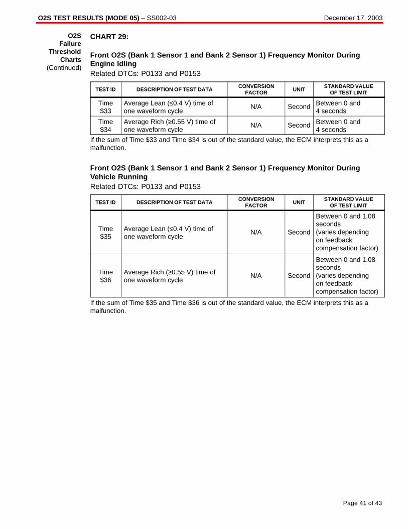
O2S TEST RESULTS (MODE 05) – SS002-03 December 17, 2003
Page 41 of 43
CHART 29:
Front O2S (Bank 1 Sensor 1 and Bank 2 Sensor 1) Frequency Monitor DuringEngine IdlingRelated DTCs: P0133 and P0153
TEST ID DESCRIPTION OF TEST DATACONVERSION
FACTORUNIT
STANDARD VALUEOF TEST LIMIT
Time$33
Average Lean (≤0.4 V) time ofone waveform cycle
N/A Second Between 0 and 4 seconds
Time$34
Average Rich (≥0.55 V) time ofone waveform cycle
N/A Second Between 0 and 4 seconds
If the sum of Time $33 and Time $34 is out of the standard value, the ECM interprets this as amalfunction.
Front O2S (Bank 1 Sensor 1 and Bank 2 Sensor 1) Frequency Monitor DuringVehicle RunningRelated DTCs: P0133 and P0153
TEST ID DESCRIPTION OF TEST DATACONVERSION
FACTORUNIT
STANDARD VALUEOF TEST LIMIT
Time$35
Average Lean (≤0.4 V) time ofone waveform cycle
N/A Second
Between 0 and 1.08seconds (varies depending on feedbackcompensation factor)
Time$36
Average Rich (≥0.55 V) time ofone waveform cycle
N/A Second
Between 0 and 1.08seconds (varies depending on feedbackcompensation factor)
If the sum of Time $35 and Time $36 is out of the standard value, the ECM interprets this as amalfunction.
O2SFailure
ThresholdCharts
(Continued)

O2S TEST RESULTS (MODE 05) – SS002-03 December 17, 2003
Page 42 of 43
CHART 29 (Continued):
Rear O2S (Bank 1 Sensor 2 and Bank 2 Sensor 2) Voltage MonitorRelated DTCs: P0136 and P0156
TEST ID DESCRIPTION OF TEST DATACONVERSION
FACTORUNIT
STANDARD VALUEOF TEST LIMIT
Time$07
The minimum voltage duringO2S monitoring
N/A V Between 0 and 0.4 V
Time$08
The maximum voltage duringO2S monitoring
N/A V Between 0.5 and1.275 V
If the sensor voltage is out of the standard value, the ECM interprets this as a malfunction.
Rear O2S (Bank 1 Sensor 2 and Bank 2 Sensor 2) Element MonitorRelated DTCs: P0136 and P0156
TEST ID DESCRIPTION OF TEST DATACONVERSION
FACTORUNIT
STANDARD VALUEOF TEST LIMIT
Time$81
Percentage of monitoring timewhere Oxygen Sensor voltage isless than 0.05 V
Multiply 0.3906 % Between 0 and 60%
Time$84
Percentage of monitoring timewhere Oxygen Sensor voltage is0.70 V or more
Multiply 0.3906 % Between 20 and100%
Time$85
Maximum Rich (≥0.45 V) time Multiply 0.2621 Second Between 20 and 66.8 seconds
If all the values (Time $81, Time $84 and Time $85) are out of the standard values, the ECMinterprets this as a malfunction.
O2SFailure
ThresholdCharts
(Continued)

O2S TEST RESULTS (MODE 05) – SS002-03 December 17, 2003
Page 43 of 43
CHART 30:
Rear O2S (Bank 1 Sensor 2 and Bank 2 Sensor 2) Voltage MonitorRelated DTCs: P0136 and P0156
TEST ID DESCRIPTION OF TEST DATACONVERSION
FACTORUNIT
STANDARD VALUEOF TEST LIMIT
Time$07
The minimum voltage duringO2S monitoring
N/A V Between 0 and0.45 V
Time$08
The maximum voltage duringO2S monitoring
N/A V Between 0.5 and1.275 V
If the sensor voltage is out of the standard value, the ECM interprets this as a malfunction.
Rear O2S (Bank 1 Sensor 2 and Bank 2 Sensor 2) Element MonitorRelated DTCs: P0136 and P0156
TEST ID DESCRIPTION OF TEST DATACONVERSION
FACTORUNIT
STANDARD VALUEOF TEST LIMIT
Time$81
Percentage of monitoring timewhere Oxygen Sensor voltage isless than 0.05 V
Multiply 0.3906 % Between 0 and 80%
Time$84
Percentage of monitoring timewhere Oxygen Sensor voltage is0.70 V or more
Multiply 0.3906 % Between 20 and100%
Time$85
Maximum Rich (≥0.45 V) time Multiply 0.2621 Second Between 20 and 66.8 seconds
If all the values (Time $81, Time $84 and Time $85) are out of the standard values, the ECMinterprets this as a malfunction.
O2SFailure
ThresholdCharts
(Continued)