Embed Size (px)
Citation preview

QUADCOPTERThe quadcopter (Fig.1) it’s a flying object, which flies with a help by four propellers,Therefore, is so called. Two opposite propellers rotate in one direction, for take-off. First pairopposite propellers (Fig. 2) rotates in one direction for keeping balance in the axis. Secondpair opposite propellers rotates in opposite direction, for keeping balance in the axis (Fig. 3).The main reason for opposite rotations of opposite pairs it's the elimination a rotation thequadcopter in the Z axis.
Fig. 1 – The principle function of quadcopter
Fig. 2 – The principle function of the first arm
Fig. 3 – The principle function of the second armIn the question of the control, is good to separate the problem into three independent

parts. The first part is control in the X axis (Fig. 2), where is important a balance on the lever,the second part is similar the first, in the Y axis (Fig. 3). The last part of control is the rotationin the Z axis (Fig. 1), which must be prevent.
Motors control whit PWMThe way to control AC motors is based on principle control a servo-motor. The basic signalhas a width 1 ms of a logic one with the period 20 ms. After turn on the quadcopter musthave the PWM pulse a width 1 ms, which mean a motor is stopped (Fig. 4 up). With a pulsewidth greater than 1 ms an ESC won’t let wind off a motor for the safety reasons. For start-up motors is need the pulse width 1 ms. Continuously increasing the pulse width from 1 msup, motors begin to spin. The upper limit of the pulse width it’s 2 ms (Fig. 5 down), when amotor has a maximal performance.
A continuity of changing the rotation is critical for stabilization. In case of the step change thepulse width is need to ensure, that the change will not cause too great a change of the motorrotation, because it may cause high change of a output value the controller and this can leadto destabilization of quadcopter.
PID CONTROLLERA proportional–integral–derivative (PID) controller is a generic control loop feedbackmechanism. The PID controller calculates whit error value as the difference between ameasured process variable (PV) and a desired set point. With this error value is countedeachactions of controller (Fig. 6). The controller attempts to minimize the error by adjusting theprocess control inputs. The main equation of the parallel PID controller:
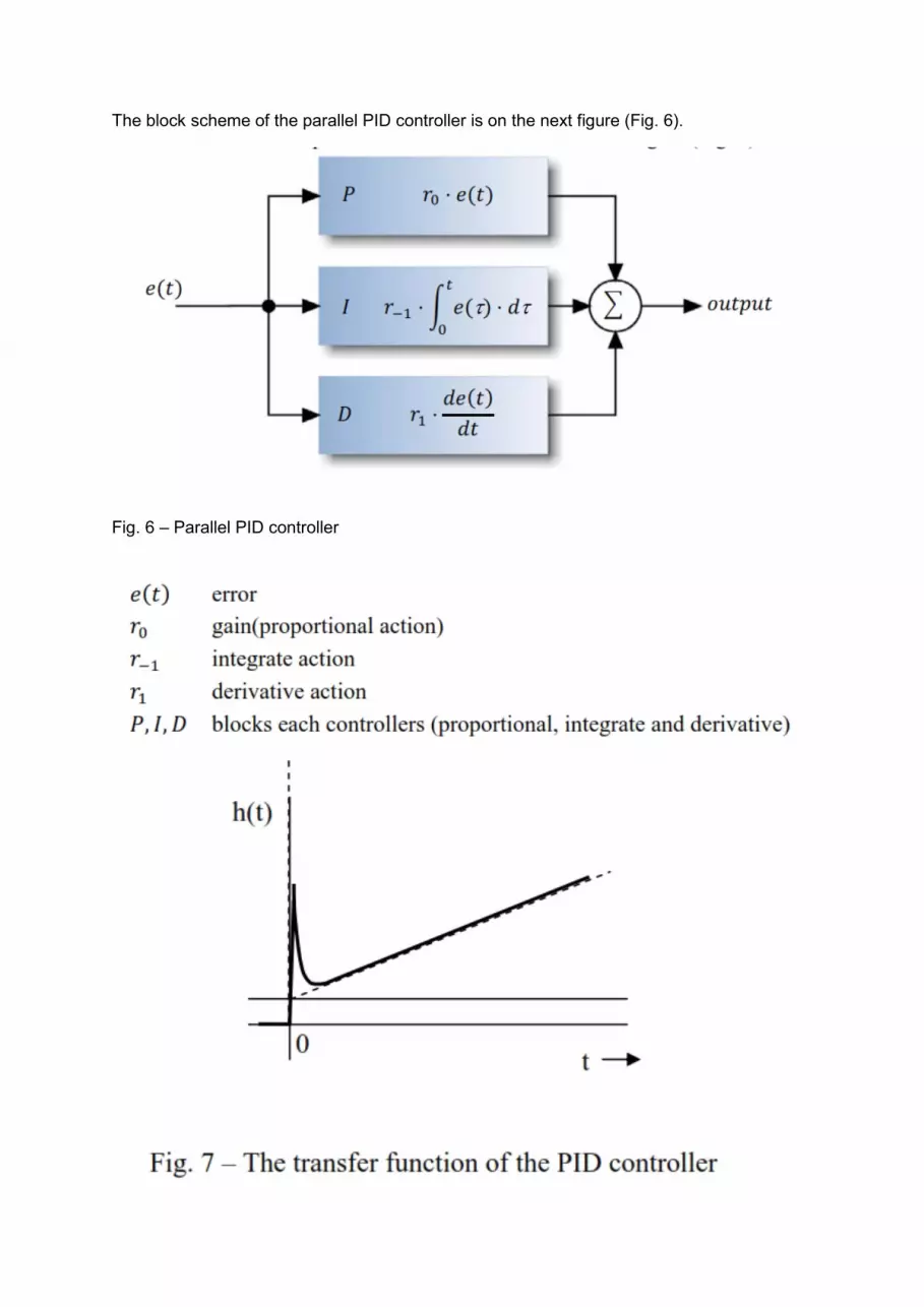
The block scheme of the parallel PID controller is on the next figure (Fig. 6).
Fig. 6 – Parallel PID controller

The transfer function of the PID controller (Fig. 7) clearly shows the influence each action ofthe controller. The gain ro means the increase level. The derivative action makes a rapiddecline the level of process action and the integrate r-1 increase the action level in time. Afterthe step change of the error dominate an influence of the derivate action and after that beginexercise the integrate action in time.The proportional action P reflect the actual deviation, the integrate action accumulatedeviation in past and the derivative action is estimate the next deviation. On controlledsystems, which aren’t with the good describe, it’s using of the PID controller suitable. Thistype of controller doesn’t always represent the best controlled solution, but with optimalparameters settings, is able resist instability. Worse parameters settings cause longer timeof regulation the error, therefore is appropriate take a time for settings of parameters.
ORIENTATION IN SPACEFor describe the motion of the quadcopter it’s necessary to define a suitable coordinatesystem. For most problems dealing with aircraft motion, two coordinate systems are used.First coordinate system is fixed to the Earth and may be considered for the purpose ofaircraft motion analysis to be an inertial coordinate system. Second coordinate system isfixed to the airplane and is referred to as a body coordinate system. The next figure (Fig. 9)shows the two right-handed coordinate systems.
The orientation of the airplane is often described by three consecutive rotations, whose orderis important. The angular rotations are called the Euler angles. The orientation of the bodyframe with respect to the fixed Earth frame can be determined in the following manner:
1. Rotate the body about its zb axis through the yaw angle Ψ2. Rotate the body about its yb axis through the pitch angle T3. Rotate the body about its xb axis through the roll angle


><=Ax di
&,, 1-v- Cttl 0 : ~,,,./c. i-,c-. aF' ~ k'ff CA~ w:« T 1Yll"h:: I .r~
vb= [21 i~[~
,/ ~ u:
-r, ,,~k. l,:;<li "'"~ ~ .
'P J '( ' .,,./ ...
y
•
•
•

c9s "¥" c¢c 1 -t S()sB .s'f
- s¢c r + C/J.5>9 5~
<:-• 'b I:, AJJ!r !, .c::_)A == ,AA, -t; fat~ T 7e,.
!llf r = ,notWn-/; d"-<-, Jo ~0 6- - ..M.~~ ~ ,, ,. ,, ro-k.f,"! mo~
.lfA "' -c_ ' • ' 1
' ' !J'd ~~copr,:.- rnd-,()IL.,
f A11~ ~ "j, ( r x f ~ ) r ts ki,tl,,u.- -lw,-, cf>,4-.-- oC m<,s .Jo ,,.,.,;.,,-.
I A~ 0 k ( J,~ + _12~ - Jl~ - J2.~{~ I Sit r. rs c<>{r c,bo,.f µ.._
==.>, l w,,1, = I-,~,.,.,., - r1 {,,;.,,;. x:L ~) ! , I
b
Z M = cli1b.:rw.,, + 0.;, x.X./Jb/,
_d__J.I · : .;t_)A'° - tJb1' xI t.Jb1• Cft b IJWr, :t~ 111
i i
ht~t- C-f.S ~4 I ; l .
•
•

\/: ~- ~+ 3cosAt!J.:>1nAdj ~t/ S/YU•I/
,
::: ~ - ~ ~o-fq),i ~· -!7 AB 5wr,.1/ ~,{
- -- i-. -::.-os•'V\Ae == -2 AEJ
01 ~ ( ()J + .dr )( V. dV) - ~. +A{)( tJ, -t.l,tJ) - ff si>'i{ ~+ A. 9) =(<;'Vo+ <oAV-t Yobr' +LtrAV)-(rot..lo + ffoAw ~~~-t-~Aw)
- ~(st~0cosA9 -+cos~.s,nA5)
[~ _rdtn~tl - ab LS + -6) s: a;~s ea&.£ - sns sht:, $1'V1 {.s.: +--t-) =- S•vi sco.s -t: + C6$.S 5'1f;-
Sh,., (X0 +Ax) ~ Slr1L1x' -t7.AX UlS, lY.o t- A.)() -;, ens & _, r
l:o1 =lt)t···f:d<.A. tAo ~ 0 v-v. +Av v() = o - - 0 l,J = t.J,, +AV L,/o:: 0 r= Po -I-AP '
t =: &0 +-.66 ' • r;"' f'o t A,,.- .
tJ -== ~ + L\e '
¢ ::;¢6+.M ( r ~10 +.At 'fa·~ ()
LA = rv - ,tW - 8 .S•'Vl & . V :: pW - vfA +. 5_ Lps,B, S 1'v-i(p b ( '. . 2 w = iv. - pv + 3c.os¢cose + 'fh tJi12 + t.}:1..z + (,.)(3 + c .. h,2)
Di'nuvize]
• ---~-------~-----------,---------~~~--


