Embed Size (px)
Citation preview

Steel and Composite Structures, Vol. 4, No. 2 (2004) 77-94 77
Behaviour of flush end-plate beam-to-column joints under bending and axial force
Luís Simões da Silva†
Civil Engineering Department, University of Coimbra, Polo II, Pinhal de Marrocos, 3030 Coimbra, Portugal
Luciano R. O. de Lima‡ and Pedro C. G. da S. Vellasco‡†
Structural Engineering Department, UERJ - State University of Rio de Janeiro, Brazil
Sebastião A. L. de Andrade‡†
Civil Engineering Department, PUC-RIO - Pontifical Catholic University of Rio de Janeiro, Brazil
(Received August 12, 2002, Accepted January 26, 2004)
Abstract. Steel beam-to-column joints are often subjected to a combination of bending and axial forces.The level of axial forces in the joint may be significant, typical of pitched-roof portal frames, sway frames orframes with incomplete floors. Current specifications for steel joints do not take into account the presence ofaxial forces (tension and/or compression) in the joints. A single empirical limitation of 10% of the beam’s plasticaxial capacity is the only enforced provision in Annex J of Eurocode 3. The objective of the present paper is todescribe some experimental and numerical work carried out at the University of Coimbra to try to extend thephilosophy of the component method to deal with the combined action bending moment and axial force.
Key words: component method; experimental analysis; flush end-plate joints; semi-rigid behaviour;bending and axial force.
1. Introduction
Beam-to-column joints are often subjected to a combination of bending and axial forces. Although inmany regular building frames the level of axial force coming from the beam is usually low, it can reachsignificant values in many instances, such as:
(i) Regular frames under significant horizontal loading (seismic or extreme wind), especially forsway frames;
(ii) Irregular frames under gravity or horizontal loading, especially with incomplete floors;(iii) Pitched-roof portal frames.
†Professor‡Ph. D.‡†Associate Professor

78 L. Simões da Silva, L. R. O de Lima, P. C. G. de S. Vellasco, and S. A. L. de Andrade
The component method, (Faella et al. 2000), as stated in Annex J of Eurocode 3 (1998), or, with animproved and enlarged scope, in Part 1.8 of Eurocode 3 (2003), consists of a simplified mechanicalmodel composed of extensional springs and rigid links, whereby the connection is simulated by anappropriate choice of rigid and flexible components. These components represent a specific part of aconnection that, dependent on the type of loading, make an identified contribution to one or more of itsstructural properties. A typical component model for a flush end-plate beam-to-column joint isillustrated in Fig. 1, the relevant components being (1) column web panel in shear, (2) column web incompression, (3) column web in tension, (4) column flange in bending, (5) end-plate in bending, (7)beam flange and web in compression, (8) beam web in tension and (10) bolts in tension. In general,each of these components is characterised by a non-linear force-displacement curve, although simpleridealisations are possible, whenever only the resistance or the initial stiffness of the connection isrequired. Application of the component method to steel joints requires the following steps:
(i) Selection of the relevant (active) components from a global list of components (20 differentcomponents currently codified, for example, in Part 1.8 of Eurocode 3);
(ii) Evaluation of the force-deformation response of each component; (iii) Assembly of the active components for the evaluation of the moment-rotation response of the
joint, using a representative mechanical model.Currently, no specific procedures are available for the analysis and design of beam-to-column joints
under bending and axial force. A single empirical limitation to an applied axial force of 10% of thebeam plastic resistance under axial force is the only enforced provision of Annex J, below which theaxial force may be disregarded in the analysis/design of the joint. However, the general principles of thecomponent method cover this situation, since any component is fully characterised independently fromthe type of loading applied to the joint; in fact, as already stated above, the behaviour of any componentis established as a force vs. displacement curve that only depends on the level of axial force.
Recently, some preliminary attempts were addressed at the prediction of the behaviour of beam-to-column joints under bending and axial force. In Liège, Jaspart et al. (1999), and Cerfontaine (2000),have applied the principles of the component method to establish design predictions of the M-Ninteraction curves and initial stiffness. Based on the same general principles, Silva and Coelho (2000)have proposed analytical expressions for the full non-linear response of a beam-to-column joint undercombined bending and axial force. Unfortunately, both results were not calibrated/validated byexperimental evidence. To provide a sound basis for further theoretical developments, an experimentalprogram was carried out at the University of Coimbra on flush and extended end-plate beam-to-columnconfigurations, that is described in the next section.
Next, component models able to deal with bending and axial force are presented and applied to simulate
Fig. 1 Component model for flush end-plate beam-to-column joint in bending

Behaviour of flush end-plate beam-to-column joints under bending and axial force 79
the behaviour of the tested joints. These comparisons show clearly that, using an adequate strategy to dealwith the load history arising from the simultaneous application of a bending moment and an axial force,the component method is directly applicable to the analysis of these joints. In addition, the individualcomponent characterisation also remains unchanged from earlier work on joints in bending.
2. Experimental program
2.1. Introduction
A description of an experimental testing programme in beam-to-column joints, currently beingperformed at the Civil Engineering Department of the University of Coimbra is presented in thissection. The test programme includes 16 prototypes, 9 flush end-plate joints and 7 extended end-platejoints, described in Fig. 2(a) and (b). Here, only the flush end-plate tests will be discussed in detail. Forthis joint configuration, application of the Eurocode 3 procedures for bending moment alone leads to theresults of Table 1 (using actual material properties and dimensions and no partial safety coefficients).
Fig. 2 Layout of joints

80 L. Simões da Silva, L. R. O de Lima, P. C. G. de S. Vellasco, and S. A. L. de Andrade
In all tests, the columns were simply-supported at both ends and consist of a HEB240, the beamsconsist of an IPE240 and the end-plate is 15 mm thick, all manufactured from steel grade S275. Thebolts are M20, class 10.9.
Nine experimental tests were carried out for the flush end-plate configuration, comprising severalcombinations of bending and axial forces and consisting of the application of a fixed level of axialtension or compression and the subsequent application of a negative bending moment, incremented upto failure of the joint.
In the first test, FE1, only bending moment was applied through a hydraulic actuator, located a meteraway from the face of the column flange. For the following tests - FE3, FE4, FE5, FE6, FE7, FE8 andFE9 - constant axial forces of, respectively, -4%, -8%, -20%, -27%, -20%, +10% and +20% of the beamplastic resistance were applied to the beam.
2.2. Test setup, instrumentation and testing procedure
The test setup is illustrated in Fig. 3 and Fig. 4(a), the bending moment being applied using ahydraulic actuator on the cantilever.
Table 1 Moment resistance and initial stiffness of the joints
Joint Mj.Rd (kN.m) Sj,ini (kN.m/rad)
Flush end-plate 70.0 11865.8
Fig. 3 Experimental test setup

Behaviour of flush end-plate beam-to-column joints under bending and axial force 81
The chosen system for the application of the compressive axial force consists of a hydraulic jack, Fig.4(b), that applies a tensile force to four prestressing cables of diameter φ = 15.2 mm, anchored against areaction wall. The transfer of this force to the connection was performed through a central load cell withcapacity of 950 kN (TML), Fig. 4(c). These cables pass through a deviator saddle (HEM100) to guaranteethat the axial force is always parallel to the beam axis. Load cells TML with capacity of 20 0kN wereinstalled in each cable to measure the installed force in each cable. The horizontal reaction forces atboth ends of the column were transmitted to the reaction wall by (i) a steel beam, at the top, and (ii) areinforced concrete footing prestressed to the strong floor using DYWIDAG bars and connected to thereaction wall using a HEB 200, at the bottom.
The tensile axial force application system is shown in Fig. 5. Four hydraulic jacks placed in one of theextremities of a circular hollow section profile transmit the tensile axial force. These circular profilesare simply supported at the other end to allow free rotation and to guarantee that the axial force isapplied always parallel to the beam axis.
All tests were instrumented as shown in Fig. 6 and Fig. 7, with single strain gauges (FLK 6-11-TML),rosettes at 45º (FRA 5-11-TML), bolt axial strain gauges (BTM 6-C-TML), and displacements transducers(LVDT’s). All data were recorded with a data acquisition system TDS602-TML.
For all tests, a constant axial force was applied first, maintained constant throughout the test, withsubsequent application of a bending moment incremented to failure. Two unloading were performed,
Fig. 4 (a) Loading frame for application of compressive loading, (b) hydraulic jack and (c) central load cell

82 L. Simões da Silva, L. R. O de Lima, P. C. G. de S. Vellasco, and S. A. L. de Andrade
Fig. 5 (a) Application of tensile loading, (b) hydraulic jack layout
Fig. 6 Single strain gauges, rosettes to 45º and bolts axial strain gauges layout
Fig. 7 Displacements transducers layout
Behaviour of flush end-plate beam-to-column joints under bending and axial force 83
the first for a bending moment of 25 kN.m (down to 5 KN.m, to eliminate possible slack in the joint)and the second for a rotation of 20 mrad. Force control was used in the first part of each test,subsequently changed to displacement control.
Tensile tests on coupons extracted from the beams and columns were carried out, aiming atcharacterizing the actual properties of the material. Then, it was possible to calculate the beam plasticresistance and to determine the true level of applied axial force to the beam for the other tests. Thesetensile tests were performed according to the following specifications, EN10002 (1990), EN10020(1989) and EN10025 (1994), yielding the results of Table 2.
2.3. Application of the axial force
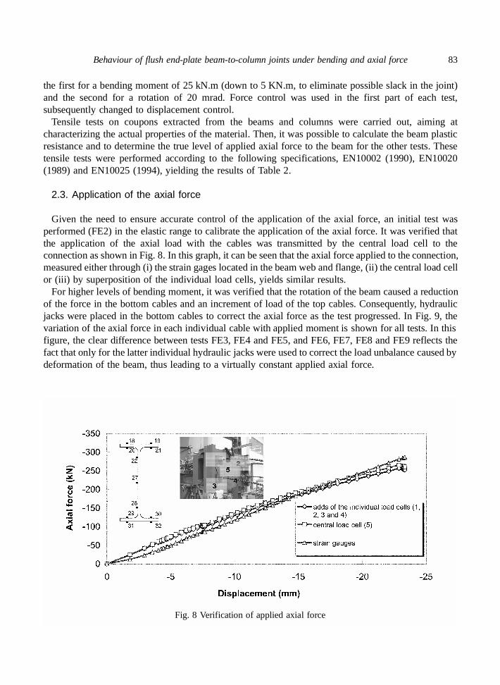
Given the need to ensure accurate control of the application of the axial force, an initial test wasperformed (FE2) in the elastic range to calibrate the application of the axial force. It was verified thatthe application of the axial load with the cables was transmitted by the central load cell to theconnection as shown in Fig. 8. In this graph, it can be seen that the axial force applied to the connection,measured either through (i) the strain gages located in the beam web and flange, (ii) the central load cellor (iii) by superposition of the individual load cells, yields similar results.
For higher levels of bending moment, it was verified that the rotation of the beam caused a reductionof the force in the bottom cables and an increment of load of the top cables. Consequently, hydraulicjacks were placed in the bottom cables to correct the axial force as the test progressed. In Fig. 9, thevariation of the axial force in each individual cable with applied moment is shown for all tests. In thisfigure, the clear difference between tests FE3, FE4 and FE5, and FE6, FE7, FE8 and FE9 reflects thefact that only for the latter individual hydraulic jacks were used to correct the load unbalance caused bydeformation of the beam, thus leading to a virtually constant applied axial force.
Fig. 8 Verification of applied axial force

84 L. Simões da Silva, L. R. O de Lima, P. C. G. de S. Vellasco, and S. A. L. de Andrade
Table 2 Steel mechanical properties
BEAM IPE240Specimen fy (MPa) fu (MPa) Young’s modulus (MPa)
Web_1 366.45 460.36 201483Web_2 358.93 454.70 202836Web_3 371.86 449.32 211839Web_4 380.25 455.99 201544Web_5 375.79 459.49 211308Web_6 379.12 461.98 210128Web_7 342.72 453.40 190443Web_8 332.32 438.76 200127
Web average 363.4 454.3 203713Standard deviaton 17.64 7.49 7214
Flange_1 365.83 444.52 215739Flange_2 331.62 448.30 213809Flange_3 340.75 448.77 212497Flange_4 346.42 450.50 216924Flange_5 355.40 458.90 221813Flange_6 349.22 455.88 213589Flange_7 312.13 443.81 214147Flange_8 319.73 435.20 213257
Flange average 340.14 448.23 215222Standard deviaton 18.08 7.38 3017
COLUMN HEB240Specimen fy (MPa) fu (MPa) Young’s modulus (MPa)
Web_1 392.63 491.82 205667Web_2 399.38 495.29 204567Web_7 340.16 454.39 218456Web_8 355.92 467.69 199055
Web average 372.02 477.29 206936Standard deviaton 28.56 19.59 8206
Flange_1 344.92 410.06 232937Flange_2 350.09 472.93 210434Flange_7 337.94 450.53 222665Flange_8 338.84 461.63 217132
Flange average 342.95 448.79 220792Standard deviaton 5.68 27.39 9516
END-PLATESpecimen fy (MPa) fu (MPa) Young’s modulus (MPa)
Ep1 365,39 504,45 198936Ep2 374,75 514,44 (not available)Ep3 380,91 497,81 199648Ep4 356,71 497,08 202161
Web average 369,44 503,45 200248Standard deviation 10,62 8,05 1694,36

Behaviour of flush end-plate beam-to-column joints under bending and axial force 85
Fig. 9 Bending moment vs. axial force curves

86 L. Simões da Silva, L. R. O de Lima, P. C. G. de S. Vellasco, and S. A. L. de Andrade
3. Analysis of the experimental results
3.1. Moment vs. rotation curves
The experimental moment vs. rotation curves for the eight tests are presented in Fig. 10, where it maybe observed that even for a level of equivalent axial force of 27% of the beam plastic resistance, thebending moment still exceeds the pure bending result (FE1). Also, the maximum bending moment wasobtained for an axial load level of 20% of the beam plastic resistance. In contrast, the application of atensile force in the beam results in a sharp reduction of the bending resistance of the joint. Table 3 presentsthe values obtained for the moment resistance and the initial stiffness of the tested joints. The theoreticalvalues calculated according to Eurocode 3 (FE1) were, respectively, 70 kN.m and 11865 kN.m/rad.
3.2. Analysis of individual components
Table 4 presents the theoretical values of the strength and initial stiffness for all components of theconnection in study, calculated in accordance with Eurocode 3.
Fig. 11 shows that, for all the tests, the column flange in bending presented deformations according tomode 1, that is, complete yielding of the flange. The measured displacements for this component arepresented in Fig. 12 where it is noticed that the behaviour of the component is similar for all the tests,independently of the applied axial force.
Table 3 Experimental values of bending moment resistance and initial stiffness
Test N (kN) MRd (kN.m) Sj,ini (kN.m/rad)
FE1 (only M) - 68.4 7244FE3 (-4% Npl) 52.7 76.7 9768FE4 (-8% Npl) 105.6 73.5 10853FE5 (-20% Npl) 265.0 78.5 10610FE6 (-27% Npl) 345.0 72.4 9927FE7 (-20% Npl) 265.0 80.0 8028FE8 (+10% Npl) 130.6 62.8 8959FE9 (+20% Npl) 264.9 52.3 9084
Fig. 10 Moment vs. rotation curves of the experimental tests

Behaviour of flush end-plate beam-to-column joints under bending and axial force 87
Table 4 Theoretical values of the resistance and initial stiffness of the components
Component FRd (kN) k / E (mm)
Tension
Column web in tension (3) 498.9 7,03Column flange in bending (4) 406.1 38,22End-plate in bending (5) 321,7 13,35Beam web in tension (8) 476.8 ∞Bolts in tension (10) 441,0 7,76
CompressionColumn web in compression (2) 598,2 10,40Beam flange in compression (7) 529.8 ∞
Shear Column web in shear (1) 601.1 7,52
Fig. 11 Moment vs. strain curves for component column flange in bending
Fig. 12 Moment vs. displacements curves for component column flange in bending

88 L. Simões da Silva, L. R. O de Lima, P. C. G. de S. Vellasco, and S. A. L. de Andrade
Fig. 13 Moment vs. strain curves for component end-plate in bending
Application of the design rules of Eurocode 3 yields a resistance of the end-plate in bending of321.7 kN (Table 4). The influence of the level of axial force may be assessed from Fig. 13, bycomparing, for example, tests FE1 and FE5. For test FE1, the yield strain is reached for a bendingmoment of, approximately, 45 kN.m. For this level of bending moment, the tensile load in the firstbolt row, evaluated using the strain gages located in the beam flange, it is equal to 333.4 kN.However, for test FE5, due to the contribution of the applied axial force, the end-plate reached theyield strain at a higher level of applied moment. Fig. 14 illustrates the moment vs. displacementscurves for this component.
Analysing the curves presented in Fig. 15 where the dashed line represents the yield strain obtained inthe tensile tests, it is clearly noticed that the beam flange also reaches yielding. According to Eurocode3, the resistance of the beam flange in compression is 529.3 kN. For that level of bending moment, theaverage of the measured strains in the bottom beam flange was 2300 µε, that is, equal to a force of570.0 kN, higher than the theoretical value of 529.3 kN presented above; this is explained because ofsteel hardening. However, it is worthwhile to point out that for the first test, where the compressionaxial force was not applied to the beam, beam flange yielding occurred for a larger value of bendingmoment than in the other tests.
Fig. 14 Moment vs. displacements curves for component end-plate in bending

Behaviour of flush end-plate beam-to-column joints under bending and axial force 89
Fig. 15 Moment vs. strain curves for component beam flange in compression
Fig. 16 Moment vs. strain curves for component column web in compression
Fig. 17 Moment vs. strain curves for component column web in shear

90 L. Simões da Silva, L. R. O de Lima, P. C. G. de S. Vellasco, and S. A. L. de Andrade
Fig. 18 Moment vs. strain curves for component bolts in tension
Fig. 19 Modified component model for flush end-plate beam-to-column joint
As can be seen in Fig. 16, except for test FE6, the component column web in compression did notreach yield for any of the tests.
The component column web in shear reached yield for tests FE1, FE3, FE4 and FE5, Fig. 17. Fortests FE6 to FE9, this component did not reach yield. This graph was obtained using a rosettepositioned in the centre of the column web panel.
Finally, the moment vs. strain curves for the component bolts in tension are presented in Fig. 18,where it is noticed that with the application of the compression axial force, this component is alleviated,having initially negative strains, for tests FE4, FE5 and FE6.
4. Component models for bending and axial force
Joints subjected to bending and axial force do not present distinct tension and compression zones.Following the terminology for column bases (Wald et al. 2000), top and bottom sides are henceforthused. These top and bottom sides must now include all possible tensile and compressive components,given that loading may vary from pure bending to pure axial force with all intermediate combinations.A resulting component model is illustrated in Fig. 19 for the same flush end-plate joint of Fig. 1. It is

Behaviour of flush end-plate beam-to-column joints under bending and axial force 91
Fig. 20 Behaviour of components (springs) subjected to tension and compression
Fig. 21 Spring model for flush end-plate joints
Fig. 22 Moment vs. rotation curves for tested joints obtained from numerical simulations
noted that the various tensile or compressive components will only become active in tension or compression,respectively, given the distinct behaviour in tension and compression, as illustrated in Fig. 20.
A final adjustment is also required to deal with the column web panel in shear that cannot beexclusively placed at the bottom side of the component model. Here, as shown in Fig. 19 (component(1*)), it is split into two equal springs characterised by the usual stiffness multiplied by a factor of 2.

92 L. Simões da Silva, L. R. O de Lima, P. C. G. de S. Vellasco, and S. A. L. de Andrade
Fig. 23 Comparison of the moment versus rotation curves

Behaviour of flush end-plate beam-to-column joints under bending and axial force 93
5. Numerical results and discussion
The flush end-plate joint of Fig. 2(a) was modelled using LUSAS Finite Element Package (2001), asshown in Fig. 21 disregarding the contribution of the second bolt row in tension. Each component wasmodelled with joint elements (JPH3) with different tension and compression behaviour (Fig. 20).
Fig. 22 illustrates the moment versus rotation curves obtained from the numerical simulations forseveral levels of axial force. The increase of resistance for low levels of compressive axial forceobserved in Fig. 23 is confirmed by the experimental results of Fig. 10.
Fig. 23 compares, test by test, the experimental and numerical results. It is clearly noticed that theapplication of the compressive axial force benefits the critical component of the tensile zone (end-platein bending) and decreases the capacity of the critical component of the compression zone (beam flangein compression). The highest moment resistance is obtained for an axial force of 20% of the beamplastic resistance.
The corresponding M-N interaction diagram, plotted in Fig. 24 for the resistance of the joint, exhibitsasymmetry around the pure bending situation (N = 0). This is a direct result of the different resistancebetween the tensile and compressive components.
6. Conclusions
Experimental results of the tests on flush end-plate beam-to-column joints loaded in bending andaxial force that were carried out at the University of Coimbra were presented in this paper.
Based on the general principles of the component method, a numerical evaluation of the response ofsteel joints subjected to bending and axial forces was also presented in this paper. For the chosen flushend-plate joint, an increase of the moment resistance was noted for compressive axial force below 20%of the beam plastic resistance, clearly revealing the asymmetry of the response, while the same jointloaded in tension exhibited a reduction of the moment capacity.
These results highlight the need to review the current 10% limitation imposed by Eurocode 3 for jointssubject to axial forces. Current experimental tests of extended end-plate joints subjected to bending momentand tension/compression axial force should provide additional clarification of these issues.
Fig. 24 M-N interaction diagram for flush end-plate joints

94 L. Simões da Silva, L. R. O de Lima, P. C. G. de S. Vellasco, and S. A. L. de Andrade
Acknowlegements
Financial support from “Ministério da Ciência e Tecnologia” - PRAXIS XXI research projectPRAXIS/P/ECM/13153/1998 is acknowledged.
Financial support from “CAPES - Coordenação de Aperfeiçoamento de Pessoal de Nível Superior -Brazil” is gratefully acknowledged.
References
Cerfontaine, F. (2000), “Etude analytique de l’interaction entre moment de flexion et effort normal dans lesassemblages boulonnés” (in french), Travail de fin d’etudes du DEA en Sciences Appliquées, DépartementMSM, University of Liège, Belgium.
Cruz, P., Silva, L.S., Rodrigues, D. and Simões, R. (1998), “Database for the semi-rigid behaviour of beam-to-column connections in seismic regions”, J. Constructional Steel Research, 46(120), 1-3.
EN 10002 (1990), “Metallic materials-tensile tests. Part1: method of test (at ambient temperature)”, CEN, EuropeanCommittee for Standardisation.
EN 10020 (1989), “Steel definition and classification”, CEN, European Committee for Standardisation.EN 10025 (1994), “Hot rolled products of non-alloy structural steels”, CEN, European Committee for Standardisation.Eurocode 3 (1998), ENV - 1993-1-1:1992/A2, Annex J, Design of Steel Structures - Joints in Building Frames.
CEN, European Committee for Standardisation, Document CEN/TC 250/SC 3, Brussels.Eurocode 3 (2003), prEN 1993-1-8: 2003, Part 1.8: Design of Joints, Eurocode 3: Design of Steel Structures,
Stage 49 draft., 5 May 2003. CEN, European Committee for Standardisation, Brussels.Faella, C., Piluso, V. and Rizzano, G. (2000), Structural Steel Semi-Rigid Connections: Theory, Design and
Software, CRC Press LLC.FEA (2001), LUSAS 13.3 User Manual, FEA Ltd, UK.Jaspart, J.P., Braham, M. and Cerfontaine, F. (1999), “Strength of joints subjected to combined action of bending
moment and axial force”, in Proc. of the Conf. Eurosteel ’99, CVUT Praha, Czech Republic, May 26-29, 465-468.Simões da Silva, L. and Coelho, A. G. (2000), “A analytical evaluation of the response of steel joints under
bending and axial force”, Comput. Struct. 79, 873-881.Simões da Silva, L., Lima, L., Vellasco, P. and Andrade, S. (2001), “Experimental and numerical assessment
of beam-to-column joints under bending and axial force”, Proc. of The First Int. Conf. on Steel &Composite Structures, 1, 715-722, June 2001, Pusan, Korea.
Notation
Mj.Rd : Connection flexural resistanceSj,ini : Connection initial stiffnessN : Axial forceE : Young’s modulusfy : Yielding stressfu : Ultimate stressk : Elastic stiffness of each componentfy
+ : Resistance of the component in tensionfy
− : Resistance of the component in compressionke
+ : Elastic stiffness of the component in tensionkpl
+ : Plastic stiffness of the component in tensionke
− : Elastic stiffness of the component in compressionkpl
− : Plastic stiffness of the component in compression
CC


