Embed Size (px)
Citation preview

Iranian Polymer Journal16 (5), 2007, 291-307
bonded joints;adhesive; optimization; stress analysis; failure analysis.
(*) To whom correspondence to be addressed.
E-mail: [email protected]
A B S T R A C T
Key Words:
Adhesively Bonded Carbon/Titanium JointsUnder In-plane and Bending Loads
Mahmood M. Shokrieh1*, Larry B. Lessard2, and Adnan Golubovic2
(1) Department of Mechanical Engineering, Iran University of Science andTechnology, Tehran, Iran
(2) Department of Mechanical Engineering, McGill University, Montréal, Canada
Received 5 February 2006; accepted 27 May 2007
The goal of this research is to optimize the design of single-lap joints made byjoining composite material to metals. The single-lap joint under both out-of-planeload and tensile load was examined. It is observed that designing a joint for one
kind of load is not always satisfactory because for other load cases, different stresseswould govern the design. Local stress peaks were investigated in order to find waysto decrease these peaks. An approach for optimizing the joint was chosen so thestress peaks at each end could be minimized (peel, axial and shear stress). By taper-ing the titanium adherend inside and outside, the stress distribution in the adhesivecan be significantly changed at the tapered end and all three important stresses thatgoverned the design (peel, axial and shear stress) are decreased for a joint under ten-sion and out-of-plane load. For dissimilar adherends, the numerically largest stressesalways occur in the adhesive at the edge of the overlap adjacent to the adherend withthe lower value of flexural stiffness and the relative difference in these peaks is a func-tion of the relative flexural stiffness of two adherends. Using an outer bead of adhe-sive decreases the stress peak at composite edge. Thus, two methods are used toreduce adhesive stresses: tapering and addition of adhesive beads. Having complet-ed a finite element stress analysis, the results are used to predict the strength of agiven joint. A strain energy based on failure criteria was evaluated, which addressedthe problem of stress singularities in the finite element method. Three point bendingtests were performed using different bonding configurations to verify the strength ofthe adhesive joint and to evaluate the failure criterion. Optimization of the parametersof the joint geometry was achieved from the results of this study.
INTRODUCTIONThe use of composite materials hasbeen growing in many branches ofindustry; however, metals are stillby far the most popular materials inmany applications. With the grow-ing use of composite materials,there is simultaneously a need forjoining composite to metal parts.For joining composite material to
other materials, such as titanium,the use of structural adhesive bond-ing is an attractive method formany reasons. For example, com-pared to other techniques, such asbolting, riveting, etc., it hasimproved fatigue resistance, theability to join thin sheets of materi-al efficiently, and greater design
Available online at: http://journal.ippi.ac.ir

flexibility. Furthermore, the bonded joint can be madewith aerodynamic smoothness, improved visualappearance and if the adhesive is sufficiently flexible,it can allow for the variations in thermal expansionwhen joining dissimilar materials.
The engineering design of structural adhesivejoints is complicated in general by the complexity ofthe stress distribution in the adhesive, and the lack ofadequate failure criteria. The differences in the basicmechanical properties of dissimilar materials willcause local stress peaks in the adhesive, which mustbe carefully evaluated. Among others, the issues ofsurface preparation, manufacturing methods and cor-rosion must be considered in the design of the joint.In this work, the emphasis is on optimizing the designof the joint ends of single-lap joints between compos-ite material and metals (titanium) in order to increasejoint strength. The single-lap joint was examinedunder concentrated out-of-plane load and tensile load.The single-lap joint is well known to be sensitive tochanges in geometrical parameters (overlap lengthand thickness of the adhesive), compared with otherjoints.
LITERATURE REVIEW
Adhesively bonded joints between two materials havebeen used in various engineering applications such asthe aircraft and automotive industries [1-3]. The fol-lowing literature review focuses on both closed-formand numerical approaches to the problem of failureprediction and stress analysis in adhesively bondedjoints.
Analytical Analysis of Adhesively Bonded JointsThe classical paper published by Goland et al. [4] in1944 is perhaps the most cited work in the analysis ofadhesively bonded joints. During the analysis theyassumed that: (1) the axial stress in adhesive layer canbe neglected, and (2) normal and transverse shearstresses in the adhesive layer do not vary across thethickness of the adhesive. Since the publication ofGoland et al. research work, more than half a centuryago, these basic assumptions have been employed bynumerous authors to extend the work in the area ofanalysis and design of bonded joints. Pahoja [5] has
considered the variation of the stress across the thick-ness of the adhesive. Pahoja has described the behav-iour of the joint by linear, homogeneous, ordinary dif-ferential equations. Vinson [6] has carried out exten-sive analytical work in the area of adhesively bondedjoints involving composite adherents. Vinson alsodeveloped analytical tools to analyze adhesivelybonded joints by including into the analysis of theeffects of transverse shear deformation, transversenormal strain, temperature and moisture variations.Adams [7,8] has predicted strength for lap joints espe-cially with composite adherends by classical linearelastic solution. He also introduced Volkersen shearlag equation that calculates shear stress in the adhe-sive.
The analytical analysis of adhesively bonded jointswas simplified in most cases. The reason for simplifi-cation was the large number of the equations that hadto be carried through the analysis, and the long timeneeded to complete the analysis. Today, there arefewer and fewer researchers who are analyzing adhe-sivley bonded joints using closed form solutions.Many workers are analyzing adhesively bonded jointsusing the finite element approach method. However,good solutions to specific problems can be obtainedby some excellent elaborate solutions [9-11]. Thesepapers by Mandenci et al. [9-11] have attempted toreach a good solution to the stress state in the regionof stress singularities between two materials [9] andthen have applied these methods to the solution ofcomposite patch repair [10] and tapered bonded joints[11]. Although the closed form solution is useful, itcannot be incorporated into a finite element model,nor can one easily experimentally verify the stressstate results in the critical regions.
Analysis of Adhesively Bonded Joints by FiniteElement MethodThe development of various numerical techniques toanalyze different kinds of bonded joints in compositestructures has resulted in some useful computer pro-grammes that can be utilized by the engineers anddesigners [12]. One of these computer codes was writ-ten by Barthelemy et al. [13]. They used eight-nodeelements in order to manage high stress gradients thatexist at the interface while analyzing the single-lapjoint, thick adherend specimen and crack-lap joint.
Adhesively Bonded Carbon/Titanium Joints Under ... Shokrieh M.M. et al.
Iranian Polymer Journal / Volume 16 Number 5 (2007)292

They indicated that the primary Young’s modulus ofthe adherend, the overlap length, and adhesive mate-rial properties are the parameters most influential inoptimizing the design of a single-lap joint.
Harris et al. [14] used a non-linear finite elementmethod to predict strength of a bonded single-lapjoint. The finite element programme that they used,was able to account for the large displacements androtations that occur in a single-lap joint, and allowedthe effects of elasto-plasticity in both the adhesive andadherends to be modelled. Adams et al. [15] have con-sidered the strength of CFRP/steel-lap joints loaded intension and performed a detailed stress analysis of theshear and transverse stresses in the joint. Adams [8]used finite element methods for elastic and elasto-plastic case to predict strength of lap joints with com-posite adherends. Hildebrand [16] has applied non-linear finite element methods in the analysis of single-lap joints between fibre-reinforced plastics (FRP) andmetals in order to optimize the joint geometry.Kairouz et al. [17] have investigated the influence ofbondline thickness and overlap length on the strengthof bonded joints. Tsai et al. [18] have analyzed a sin-gle-lap joint with laminated polymeric compositeadherends and with a spew fillet, subjected to tensileloading. They used finite element analysis (FEA) forthis problem to address the mechanics and deforma-tion of such a material and bonding configuration.
Using the finite element approach, manyresearchers encountered problems trying to predictthe strength of adhesively bonded joints because ofstress singularities that exist if an interface results in asharp corner.
Extensive research on the stress singularity nearthe vertex of a bi-material wedge has been conducted[19-23]. Authors analyzed the plane problem of acomposite body consisting of many dissimilarisotropic, homogeneous, and elastic wedges, perfectlybonded along their common interfaces. The particularbehaviour of the stress and displacement fields at theclose vicinity of each interface corner is studied. Thedependence of the order of singularity was establishedin relation with the mechanical properties of thewedges coalescing at the particular corner considered.Groth [24] has analyzed stress singularities and frac-ture at the interface corners in bonded joints. He con-sidered a number of possibilities for different crack
shapes, sizes and crack locations that may be used inanalysis.
The problem of stress singularities is thus difficultto overcome. If peak stresses are used, then the prob-lem is likely to be mesh dependent (section “Designof Adhesively Bonded Single-lap Joints”). Thus anyfinite element based on formulation must be used withcaution. Sancaktar et al. [25] circumvented the peakstress problem by using an average stress method. TheFEA results were then used only in a relative fashion,i.e., relative increase in strength from one model toanother compared to relative increase in experimentalstrength. Wang et al. [26] also avoided the peak stress-es in their bonded joint FEA formulation by looking atstresses at the centerline of the adhesive where thestresses were lower. Once again, only a qualitativecomparison could be made with the experiments.However, some important confirmations can be foundin ref. 26. The research did confirm the weakness ofany peak stress criterion and showed that thermalstresses did not significantly affect the strength of thejoint. Recent FEA work on bonded joints repaired byKaye et al. [27] also avoids the issue of stress concen-trations in the adhesive. Convergence criterion dealswith peak stresses in the plates rather than in the adhe-sive. Since no experimental results are presented, theimprovements are reported by percent reduction ofstresses from one model to the other.
Designing Bonded JointsIn this extensive work on bonded joints, Hart-Smith[2,3,28,29] has outlined various aspects of efficientbonded joint design in composite structures. Hart-Smith has also made many useful studies to analyzethe load transfer mechanism in the adhesive bondedjoints and outlined some practical ways to minimizethe transverse shear and peel stresses in the adhesivelayer. Renton et al. [30] have studied the numerousparameters that influence the stress distribution with-in the adhesive of a single-lap joint. They analyzedboth isotropic and anisotropic material systems ofsimilar or dissimilar adherends. Greszezuk et al. [31]tested scarf joint under tension, compression andfatigue load. Their results showed that the compres-sive strength of the scarf joint to be proportional to thescarf tip thickness, with joint strength increasing, thescarf tip thickness decreases. Adams et al. [32] pre-
Adhesively Bonded Carbon/Titanium Joints Under ...Shokrieh M.M. et al.
293Iranian Polymer Journal / Volume 16 Number 5 (2007)

sented a comprehensive treatise on the design andproduction of adhesively bonded joints used as pri-mary load carrying members. Recent works byOterkus et al. [11], Sancaktar et al. [25] and Wang etal. [26] present excellent work that confirms theadvantages of tapering of adherends in bonded joints.
OBJECTIVES
The objective of this research is to optimize the designof the joint ends of single-lap joints between compos-ite material and metals (titanium) in order to increasethe joint strength. Optimization has to be carried outfor a single-lap joint subjected to two different load-ing conditions that are applied alternatively: (1) sin-gle-lap joint under concentrated out-of-plane load(bending) and (2) single-lap joint under in-plane load(tension).
With a wide number of configuration optionsavailable, it is important to know what type of jointwould represent an optimum design. The aim of thisoptimization procedure is to arrive at a design that ismost effective in terms of strength and weight. It isgoverned by the load case under consideration and theway in which the stress distribution varies with designvariables: overlap length, thickness of the adhesiveand angle of the taper (outside or inside), with orwithout outer fillet (Figure 1). Joints analyzed in thiswork consisted of one metal (titanium) and one com-posite adherend with cross-ply laminate and adhesive.
DESIGN OF ADHESIVELY BONDED SINGLE-LAP JOINTSThe design and analysis of adhesively bonded jointsare very complex. If an analytical approach is used, itcan involve 26 equations and 26 unknowns, and afterthe roots of the equations are found, a computer pro-gramme is needed to do design analysis or optimiza-tion studies [5,13]. Computer programmes listed inref. 12 have different assumptions, and concern differ-ent configurations. For very simplified preliminarystudy some general design recommendations can bemade on different joint configurations [2,3,30]:• Whenever it is possible, one should join identical
adherends of a like geometrical configuration. Fordissimilar adherends, this can be accomplished by equalizing the in-plane and bending stiffness
Figure 1. Various single-lap joint configurations.
parameters. This minimizes the skewing of theadhesive peak shear and normal stresses and shearconcentration at the edges of the joint that can leadto premature adherend failure.
• Use material systems with relatively high values ofprimary modulus (Q11). Such a system minimizespeak stress levels, yielding a more uniform adhe-sive shear stress distribution. When the adherendshave relatively low values of Q11, increasing theadherend thickness can minimize the adhesivestress peaks.
• Use an overlap length of about ten times the mini-mum thickness adherend. This gives a more uni-form adhesive shear stress distribution withoutcausing the failure mode to shift into the adherend.(Renton et al.’s recommendation [30]).
• The joint's intended loading history should influencethe selection of the adhesive. If static, the adhesiveshould possess relatively high tensile and shearultimate strength values. If the application is thatof fatigue, the fracture toughness of the adhesivemust be an added consideration.
• If the adherend is laminated, the bending-stretchingcoupling matrix ([B]) should be zero (i.e., usingsymmetrical laminates).
Strength Predictions For Lap Joints by FiniteElement MethodHypothetically, an adhesively bonded joint may fail inthree distinct modes. The adhesive may fail due tohigh shear and normal stresses. The adherends mayfail due to an axial load coupled with too largemoment at joint edge or if the adherends are laminat-ed, a ply in adherend near the joint can fail by resindeterioration due to high interlaminar stresses.according to Lessard [12] the joints were categorized
Iranian Polymer Journal / Volume 16 Number 5 (2007)294
Adhesively Bonded Carbon/Titanium Joints Under ... Shokrieh M.M. et al.

according to their failure mode, where it is stated thatthe strongest joint is achieved when failure is at 100%of the adherend strength. The next strongest joint failsin the adhesive or in the interface and this is the modethat the joint normally fails. In the final category, thepoorest design of the joint fails under peel loads asfailure of the adhesive or as delamination of theadherend.
Finite Element MethodsThe finite element method (FEM) is now a well-estab-lished means for mathematically modelling stressproblems for a body of almost any geometrical shape.Adams [18] used (1) maximum stress, and (2) maxi-mum strain criteria to predict strength of adhesivelybonded joint under quasi-static loading. Adams et al.[15] used maximum principal stress criteria to predictstrength of the joint. Hildebrand [16] analyzed adhe-sively bonded joints and used the same failure criteria(Tsai-Wu) for the adhesive and composite adherend.
Analyzing joints by FEM between two or threedissimilar materials that have sharp corners (single-lap joint) will produce theoretical stress singularitiesin those locations. Mesh refinement appears to have agreat effect on stresses calculated at the attachment, asthey continue to increase with continued mesh refine-ment. Theoretically, the stress is infinite at this loca-tion and therefore increasing the mesh density will notproduce a converged stress value at this location. Themain stress components over interface region (titani-um-adhesive, Figure 2) were examined for a typical
Figure 2. Single-lap joint with overlap region (not to scale)
and actual photograph of two carbon/titanium joints.
Figure 3. Peel stress distribution over interface for elementratio of 0.01 (peel stress normalized with respect to tensilestrength).
case in Figures 3-5, from finite element analysis,using peel stress as the example stress component.Different element ratios were investigated and itsinfluence on stress values at locations where stresssingularities appeared. For a very coarse mesh (ele-
Figure 4. Peel stress distribution over interface for elementratio of 0.25 (peel stress normalized with respect to tensilestrength).
295Iranian Polymer Journal / Volume 16 Number 5 (2007)
Adhesively Bonded Carbon/Titanium Joints Under ...Shokrieh M.M. et al.

Figure 5. Peel stress distribution over interface for elementratio of 0.5 (peel stress normalized with respect to tensilestrength).
ment ratio, 0.01) under external tension force of 4 kN,the value of peel stress at the vertex is shown in Figure3. With mesh refinement (element ratios, 0.25 inFigure 4, and 0.5 in Figure 5) peel stress at the vertexincreases. For element ratio of 0.5, the peel stress val-ues at the vertex are almost five times greater thanpeel stress values for element ratio, 0.01 in Figures 3and 5. Similar results would be obtained in the analy-sis of axial or shear components of stress in the stressconcentration regions. Analyzing the stresses inFigures 3-5, it is obvious that if one uses stress-basedfailure criteria, there would be error and this error isobviously influenced by mesh refinement.
Energy Balance Method Since the use of stress-based failure criteria will pro-duce error that depends on mesh density (more densemesh will give larger stresses at the stress singularitylocations), then there is a need to find a failure param-eter that does not depend on mesh density. Strain ener-gy is the area under the curve in the stress-strain rela-tionship. Because the finite element analysis (FEA)uses an energy formulation, naturally energy is con-served and thus infinite energy is not possible. This iswhy a failure approach based on strain energy doesnot run into the same problem as the stress-basedapproach. Abaqus finite element code has an option to
Figure 6. Elastic strain energy in the adhesive for differentelement ratios.
output the strain energy for the elements that are ofuser interest, and this value converges with meshrefinement. For the present model, recoverable elasticstrain energy (Es) of the adhesive is obtained as anoutput from the Abaqus finite element code for threedifferent element ratios (Figure 6). The element ratioswere the same as those used to calculate the stress dis-tribution at the joint interface (Figures 3-5). The valueof recoverable elastic strain energy obtained for ele-mental ratio, 0.01, and external force of 4 kN in ten-sion is 1.175×10⁻² J. For element ratios of 0.25 and0.5, under the same loading conditions as for 0.01, thevalue of recoverable elastic strain energy is equal to1.18×10-2 J (Figure 6) essentially identical.
The elastic strain energy obtained for the overlapadhesive converged with mesh refinement (Figure 6).A simple single-lap joint is accepted as the baselinemodel, (Figure 1a), and the adhesive strain energyobtained for this joint is accepted as a reference value.If one examines different geometrical shapes of a sin-gle-lap joint under the same loading condition(Figures 1b, c, d) different stress-strain fields in theadhesive will be obtained and with this, elastic strainenergy will vary.
In the following, a method is proposed which usesfinite element analysis and elastic strain energy valuesin order to design shapes for a single-lap joint andmake design recommendations on best possible
Iranian Polymer Journal / Volume 16 Number 5 (2007)296
Adhesively Bonded Carbon/Titanium Joints Under ... Shokrieh M.M. et al.

design for a single-lap joint under different loadingconditions.
FINITE ELEMENT ANALYSIS AND EXPERI-MENTAL TESTING OF JOINTS Two loading cases have been considered and for bothloading cases (tension and out-of-plane load) finiteelement analysis has been performed. For joining tita-nium plates, 0.12 × 0.0254 × 0.001 m, and compositeplates, [04/904]s with 0.146 mm ply thickness, bond-ing recommendations have been taken from[2,3,16,30], as a baseline model (Figure 7). Renton etal. [30], have shown that there is a length of bondline,tested in tension, beyond which no load capacityincrease occurs, due to the nature of the shear stressdistribution. Refs. 3 and 30 state that the best overlaplength is equal to d = 0.02 m (Figure 7) for the type ofthe joint that is used in this analysis. Ref. 3 also statesthat 0.12-0.25 mm thickness of the joint adhesiveshows the best results in practice. Further, modellingis concentrated on the geometry of the joint ends. Theeffects of the ends are crucial for the strength of a sin-gle-lap joint due to the combination of high tensile,peeling and shearing stresses. Different kinds oftapering are examined:
(1) Inner taper at the metal adherend, Figure 8 andref. 16.
(2) Outer taper on the metal adherend, Figure 9and ref. 2.
(3) Inner taper on the metal adherend with combi-nation of outer adhesive fillets, Figure 10 and ref. 16.
Inner taper refers to a taper on the titaniumadherend, meaning that the extra space will be filledwith adhesive (Figure 8). Outer beads are designedonly with 45º angles and they have been combinedwith inner tapers (Figure 10). Inner taper is defined byan angle, α, where tan α = b/a (Figure 8) and outertaper is defined by an angle, β, where tan β = c/a(Figure 9). For modelling inner and outer tapers, vari-able, a, varies from 0 to 20 mm, whereas variables, band c have three values: (1) 0.5 mm, (2) 0.75 mm, and(3) 0.9 mm. From the values of b, c and a, angles forinner and outer tapers are calculated (Tables 1 and 2).
Description of Finite Element AnalysisThe single-lap joint, from Figure 7, was modelledusing three different finite element meshes. The stress
Figure 7. Geometry of the single-lap joint: baseline mode.
Figure 8. Inner taper with angle α.
Figure 9. Outer taper with angle β.
Figure 10. Inner taper with outer bead of 45 degrees.
Table 1. The angle of inner taper, α(°), for modelled speci-mens.
Adhesively Bonded Carbon/Titanium Joints Under ...Shokrieh M.M. et al.
Iranian Polymer Journal / Volume 16 Number 5 (2007) 297
Variable a
(mm)
Angle α (º)
b=0.5 mm
Angle α (º)
b=0.75 mm
Angle α (º)
b=0.9 mm
0 0.00 0.00 0.00
2 14.00 20.55 24.22
4 7.12 10.61 12.68
6 4.76 7.12 8.53
8 3.57 5.35 6.41
10 2.86 4.28 5.14
12 2.38 3.57 4.28
14 2.04 3.06 3.67
16 1.79 2.68 3.21
18 1.59 2.38 2.36
20 1.43 2.14 2.57

Table 2. The angle of outer taper, β(°), for modelled speci-mens.
state is relatively constant in the width direction,therefore the problem is considered as a two-dimen-sional one. The meshes were generated using eight-node quadrilateral 2D plain strain solid elements. Sixelements were used through thickness of the adhesive,sixteen for the composite and also sixteen for the tita-nium. The analysis assumed linear elastic materialproperties, Tables 3-5 and ref. 33. In the analysis ofasymmetric joints, such as the single-lap joint, it isimportant to take geometric non-linearity (changinggeometry under loading) into account. Joint rotationchanges the stress distributions in the adherends andthe adhesive under loading. Thus geometric non-lin-earity is included in this model. Three different meshtypes (0.001, 0.25 and 0.5 element ratios) are used toshow that: (1) stresses in the adhesive do not convergewith mesh refinement and (2) strain energy of theadhesive converges with mesh refinement.
Since it has been shown that elastic strain energyof the adhesive converged with mesh refinement(Figure 6), 0.5 element ratio is used to generate themesh for the joint geometry that is shown in Figures
Table 3. Titanium material properties.
Table 4. Depend 330 adhesive properties [34].
8-10 (single-lap joint under out-of-plane load and sin-gle-lap joint under tension). In order to create outertapers, (Figure 9), elements in the β region, that havetitanium material properties in the case of simple sin-gle-lap joints, have to be removed. If one wants to cre-ate inner taper (Figure 10), elements in the α region,that have titanium material properties in the case ofsimple single-lap joints, have to be replaced with ele-ments that have adhesive material properties. Outerbeads of 45 degrees are modelled using extra ele-ments.
Enough elements are used such that the stressesaway from the singularities are smooth and con-verged. Figure 6 confirms that the elastic strain ener-gy will not be greatly affected by the finite elementmesh. Nevertheless, the finest mesh (element ratio,0.5) is used in the modelling. A typical finite elementmesh is shown in Figure 11 for the case of a non-tapered titanium adherend, with an outer bead ofepoxy.
Table 5. Material properties for carbon/epoxy AS4/3501-6[33].
Adhesively Bonded Carbon/Titanium Joints Under ... Shokrieh M.M. et al.
298 Iranian Polymer Journal / Volume 16 Number 5 (2007)
Variable
a (mm)
Angle β (º)
c=0.5 mm
Angle β (º)
c=0.75 mm
Angle β (º)
c=0.9 mm
0
2
0.00
14
0.00
20.55
0.00
24.22
4 7.12 10.61 12.68
6 4.76 7.12 8.53
8 3.57 5.35 6.41
10 2.86 4.28 5.14
12 2.38 3.57 4.28
14 2.04 3.06 3.67
16 1.79 2.68 3.21
18 1.59 2.38 2.86
20 1.43 2.14 2.57
Material properties Units Value
Young’s modulus GPa 114
Poisson’s ratio - 0.33
Shear modulus GPa 43
Material properties Units Value
Young’s modulus MPa 689
Shear strength MPa 15
Tensile strength MPa 12
Poisson’s ratio - 0.33
Shear modulus MPa 259
Material propert ies Units Value
Longitudinal tensile modulus GPa 147
Transverse tensile modulus GPa 9
Interlaminar shear modulus GPa 5
Interlaminar Poisson’s ratio - 0.3
Longitudinal tensile strength MPa 2004
Longitudinal compres sion strength MPa 1197
Transverse tensile strength MPa 53
Transverse compression strength MPa 204
Interlaminar shear strength MPa 137
Transverse interlaminar shear strength MPa 42
Ply thickness mm 0.146

Figure 11. Typical finite element mesh in the region of thejoint (baseline model with a non-tapered titanium adherendand an outer bead of epoxy adhesive).
Loading and Boundary ConditionsIn the case of a single-lap joint under out-of-planeload, the applied load in the finite element model is apoint load, and the single-lap joint has the boundaryconditions of a simply supported beam (Figure 12).
In the case of a single-lap joint under tension, thefinite element model simulates a tension test (Figure13). Tension force is applied on the composite mate-rial (cross-ply laminate composed of zero and ninetydegree layers). Also both sides of the single-lap jointwill be gripped during experimental work (Figure 13),so that 0.025 m from each end is in the grip regionand boundary conditions are applied as shown inFigure 13. Boundary conditions are applied in a waythat allows the free rotation of the joint (overlapregion is not influenced by boundary conditions).
Figure 12. Loading and boundary conditions for a single-lap joint under out-of-plane load.
Figure 13. Loading and boundary conditions for the single-lap joint under tension.
Experimental Set-up for Single-lap Joint UnderOut-of-plane and In-plane LoadExperiments were performed in accordance with theload cases presented in the finite element analysissection. In-plane and out-of-plane load cases wereconsidered. For specimen preparation, the adhesiveused was Depend 330 [34]. For best performance, thebond surface should be free of grease, cleaned by ace-tone and dried. To ensure a fast and reliable cure,Activator 7387 [34] was applied to one of the bondsurfaces and the adhesive on the other surface. Therecommended bondline gap was from 0.1 mm to 0.5mm, and for gaps of 0.5 mm, activator was applied toboth sides. Parts were assembled immediately andclamped in place using a curing/alignment jig asshown in Figure 14. By using accurate spacers, thebondline thickness was controlled. The joint was todevelop full strength before being subjected to anyservice load, that is, 24 h after installing in the cur-ing/alignment jig. The curing jig is pre-sprayed with arelease agent that prevents the adhesive from curingto the parts that do not belong to the joint configura-tion.
Sixty specimens were made with different geome-tries, according to Table 6. The specimens were test-ed under two loading conditions: (1) out-of-planeload (bending), and (2) tension, in order to verify thefinite element model and failure analysis of suchjoints.
The out-of-plane load test and the finite elementmodel were performed as similar as possible withrespect to loading and boundary conditions. Five dif-ferent sample configurations were tested for a total of
Figure 14. Bonding jig for preparation of test specimens.
Adhesively Bonded Carbon/Titanium Joints Under ...Shokrieh M.M. et al.
Iranian Polymer Journal / Volume 16 Number 5 (2007) 299

36 specimens, as shown in Table 6. Failure load,obtained during the experimental work, is also givenin Table 6. Testing was performed using an MTSmechanical testing machine, equipped with a sensitiveload cell able to register load changes even as low as1 N. The actual displacement under the load wasmeasured using a dial gauge.
For tension tests, 24 specimens with 5 differentgeometrical configurations are tested according toTable 6. As in the bending case, the tension experi-mental set up and finite element model with its param-eters were tried to simulate the same case. It is veryimportant to allow the free rotation of the joint, thusthe specimens were gripped well away from the over-lap location.
Finite Element Model and Design VerificationIn Figure 15, a load-displacement curve from bothFEA and experiments have been obtained for anapplied force that increases from 0 to 109 Nm, show-ing excellent agreement. The value of 109 Nm repre-sents the experimental failure load of this specimen.
Design recommendations for single-lap joints thathave been taken from the literature are:• Overlap length of at least 20 mm [30].• Bondline thickness of 0.15 mm [3].• Inner tapering and adhesive fillet (45 degrees) are
highly efficient techniques for reducing stresspeaks both in the adherend and in the adhesive andhence in improving joint strength [2,3,16].
• Outer tapering is used to improve load transfer in thestructure, and in this way the stress concentrationsare minimized and the joint strength is improved[2].It has been shown that for joining a titanium plate
0.12 × 0.0254 × 0.0001m with a composite cross-plylaminate [04/904]s, an overlap length of 0.02 m will
Figure 15. Force versus displacement curve for a baselinemodel subjected to out-of-plane load.
300 Iranian Polymer Journal / Volume 16 Number 5 (2007)
Adhesively Bonded Carbon/Titanium Joints Under ... Shokrieh M.M. et al.
Number of samples Av. failure load (N)
TEST
No outer bead, +α
With outer bead (45°), +α
Inner taper
angle
No outer bead, +α
(Sta. Dev.)
With outer bead (45°), +α
(Sta. Dev.) Bending 5 3 109 (0.7) 182 (2.6)
Tension 3 3
α =0°
3820 (116) 4526 (87)
Bending 5 3 119 (1.4) 230 (1.0)
Tension 3 3
α =1.43°
3830 (112) 4835 (110)
Bending 5 3 α =2.04° 120 (1.5) 212 (1.2)
Tension 3 3 3900 (105) 4817 (125)
Bending 5 3 α =3.57° 119 (2.3) 212 (2.0)
Tension 3 3 3880 (101) 4825 (98)
TEST Number of samples Outer taper
angle Av. failure load (N)
Bending 4 β=1.43° 108.5 (1.3)
Table 6. Experimental results for a three-point bend and tension test.
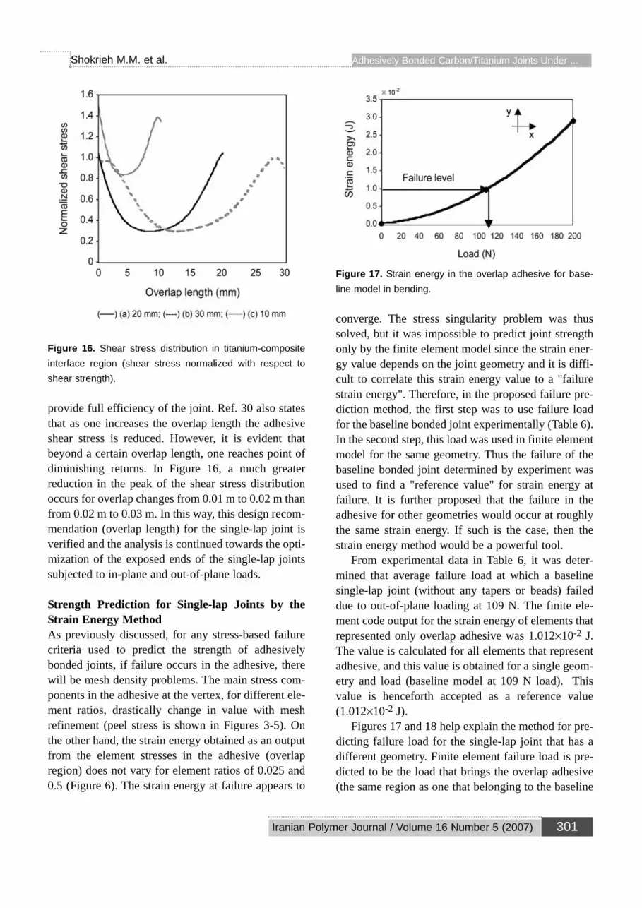
Figure 16. Shear stress distribution in titanium-compositeinterface region (shear stress normalized with respect toshear strength).
provide full efficiency of the joint. Ref. 30 also statesthat as one increases the overlap length the adhesiveshear stress is reduced. However, it is evident thatbeyond a certain overlap length, one reaches point ofdiminishing returns. In Figure 16, a much greaterreduction in the peak of the shear stress distributionoccurs for overlap changes from 0.01 m to 0.02 m thanfrom 0.02 m to 0.03 m. In this way, this design recom-mendation (overlap length) for the single-lap joint isverified and the analysis is continued towards the opti-mization of the exposed ends of the single-lap jointssubjected to in-plane and out-of-plane loads.
Strength Prediction for Single-lap Joints by theStrain Energy MethodAs previously discussed, for any stress-based failurecriteria used to predict the strength of adhesivelybonded joints, if failure occurs in the adhesive, therewill be mesh density problems. The main stress com-ponents in the adhesive at the vertex, for different ele-ment ratios, drastically change in value with meshrefinement (peel stress is shown in Figures 3-5). Onthe other hand, the strain energy obtained as an outputfrom the element stresses in the adhesive (overlapregion) does not vary for element ratios of 0.025 and0.5 (Figure 6). The strain energy at failure appears to
Figure 17. Strain energy in the overlap adhesive for base-line model in bending.
converge. The stress singularity problem was thussolved, but it was impossible to predict joint strengthonly by the finite element model since the strain ener-gy value depends on the joint geometry and it is diffi-cult to correlate this strain energy value to a "failurestrain energy". Therefore, in the proposed failure pre-diction method, the first step was to use failure loadfor the baseline bonded joint experimentally (Table 6).In the second step, this load was used in finite elementmodel for the same geometry. Thus the failure of thebaseline bonded joint determined by experiment wasused to find a "reference value" for strain energy atfailure. It is further proposed that the failure in theadhesive for other geometries would occur at roughlythe same strain energy. If such is the case, then thestrain energy method would be a powerful tool.
From experimental data in Table 6, it was deter-mined that average failure load at which a baselinesingle-lap joint (without any tapers or beads) faileddue to out-of-plane loading at 109 N. The finite ele-ment code output for the strain energy of elements thatrepresented only overlap adhesive was 1.012×10⁻² J.The value is calculated for all elements that representadhesive, and this value is obtained for a single geom-etry and load (baseline model at 109 N load). Thisvalue is henceforth accepted as a reference value(1.012×10⁻² J).
Figures 17 and 18 help explain the method for pre-dicting failure load for the single-lap joint that has adifferent geometry. Finite element failure load is pre-dicted to be the load that brings the overlap adhesive(the same region as one that belonging to the baseline
Iranian Polymer Journal / Volume 16 Number 5 (2007) 301
Adhesively Bonded Carbon/Titanium Joints Under ...Shokrieh M.M. et al.

Figure 18. Strain energy in the overlap adhesive for base-line model in tension.
model) into a stress-strain state of similar strain ener-gy to that brought about by the out-of-plane failureload (109 N). In Figures 17 and 18, the y-axis repre-sents the strain energy distribution in the adhesive,and the x-axis represents the applied load. Drawing ahorizontal line from the baseline strain energy valueof 1.012×10⁻² J, and going to the intersection with thestrain energy curve yields the x-axis value of the loadthat brings the single-lap joint to failure. If thismethod is tried with out-of-plane load and inner taperof 1.43 degrees, then the value of the failure load is116 N. This means that a load of 116 N will fail a sin-gle-lap joint with inner taper of 1.43 degrees in thesame way that out-of-plane load of 109 N failed thebaseline model. One can notice an improvement in thejoint design of 7 N, which means that the applied loadhas to be larger by 7 N than the baseline load (109 N)in order to fail the joint with inner taper of 1.43degrees.
For the joints under tension (Figure 18), the sameapproach is used as above, but now the joint strengthin tension is predicted from a bending strain energyanalysis. It is expected that a much larger in-planeload is required to bring the overlap adhesive into thesimilar stress-strain state than that brought about bythe out-of-plane failure load (109 N), since the single-lap joint is more sensitive to out-of-plane than in-plane load. For the tension case, Figure 18, and for1.012×10-2 J of strain energy, the intersection with thex-axis corresponds to 3650 N of in-plane load. Thismeans that one needs to apply 3.65 kN of in-planeload (tension) in order to bring baseline tension model
Figure 19. Tension failure load for a single-lap joint with dif-ferent adhesive thicknesses.
into a similar strain energy state to that brought aboutby an out-of-plane force of 109 N.
In Figure 19, the strength prediction for a single-lap joint with different bondline thicknesses is evalu-ated by the strain energy method. Notice that the pre-dicted strength decreases with increasing thickness ofthe adhesive. For adhesive thickness of 0.05 mm and0.15 mm, the predicted strength is almost the same.An adhesive thickness of 0.15 mm or less is acceptedas a good bondline thickness for the model that isintroduced in this research.
OptimizationSingle-lap Joint Under Out-of-plane LoadIn order to find the optimum design of the single-lapjoint, the strength values obtained from the finite ele-ment analysis and the experimental work are plottedversus the joint geometry (Figures 20-23). The finiteelement strength values for the single-lap joints, withgeometry that is shown in Figures 8-10, were deter-mined by the strain energy method, and experimentalresults are used from Table 6. As shown in Table 6, thebaseline model is failed under 109 N of out-of-planeload and used as a reference load in Figure 20. For thecases of inner taper under bending loads (Figure 20),when the design variable, b, varies from 0.5 mm to 0.9 mm, there is an increase in the joint strength. Thepeak value for the bending case (around 120.5 N) is
302 Iranian Polymer Journal / Volume 16 Number 5 (2007)
Adhesively Bonded Carbon/Titanium Joints Under ... Shokrieh M.M. et al.

Figure 20. Bending failure load for joints with inner or outertaper.
obtained for design variable b = 0.9 mm and innertaper α = 4 to 5 degrees. For b = 0.5 mm, the peakvalue is about 117 N for FEM and about 120 N for
Figure 21. Bending failure load for joints with inner taperand outer bead.
Figure 22. Tension failure load for joints with inner or outertaper.
experiments with inner taper of about 2 degrees. Fordesign variable b = 0.75 mm and the inner taperbetween 3 and 4 degrees, the highest strength value isabout 120 N. Notice that there is no significantstrength improvement obtained for the differentdesign variables: b = 0.5 mm, 0.75 mm and 0.9 mm.
The effect of some outer tapers under bendingload, on the contrary, can have a negative influence onthe joint strength. The outer tapers for angle (β)between 0 and 3 degrees decrease the joint strength,but from 3 to 6 degrees there is a strength improve-ment compared to the baseline model. It is evidentfrom Figure 20 that the experimental results obtainedfor the geometry b = 0.5 mm (Table 6) and jointstrength predicted by finite element model (b = 0.5mm) correlate well. The strength improvement for thecase of outer taper is apparently smaller than the jointstrength achieved by inner taper, therefore, furtheranalysis (bending case) is concentrated on the innertaper.
Figure 21 shows the analysis of single-lap jointswith inner tapers and outer epoxy beads. The jointsare examined by the finite element method and exper-iments. From Figure 21 it is noticed that there is a bigimprovement in the joint strength for the single-lap
Iranian Polymer Journal / Volume 16 Number 5 (2007) 303
Adhesively Bonded Carbon/Titanium Joints Under ...Shokrieh M.M. et al.

Figure 23. Tension failure load for joints with inner taper andouter bead of 45 degrees.
joints that have inner taper and outer beads comparedto the baseline model. In this analysis, good agreementis found between the experimental and finite elementresults. The maximum strength (about 249 N) isobtained for the geometry variable b = 0.9 mm, andangle of inner taper (α) of about 2 degrees. For b = 0.5 mm and inner taper angle of about 1 degree, thestrength of the adhesive joint is about 219 N for theFEM and about 233 N for the experiment. The single-lap joint with design variable b = 0.75 mm and 2degrees of inner taper failed at maximum average loadof about 233 N according to FEA.
In summary, for the case where the single-lap jointswere subjected to the out-of-plane load, the inner taperof 2 degrees from design variable b = 0.9 mm in com-bination with an epoxy bead of 45 degrees gave thebest strength result. This case is thus close to an opti-mum design for a single-lap joint under bending load.
Single-lap Joint Under Tension LoadFor the case of tension load (Figure 22), with a rangeof the design variable b from 0.5 mm to 0.9 mm, thereis no significant increase in the obtained strength val-ues. Notice that inner taper in tension produced the
same effects as outer tapers in the bending case. In theregion α = 0-3 degrees, it seems to be a decrease in thejoint strength, but from α = 3-6 degrees, the jointstrength improved according to FEA. Recall, for thebending case (without outer bead) the peak value wasobtained for design variable b = 0.9 mm (about 120.5N), but in the tension case, the highest value wasobtained for b = 0.5 mm (about 3.9 kN for FEM andexperiment). In Figure 22 it is possible to see goodagreement between finite element analysis and exper-imental results that are obtained for design variable b = 0.5 mm (thick black line and thick gray line). Theouter taper gives a small increment in strength withincrease of the design variable, c (0.5, 0.75, 0.9 mm).This did not happen in the bending case, where theouter taper produces a negative effect on the jointstrength.
As it was the case for bending, higher strength val-ues are obtained for epoxy beads with inner tapers(Figure 23). Epoxy beads are not always practical forthe joint that has outer taper. Therefore, epoxy beadswere tested in combination with an inner taper, as theprevious case. In Figure 23, it can be observed thatepoxy beads did not effect the tension joint strength asmuch as in the bending case. The peak value isobtained for design variable b = 0.5 mm and innertaper (α) between 1 and 2 degrees (around 4.65 kN forFEM and about 4.8 kN by experiment). The experi-mental and finite element joint strengths (b = 0.5 mm)are in good agreement. At this point, the optimumdesign for the tension case is considered to be deter-mined, and design variables have the values: b = 0.5mm and α = 1-2 degrees.
Optimum Design of the Joint Ends for CombinedLoadingFrom the analysis presented in previous two sections“single-lap joint under out-of-plane load and tensionload”, there are two different design solutions that aremost suitable for the single-lap joint that is subjectedto different loading conditions: (1) bending, and (2)tension. However, one objective might be to find thedesign that will suit both loading conditions. Fordesign variable b = 0.9 mm, the single-lap jointachieved the highest strength value in bending. In ten-sion, the single-lap joint had the lowest strength forthis type of the design (b = 0.9 mm), and the best result
304 Iranian Polymer Journal / Volume 16 Number 5 (2007)
Adhesively Bonded Carbon/Titanium Joints Under ... Shokrieh M.M. et al.

Figure 24. Optimum design for the single-lap joint ends.
was achieved by design variable, b = 0.5 mm. InFigures 20-21, it is noticeable that results obtained fordesign variable b = 0.75 mm are in-between theresults obtained for b = 0.5 and b = 0.9 mm.
If one wants to design a single-lap joint that mightbe subjected to two different loading conditions, thedesign variable, b = 0.75 mm, with inner taper ofabout 2 degrees and outer bead of 45 degrees might bethe most suitable one. Therefore, for the single-lapjoint that is subjected to two different loading condi-tions that are applied alternatively: (1) out-of-plane(bending), and (2) in-plane load (tension), the opti-mum configuration at joint ends can be estimatedfrom Figures 20-23 as follows:
(1) b = 0.75 mm, and(2) α = 2º + 2 × 45º outer epoxy beads (Figure 24).
Summary of the Results of OptimizationThe objective of this research was to find the designof the joint ends of single-lap joints between compos-ite material and titanium in order to increase the jointstrength. To join the titanium (0.12 × 0.0254 × 0.001m) and the composite plate [04/904]s with 0.146 mmply thickness to form a single-lap joint configuration,the bonding recommendations were accepted fromrefs. 2, 3, 16, and 30 and verified:• Overlap length of 20 mm.• Bondline thickness of 0.15 mm.• Inner tapering of the adherend with adhesive fillet of
45 degrees.• Outer tapering without adhesive fillet.
The present analysis verified, accepted and gavenew recommendations for the design of the single-lapjoint subjected to two different loading conditions: (1)bending and (2) tension. The present analysis foundthat:• Overlap length of 20 mm will provide full efficien-
cy of the single-lap joint.• An optimum adhesive thickness (bondline thick-
ness) is between 0.05-0.15 mm.
• Single-lap joint with inner taper of about 2 degreesand two outer epoxy beads of 45 degrees gavestrength improvement in tension (about 23%) andbending (about 114%).
• Outer tapers did not significantly improve the fail-ure strength in tension or bending
CONCLUSION
In this research, optimization of the configuration of asingle-lap joint was examined. Several design param-eters that can govern design of the adhesively bondedjoints were investigated: (1) inner tapers, (2) outertapers, and (3) inner tapers in combination with outerepoxy beads of 45 degrees. Finite element modelswere created and the strain energy criterion was usedas failure criteria because it converged with meshrefinement and was not affected by stress singularitiesthat exist at the vertices. This criterion can be used fordifferent joint configurations since it is property of theadhesive. Note that the criterion depends on oneexperimental baseline measurement that it is used topredict the failure of other joint configurations. It isexpected that the criterion will work well if the jointconfigurations are geometrically "close" to the base-line model, i.e., same adherends and relatively closegeometries. Once the geometry strays too far from thebaseline model then the criterion is expected to devi-ate. In the present analysis, experimental work wasperformed for two different loading conditions: (1)bending and (2) tension. In both cases, bending andtension, there is a good agreement between finite ele-ment and experimental results. In the end, the opti-mum design of the joint ends was predicted with itsdesign variables. The best joint designs gave strengthsof (1) about 233 N for the bending case, and (2) about4.5 kN for the tension case. The baseline model failedat about 109 N for the bending and about 3.65 kN forthe tension case. Thus, the improvements for the bestdesign measured from baseline values are about 114%for the bending case and about 23% for the tensioncase.
From the above results, the finite element analysismethod with the strain energy criterion is a good toolfor designing and predicting the single-lap bondedjoint strength of composite/titanium combinations.
Iranian Polymer Journal / Volume 16 Number 5 (2007) 305
Adhesively Bonded Carbon/Titanium Joints Under ...Shokrieh M.M. et al.

One limitation is the linear modelling of the adhesivematerial properties. Future analysis could implementnon-linear material properties for the adhesive.
REFERENCES
1. Williams J.H., Wang T.K., Nondestructive evalua-tion of strength and separations modes in adhesive-ly bonded automotive glass fiber composite single-lap joints, J. Compos. Mater., 21, 14-35, 1987.
2. Hart-Smith L.J., An engineer's view point on designand analysis of aircraft structural joints, J.Aerospace Eng., 209, 105-129, 1995.
3. Hart-Smith L.J., Further developments in the designand analysis of adhesive-bonded structural joints,joining of composite materials, ASTM STP 749,Kedward K.T. (Ed.), Am. Soc. Test. Mater., 3-31,1981.
4. Goland M., Reissner E., The stress in cementedjoints, J. Appl. Mechanics, A17-A26, 1944.
5. Pahoja H.M., Stress analysis of an adhesive lapjoint subjected to tension, shear force and bendingmoments, University of Illinois at Urbana-Champaign, T. & A. M. Report 361, 1972
6. Vinson J.R., Adhesive bonding of polymer compos-ites, Polym. Eng. Sci., 29, 1325-1331, 1989.
7. Adams R.D., The mechanics of bonded joints,IMechE, 17-24, 1986.
8. Adams R.D., Strength predictions for lap jointsespecially with composite adherents: A review, J.Adhes., 30, 219-242, 1989.
9. Kay N., Barut A., Madenci E., Singular stresses ina finite region of two dissimilar viscoelastic mate-rials with traction-free edges, Comput. MethodsAppl. Mechanics Eng., 191, 1221-1244, 2002.
10. Oterkus E., Barut A., Madenci E., Ambur D.R.,Nonlinear analysis of a composite panel with acutout repaired by a bonded tapered compositepatch, J. Solids Struct., 42, 5274-5306, 2005.
11. Oterkus E., Barut A., Madenci E., Smeltzer S.S.,Ambur D.R., Bonded lap joints of composite lam-inates with tapered edges, J. Solids Struct., 43,1459-1489, 2006.
12. Lessard L., Design of Joints in CompositeStructures, Computer Aided Design for CompositeStructures, Hoa S.V. (Ed.), Marcel & Dekker, NY,
273-288, 1995.13. Barthelemy B.M., Kamat M.P., Brinson H.F.,
Finite element analysis of bonded joints, MSc.Thesis, Virginia Polytechnic Institute and StateUniversity, Blacksburg, Virginia, 1984.
14. Harris J.A., Adams R.D., Strength prediction ofbonded single-lap joints by non-linear finite ele-ment methods, Int. J. Adhes. Adhes., 4, 65-78,1984.
15. Adams R.D., Atkins R.W., Harris J.A., Stressanalysis and failure properties of carbon-fibre-reinforced-plastic/steel double lap joints, J. Adhes.,20, 29-53, 1986.
16. Hildebrand M., Non-linear analysis and optimiza-tion of adhesively bonded single-lap jointsbetween fibre-reinforced plastics and metals, Int. J.Adhes. Adhes., 14, 261-267, 1994.
17. Kairouz K.C., Cook I.P., The influence of bondlinethickness and overlap length on the strength ofbonded double lap composite joints, ECCM-8 Eur.Conf. Comp. Mat., Naples, Italy, 1, 31-38, 1998.
18. Tsai M.Y., Morton J., Experimental and numericalstudies of a laminated composite single-lap adhe-sive joint, J. Compos. Mater., 29, 527-538, 1995.
19. Bogy D.B., Edge-bonded dissimilar orthogonalelastic wedges under normal and sheer loading, J.Appl. Mechanics, 35, 460-466, 1968.
20. Dunders J., Discussion of edge-bonded dissimilarorthogonal elastic wedges under normal and sheerloading, J. Appl. Mechanics, 36, 650-652, 1969.
21. Bogy D.B., Two edge-bonded elastic wedges ofdifferent materials and wedge angles under surfacetractions, J. Appl. Mechanics, 38, 377-386, 1971.
22. Erdogan F., Stress singularities in a two-materialwedge, Int. J. Fracture Mechanics, 7, 317-330,1971.
23. Theocaris P.S., The order of singularity at a multi-wedge corner of composite plate, Int. J. Eng. Sci.,12, 107-120, 1974.
24. Groth H.L., Stress singularities and fracture atinterface corners in bonded joints, Int. J. Adhes.Adhes., 8, 107-113, 1988.
25. Sancaktar E., Nirantar P., Increasing strength ofsingle-lap joints of metal adherends by taper mini-mization, J. Adhes. Sci. Technol., 17-5, 655-675,2003.
26. Wang J., Rider A.N., Heller M., Kaye R.,
306 Iranian Polymer Journal / Volume 16 Number 5 (2007)
Adhesively Bonded Carbon/Titanium Joints Under ... Shokrieh M.M. et al.

Theoretical and experimental research into opti-mum edge taper of bonded repair patches subjectto fatigue loadings, Int. J. Adhes. Adhes., 25, 410-426, 2005.
27. Kaye R., Heller M., Finite element-based three-dimensional stress analysis of composite bondedrepairs to metallic aircraft structure, J. Adhes.Adhes., 26, 261-273, 2006.
28. Hart-Smith L.J., The key to designing durableadhesively bonded joints, Composites, 25, 895-898, 1994.
29. Hart-Smith L.J., Adhesive-bonded joints for com-posites-phenomenal considerations, Proc. Conf.on Adv. Compos. Technol., El Segundo, CA, 163-180, 1978.
30. Renton W.J., Vinson J.R., The efficient design ofadhesive bonded joints, J. Adhes., 7, 175-193,1975.
31. Greszezuk L.B., Macander A.B., Static andfatigue strength of high load intensity stell-hybridcomposite bonded scarf joints, joining of compos-ite materials, ASTM STP 749, Kedward K.T.(Ed.), Am. Soc. Test. Mater., 75-96, 1981.
32. Adams R.D., Wake W.C., Structural AdhesiveJoints in Engineering, Elsevier Applied Science,1984.
33. Shokrieh M.M., Progressive Fatigue DamageModeling of Composite Materials, Ph.D.Dissertation, McGill University, 1996.
34. Loctite Inc., 1001 Trout Brook Crossing, RockyHill, CT., 33, 2296-2298, 2000.
Iranian Polymer Journal / Volume 16 Number 5 (2007) 307
Adhesively Bonded Carbon/Titanium Joints Under ...Shokrieh M.M. et al.


![Bending Stress in beams [Notes by kulkarniacademy]](https://img.pdfslide.net/doc/110x75/63178f359076d1dcf80bd9b9/bending-stress-in-beams-notes-by-kulkarniacademy.jpg)