Embed Size (px)
Citation preview
Best Practice Assessment of Software Technologies for Robotics
Azamat ShakhimardanovJan Paulus
Nico HochgeschwenderMichael Reckhaus
Gerhard K. Kraetzschmar
February 28, 2010
Abstract
The development of a complex service robot application is a very difficult, time-consuming, anderror-prone exercise. The need to interface to highly heterogeneous hardware, to run the finaldistributed software application on a ensemble of often heterogeneous computational devices, andto integrate a large variety of different computational approaches for solving particular functionalaspects of the application are major contributing factors to the overall complexity of the task.While robotics researchers have focused on developing new methods and techniques for solvingmany difficult functional problems, the software industry outside of robotics has developed atremendous arsenal of new software technologies to cope with the ever-increasing requirementsof state-of-the-art and innovative software applications. Quite a few of these techniques havethe potential to solve problems in robotics software development, but uptake in the roboticscommunity has often been slow or the new technologies were almost neglected altogether.
This paper identifies, reviews, and assesses software technologies relevant to robotics. Forthe current document, the assessment is scientifically sound, but neither claimed to be completenor claimed to be a full-fledged quantitative and empirical evaluation and comparison. Thisfirst version of the report focuses on an assessment of technologies that are generally believed tobe useful for robotics, and the purpose of the assessment is to avoid errors in early design andtechnology decisions for BRICS.
Contents
1 Introduction 51.1 The BRICS Project Context . . . . . . . . . . . . . . . . . . . . . . . . . . . . . . 51.2 Motivation for Assessing Software Technologies . . . . . . . . . . . . . . . . . . . 61.3 Goals of the Assessment Exercise . . . . . . . . . . . . . . . . . . . . . . . . . . . 71.4 Overview on the Report . . . . . . . . . . . . . . . . . . . . . . . . . . . . . . . . 7
2 Component-Based Software Technologies 82.1 Component Models . . . . . . . . . . . . . . . . . . . . . . . . . . . . . . . . . . . 9
2.1.1 OROCOS . . . . . . . . . . . . . . . . . . . . . . . . . . . . . . . . . . . . 92.1.2 OpenRTM . . . . . . . . . . . . . . . . . . . . . . . . . . . . . . . . . . . . 132.1.3 Player . . . . . . . . . . . . . . . . . . . . . . . . . . . . . . . . . . . . . . 182.1.4 ROS . . . . . . . . . . . . . . . . . . . . . . . . . . . . . . . . . . . . . . . 22
2.2 Comparison Results and Conclusions . . . . . . . . . . . . . . . . . . . . . . . . . 252.2.1 Comparison with other robotics software system component meta-models 272.2.2 Conclusion . . . . . . . . . . . . . . . . . . . . . . . . . . . . . . . . . . . 35
3 Communication Middleware 363.0.3 The Marketplace of Communication Middleware . . . . . . . . . . . . . . 363.0.4 Assessment . . . . . . . . . . . . . . . . . . . . . . . . . . . . . . . . . . . 373.0.5 Conclusions . . . . . . . . . . . . . . . . . . . . . . . . . . . . . . . . . . . 44
4 Interface Technologies 454.0.6 Component Interface Models . . . . . . . . . . . . . . . . . . . . . . . . . 454.0.7 Hardware Abstraction (by Jan) . . . . . . . . . . . . . . . . . . . . . . . . 52
5 Simulation and Emulation Technologies 635.0.8 Categorization and Application Areas . . . . . . . . . . . . . . . . . . . . 645.0.9 Conclusions . . . . . . . . . . . . . . . . . . . . . . . . . . . . . . . . . . . 67
6 Conclusions 686.1 Implications for BRICS . . . . . . . . . . . . . . . . . . . . . . . . . . . . . . . . 68
2
List of Figures
2.1 Interface types in the OROCOS component model. . . . . . . . . . . . . . . . . . 102.2 OROCOS component state machine models, as defined by class TaskContext [1, 2]. 112.3 OROCOS component implementation model. . . . . . . . . . . . . . . . . . . . . 122.4 The OpenRTM component implementation model. . . . . . . . . . . . . . . . . . 142.5 The OpenRTM component state machine model[3]. . . . . . . . . . . . . . . . . . 152.6 Player server implementation model. . . . . . . . . . . . . . . . . . . . . . . . . . 182.7 Player component model. . . . . . . . . . . . . . . . . . . . . . . . . . . . . . . . 212.8 ROS pseudo-component model. . . . . . . . . . . . . . . . . . . . . . . . . . . . . 23
4.1 Meta-component model. . . . . . . . . . . . . . . . . . . . . . . . . . . . . . . . . 474.2 Interface separation schema. . . . . . . . . . . . . . . . . . . . . . . . . . . . . . . 474.3 Topology represents functional interfaces of components. . . . . . . . . . . . . . . 484.4 Interface categorization according to data and execution flows . . . . . . . . . . . 484.5 Component interface separation scheme according to concerns. . . . . . . . . . . 494.6 Orca range finder hardware hierarchy . . . . . . . . . . . . . . . . . . . . . . . . . 554.7 YARP Hardware Abstraction Hierarchy . . . . . . . . . . . . . . . . . . . . . . . 574.8 ARIA hardware hierarchy for range devices . . . . . . . . . . . . . . . . . . . . . 584.9 MRPT hardware hierarchy . . . . . . . . . . . . . . . . . . . . . . . . . . . . . . . 584.10 OPRoS hardware hierarchy . . . . . . . . . . . . . . . . . . . . . . . . . . . . . . 59
3
List of Tables
2.1 Mapping between BRICS CMM constructs and other systems . . . . . . . . . . . 262.2 Mapping between BRICS CMM constructs and ORCA2 . . . . . . . . . . . . . . 282.3 Mapping between BRICS CMM constructs and OpenRTM . . . . . . . . . . . . . 292.4 Mapping between BRICS CMM constructs and GenoM . . . . . . . . . . . . . . . 302.5 Mapping between BRICS CMM constructs and OPRoS . . . . . . . . . . . . . . 312.6 Mapping between BRICS CMM constructs and ROS . . . . . . . . . . . . . . . . 322.7 Mapping between BRICS CMM constructs and OROCOS . . . . . . . . . . . . . 332.8 Comparison of component modelling primitives in different robot software systems
with respect to BCM . . . . . . . . . . . . . . . . . . . . . . . . . . . . . . . . . . 34
3.1 Compiled list of different middleware technologies . . . . . . . . . . . . . . . . . . 383.2 Middleware specifications and their associated implementations . . . . . . . . . . 393.3 Middleware implementations and their supported programming languages . . . . 393.4 Middleware implementations and their supported platforms . . . . . . . . . . . . 39
4.1 OpenRTM range sensing device interfaces . . . . . . . . . . . . . . . . . . . . . . 604.2 Hardware Abstraction Comparison Table . . . . . . . . . . . . . . . . . . . . . . . 61
4
Chapter 1
Introduction
The work described in this report was performed in the context of the EU project BRICS. Webriefly describe this project context, then motivate why an assessment of software technology isappropriate and what the objectives of this assessment are. Finally, we survey the structure ofthis report.
1.1 The BRICS Project Context
BRICS1[?] addresses the urgent need of the robotics research community for common roboticsresearch platforms, which support integration, evaluation, comparison and benchmarking of re-search results and the promotion of best practice in robotics. In a poll in the robotics researchcommunity[?] performed in December 2007 95% of the participants have called for such plat-forms. Common research platforms will be beneficial for the robotics community, both academicand industrial. The academic community can save a significant amount of resources, whichtypically would have to be invested in from scratch developments and me-too approaches.
Furthermore, scientific results will become more comparable which might promote a culture ofsound experimentation and comparative evaluation. Jointly specified platforms will foster rapidtechnology transfer to industrial prototypes, which supports the development of new roboticssystems and applications. This reduces the time to market and thereby gives the industrialcommunity a competitive advantage. To achieve these objectives the BRICS project proposesthe development of a design methodology, which focuses on three fundamental research anddevelopment issues. This methodology will be implemented in three interwoven lines of technicalactivities:
• Identification of best practice in robotics hardware and software components
• Development of a tool chain that supports rapid and flexible configuration of new robotplatforms and the development of sophisticated robot applications
• Cross-sectional activities addressing robust autonomy, openness and flexibility, and stan-dardisation and benchmarking
The authors of this report all work at Bonn-Rhein-Sieg University of Applied Sciences (BRSU),which is the partner in BRICS responsible for Architecture, Middleware, and Interfaces. Thiswork package is to provide fundamental software components using state-of-the-art softwaretechnologies and the usage of these components needs to be well embedded into the tool chain.
The BRICS project is of fundamental importance to ensure the sustained success and com-petitiveness of European robotics research and the European robotics industry.
1This section is a modest revision of the BRICS in a nutshell section of the project proposal[?].
5
CHAPTER 1. INTRODUCTION
1.2 Motivation for Assessing Software Technologies
Software development for robotics applications is a very time-consuming and error-prone process.Previous work described in the literature[?] identifies three major sources responsible for thecomplexity of software development in robotics:
Hardware Heterogeneity: A reasonably complex service robot integrates an arsenal of sen-sors, actuators, communication devices, and computational units (controller boards, em-bedded computers) that covers a much wider variety than most application domains. Whilee.g. aviation and the automotive industry face similar situations, their development pro-cesses are much more resourceful and use a significant number of specialists to manage theproblems arising from heterogeneity. Robotics, esp. service robotics and robot applicationstargeting a consumer market are far from enjoying a similarly comfortable situation.
Distributed Realtime Computing: Non-trivial service robots almost inevitably use severalnetworked computational devices, all of which run some part of the overall control archi-tecture, which must work together in a well-coordinated fashion. Applying concepts andprinciples of distributed computing is therefore a must. That the networking involves sev-eral kind of communication devices and associated protocols adds even more complexity.It is not unusual at all that a service robot forces a developer to handle three to five dif-ferent communication protocols. Furthermore, some devices may pose rather strict timingconstraints, and the developer must deal with realtime computing issues on top of all othercomplexities.
Software Heterogeneity: A full-fledged service robot must integrate a variety of functional-ities that include basically every sub-area of Artificial Intelligence, including knowledgerepresentation and reasoning, probabilistic reasoning, fuzzy logic, planning and scheduling,learning and adaptation, evolutionary and genetic computation, computer vision, speechprocessing and production, natural language understanding and dialogue, sensor interpre-tation and sensor fusion, and intelligent control. Many of these areas have developed theirown set of computational methods for solving their respective problems, often using verydifferent programming languages, data structures and algorithms, and control approaches.Integrating the different functionalities into a coherent and well-coordinated robot controlarchitecture is a substantial challenge.
Since about a decade there is a rising interest in the robotics community to improve the robotapplication development process. Aside of improving the development process itself (see theaccompanying report Best Practice Assessment of Software Engineering Methods, [?]) and pro-viding a suitable tool chain to support the process (see work performed in WP 4, [?]), the use ofstate-of-the-art and innovative software technology is of prime interest to improve the effectivityand efficiency of the development process and the quality of the resulting product.
The main question then is: Which software technologies can help the robotics community toovercome the problems arising from the complexity of the robot application development process?
There are three main aspects to cover when answering this question. The first aspect isidentifying software technologies that have the potential to address one or more of the problemsfaced by robot application developers. The second aspect is assessing to what extent currentrobotics software development frameworks already make use of these technologies. And thethird aspect is to look at standardization activities, which are underway even in some roboticscommunities. Neglecting existing or ongoing standardization efforts could prevent project resultsfrom becoming adapted by a wider audience. Identifying and criticizing serious deficiencies instandard proposals under discussion could help to improve standards and make them moreeffective.
6 of 75
1.3. GOALS OF THE ASSESSMENT EXERCISE
Note, that this report does not cover issues related to robot control architectures; theseaspects will be considered and discussed in a future report.
1.3 Goals of the Assessment Exercise
- identify new and known SW technologies relevant to robotics
1.4 Overview on the Report
This report is structured as follows. In Chapter?? four classes of software technologies areidentified and justified. Namely,
• Component-based Software Technologies,
• Communication Middleware,
• Interface Technologies, and
• Simulation and Emulation Technologies.
In Chapter?? the marketplace of those technologies is screened and their need for - explainstructure of the remainder of the paper
7 of 75
Chapter 2
Component-Based SoftwareTechnologies
In recent years, advancements in hardware, sensors, actuators, computing units, and — to alesser extent — in software technologies has led to the proliferation of robotics technology. Morecomplex and advanced hardware required increasingly sophisticated software infrastructures inorder to operate properly. This software infrastructure should allow developers to tackle thecomplexity imposed by hardware and software heterogeneity and distributed computing environ-ments. That is, the infrastructure software should provide a structured organization of systemelements/primitives in the form of independent software units and support communication amongthese independent software units.
Robotics is not the only field which needs such infrastructure. Others include telecommu-nication, aerospace, and automotive engineering. An analysis of the approaches used in thesedomains shows that the two essential ingredients for developing distributed software systems arei) the definition of a structured software unit model, often referred to as component model, and ii)the the definition of a communication model for modeling communication between these units.A software unit model includes strictly defined interface semantics and a method for describingthe internal dynamical structure of a unit, whereas a communication model, though often not asclearly defined as the software unit, requires the specification of inter-unit interaction styles andspecific transport protocol types.
Before categorizing and analyzing existing component models, we distinguish component-oriented programming (COP) from object-oriented programming (OOP). Basically, all the ob-jectives of OOP are also an objective in COP, but COP development was driven by the desireto fix some loose ends of OOP. The following attributes of COP are emphasized in a comparisonwith OOP in [4]:
• COP emphasizes encapsulation more strongly than OOP. COP differentiates more strictlybetween interface design and implementation of the specified functionality than OOP. Theuser of a component does not see any details of the component implementation except forits interfaces, and the component could be considered as a piece of pre-packaged code withwell-defined public access methods. This separation can also be followed in OOP, but isnot as directly enforced, e.g. by the programming language.
• COP focuses more on packaging and distributing a particular piece of technology, whileOOP is more concerned about how to implement that technology.
• COP components are designed to follow the rules of the underlying component framework,whereas OOP objects are designed to obey OO principles.
8
2.1. COMPONENT MODELS
One can also differentiate three factors exposing advantages of COP over OOP with respect tothe composition of units adopted in each approach:
• Reusability levels
• Granularity levels
• Coupling levels
These factors are tightly related to each other [4].The fundamental concept of component-oriented programming is the component and their
interfaces. Approaches can differ quite widely regarding their ability to hierarchically composemore complex components from existing components.
Equally important as the component concept itself is the supportive infrastructure that comeswith it, i.e. the framework for component instantiation, resource management, inter-componentcommunication and deployment. These frameworks often are already equipped with the meansfor inter-component communication, which can influence interface design decisions to some ex-tent. Unfortunately, it is often quite difficult or impossible to clearly delineate and decouple thecomponent interaction model from the communication model. Each framework usually featuresits own component model, communication model, and deployment model. Different frameworkshave different models for each of the above constituents. As a consequence, it is often not possibleto interoperate and integrate them. In our analysis we mostly emphasize two of these models,the component model and the communication model.
The next section provides an almost exhaustive survey on existing component models usedin robotics software. We analyze what the specific component features are and how these frame-works are implemented wrt. these models. Additionally, we provide a comparative analysis of thecomponent interface categorization schemes in Section 4.0.6. Since different interface semanticsdefine how a component interacts with other components and produces/consumes data, the typeof communication policies and the infrastructure are the other elements looked into.
2.1 Component Models
2.1.1 OROCOS
The main goal of the OROCOS project is to develop a general purpose modular framework forrobot and machine control. The framework provides basically three main libraries [5], [1], [2]:
1. The Real-Time Toolkit (RTT) provides infrastructure and functionality to build componentbased real-time application.
2. The Kinematics and Dynamics Library (KDL) provides primitives to calculate kinematicchains.
3. The Bayesian Filtering Library (BFL) provides a framework to perform inference usingDynamic Bayesian Networks.
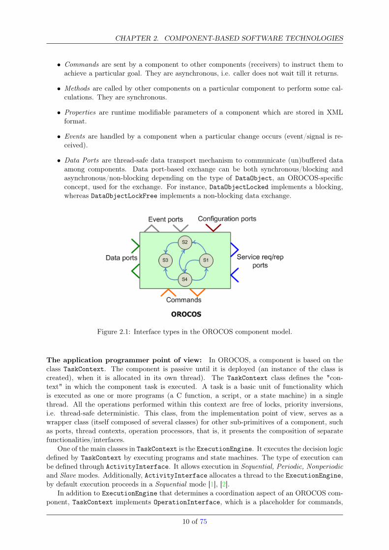
The RTT provides the core primitives defining the OROCOS component model and the necessarycode base for the implementation of components. Figure 2.1 illustrates that the OROCOS com-ponent model supports five different types of interfaces. This interface separation fits well intodata and execution flow, as well as time property-oriented schema (see Section 4.0.6). In the for-mer case, commands, methods, and events make up execution flow, whereas data ports representdata flow of the component. If one looks at temporal properties of the interfaces, synchronous(method and data) and asynchronous interfaces (command and event) can be distinguished.
9 of 75
CHAPTER 2. COMPONENT-BASED SOFTWARE TECHNOLOGIES
• Commands are sent by a component to other components (receivers) to instruct them toachieve a particular goal. They are asynchronous, i.e. caller does not wait till it returns.
• Methods are called by other components on a particular component to perform some cal-culations. They are synchronous.
• Properties are runtime modifiable parameters of a component which are stored in XMLformat.
• Events are handled by a component when a particular change occurs (event/signal is re-ceived).
• Data Ports are thread-safe data transport mechanism to communicate (un)buffered dataamong components. Data port-based exchange can be both synchronous/blocking andasynchronous/non-blocking depending on the type of DataObject, an OROCOS-specificconcept, used for the exchange. For instance, DataObjectLocked implements a blocking,whereas DataObjectLockFree implements a non-blocking data exchange.
Figure 2.1: Interface types in the OROCOS component model.
The application programmer point of view: In OROCOS, a component is based on theclass TaskContext. The component is passive until it is deployed (an instance of the class iscreated), when it is allocated in its own thread). The TaskContext class defines the "con-text" in which the component task is executed. A task is a basic unit of functionality whichis executed as one or more programs (a C function, a script, or a state machine) in a singlethread. All the operations performed within this context are free of locks, priority inversions,i.e. thread-safe deterministic. This class, from the implementation point of view, serves as awrapper class (itself composed of several classes) for other sub-primitives of a component, suchas ports, thread contexts, operation processors, that is, it presents the composition of separatefunctionalities/interfaces.
One of the main classes in TaskContext is the ExecutionEngine. It executes the decision logicdefined by TaskContext by executing programs and state machines. The type of execution canbe defined through ActivityInterface. It allows execution in Sequential, Periodic, Nonperiodicand Slave modes. Additionally, ActivityInterface allocates a thread to the ExecutionEngine,by default execution proceeds in a Sequential mode [1], [2].
In addition to ExecutionEngine that determines a coordination aspect of an OROCOS com-ponent, TaskContext implements OperationInterface, which is a placeholder for commands,
10 of 75
2.1. COMPONENT MODELS
(a) simplified
(b) expanded
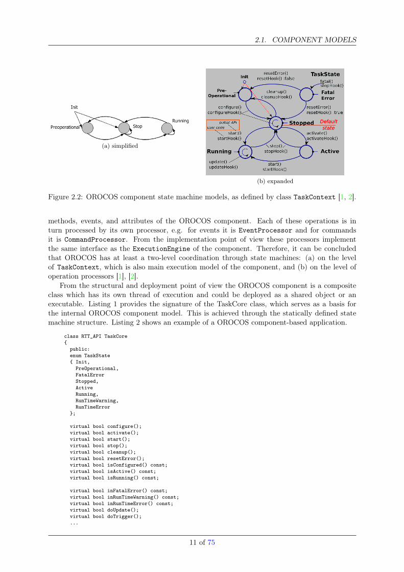
Figure 2.2: OROCOS component state machine models, as defined by class TaskContext [1, 2].
methods, events, and attributes of the OROCOS component. Each of these operations is inturn processed by its own processor, e.g. for events it is EventProcessor and for commandsit is CommandProcessor. From the implementation point of view these processors implementthe same interface as the ExecutionEngine of the component. Therefore, it can be concludedthat OROCOS has at least a two-level coordination through state machines: (a) on the levelof TaskContext, which is also main execution model of the component, and (b) on the level ofoperation processors [1], [2].
From the structural and deployment point of view the OROCOS component is a compositeclass which has its own thread of execution and could be deployed as a shared object or anexecutable. Listing 1 provides the signature of the TaskCore class, which serves as a basis forthe internal OROCOS component model. This is achieved through the statically defined statemachine structure. Listing 2 shows an example of a OROCOS component-based application.
class RTT_API TaskCore{
public:enum TaskState{ Init,
PreOperational,FatalErrorStopped,ActiveRunning,RunTimeWarning,RunTimeError
};
virtual bool configure();virtual bool activate();virtual bool start();virtual bool stop();virtual bool cleanup();virtual bool resetError();virtual bool isConfigured() const;virtual bool isActive() const;virtual bool isRunning() const;
virtual bool inFatalError() const;virtual bool inRunTimeWarning() const;virtual bool inRunTimeError() const;virtual bool doUpdate();virtual bool doTrigger();...
11 of 75
CHAPTER 2. COMPONENT-BASED SOFTWARE TECHNOLOGIES
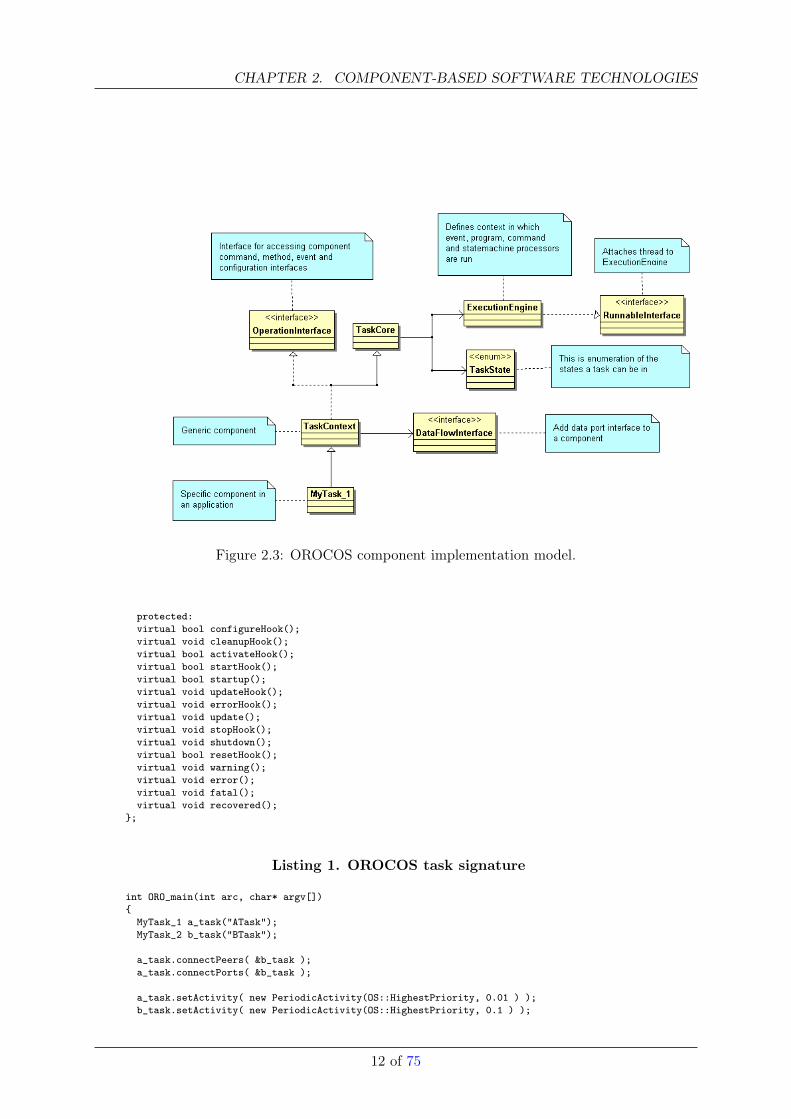
Figure 2.3: OROCOS component implementation model.
protected:virtual bool configureHook();virtual void cleanupHook();virtual bool activateHook();virtual bool startHook();virtual bool startup();virtual void updateHook();virtual void errorHook();virtual void update();virtual void stopHook();virtual void shutdown();virtual bool resetHook();virtual void warning();virtual void error();virtual void fatal();virtual void recovered();
};
Listing 1. OROCOS task signature
int ORO_main(int arc, char* argv[]){
MyTask_1 a_task("ATask");MyTask_2 b_task("BTask");
a_task.connectPeers( &b_task );a_task.connectPorts( &b_task );
a_task.setActivity( new PeriodicActivity(OS::HighestPriority, 0.01 ) );b_task.setActivity( new PeriodicActivity(OS::HighestPriority, 0.1 ) );
12 of 75
2.1. COMPONENT MODELS
a_task.start();b_task.start();
a_task.stop();b_task.stop();
return 0;}
Listing 2. OROCOS task-based application
2.1.2 OpenRTM
OpenRTM[] is open source implementation of the RT-Middleware specification and is devel-oped by AIST, Japan. This specification defines the following three sub-specifications which arecomplementary to each other: (i) functional entities, i.e. components which perform system-related computations, (ii) communication entities, i.e. middleware which provides communica-tion means for the components, and (iii) tool entities, i.e. a set of tools supporting system- andcomponent-level design and runtime utilities. Some more detailed information about each ofthese specifications include:
• The RT-Component Framework provides a set of classes which can be used to developstand-alone software components. Conceptually, any RT middleware component can bedecomposed into two main parts: (a) The component core logic, which defines the mainfunctionality of the component. All algorithms are defined within the core logic of thecomponent. (b) The component skin, or wrapper, provides necessary means to expose thefunctionality provided by the core logic through the interfaces to the external world. TheRT component framework provides a set of classes which enable this wrapping [3], [6].
• The RT-Middleware: By definition, an RT-component is a decoupled entity whose finalform can be either a shared library or an executable type. In the Robot Technologypackage, an RT-component is defined as the aggregation of several classes without mainfunction, so there is no explicit thread of execution attached to it (it is a passive functionalunit without any thread of execution). That is where RT-middleware comes into play.RT-middleware makes a call to a component and attaches an execution context and anappropriate thread to it. By doing this, RT-middleware also takes the responsibility tomanage that component’s life cycle, i.e. to execute actions defined by a component andcommunicate with other peers. Note that there can be many instances of RT-componentrunning. RT-Middleware takes care of the whole instantiation process. That is, the calls aremade from the middleware to a component. OpenRTM implementation uses a CORBA-compliant middleware environment, omniORB [3], [7], [8], [9].
• Basic Tools Group: The Robot Technology software system also comes with a set of utilitieswhich simplify development, deployment, and configuration of the applications developed.In case of the OpenRTM implementation, these tools are RtcTemplate, a component skele-ton code generation tool, and RtcLink, a component-based software composition tool.
As it was indicated, an RT-component is defined through its computational part, which is acore logic, and a component skin, which exposes the functionality of the core logic. From amore detailed perspective these two constituents can be further decomposed into the followingsubcomponents [3], [6], [7], [8], [9].
• The Component Profile contains meta-information about a component. It includes suchattributes as the name of the component, and the profile of the component’s ports.
13 of 75
CHAPTER 2. COMPONENT-BASED SOFTWARE TECHNOLOGIES
• The Activity is where main computation takes place. It forms a core logic of a component.Activity has a state machine and the core logic is executed as component which transitsbetween states or is in a particular state of processing.
• The Execution Context is defined by a thread attached to a component. It executes definedactivities according to the given state.
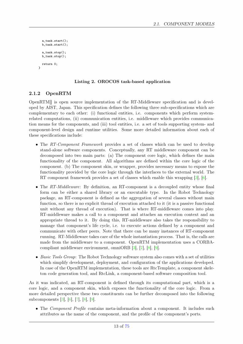
• Component Interfaces: OpenRTM components provide three types of interfaces to com-municate with other components or applications (see Figure 2.4):
– Data Ports, which either send or receive data in pull or push mode.
– Service Ports, which are equivalent to synchronous method calls or RPCs.
– Configuration Interfaces, in addition to data exchange and command invocation inter-faces. The OpenRTM component model provides an interface to refer to and modifyparameters of the core logic from outside the component. These parameters may in-clude name and value, and an identifier name. Reconfiguration of these parameterscan be performed dynamically at runtime.
Therefore, depending on the type of port used OpenRTM, a component can interact eitherthrough a client/server pattern for service ports, or through a publisher/subscriber pattern fordata ports. It can be observed that the OpenRTM interface categorization, as in case of theOROCOS component, also fits to data and execution flow-based schemes as well as a concern-based scheme (Figure 4.2).
It is interesting to compare component models of OpenRTM and OROCOS projects (figures2.3 and 2.4). The OROCOS component model provides a more fine-grained set of interfacetypes. That is, there are specific interfaces for particular types of operations. This allows abetter control over interactions of a component with other peers.
Figure 2.4: The OpenRTM component implementation model.
The application programmer point of view: As has been previously mentioned, an RT-Component is a passive functional unit that does not have a thread of execution. It is imple-mented as a class which is inherited from a special base class defined in the RT-Componentframework. All the required functionality of a component is provided by overriding methods ofthis base class. From the perspective of a component’s life cycle dynamics, any component in theOpenRTM framework goes through a life cycle consisting of a sequence of states ranging fromcomponent creation via execution to destruction 2.5, [3], [6], [7]. These states can generally becategorized as:
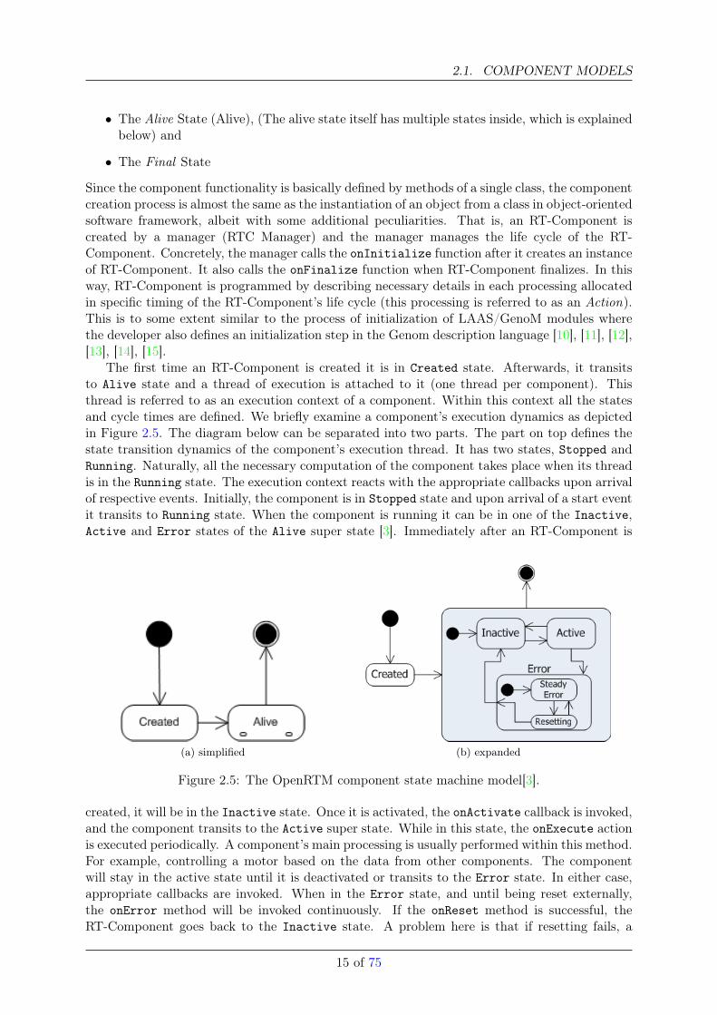
• The Created State (Created)
14 of 75
2.1. COMPONENT MODELS
• The Alive State (Alive), (The alive state itself has multiple states inside, which is explainedbelow) and
• The Final State
Since the component functionality is basically defined by methods of a single class, the componentcreation process is almost the same as the instantiation of an object from a class in object-orientedsoftware framework, albeit with some additional peculiarities. That is, an RT-Component iscreated by a manager (RTC Manager) and the manager manages the life cycle of the RT-Component. Concretely, the manager calls the onInitialize function after it creates an instanceof RT-Component. It also calls the onFinalize function when RT-Component finalizes. In thisway, RT-Component is programmed by describing necessary details in each processing allocatedin specific timing of the RT-Component’s life cycle (this processing is referred to as an Action).This is to some extent similar to the process of initialization of LAAS/GenoM modules wherethe developer also defines an initialization step in the Genom description language [10], [11], [12],[13], [14], [15].
The first time an RT-Component is created it is in Created state. Afterwards, it transitsto Alive state and a thread of execution is attached to it (one thread per component). Thisthread is referred to as an execution context of a component. Within this context all the statesand cycle times are defined. We briefly examine a component’s execution dynamics as depictedin Figure 2.5. The diagram below can be separated into two parts. The part on top defines thestate transition dynamics of the component’s execution thread. It has two states, Stopped andRunning. Naturally, all the necessary computation of the component takes place when its threadis in the Running state. The execution context reacts with the appropriate callbacks upon arrivalof respective events. Initially, the component is in Stopped state and upon arrival of a start eventit transits to Running state. When the component is running it can be in one of the Inactive,Active and Error states of the Alive super state [3]. Immediately after an RT-Component is
(a) simplified (b) expanded
Figure 2.5: The OpenRTM component state machine model[3].
created, it will be in the Inactive state. Once it is activated, the onActivate callback is invoked,and the component transits to the Active super state. While in this state, the onExecute actionis executed periodically. A component’s main processing is usually performed within this method.For example, controlling a motor based on the data from other components. The componentwill stay in the active state until it is deactivated or transits to the Error state. In either case,appropriate callbacks are invoked. When in the Error state, and until being reset externally,the onError method will be invoked continuously. If the onReset method is successful, theRT-Component goes back to the Inactive state. A problem here is that if resetting fails, a
15 of 75
CHAPTER 2. COMPONENT-BASED SOFTWARE TECHNOLOGIES
component may stay in the Error state for an indefinite period of time. There should be somesort of mechanism to take care of this, for instance automatically resetting the component aftera fixed period of time or timeout. Considering this model, ideally the main task of a componentdeveloper should be overriding each of the state-associated methods/callbacks of the templatecomponent with the desired functionality [3], [6], [7], [8], [9].
OpenRTM comes with an automatic component generation tool, RtcTemplate. RtcTemplatecan generate two types of components based on the provided input. By default, when onlya module name is given as an argument, it generates data-driven components with data portsonly. In case it is invoked with an *.idl component description file as argument, it generates codefor service port support. This is basically done via a wrapper around CORBA IDL compiler,therefore it generates a similar set of files: stubs and skeletons. This is valid for component withservice ports because they should know their peers in advance.
The component generation process is to some extent similar to that of the LAAS/GenoMsystem [10], [11], [12], [13], [14], [15]. In LAAS/GenoM, the developer has to describe thecomponent model, including its execution states, the data shared with other components, thecomponent execution life cycle, and runtime features such as threads etc. This information isthen provided to the genom command line tool, which generates skeletons for the componentsin the required programming language. In GenoM, the implementation language is mostly C,whereas RtcTemplate supports C++, Python and Java [16], [17], [3].
In addition to the problem of development of functional components, there is also the problemof composition, also referred to as “system integration”. How to connect components with eachother without extra overhead of writing special code for it? OpenRTM takes care of this issue byintroducing RtcLink, an Eclipse-based graphical composition tool. It provides a basic operatingenvironment required in order to build a system by combining multiple RT-Components. Italso enables the acquisition of meta-information of RT-Components by reading the profile of acomponent and its data and service ports. The other alternative to provide the functionality ofRtcLink would be to implment an editing program for connecting components.
The OpenRTM/AIST distribution model is based on distributed objects. It is based on theomniORB implementation of the CORBA specification. In RtcLink, openRTM allows to definea subscription type when connecting components (what data the component should receive):flush, new, periodic, triggered. Additionally, the developer can define both a communicationpolicy, either pull or push mode, and a communication mechanism, either CORBA or TCPsockets. An OpenRTM component’s computation model (the core logic) allows to perform anycomputation/processing need as long as they can be defined via the provided callback methodstied to the state. It is also possible to combine OpenRTM with external software packages, suchas Player/Stage. The build process is also simplified because both openRTM components andPlayer/Stage do come in the form of dynamic libraries. Listing 3 shows the RT-Componentstructure as it is implemented in OpenRTM/AIST.
class RTObject_impl: public virtual POA_RTC::DataFlowComponent,public virtual PortableServer::RefCountServantBase{
public:RTObject_impl(Manager* manager);RTObject_impl(CORBA::ORB_ptr orb, PortableServer::POA_ptr poa);virtual ~RTObject_impl();
protected:virtual ReturnCode_t onInitialize();virtual ReturnCode_t onFinalize();virtual ReturnCode_t onStartup(RTC::UniqueId ec_id);virtual ReturnCode_t onShutdown(RTC::UniqueId ec_id);virtual ReturnCode_t onActivated(RTC::UniqueId ec_id);virtual ReturnCode_t onDeactivated(RTC::UniqueId ec_id);virtual ReturnCode_t onExecute(RTC::UniqueId ec_id);
16 of 75
2.1. COMPONENT MODELS
virtual ReturnCode_t onAborting(RTC::UniqueId ec_id);virtual ReturnCode_t onError(RTC::UniqueId ec_id);virtual ReturnCode_t onReset(RTC::UniqueId ec_id);virtual ReturnCode_t onStateUpdate(RTC::UniqueId ec_id);virtual ReturnCode_t onRateChanged(RTC::UniqueId ec_id);
public:virtual ReturnCode_t initialize()throw (CORBA::SystemException);...
};
Listing 3. The OpenRTM component signature.
2.1.3 Player
Player is a software package developed at the University of South California. The main objectiveof Player is to simplify user level client robotics applications (e.g. localization, pathplanning etc)to have access to hardware resource/devices. Therefore one can view it as an application serverinterfacing with robot HW devices and user developed client programs.
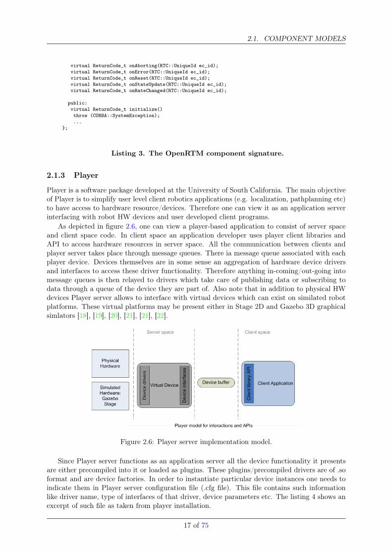
As depicted in figure 2.6, one can view a player-based application to consist of server spaceand client space code. In client space an application developer uses player client libraries andAPI to access hardware resources in server space. All the communication between clients andplayer server takes place through message queues. There ia message queue associated with eachplayer device. Devices themselves are in some sense an aggregation of hardware device driversand interfaces to access these driver functionality. Therefore anything in-coming/out-going intomessage queues is then relayed to drivers which take care of publishing data or subscribing todata through a queue of the device they are part of. Also note that in addition to physical HWdevices Player server allows to interface with virtual devices which can exist on similated robotplatforms. These virtual platforms may be present either in Stage 2D and Gazebo 3D graphicalsimlators [18], [19], [20], [21], [21], [22].
Figure 2.6: Player server implementation model.
Since Player server functions as an application server all the device functionality it presentsare either precompiled into it or loaded as plugins. These plugins/precompiled drivers are of .soformat and are device factories. In order to instantiate particular device instances one needs toindicate them in Player server configuration file (.cfg file). This file contains such informationlike driver name, type of interfaces of that driver, device parameters etc. The listing 4 shows anexcerpt of such file as taken from player installation.
17 of 75
CHAPTER 2. COMPONENT-BASED SOFTWARE TECHNOLOGIES
driver(
name "urglaser"provides ["laser:0"]port "/dev/ttyS0"#port "/dev/ttyACM0"pose [0.05 0.0 0.0]min_angle -115.0max_angle 115.0use_serial 1baud 115200alwayson 0
)driver(
name "vfh"provides ["position2d:1"]requires ["position2d:0" "laser2d:0"]cell_size 0.1window_diameter 61sector_angle 1safety_dist 0.3max_speed 0.3max_turnrate_0ms 50max_turnrate_1ms 30
)
Listing 4. Player configuration file internals.
This device related information is desribed by special keywords which are part of the Playerinterface specification. The most important of these are name, requires, and provides. Namekeyword servers as an identifier for Player server and tells which driver should be instantiated.After server instantiates that driver to make it accessible to clients this driver should declareinterfaces. These interfaces could have ‘required’ or ‘provided’ polarities (for complete referenceof .cfg keywords check Player interface specification [23].
An application programmer point of view: To understand inner-workings of Player oneneeds to look into how the server knows how to choose indicated driver from the precompiled/-plugin drivers and instantiate it. Additonally we will try to show how messages from client spaceare delivered to the right device.
When the Player server is launched with a configuration file about underlying hardwareresources, the first thing it does is to check a driver name in the driver table and register it. Thedriver table is kept inside the Player server ( this procedure is valid when when the driver ispart of the player core), if driver is in the form of a plugin/shared library then one also needs toprovide the name of the shared library which implements the driver. After this process, Playerserver reads the information about the interface which is also under the same declaration blockin .cfg file [listing 4]. As it can be seen there is a special syntax to declare interface of the driver.This syntax provides information on how many instances of this particular interface should becreated, for instance [23]. Then the type of the interface is matched with appropriate interfaceCODE (ID) to create that interface. This is needed because each interface has its own specificdata and command message semantics. That is, there is a predefined list of data structures andcommands that each interface can communicate [23]. Each interface specic message consists ofthe following headers;
• Relevant constants (size limits, etc.)
• Message subtypes
18 of 75
2.1. COMPONENT MODELS
– Data subtypes - defines code for a data header of the message
– Command subtypes - defines code for a command header of the message
– Request/reply subtypes - defines code for request/reply header of the message
• Utility structures - defines structures that appear inside messages.
• Message structures
– Data structures - defines data messages that can be communicated through this in-terface.
– Command structures - defines command messages that can be communicated throughthis interface.
– Request/reply structures - defines request/reply messages that can be communicatedthrough this interfaces.
The listing 5 provides overview of message consituents for ‘localization’ interface (excerpt istaken from Player manual [23], [21])
#define PLAYER_LOCALIZE_DATA_HYPOTHS 1Data subtype: pose hypotheses.#define PLAYER_LOCALIZE_REQ_SET_POSE 1Request/reply subtype: set pose hypothesis.#define PLAYER_LOCALIZE_REQ_GET_PARTICLES 2Request/reply subtype: get particle set.typedef player_localize_hypoth player_localize_hypoth_tHypothesis format.typedef player_localize_data player_localize_data_tData: hypotheses (PLAYER_LOCALIZE_DATA_HYPOTHS).typedef player_localize_set_pose player_localize_set_pose_tRequest/reply: Set the robot pose estimate.typedef player_localize_particle player_localize_particle_tA particle.typedef player_localize_get_particles player_localize_get_particles_tRequest/reply: Get particles.
Listing 5. Player interface specification.
Based on the discussion above one can assume that were the Player server a real component-based software system (component is a relative term here, and refers to an entity with its ownexecution context and interaction endpoints. A more through definition to a component is givenin 2.2.) One could consider it to be a component with three different interface semantics based onthe various type of information that is communicated to/from it [23]. These are DATA, COMMANDand REQUEST/REPLY. The listing 6 shows possible message subtype semantics and their respectivecodes.
#define PLAYER_MSGTYPE_DATA 1A data message.#define PLAYER_MSGTYPE_CMD 2A command message.#define PLAYER_MSGTYPE_REQ 3A request message.#define PLAYER_MSGTYPE_RESP_ACK 4A positive response message.#define PLAYER_MSGTYPE_SYNCH 5A synch message.#define PLAYER_MSGTYPE_RESP_NACK 6
Listing 6. Player message subtypes.
19 of 75
CHAPTER 2. COMPONENT-BASED SOFTWARE TECHNOLOGIES
In Player clients can use two modes for data transmission. These are PUSH and PULL modes.One has to note that these modes affect the clients’ message queues only, that is they do notaffect how messages are received from clients on the server side. In PUSH mode all messages arecommunicated as quick as possible, whereas in PULL mode [23]:
• Message is only sent to a client when it is marked as ready in client’s message queue.
• PLAYER_MSGTYPE_DATA messages are not marked as ready until the client requests data.
• PLAYER_MSGTYPE_RESP_ACK and PLAYER_MSGTYPE_RESP_NACK message types are marked asready upon entering the queue.
• When a PLAYER_PLAYER_REQ_DATA message is received, all messages in the client’s queueare marked as ready.
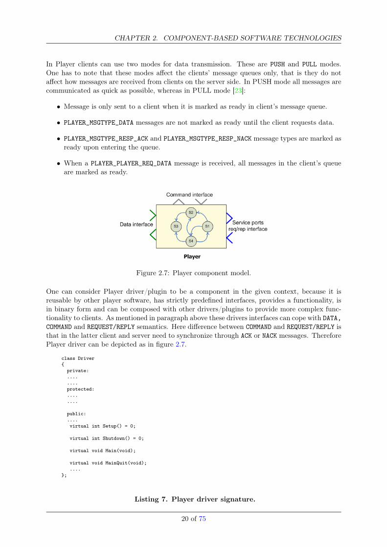
Figure 2.7: Player component model.
One can consider Player driver/plugin to be a component in the given context, because it isreusable by other player software, has strictly predefined interfaces, provides a functionality, isin binary form and can be composed with other drivers/plugins to provide more complex func-tionality to clients. As mentioned in paragraph above these drivers interfaces can cope with DATA,COMMAND and REQUEST/REPLY semantics. Here difference between COMMAND and REQUEST/REPLY isthat in the latter client and server need to synchronize through ACK or NACK messages. ThereforePlayer driver can be depicted as in figure 2.7.
class Driver{
private:........protected:........
public:....virtual int Setup() = 0;
virtual int Shutdown() = 0;
virtual void Main(void);
virtual void MainQuit(void);....
};
Listing 7. Player driver signature.
20 of 75
2.1. COMPONENT MODELS
All Player drivers/plugins have their own signle thread of execution. Listing 7 describes Driverclass definition and its life cycle management method prototypes. As it can be seen Player drivergoes through three main states during its life cycle:
• Setup - in this state driver is initialized and is active when the first client subscribes
• Shutdown - in this state driver finishes execution and is active when the last client unsub-scribes
• Main - in this state, driver performs its functionality. After execution finished thread exitsMain state and goes into auxilary MainQuit state which performs additional cleanup whenthe thread exits.
21 of 75
CHAPTER 2. COMPONENT-BASED SOFTWARE TECHNOLOGIES
2.1.4 ROS
ROS, Robot Operating System, is a software developed at Willow Garage. ROS, literally, is not acomponent oriented software as it is defined in [24]. It does not define any specific computationunit model with interaction endpoints as it has been in other systems we considered so far[2.1.1, 2.1.2]. But as it is observed in many programming paradigms (functions in functionalprogramming, objects in object-orientation etc), ROS also strives to build applications from‘modular units’. In ROS programming model, the modular programming unit is a ‘node’. Thenode can be considered as the block of functional code performing some sort of computation ina loop. The results of these computations are not available to external parties as long as thereis no an interaction end-point attached to the node. ROS defines two types of such interactionendpoints. The distinction is made with respect to the semantics of information communicatedthrough an endpoint and how those pieces of information should be communicated. Beforedelving into details of each endpoint type, one needs to emphasize that in ROS all the necessaryinformation exchange among nodes is performed through messages.
Messages are strictly typed data structures. There can be simple data structure and com-pound data structure messages. Compound messages can be formed by nesting other arbitrarilycomplex data structures. In ROS to achieve platform independence (here platform is languageof implementation) as well as to facilitate definition of user defined data types, all messages aredescribed using Message Description Language. Message specification is stored in .msg textfiles which could be described to consist of two parts, fields and constants. Here field representsdata type. Additionally to field:constant pair, messages may have a ‘Header’ which providesmeta-information about the message. As one might have already observed in other reviewedsystems and interacting software systems in general, communicated data types are part of theinterface contract between a producer and a consumer. That is, in ROS for nodes to under-stand each other they need to agree on the message types. Listing below shows a descriptionfile for multi-dimensional array of 320bit float numbers, in this listing MultiArrayLayout is alsoa message specified in another description file.
MultiArrayLayout layoutfloat32[ ] data
Listing 8. ‘.msg’ file definition.
Now coming back to the types of the endpoints.
• Should the exchanged information have data semantics (e.g. data from sensors) and becommunicated mostly asynchronously (non-blocking mode) between invoker and invokee,the endpoint is analogues to the data ports in OpenRTM2.1.2 and OROCOS2.1.1. In ROSthis functionality is achieved through introduction of the messages and a concept of Topicto which the messages are published. Topic serves as an identifier for the content of amessage. Publisher node publishes its messages to a particular topic and any interestedsubscriber node then subscribes to this topic. There can be multiple nodes publishing tothe same topic or multiple topics, as well as many nodes subscribing to the data on thosetopics. Such exchange of data has one-way semantics and is corner stone of publisher-subscriber interaction model. Usually neither the publishers nor the subsribers are aware ofeach others existance, i.e. they are completely decoupled from each other and the only awayfor them to learn about topics/data of interest is through a naming service. In ROS thisfunctionality is performed by master node. Master node keeps track of all the publishersand topics they publish to, so if any subscriber requires data the first thing it does is to learnfrom the master node the list of existing Topics. Note that in this three way interactionmodel (publisher-master, master-subscriber, publisher-subscriber) no actual data is routedtrhough the master node.
22 of 75
2.1. COMPONENT MODELS
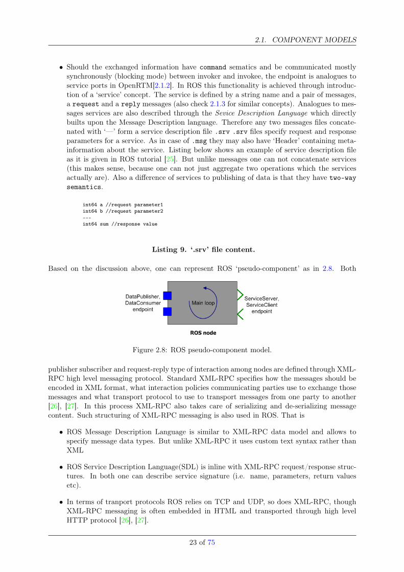
• Should the exchanged information have command sematics and be communicated mostlysynchronously (blocking mode) between invoker and invokee, the endpoint is analogues toservice ports in OpenRTM[2.1.2]. In ROS this functionality is achieved through introduc-tion of a ‘service’ concept. The service is defined by a string name and a pair of messages,a request and a reply messages (also check 2.1.3 for similar concepts). Analogues to mes-sages services are also described through the Sevice Description Language which directlybuilts upon the Message Description language. Therefore any two messages files concate-nated with ‘—’ form a service description file .srv .srv files specify request and responseparameters for a service. As in case of .msg they may also have ‘Header’ containing meta-information about the service. Listing below shows an example of service description fileas it is given in ROS tutorial [25]. But unlike messages one can not concatenate services(this makes sense, because one can not just aggregate two operations which the servicesactually are). Also a difference of services to publishing of data is that they have two-waysemantics.
int64 a //request parameter1int64 b //request parameter2---int64 sum //response value
Listing 9. ‘.srv’ file content.
Based on the discussion above, one can represent ROS ‘pseudo-component’ as in 2.8. Both
Figure 2.8: ROS pseudo-component model.
publisher subscriber and request-reply type of interaction among nodes are defined through XML-RPC high level messaging protocol. Standard XML-RPC specifies how the messages should beencoded in XML format, what interaction policies communicating parties use to exchange thosemessages and what transport protocol to use to transport messages from one party to another[26], [27]. In this process XML-RPC also takes care of serializing and de-serializing messagecontent. Such structuring of XML-RPC messaging is also used in ROS. That is
• ROS Message Description Language is similar to XML-RPC data model and allows tospecify message data types. But unlike XML-RPC it uses custom text syntax rather thanXML
• ROS Service Description Language(SDL) is inline with XML-RPC request/response struc-tures. In both one can describe service signature (i.e. name, parameters, return valuesetc).
• In terms of tranport protocols ROS relies on TCP and UDP, so does XML-RPC, thoughXML-RPC messaging is often embedded in HTML and transported through high levelHTTP protocol [26], [27].
23 of 75
CHAPTER 2. COMPONENT-BASED SOFTWARE TECHNOLOGIES
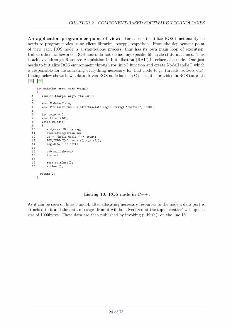
An application programmer point of view: For a user to utilize ROS functionality heneeds to program nodes using client libraries, roscpp, rospython. From the deployment pointof view each ROS node is a stand-alone process, thus has its own main loop of execution.Unlike other frameworks, ROS nodes do not define any specific life-cycle state machines. Thisis achieved through Resource Acquisition Is Initialisation (RAII) interface of a node. One justneeds to initialize ROS environment through ros::init() function and create NodeHandle() whichis responsible for instantiating everything necessary for that node (e.g. threads, sockets etc).Listing below shows how a data-driven ROS node looks in C++ as it is provided in ROS tutorials[25], [28].
int main(int argc, char **argv){
1 ros::init(argc, argv, "talker");23 ros::NodeHandle n;4 ros::Publisher pub = n.advertise<std_msgs::String>("chatter", 1000);56 int count = 0;7 ros::Rate r(10);8 while (n.ok())9 {10 std_msgs::String msg;11 std::stringstream ss;12 ss << "hello world " << count;13 ROS_INFO("%s", ss.str().c_str());14 msg.data = ss.str();1516 pub.publish(msg);17 ++count;1819 ros::spinOnce();20 r.sleep();
}return 0;
}
Listing 10. ROS node in C++.
As it can be seen on lines 3 and 4, after allocating necessary resources to the node a data port isattached to it and the data messages from it will be advertized at the topic ‘chatter’ with queuesize of 1000bytes. These data are then published by invoking publish() on the line 16.
24 of 75
2.2. COMPARISON RESULTS AND CONCLUSIONS
2.2 Comparison Results and Conclusions
The section above provided a general information on some of the current software approaches inrobotics. In the following section we provide a comparison of primary constructs of componentmodels observed in each system (comparison also includes some other software systems notdescribed above in detail). The comparison is performed with respect to draft BRICS componentmeta-model (BCM) which we take as a reference. Note that it does not imply in any way thatBRICS component model is the best choice, it just simplifies the evaluation process, because ofthe existance of the reference. First we define a number of concepts and respective modellingprimitives which are used in BRICS component meta-model.
1. Component - “a convenient approach to encapsulate robot functionality (access to hard-ware devices, simulation tools, functional libraries, etc.) in order to make them interop-erable, composable no matter what programming language, operating system, computingarchitecture, communication protocol is used” [24], [4].
2. Port - in the context of BCM, port is a software component ‘interface’ (e.g. scan-ner2D, position3D) which groups a set of operations as defined in OOP (e.g. send-Scan(), getPos()) that can only communicate information with data (e.g. set of scanpoints from a laserscanner, an array of odometry values from a localisation component)semantics with other component ports in publisher-subscriber mode. That is, port repre-sents data-flow of the BCM. Therefore, inter-component interaction policy is part of thedata-flow interface and informally one can describe by the following expression port =functional interface + publisher − subscriberinteraction policy.
3. Interface - in BCM, an interface is a software component interface (e.g. scanner2D, posi-tion3D) which groups a set of operations as defined in OOP (e.g. setApexAngle(), setRes-olution()) that can only communicate information with command semantics (e.g settingdevice/algorithm configurations). In other words it represents component control-flow. Inthe context of many robot software systems presented, BCM interface is also referred toas a service 2.1.2. As in the case of the port, inter-component interaction policy is part ofthe BCM interface in the form of remote procedure call. Informally, this can be expressedas bricsCM Interface = functional interface + client− serverinteraction policy
4. Operation - is the part of software component ‘interface’ and is equivalent to OOP method(e.g. setScan(), getConfiguration()). One can define different types of operations.
5. Connection - A connector is a language or software arhictecture construct which is usedto connect components. Since it is a construct, it can be instantiated with different annota-tions, such as types and policies (e.g. type - TAO, AMQP etc, policy - publisher-subscriber,client-server, peer-to-peer etc), whereas a connection is the concept that defines whethercomponents are connected through their particular end-points/ports. Additionally, theconnection is a system model level primitive.
6. State Machines - defines execution model, i.e. sequence of statements.
• Component internal lifecyle state machine - defines the phases in component in-tance life cycle starting from the initialization of ports, interfaces, resource allocation,cleanup and execution of component functionality/algorithm. In BCM life cycle statemachine consists of three states init, body, final and transitions among them.• functional algorithm state machine - BCM does not define a model for execution on
this level. It is second level execution manager (first level is component life cyclemanager) and runs within the body state.
25 of 75
CHAPTER 2. COMPONENT-BASED SOFTWARE TECHNOLOGIES
• Interface state machine (defines stateless and stateful interfaces) - BCM introducescontracts for the component service interfaces. The contracts are specified as statemachines which are part of the service interface and define execution order of theoperations in it. Depending on the specification of the state machine componentservice interface can be stateful or stateless.
7. Data types - BCM specifies a number of predefined data types that can be used to definedata exchange among components. These include primitive data types and compound datatypes. The latter conveys that user can define his own data types which follow particularrequirements for component data exchange.
8. Operation mode - this concept relates to the deployment aspect of the component. Thecomponent can be either in asynchronous, synchronous or any execution modes.
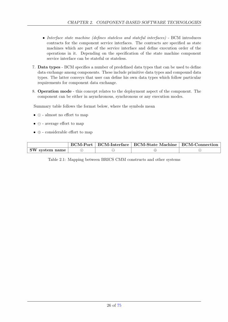
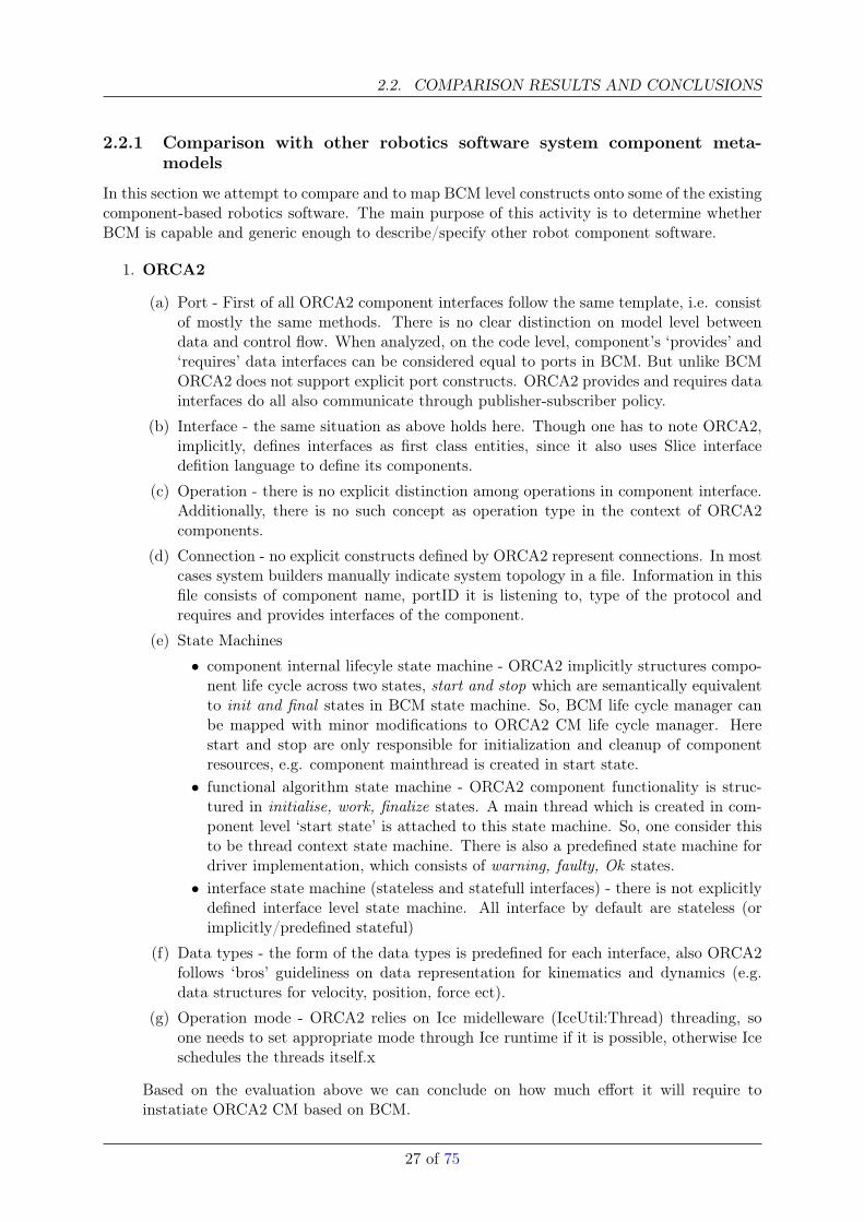
Summary table follows the format below, where the symbols mean
• � - almost no effort to map
• - average effort to map
• ⊕ - considerable effort to map
BCM-Port BCM-Interface BCM-State Machine BCM-ConnectionSW system name � ⊕ �
Table 2.1: Mapping between BRICS CMM constructs and other systems
26 of 75
2.2. COMPARISON RESULTS AND CONCLUSIONS
2.2.1 Comparison with other robotics software system component meta-models
In this section we attempt to compare and to map BCM level constructs onto some of the existingcomponent-based robotics software. The main purpose of this activity is to determine whetherBCM is capable and generic enough to describe/specify other robot component software.
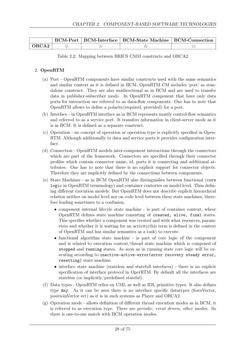
1. ORCA2
(a) Port - First of all ORCA2 component interfaces follow the same template, i.e. consistof mostly the same methods. There is no clear distinction on model level betweendata and control flow. When analyzed, on the code level, component’s ‘provides’ and‘requires’ data interfaces can be considered equal to ports in BCM. But unlike BCMORCA2 does not support explicit port constructs. ORCA2 provides and requires datainterfaces do all also communicate through publisher-subscriber policy.
(b) Interface - the same situation as above holds here. Though one has to note ORCA2,implicitly, defines interfaces as first class entities, since it also uses Slice interfacedefition language to define its components.
(c) Operation - there is no explicit distinction among operations in component interface.Additionally, there is no such concept as operation type in the context of ORCA2components.
(d) Connection - no explicit constructs defined by ORCA2 represent connections. In mostcases system builders manually indicate system topology in a file. Information in thisfile consists of component name, portID it is listening to, type of the protocol andrequires and provides interfaces of the component.
(e) State Machines
• component internal lifecyle state machine - ORCA2 implicitly structures compo-nent life cycle across two states, start and stop which are semantically equivalentto init and final states in BCM state machine. So, BCM life cycle manager canbe mapped with minor modifications to ORCA2 CM life cycle manager. Herestart and stop are only responsible for initialization and cleanup of componentresources, e.g. component mainthread is created in start state.• functional algorithm state machine - ORCA2 component functionality is struc-
tured in initialise, work, finalize states. A main thread which is created in com-ponent level ‘start state’ is attached to this state machine. So, one consider thisto be thread context state machine. There is also a predefined state machine fordriver implementation, which consists of warning, faulty, Ok states.• interface state machine (stateless and statefull interfaces) - there is not explicitly
defined interface level state machine. All interface by default are stateless (orimplicitly/predefined stateful)
(f) Data types - the form of the data types is predefined for each interface, also ORCA2follows ‘bros’ guideliness on data representation for kinematics and dynamics (e.g.data structures for velocity, position, force ect).
(g) Operation mode - ORCA2 relies on Ice midelleware (IceUtil:Thread) threading, soone needs to set appropriate mode through Ice runtime if it is possible, otherwise Iceschedules the threads itself.x
Based on the evaluation above we can conclude on how much effort it will require toinstatiate ORCA2 CM based on BCM.
27 of 75
CHAPTER 2. COMPONENT-BASED SOFTWARE TECHNOLOGIES
BCM-Port BCM-Interface BCM-State Machine BCM-ConnectionORCA2 � � ⊕
Table 2.2: Mapping between BRICS CMM constructs and ORCA2
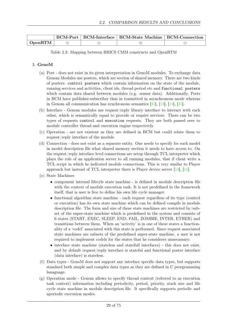
2. OpenRTM
(a) Port - OpenRTM components have similar constructs used with the same semanticsand similar context as it is defined in BCM. OpenRTM CM includes ‘port’ as stan-dalone construct. They are also unidirectional as in BCM and are used to transferdata in publisher-subscriber mode. In OpenRTM component that have only dataports for interaction are referred to as data-flow components. One has to note thatOpenRTM allows to define a polarity(required, provided) for a port.
(b) Interface - in OpenRTM interface as in BCM represents mostly control-flow semanticsand referred to as a service port. It transfers information in client-server mode as itis in BCM. It is defined as a separate construct.
(c) Operation - no concept of operation or operation type is explicitly specified in Open-RTM. Although additionally to data and service ports it provides configuration inter-face.
(d) Connection - OpenRTM models inter-component interactions through the connectorswhich are part of the framework. Connectors are specified through their connectorprofiles which contain connector name, id, ports it is connecting and additional at-tributes. One has to note that there is no explicit support for connector objects.Therefore they are implicitly defined by the connections between components.
(e) State Machines - as in BCM OpenRTM also distinguishes between functional (corelogic in OpenRTM terminology) and container contextes on model level. Thus defin-ing different execution models. But OpenRTM does not describe explicit hierarchicalrelation neither on model level nor on code level between these state machines, there-fore leading sometimes to a confusion.• component internal lifecyle state machine - is part of container context, where
OpenRTM defines state machine consisting of created, alive, final states.This specifies whether a component was created and with what resources, param-eters and whether it is waiting for an activity(this term is defined in the contextof OpenRTM and has similar semantics as a task) to execute.• functional algorithm state machine - is part of core logic of the component
and is related to execution context/thread state machine which is composed ofstopped and running states. As soon as in running state core logic will be ex-ecuting according to inactive-active-error(error recovery steady error,resetting) state machine.• interface state machine (stateless and statefull interfaces) - there is no explicit
specification of interface protocol in OperRTM. By default all the interfaces arestateless (or implicitly/predefined stateful).
(f) Data types - OpenRTM relies on UML as well as IDL primitive types. It also definestype Any. As it can be seen there is no interface specific datatypes (forceVector,positioinVector ect) as it is in such systems as Player and ORCA2.
(g) Operation mode - allows definition of different thread execution modes as in BCM, itis referred to as execution type. There are periodic, event driven, other modes. Sothere is one-to-one match with BCM operation modes.
28 of 75
2.2. COMPARISON RESULTS AND CONCLUSIONS
BCM-Port BCM-Interface BCM-State Machine BCM-ConnectionOpenRTM � � ⊕
Table 2.3: Mapping between BRICS CMM constructs and OpenRTM
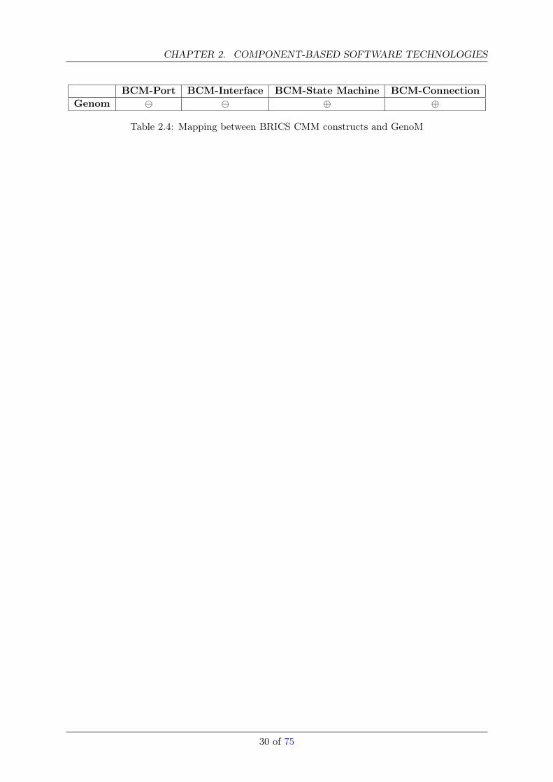
3. GenoM
(a) Port - does not exist in its given interpretation in GenoM modules. To exchange dataGenom Modules use posters, which are section of shared memory. There are two kindsof posters: control posters which contain information on the state of the module,running services and activities, client ids, thread period etc and functional posterswhich contain data shared between modules (e.g. sensor data). Additionally, Portsin BCM have publisher-subscriber thus in trasmitted in asynchronous mode whereasin Genom all communication has synchronous semantics [12], [13], [14], [15].
(b) Interface - Genom modules use request/reply library interface to interact with eachother, which is semantically equal to provide or require services. There can be twotypes of requests control and execution requests. They are both passed over tomodule controller thread and execution engine respectively.
(c) Operation - are not existent as they are defined in BCM but could relate them torequest/reply interface of the module.
(d) Connection - does not exist as a separate entity. One needs to specify for each modelin model description file what shared memory section it needs to have access to. Onthe request/reply interface level connections are setup through TCL interpreter whichplays the role of an application server to all running modules, that if client write aTCL script in which he indicated module connections. This is very similar to Playerapproach but instead of TCL interpreter there is Player device server [10], [11].
(e) State Machines• component internal lifecyle state machine - is defined in module description file
with the context of module execution task. It is not predefined in the frameworkitself, that is user is free to define his own life cycle manager.• functional algorithm state machine - each request regardless of its type (control
or execution) has its own state machine which can be defined compile in moduledescription file. The form and size of these state machines are restricted by/sub-set of the super-state machine which is predefined in the system and consists of6 states (START, EXEC, SLEEP, END, FAIL, ZOMBIE, INTER, ETHER) andtransitions between them. When an ‘activity’ is in one of these states a function-ality of a ‘codel’ associated with this state is performed. Since request associatedstate machines are subsets of the predefined super-state machine, a user is notrequired to implement codels for the states that he consideres unnecassary.• interface state machine (stateless and statefull interfaces) - this does not exist,
and by default request/reply interface is stateful and functional poster interface(data interface) is stateless.
(f) Data types - GenoM does not support any interface specific data types, but supportsstandard both simple and complex data types as they are defined in C prorgramminglanaguage.
(g) Operation mode - Genom allows to specify thread context (referred to as executiontask context) information including periodicity, period, priority, stack size and lifecycle state machine in module description file. It specifically supports periodic andaperiodic execution modes.
29 of 75
CHAPTER 2. COMPONENT-BASED SOFTWARE TECHNOLOGIES
BCM-Port BCM-Interface BCM-State Machine BCM-ConnectionGenom ⊕ ⊕
Table 2.4: Mapping between BRICS CMM constructs and GenoM
30 of 75
2.2. COMPARISON RESULTS AND CONCLUSIONS
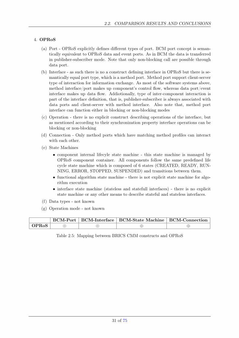
4. OPRoS
(a) Port - OPRoS explicitly defines different types of port. BCM port concept is seman-tically equivalent to OPRoS data and event ports. As in BCM the data is transferredin publisher-subscriber mode. Note that only non-blocking call are possible throughdata port.
(b) Interface - as such there is no a construct defining interface in OPRoS but there is se-mantically equal port type, which is a method port. Method port support client-servertype of interaction for information exchange. As most of the software systems above,method interface/port makes up component’s control flow, whereas data port/eventinterface makes up data flow. Addiotionally, type of inter-component interaction ispart of the interface definition, that is, publisher-subscriber is always associated withdata ports and client-server with method interface. Also note that, method portinterface can function either in blocking or non-blocking modes
(c) Operation - there is no explicit construct describing operations of the interface, butas mentioned according to their synchronization property interface operations can beblocking or non-blocking
(d) Connection - Only method ports which have matching method profiles can interactwith each other.
(e) State Machines
• component internal lifecyle state machine - this state machine is managed byOPRoS component container. All components follow the same predefined lifecycle state machine which is composed of 6 states (CREATED, READY, RUN-NING, ERROR, STOPPED, SUSPENDED) and transitions between them.• functional algorithm state machine - there is not explicit state machine for algo-
rithm execution• interface state machine (stateless and statefull interfaces) - there is no explicit
state machine or any other means to describe stateful and stateless interfaces.
(f) Data types - not known
(g) Operation mode - not known
BCM-Port BCM-Interface BCM-State Machine BCM-ConnectionOPRoS � � ⊕ ⊕
Table 2.5: Mapping between BRICS CMM constructs and OPRoS
31 of 75
CHAPTER 2. COMPONENT-BASED SOFTWARE TECHNOLOGIES
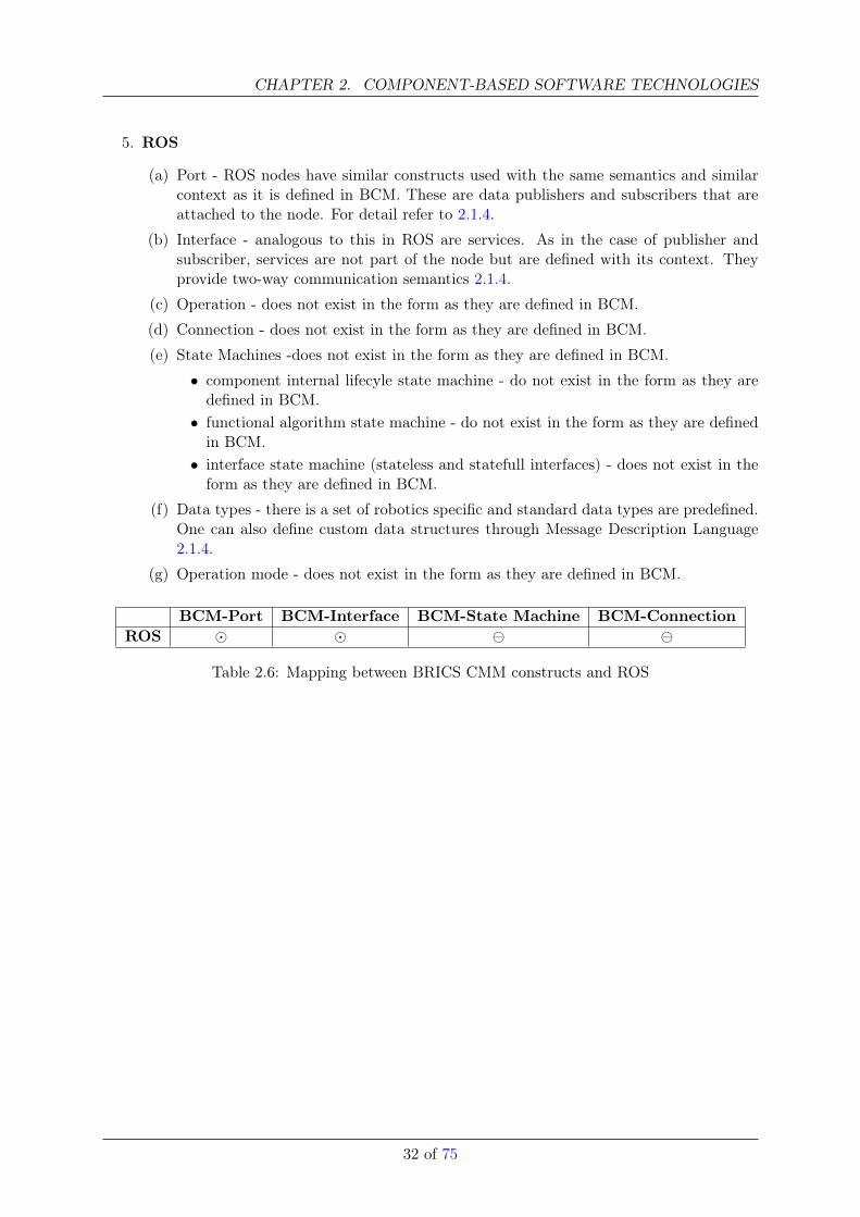
5. ROS
(a) Port - ROS nodes have similar constructs used with the same semantics and similarcontext as it is defined in BCM. These are data publishers and subscribers that areattached to the node. For detail refer to 2.1.4.
(b) Interface - analogous to this in ROS are services. As in the case of publisher andsubscriber, services are not part of the node but are defined with its context. Theyprovide two-way communication semantics 2.1.4.
(c) Operation - does not exist in the form as they are defined in BCM.
(d) Connection - does not exist in the form as they are defined in BCM.
(e) State Machines -does not exist in the form as they are defined in BCM.
• component internal lifecyle state machine - do not exist in the form as they aredefined in BCM.• functional algorithm state machine - do not exist in the form as they are defined
in BCM.• interface state machine (stateless and statefull interfaces) - does not exist in the
form as they are defined in BCM.
(f) Data types - there is a set of robotics specific and standard data types are predefined.One can also define custom data structures through Message Description Language2.1.4.
(g) Operation mode - does not exist in the form as they are defined in BCM.
BCM-Port BCM-Interface BCM-State Machine BCM-ConnectionROS � �
Table 2.6: Mapping between BRICS CMM constructs and ROS
32 of 75
2.2. COMPARISON RESULTS AND CONCLUSIONS
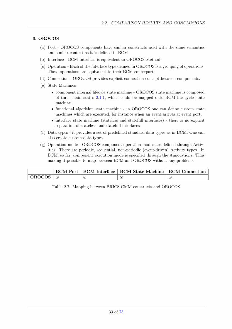
6. OROCOS
(a) Port - OROCOS components have similar constructs used with the same semanticsand similar context as it is defined in BCM
(b) Interface - BCM Interface is equivalent to OROCOS Method.
(c) Operation - Each of the interface type defined in OROCOS is a grouping of operations.These operations are equivalent to their BCM couterparts.
(d) Connection - OROCOS provides explicit connection concept between components.
(e) State Machines
• component internal lifecyle state machine - OROCOS state machine is composedof three main states 2.1.1, which could be mapped onto BCM life cycle statemachine.• functional algorithm state machine - in OROCOS one can define custom state
machines which are executed, for instance when an event arrives at event port.• interface state machine (stateless and statefull interfaces) - there is no explicit
separation of stateless and statefull interfaces
(f) Data types - it provides a set of predefined standard data types as in BCM. One canalso create custom data types.
(g) Operation mode - OROCOS component operation modes are defined through Activ-ities. There are periodic, sequential, non-periodic (event-driven) Activity types. InBCM, so far, component execution mode is specified through the Annotations. Thusmaking it possible to map between BCM and OROCOS without any problems.
BCM-Port BCM-Interface BCM-State Machine BCM-ConnectionOROCOS � � � �
Table 2.7: Mapping between BRICS CMM constructs and OROCOS
33 of 75
CHAPTER 2. COMPONENT-BASED SOFTWARE TECHNOLOGIES
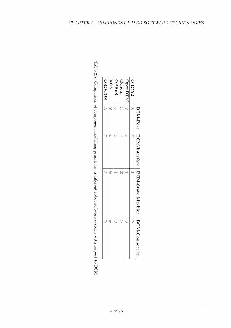
BCM-Port
BCM-Interface
BCM-State
Mach
ine
BCM-C
onnection
ORCA2
��
⊕
Open
RTM
��
⊕
Gen
om
⊕
⊕OPRoS
��
⊕⊕
ROS
��
OROCOS
��
��
Table
2.8:Com
parisonof
component
modelling
primitives
indifferent
robotsoftw
aresystem
swith
respectto
BCM
34 of 75
2.2. COMPARISON RESULTS AND CONCLUSIONS
2.2.2 Conclusion
This section provided an exaustive review of component-oriented software and its application inrobotics domain. An attempt was made to objectively analyze and evaluate robotics component-based software frameworks. The evaluation was performed with respect to BRICS ComponentModel (BCM), which is currently under the development. The final goal of BCM is to incorparatebest practices/feeatures from the existing systems and allow component level interoperatbility.This work will allow to justify design decisions behind BCM. During the evaluation process thefollowing points were observed:
• there is not only a zoo of robot software frameworks, but also a zoo of component models(CM)
• most of these CMs have almost the same type of component interfaces, i.e. data ports andservice ports
• most CMs lack an explicit concept of connectors
• most CMs have similar finite state machine categories for life cycle management
• most CMs come in the form of a framework and there is not much tool support providedfor application design and testing. Exceptions to this situation are OPRoS, OpenRTM andROS software which provide software management and design tool chain.
• even though most of the components have common features and attributes there is noa systematic approach to reuse software across the systems. Observing current trend inrobotics software developement, one can state that the number of new software packagesmight grow in the future. This situation is similar to OS domain a decade ago, when therewere a handful of systems which then grew in number. Most of those systems providedsome means for interoperability among each other. The similar trend should be taken inrobot software domain. Since there is an abundance of robot software systems and CMsout there with largely the same functionalities and at the same time there is no way topersuade people to use ’The Universal Solution’, the best approach to make further progressis to achieve interoperability between existing systems on different levels, i.e. components,models, algorithsm etc.
35 of 75
Chapter 3
Communication Middleware
In [29] Makarenko, Brooks and Kaupp analysed different robotic software frameworks like Player [30],Orocos [5] and YARP [31]. They identified that all of these frameworks are faced with distributedcommunication and computation issues. Due to the distributed nature of todays robotic systemsthis is not surprising. For instance Johnny, the world champion 2009 of the RoboCup@Homeleague is a fully distributed system, e.g. consumer and producer of laser-scans are physicallydistributed and via an ethernet network connected [32]. Having a distributed system, it is nec-essary to address several problems. Ranging from ’how is the information encoded? ’ to ’how isthe data translation between different machines managed? ’. As in other domains (automotive,aviation, and telecommunications), in robotics those problems are solved by making use of mid-dleware technologies. Beside handling the mentioned challenges those middleware technologieskeep away the complexity of distributed systems from the application developer. Interestingly,in robotics there is no exclusive middleware technology used. In fact, every robotic frameworkcomes with it’s own middleware technology, either hand-crafted [30] or integrated [29]. However,the decision criteria which middleware technology to choose are quite often fuzzy and not well-defined. Taking this in account this Section attempts to assess middleware technologies in anunambiguous manner, and serves as a screening of the current marketplace in communicationmiddleware technologies.
The remainder of this Section is structured as follows. In Section 3.0.3 the current market-place of communication middleware technologies is screened and an exhaustive list of relevanttechnologies is compiled and categorized. In Section 3.0.4 the technologies are distinguished be-tween specifications and implementations, briefly described, and with respect to characteristicscompared. In Section 3.0.5 a conclusion is drawn and some recommendations are given.
3.0.3 The Marketplace of Communication Middleware
The current marketplace for middleware technologies is confusing and almost daunting1. How-ever, several authors surveyed the current marketplace and tried to categorise them. One feasibleapproach to categorise different middleware technologies is by their means of communication.In [33] Emmerich reviewed state-of-the-art middleware technologies from a software engineeringpoint of view. For doing this, Emmerich introduced the following three middleware classes.
• Message-oriented Middleware (MOM): In a message-oriented middleware messagesare the means of communication between applications. Therefore, message-oriented middle-ware is responsible for the message exchange and generally relies on asynchronous message-passing (fire and forget semantic) leading into loose-coupling of senders and receivers.
1Typing ’middleware’ in Google results in over 6.390.000 links (last access on 5th of Januar, 2010)
36
• Procedural-oriented Middleware (POM): All middleware which mainly provides re-mote procedure calls (RPC) is considered as procedural-middleware. Procedural-orientedmiddleware generally relies on synchronous (and asynchronous) message-passing in a cou-pled client-server relation.
• Object-oriented Middleware (OOM): Object-oriented middleware evolved from RPCand applies those principles to object-orientation.
Within this survey the classes were used to classify the middleware technologies from table 3.1.The classification is shown in the fourth column of table 3.1. The list has been compiled fromvarious sources including scientific articles out of the robotics domain. The first column labels thename of the middleware technology. The name refers to a concrete implementation (e.g. mom4j)and not to a specification (e.g. mom4j is an implementation of the Java Message Service(JMS) specification). In the second column the license under which the middleware technologyis available is mentioned. Please note that the entry ’Comm’ means that the middleware solutionis commercial. The acronyms ’APL’, ’GPL’, ’LGPL’ and ’BSD ’ are referring to the well-knownopen-source licenses Apache License (APL), GNU General Public License (GPL), GNU LesserGeneral Public License (LGPL) and BSD License (BSD)2. In the third column the interestedreader will find website references for further information.
The middleware Spread comes with it’s own license which is slightly different from the BSDlicense. The MPI library Boost.MPI comes as well with it’s own license, the Boost SoftwareLicense. ZeroMQ, omniORB and TIPC are under dual-license, this means that some parts(e.g. tools in OmniORB (e.g. for debugging) are under GPL and the middleware itself is underLGPL of the projects have different license conditions. Due to the fact that MilSoft, CoreDX,ORBACUS and webMethods are commercial solutions they are not further considered in thissurvey. Furthermore, the .NET platform by Microsoft is not considered as well. .NET is still aMicrosoft-only solution and therefore not suitable for heterogenous environments as in robotics.
3.0.4 Assessment
In the following the middleware technologies (from table 3.1) are differented in associated spec-ifications and implementations, briefly described, and with respect to core characteristics assupported platforms and programming languages (see table 3.2 and 3.3) compared.
Specification versus Implementation
As mentioned above, table 3.1 shows only implemented middleware solutions. Some of theseimplementations are associated to specifications. This means they implement a concrete speci-fication. To avoid adulterated assesment (e.g. comparision among specification and implemen-tation) it is necessary to figure out which middleware corresponds to which specification. Thebreakdown in specification and associated implementation is shown in table 3.2. In the followingparagraphs specifications and their associated implementations are described (e.g. Data Dis-tribution Service) as well as purely implementations without associated specifications (e.g.TIPC).
Data Distribution Service (DDS)
Like CORBA (see section 3.0.4) the Data Distribution Service is a standard by the OMG con-sortium. The standard describes a publish-subscribe service (one-to-one and one-to-many) for
2The licenses are available on http://www.opensource.org/licenses (last access on 5th of Januar, 2010)
37 of 75
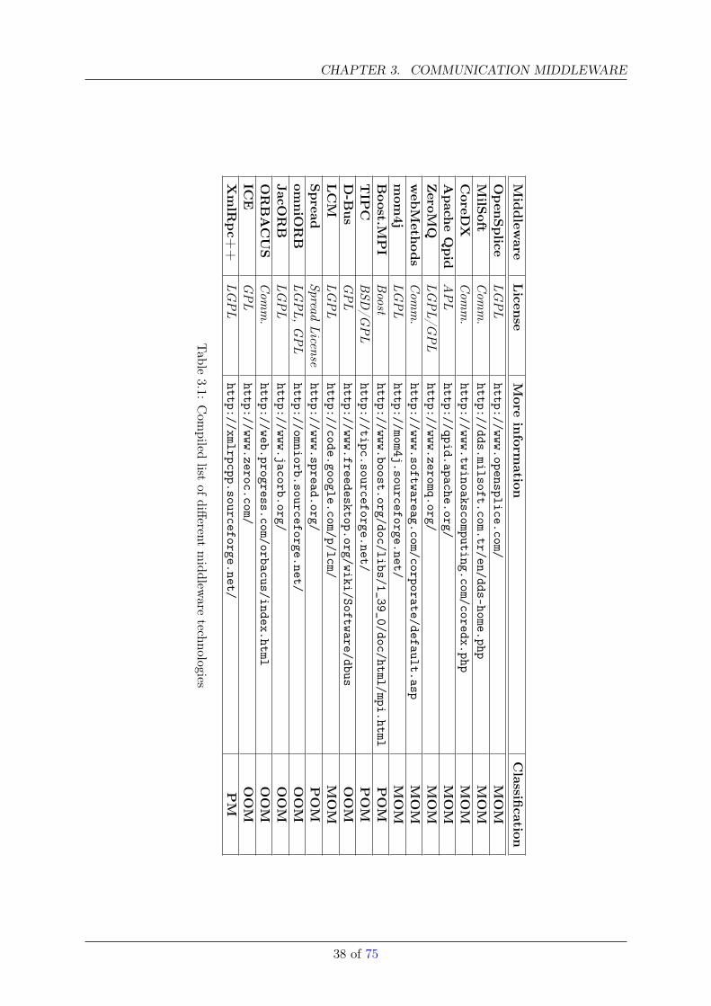
CHAPTER 3. COMMUNICATION MIDDLEWARE
Middlew
areLicen
seMore
inform
ationClassifi
cationOpen
Splice
LGPL
http://www.opensplice.com/MOM
MilS
oftCom
m.
http://dds.milsoft.com.tr/en/dds-home.phpMOM
CoreD
XCom
m.
http://www.twinoakscomputing.com/coredx.phpMOM
Apach
eQpid
APL
http://qpid.apache.org/MOM
ZeroM
QLG
PL/G
PL
http://www.zeromq.org/MOM
web
Meth
ods
Com
m.
http://www.softwareag.com/corporate/default.aspMOM
mom
4jLG
PL
http://mom4j.sourceforge.net/MOM
Boost.M
PI
Boost
http://www.boost.org/doc/libs/1_39_0/doc/html/mpi.htmlPOM
TIP
CBSD
/GPL
http://tipc.sourceforge.net/POM
D-B
us
GPL
http://www.freedesktop.org/wiki/Software/dbusOOM
LCM
LGPL
http://code.google.com/p/lcm/MOM
Spread
SpreadLicense
http://www.spread.org/POM
omniO
RB
LGPL,
GPL
http://omniorb.sourceforge.net/OOM
JacORB
LGPL
http://www.jacorb.org/OOM
ORBACUS
Com
m.
http://web.progress.com/orbacus/index.htmlOOM
ICE
GPL
http://www.zeroc.com/OOM
XmlR
pc+
+LG
PL
http://xmlrpcpp.sourceforge.net/PM
Table
3.1:Com
piledlist
ofdifferent
middlew
aretechnologies
38 of 75
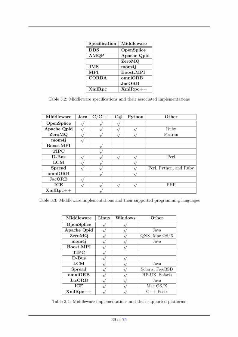
Specification MiddlewareDDS OpenSpliceAMQP Apache Qpid
ZeroMQJMS mom4jMPI Boost.MPICORBA omniORB
JacORBXmlRpc XmlRpc++
Table 3.2: Middleware specifications and their associated implementations
Middleware Java C/C++ C# Python OtherOpenSplice
√ √ √
Apache Qpid√ √ √ √
RubyZeroMQ
√ √ √ √Fortran
mom4j√
Boost.MPI√
TIPC√
D-Bus√ √ √ √
PerlLCM
√ √ √
Spread√ √ √
Perl, Python, and RubyomniORB
√ √
JacORB√
ICE√ √ √ √
PHPXmlRpc++
√
Table 3.3: Middleware implementations and their supported programming languages
Middleware Linux Windows OtherOpenSplice
√ √
Apache Qpid√ √
JavaZeroMQ
√ √QNX, Mac OS/X
mom4j√ √
JavaBoost.MPI
√ √
TIPC√
D-Bus√ √
LCM√ √
JavaSpread
√ √Solaris, FreeBSD
omniORB√ √
HP-UX, SolarisJacORB
√ √Java
ICE√ √
Mac OS/XXmlRpc++
√ √C++ Posix
Table 3.4: Middleware implementations and their supported platforms
39 of 75
CHAPTER 3. COMMUNICATION MIDDLEWARE
data-centric communication in distributed environments. For that reason DDS introduces a com-munication model with participants as the main entities. Those participants are either exclusivepublishers/subsribers or both. Similar to other message-oriented middleware publisher/sub-scriber are sending/receiving messages associated to a specific topic. Furthermore, the standarddescribes responsibilites of the DDS as:
• awareness of message adressing,
• marshalling, demarshalling, and
• delivery.
The standard itself is divided into two independent layers: the Data Centric Publish Subscribe(DCPS) and the Data Local Reconstruction Layer (DLRL). The former one describes how datafrom a publisher to a subscriber is transported according to QoS constraints. On the other handthe DLRL describes an API for an event and notification service which is quite similiar to theCORBA eventservice. Due to the fact that the DDS is independent from any wiring protocolthe QoS constraints are dependent on the used transport protocol (e.g. TCP or UDP).
OpenSplice developed by PrismTech implements the OMG Data Distribution Service. Open-Splice is available in a commercial and community edition. The community edition islicensed under LGPL. From a technical point of view OpenSplice main purpose is on real-time capabilities and therefore, reference applications are in the field where real-time is animportant issue (combat systems, aviation, etc.).
Advanced Message Queuing Protocol (AMQP)
Companies like Cisco, IONA and others specified the Advanced Message Queuing Protocol(AMQP). AMQP is a protocol for dealing with message-oriented middleware. Precisely, itspecifies how clients connect and use messaging functionality of a message-broker provided bythird-party vendor. The message-broker is responsible for delivering and storage of the messages.
Apache Qpid The opensource project Apache Qpid implements the AMQP specification. Qpidprovides two messaging services. On the one hand a C++ implementation and on the otherhand a Java implementation. Interestingly the Java implementation is also fully compliantwith the JMS specification by Sun Microsystems (see 3.0.4).
ZeroMQ The ZeroMQ message-oriented middleware is based on the AMQP model and spec-ification. In contrast to other message-oriented middleware ZeroMQ provides differentarchitectural styles of message-brokering. Usually a central message-broker is repsonsiblefor message delivering. This centralized architecture has serveral advantages.
• loose coupling of senders and receivers,• the lifetime of senders and receivers don’t overlap, and• the broker is resistent to application failures.
However, beside those advantages several disadvantages in the centralized architecture ex-ists. Firstly, the broker requires excessive amount of network communication. Secondly, dueto the potential high load of the message broker the broker itself can be the bottleneck andthe single-point-of-failure of the messaging system. Therefore, ZeroMQ supports differentmessaging models namely broker (as mentioned above), brokerless (peer-to-peer coupling),broker as directory server (senders and receivers are loosely coupled and they find eachother via the directory broker, but the messaging is done peer-to-peer), distributed bro-ker (multiple broker for one specific topic or message-queue), distributed directory server(multiple directory servers to avoid single point of failure).
40 of 75
Java Message Service (JMS)
The Java Message Service (JMS)3 itself is not a fully fledged middleware. It is an Application Pro-gramming Interface (API) specified by the Java Consortium to access and use message-orientedmiddleware provided by third-party vendors. Like in other message-oriented middleware, mes-sages in JMS are the means of communication between processes or more precisely applications.The API itself supports the delivery, production and distribution of messages. Furthermore, thesemantic of delivery (e.g. synchronous, transacted, durable and guaranteed) is attachable to themessages. Via the Java message interface, the hull of a message itself is specified. Messages arecomposed of three parts: header (destination, delivery mode, and more), properties (applicationspecific fields), and body (type of the message e.g. serialised object). JMS supports two messag-ing models: point-to-point (a message is consumed by a single consumer) and publish/subscribe(a message is consumed by multiple consumer). In the point-to-point case the destination of amessage is represented as a named queue. The named queue follows the first-in-first-out principleand the consumer of the message is able to acknowledge the receipt. In the publish/subscribecase the destination of the message is named by a so called topic. Producers publish to a topicand consumer subscribe to a topic. In both messaging-models the receiving of messages can bein blocking (receiver blocks until a message is available) and non-blocking (receiver gets informedby the messaging service when a message is available) mode.
mom4j The open-source project mom4j is a Java implementation of the JMS specification.Currently mom4j is compliant with JMS 1.1 but provides downwards compatiblities to 1.0.Due to the fact that the protocol to access and use mom4j is language independent clientsare programmable in different programming languages, e.g. Python and Java.
Message Passing Interface (MPI)
The Message Passing Interface (MPI) provides a specification for message passing especially inthe field of distributed scientific computing. Comparable to JMS (see section 3.0.4) MPI specifiesthe API but not the implementation. As Spread and TIPC MPI introduces groups and groupcommunication in the same manner as the former do. Moreover, the API provides point-to-point communication via synchronous sending/receiving, and buffered sending/receiving. Froman architectural point of view no server or broker for the communication between applications isneeded. Its purely based on the peer-to-peer communication model (group communication canbe considered as an extension). The communication model of MPI guarantees that messages willnot overtake each other.
Boost.MPI Boost.MPI is part of the well-known and popular Boost C++ source library andsupports the functionality which is defined in the MPI 1.1 specification.
Common Object Request Broker (CORBA)
The Common Object Request Broker (CORBA) is a standard architecture for distributed object-oriented middleware specified by the Object Management Group (OMG)4. CORBA was the firstspecification which heavily applied the broker-design pattern in a distributed manner resultingin providing object-oriented remote procedure calls. Beside remote procedure calls CORBAspecified several services like naming service, query service, event service, and more.
3The specification is available on http://java.sun.com/products/jms/docs.html (last access on 5th of Jan-uar, 2010)
4The CORBA specification is available on http://www.omg.org/technology/documents/corba_spec_catalog.htm(last access on 5th of Januar, 2010)
41 of 75
CHAPTER 3. COMMUNICATION MIDDLEWARE
omniORB implements the CORBA specification and is available for C++ and Python. Om-niORB is available under Windows, Linux, and several exotic Unix environments like AIX,UX, and more. From a technical point of view OmniORB provides a quite interesting threadabstaction framework. A common set of thread operations (e.g. wait(), wait_until())on top of different thread implementations (e.g. pthreads under Linux) is available.
JacORB is a CORBA implementation written in Java and available exclusively for Java plat-forms. From a technical-point of view JacORB provides the asynchronous method invo-cation as specified in Corba 3.0. Furthermore, JacORB implements a subset of the QoSpolicies defined in chapter 22.2 of the CORBA 3.0 specification. Namely, the sync scopepolicy (at which point a invocation returns to the caller e.g. invocation returns after therequest has been passed to the transport layer) and the timing policy (definition of requesttimings).
XML Remote Procedure Call (XML-RPC)
The XML-RPC protocol uses XML to encode remote procedure calls (XML as the marshallingformat). Furthermore, the protocol is bound to Http as a transport mechanism, because it uses’request’ and ’response’ http protocol elements to encapsulate remote procedure calls. XML-RPC showed to be very well suited for building cross-platform client-server applications, becauseclient and servers don’t need to be written in the same language.
XmlRpc++ is a C++ implementation of the XML-RPC protocol. Due to the fact thatXmlRpc++ is written in standard Posix C++ it is available under several platforms.XmlRpc++ is some how exotic in this survey. Firstly, the footprint is comparable small.Secondly, no further library is used (XmlRpc++ make use of the socket library providedby the host system).
Internet Communication Engine (ICE)
The Internet Communication Engine (ICE) by the company ZeroC is an object-oriented mid-dleware. ICE evolved from experiences by the core CORBA developers. From a non-technicalpoint of view the Internet Communication Engine is available in two licenses: a GPL version anda commercial one upon request. Furthermore, the documentation is exhaustive. From a techni-cal point of view ICE is quite comparable to CORBA. ICE adapts in the same way the brokerdesign-pattern from network-oriented programming to achieve object-oriented remote procedurecalls, including a specific interface definition language (called Slice) and principles like client-sideand server-side proxies. Beyond remote procedure calls ICE provides a handful of services.
• IceFreeze introduces object persistence. By the help of the Berkeley DB states of objectsare stored and upon request retrieved.
• IceGrid provides the ICE location service. By making use of the IceGrid functionality itis possible for clients to discover their servers at runtime. The IceGrid service acts as anintermediated server and therefore clients and servers are decoupled.
• IceBox is the application server within the ICE middleware. This means IceBox is re-sponsible for starting, stopping, and deployment of applications.
• IceStorm is a typical publish/subscribe service. Similar to other approaches, messagesare distributed by their associated topics. Publishers publish to topics and subscriberssubscribe to topics.
42 of 75
• IcePatch2 is a software-update service. By requesting an IcePatch service clients canupdate software versions of specific applications. However, IcePatch is not a versioningsystem in the classical sense (e.g. SVN or CVS).
• Glacier2 provides communication through firewalls, hence it is a firewall traversal servicemaking use of SSL and public-key mechanism.
Transparent Inter-Process Communication (TIPC)
The Transparent Inter-Process Communication (TIPC) framework evolved from cluster comput-ing projects at Ericsson. Comparable to Spread (see section 3.0.4) TIPC is a group communica-tion framework with an own message format. TIPC provides a layer between applications andthe packet transport mechanism, e.g. ATM or Ethernet. Even so, TIPC provides a broad rangeof network topologies both physical and logical. Furthermore, similar to Spread TIPC providesthe communication infrastructure to send and receive messages in a connection-oriented andconnectionless manner. Furthermore, TIPC provides command-line tools to monitor, query, andconfigure the communication infrastructure.
D-Bus
The D-Bus interprocess communication (IPC) framework developed mainly by RedHat is underthe umbrella of the freedesktop.org project. D-Bus is targeting mainly two IPC issues indesktop environments:
• communication between applications in the same desktop session, and
• communication between the desktop session and the operating system.
From an architectural point of view D-Bus is a message bus daemon acting as a server. Appli-cations (clients) connect to that daemon by making use of the functionality (e.g. connecting tothe daemon, sending messages,..) provided by the library libdbus. Furthermore, the daemon isresponsible for message dispatching between applications (directed), and between the operatingsystem, and potential applications (undirected). In the latter this may happen if a device isplugged in.
Lightweight Communications and Marshalling (LCM)
The Lightweight Communications and Marshalling (LCM) project provides a library. Mainpurpose of the library is to simplify the message passing and marshaling between distributedapplications. For message passing the library make use of the UDP protocol (especially UDPmulticast) and therefore no guarantees about message ordering and delivery are given. Datamarshalling and demarshalling is achieved by defining LCM types. Based on that type definitionan associated tool generates sourcecode for data marshalling and demarshalling. Due to thefact that UDP is used as a underlying communication protocol no daemon or server for relayingthe data is needed. From an architectural point of view LCM provides a publish/subscriberframework. To make the data receivable for subscribers it is necessary that the publisher providesa so called channel name, which is a string transmitted with each packet that identifies thecontents to receivers. Interestingly, from a robotics point of view is that LCM were used by theMIT team during the last year DARPA Grand Challenge. According to the developers the LCMlibrary performed quite robust and scaled very well (during the DARPA Grand Challenge).
43 of 75
CHAPTER 3. COMMUNICATION MIDDLEWARE
Spread Toolkit (Spread)
The Spread Toolkit, or shortly ’Spread’, is a group communication framework developed by Amirand Stanton at the John Hopkins University [34]. Spread provides a set of services for groupcommunication. Firstly, the abstraction of groups (a name representing a set of processes).Secondly, the communication infrastructure to send and receive messages between groups andgroup-members. The group service provided by Spread aims at scientific computing environmentswhere scalability (several thousands of active groups) is crucial. To support this, Spread providesseveral features as the agreed ordering of messages to the group, and the recovery of processesand whole groups in case of failures.
3.0.5 Conclusions
As shown in the previous sections the communication middleware marketplace is exhaustive (dif-ferent technologies, for different domains and applications), and very difficult or even impracticalto assess in an unbiased manner due to the explained reasons. However, the following conclusionscan be drawn.
• In general, communication middleware technologies tries to bridge the physical decouplingof senders and receivers (or clients and server(s)). From the software-side such decouplingis also wanted, because tight coupling leads to complexity, confusion, and suffering. All ofthe presented middleware technologies provides means of decoupling (on different levels).
• The Data Distribution Service implements the decoupling of senders and receiversthroughout the message-orientation. However, DDS is still a young standard and very fewopen-source implementation exists. Therefore, it might be too early to decide if DDS isan option for robotics or not.
• JMS and associated implementations are the de-facto standard for Java-based messaging.Regrettably, JMS is mainly limited to JAVA and therefore not an option for heterogeneous(in the sense of programming languages and platforms) environments as in robotics.
• The group communication frameworks Spread and TIPC are mature frameworks forheterogeneous communication environments. However, the functionality provided by thoseenvironments are too limited for robotics (where features as persistence are desireable).
• The most fully developed and mature communication middleware in that survey areCORBAand ICE. ICE and CORBA (with the various implementations) showed to be a feasiblemiddleware technologie in the robotics domain (as demonstrated in the Orca2 and Oro-cos framework). However, such fully-fledged middleware solutions tend to be difficult tounderstand and to use.
• As demonstrated in ROS the use of XML-RPC is feasible to develop lightweight commu-nication environments and might be an option for robotics.
44 of 75
Chapter 4
Interface Technologies
4.0.6 Component Interface Models
Generally, one can view a component in several different forms based on the context of the usageand components life cycle. Some of the notable of such views are [4]
• Specification form which describes the behavior of a set of component objects and definesa unit of implementation. Here behavior is defined as a set of interfaces. A realization ofa specification is a component implementation.
• Interface which represents a definition of a set of behaviors/services that a component canoffer or require.
• Implementation form is a realization of component specification. It is independently de-ployable unit of software. It needs not to be implemented in the form of single physicalitem (e.g. single file).
• Deployed form of a component is a copy of its implementation. Deployment takes placethrough registration of the component with the runtime environment. This is required toidentify a particular copy of the same component.
• Object form of a component is an instance of the deployed component and is a runtimeconcept. An installed component may have multiple component objects (which requireexplicit identification) or a single one (which may be implicit).
In this section we will consider components from the interface form point of view. Currentanalyses show that in addition to COP attributes and component concepts introduced so far??,there are several various design decisions which are to be made when developing with components,particularly in distributed computing environments.
First of all, the concept of “programming to interfaces” emphasizes the fact that the only thingthat a component exposes to an outside world are its interfaces as defined during design phase.It should not matter to a system developer how those interfaces/services were implemented. Inthis respect one can distinguish mostly two approaches in software community, both of whichhave their own merits and drawbacks.
1. Generation of “skeleton/template implementations” from the given interface definitions -this is the approach which is commonly adopted in many well known software standardssuch as CORBA and SOA. Here a component developer has to define component interfacesvery early at the beginning, and after the decisions are made these interface definitions,usually written in special purpose language, are parsed by a tool which generates emptytemplates for implementation code. Since some of the well known robotics software projects
45
CHAPTER 4. INTERFACE TECHNOLOGIES
rely on above mentioned standards, they directly inherit this principle. Examples areOpenRTM and MIRO. The drawback of this approach is that one has to decide on interfacedetails already at the beginning of the development, which is often a difficult task, so afterthe skeletons have been generated there is no way to introduce new interfaces withoutmodifying implemented functionality. That is, everything should be done anew. Thetoolchains supporting this process lack the property of tracing back any changes fromimplementation level to interface level, the problem which is also known as “round tripping”.One of the possible ways to handle this issue is not to allow a direct use of generated codebut rather inherit from it. This way “specialized code” will have all the functionality definedon the models/interface level, while being able to extend base functionality of generatedcode without any problem. For instance, SmartSoft adopts such approach in its new modeldriven approach [35], [36], [37], [38], [39].
2. Extraction of required interface definitions from the implementation - unlike the first ap-proach, in this case the decision which interfaces to expose is delayed until the time whencomponent functionality is complete and ready to deploy. A developer needs to indicatein his implementation code what interface he wants to expose, which is then extracted bya special parser tool. This is the approach taken by Microsoft Robotics Developer Studio,for instance [40].
Additionally “programming to interfaces” (when there is appropriate tool support) relieves adeveloper from the burden of developing glue code required in the presence of communicationinfrastructure, because this could be “standardized” through introduction of code templates forthe communication. Interface definition language based code generation allows to overcome manydifficulties related to writing code for distributed applications, but one still needs to decide onthe interfaces themselves. That is,
• what type they should take or return?
• what kind of semantics they should support?
• what interface one should make public? and so on.
Often there is no distinct approach to this definition from the developer point of view, to whomeverything is just a method call. But it would make it much simpler for a user of the interface ofthe component not only to know about its return types and parameters but also the “context” inwhich it should be invoked. Survey shows that in most of the distributed software environments,regardless of their application domain, there is clear separation among the classes of interfacemethods. Though this separation is often implicit and was not intended initially. In the followingsection we tried to provide a generic description framework for the component internal modelsand their interface categorization approaches.
We begin analysis by introduction of the generic component, i.e. “meta-component” model,which specifies generic input and output signals as well as general internal dynamics of a com-ponent. As depicted in figure 4.1, we assume that this meta-component has four various I/Osignals:
• two groups for I/O of data flow (green arrows)
• two groups for execution flow, i.e. ingoing/outgoing commands of the component (blueand orange arrows respectively).
This assumption draws from the control theory domain and based on the common denominator ofI/O signals of a physical plant. Here external signal (analogue to disturbance in case of physical
46 of 75
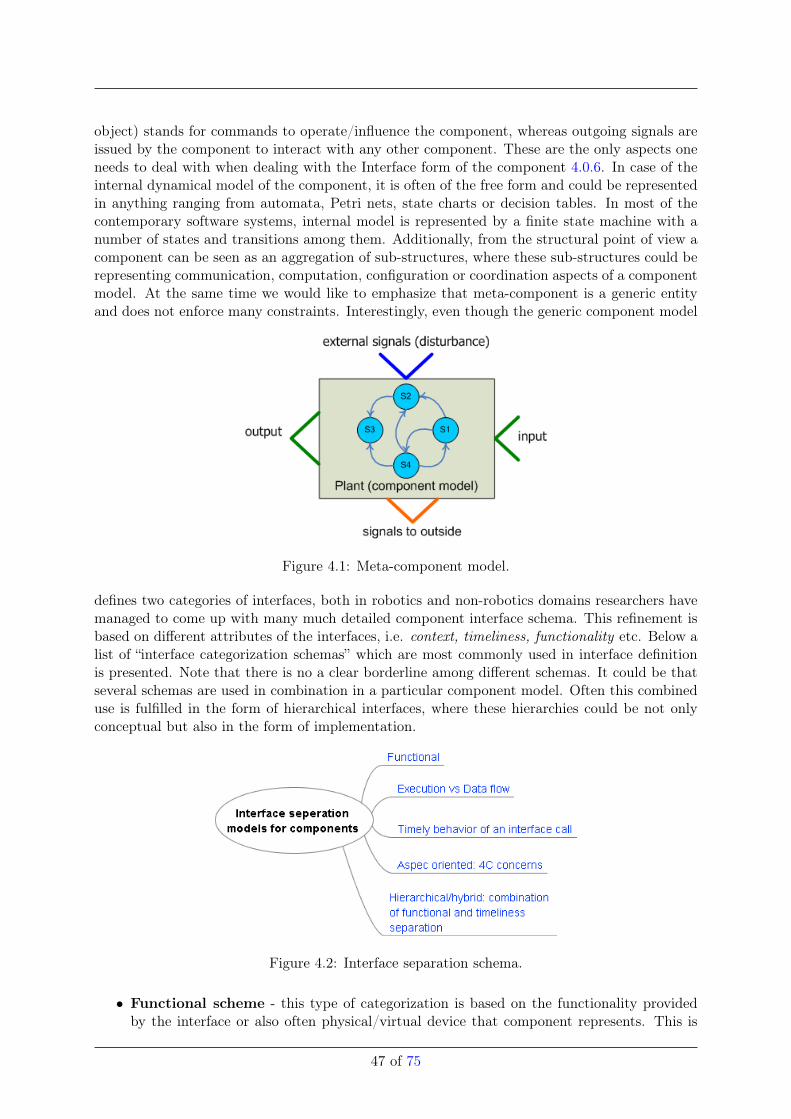
object) stands for commands to operate/influence the component, whereas outgoing signals areissued by the component to interact with any other component. These are the only aspects oneneeds to deal with when dealing with the Interface form of the component 4.0.6. In case of theinternal dynamical model of the component, it is often of the free form and could be representedin anything ranging from automata, Petri nets, state charts or decision tables. In most of thecontemporary software systems, internal model is represented by a finite state machine with anumber of states and transitions among them. Additionally, from the structural point of view acomponent can be seen as an aggregation of sub-structures, where these sub-structures could berepresenting communication, computation, configuration or coordination aspects of a componentmodel. At the same time we would like to emphasize that meta-component is a generic entityand does not enforce many constraints. Interestingly, even though the generic component model
Figure 4.1: Meta-component model.
defines two categories of interfaces, both in robotics and non-robotics domains researchers havemanaged to come up with many much detailed component interface schema. This refinement isbased on different attributes of the interfaces, i.e. context, timeliness, functionality etc. Below alist of “interface categorization schemas” which are most commonly used in interface definitionis presented. Note that there is no a clear borderline among different schemas. It could be thatseveral schemas are used in combination in a particular component model. Often this combineduse is fulfilled in the form of hierarchical interfaces, where these hierarchies could be not onlyconceptual but also in the form of implementation.
Figure 4.2: Interface separation schema.
• Functional scheme - this type of categorization is based on the functionality providedby the interface or also often physical/virtual device that component represents. This is
47 of 75
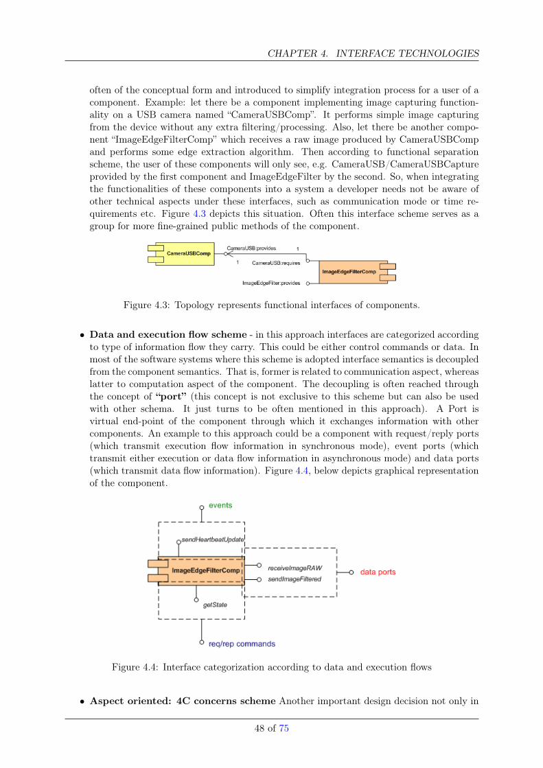
CHAPTER 4. INTERFACE TECHNOLOGIES
often of the conceptual form and introduced to simplify integration process for a user of acomponent. Example: let there be a component implementing image capturing function-ality on a USB camera named “CameraUSBComp”. It performs simple image capturingfrom the device without any extra filtering/processing. Also, let there be another compo-nent “ImageEdgeFilterComp” which receives a raw image produced by CameraUSBCompand performs some edge extraction algorithm. Then according to functional separationscheme, the user of these components will only see, e.g. CameraUSB/CameraUSBCaptureprovided by the first component and ImageEdgeFilter by the second. So, when integratingthe functionalities of these components into a system a developer needs not be aware ofother technical aspects under these interfaces, such as communication mode or time re-quirements etc. Figure 4.3 depicts this situation. Often this interface scheme serves as agroup for more fine-grained public methods of the component.
Figure 4.3: Topology represents functional interfaces of components.
• Data and execution flow scheme - in this approach interfaces are categorized accordingto type of information flow they carry. This could be either control commands or data. Inmost of the software systems where this scheme is adopted interface semantics is decoupledfrom the component semantics. That is, former is related to communication aspect, whereaslatter to computation aspect of the component. The decoupling is often reached throughthe concept of “port” (this concept is not exclusive to this scheme but can also be usedwith other schema. It just turns to be often mentioned in this approach). A Port isvirtual end-point of the component through which it exchanges information with othercomponents. An example to this approach could be a component with request/reply ports(which transmit execution flow information in synchronous mode), event ports (whichtransmit either execution or data flow information in asynchronous mode) and data ports(which transmit data flow information). Figure 4.4, below depicts graphical representationof the component.
Figure 4.4: Interface categorization according to data and execution flows
• Aspect oriented: 4C concerns scheme Another important design decision not only in
48 of 75
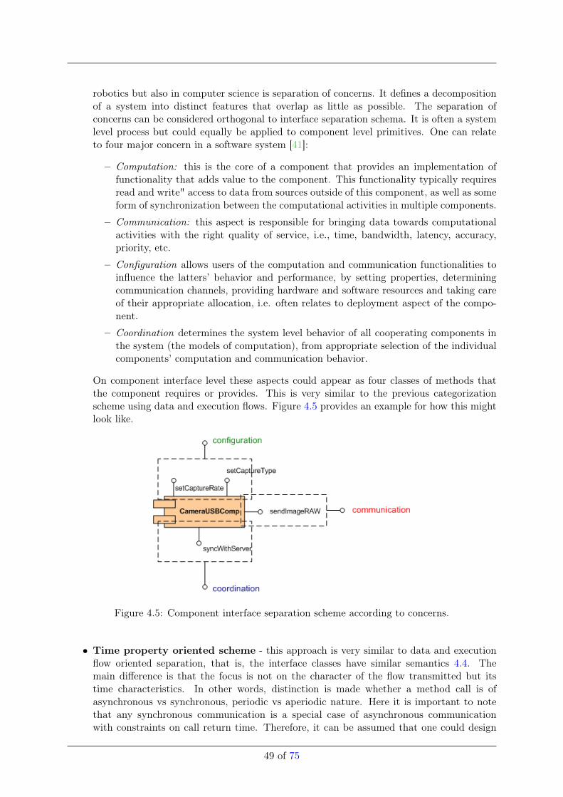
robotics but also in computer science is separation of concerns. It defines a decompositionof a system into distinct features that overlap as little as possible. The separation ofconcerns can be considered orthogonal to interface separation schema. It is often a systemlevel process but could equally be applied to component level primitives. One can relateto four major concern in a software system [41]:
– Computation: this is the core of a component that provides an implementation offunctionality that adds value to the component. This functionality typically requiresread and write" access to data from sources outside of this component, as well as someform of synchronization between the computational activities in multiple components.
– Communication: this aspect is responsible for bringing data towards computationalactivities with the right quality of service, i.e., time, bandwidth, latency, accuracy,priority, etc.
– Configuration allows users of the computation and communication functionalities toinfluence the latters’ behavior and performance, by setting properties, determiningcommunication channels, providing hardware and software resources and taking careof their appropriate allocation, i.e. often relates to deployment aspect of the compo-nent.
– Coordination determines the system level behavior of all cooperating components inthe system (the models of computation), from appropriate selection of the individualcomponents’ computation and communication behavior.
On component interface level these aspects could appear as four classes of methods thatthe component requires or provides. This is very similar to the previous categorizationscheme using data and execution flows. Figure 4.5 provides an example for how this mightlook like.
Figure 4.5: Component interface separation scheme according to concerns.
• Time property oriented scheme - this approach is very similar to data and executionflow oriented separation, that is, the interface classes have similar semantics 4.4. Themain difference is that the focus is not on the character of the flow transmitted but itstime characteristics. In other words, distinction is made whether a method call is ofasynchronous vs synchronous, periodic vs aperiodic nature. Here it is important to notethat any synchronous communication is a special case of asynchronous communicationwith constraints on call return time. Therefore, it can be assumed that one could design
49 of 75
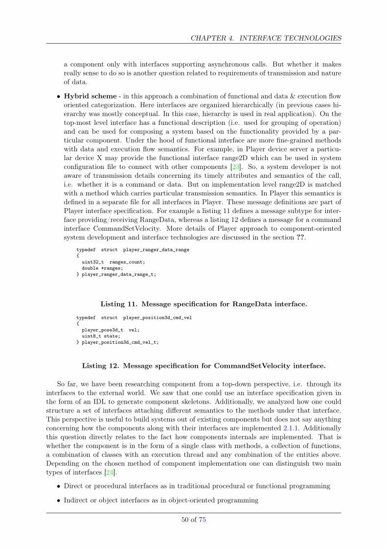
CHAPTER 4. INTERFACE TECHNOLOGIES
a component only with interfaces supporting asynchronous calls. But whether it makesreally sense to do so is another question related to requirements of transmission and natureof data.
• Hybrid scheme - in this approach a combination of functional and data & execution floworiented categorization. Here interfaces are organized hierarchically (in previous cases hi-erarchy was mostly conceptual. In this case, hierarchy is used in real application). On thetop-most level interface has a functional description (i.e. used for grouping of operation)and can be used for composing a system based on the functionality provided by a par-ticular component. Under the hood of functional interface are more fine-grained methodswith data and execution flow semantics. For example, in Player device server a particu-lar device X may provide the functional interface range2D which can be used in systemconfiguration file to connect with other components [23]. So, a system developer is notaware of transmission details concerning its timely attributes and semantics of the call,i.e. whether it is a command or data. But on implementation level range2D is matchedwith a method which carries particular transmission semantics. In Player this semantics isdefined in a separate file for all interfaces in Player. These message definitions are part ofPlayer interface specification. For example a listing 11 defines a message subtype for inter-face providing/receiving RangeData, whereas a listing 12 defines a message for a commandinterface CommandSetVelocity. More details of Player approach to component-orientedsystem development and interface technologies are discussed in the section ??.
typedef struct player_ranger_data_range{
uint32_t ranges_count;double *ranges;
} player_ranger_data_range_t;
Listing 11. Message specification for RangeData interface.
typedef struct player_position3d_cmd_vel{
player_pose3d_t vel;uint8_t state;
} player_position3d_cmd_vel_t;
Listing 12. Message specification for CommandSetVelocity interface.
So far, we have been researching component from a top-down perspective, i.e. through itsinterfaces to the external world. We saw that one could use an interface specification given inthe form of an IDL to generate component skeletons. Additionally, we analyzed how one couldstructure a set of interfaces attaching different semantics to the methods under that interface.This perspective is useful to build systems out of existing components but does not say anythingconcerning how the components along with their interfaces are implemented 2.1.1. Additionallythis question directly relates to the fact how components internals are implemented. That iswhether the component is in the form of a single class with methods, a collection of functions,a combination of classes with an execution thread and any combination of the entities above.Depending on the chosen method of component implementation one can distinguish two maintypes of interfaces [24].
• Direct or procedural interfaces as in traditional procedural or functional programming
• Indirect or object interfaces as in object-oriented programming
50 of 75
Often these two approaches are unified under the same concept, that is, to use static objects as apart of the component. Often most component interfaces are of object interface type (this is thecase because most of the contemporary implementations rely on object-oriented programminglanguages). The main difference between direct and indirect interfaces is that the latter is oftenachieved through a mechanism known as dynamic method dispatch/lookup (as it is known inobject-oriented programming). In this mechanism method invocation does not involve only theclass which owns invoked method but also other third party classes of which neither client norowner of the interface are aware of.
51 of 75
CHAPTER 4. INTERFACE TECHNOLOGIES
4.0.7 Hardware Abstraction (by Jan)
(This is a survey about the hardware abstraction techniques used in common robotic frameworks.The result is that non of the robotic framework got a satisfying solution.)
This section will examine the hardware abstraction techniques used in common robotic frame-works. The goal is to identify good practice and drawbacks.
The hardware abstraction separates the hardware dependent area from the hardware inde-pendent area. The hardware abstraction hierarchy provides generic device models for classes ofperipherals found in robotic systems, such as laser rage finder, camera, and motor controllers.The generic device models allows to write programs using a consistent API, regardless of theunderlying hardware.
Why a hardware abstraction is needed?
• Portability: The hardware abstraction minimizes the application software dependencesto a specific hardware. This will result in more portable code, which can run on multiplehardware platforms.
• Exchangeability: Standard interfaces to hardware makes it possible to exchange hard-ware.
• Reusability: Generic device classes or interfaces which are reused be multiple devices,avoid the replication of code. These generic classes are well tested source code due to thecode reuse.
• Maintainability: Consistent and standard interface to the hardware increases the main-tainability of the source code.
Benefits to Application Developers Thought the hardware abstraction the peculiarities ofvendor-specific device interfaces are hidden through well-defined, harmonized interfaces. The ap-plication developer does not have to worry about these peculiarities e.g. low level communicationto the hardware devices. They can use more convenient standard API’s to the hardware.
Benefits to Device Driver Developers Each device interface defines a set of functionsnecessary to manipulate the particular class of device. When writing a new driver for a peripheral,these set of driver functions have to be implemented. As a result, the driver development task ispredefined and well documented. In addition, it is possible to use existing hardware abstractionfunctions and applications to access the device, which saves software development effort.
Challenges for a Hardware Abstraction In the literature [42] a number of challenges arestated which have to be concert about while designing the interfaces (API) to the hardware.These challenge are as followed:
• Unstable Interfaces: For generic interfaces it is very important to have stable and matureones, but this can only be accomplished by a lot of experience or testing the interfaceson many heterogeneous robotic platforms over several years. When changing the genericinterfaces it is necessary to change all applications that use the interfaces. Which is errorprone and tedious. Such generic interfaces should be neither the union of all possiblecapabilities nor the intersection of such capabilities (least common denominator). Thesolution often lies somewhere in between. Sometimes is is possible to stabilize the interfaceby using more complex data types.
52 of 75
• Abstraction: By abstraction nonessential details of the device shall be hidden. Theinterface should just exhibit the functionality of the device and hide the rest. But thechallenge is how to define the nonessential details of the device.
• Shared Resources: Many of the sensors and actuators of a robot can be seen as a sharedresources. To prevent access collisions the data integrity can be protecting by using guardsand using reservation tokens to manage devices or manage activities with a global planner.
• Software Efficiency: No one wants to trade performance for generality. It is necessaryto keep the performance of the generic software as close as possible to a custom solution.
• Different Hardware Architectures: Just generalizing the hardware is sometimes notenough to interoperate across robotic platforms. This assumes that the hardware on thevarious platforms is similar in architecture. For instance in image acquisition hardware,some systems use high quality analog cameras with centralized image acquisition boards(frame grabbers) while other systems use digital cameras connected through a serial bus(FireWire or USB). By using hierarchical multi-level abstractions, the hardware can beaccessed at different abstraction levels, it can be possible to overcome these problem.
• Multi-functional Hardware Devices: Some off-the-shelf robots consists of a base con-taining locomotion as well sensor hardware. Often these are controlled by the same elec-tronics, accessed as a single device. Separating these different hardware in different API’scan be hard because they use the same hardware interface.
• Flexibility and Extendibility: When aiming for a general and flexible system and tryingto address as many use cases as possible. The abstraction hierarchy can get complex whichcan make it hard to extend and maintain it. It is sometimes necessary to sacrifice flexibilityfor simplicity and improved maintainability. The challenge is in defining the proper levelof flexibility.
• Different Sensor Configuration: Similar robots may use different sensor configurationsthat produce similar information. Like a 3D laser scanner and a stereo camera, bothproduce 3D point clouds. By using a multi-level abstraction hierarchy this two devicescould be exchangeable.
• Different Sensor Quality: Even if two sensors produce the same kind of information,the quality of the information can be different across the sensors. A laser scanner and asonar array both produce range information, but the information from the laser scanner ismore accurate. The challenge is how to represent such differences explicit. This could bemodeled with some additional Quality-of-Service (QoS) informations.
• Coordinate Transformations: Transformations can not be defined in isolation and re-quire a context that defines the relationships between coordinate frames. To model therelationships a uniform representation is needed. Without a uniform representation of thecoordinate transformations, sharing these information among sub-systems becomes diffi-cult, inefficient and error prone.
• Special Features: The hardware abstraction makes it more difficult to exhibit specialfeature of a certain hardware which is unique in it’s hardware class. By using a multi-levelabstraction hierarchy the special feature of a device could be exhibited.
• Separation of Hardware Abstraction and Middleware: If the hardware abstractionhierarchy should be reused in a other robotic software project, it is necessary to separatethe hardware abstraction from the communication middleware [29].
53 of 75
CHAPTER 4. INTERFACE TECHNOLOGIES
• Distinguish Hardware Devices: A robot can have multiple instances of the same hard-ware, like two identical laser scanner one for the front and the other for the back. Normallythese two devices get distinguish by the OS port name (COM1 or ttyUSB1). But this OSport name is not a unambiguous name for the device, it can change when the plug in orderof the device have been change. It is possible to distinguish between the same hardware ifthe hardware got a unique serial number. But not all hardware has a unique serial number.Especially low cost devices can lack on a serial number.
• Categorization of Devices: For some hardware devices it is is not easy to categorizethem into a single device category. There is integrated hardware which falls in two ormore categories. For example a integrated pan-tilt-zoom camera or a robot platform withintegrated motor controller and sonar sensors accessed through the same hardware interface.The problem only occurs when the device have to be categorize in a single category, there isno problem if it is possible to categorize it in multiple categories. This could be implementedby inheritance from multiple interfaces. The pan-tilt-zoom camera would inherit the camerainterface and the pan-tilt-unit interface.
Assessment
When assessing the hardware abstractions of the different robotic frameworks we concentrateon one particular hardware, the laser scanner. We chose the laser scanner because almost allrobotic frameworks (except YARP) implement a hardware abstractions for this hardware. Thehardware abstraction of these framworks will be examined: Orca, ROS, Player, YARP, ARIA,MRPT, OPRoS and OpenRTM.
Orca
Hardware Abstraction Hierarchy Orca [43] got mainly two level in the hardware hierarchy,only the range finder got three. In the first level it classifies the hardware in terms of functionality.In case of the range finders there is a further classification in terms of the type of range findere.g. laser scanner. The last level is always the actual hardware driver which can serve a group ofhardware or only one special hardware. The UML diagram figure 4.6 shows a part of the classhierarchy from robotic framework Orca, which is separate across the Orca and Hydro library.The figure just shows the hierarchy for the range finder hardware abstraction.
Laser Scanner Example The interface to the laser scanners is defined by the LaserScanner2dinterface definition which inherits from the RangeScanner2d interface. These definition are donein the ICE slice language.
In Orca every hardware device is encapsulated in its own component. For instance thereis a component for 2D laser scanner called Laser2d. This is a little bit inconsistent with thehardware hierarchy, because the component is not a generic range finder component. This ismaybe the case because Orca does not support other range finder than laser scanners. TheLaser2d component dynamically loads an implementation of a Hydro hardware interface hy-drointerfaces::LaserScanner2d.
When configure the device a selection of a driver implementation have to be made. These laserscanner implementations are available: Fake Driver, HokuyoAist, Carmen, Player or Gearbox.Generic parameter like minimum range [m], maximum range [m], field of view [rad], starting angle[rad] and the number of samples in a scan, are also set in the component. In the component youalso can provide a position vector where the scanner is physically mounted with respect to therobot’s local coordinate system. With this vector Orca is capable to hide the orientation of thelaser scanner. Even if the scanner is mounted up-side-down and the position vector is correctly
54 of 75
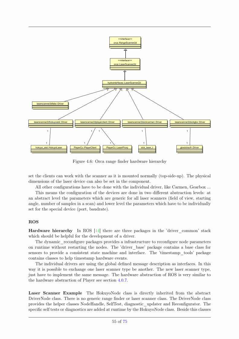
<<interface>>
orca::RangeScanner2d
<<interface>>
orca::LaserScanner2d
hydrointerfaces::LaserScanner2d
laserscanner2dfake::Driver
hokuyo_aist::HokuyoLaser
laserscanner2dplayerclient::Driver
PlayerCc::PlayerClient PlayerCc::LaserProxy gbxsickacfr::Driversick_laser_t
laserscanner2dsickcarmen::Driver laserscanner2dsickgbx::Driverlaserscanner2dhokuyoaist::Driver
11
1
1 1
1
1
11 1
Figure 4.6: Orca range finder hardware hierarchy
set the clients can work with the scanner as it is mounted normally (top-side-up). The physicaldimensions of the laser device can also be set in the component.
All other configurations have to be done with the individual driver, like Carmen, Gearbox ...This means the configuration of the devices are done in two different abstraction levels: at
an abstract level the parameters which are generic for all laser scanners (field of view, startingangle, number of samples in a scan) and lower level the parameters which have to be individuallyset for the special device (port, baudrate).
ROS
Hardware hierarchy In ROS [44] there are three packages in the ’driver_common’ stackwhich should be helpful for the development of a driver.
The dynamic_reconfigure packages provides a infrastructure to reconfigure node parameterson runtime without restarting the nodes. The ’driver_base’ package contains a base class forsensors to provide a consistent state machine and interface. The ’timestamp_tools’ packagecontains classes to help timestamp hardware events.
The individual drivers are using the global defined message description as interfaces. In thisway it is possible to exchange one laser scanner type be another. The new laser scanner type,just have to implement the same message. The hardware abstraction of ROS is very similar tothe hardware abstraction of Player see section 4.0.7.
Laser Scanner Example The HokuyoNode class is directly inherited from the abstractDriverNode class. There is no generic range finder or laser scanner class. The DriverNode classprovides the helper classes NodeHandle, SelfTest, diagnostic_updater and Reconfigurator. Thespecific self tests or diagnostics are added at runtime by the HokuyoNode class. Beside this classes
55 of 75
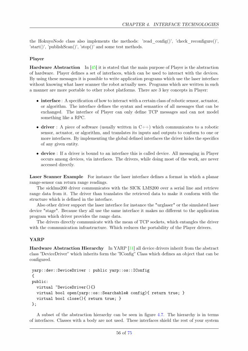
CHAPTER 4. INTERFACE TECHNOLOGIES
the HokuyoNode class also implements the methods: ’read_config()’, ’check_reconfigure()’,’start()’, ’publishScan()’, ’stop()’ and some test methods.
Player
Hardware Abstraction In [45] it is stated that the main purpose of Player is the abstractionof hardware. Player defines a set of interfaces, which can be used to interact with the devices.By using these messages it is possible to write application programs which use the laser interfacewithout knowing what laser scanner the robot actually uses. Programs which are written in sucha manner are more portable to other robot platforms. There are 3 key concepts in Player:
• interface : A specification of how to interact with a certain class of robotic sensor, actuator,or algorithm. The interface defines the syntax and semantics of all messages that can beexchanged. The interface of Player can only define TCP messages and can not modelsomething like a RPC.
• driver : A piece of software (usually written in C++) which communicates to a roboticsensor, actuator, or algorithm, and translates its inputs and outputs to conform to one ormore interfaces. By implementing the global defined interfaces the driver hides the specificsof any given entity.
• device : If a driver is bound to an interface this is called device. All messaging in Playeroccurs among devices, via interfaces. The drivers, while doing most of the work, are neveraccessed directly.
Laser Scanner Example For instance the laser interface defines a format in which a planarrange-sensor can return range readings.
The sicklms200 driver communicates with the SICK LMS200 over a serial line and retrieverange data from it. The driver than translates the retrieved data to make it conform with thestructure which is defined in the interface.
Also other driver support the laser interface for instance the "urglaser" or the simulated laserdevice "stage". Because they all use the same interface it makes no different to the applicationprogram which driver provides the range data.
The drivers directly communicate with the mean of TCP sockets, which entangles the driverwith the communication infrastructure. Which reduces the portability of the Player drivers.
YARP
Hardware Abstraction Hierarchy In YARP [31] all device drivers inherit from the abstractclass ”DeviceDriver” which inherits form the ”IConfig” Class which defines an object that can beconfigured.
yarp::dev::DeviceDriver : public yarp::os::IConfig{public:
virtual ~DeviceDriver(){}virtual bool open(yarp::os::Searchable& config){ return true; }virtual bool close(){ return true; }
};
A subset of the abstraction hierarchy can be seen in figure 4.7. The hierarchy is in termsof interfaces. Classes with a body are not used. These interfaces shield the rest of your system
56 of 75
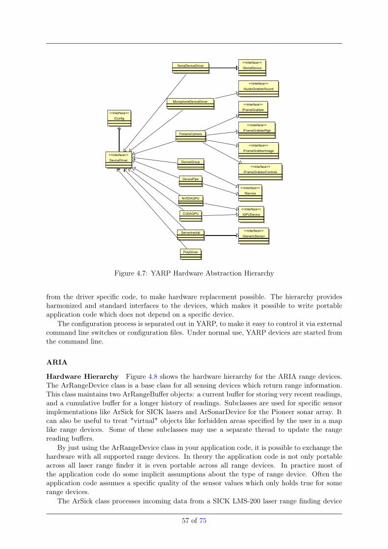
<<interface>>
IGenericSensor
<<interface>>
IFrameGrabberControls
<<interface>>
IConfig
<<interface>>
DeviceDriver
<<interface>>
IGPUDevice
NVIDIAGPU
<<interface>>
IService
DeviceGroup
<<interface>>
IFrameGrabberImage
<<interface>>
IAudioGrabberSound
SerialDeviceDriver
<<interface>>
IFrameGrabber
PolyDriver
ServerInertial
MicrophoneDeviceDriver
FirewireCamera
<<interface>>
ISerialDevice
<<interface>>
IFrameGrabberRgb
DevicePipe
CUDAGPU
Figure 4.7: YARP Hardware Abstraction Hierarchy
from the driver specific code, to make hardware replacement possible. The hierarchy providesharmonized and standard interfaces to the devices, which makes it possible to write portableapplication code which does not depend on a specific device.
The configuration process is separated out in YARP, to make it easy to control it via externalcommand line switches or configuration files. Under normal use, YARP devices are started fromthe command line.
ARIA
Hardware Hierarchy Figure 4.8 shows the hardware hierarchy for the ARIA range devices.The ArRangeDevice class is a base class for all sensing devices which return range information.This class maintains two ArRangeBuffer objects: a current buffer for storing very recent readings,and a cumulative buffer for a longer history of readings. Subclasses are used for specific sensorimplementations like ArSick for SICK lasers and ArSonarDevice for the Pioneer sonar array. Itcan also be useful to treat "virtual" objects like forbidden areas specified by the user in a maplike range devices. Some of these subclasses may use a separate thread to update the rangereading buffers.
By just using the ArRangeDevice class in your application code, it is possible to exchange thehardware with all supported range devices. In theory the application code is not only portableacross all laser range finder it is even portable across all range devices. In practice most ofthe application code do some implicit assumptions about the type of range device. Often theapplication code assumes a specific quality of the sensor values which only holds true for somerange devices.
The ArSick class processes incoming data from a SICK LMS-200 laser range finding device
57 of 75
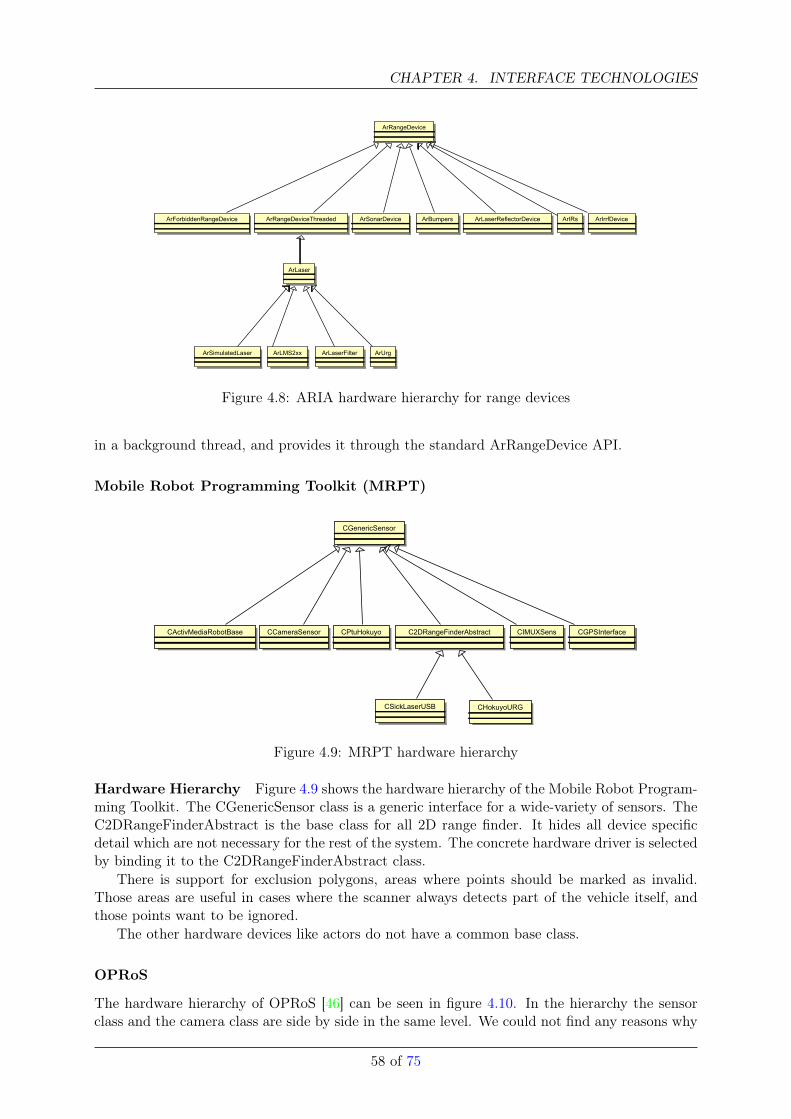
CHAPTER 4. INTERFACE TECHNOLOGIES
ArLaserFilterArLMS2xxArSimulatedLaser ArUrg
ArGPS
ArNovatelGPSArTrimbleGPS
ArAnalogGyro
ArDeviceConnection
ArLogFileConnection ArSerialConnection ArTcpConnection
ArBumpers
ArRangeDevice
ArForbiddenRangeDevice ArIrrfDeviceArIRsArRangeDeviceThreaded ArLaserReflectorDeviceArSonarDevice
ArLaser
Figure 4.8: ARIA hardware hierarchy for range devices
in a background thread, and provides it through the standard ArRangeDevice API.
Mobile Robot Programming Toolkit (MRPT)
CGenericSensor
C2DRangeFinderAbstract
CHokuyoURGCSickLaserUSB
CActivMediaRobotBase CGPSInterfaceCIMUXSensCPtuHokuyoCCameraSensor
Figure 4.9: MRPT hardware hierarchy
Hardware Hierarchy Figure 4.9 shows the hardware hierarchy of the Mobile Robot Program-ming Toolkit. The CGenericSensor class is a generic interface for a wide-variety of sensors. TheC2DRangeFinderAbstract is the base class for all 2D range finder. It hides all device specificdetail which are not necessary for the rest of the system. The concrete hardware driver is selectedby binding it to the C2DRangeFinderAbstract class.
There is support for exclusion polygons, areas where points should be marked as invalid.Those areas are useful in cases where the scanner always detects part of the vehicle itself, andthose points want to be ignored.
The other hardware devices like actors do not have a common base class.
OPRoS
The hardware hierarchy of OPRoS [46] can be seen in figure 4.10. In the hierarchy the sensorclass and the camera class are side by side in the same level. We could not find any reasons why
58 of 75
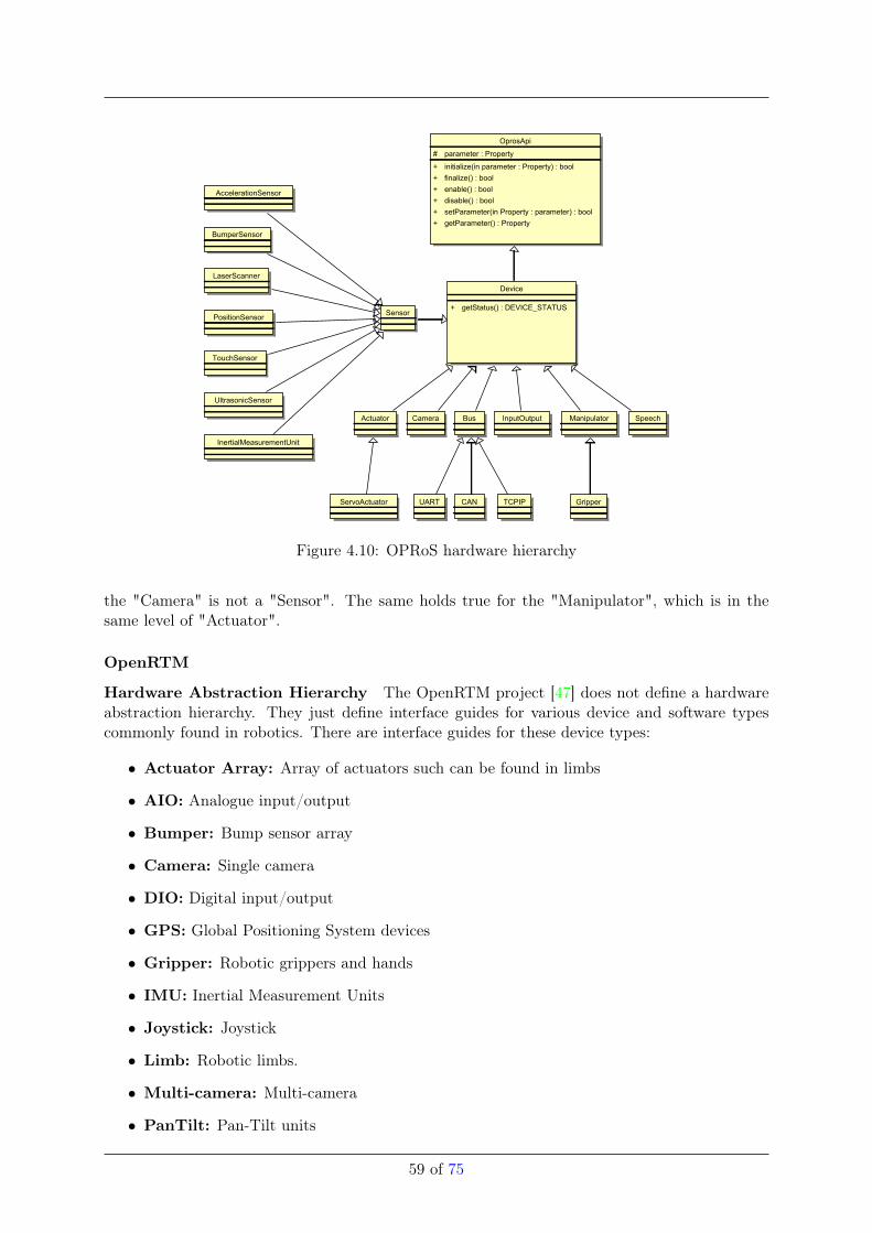
OprosApi
# parameter : Property
+ initialize(in parameter : Property) : bool
+ finalize() : bool
+ enable() : bool
+ disable() : bool
+ setParameter(in Property : parameter) : bool
+ getParameter() : Property
BumperSensor
InputOutputCamera
PositionSensor
TouchSensor
TCPIP
Bus SpeechActuator
AccelerationSensor
Device
+ getStatus() : DEVICE_STATUS
UART
UltrasonicSensor
CAN
Manipulator
Sensor
Gripper
InertialMeasurementUnit
ServoActuator
LaserScanner
Figure 4.10: OPRoS hardware hierarchy
the "Camera" is not a "Sensor". The same holds true for the "Manipulator", which is in thesame level of "Actuator".
OpenRTM
Hardware Abstraction Hierarchy The OpenRTM project [47] does not define a hardwareabstraction hierarchy. They just define interface guides for various device and software typescommonly found in robotics. There are interface guides for these device types:
• Actuator Array: Array of actuators such can be found in limbs
• AIO: Analogue input/output
• Bumper: Bump sensor array
• Camera: Single camera
• DIO: Digital input/output
• GPS: Global Positioning System devices
• Gripper: Robotic grippers and hands
• IMU: Inertial Measurement Units
• Joystick: Joystick
• Limb: Robotic limbs.
• Multi-camera: Multi-camera
• PanTilt: Pan-Tilt units
59 of 75
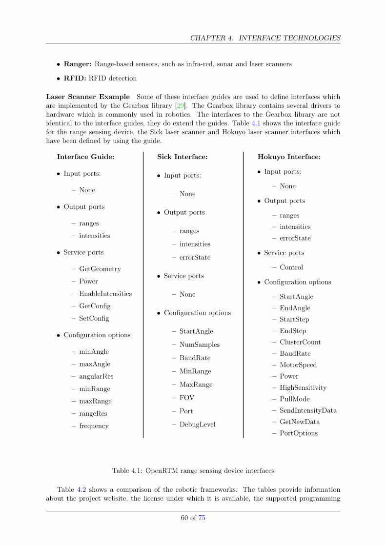
CHAPTER 4. INTERFACE TECHNOLOGIES
• Ranger: Range-based sensors, such as infra-red, sonar and laser scanners
• RFID: RFID detection
Laser Scanner Example Some of these interface guides are used to define interfaces whichare implemented by the Gearbox library [29]. The Gearbox library contains several drivers tohardware which is commonly used in robotics. The interfaces to the Gearbox library are notidentical to the interface guides, they do extend the guides. Table 4.1 shows the interface guidefor the range sensing device, the Sick laser scanner and Hokuyo laser scanner interfaces whichhave been defined by using the guide.
Interface Guide:
• Input ports:
– None
• Output ports
– ranges
– intensities
• Service ports
– GetGeometry
– Power
– EnableIntensities
– GetConfig
– SetConfig
• Configuration options
– minAngle
– maxAngle
– angularRes
– minRange
– maxRange
– rangeRes
– frequency
Sick Interface:
• Input ports:
– None
• Output ports
– ranges
– intensities
– errorState
• Service ports
– None
• Configuration options
– StartAngle
– NumSamples
– BaudRate
– MinRange
– MaxRange
– FOV
– Port
– DebugLevel
Hokuyo Interface:
• Input ports:
– None
• Output ports
– ranges
– intensities
– errorState
• Service ports
– Control
• Configuration options
– StartAngle
– EndAngle
– StartStep
– EndStep
– ClusterCount
– BaudRate
– MotorSpeed
– Power
– HighSensitivity
– PullMode
– SendIntensityData
– GetNewData
– PortOptions
Table 4.1: OpenRTM range sensing device interfaces
Table 4.2 shows a comparison of the robotic frameworks. The tables provide informationabout the project website, the license under which it is available, the supported programming
60 of 75
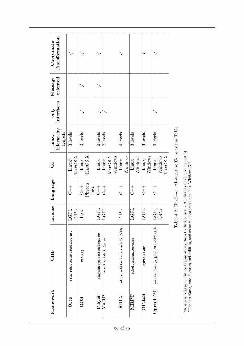
Fram
ework
URL
Licen
seLan
guage
OS
max
.on
lyMessage
Coo
rdinate
Hierarchy
Interfaces
oriented
Transformation
Dep
thOrca
orca
-rob
otic
s.so
urce
forg
e.ne
tLG
PL1
C++
Linu
x23levels
√
GPL
MacOSX
ROS
ros.
org
BSD
C++
Linu
x0levels
√√
√
Phy
ton
MacOSX
Java
Player
play
erst
age.
sour
cefo
rge.
net
LGPL
C++
Linu
x0levels
√√
√
YARP
eris
.lir
alab
.it/
yarp
/LG
PL
C++
Linu
x2levels
√
MacOSX
Windo
ws
ARIA
robo
ts.m
obil
erob
ots.
com/
wiki
/ARI
AGPL
C++
Linu
x4levels
√
Windo
ws
MRPT
babe
l.is
a.um
a.es
/mrp
tLG
PL
C++
Linu
x3levels
Windo
ws
OPRoS
opro
s.or
.kr
LGPL
C++
Linu
x3levels
?W
indo
ws
Open
RTM
www.
is.a
ist.
go.j
p/rt
/Ope
nRTM
-ais
tLG
PL
C++
Linu
x0levels
√√
GPL
Windo
ws
MacOSX
Tab
le4.2:
Hardw
areAbstraction
Com
parisonTab
le
aA
specialc
lausein
theIcelicen
seallowsthem
todistribu
teLGPLlib
raries
linking
toIce(G
PL)
bThe
interfaces,c
orelib
raries
andutilities,a
ndsomecompo
nentscompile
inW
indo
wsXP.
61 of 75
CHAPTER 4. INTERFACE TECHNOLOGIES
language and the supported operating systems. The "max. Hierarchy Depth" column indicatethe how deep or sallow the hierarchy for a particular framework is. The number of level indicatethat there are so many inheritance level in the driver hierarchy. Inheritance form generic classesor interfaces like in YARP or OPRoS are not counted. The "only Interfaces" column indicate ifclasses with a body are used in the hierarchy or only interfaces without bodies. The "Messageoriented" column indicate if the hardware abstraction interfaces are messages in the communi-cation infrastructure. The "Coordinate Transformation" column indicate if the framework gotan uniform representation of the coordinate transformations.
Conclusion
• Orca, YARP, ARIA, MRPT and OPRoS have a multi-level abstraction hierarchy. They allclassify the hardware in the same manner. They classify it by measured physical quantity(e.g. range). The robotic frameworks derive the devices driver form a generic driver if theymeasure the same quantity. This is also reflected in the implementation by using the samereturn data type.
• Only YARP has a multi-level abstraction hierarchy and it is possible to classify a devicein multiple categories.
• The robotic frameworks use configuration file, command line input or a configuration serverto read the configuration of the devices. None of the frameworks introduced a separateinterface which is just for configuration.
• ROS and Player got a similar concept to interface the devices. Both use predefined com-munication messages to unify the interface to a group of devices (e.g. laser range finder).By defining the interface with the communication message they tightly couple the commu-nication ’middleware’ with the driver, there is no separation between communication andcomputation.
• All frameworks address the hardware by the com-port name like ’COM3’ or ’ttyUSB1’.None of them is using a hardware serial number to identify the device.
62 of 75
Chapter 5
Simulation and Emulation Technologies
Simulation in robotics has been paid more and more attention in the last decade. One mainreason for this is that the computational power on computers is increasing every year whichmakes it possible to run computational intensive algorithms on personal computers instead ofspecial purpose hardware. This is related to the increased effort of the game industry to createrealistic virtual worlds in computer games. The creation of virtual worlds requires a high amountof processing power for graphical rendering and physics calculations. Thereby the game industrydevelops software engines that allows the reuse of their high quality physic simulation and ren-dering software. Since the goals of computer games and simulations are quite similar namely thecreation of a realistic virtual counterparts of a real world use case, the simulations environmentsre-use those engines and profit from the gain in processing power and state of the art engines.The relation of Computer games in scientific research is more deeply analyzed in [48].
The reason why simulation has attracted more attention in robot development are surely thebenefits that can be gained which can be summarized in two statements: Safe resources andincrease development speed. These benefits are explained below in the context of some differentscenarios which give also some examples on the applications of simulators
Limited Hardware: In robotics it is often the case that many researchers have to share thesame hardware platform since the robot hardware is often very expensive. In the worstcase developers of different institutes possibly located in different countries have to share asingle robot. In this situation it is often the case that someone can not execute his experi-ments since the hardware is blocked by another person or simply not physical available. Asimulator can be installed on multiple PC’s so that a model of the hardware is available toevery developer. A similar situation occurs at the start of a new project or developmentof a new product. Often the Hardware has to be designed, ordered and manufacturedwhich takes a lot of time where programmers only have limited programming capabilities.A simulated prototype allows software implementation before the actual hardware is evenproduced.
Hardware Maintenance: A robot is a complex machine and has to be maintained. It is oftenthe case that the hardware is not properly running or just the batteries are not charged.Even if the hardware is technically working the system has to be set up f.e. sensors mustbe calibrated which costs a lot of time. These time can be saved when a simulated modelis used. Further the simulation allows to execute tests that possibly damages the hardwaref.e. if a new manipulator path planning algorithm is tested. If the manipulator collides insuch a test with some furniture it is likely that the hardware breaks which can be avoidedin simulation.
Learning algorithms: Learning algorithms need often a high amount of teaching iterations till
63
CHAPTER 5. SIMULATION AND EMULATION TECHNOLOGIES
they achieve reasonable performance. F. e. in [49] the AIBO control parameters have beenlearned based on simulation which took 600 learning iterations, each taking 20 sec in realtime. The possibility of running simulations faster than real time makes allows it to applythose learning algorithms in very short time.
Beside gain these benefits simulation faces some challenges. As it can be directly seen fromthe different scenarios, they have different requirements to the simulators. This is often to thefact that the developer must find the proper ratio between model precision and performance.There exist currently no general purpose Simulator that can be used for any task. In the followingsection different types of simulation environments and their properties will be introduced.
5.0.8 Categorization and Application Areas
Since any research project comes with different requirements the number of available individualsimulation environments is very high. Those requirements are often related to the offset betweenperformance and precision. Since it is even with the newest PC Hardware not possible to simulatea robot model and environment that behaves exactly as its real world counterpart, differentsimulators for different purposes have evolved. Further the development of such high precisionmodels is a time consuming expert task and not always necessary.
Low level Simulators
The simulations that provide the highest precision act on a low level and are used to simulatesingle devices like motors or circuits. They often do not offer graphical visualization of the robotand its environment but provides inspection tools of signals. A very versatile but commercialenvironment is Mathworks SIMULINK [50] that allows the modeling of dynamical system in blockcharts and inspect the output signals. It is integrated in the Matlab environment. Another lowlevel simulator that is designed to simulate electric circuits is Spice [51]. These environmentsplay a little role in the software development of robots if no custom hardware is developed. It ismore common for hardware vendors that produce actuators or sensor systems.
Learning Algorithms
An application area where simulation is very beneficial is learning f.e. to achieve optimal controlparameters for a walking robot. One main requirement for these simulators is a high computa-tional performance since learning algorithms need not seldom hundreds to thousands of iterationsof the same experiment. Therefore the simulator must be capable to run experiments faster thanreal-time. Further these simulators often needs to simulate physics so that the learned parametersare applicable in real world. Therefore also the environment must be precisely simulated sincethe robot may f.e. learn to move stairs. Often these simulators provide a 3D visualization, but inmost cases to archive the highest performance the visualization can be completely deactivated.A problem that simulation on this level faces eminently is the so called reality gap [52]. Thisdescribes the danger that behaviors which are acquired in simulation may not behave exactly oreven completely fail if transfered to the real world. This directly relates to the complexity of thebehavior or parameters that the robot shall learn.
UCHILSIM is a simulation environment developed for the four legged league RoboCup compe-tition at the university of Chile [49]. It uses the Open Dynamics Engine (ODE) as physicsengine and models are defined in a customized Virtual Reality Modeling language (VRML)format. Simulated robots can be control via an Open-R API based interface [53] which isthe native API for the AIBO robots. A unique feature of this simulator is the possibility
64 of 75
to learn simulation parameters of models [54]. The aim is to reduce the problems causingthe reality gap by executing an experiment in real world and simulation while using thedifference in the result for adapting the simulation parameters via evolutionary algorithms.A drawback of this system is that it is very closely tied to the RoboCup application so thatit provides only a Sony AIBO model and a soccer field environment. Further this projectreceived no updates since 2004.
YARS claims to be fastest simulator in the context of physical 3D simulation [55]. It aimsthereby at the application of evoutionary learning algorithms and is also based on theODE physics engine. The system can be interfaced by custom UDP clients which existfor C++ and Java. Robot models can be described with the Robot Simulation MarkupLanguage (RoSimL).
Algorithm Evaluation
Some Simulators are written to target a specific area in the robot development process and tocompare and evaluate algorithms for a special use. One main application for this systems is pathplanning for mobile bases or manipulators. Those systems provide often some analytic evaluationof the executed experiments and can be very different distinct from a technical point of view.
GraspIt! is a simulation environment for robot grasp analysis [56]. It contains a manipulatormodel (Puma560) and a mobile base (Nomadics XR4000) and a set of different robot handsthat can be evaluated. The grasps are evaluated and quality measures a given based onthe book from Murry et al. [57]. To enable the precise simulation of robot grasps, customphysics routines and collision detection routines were developed. The environment providesan interface to Matlab and a text based TCP interface and is distributed as Linux andWindows version. Custom models can be described in Inventor models that are very similarto VRML.
OpenRave [58] is the successor of the RAVE project [59]. It is designed for robot manipulatorpath planning algorithm evaluation. External algorithm can interface the environment viaPython, Octave and Matlab even over the network. The different algorithms are visual-ized in a 3D scene. The physics in this environment are only approximated and no fullfledged physics engine is integrated. Purpose of this environment is to provide a commonenvironment and robot model to objectively evaluate path planning algorithms and createstatistical comparisons. The environment is not limited to manipulation. it also the useof some sensors like basic cameras and laser range finders. Further, OpenRave providesan extensive list of model importers for COLLADA, a Custom XML 3DS and VRML. Itprovides a plug-in based architecture which makes all modules in the system exchangeable.
Robot System Evaluation
These type of simulators are able to evaluate complete robot systems. The simulated robotmodel can be controlled with the complete robot system and control architecture. Thereforethese systems provide a rich set of different sensors like ultra sonic sensors, infrared sensors,laser scanners, force sensors or cameras to name only a few. Further often different predefinedrobot bases and sometimes even manipulators can be used to build a custom robot model. Sincethe simulator and robot control software must be interfaced in a manner that the robot code isunchanged often integrated solutions are provided. These provide a robot software frameworkand a simulation environment that can be seamless integrated.
65 of 75
CHAPTER 5. SIMULATION AND EMULATION TECHNOLOGIES
Player Gazebo is the first environment that provided a combined approach of a robot softwareframework with an integrated 2D simulator Stage and a 3D simulator Gazebo [60]. Sincethe the 2D Simulator is limited in the sense of simulating sensors and manipulators it isnot mentioned in this category. Gazebo thereby is set up on a standard physics engineODE and can be natively interfaces with player. Further it is integrated in the ROSsoftware framework and provides a binary interface called libgazebo. OpenGL visualizationis provided via Ogre library. Gazebo is running under Linux. New models can be createdin C++ Code while the composition of models is done in an XML file. Gazebo is publishedunder the GNU GPL license.
Microsoft Robotics Developer Studio (MRDS) provides a Web-service oriented softwareframework for robot development which is coupled with a graphical programming tool anda 3D simulation environment. The simulation environment is based on the commercialphysic engine PhysX which allows hardware accelerated physic calculations. Simulationsare visualized based on Microsofts XNA engine. The environment allow import of ColladaModels but is commercial published.
USARSim [61] has been developed at CMU for the RoboCup Rescue competition and aims atthe simulation of Urban Search and Rescue environments and robots. It is completely basedon a computer game namely Unreal. The current version is ported from Unreal Engine 2that was based on the Karma physics engine to Unreal Engine 3 which uses the physicsengine PhysX. USARsim requires therefore a license of the game itself is licensed underGPL license. USARSim is different to the afore mentioned since it is not not integrated in arobot software framework but it provides interfaces to player, MOAST [62] and Gamebots.USARSim is utilized for the RoboCup Rescue Virtual Robot Competition and IEEE VirtualManufacturing Automation Competition.
Webots is a commercial simulation environment that is the predecessor of the Khepera simu-lator [63]. It is a commercial environment based on the open source physics engine ODE.It provides a world and robot editor that can create models graphically and store them inVRML. It has platform support for Linux, Windows and Mac OS X. Webots can be usedto write robot programs and transfer them to a real robot for e-puck, Nao and Katanamanipulators or C programs can be written to control simulated robots. Further thereexist API’s to C++, Matlab, Java and Python as well as the possibility to create TCPinterfaces.
Learning Team Behaviors
The most abstract types of simulators are aiming at multi robot tams or are even designed to an-alyze swarm behavior. Since the precise simulation of an environment and a robot system with allits interactive components is very computationally intensive these systems tend to use simplifiedrobot models. For Swarm behaviors robots are often just represented as boxes with simplifiedsensor models which makes the support of modeling tools and formats mostly unnecessary.
Mason is a simulator that targets at multi agent simulation [64] and swarm robotics. It is one ofthe few simulation environments that is developed in Java. To achieve high performance anappropriate level of visualization can be chosen which are 2D, 3D and no Visualization atall. The models and state of the simulation is completely decoupled so that the simulationcan be persisted or visualization can be changed at any time. The simulator containscollision detection routines but no complete physics engine is integrated.
BREVE is a simulation environment that targets at artificial life [65] and not specificallyrobotics. It can also be used for Multi agent simulation and offers a custom language
66 of 75
called Steve for agent description. The simulator offers a custom developed physics engineand 3D visualization.
MuRoSimF is a special simulation environment which aims at robot teams but with flexiblelevel of detail [66]. They provide a system where the simulation algorithms can be dis-tributed over different CPUs. It has been developed for the RoboCup Humanoid soccercompetition. The unique feature of this simulator is that it can be varied in precision of thealgorithms for motion, sensing, collision detection and handling. With this approach thepossibility is given to change the appropriate level of detail and influence the performancebased on the desired experiments. To achieve this the simulator uses a custom developedengine. Control software can exchange data with the simulated models via RS232 andTCP.
5.0.9 Conclusions
The available simulators for robotics have all very specific fields of use. There is no all in onesolution that can be used during the robot development process and is suitable for any tasks. Asit can be seen in the categorization before sometimes it might be even necessary to use multiplesimulation environments for a single project or robot dependent on what specific field of interestshall be simulated and is often a decision between precision and performance. The same holdstrue or the techniques that are used to enable simulations. F.e. for physic engines there areopen source engines used like ODE or Bullet, but also commercial engines like PhysX or customdeveloped ones.
Another major point is the integration of simulation and control software. Integrated so-lutions like Player or the MRDS exist but there is no specific standard on which interfaces asimulator shall provide nor is there a common ground. Interfacing is done via shared Memory,custom API’s, custom TCP whereas Player and ROS integration is also common.
Further it is noticeable that no standard exist in modeling robots and environments respec-tively a model representation for persistence and data exchange. Often it is possible to storemodels at least in XML or even standards are used like Collada and VRML but these are notcapable to persist models in a way that they can be exchanged between different simulationsystems. The reason for this is that the standards are not specifically design for robot simulationand are missing important issues like the description of sensor behaviors.
It is noticeable that many simulators evolve from research projects where especially RoboCupcreates many contributions. The drawback of this is the missing continuous development andsupport so that many good simulators deprecate or never result in a stable version.
In general it can be seen that for a specific task an appropriate simulator has to be carefullychosen and simulation can be a great help in the development process for robot software if theappropriate system is chosen that fulfill the right proportion between performance and accuracyfr the specific task.
67 of 75
Chapter 6
Conclusions
The vast amount of relevant software technologies for robotics is almost overwhelming. There-fore, an assessment in an unbiased manner is difficult, or even impossible. Simply too manytechnologies from different domains, with divergent features, and characteristics are relevant forrobotics. However, as shown in the previous chapters we were able to identify four main softwaretechnology classes. Namely, component-based software technologies, communication middleware,interface technologies, and simulation and emulation technologies. With the BRICS paradigmin mind, all of those classes were screened, and analysed. Functional properties, differences, andsimilarities were identified, and most importantly implications for the future BRICS process havebeen derived (see Section 6.1).
6.1 Implications for BRICS
This work performed an exaustive survey of existing software technologies in use in robotics. Themain objective of the survey was to analyze different approaches developed to tackle the problemof software development for robotics from different perspectives. The outcome of this researchwill be used to base and justify new design and development decisions of future BRICS software.The analysis were performed along four technology dimensions which lead to the following set ofcritical focus points.
Component-based Software Technologies:
• there is an increasing trend to use component-based software engineering in robotics. Thistrend can be explained with the fact that more and more robotics software projects arebecoming an outcome of a collaboration between many research groups. Additionally, froma system user point of view, one wishes to receive readily developed software packages andwithout extra effort be able to compile a new application. This is what components deliver,being able to compose software delivered by different parties.
• on programmatic level, there seems to be a convergence of opinions of many on componentmodelling and toolchain support for developent of component-based applications. In parti-cal this is observable in component modeling primitives. Most of the software frameworksreviewed adopt semantically similar concepts, such as data and service ports for interfaces,step-by-step based component initialization, running and cleanup for statemachines 2.2.1.
• there is an increasing trend towards tool support software management, i.e. installation,cleanup, dependecy checking etc. This is followed with future goals to provide toolchainfor design, development and deployment of components for different application context.
68

6.1. IMPLICATIONS FOR BRICS
• One of the ‘Missing Link’s in software for robotics is the concept of interoperability andreuse between different software systems. The software is a representation of researcher’sknowledge embedded in a code. Everytime someone else reimplements the same algorithmagain in a different piece of code, he or she reinvents the wheel and wastes effort on theissues which have been solved in some other software framework. In order to achievehigher efficiency and make more progress in focused areas, it is absolutely necessary tofoster interoperability and reuse among existing software systems. The same situation wasobserved a decade ago in operating systems domain and introduction of interoperabilitybetween various UNIX, Linux flavours resulted in current situation, i.e. any piece of code,file binary or not can be executed on any platform. This should also be one of the maingoals in robotics software community.
Communication Middleware:
• As mentioned in Section ?? all of the predominant robot software frameworks make useof one particular communication middleware technology to achieve network, and locationtransparency. However, the decision for one particular solution is dangerous, because thesolution can lead towards a technology locked-in. Within BRICS this must be avoided.One approach to avoid such a tight binding (which leads to a lock-in) to one particu-lar communication middleware is to prescind the middleware technology from the overallsystem.
Interface Technologies: After assessing the hardware abstraction techniques from the roboticframeworks, we can conclude the following design goals for the object-oriented device interfacelevel within BRICS.
• The main goal for the BRICS OO device interface level is to hide peculiarities of vendor-specific device interfaces through well-defined, harmonized interfaces. To do so a multi-level abstraction hierarchy will be used. This enables the user to access the devices throughdifferent abstraction layers.
• Due to the fact that some devices can not be classified in one category, it is necessary toclassify device in multiple categories.
• As mentioned in section 4.0.7 sometimes it is not possible to distinguish the hardwaredevices by the OS port name. To distinguish the devices we have to identify them by theirhardware serial number.
• To make the OO device interface level portable and to make an independent use possible(e.g., without network transparency), a separation of the communication infrastructureand the devices is needed.
• To reduce complexity and increase maintainability, a uniform coordinate transformationsrepresentation is needed.
These design goals will lead to more specific and clear guidelines, for a seamless integration ofunsupported devices.
Simulation Technologies: Simulation in the field of robotics is wide spread and dependent onthe particular experiments and results that shall be achieved. There exists not the one solutionthat is appropriate for the robot development process. Hence a design decision dependent onthe used robot and the particular area of interest that shall be analyzed. It is more important
69 of 75
CHAPTER 6. CONCLUSIONS
that an integration can be achieved between different systems so that the benefit of simulation,namely increase the development speed, does not overcome by the modeling and integration ofdifferent simulation systems.
Acknowledgements
The research leading to these results has received funding from the European Community’sSeventh Framework Programme (FP7/2007-2013) under grant agreement no 231940.
70 of 75
Bibliography
[1] “Orocos api reference.” [online] http://www.orocos.org/stable/documentation/rtt/v1.8.x/api/html/index.html, 2007.
[2] P. Soetens, The OROCOS Component Builder’s Manual, 1.8 ed., 2007.
[3] “Openrtm-aist documents.” [online] http://openrtm.de/OpenRTM-aist/html-en/Documents.html, February 2010.
[4] A. J. A. Wang and K. Qian, Component-Oriented Programming. Wiley-Interscience, 1 ed.,2005.
[5] P. Soetens and H. Bruyninckx, “Realtime hybrid task-based control for robots and machinetools,” in IEEE International Conference on Robotics and Automation, pp. 260–265, 2005.
[6] N. Ando, T. SUEHIRO, K. Kitagaki, T. Kotoku, and W.-K. Yoon, “Rt-component objectmodel in rt-middleware- distributed component middleware for rt (robot technology),” inIEEE International Symposium on Computational Intelligence in Robotics and Automation,June 2005.
[7] N. Ando, T. Suehiro, K. Kitagaki, T. Kotoku, and W.-K. Yoon, “Composite componentframework for rt-middleware (robot technology middleware),” in IEEE/ASME InternationalConference on Advanced Intelligent Mechatronics (AIM2005), pp. 1330–1335, 2005.
[8] N. Ando, T. Suehiro, K. Kitagaki, T. Kotoku, and W.-K. Yoon, “Rt-middleware: Distributedcomponent middleware for rt (robot technology),” in IEEE/RSJ International Conferenceon Intelligent Robots and Systems, pp. 3555–3560, August 2005.
[9] W.-K. Yoon, T. Suehiro, K. Kitagaki, T. Kotoku, and N. ANDO, “Robot skill componentsfor rt-middleware,” in The 2nd International Conference on Ubiquitous Robots and AmbientIntelligence, pp. 61–65, 2005.
[10] S. Fleury and M. Herrb, “Genom user’s guide,” 2003.
[11] R. Alami, R. Chatila, S. Fleury, M. Ghallab, and F. Ingrand, “An architecture for autonomy,”International Journal of Robotics Research, vol. 17, April 1998.
[12] B. Lussier, A. Lampe, R. Chatila, J. Guiochet, F. Ingrand, M.-O. Killijian, and D. Powell,“Fault tolerance in autonomous systems: How and how much?,” in 4th IARP - IEEE/RAS- EURON Joint Workshop on Technical Challenges for Dependable Robots in Human Envi-ronments, 2005.
[13] B. Lussier, R. Chatila, F. Ingrand, M. Killijian, and D. Powell, “On fault tolerance androbustness in autonomous systems,” in 3rd IARP - IEEE/RAS - EURON Joint Workshopon Technical Challenges for Dependable Robots in Human Environments, (Manchester, UK),7-9 September 2004.
71
BIBLIOGRAPHY
[14] R. Alami, R. Chatila, F. Ingrand, and F. Py, “Dependability issues in a robot control archi-tecture,” in 2nd IARP/IEEE-RAS Joint Workshop on Technical Challenge for DependableRobots in Human Environments, October 7- 8 2002.
[15] S. Fleury, M. Herrb, and R. Chatila, “Genom: A tool for the specification and the imple-mentation of operating modules in a distributed robot architecture,” in In Proceedings of theIEEE/RSJ International Conference on Intelligent Robots and Systems (IROS), pp. 842–848, September 1997.
[16] K. Ohara, T. Suzuki, N. Ando, B. K. Kim, K. Ohba, and K. Tanie, “Distributed controlof robot functions using rt middleware,” in SICE-ICASE International Joint Conference,pp. 2629–2632, 2006.
[17] Y. Tsuchiya, M. Mizukawa, T. Suehiro, N. Ando, H. Nakamoto, and A. Ikezoe, “Developmentof light-weight rt-component (lwrtc) on embedded processor-application to crawler controlsubsystem in the physical agent system,” in SICE-ICASE International Joint Conference,pp. 2618–2622, 2006.
[18] B. Gerkey, K. Stoey, and R. Vaughan, “Player robot server. technical report iris-00-392,”tech. rep., Institute for Robotics and Intelligent Systems, School of Engineering, Universityof Southern California, 2000.
[19] B. Gerkey, R. Vaughan, K. Stoey, A. Howard, G. Sukhtame, and M. Mataric, “Most valu-able player: A robot device server for distributed control,” in In Proc. of the IEEE/RSJInternational Conference on Intelligent Robots and Systems (IROS), pp. 1226–1231, 2001.
[20] B. Gerkey, R. Vaughan, and A. Howard, “The player/stage project: Tools for multi-robotand distributed sensor systems,” in In Proc. of the International Conference on AdvancedRobotics, 2003.
[21] B. Gerkey, R. Vaughan, and A. Howard, “Player. version 1.5 user manual,” 2004.
[22] T. Collett, B. MacDonald, and B. Gerkey, “Player 2.0: Toward a practical robot program-ming framework,” in In Proceedings of the Australasian Conference on Robotics and Au-tomation (ACRA), December 2005.
[23] “Player 2.0 interface specification reference.” [online] http://playerstage.sourceforge.net/doc/Player-2.0.0/player/group–libplayercore.html, 2005.
[24] C. Szyperski, Component Software: Beyond Object-Oriented Programming. Addison-WesleyProfessional, 2 ed., 2002.
[25] “Ros developer documentation.” [online] http://www.ros.org/wiki/ROS/Concepts, January2010.
[26] E. Kerami, Web Services Essentials. O’Reilly Media, 2002.
[27] S. Weerawarana and F. C. et.al, Web Services Platform Architecture: SOAP, WSDL, WS-Policy, WS-Addressing, WS-BPEL, WS-Reliable Messaging and More. Prentice Hall PTR,2005.
[28] “Ros roscpp client library api reference.” [online] http://www.ros.org/wiki/roscpp/Overview/Initialization and Shutdown, January 2010.
[29] A. Makarenko, A. Brooks, and T. Kaupp, “On the benefits of making robotic softwareframeworks thin,” in IROS, 2007.
72 of 75
BIBLIOGRAPHY
[30] T. H. Collett, B. A. MacDonald, , and B. P. Gerkey, “Player 2.0: Toward a practical robotprogramming framework,” in Proceedings of the Australasian Conference on Robotics andAutomation (ACRA 2005), 2005.
[31] G. Metta, P. Fitzpatrick, , and L. Natale, “Yarp: Yet another robot platform,” InternationalJournal on Advanced Robotics Systems, vol. 3, no. 1, pp. 43–48, 2006.
[32] D. Holz, J. Paulus, T. Breuer, G. Giorgana, M. Reckhaus, F. Hegger, C. Müller, Z. Jin,R. Hartanto, P. Ploeger, and G. Kraetzschmar, “The b-it-bots robocup@home 2009 teamdescription paper.” RoboCup-2009, Graz Austria, 2009.
[33] W. Emmerich, “Software engineering and middleware: a roadmap,” in ICSE ’00: Proceedingsof the Conference on The Future of Software Engineering, pp. 117–129, ACM, 2000.
[34] Y. Amir, C. Danilov, M. Miskin-Amir, J. Schultz, and J. Stanton, “The spread toolkit:Architecture and performance,” tech. rep., John Hopkins University, 2004.
[35] C. Schlegel, “Communication patterns as key towards component interoperability,” in InDavide Brugali, editor, Software Engineering for Experimental Robotics, vol. 30, Springer,STAR series, 2007.
[36] C. Schlegel, “A component approach for robotics software: Communication patterns inthe orocos context,” in In 18. Fachtagung Autonome Mobile Systeme (AMS), pp. 253–263,Springer, December 2003.
[37] C. Schlegel and R. Woerz, “The software framework smartsoft for implementing sensorimotorsystems,” in In Proc. IEEE/RSJ Int. Conf. on Intelligent Robots and Systems (IROS),pp. 1610–1616, 1999.
[38] C. Schlegel, “A component based approach for robotics software based on communicationpatterns: Crafting modular and interoperable systems,” in In Proc. IEEE InternationalConference on RObotics and Automation, 2005.
[39] R. W. Christian Schlegel, “Interfacing different layers of a multilayer architecture for senso-rimotor systems using the object-oriented framework smartsoft,” in In Eurobot, september1999.
[40] J. Jared, “Microsoft robotics studio: A technical introduction,” IEEE Robotics & AutomationMagazine, vol. 14, pp. 82–87, 2007.
[41] M. Radestock and S. Eisenbach, “Coordination in evolving systems,” in TreDS ’96: Pro-ceedings of the International Workshop on Trends in Distributed Systems, (London, UK),pp. 162–176, Springer-Verlag, 1996.
[42] I. A. Nesnas, “The claraty project: Coping with hardware and software heterogeneity,”Springer Tracts in Advanced Robotics, vol. 30, pp. 31–70, 2007. Jet Propulsion Laboratory,California Institute of Technology.
[43] A. Brooks, T. Kaupp, A. Makarenko, S. Williams, and A. Oreback, “Orca: a componentmodel and repository,” Software Engineering for Experimental Robotics. Springer Tracts inAdvanced Robotics, vol. 30, pp. 231–251, 2007.
[44] M. Quigley, B. Gerkey, K. Conley, J. Faust, T. Foote, J. Leibs, E. Berger, R. Wheeler, andA. Ng, “Ros: an open-source robot operating system,” in ICRA, 2009.
73 of 75
BIBLIOGRAPHY
[45] R. T. Vaughan, B. P. Gerkey, and A. Howard, “On device abstractions for portable, reusablerobot code,” in IEEE/RSJ International Conference on Intelligent Robots and Systems(IROS 2003), 2003.
[46] B.-W. Choi and E.-C. Shin, “An architecture for opros based software components and itsapplications,” in IEEE International Symposium on Assembly and Manufacturing, 2009.
[47] N. Ando, T. Suehiro, K. Kitagaki, T. Kotoku, and W. keun Yoon, “Rt-middleware: Dis-tributed component middleware for rt (robot technology),” in IEEE/RSJ International Con-ference on Intelligent Robots and Systems (IROS2005), (Edmonton, Canada), pp. 3555–3560, 2005.
[48] M. Lewis and J. Jacobson, “Game engines in scientific research,” in Communications of theACM, vol. 45, pp. 43–45, 2002.
[49] J. C. Zagal and J. R. del Solar, “Uchilsim: A dynamically and visually realistic simula-tor for the robocup four legged league,” in RoboCup 2004: Robot Soccer World Cup VIII,vol. 3276/2005, pp. 34–45, Springer, 2005.
[50] Mathworks, “Simulink.” [Online] http://www.mathworks.de/, February 2010.
[51] P. W. Tuinenga, Spice: A Guide to Circuit Simulation and Analysis Using PSpice. UpperSaddle River, NJ, USA: Prentice Hall PTR, 1991.
[52] N. Jakobi, P. Husbands, and I. Harvey, “Noise and the reality gap: The use of simulationin evolutionary robotics,” in Advances in Artificial Life, vol. 929/1995 of Lecture Notes inComputer Science, pp. 704–720, Springer, 1995.
[53] J. C. Zagal, I. Sarmiento, and J. R. del Solar, “An application interface for uchilsim and thearrival of new challenges,” in RoboCup 2005: Robot Soccer World Cup IX, vol. 4020/2006,Springer, 2006.
[54] J. C. Zagal, J. R. del Solar, and P. Vallejos, “Back to reality: Crossing the reality gap inevolutionary robotics,” in IAV 2004 the 5th IFAC Symposium on Intelligent AutonomousVehicles, 2004.
[55] K. Zahedi, A. von Twickel, and F. Pasemann, “Yars: A physical 3d simulator for evolvingcontrollers for real robots,” in SIMPAR ’08: Proceedings of the 1st International Conferenceon Simulation, Modeling, and Programming for Autonomous Robots (S. Carpin, ed.), pp. 75– 86, Springer, 2008.
[56] A. Miller and P. Allen, “Graspit! a versatile simulator for robotic grasping,” Robotics Au-tomation Magazine, IEEE, vol. 11, pp. 110 – 122, Dec. 2004.
[57] R. M. Murray, S. S. S. , and L. Zexiang, A Mathematical Introduction to Robotic Manipu-lation. Boca Raton, FL, USA: CRC Press, Inc., 1994.
[58] R. Diankov and J. Kuffner, “Openrave: A planning architecture for autonomous robotics,”Tech. Rep. CMU-RI-TR-08-34, Robotics Institute, Carnegie Mellon University, Pittsburgh,PA, July 2008.
[59] K. Dixon, J. Dolan, W. Huang, C. Paredis, and P. Khosla, “Rave: A real and virtual envi-ronment for multiple mobile robot systems,” in Proceedings of the IEEE/RSJ InternationalConference on Intelligent Robots and Systems (IROS’99), vol. 3, pp. 1360–1367, October1999.
74 of 75
BIBLIOGRAPHY
[60] N. Koenig and A. Howard, “Design and use paradigms for gazebo, an open-source multi-robotsimulator,” in In IEEE/RSJ International Conference on Intelligent Robots and Systems,pp. 2149–2154, 2004.
[61] S. Carpin, M. Lewis, J. Wang, S. Balakirsky, and C. Scrapper, “Usarsim: a robot simula-tor for research and education,” in International Conference on Robotics and Automation,pp. 1400 – 1405, 2007.
[62] C. Scrapper, S. Balakirsky, and E. Messina, “Moast and usarsim: a combined frameworkfor the development and testing of autonomous systems,” in Society of Photo-Optical In-strumentation Engineers (SPIE) Conference Series, vol. 6230 of Presented at the Society ofPhoto-Optical Instrumentation Engineers (SPIE) Conference, June 2006.
[63] O. Michel, “Cyberbotics ltd. webots tm : Professional mobile robot simulation,” Int. Journalof Advanced Robotic Systems, vol. 1, pp. 39–42, 2004.
[64] S. Luke, C. Cioffi-Revilla, L. Panait, K. Sullivan, and G. Balan, “Mason: A multiagentsimulation environment,” Simulation, vol. 81, no. 7, pp. 517–527, 2005.
[65] J. Klein, “Breve: a 3d environment for the simulation of decentralized systems and artificiallife,” in Proceedings of the Eighth International Conference on Artificial Life, pp. 329 –334,2003.
[66] M. Friedmann, K. Petersen, and O. von Styrk, “Simulation of multi-robot teams with flexiblelevel of detail,” in SIMPAR ’08: Proceedings of the 1st International Conference on Simu-lation, Modeling, and Programming for Autonomous Robots, (Berlin, Heidelberg), pp. 29 –40, Springer-Verlag, 2008.
75 of 75